
Synthesis of Core-Shell Inorganic Nanotubes
10
Synthesis of Core–Shell Inorganic Nanotubes By Ronen Kreizman, Andrey N. Enyashin, Francis Leonard Deepak, Ana Albu-Yaron, Ronit Popovitz-Biro, Gotthard Seifert, and Reshef Tenne* 1. Introduction The discovery of inorganic nanotubes (INTs) and fullerene-like structures (IFs) in 1992 [1] initiated a surge of intensive research, much of it over the last few years. Recently, IFs and INTs of WS 2 [2,3] and MoS 2 [4] have started to be produced in substantial amounts and with increasing expectations of their potential for large scale application, mostly as superior solid lubri- cants [5–7] and in nanocomposites. [8–11] INT structures are of special interest due to their intrinsic internal core, which is accessible for the facile encapsulation of foreign moieties. A combined theoretical and experimental work indicated that multiwall MoS 2 (WS 2 ) nanotubes with an inner core larger than 6 nm are more stable than single-wall nanotubes. [12] The van der Waals interac- tions between the multiple (5–10) layers compensate for the large elastic energy emanating from the bending of the S–M– S sandwich layer. Carbon nanotubes (CNTs) have been used previously as filling vessels for metals and compounds, [13–17] and attempts have also been made for their use as templates for core–shell nanotubes. [18–20] However, the narrow cavity of single-wall CNTs (SWCNTs) makes it practically impos- sible for another layered material to fit into the core and enfold within it, forming a nanotube within a nanotube. The application of INT-WS 2 as templates for the formation of inorganic core–shell nanotubes, PbI 2 @WS 2 all made from layered compounds has been proposed recently. [21] For a schematic illustration of the layered crystalline structures of the materials discussed in this work, see Scheme 1. There are three principal advantages of using INT templates. INTs have a wide internal diameter of around 10nm, which allows another layered INT to be hosted with bearable stress. [12] WS 2 nanotubes are often open-ended, which makes their core more easily accessible to the molten salt. Transmission electron microscopy (TEM) shows that most INT-WS 2 are essentially defect-free, having uniform inner and outer diameters (Fig. 1). Not surprisingly, therefore, the measured mechanical properties compare very favorably with theoretical analysis. [22] The use of a stable template may allow the formation of INTs that would not otherwise be achievable. For instance, a stiff and chemically stable framework, like WS 2 nanotubes, can protect a more vulnerable species, such as a halide INTs, which are very hygroscopic and difficult to handle in high resolution TEM (HR-TEM). Furthermore, core–shell nanotubes may have special applications, for example as nano-radiation detectors, when the outer NT is transparent to the relevant spectrum. FULL PAPER www.MaterialsViews.com www.afm-journal.de [*] R. Kreizman, Dr. F. L. Deepak, Dr. A. Albu-Yaron, Dr. R. Popovitz-Biro, Prof. R. Tenne The Department of Materials and Interfaces, Weizmann Institute of Science Rehovot 76100 (Israel) E-mail: [email protected] Dr. A. N. Enyashin, Prof. G. Seifert Physical Chemistry, Technical University Dresden 01062 Dresden (Germany) Dr. A. N. Enyashin Institute of Solid State Chemistry UB RAS 620990 Ekaterinburg (Russia) Dr. F. L. Deepak International Iberian Nanotechnology Laboratory, Avda Mestre Jose Veiga Braga 4715 (Portugal) DOI: 10.1002/adfm.201000490 New materials and techniques pertaining to the synthesis of inorganic nanotubes have been ever increasing since the initiation of the field in 1992. Recently, WS 2 nanotubes, which are produced now in large amounts, were filled with molten lead iodide salt by a capillary wetting process, resulting in PbI 2 @WS 2 core–shell nanotubes. This work features progress in the synthesis of new core–shell nanotubes, including BiI 3 @WS 2 nanotubes produced in a similar same manner. In addition, two new techniques for obtaining core–shell nanotubes are presented. The first is via electron-beam irradiation, i.e., in situ synthesis within a transmission electron microscope. This synthesis results in SbI 3 nanotubes, observed either in a hollow core of WS 2 ones (SbI 3 @WS 2 nanotubes), or atop of them (WS 2 @SbI 3 nanotubes). The second technique involves a gaseous phase reaction, where the layered product employs WS 2 nanotubes as nucleation sites. In this case, the MoS 2 layers most often cover the WS 2 nanotube, resulting in WS 2 @MoS 2 core–shell nanotubes. Notably, superstructures of the form MoS 2 @WS 2 @MoS 2 are occasionally obtained. Using a semi-empirical model, it is shown that the PbI 2 nanotubes become stable within the core of MoS 2 nanotubes only above a critical core diameter of the host (>12 nm); below this diameter the PbI 2 crystallizes as nanowires. These model calculations are in agreement with the current experimental observations, providing further support to the growth mechanism of such core–shell nanotubes. Adv. Funct. Mater. 2010, 20, 2459–2468 ß 2010 WILEY-VCH Verlag GmbH & Co. KGaA, Weinheim 2459
Transcript of Synthesis of Core-Shell Inorganic Nanotubes

FUL
www.MaterialsViews.comwww.afm-journal.de
Synthesis of Core–Shell Inorganic Nanotubes
LPAPER
By Ronen Kreizman, Andrey N. Enyashin, Francis Leonard Deepak,
Ana Albu-Yaron, Ronit Popovitz-Biro, Gotthard Seifert, and Reshef Tenne*
Newmaterials and techniques pertaining to the synthesis of inorganic nanotubes
have been ever increasing since the initiation of the field in 1992. Recently, WS2nanotubes, which are produced now in large amounts, were filled with molten
lead iodide salt by a capillary wetting process, resulting in PbI2@WS2 core–shell
nanotubes. This work features progress in the synthesis of new core–shell
nanotubes, including BiI3@WS2 nanotubes produced in a similar same manner.
In addition, two new techniques for obtaining core–shell nanotubes are
presented. The first is via electron-beam irradiation, i.e., in situ synthesis within a
transmission electron microscope. This synthesis results in SbI3 nanotubes,
observed either in a hollow core of WS2 ones (SbI3@WS2 nanotubes), or atop of
them (WS2@SbI3 nanotubes). The second technique involves a gaseous phase
reaction, where the layered product employs WS2 nanotubes as nucleation sites.
In this case, the MoS2 layers most often cover the WS2 nanotube, resulting in
WS2@MoS2 core–shell nanotubes. Notably, superstructures of the form
MoS2@WS2@MoS2 are occasionally obtained. Using a semi-empirical model, it
is shown that the PbI2 nanotubes become stable within the core of MoS2nanotubes only above a critical core diameter of the host (>12nm); below this
diameter the PbI2 crystallizes as nanowires. These model calculations are in
agreement with the current experimental observations, providing further support
to the growth mechanism of such core–shell nanotubes.
1. Introduction
The discovery of inorganic nanotubes (INTs) and fullerene-likestructures (IFs) in 1992[1] initiated a surge of intensive research,
much of it over the last few years. Recently, IFs and INTs ofWS2[2,3]
[*] R. Kreizman, Dr. F. L. Deepak, Dr. A. Albu-Yaron, Dr. R. Popovitz-Biro,Prof. R. TenneThe Department of Materials and Interfaces, Weizmann Institute ofScienceRehovot 76100 (Israel)E-mail: [email protected]
Dr. A. N. Enyashin, Prof. G. SeifertPhysical Chemistry, Technical University Dresden01062 Dresden (Germany)
Dr. A. N. EnyashinInstitute of Solid State Chemistry UB RAS620990 Ekaterinburg (Russia)
Dr. F. L. DeepakInternational Iberian Nanotechnology Laboratory, Avda Mestre JoseVeigaBraga 4715 (Portugal)
DOI: 10.1002/adfm.201000490
Adv. Funct. Mater. 2010, 20, 2459–2468 � 2010 WILEY-VCH Verlag GmbH & Co. KGaA, Wein
and MoS2[4] have started to be produced in
substantial amounts and with increasing
expectations of their potential for large scale
application, mostly as superior solid lubri-
cants[5–7] and in nanocomposites.[8–11] INT
structures are of special interest due to their
intrinsic internal core,which isaccessible for
the facile encapsulation of foreign moieties.
A combined theoretical and experimental
work indicated that multiwall MoS2 (WS2)
nanotubes with an inner core larger than
6 nm are more stable than single-wall
nanotubes.[12] The van der Waals interac-
tions between the multiple (5–10) layers
compensate for the large elastic energy
emanating from the bending of the S–M–
S sandwich layer. Carbon nanotubes (CNTs)
have been used previously as filling vessels
for metals and compounds,[13–17] and
attempts have also been made for their use
as templates for core–shell nanotubes.[18–20]
However, the narrow cavity of single-wall
CNTs (SWCNTs)makes it practically impos-
sible for another layered material to fit into
the core and enfold within it, forming a
nanotubewithinananotube.Theapplication
of INT-WS2 as templates for the formation of inorganic core–shell
nanotubes, PbI2@WS2 allmade from layered compounds has been
proposed recently.[21] For a schematic illustration of the layered
crystalline structures of the materials discussed in this work, see
Scheme 1.There are three principal advantages of using INT templates.
INTs have a wide internal diameter of around 10 nm, whichallows another layered INT to be hosted with bearable stress.[12]
WS2 nanotubes are often open-ended, which makes theircore more easily accessible to the molten salt. Transmissionelectron microscopy (TEM) shows that most INT-WS2 areessentially defect-free, having uniform inner and outerdiameters (Fig. 1). Not surprisingly, therefore, the measuredmechanical properties compare very favorably with theoreticalanalysis.[22] The use of a stable templatemay allow the formationof INTs that would not otherwise be achievable. For instance, astiff and chemically stable framework, like WS2 nanotubes,can protect a more vulnerable species, such as a halide INTs,which are very hygroscopic and difficult to handle in highresolution TEM (HR-TEM). Furthermore, core–shell nanotubesmay have special applications, for example as nano-radiationdetectors, when the outer NT is transparent to the relevantspectrum.
heim 2459

FULLPAPER
www.afm-journal.dewww.MaterialsViews.com
Figure 1. TEM image of a pristine WS2 inorganic nanotube.
Scheme 1. Schematic crystalline structures of a) MoS2 b) CdI2; and,
c) BiI3.
2460
This work demonstrates three paths for the synthesis of core–shell nanotubes, using the currently available INT-WS2 astemplate. The templates, or the framework INTs, in this caseare WS2 nanotubes that have been proven to be stable at elevatedtemperatures[23] and can be produced in high quality and atappreciable amounts.[3]
1.1. Wetting and Capillary Filling of INT
Shortly after their discovery, CNTs were successfully filled withdifferent materials via capillary action.[13] Several studies haverevealed that some solids, like KI, crystallized in a drastically newlattice structure in the confined space of single-wall CNTs(SWCNTs) cores.[14–17] Lattice distortions were also observed inspecies filled into BN INTs.[24] In the case of transition metaldichalcogenide (WS2 or MoS2) INTs, however, theoreticalcalculations and experiments showed that the hollow corediameter is approximately one order of magnitude larger thanin SWCNTs.[12] For example if one takes a stability criteria of0.02 eV atom�1, the typical diameter of SWCNTs is >1 nm,compared to 6–10 nm for (multiwall) INTs.[25] It was therefore
� 2010 WILEY-VCH Verlag GmbH & C
anticipated that inorganic compounds with a layered structure,when inserted into the core of INT-WS2 could coat the innersurface conformably thereby forming an inner nanotube, which isnevertheless highly strained. Furthermore, the strong van derWaals forces between the inner surfaces ofWS2 orMoS2 INTs andmetal halides (such as PbI2 or BiI3) suggest a good wettability, incomparison with CNTs and BN INTs.[26] This can lead to the totalspread of the melt over the inner surface of the nanotube, whichcan crystallize into cylindrical nanostructures upon cooling.[26]
This theoretical prediction was indeed verified by the observationof PbI2@WS2 core–shell nanotubes.[21] From the above discus-sions, it is clear that, owing to their open-ended perfect structure,wide cavity and availability, INT-WS2make attractive templates forcore–shell nanostructures.
In this work, the synthesis of new BiI3@WS2 core–shellnanotubes is presented in addition to the previously reportedPbI2@WS2 ones, which are also studied here in greater detail.
1.2. Core–Shell INT Synthesis via Electron Beam Radiation
Electron beam irradiation studies, resulting in the first carbononions, were presented by Ugarte in 1992.[27] Perhaps the greatestadvantage of transmission electron microscope beam-inducedsynthesis is the possibility to observe the entire process in situ andat a nanometric resolution. A focused transmission electronmicroscope beam can also be used to engineer the structure andproperties of nanosystems in aprecisemanner (e.g., CNTwelding)and to initiate self-organization in nanostructures, such as carbononions formed from graphite.[28–30]
Inorganic closed-cage nanostructures formed by e-beamirradiation were not late to follow. In 1996, Jose-Yacaman andco-workers showed enfolding of MoS2 onions via e-beamirradiation of the respective bulk crystals.[31] Other layeredmaterials to form cage structures under e-beam irradiationinclude BN[32] and transitionmetal halides (CdI2,
[33] NiBr2[34]). In
the latter case, the formation mechanism was explained byevaporation–recrystallization, which led to the annealing ofdangling bonds under the intense irradiation.
Thus, the second strategy towards core–shell inorganicnanotubes described here involves recrystallization of a lowmelting point layered halide, SbI3, which is irradiated in situ usingTEM in the presence of the INT-WS2 template.
1.3. INT-WS2 as Templates for Gas-Phase Chemical Reaction
CNTs have been shown to function as removable templates for thesynthesis of metal oxide nanorods,[35] and as sacrificial templatesfor a gas-phase reaction to formquasi-1-D crystals, such asGaN.[36]
Encapsulation of IF-MoS2 nanoparticles inside a MoS2 nanotubehas been recently described.[37] Olivas et al. reported chemicalreactions resulting in the formation of WO2 and nickelsulfides (NiS and Ni9S8) as core phases within a closed-cageWS2 shell (in the form of INTor IF).[38] Very fewworks concerninglayered materials forming tubular structures atop CNTs,including CNT@V2O5,
[35] CNT@WS2,[18] CNT@ReS2
[19] andCNT@NbS2,
[20] have been reported.
o. KGaA, Weinheim Adv. Funct. Mater. 2010, 20, 2459–2468

FULLPAPER
www.MaterialsViews.comwww.afm-journal.de
The third route to achieve core–shell inorganic nanotubespresented here is via a gaseous phase chemical synthesis. Themostly flawless inner and outer surfaces of the template INT-WS2may provide a basis for quasi-epitaxial growth of a layeredmaterialin a well-designed reaction, resulting in an inorganic core–shellnanotubular structure. An example of this kind of reaction is theWS2@MoS2 core–shell nanotubes reported here.
Figure 2. HRTEM image of a core–shell BiI3@WS2 INT obtained from a
wetting experiment. Bold arrows represent BiI3 layers. The hollow arrow
marks the meniscus front. Top inset is an EDS spectrum taken from the
INT showing signals due to tungsten, sulfur, bismuth and iodine (bismuth
peaks are denoted by blue arrows and the iodine peak is denoted by a red
arrow). Bottom inset is the corresponding line profile from the framed area.
2. Results and Discussion
2.1. Wetting and Capillary Filling of INT
Figure 2 shows a WS2 nanotube which consists of a multilayeredINT-WS2 filled with crystalline BiI3, and a segment of a BiI3@WS2core–shell INT. This tube is adjacent to a second WS2 nanotubehosting a single crystalline BiI3 nanorod. Analogues WS2-PbI2systems have been previously reported (see the SupportingInformation, Figure S1).[21] The insets of Figure 2 and S1 are lineprofiles that demonstrate the layer spacing difference betweenhalides (around 7 A for PbI2 andBiI3) andWS2 (around 6.2 A). Thecrystallineparameters (Table1) togetherwith the chemical analysis(EDS and EELS) confirm the core–shell superstructure of the INT(for FFT patterns of this core-shell INT see the Supportinginformation, Fig. S2). The above two images (Figs. 2 and S1)suggest that these core–shell nanotubular structures wereobtained by wetting of the inner wall of the WS2 nanotubes withamolten salt (guest) of the layered compound PbI2 or BiI3 close tothermodynamic equilibrium. The yield of the filling process isfairly high, yet in only around 20% of the filled INT-WS2 does theiodide salt crystallizes in a tubular form.The complexity in analysisand characterization is further enhanced by the overall lowconcentrationof thehost INT-WS2 in theprecursor (approximately5%).Note also that in general the core–shell nanotubular structureoccupies only a part of the host nanotube length. The mechanismproposed for the formation of a layered metal dihalide nanotubeinside a transitionmetal dichalcogenide INT is consistent with thetheoretical predictions of Enyashin et al.[26] In these calculationsthe imbibition of themolten PbI2 salt into the hollow core ofMoS2nanotubes (which are structurally and chemically very similar toWS2 nanotubes), was studied. Themolten salt (PbI2) was shown tohave a comparably strong van der Waals interaction with thetransition metal dichalcogenide INT inner walls, allowing goodwettability.[26] This characteristic allows for a total spread of theliquid, which remains behind the progressing leading front of thedroplet on the inner surface of the host INT. This coatedmelt may
Table 1. Some chemical and physical properties of the materials discussed i
Compound Electronegativity
difference [a]
Molecular
ionicity [39] [%]
Crystalline
Ionicity [39] [%]
M
po
WS2 0.22 1 34 1 250 (
MoS2 0.42 4 36 1 184 (
PbI2 0.33 2 68
BiI3 0.64 9 55
SbI3 0.61 9 54
CdI2 0.97 22 74
[a] Pauling’s scale is used for electronegativity values.
Adv. Funct. Mater. 2010, 20, 2459–2468 � 2010 WILEY-VCH Verl
crystallize to form inner tubular layers during cooling, thusforming a core–shell INT (see the Supporting Information, Fig.S1). A similarmechanism is expected to occur while forming INT-BiI3@WS2 (Fig. 2). Moreover, in agreement with moleculardynamics calculations,[26] the core–shell INTs are terminated by aconcavemeniscus (see Fig. 2 and S1), indicating strong interfacialforces between the molten salt and the inner walls of the tube.Uponcooling, themoltensaltmaysolidify in the formof crystallinenanorods, polycrystalline segments or even as solidified amor-phous matter in the inner core of the templating INT. Scheme 2illustrates thegeneralmechanism,presenting snap-shots fromthedifferent stages of the process. Due to the quenching of thesamples, some intermediate species may occur and can beemployed to obtain a better understanding of the core–shell INTformation mechanism.
An interesting transformation from a BiI3 nanorod into ananotube trapped within the INT-WS2 is presented in Figure 3.Unlike the examples given above, in this image the outer INT-WS2walls are not parallel, causing a variation of the strain in the core
n this work.
elting
int [8C]Crystallographic
structure
Space
group
Interlayer
distance [A]
Intralayer
distance [A]
decomposes) 2Hb-MoS2 P63/mmc 6.180 3.171
decomposes) 2Hb-MoS2 P63/mmc 6.138 3.156
410 2H-CdI2 P3m1 6.986 4.558
408 BiI3 R3 6.906 7.516
168 BiI3 R3 6.966 7.480
387 2H-CdI2 P3m1 6.840 4.240
ag GmbH & Co. KGaA, Weinheim 2461

FULLPAPER
www.afm-journal.dewww.MaterialsViews.com
Scheme 2. Schematic illustration of the formation mechanism of core–shell INTs via capillary
wetting experiment. The template nanoparticles are INT-WS2, whereas the fillingmaterial is a low
melting point layered metal halide marked as ABx (Here, ABx¼ PbI2, BiI3).
2462
BiI3 layers, depending on the lateral position. This situation issimilar to a previously reported one involving a core–shellPbI2@WS2INT (seeFig. 3 inRef. [21]). Inbothcore–shell INTs, theenclosure of the inner salt layers within a core nanotube isenergetically favorable only below some cutoff strain, namely,above some value of the shell nanotube inner diameter. Below thatdiameter, the energy reduction due to the elimination of danglingbonds is exceeded by the additional strain energy.[21] This energybalance appears to bemore favorable for the formation of an innernanorod or nanowire, akin to the case of the narrower hostnanotubes, such as SWCNTs and INT-BN. It is well documentedthat in these cases inorganic nanorods of, for example, PbI2 ratherthan the respective nanotubes are preferable.[26] Indeed, theoccurrence of inner layered crystalline structures, which are notnanotubular, iswell documented in experiments involvingwettingof SWCNT with inorganic layered compounds.[16] The subject ofcore–shell INT stability is further elaborated, via a theoreticalmodel, in Section 2.4.
Figure 3. HRTEM image of a BiI3 nanotube adjacent to a BiI3 nanorod
formed inside the tubular cavity of an oblique-shaped INT-WS2. Bold
arrows represent BiI3 layers. The hollow arrow marks the meniscus front.
� 2010 WILEY-VCH Verlag GmbH & Co. KGaA, Weinheim
2.2. Core–Shell INT Synthesis via Electron
Beam Irradiation
Closed-cage structures have been obtained byirradiating a PbI2 specimen for 15min withfocused electron beam (see the SupportingInformation, Figure S3). Closer examination ofthe nanoparticles shows thatmost of them havea closed-cage PbI2 shell. These findings are inaccordance with previous works, which showedthe formation of closed-cage polygonal struc-tures of different transition metal halides(CdCl2,
[40] CdI2[33] and NiBr2
[34]) by electronbeam irradiation. It is believed that themechanism leading to the formation of thesenested closed-cage nanoparticles is evaporationof the compound followed by recrystalliza-tion.[33] This mechanism is different, however,from that reported for the electron beaminduced synthesis of carbon onions (the‘‘knock-on’’ mechanism).[27] It is thought thatthe lowmelting and boiling temperatures of thehalides allow their evaporationbyelectronbeam
irradiation and subsequent condensation/crystallization.[33]
An analogous result is achieved while irradiating with anelectron beam a powder of a layered compound with low melting(boiling) temperature in the presence of stable WS2 nanotubes. Acase illustrating this point is the irradiation of a powder of SbI3,withmelting and boiling points of 168 and 401 8C, respectively. Inthe TEMmicrographs shown in Figure 4, one can distinguish thelayers of SbI3 wrapping the outer surface of an INT-WS2, as well asits innermost layer (Fig. 4a). Themicrograph in Figure 4b shows atypical SbI3@WS2 core–shell nanotube. The negative image of theoriginal figure is shown in order to emphasize the SbI3@WS2superstructure. The layers of the SbI3 nanotube are marked witharrows.
EDS analysis (Fig. 4c) shows no other elements apart fromW, S,Sb and I (plus C and Cu, originating from the TEM grid). Thefocused electron beam of the TEM has sufficient energy density toevaporate the SbI3 powder. Subsequently, the vapors condense onthe surfaces of the nearby template WS2 nanotube, which is a verycomfortable nucleation site. This possible explanation is consistentwith the model proposed for the formation IF-CdI2.
[33] In someplaces the crystalline layers are interfaced with an amorphous SbIxphase (Fig. 5). It should be emphasized that the electron beamperformsasananometricheating source forannealing thematerial.Theseexperimentsexpose the irradiatedmaterials toconditions thatare extremely far from thermodynamic equilibrium.
However, the extremely lowmelting point of SbI3 suggests alsoan alternative growth mechanism for the WS2@SbI3 core shellnanotubes. It is possible that during the electron beam irradiation,the temperatureof the INT-WS2 surfaces–whicharewell above themelting point of SbI3 – allow the latter compound to melt, wetthe surfaces and flow along them. This creates basically a wettingprocess, which may be followed by complete or partial crystal-lization, or solidification into an amorphous state. An example ofthis complex situation is presented in Figure 4a. In this TEMmicrograph, perfect wetting of the outer surface of an INT-WS2 by
Adv. Funct. Mater. 2010, 20, 2459–2468

FULLPAPER
www.MaterialsViews.comwww.afm-journal.de
Figure 4. a and b) TEM images of a SbI3@WS2@SbI3 core–shell inorganic nanotube acquired
via in situ electron beam irradiation in a TEM. Arrows represent SbI3 layers. c) A typical EDS
spectrum showing signals due to tungsten, sulfur, antimony and iodine (antimony peaks are
denoted by blue arrows and the iodine peak is denoted by a red arrow). d) A line profile taken
from the framed area in (a).
molten SbI3 salt is seen. While most of the SbI3 is in amorphousstate, parts of the salt were crystallized as isolated nanoparticles.Repetition of the melting/migration and solidification cycles byrepeating the irradiation/cooling cycles a few times can result inthe formation of a core–shell INT (see Fig. 4). In Figure 5b, partialcrystallization of the SbI3 layers onto the INT-WS2 outer surface isseen. InbothFigure 5a andb, short segments of tubular SbI3 layersare present within the INT-WS2, possibly due to capillarity. Thissolid–liquid–vapor process is yet to be fully understood. Thesedifficulties arise from the poor control of the annealing conditionsprovided by the electron irradiation. The addition of an externalheating source may open new reaction channels not exploredhitherto by the present process (for a simplified illustration of themechanism proposed for the formation of the core-shell INTdiscussed above see the Supporting Information, Scheme S1).
2.3. Synthesis of Core–Shell Nanotubes through Chemical
Reaction
Conformal coating of theMoS2 layers atop template INT-WS2 leadto WS2@MoS2 core–shell INTs. These core–shell nanotubes areobtained in high yields (approximately 80% of the original WS2
Adv. Funct. Mater. 2010, 20, 2459–2468 � 2010 WILEY-VCH Verlag GmbH & Co. KGaA
nanotubes are found to be covered with MoS2layers) and are characterized by high crystallineorder (Figs. 6 and 7). The very similar inter-layerspacing of WS2 and MoS2 makes them almostindistinguishable. Chemical analysis via EDSand EELS shows clear evidence for the existenceof both molybdenum and tungsten, in additionto sulfur. Mapping of the molybdenum andtungsten atoms by both techniques (not shown)with sub-nm resolution was undertaken. Theseanalyses allow confirming the suggested core(WS2)–shell (MoS2) nanotube structure.
Figure 6 presents a WS2 nanotube withtelescopic stacking of its outer layers. Thesetop layers are believed to be composed of MoS2engulfing theWS2nanotube template. Also to benoticed is the defective structure of the outerlayers in Figure 7. Such defective structures aregenerally not observed in the pristine WS2nanotube phase (see Fig. 1), which are obtainedunder strong reducing conditions in a flowreactor.[2] Contrarily, defective nanotubularstructures are frequently observedwhen heatingthe perfectly crystallineWS2nanotubes in closedampoules above 600 8C. It is believed that, in thiscase, water traces emanating from the ampoulewall vaporize and reactwith the outerwalls of thenanotubes leading to their partial oxidation intoavolatile WO3–x phase,[41] which crystallizes atsome colder point of the ampoule. This processleads to partial removal of the outer walls of theWS2 nanotubes, which is nonetheless difficult tocontrol. A similar process, i.e., partial oxidationof the outer walls of the template nanotubes, islikely to occur also during theMoS2 growth. This
process leads to the formation of the imperfect WS2@MoS2 core–shell nanotubular structures as shown in Figure 7. The slightdifference in contrast between the inner and outer layers may alsosuggest substance alternation, i.e., a lower electron scatteringpower of the lighter external molybdenum atoms as compared tothe heavier inner tungsten atoms.
The chemical reactionproposed for the synthesis ofmolybdenumdisulfide nanoparticles from molybdenum penta-chloride is[42]
2MoCl5 þ 14 S ! 2MoS2 þ 5Cl2S2 (1)
Alternatively, if sufficient humidity exists within the reactor, thereactive process might include the reaction
MoCl5 þ 2H2O ! MoO2 þ 4HClþ 1=2Cl2 (2)
followed by
MoO2 þ 2 S ! MoS2 þ O2 (3)
To further verify this latter proposedmechanism, an alternativetwo-step experiment was conducted (described in Section 4.3). Inthefirst step, themolybdenumchloridewasheated in the presence
, Weinheim 2463
FULLPAPER
www.afm-journal.dewww.MaterialsViews.com
Figure 5. TEM images demonstrating the intermediate stages of
SbI3@WS2@SbI3 INT synthesis in the TEM: a) complete wetting and
filling of INT-WS2 by SbI3; and, b) outer and inner SbI3 layers formation
from the amorphous matter. Bold arrows represent SbI3 layers. Hollow
arrows mark menisci fronts.
Figure 6. TEM image of a WS2@MoS2 core–shell INTs prepared via a gas-
phase reaction. Arrows representMoS2 layers. The inset is a part of the EDS
spectrum taken from the INT, exhibiting molybdenum peaks.
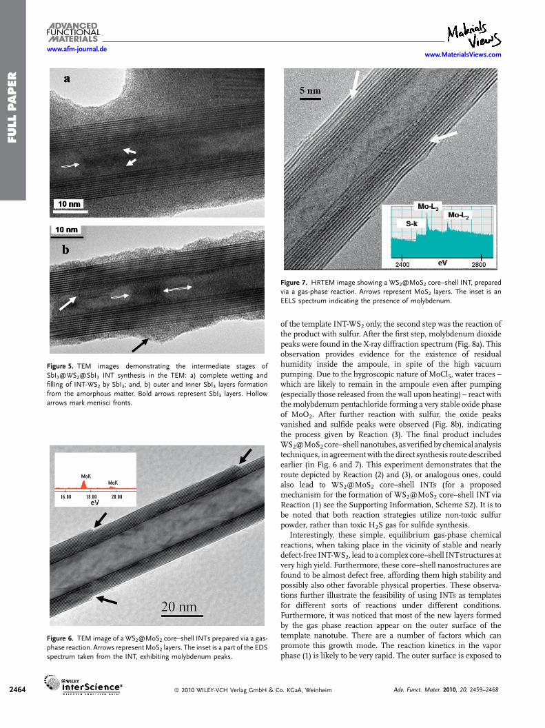
Figure 7. HRTEM image showing a WS2@MoS2 core–shell INT, prepared
via a gas-phase reaction. Arrows represent MoS2 layers. The inset is an
EELS spectrum indicating the presence of molybdenum.
2464 � 2010 WILEY-VCH Verlag GmbH & C
of the template INT-WS2 only; the second step was the reaction ofthe product with sulfur. After the first step, molybdenum dioxidepeaks were found in the X-ray diffraction spectrum (Fig. 8a). Thisobservation provides evidence for the existence of residualhumidity inside the ampoule, in spite of the high vacuumpumping. Due to the hygroscopic nature of MoCl5, water traces –which are likely to remain in the ampoule even after pumping(especially those released from the wall upon heating) – react withthe molybdenum pentachloride forming a very stable oxide phaseof MoO2. After further reaction with sulfur, the oxide peaksvanished and sulfide peaks were observed (Fig. 8b), indicatingthe process given by Reaction (3). The final product includesWS2@MoS2core–shell nanotubes, as verifiedbychemical analysistechniques, in agreementwith the direct synthesis route describedearlier (in Fig. 6 and 7). This experiment demonstrates that theroute depicted by Reaction (2) and (3), or analogous ones, couldalso lead to WS2@MoS2 core–shell INTs (for a proposedmechanism for the formation of WS2@MoS2 core–shell INT viaReaction (1) see the Supporting Information, Scheme S2). It is tobe noted that both reaction strategies utilize non-toxic sulfurpowder, rather than toxic H2S gas for sulfide synthesis.
Interestingly, these simple, equilibrium gas-phase chemicalreactions, when taking place in the vicinity of stable and nearlydefect-free INT-WS2, lead to a complex core–shell INTstructures atvery high yield. Furthermore, these core–shell nanostructures arefound to be almost defect free, affording them high stability andpossibly also other favorable physical properties. These observa-tions further illustrate the feasibility of using INTs as templatesfor different sorts of reactions under different conditions.Furthermore, it was noticed that most of the new layers formedby the gas phase reaction appear on the outer surface of thetemplate nanotube. There are a number of factors which canpromote this growth mode. The reaction kinetics in the vaporphase (1) is likely to be very rapid. The outer surface is exposed to
o. KGaA, Weinheim Adv. Funct. Mater. 2010, 20, 2459–2468

FULLPAPER
www.MaterialsViews.comwww.afm-journal.de
Figure 8. WS2@MoS2 core–shell INT formed via a 2-step process. X-ray
diffraction spectra of: a) the sample after reaction with molybdenum
pentachloride; and, b) the final sulfidized product. Triangles symbolize
MoO2 peaks and diamond shapes WS2/MoS2.
larger concentrations of theprecursors and it ismore accessible forthe reactant. Therefore, the outer surface of the WS2 nanotubes isengulfed with closedMoS2 layersmore readily than the inner coreof thenanotube. Furthermore, the strain energyof the closedMoS2shells is smaller on the outer surface as compared to the innerone.[12] This observation is also common to the products formedbyelectron beam irradiation experiments, i.e.,WS2@SbI3 core–shellINTs (see Section 2.2).
Notwithstanding the proposed growth mechanisms for thecore–shell nanotube structures, it is not fully clear why in certaincases the metal halides (PbI2 and BiI3) are formed inside thetemplate (WS2 nanotubes) core, while in other cases (WS2@SbI3and WS2@MoS2) the new layers appear almost exclusively on theouter surface of the template INT-WS2.
Figure 9. Calculated energies of kt-layered PbI2 nanotubes (black lines)
versus the energies of ks stacks of PbI2 nanostripes (red line), both
encapsulated within the cavities of MoS2 nanotubes: a) as a function of
host MoS2 nanotube radius; and, b) as a function of the number of guest
material atoms. The energy of a PbI2 monolayer is set to zero. The arrows at
(a) indicate the number of guest atoms; for a five-walled nanotube and a
nano-stripe stack, corresponding to two intersections of their energy curves.
2.4. Theoretical Considerations
In order to determine the stability of core–shell INTs from basicprinciples, a phenomenological model comparing the stability ofiodide nanotubes to stacks of iodide nano-stripes, both trapped in atemplate INT-MoS2 was developed. In this model, cylindricalmultiwalled PbI2 nanotubes with an interlayer distance w,encapsulated in a MoS2 single-walled nanotube with a radius R,were considered. The wall of the outermost PbI2 nanotube isseparated from the wall of theMoS2 nanotube by a distance w0. Forthe sake of simplicity in the calculations, MoS2 rather than WS2nanotubeswereconsidered ashosts.The structure and thechemicalreactivity ofMoS2 are very similar to those ofWS2, and therefore thecalculations are not expected to be very different for the two kinds of
Adv. Funct. Mater. 2010, 20, 2459–2468 � 2010 WILEY-VCH Verl
nanotubes. ThePbI2weremodeled as a set of nano-stripes or closednanotubeswith interlayer distancew. The nano-stripes are assumedto fully occupy the cavity of the MoS2 nanotube (Fig. 9). Similarsimulationswereapplied in thepast for the stability analysis ofMoS2nanotubes in comparison to the corresponding nano-stripes.[12] Inthis study, the relativestabilityof anano-stripe vs. ananotubewithanequal number of atoms was calculated. The stability criterion wasdictated by the competition between the energies of the danglingbonds at the edges of the nanostripe and the strain energy of thefolded nanotube. In the present case, however, the iodide nano-stripes are encapsulated within a cylindrical cavity and hence havevariable widths across the diameter of the sulfide nanotube. Whenthe radius of the nanotube increases beyond a certain value and thespacing of the inner core can accommodate an extra pair of nano-stripes, avertical jumpintheenergyof thesystemisclearlyobserved.The size of the added nanostripe is initially very small and hencethere isa vertical jumpintheenergy,which isgradually reducedwithincreasing radius of the host nanotube and the size of the nano-stripe.Thestability regimewasdefinedthroughthecrossingpointofthe energy curves of these two kinds of nanostructures.
The main factors that determine the stability of a stack ofnanostripes are the energy of the dangling bonds at their edges ex,
ag GmbH & Co. KGaA, Weinheim 2465

FULLPAPER
www.afm-journal.dewww.MaterialsViews.com
2466
and the energy of the van der Waals’ interaction between thenanostripes, evdW. Taking into account that the number ofnanostripes within a stack cannot exceed the truncation ks ofR/w, the expression for the energy can be written as
ENS ¼"wdV
a2ffiffi3
pPksi¼1
ffiffiffiffiffiffiffiffiffiffiffiffiffiffiffiffiffiffiffiffiffiffiffiffiffi1� i2w2
ðR�w0=2Þ2q
þ "xaffiffi3
p ð2ksþ1ÞðR�w0=2Þ
1þPksi¼1
ffiffiffiffiffiffiffiffiffiffiffiffiffiffiffiffiffiffiffiffiffiffiffiffiffi1� i2w2
ðR�w0=2Þ2q ; ks ¼
R
w
� �� 1
(4)
where a¼ 4.558 A, is the spatial lattice parameter of PbI2.[43]Wehave
assumed w to be equal to the interlayer distance in bulk PbI2,6.986 A,[43] and w0 to be the average interlayer distance of bulk PbI2andMoS2,6.567 A.
[44]Thedanglingbondenergy,ex,hasbeenroughlyestimated from the atomization energy of bulk PbI2 which equals0.508 eVatom�1.[45]Theenergyof theweakvanderWaals’ interactionevdW was calculated using a universal force field method (UFF)implemented in a deMon package and equals �8.5meV A�2.[46]
Equation (4) is visualized in Figure 9a and b. Figure 9a plotsthe energy/atom of a system consisting of INT-MoS2 nanotubecontaining PbI2 nano-stripes and nanotubes as a function of thenanotube radius R. In Figure 8b the energy per atom of the twosystems as a function of thenumber of atoms (N) are compared.Asnoticed, the energy of the nano-stripes stack is a discontinuousfunction of R(N). This is related to the fact that an integer numberof nano-stripes of variable width can be inserted in a certaindiameter range of the sulfide nanotubes. Thus, in a given sizerange (R2<R<R1) of the MoS2 nanotube, the number of PbI2nano-stripes is fixed, but their size varies with the radius of thenanotubeR.OnceR is greater thanR1 or smaller thanR2, twonano-stripes are added (subtracted) from the nanostructure and theenergy changes discontinuously.However, the general trend in thebehavior of the energy function for the stacks of nano-stripesconfined within a sulfide nanotube is similar to that of free nano-stripes stacks,[12] i.e., the energy/atom decreases with an increaseof the number and width (circumference) of the nano-stripeswithin a stack, approaching asymptotically the energy of bulkmaterial. The slope of the energy curve for large sized PbI2nanostripes has a smoother character, reflecting the fact that thefraction of atoms with dangling bonds becomes smaller.
The stability of multiwalled iodide nanotubes is determinedmainly by two factors. The first one is evdW, which is the energy ofthe van der Waals’ interaction between the lead iodide walls. Thesecond factor is estr –their strain energy, which is inverselyproportional to the square of the radii r taking the form b/R2. Theenergy of a multiwalled nanotube composed of kt single-wallednanotubes can be calculated as
ENT ¼"wdV
a2ffiffi3
p
6
Pkti¼1
ðR� w0 � iwÞ þ bPkt�1
i¼0
1ðR�w0�iwÞ
Pkt�1
i¼0
ðR� w0 � iwÞ(5)
The parameter b can be calculated from experimental dataconcerning the elastic moduli of bulk PbI2 and from the classicaltheory of elasticity.[46,47]Wehave estimated b to equal 28.386 eVA2.
� 2010 WILEY-VCH Verlag GmbH & C
Analysis ofEquation (5) (Fig. 9) shows thewell knownstability ofmultiwalled nanotubes in comparison to their single-walledcounterparts and to monolayers. Nevertheless, the most interest-ing conclusion follows from a comparison between the energies ofnano-stripes and that of multiwalled nanotubes. When R is verysmall, the (PbI2) nanotubes are much less stable than the nano-stripes, because the elastic energy of folding is somuch larger thanthe energy of the dangling bonds. However, one can notice that astack of encapsulated PbI2 nano-stripes becomes less stable thanan encapsulated multiwalled PbI2 nanotubes with kt> 2, whenR> 60 A (or when the number of nanostripes within a stackexceeds ks¼ 14). Note however that the number of PbI2moleculesin the nanostripes largely exceeds that in the nanotubes at thispoint. If equal number of PbI2 is taken for both cases, then thenanostripes do not fill the entire hollow core of the host MoS2nanotube at this point which also moves to lower radius. One canexpect an analogous behavior to occur in other core–shell systems.Experimental evidence for the above prediction is provided by theBiI3@WS2 core–shell structure presented in Figure 3, where ananotube–nanorod transformation of the guest material isobserved at a certain host INT diameter (see Section 2.1 forfurther discussion). The stacks of nanostripes becomemore stablethan nanotubes again at very large diameters of the hosting MoS2nanotube. This situation may be described already as theencapsulation of sub-micron PbI2 particles with sizes greaterthan0.3mm.This observation is nothingbut amanifestation of thefact that the nanotubes are ametastable phase in the nano-regime.The overall stable macroscopic phase consists of PbI2 platelets.
Thus, the simple phenomenological model presented heredemonstrates that the formation of iodide nanotubes withinchalcogenide nanotubes is thermodynamically favorable only overa certain size range; while encapsulated iodide nanostripes willbe more stable below this range, the macroscopic platelets are theglobally stable phase. However, at both ends of this range, thenumber of atoms in a nano-stripe stack configuration exceedsthat in a nanotubular one (Fig. 9a). This observation is amanifestation of the fact that more PbI2 atoms can braccommodated as platelets into the core of the WS2 (MoS2)nanotube than in the nanotube form. Obviously, this model is notlimited to a specific pair of compounds and can be applied for anycore–shell nanotube.
2.5. Further Discussion
The materials used for the synthesis of the core–shell INT viawetting are PbI2 and BiI3, which are low melting point iodides.Their lattice structures are related to the layered2H-CdI2 structure,while in the case of BiI3, metal vacancies are present in the lattice,hence its altered stoichiometry (Scheme 1).[48] SbI3, having asimilar structure to BiI3, was also used to wet INT-WS2, with theexception of an electron beam as a heat source, also producingcore–shell INTs. The gas phase chemical synthesis of core–shellINTs employsMoS2, which is very close toWS2 in its structure andchemistry. The molecular ionicity of all the compounds listedabove is low (under 10%), as derived from the electro-negativitydifference between the two types of atoms composing them (seeTable 1).[39] The structure and the physiochemical behavior of the
o. KGaA, Weinheim Adv. Funct. Mater. 2010, 20, 2459–2468

FULLPAPER
www.MaterialsViews.comwww.afm-journal.de
core–shell INT-forming compounds, raises the question of theproperties required for the construction of such compositenanostructures.
From all the above examples, it is clear that the ionicity plays amajor role in the ability of layered materials to wet the templatesurface and enfold it to form INT. Table 1 summarizes themolecular ionicity values for the different compounds studied inthis work (note that molecular rather than crystalline ionicity scalewas used in this work).[39] The proposed explanation for thedependence of the core–shell INT on ionicity is as follows: whileforming a nanotube, the intralayer separation of the outer iodineatoms in the I–M–I trilayer is larger than the equilibrium distanceof the bulk (2H) atoms and therefore they are subject to a tensilestress. Contrarily, the inner iodine atoms of the triple layer arecloser to each other than the equilibrium distance of the bulkmaterial and thus withstand a compressive stress.[12] The residualnegative charge on the iodine atomsof, e.g., CdI2 is larger than thatof PbI2, due to the increased ionicity of the former (Table 1).Consequently, the compressive (tensile) stress between the inner(outer) iodine atoms inCdI2 is stronger,making the formation of ananotube less favorable than the case of PbI2. Furthermore, at theinterface between the guest and host nanotubes, the innermostsulfur atoms of WS2 are in great proximity to the iodine atoms ofthemetal iodidecompound.Hence, themorepolar iodineatomsofCdI2 are not likely to favor the vicinity to the non-polar sulfuratoms. Indeed, attempts to form core–shell nanotubes with CdI2,via wetting of the molten salt (as specified in Section 2.1) have notso far been successful. It is thus assumed that the greater theionicity or electronegativity difference a layered compound mighthave, the less probable it will form an INTand in particular a core–shell nanotube structure with WS2 nanotube as template.Similarly, unsuccessful attempts to form core–shell nanotubeswith INT-WS2 templates, applying a gas phase chemical reaction(as detailed in Section 2.3), were carried out for the relatively ionic(22%; see Table 1) NbS2 compound. This conclusion is furthersupported by the fact that the inorganic compounds with thesmallest ionicity (WS2 andMoS2) form themost stable INTand IFand in particular core–shell WS2@MoS2 INT and vice versa.
3. Conclusions
In this work, core–shell inorganic nanotubes were synthesizedusing different experimental techniques and under differentthermodynamic conditions. In all the studied cases, INT-WS2,which are produced in large amounts,were utilized as templates tothe reaction.
The molten salt technique basically engaged the wetting andcapillary filling of liquid metal iodides (PbI2 and BiI3) into thetemplate INT. The synthesized core–shell nanotubes werecharacterized by inner iodide layers, in addition to crystalline oramorphousmatter terminating in a meniscus shape, indicative ofthe wetting properties.
The second process was conducted in situ using TEM. Thehighly energetic electron beam caused a local melting orevaporation of the layered compound (SbI3), which in turndeposited on the inner and outer surfaces of the nearby templateINT-WS2. This deposition was shown to transform into tubularlayers atop the INT-WS2, or within their hollow core. Possible
Adv. Funct. Mater. 2010, 20, 2459–2468 � 2010 WILEY-VCH Verl
mechanisms leading to these core-shell INTstructures are brieflydiscussed in Section 2.2.
The last process, unlike its two predecessors, involved a single-or a double-step chemical reaction. Closed layers of MoS2 formedaround or inside the INT-WS2 template giving rise to core–shellnanotubular structures. Most often, these reactions resulted inouter closed MoS2 layers engulfing the template INT-WS2.
This paper elaborates on the possible compositions andtechniques towards core–shell inorganic nanotubes, as well asexpands the list of nanotube forming materials. It clearlydemonstrates the versatility and feasibility of core–shell INTs,and aims towards the production, or even application, of differenttypes of these unique nanomaterials.
4. Experimental
Some important properties of the materials used in the current work arepresented in Table 1.
INT Wetting and Capillary Filling: WS2 nanoparticulate powder contain-ing 5% multiwalled nanotubes (30 mg) was carefully mixed with iodidepowder (120mg, PbI2 98.5% Alfa Aesar, or BiI3 99% Sigma Aldrich). Thenanotubes are typically 5–8 layers thick with inner and outer diameters ofca. 10 and 25 nm, respectively, and are a fewmicrons long [2]. The mixtureswere gently ground using a mortar and pestle and then added with aproximal amount of iodine (15mg, 99.5% Alfa Aesar) before beingtransferred to a silica quartz ampoule. The ampoules were pumped underhigh vacuum (ca. 5� 10�5 mbar) and sealed. They were placed for14–30 days in a horizontal furnace at a constant temperature (500 8C) andthen quenched to 0 8C in an ice–water mixture.
Core–shell INT Synthesis via Electron Beam Irradiation: A saturatedsolution of SbI3 (anhydrous, 10 mesh, 99.999% Sigma Aldrich) indehydrated ethanol (max. 0.01% H2O, SeccoSolv) was prepared, addedwith WS2 nanoparticulate powder (approximately 50 mg, for details, seeSection 2.1) and mixed (via 5min sonication followed by 4 h of magneticplate stirring at 80 8C). The product was then placed on a carbon/Formvar-coated Cu grid and inserted in a CM-120 Philips transmission electronmicroscope. When a WS2 nanotube was found to be in the vicinity of theantimony iodide powder, the e-beam was settled upon it for a few minutes,until melting and filling or wetting of the nanotubes with the compoundoccurred.
INT as Templates for Gas-Phase Chemical Reaction: WS2 nanoparticulatepowder (30mg, for details, see Section 2.1) was mixed with MoCl5 powder(137mg, 95% Aldrich) and sulfur powder (112 mg, 99.98% Sigma Aldrich).The large sulfur excess (sulfur/chloride ratio 7:1) was intended to ensureMoS2 formation. The details of the evacuation, sealing and TEM gridpreparation are similar to the procedure described in Section 2.1. The samplewas thermally treated at 800 8C for 6 h followed by a slow overnight cooling.
An alternative route included a two step process. First, a reactionbetween WS2 nanoparticulate powder (30 mg) and MoCl5 powder(137mg) at 700 8C was carried out in a sealed quartz ampoule. Theampoule was broken and the product was collected and grinded.Subsequently, sulfur, in yet greater ratio to the chloride (200mg) wasadded and the mixture was pumped and sealed in a new ampoule,following a treatment at 500 8C. The rest of the experimental detailsremained unchanged. The products of each step were examined by X-raydiffraction using an Ultima 3 Rigaku X-ray diffractometer. The data wereanalyzed with the assistance of MDI Jade 7.0 program.
Transmission Electron Microscopy: All products were sonicated indehydrated ethanol (max 0.01% H2O, SeccoSolv), placed on a carbon/Formvar-coated Cu grid, and analyzed by TEM; the microscopes in usewere the 120 kV (Philips CM-120) equipped with an EDS detector (EDAX-Phoenix Microanalyzer), and for high resolution the FEI Tecnai F-30equipped with a parallel electron energy loss spectroscopy (EELS) detector(Gatan imaging filter, GIF; Gatan) for chemical analysis.
ag GmbH & Co. KGaA, Weinheim 2467

FULLPAPER
www.afm-journal.dewww.MaterialsViews.com
2468
Theoretical Considerations: The energy of the weak van der Waals’interaction was calculated using the universal force field method (UFF)with a full geometry optimization [49], as implemented in the deMonsoftware package [50]. As themodel, a supercell was used, which containedtwo monolayers of PbI2 (10� 10 unit cells) at different interlayer distancesfrom 4 to 12 A. The factor b, which is the bending energy of the PbI2nanotubes, was estimated using the experimental values of elastic stiffnessconstants cij for bulk PbI2 [46], and classical theory of elasticity [47], bymeans of the following equations:
b ¼ Yw3
4N(6)
Y ¼ ðc11 � c12Þðc33ðc11 þ c12Þ � 2c213Þc11c33 � c213
(7)
where Y is the Young’s modulus of a hexagonal crystal in the direction? c, and N and w are the number of atoms per unit area of a monolayer
and the van der Waals’ gap between the monolayers, respectively.Acknowledgements
This work was supported by the G. M. J. Schmidt Minerva Center; theHarold Perlman Foundation; the Gurwin Fund; ERC grant INTIF 226639;the Irving and Cherna Moskowitz Center for Nano- and Bio-Nano imaging,and the Israel Science Foundation. R.T. holds the Drake Family Chair inNanotechnology and is the director of the Helen andMartin Kimmel Centerfor Nanoscale Science. We are grateful to Dr. R. Rosentsveig for the WS2nanotubes synthesis. Supporting Information is available online fromWileyInterScience or from the author.
Received: March 15, 2010
Published online: June 30, 2010
[1] R. Tenne, L. Margulis, M. Genut, G. Hodes, Nature 1992, 360, 444.
[2] A. Margolin, R. Rosentsveig, A. Albu-Yaron, R. Popovitz-Biro, R. Tenne,
J. Mater. Chem. 2003, 14, 617.
[3] A. Zak, L. Sallacan-Ecker, A. Margolin, M. Genut, R. Tenne, Nano 2009, 4,
91.
[4] Y. Feldman, E. Wasserman, D. J. Srolovitz, R. Tenne, Science 1995, 267,
222.
[5] L. Rapaport, N. Fleicher, R. Tenne, J. Mater. Chem. 2005, 15, 1782.
[6] A. Katz, M. Redlich, L. Rapaport, H. D. Wagner, R. Tenne, Tribol. Lett. 2006,
21, 135.
[7] R. Dominko, M. Gaberscek, D. Arcon, A. Mrzel, M. Remskar, D. Mihailovic,
S. Pejovnik, J. Jamnik, Electrochim. Acta 2003, 48, 3079.
[8] M. Shneider, H. Dodiuk, S. Kenig, R. Tenne, J. Adhes. Sci. Technol. 2010, 24,
1083.
[9] M. Naffakh, C. Marco, M. A. Gomez, I. Jimenez, J. Phys. Chem. B 2009, 113,
7107.
[10] M. Naffakh, Z. Martın, C. Marco, M. A. Gomez, I. Jimenez, Thermochim.
Acta 2008, 472, 11.
[11] X. Hou, C. X. Shan, K. L. Choy, Surf. Coat. Technol. 2008, 202. 2287.
[12] G. Seifert, T. Kohler, R. Tenne, J. Phys. Chem. B 2002, 106, 2497.
[13] P. M. Ajayan, S. Iijima, Nature 1993, 361, 333.
[14] R. R. Meyer, J. Sloan, R. E. Dunin-Borkowski, A. I. Kirkland, M. C. Novotny,
S. R. Bailey, J. L. Hutchison, M. L. H. Green, Science 2000, 289, 1324.
� 2010 WILEY-VCH Verlag GmbH & C
[15] J. Sloan, S. J. Grosvenor, S. Friedrichs, A. I. Kirkland, J. L. Hutchison,
M. L. H. Green, Angew. Chem, Int. Ed. 2002, 41, 1156.
[16] E. Philp, J. Sloan, A. I. Kirkland, R. R. Meyer, S. Friedrichs, J. L. Hutchison,
M. L. H. Green, Nat. Mater. 2003, 2, 788.
[17] E. Flahaut, J. Sloan, S. Friedrichs, A. I. Kirkland, K. S. Coleman, V. C.
Williams, N. Hanson, J. L. Hutchison, M. L. H. Green, Chem. Mater. 2006,
18, 2059.
[18] R. L. D. Whitby, W. K. Hsu, P. K. Fearon, N. C. Billingham, I. Maurin, H. W.
Kroto, D. R. M. Walton, B. Boothroyd, S. Firth, R. J. H. Clark, D. Collison,
Chem. Mater. 2002, 14, 2209.
[19] M. Brorson, T. W. Hansen, C. J. H. Jacobsen, J. Am. Chem. Soc. 2002, 124,
11582.
[20] Y. Q. Zhu, W. K. Hsu, H. W. Kroto, D. R. M. Walton, Chem. Commun. 2001,
2001. 2184.
[21] R. Kreizman, S. Y. Hong, J. Sloan, R. Popovitz-Biro, A. Albu-Yaron, G.
Tobias, B. Ballesteros, B. G. Davis, M. L. H. Green, R. Tenne, Angew. Chem,
Int. Ed. 2009, 48, 1230.
[22] I. Kaplan-Ashiri, S. R. Cohen, K. Gartsman, V. Ivanovskaya, T. Heine, G.
Seifert, I. Wiesel, H. D. Wagner, R. Tenne, Proc. Nat. Acad. Sci. 2006, 103,
523.
[23] C. Schuffenhauer, G. Wildermuth, J. Felsche, R. Tenne, Phys. Chem. Chem.
Phys. 2004, 6, 3991.
[24] W. Q. Han, C. W. Chang, A. Zettl, Nano Lett. 2004, 4, 1355.
[25] G. Seifert, private communication.
[26] A. N. Enyashin, R. Kreizman, G. Seifert, J. Phys. Chem. C 2009, 113,
13664.
[27] D. Ugarte, Nature 1992, 359, 707.
[28] F. Banhart, Rep. Prog. Phys. 1999, 62, 1181.
[29] A. V. Krasheninnikov, F. Banhart, Nat. Mater. 2007, 6, 723.
[30] F. Banhart, J. Mater. Sci. 2006, 41, 4505.
[31] M. Jose-Yacaman, H. Lopez, P. Santiago, D. H. Galvan, I. L. Garzon, A.
Reyes, Appl. Phys. Lett. 1996, 69, 1065.
[32] E. Hernandez, V. Meunier, B. W. Smith, R. Rurali, H. Terrones, M.
Buongiorno Nardelli, M. Terrones, D. E. Luzzi, J. C. Charlier, Nano Lett.
2003, 3, 1037.
[33] N. Sallacan, R. Popovitz-Biro, R. Tenne, Solid State Sci. 2003, 5, 905.
[34] M. Bar-Sadan, R. Popovitz-Biro, Y. Prior, R. Tenne, Mater. Res. Bull. 2006,
41, 2137.
[35] P. M. Ajayan, O. Stephan, Ph. Redlich, C. Colliex, Nature 1995, 375, 564.
[36] W. Han, S. Fan, Q. Li, Y. Hu, Science 1997, 277, 1287.
[37] M. Remskar, A. Mrzel, M. Virsek, A. Jesih, Adv. Mater. 2007, 19, 4276.
[38] A. Olivas, A. Camacho, M. J. Yacaman, S. Fuentes, J. Mater. Res. 2004, 19,
2176.
[39] A. Garcıa, M. L. Cohen, Phys. Rev. B 1993, 47, 4215.
[40] R. Popovitz-Biro, A. Twersky, Y. Rosenfeld Hacohen, R. Tenne, Isr. J. Chem.
2001, 41, 7.
[41] V. K. Sarin, J. Mater. Sci. 1975, 10, 593.
[42] X. L. Li, J. P. Ge, Y. D. Li, Chem. Eur. J. 2004, 10, 6163.
[43] E. Salje, B. Palosz, B. Wruck, J. Phys. C 1987, 20, 4077.
[44] T. Boker, R. Severin, A. Muller, C. Janowitz, R. Manzke, D. Voß, P. Kruger,
A. Mazur, J. Pollmann, Phys. Rev. B 2001, 64, 235305/1.
[45] V. S. Urusov, V. B. Dudnikova, Theor. Exp. Chem. 1985, 21, 708.
[46] B. Dorner, R. E. Ghosh, G. Harbeke, Phys. Status Solidi B 1976, 73, 655.
[47] M. Cote, M. L. Cohen, D. J. Chadi, Phys. Rev. B 1998, 58, R4277.
[48] J. A. Wilson, A. D. Yoffe, Adv. Phys. 1969, 269, 193.
[49] A. K. Rappe, C. J. Casewit, K. S. Colwell, W. A. Goddard, III, W. M. Skiff,
J. Am. Chem. Soc. 1992, 114, 10024.
[50] L. Zhechkov, T. Heine, S. Patchkovskii, G. Seifert, H. A. Duarte, J. Chem.
Theory Comp. 2005, 1, 841.
o. KGaA, Weinheim Adv. Funct. Mater. 2010, 20, 2459–2468