
INORGANIC CHEMISTRY - mpbou
224
B.Sc., Third Year Chemistry, Paper - II INORGANIC CHEMISTRY MADHYA PRADESH BHOJ (OPEN) UNIVERSITY - BHOPAL
-
Upload
khangminh22 -
Category
Documents
-
view
1 -
download
0
Transcript of INORGANIC CHEMISTRY - mpbou

B.Sc., Third Year
Chemistry, Paper - II
INORGANIC CHEMISTRY
MADHYA PRADESH BHOJ (OPEN) UNIVERSITY - BHOPAL

Vikas® is the registered trademark of Vikas® Publishing House Pvt. Ltd.
VIKAS® PUBLISHING HOUSE PVT. LTD.E-28, Sector-8, Noida - 201301 (UP)Phone: 0120-4078900 Fax: 0120-4078999Regd. Office: A-27, 2nd Floor, Mohan Co-operative Industrial Estate, New Delhi 1100 44 Website: www.vikaspublishing.com Email: [email protected]
All rights reserved. No part of this publication which is material protected by this copyright noticemay be reproduced or transmitted or utilized or stored in any form or by any means now known orhereinafter invented, electronic, digital or mechanical, including photocopying, scanning, recordingor by any information storage or retrieval system, without prior written permission from the Registrar,Madhya Pradesh Bhoj (Open) University, Bhopal.
Information contained in this book has been published by VIKAS® Publishing House Pvt. Ltd. and hasbeen obtained by its Authors from sources believed to be reliable and are correct to the best of theirknowledge. However, the Madhya Pradesh Bhoj (Open) University, Bhopal, Publisher and its Authorsshall in no event be liable for any errors, omissions or damages arising out of use of this informationand specifically disclaim any implied warranties or merchantability or fitness for any particular use.
Published by Registrar, MP Bhoj (Open) University, Bhopal in 2020
Copyright © Reserved, Madhya Pradesh Bhoj (Open) University, Bhopal
Advisory Committee
1. Dr Jayant SonwalkarHon'ble Vice ChancellorMadhya Pradesh Bhoj (Open) University,Bhopal
2. Dr L.S.SolankiRegistrarMadhya Pradesh Bhoj (Open) University, Bhopal
3. Dr Neelam WasnikDy Director PrintingMadhya Pradesh Bhoj (Open) University,Bhopal
5. Dr Neetu Priya LachoriaAsst ProfessorShyama Prasad Mukerjee Science & CommerceCollege Old Benazir Bhopal
6. Dr Anita DubeyAsst ProfessorMLB College Bhopal
Reviewer Committee
2. Dr Neetu Priya LachoriaAsst ProfessorShyama Prasad Mukerjee Science & CommerceCollege Old Benazir Bhopal
COURSE WRITERS
Dr Brajendra Singh Chauhan, Professor & Dean, Greater Noida Institute of Technology (GNIT), Greater Noida (UP)Units: (1.0-1.3, 2.2.1-2.7, 3, 4.3-4.5, 4.8-4.14, 5)
Meena Kumar, M. Sc. Botany, B.ED, TGT, Senior Science Teacher, Delhi Government School, DelhiUnits: (1.3.1-1.10, 2.0-2.2, 2.8-2.13)
K S Tewari, M.Sc., Ph. D. Formerly, Head of the Department of Chemistry Christ Church College, KanpurN K Vishnoi, M.Sc., Ph. D. Professor, NIIT University Neemrama (Rajasthan)Units: (4.0-4.2, 4.6-4.7)
3. Dr Anita DubeyAsst ProfessorMLB College Bhopal
1. Dr Ila JainProfessorShyama Prasad Mukharjee Govt Science & CommerceCollege Benazir Bhopal
4. Dr Ila JainProfessorShyama Prasad Mukharjee Govt Science & CommerceCollege Benazir Bhopal

SYLLABI-BOOK MAPPING TABLEInorganic Chemistry
Unit-11. Hard and Soft Acids and Bases (HSAB)Introduction: Classification of Hard and Soft Acid-Base, Hard andSoft Acid-Base Concept of Pearson, Application of Hard-Soft AcidBase Theory, Symbiosis, Acid-Base Strength and Hardness andSoftness; Theoretical Basis of Hardness and Softness, ElectronicTheory, π-Bonding Theory and Drago Wayland Theory,Electronegativity and Hardness and Softness, Limitations of SoftAcid-Base Concept.2. Silicones and PhosphazenesIntroduction: Silicones-Method of Preparation, Classification,Properties and Application (Uses); Phosphazene (PhosphonitrilicChloride) - Method of Preparation and Properties, Structure ofTriphosphazenes, Some other Phosphazenes and Uses ofPhosphazenes.
Unit-21. Metal Ligand Bonding in Transition Metal ComplexesIntroduction: Limitations of Valence Bond Theory, Crystal FieldTheory, Crystal Field Splitting of d-Orbitals, d-Orbitals Splittingand Stabilisation Energy in Octahedral, Tetrahedral and SquarePlanar Complexes, Factors Affecting the Crystal Field Parameters,Applications of Crystal Field Theory and Limitations of CrystalField Theory.2. Thermodynamic and Kinetic Aspects of MetalsIntroduction: Thermodynamic Aspects of Metal Complexes,Factors Affecting Thermodynamic Stability of Complexes, KineticAspects of Metal Complexes, Stabilisation Reactions of SquarePlanar Complexes and Factors Affecting the Rate of SubstitutionReactions in Square Planar Complexes.
Unit-3Magnetic Properties of Transition Metal ComplexesIntroduction: Types of Magnetic Behaviour, Diamagnetism,Paramagnetism, Ferromagnetism, Antiferromagnetism,Ferrimagnetism, Origin and Calculation of Magnetism, Methodsof Determining Magnetic Susceptibility- Gouy’s, BhatnagarMathur, Quincke’s, Curie and Nuclear Magnetic ResonanceMethod, Magnetic Moment - L-S Coupling, Determination ofGround State, Term Symbol, Correlation of
s and
eff Values,
Orbital Contribution to Magnetic Moments and Applications ofMagnetic Moment Data for 3d-Metal Complexes.
Unit-1: HSAB, Silicones andPhosphazenes
(Pages 3-27)
Unit-2: Metal Ligand Bonding,Thermodynamic and
Kinetic Aspects in TransitionMetal Complexes
(Pages 29-58)
Unit-3: Magnetic Properties ofTransition Metal Complexes
(Pages 59-115)

Unit-4:1. Electronic Spectra of Transition Metal ComplexesIntroduction: Types of Electronic Transition, Selection Rules ford-d Transition: Spectroscopic Ground States-Notations,Spectroscopic States and Spectroscopic Ground States inComplexes; Spectrochemical Series, Orgel Energy Level Diagram-Uses in Octahedral and Tetrahedral Complexes having D1 To D9
States: Electronic Spectrum of [Ti(H2O)
6]3+ Complex Ion.
2. Organometallic ChemistryIntroduction: Nomenclature and Classification of OrganometallicCompounds. General Methods of Preparation: Alkyl and ArylOrganometallic Compounds of Lithium - Preparation, Properties,Bond Nature and Applications, Organometallic Compounds of AlApplications.
UNIT 5:1. Bioinorganic ChemistryIntroduction: Essential and Trace Elements in Biological Processes,Biological Functions of the Bio-Elements, Availability of Bio-Metalsand Bio-Non-Metals - Metalloporphyrins, Haemoglobin Structureand Biological Functions, Myoglobin-Mechanism of OxygenTransfer through Haemoglobin and Myoglobin, Relation betweenHaemoglobin and Myoglobin and Chemical Reaction ofHaemoglobin and Myoglobin, Biological Role of Alkali and AlkalineEarth Metal Ions with Special Reference to Ca2+, Nitrogen Fixation.2. Metal Nitrosyl ComplexNitrosylating Agents, Synthesis, Structure, Properties and Bonding.
Unit-4: Electronic Spectra ofTransition Metal Complexes and
Organometallic Chemistry(Pages 117-182)
Unit-5: Bioinorganic Chemistry andMetal Nitrosyl Complex
(Pages 183-216)

INTRODUCTION
UNIT 1 HSAB, SILICONES AND PHOSPHAZENES 3-27
1.0 Introduction1.1 Objectives1.2 Classification of Hard and Soft Acids and Bases
1.2.1 Arland, Chatt and Davies Classification1.2.2 Pearson’s Classification of HSAB1.2.3 Applications of HSAB Principle1.2.4 Symbiosis1.2.5 Stability of Compounds1.2.6 Limitations of HSAB Principle
1.3 Acid-Base Strength and Hardness and Softness1.3.1 Theories and Concepts of Hardness and Softness
1.4 Silicones1.5 Phosphazenes1.6 Answers to ‘Check Your Progress’1.7 Summary1.8 Key Terms1.9 Self-Assessment Questions and Exercises
1.10 Further Reading
UNIT 2 METAL LIGAND BONDING, THERMODYNAMIC AND
KINETIC ASPECTS IN TRANSITION METAL COMPLEXES 29-58
2.0 Introduction2.1 Objectives2.2 Metal Ligand Bonding in Transition Metal Complexes
2.2.1 Limitations of Valence Bond Theory
2.3 Crystal Field Theory2.3.1 Important Postulates of Crystal Field Theory2.3.2 Crystal Field Splitting in Octahedral Complexes2.3.3 Strong and Weak Field Splitting/Distribution of dx Electron (x = 1 to 10)2.3.4 Factors Affecting the Magnitude of
0
2.3.5 Crystal Field Splitting in Tetrahedral Complexes
2.4 Square Planar Complexes2.5 Factors Affecting the Crystal Field Parameters2.6 Applications of Crystal Field Theory2.7 Limitations of Crystal Field Theory2.8 Thermodynamic and Kinetic Aspects of Metals2.9 Answers to ‘Check Your Progress’
2.10 Summary2.11 Key Terms2.12 Self-Assessment Questions and Exercises2.13 Further Reading
CONTENTS

UNIT 3 MAGNETIC PROPERTIES OF TRANSITION METAL COMPLEXES 59-115
3.0 Introduction3.1 Objectives3.2 Magnetic Behaviour of Transition Metal Complexes
3.2.1 Types of Magnetic Behaviour3.2.2 Illustration of Magnetic Phenomena
3.3 Origin and Calculation of Magnetism3.4 Magnetic Susceptibility
3.4.1 Determination of Magnetic Susceptibility
3.5 L–S Coupling or Russell Saunders Coupling3.6 Determination of Ground State Term Symbols : p2 and d2 Configurations
3.6.1 Derivation of Term Symbols for p2—Configuration3.6.2 Derivation of the Term Symbles for d2 Configration3.6.3 Applications of These Rules for p2 and d2 Configurations
3.7 Orbital Contribution to Magnetic Moment3.8 Applications of Magnetic Moment for 3d-Metal Complexes3.9 Answers to ‘Check Your Progress’
3.10 Summary3.11 Key Terms3.12 Self-Assessment Questions and Exercises3.13 Further Reading
UNIT 4 ELECTRONIC SPECTRA OF TRANSITION METAL
COMPLEXES AND ORGANOMETALLIC CHEMISTRY 117-182
4.0 Introduction4.1 Objectives4.2 Introduction to Electronic Spectra of Transition Metal Complexes4.3 Types of Transitions
4.3.1 Selection Rules for Electronic Transitions
4.4 Spectroscopic Ground States4.4.1 Spectroscopic Methods4.4.2 Splitting of Russel Saunder's States in Octaheredral and Tetrahedral Crystal Fields4.4.3 Spectrochemical Series
4.5 Orgel Energy Level Diagrams4.5.1 Tetrahedral Complexes of Metal Ions with d1 and d9 Configuration4.5.2 Spectra of Octahedral Complexes of Metal Ions with d1 Configuration
4.6 Nomenclature and Classification of Organometallic Compounds4.7 General Methods of Preparation4.8 Alkyl and Aryl Organometallic Compounds of Lithium4.9 Organoaluminium Compounds
4.10 Answers to ‘Check Your Progress’4.11 Summary4.12 Key Terms4.13 Self-Assessment Questions and Exercises4.14 Further Reading

UNIT 5 BIOINORGANIC CHEMISTRY AND
METAL NITROSYL COMPLEX 183-216
5.0 Introduction5.1 Objectives5.2 Bioinorganic Chemistry
5.2.1 Essential Trace Metal Elements in Biological Processes5.2.2 Essential Trace Non-Metals in Biological Processes
5.3 Metalloporphyrins5.4 Iron Porphyrins
5.4.1 Structure of Myoglobin5.4.2 Structure of Haemoglobin5.4.3 Function of Haemoglobin and Myoglobin5.4.4 Reactions of Haemoglobin and Myoglobin5.4.5 Myoglobin and Haemoglobin Functions and Cooperativity
5.5 Alkali and Alkaline Earth Metal Ions5.5.1 Role of Mg2+ and Ca2+ in Biological Systems
5.6 Nitrogen Fixation5.7 Metal Nitrosyl Complex
5.7.1 Classification of Nitrosyl Compounds5.7.2 Types of Metal Nitrosyls5.7.3 Structure and Bonding in Metal Nitrosyls
5.8 Answers to ‘Check Your Progress’5.9 Summary
5.10 Key Terms5.11 Self-Assessment Questions and Exercises5.12 Further Reading


Introduction
NOTES
Self - LearningMaterial 1
INTRODUCTION
Inorganic chemistry is the study of the structures, properties and reactions of allchemical elements and compounds except for organic compounds, such ashydrocarbons and their derivatives. The principles of inorganic chemistry aretypically used for studying the synthesis, reactions, structures and properties ofcompounds of the elements. Inorganic chemistry is fundamental to many practicaltechnologies including catalysis and materials (structural, electronic, magnetic, etc.),energy conversion and storage, and electronics. Inorganic compounds are alsofound in biological systems where they are essential to life processes. Significantclasses of inorganic compounds are the oxides, the carbonates, the sulphates, andthe halides. Many inorganic compounds are characterized by high melting points.Inorganic salts typically are poor conductors in the solid state. Other importantfeatures include their high melting point and ease of crystallization. Descriptiveinorganic chemistry focuses on the classification of compounds based on theirproperties. Partly the classification focuses on the position in the periodic table ofthe heaviest element, the element with the highest atomic weight in the compound,partly by grouping compounds by their structural similarities.
HSAB concept is an initialism for ‘Hard and Soft (Lewis) Acids and Bases’.It is also known as the Pearson acid-base concept. HSAB is widely used inchemistry for explaining stability of compounds, reaction mechanisms and pathways.It assigns the terms ‘Hard’ or ‘Soft’, and ‘Acid’ or ‘Base’ to chemical species.‘Hard’ applies to species which are small, have high charge states, the chargecriterion applies mainly to acids, to a lesser extent to bases, and are weaklypolarizable. ‘Soft’ applies to species which are big, have low charge states andare strongly polarizable. The theory is used in contexts where a qualitative, ratherthan quantitative, description helps in understanding the predominant factors whichdrive chemical properties and reactions. HSAB theory is also useful in predictingthe products of metathesis reactions. In 2005, it was shown that even the sensitivityand performance of explosive materials can be explained on basis of HSAB theory.Ralph Pearson introduced the HSAB principle in the early 1960s as an attempt tounify inorganic and organic reaction chemistry. Essentially, the theory states thatsoft acids react faster and form stronger bonds with soft bases, whereas hardacids react faster and form stronger bonds with hard bases, all other factors beingequal. The classification was mostly based on equilibrium constants for reaction oftwo Lewis bases competing for a Lewis acid.
Crystal Field Theory (CFT) describes the breaking of degeneracies ofelectron orbital states, usually d or f orbitals, due to a static electric field producedby a surrounding charge distribution (anion neighbours). This theory has beenused to describe various spectroscopies of transition metal coordination complexes,in particular optical spectra (colours). CFT successfully accounts for some magneticproperties, colours, hydration enthalpies, and spinel structures of transition metalcomplexes, but it does not attempt to describe bonding. CFT was developed byphysicists Hans Bethe and John Hasbrouck van Vleck in the 1930s. Basically, theCFT was subsequently combined with molecular orbital theory to form the more

Introduction
NOTES
Self - Learning2 Material
realistic and complex Ligand Field Theory (LFT), which delivers insight into theprocess of chemical bonding in transition metal complexes. The bonding betweenmetals and ligands can occur on a spectrum of covalence and strength.
In chemistry, the ‘Bioinorganic Chemistry’ is a field that examines the roleof metals in biology. Bioinorganic chemistry includes the study of both naturalphenomena, such as the behaviour of metalloproteins as well as artificiallyintroduced metals, including those that are non-essential, in medicine and toxicology.Many biological processes, such as respiration depend upon molecules that fallwithin the realm of inorganic chemistry. The discipline also includes the study ofinorganic models or mimics that imitate the behaviour of metalloproteins. As amixture of biochemistry and inorganic chemistry, bioinorganic chemistry is importantin elucidating the implications of electron-transfer proteins, substrate bindings andactivation, atom and group transfer chemistry as well as metal properties in biologicalchemistry.
Fundamentally, the inorganic chemistry deals with the synthesis and behaviourof inorganic and organometallic compounds. It has applications in every aspect ofthe chemical industry, including catalysis, materials science, pigments, surfactants,coatings, medications, fuels, and agriculture.
This book, Inorganic Chemistry, is designed to be a comprehensive andeasily accessible book covering the basic concepts of Hard and Soft Acids andBases (HSAB), silicones and phosphazenes, metal ligand bonding in transitionmetal complexes, thermodynamic and kinetic aspects of metals, magnetic propertiesof transition metal complexes, electronic spectra of transition metal complexes,organometallic chemistry, bioinorganic chemistry, and metal nitrosyl complex.
The book is divided into five units that follow the Self-Instruction Mode(SIM) with each unit beginning with an Introduction to the unit, followed by anoutline of the Objectives. The detailed content is then presented in a simple butstructured manner interspersed with Check Your Progress to test the student’sunderstanding of the topic. A Summary along with a list of Key Terms and a set ofSelf-Assessment Questions and Exercises is also provided at the end of each unitfor understanding, revision and recapitulation. The topics are logically organizedand explained with related text, figures and examples, analysis and formulations toprovide a background for logical thinking and analysis with good knowledge ofinorganic chemistry. The examples have been carefully designed so that the studentscan gradually build up their knowledge and understanding.

HSAB, Silicones andPhosphazenes
NOTES
Self - LearningMaterial 3
UNIT 1 HSAB, SILICONES ANDPHOSPHAZENES
Structure
1.0 Introduction1.1 Objectives1.2 Classification of Hard and Soft Acids and Bases
1.2.1 Arland, Chatt and Davies Classification1.2.2 Pearson’s Classification of HSAB1.2.3 Applications of HSAB Principle1.2.4 Symbiosis1.2.5 Stability of Compounds1.2.6 Limitations of HSAB Principle
1.3 Acid-Base Strength and Hardness and Softness1.3.1 Theories and Concepts of Hardness and Softness
1.4 Silicones1.5 Phosphazenes1.6 Answers to ‘Check Your Progress’1.7 Summary1.8 Key Terms1.9 Self-Assessment Questions and Exercises
1.10 Further Reading
1.0 INTRODUCTION
HSAB concept is an initialism for ‘Hard and Soft (Lewis) Acids and Bases’. It isalso known as the Pearson acid-base concept. HSAB is widely used in chemistryfor explaining stability of compounds, reaction mechanisms and pathways. It assignsthe terms ‘Hard’ or ‘Soft’, and ‘Acid’ or ‘Base’ to chemical species. ‘Hard’ appliesto species which are small, have high charge states, the charge criterion appliesmainly to acids, to a lesser extent to bases, and are weakly polarizable. ‘Soft’applies to species which are big, have low charge states and are strongly polarizable.The theory is used in contexts where a qualitative, rather than quantitative, descriptionhelps in understanding the predominant factors which drive chemical propertiesand reactions. This is especially so in transition metal chemistry, where numerousexperiments have been done to determine the relative ordering of ligands andtransition metal ions in terms of their hardness and softness.
HSAB theory is also useful in predicting the products of metathesis reactions.In 2005, it was shown that even the sensitivity and performance of explosivematerials can be explained on basis of HSAB theory. Ralph Pearson introducedthe HSAB principle in the early 1960s as an attempt to unify inorganic and organicreaction chemistry. Essentially, the theory states that soft acids react faster andform stronger bonds with soft bases, whereas hard acids react faster and formstronger bonds with hard bases, all other factors being equal. The classificationwas mostly based on equilibrium constants for reaction of two Lewis basescompeting for a Lewis acid.

HSAB, Silicones andPhosphazenes
NOTES
Self - Learning4 Material
In 1983, Pearson together with Robert Parr extended the qualitative HSABtheory with a quantitative definition of the chemical hardness (η) as beingproportional to the second derivative of the total energy of a chemical system withrespect to changes in the number of electrons at a fixed nuclear environment. If theinteraction between acid and base in solution results in an equilibrium mixture thestrength of the interaction can be quantified in terms of an equilibrium constant. Analternative quantitative measure is the heat (enthalpy) of formation of the Lewisacid-base adduct in a non-coordinating solvent.
A silicone or polysiloxane are polymers made up of siloxane (–R2Si–O–
SiR2–, where R = Organic Group). They are typically colourless, oils or rubber-
like substances. Silicones are used in sealants, adhesives, lubricants, medicine,cooking utensils, and thermal and electrical insulation. Some common forms includesilicone oil, silicone grease, silicone rubber, silicone resin, and silicone caulk.
Phosphazenes refer to classes of organophosphorus compounds featuringphosphorus(V) with a double bond between P and N. One class of phosphazeneshave the formula RN = P(NR
2)
3. These phosphazenes are also known as
iminophosphoranes and phosphine imides. They are superbases. Another class ofcompounds called phosphazenes are represented with the formula [X
2PN]n, where
X = Halide, Alkoxide, Amide. One example is hexachlorocyclotriphosphazene.Bis(triphenylphosphine)iminium chloride is also referred to as a phosphazene.Phosphazene bases are strong non-metallic non-ionic and low-nucleophilic bases.They are stronger bases than regular amine or amidine bases. Protonation takesplace at a doubly bonded nitrogen atom.
In this unit, you will study about the classification of hard and soft acids andbases, hard and soft acid-base concept of Pearson, applications of hard-soft acidbase theory, symbiosis, acid-base strength, and hardness and softness, theoreticalbasis of hardness and softness, limitations of soft acid-base concept, silicones andphosphazenes.
1.1 OBJECTIVES
After going through this unit, you will be able to:
Discuss the concept and theory of Hard and Soft Acids and Bases (HSAB)
Classify the hard and soft acids and bases
Explain the hard and soft acid-base concept of Pearson
State the applications of hard and soft acids and bases
Define what symbiosis is
Elaborate on the acid-base strength, and hardness and softness
Analyse the theoretical basis of hardness and softness
State the limitations of acids and bases
Explain the significance and properties of silicones
Discuss the significance and properties of phosphazenes
HSAB, Silicones andPhosphazenes
NOTES
Self - LearningMaterial 5
1.2 CLASSIFICATION OF HARD AND SOFTACIDS AND BASES
The terms softness and hardness are used in HSAB theory to distinguish Lewisacids and bases by charge density, polarizability, electronegativity, and, in the caseof molecular compounds, Highest Occupied Molecular Orbital (HOMO) andLowest Unoccupied Molecular Orbital (LUMO) energies.
Charge density is inversely proportional to atomic/ionic radius andproportional to oxidation state (in case of a neutral atom) or charge (in case of anion). Hence charge density increases with decreasing radius and increasing oxidationstate.
Polarizability is the tendency of the electron shell of an atom/molecule tobecome deformed in an electric field, which can originate, for example from thecharge of an adjacent ion or the partial charge of a dipole. An electron cloud of anatom or ion is more easily deformed with increasing volume, as it is more diffuse,and its outer electrons tend to be more loosely bound. Therefore, larger atomsand molecules tend to be more polarizable, and higher polarizability is oftenaccompanied by lower charge density or oxidation state.
In the case of molecules, when a Lewis acid reacts with a Lewis base,electrons from the Highest Occupied Molecular Orbital (HOMO) of the Lewisbase are transferred to the Lowest Unoccupied Molecular Orbital (LUMO) ofthe Lewis acid. How well this transfer of electron density works depends on therelative energies of the acid LUMO and the base HOMO. The stability of thereaction product will increase with the energy difference between its HOMO andLUMO.
The HSAB theory predicts that hard Lewis bases react preferentially withhard acids, and that likewise soft bases form stronger bonds with soft acids. In thecase of soft acids and bases, the difference of electronegativity tends to be smaller,and the bonds have more covalent character (for example, silver iodide) thanthose between hard acids and bases (for example, lithium fluoride) with largerdifference in electronegativity.
Therefore, the HSAB concept is an initialism for ‘Hard and Soft (Lewis)Acids and Bases’. It is also known as the Pearson acid-base concept. HSAB iswidely used in chemistry for explaining stability of compounds, reaction mechanismsand pathways.
1.2.1 Arland, Chatt and Davies Classification
Based on prefertial bonding Arland, Chatt and Davies (1958) classified the metalion into two classes:
Class (a): The ion included in this category have following characteristics:
Small size, high polarizing power and high oxidation state.
The outer electrons or orbital’s are not early distorted.

HSAB, Silicones andPhosphazenes
NOTES
Self - Learning6 Material
This class includes ions of alkali metals, alkaline earth metals, lighter transitionmetals in high oxidation state like Ti4+, Cr3+, Fe3+, and Co3+, and the hydrogen ion,H+.
Class (b): These ions have following characteristics:
They are large sized.
Their outer electrons or orbitals are easily distorted.
These includes ion of the heavier transition metals and those in lower oxidationstates, such as Cu+, Hg+, Agh2+, Pd2+, Pt2+, etc.
Based on the behaviour towards the metals of Classes (a) and (b), the ligandshave been classified by Arland, Chatt and Dawies into following class:
Class (a): These includes ligands which preferably combines with the metal ionsof Class (a). For example, the ligands NH
3, R
3N, H
2O and F- ions. The tendency
of the complex formation with metals ion of Class (a) follows the order:
F > Cl > Br > I
O > S > Se > Te
N > P > As > Sb
Class (b): These include ligands which preferably combine with metal ions ofClass (b). For example, ligands, such as R
3P and R
2S. The tendency of the
complexation of ligands with Class (b) metals ion follows the order:
F < Cl < Br < I
O P < As < Sb
1.2.2 Pearson’s Classification of HSAB
Person in 1963 suggested that the term hard and soft can be used for class (a) andClass (b), respectively. Thus in his classification, metal ions of Class (a) are calledhard acids and ligands of Class (a) are called hard bases. On the other hand,metal ions of Class (b) are called soft acids and ligands of Class (b) are called softbases.
R.G. Pearson in 1963, classified the Lewis acids and Lewis bases as hard andsoft acids and bases. A third category whose characteristics are intermediatebetween hard and soft acids/bases are called border line acids and border linebases.
HSAB principle states that a hard Lewis acid prefers to combine with an hardLewis base and similarly as soft Lewis acid prefers to combine with a soft Lewisbase, since this type of combination gives a more stable product. Thus we can saythat [Hard Acid + Hard Base] and [Soft Acid + Soft Base] combination givesmore stable products than the [Hard Acid + Soft Base] or [Soft Acid + HardBase] combinations. The main characteristics of hard and soft acids and basesalong with their example are given in Table 1.1.

HSAB, Silicones andPhosphazenes
NOTES
Self - LearningMaterial 7
Table 1.1 Classification of Lewis Acids and Lewis Base into Hard, Soft and BorderlineAcids and Bases
Lewis Acids (Acceptors)
Hard Acids [Ahrland and Chatt (1958) have arbitrarily called hard acids as Class (a) metals ions or metal acceptors]
Soft Acids [These have been called Class (b) metal ions or metal accpetors]
Borderline (Intermediate) Acids
(i) They have acceptor metal atom of small size. (ii) They have acceptor with high positive charge (oxidation state). (iii) The valence-electrons of the acceptor atom of these acids cannot be polarized (or distorted or removed) easily (i.e., they have low polarisability), since they are held strongly and it is for the reason that these Lewis acids have been called hard acids (or hard metal ions) by Pearson (1963)
(i) They have acceptor metal atom of large size. (ii) They have acceptor atom with low or zero positive charge. (iii) The valence-electrons of the acceptor atom of these acids can be polarized easily (i.e., they have high polarisability), since they are held weakly and for this reason these Lewis acids have been called soft acids (or soft metal ions) by Pearson.
The characteristics of borderline acids are intermediate between those of hard acids and soft acids.
Example: H+, Li+, Na+, Be2+, Mg2+, Ca2+, Sr2+, Mn2+, Ag2+, Al3+, Sc3+, Ga3+, In3+, La3+, N3+, Cl3+, Gd3+, Lu3+, Cr3+, Co3+, Fe3+, As3+, CH3Sn3+, Si4+, Ti4+, Zr4+, Th4+, Li4+, Pu4+, Ce3+, Hf4+, Wo4+, Sn4+, UO2
2+, MoO3+, BeMe2+, BF2, B(OR)3, Al(CH3)3, LiH3, ROo2, SO3, phenol. I7+, I5+, Cl7+, Cr6+, RCO+, Fe6+, CO2, NC+, HX (Hydrogen-Bonding Molecules)
Example: Cu+, Ag+, Au+, Tl+, Hg+, Cs2+, Cd2+, Pt2+, Hg2+, CH3Hg+, Co(CN)5
2-, Pt4+, Te4+, Tl3+, TYi(Ch3)3, BH3, GaCl3, Ga(CH3)3, GaCl3, GaI3, InCl3, Rs3, RSe+, RTe+, I+, Br+, I2, Br2, ICN, Trinitrobenzene, chloranil, quinines, tetracyanoethylene, O, Cl, Br, I, N, RO, RO2, M (Metal Atoms), CH2, Carbenes.
Example: Fe2+, Co2+, Ni2+, Cu2+, Zn2+, Pb2+, Sn2+, Sb3+, Bi3+, Rh3+, Ir3+, B(CH3)3, SO2, NO+, Ru2+, Os2+, R3C+, C6H5+, GaH3.
Lewis Bases (Donors or Ligands
Hard Bases (Hard Ligands) Soft bases (Soft Ligands) Borderline (Intermediate) Bases
The donor atom of a hard base (i) Has high electronegativity (ii)Holds its valence-electrons strongly and hence cannot be polarized (removed or deformed) easily, i.e., the donor atom of hard base has low polarisability. (iii) Has filled orbitals Examples : H2O, OH-, ROH, R2O, RO-, CH3klCOO-, PO4
3-, SO42-,
RCO2-, CO3
2-, ClO4-, NO3
-, O2-, C2O4
2-, (Co-ordination through O-atom), NH3, NR3, NHR2, NH2R, N2H4, NCS-, (Co-ordination through N-Atom), F-, Cl-.
The donor atom of a soft base (i) Has low electronegativity (ii) Holds its valence-electrons weakly and hence can be polarized easily, i.e., the donor atom of a soft base has high polarisability. (iii) Has partially filled orbitals. Example: R2s, RSH, RS-, SCN-, (co-ordination through S-atom). S2-, R3P, R3As, I-, CN-, H-, R-, S2O3
2-, (RO3P, RNC< CO, C2H4, C6H6, CH3
-.
These base have intermediate properties. Examples: C6H5NH2, C5H5N, N3
-, Br-, NO2-,
SO32-, N2.
1.2.3 Applications of HSAB Principle
The principle of soft and hard acid-base finds application in various domains ofchemical reaction common examples are discussed below:
Stability of Complex Compounds having Same Ligands: This can beunderstood by considering following examples:

HSAB, Silicones andPhosphazenes
NOTES
Self - Learning8 Material
AgI-2 is stable while AgF-
2 does not exist. We know that Ag+ is a soft acid,
F- ion is a hard base and I- ions is a soft base. Thus, since AgI-2 is obtained
by the combination of a soft acid (Ag+) and soft base (I-) and AgF-2 results
by the interaction of a soft acid (Ag+) and a hard base (F-), AgF-2 , ion is
stable but AgF-2 does not exist.
CoF3-6 (Hard Acid + Hard Base) is more stable than CoI3-
6 (Hard Acid +
Soft Base).
Stability of Complexes having Different Ligands: It is a complex compoundhaving different ligands, if all the ligands are of the same nature, i.e., if all theligands are soft ligands or hard ligands, the complex compound will be stable. Onthe other hand, if the ligands are of different nature, the complex compound wouldbe unstable. This point may be illustrated by the following examples:
Since in [CO(NH3)F]2 (I) both the ligands viz, NH
3 molecule and F- ion are
hard ligands and in [Co(NH3)
5I]2+ (II) NH
3 is a hard ligands and I- ion is a
ost ligand, (I) is a stable complex ion while (II) is unstable.
[Co(CN)5I]3- (I) is more stable than ][Co(CN(
5F]3- (II) because in (I) both
the ligands are soft ligands while in (II) CN- ions are soft ligands and F- ionis a hard ligands.
1.2.4 Symbiosis
Soft ligands prefer to get attached with a centre which is already linked with softligands. Similarly hard ligands prefer to get attached with a centre which is alreadylinked with hard ligands. This tendency of ligands is called symbiosis and can beexplained by considering the formation of (F
3B NH
3) adduct and BH-
4 ion.
Hard ligand like NH3 coordinates with B-atom of BF
3 molecule to form
(F3B NH
3) adduct, since F- ions which are already attached with 8 B-atom in
BF3 molecule are also hard ligands. Thus, similarly the formation of 4BH ion by
the combination of BH3 (in which H atoms are soft ligands) and H- ions (Soft
Ligands) can also be explained ( Refer Figure 1.1).
Similarly the formation of BH–4 ion by the combination BH
3 (in which H
atoms are soft ligands) H– ions (soft ligands) can also be explained.
Fig. 1.1 Symbiosis

HSAB, Silicones andPhosphazenes
NOTES
Self - LearningMaterial 9
1.2.5 Stability of Compounds
Consider the relative stability of HgS and Hg(OH)2 in acidic aqueous solution.
HgS (Soft Acid + Soft Base) is more stable than Hg(OH)2 (Soft Acid + Hard
Base). More stability of HgS than that of Hg(OH)2 explains why Hg(OH)
2 readily
diskless in acidic aqueous solution but HgS does not.
The principle of (Hard Acid + Hard Base) and (Soft Acid + Soft Base)combination be used in prediction of course of many reactions. For example,
LiI + CsF LiF + CsI
(Hard Acid + Soft Base) (Soft Acid + Hard Base) (Hard Acid + HardBase) (Soft Acid + Soft Base)
HgF2 + BeJ
2 BeF
2 + HgI
2
(Soft Acid + Hard Base) (Hard Acid + Soft Base) (Hard Acid + HardBase) (Soft Acid + Soft Base).
1.2.6 Limitations of HSAB PrincipleAlthough (Hard + Hard) and (Soft + Soft) combination is a useful principle, yetmany reactions cannot be explained with the help of this principle. For example inthe reaction:
23SO + HF 3HSO + F-
or 3SO + H+F- [H]+[SO3]2- + F-
(Soft Base) (Hard Acid + Hard Base) (Hard Acid + Soft Base)
Which proceeds towards right, hard acid (H+) combines with soft or
borderline base 23SO to form 2
3H SO or 3HSO ion which is a stable ion.
(Hard Acid + Soft Base) combination is against the HSAB principle.
1.3 ACID-BASE STRENGTH AND HARDNESSAND SOFTNESS
The strength of an acid or a base is usually a measure of its tendency to donate oraccept a proton. These strengths are most affected by the structural features andsolvent effects. The factors like inductive effect, resonance, steric effect andH=Bonding play important role in deciding the strengths of these substances.
Strength of an acid (HX) in water may be represented as:
+2 3HX + H O H O + X
If the law of mass action is applied to this equilibrium, an equilibrium constant(K) will be obtained which, if the concentration of water is considered constant, isknown as acidity constant (Ka).
+
3
2
[H O ][X ]K = ;
[HX][H O]
+3[H O ][X ]
K[HX]a
(If [H2O] is taken Constant)

HSAB, Silicones andPhosphazenes
NOTES
Self - Learning10 Material
The values for acidity constant are usually expressed as negative logarithm(pKa)
10K = log Ka ap
Thus, for Acetic Acid Ka = 1.75 × 10⁻⁵ and so pKa = 4.76.
The pKavalues are used to avoid using negative and large values of Ka.However, it is important to note that since pKa values are powers of ten of theacidity constant, the difference of one unit in pKa value of acids will mean tentimes greater or lesser acidity and a difference of 3 unit will mean thousand timelesser or greater acidity. Smaller the pKa value greater will be the strength of acid.
Similarly for a Base (B:) in water, the following equilibrium may be writtenand law of mass action applied to obtain basicity constant (Kb).
B: + HOH B+ : H + OH–
+
2
[B H][OH ]K =
[B:][H O]
; [B H] [OH ]
K[B:]
b (If [H2O] is taken Constant)
Hence 10K = log K .b bp
The strength of bases may also be expressed in terms of pKa value toprovide a continuous scale for acids and bases.
K K 14.0a bp p at 25°C.
Effect of Solvents: Solvents like water can function as an acid or a base withequal ease. It has a high dielectric constant and ion solvating ability. However,acids like HCl or HBr which are very strong acids in water solution do not ionisein solvent like benzene and thus are poor acids in benzene.
Ions in solution stabilize themselves by polarising solvent molecules nearthem and thus spreading their charge over solvent molecules collected aroundthem. The effect is known as solvation.
Origin of Acidity: The origin of acidity in organic compound HX may be becauseof greater electronegativity of X or factors stabilizing X– as compared to XH.Electron withdrawing groups increase the acid strength because of their inductiveeffects (csf. Inductive effect). Stabilization of resultant anion may be because ofconjugation or resonance effect. Thus R—COOH is stronger acid than R— OHbecause of resonance stability of R.COO–
ion.
Examples of organic acids are fatty acids and their substituted derivatives,phenols, aromatic carboxylic acids, etc.
Effect of Structure: Acidity of hydrides within a sub-group of periodic tableincreases with increase in atomic number. For example, acid strength of halogenacids is in the order
HI HBr HCl HF
The acidity of hydrides within a period of periodic table increases withincrease in electronegativity.
H—CH3 H—NH2 H— OH H—F

HSAB, Silicones andPhosphazenes
NOTES
Self - LearningMaterial 11
Thus acidity of are in the order of electronegativities of C, N, O and F,respectively.
The attachment of a multiple linkage to an atom increases its effectiveelectronegativity. It is known that during change from sp3 to sp type of hybridization,s-character in hybrid orbitals increases from 25 to 50% . The greater the s-characterof hybrid orbital the greater will be the tendency of that atom to keep the bondingelectron pair nearer to it. For example acetylene is stronger acid than ethylene orethane.
CHCH CH2 == CH2 CH3—CH3
Acetylene Ethylene Ethane(Triple bond) (Double bond)
sp Hybridization sp2 Hybridization sp3 Hybridization50% s-character 30% s-character 25% s-character
Origin of Basicity: The origin of basicity in organic compounds is due to thepresence of an unshared pair of electrons at hetero atoms like N, O, etc. If thispair is available for sharing or the conjugate acid of this base is stabilized byfactors like resonance or inductive effect the strength of base goes on increasing.Examples of organic bases are aliphatic and aromatic amines. The order of basestrength of some classes of organic compounds is as follows:
Secondary Amines > Primary Amines > Aromatic Amines > Pyrrole.
In case of tertiary amines steric factor reduces the base strength.
Steric effect may directly or indirectly affect the basicity or acidity by inhibitingthe resonance.
1.3.1 Theories and Concepts of Hardness and Softness
HSAB concept is an initialism for ‘Hard and Soft (Lewis) Acids and Bases’. It isalso known as the Pearson acid-base concept. HSAB is widely used in chemistryfor explaining stability of compounds, reaction mechanisms and pathways. It assignsthe terms ‘Hard’ or ‘Soft’, and ‘Acid’ or ‘Base’ to chemical species. ‘Hard’ appliesto species which are small, have high charge states, the charge criterion appliesmainly to acids, to a lesser extent to bases, and are weakly polarizable. ‘Soft’applies to species which are big, have low charge states and are strongly polarizable.The theory is used in contexts where a qualitative, rather than quantitative, descriptionhelps in understanding the predominant factors which drive chemical propertiesand reactions. This is especially so in transition metal chemistry, where numerousexperiments have been done to determine the relative ordering of ligands andtransition metal ions in terms of their hardness and softness.
HSAB theory is also useful in predicting the products of metathesis reactions.In 2005, it was shown that even the sensitivity and performance of explosivematerials can be explained on basis of HSAB theory. Ralph Pearson introducedthe HSAB principle in the early 1960s as an attempt to unify inorganic and organicreaction chemistry. Essentially, the theory states that soft acids react faster andform stronger bonds with soft bases, whereas hard acids react faster and formstronger bonds with hard bases, all other factors being equal. The classification

HSAB, Silicones andPhosphazenes
NOTES
Self - Learning12 Material
was mostly based on equilibrium constants for reaction of two Lewis basescompeting for a Lewis acid.
Theoretical Basis of Hardness and Softness
Essentially, the theory states that soft acids react faster and form stronger bondswith soft bases, whereas hard acids react faster and form stronger bonds withhard bases, all other factors being equal. The classification was originally basedon the equilibrium constants for reaction of two Lewis bases competing for aLewis acid. Following Table 1.2 shows the comparing tendencies of hard acidsand bases vs. soft acids and bases.
Table 1.2 Comparing Tendencies of Hard Acids and Bases Vs. Soft Acids and Bases
Property Hard Acids and Bases Soft Acids and Bases Atomic/Ionic Radius Small Large Oxidation State High Low or Zero Polarizability Low High Electronegativity (Bases) High Low HOMO Energy of Bases Low Higher LUMO Energy of Acids High Lower (but > Soft-Base
HOMO) Affinity Ionic Bonding Covalent Bonding
Generally speaking, acids and bases interact and the most stable interactions
are hard-hard (ionogenic character) and soft-soft (covalent character).
To quantify the ‘Softness’ of a base consists in determining the equilibriumconstant for the following equilibrium:
BH + CH3Hg+ H+ + CH
3HgB
Where CH3Hg+ (methyl mercury ion) is a very soft acid and H+ (proton) is
a hard acid, which compete for B (the base to be classified).
Following examples illustrate the effectiveness of the theory:
Bulk metals are soft acids and are poisoned by soft bases, such asphosphines and sulfides.
Hard solvents, such as hydrogen fluoride, water and the protic solventstend to solvate strong solute bases, such as the fluorine anion and theoxygen anions. On the other hand, dipolar aprotic solvents, such asdimethyl sulfoxide and acetone are soft solvents with a preference forsolvating large anions and soft bases.
In coordination chemistry soft-soft and hard-hard interactions existbetween ligands and metal centers.
Chemical Hardness
In 1983, Pearson together with Robert Parr extended the qualitative HSAB theorywith a quantitative definition of the chemical hardness (η) as being proportional tothe second derivative of the total energy of a chemical system with respect tochanges in the number of electrons at a fixed nuclear environment. If the interactionbetween acid and base in solution results in an equilibrium mixture the strength of

HSAB, Silicones andPhosphazenes
NOTES
Self - LearningMaterial 13
the interaction can be quantified in terms of an equilibrium constant. An alternativequantitative measure is the heat (enthalpy) of formation of the Lewis acid-baseadduct in a non-coordinating solvent.
ECW Model
In chemistry, the ECW model is a semi-quantitative model that describes andpredicts the strength of Lewis acid–Lewis base interactions. Many chemicalreactions can be described as acid–base reactions. The model initially assigned Eand C parameters to each and every acid and base. The model was later expandedto the ECW model to cover reactions that have a constant energy term, W, whichdescribes processes that precede the acid–base reaction. This quantitative modelis often discussed with the qualitative HSAB theory, which also seeks to rationalizethe behaviour of diverse acids and bases.
The E-C model accommodates the failure of single parameter descriptionsof acids and bases. In 1965, Russell S. Drago and Bradford Wayland publishedthe two term equations such that each acid and each base is described by twoparameters. Each acid is characterized by an E
A and a C
A. Each base is likewise
characterized by its own EB and C
B. The E and C parameters refer, respectively,
to the electrostatic and covalent contributions to the strength of the bonds that theacid and base will form. These parameters have been empirically obtained byusing enthalpies for adducts that form only bonds between the acid and base aswell as adducts that have no steric repulsion between the acid and base.
–ΔH = EAE
B + C
AC
B
This equation reproduces and predicts the enthalpy, ΔH, of a reactionbetween many acids and a bases. ΔH is a measure of strength of the bond betweenthe acid and the base, both in the gas phase and in weakly solvatingmedia. Entropy effects are ignored.
In the ECW model, a new term W was added to the equation.
–ΔH = EAE
B + C
AC
B + W
The term ‘W’ represents a constant energy for cleavage of a dimeric acid orbase. For example, the enthalpy of cleavage the [Rh(CO)
2Cl]
2 by base B involves
two steps. The first step is cleavage of the dimer, which is W:
½ [Rh(CO)2Cl]
2 Rh(CO)
2Cl W = 10.39 kcal/mol
The second step is the binding of B to RhCl(CO)2 monomer. In this case,
W = 10.39 kcal/mol.
In other cases, W is the enthalpy needed to cleave the internal hydrogenbonding of the H-bonding acid (CF
3)
3COH. W is also useful for a base
displacement reaction in poorly solvating media:
F3B-OEt
2 BF
3 + OEt
2
For any base, a constant energy contribution is observed for the breakingof the F
3B-OEt
2 bond. An ECW study of the enthalpies of a series of bases
produces a W value that corresponds to the enthalpy of dissociation of the F3B-
OEt2 bond. The E
A and C
A parameters that result are those for uncomplexed BF
3.

HSAB, Silicones andPhosphazenes
NOTES
Self - Learning14 Material
(Pi) Bonding
The E and C parameters are obtained from enthalpies of adduct formation inwhich the bond between the acid and base is the interaction and adducts thathave no steric repulsion between the acid and base. As a results, E and Cparameters can be used to collect information about (Pi) bonding. When (Pi)bonding contributes to the measured enthalpy, the enthalpy calculated from the Eand C parameters will be less than the measured enthalpy and the differenceprovides a measure of the extent of the (Pi) bonding contribution.
The H calculated for the reaction of Me3B with Me
3N is larger than the
observed. This discrepancy is attributed to steric repulsion between the methylgroups on the B and N. The difference between the calculated and observedvalues can then be taken as the amount of the steric effect, a value otherwise notattainable. Steric effects have also been identified with (CH
3)
3SnCl and
with Cu(HFacac)2.
1.4 SILICONES
A silicone or polysiloxane are polymers made up of siloxane (–R2Si–O–SiR
2–,
where R = Organic Group). They are typically colourless, oils or rubber-likesubstances. Silicones are used in sealants, adhesives, lubricants, medicine, cookingutensils, and thermal and electrical insulation. Some common forms include siliconeoil, silicone grease, silicone rubber, silicone resin, and silicone caulk.
More precisely called polymerized siloxanes or polysiloxanes, siliconesconsist of an inorganic silicon–oxygen backbone chain (...–Si–O–Si–O–Si–O–...) with two organic groups attached to each silicon center. Commonly, the organicgroups are methyl. The materials can be cyclic or polymeric. By varying the–Si–O– chain lengths, side groups, and crosslinking, silicones can be synthesizedwith a wide variety of properties and compositions. They can vary in consistencyfrom liquid to gel to rubber to hard plastic. The most common siloxane is linearPolyDiMethylSiloxane (PDMS), a silicone oil. The second-largest group of siliconematerials is based on silicone resins, which are formed by branched and cage-likeoligosiloxanes. Following is the chemical structure of the siliconePolyDiMethylSiloxane (PDMS).
F. S. Kipping coined the word ‘Silicone’ in 1901 to describe the formulaof polydiphenylsiloxane, Ph
2SiO (Ph denoting phenyl, C
6H
5), by analogy with the
formula of the ketone benzophenone, Ph2CO (his term was originally
silicoketone). Kipping was well aware that polydiphenylsiloxane is polymeric

HSAB, Silicones andPhosphazenes
NOTES
Self - LearningMaterial 15
whereas benzophenone is monomeric and noted the contrasting properties ofPh
2SiO and Ph
2CO. The discovery of the structural differences between Kipping’s
molecules and the ketones means that silicone is no longer the correct term (thoughit remains in common usage) and that the term siloxanes is correct according tothe nomenclature of modern chemistry.
Silicone is often confused with silicon, but they are distinct substances. Siliconis a chemical element, a hard dark-grey semiconducting metalloid, which inits crystalline form is used to make integrated circuits (‘Electronic Chips’) and solarcells. Silicones are compounds that contain silicon, carbon, hydrogen, oxygen,and perhaps other kinds of atoms as well, and have very different physical andchemical properties.
Compounds containing silicon–oxygen double bonds, now called silanones,but which could deserve the name ‘Silicone’, have long been identifiedas intermediates in gas-phase processes, such as chemical vapour depositionin microelectronics production, and in the formation of ceramics bycombustion. However, they have a strong tendency to polymerize into siloxanes.The first stable silanone was obtained in 2014 by A. Filippou and others.
Synthesis
Most common are materials based on polydimethylsiloxane, which is derived byhydrolysis of dimethyldichlorosilane. This dichloride reacts with water as follows:
n Si(CH3)
2Cl
2 + n H
2O [Si(CH
3)
2O]
n + 2n HCl
The polymerization typically produces linear chains capped with Si–Cl orSi–OH (Silanol) groups. Under different conditions, the polymer is a cyclic, not achain.
For consumer applications, such as caulks silyl acetates are used instead ofsilyl chlorides. The hydrolysis of the acetates produces the less dangerous aceticacid (the acid found in vinegar) as the reaction product of a much slower curingprocess. This chemistry is used in many consumer applications, such assilicone caulk and adhesives.
n Si(CH3)
2(CH
3COO)
2 + n H
2O [Si(CH
3)
2O]
n + 2n CH
3COOH
Branches or crosslinks in the polymer chain can be introduced by usingorganosilicone precursors with fewer alkyl groups, such as methyl trichlorosilaneand methyltrimethoxysilane. Ideally, each molecule of such a compound becomesa branch point. This process can be used to produce hard silicone resins. Similarly,precursors with three methyl groups can be used to limit molecular weight, sinceeach such molecule has only one reactive site and so forms the end of a siloxanechain.
Combustion
When silicone is burned in air or oxygen, it forms solid silica (Silicon Dioxide, SiO2)
as a white powder, char, and various gases. The readily dispersed powder issometimes called silica fume. The pyrolysis of certain polysiloxanes under an inertatmosphere is a valuable pathway towards the production of amorphous siliconoxycarbide ceramics, also known as polymer derived ceramics. Polysiloxanes

HSAB, Silicones andPhosphazenes
NOTES
Self - Learning16 Material
terminated with functional ligands, such as vinyl, mercapto or acrylate groups havebeen cross linked to yield preceramic polymers, which can be photopolymerisedfor the additive manufacturing of polymer derived ceramics by stereolithographytechniques.
Properties
Silicones exhibit many useful characteristics, including:
• Low thermal conductivity.
• Low chemical reactivity.
• Low toxicity.
• Thermal stability (constancy of properties over a wide temperature rangeof –100 to 250 °C).
• The ability to repel water and form watertight seals.
• Does not stick to many substrates, but adheres very well to others, such asglass.
• Does not support microbiological growth.
• Resistance to oxygen, ozone, and UltraViolet (UV) light. This property hasled to the widespread use of silicones in the construction industry (forexample, coatings, fire protection, glazing seals) and the automotive industry(external gaskets, external trim).
• Electrical insulation properties. Because silicone can be formulated to beelectrically insulative or conductive, it is suitable for a wide range of electricalapplications.
• High gas permeability. At room temperature (25 °C), the permeability ofsilicone rubber for such gases as oxygen is approximately 400 times that ofbutyl rubber, making silicone useful for medical applications in whichincreased aeration is desired. Conversely, silicone rubbers cannot be usedwhere gas-tight seals are necessary, such as seals for high-pressure gassesor high vacuum.
Silicone can be developed into rubber sheeting, where it has other properties,such as being FDA compliant. This extends the uses of silicone sheeting to industriesthat demand hygiene, for example, food and beverage and pharmaceutical.
Uses
Silicones are used in many products. Ullmann’s Encyclopedia of Industrial Chemistrylists the major categories of applications as Electrical (insulation), Electronics(coatings), Household (sealants and cooking utensils), Automobile (gaskets),Airplane (seals), Office Machines (keyboard pads), Medicine and Dentistry (toothimpression molds), Textiles and Paper (coatings).
1.5 PHOSPHAZENES
Phosphazenes refer to classes of organophosphorus compounds featuringPhosphorus(V) with a double bond between P and N. One class of phosphazenes

HSAB, Silicones andPhosphazenes
NOTES
Self - LearningMaterial 17
have the formula RN = P(NR2)
3. These phosphazenes are also known as
iminophosphoranes and phosphine imides. They are superbases. Another class ofcompounds called phosphazenes are represented with the formula [X
2PN]n, where
X = Halide, Alkoxide, Amide. One example is hexachlorocyclotriphosphazene.Bis(triphenylphosphine)iminium chloride is also referred to as a phosphazene.
Phosphazene bases are strong non-metallic non-ionic and low-nucleophilicbases. They are stronger bases than regular amine or amidine bases. Protonationtakes place at a doubly bonded nitrogen atom.
Related to phosphazene bases are the Verkade bases, which feature P(III)with three amido substituents and a transannular amine. The pK
a’s of [tert-
Bu(H)N=P(N=PNR2)
3)
3]+ for R = Me, pyrrolide are 42.7 and 44, respectively.
These are the highest pKa measured for the conjugate acid of charge-neutral
molecular base. Consider the following examples:
t-Bu-P4
BEMP
Phosphazene bases are established reagents in organic synthesis. Perhapsthe best known phosphazene bases are BEMP with an acetonitrile pKa ofthe conjugate acid of 27.6 and the phosphorimidic triamide t-Bu-P4 (pK
BH+ = 42.7) also known as Schwesinger base after one of its inventors.
In one application t-Bu-P4 is employed in a nucleophilic addition convertingthe pivaldehyde to the alcohol.

HSAB, Silicones andPhosphazenes
NOTES
Self - Learning18 Material
The active nucleophile is believed to be a highly reactive phosphazeniumspecies with full negative charge on the arene sp2 carbon.
Besides organic synthesis, phosphazene bases are used as basic titrants innon-aqueous acid-base titration. Their advantages for this are: they are very strongbases in many solvents and their conjugate acids are inert and non-HBD cations.
The phosphazene polymers constitute a family of greatly diverse performancematerials. These polymers possess a ‘Backbone’ of alternating nitrogen andphosphorous atoms. To a basic backbone polymer, a variety of substituents canbe added that control the physical properties of the final product. There are over700 known phosphazene derivatives, many of which have been custom-configuredfor end applications or value added characteristics. Although the substituents arethe main influence on the polymer’s physical properties, phosphazene polymershave the characteristics, such as Bio-Compatibility, Flexibility, High Dipole Moment,Broad Range of Tg (Glass Transition Temperature), Chemical Inertness, MechanicalStrength, Solvent Permeability or Impermeability, Elastomeric Properties, andFlame-Retardancy. Because of the endless number of permutations of substituentsthat can be attached to the basic ‘Backbone’ polymer, and thus polyphosphazenescan be customized to suit any performance-polymer needs.
Uses
Although polyphosphazenes can be customized for virtually any application, mostactivity can be grouped into four segments, namely Fuel Cell, Medical, HighPerformance, and Membrane.
Fuel Cell: A fuel cell is a device that produces electricity by efficient electrochemicalconversion of fuel. Polyphosphazene is currently the highest performing membranematerial for Methanol based Proton-Exchange Membrane (PEM) Fuel Cells. Thisfuel cell type is ideal for miniature power supply and is a leading candidate forautomotive applications.
Medical: Polyphosphazenes make ideal medical polymers because of theirbiocompatibility, capability for intricate customization, high affinity for water, andthe ability to accept grafts of influencing substituents. Medical applications includeDrug Delivery, Biological Membranes, Coatings, and Polymeric Medical Devicesand components, such as Prosthetics and Implants.

HSAB, Silicones andPhosphazenes
NOTES
Self - LearningMaterial 19
High Performance: Polyphosphazenes are used as flame retardants, additives,performance polymers, and in specialty applications. The exceptional performanceof polyphosphazene derivatives under extreme temperature conditions, theirinertness to chemical environments, and their non-flammability, make them premierematerials for applications in hostile landscapes. The products include specialtyrubbers, flame resistant materials, polymer conductors, lubricants, liquid crystalpolymers, catalysis, paints, adhesives, photocuring polymers, self-stabilizedpolymers, and additives.
Membrane: Polyphosphazenes are being used to make membranes morethermally, mechanically, and chemically stable, as well as to enhance selectivityand overall performance. They are mainly used in electrodialysis, microfiltration,ultrafiltration, and reverse osmosis applications.
Check Your Progress
1. Why the terms softness and hardness are used in HSAB theory?
2. Explain the Arland, Chatt and Davies classification of the metal ions.
3. Give the Pearson’s classification of HSAB.
4. What does HSAB principle states?
5. Define the stability and unstability of complexes having different ligands.
6. State the theory of HSAB.
7. What is silicone or polysiloxane? What are its uses?
8. What are phosphazenes?
9. Define the phosphazene bases.
1.6 ANSWERS TO ‘CHECK YOUR PROGRESS’
1. The terms softness and hardness are used in HSAB theory to distinguishLewis acids and bases by charge density, polarizability, electronegativity,and, in the case of molecular compounds, Highest Occupied MolecularOrbital (HOMO) and Lowest Unoccupied Molecular Orbital (LUMO)energies.
2. Based on prefertial bonding Arland, Chatt and Davies (1958) classified themetal ion into two classes:
Class (a): The ion included in this category have following characteristics:
Small size, high polarizing power and high oxidation state.
The outer electrons or orbital’s are not early distorted.
This class includes ions of alkali metals, alkaline earth metals, lighter transitionmetals in high oxidation state like Ti4+, Cr3+, Fe3+, and Co3+, and the hydrogenion, H+.
Class (b): These ions have following characteristics:
They are large sized.
Their outer electrons or orbitals are easily distorted.

HSAB, Silicones andPhosphazenes
NOTES
Self - Learning20 Material
These includes ion of the heavier transition metals and those in lower oxidationstates.
3. Person in 1963 suggested that the term hard and soft can be used for class(a) and Class (b), respectively. Thus in his classification, metal ions of Class(a) are called hard acids and ligands of Class (a) are called hard bases. Onthe other hand, metal ions of class (b) are called soft acids and ligands ofClass (b) are called soft bases.
4. HSAB principle states that a hard Lewis acid prefers to combine with anhard Lewis base and similarly as soft Lewis acid prefers to combine with asoft Lewis base, since this type of combination gives a more stable product.Thus we can say that [Hard Acid + Hard Base] and [Soft Acid + SoftBase] combination gives more stable products than the [Hard Acid + SoftBase] or [Soft Acid + Hard Base] combinations.
5. Stability of Complexes having Different Ligands: It is a complex compoundhaving different ligands, if all the ligands are of the same nature, i.e., if all theligands are soft ligands or hard ligands, the complex compound will bestable. On the other hand, if the ligands are of different nature, the complexcompound would be unstable.
6. Essentially, the theory of HSAB states that soft acids react faster and formstronger bonds with soft bases, whereas hard acids react faster and formstronger bonds with hard bases, all other factors being equal. Theclassification was originally based on the equilibrium constants for reactionof two Lewis bases competing for a Lewis acid.
7. A silicone or polysiloxane are polymers made up of siloxane (–R2Si–O–
SiR2–, where R = Organic Group). They are typically colourless, oils or
rubber-like substances. More precisely called polymerized siloxanes orpolysiloxanes, silicones consist of an inorganic silicon–oxygen backbonechain (...–Si–O–Si–O–Si–O–...) with two organic groups attached to eachsilicon center. Commonly, the organic groups are methyl. The materials canbe cyclic or polymeric. By varying the –Si–O– chain lengths, side groups,and crosslinking, silicones can be synthesized with a wide variety of propertiesand compositions. They can vary in consistency from liquid to gel to rubberto hard plastic. Silicones are used in sealants, adhesives, lubricants, medicine,cooking utensils, and thermal and electrical insulation. Some common formsinclude silicone oil, silicone grease, silicone rubber, silicone resin, and siliconecaulk.
8. Phosphazenes refer to classes of organophosphorus compounds featuringPhosphorus(V) with a double bond between P and N. One class ofphosphazenes have the formula RN = P(NR
2)
3. These phosphazenes are
also known as iminophosphoranes and phosphine imides. They aresuperbases. Another class of compounds called phosphazenes arerepresented with the formula [X
2PN]n, where X = Halide, Alkoxide, Amide.
One example is hexachlorocyclotriphosphazene. Bis (triphenylphosphine)iminium chloride is also referred to as a phosphazene.

HSAB, Silicones andPhosphazenes
NOTES
Self - LearningMaterial 21
9. Phosphazene bases are strong non-metallic non-ionic and low-nucleophilicbases. They are stronger bases than regular amine or amidine bases.Protonation takes place at a doubly bonded nitrogen atom. Related tophosphazene bases are the Verkade bases, which feature P(III) with threeamido substituents and a transannular amine. The pK
a’s of [tert-
Bu(H)N=P(N=PNR2)
3)
3]+ for R = Me, pyrrolide are 42.7 and 44,
respectively.
1.7 SUMMARY
The terms softness and hardness are used in HSAB theory to distinguishLewis acids and bases by charge density, polarizability, electronegativity,and, in the case of molecular compounds, Highest Occupied MolecularOrbital (HOMO) and Lowest Unoccupied Molecular Orbital (LUMO)energies.
Charge density is inversely proportional to atomic/ionic radius andproportional to oxidation state (in case of a neutral atom) or charge (in caseof an ion). Hence charge density increases with decreasing radius andincreasing oxidation state.
Polarizability is the tendency of the electron shell of an atom/molecule tobecome deformed in an electric field, which can originate, for example fromthe charge of an adjacent ion or the partial charge of a dipole.
An electron cloud of an atom or ion is more easily deformed with increasingvolume, as it is more diffuse, and its outer electrons tend to be more looselybound. Therefore, larger atoms and molecules tend to be more polarizable,and higher polarizability is often accompanied by lower charge density oroxidation state.
Based on prefertial bonding Arland, Chatt and Davies (1958) classified themetal ion into two classes:
Class (a): The ion included in this category have following characteristics:
Small size, high polarizing power and high oxidation state.
The outer electrons or orbital’s are not early distorted.
This class includes ions of alkali metals, alkaline earth metals, lighter transitionmetals in high oxidation state like Ti4+, Cr3+, Fe3+, and Co3+, and the hydrogenion, H+.
Class (b): These ions have following characteristics:
They are large sized.
Their outer electrons or orbitals are easily distorted.
These includes ion of the heavier transition metals and those in lower oxidationstates.
Based on the behaviour towards the metals of Classes (a) and (b), theligands have been classified by Arland, Chatt and Dawies into followingclass:

HSAB, Silicones andPhosphazenes
NOTES
Self - Learning22 Material
Class (a): These includes ligands which preferably combines with the metalions of class (a). For example, the ligands NH
3, R
3N, H
2O and F- ions. The
tendency of the complex formation with metals ion of Class (a) follows theorder:
F > Cl > Br > I
O > S > Se > Te
N > P > As > Sb
Class (b): These include ligands which preferably combine with metal ionsof Class (b). For example, ligands, such as R
3P and R
2S. The tendency of
the complexation of ligands with Class (b) metals ion follows the order:
F < Cl < Br < I
O P < As < Sb
R.G. Pearson in 1963, classified the Lewis acids and Lewis bases as hardand soft acids and bases. A third category whose characteristics areintermediate between hard and soft acids/bases are called border line acidsand border line bases.
HSAB principle states that a hard Lewis acid prefers to combine with anhard Lewis base and similarly as soft Lewis acid prefers to combine with asoft Lewis base, since this type of combination gives a more stable product.Thus we can say that [Hard Acid + Hard Base] and [Soft Acid + SoftBase] combination gives more stable products than the [Hard Acid + SoftBase] or [Soft Acid + Hard Base] combinations.
Stability of Complexes having Different Ligands: It is a complex compoundhaving different ligands, if all the ligands are of the same nature, i.e., if all theligands are soft ligands or hard ligands, the complex compound will bestable. On the other hand, if the ligands are of different nature, the complexcompound would be unstable.
Soft ligands prefer to get attached with a centre which is already linked withsoft ligands. Similarly hard ligands prefer to get attached with a centre whichis already linked with hard ligands. This tendency of ligands is calledsymbiosis and can be explained by considering the formation of (F
3B
NH3) adduct and BH-
4 ion. Hard ligand like NH
3 coordinates with B-atom
of BF3 molecule to form (F
3B NH
3) adduct, since F- ions which are
already attached with 8 B-atom in BF3 molecule are also hard ligands.
Consider the relative stability of HgS and Hg(OH)2 in acidic aqueous solution.
HgS (Soft Acid + Soft Base) is more stable than Hg(OH)2 (Soft Acid +
Hard Base). More stability of HgS than that of Hg(OH)2 explains why
Hg(OH)2 readily diskless in acidic aqueous solution but HgS does not.
The strength of an acid or a base is usually a measure of its tendency todonate or accept a proton. These strengths are most affected by the structuralfeatures and solvent effects. The factors like inductive effect, resonance,steric effect and H=Bonding play important role in deciding the strengths ofthese substances.

HSAB, Silicones andPhosphazenes
NOTES
Self - LearningMaterial 23
The pKavalues are used to avoid using negative and large values of Ka.However, it is important to note that since pKa values are powers of ten ofthe acidity constant, the difference of one unit in pKa value of acids willmean ten times greater or lesser acidity and a difference of 3 unit will meanthousand time lesser or greater acidity. Smaller the pKa value greater willbe the strength of acid.
Solvents like water can function as an acid or a base with equal ease. It hasa high dielectric constant and ion solvating ability. However, acids like HClor HBr which are very strong acids in water solution do not ionise in solventlike benzene and thus are poor acids in benzene.
HSAB concept is an initialism for ‘Hard and Soft (Lewis) Acids and Bases’.It is also known as the Pearson acid-base concept. HSAB is widely used inchemistry for explaining stability of compounds, reaction mechanisms andpathways. It assigns the terms ‘Hard’ or ‘Soft’, and ‘Acid’ or ‘Base’ tochemical species.
‘Hard’ applies to species which are small, have high charge states, the chargecriterion applies mainly to acids, to a lesser extent to bases, and are weaklypolarizable.
‘Soft’ applies to species which are big, have low charge states and arestrongly polarizable. The theory is used in contexts where a qualitative,rather than quantitative, description helps in understanding the predominantfactors which drive chemical properties and reactions.
HSAB theory is also useful in predicting the products of metathesis reactions.In 2005, it was shown that even the sensitivity and performance of explosivematerials can be explained on basis of HSAB theory.
Ralph Pearson introduced the HSAB principle in the early 1960s as anattempt to unify inorganic and organic reaction chemistry. Essentially, thetheory states that soft acids react faster and form stronger bonds with softbases, whereas hard acids react faster and form stronger bonds with hardbases, all other factors being equal.
Generally speaking, acids and bases interact and the most stable interactionsare Hard-Hard (Ionogenic Character) and Soft-Soft (Covalent Character).
To quantify the ‘Softness’ of a base consists in determining the equilibriumconstant for the following equilibrium:
BH + CH3Hg+ H+ + CH
3HgB
Where CH3Hg+ (Methyl Mercury Ion) is a very soft acid and H+ (Proton)
is a hard acid, which compete for B (the base to be classified).
In 1983, Pearson together with Robert Parr extended the qualitative HSABtheory with a quantitative definition of the chemical hardness (η) as beingproportional to the second derivative of the total energy of a chemical systemwith respect to changes in the number of electrons at a fixed nuclearenvironment.

HSAB, Silicones andPhosphazenes
NOTES
Self - Learning24 Material
If the interaction between acid and base in solution results in an equilibriummixture the strength of the interaction can be quantified in terms of anequilibrium constant. An alternative quantitative measure is the heat (enthalpy)of formation of the Lewis acid-base adduct in a non-coordinating solvent.
In chemistry, the ECW model is a semi-quantitative model that describesand predicts the strength of Lewis acid–Lewis base interactions. Manychemical reactions can be described as acid–base reactions. The modelinitially assigned E and C parameters to each and every acid and base. Themodel was later expanded to the ECW model to cover reactions that havea constant energy term, W, which describes processes that precede theacid–base reaction.
In 1965, Russell S. Drago and Bradford Wayland published the two termequations such that each acid and each base is described by two parameters.Each acid is characterized by an E
A and a C
A. Each base is likewise
characterized by its own EB and C
B.
The E and C parameters refer, respectively, to the electrostatic and covalentcontributions to the strength of the bonds that the acid and base will form.These parameters have been empirically obtained by using enthalpies foradducts that form only bonds between the acid and base as well asadducts that have no steric repulsion between the acid and base.
–ΔH = EAE
B + C
AC
B
In the ECW model, a new term W was added to the equation.
–ΔH = EAE
B + C
AC
B + W
The term ‘W’ represents a constant energy for cleavage of a dimeric acidor base.
When (Pi) bonding contributes to the measured enthalpy, the enthalpycalculated from the E and C parameters will be less than the measuredenthalpy and the difference provides a measure of the extent of the (Pi)bonding contribution.
A silicone or polysiloxane are polymers made up of siloxane (–R2Si–O–
SiR2–, where R = Organic Group). They are typically colourless, oils or
rubber-like substances.
More precisely called polymerized siloxanes or polysiloxanes, siliconesconsist of an inorganic silicon–oxygen backbone chain (...–Si–O–Si–O–Si–O– ...) with two organic groups attached to each silicon center.Commonly, the organic groups are methyl. The materials can be cyclic orpolymeric.
By varying the –Si–O– chain lengths, side groups, and crosslinking, siliconescan be synthesized with a wide variety of properties and compositions.They can vary in consistency from liquid to gel to rubber to hard plastic.
The most common siloxane is linear PolyDiMethylSiloxane (PDMS), asilicone oil. The second-largest group of silicone materials is based on siliconeresins, which are formed by branched and cage-like oligosiloxanes.

HSAB, Silicones andPhosphazenes
NOTES
Self - LearningMaterial 25
Silicones are used in sealants, adhesives, lubricants, medicine, cookingutensils, and thermal and electrical insulation. Some common forms includesilicone oil, silicone grease, silicone rubber, silicone resin, and silicone caulk.
Phosphazenes refer to classes of organophosphorus compounds featuringPhosphorus(V) with a double bond between P and N. One class ofphosphazenes have the formula RN = P(NR
2)
3. These phosphazenes are
also known as iminophosphoranes and phosphine imides. They aresuperbases.
Another class of compounds called phosphazenes are represented with theformula [X
2PN]n, where X = Halide, Alkoxide, Amide. One example is
hexachlorocyclotriphosphazene. Bis(triphenylphosphine)iminium chloride isalso referred to as a phosphazene.
Phosphazene bases are strong non-metallic non-ionic and low-nucleophilicbases. They are stronger bases than regular amine or amidine bases.Protonation takes place at a doubly bonded nitrogen atom.
Related to phosphazene bases are the Verkade bases, which feature P(III)with three amido substituents and a transannular amine. The pK
a’s of [tert-
Bu(H)N=P(N=PNR2)
3)
3]+ for R = Me, pyrrolide are 42.7 and 44,
respectively. These are the highest pKa measured for the conjugate acid of
charge-neutral molecular base.
1.8 KEY TERMS
HSAB (Hard and Soft Acids and Bases): The terms softness andhardness are used in HSAB theory to distinguish Lewis acids and bases bycharge density, polarizability, electronegativity, and, in the case of molecularcompounds, Highest Occupied Molecular Orbital (HOMO) and LowestUnoccupied Molecular Orbital (LUMO) energies.
Charge density: Charge density is inversely proportional to atomic/ionicradius and proportional to oxidation state (in case of a neutral atom) orcharge (in case of an ion). Hence charge density increases with decreasingradius and increasing oxidation state.
Polarizability: Polarizability is the tendency of the electron shell of an atom/molecule to become deformed in an electric field, which can originate, forexample from the charge of an adjacent ion or the partial charge of a dipole.
Stability of complexes having different ligands: In a complex compoundhaving different ligands, if all the ligands are of the same nature, i.e., if all theligands are soft ligands or hard ligands, the complex compound will bestable. On the other hand, if the ligands are of different nature, the complexcompound would be unstable.
Symbiosis: Soft ligands prefer to get attached with a centre which is alreadylinked with soft ligands. Similarly hard ligands prefer to get attached with acentre which is already linked with hard ligands. This tendency of ligands iscalled symbiosis.

HSAB, Silicones andPhosphazenes
NOTES
Self - Learning26 Material
Silicones: Siliocones are used in sealants, adhesives, lubricants, medicine,cooking utensils, and thermal and electrical insulation. Some common formsinclude silicone oil, silicone grease, silicone rubber, silicone resin, and siliconecaulk.
1.9 SELF-ASSESSMENT QUESTIONS ANDEXERCISES
Short-Answer Questions
1. What are hard and soft acids and bases?
2. How the hard and soft acids and bases are classified?
3. State the hard and soft acid-base concept of Pearson.
4. Explain the applications of hard and soft acids and bases.
5. What is symbiosis?
6. Define the concept of acid-base strength.
7. What are hardness and softness?
8. Explain the theoretical basis of hardness and softness.
9. What are the limitations of hard and soft acids and bases?
10. What are silicones? Give its properties and uses.
11. What are phosphazenes? Why these are used?
Long-Answer Questions
1. Briefly discuss the concept of hard and soft acids and bases givingappropriate examples.
2. Explain the classification system of hard and soft acids and bases givingexamples.
3. Discuss the hard and soft acid-base concept of Pearson giving appropriateexamples.
4. Explain the applications of hard and soft acids and bases.
5. Explain symbiosis giving appropriate examples.
6. Discuss the strength of hard and soft acids and bases giving examples.
7. Elaborate on the hardness and softness of hard and soft acids and basesgiving examples.
8. Explain briefly the theoretical basis of hardness and softness of hard andsoft acids and bases.
9. Give the limitations of hard and soft acids and bases. Support your answergiving examples.
10. Explain silicones giving its formula, properties and uses.
11. Discuss the role of phosphazenes giving examples.

HSAB, Silicones andPhosphazenes
NOTES
Self - LearningMaterial 27
1.10 FURTHER READING
Emeleus, H. J. and A. G. Sharpe. 1989. Modern Aspects of Inorganic Chemistry.New York: John Wiley & Sons.
Huheey, J. E., E. A. Keiter and R.L. Keiter. 2002. Inorganic Chemistry:Principles of Structure and Reactivity, 4th Edition. New York:HarperCollins Publishers.
Cotton, F. A. and G. Wilkinson. 1988. Advanced Inorganic Chemistry, 5thEdition. New Jersey: Wiley Eastern.
Adams, D. M. 1974. Inorganic Solids. New York: John Wiley & Sons.
Dasmohapatra, Dr Gourkrishna. 2011. Engineering Chemistry. New Delhi: VikasPublishing House Pvt. Ltd.
Rajaram, J. and J.C. Kuriacose. 1986. Thermodynamics for Students ofChemistry. New Delhi: Lal Nagin Chand.
Rajaram , J. and J.C. Kuriacose. 1993. Kinetics and Mechanism of ChemicalTransformations. New Delhi: MacMillan India Ltd.
Hanna, M.W. 1965. Quantum Mechanics in Chemistry. London: W.A. BenjaminInc.
Rohatgi-Mukherjee, K.K. 2008. Fundamentals of Photochemistry. New Delhi:New Age International (P) Ltd.
Billmeyer Jr., F.W. 2003. Text Book of Polymer Science, 3rd Edition. NewYork: John Wiley & Sons, Inc.
Cotton, F. Albert, Geoffrey Wilkinson, Carlos A. Murillo and Manfred Bochmann.1999. Advanced Inorganic Chemistry, 6th Edition. New York: John Wiley& Sons, Inc.
Lee, J. D. 2008. Concise Inorganic Chemistry, 5th Edition. UK: OxfordUniversity Press.
Sharma, K. K. and L. K. Sharma. 2012. A Textbook of Physical Chemistry,5th Edition. Noida: Vikas Publishing House Pvt. Ltd.


NOTES
Self - LearningMaterial 29
Metal Ligand Bonding, Thermodynamic and
Kinetic Aspects in Transition Metal Complexes
UNIT 2 METAL LIGAND BONDING, THERMODYNAMIC AND KINETIC ASPECTS IN TRANSITION METAL COMPLEXES
Structure 2.0 Introduction 2.1 Objectives 2.2 Metal Ligand Bonding in Transition Metal Complexes
2.2.1 Limitations of Valence Bond Theory 2.3 Crystal Field Theory
2.3.1 Important Postulates of Crystal Field Theory 2.3.2 Crystal Field Splitting in Octahedral Complexes 2.3.3 Strong and Weak Field Splitting/Distribution of dx Electron (x = 1 to 10) 2.3.4 Factors Affecting the Magnitude of ∆0 2.3.5 Crystal Field Splitting in Tetrahedral Complexes
2.4 Square Planar Complexes 2.5 Factors Affecting the Crystal Field Parameters 2.6 Applications of Crystal Field Theory 2.7 Limitations of Crystal Field Theory 2.8 Thermodynamic and Kinetic Aspects of Metals 2.9 Answers to ‘Check Your Progress’ 2.10 Summary 2.11 Key Terms 2.12 Self-Assessment Questions and Exercises 2.13 Further Reading
2.0 INTRODUCTION
Crystal Field Theory (CFT) describes the breaking of degeneracies of electron orbital states, usually d or f orbitals, due to a static electric field produced by a surrounding charge distribution (anion neighbours). This theory has been used to describe various spectroscopies of transition metal coordination complexes, in particular optical spectra (colours). CFT successfully accounts for some magnetic properties, colours, hydration enthalpies, and spinel structures of transition metal complexes, but it does not attempt to describe bonding. CFT was developed by physicists Hans Bethe and John Hasbrouck van Vleck in the 1930s. Basically, the CFT was subsequently combined with molecular orbital theory to form the more realistic and complex Ligand Field Theory (LFT), which delivers insight into the process of chemical bonding in transition metal complexes. The bonding between metals and ligands can occur on a spectrum of covalence and strength. Some metal-ligand bonds are similar to ionic interactions,

Metal Ligand Bonding, Thermodynamic and Kinetic Aspects in Transition Metal Complexes
NOTES
Self - Learning 30 Material
while others are essentially covalent. Bonds between metals and ligands are commonly referred to as coordinate covalent bonds.
According to crystal field theory, the interaction between a transition metal and ligands arises from the attraction between the positively charged metal cation and the negative charge on the non-bonding electrons of the ligand. The theory is developed by considering energy changes of the five degenerate d-orbitals upon being surrounded by an array of point charges consisting of the ligands. As a ligand approaches the metal ion, the electrons from the ligand will be closer to some of the d-orbitals and farther away from others, causing a loss of degeneracy. The electrons in the d-orbitals and those in the ligand repel each other due to repulsion between like charges. Thus the d-electrons closer to the ligands will have a higher energy than those further away which results in the d-orbitals splitting in energy.
The stability of coordination complex is an important factor that decides the stability and reactivity of a metal complex. The stability of metal complex is governed by two different aspects, such as thermodynamic and kinetic stabilities. The correlation between stability and reactivity of coordination compounds can be defined on the basis of factors influencing the stability of metal complexes, such as the nature of metal ions, ligands, bonding between metal ions and ligands, etc.
In this unit, you will study about the metal ligand bonding in transition metal complexes, limitations of valence bond theory, crystal field theory, crystal field splitting of d-orbitals, d-orbitals - splitting and stabilisation energy in octahedral, tetrahedral and square planar complexes, factors affecting the crystal field parameters, applications of crystal field theory, limitations of crystal field theory, thermodynamic aspects of metal complexes, and kinetic aspects of metal complexes.
2.1 OBJECTIVES
After going through this unit, you will be able to: •Understand about the metal ligand bonding in transition metal
complexes •Analyse the limitations of valence bond theory •Discuss the significance of crystal field theory •Elaborate on the crystal field splitting of d-orbitals •Explain the splitting and stabilisation energy in octahedral, tetrahedral
and square planar complexes in d-orbitals •Describe the factors affecting the crystal field parameters •State the applications and limitations of crystal field theory •Analyse the thermodynamic aspects of metal complexes •Explain the kinetic aspects of metal complexes

NOTES
Self - LearningMaterial 31
Metal Ligand Bonding, Thermodynamic and
Kinetic Aspects in Transition Metal Complexes
2.2 METAL LIGAND BONDING IN TRANSITION METAL COMPLEXES
Typically, the Crystal Field Theory (CFT) model is used for specifying the bonding interaction between the transition metals and ligands. Basically, it defines the attraction effect between the positive charge of the metal cation and the negative charge on the non-bonding electrons of the ligand. As soon as the ligands approaches the central metal ion, the degeneracy of electronic orbital states, generally d or f orbitals, are fragmented/broken because of the static electric field that is produced through a charge distribution from the surrounding. CFT effectively states some magnetic properties, colours, and hydration energies of transition metal complexes, but it cannot define bonding.
Crystal Field Theory (CFT) states that d or f orbital degeneracy can be broken by the electric field produced by ligands, stabilizing the complex. When the ligands approaches the central metal ion, d- or f-subshell then the degeneracy is fragmented because of the static electric field. Subsequently, the electrons repel each other, and hence the d electrons closer to the ligands will have a higher energy as compared to those electrons which are at some distance, resulting in the d orbitals splitting. The Crystal Field Stabiliza-tion Energy (CFSE) can be defined as the stability that consequences/results from the ligand binding. The electrons in the d orbitals of the central metal ion and the electrons in the ligand repel each other because of the repulsion between the like charges. Consequently, the d electrons that are closer to the ligands will have a higher energy as compared to those electrons which are at some distance and hence it will result in the energy splitting of d orbitals. Following are the reasons/factors that affect the energy splitting: • Nature of the metal ion. • Metal’s oxidation state. A higher oxidation state leads to a larger
splitting relative to the spherical field. • Arrangement of the ligands around the metal ion. • Coordination number of the metal (i.e., tetrahedral, octahedral, etc.) • Nature of the ligands surrounding the metal ion. The stronger the effect
of the ligands then the greater the difference between the high and low energy of groups.The Crystal Field Stabilization Energy (CFSE) refers to the stability
that results from placing a transition metal ion in the crystal field generated by a set of ligands. It arises due to the fact that when the d orbitals are split in a ligand field, some of them become lower in energy than before. For example, in the case of an octahedron, the t2g set becomes lower in energy. As a result, if there are any electrons occupying these orbitals, the metal ion is more stable in the ligand field by the amount known as the CFSE. Con-versely, the eg orbitals are higher in energy. So, putting electrons in them reduces the amount of CFSE.
Crystal field stabilization is applicable to the transition metal com-plexes of all geometries. The reason that many d 8 complexes are square pla-nar is the very large amount of crystal field stabilization that this geometry produces with this number of electrons.
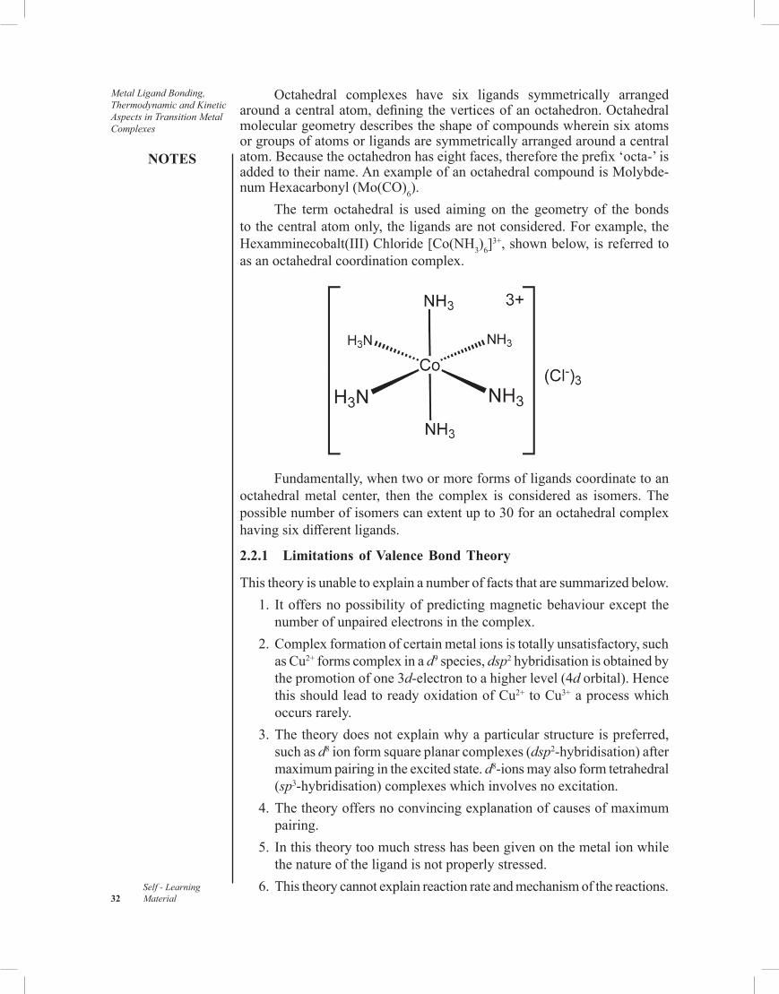
Metal Ligand Bonding, Thermodynamic and Kinetic Aspects in Transition Metal Complexes
NOTES
Self - Learning 32 Material
Octahedral complexes have six ligands symmetrically arranged around a central atom, defining the vertices of an octahedron. Octahedral molecular geometry describes the shape of compounds wherein six atoms or groups of atoms or ligands are symmetrically arranged around a central atom. Because the octahedron has eight faces, therefore the prefix ‘octa-’ is added to their name. An example of an octahedral compound is Molybde-num Hexacarbonyl (Mo(CO)6).
The term octahedral is used aiming on the geometry of the bonds to the central atom only, the ligands are not considered. For example, the Hexamminecobalt(III) Chloride [Co(NH3)6]
3+, shown below, is referred to as an octahedral coordination complex.
Fundamentally, when two or more forms of ligands coordinate to an octahedral metal center, then the complex is considered as isomers. The possible number of isomers can extent up to 30 for an octahedral complex having six different ligands.
2.2.1 Limitations of Valence Bond Theory
This theory is unable to explain a number of facts that are summarized below. 1. It offers no possibility of predicting magnetic behaviour except the
number of unpaired electrons in the complex. 2. Complex formation of certain metal ions is totally unsatisfactory, such
as Cu2+ forms complex in a d9 species, dsp2 hybridisation is obtained by the promotion of one 3d-electron to a higher level (4d orbital). Hence this should lead to ready oxidation of Cu2+ to Cu3+ a process which occurs rarely.
3. The theory does not explain why a particular structure is preferred, such as d8 ion form square planar complexes (dsp2-hybridisation) after maximum pairing in the excited state. d8-ions may also form tetrahedral (sp3-hybridisation) complexes which involves no excitation.
4. The theory offers no convincing explanation of causes of maximum pairing.
5. In this theory too much stress has been given on the metal ion while the nature of the ligand is not properly stressed.
6. This theory cannot explain reaction rate and mechanism of the reactions.

NOTES
Self - LearningMaterial 33
Metal Ligand Bonding, Thermodynamic and
Kinetic Aspects in Transition Metal Complexes
7. It does not predict any distortion in symmetrical complexes whereas all the Cu(II) and Ti(III) complexes are distorted.
8. It does not explain thermodynamic properties of the complexes. 9. It does not attempt to explain the spectra of the complexes. 10. It cannot explain the temperature dependent paramagnetism of the
complexes.
2.3 CRYSTAL FIELD THEORY
This theory is based on the theoretical work on the interaction of ion in crystals by Hans Bethe (1929) and John Hasbrouck van Vleck (1931-55). It was not until 1952 that Orgel popularized its use for inorganic chemistry. Crystal field theory is an electrostalic approach, considering a complex as consisting of a central cation surrounded by a cage of anions. In this theory attraction between central metal and ligands in a complex is regarded as purely electrostatic. This theory was quite successful in explaining some of the drawbacks of valence bond theory.
The electrical field (arising from the ligands) alters the energies of the d-electron and this energy change plays a very important role in the complex formation and the properties of the complex formed.Splitting of Energy Levels: In an isolated atom all five d-orbitals are degenerate, i.e., are of equal energy, but under the influence of a ligand field they split into following two sets. (i) eg Set of Orbitals: dz
2 and dx2–y2 Orbitals. This set consists of the orbitals which have their lobes along the axes and hence are called axial orbitals. Quite obviously these are dz2 and dx2–y2 orbitals. Group theory calls these egorbitals in which e refers to doubly degenerate set.
(ii) t2g Set of Orbitals: dxydyzdzx Orbitals. This set includes the orbitals whose lobes lie between the axes and are called non-axial orbitals. Group theory calls these t2g orbitals wherein t refers to triply degenerate set.
2.3.1 Important Postulates of Crystal Field Theory
(i) The central metal cation is surrounded by ligands which contain one or more lone pairs of electrons.
(ii) The ionic ligands (for example, F–, Cl–, CN–, etc.) are regarded as negative point charges (also called point charges) and the neutral ligands (e.g., H2O, NH3, etc.) are regarded as point dipoles or simply dipoles, i.e., according to this theory neutral ligands are dipolar. If the ligand is neutral, the negative end of this ligand dipole is oriented towards the metal cation.
(iii) The CFT does not provide for electrons to enter the metal orbitals. Thus the metal ion and the ligands do not mix their orbitals or share electrons, i.e., it does not consider any orbital overlap.

Metal Ligand Bonding, Thermodynamic and Kinetic Aspects in Transition Metal Complexes
NOTES
Self - Learning 34 Material
(iv) According to CFT, the bonding between the metal cation and ligand is not covalent but it is regarded as purely electrostatic or coulombic attraction between positively- charged (i.e., cation) and negatively-charged (i.e., anions or dipole molecules which act as ligands) species. Complexes are thus presumed to form when centrally situated cations electrically attract ligands which may be either anions or dipole molecules. The attraction between the cations and the ligands is because the cations are positively charged and the anions are negatively charged and the dipole molecules, as well, can offer their negatively incremented ends of such electrostatic attractions.
2.3.2 Crystal Field Splitting in Octahedral Complexes
Consider an octahedral complex, [ML6]n+ in which the central metal cation,
Mn+ is palced at the centre of the octahedron and is surrounded by six ligands which reside at the six corners of the octahedron as shown in Figure 2.1 The three axes, viz., x, y and z-axes which point along the corners have also been shown.
LL
zx
y
L
LLL
Fig. 2.1 Position of the Central Metal Cation, Mn+ and Six Ligands, L’s in an Octahedral Complex, [ML6]
n+.
Now suppose both the ligands on each of the three axes are allowed to approach towards the metal cation, Mn+ from both the ends of the axes. In this process the electrons in d-orbitals of the metal cation are repelled by the negative point charge or by the negative end at the dipole of the ligand. This repulsion will raise the energy of all the five d-orbitals. If all the ligands approaching the metal ion are at equal distance, the energy of each of the five d-orbital will raise by same amount. But this is not the case, since the takes of the two eg orbitals lie directly in the path of the approaching ligands, the electrons in these orbitals will experience greater for of repulsion than those in three t2g orbitals (i.e., dxy dyz and dzx orbitals) whose lobes are directed in space between the path of the approaching ligands, i.e., the energy of eg orbitals is increased while that of t2g is decreased. Thus we find that under the influence of approaching ligands, the five d-orbitals which were originally degenerate in the free metallic cation are now split (or resolved) into two levels, viz., t2g level which is triply degenerate and is of lower energy, and eg level which is doubly degenerate and is of higher energy (Refer Figure 2.2). In other words the degeneracy of the five d-orbitals is removed under the

NOTES
Self - LearningMaterial 35
Metal Ligand Bonding, Thermodynamic and
Kinetic Aspects in Transition Metal Complexes
influence of the ligands. The separation of five d-orbitals of the metal ion into two sets having different energies is called crystal field splitting or energy level splitting. This concept of crystal field splitting makes the basis of CFT.
The energy gap between t2g and eg sets is denoted by ∆0 or 10Dq where 0 in ∆0 indicates an octahedral arrangement of the ligands round the central metal cation. This energy difference arises because of the difference in electrostatic field exerted by the ligands on t2g and eg sets of orbitals of the central metal cation. ∆0 or 10Dq is called crystal field splitting energy. With the help of simple geometry it can be shown that the energy of t2g orbitals is 0.4 ∆0 (= 4Dq) less than that of hypothetical degenerate d-orbitals (No splitting state shown by dotted line in Figure 2.2) and, hence, that of eg orbitals is 0.6∆0 (= 6Dq) above that of the hypothetical degenerate d-orbitals. Thus, we find that t2g set loses an energy equal to 0.4∆0 (= 4Dq) while eg set gains an energy equal to 0.6∆0 (= 6Dq). In Figure 2.2, the loss and gain in energies of t2g and egorbitals is shown by negative (–) and positive (+) signs, respectively. ∆0 is generally measured in cm–1.
t2g
(c)
-0.4 ∆0
= –4Dq
∆0
=10 Dq
+ 0.6∆0
= +6DqNo splitting
Ener
gy In
crea
sing
state(b)
(a)xy yz zx x2 x2– y2
eg
egt2g
Fig. 2.2 Splitting of Five d-Orbitals in an Octahedral Complex. (a) Five Degenegate d-Orbitals on the Central Metal Cation which are Free from any Ligand Field. (b) Hypothetical Degenerate d-Orbitals at a Higher Energy Level (c) Splitting of d-Orbitals into t2g and eg Orbitals Under the Influence of Six Ligands in Octahedral Complex.
2.3.3 Strong and Weak Field Splitting/Distribution of dx Electron (x = 1 to 10)
The distribution of dn elctrons of the central metal atom in t2g and eg orbitals in an octahedral complex depends on whether the six ligands are weak or strong. So, we have two types of ligand cases: 1. When the Ligands are Weak: Under the influence of weak ligands,
the energy difference ∆0 between t2g and eg is small and all the five d-orbitals remain degenerate, so the distribution of d-electrons takes place according to the Hund’s rule. Thus in weak field the first three electron occupy t2g and 4th and 5th electrons go to eg orbitals (Refer Table 2.1). The octahedral complexes having weak ligands are called weak field or low field complexes.

Metal Ligand Bonding, Thermodynamic and Kinetic Aspects in Transition Metal Complexes
NOTES
Self - Learning 36 Material
In Table 2.1 the distribtuion of dx Electrons (x = 1 to 10) in t2g and eg sets of orbitals in weak(er) field (high spin or spin free) octahedral complexes are illustrated where, (n = No. of unpaired electrons, S= Resultant Spin = n/2, p + q = x = 1, 2, ….8, 9 or 10). Here ∆0< P.
Table 2.1 Distribution of dx Electrons
dx Ions
Distribution of dx Electrons in t2g and eg Oribitals
tp2g e
qg
Configurationn S = n/2
d1
d2
d3
t2g (Lower Energy)↑ ↑ ↑ ↑ ↑ ↑
(Higher Energy)
t12g e
0g
t22g e
0g
t32g e
0g
1
2
3
1/2
1
3/2
d4
d5
d6
d7
↑↓ ↑ ↑↑↓ ↑↓ ↑↑↓ ↑↓ ↑↓↑↓ ↑↓ ↑↓
↑
t32g e
1g
t32g e
2g
t42g e
2g
t52g e
2g
4
5
4
3
2
5/2
2
3/2
d8
d9
d10
↑↓ ↑↓ ↑↓↑↓ ↑↓ ↑↓↑↓ ↑↓ ↑↓
↑ ↑ ↑↓ ↑↑↓ ↑↓
t52g e
2g
t62g e
3g
t72g e
4g
2
1
0
1
1/2
0
2. When the Ligands are Strong Octahedral complexes containing strong ligands, doesnot obey Hund’s
rules thus in strong first the first six electrons go to t2g orbitals and remaining four electrons enter eg orbitals as shown in Table 2.2. The octahedral complexes having strong field ligands are called strong field or high field complexes.
Table 2.2. Distribution of dx Electrons (x = 1 to 10) in t2g and eg Orbitals in Strong(er) Field (Low Spin or Spin Paired) Octahedral Complexes (n = No. of Unpaired Electrons, S= Resultant Spin = n/2, p + q = x = 1,2, …. 8, 9 or 10). Here ∆0 > P.
dx Ions Distribution of dx Electrons in t2g and eg Oribitals
tp2g e
qg
Configurationn S = n/2
d1
d2
d3
t2g (Lower Energy)↑ ↑ ↑ ↑ ↑ ↑
eg (Higher Energy)
t12g e
0g
t22g e
0g
t32g e
0g
1
2
3
1/2
1
3/2
d4
d5
d6
d7
↑↓ ↑ ↑↑↓ ↑↓ ↑↑↓ ↑↓ ↑↓↑↓ ↑↓ ↑↓
↑
t42g e
0g
t52g e
0g
t62g e
0g
t62g e
1g
2
1
0
1
2
1/2
0
1/2
d8
d9
d10
↑↓ ↑↓ ↑↓↑↓ ↑↓ ↑↓↑↓ ↑↓ ↑↓
↑ ↑ ↑↓ ↑↑↓ ↑↓
t62g e
2g
t62g e
3g
t72g e
4g
2
1
0
1
1/2
0

NOTES
Self - LearningMaterial 37
Metal Ligand Bonding, Thermodynamic and
Kinetic Aspects in Transition Metal Complexes
The following points may be onsidered in distribution of dn electrons. (i) In case of both strong or weak field, for d1, d2 and d3 configurations,
the electrons go to the lower energy t2g– level (more stable), for d8, d9 and d10 configurations, the first six electrons go to the t2g– level and the remaining two (in case of d8 ion), three (in case of d9 ion) and four (in case of d10 ion) electrons occupy the eg level. Thus, the distribution of electrons of d1, d2, d3, d8, d9 and d10 configurations in t2gand eg levels for both strong(er) and weak(er) octahedral ligand field is the same.
(ii) For each of d4, d5, d6 and d7 configurations there is a difference in the arrangement of electrons in weak(er) and strong(er) ligand fields.
(iii) Number of Unpaired Electrons (n) : High-Spin and Low-Spin Complexes. Weak-field complexes of d4, d5, d6 and d7 ions have greater number of unpaired electrons (n) than those of (same ions) strong-field complexes and are thus with a higher value of resultant spin (S). It is for this reason that the weak-field and strong-field complexes are also called spin-free or High-Spin (abbreviated as HS) and spin-paired or Low-Spin (LS) complexes, respectively. Recall that VBT has called these complexes as ionic (Pauling) or outer-orbital (Huggin) and covalent (Pauling) or inner-orbital (Huggin) complexes, respectively.
The number of unpaired electrons (i.e., the value of the resultant spin, S) in the cases namely d1 to d3 and d8 to d10 is the same in both the fields, and it is due to this reason that for these configurations the question of the formation of HS- and LS-complexes does not arise. The question does arise for the system d4 to d7.
The paramagnetism of HS-complexes is larger than that of LS-complexes, since, as is evident from Tables 2.1 and 2.2. HS-complexes have more unpaired electrons (i.e., larger value of S) than the LS-complexes (i.e., smaller value of S).
2.3.4 Factors Affecting the Magnitude of ∆0
The magnitude of ∆0 depends on many factors discussed below.
A. Nature of Metal Cation
The effect of the nature of metal cation can be studied as: 1. Different Charges on the Cation of the Same Metal: The ∆0 value
of the cation of the same metal having same oxidation state is almost same but the cation having higher oxidation state has a larger value of ∆0. For example,
(a) ∆0 for [Fe2+(H2O)6]2+ = 10,400 cm-1 … 3d6
∆0 for [Fe3+(H2O)6]3+ = 13,700 cm-1 … 3d5
(b) ∆0 for [Co2+(H2O)6]2+ = 9,300 cm-1 … 3d7
∆0 for [Co3+(H2O)6]3+ = 18,200 cm-1 … 3d6
This is because the central ion with higher oxidation state (i.e., with higher charge) will polarise the ligands more effectively and thus the

Metal Ligand Bonding, Thermodynamic and Kinetic Aspects in Transition Metal Complexes
NOTES
Self - Learning 38 Material
ligands would approach such a cation more closely than they can do the cation of lower oxidation state, resulting in larger splitting.
2. Different Charges on the Cation of the Different Metals: The cation with higher oxidation state has a larger value of ∆0 than with that of lower oxidation state. For example,
∆0 for [V(H2O)6]2+ = 12400 cm–1
∆0 for [Cr(H2O)5]3+ = 17400 cm–1
3. In case of complexes having same cations with the same charges but with different number of d-electron, ∆0 decrease with the increase of the number of d-electrons. For example,
∆0 for [Co2+(H2O)6]2+ = 9,300 cm-1 … 3d7
∆0 for [Ni2+(H2O)6]2+ = 8,500 cm-1 … 3d8
From the combination of 1, 2 and 3 mentioned above it can be concluded that: (a) For the complexes having the same geometry and the same ligands
but having different number of d-electrons, the magnitude of ∆0 decreases with the increase of the number of d-electrons in the
central metal cation (No. of d-electrons ∝0
1∆
)
(b) In case of complexes having the same number of d-electrons the magnitude of ∆0 increases with the increase of the charges (i.e., oxidation state) on the central metal cation (oxidation state ∝∆0).
4. Quantum Number (n) of the d-Orbitals of the Cation: The ∆0 increase about 30-50% form 3dn to 4dn and by about the same amount from 4dn to 5dn complexes. ∆0for [Co3+(NH3)6]
3+ = 23,000 cm-1 … 3d6
∆0 for [Rh3+(NH3)6]3+ = 34,000 cm-1 … 4d6
∆0 for [Ir3+(NH3)6]3+ = 41,000 cm-1 … 5d6
B. Spectrochemical SeriesA spectrochemical series is a list of ligands ordered on ligand strength and a list of metal ions based on oxidation number, group and its identity. In Crystal Field Theory or CFT, the ligands modify the difference in energy between the d orbitals (Δ) called the Ligand Field Splitting Parameter for ligands or the Crystal Field Splitting Parameter, which is mainly reflected in differences in colour of similar Metal-Ligand Complexes.
We have seen earlier that stronger ligands are those which exert a stronger field on the central metal ion and hence have higher splitting power while weaker ligands have comperatively lower splitting power as they exert weak field on the central metal cation. This can be shown in Figure 2.3 where strong ligand CN– give larger value of ∆0 and weaker ligand F– yield a smaller value of ∆0.

NOTES
Self - LearningMaterial 39
Metal Ligand Bonding, Thermodynamic and
Kinetic Aspects in Transition Metal Complexes
yzyz
yz
zxzx
zx
t2gt2'g
eg
xyxy
xy∆0 is large∆0 is small
Ener
gy in
crea
sing
(a)
z2z2
z2
x2 – y2x2 – y2
x2 – y2
(c) (b)
Fig. 2.3 Splitting of Five d-Orbitals in Presence of Strong(er) and Weak(er) Ligands in an Octahedral Complex.
In the Figure 2.3,
(a) Five d-Orbitals in the Free Metal Ion. (b) Splitting of d-Orbitals in Presence of Strong(er) Ligands. (c) Splitting of d-Orbitals in Presence of Weak(er) Ligands.
Figure 2.3 shows that not only ∆0, which represents the energy difference between the t2g and eg-sets of orbitals, is smaller in the weak(er) field complex than in the strong(er) field, but also that both the t2g and eg– levels of the weak(er) field are correspondingly closer to the level of the degenerate five d-orbitals of the free isolated metallic ion than are those, respectively, of the strong(er) field.
The common ligands can be arranged in the order of their increasing splitting power to cause d-orbitals splitting. This series is called spectrochemical series and is given below:
I– < Br–< Cl– – SCN– – N–3< (C2H5O)2 PS–
2< F– < (NH2)2CO < OH–
< C2O2–
4 – H2O < NCS– – H– < CN– < NH2CH2CO–
2< NH3 – C5H5N < en –
SO2–
3 < NH2OH < NO–2 <phen < H– < CH–
3< CN–, CO.This series shows that the value of ∆0 in the series also increase from
left to right.The order of field strength of the common ligands shown above is, in
fact, independent of the nature of the central metal ion and the geometry of the complex.
The increase in the value of ∆0 on proceeding from left to right in the spectrochemical series is quite evident from the values of ∆0 for some octahedral complexes given in Table 2.3 which clearly shows that since on proceeding from 6Br-→ 3 en, the field strength of the ligands increases, the value of ∆0 also correspondingly increases.

Metal Ligand Bonding, Thermodynamic and Kinetic Aspects in Transition Metal Complexes
NOTES
Self - Learning 40 Material
Table 2.3 ∆0 Values (Energy Difference between t2g and eg Levels) in cm-1 for Some Octahedral Complexes
Ligands → 6 Br- < 6Cl- < 6H2O < 6NH3 < 3 en
Metal Ion Field Strength Increasing
Ni (II) 7000 cm-1 < 7200 cm-1 < 8500 cm-1 < 10800 cm-1 < 11500 cm-1
Cr (III) − 13800 < 17400 < 21600 < 21900
Co (III) − − 18200 < 23000 < 23200
Rh (III) 19000 < 20300 < 27000 < 34100 < 34600
∆0 Values (in cm-1) also Increasing
Mean Pairing Energy (P)The energy which is required for pairing of two electrons against electron-electron repulsion in the same orbital is called the mean pairing energy far one electron pair. It is generally expressed in cm-1. Pairing energy depends on the principal energy level (n) of the d-electrons.
If m is the total number of paired electrons in t2g and eg orbitals, then, Total pairing energy for m electron pairs = mP cm-1.
Predicting Spin State of an Octahedral ComplexThe spin state of an octahedral complex can be predicted by comparing the values of ∆0 and P. ∆0 tends to force as many electrons to occupy t2g orbitals while P tends to prevent the electrons to pair in t2g orbitals. (i) When ∆0> P, the electrons tend to pair and hence low spin octahedral
complex is obtained. (ii) When ∆0< P, the electron tends to remains unpaired and hence high
spin octahedral complexes are obtained.Some of the example of low spin and high spins complexes are given in Table 2.4.
Table 2.4 Examples of Some LS and HS Octahedral Complexes
dx Con-figuration
Examples of Complexes
Value of P(cm-1)
Value of ∆0(cm-1)
Spin-State Relative Magni-tudes of ∆0 and P
Pre-dicted by CFT
Observed Experi-mentally
d4 [Cr(H2O)6]2+
[Mn(H2O)6]3+
[Mn(CN)6]3-
235002880028800
139002100038500
HSHSLS
HSHSLS
∆0< P∆0< P∆0> P
d5 [Mn(H2O)6]2+
[Fe(H2O)6]3+
2550030000
780013700
HS HS
HSHS
∆0< P∆0< P
d6 [Fe(H2O)6]2+
[Fe(CN)6]4-
[Co(NH3)6]3+
[CoF6]3-
17600176002100021000
10400330002300013000
HSLSLSHS
HSLSLSHS
∆0< P∆0> P∆0> P∆0< P
d7 [Co(H2O)6]2+ 22500 9300 HS HS ∆0< P

NOTES
Self - LearningMaterial 41
Metal Ligand Bonding, Thermodynamic and
Kinetic Aspects in Transition Metal Complexes
C. Crystal Field Stabilization EnergiesFrom Figure 2.3 it is clear that electrons will tend to occupy the lower energy (t2g) orbitals in order to achieve stability. Each electron entering the t2g orbital stabilizes the complex ion by 0.4 ∆0 units and each electron entering the higher energy (eg) orbital destabilizes the complex ion by 0.6 ∆0, i.e., stabilization energy in the two cases is 0.4 ∆0 and 0.6 ∆0, respectively. The gain is energy achieved by preferential filling up of orbitals by electrons is known as Crystal Field Stabilization Energy (CFSE). Creater the amount of CFSE of the complex, greater is the stability of the complex. The derivation far CFSE is discussed below.
Consider a dx ion containing t2gpeg
q configuration in which p is the number of electrons in t2g set, q is the number of electrons in eg set and x = p + q. So,
Change in energy (in terms of ∆0) for t2gpeg
q configuration: = Loss in Energy due to p Electrons in t2g Set + Gain
in Energy due to q Electrons in eg Set = –0.4 ∆0 × p + 0.6 ∆0 × q = [–0.4 p + 0.6q] ∆0 … (1)Now, since ∆0= 10Dq, the above expression can also be written as:Change in energy (in terms of Dq) for t2g
pegq configuration
= [–0.4p + 0.6q] × 10 Dq = [–4p + 6q] Dq … (2)Thus Equations (1) and (2) give the energies of dx ion containing t2g
pegq
configuration. The change in energy for dx ion containing t2gpeg
q configuration calculated as above is called Crystal Field Stabilization Energy (CFSE) of dx ion, since it stabilizes d-orbitals by lowering their energy which results from their splitting into t2g and eg orbitals.
In the derivation of Equations (1) and (2) we have not considered the pairing energy, P, of dx ion which is the energy required to pair two electrons against electron-electron repulsion in the same orbital. If the pairing energy of the ion is also involved in the t2g
pegq configuration of a given dx ion, then
CFSE of the ion is given by the expression: CFSE = [–0.4p + 0.6q] ∆0 + mP … (3) = [–4p + 6q] Dq + mP (∆0 = 10Dq) … (4)
Here m is the total number of paired electrons in t2g and eg sets of orbitals. Equations (3) and (4) have been used to calculate the CFSE values (in terms of ∆0 and Dq, respectively).
For d0 to d10 ions of high spin and low spin octahedral complexes, the values calculated from above equations are listed in Table 2.5 and Table 2.6.In Table 2.5, the CFSE values (in the units of ∆0 and Dq) for dx configuration (x = 0 to 10) of the central metal ion in weak field (spin free or high spin) octahedral complexes. m = Total number of paired electrons in t2g and eg orbitals, P = Mean pairing energy, p + q = x = 0, 1, 2, …., 8, 0 or 10.
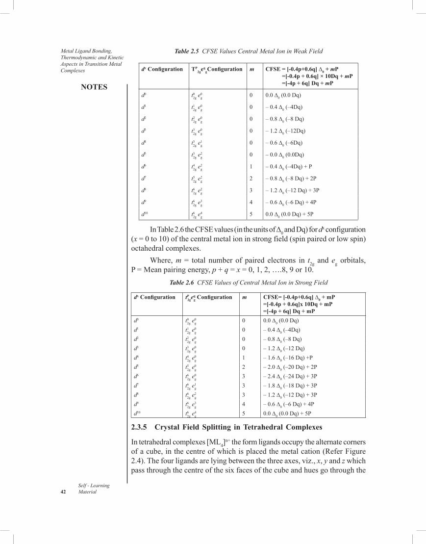
Metal Ligand Bonding, Thermodynamic and Kinetic Aspects in Transition Metal Complexes
NOTES
Self - Learning 42 Material
Table 2.5 CFSE Values Central Metal Ion in Weak Field
dx Configuration TP2ge
qgConfiguration m CFSE = [-0.4p+0.6q] ∆0 + mP
=[-0.4p + 0.6q] × 10Dq + mP =[-4p + 6q] Dq + mP
d0 t02g e
0g 0 0.0 ∆0 (0.0 Dq)
d1 t12g e
0g 0 – 0.4 ∆0 (–4Dq)
d2 t22g e
0g 0 – 0.8 ∆0 (–8 Dq)
d3 t32g e
0g 0 – 1.2 ∆0 (–12Dq)
d4 t32g e
1g 0 – 0.6 ∆0 (–6Dq)
d5 t32g e
2g 0 – 0.0 ∆0 (0.0Dq)
d6 t42g e
2g 1 – 0.4 ∆0 (–4Dq) + P
d7 t52g e
2g 2 – 0.8 ∆0 (–8 Dq) + 2P
d8 t62g e
2g 3 – 1.2 ∆0 (–12 Dq) + 3P
d9 t62g e
3g 4 – 0.6 ∆0 (–6 Dq) + 4P
d10 t62g e
4g 5 0.0 ∆0 (0.0 Dq) + 5P
In Table 2.6 the CFSE values (in the units of ∆0 and Dq) for dx configuration (x = 0 to 10) of the central metal ion in strong field (spin paired or low spin) octahedral complexes.
Where, m = total number of paired electrons in t2g and eg orbitals, P = Mean pairing energy, p + q = x = 0, 1, 2, ….8, 9 or 10.
Table 2.6 CFSE Values of Central Metal Ion in Strong Field
dx Configuration tP2ge
qg Configuration m CFSE= [-0.4p+0.6q] ∆0 + mP
=[-0.4p + 0.6q]x 10Dq + mP=[-4p + 6q] Dq + mP
d0 t02g e
0g 0 0.0 ∆0 (0.0 Dq)
d1 t12g e
0g 0 – 0.4 ∆0 (–4Dq)
d2 t22g e
0g 0 – 0.8 ∆0 (–8 Dq)
d3 t32g e
0g 0 – 1.2 ∆0 (–12 Dq)
d4 t42g e
0g 1 – 1.6 ∆0 (–16 Dq) +P
d5 t52g e
0g 2 – 2.0 ∆0 (–20 Dq) + 2P
d6 t62g e
0g 3 – 2.4 ∆0 (–24 Dq) + 3P
d7 t62g e
1g 3 – 1.8 ∆0 (–18 Dq) + 3P
d8 t62g e
2g 3 – 1.2 ∆0 (–12 Dq) + 3P
d9 t62g e
3g 4 – 0.6 ∆0 (–6 Dq) + 4P
d10 t62g e
4g 5 0.0 ∆0 (0.0 Dq) + 5P
2.3.5 Crystal Field Splitting in Tetrahedral Complexes
In tetrahedral complexes [ML4]n+ the form ligands occupy the alternate corners
of a cube, in the centre of which is placed the metal cation (Refer Figure 2.4). The four ligands are lying between the three axes, viz., x, y and z which pass through the centre of the six faces of the cube and hues go through the

NOTES
Self - LearningMaterial 43
Metal Ligand Bonding, Thermodynamic and
Kinetic Aspects in Transition Metal Complexes
centre of the cube. So, the t2g orbital (dxy, dyz, dzx) are lying between the axes, i.e., directly in the path of the ligands. Hence these orbitals will experience greater repulsive force from the ligands. eg(dz2/dx2 – y2) orbitals lie along the axes, i.e., along the space between the ligands, thus will experience lesser repulsive force.
Thus the energy of t2g orbitals will be increased while that of eg orbitals will be decreased.
Fig. 2.4 Tetrahedral Arrangement of Four Ligands (L) Around the Metal Ion (Mn+) in Tetrahedral Complex Ion, [ML4]
n+.
Unsequently the d orbitals again split into two sets as shown in Figure 2.5. The order of energy of t2g and eg orbitals is reverse as observed in case of octahedral complexes. The energy difference between t2g and eg orbitals for tetrahedral complexes is designated as ∆t. It is shown that ∆t < ∆0, because the t2g orbitals do not point directly at the ligands and also there are only four ligands in tetrahedral complexes against six ligands in octahedral complexes, for the same metal and ligands and the same inter nuclear distances. It is also shown that,
∆t = 0.45 ∆0. Thus the energy of the t2 set is raised by 0.4 ∆t = 0.18 ∆0 while that of
e set is lowered by 0.6 ∆t = 0.27 ∆0. The relation namely ∆t = 0.45 ∆0 also shows that, other things being equal, the crystal field splitting in a tetrahedral complex will be about half the magnitude of that in an octahedral complex.
In case of tetrahedral complex, since ∆t is generally less than P (∆t < P), the electrons tend to remain unpaired and hence only high spin tetrahedral complexes are known, i.e., low complexes.
Note: The subscript g is not used for the splitting of d-orbitals in tetrahedral complexes because a tetrahedron has no centre of symmetry. The symbol g is used for the ligand fields which have centre of symmetry.

Metal Ligand Bonding, Thermodynamic and Kinetic Aspects in Transition Metal Complexes
NOTES
Self - Learning 44 Material
e (c)
∆t = +0.45 ∆0
+ 0.4∆t= +0.18∆0
+ 0.6∆t= –0.27∆0
No splitting
Ener
gy in
crea
sing
state(b)
(a)xy
xy
yz
yz
zx
zx
z2z2
z2x2– y2x2– y2
x2– y2
t2
egt2g
Fig. 2.5 Splitting of Five d-Orbitals in a Tetrahedral Complex, (a) Five Degenerate d-Orbitals on the Central Metal Cation which are Free From any Ligand Field (b)
Hypothetical Degenerate d-Orbitals at a Higher Energy Level (c) Splitting of d-Orbitals into e and t2 Orbitals Under the Influence of Four Ligands in Tetrahedral Complex.
Distribution of dx Electrons (x = 1 – 10) in Tetrahedral Complexes
It has been discussed above that only high spin tetrahedral complexes are known. In case of these complexes, the distribution of dx electrons in e and t2 orbitals takes place according to Hund’s rule, i.e., the electrons will pair up only when each of the five d-orbitals is at least singly-filled. The pairing of electrons will start from e orbitals, since these orbitals have less energy than t2 orbitals. The distribution of dx electrons in high spin tetrahedral complexes has been shown in Table 2.7.In Table 2.7 The distribution of dx electrons (x = 1 to 10) in e and t2 orbitals in high spin tetrahedral complexes (n = Number of unpaired electrons, p + q = x = 1, 2, …. 8, 9 or 10). Here ∆t < P.
Table 2.7 Distribution of dx Electrons
dx Ions ep tq2 Configuration n CFSE = -0.27 ∆0 × p + 0.18∆0 × q
= [–0.27 × p + 0.18 × q] ∆0
d1 e1 t02 1 [–0.27 × 1 + 0.18 × 0] ∆0 = –0.27∆0
d2 e2 t02 2 [–0.27 × 2 + 0] ∆0 = –0.54∆0
d3 e2 t12 3 [–0.27 × 2 + 0.18 × 1] ∆0 = –0.36∆0
d4 e2 t22 4 [–0.27 × 2 + 0.18 × 2] ∆0 = –0.18∆0
d5 e2 t32 5 [–0.27 × 2 + 0.18 × 3] ∆0 = 0.0∆0
d6 e3 t32 4 [–0.27 × 3 + 0.18 × 3] ∆0 = –0.27∆0
d7 e4 t32 3 [–0.27 × 4 + 0.18 × 3] ∆0 = –0.54∆0
d8 e4 t42 2 [–0.27 × 4 + 0.18 × 4] ∆0 = –0.36∆0
d9 e4 t52 1 [–0.27 × 4 + 0.18 × 5] ∆0 = –0.18∆0
d10 e4 t62 0 [0.27 × 4 + 0.18 × 6] ∆0 = 0.0∆0
CFSE of dx Electrons (x = 1 – 10) in Tetrahedral ComplexesAccording to CFT, under the influence at four ligands approaching towards the central metal ion during the formation of a high spin tetrahedral complex, the d-orbitals of the central metal ion are split into lower energy doublet eg orbitals

NOTES
Self - LearningMaterial 45
Metal Ligand Bonding, Thermodynamic and
Kinetic Aspects in Transition Metal Complexes
(dz2 and dx2 – y2 orbitals) and higher energy triplet t2g orbitals (dxydyz and dzx orbitals). The energy gap between eg and t2g orbitals is denoted by ∆t which is equal to 0.45 ∆0. The energy of e orbitals is lowered by 0.6 ∆t = 0.6 × 0.45 ∆0 = 0.27 ∆0 and that of t2g orbitals is raised by 0.4 ∆t = 0.4 × 0.45 ∆0 = 0.18 ∆0 relative to the energy of no splitting state. Thus each electron occupying e orbitals decreases the energy of d-orbitals by –0.6 ∆t = –0.27 ∆0 while that going to t2g orbitals increases its energy by + 0.4 ∆t = + 0.18 ∆0. ‘–’ and ‘+’ signs indicate, respectively, the decrease and increase in the energy of d-orbitals caused by their splitting under the influence of four ligands. Now let us consider a dx ion containing ep tq
2 configuration in which p is the number of electrons in e set of orbitals and q is the number of electrons in t2 set of orbitals and x = p + q. Obviously,
CFSE for ep tq2 Configuration = Loss in Energy due to p Electrons in
eg Set of Orbitals + Gain in Energy due to q Electrons in t2 Set of Orbitals.Or CFSE = –0.27∆0 × p + 0.18 ∆0 × q = [–0.27 × p + 0.18 × q] ∆0
2.4 SQUARE PLANAR COMPLEXES
We have seen that in octahedral complexes, the energy of tzg orbitals (dxy, dyz, dzx) is decreased while that of eg orbitals ( 2z
d , 2 2x yd
− ) is increased orbitals) is decreased while that of 2z
d and 2 2x yd
− orbitals (eg orbitals) is increased (Refer Figure 2.6).
Now in elongated distorted octahedral complex, since the distance of the trans-ligands (La ligands) is increased from the central metal ion by removing them away along the z-axis, d-orbitals along the z-axis (i.e., orbital), d-orbital in yz plane (i.e., dyz orbital) and d-orbital in zx plane (i.e., dzx orbital) experience less repulsion from the ligands than they do in the octahedral complex while the d-orbital in xy plane (i.e., dxy and 2 2x y
d−
orbitals) experience more repulsion than they do in the octahedral complex. Consequently the energy of 2z
d , dyz and dyz orbitals rise up (Refer Figure 2.6). Thus the splitting of d-orbitals into various orbitals in square planar complexes takes place as shown at (d) of Figure 2.6. The relative energy order between the various splitted d-orbitals in square planar complexes is uncertain but the order shown in Figure 2.6 (d) has been established for 5d8 configuration from spectroscopic data. The extent of splitting of d-orbitals in square planar complexes depends on the nature of the central metal atom and ligands. Semi-quantitative calculations for square planar complexes of Co2+ (3d7), Ni2+(3d8) and Cu2+(3d9) have
shown that ∆1= ∆0, ∆2=23
∆0 (or 0.66 ∆0) and ∆3=1
12∆0 (or 0.08 ∆0) and hence
∆sp = ∆1+∆2+∆3=∆0+23
∆0 + 1
12∆0
= ∆0 + 0.66∆0 + 0.08∆0 = 1.74∆0

Metal Ligand Bonding, Thermodynamic and Kinetic Aspects in Transition Metal Complexes
NOTES
Self - Learning 46 Material
Fig. 2.6 Splitting of Metal d-Orbitals in Octahedral, Tetragonal and Square Planar Complexes
For the square planar complexes of Pd2+ (4d8) and Pt2+ (5d8) spectroscopic results have shown that: ∆sp = ∆1 + ∆2 + ∆3 = 1.3∆0

NOTES
Self - LearningMaterial 47
Metal Ligand Bonding, Thermodynamic and
Kinetic Aspects in Transition Metal Complexes
2.5 FACTORS AFFECTING THE CRYSTAL FIELD PARAMETERS
The value of ∆0 or 10 Dq depends upon the factors discussed below. 1. Nature of the metal ion. 2. Nature of ligands - If the values of ∆0 for the complexes of same metal
ion with different, then we observe that the values of ∆0 varies regularly.It means the value of ∆0 depends upon the nature of the ligands. Thus
the ligands can be arranged in the order of increasing field strength and the series thus obtained is known as spectrochemical series. Jorgenson (1962) has given a field factor (f) for the ligands taking f =1.00 for water ligand. The ligands which have ‘f’ values less than 1.00 are known as weak field ligands and that have more than 1.00 are called as strong field ligands. The ‘f’ values for some common ligands are given below:Ligand: I- <Br- <SCN- <Cl- <NO3
- <F- <OH-=C2O2-
4 = CH3COO-<H2O <‘f’ Value: 0.70 0.72 0.73 0.78 0.83 0.90 0.94 0.94 0.94 1.00 NCS- < NC- <Py <NH3 <en <dipy=phen <NO-
2<CN- =CO 1.02 1.15 1.23 1.25 1.28 1.33 1.34 1.4 1.7 1.7 3. Geometry of the Complex- As discussed earlier, the 10 Dq values for
octahedral, tetrahedral and square planar complexes are in the order of:
∆sp>∆0> ∆t
Or 1.3 ∆0∆0 0.45 ∆0
This order is due to the following facts: (a) In octahedral complexes six ligands are involved while in
tetrahedral complex only four ligands are involved. (b) In octahedral complexes ligands approach exactly in the direction
of 2 2x yd
− dz2 orbitals. While it is not so in the case of tetrahedral
complexes. Thus have m influence on the t2g orbitals than on the eg orbitals. However, degree of splitting is larger in the case of square planar complexes.
2.6 APPLICATIONS OF CRYSTAL FIELD THEORY
Some of the important application of crystal field theory are discussed below. 1. Colour of the Metal Complexes 2. Crystal Structure of Spinels
Mixed oxides of the general formula, ( )2 342
A B O+ + are called spinels after the name of the mineral spinel, MgAl2O4. Here A2+ = Mg2+, Mn2+, Fe2+, Co2+,

Metal Ligand Bonding, Thermodynamic and Kinetic Aspects in Transition Metal Complexes
NOTES
Self - Learning 48 Material
Ni2+, Cu3+, Zn2+, etc., and B3+ = Al3+, Cr3+, Mn3+, Co3+, Fe3+, etc. A2+ and B3+ ions may be of different metals or of the same metal.
Spinels of A2+B23+O4 type are classified as normal or simple and inverse
spinels. In normal spinels all the A2+ cations occupy one of the eight available tetrahedral holes (positions where a cation can be surrounded by four anions) and all B3+ cations occupy half of the available octahedral holes. Normal spinels are represented as A2+ [B2
3+] O4. This representation shows that the cations outside the bracket (i.e., A2+ cations) occupy the octahedral holes.
Examples of normal spinels are Mg2+[Cr23+]O4, Ni2+[Cr2
3+]O4, Mn3O4 or Mn2+[Mn2
3+]O4, Co3O4 or Co2+[Co23+]O4 etc.
In inverse spinels all the A2+ and half of the B3+ cations are in octahedral and the other half of the B3+ cations are in tetrahedral holes. Inverse spinels are represented as B3+[A2+B3+]O4. This formulation shows that the tetrahedral holes are occupied by half of the B3+ ions and the octahedral holes are occupied by A2+ ions and the remaining half B3+ ions. Examples of inverse spinels are CuFe2O4 or Fe3+[Cu2+Fe3+]O4, MgFe2O4 or Fe3+[Mg2+Fe3+]O4, Fe3O4 or Fe3+[Fe2+ Fe3+]O4, etc.
Inverse spinels of A4+B22+O4 type are also known. Examples are TiZn2O4
and SnCo2O4.These are represented as Zn2+[Ti4+Zn2+]O4and Co2+[Sn4+Co2+]O4,
respectively.Now let us see how CFT helps in predicting the structure of spinels.
For example with the help of CFT it can be shown why the oxide Mn3O4 or Mn2+Mn2
3+O4 is a normal spinel while the oxide Fe3O4 or Fe2+Fe23+O4 is an
inverse spinel. CFSE values in octahedral and tetrahedral fields have been used for the interpretation. For this it is assumed that the oxide ions, O2-, like water molecuels, produce weak field. CFSE values (in terms of ∆0) for Mn3+(d4), Fe3+, Mn2+(d5) and Fe2+(d6) ions in octahedral and tetrahedral weak ligand (i.e., high spin) field are given below: (Negative sign has not been considered). Mn3+(d4) Mn2+(d5) Fe3+(d5) Fe2+(d6)CFSE (Octahedral Weak Field): 0.60∆0 0 0 0.40∆0
CFSE (Tetrahedral Weak Field): 0.18∆0 0 0 0.27∆0
It is obvious that for Mn3+(d4) and Fe2+(d6) ions the CFSE values are greater for octahedral than for tetrahedral sites. Thus Mn3+ and Fe2+ ions will preferentially occupy the octahedral sites, maximizing the CFSE values of the system. Hence in Mn3O4 all the Mn3+ ions occupy octahedral sites and all Mn2+ ions are in the tetrahedral sites, i.e., it is a normal spinel and its structure is, therefore, represented as Mn2+[Mn2
3+]O4. In Fe3O4 all the Fe2+ ions and half of the Fe3+ ions are in the octahedral sites, while the remaining half of Fe3+ ions occupy tetrahedral sites. Thus it is an inverse spinel and is, therefore represented as Fe3+[Fe2+Fe3+]O4.

NOTES
Self - LearningMaterial 49
Metal Ligand Bonding, Thermodynamic and
Kinetic Aspects in Transition Metal Complexes
3. Stabilization of Oxidation States Certain oxidation states are preferentially stabilized by coordinating
with certain ligands. This fact can be explained using CFSE values. For example,
(a) Although H2O molecule which is a weak ligand should be expected to coordinate with Co2+ and Co3+ ions to form the high-spin octahedral complexes, viz., [Co(H2O)6]
2+ and [Co(H2O)6]3+
respectively, experiments show that H2O stabilizes Co2+ ion and not Co3+, i.e., [Co(H2O)6]
2+is more stable than. [Co(H2O)6]3+.
This is because of the fact that Co2+ (d7) has a much higher value of CFSE in weak octahedral configuration (CFSE=0.8 ∆0) than Co3+ (d6) in the same configuration (CFSE = 0.4 ∆0).
(b) If we consider the coordination of NH3 molecules with Co2+ and Co3+ ions, it may be seen that NH3 which is a strong ligand stabilizes Co3+ ion by forming [Co(NH3)6]
3+ rather than Co2+ ion. This is because of the fact that Co3+ ion (d6 system) has much higher value of CFSE in strong octahedral configuration (CFSE =2.4 ∆0) than Co2+ ion (d7 system) in the same configuration (CFSE= 1.8 system) in the same configuration (CFSE= 1.8 ∆0).
4. Stereo Chemistry of Complexes CFSE values are also helpful in predicting the stereochemistry of the
complexes. For example, (i) CFSE values predicts that Cu2+ ion form square planar complexes
rather than tetrahedral or octahedral complexes in both the fields. This is because, Cu2+ ion (d9 system) has much higher CFSE value in a square planar configuration (CFSE = 1.22 ∆0) than in octahedral (CFSE = 0.6 ∆0) or tetrahedral configuration (CFSE= 0.18 ∆0).
(ii) Most of the four coordinated complexes of Ni2+ ion (d8 system) are square planar rather than tetrahedral [(NiX4)
2- is an exception, X= Cl-, Br–, I-]. This is because CFSE values of d8 ion are higher in square planar configuration (= 1.45 ∆0) than those of the same ion in tetrahedral configuration (= 0.36 ∆0).
5. Other Applications of Crystal Field Theory (i) The number of unpaired electrons (n) in the central metal ion of
a given complex ion of a given complex ion and hence the value of magnetic moment (μ) of the ion. μ (in B.M.) is given by:
( 2)n nµ = +
Thus, for n = 0, μ = 0.0 (diamagnetic); n = 1, μ = 1.73 B.M; n = 2, μ = 2.83 B.M;
n = 3, μ = 3.87 B.M; n = 4, μ = 4.90B.M; n = 5, μ = 5.92 B.M. (ii) Whether the given complex ion is high spin or low spin. (iii) Whether the given complex ion is paramagnetic or diamagnetic.

Metal Ligand Bonding, Thermodynamic and Kinetic Aspects in Transition Metal Complexes
NOTES
Self - Learning 50 Material
2.7 LIMITATIONS OF CRYSTAL FIELD THEORY
Some of the Limitations of CFT are: (i) The CFT ignores the attractive forces between the d-electrons of
the metal ion and nuclear charge on the ligand atom. Therefore, all properties are dependent upon the ligand orbitals and their interactions with metal orbitals are not explained.
(ii) In CFT model partial covalency of metal-ligand bonds are not taken into consideration. According to CFT metal-ligands bonding is purely electrostatic.
(iii) In CFT only d-electrons of the metal ion are considered, the other orbitals, such as s, px, py and pz are not taken into considered.
(iv) In CFT π orbitals of ligand are not considered. (v) This theory can not explain the relative strength of the ligands, i.e., it
can not explain that why H2O is a stronger ligand than OH according to spectrochemical series.
(vi) It does not explain the charge transfer spectra on the intensities of the absorption bands.
2.8 THERMODYNAMIC AND KINETIC ASPECTS OF METALS
The stability of coordination complex is an important factor for deciding and explaining the stability and reactivity of a metal complex. The stabil-ity of metal complex is governed by two different aspects, such as ther-modynamic and kinetic stabilities. The correlation between stability and reactivity of coordination compounds depends on the factors that influence the stability of metal complexes, such as the nature of metal ions, ligands, bonding between metal ions and ligands, etc.
The stability of metal complex generally means that it exists under favourable conditions without undergoing decomposition and has a con-siderable shelf life period. The term stability of metal complex cannot be generalized since the complex may be stable to one reagent/condition and may decompose in presence of another reagent/condition. The stability of metal complexes can be explained with the help of two different aspects, namely, thermodynamic stability and kinetic stability. Nevertheless, a metal complex is said to be stable if it does not react with water, which would lead to a decrease in the free energy of the system, i.e., thermodynamic stabil-ity. On the other hand, the complex is said to possess kinetic stability if it reacts with water to form a stable product and there is a known mechanism through which the reaction can proceed.
Thermodynamic stability is associated with the bond energy, stability constant and redox potentials (the equilibrium conditions). Kinetic stability

NOTES
Self - LearningMaterial 51
Metal Ligand Bonding, Thermodynamic and
Kinetic Aspects in Transition Metal Complexes
is associated with the rates and the mechanisms of the chemical reactions, formation of intermediate complexes, activation energies for the processes, etc. Stability constant of a complex is the equilibrium constant for the com-plex ion formation. Stability of a complex refers to the tendency to occur under equilibrium conditions and is directly related to metal-ligand bond energies.
Following are the two types of stabilities that are considered for the complexes: 1. Thermodynamic Stability 2. Kinetic Stability
1. Thermodynamic Aspects of Complexes
Thermodynamic equilibrium constant refer to the standard activity scale and hence can be acquired/evaluated through the following points: (i) The very dilute solutions are studied having total electrolyte
concentration <10−3M in which activity coefficient have practically the value of unity which can be studied in presence of electrolyte by maintaining their ionic strength using the formula,
(ii) Very dilute solution where the activity coefficients can be obtained
thermodynamically or empirically (Debye-Huckel Theory), will not affect the whole system.
(iii) By determining the equilibrium constants at different ion strengths and then extrapolating to infinite dilution.Thermodynamic stability of a complex refers to its tendency to
exist under equilibrium conditions. It determines the extent to which the complex will be formed or be converted into another complex at the point of equilibrium. In other words, thermodynamic stability of complexes is the measure of tendency of a metal ion to selectively form a specific metal complex and is directly related to the metal-ligand bond energies. The thermodynamic stability of complexes is represented by formation constant. The formation constant is also known as stability constant, which is the equilibrium constant obtained for the formation metal complex.
2. Kinetic Aspects of Complexes
The ability of a complex to engage itself in reactions involving the replacement of one or more ligands in it coordination sphere by other ligands is called the stability of the complex. The complexes that undergo rapid substitution (half time period or reaction rate K is used to denote the speed of the reactions) are termed labile, whereas those with low rates of substitution are called inert.
Kinetic stability is related to the reactivity of the metal complexes in solution and deals with the rate of the reaction, its activation energy, etc. Kinetic stability is also related to how fast a compound reacts rather than

Metal Ligand Bonding, Thermodynamic and Kinetic Aspects in Transition Metal Complexes
NOTES
Self - Learning 52 Material
how stable it is. It aids in determining the rate at which the reaction occurs to establish the equilibrium.
For metal complexes, the stability and reactivity are described in thermodynamic and kinetic terms, respectively. In particular, the terms stable and unstable are related to thermodynamic aspects, whereas labile and inert terms are related to kinetic aspects. As a rule of thumb, a metal complex is said to be labile if it reacts within 1 min at 25°C, and if it takes longer time, it is considered to be inert.
Check Your Progress
1. Why is Crystal Field Theory (CFT) model used? 2. What does Crystal Field Theory (CFT) model state? 3. Give the reasons/factors that affect the energy splitting. 4. Define octahedral complexes. 5. What is ex set of orbitals? 6. Explain about the t2g set of orbitals. 7. What is spectrochemical series? 8. What is mean pairing energy? 9. Explain CFSE of d8 electrons in tetrahedral complexes. 10. What does the stability of coordination complexes specify?
2.9 ANSWERS TO ‘CHECK YOUR PROGRESS’
1. Typically, the Crystal Field Theory (CFT) model is used for specifying the bonding interaction between the transition metals and ligands. Basically, it defines the attraction effect between the positive charge of the metal cation and the negative charge on the non-bonding electrons of the ligand. As soon as the ligands approaches the central metal ion, the degeneracy of electronic orbital states, generally d or f orbitals, are fragmented/broken because of the static electric field that is produced through a charge distribution from the surrounding. CFT effectively states some magnetic properties, colours, and hydration energies of transition metal complexes, but it cannot define bonding.
2. Crystal Field Theory (CFT) states that d or f orbital degeneracy can be broken by the electric field produced by ligands, stabilizing the complex. When the ligands approaches the central metal ion, d- or f-subshell then the degeneracy is fragmented because of the static electric field. Subsequently, the electrons repel each other, and hence the d electrons closer to the ligands will have a higher energy as compared to those electrons which are at some distance, resulting in the d orbitals splitting.

NOTES
Self - LearningMaterial 53
Metal Ligand Bonding, Thermodynamic and
Kinetic Aspects in Transition Metal Complexes
3. Following are the reasons/factors that affect the energy splitting:• Nature of the metal ion.• Metal’s oxidation state. A higher oxidation state leads to a larger
splitting relative to the spherical field.• Arrangement of the ligands around the metal ion.• Coordination number of the metal (i.e., tetrahedral, octahedral, etc.)• Nature of the ligands surrounding the metal ion. The stronger the
effect of the ligands then the greater the difference between the high and low energy of groups.
4. Octahedral complexes have six ligands symmetrically arranged around a central atom, defining the vertices of an octahedron. Octahedral molecular geometry describes the shape of compounds wherein six atoms or groups of atoms or ligands are symmetrically arranged around a central atom. Because the octahedron has eight faces, therefore the prefix ‘octa-’ is added to their name. An example of an octahedral compound is molybdenum hexacarbonyl (Mo(CO)6).
5. eg Set of Orbitals: dz2 and dx2–y2 Orbitals. This set consists of the orbitals
which have their lobes along the axes and hence are called axial orbitals. Quite obviously these are dz2 and dx2–y2 orbitals. Group theory calls these egorbitals in which e refers to doubly degenerate set.
6. t2g Set of Orbitals: dxydyzdzx Orbitals. This set includes the orbitals whose lobes lie between the axes and are called non-axial orbitals. Group theory calls these t2g orbitals wherein t refers to triply degenerate set.
7. A spectrochemical series is a list of ligands ordered on ligand strength and a list of metal ions based on oxidation number, group and its identity. In Crystal Field Theory or CFT, the ligands modify the difference in energy between the d orbitals (Δ) called the Ligand Field Splitting Parameter for ligands or the Crystal Field Splitting Parameter, which is mainly reflected in differences in colour of similar Metal Ligand Complexes.
8. The energy which is required for pairing of two electrons against electron-electron repulsion in the same orbital is called the mean pairing energy far one electron pair. It is generally expressed in cm-1. Pairing energy depends on the principal energy level (n) of the d-electrons.
If m is the total number of paired electrons in t2g and eg orbitals, then, Total pairing energy for m electron pairs = mP cm-1.
9. According to CFT, under the influence at four ligands approaching towards the central metal ion during the formation of a high spin tetrahedral complex, the d-orbitals of the central metal ion are split into lower energy doublet eg orbitals (dz2 and dx2 – y2 orbitals) and higher energy triplet t2g orbitals (dxydyz and dzx orbitals). The energy gap between eg and t2g orbitals is denoted by ∆t which is equal to 0.45 ∆0. The energy of e orbitals is lowered by 0.6 ∆t = 0.6 × 0.45 ∆0 = 0.27

Metal Ligand Bonding, Thermodynamic and Kinetic Aspects in Transition Metal Complexes
NOTES
Self - Learning 54 Material
∆0 and that of t2g orbitals is raised by 0.4 ∆t = 0.4 × 0.45 ∆0 = 0.18 ∆0 relative to the energy of no splitting state.
10. The stability of coordination complex is an important factor for deciding and explaining the stability and reactivity of a metal complex. The stability of metal complex is governed by two different aspects, such as thermodynamic and kinetic stabilities. The correlation between stability and reactivity of coordination compounds depends on the factors that influence the stability of metal complexes, such as the nature of metal ions, ligands, bonding between metal ions and ligands, etc.
Thermodynamic stability is associated with the bond energy, stability constant and redox potentials (the equilibrium conditions). Kinetic stability is associated with the rates and the mechanisms of the chemical reactions, formation of intermediate complexes, activation energies for the processes, etc.
2.10 SUMMARY
• Typically, the Crystal Field Theory (CFT) model is used for specifying the bonding interaction between the transition metals and ligands. Basically, it defines the attraction effect between the positive charge of the metal cation and the negative charge on the non-bonding electrons of the ligand. As soon as the ligands approaches the central metal ion, the degeneracy of electronic orbital states, generally d or f orbitals, are fragmented/broken because of the static electric field that is produced through a charge distribution from the surrounding. CFT effectively states some magnetic properties, colours, and hydration energies of transition metal complexes, but it cannot define bonding.
• Crystal Field Theory (CFT) states that d or f orbital degeneracy can be broken by the electric field produced by ligands, stabilizing the complex. When the ligands approaches the central metal ion, d- or f-subshell then the degeneracy is fragmented because of the static electric field. Subsequently, the electrons repel each other, and hence the d- electrons closer to the ligands will have a higher energy as compared to those electrons which are at some distance, resulting in the d- orbitals splitting.
• The Crystal Field Stabilization Energy (CFSE) refers to the stability that results from placing a transition metal ion in the crystal field generated by a set of ligands. It arises due to the fact that when the d- orbitals are split in a ligand field, some of them become lower in energy than before. For example, in the case of an octahedron, the t2g set becomes lower in energy. As a result, if there are any electrons occupying these orbitals, the metal ion is more stable in the ligand field by the amount known as the CFSE. Conversely, the eg orbitals are higher in energy. So, putting electrons in them reduces the amount of CFSE.

NOTES
Self - LearningMaterial 55
Metal Ligand Bonding, Thermodynamic and
Kinetic Aspects in Transition Metal Complexes
• Crystal field theory is an electrostalic approach, considering a complex as consisting of a central cation surrounded by a cage of anions. In this theory attraction between central metal and ligands in a complex is regarded as purely electrostatic.
• eg Set of Orbitals: dz2 and dx2–y2 Orbitals. This set consists of the orbitals
which have their lobes along the axes and hence are called axial orbitals. Quite obviously these are dz2 and dx2–y2 orbitals. Group theory calls these egorbitals in which e refers to doubly degenerate set.
• t2g Set of Orbitals: dxydyzdzx Orbitals. This set includes the orbitals whose lobes lie between the axes and are called non-axial orbitals. Group theory calls these t2g orbitals wherein t refers to triply degenerate set.
• The separation of five d-orbitals of the metal ion into two sets having different energies is called crystal field splitting or energy level splitting. This concept of crystal field splitting makes the basis of CFT.
• A spectrochemical series is a list of ligands ordered on ligand strength and a list of metal ions based on oxidation number, group and its identity. In Crystal Field Theory or CFT, the ligands modify the difference in energy between the d orbitals (Δ) called the Ligand Field Splitting Parameter for ligands or the Crystal Field Splitting Parameter, which is mainly reflected in differences in colour of similar Metal-Ligand Complexes.
• The common ligands can be arranged in the order of their increasing splitting power to cause d-orbitals splitting. This series is called spectrochemical series and is given below:
I– < Br–< Cl– – SCN– – N–3< (C2H5O)2 PS–
2< F– < (NH2)2CO < OH–
< C2O2–
4 – H2O < NCS– – H– < CN– < NH2CH2CO–
2< NH3 – C5H5N < en –
SO2–
3 < NH2OH < NO–2 <phen < H– < CH–
3< CN–, CO.
• The energy which is required for pairing of two electrons against electron-electron repulsion in the same orbital is called the mean pairing energy far one electron pair. It is generally expressed in cm-1. Pairing energy depends on the principal energy level (n) of the d-electrons.
• If m is the total number of paired electrons in t2g and eg orbitals, then, Total pairing energy for m electron pairs = mP cm-1.
• The spin state of an octahedral complex can be predicted by comparing the values of ∆0 and P. ∆0 tends to force as many electrons to occupy t2g orbitals while P tends to prevent the electrons to pair in t2g orbitals.
• In case of tetrahedral complex, since ∆t is generally less than P (∆t < P), the electrons tend to remain unpaired and hence only high spin tetrahedral complexes are known, i.e., low complexes.
• The subscript g is not used for the splitting of d-orbitals in tetrahedral complexes because a tetrahedron has no centre of symmetry. The symbol g is used for the ligand fields which have centre of symmetry.

Metal Ligand Bonding, Thermodynamic and Kinetic Aspects in Transition Metal Complexes
NOTES
Self - Learning 56 Material
• According to CFT, under the influence at four ligands approaching towards the central metal ion during the formation of a high spin tetrahedral complex, the d-orbitals of the central metal ion are split into lower energy doublet eg orbitals (dz2 and dx2 – y2 orbitals) and higher energy triplet t2g orbitals (dxydyz and dzx orbitals). The energy gap between eg and t2g orbitals is denoted by ∆t which is equal to 0.45 ∆0. The energy of e orbitals is lowered by 0.6 ∆t = 0.6 × 0.45 ∆0 = 0.27 ∆0 and that of t2g orbitals is raised by 0.4 ∆t = 0.4 × 0.45 ∆0 = 0.18 ∆0 relative to the energy of no splitting state.
•The stability of coordination complex is an important factor for deciding and explaining the stability and reactivity of a metal complex. The stability of metal complex is governed by two different aspects, such as thermodynamic and kinetic stabilities.
•The correlation between stability and reactivity of coordination compounds depends on the factors that influence the stability of metal complexes, such as the nature of metal ions, ligands, bonding between metal ions and ligands, etc.
•The term stability of metal complex cannot be generalized since the complex may be stable to one reagent/condition and may decompose in presence of another reagent/condition.
•The stability of metal complexes can be explained with the help of two different aspects, namely, thermodynamic stability and kinetic stability.
•Thermodynamic stability is associated with the bond energy, stability constant and redox potentials (the equilibrium conditions).
•Kinetic stability is associated with the rates and the mechanisms of the chemical reactions, formation of intermediate complexes, activation energies for the processes, etc.
•Stability constant of a complex is the equilibrium constant for the complex ion formation. Stability of a complex refers to the tendency to occur under equilibrium conditions and is directly related to metal-ligand bond energies.
2.11 KEY TERMS
• Crystal Field Theory (CFT): Crystal Field Theory (CFT) states that d or f orbital degeneracy can be broken by the electric field produced by ligands, stabilizing the complex. When the ligands approaches the central metal ion, d- or f-subshell then the degeneracy is fragmented because of the static electric field.
• Crystal Field Stabilization Energy (CFSE): The Crystal Field Stabilization Energy (CFSE) can be defined as the stability that consequences/results from the ligand binding. The electrons in the d orbitals of the central metal ion and the electrons in the ligand repel each other because of the repulsion between the like charges.

NOTES
Self - LearningMaterial 57
Metal Ligand Bonding, Thermodynamic and
Kinetic Aspects in Transition Metal Complexes
• Stability: Stability of coordination complex is an important factor for deciding and explaining the stability and reactivity of a metal complex. The stability of metal complex is governed by two different aspects, such as thermodynamic and kinetic stabilities.
2.12 SELF-ASSESSMENT QUESTIONS AND EXERCISES
Short-Answer Questions
1. What is metal ligand bonding in transition metal complexes? 2. State the limitations of valence bond theory. 3. What is crystal field theory? 4. Define crystal field splitting of d-orbitals. 5. Differentiate between octahedral, tetrahedral and square planar
complexes. 6. What are the applications of crystal field theory? 7. Give limitations of crystal field theory. 8. What does thermodynamic aspects of metal complexes state? 9. Explain the kinetic aspects of metal complexes.
Long-Answer Questions
1. Discuss briefly about the metal ligand bonding in transition metal complexes giving appropriate examples.
2. Explain the limitations of valence bond theory. 3. Briefly discuss the concept of crystal field theory giving appropriate
examples. 4. Elaborate on the crystal field splitting of d-orbitals giving appropriate
examples. 5. Discuss splitting and stabilisation energy in octahedral, tetrahedral and
square planar complexes with reference to d-orbitals. 6. Explain the factors affecting the crystal field parameters giving
appropriate examples. 7. Brief a note on the applications and limitations of crystal field theory. 8. Briefly discuss the concept of thermodynamic aspects of metal
complexes with reference to factors affecting thermodynamic stability of complexes.
9. Explain the kinetic aspects of metal complexes with reference to stabilisation reactions of square planar complexes and factors affecting the rate of substitution reactions in square planar complexes.

Metal Ligand Bonding, Thermodynamic and Kinetic Aspects in Transition Metal Complexes
NOTES
Self - Learning 58 Material
2.13 FURTHER READING
Emeleus, H. J. and A. G. Sharpe. 1989. Modern Aspects of Inorganic Chemistry. New York: John Wiley & Sons.
Huheey, J. E., E. A. Keiter and R.L. Keiter. 2002. Inorganic Chemistry: Principles of Structure and Reactivity, 4th Edition. New York: HarperCollins Publishers.
Cotton, F. A. and G. Wilkinson. 1988. Advanced Inorganic Chemistry, 5th Edition. New Jersey: Wiley Eastern.
Adams, D. M. 1974. Inorganic Solids. New York: John Wiley & Sons.Dasmohapatra, Dr Gourkrishna. 2011. Engineering Chemistry. New Delhi:
Vikas Publishing House Pvt. Ltd.Rajaram, J. and J.C. Kuriacose. 1986. Thermodynamics for Students of
Chemistry. New Delhi: Lal Nagin Chand.Rajaram , J. and J.C. Kuriacose. 1993. Kinetics and Mechanism of Chemical
Transformations. New Delhi: MacMillan India Ltd.Hanna, M.W. 1965. Quantum Mechanics in Chemistry. London: W.A.
Benjamin Inc.Rohatgi-Mukherjee, K.K. 2008. Fundamentals of Photochemistry. New
Delhi: New Age International (P) Ltd. Billmeyer Jr., F.W. 2003. Text Book of Polymer Science, 3rd Edition. New
York: John Wiley & Sons, Inc.Cotton, F. Albert, Geoffrey Wilkinson, Carlos A. Murillo and Manfred
Bochmann. 1999. Advanced Inorganic Chemistry, 6th Edition. New York: John Wiley & Sons, Inc.
Lee, J. D. 2008. Concise Inorganic Chemistry, 5th Edition. UK: Oxford University Press.
Sharma, K. K. and L. K. Sharma. 2012. A Textbook of Physical Chemistry, 5th Edition. Noida: Vikas Publishing House Pvt. Ltd.

NOTES
Self - LearningMaterial 59
Magnetic Properties of Transition Metal ComplexesUNIT 3 MAGNETIC PROPERTIES
OF TRANSITION METAL COMPLEXES
Structure 3.0 Introduction 3.1 Objectives 3.2 Magnetic Behaviour of Transition Metal Complexes
3.2.1 Types of Magnetic Behaviour 3.2.2 Illustration of Magnetic Phenomena
3.3 Origin and Calculation of Magnetism 3.4 Magnetic Susceptibility
3.4.1 Determination of Magnetic Susceptibility 3.5 L–S Coupling or Russell Saunders Coupling 3.6 Determination of Ground State Term Symbols : p2 and d2 Configurations
3.6.1 Derivation of Term Symbols for p2—Configuration 3.6.2 Derivation of the Term Symbles for d2 Configration 3.6.3 Applications of These Rules for p2 and d2 Configurations
3.7 Orbital Contribution to Magnetic Moment 3.8 Applications of Magnetic Moment for 3d-Metal Complexes 3.9 Answers to ‘Check Your Progress’ 3.10 Summary 3.11 Key Terms 3.12 Self-Assessment Questions and Exercises 3.13 Further Reading
3.0 INTRODUCTION
In chemistry, the term transition metal or transition element has the three possible definitions. The IUPAC definition defines a transition metal as, “An element whose atom has a partially filled d sub-shell, or which can give rise to cations with an incomplete d sub-shell”. Many scientists describe a ‘Transition Metal’ as any element in the d-block of the periodic table, which includes Groups 3 to 12 on the periodic table. In actual practice, the f-block lanthanide and actinide series are also considered transition metals and are called ‘Inner Transition Metals’. Cotton and Wilkinson expanded the IUPAC definition by specifying which elements are included. As well as the elements of Groups 4 to 11, they add scandium and yttrium in Group 3, which have a partially filled d sub-shell in the metallic state. Lanthanum and actinium in Group 3 are, however, classified as lanthanides and actinides, respectively. English chemist Charles Bury (1890–1968) first used the word transition in this context in 1921, when he referred to a transition series of elements during the change of an inner layer of electrons, for example n = 3 in the 4th row of the periodic table from a stable Group of 8 to one of 18, or from 18 to 32. These elements are now known as the d-block.

Magnetic Properties of Transition Metal Complexes
NOTES
Self - Learning 60 Material
The elements of Groups 4–11 are generally recognized as transition metals, justified by their typical chemistry, i.e., a large range of complex ions in various oxidation states, coloured complexes, and catalytic properties either as the element or as ions or both. Sc and Y in Group 3 are also generally recognized as transition metals. However, the elements La–Lu and Ac–Lr and Group 12 are defined differently by different authors.
The remarkable characteristic of transition metals is their ability to form magnets. Metal complexes that have unpaired electrons are magnetic. Since the last electrons reside in the d orbitals, this magnetism must be due to having unpaired d electrons. Considering only monometallic complexes, unpaired electrons arise because the complex has an odd number of electrons or because electron pairing is destabilized, for example, Monomeric Ti(III) species have one d electron and must be (para) magnetic, regardless of the geometry or the nature of the ligands. Ti(II), with two d electrons, forms some complexes that have two unpaired electrons and others with none.
Magnetochemistry is concerned with the magnetic properties of chemical compounds. Magnetic properties arise from the spin and orbital angular momentum of the electrons contained in a compound. Compounds are diamagnetic when they contain no unpaired electrons. Molecular compounds that contain one or more unpaired electrons are paramagnetic. The magnitude of the paramagnetism is expressed as an effective magnetic moment, µeff. For first row transition metals the magnitude of µeff is, to a first approximation, a simple function of the number of unpaired electrons, the spin-only formula. In general, spin-orbit coupling causes µeff to deviate from the spin-only formula. For the heavier transition metals, lanthanides and actinides, spin-orbit coupling cannot be ignored. Exchange interaction can occur in clusters and infinite lattices, resulting in ferromagnetism, antiferromagnetism or ferrimagnetism depending on the relative orientations of the individual spins.
The primary measurement in magnetochemistry is magnetic susceptibility. This measures the strength of interaction on placing the substance in a magnetic field. There are different methods for the measurement of magnetic susceptibility. With the Gouy balance the weight change of the sample is measured with an analytical balance when the sample is placed in a homogeneous magnetic field.
Diamagnetism is a universal property of chemical compounds, because all chemical compounds contain electron pairs. A compound in which there are no unpaired electrons is said to be diamagnetic. The effect is weak because it depends on the magnitude of the induced magnetic moment.
A metal ion with a single unpaired electron, such as Cu2+, in a coordination complex provides the simplest illustration of the mechanism of paramagnetism. The individual metal ions are kept far apart by the ligands, so that there is no magnetic interaction between them. The system is said to be magnetically dilute. For substances that obey the Curie law, the effective magnetic moment is independent of temperature. For other substances µeff is temperature dependent, but the dependence is small if the Curie-Weiss

NOTES
Self - LearningMaterial 61
Magnetic Properties of Transition Metal Complexes
law holds and the Curie temperature is low. The effective magnetic moment for a compound containing a transition metal ion with one or more unpaired electrons depends on the total orbital and spin angular momentum of the unpaired electrons.
In this unit, you will study about the magnetic properties of transition metal complexes, types of magnetic behaviour, diamagnetism, paramagnetism, ferromagnetism, antiferromagnetism, ferrimagnetism, origin and calculation of magnetism, methods of determining magnetic susceptibility by Gouy, Bhatnagar Mathur, Quincke’s, Curie and Nuclear Magnetic Resonance (NMR) methods, magnetic moment - L-S coupling, determination of ground state, term symbol, correlation of µs and µeff values, and orbital contribution to magnetic moments for 3d-metal complexes.
3.1 OBJECTIVES
After going through this unit, you will be able to: • Discuss about the magnetic properties of transition metal complexes • Understand the different types of magnetic behaviour, such as
diamagnetism, paramagnetism, ferromagnetism, antiferromagnetism and ferrimagnetism
• Elaborate on the origin and calculation of magnetism • Analyse the methods of determining magnetic susceptibility, such as
Gouy, Bhatnagar Mathur, Quincke’s, Curie and Nuclear Magnetic Resonance (NMR) methods
• Explain the magnetic moment and L-S coupling • Determine the ground state and define the significance of term symbol • Describe the correlation of µs and µeff values • Elucidate on the concept of orbital contribution to magnetic moments
for 3d-metal complexes
3.2 MAGNETIC BEHAVIOUR OF TRANSITION METAL COMPLEXES
In chemistry, the term transition metal or transition element has following the three possible definitions.
Definition 1: The IUPAC definition defines a transition metal as, “An element whose atom has a partially filled d sub-shell, or which can give rise to cations with an incomplete d sub-shell”.
Definition 2: Many scientists describe a ‘Transition Metal’ as any element in the d-block of the periodic table, which includes Groups 3 to 12 on the periodic table. In actual practice, the f-block lanthanide and actinide series are also considered transition metals and are called ‘Inner Transition Metals’.

Magnetic Properties of Transition Metal Complexes
NOTES
Self - Learning 62 Material
Definition 3: Cotton and Wilkinson expanded the IUPAC definition by specifying which elements are included. As well as the elements of Groups 4 to 11, they add scandium and yttrium in Group 3, which have a partially filled d sub-shell in the metallic state. Lanthanum and actinium in Group 3 are, however, classified as lanthanides and actinides, respectively.
English chemist Charles Bury (1890–1968) first used the word transition in this context in 1921, when he referred to a transition series of elements during the change of an inner layer of electrons, for example n = 3 in the 4th row of the periodic table from a stable Group of 8 to one of 18, or from 18 to 32. These elements are now known as the d-block. The elements of Groups 4–11 are generally recognized as transition metals, justified by their typical chemistry, i.e., a large range of complex ions in various oxidation states, coloured complexes, and catalytic properties either as the element or as ions or both. Sc and Y in Group 3 are also generally recognized as transition metals. However, the elements La–Lu and Ac–Lr and Group 12 are defined differently by different authors.
The remarkable characteristic of transition metals is their ability to form magnets. Metal complexes that have unpaired electrons are magnetic. Since the last electrons reside in the d orbitals, this magnetism must be due to having unpaired d electrons. Considering only monometallic complexes, unpaired electrons arise because the complex has an odd number of electrons or because electron pairing is destabilized, for example, Monomeric Ti(III) species have one d electron and must be (para) magnetic, regardless of the geometry or the nature of the ligands. Ti(II), with two d electrons, forms some complexes that have two unpaired electrons and others with none.
Magnetochemistry is concerned with the magnetic properties of chemical compounds. Magnetic properties arise from the spin and orbital angular momentum of the electrons contained in a compound. Compounds are diamagnetic when they contain no unpaired electrons. Molecular compounds that contain one or more unpaired electrons are paramagnetic. The magnitude of the paramagnetism is expressed as an effective magnetic moment, µeff. For first row transition metals the magnitude of µeff is, to a first approximation, a simple function of the number of unpaired electrons, the spin-only formula. In general, spin-orbit coupling causes µeff to deviate from the spin-only formula. For the heavier transition metals, lanthanides and actinides, spin-orbit coupling cannot be ignored. Exchange interaction can occur in clusters and infinite lattices, resulting in ferromagnetism, antiferromagnetism or ferrimagnetism depending on the relative orientations of the individual spins.
The primary measurement in magnetochemistry is magnetic susceptibility. This measures the strength of interaction on placing the substance in a magnetic field. There are different methods for the measurement of magnetic susceptibility. With the Gouy balance the weight change of the sample is measured with an analytical balance when the sample is placed in a homogeneous magnetic field.
Magnetism is a class of physical phenomena that are mediated by magnetic fields. Electric currents and the magnetic moments of elementary

NOTES
Self - LearningMaterial 63
Magnetic Properties of Transition Metal Complexes
particles give rise to a magnetic field, which acts on other currents and magnetic moments. Magnetism is one aspect of the combined phenomenon of electromagnetism. The most familiar effects occur in ferromagnetic materials, which are strongly attracted by magnetic fields and can be magnetized to become permanent magnets, producing magnetic fields themselves. Demagnetizing a magnet is also possible. Only a few substances are ferromagnetic; the most common ones are iron, cobalt and nickel and their alloys. The prefix ‘ferro-’ refers to iron, because permanent magnetism was first observed in lodestone, a form of natural iron ore called magnetite, Fe3O4.
All substances exhibit some type of magnetism. Ferromagnetism is responsible for most of the effects of magnetism encountered in everyday life, but there are actually several types of magnetism. Paramagnetic substances, such as aluminium and oxygen, are weakly attracted to an applied magnetic field; diamagnetic substances, such as copper and carbon, are weakly repelled; while antiferromagnetic materials, such as chromium and spin glasses, have a more complex relationship with a magnetic field. The force of a magnet on paramagnetic, diamagnetic, and antiferromagnetic materials is usually too weak to be felt and can be detected only by laboratory instruments, so in everyday life, these substances are often described as non-magnetic. The magnetic state or magnetic phase of a material depends on temperature, pressure, and the applied magnetic field. A material may exhibit more than one form of magnetism as these variables change. The strength of a magnetic field almost always decreases with distance, though the exact mathematical relationship between strength and distance varies. Different configurations of magnetic moments and electric currents can result in complicated magnetic fields.
Diamagnetism is a universal property of chemical compounds, because all chemical compounds contain electron pairs. A compound in which there are no unpaired electrons is said to be diamagnetic. The effect is weak because it depends on the magnitude of the induced magnetic moment.
A metal ion with a single unpaired electron, such as Cu2+, in a coordination complex provides the simplest illustration of the mechanism of paramagnetism. The individual metal ions are kept far apart by the ligands, so that there is no magnetic interaction between them. The system is said to be magnetically dilute. For substances that obey the Curie law, the effective magnetic moment is independent of temperature. For other substances µeff is temperature dependent, but the dependence is small if the Curie-Weiss law holds and the Curie temperature is low. The effective magnetic moment for a compound containing a transition metal ion with one or more unpaired electrons depends on the total orbital and spin angular momentum of the unpaired electrons.
Only magnetic dipoles have been observed, although some theories predict the existence of magnetic monopoles. Most solid materials are non-magnetic, that is, they do not display a magnetic structure. Due to the Pauli Exclusion Principle, each state is occupied by electrons of opposing spins, so that the charge density is compensated everywhere and the spin degree of

Magnetic Properties of Transition Metal Complexes
NOTES
Self - Learning 64 Material
freedom is trivial. Still, such materials typically do show a weak magnetic behaviour, for example due to Pauli Paramagnetism or Langevin or Landau Diamagnetism.
The more interesting case is when the material’s electron spontaneously break above-mentioned symmetry. For ferromagnetism in the ground state, there is a common spin quantization axis and a global excess of electrons of a given spin quantum number, there are more electrons pointing in one direction than in the other, giving a macroscopic magnetization typically, the majority electrons are chosen to point up. In the simplest collinear cases of antiferromagnetism, there is still a common quantization axis, but the electronic spins are pointing alternatingly up and down, leading again to cancellation of the macroscopic magnetization. However, specifically in the case of frustration of the interactions, the resulting structures can become much more complicated, with inherently three-dimensional orientations of the local spins. Finally, ferrimagnetism as prototypically displayed by magnetite is in some sense an intermediate case: here the magnetization is globally uncompensated as in ferromagnetism, but the local magnetization points in different directions.
Here two extreme points of view can be contrasted; in the Stoner picture of magnetism also called itinerant magnetism, the electronic states are delocalized, and their mean-field interaction leads to the symmetry breaking. In this view, with increasing temperature the local magnetization would thus decrease homogeneously, as single delocalized electrons are moved from the up to the down-channel. On the other hand, in the local-moment case the electronic states are localized to specific atoms, giving atomic spins, which interact only over a short range and typically are analysed with the Heisenberg model. Here, finite temperatures lead to a deviation of the atomic spins’ orientations from the ideal configuration, thus for a ferromagnet also decreasing the macroscopic magnetization.
For localized magnetism, many magnetic structures can be described by magnetic space groups, which give a precise accounting for all possible symmetry groups of up/down configurations in a three-dimensional crystal. However, this formalism is unable to account for some more complex magnetic structures, such as those found in helimagnetism.
3.2.1 Types of Magnetic Behaviour
The magnetic properties of a compound can be determined from its electron configuration and the size of its atoms. Because magnetism is generated by electronic spin, the number of unpaired electrons in a specific compound indicates how magnetic the compound is. In this section, the magnetism of the d-block elements (or transition metals) are evaluated. These compounds tend to have a large number of unpaired electrons. An interesting characteristic of transition metals is their ability to form magnets. Metal complexes that have unpaired electrons are magnetic. Depending on the strength of the ligand, the compound may be paramagnetic or diamagnetic.

NOTES
Self - LearningMaterial 65
Magnetic Properties of Transition Metal Complexes
As electric current flows through a wire, the magnetic moment is generated. Similarly electrons spin on their axes and are regarded to generate magnetic moment. The electrons occupying the same orbital have zero magnetic movement as the opposite spins of the two electrons counter the magnetic movement. Substances which are weakly repelled by the strong magnetic field are termed as diamagnetic while those which are weakly attracted by a strong magnetic field are termed as paramagnetic. 1. Diamagnetism: This arrives due to paired electrons when all
the electrons in a molecule are paired. It is called a diamagnetic compound. The compound will be slightly repelled by the external magnetic field.
2. Paramagnetism: The paramagnetism is due to the unpaired electrons in a compound. The compound will be moderately attracted by the external magnetic fields. The dipoles will not be aligned uniformly but at random in the absence of external fields.
3. Ferromagnetism: In ferromagnetic compound, the magnetic dipoles are arranged in a parallel manner even in the absence of magnetic field. Hence, these compounds will be magnetic even in the absence of external magnetic field. These compounds are strongly attracted by external magnetic fields.
4. Antiferromagnetism: In the case of antiferromagnetism, the magnetic dipoles are arranged in antiparallel method. These compounds are weakly attracted by external fields.
3.2.2 Illustration of Magnetic Phenomena
In order to illustrate the magnetic phenomena, a rod of paramagnetic substance is placed in a magnetic field where it takes up a parallel position to the magnetic field. On the other hand a rod of a diamagnetic substance is place in a magnetic field, when it sets itself at right angle to the magnetic field, as shown in Figure 3.1.
Table 3.1 shows the paramagnetic moments of some of the transition metal ions of the first transition series expressed in arbitrary units.
Table 3.1 Magnetic Behaviour
Transition Metal Ion
Number of Electrons in 3d-Orbitals
Number of Unpaired
3d-Electrons
Paramagnetic Moments
(Arbitrary Units)Sc3+ 0 0 0Ti3+ 1 1 1V3+ 1, 1 2 2Cr3+ 1, 1, 1 3 3Mn3+ 1, 1, 1, 1 4 4
Mn2+ Fe3+ 1, 1, 1, 1, 1 5 5Fe2+ 2, 1, 1, 1, 1 4 4Co2+ 2, 2, 1, 1, 1 3 3

Magnetic Properties of Transition Metal Complexes
NOTES
Self - Learning 66 Material
Ni2+ 2, 2, 2, 1, 1 2 2Cu2+ 2, 2, 2, 2, 1 1 1Zn2+ 2, 2, 2, 2, 2 0 0
Fig. 3.1 Illustration of Paramagnetic and Diamagnetism
From the above Table 3.1, it is clear that the paramagnetic depends on the number of unpaid d-electrons. When the force of attraction between the substance and the strong magnetic field is very large, the substance is said to be ferromagnetic, for example, Iron, Cobalt and Nickel compounds. The ferromagnetic ions like those of Iron, Cobalt and Nickel are permanently magnetized, as shown in Figure 3.2. They do not get demagnetized even when they are removed from the magnetic field.
Fig. 3.2 A Paramagnetic Substance Appears to Weigh More in a Magnetic Field while a Diamagnetic Substance Shows Less Weight
Magnetic Properties of Complexes
Magnetic properties are useful in deciding the oxidation state, electronic configuration and coordination number of the central metal atom or ion.
In 1845 Faraday classified the substances as diamagnetic and paramagnetic. Later on these terms were related with electronic structure. The substances, which have paired electrons, are known as diamagnetic and which have one or more unpaired electron(s) are known as paramagnetic. The paramagnetic effect is observed only in the presence of an external field. When the field is removed, the substance has no overall moment.

NOTES
Self - LearningMaterial 67
Magnetic Properties of Transition Metal Complexes
When any substance is placed in a magnetic field, the field developed within the substance will either be greater than or less than the applied magnetic field, which depends upon the nature (paramagnetic or diamagnetic) of the substance. The difference between the two (∆H) may be given as follows:
∆H = B – H0 ...(1)Where, B = Induced Field Inside the Sample H0 = Free Field ValueEvidently, for Paramagnetic B > H0 and for Diamagnetism B < H0
Generally, ∆H is expressed as Intensity of Magnetization (I) which is Magnetic Moment Per Unit Volume, therefore,
4πI = B – H0 …(2)
Or, 0 0
4 I B 1H Hπ = −
Where I/H0 is known as Magnetic Susceptibility Per Unit Volume (k).
Therefore, 4pk = 0
B 1H
− …(3)
But, experimentally we determined the Specific (or Mass) Susceptibility (χ).
Therefore, χ= k/d …(4) Where d is Density of the substance.When χ is multiplied by molecular weight of the substance then it is
called Molar Susceptibility, represented as χm.Or χm = χ. Molecular Weight …(5)There are many methods for the measurement of magnetic susceptibility,
such as the Gouy, Faraday or NMR methods. But Gouy’s method is generally used. In this method we determine the molar susceptibility (χm) of the substance, i.e., the molar susceptibility of the substance is calculated. It is related with Magnetic Moment (µ) of the substance as follows:
µ = .284 χm T BM …(6)
Where T is the temperature in Kelvin, BM is Bohr Magnetrons. 1 BM = eh/4π me = 9.273 × 10⁻²⁴ JT–1.In place of magnetic moment generally Effective Magnetic Moment
(µeff) term is used which is obtained as follows:
µeff = .284 χm T BM …(7)
Where 'χ = χ − χm m dia
And diaχ = Diamagnetic Corrections (Pascal’s Constants).
The value of diaχ for different atoms, ions and bonds are known which can be taken from the standard scientific tables.

Magnetic Properties of Transition Metal Complexes
NOTES
Self - Learning 68 Material
Since, the paramagnetic originates in the spins and orbital motions of the unpaired electrons in the substance, hence following three types of couplings are possible:
• Spin-Spin• Orbital-Orbital • Spin-OrbitalThese types of couplings are common especially in Lanthanides which
are given in Table 3.2. µ = g [J (J +1)]1/2 …(8)Where J = Total Spin Angular Momentum Quantum Number g = Lande’s Splitting Factor which may be given as,
g = 1 + ( 1) ( 1) ( 1)2 ( 1)
J J S S L LJ J
+ + + − ++
…(9)Where, S = Total Spin Angular Momentum Quantum Number L = Total Orbital Angular Momentum Quantum NumberFor the complexes where spin and orbital contributions are significant
and Spin-Orbital Coupling is negligible, the expression for µ may be given as follows:
µ = [4(S)(S+1) + L(L+1)]1/2 …(10)Table 3.2 Magnetic Moments (BM) Calculated and Experimental Values for Lanthanides
Lanthanide Ion
No. of f-Electrons Ground State µcal BM µexp BM
Ce3+ 1 25/ 2F 2.54 2.28
Pr3+ 2 34H 3.58 3.40
Nd3+ 3 4/ 2gI 3.62 3.50
Sn3+ 5 65/ 2H 1.6* 1.58
Eu3+ 6 70F 3.61* 3.42
Sm2+ 6 70F 3.61* 3.57
Gd3+ 7 83/ 2S 7.94 7.91
Eu2+ 7 83/ 2S 7.94 7.91
Tb3+ 8 76F 9.72 9.50
Dy3+ 9 615/ 2H 10.63 10.40
Ho3+ 10 58I 10.60 10.40
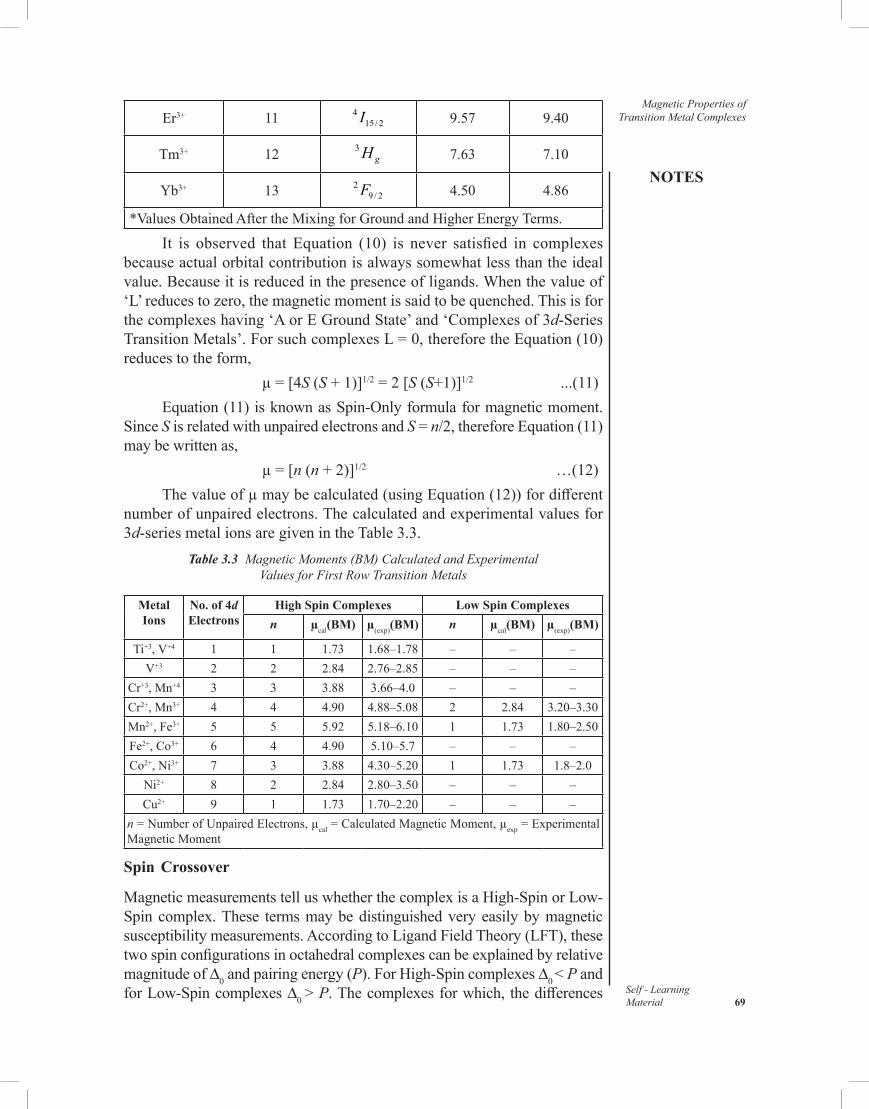
NOTES
Self - LearningMaterial 69
Magnetic Properties of Transition Metal ComplexesEr3+ 11 4
15/ 2I 9.57 9.40
Tm3+ 12 3gH 7.63 7.10
Yb3+ 13 29/ 2F 4.50 4.86
*Values Obtained After the Mixing for Ground and Higher Energy Terms.
It is observed that Equation (10) is never satisfied in complexes because actual orbital contribution is always somewhat less than the ideal value. Because it is reduced in the presence of ligands. When the value of ‘L’ reduces to zero, the magnetic moment is said to be quenched. This is for the complexes having ‘A or E Ground State’ and ‘Complexes of 3d-Series Transition Metals’. For such complexes L = 0, therefore the Equation (10) reduces to the form,
µ = [4S (S + 1)]1/2 = 2 [S (S+1)]1/2 ...(11)Equation (11) is known as Spin-Only formula for magnetic moment.
Since S is related with unpaired electrons and S = n/2, therefore Equation (11) may be written as,
µ = [n (n + 2)]1/2 …(12)The value of µ may be calculated (using Equation (12)) for different
number of unpaired electrons. The calculated and experimental values for 3d-series metal ions are given in the Table 3.3.
Table 3.3 Magnetic Moments (BM) Calculated and Experimental Values for First Row Transition Metals
Metal Ions
No. of 4d Electrons
High Spin Complexes Low Spin Complexesn µcal(BM) µ(exp)(BM) n µcal(BM) µ(exp)(BM)
Ti+3, V+4 1 1 1.73 1.68–1.78 – – –V+3 2 2 2.84 2.76–2.85 – – –
Cr+3, Mn+4 3 3 3.88 3.66–4.0 – – –Cr2+, Mn3+ 4 4 4.90 4.88–5.08 2 2.84 3.20–3.30Mn2+, Fe3+ 5 5 5.92 5.18–6.10 1 1.73 1.80–2.50Fe2+, Co3+ 6 4 4.90 5.10–5.7 – – –Co2+, Ni3+ 7 3 3.88 4.30–5.20 1 1.73 1.8–2.0
Ni2+ 8 2 2.84 2.80–3.50 – – –Cu2+ 9 1 1.73 1.70–2.20 – – –
n = Number of Unpaired Electrons, µcal = Calculated Magnetic Moment, µexp = Experimental Magnetic Moment
Spin Crossover
Magnetic measurements tell us whether the complex is a High-Spin or Low-Spin complex. These terms may be distinguished very easily by magnetic susceptibility measurements. According to Ligand Field Theory (LFT), these two spin configurations in octahedral complexes can be explained by relative magnitude of D0 and pairing energy (P). For High-Spin complexes D0 < P and for Low-Spin complexes D0 > P. The complexes for which, the differences

Magnetic Properties of Transition Metal Complexes
NOTES
Self - Learning 70 Material
between D0 and P in very small, are called intermediate field situation. Here two spin states coexist in equilibrium. Let us consider two complexes of d6 configuration, i.e., High-Spin Paramagnetic [Fe(H2O)6]
2+ (S=2) and Low-Spin Diamagnetic [Fe(CN)6]
4–(S = 0). The Tanabe-Sugano diagram shows that near the crossover point between weak and strong field the difference in energy between 5T2g and 1A1g is very small in ground state (Refer Figure 3.3). Both these states depend upon temperature as D0 – P = kT. If we consider the complex [Fe (phen)2 (NCS)2], then its graph between magnetic moment and temperature can be obtained as given in Figure 3.4. It is clear that at high temperature there are four unpaired electrons, but at low temperature Low-Spin form dominates.It is clear that energy difference is smaller near the spin crossover point.Magnetic Exchange: In 1895 Pierre Curie established a relation between paramagnetic susceptibility and temperature. According to him magnetic susceptibility is inversely proportional to the absolute temperature, i.e.,
χ = 1∝
Τ
M
CT
χ = …(13)
Fig. 3.3 Variation in Energies of 5T2g and 1A1g Terms with increasing D0 for Fe2+Octahedral Complexes (d6-Configuration)
Fig. 3.4 Variation in Magnetic Moment of |Fe (phen)2(NCS)2| with Temperature

NOTES
Self - LearningMaterial 71
Magnetic Properties of Transition Metal Complexes
Where C is a constant and Equation (13) is known as Curie’s Law. Paramagnetic substances obey this law and called magnetically dilute, i.e., those substances in which the paramagnetic centres are well separated from each other by diamagnetic atoms. On the other hand, the substances which are not magnetically dilute unpaired spins on neighbouring atoms may couple with each other, this phenomenon is called magnetic exchange. For such substance the Equation (13) is modified as follow:
–χ =
θMC
T … (14)Where θ is a constant with units of temperature and is called Weiss
constant. The Equation (14) is called Curie-Weiss Law.If the value of θ is positive, i.e., above 0°K then the substance is said
to be ferromagnetic and if θ is negative, i.e., below 0°K, then the substance is said to be antiferromagnetic.
The substance is called ‘Ferromagnetic’ if the interacting magnetic dipoles on neighbouring atoms tend to assume a parallel alignment (Refer Figure 3.5). On the other hand if the tendency is for an antiparallel arrangement of the coupled spins, the substance is called ‘Antiferromagnetic’ (Refer Figure 3.6).
Fig. 3.5 Graph Plotted Between Reciprocal of Magnetic Susceptibility and Temperature in Kelvin
Figure 3.5 illustrates the graph plotted between the reciprocal of Magnetic Susceptibility and Temperature in Kelvin, in which (a) According to Curie Law (b) According to Curie-Weiss Law for Ferromagnetic Substances with Curie Temperature Tc (c) According to Curie-Weiss Law for Antiferromagnetic Substances with Néel Temperature TN.
Fig. 3.6 Representation of Magnetic Dipole Arrangement (a) Paramagnetic (b) Ferromagnetic and (c) Antiferromagnetic Materials

Magnetic Properties of Transition Metal Complexes
NOTES
Self - Learning 72 Material
On the basis of Figure 3.6, we can state that any material that exhibits magnetic exchange, the tendency towards spin alignment will complete with the thermal tendency favouring spin randomness. The temperature below which magnetic exchange dominates is called Curie Temperature (TC) if the type of exchange displayed is Ferromagnetic and the Nèel Temperature (TN) if it is Antiferromagnetic. In Figure 3.7, four types of magnetism (Diamagnetism, Paramagnetic, Ferromagnetism and Antiferromagnetism) are shown while their behaviours are given in Table 3.4.
Fig.3.7 Variation of Magnetic Susceptibility with Temperature for Diamagnetic, Paramagnetic, Ferromagnetic and Antiferromagnetic Substances
Table 3.4 Comparison of Magnetic Properties
Properties Sign Magnitude of χ (CGS)
Temperature Dependence
of χ
Field Dependence
of χOrigin
Diamagnetic Negative 1 × 10⁻⁶ Independent Independent Electronic Charge
Paramagnetic Positive 0 – 10–4 1 1–
orT T θ
IndependentAngular
Momentum (Electron Spin)
Ferromagnetic Positive 10–2 – 10–4 Decrease Before TC
Dependent ↑↓ Dipole Exchange
Antiferromagnetic Positive 0–10–4 Increase Before TN
Dependent ↑↓ Dipole Exchange
Ferromagnetism, Antiferromagnetic and Ferrimagnetism are of rare occurrence.
Ferrimagnetism
The ‘Ferrimagnetism’ is a permanent magnetism in which the magnetic fields associated with individual atoms spontaneously align themselves, some parallel, or in the same direction (as in ferromagnetism) and others antiparallel, or paired off in opposite direction as in antiferromagnetism.
Most of the ferrimagnetic materials consist of cations of two or more types, sub-lattices contain two different types of ions with different magnetic moment for two types of atoms and as a result, net magnetization is not equal
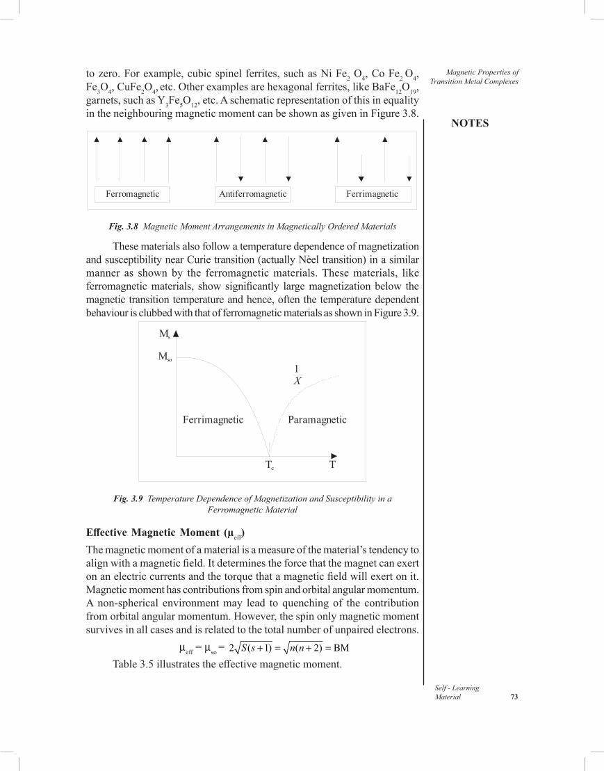
NOTES
Self - LearningMaterial 73
Magnetic Properties of Transition Metal Complexes
to zero. For example, cubic spinel ferrites, such as Ni Fe2 O4, Co Fe2 O4, Fe3O4, CuFe2O4, etc. Other examples are hexagonal ferrites, like BaFe12O19, garnets, such as Y3Fe5O12, etc. A schematic representation of this in equality in the neighbouring magnetic moment can be shown as given in Figure 3.8.
Ferromagnetic Antiferromagnetic Ferrimagnetic
Fig. 3.8 Magnetic Moment Arrangements in Magnetically Ordered Materials
These materials also follow a temperature dependence of magnetization and susceptibility near Curie transition (actually Nèel transition) in a similar manner as shown by the ferromagnetic materials. These materials, like ferromagnetic materials, show significantly large magnetization below the magnetic transition temperature and hence, often the temperature dependent behaviour is clubbed with that of ferromagnetic materials as shown in Figure 3.9.
Ms
Mso
Ferrimagnetic Paramagnetic
Tc T
1X
Fig. 3.9 Temperature Dependence of Magnetization and Susceptibility in a Ferromagnetic Material
Effective Magnetic Moment (µeff)The magnetic moment of a material is a measure of the material’s tendency to align with a magnetic field. It determines the force that the magnet can exert on an electric currents and the torque that a magnetic field will exert on it. Magnetic moment has contributions from spin and orbital angular momentum. A non-spherical environment may lead to quenching of the contribution from orbital angular momentum. However, the spin only magnetic moment survives in all cases and is related to the total number of unpaired electrons.
µeff = µso = 2 ( 1) ( 2) BM+ = + =S s n nTable 3.5 illustrates the effective magnetic moment.

Magnetic Properties of Transition Metal Complexes
NOTES
Self - Learning 74 Material
Table 3.5 Effective Magnetic Moment
Ion Number of Unpaired Electrons S Predicted µeff ValuesTi3+ 1 ½ 3 = 1.73V3+ 2 1 8 = 2.83Cr3+ 3 3/2 15 = 3.87Mn3+ 4 2 24 = 4.90Fe3+ 5 5/2 35 = 5.92
If there is a possibility for contribution from the orbital angular momentum,
µ = ( 1) 4 ( 1)L L S S+ + +
For a given value of the orbital quantum number l, the magnetic quantum number m can have any values from –l to +l and L = Sum of m.
For d-orbital electrons, m = 2, 1, 0, –1, –2.If there is only one electron in the d-orbital, then L = 2.Table 3.6 illustrates the configuration 3dn, for n = 1 to 10, and the
observed values of µeff at 300 K. Table 3.6 Configuration 3dn (n = 1 to 10) and Observed Values of µeff at 300 K
Configuration 3dn, n = 1 to
10
µSO = ( 1) 4 ( 1)L L + + S S + BM µS 4 ( 1)S S + BM µeff Observed at 300 K
1 3.00 1.73 1.7 – 1.82 4.47 2.83 2.8 – 2.93 5.20 3.87 3.7 – 3.94 5.48 4.90 4.8 – 5.05 5.92 5.92 5.8 – 6.06 5.48 4.90 5.1 – 5.7 7 5.20 3.87 4.3 – 5.28 4.47 2.83 2.9 – 3.99 3.00 1.73 1.7 – 2.210 0.00 0.00 0
K3 [Fe (CN)6] has a magnetic moment of 2.3M, which is a d5 Low-Spin Complex with one unpaired electron. [Fe (H2O)6]
3+ ions are High-Spin with five unpaired electrons. It has a magnetic moment of 6 B.M.
Correlation of µs and µeff ValuesWhen the Curie law is obeyed, the product of molar susceptibility and temperature is a constant. The effective magnetic moment, µeff is then defined as,
Where C has CGS units cm3 mol−1 K, µeff is,

NOTES
Self - LearningMaterial 75
Magnetic Properties of Transition Metal Complexes
ConstantT χ⋅ µ
Where C has SI units m3 mol−1 K, µeff is,
ConstantT χ⋅ µ
The quantity µeff is effectively dimensionless, but is often stated as in units of Bohr Magneton (µB). For substances that obey the Curie law, the effective magnetic moment is independent of temperature. For other substances µeff is temperature dependent, but the dependence is small if the Curie-Weiss law holds and the Curie temperature is low.
3.3 ORIGIN AND CALCULATION OF MAGNETISM
The magnetic properties of a substance are consequence of magnetic moment associeated with individual electrons. The electron creates magnetic moment in the following two ways:
(i) An electron can be treated as a small negative charge spinning on its axis. The spinning of charge produces magnetic moment.
(ii) An electron moving in a closed path around a nucleus also produces magnetic moment like an electric current flowing in a circular loop of wire.The magnetic moment due to spin of the electron on its axis is called
spin magnetic moment and the magnetic moment due to motion of the electron around the nucleus is termed as orbital magnetic moment. So, the observed magnetic moment of an atom in ion is the sum of the spin magnetic moment and orbital magnetic moment.
The magnetic moment is expressed in terms of units called Bohr Magneton, abbreviated as B.M. The magnetic moment for an electron having charge e and mass m is given by the relation.
µs =
Where h is Planck’s constant and c is the velocity of light.
The value of µs for an electron as obtained by the above expression is 0.9273 × 10⁻²⁰ erg Gauss–1. This is taken as one unit of magnetic moment called Bohr Magneton. Thus, Bohr Magneton is defined as,
1 B.M. = (15)
The magnetic moment, µs of a single electron is given by the relation,
µs = (16)
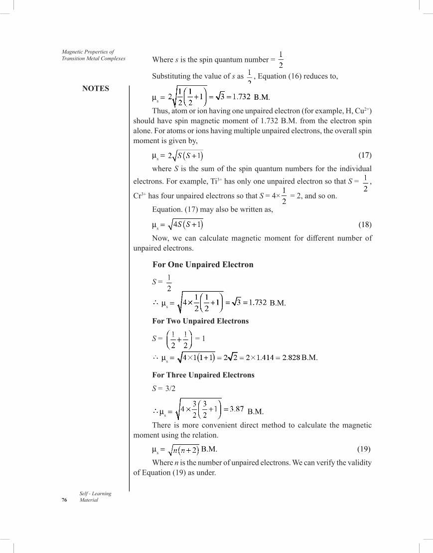
Magnetic Properties of Transition Metal Complexes
NOTES
Self - Learning 76 Material
Where s is the spin quantum number =
Substituting the value of s as , Equation (16) reduces to,
µs = Β.Μ.
Thus, atom or ion having one unpaired electron (for example, H, Cu2+) should have spin magnetic moment of 1.732 B.M. from the electron spin alone. For atoms or ions having multiple unpaired electrons, the overall spin moment is given by,
µs = (17)
where S is the sum of the spin quantum numbers for the individual electrons. For example, Ti3+ has only one unpaired electron so that S = ,
Cr3+ has four unpaired electrons so that S = 4× = 2, and so on.
Equation. (17) may also be written as,
µs = (18)
Now, we can calculate magnetic moment for different number of unpaired electrons.
For One Unpaired Electron
S =
µs = B.M.
For Two Unpaired Electrons
S = = 1
µs = B.M.
For Three Unpaired Electrons
S = 3/2
µs = B.M.
There is more convenient direct method to calculate the magnetic moment using the relation.
µs = B.M. (19)
Where n is the number of unpaired electrons. We can verify the validity of Equation (19) as under.

NOTES
Self - LearningMaterial 77
Magnetic Properties of Transition Metal Complexes
For One Unpaired Electron
µs = B.M.
For Two Unpaired Electrons
µs = B.M.
Table 3.7 gives the calculated values of µs for the different number of unpaired electrons.
Table 3.7 Spin Only Magnetic Moments for Different Number of Unpaired Electrons
No. of Unpaired Electrons µs (B.M.)
1 1.73 2 2.84 3 3.87 4 4.90 5 5.92 6 6.93 7 7.94
Experimental values of magnetic moments of some transition metal ions obtained from spin only formula are in agreement, however in some cases experimental values differ from spin only values. This is because in such cases orbital motion of electron also contribute to the magnetic moment. Magnetic moment in such cases is calculated by the following equation:
µS+L = (20)
Where S is the resultant spin angular momentum and L is the resultant orbital angular momentum quantum number.
3.4 MAGNETIC SUSCEPTIBILITY
Magnetic moment of a substance cannot be measured directly, first magnetic susceptibility (χ) is measured.
Magnetic Susceptibility (χ) is a measure of the capacity of a substance to take up magnetisation in an applied magnetic field. If a substance is placed in a magnetic field of strength H, then magnetic induction or magnetic flux density, B, within it is given by,
B = H – 4 π I (21)
I =
=

Magnetic Properties of Transition Metal Complexes
NOTES
Self - Learning 78 Material
Where, a = Area of crossection of the magnetic substance
2l = Length of the substance
Therefore, intensity of magnetisation is also defined as the pole strength per unit area of crossection of the material. The ratio B/H, called magnetic permeability can be given as :
(22)
Dividing both sides by H, we get,
= 1 + 4 π (23)
k is called magnetic susceptibility unit volume.
Magnetic Permeability is the ability of a material to permit the passage of magnetic lines of force through it. B/H is the ratio of the density of lines of force within the substance to the density of such lines in the same region in the absence of the substance. Therefore, the volume susceptibility of vacuum is obiously zero because in vacuum B/H = 1, So, Equation (23) becomes.
1 = 1 + 4 π or = 0
The susceptibility of a diamagnetic substance is negative because lines of force from induced dipole cancel out the lines of force due to applied field and B/H is less than 1.
Paramagnetic substances have the flux that is greater within the substance than it would be in vacuum and thus paramagnetic substances have positive susceptibilities.
Susceptibility may be expressed in two forms, specific susceptibility and molar susceptibility given by the following relations:
Specific Susceptibility,
Where ρ is the Density.
Molar Susceptibility, MMκ ×χ =
ρWhere M is the Molecular Mass of the Substance.
3.4.1 Determination of Magnetic Susceptibility
1. Gouy’s Method : This method was devised by French Scientist Gouy in 1889. It is one of the methods for the measurement of magnetic susceptibility of various substances.
‘The principle of this method is based on the fact that the magnetic field exerted on the sample when placed in the magnetic field varies directly as its mass (i.e., the difference in the masses when the field is switched OFF and ON)’.

NOTES
Self - LearningMaterial 79
Magnetic Properties of Transition Metal Complexes
Apparatus and Method: Finely powdered substance or solution is taken in a pyrex glass tube called Gouy tube. The substance is weighed first without magnetic field and then in the presence of magnetic field. If paramagnetic, the substance will weigh more in the presence of a magnetic field than in its absence. The increase in weight gives a measure of paramagnetism of the substance. Larger the number of unpaired electrons in a substance, greater is the increase in its weight in a magnetic field. The susceptibility is calculated from the difference in weight of the sample when the magnetic is off and when it is on. (Refer Figure 3.10)
Weights
Analytical Balance with One Pan Removed
Tube Containing Specimen
Electromagnet
Fig. 3.10 Gouy’s Magnetic Balance
Calculation of Magnetic Moment : The sample is in the form of a cylinder which is suspended in a non-homogeneous magnetic field and the force exerted on the sample is determined by weirghing. The force acting on the sample is given by,
F = A κ H2 (24)
Where, A = The crosssection area of cylinder.
H = Intensity in the central homogenous part of the magnetic field.
κ = Volume susceptibility.
This equation is valied only if the measurements are done in vacuum. However, if the sample is surrounded by air, then the susceptibility of air (κ’) must be subtracted from the measured susceptibility. In such case, the Equation (24) is modified as,
F = AH2 (κ–κ1) (25)
Where, κ’ = Volume susceptibility of air
Now, the Gouy tube itself develops a force which is always present. Therefore, the actual force acting on the sample is the force acting on the Gouy tube subtracted from the observed force. This force is negative because

Magnetic Properties of Transition Metal Complexes
NOTES
Self - Learning 80 Material
of the diamagnetic material of the tube. It is denoted by 8, then Equation (25) becomes,
F = AH2 (κ–κ’)+8 (26)
For a sample of constant length and cross sectional area, the factor AH2 is constant. Now if the density of the sample is introduced, the Equation (26) may be rewritten as,
106χ = (27)
Where, α = Constant allowing for the displaced air and is equal to 0.029 × Specimen volume and is expressed in mg.
W = Weight of the sample expressed in gram.
F1 = Force on the sample and is equal to F-8; both F and 8 are given in mg.
β = Tube Calibration Constant.
The apparatus is calibrated by making measurements on a substance whose susceptibility is accurately known. The standard substance used for calibration is Mercury tetrathiocyanatocobaltate (I), Hg [Co(SCN)4]. Its susceptibility is 16.44×10⁶ at 20°C.
By making measurement with this standard substance the constant β is first calculated. Substituting the values of α, β, 8 and F on a given sample of weight w, the susceptibility χ can be calculated using Equation (24).
Limitations : This method is not suitable for investigation of gases. Errors arise due to the presence of ferromagnetic impurities in the specimen and lack of complete uniformity in the field especially just outside the pole pieces.
2. Bhatnagar–Mathur Method : In 1923, Bhatnagar and Mathur modified the Gouy balance in such a way that it could be used for the measurement of susceptibilities of liquids.
The basic principle in the method is that the forces acting on the sample varies directly proportional to the magnetic pull producing a displacement of the pointer when the magnetic current is started.
Apparatus : The apparatus is shown in Figure 3.11. S’ is a five silver spiral which is suspended from a brass hook at the top. ‘A’ is a specimen whose susceptibility is to be measured. It is suspended from the lower end of the spiral. The lower end of the spicemen lies in the region of strong uniform magnetic field. ‘P’ is a very thin pointer attached to the spiral. The displacement of ‘P’ is measured by means of a microscope provided with a scale.

NOTES
Self - LearningMaterial 81
Magnetic Properties of Transition Metal Complexes
Process: When a specimen is put in between the two poles of a strong magnet as shown in Figure (3.11), the vertical magnetic pull on the specimen is given by,
F = ½ (κ1—κ2) AH2 (28)
In this balance, the strong magnetic field pulls the specimen which in turn pulls the spring, producing a displacement of the pointer. Reading is recorded with and without the application of magnetic field. Thus, the force F is defined as,
F = (29)Pointer
Scale
Substance
Fig 3.11 Bhatnagar–Mathur Method
Where l is the displacement of the pointer and s is the displacement of pointer produced by 1 gm of the substance. From Equations (28) and (29), we get
or
Where κ1 and κ2 are the volume susceptibilities of the specimen and the surrounding medium.
3. Quincke’s Method : This method is given by G. Quincke in 1885 and strictly suitable for liquids, aqueous solutions and with some modifications for gases.
Principle : The principle of this method is the same as that employed in Gouy’s method except that the force acting on the liquid sample is measured in terms of the hydrostatic pressure developed when the liquid is placed in a capillary tube so that the meniscus stands in a strong and uniform field. When field is applied, the meniscus will fall if the liquid is diamagnetic or will rise if the liquid is paramagnetic.
Apparatus : The apparatus used in the Quincke’s method is shown diagrammatically in Figure (3.12). This apparatus makes use of a specially designed modified U tube (ABC’CD). The limb C’ D is a capillary tube which is placed in a uniform magnetic field of strength 25,000 Oersted. The term ‘Orested’ is named after Hans Christion Oersted. The field near the wider end of the U tube (end C’) is 50–100 Oersted which is quite negligble. When

Magnetic Properties of Transition Metal Complexes
NOTES
Self - Learning 82 Material
the field is applied, the liquid meniscus rises or falls in the capillary tube C’ D if the liquid sample is paramagnetic or diamagnetic in nature, respectively.
In most of the cases, the rise or fall of the meniscus is observed directly. Accuracy of the readings may be incressed slightly by including the capillary.
Process : As soon as the current is switched on, a strong and uniform magnetic field is established at the upper surface of the capillary tube whereas the lower surface of the capillary experiences a weak field. If the liquid is paramagnetic, the meniscus will rise whereas a fall will be observed if the liquid is a diamagnetic liquid. Suppose Dh is the change in the height of the meniscus. Then, the corresponding hydrostatic prossure will be given by,
Capillary Tube Fluid
Fig. 3.12 Quincke’s Method
But p = ρ.g Dh ...(30)
Force = Pressure × Area
Force = (ρ.g Dh) × A ...(31)
Where A is the area of cross section of the tube. Equation (31) represents the vertical. force D Fx, i.e.,
D Fx = (ρ.g Dh) × A
The vertical force due to change in the hydrostatic pressure will be balanced by magnetic pull given by Equation (30), i.e.,
(ρ.g Dh) × A = (κ1 – κ2)AH2
Or κ1 – κ2 =
Or
Or
Or ...(32)
Where, and are the mass susceptibilities of the liquid (or density ρ) and gas or vapour (of density ρ0) above the liquid, respectively. If a wider

NOTES
Self - LearningMaterial 83
Magnetic Properties of Transition Metal Complexestube (AB) is of sufficient larger diameter and the susceptibility ( ) of the
vapour above the liquid meniscus is negligible, Equation (32) modifies to,
(33)
From Equation (33) it follows that this method has some advantages due to the following reasons :
(i) There is no need for the density of liquid to be measured separately, because Equation (33) does not include density term.
(ii) As Equation (33) does not include the radius of capillary, there is no need to determine its value.
(iii) The measurement of the magnetic field can be avoided if the magnetic susceptibilities are measured for a sample and a reference substance under identical conditions, i.e.,
...(34)Where s and r are used as subscripts for a liquid (Whose magnetic
susceptibility is to be measured) and reference liquid (Whose magnetic susceptibility is known). From Equation (34), it is also evident that the magnetic susceptibility of a liquid can be measured by simply noting down the change in the height of the liquid meniscus under strong and uniform magnetic field.
Applications : The Quincke’s method has been found to be very useful for the determination of magnetic susceptibilities of the following types of substances:
(i) For Solutions : Bauer and Piccard applied the Quincke’s method for the determination of the susceptibilities of solution and deduced the following equation.
...(35) Where χ0 and ρ0 denote the susceptibility and density of vapours above
the solution, respectively. The magnetic susceptibility of the solution can also be determined by applying the following relation :
...(36)
Where are the susceptibilities of the solution, dissolved salt and solvent water, respectively, and fs, is the mole fraction of the solute.
(ii) For Gases : The Quinckes’s method may also be used for gases. If the susceptibility of the vapour over the meniscus is not negligible, the Hydrostatic Pressure (P) developed on the application of the field is

Magnetic Properties of Transition Metal Complexes
NOTES
Self - Learning 84 Material
P = (K – K0)H2 where K and K0 are the volume susceptibilities of
liquid and vapour, respectively.In order to avoid the surface tension changes, the bore of the narrow
limb must be strictly uniform. Further, the bore should not be very much narrow otherwise on applying field, the surface of the liquid will get deformed and there will be no rise and fall of liquid column.
4. Curie’s Method : Curie’s balance is a simple and useful magnetic balance, devise by Curie in 1895. It is used to study the variation of magnetic susceptibility with temperature, giving a clear distinction between para-, di-and ferromagnetic substances.
According to the principle of Curie’s balance, if a specimen is kept in a non-uniform magnetic field, a force is exerted on the specimen giving it a displacement which is measured in terms of torque requirement to bring the specimen back to the original position. Let us consider the small volume dV of the specimen. The force exerted d F, on the sample is give by equation.
dF = (κ1—κ2) d VHy ...(37)
As the field gradient lies along the x-axis, the quantities and
are neglected. The total force exerted on the specimen may be evaluated by integrating Equation (37).
Thus,
Fig. 3.13 Curie Balance Fig. 3.14 Curie’s Method
dFx = (κ1 – κ2) V Hy

NOTES
Self - LearningMaterial 85
Magnetic Properties of Transition Metal ComplexesOr Fx = (κ1 – κ2) V Hy ...(38)
But W = Vρ ...(39)
And and ...(40)
Substituting Equations (39) and (40) in Equation (38), we get
Fx = WHy ...(41)
where W is the weight of the sample. From Equation (41), it follows that all the quantities except ∂H, ∂x can be measured very easily. In order to measure ∂H/∂x, a test coil and a ballistic galvanometer is employed. In the Curie’s method, the non-uniform field can be generated by inclining the two pole-pieces of an electromagnet at a certain angle. The Curie balance using a electromagnet is shown in Figure (3.13).
The Curie method has the advantage that only a small sample is required and that the specimen can be of irregular shape. The only disadvantage of this method is that ∂Hy/∂x cannot be determined very accurately at a point and hence, the precision is usually not better than a few percent. The method is of great sensitivity if the sample is held on a horizontal arm which is suspended from a torsion fibre.
5. Nuclear Magnetic Resonance (NMR) Method : NMR spectrometer can be used to measure the magnetic susceptibility. This approach was developed by Dennis Evans in 1959. This method is simple and is based on the effect a paramagnet in solution has on the chemical shift of a reference compound, usually the solvent. Data collection is done on an NMR spectrometer, the data is easy to interpret, and sample preparation is straight forward and requires tittle material. It has become the standard method for determining magnetic susceptibility data for inorganic complexes.
This method relies on the fact that the unpaired electrons from the paramagnet in solution will result in a change of the chemical shift of all species in solution. Thus, by noting the chemical shift difference of a solvent molecule in the presence and absence of a paramagnetic species. The magnetic susceptibility can be obtained by the equation :
XM =
Where, F = Frequence difference in Hz between the shifted reronance and the pure solvent resonance.
f = Spectrometer radio frequency in H z
c = Concentration of paramagnetic species (mol/ML).

Magnetic Properties of Transition Metal Complexes
NOTES
Self - Learning 86 Material
Check Your Progress
1. Give definitions for transition metals. 2. Define the term magnetism. 3. What is diamagnetism? 4. Explain the magnetic properties of complexes. 5. What is spin crossover? 6. Define ferrimagnetism. 7. What is effective magnetic moment? 8. How the electron creates the magnetic moment? 9. Explain magnetic susceptibility giving the formula. 10. What does Gouy’s method state? 11. Explain Curie’s method.
3.5 L–S COUPLING OR RUSSELL SAUNDERS COUPLING
L–S coupling scheme is applicable to systems in which spin orbital interactions are relatively small. In this scheme, the individual orbital angular momentum of the electron couple to give a resultant angular momentum respresented by the quantum number, L for the state.The individual electron spin momentum a also couple (Interact) to give a resultant spin momentum described by the quantum number, S. The L and S values together determine the total angular momentum, J which can take quantized positive values ranging from |L–S| to |L+S|. | | indicates the absolute value of |L–S| and no regard is paid to its sign, so that J is always > 0. Thus, the range for J can be written as,
J = |L–S|, |L+S–1| |........| |L–S|.
Rules for Determing the Term Symbol as Per L–S Coupling Scheme.
1. Determination of Total Spin Angular Momentum (SS Coupling)For a single electron, spin quantum number, ms = ½, when two or more electrons are present in subshell, their magnetic fields couple to produce resultant spin quantum numbers, S given us,
S = (S1 + S2), (S1 + S2–1) ....... |S1 — S2|, where, the modulus sign | | indicates the positive value.
For example, for a subshell having two electrons (p2 or d2)S = ½ + ½, ½ + ½–1= 1, 0
The spin multiplicity is given by the relation 2S+1 and is written in the upper left hand corner of the term symbol for the state.

NOTES
Self - LearningMaterial 87
Magnetic Properties of Transition Metal Complexes
Spin multiplicity of 3 represents triplet state and a spin multiplicity of 1 represents a singlet state.
Unpaired S Spin Multiplicity Name of Electrons (2S + 1) State
0 0 1 Singlet
1 2 Doublet
2 3 Triplet
3 4 Quartet
4 5 Quintet
2. Determination of Resultant Orbital Angular Momentum (LL Coupling)When two electrons with angular quantum number l1 and l2 interact, the resultant angular quantum number, L are given by the relationship :
L = (l1 + l2), (l1 + l2 –1), (l1 + l2 –2) ............. |l1 – l2|
where the modulus sign | | indicates the positive value.
For example, for a p subshell having two electrons (as in Carbon).
l1 = 1 and l2 = 1 so that
L = (1 + 1), (1+1–1), .......... (1–1)
= 2 1 .......... 0
States D P .......... S
Therefore, p2 electrons (as in Carbon) will be represented by three energy states S, P and D corresponding to L = 0, 1 and 2, respectively.
Similarly, for d2 configuration, the energy states can be obtained as under :
l1 = 2 and l2 = 2
L = (2+2) (2+2–1), 2+2–2, (2+2–3), 2–2
= 4 3 2 1 0
States G F D P S
Thus, d2 configuration is represented by five energy S, P, D, F and G corresponding to L = 0, 1, 2, 3 and 4, respectively.
3. Spin-Orbital or L–S CouplingThe magnetic effects of resultant angular momentum, L and the resultant spin moment S couple together to give new quantum number J called the total angular momentum. J values can be obtained by the vectorial combination

Magnetic Properties of Transition Metal Complexes
NOTES
Self - Learning 88 Material
of L and S coupling Scheme called Russell Saunders or LS Coupling. The J can acquire all quantized positive values in the range |L–S| to |L+S| as :
J = (L+S), (L+S–1), (L+S–2)......... |L–S|
The J values are separated by1. The modulus sign, || indicates the absolute value of |L–S| so that J 0. The J value is written as a subscript in the term symbol.
3.6 DETERMINATION OF GROUND STATE TERM SYMBOLS : p2 AND d2 CONFIGURATIONS
Consider, there rules for p2 and d2 configurations.
Term Symbols
It may be recalled that the electron in an atom can be described completely by the set of four quantum numbers, briefly discussed below.
(i) Principal Quantum Number, n: It determines the main energy level or shell in which the electron is present. It can have whole number values as :
n = 1, 2, 3, 4................ (ii) Angular Quantum Number, l: It is related to the angular momentum
of the electron. In multi-electron atoms (an atom having a number of electrons) the energy besides depending upon n, also depends on l. Corresponding to each value of n, there are n possible values of l as :
l = 0, 1, 2, 3 ........... (n–1) These various values of l (called subshells) are designated as s, p, d, f
...........Value of l 0 1 2 3 4 and so onDesignation s p d f g and so on (iii) Magnetic Quantum Number, m: It refers to the different orientations
of the orbitals in space. For a given value of l, m can have (2l + 1) values as :
m = –l, –(l – 1) ........... 0 ................. + (l – 1), + lThus if l = 1, m will have 3 values viz., –1, 0, +1.
If l = 2, m will have 5 values viz., –2, –1, 0, + 1, + 2.
(iv) Spin Quantum Number, s: This describes the spin orientation of the electron. Since the electron can spin only in two ways : Clockwise and Anticlockwise, s can have only two values. + and – .The values may also be indicating by arrows pointing up (↑) and down (↓), respectively. It determines the spin angular momentum.

NOTES
Self - LearningMaterial 89
Magnetic Properties of Transition Metal Complexes
The distribution of electrons in different levels in an atom is known as electronic configuration. The filling of orbitals is governed by the three well known rules.
1. Aufbau Principle: Electrons enter the orbitals of lowest energy first and subsequent electron are filled in increasing order of energy (1s, 2s, 2p, 3s, 3p, 4s, 3d...........).
2. Pauli’s Exclusion Principle: No two electrons in an atom can have the same value for the four quantum numbers.
3. Hund’s Rule: When several orbitals of the same energy are available (Degenerate Orbitals) the electrons tend to remain unpaired as far as possible, i.e., the electrons tend to retain parallel spin as much as possible, on energy consideration.The electronic configuration of the outershell is generally represented
by a box diagram. The boxes represent orbitals and is indicated by arrows. For example, the s-orbitals are indicated by a single box, the p-orbitals are indicated by three boxes, one each for the px, py and pz orbitals.
Similarly the d-orbitals are represented by five boxes, one each for dxy, dyz, dzx, dx2–y2 and dz2 as shown below :
One s-orbitals
Three p-orbitals
Five d-orbitals
The f-orbitals are represented by seven boxes. A spin quantum number of + is indicated by the arrow ↑ and – by the arrow ↓. When only one electron is present in a degenerate energy level such as s, p or d subshell, it can occupy any one of the possible arrangements.
However, for atoms more than one electron in the degenerate orbitals, several different arrangements are possible which may not have the same energy. Some of these arrangements would be of higher energy and some would be degenerate because of different inter electronic repulsions. The inter-electronic repulsions for the arrangements where two electrons are present in the same orbital are higher than for those arrangements in which they are present in different orbitals. So, the energy for the former arrangements would be larger than those for the later arrangements. Thus, many more energy states exist in multielectron systems. Those different arrangements may be grouped into different sets of degenerate energy states. Furthermore, spin angular momentum (s) and orbital angular momentum (l) of the electrons may interact or couple to give a resultant angular momentum for the entire multi electron atom. The resultant angular momentum and the energy of the system is expressed in a term symbol.
Term symbols are used to indicate the electronic configuration and the resultant angular momentum of an atom.

Magnetic Properties of Transition Metal Complexes
NOTES
Self - Learning 90 Material
The term symbol for a particular atomic state is expressed as :2S + 1LJ
Where
S = Total spin angular quantum number
L = Total orbital angular quantum number
J = Total angular momentum quantum number
(2S + 1) is called the spin multiplicity of the state (Arrangement)
Just as we have the symbols s, p, d, f ........ for l = 0, 1, 2,3 .........., the different values of L are designated by S, P, D, F, G, H, I, etc. Thus the state S represents L = 0, P represents L = 1, and so on.
L 0 1 2 3 4 5 6 7
State S P D F G H I K
It may be noted that we do not assign the state J because this letter is used to represent another quantum number, viz. total angular moment quantum number.
The total angular momentum, J of an atom can be generally determined by L–S or Russell Saunders Coupling and J–J Coupling.
3.6.1 Derivation of Term Symbols for p2—Configuration
Step 1: For the two p-electrons l1 = 1 and l2 = 1
L = (1 + 1), (1+1–1), (1+1–2)
= 2, 1, 0
States D P S
It may be noted that the last value of L can also be obtained by |l1 – l2 | i.e.
1 – 1 = 0
The energy states are S, P and D.
Step 2: For two electrons,
S =
= 1, 0
It may be noted that the second value of S can also be obtained by
|s1–s2| or = 0
The Spin Multiplicity (2S + 1) is :
For S = 1, Spin Multiplicity = 3 (Triplet)
For S = 0, Spin Multiplicity = 1 (Singlet)

NOTES
Self - LearningMaterial 91
Magnetic Properties of Transition Metal Complexes
Therefore, we have six states corresponding to states D, P and S and corresponding to spin multiplicity 3 and 1 each which can be written as,
3S, 3P, 3D, 1S, 1P and 1D.
Step 3 : Calculation of J values;
(a) When L = 2, 1 and 0 and S = 1
(i) When L = 2, S = l, i.e., 3D state
J = (2 + 1), (2 + 1 – 1), (2 + 1 – 2)
= 3, 2, 1
We cannot have J = 0 because the range J is from |L+S| to |L–S|, i.e.,
| 2 + 1 |to| 2 – 1|, i.e., 3 to 1
Complete spectroscopic term symbols 2S+1LJ
3D3, 3D2 and 3D1.
(ii) When L = 1 and S = 1, i.e. 3P state.
J = (1 + 1), (1 + 1 – 1), (1 + 1 – 2)
= 2, 1, 0
Complete spectroscopic terms are,3P2,
3P1 and 3P0.
(iii) When L = 0 and S = 1, i.e. 3S state
J = 1 + 0
= 1
We cannot have J = 0 because the range for J is from |L + S| to |L – S|,
i.e., | 0 + 1 | to | 0 – 1 |, i.e., 1 only
Complete spectroscopic term symbol 2S+1LJ is 3S1
(b) When L = 2, 1 and 0 and S = 0 (i) When L = 2 and S = 0, i.e., 1D states
J = 2 + 0
= 2 J cannot have values 1 and 0 because the range is from |2+0| to | 2 – 0|,
i.e., 2 only∴ Complete Spectroscopic Term symbol, 2S+1LJ is 1D2
(ii) When L = 1 and S = 0, i.e., 1P statesJ = 1 + 0
= 1.

Magnetic Properties of Transition Metal Complexes
NOTES
Self - Learning 92 Material
J cannot have values 0 because J range between |1+0| and |1–0|, i.e., 1 only.
Complete spectroscopic term is 1P1
(iii) When L = 0 and S = 0, i.e., 1S stateJ = 0
∴ Complete spectroscopic term is 1S0
Thus, the total term symbols for p2 configuration are :3D3,
3D2, 3D1,
3P2, 3P1,
3P0, 3S1,
1D2, 1P1, and 1S0
Each of these value corresponds to an electronic arrangement.
All the spectroscopic terms derived for a p2 configration would occur for an excited state of carbon (1s2, 2s2, 2p1 3p1) in which two p electrons belong to different subshells. But in ground state of carbon (1s2, 2s2, 2p2) the number of states are restricted by Pauli’s Exclusion principle.
In the ground state configuration of carbon, both the p electrons have the same values of n and l (n = 2, l = 1), so they must differ in at least one of the remaining quantum numbers m or s. Pauli’s Exchusion principle restricts the number of terms from 1S, 1P,
1D, 3S, 3P, 3D to 1S, 3P and 1D only. Table 3.8 gives all the fifteen alowed values of ML and MS for the p2 configration (which does not violate Pauli’s Exclusion principle). These fifteen arrangements can be represented by only three term 1S, 3P and 1D by taking suitable values of ML (2L + 1) and MS (2S + 1) explained below:

NOTES
Self - LearningMaterial 93
Magnetic Properties of Transition Metal Complexes
For p electrons, the angular quantum number l = 1 and magnetic quantum number m has values from + l ......... 0 ........... –l, giving in this case values of m = 1, 0, –1. The spin quantum number has values of + and – for each value of m. The total spin quantum numbers and total orbital quantum can be obtained by adding the appropriate values of m and l as explained earlier :
ML has values from + L ........... 0 ............ –L (a total of 2L + 1 values).
MS has values from + S ........... 0 ............ –S (a total of 2S + 1 values).
The L and S quantum numbers which are associated with each electronic configuration or term symbol can be obtained from ML and MS quantum numbers as shown in Table 3.8. The values of MS and ML can be obtained by adding the appropriate values of ms and n
MS = ∑ ms and ML = ∑ m
Table 3.8 Allowed Values of ML and MS for p2 Configuration
Assigning Spectroscopic Term Symbols
This can be done in following steps : (i) Write the different values of MS and ML for the given configuration of
valence shell electrons.

Magnetic Properties of Transition Metal Complexes
NOTES
Self - Learning 94 Material
(ii) Select the maximum MS value and then maximum ML value associated with it. In present case, MS = 1 and ML = 1. This correspond to a group of terms where L=1 and S=1 Since L=1, it must be a P state and since S = 1, the multiplicity, 2S+1=3, so that it is a 3P (Triple P) state.
Now if L= 1, ML may have the values +1, 0 and –1 and if S=1, MS may have the values +1, 0 and –1. It gives to nine combinations of ML and MS values given below :ML = 1 MS = +1, 0, –1
ML = 0 MS = +1, 0, –1
ML = –1 MS = +1, 0, –1
Thus we assign the symbol 3P to nine of the allowed values (Show in Table 3.9).
(iii) From the remaining MS and ML values, we pick out the maximum MS and ML values. It is MS = 0 and ML =2. Since L = 2, it must be a D state and S = 0 gives a multiplicity of 2S + 1 = 1, so it is a 1D (Singlet D) state.With L = 2, ML may have values of + 2, + 1, 0, –1, –2 and if S = 0. MS
has only one value, i.e., 0.
We get the following five combinations of ML and MS which can be assigned 1D term symbol.
ML = +2 MS = 0
ML = +1 MS = 0
ML = +0 MS = 0
ML = –1 MS = 0
ML = –2 MS = 0
So far, we have considered 14 combinations, 9 of 3P and 5 of 1D. The remaining configuration corresponds of MS = 0 and ML = 0. This gives a singlet S state 1S.
Thus we can say that all the 15 electronic arrangements can be represented by three states :
1S, 3P and 1D.
3.6.2 Derivation of the Term Symbles for d2 Configration
For d electrons, the subsidiary quantum number l is 2. For two d-electrons having l1 = 2 and l2 = 2, the values of L can be obtained as,

NOTES
Self - LearningMaterial 95
Magnetic Properties of Transition Metal Complexes
L = (2+2), (2+2–1), (2+2–2), (2+2–3), (2+2–4)
4 3 2 1 0
These values of L represent S, P, D, F and G states corresponding to L = 0, 1, 2, 3 and 4, respectively.
Values of S can be obtained as,
S = (+ + ), ( + –1)
Therefore, the values of spin multiplicity, (2S + 1) are 3 and 1. So we have 1S, 1P, 1D, 1F, 1G and 3S, 3P, 3D, 3F and 3G. There are 45 ways in which two d-electrons may be arranged without violating the Pauli Exclusion principle. These arrangements are given in Table 3.9.
However, these arrangement can be represented by only five states; 1S, 3P, 1D, 3F and 1G. This can be seen in a similar way as for p2 electrons.
(i) Maximum value of Ms = 1 and the maximum value of ML corresponding to this MS is 3 (Refer to S.No. 2 in Table 3.9). Since this corresponds to L=3, it represents F state. This occurs with MS = + 1, 0, –1 suggesting a triplet F state i.e. 3F.Now there are 21 combinations of ML and MS values associated with
3F term for L = 3 as shown below :
ML = + 3 MS = + 1 , 0, –1
ML = + 2 MS = + 1 , 0, –1
ML = + 1 MS = + 1 , 0, –1
ML = 0 MS = + 1 , 0, –1
ML = – 1 MS = + 1 , 0, –1
ML = – 2 MS = + 1 , 0, –1
ML = – 3 MS = + 1 , 0, –1
(ii) The next highest unassigned MS is 0. The corresponding value of ML is 4 (Refer Sr. No. 1 in the Table 3.9). This corresponds to G state. Since MS = 0, S must be 0 and it is singlet G term, 1G.
Now, if L = 4, ML can have the values + 4, + 3, + 2, + 1, 0, –1, –2, –3, –4. If S = 0, MS = 0 (Only One Value).
Thus, there are nine configurations associated with this term, 1G. (iii) For ML value of 2, maximum value of MS = 0. This ML = 2 corresponds
to D state. Since MS = 0 for this state, it corresponds to spin multiplicity of 1 suggesting the state 1D.

Magnetic Properties of Transition Metal Complexes
NOTES
Self - Learning 96 Material
Table 3.9 Allowed Values of MS and ML for d2 Configuration

NOTES
Self - LearningMaterial 97
Magnetic Properties of Transition Metal Complexes
Now, if L = 2, ML may have values + 2, + 1, 0, –1, –2
and if S = 0, MS may have (Only One Value) that is 0.
We can assign this state to five of the combinations (Refer Table 3.9).
(iv) We have some combinations, in which maximum MS = 1 and the maximum ML value associated with it is 1. Therefore, it corresponds to a p state. Since s = 1, spin multiplicity is 2 × 1 + 1 = 3. So it corresponds to a triplet p state, 3p.
Now, if L = 1, ML may have values + 1, 0, –1 if S = 1, MS may have the values + 1, 0, –1.Thus, there are nine combinations of ML and MS values:
ML = +1 MS = +1, 0, –1
ML = 0 MS = +1, 0, –1
ML = –1 MS = +1, 0, –1
These 9 combinations can thus be assigned the state 3p.
(v) We have considered 21+9+5+9=44 combinations so far and only one combination is left. Combination of MS = 0 and ML = 0 is left. Here L = 0 and it corresponds to singlet. The term (State) 1s can be assigned to it.Since L = 0 and S = 0, it corresponds to only one term.
Thus, all the allowed values of ML and MS for d2 configuration may be represented by 1S, 3P, 1D, 3F and 1G states.
Derivation of the Term Symbol for Closed Shell Configuration
If a subsell is completely filled with electrons for example p6 or d10 arrangements, then the values of both MS and ML come out to be zero.

Magnetic Properties of Transition Metal Complexes
NOTES
Self - Learning 98 Material
Since, ML = 0, so L = 0 and it corresponds to ‘S’ state. Since MS = 0 and so S = 0 and therefore, multiplicity is 2S + 1 = 1.
Thus, a closed shell of electrons always produces a singlet S state, 1S0.
3.6.3 Applications of These Rules for p2 and d2 Configurations
1. P2 Configuration : The terms for ground state of p2 configuration one 3p1
1d and 1s. The most stable out of these ground states is 3p because its multiplicity is maximum. So, 3p is the ground state (most stable state). Out of 1d and 1s (Both having same value of S), 1d is more stable because it has a higher value of L = 2. Now the triplet P state has three terms 3p2,
3p1, 3p0, According to the third rule, 3p0 is the lowest energy
term (Because 2p2 configuration of carbon is less than half filled) and these terms may be arranged in increasing order of energy as,
3p0 < 3p1 < 3p2
The different terms of carbon are arranged in the increasing order of energy in Figure 3.15. This order corresponds to experimentally measured energy shown in brackets.
Fig. 3.15 Splitting of Terms in Ground State of Carbon
2. d2 Configuration : The terms for ground state of d2 configuration (for example, V3+ ion) are 1s, 3p, 1d, 3f and 1g. Let us arrange them in increasing order of energy and determine the ground state.
As per the rule 1, the stable corresponds to highest multiplicity. In this case both 3P and 3F have common multiplicity 3 (or S = 1). Applying rule 2, 3F term will be more stable because it has higher valve of L, i.e., 3 (3p state has L = 1). So energies of there two states are arranged as
3F < 3p

NOTES
Self - LearningMaterial 99
Magnetic Properties of Transition Metal Complexes
The remaining three states have same spin multiplicity = 1, i.e., S = 0. These can be arranged according to values.
1G, < 1D < 1S
The splitting of terms in ground state of d2 configuration are shown in Fig. 4A 2. It may be noted that the two triplet states 3F (3F2,
3F3, 3F4) and 3P
(3P0, 3P1,
3P2) can further split and arranged according to the rule 3 as shown in Figure 3.16
Fig. 3.16 Splitting of Terms in d2 Configuration
The ground state terms of d1 to d10 electronic configuration (without splitting) are given in Table 3.10.
Table 3.10 Ground State Terms for d1 to d10 Configuration
Configuration Ground State Term Example d1 2d TI3+
d2 3f V3+
d3 4f Cr3+
d4 5d Cr2+
d5 6s Mn2+
d6 5d Fe2+
d7 4f Co2+
d8 3d Ni2+
d9 2d Cu2+
d10 1s Cu+

Magnetic Properties of Transition Metal Complexes
NOTES
Self - Learning 100 Material
3.7 ORBITAL CONTRIBUTION TO MAGNETIC MOMENT
As discussed earlier that magnetic moment of some complexes of transtion metals (particularly 3d-series) give a magnetic moment much higher tham µs. This is due to the orbital contributions to magnetic moment. The spin angular momentum of an electron is independent of its surroundings, whereas, the orbital angular momentum of the electron depends upon the chemical environment. The orbital contribution to magnetic moment may get compensated or quenched. As a result, the observed magnetic moments are very close to spin-only magnetic moment values. The quenching of orbital angular momentum can be explained on the basis of crystal field theory of bond in transition metal complexes.
A transition metal ion has five 3d Orbitals which are degenerated. An electron possesses an angular momentum along a given axis if it is possible to transform its orbital by rotation around this axis into another orbital which is equivalent to it in shape, size and energy. This circulation of electron is equivalent to a current flowing and therefore, it produces a magnetic effect.
Thus, for orbital contribution to magnetic moment, these must be two or more degenerated orbitals which can be interconverted by rotation about a suitable axis and there orbitals must be unequally occupied.
The orbital angular momentum along the given axis possessed by the electron in such an orbital is equal to the mumber of times the orbitals gets transformed into the equivalent orbital during at rotation of 90° around that axis. If the orbital degeneracy is lost by chemical bonding or crystal field effects, the orbital contribution to the total magnetic moment is partially or completely quenched.
Consider a free metal ion in which all the d-orbitals are degenerate. An electron in dx2 – y2 orbital will contribute to orbital angular momentum equal to 2 units of h/2π along z-axis because a rotation of dx2 – y2 orbital by 45° around the z-axis takes it to equivalent dxy orbital (Refer Figure 3.17)
Remember. dx2 – y2 and dxy are Four Lobed Orbitals.
Fig. 3.17 Circulation of Electron Density About z-Axis (Perpendicular to the Plane) in dxy and Orbitals.

NOTES
Self - LearningMaterial 101
Magnetic Properties of Transition Metal ComplexesThis means that a rotation of orbital by 90° around z-axis will
carry this orbital into dxy orbital two times. Similarly, we can also say that an electron in dxy orbital will contribute to orbital angular momentum of 2 in the units of along z-axis. In a similar manner, an electron in dxz orbital will
have an orbital angular momentum equal to 1 unit of along z-axis because dxz orbital gets transformed into an equivalent dyz orbital by rotating the dxz orbital around x-axis by an angle of 90°. The situation is different in dz2, it cannot be transformed into any other equivalent orbital by rotation aroung z-axis and therefore, its has zero orbital angular momentum along z-axis.
When the metal ion is surrounded octahedrally by six, the degeneracy of d-orbitals gets disturbed. The dxy and orbitals acquire different energies and therefore, are non equivalent. As a result, an electron in orbital cannot be equated with an electron in dxy
orbital. In other words, the orbital cannot be transformed into dxy
orbital and vice versa by rotation of the orbital along z-axis. Thus, electron in orbital will cease to have orbital contribution along the z-axis.
Quenching of Orbital Angular Momentum in Octahedral Complexes
In octahedral complexes, the five d-orbitals get split into two sets, t2g (dxy, dyz, dzx) and (dx2–y2, dz2). Therefore, the equivalence of dx2–y2 and dxy orbitals disappears and consequently, their orbital contribution gets quenched. However, there will be some contribution of orbital angular momentum along z– direction because dxz and dyz orbitals are still degenerate in octahedral field. Therefore, an electron in dzx or dyz orbital will contribute an orbital angular moment along z-axis in octahedral complexes. Thus a metal less with electrons in t2g orbitals would make some contribution along the z-direction to the overall magnetic moment (µeff) of the complex. The direction of the applied magnetic field is also taken to be z-axis by convention. However, if t2g or eg orbitals are half filled or fully filled, i.e. having one to two electrons each, their rotational transformation into one another becomes invalid. For example, the dxz orbital cannot be transformed by rotation into equivalent dyx orbitals because this has an electron already. Thus, the orbital magnetic moment will be zero.
Following the above principles, we can predict that metal ions having the configuration d1 (t2g
1) and d2 (t2g2) will have orbital contribution but the
complex with d3 (t2g3) configuration will not have any orbital contribution.
Table 3.11 lists the electronic configurations of the central metal atom in which the orbital contribution is present or absent in high spin and low spin octahedral complexes with d1 to d2 configurations.
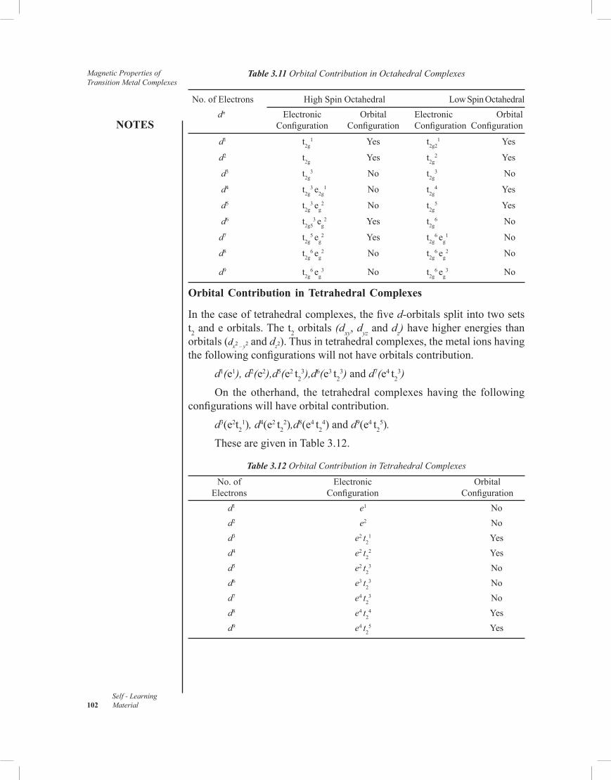
Magnetic Properties of Transition Metal Complexes
NOTES
Self - Learning 102 Material
Table 3.11 Orbital Contribution in Octahedral Complexes
No. of Electrons High Spin Octahedral Low Spin Octahedral dn Electronic Orbital Electronic Orbital Configuration Configuration Configuration Configuration
d1 t2g1 Yes t2g2
1 Yes
d2 t2g Yes t2g2 Yes
d3 t2g3 No t2g
3 No
d4 t2g3 e2g
1 No t2g4 Yes
d5 t2g3 eg
2 No t2g5 Yes
d6 t2g53 eg
2 Yes t2g6 No
d7 t2g5 eg
2 Yes t2g6 eg
1 No
d8 t2g6 eg
2 No t2g6 eg
2 No
d9 t2g6 eg
3 No t2g6 eg
3 No
Orbital Contribution in Tetrahedral Complexes
In the case of tetrahedral complexes, the five d-orbitals split into two sets t2 and e orbitals. The t2 orbitals (dxy, dyz and dz) have higher energies than orbitals (dx2 – y2 and dz2). Thus in tetrahedral complexes, the metal ions having the following configurations will not have orbitals contribution.
d1(e1), d2(e2),d5(e2 t23),d6(e3 t2
3) and d7(e4 t23)
On the otherhand, the tetrahedral complexes having the following configurations will have orbital contribution.
d3(e2t21), d4(e2 t2
2),d8(e4 t24) and d9(e4 t2
5).
These are given in Table 3.12.
Table 3.12 Orbital Contribution in Tetrahedral Complexes
No. of Electronic Orbital Electrons Configuration Configuration d1 e1 No d2 e2 No d3 e2 t2
1 Yes d4 e2 t2
2 Yes d5 e2 t2
3 No d6 e3 t2
3 No d7 e4 t2
3 No d8 e4 t2
4 Yes d9 e4 t2
5 Yes

NOTES
Self - LearningMaterial 103
Magnetic Properties of Transition Metal Complexes3.8 APPLICATIONS OF MAGNETIC MOMENT
FOR 3d-METAL COMPLEXES
The magnetic moments of the compounds of first transition series in common oxidation states are given in Table 3.13. Magnetic moments due to spin only (µs) as well as magnetic moments due to Spin and Orbital Contributions (µS+L) are also given:
Table 3.13 Magnetic Moments of Metal Ions of First Transition Series
It is observed that the magnetic moments of compounds of first half of transition series are fairly close to their calculated spin only magnetic moments and are quite different from the calculated magnetic moments based upon spin and orbital contributions. However, in the later half of the compounds of first transition series the observed values are slightly higher than the calculated spin only values. So, in the first transition series, orbital contritution to the magnetic moments is negligible. Important features of some complexes first transition series with different dn configurations are discussed below :
(i) d1 System : Titanium (III) octahedral complexes having t2g1
configuration such as [Ti (H2O)6]3+ are coloured and paramagnetic.
These have magnetic moment of 1.8 B.M. at room temperature. This value is higher than the expected spin only value of 1.73 B.M. and is attributed to the partially quenched orbital contribution.
(ii) d2 System : The metals ions having d2 system with t2g2 configuration
such as V (III) octahedral complexes are also expected to have some orbital contribution to magnetic moment. However, the observed magnetic moment values of V(III) octahedral complexes are in the range of 2.7 to 2.8 B.M. and are even less than the expected spin only value of 2.84 B.M. This observation is not easy to explain and is

Magnetic Properties of Transition Metal Complexes
NOTES
Self - Learning 104 Material
attributed to the presence of some distortions which split the ground state term t2g .
(iii) d3 System : Chromium (III) octahedral complexes are most extensively studied compounds in this category. The observed magnetic moment values at room temperature lie in the range 3.70 to 3.84 B.M. The magnetic moment arising from spin only value of 3.87 B.M. agrees fairly well with the observed values and is independent of temperature. However, the reduced values of magnetic moment are observed in some bridged complexes such as [(NH3)5 Cr (µ—OH) Cr(NH3)5] X5 (Where X = Cl or Br) and [(NH3)5 Cr–O–Cr(NH3)5]
4+ are temperature dependent.
(iv) d4 System : Chromium (II) octahedral complexes have d4 or t2g3 eg
1 configurations. The complex [Cr(SO4)2]
2+ has magnetic moment of 4.90 B.M. which agrees with the spin-only value. Low spin octahedral complex like K4[Cr(CN)6]. 3H2O having the configuration t2g
4 shows the magnetic moment in the expected range of 2.74 to 2.84 B.M. (spin only with partial orbital contribution). However, Chromium (II) acetate dihydrate, Cr2 (CH3COO)4 2H2O is one of the most stable chromium compounds and is Diamagnetic. This suggests that all the four unpaired electrons take part in Cr-Cr bonding in the form of quadruple Cr ≡ Cr bond, thereby leaving no unpaired d-electron on Cr-atoms.
(v) d5 System : Octahedral complexes of Mn (II) and Fe(III) with t2g3 eg
2 configuration belong to this configuration. These are high spin complexes and show magnetic moments in the expected range of spin only value of 5.92 B.M. However, some oxo bridged species of Fe(II) like those of Cr(III) show values lower than 5.92 B.M. This is explained due to the antiferromagnetic interactions between the electron spins of two metal ions transmitted across Fe-O-Fe Bridge.
(vi) d6 System : This system includes Iron (III) octahedral complexes of high spin having the configuration t2g
4 eg2. It has 4 unpaired electrons
and has magnetic moment of around 5.5 B.M. which agrees well with orbital contribution to spin only value of 4.9 B.M. Some distortions produced values in the range of 5.2 to 5.4 B.M. However, low spin Fe(II) complexes having the configuartion t2g
6 are diamagnetic. Most of the Cobalt (II) Complexes of t2g
6 configuration show diamagnetism. However, octahedral complexes, such as K3[CoF6] are high spin having the configuration t2g
4 eg2 and having the magnetic
moment equal to 5.8 B.M. This explained in terms of spin only value having some orbital contribution.
(vii) d7 System : Cobalt (II) having d7 system forms a number of complexes which are less stable than those of Co(III). These complexes may be tetrahedral or octahedral. Most cobalt (II) complexes are high spin but CN– produces low spin complexes. A low spin octahedral complex will have the configuration t2g
6 eg1 The magnetic moments of tetrahedral

NOTES
Self - LearningMaterial 105
Magnetic Properties of Transition Metal Complexes
Cobalt (II) having configuration e4 t23 lie in the range of 4.4 to 4.8 B.M.
at room temperature. The spin only magnetic moment value is 3.87 B.M.
(viii) d8 System : Nickel (II) d8 octahedral complexes, such as [Ni(H2O6)]2+
with t2g6 eg
2 configuration have magnetic moment of 3.2 B.M. at room temperature. This is explained on the basis of spin-orbital complexes. Similarly, the [Ni(acac)2] Complex is octahedral and shows a normal magnetic moment of 3.2 B.M. like other Ni (II) complexes. However, it shows normal magnetic moment down to about 80K but below this temperature, the magnetic moment increases from 3.2 B.M. to 4.1 B.M. at 4.3 K. This is attributed to ferromagnetic coupling.
Check Your Progress
12. Explain L-S coupling giving formula. 13. What is total angular momentum? 14. Explain the terms principal quantum number and angular quantum
number. 15. What is Hund’s rule? 16. When the transition metal ion having 3d orbitals degenerated? 17. Explain the orbital configuration in tetrahedral complexex.
3.9 ANSWERS TO ‘CHECK YOUR PROGRESS’
1. In chemistry, the term transition metal or transition element has following the three possible definitions. Definition 1: The IUPAC definition defines a transition metal as, “An element whose atom has a partially filled d sub-shell, or which can give rise to cations with an incomplete d sub-shell”. Definition 2: Many scientists describe a ‘Transition Metal’ as any element in the d-block of the periodic table, which includes Groups 3 to 12 on the periodic table. In actual practice, the f-block lanthanide and actinide series are also considered transition metals and are called ‘Inner Transition Metals’.
2. Magnetism is a class of physical phenomena that are mediated by magnetic fields. Electric currents and the magnetic moments of elementary particles give rise to a magnetic field, which acts on other currents and magnetic moments. Magnetism is one aspect of the combined phenomenon of electromagnetism.
3. Diamagnetism is a universal property of chemical compounds, because all chemical compounds contain electron pairs. A compound in which there are no unpaired electrons is said to be diamagnetic. The effect is weak because it depends on the magnitude of the induced magnetic moment.

Magnetic Properties of Transition Metal Complexes
NOTES
Self - Learning 106 Material
4. In 1845 Faraday classified the substances as diamagnetic and paramagnetic. Later on these terms were related with electronic structure. The substances, which have paired electrons, are known as diamagnetic and which have one or more unpaired electron(s) are known as paramagnetic. The paramagnetic effect is observed only in the presence of an external field. When the field is removed, the substance has no overall moment.
5. Magnetic measurements tell us whether the complex is a High-Spin or Low-Spin complex. These terms may be distinguished very easily by magnetic susceptibility measurements. According to Ligand Field Theory (LFT), these two spin configurations in octahedral complexes can be explained by relative magnitude of D0 and pairing energy (P). For High-Spin complexes D0 < P and for Low-Spin complexes D0 > P. The complexes for which, the differences between D0 and P in very small, are called intermediate field situation.
6. The ‘Ferrimagnetism’ is a permanent magnetism in which the magnetic fields associated with individual atoms spontaneously align themselves, some parallel, or in the same direction (as in Ferromagnetism) and others antiparallel, or paired off in opposite direction as in Antiferromagnetism.
Most of the ferrimagnetic materials consist of cations of two or more types, sub-lattices contain two different types of ions with different magnetic moment for two types of atoms and as a result, net magnetization is not equal to zero. For example, cubic spinel ferrites, such as Ni Fe2 O4, Co Fe2 O4, Fe3O4, CuFe2O4, etc. Other examples are hexagonal ferrites, like BaFe12O19, garnets, such as Y3Fe5O12, etc.
7. The magnetic moment of a material is a measure of the material’s tendency to align with a magnetic field. It determines the force that the magnet can exert on an electric currents and the torque that a magnetic field will exert on it. Magnetic moment has contributions from spin and orbital angular momentum.
8. The magnetic properties of a substance are consequence of magnetic moment associeated with individual electrons. The electron creates magnetic moment in the following two ways:
(i) An electron can be treated as a small negative charge spinning on its axis. The spinning of charge produces magnetic moment.
(ii) An electron moving in a closed path around a nucleus also produces magnetic moment like an electric current flowing in a circular loop of wire.
9. Magnetic moment of a substance cannot be measured directly, first magnetic susceptibility (χ) is measured.
Magnetic Susceptibility (χ) is a measure of the capacity of a substance to take up magnetisation in an applied magnetic field. If a substance is placed in a magnetic field of strength H, then magnetic induction or magnetic flux density, B, within it is given by,

NOTES
Self - LearningMaterial 107
Magnetic Properties of Transition Metal Complexes
B = H – 4 π I
I =
=
Where, a = Area of crossection of the magnetic substance
2l = Length of the substance
10. Gouys’s Method: This method was devised by French Scientist Gouy in 1889. It is one of the methods for the measurement of magnetic susceptibility of various substances.
‘The principle of this method is based on the fact that the magnetic field exerted on the sample when placed in the magnetic field varies directly as its mass (i.e., the difference in the masses when the field is switched OFF and ON)’.
11. Curie’s balance is a simple and useful magnetic balance, devise by Curie in 1895. It is used to study the variation of magnetic susceptibility with temperature, giving a clear distinction between para-, di-and ferromagnetic substances.
According to the principle of Curie’s balance, if a specimen is kept in a non-uniform magnetic field, a force is exerted on the specimen giving it a displacement which is measured in terms of torque requirement to bring the specimen back to the original position.
12. L–S coupling scheme is applicable to systems in which spin orbital interactions are relatively small. In this scheme, the individual orbital angular momentum of the electron couple to give a resultant angular momentum respresented by the quantum number, L for the state.The individual electron spin momentum a also couple (Interact) to give a resultant spin momentum described by the quantum number, S. The L and S values together determine the total angular momentum, J which can take quantized positive values ranging from |L–S| to |L+S|. | | indicates the absolute value of |L–S| and no regard is paid to its sign, so that J is always > 0. Thus, the range for J can be written as,
J = |L–S|, |L+S–1| |........| |L–S|. 13. The magnetic effects of resultant angular momentum, L and the resultant
spin moment S couple together to give new quantum number J called the total angular momentum.
14. Quincke’s Method: This method is given by G. Quincke in 1885 and strictly suitable for liquids, aqueous solutions and with some modifications for gases.

Magnetic Properties of Transition Metal Complexes
NOTES
Self - Learning 108 Material
Principal Quantum Number, n: It determines the main energy level or shell in which the electron is present. It can have whole number values as :
n = 1, 2, 3, 4................ Angular Quantum Number, l: It is related to the angular momentum
of the electron. In multi-electron atoms (an atom having a number of electrons) the energy besides depending upon n, also depends on l. Corresponding to each value of n, there are n possible values of l as :
l = 0, 1, 2, 3 ........... (n–1) 15. Hund’s Rule: When several orbitals of the same energy are available
(Degenerate Orbitals) the electrons tend to remain unpaired as far as possible, i.e., the electrons tend to retain parallel spin as much as possible, on energy consideration.
16. A transition metal ion has five 3d Orbitals which are degenerated. An electron possesses an angular momentum along a given axis if it is possible to transform its orbital by rotation around this axis into another orbital which is equivalent to it in shape, size and energy. This circulation of electron is equivalent to a current flowing and therefore, it produces a magnetic effect.
17. In the case of tetrahedral complexes, the five d-orbitals split into two sets t2 and eg orbitals. The t2 orbitals (dxy, dyz and dz) have higher energies than orbitals (dx2 – y2 and dz2). Thus in tetrahedral complexes, the metal ions having the following configurations will not have orbitals contribution. d1(e1), d2(e2),d5(e2 t2
3),d6(e3 t23) and d7(e4 t2
3) On the otherhand, the tetrahedral complexes having the following
configurations will have orbital contribution. d3(e2t2
1), d4(e2 t22),d8(e4 t2
4) and d9(e4 t25).
3.10 SUMMARY
• The IUPAC definition defines a transition metal as, “An element whose atom has a partially filled d sub-shell, or which can give rise to cations with an incomplete d sub-shell”.
• Many scientists describe a ‘Transition Metal’ as any element in the d-block of the periodic table, which includes Groups 3 to 12 on the periodic table. In actual practice, the f-block lanthanide and actinide series are also considered transition metals and are called ‘Inner Transition Metals’.
• Cotton and Wilkinson expanded the IUPAC definition by specifying which elements are included. As well as the elements of Groups 4 to 11, they add scandium and yttrium in Group 3, which have a partially

NOTES
Self - LearningMaterial 109
Magnetic Properties of Transition Metal Complexes
filled d sub-shell in the metallic state. Lanthanum and actinium in Group 3 are, however, classified as lanthanides and actinides, respectively.
• Magnetism is a class of physical phenomena that are mediated by magnetic fields. Electric currents and the magnetic moments of elementary particles give rise to a magnetic field, which acts on other currents and magnetic moments. Magnetism is one aspect of the combined phenomenon of electromagnetism.
• The prefix ‘ferro-’ refers to iron, because permanent magnetism was first observed in lodestone, a form of natural iron ore called magnetite, Fe3O4.
• Diamagnetism is a universal property of chemical compounds, because all chemical compounds contain electron pairs. A compound in which there are no unpaired electrons is said to be diamagnetic. The effect is weak because it depends on the magnitude of the induced magnetic moment.
• The effective magnetic moment for a compound containing a transition metal ion with one or more unpaired electrons depends on the total orbital and spin angular momentum of the unpaired electrons.
• Due to the Pauli Exclusion Principle, each state is occupied by electrons of opposing spins, so that the charge density is compensated everywhere and the spin degree of freedom is trivial. Still, such materials typically do show a weak magnetic behaviour, for example due to Pauli paramagnetism or Langevin or Landau diamagnetism.
• The magnetic properties of a compound can be determined from its electron configuration and the size of its atoms. Because magnetism is generated by electronic spin, the number of unpaired electrons in a specific compound indicates how magnetic the compound is.
• The paramagnetism is due to the unpaired electrons in a compound. The compound will be moderately attracted by the external magnetic fields. The dipoles will not be aligned uniformly but at random in the absence of external fields.
• In ferromagnetic compound, the magnetic dipoles are arranged in a parallel manner even in the absence of magnetic field. Hence, these compounds will be magnetic even in the absence of external magnetic field. These compounds are strongly attracted by external magnetic fields.
• In the case of antiferromagnetism, the magnetic dipoles are arranged in antiparallel method. These compounds are weakly attracted by external fields.
• Magnetic properties are useful in deciding the oxidation state, electronic configuration and coordination number of the central metal atom or ion.
• In 1845 Faraday classified the substances as diamagnetic and paramagnetic. Later on these terms were related with electronic

Magnetic Properties of Transition Metal Complexes
NOTES
Self - Learning 110 Material
structure. The substances, which have paired electrons, are known as diamagnetic and which have one or more unpaired electron(s) are known as paramagnetic. The paramagnetic effect is observed only in the presence of an external field. When the field is removed, the substance has no overall moment.
• Magnetic measurements tell us whether the complex is a High-Spin or Low-Spin complex. These terms may be distinguished very easily by magnetic susceptibility measurements. According to Ligand Field Theory (LFT), these two spin configurations in octahedral complexes can be explained by relative magnitude of D0 and pairing energy (P). For High-Spin complexes D0 < P and for Low-Spin complexes D0 > P. The complexes for which, the differences between D0 and P in very small, are called intermediate field situation.
• The temperature below which magnetic exchange dominates is called Curie Temperature (TC) if the type of exchange displayed is Ferromagnetic and the Nèel Temperature (TN) if it is Antiferromagnetic.
• The ‘Ferrimagnetism’ is a permanent magnetism in which the magnetic fields associated with individual atoms spontaneously align themselves, some parallel, or in the same direction (as in ferromagnetism) and others antiparallel, or paired off in opposite direction as in antiferromagnetism.
• The magnetic moment of a material is a measure of the material’s tendency to align with a magnetic field. It determines the force that the magnet can exert on an electric currents and the torque that a magnetic field will exert on it. Magnetic moment has contributions from spin and orbital angular momentum.
• When the Curie law is obeyed, the product of molar susceptibility and temperature is a constant. The effective magnetic moment, µeff is then defined as,
• The magnetic properties of a substance are consequence of magnetic
moment associeated with individual electrons. The electron creates magnetic moment in the following two ways:
(i) An electron can be treated as a small negative charge spinning on its axis. The spinning of charge produces magnetic moment.
(ii) An electron moving in a closed path around a nucleus also produces magnetic moment like an electric current flowing in a circular loop of wire.
• Magnetic moment of a substance cannot be measured directly, first magnetic susceptibility (χ) is measured.
• Paramagnetic substances have the flux that is greater within the substance than it would be in vacuum and thus paramagnetic substances have positive susceptibilities.

NOTES
Self - LearningMaterial 111
Magnetic Properties of Transition Metal Complexes
• Gouys’s Method: This method was devised by French Scientist Gouy in 1889. It is one of the methods for the measurement of magnetic susceptibility of various substances.
‘The principle of this method is based on the fact that the magnetic field exerted on the sample when placed in the magnetic field varies directly as its mass (i.e., the difference in the masses when the field is switched OFF and ON)’.
• In 1923, Bhatnagar and Mathur modified the Gouy balance in such a way that it could be used for the measurement of susceptibilities of liquids.
The basic principle in the method is that the forces acting on the sample varies directly proportional to the magnetic pull producing a displacement of the pointer when the magnetic current is started.
• Quincke’s Method : This method is given by G. Quincke in 1885 and strictly suitable for liquids, aqueous solutions and with some modifications for gases.
Principle : The principle of this method is the same as that employed in Gouy’s method except that the force acting on the liquid sample is measured in terms of the hydrostatic pressure developed when the liquid is placed in a capillary tube so that the meniscus stands in a strong and uniform field. When field is applied, the meniscus will fall if the liquid is diamagnetic or will rise if the liquid is paramagnetic.
• NMR spectrometer can be used to measure the magnetic susceptibility. This approach was developed by Dennis Evans in 1959. This method is simple and is based on the effect a paramagnet in solution has on the chemical shift of a reference compound, usually the solvent.
• Data collection is done on an NMR spectrometer, the data is easy to interpret, and sample preparation is straight forward and requires tittle material. It has become the standard method for determining magnetic susceptibility data for inorganic complexes.
• L–S coupling scheme is applicable to systems in which spin orbital interactions are relatively small. In this scheme, the individual orbital angular momentum of the electron couple to give a resultant angular momentum respresented by the quantum number, L for the state.
• The magnetic effects of resultant angular momentum, L and the resultant spin moment S couple together to give new quantum number J called the total angular momentum.
• Principal Quantum Number, n: It determines the main energy level or shell in which the electron is present. It can have whole number values as :
n = 1, 2, 3, 4................

Magnetic Properties of Transition Metal Complexes
NOTES
Self - Learning 112 Material
Angular Quantum Number, l: It is related to the angular momentum of the electron. In multi-electron atoms (an atom having a number of electrons) the energy besides depending upon n, also depends on l. Corresponding to each value of n, there are n possible values of l as :
l = 0, 1, 2, 3 ........... (n–1) • Hund’s Rule: When several orbitals of the same energy are available
(Degenerate Orbitals) the electrons tend to remain unpaired as far as possible, i.e., the electrons tend to retain parallel spin as much as possible, on energy consideration.
• A transition metal ion has five 3d Orbitals which are degenerated. An electron possesses an angular momentum along a given axis if it is possible to transform its orbital by rotation around this axis into another orbital which is equivalent to it in shape, size and energy. This circulation of electron is equivalent to a current flowing and therefore, it produces a magnetic effect.
• The orbital angular momentum along the given axis possessed by the electron in such an orbital is equal to the mumber of times the orbitals gets transformed into the equivalent orbital during at rotation of 90° around that axis. If the orbital degeneracy is lost by chemical bonding or crystal field effects, the orbital contribution to the total magnetic moment is partially or completely quenched.
• In octahedral complexes, the five d-orbitals get split into two sets, t2g (dxy, dyz, dzx) and (dx2–y2, dz2). Therefore, the equivalence of dx2–y2 and dxy orbitals disappears and consequently, their orbital contribution gets quenched. However, there will be some contribution of orbital angular momentum along z– direction because dxz and dyz orbitals are still degenerate in octahedral field.
3.11 KEY TERMS
• Diamagnetism: This arrives due to paired electrons when all the electrons in a molecule are paired. It is called a diamagnetic compound. The compound will be slightly repelled by the external magnetic field.
• Paramagnetism: The paramagnetism is due to the unpaired electrons in a compound. The compound will be moderately attracted by the external magnetic fields. The dipoles will not be aligned uniformly but at random in the absence of external fields.
• Ferromagnetism: In ferromagnetic compound, the magnetic dipoles are arranged in a parallel manner even in the absence of magnetic field. Hence, these compounds will be magnetic even in the absence of external magnetic field. These compounds are strongly attracted by external magnetic fields.

NOTES
Self - LearningMaterial 113
Magnetic Properties of Transition Metal Complexes
• Antiferromagnetism: In the case of antiferromagnetism, the magnetic dipoles are arranged in antiparallel method. These compounds are weakly attracted by external fields.
• Ferrimagnetism: It is a permanent magnetism in which the magnetic fields associated with individual atoms spontaneously align themselves, some parallel, or in the same direction (as in ferromagnetism) and others antiparallel, or paired off in opposite direction as in antiferromagnetism.
• Effective Magnetic Moment (µeff): The magnetic moment of a material is a measure of the material’s tendency to align with a magnetic field. It determines the force that the magnet can exert on an electric currents and the torque that a magnetic field will exert on it. Magnetic moment has contributions from spin and orbital angular momentum.
• Gouys’s method: This method was devised by French Scientist Gouy in 1889. It is one of the methods for the measurement of magnetic susceptibility of various substances.
‘The principle of this method is based on the fact that the magnetic field exerted on the sample when placed in the magnetic field varies directly as its mass (i.e., the difference in the masses when the field is switched OFF and ON)’.
• Quincke’s Method : This method is given by G. Quincke in 1885 and strictly suitable for liquids, aqueous solutions and with some modifications for gases.
• Principal Quantum Number, n: It determines the main energy level or shell in which the electron is present. It can have whole number values as :
n = 1, 2, 3, 4................ • Angular Quantum Number, l: It is related to the angular momentum
of the electron. In multi-electron atoms (an atom having a number of electrons) the energy besides depending upon n, also depends on l. Corresponding to each value of n, there are n possible values of l as :
l = 0, 1, 2, 3 ........... (n–1) • Hund’s Rule: When several orbitals of the same energy are available
(Degenerate Orbitals) the electrons tend to remain unpaired as far as possible, i.e., the electrons tend to retain parallel spin as much as possible, on energy consideration.
3.12 SELF-ASSESSMENT QUESTIONS AND EXERCISES
Short-Answer Questions
1. Explain the significance of magnetic properties of transition metal complexes.

Magnetic Properties of Transition Metal Complexes
NOTES
Self - Learning 114 Material
2. What are the types of magnetic behaviour of metals? 3. Explain the terms diamagnetism, paramagnetism, ferromagnetism,
antiferromagnetism and ferrimagnetism. 4. How the magnetism is calculated? 5. How the magnetic susceptibility is determined? 6. What is Gouy’s method? 7. Define Bhatnagar Mathur method. 8. What does Quincke’s method state? 9. Explain the method defined by Curie. 10. What is Nuclear Magnetic Resonance (NMR) method? 11. What is magnetic moment? 12. Define L-S coupling. 13. Explain the terms ground state and term symbol. 14. What are µs and µeff values? 15. State the orbital contribution for magnetic moments. 16. Explain about the applications of magnetic moment data for 3d-metal
complexes.
Long-Answer Questions
1. Discuss briefly about the magnetic properties of transition metal complexes giving appropriate examples.
2. Elaborate briefly on the types of magnetic behaviour with reference to diamagnetism, paramagnetism, ferromagnetism, antiferromagnetism, and ferrimagnetism.
3. Briefly discuss about the origin of magnetism giving examples. 4. Discuss the method of calculation of magnetism giving examples. 5. Explain the methods of determining magnetic susceptibility with
reference to Gouy’s, Bhatnagar Mathur, Quincke’s, Curie and Nuclear Magnetic Resonance (NMR) method.
6. Explain the apparatus and methods of Gouy’s, Bhatnagar Mathur, Quincke’s, Curie and Nuclear Magnetic Resonance (NMR) method with the help of diagrams.
7. Briefly explain the concept of magnetic moment giving asppropriate examples.
8. Discuss the significance of L-S coupling in determining magnetic moment.
9. How is ground state determined? Discuss the role of ground state giving examples.
10. Briefly explain the concept of term symbol giving examples. 11. What are correlation of µs and µeff values? How it is calculated? Explain
giving examples.

NOTES
Self - LearningMaterial 115
Magnetic Properties of Transition Metal Complexes
12. Explain briefly the concept of orbital contribution for magnetic moments giving appropriate examples.
13. Discuss the role and applications of magnetic moment data for 3d-metal complexes.
3.13 FURTHER READING
Emeleus, H. J. and A. G. Sharpe. 1989. Modern Aspects of Inorganic Chemistry. New York: John Wiley & Sons.
Huheey, J. E., E. A. Keiter and R.L. Keiter. 2002. Inorganic Chemistry: Principles of Structure and Reactivity, 4th Edition. New York: HarperCollins Publishers.
Cotton, F. A. and G. Wilkinson. 1988. Advanced Inorganic Chemistry, 5th Edition. New Jersey: Wiley Eastern.
Adams, D. M. 1974. Inorganic Solids. New York: John Wiley & Sons.Dasmohapatra, Dr Gourkrishna. 2011. Engineering Chemistry. New Delhi:
Vikas Publishing House Pvt. Ltd.Rajaram, J. and J.C. Kuriacose. 1986. Thermodynamics for Students of
Chemistry. New Delhi: Lal Nagin Chand.Rajaram , J. and J.C. Kuriacose. 1993. Kinetics and Mechanism of Chemical
Transformations. New Delhi: MacMillan India Ltd.Hanna, M.W. 1965. Quantum Mechanics in Chemistry. London: W.A.
Benjamin Inc.Rohatgi-Mukherjee, K.K. 2008. Fundamentals of Photochemistry. New
Delhi: New Age International (P) Ltd. Billmeyer Jr., F.W. 2003. Text Book of Polymer Science, 3rd Edition. New
York: John Wiley & Sons, Inc.Cotton, F. Albert, Geoffrey Wilkinson, Carlos A. Murillo and Manfred
Bochmann. 1999. Advanced Inorganic Chemistry, 6th Edition. New York: John Wiley & Sons, Inc.
Lee, J. D. 2008. Concise Inorganic Chemistry, 5th Edition. UK: Oxford University Press.
Sharma, K. K. and L. K. Sharma. 2012. A Textbook of Physical Chemistry, 5th Edition. Noida: Vikas Publishing House Pvt. Ltd.

Electronic Spectra ofTransition Metal Complexes
and OrganometallicChemistry
NOTES
Self - LearningMaterial 117
UNIT 4 ELECTRONIC SPECTRA OFTRANSITION METALCOMPLEXES ANDORGANOMETALLICCHEMISTRY
Structure
4.0 Introduction4.1 Objectives4.2 Introduction to Electronic Spectra of Transition Metal Complexes4.3 Types of Transitions
4.3.1 Selection Rules for Electronic Transitions4.4 Spectroscopic Ground States
4.4.1 Spectroscopic Methods4.4.2 Splitting of Russel Saunder's States in Octaheredral and Tetrahedral
Crystal Fields4.4.3 Spectrochemical Series
4.5 Orgel Energy Level Diagrams4.5.1 Tetrahedral Complexes of Metal Ions with d1 and d9 Configuration4.5.2 Spectra of Octahedral Complexes of Metal Ions with d1 Configuration
4.6 Nomenclature and Classification of Organometallic Compounds4.7 General Methods of Preparation4.8 Alkyl and Aryl Organometallic Compounds of Lithium4.9 Organoaluminium Compounds
4.10 Answers to ‘Check Your Progress’4.11 Summary4.12 Key Terms4.13 Self-Assessment Questions and Exercises4.14 Further Reading
4.0 INTRODUCTION
Molecular electronic transitions take place when electrons in a molecule are excitedfrom one energy level to a higher energy level. The energy change associated withthis transition provides information on the structure of a molecule and determinesmany molecular properties, such as colour. The relationship between the energyinvolved in the electronic transition and the frequency of radiation is given by Planck’srelation.
Ligand Field Theory (LFT) describes the bonding, orbital arrangement,and other characteristics of coordination complexes. It represents an applicationof molecular orbital theory to transition metal complexes. A transition metal ionhas nine valence atomic orbitals consisting of five nd, one (n+1)s, and three (n+1)porbitals. These orbitals are of appropriate energy to form bonding interaction withligands. The LFT analysis is highly dependent on the geometry of the complex, but

NOTES
Self - Learning118 Material
Electronic Spectra ofTransition Metal Complexesand OrganometallicChemistry
most explanations begin by describing octahedral complexes, where six ligandscoordinate to the metal. Other complexes can be described by reference to CrystalField Theory (CFT).
In an octahedral complex, the molecular orbitals created by coordinationcan be seen as resulting from the donation of two electrons by each of six-donor ligands to the d-orbitals on the metal. The bonding in octahedral complexesoccurs in two ways, via any ligand p-orbitals that are not being used in bonding,and via any or * molecular orbitals present on the ligand. One significant bonding in coordination complexes is metal-to-ligand bonding, also called backbonding. It occurs when the LUMOs (Lowest Unoccupied MolecularOrbitals) of the ligand are anti-bonding * orbitals. The other form of coordination bonding is ligand-to-metal bonding. This situation arises when the -symmetry por orbitals on the ligands are filled.
The greater stabilization that results from metal-to-ligand bonding is causedby the donation of negative charge away from the metal ion, towards the ligands.This allows the metal to accept the bonds more easily. The combination ofligand-to-metal -bonding and metal-to-ligand -bonding is a synergic effect, aseach enhances the other.
The emission spectrum of a chemical element or chemical compound is thespectrum of frequencies of electromagnetic radiation emitted due to an atom ormolecule making a transition from a high energy state to a lower energy state. Thephoton energy of the emitted photon is equal to the energy difference between thetwo states. There are many possible electron transitions for each atom, and eachtransition has a specific energy difference. Each element’s emission spectrum is unique.
Spectra are broadly classified into two groups as emission spectra andabsorption spectra. Emission spectra are of three types, namely continuous spectra,band spectra and line spectra. Solids like iron or carbon emit continuous spectrawhen they are heated until they glow. Continuous spectrum is due to the thermalexcitation of the molecules of the substance. The band spectrum consists of anumber of bands of different colours separated by dark regions. A line spectrumconsists of bright lines in different regions of the visible spectrum against a darkbackground. All the lines do not have the same intensity. Line spectra are emittedby vapours of elements. No two elements do ever produce similar line spectra.
When a substance is placed between a light source and a spectrometer, thesubstance absorbs certain part of the spectrum. This spectrum is called theabsorption spectrum of the substance. Electronic absorption spectrum is of twotypes, d-d spectrum and charge transfer spectrum. The d-d spectrum deals withthe electronic transitions within the d-orbitals. In the charge transfer spectrum,electronic transitions occur from metal to ligand or vice-versa.
Organometallic chemistry is the study of organometallic compounds,chemical compounds containing at least one chemical bond between a carbonatom of an organic molecule and a metal, including alkaline, alkaline earth, andtransition metals, and sometimes broadened to include metalloids like boron, silicon,and tin, as well. Some related compounds, such as transition metal hydrides and

Electronic Spectra ofTransition Metal Complexes
and OrganometallicChemistry
NOTES
Self - LearningMaterial 119
metal phosphine complexes are often included in discussions of organometalliccompounds, though strictly speaking, they are not necessarily organometallic.
Organometallic compounds are distinguished by the prefix ‘Organo-’, suchas organopalladium compounds. Examples of such organometallic compoundsinclude all Gilman reagents, which contain lithium and copper. Tetracarbonyl nickel,and ferrocene are examples of organometallic compounds containing transitionmetals. Other examples include organomagnesium compounds likeiodo(methyl)magnesium MeMgI, dimethylmagnesium (Me
2Mg), and all Grignard
reagents; organolithium compounds, such as n-butyllithium (n-BuLi), organozinccompounds, such as diethylzinc (Et
2Zn) and chloro(ethoxycarbonylmethyl)zinc
(ClZnCH2C(=O)OEt); and organocopper compounds, such as lithium
dimethylcuprate (Li+[CuMe2]”).
In this unit, you will study about the electronic spectra of transition metalcomplexes, types of electronic transition, selection rules for d-d transition,spectroscopic ground states in complexes, spectrochemical series, Orgel energylevel diagram for octahedral and tetrahedral complexes having d1 To d9 states,electronic spectrum of [Ti(H
2O)
6]3+ complex ion, organometallic chemistry,
nomenclature and classification of organometallic compounds, bond nature, generalmethods of preparation and applications, alkyl and aryl organometallic compoundsof lithium, and organometallic compounds of Al applications.
4.1 OBJECTIVES
After going through this unit, you will be able to:
Discuss the electronic spectra of transition metal complexes
Explain the types of electronic transition
State the selection rules for d-d transition
Elaborate on the notations and the spectroscopic ground states in complexes
Understand what spectrochemical series are
Analyse the Orgel energy level diagrams for octahedral and tetrahedralcomplexes having d1 To d9 states
Define the electronic spectrum of [Ti(H2O)
6]3+ complex ion
Describe the significance of organometallic chemistry
Understand the method of nomenclature and classification of organometalliccompounds
Specify the bond nature of organometallic compounds
Explain the general methods of preparation and applications oforganometallic compounds
Discuss about the alkyl and aryl organometallic compounds of lithium
Analyse the organometallic compounds of Al applications

NOTES
Self - Learning120 Material
Electronic Spectra ofTransition Metal Complexesand OrganometallicChemistry
4.2 INTRODUCTION TO ELECTRONICSPECTRA OF TRANSITION METALCOMPLEXES
We know that many transition metal complexes exhibit colours of varying intensitythroughout a visible range. This characteristic feature of these complexes can beexplained by d-d transitions. So electronic spectra of these complexes help us tostudy structure and bonding in these compounds.
In tetrahedral complexes, the electrons get excited from lower set of dorbitals to higher set of d–orbitals when visible light is incident on them. As a resultof transition, some selected wavelength of visible light corresponding to energydifference between t
2g and e
g levels is absorbed. The transmitted light gives colour
to complexes. This is explained with the help of following equation:
The amount of energy absorbed is given as :
hcE hv
Where c in the velocity of light and h is Planck’s Constant. The extent ofintensity of absorption of light is given by Beer's-Lamber law, defined by theequation.
OIlog A Cl
I
Where, A= Absorbance
C = Molar Concentration of Absorbing Species
E = Molar Absorption Coefficient
I = Path Length through Solution (in cm)
A plot of molar absorptivity versus wavelength gives a spectrum characteristicof the molecule or ion. This spectrum provides valuable information about bondingand structure of the molecule or ion.

Electronic Spectra ofTransition Metal Complexes
and OrganometallicChemistry
NOTES
Self - LearningMaterial 121
The energy corresponding to ultraviolet and visible radiations may bring about thefollowing electronic excitations:
(i) Sigma bonding electrons to vacant sigma antibonding orbitals *( ) .
(ii) pi bonding electrons to vacant pi antibonding orbitals *( ) .
(iii) Nonbonding electrons to vacant sigma antibonding orbitals *( )n .
(iv) Nonbonding electrons to vacant pi antibonding orbitals *( )n .
The energy required for these transitions is in the order * > *n
> * > *n .
n
Fig. 14.1 Energy Levels and Electronic Transitions Possible in a Molecule
(i) * Transitions. The energy required for these transitions is highand lies in the vacuum ultraviolet region (below 210 nm). Consequently compoundsin which all valence shell electrons are involved in single bond formation such assaturated hydrocarbons do not show any absorption in ordinary ultraviolet region(i.e., 200–400 nm).
Methane shows an absorption band at 125 nm corresponding to * transition.
(ii) *n Transitions: The energy required to promote a nonbonding(unshared) electron to vacant sigma antibonding orbital is much less than that required
for *. Hence molecules having lone pair or nonbonding electrons tend toabsorb higher wavelength as compared to compounds having only sigma electrons.
Thus *n transitions in
3CH..OH occurs at 183 nm
3 2CH..NH occurs at 215 nm
3CH..I occurs at 258 nm
3 3(CH..
) N occurs at 227 nm

NOTES
Self - Learning122 Material
Electronic Spectra ofTransition Metal Complexesand OrganometallicChemistry
Polar solvents shift these *n transitions towards shorter wavelength(higher energy) because of some interaction of nonbonding electrons with thesolvent. The spectrum of tri-methylamine in aqueous acid shows no absorption
due to *n transition (at 227 nm) because in acid solution tri-methylaminegets protonated and there are no free nonbonding electrons.
(iii) Transitions: The excitation of bonding pi electrons to vacant
antibonding pi orbitals requires still lesser energy as compared to *n excitation. Hence these absorptions generally occur in common ultraviolet region.
* transitions in some common compounds are given below:
Ethylene 2 2(CH ==CH ) 170 nm
Acetone 3 3(CH CO.CH ) 180 nm
Acetylene (CH CH) 178 nm
Conjugation of bonds shifts the wavelength of maximum absorption tolonger wavelength. Thus 1,3 butadiene has a max at 217 nm.
Polar solvents further shift the wavelength of absorption to longer regions inconjugated systems.
(iv) *n Transitions. Such transitions are possible only in compoundshaving both the nonbonding (n) electrons as well as multiple bonds ( electrons)as they involve excitation of nonbonding electron to vacant antibonding pi orbital.These are generally the lowest energy transitions and occur at higher wavelengths.
* n transitions in some common compounds are given below:
Acetone (CH3COCH3) 280 nm
Acetaldehyde (CH3CHO) 292 nm
Benzaldehyde (C6H5CHO) 328 nm
Nitroethane (C2H5NO2) 271 nm
Here also the conjugation shifts the absorption to a higher wavelength. Thus
CH2==CH—CH==O absorbs at 320 nm but the polar solvents shift these * ntransitions to lower wavelength due to interaction between nonbonding electronswith polar solvents.
Thus * n transition of acetone in hexane occurs at 280 nm, in ethanol
at 270 nm and in water at 264 nm.
Molecules having , and n electrons may undergo all types of possibletransitions giving a number of absorption bands. The Table 4.1 gives some examplesof energy transitions.

Electronic Spectra ofTransition Metal Complexes
and OrganometallicChemistry
NOTES
Self - LearningMaterial 123
Table 4.1 Energy Transitions
Compound max max
CH3COCH3*n
166 nm 16,000
*
180 nm 10,000
*n
280 nm 20
CH3CHO *n
160 nm 20,000
*
194 nm 10,000
*n
292 nm 17
C6H5CHO *
244 nm 15,000
*
280 nm 1,500
*n
328 nm 20
C2H5NO2*
201 nm 5,000
*n
271 nm 19
The exact electronic structure of excited state is not well understood butthere is some kind of redistribution of electrons—not necessarily in accordancewith present valence rules. Absorbed energy is generally re-emitted as light.
Electronic spectra are obtained when electrons are excited from one energylevel (Ground State) to a higher every level (Excited State). These transitions areknown as electronic transitions. These are high energy processes and are alwaysaccompanied by lower energy vibrational and rotational transitions. The vibrationaland rotational energy levels are so close in energy that these cannot be resolvedinto separate absorption bands and they cause considerable broadening of electronicabsorption peaks in d-d spectra. The band widths are usually of the order of 1000to 3000 cm–1. The rules governing these transitions are called selection rules. If thetransition of electrons takes place according to set criteria, it is an allowedtransition, if it is not then, it is called a forbidden transition.

NOTES
Self - Learning124 Material
Electronic Spectra ofTransition Metal Complexesand OrganometallicChemistry
4.3 TYPES OF TRANSITIONS
Organic molecules exhibit n and n electronictransitions, where n and are –bonding, –bonding, non-bonding, antibonding and antibonding electrons, respectively. On the other hand,transition metal complexes exhibit following four types of transitions.
(i) d-d Transitions : These transition occur between t2g
and eg orbitals of the
central metal atom ion of the complexes. These are also known of ligandfield spectra. The bands are observed in UV, visible and near IR regions,i.e., from 333 to 1000 nm, E
max being in the range 1 to 50. The peaks are of
low intensity, the spliting of d-orbitals are shown in the Figure 4.2.
Fig. 4.2 Splitting of d-Orbitals in Various Fields
(ii) Metal to Ligand Charge Transfer Transitions : These transitions occurwhen electrons of central metal atom ion present in non-bonding orantibonding orbitals shifts to antibonding orbitals of the ligands. Thus itmeasure the tendency of the metal ion to reduce the ligand. Generally thesebands occur in the UV region for the metal ions in low oxidation states.These bands have much more intensity ( ε max 1000–10000) as comparedto d-d- transitions ( ε max1–50).
(iii) Ligand to Metal Charge Transfer Transitions : These transitions occurwhen the electrons transition takes place from a molecular orbital locatedprimarily on the ligand to a non-bonding or antibonding molecular orbitalsituated on the metal atom. These transitions show the tendency of theligands to reduce the metal ion. These transitions also occur in UV region.
The position of these bands [occur in (ii) and (iii) transitions] depend on thenature of metal and the ligand.
(iv) Inter-Ligand Transitions : These transitions occur when an electrontransition takes place from one ligand orbitals to another ligand orbitals.These bands occur in UV region and corresponds to and xxtransitions, thus can be readily separated from M-L charge transfer bands.These bands depend upon the M-L bond strength as well as by coordination.

Electronic Spectra ofTransition Metal Complexes
and OrganometallicChemistry
NOTES
Self - LearningMaterial 125
4.3.1 Selection Rules for Electronic Transitions
In order to use the correlation diagrams or simplifications of them, it is necessaryto know the selection rules that govern electronic transitions. These rules imposerestrictions on state changes available to an atom or molecule. Any transition inviolation of a selection rule is said to be forbidden. These rules are discussedbelow.
(1) Spin-Selection Rule : If there is a change in the number of unpairedelectrons is going from groundstate to the excited state, the transition isreferred to as spin or multiplicity forbidden. This means that transition toonly those excited state are considered which have the same spin multiplicityas the ground state. This is also known as S = 0 rule. For example, for ad2 configuration, the transition from 3f (Ground State) to 3p (Excited State)because both the 3f and 3p terms have same multiplicity 3. The transitions inwhich S 0 (, for example, S = +1) one forbidden or very-very weak.
(2) Laporte's Selection Rule : If the transition occurs within a set of p -or d-orbitals (i.e., a transition in which redistribution of electrons takes placewithin a particular orbital or there is no change is Azimuthal quantum number‘l’ it is called Laporte's forbidden transition. The molecule must havecentre of symmetry. According to this rule, transitions in the octahedralcomplexes are forbidden, therefore these are colourless.
This would suggest that transitions metals complexes should not give d-dtransitions and should not give colours. But actually it is not so. The transition dotake place with the help of slight relaxation in Laporte's rule. Consider some example,
(i) If the transition metal complex ion does not have perfect octahedral structure,but is slightly distorted so that the centre of symmetry is destroyed, thenmixing of d and p-orbitals of the metal ion may occur. In such a case, thetransitions are no more pure d-d transitions but they occur between d-levelswith varying amounts of p-character. The intensity of such transitions is veryweak in the range = 20 to 50. Thus, octahedral complexes in which all theligands are not same such as [Co(NH
3)
5Cl]2+ have irregular octahedral
structure and do not possess a centre of symmetry. d-d transitions withvarying amounts of p-character take place giving this compound a colour.
The tetrahedral complexes, such as [MnCl4]2–, [MnBr
4]2–, etc., also do not
possess a centre of symmetry because a tetrahedron shape never possessesa centre of symmetry. Thus, intense transition are observed in thesecomplexes which result in their deep colours. However, mixing of d and porbitals does not occur in perfectly octahedral complexes, which have acentre of symmetry, such as [Co(NH
3)
6]3+.
(ii) A complex which has a perfect octahedral structure can also exhibitabsorption spectrum because the bonds in the transition metal complexesare not rigid but undergo vibrations that may temporarily change the centreof symmetry. These vibrations continue all the time and at any particular

NOTES
Self - Learning126 Material
Electronic Spectra ofTransition Metal Complexesand OrganometallicChemistry
time some ligands may spend an appreciable amount of time out of thecentro symmetric equilibrium position. As a result, the molecule may possessdistorted octahedral symmetry so that small amount of mixing of d and p-orbitals occurs and therefore, low intensity (= 5 to 25) spectra areobserved. These transitions are called vibronically allowed transitionsand the effect is called vibronic coupling. For example, in [Mn(H
2O)
6]2+
complexes, all transitions are spin multiplicity forbidden and Laporteforbidden. But the complex ion is pale pink in colour. This is explained byvibronic coupling which results in very low intensity transitions.
In short Laporte allowed transition are very intense while Laporte forbiddentransitions vary from weak intensity, if the complex is non centro symmetric tovery weak if it is centro symmetric.
4.4 SPECTROSCOPIC GROUND STATES
The different terms in an atom as obtained above can be arranged in order ofenergy and ground state term is done on the basis of following rules :
(i) The terms are arranged on the basis of their spin multiplicities, i.e. their S-values. The most stable state has the highest S-value and stability decreaesas the value of S decreases. So, the most Stable State (Ground State) hasmaximum unpaired electrons.
(ii) For a given value of S, the state with the highest value of L is the most stablestate. It means that if two or more terms have the same value of S, the statewith highest value of L will have the lowest energy.
(iii) For terms having same S and L values, the term with smallest J value ismost stable if the subshell is more than half filled.
4.4.1 Spectroscopic Methods
The word spectroscopy is widely used to mean the separation, detection andrecording of energy changes (resonance peaks) involving nuclei, atoms ormolecules. These changes are due to the emission absorption or scattering ofelectromagnetic radiation or particles. Spectrometry is that branch of physicalscience that treats the measurement of spectra.
According to the quantum theory of matter, the internal energy of a moleculemay be raised by the absorption of a quantum of electromagnetic radiation if theenergy of the quantum exactly equals the difference E between two energylevels in the molecule, i.e.,
E = hv = hc
...(i)
Where h is the Planck’s constant, v is the frequency, is the wavelength ofthe electromagnetic radiation and c is the velocity of light in vacuum.
Molecules, like atoms, can exist in a number of states of differing energy andtransitions in between them result in the absorption or emission of energy in the

Electronic Spectra ofTransition Metal Complexes
and OrganometallicChemistry
NOTES
Self - LearningMaterial 127
form of radiation of definite frequencies, i.e., a line spectrum of the molecule,appears. A large number of such transitions are possible so that the resulting spectrumconsists of several lines spaced so close together making a band. A typical bandspectrum is shown in Figure 4.3.
Fig. 4.3 A Typical Band Spectrum
The energy changes, which give rise to the spectrum, may consist of threetypes: (i) Rotational, (ii) Vibrational, and (iii) Electronic Excitation.
The whole spectral region can be divided into various regions though thereare no precise boundaries between them. These are:
1. Radio frequency region 3 × 10⁶ –3 × 10¹⁰ Hz, 10 m – 1 cm wavelength.This involves reversal of spin of a nucleus or electron. The energy changeis of the order of 0.001–10 joules/mole. NMR and /ESR spectroscopyfalls in this region.
2. Microwave region 3 × 10¹⁰–3 × 10¹² Hz; 1 cm – 100 m wavelength.Rotational spectroscopy. The separation between rotation levels are ofthe order of hundred of Joules per mole. A molecule such as hydrogenchloride HCl which has permanent dipole moment or molecules like H2 orCl2 can be studied. All molecules having a permanent moment are said tobe microwave active. H2 or Cl2 where no interaction can take place aremicrowave active. This is the limitation of microwave spectroscopy.
3. Infrared region: 3 × 10¹² – 3 × 10¹⁴ Hz; 100 m – 1 m wavelength.This is also called vibrational spectroscopy. The separation between levelsare some 104 Joules/mol. Here there is vibration resulting in the change ofdipole moment.
4. Visible and ultraviolet regions: 3 × 10¹⁴ – 3 × 10¹⁶ Hz: 1m – 10 nmwavelength. The separation between levels are of the order of some thehundreds of kilo Joules per mol. This is referred to as electronicspectroscopy.
5. X-ray region: 3 × 10⁶ – 3 × 10¹⁸ Hz; 10 nm – 100 pm wavelength. Theenergy changes involve inner electrons of an atom or a molecule, whichmay be of order of ten thousand kilojoules.
6. -ray region: 3 × 10¹⁸ – 3 × 10²⁰ Hz; 100 pm – 1 pm wavelength. Theenergy changes involve rearrangement of nuclear particles and are of theorder of 109 – 1011 Joules gram atom. One can also divide spectroscopyaccording to the instruments used.
(i) Microwave spectrometers Klystron source, wave guide and crystal detector-molecular rotation spectra.
(ii) Infrared spectrometer; hot ceramic source, rock salt prism or gratingthermocouple detector-molecular vibration spectra.
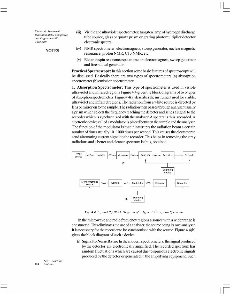
NOTES
Self - Learning128 Material
Electronic Spectra ofTransition Metal Complexesand OrganometallicChemistry
(iii) Visible and ultraviolet spectrometer; tungsten lamp of hydrogen dischargetube source, glass or quartz prism or grating photomultiplier detectorelectronic spectra.
(iv) NMR spectrometer: electromagnets, sweep generator, nuclear magneticresonance, proton NMR, C13 NMR, etc.
(v) Electron spin resonance spectrometer: electromagnets, sweep generatorand free radical generator.
Practical Spectroscopy: In this section some basic features of spectroscopy willbe discussed. Basically there are two types of spectrometers (a) absorptionspectrometer (b) emission spectrometer.
1. Absorption Spectrometer: This type of spectrometer is used in visibleultraviolet and infrared regions Figure 4.4 gives the block diagrams of two typesof absorption spectrometers. Figure 4.4(a) describes the instrument used for visible,ultraviolet and infrared regions. The radiation from a white source is directed bylens or mirror on to the sample. The radiation then passes through analyser usuallya prism which selects the frequency reaching the detector and sends a signal to therecorder which is synchronized with the analyser. A spectra is thus, recorded. Aelectronic device called a modulator is placed between the sample and the analyser.The function of the modulator is that it interrupts the radiation beam a certainnumber of times usually 10–1000 times per second. This causes the electector tosend alternating current signal to the recorder. This helps in removing the strayradiations and a better and cleaner spectrum is thus, obtained.
Fig. 4.4 (a) and (b) Block Diagram of a Typical Absorption Spectrum
In the microwave and radio frequency regions a source with a wider range isconstructed. This eliminates the use of a analyser, the source being its own analyser.It is necessary for the recorder to be synchronised with the source. Figure 4.4(b)gives the block diagram of such a device.
(i) Signal to Noise Ratio: In the modern spectrometers, the signal producedby the detector are electronically amplified. The recorded spectrum hasrandom fluctuations which are caused due to spurious electronic signalsproduced by the detector or generated in the amplifying equipment. Such

Electronic Spectra ofTransition Metal Complexes
and OrganometallicChemistry
NOTES
Self - LearningMaterial 129
fluctuations are called noise in spectroscopy. In order that a real peak shouldshow itself distinctly from the noise it must have an intensity three to fouritems that of the noise fluctuations, i.e., it must have a signal to noise ratio ofthree to four.
(ii) Resolving Power: A molecular absorption occurs over a spread offrequencies of variable width. Therefore in order to scan the spectrum plainlya narrow slit is used. This will allow less total energy from the radiationbeam to reach detector. It may be noted that one can not decrease the slitwidth beyond a particular limit as this could decrease the intensity of thesignal. Therefore, a compromise has to be made between the minimum slitwidth consistent with the acceptable signal to noise ratio.
2. Rotational Absorption Spectra: Pure rotational absorption spectra areobserved in the far infrared and microwave regions of the electromagnetic spectrum.The molecule must have a permanent dipole moment, before it can produce therotational absorption spectra. Rotational energy levels are spaced close togetherwith separations of ~300 Cal. The energies of the rotational levels of a diatomicmolecule AB is given by
EJ = 2
28
h
IJ (J + 1)
Where J is the rotational quantum number and I is the moment of inertiagiven by
I = 2A BAB
A B
m mr
m m
where mA and mB are the respective masses of the atoms and rAB is thebond length. The term inside the brackets is called the reduced mass of the moleculeand is denoted by . Transitions occur only between adjacent quantum levels, thatis the permitted transitions according to the selection rule is
J = ± 1
When a molecule is raised form one rotation level to another, i.e., fromquantum number J – 1 to the level J, the energy emitted is given by
hv = EJ – EJ–1
v = 2
2[ ( 1) ( 1)]
8
hJ J J J
I
v = 2
24
hJ
I
Or v = 24
hJ
I...(i)
From Equation (i), it is clear that the spacing between the lines is equal to
24
h
I. In terms of wave number, we have

NOTES
Self - Learning130 Material
Electronic Spectra ofTransition Metal Complexesand OrganometallicChemistry
Or v = 1
= 24
v hc cI
The moment of inertial is obtained from the measured spacing between thelines in the rotational spectrum. The bond length rAB can thus, be determined forheteronuclear diatomic molecule from the knowledge of I and µ.
(i) The Intensities of Spectral Lines: The relative intensities of the spectrallines can be calculated from the knowledge of the relative probabilities of transitionbetween the various energy levels. Even though there is equal probability forJ = 0 J = 1, J = 1, J = 2 J = 2 J = 3 transitions to occur yet all spectrallines will not be equally intense. This is because the population of molecules ateach level will be different. In fact, since the intrinsic probabilities are equal, theline intensities will be directly proportional to the initial number of molecules ineach level.
The population of the levels is governed by the relation,
0
jN
N= exp(–EJ/kT)
0
jN
N= exp{–BhcJ (J + 1)/kT} ...(v)
Where c is the velocity of light in cm s–1. The relative population decreasewith an increase in the value of J. It can easily be shown that each energy level is2J + 1 – fold degenerate.
The total relative population at an energy EJ will be given by,
Population (2J + 1) exp (– EJ/KT) ...(vi)
On differentiation the above equation the maximum population at the nearestintegral J value will be,
J = 1
2 2kThcB
...(vii)
Isotopic substitution will produce a change in the rotational spectra of amolecule and enables us to determine the atomic weights. Thus, rotational spectralmeasurement will enable us to calculate moment of inertia and the bond length ofa molecule. Any departure in the calculated values may be primarily due to non-rigidity in the molecule.
Example 4.1: The vibrational frequency of HCl is 2989 cm–1 (in wave numbers).The isotopic weights are H1 = 1.008 and Cl35 = 35.97 amu.
(6.023 × 10²³ amu = 1 g).
(a) Convert this frequency to sec–1
(b) Calculate the reduced mass of the two atoms in HCl, in amu and in grams.

Electronic Spectra ofTransition Metal Complexes
and OrganometallicChemistry
NOTES
Self - LearningMaterial 131
Solution: (a) 1
= 2989 cm–1
v = c
= 2.998 × 1010 cm sec–1 × 2989 cm–1
= 8.96 × 10¹³ sec–1
(b) = A B
A B
m mm m
= 1.008 34.9735.97 = 0.981 amu
and = 23
0.981amu 1g
6.023 ×10 amu
= 1.63 × 10⁻²⁴ g.
Example 4.2: The rotation spectrum of HCl vapour consists of a series of relativelyeven spaced lines when the chlorine is exclusively the 35Cl isotope. The spacingbetween the two lines of spectrum in terms of wavelength, is 4.7 × 10⁻² cm.Calculate the bond length in HCl.
Solution: The difference in the frequency of any two adjacent rotationalabsorptions is equal to 2B. The wavelength difference can be converted to afrequency difference.
2B = v = c
= 10 1
2
3.0 10 cm s
4.7 10 cm
or B = 3.2 × 10¹¹s–1
Since B = 28
h
I
I = 27
2 11 1
6.6 10
8 3.2 10 s
= 2.6 × 10–40 erg s2
For a diatomic molecule
I = r2e
When e is the internuclear separation at equilibrium
r2e =
40 2
23
2.6 10 erg s35 1
6.02 10 g35 1
h
= 1.61 × 10⁻¹⁶ cm
re = 1.3 Å
3. Vibrational Spectra: Atoms within molecules may vibrate about their averagepositions undergoing periodic displacements from positions. The vibration of an

NOTES
Self - Learning132 Material
Electronic Spectra ofTransition Metal Complexesand OrganometallicChemistry
atom with respect to other atoms in a molecule involves bending or stretching ofthe valence bonds which hold it. Vibrational spectra result from the changes invibrational energy levels. All the vibrations of a molecule can be described asone or a combination of a certain number of fundamental modes of vibration.Consider a molecule containing n atoms. The position of each atom can bedefined by specifying the three coordinates, i.e., x, y and z Cartesian coordinates.This will give rise to 3n number of coordinates. Since each coordinate valuemay be specified independently, a molecule of n atoms has 3n degrees of freedom.Once all 3n coordinates have been fixed, the bond distances and bond anglesof the molecule are all fixed.
When a molecule is free to move in three dimensional space as a whole withoutchange of shape, we can refer to such movement by noting the position of itscentre of gravity at any instant and the position can be described if the values of itsthree coordinates is known. This translational motion use 3 degrees of freedomand hence the remaining degrees of freedom will be 3n – 3. Similarly, the rotationof a non-linear molecule can be resolved into components about three perpendicularaxes and this will require three degree of freedom. The molecule will now be leftwith 3n – 6 degrees of freedom.
Therefore, for a non-linear molecule, the number of fundamental vibrations= 3 n – 6.
If the molecule is linear, there is no rotation about the bond axis, hence onlytwo degrees of rotational freedom are required leaving 3n – 5 degrees of vibrationalfreedom. It can be shown from quantum mechanical considerations that thevibrational energy levels of a molecule are given by:
E = 012
v hv
Where v is the vibrational quantum number.
The vibrational frequency of a diatomic molecule is given by Hook’s Law.The two atoms and their connecting bond are treated as a simple harmonic oscillatorcomposed of two masses Mx and My connected by a spring.
v =
1 / 2
12
x y
x y
fM M
c M M
Where v = Vibrational Frequency (cm–1)
c = Velocity of Light
f = Force Constant of the Bond
The value of f is approximate 5 × 10⁵ dynes per cm for single bonds andapproximately 2 and 3 times this value for double bonds and triple bonds

Electronic Spectra ofTransition Metal Complexes
and OrganometallicChemistry
NOTES
Self - LearningMaterial 133
respectively. The frequency of infra-red absorption is commonly used to calculatethe force constants of bonds. In the IR studies the wave number ( v ) are oftencalled frequencies though it is not rigorously correct. B and intensities are expressedeither as Transmittance (T) or Absorbance (A).
A molecule has many degrees of freedom as the total degrees of freedom ofits individual atom. Each atom has 3 degrees of the vibrational energies which arequantised and for a simple harmonic oscillator it is given by,
Ev = 1joules
2oScv hw
Where v is called vibrational quantum number and have values, v = 0, 1, 2,... Inspectroscopic units v (cm–1) we have
v = vEhc
= 112 oscv w cm
For v = 0
0 = 112 oscw cm
This is known as zero-point energy. For simple harmonic oscillator, the selectionrule.
v ± 1
Real molecules do not obey exactly the laws of simple harmonic oscillator, thereal bonds though elastic so as to obey Hooke’s law. This is due to anharmonicityin the vibrational motion, and in such case ew is the oscillation frequency and xe is
the anharmonicity constant. One can introduce ye, ze, etc.
M = 2
11 12 2e e ev w v w x cm
In order to account for higher order corrections freedom corresponding to theCartesian coordinates (x, y, z) needed to define its position relative to other atoms inthe molecule. A molecule of n atoms therefore has 3n degrees of freedom. For non-linear molecules 3 degrees of freedom describe rotation and 3 describe translationmotion. Hence there will be 3n – 6 vibrational degrees or fundamental vibrations.Linear molecules will have 3n – 5 vibrational degrees of freedom. Since two degreesof freedom are required to describe its rotations motion. There are two types ofvibrations; stretching vibrations and bending vibrations. A stretching vibration is arhythmical movement along and bond axis such that the interatomic distances areincreasing or decreasing. On the other hand, a bending vibration may consist of achange in bond angle between bonds with a common atom or the movement of agroup of atoms in the group with respect to one another. The various stretching andbending modes for CH2 group in a hydrocarbon molecule are shown in Figure 4.5.CH2 being a portion of a molecule 3n – 6 rule does not apply in this case.

NOTES
Self - Learning134 Material
Electronic Spectra ofTransition Metal Complexesand OrganometallicChemistry
Fig. 4.5: Vibrational Modes for a CH2 Group (+ and – Indicate
Movement Perpendicular to the Plane of the Page)
The theoretical number of fundamental vibrations are seldom observed becauseovertones (multiples of a given frequency) and combination tones (sum of twoother vibrations increase the number of bands whereas the other factors reducethe number of bands.
1. Fundamental frequencies that fall outside the 4000–666 cm–1 region.
2. Fundamentals that are too weak to be observed.
3. Fundamental vibrations which absorb at the same frequencies.
4. Fundamental vibrations that do not cause a change in the dipole moment.
4. Experimental Recording of IR Spectra: The modern double beam infraredspectrophotometer is employed for recording IR spectra of a compound. Ithas four major components (i) Radiation source, (ii) Sample Handling,(iii) Monochromator and (iv) Detector.
(i) Radiation Source: Infrared radiation source is often a Nernst filamentwhich is fabricated from a binder and oxides of cerium, zirconium and thoriumor globar which is a small rod of silicon carbide. The source is heatedelectrically to 1000–1800ºC. The radiation from the source is divided intotwo beams by mirrors M1 and M2. These are called sample beam andreference beam.

Electronic Spectra ofTransition Metal Complexes
and OrganometallicChemistry
NOTES
Self - LearningMaterial 135
(ii) Sample Handling: Infrared spectra may be recorded of sample in gases,liquids of solids state. The spectra of gases or low boiling liquids may berecorded by expansion of the sample into an evacuated cells. Gas cells asof length varying from few centimeters to 40 meters.
Liquids may be examined neat or in solution. This is pressed between flatplates of 0.001 mm or less in thickness. Solutions are handled in cells of0.1–1 mm thickness. The solvent selected must be dry and transparent inthe IR region. Carbon tetrachloride and carbon disulphide are used assolvents. Solids are usually examined as a mull. Mules are prepared bythroughly grinding 2–5 mg of a solid with 1–2 ml of mulling oil in an agatemortar. Nujol, a high boiling petroleum oil is used as a mulling agent.Fluorolube (a completely halogenated polymer containing F and Cl) is acommon mulling agent.
The pressed-disc technique depends upon the fact that dry powderedpotassium bromide can be pressed under pressure in vaccuo to form atransparent disc. 0.5–1.0 mg of the sample is intimately mixed with 100 mgof dry KBr. This is mixed and pressed with special dies under a pressure of10,000 pounds per square inch.
Fig. 4.6 Double Beam IR Spectrometer
(iii) Monochromator: The combined beam passes through the monochromatorentrance slit to the mirror which reflects it to the diffraction grating. Maximumresolution is obtained by using grating only in the range of greatest dispersingeffectiveness, Figure.4.6 shows a double beam IR spectrometer.
(iv) Detectors: The most common type of detectors used in IR spectroscopyare bolometers, thermocouples and thermistors. The bolometer usuallyconsists of a thin metal conductor such as platinum wire. When IR radiationfalls on the conductor it becomes war mer and produces a change in itselectrical resistance. The change in resistance is a measure of amount ofradiation falling on it.
A thermocouple is made by joining two wires of different metals. One of theseis called the hot junction while the other is called the cold junction. Potential isdeveloped when the radiation falls on it.
Thermistors are made of a fused mixture of metal oxides. As their temperatureincreases their electrical resistance decreases. Thermistors typically changesresistance about 5 percent perºC. Response time of thermistors is rather slow.

NOTES
Self - Learning136 Material
Electronic Spectra ofTransition Metal Complexesand OrganometallicChemistry
Semiconductor detectors show a rapid response to the IR signal. These areotherwise insulators but become conductors when radiation does fall on them. Inrecent years Fourier-Transform (FT) instruments have become available. FT IRallows analysis of very small samples.
5. Interpretation of Spectra: There are no rigid rules for interpreting an IRspectrum. However certain requirements must be met before an attempt is madeto interpret spectrum.
(i) The spectrum must be well resolved and of good intensity.
(ii) The sample must be extremely pure whose pure whose spectrum isrecorded.
(iii) The spectrum be calibrated properly using a polystyrene film.
(iv) The method of sample handling must be specified and the solvent,concentration and cell thickness must be specified.
It must be clearly understood that the IR spectra of molecule is highly complex,it is therefore not possible to analyse all the bands. Only a few bands are analysed toget information about the different groups present in the molecule. Final confirmationis however done by comparing the spectra with the probable compound by matchingband by band. This technique is called the finger print method. The whole region ofIR spectra has been divided into eight most well defined areas.
Wavelength Wave Number Bond Causing
(Micrometers) v m–1 Absorption
1. 2.7–3.3 3750–3000 O–H, N– H stretching2. 3.0–3.4 3300–2900 –C=CH, C=C, Ar – H
(C–H stretching)3. 3.3–3.7 3000–2700 –CH3, –CH2–, –C–H
–C–H (C–H stretching) || O
4. 4.2–4.9 2400–2100 C =C, C=N (stretching)5. 5.3–6.1 1900–1650 C = 0 (acids, aldehydes, ketones,
amides, esters, anhydride)stretching
6. 5.9–6.2 1675–1500 C=C (aliphatic aromatic)7. 6.8–7.7 1475–1300 – C – H (bending)8. 10.0–15.4 1000–650 C = C, Ar – H (bending)
(out of plane)
We may divide normal modes into two classes, the skeltal vibrations whichinvolve all the atoms to the same extent and the characteristic group vibrationswhich involve only a small portion of the molecule, the remainder bring more orless stationary. The skeltal frequencies usually fall in the range 1400–700 cm–1.These arise due to linear or branched chain or aromatic structures in the molecule.It is not possible to assign particular bands to specific vibrational modes.
On the other hand group frequencies are almost independent of the structureof the molecule as a whole and fall in the regions well below or well above that ofskeletal vibrations.

Electronic Spectra ofTransition Metal Complexes
and OrganometallicChemistry
NOTES
Self - LearningMaterial 137
Example 4.3: Calculate the number of vibrations in the following molecules:(a) SO
2, (b) H
2 and (c) CO
2.
Solution: (a) SO2 is non-linear molecule. The number of modes of vibration willbe 3n–6, where n is the number of atoms.
3n – 6 = 3 × 3 – 6 = 3 modes
(b) Since H2 is linear. There should be 3n – 5 = 3 × 2 – 5 = 1 mode ofvibration.
(c) CO2 is a linear triatomic molecule. The modes of vibration will be
3n – 5 = 3 × 3 – 5 = 4 modes.
Example 4.4: Calculate the force constant for HCl35 from the fact that thefundamental vibration frequency is 8.667 × 10¹³ sec–1.
The reduced mass of HCl is 1.628 × 10⁻²⁴ gram.
Solution: k = (2v0)2
= (2 × 3.142 × 8.667 × 1013 sec–1)2 (1.628 × 10⁻³⁴g)
= 4.81 × 10⁵ dynes cm–1.
6. Vibration-Rotation Spectra: Vibration-rotation spectra are exhibited bydiatomic molecules with permanent dipole moments, Homonuclear diatomicmolecules with permanent dipole moments, Homonuclear diatomic molecules, suchas O2, Cl2 of H2, do not show vibration-rotation spectra since they do not havepermanent dipoles.
In typical diatomic molecule the rotational levels are separated by 1–10 cm–1
while the vibrational level are separated by nearly 3000 cm–1. Therefore, to a firstapproximation rotational and vibrational motions can be considered independently.The rotational and vibrational energy is the sum of the separate energies, i.e.,
Etotal = Erot + Evib (Joules)
total = rot + vib (cm–1)
J,v = J + v
J,v = BJ (J + 1) – DJ2(J + 1)2 + ...+ 21 1
2 2e e ev w x v w
...(2)
Ignoring D the non-rigidity constant in Equation (2), we get,
J,v = BJ (J + 1) + 21 1
2 2e e ev w x v w
J,v = BJ (J + 1) + 21 1
2 2e e ev w x v w
The selection rules are
v = ± 1, ± 2, etc., J = ± 1
It is the convention in spectroscopy to use single prime for the upper state anddouble prime for the lower state.

NOTES
Self - Learning138 Material
Electronic Spectra ofTransition Metal Complexesand OrganometallicChemistry
Let us consider the transition from v = o v = 1
Jv = J,v = 1 – J,v = 0
J,v = 1 1 1 1( 1) 1 2 ( 1)
2 4 2 4e e e ee eBJ J w x w BJ J w w x
J,v = 11 2 1e ew x B J J J J cm
where 0w = ew (1 –2xe)
J,v = 0w + B (J –J) + (J + J + 1)
Here two cases arise
Case IJ + 1 J = J + 1; J = J = 1
J,v = 0w + 2B (J + 1) cm–1
Case IIJ = – 1 J = 0 1, 2, ...
J = J + 1 J – J = – 1
J,v = 0w – 2B (J + 1) cm–1
Fig. 4.7 Vibration-Rotation Spectrum of HBr for Transition From v = 0 to v = 1
These two expressions may be conveniently combined to
J,v = 0w – 2Bm cm–1; m = 1, 2,...
0w is called the band origin or centre lines corresponding to the low frequency
side of 0w corresponding m negative (I = – 1) are called P branch and thosecorresponding to m positive (J = –1) are called R branch

Electronic Spectra ofTransition Metal Complexes
and OrganometallicChemistry
NOTES
Self - LearningMaterial 139
lines arising from, J = –2 –1 0 + 1 + 2
O P Q R S
Figure 4.7 shows the vibrational levels of a diatomic molecule
Raman Spectra
When a beam of monochromatic visible or ultraviolet light is passed through ahomogeneous medium, some light may be absorbed, some will be transmitted andsome of it will be scattered. The scattered energy will consist almost entirely ofradiation of the incident frequency. This is known as Rayleigh scattering, but inaddition, certain, discrete frequencies above and below that of the incident beamwill be scattered; this is referred to as Raman scattering.
The schematic arrangement for recording Raman spectrum is shown in Figure4.8.
Sample
Monochromatic Non-scattered light
Slit
Scattered light
Prism
Photographic film
Fig. 4.8 Schematic Diagram for Raman Spectroscopy
Raman found that the difference, v, between the incident and scatteredradiation is constant, characteristic of the substance irradiated and is completelyindependent of the frequency of the incident radiation. In the Raman spectrum,the radiation scattered with a frequency lower than that of the incident beam isknown as stokes radiation while that of the higher frequency is called antistokesradiation. Stokes radiation is generally more intense than anti-stokes. The Ramanspectra can be used to study the vibration energy levels of molecules.
The differences between the frequencies of the scattered light and the frequencyof the incident light correspond to transition between vibrational and rotationalenergy levels in the molecule. Thus, Raman spectroscopy essentially provides thesame kind of information as infrared spectroscopy with one important difference,i.e., a given molecular vibration will be Raman active only if there is a change in thepolarizability of the molecule during the vibration. Qualitatively, it is associated withthe deformation of electron cloud surrounding a molecule. The polarizability of amolecule will change during vibration if during vibration, the electron cloud becomecompact or diffuse in going from one extreme vibrational configuration to another.The numbers of fundamental molecular vibrations which are infrared active or

NOTES
Self - Learning140 Material
Electronic Spectra ofTransition Metal Complexesand OrganometallicChemistry
Raman active can be predicted for any molecular geometry. The proposedgeometry of a molecule is confirmed by the agreement of its observed spectrumwith the predicted spectrum.
Rule of Mutual Exclusion: It is a general rule which provides extremely usefulinformation about the molecular structure. It states the following.
If a molecule has a centre of symmetry then Raman active vibrations are infraredinactive and vice versa. If there is no center of symmetry then some (note necessarilyall) vibrations may be both Raman and infrared active.
The converse of this rule also holds, i.e., In case there are no common lines inthe Raman and infrared spectra of a molecule, it implies that the molecule has acenter of symmetry. Here is a word of caution is necessary since sometimes theRaman line may be too weak to be detected. This may lead to wrong conclusion.But if some of the vibrational modes are both Raman and infrared active it iscertain that the molecule does not have a center of symmetry.
Raman spectra and infrared spectra of a molecule help in the structuredetermination. Let us consider an example of a simple triatomic molecule of AB,type. Here it is to be decided whether the molecule is linear or not, and if linearwhether it is symmetrical (B–A–B) or a symmetrical (B–B–A). In case of carbondioxide CO2 and nitrous oxide N2O, both molecules give infrared bonds withPR contours they must therefore be linear. The mutual exclusion rule shows thatCO2 has a center of symmetry (O–C–O) while N2O has not (N–N–O).
In ase of a non-linear molecule the PR contours are absent and the rotationalfine spectra is complicated.
We can study the rotations and vibrations of molecules such as O2 or H2
which are in accessible to infrared or microwave techniques. We can also observethe symmetric vibrations of CO2 which produces no dipole change and thereforeno infra-red spectrum. For center of symmetric molecules Raman and infra-redstudies are exactly complementary. For other molecules too Raman techniqueyields data which can not be obtained otherwise.
Example 4.5: A molecule A2B
2 has infrared absorptions and Raman spectral
lines as in the following table.
cm–1 Infrared Raman
3374 — Strong
3287 Very strong, PR contour —
1973 — Very strong
729 Very strong PQR contour —
612 — Weak
Deduce what you can regarding the structure of the molecule and assign theobserved vibrations to particular molecular modes as far as possible.
Solution: The molecule is liner (PR contour of an infra-red band) and has a centerof symmetry hence, is A–B–B–A. 3374 cm–1 and 3287 cm–1 are close to the C–H stretching frequency. So the molecule is acetylene HCCH.

Electronic Spectra ofTransition Metal Complexes
and OrganometallicChemistry
NOTES
Self - LearningMaterial 141
3374 cm–1; symmetric C–H stretch
3287 cm–1 asymmetric C–H stretch.
1973 cm–1; a C stretch
729 and 612 cm–1; bending vibrations
Example 4.6: A molecule AB2 has the following infrared and Raman spectra
cm–1 Infrared Raman
3756 Very strong Perpendicular —
3652 Strong, Parallel Strong, Polarised
1595 Very strong, Parallel —
The rotational fine structure of the infrared bands is complex and does notshow PR or PQR characteristics. Comment on the molecular structure and assignthe observed lines to specific molecular vibrations as far as possible.
Solution. The molecule is non-linear and does not have an center of symmetry,
hence A
B B 3756 cm and 3652 cm–1 are in the region of OH stretching frequency,,so the molecule is H2O assignments:
3756 m–1 : Asymmetric Stretch
3652 cm–1 : Symmetric Stretch
1595 cm–1 : Bend
4.4.2 Splitting of Russel Saunder's States inOctaheredral and Tetrahedral Crystal Fields
While discussing the electronic transitions in complexes, we must know how thesplitting of electronic energy levels and spectroscopic terms occur in s, p, d and f-orbitals. Important points may be summarized as :
(i) An S-orbital is spherically symmetrical and is not affected by octahedral orany other type of field. Hence, no splitting is observed.
(ii) The p-orbitals are directional but they have same type of orientation. Theseare affected by an octahedral field but to equal extent. Therefore, theirenergy levels remain equal and no splitting occurs.
(iii) The five d-orbitals are split by an octahedral field into two levels t2g
(dxy, d
yz,
dzx) and e
g 2 2 2x y z(d ,d ) having different energies. The difference between
these two levels is 10D1 (or D
2). The t
2g level is triply degenerate and is
4Da below the Bary centre. Whereas, g is level is doubly degenerate and is6D
q above the Bary centre. For a d1 configuration, ground state in 2D state
and the t2g
and eg levels correspond to T
2g and E
g spectroscopic states
shown in Figure 4.9.
(iv) There are seven f-orbitals and these split by an octahedral field into threelevels. For an f1 arrangement, the ground state is a 3F state and is split intoa triply degenerate T
1g state which is 6D
q below the Bary centre, a triply

NOTES
Self - Learning142 Material
Electronic Spectra ofTransition Metal Complexesand OrganometallicChemistry
degenerate T2g
level which is 2Dq above the Bary centre and a single A
2g
state which is 12Dq above the Bary centre as shown in Figure 4.9.
Fig. 4.9 Splitting of Spectroscopic Terms Arising from(a) d1 Electronic Arrangement and (b) f1 Electronic Arrangement
So, in an octahedral field,
(i) S and P states do not split.
(ii) D states split into two states, Eg and T
2g
(iii) F states split into three states, A2g
, T2g
and T1g
.
These states split by the external field are called Mulliken Symbols. Thesesymbols are used in interpreting electronic spectra of transition metalcomplexes. Common Mulliken symbols are used in the octahedral andtetrahedral field these are distinguished by introducing the symmetry symbol'g' in Octahedral field.
Table 4.2 Correlation of Spectroscopic Terms into Mulliken Symbol
Spectroscopic Term Mulliken Symbol
Octahedral Field Tetrahedral Field
S A1g
A1
P T1g
T1
D Eg +T
2gE + T
2
F A2g
+ T1g
+ T2g
A2 + T
1 + T
2
G A1g
+ Eg + T
1g T
2gA
1 + E + T
1 + T
2
We can obtain Mulliken symbols if we know the spectroscopic terms S, P,D, F, etc. It may be recalled that :
(i) The term S stands for resultant angular momentum L, when L = 0. Thenumber of components of L is 2L + 1. When L = 0, this is called onecomponent term and is represented by A.

Electronic Spectra ofTransition Metal Complexes
and OrganometallicChemistry
NOTES
Self - LearningMaterial 143
(ii) The term P means L = 1 which has 3 components (2L + 1). It is triplydegenerate and is represented by T.
(iii) The term D means L = 2 which has 5 components (2L + 1). This constitutedof doubly degenerate E and a triply degenerate T terms.
(iv) The term G means L = 3 which has 7 components (2L + 1). This is constitutedof one singly degenerate A, a doubly degenerate E and two triply degenerateT
1 and T
2 terms.
We observe from the Table 4.2 that the single degenerate term is sometimesrespresented by A
1 and sometimes by A
2. Similarly triply degenerate terms are
represented by T1 or T
2. The numbers 1 and 2 define symmetry to Mulliken symbols
and are derived from group theory.
4.4.3 Spectrochemical Series
It is the arrangement of ligands increasing order of ligand field splitting energy ().It may be shown as :
Increasing Crystal field Splitivs Energy
I– < Br– < Cl– < SCN– < F– < OH– < Acetate < Ox2– < H2O < NCS–
< Glycine <
py = NH3 < en < Dipy = O-phen < NO
2– < CN– < CO
A more compact form of the series involving most common ligands is :
Halides < C2O
42– < H
2O < NH
3 < en < NO
2– < CN– < CO
Ligands are commonly classified by their donor and acceptor capabilities.The ligands like mmonia are sigma donors only, with no orbitals for -bonding.The ligand field splitting () depends on the degree of overlap. Ethylenediaminehas a stronger effect than ammonia among these ligands generating a larger .
The halide ions ligand field strengths are in the order,
F– > Cl– > Br– > I–
The small ligands can cause greater crystal field splitting because they canapproach the metal ion closely. For example, F– ions produces more than largeCl– ion and Br– ion.
The metal ion also influences the magnitude of o through the overlap and
energy match criteria. For example,
Mn2+ < Ni2+ < Co2+ < Fe2+ <Fe3+ < Cr3+ < Co3+ <Mn4+ < Mo3+ < Pd4+ <Ir3+ < Re3+ < Pt4+
The crystal field splitting is influenced by oxidations state of transition metalion. Higher the oxidation state of metal ion greater is the crystal field splitting.

NOTES
Self - Learning144 Material
Electronic Spectra ofTransition Metal Complexesand OrganometallicChemistry
Check Your Progress
1. Explain the electronic excitations of energy corresponding to ultravioletand visible radiations.
2. How is electronic spectra obtained?
3. Specify the electronic transitions exhibited by the organic molecules.
4. Explain d-d transition.
5. Define spin-selection rule.
6. State the Laporte's selection rule.
7. Explain the term spectroscopy.
8. According to the quantum theory of matter state the internal energy of amolecule.
9. What is vibrational spectra?
10. What type of detectors are used in IR spectroscopy?
11. Explain the Raman spectra.
4.5 ORGEL ENERGY LEVEL DIAGRAMS
This concept was developed by Lesile Orgel.
The plots of variation of energy level of spectio scopic states of differentsymmetry as a function of field strength D
q are called Orgel diagrams. The energy
level diagram for d1 and d9 in octahedral field (Oh) are shown in Figure 4.10.
4.5.1 Tetrahedral Complexes of Metal ions with d1
and d9 Configuration
We know that in tetrahedral field, d-orbitals split into two e orbitals of lowerenergy and three t
2 orbitals of higher energy.
In case of tetrahedral ligand field, the energy level diagram is inverse of thatof octahedral field. In tetrahedral field, splitting is only 4/9 as that of octahedralfield (
t = 4/2 D
o)
Similarly, the tetrahedral complex of d9 configuration have energy levelsinverse of d1 configuration. So, the energy level diagram for d9 configuration willalso be inverse of that of octahedral field. The splitting of energy levels of d1 andd9 configurations in tetrafield (T
d) are shown in Figure 4.10. The inverse relation
between octahedral complexes and tetrahedral complexes with d1 configurationand also with d9 configuration can be understood from Figure 410. Similarly, inverserelation between tetrahedral complexes with d1 and d9 configuration can also beunderstood from this Figure. 4.10.

Electronic Spectra ofTransition Metal Complexes
and OrganometallicChemistry
NOTES
Self - LearningMaterial 145
Fig.4.10 Splitting of Energy Levels for d1 and d9 Configuration in a Tetrahedral Field (Td)
To summarise,we can say
d1 (Td) is inverse of d9 (T
d) as well as d1 (O
h)
d9 (Td) is inverse of d1 (T
d) as well as d9 (O
h)
We can check that the values of L is the same in the case of d1 and d6
configurations, but the spin multiplities are different.
Thus the term symbols for d1 and d2 configurations are 2D and 5D,respectively. The state D splits into doubly degenerated term E and triply degenerateterm T in octahedral as well as tetrahedral fields. Consequently, only a single d-dtransition can occur. Thus, we come to know that electronic transitions will besimilar for d9 (2D) and d4 (5D). In other words, transitions in metal ions differing byfive d-electrons in their configurations give similar transitions in octahedral andtetrahedral fields.
From the Orgel diagram (Refer Figure 4.11) it is clear that d1, d4, d6 and d9
ions should also give only one d-d absorption band. Splitting of these states as afunctions of
o for octahedral complexes with d1 and d6 configrations and tetrahedral
complexes with d4 and d9 configurations are described on the left handsides. Thespectra of these complexes contain only one band arising from d-d trainsitionsand is assigned as T
2g E
g.
The right handside of the Orgel diagram applies to octahedral complexeswith d4 and d9 configurations and tetrahedral complexes with d1 and d6
configurations. The spectra of these complexes contain only one band arising fromsingle d-d transitions and is assigned as E T
2. For tetrahedral complexes we
drop the subscripts because a tetrahedron does not have centre of symmetry.
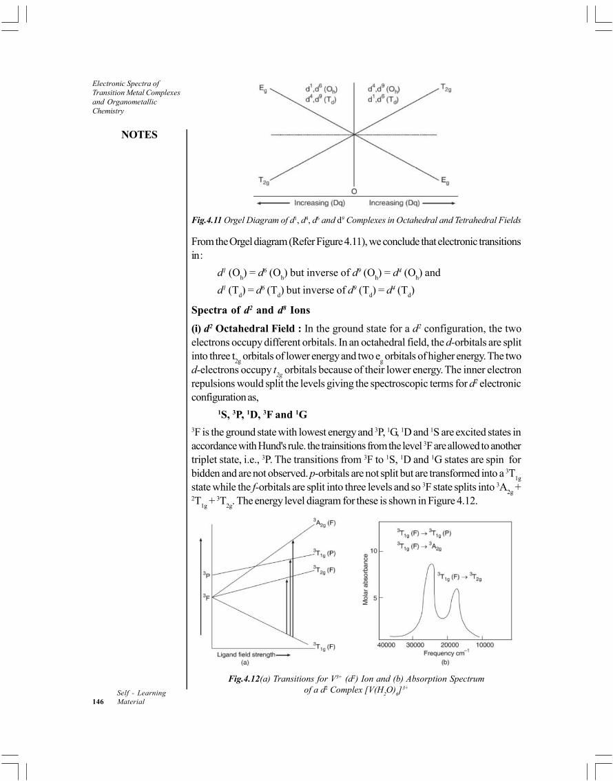
NOTES
Self - Learning146 Material
Electronic Spectra ofTransition Metal Complexesand OrganometallicChemistry
Fig.4.11 Orgel Diagram of d1, d4, d6 and d9 Complexes in Octahedral and Tetrahedral Fields
From the Orgel diagram (Refer Figure 4.11), we conclude that electronic transitionsin :
d1 (Oh) = d6 (O
h) but inverse of d9 (O
h) = d4 (O
h) and
d1 (Td) = d6 (T
d) but inverse of d9 (T
d) = d4 (T
d)
Spectra of d2 and d8 Ions
(i) d2 Octahedral Field : In the ground state for a d2 configuration, the twoelectrons occupy different orbitals. In an octahedral field, the d-orbitals are splitinto three t
2g orbitals of lower energy and two e
g orbitals of higher energy. The two
d-electrons occupy t2g
orbitals because of their lower energy. The inner electronrepulsions would split the levels giving the spectroscopic terms for d2 electronicconfiguration as,
1S, 3P, 1D, 3F and 1G3F is the ground state with lowest energy and 3P, 1G, 1D and 1S are excited states inaccordance with Hund's rule. the trainsitions from the level 3F are allowed to anothertriplet state, i.e., 3P. The transitions from 3F to 1S, 1D and 1G states are spin forbidden and are not observed. p-orbitals are not split but are transformed into a 3T
1g
state while the f-orbitals are split into three levels and so 3F state splits into 3A2g
+2T
1g + 3T
2g. The energy level diagram for these is shown in Figure 4.12.
Fig.4.12(a) Transitions for V3+ (d2) Ion and (b) Absorption Spectrumof a d2 Complex [V(H
2O)
6]3+

Electronic Spectra ofTransition Metal Complexes
and OrganometallicChemistry
NOTES
Self - LearningMaterial 147
We expect three peaks corresponding to three transitions as shown in Figure4.12 (a). The three transitions are from the ground state 3T
1g (F) to 3T
1g, 3T
2g, (P)
and 3T2g
, respectively. The spectrum of [V(H2O)
6]3+ is shown in Figure 4.12(b)
which shows only two peaks. The peak at 17,000 cm–1 is assigned to 3T1g
(F) 3T
2g (F) and the peak at 24,000 cm–1 is due to both 3T
1g (F) 3T
1g (P) and
3T1g
(F) 3A2g
transitions.
Thus, for [V(H2O)
6]2+, the bands are assigned as :
3T1g
(F) 3A2g
(F) 17,000 cm–1
3T1g
(F) 3A2g
(F) 24,000 cm–1
The energies corresponding to these two transitions lie very close to eachother and therefore, these two tansitions are not resolved into two separate peaks.
However, with strong field ligands like NH3, we get three bonds which may
be assigned as :3T
1g (F) 3T
2g (F) 17,200 cm–1
3T1g
(F) 3T1g
(F) 25,600 cm–1
3T1g
(F) 3A2g
(F) 36,000 cm–1
(ii)d2 Tetrahedral Field : A few tetrahedral complexes also exhibit two bands inthe range of 9000 cm–1 corresponding to 3A
2 (F) 3T
1 (F) and 15000 cm–1
corresponding to 3A2 (F) 3T
1 (P) transitions.
3A2 (F) 3T
1 (F) 9,000 cm–1
3A2 (F) 3T
1 (P) 15,000 cm–1
The transition 3A2 (F) 3T
2 (F) is of very low energy and does not fall in
the visible region and hence its not observed in the eletronic spectrum of d2 (Td).
(iii) d8 Octahedral : The complexes of metal with d8 configuration can be treatedsimilar to d2 octahedral complexes. These are two holes in the e
g level and therefore,
promoting one electron is equivalent to transferring a hole from eg to t
2g level. This
is inverse of d2 case and is shown in Figure 4.13. As explained earlier 3P state isnot split and is not inverted but the 3F state is split into three states and is inverted.Hence, the ground state term of Ni2+ is 3A
2g. It may be noted that is both d2 and d1
configuration, the 3F state is the lowest energy state. Three spin allowed transitionsare observed in spectra of [Ni (H
2O
6]2+, [Ni (NH
3)
6]2+, etc. The transitions
correspond to the following:3A
2g (F) 3T
2g (F)
3T2g
(F) 3A1g
(F)3TA
2g (F) 3A
1g (P)

NOTES
Self - Learning148 Material
Electronic Spectra ofTransition Metal Complexesand OrganometallicChemistry
Fig. 4.13 Energy Level Diagram of d8 Ion
Fundamentally, the d8 octahedral energy level diagram is similar to the highspin d7 octahedral and d3 and d8 tetrahedral cases. The inverse diagram is similarfor d3 and d8 octahedral and d2 and d7 tetrahedral complexes.
Figure 4.14 gives Orgel diagram for two electrons and two electron holeconfiguration. In this Figure 4.14, the two T
1g states, one from P state and other
from F state are slightly curved lines. This may be attributed to mixing between thetwo T
1g terms arising from the high energy P term and low energy F term because
of same symmetry possessed by them.
Fig. 4.14 Orgel Diagram for Two Electron (d2) and Two Hole electron (d8) Configuration
4.5.2 Spectra of Octahedral Complexes of Metal ionswith d1 Configuration
In a free gaseous metal ion, the five d- orbitals are degenerate and electronictransition is not expected. However, when this ion is surrounded by an electrostaticfield of ligands, the d- orbitals split into two groups, t
29 and e
g. For example,
Ti (III) octahedral complex [Ti(H2O)
6]3+.

Electronic Spectra ofTransition Metal Complexes
and OrganometallicChemistry
NOTES
Self - LearningMaterial 149
Electronic Spectrum of [Ti (H2O)
6] Complex Ion
The splitting of d- orbitals is shown in Figure 4.12. In the ground state the singleelectron occupies the lower t
2g level and only one transition from t
2g e
g is
possible. Therefore, the spectrum of [Ti(H2O)
6]3+ shows only one band with a
peak at 20300 cm–1 as shown in Figure 4.12 (b). Wavelengths corresponding togreen and yellow light are absorbed from the while light while the blue and redportions of the light are emitted. Therefore, Ti solution of complex [Ti (H
2O)
6]3+
looks purple.
Fig. 4.15 Splitting of Energy Levels for d1 Configuration in an Octahedral Field and (b)Visible Spectrum of [Ti(H
2O)
6]3+ Complex Ion
We observe that the intensity of the absorption band is very weak ( =5–10). This is because it is a forbidden transition. The transitions from one centrosymmetric d-orbital to another centro symmetric d-orbital are forbidden. The molarabsorbance value of such forbidden transitions are of order of = 1 to 10 whereasallowed transitions have values of about 10,000.
The ground state terms for a free ion with d1 configuration is 2 D and it isshown on the left (Refer Figure 4.16). Under the influence of a ligand field, thissplits into two states which are described by Mulliken symbols 2E
g and 2T
2g. The
lower T2g
state corresponds to the electron occupying on of the Eg orbitals. The
two states 2Eg and 2T
2g are separated more widely as the strength of ligand field
increases.
Fig.4.16 Splitting of d-Levels for d1 Case in Octahedral Field
Octahedral Complexes of Ions with d9 Configuration
In the d1 complex, there is a single electron hole in the upper Eg level. Thus, the
transition in the d1 transition corresponds to the promotion of an electron from T2g
to Eg level. Whereas, in case of d9, the transition involves the promotion of an
electron as the transfer of an electron hole from Eg to T
2g. So, the energy level

NOTES
Self - Learning150 Material
Electronic Spectra ofTransition Metal Complexesand OrganometallicChemistry
diagram for d9 is the inverse of that for a d1 configuration (Refer Figure 4.17) Inthis Figure (4.17) 1E
g has been share at lower level and T
2g at a higher level.
Fig. 4.17 Splitting of Energy Levels for d9 Complex in Octahedral Field
4.6 NOMENCLATURE AND CLASSIFICATIONOF ORGANOMETALLIC COMPOUNDS
Organometallic compounds may be defined as substances having carbon to metalbonds. A large number of metals , for example, lithium, magnesium, aluminium,lead, tin, zinc, cadmium, mercury, etc., form fairly stable organic compounds. Theorganic residue is usually an alkyl, alkenyl, alkynyl or aryl group. A feworganometallic compounds of different metals are given below:
Group I Group II Group III Group IV
Alkali Metals Alkaline Earth Metals
3Methyl-lithium
CH Li 2 5Ethylmagnesiumbromide
C H MgBr 3 3Trimethylaluminium
(CH ) Al 2 5 4Tetraethyl lead(C H ) Pb
3Propynylmagnesium halide
CH C CMgX
2 5 2Ethoxymethylmagnesium chloride
C H OCH .MgCl
Transition Metals
2 5 2 3 2 6 5 2 5 2Dimethylcadmium Phenylmercury DiethylmercuryDiethylzinc
chloride
(C H ) Zn (CH ) Cd C H HgCl (C H ) Hg
Metalloids like boron, silicon, germanium and arsenic too form organiccompounds which are also regarded as organometallic compounds.
Organometallic compounds may be substantially ionic as alkylsodium andpotassium compounds or essentially covalent as alkylmercury compounds. Ingeneral, the more electropositive is the metal, the more ionic is the carbon to metalbond. Compounds like sodium acetate, calcium formate, where the metal is linkedto oxygen are largely ionic because of the greater difference in the electronegativity

Electronic Spectra ofTransition Metal Complexes
and OrganometallicChemistry
NOTES
Self - LearningMaterial 151
of oxygen and the metal. Such compounds are, therefore, not considered as trueorganometallic compounds.
The reactivity of organometallic compounds increases with the increase inionic character of carbon to metal bond. Of special interest are the compounds ofintermediate ionic character because of their reactivity and the selective nature oftheir reactions. By and large, organometallic compounds are obtained directly orindirectly form alkyl halides.
They are put to uses varying over a wide range. Thus tin, lead, aluminium,boron compounds are of technical importance as fungicide, antiknock compounds,catalysts, whereas compounds of arsenic, antimony, bismuth, mercury, silver areused as war gases, medicinals and pesticides. However, the most importantorganometallic compounds are those of magnesium, zinc and lithium, which areextensively used in the synthesis of a large number of organic compounds.
4.7 GENERAL METHODS OF PREPARATION
In 1899 Barbier used a mixture of alkyl halide and magnesium in ether to preparea large number of organic compounds. Later in 1900 Grignard, a student of Barbier,prepared alkylmagnesium halide solution and studied its reactions with a variety ofcompounds. Alkylmagnesium halides are therefore commonly known as Grignardreagents after the name of the discoverer. Their general formula is R—Mg—Xwhere R is a univalent hydrocarbon radical , for example, —CH3; —C2H5; —CH2—CH==CH2; —C6H5; C6H5CH2— and —X is a halogen. The reactioncan be applied to pr., sec. and tert. alkyl halides. Allylic Grignard reagent can beprepared in the usual manner or in THF. However alkynyl Grignard reagent areprepared by abstraction of a proton from alkyne by alkylmagnesium halide
2 5 2 6(RC CH + C H MgX RC C.MgX + C H ). Alkylmagnesium fluoridecan be prepared by refluxing alkyl fluorides with magnesium in presence of suitablecatalyst. Grignard reagent from -halo ethers can be formed only when THF ordimethoxymethane is used as solvent at low temperature.
2 2(MeO) CH or THF2 5 2 2 5 2–35°
C H OCH Cl + Mg C H OCH MgCl
There is some difficulty in preparing aryl and vinylmagnesium halides becauseof the low reactivity of aryl or vinyl halides. However this difficulty was overcomeby Normant (1953–1957) using TetraHydroFuran (THF) in place of ether duringpreparation (see below) of the reagent.
Grignard reagent cannot be prepared from alkyl halides containing groupswith which it is known to react. Thus only very few groups , for example, R, OR,X may be present in alkyl halide from which Grignard reagent is to be prepared.They cannot be prepared from alkyl halides having groups like — COOH, —
OH,—NH2, —NO2,—SO3H and the like.

NOTES
Self - Learning152 Material
Electronic Spectra ofTransition Metal Complexesand OrganometallicChemistry
Preparation
Common Grignard reagents are prepared by the action of magnesium metal onalkyl halide in the presences of alcohol free and dry ether.
Ether
Akyl halide Magnesium Grignard reagentR.X + Mg R.Mg.X
Ether2 5 2 5
Ethylmagnesium bromideC H Br + Mg C H MgBr
Diethylether is the most common solvent though other ethers like butyl ether,dimethyl- ether of glycol (diglyme) or TetraHydroFuran (THF) may also be used.The order of reactivity of various alkyl halides with magnesium is iodides > bromides> chlorides for a given alkyl group, but the yields are in the reverse order. As thenumber of carbon atoms increases the formation of Grignard reagents becomesmore and more difficult and for a given halogen the order or reactivity of alkylgroups is CH3 > C2H5 > C3H7, etc. It is important that all the reactants must beabsolutely dry and pure because the presence of moisture and impurities retardsthe reaction and results in the formation of other undesirable products.
Purification of Reactants
1. Magnesium. Magnesium turnings or ribbon is rubbed with sand paper andtreated with dilute acid to remove the surface film of magnesium oxide. It isthen washed with ether and dried immediately before use.
2. Ether. Diethylether is washed with water to remove any alcohol and thendried over anhydrous calcium chloride for 2–3 days to remove traces ofalcohol and moisture. It is then distilled over sodium or phosphoruspentoxide to remove final traces of alcohol and water.
3. Alkyl Halide. Alkyl halide is dried over anhydrous calcium chloride andthen distilled over phosphorus pentoxide.
Dry and clean magnesium turnings are suspended in dry and pure ether, in around bottom flask, fitted with a water condenser carrying a calcium chlorideguard tube at the top. Weight of ether taken is about 10 times that of magnesium.Alkyl halide (1 gm mole for every 1 gm atom of Mg.) dissolved in ether is slowlypoured through the condenser after removing the guard tube. The flask is thenwarmed and few crystals of iodine or few drops of ethylene bromide are added tocatalyze the reaction. Once the reaction starts, it often becomes brisk and it issometimes necessary to cool the flask to control the reaction.
After the addition of alkyl halide is complete, the flask is heated on waterbath till all magnesium dissolves. This solution is used as such for most of thereactions and Grignard reagent is never isolated in solid state for synthetic purposes.
The reaction occurs by a free radical mechanism. Alkyl halide is absorbedon the magnesium surface which then transfers an electron to halogen and insertionof magnesium between alkyl groups and halogen gives alkylmagnesium halides.
Structure of Grignard Reagents, Function of Ether and Nature ofGrignard Reactions. The structure of Grignard reagent is not understood with

Electronic Spectra ofTransition Metal Complexes
and OrganometallicChemistry
NOTES
Self - LearningMaterial 153
certainty. Grignard suggested that the alkylmagnesium halide contains ether ofcrystallization and can be represented as:
The electronic configuration of magnesium is 1s2, 2s2, 2p6, 3s2. By promotingone of the 3s electron to 3p orbital and then by the hybridization of these 3s and3p orbitals, magnesium atom in organomagnesium compounds exists in sphybridized state. Overlapping of these orbitals with those of carbon and halogenforms sigma bonds. There are two empty remaining 3p orbitals of magnesiumdue to which it behaves as a Lewis acid and coordinates with two ether molecules.Jolibois in 1912 observed that magnesium is present both in the form of anionsand cations and suggested the formula R2Mg2X2 for Grignard reagent.
+2 2 2 2R Mg X R.Mg + R.MgX
Ubbelohde in 1955 suggested that Grignard reagent exists in dimeric formsolvated in ether, and following equilibria exists in solution.
2 2 2 2R Mg.MgX R .Mg + MgX 2RMgX
Various physical measurements. NMR studies, etc., favour this dimericformula for the reagent. However in solution it exits as a complex of variousstructures including solvated complexes, such as:
In this text, formula RMgX has been used to represent alkylmagnesiumhalides. It is thus evident that due to the polarity of alkylmagnesium bond, most ofthe reactions of Grignard reagent involve an unsymmetrical or heterolytic cleavageof carbon-magnesium bond to form a carbanion and cationic magnesium. Thus:
+R—Mg—X R: + M gX
This carbanion possesses an unshared pair of electrons and acts as anucleophile. Hence, most of the reactions of Grignard reagents are nucleophilicreactions.
Characteristics and Uses of Grignard Reagents
Grignard reagents are colourless, hygroscopic solids. They are fairly stable in airbut are never obtained in solid state for chemical reactions in synthesis.
Grignard reagents are highly reactive and enter into reaction with wide varietyof substrates yielding many types of organic compounds. Despite their high reactivitythey are highly selective also. Thus they add to a carbon-oxygen double bond butdo not react with carbon-carbon double bond. Usually the addition of Grignard

NOTES
Self - Learning154 Material
Electronic Spectra ofTransition Metal Complexesand OrganometallicChemistry
reagents gives an intermediate addition complex which is hydrolysed by acids orammonium chloride to give useful products.
Alkylmagnesium bromides and iodides, in general react more readily thanthe corresponding chlorides. Some of the important reactions of Grignard reagentsare given below.
(A) Nucleophilic Substitution Reactions
The carbon metal bond is highly polar. Although the organic group is not a completeanion yet it has a considerable anionic character. Thus carbanion with an unsharedpair of electrons acts as a nucleophile. Grignard reagent thus shows nucleophilicaddition and nucleophilic substitution reaction.
We shall first take up nucleophilic substitution reaction in which generalpattern of mechanism of nucleophilic substitution is as given below:
1. Reaction with Active Hydrogen Compounds. Formation of hydrocarbonscompounds, such as alcohols, water, ammonia, amines, etc., in which hydrogen isattached to highly electronegative atom and can be easily dissociated as a proton,are known as compounds containing active hydrogen. Grignard reagent reactswith such compound, to form hydrocarbons.
(i)
(ii) In case of ammonia and primary amines only one hydrogen atom of a primaryamine reacts at room temperature.
However, at higher temperature the magnesium derivative of primary aminereacts with another molecule of Grignard reagent.
Amines reacting with vinylmagnesium bromide form unsaturatedhydrocarbon.

Electronic Spectra ofTransition Metal Complexes
and OrganometallicChemistry
NOTES
Self - LearningMaterial 155
(iii) Both hydrogen atom in acetylene are acidic and therefore when acetylene ispassed in ether solution of Grignard reagent both are replaced.
2 5 2 6HC CH + C H MgI HC C.MgI + C H
2 5 2 6Ethynyl bis (Magnesium iodide)
HC CMgI + C H MgI IMgC C.MgI + C H
Jones et al., in 1956 found that second step can be avoided if THF saturatedwith acetylene is allowed to react with Grignard reagent.
(iv) The enolic form of compounds like nitroethane and acetoacetic ester containactive hydrogen hence react with Grignard reagent. The rate of alkane evolveddepends upon the rate of conversion to enolic form.
3 3 4 3
OMgIOH|
CH .CH== N O + CH MgI CH + (CH CH== N O
3 3 3 4
IOH OMg
CH .C CH.COOEt + CH MgI CH — C ==CH.COOEt + CH==
When methylmagnesium halide is used, for every active gm atom of hydrogenone mole of methane gas is evolved quantitatively. This reaction is, therefore, usedfor estimating the groups containing active hydrogens, such as OH, NH2, SH,etc., in organic compounds and the method is known as Zerevitinov’s method.
2. Reaction with Alkyl Halides. (Formation of Alkanes). Alkyl halides reactwith Grignard reagents to form alkanes.
2 5 2 5 2 5 2 5 2Ethylbromide -Butane
C H MgBr + Br.C H C H .C H + MgBrn
3. Reaction with Alkenyl Halides (Formation of Alkenes). Alkenyl halidesreact with Grignard reagent by double decomposition to form alkenes.
2 5 2 2 3 2 2 2 2Allylbromide Pentene-1
C H MgBr + Br.CH .CH==CH CH .CH .CH .CH==CH + MgBr
4. Reaction with Alkynyl Halides (Formation of Alkynes). Alkynyl halidesreact with Grignard reagent to form alkynes.
3 2 3 2 2Butyne-1
CH MgBr Br.CH .C CH CH .CH C CH + MgBr
Alternatively alkynyl magnesium halide may be reacted with an alkyl halideto yield alkynes.
3 3 4 3CH .C CH + CH MgI CH + CH .C C.MgI

NOTES
Self - Learning156 Material
Electronic Spectra ofTransition Metal Complexesand OrganometallicChemistry
3 3 3 3 2Propynylmagnesiumiodide Butyne-2
CH .C C.MgI CH I CH .C C.CH MgI
5. Reaction with Monohaloethers (Formation of Higher Ethers). Halogenof monochloroethers reacts with Grignard reagents by double decomposition togive higher ethers.
6. Reaction with Inorganic Halides (Formation of Organometalliccompounds). Reaction of Grignard reagents with inorganic halides yields differentorganometallic compounds.
7. Reaction with Chloroformic Esters (Formation of Esters). When Grignardreagent is reacted with equimolar amount of chloroformic ester, higher esters areformed.
If the Grignard reagent is in excess the ester formed will react with Grignardreagent (nucleophilic addition) to produce ketone and tertiary alcohol.
8. Reaction with Cyanogen Chloride (Formation of cyanides). Reactivechlorine of cyanogen chloride reacts with Grignard reagent to yield alkyl cyanides.
If Grignard reagent is present in excess it will react with cyanide (NucleophilicAddition) to form ketones and tertiary alcohols.
9. Reaction with Chloramine (Formation of Primary Amines). Replacementof reactive chlorine by the carbanion derived from Grignard reagent gives primaryamines.
(B) Nucleophilic Addition Reactions
Grignard reagent reacts with compounds having carbon-oxygen, carbon-sulphurand carbon-nitrogen multiple bonds to give addition products which on hydrolysis
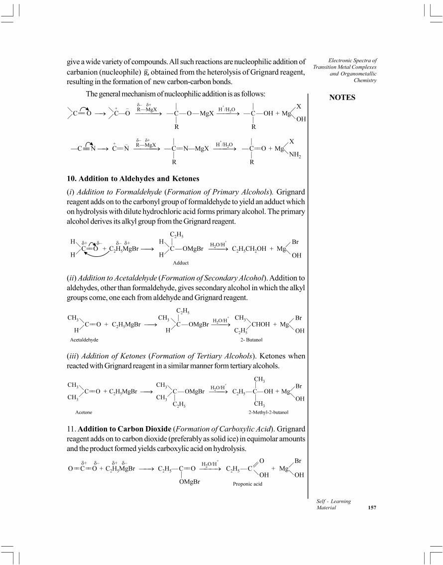
Electronic Spectra ofTransition Metal Complexes
and OrganometallicChemistry
NOTES
Self - LearningMaterial 157
give a wide variety of compounds. All such reactions are nucleophilic addition ofcarbanion (nucleophile) R, obtained from the heterolysis of Grignard reagent,resulting in the formation of new carbon-carbon bonds.
The general mechanism of nucleophilic addition is as follows:
10. Addition to Aldehydes and Ketones
(i) Addition to Formaldehyde (Formation of Primary Alcohols). Grignardreagent adds on to the carbonyl group of formaldehyde to yield an adduct whichon hydrolysis with dilute hydrochloric acid forms primary alcohol. The primaryalcohol derives its alkyl group from the Grignard reagent.
(ii) Addition to Acetaldehyde (Formation of Secondary Alcohol). Addition toaldehydes, other than formaldehyde, gives secondary alcohol in which the alkylgroups come, one each from aldehyde and Grignard reagent.
(iii) Addition of Ketones (Formation of Tertiary Alcohols). Ketones whenreacted with Grignard reagent in a similar manner form tertiary alcohols.
11. Addition to Carbon Dioxide (Formation of Carboxylic Acid). Grignardreagent adds on to carbon dioxide (preferably as solid ice) in equimolar amountsand the product formed yields carboxylic acid on hydrolysis.

NOTES
Self - Learning158 Material
Electronic Spectra ofTransition Metal Complexesand OrganometallicChemistry
12. Addition to Esters
(i) Addition to Formic Ester (Formation of Aldehydes). Reaction of Grignardreagent with equimolar amount of formic ester, first gives aldehyde which thenreact with further quantity of Grignard reagent to yield sec-alcohol.
(ii) Addition to Esters other than Formic Ester (Formation of Ketones).Equimolar amounts of ester and Grignard reagent react to form a ketone.

Electronic Spectra ofTransition Metal Complexes
and OrganometallicChemistry
NOTES
Self - LearningMaterial 159
13. Reaction with Acid Halides (Formation of Ketones). The reaction of acidhalides (one mole) with Grignard reagent (one mole) yields ketones. As the ketonesalso react with Grignard reagent it is essential that reaction be carried out undercarefully controlled conditions.
If, however, acetyl chloride reacts with two moles of the Grignard reagentthe product is a tertiary alcohol. Ketone formed reacts with Grignard reagent toproduce tertiary alcohol.
14. Addition of Cyanides (Formation of Ketones). Equimolar amounts of alkylcyanides react with Grignard reagent to form ketones. If Grignard reagent is inexcess tertiary alcohols are obtained as final product of the reaction.
15. Addition to Ethylene Oxide (or Similar Ring Compounds). (Formationof Primary Alcohols). Small ring compounds such as ethylene oxide undergocleavage at carbon-oxygen bond when treated with Grignard reagent to formprimary alcohol with higher number of carbon atoms.
16. Addition to Carbon Disulphide (Formation of Dithioic Acids)
17. Addition to Sulphur Dioxide (Formation of Sulphinic Acids)

NOTES
Self - Learning160 Material
Electronic Spectra ofTransition Metal Complexesand OrganometallicChemistry
18. Addition to Carbon-Carbon Double Bonds. Grignard reagents do not reactwith simple alkenes because a carbon-carbon double bond is less susceptible to
nucleophilic attack of R derived from R.Mg.X. However, in the presence oftitanium tetrachloride, alkenes having a terminal double bond react withGrignard reagent to give an olefin exchange reaction.
4TiCl2 2 5 2 2 2 2
Alkene New Grignard EtheneEthylmagnesiumreagentbromide
R.CH == CH + C H MgBr R.CH .CH MgBr + CH == CH
(C) Miscellaneous Reactions
19. Reaction with Oxygen (Formation of Hydroperoxides or Alcohols).Grignard reagent reacts with oxygen at –80°C to give the halomagnesium salt ofhydroperoxide which further reacts with excess of Grignard reagent at the roomtemperature to give halomagnesium salt of alcohol which on hydrolysis forms alcohol.
+2–80°C H O/H
2 5 2 2 5 2 5Bromomagnesium Ethyl
ethyl hydroperoxide hydroperoxide
C H MgBr + O C H .O.O.MgBr C H .O.OH +
2 5 2 5 2 5C H .O.O.MgBr + C H MgBr 2C H .O.MgBr
+2H O/H 2 52C H OH +
20. Reaction with Sulphur (Formation of Thio Alcohols). Reaction of Grignardreagents with sulphur yields thio alcohols.
+2H O/H
2 5 8 2 5 2 5Bromomagnesium Ethylethyl mercaptan mercaptan
8C H MgBr + S 8C H S.MgBr 8C H SH +
21. Reaction with Halogens (Formation of Alkyl Halides). Action of halogens,particularly iodine, on the Grignard reagent give corresponding alkyl halide(Iodides).
2 5 2 2 5Ethyl iodide
C H MgBr + I C H I +
It has been observed that if more than one reactive group is present in thecompound reacting with Grignard reagent, following order of preference is shown:
Group with active hydrogen > carbonyl group of aldehydes > carbonylgroup of ketones > halogen of acid halides > carbonyl group of ester > halogen ofan alkyl halide, etc.
Therefore, it is essential that all reactions with Grignard reagent must becarried out under carefully controlled conditions and using proper amounts of thereactants so as to avoid side reactions and formation of undesirable products.
Limitations of Grignard Reagents
1. The high reactivity of these reagents with practically every type ofcompounds, requires that the reaction mixture must be protected from

Electronic Spectra ofTransition Metal Complexes
and OrganometallicChemistry
NOTES
Self - LearningMaterial 161
moisture, air and carbon dioxide. This increases difficulty in handling Grignardreagents.
2. If the Grignard reagent is reacted with a polyfunctional compound mixtureof a large number of undesirable products is always present in the finalproduct. Similarly, if the end product has a functional group which can reactwith Grignard reagent, reaction has to be carried out with controlled amountof reactants but even then side reactions prevail.
However, despite these drawbacks, Grignard reagents are the mostimportant tools used in organic synthesis.
4.8 ALKYL AND ARYL ORGANOMETALLICCOMPOUNDS OF LITHIUM
Organolithium compounds are versatile reagents to achieve synthesis of a widevariety of inorganic and organic compounds. These compounds are particularlyused as alkylating reagents. These compounds are generally polymeric in natureand are soluble in hydrocarbon solvents.
The important Organolithium Compounds are alkyl or aryl lithium. Theseare prepared as :
1. By Heating an Alkyl or Aryl Halide in Ether or Benzene with MetallicLithium
Alkyl Lithum
RX + 2 Li RLi LiX (R-alkyl or aryl)
–10ºC3 ether methyl
Lithum
CH I + 2Li CH3Li + LiI
3 2 2 2 3 2 2 2n butylChloride n butyl Lithium
CH CH CH CH Cl 2Li CH CH CH CH Li + LiCl
2. By Metal Halogen Exchange
As aryl and vinyl halides do not react well with metallic lithium, theircorresponding lithium compounds can be prepared by the metal - halogenexchange reaction, for example,
(i) 6 5 4 9 6 5 4 9Phenyl bromide n–Butyl Lithium Phenyl lithium
C H Br C H Li C H Li C H Br
(ii)

NOTES
Self - Learning162 Material
Electronic Spectra ofTransition Metal Complexesand OrganometallicChemistry
(iii)
(iv) CH2 = CHBr + C
3H
7Li CH
2 = CHLi + C
3H
7Br
3. Metalation by Phenyl Lithium
This method has been found to be suitable for the preparation of lithiumderivatives of comparatively acidic hydrocarbons, for example,
(i)
(ii)
(iii)
4. From Organomercury Compounds
It is possible to prepare organolithium veniently treating the lithium metalwith organomercury compounds, for example,
R2Hg+2Li 2RLi + Hg
5. By Deprotonation of Alkynes in Liquid Ammonia Solution
For example,
Li + HC CH 3Liq.NH LiC CH + ½H2
2Li + HC CH 3Liq.NH Li2C
2 + H
2
6. By Metal-Metal Exchange in Petrolium or Benzene
For example,
2Li + Hg R2 Petrol or Benzene 2 LiR + Hg
Properties
1. Alkyl lithiums are either liquids or solids with low melting points.
2. Organolithium compounds tend to be thermally stable and most of themdecompose to LiH and an alkene at room temperature.
3. These are typical covalent substances, soluble in hydocarbons or othernon-polar liquids.
4. They react rapidly with oxygen and are usually spontaneously flammable inair, with liquid water or water vapour.

Electronic Spectra ofTransition Metal Complexes
and OrganometallicChemistry
NOTES
Self - LearningMaterial 163
Reactions Showing Resemblences with Grignard Reagents
1. Preparation of Hydrocarbons : Like Grignard reagents, organolithiumcompounds containing active hydrogen to yield the correspondinghydrocarbons, viz.,
RLi + HOH R – H + LiOH
RLi + R'OH R – H + LiOR'
RLi + BrCH3 R – CH
3 + LiBr
CH3CH = CHLi + R'OH CH
3CH = CH
2 + LiOR'
CH CLi + R'OH CH CH + LiOR'
2. Preparation of Alcohols : It is possible to prepare primary, secondaryand the action of organlithium compounds on HCHO, CH
3CHO and ketone,
respectively.
(a) Primary Alcohols
HOH
O OLi OH| | | |
H – C – H RLi H – C – H H – C – H Li OH| |R R
Primary alcohol
(b) Secondary Alcohols
HOH3 3 3
O OLi OH| | | |
CH – C – H RLi CH – C – H CH – C – H| |R R
Secondary alcohol
(c) Tertiary Alcohols
HOH3 3 3
O OLi OH| | | |
CH – C – R RLi CH – C – R CH – C – R| |R R
Tertiary alcohol
z
3. Preparation of Ether : It is possible to prepare higher ethers by the actionof organlithium compounds on a monochloro ether
ROCH2Cl + R'Li ROCH
2R' + LiCl
4. Preparation of Aldehydes : It becomes possible to prepare aldchydes bythe reaction between organolithium compounds with hydrogen cyanide.
HOH HOH–LiOHHC N RLi H C NLi RCH NH RCHO NH
|R
HOH HOH3HC N RLi H C NLi RCH NH RCHO NH

NOTES
Self - Learning164 Material
Electronic Spectra ofTransition Metal Complexesand OrganometallicChemistry
5. Preparation of Ketones : Like aldehydes, ketones can be prepared bythe reaction between organolithium compounds with alkyl cyanide.
2 2H O H O3 3 3 3 3– LiOH
CH C N RLi CH C NLi CH C NH CH C O NH| | |R R R
2 2H O H O3 3 3 3 3CH C N RLi CH C NLi CH C NH CH C O NH
| | |R R R
It is also possible to prepare ketones from carbon dioxide or carboxylicacids.
6. Alkyl Cyanides : These may be prepared by the interaction of cyanogenchloride and RLi.
RLi + ClCN RCN + LiCl
7. Preparation of Amines : These may be prepared by the reaction betweenRLi and chloramine as follows.
RLi + ClNH2 RNH
2 + LiCl
8. Preparation of Thioalcobols : These may be prepared by the action oforganolithium compounds on sulphur and hydrolysing the product.
HOH
RLi + S RSLi RSH + LiOH
9. Preparation of Alkyl Iodides : These may be prepared by the action ofiodine on RLi.
RLi + I2 RI + LiI
10. Preparation of other Organometallic Compounds : It is possible toprepare other organometallic compounds by the action of metal halide onorganolithium compounds as follows.
3CH1Li + AuBr
1 (CH
3)
3 Au + 3LiBr
2CH3Li + CdCl
2 (CH
3)
2 Cd + 2LiBr
4CH3Li + SiCl
4 (CH
3)
4 Si + 4LiBr
Reactions showing Differences with Grignard Reagent
1. Preparation of Ketones: For example,
22 LiR + 3CO 2 LiCO + R CO
2. Addition or Olefinic Double Bond: For example,
2 2 2 2CH CH CH CH4 2 2 4 2 2 4 2 4C HgLi + CH = CH C HgCH CH Li C Hg(CH ) Li etc.
2 2 2 2CH CH CH CH4 2 2 4 2 2 4 2 4C HgLi + CH = CH C HgCH CH Li C Hg(CH ) Li etc.

Electronic Spectra ofTransition Metal Complexes
and OrganometallicChemistry
NOTES
Self - LearningMaterial 165
3. Addition on Activated Carbon Atom of Aromatic System: For example,preparation of pyridine.
N
+ C H Li5 5
Hydrolysing
H O2
N C H6 5
+ LiOH + H2
Structure of Organolithium Compounds
In the crystal of methy-ethyl-lithium (Refer Figure 4.18), the lithium atoms are atthe corners of a tetrahedron with alkyl groups centered over the facial planes.Although the CH
3 group is symmetrically bound to three Li atoms, the -carbon
of the C2H
5 group is closer to one Li atom than the other two.
Fig. 4.18 The Structure of (CH3Li)
4 (a) Showing the Tetrahedral Li
4 Unit with the CH
3
Groups Located Symmetrically Above Each Face of the Tetrahedral.
The alkyl bridge bonding is of the electron deficient multicentre type foundin Be and Al alkyls and in boranes. Aggregate formation is due to Li – C – Lirather than to Li – Li bonding interactions. The electronic structure can beaccommodated by MO theory. The question whether any significant direct Li–Libonding occurs in these tetrahedral remains controversial, MO calculations havesuggested that there is bonding, but Raman and NMR spectra suggest that there isnone.
Applications of Organolithium Compounds
The important applications of organolithium compounds are given below.
1. These compounds are used as catalysts in polymerisation reactions. Forexample, n-Buti catalyses the polymerisation of butadines.
2. These compounds are also used as precursors to metalated organic reagents.
3. Organolithium compounds are useful synthetic reagents and are beingincreasingly used in industry and taboratories.
4. These compounds combines with butadience and tend to copolymirise withmonomers such as styrene to give block copolymers by forming the stableliving polymer.

NOTES
Self - Learning166 Material
Electronic Spectra ofTransition Metal Complexesand OrganometallicChemistry
4.9 ORGANOALUMINIUM COMPOUNDS
Organoaluminium compounds are those which contain bonds between carbonand aluminium. The first ‘Organoaluminium Compounds’ (C
2H
5)
3 Al
2I
3 was
discovered in 1859. However, little was known about these compounds until in1950s when Karl Ziegler et al. discovered the direct synthesis of these compoundsapplied then for olefinic polymerization.
Preparation
1. By the reaction of aluminium with an organomercury compound.
2Al + 3HgMe2 363K Al
2Me
6 + 3Hg
2. By the reaction of Grignard reagents with AlCl3.
RMgCL + AlCl3 RAlCl
2, R
2AlCl, R
3Al
3. Alkylation of Al by RX.
2Al + 3RCl 2
3
3
Trace of IAl Cl orAIR
R3Al
2Cl
3
4. Higher trialkyls of Al are prepared as follows:
2Al + 3H2 + 2Al
2Et
6 425 K 6(Et
2AlH) 2 26CH CH
345 K 3Al2Et
6
Properties
1. Aluminium triakyls or triaryls are highly reactive volatile liquids or low meltingsolids, which burn in air and react violently with water.
2. They react with protogenic reagents to liberate alkanes.
Al2 R
6 + 6HX 6RH + 2Al X
3
3. Aluminium alkyls combine with lithium alkyls to give mixed alkyls
(C2H
5)
3 Al + LiC
2H
5 benzene Li Al(C
2H
5)
4
4. These compounds give alkene insertion reactions known as growth reactionto synthesize unbranched long chain primary alcohols and alkenes.
C H2 4
H O2
C H2 4
Al
C H2 5
CH CH2 2 2 5C HAl
C H2 5
C H2 5 C H2 5n C H2 4
(CH CH2 2 2 5)n C HAl (CH CH2 2 2 5)n C H
(CH CH2 2 2 5)n C H
5. Organoaluminium compounds bring about low pressure polymerization ofethene and propene in presence of Ziegler Natta Catalyst. The polymerproduced by this method have superior properties.
Structure
In solid and gas phase/Al (CH3)
3 is dimeric and has the methylated bridged structure.
Al (C6H
5)
3 also exist in similar dimeric structure. In both the cases bridging Al-C
distance is 10% longer than the terminal Al-C distance. Solution of Al2(CH
3)
6

Electronic Spectra ofTransition Metal Complexes
and OrganometallicChemistry
NOTES
Self - LearningMaterial 167
shows only one NMR signal at room temperature due to the rapid interchange ofbridging and terminal Me groups. In Al
2 Me
6, the terminal Al-C distances are 195
pm and the bridging distances 212 pm, the bridging Al-C-Al angle is 78°. Ingeneral Al R
3 molecules are bridged dimers in the solid state except when R is
very bulky, such as tertiary butyl. The Crystal structure of Al2Ph
6 shows phenyl
as brindging groups and the terminal and bridging Al-C distances being 196 pmand 218 pm, respectively. The bridging Al-C-Al angle is measured to be 77°.
The bridges Al-CH3–Al or Al-C
6H
5–Al have three centre (–) two electron
(3e-2e) bond involving SP3 hybrid orbitals an Al and C. The four terminal Al-Cbonds are normal two centre two electron (2e–2e) bonds. The Al-C bridgedbonds are longer than the terminal Al-C bonds. Orbital overlap is shown as :
Fig. 4.19 Bonding in Al (CH3)
3
Applications of Organoaluminium Compounds
Organoaluminium chemistry is the study of compounds containing bonds betweencarbon and aluminium. It is one of the major themes within organometallic chemistry.Illustrative organoaluminium compounds are the dimer trimethylaluminium, themonomer tri-isobutylaluminium, and the titanium-aluminium compound calledTebbe’s reagent. The behaviour of organoaluminium compounds can be understoodin terms of the polarity of the C– Al bond and the high Lewis acidity of the three-coordinated species. Industrially, these compounds are mainly used for theproduction of polyolefin.

NOTES
Self - Learning168 Material
Electronic Spectra ofTransition Metal Complexesand OrganometallicChemistry
Organoaluminium compounds generally feature three- and four-coordinateAl centres, although higher coordination numbers are observed with inorganicligands, such as fluoride. In accord with the usual trends, four-coordinate Al prefersto be tetrahedral. In contrast to boron, aluminium is a larger atom and easilyaccommodates four carbon ligands. The tri-organoaluminium compounds are thususually dimeric with a pair of bridging alkyl ligands, for example, Al
2(C
2H
5)
4
(μ-C2H
5)
2. Thus, despite its common name of tri-ethylaluminium, this compound
contains two aluminium centres, and six ethyl groups. When the organoaluminiumcompound contain hydride or halide, these smaller ligands tend to occupy thebridging sites. Three coordination occurs when the R groups is bulky, for example,Al (Mes)
3 (Mes = 2,4,6-Me
3C
6H
2 or mesityl) or isobutyl.
Organoaluminum compounds can react with alkenes and alkynes, resultingin the net addition of one organyl group and the metal fragment across the multiplebond (carboalumination). This process can proceed in a purely thermal manner orin the presence of a transition metal catalyst. For the uncatalyzed process,monoaddition is only possible when the alkene is substituted. For ethylene,carboalumination leads to a Poisson distribution of higher alkylaluminum species.The reaction is regioselective for 1-alkenes. The so-called ZACA reaction firstreported by Ei-ichi Negishi is an example of an asymmetric carboalumination ofalkenes catalyzed by a chiral zirconocene catalyst. New organoaluminumcompounds with transition metals have been prepared as potential precursors forMOCVD mixed metal thin films for microelectronics.
Organolithium compounds, particularly alkyl-lithium are highly reactive andare very useful in synthetic organic chemistry. They are prepared by heating analkyl halide (usually alkyl chloride) with metallic lithium in ether or benzene solution.
Ether3 3
Methyl lithiumCH Br + 2Li CH Li + LiBr
Ether3 2 3 3 2 3
-Butylchloride -Butyl lithiumCH .(CH ) Cl + 2Li CH (CH ) Li + LiCl
n n
They are used as such in ether or hydrocarbon solution.
Properties and Synthetic Uses
They are usually colourless liquids or solids with low b.p. and m.p. Methyl lithiumis mainly covalent while butyl lithium has considerable ionic character.
Compounds like methyl lithium are formed by the overlap of 2s orbital oflithium with sp3 hybrid orbital of carbon. The vacant 2p orbital of the metal mayco-ordinate with Lewis bases.
Alkyl lithium compounds are more reactive than Grignard reagent and reacteven with a carbon-carbon multiple bond.
The C—Li bond is more polar than the C—Mg bond of Grignard reagentbecause of the greater electropositive character of lithium. Their reactions aresimilar in nature to those of Grignard reagent.

Electronic Spectra ofTransition Metal Complexes
and OrganometallicChemistry
NOTES
Self - LearningMaterial 169
1. Nucleophilic Substitution Reactions
(i) Reaction with compounds containing active hydrogen gives alkanes
3 4CH —Li + HOH CH + LiOH
3 4CH —Li + HCl CH + LiCl
(ii) Reaction with metallic bromides results in substitution of lithium.
3 3 3 33CH —Li + AuBr (CH ) Au + 3LiBr
2. Nucleophilic Addition Reactions
(i) Reaction with aldehydes and ketones result in products similar to those obtainedby Grignard reagent.
(ii) Reaction with carbon dioxide. Carboxylic acids are obtained.
(iii) Reaction with ethylene oxide. The oxygen carbon bond breaks up to giveaddition product which on hydrolysis gives primary alcohol.
(iv) Reaction with carboxylic acids. Reaction is similar to that of esters with Grignardreagent. Ketones are obtained.

NOTES
Self - Learning170 Material
Electronic Spectra ofTransition Metal Complexesand OrganometallicChemistry
3. Reaction with Oxygen. An intermediate peroxide is formed which results inthe formation of alkoxy lithium which gets hydrolysed to alcohol.
3CH Li3 2 3 3CH —Li + O CH .O.O.Li 2CH OLi
+2H O/H 32CH OH + 2LiOH
4. Reaction with Alkene. It reacts to yield another alkyl lithium.Pressure
3 2 2 3 2 2Propyl lithium
CH —Li + CH == CH CH .CH .CH .Li
5. Reaction with Ether. Alkenes are formed.
2 5 2 5 3 4 2 2 2 5C H .O.C H + CH Li CH + CH == CH + C H OLi
Check Your Progress
12. What are Orgel’s energy level diagrams?
13. Explain about the d2 octahedral field.
14. Explain about the d2 tetrahedral field.
15. What are organometallic compounds?
16. What is Grignard reagent?
17. How the common Grignard reagents are prepared? Give reactions.
18. Give the structure of the alkylmagnesium halide as suggested by Grignard.
19. Explain the nucleophilic substitution reaction giving reactions.
20. What is nucleophilic addition reaction? Define giving reactions.
21. What are organolithium compounds?
22. Explain organoaluminium compounds. Who discovered it?
23. State the structure of Al(CH3)3.
4.10 ANSWERS TO ‘CHECK YOUR PROGRESS’
1. The energy corresponding to ultraviolet and visible radiations may bringabout the following electronic excitations:
(i) Sigma bonding electrons to vacant sigma antibonding orbitals*( )
(ii) pi bonding electrons to vacant pi antibonding orbitals *( )
(iii) Nonbonding electrons to vacant sigma antibonding orbitals
*( )n and

Electronic Spectra ofTransition Metal Complexes
and OrganometallicChemistry
NOTES
Self - LearningMaterial 171
(iv) Nonbonding electrons to vacant pi antibonding orbitals *( )n .
The energy required for these transitions is in the order * > *n
> * > *n .
2. Electronic spectra are obtained when electrons are excited from one energylevel (Ground State) to a higher every level (Excited State). These transitionsare known as electonic transitions. These are high energy processes andare always accompanied by lower energy vibrational and rotationaltransitions.
3. Organic molecules exhibit n and n electronic transitions, where n and are –bonding, –bonding,non-bonding, antibonding and antibonding electrons, respectively.
4. d-d Transitions : These transition occur between t2g
and eg orbitals of the
central metal atom ion of the complexes. These are also known of ligandfield spectra. The bands are observed in UV, visible and near IR regions,i.e., From 333 to 1000 nm, Emax being in the range 1 to 50.
5. Spin-Selection Rule : If there is a change in the number of unpaired electronsis going from groundstate to the excited state, the transition is referred to asspin or multiplicity forbidden. This means that transition to only those excitedstate are considered which have the same spin multiplicity as the groundstate.
6. If the transition occurs within a set of p -or d-orbitals (i.e., a transition inwhich redistibution of electrons takes place within a particular orbital orthere is no change is Azimuthal quantum number ‘l’ it is called Laporte'sforbidden transition.
7. The word spectroscopy is widely used to mean the separation, detectionand recording of energy changes (resonance peaks) involving nuclei, atomsor molecules. These changes are due to the emission absorption or scatteringof electromagnetic radiation or particles. Spectrometry is that branch ofphysical science that treats the measurement of spectra.
8. According to the quantum theory of matter, the internal energy of a moleculemay be raised by the absorption of a quantum of electromagnetic radiationif the energy of the quantum exactly equals the difference E between twoenergy levels in the molecule, i.e.,
E = hv = hc
Where h is the Planck’s constant, v is the frequency, is the wave length ofthe electromagnetic radiation and c is the velocity of light in vacuum.
9. Atoms within molecules may vibrate about their average positions undergoingperiodic displacements from positions. The vibration of an atom with respectto other atoms in a molecule involves bending or stretching of the valencebonds which hold it. Vibrational spectra result from the changes in vibrational

NOTES
Self - Learning172 Material
Electronic Spectra ofTransition Metal Complexesand OrganometallicChemistry
energy levels. All the vibrations of a molecule can be described as one or acombination of a certain number of fundamental modes of vibration.
10. The most common type of detectors used in IR spectroscopy are bolometers,thermocouples and thermistors. The bolometer usually consists of a thinmetal conductor such as platinum wire. When IR radiation falls on theconductor it becomes war mer and produces a change in its electricalresistance. The change in resistance is a measure of amount of radiationfalling on it.
11. When a beam of monochromatic visible or ultraviolet light is passed througha homogeneous medium, some light may be absorbed, some will betransmitted and some of it will be scattered. The scattered energy will consistalmost entirely of radiation of the incident frequency. This is known as Rayleighscattering, but in addition, certain, discrete frequencies above and belowthat of the incident beam will be scattered; this is referred to as Ramanscattering.
12. This concept was developed by Lesile Orgel.
The plots of varriation of energy level of spectio scopic states of differentsymmetry as a function of field strength D
q are called Orgel diagrams.
We know that in tetrahedral field, d-orbitals split into two e orbitals oflower energy and three t
2 orbitals of higher energy.
In case of tetrahedral ligand field, the energy level diagram is inverse of thatof octahedral field. In tetrahedral field, splitting is only 4/9 as that ofoctahedral field (
t = 4/2 D
o)
Similarly, the tetrahedral complex of d9 configuration have energy levelsinverse of d1 configuration. So, the energy level diagram for d9 configurationwill also be inverse of that of octahedral field. The splitting of energy levelsof d1 and d9 configurations in tetrafield (T
d)
13. In the ground state for a d2 configuration, the two electrons occupy differentorbitals. In an octahedral field, the d-orbitals are split into three t
2g orbitals
of lower energy and two eg orbitals of higher energy. The two d-electrons
occupy t2g
orbitals because of their lower energy. The inner electronrepulsions would split the levels giving the spectroscopic terms for d2
electronic configuration as,1S, 3P, 1D, 3F and 1G
14. A few tetrahedral complexes also exhibit two bands in the range of 9000cm–1 corresponding to 3A
2 (F) 3T
1 (F) and 15000 cm–1 corresponding
to 3A2 (F) 3T
1 (P) transitions.
3A2 (F) 3T
1 (F) 9,000 cm–1
3A2 (F) 3T
1 (P) 15,000 cm–1
The transition 3A2 (F) 3T
2 (F) is of very low energy and does not fall
in the visible region and hence its not observed in the eletronic spectrum ofd2 (Td).

Electronic Spectra ofTransition Metal Complexes
and OrganometallicChemistry
NOTES
Self - LearningMaterial 173
15. Organometallic compounds may be defined as substances having carbonto metal bonds. A large number of metals , for example, lithium, magnesium,aluminium, lead, tin, zinc, cadmium, mercury, etc., form fairly stable organiccompounds. The organic residue is usually an alkyl, alkenyl, alkynyl or arylgroup.
Metalloids like boron, silicon, germanium and arsenic too form organiccompounds which are also regarded as organometallic compounds.
16. Alkylmagnesium halides are therefore commonly known as Grignard reagentsafter the name of the discoverer. Their general formula is R—Mg—X whereR is a univalent hydrocarbon radical , for example, —CH3; —C2H5; —CH2—CH==CH2; —C6H5; C6H5CH2— and —X is a halogen.
17. Common Grignard reagents are prepared by the action of magnesium metalon alkyl halide in the presences of alcohol free and dry ether.
Ether
Akyl halide Magnesium Grignard reagentR.X + Mg R.Mg.X
Ether2 5 2 5
Ethylmagnesium bromideC H Br + Mg C H MgBr
18. Grignard suggested that the alkylmagnesium halide contains ether ofcrystallization and can be represented as:
19. The carbon metal bond is highly polar. Although the organic group is not acomplete anion yet it has a considerable anionic character. Thus carbanionwith an unshared pair of electrons acts as a nucleophile. Grignard reagentthus shows nucleophilic addition and nucleophilic substitution reaction.
We shall first take up nucleophilic substitution reaction in which generalpattern of mechanism of nucleophilic substitution is as given below:
20. Grignard reagent reacts with compounds having carbon-oxygen, carbon-sulphur and carbon-nitrogen multiple bonds to give addition products whichon hydrolysis give a wide variety of compounds. All such reactions arenucleophilic addition of carbanion (nucleophile) R, obtained from theheterolysis of Grignard reagent, resulting in the formation of new carbon-carbon bonds.
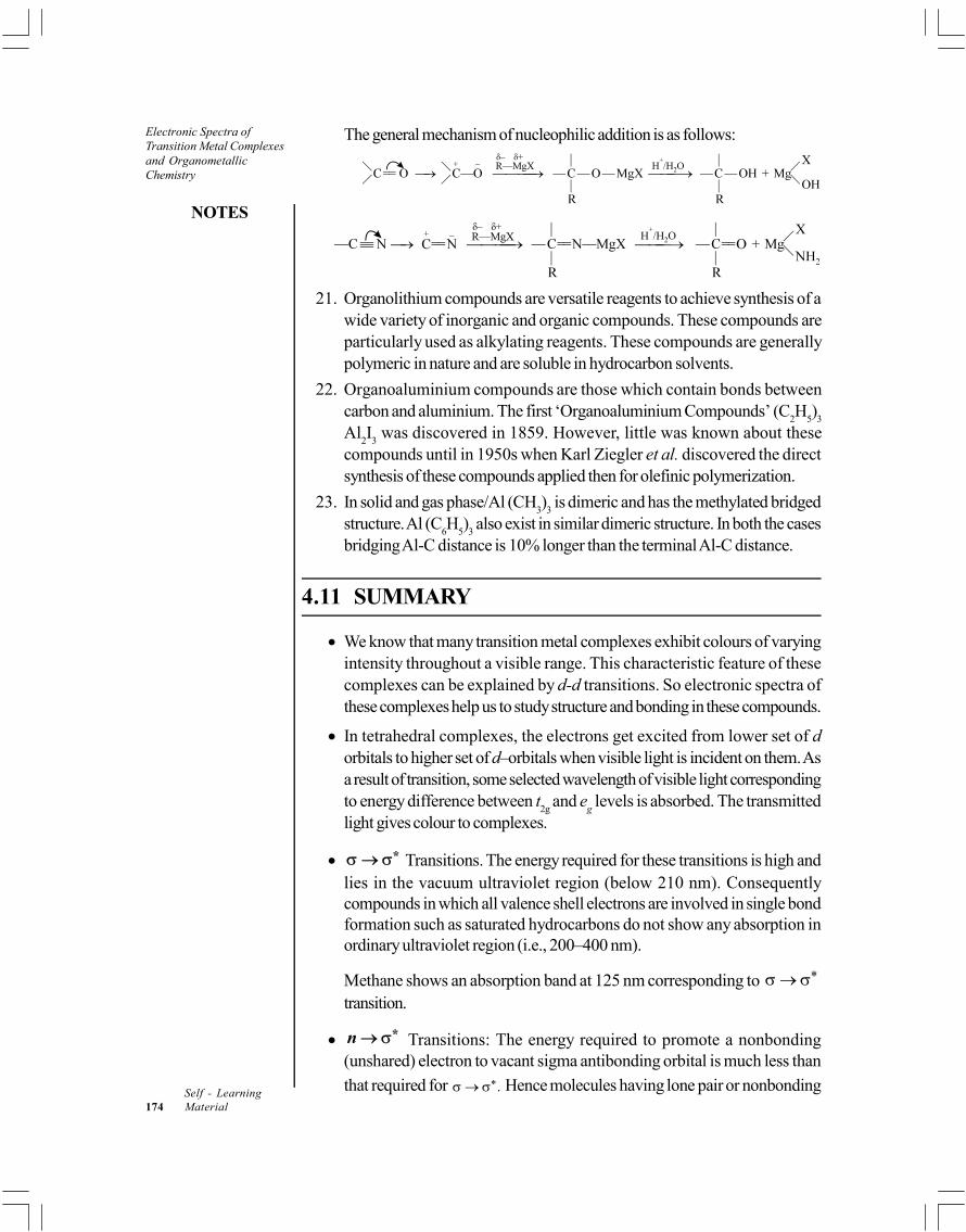
NOTES
Self - Learning174 Material
Electronic Spectra ofTransition Metal Complexesand OrganometallicChemistry
The general mechanism of nucleophilic addition is as follows:
21. Organolithium compounds are versatile reagents to achieve synthesis of awide variety of inorganic and organic compounds. These compounds areparticularly used as alkylating reagents. These compounds are generallypolymeric in nature and are soluble in hydrocarbon solvents.
22. Organoaluminium compounds are those which contain bonds betweencarbon and aluminium. The first ‘Organoaluminium Compounds’ (C
2H
5)
3
Al2I
3 was discovered in 1859. However, little was known about these
compounds until in 1950s when Karl Ziegler et al. discovered the directsynthesis of these compounds applied then for olefinic polymerization.
23. In solid and gas phase/Al (CH3)
3 is dimeric and has the methylated bridged
structure. Al (C6H
5)
3 also exist in similar dimeric structure. In both the cases
bridging Al-C distance is 10% longer than the terminal Al-C distance.
4.11 SUMMARY
We know that many transition metal complexes exhibit colours of varyingintensity throughout a visible range. This characteristic feature of thesecomplexes can be explained by d-d transitions. So electronic spectra ofthese complexes help us to study structure and bonding in these compounds.
In tetrahedral complexes, the electrons get excited from lower set of dorbitals to higher set of d–orbitals when visible light is incident on them. Asa result of transition, some selected wavelength of visible light correspondingto energy difference between t
2g and e
g levels is absorbed. The transmitted
light gives colour to complexes.
* Transitions. The energy required for these transitions is high andlies in the vacuum ultraviolet region (below 210 nm). Consequentlycompounds in which all valence shell electrons are involved in single bondformation such as saturated hydrocarbons do not show any absorption inordinary ultraviolet region (i.e., 200–400 nm).
Methane shows an absorption band at 125 nm corresponding to * transition.
*n Transitions: The energy required to promote a nonbonding(unshared) electron to vacant sigma antibonding orbital is much less than
that required for *. Hence molecules having lone pair or nonbonding

Electronic Spectra ofTransition Metal Complexes
and OrganometallicChemistry
NOTES
Self - LearningMaterial 175
electrons tend to absorb higher wavelength as compared to compoundshaving only sigma electrons.
Transitions: The excitation of bonding pi electrons to vacant
antibonding pi orbitals requires still lesser energy as compared to *n excitation. Hence these absorptions generally occur in common ultravioletregion.
*n Transitions. Such transitions are possible only in compounds havingboth the nonbonding (n) electrons as well as multiple bonds ( electrons)as they involve excitation of nonbonding electron to vacant antibonding piorbital. These are generally the lowest energy transitions and occur at higherwavelengths.
Electronic spectra are obtained when electrons are excited from one energylevel (Ground State) to a higher every level (Excited State). These transitionsare known as electonic transitions. These are high energy processes andare always accompanied by lower energy vibrational and rotationaltransitions.
Organic molecules exhibit n and n electronic transitions, where n and are –bonding, –bonding,non-bonding, antibonding and antibonding electrons, respectively.
If the transition occurs within a set of p -or d-orbitals (i.e., a transition inwhich redistibution of electrons takes place within a particular orbital orthere is no change is azimuthal quantum number ‘l’ it is called Laporte'sforbidden transition.
The word spectroscopy is widely used to mean the separation, detectionand recording of energy changes (resonance peaks) involving nuclei, atomsor molecules. These changes are due to the emission absorption or scatteringof electromagnetic radiation or particles. Spectrometry is that branch ofphysical science that treats the measurement of spectra.
According to the quantum theory of matter, the internal energy of a moleculemay be raised by the absorption of a quantum of electromagnetic radiationif the energy of the quantum exactly equals the difference E between twoenergy levels in the molecule, i.e.,
E = hv = hc
Molecules, like atoms, can exist in a number of states of differing energyand transitions in between them result in the absorption or emission of energyin the form of radiation of definite frequencies, i.e., a line spectrum of themolecule, appears.
The moment of inertial is obtained from the measured spacing between thelines in the rotational spectrum. The bond length rAB can thus, be determinedfor heteronuclear diatomic molecule from the knowledge of I and µ.
Atoms within molecules may vibrate about their average positions undergoingperiodic displacements from positions. The vibration of an atom with respect

NOTES
Self - Learning176 Material
Electronic Spectra ofTransition Metal Complexesand OrganometallicChemistry
to other atoms in a molecule involves bending or stretching of the valencebonds which hold it. Vibrational spectra result from the changes in vibrationalenergy levels. All the vibrations of a molecule can be described as one or acombination of a certain number of fundamental modes of vibration.
The most common type of detectors used in IR spectroscopy are bolometers,thermocouples and thermistors. The bolometer usually consists of a thinmetal conductor such as platinum wire. When IR radiation falls on theconductor it becomes war mer and produces a change in its electricalresistance. The change in resistance is a measure of amount of radiationfalling on it.
Vibration-rotation spectra are exhibited by diatomic molecules withpermanent dipole moments, Homonuclear diatomic molecules withpermanent dipole moments, Homonuclear diatomic molecules, such as O2,Cl2 of H2, do not show vibration-rotation spectra since they do not havepermanent dipoles.
When a beam of monochromatic visible or ultraviolet light is passed througha homogeneous medium, some light may be absorbed, some will betransmitted and some of it will be scattered. The scattered energy will consistalmost entirely of radiation of the incident frequency. This is known asRayleigh scattering, but in addition, certain, discrete frequencies above andbelow that of the incident beam will be scattered; this is referred to asRaman scattering.
An S-orbital is spherically symmetrical and is not affected by octahedral orany other type of field. Hence, no splitting is observed.
The p-orbitals are directional but they have same type of orientation. Theseare affected by an octahedral field but to equal extent. Therefore, theirenergy levels remain equal and no splitting occurs.
The crystal field splitting is influenced by oxidations state of transition metalion. Higher the oxidation state of metal ion greater is the crystal field splitting.
This concept was developed by Lesile Orgel.
The plots of varriation of energy level of spectio scopic states of differentsymmetry as a function of field strength D
q are called Orgel diagrams.
In the ground state for a d2 configuration, the two electrons occupy differentorbitals. In an octahedral field, the d-orbitals are split into three t
2g orbitals
of lower energy and two eg orbitals of higher energy. The two d-electrons
occupy t2g
orbitals because of their lower energy. The inner electronrepulsions would split the levels giving the spectroscopic terms for d2
electronic configuration as,1S, 3P, 1D, 3F and 1G
The transition 3A2 (F) 3T
2 (F) is of very low energy and does not fall
in the visible region and hence its not observed in the eletronic spectrum ofd2 (Td).

Electronic Spectra ofTransition Metal Complexes
and OrganometallicChemistry
NOTES
Self - LearningMaterial 177
In a free gaseous metal ion, the five d- orbitals are degenerate and electronictransition is not expected. However, when this ion is surrounded by anelectrostatic field of ligands, the d- orbitals split into two groups, t
29 and e
g.
For example, Ti (III) octahedral complex [Ti(H2O)
6]3+.
Organometallic compounds may be defined as substances having carbonto metal bonds. A large number of metals , for example, lithium, magnesium,aluminium, lead, tin, zinc, cadmium, mercury, etc., form fairly stable organiccompounds. The organic residue is usually an alkyl, alkenyl, alkynyl or arylgroup.
Metalloids like boron, silicon, germanium and arsenic too form organiccompounds which are also regarded as organometallic compounds.
Alkylmagnesium halides are therefore commonly known as Grignard reagentsafter the name of the discoverer. Their general formula is R—Mg—X whereR is a univalent hydrocarbon radical , for example, —CH3; —C2H5; —CH2—CH==CH2; —C6H5; C6H5CH2— and —X is a halogen.
Grignard reagents are colourless, hygroscopic solids. They are fairly stablein air but are never obtained in solid state for chemical reactions in synthesis.
The carbon metal bond is highly polar. Although the organic group is not acomplete anion yet it has a considerable anionic character. Thus carbanionwith an unshared pair of electrons acts as a nucleophile. Grignard reagentthus shows nucleophilic addition and nucleophilic substitution reaction.
Grignard reagent reacts with compounds having carbon-oxygen, carbon-sulphur and carbon-nitrogen multiple bonds to give addition products whichon hydrolysis give a wide variety of compounds. All such reactions arenucleophilic addition of carbanion (nucleophile) R, obtained from theheterolysis of Grignard reagent, resulting in the formation of new carbon-carbon bonds.
Organolithium compounds are versatile reagents to achieve synthesis of awide variety of inorganic and organic compounds. These compounds areparticularly used as alkylating reagents. These compounds are generallypolymeric in nature and are soluble in hydrocarbon solvents.
Organoaluminium compounds are those which contain bonds betweencarbon and aluminium. The first ‘Organoaluminium Compounds’ (C
2H
5)
3
Al2I
3 was discovered in 1859. However, little was known about these
compounds until in 1950s when Karl Ziegler et al. discovered the directsynthesis of these compounds applied then for olefinic polymerization.
In solid and gas phase/Al (CH3)
3 is dimeric and has the methylated bridged
structure. Al (C6H
5)
3 also exist in similar dimeric structure. In both the cases
bridging Al-C distance is 10% longer than the terminal Al-C distance.
Organoaluminum compounds can react with alkenes and alkynes, resultingin the net addition of one organyl group and the metal fragment across themultiple bond (carboalumination). This process can proceed in a purelythermal manner or in the presence of a transition metal catalyst.

NOTES
Self - Learning178 Material
Electronic Spectra ofTransition Metal Complexesand OrganometallicChemistry
Compounds like methyl lithium are formed by the overlap of 2s orbital oflithium with sp3 hybrid orbital of carbon. The vacant 2p orbital of the metalmay co-ordinate with Lewis bases.
The C—Li bond is more polar than the C—Mg bond of Grignard reagentbecause of the greater electropositive character of lithium.
4.12 KEY TERMS
Electronic transitions: Electronic spectra are obtained when electronsare excited from one energy level (Ground State) to a higher every level(Excited State). These transitions are known as electronic transitions andthe rules governing these transitions are called selection rules.
d-d transitions: These transition occur between t2g and eg orbitals of thecentral metal atom ion of the complexes. These are also known of ligandfield spectra. The bands are observed in UV, visible and near IR regions,i.e., from 333 to 1000 nm, Emax being in the range 1 to 50.
Metal to ligand charge transfer transitions: These transitions occurwhen electrons of central metal atom ion present in non-bonding orantibonding orbitals shifts to antibonding orbitals of the ligands. Thus itmeasures the tendency of the metal ion to reduce the ligand. Generallythese bands occur in the UV region for the metal ions in low oxidationstates.
Ligand to metal charge transfer transitions: These transitions occurwhen the electrons transition takes place from a molecular orbital locatedprimarily on the ligand to a non-bonding or antibonding molecular orbitalsituated on the metal atom. These transitions show the tendency of theligands to reduce the metal ion. These transitions also occur in UV region.
Inter-ligand transitions: These transitions occur when an electron transitiontakes place from one ligand orbitals to another ligand orbitals.
Laporte’s forbidden transition: If the transition occurs within a set of p-or d-orbitals (i.e., a transition in which redistribution of electrons takes placewithin a particular orbital or there is no change is Azimuthal quantum number‘l’ then it is called Laporte’s forbidden transition.
Spectroscopy: The word spectroscopy is widely used to mean theseparation, detection and recording of energy changes (resonance peaks)involving nuclei, atoms or molecules. These changes are due to the emissionabsorption or scattering of electromagnetic radiation or particles.
Spectrometry: Spectrometry is that branch of physical science that treatsthe measurement of spectra.
Spectrochemical series: It is the arrangement of ligands increasing orderof ligand field splitting energy ().
Orgel diagrams: This concept was developed by Lesile Orgel. The plotsof variation of energy level of spectio scopic states of different symmetry asa function of field strength are called Orgel diagrams.

Electronic Spectra ofTransition Metal Complexes
and OrganometallicChemistry
NOTES
Self - LearningMaterial 179
Organometallic compounds: Organometallic compounds may be definedas substances having carbon to metal bonds. A large number of metals, forexample, lithium, magnesium, aluminium, lead, tin, zinc, cadmium, mercury,etc., form fairly stable organiometallic compounds.
Grignard reagents: Grignard reagents are colourless, hygroscopic solids.They are fairly stable in air but are never obtained in solid state for chemicalreactions in synthesis. Grignard reagents are highly reactive and enter intoreaction with wide variety of substrates yielding many types of organiccompounds.
Organolithium compounds: Organolithium compounds are versatilereagents to achieve synthesis of a wide variety of inorganic and organiccompounds. These compounds are particularly used as alkylating reagentsand are generally polymeric in nature and are soluble in hydrocarbon solvents.
Organoaluminium compounds: Organoaluminium compounds are thosewhich contain bonds between carbon and aluminium. The first‘Organoaluminium Compounds’ (C2H5)3 Al2I3 was discovered in 1859.
Organoaluminium chemistry: Organoaluminium chemistry is the studyof compounds containing bonds between carbon and aluminium.
4.13 SELF-ASSESSMENT QUESTIONS ANDEXERCISES
Short-Answer Questions
1. What does the electronic spectra of transition metal complexes specify?
2. Why many transition metal complexes exhibit colours of varying intensity?
3. State the order of energy required for the transitions in matters.
4. What is forbidden transition?
5. Explain the selection rules for d-d transition.
6. Define the term spectroscopic ground state.
7. What is the importance of spectroscopic ground states in complexes?
8. What is spectrochemical series?
9. Why are Orgel energy level diagrams used?
10. Give examples of octahedral complexes having d1 to d 9 states.
11. Specify the examples of tetrahedral complexes having d 1 to d 9 states.
12. State the electronic spectrum of [Ti(H2O)
6]3+ complex ion.
13. Define the term organometallic chemistry.
14. How are organometallic compounds classified?
15. Explain the alkyl and aryl organometallic compounds of lithium.
16. What are the applications of organoaluminium compounds?

NOTES
Self - Learning180 Material
Electronic Spectra ofTransition Metal Complexesand OrganometallicChemistry
Long-Answer Questions
1. Discuss briefly about the electronic spectra of transition metal complexesgiving appropriate examples.
2. Explain the order and various types of electronic excitations of energycorresponding to ultraviolet and visible radiations with the help of examples.
3. Briefly discuss the types of transitions exhibited by the transition metalcomplexes giving appropriate examples.
4. Discuss the selection rules for d-d transitions with the help of examples.
5. Explain the significance and notations used in spectroscopic ground states.
6. Briefly discuss about the spectroscopic ground states in complexes givingappropriate examples.
7. Elaborate briefly about the tetrahedral complexes of metal ions having d1
and d9 configurations giving appropriate examples.
8. Explain the spectrochemical series with reference to arrangement of ligandsin increasing order of ligand field splitting energy giving appropriate examples.
9. Briefly discuss the concept of Orgel energy level diagrams with referenceto octahedral and tetrahedral complexes having d 1 To d 9 states.
10. Explain the electronic spectrum of [Ti(H2O)
6]3+ complex ion.
11. Discuss the significance of organometallic chemistry giving appropriateexamples.
12. Describe the methods of nomenclature and classification of organometalliccompounds with the help of examples.
13. Write detailed note on the general methods of preparation of organometalliccompounds.
14. Explain the preparation methods, properties, bond nature and applicationsof organometallic compounds.
15. Discuss the methods of preparation, properties, and applications of alkyland aryl organometallic compounds of lithium.
16. What are organoaluminium compounds? Give the methods of preparation,properties and structure of organoaluminium compounds.
17. Explain the applications of organoaluminium compounds.
4.14 FURTHER READING
Emeleus, H. J. and A. G. Sharpe. 1989. Modern Aspects of Inorganic Chemistry.New York: John Wiley & Sons.
Huheey, J. E., E. A. Keiter and R.L. Keiter. 2002. Inorganic Chemistry:Principles of Structure and Reactivity, 4th Edition. New York:HarperCollins Publishers.

Electronic Spectra ofTransition Metal Complexes
and OrganometallicChemistry
NOTES
Self - LearningMaterial 181
Cotton, F. A. and G. Wilkinson. 1988. Advanced Inorganic Chemistry, 5thEdition. New Jersey: Wiley Eastern.
Adams, D. M. 1974. Inorganic Solids. New York: John Wiley & Sons.
Dasmohapatra, Dr Gourkrishna. 2011. Engineering Chemistry. New Delhi: VikasPublishing House Pvt. Ltd.
Rajaram, J. and J.C. Kuriacose. 1986. Thermodynamics for Students ofChemistry. New Delhi: Lal Nagin Chand.
Rajaram , J. and J.C. Kuriacose. 1993. Kinetics and Mechanism of ChemicalTransformations. New Delhi: MacMillan India Ltd.
Hanna, M.W. 1965. Quantum Mechanics in Chemistry. London: W.A. BenjaminInc.
Rohatgi-Mukherjee, K.K. 2008. Fundamentals of Photochemistry. New Delhi:New Age International (P) Ltd.
Billmeyer Jr., F.W. 2003. Text Book of Polymer Science, 3rd Edition. NewYork: John Wiley & Sons, Inc.
Cotton, F. Albert, Geoffrey Wilkinson, Carlos A. Murillo and Manfred Bochmann.1999. Advanced Inorganic Chemistry, 6th Edition. New York: John Wiley& Sons, Inc.
Lee, J. D. 2008. Concise Inorganic Chemistry, 5th Edition. UK: OxfordUniversity Press.
Sharma, K. K. and L. K. Sharma. 2012. A Textbook of Physical Chemistry,5th Edition. Noida: Vikas Publishing House Pvt. Ltd.


Bioinorganic Chemistry andMetal Nitrosyl Complex
NOTES
Self - LearningMaterial 183
UNIT 5 BIOINORGANIC CHEMISTRYAND METAL NITROSYLCOMPLEX
Structure
5.0 Introduction5.1 Objectives5.2 Bioinorganic Chemistry
5.2.1 Essential Trace Metal Elements in Biological Processes5.2.2 Essential Trace Non-Metals in Biological Processes
5.3 Metalloporphyrins5.4 Iron Porphyrins
5.4.1 Structure of Myoglobin5.4.2 Structure of Haemoglobin5.4.3 Function of Haemoglobin and Myoglobin5.4.4 Reactions of Haemoglobin and Myoglobin5.4.5 Myoglobin and Haemoglobin Functions and Cooperativity
5.5 Alkali and Alkaline Earth Metal Ions5.5.1 Role of Mg2+ and Ca2+ in Biological Systems
5.6 Nitrogen Fixation5.7 Metal Nitrosyl Complex
5.7.1 Classification of Nitrosyl Compounds5.7.2 Types of Metal Nitrosyls5.7.3 Structure and Bonding in Metal Nitrosyls
5.8 Answers to ‘Check Your Progress’5.9 Summary
5.10 Key Terms5.11 Self-Assessment Questions and Exercises5.12 Further Reading
5.0 INTRODUCTION
In chemistry, the ‘Bioinorganic Chemistry’ is a field that examines the role of metalsin biology. Bioinorganic chemistry includes the study of both natural phenomena,such as the behaviour of metalloproteins as well as artificially introduced metals,including those that are non-essential, in medicine and toxicology. Many biologicalprocesses, such as respiration depend upon molecules that fall within the realm ofinorganic chemistry. The discipline also includes the study of inorganic models ormimics that imitate the behaviour of metalloproteins. As a mixture of biochemistryand inorganic chemistry, bioinorganic chemistry is important in elucidating theimplications of electron-transfer proteins, substrate bindings and activation, atomand group transfer chemistry as well as metal properties in biological chemistry.
About 99% of mammals’ mass are the elements carbon, nitrogen, calcium,sodium, chlorine, potassium, hydrogen, phosphorus, oxygen and sulfur. The organiccompounds (proteins, lipids and carbohydrates) contain the majority of the carbonand nitrogen and most of the oxygen and hydrogen is present as water. The entirecollection of metal-containing biomolecules in a cell is called the metallome.

Bioinorganic Chemistry andMetal Nitrosyl Complex
NOTES
Self - Learning184 Material
Heme (American English) or haem (British English) is a substance precursiveto haemoglobin, which is necessary to bind oxygen in the bloodstream. Haem isbiosynthesized in both the bone marrow and the liver. In microbiological terms,haem is coordination complex ‘consisting of an iron ion coordinated to a porphyrinacting as a tetradentate ligand, and to one or two axial ligands’. Among themetalloporphyrins deployed by metalloproteins as prosthetic groups, heme is oneof the most widely used and defines a family of proteins known as hemoproteins.Hemes are most commonly recognized as components of hemoglobin, the redpigment in blood, but are also found in a number of other biologically importanthemoproteins, such as myoglobin, cytochromes, catalases, heme peroxidase, andendothelial nitric oxide synthase.
The nitrogen cycle is the biogeochemical cycle by which nitrogen is convertedinto multiple chemical forms as it circulates among atmosphere, terrestrial, andmarine ecosystems. The conversion of nitrogen can be carried out through bothbiological and physical processes. Important processes in the nitrogen cycle includefixation, ammonification, nitrification, and denitrification. The majority of Earth’satmosphere (78%) is atmosphere nitrogen, making it the largest source of nitrogen.
Metal nitrosyl complexes are complexes that contain nitric oxide, NO, bondedto a transition metal. Many kinds of nitrosyl complexes are known, which varyboth in structure and coligand. Most complexes containing the NO ligand can beviewed as derivatives of the nitrosyl cation, NO+. The nitrosyl cation is isoelectronicwith carbon monoxide, thus the bonding between a nitrosyl ligand and a metalfollows the same principles as the bonding in carbonyl complexes. The nitrosylcation serves as a two-electron donor to the metal and accepts electrons from themetal via back-bonding. Metal-nitrosyls are assumed to be intermediates in catalyticconverters, which reduce the emission of NOx from internal combustion engines.This application has been described as one of the most successful development ofcatalysts. Metal-catalyzed reactions of NO are not often useful in organic chemistry.In biology and medicine, nitric oxide is however an important signalling moleculein nature and this fact is the basis of the most important applications of metalnitrosyls.
In this unit, you will study about the bioinorganic chemistry, essential andtrace elements in biological processes, biological functions of the bio-elements,availability of bio-metals and bio-non-metals, metalloporphyrins, haemoglobinstructure and biological functions, myoglobin-mechanism of oxygen transfer throughhaemoglobin and myoglobin, biological role of alkali and alkaline earth metal ionswith special reference to Ca2+ and nitrogen fixation, metal nitrosyl complex andnitrosylating agents.
5.1 OBJECTIVES
After going through this unit, you will be able to:
Discuss about the significance of bioinorganic chemistry
Understand the essential and trace elements in biological processes
Elaborate on the biological functions of the bio-elements

Bioinorganic Chemistry andMetal Nitrosyl Complex
NOTES
Self - LearningMaterial 185
Analyse the availability of bio-metals and bio-non-metals
State the structure and biological functions of metalloporphyrins
Explain the structure, relation and biological functions of myoglobin andhaemoglobin
Elaborate on the oxygen transfer mechanism of myoglobin
Describe the biological role of alkali and alkaline earth metal ions
Elucidate on the concept of nitrogen fixation
Explain the structure, bonding and properties of metal nitrosyl complex
Discuss the importance of nitrosylating agents
5.2 BIOINORGANIC CHEMISTRY
Bioinorganic chemistry is the study of inorganic compounds involved in life and lifeprocessses. It is concerned with the functions of all metallic and most non-metallicelements involved in biology. Metal ions play a vital role in a large number ofbiological processes in a very specific way. For example role of metal ions inrespiratory pigments (haemoglobin, myoglobin, hemerythrin and hemocyanin) andvitamin B
12 derivatives.
Essesntial and Trace Elements
Living organism consist of a relatively small number of elements, C, H, O, N, Pand S, all of which readily form covalent bonds. These elements comprise about92% of the dry weight of living things. The balance consist of elements that aremainly present as ions and occur in trace quantities.
A total count of thirty essential elements have till now been discovered andperhaps more are yet to be discovered. The list of essential trace elements isexpanding rapidly and is summarized below in Table 5.1
Table 5.1 Classification of Essential Elements
1. Bulk Structural Elements : C, H, O, N, P, S
2. Macrominerals : Na, K, Mg, Ca, Cl–, PO43–, SO
42–
3. Trace Elements : Fe, Cu, Zn
4. Ultra Trace Elements
Non-Metals : F, I, Se, Si, As, B
Metals : Mn, Mo, Co, V, Ni, Cd, Sn, Pb, Li
The Concept of Essentiality
The concept of essentiality is based on the study of maintenance of animals onspecially formulated synthetic diets in controlled environmental chambers. Thecriteria for an essential element is based on following facts :
1. An element is considered essential when a deficient intake produces animpairment of function and when restoration of level of that element curesthe impaired function.

Bioinorganic Chemistry andMetal Nitrosyl Complex
NOTES
Self - Learning186 Material
2. A specific biochemical function is associated with a particular element.
3. The element should be present in tissues of different animals at comparableconcentrations.
All the essential and trace elements are not required by every plant or animal.Sodium is vital for humans and higher animals but it is not essential for bacteria.Some higher plants require Al, B and V, C which are not much required by humans.Some essential element may be toxic or even fatal, when taken in higherconcentration.
5.2.1 Essential Trace Metal Elements in Biological Processes
All the non-metals, excluding the inert gases with an atomic weight less than bromineare now considered to be essential. The division between the essential metals andnan metals is shown in Figure. 5.1.
H Non-Metals He
Li Be B C N O F Ne
Na Mg Al Si P S Cl Ar
Na Ca Ga Ge As Se Br Kr
Rb Sr In Sn Sb Te I Xe
Cs Ba Ti Pb Bi Po At Rn
Fr Ra Metals
Fig. 5.1 Part of the Periodic Table of the Elements Showing the Division BetweenMetals and Non-Metals
Most of remaining lighter elements are metals and most of the recognized traceelements can be regarded as transition metals. The pre-transition metals includethe alkali metals, the alkaline earth metals and the group 13 elements. Many ofthese metals are essential.
Some of these essential metals are discussed below :
1. Iron : It is an important trace metal required for the growth and survival ofcells and organism. Of the total iron in the human body about 70% is presentin haemoglobin and about 3% in myoglobin. Most of the remaining iron isstored as ferritin. An adult with about 70 kg body weight carries 4.3 g ofiron.
Ferritin is major iron storage protein in mammals but it is also found in plantchloroplasts and fungi. It is distributed mainly in the spleen, liver and bonemarrow. The iron content of ferritin varies from zero to about 23%.Apoferritin protein may be prepared from ferritin by reduction of ferric ionsto ferrous ions at pH = 4.5 followed by removal of Fe2+ ions by dialysis.The apoferritin protein can store iron and then transport it to an appropriatesite to aid in the biosynthesis of other molecules involving this particularmetal. Recommended dietary intake of iron are 10 mg/day for male adultand 18 mg/day for female adult.

Bioinorganic Chemistry andMetal Nitrosyl Complex
NOTES
Self - LearningMaterial 187
Reaction pathway of Fe3+ from food stuffs to haemoglobin and to ferritininvolves the following processes :
(i) The Fe3+ of dietary material is reduced to Fe2+ in the gastrointestinaltract.
(ii) After absorption into the cells of the intestinal mucosa, Fe2+ isincorporated into ferritin as Fe3+.
(iii) The Fe2+ in mucosa is also converted to Fe3+ plasma (bound by iron-binding globulin named transferrin).
(iv) Plasma Fe3+ is in equilibrium with iron in the liver, spleen and bonemarrow.
The changes that occur are depicted as under:
Iron salts in the form of tablets and capsules are given to patients sufferingfrom anaemia.
2. Copper : Copper is essential to all organisms and is a constituent of redoxenzymes and hemocyanin. Copper in hemocyanin is oxygen carrier andsupplies oxygen to certain aquatic creatures. Copper remaining enzymesplay an important role in the pigmentation of skin and functioning of brain.The deficiency of copper in human system develops an anaemia characterizednot only by marked decrease in the total iron and heme content in bloodand tissues but also by an increased amount of free porphyrin in theerythrocytes.
3. Cobalt : Cobalt is also essential trace element which is essential for manyorganisms include mammals. It activates a number of enzymes. It is constituentof vitamin B
12 which is require for the formation of haemoglobin in vivo.
However, it is highly toxic to plants and moderately less to mammals wheninjected intravenously. Deficiency of cobalt in soil adversely affects the herdof grazing animals. Adding cobalt salts to soil, improves their health.
4. Zinc : Zinc is a constituent of enzyme carboxypeptidase which catalysesthe hydrolysis of terms peptide bond at the carboxy end of peptide chain.Zinc is an essential element for almost organisms. It behaves as a Lewisacid in biochemical systems. It is soft acceptor as compared to other divalentcations like Mg2+, Ca2+ or Mn2+ and therefore, acts as a stronger Lewisacid toward many biomolecules. Zinc containing enzyme carbonic anhydrase
Bioinorganic Chemistry andMetal Nitrosyl Complex
NOTES
Self - Learning188 Material
is vital for respiration in animals because it catalyses the normally slowcarbonic acid-carbon dioxide reaction equilibrium.
Carbonic
2 2 2 3AnhydraseCO (aq) H O H CO (aq)
5. Selenium : It is trace element for mammals and some higher plants. It is acomponent of glutathion peroxidase. It is an essential constituent of someenzymes and protects biological systems against free radical oxidants andstresses.
6. Molybdenum : It is an essential trace element for all organisms exceptgreen algae. It is a constituent of several enzymes used by nature for nitrogenfixation and nitrate reduction. It is moderately toxic. Mo excesses in biologicalsystems may cause goverment like syndrome.
7. Chromium : It is present in adult human body in ultra trace amounts. It isinvolved in glucose metabolism and diabetes. Cr (III) and insulin bothmaintain the correct level of glucose in the blood. In +6 oxidation state it iscarcinogenic.
8. Nickel : It is an essential trace element for several hydrogenases and plantureases. Its deficiency in food slows down in functioning of liver in chicksand ratsraised on deficient diet. It is highly toxic to most plants andmoderately toxic to mammals. It present in higher concentrations in biologicalsystems, if can cause cancer.
9. Arsenic : It is an essential ultratrace element for biological systems includinghumans. Its deficiency in chicks results in depressed growth. It is moderatelytoxic plants and highly toxic to mammals when present in more than ultratraceamounts.
10. Cadmium : It has practically no significance for living organisms. It is toxicto all organisms.
11. Mercury : It is a toxic substance. Its absorption causes irreversible damageto the central nervous system.
12. Manganese : It is present in several important enzymes such asmitochondrial superoxide dismutase, arginase etc. It is involved incarbohydrate metabolism. Its deficiency causes growth deprestion, bonedeformation, membrane abnormalities, etc.
13. Vanadium : It is involved in sodium pump, inhibition of ATPase. Itsdeficiency causes growth depression.
14. Lithium : It controls sodium pump and its deficiency causes growthdepression and reduced reproduction.
5.2.2 Essential Trace Non-Metals in Biological Processes
1. Phosphorus : It is an essential element for life. It is an important part ofenergy rich molecules, ATP. It is an important component of the bones asApatite Ca
5 (PO
4)
3 in the skeleton of vertebrates. It also gives strength
ensuring material of the teeth. Partial formation of fluorapatite, Ca5 (PO
4)
3

Bioinorganic Chemistry andMetal Nitrosyl Complex
NOTES
Self - LearningMaterial 189
strengthens the structure and makes it less soluble in the acid formed fromfermenting organic material in teeth, and thus protects tooth decay.
2. Chloride : Chloride ion has a vital role in ion balance. It is essential forhigher plants and mammals NaCl electrolyte. In HCl, it is essential in digesticjuices. The deficiency of chloride infants cause impaired growth.
3. Iodine : It is an essential constituent of thyroid hormone, for example,thyroxine which is important in metabolism and growth regulation.
Nearly 75% of iodine present in out body is located in thyroid gland. Iodinedeficiency causes abnormal functioning of thyroid gland and causes goitre.
4. Fluoride : It has remarkable anti-dental caries effect. It can also inhibitcertain key enzymes enolase, pyrophosphatase.
5. Silicon : It has structural role in connective tissue and an osteogenic cells.Its deficiency causes growth depression; bone and matrix deformities.
6. Boron : It has essential role in plants. It control membrane function, nucleicacid biosynthesis and lignin biosynthesis.
5.3 METALLOPORPHYRINS
Porphyrins are one of the most important groups of bioinorganic compounds inwhich a metal ion is surrounded by the four nitrogens of porphin ring. Porphinesare made of four pyrrole rings linked together through methene bridges. Therefore,porphines have macrocylic pyrrole system with conjugated double bonds as shownin Figure. 5.2. These porphines act as tetradentate ligands with four nitrogen donorsites. Two of these are tertiary nitrogen donor positions which can form coordinatebonds by donating a pair of electrons each to the metal ion. The other two aresecondary nitrogen donor positions, each of which lose a proton in forming acoordinate bond with a metal ion. Thus, a porphin ring acts as a tetradentatedinegative ligand (or dianion). Dipositive cations such as Mg2+, Fe2+, or Ni2+ arecapable of forming neutral complexes with porphine as shown Figure. 5.3.
M = Mg2+, Fe2–, Ni2–, etc.
Fig. 5.2 Porphin Ligand Fig. 5.3 Metal Complex with Porphin Ligand

Bioinorganic Chemistry andMetal Nitrosyl Complex
NOTES
Self - Learning190 Material
Four pyrrole rings of porphin carrying substituents other than hydrogen are calledporphyrins. The complexes in which a metal ion is held in the porphyrin ring systemare called metallopporphyrins. Such complexes play a vital role in biological systems.
The structures of two important metalloporphyrins heme and chlorophyllis discussed below :
Iron (II) - Porphyrin
Fig. 5.4 Iron Protoporphyrin in Heme
Chlorophyll is magnesium complex of porphyrin which plays important role inphotosynthis. In this metalloporphyrin, in addition to substituents, a double bondin one of the pyrrole rings is reduced to form a magnesium dihydrido porphyrincomplex as shown in Figure. 5.5. A cyclopentanone ring is also fixed to a pyrrolering.
Fig. 5.5 Structure of Chlorophyll

Bioinorganic Chemistry andMetal Nitrosyl Complex
NOTES
Self - LearningMaterial 191
Photosynthesis is an important redox reaction occurring in nature to convert waterand carbon dioxide into carbohydrates and oxygen in the presence of sunlight.(Refer Figure 5.5).
5.4 IRON PORPHYRINS
Oxygen is necessary for the survival of life. It is formed during photosynthesis.Different proteins have different tendencies to bind and transfer oxygen. Theseproteins are known as oxygen carriers. The two most important oxygen transferand carrier proteins are haemoglobin (Hb) and myoglobin (Mb). These are ironporphyrin complexes which are involved in oxygen transfer and oxygen storageagents in the blood and muscle tissues respectively.
Haemoglobin picks up the oxygen from lungs and delivers it to the rest ofthe body. Myoglobin accepts oxygen from the haemoglobin in the musles andstores it until needed for energetic processes.
5.4.1 Structure of Myoglobin
Myoglobin is a heme containing protein (molecular weight, 17000) and its proteinchain consist of a single polypeptide chain of 153 amino acid residues which foldsaround the heme prosthetic group (Refer Figure 5.6).
Fig. 5.6 The Structure of Myoglobin Containing Heme Group and Polypeptide Chain
The heterocyclic ring system of heme is porphyrin derivative containing four pyrrolegroups joined by methane bridges. The Fe (II) atom present at the centre of theheme is bonded by four porphyrin nitrogen atoms and one nitrogen atom formimidazole side chain of histidine residue which is a part of long protein chain aminoacid residues. This polypeptide chain plays a vital role in biological fixation of O
2.

Bioinorganic Chemistry andMetal Nitrosyl Complex
NOTES
Self - Learning192 Material
5.4.2 Structure of Haemoglobin
Haemoglobin (molecular weight 64,450) can be considered as an approximatetetramer of myoglobin. It contains four heme groups and four proteins. Chains towhich heme groups are attached. Two of the chains are identical and known as-chains while the other two identical chains are called -chains.
-Chains : The -chains have 146 amino acids and closely resemble thechain of myoglobin. The two -chains with 141 amino acids are somewhat lesslike the chain in myoglobin.
Both Hb and Mb have five coordinated Fe (II) atom. It is bonded by fournitrogen atoms from pyrrole rings and fifth from protein chain. The sixth position isoccupied by weakly bonded water. Mb and Hb in such molecules are usuallycalled as deoxymyoglobin (Deoxy-Mb) and deoxyhaemoglobin (Deoxy-Hb).However when the sixth position which is trans to histidine chain (Refer Figure.5.7) is occupied by molecular oxygen then these molecules are called oxymyoglobin(Refer Figure 5.7).
(Oxy–Mb) and
Oxyhaemoglobin (Oxy–H6)
Fig. 5.7 Haemoglobin Molecule
5.4.3 Function of Haemoglobin and Myoglobin
Both haemoglobin and myoglobin play a vital role in transportation of oxygenfrom lungs to tissues and CO
2 (as HCO
3–) from tissues to the lungs. Oxygen is
inhaled into the lungs at a very high pressure when it binds Hb in the blood formingHbO
2. The oxygen is then transported to tissues where the partial pressure of O
2
is low. The O2 then get dissociated from Hb and diffuses to the tissues where
myoglobin picks it up and stores it until it is needed. Mb has greater affinity for O2
than Hb. This increases the rate of diffusion of O2 from the capillaries to the tissues
by increasing its solublity. The Hb and CO2 (as HCO
3–) are returned to the lungs
from where CO2 is exhaled. This process may be shown as :

Bioinorganic Chemistry andMetal Nitrosyl Complex
NOTES
Self - LearningMaterial 193
5.4.4 Reactions of Haemoglobin and Myoglobin
The heme group consists of Fe2+ ion enclosed in a porphyrin ligand. Fe2+ ion hassix coordination sites. The porphyrin ligand takes up only four of the six sites,leaving two free binding sites on opposite sides of the metal ion. If a free heme ispresent in aqueous solution, the two vacant sites may be occupied by watermolecules. A naked heme group binds to oxygen molecule in an irreversible mannerwhen Fe2+ is oxidised to Fe3+. This oxidation destroys its oxygen binding capacity.The reactions occur as (Refer Figure 5.8) follows:
Hematin
Fig. 5.8 This Dimer can no Longer act as Oxygen Carrier
From Figure. 5.8 it is clear that porphyrin Fe is protected due to the presenceof hydrophobic protein chain around the Fe (II) and blocks the approach of largermolecules to the neighbourhood of Fe (II) and hence prevent oxidation of Fe (II)in haemoglobin to Fe (III). The hydrophobic groups also prevent the solvation ofions. Fe (II) of myoglobin and haemoglobin can be oxidised under certain controlledconditions to Fe (III) forming metamyoglobin of Mb and metahaemoglobin of Hb.

Bioinorganic Chemistry andMetal Nitrosyl Complex
NOTES
Self - Learning194 Material
These Fe (III) proteins are responsible for brown colour of old meat and driedblood.
Deoxy myoglobin (Deoxy-Mb) is a five coordinated high spin Fe (II) complexwith four of the coordination positions occupied by porphyrin N atoms. The fifthposition is occupied by an N atom of an imidazole ligand of a histadine residuewhich joins the heme to the protein. In the absence of O
2, the ligand field is weak
so that the five coordinate heme complexes of Fe (II) are always high spin havinga configuration t
2g4e
g2. Therefore, these five coordinate complexes are
paramagnetic. In this high spin state, O2 has substantially larger radius than in the
low spin Fe (II) state having the configuration t2g
6 because of repulsive effect ofone e
g electron occupying the d
x2–y2 orbital directed towards the four N atoms ofthe porphyrin ring. Therefore, Fe lie above the plane of the four nitrogen atoms byabout 70 pm to give a square pyramidal arrangement as shown below :
Fig. 5.9 Square Pyramidal Structure with Fe Lying about 70 pm Above thePlane of the Ring
When oxygen bonds to the sixth position of the ion become coplanar. Insuch a situation oxygen gets coordinated to Fe (II). The ligand field becomesstrong resulting in spin pairing giving a low spin t
2g6 complex. The resulting complex
is diamagnetic and Fe-N bond distance is approximately same as porphyrin hole.Therefore, the iron becomes coplanar. The release of strain energy of the squarepyramidal complex compensates the loss of spin pairing energy in going from 5-coordinated deoxy Hb or Mb to six coordinated Oxy-Hb or Oxy Mb. Therefore,the coordination of O
2 will result in dropping of Fe in the plane of the heme group.
(Refer Figure 5.10).
Fig. 5.10 Oxy Haemoglobin Low Spin Octahedral Complex

Bioinorganic Chemistry andMetal Nitrosyl Complex
NOTES
Self - LearningMaterial 195
The shrinkage of Fe2+ and falling into the plane of porphyrin ligand is shownin Figure 5.11
The net result of this interaction in haemoglobin is to increase the affinity ofO
2 of the second heme site and so on. As, one ion binds an oxygen molecule,
the molecular shape of chages to make the binding of additional oxygenmolecules easier. This is known as the phenomenon of cooperativity.
Cooperativity enables Hb to bind and release O2 more effectively.
Fig. 5.11 The Shrinkage in Size of Fe2+ and Dropping into thePlane of Porphyrin Ligands
5.4.5 Myoglobin and Haemoglobin Functions andCooperativity
The main function of haemoglobin is to bind O2 at high partial pressure of O
2 in the
lungs and then carry in through the blood to the tissues where myoglobin picks upO
2 from Hb. In the lungs where the pressure O
2 is high and much O
2 is bound, the
affinity of heme for O2 becomes very high. If defficiently loads up with as much O
2
as possible. But when the haemoglobin reaches the cells where the pressure of O2
is low, O2 begins to dissociate from the complex. The myoglobin picks up all the
O2. Since myoglobin has only one heme group, it does not have any cooperative
binding, so it does not lose its affinity for O2. This shows the Mb has a higher
affinity for O2 than Hb at low partial pressure of O
2 in the muscle.
Transport of CO2 and Bohr Effect
A graph between percentage saturation and partial pressure of O2 is shown in
Figure 5.12.
The graph shows that Hb and Mb have almost similar binding affinity for O2
at high pressure but Hb is much poor O2 binder at lower pressures of O
2 in muscles.
As a result, Hb passes its O2 onto Mb as required. Moreover, the need for O
2 is
greatest in tissues arhich have already consumed oxygen and simultaneouslyproduced CO
2. The CO
2 lowers the pH (2H
2O + CO
2 HCO
3– + H
3O+) and
the increased acidity favours the release CO2 from oxyhaemoglobin to Mb. The

Bioinorganic Chemistry andMetal Nitrosyl Complex
NOTES
Self - Learning196 Material
oxygen affinity of haemoglobin varies with the pH of the medium. This pHsensitivity effect is called Bohr effect. In other words the variation in Oxygenaffinity with the pH of the medium is called Bohr effect. It can be explained interms of the effect of pH on the interaction between the heme group and theionizable groups of the protein.
20 40 60 80 100Partial Pressure of O (Torr)2
20
40
50
80
60
100
Per
cent
age
Sat
urat
ion
Partial Pressure of Oxygen
in lungsAt muscles
Hemoglobin
Myo
globin
Fig. 5.12 O2 Binding Curves for Mb and Hb with Partial Pressure of O
2
5.5 ALKALI AND ALKALINE EARTHMETAL IONS
The alkali (Na+, K+) and alkaline earth metals (Mg2+, Ca2+) constitute about 1%of human body weight. The solution chemistry of these metals was mainly developedquite recently due to :
(i) Lack of complexes of these cations with simple neutral ligands like ammonia,ethylene diammine, etc.
(ii) The absence of spectroscopic UV-vis and magnetic properties.
Alkali metal ions along with magnesium and calcium ions play an essential role inbiological systems. They are involved in several physiological processes such astransmission of nervous impulses, nervous control of secretary and muscularfunctions, protein synthesis, enzymatic regulation, etc.

Bioinorganic Chemistry andMetal Nitrosyl Complex
NOTES
Self - LearningMaterial 197
Role of these metal ions in biological systems is discussed below :
1. Sodium : It is the major component of extracellular fluid. It mainly exists aschloride and bicarbonate. It plays following functions :
(i) Its role in biological system is regulate acid-base equilibrium.(ii) It also helps in maintaining osmotic pressure of the body fluid, thereby
protecting the body against fluid loss.(iii) It has a role to play in preservation of normal irritability of muscle and
permeability of the cell.(iv) Many enzyme reactions are controlled by Na+.(v) The injectable medicines are dissolved in sodium chloride before they
are injected human body.
2. Potassium : Potassium is present as cation in intracellular fluid as well asextracellular fluid.
(i) It influences acid base equilibrium like sodium in extracellular fluid.(ii) It controls osmotic pressure and water retention.(iii) It is important for metabolic functions like protein biosynthesis by
ribosomes.
Chemically, sodium and potassium may be similar (alkali metals, Group 1)but there is different biological response for the two ions. While Na+ ions arepumped out of the cytoplasm, K+ ions pumped in. This ion transport is calledsodium-pump, which involves active take up of K+ ions and expulsion of Na+
ions. The difference in concentration of the two ions inside and outside the cellmembrane produces an electrical potential, which is crucial for the functioning ofnerve and muscle cells.
It may be noted that higher intake (we require about 1 g of Na+ per day) ofNa+ ions is problem, but there is no such risk from higher intake of K+ ions. Ratherpotassium deficiency more common. We can make up the K+ ions deficiency byconsuming more of banana and coffee.
A number of enzymes such as glycolytic enzyme pyruvate kinase require K+
for maximum activity.
Na+ and K+ are present in the red blood cells. The ratio of these ions inmammals such as human beings, rabbits, rats and horses is 1:7. In cats and dogs,this ratio is 15:1.
To establish this ratio also called concentration gradient in the cell,biologists have suggest different mechanisms involving sodium pump and potassiumpump.
(i) The concentration gradient controls the development and functioningof the nerve cells.
(ii) In restful state, potential of the nerve cell is linked to K+ concentrationacross the memberrane.
(iii) During activation of the nerve cells, a chemical called acetylcholine isdischarged. The discharge is transmitted through the length of the nervecell by electric impulse.

Bioinorganic Chemistry andMetal Nitrosyl Complex
NOTES
Self - Learning198 Material
5.5.1 Role of Mg2+ and Ca2+ in Biological Systems
1. Mg2+ ions are present in the enzyme aminopeptidase which hydrolysispolypeptides at the free amino acid end of the chain to form lower peptidesand sometimes free amino acids.
2. Ca2+ ions are present as phosphates in the bones of human beings andanimals. These ions play an important role in muscle contraction.
3. About 99% of the body calcium is in the skeleton as the deposits of calciumphosphates in soft and fibrous matrix. A very small quantity of calcium isalso present in the body fluids where it is partly ionized. The small amountof ionized calcium is of great importance in blood coagulation, excitabilityof the heart, muscles and nerves.
Important minerals of calcium used in biological structures are given infollowing Table 5.2.
Table 5.2 Important Minerals
Organism Location Mineral Formula
Birds Egg shells Calcite CaCO3
Molluscas Shell Argonite CaCO3
Vertebrates
Mammals Bone Hydroxyapatite Ca5(PO
4)
3 (OH)
Some important points regarding Ca2+ & Mg2+ are :
(i) Calcium ions are needed to bring about blood clotting and contract ofmuscles such as heart beat.
(ii) Deficiency of Ca2+ ions causes tetany, while excess of it causes Calcification.
(iii) Both Mg2+ and Ca2+ ions are excreted via the large intestine instead ofkidney. Calcium deficiency might occur due to its precipitation as calciumoxalate, after reaction with soluble oxalates present in the body.
Magnesium, essential to all organisms is relatively present in greater concentrationin red cells than in plasma. It is constituent of chlorophyll which plays an importantrole in photosynthesis. Mg2+ ions play of vital role in conversion of ATP (a highenergy rich molecule) to ADP, which drives most of the cell reactions.
5.6 NITROGEN FIXATION
The conversion of atmospheric nitrogen into useful nitrogenous compounds bynatural or artificial methods is called fixation of nitrogen. Nitrogen present inthese nitrogenous compounds is called fixed nitrogen.
Nitrogen Fixation by Natural Methods
1. By Lightning Discharges : Nitrogen and oxygen present in air combineto form nitric oxide in influence of lightning discharges. Nitric oxide gets

Bioinorganic Chemistry andMetal Nitrosyl Complex
NOTES
Self - LearningMaterial 199
oxidised by excess of O2 present in atmosphere to form N
2O
5 which dissolves
in water to form nitric acid. The acid is washed down by rain into soil,where it reacts with limestone and alkalis of the soil to form nitrates andstored there as plant food.
Lighing2 2N O 2NO
2 2 54NO 3O 2N O
2 5 2 3N O H O 2HNO
3 3 3 2 2 22HNO CaCO Ca(NO ) CO H O
2. By Symbiotic Bacteria : The atmospheric N2 is constantly transferred to
the soil though certain bacteria called symbiotic bacterium (Rhizobium).The grow in small nodules in the roots of plants belonging to the family ofLeguminacea (pea, gram etc.) and directly assimilate atmospheric N
2 and
convert it into products useful for plants.
Nitrogen and ammonium salts present in the soil are converted by nitrosifyingbacteria into nitrites and by nitrifying bacteria into nitrates. The final productsnitrates serve as a plant food. This process of oxidation is known as nitrificationand it causes the combined nitrogen to be available to the plant.
The species of rhizobium is specific for each species of plant. Cyanobacteria(blue-green algae perform nitrogen fixation in the ocean and, to some extent, infresh water. All these micro organism produce ammonia through the activity ofnitrogenase.
Most free nitrogen bacteria perform nitrogen fixation anaerobically whereascyanobacteria do it aerobically.
nATP nADP + nPO4
3–
N + 8H2+ 2NH4
+
Ammonium ion(Reactive andsoluble form)
3 Ferrodoxin(Oxidised)
3 Ferrodoxin(Reduced)
(unreactive andInsoluble form)
The reaction involves three reduced molecules of ferredoxin which donatesix electrons. The source of this reducing power is NADPH. Twelve to eighteenmolecules of ATP supply the necessary energy for the production of ammonia at arate which is regulated by the inhibitory effect of the product on the association ofthe two components of the nitrogenase.
Denitrification: The process in which denitrifying bacterias convert nitrogenouscompounds of the soil into free nitrogen which goes back to atmosphere is knownas denitrification. Because of these cycles of changes which constantly occur innature, the total average amount of nitrogen in the atmosphere remain unchanged.

Bioinorganic Chemistry andMetal Nitrosyl Complex
NOTES
Self - Learning200 Material
Important Features of Nitrogen Fixation
All nitrogen fixation processes have the following fundamental features :
(i) The bacterial enzyme called Nitrogenase catalyses the process.
(ii) Strong reductant, such as Ferredoxin which behaves as an electron carrierwith a very low redox potential.
(iii) The energy rich molecule, ATP in biological systems
(iv) Oxygen free conditions (Anaerobic).
The enzyme nitrogenase is at the heart of biological nitrogen fixation. It has solvedthe problem of overcoming the great inertness of the N N molecule. It is animportant enzyme which catalyses the conversion of molecular nitrogen toammonia.
The nitrogenase enzymes responsible for nitrogen fixation consists of twometalloproteins :
(i) Fe-Protein also known as Fe-S-Protein or nitrogenase reductase(ii) Mo-Fe-Protein also known as Mo-Fe-S-Protein
Thus, nitrogenase is a complex of two proteins in a dynamic equilibriumwith its components :
Mo-Fe-Protein +2Fe-Protein Nitrogenase Complex.
Thus, nitrogenases are the complexes of Iron-Sulphur Protein (Fe-S-Protein)and Molybdenum. Iron-Sulphur Protein whose activity couples ATP hydrolysis toelectron transfer from ferredoxins for carrying out reduction of nitrogen to ammonia.
Nitrogen Fixation by Artificial Methods
1. Fixation of Nitrogen as HNO3: In a high tension electric are where the
temperature is high, nitrogen of the air combines with oxygen to form nitricoxide. It combines with more of oxygen to form nitrogen peroxide. Thismay be absorbed in water in presence of excess of air to give nitric acidwhich may be used for the manufacture of nitrogenous fertilisers.
2 2N O 2NO (Nitric Oxide)
2 22NO O 2NO (Nitrogen Peroxide)
2 2 2 3Nitrogen From Nitricperoxide air acide
4 NO 2H O + O 4HNO
2. Fixation of Nitrogen as NH3 and Ammonium Salts: A mixture of nitrogen
(manufactured by Biquification of air) and hydrogen in the ratio 1 : 3 iscompressed to a pressure of 200–500 atmospheres and is passed over acatalyst (Finely Divided Iron + Molybdenum) heated to about 550°C. Thisforms the Haber's process for manufacture of ammonia which then can beconverted into ammonium salts by treatment, with suitable acids.
catalyst
2 2 3highpressN 3H 2NH

Bioinorganic Chemistry andMetal Nitrosyl Complex
NOTES
Self - LearningMaterial 201
3. Fixation of Nitrogen as Calcium Cyanamide, CaCN2: Nitrogen gas
obtained by the evaporation of liquid air is passed over calcium carbideheated to 800–1000°C. A mixture of calcium cyanamide and carbon isobtained which is extensively used as a fertilizer under the name of nitrolim.
2 2 2Calcium Calciumcarbide cynamide
CaC N [CaCN C]( )Nitrolim
4. Fixation of Nitrogen as Nirides: Nitrogen combines with magnesium andaluminium a high temperature to give nitrides which are employed as a sourceof ammonia. These nitrides are decomposed by H
2O and NH
3 is evolved.
2 3 2Magnesium nitride
3Mg N Mg N
2Aluminium nitride
2Al N 2AlN
2 3 3AlN 3H O Al(OH) NH
Aluminium Hydroride
5.7 METAL NITROSYL COMPLEX
The compounds containing nitric oxide group are called nitrosyl compounds orthe compounds in which the nitrogen of the nitrosyl group is directly bonded to theatoms or ions.
Nitric Oxide molecule is an odd eletron molecule having an unpaired electron.Due to its structure it readily combines with other elements by direct addition to formnitrosyl compounds. Nitric oxide forms nitrosyl compounds in following ways :
(i) A positive ion, NO+, is formed due to the loss of an electron which thencombiness with atom or malecule. It may have the following structure :
(: N : : : O :)+ or (: N = O:)+
(ii) A negative ion NO– is formed due to the gain of an electron from someelectrons positive metal and it has probably the structure :
(: N : : O :)– or (: N = O:)–
(iii) Nitric oxide may act as a co-ordinating group through the donation of anelectron pair. Such behaviour might involve neutral molecule or NO+ orNO– group.
5.7.1 Classification of Nitrosyl Compounds
Nitrosyl Compounds are classified as :
1. Simple Compounds Containing the NO+ Group: For example,
(i) NOHSO4 and (NO)
2S
2O
7, (ii) Nitrosyl Halides (NOX, where X = F, Cl,
Br), (iii) NOClO4, NOBF
4 (iv) (NO)
2SeO
4, (v) NOSCN, (vi)
NO[Cr(NH3)
2 (SCN)
4] (NO)
2 PtCl
6, NOFeCl
4 and NONO
3.

Bioinorganic Chemistry andMetal Nitrosyl Complex
NOTES
Self - Learning202 Material
2. Compounds Containing NO– Group : The only compound of this type issodium nitrosyl, which is prepared by the action of dry nitric oxide on sodiumin liquid ammonia.
Sodium NitrosylsNa + NO NaNO
It is an white substance which is unstable.
3. Coordination Compounds Containing No Group or Metal Nitrosyl:These are the compounds in which nitrogen of the nitrosyl group is directlybonded to the metal atoms or ions. Metal nitrosyls occur mostly as mixedligand.
Complex in conjugation with other –bonding low oxidation state stabilizing ligands.
In metal nitrosyls, the nitric oxide act as a coordinating group through thedonation of an electron pair to the metal atom or ion. This may involve the neutralmolecule on the NO+ or NO– group.
5.7.2 Types of Metal Nitrosyls
The corrdinated nitrosyl compounds may be classified as :
1. Nitrosyl Carbonyls : These include compounds of cobalt and ironcompounds such as Co(NO) (CO)
3 and Fe (NO)
2 (CO)
2. Nitrosyl
carbonyls chemically resemble to carbonyls.
As CO donates two electrons to the metal atom in the formation of metalliccarbonyls while no molecule donates three electrons of metal atom information of nitrosyls, there is possibility that two no molecules can replacethree CO groups from metallic carbonyls to form nitrosyls carbonyls.Examples of pairs of compounds so related are given as follows (oxidationstate of the metal atom is shown in parentheses) :
Fe(CO)5 (Fe = 0) Fe(CO)
2 (NO)
2 (Fe = –2)
Mn(CO)4 (NO)[Mn = –1] Mn (CO) (NO)
3 [Mn = –3]
Co(CO)3 (NO) (Co = –1) Co (NO)
2 (Co = –3]
(OC) Fe – Fe(CO) [Fe = 0] (NO) Fe – Fe(NO) [Fe = +2]2 3 2 2
Et
SEt
Et
SEt
Preparation
(i) The nitrosyl carbonyl compounds like Co(CO)3 NO and Fe(NO)
2 (CO)
2
can be prepared by the action of nitric oxide on polynuclear carbonyls ofcobalt and iron.
Co2(CO)
3 + 3NO 2Co (CO)
3 NO+2CO
[Fe(CO)4]
3 + 6NO 3Fe(NO)
2(CO)
2 + Fe(CO)
5 + CO

Bioinorganic Chemistry andMetal Nitrosyl Complex
NOTES
Self - LearningMaterial 203
(ii) Cobalts nitrosyl carbonyl may be prepared by the action of oxide on solutionscontaining the [Co(CO)]–
4 ion.
(iii) Cobalt nitrosyl carbonyl may also be prepared by treating an alkalinesuspension of Cobalt (II) cyanide first with carbon monoxide and then withnitric oxide.
Properties
(i) Substitution Reactions : In metal carbonyl nitrosyls, the NO+ ions aremore firmly attached with the metal ion than the CO groups. So when theseare treated with ligands like PR
3, CNR, phen, etc., only CO groups are
replaced by these ligands, for examples.
2 2 3 2 2Fe (CO) (NO) + 2L (L = PR , CNR) Fe (L) (NO) + 2CO
2 2 2Fe (CO) (NO) + Phen Fe (Phen) (NO) + 2CO
(ii) Action of Halogens : When metal carbonyl nitrosyls are treated withhalogens, these get converted into metal nitrosyl halides, for examples.
2 2 2 2 22[Fe (CO) (NO) ] + I [Fe (NO) I] + 4CO
2. Nitrosyl Compounds of Type (MI (NO)xAy) : Nitrosyls of monopositivemetals include :
(i) Metal Nitrosyl Hydroxides : The examples of this are : Ni(NO)OH andis alcohol derivatives like Ni(NO)(OR)OH and Ni(OH)(OR). x(ROH).[R=CH
3 (x=1),
C2H
5 (x = 0) Metal nitrosyl hydroxides are strong reducing compounds
and have been prepared by the action of nitric oxide on nickel tetracarbonylin the presence of water or water and alcohol.
(ii) Metal Nitrosyl Halides : Examples are :
(a) Fe2(NO)
4I
3Fe (NO)
2I, Fe(NO)I,
Fe(NO)3Cl
(b) Co(NO)2X, Where X = Cl, Br, I
(c) Ni (NO)X Where X = Cl, Br, I
Preparation
(a) Volatile diamagnetic Trinitrosyl Iron Halides Fe (NO)3X, may be prepared
by the direct action of nitric oxide on iron carbonyl halides in the presenceof finely divided iron as a halogen acceptor. These readily lose nitric oxide,yeilding the corresponding dinitrosyl halides. Similarly, nitrosyl halides, i.e.,Co(NO)
2X and Ni(NO)X may be prepared.
(b) Nitrosyl halides of cobalt and nickel can be prepared by the action of nitricoxide an metallic in the presence of a suitable halogen acceptor.
CoX2 + Co + 4NO 2[Co(NO)
2X]
4NI2 + 2Zn + 8NO 2[Ni(NO)I]
4 + 2ZnI
2
SnI4+2Co + 4NO 2Co(NO)
2I + SnI
2

Bioinorganic Chemistry andMetal Nitrosyl Complex
NOTES
Self - Learning204 Material
Ease of the formation of these compounds increases in the sequence Ni <Co < Fe and X = Cl < Br < I. Thus, Fe(NO)
2I is the most stable compound
and is readily formed by the direct action of nitric oxide on cobalt iodide inthe presence of metallic iron.
CoI2 + 2Fe + 4No Co + [Fe(NO)
2I]
2
(c) Nitrosyl halides may also be prepared by the action of halogen on nitrosylcabonyls
2[Fe(CO)2(NO)
2] + I
2 [Fe(NO)
2I]
2 + 4CO
The M(NO)2Cl (M=Mo or W) may also be prepared as follows :
2 2º
CH Cl–2 2 2 220 C
M(NO) Cl 2N OCl M(NO) Cl 6CO
Properties of Metal Nitrosyl Halides
(i) Metal nitrosyl halides react with other ligands to from mono-nuclearcomplexes, for example,
[Fe(NO)2X]
2 + 2L 2 [Fe(NO)
2XL]
(ii) Iron nitrosyl halides [Fe(NO)2I]
2 reacts with K
2S and CH
3Cl to form dark
red compounds which have the composition, K2 [Fe(NO)
2S]
2 and
[Fe(NO)2(SCH
3)]
2 and are called Roussin's salts. In these compounds Fe
is in –1 oxidation state.
32 CH ClK S2 2 2 2 2 2 3 2–2KI 2KCl[Fe(NO) I] K [Fe(No) S] [Fe(NO) (SCH )]
(iii) Metal Nitrosyl Thio Compounds : The true structures of most of themetal nitrosyl thio compounds have not been confirmed. These compoundsappear to have unipositive metals but the exact oxidation states of the metalshave never been determined with certainity. Iron forms the compoundFe(NO)
2SA, where A may be hydrogen or a metal,sulphonic acid groups,
or an alkyl or aryl group.
Best examples are Roussin's red salts, M[Fe(NO)2S] where M=Na+, K+,
and NHI. These are unstable compounds which have been prepared bythe action of nitric oxide on freshly precipitated Iron (II) sulphide.
3. Nitrosyl Compounds of the Type (M(II) (NO)xA
y) : Iron (II) nitrosyl
compounds are generally brown, but green and red species have also beenprepared. Crystalline compounds such as Fe (NO) HPO
4 and Fe(NO)
SeO4. H
2O have been prepared.
Nitroso ferrous sulphate, FeSO4, NO or [Fe+(NO+) SO
4] : When, to the
aqueous solution of a metallic nitrate (say NaNO3) is added freshly prepared
solution of FeSO4 and a few drops of conc. HNO
3 along the sides of the
test tube, a brown ring of nitroso ferrous sulphate, [Fe+(NO)+] SO4 is formed
at the junction of the two liquids in the test tube.
The formation of nitrose saferrous sulphate occurs in following steps :
(i) 6NaNO3+H
2SO
4 NaHSO
3+HNO
3

Bioinorganic Chemistry andMetal Nitrosyl Complex
NOTES
Self - LearningMaterial 205
(ii) 6FeSO4 + 2HNO
3 + 3H
2SO
4 3Fe
2 (SO
4)
3 + 2NO + 4H
2O
(iii) FeSO4 + NO FeSO
4 NO or [Fe+ (NO+)]2+ SO
42–
4. Nitrosyl Compounds of the Type M (IV) (NO) xA
y : The only known
compounds of this type are :
Fe2(NO)
2 (SO
4)
3, B(NO)F
3, B(NO)Cl
3 and Ru (NO) (R
2NCS)
3
Where, R= CH3, C
2H
5 etc.
5. Nitrosyl Derivatives Containing Groups of the Type [MA(NO)]n– :This includes the compounds such as
[Mn(CN)5NO]3–, [Fe(CN)
5NO]2–, [Mo(CN)
5NO]4–
[Ru(CN)5NO]3–, [Co(NO
2)
5NO]3–, [Co(NH
3)
5NO]2+
Iron compounds [M(CN)5(NO)]3– have been prepared by the action oxide
on hexacyano ferrate (II) salts. [Mn(CN)5NO]3– is obtained by saturating
manganese (II) acetate solution containing cyanide with nitric oxide.
Na4 [Fe(CN)
6] + NO Na
2 [Fe(CN)
5NO] + 2NaCN
Sodium nitroprusside, Na2 [Fe2+(CN)
5(NO4)] is one of the important
compounds of this type. It may be prepared by the reaction of sodiumnitrite on sodium ferrocyanide.
Na4[Fe2+ (CN)
6)] + NaNO
2+ H
2O Na
2 [Fe2+ (CN)
5NO+] +
2NaOH+NaCN
It may also be prepared by passing nitric oxide (NO) into acidified solutionof Na
4 [Fe(CN)
6]
2Na4[Fe (CN)
6) + H
2SO
4+ 3NO 2Na
2 [Fe (NO)(CN)
5] +
2NaCN
+ Na2SO
4+1/2 N
2 + H
2O
Properties
(i) Sodium nitroprusside forms beautiful ruby red rhombic crystals which aresoluble in water.
(ii) If freshly prepared sodium nitroprusside is added to a solution having sulphideion (i.e.). Na
2S but not H
2S), a purple or violet colour is produced.The
production of this colour is ascribed to the formation ofNa
4[Fe2+(CN)
5(NO+)(S)]. The production of this colour is ascribed to the
formation of Na4[Fe2+(CN)
5(NO+)(S)]. The production of this purple or
violet colour is used to confirm the presence of S2– ion in a given mixture.
Na2S+Na
2[Fe2+(CN)
5(NO+) Na
4[Fe2+(CN)
5(NO+)(S2–)]
(Violet or Purple Colour)
(iii) Alkali sulphites give a rose red colour because of the formation ofNa
4[Fe(CN)
5(NO)(SO
3)]. This reaction can be used to distinguish sulphites
from the thiosulphate which do not show this reaction.

Bioinorganic Chemistry andMetal Nitrosyl Complex
NOTES
Self - Learning206 Material
(iv) With silver nitrate a flesh coloured Ag2[Fe(CN)
5(NO)] is,
2AgNO3+Na
2[Fe(CN)
5(NO)] Ag
2[Fe(CN)
5(NO)]+2NaNO
3
O ||
(v) Aldehydes and Ketones having CH3— C —R group yield deep red colour
with sodium nitroprusside and excess of NaOH.
(vi) It gets converted into sodium ferrocyanide, Na4[Fe(CN)
6] on treatment
with an alkali.
6Na2[Fe(CN)
5(NO)]+14NaOH 5Na
4[Fe(CN)
6]
+Fe(OH)2+6NaNO
3+6H
2O
According to another view NO+ group present in nitroprusside gets oxidisedto NO
2 and thus a nitro complex is obtained.
Na2[Fe(CN)
5(NO)]+2NaOH Na
4[Fe(CN)
5 (NO
2)] + H
2O
(vii) [Fe(CN)5(NO)]2– ion is having diamagnetic character. Its diamagnetic
character confirms the fact that NO is present as NO+ ion is this complexion.
5.7.3 Structure and Bonding in Metal Nitrosyls
Structures of some important metal nitrosyls are discusses below :
(i) Fe(NO)4 : Orbital diagram of Fe(NO)
4 is given below in Figure 5.13.
3d 4s 4p
O O O OCCBB
N+ N+ N+
N+R R
Fig. 5.13
(ii) Fe(NO)2(CO)
2 : Its orbital diagram as shown in Figure 5.14.
B B O+ O+
N+ N+C C
R R
3d 4s 4p4s 4p
Fig. 5.14

Bioinorganic Chemistry andMetal Nitrosyl Complex
NOTES
Self - LearningMaterial 207
(iii) Fe2(NO)
4I
2 : Its orbital diagram is as shown in Figure 5.15
3d 4s 4p
R RN+ N+
OB
OD
I+ I+
DBO
O
RN+
N+
R
Fig. 5.15
(iv) Fe(NO)3CI : Its orbital diagram is shown in Figure 5.16.
OD
OB
OD
R R RN+
N+ N+ OI
3d 4s 4p
Fig. 5.16
(v) Configuration of Fe(NO)3I : It has the following dimeric structure with metal-
metal bonds (Refer Figure 5.17
Configuration of [NI(NO)I]4 : It is shown in Figure. 5.18.
Fig. 5.17 Fig. 5.18

Bioinorganic Chemistry andMetal Nitrosyl Complex
NOTES
Self - Learning208 Material
(vi) Configuration of Roussin's black salts [Fe4S
3(NO)
7] : It is shown in Figure.
5.19.
Fig. 5.19
Check Your Progress
1. What do you understand by bioinorganic chemistry?
2. What are the essential and trace elements?
3. What do you mean by the concept of essentiality?
4. State the components that comprise to form a pre-transition metal.
5. Define the term ferritin.
6. What is the significance of porphyrins?
7. Define the process of photosynthesis.
8. What do you understand by iron porphyrins?
9. What is the importance of -chain and -chain in the structure ofhaemoglobin?
10. State the definitions of oxymyoglobin and deoxymyoglobin.
11. Explain about the Bohr Effect.
12. Define the term fixed nitrogen.
13. Explain the method of denitrification.
14. What do you mean by the term metal nitrosyl complex?
5.8 ANSWERS TO ‘CHECK YOUR PROGRESS’
1. Bioinorganic chemistry is the study of inorganic compounds involved in lifeand life processses. It is concerned with the functions of all metallic andmost non-metallic elements involved in biology. Metal ions play a vital rolein a large number of biological processes in a very specific way. For examplerole of metal ions in respiratory pigments (haemoglobin, myoglobin,hemerythrin and hemocyanin) and vitamin B
12 derivatives.

Bioinorganic Chemistry andMetal Nitrosyl Complex
NOTES
Self - LearningMaterial 209
2. Living organism consist of a relatively small number of elements, C, H, O,N, P and S, all of which readily form covalent bonds. These elementscomprise about 92% of the dry weight of living things. The balance consistof elements that are mainly present as ions and occur in trace quantities.
A total count of thirty essential elements have till now been discovered andperhaps more are yet to be discovered.
3. The concept of essentiality is based on the study of maintenance of animalson specially formulated synthetic diets in controlled environmental chambers.
4. Most of remaining lighter elements are metals and most of the recognizedtrace elements can be regarded as transition metals. The pre-transition metalsinclude the alkali metals, the alkaline earth metals and the Group 13 elements.
5. Ferritin is major iron storage protein in mammals but it is also found in plantchloroplasts and fungi. It is distributed mainly in the spleen, liver and bonemarrow. The iron content of ferritin varies from zero to about 23%.Apoferritin protein may be prepared from ferritin by reduction of ferric ionsto ferrous ions at pH = 4.5 followed by removal of Fe2+ ions by dialysis.The apoferritin protein can store iron and then transport it to an appropriatesite to aid in the biosynthesis of other molecules involving this particularmetal. Recommended dietary intake of iron are 10 mg/day for male adultand 18 mg/day for female adult.
6. Porphyrins are one of the most important groups of bioinorganic compoundsin which a metal ion is surrounded by the four nitrogens of porphin ring.Porphines are made of four pyrrole rings linked together through methenebridges. Therefore, porphines have macrocylic pyrrole system withconjugated double bonds.
8. Oxygen is necessary for the survival of life. It is formed during photosynthesis.Different proteins have different tendencies to bind and transfer oxygen.These proteins are known as oxygen carriers. The two most importantoxygen transfer and carrier proteins are haemoglobin (Hb) and myoglobin(Mb). These are iron porphyrin complexes which are involved in oxygentransfer and oxygen storage agents in the blood and muscle tissues,respectively.
Haemoglobin picks up the oxygen from lungs and delivers it to the rest ofthe body. Myoglobin accepts oxygen from the haemoglobin in the muslesand stores it until needed for energetic processes.
9. The -chains have 146 amino acids and closely resemble the chain ofmyoglobin. The two -chains with 141 amino acids are somewhat less likethe chain in myoglobin.
Both Hb and Mb have five coordinated Fe (II) atom. It is bonded by fournitrogen atoms from pyrrole rings and fifth from protein chain. The sixthposition is occupied by weakly bonded water.

Bioinorganic Chemistry andMetal Nitrosyl Complex
NOTES
Self - Learning210 Material
10. Mb and Hb in such molecules are usually called as deoxymyoglobin (Deoxy-Mb) and deoxyhaemoglobin (Deoxy-Hb). However when the sixth positionwhich is trans to histidine chain is occupied by molecular oxygen then thesemolecules are called oxymyoglobin.
Deoxy myoglobin (Deoxy-Mb) is a five coordinated high spin Fe (II) complexwith four of the coordination positions occupied by porphyrin N atoms.The fifth position is occupied by an N atom of an imidazole ligand of ahistadine residue which joins the heme to the protein. In the absence of O
2,
the ligand field is weak so that the five coordinate heme complexes of Fe(II) are always high spin having a configuration t
2g4e
g2.
11. The need for O2 is greatest in tissues arhich have already consumed oxygen
and simultaneously produced CO2. The CO
2 lowers the pH (2H
2O + CO
2
HCO3– + H
3O+) and the increased acidity favours the release CO
2 from
oxyhaemoglobin to Mb. The oxygen affinity of haemoglobin varies with thepH of the medium. This pH sensitivity effect is called Bohr Effect.
12. The conversion of atmospheric nitrogen into useful nitrogenous compoundsby natural or artificial methods is called fixation of nitrogen. Nitrogen presentin these nitrogenous compounds is called fixed nitrogen.
13. The process in which denitrifying bacterias convert nitrogenous compoundsof the soil into free nitrogen which goes back to atmosphere is known asdenitrification. Because of these cycles of changes which constantly occurin nature, the total average amount of nitrogen in the atmosphere remainunchanged.
14. The compounds containing nitric oxide group are called nitrosyl compoundsor the compounds in which the nitrogen of the nitrosyl group is directlybonded to the atoms or ions.
Nitric Oxide molecule is an odd eletron molecule having an unpaired electron.Due to its structure it readily combines with other elements by direct additionto form nitrosyl compounds.
5.9 SUMMARY
Bioinorganic chemistry is the study of inorganic compounds involved in lifeand life processses. It is concerned with the functions of all metallic andmost non-metallic elements involved in biology.
Metal ions play a vital role in a large number of biological processes in avery specific way. For example, role of metal ions in respiratory pigments(haemoglobin, myoglobin, hemerythrin and hemocyanin) and vitamin B
12
derivatives.
A total count of thirty essential elements have till now been discovered andperhaps more are yet to be discovered.

Bioinorganic Chemistry andMetal Nitrosyl Complex
NOTES
Self - LearningMaterial 211
An element is considered essential when a deficient intake produces animpairment of function and when restoration of level of that element curesthe impaired function.
A specific biochemical function is associated with a particular element.
The element should be present in tissues of different animals at comparableconcentrations.
All the non-metals, excluding the inert gases with an atomic weight less thanbromine are now considered to be essential.
It is an important trace metal required for the growth and survival of cellsand organism. Of the total iron in the human body about 70% is present inhaemoglobin and about 3% in myoglobin. Most of the remaining iron isstored as ferritin. An adult with about 70 kg body weight carries 4.3 g ofiron.
Ferritin is major iron storage protein in mammals but it is also found in plantchloroplasts and fungi. It is distributed mainly in the spleen, liver and bonemarrow.
The iron content of ferritin varies from zero to about 23%. Apoferritin proteinmay be prepared from ferritin by reduction of ferric ions to ferrous ions atpH = 4.5 followed by removal of Fe2+ ions by dialysis. The apoferritinprotein can store iron and then transport it to an appropriate site to aid inthe biosynthesis of other molecules involving this particular metal.Recommended dietary intake of iron are 10 mg/day for male adult and 18mg/day for female adult.
Copper is essential to all organisms and is a constituent of redox enzymesand hemocyanin. Copper in hemocyanin is oxygen carrier and suppliesoxygen to certain aquatic creatures. Copper remaining enzymes play animportant role in the pigmentation of skin and functioning of brain.
Cobalt is also essential trace element which is essential for many organismsinclude mammals. It activates a number of enzymes. It is constituent ofvitamin B
12 which is require for the formation of haemoglobin in vivo.
Cobalt in soil adversely affects the herd of grazing animals. Adding cobaltsalts to soil, improves their health.
Zinc is an essential element for almost organisms. It behaves as a Lewisacid in biochemical systems. It is soft acceptor as compared to other divalentcations like Mg2+, Ca2+ or Mn2+.
It is present in adult human body in ultra trace amounts. It is involved inglucose metabolism and diabetes. Cr (III) and insulin both maintain thecorrect level of glucose in the blood. In +6 oxidation state it is carcinogenic.
Cadmium : It has practically no significance for living organisms. It is toxicto all organisms.
Mercury : It is a toxic substance. Its absorption causes irreversible damageto the central nervous system.

Bioinorganic Chemistry andMetal Nitrosyl Complex
NOTES
Self - Learning212 Material
Vanadium : It is involved in sodium pump, inhibition of ATPase. Its deficiencycauses growth depression.
Chloride ion has a vital role in ion balance. It is essential for higher plantsand mammals NaCl electrolyte. In HCl, it is essential in digestic juices. Thedeficiency of chloride infants cause impaired growth.
Silicon : It has structural role in connective tissue and an osteogenic cells.Its deficiency causes growth depression; bone and matrix deformities.
Boron : It has essential role in plants. It control membrane function, nucleicacid biosynthesis and lignin biosynthesis.
Four pyrrole rings of porphin carrying substituents other than hydrogen arecalled porphyrins. The complexes in which a metal ion is held in the porphyrinring system are called metallopporphyrins. Such complexes play a vital rolein biological systems.
Chlorophyll is magnesium complex of porphyrin which plays important rolein photosynthis.
Photosynthesis is an important redox reaction occurring in nature to convertwater and carbon dioxide into carbohydrates and oxygen in the presenceof sunlight.
Haemoglobin picks up the oxygen from lungs and delivers it to the rest ofthe body. Myoglobin accepts oxygen from the haemoglobin in the muslesand stores it until needed for energetic processes.
Myoglobin is a heme containing protein (molecular weight, 17000) and itsprotein chain consist of a single polypeptide chain of 153 amino acid residueswhich folds around the heme prosthetic group.
Haemoglobin (molecular weight 64,450) can be considered as anapproximate tetramer of myoglobin. It contains four heme groups and fourproteins. Chains to which heme groups are attached. Two of the chains areidentical and known as -chains while the other two identical chains arecalled -chains.
Deoxy Myoglobin (Deoxy-Mb) is a five coordinated high spin Fe (II)complex with four of the coordination positions occupied by porphyrin Natoms. The fifth position is occupied by an N atom of an imidazole ligand ofa histadine residue which joins the heme to the protein. In the absence ofO
2, the ligand field is weak so that the five coordinate heme complexes of
Fe (II) are always high spin having a configuration t2g
4eg2.
The release of strain energy of the square pyramidal complex compensatesthe loss of spin pairing energy in going from 5-coordinated deoxy Hb orMb to six coordinated Oxy-Hb or Oxy Mb. Therefore, the coordination ofO
2 will result in dropping of Fe in the plane of the heme group
The molecular shape of chages to make the binding of additional oxygenmolecules easier. This is known as the phenomenon of cooperativity.

Bioinorganic Chemistry andMetal Nitrosyl Complex
NOTES
Self - LearningMaterial 213
The need for O2 is greatest in tissues arhich have already consumed oxygen
and simultaneously produced CO2. The CO
2 lowers the pH (2H
2O + CO
2
HCO3– + H
3O+) and the increased acidity favours the release CO
2 from
oxyhaemoglobin to Mb. The oxygen affinity of haemoglobin varies with thepH of the medium. This pH sensitivity effect is called Bohr effect.
The injectable medicines are dissolved in sodium chloride before they areinjected into human body.
Sodium and potassium may be similar (alkali metals, Group 1) but there isdifferent biological response for the two ions. While Na+ ions are pumpedout of the cytoplasm, K+ ions pumped in. This ion transport is called sodium-pump, which involves active take up of K+ ions and expulsion of Na+ ions.
Na+ and K+ are present in the red blood cells. The ratio of these ions inmammals such as human beings, rabbits, rats and horses is 1:7. In cats anddogs, this ratio is 15:1.
To establish this ratio also called concentration gradient in the cell.
During activation of the nerve cells, a chemical called acetylcholine isdischarged. The discharge is transmitted through the length of the nerve cellby electric impulse.
The conversion of atmospheric nitrogen into useful nitrogenous compoundsby natural or artificial methods is called fixation of nitrogen. Nitrogen presentin these nitrogenous compounds is called fixed nitrogen.
Nitrogen and ammonium salts present in the soil are converted by nitrosifyingbacteria into nitrites and by nitrifying bacteria into nitrates.
The bacterial enzyme called nitrogenase catalyses the process.
The enzyme nitrogenase is at the heart of biological nitrogen fixation. It hassolved the problem of overcoming the great inertness of the N N molecule.It is an important enzyme which catalyses the conversion of molecular nitrogento ammonia.
Nitric Oxide molecule is an odd eletron molecule having an unpaired electron.Due to its structure it readily combines with other elements by direct additionto form nitrosyl compounds.
Nitrosyl Carbonyls : These include compounds of cobalt and iron compoundssuch as Co(NO) (CO)
3 and Fe (NO)
2 (CO)
2. Nitrosyl carbonyls chemically
resemble to carbonyls.
The nitrosyl carbonyl compounds like Co(CO)3 NO and Fe(NO)
2 (CO)
2
can be prepared by the action of nitric oxide on polynuclear carbonyls ofcobalt and iron.
Volatile diamagnetic Trinitrosyl Iron Halides Fe (NO)3X, may be prepared
by the direct action of nitric oxide on iron carbonyl halides in the presenceof finely divided iron as a halogen acceptor.

Bioinorganic Chemistry andMetal Nitrosyl Complex
NOTES
Self - Learning214 Material
Sodium nitroprusside forms beautiful ruby red rhombic crystals which aresoluble in water.
Alkali sulphites give a rose red colour because of the formation ofNa
4[Fe(CN)
5(NO)(SO
3)].
5.10 KEY TERMS
Iron: It is an important trace metal required for the growth and survival ofcells and organism. Of the total iron in the human body about 70% is presentin haemoglobin and about 3% in myoglobin. Most of the remaining iron isstored as ferritin.
Ferritin: Ferritin is major iron storage protein in mammals but it is alsofound in plant chloroplasts and fungi. It is distributed mainly in the spleen,liver and bone marrow.
Porphyrins: Four pyrrole rings of porphin carrying substituents other thanthe hydrogen are called porphyrins.
Oxygen carries: Oxygen is necessary for the survival of life. It is foundduring photosynthesis. Different proteins have different tendencies to bindand transfer oxygen. These proteins are known as oxygen carries.
Bohr effect: The oxygen affinity of haemoglobin varies with the pH of themedium. This pH sensitivity effect is called Bohr Effect.
Fixed nitrogen: The conversion of atmosphere nitrogen into usefulnitrogenous compounds by natural or artificial methods is called fixation ofnitrogen. Nitrogen present in these nitrogenous compounds is called fixednitrogen.
Denitrification: The process in which denitrifying bacterias convertnitrogenous compound of the soil into free nitrogen which goes back toatmosphere is known as denitrification.
Nitrosyl compounds: Nitric oxide molecule is an odd electron moleculehaving an unpaired electron. Due to its structure it readily combines withother elements by direct addition to form nitrosyl compounds.
5.11 SELF-ASSESSMENT QUESTIONS ANDEXERCISES
Short-Answer Questions
1. Write a short note on the study of bioinorganic chemistry.
2. What is the significance of copper in human body?
3. State the role of phosphorus in the biological process.
4. Define the concept of metalloporphyrins.
5. Give the labelled structure of chlorophyll and haemoglobin.

Bioinorganic Chemistry andMetal Nitrosyl Complex
NOTES
Self - LearningMaterial 215
6. State the functions and cooperativity of myoglobin and haemoglobin.
7. Define the term calcification.
8. Give the role of metal ions, such as Mg2+ and Ca2+ in biological system.
9. Define the process of nitrogen fixation by natural methods.
10. List some important features of nitrogen fixation.
11. Define the method of preparation of metal nitrosyl halides giving suitableexamples.
12. How is the ruby red rhombic crystals formed using sodium nitroprusside?
Long-Answer Questions
1. Discuss briefly about the essential and trace elements giving appropriateclassification of essential elements.
2. Analyse the difference between essential metals and essential non-metals inbiological processes.
3. Elaborate briefly on the structures and the functioning of metalloporphyrins,porphyrin and chlorophyll.
4. Briefly discuss about the active structure of myoglobin. Also give the structureof myoglobin containing heme group and polypeptide chain. Support youranswer with the help of appropriate diagrams.
5. Explain the reactions involved in the formation of haemoglobin andmyoglobin.
6. Describe the transfer of carbon dioxide and the significance of Bohr Effectwith reference to the schematic representation of partial pressure of oxygen.
7. What is alkali and alkaline earth metal ions? Discuss the role of these metalions in biological system.
8. Briefly explain the process of nitrogen fixation using artificial methods. Alsodiscuss the important features and reactions involved in nitrogen fixation.
9. What is nitrosyl carbonyls? Explain the methods of preparation andproperties of nitrosyl carbonyl.
10. Explain the classification of nitrosyl compounds. Illustrate its structure andbonding in metal nitrosyls.
5.12 FURTHER READING
Emeleus, H. J. and A. G. Sharpe. 1989. Modern Aspects of Inorganic Chemistry.New York: John Wiley & Sons.
Huheey, J. E., E. A. Keiter and R.L. Keiter. 2002. Inorganic Chemistry:Principles of Structure and Reactivity, 4th Edition. New York:HarperCollins Publishers.
Cotton, F. A. and G. Wilkinson. 1988. Advanced Inorganic Chemistry, 5thEdition. New Jersey: Wiley Eastern.

Bioinorganic Chemistry andMetal Nitrosyl Complex
NOTES
Self - Learning216 Material
Adams, D. M. 1974. Inorganic Solids. New York: John Wiley & Sons.
Dasmohapatra, Dr Gourkrishna. 2011. Engineering Chemistry. New Delhi: VikasPublishing House Pvt. Ltd.
Rajaram, J. and J.C. Kuriacose. 1986. Thermodynamics for Students ofChemistry. New Delhi: Lal Nagin Chand.
Rajaram , J. and J.C. Kuriacose. 1993. Kinetics and Mechanism of ChemicalTransformations. New Delhi: MacMillan India Ltd.
Hanna, M.W. 1965. Quantum Mechanics in Chemistry. London: W.A. BenjaminInc.
Rohatgi-Mukherjee, K.K. 2008. Fundamentals of Photochemistry. New Delhi:New Age International (P) Ltd.
Billmeyer Jr., F.W. 2003. Text Book of Polymer Science, 3rd Edition. NewYork: John Wiley & Sons, Inc.
Cotton, F. Albert, Geoffrey Wilkinson, Carlos A. Murillo and Manfred Bochmann.1999. Advanced Inorganic Chemistry, 6th Edition. New York: John Wiley& Sons, Inc.
Lee, J. D. 2008. Concise Inorganic Chemistry, 5th Edition. UK: OxfordUniversity Press.
Sharma, K. K. and L. K. Sharma. 2012. A Textbook of Physical Chemistry,5th Edition. Noida: Vikas Publishing House Pvt. Ltd.