Process for preparing discrete, zeolite-containing particles
Upload
independentCategory
view
0download
0
Journal of Catalysis 327 (2015) 22–32
Contents lists available at ScienceDirect
Journal of Catalysis
journal homepage: www.elsevier .com/locate / jcat
Morphology-induced shape selectivity in zeolite catalysis
http://dx.doi.org/10.1016/j.jcat.2015.03.0130021-9517/� 2015 Elsevier Inc. All rights reserved.
⇑ Corresponding authors.E-mail addresses: [email protected] (P. Beato), [email protected]
(S. Svelle).
Shewangizaw Teketel a, Lars F. Lundegaard b, Wegard Skistad a, Sachin M. Chavan a,Unni Olsbye a, Karl Petter Lillerud a, Pablo Beato b,⇑, Stian Svelle a,⇑a inGAP Center of Research Based Innovation, Department of Chemistry, University of Oslo, P.O. Box 1033, Blindern, N-0315 Oslo, Norwayb Haldor Topsøe A/S, Nymøllevej 55, 2800 Kgs. Lyngby, Denmark
a r t i c l e i n f o
Article history:Received 3 February 2015Revised 20 March 2015Accepted 24 March 2015
Keywords:Methanol to gasolineMTGMethanol to olefinsMTOMechanismCrystal growthParticle size
a b s t r a c t
Zeolites are crystalline aluminosilicates that are widely used as shape-selective catalysts in the refineryand petrochemical industries. By synthesizing a series of structurally related zeolite catalyst and applyingthem in the industrially relevant conversion of methanol to hydrocarbons, new and extended under-standing of the concept of shape selectivity has been reached. We have analyzed the relationshipbetween particle morphology and pore system for catalysts having both small- and medium-sized poresusing microscopy and diffraction, as well as performing extensive standard characterization. Twoinstances of preferential exposure of certain crystal facets, favoring access to one pore system over theother, have been found. Zeolites ZSM-57 (MFS) and SUZ-4 (SZR) both have both 8- and 10-ring channels.MFS prefers a plate-like or nanosheet-type morphology, where the 10-ring channels are perpendicular tothe plates/sheets. This leads to favorable diffusion properties and a pronounced deactivation resistance.For SZR, needle-like crystals with high aspect ratio are preferred. In this instance, the sides of the needlesare covered by the 8-ring pore openings, whereas the 10-ring pore openings are only exposed at the endsof the needles. This leads to unexpected product selectivity, as the material behaves essentially as an8-ring catalyst. We argue that it should be possible to tune the shape selectivity of zeolite catalystshaving pore systems of different dimensions by controlling the crystal morphology.
� 2015 Elsevier Inc. All rights reserved.
1. Introduction
The defining characteristic of microporous zeolite catalysts isthat they possess strong Brønsted acid sites, which are dispersedwithin regular pores of molecular dimensions. The confined spacearound the active sites and the restricted access to and exit fromthe internal surface gives rise to the widespread use of zeolitesas shape-selective catalysts in the refinery and petrochemicalindustries. The shape-selective behavior of zeolites is frequentlydiscussed based on simple mass transport limitations or transitionstate control of reactions [1]. This provides an adequate rational-ization of the well-known reactant shape selectivity, product shapeselectivity, and transition state selectivity, which is sometimesexpanded to include steric manipulation also of reaction interme-diates [2,3]. However, several other and more diffuse aspects ofshape selectivity are occasionally encountered, such as moleculartraffic control [4] and inverse shape selectivity [5], as well as sur-face effects such as the ‘‘nest’’ effect [6], pore mouth catalysis
[7,8], and key–lock shape selectivity [9,10]. Thus, shape selectivityis a complex phenomenon, and the parameters that induce shapeselectivity in zeolite catalysis are not always fully understoodand/or a priori predictable.
One process that uses zeolites as shape-selective catalysts is theconversion of methanol to hydrocarbons (MTH), which is a genericterm for a group of industrial processes [11]. The MTH product maybe an aromatic and paraffin-rich high octane gasoline mixture(MTG); light alkenes (methanol to olefins – MTO); or mainly pro-pene with some gasoline by-product (methanol to propene –MTP) [12]. Clearly, the product distribution of the MTH reactiondepends on reaction conditions, but it is to a great extent pre-dictable based on product shape selectivity arguments. That is,small-pore zeolites will give mainly light olefins, while medium-and large-pore zeolites give heavier hydrocarbons. However, forcatalysts with more complex pore systems, consisting of combina-tions of pores (small and medium or medium and large, etc.),and/or pore extensions (side pockets), the shape selectivity is lesspredictable. For example, studies of the MTH reaction overMWW (MCM-22) and EUO (EU-1) zeolites have reported unex-pected product distribution, due to contributions from side pocketslocated at the exterior surface of the crystals [13,14].

Table 1Key structural data for the zeolite catalyst studied, from [15].
Topology(material)
Channeldimensionality
10-Ring 8-Ring(s) dmaxa
(Å)
EUO (EU-1)b 1D 4.1 � 5.4 Å None 7.0FER (Ferrierite) 2D 4.2 � 5.4 Å 3.5 � 4.8 Å 6.3CHA (SAPO-34) 3D None 3.8 � 3.8 Å 7.4SZR (SUZ-4) 3D 4.1 � 5.2 Å 3.0 � 4.8 Å 6.3
3.2 � 4.8 ÅMFI (ZSM-5) 3D 5.3 � 5.5 Å None 6.4
5.4 � 5.6 ÅTON (ZSM-22) 1D 4.6 � 5.7 Å None 5.7MTT (ZSM-23) 1D 4.5 � 5.2 Å None 6.2⁄MRE (ZSM-48) 1D 5.3 � 5.6 Å None 6.4MFS (ZSM-57) 2D 5.1 � 5.4 Å 3.3 � 4.8 Å 6.8
a Maximum diameter of a sphere that can be included inside the largest cavity/intersection.
b Has large 12-ring side pockets.
S. Teketel et al. / Journal of Catalysis 327 (2015) 22–32 23
About 200 distinct framework topologies are described in thedatabase of the International Zeolite Association, and the listincreases by 5–10 members every year [15]. Efforts to match noveland existing zeolite structures with new or improved applicationsrequire both the optimum tools and concise concepts to identifyzeolite catalysts suitable for the desired applications in a pre-dictable manner. Smit and Maesen highlighted that computer sim-ulation can provide valuable and detailed mechanistic insights intothe nucleation and crystal growth of zeolites, which eventuallymight lead to a rational zeolite choice from the continuously grow-ing database [16,17]. In this contribution, we highlight how parti-cle morphology may influence the access to the zeolite internalsurface and thus become a tunable parameter giving rise to shapeselectivity in zeolite catalysis. The effects of preferential exposureof certain crystal facets are well documented within other areasof catalysis, such as nanoparticle-based catalysis [18–20], butappear to have received less attention or to have been addressedfrom a somewhat different perspective within zeolite catalysis.
Several reviews cover the creation of secondary mesopores orhierarchical structures and catalytic application of such zeolitematerials [21–30]. Most of these report improved deactivationresistance and access to active sites. The importance of extra-large-pore zeolites as catalysts and their ability to process bulkymolecules have been demonstrated most clearly by Corma andco-workers [31,32]. Particle size is also an important parameterfor zeolite applications, which may influence both catalyst life-time and selectivities [33–36]. The roles of intergrowths withinzeolite crystals and the effects of these on diffusion have beenhighlighted [37,38]. Layered two-dimensional zeolite materialstypically show high accessibility to and reactivity of the activesites [39,40]. Of particular impact are the recent efforts of Ryooand co-workers [41,42] on unit cell thick ZSM-5 nanosheets,which also address the effects of morphology on shape selectiv-ity. It thus appears that most of the literature that concerns theeffect of zeolite particle morphology and catalytic performance,some of which is cited above, is essentially based on the alter-ations of the access to or from the active sites by tuning diffusionlengths, either by creating mesopores, adjusting the particle sizeand shape, or by synthesizing layered materials by variousmethods.
In this work, the shape selectivity of nine zeolite catalysts com-prising different combinations of 8- and 10-ring pores, namely EUO(EU-1), FER (Ferrierite), CHA (SAPO-34), SZR (SUZ-4), (MFI) (ZSM-5), TON (ZSM-22), MTT (ZSM-23), ⁄MRE (ZSM-48), and MFS(ZSM-57) has been investigated in the MTH process. To the bestof our knowledge, MFS and SZR have not previously been investi-gated as catalysts in the MTH reaction. One report concerningmethanol dehydration into dimethyl ether exists for SZR [43].During these systematic studies of the effects of zeolite topologyon catalyst performance in the MTH reaction [13,44], we haveencountered two separate instances where the catalyst perfor-mance is determined predominantly by particle morphology, andin particular, how the framework topology is structurally relatedto the morphology. These observations were made for the SZR(SUZ-4) and MFS (ZSM-57) catalysts. For SZR, unexpected andremarkable results were obtained, and it is demonstrated thatthe product shape selectivity is determined by the preferentialexposure of certain crystal facets that effectively forces the productsto leave the crystals via the narrow 8-rings and not the 10-rings,which would otherwise be preferred. For MFS, a profound deacti-vation resistance is observed, which we attribute to short diffusionpathways in line with previous reports [42]. Finally, analysis of themorphology using transmission electron microscopy (TEM) crys-tallographic and imaging methods, bulk X-ray diffraction analysis,and crystal growth simulation revealed that for these two catalysts(SZR and MFS), the data inferred from the ideal crystal structure
alone do not provide a sufficient background for a discussion oftheir shape-selective properties.
Professor Jean-Pierre Gilson graduated with a doctorate inscience from the University of Namur in 1982 in collaboration withEric G. Derouane and with the support of Haldor Topsøe A/S.Throughout his research career, he has worked extensively withshape selectivity and zeolite catalysts. We cannot be exhaustivehere, but we would like to mention that he has reviewed the basisof zeolites as shape-selective catalysts together with Guisnet [45],and he has reviewed the use of zeolites in the petroleum and petro-chemical industry with Vermeiren [46]. He has studied a numberof acid-catalyzed reactions, including the conversion of methanolto hydrocarbons already in 1979 [47], and (as director of the catal-ysis and spectrochemistry lab in Caen) he has applied infraredspectroscopy extensively in his zeolite research. More recently,he has studied also the morphology of zeolite catalysts, with par-ticular emphasis on nanosized [48] and hierarchical materials[49,50]. Thus, it is clear that Jean-Pierre has contributed signifi-cantly to our understanding of virtually all areas encountered inthis contribution, which we are particularly pleased to dedicateto him on the occasion of his 60th birthday!
2. Catalysts
Nine different catalysts are employed in this work; one silicoa-luminophosphate zeotype and eight aluminosilicate zeolites. Thetopologies (see Table 1 and Fig. 1) of these catalysts contain manyof the same structural elements. Based on the dimensionality of thepores in the idealized framework, the nine topologies fall intothree categories: one-dimensional (TON, MTT, ⁄MRE, EUO), two-dimensional (FER, MFS), and three-dimensional (CHA, SZR, MFI).The structure of each of the materials is discussed in theSupplementary Material.
3. Experimental
3.1. Catalyst preparation
Except for Ferrierite, ZSM-5, and ZSM-23, the materials in thiswork were synthesized in-house under hydrothermal conditions.Details on the synthesis procedures are presented in theSupplementary Material. The syntheses are based on proceduresdetailed in Refs. [13,43,51–53]. The synthesized ZSM-22, EU-1,ZSM-48, SUZ-4, and ZSM-57 catalysts were ion-exchanged andcalcined after the removal of the structure-directing agent. Thecalcined material was ion-exchanged three times for 2 h with1 M NH4NO3 at 70 �C. The ion-exchanged catalysts were calcined
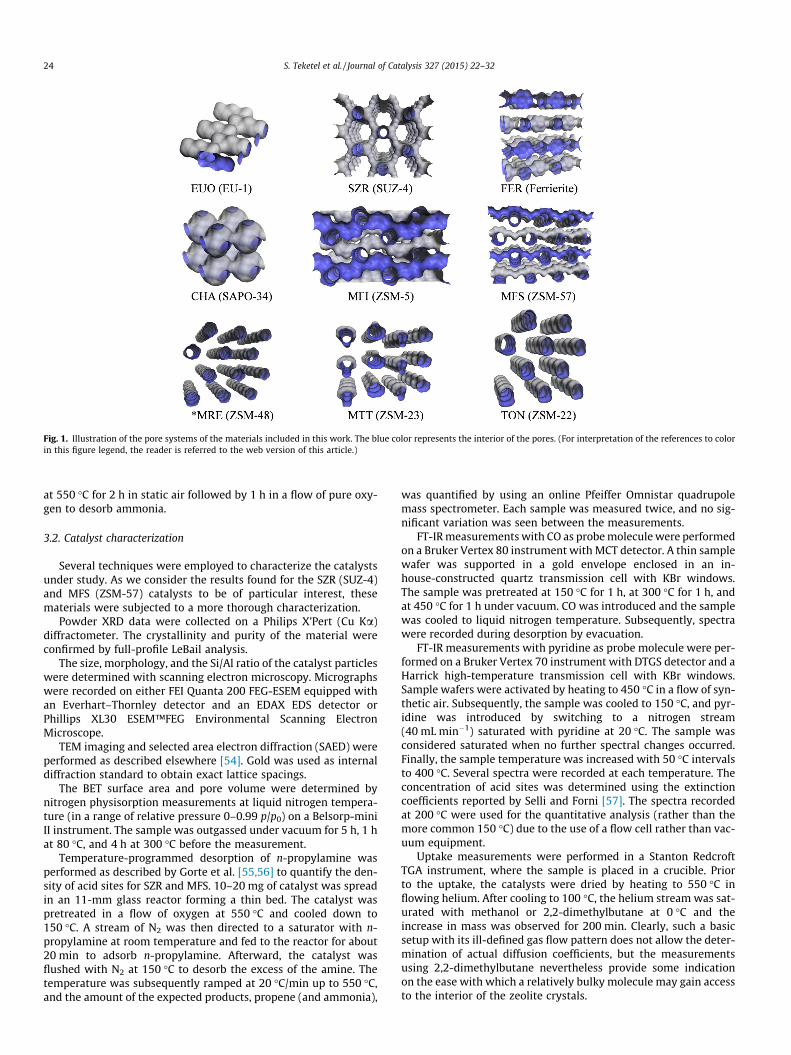
Fig. 1. Illustration of the pore systems of the materials included in this work. The blue color represents the interior of the pores. (For interpretation of the references to colorin this figure legend, the reader is referred to the web version of this article.)
24 S. Teketel et al. / Journal of Catalysis 327 (2015) 22–32
at 550 �C for 2 h in static air followed by 1 h in a flow of pure oxy-gen to desorb ammonia.
3.2. Catalyst characterization
Several techniques were employed to characterize the catalystsunder study. As we consider the results found for the SZR (SUZ-4)and MFS (ZSM-57) catalysts to be of particular interest, thesematerials were subjected to a more thorough characterization.
Powder XRD data were collected on a Philips X’Pert (Cu Ka)diffractometer. The crystallinity and purity of the material wereconfirmed by full-profile LeBail analysis.
The size, morphology, and the Si/Al ratio of the catalyst particleswere determined with scanning electron microscopy. Micrographswere recorded on either FEI Quanta 200 FEG-ESEM equipped withan Everhart–Thornley detector and an EDAX EDS detector orPhillips XL30 ESEM™FEG Environmental Scanning ElectronMicroscope.
TEM imaging and selected area electron diffraction (SAED) wereperformed as described elsewhere [54]. Gold was used as internaldiffraction standard to obtain exact lattice spacings.
The BET surface area and pore volume were determined bynitrogen physisorption measurements at liquid nitrogen tempera-ture (in a range of relative pressure 0–0.99 p/p0) on a Belsorp-miniII instrument. The sample was outgassed under vacuum for 5 h, 1 hat 80 �C, and 4 h at 300 �C before the measurement.
Temperature-programmed desorption of n-propylamine wasperformed as described by Gorte et al. [55,56] to quantify the den-sity of acid sites for SZR and MFS. 10–20 mg of catalyst was spreadin an 11-mm glass reactor forming a thin bed. The catalyst waspretreated in a flow of oxygen at 550 �C and cooled down to150 �C. A stream of N2 was then directed to a saturator with n-propylamine at room temperature and fed to the reactor for about20 min to adsorb n-propylamine. Afterward, the catalyst wasflushed with N2 at 150 �C to desorb the excess of the amine. Thetemperature was subsequently ramped at 20 �C/min up to 550 �C,and the amount of the expected products, propene (and ammonia),
was quantified by using an online Pfeiffer Omnistar quadrupolemass spectrometer. Each sample was measured twice, and no sig-nificant variation was seen between the measurements.
FT-IR measurements with CO as probe molecule were performedon a Bruker Vertex 80 instrument with MCT detector. A thin samplewafer was supported in a gold envelope enclosed in an in-house-constructed quartz transmission cell with KBr windows.The sample was pretreated at 150 �C for 1 h, at 300 �C for 1 h, andat 450 �C for 1 h under vacuum. CO was introduced and the samplewas cooled to liquid nitrogen temperature. Subsequently, spectrawere recorded during desorption by evacuation.
FT-IR measurements with pyridine as probe molecule were per-formed on a Bruker Vertex 70 instrument with DTGS detector and aHarrick high-temperature transmission cell with KBr windows.Sample wafers were activated by heating to 450 �C in a flow of syn-thetic air. Subsequently, the sample was cooled to 150 �C, and pyr-idine was introduced by switching to a nitrogen stream(40 mL min�1) saturated with pyridine at 20 �C. The sample wasconsidered saturated when no further spectral changes occurred.Finally, the sample temperature was increased with 50 �C intervalsto 400 �C. Several spectra were recorded at each temperature. Theconcentration of acid sites was determined using the extinctioncoefficients reported by Selli and Forni [57]. The spectra recordedat 200 �C were used for the quantitative analysis (rather than themore common 150 �C) due to the use of a flow cell rather than vac-uum equipment.
Uptake measurements were performed in a Stanton RedcroftTGA instrument, where the sample is placed in a crucible. Priorto the uptake, the catalysts were dried by heating to 550 �C inflowing helium. After cooling to 100 �C, the helium stream was sat-urated with methanol or 2,2-dimethylbutane at 0 �C and theincrease in mass was observed for 200 min. Clearly, such a basicsetup with its ill-defined gas flow pattern does not allow the deter-mination of actual diffusion coefficients, but the measurementsusing 2,2-dimethylbutane nevertheless provide some indicationon the ease with which a relatively bulky molecule may gain accessto the interior of the zeolite crystals.

S. Teketel et al. / Journal of Catalysis 327 (2015) 22–32 25
The crystal shape of SZR and FER was simulated using theBravais–Friedel Donnay–Harker (BFDH) method as implementedin Materials Studio 7.0. The BFDH method allows the estimationof the morphology from the crystal symmetry and the latticeparameters without taking into account the chemical nature andpacking of the atoms or molecules that form the crystal. The pur-pose of the simulations was to illustrate how the crystal structuremay be embedded into crystals of the observed morphology.
3.3. Catalytic tests
The catalytic experiments were performed using fixed-bed glassreactors (i.d. 10 mm) and 50 mg catalyst. The protonated catalystwas pressed, gently crushed, and sieved to particle sizes between250 and 420 lm. Before each test, the reactor was heated to550 �C under a flow of helium. The catalysts were calcined in situat this temperature with a flow of pure oxygen for 1 h. Thein situ calcination is performed to remove species adsorbed duringcatalyst handling and storage and is important for the repro-ducibility of the results. The reaction products were analyzed byan online gas chromatograph connected to the outlet of the reactorvia a heated transfer line. An Agilent 6890 A GC with FID using aSupelco SPB-5 capillary column (60 m, 0.530 mm i.d., stationaryphase thickness 3 lm) was used for the analysis. The temperaturewas programmed between 45 and 260 �C with a heating rate of25 �C min�1 (hold time = 5 min at 45 �C and 16 min at the finaltemperature).
4. Results
4.1. General catalyst characterization
Table 2 summarizes the main characteristics of the catalysts.The composition of the materials was determined using EDS. Thefrequency shift observed during CO adsorption (Fig. S.1 of theSupplementary Material) is a measure of the acid strength ofBrønsted acid sites in zeolites and zeotype materials [58,59]. Thevalues presented for the materials in this work are in the rangeexpected from zeolites, which are indistinguishable in acidstrength as measured by this approach. SAPO materials are weakerin acid strength than zeolites [60–62], as a result the frequencyshift observed on SAPO-34 is the smallest in this work. The BETsurface areas agree well with previously reported values; however,the surface area for the commercial MTT catalyst is somewhat low[13,51,63–66]. The particle shapes and sizes presented for thematerials are observed from the SEM images in Fig. S.2.
Table 2Main characteristics of the investigated catalysts.
Topology(material)
Si/Alratioa
Dm((OH)(cm�1)upon COadsorption
BETarea(m2 g�1)
Particleshape
Particlesize(lm)
EUO (EU-1) 30 310 420 Rods <1FER (Ferrierite) 11 312 352 Irregular
plates1–10
CHA (SAPO-34) 11b 274 NA Cubes 1–2SZR (SUZ-4) 8 301 346 Needles 2–5MFI (ZSM-5) 50 302 430 Round/
agglomerates1–2
TON (ZSM-22) 30 320 207 Needles 2–3MTT (ZSM-23) 33 330 115 Rods/
needles<1
⁄MRE (ZSM-48) 52 NAc 275 Rods 1–2MFS (ZSM-57) 30 326 421 Plates �1
a From EDS.b (Al + P)/Si.c Not available.
As seen from Table 2, the catalysts display different particleshapes and sizes as well as different surface areas and acid sitedensities. Clearly, it would have been beneficial to investigate aset of samples with more comparable physicochemical properties.However, this would require a formidable synthesis effort, beyondthe substantial effort already made. Moreover, it is doubtfulwhether this would even be feasible, as some materials crystallizewithin fairly narrow composition ranges (e.g. no reports exist forthe preparation of SZR with Si/Al higher than 9) and most of thematerials with 1D pore systems show a strong preference for elon-gated crystals. Thus, in the following, emphasis will be placed pri-marily on the major observations made and conclusion which maybe safely ascribed to the influence of catalyst morphology.
4.2. Extended characterization of SZR and MFS
Fig. 2 shows powder XRD data of SZR (panel A) and MFS (panelB). The crystallinity and purity of the materials are confirmed byfull-profile LeBail analysis. The difference curve reveals anisotropyin the peak broadening, which is related to the anisotropic mor-phology of the crystallites. In the case of SZR, the observed peakswith indices (hk0) are broader relative to the model peaks, forwhich isotropic particle shape has been assumed. In contrast,observed (00l) peaks are sharper compared with model peaks.Notice how the difference curve for broad peaks is pointing downwhile it is pointing up for sharp peaks. These observations are con-sistent with a c-axis parallel to the needle morphology as observedusing electron microscopy (Figs. S.2 and 5). In the case of MFS, theobserved peaks of the type (0kl) are relatively sharp, whileobserved peaks with a nonzero h index are relatively broad. Thisis consistent with the a-axis being perpendicular to the plate mor-phology observed using electron microscopy (Figs. S.2 and 6).
The acidity of SZR and MFS was characterized using TPD ofn-propylamine. By monitoring the evolution of propene fromdecomposition of n-propylamine during heating, the density ofacid sites was determined to be 0.46 mmol g�1 for MFS and0.63 mmol g�1 for SZR. Assuming that one acid site correspondsto one Al, this gives Si/Al ratios of 36 for MFS and 26 for SZR.Thus, for MFS, this measurement agrees well with the sample com-position from EDS (Si/Al = 30 from EDS, Table 2). For SZR, however,a significant discrepancy is observed (Si/Al = 8 from EDS, Table 2).This could suggest that some of the acid sites in SZR are inaccessi-ble, that some of the acid sites are located too closely to facilitateaccommodation of probe molecules on every site, or that some ofthe sites are too weakly acidic to protonate the amine. It has pre-viously been reported that TPD of n-propylamine underestimatesthe acid site density for high Al materials [67]. It is likely that someof the Al present in the sample does not give rise to acidity. This islinked to non-exchangeable potassium cations present in cages inthe structure [68]. Lawton et al. [68] have reported that only about50% of the potassium cations were exchangeable (sample Si/Al = 6),whereas Zholobenko et al. [69] were able to exchange 75% (sampleSi/Al = 6).
FT-IR characterization of SZR and MFS was performed usingboth pyridine and CO as probe molecules. Turning first to the spec-tra of the dehydrated catalysts (Figs. 3 and 4; also shown in Fig. S.3for clarity), several bands are seen in the hydroxyl stretchingregion, which may be assigned as follows [70]. Sharp bands seenat 3750/3749 cm�1 correspond to isolated/terminal silanols,whereas the shoulders extending to lower wavenumbers are signa-tures of silanol groups involved in hydrogen bonding. Bridginghydroxyls (Brønsted sites) are seen at 3613 cm�1. For MFS, a smallbut distinct feature is seen at 3662 cm�1, which may be attributedto hydroxyl groups attached to partial extra framework Al species.For SZR, a broad band is seen centered at 3651 cm�1. Definitiveassignment is not (yet) straightforward. Plausible explanations

Fig. 2. Full-profile powder XRD data analysis. (A) LeBail analysis of the SZR data. (B) LeBail analysis of the MFS data. The blue and the red curves are observed and model data,respectively. The gray curve is the difference between the observed and model data. The arrows mark indexed peaks. (For interpretation of the references to color in thisfigure legend, the reader is referred to the web version of this article.)
26 S. Teketel et al. / Journal of Catalysis 327 (2015) 22–32
are partial extra framework Al species (as for MFS) and/or Brønstedsites interacting with non-exchanged potassium cations (see alsobelow).
Upon interaction with CO, several previously well-describedfeatures [70] are observed in the spectra, and for brevity, we willfocus mainly on the features which are particular for these cata-lysts. For SZR at low loadings, the Brønsted band (3613 cm�1) iseroded and shifted to 3312 cm�1 as adducts between theBrønsted sites and the probe molecule are formed. This occursbefore the erosion of the band at 3651 cm�1, which appears to belinked to the appearance of the feature at 3483 cm�1. Bands in thisregion have been linked to both a Fermi resonance phenomenonand the formation of adducts between hydroxyls on partial extraframework Al species and CO [70–72]. Given the apparent corre-spondence between the disappearance of the band at 3651 cm�1
and the appearance of the band at 3483 cm�1, an assignment topartial extra framework Al becomes likely. Importantly, at higherloadings of CO, all strongly acidic hydroxyls are consumed by inter-action with CO. In the CO stretching region, bands at 2172 and2163 cm�1 appear at low loadings. The band at 2172 cm�1 can con-fidently be assigned to CO on Brønsted sites [70,72], whereas theband at 2163 cm�1 most likely is a composed of contributions fromCO interacting with hydroxyls on partial extra framework Al spe-cies as well as CO interacting with potassium cations [73,74]. Athigher loadings, a fraction of the silanols are consumed and theadducts between CO and silanols appear at 2158 cm�1, overlappingwith the band at 2163 cm�1 mentioned above. Physisorbed or liq-uid-like CO is seen at 2140 cm�1. For MFS, the spectra are some-what less complex. At low loadings of CO, the Brønsted band at3613 cm�1 is shifted to 3287 cm�1, and CO on Brønsted sites is evi-dent at 2177 cm�1. It may be noted that features associated withpartial extra framework Al species are much less dominant andthat no evidence of alkali cations are seen (no discernible band at
�2160 cm�1 and a much less pronounced feature at �3470 cm�1
at low loadings). Upon increasing CO pressure, the silanol band ispartially consumed, giving rise to absorption at 2157 cm�1.
FT-IR spectra recorded during desorption of pyridine are shownin Fig. 4. Three main bands are expected and seen [57,75]. The bandat 1541 cm�1 corresponds to CC stretching modes of protonatedpyridine (Brønsted sites), whereas a band at 1453 cm�1 is expectedfor pyridine on Lewis acid sites. The band at 1490 cm�1 consistsof overlapping contributions from both adsorption modes.Interestingly, for SZR, only a fraction of the Brønsted sites areaccessible to pyridine (see inset). Moreover, it appears thatthe component at 3651 cm�1 is virtually unperturbed, even afterthe exposure to pyridine overnight. Fig. S.4 of the SupplementaryMaterial shows the FT-IR spectra recorded during uptake of pyri-dine on SZR as a function of saturation time. In contrast, for MFS,all Brønsted sites were consumed after �10 min exposure. No clearband corresponding to pyridine on Lewis acid sites is seen for SZR.Rather, a broad feature, which diminishes fairly rapid with increas-ing temperature, is seen in this spectral region. This is most likelyrelated to pyridine interacting with potassium cations. Turning tothe quantitative evaluation, a total acid site concentration of0.49 mmol g�1, which corresponds to an Si/Al ratio of 33, wasfound for MFS. This agrees well with the overall composition ofthe material and the value from TPD. The Brønsted/Lewis ratiowas 15. For SZR, a Brønsted acid site concentration of0.20 mmol g�1 was found, which is substantially less than inferredfrom composition as well as from TPD (see above). It was not pos-sible to quantify the concentration of Lewis acid sites for SZR.
Fig. 5 displays TEM images (A and B) and the correspondingselected area electron diffraction (SAED) image (C) of an SZR crys-tal. The characteristic feature of the particles is the distinct needleshape. Typically, the needles are 2–5 lm long and 50–70 nm wide.Such a needle-like morphology was previously reported for the

Fig. 3. FT-IR spectra for SZR (top panels) and MFS (bottom panels) upon interactionwith CO. The left panels show the hydroxyl-stretching region and the right panelsshow the CO-stretching region. The bottom spectra in each panel correspond to lowloading of CO (until near complete erosion of the Brønsted band) and the topspectra correspond to high loading.
S. Teketel et al. / Journal of Catalysis 327 (2015) 22–32 27
material and appears to be favored [76]. Bragg spots in the direc-tion of the needle were readily observed. Lattice spacings of�7.46 Å, which corresponds to the c axis of the unit cell, were con-sistently observed. This confirms that the c direction of the unit cellruns in the direction of the needles. Once the c direction is cor-rectly assigned, the orientation of the 8-ring and 10-ring channelsis readily determined: the 10-ring channels are oriented along thec direction, that is, along the needles, and the 8-ring channels areperpendicular. This conclusion is supported by the bulk X-raydiffraction analysis (above) and crystal growth simulations(Fig. S.5 and Supplementary Material).
The same methods as described above for the SZR catalyst wereemployed to investigate MFS, see Fig. 6. The MFS crystals are pen-tagonal, but also highly defective and irregular. A platelet ornanosheet-type morphology is seen for this material. Typicalsheets are 30–60 nm thick (B) with a longest distance of about1.5 lm (A). Electron diffraction (D) revealed that the 10-ring chan-nel system runs perpendicular to the sheets of MFS. Furthermore,the crystals are fivefold twinned (E, F), as also originally observedby Schlenker et al. [77]. It may be realized that the 8-ring channel
system would form a closed pentagon shape in defect free crystals,with no 8-rings exposed at the terminating crystal surfaces, that isa pore system exclusively connecting the interior surface of thecrystals (F). In an actual, defective crystal, the access to the 8-ringsis via the defect surfaces only. Thus, this catalyst may be describedas an array of very short (30–60 nm) 10-ring pores exposed at bothends.
In order to provide a simple measure of the diffusion propertiesof some of the catalysts investigated, the uptake of the methanolreactant and that of a bulky inert hydrocarbon were investigated.As is evident from Fig. 7 (top panel), the uptake of 2,2-dimethylbu-tane is dramatically more pronounced for MFI and MFS comparedwith the other materials. The rate and the extent of the uptakeappear to be comparable for these two materials, despite theone-dimensional nature of the MFS material. Further, the uptakeis practically negligible for the other four catalysts. We do not attri-bute any significance to the marginally higher total uptake seen forSZR compared with CHA (for which no uptake is expected as thematerial has only 8-rings), FER, and TON. The main question tobe answered is whether the large and fast uptake seen for MFSmay be attributed to the short diffusion pathways (the 10-ringsare 30–60 nm long only) or to the relatively large 10-rings(5.1 � 5.4 Å) compared with FER (4.2 � 5.4 Å), TON (4.6 � 5.7 Å),and SZR (4.1 � 5.2 Å). Unfortunately, data could not be recordedfor ⁄MRE (5.3 � 5.6 Å), which has relatively large 10-ring channels.However, in a similar and more extensive study, Wu et al. [78]investigated the uptake of several hydrocarbons in a range of zeo-lites. It was seen that ⁄MRE behaved very similarly to TON(4.6 � 5.7 Å). Thus, it does not seem likely that the favorableuptake behavior seen here for MFS is related primarily to the com-paratively large 10-rings in this material. Rather, the significantlyfaster and higher total uptake seen for the MFS catalyst comparedwith the other one-dimensional 10-ring materials may reasonablybe attributed to the fast diffusion associated with the very shortlength of the 10-ring channels.
Turning to methanol (Fig. 7, bottom panel), a significant uptakeof methanol is seen for all of the catalysts investigated. A plateau isreached within �10 min for MFS, SZR, and TON, whereas a stablesample mass is reached after �17 min for FER. For CHA, a slightincrease in sample mass is seen after the initial large and rapidweight change. The final weights do not scale with BET surface areaor acid site densities in a straightforward manner. Presumably,subtle differences in the free energy of adsorption among theframeworks, which would influence the adsorption equilibriumin an exponential term, will dominate. Nevertheless, it is evidentthat the methanol molecule, in contrast to 2,2-dimethylbutane,has easy and ample access to the internal surface of all thesecatalysts.
4.3. Catalyst performance
Fig. 8 shows the catalyst lifetime and product distribution forthe MTH reaction over the different catalysts at 400 �C andWHSV = 2 gg�1 h�1. With respect to catalyst lifetime, it is clearfrom Fig. 1 that MFI vastly outperforms the other zeolites. Theunique longevity of MFI is well documented and, along with selec-tivity toward high octane number gasoline components, forms thebasis for the MTG process [11,12]. In contrast, SZR and FER deacti-vate extremely rapidly (the curves overlap). This is almost cer-tainly due to the high acid site density and diffusion limitationsimposed by the fairly large particles of the investigated materials(see also Supplementary Material for more details on the catalyticperformance of SZR). For SZR, the significant content of partialextra framework Al might also contribute to deactivation. ForCHA, a high density of only moderately strong acid sites in cagesconnected in three dimensions by small 8-ring windows leads to

Fig. 4. FT-IR spectra for SZR (left panel) and MFS (right panel) upon desorption of pyridine. The spectra are reported after subtracting the spectrum of the activated zeolite.The insets show the hydroxyl stretching region (without subtraction) at 200 �C.
Fig. 5. Morphology analysis of SZR. (A) TEM image showing the general needle morphology. (B) TEM image of a needle lying on a holy carbon film coated with gold, whichserves as an internal diffraction standard. (C) Selected area diffraction image of the area shown in (B). Powder rings are from the gold diffraction standard. The line of Braggspots parallel to the needle morphology corresponds to a periodicity of 7.46 Å, which is the direction of the 10-ring channel system in SZR.
28 S. Teketel et al. / Journal of Catalysis 327 (2015) 22–32
a moderate catalyst lifetime, giving rise to fluid bed operation inthe MTO process [11,12]. The strictly unidirectional, medium-poreTON, MTT, EUO, and ⁄MRE catalysts display lifetimes similar to thatof CHA. It is generally accepted that zeolite catalysts with one- ortwo-dimensional pore systems suffer from more rapid deactivationthan materials with three-dimensional porosity [79]. In contrast,for MFS, which does not have a three-dimensional pore system,an unexpectedly long lifetime is found. The origins of this featurewill be discussed below.
Over the MFI, EUO, ⁄MRE, MFS, TON, MTT, and FER catalysts, themajority of the product formed is C4+ hydrocarbons. This is asexpected from medium-pore (10-ring) zeolites and in agreementwith previous reports over such materials [11,13,51]. Notably,medium-pore zeolites TON, MTT, and FER yield a product rich inC5+, which is very nearly free from aromatics, also in agreementwith previous reports [13,51,80]. Medium-pore zeolites MFS,EUO, and ⁄MRE convert methanol into a hydrocarbon mixture richin aromatics; similar to that found for MFI, despite not havingthree-dimensional pore systems of intersecting 10-rings. ForEUO, aromatics formation has been linked to side pockets on theexternal surface [13]. For MFS and ⁄MRE on the other hand, aro-matics formation must be due to the product shape selectivity
induced by the fairly large one-dimensional 10-rings, which aredistinctly larger than those found in TON, MTT, and FER(Table 1). Small-pore (8-ring) CHA yields a product stream rich inlight alkenes; the combined selectivity toward C2 + C3 hydrocar-bons is 72%, which is also expected for the MTO catalyst. 10- and8-ring zeolite SZR unexpectedly shows high selectivity towardthe light hydrocarbons, C2 and C3 constitute 62%. In fact, the pro-duct spectrum observed for the medium-pore zeolite SZR isremarkably similar to the typical MTO product spectrum seen forsmall pore CHA, for which the 8-ring windows control the diffusionof molecules. The catalytic test results thus suggest that the selec-tivity of SZR also is controlled by the smaller 8-ring windows,despite the presence of 10-ring channels in the framework.
It is of some interest to investigate the C4+ fraction formed oversome of the catalysts more closely. Fig. 9 shows that for CHA, thisproduct fraction (which is undesired from an MTO perspective) iscomposed almost exclusively of the three linear butene isomersand some linear C5 products. For SZR, on the other hand, a signifi-cantly larger amount of C5 and even some C6 compounds are seen.Looking at the distribution of the four butene isomers in detail, it isobserved that MFI and TON yield a branched to linear ratio of 0.42and 0.46, respectively, which is close to the equilibrium value.
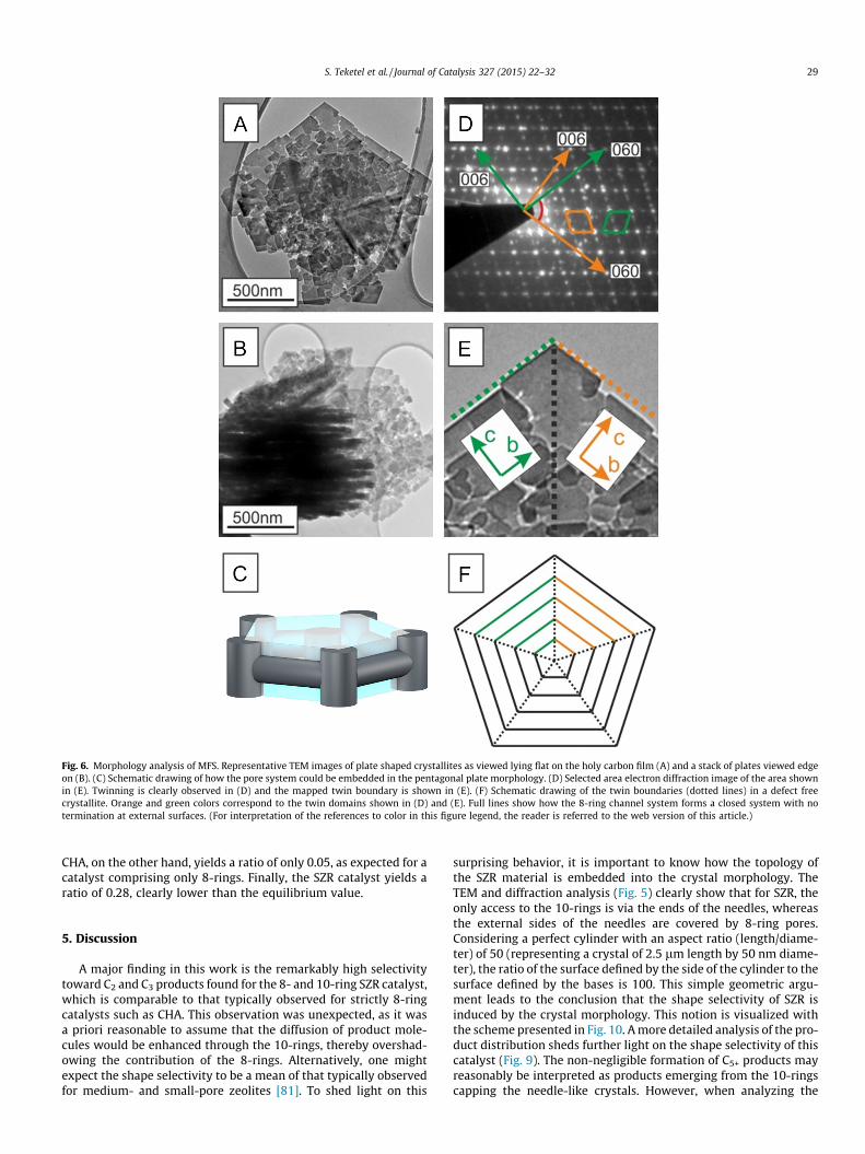
Fig. 6. Morphology analysis of MFS. Representative TEM images of plate shaped crystallites as viewed lying flat on the holy carbon film (A) and a stack of plates viewed edgeon (B). (C) Schematic drawing of how the pore system could be embedded in the pentagonal plate morphology. (D) Selected area electron diffraction image of the area shownin (E). Twinning is clearly observed in (D) and the mapped twin boundary is shown in (E). (F) Schematic drawing of the twin boundaries (dotted lines) in a defect freecrystallite. Orange and green colors correspond to the twin domains shown in (D) and (E). Full lines show how the 8-ring channel system forms a closed system with notermination at external surfaces. (For interpretation of the references to color in this figure legend, the reader is referred to the web version of this article.)
S. Teketel et al. / Journal of Catalysis 327 (2015) 22–32 29
CHA, on the other hand, yields a ratio of only 0.05, as expected for acatalyst comprising only 8-rings. Finally, the SZR catalyst yields aratio of 0.28, clearly lower than the equilibrium value.
5. Discussion
A major finding in this work is the remarkably high selectivitytoward C2 and C3 products found for the 8- and 10-ring SZR catalyst,which is comparable to that typically observed for strictly 8-ringcatalysts such as CHA. This observation was unexpected, as it wasa priori reasonable to assume that the diffusion of product mole-cules would be enhanced through the 10-rings, thereby overshad-owing the contribution of the 8-rings. Alternatively, one mightexpect the shape selectivity to be a mean of that typically observedfor medium- and small-pore zeolites [81]. To shed light on this
surprising behavior, it is important to know how the topology ofthe SZR material is embedded into the crystal morphology. TheTEM and diffraction analysis (Fig. 5) clearly show that for SZR, theonly access to the 10-rings is via the ends of the needles, whereasthe external sides of the needles are covered by 8-ring pores.Considering a perfect cylinder with an aspect ratio (length/diame-ter) of 50 (representing a crystal of 2.5 lm length by 50 nm diame-ter), the ratio of the surface defined by the side of the cylinder to thesurface defined by the bases is 100. This simple geometric argu-ment leads to the conclusion that the shape selectivity of SZR isinduced by the crystal morphology. This notion is visualized withthe scheme presented in Fig. 10. A more detailed analysis of the pro-duct distribution sheds further light on the shape selectivity of thiscatalyst (Fig. 9). The non-negligible formation of C5+ products mayreasonably be interpreted as products emerging from the 10-ringscapping the needle-like crystals. However, when analyzing the

Fig. 7. Uptake of 2,2,-dimethylbutane (top panel) and methanol (bottom panel) at100 �C on several zeolite catalysts.
Fig. 8. Catalyst performance for nine different zeolite catalysts in the methanol tohydrocarbons reaction. (A) Methanol conversion versus time on stream at 400 �Cand WHSV = 2 gg�1 h�1 and (B) product distribution at full conversion. The black-shaded area in the C4+ fraction corresponds to the amount of aromatics in theeffluent.
30 S. Teketel et al. / Journal of Catalysis 327 (2015) 22–32
distribution of the C4 isomers, a notable preference for linear C4
isomers is evident for SZR. This again indicates that the 8-ringpore openings, rather than the less abundant 10-rings, play adecisive role in determining the product shape selectivity for thiscatalyst.
The characterization data presented for SZR may also berationalized according to the scheme in Fig. 10. A high surface areawas found using nitrogen adsorption, uptake measurements showthat methanol has easy access to a large internal surface/volume,and CO is able to interact with all strongly acidic sites distributedwithin the material. Clearly, these small probe molecules experi-ence easy access the internal structure via both the 8- and 10-rings.However, when using larger probe molecules, virtually no access isseen for 2,2-dimethylbutane and a strongly restricted access isseen for pyridine, as the only possibility for these compounds toenter the internal volume is via the very scarce 10-rings.
The notion of selectivity engineering by preferential exposure ofcrystal facets that allow access to the particle interior via one set ofpore openings, but not another, is conceptually different from mostof the perspectives discussed in the introduction, which are basedprimarily on the shortening and lengthening of diffusion pathways.It is our opinion that these finding for SZR could open up for a newstrategy to achieve selectivity control in zeolite catalysis. It is nowstraightforward to suggest that the concept of morphology-inducedshape selectivity as introduced here may be explored further andextended to different framework topologies. However, for thisapproach to be applicable, the catalyst must comprise pore systemsof distinct sizes. An obvious, but exceedingly demanding extensionof this work would be to synthesize a series of, for example, SZR cat-alysts of differing aspect ratios and morphologies and to evaluatethe resulting product distributions. Many other zeolite topologieswould also be suited for such explorations. Clearly, this discussionis not independent of previous literature; the potential for selectiv-ity control by using zeolite catalysts having channels of differentdiameter has been emphasized by Corma and co-workers[31,81,82] and links back to the idea of molecular traffic controloriginally introduced by Derouane [4].
It should be pointed out that both FER and MFS, which also havepore systems comprising both 10- and 8-rings, do not display thisunusual product shape selectivity. However, for both FER andMFS, this is readily rationalized by analyzing the relation betweenpore systems and morphology. FER prefers a platelet morphology,for which the 8- and 10-ring channel openings are available onthe edges of the platelets only, and the large flat facets are dense[63] (see also Supplementary Material). For MFS, the situation issimilar, as the abundance of exposed 8-ring pore openings for thisparticular sample and morphology (see below) is limited. Thus, bothFER and MFS as studied here do not offer a sufficient excess of 8-ringpore openings to facilitate morphology-induced shape selectivity.Moreover, by employing the line of reasoning outlined above, it isalso possible to explain why in a rather gratifying manner.
It was shown above that MFS is fairly resistant toward deactiva-tion. It is well known that lifetime is associated with the dimen-sionality of the catalyst pore system [79] and acid site density[83]. Nevertheless, MFS clearly outperforms the structurallyrelated catalysts comprising one-dimensional 10-rings with simi-lar acid site density. However, particle size, or more precisely dif-fusion lengths may also have a profound impact. Large crystalcatalysts typically deactivate faster than catalysts comprisingsmaller (sub-micron or nanosized) crystals [53], and hierarchicalmesoporous zeolites are often found to be more stable than regu-lar, strictly microporous materials [84]. It was shown above (Fig. 6)

Fig. 9. GC–MS chromatograms of the product effluent from CHA (SAPO-34), SZR(SUZ-4), TON (ZSM-22), and MFI (ZSM-5) tested under identical reaction conditionsafter 5 min on stream (400 �C and WHSV = 2.05 gg�1 h�1). C1 is not included in thechromatograms.
Fig. 10. Schematic illustrating the proposed morphology-controlled mechanismcausing the unexpectedly high product selectivity toward the light C1–C3 fraction.The reactant (methanol) may enter the needles via both the ends and the sides.Heavier C5+ products and isobutene/isobutane can only escape via the ends of theneedles, whereas the lighter products in addition will diffuse out of the abundant 8-ring openings that cover the sides of the needles.
S. Teketel et al. / Journal of Catalysis 327 (2015) 22–32 31
that the MFS catalyst employed here displays a nanosheet-typemorphology, where the length of the 10-ring channels is deter-mined by the sheet thickness (30–60 nm). This in turn leads tofavorable diffusion properties, as shown by uptake measurements(Fig. 7) and pyridine adsorption (Fig. 4). This constitutes a veryplausible explanation for why the lifetime of the MFS catalyst is
markedly better than that seen for the structurally related EUO,⁄MRE, TON, and MTT catalysts, for which the 10-rings are severalmicrons in length. Obviously, this is strongly related to the recentprogress of Ryoo and co-workers [41,42] on the preparation ofdeactivation resistant ZSM-5 nanosheets, and, in general, workon layered zeolite-based materials [39,40].
6. Conclusions
Herein, the catalytic performance of nine different zeolite orzeotype catalysts has been investigated and compared in the con-version of methanol to hydrocarbons (MTH). Two of these topolo-gies (SZR – SUZ-4 and MFS – ZSM-57) have not been employed asMTH catalysts previously. SZR yields a product spectrum rich inlight alkenes (C2 and C3), but suffers from rapid deactivation, mostlikely due to being a diffusion restricted system and a high densityof acid sites. Both will lead to coke accumulation. MFS yields ahydrocarbon product which is similar to the typical MFI MTG pro-duct, that is, an aromatics-rich mixture. The lifetime of MFS islonger than several structurally comparable catalysts, but still sig-nificantly shorter than for MFI.
For the SZR and MFS catalysts, the effect of morphology on cat-alyst performance is clearly observed. For MFS, the resistancetoward deactivation appears to be due to a preferred platelet mor-phology, which results in short channels and therefore facile diffu-sion. SZR crystallizes preferably with needle-like morphology, andthe 8- and 10-ring channels are accessed from the side and the endof the needle crystals, respectively. Consequently, the 8-ring chan-nels unexpectedly dominate and control the product distributionduring the MTH reaction, leading to morphology-induced shapeselectivity in zeolite catalysis.
Finally, it should be pointed out that for both SZR and MFS, ananalysis of how the framework topology is embedded into theactual crystals was instrumental to provide a rationalization ofthe observation made. Both materials comprise a combination of8- and 10-ring channels, but for SZR, the 8-rings dominate. ForMFS, on the other, the 8-rings are, in the extreme case of defect freecrystals, not accessible from the crystal exterior at all.
Acknowledgments
This publication forms a part of the inGAP Center of Researchbased Innovation, which received financial support from theResearch Council of Norway under Contract No. 174893.Financial support was also received via the European IndustrialDoctorates project ‘‘ZeoMorph’’ (Grant Agreement No. 606965),part of the Marie Curie actions (FP7-PEOPLE-2013-ITN-EID). JuanS.M. Espin is acknowledged for performing the TPD measurements.
Appendix A. Supplementary material
Supplementary data associated with this article can be found, inthe online version, at http://dx.doi.org/10.1016/j.jcat.2015.03.013.
References
[1] S.M. Csicsery, Pure Appl. Chem. 58 (1986) 841.[2] T.F. Degnan, J. Catal. 216 (2003) 32.[3] S. Svelle, M. Bjørgen, in: A. Zecchina, S. Bordiga, E. Groppo (Eds.), Selective
Nanocatalysts and Nanoscience: Concepts for Heterogeneous andHomogeneous Catalysis, Wiley-VCH Verlag GmbH & Co. KGaA, Weinheim,Germany, 2011, p. 237.
[4] E.G. Derouane, Z. Gabelica, J. Catal. 65 (1980) 486.[5] D.S. Santilli, T.V. Harris, S.I. Zones, Microporous Mater. 1 (1993) 329.[6] S. Lawton, M.E. Leonowicz, R. Partridge, P. Chu, M.K. Rubin, Microporous
Mesoporous Mater. 23 (1998) 109.[7] R. Parton, L. Uytterhoeven, J.A. Martens, P.A. Jacobs, G.F. Froment, Appl. Catal.
76 (1991) 131.

32 S. Teketel et al. / Journal of Catalysis 327 (2015) 22–32
[8] W. Souverijns, J.A. Martens, G.F. Froment, P.A. Jacobs, J. Catal. 174 (1998) 177.[9] J.A. Martens, W. Souverijns, W. Verrelst, R. Parton, G.F. Froment, P.A. Jacobs,
Angew. Chem., Int. Ed. 34 (1995) 2528.[10] M.C. Claude, J.A. Martens, J. Catal. 190 (2000) 39.[11] U. Olsbye, S. Svelle, M. Bjørgen, P. Beato, T.V.W. Janssens, F. Joensen, S. Bordiga,
K.P. Lillerud, Angew. Chem., Int. Ed. 51 (2012) 5810.[12] M. Stöcker, Microporous Mesoporous Mater. 29 (1999) 3.[13] S. Teketel, W. Skistad, S. Benard, U. Olsbye, K.P. Lillerud, P. Beato, S. Svelle, ACS
Catal. 2 (2012) 26.[14] R. Ravishankar, D. Bhattacharya, N.E. Jacob, S. Sivasanker, Microporous Mater.
4 (1995) 83.[15] C. Baerlocher, L.B. McCusker, Database of Zeolite Structures. <http://www.iza-
structure.org/databases/>.[16] B. Smit, T.L.M. Maesen, Nature 451 (2008) 671.[17] B. Smit, T.L.M. Maesen, Chem. Rev. 108 (2008) 4125.[18] G.J. Hutchings, C.J. Kiely, Acc. Chem. Res. 46 (2013) 1759.[19] P.L. Hansen, J.B. Wagner, S. Helveg, J.R. Rostrup-Nielsen, B.S. Clausen, H.
Topsøe, Science 295 (2002) 2053.[20] G. Ertl, Angew. Chem., Int. Ed. 47 (2008) 3524.[21] T.O. Drews, M. Tsapatsis, Curr. Opin. Colloid Interface Sci. 10 (2005) 233.[22] K. Li, J. Valla, J. Garcia-Martinez, ChemCatChem 6 (2014) 46.[23] R. Chal, C. Gerardin, M. Bulut, S. van Donk, ChemCatChem 3 (2011) 67.[24] K. Egeblad, C.H. Christensen, M. Kustova, C.H. Christensen, Chem. Mater. 20
(2008) 946.[25] K. Möller, T. Bein, Chem. Soc. Rev. 42 (2013) 3689.[26] J. Perez-Ramirez, C.H. Christensen, K. Egeblad, C.H. Christensen, J.C. Groen,
Chem. Soc. Rev. 37 (2008) 2530.[27] D.P. Serrano, J.M. Escola, P. Pizarro, Chem. Soc. Rev. 42 (2013) 4004.[28] S. van Donk, A.H. Janssen, J.H. Bitter, K.P. de Jong, Catal. Rev. 45 (2003) 297.[29] S. Al-Khattaf, S.A. Ali, A.M. Aitani, N. Zilkova, D. Kubicka, J. Cejka, Catal. Rev.:
Sci. Eng. 56 (2014) 333.[30] D. Verboekend, J. Perez-Ramirez, Catal. Sci. Technol. 1 (2011) 879.[31] A. Corma, J. Catal. 216 (2003) 298.[32] J. Jiang, J. Yu, A. Corma, Angew. Chem., Int. Ed. 49 (2010) 3120.[33] L. Tosheva, V.P. Valtchev, Chem. Mater. 17 (2005) 2494.[34] T. Alvaro-Munoz, E. Sastre, C. Marquez-Alvarez, Catal. Sci. Technol. 4 (2014)
4330.[35] R. Khare, D. Millar, A. Bhan, J. Catal. 321 (2015) 23.[36] C.-J. Jia, Y. Liu, W. Schmidt, A.-H. Lu, F. Schüth, J. Catal. 269 (2010) 71.[37] R.A. Schoonheydt, Angew. Chem., Int. Ed. 47 (2008) 9188.[38] L. Karwacki, M.H.F. Kox, D.A.M. deWinter, M.R. Drury, J.D. Meeldijk, E. Stavitski,
W. Schmidt, M. Mertens, P. Cubillas, N. John, A. Chan, N. Kahn, S.R. Bare, M.Anderson, J. Kornatowski, B.M. Weckhuysen, Nat. Mater. 8 (2009) 959.
[39] U. Diaz, A. Corma, Dalton Trans. 43 (2014) 10292.[40] W.J. Roth, P. Nachtigall, R.E. Morris, J. Cejka, Chem. Rev. 114 (2014) 4807.[41] M. Choi, K. Na, J. Kim, Y. Sakamoto, O. Terasaki, R. Ryoo, Nature 461 (2009) 246.[42] J. Kim, M. Choi, R. Ryoo, J. Catal. 269 (2010) 219.[43] S. Jiang, Y.K. Hwang, S.H. Jhung, J.S. Chang, J.S. Hwang, T.X. Cai, S.E. Park, Chem.
Lett. 33 (2004) 1048.[44] F. Bleken, W. Skistad, K. Barbera, M. Kustova, S. Bordiga, P. Beato, K.P. Lillerud,
S. Svelle, U. Olsbye, Phys. Chem. Chem. Phys. 13 (2011) 2539.[45] M. Guisnet, J.-P. Gilson, in: M. Guisnet, J.-P. Gilson (Eds.), Zeolites for Cleaner
Technology, Catalysis Science Series, vol. 3, Imperial College Press, London,2002, p. 1.
[46] W. Vermeiren, J.-P. Gilson, Top. Catal. 52 (2009) 1131.
[47] J.B. Nagy, J.P. Gilson, E.G. Derouane, J. Mol. Catal. 5 (1979) 393.[48] S. Mintova, J.-P. Gilson, V. Valtchev, Nanoscale 5 (2013) 6693.[49] F.C. Meunier, D. Verboekend, J.-P. Gilson, J.C. Groen, J. Perez-Ramirez,
Microporous Mesoporous Mater. 148 (2012) 115.[50] X. Chen, T. Todorova, A. Vimont, V. Ruaux, Z. Qin, J.-P. Gilson, V. Valtchev,
Microporous Mesoporous Mater. 200 (2014) 334.[51] S. Teketel, S. Svelle, K.P. Lillerud, U. Olsbye, ChemCatChem 1 (2009) 78.[52] S.H. Lee, C.H. Shin, G.J. Choi, T.J. Park, I.S. Nam, B. Han, S.B. Hong, Microporous
Mesoporous Mater. 60 (2003) 237.[53] B.P.C. Hereijgers, F. Bleken, M. Hellner Nilsen, S. Svelle, M. Bjørgen, K.P.
Lillerud, B.M. Weckhuysen, U. Olsbye, J. Catal. 264 (2009) 77.[54] A. Katerinopoulou, T. Balic-Zunic, L.F. Lundegaard, J. Appl. Crystallogr. 45
(2012) 22.[55] R.J. Gorte, Catal. Lett. 62 (1999) 1.[56] C. Pereira, R.J. Gorte, Appl. Catal. A 90 (1992) 145.[57] E. Selli, L. Forni, Microporous Mesoporous Mater. 31 (1999) 129.[58] A. Zecchina, G. Spoto, S. Bordiga, Phys. Chem. Chem. Phys. 7 (2005) 1627.[59] K. Chakarova, K. Hadjiivanov, J. Phys. Chem. C 115 (2011) 4806.[60] J. Sauer, K.P. Schröder, V. Termath, Collect. Czech. Chem. Commun. 63 (1998)
1394.[61] S. Bordiga, L. Regli, D. Cocina, C. Lamberti, M. Bjørgen, K.P. Lillerud, J. Phys.
Chem. B 109 (2005) 2779.[62] R. Shah, J.D. Gale, M.C. Payne, Chem. Commun. (1997) 131.[63] A. Bonilla, D. Baudouin, J. Perez-Ramirez, J. Catal. 265 (2009) 170.[64] M.A. Asensi, M.A. Camblor, A. Martinez, Microporous Mesoporous Mater. 28
(1999) 427.[65] S. Gao, X. Wang, X. Wang, Y. Bai, Microporous Mesoporous Mater. 174 (2013)
108.[66] P. Worathanakul, D. Trisuwan, A. Phatruk, P. Kongkachuichay, Colloids Surf., A
377 (2011) 187.[67] B. Louis, S. Walspurger, J. Sommer, Catal. Lett. 93 (2004) 81.[68] S.L. Lawton, J.M. Bennett, J.L. Schlenker, M.K. Rubin, J. Chem. Soc., Chem.
Commun. (1993) 894.[69] V.L. Zholobenko, D.M. Lukyanov, J. Dwyer, W.J. Smith, J. Phys. Chem. B 102
(1998) 2715.[70] A. Zecchina, S. Bordiga, G. Spoto, D. Scarano, G. Petrini, G. Leofanti, M. Padovan,
C. Otero Arean, J. Chem. Soc. Faraday Trans. 88 (1992) 2959.[71] K. Chakarova, K. Hadjiivanov, Chem. Commun. 47 (2011) 1878.[72] S. Bordiga, E. Escalona Platero, C. Otero Arean, C. Lamberti, A. Zecchina, J. Catal.
137 (1992) 179.[73] S. Bordiga, G. Turnes Palomino, C. Paze, A. Zecchina, Microporous Mesoporous
Mater. 34 (2000) 67.[74] R. Bulanek, E. Koudelkova, Microporous Mesoporous Mater. 151 (2012) 149.[75] C.A. Emeis, J. Catal. 141 (1993) 347.[76] W. Zhang, Y. Wu, J. Gu, H. Zhou, J. Wang, Mater. Res. Bull. 46 (2011) 1451.[77] J.L. Schlenker, J.B. Higgins, E.W. Valyocsik, Zeolites 10 (1990) 293.[78] E.L. Wu, G.R. Landolt, A.W. Chester, Stud. Surf. Sci. Catal. 28 (1986) 547.[79] M. Guisnet, L. Costa, F.R. Ribeiroa, J. Mol. Catal. A 305 (2009) 69.[80] J.F. Haw, W. Song, D.M. Marcus, J.B. Nicholas, Acc. Chem. Res. 36 (2003) 317.[81] A. Corma, Microporous Mesoporous Mater. 21 (1998) 487.[82] R. Simancas, D. Dari, N. Velamazan, M.T. Navarro, A. Cantin, J.L. Jorda, G. Sastre,
A. Corma, F. Rey, Science 330 (2010) 1219.[83] M. Bjørgen, S. Kolboe, Appl. Catal. A 225 (2002) 285.[84] M. Bjørgen, F. Joensen, M. Spangsberg Holm, U. Olsbye, K.P. Lillerud, S. Svelle,
Appl. Catal. A 345 (2008) 43.
Copyright © 2022 FDOKUMEN