Zirconia in Dentistry - AMS Dottorato
166
ALMA MATER STUDIORUM UNIVERSITA’ DI BOLOGNA DEPARTMENT OF CIVIL, CHEMICAL, ENVIRONMENTAL AND MATERIALS ENGINEERING - DICAM - FACULTY OF ENGINEERING PhD PROGRAM: “MATERIALS ENGINEERING” Cycle XXV ING-IND/22 Zirconia in Dentistry PhD THESIS OF: Dott. Carlo Monaco Promoter: Prof. Ing. Giorgio Timellini Co-Promoter: Dott. Ing. Arturo Salomoni Co-Promoter: Prof. Roberto Scotti
-
Upload
khangminh22 -
Category
Documents
-
view
4 -
download
0
Transcript of Zirconia in Dentistry - AMS Dottorato

ALMA MATER STUDIORUM
UNIVERSITA’ DI BOLOGNA
DEPARTMENT OF CIVIL, CHEMICAL,
ENVIRONMENTAL AND MATERIALS ENGINEERING
- DICAM -
FACULTY OF ENGINEERING
PhD PROGRAM:
“MATERIALS ENGINEERING”
Cycle XXV
ING-IND/22
Zirconia in Dentistry
PhD THESIS OF:
Dott. Carlo Monaco
Promoter:
Prof. Ing. Giorgio Timellini
Co-Promoter:
Dott. Ing. Arturo Salomoni
Co-Promoter:
Prof. Roberto Scotti


To my wife Francesca
that smiles through the eyes of the
sweet Camilla and the radiant Ludovico


“It would be possible to describe everything scientifically, but it would make no sense; it would
be without meaning, as if you described a Beethoven symphony as a variation of wave pressure.”
Albert Einstein
5


CONTENTS
Chapter 1: Properties of the zirconia
9
Chapter 2: Microstructural changes produced by abrading Y-TZP in pre-sintered and
sintered conditions.
25
Chapter 3: Microstructural study of microwave sintered zirconia for dental applications
45
Chapter 4: Bonding effectiveness of zirconia after different sandblasting procedures.
63
Chapter 5: Adhesion mechanisms at the interfaces between Y-TZP and veneering
ceramics.
83
Chapter 6: Marginal adaptation, gap width, and fracture strength of teeth restored
with different all-ceramic vs metal ceramic crown systems: an in vitro study.
105
Chapter 7: Marginal and internal fitting of zirconia-based single crowns made after
intraoral digital impression.
125
Chapter 8: Clinical evaluation of 1132 zirconia-based single crowns: a retrospective
cohort study from the AIOP Clinical Research Group.
145
Chapter 9: Conclusions and recommendations
163
7


Chapter 1
CHAPTER 1
Properties of the zirconia
9

Properties of the zirconia
1.1 Introduction
Rapid improvements of the all-ceramic restorations, combined with the use of computer-aided
design (CAD)/computer-aided manufacturing (CAM), has made the digital dentistry
increasingly popular over the past decade. CAD/CAM systems have been continuously
developed and upgraded in prosthetic dentistry in association with zirconium oxide, used
primarily for the restoration of single crowns and fixed partial dentures (FPDs) in both the
anterior and posterior regions. Zirconium oxide–based materials, especially yttria-tetragonal
zirconia polycrystals (Y-TZP), were recently introduced for prosthetic rehabilitations as a core
material for single crowns, conventional and resin-bonded fixed partial dentures (FPDs) [1],
and, in dental implantology, as abutments or implants [2]. The raw materials of the zirconia are
the minerals zircon (ZrSiO4) and baddelyite (β-ZrO2), whose mines are located in South
Africa, Australia and USA. Zirconia was discovery by the German chemist Martin Heinrich
Klaproth in 1789. The term zirconium refers to the metal, while zirconia ceramic (“zirconia”)
refers to zirconia-dioxide-ceramic (ZrO2) [Figure 1].
Figure 1. Surface of the zirconia: grain size at 20.000 magnification.
1.2 Properties
Zirconia takes up a peculiar place amongst oxide ceramics due to its excellent mechanical
properties. This condition is due to the huge amount of the research that has been performed
since the discovery of the transformation toughening capabilities of this material. The different
10

Chapter 1
stages of polymorph zirconia are temperature dependent: at ambient pressure, unalloyed
zirconia can assume three crystallographic forms. At room temperature and upon heating up to
1170°C, the symmetry is monoclinic (P21/c). The structure is tetragonal (P42/nmc) between
1170 and 2370°C and cubic (Fm¯3m) above 2370°C and up to the melting point [3] [4]. The
transformation from the tetragonal (t) phase to the monoclinic (m) phase upon cooling is
accompanied by a substantial increase in volume (∼4.5%), sufficient to lead to catastrophic
failure [5]. The ceramic shows a hysteretic martensic t → m transformation during heating and
cooling. This transformation is reversible and begins at ∼950 ◦C on cooling. Alloying pure
zirconia with stabilizing oxides such as CaO,MgO,Y2O3 or CeO2 allows the retention of the
tetragonal structure at room temperature and therefore the control of the stress-induced.
Zirconia has a high temperature stability and melting point (2680°C), high hardness (1200-1350
HVN), high thermal expansion (>10 x 10-6 1/K), low thermal conductivity (<1 W/mK) and a
good thermo-shock resistance (ΔT=400-500°C) [6] [Figure 2].
Figure 2. Crystallographic and relative temperature of the three zirconia phases.
1.3 Transformation toughening
However, the metastability of tetragonal zirconia could increase the susceptibility to aging
because some stress-generating surface treatments such as grinding or sandblasting can trigger
the t→m transformation with volume increase and formation of compressive stresses on the
surface, thereby modifying the phase integrity though increasing the flexural strength [7]. The
increase of volume determines a local stop of the crack propagation. This process is called
“transformation toughening”, with the resistance against crack propagation that increases with
the length of the crack [8] [Figure 3-4-5].
11

Properties of the zirconia
Figure 3. Microcracks due to the sandblasting treatment.
Figure 4. Tensile area in a fixed partial denture during chewing cycles.
12

Chapter 1
Figure 5. Representation of the transformation toughening.
Only three types of zirconia systems are used in dentistry although currently there are many
systems of zirconia available on the market . Thee first is yttrium cation-doped tetragonal
zirconia polycrystals (3Y-TZP), the second is magnesium cation-doped partially stabilized
zirconia (Mg-PSZ) and finally the zirconia-toughened alumina (ZTA). The partly stabilized
zirconia (PSZ) is stabilized with magnesia and in addition to the cubic phase, a transformable
tetragonal phase is available. Its microstructure at room temperature is mostly cubic with
portions of monoclinic and tetragonal phases. While the Tetragonal Zirconia Polycrystals (TZP)
have a ultra-fine, nanometre-scaled structure that allows the transformation during cooling from
the cubic to the tetragonal phase, but not to the monoclinic phase. [10]
13

Properties of the zirconia
1.4 Low temperature degradation (LTD)
One of the aging process is well-described in the literature and is called ”low temperature
degradation” (LTD) of the zirconia. This is a phenomenon due to the presence of water [10]
[11] [12]. The consequences of this aging process are determine the degradation of the zirconia
surface with the grain pullout and subsequently microcracking of the structure. This phenomena
represent an strength degradation [Figure 6-7].
[a]
[b]
Figure 6. The t-m trasformation starts [a] from the surface of the sample and then proceeds inward [b].
14

Chapter 1
[a]
[b]
[c]
Figure 7. The phase transformation determines [a] the increase of the grain volume with the subsequent
uplift of the surface [b]. The presence of the water rapidly causes microcracks and esthetic degradation of
the zirconia surface [c].
15

Properties of the zirconia
Three are the hypotheses of the low temperature degradation. The first speculate that there is
the the diffusion of water species (here OH-) into the lattice via oxygen vacancies and (b)
resulting change of lattice parameters [13] [Figure 8].
Figure 8. Diffusion of the OH- into the regular lattice arrangement of the particles (molecule of the water
in the dashed circle that migrate in the red rectangle).
The second hypothesis claim that H2O reacts with Y2O3 to form clusters rich in Y(OH)3
[14][Figure 9].
Figure 9. Y2O3 and H2O reacts together.
16

Chapter 1
The last hypothesis sustain that the water vapor attacks the Zr-O bond, breaking it and leading
to a stress accumulation due to movement of -OH. This in turn generates lattice defects acting
as nucleating agents for the subsequent T-M transformation [15] [Figure 10].
Figure 10. Rupture of the Ze-O bond due to the water vapor.
1.5 Mechanical Properties
Zirconia-based materials have higher strength, fracture toughness [16] in comparison to the
feldspatic ceramics [17]. The failure mechanism of the zirconia, like others ceramic materials,
is due to sub-critical crack-growth. The metal-oxide bonds which were destroyed when the
stress is present near the tip of the initial crack with a water-assisted mechanism [18]. Cyclic
loading during the biting or chewing simulation can slowly cause the degradation of the
toughening mechanisms [19] determine the fracture of the zirconia framework because a
toughened material could be more susceptible to rupture. The cracks can originate inside of the
zirconia framework or close to the ceramic veneer interface and propagate to the interface [20].
1.6 Configuration
The zirconia in dentistry is milled in pre-sintered stage. This configuration is a soft, chalk-like
stage that is called “green” stage. During the sintering process, the material shrinks and reduces
the volume shrinkage of about 20-25%. It’s very important to know the exact volume shrinkage
information for the individual zirconia blank blocks in order to optimize the fitting of the
restoration. The zirconia is called hipped (hot iso-static pressed) when the material is
17

Properties of the zirconia
industrially sintered, and then is CAD-milled at its final high strength. Hipped zirconia has a
constant grading and thus a more homogeneous quality. As expected, milling time and wear of
the milling tools is higher in comparison to the pre-sintered variants. The zirconia for dental
applications, zirconia is stabilized at room temperature with the addition of 3 mol% yttria. This
configurations reach high strength (800-1200 MPa) good fracture toughness (6-15 MPa x m1/2).
1.7 Fabrication process
The fabrication of the framework or the monolitic zirconia requires rapid prototyping
procedures such as milling with a computer aided design and manufacturing (CAD/CAM)
[21]. The different manufacturers use milling-machines directly in the dental laboratories or
centralized production center. The process starts with optically digitizing the clinical abutment
with an intraoral camera or with 3D-scanning devices using gypsum models or wax models.
Afterwards the substructure is designed on the computer (CAD) and the core is anatomically
shaped to support the ceramic veneering material. In the last few year is increased the use of
zirconia as monolitic restoration. This approach is been possible because now the burs can mill
the anatomic occlusal design with fissures.
The properties of the zirconia substructures could depend by the manufacturing process. The
use of insufficient preparations, or frameworks with imprecise dimensions / thickness could
reduce the integrity of zirconia restorations. The design of the core, when it is a simple cap or
an occlusal supporting design, has a strong influence on the lifetime of the veneering [22-23]
[Figure 11].
Figure 11. The zirconia frameworks don’t support the ceramic material even in the Fixed partial denture
that in the single crown. In this clinical case the risk of chipping or delamination is higher.
18

Chapter 1
The zirconia framework has to support completely the veneering ceramic material in order to
avoid chipping or delamination of the aesthetic porcelain [Figure 12].
Figure 12. The zirconia framework support the ceramic material even in the marginal ridge that under the
palatal cusps. In this case the risk of chipping or delamination is lower.
19

Properties of the zirconia
The dimensions and design of FPDs, especially in the connector areas in posterior and in
anterior fixed partial dentures, is important to increase the clinical life of the all-ceramic
restoration. The volume of the connector area in anterior and posterior FPDs must be minimum
of 3x3mm2 [24-25].
Figure 13. In anterior fixed partial dentures the zirconia framework could support the ceramic material in
the marginal ridge and have sufficient volume of the connector areas.
For the quality of the marginal fit, besides the well-known clinical parameters, the CAD/CAM
fabrication process may play a decisive role. Different milling devices, milling strategies, and
software capabilities may contribute to the results even more than the different types of ceramic
materials. Based on the assumption that the clinically acceptable marginal fit extends to 200µm,
CAD/CAM fabricated restorations with values between 64-83µm and 245µm [26-28] are in
most cases good to acceptable. The results for the marginal fit are in the range of porcelain-
fused-to-metal (PFM) restorations or pressed-ceramics and vary widely depending on the
abilities of the dental technician.
1.8 Content of this thesis
The above factors emphasize the scope of this thesis for further investigations on zirconia, the
improvement of all-ceramic zirconia restorations, and especially the interaction of zirconia
20

Chapter 1
and veneering and its influence on the performance of the whole restoration.
The introduction, chapter 1, gave a literature overview on zirconia ceramics.
In chapter 2, the objective of the study was to evaluate the effect of abrading before and after
sintering using alumina-based abrasives on the surface of yttria-tetragonal zirconia polycrystals.
Particular attention was paid to the amount of surface stress–assisted phase transformation
(tetragonal→monoclinic) and the presence of microcracks.
Chapter 3 is based on the idea that the conventional sintering techniques for zirconia based
materials, which are commonly used in dental reconstruction, may not provide a uniform
heating, with consequent generation of microstructural flaws in the final component. As a
consequence of the sintering system, using microwave heating, may represent a viable
alternative. The purpose of the study was to compare the dimensional variations and physical
and microstructural characteristics of commercial zirconia (Y-TZP), used as a dental restoration
material, sintered in conventional and microwave furnaces.
Chapter 4 described the effect of sandblasting before and after sintering on the surface
roughness of zirconia and the microtensile bond strength of a pressable veneering ceramic to
zirconia.
Chapter 5 analyzed the interface between zirconia and ceramic materials using two different
methods of veneering. Alternative veneering in the press-technique was compared to
conventional layering methods. Moreover was described the interface between before and after
sandblasting treatment.
Chapter 6 compared the fracture resistance of various available systems for posterior
restorations. The study evaluated marginal adaptation before and after thermomechanical
loading, gap width and fracture strength of all-ceramic single crowns, as compared to porcelain-
fused-to-metal (PFM).
The last two chapters 7 and 8 are clinical evaluation of the behaviour of the zirconia
restorations. Chapter 7 evaluated the accuracy of single all-ceramic zirconia crowns resulting
21

Properties of the zirconia
from digital intraoral impressions with active wavefront sampling technology by measuring the
marginal and internal fits of the crowns, moreover chapter 8 recorded the survival of the and
zirconia restorations on single crowns, FPD and on implants.
1.9 References
[1] Denry I, Kelly JR. State of art of zirconia for dental applications. Dental Materials 2008;
24: 299 – 307.
[2] Hisbergues M, Vendeville S, Vendeville P. Zirconia: established facts and perspectives for a
biomaterial in dental implantology. Journal of Biomedical Material Research 2009; Part B:
Appl Biomater 88B: 519 - 29.
[3] Garvie RC, Hannink RH, Pascoe RT. Ceramic steel? Nature 1975;258:703–4.
[4] Subbarao EC. Zirconia-an overview. In: Heuer AH, Hobbs LW, editors. Science and
technology of zirconia. Columbus, OH: The American Ceramic Society; 1981. p. 1–24.
[5] Kisi E, Howard C. Crystal structures of zirconia phases and their interrelation. Key Eng
Mater 1998;153/154:1–35.
[6] Badwal SPS, Zirconia-based solid electrolytes: microstructure, stability and ionic
conductivity. Solid state Ionics 1992; 52: 23-32.
[7] Deville S, Chevalier J, Gremillard L. Influence of surface finish and residual stresses on the
ageing sensitivity of biomedical grade zirconia. Biomaterials 2006;27:2186–92.
[8] Fischer H, Rentzsch W, Marx R. R-curve behavior of dental ceramic materials. J Dent Res
2002;81:547-51.
[9] Hannink RHJ, Kelly PM, Muddle BC. Transformation toughening in zirconia-containing
ceramics. J Am Ceram Soc 2000;83:461–87.
[10] Sato T, Shimada M. Crystalline phase-change in yttria-partially-stabilized zirconia by low-
22

Chapter 1
temperature annealing. J Am Ceram Soc 1984;67:C212–3.
[11] Lange FF, Dunlop GL, Davis BI. Degradation during aging of transformation-toughened
ZrO2–Y2O3 materials at 250 ◦C. J Am Ceram Soc 1986;69:237–40.
[12] Chevalier J, Cales B, Drouin JM. Low-temperature aging of Y-TZP ceramics. J Am Ceram
Soc 1999;82:2150–4.
[13] Chevalier J, Gremillard L. The Tetragonal-Monoclinic Transformation in Zirconia. J Am
Ceram Soc 2009;92:1901-20.
[14] Lange FF, et al. Degradation during aging of transformation toughened ZrO2-Y2O3. J Am
Ceram Soc 1986;69:1-4.
[15] Yoshimura M, Noma T, Kawabata K, Somiya S. Role of water on the degradation process
of T-TZP. J Mater Sci Lett 1987;6:465-7.
[16] De Aza AH, Chevalier J, Fantozzi G, Schehl M, Torrecillas R. Crack growth resistance of
alumina, zirconia and zirconia toughened alumina ceramics for joint prostheses. Biomat
2002;23(3):937-45.
[17] Guazzato M, Albakry M, Ringer SP, Swain MV. Strength, fracture toughness and
microstructure of a selection of all-ceramic materials. Part II. Zirconia-based dental ceramics.
Dent Mater 2004;20:449-56.
[17] Michalske TA, Freiman SW. A molecular mechanism for stress-corrosion in vitreous
silica. J Am Cer Soc 1983;66:284-288.
[19] Studart A, Filser F, Kocher P, Lüthy H, Gauckler LJ. Cyclic fatigue in water of veneer
framework composites for all-ceramic dental bridges. Dent Mater 2007;23:177-85.
[20] Chevalier J, Olagnon C, Fantozzi G. Subcritical crack propagation in 3Y-TZP ceramics:
static and cyclic fatigue. J Am Cer Soc 1999;82:3129-3138.
[21] Otzel C, Clasen R. Preparation of zirconia dental crowns via electrophoretic deposition. J
Mat Sci 2006;41:8130-37.
[22] de Jager N, Pallav P, Feilzer AJ. The influence of design parameters on the FEA
determined stress distribution in CAD-CAM produced all-ceramic dental crowns. Dent Mater
23

Properties of the zirconia
2005;21:242-51.
[23] de Jager N, de Kler M, van der Zel JM. The influence of different core material on the
FEA-determined stress distribution in dental crowns. Dent Mater 2006;22:234-42.
[24] Proos KA, Swain MV, Ironside J, Steven GP. Influence of margin design and taper
abutment angle on a restored crown of a first premolar using finite element analysis. Inter J
Prosthodont 2003;16:442-9.
[25] Kou W, Kou S, Liu H, Sjogren G. Numerical modelling of the fracture process in a
threeunit all-ceramic fixed partial denture. Dent Mater 2007;23:1042-49.
[26] Reich S, Wichmann M, Nkenke E, Proeschel P. Clinical fit of all-ceramic three-unit fixed
partial dentures, generated with three different CAD/CAM systems. Eur J Oral Sci
2005;113:174-179.
[27] Coli P, Karlsson S. Precision of CAD/CAM technique for the production of zirconium
dioxide copings. Int J Prosthodont 2004;17:577-580.
[28] Naert I, Van der Donck A, Beckers L. Precision of fit and clinical evaluation of allceramic
full restorations followed between 0.5 and 5 years. J Oral Rehabil 2005;32:51-57.
24

Chapter 2
CHAPTER 2
Microstructural changes produced by abrading Y-TZP in pre-sintered and
sintered conditions.
25

Microstructural changes produced by abrading Y-TZP in pre-sintered and sintered conditions.
2.1 Abstract
Objective: To evaluate the effect of abrading before and after sintering using alumina-based
abrasives on the surface of yttria-tetragonal zirconia polycrystals. Particular attention was paid
to the amount of surface stress–assisted phase transformation (tetragonal→monoclinic) and the
presence of microcracks. Methods: Pre-sintered zirconia ceramic specimens (ZirCAD; Ivoclar
Vivadent) were first surface-ground flat with #600-800-1000-grit SiC paper. They were then
surface-treated with different grain size abrasives before and after the sintering step. Samples
that underwent no surface treatment were used as controls. For each condition, eight specimens
were prepared. The physical/mechanical characteristics of zirconia material were determined by
measuring density, porosity, grain size, hardness, and fracture toughness. The effects of surface
treatments were assessed by surface roughness measurements, quantitative X-ray diffraction
analysis, and scanning electron microscopy. Results: With increased dimensions of the
abrasive particles, the abraded surfaces of zirconia specimens exhibited a widespread system of
microcracks and an increased monoclinic zirconia quantity. These structural changes likely
affect the aging of the material during its clinical service.
26

Chapter 2
2.2 Introduction
In recent years, the use of ceramic restorations has increased due to their superior aesthetic
appearance, biocompatibility, and absence of metal [1]. Zirconium oxide–based materials,
especially yttria-tetragonal zirconia polycrystals (Y-TZP), were recently introduced for
prosthetic rehabilitations as a core material for single crowns, conventional and resin-bonded
fixed partial dentures (FPDs) [2], and, in dental implantology, as abutments or implants [3].
The combination of Y-TZP and computer-aided design/computer-aided manufacture
(CAD/CAM) systems is a new approach that reduces the number of steps in prosthetic
manufacturing and eliminates the variables introduced by the manual procedures of the dental
technician. Y-TZP exhibits exceptional physical and mechanical properties, such as high
flexural strength, fracture toughness, hardness, wear and corrosion resistance in acidic and basic
ambient conditions, translucency [4], colour stability, greater effectiveness of diagnostic
radiographs [5] [6], and high biocompatibility. Moreover, the polycrystalline structure, which
lacks a glass matrix, makes zirconia ceramic more resistant to hydrofluoridric acid etching and,
as a consequence, resistant to chemical roughening [7]. For this reason, different approaches
have been used to enhance the bond between the zirconia and resin cements, such as coating
methods [8], a selective infiltration-etching technique [9], phosphate ester monomer, 10-
methacryloyloxydecyl dihydrogen phosphate (MDP)-based materials [10] and, above all,
surface roughening by airborne-particle abrasion.
To enhance the bonding between zirconia frameworks and veneering porcelain, surface
roughness is increased with variable-grained alumina-based abrasives and/or the use of
interlayers in current practice. Furthermore, despite the use of CAD/CAM, the final steps,
involving strong mechanical action on zirconia components, must be still performed by dental
technicians [11] [12]. By favouring the tetragonal to monoclinic phase transformation, the
stresses induced by this kind of operation cause surface compressive stresses with an increased
fracture toughness, low temperature degradation (LTD) [13], and crack formation. This affects
the flexural strength of zirconia components, in line with the damage induced [14] [15].
Furthermore, the high kinetic energy of the impacting abrasive particles may chemically
contaminate the surface during machining [16] [17]. This phenomenon may have a positive
effect on bond strength at the interface between zirconia and the veneering ceramic.
The aim of this investigation was to evaluate the effect of abrading the surface of zirconia
27

Microstructural changes produced by abrading Y-TZP in pre-sintered and sintered conditions.
ceramics (Y-TZP) before and after sintering with alumina-based abrasives with varying grit.
Particular attention was paid to the development of surface stress–assisted phase transformation
(tetragonal→monoclinic) and microcracking. X-ray diffraction (XRD) and scanning electron
microscopy (SEM) analyses were used to detect changes in surface morphology.
2.3 Materials and methods
The starting material was a 3 mol% yttria-doped zirconia (ZirCAD C15L; Ivoclar Vivadent,
Schaan, Liechtenstein) in the form of pre-sintered blocks. Specimens were cut using a low-
speed diamond disc (MDS100; Norton, USA) in a special device to obtain blocks of zirconia
that were 7.2 mm in height, 9.2 mm in width, and 9.2 mm in length. To ensure identical initial
roughness, surface treatment with a #600-800-1000-grit SiC polishing paper was performed on
all specimens. For each treatment eight specimens were prepared. The samples were randomly
divided in seven groups. The control group (group A) was not sandblasted. Three groups (B-C-
D) were abraded in the pre-sintered condition and then sintered in a dedicated machine
(Sintramat; Ivoclar Vivadent), following the manufacturer’s instructions. Three other groups
(E-F-G) were before subjected to the same thermal treatment and then surface abraded.
Abrasion of the surfaces of pre-sintered and sintered zirconia samples was performed using a
Rocatec system (3M ESPE). The abrasive particles were ejected for 10 seconds at a pressure of
two bars, with a nozzle–specimen distance of 15 mm. Three abrasives were used; two were
alumina with average particle sizes of 50 and 110 µm, and the third was silica-coated alumina
with an average particle size of 30 µm. Samples B to D were abraded in the pre-sintered
condition with these abrasive particles, and samples E to G were abraded after sintering using
the same particles (Table I).
The density and porosity of pre-sintered and sintered zirconia samples were determined
following the 1993 standard of EN 623-2 [18]. The phase fraction amounts of zirconia were
evaluated by XRD using a diffractometer (PW 3830; Philips, The Netherlands), with CuKα
radiation (0.02° step-scan, 10 s per step). Zirconia diffraction peaks were deconvoluted using a
Lorentz function to obtain the integral breadth. The monoclinic phase fraction of the zirconia
was calculated using the Garvie and Nicholson method [19]:
where It(111) and Im(111) represent the integrated intensity of the tetragonal t(111) and monoclinic
m(111) respectively and the peaks.
28

Chapter 2
Hardness and fracture toughness (KIC) of the material were determined by the Vickers
indentation technique. Ten valid impressions were obtained using a semi-automatic hardness
tester (model 3212; Zwick, Germany), and the mirror finish surface of the specimens was
measured under an applied load of 196.2 N at room temperature in an air atmosphere with a
relative humidity of ~50%. KIC was calculated by the Palmqvist formula [20] [21]:
KIC = 0.0319 (P d-1 l-0.5),
where P is the indentation load, d is the diagonal of the impression, and l is the length of the
crack arising from the corner of the impression.
Surface microstructure was observed under a scanning electron microscope (EVO 40; Zeiss
Corporation, Germany) equipped with an energy-dispersive X-ray analyser (EDS; Inca; Oxford
Instruments, UK). The average grain size of the zirconia was determined using SEM
observations of the fractured surface of each pre-sintered sample and the polished surface of
each sintered sample after thermal etching. SEM images of randomly selected areas were
analysed with computer software (Qwin Imaging System; Leica), and average values were
obtained using a base of at least 150 grains.
The average roughness values (Ra) of treated surfaces were measured for all samples after
sinterization treatment using a roughness meter (Hommel tester T2000; Germany) according to
the test method recommended by the EN 623-4 standard [22].
2.4 Results and discussion
The physicomechanical characteristics of pre-sintered and sintered zirconia samples are shown
in Table II. Sintered samples reached the theoretical density, with a dense microstructure
characterised by the presence of small grains (average size, 0.44 µm). In addition, the thermal
cycle used completely transformed the monoclinic zirconia that remained in the pre-sintered
sample in the tetragonal phase.
Average roughness values (Ra) are reported in Table I. The surfaces of all abraded groups were
rougher than that of the control (A). Ra values of samples B to D, which were abraded in the
pre-sintered condition, were higher than those of samples E to G, which were abraded after the
final sintering step. Surface roughness, as expressed by Ra, increased with the size of the
impacting particles in all treated groups.
29

Microstructural changes produced by abrading Y-TZP in pre-sintered and sintered conditions.
The proportion of the monoclinic phase on the treated surfaces of sintered zirconia samples is
shown in Table I. The surfaces of control samples and samples B–D consisted of 100%
tetragonal phase; no diffraction peak of the monoclinic phase was detected. Thus, in these
samples, the sintering step allowed complete phase transformation of the monoclinic phase that
existed in the pre-sintered condition.
In contrast, abrasion of the sintered zirconia surface produced detectable monoclinic peaks with
a marked m(111) preference. The tetragonal to monoclinic phase transformation induced by the
impact of abrasive particles with average dimensions of 50 and 30 µm (groups F and G) was
similar (10% and 8%, respectively). A further increase in monoclinic proportion (to 14%)
resulted from abrading with particles with an average diameter of 110 µm (group E).
Mechanical stress, in this case erosion by hard ceramic particles, induces phase transformation
of the metastable tetragonal phase into the monoclinic phase and is associated with an increase
in volume (~4%) and shear strain (~7%) [23]. This may result in both a compressive residual
stress on the surface and a widespread crack network if the intrinsic strength of the material is
overcome. Thus, in addition to the presence of stress-induced tetragonal to monoclinic phase
transformation, analysis of zirconia peaks in XRD patterns (Fig. 1) allowed the identification of
a hump at the left shoulder of the tetragonal (111) peak of the sandblasted surfaces. The size of
this peak increased with the abrasive grain size used in the surface treatments. This
phenomenon, observed by various authors [24] after cutting or surface grinding TZP ceramics,
is correlated with the presence of lattice distortion [25] [26] induced by strong mechanical
action. Residual stresses can also be detected by analysing the ratio of the intensity peaks
(I(002)t/I(200)t; Fig. 2 and Table I).
This ratio was increased after abrasion of sintered samples (samples E–G) and was highest
when the largest (110 µm) abrasive particles were used. This intensity change has been
attributed to the ferroelasticity of Y-TZP ceramics [27]. Strong mechanical stresses can induce
a permanent strain in zirconia due to a hysteresis loop between the strain and the applied stress
(in this case abrasion), which results in the failure to induce tetragonal to monoclinic phase
transformation. Instead, an interchange of the a and c axes occurs, as indicated by the altered
relative intensity of the diffraction peaks. This can cause an additional increase in the fracture
toughness of the sample because the application of tensile stress, as found at the tip of an
advancing crack, can cause domain reorientation and the absorption of fracture energy without
30

Chapter 2
phase transformation.
Evidence of the presence of residual stresses in samples that were abraded after sintering
indicates that the abrasion processes performed here introduced various levels of compressive
stresses to the surfaces of the zirconia samples. This finding was supported by the
morphological SEM analysis. The sintered surfaces of control samples were rough, but cracks
were absent (Fig. 3). In contrast, the zirconia surface of sample G exhibited some small cracks
after abrasion with 30-µm abrasive particles, which were probably caused by stress-induced
phase transformation. Furthermore, very small particles adhered to the surface in some areas
(Fig. 4). EDS analyses revealed the presence of silicon and aluminium residues of the
impacting abrasive particles.
The use of 50-µm alumina particles (sample F) caused more marked deformation. The impact
of an alumina particle (Fig. 5) ploughed and plastically deformed the zirconia surface.
Microanalyses detected aluminium at the base of the impact area, testifying to a strong reaction
between zirconia and the alumina abrasive particle due to the energy of the impact.
The use of larger (average diameter 110 µm, sample E) abrasive particles resulted in further
enhanced surface abrasive phenomena (Fig. 6a). The impact area of plastically deformed
zirconia was larger and exhibited deep ploughing. Several cracks formed when the intrinsic
strength of the material was overcome, and the branching of the cracks caused the detachment
of surface sheets in tetragonal to monoclinic phase transformation (Fig. 6b).
Samples B–D, which were abraded in the pre-sintered state (Fig. 7a), did not exhibit such
plastic deformation. Their surfaces were very rough and valleys and scratches were present,
although they were not as deep and sharp as those in samples E–G. Average roughness
measurements showed that the use of larger abrasive particles caused the formation of longer
and deeper scratches. Chemical contamination due to the co-sintering of particles containing
silicon and/or aluminium onto zirconia surfaces was also detected (Fig. 7b).
Our data suggest that the abrasion of pre-sintered zirconia specimens (samples B to D) resulted
in the formation of a highly rough surface after the final firing step. The resulting material was
exclusively zirconia in the tetragonal phase and was free from residual stresses, but contained
some contaminants (silicon and aluminium) due to the embedding of the harder abrasive
particles in the pre-sintered (softer) zirconia after impact.
31

Microstructural changes produced by abrading Y-TZP in pre-sintered and sintered conditions.
The abrasion of sintered samples (E to G) caused a lower surface roughness due to the
increased hardness of sintered zirconia, and a meaningful tetragonal to monoclinic phase
transformation. The proportion of the monoclinic phase was correlated directly with abrasive
particle diameter, and thus with impact energy. Several surface cracks were caused by the high
stress developed during abrasion and by the tetragonal to monoclinic phase transformation.
These cracks negatively affect the mechanical behaviour of the component. In particular, they
could cause: i) decreased reliability due to the increased number and dimension of flaws, and ii)
decreased toughness due to the lower proportion of available tetragonal phase. On the other
hand, analysis of the XRD spectra showed a lattice distortion of the tetragonal phase, as
evidenced by the increase in (002) peak intensity and simultaneous decrease in that of the (200)
peak. This phenomenon represents an index of the development of surface residual stresses that
can be considered a positive attribute because the domain reorientation caused by stresses at the
tip of an advancing crack represents an additional energy-absorbing mechanism and serves to
increase fracture toughness [20] .
While surface cracks [15] increase the kinetic aging of zirconia components at low
temperatures, the role of residual stresses [16] has not been well studied. However, these
phenomena play a key role in phase transformation and thus likely have some effect on the
aging of the material. These structural changes likely affect the aging of the material during its
clinical service [28] [29].
32

Chapter 2
2.5 Conclusions
This study evaluated the effects of different abrasive procedures on the surfaces of pre-sintered
and sintered zirconia. The abrasive techniques we employed are currently used to increase
adhesion between zirconia and luting cement. The results can be summarized as follows:
1. Abrasion of pre-sintered zirconia specimens resulted in rougher surfaces, and the monoclinic
phase associated with the abrasion was completely transformed to the tetragonal state during
the subsequent sintering step;
2. Abrasion of sintered zirconia specimens resulted in surfaces with a lower roughness, a
monoclinic phase, and compressive surface residual stresses, the degree of which was
associated with the abrasive grain size;
3. The phases and microstructural changes induced by abrasion may markedly impact clinical
performance, i.e. by increasing the rate of aging.
33

Microstructural changes produced by abrading Y-TZP in pre-sintered and sintered conditions.
2.6 Tables
Table I – Surface treatments.
Samples
Surface condition before abrasion
Abrasive grain size (µm)
Nozzle–zirconia surface distance (cm)
Surface roughness, Ra (µm)§
Monoclinic (%)§
I(002)t/ I(200)t#
A -- -- -- 0.35 ± 0.16 0 0.6
B pre-sintered 110* 1.5 3.44 ± 0.44 0 -
C pre-sintered 50* 1.5 2.33 ± 0.46 0 - D pre-sintered 30** 1.5 1.22 ± 0.22 0 -
E sintered 110* 1.5 0.60 ± 0.04 14 4.2
F sintered 50* 1.5 0.48 ± 0.04 10 1.5 G sintered 30** 1.5 0.41 ± 0.03 8 1.6
*Al2O3; **SiO2-coated Al2O3 § Values determined after sintering. #Ratio of the intensity peaks.
Table II - Physicomechanical characteristics of pre-sintered and sintered zirconia samples.
Characteristic Pre-sintered Sintered Bulk density, g cm-3 3.11 6.05 Porosity, % 48.0 0.0 Grain size, µm 0.20 0.45
Phase composition 97% tetragonal 3% monoclinic
100% tetragonal
HV19.62, GPa -- 12.0 KIC, MPa m0.5 -- 6.9
34

Chapter 2
2.7 Figures
Figure 1 – X-ray diffraction patterns of the control sample (A) and samples E–G, the surfaces
of which were treated with 110-, 50-, and 30-µm abrasive particles, respectively, after firing.
Arrow indicates the hump.
35

Microstructural changes produced by abrading Y-TZP in pre-sintered and sintered conditions.
Figure 2 – X-ray diffraction patterns of the control sample (A) and samples E–G, the surfaces
of which were treated with 110-, 50-, and 30-µm abrasive particles, respectively, after firing.
36

Chapter 2
Figure 3 – Scanning electron micrograph of the sintered surface of sample A without cracks.
Figure 4 – SEM-SE micrograph of the surface of Sample G, the small agglomerated particles
contain silicon.
37

Microstructural changes produced by abrading Y-TZP in pre-sintered and sintered conditions.
Figure 5 – Scanning electron micrograph of the surface of sample F. The smooth area was
ploughed by 50µm alumina abrasive particle.
Figure 6a. SEM image of the abrasive phenomena after the use of 110µm alumina particles on
the surface of sample E.
38

Chapter 2
Figure 6b. Magnified image of the central area of the Fig. 6a. The surfaces showed several
cracks and the detachment of the surface sheets with tetragonal to monoclinic transformation.
Figure 7a. Scanning electron micrographs of the surface of sample B. The surface did not
exhibit plastic deformation although valleys and scratches were present.
39

Microstructural changes produced by abrading Y-TZP in pre-sintered and sintered conditions.
Figure 7b. Central magnification of the fig. 7a showed an elongated particle containing
aluminium embedded in the zirconia matrix.
40

Chapter 2
2.8 References
[1] Stevenson B, Ibbetson R. The effect of the substructure on the colour of
samples/restorations veneered with ceramic: A literature review. Journal of Dentistry 2010; 38:
361-368.
[2] Denry I, Kelly JR. State of art of zirconia for dental applications. Dental Materials 2008;
24: 299 – 307.
[3] Hisbergues M, Vendeville S, Vendeville P. Zirconia: established facts and perspectives for a
biomaterial in dental implantology. Journal of Biomedical Material Research 2009; Part B:
Appl Biomater 88B: 519 - 29.
[4] Vagkopoulou T, Koutayas SO, Koidis P, Strub JR. Zirconia in dentistry: part 1. Discovering
the nature of an upcoming bioceramic. European Journal of Esthetic Dentistry 2009; 4: 2 - 23.
[5] Blatz MB. Long-term clinical success of all-ceramic posterior restorations. Quintessence
International 2002; 33: 415 - 426.
[6] Raigrodski AJ. Contemporary materials and technologies for all-ceramic fixed partial
dentures: a review of the literature. Journal of Prosthetic Dentistry 2004; 92: 557 - 62.
[7] Piconi C, Maccauro G. Zirconia as a ceramic biomaterial. Biomaterials 1999; 20: 1 - 25.
[8] Kitayama S, Nikaido T, Takahashi R, Zhu L, Ikeda M, Foxton RM, Sadr A, Tagami J.
Effect of primer treatment on bonding of resin cements to zirconia ceramic. Dental Materials
2010; 26: 426 - 32.
[9] Aboushelib MN, Kleverlaan CJ, Feilzer AJ. Selective infiltration-etching technique for a
strong and durable bond of resin cements to zirconia-based materials. Journal of Prosthetic
Dentistry 2007; 97: 379 - 388.
[10] Blatz MB, Sadan A, Martin J, Lang B. In vitro evaluation of shear bond strengths of resin
to densely sintered high-purity zirconium-oxide ceramic after long-term storage and thermal
cycling. Journal of Prosthetic Dentistry 2004; 91: 356 - 62.
[11] Deville S, Chevalier J, Gremillard L. Influence of surface finish and residual stresses on
the aging sensitivity of biomedical grade zirconia, Biomaterials 2006; 27: 2186 - 92.
[12] Bonfante EA, Sailer I, Silva NR, Thompson VP, Rekow ED, Coelho PG. Failure modes of
Y-TZP crowns at different cusp inclines. Journal of Dentistry 2010; 38: 707-712.
[13] Bonfante EA, Coelho PG, Guess PC, Thompson VP, Silva NR. Fatigue and damage
accumulation of veneer porcelain pressed on Y-TZP. Journal of Dentistry 2010; 38: 318-324.
[14] Guazzato M, Quach L, Albakry M, Swain MV. Influence of surface and heat treatments
on the flexural strength of Y-TZP dental ceramic Journal of Dentistry 2005; 33: 9 - 18.
41

Microstructural changes produced by abrading Y-TZP in pre-sintered and sintered conditions.
[15] Guazzato M, Albakry M, Ringer SP, Swain MV. Strength, fracture toughness and
microstructure of a selection of all-ceramic materials. Part II. Zirconia-based dental ceramics.
Dental Materials 2004; 20: 449 - 56.
[16] Rateick RG Jr, Karasek KR, Cunningham AJ, Goretta KC, Routbort JL. Solid-particle
erosion of tungsten carbide/cobalt cermet and hardened 440C stainless steel-A comparison.
Wear 2006; 7: 773 - 78.
[17] de Arellano-Lopez AR, Martınez-Fernandez J, Varela-Feria FM, Orlova TS, Goretta KC,
Gutierrez-Mora F, Chen N, Routbort JL. Erosion and strength degradation of biomorphic SiC.
Journal of the European Ceramic Society 2004; 24: 861 - 70.
[18] European Standard EN 623-2, Advanced technical ceramics - monolithic ceramics -
general and textural properties - Part 2: Determination of density and porosity, 1993.
[19] Garvie RC, Nicholson PS. Phase analysis in Zirconia systems. Journal of American
Ceramic Society 1984; 67: 119 - 21.
[20] Ponton CB, Rawlings RD. Vickers indentation fracture toughness test—Part 1: Review of
literature and formulation of standardised indentation toughness equation. Materials Science
and Technology 1989; 5: 865 - 72.
[21] Ponton CB, Rawlings RD. Vickers indentation fracture toughness test—Part 2:
Application and critical evaluation of standardised indentation toughness equations. Materials
Science and Technology 1989; 5: 961–76.
[22] European Standard EN 623-4, Advanced technical ceramics - monolithic ceramics-general
and textural properties - Part 4: Determination of surface roughness, 1993.
[23] Swain MV. Limitation of maximum strength of zirconia-toughened ceramics by
transformation toughening increment. Journal of American Ceramic Society 1985; 68: C97 -
C99.
[24] Kosmač T, Oblak C, Jevnikar P, Funduk, N, Marion L. The effect of surface grinding and
sandblasting on flexural strength and reliability of Y-TZP zirconia ceramic. Dental Materials
1999; 15: 426 - 33.
[25] Chang JH, Hsuan CL, Wei HT. Effect of abrasive grinding on the strength of Y-TZP.
Journal of European Ceramic Society: 2009; 29: 2665 - 669.
[26] Kondoh J. Origin of the hump on the left shoulder of the X-ray diffraction peaks observed
in Y2O3-fully and partially stabilized ZrO2. Journal of Alloys and Compounds: 2004; 375: 270 -
82.
[27] Virkar AV, Matsumoto RLK. Ferroelastic Domain Switching as a Toughening Mechanism
in Tetragonal Zirconia. Journal of American Ceramic Society: 1986; 69: C224 - C226.
42

Chapter 2
[28] Abou Tara M, Eschbach S, Wolfart S, Kern M. Zirconia ceramic inlay-retained fixed
dental prostheses - first clinical results with a new design. Journal of Dentistry 2011; 39: 208-
211.
[29] Harder S, Wolfart S, Eschbach S, Kern M. Eight-year outcome of posterior inlay-retained
all-ceramic fixed dental prostheses. Journal of Dentistry 2010; 38: 875-881.
43


Chapter 3
CHAPTER 3
Microstructural study of microwave sintered zirconia for dental
applications.
45

Microstructural study of microwave sintered zirconia for dental applications.
3.1 Abstract
Statement of problem. Conventional sintering techniques for zirconia based materials, which
are commonly used in dental reconstruction, may not provide a uniform heating, with
consequent generation of microstructural flaws in the final component. A sintering system,
using microwave heating, may represent a viable alternative.
Purpose. The purpose of this study was to compare the dimensional variations and physical
and microstructural characteristics of commercial zirconia (Y-TZP), used as a dental restoration
material, sintered in conventional and microwave furnaces.
Material and Methods. Microwave sintering tests were conducted using a commercial CEM-
MAS 7000 multimode applicator (2.45-GHz, 950 W nominal power) and on a TE10n single
mode applicator, connected to a 2.45GHz TM030 microwave generator (0.5–3-kW output
power), under various experimental conditions. The same material was sintered in an electric
heating furnace for comparison. A physical-mineralogical-microstructural characterization was
carried out to evaluate the level of densification and the presence of flaws in the sintered
specimens.
Results. Use of the microwave systems allowed reducing the length of the sintering cycle to a
few minutes, compared to several hours necessary with a traditional heating system.
Additionally, the maximum temperature, used to reach the required density, decreased from
values 1450-1480°C with the electric furnace to 1200°C in the microwave furnace.
Conclusions. Microwave heating systems have specific advantages in terms of energy
efficiency, process simplicity, and equipment maintenance and operator costs.
Clinical implications: The reduced of the sintering time could allow the introduction of
zirconia in the chair-side treatments, if used as a monolithic material.
46

Chapter 3
3.2 Introduction
A well-known review on zirconia for dental applications [1] noted that as in the last 20 years,
the diffusion of metal-free restorations in the dental practice has increased considerably due to
the growing demand for highly esthetic and natural-appearing components. In particular,
bioceramics [2] are particularly suitable for use in prosthodontics as possible metal substitutes
because of their combination of several excellent properties, including wear resistance,
excellent esthetical appearance, superior mechanical properties and high biocompatibility.
Particular attention has been paid to yttria tetragonal zirconia polycrystalline materials (Y-
TZPs), which have been used as a framework materials for dental crowns and fixed partial
dentures (FDPs), because their esthetical appearance is very similar to that of natural teeth and
their mechanical characteristics are good, indeed, the highest ever reported for any dental
ceramic [3]. Both the chemistry and the processing of these materials allow obtaining a fully
dense polycrystalline zirconia, in its tetragonal phase, with a homogeneous distribution of
submicron zirconia grains, giving a translucent aspect, that meets the requirements for natural
teeth-looking restorations2. Furthermore, its particular mechanical behavior, characterized by
high fracture toughness and flexural strength, is essentially caused by a stress-induced phase
transformation, from a tetragonal (t) phase to monoclinic (m) phase, which increases its crack-
propagation resistance [4].
This combination of features also allows Y-TZP to be particularly suitable for use with
CAD/CAM systems [5]. Thus, Y-TZP blocks, in a pre-sintered condition, are quickly converted
into dental restoration components that need a final firing step, necessary both to reach a higher
density and to eliminate any stress induced by the strong surface working actions.
The final sintering is currently performed using electrically heated ovens, and, following the
thermal cycles typically indicated by the manufacturer, is characterized by the reaching of
maximum temperatures in the range 1350-1550°C, at which the ceramic components remain for
almost 60 min. Furthermore, because the cooling step must be rather slow, to prevent cracking
of ceramic components, a total sintering cycle can take 6-10 h.
One possible method of shortening the thermal cycle and lowering the maximum temperature is
the use of microwave irradiation in place of the conventional electrical heating sources.
Microwave irradiation, also known as dielectric heating, as applied to the sintering of advanced
ceramic components, has recently become an important topic of scientific research [6], [7], [8],
[9]. In particular, regarding the microwave sintering of zirconia, significant advantages in terms
of higher density at lower heat work for cubic zirconia ceramics have been found [10]. The
sintering behavior of nano Y-TZP by using hybrid conventional-microwave heating sintering
47

Microstructural study of microwave sintered zirconia for dental applications.
allowed obtaining greater than 99% dense ceramics with an average grain size < 100 nm [11],
but also near theoretical density values for 3-YTZP using a multimode microwave sintering
furnace at 2.45 GHz [12]. Further improvements in the physical and mechanical properties of
Y2O3–ZrO2 ceramics through the use of nanopowders and utilization of microwave sintering
have been achieved [13].
The results of these studies underlined that, compared with conventional sintering, the use of
microwaves provides to obtain several advantages, such as rapid and volumetric heating, lower
heating temperatures, enhancements in densification, grain growth limitations and cost savings.
In conventional sintering, heat is transferred from the radiant elements of the furnace to the
surface of the ceramic component, by reaching the core of the component through conduction
mechanisms. In microwave sintering, the heat is produced as a consequence of the interaction
between the ceramic sample and the electromagnetic waves and involves the entire sample
volume; in this way, the heating is more rapid and uniform [14].
The extent of the energy transfer, from the electromagnetic field to the matter, depends strongly
on the dielectric properties of the sample, on the temperature, and on the radiation frequency
[15], [16], [17], [18]. Most of advanced ceramics, such as Al2O3 and ZrO2, have low microwave
absorption capacities at room temperature and an increased absorption capacities at higher
temperatures. Thus, to improve microwave coupling and to enhance sintering efficiency, it is
important to raise the initial temperature of the material to the critical value it starts to absorb
more effectively. For this purpose, silicon carbide susceptors, that are strongly microwave
absorbing materials, are commonly used because they absorb microwave energy and
subsequently transfer it in the form of heat to the material via conduction. This approach is
often referred to in the literature as hybrid microwave heating.
When samples are heated in an electric furnace or a microwave furnace, two methods can be
used to control the temperature: 1) intermittent powering of the magnetron at a fixed power
output (on/off control method or time-control method), or 2) continuous powering of the
magnetron with a variable power output (power-control method). The first method involves the
use of the magnetron at its highest output power as typically programmed in domestic ovens,
while the second one is commonly used in industrial processes, where continuous adjustments
of output power are necessary to follow the desired heating profile. It has been pointed out that
there is no difference between the two methods in terms of grain growth or sample
densification level, but the power-control method gives more precise control of temperature
versus the on/off control method [19].
The aim of the present work was to assess the possibility of applying the hybrid microwave
48

Chapter 3
sintering to a Y-TZP pre-sintered material, used for dental applications. Two different
microwave methods, multimode and single mode, were used for the tests, both of which were
fed with continuous variable power to better control the process temperature. Results indicate
that the density of the microwave-fired samples depended strongly on the different firing
changes, which, once optimized, allowed generation of highly dense zirconia samples with a
firing time of only a few minutes.
3.3 Materials and methods
A 3% Y-TZP pre-sintered commercial material (Biotech Srl, Milano, Italy), suitable for
shaping using CAD-CAM technology, was used for the sintering tests. From the commercial
supplies, provided in the form of cylinders, rectangular specimens, of about 20x10x14 mm,
were cut with an electric high-precision saw (Isomet 1000 Precision Saw, Buehler Ltd,
Düsseldorf, Germany) and subjected to three heat heating treatments: conventional, multimode,
and single-mode microwave sintering.
Conventional sintering was conducted in an electric furnace by using the following sintering
cycle: 12°C/min up to 300°C, 5°C/min up to the maximum temperature, holding time 60 min,
natural cooling. Two different maximum temperatures were used: 1450 and 1480°C. These
sintering cycles required ~ 10 h at either maximum temperature.
Microwave sintering was performed, with a commercial CEM-MAS 7000 multimode
applicator (CEM Corporation, Matthews, NC) at 2.45 GHz (950 W of nominal power) and on a
TE10n single mode applicator (0.5–3-kW output power), connected to a 2.45-GHz TM030
microwave generator (Alter Power System,Long Beach CA). The multimode applicator can
generate lower field density versus the single mode applicator; this was the reason for
comparing the two systems. Additionally, a single-mode process can be designed or adjusted to
stay in tune with the load to ensure that the sample is in the region of high microwave intensity.
Because microwave sintering causes very rapid temperature increases in tested samples, the
resulting thermal shock could be able to destroy the zirconia specimens. For this reason, several
trials, with different arrangements using SiC susceptors or a refractory crucible, were conducted
to choose the optimum operating conditions, allowing us to obtain sintered specimens with no
cracks. In this study, the following sintering conditions were used. For the multimode
applicator, a fiber insulating housing was placed inside the microwave chamber. Temperature
measurements were made possible by using a k-type thermocouple inserted into the multimode
cavity and placed in direct contact with the specimen. Each sample was located inside a
cordierite crucible full of alumina powder. The general scheme of the experimental set-up is
49

Microstructural study of microwave sintered zirconia for dental applications.
shown in Figure 1. For the experiments conducted in the single-mode applicator, each sample
was located inside a SiC crucible full of alumina powder (Fig. 2a). The crucible was positioned
inside a refractory support (Fig. 2a) and then placed in the microwave chamber (Fig. 2b).
Temperature was detected, in contact with the sample, using an optical fiber and transformed to
a temperature signal. Manual adjustment to keep the sample in the maximum of electric field
intensity was made during the whole heating cycle by means of a shorting plunger, which was
positioned at the end of the single-mode applicator.
The relative density and apparent porosity of each sample were measured, before and after
conventional or microwave sintering, following the European Standard EN 623-2 (1993) [20].
The degree of shrinkage after the firing was calculated, and the thickness of each rectangular
specimen was measured using a digital micrometer before and after sintering. To avoid errors
due to possible distortion of the specimens, the resulting values were the means of three
measurements made at different parts of the bars.
The phase fraction amounts of zirconia, in the pre-sintered and sintered conditions, were
evaluated by X-ray diffraction (XRD), using a diffractometer (Philips PW 3830; Koninklijke;
the Netherland), with Cu Kα radiation (0.02° step-scan, 10 s per step). Zirconia diffraction
peaks were deconvoluted by using a Lorentz function in order to obtain the integral breadth.
The monoclinic phase fraction of the zirconia was calculated as follows [21]:
where It and Im are the integrated intensities of the tetragonal t(111), and monoclinic m(111),
and m(11 ) peaks.
The microstructures of the zirconia specimens, before and after the sintering step were
determined by analyzing gold sputter-coated fresh fractured and sintered surfaces using a
scanning electron microscope (EVO 40; Carl Zeiss Microscopy GmbH, Oberkochen, Germany)
equipped with an EDS system (Inca Energy 250; Oxford Analytical Instruments, Uedem,
Germany).
3.4 Results
The results of the physical-mineralogical characterization of the tested material, in the as-
received pre-sintered” condition, are reported in Table 1. Even though it had a rather compact
50

Chapter 3
microstructure, with a density consistent with other commercial materials of the same class,
SEM analysis performed on the bulk of the samples showed some microcracks, usually
connected with fragments of agglomerates originating from the starting powder, not completely
destroyed by the processing operations (Fig. 3). The zirconia grains, with an equiaxed
geometry, are rather fine, with a diameter of ~80nm, confirming that the pre-sintering heating
cycle did not allow grain growth. The crystalline structure was present at 4 wt% of zirconia in
the monoclinic phase, while after each of the different sintering cycles, only the tetragonal
phase was detected.
In Table 2, the values of density, apparent porosity, and shrinkage of the samples, sintered
under the different conditions, are presented.
Samples B1 and B2, sintered with the two conventional cycles in the electrical furnace, reached
rather high values of density, > 99% TD, with similar values of shrinkage. The use of the lower
temperature, 1450°C, provided a good level of compactness, even if some small flaws, pre-
existing in the pre-sintered specimen, were still present, as evidenced by the SEM analysis (Fig.
4a). With the increase in the maximum sintering temperature, to 1480°C, an almost total
elimination of the flaws was observed, although the higher temperature caused an increase in
grain size dimension (Fig. 4b).
Samples B3 and B4 were microwave-sintered in the system CEM-MAS 7000 multimode
applicator by using two different cycle lengths, both reaching the maximum temperature of
1200°C. The shortest one, with a total length of 6 min, caused only a partial sintering of the
specimens; the apparent porosity was rather high, 5.20%, with a density that reached 92.1%
TD. Increasing of the time, to 25 min, did improve the final shrinkage, but did not increase
meaningfully change the density, which reached only 95.6%TD with an apparent porosity of
1.03%. The microstructural analysis showed the presence of very small pores, distributed rather
homogeneously among the submicron zirconia grains (Fig. 5). They were likely responsible for
the poor level of density.
Samples B5 and B6, microwave-sintered with the TE10n single mode applicator, reached two
maximum temperatures, 1100 and 1200°C, with sintering cycle lengths of few minutes, 4 and 6
minutes. The temperature of 1100°C, samples B5, did not allow to reach acceptable level of
density and shrinkage. Its microstructure is characterized by the presence of rather
homogeneous distribution of small pores, but also microcracks, already present in the
presintered samples, and agglomerates of microporosity, linked to the presence of fragments of
the original powder agglomerates, are recognizable (Fig. 6a). This sintering condition allows to
rapid densify the zirconia, in the areas where the particles are rather well close, but it is not able
51

Microstructural study of microwave sintered zirconia for dental applications.
to eliminate the larger flaws, that probably would need higher temperature and time.
The same sintering time, 4 minutes, but at 1200°C, sample B6, allows to meaningfully increase
the density, even if there is still a certain amount of open porosity, its apparent porosity is in
fact 0.80wt%. From the microstructural analysis, together with very small isolated pores, some
open porosity is still evident (Fig. 6b), while no appreciable growth of zirconia grains is visible.
With the use of a longer time, 6 minutes, always at 1200°C, the zirconia sample, B7, reached
the maximum density value, for the microwaves sintering, comparable with the ones reached
with the longer conventional heating treatments.
3.5 Discussion
The results of this study underline as it is possible to reach high level of densification and
shrinkage by using the single mode microwaves sintering, in the conditions related to samples
B7, 6 minutes at 1200°C. While the open porosity of the specimens is not practically ever
existing, the shrinkage is slightly lower in comparison with samples B1 and B2, conventionally
heated. All that can be better understood by examining their microstructural features. From Fig.
6c, corresponding to a cross-section of B7, it is evident as, at the border near the external
surface, the material is perfectly compact, without any pores, while in the bulk some small
close porosities are still present, responsible of the reduced shrinkage (Fig. 6d).
It is to underline as reduced grain growth was observed for all the microwaves sintered
samples, in comparison with the ones conventionally sintered, also when the lowest
temperature, 1450°C, was adopted. This aspect is of particular importance for ceramic
materials, because the presence, of coarse grains size distribution or also of few grains
characterized by exaggerated grain growth, is strongly deleterious for the mechanical
characteristics of a structural component. In these conditions, microwave sintering allows to
obtain specimens with a more uniform microstructure, by confirming the volumetric heating
phenomenon.
The elemental EDX microanalysis performed on the external surfaces of the specimens,
differently microwaves sintered, did not find any extraneous element, only zirconium, oxygen
and yttrium were detected. That means as no contamination phenomena from the alumina
powder used to eliminate thermal shock phenomena happened.
The results of the present study allow to foresee very interesting possibility in a larger use of
microwave sintering, even if several implementations are still necessary to provide larger
furnace chamber and easier temperature control systems. Further works, regarding these
aspects, is in progress.
52
Chapter 3
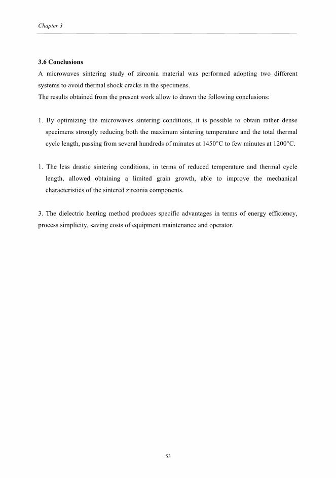
3.6 Conclusions
A microwaves sintering study of zirconia material was performed adopting two different
systems to avoid thermal shock cracks in the specimens.
The results obtained from the present work allow to drawn the following conclusions:
1. By optimizing the microwaves sintering conditions, it is possible to obtain rather dense
specimens strongly reducing both the maximum sintering temperature and the total thermal
cycle length, passing from several hundreds of minutes at 1450°C to few minutes at 1200°C.
1. The less drastic sintering conditions, in terms of reduced temperature and thermal cycle
length, allowed obtaining a limited grain growth, able to improve the mechanical
characteristics of the sintered zirconia components.
3. The dielectric heating method produces specific advantages in terms of energy efficiency,
process simplicity, saving costs of equipment maintenance and operator.
53

Microstructural study of microwave sintered zirconia for dental applications.
3.7 Tables
Table 1 - Physical-mineralogical characteristics of the pre-sintered material
Density (g/cm3)
Porosity
(%)
t phase (wt%)
m phase (wt%)
Grain size
(nm)
3.04
49.62
96
4
80
Table 2 - Physical characteristics of the tested samples, after the different sintering conditions.
Sample
Sintering temperatur
e (°C)
Thermal
cycle length (min)
Density
(g/cm3)
Apparent porosity (vol.%)
Shrinkage
(%)
Conventional sintering B1 1450 600 6.06 0.01 21.77 B2 1480 600 6.06 0.01 21.70 Multi mode microwaves sintering B3 1200 6 5.60 5.20 18.90 B4 1200 25 5.82 1.03 21.52 Single mode microwaves sintering B5 1100 4 5.05 14.52 16.71 B6 1200 4 5.98 0.80 21.49 B7 1200 6 6.01 0.01 21.32
54

Chapter 3
3.8 Figures
Fig. 1. Sample arrangement inside the microwave multi mode applicator.
55

Microstructural study of microwave sintered zirconia for dental applications.
Fig. 2a. Sample arrangement used in the microwave single mode applicator; a) SiC crucible
filled with alumina powder inserted into a refractory support.
Fig. 2b. Refractory support positioned inside the single mode cavity.
56

Chapter 3
Fig. 3. SEM -SEI micrograph of the fracture surface of the tested material, in the pre-sintered
condition. An evident microcrack, sorrounding rests of agglomerates of the starting powder, is
arrowed.
Fig. 4a. SEM-SEI micrograph of the fracture surface of sample B1, conventional sintering
1450°C/1h. Microflaws are arrowed.
57

Microstructural study of microwave sintered zirconia for dental applications.
Fig. 4b. SEM -SEI micrograph of the fracture surface of sample B2, conventional sintering
1480°C/1h.
Fig. 5. SEM -SEI micrograph of the fracture surface of sample B4, multimode microwaves
sintered, maximum temperature 1200°C, total length of the thermal cycle 25 minutes.
58

Chapter 3
Fig. 6a. SEM - SEI micrograph of the fracture surface of sample B5, single mode microwaves
sintered, maximum temperature 1100°C, total length of the thermal cycle 4 minutes. A
microcrack is arrowed, an agglomerates of pores is circled.
Fig. 6b. SEM - SEI micrograph of the fracture surface of sample B6, single mode microwaves
sintered, maximum temperature 1200°C, total length of the thermal cycle 4 minutes.
59

Microstructural study of microwave sintered zirconia for dental applications.
Fig. 6c. SEM - SEI micrograph of the fracture surface of sample B7, single mode microwaves
sintered, maximum temperature 1200°C, total length of the thermal cycle 6 minutes. The
external surface is at the topbright of the micrograph.
Fig. 6d. Small close porosities are responsible of the reduced shrinkage.
60

Chapter 3
3.9 References
[1] Denry I, Kelly JR. State of the art of zirconia for dental applications. Dent Mater 2008;
24:299 - 307.
[2] Chevalier J, Gremillard L. Ceramics for medical applications: A picture for the next 20
years. J Eur Ceram Soc 2009;29:1245 - 55.
[3] Kelly JR, Denry I. Stabilized zirconia as a structural ceramic: An overview. Dent Mater
2008;24:289 - 98.
[4] Becher PF. Toughening behavior in ceramics associated with the transformation of
tetragonal ZrO2. Acta Metal 1996;34:1885 - 91.
[5] Davidowitz G, Kotick PG. The Use of CAD/CAM. Dent Clin North Am 2011;55:559 - 70.
[6] Mizuno M, Obata S, Takayama S, Ito S, Kato N, Hirai T, et al. Sintering of alumina by 2.45
GHz microwave heating. J Eur Ceram Soc 2004;24:387 - 91.
[7] Cheng J, Agrawal D, Zhang Y, Roy R. Microwave sintering of transparent alumina. Mater
Lett 2002;56:587 - 92.
[8] Menezes RR, Kiminami RG. Microwave sintering of alumina–zirconia nanocomposites. J
Mater Proc Tech 2008;203:513 - 17.
[9] Travitzky NA, Goldstein A, Avsian O, Singurindi A. Microwave sintering and mechanical
properties of Y-TZP/20 wt.% Al2O3 composites. Mate Sci Eng A 2000; 286:225-29.
[10] Upadhyaya DD, Ghosh A, Gurumurthy KR, Prasad R. Microwave sintering of cubic
3131zirconia. Ceram Intern 2001;27:415 - 18.
[11] Binner J, Annapoorani K, Paul A, Santacruz I, Vaidhyanathan B. Dense nanostructured
zirconia by two stage conventional/hybrid microwave sintering. J Eur Ceram Soc 2008;28:973
- 7.
[12] Garcìa GC, Meléndez MJ, Gòmez GD, Domìnguez MA. Microwave sintering of
nanocristalline Y-TZP (3mol.%), J Mat Sci 2006;41:5231 - 4.
[13] Reidy CJ, Fleming TJ, Hampshire S, Towler MR. Comparison of microwave and
conventional sintered Yttria-doped Zirconia ceramics. Intern J Appl Ceram Tech 2011;8:1475 -
85.
[14] Oghbaei M, Mirzaee O. Microwave versus conventional sintering: A review of
fundamentals, advantages and applications. J All Comp 2010;494:175 - 89.
[15] Clark DE, Sutton WH, Microwave processing of materials. Ann Rev Mater Scie 1996;26:
299 - 331.
[16] Lewis D, Rayne RJ, Bender BA, Kufihara LK, Chow GM, Fliflet A. Conventional and
61

Microstructural study of microwave sintered zirconia for dental applications.
high frequency microwave processing of nanophase ceramic materials. Nanostr Mater
1997;9:97 - 100.
[17] Thostenson ET, Chou TW. Microwave processing: fundamentals and applications.
Composites: Part A 1999;30:1055 - 71.
[18] Clark DE, Folz DC, West JK. 2000. Processing materials with microwave energy. Mater
Sci Eng A 2000;287:153-8.
[19] Yasuoka M, Nishimura Y, Nagaoka T, Watari K. Influence of different methods of
controlling microwave sintering: the characteristics of oxide ceramics. J Therm Anal Calor
2006;83:407 - 410.
[20] European Standard EN 623-2, 1993. Advanced technical ceramics - monolithic ceramics -
general and textural properties - Part 2: Determination of density and porosity. Geneva: ISO;
1995. Available at: http://www.iso.org/iso/store.htm
[21] Garvie RC, Nicholson PS. Phase analysis in zirconia systems. J Am Ceram Soc 1972;
55:302 - 5.
62

Chapter 4
CHAPTER 4 Bonding effectiveness of zirconia after different sandblasting procedures.
63
Bonding effectiveness of zirconia after different sandblasting procedures
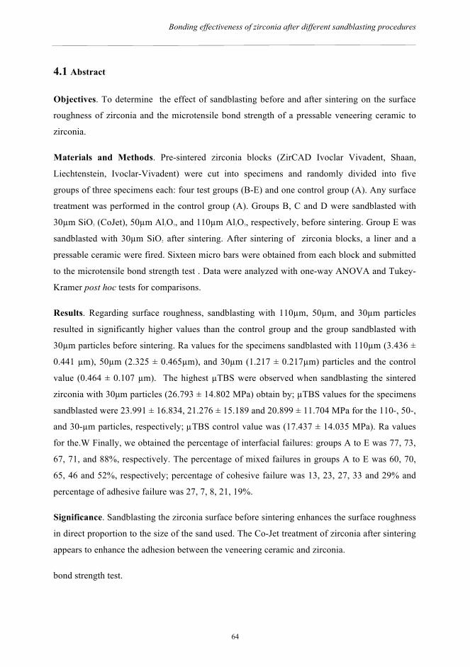
4.1 Abstract
Objectives. To determine the effect of sandblasting before and after sintering on the surface
roughness of zirconia and the microtensile bond strength of a pressable veneering ceramic to
zirconia.
Materials and Methods. Pre-sintered zirconia blocks (ZirCAD Ivoclar Vivadent, Shaan,
Liechtenstein, Ivoclar-Vivadent) were cut into specimens and randomly divided into five
groups of three specimens each: four test groups (B-E) and one control group (A). Any surface
treatment was performed in the control group (A). Groups B, C and D were sandblasted with
30µm SiO2 (CoJet), 50µm Al2O3, and 110µm Al2O3, respectively, before sintering. Group E was
sandblasted with 30µm SiO2 after sintering. After sintering of zirconia blocks, a liner and a
pressable ceramic were fired. Sixteen micro bars were obtained from each block and submitted
to the microtensile bond strength test . Data were analyzed with one-way ANOVA and Tukey-
Kramer post hoc tests for comparisons.
Results. Regarding surface roughness, sandblasting with 110µm, 50µm, and 30µm particles
resulted in significantly higher values than the control group and the group sandblasted with
30µm particles before sintering. Ra values for the specimens sandblasted with 110µm (3.436 ±
0.441 µm), 50µm (2.325 ± 0.465µm), and 30µm (1.217 ± 0.217µm) particles and the control
value (0.464 ± 0.107 µm). The highest µTBS were observed when sandblasting the sintered
zirconia with 30µm particles (26.793 ± 14.802 MPa) obtain by; µTBS values for the specimens
sandblasted were 23.991 ± 16.834, 21.276 ± 15.189 and 20.899 ± 11.704 MPa for the 110-, 50-,
and 30-µm particles, respectively; µTBS control value was (17.437 ± 14.035 MPa). Ra values
for the.W Finally, we obtained the percentage of interfacial failures: groups A to E was 77, 73,
67, 71, and 88%, respectively. The percentage of mixed failures in groups A to E was 60, 70,
65, 46 and 52%, respectively; percentage of cohesive failure was 13, 23, 27, 33 and 29% and
percentage of adhesive failure was 27, 7, 8, 21, 19%.
Significance. Sandblasting the zirconia surface before sintering enhances the surface roughness
in direct proportion to the size of the sand used. The Co-Jet treatment of zirconia after sintering
appears to enhance the adhesion between the veneering ceramic and zirconia.
bond strength test.
64

Chapter 4
4.2 Introduction
Porcelain-fused to metal prosthesis (PFM) are routinely used in dental practice thanks to the
well known technical procedures, good aesthetics and reliability over years [1]. Despite the
survival rate of PFMs range from 74 to 85% at 15 years, discolorations may occur at the
metallic margin and some alloy’s components may generate allergic reactions [2-3].
Therefore, replacement of PFMs by all-ceramic restorations has been driven by the
improved aesthetics and lower allergenic potential achieved using ceramic materials as core
frameworks. All-ceramic single crowns and anterior fixed partial dentures (FPD) have been
used successfully since nineties. Afterwards, due to the development of high-strength ceramic
frameworks, such as tetragonal zirconia polycrystals (TZP), missing teeth in the posterior
regions have also been replaced by all-ceramic FPDs. The superior mechanical properties of
zirconia combined with state-of-the-art computer-aided design and machining (CAD/CAM)
fabrication procedures have allowed large and complex restorations with high accuracy and
success rates [4]. To achieve better aesthetics, zirconia frameworks can be veneered with a
ceramic material, which is built in successive layers, giving the final restoration individual
optical characteristics that can barely be distinguished from the surrounding natural dentition.
Alternatively, ceramic can be pressed on zirconia frameworks for veneering. The main
advantage of the heat pressing technique is that it allows pores due to the lost-wax technique to
be avoided and one-step layering procedures [5].
However, establishing a strong and stable bond between yttrium, partially stabilized tetragonal
zirconia polycrystal materials (Y-TZP) and veneering ceramics has been proven to be
cumbersome [6]. Bonding mechanisms between veneering ceramics and zirconia frameworks
are currently subject of comprehensive investigations [7].
It has been reported that the zirconia–veneer bond is weaker than that of other all-ceramic
systems, which suggests that layered zirconia frameworks are more susceptible to delamination
and chipping during function [8].
Clinical studies have reported a failure rate of 13.0% after three years and 15.2% after five
years for veneered yttrium-TZP (YTZP) frameworks due to chipping of the ceramic veneer [9].
This fracture pattern is associated with a thin layer of glass-ceramic that remains on the zirconia
framework [10]. This finding supports the hypothesis of a reliable bonding of veneering
ceramics to zirconia frameworks, but also reveals the brittleness brittleness weakness of the
veneering ceramic. Moreover, it is difficult to determine the point of initial fracture. As already
explained by Aboushelib et al., a crack initiated at the ceramic-zirconia interface can propagate
through the weakest layer due to the asymmetric stress distribution in the specimen. As a
65

Bonding effectiveness of zirconia after different sandblasting procedures
consequence, traces of elements may be left attached to the interface. When analyzing, this will
be incorrectly classified as cohesive failure [6-7].
Silica coating has been proved to improve bonding of zirconia to luting agents, particularly
when using the Co-Jet system (3M ESPE, St. Paul, MN, USA) [11]. This system uses silicate-
coated alumina particles for sandblasting, thereby welding a silicate layer onto the surface by
means of the high spot heat produced by the blasting pressure followed by silanization. The
effects of CoJet system are related to the high kinetic energy of the Al2O3 particles modified
with SiO2 at impact and the fusion of the silica to the substrate surface.
Since silicate-based veneering porcelains are often used to bond to zirconia frameworks,
silica coating of zirconia might enhance the bond strength of the veneering ceramics as well.
However, any other studies have previously been carried out to support this hypothesis [12].
In general, shear tests or microtensile tests are used to measure the bond strength of an all-
ceramic system, but using shear bond test may lead to undesired stress pattern distribution,
causing cohesive failures and erroneous interpretation of the data, and to evaluate the influence
of the substrate surface on bond quality. In particular the microtensile bond strength test
(µTBS) has been proven to be a reliable test for evaluating the bond strength of composite
materials to a variety of substrates [13]. To evaluate bond quality is preferable to use SEM
analysis.
Aim of this study was to determine the effect of different sandblasting procedures on the
surface roughness of zirconia and the microtensile bond strength of a veneering ceramic to
zirconia. The hypotheses tested were that sandblasting before sintering enhances the surface
roughness of zirconia (hypothesis 1) and the µTBS of a pressable veneering ceramic to zirconia
(hypothesis 2).
4.3 Materials and Methods
Three zirconia ZirCAD C15L (Ivoclar Vivadent, Shaan, Liechtenstein) specimens were cut
using a low-speed diamond disc (MDS100, Norton, USA) in a special device to obtain 15
blocks of zirconia of 7.2 mm height, 9.2 mm width, and 9.2 mm length.
The surface of each test block was sandblasted before or after sintering. Then, ZirLiner
(Ivoclar Vivadent, Shaan, Liechtenstein) was applied and veneered with the pressable ceramic
ZirPress (Ivoclar Vivadent, Shaan, Liechtenstein). Finally, the specimens were cut into micro-
bars to measure the core-veneer microtensile bond strength.
The materials tested and their properties are summarized in Table 1. Pre-sintered zirconia
blocks (ZirCAD C15L, Ivoclar Vivadent, Shaan, Liechtenstein) were cut into specimens and
66

Chapter 4
divided randomly into five groups of three specimens each. Groups B to E were the test groups
and group A was the control. The following surface treatments were applied. Groups B to D
were sandblasted before sintering with 30-µm SiO2 (CoJet, 3M ESPE), 50-µm Al2O3, and 110-
µm Al2O3 particles, respectively. Group E was sandblasted after sintering with 30-µm SiO2
(CoJet, 3M ESPE). Group A was sintered without any surface treatment. The sandblasting was
performed at the same pressure of 2 bars for 15 seconds. The distance between the nozzle and
the surface differed; it was 1 cm for the 30-µm Al2O3 SiO2 (CoJet, 3M ESPE) and 1.5 cm for the
50-µm and 110-µm Al2O3. The treatments are summarized in Table 2. The zirconia blocks (20%
ca. contraction) were sintered in a Sintramat (Ivoclar ViIvadent, Shaan, Liechtenstein) oven
according to the manufacturer’s instructions. The surface roughness (Perthometer M4P, Mahr
Perthen) of the polished, sandblasted, and silica-coated specimens was measured for each
treatment. The surface for each treatment was scanned two times by five parallel tracings
with1.0-mm intervals and the Ra values were registered.
After the preliminary measurements, a layer of ZirLiner (IPS e.max, Ivoclar Vivadent, Shaan,
Liechtenstein) was applied to the zirconia blocks and fired at a temperature of 960°C. Then,
wax-up onto the coping was performed in order to obtain an equivalent veneering structure for
the corresponding ZirCAD specimen. The wax surface was smoothed, finished, and invested in
a special investing material (IPS PressVEST, Ivoclar Vivadent, Shaan, Liechtenstein) in a size
two muffle according to the manufacturer’s instructions. The wax was burnt out and the muffle
was heated. The copings were over-pressed using special porcelain (IPS e.max ZirPress, Ivoclar
Vivadent. Shaan, Liechtenstein) with the appropriate coefficient of thermal expansion with
respect to zirconia. After cooling, the investment was removed in the sandblasting unit
(Eurosab, Tissi, San Donato Milan, Italy) using 50-µm glass beads at 2 bars pressure. The
reaction layer formed during the pressing procedure was removed by immersing the crowns in
HF solution (IPS e.max Press Invex Liquid, Ivoclar Vivadent, Shaan, Liechtenstein) in an
ultrasonic cleaner (Sonorex, Bandelin, Berlin, Germany) for 5 min. Subsequently, the blocks
were cleaned under running water for 3 min and dried. The pressing sprue and extrusion flashes
were removed using a water-cooled air-turbine without pressure to protect the porcelain from
heat damage.
The 15 blocks ZirCAD-ZirPress were stored in distilled water at 37°C for at least 1 week. Then,
they were cutted using a diamond-coated blade (Acutom-40, Automatic Blade) for sintered
zirconia, under water cooling, to obtain 20 micro bars from each block ZirCAD-ZirPress. Each
micro bar had a vertical dimension of 10 mm (5 mm of ZirCAD and 5 mm of ZirPress) and a
67

Bonding effectiveness of zirconia after different sandblasting procedures
horizontal cross-section of 1 mm2. Randomly, 16 sound micro bars were selected from each
group. Using reported methods, the micro bars were attached to the attachment unit using an
adhesive resin (Model Repair II Blue, Dentsply-Sankin, Ohtawara, Japan), taking care to centre
the zirconia veneer interface at the free space of the attachment unit, and were loaded to failure
at a crosshead speed of 1 mm/min (LRX, Lloyd, Hampshire, UK). The maximum load at failure
[N and MPa] was extracted from computer-generated files.
The surface roughness measurements and microtensile values were analyzed statistically using
one-way analysis of variance (ANOVA), follow by a post hoc Tukey-Kramer test (Jmp7 ver.
7.0, Chicago, USA).
4.4 Results
The morphology of sintered zirconia surfaces was observed by using a scanning electron
microscope (SEM, Zeiss EVO 40, D) equipped with an energy-dispersive X-ray analyzer (EDS,
Inca, Oxford Instruments, UK), after gold sputtering.
The mode of failure was analyzed by using a stereomicroscope at 50× (Wild M5A, Heerbrugg,
Switzerland) at 25× magnification. Failures fractures were classified into three groups: cohesive
(within the veneer ceramic), mixed, and adhesive (within the interface between veneer and
zirconia ceramics). In addition, the lateral side of some of the tested micro-bars were cleaned
ultrasonically and analyzed by SEM and EDS. Regarding surface roughness (Ra), the values for
the specimens sandblasted with 110µm were 3.4 ± 0.4µm, with 50µm were 2.3 ± 0.4µm, with
30µm were 1.2 ± 0.2µm for the control group were 0.4 ± 0.1, (Figure 1).
The highest value of the micro-tensile bond strength was obtain by Group E sandblasting the
already sintered zirconia with a µTBS of 26.793 ± 14.802 MPa. The µTBS values for the
specimens sandblasted were 23.9 ± 16.8, 21.2 ± 15.1 and 20.8 ± 11.7 MPa for the 110-, 50-,
and 30-µm particles, respectively; the µTBS of the control group (A) was (17.4 ± 14.0 MPa).
The results are shown in Figure 2. The mean microtensile bond strength, standard deviation and
failure pattern are summarized in Table 3.
The statistical analysis showed that sandblasting the zirconia surface before sintering
enhanced the roughness values in direct proportion to the dimensions of the sand used. There
was a significant difference between group D and the control group, whereas the results for the
other test groups were intermediate between these two groups. Finally, we determined the
percentages of failures involving defects that crossed the interface with the porcelain veneer
(mixed), at the interface (adhesive), and within the veneering porcelain itself (cohesive). The
68

Chapter 4
term “interfacial failure” was used for both mixed and adhesive failures. Regarding the type of
failure, the percentage of mixed failures in groups A to E was 60, 70, 65, 46 and 52%,
respectively; percentage of cohesive failure was 13, 23, 27, 33 and 29% and percentage of
adhesive failure was 27, 7, 8, 21, 19%. The results are shown in Figure 3.
4.5 Discussion
Clinical recommendations on materials and procedures are often based on mechanical
laboratory tests. Most common tests used for evaluating the bond strength are the shear bond
test and microtensile bond strength test. These tests are also used to evaluate the bond strength
between core and veneer in different all-ceramic systems. Al-Dohan et al. reported for
commercially available core veneered all-ceramic systems shear bond strength in the range of
22-31 MPa [14].
Unfortunately, using shear bond test may lead to undesired stress pattern distribution,
causing cohesive failures and erroneous interpretation of the data.
Application of the microtensile bond strength test for measuring the tensile strength of the
core and veneer components of all-ceramic restorations allowed direct evaluation of their
tensile strength. However, using the microtensile bond strength to measure the core veneer
bond strength this test requires careful attention while cutting the brittle specimens in order to
avoid creating cutting defects or unexpected cracking of the microbars. Using sharp new cutting
discs at high cutting speeds and low loads reduces vibration and ensures fine cutting of the
specimens.
The data of surface roughness and microtensile tests did not show a direct correlation
between the Ra values and the strength of adhesion obtained in the different test groups. The
Ra parameter, the most common one reported in the dental literature [15], represent the
average roughness as measured by the profilometer, and as lower is its value, smoother is the
surfaces [16]. Relative to the roughness values, the data are shown in Figure 1. The statistical
analysis showed that sandblasting the zirconia surface before sintering enhanced the roughness
values in direct proportion to the dimensions of the sand used.
The SEM analysis of the same samples allowed to have a more deep sight of the real surfaces
morphology. The sand blasted surfaces drastically change the surface microstructure of the
zirconia samples, increasing the roughness according to the dimensions of the impacting
particles [17].
69

Bonding effectiveness of zirconia after different sandblasting procedures
The worn surfaces present detachments and plastic deformation of the material, Fig. A. The
sand-blasting operation causes also changes from a chemical point of view, the EDS analysis
allowed to recognize the presence of small fragments of alumina and silica. In particular, for the
samples of the groups CB and DC, alumina particles appear to be well immersed the zirconia
matrix, and co-sintered (Fig. B). While for the samples of the group ED, several fine silica
particles, coming from the CoJet abrasive, are smeared on the zirconia surface (Fig. C).
The best adhesion was obtain by sandblasting the already sintered zirconia with the smallest
sand particles (30 µm) (Ra = 0.546 ± 0.099 µm; µTBS = 26.793 ± 14.802 MPa). There was a
significant difference between group D and the control group, whereas the results for the other
test groups were intermediate between these two groups. Therefore, the surface treatment with
CoJet after sintering is a good way to enhance the adhesion between zirconia and the veneering
porcelain.
In addition, the bond strength of the samples sandblasted before sintering was increased
relative to the control group. The values were 23.991 ± 16.834, 21.276 ± 15.189, and 20.899 ±
11.704 MPa for the 110-, 50-, and 30-µm particles, respectively, and all were better than the
control value (17.437 ± 14.035 MPa), although the differences were not significant. By contrast
the Ra values for the specimens sandblasted with 110-µm (3.436 ± 0.441 µm), 50-µm (2.325 ±
0.465µm), and 30-µm (1.217 ± 0.217µm) particles were significantly different from the control
value (0.464 ± 0.107 µm).
The results obtained for the specimens sandblasted before sintering were likely dependent
on the roughness produced by sandblasting, whereas the significant improvement obtained with
sandblasting after sintering was likely associated with the CoJet treatment.
We determined the percentages of failures involving defects that crossed the interface with
the porcelain veneer (mixed), at the interface (adhesive), and within the veneering porcelain
itself (cohesive). (Fig. 3).
The failure analysis showed a high percentage of mixed interfacial failures with all
treatments; the percentage of mixed interfacial failures in groups A to E was 60, 70%, 65%,
46%, 52%, respectively. These values depend on the correct execution of the microtensile test
and the distribution of forces at the interface are due to the brittleness of veneer ceramics [18].
Figure D shows an example of mixed failure with exposed zirconia crystals.
Different punctual micro-analysis, conducted in the contact area zirconia-veneering ceramic,
on the cross section of the sample (Fig. D), pointed out the presence of a certain reaction area at
70

Chapter 4
the interface of the two materials. The EDS spectrum corresponding to the contact area, shows
the presence of large amount both of zirconia and the elements, characteristics of the veneering
layer. It is to underline as the sandblasting, after the sintering step, as in the samples of group
ED, not only causes a widespread silica particles smearing on the surface, but it is also
responsible of a partial zirconia phase transformation, from tetragonal to monoclinic, and a
lattice distortion, as indicated by the hump at the left shoulder of (111)t peak, for the presence
of residual stresses (Fig. E). (il centro ceramico ci deve dare questa Figura) Even if
additional crystallographic study is necessary, it is rather clear as these phenomena give a
higher reactivity to the zirconia surface, that results to be more prone to react with the
veneering ceramic.
To prevent the delamination or chipping of a restoration, it is necessary to select the
appropriate ceramic materials. Surface treatments are used to enhance the bonding of the
ceramic.
Different treatments can be used to color the zirconia framework for aesthetic purposes. As our
results showed, the best way to enhance the bonding between zirconia and ceramic is post-
sintering sandblasting with 30-µm sand (CoJet, 3M ESPE). Tribochemical silica coating also
deposited a silica layer on the ceramic surface, due to the high-pressure impaction of alumina
particles modified by silica on the conditioned substrate. Unfortunately, less information is
available regarding the effect of tribochemical silica coating in zirconia–resin bonds. Such a
technique is supposed to provide ultra fine mechanical retention embedding treated surfaces
with silica particles [19].
The addition of pigments to the zirconia framework could alter its structure, necessitating a
different surface treatment before veneering. To prevent delamination and chipping failure of
zirconia veneered restorations, careful selection of both the framework and veneer ceramic
materials, in addition to proper surface treatment, are essential for maintaining good bond
strength.
In Aboushelib et al., the liner was applied over a sandblasted surface. Although it increased
the bond strength of colored zirconia frameworks, it also increased the percentage of interfacial
failures. Further study is needed to understand this phenomena.
4.6 Conclusions
Within the limitations of this study, the following conclusions were drawn:
71

Bonding effectiveness of zirconia after different sandblasting procedures
1. Sandblasting the zirconia surface before sintering enhances the surface roughness in direct
proportion to the size of the sand used;
1. Increasing the surface roughness of the zirconia enhance its microtensile strength, although
the differences were not significant;
2. Evaluating microtensile bond strength we can say that using the CoJet treatment after
sintering is recommended for clinical situations where it is important improve the
adhesion of ceramic veneer to zirconia;
3. Improving the strength of veneering ceramics is necessary to realize the benefits of the
high strength of zirconia frameworks.
4. High percentage of mixed failures are due to the brittleness of veneer ceramics.
72

Chapter 4
4.7 Tables.
Material Batch Number
s Composition Coefficient of thermal
expansion (ppm/°C) ZirCAD K30504 K54201 yttrium oxide (4–6% vol)
hafnium oxide (1–5% vol) and alumina and silica (<1% vol)
10.75 (0.25)
ZirPress H26883 H20589 SiO2 primarily, with Li2O, Na2O, K2O, MgO, Al2O3, CaO, ZrO2, P2O5.
10 to 10.5
Table 1: Properties of the materials according to the manufacturer’s data used in this study
Group
Abrasive Working distance
Working time
A No sandblasting - - B Al2O3, SiO2 30 µm Co-Jet pre-sintered treatment 1 cm 15 sec C Al2O3 50 µm pre-sintered treatment 1,5 cm 15 sec D Al2O3 110 µm pre-sintered treatment 1,5 cm 15 sec E Al2O3, SiO2 30 µm Co-Jet post-sintered treatment 1 cm 15 sec
Table 2: Different treatment of the groups A to E.
73

Bonding effectiveness of zirconia after different sandblasting procedures
Group Abrasive MTBS (MPa) Failure Pattern A - 17,44 (14,03) Cohesive 13%
Mixed 60% Adhesive 27%
B Al2O3, SiO2 30 µm Co-Jet pre-sintered treatment
20,9 (11,7) Cohesive 23% Mixed 70% Adhesive 7%
C Al2O3 50 µm pre-sintered treatment
21,28 (15,19) Cohesive 27% Mixed 65% Adhesive 8%
D Al2O3 110 µm pre-sintered treatment
23,99 (16,83) Cohesive 33% Mixed 46% Adhesive 21%
E Al2O3, SiO2 30 µm Co-Jet post-sintered treatment
26,79 (14,8) Cohesive 29% Mixed 52% Adhesive 19%
Table 3: Micro tensile bond strength (µTBS) and percentage of failure mode of the different
groups.
74

Chapter 4
75

Bonding effectiveness of zirconia after different sandblasting procedures
Figure 2. Micro tensile bond strength (µTBS) expressed in
MPa. Figure 3. Percentage of failure mode of the different groups.
76

Chapter 4
Figure A. SEM micrograph of the zirconia surface, group B.
Figure B. SEM micrograph of the zirconia surface, group C. The darker particles, arrowed, is
alumina.
77

Bonding effectiveness of zirconia after different sandblasting procedures
Figure C. SEM micrograph of the zirconia surface, group D. The several light particles are
rich in silicon.
Figure D. A fractured microbar showing exposed zirconia crystal
78

Chapter 4
Figure E – X-ray diffraction patterns of the control sample (A) and samples E–G, the surfaces
of which were treated with 110-, 50-, and 30-µm abrasive particles, respectively. Arrow
indicates the hump.
References
[1] Raigrodski AJ. Contemporary materials and technologies for all-ceramic fixed partial
dentures: A review of the literature. J Prosthet Dent 2004;92:557 - 562.
[2] Kansu G, Aydin AK. Evaluation of the biocompatibility of various dental alloys: Part I—
Toxic potentials. Eur J Prosthodont Restor 1996;4:129 - 136.
[3] Kansu G, Aydin AK. Evaluation of the biocompatibility of various dental alloys: Part 2—
Allergenical potentials. Eur J Prosthodont Restor Dent. 1996;4:155 - 161.
[4] Blatz MB. Long-term clinical success of all-ceramic posterior restorations. Quintessence
Int. 2002;33:415–426.
[5] Oguri T, Tamaki Y, Hotta Y, Miyazaki T. Effect of a convenient silica-coating treatment on
shear bond strengths of porcelain veneers on zirconia-based ceramics. Dent Mater J;31:788 -
96.
[6] Aboushelib MN, de Jager N, Kleverlaan CJ, Feilzer AJ. Microtensile bond strength of
different components of core veneered all-ceramic restorations. Dent Mater 2005;21:984 - 91.
79

Bonding effectiveness of zirconia after different sandblasting procedures
[7] Aboushelib MN, DDS, Cornelis J. Kleverlaan, Feilzer AJ. Microtensile Bond Strength of
Different Components of Core Veneered All-Ceramic Restorations. Part 3: Double Veneer
Technique. J Prosthodont; 2008:17: 9 - 13.
[8] Isgrò G, Feilzer AJ. The influence of the veneering porcelain and difference surface
treatments on the biaxial flexural strength of a heat-pressed ceramic. J Prosthet Dent 2004;90:
465 - 73.
[9] Sailer I, Fehér A, Filser F, Gauckler LJ, Lüthy H, Hämmerle CHF. Five-year clinical results
of zirconia frameworks for posterior fixed partial dentures. Int J Prosthodont 2007;20: 383 - 8.
[10] Sailer I, Fehér A, Filser F, Lüthy H, Gauckler LJ, Schärer P, Hämmerle CHF. Prospective
clinical study of zirconia posterior fixed partial dentures: 3-year follow-up. Quintessence Int
2006; 37: 41 - 49.
[11] Kim BK, Bae HE, Shim JS, Lee KW. The influence of ceramic surface treatments on the
tensile bond strength of composite resin to all-ceramic coping materials. J Prosthet Dent
2005;4:357 - 62.
[12] Fischer J, Stawarczyk B. Effect of zirconia surface treatments in the shear strength of
zirconia/veneering ceramic composites. Dent Mater 2008;3:448 - 54.
[13] El Zohairy AA, De Gee AJ, de Jager N, Ruijven LJ, Feilzer AJ. The influence of specimen
attachment and dimension on the microtensile strength. J Dent Res 2004; 83:420-4.
[14] Al-Dohan HM, Yaman P, Dennison JB, Razzoog ME, Lang BR. Shear strength of core-
veneer interface in bi-layered ceramics. J Prosthet Dent 2004; 91:349-55
[15] Ayad MF, Fahmy NZ and Rosenstiel SF. Effect of surface treatment on roughness and
bond strength of a heat-pressed ceramic. J Prosthet Dent 2008;2:123-130.
[16] Advanced technical ceramics. Monolithic ceramics. General and textures properties. Part
4: Determination of surface roughness. The European Standard EN 623–4:2004.
[17] Aboushelib MN, Kleverlaan CJ, Feilzer AJ. Effect of Zirconia Type on Its Bond Strength
with Different Veneer Ceramics. J Prosthodont 2008;17:401 - 408.
[7] Burke FJ, Flemming GI, Nathanson D, Marquis PM. Are adhesive technologies needed to
support ceramics? An assessment of the current evidence. J Aesthet Dent 2002;4:7 - 22.
[18] Valandro LF, Della Bona A, Bottino MA, Neisser MP. The effect of ceramic surface
treatment on bonding to densely sintered alumumina ceramic. J Prosthet Dent 2005;93:253 - 9.
[19] Sun R, Suansuwan N, Kilpatrick N, Swain M. Characterisation of tribochemically assisted
bonding of composite resin to porcelain and metal. J Dent 2000;28:441–5.
[20] De Oyahue RC, Monticelli F, Toledano M, Osorio E, Ferrari, Osorio R. Influence of
surface treatments and resin cement selection on bonding to densely-sintered zirconium-oxide
80

Chapter 4
ceramic. Dent Mater 2009;2:172 - 9.
81


Chapter 5
CHAPTER 5
Adhesion mechanisms at the interfaces between Y-TZP and veneering
ceramics
83

Adhesion mechanisms at the interfaces between Y-TZP and veneering ceramics
5.1 Introduction
Due to better mechanical properties of Yttria-stabilized tetragonal zirconia (Y-
TZP) compared with other polycrystalline ceramics such as alumina; the use of
this framework material has been increasingly on dental practice. The most
important characteristics of this material are high flexural straight and fracture
toughness, and the capacity of phase transformation from tetragonal to
monoclinic (t→m), which results in a volumetric increase preventing crack
propagation [1-3].
Despite all qualities of this material, several authors have been reported clinical
failures mainly because chipping of the veneering porcelain [4]. A recently
literature review, which evaluated the clinical studies published between 1999
and 2009 and with 330 fixed partial dentures or crowns made with zirconia
framework, revealed that in 41 cases was detected chipping of veneered
ceramics, being the most frequently complication type occurred and reflecting
as a 5 year-complication-free rate of 79.44% [5].
Several authors attempt to explain the causes of these failures and many
hypotheses are raised, such as different thermal-expansion coefficients of
zirconia and veneering ceramics [6-7] or the problem of residual stress that may
occur during preparation procedures combined with contact-induced cracking
[8-9].
In order to enhance the bond strength between zirconia and veneering porcelain
and, consequently, reduce the incidence of chipping during the life of
prostheses, various procedures have been proposed. The surface treatment of
zirconia before veneering process is one of the means to increase bonding area
and, thereby, increase the bond strength between the two materials. Another
tested procedure is the tribochemical silica coating and silanization, where the
zirconia is sandblasted with silica modified aluminum oxide particles causing
84

Chapter 5
the incorporation of silica on the ceramic surface and, then a silane is applied
linking the silica of the zirconia surface with veneer porcelain [10].
There are also works that proposed the use of a liner between zirconia and
veneering porcelain. Aboushelib et al. conducted a study comparing the
aluminum oxide sandblasting of zirconia combined or not with the application
of liner and their results showed that, independent of veneering porcelain type,
this layer can promote delamination of the porcelain, principally when press-on
ceramic is used [11].
Furthermore, most of studies tested the adhesive strength of veneered zirconia
by means of microtensile or shear. But is also important analyze the phase
transition (t→m) of zirconia, since it can be stimulated by the mechanical
treatment of zirconia or even because the technical application of veneer
ceramics [12].
Based on the literature and seeking a way to reduce the chipping occurrence of
veneered zirconia, the objective of this study was to evaluate the use of a liner
combined or not with the silica coating sandblasting of zirconia, assessing the
fracture resistance, phase composition and SEM observation. The objective of
this study was to evaluate the Adhesion mechanisms at the interfaces between
Y-TZP and veneering ceramics.
85

Adhesion mechanisms at the interfaces between Y-TZP and veneering ceramics
5.2 Material and Methods
Thirty-two specimens of a commercial zirconia (Y-TZP) (Lava Frame 61mm
blocks; 3M ESPE, Seefeld, Germany) were cut from presintered blocks with a
low speed diamond blade (MDS100, Norton, USA) connected to a special
device; the dimensions of the resulting presintered specimens were 7.2 mm
height, 9.2 mm width, and 9.2 mm length. In order to assure the same starting
roughness, a surface treatment with 3 steps of polishing paper (600-800-
1000grit) was performed for all the specimens. Before sintering, the specimens
of each group were divided between the ones that had to be tested after fracture
(-F specimens) and the ones that has to be observed after mirror finishing (-M
specimens). For these latter, with the aims to easily induce crack, two wedge-
shaped incisions were performed on the surfaces, one obtained in the zirconia
surface before sintering and the opposing one obtained in the veneering
ceramic, after its application. At the end, the first sintering were performed
(Lava Therm, 3M ESPE) following manufacturer's instructions. After randomly
dividing into 4 groups, the zirconia specimens were veneered with a layerable
ceramic (Lava Ceram Overlay Porcelain, 3M ESPE), with different
intermediate steps, as reported in Table I. For the specimens of group A, the
zirconia base was directly veneered, without the application of framework
modifier. The zirconia samples of the group B were coated with the framework
modifier provided by the manufacturer (Framework Modifier, 3M ESPE) and
fired as manufacturer's recommendation before the final veneering. The
zirconia samples of the group C were sandblasted with 30µm SiO2-coated
Al2O3 (Cojet, 3M ESPE) with a pressure of 2 bars, at a distance of 15mm for 15
seconds; subsequently they were veneered without the application of modifier
layer. Group D specimens were both sandblasted and layered with the
framework modifier before veneering. The final venering sintering, for all the
86

Chapter 5
samples, followed the manufacturer's instructions, that foresee a firing at 850°C
for 1 minute.
In Figure 1, the –F and –M specimens, as appeared after the final sintering step,
are shown.
The analysis of the interface were conducted both on polished and fractured
samples, after the final sintering. The first ones were obtained by embedding in
a polyester resin the -M subgroup specimens; then the sides with the interface
were mirror finished in a bench grinder polisher machine (LECO Co., VP-150,
USA). For the second ones, the -F subgroup specimens were easily fractured,
with the aid of the two wedge-shaped incisions.
The average roughness values, Ra, of the zirconia surfaces, in both the as fired
and after the Coject treatment, were measured by using a roughnessmeter
(Hommel Tester, T2000, Germany), according to the test method recommended
in the standard EN 623-4 (European Standard EN 623-4, Advanced technical
ceramics - monolithic ceramics-general and textural properties - Part 4:
Determination of surface roughness, 1993).
The phase fraction amounts of zirconia were evaluated by X-rays diffraction
technique (XRD), with the use of a diffractometer (Philips PW 3830;
Netherlands), with CuKα radiation (0.02° step-scan, 10s per step). Zirconia
diffraction peaks were deconvoluted by using a Lorentz function in order to
obtain the integral breadth. The monoclinic phase fraction of the zirconia was
calculated using the Garvie and Nicholson method [13].
The microstructure of the surface and the interfaces between the two ceramics
was analysed by using a scanning electron microscope (SEM, Zeiss EVO 40,
Germany) equipped with an energy-dispersive X-ray analyser (EDS, Inca,
Oxford Instruments, UK), after gold sputtering. The EDS spectra at the
interface were acquired by using an acceleration voltage of 10kV with an
acquisition time of 150 of live second per point. The observations have been
87

Adhesion mechanisms at the interfaces between Y-TZP and veneering ceramics
repeated on at least for 10 times, the more meaningfull micrographs are
reported in the present study.
Table I – Grouping and treatments characteristics for the tested samples.
Group Zirconia Surface condition before veneering Veneering
A Lava -- -- Lava Ceram
B Lava -- framework modifier Lava Ceram
C Lava Cojet pretreatment -- Lava Ceram
88

Chapter 5
5.3 Results
The microstructural changes, induced on the zirconia surface by the Coject
treatment, were assessed by means of both the techniques XRD and SEM. The
zirconia crystalline phases, existing in the pre-sintered condition, are tetragonal
and monoclinic (3 wt%) phases, as detected by the XRD analysis. After the
first sintering step, in the untreated zirconia surfaces, samples of groups A and
B before the veneering step, only peaks of the high temperature phases
(tetragonal and cubic) were detected without any diffraction peaks of
monoclinic phase. After the impact with the erosive particles of the Coject
treatment, monoclinic phase is present in ana amount of 5 wt%.
The surface average roughness value, for the differently treated zirconia
surfaces, presents only a slight increase after the Coject treatment, passing from
the 0.36±0.14 µm of the as fired condition to 0.42±0.05 µm after the erosive
treatment. The morphological features variations induced by the erosive
treatment were also analysed. The sintered zirconia surface, corresponding to
the substrates for samples A and B (Fig. 2a), before the application of the
veneering ceramic, even if rough, does not present cracks. After the Coject
treatment, the zirconia surface, corresponding to the substrates of samples C
and D (Fig. 2b, c), is characterised by the presence of some cracks of reduced
dimension. In addition, the surface is covered by very small loose particles,
well adhering at the surface (Fig. 2c), they correspond to residues of the
impacting erosive particles, because the EDS analyses revealed in them the
presence of silicon and aluminium.
The morphological analysis of the polished cross sections of the samples after
the final sintering step, belonging to all the groups samples, clearly shows a
well defined interface zirconia-veneering ceramic (Fig. 3). The interfaces in the
samples of the A and C groups, without the application of the framework
modifier, are characterized by the presence of round porosities opening in the
89

Adhesion mechanisms at the interfaces between Y-TZP and veneering ceramics
ceramic layer and micro detachments (Fig. 4a, c). Differently, the zirconia-
veneering ceramic interfaces in the samples of the B and D groups, with the
framework modifier layer, present a rather well continuous contact between the
two different materials (Fig. 4b, d). No detachments were observed, only rather
small pores in the ceramic layer, essentially far from the interface.
Different punctual micro-analysis were performed in the contact areas zirconia-
veneering ceramic, on the cross section of the samples of all groups. In
particular, many EDS spectra were collected starting from the interfaces and
moving toward the inner part both of zirconia and ceramic veneer layers, at
distances of about 500nm, 1µm and 5µm. These analysis were repeated almost
3 times in different parts of the interfaces to have sound results. In addition, the
chemical analysis were performed, by EDS, on the surface of the ceramic
veneer, to assess the possible presence of zirconium that could affect the
analysis at the interface. The result, reported in Table II, shows the absence of
this element in the bulk of the ceramic veneer layer.
Table II - Chemical analysis of the ceramic veneer Oxides Na2O Al2O3 SiO2 K2O CaO TiO2 BaO
Wt% 10.51 12.10 65.62 6.46 2.43 0.65 2.23
90

Chapter 5
For all the four samples groups, the elemental analysis showed the presence of
zirconium in the ceramic veneer layer and the elements characteristics of the
veneering layer (silicon as main element) in the zirconia layer, till a distance of
about 1µm from the interface. At 5µm from the interface both in the zirconia
and in the veneering ceramic layers, zirconia and silicon, respectively, amounts
were not detectable. In Figure 5, a representative sequence of EDS spectra
performed at 500nm and 1µm from the interface both in the ceramic veneering
and in the zirconia layers are reported for sample A and D.
To be sure that no elemental interchange due to the polishing operation had
affected the results, the interface of fresh fractured surfaces, sample type-F,
were analysed, and the results were identical to the previous ones.
91

Adhesion mechanisms at the interfaces between Y-TZP and veneering ceramics
5.4 Discussion
In order to clarify the effect of the Coject treatment on the zirconia surface, a
preliminary microstructural analysis was carried out on some specimens of
sintered zirconia before the veneering step. This kind of erosion treatment does
not usually change in a dramatic way the surface roughness [14] and for the
present study too, only a slight increase in the average roughness value has
been detected, while a more meaningful morphological features and crystalline
phases variation was observed.
As detected by the XRD analysis, the first sintering step, the sintering of the
zirconia alone, allowed to transform the small amount of residual monoclinic
phase, still existing in the presinterd (as received) material, in a such way that
only the high temperature phases (tetragonal-cubic) are present. The impact
with the erosive particles of the Coject treatment causes a certain amount of
stress induced tetragonal to monoclinic phase transformation, in fact about
5wt% of monoclinic phase has been detected. The erosion action of the ceramic
particles, constituted by silica coated alumina, this latter a harder material than
zirconia [15], causes a mechanical stress able to induce the phase
transformation of the metastable tetragonal phase into the monoclinic one [16].
This phase transformation is associated to an increase of volume, about 4%, and
a shear strain, about 7% both ones develop a compressive residual stress on the
zirconia surface, often associated to widespread cracks network, if the intrinsic
strength of the material is overcome, as here observed on the zirconia
surfaces[17], corresponding to the substrates of samples C and D (Fig. 2b, c).
Without the Coject treatment, cracks are not present on the zirconia surface,
substrates for samples A and B (Fig. 2a).
From the morphological analysis of the cross sections of the zirconia-veneering
ceramic, it is evident the effect of the presence of the framework modifier layer,
that, changing the chemical surface conditions at the interface, allow to obtain
92

Chapter 5
interfaces characterized by a rather well continuous contact between zirconia
and veneering ceramic, samples of the B and D groups (Fig. 4b, d). Where it
has not been applied, samples of the A and C groups, the adhesion is poor,
micro detachments and several round porosities, opening in the ceramic layer,
are observed (Fig. 4a, c). The present results testify as the application of the
modifier layer is able to better decrease the wettability of the zirconia surfaces,
differently by the use of the ceramic veneer alone, so to allow a continous
contact between the two layer and strength their adhesion.
The pore formation, in samples belonging to groups A and C, is due to the
evolution of bubbles of gas during the final thermal step. This phenomenon can
be due both to the presence of gas trapped among the ceramic particles, that
have not the possibility to escape for the viscosity of the viscous mass, and to
devitrification phenomena. During the sintering step, in the veneering ceramic
the amount of glassy phase decreases and the concentration of the dissolved gas
in the decreased glassy phase increases, ifthe solubility limits are overcame,
bubbles of gas can nucleate and grow [18-19]. The presence of the framework
modifier layer could be able locally to decrease the viscosity of the viscous
mass, favouring the escape of the gas and not allowing the formation of larger
pores
Moreover, the formation of large closed pores at the interface is expected to
result in weakening of the mechanical strength of the end product.
The several punctual micro-analysis, performed in the contact areas zirconia-
veneering ceramic, on the cross section of the samples of all groups, underline
as a certain diffusion of the different elements through the interfaces from both
the two different layers happened during the firing, for a length of about
500nm.
Theoretical calculations for ZrO2/SiO2 interface show as bulk ZrO2 in contact
with bulk SiO2 and silicon are both interfaces thermodynamically slightly
93

Adhesion mechanisms at the interfaces between Y-TZP and veneering ceramics
unstable, with the formation of ZrSiO4, with a small negative enthalpy [20-21],
even if kinetic effects limit this reaction and the real solubility between the two
oxides is low. Despite this low solubility, when glass ceramics are used a good
bonding results with a ZrO2 film, for an effective wetting of the zirconia surface
[22]. It is reported that when a glassy phase becomes viscous or liquid at high
temperatures, the adhesion and chemical compatibility between glassy phases
and base ceramics are generally good [23]. In the present case, during the
second firing step, the increase of the temperature causes the glassy silicate
phase, existing in the veneering ceramic layer, to become viscous. That is
sufficient to promote a strong bonding, as a result from the wetting and
dissolution of zirconia along the grain boundaries. Depending from the
chemistry of the veneering ceramic layer and the thermal cycle, the thickness of
the reaction layer at the interface can be variable. It is to underline as the
formation of a glassy phase along grain boundary may destabilize the tetragonal
phase, because these sites are yttria segregation points, with a spontaneous
phase transformation into the monoclinic phase [24], but also a thermal
expansion coefficients difference mismatch could affect the tetragonal stability,
which could cause local mechanical stress and decrease the reliability of the
final product.
94

Chapter 5
5.5 References
[1] Christel P, Meunier A, Heller M, Torre JP, Peille CN. Mechanical
properties and short-term in vivo evaluation of Yttrium-oxide-partially-
stabilized zirconia. J Biomed Mater Res 1989;23:45-61.
[2] Conrad HJ, Seong WJ, Pesun IJ. Current ceramic materials and systems
with linical recommendations: a systematic review. J Prosthet Dent
2007;98:389–404.
[3] Denry I, Kelly JR. State of the art of zirconia for dental applications. Dent
Mater 2008;24:299–307
[4] Wittneben JG, Wright RF, Weber HP, Gallucci GO. A systematic review
of the clinical performance of CAD/CAM single-tooth restorations. Int J
Prosthodont 2009;22:466-71.
[5] Sailer I, Gottnerb J, Kanelb S, Hammerle CH. Randomized controlled
clinical trial of zirconia-ceramic and metal-ceramic posterior fixed dental
prostheses: a 3-year follow-up. Int J Prosthodont 2009;22:553-60.
[6] Saito A, Komine F, Blatz MB, Matsumura H. A comparison of bond
strength of layered veneering porcelains to zirconia and metal. J Prosthet Dent
2010;104:247-57.
[7] Ozkurt Z, Kazazoglu E, Unal A. In vitro evaluation of shear bond strength
of veneering ceramics to zirconia. Dent Mater J 2010;29:138-46.
[6] Schley J-S, Heussen N, Reich S, Fisher J, Haselhuhn K, Wolfart S. Survival
probability of zirconia-based fixed prostheses up to 5 yr: a systematic rewiew
of the literature. Eur J Oral Sci 2010;118: 443-450.
[7] Saito A, Komine F, Blatz M B, Matsumura H. A comparison of bond
strengtn of layered veneering porcelains to zirconia and metal. J Prosthet Dent
2010; 104:247-257.
95

Adhesion mechanisms at the interfaces between Y-TZP and veneering ceramics
[8] Ozkurt Z, Kazazoglu E, Unal A. In vitro evaluation of shear bond strength
of vennering ceramics to zirconia. Dental Materials Journal, 2010; 29(2): 138-
146.
[9] Wittneben JG, Wright RF, Weber HP, Gallucci GO. A systematic review of
the clinical performance of CAD/CAM single-tooth restorations. Int J
Prosthodont. 2009 Sep-Oct;22(5):466-71.
[10] Fischer J, Stawarczyk B, Tomic M, Strub J, Hammerle C. Effect of
thermal misfit between different veneering ceramics and zirconia frameworks
on in vitro fracture load of single crowns. Dent Mater J 2007;26:766-772.
[11] Aboushelib Moustafa N,Cornelia J Kleverlaan, Albert J. Feilzer. Effect of
Zirconia Type on Its Bond Strength with Different Veneer Ceramics. Journal
Prosthodontics 2008;17:401–408.
[12] Tholey M J, Berthold C, Swain M V, Tiel N. XRD2 micro-diffraction
analysis of the interface between Y-TZP and vennering porcelain: Role of
application methods. Dental Materials (26) 2010:545-552.
[13] Garvie R.C., Nicholson P.S. Phase analysis in Zirconia systems. J Am
Ceram Soc 1984;67:119-121.
[14] Scherrer SS, Cattani-Lorente M, Vittecoq E, de Mestral F, Griggs JA,
Wiskott HW. Fatigue behavior in water of Y-TZP zirconia ceramics after
abrasion with 30µm silica-coated alumina particles. Dent Mater 2011;27:e28-
42.
[15] Chevalier J, Gremillard L. Ceramics for medical applications: A picture
for the next 20 years J Eur Ceram Soc 2009;29:1245–1255.
[16] Monaco C, Tucci A, Esposito L, Scotti R. Microstructural changes
produced by abrading Y-TZP in presintered and sintered conditions. J Dent
2013;41:121-6.
96

Chapter 5
[17] Swain M.V. Limitation of maximum strength of zirconia-toughened
ceramics by transformation toughening increment. J Am Ceram Soc1985;68:
C97-C99.
[18] Boffè M, Pecriaux G, Plumat E. Formation of Bubbles During
Devitrification and Remelting of Crystals in Glass. In Symposium on
Nucleation and Crystallization in Glasses and Melts, ed. M. K. Reser, G. Smith,
H. Insley, American Ceramic Society, 1962, Columbus, Ohio, pp. 47-48.
[19] Davis MJ, Ihinger PD. Heterogeneous crystal nucleation on bubbles in
silicate melt, Am. Mineral. 1998;83:1008-15.
[20] Gutowski M, Jaffe JE, Liu CL, Stoker M, Hegde RI, Rai RS, Tobin PJ.
Thermodynamic Stability of High-K Dielectric Metal Oxides ZrO2 and HfO2 in
Contact with Si and SiO2. Appl Phys Lett 2002;80:1897–99.
[21] Jarvis EAA, Carter EA. Exploiting Covalency to Enhance Metal–Oxide
and Oxide–Oxide Adhesion at Heterogeneous Interfaces J Am Ceram Soc
2002;86:373–86.
[22] Zeng L, Case ED, Crimp MA. The Interfacial Microstructure of Zirconia
and MaCorTM Joined Using Spin-On Layers. Mater Sci Eng 2001;307:74-79.
[23] Santella ML. A Review of techniques for Joining Advanced Ceramics Am
Ceram Soc Bull. 1992;71: 947-54.
[24] Budan J, Matsunaga K, Yamamoto T, Ikuhana Y. Systematic study of
grain boundary structure and chemical Analysis of [100] and [111] tilt grain
boundaries in yttria-stabilized zirconia. Microsc Microanal 2004;10:304-5.
97

Adhesion mechanisms at the interfaces between Y-TZP and veneering ceramics
a
b
Figure 1 – M-type (a) and F-type (b) specimens after sintering. The veneer
layer is at the top.
98

Chapter 5
a)
b)
c)
Figure 2 - SEM-SEI micrographs of the surface of the sintered zirconia a)
without the Coject treatment, b) and c) after the Coject treatment. In c) the EDS
analysis of the fine loose particles adhering onto the zirconia surface report the
presence of silicon and aluminum.
99

Adhesion mechanisms at the interfaces between Y-TZP and veneering ceramics
a)
b)
Figure 3 - SEM-SEI micrographs of the cross section of the polished samples of
a) A group, b) C group. The zirconia layer is at the bottom, the veneering
ceramic at the top of the micrographs.
100

Chapter 5
a)
b)
101

Adhesion mechanisms at the interfaces between Y-TZP and veneering ceramics
c)
d)
Figure 4 - SEM-SEI micrographs of the cross section of the fractured samples
of a) A group, b) B group, c) C group and d) D group. The zirconia layer is at
the bottom, the veneering ceramic at the top of the micrographs.
102

Chapter 5
a) b) c) d)
Figure 5 - EDS spectra performed at the interface of sample A (at the top) and
sample D (at the bottom). In the ceramic venneer a) at 500nm and b) at 200nm
103

Adhesion mechanisms at the interfaces between Y-TZP and veneering ceramics
from the interface. In the zirconia layer c) at 200nm and d) at 500nm from the
interface. The peaks are labeled with a black circle for the silicon, with a star
for the zirconium.
104

Chapter 6
CHAPTER 6
Marginal adaptation, gap width, and fracture strength of teeth restored
with different all-ceramic vs metal ceramic crown systems: an in vitro
study.
105

Marginal adaptation, gap width, and fracture strength of teeth restored with different all-ceramic vs metal
ceramic crown system
6.1 Abstract
Aims: This study evaluated marginal adaptation before and after thermomechanical loading,
gap width and fracture strength of all-ceramic single crowns, as compared to porcelain-fused-
to-metal (PFM).
Materials and Methods: Twenty-four extracted premolars were prepared with a round
shoulder of 1.0 mm depth. Specimens were restored with zirconia–ceramic (Group 1), lithium
disilicate (Group 2) and metal–ceramic single crowns (Group 3). All crowns were luted with a
self-adhesive luting agent. Thermal cycling and mechanical loading (TCML) was performed to
simulate a 5-year period of oral service. The replica of each sample was observed with a
scanning electron microscope (SEM) to evaluate the crown–cement (c–c) and tooth–cement
interface (t–c). After TCML, the restorations were loaded with an universal testing machine (v
= 1 mm/min, Zwick 1446, Germany,) in the axial direction at an angle of 135°. Medians and
25th/75th percentiles were calculated and statistical analyses were performed using the Mann–
Whitney and Tukey–Kramer tests, at a significance level of α = 0.05.
Results: Before TCML, 100% perfect margins were observed in Groups 1 and 2 at both
interfaces. The proportions of perfect margins for Group 3 were 81.6% (c–c) and 69.8% (t–c).
After TCML, perfect margins decreased to 91.3% (c–c) and 93.9% (t–c) in Group 1, 94.6% (c–
c) and 96.0% (t–c) in Group 2 and 73.5% (c–c) and 53.1% (t–c) in Group 3. The differences
among the groups were not significant before (P < 0.001) or after TCML (P < 0.019). The mean
of the gap, measured as arithmetic mean, width between Group 1 (165 µm±21), Group 2
(97 µm±14) and Group 3 (124 µm±24) was significantly different (P < 0.001), while that
between Groups 2 and 3 was not (P = 0.144). The mean fracture strengths were 654.8 ± 98.1 N
for Group 1, 551.3 ± 127 N for Group 2 and 501.43 ± 110.1 N for Group 3. During the TCML,
four fractures occurred in Group 1, and one each in Groups 2 and 3. The median (25th/75th
percentile) fracture strengths were 643 N (608 N/682 N) for Group 1, 556 N (444 N/651 N) for
Group 2, and 496 N (418 N/580 N) for Group 3; Tukey–Kramer analysis showed no significant
difference among the groups.
Conclusions: Although metal–ceramic crowns showed a tendency towards lower marginal
adaption, no statistically significant difference was observed with the all-ceramic systems under
the conditions of this experiment. Zirconia restorations showed the highest value of fracture
strength than the others two groups. All-ceramic systems could substitute for metal–ceramic
crowns, but chipping of veneering ceramics, especially in zirconia-based crowns, should be
investigated.
106

Chapter 6
6.2 Introduction
Conventional metal–ceramic crowns (MCC) still represent the gold standard for the
rehabilitation of endodontically treated teeth. However, the metal framework reduces the
translucency, tends to cause a graying of the free gingival margin and may give rise to allergic
or toxic reactions [1-2]. The need for aesthetic enhancement and the desire to use metal-free
restorative materials have increased the demand for all-ceramic systems, in both the anterior
and posterior areas [3]. The rapid improvement of these intrinsically brittle materials, combined
with the use of CAD/CAM, has made all-ceramic systems increasingly popular over the past
decade. All-ceramic materials show advantageous characteristics, such as translucency, color
stability, biocompatibility, low thermal conductivity, high wear resistance, and greater
effectiveness of diagnostic radiographs [4].
Among ceramic materials, excellent aesthetic results have been obtained with the introduction
of densely sintered aluminum oxide ceramic (Procera AllCeram, NobelBiocare, USA) and
lithium disilicate material (IPS Empress II, Ivoclar Vivadent, Liechtenstein); the latter is a
thermopressed glass ceramic in which the inclusion of fluroapatite crystals causes the
enhancement of translucency, brightness and light diffusion within the material [5].
Nevertheless, the flexural strength of these materials is 500–650 MPa for alumina [6] and 350–
400 MPa for lithium disilicate [7], limiting their application to single crowns or fixed partial
dentures (FPDs) in the anterior and premolar regions [8].
CAD/CAM systems have been continuously developed and upgraded in prosthetic dentistry;
zirconium oxide, is commonly used for single crowns and FPDs in both the anterior and
posterior areas. Zirconia seems to satisfy both aesthetic [9-10] and mechanical needs [11-12] as
a core material for all-ceramic restorations. In vitro studies of Y-TZP samples have shown
values of 900–1200 MPa for flexural strength and values of 9–10 MPa·m½ for fracture
toughness [13]. In production, different types of zirconium oxide are used, differing in the
concentration of zirconium and yttrium oxide, grain size of the matrix, sintering technique [14],
compounds and methods used for coloration [15] and surface treatment [16].
After aesthetic and mechanical properties, marginal adaptation is considered to be one of the
most important criteria in clinical success [17]. A high marginal discrepancy leads to cement
dissolution and microleakage, which can lead to plaque retention, recurrent caries and
periodontal disease [18].
For monolithic lithium disilicate glass, leucite glass, and feldspathic restorations, the adhesive
technique is key for successful bonding and reduced marginal discrepancies. Adhesive
107

Marginal adaptation, gap width, and fracture strength of teeth restored with different all-ceramic vs metal
ceramic crown system
cementation has been shown to increase fracture loading and to improve clinical performance
[19]. However, no significant difference exists between conventional and adhesive luting with
zirconia restorations in terms of retention [20]. The strength of an all-ceramic restoration
depends on the characteristics of the material used, thickness of the crown, design of the
restoration, core-veneer bond strength and cementation [21]. An in vitro study showed that
among different zirconia veneering porcelains, the highest microtensile strength was obtained
with pressable veneering ceramics [22].
Several in vivo studies were conducted with zirconia FPDs demonstrating good clinical
performance, but the most commonly reported clinical complication was chipping of the
veneering porcelain [23] [24] [25]. The causes of this phemonenon are supposedly insufficient
support of the veneering material by the framework design, changes in the ceramic composition
versus conventional feldspathic ceramics, mismatch of the coefficient of thermal expansion
(CTE), unfavorable surface and heat treatments, and thermal conductivity of the Y-TZP (12
times lower than Al2O3 99%) [26]. Short-term in vivo studies have demonstrated that survival
rates for all-ceramic restorations are in the range 88-100% [27]. A recent systematic review
[28] of the survival and complication rates of all-ceramic and metal–ceramic single crowns
after an observation period of at least 3 years reported that all-ceramic crowns, when used for
anterior teeth, showed survival rates of 5 years, comparable with those seen for metal–ceramic
crowns. When used for posterior teeth, only the survival rates of densely sintered alumina
crowns (Procera technique; 94.9%) and reinforced glass–ceramic crowns (Empress technique;
93.7%) were similar to those obtained for metal–ceramic crowns (95.6%). Furthermore, the
survival of InCeram- (90.4%) and glass ceramic-crowns (84.4%) was lower than that of MCC.
Based on in vivo studies, the choice of material for rehabilitation in the posterior area was
difficult because only limited clinical information is available for zirconia–ceramic or lithium
disilicate single crowns [29].
The aim of this in vitro study was to evaluate marginal adaptation before and after
thermomechanical loading, gap width, chipping during loading and fracture strength of all-
ceramic single crowns compared with metal–ceramic crowns.
6.3 Materials and Methods
In total, 24 caries-free extracted premolars with completed root growth and nearly identical size
were selected for the study. The size was measured at the cement–enamel junction (CEJ) using
a digital caliper (Tresna Instruments, USA). First, for all teeth, the points of the maximum
108

Chapter 6
equator on the vestibular and buccal sides were signed. Then, the equidistant point from the
previous markers in the mesial and distal sides was individuated. The measurements of the
mesio–distal and vestibular–buccal sides were performed using these four points. The inclusion
criterion was that the difference of width measured as mesio–distal and vestibular–buccal
distance was in the range of 1 mm. The teeth were stored in 0.02% thymol solution for at least
3 months at 4°C before the start of the experiment. All teeth were endodontically treated and
the root canal preparations were performed using NiTi rotary instruments (Protaper, Denstply
Maillefer, Switzerland) in a low-speed handpiece (Tecnika, Denstply Maillefer) under
intermittent rinsing with 5% NaOCl (Niclor 5, Ogna, Italy). An epoxy sealer (Pulp Canal
Sealer, Kerr, USA) and warm gutta percha (Denstply Maillefer) associated with a vertical
condensation technique (System B, Sybron Dental, USA) were used as the three-dimensional
canal filling system. Provisional restorations of the pulp chamber were made with Cavit (3M
ESPE, Germany) before cavity preparations.
The crowns of the endodontically treated teeth were cut off 2 mm coronal to the CEJ. All teeth
were restored with fiber posts (FRC Postec, Ivoclar Vivadent), luted using a dual curing
composite resin cement (Multilink Automix, Ivoclar Vivadent). A composite build-up was
conducted using a bonding system (Adhese, Ivoclar Vivadent) and a dual curing composite
(MultiCore HB, Ivoclar Vivadent). The decision to devitalize the samples cut off at the coronal
portion at 2 mm to obtain the ferrule effect and reconstruct them with post and resin composite
was clinically driven. Based on a minimal intervention approach, all vital teeth are commonly
treated with adhesive partial restorations, not complete crowns. All teeth were prepared in a
standardized manner: 2 mm of occlusal reduction, 1.5 mm of axial reduction and a round
shoulder of 1.0 mm depth with ∼8° convergence, placed coronal to the cement–enamel
junction. Teeth preparations and finishing were made using diamond burs (881, 8881, 881EF,
8379 Komet, USA), Dura White stones (CN1 4° convergence) and silicon points (Shofu,
Japan) under profuse water-spray cooling. Impressions were made with polyester material
(Permadyne Penta H + Permadyne Garant; 3M ESPE) with a simultaneous mixing technique,
according the manufacturer’s instructions. The teeth were randomly divided into three equal
groups for the material and system applied for the restoration using the Random Allocation
Software 1.0
Laboratory manufacturing process
Group 1 teeth were restored with all-ceramic crowns, fabricated with a zirconia core and
pressable veneering ceramic with specific CTE for zirconia (ZirCad/Zirpress, Ivoclar
109

Marginal adaptation, gap width, and fracture strength of teeth restored with different all-ceramic vs metal
ceramic crown system
Vivadent). The CEREC II CAD/CAM system was used for scanning the gypsum models,
designing the framework and milling the e.max ZirCad blocks. The thickness of the core was
0.5 mm according to the manufacturer. For Group 1 specimens, zirconium was prepared and
veneered with Zirliner (Ivoclar Vivadent) and placed in brass dies for the veneering process.
Glass–ceramic ingots (IPS e.max ZirPress, Ivoclar Vivadent) were heat-pressed according to
the manufacturer's recommended parameters (pressing temperature 910°C, pressing time
15 min, pressure 5 bar). After cooling, the crowns were cleaned under running water for 2 min
and dried.
Group 2 was restored with a monolithic lithium disilicate glass ceramic material (IPS e.max
press, Ivoclar Vivadent). This material was processed in a dental laboratory with Empress
pressing equipment. A wax-up of the restoration was made before pressing the ingot of the
precristallized ceramic in the refractory mound created with the final anatomy of the
restorations according to the (pressing temperature 910/850°C, pressing time 15 min, pressure
5 bar). Group 3, as a control group, used a conventional metal alloy framework (IPS D.sign 91,
Ivoclar Vivadent) and a pressable veneering ceramic specific for metal (IPS In Line PoM, press
on metal, Ivoclar Vivadent). The pressing technique of the veneering ceramic was the same as
for Groups 1 and 2. The choice of pressable ceramic on metal was made to standardise the
application of the veneering ceramic to the other two groups.
Luting procedure
All teeth were cleaned with a polishing brush and a fluoride-free cleaning paste (Nupro,
Dentsply, USA), then rinsed with a water spray and dried. Luting was effected with a self-
adhesive, dual-curing composite cement (Multilink Sprint, Ivoclar Vivadent). No particle air-
abrasion was performed on the inner side of the crowns. The debridements were cleaned with a
gentle spray using a small steam-cleaning unit for dental laboratories (Mini Vapor ceramic,
Brega). Luting was effected with a self-adhesive, dual-curing composite cement (Multilink
Sprint, Ivoclar Vivadent). Cement from the automix syringe was applied into the restoration
and then the crown was seated in place and held with a steady pressure. Excess material was
removed with a scaler and microbrush and after the setting time, the marginal area of the
restoration was finished with silicone polishers (Astropol, Ivoclar Vivadent).
110

Chapter 6
Evaluation
Semi-quantitative investigation of marginal adaptation
The samples were cleaned with rotating nylon brushes (Hawe Neos) and toothpaste (Signal
Anti Caries) before making impressions for the replicas. Impressions of the samples were taken
using polyvinylsiloxane impressions (President Plus Light-body, Colténe AG, Altstätten,
Switzerland), and replicas in epoxy resin (Epoxy VP 1031, Ivoclar Vivadent) were made before
and after the artificial aging. The replicated specimens were subjected to a semi-quantitative
evaluation of marginal adaptation at a standard 200× magnification with a scanning electron
microscope (SEM; Cambridge S240 Leica, Nußloch G, Germany) before and after thermal
cycling and mechanical loading (TCML) with a Regensburg device. Analysis of SEM images
for the complete circumference was carried out with the Optimas 6.2 system (Optimas Inc.,
USA). TCML was performed to simulate a 5-year period of oral service with a Regensburg
machine (Fig. 1) [parameters: 6000 thermal cycles (5°C/55°C) 2 min each cycle, 1.2 × 10⁶
mastication cycles at 50 N with a vertical loading] using an artificial oral environment [30]
[31].
The interface between crown and cement and the interface between cement and dentine were
examined. The assessment criteria were as follows:
1. Perfect margin (PM): the two adjoining surfaces showed no interruption of the continuous
margin and merged into each other, with no difference in level.
1. Marginal gap (MG): the two adjoining surfaces showed slight imperfections with
interruptions in continuity, and the formation of gaps or cracks due to loss of cohesion or
adhesion.
3. Non-assessable areas (NA): all adjoining areas that did not fit criteria 1 or 2. Overhangs,
underfilled margins or dusty part of the sample in which is impossible see PM or MG.
The distance between tooth and restoration (‘gap width’) was measured only before TCML to
control the thickness of the luting composite. The mean of the gap width was randomly
measured every 100 micron of the perimeter for a total of approximatively 200 site for each of
the restoration.
Fracture resistance testing after TCML
After TCML, the restorations were loaded to evaluate the fracture resistance. Each sample was
tilted at an angle of 135° with respect to the axial direction of the punch testing in a universal
testing machine (v = 1 mm/min, Zwick 1446, Germany) until fracture occurred. To distribute
the force evenly and to avoid peaks, a 0.3-mm-thick tin foil was placed between the sample and
111

Marginal adaptation, gap width, and fracture strength of teeth restored with different all-ceramic vs metal
ceramic crown system
the loading die. The failure procedures were evaluated using a stereomicroscope (Olympus
SV8, Japan). Types of failure for the restorations were divided into four groups: root fracture,
crown fracture, cracking of the veneering ceramic, and chipping of the veneering ceramic.
From all results, means, medians, and 25th/75th percentiles were calculated and statistical
analyses were performed using the Mann–Whitney and Tukey–Kramer tests, at a significance
level of α = 0.05.
6.5 Results
SEM marginal adaptation
The marginal adaptation for all groups is described in Table 1. Before TCML, 100.0% perfect
margins were observed in Groups 1 and 2 at both interfaces, crown–cement and tooth–cement.
In Group 3, the proportion of perfect margins was 81.6% at the crown–cement interface and
69.8% at the tooth–cement interface.
After TCML, perfect margins in Group 1 decreased to 91.3% (crown–cement interface) and
93.9% (tooth–cement). For Group 2, values of 94.6% (crown–cement) and 96.0% (tooth–
cement) were found. Group 3 revealed results of 73.5% (crown–cement) and 53.1% (tooth–
cement). The percentage of non-assessable areas before and after TCML were 0%. The
influence of TCML on marginal adaptation was not significant (P> 0.28). Although the results
of Group 3 showed a tendency towards lower marginal adaptation, high variation in the results
meant that there was no statistically significant difference among the groups before or after
TCML (P < 0.019). The mean of the gap width among Group 1 (165 µm±21), Group 2
(97 µm±14) and Group 3 (124 µm±24) was significantly different (P < 0.001), while that
between Groups 2 and 3 was not (P = 0.144). During TCML, four fractures occurred in Group
1, three of them were chipping of the ceramic veneering and one was a delamination of the
veneering from the zirconia, and respectively one chipping each for Groups 2 and 3 (Fig. 2; 3a-
c). No fractographic but only visual analysis was done after TCML and fracture test.
Fracture results
The mean fracture strengths (Table 2) were 654.8 ± 98.1 N for Group 1, 551.3 ± 127. N for
Group 2, and 501.4 ± 110.1 N for Group 3; The zirconia restorations showed the highest value
of the fracture strength respect the metal-ceramic and lithium disilicate crowns. Moreover
Tukey–Kramer analysis showed no significant difference among the groups. The median
(25th/75th percentile) fracture strengths were 643 N (608 N/682 N) for Group 1, 556 N
(444 N/651 N) for Group 2, and 496 N (418 N/580 N) for Group 3.
112

Chapter 6
6.6 Discussion
An in vitro study was conducted to examine marginal adaptation and fracture strength of single
crowns made of different materials. Specimens restored with both ZirCad/ZirPress and
e.max Press materials showed greater marginal adaptation, with a proportion of perfect margins
greater than 90%, suggesting adequate clinical performance. No significant difference was seen
between Groups 1 and 2 in marginal adaptation before or after the thermal cycling and
mechanical loading. The highest percentage of perfect margins was at the cement–tooth
interface. The results obtained for Groups 1 and 2 may be explained by the strong bonding
created between the luting agent (Multilink Sprint, Ivoclar Vivadent) and the core materials.
Recent studies have demonstrated the high retentive strength of all-ceramic systems with resin
luting agents [32]. Additionally, some treatments, such as air-abrasion with fine particles at low
bars of pressure [33], specific primers containing phosphonic acid monomers purposely
prepared for zirconia [34] [35], and phosphate ester monomer [36] could increase the bond and,
as a consequence, the marginal adaptation of zirconia restorations. Nevertheless, specimens
from Group 3 showed a significantly lower percentage of perfect margins, after and before
TCML. As expected for metal–ceramic restorations, the lowest values were found for the
tooth–cement interface [37] [38]. The results obtained were probably due to weak bonding
between the luting agent and the IPS D.sign 91 alloy.
All samples were subjected to TCML to simulate a 5-year period of oral service [39]. After
TCML, the restorations were loaded in the axial direction until failure. The mean fracture
strengths of Groups 1 and 2 were not statistically different from that of Group 3, which
suggests that all-ceramic crowns are comparable to conventional metal–ceramics restorations in
terms of resistance. These results may be expected for Group 1, in which the Y-TZP
substructure, with high mechanical properties, allows the production of resistant prosthetic
restorations. Potiket et al. [40] also concluded that no significant difference of fracture strength
existed between metal–ceramic single crowns and those prepared from alumina or zirconia. The
results from the second group are interesting; in these specimens, the monolithic lithium
disilicate ceramic material showed a high fracture strength value, not significantly different
from that of the control group. Lithium disilicate is a monolithic material, as opposed to the
other groups, in which the restoration is with a combination of two materials with completely
different mechanical properties. Although the mechanical properties of this material, such as
the flexural strength, are lower than zirconia and metal, the results of the fracture strength were
comparable with those of the other groups.
113

Marginal adaptation, gap width, and fracture strength of teeth restored with different all-ceramic vs metal
ceramic crown system
During TCML, four failures resulted in Group 1, one in Group 2, and another in Group 3.
Visual analysis of the failed specimens showed that the mode of fracture was chipping of the
veneering ceramic. Cohesive fracture of the veneering ceramic has been reported to be the
failure pattern in different in vivo studies with Y-TZP all-ceramic FPDs. The causes of this
phenomenon are supposedly due to insufficient support of the veneering material by the
framework design, changes in the ceramic composition versus conventional feldspathic
ceramics, mismatch of the CTE, unfavorable surface and heat treatments and thermal
conductivity of the Y-TZP (12 times lower than Al2O3 99%) [41] [42].
The matching of the thermal expansion between the porcelain and underlying framework, be it
metal or ceramic, is critical for the avoidance of cracking after firing. A great difference in the
CTE between core and veneering material results in clinical failure; the failure mode, adhesive
or cohesive, depends on whether the porcelain has a higher or lower CTE than the framework
[43]. If the porcelain has a much higher CTE than the framework, cracks usually initiate from
the surface because of the tensile stresses on cooling that result in chipping. If the CTE of the
framework is considerably higher, delamination of the porcelain may occur. An important
factor in the chipping of layering materials could be the design of the zirconia framework. A
simplistic and not anatomical modelling of the zirconium core can result in inappropriate
support for the veneering ceramic [44]. In our study, the high number of chippings in Group 1
may have been due to insufficient support of the veneering ceramic. Currently upgraded
software for the design of the zirconia substructure could allow a framework derived from a
virtual diagnostic wax-up with a digital cutback procedure. In this way, the thickness of the
veneering ceramic could be equally distributed and supported [45]. However, a fractographic
analysis is necessary to better evaluate causes and modes of fracture.
Various values have been reported as the maximally acceptable marginal gap width, depending
on the type of restoration. Some authors define clinically acceptable values for the marginal gap
after cementation to be smaller than 150 µm. Others consider only marginal gap values of less
than 120 µm to be within the clinically acceptable limit. Moreover, it has been demonstrated
that marginal discrepancies can be affected by the type of finish line, the firing procedure of the
veneering porcelain and cement, and the cementation technique. Additionally, it must be
underscored that the marginal fit changes before and after luting procedures, as demonstrated
by Kern et al. In our study, although the marginal adaptation after loading and thermocycling of
two ceramic systems was greater than 90%, the gap width of zirconia-based crowns
(165 µm±21) was statistically different from the other groups. This value may have been due to
114

Chapter 6
the CAD/CAM system used (Cerec II). The milling machine has been upgraded to a more
precise system (Cerec III). The gap width of lithium disilicate (97 µm) and metal–ceramic
crowns (124 µm) was similar to the value reported in the previous literature.
6.7 Conclusions
Within the limits of this type of in vitro study, no significant difference was found in terms of
fracture strength between teeth restored with all-ceramic and metal–ceramic single crowns.
Although the control group showed a tendency toward lower marginal adaption, no significant
difference was detected between all-ceramic and metal–ceramic single crowns. Pressable
monolithic lithium disilicate ceramic, in combination with a resin luting agent, can act as a
biomimetic of enamel, optimizing the distribution of occlusal stresses at the margin and
showing the same value in fracture strength in restorations.
6.8 Tables
Crown–cement interface
Group 1 (ZirCad/ZirPress)
Group 2 (IPS e.max press)
Group 3 (IPS D.sign91/PoM)
Before loading 100% 100% 81,6% After loading 91,3% 94,6% 73,5% Tooth–cement interface Before loading 100% 100% 69,8% After loading 93,9% 96% 53,1%
Table 1. Percentage of perfect margin of the marginal adaptation before and after loading at the
crown–cement and tooth–cement interfaces.
Group 1
(ZirCad/ZirPress) Group 2
(IPS e.max press) Group 3
(IPS D.sign91/PoM) Mean fracture strength 654.8 ± 98.1 N 551.3 ± 127. N 501.4 ± 110.1 N
Median (25th/75th
percentile) 643N
(608 N/682 N) 556N (444 N/651 N) 496N (418 N/580 N)
Tables 2. Percentage of perfect margin of the marginal adaptation before and after loading at
115

Marginal adaptation, gap width, and fracture strength of teeth restored with different all-ceramic vs metal
ceramic crown system
the crown–cement and tooth–cement interfaces.
Figure 1. A sample in the Regensburg device for a thermal cycling and mechanical loading
(TCML) to simulate a 5-year period of oral service.
Figure 2. Chipping of the veneering of the zirconia/ ceramic during TCML but no zirconia
exposition was visible.
116

Chapter 6
A: Small chipping
B: Large chipping
117

Marginal adaptation, gap width, and fracture strength of teeth restored with different all-ceramic vs metal
ceramic crown system
C: Delamination
Figure 3a-c: Main fracture patterns. Dotted line: delamination of the veneering ceramic with
exposed zirconia; Continous line: chipping of the veneering ceramic without exposed zirconia.
6.9 References
[1] Kansu G, Aydin AK. Evaluation of the biocompatibility of various dental alloys: Part I—
Toxic potentials. Eur J Prosthodont Restor 1996;4:129–136.
[2] Kansu G, Aydin AK. Evaluation of the biocompatibility of various dental alloys: Part 2—
Allergenical potentials. Eur J Prosthodont Restor Dent 1996;4:155–161.
[3] Blatz MB. Long-term clinical success of all-ceramic posterior restorations. Quintessence
Int. 2002;33:415–426.
[4] Raigrodski AJ. Contemporary materials and technologies for all-ceramic fixed partial
dentures: A review of the literature. J Prosthet Dent 2004;92:557–562.
[5] Della Bona A., Mecholsky JJ Jr, Anusavice KJ. Fracture behavior of lithia disilicate- and
118

Chapter 6
leucite-based ceramics. Dent Mater 2004;20:956–962.
[6] Zeng K, Oden A, Rowclifffe D. Flexure tests on dental ceramics. Int J Prosthodont
1996;9:434–439.
[7] Sorensen JA. The Empress 2 system: Defining the possibilities. Quintessence Dent Technol
1999;22:153–163.
[8] Zawta C. Fixed partial dentures with an all-ceramic system: A case report. Quintessence Int
2001;32:351–358.
[9] Toksavul S, Türkün M, Toman M. Esthetic enhancement of ceramic crown with zirconia
dowel and cores: A clinical report. J Prosthet Dent 2004:92:116–119.
[10] Raigrodski AJ. All-ceramic full-coverage restorations: Concepts and guidelines for
material selection. Pract Proc Aesthet Dent 2005;17:249–256.
[11] Coli P, Karlsson S. Precision of a CAD/CAM technique for the production of zirconium
dioxide copings. Int J Prosthodont 2004;17:577–580.
[12] Coelho PG, Silva NR, Bonfante EA, Guess PC, Rekow ED, Thompson VP. Fatigue testing
of two porcelain–zirconia all-ceramic crown systems. Dent Mater 2009 ;25:1122–1127.
[13] Denry I, Kelly JR. State of the art of zirconia for dental applications. Dent Mater.
2008;24:299–307.
[12] Blatz MB, Sadan A, Kern M. Ceramic restorations. Compend Contin Educ Dent
2004;25:412-416
[14] Lee YK, Cha HS, Ahn JS. Layered color of all-ceramic core and veneer ceramics. J
Prosthet Dent 2007;97:279–286.
[15] Guazzato M, Quach L, Albakry M, Swain MV. Influence of surface and heat treatments on
the flexural strength of Y-TZP dental ceramic. J Dent 2005;33:9–18.
119

Marginal adaptation, gap width, and fracture strength of teeth restored with different all-ceramic vs metal
ceramic crown system
[16] Rinke S, Hüls A, Jahn L. Marginal accuracy and fracture strength of conventional and
copy-milled all-ceramic crowns. Int J Prosthodont 1995;8:303–310.
[172] Jacobs MS, Windeler AS. An investigation of dental luting cements solubility as a
function of a marginal gap. J Prosthet Dent 1991;65:436–442.
[18] Bindl A, Lüthy H, Mörmann WH. Strength and fracture pattern of monolithic CAD/CAM-
generated posterior crowns. Dent Mater 2006;22:29–36.
[19] Ernst CP, Cohnen U, Stender E, Willershausen B. In vitro retentive strength of zirconium
oxide ceramic crowns using different luting agents. J Prosthet Dent 2005;93:551–558.
Aboushelib MN, de Jager N, Kleverlaan CJ., Feilzer AJ. Microtensile bond strength of different
components of core veneered all-ceramic restorations. Dent Mater 2005;21:984–991.
[20] Aboushelib MN, Kleverlaan CJ, Feilzer AJ. Microtensile bond strength of different
components of core veneered all-ceramic restorations. Part II: Zirconia veneering ceramics.
Dent Mater 2006;22:857–863.
[21] Raigrodski AJ, Chiche GJ, Potiket N, Hochstedler JL, Mohamed SE, Billiot S. The
efficacy of posterior three-unit zirconium-oxide-based ceramic fixed partial dental prostheses: a
prospective clinical pilot study. J Prosthet Dent 2006;96:237–244.
[22] Sailer I, Fehér A, Filser F, Gauckler LJ, Lüthy H, Hämmerle CH. Five-year clinical results
of zirconia frameworks for posterior fixed partial dentures. Int J Prosthodont 2007;20:383–388.
[23] Vult von Steyern P, Carlson P, Nilner K. All-ceramic fixed partial dentures designed
according to the DC-Zirkon technique. A 2-year clinical study. J Oral Rehabil 2005;32:180–
187.
[24] Edelhoff D, Florian B, Florian W, Johnen C. HIP zirconia fixed partial dentures--clinical
results after 3 years of clinical service. Quintessence Int 2008;39:459–471.
Conrad HJ, Seong WJ, Pesun IJ. Current ceramic materials and systems with clinical
120

Chapter 6
recommendations: A systematic review. J Prosthet Dent 2007;98:389–404.
[25] Pjetursson BE, Sailer I, Zwahlen M, Hv§mmerle CH. A systematic review of the survival
and complication rates of all-ceramic and metal-ceramic reconstructions after an observation
period of at least 3 years. Part I: Single crowns. Clin Oral Implants Res. 2007;18 Suppl 3:73–
85.
[26] Al-amleh B, Lyons K, Swain M. Clinical trials in zirconia: a systematic review. J Oral
Rehabil. 2010;37:641-652.
[27] Ernst CP, Cohnen U, Stender E, Willershausen B. In vitro retentive strength of zirconium
oxide ceramic crowns using different luting agents. J Prosthet Dent 2005;93:551–558.
[28] Phark JH, Duarte S Jr, Blatz M, Sadan A. An in vitro evaluation of the long-term resin
bond to a new densely sintered high-purity zirconium-oxide ceramic surface. J Prosthet Dent
2009;101:29–38.
[29] Kitayama S, Nikaido T, Takahashi R, Zhu L, Ikeda M, Foxton RM, Sadr A, Tagami J.
Effect of primer treatment on bonding of resin cements to zirconia ceramic. Dent Mater
2010;26:426-432.
[30] Magne P, Paranhos MP, Burnett LH Jr. New zirconia primer improves bond strength of
resin-based cements. Dent Mater 2010;26:345–352.
[31] Mirmohammadi H, Aboushelib MN, Salameh Z, Feilzer AJ, Kleverlaan CJ. Innovations in
bonding to zirconia based ceramics: Part III. Phosphate monomer resin cements. Dent Mater
2010;26:786-792.
[32] White SN, Sorensen JA, Kang SK, Caputo A.A. Microleakage of new crown and fixed
partial denture luting agents. J Prosthet Dent 1992;67:156–161.
[33] White SN, Zhaokun Y, Tom JF, Sangsurasak S. In vivo microleakage of luting cements for
cast crowns. J Prosthet Dent1994;74:333–338.
121

Marginal adaptation, gap width, and fracture strength of teeth restored with different all-ceramic vs metal
ceramic crown system
[34] Rosentritt M, Behr M, van der Zel JM, Feilzer AJ. Approach for valuating the influence of
laboratory simulation. Dent Mater 2009;25:348–352.
[35] Potiket N, Chiche G, Finger I.M. In vitro fracture strength of teeth restored with different
all-ceramic crown systems. J Prosthet Dent 2004;92:491–495.
[36] Swain MV. Unstable cracking (chipping) of veneering porcelain on all-ceramic dental
crowns and fixed partial dentures. Acta Biomater 2009;5:1668–1677.
[37] Edelhoff D, Florian B, Florian W, Johnen C. HIP zirconia fixed partial dentures--clinical
results after 3 years of clinical service. Quintessence Int 2008;39:459–71.
[38] Anusavice KJ, Dehoff PH, Hojjatie B, Gray A. Influence of tempering and contraction
mismatch on crack development in ceramic surfaces. J Dent Res.1989;68:1182–1187.
[39] Rosentritt M, Behr M, Thaller C, Rudolph H, Feilzer A. -Fracture performance of
computer-aided manufactured zirconia and alloy crowns. Quintessence Int 2009;40:655–662.
[12] Rosentritt M, Steiger D, Behr M, Handel G, Kolbeck C. Influence of substructure design
and spacer settings on the in vitro performance of molar zirconia crowns. J Dent 2009;37:978–
983.
[40] Fransson B, Oilo G, Gjeitanger R. The fit of metal-ceramic crowns, a clinical study. Dent
Mater 1985;1:197–199.
[41] Tinschert J, Natt G, Mautsch W, Spiekermann H, Anusavice KJ. Marginal fit of alumina-
and zirconia-based fixed partial dentures produced by a CAD/CAM system. Oper Dent
2001;26:367–74.
[42] Att W, Komine F, Gerds T, Strub JR. Marginal adaptation of three different zirconium
dioxide three-unit fixed dental prostheses. J Prosthet Dent 2009;101:239–247.
[43] Kokubo Y, Ohkubo C, Tsumita M, Miyashita A, Vult von Steyern P, Fukushima S.
122

Chapter 6
Clinical marginal and internal gaps of Procera AllCeram crowns. J Oral Rehabil 2005;32:526–
30.
[44] Bindl A, Mörmann WH. Fit of all-ceramic posterior fixed partial denture frameworks in
vitro. Int J Periodontics Restorative Dent 2007;27:567–75.
[45] Kern M, Schaller HG, Strub JR. Marginal fit of restorations before and after cementation
in vivo. Int J Prosthodont 1993;6:585–591.
123


Chapter 7
CHAPTER 7
Marginal and internal fitting of zirconia-based single crowns made after
intraoral digital impression.
125

Marginal and internal fitting of zirconia-based single crowns made after intraoral digital impression
7.1 Abstract
Objectives: The aim of this clinical trial was to test the accuracy of single all-ceramic zirconia
crowns resulting from digital intraoral impressions with active wavefront sampling technology
by measuring the marginal and internal fits of the crowns.
Materials and Methods: Thirty-seven teeth (24 anterior, 13 posterior) in fifteen patients were
restored with single zirconia-ceramic crowns (Lava/Lava Ceram; 3M ESPE) generated from a
digital intraoral scanner (Lava Chairside Oral Scanner; 3M ESPE). Before definitive insertion,
silicone replicas were produced for all 37 crowns. The sample was cut in four sections; each
section was evaluated in four points: marginal gap, mid-axial wall, axio-occlusal edge and
centro-occlusal. A total of 592 measurements (148 for each evaluation point) was examined
using stereomicroscopy with a magnification of x50. The Wilcoxon signed rank test was used
to evaluate whether there were differences between anterior and posterior values (p≤0.05).
Results: The mean values for each point were: 48.65 µm for the marginal gap, 112.25 µm at
the mid-axial wall, 138.25 µm at the axio-occlusal edge of the abutments, and 159.22 µm at the
centro-occlusal location. No statistical differences were found between the anterior and
posterior group.
Conclusions: The marginal and internal fitting values were clinically satisfactory for both
anterior and posterior teeth.
Clinical Relevance: Zirconia–ceramic crowns obtained from digital intraoral impressions
using active wavefront sampling technology could be used single crown restorations with a
clinically acceptable fit.
126

Chapter 7
7.2 Introduction
All-ceramic restorations are a metal-free alternative with excellent aesthetic and
biocompatibility properties [1].
These systems often use the concept of computer-aided design/computer-aided manufacturing
(CAD/CAM) for the fabrication of ceramic crowns and fixed dental prostheses (FDPs). This
technology has been largely limited to the dental laboratory; today, various systems are
available for taking digital intraoral impressions.
The CEREC system (Sirona, Bensheim, Germany) is based on the ‘triangulation of light’
concept, in which the intersection of three linear light beams is used to locate a given point in
three-dimensional (3D) space [2]. An opaque powder coating (titanium dioxide) is used to
provide uniform light dispersion and enhance the accuracy of the scan [3].
Another available digital-impression technology is based on parallel confocal imaging; it
utilises laser and optical scanning to capture the surfaces and contours of the teeth and gingival
structures. A commercially available system (iTero; Cadent) can capture 100 000 points of laser
light at 300 focal depths of the tooth structure. These focal depth images are spaced
approximately 50 µm apart [4-5]. Another currently used digital-impression system was
developed around a laser acquisition technology (E4D; D4D Technologies, LLC); it is also
capable of model scanning and conventional impression scanning [6].
A digital-impression system based on the principle of active (optical) wavefront sampling was
recently introduced (Lava™ Chairside Oral Scanner; 3M ESPE, Seefeld, Germany) [7]. Active
wavefront sampling refers to obtaining 3D information from a single-lens imaging system.
Three sensors simultaneously capture the clinical situation from different perspectives; 3D
surface patches are generated in real time by means of proprietary image processing algorithms
using in-focus and out-of-focus information [8]. This should enhance the accuracy of the
impression and thus promote an accurate fit of the restoration.
127

Marginal and internal fitting of zirconia-based single crowns made after intraoral digital impression
Regarding ceramic restorations, the marginal and internal fits are two of the most important
criteria for the long-term success of ceramic restorations, in addition to fracture resistance and
aesthetics. A significant space between the tooth and the restoration exposes the luting material
to the oral environment, resulting in a more aggressive rate of cement dissolution caused by
oral fluids and chemomechanical forces [9]. The consequent micro-leakage may result in
inflammation of the periodontal tissues, secondary caries, and subsequent failure of the
prosthesis [10-11]. McLean and von Fraunhofer [12] concluded that 120 µm was the maximum
tolerable marginal opening [13-14-15]; however, there is no consensus on what constitutes a
clinically acceptable maximum marginal gap width. The values reported in the literature have a
wide range (50–200 µm) [16-17-18]. Moreover, there is no standardisation in the methodology
used, which makes data comparison difficult [19-20-21-22-23]. Marginal gaps of 1 to 161 µm
have been reported in the literature for conventionally fabricated ceramic crowns [24-25]. In
contrast, marginal gaps of 17 to 118 µm have been reported for CAD/CAM-fabricated ceramic
crowns [26-27-28-29-30-31-32-33-34-35-36]. Larger internal discrepancies may have
weakening effects on the ceramic [37]. Even for zirconia core materials, an influence of the
cement thickness on radial crack growth has been demonstrated [38-39].
According to the manufacturer of the active wavefront scanner cited above, the high data
redundancy resulting from many overlapping pictures together with special image-processing
algorithms ensures excellent image quality and, consequently, high accuracy. However, there
are few clinical studies on the in vivo performance of this intraoral scanner, especially on
clinical fitting of the copings [40].
The aim of this clinical trial was to test the accuracy of a digital intraoral impression system
with active wavefront-sampling technology by measuring the marginal and internal fits of the
zirconia-ceramic crowns that have been generated.
128

Chapter 7
7.3 Materials and methods
Fifteen patients with indications for full-coverage restorations were provided with thirty-seven
zirconia–ceramic single crown (24 anterior, 13 posterior). The preparation of the abutment teeth
for the all-ceramic FDPs was similar to that for metal–ceramic crowns. A distinct chamfer
finish line was prepared. The circumferential reduction of the tooth substance was between 1.2
and 1.5 mm, in accordance with the remaining hard tissue. Occlusal reduction was
approximately 1.5 mm. All internal edges were rounded to an estimated radius of 0.6 mm. After
preliminary preparation, temporary restorations of polymethyl methacrylate (PMMA) resin
were placed. The patients were then scheduled for refining of the preparation with small grain-
sized diamond burs and Arkansas stone, followed by polishing with a brown amalgam rubber
point.
After this stage, two retraction cords of different sizes (Ultrapack, Ultradent Products, South
Jordan, Utah, USA) were placed for the final impression. The correct cord sizes were chosen
according to each patient’s gingival biotype and sulcus depth; the coronal cord was placed
slightly apical to the margin of the preparation. A waiting time of 5 minutes allowed for
adequate sulcus expansion; meanwhile, a disposable soft tissue retractor (Optragate; Ivoclar
Vivadent, Schaan, Liechtenstein) was placed to retract the cheeks and lips.
The mouth was then rinsed with water and air dried, and a light dusting of the teeth and
gingival tissues was performed by a dedicated powder for optical scanning (Lava™ Powder for
Chairside Oral Scanner, 3M ESPE) with its own device (Lava™ Sprayer, 3M ESPE). Eventual
powdering excess was removed by air spraying.
The coronal cord was then delicately removed, avoiding contact with the abutment; a second
small powdering was performed to cover the area of the removed cord. The digital intraoral
impression of the quadrant hosting the preparation (Lava™ Chairside Oral Scanner, 3M ESPE)
was immediately begun. The preparation area was then marked on a 3D simplified view of the
129

Marginal and internal fitting of zirconia-based single crowns made after intraoral digital impression
scan to allow the system to show the 3D high-resolution images of the preparation. The
evaluation of these images was necessary to verify the correctness of the impression: total
abutment visibility, beyond-preparation scanning, impression of the inter-proximal areas of the
adjacent teeth, absence of oral fluids and/or powder excess, etc. If the impression revealed any
of these problems, the scan was repeated.
Following the scan approval of the prepared tooth and adjacent teeth, the next step was to
powder and scan the opposing arch. The system then required the bite scan, which was acquired
by vestibularly scanning the opposing quadrants with the arches in maximum inter-cuspidation.
A digital Rx was compiled in a dedicated interface of the scanner in which the restoration type
(Lava™ Framework, 3M ESPE) was chosen; the colour indication was given after checking
with a colour scale (Vita Classical Shade; Vita Zahnfabrik, Bad Säckingen, Germany). After
signing, the scans were immediately sent via the Internet to the dental laboratory, where a
technician marked the margins. The file was then sent to the United States, where a dedicated
structure performed the digital ditching. The file was then returned for framework designing by
the technician and stereolithographic (SLA) model construction in a dedicated manufacturer’s
structure.
Whereas the preparation margins were detected automatically, the shape of the frameworks
could be designed individually. An internal marginal area of at least 0.8 mm was not affected
by the spacer setting. The cement gap thickness was set at 30 µm for 0.7 mm; the subsequent
value for the residual coronal area of the abutment was 50 µm. The virtual framework was then
transformed into machine-readable codes, taking into account the sintering shrinkage. Because
semi-sintered zirconia blanks were used, it was possible to mill the frameworks by the use of
simple hard metal burs in the milling unit (Lava Form; 3M ESPE). The frameworks could have
been coloured in one of seven shades to correspond to each patient’s natural tooth colour before
the sintering process, which lasted for approximately 7 h, was begun (Lava Therm; 3M ESPE).
130

Chapter 7
The densely sintered frameworks were tried in, and a fit check (Fit Checker Black 1-1 PKG;
GC Corporation, Tokyo, Japan) was made. If necessary, the abutment was corrected with a red
ring handpiece and a fine cylindrical bur under water-cooling. The final wall thicknesses were
checked using a calliper so that the recommended framework dimensions of at least 0.5 mm
were retained. The frameworks were then veneered with Lava Ceram by an experienced
ceramist. Before glazing, the veneered framework was tried in to check both the proximal
contacts and the static and dynamic occlusions, and to adjust them if necessary. After glazing,
the crowns and the FPD were luted with a resin-based luting agent (RelyX Unicem Applicap,
3M ESPE).
-FIT RECORDING-
Before definitive insertion, silicone replicas were produced for all 37 crowns. To document the
internal space of the retainers, a technique similar to that described by Boening et al. [31] and
Molin & Karlsson [41] was applied: coping was filled with a light-body silicone (Express II;
3M ESPE, Seefeld, Germany) and placed on the abutment tooth. A cotton roll was placed
between the opposing arch and the occlusal surface. The thin silicone layer represented the gap
width between the inner surface (inclusively, the crown margin) of the crown and the surface of
the abutment tooth. After setting the light-body silicone and removing the coping, the thin
silicone film contained in it was stabilised by injecting a more viscous silicone into the
retainers, that mimicked the abutment tooth [43. The replicas could then be removed from the
copings. The replicas were cut once along the abutment axis in the mesio–distal direction and
once in the bucco–oral direction using a razor blade so that four fragments per abutment were
produced.
131

Marginal and internal fitting of zirconia-based single crowns made after intraoral digital impression
-MEASUREMENT PROCEDURE -
The thickness of the low-viscosity silicone was measured using a microscope (Stemi 2000C;
Carl Zeiss, Oberkochen, Germany) at a magnification of ×50. The cross-sections were adjusted
horizontally on modelling clay to obtain a parallel orientation to the microscope’s plate and to
achieve a vertical observation angle. The distance was counted in µm using a digital measuring
device (AxioVision LE, Carl Zeiss), which was checked and calibrated at regular intervals. The
procedure was carried out by one trained investigator who was not involved in clinical
treatment. At each cross-section, the following four points were measured:
- Marginal gap (P1): the marginal discrepancy, which represented the marginal gap
according to Holmes et al. [19]. The width was measured as the perpendicular
distance from the internal surface at the margin of the restoration to the preparation
[17].
- Axial wall (P2): the mid-axial discrepancy, which represented the distance between
the die and the inner surface of the crown at the mid-axial wall.
- Axio – Occlusal edge (P3): the axio-occlusal transition discrepancy, which was
defined as the bisector of the angle between the straight line attached to the incisal
plateau and the straight line applied to the axial wall
- Centro-occlusal area (P4): centro-occlusal discrepancy (Fig. 1)
Owing to the availability of four fragments per abutment, four locations per landmark and
crown were present.
-STATISTICAL PROCEDURES-
132

Chapter 7
The statistical analysis was carried out using JMP, v.9 (SAS Institute, Inc., Cary, NC, USA).
Descriptive statistics included the calculation of the mean, standard deviation (SD), median,
minimum, maximum, and confidence interval of all available measurements for each landmark
the statistical calculation was adapted if the measuring point could not be interpreted. The
Wilcoxon signed rank test was used to evaluate whether there were differences between
anterior and posterior values (p≤0.05).
7.4 Results
The single crowns revealed a mean gap width of 48.65 µm (SD 29.45 µm) at point P1. The
median was 38,81 µm. At point P2, a mean discrepancy of 112.25 µm (SD 55.54 µm) and a
median of 103,03 µm were measured. For point P3, a mean of 137.81 µm (71.31 µm) and a
median of 118,56 µm were obtained. At point P4, mean and median values of 157.25 µm
(75.51 µm) and 141.48 µm were found, respectively. There was no significant difference
between anterior and posterior gap widths, either considering marginal or internal measurement
points. The overall values and anterior and posterior results are displayed in Tables 1–3,
respectively. Graph 1 shows a comparison between anterior and posterior results.
7.5 Discussion
The aim of this study was to examine the placement accuracy of zirconia–ceramic crowns
under clinical conditions after a digital intraoral impression. As a result of the study design,
only intraoral data were recorded; thus, it was not possible to evaluate differences between the
model and the in vivo situation. As recent publications have shown, the clinical marginal and
133

Marginal and internal fitting of zirconia-based single crowns made after intraoral digital impression
internal fit of prosthetic restorations is still an important topic [42,43]. A mean marginal gap of
100 to 120 µm is deemed to be clinically acceptable. It has been reported that for single
telescopic crowns, median values of 23 µm before cementation and 63 µm after cementation
could be achieved [44]. A further report discussed single-cast crowns in which 50% of the
marginal values obtained were greater than 150 µm [45]. Single metal-alloy crowns fabricated
using computer-supported laser-melting technology revealed mean marginal openings from 74
to 99 µm [46]. With respect to all-ceramic restorations for Procera crowns, which are clinically
established restorations [47], median values between 80 and 95 µm for anterior restorations and
between 90 and 145 µm for posterior indications were measured. The two latter investigations
used a replica technique similar to that applied in this study.
A clinical study analysed the marginal fit of 20 zirconia crowns from digital intraoral
impressions with active wavefront sampling and reported a mean marginal gap of 49 µm; this
value can be considered comparable to the value obtained in the present investigation.
Despite some extreme values measured, the overall marginal 95% confidence interval showed a
narrow range between 43.59 and 53.43 µm. The study revealed that it is possible to fabricate
accurate zirconia-ceramic crowns by the use of digital intraoral impressions with active
wavefront sampling technology. These results also showed that it is possible to accurately
reproduce the clinical situation by means of scanning, even in a sub-gingival location if the soft
tissues are retracted.
In a study of the marginal accuracy of a laboratory-processed glass-ceramic crown, Wolfart et
al. [48] determined a random error of 4.9% between different examiners. In the present study,
the random error among measurements by a single investigator was 7.3%. This relatively
higher deviation might be explained by the different replica methods and different finish lines.
Wolfart et al. applied a shoulder preparation with a 1.2-mm width, which did not exceed a sub-
gingival depth of 0.5 mm. The authors took external impressions from the marginal gaps and
134

Chapter 7
used casts to determine the marginal-gap width. As a result of the mostly sub-gingival locations
of the finish lines in the present study, experience was required to define the marginal gaps on
the cross-sections and these measurements might be more prone to variability; this experience
has been confirmed by other publications. However, despite some shortcomings, the replica
method is a commonly accepted evaluation method for clinical accuracy [49]. The internal gap
widths are also regarded as important. Large discrepancies at the axio-occlusal transition and
centro-occlusally reduce the inter-occlusal distance between the occlusal surface of the
framework and the antagonists. This limits the space available for the layering ceramic and may
lead to functional drawbacks due to the limitation of the anatomical design of the occlusal
surfaces. On the other hand, greater reduction in the occlusal plateau compromises the vitality
of the abutment tooth and therefore must be avoided. It has also been described that large
internal-gap widths and variations in internal discrepancies may affect the stability of ceramic
restorations. The internal gaps revealed in the present study were smaller than those found in
other studies. Clinical long-term observations will show whether these internal discrepancies
have a clinical impact.
7.6 Conclusion
This clinical study demonstrated that it was possible to fabricate CAD-CAM zirconia-ceramic
single crowns with satisfactory accuracy following a digital-impression technique based on
active wavefront sampling.
135

Marginal and internal fitting of zirconia-based single crowns made after intraoral digital impression
7.7 References
[1] Conrad HJ, Seong WJ and Pesun IJ. Current ceramic materials and systems with clinical
recommendations: a systematic review. Journal of Prosthetic Dentistry, 2007; 98:389-404.
[2] Mormann WH. The evolution of the CEREC system. Journal of the American Dental
Association, 2006; 137(Suppl.)7S-13S.
[3] Cerec 3. Operating instructions for the acquisition unit. Sirona The Dental Company. 2004.
[4] iTero Cadent Technical Datasheet; 2011.
[5] Kachalia PR and Geissberger MJ. Dentistry a la carte: in-office CAD/CAM technology.
Journal of the California Dental Association, 2010 May; 38(5):323-330.
[6] E4D D4D Technical Datasheet; 2011
[7] Rohaly J, inventor. Three-channel camera systems with non-collinear apertures. United
States Patent 7,372,642; 2006.
[8] Lava Chairside Oral Scanner C.O.S. 3M ESPE Technical Datasheet; 2009.
[9] Jacobs MS and Windeler AS. An investigation of dental luting cement solubility as a
function of the marginal gap. Journal of Prosthetic Dentistry, 1991; 65:436-442.
[10] Knoernschild KL and Campbell SD. Periodontal tissue responses after insertion of
artificial crowns and fixed partial dentures. Journal of Prosthetic Dentistry, 2000; 84:492-498.
[11] Sailer I, Fehér A, Filser F, Gauckler LJ, Lüthy H and Hämmerle CH. Five-year clinical
results of zirconia frameworks for posterior fixed partial dentures. International Journal of
Prosthodontics, 2007; 20:383-388.
[12] McLean JW and von Fraunhofer JA. The estimation of cement film thickness by an in vivo
technique. British Dental Journal, 1971; 131:107-111.
136

Chapter 7
[13] Belser UC, MacEntee MI and Richter WA. Fit of three porcelain-fused-to-metal marginal
designs in vivo: a scanning electron microscope study. Journal of Prosthetic Dentistry, 1985;
53:24-29.
[14] Yeo IS, Yang JH and Lee JB. In vitro marginal fit of three all-ceramic crown systems.
Journal of Prosthetic Dentistry, 2003; 90:459-464.
[15] Goldin EB, Boyd NW 3rd, Goldstein GR, Hittelman EL and Thompson VP. Marginal fit
of leucite-glass pressable ceramic restorations and ceramic-pressed-to-metal restorations.
Journal of Prosthetic Dentistry, 2005; 93:143-147.
[16] Christensen GJ. Marginal fit of gold inlay castings. Journal of Prosthetic Dentistry, 1966;
16:297-305.
[17] Björn AL, Björn H and Grkovic B. Marginal fit of restorations and its relation to
periodontal bone level. II. Crowns. Odontologisk Revy, 1970; 21:337-346.
[18] Mitchell CA, Pintado MR and Douglas WH. Nondestructive, in vitro quantification of
crown margins. Journal of Prosthetic Dentistry 2001; 85:575-584.
[19] Holmes JR, Bayne SC, Holland GA, Sulik WD. Considerations in measurement of
marginal fit. Journal of Prosthetic Dentistry, 1989; 62:405-408.
[20] Groten M, Axmann D, Pröbster L and Weber H. Determination of the minimum number of
marginal gap measurements required for practical in-vitro testing. Journal of Prosthetic
Dentistry, 2000; 83:40-49.
[21] Gassino G, Barone Monfrin S, Scanu M, Spina G and Preti G. Marginal adaptation of
fixed prosthodontics: a new in vitro 360-degree external examination procedure. International
Journal Prosthodontics, 2004; 17:218-223.
[22] Gonzalo E, Suárez MJ, Serrano B and Lozano JF. Comparative analysis of two
measurement methods for marginal fit in metalceramic and zirconia posterior FPDs.
International Journal Prosthodontics, 2009; 22:374-377.
137

Marginal and internal fitting of zirconia-based single crowns made after intraoral digital impression
[23] Groten M, Girthofer S and Pröbster L. Weber H. Marginal fit consistency of copy-milled
all-ceramic crowns during fabrication by light and scanning electron microscopic analysis in
vitro. Journal of Oral Rehabilitation, 1997; 24:871-881.
[24] Schaerer P, Sato T and Wohlwend A. A comparison of the marginal fit of three cast
ceramic crown systems. Journal of Prosthetic Dentistry, 1988; 59:534-542.
[25] Pera P, Gilodi S, Bassi F and Carossa S. In vitro marginal adaptation of alumina porcelain
ceramic crowns. Journal of Prosthetic Dentistry, 1994; 72:585-590.
[26] Sulaiman F, Chai J, Jameson LM and Wozniak WT. A comparison of the marginal fit of
In-Ceram, IPS Empress, and Procera Crowns. International Journal Prosthodontics,1997;
10:478-484.
[27] Bindl A and Mörmann WH. Marginal and internal fit of all-ceramic CAD/CAM crown
copings on chamfer preparations. Journal of Oral Rehabilitation, 2005; 32:441-447.
[281] Coli P and Karlsson S. Precision of a CAD/CAM technique for the production of
zirconium dioxide copings. International Journal Prosthodontics, 2004; 17:577-580.
[29] May KB, Russell MM, Razzoog ME and Lang BR. Precision of fit: the Procera AllCeram
crown. Journal of Prosthetic Dentistry, 1998; 80:394-404.
[30] Beschnidt SM and Strub JR. Evaluation of the marginal accuracy of different all-ceramic
crown systems after simulation in the artificial mouth. Journal of Oral Rehabilitation, 1999;
26:582-593.
[31] Boening KW, Wolf BH, Schmidt AE, Kästner K and Walter MH. Clinical fit of Procera
AllCeram crowns. Journal of Prosthetic Dentistry, 2000; 84:419-424.
[32] Suárez MJ, González de Villaumbrosia P, Pradíes G and Lozano JF. Comparison of the
marginal fit of Procera AllCeram crowns with two finish lines. International Journal of
Prosthodontics, 2003; 16:229-232.
138

Chapter 7
[33] Nakamura T, Dei N, Kojima T and Wakabayashi K. Marginal and internal fit of Cerec 3
CAD/CAM all-ceramic crowns. International Journal of Prosthodontics, 2003; 16:244-248.
[34] Balkaya MC, Cinar A and Pamuk S. Influence of firing cycles on the margin distortion of
3 all-ceramic crown systems. Journal of Prosthetic Dentistry, 2005; 93:346-355.
[35] Nakamura T, Tanaka H, Kinuta S, Akao T, Okamoto K, Wakabayashi K, Yatani H. In
vitro study on marginal and internal fit of CAD/CAM all-ceramic crowns. Dental Materials
Journal, 2005; 24:456-459.
[36] Lee KB, Park CW, Kim KH and Kwon TY. Marginal and internal fit of all-ceramic
crowns fabricated with two different CAD/CAM systems. Dental Materials Journal, 2008;
27:422-426.
[37] Tuntiprawon M and Wilson PR. The effect of cement thickness on the fracture strength of
all-ceramic crowns. Australian Dental Journal, 1995; 40:17-21.
[38] Lawn BR, Pajares A, Zhang Y, Deng Y, Polack MA, Lloyd IK, Rekow ED and Thompson
VP. Materials design in the performance of all-ceramic crowns. Biomaterials, 2004; 25:2885-
2892.
[39] Thompson V and Rekow ED. Dental ceramics and the molar crown testing ground.
Journal of Applied Oral Science, 2004; 12:26-36.
[40] Syrek A, Reich G, Ranftl D, Klein C, Cerny B and Brodesser J. Clinical evaluation of all
ceramic crowns fabricated from intra-oral digital impressions based on the principle of active
wavefront sampling. Journal of Dentistry, 2010 Jul; 38(7):553-559.
[41] Molin M and Karlsson S. The fit of gold inlays and three ceramic inlay systems. A clinical
and in vitro study. Acta Odontolologica Scandinavica, 1993; 51:201-206.
[42] Sailer I, Pjetursson BE, Zwahlen M and Hammerle CH. A systematic review of the
survival and complication rates of all-ceramic and metal-ceramic reconstructions after an
139

Marginal and internal fitting of zirconia-based single crowns made after intraoral digital impression
observation period of at least 3 years. Part I: Single crowns. Clinical Oral Implants Research,
2007 Jun; 18 Suppl 3:73-85. Review. Erratum in: Clinical Oral Implants Research, 2008 Mar;
19(3):326-328.
[43] Wettstein F, Sailer I, Roos M and Hammerle CH. Clinical study of the internal gaps of
zirconia and metal frameworks for fixed partial dentures. European Journal of Oral Sciences,
2008; 116:272-279.
[441] Kern M, Schaller HG and Strub JR. Marginal fit of restorations before and after
cementation in vivo. International Journal of Prosthodontics, 1993; 6:585-591.
[45] Fransson B, Oilo G and Gjeitanger R. The fit of metal-ceramic crowns, a clinical study.
Dental Materials, 1985; 1:197-199.
[46] Quante K, Ludwig K and Kern M. Marginal and internal fit of metal-ceramic crowns
fabricated with a new laser melting technology. Dental Materials, 2008; 24:1311-1315.
[47] Odman P and Andersson B. Procera AllCeram crowns followed for 5 to 10.5 years: a
prospective clinical study. International Journal of Prosthodontics, 2001; 14:504-509.
[48] Wolfart S, Wegner SM, Al-Halabi A and Kern M. Clinical evaluation of marginal fit of a
new experimental all-ceramic system before and after cementation. International Journal of
Prosthodontics, 2003; 16:587-592.
[49] Reich S, Wichmann M, Nkenke E and Proeschel P. Clinical fit of all-ceramic three-unit
fixed partial dentures, generated with three different CAD/CAM systems. European Journal of
Oral Sciences, 2005; 113:174-179.
140

Chapter 7
Figures
Figure a-b. Cross-section of the PVS used to measure the internal fit.
141

Marginal and internal fitting of zirconia-based single crowns made after intraoral digital impression
Tables Intraoral scanner
Company Working principles Light source
Imaging type
Necessity of coating
In-office milling
Output format
CEREC® AC – Bluecam
Sirona Dental System GmbH
(DE)
Active triangulation and optical microscopy
Visible blue light
Multiple images
Yes Yes Proprietary
iTero Cadent Inc (IL)
Parallel confocal microscopy
Red laser Multiple None No Proprietary or
Selective STL
E4D D4D Technologies,
LLC (US)
Optical coherence tomography and
confocal microscopy
Laser Multiple Occasionally
Yes Proprietary
Lava™ C.O.S.
3M ESPE (US)
Active wavefront sampling
Pulsating visible blue
light
Video Yes No Proprietary
IOS FastScan
IOS Technologies,
INC (US)
Active triangulation and Schleimpflug
principle
Laser 3 images
Yes No STL
MIA3d Densys LTD (IL)
Active stereophotogrammet
ry
Visible light
2 images
Yes No ASCII
DPI-3D Dimensional Photonics
International, INC (US)
Accordion fringe interferometry (AFI)
Wavelength 350-500
nm
Multiple images
None No STL
3D Progress
MHT SpA (IT) – MHT Optic Research AG
(CH)
Confocal microscopy and Moireé effect
Not disclosed
3 images
Occasionally
No STL
directScan Hint-Els GmbH (DE)
Steroscopic vision Not disclosed
Multiple images
Not disclosed
No Not Disclosed
Trios 3Shape A/S (DK)
Confocal microscopy
Not disclosed
Multiple images
None No Proprietary or STL
95% CI
Mean SD Median Min. Max. Lower Bound
Upper Bound
P1 48.65 29.25 38.81 5.9 175.86 43.89 53.42 P2 112.03 55.45 103.03 19.61 360.39 102.99 121.07 P3 137.81 71.31 118.56 25.99 413.72 126.18 149.43 P4 157.25 75.51 141.48 32.64 443.09 144.95 169.56
142

Chapter 7
Table 1. Means, standard deviation (SD), medians, minima (Min.), maxima (Max.), and confidence intervals of gap width revealed for zirconia all-ceramic single crowns at the landmarks P1, P2, P3, and P4.
95% CI
Mean SD Median Min. Max. Lower Bound
Upper Bound
P1 48.81 26.56 38.81 17.14 145.96 43.4 54.22 P2 112.45 61.02 98.66 25.71 360.39 100.02 124.88 P3 131.68 71.23 111.75 25.99 391.88 117.17 146.19 P4 165.47 85.94 150.34 32.64 443.69 147.96 182.97
Table 2. Mean, standard deviation (SD), median, minimum (Min.), and maximum (Max.) values of gap width on anterior abutments at the landmarks P1, P2, P3, and P4.
95% CI
Mean SD Median Min. Max. Lower Bound
Upper Bound
P1 48.38 33.91 38.33 5.9 175.86 38.94 57.82 P2 111.27 44 106.62 19.61 227.17 99.02 123.52 P3 149 70.79 129.85 59.03 413.72 129.29 168.71 P4 142.25 48.53 134.35 38.81 236.67 128.74 155.76
Table 3. Mean, standard deviation (SD), median, minimum (Min.), and maximum (Max.) values of gap width on posterior abutments at the landmarks P1, P2, P3, and P4
143

Marginal and internal fitting of zirconia-based single crowns made after intraoral digital impression
Anterior Posterior
Mean SD Mean SD
P1 48,81 26,56 48,38 33,91 P2 112,45 61,02 111,27 44,00 P3 131,68 71,23 149,00 70,79 P4 165,47 85,94 142,25 48,53
Graph 1. Mean comparison between anterior and posterior values for each measurement point, with standard deviation represented.
144

Chapter 8
CHAPTER 8
Clinical evaluation of 1132 zirconia-based single crowns: a retrospective
cohort study from the AIOP Clinical Research Group.
145

Clinical evaluation of 1132 zirconia-based single crowns: a retrospective cohort study from the AIOP Clinical Research Group.
8.1 Abstract
Aim: The aim of this retrospective cohort study was to gather the outcomes of zirconia single crowns made by 15 members of the Italian Academy of Prosthetic Dentistry (AIOP) over a time period of up to 5 years. Methods: In total, 398 patients treated in private practices with 1132 zirconia-based single-crown restorations made on natural teeth during the period January, 2005 to July 2010, were included. A total of 343 anterior restorations (30.3%) and 789 posterior crowns (69.7%) were made with 16 types of zirconia, using primarily chamfer or knife-edge tooth preparation, and were examined according to the esthetic, functional, and biological USPHS criteria as modified by the FDI World Dental Federation. To evaluate the relationship of parafunction with mechanical failure, patients with clenching or bruxism were not excluded from the study group. Results: The cumulative survival rate of all restorations was 98.1%, while the cumulative success rate was 94.2%. Functional criteria showed the most failures, with only 1 fractured
zirconia core, 13 delaminations, and 46 chippings of the ceramic veneering. The odds ratio (OR) for all restorations was calculated to clarify the relationship between patients who were subject/not subject to parafunctions and technical complications; the OR was 2.60 (95% confidence interval (CI) = 1.60–4.24; P < 0.001). An association between parafunction and mechanical failure was found in patients with severe parafunction (OR 3.29 95% CI = 1.62–6.72). Conclusions: Porcelain-veneered zirconia single crowns with chamfer and knife-edged preparations showed good clinical results over a period of up to 5 years. Technical complications were few and were limited primarily to patients with parafunction.
146

Chapter 8
8.2 Introduction
Conventional metal–ceramic crowns were the most common restorations for severely
compromised, heavily repaired teeth and were used for the replacement of unsuitable prosthetic
restorations. Moreover, they still represent the "gold standard" for comparison with newer
metal-free materials [1]. However, the metal framework can reduce the translucency, tends to
cause a graying of the free gingival margin, and may give rise to allergic or even toxic reactions
[2]. Increasing esthetic demands in dentistry have driven the development of many new ceramic
materials for their esthetic properties in terms of translucency, biocompatibility, color stability,
wear resistance, and low thermal conductivity[3] and the effectiveness of diagnostic
radiographs [4]. Densely sintered alumina has been introduced as a favorable material with
increased mechanical properties versus feldspathic ceramics for metal-free restorations in the
posterior region [5]. Indeed, in the posterior region, the 5-year survival summary estimates of
densely sintered alumina crowns (94.9%) and reinforced glass–ceramic crowns (93.7%) were
similar to those obtained for metal–ceramic crowns (95.6%). Furthermore, lower survival rates
of 90.4% and 84.4% were seen for In-Ceram crowns and glass–ceramic crowns, respectively,
when used for posterior teeth [6].
Rapid improvements in the properties of these intrinsically brittle materials, combined with the
use of computer-aided design (CAD) / computer-aided manufacturing (CAM), has made all-
ceramic systems increasingly popular over the past decade. CAD/CAM systems have been
continuously developed and upgraded in prosthetic dentistry in association with zirconium
oxide, used primarily for the restoration of single crowns and fixed partial dentures (FPDs) in
both the anterior and posterior regions. Zirconia seems to satisfy both esthetic and mechanical
needs as a core material for all-ceramic restorations [7]. Its mechanical properties are the
highest ever reported for any dental ceramic; indeed, this material can exhibit toughness higher
than 6 MPa√m and strength greater than 1000 MPa [8].
Zirconia dioxide in its pure form is a polymorphic material that occurs in three temperature-
dependent forms, monoclinic (room temperature to 1170°C), tetragonal (1170–2370°C), and
cubic (2370°C up to the melting point) [9]. However, when stabilizing oxides such as ceria or
yttria are added to zirconia, the tetragonal phase is retained in a metastable condition at room
temperature, enabling a phenomenon called transformation toughening, which increases its
crack-propagation resistance. However, mechanical stress can induce phase transformation,
leading to metastable tetragonal grains in the monoclinic phase with volume expansion that
induces compressive stresses with sequential crack propagation. Another failure mechanism
147

Clinical evaluation of 1132 zirconia-based single crowns: a retrospective cohort study from the AIOP Clinical Research Group.
due to this metastability is low-temperature degradation (LTD, also referred to as aging) in the
presence of water that causes the progressive tetragonal to monoclinic transformation at the
surface, triggered by water molecules, with surface modifications such as roughening and
microcracking. These phenomena can influence the performance and reliability of zirconia
restorations and reduce their lifetime [10].
Zirconia dioxide has been used in dentistry during the recent years, but little information on its
clinical performance or behavior as a core material in prosthodontic rehabilitation has been
reported. A recent systematic review of zirconia restorations and a clinical long-term evaluation
of on all-ceramic restorations showed that the most of the studies were performed on FPDs [11-
12].
To date, three studies have reported a small number of restorations and short-term results[13-
14-15]. These studies demonstrated good clinical performance as a promising prosthodontic
alternative in the premolar and molar regions, with a cumulative survival rate that was about
93% after 3 years of clinical service. However, further randomized controlled trials with a
larger number of treatments are needed to evaluate the long-term success of the zirconia-based
restorations. One of the most commonly reported clinical complications was chipping of the
veneering porcelain. Causes of this may include insufficient support of the veneering material
by the framework design, changes in the ceramic composition versus conventional feldspathic
ceramics, excessive occlusal forces, improper clinical steps/handling, mismatch of the linear
coefficient of thermal expansion (CTE), unfavorable surface and heat treatments, and thermal
conductivity of the Y-TZP (12 times lower than Al2O3 99%) [16].
The primary aim of this retrospective cohort study was to evaluate the 1–5 year clinical
outcome of a large number of zirconia-based single crowns, performed in general dental
practice, in an attempt to establish major risk factors that may contribute to zirconia failure and
potential risk indicators associated with zirconia failures.
8.3 Materials and Methods
This retrospective cohort clinical study was conducted in private dental practice in Italy by 15
general dentists who are active members of the Italian Academy of Prosthetic Dentistry
(AIOP), with a high level of experience in prosthodontics, in collaboration with 15 dental
technicians with a deep knowledge of ceramic restorations.
The study design was organized and conducted by two academic teachers in the Department of
the Oral Science of the University of Bologna, Italy who were not involved in the patient
148

Chapter 8
treatment. A specific database created (Access, Office 2003; Microsoft) and used a
standardized data-collection form to collect all data recorded for all patients. The two
researchers who analyzed all data were blinded with regard to information about the dentist and
patient during the period of the analyses.
The dentists recalled all patients who had received zirconia restorations. In total, 398 patients
who received one or more single crowns between January 2005 and October, 2009 and who
responded to follow up were recruited and examined. Among them, 261 patients were women
(65.5%) and 137 were men (34.4%). The mean age was 48.6 years (range, 18–84 years) at the
time of crown cementation. In total, 1132 restorations, 343 on anterior teeth (107 patients: 42
men, 65 women) and 789 on posterior teeth (330 patients: 110 men, 220 women), were checked
during the last recall. The data collected from patient records are described in tables 1 and 2.
All the patients were treated according to AIOP guidelines. All patients had a moderate-to-
good oral hygiene, and low-to-moderate dental caries. All teeth showed an absence of pain and
active periodontal or pulpal disease; they had an occlusogingival dimension of at least 3.0 mm
from the interdental papilla to the marginal ridge of the abutment teeth and presented at least
1 mm of ferrule effect.
Of the total 1132 tooth elements, 282 restorations were luted on vital teeth while 850 abutments
were endodontically treated teeth before prosthetic rehabilitation. Information was also
collected regarding the occlusion, and the presence of parafunctions, such as clenching or
bruxism was identified. Among all the patients, 273 showed no parafunctions, in combination
with the absence of wear facets, whereas 67, 33, and 25 patients showed light, moderate, and
severe parafunctional habits, respectively. All patients with parafunction (light to severe; 125)
were used as a subgroup for comparison with the other patients (control group). For more than
half of the abutments (700), a knife-edge preparation was used. A chamfer design was chosen
in 419 treatments, whereas only 13 teeth were prepared with a shoulder. The knife-edge
finishing line for complete all-ceramic crowns with a zirconia substructure was prepared with
1.5–2 mm of occlusal clearance and 6° of axial convergence. The chamfer preparation was
performed with 1.5–2 mm of occlusal reduction, 0.8–1 mm of marginal depth, and almost 6° of
axial convergence. The shoulder design was performed with the same characteristics of as the
chamfer but with 1–1.2 mm of marginal depth. A gingival displacement procedure was
performed, if necessary, by placement of a gingival cord. Polyether or polyvinyl siloxane
impression materials in combination with prefabricated or custom-made trays were used to take
impressions. Zirconia substructures were fabricated in differing ways, depending on the brand
used. In most cases, a gypsum cast of the prepared tooth was scanned with a laser, and the
149

Clinical evaluation of 1132 zirconia-based single crowns: a retrospective cohort study from the AIOP Clinical Research Group.
zirconia core was designed using CAD software. All zirconia substructures were designed
anatomically after a traditional or digital wax-up to support each side of the ceramic veneer.
The minimum thickness of the core was 0.5 mm. A CAM process was set in relation to the
digital information received from the CAD software. The zirconia copings were sintered at
different temperatures in the range of 1450–1500°C. Sixteen different types of soft milling
zirconia were used in this study and because the distribution was different, five groups of
restorations were created, based on the number made with each brand (Table 3). This grouping
was performed to allow statistical analyses of the restorations to analyze brands using a large
number of restorations and identify within a group of experienced clinicians the major systems
of zirconia used. Thirteen ceramic veneering materials (Table 4) were used with the zirconia
cores in different combinations. In total, 495 restorations were made with veneering ceramics
and zirconia cores produced by the same company. In the other patients, the choice of the
ceramic was made independently of the core, but the linear CTE between the two ceramic
materials was matched. Particular attention was paid in the analysis of chipping/delamination of
the veneering materials, while examining the correlation between zirconia and ceramic
veneering of the same versus different brands. Fifteen dental laboratories produced the
restorations, according to the recommendations of each manufacturer, but in all crowns, the
veneering ceramic was anatomically supported by the zirconia core. In 792 restorations were
utilized different resin cement systems for the definitive cementation. Two glass ionomer
cements were used for 235 zirconia crowns. Moreover 77 cases were cemented with zinc
phosphate cement and 28 zirconia crowns were luted with temporary cement.
Clinical Evaluation
Bite-wing or periapical radiographs were used in most cases to check the radiographic quality
of the interface tooth/zirconia restoration. Most of the restorations were placed in the posterior
area (n = 789; 69.7%). Fewer than one-third of the total restorations were in the anterior area (n
= 343; 30.3%). Most of the patients who received zirconia single crowns had had the
restorations from 1 to 3 years (n = 805; 71%). One-third of the restorations had a short follow-
up period of 1 year (n = 388; 34.3%) and a few had a medium/long period observation of
5 years (n = 70; 6.2%).
Esthetic, functional, and biological USPHS parameters modified by the FDI World Dental
Federation study design [17] were collected at the final recall: surface luster, framework
150

Chapter 8
fracture, fracture of the ceramic veneering, marginal discrepancy, crown decementation,
patient’s view, tooth vitality, postoperative hypersensitivity, secondary caries, and periodontal
response. Each parameter was ranked in four subclasses, where 1 and 2 indicated excellent and
good, respectively, 3 was clinically sufficient or repairable, and 4 was clinically unsatisfactory
or not repairable.
In some cases, the same patient reported a score of 4 for two parameters, such as delamination
and patient’s view. This situation was calculated as a single failure because of the supposition
that if the crown were delaminated, the patient would not be satisfied.
Statistical analysis
The data for the 1132 zirconia single-crown restorations were subjected to a life-table analysis.
Cumulative Survival Rate (CSR). This analysis calculated the internal survival rate for each
time interval and the cumulative survival rate for the entire 5-year period. Treatment with
zirconia restorations was considered a failure when the abutment tooth was extracted or the
zirconia crowns were no longer performing, reaching a score of 4 for esthetic, functional, or
biological parameters. Fractures of the ceramic veneering (chipping) or decementation were not
considered failures because these are at least theoretically repairable.
Cumulative Success Rate (SR). This analysis was stricter than the survival rate analysis because
all restorations exhibiting chipping, decementation, or secondary caries of level 3 at the
examination were also considered failures. Although the degree of bruxism or clenching was
difficult to recognize, the Mantel–Haenszel odds ratios (OR) related to parafunction of all
restorations and of the subgroups of patients with light, moderate, and severe parafunctions
were also calculated.
8.4 Results
The CSR of all zirconia restorations at 1–5 years recall was 98.1%, but if chippings and
decementations were considered as failures (not repairable), the SR decreased to 94.2%. Table
5 describes the life-table analysis of the number of failures by year, tooth position and the
relative CSR and SR. Results and complications with details regarding esthetic functional and
biological USPHS parameters are shown in Table 6. Additional information related to the five
groups of zirconia materials is presented in Table 7.
The Odds Ratio for all restorations was 2.60 with a 95% confidence interval (CI) of 1.60–4.24
151

Clinical evaluation of 1132 zirconia-based single crowns: a retrospective cohort study from the AIOP Clinical Research Group.
(P < 0.001). This result indicates a moderate association between parafunction and failure. The
OR of the group with light parafunctions was 0.93 (95% CI, 0.40–2.16), with no statistically
significant difference between this group and the patients without parafunction (P = 0.863). The
groups with moderate and severe parafunctions showed OR of 2.62 (95% CI, 1.38–4.98; P =
0.002) and 3.29 (95% CI, 1.62–6.72; P = 0.0006), respectively, both statistically significant.
The correlation coefficient (r2 = 0.015) showed no strong correlation between failure and
parafunction, although a tendency to increase the probability of functional breakdown as
chipping or delamination was detected. No correlation in terms of functional failures between
the coupling of zirconia with the same/different brand of veneering ceramics was found.
Moreover, no correlation was observed between the type of finishing line (chamfer, shoulder,
or knife-edge) and any kind of failure. Only two decementations occurring a few weeks after
the definitive luting procedure were recorded during the screening of the clinical records. Both
of the crowns had knife-edge finishing lines and were luted with resin cements.
8.5 Discussion
In this retrospective cohort study conducted in general dental practice of zirconium oxide-based
single crown restorations, the short/medium-term results are promising although some results
could be limited scientific value due to the inquiri
The collected data on a large number of the zirconia-based restorations reported a similar
survival rate to metal–ceramic restorations over the same period [6], but more observations and
randomized clinical studies are need to create a sound basis for the final assessment of the
zirconia/ceramic restorations.
The cumulative survival rate of 98.1% and the cumulative success rate of 94.2% after 1–5 years
recall reported of the present study were slightly lower than in one recent report of use of a
large number of restorations, in which the Kaplan–Meier survival rate was 100% if segregated
by tooth number, and ranged from 88% to 99% when failures were analyzed by specific tooth
position [18]. Both studies had the same approach to the anatomical design of the framework
substructure and had the criterion of not excluding patients with parafunctional habits.
Only one fracture of a zirconia core restored with Procera/Creation and luted with zinc
phosphate was found at 3-year follow-up on a posterior endodontically treated tooth. Thirteen
delaminations of the veneering ceramic from zirconia core (1 anterior, 12 posterior) occurred
during the follow-up period. Of 11 restorations, only two were used zirconia and veneering
ceramic of the same brand. No correlation was found between delamination and the finishing
152

Chapter 8
line of the tooth preparation, vitality of the abutment, antagonist tooth, or type of occlusion.
Cohesive fracture of the veneering ceramic and delamination from the zirconia core have been
reported to be the primary complications in various in vivo studies of Y-TZP single crowns and
FPDs [14-15]. One of the causes of this phenomenon could be insufficient support of the
veneering material by the framework design. A simplistic and non-anatomical modeling of the
zirconium core may result in inappropriate support of the veneering ceramic [11]. Upgraded
software for the design of the zirconia substructure facilitates use of a framework derived from
a virtual diagnostic wax-up with a digital cutback procedure. With regard to these failures, the
results of this study were encouraging. The design of the core zirconia core plays an essential
role in preventing crack propagation and fracture of the veneering ceramic. Anatomical support
provided by zirconia core results in uniform thickness of the layering material that may better
resist the load during the mastication [19].
Chipping occurred in 64 restorations, and was fairly equally distributed in the anterior (3.2%)
and posterior (4.4%) regions. Also, the finishing line of the margin did not affect it, with a 4.1%
failure rate for knife-edge and 3.8% for chamfer preparation. This phenomenon was more
common in endodontically treated teeth with FRC posts (4.8%) than in vital abutments (1.7%).
Of a total of 55 patients using a night guard, 23 of them reported delamination or chipping. One
might assume that the use of a night guard could limit the nocturnal stress due to the
parafunctions, but these habits cannot be completely controlled during the day. However, a
fractographic analysis is always necessary to better evaluate the causes and the pattern of
fracture.
Chipping could be due to a the mismatch of the CTE, an unfavorable surface, heat treatment, or
finally, the thermal conductivity of the Y-TZP being lower than that of gold, which could
generate residual stresses within the porcelain during rapid cooling, contributing to chipping-
induced fracturing [20]. Matching the thermal expansion between the porcelain and the
underlying framework, metal or ceramic, is critical to avoid cracking after firing. A great
difference in the CTE between core and veneering materials can result in clinical failure; the
failure mode, adhesive or cohesive, depends on whether the porcelain has a higher or lower
CTE than the framework [21]. Residual stresses that remain after cooling in the veneering
ceramic are one possible explanation for the differences in chipping failures between metal and
Y-TZP-based all-ceramic restorations. The markedly different thermal conductivities of the
different framework materials may be the origin of this special failure mode. In the present
study, no association was found between the zirconia core and ceramic veneering of the
same/different brands and mechanical failure. The Lava zirconia in association with Lava
153

Clinical evaluation of 1132 zirconia-based single crowns: a retrospective cohort study from the AIOP Clinical Research Group.
Ceram showed 3.80% mechanical failures versus 3.87% for chippings and delaminations that
occurred when sintered with other brands of veneering ceramic.
No secondary caries was detected under the margins of the zirconia restorations and no adverse
soft tissue reaction around the crowns was observed. These results could be associated with the
excellent quality of the marginal adaptation of the zirconia core in combination with the
CAD/CAM system and the reliable sealing of traditional and resin luting cements. Thirty-two
cases of postoperative sensitivity for a limited period of time were recorded in this study. In
most, the restorations were luted with temporary cement. Gingival blending on probing (level 3
of periodontal response) occurred in only in fourteen restorations. Patient satisfaction with the
zirconia-based crowns was very high, and the few completely dissatisfied people or those with
minor criticisms about esthetics or function in the most of the cases coincided with the
technical failures.
Half of the zirconia crowns were luted with on knife-edge tooth preparations. This type of
preparation is supposedly more stressful for all-ceramic restorations, but based on the
preliminary results of the present study, the chance to choose the best margin preparation
finishing line in relation to the specific clinical situation extends the application of zirconia
restorations, especially in esthetically important regions. The historical indication for a knife-
edge finishing line is use of fixed prostheses on teeth with periodontal pathology [22]. An in
vitro test showed a significantly higher mean failure load for cemented zirconia copings with
knife-edge margins versus chamfer [23]. In addition, the vertical preparation may be a less
invasive alternative and could preserve sound tooth structure more effectively than shoulder or
chamfer, not only for periodontally treated teeth, but also for endodontically treated teeth to
increase the ferrule effect, teeth affected by caries at the cervical third of the clinical crown and
vital teeth in young patients [24]. In addition, a recent clinical study suggests that knife-edge
margins in feldspathic porcelain veneered-zirconia crowns do not affect the clinical
performance of the restorations during a short-term observation period [25].
8.7 Conclusions
The level of evidence of the retrospective approach of the cohort study has several limitations
compared to randomized controlled trials and for this reason the results should be taken with
caution. In conclusion, over a period of up to 5 years porcelain-veneered zirconia single
154

Chapter 8
crowns with knife-edge and chamfer preparations showed encouraging clinical results.
Technical complications were few and were limited primarily to patients with parafunction
although the degree of bruxism or clenching it’s a difficult clinical parameter to recognize.
8.8 Tables
TOOTH POSITION MAXILLA MANDIBLE TOTAL CROWNS
Incisor 207 40 247 (21.8%) Canine 69 27 96 (8.4%) Premolar 246 126 372 (32.9%) Molar 240 177 417 (36.9%)
Total crowns 762 (67.3%) 370 (32.7%) 1132 (100%)
Table 1. Distribution of single crowns by tooth position.
RELATIVE DATA DETAILS ANTERIOR POSTERIOR TOTAL
Vitality of the abutment and kind of restoration
Yes 115 167 282
No 228 622 850
Antagonist tooth un-restored tooth 194 250 444
Amalgam/composite restoration 3 134 137
All ceramic or PFM* on natural tooth
138 339 477
PFM* or gold/resin on the implant
7 67 74
Type of occlusion (patients)
Incisal and canine guidance 55 177 232
Canine without incisal 14 63 77
Group function 35 79 114
other 3 11 14
Type of tooth preparation
Chamfer 153 266 419
Shoulder 7 6 13
Knife-edge 183 517 700
155

Clinical evaluation of 1132 zirconia-based single crowns: a retrospective cohort study from the AIOP Clinical Research Group.
RELATIVE DATA DETAILS ANTERIOR POSTERIOR TOTAL
Clenching and bruxism history (related to patients)
No 56 236 273
Light 26 51 67
Moderate 13 27 33
Severe 12 16 25
Use of a night guard (related to patients)
No 85 286 343
Yes 22 44 55
Table 2. Data at delivery regarding on vitality, antagonist tooth, occlusion, tooth preparation,
parafunctions and use of a night guard. *PFM, porcelain fused to metal.
156

Chapter 8
Table 3. Number of restorations for each zirconia brand divided in five groups.
GROUP (N° OF
RESTORATIONS)
NUMBER OF RESTORATIONS (ZIRCONIA BRAND)
Group 1 (1 to 20)
3 Everest ZS (Kavo, Germany) 9 Zirconia dioxide Cara (Heraeus, Germany) 19 Biotech (Biotech Srl, Italy) 19 New Ancorvis zirconia (New Ancorvis, Italy) 17 Echo (Sweden & Martina, Italy) 14 Kéramo zirconia (Kéramo S.p.A, Italy) 11 e.max ZirCad (Ivoclar Vivadent, Liechtenstein)
Group 2 (21 to 50)
32 Byoziram (Cyrtina), 31 Zircodent (Orodent Srl, Italy), 27 Ceramill ZI (Amann Girrbach, Germany), 30 DD Bio Z (Dental Direkt, Italy), 21 Diazir (Diadem Srl, Italy), 21 Zenostar (Wieland Dental, Germany).
Group 3 (51 to 100) 74 ICE (Zirkonzhan, Italy).
Group 4 (101 to 500) 180 NobelProcera Zirconia (Nobel Biocare, Sweden).
Group 5 (>500) 624 Lava (3M ESPE AG, Germany) TOTAL 1132
Table 4. Veneering materials used in the study.
157

Clinical evaluation of 1132 zirconia-based single crowns: a retrospective cohort study from the AIOP Clinical Research Group.
VENEERING MATERIALS
NUMBER OF RESTORATIONS
Lava Ceram (3M ESPE, Seefeld) 523
Creation (Jensen GmbH, Germany) 211
Initial zr-FS (GC Europe) 119
Triceram (Dentaurum, Germany) 104
Pulse ZR (Ceramay, Germany) 11
NobelRondo (Nobel Biocare, Sweden) 10
CZR press (Noritake, Japan) 9
Duceram (DeguDent GmbH, Germany) 7
Ceramco3 (Densply, Europe) 9
ICE (Zirkonzhan, Italy) 5
Zirox (Wieland, Germany) 8
Natural Zir (Tressis, Italy) 31
e.max ceram (Ivoclar Vivadent, Liechtenstein) 74
not specified 11
TOTAL 1132
Table 5. Life-table analysis of 1132 placed zirconia crowns with success rates (SR) and
cumulative survival rates (CSR).
Time Anterior Failed and CSR (%)
Failed and SR (%) Posterior Failed and
CSR (%) Failed and
SR (%) TOTAL (%) Failed and CSR (%)
Failed and SR (%)
1 year 105 0 (100) 0 (100) 283 2 (99.3) 7 (97.3) 388 (34.3%) 3 (99.7) 7 (99.7)
2 years 80 0 (100) 0 (100) 192 3 (98.4) 12 (93.7) 272 (24%) 3 (98.9) 12 (95.5)
3 years 90 2 (97.8) 13 (85.6) 160 6 (96.2) 20 (87.5) 250 (22%) 10 (96) 33 (86.8)
4 years 40 0 (100) 0 (100) 112 8 (92.8) 11 (90.1) 152 (13.5%) 11 (92.77) 11 (92.77)
5 years 28 0 (100) 0 (100) 42 0 (100) 2 (95) 70 (6.2%) 0 (100) 2 (97.1)
Total 343 2 (99.4%) 13 (96.2%) 789 19 (96.8%) 52 (93.4%) 1132 (100%) 21 (98.1%) 65 (94.2%)
Table 6. Results and major complications of cemented zirconia crowns in terms of esthetic,
functional, and biological properties following the USPHS parameters. The numbers
correspond to 1, Clinically excellent/very good; 2, Clinically good; 3, Clinically
sufficient/satisfactory; and 4, Clinically unsatisfactory.
158

Chapter 8
PROPERTIES PARAMETERS ANTERIOR POSTERIOR TOTAL
ESTHETIC PROPERTIES
Surface luster 1. Surface luster comparable to enamel 305 709 1014
2. Slightly dull, not noticeable if covered with a film of saliva 38 78 116
3. Dull, cannot be masked by saliva film 0 1 1
4. Rough surface, unacceptable plaque-retentive surface 0 1 1
FUNCTIONAL PROPERTIES
Framework fracture 1. No 343 788 1131
4. Yes 0 1 1
Fracture of ceramic veneering 1. No 331 739 1070
2. Yes, hairline crack 0 3 3
3. Yes, chipping (theoretically “repairable”) 11 35 46
4. Yes, delamination 1 12 13
Marginal discrepancy 1. No gap 342 785 1127
2. Yes, <50 microns 0 4 4
3. Yes, >50 but <250 microns 0 0 0
4. Yes, >250 microns 1 0 1
Crown decementation 1. No 343 787 1130
4. Yes (re-luted “repairable”) 0 2 2
Patient’s view 1. Entirely satisfied 292 661 953
2. Satisfied 44 104 148
3. Minor criticism of esthetics. No adverse effect. 7 16 23
4. Completely dissatisfied and/or adverse effect, including pain 0 8 8
BIOLOGICAL PROPERTIES
Post-op sensitivity; tooth vitality 1. No hypersensitivity, normal vitality 106 151 257
2. Yes, low hypersensitivity for a limited period of time. Normal vitality 9 14 23
3. Yes, premature/intense or in response to the stimulus 0 0 0
4. Yes, very intense. Need for endodontic treatment 0 2 2
Secondary caries 1. No primary or secondary caries 343 788 1131
2. Yes, very small and localized 0 1 1
159
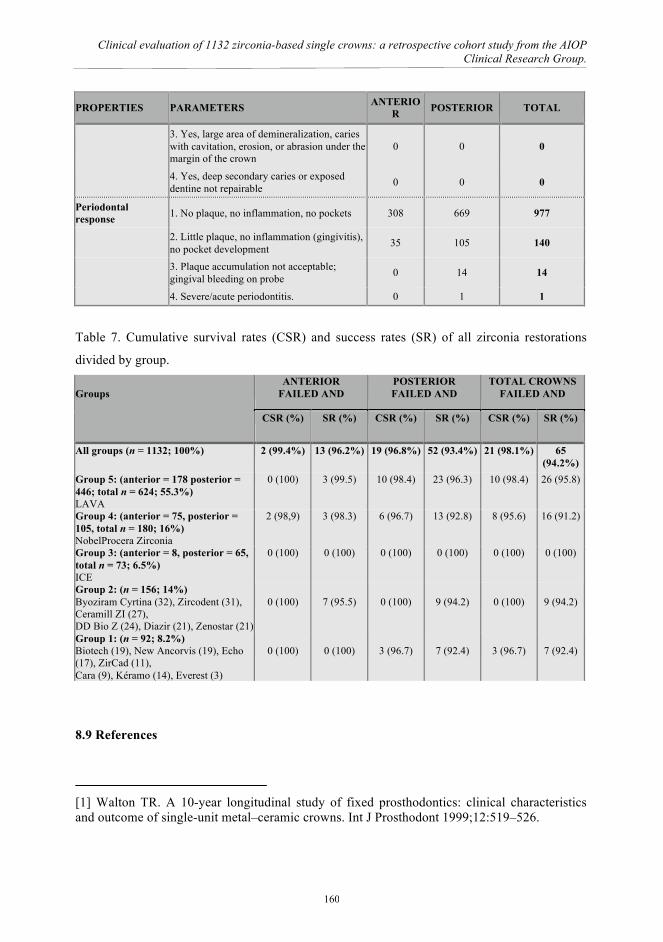
Clinical evaluation of 1132 zirconia-based single crowns: a retrospective cohort study from the AIOP Clinical Research Group.
PROPERTIES PARAMETERS ANTERIOR POSTERIOR TOTAL
3. Yes, large area of demineralization, caries with cavitation, erosion, or abrasion under the margin of the crown
0 0 0
4. Yes, deep secondary caries or exposed dentine not repairable 0 0 0
Periodontal response 1. No plaque, no inflammation, no pockets 308 669 977
2. Little plaque, no inflammation (gingivitis), no pocket development 35 105 140
3. Plaque accumulation not acceptable; gingival bleeding on probe 0 14 14
4. Severe/acute periodontitis. 0 1 1
Table 7. Cumulative survival rates (CSR) and success rates (SR) of all zirconia restorations
divided by group. Groups
ANTERIOR FAILED AND
POSTERIOR FAILED AND
TOTAL CROWNS FAILED AND
CSR (%) SR (%) CSR (%) SR (%) CSR (%) SR (%)
All groups (n = 1132; 100%) 2 (99.4%) 13 (96.2%) 19 (96.8%) 52 (93.4%) 21 (98.1%) 65 (94.2%)
Group 5: (anterior = 178 posterior = 446; total n = 624; 55.3%) LAVA
0 (100) 3 (99.5) 10 (98.4) 23 (96.3) 10 (98.4) 26 (95.8)
Group 4: (anterior = 75, posterior = 105, total n = 180; 16%) NobelProcera Zirconia
2 (98,9) 3 (98.3) 6 (96.7) 13 (92.8) 8 (95.6) 16 (91.2)
Group 3: (anterior = 8, posterior = 65, total n = 73; 6.5%) ICE
0 (100) 0 (100) 0 (100) 0 (100) 0 (100) 0 (100)
Group 2: (n = 156; 14%) Byoziram Cyrtina (32), Zircodent (31), Ceramill ZI (27), DD Bio Z (24), Diazir (21), Zenostar (21)
0 (100)
7 (95.5)
0 (100)
9 (94.2)
0 (100)
9 (94.2)
Group 1: (n = 92; 8.2%) Biotech (19), New Ancorvis (19), Echo (17), ZirCad (11), Cara (9), Kéramo (14), Everest (3)
0 (100)
0 (100)
3 (96.7)
7 (92.4)
3 (96.7)
7 (92.4)
8.9 References
[1] Walton TR. A 10-year longitudinal study of fixed prosthodontics: clinical characteristics and outcome of single-unit metal–ceramic crowns. Int J Prosthodont 1999;12:519–526.
160

Chapter 8
[2] Kansu G, Aydin AK. Evaluation of the biocompatibility of various dental alloys: Part I—Toxic potentials. Eur J Prosthodont Restor Dent 1996;4:129–136. [3] Blatz MB. Long-term clinical success of all-ceramic posterior restorations. Quintessence Int 2002;33:415–426. [4] Raigrodski AJ. Contemporary materials and technologies for all-ceramic fixed partial dentures: A review of the literature. J Prosthet Dent 2004;92:557–562. [5] Odman P, Andersson B. Procera AllCeram crowns followed for 5-10.5 years: a prospective clinical study. Int J Prosthodont 2001;14:504–509. [6] Pjetursson BE, Sailer I, Zwahlen M, Hämmerle CH. A systematic review of the survival and complication rates of all-ceramic and metal–ceramic reconstructions after an observation period of at least 3 years. Part I. Single crowns. Clin Oral Implants Res 2007;18:73–85. [7] Guazzato M, Quach L, Albakry M, Swain MV. Influence of surface and heat treatments on the flexural strength of Y-TZP dental ceramic. J Dent 2005;33:9–18. [8] Coelho PG, Silva NR, Bonfante EA, Guess PC, Rekow ED, Thompson VP. Fatigue testing of two porcelain–zirconia all-ceramic crown systems. Dent Mater 2009;25:1122–1127. [9] Manicone PF, Iommetti PR, Raffaelli L. An overview of zirconia ceramics: Basic properties and clinical applications. J Dent 2007;35:819–826. [10] Chevalier J, Gremillard L, Deville S. Low-temperature degradation of zirconia and implications for biomedical implants. Annu Rev Mater Res 2007;37:1–32. [11] Raigrodski AJ, Hillstead MB, Meng GK, Chung KH. Survival and complications of zirconia-based fixed dental prostheses: A systematic review. J Prosthet Dent 2012;107:170-177. [12] Beier US, Kapferer I, Dumfahrt H. Clinical long-term evaluation and failure characteristics of 1,335 all-ceramic restorations. Int J Prosthodont. 2012;25:70-78. [13] Kollar A, Huber S, Mericske E, Mericske-Stern R. Zirconia for teeth and implants: a case series. Int J Periodontics Restorative Dent 2008;28:479-487. [14] Cehreli MC, Kökat AM, Akca K. CAD/CAM Zirconia vs. slip-cast glass-infiltrated Alumina/Zirconia all-ceramic crowns: 2-year results of a randomized controlled clinical trial. J Appl Oral Sci 2009;17:49–55. [15] Ortorp A, Kihl ML, Carlsson GE. A 3-year retrospective and clinical follow-up study of zirconia single crowns performed in a private practice. J Dent 2009;37:731-736. [16] Edelhoff D, Florian B, Florian W, Johnen C. HIP zirconia fixed partial dentures--clinical results after 3 years of clinical service. Quintessence Int 2008;39:459–471.
161

Clinical evaluation of 1132 zirconia-based single crowns: a retrospective cohort study from the AIOP Clinical Research Group.
[17] Hickel R, Peschke A, Tyas M, Mjör I, Bayne S, Peters M, Hiller KA, Randall R, Vanherle G, Heintze SD. FDI World Dental Federation: clinical criteria for the evaluation of direct and indirect restorations-update and clinical examples. Clin Oral Investig 2010;14:349-366. [18] Keough BE, Kay HB, Sager RD, Keen E. Clinical performance of scientifically designed, hot isostatic-pressed (HIP'd) zirconia cores in a bilayered all-ceramic system. Compend Contin Educ Dent 2011;32:58-68. [19] Rosentritt M, Steiger D, Behr M, Handel G, Kolbeck C. Influence of substructure design and spacer settings on the in vitro performance of molar zirconia crowns. J Dent 2009;37:978–983. [20] Tholey MJ, Swain MV, Thiel N. Thermal gradients and residual stresses in veneered Y-TZP frameworks. Dent Mater 2011;27:1102-1110. [21] Anusavice KJ, Dehoff PH, Hojjatie B, Gray A. Influence of tempering and contraction mismatch on crack development in ceramic surfaces. J Dent Res 1989;68:1182–1187. [22] Di Febo G, Carnevale G, Sterrantino SF. Treatment of a case of advanced periodontitis: clinical procedures utilizing the "combined preparation" technique. Int J Periodontics Restorative Dent 1985;5:52-62. [23] Reich S, Petschelt A, Lohbauer U. The effect of finish line preparation and layer thickness on the failure load and fractography of ZrO2 copings. J Prosthet Dent 2008;99:369-376. [24] Schmitt J, Wichmann M, Holst S, Reich S. Restoring severely compromised anterior teeth with zirconia crowns and feather-edged margin preparations: a 3-year follow-up of a prospective clinical trial. Int J Prosthodont 2010;23:107-109. [25] Poggio CE, Dosoli R, Ercoli C. A retrospective analysis of 102 zirconia single crowns with knife-edge margins. J Prosthet Dent 2012;107:316-321.
162

Chapter 9
CHAPTER 9
Conclusions and recommendations
163

Conclusions and recommendations
The following conclusions and recommendations may be drawn from our basic and clinical
evaluations on the use of zirconia based restorations applied in dentistry:
1. Abrasion of pre-sintered zirconia specimens resulted in rougher surfaces, and the
monoclinic phase associated with the abrasion was completely transformed to the
tetragonal state during the subsequent sintering step;
2. Abrasion of sintered zirconia specimens resulted in surfaces with a lower roughness, a
monoclinic phase, and compressive surface residual stresses, the degree of which was
associated with the abrasive grain size;
3. The phases and microstructural changes induced by abrasion may markedly impact
clinical performance, i.e. by increasing the rate of aging.
4. By optimizing the microwaves sintering conditions, it is possible to obtain rather dense
specimens strongly reducing both the maximum sintering temperature and the total
thermal cycle length, passing from several hundreds of minutes at 1450°C to few
minutes at 1200°C.
5. The less drastic sintering conditions, in terms of reduced temperature and thermal cycle
length, allowed obtaining a limited grain growth, able to improve the mechanical
characteristics of the sintered zirconia components.
6. The dielectric heating method produces specific advantages in terms of energy
efficiency, process simplicity, saving costs of equipment maintenance and operator.
7. Sandblasting the zirconia surface before sintering enhances the surface roughness in
direct proportion to the size of the sand used;
8. Increasing the surface roughness of the zirconia enhance its microtensile strength,
although the differences were not significant;
9. Evaluating microtensile bond strength we can say that using the CoJet treatment after
sintering is recommended for clinical situations where it is important improve the
164

Chapter 9
adhesion of ceramic veneer to zirconia;
10. Improving the strength of veneering ceramics is necessary to realize the benefits
of the high strength of zirconia frameworks.
11. High percentage of mixed failures are due to the brittleness of veneer ceramics.
12. Pressable monolithic lithium disilicate ceramic, in combination with a resin luting
agent, can act as a biomimetic of enamel, optimizing the distribution of occlusal
stresses at the margin and showing the same value in fracture strength in restorations.
13. Over a period of up to 5 years porcelain-veneered zirconia single crowns with knife-
edge and chamfer preparations showed encouraging clinical results. Technical
complications were few and were limited primarily to patients with parafunction
although the degree of bruxism or clenching it’s a difficult clinical parameter to
recognize.
165

Conclusions and recommendations
Acknowledgements I’d like to thank everyone who has been involved in this thesis.
I want to express my thanks to my promoter Prof. Giorgio Timellini and my co-promoter Dr.
Eng. Arturo Salomoni. They gave me the possibility to start my adventure in the Ceramic
Center in Bologna.
I really don’t know how to thank my co-promoter Prof. Roberto Scotti He is for me like a father
that provided guidance, scientific advice and continued encouragement throughout this project
and without whose help, this work would not have come to fulfilment. Thank you for being a
great teacher and a point of reference every day.
My deepest thank to Antonella Tucci and Leonardo Esposito. During my Ph.D program they
“switched on the light” of the research. They represented a lighthouse and never I forgot the
helpfulness at any time. The research meetings with Antonella and Leonardo represent for me
the best lesson of chemistry, engeneering and humaneness. They opened my way to the
research and always supported my troubles.
I would like to thank my mother Michela that supported me during this busy period. I’ll love
her forever.
Finally, the biggest kiss to my wife Francesca and my babies Camilla and Ludovico. “All the
things they are!!”. They represent the milestones of my life.
166