Microstructure and Fracture Toughness of Nitrided D2 Steels ...
11
Citation: Kim, K.-H.; Lee, W.-B.; Kim, T.-H.; Son, S.-W. Microstructure and Fracture Toughness of Nitrided D2 Steels Using Potential-Controlled Nitriding. Metals 2022, 12, 139. https://doi.org/10.3390/met12010139 Academic Editors: Filippo Berto, Ricardo Branco and Yanxin Qiao Received: 18 December 2021 Accepted: 6 January 2022 Published: 11 January 2022 Publisher’s Note: MDPI stays neutral with regard to jurisdictional claims in published maps and institutional affil- iations. Copyright: © 2022 by the authors. Licensee MDPI, Basel, Switzerland. This article is an open access article distributed under the terms and conditions of the Creative Commons Attribution (CC BY) license (https:// creativecommons.org/licenses/by/ 4.0/). metals Article Microstructure and Fracture Toughness of Nitrided D2 Steels Using Potential-Controlled Nitriding Ki-Hong Kim 1 , Won-Beom Lee 1 , Tae-Hwan Kim 1,2 and Seok-Won Son 1,2, * 1 Heat & Surface Technology R&D Department, Research Institute of Advanced Manufacturing & Materials Technology (KITECH), Siheung 15014, Korea; [email protected] (K.-H.K.); [email protected] (W.-B.L.); [email protected] (T.-H.K.) 2 Department of Materials Science and Engineering, Inha University, Incheon 22212, Korea * Correspondence: [email protected]; Tel.: +82-31-8084-8654 Abstract: Potential-controlled nitriding is an effective technique for enhancing the life of steel molds and dies by improving their surface hardness and toughness against fatigue damage. In this study, the effect of the nitriding potential on the microstructure and fracture toughness of nitrided AISI D2 steels was investigated. The nitrided layers were characterized by microhardness measurements, optical microscopy, and scanning electron microscopy, and their phases were identified by X-ray and electron backscatter diffraction. As the nitriding potential increased to 2.0 atm -1/2 , an increase in the surface hardness and fracture toughness was observed with the growth of the compound layer. However, both the surface hardness and the fracture toughness decreased at the higher nitriding potential of 5.0 atm -1/2 owing to the increased porosity in the compound layers, which mainly consist of the ε (Fe 2–3 N) phase. Additionally, by observing crack growth behavior, the fracture toughness was analyzed considering the material characteristics of the diffusion and compound layers. The fracture toughness was influenced by the location of the initial Palmqvist cracks due to the localized plastic deformation of the diffusion layer and increased crack length due to the porous compound layer. Keywords: nitride materials; X-ray diffraction; diffusion; precipitation 1. Introduction High-carbon, high-chromium AISI D2 steel, also known as cold work tool steel, is widely used in the fabrication of punches, shear knives, tools, molds, and dies because of its hardenability and high resistance to wear and softening [1,2]. Recently, it has been utilized for various manufacturing applications to enhance the working life of components against impact, shear, and fatigue damage [3–5]. For instance, cold work tool steel performance was improved by modifying its chemical composition to obtain high strength, toughness, and high fatigue resistance [3]. Heat treatment processes, such as cryogenic treatment and salt bath quenching, were also developed to further improve the hardness, toughness, and wear resistance of cold work tool steel [4,5]. Well-known techniques for surface modification, such as nitriding treatment (e.g., compound-free, ion-nitriding) and physical vapor deposition (e.g., TiN, AlTiN coat- ings), have been studied and implemented to improve the working performance of molds and dies [6–8]. Nitriding is one of the most useful thermochemical surface treatments because it can be performed at temperatures of 450–600 ◦ C, resulting in low distortion and high surface hardness [9,10]. However, there are deleterious effects on the mechanical properties of the nitrided layers, namely decreased surface hardness, wear resistance, and toughness [8,11]. This is due to the presence of excess nitrogen and discontinuous precipi- tation, which result in the coarsening of the nitrides and porosity of the compound layer during nitriding [12]. Techniques such as ion-nitriding and gas-controlled nitriding have been developed to guarantee the long service life of the nitrided layer [13–15]. Metals 2022, 12, 139. https://doi.org/10.3390/met12010139 https://www.mdpi.com/journal/metals
-
Upload
khangminh22 -
Category
Documents
-
view
1 -
download
0
Transcript of Microstructure and Fracture Toughness of Nitrided D2 Steels ...

�����������������
Citation: Kim, K.-H.; Lee, W.-B.;
Kim, T.-H.; Son, S.-W. Microstructure
and Fracture Toughness of Nitrided
D2 Steels Using Potential-Controlled
Nitriding. Metals 2022, 12, 139.
https://doi.org/10.3390/met12010139
Academic Editors: Filippo Berto,
Ricardo Branco and Yanxin Qiao
Received: 18 December 2021
Accepted: 6 January 2022
Published: 11 January 2022
Publisher’s Note: MDPI stays neutral
with regard to jurisdictional claims in
published maps and institutional affil-
iations.
Copyright: © 2022 by the authors.
Licensee MDPI, Basel, Switzerland.
This article is an open access article
distributed under the terms and
conditions of the Creative Commons
Attribution (CC BY) license (https://
creativecommons.org/licenses/by/
4.0/).
metals
Article
Microstructure and Fracture Toughness of Nitrided D2 SteelsUsing Potential-Controlled NitridingKi-Hong Kim 1 , Won-Beom Lee 1, Tae-Hwan Kim 1,2 and Seok-Won Son 1,2,*
1 Heat & Surface Technology R&D Department, Research Institute of Advanced Manufacturing & MaterialsTechnology (KITECH), Siheung 15014, Korea; [email protected] (K.-H.K.);[email protected] (W.-B.L.); [email protected] (T.-H.K.)
2 Department of Materials Science and Engineering, Inha University, Incheon 22212, Korea* Correspondence: [email protected]; Tel.: +82-31-8084-8654
Abstract: Potential-controlled nitriding is an effective technique for enhancing the life of steel moldsand dies by improving their surface hardness and toughness against fatigue damage. In this study, theeffect of the nitriding potential on the microstructure and fracture toughness of nitrided AISI D2 steelswas investigated. The nitrided layers were characterized by microhardness measurements, opticalmicroscopy, and scanning electron microscopy, and their phases were identified by X-ray and electronbackscatter diffraction. As the nitriding potential increased to 2.0 atm−1/2, an increase in the surfacehardness and fracture toughness was observed with the growth of the compound layer. However,both the surface hardness and the fracture toughness decreased at the higher nitriding potential of5.0 atm−1/2 owing to the increased porosity in the compound layers, which mainly consist of theε (Fe2–3N) phase. Additionally, by observing crack growth behavior, the fracture toughness wasanalyzed considering the material characteristics of the diffusion and compound layers. The fracturetoughness was influenced by the location of the initial Palmqvist cracks due to the localized plasticdeformation of the diffusion layer and increased crack length due to the porous compound layer.
Keywords: nitride materials; X-ray diffraction; diffusion; precipitation
1. Introduction
High-carbon, high-chromium AISI D2 steel, also known as cold work tool steel, iswidely used in the fabrication of punches, shear knives, tools, molds, and dies because of itshardenability and high resistance to wear and softening [1,2]. Recently, it has been utilizedfor various manufacturing applications to enhance the working life of components againstimpact, shear, and fatigue damage [3–5]. For instance, cold work tool steel performancewas improved by modifying its chemical composition to obtain high strength, toughness,and high fatigue resistance [3]. Heat treatment processes, such as cryogenic treatment andsalt bath quenching, were also developed to further improve the hardness, toughness, andwear resistance of cold work tool steel [4,5].
Well-known techniques for surface modification, such as nitriding treatment(e.g., compound-free, ion-nitriding) and physical vapor deposition (e.g., TiN, AlTiN coat-ings), have been studied and implemented to improve the working performance of moldsand dies [6–8]. Nitriding is one of the most useful thermochemical surface treatmentsbecause it can be performed at temperatures of 450–600 ◦C, resulting in low distortionand high surface hardness [9,10]. However, there are deleterious effects on the mechanicalproperties of the nitrided layers, namely decreased surface hardness, wear resistance, andtoughness [8,11]. This is due to the presence of excess nitrogen and discontinuous precipi-tation, which result in the coarsening of the nitrides and porosity of the compound layerduring nitriding [12]. Techniques such as ion-nitriding and gas-controlled nitriding havebeen developed to guarantee the long service life of the nitrided layer [13–15].
Metals 2022, 12, 139. https://doi.org/10.3390/met12010139 https://www.mdpi.com/journal/metals
Metals 2022, 12, 139 2 of 11
Mechanical properties, such as high surface hardness and wear resistance, combinedwith toughness, are required to enhance the durability of steel dies and molds [16,17]. Asreported by Yong et al. [18], the low toughness of the compound layer leads to brittle cracksand decreases the die and mold thickness owing to wear damage, resulting in the crackingand spalling of the compound layer. Nolan et al. [19] applied plasma nitrided treatment onAISI H11 steel to evaluate the fracture toughness of the compound layers as a function ofindentation load using the Vickers hardness test and established that fracture toughnessis dependent on the compound layer thickness owing to different crack behaviors. Theelastic and toughness properties of the nitrided layers were recently investigated usingmicro-mechanical tensile test methods [20]. To improve the life of die and mold steel, acontrolled nitriding process that involves regulating the applied nitriding potential Kn iscrucial for minimizing the crack growth of the nitrided layer [21].
As mentioned earlier, the fracture toughness of nitrided AISI D2 steel relies heavilyon the material characteristics of the nitrided layers. In other words, the thickness of thecompound layer, as well as the phase evolution of the nitrided layer, must be evaluated inorder to accurately estimate the fracture behavior, which can be achieved by controllingthe nitriding potential [22]. However, studies on this topic using die and mold steels arescarce. Herein, we investigated the effect of the nitriding potential on the microstructuralevolution and fracture toughness of nitrided AISI D2 steel. This steel was chosen as it iswidely applied in the gas nitriding process to prolong die and mold working life. The crackgrowth behavior of the nitrided layers is analyzed in detail to verify its association withfracture toughness.
2. Materials and Methods
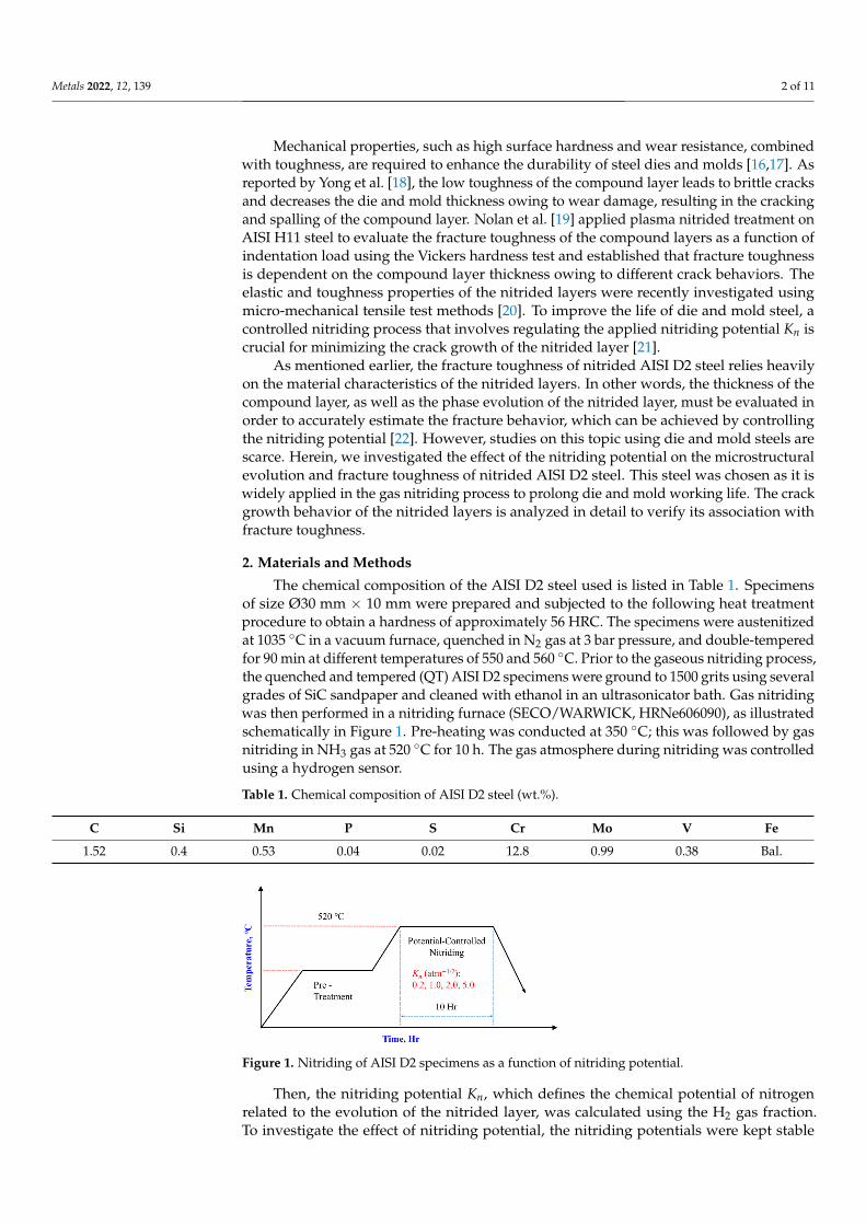
The chemical composition of the AISI D2 steel used is listed in Table 1. Specimensof size Ø30 mm × 10 mm were prepared and subjected to the following heat treatmentprocedure to obtain a hardness of approximately 56 HRC. The specimens were austenitizedat 1035 ◦C in a vacuum furnace, quenched in N2 gas at 3 bar pressure, and double-temperedfor 90 min at different temperatures of 550 and 560 ◦C. Prior to the gaseous nitriding process,the quenched and tempered (QT) AISI D2 specimens were ground to 1500 grits using severalgrades of SiC sandpaper and cleaned with ethanol in an ultrasonicator bath. Gas nitridingwas then performed in a nitriding furnace (SECO/WARWICK, HRNe606090), as illustratedschematically in Figure 1. Pre-heating was conducted at 350 ◦C; this was followed by gasnitriding in NH3 gas at 520 ◦C for 10 h. The gas atmosphere during nitriding was controlledusing a hydrogen sensor.
Table 1. Chemical composition of AISI D2 steel (wt.%).
C Si Mn P S Cr Mo V Fe
1.52 0.4 0.53 0.04 0.02 12.8 0.99 0.38 Bal.
Figure 1. Nitriding of AISI D2 specimens as a function of nitriding potential.
Then, the nitriding potential Kn, which defines the chemical potential of nitrogenrelated to the evolution of the nitrided layer, was calculated using the H2 gas fraction.To investigate the effect of nitriding potential, the nitriding potentials were kept stable

Metals 2022, 12, 139 3 of 11
at 0.2, 1.0, 2.0, and 5.0 atm−1/2 for each nitriding process as per AMS 2759-10B. Thenitriding process can be expressed by the decomposition reactions of nitrogen from NH3gas as follows:
NH3 =12
N2 +32
H2 (1)
Kn =PNH3
P3/2H2
(2)
where PNH3 is the partial pressure of ammonia, and PH2 is that of hydrogen. After thenitriding treatment, the surface and section hardnesses were obtained using a Vickersmicro-hardness tester (Future Tech, FLV-10 ARS-F, Kawasaki, Japan) with a load of 100 gffor a dwell time of 10 s. At least five measurements at each section were taken, and theaverage hardness value was obtained. The effective hardening depth was determinedas the depth corresponding to the high 50 HV0.1 from the hardness of the quenched andtempered specimen as per ISO 18203.
To characterize the microstructure, the nitrided specimens were etched with a mixtureof 100 mL ethanol and 3% nitric acid solution. The cross-sectional microstructures werethen observed using optical microscopy and scanning electron microscopy (SEM, FEI,NNS450, Hillsboro, OR, USA). To determine the phase evolution of the nitrided specimens,X-ray diffraction (XRD, PANalytical, X’Pert-PRO MPD, Malvern, UK) was performed underaccelerating conditions of 40 kV and 30 mA and diffraction angle measurements from 20◦
to 90◦ using the Cu-Kα target were taken. Electron backscatter diffraction (EBSD, Hitachi,SU5000, Tokyo, Japan) was performed to characterize the phase of the compound layer.Finally, hardness measurements were carried out using a Vickers macrohardness tester(Mitutoyo HV-100, 810–440 K, Kawasaki, Japan) with a load of 50 kgf for a dwell time of5 s, and the Vickers hardness (HV) was calculated using Equation (3) [23]:
HV = 1.8544P/d2m (3)
where P is the indentation load (kgf), and dm is the mean indentation diagonal (mm). Todetermine the fracture toughness of the nitrided layer, the Palmqvist-method was used byestimating the total crack length. The Palmqvist crack lengths at the indentation cornerswere measured using SEM at 500× magnification. The fracture toughness was calculatedusing Equation (4) [23]:
KIc = 0.0028·HV1/2·(
PT
)1/2(4)
where T is the total crack length (mm).
3. Results3.1. Hardness
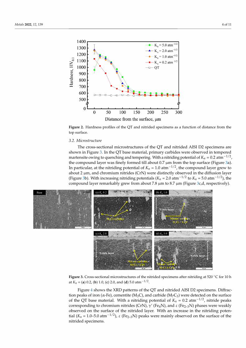
Figure 2 shows the hardness profiles of the QT material and nitrided specimensin relation to the distance from the surface. The average hardness of the heat-treatedspecimen was 570 HV0.1. With a nitriding potential of Kn = 0.2 atm−1/2, the hardness wasapproximately 1130 HV0.1 on the surface of the nitrided layer, which decreased as thedepth increased. The case depth at Kn = 0.2 atm−1/2 was measured to be approximately100 µm from the top surface. With a nitriding potential of Kn = 1.0 atm−1/2, the surfacehardness and the case depth increased to about 1260 HV0.1 and 130 µm, respectively. As Knincreased to 2.0 atm−1/2, the surface hardness reached a maximum value of approximately1270 HV0.1, and there was no significant change in the case depth with the increase innitriding potential. However, at Kn = 5.0 atm−1/2, the decrease in surface hardness wasobserved to be approximately 960 HV0.1. The compound layer grew with the increase ofthe nitriding potential to 2.0 atm−1/2. However, the hardness profile at Kn = 5.0 atm−1/2
deviated from the general shape.
Metals 2022, 12, 139 4 of 11
Figure 2. Hardness profiles of the QT and nitrided specimens as a function of distance from thetop surface.
3.2. Microstructure
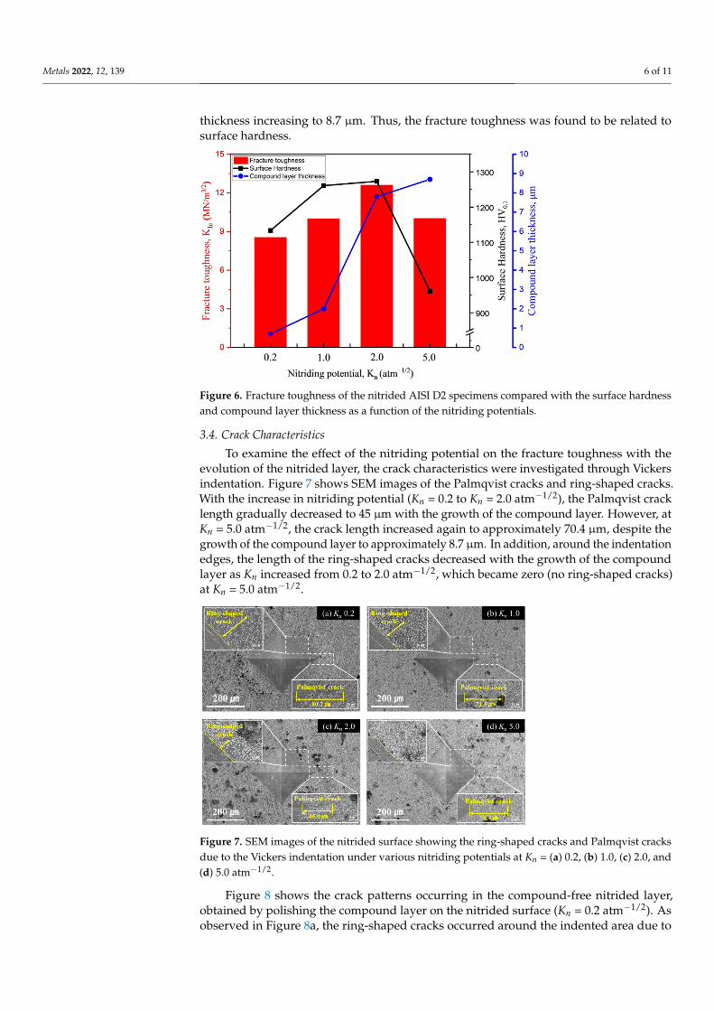
The cross-sectional microstructures of the QT and nitrided AISI D2 specimens areshown in Figure 3. In the QT base material, primary carbides were observed in temperedmartensite owing to quenching and tempering. With a nitriding potential of Kn = 0.2 atm−1/2,the compound layer was finely formed till about 0.7 µm from the top surface (Figure 3a).In particular, at the nitriding potential of Kn = 1.0 atm−1/2, the compound layer grew toabout 2 µm, and chromium nitrides (CrN) were distinctly observed in the diffusion layer(Figure 3b). With increasing nitriding potentials (Kn = 2.0 atm−1/2 to Kn = 5.0 atm−1/2), thecompound layer remarkably grew from about 7.8 µm to 8.7 µm (Figure 3c,d, respectively).
Figure 3. Cross-sectional microstructures of the nitrided specimens after nitriding at 520 ◦C for 10 hat Kn = (a) 0.2, (b) 1.0, (c) 2.0, and (d) 5.0 atm−1/2.
Figure 4 shows the XRD patterns of the QT and nitrided AISI D2 specimens. Diffrac-tion peaks of iron (α-Fe), cementite (M3C), and carbide (M7C3) were detected on the surfaceof the QT base material. With a nitriding potential of Kn = 0.2 atm−1/2, nitride peakscorresponding to chromium nitrides (CrN), γ’ (Fe4N), and ε (Fe2–3N) phases were weaklyobserved on the surface of the nitrided layer. With an increase in the nitriding poten-tial (Kn = 1.0–5.0 atm−1/2), ε (Fe2–3N) peaks were mainly observed on the surface of thenitrided specimens.

Metals 2022, 12, 139 5 of 11
Figure 4. X-ray diffraction pattern of the QT and nitrided specimens.
Figure 5 shows the EBSD of the nitrided AISI D2 specimens for characterizing thephase of the nitrided layers. Prior to phase analysis, the phases of the compound layer canbe easily distinguished to consist of ε (Fe2–3N) and γ’ (Fe4N) phases, which have hexagonalclose-packed (HCP) and face-centered cubic (FCC) structures, respectively [24]. At thelower nitriding potential (0.2 atm−1/2), the α-Fe phase was detected on the surface of thenitrided layer, and there were no obvious nitride phases consisting of ε (Fe2–3N) and γ’(Fe4N) near the nitrided surface. At Kn = 1.0 atm−1/2, the ε (Fe2–3N) phase, which consistedof the compound layer, was mainly observed, and the γ’ (Fe4N) phase was finely detectedaround the compound layer. As the nitriding potential increased from 2.0 to 5.0 atm−1/2,the compound layer, which mainly consisted of the ε (Fe2–3N) phase, grew remarkably onthe surface of the nitrided AISI D2 specimens. From both XRD and EBSD phase analyses, itwas found that the compound layer of the nitrided AISI D2 specimens mainly consisted ofthe ε (Fe2–3N) phase.
Figure 5. EBSD phase maps analyzed near the compound layer of the nitrided specimens afternitriding at 520 ◦C for 10 h at Kn = (a) 0.2, (b) 1.0, (c) 2.0, and (d) 5.0 atm−1/2.
3.3. Fracture Toughness
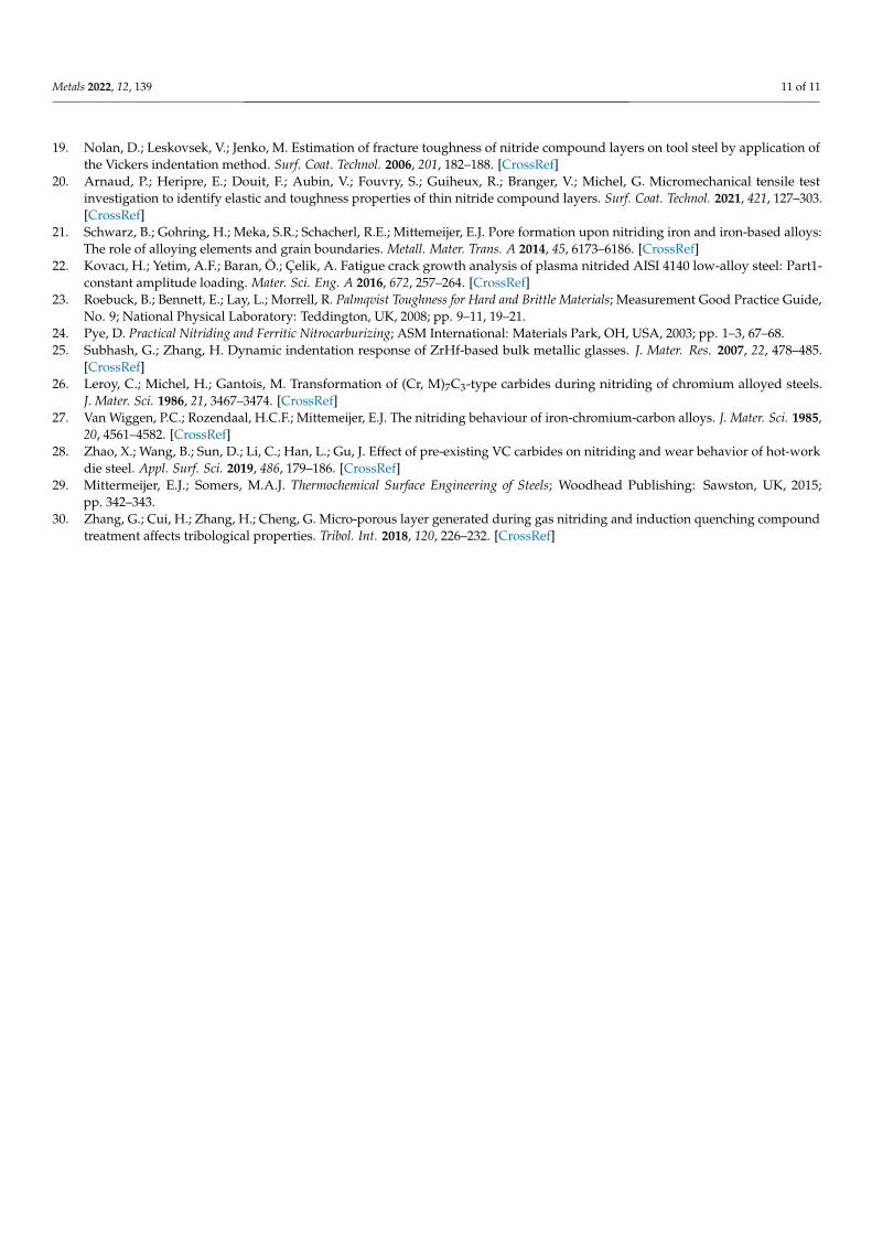
Figure 6 shows the fracture toughness (KIc) as a function of various nitriding potentialscompared with the surface hardness and compound layer thickness. With a nitriding poten-tial of Kn = 0.2 atm−1/2 and a compound layer of 0.7 µm thickness, the fracture toughnessand the surface hardness were observed to be about 8.5 MN/m3/2 and 1130 HV0.1, respec-tively. As the nitriding potential increased to 2.0 atm−1/2, the compound layer thicknessincreased, and the maximum fracture toughness and surface hardness were measured tobe approximately 12.6 MN/m3/2 and 1270 HV0.1, respectively. However, at the highernitriding potential of Kn = 5.0 atm−1/2, the fracture toughness decreased to approximately10.0 MN/m3/2 with the decrease in the surface hardness despite the compound layer
Metals 2022, 12, 139 6 of 11
thickness increasing to 8.7 µm. Thus, the fracture toughness was found to be related tosurface hardness.
Figure 6. Fracture toughness of the nitrided AISI D2 specimens compared with the surface hardnessand compound layer thickness as a function of the nitriding potentials.
3.4. Crack Characteristics
To examine the effect of the nitriding potential on the fracture toughness with theevolution of the nitrided layer, the crack characteristics were investigated through Vickersindentation. Figure 7 shows SEM images of the Palmqvist cracks and ring-shaped cracks.With the increase in nitriding potential (Kn = 0.2 to Kn = 2.0 atm−1/2), the Palmqvist cracklength gradually decreased to 45 µm with the growth of the compound layer. However, atKn = 5.0 atm−1/2, the crack length increased again to approximately 70.4 µm, despite thegrowth of the compound layer to approximately 8.7 µm. In addition, around the indentationedges, the length of the ring-shaped cracks decreased with the growth of the compoundlayer as Kn increased from 0.2 to 2.0 atm−1/2, which became zero (no ring-shaped cracks)at Kn = 5.0 atm−1/2.
Figure 7. SEM images of the nitrided surface showing the ring-shaped cracks and Palmqvist cracksdue to the Vickers indentation under various nitriding potentials at Kn = (a) 0.2, (b) 1.0, (c) 2.0, and(d) 5.0 atm−1/2.
Figure 8 shows the crack patterns occurring in the compound-free nitrided layer,obtained by polishing the compound layer on the nitrided surface (Kn = 0.2 atm−1/2). Asobserved in Figure 8a, the ring-shaped cracks occurred around the indented area due to

Metals 2022, 12, 139 7 of 11
the plastic deformation in the compound-free nitrided layer, and semi-circular cracks wereformed beneath the indentation. As shown in Figure 8b, micro-cracks were formed alongthe primary carbides when the Palmqvist crack propagated outward along the diagonal ofthe indentation.
Figure 8. SEM images of the nitrided surface (compound-free) showing (a) semi-circular cracks and(b) crack formation along the coarse carbides.
4. Discussion
In this study, we investigated the effect of the nitriding potential on the evolutionof the nitrided layers, and consequently, the fracture toughness by analyzing the crackpropagation. The results indicate that the nitriding potential has a significant effect onfracture toughness. In addition, a previous study [19] showed that the fracture toughness isdependent on the thickness of the compound layer; however, in this study, it was verifiedthat phases, such as the chromium nitrides (CrN) and iron nitrides (ε-Fe2–3N), and theporous compound layer significantly influenced the different behaviors of crack growththat resulted from the indentation. It was found that these were the main factors affectingfracture toughness and surface hardness.
As shown by the SEM images in Figure 9a–f, with increasing nitriding potential(Kn = 0.2–5.0 atm−1/2), the initial Palmqvist crack moves nearer to the indentation cornerswith the growth of compound layers. At the lower nitriding potential (0.2 atm−1/2), thesemi-circular cracks were formed beneath the Vickers indentation (see Figure 9a). Subhashet al. [25] reported that micro-cracks are developed by localized plastic deformation (shearbands) owing to the Vickers indentation, which then grows into semi-circular cracks. Thecrack characteristics of nitrided H11 steel are dependent on the thickness of the compoundlayer, as reported by Nolan et al. [19].
For the crack characteristics of the nitrided mold steel, alloy compositions (Cr, Mo,V, etc.) affect the precipitation reactions of the diffusion layer. During the nitriding process,M7C3 gradually decomposes with decarburization as CrN grows. In this recrystallization,the M7C3 retains discontinuous morphologies of carbide [26–28]. In particular, as shownin Figure 10, a discontinuous precipitation network of newly formed carbides (MxCy) ispresent in the carbon-rich zone along the coarse CrN nitrides. As the localized plasticdeformation occurred during the Vickers indentation, the interface brittle cracks, as shownin Figure 8, developed at the weakly bonded interfaces between the different precipitates.This crack formation during the localized plastic deformation of the diffusion layer wasfound to be influenced by the initial Palmqvist cracks. Accordingly, at the lower nitridingpotential (Kn = 0.2 atm−1/2), the fracture toughness was the lowest at 8.5 MN/m3/2 whenthe crack length was 80.2 µm.

Metals 2022, 12, 139 8 of 11
Figure 9. SEM images showing the locations of initial Palmqvist cracks on the nitrided surface(a,c,e) corresponding to the cross-sectional microstructures of compound layers (b,d,f), and schematicdiagrams of crack patterns near the nitrided surface showing the different crack growth behaviors atKn = (g) 0.2, and (h) 5.0 atm−1/2.
Figure 10. Schematic drawings of cross-sectional surface and SEM-EDX analysis showing (a) the basematerial (QT) and (b) nitrided D2 steel.
As shown in Figure 9a–f, with increasing nitriding potential (Kn = 0.2–5.0 atm−1/2),the initial Palmqvist cracks move closer to the indentation corners with the growth ofcompound layers. This eventually leads to a decrease in the length of the Palmqvist crack toapproximately 45.5 µm owing to the differently located initial cracks (see Figures 7c and 9c).

Metals 2022, 12, 139 9 of 11
Therefore, at the nitriding potential of 2.0 atm−1/2, the fracture toughness was found to bethe highest at approximately 12.6 MN/m3/2. However, at the higher nitriding potential of5.0 atm−1/2, the crack length increased again to approximately 70.4 µm as the compoundlayer grew to approximately 8.7 µm (Figure 7d). This may be related to the porous layerformed near the surface of the compound layer (Figure 9f) due to the weakly bondeddissolved nitrogen at the higher nitriding potential [29,30]. These porosities near thesurface of the compound layer led to a decrease in the surface hardness owing to stressconcentrations during the Vickers indentation. Thus, the increase in the Palmqvist cracklength was influenced by the porosity of the compound layer, and thereby, the consequentfracture toughness decreased to approximately 10.0 MN/m3/2.
In the diffusion layers developed by the nitriding potential, the discontinuous precipi-tation network of the carbides (MxCy) grew in the carbon-rich zone along the coarse CrNnitrides. Furthermore, at a higher nitriding potential, the compound layer consisting of theε (Fe2–3N) phase grew and developed pores near the surface of the compound layer due toexcess nitrogen. These material characteristics are closely related to surface hardness andfracture toughness. Thus, the crack growth behavior can be briefly described by a schematicdiagram (Figure 9g,h) of the crack patterns in the nitrided AISI D2 specimens. This figureshows the location of initial cracks according to the localized plastic deformation in thediffusion layer and the increase in the crack length due to the porous compound layer. Withthe low nitriding potential of Kn = 0.2 atm−1/2, the ring-shaped cracks grew radially outtoward the indentation due to the plastic deformation of the diffusion layers and inside theindentation; micro-cracks grew and developed into Palmqvist cracks due to the interface ofthe weakly bonded precipitates. Therefore, the fracture toughness was the lowest at thenitriding potential of 0.2 atm−1/2. However, at Kn = 5.0 atm−1/2, the porosities developedon the surface of the compound layer led to an increase in the crack length (Figure 9h).Thus, the control nitriding for D2 steel can be effectively used to form the non-porouscompound layer, which leads to the increase in fracture toughness by controlling the Kn.
5. Conclusions
In this study, the evolution of nitrided layers and fracture toughness of AISI D2 steelswere investigated using various nitriding potentials.
• The average hardness of the heat-treated specimen was measured to be 570 HV0.1,whereas that of the nitrided steel peaked at 1270 HV0.1 for applied nitriding potentialsbelow 5.0 atm−1/2. At the high nitriding potential of Kn = 5.0 atm−1/2, the surfacehardness decreased to about 960 HV0.1.
• Chromium nitrides (CrN) develop in the diffusion layer as the carbide precipitationnetwork grows in the carbon-rich zone owing to the recrystallization resulting fromnitrogen diffusion. At a nitriding potential of 5.0 atm−1/2, a compound layer consistingof the ε (Fe2–3N) phase grows and develops pores near the surface of the compoundlayers due to the excess nitrogen.
• The fracture toughness was measured to be approximately 8.5 MN/m3/2 at Kn = 0.2 atm−1/2
at which the compound layer had a thickness of about 0.7 µm. As Kn was increased to2.0 atm−1/2, the compound layer further increased in thickness, and the fracture tough-ness peaked at 12.6 MN/m3/2. However, as Kn was further increased to 5.0 atm−1/2,the fracture toughness decreased to approximately 10.0 MN/m3/2 with a decrease inthe surface hardness, despite the compound layer growing up to 8.7 µm thick. Thus,the fracture toughness was found to be related to the surface hardness.
• Two main reasons for different crack growth behaviors of the nitrided layers withchanges in the nitriding potentials were observed: the location of the initial crackinside the indentation due to the localized deformation of the diffusion layer and anincreased crack length due to the porous compound layer. These main factors affectedthe fracture toughness. In short, with the growth of the non-porous compound layer,the increase in fracture toughness was closely related to the location of the initial crack.

Metals 2022, 12, 139 10 of 11
This study showed that potential-controlled nitriding can be extended to molds anddies and can improve their mechanical properties, prolonging their service lives.
Author Contributions: Writing—original draft, K.-H.K.; manuscript review and editing, S.-W.S. andK.-H.K.; methodology, W.-B.L. and S.-W.S.; data curation, K.-H.K.; Formal analysis, S.-W.S. andK.-H.K.; visualization, K.-H.K.; investigation, S.-W.S. and T.-H.K.; resources, S.-W.S. and T.-H.K.;supervision, W.-B.L.; funding acquisition, W.-B.L. All authors have read and agreed to the publishedversion of the manuscript.
Funding: This research received no external funding.
Institutional Review Board Statement: Not applicable.
Informed Consent Statement: Not applicable.
Data Availability Statement: The data are available from the authors upon reasonable request.
Acknowledgments: This work was supported by the Material parts technology development project(program: 20012857) funded by the Ministry of Trade, industry & Energy (MI, Korea).
Conflicts of Interest: The authors declare no conflict of interest.
References1. Roberts, G.; Krause, G.; Kennedy, R. Tool Steels, 5th ed.; ASM International: Materials Park, OH, USA, 1998; pp. 203–217.2. Bombac, D.; Fazarinc, M.; Saha Podder, A.; Kugler, G. Study of carbide evolution during thermo-mechanical processing of AISI
D2 tool steel. J. Mater. Eng. Perform. 2013, 22, 742–747. [CrossRef]3. Fukaura, K.; Yokoyama, Y.; Yokoi, D.; Tsujii, N.; Ono, K. Fatigue of cold-work tool steels: Effect of heat treatment and carbide
morphology on fatigue crack formation, life, and fracture surface observations. Metall. Mater. Trans. A 2004, 35, 1289–1300.[CrossRef]
4. Das, D.; Dutta, A.K.; Ray, K.K. Influence of varied cryotreatment on the wear behavior of AISI D2 steel. Wear 2009, 266, 297–309.[CrossRef]
5. Torkamani, H.; Raygan, S.; Rassizadehghani, J. Comparing microstructure and mechanical properties of AISI D2 steel after brighthardening and oil quenching. Mater. Des. 2014, 54, 1049–1055. [CrossRef]
6. Unterweiser, P.M.; Gray, A.G. Source Book on Nitriding; ASM International: Metals Park, OH, USA, 1977; pp. 1–25.7. Podgornik, B.; Sedlacek, M.; Cekada, M.; Jacobson, S.; Zajec, B. Impact of fracture toughness on surface properties of PVD coated
cold work tool steel. Surf. Coat. Technol. 2015, 277, 144–150. [CrossRef]8. Diaz-Guillen, J.C.; Naeem, M.; Hdz-Garcia, H.M.; Acevedo-Davila, J.L.; Diaz-Guillen, M.R.; Khan, M.A.; Iqbal, J.;
Mtz-Enriquez, A.I. Duplex plasma treatment of AISI D2 tool steel by combining plasma nitriding (with and withoutwhite layer) and post-oxidation. Surf. Coat. Technol. 2020, 385, 125420. [CrossRef]
9. Kim, Y.-M.; Son, S.W.; Lee, W.-B. Thermodynamic and kinetic analysis of formation of compound layer during gas nitriding ofAISI1018 carbon steel. Met. Mater. Int. 2018, 24, 180–186. [CrossRef]
10. Son, S.-W.; Lee, W.-B. Surface hardening and wear properties of AISI 410 martensitic stainless steel by high & low temperaturegaseous nitriding. J. Korean Inst. Surf. Eng. 2018, 51, 249–255. [CrossRef]
11. Shukla, K.; Purandare, Y.P.; Khan, I.; Ehiasarian, A.P.; Hovsepian, P.E.H. Effect of nitriding voltage on the impact load fatigueand fracture toughness behavior of CoCrMo alloy nitride utilising a HIPIMS discharge. Surf. Coat. Technol. 2020, 400, 126227.[CrossRef]
12. Somers, M.A.J.; Mittemeijer, E.J. Layer-growth kinetics on gaseous nitriding of pure iron: Evalution of diffusion coeffients fornitrogen in iron nitrides. Metall. Mater. Trans. 1995, 26, 57–74. [CrossRef]
13. Conci, M.D.; Bozzi, A.C.; Franco, A.R., Jr. Effect of plasma nitriding potential on tribological behaviour of AISI D2 cold-workedtool steel. Wear 2014, 317, 188–193. [CrossRef]
14. Cho, K.T.; Song, K.; Oh, S.H.; Lee, Y.-K.; Lee, W.B. Enhanced surface hardening of AISI D2 steel by atomic attrition during ionnitriding. Surf. Coat. Technol. 2014, 251, 115–121. [CrossRef]
15. Lee, W.-B.; Yu, K.-C.; Kim, Y.-M.; Wi, J.-L. Microstructural evolution of compound layers during gaseous nitriding of AISI1045carbon steels. Korean J. Met. Mater. 2016, 54, 475–482. [CrossRef]
16. Leite, M.V.; Figueroa, C.A.; Corujeira Gallo, S.; Rovani, A.C.; Basso, R.L.O.; Mei, P.R.; Baumvol, I.J.R.; Sinatora, A. Wearmechanisms and microstructure of pulsed plasma nitrided AISI H13 tool steel. Wear 2010, 269, 466–472. [CrossRef]
17. Gronostajski, Z.; Widomski, P.; Kaszuba, M.; Zwierzchowski, M.; Polak, S.; Piechowicz, L.; Kowalska, J.; Dlugozima, M. Influenceof the phase structure of nitrides and properties of nitrided layers on the durability of tools applied in hot forging processes.J. Manuf. Process. 2020, 52, 247–262. [CrossRef]
18. Duan, Y.; Qu, S.; Jia, S.; Li, X. Evolution of the fretting wear damage of a complex phase compound layer for a nitrided high-carbonhigh-chromium steel. Metals 2020, 10, 1391. [CrossRef]
Metals 2022, 12, 139 11 of 11
19. Nolan, D.; Leskovsek, V.; Jenko, M. Estimation of fracture toughness of nitride compound layers on tool steel by application ofthe Vickers indentation method. Surf. Coat. Technol. 2006, 201, 182–188. [CrossRef]
20. Arnaud, P.; Heripre, E.; Douit, F.; Aubin, V.; Fouvry, S.; Guiheux, R.; Branger, V.; Michel, G. Micromechanical tensile testinvestigation to identify elastic and toughness properties of thin nitride compound layers. Surf. Coat. Technol. 2021, 421, 127–303.[CrossRef]
21. Schwarz, B.; Gohring, H.; Meka, S.R.; Schacherl, R.E.; Mittemeijer, E.J. Pore formation upon nitriding iron and iron-based alloys:The role of alloying elements and grain boundaries. Metall. Mater. Trans. A 2014, 45, 6173–6186. [CrossRef]
22. Kovacı, H.; Yetim, A.F.; Baran, Ö.; Çelik, A. Fatigue crack growth analysis of plasma nitrided AISI 4140 low-alloy steel: Part1-constant amplitude loading. Mater. Sci. Eng. A 2016, 672, 257–264. [CrossRef]
23. Roebuck, B.; Bennett, E.; Lay, L.; Morrell, R. Palmqvist Toughness for Hard and Brittle Materials; Measurement Good Practice Guide,No. 9; National Physical Laboratory: Teddington, UK, 2008; pp. 9–11, 19–21.
24. Pye, D. Practical Nitriding and Ferritic Nitrocarburizing; ASM International: Materials Park, OH, USA, 2003; pp. 1–3, 67–68.25. Subhash, G.; Zhang, H. Dynamic indentation response of ZrHf-based bulk metallic glasses. J. Mater. Res. 2007, 22, 478–485.
[CrossRef]26. Leroy, C.; Michel, H.; Gantois, M. Transformation of (Cr, M)7C3-type carbides during nitriding of chromium alloyed steels.
J. Mater. Sci. 1986, 21, 3467–3474. [CrossRef]27. Van Wiggen, P.C.; Rozendaal, H.C.F.; Mittemeijer, E.J. The nitriding behaviour of iron-chromium-carbon alloys. J. Mater. Sci. 1985,
20, 4561–4582. [CrossRef]28. Zhao, X.; Wang, B.; Sun, D.; Li, C.; Han, L.; Gu, J. Effect of pre-existing VC carbides on nitriding and wear behavior of hot-work
die steel. Appl. Surf. Sci. 2019, 486, 179–186. [CrossRef]29. Mittermeijer, E.J.; Somers, M.A.J. Thermochemical Surface Engineering of Steels; Woodhead Publishing: Sawston, UK, 2015;
pp. 342–343.30. Zhang, G.; Cui, H.; Zhang, H.; Cheng, G. Micro-porous layer generated during gas nitriding and induction quenching compound
treatment affects tribological properties. Tribol. Int. 2018, 120, 226–232. [CrossRef]