Influence of SiO2 nanoparticles on hardness and corrosion resistance of electroless Ni–P coatings
8
Influence of SiO 2 nanoparticles on hardness and corrosion resistance of electroless Ni–P coatings Mohammad Islam a, ⁎, Muhammad Rizwan Azhar b , Narjes Fredj c , T. David Burleigh c , Olamilekan R. Oloyede d,e , Abdulhakim A. Almajid f , S. Ismat Shah g a Center of Excellence for Research in Engineering Materials (CEREM), Advanced Manufacturing Institute, King Saud University, P.O. Box 800, Riyadh 11421, Saudi Arabia b Chemical Engineering Department, Curtin University, Bentley 6102, WA, Australia c Materials and Metallurgical Engineering Department, New Mexico Institute of Mining and Technology, Socorro, NM 87801, USA d Institute for Materials Research (IMR), School of Chemical & Process Engineering, Faculty of Engineering, University of Leeds, UK e Maritime Academy of Nigeria, Oron, Nigeria f Department of Mechanical Engineering, King Saud University, P.O. Box 800, Riyadh 11421, Saudi Arabia g Department of Materials Science & Engineering, University of Delaware, Newark, DE 19716, USA abstract article info Article history: Received 1 May 2014 Accepted in revised form 18 November 2014 Available online xxxx Keywords: Nanocomposite Coatings Electroless Electrochemical Impedance Spectroscopy Ni-P-SiO 2 Hardness Nickel–phosphorus (Ni–P) coatings with controllable P content and desirable characteristics can be produced by tuning bath chemistry and processing conditions during the electroless process. Although pure medium- and high-P coatings offer a good combination of mechanical and corrosion properties, their performance attributes can be further enhanced through incorporation of silica (SiO 2 ) nanoparticles. Using 15 and 30 g/L of sodium hypophosphite as reducing agent in the plating bath, Ni–P coatings with respective P content of 10.8 and 14.3 wt.% were produced. While the surface roughness and grain size increased with an increase in the P content, the average hardness value and corrosion resistance of medium-P coatings were superior to their high-P counter- parts. The average hardness of the Ni–P– SiO 2 coatings based on medium-P Ni–P matrix was determined to be ~11.0 GPa. Electrochemical impedance spectroscopy (EIS) studies of these coatings indicated area-impedance values on the order of 10 8 Ω·cm 2 , whereas the double-layer capacitance per unit area (C dl ) and charge transfer area-resistance (R ct ) values, computed from theoretical fit of the EIS data, were in the range of 1.18 × 10 −10 F·cm −2 and 3.14 × 10 8 Ω·cm 2 , respectively. The findings confirmed that addition of SiO 2 nanopar- ticles modifies deposit morphology through grain refinement, reduction in the surface roughness and minimiza- tion of surface porosity in the nanocomposite coatings. © 2014 Elsevier B.V. All rights reserved. 1. Introduction The electroless deposition process can be employed to produce pure nickel–phosphorus (Ni–P) alloy coatings as well as nanocomposite coatings that offer strong potential for use in structural and functional applications [1,2]. Several factors including substrate pre-treatment, plating bath composition, temperature, pH, agitation, heat treatment, etc. strongly influence deposit characteristics such as growth rate, composition, morphology and physical properties [3–9]. An essential component of the precursor bath is the reducing agent that acts as a continuous source of electrons for reduction of cations in the solution. Among several choices, sodium hypophosphite (NaH 2 PO 2 ) is the most commonly used reducing agent in the plating bath. It is also a source of P in the resulting deposit which gets codeposited along with nickel from the solution. Thus, the amount of reducing agent dictates P content in the coatings, which can be categorized as (by weight percent) low- (1–5%), medium- (6–9%) or high-P (≥10%) coatings with a maximum amount of ~17 wt.%. Generally, medium- and high-P coatings exhibit an excellent combination of wear and corrosion resistance [10]. Incorporation of uniformly distributed second-phase particles or nanostructures into the electroless Ni–P coatings has strong potential for diverse applications due to the enhancement of tribological proper- ties and corrosion resistance via improvements in coating characteris- tics and dispersion hardening [11]. Uniform distribution of the second phase particles into the metallic matrix is ensured by magnetic agita- tion, stirring, sonication and/or particle surface modification using an appropriate surfactant to avoid flocculation, particularly in case of nanostructures. Several studies have reported the effect of micro- and nanometer size particle incorporation (such as Al 2 O 3 , CNTs, SiC, SiO 2 , TiO 2 , ZrO 2 , etc.) on the corrosion resistance and tribological behavior of the composite coatings [12–17]. The particle incorporation into the growing coating is accomplished through a number of steps namely, Surface & Coatings Technology xxx (2014) xxx–xxx ⁎ Corresponding author. Tel.: +966 11 467 0760 (work); fax: +966 11 467 0199. E-mail addresses: [email protected], [email protected] (M. Islam), [email protected] (M.R. Azhar), [email protected] (N. Fredj), [email protected] (T.D. Burleigh), [email protected] (O.R. Oloyede), [email protected] (A.A. Almajid), [email protected] (S. Ismat Shah). SCT-19905; No of Pages 8 http://dx.doi.org/10.1016/j.surfcoat.2014.11.044 0257-8972/© 2014 Elsevier B.V. All rights reserved. Contents lists available at ScienceDirect Surface & Coatings Technology journal homepage: www.elsevier.com/locate/surfcoat Please cite this article as: M. Islam, et al., Surf. Coat. Technol. (2014), http://dx.doi.org/10.1016/j.surfcoat.2014.11.044
-
Upload
independent -
Category
Documents
-
view
3 -
download
0
Transcript of Influence of SiO2 nanoparticles on hardness and corrosion resistance of electroless Ni–P coatings
Surface & Coatings Technology xxx (2014) xxx–xxx
SCT-19905; No of Pages 8
Contents lists available at ScienceDirect
Surface & Coatings Technology
j ourna l homepage: www.e lsev ie r .com/ locate /sur fcoat
Influence of SiO2 nanoparticles on hardness and corrosion resistance ofelectroless Ni–P coatings
Mohammad Islam a,⁎, Muhammad Rizwan Azhar b, Narjes Fredj c, T. David Burleigh c, Olamilekan R. Oloyede d,e,Abdulhakim A. Almajid f, S. Ismat Shah g
a Center of Excellence for Research in Engineering Materials (CEREM), Advanced Manufacturing Institute, King Saud University, P.O. Box 800, Riyadh 11421, Saudi Arabiab Chemical Engineering Department, Curtin University, Bentley 6102, WA, Australiac Materials and Metallurgical Engineering Department, New Mexico Institute of Mining and Technology, Socorro, NM 87801, USAd Institute for Materials Research (IMR), School of Chemical & Process Engineering, Faculty of Engineering, University of Leeds, UKe Maritime Academy of Nigeria, Oron, Nigeriaf Department of Mechanical Engineering, King Saud University, P.O. Box 800, Riyadh 11421, Saudi Arabiag Department of Materials Science & Engineering, University of Delaware, Newark, DE 19716, USA
⁎ Corresponding author. Tel.: +966 11 467 0760 (workE-mail addresses: [email protected], miqu
[email protected] (M.R. Azhar), [email protected](T.D. Burleigh), [email protected] (O.R. Oloyede), [email protected] (S. Ismat Shah).
http://dx.doi.org/10.1016/j.surfcoat.2014.11.0440257-8972/© 2014 Elsevier B.V. All rights reserved.
Please cite this article as: M. Islam, et al., Sur
a b s t r a c t
a r t i c l e i n f oArticle history:Received 1 May 2014Accepted in revised form 18 November 2014Available online xxxx
Keywords:Nanocomposite CoatingsElectrolessElectrochemical Impedance SpectroscopyNi-P-SiO2
Hardness
Nickel–phosphorus (Ni–P) coatings with controllable P content and desirable characteristics can be produced bytuning bath chemistry and processing conditions during the electroless process. Although pure medium- andhigh-P coatings offer a good combination of mechanical and corrosion properties, their performance attributescan be further enhanced through incorporation of silica (SiO2) nanoparticles. Using 15 and 30 g/L of sodiumhypophosphite as reducing agent in the plating bath, Ni–P coatings with respective P content of 10.8 and14.3wt.%were produced.While the surface roughness and grain size increasedwith an increase in the P content,the average hardness value and corrosion resistance ofmedium-P coatingswere superior to their high-P counter-parts. The average hardness of the Ni–P– SiO2 coatings based on medium-P Ni–P matrix was determined to be~11.0 GPa. Electrochemical impedance spectroscopy (EIS) studies of these coatings indicated area-impedancevalues on the order of 108 Ω·cm2, whereas the double-layer capacitance per unit area (Cdl) and chargetransfer area-resistance (Rct) values, computed from theoretical fit of the EIS data, were in the range of1.18 × 10−10 F·cm−2 and 3.14 × 10⁸Ω·cm2, respectively. The findings confirmed that addition of SiO2 nanopar-ticlesmodifies depositmorphology through grain refinement, reduction in the surface roughness andminimiza-tion of surface porosity in the nanocomposite coatings.
© 2014 Elsevier B.V. All rights reserved.
1. Introduction
The electroless deposition process can be employed to produce purenickel–phosphorus (Ni–P) alloy coatings as well as nanocompositecoatings that offer strong potential for use in structural and functionalapplications [1,2]. Several factors including substrate pre-treatment,plating bath composition, temperature, pH, agitation, heat treatment,etc. strongly influence deposit characteristics such as growth rate,composition, morphology and physical properties [3–9]. An essentialcomponent of the precursor bath is the reducing agent that acts as acontinuous source of electrons for reduction of cations in the solution.Among several choices, sodium hypophosphite (NaH2PO2) is the mostcommonly used reducing agent in the plating bath. It is also a source
); fax: +966 11 467 [email protected] (M. Islam),(N. Fredj), [email protected]@ksu.edu.sa (A.A. Almajid),
f. Coat. Technol. (2014), http:
of P in the resulting deposit which gets codeposited along with nickelfrom the solution. Thus, the amount of reducing agent dictates P contentin the coatings, which can be categorized as (by weight percent) low-(1–5%), medium- (6–9%) or high-P (≥10%) coatings with a maximumamount of ~17 wt.%. Generally, medium- and high-P coatings exhibitan excellent combination of wear and corrosion resistance [10].
Incorporation of uniformly distributed second-phase particles ornanostructures into the electroless Ni–P coatings has strong potentialfor diverse applications due to the enhancement of tribological proper-ties and corrosion resistance via improvements in coating characteris-tics and dispersion hardening [11]. Uniform distribution of the secondphase particles into the metallic matrix is ensured by magnetic agita-tion, stirring, sonication and/or particle surface modification usingan appropriate surfactant to avoid flocculation, particularly in case ofnanostructures. Several studies have reported the effect of micro- andnanometer size particle incorporation (such as Al2O3, CNTs, SiC, SiO2,TiO2, ZrO2, etc.) on the corrosion resistance and tribological behaviorof the composite coatings [12–17]. The particle incorporation into thegrowing coating is accomplished through a number of steps namely,
//dx.doi.org/10.1016/j.surfcoat.2014.11.044
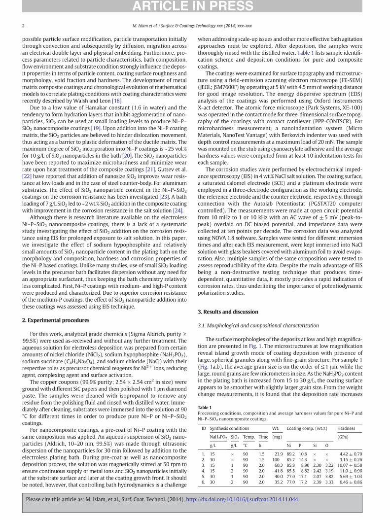
Table 1Processing conditions, composition and average hardness values for pure Ni–P andNi–P–SiO2 nanocomposite coatings.
ID Synthesis conditions Wt. Coating comp. (wt.%) Hardness
NaH2PO2 SiO2 Temp. Time (mg) (GPa)
g/L g/L °C h Ni P Si O
1. 15 × 90 1.5 23.9 89.2 10.8 × × 4.42 ± 0.702. 30 × 90 1.5 100 85.7 14.3 × × 3.15 ± 0.263. 15 1 90 2.0 60.3 85.8 8.90 2.30 3.22 10.07 ± 0.584. 15 2 90 2.0 41.8 85.5 8.82 2.42 3.19 11.0 ± 0.965. 30 1 90 2.0 40.0 77.0 17.1 2.07 3.82 5.69 ± 1.036. 30 2 90 2.0 35.2 77.0 17.2 2.39 3.33 6.46 ± 0.86
2 M. Islam et al. / Surface & Coatings Technology xxx (2014) xxx–xxx
possible particle surface modification, particle transportation initiallythrough convection and subsequently by diffusion, migration acrossan electrical double layer and physical embedding. Furthermore, pro-cess parameters related to particle characteristics, bath composition,flowenvironment and substrate condition strongly influence thedepos-it properties in terms of particle content, coating surface roughness andmorphology, void fraction and hardness. The development of metalmatrix composite coatings and chronological evolution ofmathematicalmodels to correlate plating conditionswith coating characteristics wererecently described by Walsh and Leon [18].
Due to a low value of Hamakar constant (1.6 in water) and thetendency to form hydration layers that inhibit agglomeration of nano-particles, SiO2 can be used at small loading levels to produce Ni–P–SiO2 nanocomposite coatings [19]. Upon addition into the Ni–P coatingmatrix, the SiO2 particles are believed to hinder dislocation movement,thus acting as a barrier to plastic deformation of the ductile matrix. Themaximum degree of SiO2 incorporation into Ni–P coatings is ~25 vol.%for 10 g/L of SiO2 nanoparticles in the bath [20]. The SiO2 nanoparticleshave been reported to maximize microhardness and minimize wearrate upon heat treatment of the composite coatings [21]. Gutsev et al.[22] have reported that addition of nanosize SiO2 improves wear resis-tance at low loads and in the case of steel counter-body. For aluminumsubstrates, the effect of SiO2 nanoparticle content in the Ni–P–SiO2
coatings on the corrosion resistance has been investigated [23]. A bathloading of 7 g/L SiO2 led to ~2wt.% SiO2 addition in the composite coatingwith improvement in the corrosion resistance in the salt solution [24].
Although there is research literature available on the electrolessNi–P–SiO2 nanocomposite coatings, there is a lack of a systematicstudy investigating the effect of SiO2 addition on the corrosion resis-tance using EIS for prolonged exposure to salt solution. In this paper,we investigate the effect of sodium hypophosphite and relativelysmall amounts of SiO2 nanoparticle content in the plating bath on themorphology and composition, hardness and corrosion properties ofthe Ni–P based coatings. Unlike many studies, use of small SiO2 loadinglevels in the precursor bath facilitates dispersion without any need foran appropriate surfactant, thus keeping the bath chemistry relativelyless complicated. First, Ni–P coatings with medium- and high-P contentwere produced and characterized. Due to superior corrosion resistanceof the medium-P coatings, the effect of SiO2 nanoparticle addition intothese coatings was assessed using EIS technique.
2. Experimental procedures
For this work, analytical grade chemicals (Sigma Aldrich, purity ≥99.5%) were used as-received and without any further treatment. Theaqueous solution for electroless deposition was prepared from certainamounts of nickel chloride (NiCl2), sodium hypophosphite (NaH2PO2),sodium succinate (C4H4Na2O4), and sodium chloride (NaCl) with theirrespective roles as precursor chemical reagents for Ni2+ ions, reducingagent, complexing agent and surface activation.
The copper coupons (99.9% purity; 2.54 × 2.54 cm2 in size) wereground with different SiC papers and then polished with 1 μmdiamondpaste. The samples were cleaned with isopropanol to remove anyresidue from the polishing fluid and rinsed with distilled water. Imme-diately after cleaning, substrates were immersed into the solution at 90°C for different times in order to produce pure Ni–P or Ni–P–SiO2
coatings.For nanocomposite coatings, a pre-coat of Ni–P coating with the
same composition was applied. An aqueous suspension of SiO2 nano-particles (Aldrich, 10–20 nm, 99.5%) was made through ultrasonicdispersion of the nanoparticles for 30 min followed by addition to theelectroless plating bath. During pre-coat as well as nanocompositedeposition process, the solution was magnetically stirred at 50 rpm toensure continuous supply of metal ions and SiO2 nanoparticles initiallyat the substrate surface and later at the coating growth front. It shouldbe noted, however, that controlling bath hydrodynamics is a challenge
Please cite this article as: M. Islam, et al., Surf. Coat. Technol. (2014), http:
when addressing scale-up issues and othermore effective bath agitationapproaches must be explored. After deposition, the samples werethoroughly rinsed with the distilled water. Table 1 lists sample identifi-cation scheme and deposition conditions for pure and compositecoatings.
The coatingswere examined for surface topography andmicrostruc-ture using a field-emission scanning electron microscope (FE-SEM)(JEOL; JSM7600F) by operating at 5 kVwith 4.5mmofworking distancefor good image resolution. The energy dispersive spectrum (EDS)analysis of the coatings was performed using Oxford InstrumentsX-act detector. The atomic force microscope (Park Systems, XE-100)was operated in the contact mode for three-dimensional surface topog-raphy of the coatings with contact cantilever (PPP-CONTSCR). Formicrohardness measurement, a nanoindentation system (MicroMaterials, NanoTest Vantage) with Berkovich indenter was used withdepth control measurements at a maximum load of 20 mN. The samplewasmounted on the stub using cyanoacrylate adhesive and the averagehardness values were computed from at least 10 indentation tests foreach sample.
The corrosion studies were performed by electrochemical imped-ance spectroscopy (EIS) in 4wt.% NaCl salt solution. The coating surface,a saturated calomel electrode (SCE) and a platinum electrode wereemployed in a three-electrode configuration as the working electrode,the reference electrode and the counter electrode, respectively, throughconnection with the Autolab Potentiostat (PGSTAT20 computercontrolled). The measurements were made at open circuit potentialfrom 10 mHz to 1 or 10 kHz with an AC wave of ±5 mV (peak-to-peak) overlaid on DC biased potential, and impedance data werecollected at ten points per decade. The corrosion data was analyzedusing NOVA 1.8 software. Samples were tested for different immersiontimes and after each EIS measurement, were kept immersed into NaClsolution with glass beakers coveredwith aluminum foil to avoid evapo-ration. Also, multiple samples of the same composition were tested toassess reproducibility of the data. Despite the main advantage of EISbeing a non-destructive testing technique that produces time-dependent, quantitative data, it mostly provides a rapid indication ofcorrosion rates, thus underlining the importance of potentiodynamicpolarization studies.
3. Results and discussion
3.1. Morphological and compositional characterization
The surfacemorphologies of the deposits at low and highmagnifica-tion are presented in Fig. 1. The microstructures at low magnificationreveal island growth mode of coating deposition with presence oflarge, spherical granules along with fine-grain structure. For sample 1(Fig. 1a,b), the average grain size is on the order of ≤1 μm, while thelarge, round grains are fewmicrometers in size. As theNaH2PO2 contentin the plating bath is increased from 15 to 30 g/L, the coating surfaceappears to be smoother with slightly larger grain size. From the weightchange measurements, it is found that the deposition rate increases
//dx.doi.org/10.1016/j.surfcoat.2014.11.044
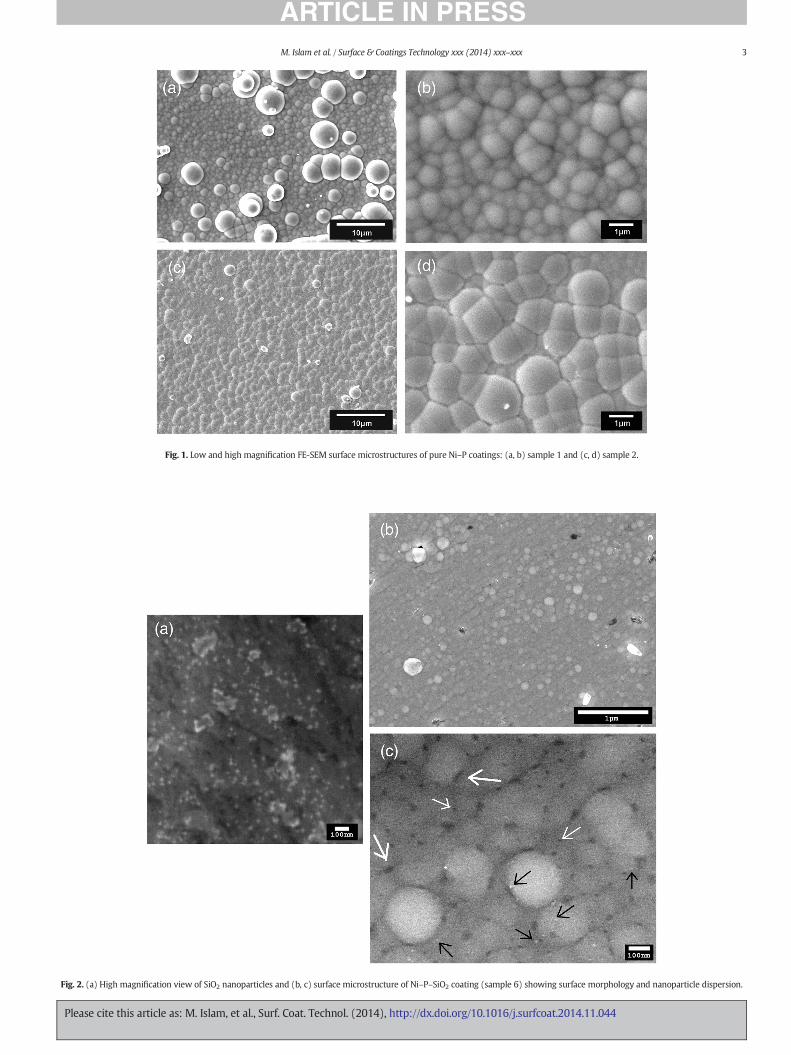
Fig. 1. Low and high magnification FE-SEM surface microstructures of pure Ni–P coatings: (a, b) sample 1 and (c, d) sample 2.
Fig. 2. (a) High magnification view of SiO2 nanoparticles and (b, c) surface microstructure of Ni–P–SiO2 coating (sample 6) showing surface morphology and nanoparticle dispersion.
3M. Islam et al. / Surface & Coatings Technology xxx (2014) xxx–xxx
Please cite this article as: M. Islam, et al., Surf. Coat. Technol. (2014), http://dx.doi.org/10.1016/j.surfcoat.2014.11.044
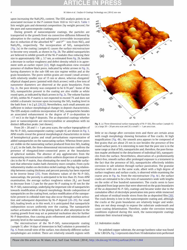
Fig. 3. (a) Three-dimensional surface topography of Ni–P–SiO2 film surface (sample 4):(a) a large 20 × 20 μm area scan and (b) a small 1 × 1 μm area scan.
4 M. Islam et al. / Surface & Coatings Technology xxx (2014) xxx–xxx
upon increasing the NaH2PO2 content. The EDS analysis points to anassociated increase in the P content from 10.8 to 14.3 wt.%. Table 1lists weight gain and elemental composition (by weight percent) forthe pure and nanocomposite coatings.
During growth of nanocomposite coatings, the particles aretransported to the growth front via convective-diffusion followed byadsorption to the coating and subsequent irreversible incorporationdue to reduction of the adsorbed Ni2+ and P3+ ions from NiCl2 andNaH2PO2, respectively. The incorporation of SiO2 nanoparticles(Fig. 2a) in the coating (sample 6) causes the surface microstructureto become very smooth, as shown in Fig. 2b. The added nanoparticlesare believed to inhibit growth of the Ni–P nodules thus reducing theirsize to approximately 106 ± 3.7 nm, as estimated from Fig. 2b, besidesa decrease in surface roughness and defect density which is in agree-ment with an earlier report [22]. High magnification view revealedpresence of shallow black pores, indicated by white arrows in Fig. 2c,having diameters in the sub-100 nm size regime within and at thegrain boundaries. The pores within grains are round (small arrows)with relatively smaller size of 15 nm or above, whereas elongated/elliptical shaped pores (pointed with thick arrows) with a few tens ofnanometer diameters are observed at the grain boundaries. FromFig. 2c, the pore density was computed to be 0.76 μm2. Some of theSiO2 nanoparticles present in the coating are also visible as whiteround spots, as indicated by black arrows in Fig. 2c. The volume fractionof SiO2 within Ni–P matrix is not expected to exceed 7% and does notexhibit a dramatic increase upon increasing the SiO2 loading level inthe bath from 1 to 2 g/L [20,22]. Nevertheless, such small amounts aresufficient to induce morphological changes in deposit characteristics.The EDS analysis confirms incorporation of SiO2 nanoparticles besidesan associated enhancement in the degree of P co-deposition to~17 wt.% in the high-P deposits. The as-deposited coatings whetherpure or nanocomposite are microcrystalline or amorphous with nodistinct diffraction peaks (not shown).
From 20 × 20 and 1 × 1 μm area scans, the surface topographies ofthe Ni–P–SiO2 nanocomposite coating (sample 4) are shown in Fig. 3.AFM results reveal the general morphological characteristics in termsof hemispherical grains and small perturbations representative ofadded nanoparticles on the nanocoating surface. Whereas fewer poresare visible on the nanocoating surface produced from less SiO2 loading(1 g/L) in the bath, the three-dimensional microstructure confirms thepresence of elongated/inter-connected pores at the boundariesof spherical nodules. The absence of any agglomerates from thenanocoating microstructures confirm uniform dispersion of nanoparti-cles in the Ni–P matrix, thus eliminating the need for a suitable surfac-tant that otherwise makes bath chemistry more complex. From cyclicvoltammetry studies on electroless nickel coatings, the log–log relation-ship between coating thickness and percent porosity has been reportedto be inverse linear [25]. From thickness values of the Ni–P–SiO2
nanocoatings, the porosity is anticipated to be less than 2%. From AFMexamination, the average surface roughness values (Ra) are foundto decrease from 1.3 μm for the pure Ni–P coating to 45 nm for theNi–P–SiO2 nanocoatings, underlying the important role of nanoparticlestowards modification of deposit morphology. Beside codeposition ofnanoparticles on the coating front, surfacemodification of the nanopar-ticles present in colloidal state may also occur through surface activa-tion and subsequent deposition by Ni–P deposit [26–29]. For smallSiO2 loading levels as in this work, it is anticipated that nanoparticlecodeposition occurs uniformly over the coating. The nanoparticlesurface activation while in the plating bath or after adsorption to thecoating growth front may act as potential nucleation sites for furtherNi–P deposition, thus causing grain refinement and minimization ofporosity level in the nanocoatings.
The microstructure of the Ni–P–SiO2 nanocomposite coating(sample 5) after 14 days of immersion in NaCl solution is presented inFig. 4. From overall view of the surface, two distinctly different surfacemorphologies are evident. There are relatively smooth regions with
Please cite this article as: M. Islam, et al., Surf. Coat. Technol. (2014), http:
little or no change after corrosion tests and there are certain areaswith rough morphology showing formation of fine cracks. At highmagnification (Fig. 4b), the smooth area appears to be composed offine grains that are about 25 nm in size besides the presence of fewround surface pores. It is interesting to note that the pore size is in thesame range as that of SiO2 nanoparticles and, therefore, the pore forma-tion maybe attributed to the detachment of individual SiO2 nanoparti-cles from the surface. Nevertheless, observation of a predominantlydefect-free, smooth surface after prolonged exposure is a testament tothe fact that the presence of SiO2 nanoparticles effectively inhibitscorrosion in salt solution through surface passivation. The granularstructure with size on the same scale, albeit with a high degree ofsurface roughness and surface cracks, is observed while examining thecoarse area in Fig. 4a. From the microstructure (Fig. 4c), the surfacecracks are estimated to be a few tens of nanometers wide with lengthson the order of few hundred nanometers. The cracks seem to haveoriginated from large pores thatwere observed on the grain boundariesof the as-deposited Ni–P–SiO2 coatings and became wider due to thecumulative effect of electrolyte penetration into pores while immersedand release of residual tensile stress from the as-deposited film [30].The crack density is low in the nanocomposite coating and, althoughthe cracks at the grain boundaries are relatively longer and wider,they are not deep enough to expose the substrate underneath andcause coating delamination. Therefore, under the corrosion testingconditions explored during this work, the nanocomposite coatingsmaintain their structural integrity.
3.2. Indentation studies
For polished copper substrate, the average hardness value was foundto be 1.80GPa. Fig. 5 represents data from10 indentation tests performed
//dx.doi.org/10.1016/j.surfcoat.2014.11.044
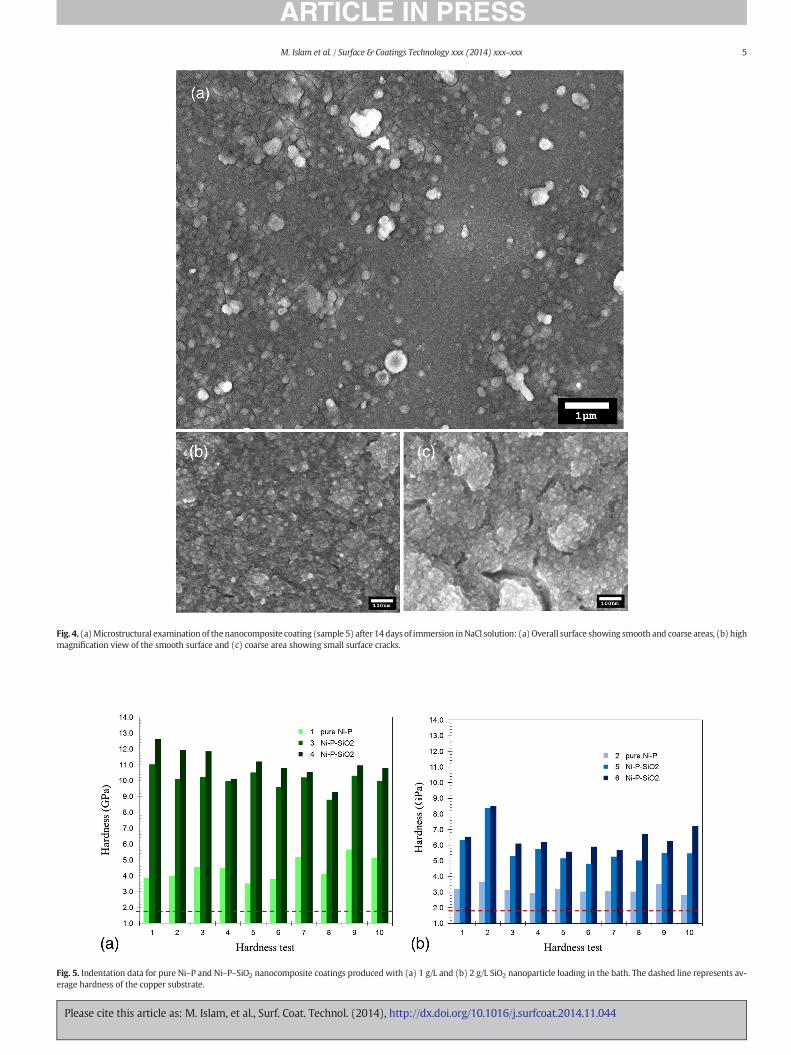
Fig. 4. (a)Microstructural examination of thenanocomposite coating (sample 5) after 14days of immersion inNaCl solution: (a) Overall surface showing smooth and coarse areas, (b) highmagnification view of the smooth surface and (c) coarse area showing small surface cracks.
Fig. 5. Indentation data for pure Ni–P and Ni–P–SiO2 nanocomposite coatings produced with (a) 1 g/L and (b) 2 g/L SiO2 nanoparticle loading in the bath. The dashed line represents av-erage hardness of the copper substrate.
5M. Islam et al. / Surface & Coatings Technology xxx (2014) xxx–xxx
Please cite this article as: M. Islam, et al., Surf. Coat. Technol. (2014), http://dx.doi.org/10.1016/j.surfcoat.2014.11.044
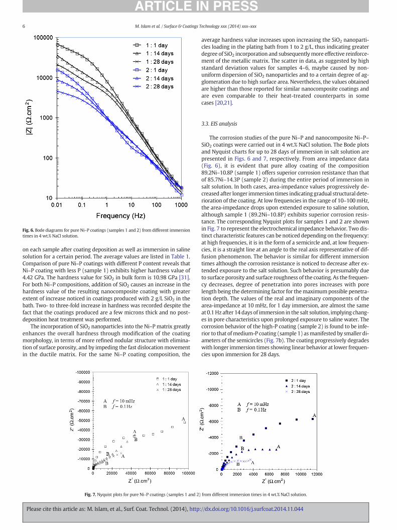
Fig. 6. Bode diagrams for pure Ni–P coatings (samples 1 and 2) from different immersiontimes in 4 wt.% NaCl solution.
6 M. Islam et al. / Surface & Coatings Technology xxx (2014) xxx–xxx
on each sample after coating deposition as well as immersion in salinesolution for a certain period. The average values are listed in Table 1.Comparison of pure Ni–P coatings with different P content reveals thatNi–P coating with less P (sample 1) exhibits higher hardness value of4.42 GPa. The hardness value for SiO2 in bulk form is 10.98 GPa [31].For both Ni–P compositions, addition of SiO2 causes an increase in thehardness value of the resulting nanocomposite coating with greaterextent of increase noticed in coatings produced with 2 g/L SiO2 in thebath. Two- to three-fold increase in hardness was recorded despite thefact that the coatings produced are a few microns thick and no post-deposition heat treatment was performed.
The incorporation of SiO2 nanoparticles into the Ni–P matrix greatlyenhances the overall hardness through modification of the coatingmorphology, in terms of more refined nodular structure with elimina-tion of surface porosity, and by impeding the fast dislocationmovementin the ductile matrix. For the same Ni–P coating composition, the
Fig. 7. Nyquist plots for pure Ni–P coatings (samples 1 and 2)
Please cite this article as: M. Islam, et al., Surf. Coat. Technol. (2014), http:
average hardness value increases upon increasing the SiO2 nanoparti-cles loading in the plating bath from 1 to 2 g/L, thus indicating greaterdegree of SiO2 incorporation and subsequentlymore effective reinforce-ment of the metallic matrix. The scatter in data, as suggested by highstandard deviation values for samples 4–6, maybe caused by non-uniform dispersion of SiO2 nanoparticles and to a certain degree of ag-glomeration due to high surface area. Nevertheless, the values obtainedare higher than those reported for similar nanocomposite coatings andare even comparable to their heat-treated counterparts in somecases [20,21].
3.3. EIS analysis
The corrosion studies of the pure Ni–P and nanocomposite Ni–P–SiO2 coatings were carried out in 4 wt.% NaCl solution. The Bode plotsand Nyquist charts for up to 28 days of immersion in salt solution arepresented in Figs. 6 and 7, respectively. From area impedance data(Fig. 6), it is evident that pure alloy coating of the composition89.2Ni–10.8P (sample 1) offers superior corrosion resistance than thatof 85.7Ni–14.3P (sample 2) during the entire period of immersion insalt solution. In both cases, area-impedance values progressively de-creased after longer immersion times indicating gradual structural dete-rioration of the coating. At low frequencies in the range of 10–100mHz,the area-impedance drops upon extended exposure to saline solution,although sample 1 (89.2Ni–10.8P) exhibits superior corrosion resis-tance. The corresponding Nyquist plots for samples 1 and 2 are shownin Fig. 7 to represent the electrochemical impedance behavior. Two dis-tinct characteristic features can be noticed depending on the frequency:at high frequencies, it is in the form of a semicircle and, at low frequen-cies, it is a straight line at an angle to the real axis representative of dif-fusion phenomenon. The behavior is similar for different immersiontimes although the corrosion resistance is noticed to decrease after ex-tended exposure to the salt solution. Such behavior is presumably dueto surface porosity and surface roughness of the coating. As the frequen-cy decreases, degree of penetration into pores increases with porelength being the determining factor for themaximumpossible penetra-tion depth. The values of the real and imaginary components of thearea-impedance at 10 mHz, for 1 day immersion, are almost the sameat 0.1 Hz after 14 days of immersion in the salt solution, implying chang-es in pore characteristics upon prolonged exposure to saline water. Thecorrosion behavior of the high-P coating (sample 2) is found to be infe-rior to that ofmedium-P coating (sample 1) asmanifested by smaller di-ameters of the semicircles (Fig. 7b). The coating progressively degradeswith longer immersion times showing linear behavior at lower frequen-cies upon immersion for 28 days.
from different immersion times in 4 wt.% NaCl solution.
//dx.doi.org/10.1016/j.surfcoat.2014.11.044
7M. Islam et al. / Surface & Coatings Technology xxx (2014) xxx–xxx
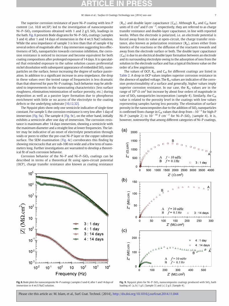
The superior corrosion resistance of pure Ni–P coating with less Pcontent (i.e. 10.8 wt.%P) led to the investigation of nanocompositeNi–P–SiO2 compositions obtained with 1 and 2 g/L SiO2 loadings inthe bath. Fig. 8 presents Bode diagrams for Ni–P–SiO2 coatings (samples3 and 4) after 1 and 14 days of immersion in the 4 wt.% NaCl solution.While the area impedance of sample 3 is less than that of sample 4 byseveral orders ofmagnitude after 1 day immersion suggesting less effec-tiveness of SiO2 nanoparticles towards corrosion inhibition, the corro-sion resistance is noticed to increase and become equivalent for bothcoating compositions after prolonged exposure of 14 days. It is speculat-ed that extended exposure to the saline solution causes preferentialnickel dissolutionwith subsequent appearance of embedded SiO2 nano-particles on the surface, hence increasing the degree of surface passiv-ation. In addition to a significant increase in area-impedance, the dropin these values over the tested range of frequencies is less dramaticthan that observed for pure Ni–P coatings. Such behavior may be attrib-uted to improvements in the nanocoating characteristics (less surfaceroughness, elimination/minimization of surface porosity, etc.) duringdeposition as well as a passive layer formation due to phosphorusenrichment with little or no access of the electrolyte to the coatingdefects or the underlying substrate [10,12,32].
The Nyquist plots show only one semicircle indicative of single timeconstant. For sample 3, the corrosion resistance is very low after 1 day ofimmersion (Fig. 9a). The sample 4 (Fig. 9c), on the other hand, initiallyexhibits a semicircle after one day of immersion. The corrosion resis-tance is maximum after 14 days immersion, showing a semicircle withthemaximumdiameter and a straight line at lower frequencies. The lat-ter may be indicative of an onset of electrolyte penetration throughvoids or pores to either the pre-coat Ni–P layer or the copper substratesurface. The SEM examination (Fig. 4c) corroborates this finding byshowingmicrocracks that are sub-100 nmwide and a few tens of nano-meters long. Further investigations are warranted to develop a theoret-ical fit of such corrosion behavior.
Corrosion behavior of the Ni–P and Ni–P–SiO2 coatings can bedescribed in terms of a theoretical fit using open-circuit potential(OCP), charge transfer resistance also known as coating resistance
Fig. 8.Bodeplots for nanocomposite Ni–P coatings (samples 3 and4) after 1 and14days ofimmersion in 4 wt.% NaCl solution.
Please cite this article as: M. Islam, et al., Surf. Coat. Technol. (2014), http:
(Rct) and double layer capacitance (Cdl). Although Rct and Cdl haveunits of Ω cm2 and F cm−2, respectively, they are referred to as chargetransfer resistance and double-layer capacitance, in line with reportedworks. When the electrode is polarized, i.e. an electrode potential isforced away from its value at open-circuit, the charge transfer resis-tance, also known as polarization resistance (Rp), arises either fromkinetics of the reactions or the diffusion of the reactants towards andaway from the electrode surface or both. The double layer capacitance(Cdl) is due to an electrical double layer formation between an electrodeand its surrounding electrolyte owing to the adsorption of ions from thesolution to the electrode surface and has a typical thickness value on theorder of a few angstroms.
The values of OCP, Rct and Cdl for different coatings are listed inTable 2. A drop in OCP values implies superior corrosion resistance inthe absence of applied voltage. The Rct values are indicative of the corro-sion protectionability of a surface and generally, higher values implysuperior corrosion resistance. In our case, the Rct values are in therange of 104 Ω cm2 but increase by about four orders of magnitude incase of SiO2 nanoparticles incorporation (sample 4). Similarly, the Cdlvalue is related to the porosity level in the coatings with low valuesrepresenting samples having less porosity. The elimination of surfaceporosity in the nanocomposites due to the addition of SiO2 nanoparticlesis confirmed from change in Cdl values that drop from ~10−5 for high-PNi–P (sample 2) to 10−10 F cm−2 for Ni–P–SiO2 (sample 4). It is,however, noteworthy that among different categories of Ni–P coatings,
Fig. 9. Nyquist plots for Ni–P–SiO2 nanocomposite coatings produced with SiO2 bathloading of: (a, b) 1 g/L (Sample 3) and (c) 2 g/L (Sample 4).
//dx.doi.org/10.1016/j.surfcoat.2014.11.044

Table 2Corrosion properties of pure and nanocomposite coatings at 24 °C after different immersion times in 4 wt.% NaCl solution.
Sample ID Days |Z|10 mHz (Ω cm2) OCP (mV vs. Ag/AgCl) Cdl (F/cm2) Rct (Ω cm2)
1. 11428
6.85 × 10⁴
5.19 × 10⁴
2.12 × 10⁴
−278 2.37 × 10⁻⁶ 8.45 × 10⁵
2. 11428
1.58 × 10⁴
1.00 × 10⁴
4.61 × 10³
−310 1.79 × 10⁻⁵ 6.77 × 10⁴
3. 114
4.24 × 10³
5.54 × 10⁸−84 1.42 × 10⁻¹⁰ 2.74 × 10⁸
4. 114
2.25 × 10⁸
5.66 × 10⁸−124 1.18 × 10⁻¹⁰ 3.14 × 10⁸
8 M. Islam et al. / Surface & Coatings Technology xxx (2014) xxx–xxx
high-P coatings offer superior corrosion characteristics due to theiramorphous structure and less susceptibility to pitting with resultantmore noble and passive polarization potential [33].
It is speculated that initial preferential dissolution of nickel causescoating surface enrichment with phosphorus followed by reactionwith water to form an adsorbed layer of hypophosphite anions(H2PO2)− that surface passivates by blocking transport of water mole-cules to the electrode surface [34]. The influence of SiO2 nanoparticleson further improvement in corrosion resistance of the nanocompositecoatings in saline water may be attributed to two factors namely:(i) modified microstructure promoting inhibition of defect corrosionby acting as inert physical barrier and (ii) uniform SiO2 dispersion inNi–P matrix causing formation of many corrosion micro-cells in whichSiO2 nanoparticle andnickelmetal act as cathode and anode, respective-ly, due tomore positive potential of SiO2 than nickel and subsequent oc-currence of homogeneous corrosion instead of localized corrosion.
4. Conclusions
By tuning the amount of NaH2PO2 (15 or 30 g/L) used as reducingagent in the precursor bath, the P-content in the Ni–P coatings can becontrolled to produce medium- and high-P Ni–P. In the latter case, anincrease in P weight percent is accompanied with an increase in thegrain size and surface roughness. The addition of SiO2 nanoparticles inthe Ni–P matrix refines the grain size, lowers the degree of surfaceroughness and enhances coating density through reduction in surfaceporosity along with an increase in the hardness value. The maximumimprovement in hardness to a value of ~11 GPa is observed in Ni–P–SiO2 nanocoatings with medium-P that may be considered to be dueto hindrance to dislocationmovement offered by the SiO2 nanoparticlesin the ductile matrix. EIS studies after immersion of coatings in the4 wt.% NaCl solution for 2 to 4 weeks indicate superior corrosion resis-tance offered by the medium-P coatings and a further improvementby orders of magnitude upon SiO2 incorporation. The theoretical fitof the EIS data indicates a combination of very low double layercapacitance (Cdl) and very high charge transfer resistance (Rct) thatconfirm reduced levels of surface porosity and improved corrosionprotectionability of the Ni–P–SiO2 nanocomposite coatings.
Acknowledgements
The authors gratefully acknowledge the technical and financial sup-port of the Research Center of College of Engineering, Deanship of Scien-tific Research, King Saud University.
Please cite this article as: M. Islam, et al., Surf. Coat. Technol. (2014), http:
References
[1] C.K. Lee, Surf. Coat. Technol. 202 (2008) 4868.[2] C. Sun, S.A. Baig, Z. Lou, J. Zhou, Z. Wang, X. Li, J. Wu, Y. Zang, X. Xu, Appl. Catal. B
Environ. 158–58 (2014) 38.[3] Y.S. Huang, F.Z. Cui, Surf. Coat. Technol. 201 (2007) 5416.[4] V.K. Bulasara, O. Chandrashekar, R. Uppaluri, Chem. Eng. Res. Des. 89 (2011) 2485.[5] J. Li, Y. Tian, Z. Huang, X. Zhang, Appl. Surf. Sci. 252 (2006) 2839.[6] W.L. Liu, S.H. Hsieh, T.K. Tsai, W.J. Chen, S.S. Wu, Thin Solid Films 510 (2006) 102.[7] L.-C. Kuo, Yu-C. Huang, C.-L. Lee, Y.-W. Yen, Electrochim. Acta 52 (2006) 353.[8] So-Y. Cheon, So-Y. Park, Y.-M. Rhym, D.-H. Kim, J. Ho Lee, Curr. Appl. Phys. 11 (2011)
790.[9] M. Islam, M.R. Azhar, N. Fredj, T.D. Burleigh, Surf. Coat. Technol. 236 (2013) 262.
[10] P.H. Lo, W.T. Tsai, J.T. Lee, M.P. Hung, Surf. Coat. Technol. 67 (1994) 27.[11] C.T.J. Low, R.G.A. Wills, F.C. Walsh, Surf. Coat. Technol. 201 (2006) 371.[12] M. Alishahi, S.M. Monirvaghefi, A. Saatchi, S.M. Hosseini, Appl. Surf. Sci. 258 (2012)
2439.[13] S. Alirezaei, S.M. Monirvaghefi, A. Saatchi, M. Urgen, K. Kazmanlı, Tribol. Int. 62
(2013) 110.[14] J. Novakovic, P. Vassiliou, Electrochim. Acta 54 (2009) 2499.[15] K. Zielińska, A. Stankiewicz, I. Szczygieł, J. Colloid Interface Sci. 377 (1) (2012) 362.[16] F. Bratu, L. Benea, J.-P. Celis, Surf. Coat. Technol. 201 (2007) 6940.[17] L. Benea, E. Danaila, J.-P. Celis, Mater. Sci. Eng. A 610 (2014) 106.[18] F.C. Walsh, C.P. de Leon, Trans. Inst. Met. Finish. 92 (2) (2014) 83.[19] H.D. Ackler, R.H. French, Y.-M. Chiang, J. Colloid Interface Sci. 179 (1996) 460.[20] Y. de Hazan, D. Zimmermann,M. Z'Graggen, S. Roos, C. Aneziris, H. Bollier, et al., Surf.
Coat. Technol. 204 (2010) 3464.[21] D. Dong, X.H. Chen,W.T. Xiao, G.B. Yang, P.Y. Zhang, Appl. Surf. Sci. 255 (2009) 7051.[22] D. Gutsev, M. Antonov, I. Hussainova, A.Y. Grigoriev, Tribol. Int. 65 (2013) 295.[23] S. Sadreddini, A. Afshar, Appl. Surf. Sci. 303 (2014) 125.[24] T. Rabizadeh, S.R. Allahkaram, Mater. Des. 32 (2011) 133.[25] F.C. Walsh, C.P. de León, C. Kerr, S. Court, B.D. Barker, Surf. Coat. Technol. 202 (2008)
5092.[26] H.-M. Wu, W.J. Tseng, Ceram. Int. 41 (2015) 1863–1868.[27] S.L. Zhu, L. Tang, Z.D. Cui, Q. Wei, X.J. Yang, Surf. Coat. Technol. 205 (2011)
2985–2988.[28] S. Okada, T. Kamegawa, K. Mori, H. Yamashita, Catal. Today 185 (2012) 109–112.[29] L. Benea, E. Danaila, J.-P. Celis, Mater. Sci. Eng. A 610 (2014) 106–115.[30] J.Y. Song, Jin Yu, Thin Solid Films 415 (2002) 167.[31] J.F. Shackelford, W. Alexander, Materials Science and Engineering Handbook, CRC
Press LLC, Boca Raton, 2001. 474.[32] A. Lasia, in: B.E. Conway, J. Bockris, R.E. White (Eds.), vol. 32, Kluwer Academic/
Plenum Publishers, New York, 1999, pp. 143–248.[33] R.Weil, K. Parker, in: G.O.Mallory, J.B. Hajdu (Eds.), Electroless Plating: Fundamentals
and Applications, Noyes Publications/William Andrew Publishing, NY1990.[34] E.T. van Der Kouwe, Electrochim. Acta 38 (14) (1993) 2093–2097.
//dx.doi.org/10.1016/j.surfcoat.2014.11.044