
Corrosion Basic
500
http://users6.nofeehost.com/mestijaya/cmm/ Inspector Knowledge Series 03-0 An Introduction to Corrosion 材料基础-腐蚀 图文简易教材 Descriptive approach- Corrosion Basic This Ebook are meant to be read with internet connection hook-on. Online interactive material, videos and animations will assist you in the understanding of corrosion basic. Video contents are highlighted by icons 此册为多媒体互动书本-请链接互联网阅读 (在线阅读,视频播放,外部链接,书本下载) Mok Chek Min 莫泽民 CMM NDT Services
-
Upload
independent -
Category
Documents
-
view
3 -
download
0
Transcript of Corrosion Basic

http://users6.nofeehost.com/mestijaya/cmm/
Inspector Knowledge Series 03-0
An Introduction to Corrosion 材料基础-腐蚀 图文简易教材 Descriptive approach- Corrosion Basic
This Ebook are meant to be read with internet connection hook-on. Online interactive material, videos and animations will assist you in the understanding of
corrosion basic. Video contents are highlighted by icons
此册为多媒体互动书本-请链接互联网阅读 (在线阅读,视频播放,外部链接,书本下载)
Mok Chek Min 莫泽民
CMM NDT Services

http://users6.nofeehost.com/mestijaya/cmm/
Pg: 2/ 220
REVISION HISTORY
01 01.10.2008 For Approval Charlie C. CM Mok Rev Date (dd.mm.yyyy) Reason for issue Prep Check Appr
CHANGE DESCRIPTION
Revision Change description
01
For Approval

http://users6.nofeehost.com/mestijaya/cmm/
Pg: 3/ 220
Content: Chapter 1: Corrosion Fundamentals
1.1 Why Metals Corrode
1.2 Electrochemistry Fundamentals
1.2.1 The Nature of Matter
1.2.2 Electrochemical Cells
1.3 Basic Corrosion Theory
1.3.1 Standard EMF / Galvanic Series
1.3.2 Why Corrosion Cells Form
1.3.2.1 Metallurgical factors.
1.3.2.2 Environmental factors
O2.
CO2.
H2S.
Microbial Influenced MIC.
Chapter 2: Forms of Corrosion
Uniform Corrosion
Galvanic Corrosion
Concentration Cell Corrosion
Pitting Corrosion
Crevice Corrosion
Filiform Corrosion
Intergranular Corrosion.
Leaching, Selective attack.
Stress Corrosion Cracking
Corrosion Fatigue
Fretting Corrosion
Erosion Corrosion
De-alloying
Hydrogen Damage
Environmental assist HIC
Blistering
HTHA and Welds related hydrogen corrosion
Corrosion in Concrete
Microbial Corrosion
Cavitation.
Liquid Metal Embrittlement.
Exfoliation Corrosion

http://users6.nofeehost.com/mestijaya/cmm/
Pg: 4/ 220
Chapter 3 Corrosion Control Design
Materials Selection
Protective Coatings
Inhibitors and Other Means of Environmental Alteration
Corrosion Allowances
Cathodic Protection / Anodic Protection
Chapter 4: Sources of Additional Information Chapter 5: Online Books Appendix:
Pourbaix Diagram.
Hydrogen Damages
Degrading Mechanisms of the Oil & Gas Industries
Corrosion Testing Standards
Online Courses
Recommended corrosion forum:
Recommended download:
http://university.arabsbook.com/forum25/thread37770.html

http://users6.nofeehost.com/mestijaya/cmm/
Pg: 5/ 220
Chapter 1: Corrosion Fundamentals
Corrosion can be defined as the degradation of a material due to a reaction with its environment.
Degradation implies deterioration of physical properties of the material. This can be a weakening of the material due to a loss of cross-sectional area, it can be the shattering of a metal due to hydrogen embitterment, or it can be the cracking of a polymer due to sunlight exposure.
Materials can be metals, polymers (plastics, rubbers, etc.), ceramics (concrete, brick, etc.) or composites-mechanical mixtures of two or more materials with different properties. Because metals are the most used type of structural materials most of this book will be
devoted to the corrosion of metals. Most corrosion of metals is electrochemical in nature. Corrosion can be broadly classified into wet aqueous and dry high temperature corrosion.This study material deals only on wet corrosion.
1.1 Why Metals Corrode
Metals corrode because we use them in environments where they are chemically unstable.
All metals exhibit a tendency to be oxidized, some more easily than others. The driving force that causes metals to corrode is a natural consequence of their temporary existence in metallic form. To reach this metallic state from their occurrence in nature in the form of various chemical compounds (ores), it is necessary for them to absorb energy by smelting, refining processes. These stored up energy later return by corrosion, the energy required to release the metals from their original compounds.
Only copper and the precious metals (gold, silver, platinum, etc.) are found in nature in their metallic state. All other metals, to include iron-the metal most commonly used-are processed from minerals or ores into metals which are inherently unstable in their environments.
http://users6.nofeehost.com/mestijaya/cmm/
Pg: 6/ 220
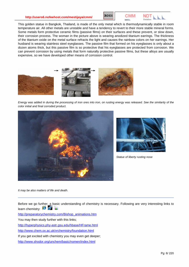
This golden statue in Bangkok, Thailand, is made of the only metal which is thermodynamically stable in room temperature air. All other metals are unstable and have a tendency to revert to their more stable mineral forms. Some metals form protective ceramic films (passive films) on their surfaces and these prevent, or slow down, their corrosion process. The woman in the picture above is wearing anodized titanium earrings. The thickness of the titanium oxide on the metal surface refracts the light and causes the rainbow colors on her earrings. Her husband is wearing stainless steel eyeglasses. The passive film that formed on his eyeglasses is only about a dozen atoms thick, but this passive film is so protective that his eyeglasses are protected from corrosion. We can prevent corrosion by using metals that form naturally protective passive films, but these alloys are usually expensive, so we have developed other means of corrosion control.
→ →
Energy was added in during the processing of iron ores into iron, on rusting energy was released. See the similarity of the color initial and final corroded product.
Statue of liberty rusting nose
It may be also matters of life and death.
Before we go further, a basic understanding of chemistry is necessary. Following are very interesting links to learn chemistry: http://preparatorychemistry.com/Bishop_animations.htm
You may then study further with this links;
http://hyperphysics.phy-astr.gsu.edu/hbase/HFrame.html
http://www.chem.ox.ac.uk/vrchemistry/foundation.html
If you get excited with chemistry you may even get deeper;
http://www.shodor.org/unchem/basic/nomen/index.html

http://users6.nofeehost.com/mestijaya/cmm/
Pg: 7/ 220
Uncontrolled corrosion may lead to disastrous consequences.
1.2 Electrochemistry Fundamentals The following brief introduction to chemistry and electrochemistry is intended to give the user of this book a basic understanding of corrosion.
Pourbaix Dig. / BASIC PRINCIPLES OF CORROSION

http://users6.nofeehost.com/mestijaya/cmm/
Pg: 8/ 220
1.2.1 The Nature of Matters
Atoms:
All matter is made of atoms composed of protons, neutrons, and electrons. The center, or nucleus, of the atom is composed of positively charge protons and neutral neutrons. The outside of the atom has negatively charged electrons in various orbits. This is shown schematically in the picture to the right where the electrons are shown orbiting the center, or nucleus, of the atom in much the same way that the planets orbit the sun in our solar system.
All atoms have the same number of protons (positively charged) and electrons (negatively charged). Therefore all atoms have a neutral charge (the positive and negative charges cancel each other). Most atoms have
approximately the same number of neutrons as they do protons or electrons, although this is not necessary, and the number of neutrons does not affect the identity of the element.
The number of protons (atomic number) in an atom determines which kind of atom we have, and the atomic mass (weight) of the atom is determined by the number of protons and neutrons in the nucleus (the electrons are so small as to be almost weightless).
There are over 100 different elements that have been discovered. These are shown in the Periodic Table of the Elements below. The letter symbols for the elements come from their Latin names, so for example, H stands for hydrogen, C for Carbon, O for oxygen, while Fe stands for iron and Cu stands for copper.
Atomic number Z = Numbers of protons in the nucleus.
Mass number A = Numbers of protons and neutron in the nucleus.
Administrator
v3

http://users6.nofeehost.com/mestijaya/cmm/
Pg: 9/ 220
Table: Subatomic particles important in chemistry.
Ions: Charged atoms or molecules are call ions.
Ions are formed when atoms, or groups of atoms, lose or gain electrons and become charged. Metals lose some of their electrons to form positively charged ions, e.g. Fe+2, Al+3, Cu+2, etc. Nonmetals gain electrons and form negatively charged ions, e.g. Cl-, O-2, S-2 etc.
An ion is an atom or molecule which has lost or gained one or more valence electrons, giving it a positive or negative electrical charge. A negatively charged ion, which has more electrons in its electron shells than it has protons in its nuclei, is known as an anion. Conversely, a positively-charged ion, which has fewer electrons than protons, is known as a cation.
Anion – Negative charged ion, it is attracted to the Positive Anode (+ve).
Cation – Positive charged ion, it is attracted to the Negative Cathode (-ve).
An ion consisting of a single atom is called a monatomic ion, but if it consists of two or more atoms, it is a polyatomic ion. Polyatomic ions containing oxygen, such as carbonate and sulfate, are called oxyanions.
Ions are denoted in the same way as electrically neutral atoms and molecules except for the presence of a superscript indicating the sign of the net electric charge and the number of electrons lost or gained, if more than one. For example: H+ and SO4
2−.
More reading:
http://csep10.phys.utk.edu/astr162/lect/light/bohr.html
http://chemmovies.unl.edu/ChemAnime/atomic_orbits.htm
http://www.chemguide.co.uk/atoms/properties/atomorbs.html
particle symbol charge mass, kg mass, daltons
electron e- -1 9.10953×10⁻³¹ 0.000548
proton p+ +1 1.67265×10⁻²⁷ 1.007276
neutron n 0 1.67495×10⁻²⁷ 1.008665
Administrator
v3

http://users6.nofeehost.com/mestijaya/cmm/
Pg: 10/ 220
Atomic Orbitals
Models of the Atom
Administrator
v3
Administrator
v3

http://users6.nofeehost.com/mestijaya/cmm/
Pg: 11/ 220
Formation of polyatomic and molecular ions
Polyatomic and molecular ions are often formed by the combination of elemental ions such as H+ with neutral molecules or by the gain of such elemental ions from neutral molecules. A simple example of this is the ammonium ion NH4
+ which can be formed by ammonia NH3 accepting a proton, H+. Ammonia and ammonium have the same number of electrons in essentially the same electronic configuration but differ in protons. The charge has been added by the addition of a proton (H+) not the addition or removal of electrons. The distinction between this and the removal of an electron from the whole molecule is
important in large systems because it usually results in much more stable ions with complete electron shells. For example NH3·+ is not stable because of an incomplete valence shell around nitrogen and is in fact a radical ion.
(NH3 was oxidized to NH4+ and HCl was reduced to Cl-)
The ammonia NH3 molecule has a trigonal pyramidal shape, as predicted by VSEPR theory. The nitrogen atom in the molecule has a lone electron pair, and ammonia acts as a base, a proton acceptor. This shape gives the molecule a dipole moment and makes it polar so that ammonia readily dissolves in water.
Ionization potential The ionization potential, ionization energy or EI of an atom or molecule is the energy required to remove an electron from the isolated atom or ion. More generally, the nth ionization energy is the energy required to strip it of the nth electron after the first n − 1 electrons have been removed. It is considered a measure of the "reluctance" of an atom or ion to surrender an electron, or the "strength" by which the electron is bound; the greater the ionization energy, the more difficult it is to remove an electron. The ionization potential is an indicator of the reactivity of an element. Elements with low ionization energy tend to be reducing agents and to form salts. Ions
• Anions are negatively charged ions, formed when an atom gains electrons in a reaction. Anions are negatively charged because there are more electrons associated with them than there are protons in their nuclei.
• Cations are positively charged ions, formed when an atom loses electrons in a reaction, forming an 'electron hole'. Cations are the opposite of anions, since cations have fewer electrons than protons.
• Radical ions: radical ions are ions that contain an odd number of electrons and are mostly very reactive and unstable.
In chemistry, radicals (often referred to as free radicals) are atoms, molecules or ions with unpaired electrons on an otherwise open shell configuration. These unpaired electrons are usually highly reactive.
Administrator
2

http://users6.nofeehost.com/mestijaya/cmm/
Pg: 12/ 220
In written chemical equations, free radicals are frequently denoted by a dot placed immediately to the right of the atomic symbol or molecular formula as follows:
Chlorine gas can be broken down by ultraviolet light to form atomic chlorine radicals.
Molecules:
Compounds are groups of metals and nonmetals that form distinct chemicals. Most of us are familiar with the formula H2O, which indicates that each water molecule is made of two hydrogen atoms and one oxygen atom. Many molecules are formed by sharing electrons between adjacent atoms. A water molecule has adjacent hydrogen and oxygen atoms sharing some of their electrons.
Note: The color distribution indicates dipole property of water molecule.
Acids and bases:
Water is the most common chemical on the face of the earth. It is made of three different constituents, hydrogen ions, hydroxide ions, and covalently bonded (shared electron) water molecules. Most of water is composed of water molecules, but it also has low concentrations of H+ ions and OH- ions.
Neutral water has an equal number of H+ ions and OH- ions. When water has an excess of H+ ions, we call the resultant liquid an acid. If water has more OH- ions, then we call it a base.
We measure the strength of an acid or a base on the pH scale. pH is defined by the following equation:
pH = -log [H+]
It is sufficient to note that some metals (e.g. zinc and aluminum) will corrode at faster rates in acids or bases than in neutral environments. Other metals, e.g. steel, will corrode at relatively high rates in acids but have lower corrosion rates in most neutral and basic environments.
Even a strong acid, with a pH of 0, will be less than 1/1000th by weight hydrogen ions. Neutral water, at a pH of 7, is less than 1 part H+ in 10 million parts covalently bonded water molecules.
pH is the negative logarithm of the effective hydrogen ion concentration in moles per liter of solution (more exactly the activity), or algebraically pH = −log10 [H+] or pH= log101/[H+].
Administrator
v3

http://users6.nofeehost.com/mestijaya/cmm/
Pg: 13/ 220
Exercise:
[H+] of 0.00000001, pH= -log [0.00000001], pH=8
[H+] of 0.001, pH= -log [0.001], pH=3
[H+] of 0.1, pH= -log [0.1], pH=?
Mnemonic device: Acids have low numbers (less than 7), bases have high numbers (greater than 7). Neutral waters have pH near 7 and tend to be relatively non-corrosive to many materials.
pH 1 has 10 times more active H+ pH 2
Galvanic cell
Administrator
v3

http://users6.nofeehost.com/mestijaya/cmm/
Pg: 14/ 220
1.2.2 The Electrochemical Cell
The following brief introduction to chemistry and electrochemistry is intended to give the user of this book a basic understanding of corrosion. Oxidation and Reduction: Metals are elements that tend to lose electrons when they are involved in chemical reactions, and nonmetals are those elements that tend to gain electrons. Sometimes these elements form ions, charged elements or groups of elements. Metallic ions, because they are formed from atoms that have lost electrons, are positively charged (the nucleus is unchanged). When an atom or ion loses electrons it is said to have been oxidized.
A common oxidation reaction in corrosion is the oxidation of neutral iron atoms to positively charged iron ions:
Fe » Fe+2 + 2e-
The electrons lost from a metal must go somewhere, and they usually end up on a nonmetallic atom forming a negatively charged nonmetallic ion. Because the charge of these ions has become smaller (more negative charges) the ion or atom which has gained the electron(s) is said to have been reduced.
4H+ +O2 + 4e- » 2H2O or
2H+ +2e- » H2
While other reduction reactions are possible, the reduction of oxygen is involved in well over 90% of all corrosion reactions. Thus the amount of oxygen present in an environment, and its ability to absorb electrons, is an important factor in determining the amount of oxidation, or corrosion, of metal that occurs.
Electrochemical Reactions: The two metal strips shown below are exposed to the same acid. Both metals undergo similar oxidation reactions:
Cu → Cu+2 + 2e-
Zn → Zn+2 + 2e-
The electrons freed by the oxidation reactions are consumed by reduction reactions. On the copper the reduction reaction is:
4H+ +O2 +4e- → 2H2O
The corrosion rate of the copper is limited by the amount of dissolved oxygen in acid. On the zinc the reduction reaction is:
2H+ +2e- → H2

http://users6.nofeehost.com/mestijaya/cmm/
Pg: 15/ 220
The hydrogen ions are converted to hydrogen gas molecules and can actually be seen bubbling off from the acid. If we now connect the two metal samples with a wire and measure the electricity through the connecting wire, we find that one of the electrodes becomes different in potential than the other and that the corrosion rate of the copper decreases while the corrosion rate of the zinc increases. By connecting the two metals, we have made the copper a cathode in an electrochemical cell, and the zinc has become an anode. The accelerated corrosion of the zinc may be so much
that all of the oxidation of the copper stops and it becomes protected from corrosion. We call this method of corrosion control cathodic protection. The reaction at the copper (cathode) becomes:
2H+ +2e- → H2
The voltage of the copper shifts to a point where hydrogen ion reduction can occur at the copper surface. The oxidation (corrosion) of the copper cathode may completely stop due to the electrical connection to the zinc anode. The reaction at the zinc (anode) remains the same,
Zn » Zn+2 + 2e-
But the reaction rate increases due to the fact that the surface area of the clean (un-corroding) copper surface can now support a reduction reaction at a high rate.
Thus connecting these two metals virtually stopped the corrosion of the copper and increased the corrosion rate of the zinc. We say that the zinc cathodically protected the copper from corrosion. Cathodic protection is a common means of corrosion control.
Mnemonic device: Anodes oxidize; cathodes reduce.

http://users6.nofeehost.com/mestijaya/cmm/
Pg: 16/ 220
Oxidation and Reduction (electrons)
Acronyms for oxidation and reduction:
• Oxidation is losing electron or gaining Proton H+
• Reduction is gaining electrons or losing H+
• Electron loss means oxidation:
• Losing electrons oxidation, gaining electrons reduction:
Administrator
v3
Administrator
2
Administrator
v3

http://users6.nofeehost.com/mestijaya/cmm/
Pg: 17/ 220
More on oxidation and reduction.
• Oxidation describes the loss of electrons by a molecule, atom or ion
• Reduction describes the gain of electrons by a molecule, atom or ion
Oxidizing and reducing agents Substances that have the ability to oxidize other substances are said to be oxidative and are known as oxidizing agents, oxidants or oxidizers. Put another way, the oxidant removes electrons from another substance, and is thus reduced itself. And because it "accepts" electrons it is also called an electron acceptor. The chemical way to look at redox processes is that the
Reductant transfers electrons to the oxidant. Thus, in the reaction, the reductant or reducing agent loses electrons and is oxidized
Oxidant or oxidizing agent gains electrons and is reduced.
The pair of an oxidizing and reducing agent that are involved in a particular reaction is called a redox pair. Mnemonic device:
To be oxidized other has to be reduced and vice versa. If you get oxidized you are a reducing agent, if you get reduced you are an oxidizing agent.
Examples of redox reactions A good example is the reaction between hydrogen and fluorine:
We can write this overall reaction as two half-reactions: the oxidation reaction
H2 was oxidized by losing electrons, it was a reducing agent. and the reduction reaction:
F2 was reduced by gaining electron, it was an oxidizing agent. Analyzing each half-reaction in isolation can often make the overall chemical process clearer. Because there is no net change in charge during a redox reaction, the number of electrons in excess in the oxidation reaction must equal the number consumed by the reduction reaction (as shown above).
Elements, even in molecular form, always have an oxidation number of zero. In the first half reaction, hydrogen is oxidized from an oxidation number of zero to an oxidation number of +1. In the second half reaction, fluorine is reduced from an oxidation number of zero to an oxidation number of −1.
When adding the reactions together the electrons cancel:
And the ions combine to form hydrogen fluoride:

http://users6.nofeehost.com/mestijaya/cmm/
Pg: 18/ 220
Displacement reactions Redox occurs in single displacement reactions or substitution reactions. The redox component of this type of reaction is the change of oxidation state (charge) on certain atoms, not the actual exchange of atoms in the compounds.
For example, in the reaction between iron and copper(II) sulphate solution:
The ionic equation for this reaction is:
As two half-equations, it is seen that the iron is oxidized:
And the copper is reduced:
Other examples
• iron(II) oxidizes to iron(III):
Fe2+ → Fe3+ + e−
• hydrogen peroxide reduces to hydroxide in the presence of an acid:
H2O2 + 2 e− → 2 OH−
Overall equation for the above:
2Fe2+ + H2O2 + 2H+ → 2Fe3+ + 2H2O
4Fe + 3O2 → 2 Fe2O3
Example: Fe0 + Cu++SO4- - --> Cu0 + Fe++SO4
- -
Copper is more electrochemically noble than iron (Fe) and will displace iron from the surface, i.e., cause iron to dissolve into solution so it can come out as a metal.
Click here to see interactive materials on Redox Reactions and Electrochemical Reactions.
Administrator
New Stamp
Administrator
pdfsmall
Administrator
v3

http://users6.nofeehost.com/mestijaya/cmm/
Pg: 19/ 220
Rusting of iron is oxidation-reduction reaction, where iron is oxidized, Fe → Fe2+ with loss of 2 electron and iron in this case a reductant.
More reading: Oxidation-Reduction The following is a brief overview of the basics. Oxidation-reduction reactions involve the transfer of electrons between substances. They take place simultaneously, which makes sense because if one substance loses electrons, another must gain them. Many of the reactions we’ve encountered thus far fall into this category. For example, all single-replacement reactions are redox reactions. Terms you’ll need to be familiar with. Electrochemistry: The study of the interchange of chemical and electrical energy. Oxidation: The loss of electrons. Since electrons are negative, this will appear as an increase in the charge (e.g., Zn loses two electrons; its charge goes from 0 to +2). Metals are oxidized. Oxidizing agent (OA): The species that is reduced and thus causes oxidation. Reduction: The gain of electrons. When an element gains electrons, the charge on the element appears to decrease, so we say it has a reduction of charge (e.g., Cl gains one electron and goes from an oxidation number of 0 to -1). Nonmetals are reduced. Reducing agent (RA): The species that is oxidized and thus causes reduction. Oxidation number: The assigned charge on an atom. You’ve been using these numbers to balance formulas.
Administrator
v3

http://users6.nofeehost.com/mestijaya/cmm/
Pg: 20/ 220
Half-reaction: An equation that shows either oxidation or reduction alone. Example When powdered zinc metal is mixed with iodine crystals and a drop of water is added, the resulting reaction produces a great deal of energy. The mixture bursts into flames, and a purple smoke made up of I2 vapor is produced from the excess iodine. The equation for the reaction is
Zn(s) + I2(s) ZnI2(s) + energy
Identify the elements that are oxidized and reduced, and determine the oxidizing and reducing agents. Voltaic (or Galvanic) Cells Redox reactions release energy, and this energy can be used to do work if the reactions take place in a voltaic cell. In a voltaic cell (sometimes called a galvanic cell), the transfer of electrons occurs through an external pathway instead of directly between the two elements. The figure below shows a typical voltaic cell (this one contains the redox reaction between zinc and copper):
Administrator
Stamp
Administrator
v3

http://users6.nofeehost.com/mestijaya/cmm/
Pg: 21/ 220
Standard Reduction Potentials
The potential of a voltaic cell as a whole will depend on the half-cells that are involved. Each half-cell has a
known potential, called its standard reduction potential (Eº). The cell potential is a measure of the difference
between the two electrode potentials, and the potential at each electrode is calculated as the potential for
reduction at the electrode. That’s why they’re standard reduction potentials, not standard oxidation potentials.
On this reduction potential chart, the elements that have the most positive reduction potentials are easily
reduced and would be good oxidizing agents (in general, the nonmetals), while the elements that have the
least positive reduction potentials are easily oxidized and would be good reducing agents (in general, metals).
Electrolytic Cells While voltaic cells harness the energy from redox reactions, electrolytic cells can be used to drive non-
spontaneous redox reactions, which are also called electrolysis reactions. Electrolytic cells are used to
produce pure forms of an element; for example, they’re used to separate ores, in electroplating metals (such
as applying gold to a less expensive metal), and to charge batteries (such as car batteries). These types of
cells rely on a battery or any DC source—in other words, whereas the voltaic cell is a battery, the electrolytic
cell needs a battery. Also unlike voltaic cells, which are made up of two containers, electrolytic cells have just
one container. However, like in voltaic cells, in electrolytic cells electrons still flow from the anode to the
cathode. An electrolytic cell is shown below.
More reading: Electrochemistry
http://hyperphysics.phy-astr.gsu.edu/hbase/chemical/electrochem.html Physic and Chemistry (College Level)
http://www.ionode.com.au/Techorp.html Redox Theory
http://www6.grafton.k12.wi.us/ghs/teacher/mstaude/ Chemistry Basic
http://www.tannerm.com/electrochem.htm General Chemistry
http://www.chem1.com/acad/pdf/c1xElchem.pdf Electrolysis
http://www.chem1.com/acad/webtext/elchem/ec4.html All about Nernst Equation.
Administrator
Stamp
http://users6.nofeehost.com/mestijaya/cmm/
Pg: 22/ 220
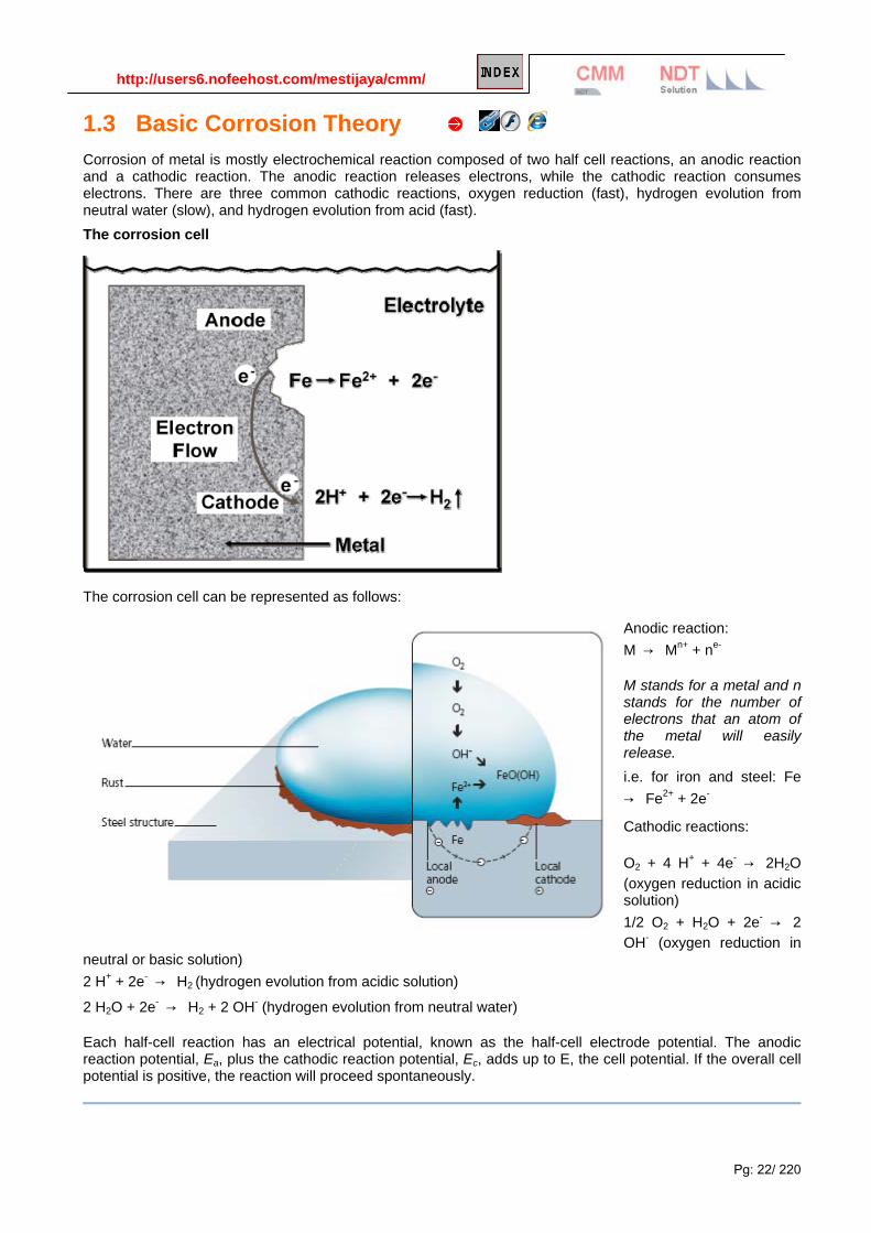
1.3 Basic Corrosion Theory Corrosion of metal is mostly electrochemical reaction composed of two half cell reactions, an anodic reaction and a cathodic reaction. The anodic reaction releases electrons, while the cathodic reaction consumes electrons. There are three common cathodic reactions, oxygen reduction (fast), hydrogen evolution from neutral water (slow), and hydrogen evolution from acid (fast). The corrosion cell
The corrosion cell can be represented as follows:
Anodic reaction: M → Mn+ + ne-
M stands for a metal and n stands for the number of electrons that an atom of the metal will easily release. i.e. for iron and steel: Fe → Fe2+ + 2e-
Cathodic reactions:
O2 + 4 H+ + 4e- → 2H2O (oxygen reduction in acidic solution) 1/2 O2 + H2O + 2e- → 2 OH- (oxygen reduction in
neutral or basic solution) 2 H+ + 2e- → H2 (hydrogen evolution from acidic solution)
2 H2O + 2e- → H2 + 2 OH- (hydrogen evolution from neutral water)
Each half-cell reaction has an electrical potential, known as the half-cell electrode potential. The anodic reaction potential, Ea, plus the cathodic reaction potential, Ec, adds up to E, the cell potential. If the overall cell potential is positive, the reaction will proceed spontaneously.

http://users6.nofeehost.com/mestijaya/cmm/
Pg: 23/ 220
Every metal or alloy has a unique corrosion potential in a defined environment. When the reactants and products are at an arbitrarily defined standard state, the half-cell electrode potentials are designated Eo. These standard potentials are measured with respect to the standard hydrogen electrode (SHE). A listing of standard half-cell electrode potentials is given in Table 1. Selected half-cell reduction potentials are given in Table 1. To determine oxidation potentials, reverse the direction of the arrow and reverse the sign of the standard potential. For a given cathodic reaction, those anodic (reversed) reactions below it in the table will go spontaneously, while those above it will not. Thus any metal below the hydrogen evolution reaction will corrode (oxidize) in acidic solutions. e.g., Cathodic reaction: 2H+ + 2e- → H2 (hydrogen evolution) Two possible anodic reactions: Cu → Cu2+ + 2e- (above cathodic reaction in table - will not corrode)
Zn → Zn2+ + 2e- (below cathodic reaction in table - spontaneous corrosion) Thus, in the presence of H+ ions, Zinc (Zn) will spontaneously corrode while copper (Cu) will not.
1.3.1 Oxidation-reduction electromotive-force potentials / galvanic series. There has been some confusion regarding oxidation-reduction electromotive-force potentials and the galvanic series. While there are similarities between the galvanic series and standard reduction potentials, there are also some fundamental differences. While standard potentials can provide an indication of the stability of a metal, as it is done with E-pH or Pourbaix diagrams, galvanic series are used to predict whether or not galvanic corrosion will occur, and if so, which of the two coupled metals will exhibit increased corrosion. Thus, these two tabulations have entirely different uses and should therefore not be confused. Table1. Standard Electromotive Force Potentials Cathodic Reactions
Standard Potential, eo (volts vs. SHE)
Au3+ + 3e- → Au +1.498 (Most Noble) O2 + 4H+ + 4e- → 2H2O +1.229 (in acidic solution) Pt2+ + 2e- → Pt +1.118 NO3
- + 4H+ + 3e- → NO + 2H2O +0.957 Ag+ + e- → Ag +0.799 O2 + 2H2O + 4e- → 4OH- +0.401 (in neutral or basic solution) Cu2+ + 2e- → Cu +0.337 2H+ + 2e- → H2 0.000 Pb2+ + 2e- → Pb -0.126 Sn2+ + 2e- → Sn -0.138 Ni2+ + 2e- → Ni -0.250

http://users6.nofeehost.com/mestijaya/cmm/
Pg: 24/ 220
Co2+ + 2e- → Co -0.277 Cd2+ + 2e- → Cd -0.403 Fe2+ + 2e- → Fe -0.447 Cr3+ + 3e- → Cr -0.744 Zn2+ + 2e- → Zn -0.762 2H2O + 2e- → H2 + 2OH- -0.828 (pH = 14) Al3+ + 3e- → Al -1.662 Mg2+ + 2e- → Mg -2.372 Na+ + e- → Na -2.71 K+ + e- → K -2.931 (Most Active)
Source: Handbook of Chemistry and Physics, 71st ed, CRC Press, 1991
Table 1 can be used to show that copper will corrode in nitric acid solutions (oxidizing) and aerated water. Similarly, aluminum (Al), magnesium (Mg), sodium (Na) and potassium (K) will react spontaneously with water in neutral or basic solutions.
Galvanic series (nobler higher) The following is the galvanic series for stagnant (that is, low oxygen content) seawater. The order may change in different environments.
• Graphite
• Palladium
• Platinum
• Gold
• Silver
• Titanium
• Stainless steel (316 passive)
• Stainless Steel (304 passive)
• Silicon bronze
• Stainless Steel (316 active)
• Monel 400
• Phosphor bronze
• Admiralty brass
• Cupronickel
• Molybdenum
• Red brass
• Brass plating
• Yellow brass
• Naval brass 464
• Uranium 8% Mo

http://users6.nofeehost.com/mestijaya/cmm/
Pg: 25/ 220
• Niobium 1% Zr
• Tungsten
• Stainless Steel (304 active)
• Tantalum
• Chromium plating
• Nickel (passive)
• Copper
• Nickel (active)
• Cast iron
• Steel
• Lead
• Tin
• Indium
• Aluminum
• Uranium (pure)
• Cadmium
• Beryllium
• Zinc plating (see galvanization)
• Magnesium
Pourbaix diagram for iron
Stability diagrams are able to condense a great amount of information into a compact representation, and are
widely employed in geochemistry and corrosion engineering. The Pourbaix diagram for iron is one of the more
commonly seen examples:
Three oxidation states of iron (0, +2 and +3) are represented on this diagram. The stability regions for the oxidized iron states are shown only within the stability region of H2O. Equilibria between species separated by vertical lines are dependent on pH only.
The +3 oxidation state is the only stable one in environments in which the oxidation level is controlled by
atmospheric O2. This is the reason the Earth’s crust contains iron oxides, which developed only after the
appearance of green plants which are the source of O2.
Iron is attacked by H+ to form H2 and Fe(II); the latter then reacts with O2 to form the various colored Fe(III)
oxides that constitute “rust”.
Numerous other species such as oxides and hydrous oxides are not shown. A really “complete” diagram for
iron would need to have at least two additional dimensions showing the partial pressures of O2 and CO2.

http://users6.nofeehost.com/mestijaya/cmm/
Pg: 26/ 220
More reading: Appendix Pourbaix | Redox Reaction
A simple experiment Procedure:
Prepare 200 ml of agar-agar solution. Measure out a mass of 2.0 grams of powdered agar-agar. Heat 200 ml of water to boiling. Remove the water from the heat and add the agar-agar powder slowly while constantly stirring. Once the agar has dissolved, add 5 drops of phenolphthalein solution or 5 drops of bromothymol blue
Take two nails (or strips of pure iron) and wrap them in the strips of metal. One nail should be wrapped with zinc
metal and the other nail wrapped with copper metal. Place these two wrapped nails into a petri dish. Be sure the nails do not touch. (The zinc and copper metals should be rubbed down and cleaned with sandpaper before they are wrapped around the nails). Make sure the nails are not galvanized or have some other type of coating. The idea is to use iron.
Slowly pour the agar-agar solution into the petri dishes to a depth of about 0.5 cm above the nails and metals.
Allow the petri dishes to remain untouched for a day or two. From time to time make observations. At the end of
the next day and then at the end of the second day make and record observations.
Note: Phenolphthalein is used as an acid or base indicator where in contact or presence of acid it will turn colorless and with base,

http://users6.nofeehost.com/mestijaya/cmm/
Pg: 27/ 220
Observation: 观察实验
Figure 1. Using Phenolphthalein as indicator. Iron wrapped in zinc is on the left and iron wrapped in copper is on the right.
Questions:
1. What changes did you observe in the petri dish? Why did the color changes occur where they did? 2. In which nail did the iron of the nail corrode? 3. Why did the iron nail corrode in the one situation and not in the other? 4. Explain "corrosion" or "rust" in an electrochemical point of view. 5. What does the "pink" color (if phenolphthalein was used) indicate? 6. What is a cathode and what is an anode? 7. What is oxidation?
Explanations:
1. As can be seen in Figure 1, the iron strip which is wrapped in copper corroded. Pink color is found around the copper strip and the iron can be seen to be turning orange-yellow. This is only after 5 hours. More corrosion would be visible days later. The second strip of iron is not corroded. Pink is found on the iron and nothing by the zinc strip. The color changes occurred where they did as a result of the corrosion.
2. In the strip of iron wrapped with copper the iron corroded. Iron metal oxidizes faster or more easily than does the copper. It is said that the iron is oxidized and the copper is reduced. What is happening is that the iron is losing electrons and the copper is gaining electrons. The copper is considered the cathode in this case and the iron is considered to be the anode. The iron metal loses electrons and turns into an iron ion according to this equation:
Fe (s) → Fe+2 + 2 e- Equation 1.1
These two electrons travel through the iron metal to the copper. At the copper there is water and oxygen which take the two electrons and use them to form hydroxide ions as in Equation 1.2:
½ O2 (g) + H2O (l) + 2 e- → 2 OH- Equation 1.2
This excess of OH- produced causes the solution next to the copper to be pink. Hydroxide ions (OH-) make a solution to be basic which turns pink in the presence of phenolphthalein.
What ultimately happens in the case of the iron metal wrapped with copper is that the iron metal loses two electrons which are used by water and oxygen to make hydroxide ions. It is evident that the hydroxide ions are formed at the copper surface because of the pink that exists around the copper. The iron ions that are formed react with oxygen and water to form "rust" as is seen in Equation 1.3:
Fe+2 + ½ O2 (g) + H2O (l) → Fe (OH)2 (s) Equation 1.3
This Fe (OH)2 (s) combines with a second molecule of Fe (OH)2 (s) in the presence of oxygen to form iron(III)oxide (the more common form of rust) and water.

http://users6.nofeehost.com/mestijaya/cmm/
Pg: 28/ 220
2 Fe (OH)2 (s) + ½ O2 (g) → Fe2O3 (s) + 2H2O (l) Equation 1.4
Thus iron "rusts" and the copper does not react with anything.
3. In the other situation in which iron is wrapped with zinc the opposite occurs. In this case zinc is oxidized faster or more easily than the iron and therefore it undergoes a very similar reaction as did the iron in the last example. Here zinc loses two electrons and forms a Zn +2 ion. On the surface of the iron the same reaction occurs as did on the copper. Water and oxygen combine with the two electrons to make hydroxide ions, which turn the solution next to the iron surface pink. In this case the zinc is considered to be the anode and the iron is considered to be the cathodeThis has very practical implications. The auto industry and boating industry have used this idea to prevent automobiles and the steel hulls of ships from rusting. Water is a crucial component to act as a medium to transfer electrons. Iron metal will not "rust" when it is in dry air. So these industries, knowing that zinc, aluminum, and magnesium oxidize or "rust" faster and more easily than iron, place these metals adjacent to the steel so that these metals will "rust" before the iron does.
4. See number 2.
5. The pink color indicates that hydroxide ions are produced. This indicates a chemical reaction has occurred. The location of the pink indicates that the metal nearest to it was producing the hydroxide ions, and therefore, was the metal "gaining" electrons. This metal which "gained" electrons is said to have been "reduced" while the metal which "lost" the electrons is said to have been "oxidized" or "rusted" or "corroded".
6. The cathode is the place in an electrochemical cell to where the electrons travel. The anode is the place in an electrochemical cell from where the electrons came.
7. Oxidation is the "loss of electrons". It is usually comparable to "rusting" or "corroding" because the metal loses electrons, turns into an ion, and therefore, there are less "metal" atoms around. Thus the metal is said to have corroded.
http://users6.nofeehost.com/mestijaya/cmm/
Pg: 29/ 220
1.3.2 Why corrosion cells form Corrosion cells are created on metal surfaces in contact with an electrolyte because of energy differences between the metal and the electrolyte. Different area on the metal surface could also have different potentials with respect to the electrolyte. These variations could be due to:
Metallurgical factors, due to fabrication, field installations etc.: Compositions. Microstructures. Inclusions. Precipitations. Heat treatment. Mechanical rolling and tempering. Welding. Work hardening. Fabrication, installation and external stress, strain factors.
Environmental factors.
Concentration Cells. Environmental induced SCC, SSC, HIC etc. Microbial MIC etc. Temperature induced corrosion. Mechanical environmental induced erosion, fretting, cavitation etc. Galvanic, CP and Impressed current anodic dissolution, stray current, cathodic embrittlement etc.
Above also include corrosion mechanisms of non-electrolytic nature.
Discussion:
1.3.2.1 Metallurgical Factors: Carbon and low alloy steels are the most widely used material in the oilfield. Stainless steels (Fe-Cr-Ni), and nickel-base corrosion resistant alloys (CRA), such as Incoloys (Ni-Fe-Cr), Inconels (Ni-Cr), Hastelloys (Ni-Cr-Mo-Fe-Co) etc., are also used in highly corrosive environments.
Steel is an alloy of iron (Fe) and carbon (C). Carbon is fairly soluble in liquid iron at steel making temperatures, however, it is practically insoluble in solid iron (0.02% at 723C), and trace at room temperature. Pure iron is soft and malleable; small amounts carbon and manganese are added to give steel its strength and toughness.
Most of the carbon is oxidized during steelmaking. The residual carbon and post-fabrication heat treatment determines the microstructure, therefore strength and hardness of steels. Carbon steels are then identified by their carbon contents, i.e., low-carbon or mild steel, medium carbon (0.2- 0.4 % C), high-carbon (up to 1% C) steels, and cast irons (>2 % C). American Iron and Steel Institute (AISI) designation 10xx series represent plain carbon steels, last two digits indicating the carbon content. For instance, AISI 1036 steel, commonly used in sucker rods, contain 0.36% carbon. Low alloy steels contain 1-3% alloying elements, such as chromium-molybdenum steels, 4140 (1% Cr-0.2% Mo-0.4% C), for improved strength and corrosion resistance. American Petroleum Institute (API) specifications also provide guidelines for strength and chemical composition of oilfield steels.

http://users6.nofeehost.com/mestijaya/cmm/
Pg: 30/ 220
The microstructure of a low-carbon pipe steel is shown (magnified 100X) in (a) transverse and (b) in longitudinal sections, where light grains are ferrite and the dark grains are pearlite. Other impurities in iron may also migrate to grain boundaries forming micro-alloys that may have entirely different composition from the grains, hence may have different corrosion properties. As in the case of intergranular corrosion, grain boundary precipitation, notably chromium carbides in stainless steels, is a well recognized and accepted mechanism of weld decay. In this case, the precipitation of chromium carbides is induced by the welding operation when the heat affected zone (HAZ) experiences a particular temperature range (550oC~850oC). The precipitation of chromium carbides consumed the alloying element - chromium from a narrow band along the grain boundary and this makes the zone anodic to the unaffected grains. The chromium depleted zone becomes the preferential path for corrosion attack or crack propagation if under tensile stress.
Low-carbon pipe steel is shown (magnified 100X) in transverse sections.
Same low-carbon pipe steel is shown (magnified 100X) in longitudinal sections,

http://users6.nofeehost.com/mestijaya/cmm/
Pg: 31/ 220
In a corrosive environment, either grains or the grain boundaries having different composition can become anodic or cathodic, thus forming the corrosion cells. Hydrogen evolution reaction can take place on iron carbide, and spheroidized carbon in steels, and graphite in cast irons, in acidic solutions with relative ease; areas denuded in carbon become anodic and corrode preferentially. Therefore, post-weld heat treatment of steels is critical in order to prevent corrosion of the heat affected zone (HAZ), sensitization and intergranular corrosion in stainless steels.
Other metallurgical factors include improper heat treatment for stress relief after hot rolling, upsetting, or excessive cold working; slag inclusions, mill scale, water deposited scale and corrosion product scales, nicks, dents and gouges on the metal surface. Scars caused by pipe wrench, tongs, and other wellhead equipment on sucker rods and tubing would become anodic and corrode downhole. Likewise, new threads cut into pipe will be anodic and corrode in the absence of suitable corrosion protection.
Deformation caused by cold bending or forcing piping into alignment will create internal stresses in the metal. The most highly stressed areas will become anodic with respect to the rest of the metal. Hammer marks, nicks and gauges will also act as stress raisers and may cause fatigue failures.
Sections of the same steel may corrode differently due to variations in the concentration of aggressive ions in the environment. For instance, a casing or a pipeline could pass through several formations or soils with different water composition, hence, sections of the casing or the pipe could experience different rates of corrosion. Similarly, a pipeline crossing a river will be exposed to higher concentration salts as compared to dry land. It is difficult to predict the effect of higher salt concentrations but, generally, sections of steel exposed to higher salt concentrations become anodic and corrode.
Differences in the oxygen concentration on the metal surface (differential aeration or differential oxygen concentration cells) cause particularly insidious forms of corrosion. A common example is corrosion of pipes under paved roads, parking lots, or pavements.
Lack of oxygen under the pavement render that section of the pipe anodic, hence pipe corrodes preferentially. Similarly, loose backfill placed into ditch to cover a pipeline is more permeable to oxygen diffusion; the topside of the pipe will become cathodic, and the bottom resting on undisturbed soil will become anodic and corrode. Crevice and pitting corrosion mechanisms in aerated systems can also be explained by differential concentration cells.

http://users6.nofeehost.com/mestijaya/cmm/
Pg: 32/ 220
Intergranular Corrosion: Knife-Line Attack (KLA) Recognition: What is knife-line attack? Knife-Line Attack (KLA) is a form of intergranular corrosion of an alloy, usually stabilized stainless steel, along a line adjoining or in contact with a weld after heating into the sensitization temperature range. The corrosive attack is restricted to extremely narrow line adjoining the fusion line. Attack appears razor-sharp (and hence the name of "knife-line" attack). It is possible to visually recognize knife-line attack if the lines are already formed in the along the weld.
Mechanisms: What causes knife-line attack? For stabilized stainless steels and alloys, carbon is bonded with stabilizers (Ti or Nb) and no weld decay occurs in the heat affected zone during welding. In the event of a subsequent heat treatment or welding, however, precipitation of chromium carbide is possible and this leaves the narrow band adjacent to the fusion line susceptible to intergranular corrosion.
Prevention: How to prevent knife-line attack? Knife-Line Attack can be prevented through:
• Heat treatment - heating the weld to 1065oC to re-stabilize the material.
http://users6.nofeehost.com/mestijaya/cmm/
Pg: 33/ 220
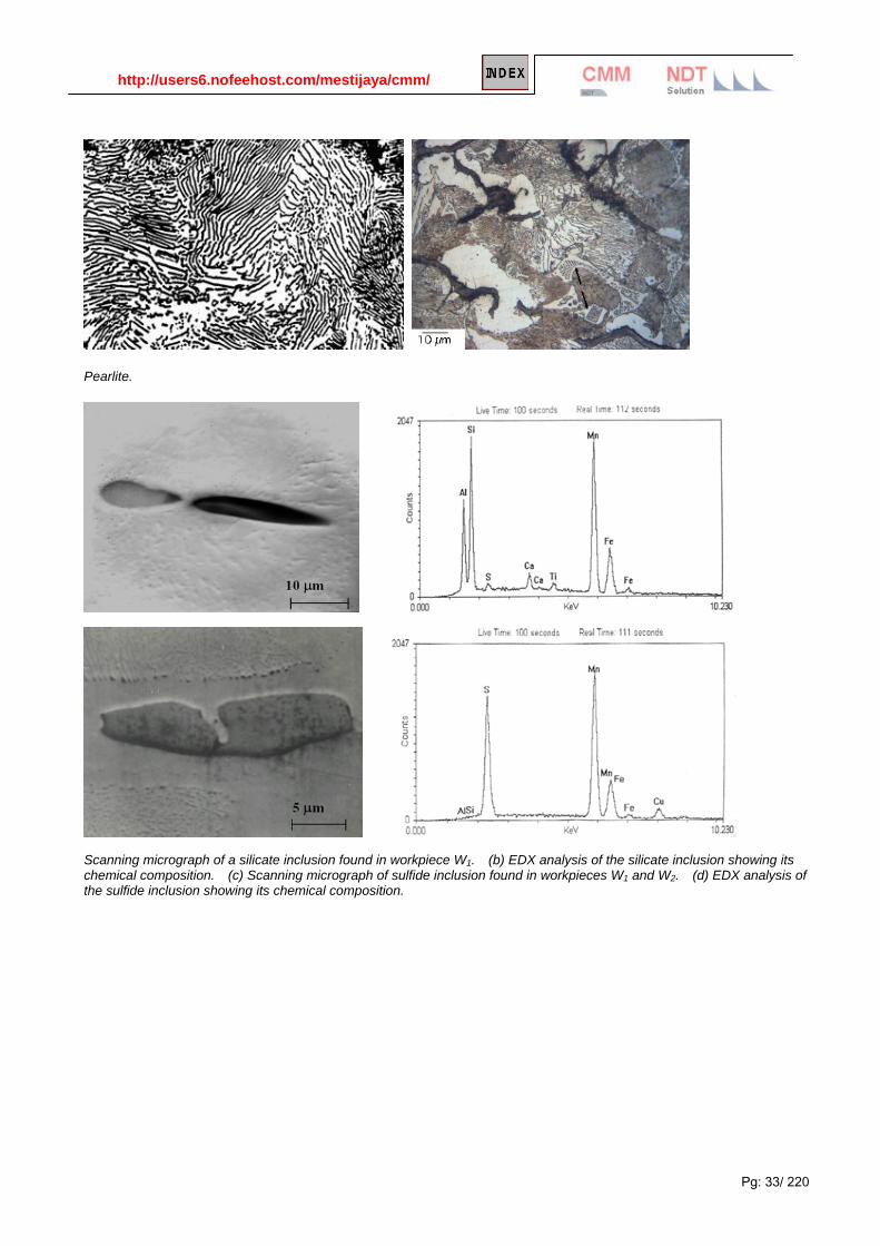
Pearlite.
Scanning micrograph of a silicate inclusion found in workpiece W1. (b) EDX analysis of the silicate inclusion showing its chemical composition. (c) Scanning micrograph of sulfide inclusion found in workpieces W1 and W2. (d) EDX analysis of the sulfide inclusion showing its chemical composition.

http://users6.nofeehost.com/mestijaya/cmm/
Pg: 34/ 220
1.3.2.2 Environmental Factors Corrosion gas and microbes. There are many unique environments in the oil field industry where corrosion commonly occurs. Oxygen (O2) , which is a strong oxidizer, is one of the most corrosive gases when present. Other common corrosive gases in the oil field are carbon dioxide (CO2) and hydrogen sulfide (H2S), which form weak acids in water. Microbial activity may cause corrosion alone, create more corrosive gases, and/or act to induce blockage within pipes.
Corrosion rates of steel versus oxygen, carbon dioxide, and hydrogen sulfide. Note the different gas concentrations on the x axis.
O2 Corrosion
O2 Information
Oxygen dissolved in water is one of the primary causes of corrosion in the oil field. When oxygen is present, the most common types of corrosion include pitting corrosion and uniform corrosion.
Oxygen is a strong oxidant and reacts quickly with metal. The maximum amount of oxygen in water is only 8 ppm, so the mass transport of oxygen is the rate limiting step in oxygenated non-acidic environments. Controlling the rate of oxygen transport (often by controlling flow velocity) is thus critical to corrosion control.
O2 corrosion products include iron oxides, including FeO(OH) - goethite, Fe2O3 - hematite, Fe3O3 - magnetite, and FeO(OH) - ferrous hydroxide.
Differential Aeration
Corrosion may occur in oilfield applications due to the existence of differential aeration. In these cases, one section of the metal is exposed to oxygen while the other is not. The section with no aeration becomes anodic, and is subject to preferential corrosion. This can occur with pipelines and other metals near the surface. The first figure shows an example of how a corrosion cell can form when a pipe is buried below the surface. The soil above the pipe can become aerated due to the digging and backfilling process, so the top of the pipe is

http://users6.nofeehost.com/mestijaya/cmm/
Pg: 35/ 220
second figure, a section of pavement restricts oxygen from reaching the pipe in the part of the pipe under the pavement. That part of the pipe becomes anodic and corrodes preferentially.
Where Found
Although it is not normally present at depths below around 330 ft (100 m), oxygen is often introduced in oil production through leaking pump seals, casing and process vents, open hatches, and open handling. In addition, oxygen removal processes such as gas stripping and chemical scavenging often fail, allowing oxygen contamination in waterflood systems.
Oxygen corrosion occurs commonly in drilling fluid, primary production in rod pumped wells, outdoor rod storage (rusting), oxygen entry into wellbore through annulus, lower part of well including casing, pump, tubing, lower part of rod string
Prevention / Mitigation
Oxygen removal may be done by mechanical and chemical means. Mechanical means include gas stripping and vacuum deaeration; chemical means include sodium sulfite, ammonium bisulfite and sulfur dioxide. Mechanical means of oxygen removal are usually employed when large quantities of oxygen need to be removed, while chemical means are used to remove small quantities of oxygen and may be used to remove residual oxygen after mechanical means have been used.
It is often more economical to exclude oxygen from oilfield equipment than to remove it after it has entered the system. The most common way of excluding oxygen is through the use of gas blankets, composed of oxygen free gas such as natural gas (methane) or nitrogen. Gas blankets may be used on water supply wells and water storage tanks, supply wells and producing wells, and pumps. Most tanks only require a few ounces of pressure. The regulator should supply gas at a rate adequate to maintain pressure when the fluid level drops. Maintenance of valve stems and pump packing is also important.
To reduce or prevent corrosion in an O2 environment: Drilling - oxygen scavengers Producing wells - corrosion inhibitors, oxygen scavengers, elimination of O2 sources Flowlines - corrosion inhibitors, oxygen scavengers, elimination of O2 sources
More reading:
Corrosion Control in Pipelines Using Oxygen Stripping

http://users6.nofeehost.com/mestijaya/cmm/
Pg: 36/ 220
Signs of oxygen corrosion include wide shallow pits and reddish brown rust.
Oxygen corrosion also causes large areas of metal loss on sucker rods
It is virtually impossible to keep oxygen out of any tophole system. Downhole systems do not have oxygen, unless oxygen is injected with treating chemicals or other secondary recovery methos are used, such as firefloods. Oxygen from the air can react with iron sulfides to form iron oxides. The presence of iron oxides as corrosion by-products is a strong indication that oxygen corrosion is occurring in the system. If X-Ray Diffraction (XRD) finds magnetite (Fe3O4), hematite (Fe2O3), and / or akaganeite [Fe+3(O,OH,Cl)], which is an iron oxy chloride, it is a strong indication that oxygen corrosion is occurring. The topography of oxygen corrosion pits includes the following characteristics:
• round pits
• shallow pits
• sloping sidewalls
• tend to grow into one another
• bright red rust color

http://users6.nofeehost.com/mestijaya/cmm/
Pg: 37/ 220
Oxygen is not determined directly by XRF, however, subtracting the sum of all the elements from 100% gives the oxygen level. Oxygen corrodes carbon steel forming iron oxides as the corrosion by-products. Oxygen corrosion is usually controlled by the addition of oxygen scavengers to the system. Oxygen scavengers help to reduce the oxygen level, and hence control Oxygen Corrosion. Note that the selection of a particular oxygen scavenger should be based on compatibility, cost, and other pertinent factors.
CO2 Corrosion
CO2 Information
Carbon dioxide systems are one of the most common environments in the oil field industry where corrosion occurs. Carbon dioxide forms a weak acid known as carbonic acid (H2CO3) in water, a relatively slow reaction. However, CO2 corrosion rates are greater than the effect of carbonic acid alone. Cathodic depolarization may occur, and other attack mechanisms may also be at work. The presence of salts is relatively unimportant.
Corrosion rates in a CO2 system can reach very high levels (thousands of mils per year), but it can be effectively inhibited. Velocity effects are very important in the CO2 system; turbulence is often a critical factor in pushing a sweet system into a corrosive regime. This is because it either prevents formation or removes a protective iron carbonate (siderite) scale.
Conditions favoring the formation of the protective iron carbonate scale are elevated temperature, increased pH (bicarbonate waters) and lack of turbulence. Magnetite scales are also formed in CO2 systems, and corrosion product scales often consist of layers or mixtures of siderite and magnetite.
The maximum concentration of dissolved CO2 in water is 800 ppm. When CO2 is present, the most common forms of corrosion include uniform corrosion, pitting corrosion, wormhole attack, galvanic ringworm corrosion, heat affected corrosion, mesa attack, raindrop corrosion, erosion corrosion, and corrosion fatigue. The presence of carbon dioxide usually means no H2 Embrittlement. CO2 corrosion products include iron carbonate (siderite, FeCO3), Iron oxide, and magnetite. Corrosion product colors may be green, tan, or brown to black.
Where Found
As stated before, CO2 corrosion is one of the most common environments where corrosion occurs, and exists almost everywhere.
Areas where CO2 corrosion is most common include flowing wells, gas condensate wells, areas where water condenses, tanks filled with CO2, saturated produced water and flowlines, which are generally corroded at a slower rate because of lower temperatures and pressures. For more information on specific equipment corrosion issues,
CO2 corrosion is enhanced in the presence of both oxygen and organic acids, which can act to dissolve iron carbonate scale and prevent further scaling.
Prevention / Mitigation
To reduce or prevent corrosion in an CO2 environment: Drilling - pH control with caustic soda Producing wells - corrosion inhibitors Flowlines - continuous corrosion inhibitor injection
Prediction of corrosion
In sweet gas wells with a pH of 7 or less,
CO2 partial pressure of 30 psi usually indicates corrosion.

http://users6.nofeehost.com/mestijaya/cmm/
Pg: 38/ 220
CO2 partial pressure of 7 - 30 psi may indicate corrosion.
CO2 partial pressure of 7 psi is usually considered non-corrosive.
Uniform Corrosion
Pitting Corrosion showing wormhole attack pattern, where pits are interconnected.

http://users6.nofeehost.com/mestijaya/cmm/
Pg: 39/ 220
Galvanic ringworm corrosion, often occurring four to six inches from the upset, where carbon particles have been spheroidized
Heat-affected zone (HAZ) corrosion is a type of galvanic corrosion which occurs along a weld seam.
Raindrop attack occurs in gas condensate wells. In areas, water condenses on the metal surface, causing deep pits with tails.

http://users6.nofeehost.com/mestijaya/cmm/
Pg: 40/ 220
CO2 corrosion in flowing environments
Mesa attack is a form of CO2 corrosion that occurs in flowing environments, and occurs where a protective iron carbonate coating is worn away in areas.
Erosion Corrosion, or flow-enhanced corrosion, usually occurs in areas where the diameter of the pipe or direction of flow is changing. Severe metal loss can quickly occur.
Corrosion due to fatigue occurs in areas of cyclic stresses. Here we see fatigue corrosion in a drill pipe.

http://users6.nofeehost.com/mestijaya/cmm/
Pg: 41/ 220
Water with dissolved CO2 led to diffusion of atomic hydrogen (H) which combined as molecular hydrogen (H2) in voids. The pressure buildup in these voids led to the cracking.
Carbon Dioxide Attack Connection irregularities caused turbulence in the wet CO2 natural gas. This turbulence prevented formation of the normal protective film. API literature states that steel equipment is susceptible to carbon dioxide corrosion when the partial pressure of carbon dioxide is greater than 7 psi. This partial pressure of carbon dioxide is calculated by multiplying the operating pressure by the mol % of carbon dioxide in the system and dividing by 100. For instance, in a well with 1000 psi pressure and 0.5 mol % carbon dioxide, the carbon dioxide partial pressure would be 1000 x 0.5 = 500 / 100 = 5 psi carbon dioxide. The topography of carbon dioxide corrosion pits includes the following characteristics:
• sharp edges
• smooth sidewalls
• smooth bottoms
• pits tend to run into each other The main corrosion by-product that indicates carbon dioxide corrosion is taking place is siderite (FeCO3). Magnetite (Fe3O4) and hematite (Fe2O3), both iron oxides, could indicate that carbon dioxide corrosion is occurring. The main mechanism occurring is indicated by the following equation:
2Fe + 2CO2 + O2 → 2FeCO3

http://users6.nofeehost.com/mestijaya/cmm/
Pg: 42/ 220
Note that in the above equation, oxygen is required to form siderite. Another indication that carbon dioxide corrosion is occurring is the amount of carbonates present in the deposits. If the deposits contain over 3% carbonates, then most likely carbon dioxide is present in the system. Carbon dioxide corrosion is usually controlled with the addition of a corrosion inhibitor to the system. A corrosion inhibitor effective in a carbon dioxide environment should be specified. Note that the selection of a particular corrosion inhibitor should be based on compatibility, cost, and other pertinent factors. Corrosion resistant alloys (CRAs) can also be added to help prevent carbon dioxide corrosion.
H2S Corrosion
H2S, polysulfides, and sulfur Information
The maximum concentration of H2S in water is 400 ppm. Wells with large amounts of H2S are usually labeled sour; however wells with only 10 ppm or above can be labeled sour. Partial pressures of only 0.05 H2S are considered corrosive.
The primary problem in the presence of H2S is metal embrittlement, caused by penetration of H2 in metal. The attack mechanism is complex, with many postulated routes. May involve SH- ion, since it is the only dissolved sulfur ion.
Hydrogen sulfide is a weak acid when dissolved in water, and can act as a catalyst in the absorption of atomic hydrogen in steel, promoting sulfide stress cracking (SSC) in high strength steels. Polysulfides and sulfanes (free acid forms of polysulfides) may be formed when hydrogen sulfide reacts with elemental sulfur. These sulfanes are produced along with other gaseous constituents. As pressure decreases up the production tubing, the sulfanes dissociate and elemental sulfur precipitates, which can cause plugging.
Iron sulfides are often formed from corrosion reactions, and can be important in corrosion control, especially at lower temperatures and low H2S partial pressures, where a protective film often forms. However, in order for this protective film to form, the absence of oxygen and chloride salts is required.
In environments with hydrogen sulfide (H2S) corrosion, the most common types include uniform corrosion, pitting corrosion, corrosion fatigue, sulfide stress cracking, hydrogen blistering, hydrogen embrittlement, and stepwise cracking.
Corrosion products include black or blue-black iron sulfides, pyrite, greigite, mackinwaite, kansite, iron oxide (Fe3O4), magnetite, sulfur (S), and sulfur dioxide (SO2).
Where Found
H2S corrosion can be found in production wells, flowlines, and during drilling. Areas where H2S corrosion is common include sucker rods
Prevention / Mitigation
To reduce or prevent corrosion in an H2S environment: Drilling - High pH, zinc treatments Production - corrosion inhibitors Flowlines - Corrosion inhibitors, H2S scavengers
Predicting corrosion
Sour gas wells may be corrosive if the pH is 6.5 or less, and H2S concentration is 250 ppm or more.

http://users6.nofeehost.com/mestijaya/cmm/
Pg: 43/ 220
Signs of hydrogen sulfide corrosion include shallow round pits with etched bottoms.
H2S Attack on sucker rods followed by corrosion fatigue break, caused by alternating stresses.
Sulfide stress cracking occurs when H2S corrosion is accelerated by stresses.
http://users6.nofeehost.com/mestijaya/cmm/
Pg: 44/ 220
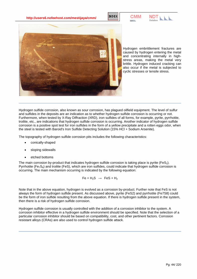
Hydrogen embrittlement fractures are caused by hydrogen entering the metal and concentrating internally in high-stress areas, making the metal very brittle. Hydrogen induced cracking can also occur if the metal is subjected to cyclic stresses or tensile stress.
Hydrogen sulfide corrosion, also known as sour corrosion, has plagued oilfield equipment. The level of sulfur and sulfides in the deposits are an indication as to whether hydrogen sulfide corrosion is occurring or not. Furthermore, when tested by X-Ray Diffraction (XRD), iron sulfides of all forms, for example, pyrite, pyrrhotite, troilite, etc., are indications that hydrogen sulfide corrosion is occurring. Another indicator of hydrogen sulfide corrosion is a positive spot test for iron sulfides in the form of a yellow precipitate and a rotten eggs odor, when the steel is tested with Baroid's Iron Sulfide Detecting Solution (15% HCl + Sodium Arsenite). The topography of hydrogen sulfide corrosion pits includes the following characteristics:
• conically-shaped
• sloping sidewalls
• etched bottoms The main corrosion by-product that indicates hydrogen sulfide corrosion is taking place is pyrite (FeS2). Pyrrhotite (Fe7S8) and troilite (FeS), which are iron sulfides, could indicate that hydrogen sulfide corrosion is occurring. The main mechanism occurring is indicated by the following equation:
Fe + H2S → FeS + H2 Note that in the above equation, hydrogen is evolved as a corrosion by-product. Further note that FeS is not always the form of hydrogen sulfide present. As discussed above, pyrite (FeS2) and pyrrhotite (Fe7S8) could be the form of iron sulfide resulting from the above equation. If there is hydrogen sulfide present in the system, then there is a risk of hydrogen sulfide corrosion. Hydrogen sulfide corrosion is usually controlled with the addition of a corrosion inhibitor to the system. A corrosion inhibitor effective in a hydrogen sulfide environment should be specified. Note that the selection of a particular corrosion inhibitor should be based on compatibility, cost, and other pertinent factors. Corrosion resistant alloys (CRAs) are also used to control hydrogen sulfide attack.

http://users6.nofeehost.com/mestijaya/cmm/
Pg: 45/ 220
Sulfide Stress Cracking - NACE MR0175 The NACE Standard MR0175, "Sulfide Stress Corrosion Cracking Resistant Metallic Materials for Oil Field
Equipment" is widely used throughout the world. The standard specifies the proper materials, heat treat
conditions and strength levels required to provide good service life in sour gas and oil environments. NACE
(National Association of Corrosion Engineers) is a worldwide technical organization which studies various
aspects of corrosion and the damage that may result in refineries, chemical plants, water systems, and other
industrial systems.
History
MR0175 was first issued in 1975, but the origin of the document dates to 1959 when a group of engineers in
Western Canada pooled their experience in successful handling of sour gas. The group organized as NACE
committee T-1B and in 1963 issued specification 1B163, "Recommendations of Materials for Sour Service." In
1965, NACE organized the nationwide committee T-1F-1 which issued 1F166 in 1966 and MR0175 in 1975.
The specification is revised on an annual basis.
NACE committee T-1F-1 continues to have responsibility for MR0175. All revisions and additions must be
unanimously approved by the 500-plus member committee T-1, Corrosion Control in Petroleum Production.
MR0175 is intended to apply only to oil field equipment, flow line equipment, and oil field processing facilities
where H2S is present. Only sulfide stress cracking (SSC) is addressed. Users are advised that other forms of
failure mechanisms must be considered in all cases. Failure modes, such as severe general corrosion,
chloride stress corrosion cracking, hydrogen blistering or step-wise cracking are outside the scope of the
document. Users must carefully consider the process conditions when selecting materials.
While the standard is intended to be used only for oil field equipment, industry has taken MR0175 and applied
it to many other areas including refineries, LNG plants, pipelines, and natural gas systems. The judicious use
of the document in these applications is constructive and can help prevent SSC failures wherever H2S is
present.
Requirements The various sections of MR0175 cover the commonly available forms of materials and alloy systems. The
requirements for heat treatment, hardness levels, conditions of mechanical work, and post-weld heat treatment
are addressed for each form of material. Fabrication techniques, bolting, platings, and coatings are also
addressed.

http://users6.nofeehost.com/mestijaya/cmm/
Pg: 46/ 220
Figure 1
Figure 2
Figures 1 and 2 taken from MR0175 define the sour systems where SSC may occur. Low concentrations of
H2S at low pressures are considered outside the scope of the document. The low stress levels at low
pressures or the inhibitive effects of oil may give satisfactory performance with standard commercial
equipment. Many users, however, have elected to take a conservative approach and specify NACE
compliance any time a measurable amount of H2S is present. The decision to follow MR0175 must be made by

http://users6.nofeehost.com/mestijaya/cmm/
Pg: 47/ 220
the user based on economic impact, the safety aspects should a failure occur, and past field experience.
Legislation can impact the decision as well. MR0175 must now be followed by law for sour applications under
several jurisdictions; Texas (Railroad Commission), off-shore (under U.S. Minerals Management Service), and
Alberta, Canada (Energy Conservation Board).
The Basics of Sulfide Stress Cracking
Figure 3
SSC develops in aqueous solutions as corrosion forms on a material. Hydrogen ions are a product of many
corrosion processes (Figure 3). These ions pick up electrons from the base material producing hydrogen
atoms. At that point, two hydrogen atoms may combine to form a hydrogen molecule. Most molecules will
eventually collect, form hydrogen bubbles, and float away harmlessly. Some percentage of the hydrogen
atoms will diffuse into the base metal and embrittle the crystalline structure. When the concentration of
hydrogen becomes critical and the tensile stress exceeds the threshold level, SSC occurs. H2S does not
actively participate in the SSC reaction; sulfides promote the entry of the hydrogen atoms into the base
material.
In many instances, particularly among carbon and low alloy steels, the cracking will initiate and propagate
along the grain boundaries. This is called intergranular stress cracking. In other alloy systems or under specific
conditions, the cracking will propagate through the grains. This is called transgranular stress corrosion
cracking. Sulfide stress cracking is most severe at ambient temperature, 20° to 120°F (-7° to 49°C). Below
20°F (-7°C) the diffusion rate of the hydrogen is so slow that the critical concentration is never reached. Above
120°F (49°C) the diffusion rate is so fast that the hydrogen passes through the material in such a rapid manner
that the critical concentration is not reached. The occurrence of stress corrosion cracking above 120°F (49°C)
is still likely and must be carefully considered when selecting material. In most cases, the stress corrosion
cracking will not be SSC but some other form. Chloride stress corrosion cracking is likely in deep sour wells as
most exceed 300°F (149°C) and contain significant chloride levels.

http://users6.nofeehost.com/mestijaya/cmm/
Pg: 48/ 220
Figure 4
The susceptibility of a material to SSC is directly related to its strength or hardness level. This is true for
carbon steels, stainless steels, and nickel based alloys. When carbon or alloy steel is heat treated to
progressively higher hardness levels, the time to failure decreases rapidly for a given stress level (Figure 4).
Years of field experience have shown that good SSC resistance is obtained below 22 HRC for the carbon and
low alloy steels. SSC can still occur below 22 HRC, but the likelihood of failure is greatly reduced.
Carbon Steel
Carbon and low alloy steels have acceptable resistance to SSC provided their processing is carefully
monitored. The hardness must be less than 22 HRC. If welding or significant cold working is done, stress relief
is required. Even though the base metal hardness of a carbon or alloy steel is less than 22 HRC, areas of the
heat effected zone will be harder. Post-weld heat treatment will eliminate these excessively hard areas.
ASME SA216 grades WCB and WCC are the most commonly used body casting materials. It is Fishers™
policy to stress relieve all WCB and WCC castings to MR0175 whether they have been welded or not. This
eliminates the chance of a weld repair going undetected and not being stress-relieved.
ASME SA352 grades LCB and LCC are very similar to WCB and WCC. They are impact tested at -50°F (-
46°C) to ensure good toughness in low temperature service. LCB and LCC are used in the northern U.S.,
Alaska, and Canada where temperatures commonly drop below the -20°F (-32°C) permitted for WCB. All LCB
and LCC castings to MR0175 are also stress-relieved.
Cast Iron
Gray, austenitic, and white cast irons cannot be used for any pressure retaining parts, due to low ductility.
Ferritic ductile iron to ASTM A395 is acceptable when permitted by ANSI, API, or industry standards.
Stainless Steel
UNS S41000 stainless steel (410 stainless steel) and other martensitic grades must be double tempered to a
maximum allowable hardness level of 25 HRC. Post-weld heat treatment is also required. S41600 stainless
steel is similar to S41000 with the exception of a sulfur addition to produce free machining characteristics. Use
of free machining steels is not permitted by MR0175.

http://users6.nofeehost.com/mestijaya/cmm/
Pg: 49/ 220
CA6NM is a modified version of the cast S41000 stainless steel. MR0175 allows its use, but specifies the
exact heat treatment required. Generally, the carbon content must be restricted to 0.3 percent maximum to
meet the 23 HRC maximum hardness. Post-weld heat treatment is required for CA6NM.
The austenitic stainless steels have exceptional resistance to SSC in the annealed condition. The standard
specifies that these materials must be 22 HRC maximum and free of cold work to prevent SSC. The cast and
wrought equivalents of 302, 304, 304L, 305, 308, 309, 310, 316, 316L, 317, 321, and 347 are all acceptable
per MR0175.
Post-weld heat treatment of the 300 Series stainless steels is not required. The corrosion resistance may be
effected by welding. However, this can be controlled by using the low carbon grades, or low heat input levels
and low interpass temperatures.
Wrought S17400 (17-4PH) stainless steel is allowed, but must be carefully processed to prevent SSC. The
standard now gives two different acceptable heat treatments for S17400. One treatment is the double H1150
heat treatment which requires exposing the material at 1150°F (621°C) for four hours followed by air cooling
and then exposing for another four hours at 1150°F (621°C). A maximum hardness level of 33 HRC is
specified. The second heat treatment is the H1150M treatment. First, the material is exposed for two hours at
1400°F (760°C), then air cooled and exposed for four hours at 1150°F (621°C). The maximum hardness level
is the same for this condition.
CB7Cu-1 (Cast 17-4PH) is not approved per MR0175. However, many users have successfully applied it for
trim parts in past years in the same double heat treated conditions as the wrought form.
Two high strength stainless steel grades are acceptable for MR0175. The first is S66286 (grade 660 or A286)
which is a precipitation hardening alloy with excellent resistance to SSC and general corrosion. The maximum
hardness level permitted is 35 HRC.
The second material is S20910 (XM-19) which is commonly called Nitronic 50R. This high strength stainless
steel has excellent resistance to SSC and corrosion resistance superior to S31600 or S31700. The maximum
allowable hardness is 35 HRC. The "high strength" condition, which approaches 35 HRC, can only be
produced by hot working methods. Cold drawn S20910 is also acceptable for shafts, stems, and pins. It is our
experience that the SSC resistance of S20910 is far superior to S17400 or other austenitic stainless steels at
similar hardness levels. The only other materials with similar stress cracking resistance at these strength levels
are the nickel-based alloys which are, of course, much more expensive. A few duplex stainless steels are now
acceptable per MR0175. Wrought S31803 (2205) and S32550 (Ferralium 255) are acceptable to 28 HRC.
Wrought S32404 (Uranus 50) is acceptable to 20 HRC. Only one cast duplex stainless steel is acceptable,
alloy Z 6CNDU20.08M, NF A 320-55 French National Standard.
Nonferrous Alloys
The final category in MR0175 is the nonferrous materials section. In general, the nickel-based alloys are
acceptable to a maximum hardness level of 35 HRC. All have excellent resistance to SSC. Commonly used
acceptable materials include nickel-copper alloys N04400 (alloy 400) and N04405 (alloy 405) and the

http://users6.nofeehost.com/mestijaya/cmm/
Pg: 50/ 220
precipitation hardening alloy N05500 (K500). The nickel-iron-chromium alloys include alloys N06600 (alloy 600)
and N07750 (alloy X750). The acceptable nickel-chromium-molybdenum alloys include alloys N06625 (alloy
625), and N10276 (alloy C276). The precipitation hardening grade N07718 (alloy 718) is also acceptable to 40
HRC. Where high strength levels are required along with good machinability, The Emerson Process
Management Regulator Division uses N05500, N07718, N07750, or N09925 (alloy 925). They can be drilled or
turned, then age hardened. Several cobalt based materials are acceptable, including R30035 (alloy MP35N),
R30003 (Elgiloy), and R30605 (Haynes 25 or L605).
Aluminum based and copper alloys may be used for sour service, but the user is cautioned that severe
corrosion attack may occur on these materials. They are seldom used in direct contact with H2S.
Several wrought titanium grades are now included in MR0175. The only common industrial alloy is R50400
(grade 2).
Springs
Springs in compliance with NACE represent a difficult problem. To function properly, springs must have very
high strength (hardness) levels. Normal steel and stainless steel springs would be very susceptible to SSC and
fail to meet MR0175.
In general, very soft, low strength materials must be used. Of course, these materials produce poor springs.
The two exceptions allowed are the cobalt based alloys, such as R30003, which may be cold worked and
hardened to a maximum hardness of 60 HRC and alloy N07750 which is permitted to 50 HRC.
Coatings
Coatings, platings, and overlays may be used provided the base metal is in a condition which is acceptable per
MR0175. The coatings may not be used to protect a base material which is susceptible to SSC. Coatings
commonly used in sour service are chromium plating, electroless nickel (ENC) and ion nitriding. Overlays and
castings commonly used include CoCr-A (StelliteR or alloy 6), R30006 (alloy 6B), and NiCr-C (ColmonoyR 6)
nickel-chromium-boron alloys. Tungsten carbide alloys are acceptable in the cast, cemented, or thermally
sprayed conditions. Ceramic coatings such as plasma sprayed chromium oxide are also acceptable.
ENC is often used by the Emerson Process Management Regulator Division as a wear-resistant coating. As
required by MR0175, it is applied only to acceptable base metals. ENC has excellent corrosion resistance in
sour, salt containing environments.
Stress Relieving
Many people have the misunderstanding that stress relieving following machining is required by MR0175.
Provided good machining practices are followed using sharp tools and proper lubrication, the amount of cold
work produced is negligible. SSC resistance will not be affected. MR0175 actually permits the cold rolling of
threads, provided the component will meet the heat treat conditions and hardness requirements specified for
the given parent material. Cold deformation processes such as burnishing are also acceptable.

http://users6.nofeehost.com/mestijaya/cmm/
Pg: 51/ 220
Bolting
Bolting materials must meet the requirements of MR0175 when bolting is directly exposed to a sour
environment. Standard ASTM A193 grade B7 bolts or A194 grade 2H nuts can be used per MR0175 provided
they are outside of the sour environment. If the bolting will be deprived atmospheric contact by burial,
insulation, or flange protectors, then grades of bolting such as B7 and 2H are unacceptable. The most
commonly used fasteners for "exposed" applications are ASTM A193 grade B7M bolts and A194 grade 2M
nuts. They are tempered and hardness tested versions of the B7 and 2H grades. HRC 22 is the maximum
allowable hardness.
Many customers use only B7M bolting for bonnet, packing box, and flange joints. This reduces the likelihood of
SSC if a leak develops and goes undetected or unrepaired for an extended time. It must be remembered,
however, that use of lower strength bolting materials such as B7M often requires pressure vessel derating.
Composition Materials
MR0175 does not address elastomer and polymer materials. However, the importance of these materials in
critical sealing functions cannot be overlooked. User experience has been successful with elastomers such as
nitrile, neoprene, fluoroelastomer (FKM), and perfluoroelastomer (FFKM). In general, fluoropolymers such as
teflon (TFE) can be applied without reservation within their normal temperature range.
Codes and Standards
Applicable ASTM, ANSI, ASME, and API standards are used along with MR0175 as they would normally be
used for other applications. The MR0175 requires that all weld procedures be qualified to these same
standards. Welders must be familiar with the procedures and capable of making welds which comply.
The Commercial Application of NACE
Special documentation of materials to MR0175 is not required by the standard and NACE itself does not issue
any type of a certification. It is the producer's responsibility to properly monitor the materials and processes as
required by MR0175.
It is not uncommon for manufacturers to "upgrade" standard manufactured components to MR0175 by
hardness testing. This produces a product which complies with MR0175, but which may not provide the best
solution for the long-term. If the construction was not thoroughly recorded at the outset, it may be difficult to get
replacement parts in the proper materials. The testing necessary to establish that each part complies is quite
expensive. And, due to the "local" nature of a hardness test, there is also some risk that "upgraded" parts do
not fully comply.
With proper in-house systems, it is quite simple to confidently produce a construction which can be certified to
MR0175 without the necessity of after manufacture testing. This eliminates many costly extras and additionally
provides a complete record of the construction for future parts procurement. An order entry, procurement, and

http://users6.nofeehost.com/mestijaya/cmm/
Pg: 52/ 220
manufacturing system which is integrated and highly structured is required in order to confidently and
automatically provide equipment which complies.
Due to its hierarchical nature and its use by all company functions, the Emerson Process Management
Regulator Division system is ideal for items such as MR0175 which requires a moderate degree of control
without undue cost. In order to illustrate the system used by the Emerson Process Management Regulator
Division, an example will be used.
Most products produced by the Emerson Process Management Regulator Division (including products to
MR0175) will be specified by a Fisher Standard (FS) number. These numbers (e.g. FSED-542) completely
specify a standardized construction including size, materials, and other characteristics. The FS number is a
short notation which represents a series of part groups (modules) describing the construction. One module
may represent a 3-inch WCB valve body with ANSI Class 300 flanges, another may specify a certain valve
plug and seat ring. The part numbers which make up these modules are composed of a drawing number and a
material/finish identifier. The drawing describes the dimensions and methods used to make the part, while the
material/finish reference considers material chemistry, form, heat treatment, and a variety of other variables.
The part number definition also includes a very specific "material reference number" which is used to identify a
material specification for purchase of materials. The material specification includes the ASME designation as
well as additional qualifiers, as necessary, to ensure compliance with specifications such as NACE MR0175.
For NACE compliant products, an FS number and a NACE option are generally specified. The FS number
establishes the standard construction variation. The option modifies the construction and materials to comply
totally with MR0175 requirements. The option eliminates certain standard modules and replaces them with
NACE suitable modules. Each part in a NACE suitable module has been checked to assure that it complies to
the specification in form and manufacturing method and that it is produced from an appropriate material.
It is due to this top-to-bottom system integrity that the Emerson Process Management Regulator Division can
be confident of MR0175 compliance without the need for extensive test work. At each level of the system
documentation, there are specific references to and requirements for compliance to MR0175. Further, since
the construction is permanently documented at all levels of detail, it is possible to confidently and simply
procure replacement parts at any future date.
Test documentation is available in a variety of forms, including certificates of compliance, hardness test data,
chemical and physical test reports, and heat treat reports. Since these items will have some cost associated
with them, it is important to examine the need for documentation in light of the vendor's credibility and
manufacturing control systems. The Emerson Process Management Regulator Division's normal
manufacturing processes and procedures assure that all NACE specified products will comply without the need
for additional test expense.

http://users6.nofeehost.com/mestijaya/cmm/
Pg: 53/ 220
SRB (Microbial Influenced Corrosion)
Microbe Information
The mechanisms commonly thought to be involved in MIC include:
• Cathodic depolarization, whereby the cathodic rate limiting step is accelerated by micro-biological action.
• Formation of occluded surface cells, whereby microorganisms form "patchy" surface colonies. Sticky polymers attract and aggregate biological and non-biological species to produce crevices and concentration cells, the basis for accelerated attack.
• Fixing of anodic reaction sites, whereby microbiological surface colonies lead to the formation of corrosion pits, driven by microbial activity and associated with the location of these colonies.
• Under-deposit acid attack, whereby corrosive attack is accelerated by acidic final products of the MIC "community metabolism", principally short-chain fatty acids.
Microbes fall into two basic groups, aerobic and anaerobic. These two groups are based on the kind of environment they prefer, either with or without oxygen. Slime formers form a diverse group of aerobic bacteria. Common anaerobic bacteria include Sulfur/sulfate reducing bacteria (SRB's) and organic acid formers.
Microbes tend to form colonies, with different characteristics from the outside to inside. On the outside, "slimers" may produce polymers (slime) that attract inorganic material, making the colony look like a pile of mud and debris. These aerobic organisms can efficiently use up all available oxygen, giving anaerobic microbes (SRB's) inside the colony a hospitable environment, allowing enhanced corrosion under the colony.
Microbially influenced corrosion (MIC) is a special danger when steels or alloys of aluminum and copper are in constant contact with nearly neutral water, of pH 4 to 9, 50° to 122°F (10° to 50°C), especially when stagnant. Microbially influenced corrosion mostly takes the form of pitting corrosion.
Corrosion products and effects include iron sulfates, slime, plugging, and bacteria growths. Sulfate-reducing bacteria (SRB) are anaerobic bacteria which metabolize sulfates (SO4
2-) and produce sulfuric acids or H2S, thus introducing hydrogen sulfide into the system. SRB colonies can also form deposits that are conducive to under-deposit corrosion (crevice corrosion.)
Where Found
Water storage tanks are a common site where MIC occurs. SRB's can contaminate tanks, which must then be cleaned and sterilized because it is impossible for biocides to penetrate the large amounts of sludge and debris in tank bottoms. Flow lines are another common MIC site, especially at the bottom of the line where water accumulates. MIC has also been detected at the 3 o'clock and 9 o'clock positions, presumably at the oil and water interface.
Prevention / Mitigation
To reduce or prevent microbial corrosion: Drilling - biocides Production - biocides, chlorine dioxide Flowlines - biocides, chlorine dioxide Cost considerations - Continuous vs. batch; EPA; biostat vs. biocide

http://users6.nofeehost.com/mestijaya/cmm/
Pg: 54/ 220
Bacterial attack is usually characterized by rounded pits with etched sides, edges, and bottoms.
MIC pits often have a terraced effect.
Although MIC normally occurs at the bottom of the line where water accumulates, it has also been detected at the 3 o'clock and 9 o'clock positions, presumably at the oil and water interface.

http://users6.nofeehost.com/mestijaya/cmm/
Pg: 55/ 220
One of the quick texts for SRB is the pipe cleaner test. Positive results are shown in these examples.
Bacterial growths tend to thrive in a downhole environment. Bacteria tend to propagate faster in the presence of water or liquid. There are many tests that can be run to determine the presence or absence of sulfate reducing bacteria (SRB), acid producing bacteria (APB), and general heterotopic bacteria (GHB). Also, the presence of aerobes and anaerobes can be determined. The topography of microorganism influenced corrosion pits includes the following characteristics:
• volcano-shaped craters
• bulls-eye patterns
• terraced sidewalls
• sloping edges
• etched edges
Bacterial counts are usually reported to the nearest power of 10. Hence, there could be 100 to 1000 colonies per milliliter of SRB, 10 to 100 colonies per milliliter of APB, and 1000 to 10000 colonies per milliliter of GHB. Additional counts can be given for aerobes and anaerobes. Note that some testing facilities will only report one figure, for example, 1000 colonies per milliliter of SRB. This should be taken as the upper limit, and would equate to 100 to 1000 colonies per milliliter of SRB. Bacteria is usually controlled by the addition of biocide to the system. Biocides help to reduce the bacterial counts, and hence control Microorganism Influenced Corrosion. Note that the selection of a particular biocide should be based on compatibility, cost, and other pertinent factors.
More on MIC
Administrator
v3

http://users6.nofeehost.com/mestijaya/cmm/
Pg: 56/ 220
http://hyperphysics.phy-astr.gsu.edu/hbase/chemical/corrosion.html

http://users6.nofeehost.com/mestijaya/cmm/
Pg: 57/ 220
Chapter 2: Forms of Corrosion
The forms of corrosion described here use the terminology in use at NASA-KSC. There are other equally valid methods of classifying corrosion, and no universally-accepted terminology is in use. Keep in mind that a given situation may lead to several forms of corrosion on the same piece of material.
Illustration Form of Corrosion
Uniform Corrosion
This is also called general corrosion. The surface effect produced by most direct chemical attacks (e.g., as by an acid) is a uniform etching of the metal.
Galvanic Corrosion
Galvanic corrosion is an electrochemical action of two dissimilar metals in the presence of an electrolyte and an electron conductive path. It occurs when dissimilar metals are in contact.

http://users6.nofeehost.com/mestijaya/cmm/
Pg: 58/ 220
Concentration Cell Corrosion
Concentration cell corrosion occurs when two or more areas of a metal surface are in contact with different concentrations of the same solution.
Pitting Corrosion
Pitting corrosion is localized corrosion that occurs at microscopic defects on a metal surface. The pits are often found underneath surface deposits caused by corrosion product accumulation.

http://users6.nofeehost.com/mestijaya/cmm/
Pg: 59/ 220
Crevice Corrosion
Crevice or contact corrosion is the corrosion produced at the region of contact of metals with metals or metals with nonmetals. It may occur at washers, under barnacles, at sand grains, under applied protective films, and at pockets formed by threaded joints.
Filiform Corrosion
This type of corrosion occurs on painted or plated surfaces when moisture permeates the coating. Long branching filaments of corrosion product extend out from the original corrosion pit and cause degradation of the protective coating.
Intergranular Corrosion
Intergranular corrosion is an attack on or adjacent to the grain boundaries of a metal or alloy.

http://users6.nofeehost.com/mestijaya/cmm/
Pg: 60/ 220
Stress Corrosion Cracking
Stress corrosion cracking (SCC) is caused by the simultaneous effects of tensile stress and a specific corrosive environment. Stresses may be due to applied loads, residual stresses from the manufacturing process, or a combination of both.
Corrosion Fatigue
Corrosion fatigue is a special case of stress corrosion caused by the combined effects of cyclic stress and corrosion. No metal is immune from some reduction of its resistance to cyclic stressing if the metal is in a corrosive environment.
Fretting Corrosion
The rapid corrosion that occurs at the interface between contacting, highly loaded metal surfaces when subjected to slight vibratory motions is known as fretting corrosion.

http://users6.nofeehost.com/mestijaya/cmm/
Pg: 61/ 220
Erosion Corrosion
Erosion corrosion is the result of a combination of an aggressive chemical environment and high fluid-surface velocities.
Dealloying
Dealloying is a rare form of corrosion found in copper alloys, gray cast iron, and some other alloys. Dealloying occurs when the alloy loses the active component of the metal and retains the more corrosion resistant component in a porous "sponge" on the metal surface.
Hydrogen Damage
Hydrogen embrittlement is a problem with high-strength steels, titanium, and some other metals. Control is by eliminating hydrogen from the environment or by the use of resistant alloys.

http://users6.nofeehost.com/mestijaya/cmm/
Pg: 62/ 220
Corrosion in Concrete
Concrete is a widely-used structural material that is frequently reinforced with carbon steel reinforcing rods, post-tensioning cable or prestressing wires. The steel is necessary to maintain the strength of the structure, but it is subject to corrosion.
Microbial Corrosion
Microbial corrosion (also called microbiologically -influenced corrosion or MIC) is corrosion that is caused by the presence and activities of microbes. This corrosion can take many forms and can be controlled by biocides or by conventional corrosion control methods.
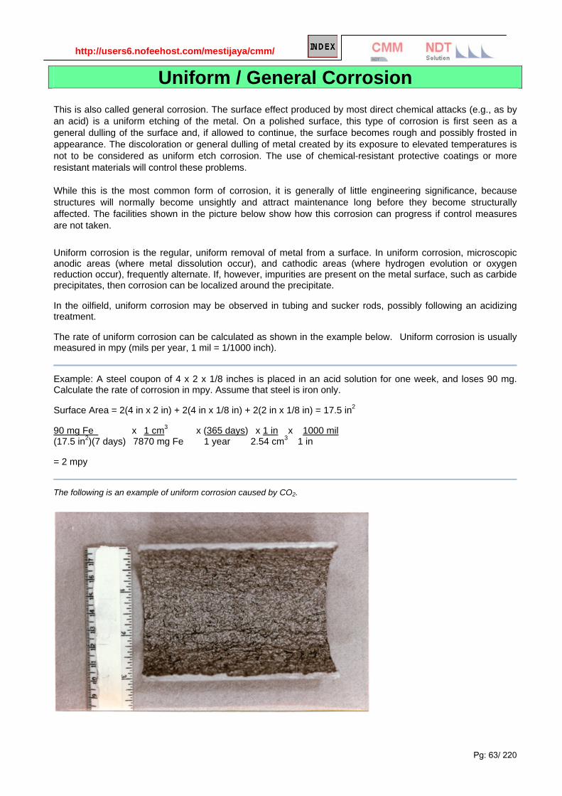
http://users6.nofeehost.com/mestijaya/cmm/
Pg: 63/ 220
Uniform / General Corrosion This is also called general corrosion. The surface effect produced by most direct chemical attacks (e.g., as by an acid) is a uniform etching of the metal. On a polished surface, this type of corrosion is first seen as a general dulling of the surface and, if allowed to continue, the surface becomes rough and possibly frosted in appearance. The discoloration or general dulling of metal created by its exposure to elevated temperatures is not to be considered as uniform etch corrosion. The use of chemical-resistant protective coatings or more resistant materials will control these problems. While this is the most common form of corrosion, it is generally of little engineering significance, because structures will normally become unsightly and attract maintenance long before they become structurally affected. The facilities shown in the picture below show how this corrosion can progress if control measures are not taken.
Uniform corrosion is the regular, uniform removal of metal from a surface. In uniform corrosion, microscopic anodic areas (where metal dissolution occur), and cathodic areas (where hydrogen evolution or oxygen reduction occur), frequently alternate. If, however, impurities are present on the metal surface, such as carbide precipitates, then corrosion can be localized around the precipitate.
In the oilfield, uniform corrosion may be observed in tubing and sucker rods, possibly following an acidizing treatment.
The rate of uniform corrosion can be calculated as shown in the example below. Uniform corrosion is usually measured in mpy (mils per year, 1 mil = 1/1000 inch).
Example: A steel coupon of 4 x 2 x 1/8 inches is placed in an acid solution for one week, and loses 90 mg. Calculate the rate of corrosion in mpy. Assume that steel is iron only.
Surface Area = 2(4 in x 2 in) + 2(4 in x 1/8 in) + 2(2 in x 1/8 in) = 17.5 in2
90 mg Fe x 1 cm3 x (365 days) x 1 in x 1000 mil (17.5 in2)(7 days) 7870 mg Fe 1 year 2.54 cm3 1 in
= 2 mpy
The following is an example of uniform corrosion caused by CO2.

http://users6.nofeehost.com/mestijaya/cmm/
Pg: 64/ 220
DESCRIPTION
General attack is typically caused by uniform general corrosion. Uniform corrosion can be described as follows: Corrosion reaction that takes place uniformly over the surface of the material, thereby causing a general thinning of the component and an eventual failure of the material.
Prevention or Remedial Action
• selection of a more corrosion resistant alloy (i.e. higher alloy content or more inert alloy)
• Utilize coatings to act as a barrier between metal and environment.
• Modify the environment or add chemical inhibitors to reduce corrosion rate.
• Apply cathodic protection.
• Replace with corrosion resistant non-metallic material.
Standard Test Methods
• ASTM G-31 - laboratory immersion corrosion testing of metals.
• ASTM G-4 - corrosion coupon tests in plant equipment.
• ASTM G-54 - practice for simple static oxidation testing.
• ASTM G-59 - practice for conducting potentiodynamic polarization resistance measurements.
• NACE TM0169 - laboratory corrosion testing of metals for the process industries.
• NACE TM0274 - dynamic corrosion testing of metals in high temperature water.
• ASTM B-117 - salt fog testing.
• ASTM G-85 - modified salt spray (fog) testing.
• ASTM D-2776 - test for corrosivity of water in the absence of heat transfer, by electrical methods.
• ASTM D-2688 - test for corrosivity of water in the absence of heat transfer, by weight loss methods.
• ASTM G-91 - test method of monitoring atmospheric SO2 using the sulfation plate technique.
Evaluation of General Corrosion
The predominant standard utilized for general corrosion assessment is ASTM G31. This standard gives guidelines for conducted simple immersion corrosion tests. Important considerations when conducting such tests in either the laboratory, field or plant setting are:
• Adequate solution volume for the surface area of corroding specimens in test.
• Electric isolation of the specimens from other specimens and any dissimilar metals in the system.
• Exposure of specimens to more than one phase, if applicable, since corrosion rates can change substantially in the different phases especially as water and impurity contents vary.
• Other test conditions such as flow rate, temperature, and aeration can produce variable results and locally high corrosion rates.
Methods of specimen surface preparation and post-test cleaning should be controlled as defined in the test standards.

http://users6.nofeehost.com/mestijaya/cmm/
Pg: 65/ 220
Galvanic Corrosion Galvanic corrosion is an electrochemical action of two dissimilar metals in the presence of an electrolyte and
an electron conductive path. It occurs when dissimilar metals are in contact.
It is recognizable by the presence of a buildup of corrosion at the joint between the dissimilar metals. For
example, when aluminum alloys or magnesium alloys are in contact with steel (carbon steel or stainless steel),
galvanic corrosion can occur and accelerate the corrosion of the aluminum or magnesium. This can be seen
on the photo above where the aluminum helicopter blade has corroded near where it was in contact with a
steel counterbalance.
Galvanic corrosion can be defined simply as being the effect resulting from contact between two different
metals or alloys in a conducting corrosive environment. Another term employed is galvanic coupling.
When a metal is immersed in any electrolytic solution, it is possible to measure its dissolution (natural
corrosion). For each solution, it is possible to establish a "galvanic series", that is, a ranking of different metals
and alloys as a function of this measured potential. When two different metals or alloys immersed in the same
solution are joined together electrically, an electric current will be set up between them, resulting from the short
circuit created. The coupling potential must of necessity lie between the two potentials for the uncoupled
metals and an increase in corrosion is generally observed in the less noble alloy and a decrease or
suppression of corrosion in the more noble material.
Due to modifications in the electrolyte, inversions may occur in the potential series. Thus, zinc covered with
corrosion products can become more "noble" than iron in certain hot waters (problem encountered in domestic

http://users6.nofeehost.com/mestijaya/cmm/
Pg: 66/ 220
hot water tanks); tin can become less "noble" than iron in organic acid solutions (problem encountered in food
cans).
For a given current between two different metals, the current density, and hence the rate of dissolution of the
less noble metal (anode,) will be greater the smaller the surface area SA of the anode. The use of unfavorable
surface area ratios has led to many expensive and often spectacular failures.
Some Means of preventing galvanic corrosion : choose metal combinations in which the constituents are as
close as possible in the corresponding galvanic series, avoid an unfavorable surface area ratio. Wherever
possible, use a seal, insulator, coating, etc. to avoid direct contact between two different metals, avoid
threaded junctions between materials widely separated in the galvanic series,
Galvanic Series in Sea Water
Noble (least active)
Platinum Gold Graphite Silver 18-8-3 Stainless steel, type 316 (passive) 18-8 Stainless steel, type 304 (passive) Titanium 13 percent chromium stainless steel, type 410 (passive) 7NI-33Cu alloy 75NI-16Cr-7Fe alloy (passive) Nickel (passive) Silver solder M-Bronze G-Bronze 70-30 cupro-nickel Silicon bronze Copper Red brass Aluminum bronze Admiralty brass Yellow brass 76NI-16Cr-7Fe alloy (active) Nickel (active) Naval brass Manganese bronze Muntz metal Tin Lead 18-8-3 Stainless steel, type 316 (active) 18-8 Stainless steel, type 304 (active) 13 percent chromium stainless steel, type 410 (active) Cast iron Mild steel Aluminum 2024 Cadmium Alclad Aluminum 6053 Galvanized steel
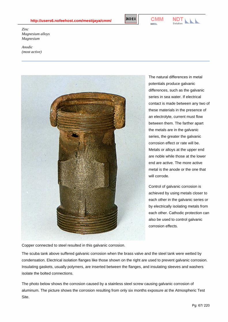
http://users6.nofeehost.com/mestijaya/cmm/
Pg: 67/ 220
Zinc Magnesium alloys Magnesium
Anodic (most active)
The natural differences in metal
potentials produce galvanic
differences, such as the galvanic
series in sea water. If electrical
contact is made between any two of
these materials in the presence of
an electrolyte, current must flow
between them. The farther apart
the metals are in the galvanic
series, the greater the galvanic
corrosion effect or rate will be.
Metals or alloys at the upper end
are noble while those at the lower
end are active. The more active
metal is the anode or the one that
will corrode.
Control of galvanic corrosion is
achieved by using metals closer to
each other in the galvanic series or
by electrically isolating metals from
each other. Cathodic protection can
also be used to control galvanic
corrosion effects.
Copper connected to steel resulted in this galvanic corrosion.
The scuba tank above suffered galvanic corrosion when the brass valve and the steel tank were wetted by
condensation. Electrical isolation flanges like those shown on the right are used to prevent galvanic corrosion.
Insulating gaskets, usually polymers, are inserted between the flanges, and insulating sleeves and washers
isolate the bolted connections.
The photo below shows the corrosion caused by a stainless steel screw causing galvanic corrosion of
aluminum. The picture shows the corrosion resulting from only six months exposure at the Atmospheric Test
Site.

http://users6.nofeehost.com/mestijaya/cmm/
Pg: 68/ 220
Galvanic corrosion occurs when two dissimilar metals are connected electrically and are in contact with an
electrolyte solution. One of the two metals is corroded preferentially; this metal is the anode and the un-
attacked metal is the cathode in the galvanic couple.
One example found in the oilfield is when a new section of pipe is added to an older section. The new pipe
becomes anodic and corrodes preferentially.
The Galvanic Series is a list sorted by corrosion
potentials for various alloys and pure metals in sea
water. It should not be confused with the emf
series. The emf series is a list of half-cell
potentials for standard state conditions measured
with respect to the standard hydrogen electrode,
while the Galvanic Series is based on corrosion
potentials in sea water.
Each metal or alloy has a unique corrosion
potential, Ecorr, when immersed in a corrosive
electrolyte. The most negative or active alloy is
always attacked preferentially by galvanic
corrosion, whereas the more noble metal becomes
cathodic (where reduction of hydrogen ions or
oxygen takes place) and is protected from corrosion.
Often the relative areas of each metal exposed are more important than their position in the galvanic series. If
the anode (more active metal) has a large area with respect to the cathode (more noble metal), the small area
of the cathode will not provide enough current to support uniform corrosion of the anode. However, if the
anode is small in comparison to the cathode, the rate of corrosion of the anode will be greatly accelerated and
corrosion will be localized adjacent to the more noble metal. When using coatings to prevent galvanic
corrosion, it is important to coat the more noble metal rather than the active metal, so that when defects are
introduced to the coat, the effects are not catastrophic.
There are some well-known examples of bimetallic (galvanic) corrosion. For example, N-80 couplings
connected to J-55 tubing always corrode preferentially to the J-55 grade at fairly rapid rates in wet CO2

http://users6.nofeehost.com/mestijaya/cmm/
Pg: 69/ 220
environment. Stainless steel valve in cast steel body also create a galvanic couple. Corrosion occurs
immediately adjacent to the more noble metal.
Galvanic corrosion is also frequently
observed in downhole pumps. Pump
barrels, balls and cages are usually
made of different alloys that may form
galvanic couples. Pump barrels are
also chromium plated for increased
abrasion resistance. However,
chromium plate may be scored by
sand grains or crack, which leads to
severe galvanic corrosion that is rapid
and usually catastrophic. Electro less
nickel plating also suffers from
galvanic effects
There are many subsets of galvanic
corrosion. A piece of metal is not uniform on the micro-scale, but contains grain boundaries and precipitates.
These precipitates are electrochemically different from the base metal, and may act as cathodes or anodes
with respect to the base metal.
Stainless steel, an alloy of chromium (Cr), nickel and iron, requires at least 12% Cr for passivity. If stainless
steel is heated to a high temperature (such as 425 C), chromium carbide precipitates will start to form along
grain boundaries, leaving a zone depleted of chromium. The precipitates will dissolve back into the grain
structure when heated above 850 C and fast cooled (quenched) back to room temperature.
Stainless steel may become sensitized during welding. The area surrounding the weld bead is known as a
heat affected zone (HAZ), a zone depleted of chromium, which will preferentially dissolve away. Therefore,
post-welding heat treatment or the use of low-carbon varieties is needed to prevent grain boundary corrosion.
The following picture shows a weld at the granular level:
Another well-known example of HAZ
corrosion in wet CO2 service is the failure
of upset J-55 tubing that has not been full-
length normalized (heat treated) after
upsetting. This form is known as
“ringworm” corrosion and it usually occurs
4-6 inches below the upset in the heat-
affected zone that has a different
microstructure from the rest of the tubing.

http://users6.nofeehost.com/mestijaya/cmm/
Pg: 70/ 220
Aluminum Galvanic Corrosion: The aluminum coupled to carbon steel in this hot water system corroded badly due to the galvanic couple.
Minimizing the Effect of Galvanic Attack
Galvanic attack can be minimized, as can other forms of corrosion, by correct design. The use of galvanically
compatible materials and the use of electrical insulation between dissimilar materials will help. Not coating
the anodic surface in case of pinhole damage to it is also useful as this could give rapid local attack.
The galvanic effect is the reason why different phases and segregated regions in alloy microstructures will
have varying resistance to corrosion. This effect is made good use of when polished specimens are selectively
attacked by etching in order to reveal and study microstructures features under the microscope. In stainless
steels Cr-depleted zones around Cr-rich second phases will be less noble and as such will be subject to highly
localized attack leading to inter-dendritic and/or intergranular forms of corrosion

http://users6.nofeehost.com/mestijaya/cmm/
Pg: 71/ 220
Stray Current Corrosion Electrical appliances were grounded to this gas pipeline. The stray currents led to
localized attack.
Testing Description
Accelerated corrosion which can occur when dissimilar metals are in electrical contact in the presence of an
electrolyte (i.e. conductive solution). An example of this corrosion phenomenon is increased rate of corrosion
of steel in seawater when in contact with copper alloys. Galvanic attack can be uniform in nature or localized at
the junction between the alloys depending on service conditions. Galvanic corrosion can be particularly severe
under conditions where protective corrosion films do not form or where they are removed by conditions of
erosion corrosion.
Prevention or Remedial Action
• selection of alloys which are similar in electrochemical behavior and/or alloy content.
• area ratio of more actively corroding material (anode) should be large relative to the more inert material (cathode).
• use coatings to limit cathode area.

http://users6.nofeehost.com/mestijaya/cmm/
Pg: 72/ 220
• insulate dissimilar metals.
• use of effective inhibitor.
Standard Test Methods
• ASTM G-71 - guide for conducting and evaluating galvanic corrosion tests in electrolytes.
• ASTM G-82 - guide for development and use of a galvanic series for predicting galvanic corrosion performance.
• ASTM G-104 - test method for assessing galvanic corrosion caused by the atmosphere.
Evaluation for Galvanic Corrosion
Many people utilized the standard galvanic series of materials in seawater to predict service performance
relative to galvanic corrosion. In fact, this galvanic series is specific to only seawater at near ambient
conditions. Other factors such as temperature and the presence of other chemical species can greatly affect
the rank ordering of materials. Such differences in environmental conditions can reverse galvanic couples
whereby the material expected to be the cathode may actually be the anode and experience severe corrosion.
In making galvanic corrosion measurements, it is good practice to try to separate the effects if crevices
between contacting materials and actual galvanic corrosion. This is the reason that in many tests, the
actual electrical coupling of the two materials is performed in a region protected from the environment or
externally from the environment. The external coupling is a good idea since it allows for measurement of
the mixed potential of the couple and the galvanic corrosion current. While the potential serves as a
measure of the thermodynamic driving force for galvanic corrosion, it is the galvanic corrosion current that
indicates the acceleration of corrosion by the influence of the galvanic couple.
More reading:
Galvanic Corrosion
http://www.key-to-steel.com/Articles/Art160.htm http://www.corrosionclinic.com/types_of_corrosion/galvanic_corrosion.htm http://www.roymech.co.uk/Useful_Tables/Corrosion/Cor_bi_met.html
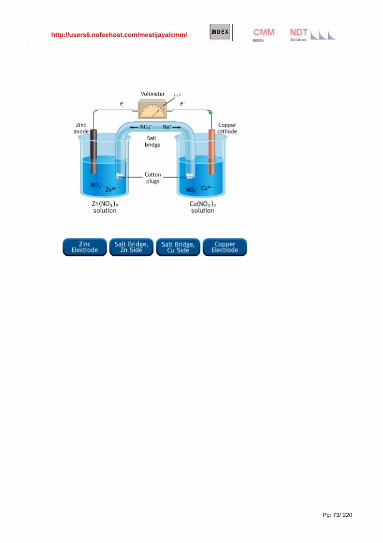
http://users6.nofeehost.com/mestijaya/cmm/
Pg: 73/ 220
Administrator
v3

http://users6.nofeehost.com/mestijaya/cmm/
Pg: 74/ 220
Concentration Cell Corrosion Concentration cell corrosion occurs when two or more areas of a metal surface are in contact with different concentrations of the same solution. There are three general types of concentration cell corrosion:
1. metal ion concentration cells
2. oxygen concentration cells, and
3. active-passive cells. Metal Ion Concentration Cells In the presence of water, a high concentration of metal ions will exist under faying surfaces and a low
concentration of metal ions will exist adjacent to the crevice created by the faying surfaces. An electrical
potential will exist between the two points. The area of the metal in contact with the low concentration of metal
ions will be cathodic and will be protected, and the area of metal in contact with the high metal ion
concentration will be anodic and corroded. This condition can be eliminated by sealing the faying surfaces in a
manner to exclude moisture. Proper protective coating application with inorganic zinc primers is also effective
in reducing faying surface corrosion.
Oxygen Concentration Cells
A water solution in contact with the metal surface will normally contain dissolved oxygen. An oxygen cell can
develop at any point where the oxygen in the air is not allowed to diffuse uniformly into the solution, thereby
creating a difference in oxygen concentration between two points. Typical locations of oxygen concentration
cells are under either metallic or nonmetallic deposits (dirt) on the metal surface and under faying surfaces
such as riveted lap joints. Oxygen cells can also develop under gaskets, wood, rubber, plastic tape, and other
materials in contact with the metal surface. Corrosion will occur at the area of low-oxygen concentration
(anode). The severity of corrosion due to these conditions can be minimized by sealing, maintaining surfaces
clean, and avoiding the use of material that permits wicking of moisture between faying surfaces.
Active-Passive Cells
Metals that depend on a tightly adhering passive film (usually an oxide) for corrosion protection; e.g., austenitic
corrosion-resistant steel, can be corroded by active-passive cells. The corrosive action usually starts as an
oxygen concentration cell; e.g., salt deposits on the metal surface in the presence of water containing oxygen
can create the oxygen cell. If the passive film is broken beneath the salt deposit, the active metal beneath the
film will be exposed to corrosive attack. An electrical potential will develop between the large area of the
cathode (passive film) and the small area of the anode (active metal). Rapid pitting of the active metal will
result. This type of corrosion can be avoided by frequent cleaning and by application of protective coatings.

http://users6.nofeehost.com/mestijaya/cmm/
Pg: 75/ 220

http://users6.nofeehost.com/mestijaya/cmm/
Pg: 76/ 220
Pitting Corrosion Passive metals, such as stainless steel, resist corrosive media and can perform well over long periods of time.
However, if corrosion does occur, it forms at random in pits. Pitting is most likely to occur in the presence of
chloride ions, combined with such depolarizers as oxygen or oxidizing salts. Methods that can be used to
control pitting include maintaining clean surfaces, application of a protective coating, and use of inhibitors or
cathodic protection for immersion service. Molybdenum additions to stainless steel (e.g. in 316 stainless) are
intended to reduce pitting corrosion.
The rust bubbles or tubercules on the cast iron above indicate that pitting is occurring. Researchers have
found that the environment inside the rust bubbles is almost always higher in chlorides and lower in pH (more
acidic) than the overall external environment. This leads to concentrated attack inside the pits.
Similar changes in environment occur inside crevices, stress corrosion cracks, and corrosion fatigue cracks. All
of these forms of corrosion are sometimes included in the term "occluded cell corrosion."

http://users6.nofeehost.com/mestijaya/cmm/
Pg: 77/ 220
Pitting corrosion can lead to unexpected catastrophic system failure. The split tubing above left was caused by
pitting corrosion of stainless steel. A typical pit on this tubing is shown above right.
Sometimes pitting corrosion can be quite small on the surface and very large below the surface. The figure
below left shows this effect, which is common on stainless steels and other film-protected metals. The pitting
shown below right (white arrow) led to the stress corrosion fracture shown by the black arrows.
Pitting Corrosion on Metal Surface
Pitting is one of the most destructive forms of corrosion as it will potential cause equipment failures due to
perforation / penetration. pitting generally occurs on metal surfaces protected by oxide film such as Stainless
steel, aluminum, etc. Typically for boiler and feed water system, pitting corrosion rate increase dramatically
with the increase of oxygen content in the fluid.

http://users6.nofeehost.com/mestijaya/cmm/
Pg: 78/ 220
Pitting can occur in any metal surfaces. Following are some pictures of pitting corrosion.
Pitting corrosion on external pipe surface
Pitting corrosion on external pipe surface
H2S Pitting corrosion on internal pipe surface

http://users6.nofeehost.com/mestijaya/cmm/
Pg: 79/ 220
Co2 Pitting corrosion on internal pipe surface
Mechanism
Lets look at figure below, oxygen rich fluid in contact with metal surface (at the top of the pit) will becomes
the cathode. At the bottom of the pit, low in oxygen level becomes the anode. this will form a complete
circuit where metal at the pit (FE) will be ionized to release electron (e) and form ion Ferum (FE2+), this
electron will travel to the top of pit to react with Oxygen (O2) (and water, H2O) to form ion hydroxides (OH-).
Ion Ferum (FE2+) will react with ion hydroxides (OH-) to form Ferum Oxide (Fe2O3) which typically a brown
rust. Deeper the pit leeser the oxygen content and higher the potential and pitting corrosion rate.
Severity of pitting corrosion
Knowing that pitting can cause failure due to perforation while the total corrosion, as measured by weight
lossm might be rather minimal, experience shown that rate of penetration may be 10 to 100 times that by general corrosion, pitting corrosion has been considered to be more dangerous than the uniform corrosion damage because it is very difficult to detect, predict and design against. General metal weight
loss method almost impossible to detect the internal pitting corrosion.
Pitting corrosion shape
Pits formed due to pitting corrosion can become wide and shallow or narrow and deep which can rapidly
perforate the wall thickness of a metal. Following picture demonstrate several types of pitting corrosion shape.
This has made it even more difficult to be detected especially undercutting, subsuface and horizontal type.
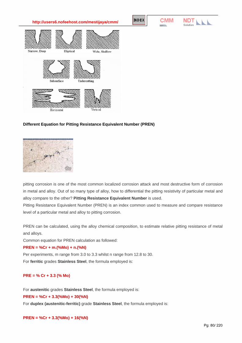
http://users6.nofeehost.com/mestijaya/cmm/
Pg: 80/ 220
Different Equation for Pitting Resistance Equivalent Number (PREN)
pitting corrosion is one of the most common localized corrosion attack and most destructive form of corrosion
in metal and alloy. Out of so many type of alloy, how to differential the pitting resistivity of particular metal and
alloy compare to the other? Pitting Resistance Equivalent Number is used.
Pitting Resistance Equivalent Number (PREN) is an index common used to measure and compare resistance
level of a particular metal and alloy to pitting corrosion.
PREN can be calculated, using the alloy chemical composition, to estimate relative pitting resistance of metal
and alloys.
Common equation for PREN calculation as followed:
PREN = %Cr + m.(%Mo) + n.(%N) Per experiments, m range from 3.0 to 3.3 whilst n range from 12.8 to 30.
For ferritic grades Stainless Steel, the formula employed is:
PRE = % Cr + 3.3 (% Mo)
For austenitic grades Stainless Steel, the formula employed is:
PREN = %Cr + 3.3(%Mo) + 30(%N) For duplex (austenitic-ferritic) grade Stainless Steel, the formula employed is:
PREN = %Cr + 3.3(%Mo) + 16(%N)

http://users6.nofeehost.com/mestijaya/cmm/
Pg: 81/ 220
For high Ni-Cr-Mo alloys e.g. Inconel 625, Hastelloy, etc, the formula employed is:
PREN = %Cr + 1.5(%Mo + %W + %Nb) Where:
Cr - Chromium
Mo - Molybdenum
W - Tungsten
Nb - Niobium
Pitting is one of main problem for material expose to seawater. Minimum PREN required for material expose to
seawater is 40. Duplex Stainless steel, Super duplex stainless steel, etc are exhibiting PREN > 40.
Description
Pitting corrosion is highly localized corrosion occurring on a metal surface. Pitting is commonly observed on
surfaces with little or no general corrosion. Pitting typically occurs as a process of local anodic dissolution
where metal loss is exacerbated by the presence of a small anode and a large cathode.
Prevention or Remedial Action
There are several preventive approaches to avoid pitting. There are:
• Proper material selection e.g. SS316 with molybdenum having higher pitting resistance compare to SS304
• Use higher alloys (ASTM G48) for increased resistance to pitting corrosion
• Control oxygen level by injecting oxygen scavenger in boiler water system
• Control pH, chloride concentration and temperature
• Cathodic protection and/or Anodic Protection
• Proper monitoring of oxygen & chloride contents by routine sampling
• Agitation of stagnant fluid
• increase velocity of media and/or remove deposits of solids from exposed metal surface.
• selection of alloy with higher alloy content (e.g. in stainless alloys higher Cr, Mo and N content
according to the following formula):
PI = Cr + 3.3(Mo) + X(N) where PI is pitting index and
x = 0 for ferritic stainless steels
x = 16 for duplex (austenitic/ferritic) stainless steels
x = 30 for austenitic stainless steels
For more severe pitting service in some environments Ti - and Zr - alloys may also be appropriate.
• Use of effective chemical inhibitor to enhance resistance to localized attack.

http://users6.nofeehost.com/mestijaya/cmm/
Pg: 82/ 220
• Deaeration of aerated environments to reduce localized corrosion through elimination of oxygen
concentration cell mechanism.
Standard Test Methods
• ASTM G-46 - practice for examination and evaluation of pitting corrosion.
• ASTM G-48 - test methods for pitting and crevice corrosion resistance of stainless steels and related
alloys by the use of ferric chloride solution.
• ASTM G - standard reference test method for making poteniostatic and potentiodynamic anodic
polarization measurements.
• ASTM G-61 - test method for conducting cyclic potentiodynamic polarization measurements for
localized corrosion susceptibility of iron, nickel or cobalt based alloys.
• NACE TM0274 - dynamic corrosion testing of metals in high temperature water.
• ASTM G-85 - modified salt spray (fog) testing.
Evaluation of Pitting Corrosion
The extent of pitting corrosion can vary greatly depending on the exposure conditions and surface condition of
the material. Commonly used methods to determine the pitting corrosion resistance are
• Simple exposure of corrosion coupons to standardized environments of know severity (ASTM
G48).
• Evaluation of coupons and metal surfaces with standardized techniques to categorize the
nature of the pitting attack (ASTM G46).
• Use of electrochemical techniques (ASTM G61) to characterize the current-potential
polarization behavior of the material in specific service environments to identify materials
susceptible to pitting attack.
Most important in studies of pitting corrosion are the use of visual examination and/or metallographic
techniques to characterize the physical nature of the localized corrosive attack. Electrochemical
measurements should always be supplemented by such techniques to obtain the most accurate indications.
Typically, the most relevant information is the maximum attack depth and/or rate since these parameters will
most directly indicate the serviceability of actual components in service.

http://users6.nofeehost.com/mestijaya/cmm/
Pg: 83/ 220
Crevice Corrosion This form of attack is generally associated with the presence of small volumes of stagnant solution in occluded
interstices, beneath deposits and seals, or in crevices, e.g. at nuts and rivet heads. Deposits of sand, dust,
scale and corrosion products can all create zones where the liquid can only be renewed with great difficulty.
This is also the case for flexible, porous or fibrous seals (wood, plastic, rubber, cements, asbestos, cloth, etc.).
Crevice corrosion is encountered particularly in metals and alloys which owe their resistance to the stability of
a passive film, since these films are unstable in the presence of high concentrations of Cl- and H+ ions.
The basic mechanism underlying crevice corrosion in passivatable alloys exposed to aerated chloride-rich
media is gradual acidification of the solution inside the crevice, leading to the appearance of highly aggressive
local conditions that destroy the passivity.
in an interstice, convection in the liquid is strongly impeded and the dissolved oxygen is locally rapidly
exhausted. A few seconds are sufficient to create a "differential aeration cell" between the small deaerated
interstice and the aerated remainder of the surface. However, "galvanic" corrosion between these two zones
remains inactive.
As dissolution of the metal M continues, an excess of Mn+ ions is created in the
crevice, which can only be compensated by electromigration of the Cl- ions (more
numerous in a chloride-rich medium and more mobile than OH- ions). Most
metallic chlorides hydrolyze, and this is particularly true for the elements in
stainless steels and aluminum alloys. The acidity in the crevice increases (pH 1-3)
as well as the Cl- ion concentration (up to several times the mean value in the
solution). The dissolution reaction in the crevice is then promoted and the oxygen
reduction reaction becomes localized on the external surfaces close to the
crevice. This "autocatalytic" process accelerates rapidly, even if several days or
weeks were necessary to get it under way.
Means of preventing or limiting crevice corrosion : Use welds rather than bolted
or riveted joints, design installations to enable complete draining (no corners or
stagnant zones), hydrofuge any interstices that cannot be eliminated, and in
particular, grease all seals and seal planes, use only solid, non-porous seals, etc.

http://users6.nofeehost.com/mestijaya/cmm/
Pg: 84/ 220
Crevice or contact corrosion is the corrosion produced at the region of contact of metals with metals or
metals with nonmetals. It may occur at washers, under barnacles, at sand grains, under applied protective
films, and at pockets formed by threaded joints. Whether or not stainless steels are free of pit nuclei, they are
always susceptible to this kind of corrosion because a nucleus is not necessary.
Cleanliness, the proper use of sealants, and protective coatings are effective means of controlling this
problem. Molybdenum-containing grades of stainless steel (e.g. 316 and 316L) have increased crevice
corrosion resistance.
The crevice corrosion shown above happened when an
aerospace alloy (titanium - 6 aluminum - 4 vanadium) was used
instead of a more corrosion-resistant grade of titanium. Special
alloying additions are added to titanium to make alloys which are
crevice corrosion resistant even at elevated temperatures.
Screws and fasteners have are common sources of crevice
corrosion problems. The stainless steel screws shown below
corroded in the moist atmosphere of a pleasure boat hull.
Crevice corrosion and pitting corrosion are related because they both require stagnant water, chloride, and
oxygen or carbon dioxide. The mechanism of corrosion is very similar for both.

http://users6.nofeehost.com/mestijaya/cmm/
Pg: 85/ 220
Crevice corrosion tends to occur in crevices (stagnant, shielded areas) such as those formed under gaskets,
washers, insulation material, fastener heads, surface deposits, disbonded coatings, threads, lap joints and
clamps.
TESTING DESCRIPTION
Crevice corrosion is localized corrosion which may occur in small areas of stagnant solution in crevices, joints
and under corrosion deposits (i.e. under deposit corrosion).
PREVENTION OR REMEDIAL ACTION
• redesign of equipment to eliminate crevices.
• close crevices with non-absorbent materials or incorporate a barrier to prevent of moisture penetration
into crevice.
• prevent or remove builds-up of scale or other solids on surface of material.
• use of one-piece or welded construction versus bolting or riveting.
• select more corrosion resistant or inert alloy (note: see pitting corrosion for more information).
STANDARD TEST METHODS
• ASTM G-48 - test methods for pitting and crevice corrosion resistance of stainless steels and related
alloys by the use of ferric chloride solution.
• ASTM G-78 - guide for crevice corrosion testing of iron-base and nickel-base stainless alloys in sea
water and other chloride-containing aqueous media.

http://users6.nofeehost.com/mestijaya/cmm/
Pg: 86/ 220
Evaluation of Crevice Corrosion
The principal reference for the evaluation of crevice corrosion is ASTM G78. The extent of crevice corrosion
can be greatly influenced by the nature of the crevice and the technique utilized in the exposure test. Typically,
tighter crevices promote greater localized corrosive attack. The use of serrated TFE or ceramic washers is one
of the most common methods for obtaining reproducible simulation of crevice corrosion. These washers are
bolted to the specimen using a corrosion resistant bolt with constant applied torque for each crevice washer
assembly. In most cases, the rate of crevice attack in not constant. Initially, there is an incubation period where
the attack rate is essentially zero. However, as the corrosivity of the crevice environment increases with
exposure time, the local attack rate can actually increase with time in test. Therefore, multiple exposure
periods may be needed to accurately assess crevice corrosion attack rates.

http://users6.nofeehost.com/mestijaya/cmm/
Pg: 87/ 220
Pitting Corrosion
Pitting Corrosion is "self nucleating" crevice corrosion, starting at occluded cells. Corrosion products often
cover the pits, and may form "chimneys". Pitting is considered to be more dangerous than uniform corrosion
damage because it is more difficult to detect, predict and prevent. A small, narrow pit with minimal overall
metal loss can lead to the failure of an entire engineering system.
Schematic of an actively growing pit in iron
Once initiated, both crevice and pitting corrosion can be explained by differential concentration cells, Cathodic
reactions, i. e. oxygen reduction or hydrogen evolution may start in the crevice or the pits. Large surface areas
will become cathodic and pits or crevices will become anodic and corrode. Metal dissolution will thus be
concentrated in small areas and will proceed at much higher rates than with uniform corrosion. Large crevices
are less likely to corrode because water movement causes mixing and replenishes oxygen, hydrogen ions,
bicarbonate or hydrogen sulfide.
The chloride ion acts as a catalyst in pitting and crevice corrosion. In other words, increases the corrosion rate
but is not used up in the reaction. It has the ability to absorb on the metal surface or the passive films and
polarize the metal, initializing localized corrosion. (e.g. pitting corrosion of austenitic stainless steels (304) in
salt water). This photo is an example of crevice corrosion on a tubing end.
Administrator
2

http://users6.nofeehost.com/mestijaya/cmm/
Pg: 88/ 220
Pitting corrosion is frequently observed in CO2 and H2S environments in the oilfield. Pits will generally initiate
due to local breakdown of corrosion product films on the surface and corrosion will proceed at an accelerated
rate. In sweet (CO2) systems, the pits are generally small with sharp edges and smooth rounded bottoms. Pits
may become connected as the corrosion damage increases. Corrosion products are dark brown to grayish
black and loosely adhering. In sour (H2S) systems, the pits are usually shallow round depressions with etched
bottoms and sloping sides. Generally, the pits are not connected, and corrosion products are black and tightly
adhering to the metal surface.
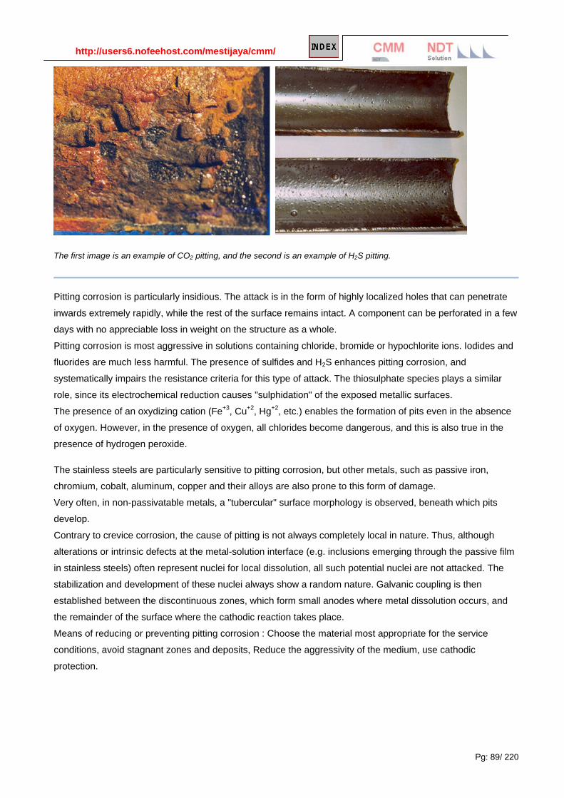
http://users6.nofeehost.com/mestijaya/cmm/
Pg: 89/ 220
The first image is an example of CO2 pitting, and the second is an example of H2S pitting.
Pitting corrosion is particularly insidious. The attack is in the form of highly localized holes that can penetrate
inwards extremely rapidly, while the rest of the surface remains intact. A component can be perforated in a few
days with no appreciable loss in weight on the structure as a whole.
Pitting corrosion is most aggressive in solutions containing chloride, bromide or hypochlorite ions. Iodides and
fluorides are much less harmful. The presence of sulfides and H2S enhances pitting corrosion, and
systematically impairs the resistance criteria for this type of attack. The thiosulphate species plays a similar
role, since its electrochemical reduction causes "sulphidation" of the exposed metallic surfaces.
The presence of an oxydizing cation (Fe+3, Cu+2, Hg+2, etc.) enables the formation of pits even in the absence
of oxygen. However, in the presence of oxygen, all chlorides become dangerous, and this is also true in the
presence of hydrogen peroxide.
The stainless steels are particularly sensitive to pitting corrosion, but other metals, such as passive iron,
chromium, cobalt, aluminum, copper and their alloys are also prone to this form of damage.
Very often, in non-passivatable metals, a "tubercular" surface morphology is observed, beneath which pits
develop.
Contrary to crevice corrosion, the cause of pitting is not always completely local in nature. Thus, although
alterations or intrinsic defects at the metal-solution interface (e.g. inclusions emerging through the passive film
in stainless steels) often represent nuclei for local dissolution, all such potential nuclei are not attacked. The
stabilization and development of these nuclei always show a random nature. Galvanic coupling is then
established between the discontinuous zones, which form small anodes where metal dissolution occurs, and
the remainder of the surface where the cathodic reaction takes place.
Means of reducing or preventing pitting corrosion : Choose the material most appropriate for the service
conditions, avoid stagnant zones and deposits, Reduce the aggressivity of the medium, use cathodic
protection.

http://users6.nofeehost.com/mestijaya/cmm/
Pg: 90/ 220
Tubercle on the surface of a copper tube (corrosion by type I pits in sanitary cold water).
Pitting corrosion on the wall of an Cr18-Ni10 austenitic stainless steel tank.

http://users6.nofeehost.com/mestijaya/cmm/
Pg: 91/ 220
Filiform Corrosion
This type of corrosion occurs under painted or plated surfaces when moisture permeates the coating. Lacquers and "quick-dry" paints are most susceptible to the problem. Their use should be avoided unless absence of an adverse effect has been proven by field experience. Where a coating is required, it should exhibit low water vapor transmission characteristics and excellent adhesion. Zinc-rich coatings should also be considered for coating carbon steel because of their cathodic protection quality.
Filiform corrosion normally starts at small, sometimes microscopic, defects in the coating. Lacquers and "quick-dry" paints are most susceptible to the problem. Their use should be avoided unless absence of an adverse effect has been proven by field experience. Where a coating is required, it should exhibit low water vapor transmission characteristics and excellent adhesion. Zinc-rich coatings should also be considered for coating carbon steel because of their cathodic protection quality.
The picture on the left shows filiform corrosion causing bleed-through on a welded tank. The picture on the right shows "worm-like" filiform corrosion tunnels forming under a coating at the Atmospheric Test Site.
Filiform corrosion is minimized by careful surface preparation prior to coating, by the use of coatings that are resistant to this form of corrosion (see above), and by careful inspection of coatings to insure that holidays, or holes, in the coating are minimized.

http://users6.nofeehost.com/mestijaya/cmm/
Pg: 92/ 220
Intergranular Corrosion Intergranular corrosion is an attack on or adjacent to the grain boundaries of a metal or alloy. A highly
magnified cross section of most commercial alloys will show its granular structure. This structure consists of
quantities of individual grains, and each of these tiny grains has a
clearly defined boundary that chemically differs from the metal
within the grain center. Heat treatment of stainless steels and
aluminum alloys accentuates this problem.
The picture above shows a stainless steel which corroded in the
heat affected zone a short distance from the weld. This is typical of
intergranular corrosion in austenitic stainless steels. This corrosion
can be eliminated by using stabilized stainless steels (321 or 347)
or by using low-carbon stainless grades (304L or 3I6L).
Heat-treatable aluminum alloys (2000, 6000, and 7000 series alloys) can also have this problem. See the
section on exfoliation corrosion below.
In most cases of corrosion, including uniform corrosion, the grain boundaries behave in essentially the same
way as the grains themselves. However, in certain conditions, the grain boundaries can undergo marked
localized attack while the rest of the material remains unaffected. The alloy disintegrates and loses its
mechanical properties.
This type of corrosion is due either to the presence of impurities in the boundaries, or to local enrichment or
depletion of one or more alloying elements. For example, small quantities of iron in aluminum or titanium
(metals in which iron has a low solubility), segregate to the grain boundaries where they can induce
intergranular corrosion. Certain precipitate phases (e.g. Mg5Al8, Mg2Si, MgZn2, MnAl6, etc.) are also known to
cause or enhance intergranular attack of high strength aluminum alloys, particularly in chloride-rich media.
The exfoliation corrosion phenomenon observed in rolled aluminum alloys is usually, but not always,
intergranular in nature. In this case, the corrosion products occupy a larger volume than the metal "consumed",
generating a high pressure on the slivers of uncorroded metal, leading to the formation of blisters.
Numerous alloy types can undergo intergranular attack, but the most important practical example is the
intergranular corrosion of austenitic stainless steels, related to chromium depletion in the vicinity of the
boundaries, due to the intergranular precipitation of chromium carbides (Cr23C6), during a "sensitizing" heat
treatment or thermal cycle.
Exfoliation Corrosion Exfoliation is a form of intergranular corrosion. It manifests itself by
lifting up the surface grains of a metal by the force of expanding
corrosion products occurring at the grain boundaries just below the
surface. It is visible evidence of intergranular corrosion and most
often seen on extruded sections where grain thickness is less than
in rolled forms. This form of corrosion is common on aluminum,
and it may occur on carbon steel.
(See also other section on exfoliation corrosion)

http://users6.nofeehost.com/mestijaya/cmm/
Pg: 93/ 220
The picture on the left shows exfoliation of aluminum. Exfoliation of carbon steel is apparent in the channel on
the coating exposure panel on the right. The expansion of the metal caused by exfoliation corrosion can create
stresses that bend or break connections and lead to structural failure.

http://users6.nofeehost.com/mestijaya/cmm/
Pg: 94/ 220
Description
Metals and alloys are composed of grains similar to sand grains in a common sandstone. Intergranular
corrosion refers to the selective corrosion of the grain boundary regions. This attack is very common in some
stainless steels and nickel alloys. Some aluminum alloys can also exhibit intergranular and exfoliation (i.e.
corrosion at grain boundary sites parallel to the metal surface where corrosion products force apart the metal).
Prevention or Remedial Action
• Heat treatment of alloy to remove phases from grain boundary regions which reduce corrosion
resistance (i.e. solution annealing).
• Use modified alloys which have eliminated such grain boundary phases through stabilizing elements
or reduced levels of impurities:
EXAMPLE: stainless steels such as AISI 304 or 316 can be "sensitized" by heating or welding in the
range 900 to 1500 F. This forms carbide precipitates which reduce corrosion resistance of grain
boundaries. The use of low carbon 304L or 316L will increase resistance to inter granular corrosion in
welded components. for prolonged service at high temperature stabilized stainless steels (i.e. aisi 321
and 347) will increase resistance to inter granular corrosion.
Standard Test Methods
• ASTM A 262 - practices for detecting susceptibility to intergranular attack in austenitic stainless steels.
• ASTM G-28 - test methods for detecting susceptibility to intergranular attack in wrought, nickel rich,
chromium-bearing alloys.
• ASTM G-34 - test method for exfoliation corrosion susceptibility in 2xxx and 7xxx series aluminum
alloys (EXCO test).
• ASTM G-66 - test method for visual assessment of exfoliation corrosion susceptibility of 5xxx series
aluminum alloys (asset test).

http://users6.nofeehost.com/mestijaya/cmm/
Pg: 95/ 220
• ASTM G-67 - test method for determining the susceptibility to inter granular corrosion of 5xxx series
aluminum alloys by mass loss after exposure to nitric acid (namlt test).
Evaluation of Intergranular Attack
The most common concern for stainless alloys is the influence of welding and/or heat treatment on
susceptibility to intergranular corrosion produced by carbide precipitation (i.e. senitization). Therefore, the
carbon content is an important metallurgical consideration with lower carbon (and nitrogen) materials or
materials that have been stabilized with additions of Ti or Nb showing lower tendencies to intergranular
corrosion. In evaluation, the tendencies for intergranular corrosion can vary greatly depending on the severity
of the test conditions and environment. Oftentimes, standardized environments are used such as those given
in ASTM A262.
Intergranular corrosion various alloys require the use of different environments:
• Aluminum alloys - acidified NaCl/HCl solution or HNO3solution.
• Magnesium alloys - NaCl/HF solution
• Copper alloys - NaCl solution with H2SO4 or HNO3.
• Lead alloys - Acetic acid or HF solutions
More reading on corrosion on stainless steel

http://users6.nofeehost.com/mestijaya/cmm/
Pg: 96/ 220
Selective Leaching or Phase Attack
The removal of one element from a solid solution alloy is often called
leaching. The gradual loss of zinc from brass (dezincification) is
perhaps the most well known example of this type of corrosion, but
aluminum can also be leached from aluminum bronzes
(dealuminification) and nickel from 70/30 Cupronickel alloys
(denickelification).
In each case initial corrosion dissolves both components of the alloy
but the more noble metal, copper, is then precipitated from solution at
the surface. This leads to increased solution of the parent alloy due to
galvanic effects and hence further deposition of copper. The overall
effect is to reduce the surface and underlying regions of a component
to a spongy mass of material with much reduced mechanical strength,
leading to possible collapse under normal working stresses.
The tendency to this form of attack can be decreased by additional
alloying such as the addition of arsenic to brass and nickel to Al-bronzes. Leaching and other examples of the
selective attack are illustrated schematically in figure 1.
Figure 1. Leaching (top) and selective corrosion (bottom)

http://users6.nofeehost.com/mestijaya/cmm/
Pg: 97/ 220
Dealumnification of a C95800 nickel aluminum bronze pump impeller in service in a wastewater plant.
Graphitization of Cast Iron
A common form of leaching is the graphitization of cast irons. In slightly acidic waters both flake graphite (grey)
and nodular graphite (ductile) irons are corroded due to the anodic behavior of the matrix with respect to the
cathodic graphite. This results in the conversion of the structure to a weak porous mass of corrosion product
and graphite residue. However, there is often little sign of the extent of this damage from the outwards
appearance of the material, since the original shape and dimensions of components and pipes remain
unaffected. This highlights the importance of correct application of ultrasonic testing in the assessment of
condition of cast iron sections that may have suffered this form of attack.
In water pipes both internal and external graphitization may occur where soil chemistry is aggressive.
Corrosion mechanisms will also be subject to the influence of microbiological activity. In some cases, in
effluent lines and older water mains, pipe sections can be almost fully graphitized whilst still holding water.
They have been severely weakened, however, and are prone to sudden failure if water pressure changes, if
supporting soil moves or vibration from overhead traffic increases.
The graphitized surface can be easily penetrated by a screwdriver or knife and the extent of the damage
revealed by a examination under a microscope. Where it is cost effective graphitization is avoided by the use
of high nickel austenitic cast irons
Graphitization of cast iron pipe.
Copper-Nickel pipe selective attack on copper phase was initial suspected.

http://users6.nofeehost.com/mestijaya/cmm/
Pg: 98/ 220
On cleaning the surface dark corrosion products, green oxide indicate nickel selective attack.
Dealloying occurs when one or more
components of an alloy are more
susceptible to corrosion than the rest, and
are preferentially dissolved. The most
important example of dealloying is the
removal of zinc from brass, known as
dezincification. Another common example
is graphitic corrosion, which occurs in gray
cast iron. In graphitic corrosion, the
graphite acts as a cathode, anodically
dissolving the iron and leaving a graphite
frame. This frame maintains its shape but
loses mechanical strength. Graphitic
corrosion is observed in buried cast iron
pipe after many years exposure to soil; it
can also be seen in cast iron cannons in
ships that have been sunk at sea.
Case Study #2: Graphitic Corrosion in Grey Cast Iron - Water Pipe
Inspection
These SEM images show cross sections of a grey cast iron water pipe. The
cross section surfaces were ground and polished to reveal the continuous
network of flake-like graphite peculiar to this form of iron.
A grey cast iron pipe that has undergone graphitic corrosion often visually
appears to be fine other then some general surface corrosion. However,
Graphitization of cast iron pipe.

http://users6.nofeehost.com/mestijaya/cmm/
Pg: 99/ 220
due possible subsurface attack a substantial portion of a pipes wall thickness can be converted to a weak and
brittle graphite network with dramatically reduced mechanical strength. Graphitic corrosion can lead to
catastrophic failure in grey cast iron pipes carrying water at relatively high pressures.
The free surface at the left side of the first image was the outside
surface of the previously buried pipe, which had been in contact
with moist soil. A damaged area is plainly visible penetrating the
pipe wall from the outer surface at the left. This form of attack,
known as graphitic corrosion, is specific to grey cast iron. It occurs
when the more noble graphite promotes the accelerated attack of
the nearby iron metal through galvanic action in a corrosive
environment such as a damp soil.
The free surface at the right side of the second image was the inner
surface of the same pipe, which had been in contact with potable
water. The inner surface clearly suffered corrosive attack resulting
in roughening and loss of wall thickness. Additional evidence of
graphitic corrosion is visible here. Metal loss due to galvanic attack
is obvious around several of the graphite flake clusters visible in
this cross section plane. This subsurface damage is possible
because of the continuous graphite network and would not have
been identified through a surface-based visual inspection.
An example of the use of electrochemical etching to reveal grain structure in a metallographic sample is shown
in Corrosion and Electrochemistry Case Study 1: Evaluating Chemical Plant Intergranular Corrosion with
Metallography and XPS Chemical Analysis.
See another example of metallographic microscopy images used to examine grain size and carbide precipitate
number and size in a sensitization investigation of 304 stainless steel using the ASTM G108 Test Method.
Description
Selective leaching/phase attack is the removal of one element from a metal or alloy by a corrosion process,
similarly, this process can also selectively remove one phase from an alloy. The most common example of this
form of attack is the removal of zinc (Zn) from brass alloys. In duplex stainless steels, some acidic
environments can selectively remove either the ferrite or austenite in the microstructure.
Prevention or Remedial Action
• reduce severity of environment through environmental control or addition of effective chemical
inhibitors.

http://users6.nofeehost.com/mestijaya/cmm/
Pg: 100/ 220
• cathodic protection.
• use of coating to act as a barrier between the environment and the alloy.
Standard Test Methods
• ASTM G-31 - practice for laboratory immersion corrosion testing of metals.
• ASTM G-4 - method for conducting corrosion coupon tests in plant equipment.

http://users6.nofeehost.com/mestijaya/cmm/
Pg: 101/ 220
Stress Corrosion Cracking Stress corrosion cracking (SCC) is the unexpected sudden failure of normally ductile metals or tough
thermoplastics subjected to a tensile stress in a corrosive environment, especially at elevated temperature (in
the case of metals). SCC is highly chemically specific in that certain alloys are likely to undergo SCC only
when exposed to a small number of chemical environments. The chemical environment that causes SCC for a
given alloy is often one which is only mildly corrosive to the metal otherwise. Hence, metal parts with severe
SCC can appear bright and shiny, while being filled with microscopic cracks. This factor makes it common for
SCC to go undetected prior to failure. SCC often progresses rapidly, and is more common among alloys than
pure metals. The specific environment is of crucial importance, and only very small concentrations of certain
highly active chemicals are needed to produce catastrophic cracking, often leading to devastating and
unexpected failure.
The stresses can be the result of the crevice loads due to stress concentration, or can be caused by the type
of assembly or residual stresses from fabrication (eg. cold working); the residual stresses can be relieved by
annealing.
Metals attacked
Certain austenitic stainless steels and aluminum alloys crack in the presence of chlorides, mild steel cracks in
the present of alkali (boiler cracking) and nitrates, copper alloys crack in ammoniacal solutions (season
cracking). This limits the usefulness of austenitic stainless steel for containing water with higher than few ppm
content of chlorides at temperatures above 50 °C. Worse still, high-tensile structural steels crack in an
unexpectedly brittle manner in a whole variety of aqueous environments, especially containing chlorides. With
the possible exception of the latter, which is a special example of hydrogen cracking, all the others display the
phenomenon of subcritical crack growth, i.e. small surface flaws propagate (usually smoothly) under conditions
where fracture mechanics predicts that failure should not occur. That is, in the presence of a corrodent, cracks
develop and propagate well below KIc. In fact, the subcritical value of the stress intensity, designated as KIscc,
may be less than 1% of KIc, as the following table shows:
Alloy KIc
MN/m3/2 SCC environmentKIscc
MN/m3/2
13Cr steel 60 3% NaCl 12
18Cr-8Ni 200 42% MgCl2 10
Cu-30Zn 200 NH4OH, pH7 1
Al-3Mg-7Zn 25 Aqueous halides 5
Ti-6Al-1V 60 0.6M KCl 20

http://users6.nofeehost.com/mestijaya/cmm/
Pg: 102/ 220
Stress corrosion cracking (SCC) is
caused by the simultaneous effects of
tensile stress and a specific corrosive
environment. Stresses may be due to
applied loads, residual stresses from the
manufacturing process, or a combination
of both.
Cross sections of SCC frequently show
branched cracks. This river branching
pattern is unique to SCC and is used in failure analysis to identify when this form of corrosion has occurred.
The photo below shows SCC of an insulated stainless-steel condensate line. Water wetted the insulation and
caused chlorides to leach from the insulation onto the hot metal surface. This is a common problem on steam
and condensate lines. Control is by maintaining the jackets around the lines so that moisture doesn't enter the
insulation or is quickly drained off.
The next two photos show intergranular SCC of an aluminum aerospace
part. The intergranular nature of the corrosion can be seen in the scanning
electron microscope image on the left and in the microscopic cross section
on the right. The arrows indicate the primary crack shown in both pictures.
Note that secondary cracks are also apparent. These secondary cracks
are common in stress corrosion cracking. The failure above occurred on
an aluminum alloy subjected to residual stresses and salt water. Changes
in alloy heat treatment recommended by KSC Materials Laboratory
eliminated this problem.
Several years ago, wide spread use of plastic tubing was started in new
house construction and for repair of old systems. Flexible tubing was used
to connect faucets to the fixed metal piping. The picture below shows
stress corrosion cracking after eight years in this service. The tubing was bent and stress cracks started at the
outside tensile side of the tube. Flexible plastic piping is now used less often in this service-especially for hot
water service.

http://users6.nofeehost.com/mestijaya/cmm/
Pg: 103/ 220
Stress corrosion cracking (SCC) is a process involving the initiation of cracks and their propagation, possibly
up to complete failure of a component, due to the combined action of tensile mechanical loading and a
corrosive medium. Indeed, it is the presence of tensile stresses that is dangerous, compressive stresses
exerting a protective influence.
SCC frequently occurs in media that are little or non-aggressive towards the metal or alloy concerned in the
absence of tensile loading (e.g. austenitic stainless steels in high temperature water and steam). The
associated weight losses are generally very small and even insignificant compared to the extent of the overall
damage incurred. This form of corrosion is of great practical importance and represents a permanent risk in
numerous industrial installations, in terms of both the economic consequences and the safety considerations
involved (personnel, equipment reliability, respect of the environment). There is no known category of
commercial metals and alloys that is fully immune to SCC. Even materials such as glasses, plastics and
rubbers can also be prone to this type of attack in certain conditions.
The time necessary for a part to fail by SCC can vary from a few minutes to several years.
Means of reducing or preventing stress corrosion cracking are : elimination of residual stresses by stress
relieving heat treatments, purification of the medium, choice of the most appropriate material, improvement of
the surface condition, avoid surface machining stresses, perform peening treatments on welds to induce
surface compressive stresses, apply external protection methods (cathodic protection, inhibitors and organic or
inorganic protective coatings).
Intergranular SCC in a copper alloy

http://users6.nofeehost.com/mestijaya/cmm/
Pg: 104/ 220
SCC Corrosion
Stress-corrosion cracking of stainless alloys
Stress corrosion cracking (SCC) is the formation of brittle cracks in a normally sound material through the
simultaneous action of a tensile stress and a corrosive environment. In most cases, SCC has been associated
with the process of active path corrosion (APC) whereby the corrosive attack or anodic dissolution initiates at
specific localized sites and is focused along specific paths within the material. In some cases, these are along
grain boundaries, in other cases, the path is along specific crystallographic within the grains. Quite often, SCC
is strongly affected by alloy composition, the concentration of specific corrodent species, and, to a lesser

http://users6.nofeehost.com/mestijaya/cmm/
Pg: 105/ 220
degree, the stress intensity. In some cases, this latter point may make the use of test methods based on
fracture mechanics concepts difficult to utilize effectively due to excessive crack branching and tendencies for
nonplanar propagation of cracks.
Furthermore, corrosion film characteristics (i.e., passivation) and local anodic attack (i.e., depassivation) serve
as controlling factors in SCC crack initiation and growth. Therefore, localized corrosion can promote SCC
making exposure geometry and specimen design important factors. In many cases, mechanical straining or
electrochemical inducements such as crevices or controlled potential are utilized to overcome the problems
and uncertainties of SCC initiation so that the inherent resistance of the material to SCC can be obtained at
reasonable test duration (see Table 1).
Table 1 - Applied Potentials for SCC in Steel Exposed to Various Service Environments
Environment Potential rate (mV, SCE)
Nitrate -250 to +1200
Liquid ammonia -400 to > +1500
Carbonate -650 to -550
Hydroxide -1100 to -850 and +350 to +500
Stress Corrosion Cracking Caustic leakage into a steam line embrittled this steam line causing cracking that
started near the welds.
Administrator
Highlight

http://users6.nofeehost.com/mestijaya/cmm/
Pg: 106/ 220
Nitrate Cracking Nitrate-contaminated rain water entering through insulation faults on an autoclave led to
stress corrosion cracking beginning at the weld.
The study of environmentally assisted cracking (EAC) in its most basic sense involves the consideration and
evaluation of the inherent compatibility between a material and the environment under conditions of either
applied or residual stress. This is a very broad topic encompassing many possible combinations of materials
and environments. However. it is also a critical consideration because equipment, components, and structures
are intended to be used under specific conditions of environment and stress. Furthermore, the materials used
in construction typically have a multitude of manufacturing and process variables that may affect materials
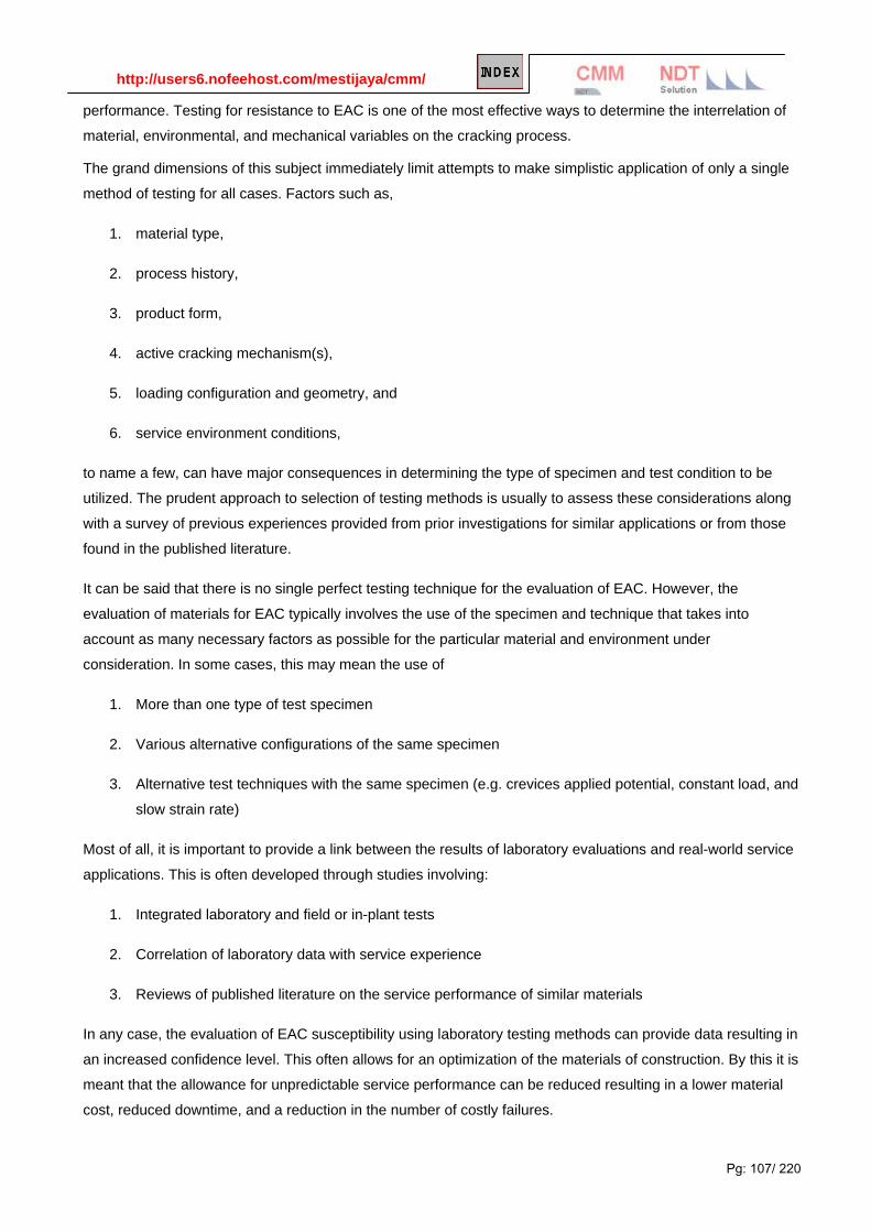
http://users6.nofeehost.com/mestijaya/cmm/
Pg: 107/ 220
performance. Testing for resistance to EAC is one of the most effective ways to determine the interrelation of
material, environmental, and mechanical variables on the cracking process.
The grand dimensions of this subject immediately limit attempts to make simplistic application of only a single
method of testing for all cases. Factors such as,
1. material type,
2. process history,
3. product form,
4. active cracking mechanism(s),
5. loading configuration and geometry, and
6. service environment conditions,
to name a few, can have major consequences in determining the type of specimen and test condition to be
utilized. The prudent approach to selection of testing methods is usually to assess these considerations along
with a survey of previous experiences provided from prior investigations for similar applications or from those
found in the published literature.
It can be said that there is no single perfect testing technique for the evaluation of EAC. However, the
evaluation of materials for EAC typically involves the use of the specimen and technique that takes into
account as many necessary factors as possible for the particular material and environment under
consideration. In some cases, this may mean the use of
1. More than one type of test specimen
2. Various alternative configurations of the same specimen
3. Alternative test techniques with the same specimen (e.g. crevices applied potential, constant load, and
slow strain rate)
Most of all, it is important to provide a link between the results of laboratory evaluations and real-world service
applications. This is often developed through studies involving:
1. Integrated laboratory and field or in-plant tests
2. Correlation of laboratory data with service experience
3. Reviews of published literature on the service performance of similar materials
In any case, the evaluation of EAC susceptibility using laboratory testing methods can provide data resulting in
an increased confidence level. This often allows for an optimization of the materials of construction. By this it is
meant that the allowance for unpredictable service performance can be reduced resulting in a lower material
cost, reduced downtime, and a reduction in the number of costly failures.

http://users6.nofeehost.com/mestijaya/cmm/
Pg: 108/ 220
Evaluation of SCC and other forms of Environmentally Assisted Cracking (EAC)
The evaluation of SCC and EAC (e.g. , Stress Corrosion Cracking, Hydrogen Embrittlement, Liquid Metal
Embrittlement) requires understanding of various materials, mechanical and environmental factors that come
together to produce resistance or susceptibility to cracking. In many cases, SCC involves the combination of
tensile stress and local anodic attack which dictate the period of incubation prior to the initiation of SCC.
Therefore, to conduct tests for SCC, either mechanical or electrochemical means are often utilized to promote
localized corrosion so that the inherent susceptibility of the material can be determined. Such techniques
include the use of slow strain rate, cyclic slow strain rate, fracture mechanics and electrochemical potential
control.
In some cases, where constant load tests are used, environmental cracks can initiate but not propagate
through the entire cross-section of the specimen. Therefore, the specimen may not fail, but significant cracking
may take place.
The study of environmentally assisted cracking (EAC) in its most basic sense involves the consideration and
evaluation of the inherent compatibility between a material and the environment under conditions of either
applied or residual stress. This is a very broad topic encompassing many possible combinations of materials
and environments. However. it is also a critical consideration because equipment, components, and structures
are intended to be used under specific conditions of environment and stress. Furthermore, the materials used
in construction typically have a multitude of manufacturing and process variables that may affect materials
performance. Testing for resistance to EAC is one of the most effective ways to determine the interrelation of
material, environmental, and mechanical variables on the cracking process.
The grand dimensions of this subject immediately limit attempts to make simplistic application of only a single
method of testing for all cases. Factors such as,
1. material type,
2. process history,
3. product form,
4. active cracking mechanism(s),
5. loading configuration and geometry, and
6. service environment conditions,
to name a few, can have major consequences in determining the type of specimen and test condition to be
utilized. The prudent approach to selection of testing methods is usually to assess these considerations along
with a survey of previous experiences provided from prior investigations for similar applications or from those
found in the published literature.
It can be said that there is no single perfect testing technique for the evaluation of EAC. However, the
evaluation of materials for EAC typically involve the use of the specimen and technique that takes into account

http://users6.nofeehost.com/mestijaya/cmm/
Pg: 109/ 220
as many necessary factors as possible for the particular material and environment under consideration. In
some cases, this may mean the use of
1. More than one type of test specimen
2. Various alternative configurations of the same specimen
3. Alternative test techniques with the same specimen (e.g. crevices applied potential, constant load, and
slow strain rate)
Most of all, it is important to provide a link between the results of laboratory evaluations and real-world service
applications. This is often developed through studies involving:
1. Integrated laboratory and field or in-plant tests
2. Correlation of laboratory data with service experience
3. Reviews of published literature on the service performance of similar materials
In any case, the evaluation of EAC susceptibility using laboratory testing methods can provide data resulting in
an increased confidence level. This often allows for an optimization of the materials of construction. By this it is
meant that the allowance for unpredictable service performance can be reduced resulting in a lower material
cost, reduced downtime, and a reduction in the number of costly failures.
Ammonia Attack :A few parts per million of ammonia in boiler feed water caused failure of this bronze valve.

http://users6.nofeehost.com/mestijaya/cmm/
Pg: 110/ 220
Chloride Attack: Waste water with a high chloride content caused rapid corrosion of this stainless steel mixing valve.
Galvanized Bolt: The zinc galvanizing on this bolt failed rapidly in the industrial atmosphere containing SO2 and ammonium nitrate.

http://users6.nofeehost.com/mestijaya/cmm/
Pg: 111/ 220
Chloride Attack on Titanium This titanium heating coil was attacked by chlorides in an acidic environment.
Chloride stress - corrosion cracking (CSCC) is initiation and propagation of cracks in a metal or alloy under tensile stresses and a corrosive environment contains Chloride compounds. Once the crack is initiated, it will propagate rapidly and potentially lead to catastrophic failure. Factors that influence the rate and severity of cracking include
• chloride content
• oxygen content
• temperature
• stress level
• pH value of an aqueous solution Higher chloride content in process fluid will increase potential of CSCC. The severity of cracking increases with temperature. Figure below shows several Stainless Steel materials increases it susceptibility to CSCC as temperature is increased.

http://users6.nofeehost.com/mestijaya/cmm/
Pg: 112/ 220
Source : Sandvik Material Technology SAF 2205 (UNS 31803) = Duplex Stainless Steel SAF 2507 (UNS 32750) = Super Duplex Stainless Steel Material under pressure without Post weld heat treatment will experience high stress level. Higher the stress level, higher the potential of CSCC. Acidic process(low pH) with chloride content in it tends to increase the CSCC potential.
CASE STUDIES Hot gas (Shell) is cooled by seawater (Tube) from 220 degC to 180 degC in a Shell & Tube heat exchanger.
Seawater is being heated from 30 degC to 35 degC and return to sea. The Shell and Tube material of
construction are Carbon steel (CS) and Duplex Stainless Steel (DSS) respectively. After 2 months in operation,
cracks occurred at the tube (DSS) and leads to major platform shutdown. Investigation found crack was
caused by CSCC at tube.
Why a CSCC occurred at DSS tube although the seawater temperature only 35 degC maximum ?
Eventhough the inlet and outlet temperature are below 150 degC, thermal designer may design the heat
exchanger with high heat flux in order to reduce the heat exchanger area and this result tube skin temperature
exceeded 150 degC. Condition with Seawater which contains ~20,000 mg/l Chloride, high in dissolved oxygen,
slightly acidic and skin temperature exceeded 150 degC is perfect combination conditions for CSCC to occur
for DSS. Those heat exchanger designer shall always check skin temperature profile especially for low flow
condition or specify better material i.e. Super DSS for above service.

http://users6.nofeehost.com/mestijaya/cmm/
Pg: 113/ 220
The following are some images of metal experienced Chloride Stress Corrosion Cracking.
Inter granular SCC of an Inconel heat exchanger tube
Trans granular SCC of 316 stainless steel chemical processing piping system

http://users6.nofeehost.com/mestijaya/cmm/
Pg: 114/ 220
CSCC occured on insulated vessel
CSCC occured on insulated vessel
CSCC occured on Condenser tube

http://users6.nofeehost.com/mestijaya/cmm/
Pg: 115/ 220
CSCC on pipe
Inter granular SCC of a pipe
Description
SCC is the brittle cracking of a metal due to the result of combined effects from localized corrosion and tensile
stress. there are many examples in which specific metals and environments in combination cause such
problems. a few examples include:
• brass - SCC in solutions with ammonia
• steel - SCC in caustic (high ph), amine solutions
• stainless steels and aluminum alloys - SCC in solutions containing chlorides.
• ti-alloys - SCC in nitric acid or methanol.
Stress Corrosion Cracking of Stainless Steel
http://users6.nofeehost.com/mestijaya/cmm/
Pg: 116/ 220
The example shown indicates many intersecting, branched cracks with a transgranular propagation mode.
These are typical of stress corrosion cracking (SCC) in austenitic stainless steel. In this case, however, the
alloy was reported to be resistant to SCC in the NaCl brine service environment. The location of cracking was
limited to a region covered by an elastomeric sleeve. Under the sleeve, evidence of severe general and pitting
corrosion were found and evidence of sulfur-containing corrosion products. Analysis of the elastomer indicate
that it was not the correct grade and chemical degradation had occurred in service to produce organic acids
and sulfur compounds. This local environment resulted in enhanced localized susceptibility of the material to
pitting corrosion and SCC.
Prevention or Remedial Action
• lower either applied or residual tensile stresses.
• modification of the environment to eliminate specific scc agent(s).
• change alloy or increase alloy content (i.e. stainless steels and nickel base alloys).
• cathodic protection to change corrosion potential out of scc range.
• add chemical inhibitor.
Standard Test Methods
• ASTM G-30 - practice for making and using U-bend ssc test specimens.
• ASTM G-38 - practice for making and using C-ring scc test specimens.
• ASTM G-39 - practice for preparation and use of bent-beam scc test specimens.
• ASTM G-44 - practice for evaluation of scc resistance of metals and alloys in 3.5% NaCl solution.
• ASTM G-49 - practice for preparation and use of direct tension scc test specimens.
• ASTM G-58 - practice for preparation of scc test specimens for weldments.
• aluminum alloys: ASTM G-44 (seawater - alternate immersion), ASTM G-47(high
• stainless steels and nickel base alloys: ASTM G-35 (polythionic acid),
• ASTM G-36 stainless steels (boiling MgCl2 solution)
• ASTM G-37: copper-zinc alloys (ammonia solution).
• ASTM D-807 steels (caustic).
• ASTM F-945 titanium (aircraft engine cleaning materials).
• ASTM G129: Slow Strain Rate Testing of Materials for Environmentally Assisted Cracking

http://users6.nofeehost.com/mestijaya/cmm/
Pg: 117/ 220
• ASTM G142 - Tensile tests method in hydrogen environments
• NACE TM0274 - dynamic corrosion testing of metals in high temperature water.
Corrosion Engineering and Metal Corrosion Testing Services - Example 3: A SEM/BSE image of a corrosion pit associated with stress corrosion cracking in a stainless steel drum. The Back Scatter Electron (BSE) imaging mode of the Scanning Electron Microscope is sensitive to compositional variations. The corrosion products appear dark with the stainless steel base metal appearing white. SEM/EDS analysis indicated a high concentration of chlorine in the corrosion deposit. (Scanning Electron Microscope (SEM) photo, Mag: 100X)
Azom SCC: http://www.azom.com/Details.asp?ArticleID=102
Stress Corrosion cracking of Stainless Steel.
Stress Corrosion Cracking.
Piping Failures Q&A
PWHT to avoid IGSC of Supermartensitic Stainless Steel.
SCC of UNS 20910 SS Steel. http://web.nace.org/content/publications/mp/2007/0701058.pdf
Stress Corrosion Cracking

http://users6.nofeehost.com/mestijaya/cmm/
Pg: 118/ 220
Corrosion Fatigue
Corrosion fatigue is a special case of stress corrosion caused by the combined effects of cyclic stress and
corrosion. No metal is immune from some reduction of its resistance to cyclic stressing if the metal is in a
corrosive environment. Damage from corrosion fatigue is greater than the sum of the damage from both cyclic
stresses and corrosion. Control of corrosion fatigue can be accomplished by either lowering the cyclic
stresses or by corrosion control. The "beach marks" on the propeller shown below mark the progression of
fatigue on this surface.
Similar beach marks are shown on the aerospace part below left.
The high magnification scanning electron microscope image on
the right shows striations (individual crack progression marks).
The part shown below is also discussed in the section on fretting
corrosion. An infamous example of corrosion fatigue occurred in
1988 on an airliner flying between the Hawaiian Islands. This
disaster, which cost one life, prompted the airlines to look at their
airplanes and inspect for corrosion fatigue.

http://users6.nofeehost.com/mestijaya/cmm/
Pg: 119/ 220
Corrosion-fatigue differs from SCC by the fact that the applied stresses are no longer static, but cyclic (periodically fluctuating or alternating loads).
In the case of steels, the conventional fatigue limit determined from so-called Wöhler curves (applied stress as a function of cycles to failure δ = f(N)) does not exist for tests performed in a corrosive medium. Whatever the stress level, failure will eventually occur after a finite number of cycles. The cracks are generally transgranular in nature, with little tendency for branching. However, a few small secondary cracks may appear in the vicinity of the main crack. Although there is no direct relationship between the sensitivity to corrosion-fatigue and the mechanical properties of the material, high strength alloys tend to be most highly prone.
Corrosion-fatigue damage can be prevented or reduced by decreasing the tensile stresses, either by the use of stress-relief annealing, by modifying component design, or by applying mechanical surface treatments such as peening, to introduce surface compressive stresses. Improvement of the surface condition by polishing is generally beneficial. Corrosion inhibitors are highly effective.
Applied stress versus cycles to failure.

http://users6.nofeehost.com/mestijaya/cmm/
Pg: 120/ 220
Failure Modes Fatigue fractures are caused by the simultaneous action of cyclic stress, tensile stress, and plastic strain. The cyclic stress and strain starts the crack, and the tensile stress produces crack growth. Defects, pits, imperfections, .etc are initiators of fatigue. Corrosion fatigue occurs in corrosive environments, such as wash-out.
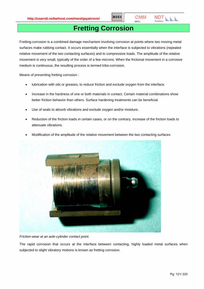
http://users6.nofeehost.com/mestijaya/cmm/
Pg: 121/ 220
Fretting Corrosion
Fretting-corrosion is a combined damage mechanism involving corrosion at points where two moving metal
surfaces make rubbing contact. It occurs essentially when the interface is subjected to vibrations (repeated
relative movement of the two contacting surfaces) and to compressive loads. The amplitude of the relative
movement is very small, typically of the order of a few microns. When the frictional movement in a corrosive
medium is continuous, the resulting process is termed tribo-corrosion.
Means of preventing fretting corrosion :
• lubrication with oils or greases, to reduce friction and exclude oxygen from the interface.
• Increase in the hardness of one or both materials in contact. Certain material combinations show
better friction behavior than others. Surface hardening treatments can be beneficial.
• Use of seals to absorb vibrations and exclude oxygen and/or moisture.
• Reduction of the friction loads in certain cases, or on the contrary, increase of the friction loads to
attenuate vibrations.
• Modification of the amplitude of the relative movement between the two contacting surfaces
Friction-wear at an axle-cylinder contact point.
The rapid corrosion that occurs at the interface between contacting, highly loaded metal surfaces when
subjected to slight vibratory motions is known as fretting corrosion.
Administrator
v3

http://users6.nofeehost.com/mestijaya/cmm/
Pg: 122/ 220
The photo above shows fretting corrosion of a fence post and
wires which swing in the wind and wear against the post. Both the
fence post and the connecting wires are experiencing fretting
corrosion.
This type of corrosion is most common in bearing surfaces in
machinery, such as connecting rods, splined shafts, and bearing
supports, and often causes a fatigue failure. It can occur in
structural members such as trusses where highly loaded bolts are
used and some relative motion occurs between the bolted members.
Fretting corrosion is greatly retarded when the contacting surfaces
can be well lubricated as in machinery-bearing surfaces so as to
exclude direct contact with air.
The bearing race above is a classic example of fretting corrosion.
This is greatly retarded when the contacting surfaces can be well
lubricated as in machinery-bearing surfaces so as to exclude
direct contact with air.
The fretting on a large aluminum part (above left) led to deposits of debris (shown in the cross sections on the
right). The vibratory motions rubbing back and forth also produced the fatigue cracks shown in the section on
fatigue corrosion.
Fretting corrosion is a limited but highly damaging type of corrosion. It is caused by a slight vibration,
friction, or slippage between two contacting surfaces that are under stress and heavily loaded. It is usually
associated with machined parts. Examples of these parts are the area of contact of bearing surfaces, two
mating surfaces, and bolted or riveted assemblies. At least one of the surfaces must be metal. In fretting
corrosion, the slipping movement on the contacting surface destroys the protective films that are

http://users6.nofeehost.com/mestijaya/cmm/
Pg: 123/ 220
present on the metallic surface. This action removes fine particles of the basic metal. The particles oxidize and
form abrasive materials, which further agitate within a confined area to produce deep pits. Such pits are
usually located in an area that increases the fatigue failure potential of the metal. Early signs of
fretting corrosion are surface discoloration and the presence of corrosion products in lubrication. Lubrication
and securing the parts so that they are rigid are effective measures to prevent this type of corrosion.
Description
Fretting corrosion is corrosion that can occur on the load bearing contact surface between mating material. It is
caused by the combination of corrosion and the abrasive effects of corrosion product debris often seen in
equipment with moving or vibrating parts. Other problems induced by fretting corrosion include: surface pitting.
seizing and galling of mating surfaces. reduced fatigue life as a result of stress concentrations produced on the
metal surface.
Prevention or Remedial Action
• use of lubricants and surface coatings designed to improve lubricity and limit metal-on-metal wear.
• increased surface hardness.
• use of barriers to limit ingress of corrosive environment to mating surfaces.
• reduce bearing loads on mating surfaces.";
Standard Test Methods
• ASTM G-77 - practice for ranking materials to sliding wear using block-on-ring wear test.
• ASTM G-98 - test for galling resistance of materials.
Evaluation of Fretting Corrosion
Fretting corrosion is produced by the combined effects of corrosion and wear. Therefore, factors influencing
either the severity of corrosion or the bearing load between the surfaces can affect fretting corrosion.
Parameters that need to be controlled in fretting corrosion evaluations include:
• corrosive environment
• contact load
• amplitude and frequency of load fluctuations
• cycles
• temperature
• availability of moisture

http://users6.nofeehost.com/mestijaya/cmm/
Pg: 124/ 220
Typically the more volumous the corrosion product and the high the bearing loads, the more intense will be the
fretting corrosion response in service.
More reading:
Take special note as you examine the asperity model: The asperity contact points are very small, of the order
of microns in diameter. These points are distributed across an apparent contact area determined by the
geometry of the contact springs at the interface and the contact force exerted by the springs, due to their
deflection on mating. The electrical current across the contact interface must flow through the asperity contact
points, resulting in a resistance called constriction resistance. The magnitude of the constriction resistance
depends on the number, size, and distribution of the asperity contacts at the interface, because all the asperity
contacts are in parallel, electrically. Constriction resistance exists even in the ideal case, when all the asperity
contact interfaces are metal-to-metal, e.g. gold-to-gold or tin-to-tin. If any of the asperity interfaces are
compromised by corrosion films or contaminants, the constriction resistance will increase. This is the reason
why corrosion is a degradation mechanism for connectors. Loss of asperity contact area, or of asperity
contacts, due to corrosion or contamination can result in contact interface resistance increases that are
sufficient to lead to connector failures.
Figure 1: Schematic illustration of the structure of a contact interface resulting from
the intrinsic surface roughness on the micro-scale of the contact interface.
The kinetics of corrosion mechanisms in connectors can be very complex, but for the purposes of this
discussion, two such mechanisms will be highlighted: surface corrosion and motion-induced corrosion, or
fretting corrosion. Surface corrosion is a concern for all connector interfaces, even gold. It is important to note
that the gold is not the source of corrosion products; rather it is the base metal of the contact spring, usually a
copper alloy, that is the corrosion source.
In motion-induced, or fretting corrosion, the term “fretting” refers to the small scale of a few, or up to a few tens
of micron’s repetitive motions. Driving forces for fretting include vibration, mechanical and thermal shock, and
thermal expansion mismatch due to temperature cycling. Those driving forces probably sound familiar, as they
are the conditioning methods for a number of connector test specifications to assess the stability of connector
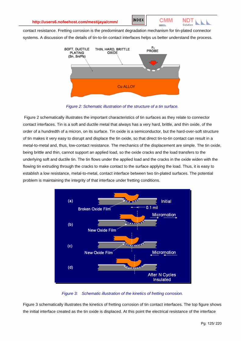
http://users6.nofeehost.com/mestijaya/cmm/
Pg: 125/ 220
contact resistance. Fretting corrosion is the predominant degradation mechanism for tin-plated connector
systems. A discussion of the details of tin-to-tin contact interfaces helps us better understand the process.
Figure 2: Schematic illustration of the structure of a tin surface.
Figure 2 schematically illustrates the important characteristics of tin surfaces as they relate to connector
contact interfaces. Tin is a soft and ductile metal that always has a very hard, brittle, and thin oxide, of the
order of a hundredth of a micron, on its surface. Tin oxide is a semiconductor, but the hard-over-soft structure
of tin makes it very easy to disrupt and displace the tin oxide, so that direct tin-to-tin contact can result in a
metal-to-metal and, thus, low-contact resistance. The mechanics of the displacement are simple. The tin oxide,
being brittle and thin, cannot support an applied load, so the oxide cracks and the load transfers to the
underlying soft and ductile tin. The tin flows under the applied load and the cracks in the oxide widen with the
flowing tin extruding through the cracks to make contact to the surface applying the load. Thus, it is easy to
establish a low resistance, metal-to-metal, contact interface between two tin-plated surfaces. The potential
problem is maintaining the integrity of that interface under fretting conditions.
Figure 3: Schematic illustration of the kinetics of fretting corrosion.
Figure 3 schematically illustrates the kinetics of fretting corrosion of tin contact interfaces. The top figure shows
the initial interface created as the tin oxide is displaced. At this point the electrical resistance of the interface

http://users6.nofeehost.com/mestijaya/cmm/
Pg: 126/ 220
will be of the order of a milliohm or so. If the contact interface moves, it experiences a fretting event as a result
of any of the driving forces mentioned previously, and a new contact interface will be created in essentially the
same manner as the original interface. This new contact will have a similar contact resistance. At the site of the
original interface, the disrupted tin interface area will be exposed to air—specifically, to oxygen—and a new
layer of tin oxide will form at all the original contact points. This is the corrosion part of fretting corrosion. If the
fretting motions are repeated, each repetition will result in the formation of additional tin oxide debris in the
general area of the contact interface. As this debris accumulates in and around the contact interface, it
interferes with an increasing number of asperity contact spots and, eventually, the contact resistance of the
interface will increase. The rate of resistance increase is dependent on many factors, the most important being
the length of the fretting motion and the contact force. The importance of the length of motion is in its impact on
the accumulation of oxide debris at the interface. Small motions produce a small amount of debris, but the
debris remains at the contact interface. Longer motions may produce larger amounts of oxide debris, but the
debris may be pushed towards the end of the fretting motion track, reducing the immediate impact of the debris
on contact resistance. The effect of contact force is similar. Low forces will produce less wear, and, therefore,
less oxide debris, but high forces will be more effective at displacing the oxide debris towards the ends of the
fretting track. Needless to say, the geometry of the contact springs at the contact interface also plays an
important role. The kinetics of fretting corrosion are complex indeed.
Figure 4: Schematic illustration of the relationship between contact resistance and fretting cycles.

http://users6.nofeehost.com/mestijaya/cmm/
Pg: 127/ 220
Figure 4 schematically illustrates the general relationship between the average resistance increase due to
fretting corrosion and the number of fretting cycles. The green curve is for a dry, non-lubricated tin interface.
The rapid increase in resistance generally occurs at the order of a few thousand fretting cycles. The magnitude
of resistance change can vary from tens of milliohms to ohms, and even open circuit. Two features, not shown
explicitly in the graph, merit discussion. The first feature is the time dependence of fretting corrosion. That time
is, of course, dependent on the rate of fretting cycles and fretting degradation kinetics. Suffice it to say that
fretting corrosion can lead to resistance increases of the order of ohms, in tens of minutes under severe
fretting conditions. Second, Figure 4 shows the average resistance, but that is not the whole story. If the
contact resistance was continuously monitored at a high sampling rate, intermittent high resistance events
would be noted before significant changes in average resistance would be recorded. The frequency of
intermittent and the magnitude of the resistance change at each intermittent event would increase dramatically
in the same manner as the average resistance as fretting corrosion continued.
OK, fretting corrosion as a degradation mechanism leading to contact resistance degradation is a real and
significant performance issue for connectors. What can be done about it? There are two general approaches to
fretting corrosion prevention: one directed at preventing fretting, and one at preventing corrosion.
Fretting motions can be prevented if the mechanical stability of the contact interface is sufficient to withstand
the driving forces for fretting motion in the application environment of concern. The most effective means of
providing mechanical stability is through high contact forces. High contact forces mean high friction forces at
the contact interface to resist the driving forces for fretting motions. This is the reason that contact forces for tin
connector systems are in the range of hundreds of grams, as compared to the hundred grams or less typical of
gold connector systems. There are, however, limits to the magnitude of contact force that can be employed.
The benefit of the friction force that comes with contact force in providing mechanical stability has a downside
in that the same contact force also increases the mating force of the connector system. This effect may limit
the number of positions that can be realized in a tin connector system. High contact forces also mean
enhanced wear of the contact surface at the interface. As mentioned, tin is a soft material, and high contact
forces will reduce the number of mating cycles the connector system can support before the tin is worn away.
Recall also that high forces will enhance the rate of fretting debris formation, if fretting motions are not
prevented. Thus, if the contact force is not sufficient to prevent fretting motions, the fretting degradation rate
may be significantly increased.
Preventing the “corrosion” part of fretting corrosion is accomplished by using a contact lubricant. Contact
lubricant is a generic term and includes lubricants that are intended to reduce friction, as well as lubricants to
prevent fretting corrosion. It is important to specify to any lubricant supplier that an anti-fretting lubricant is
desired to prevent the improper selection and application of lubricants. There are many formulations of anti-
fretting contact lubricants available in various consistencies and with application processes designed to suit
different operating conditions and applications. Properly formulated anti-fretting lubricants can be effective at
reducing the potential for fretting corrosion. An example is the white curve, the “active lubricant,” in Figure 4.
With this lubricant, the fretting cycling was carried out to 50,000 cycles with no significant degradation in
contact resistance.

http://users6.nofeehost.com/mestijaya/cmm/
Pg: 128/ 220
One concern with the use of contact lubricants is ensuring proper application of the lubricant, as well as
confirming its presence on the product as received. If the lubricant is to be self-applied, the costs and possible
environmental effects of the selected lubricant must be considered. An additional potential issue may arise in
applications where the potential dust and/or contamination are high. Some contact lubricants may tend to be
“tacky” and to retain dust with the dust itself then contributing to fretting degradation.
The major connector plating systems that are susceptible to fretting corrosion are tin and nickel. Flash gold
systems may become susceptible to fretting corrosion if the flash gold is worn away due to fretting wear or the
mating cycles of the connector and the nickel under plate is exposed.

http://users6.nofeehost.com/mestijaya/cmm/
Pg: 129/ 220
Erosion Corrosion
Erosion corrosion is the result of a combination of an aggressive chemical environment and high fluid-
surface velocities. This can be the result of fast fluid flow past a stationary object, such as the case with the oil-
field check valve shown on the left below, or it can result from the quick motion of an object in a stationary fluid,
such as happens when a ship's propeller churns the ocean.
Surfaces which have undergone erosion corrosion are generally fairly clean, unlike the surfaces from many
other forms of corrosion.
Erosion corrosion can be controlled by the use of harder alloys (including flame-sprayed or welded hard
facings) or by using a more corrosion resistant alloy. Alterations in fluid velocity and changes in flow patterns
can also reduce the effects of erosion corrosion.
Erosion corrosion is often the result of the wearing away of a protective scale or coating on the metal
surface. The oil field production tubing shown above on the right corroded when the pressure on the well
became low enough to cause multiphase fluid flow. The impact of collapsing gas bubbles caused the damage
at joints where the tubing was connected and turbulence was greater.
Many people assume that erosion corrosion is associated with turbulent flow. This is true, because all
practical piping systems require turbulent flow-the fluid would not flow fast enough if lamellar (nonturbulent)
flow were maintained. Most, if not all, erosion corrosion can be attributed to multiphase fluid flow. The check
valve on the left above failed due to sand and other particles in an otherwise noncorrosive fluid. The tubing on
the right failed due to the pressure differences caused when gas bubbles collapsed against the pipe wall and
destroyed the protective mineral scale that was limiting corrosion.

http://users6.nofeehost.com/mestijaya/cmm/
Pg: 130/ 220
Erosion corrosion is acceleration in the rate of corrosion attack in metal due to the relative motion of a
corrosive fluid and a metal surface. The increased turbulence caused by pitting on the internal surfaces of a
tube can result in rapidly increasing erosion rates and eventually a leak. Erosion corrosion can also be
aggravated by faulty workmanship. For example, burrs left at cut tube ends can upset smooth water flow,
cause localized turbulence and high flow velocities, resulting in erosion corrosion. A combination of erosion
and corrosion can lead to extremely high pitting rates.
Erosion-corrosion is most prevalent in soft alloys (i.e. copper, aluminum and lead alloys). Alloys which form a
surface film in a corrosive environment commonly show a limiting velocity above which corrosion rapidly
accelerates. With the exception of cavitation, flow induced corrosion problems are generally termed erosion-
corrosion, encompassing flow enhanced dissolution and impingement attack. The fluid can be aqueous or
gaseous, single or multiphase. There are several mechanisms described by the conjoint action of flow and
corrosion that result in flow-influenced corrosion:
Mass transport-control: Mass transport-controlled corrosion implies that the rate of corrosion is dependent
on the convective mass transfer processes at the metal/fluid interface. When steel is exposed to oxygenated
water, the initial corrosion rate will be closely related to the convective flux of dissolved oxygen towards the
surface, and later by the oxygen diffusion through the iron oxide layer. Corrosion by mass transport will often
be streamlined and smooth.
Phase transport-control: Phase transport-controlled corrosion suggests that the wetting of the metal surface
by a corrosive phase is flow dependent. This may occur because one liquid phase separates from another or
because a second phase forms from a liquid. An example of the second mechanism is the formation of
discrete bubbles or a vapor phase from boiler water in horizontal or inclined tubes in high heat-flux areas under
low flow conditions. The corroded sites will frequently display rough, irregular surfaces and be coated with or
contain thick, porous corrosion deposits.
Erosion-corrosion: Erosion-corrosion is associated with a flow-induced mechanical removal of the protective
surface film that results in a subsequent corrosion rate increase via either electrochemical or chemical
processes. It is often accepted that a critical fluid velocity must be exceeded for a given material. The
mechanical damage by the impacting fluid imposes disruptive shear stresses or pressure variations on the
material surface and/or the protective surface film. Erosion-corrosion may be enhanced by particles (solids or

http://users6.nofeehost.com/mestijaya/cmm/
Pg: 131/ 220
gas bubbles) and impacted by multi-phase flows. The morphology of surfaces affected by erosion-corrosion
may be in the form of shallow pits or horseshoes or other local phenomena related to the flow direction.
Corrosion Erosion
Air was sucked into the intake and the turbulence caused failure from a combination of corrosion and erosion.

http://users6.nofeehost.com/mestijaya/cmm/
Pg: 132/ 220

http://users6.nofeehost.com/mestijaya/cmm/
Pg: 133/ 220
DESCRIPTION
Erosion corrosion is the corrosion of a metal which is caused or accelerated by the relative motion of the environment and the metal surface. It is characterized by surface features with a directional pattern which are a direct result of the flowing media. Erosion corrosion is most prevalent in soft alloys (i.e. copper, aluminum and lead alloys). Alloys which form a surface film in a corrosive environment commonly show a limiting velocity above which corrosion rapidly accelerates. Other factors such as turbulence, cavitation, impingement or galvanic effects can add to the severity of attack.
Prevention or Remedial Action
• selection of alloys with greater corrosion resistance and/or higher strength.
• re-design of the system to reduce the flow velocity, turbulence, cavitation or impingement of the environment.
• reduction in the corrosive severity of the environment.
• use of corrosion resistant and/or abrasion resistant coatings.
• cathodic protection.
Standard Test Methods
• ASTM G-32 - method of vibratory cavitation erosion testing.
• ASTM G-73 - practice for liquid impingement erosion testing
• ASTM G-75 - test method for slurry abrasivity by miller number.
• ASTM G-76 - practice for conducting erosion tests by solid particle impingement using gas jet.
• NACE TM0170 - method of conducting controlled velocity laboratory corrosion tests.
• NACE TM0286 - cooling water test units incorporating heat transfer surfaces.
Evaluation of Erosion Corrosion
Many specialized tests have been utilized to evaluate erosion corrosion. Typically, the nature of the attack from
erosion corrosion and/or velocity accelerated corrosion can be vary specific to the geometry and exposure
conditions. Therefore, the results of tests and the test/service conditions must always be careful examined.
The most commonly utilized methods are spinning cylinder and disk apparatus since they are relatively easy to
set-up and they produce conditions that are easily evaluated. However, they do not always give conditions that
represent those in actual service. Recently, great use of jet impingement and actual pipe flow cells have been
utilized which can more accurately simulate conditions of turbulent flow and multiphase environments. These
tests should be conducted to produce carefully quantified conditions of wall shear stress that match those in
the intended service. The wall shear stress is a measure of the mechanical action produced on the surface of
the material by the flowing media and most directly relates to the damage or removal of normally protective
corrosion products and inhibitor films.

http://users6.nofeehost.com/mestijaya/cmm/
Pg: 134/ 220
Dealloying Corrosion Dealloying is a rare form of corrosion found in copper alloys, gray cast iron, and some other alloys. Dealloying
occurs when the alloy loses the active component of the metal and retains the more corrosion resistant
component in a porous "sponge" on the metal surface. It can also occur by re-deposition of the noble
component of the alloy on the metal surface.
Control is by the use of more resistant alloys-inhibited brasses and malleable or nodular cast iron.
The brass on the left dezincified leaving a porous copper plug on the surface. The gray cast iron water pipe
shown on the right photo has graphitized and left graphitic surface plugs which can be seen on the cut surface.
The rust tubercules or bubbles are also an indication of pitting corrosion.
The bottom photo shows a layer of copper on the surface of a de-alloyed 70% copper-30% nickel cupronickel
heat exchanger tube removed from a ship. Stagnant seawater is so corrosive that even this normally
corrosion-resistant alloy has corroded. Virtually all copper alloys are subject to de-alloying in some
environments.
a
This process, also called "dealloying" or "selective leaching", involves the selective dissolution of one of the
elements in a single phase alloy or one of the phases in a multiphase alloy
The most well known example is the dezincification of brass (e.g. 70Cu - 30Zn). In this case, the brass takes
on a red coppery tinge as the zinc is removed. It also becomes porous and very brittle, without modification to
the overall dimensions of the part
This problem can be overcome by choosing an alloy that is less prone, such as a copper-rich cupro-nickel.
Brasses with lower zinc contents or containing elements such as tin (1%) and/or small quantities of arsenic,
antimony, or phosphorus have much greater resistance.
Numerous other alloys are susceptible to selective corrosion in certain conditions. For example, denickelization

http://users6.nofeehost.com/mestijaya/cmm/
Pg: 135/ 220
can occur in Cu-Ni alloys, and dealuminization in aluminum bronzes, while the graphitization phenomenon in
grey cast irons is due to slow dissolution of the ferrite matrix.
Micrographic appearance of a dezincification of brass.
The brass on the left dezincified leaving a porous copper plug on the surface. The gray cast iron water pipe shown on the right photo has graphitized and left graphitic surface plugs which can be seen on the cut surface. The rust tubercules or bubbles are also an indication of pitting corrosion
Dezincification corrosion of an Admiralty brass exchanger tube in cooling water service.

http://users6.nofeehost.com/mestijaya/cmm/
Pg: 136/ 220
Hydrogen Damages Hydrogen damages can be broadly classified into 3 categories:
Ductile hydrogen blistering.
Brittle hydrogen embrittlement.
High temperature H2 surface attack.
Hydrogen blistering can occur when hydrogen enters steel as a result of the reduction reaction on a metal
cathode. Single-atom nascent H+ hydrogen atoms then diffuse through the metal until they meet with another
atom, usually at inclusions or defects in the metal. The resultant diatomic hydrogen molecules are then too big
to migrate and become trapped. Eventually a gas blister builds up and may split the metal.
Hydrogen Induced Cracking (HIC) or hydrogen embrittlement is a brittle mechanical fracture caused by
penetration and diffusion of atomic hydrogen into the crystal structure of an alloy. It occurs in corrosive
environment under tensile stress, similar to stress corrosion cracking (SCC); however, cathodic protection initiates or enhances HIC but suppresses or stops SCC. The cracks are usually non-branching and fast
growing, and can be transgranular (through the grains) or intergranular (through the grain boundaries).
Hydrogen embrittlement is a problem with high-strength steels, titanium, and some other metals. Control is by
eliminating hydrogen from the environment or by the use of resistant alloys.
High temperature H2 attack occurs when an alloy is exposed to high temperature in H2 environment, It is most
surface phenomenon involve decarburizing, hydride H- formation and deterioration of mechanical properties
and post heat susceptibility to cracking.
Hydrogen Induce Cracking.
HIC occurs in high strength steels when atomic hydrogen dissolves in the crystal lattice of the metal rather
than forming H2 gas. In the oilfield, the presence of H2S gas often leads to sulfide stress cracking (SSC), which
is a special case of hydrogen induced stress cracking. A process resulting in a decrease of the toughness or ductility
of a metal due to the presence of atomic hydrogen.
The presence of hydrogen atoms in a metal crystal lattice can be extremely detrimental, leading to a
catastrophic loss of mechanical strength and ductility. It is generally accepted that the hydrogen is first of all
adsorbed on the metal surface before penetrating the lattice, where it diffuses in ionic form (i.e. as protons).
The hydrogen atoms can have various origins the surrounding atmosphere containing hydrogen or
hydrogenated compounds (H2S, NH3, H2O, etc.), electroplating processes during which the proton reduction
reaction occurs, electrochemical corrosion during which the cathodic reaction is proton reduction.
Once they have penetrated the crystal lattice, hydrogen atoms can cause several types of damage.
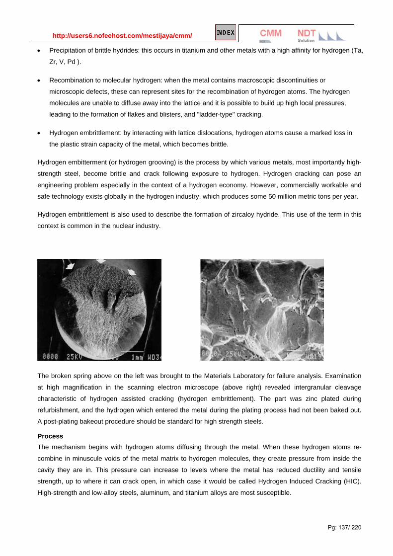
http://users6.nofeehost.com/mestijaya/cmm/
Pg: 137/ 220
• Precipitation of brittle hydrides: this occurs in titanium and other metals with a high affinity for hydrogen (Ta,
Zr, V, Pd ).
• Recombination to molecular hydrogen: when the metal contains macroscopic discontinuities or
microscopic defects, these can represent sites for the recombination of hydrogen atoms. The hydrogen
molecules are unable to diffuse away into the lattice and it is possible to build up high local pressures,
leading to the formation of flakes and blisters, and "ladder-type" cracking.
• Hydrogen embrittlement: by interacting with lattice dislocations, hydrogen atoms cause a marked loss in
the plastic strain capacity of the metal, which becomes brittle.
Hydrogen embitterment (or hydrogen grooving) is the process by which various metals, most importantly high-
strength steel, become brittle and crack following exposure to hydrogen. Hydrogen cracking can pose an
engineering problem especially in the context of a hydrogen economy. However, commercially workable and
safe technology exists globally in the hydrogen industry, which produces some 50 million metric tons per year.
Hydrogen embrittlement is also used to describe the formation of zircaloy hydride. This use of the term in this
context is common in the nuclear industry.
The broken spring above on the left was brought to the Materials Laboratory for failure analysis. Examination
at high magnification in the scanning electron microscope (above right) revealed intergranular cleavage
characteristic of hydrogen assisted cracking (hydrogen embrittlement). The part was zinc plated during
refurbishment, and the hydrogen which entered the metal during the plating process had not been baked out.
A post-plating bakeout procedure should be standard for high strength steels.
Process The mechanism begins with hydrogen atoms diffusing through the metal. When these hydrogen atoms re-
combine in minuscule voids of the metal matrix to hydrogen molecules, they create pressure from inside the
cavity they are in. This pressure can increase to levels where the metal has reduced ductility and tensile
strength, up to where it can crack open, in which case it would be called Hydrogen Induced Cracking (HIC).
High-strength and low-alloy steels, aluminum, and titanium alloys are most susceptible.

http://users6.nofeehost.com/mestijaya/cmm/
Pg: 138/ 220
Hydrogen embrittlement can happen during various manufacturing operations or operational use, anywhere
where the metal comes in contact with atomic or molecular hydrogen. Processes which can lead to this include
cathodic protection, phosphating, pickling, and electroplating. A special case is arc welding, in which the
hydrogen is released from moisture (for example in the coating of the welding electrodes; to minimize this,
special low-hydrogen electrodes are used for welding high-strength steels). Other mechanisms of introduction
of hydrogen into metal are galvanic corrosion, chemical reactions of metal with acids, or with other chemicals
(notably hydrogen sulfide in sulphide stress cracking, or SSC, a process of importance for the oil and gas
industries).
Counteractions-HIC Means of preventing hydrogen embrittlement are;
Control hardness.
Control of stress level.
Avoid hydrogen source
Careful selection of materials of construction and plating systems.
Heat treatment to remove absorbed hydrogen.
For prevention of hydrogen embrittlement: reduce the corrosion rate, modify the electroplating conditions,
change the alloy, take appropriate precautions during welding and so on.
If the metal has not yet started to crack, the condition can be reversed by removing the hydrogen source and
causing the hydrogen within the metal to diffuse out - possibly at elevated temperatures. Susceptible alloys,
after chemical or electrochemical treatments where hydrogen is produced, are often subjected to heat
treatment in order to remove absorbed hydrogen.
In the case of welding, often pre- and post-heating the metal is applied to allow the hydrogen to diffuse out
before it can cause any damage. This is specifically done with high-strength steels and low alloy steels such as
the chrome/molybdenum/vanadium alloys. Due to the time needed to re-combine hydrogen atoms to the
harmful hydrogen molecules, hydrogen cracking due to welding can occur over 24 hours after the welding
operation is completed.
Hydrogen may enter a metal surface by the cathodic reduction of hydrogen or water:
2H+ + 2e- → 2HAdsorbed (acidic waters)
2H2O + 2e- → 2HAdsorbed + 2OH- (neutral waters)
Normally, the adsorbed hydrogen at the surface recombines to form hydrogen gas:
2HAdsorbed → H2
However, recombination poisons such as sulfide (S2-), prevent hydrogen gas from forming and the adsorbed
hydrogen moves through the metal, thereby weakening it. Hydrogen sulfide (H2S) is especially aggressive in
promoting hydrogen damage because it provides not only the sulfide poison, but hydrogen ions (H+) as well.

http://users6.nofeehost.com/mestijaya/cmm/
Pg: 139/ 220
Sulfide stress cracking (SSC) occurs in high-strength drill pipes, casing, tubing, and sucker rods. Like stress
corrosion cracking (SCC), cracking may not occur below a threshold stress, however, increasing strength and
applied stress, increasing H2S concentrations and increasing acidity (decreasing pH) increase SSC
susceptibility.
As opposed to SCC, decreasing temperature also increases SSC susceptibility. Time to failure is minimum at
room temperature. The ramification is that, steels become most susceptible to SSC near the surface where the
highest strength is required to carry the weight of the string. Increasing the wall thickness of the tubular can
reduce the applied stress thus allowing the use of lower strength steels, but strength must be balanced against
the applied load at the top of the joint due to increasing weight. High strength casing may be used deeper in
the well where temperatures are higher.
In SCC, failure initiates at the crevices on the metal surface, usually in the pits. Thus, SCC susceptibility of
steels is related to its susceptibility to pitting. Whereas SSC generally initiates at impurity inclusions in the
metal, hence it is dependent on the hydrogen absorption characteristics of the metal.
Microstructure of steel also influences the SSC susceptibility. Quenched and tempered steels have better SSC
resistance than normalized and normalized and tempered steels. Acceptable hardness limits for many alloys in
sour service are described in the National Association of Corrosion Engineers (NACE) Specification MR-01-75.
For SSC resistance, the hardness of carbon and low alloy steels must be maintained below 22 Rockwell
Hardness C (HRC). Tubular based on AISI 4100 series low-alloy steels are acceptable up to HRC 26. Higher
alloyed steels may have higher hardness levels.
Hydrogen Induced Cracking-Resistant Steel Plates
Sumitomo started research earlier, and has continued it in earnest, on mechanism of and counter-measures
against hydrogen induced cracking under humid hydrogen sulfide environment. Such research was started in
the course of the development of materials for line-pipes used for sour gas and/or sour oil, and achieved
results are ranked in the top level of world research in this area.
As a result, Sumitomo's hydrogen induced cracking resistant plate, "CR5" was developed and commercialized,
aimed at application for oil refining facilities.
CR50 is produced by treating 40 and 50 kg/mm2 strength class plates as countermeasures to prevent
hydrogen induced cracking, such as reducing quantity of inclusions, shape control of inclusions and addition of
infinitesimal amount of elements to inhibit hydrogen penetration into a plate.

http://users6.nofeehost.com/mestijaya/cmm/
Pg: 140/ 220
1. Cracking in environment of humid hydrogen sulfide
It was known for a long time since the old days that cracks occur under
humid environment containing hydrogen sulfide.
Mechanisms for such cracks are classified into the following two
categories.
(1) Sulfide stress corrosion cracking (SSC) It occurs when external stress (working stress, residual stress) is
working on steel, and propagates to the vertical direction to axial stress.
It is also called Sulfide Stress Cracking (SC).
(2) Hydrogen induced cracking (HIC) It occurs under a condition without external stress. The cracking is
parallel to the plate surface and propagates stepwise to the thickness
direction with time.
Surface swelling due to occurrence of cracks on the surface or
immediately beneath the surface is called blistering.
Schematic illustration of various
cracks
a. Blister
b. HIC
c. SSC (low strength steel)
d. (high strength steel)
Example of HIC cracking
Cracking is stepwise and almost
goes through the thickness.

http://users6.nofeehost.com/mestijaya/cmm/
Pg: 141/ 220
Hydrogen Blistering.
A special case of hydrogen damage is known as hydrogen blistering. Hydrogen blistering occurs when
hydrogen atoms diffuse into the steel, and hydrogen gas nucleates at internal defects and inclusions, forming
voids which eventually generate enough pressure to locally rupture the metal.
Hydrogen blistering is occasionally observed in the oilfield in sour systems.
Hydrogen blistering is controlled by minimizing corrosion in acidic environments. It is not a problem in neutral
or caustic environments or with high-quality steels that have low impurity and inclusion levels.
Blistering related to excessive cathodic protection of an oil pipe collector
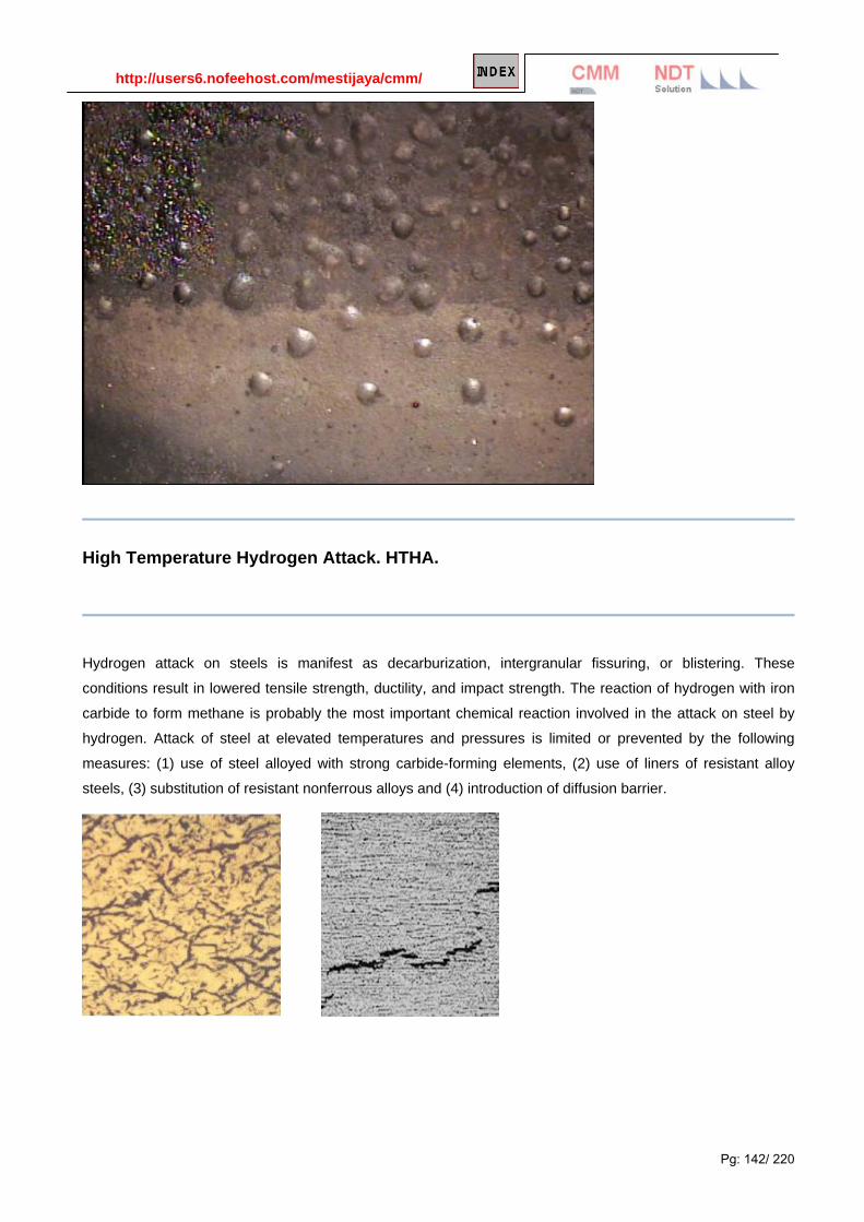
http://users6.nofeehost.com/mestijaya/cmm/
Pg: 142/ 220
High Temperature Hydrogen Attack. HTHA.
Hydrogen attack on steels is manifest as decarburization, intergranular fissuring, or blistering. These
conditions result in lowered tensile strength, ductility, and impact strength. The reaction of hydrogen with iron
carbide to form methane is probably the most important chemical reaction involved in the attack on steel by
hydrogen. Attack of steel at elevated temperatures and pressures is limited or prevented by the following
measures: (1) use of steel alloyed with strong carbide-forming elements, (2) use of liners of resistant alloy
steels, (3) substitution of resistant nonferrous alloys and (4) introduction of diffusion barrier.

http://users6.nofeehost.com/mestijaya/cmm/
Pg: 143/ 220
Hydrogen attack corrosion and cracking on the ID of an 1800 psig carbon steel boiler tube.
If steel is exposed to hydrogen at high temperatures, hydrogen will diffuse into the alloy and combine with
carbon to form tiny pockets of methane at internal surfaces like grain boundaries and voids. This methane
does not diffuse out of the metal, and collects in the voids at high pressure and initiates cracks in the steel.
This process is known as hydrogen attack and leads to decarburization of the steel and loss of strength.
High Temperature Hydrogen Attack (HTHA) is a form of degradation caused by hydrogen reacting with carbon to form methane in a high temperature environment. C + 4H --> CH4 The methane forms and stays in grain boundaries and voids however it does not diffuse out of the metal. Once it accumulated in the grains and voids, it expands and forms blister , weaken the metal strength and initiate cracks in the steel. High-strength low-alloy steels are particularly susceptible to this mechanism, which leads to embrittlement of the bulk parent metal (typical C-0.5 Mo steels). The embrittlement in the material can result in a catastrophic brittle fracture of the asset.

http://users6.nofeehost.com/mestijaya/cmm/
Pg: 144/ 220
Description Hydrogen induced damage describes any of a number of forms of degradation of metals caused by exposure to environments (liquid or gas) which cause absorption of hydrogen into the material to cause degradation in mechanical performance. Examples of hydrogen induced damage are:
1. Formation of internal cracks, blisters or voids in steels.
2. Embrittlement (i.e. loss of ductility).
3. High temperature hydrogen attack (i.e. surface decarburizing and chemical reaction with hydrogen).
Prevention or Remedial Action
1. internal cracking or blistering
Use of steel with low levels of impurities (i.e. sulfur and phosphorus).
Modifying environment to reduce hydrogen charging.
Use of surface coatings and effective inhibitors.
2. hydrogen embrittlement
Use of lower strength (hardness) or high resistance alloys.
Careful selection of materials of construction and plating systems.
Heat treatment to remove absorbed hydrogen.
3. high temperature hydrogen attack
Selection of material (for steels, use of low and high alloy Cr-Mo steels; selected Cu alloys; non-ferrous alloys).
Limit temperature and partial pressure H2.
Standard Test Methods
NACE TM0177 - laboratory testing of metals for resistance to sulfide stress cracking in H2S environments.
• NACE TM0284 - evaluation of pipeline and plate steels for resistance to stepwise cracking.
• ASTM G129 - slow strain rate test for determination of environmentally assisted cracking.
• ASTM G142 - tension tests in hydrogen environments.
• ASTM G146 - hydrogen induced disbonding of stainless clad steel plate in refinery hydrogen service.
• ASTM F-326 - method for electronic hydrogen embrittlement test for cadmium electroplating processes.
• ASTM F-519 - method for mechanical hydrogen embrittlement testing of plating processes and aircraft maintenance chemicals.
• ASTM A-143 - practice of safeguarding against embrittlement of hot dip galvanized structural steel products and detecting embrittlement.
• ASTM B-577 - hydrogen embrittlement of deoxidized and oxygen free copper.

http://users6.nofeehost.com/mestijaya/cmm/
Pg: 145/ 220
• NACE TM0177 - laboratory testing of metals for resistance to sulfide stress cracking in H2S environments
• F1459-06 Standard Test Method for Determination of the Susceptibility of Metallic Materials to Hydrogen Gas Embrittlement (HGE)
Evaluation for Hydrogen Induced Damage
Since hydrogen can induce many types of damage in engineering materials, it is impossible to look to only one test method for all problems.
• Slow strain rate test methods are good to obtain general information on the inherent susceptibility to hydrogen embrittlement is a short period of time. However, the results will generally be very conservative.
• For higher strength materials, the use of constant load tests for determination of an apparent threshold stress for cracking is a generally accepted technique.
• Hydrogen induced cracking and blistering of low strength steels can be tested using non-stressed coupons exposed to the test environment. However, in some cases, the addition of an externally applied or residual tensile stress can cause materials to crack that do not show cracking in the non-stressed condition. Also, constant load specimens may not fail under tensile stress even though they may have extensive internal cracking or blistering.
High temperature hydrogen damage and disbonding must be evaluated for the specific conditions of time and temperature for the intended use. However, it can in many cases, be accelerated with the combination of higher temperature and/or hydrogen pressure.
Clicks for more information on the subjects:
Hydrogen Induced cracking along the fusion boundary of welding of dissimilar metals.
Hydrogen Effects in Metals.
Ferritic and austenitic sintered stainless steel fatigue cracking resistance propagation: Hydrogen
embrittlement influences.
Influences of thermo-hydrogen of micro structural evolution and hardness of Ti600 alloy.
Hydrogen permeability and integrity of hydrogen transfers pipeline.
Hydrogen delay cracking of high strength weldable steels.

http://users6.nofeehost.com/mestijaya/cmm/
Pg: 146/ 220
Concrete Corrosion
The picture on the left shows cracking and staining of a seawall near the Kennedy Space Center. The pitting corrosion in the right photo occurred on an aluminum railing on a concrete causeway over an inlet to the Atlantic Ocean.
Concrete is a widely-used structural material that is frequently reinforced with carbon steel reinforcing rods, post-tensioning cable or pre-stressing wires. The steel is necessary to maintain the strength of the structure, but it is subject to corrosion. The cracking associated with corrosion in concrete is a major concern in areas with marine environments (like KSC) and in areas which use deicing salts.
There are two theories on how corrosion in concrete occurs:
Salts and other chemicals enter the concrete and cause corrosion. Corrosion of the metal leads to expansive forces that cause cracking of the concrete structure.
Cracks in the concrete allow moisture and salts to reach the metal surface and cause corrosion.
Both possibilities have their advocates, and it is also possible that corrosion in concrete can occur either way. The mechanism isn't truly important, the corrosion leads to damage, and the damage must be controlled.
In new construction, corrosion in concrete is usually controlled by embedding the steel deep enough so that chemicals from the surface don't reach the steel (adequate depth of cover). Other controls include keeping the water/cement ratio below 0.4, having a high cement factor, proper detailing to prevent cracking and ponding, and the use of chemical admixtures. These methods are very effective, and most concrete structures, even in marine environments, do not corrode.
Unfortunately, some concrete structures do corrode. When this happens, remedial action can include repairing the cracked and spalled concrete, coating the surface to prevent further entry of corrosive chemicals into the structure, and cathodic protection, an electrical means of corrosion control. KSC has experience with all of these methods of controlling corrosion on existing concrete structures.

http://users6.nofeehost.com/mestijaya/cmm/
Pg: 147/ 220
Microbial Corrosion Microbial corrosion (also called microbiologically-influenced corrosion or MIC) is corrosion that is caused by
the presence and activities of microbes. This corrosion can take many forms and can be controlled by biocides
or by conventional corrosion control methods.
There are a number of mechanisms associated with this form of corrosion, and detailed explanations are listed
at the bottom of this section. Most MIC takes the form of pits that form underneath colonies of living organic
matter and mineral and biodeposits. This biofilm creates a protective environment where conditions can
become quite corrosive and corrosion is accelerated.
The physical presence of microbial cells on a metal surface, as well as their metabolic activities, can cause
Microbiologically Influenced Corrosion (MIC) or biocorrosion. The forms of corrosion caused by bacteria are
not unique. Biocorrosion results in pitting, crevice corrosion, selective dealloying, stress corrosion cracking,
and under-deposit corrosion. The following mechanisms are some of the causes of biocorrosion.
Oxygen depletion or differential aeration cells
Nonuniform (patchy) colonization by bacteria results in differential aeration cells. This schematic shows pit
initiation due to oxygen depletion under a biofilm. (Borenstein 1994)
Nonuniform (patchy) colonies of biofilm result in the formation of differential aeration cells where areas under
respiring colonies are depleted of oxygen relative to surrounding noncolonized areas. Having different oxygen
concentrations at two locations on a metal causes a difference in electrical potential and consequently
corrosion currents. Under aerobic conditions, the areas under the respiring colonies become anodic and the
surrounding areas become cathodic.
Stainless steels’ protective film Oxygen depletion at the surface of stainless steel can destroy the protective passive film. Remember that
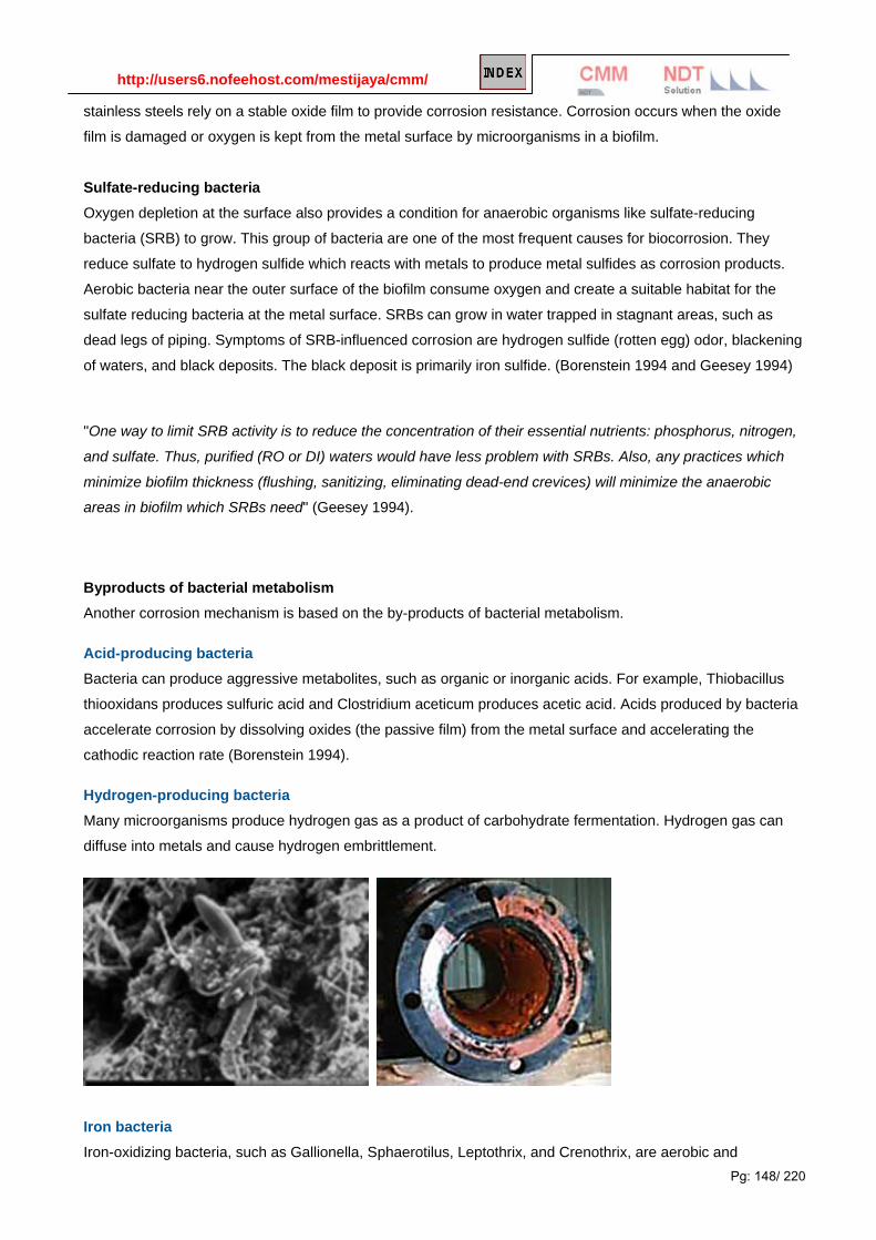
http://users6.nofeehost.com/mestijaya/cmm/
Pg: 148/ 220
stainless steels rely on a stable oxide film to provide corrosion resistance. Corrosion occurs when the oxide
film is damaged or oxygen is kept from the metal surface by microorganisms in a biofilm.
Sulfate-reducing bacteria
Oxygen depletion at the surface also provides a condition for anaerobic organisms like sulfate-reducing
bacteria (SRB) to grow. This group of bacteria are one of the most frequent causes for biocorrosion. They
reduce sulfate to hydrogen sulfide which reacts with metals to produce metal sulfides as corrosion products.
Aerobic bacteria near the outer surface of the biofilm consume oxygen and create a suitable habitat for the
sulfate reducing bacteria at the metal surface. SRBs can grow in water trapped in stagnant areas, such as
dead legs of piping. Symptoms of SRB-influenced corrosion are hydrogen sulfide (rotten egg) odor, blackening
of waters, and black deposits. The black deposit is primarily iron sulfide. (Borenstein 1994 and Geesey 1994)
"One way to limit SRB activity is to reduce the concentration of their essential nutrients: phosphorus, nitrogen,
and sulfate. Thus, purified (RO or DI) waters would have less problem with SRBs. Also, any practices which
minimize biofilm thickness (flushing, sanitizing, eliminating dead-end crevices) will minimize the anaerobic
areas in biofilm which SRBs need" (Geesey 1994).
Byproducts of bacterial metabolism Another corrosion mechanism is based on the by-products of bacterial metabolism.
Acid-producing bacteria
Bacteria can produce aggressive metabolites, such as organic or inorganic acids. For example, Thiobacillus
thiooxidans produces sulfuric acid and Clostridium aceticum produces acetic acid. Acids produced by bacteria
accelerate corrosion by dissolving oxides (the passive film) from the metal surface and accelerating the
cathodic reaction rate (Borenstein 1994).
Hydrogen-producing bacteria
Many microorganisms produce hydrogen gas as a product of carbohydrate fermentation. Hydrogen gas can
diffuse into metals and cause hydrogen embrittlement.
Iron bacteria
Iron-oxidizing bacteria, such as Gallionella, Sphaerotilus, Leptothrix, and Crenothrix, are aerobic and

http://users6.nofeehost.com/mestijaya/cmm/
Pg: 149/ 220
filamentous bacteria which oxidize iron from a soluble ferrous (Fe2+) form to an insoluble ferric (Fe3+) form.
The dissolved ferrous iron could be from either the incoming water supply or the metal surface. The ferric iron
these bacteria produce can attract chloride ions and produce ferric chloride deposits which can attack
austenitic stainless steel. For iron bacteria on austenitic stainless steel, the deposits are typically brown or red-
brown mounds.
Biofilm can be removed and/or destroyed by chemical and physical treatments. Chemical biocides can be
divided into two major groups: oxidizing and nonoxidizing. Physical treatments include mechanical scrubbing
and hot water.
The picture below shows a biofilm on a metallic condenser surface. These biofilms can allow corrosive
chemicals to collect within and under the films. Thus the corrosive conditions under a biofilm can be very
aggressive, even in locations where the bulk environment is noncorrosive.
MIC can be a serious problem in stagnant water systems such as the fire-protection system that produced the
pits shown above. The use of biocides and mechanical cleaning methods can reduce MIC, but anywhere
where stagnant water is likely to collect is a location where MIC can occur.
Corrosion (oxidation of metal) can only occur if some other chemical is present to be reduced. In most
environments, the chemical that is reduced is either dissolved oxygen or hydrogen ions in acids. In anaerobic
conditions (no oxygen or air present), some bacteria (anaerobic bacteria) can thrive. These bacteria can
provide the reducible chemicals that allow corrosion to occur. That's how the limited corrosion that was found
on the hull of the Titanic occurred. The picture below shows a "rusticle" removed from the hull of Titanic. This
combination of rust and organic debris clearly shows the location of rivet holes and where two steel plates
overlapped.
Much microbial corrosion involves anaerobic or stagnant conditions, but it can also be found on structures
exposed to air. The pictures below show a spillway gate from a hydroelectric dam on the Columbia River. The
stress corrosion cracks were caused by pigeon droppings which produced ammonia-a chemical that causes
stress corrosion cracking on copper alloys like the washers used on this structure. Since it's impossible to potty
train pigeons, a new alloy resistant to ammonia was necessary.
In addition to the use of corrosion resistant alloys, control of MIC involves the use of biocides and cleaning
methods that remove deposits from metal surfaces. Bacteria are very small, and it is often very difficult to get a
metal system smooth enough and clean enough to prevent MIC.
Typical corrosion morphology of line pipe steel induced by SRB-related MIC buried at anaerobic soil
Overview MIC is the one of major risk factor for underground pipelines. This interdisciplinary subject require
knowledge for corrosion science, surface chemistry, microbiology, soil science etc. Our continuous field and
laboratory experience for 6 years in this area makes it possible to detection, monitoring, mitigation of MIC
successfully. The expertise provide a better understanding of corrosion mechanisms, permitting the use of
cost-effective solutions to MIC problems .

http://users6.nofeehost.com/mestijaya/cmm/
Pg: 150/ 220
SEM photo of sulfate reducing bacteria (SRB) mixed with biogenic, porous iron sulfides, attached to carbon steel surface exposed to anaerobic soil for 140 day

http://users6.nofeehost.com/mestijaya/cmm/
Pg: 151/ 220
Bacteria Stress Corrosion Cracking : Bacterial activity led to stress corrosion cracking in this 304 SS bolt. As the cracking progressed, the bacteria colonized the cracks, causing more cracking.
Bacteria Nodule: Bacteria growth on a weld in a 304 SS tank
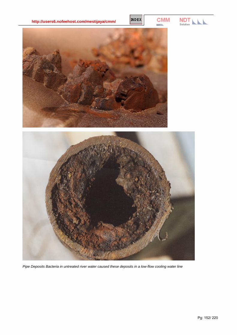
http://users6.nofeehost.com/mestijaya/cmm/
Pg: 152/ 220
Pipe Deposits Bacteria in untreated river water caused these deposits in a low-flow cooling water line

http://users6.nofeehost.com/mestijaya/cmm/
Pg: 153/ 220
Treated & Untreated River Water Bacteria deposits on the untreated water coupon contrast with the clean coupon in the water treated with a biocide.
scanning electron micrograph image shows a metal surface from which the sulfate-reducing biofilm was scraped away, as well as a portion of the metal surface still encrusted by biofilm and corrosion products. Pitting due to microbial corrosion is evident in the exposed metal.
More Reading on MIC of Piping
MIC Predictive Maintenance for Fire Sprinkler Systems
Microbial Lecture University of Florida: http://www.abe.ufl.edu/~chyn/age4660/lect.htm
Microbial Diversity: http://www.learner.org/courses/biology/units/microb/index.html

http://users6.nofeehost.com/mestijaya/cmm/
Pg: 154/ 220
Cavitation Corrosion Cavitation:
Cavitation sometimes is considered a special case of erosion-corrosion and is caused by the formation and
collapse of vapor bubbles in a liquid near a metal surface. Cavitation removes protective surface scales by the
implosion of gas bubbles in a fluid. Calculations have shown that the implosions produce shock waves with
pressures approaching 60 ksi. The subsequent corrosion attack is the result of hydro-mechanical effects from
liquids in regions of low pressure where flow velocity changes, disruptions, or alterations in flow direction have
occurred. Cavitation damage often appears as a collection of closely spaced, sharp-edged pits or craters on
the surface.
In offshore well systems, the process industry in which components come into contact with sand-bearing
liquids, this is an important problem. Materials selection plays an important role in minimizing erosion corrosion
damage. Caution is in order when predicting erosion corrosion behavior on the basis of hardness. High
hardness in a material does not necessarily guarantee a high degree of resistance to erosion corrosion.
Design features are also particularly important.
It is generally desirable to reduce the fluid velocity and promote laminar flow; increased pipe diameters are
useful in this context. Rough surfaces are generally undesirable. Designs creating turbulence, flow restrictions
and obstructions are undesirable. Abrupt changes in flow direction should be avoided. Tank inlet pipes should
be directed away from the tank walls, towards the center. Welded and flanged pipe sections should always be
carefully aligned. Impingement plates of baffles designed to bear the brunt of the damage should be easily
replaceable.
The thickness of vulnerable areas should be increased. Replaceable ferrules, with a tapered end, can be
inserted into the inlet side of heat exchanger tubes, to prevent damage to the actual tubes. Several
environmental modifications can be implemented to minimize the risk of erosion corrosion. Abrasive particles
in fluids can be removed by filtration or settling, while water traps can be used in steam and compressed air
systems to decrease the risk of impingement by droplets. De-aeration and corrosion inhibitors are additional
measures that can be taken. Cathodic protection and the application of protective coatings may also reduce
the rate of attack.
Cavitation occurs in liquid when bubbles form and implode in pump systems or around propellers. Pumps put
liquid under pressure, but if the pressure of the substance drops or its temperature increases, it begins to
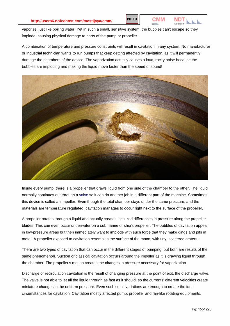
http://users6.nofeehost.com/mestijaya/cmm/
Pg: 155/ 220
vaporize, just like boiling water. Yet in such a small, sensitive system, the bubbles can't escape so they
implode, causing physical damage to parts of the pump or propeller.
A combination of temperature and pressure constraints will result in cavitation in any system. No manufacturer
or industrial technician wants to run pumps that keep getting affected by cavitation, as it will permanently
damage the chambers of the device. The vaporization actually causes a loud, rocky noise because the
bubbles are imploding and making the liquid move faster than the speed of sound!
Inside every pump, there is a propeller that draws liquid from one side of the chamber to the other. The liquid
normally continues out through a valve so it can do another job in a different part of the machine. Sometimes
this device is called an impeller. Even though the total chamber stays under the same pressure, and the
materials are temperature regulated, cavitation manages to occur right next to the surface of the propeller.
A propeller rotates through a liquid and actually creates localized differences in pressure along the propeller
blades. This can even occur underwater on a submarine or ship's propeller. The bubbles of cavitation appear
in low-pressure areas but then immediately want to implode with such force that they make dings and pits in
metal. A propeller exposed to cavitation resembles the surface of the moon, with tiny, scattered craters.
There are two types of cavitation that can occur in the different stages of pumping, but both are results of the
same phenomenon. Suction or classical cavitation occurs around the impeller as it is drawing liquid through
the chamber. The propeller's motion creates the changes in pressure necessary for vaporization.
Discharge or recirculation cavitation is the result of changing pressure at the point of exit, the discharge valve.
The valve is not able to let all the liquid through as fast as it should, so the currents' different velocities create
miniature changes in the uniform pressure. Even such small variations are enough to create the ideal
circumstances for cavitation. Cavitation mostly affected pump, propeller and fan-like rotating equipments.

http://users6.nofeehost.com/mestijaya/cmm/
Pg: 156/ 220
Cavitation damage
Cavitation damage to a Francis turbine. Cavitation is, in many cases, an undesirable occurrence. In devices such as propellers and pumps, cavitation causes a great deal of noise, damage to components, vibrations, and a loss of efficiency.
When the cavitation bubbles collapse, they force liquid energy into very small volumes, thereby creating spots of high temperature and emitting shock waves, the latter of which are a source of noise. The noise created by cavitation is a particular problem for military submarines, as it increases the chances of being detected by passive sonar.
Although the collapse of a cavity is a relatively low-energy event, highly localized collapses can erode metals, such as steel, over time. The pitting caused by the collapse of cavities produces great wear on components and can dramatically shorten a propeller's or pump's lifetime.
After a surface is initially affected by cavitation, it tends to erode at an accelerating pace. The cavitation pits increase the turbulence of the fluid flow and create crevasses that act as nucleation sites for additional cavitation bubbles. The pits also increase the component's surface area and leave behind residual stresses. This makes the surface more prone to stress corrosion.
Pumps and propellers Major places where cavitation occurs are in pumps, on propellers, or at restrictions in a flowing liquid.
As an impeller's (in a pump), or propeller's (as in the case of a ship or submarine) blades move through a fluid, low pressure areas are formed as the fluid accelerates around and moves past the blades. The faster the blades move, the lower the pressure around it can become. As it reaches vapor pressure, the fluid vaporizes and forms small bubbles of gas. This is cavitation. When the bubbles collapse later, they typically cause very strong local shockwaves in the fluid, which may be audible and may even damage the blades.

http://users6.nofeehost.com/mestijaya/cmm/
Pg: 157/ 220
Cavitation in pumps may occur in two different forms:
Suction cavitation Suction cavitation occurs when the pump suction is under a low-pressure/high-vacuum condition where the liquid turns into a vapor at the eye of the pump impeller. This vapor is carried over to the discharge side of the pump where it no longer sees vacuum and is compressed back into a liquid by the discharge pressure. This imploding action occurs violently and attacks the face of the impeller. An impeller that has been operating under a suction cavitation condition can have large chunks of material removed from its face or very small bits of material removed causing the impeller to look sponge-like. Both cases will cause premature failure of the pump often due to bearing failure. Suction cavitation is often identified by a sound like gravel or marbles in the pump casing.
Discharge cavitation Discharge cavitation occurs when the pump discharge pressure is extremely high, normally occurring in a pump that is running at less than 10% of its best efficiency point. The high discharge pressure causes the majority of the fluid to circulate inside the pump instead of being allowed to flow out the discharge. As the liquid flows around the impeller it must pass through the small clearance between the impeller and the pump cutwater at extremely high velocity. This velocity causes a vacuum to develop at the cutwater (similar to what occurs in a venturi) which turns the liquid into a vapor. A pump that has been operating under these conditions shows premature wear of the impeller vane tips and the pump cutwater. In addition, due to the high pressure conditions, premature failure of the pump's mechanical seal and bearings can be expected. Under extreme conditions, this can break the impeller shaft.
Discharge cavitation is believed to be the cause of the cracking of joints.
Cavitation in engines Some bigger diesel engines suffer from cavitation due to high compression and undersized cylinder walls. Vibrations of the cylinder wall induce alternating low and high pressure in the coolant against the cylinder wall. The result is pitting of the cylinder wall that will eventually let cooling fluid leak into the cylinder and combustion gases to leak into the coolant.
It is possible to prevent this from happening with chemical additives in the cooling fluid that form a protecting layer on the cylinder wall. This layer will be exposed to the same cavitation, but rebuilds itself.

http://users6.nofeehost.com/mestijaya/cmm/
Pg: 158/ 220
Cavitation : Low suction pressure led to suction bubbles forming that destroyed the protective film.
Stainless Steel Cavitation :Steam bubble formation due to inadequate suction pressure caused this damage to the 316 stainless impeller.
Administrator
v3
Administrator
2
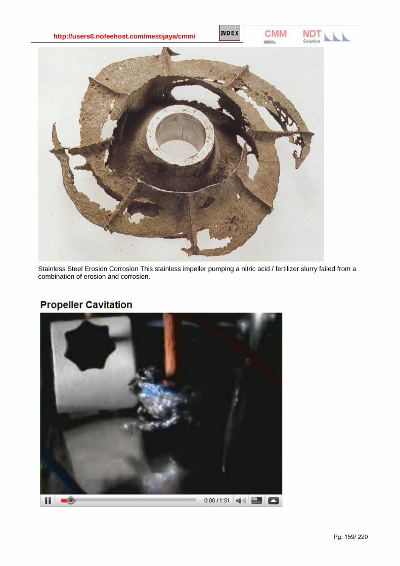
http://users6.nofeehost.com/mestijaya/cmm/
Pg: 159/ 220
Stainless Steel Erosion Corrosion This stainless impeller pumping a nitric acid / fertilizer slurry failed from a combination of erosion and corrosion.

http://users6.nofeehost.com/mestijaya/cmm/
Pg: 160/ 220
DESCRIPTION
Cavitaion and erosion corrosion is the corrosion of a metal which is caused or accelerated by the relative motion of the environment and the metal surface. It is characterized by surface features with a directional pattern which are a direct result of the flowing media. Erosion corrosion is most prevalent in soft alloys (i.e. copper, aluminum and lead alloys). Alloys which form a surface film in a corrosive environment commonly show a limiting velocity above which corrosion rapidly accelerates. Other factors such as turbulence, cavitation, impingement or galvanic effects can add to the severity of attack.
Prevention or Remedial Action
• selection of alloys with greater corrosion resistance and/or higher strength.
• re-design of the system to reduce the flow velocity, turbulence, cavitation or impingement of the environment.
• reduction in the corrosive severity of the environment.
• use of corrosion resistant and/or abrasion resistant coatings.
• cathodic protection.
Standard Test Methods
• ASTM G-32 - method of vibratory cavitation erosion testing.
• ASTM G-73 - practice for liquid impingement erosion testing
• ASTM G-75 - test method for slurry abrasivity by miller number.
• ASTM G-76 - practice for conducting erosion tests by solid particle impingement using gas jet.
• NACE TM0170 - method of conducting controlled velocity laboratory corrosion tests.
• NACE TM0286 - cooling water test units incorporating heat transfer surfaces.
Evaluation of Cavitation and Erosion Corrosion
Many specialized tests have been utilized to evaluate erosion corrosion. Typically, the nature of the attack from erosion corrosion and/or velocity accelerated corrosion can be vary specific to the geometry and exposure conditions. Therefore, the results of tests and the test/service conditions must always be careful examined. The most commonly utilized methods are spinning cylinder and disk apparatus since they are relatively easy to set-up and they produce conditions that are easily evaluated. However, they do not always give conditions that represent those in actual service. Recently, great use of jet impingement and actual pipe flow cells have been utilized which can more accurately simulate conditions of turbulent flow and multiphase environments. These tests should be conducted to produce carefully quantified conditions of wall shear stress that match those in the intended service. The wall shear stress is a measure of the mechanical action produced on the surface of the material by the flowing media and most directly relates to the damage or removal of normally protective corrosion products and inhibitor films.
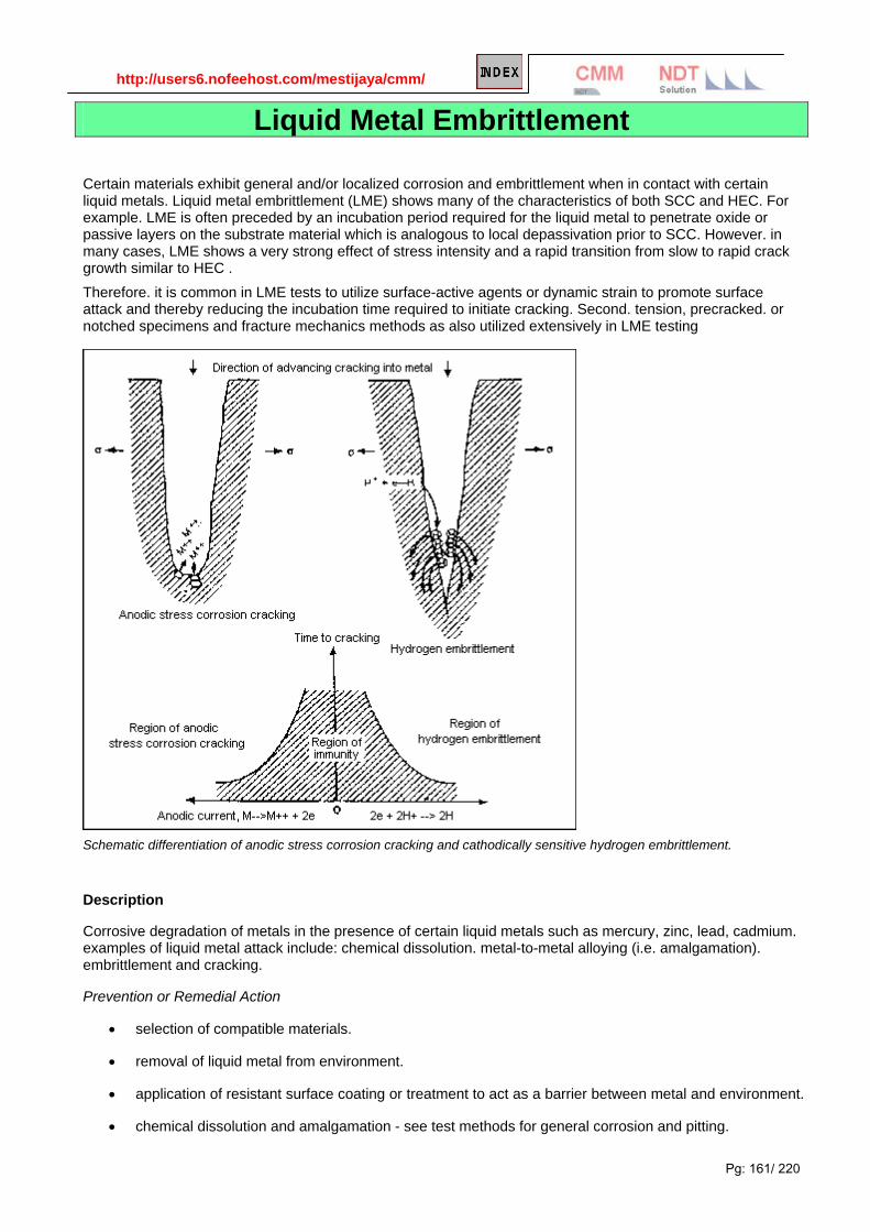
http://users6.nofeehost.com/mestijaya/cmm/
Pg: 161/ 220
Liquid Metal Embrittlement Certain materials exhibit general and/or localized corrosion and embrittlement when in contact with certain liquid metals. Liquid metal embrittlement (LME) shows many of the characteristics of both SCC and HEC. For example. LME is often preceded by an incubation period required for the liquid metal to penetrate oxide or passive layers on the substrate material which is analogous to local depassivation prior to SCC. However. in many cases, LME shows a very strong effect of stress intensity and a rapid transition from slow to rapid crack growth similar to HEC . Therefore. it is common in LME tests to utilize surface-active agents or dynamic strain to promote surface attack and thereby reducing the incubation time required to initiate cracking. Second. tension, precracked. or notched specimens and fracture mechanics methods as also utilized extensively in LME testing
Schematic differentiation of anodic stress corrosion cracking and cathodically sensitive hydrogen embrittlement.
Description
Corrosive degradation of metals in the presence of certain liquid metals such as mercury, zinc, lead, cadmium. examples of liquid metal attack include: chemical dissolution. metal-to-metal alloying (i.e. amalgamation). embrittlement and cracking.
Prevention or Remedial Action
• selection of compatible materials.
• removal of liquid metal from environment.
• application of resistant surface coating or treatment to act as a barrier between metal and environment.
• chemical dissolution and amalgamation - see test methods for general corrosion and pitting.

http://users6.nofeehost.com/mestijaya/cmm/
Pg: 162/ 220
• liquid metal embrittlement - see test methods for scc.
Standard Test Methods
• ASTM G129 - slow strain rate test for determination of environmentally assisted cracking.
• ASTM G-30 - practice for making and using U-bend SCC test specimens.
• ASTM G-38 - practice for making and using C-ring SCC test specimens.
• ASTM G-39 - practice for preparation and use of bent-beam SCC test specimens.
Evaluation for Liquid Metal Embrittlement (LME)
The evaluation of LME usually requires chemical or mechanical techniques to overcome the incubation period
for cracking. In much the same way that a localized corrosion event is needed to initiate SCC, local chemical
attack is usually a precursor for LME. Dynamically applied loads as in the slow strain rate test can be used to
break normally protective surface films to allow intimate contact of the material surface and the liquid metal.
Chemical agents can also be used to remove or breach this surface films and initiate localized attack so that
the inherent susceptibility of the material can be determined. In some cases, surface treatments may be
utilized to enhance resistance to LME. However, this should be conducted with extreme caution since damage
to this surface layer may induce cracking.
Certain materials exhibit general and/or localized corrosion and embrittlement when in contact with certain
liquid metals. Liquid metal embrittlement (LME) shows many of the characteristics of both SCC and HEC. For
example. LME is often preceded by an incubation period required for the liquid metal to penetrate oxide or
passive layers on the substrate material which is analogous to local depassivation prior to SCC. However. in
many cases, LME shows a very strong effect of stress intensity and a rapid transition from slow to rapid crack
growth similar to HEC .
Therefore. it is common in LME tests to utilize surface-active agents or dynamic strain to promote surface
attack and thereby reducing the incubation time required to initiate cracking. Second. tension, precracked. or
notched specimens and fracture mechanics methods as also utilized extensively in LME testing.
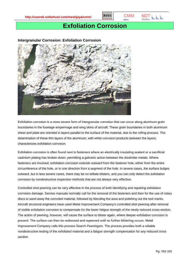
http://users6.nofeehost.com/mestijaya/cmm/
Pg: 163/ 220
Exfoliation Corrosion
Intergranular Corrosion: Exfoliation Corrosion
Exfoliation corrosion is a more severe form of intergranular corrosion that can occur along aluminum grain
boundaries in the fuselage empennage and wing skins of aircraft. These grain boundaries in both aluminum
sheet and plate are oriented in layers parallel to the surface of the material, due to the rolling process. The
delamination of these thin layers of the aluminum, with white corrosion products between the layers,
characterizes exfoliation corrosion.
Exfoliation corrosion is often found next to fasteners where an electrically insulating sealant or a sacrificial
cadmium plating has broken down, permitting a galvanic action between the dissimilar metals. Where
fasteners are involved, exfoliation corrosion extends outward from the fastener hole, either from the entire
circumference of the hole, or in one direction from a segment of the hole. In severe cases, the surface bulges
outward, but in less severe cases, there may be no telltale blisters, and you can only detect the exfoliation
corrosion by nondestructive inspection methods that are not always very effective.
Controlled shot peening can be very effective in the process of both identifying and repairing exfoliation
corrosion damage. Service manuals normally call for the removal of the fasteners and then for the use of rotary
discs to sand away the corroded material, followed by blending the area and polishing out the tool marks.
Aircraft structural engineers have used Metal Improvement Company's controlled shot peening after removal
of visible exfoliation corrosion to compensate for the lower fatigue strength of the newly reduced cross-section.
The action of peening, however, will cause the surface to blister again, where deeper exfoliation corrosion is
present. The surface can then be redressed and repeened until no further blistering occurs. Metal
Improvement Company calls this process Search Peeningsm. The process provides both a reliable
nondestructive testing of the exfoliated material and a fatigue strength compensation for any reduced cross
section.

http://users6.nofeehost.com/mestijaya/cmm/
Pg: 164/ 220
Metal Improvement Company can perform its Search Peening process on-site at aircraft repair hangers to
address exfoliation corrosion.
Recognition What is exfoliation? Exfoliation is yet another special form of intergranular corrosion that proceeds laterally
from the sites of initiation along planes parallel to the surface, generally at grain boundaries, forming corrosion
products that force metal away from the body of the material, giving rise to a layered appearance.
Exfoliation is sometimes described as lamellar, layer, or stratified corrosion. In this type of corrosion, attack
proceeds along selective subsurface paths parallel to the surface. It is possible to visually recognize this type
of corrosion if the grain boundary attack is severe otherwise microstructure examination under a microscope is
needed.
Exfoliation corrosion in an aluminum alloy exposed to tropical marine environment. Also note the paint failures
caused by corrosion of aluminum at the coating/aluminum interface.
Mechanisms What causes exfoliation? Exfoliation is a special type of intergranular corrosion that occurs on the
elongated grain boundaries. The corrosion product that forms has a greater volume than the volume of the
parent metal. The increased volume forces the layers apart, and causes the metal to exfoliate or delaminate.
Aluminum alloys are particularly susceptible to this type of corrosion.
Prevention How to prevent exfoliation corrosion? Exfoliation corrosion can be prevented through:
the use of coatings
selecting a more exfoliation resistant aluminum alloy
using heat treatment to control precipitate distribution.
Exfoliation Corrosion: Exfoliation is a form of intergranular corrosion. It manifests itself by lifting up the surface
grains of a metal by the force of expanding corrosion products occurring at the grain boundaries just below the

http://users6.nofeehost.com/mestijaya/cmm/
Pg: 165/ 220
surface. It is visible evidence of intergranular corrosion and most often seen on extruded sections where grain
thickness is less than in rolled forms.
It is generally considered that exfoliation corrosion is due to the build-up of corrosion products that create a
wedging stress that lifts up the surface grains. However, the exfoliation mechanism is still under discussion:
possible operating mechanisms include intergranular corrosion of in plane grain boundaries accelerated by the
wedging effect, or crack propagation by a "purely" stress corrosion mechanism.
Exfoliation
Exfoliation corrosion is a particular form of intergranular corrosion associated with high strength aluminum
alloys. Alloys that have been extruded or otherwise worked heavily, with a microstructure of elongated,
flattened grains, are particularly prone to this damage.
Corrosion products building up along these grain boundaries exert pressure between the grains and the end
result is a lifting or leafing effect. The damage often initiates at end grains encountered in machined edges,
holes or grooves and can subsequently progress through an entire section.
Anisotropic grain structure of wrought aluminum alloys
SL = Short longitudinal LT = Longitudinal transverse ST = Short transverse

http://users6.nofeehost.com/mestijaya/cmm/
Pg: 166/ 220
Notice how the corrosion separates into distinct layers which have expanded to occupy a much larger area than the original, un-corroded part. Obviously, the structural integrity of this part disappeared long ago. Micrograph of a failed aircraft component
Exfoliation of a failed aircraft component made of 7075-T6 aluminum (picture width = 400 mm)

http://users6.nofeehost.com/mestijaya/cmm/
Pg: 167/ 220
Exfoliation Corrosion, Evaluation of Exfoliation Corrosion EXFOLIATION is a structure-dependent form of localized (usually) intergranular corrosion that is most familiar in certain alloys and tempers of aluminum. The occurrence of exfoliation in susceptible materials is influenced to a marked degree by environmental conditions. Figure 1 illustrates the broad range of behavior in different types of atmospheres. For example, forged truck wheels made of an aluminum-copper alloy (2024-T4) give corrosion-free service for many years in the warm climates of the southern and western United States, but they exfoliate severely in only 1 or 2 years in the northern states, where deicing salts are used on the highways during the winter months. Accelerated laboratory tests do not precisely predict long-term corrosion behavior; however, answers are needed quickly in the development of new materials. For this reason, accelerated tests are used to screen candidate alloys before conducting atmospheric exposures or other field tests. They are also sometimes used for quality control tests. Several new laboratory tests for exfoliation corrosion have been standardized in recent years under the jurisdiction of American Society for Testing and Materials (ASTM) Committee G-1 on the Corrosion of Metals. Test Method used: ASTM G85 Standard Practice for Modified Salt Spray (Fog) Testing The ASTM G85 standard consists of a set of 5 modifications to the ASTM B117 Salt Spray Test. These modifications are applicable to ferrous and nonferrous metals, and also to organic and inorganic coatings. These variations are useful when a different or more corrosive environment than the salt fog described in Practice B 117 is desired. This test standard comprises of five climate modifications to the basic ASTM B117 salt spray test. These five
modifications are known by the following annexes and descriptions:
ASTM G85 annex A1 – acetic acid salt spray test, continuous
This test is also referred to as an ASS test.
ASTM G85 annex A2 – cyclic acidified salt spray test
This test is also referred to as a MASTMAASIS test.
ASTM G85 annex A3 – seawater acidified test, cyclic
This test is also referred to as a SWAAT test.
ASTM G85 annex A4 – Sulphur dioxide (SO2 ) salt spray test, cyclic
This test is also referred to as an SO 2 test.
ASTM G85 annex A5 – dilute electrolyte cyclic fog /dry test
This test is also referred to as a PROHESION test.
The standard in salt spray testing ASTM B117 The American Society of Testing and Materials (ASTM) test B117 is one of the most widely adopted continuous salt
spray test specifications. Its use is internationally widespread and its provisions have been frequently re-written into
the national standards of other countries, and also appear in other industry specific corrosion test standards.
ASTM B117 has always been and excellent reference document for the salt spray practitioner, with many helpful
hints and tips contained in its useful appendixes. But since it is also regularly updated, by an active and broad based
ASTM sub-committee, it is a standard that is always evolving and becoming ever more ‘user friendly’. The suffix to
the main standard number indicates the year of publication. For example, ASTM B117 – 03 indicates a 2003

http://users6.nofeehost.com/mestijaya/cmm/
Pg: 168/ 220
publication date (which was the latest version available at the time of writing). Please check you are using the most
up to date edition available for your application.
Other Exfoliation Corrosion Tests: Exfoliation Corrosion is a severe form of intergranular corrosion that can occur along aluminum grain boundaries, parallel to the surface. Exfoliation Corrosion represents a special type of localized corrosion, which develops under the surface of aluminum high-alloyed alloys.
If intergranular corrosion is allowed to propagate, delamination of the thin layers of aluminum, known as exfoliation corrosion will occur. The resulting corrosion forces the metal upward, giving rise to a layered or leaf-like appearance to the surface.
Exfoliation Corrosion Testing applies to all wrought products from industry, especially aeronautics, and can include sheet, plate, extrusion and forging.
ASTM G34-Describes a procedure for constant immersion exfoliation corrosion (EXCO)
ASTM G66-Method covers a procedure for continuous immersion exfoliation corrosion testing of aluminum alloys (ASSET Test)
ASTM G112-Covers the aspects of specimen preparation, exposure, inspection and evaluation for conducting exfoliation corrosion tests
ASTM G34 - 01(2007) Standard Test Method for Exfoliation Corrosion Susceptibility in 2XXX and 7XXX Series Aluminum Alloys (EXCO Test)
Significance and Use This test method was originally developed for research and development purposes; however, it is referenced, in specific material specifications, as applicable for evaluating production material Use of this test method provides a useful prediction of the exfoliation corrosion behavior of these alloys in various types of outdoor service, especially in marine and industrial environments.4 The test solution is very corrosive and represents the more severe types of environmental service, excluding, of course, unusual chemicals not likely to be encountered in natural environments. The exfoliation ratings were arbitrarily chosen to illustrate a wide range in resistance to exfoliation in this test. However, it remains to be determined whether correlations can be established between EXCO test ratings and realistic service conditions for a given alloy. It is an ongoing activity of the Task Group on Exfoliation Corrosion of Aluminum Alloys (G01.05.02.08) to maintain outdoor exposure tests for this purpose. For example, it has been reported that samples of Al-Zn-Mg-Cu alloys rated EA or P in a 48-h EXCO test did not develop more than a slight amount of incipient exfoliation (EA) during six- to nine-year exposures to seacoast atmospheres, whereas, ED rated materials in most cases developed severe exfoliation within a year in the seacoast atmosphere. It is anticipated that additional comparisons will become available as the outdoor tests are extended. 1. Scope 1.1 This test method covers a procedure for constant immersion exfoliation corrosion (EXCO) testing of high-strength 2XXX and 7XXX series aluminum alloys. Note 1—This test method was originally developed for research and development purposes; however, it is referenced, in specific material specifications, as applicable for evaluating production material (refer to Section 14 on Precision and Bias). 1.2 This test method applies to all wrought products such as sheet, plate, extrusions, and forgings produced from conventional ingot metallurgy process. 1.3 This test method can be used with any form of specimen or part that can be immersed in the test solution. 1.4 This standard does not purport to address all of the safety concerns, if any, associated with its use. It is the responsibility of the user of this standard to establish appropriate safety and health practices and determine the applicability of regulatory limitations prior to use.

http://users6.nofeehost.com/mestijaya/cmm/
Pg: 169/ 220
ASTM G112 - 92(2003) Standard Guide for Conducting Exfoliation Corrosion Tests in Aluminum Alloys
Significance and Use Although there are ASTM test methods for exfoliation testing, they concentrate on specific procedures for test methodology itself. Existent test methods do not discuss material variables that can affect performance. Likewise they do not address the need to establish the suitability of an accelerated test for alloys never previously tested nor the need to correlate results of accelerated tests with tests in outdoor atmospheres and with end use performance.
This guide is a compilation of the experience of investigators skilled in the art of conducting exfoliation tests and assessing the degree and significance of the damage encountered. The focus is on two general aspects: guides to techniques that will enhance the likelihood of obtaining reliable information, and tips and procedures to avoid pitfalls that could lead to erroneous results and conclusions.
The following three areas of testing are considered: the test materials starting with the “as-received” sample up through final specimen preparation, the corrosion test procedures including choice of test, inspection periods, termination point, and rating procedures, and analyses of results and methods for reporting them.
This guide is not intended as a specific corrosion test procedure by which to evaluate the resistance to exfoliation of an aluminum alloy product.
This guide is not intended as a basis for specifications, nor as a guide for material lot acceptance.
1. Scope
1.1 This guide differs from the usual ASTM standard in that it does not address a specific test. Rather, it is an introductory guide for new users of other standard exfoliation test methods, (see Terminology G 15 for definition of exfoliation).
1.2 This guide covers aspects of specimen preparation, exposure, inspection, and evaluation for conducting exfoliation tests on aluminum alloys in both laboratory accelerated environments and in natural, outdoor atmospheres. The intent is to clarify any gaps in existent test methods.
1.3 The values stated in SI units are to be regarded as the standard. The inch-pound units given in parentheses are for information only.
1.4 This standard does not purport to address all of the safety concerns, if any, associated with its use. It is the responsibility of the user of this standard to establish appropriate safety and health practices and determine the applicability of regulatory limitations prior to use.
2. Referenced Documents
G1 Practice for Preparing, Cleaning, and Evaluating Corrosion Test Specimens G15 Terminology Relating to Corrosion and Corrosion Testing G34 Test Method for Exfoliation Corrosion Susceptibility in 2XXX and 7XXX Series Aluminum Alloys (EXCO Test) G50 Practice for Conducting Atmospheric Corrosion Tests on Metals G66 Method for Visual Assessment of Exfoliation Corrosion Susceptibility of 5XXX Series Aluminum Alloys (ASSET Test) G85 Practice For Modified Salt Spray (Fog) Testing G92 Practice for Characterization of Atmospheric Test Sites
ISO 11881:1999 Corrosion of metals and alloys -- Exfoliation corrosion testing of aluminum alloys

http://users6.nofeehost.com/mestijaya/cmm/
Pg: 170/ 220
Chapter 3: Corrosion Controls
There are a number of means of controlling corrosion. The choice of a means of corrosion control depends on economics, safety requirements, and a number of technical considerations.
Design.
Materials Selection.
Protective Coatings.
Inhibitors and Other Means of Environmental Alteration. (Chemical Treatment)
Corrosion Allowances.
Cathodic Protection.
Anodic Protection.
Corrosion Protections of Metals - Overview
Corrosion Control: http://www.vulcanhammer.net/marine/Mo307.pdf
Design.

http://users6.nofeehost.com/mestijaya/cmm/
Pg: 171/ 220
Engineering design is a complicated process that includes design for purpose, manufacturability, inspection, and maintenance. One of the considerations often overlooked in designing manufactured products is drainage. The corrosion of the automobile side panel above could have been minimized by providing drainage to allow any water and debris to fall off of the car instead of collecting and causing corrosion from the far side of the panel. All of the other methods of corrosion control should be considered in the design process.

http://users6.nofeehost.com/mestijaya/cmm/
Pg: 172/ 220
Material Selections.
Carbon Steel Stainless Steel
Aluminum
Copper Alloys
Titanium
Carbon Steel
Most large metal structures are made from carbon steel-the world's most useful structural material. Carbon steel is inexpensive, readily available in a variety of forms, and can be machined, welded, and formed into many shapes.
This large statue by Pablo Picasso in front of the Chicago city hall is made from a special form of carbon steel known as weathering steel. Weathering steel does not need painting in many boldly exposed environments. Unfortunately, weathering steel has been misused in many circumstances where it could not drain and form a protective rust film. This has given the alloy a mixed reputation in the construction industry.
Where other means of corrosion control are not practical, other alloys can be substituted for carbon steel. This normally doubles or more the material cost for a structure, and other corrosion control methods must be considered before deciding on the use of more expensive alternates to carbon steel.
Some forms of carbon steel are subject to special types of corrosion such as hydrogen embrittlement, etc. It is common practice to limit the allowable strength levels of carbon steel to avoid brittle behavior in environments where environmental cracking may occur. High strength bolts cannot be galvanized for the same reason-a concern that they may hydrogen embrittle due to corrosion on the surface.
Protective coatings, cathodic protection, and corrosion inhibitors are all extensively used to prolong the life of carbon steel structures and to allow their use in environments such as the Kennedy Space Center where the environment would otherwise be too corrosive for their use.
Stainless Steels
The stainless steel body on this sports car is one example of how stainless steels can be used. The stainless steel is virtually immune to corrosion in this application-at least in comparison to the corrosion that would be experienced by conventional carbon steel or aluminum auto bodies.
Stainless steels are a common alternative to carbon steels. There are many kinds of stainless steels, but the most common austenitic stainless steels (300-series stainless steels) are based on the general formula of iron with approximately 18% chromium and 8% nickel. These austenitic stainless steels
are frequently immune to general corrosion, but they may experience pitting and crevice corrosion and undergo stress corrosion cracking in some environments.
Aluminum
Aluminum alloys are widely used in aerospace applications where their favorable strength-to-weight ratios make them the structural metal of choice. They can have excellent atmospheric corrosion capabilities.

http://users6.nofeehost.com/mestijaya/cmm/
Pg: 173/ 220
Unfortunately, the protective properties of the aluminum oxide films that form on these alloys can break down locally and allow extensive corrosion. This is discussed further in the section on intergranular corrosion.
The highway guardrail shown on the right is located near the ocean in Florida. The aluminum alloy maintains a silvery shine except in locations where the passive film has suffered mechanical damage. The wear caused by the rail touching the wooden post at this location destroyed the passive film on the edges of the rail and allowed intergranular corrosion to proceed and cause the exfoliation corrosion shown above. While the corrosion above is very interesting and makes for an interesting web site, it is important to note that the railing is decades old and would have never lasted as long in this location if it were made of carbon steel.
Intergranular corrosion is a major problem on airplanes and other structures made from aluminum alloys. It frequently occurs at bolt and rivet holes or at cutouts where the small grain boundaries perpendicular to the metal surface are exposed.
Copper Alloys
Brasses and bronzes are commonly used piping materials, and they are also used for valves and fittings. They are subject to stress corrosion cracking in the presence of ammonia compounds. They also suffer from dealloying and can cause galvanic corrosion when coupled with steel and other structural metals. Most copper alloys are relatively soft and subject to erosion corrosion.
The dezincification shown above could have been controlled by using inhibited brasses which have been commercially available since the 1930's.
Titanium
Titanium is one of the more common metals in nature, but its limited use means that small-scale production operations result in a relatively expensive metal. In the United States it finds extensive use in the aerospace industry. The Japanese make extensive use of titanium in the chemical process industries.
There are two general types of titanium alloys-aerospace alloys and corrosion resistant alloys. The crevice corrosion of an aerospace alloy flange in a saltwater application is a classic example of how titanium gets misused.
Selection of materials: http://www.hse.gov.uk/comah/sragtech/techmeasmaterial.htm Ebooks on materials: http://iran-eng.com/showthread.php?t=43015&page=14 Corrosion and material selection in desalination plants: http://www.scribd.com/doc/7457739/Corrosion-and-Material-Selection-in-Desalination-Plants Corrosion resistance alloys: http://www.hpalloy.com/alloys/corrosionResistant.html Chemical and material performance: http://www.engineeringtoolbox.com/metal-corrosion-resistance-d_491.html Materials selection at high temperature: http://www2.mtec.or.th/th/research/famd/corro/mshtemp.htm Material selection guides: http://www.documentation.emersonprocess.com/groups/public_public_mmisami/documents/articles_articlesreprints/mc-00992.pdf Materials selection guides for valves: http://d.scribd.com/docs/bkl25fpw3pcakaotfui.pdf DOE fundamental handbooks on material Science-Vol1 & 2 http://hss.energy.gov/NuclearSafety/techstds/standard/hdbk1017/h1017v1.pdf http://hss.energy.gov/NuclearSafety/techstds/standard/hdbk1017/h1017v2.pdf Material handbooks collection: http://community.h2vn.com/index.php?topic=96.0 http://iran-eng.com/showthread.php?t=43015&page=14
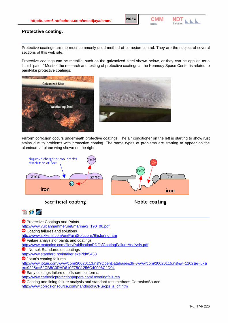
http://users6.nofeehost.com/mestijaya/cmm/
Pg: 174/ 220
Protective coating.
Protective coatings are the most commonly used method of corrosion control. They are the subject of several sections of this web site.
Protective coatings can be metallic, such as the galvanized steel shown below, or they can be applied as a liquid "paint." Most of the research and testing of protective coatings at the Kennedy Space Center is related to paint-like protective coatings.
Filiform corrosion occurs underneath protective coatings. The air conditioner on the left is starting to show rust stains due to problems with protective coating. The same types of problems are starting to appear on the aluminum airplane wing shown on the right.
Protective Coatings and Paints http://www.vulcanhammer.net/marine/3_190_06.pdf
Coating failures and solutions http://www.sikkens.com/en/PaintSolutions/Blistering.htm
Failure analysis of paints and coatings http://www.matcoinc.com/files/PublicationPDFs/CoatingFailureAnalysis.pdf
Norsok Standards on coatings http://www.standard.no/imaker.exe?id=5438
Jotun’s coating failures. http://www.jotun.com/www/com/20020113.nsf?OpenDatabase&db=/www/com/20020115.nsf&v=1102&e=uk&m=922&c=52CB8C0DAD610F78C1256C40006C2D04
Early coatings failure of offshore platforms. http://www.cathodicprotectionpapers.com/3coatingfailures
Coating and lining failure analysis and standard test methods-CorrosionSource. http://www.corrosionsource.com/handbook/CPS/cps_a_clf.htm

http://users6.nofeehost.com/mestijaya/cmm/
Pg: 175/ 220
Inhibitions and environmental alteration. [Inhibitor]
Corrosion inhibitors are chemicals that are added to controlled environments to reduce the corrosivity of
these environments. Examples of corrosion inhibitors include the chemicals added to automobile antifreezes to make them less corrosive. Most of the Kennedy Space Center's corrosion inhibitor research involves the effectiveness of inhibitors added to protective coatings.
[Inhibitor types]
Corrosion allowances.
Engineering designers must consider how much metal is necessary to withstand the anticipated load for a given application. Since they can make mistakes, the use of the structure can change, or the structure can be misused, they usually are required to over design the structure by a safety factor that can vary from 20% to over 300%. Once the necessary mechanical load safety factor has been considered, it becomes necessary to consider whether or not a corrosion allowance is necessary to keep the structure safe if it does corrode.
The picture above shows extra steel added to the
bottom of an offshore oil production platform. The one inch of extra steel was added as a corrosion allowance.

http://users6.nofeehost.com/mestijaya/cmm/
Pg: 176/ 220
Cathodic protection.
Cathodic protection is an electrical means of corrosion control. Cathodic protection can be applied using
sacrificial (galvanic) anodes or by means of more complicated impressed current systems.
This Louisiana fishing boat has sacrificial zinc anodes welded to the hull to slow down corrosion.
Cathodic protection (CP) is a technique to control the corrosion of a metal surface by making that surface the
cathode of an electrochemical cell.
It is a method used to protect metal structures from corrosion. Cathodic protection systems are most
commonly used to protect steel, water/fuel pipelines and storage tanks; steel pier piles, ships, offshore oil
platforms and onshore oil well casings.
A side effect of improperly performed cathodic protection may be production of molecular hydrogen, leading to
its absorption in the protected metal and subsequent hydrogen embrittlement.
Cathodic protection is an effective method of preventing stress corrosion cracking.
Galvanic CP
Today, galvanic or sacrificial anodes are made in various shapes using alloys of zinc, magnesium and
aluminum. The electrochemical potential, current capacity, and consumption rate of these alloys are superior
for CP than iron.
*Also Ag/AgCl in 20 ohm-cm seawater
Corrosion Potentials in Flowing Seawater (8-13 ft/s), Temperature Range 50-80 F (10-27 C)
Administrator
pdfsmall
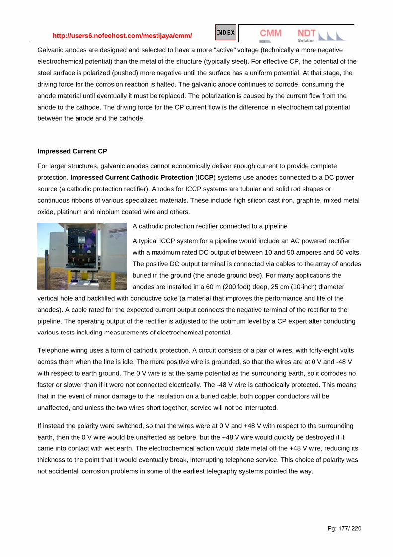
http://users6.nofeehost.com/mestijaya/cmm/
Pg: 177/ 220
Galvanic anodes are designed and selected to have a more "active" voltage (technically a more negative
electrochemical potential) than the metal of the structure (typically steel). For effective CP, the potential of the
steel surface is polarized (pushed) more negative until the surface has a uniform potential. At that stage, the
driving force for the corrosion reaction is halted. The galvanic anode continues to corrode, consuming the
anode material until eventually it must be replaced. The polarization is caused by the current flow from the
anode to the cathode. The driving force for the CP current flow is the difference in electrochemical potential
between the anode and the cathode.
Impressed Current CP
For larger structures, galvanic anodes cannot economically deliver enough current to provide complete
protection. Impressed Current Cathodic Protection (ICCP) systems use anodes connected to a DC power
source (a cathodic protection rectifier). Anodes for ICCP systems are tubular and solid rod shapes or
continuous ribbons of various specialized materials. These include high silicon cast iron, graphite, mixed metal
oxide, platinum and niobium coated wire and others.
A cathodic protection rectifier connected to a pipeline
A typical ICCP system for a pipeline would include an AC powered rectifier
with a maximum rated DC output of between 10 and 50 amperes and 50 volts.
The positive DC output terminal is connected via cables to the array of anodes
buried in the ground (the anode ground bed). For many applications the
anodes are installed in a 60 m (200 foot) deep, 25 cm (10-inch) diameter
vertical hole and backfilled with conductive coke (a material that improves the performance and life of the
anodes). A cable rated for the expected current output connects the negative terminal of the rectifier to the
pipeline. The operating output of the rectifier is adjusted to the optimum level by a CP expert after conducting
various tests including measurements of electrochemical potential.
Telephone wiring uses a form of cathodic protection. A circuit consists of a pair of wires, with forty-eight volts
across them when the line is idle. The more positive wire is grounded, so that the wires are at 0 V and -48 V
with respect to earth ground. The 0 V wire is at the same potential as the surrounding earth, so it corrodes no
faster or slower than if it were not connected electrically. The -48 V wire is cathodically protected. This means
that in the event of minor damage to the insulation on a buried cable, both copper conductors will be
unaffected, and unless the two wires short together, service will not be interrupted.
If instead the polarity were switched, so that the wires were at 0 V and +48 V with respect to the surrounding
earth, then the 0 V wire would be unaffected as before, but the +48 V wire would quickly be destroyed if it
came into contact with wet earth. The electrochemical action would plate metal off the +48 V wire, reducing its
thickness to the point that it would eventually break, interrupting telephone service. This choice of polarity was
not accidental; corrosion problems in some of the earliest telegraphy systems pointed the way.

http://users6.nofeehost.com/mestijaya/cmm/
Pg: 178/ 220
Testing
Electrochemical potential is measured with reference electrodes.
Copper-copper(II) sulfate electrodes are used for structures in
contact with soil or fresh water. Silver chloride electrodes are
used for seawater applications.
Silver/silver-chloride electrode is by far the most common
reference type used today because it is simple, inexpensive, very
stable and non-toxic. It is mainly used with saturated potassium
chloride electrolyte, but can be used with lower concentrations
such as 3.5 mol dm-3 or 1 mol dm-3 potassium chloride.
Silver/silver-chloride electrode is a referent electrode based on
the following halfreaction
AgCl(s) + e- Ag(s) + Cl-
Dependence of potential of silver/silver chloride electrode upon temperature and concentration of KCl
according to standard hydrogen electrode:
Potential vs. SHE / V
t / °C3.5 mol dm-
3 sat. solution
15 0.212 0.209
20 0.208 0.204
25 0.205 0.199
30 0.201 0.194
35 0.197 0.189
Galvanized Steel
Galvanizing (or galvanising, outside of the USA) generally refers to hot-dip galvanizing which is a way of
coating steel with a layer of metallic zinc. Galvanized coatings are quite durable in most environments because
they combine the barrier properties of a coating with some of the benefits of cathodic protection. If the zinc
coating is scratched or otherwise locally damaged and steel is exposed, the surrounding areas of zinc coating

http://users6.nofeehost.com/mestijaya/cmm/
Pg: 179/ 220
form a galvanic cell with the exposed steel and protect it from corrosion. This is a form of localised cathodic
protection - the zinc acts as a sacrificial anode.
IMPACT AND ABRASION RESISTANCE
Hardness, ductility and adherence combine to provide the galvanized coating with unmatched protection
against damage caused by rough handling during transportation to and/or at the job site as well during its
service life. The toughness of the galvanized coating is extremely important since barrier protection is
dependent upon coating integrity.
Other coatings damage easily during shipment or through rough handling on the job site. Experts will argue
that all organic forms of barrier protection (such as paint) by their nature are permeable to some degree.
Correctly applied galvanized coatings are impermeable.
If the galvanized coating is physically damaged, it will continue to provide cathodic protection to the exposed
steel. If individual areas of underlying steel or iron become exposed by up to 1/4" diameter spot, the
surrounding zinc will provide these areas with cathodic protection for as long as the coating lasts.
Below the name of each layer in the figure appears its respective hardness, expressed by a Diamond Pyramid
Number (DPN). The DPN is a progressive measure of hardness. The higher the number the greater the
hardness. Typically, the Gamma, Delta, and Zeta layers are harder than the underlying steel. The hardness of
these inner layers provides exceptional protection against coating damage through abrasion. The Eta layer of
the galvanized coating is quite ductile, providing the coating with some impact resistance.PERFORMANCE AT ELEVATED TEMPERATURES
Galvanized coatings perform well under continuous exposure to temperatures up to 392o F (200o C).
Exposure to temperatures above this can cause the outer free zinc layer to peel from the underlying zinc-iron
alloy layer. However, the remaining zinc-iron alloy layer will provide good corrosion resistance and will
continue to protect the steel for a long time, depending upon its thickness.
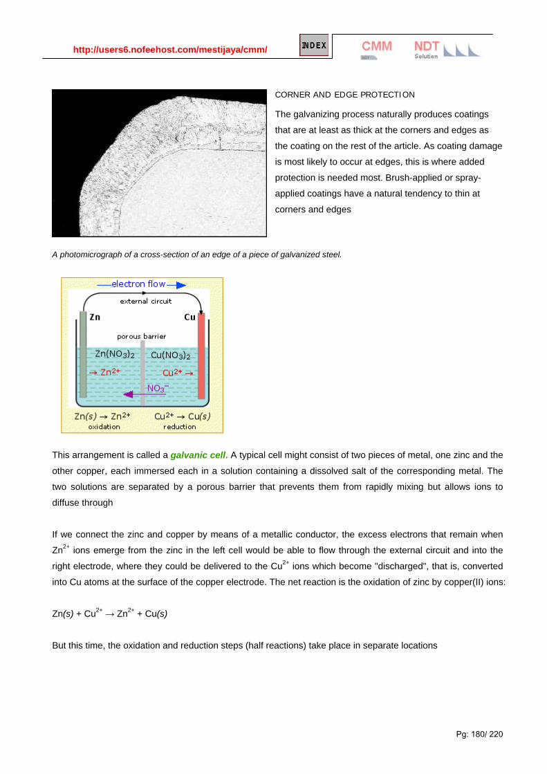
http://users6.nofeehost.com/mestijaya/cmm/
Pg: 180/ 220
CORNER AND EDGE PROTECTION
The galvanizing process naturally produces coatings
that are at least as thick at the corners and edges as
the coating on the rest of the article. As coating damage
is most likely to occur at edges, this is where added
protection is needed most. Brush-applied or spray-
applied coatings have a natural tendency to thin at
corners and edges
A photomicrograph of a cross-section of an edge of a piece of galvanized steel.
This arrangement is called a galvanic cell. A typical cell might consist of two pieces of metal, one zinc and the
other copper, each immersed each in a solution containing a dissolved salt of the corresponding metal. The
two solutions are separated by a porous barrier that prevents them from rapidly mixing but allows ions to
diffuse through
If we connect the zinc and copper by means of a metallic conductor, the excess electrons that remain when
Zn2+ ions emerge from the zinc in the left cell would be able to flow through the external circuit and into the
right electrode, where they could be delivered to the Cu2+ ions which become "discharged", that is, converted
into Cu atoms at the surface of the copper electrode. The net reaction is the oxidation of zinc by copper(II) ions:
Zn(s) + Cu2+ → Zn2+ + Cu(s)
But this time, the oxidation and reduction steps (half reactions) take place in separate locations

http://users6.nofeehost.com/mestijaya/cmm/
Pg: 181/ 220
Cathodic Protection Systems for Civil Works Structures http://www.vulcanhammer.net/marine/EM-1110-2-2704.pdf
Operation and Maintenance: Cathodic Protection Systems http://www.vulcanhammer.net/marine/ufc_3_570_06.pdf
Electrical Engineering Cathodic Protection http://www.vulcanhammer.net/marine/3_570_02.pdf
Cathodic and anodic protection: http://cheserver.ent.ohiou.edu/ChE430(530)/cathodic_anodic_protection.pdf
Corrosion and oxidation: http://www.ecm.auckland.ac.nz/course/cm322/322PPT_06.pdf
Metallic corrosion: http://cheserver.ent.ohiou.edu/ChE430(530)/

http://users6.nofeehost.com/mestijaya/cmm/
Pg: 182/ 220
http://www.chem1.com/acad/webtext/elchem/ec2.html
Anodic Protection.
Anodic protection or anodizing, is an electrolytic passivation process used to increase the thickness of the natural oxide layer on the surface of metal parts. Anodizing increases corrosion resistance and wear resistance, and provides better adhesion for paint primers and glues than bare metal. Anodic films can also be used for a number of cosmetic effects, either with thick porous coatings that can absorb dyes or with thin transparent coatings that add interference effects to reflected light. Anodizing is also used to prevent galling of threaded components and to make dielectric films for electrolytic capacitors. Anodic films are most commonly applied to protect aluminium alloys, although processes also exist for titanium, zinc, magnesium, and niobium. This process is not a useful treatment for iron or carbon steel because these metals exfoliate when oxidized; i.e. the iron oxide (also known as rust) flakes off, constantly exposing the underlying metal to corrosion. "Stay-Brite" is sometimes used as market name for products made from anodised aluminium such as brass replica.
Read more……

http://users6.nofeehost.com/mestijaya/cmm/
Pg: 183/ 220
Appendix

http://users6.nofeehost.com/mestijaya/cmm/
Pg: 184/ 220
Appendix A - Pourbaix Diagram The effects of pH on the form in which an element in a given oxidation state exists in natural waters can be summarized with predominance diagrams such as that for phosphorous (V) shown below.
However, if suitable reducing agents are present, the phosphorous may not remain in the +5 oxidation state. Knowledge of the pH condition of the environment is not sufficient for predicting the form in which an element will exist in natural waters. You must also take into consideration whether the aqueous environment is well aerated (oxidizing) or polluted with organic wastes (reducing). In order to add this variable, we must expand the predominance diagram to include the reduction potential of the environment as well as the pH. This type of predominance diagram is known as a Pourbaix diagram.Eo-pH diagram, or pE-pH diagram.
Simplified Pourbaix diagram for 1 M iron solutions.
Low E (or pE) values represent a reducing environment. High E values represent an oxidizing environment.
Administrator
Stamp
Administrator
Stamp
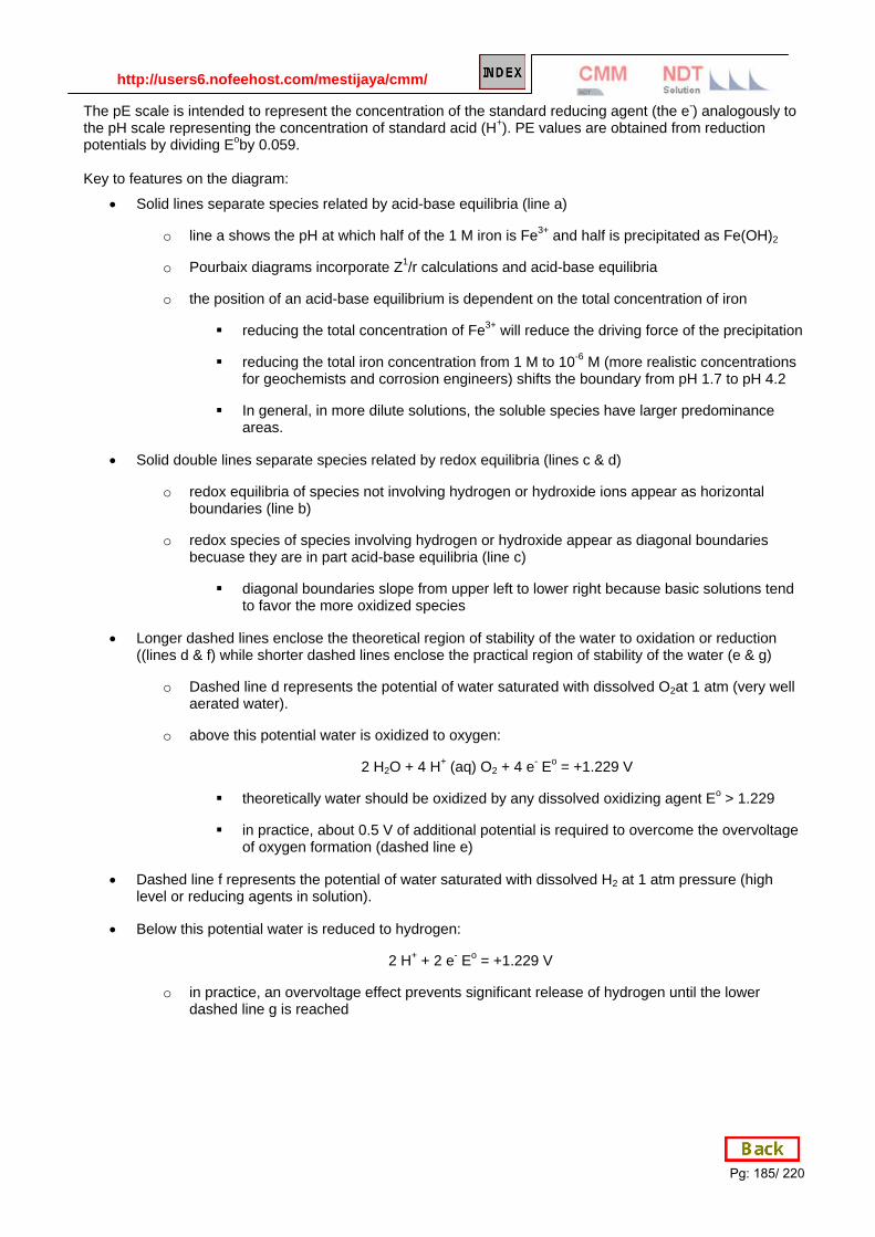
http://users6.nofeehost.com/mestijaya/cmm/
Pg: 185/ 220
The pE scale is intended to represent the concentration of the standard reducing agent (the e-) analogously to the pH scale representing the concentration of standard acid (H+). PE values are obtained from reduction potentials by dividing Eoby 0.059. Key to features on the diagram:
• Solid lines separate species related by acid-base equilibria (line a)
o line a shows the pH at which half of the 1 M iron is Fe3+ and half is precipitated as Fe(OH)2
o Pourbaix diagrams incorporate Z1/r calculations and acid-base equilibria
o the position of an acid-base equilibrium is dependent on the total concentration of iron
reducing the total concentration of Fe3+ will reduce the driving force of the precipitation
reducing the total iron concentration from 1 M to 10-6 M (more realistic concentrations for geochemists and corrosion engineers) shifts the boundary from pH 1.7 to pH 4.2
In general, in more dilute solutions, the soluble species have larger predominance areas.
• Solid double lines separate species related by redox equilibria (lines c & d)
o redox equilibria of species not involving hydrogen or hydroxide ions appear as horizontal boundaries (line b)
o redox species of species involving hydrogen or hydroxide appear as diagonal boundaries becuase they are in part acid-base equilibria (line c)
diagonal boundaries slope from upper left to lower right because basic solutions tend to favor the more oxidized species
• Longer dashed lines enclose the theoretical region of stability of the water to oxidation or reduction ((lines d & f) while shorter dashed lines enclose the practical region of stability of the water (e & g)
o Dashed line d represents the potential of water saturated with dissolved O2at 1 atm (very well aerated water).
o above this potential water is oxidized to oxygen:
2 H2O + 4 H+ (aq) O2 + 4 e- Eo = +1.229 V
theoretically water should be oxidized by any dissolved oxidizing agent Eo > 1.229
in practice, about 0.5 V of additional potential is required to overcome the overvoltage of oxygen formation (dashed line e)
• Dashed line f represents the potential of water saturated with dissolved H2 at 1 atm pressure (high level or reducing agents in solution).
• Below this potential water is reduced to hydrogen:
2 H+ + 2 e- Eo = +1.229 V
o in practice, an overvoltage effect prevents significant release of hydrogen until the lower dashed line g is reached

http://users6.nofeehost.com/mestijaya/cmm/
Pg: 186/ 220
Administrator
Stamp

http://users6.nofeehost.com/mestijaya/cmm/
Pg: 187/ 220
Uses of Pourbaix Diagrams:
• Any point on the diagram will give the termodynamically most stable (theoretically the most abundant) form of the element for that E and pH.
o E=+0.8 V and pH = 14 predominant form is FeO4
2-.
• The diagram gives a visual representation of the oxidizing and reducing abilities of the major stable compounds of an element
o Strong oxidizing agents and oxidizing conditions are found ONLY at the top of the diagram. The lower boundaries of strong oxidizing agents are high on the diagram.
o Reducing agents and reducing conditions are found at the bottom of a diagram and nowhere else. Strong reducing agents have boundaries that are low on the diagram.
o A species that prevails from top to bottom at the pH in question has no oxidizing or reducing properties at all within that range.
Administrator
Stamp

http://users6.nofeehost.com/mestijaya/cmm/
Pg: 188/ 220
EXAMPLE
On the Pourbaix diagram for iron find: 1. the chemical form of iron that is the strongest oxidizing agent.
2. the form of iron that is the strongest reducing agent
3. the form of iron that would predominate in a neutral solution at a potential of 0.00V
4. the standard reduction potential for the reduction of Fe2+ to Fe metal
For some elements, the predominance area for a given oxidation state may disappear completely above or below a given pH.
If the element is in an intermediate oxidation state, the element will undergo disproportionation at appropriate pH's.
Notice that predominance areas are missing for hypochlorite, chlorite and chlorate ions. This is due to either lack of electrochemical data for a species or (in this case) the fact that the ions are thermodynamically unstable to disproportionation. In the case of chlorine the rates of disproportionation reactions are slow enough that these chlorine species can be observed and used.
In predicting when cations and anions would react to form precipitates, we only considered the most stable oxidation states of the elements so that interference of redox reactions between the anion and cation could be avoided.
Administrator
Stamp
Administrator
Stamp
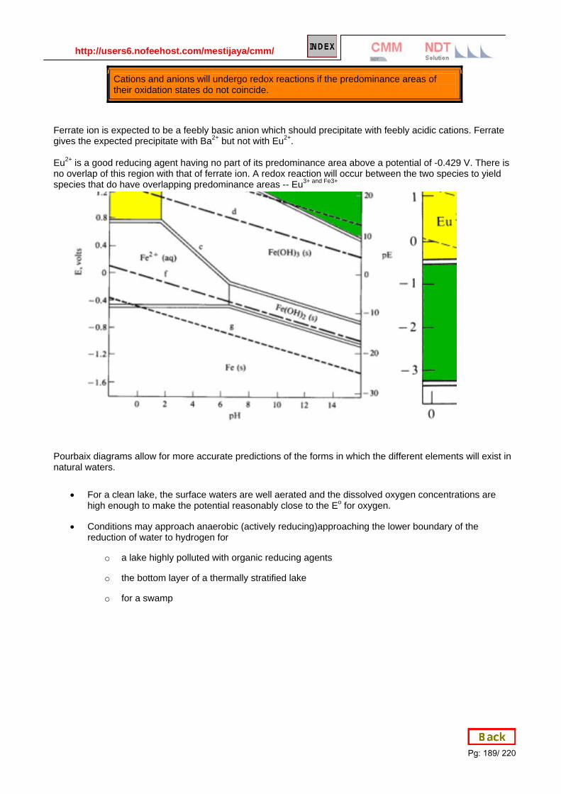
http://users6.nofeehost.com/mestijaya/cmm/
Pg: 189/ 220
Cations and anions will undergo redox reactions if the predominance areas of their oxidation states do not coincide.
Ferrate ion is expected to be a feebly basic anion which should precipitate with feebly acidic cations. Ferrate gives the expected precipitate with Ba2+ but not with Eu2+. Eu2+ is a good reducing agent having no part of its predominance area above a potential of -0.429 V. There is no overlap of this region with that of ferrate ion. A redox reaction will occur between the two species to yield species that do have overlapping predominance areas -- Eu3+ and Fe3+
Pourbaix diagrams allow for more accurate predictions of the forms in which the different elements will exist in natural waters.
• For a clean lake, the surface waters are well aerated and the dissolved oxygen concentrations are high enough to make the potential reasonably close to the Eo for oxygen.
• Conditions may approach anaerobic (actively reducing)approaching the lower boundary of the reduction of water to hydrogen for
o a lake highly polluted with organic reducing agents
o the bottom layer of a thermally stratified lake
o for a swamp
Administrator
Stamp
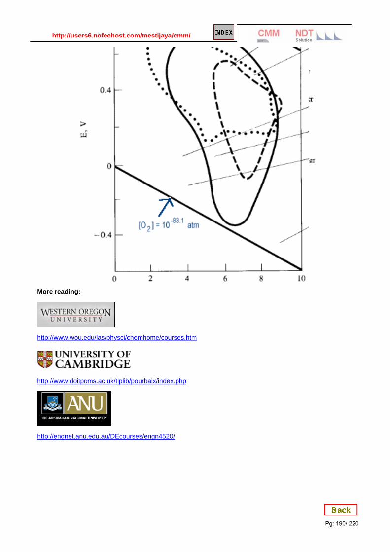
http://users6.nofeehost.com/mestijaya/cmm/
Pg: 190/ 220
More reading:
http://www.wou.edu/las/physci/chemhome/courses.htm
http://www.doitpoms.ac.uk/tlplib/pourbaix/index.php
http://engnet.anu.edu.au/DEcourses/engn4520/
Administrator
Stamp

http://users6.nofeehost.com/mestijaya/cmm/
Pg: 191/ 220
Answer 1: FeO42- is the strongest oxidizing agent
Answer 2: Elemental Fe
Administrator
Stamp
Administrator
Stamp

http://users6.nofeehost.com/mestijaya/cmm/
Pg: 192/ 220
Answer 3: Fe(OH)3
Answer 4: -0.5 V3
Administrator
Stamp
Administrator
Stamp

http://users6.nofeehost.com/mestijaya/cmm/
Pg: 193/ 220
APPENDIX B: Hydrogen damages:
Factors Affecting In-Service Cracking of Weld Zone in Corrosive Service
January 1986
Category: Incidents
Summary: The following article is a part of National Board Classic Series and it was published in the National
Board BULLETIN . The article was reprinted in the January 1986 National Board BULLETIN . Permission to
reprint was granted by the Illinois Division of Boiler and Pressure Vessel Safety, D. R. Gallup, Superintendent.
(6 printed pages)
< This article describes the cause of failure of a monoethandamine (MEA) absorber vessel that ruptured in the
state of Illinois in 1984, resulting in 17 fatalities and property damage in excess of $100 million.
VESSEL DESCRIPTION
The ruptured vessel was designed in accordance with The American Society of Mechanical Engineers (ASME)
Boiler and Pressure Vessel Code, Section VIII rules. The vessel was constructed of 1 inch thick SA516 Gr 70
steel plates rolled and welded with full penetration submerged arc joints, without postweld heat treatment. The
cylindrical vessel measures 81/2 feet in diameter with hemispherical ends comprising an overall height of 55
feet. Operating conditions were 200 psig internal pressure containing largely propane and hydrogen sulfide at
100¡F. An internal system distributed monoethanolamine (MEA) through the vessel for the purpose of
removing hydrogen sulfide from the gas.
VESSEL OPERATING HISTORY
The vessel went into operation in 1969. Soon after start-up, hydrogen blisters were observed to be forming in
the bottom two courses of the cylindrical vessel wall. Metallurgical analysis showed laminations to be present
in the steel.
In 1974, due to the large blister area found in the second course, a full circumferential ring 8 feet high was
replaced in field by inserting a preformed ring in three equal circumferential segments. The welding was
accomplished by the shielded metal arc process ("stick welding") without preheating or postweld heat treating.
The ASME Code does not require preheating or postweld heat treatment for SA516 Gr 70 steel 1 inch thick or
less. However, this steel is slightly air hardenable during welding, depending on the welding process, position
and procedure employed. This material is classified as a P1, Group 2 material according to ASME Code
Section IX.
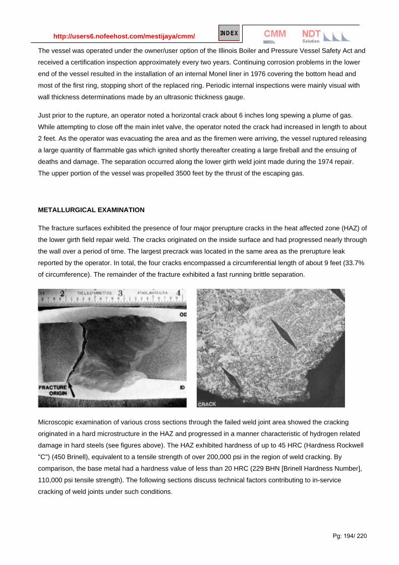
http://users6.nofeehost.com/mestijaya/cmm/
Pg: 194/ 220
The vessel was operated under the owner/user option of the Illinois Boiler and Pressure Vessel Safety Act and
received a certification inspection approximately every two years. Continuing corrosion problems in the lower
end of the vessel resulted in the installation of an internal Monel liner in 1976 covering the bottom head and
most of the first ring, stopping short of the replaced ring. Periodic internal inspections were mainly visual with
wall thickness determinations made by an ultrasonic thickness gauge.
Just prior to the rupture, an operator noted a horizontal crack about 6 inches long spewing a plume of gas.
While attempting to close off the main inlet valve, the operator noted the crack had increased in length to about
2 feet. As the operator was evacuating the area and as the firemen were arriving, the vessel ruptured releasing
a large quantity of flammable gas which ignited shortly thereafter creating a large fireball and the ensuing of
deaths and damage. The separation occurred along the lower girth weld joint made during the 1974 repair.
The upper portion of the vessel was propelled 3500 feet by the thrust of the escaping gas.
METALLURGICAL EXAMINATION
The fracture surfaces exhibited the presence of four major prerupture cracks in the heat affected zone (HAZ) of
the lower girth field repair weld. The cracks originated on the inside surface and had progressed nearly through
the wall over a period of time. The largest precrack was located in the same area as the prerupture leak
reported by the operator. In total, the four cracks encompassed a circumferential length of about 9 feet (33.7%
of circumference). The remainder of the fracture exhibited a fast running brittle separation.
Microscopic examination of various cross sections through the failed weld joint area showed the cracking
originated in a hard microstructure in the HAZ and progressed in a manner characteristic of hydrogen related
damage in hard steels (see figures above). The HAZ exhibited hardness of up to 45 HRC (Hardness Rockwell
"C") (450 Brinell), equivalent to a tensile strength of over 200,000 psi in the region of weld cracking. By
comparison, the base metal had a hardness value of less than 20 HRC (229 BHN [Brinell Hardness Number],
110,000 psi tensile strength). The following sections discuss technical factors contributing to in-service
cracking of weld joints under such conditions.

http://users6.nofeehost.com/mestijaya/cmm/
Pg: 195/ 220
WELDING FACTORS
Welding procedures adopted must take into account not only the minimum requirements of ASME Code
Section IX and the appropriate design section, but must also be suitable for the specific service conditions
likely to be encountered. Stress corrosion cracking, hydrogen embrittlement and corrosion fatigue are typical of
material/environment interactions that are not fully accounted for in the ASME Code design rules. Appreciation
of such potential problems is left to the process designer, vessel designer, owner, contractor or inspector.
Reliance on only the ASME Code rules is not enough to assure safety of vessels operating in many corrosive
environments.
The weld HAZ contains potentially crack susceptible metallurgical structure, hardness variations and residual
stresses that can promote various types of unexpected service induced cracking depending on the chemical
environment and operating temperature. Industry experience has shown that steel having a hardness of 22
HRC maximum is resistant to cracking even under severe exposure conditions where hydrogen can be
absorbed by the steel. At hardness levels above 22 HRC, steel becomes less resistant to hydrogen induced
cracking and other environmental effects. At high hardness (above about 40 HRC), steel becomes quite
susceptible to cracking in the presence of hydrogen.
In potentially critical environments, the weld joint properties must be carefully controlled. Weld HAZ hardness
is a function of the cooling rate after welding. Preheating to at least several hundred degrees and maintaining
an interpass temperature during welding can warm the joint area sufficiently to prevent rapid cooling after
welding. Carbon content and alloy composition will dictate the appropriate temperature. Rapid cooling of even
mild steel can result in unacceptably high HAZ hardness for service in aggressive chemical environments.
Postweld heat treating (PWHT) is often necessary in critical weld joints to temper (soften) or stress relieve
weld joints in rugged duty or aggressive chemical environments. Higher carbon steels and more alloyed steels
are nearly always given PWHT. Even when not specifically called for in ASME Code Section IX, preheating or
PWHT may be necessary. In hydrogen environments, avoiding formation of a hard HAZ is crucial. Other
corrosive environments present similar concerns.
The specific weld procedure employed must be developed by individuals with pertinent knowledge of the
ASME Code (which should be viewed as the minimum guideline) as well as material behavior expertise in
aggressive environments.
CORROSION FACTORS
There are many specific ways that corrosion may contribute to unexpected failures. Often, corrosion problems
are handled simply by making the component thicker (a corrosion allowance). This is appropriate so long as
the corrosive conditions are known, the vessel is periodically inspected and if the corrosion is not highly
localized. Corrosion fatigue, pitting, stress corrosion and hydrogen attack are examples of metal/environment
problems that cannot be adequately handled by a corrosion allowance and superficial inspection methods
alone.
Hydrogen-assisted cracking and stress corrosion cracking will not always be readily apparent. Carefully
preparing the surface for visual examination, along with other techniques such as dye penetrant, magnetic

http://users6.nofeehost.com/mestijaya/cmm/
Pg: 196/ 220
particle, or shear wave ultrasonic inspection methods, may be required to detect such defects. Corrosion-
enhanced damage is often associated with welds, nozzles, or areas of unstable environmental conditions;
places where either the environment, stress, or metallurgical condition may abruptly change.
High pressure hydrogen or acidic environments can
introduce damaging levels of hydrogen into steel,
particularly hard steels or hard HAZs. The
mechanism of hydrogen evolution and penetration
is illustrated above. The absorbed hydrogen atoms
are attracted to high stress regions in the structure,
such as crack-like defects. The combination of hard
steel and absorbed hydrogen leads to the
development of cracks. Once inside the steel, these
hydrogen atoms also migrate to inclusions or
laminations and create hydrogen fissures and
blisters.
Hydrogen sulfide, cyanide and arsenic, even in
trace deposits, are examples of materials that
greatly increase the amount of hydrogen that
becomes absorbed by steel. Therefore, under
acidic corrosive conditions, particularly those
environments that also contain hydrogen sulfide,
cyanide or arsenic, hydrogen damage can be
severe. Weld HAZ hardness must be carefully
controlled under these circumstances, regardless of
whether or not the ASME Code or the National
Board Inspection Code specifically address the
subject.
Welding procedures, repair methods, and
inspection procedures must include careful
consideration of potential failure modes in corrosive environments. If pressure vessels or allied components
are operating in an aggressive environment, special steps should be taken to assure that individuals with
pertinent expertise are involved in the planning and review stages of design, inspections and repairs. When
distress signals are present, take the time to evaluate the cause and determine what special precautions are
necessary.

http://users6.nofeehost.com/mestijaya/cmm/
Pg: 197/ 220
SUMMARY
The problems of in-service cracking of weld zones can be minimized by attention to the important factors
summarized below.
• Preheat or postweld heat treat weld joints that may develop a hard HAZ when corrosive conditions are
met.
• Inspect weld HAZs for cracks by a suitable NDE method if hard HAZs are suspected.
• Field repair welds are likely to have hard HAZs unless proper preheat or PWHT is applied.
• Small welds on thick members and arc strikes are examples of conditions resulting in rapid heating
and cooling and are likely areas for trouble.
• Shop welds made according to the ASME Code may also crack in service under severely corrosive
conditions.
• Preheating field weld joints will help drive off the dissolved hydrogen that has been picked up by the
steel in service.
• Be particularly cautious when inspecting critical components in unfamiliar corrosive service, especially
when prior history reveals problems and when field repairs have been made.

http://users6.nofeehost.com/mestijaya/cmm/
Pg: 198/ 220
APPENDIX C: Degradation Mechanisms for the Oil and Gas Industry
API RP571 "Damage Mechanisms Affecting Fixed Equipment in the Refining Industry." This recommended
practice describes degradation mechanisms found in refineries, affected materials, critical factors used to
identify the mechanism, affected units or equipment, appearance or morphology of damage,
prevention/mitigation measures, inspection and monitoring recommendations, and related mechanisms.
References are also provided where the reader may be looking for additional information regarding the
degradation mechanism.
Figure 1- Sand erosion of wellhead piping

http://users6.nofeehost.com/mestijaya/cmm/
Pg: 199/ 220
Figure 2- Erosion/Corrosion at a pipe elbow
Figure 3- Shackle pin from FPSO mooring chain

http://users6.nofeehost.com/mestijaya/cmm/
Pg: 200/ 220
Figure 4 - Galvanic corrosion of seawater cooler brass tube sheet connected to titanium distribution grid (bars shown
looking through nozzle) and copper nickel cover/nozzle.
Figure 5 - Steam manifold valve, located on ship deck, wet mineral wool insulation.

http://users6.nofeehost.com/mestijaya/cmm/
Pg: 201/ 220
Figure 6 - Corrosion under insulation (CUI) on steam condensate return line at main deck penetration.
Figure 7 - This design facilitates water entrapment, coating breakdown and accelerated corrosion

http://users6.nofeehost.com/mestijaya/cmm/
Pg: 202/ 220
Case Study: 1
Factors Affecting In-Service Cracking of Weld Zone in Corrosive Service Harold L. Schmeilski
Illinois Division of Boiler and Pressure Vessel Safety, D. R. Gallup, Superintendent.
January 1986
Category: Incidents
Summary: The following article is a part of National Board Classic Series and it was published in the National
Board BULLETIN . The article was reprinted in the January 1986 National Board BULLETIN . Permission to
reprint was granted by the Illinois Division of Boiler and Pressure Vessel Safety, D. R. Gallup, Superintendent.
(6 printed pages)
< This article describes the cause of failure of a monoethandamine (MEA) absorber vessel that ruptured in the
state of Illinois in 1984, resulting in 17 fatalities and property damage in excess of $100 million.
VESSEL DESCRIPTION
The ruptured vessel was designed in accordance with The American Society of Mechanical Engineers (ASME)
Boiler and Pressure Vessel Code, Section VIII rules. The vessel was constructed of 1 inch thick SA516 Gr 70
steel plates rolled and welded with full penetration submerged arc joints, without postweld heat treatment. The
cylindrical vessel measures 81/2 feet in diameter with hemispherical ends comprising an overall height of 55
feet. Operating conditions were 200 psig internal pressure containing largely propane and hydrogen sulfide at
100¡F. An internal system distributed monoethanolamine (MEA) through the vessel for the purpose of
removing hydrogen sulfide from the gas.
VESSEL OPERATING HISTORY
The vessel went into operation in 1969. Soon after start-up, hydrogen blisters were observed to be forming in
the bottom two courses of the cylindrical vessel wall. Metallurgical analysis showed laminations to be present
in the steel.
In 1974, due to the large blister area found in the second course, a full circumferential ring 8 feet high was
replaced in field by inserting a preformed ring in three equal circumferential segments. The welding was
accomplished by the shielded metal arc process ("stick welding") without preheating or postweld heat treating.
The ASME Code does not require preheating or postweld heat treatment for SA516 Gr 70 steel 1 inch thick or
less. However, this steel is slightly air hardenable during welding, depending on the welding process, position
and procedure employed. This material is classified as a P1, Group 2 material according to ASME Code
Section IX.
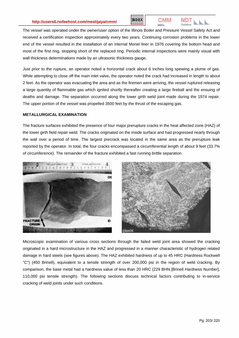
http://users6.nofeehost.com/mestijaya/cmm/
Pg: 203/ 220
The vessel was operated under the owner/user option of the Illinois Boiler and Pressure Vessel Safety Act and
received a certification inspection approximately every two years. Continuing corrosion problems in the lower
end of the vessel resulted in the installation of an internal Monel liner in 1976 covering the bottom head and
most of the first ring, stopping short of the replaced ring. Periodic internal inspections were mainly visual with
wall thickness determinations made by an ultrasonic thickness gauge.
Just prior to the rupture, an operator noted a horizontal crack about 6 inches long spewing a plume of gas.
While attempting to close off the main inlet valve, the operator noted the crack had increased in length to about
2 feet. As the operator was evacuating the area and as the firemen were arriving, the vessel ruptured releasing
a large quantity of flammable gas which ignited shortly thereafter creating a large fireball and the ensuing of
deaths and damage. The separation occurred along the lower girth weld joint made during the 1974 repair.
The upper portion of the vessel was propelled 3500 feet by the thrust of the escaping gas.
METALLURGICAL EXAMINATION
The fracture surfaces exhibited the presence of four major prerupture cracks in the heat affected zone (HAZ) of
the lower girth field repair weld. The cracks originated on the inside surface and had progressed nearly through
the wall over a period of time. The largest precrack was located in the same area as the prerupture leak
reported by the operator. In total, the four cracks encompassed a circumferential length of about 9 feet (33.7%
of circumference). The remainder of the fracture exhibited a fast running brittle separation.
Microscopic examination of various cross sections through the failed weld joint area showed the cracking
originated in a hard microstructure in the HAZ and progressed in a manner characteristic of hydrogen related
damage in hard steels (see figures above). The HAZ exhibited hardness of up to 45 HRC (Hardness Rockwell
"C") (450 Brinell), equivalent to a tensile strength of over 200,000 psi in the region of weld cracking. By
comparison, the base metal had a hardness value of less than 20 HRC (229 BHN [Brinell Hardness Number],
110,000 psi tensile strength). The following sections discuss technical factors contributing to in-service
cracking of weld joints under such conditions.

http://users6.nofeehost.com/mestijaya/cmm/
Pg: 207/ 220
Case Study: 2
High temperature degradation in power plants and refineries
Heloisa Cunha FurtadoI, *; Iain Le MayII, *
ICEPEL, Centro de Pesquisas de Energia Elétrica C.P. 2754, Cidade Universitaria,
20001-970 Rio de Janeiro - RJ, Brazil IIMetallurgical Consulting Services Ltd. P.O. Box 5006, Saskatoon, SK S7K 4E3,
Canada
ABSTRACT
Thermal power plants and refineries around the world share many of the same problems,
namely aging equipment, high costs of replacement, and the need to produce more
efficiently while being increasingly concerned with issues of safety and reliability. For
equipment operating at high temperature, there are many different mechanisms of
degradation, some of which interact, and the rate of accumulation of damage is not
simple to predict. The paper discusses the mechanisms of degradation at high
temperature and methods of assessment of such damage and of the remaining safe life
for operation.
Keywords: degradation mechanisms, high temperature, life assessment, power plants,
refineries
1. Introduction
Thermal power plants and refineries around the world are aging and need to be
assessed to ensure continued safe operation. Replacement is frequently not an option
because of high capital costs, and the much lower cost of continuing the operation of the
older plant. However, reliability and safety are issues that have become much more
important in recent years, so the assessment of damage and of the risk associated with
failure have become increasingly important. In order to make such assessments on a
sound basis, it is necessary to know the potential mechanisms of degradation and the
rate of accumulation of damage that may be expected with each.

http://users6.nofeehost.com/mestijaya/cmm/
Pg: 204/ 220
WELDING FACTORS
Welding procedures adopted must take into account not only the minimum requirements of ASME Code
Section IX and the appropriate design section, but must also be suitable for the specific service conditions
likely to be encountered. Stress corrosion cracking, hydrogen embrittlement and corrosion fatigue are typical of
material/environment interactions that are not fully accounted for in the ASME Code design rules. Appreciation
of such potential problems is left to the process designer, vessel designer, owner, contractor or inspector.
Reliance on only the ASME Code rules is not enough to assure safety of vessels operating in many corrosive
environments.
The weld HAZ contains potentially crack susceptible metallurgical structure, hardness variations and residual
stresses that can promote various types of unexpected service induced cracking depending on the chemical
environment and operating temperature. Industry experience has shown that steel having a hardness of 22
HRC maximum is resistant to cracking even under severe exposure conditions where hydrogen can be
absorbed by the steel. At hardness levels above 22 HRC, steel becomes less resistant to hydrogen induced
cracking and other environmental effects. At high hardness (above about 40 HRC), steel becomes quite
susceptible to cracking in the presence of hydrogen.
In potentially critical environments, the weld joint properties must be carefully controlled. Weld HAZ hardness
is a function of the cooling rate after welding. Preheating to at least several hundred degrees and maintaining
an interpass temperature during welding can warm the joint area sufficiently to prevent rapid cooling after
welding. Carbon content and alloy composition will dictate the appropriate temperature. Rapid cooling of even
mild steel can result in unacceptably high HAZ hardness for service in aggressive chemical environments.
Post weld heat treating (PWHT) is often necessary in critical weld joints to temper (soften) or stress relieve
weld joints in rugged duty or aggressive chemical environments. Higher carbon steels and more alloyed steels
are nearly always given PWHT. Even when not specifically called for in ASME Code Section IX, preheating or
PWHT may be necessary. In hydrogen environments, avoiding formation of a hard HAZ is crucial. Other
corrosive environments present similar concerns.
The specific weld procedure employed must be developed by individuals with pertinent knowledge of the
ASME Code (which should be viewed as the minimum guideline) as well as material behavior expertise in
aggressive environments.
CORROSION FACTORS
There are many specific ways that corrosion may contribute to unexpected failures. Often, corrosion problems
are handled simply by making the component thicker (a corrosion allowance). This is appropriate so long as
the corrosive conditions are known, the vessel is periodically inspected and if the corrosion is not highly
localized. Corrosion fatigue, pitting, stress corrosion and hydrogen attack are examples of metal/environment
problems that cannot be adequately handled by a corrosion allowance and superficial inspection methods
alone.

http://users6.nofeehost.com/mestijaya/cmm/
Pg: 205/ 220
Hydrogen-assisted cracking and stress corrosion
cracking will not always be readily apparent.
Carefully preparing the surface for visual
examination, along with other techniques such as
dye penetrant, magnetic particle, or shear wave
ultrasonic inspection methods, may be required to
detect such defects. Corrosion-enhanced damage is
often associated with welds, nozzles, or areas of
unstable environmental conditions; places where
either the environment, stress, or metallurgical
condition may abruptly change.
High pressure hydrogen or acidic environments can
introduce damaging levels of hydrogen into steel,
particularly hard steels or hard HAZs. The
mechanism of hydrogen evolution and penetration
is illustrated above. The absorbed hydrogen atoms
are attracted to high stress regions in the structure,
such as crack-like defects. The combination of hard
steel and absorbed hydrogen leads to the
development of cracks. Once inside the steel, these
hydrogen atoms also migrate to inclusions or
laminations and create hydrogen fissures and
blisters.
Hydrogen sulfide, cyanide and arsenic, even in
trace deposits, are examples of materials that greatly increase the amount of hydrogen that becomes
absorbed by steel. Therefore, under acidic corrosive conditions, particularly those environments that also
contain hydrogen sulfide, cyanide or arsenic, hydrogen damage can be severe. Weld HAZ hardness must be
carefully controlled under these circumstances, regardless of whether or not the ASME Code or the National
Board Inspection Code specifically address the subject.
Welding procedures, repair methods, and inspection procedures must include careful consideration of potential
failure modes in corrosive environments. If pressure vessels or allied components are operating in an
aggressive environment, special steps should be taken to assure that individuals with pertinent expertise are
involved in the planning and review stages of design, inspections and repairs. When distress signals are
present, take the time to evaluate the cause and determine what special precautions are necessary.

http://users6.nofeehost.com/mestijaya/cmm/
Pg: 206/ 220
SUMMARY
The problems of in-service cracking of weld zones can be minimized by attention to the important factors
summarized below.
• Preheat or postweld heat treat weld joints that may develop a hard HAZ when corrosive conditions are
met.
• Inspect weld HAZs for cracks by a suitable NDE method if hard HAZs are suspected.
• Field repair welds are likely to have hard HAZs unless proper preheat or PWHT is applied.
• Small welds on thick members and arc strikes are examples of conditions resulting in rapid heating
and cooling and are likely areas for trouble.
• Shop welds made according to the ASME Code may also crack in service under severely corrosive
conditions.
• Preheating field weld joints will help drive off the dissolved hydrogen that has been picked up by the
steel in service.
• Be particularly cautious when inspecting critical components in unfamiliar corrosive service, especially
when prior history reveals problems and when field repairs have been made.

http://users6.nofeehost.com/mestijaya/cmm/
Pg: 208/ 220
2. Deterioration mechanisms
The principal deterioration mechanisms in high temperature plant are creep damage,
microstructural degradation, high temperature fatigue, creep-fatigue, embrittlement,
carburization, hydrogen damage, graphitization, thermal shock, erosion, liquid metal
embrittlement, and high temperature corrosion of various types. Additionally, stress
corrosion cracking and aqueous corrosion may be problems although these damage
mechanisms are not generally expected in high temperature components: however they
may occur when components are cooled down and liquid is still present within or in
contact with them. Aspects of each will be considered in turn.
2.1. Creep
Creep is one of the most serious high temperature damage mechanisms. It involves
time-dependent deformation and high temperature creep cracking generally develops in
an intercrystalline manner in components of engineering importance that fail over an
extended time. These include boiler superheater and other components operating at
high temperature, petrochemical furnace and reactor vessel components and gas
turbine blades. At higher temperatures, as can occur with local overheating, deformation
may be localized, with large plastic strains and local wall thinning. At somewhat lower
temperatures and under correspondingly higher stress levels, fracture can be
transgranular in nature. To characterize the type of deformation and the relevant fracture
mechanisms to be expected or to correlate observed deformation and fracture
characteristics with probable operating conditions, deformation and fracture mechanism
maps as developed by Ashby1 and Mohamed and Langdon2 can be useful in this regard.
Classification of creep damage in steam generators has been made using the largely
qualitative approach of Neubauer and Wedel3 based on the distribution of creep voids
and microcracks observed by in situ metallography, and illustrated schematically in Fig.
1. However, as has been shown subsequently, the method is unreliable for CrMo steels,
at least, as apparent voids may be developed during the polishing and etching
sequence4-5. Replica metallography is useful, however, and the degree of
spheroidization of carbides in bainitic and pearlitic structures can provide a good
indication of the degree of thermal exposure and can be correlated with the extent of
creep damage6. Used in conjunction with hardness measurements, indicating loss of
tensile strength, these semi-quantitative tools have served to allow estimates of
remaining safe life to be made of components undergoing damage by creep.

http://users6.nofeehost.com/mestijaya/cmm/
Pg: 209/ 220
2.2. Microstructural degradation
Microstructural degradation is a damage mechanism that can lead to failure by some
other process such as creep, fatigue or more rapid fracture. It is important that it is
recognized as a mechanism of damage as it can result in a significant loss in strength in
a material. It is appropriate to discuss this following directly upon the discussion of creep
damage, because the two mechanisms are closely bound together and, indeed, are
difficult to separate. It has already been noted that Cr-Mo steels that are liable to fail by
creep in a short time may display spheroidization of the carbides but little, if any, void
formation. The formation of voids appears, in many cases, to be a very local
phenomenon occurring very close to the time of fracture. It is worth commenting that the
approach of Kachanov7 to the accumulation of damage (the continuum damage
approach), postulating a loss of effective area or a loss in resistance to deformation,
does not require any actual voids or loss of cross-section, and microstructural damage
may be the dominant aspect of reduction in creep strength. Thus, evaluation of the
potential for creep failure and the extent of creep damage needs to take account of
microstructural changes. This may be done directly or through a measurement of the
change in hardness, as this quantity provides an indication of the resistance of a
material to deformation. Recently, Dyson8 has discussed continuum damage mechanics
modelling of creep in terms of several damage mechanisms, including microstructural
degradation.
Another example of microstructural degradation is decarburization of carbon or alloy
steel when exposed to an oxidizing atmosphere at high temperature. There is a loss of
strength in the surface layer of the steel.
2.3. High temperature fatigue and thermal fatigue
Fatigue, involving repeated stressing, can lead to failure at high temperature as it does
at low temperature. In components operating at high temperature it often arises through
temperature changes that can lead to cyclic thermal stresses. This can lead to thermal
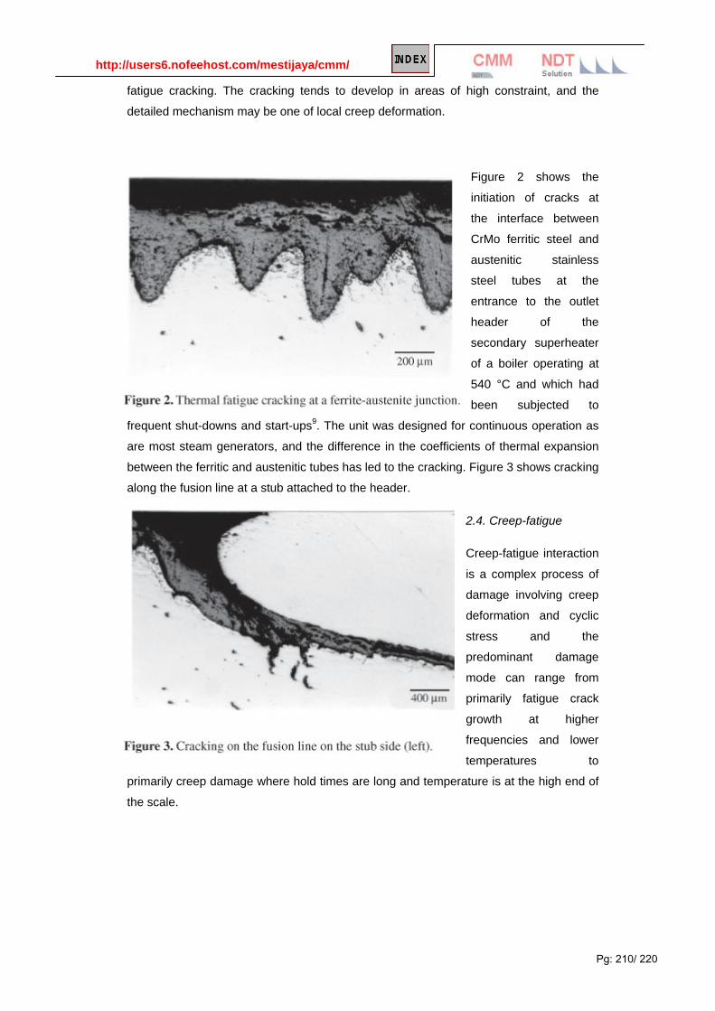
http://users6.nofeehost.com/mestijaya/cmm/
Pg: 210/ 220
fatigue cracking. The cracking tends to develop in areas of high constraint, and the
detailed mechanism may be one of local creep deformation.
Figure 2 shows the
initiation of cracks at
the interface between
CrMo ferritic steel and
austenitic stainless
steel tubes at the
entrance to the outlet
header of the
secondary superheater
of a boiler operating at
540 °C and which had
been subjected to
frequent shut-downs and start-ups9. The unit was designed for continuous operation as
are most steam generators, and the difference in the coefficients of thermal expansion
between the ferritic and austenitic tubes has led to the cracking. Figure 3 shows cracking
along the fusion line at a stub attached to the header.
2.4. Creep-fatigue
Creep-fatigue interaction
is a complex process of
damage involving creep
deformation and cyclic
stress and the
predominant damage
mode can range from
primarily fatigue crack
growth at higher
frequencies and lower
temperatures to
primarily creep damage where hold times are long and temperature is at the high end of
the scale.

http://users6.nofeehost.com/mestijaya/cmm/
Pg: 211/ 220
2.5. Embrittlement and carburization
Embrittlement from precipitation can arise in a number of different ways. For example,
sigma phase formation in austenitic stainless steels maintained at high temperature or
cycled through the critical temperature range (approximately 565 to 980 °C) causes loss
of ductility and embrittlement. Ferritic stainless steels may be subject to an embrittlement
phenomenon when held at or cooled over the temperature range 550 to 400 °C10. If the
temperature conditions are considered likely to lead to such effects, metallographic
checks are advisable after extended exposure prior to an unexpected rupture developing.
In addition to the embrittlement of ferritic steels exposed to high temperature during
service, and of austenitic stainless steels through the formation of sigma phase,
carburization can produce brittle material when a component is exposed to a carburizing
atmosphere for extended time at high temperature. Figure 4 shows extensive carbide
formation in the hot gas casing of a gas turbine used for peak load power generation
after 18,000 h of operation, involving 1,600 operating cycles. With a gas-side
temperature of 985 °C and an air side temperature of 204 °C, the 321 stainless steel had
developed severe thermal (fatigue) cracking. The cracks had initiated at the brittle,
carburized gas side surface, the material having little resistance to bending without
cracks occurring.
2.6. Hydrogen damage
Hydrogen damage, arising particularly in petrochemical plant, can occur in carbon steels
through diffusion of atomic hydrogen into the metal, where it combines with the carbon in
the Fe3C to form methane and to eliminate the pearlite constituent. This is a special case
of micro structural degradation, and is much less common today than in the past

http://users6.nofeehost.com/mestijaya/cmm/
Pg: 212/ 220
because of the use of low-alloy steels containing elements that stabilize carbides. Figure
5 shows carbon steel from a catalytic cracking unit. Carbide from the original pearlite has
been converted to methane, producing voids. In fact, recrystallization of the ferrite was
observed around some of the voids, produced by the combination of deformation under
pressure of the methane and the elevated temperature. The steel had been subjected to
a temperature during service that was higher than appropriate for the grade of steel
employed.
Hydrogen-assisted cracking is a potential problem in petroleum reactor pressure vessels
in hydrogen service, and the concern is that such sub-critical cracks do not reach a
critical size for failure. Relations are available to estimate crack growth rates, and the
important matter is the ability to detect and measure accurately the depth of such cracks
lying beneath stainless steel cladding so that accurate predictions can be made.
2.7. Graphitization
Graphitization can take place in ferritic steels after exposure to high temperature for
extended time, owing to reversion of the cementite in the pearlite to the more stable
graphite phase. It is a particular form of microstructural degradation that was formerly
observed relatively frequently in petrochemical components. With the development of
more stable CrMo steels, it is not often seen today, but occurs from time to time both in
petrochemical plant and in steam generators in which the temperature is high and the
material is not entirely stable.
Figure 6 shows graphitization in a steam pipe of DIN 15Mo3 alloy steel at the exit of a
superheater at a nominal operating temperature of 480 °C. The tube suffered a local
failure in the form of a "window" after some 100,000 h of service. Clearly the
temperature was in excess of that which the material could withstand without serious
deterioration.

http://users6.nofeehost.com/mestijaya/cmm/
Pg: 213/ 220
Fracture occurred along planes of graphite nodules, with decohesion between the
graphite and the ferrite matrix, these regions linking together from the growth of creep
cracks as shown in Fig. 7. The formation of graphite in local planes or lines is believed to
be due either to banding in the original structure or to local cold working during tube
straightening, as can occur when Lüder's bands are produced.

http://users6.nofeehost.com/mestijaya/cmm/
Pg: 214/ 220
2.8. Thermal shock
Thermal shock involves rapid temperature change producing a steep temperature
gradient and consequent high stresses. Such loading can produce cracking, particularly
if the shock loading is repetitive. Cracks generated in this manner progress by a process
of thermal fatigue. Such conditions are not encountered in thermal generating plants and
refineries under normal operating conditions, but may arise during emergencies or with
an excursion in the operating conditions. Brittle materials are much more susceptible to
thermal shock and ceramic components, as are becoming more common in advanced
gas turbines for example, are susceptible to such damage.
2.9. Erosion
Erosion can occur in high temperature components when there are particles present in
flowing gases. This is a not uncommon situation in coal-fired power plants in which
erosion by fly-ash can lead to tube thinning and failure in economizers and reheaters,
and sootblower erosion can produce thinning in superheaters and reheaters in those
tubes that are in the paths of the blowers. The solution to fly ash erosion depends in part
on improving boiler flue gas distribution, and cutting down on local excessively high gas
velocities. The control of soot blower erosion depends on many factors including
excessive blowing pressure, poor maintenance and the provision of effective tube
protection where required.
2.10. Liquid metal embrittlement (LME)
The classic example of liquid copper metal embrittlement of steel is shown in Fig. 8,
where the Cu has penetrated along the austenite grain boundaries when the carbon
steel was at a temperature of 1100 °C.

http://users6.nofeehost.com/mestijaya/cmm/
Pg: 215/ 220
Liquid metal
embrittlement can
occur with a number of
liquid-solid metal
combinations, and one
that can have serious
consequences for the
refining industry is LME
of austenitic stainless
steel by zinc. Rapid
embrittlement can
occur at temperatures
above 750 °C, and has
been observed to
produce widespread cracking in stainless steel components after a fire when there is a
source of Zn present such as galvanized steel structural parts, or when there is
contamination from Zn-based paints11. This latter source led to considerable cracking at
the time of the Flixborough disaster12. Cracking can be extremely rapid (m/s) and stress
levels can be as low as 20 MPa for such cracking to take place13.
Two types of attack are
believed to occur in the
process of Zn-
embrittlement of
austenitic stainless
steel14, as illustrated in
Fig. 9. Type 1
embrittlement is a
relatively slow process,
controlled by the rate of
diffusion along
austenite grain
boundaries, and
involves the
combination of Zn with
Ni, this producing Ni-
depleted zones along
the boundaries. As a
consequence, the FCC austenite structure transforms to BCC ferrite, producing
expansion and a stress that initiates cracking. Type 2 embrittlement occurs at a much
faster rate, requiring an external stress to facilitate crack initiation. Cracking will not
occur in the presence of a substantial oxide film unless this is ruptured locally.

http://users6.nofeehost.com/mestijaya/cmm/
Pg: 216/ 220
Figure 10 shows an example of LME cracking by Zn in an austenitic steel as a result of
a fire in a refinery and the formation of molten Zn from a galvanized component on the
stainless steel tubing. The resemblance to the crack morphology of stress corrosion
cracking is obvious.
2.11. High temperature corrosion
Minimization of corrosion in alloys for high temperature applications depends on the
formation of a protective oxide scale. Alternatively, for alloys with very high strength
properties at high temperature, a protective coating may need to be applied. The oxides
that are generally used to provide protective layers are Cr2O3 and Al2O3. Corrosion
protection usually breaks down through mechanical failure of the protective layer
involving spalling of the oxide as a result of thermal cycling or from erosion or impact.
High temperature
corrosion can also
occur by carburization
or sulphidation. As has
already been discussed,
carburization takes
place in carbon-rich
atmospheres such as in
reformer or other
furnaces and the
surface layer of the
alloy can become brittle,
leading to the formation
of cracks, particularly
when there are severe or cyclic temperature changes and this can greatly reduce the
strength of the component. Sulphidation can be a serious problem in nickel-based
superalloys and austenitic stainless steels, with sulphides forming on grain boundaries
and then being progressively oxidized, with the sulphides moving ahead along the grain
boundaries, so causing embrittlement in the alloy.
2.12. Stress corrosion cracking and aqueous corrosion
As indicated earlier, these are not damage mechanisms that are normally associated
with components operating at high temperature. However, when shutdown of a plant
occurs, fluid may condense and there may be water containing contaminants within
pipes or vessels in the plant. The corrosion or stress corrosion cracking that occurs at
low temperature may lead to preferential damage at high temperature during later
operation of the plant.

http://users6.nofeehost.com/mestijaya/cmm/
Pg: 217/ 220
Cracking that initiated in the inlet header of a primary superheater at the stub
attachments is shown in Fig. 11. The cracks are thought to have grown by a combination
of stress corrosion cracking during shutdown periods as well as by thermal cycling of the
boiler, although the initiation in this case is believed to have been caused by thermal
fatigue cracking. This conclusion is supported by the higher magnification view, where
the displacement of the inner surface of the header on opposite sides of the crack is
seen clearly.
3. Assessment of damage and of remaining life
Assessment of the extent of damage depends on inspection, or on an estimation of the
accumulation of damage based on a model for damage accumulation, or both. Sound
planning of inspections is critical so that the areas inspected are those where damage is
expected to accumulate and the inspection techniques used are such as will provide
reliable estimates of the extent of damage. If the extent of the damage is known or can
be estimated, a reduced strength can be ascribed to the component and its adequacy to
perform safely can be calculated.
The general philosophy for estimating fitness for service is outlined in the American
Petroleum Institute (API) Recommended Practice 579, "Fitness-for-Service", the first
edition of which was published in 2000. This document provides assessment procedures
for the various types of defects to be expected in pressurized equipment in the refinery
and chemical industry. The steps involved are as follows:
• Step 1: Identification of flaws and damage mechanisms.
• Step 2: Identification of the applicability of the assessment procedures applicable to the
particular damage mechanism.
• Step 3: Identification of the requirements for data for the assessment.
• Step 4: Evaluation of the acceptance of the component in accordance with the
appropriate assessment techniques and procedures.

http://users6.nofeehost.com/mestijaya/cmm/
Pg: 218/ 220
• Step 5: Remaining life evaluation, which may include the evaluation of appropriate
inspection intervals to monitor the growth of damage or defects.
• Step 6: Remediation if required.
• Step 7: In-service monitoring where a remaining life or inspection interval cannot be
established.
• Step 8: Documentation, providing appropriate records of the evaluation made.
API 579 does not presently cover high temperature damage to components operating in
the creep regime, this section still being under discussion and development. It should be
noted in addition that the entire API 579 document is being re-developed in conjunction
with the American Society of Mechanical Engineers (ASME) to provide a common
document as a Standard issued by both societies.
For equipment operating at high temperature in the creep range, the principles outlined
above are followed. Creep damage can be assessed by various procedures including
those described earlier. Life estimates can also be made based on the predicted life at
the temperature and stress that are involved, by subtracting the calculated life used up,
and making an allowance for loss of thickness by oxidation or other damage. Recently
there has been increased use of the procedures of continuum damage mechanics7 for
creep damage and remaining life assessment. These ideas were initially developed for
practical use by Penny15, and have been advanced further by Penny and Marriott16 and
through the application of the Omega method developed by the Materials Properties
Council17
The growth of cracks in components operating at high temperature that are detected can
be estimated using established predictive methods as given, for example, by Webster
and Ainsworth18. Additionally, various examples of simplified methods to predict safe life
in petrochemical plant containing cracks have been published, for example in a reformer
furnace19.

http://users6.nofeehost.com/mestijaya/cmm/
Pg: 219/ 220
Case Study: 3
Microbiologically Influenced Corrosion (MIC) Mitigation
Corrosion, including microbially influenced corrosion (MIC), negatively impacts the integrity, safety, and
reliability of natural gas pipeline operations throughout the world. Studies estimate that corrosion and
deterioration caused by various mechanisms in recovery wells and pipes carrying natural gas, water, and
chemicals cost U.S. companies $117.8 billion per year. The biocides that U.S. industries use cost at least $1.3
billion per year (1991 estimates), are toxic to humans and the environment, and face regulatory scrutiny and
restrictions in the future. In response, GTI is developing products and processes to detect, prevent, and
mitigate MIC in pipelines.
Objective In a program sponsored by the U.S.
Department of Energy's National Energy
Technology Laboratory (DOE NETL) and
others, GTI researchers are working to
develop one or more biocides and/or
corrosion inhibitors based on the methods of
"green" chemistry. These naturally occurring
biocides will avoid most or all of the
regulatory limitations facing existing biocides
and corrosion-preventing chemicals. These
biocides/corrosion inhibitors are produced from plants, animals, microorganisms, or even waste materials so
they may be not only technically effective, but economically competitive. Current off-the-shelf products and
technologies to combat biofouling and biologically influenced corrosion involve high labor costs and can
require the shutdown and depressurization of large segments of pipeline for extended time periods. Many
technologies can only be applied to localized sections of pipeline for limited time periods; however, GTI's
proposed technology will be cost-effective, applicable without depressurizing the pipelines, environmentally
friendly, and multi-faceted in its uses (foam pigging, coatings, incorporation in the linings, etc.)
Background Biodeterioration (including biocorrosion or MIC) is defined as any undesirable change in the properties of a
material caused by the vital activities of organisms. The activity of living organisms, especially microorganisms
(bacteria, yeast, fungi, etc.) can negatively impact the infrastructure in all facets of the production, refining,
transmission, and distribution of natural gas for commercial, industrial, and residential use. Biocorrosion,
biodeterioration, and biofouling, all components of materials biodegradation, are responsible for major natural
gas infrastructure degeneration in the U.S. This is especially true for natural gas pipelines, both in the
transmission and distribution area of the industry. The materials that can be impacted by biological activity
include: metals (e.g., iron, stainless steel, and high molybdenum austenitic stainless steel), concrete and
masonry, man-made materials, plastics, and fiber-reinforced polymeric composites.

http://users6.nofeehost.com/mestijaya/cmm/
Pg: 220/ 220
To control biocorrosion, various biocides are typically used; however, natural products have a number of
advantages over more traditional sources of biocides and other industrial chemicals. The majority of industrial
biocides are manufactured from fossil fuels, such as petroleum or natural gas. As the supplies of these
resources become limited, the cost of industrial or commodity chemicals derived from them will continue to rise.
In addition, most, if not all, petrochemical-derived biocides are extremely toxic to most other living organisms,
including man. This is especially true of metal-containing biocides, which usually contain tin, silver, or mercury.
Thus, the production, use, and disposal of these agents commonly lead to environmental threat or damage.
Organic biocidal compounds, including aldehydes such as glutaraldehyde, are very effective in control of
microorganisms in both the attached and planktonic states; however, these compounds are also toxic. This
potential damage to humans or the environment is one reason for the ongoing search for environmentally
benign MIC control agents.
Status Numerous plant species generate oily coatings to block the adhesion and/or attachment of bacteria, fungi, etc.
to their leaf, stem, and root surfaces. Pepper plants are very effective in using this defense mechanism. Since
pepper oils are commercially available, volatile, and effective (at least for the plants), GTI scientists have been
extensively researching these substances for blocking the initial step in MIC-namely, the attachment of
"exploratory" bacteria that initiates biofilm formation. Results of GTI research conducted to date have shown
the ability of extracts obtained from various Capsicum species to both inhibit biofilm spread ("bacteriostatic"
effects) and kill planktonic bacteria prior to the initial formation of biofilms that leads to corrosion.
Benefits Pepper oil, or its effective component(s), have significant potential advantages over existing biocides and MIC-
control agents. These oils:
> Inhibit microbial growth and attachment
> Are a readily available plant product (renewable)
> Have proven stability
> Are environmentally benign
> May contain numerous active compounds
> Concentration of active ingredient(s) can be controlled and produced by biotechnology.
In summary, naturally produced (or, "green") biocides have the potential to not only inhibit biodeterioration, but
also achieve this goal in a cost-effective manner while protecting the environment.
April 2003

Ebook Reading

Recommended Reading:
Piracy Kill Creativity If you like the books please purchase genuine! 喜欢这本书的话,敬请买正版书本,有好的读者才会有优秀的作者-珍惜创作者的劳动
Open in Browser Download

Recommended Reading:
Piracy Kill Creativity If you like the books please purchase genuine! 喜欢这本书的话,敬请买正版书本,有好的读者才会有优秀的作者-珍惜创作者的劳动
Open in Browser Download
Recommended Reading:
Piracy Kill Creativity If you like the books please purchase genuine! 喜欢这本书的话,敬请买正版书本,有好的读者才会有优秀的作者-珍惜创作者的劳动
Open in Browser Download

Recommended Reading:
Piracy Kill Creativity If you like the books please purchase genuine! 喜欢这本书的话,敬请买正版书本,有好的读者才会有优秀的作者-珍惜创作者的劳动
Open in Browser Download

Recommended Reading:
Piracy Kill Creativity If you like the books please purchase genuine! 喜欢这本书的话,敬请买正版书本,有好的读者才会有优秀的作者-珍惜创作者的劳动
Open in Browser Download

Recommended Reading:
Piracy Kill Creativity If you like the books please purchase genuine! 喜欢这本书的话,敬请买正版书本,有好的读者才会有优秀的作者-珍惜创作者的劳动
Open in Browser Download

Recommended Reading:
Piracy Kill Creativity If you like the books please purchase genuine! 喜欢这本书的话,敬请买正版书本,有好的读者才会有优秀的作者-珍惜创作者的劳动
Open in Browser Download

Recommended Reading:
Piracy Kill Creativity If you like the books please purchase genuine! 喜欢这本书的话,敬请买正版书本,有好的读者才会有优秀的作者-珍惜创作者的劳动
Open in Browser Download

Recommended Reading:
Piracy Kill Creativity If you like the books please purchase genuine! 喜欢这本书的话,敬请买正版书本,有好的读者才会有优秀的作者-珍惜创作者的劳动
Open in Browser Download

Recommended Reading:
Piracy Kill Creativity If you like the books please purchase genuine! 喜欢这本书的话,敬请买正版书本,有好的读者才会有优秀的作者-珍惜创作者的劳动
Open in Browser Download

Recommended Reading:
Piracy Kill Creativity If you like the books please purchase genuine! 喜欢这本书的话,敬请买正版书本,有好的读者才会有优秀的作者-珍惜创作者的劳动
Open in Browser Download

Recommended Reading:
Piracy Kill Creativity If you like the books please purchase genuine! 喜欢这本书的话,敬请买正版书本,有好的读者才会有优秀的作者-珍惜创作者的劳动
Open in Browser Download

Recommended Reading:
Piracy Kill Creativity If you like the books please purchase genuine! 喜欢这本书的话,敬请买正版书本,有好的读者才会有优秀的作者-珍惜创作者的劳动
Open in Browser Download

Recommended Reading:
Piracy Kill Creativity If you like the books please purchase genuine! 喜欢这本书的话,敬请买正版书本,有好的读者才会有优秀的作者-珍惜创作者的劳动
Open in Browser Download

Recommended Reading:
Piracy Kill Creativity If you like the books please purchase genuine! 喜欢这本书的话,敬请买正版书本,有好的读者才会有优秀的作者-珍惜创作者的劳动
Open in Browser Download

Recommended Reading:
Piracy Kill Creativity If you like the books please purchase genuine! 喜欢这本书的话,敬请买正版书本,有好的读者才会有优秀的作者-珍惜创作者的劳动
Open in Browser Download

Recommended Reading:
Piracy Kill Creativity If you like the books please purchase genuine! 喜欢这本书的话,敬请买正版书本,有好的读者才会有优秀的作者-珍惜创作者的劳动
Open in Browser Download

Recommended Reading:
Piracy Kill Creativity If you like the books please purchase genuine! 喜欢这本书的话,敬请买正版书本,有好的读者才会有优秀的作者-珍惜创作者的劳动
Book 1:MIC An investigation of the mechanism of IGS/SCC of Alloy 600 in corrosion accelerating heated crevice environments.
Open in Browser Download
Book 2: MIC Recent advances in the study of biocorrosion - an overview
Open in Browser Download
Book 3: Microbiologically Influenced Corrosion of Stainless Steel
Open in Browser Download
Book 4: HIC Microbiologically Influenced Corrosion of Stainless Steel
Open in Browser Download
Book 5: General failure Metal failures: Mechanisms, analysis and prevention
Open in Browser Download
Book 6: HIC Theoretical model for hydrogen-induced Cracking in steels in aqueous environments
Open in Browser Download

Recommended Reading:
Piracy Kill Creativity If you like the books please purchase genuine! 喜欢这本书的话,敬请买正版书本,有好的读者才会有优秀的作者-珍惜创作者的劳动
Suggested links: may obsolete with time, or http://images.google.cn/images?hl=zh-CN&q=corrosion%20mihd&um=1&ie=UTF-8&sa=N&tab=wi
http://rapidshare.com/files/6665816/Corrosion_Scienc
e_and_Technology.rar
http://rapidshare.com/files/65485033/Corrosion_in_refin
eries.rar
http://rapidshare.com/files/11921921/Corrosion_of_steel_in_concrete_-_Ubderstanding__investigation_an
d_repair.pdf
http://rapidshare.de/files/20320060/Electrochemical_Techniques_in_Corrosion_Science_and_Engineering.pdf.ht
ml
http://rapidshare.com/files/57479869...59246.rar.ht
ml http://www.mediafire.com/?1eimyjmjo7n
http://mihd.net/89erwl
http://rapidshare.com/files/67417695/0849382432.rar
http://depositfiles.com/en/files/2256691
http://rapidshare.com/files/22542215/1432455.rar.htm
l
http://rapidshare.de/files/20323168/Roberge_P.R._-_Handbook_of_Corrosion_Engineering__McGraw-Hill_1999
_.rar

Recommended Reading:
Piracy Kill Creativity If you like the books please purchase genuine! 喜欢这本书的话,敬请买正版书本,有好的读者才会有优秀的作者-珍惜创作者的劳动
Open in Browser Download

Online website on corrosion
Learn Online – Use your own Creativity The great thing about learning online is that the courses are so flexible. You can do many of the courses at your home or work if you have access to the Internet. you can learn at your own pace whenever and wherever it suits you. The only disadvantage is that it may accelerate your hair-drop b’cos there is no instructor to assist you! It is therefore not recommended for BALD header, people like Pete.
MS402 -Corrosion http://www.corrosionclinic.com/corrosion_online_lectures/ME303.HTM Corrosion Control http://www.cee.vt.edu/ewr/environmental/teach/wtprimer/corrosion/corrosion.html Introduction to Materials and Processes http://www.ndt-ed.org/EducationResources/CommunityCollege/Materials/cc_mat_index.htm Corrosion Doctors http://corrosion-doctors.org/Modules/mod-prevention.htm Corrosion and Degradation Engineering. http://engnet.anu.edu.au/DEcourses/engn4520/ Corrosion Clinics http://www.corrosionclinic.com/ Aluminum Corrosion http://aluminium.matter.org.uk/content/html/eng/default.asp?catid=180&pageid=2144416690/ Multimedia Corrosion Guides http://www.cdcorrosion.com/mode_corrosion/corrosion_uniform.htm ESDEP Course http://www.esdep.org/4ccr/members/master/toc.htm

Recommended Reading:
Piracy Kill Creativity If you like the books please purchase genuine! 喜欢这本书的话,敬请买正版书本,有好的读者才会有优秀的作者-珍惜创作者的劳动
Add-on Materials

Corrosion type
Mechanism Preferential local attack at grain boundaries in polycrystalline metals arises due to the higher internal energy of the grain boundary regions. This is enhanced by the segregation of impurities to the boundaries and by the precipitation of second phases which may be more noble and which may also lower the resistance of the surrounding matrix by denudation. The extent of intergranular corrosion will depend on the level of sensitisation and the aggressiveness of the corrosive environment.
In austenitic stainless steel sensitisation due to grain boundary precipitation of Cr carbides can occur on heating in the temperature range 450-900°C, for example during annealing or stress relieving, at service in this range or during welding, when it is called Weld decay (see figure 1).
Figure 1. Schematic views of intergranular corrosion in austenitic stainless steel, for example weld decay
Sensitization
Sensitisation can be reduced by use of very low carbon grades and by stabilisation by the addition of titanium or

niobium. These elements have a greater affinity to form carbides than chromium, hence any carbide precipitation that occurs will not remove Cr from the matrix.
Intergranular corrosion
Sensitization that progresses when
chrome carbide is educed from intergranular
The intergranular corrosion is hardly generated under thegeneral circumstance. However, it may educes reactive impurity and passiveelement like Cr can be exhausted because the intergranularhas strong reactivity under the certain condition As a result of it, the corrosion is seriously generated tointergranular first because corrosion resistance ofintergranular and its neighbor region are reducing and it iscalled intergranular corrosion.
The most general intergranular corrosion is when austenitestainless steel is heated and chrome reacts with carbon, thechrome in neighbor region of intergranular exhausts andcorrosion resistance decreases.
Surface temperature of welded area of Stainless Steel 304 stainless steel
Some compositions of stainless steel are prone to intergranular corrosion. When heated to around 700 °C, chromium carbide forms at the intergranular boundaries, depleting the grain edges of chromium, impairing their corrosion resistance. Steel in such condition is called sensitized. Steels with carbon content 0.06% undergo sensitization in about 2 minutes, while steels with carbon content under 0.02% are not sensitive to it. There is a possibility to reclaim sensitized steel, by heating it to above 1000 °C and then quenching it in water. This process dissolves the carbide particles and keeps them in solution. It is also possible to stabilize the steel to avoid this effect and make it welding-friendly. Addition of titanium,
niobium and/or tantalum serves this purpose; titanium carbide, niobium carbide and tantalum carbide form preferentially to chromium carbide, protecting the grains from chromium depletion. Use of extra-low carbon steels is another method. Light-gauge steel also does not tend to display this behavior, as the cooling after welding is too fast to cause effective carbide formation.
Stainless Steel - Heat Treatment Background Stainless steels are often heat treated; the nature of this treatment depends on the type of stainless steel and the reason for the treatment. These treatments, which include annealing, hardening and stress relieving, restore desirable properties such as corrosion resistance and ductility to metal altered by prior fabrication operations or produce hard structures able to withstand high stresses or abrasion in service. Heat treatment is often performed in controlled atmospheres to prevent surface scaling, or less commonly carburisation or decarburisation. Annealing The austenitic stainless steels cannot be hardened by thermal treatments (but they do harden rapidly by cold work). Annealing (often referred to as solution treatment) not only recrystallises the work hardened grains but also takes chromium carbides (precipitated at grain boundaries in sensitised steels) back into solution in the austenite. The treatment also homogenises dendritic weld metal structures, and relieves all remnant stresses from cold working. Annealing temperatures usually are above 1040°C, although some types may be annealed at closely controlled temperatures as low as 1010°C when fine grain size is important. Time at temperature is often kept short to hold surface scaling to a minimum or to control grain growth, which can lead to "orange peel" in forming.
Quench Annealing
Annealing of austenitic stainless steel is occasionally called quench annealing because the metal must be cooled rapidly, usually by water quenching, to prevent sensitisation (except for stabilised and extra-low carbon grades).
Stabilising Anneal
A stabilising anneal is sometimes performed after conventional annealing for grades 321 and 347. Most of the carbon content is combined with titanium in grade 321 or with niobium in grade 347 when these are annealed in the usual manner. A further anneal at 870 to 900°C for 2 to 4 hours followed by rapid cooling precipitates all possible carbon as a titanium or niobium carbide and prevents subsequent precipitation of chromium carbide. This special protective treatment is sometimes useful when service conditions are rigorously corrosive, especially when service also involves temperatures from about 400 to 870°C, and some specifications enable this treatment to be specified for the product.
Cleaning
Before annealing or other heat treating operations are performed on austenitic stainless steels, the surface must be cleaned to remove oil, grease and other carbonaceous residues. Such residues lead to carburisation during heat treating, which degrades corrosion resistance.
Process Annealing
All martensitic and most ferritic stainless steels can be subcritical annealed (process annealed) by heating into the upper part of the ferrite temperature range, or full annealed by heating above the critical temperature into the

austenite range, followed by slow cooling. Usual temperatures are 760 to 830°C for sub-critical annealing. When material has been previously heated above the critical temperature, such as in hot working, at least some martensite is present even in ferritic stainless steels such as grade 430. Relatively slow cooling at about 25°C/hour from full annealing temperature, or holding for one hour or more at subcritical annealing temperature, is required to produce the desired soft structure of ferrite and spheroidised carbides. However, parts that have undergone only cold working after full annealing can be sub-critically annealed satisfactorily in less than 30 minutes.
The ferritic types that retain predominantly single-phase structures throughout the working temperature range (grades 409, 442, 446 and 26Cr-1Mo) require only short recrystallisation annealing in the range 760 to 955°C.
Controlled Atmospheres
Stainless steels are usually annealed in controlled atmospheres to prevent or at least reduce scaling. Treatment can be in salt bath, but the best option is "bright annealing" in a highly reducing atmosphere. Products such as flat rolled coil, tube and wire are regularly bright annealed by their producers, usually in an atmosphere of nitrogen and hydrogen. The result is a surface requiring no subsequent scale removal; the product is as bright after as before annealing. These products are often referred to as "BA".
Hardening
Martensitic stainless steels are hardened by austenitising, quenching and tempering much like low alloy steels. Austenitising temperatures normally are 980 to 1010°C, well above the critical temperature. As-quenched hardness increases with austenitising temperature to about 980°C and then decreases due to retention of austenite. For some grades the optimum austenitising temperature may depend on the subsequent tempering temperature.
Preheating before austenitising is recommended to prevent cracking in high-carbon types and in intricate sections of low-carbon types. Preheating at 790°C, and then heating to the austenitising temperature is the most common practice.
Cooling and Quenching
Martensitic stainless steels have high hardenability because of their high alloy content. Air cooling from the austenitising temperature is usually adequate to produce full hardness, but oil quenching is sometimes used, particularly for larger sections. Parts should be tempered as soon as they have cooled to room temperature, particularly if oil quenching has been used, to avoid delayed cracking. Parts sometimes are frozen to approximately -75°C before tempering to transform retained austenite, particularly where dimensional stability is important, such as in gauge blocks made of grade 440C. Tempering at temperatures above 510°C should be followed by relatively rapid cooling to below 400°C to avoid "475°C" embrittlement.
Some precipitation-hardening stainless steels require more complicated heat treatments than standard martensitic types. For instance, a semi-austenitic precipitation-hardening type may require annealing, trigger annealing (to condition austenite for transformation on cooling to room temperature), sub-zero cooling (to complete the transformation of austenite) and aging (to fully harden the alloy). On the other hand, martensitic precipitation-hardening types (such as Grade 630) often require nothing more than a simple aging treatment.

Stress Relieving
Stress relieving at temperatures below 400°C is an acceptable practice but results in only modest stress relief. Stress relieving at 425 to 925°C significantly reduces residual stresses that otherwise might lead to stress corrosion cracking or dimensional instability in service. One hour at 870°C typically relieves about 85% of the residual stresses. However, stress relieving in this temperature range can also precipitate grain boundary carbides, resulting in sensitisation that severely impairs corrosion resistance in many media. To avoid these effects, it is strongly recommended that a stabilised stainless steel (grade 321 or 347) or an extra-low-carbon type (304L or 316L) be used, particularly when lengthy stress relieving is required.
Full solution treatment (annealing), generally by heating to about 1080°C followed by rapid cooling, removes all residual stresses, but is not a practical treatment for most large or complex fabrications.
Low Temperature Stress Relieving
When austenitic stainless steels have been cold worked to develop high strength, low temperature stress relieving will increase the proportional limit and yield strength (particularly compressive yield strength). This is a common practice for austenitic stainless steel spring wire. A two hour treatment at 345 to 400°C is normally used; temperatures up to 425°C may be used if resistance to intergranular corrosion is not required for the application. Higher temperatures will reduce strength and sensitise the metal, and generally are not used for stress relieving cold worked products.
Annealing After Welding
Stainless steel weldments can be heated to temperatures below the usual annealing temperature to decrease high residual stresses when full annealing after welding is impossible. Most often, stress relieving is performed on weldments that are too large or intricate for full annealing or on dissimilar metal weldments consisting of austenitic stainless steel welded to low alloy steel.
Stress relieving of martensitic or ferritic stainless steel weldments will simultaneously temper weld and heat affected zones, and for most types will restore corrosion resistance to some degree. However, annealing temperatures are relatively low for these grades, and normal subcritical annealing is the heat treatment usually selected if the weldment is to be heat treated at all.
Surface Hardening
Only limited surface hardening treatments are applicable to the stainless steels. In most instances hardening of carbon and low alloy steels is due to the martensitic transformation, in which the achievable hardness is related to the carbon content - as most martensitic stainless steels have carbon contents ranging from fairly low to extremely low, this hardening mechanism is of little use.
Nitriding
It is possible to surface harden austenitic stainless steels by nitriding. As in nitriding of other steels the hard layer is very hard and very thin; this makes the process of limited use as the underlying stainless steel core is relatively soft and unsupportive in heavily loaded applications. A further drawback is that the nitrided case has a

significantly lower corrosion resistance than the original stainless steel.
A number of alternative, proprietary surface hardening processes for austenitic stainless steels have been developed but these have not as yet become commercially available in Australia.
Physical Vapour Deposition (PVD)
An interesting recent development is the PVD (Physical Vapour Deposition) process. This enables very thin but hard layers to be deposited on many materials, including stainless steels. The most commonly applied coating is Titanium Nitride "TiN", which in addition to being very hard is also an aesthetically pleasing gold colour. Because of its appearance this coating has been applied, generally on No8 mirror polished surface, to produce gold mirror finished architectural panels.
More on Stainless Steel:
Corrosion of Stainless Steels
Aside from steel, stainless steels are the most common construction metals. There are many different types of stainless steels, divided into five major categories by crystal structure type. The austenitic stainless steel alloys, with AISI numbers from 200 to 399, are usually nonmagnetic. The alloys with numbers of 300 or above contain more nickel than those with numbers below 300, and have better seawater resistance. These 300-series alloys are very corrosion resistant, and are used for architectural applications, boat topside fittings, and household goods such as sinks and silverware. The 300-series alloys will usually show no appreciable corrosion in fresh water or sea atmosphere. The 400-series ferritic and the martensitic alloys are usually magnetic, stronger, and less corrosion resistant than the austenitic alloys. They are used for knife blades and certain hand tools. These alloys will sometimes suffer from mild surface rusting when exposed to fresh water or sea atmosphere. Duplex and precipitation hardenable stainless steels are specialty alloys. Some are very strong and not very corrosion resistant, such as 17-4PH, and others have intermediate strength and corrosion resistance between the austenitic and the ferritic or martensitic alloys. There are some specialty alloys that are very corrosion resistant because they add more special elements to the alloy, and are consequently somewhat more expensive than standard grades, such as the austenitic 6XN.
Stainless steels get their corrosion resistance by the formation of a very thin surface film, called the passive film, which forms on the surface in the presence of oxygen. Therefore, stainless steels usually have poor corrosion resistance in low-oxygen environments, such as under deposits, in mud, or in tight places, called crevices, where structures or hardware are attached. This is particularly true in seawater, where the chlorides from the salt will attack and destroy the passive film faster than it can reform in low oxygen areas. All of the stainless steels except the best of the specialty alloys will suffer from pitting or crevice corrosion when immersed in seawater. One of the best 300-series stainless steels is type 316. Even this alloy will, if unprotected, start corroding under soft washers, in o-ring grooves, or any other tight crevice area in as little as one day, and it is not unusual to have penetration of a tenth of an inch in a crevice area after only 30 days in seawater. If water flows fast past a stainless steel, more oxygen is delivered to the stainless steel and it corrodes less. For this reason, stainless steels have been successfully used for impeller blades and propellers. These need to be protected from corrosion when there is no flow.

Painting stainless steels usually does not stop the crevice corrosion; it will occur any place where there is a scratch or nick in the paint. For this reason, I usually recommend against using any stainless steel except certain specialty alloys in seawater for more than a few hours at a time. There is a strong tendency to use in seawater the same materials that work well in fresh water or sea atmosphere, so that types 303, 304, and 316 stainless steel are often used for undersea applications. They will also usually fail if the exposure is long enough, unless they are in continuous solid electrical contact with a material that will provide them with cathodic protection such as steel or aluminum. As soon as the electrical contact is broken, the steel will corrode.
Crevice corrosion of stainless steels happens irregularly, but when it occurs it is very destructive. For example, if 10 stainless steel screws are put in a plate in seawater, it may be that all but one will be un-attacked, as bright and shiny as the day they were made. That one screw, however, may well have attack over one quarter inch deep in only a few months. The attack will occur in crevices where it can not be seen, and will destroy the screw from the inside out. This is because the corrosion starts inside the crevice between the screw and the metal, where it cannot be seen, then proceeds inside the metal where there is no oxygen, sometimes hollowing out the part or giving it the appearance of Swiss cheese.
Even the best of stainless steels may have its corrosion resistance affected by the way it is made. For example, 316 stainless steel is very corrosion resistant in fresh water, but when it is welded, the areas next to the welds experience a thermal cycle that can cause that material to corrode. This is called sensitization, and can lead to the appearance of knife-line attack next to welds. This is why certain heat treatments should be avoided with this and similar alloys. On the other hand, a low-carbon version of 316, called 316L, will not be sensitized, and can be welded with little effect on corrosion properties.
Austenitic stainless steels can suffer from stress corrosion cracking to various degrees when fully immersed in seawater. Stress corrosion cracking is cracking without much metal loss in the presence of a continuous applied load in the environment. If a susceptible material fails by cracking and has numerous side cracks besides the one causing the failure, stress corrosion cracking should be suspected. The ferritic and duplex stainless steels usually do not have this problem.
Questions and Answers
When buying stainless steels, some companies claim that they passivate them. What is passivation, why is it done, and does it make the stainless steel corrode less?

When a stainless steel is passivated, it is put into a bath of an oxidizing acid, such as nitric acid. Stainless steels get their corrosion resistance from the formation of a very thin corrosion product film of uncertain composition called the passive film. It was observed that when stainless steels were first treated with an oxidizing acid, they would later appear to corrode less than if they had not been treated. It was thought that the oxidizing acid somehow thickened the passive film on the stainless steel to make the steel more corrosion resistant. Therefore, the treatment was called passivation. We now know that this treatment does not affect the passive film in a way that lasts very long in water. The film will stabilize at the same thickness when exposed to the same water whether or not passiviation has been done. Then why do stainless steels appear to corrode less after passivation? The oxidizing acid treatment is essentially a cleaning process that removes small particles of iron and other impurities that have gotten on the surface of the stainless steel during the rolling process, or are in the structure of the stainless steel itself and happen to be protruding from the surface. These particles corrode in waters that normally don 抰 corrode stainless steels, leaving behind rust or other corrosion products that are readily visible. It looks like the stainless steel is corroding when, in fact, it is only the surface particles that corrode. Cleaning these particles off with the acid treatment means that they will not later corrode and leave behind ugly rust spots. It therefore seems that the stainless steel is corroding less. Some people believe that surface particle corrosion can start pitting corrosion, but controlled tests show that pitting will still happen even if all of these particles are removed.
The reason for the passivation treatment now becomes clear. It makes the stainless steel look prettier after it has been exposed to the water for a while. It actually does not affect the corrosion of the stainless steel itself, however. The treatment is fairly cheap, and usually does not hurt anything, so manufacturers usually go ahead and do it, just to avoid later questions about "rust" spots forming on their stainless steel. Passivation can be a problem for parts with tight crevices that can trap the acid used. Over time, these acids can cause crevice corrosion. For parts without crevices, passivation does have a benefit if the stainless steel is to be given some later treatment for which a clean surface is necessary. For example, it is prudent to use passivation before painting or plating over the stainless steel.
Stainless Steel Grade 321: http://www.azom.com/Details.asp?ArticleID=967


MIC of Piping
Microbiologically Influenced Corrosion (MIC) is a problem in many commercial and industrial properties simply due to the fact that microbiological communities are such common inhabitants in our environment. MIC is most commonly found in open condenser water and process cooling loops, although its presence has been identified in most piping systems - from domestic water and fire sprinkler lines, to those serving hot water heating systems.
Corrosion Engineering and Metal Corrosion Testing Services - Example 1:
Carbon steel pipe fittings from a fire suppression system corroded due to
micro-biologically influenced corrosion (MIC), most likely due to anaerobic
sulfate reducing bacteria. Structures that appear to be tubercles (i.e. hollow
mounds of corrosion product and deposits that cap localized regions of metal
loss) form due to oxygen concentration cells. The oxygen gradient inside
tubercles can lead to the formation of anaerobic conditions and colonization by
sulfate reducing bacteria. Tubercles generally have shallow dish shaped
depressions caused by corrosion of the base metal. However, when sulfate
reducing bacteria are present, deep discrete hemispherical pits form.
(Scanning Electron Microscope (SEM) Photo, Mag: 100X)
For open systems, the main entry point for MIC is via the cooling tower - which acts similar to a giant air scrubber by washing large quantities of particulates, organic material, and microbes into the water. For closed systems, the microbes present in the make-up water usually provide the initial source of the problem. Under favorable conditions, even a small initial contamination can produce significant end result. MIC based corrosion is extremely aggressive, and in its worst form, will lead to piping failures within a short period of time. Once established, MIC is extremely difficult to eliminate, and may elevate into a chronic maintenance and operating problem for years following. The failure to totally remove MIC from deep pits and the furthermost branches and dead legs of a piping system generally results in reinfection by the same microorganisms within a short period of time. Most alloys including steel, cast iron, copper, and even stainless steel are known to be susceptible to MIC corrosion - meaning that MIC can attack any piping system given the proper conditions. Of the many potential corrosion problems which can plague any building or plant property, MIC is unquestionably the most feared, as well as the most difficult to identify and correct.
Different of Types MIC Exist
When a metal surface is exposed to water, the microorganisms typically resident in the water quickly attach themselves to the surface to form a biofilm - which is a living biological mass composed of bacteria, algae and other microorganisms. Those microorganisms grow, break free, and distribute throughout the piping system. Chemical biocides are generally applied to prevent the growth of such microorganisms, although they are not always effective. Even under well controlled conditions, MIC can develop within a short period of time due to a variety of factors. Once MIC has gained a solid presence in the system, the reliance on biocides alone as a

corrective measure becomes worthless. Many forms of MIC types exist to present different levels of threat. Some microorganisms are capable of producing metal dissolving metabolic by-products such as sulfuric acid, and are often identified within a classification termed sulfur reducing bacteria, or SRB. Whereas normal condenser water corrosion rates may range between 1 to 5 mils per year (MPY), MIC attack often results in accelerated corrosion rates exceeding 20 MPY and more - causing penetration of some metal surfaces in as little as one or two years.
The below close-up photographs well illustrate the deep penetration typical of an MIC infection. In many examples, the surrounding area suffers only moderate deterioration, or little metal loss at all. We offer a number of excellent resources with additional information regarding MIC in our reprints section.
Most Pipes Vulnerable
Microbiological activity should be assumed to exist to some degree in anything but a steam piping system - an excellent indicator of which is always plate count monitoring. Whether a microbiological presence turns into a severe corrosion loss, however, depends upon a number of special factors related to the piping system and service involved. MIC can be found in domestic cold water systems comprised of copper pipe, and will similarly produce pinhole leaks in short periods of time. Due to the optimal temperatures maintained in hot domestic water systems, the possibility of encountering MIC is slightly higher - though still not a common occurrence. While MIC is a concern due to its potential for damaging domestic water piping, it is still of secondary importance to other pathogenic microorganisms such as Legionella Pneumophila - which can cause acute sickness to humans, and in isolated cases, even death.
Testing the First Step
An understanding of any corrosion problem is an extremely important first step prior to attempting any cleanout procedure. This requires a thorough assessment of remaining pipe condition, and most importantly - the identification of any weak areas of the piping system. For most MIC problems, the greatest threat always exists at the threaded joints, at fixtures such as temperature wells and pressure gauges, and at lower floors where higher pressures exist. Installing sufficient shut-off valves to
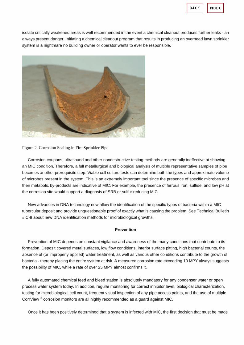
isolate critically weakened areas is well recommended in the event a chemical cleanout produces further leaks - an always present danger. Initiating a chemical cleanout program that results in producing an overhead lawn sprinkler system is a nightmare no building owner or operator wants to ever be responsible.
Figure 2. Corrosion Scaling in Fire Sprinkler Pipe
Corrosion coupons, ultrasound and other nondestructive testing methods are generally ineffective at showing an MIC condition. Therefore, a full metallurgical and biological analysis of multiple representative samples of pipe becomes another prerequisite step. Viable cell culture tests can determine both the types and approximate volume of microbes present in the system. This is an extremely important tool since the presence of specific microbes and their metabolic by-products are indicative of MIC. For example, the presence of ferrous iron, sulfide, and low pH at the corrosion site would support a diagnosis of SRB or sulfur reducing MIC. New advances in DNA technology now allow the identification of the specific types of bacteria within a MIC tubercular deposit and provide unquestionable proof of exactly what is causing the problem. See Technical Bulletin # C-8 about new DNA identification methods for microbiological growths.
Prevention
Prevention of MIC depends on constant vigilance and awareness of the many conditions that contribute to its formation. Deposit covered metal surfaces, low flow conditions, interior surface pitting, high bacterial counts, the absence of (or improperly applied) water treatment, as well as various other conditions contribute to the growth of bacteria - thereby placing the entire system at risk. A measured corrosion rate exceeding 10 MPY always suggests the possibility of MIC, while a rate of over 25 MPY almost confirms it. A fully automated chemical feed and bleed station is absolutely mandatory for any condenser water or open process water system today. In addition, regular monitoring for correct inhibitor level, biological characterization, testing for microbiological cell count, frequent visual inspection of any pipe access points, and the use of multiple CorrView ® corrosion monitors are all highly recommended as a guard against MIC. Once it has been positively determined that a system is infected with MIC, the first decision that must be made

relates to the method of cleaning. This is an often difficult decision which must take into account the remaining condition of the pipe wall, physical layout of the piping system, deposit buildup, the relative level of MIC infection, and system operating conditions, among other factors.
Cleaning the Systems
Resolving an MIC problem is a matter of repeated cleanings and sterilization, followed by testing. Generally, microbiological growths exist hidden within other deposits in a stratification of layers. Removing only the surface deposits, therefore, will not provide an effective solution, and it is necessary to clean the pipe down to the bare metal if any success is expected. See Technical Bulletin # C-15 about an effective but rarely employed solution to many MIC problems. Establishing a spool piece at a section of larger 3 in. to 6 in. pipe is well advised in order to periodically evaluate cleanout effectiveness. Due to the high volume of rust and particulates typically associated with an MIC problem, and the physical volume of material returned into solution through any cleanout procedure, an effective filtration system is always recommended. Following the elimination or control of an MIC condition, added attention to the system is mandatory since under deposit corrosion and pits will have provided the ideal environment for new microorganisms to collect and grow. For any system which has undergone a vigorous cleaning down to the base metal, it is imperative to increase the inhibitor level in order to discourage new corrosion activity while the surface metal is being passivated. Biocides should be added regularly.
Long Term Maintenance Problems
Because the microbiological agents causing MIC are generally found at the boundary layer between the pipe and interior deposits, it is often difficult to physically solve the problem with sterilizing chemicals alone. Increased biocide use alone is generally useless, as they are only designed to suppress microbiological growths, not kill and eradicate them. And the extended use of high concentrations of strongly oxidizing chemicals such as chlorine leads to further metal damage. Often, a multi-stage program of repeated heavy duty chemical cleanings and high dosage level sterilizations must be established. The use of chemical dispersants and chelating agents are some additional methods which may be employed to remove the attached deposits. Mechanical cleaning using a high pressure water jet may be applicable in some specific examples. See Technical Bulletin # M-3 about high pressure water jet pipe cleaning. The benefits of any proposed aggressive cleaning program must always be weighed against the potential damage caused to the piping itself. Yet, it is important to realize that the failure to aggressively address an established MIC problem will lead to advanced pipe failure anyway! Due to the fact that MIC produces intensive corrosion rates at localized sites, it is critically important to first establish the extent throughout the piping system and the depth of surface pitting prior to any cleaning program.
Treatment Options
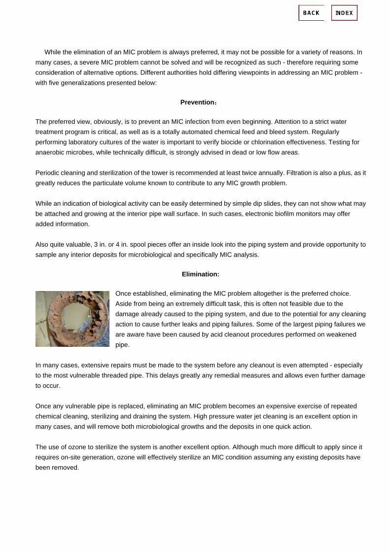
While the elimination of an MIC problem is always preferred, it may not be possible for a variety of reasons. In many cases, a severe MIC problem cannot be solved and will be recognized as such - therefore requiring some consideration of alternative options. Different authorities hold differing viewpoints in addressing an MIC problem - with five generalizations presented below:
Prevention:
The preferred view, obviously, is to prevent an MIC infection from even beginning. Attention to a strict water treatment program is critical, as well as is a totally automated chemical feed and bleed system. Regularly performing laboratory cultures of the water is important to verify biocide or chlorination effectiveness. Testing for anaerobic microbes, while technically difficult, is strongly advised in dead or low flow areas. Periodic cleaning and sterilization of the tower is recommended at least twice annually. Filtration is also a plus, as it greatly reduces the particulate volume known to contribute to any MIC growth problem. While an indication of biological activity can be easily determined by simple dip slides, they can not show what may be attached and growing at the interior pipe wall surface. In such cases, electronic biofilm monitors may offer added information. Also quite valuable, 3 in. or 4 in. spool pieces offer an inside look into the piping system and provide opportunity to sample any interior deposits for microbiological and specifically MIC analysis.
Elimination:
Once established, eliminating the MIC problem altogether is the preferred choice. Aside from being an extremely difficult task, this is often not feasible due to the damage already caused to the piping system, and due to the potential for any cleaning action to cause further leaks and piping failures. Some of the largest piping failures we are aware have been caused by acid cleanout procedures performed on weakened pipe.
In many cases, extensive repairs must be made to the system before any cleanout is even attempted - especially to the most vulnerable threaded pipe. This delays greatly any remedial measures and allows even further damage to occur. Once any vulnerable pipe is replaced, eliminating an MIC problem becomes an expensive exercise of repeated chemical cleaning, sterilizing and draining the system. High pressure water jet cleaning is an excellent option in many cases, and will remove both microbiological growths and the deposits in one quick action. The use of ozone to sterilize the system is another excellent option. Although much more difficult to apply since it requires on-site generation, ozone will effectively sterilize an MIC condition assuming any existing deposits have been removed.
Inhibits Growth:
Another view is to identify the corrosion mechanism involved and inhibit the corrosion process to the best degree possible. Identifying a specific MIC organism responsible is often difficult, although new developments in DNA analysis will provide most answers. Identifying the corrosion mechanism is more difficult, though necessary in order to plan its remediation. By many authoritative opinions, however, removing an MIC infection completely, once it has been firmly established, is nearly an impossible task. Of all sterilizing agents, ozone likely offers the highest probability of providing a cure for any piping system having a severe MIC condition.
Minimize Damages:
The fourth view assumes the impossibility of eliminating MIC once present, and instead focuses on minimizing its corrosive damage. In many cases, the higher 15-20 MPY corrosion rates can be significantly reduced to extend system life, though random pockets of microbiological growths may produce periodic pipe failures. Many corrosion and water treatment authorities consider that a piping system cannot be returned to normal conditions once MIC has established itself system wide. Multiple chemical sterilizations and high expense can be assumed necessary in any such cleaning effort.
Replace Pipes:
In many cases, a piping system seriously infected with MIC will require replacement. This occurs usually only after MIC damage has resulted in multiple failures and the cost of another major failure is deemed to be an unacceptable risk. Replacing less then the entire piping system, without good reason to believe that any MIC infection in those remaining areas has been eradicated, will generally reintroduce the microbiological agent into the new piping and begin the problem all over. Intense chemical treatment and monitoring may reduce such a threat to any new piping installed
In short, our obvious recommendation is to take the necessary precautions now to ensure that an MIC condition does not begin in the first place. Aside from operating problems and equipment damage, an MIC infection is an extremely costly - producing expenses from pipe testing, lab tests, maintenance overtime, chemicals cleanings, and monitoring and services, etc. in the hundreds of thousands of dollars.

Microbiologically Influenced Corrosion:
An Engineering Insight (Engineering Materials and Processes) By Reza Javaherdashti
Publisher: Springer
Number Of Pages: 164
Publication Date: 2008-03-12
ISBN-10 / ASIN: 1848000731
ISBN-13 / EAN: 9781848000735
Binding: Hardcover
Microbiologically-influenced corrosion (MIC) is one of the
greatest mysteries of corrosion science and engineering, due
to the complexities resulting from the involvement of living
things such as bacteria. Bacteria are not only able to affect our
health, but are also capable of impacting upon everyday life
through a wide range of industrial sectors and the economy.
Microbiologically Influenced Corrosion: An Engineering Insight
introduces a new approach to the basics of MIC and explains
how to recognise, understand, mitigate and/or prevent this
type of corrosion. Topics explored include stress corrosion
cracking and microbial corrosion, the pros and cons of biocides, the involvement of magnetic bacteria in microbial corrosion,
and a new interpretation of cathodic protection based on recent research in microbial environments.
The material covered by Microbiologically Influenced Corrosion: An Engineering Insight will be of benefit to professional and
consultant engineers in power generating, oil and gas, marine, and mining industries; as well as to researchers in the fields of
chemistry, chemical engineering, materials science, corrosion and mechanical engineering.
http://www.filefactory.com/file/d3b8c0/
Predictive Maintenance for Fire Sprinkler Systems
Jeffrey D. Gentry Sonic Inspection Corporation
May 2005

Sonic Inspection Corporation Phone (303) 308-3000 2070 Kahala Circle Fax (720) 733-9975 Castle Rock, CO 80104 www.SonicInspection.com
Table of Contents
TABLE OF CONTENTS............................................................................2
INTRODUCTION....................................................................................3 Overview of Problem .......................................................................3 Solution.........................................................................................3
FIRE SPRINKLER PROBLEMS WITH CORROSION AND MIC ..................................4
Microbiologically Influenced Corrosion (MIC) .........................................4
SOLUTION: SONIC PREDICTIVE MAINTENANCE PROGRAM..................................6 Predictive Maintenance....................................................................6 Risk Mitigation................................................................................6 Return on Investment......................................................................7
NON-INVASIVE, ULTRASONIC INSPECTION TECHNOLOGIES .................................8
Patented Guided Wave Pipe Corrosion Detection .................................8 Conventional Ultrasonic Thickness Measurements ...............................8 Alternative Inspection Techniques......................................................9 Analysis and Reporting ....................................................................9
SUMMARY REMARKS ..........................................................................10
REFERENCES....................................................................................10

Sonic Inspection Corporation Phone (303) 308-3000 2070 Kahala Circle Fax (720) 733-9975 Castle Rock, CO 80104 www.SonicInspection.com
Introduction
Overview of Problem Corrosion of Fire Sprinkler piping can lead to potentially hazardous system malfunctions, as well as costly water damage and repair costs. Microbiologically Influenced Corrosion (MIC) can rapidly accelerate corrosive growth leading to these problems even in buildings less than five years old [1]. Unfortunately, inspections for MIC and Corrosion are often overlooked until expensive problems such as damaging leaks occur or the corrosion is so prevalent that large areas of the entire Fire Sprinkler system have to be replaced. This corrective maintenance approach is a retro-active strategy. The task of the maintenance team in this scenario is usually to effect repairs as soon as possible. Costs associated with corrective maintenance include repair costs (replacement components, labor, and consumables), lost production and lost sales.
Solution A new, proactive approach to fire sprinkler maintenance is available using completely non-invasive, ultrasonic technologies that form the basis of a predictive maintenance approach. This approach provides a cost-effective means of detecting the presence and monitoring progression of corrosion and creating a digital record of the system state that can be used to schedule replacement of localized sections of the system before leaks or operation failures occur.
Figure 1. Typical Sections of Fire Sprinkler System

Sonic Inspection Corporation Phone (303) 308-3000 2070 Kahala Circle Fax (720) 733-9975 Castle Rock, CO 80104 www.SonicInspection.com
Fire Sprinkler Problems with Corrosion and MIC The most common Fire Sprinkler Pipes are constructed using steel pipes sized according to hydraulic requirements but typically ranging from 1.0 inch diameter to 8.0 inch diameter pipes in Schedule 5, 10 or 40 (with Schedule 40 having a significantly thicker wall than Schedule 5 or 10). There are numerous types of corrosive reactions that can occur with steel and various methods for combating or trying to slow the corrosive activity. Corrosion in Wet fire sprinkler systems is not usually a problem IF all of the air is removed from the system after filling the system with water unless MIC is present (see below). Even a small amount trapped air can cause the onset of corrosive activity.
Figure 2. Corrosion Scaling in Fire Sprinkler Pipe
Microbiologically Influenced Corrosion (MIC) MIC is the term used for corrosion influenced by microbes in the water. The primary concern is that the influence of these microbes is often an extremely accelerated rate of corrosion. MIC is not caused by a single microbe, but is attributed to many different microbes. These are often categorized by common characteristics such as by-products (i.e., sludge producing) or compounds they effect (i.e. sulfur oxidizing). In a general sense, they all fall into one of two groups based upon their oxygen requirements; one being aerobic (requires oxygen) such as sulfur oxidizing bacteria, and the other being anaerobic, (requires little or no oxygen), such as sulfate reducing bacteria [2]. Although there have been regions of the United States, such as the Phoenix, Arizona area, where a large number of MIC cases have been reported and documented, there is presently no indication that MIC is confined to any specific geographical area. Reports of MIC have been received from throughout the United States and also from abroad [1].

Sonic Inspection Corporation Phone (303) 308-3000 2070 Kahala Circle Fax (720) 733-9975 Castle Rock, CO 80104 www.SonicInspection.com
Figure 3. Large MIC Nodules in a Wet Fire Sprinkler System MIC almost always occurs concurrently with other corrosion mechanisms, and it is virtually impossible to separate them. This is in part due to the fact that microbes help create conditions under which other corrosion mechanisms can occur, such as crevice corrosion, pitting, and under-deposit corrosion [1]. In a Dry system, water often collects in low spots in the piping after the pipe is periodically flushed (per NFPA requirements for Dry systems). As the water sits in the bottom of the pipe, MIC can begin to rapidly eat through the wall thickness, as most Dry systems incorporate thinner Schedule 5 or 10 pipes.
Figure 4. Wall Thinning & Pitting in a Dry Fire Sprinkler System

Sonic Inspection Corporation Phone (303) 308-3000 2070 Kahala Circle Fax (720) 733-9975 Castle Rock, CO 80104 www.SonicInspection.com
Solution: Sonic Predictive Maintenance Program Sonic Inspection has developed a comprehensive inspection service and predictive maintenance program for facility managers and building owners. The basis of this program is a completely non-invasive, ultrasonic inspection technique that provides a quick and accurate measurement of internal pipe corrosion and MIC. Sonic’s proprietary software permanently stores the analyzed results and ties the measurements to copies of the facilities blueprints.
Predictive Maintenance Predictive maintenance refers to maintenance based on the actual condition of a component. Maintenance is not performed according to fixed preventive schedules but rather when a certain change in characteristics is noted. Periodically inspecting fire sprinkler systems for the presence of MIC or Corrosion allows the facility manager to accurately monitor the condition of the system, schedule localized replacement and significantly reduce the risk and costs associated with corrective maintenance. Using the non-invasive, ultrasonic inspection techniques described in the next section, a cost-effective predictive maintenance program can be implemented to detect the presence and the progression of corrosion or MIC in the sprinkler piping. The density of inspection locations and the frequency of inspections should be chosen based on the risk associated with a leak or operational failure, history of the system, and condition of the sprinkler system water supply.
Risk Mitigation The risk of MIC or Corrosion in fire sprinkler piping can be broken into two general categories: (1) loss of life or property damage caused by fire that spreads due to an operational failure; and (2) significant property damage caused by a leak from corrosive pitting. Almost any facility that is required to have a fire sprinkler system is subject to the first risk, but several types of facilities rely on the sprinkler system to extinguish or slow the spread of fire more so than other structures. These include military and commercial ships at sea, correctional facilities, petroleum refineries, chemical plants, power plants (oil, coal, and especially nuclear).
Figure 5. Fire sprinkler operation is critical for both military and commercial ships The potential of fire sprinkler leaks may not seem especially risky, but for facilities that house sensitive electronics and equipment such as clean rooms and computer data centers a single small leak can produce potentially catastrophic financial losses.

Sonic Inspection Corporation Phone (303) 308-3000 2070 Kahala Circle Fax (720) 733-9975 Castle Rock, CO 80104 www.SonicInspection.com
Figure 6. Leaks above Data Centers like these could be disastrous
Return on Investment Calculating the Return on Investment in a predictive maintenance program for MIC and corrosion in the fire sprinkler piping requires assessing the risk of either type of system failure, estimating the potential cost of such a failure, estimating the cost of a corrective maintenance approach once a problem is discovered. Once these costs are estimated they need to be weighed against the cost of inspecting the system using a non-invasive, ultrasonic technique and monitoring the level of corrosion at suitable intervals for the associated level of risk.

Sonic Inspection Corporation Phone (303) 308-3000 2070 Kahala Circle Fax (720) 733-9975 Castle Rock, CO 80104 www.SonicInspection.com
Non-invasive, Ultrasonic Inspection Technologies Sonic uses two separate ultrasonic inspection technologies can be used to quickly detect and monitor the level of corrosion and MIC in a fire sprinkler system.
Patented Guided Wave Pipe Corrosion Detection Sonic Inspection uses a patented Guided Wave Ultrasonic technique to rapidly identify areas of pipe that show indications of internal corrosion. The technique uses a specialized ultrasonic scanning head placed on the exterior of the pipe to excite guided waves that propagate around the circumference of the pipe.
Figure 7. Guided Wave Scan Head Guided Wave signatures for brand new, pristine pipe have been stored in software for all of the possible pipe diameters and schedules, for both Wet and Dry systems. The measured signature is compared to a pristine pipe. The more corrosion (presence of nodules attached to the interior of the pipe and amount of wall thinning) the more the received signal is affected.
Figure 8. No Corrosion (left) versus Corrosion Indication (right)
Conventional Ultrasonic Thickness Measurements Any areas of pipe that show indications of corrosion are investigated further with highly accurate wall thickness measurements made around the circumference of the pipe.

Sonic Inspection Corporation Phone (303) 308-3000 2070 Kahala Circle Fax (720) 733-9975 Castle Rock, CO 80104 www.SonicInspection.com
Figure 9. Conventional Ultrasonic Thickness Measurements
Alternative Inspection Techniques Some areas of pipe may be inaccessible and therefore cannot be measured using the ultrasonic techniques described above. One alternative method for inspecting hard to reach pipe includes feeding a digital video boroscope into the pipe and recording the visual condition of the pipe interior. This method may be appropriate for limited use in high risk areas but is too intrusive and expensive for a general recurring inspection of an entire facility.
Analysis and Reporting The measurements are permanently stored for each location and a report showing the current level of corrosion can be produced using the sprinkler system blueprints.
Figure 10. Corrosion measurements are tracked for each location

Sonic Inspection Corporation Phone (303) 308-3000 2070 Kahala Circle Fax (720) 733-9975 Castle Rock, CO 80104 www.SonicInspection.com
Summary Remarks There are four general approaches to maintaining any system: (1) Corrective Maintenance; (2) Preventative Maintenance; (3) Reliability Centered Maintenance (RCM); and (4) Predictive Maintenance. Because of the nature of MIC and corrosion and expense of Fire Sprinkler Systems, neither Preventative Maintenance (i.e. simply replacing the pipes on a scheduled basis before corrosion can occur) nor RCM are good choices. Corrective maintenance refers to the practice that is common today of waiting until the corrosion causes a leak or operational problem and then reacting to the problem with some sort of corrective action. Until recently, facility managers and building owners had little choice but to wait for corrosive problems to arise before implementing costly corrective maintenance in a totally reactionary mode. Under these circumstances, a lot of pipe is either replaced unnecessarily (at a very high cost), or corroded pipe is left in place to cause a future problem (which is also costly). Now, with Sonic’s Predictive Maintenance Program, the presence of MIC and corrosion can be quickly identified, and tracked to provide cost-effective risk mitigation for both pin-hole leaks and operational failure of the system. Facility managers and building owners now have the means to create a database (see Figure 10) with the current level of corrosion and MIC in their fire sprinkler system piping and use this information to proactively schedule replacement of only the pipe deemed unacceptable.
References 1. FM Global Property Loss Prevention Data Sheet for Internal Corrosion in Automatic Sprinkler Systems. May 2001. 2. Huggins, Roland. “Microbiologically Influenced Corrosion: What It Is and How It Works”, Article on American Fire Sprinkler Association Web Site.

Corrosion type Stress Corrosion Cracking (SCC)
Progress of SCC on stainless steel in austenite system
The SCC is a type of corrosion when it receives environmental influence and mechanical stress at the same time and cracks
and its impact transfers.
The stress corrosion of stainless is mainly generates from the liquid including chloride like a pitting and crevice corrosions and it
is caused more than 50° C. As its density of chloride is low, it is generated to the environment where pitting and crevice
corrosion are not generated. Above figure shows generation and propagation processes of SCC on austenite stainless steel
with various factors that affects SCC.
The pitting corrosion is generated when the film is broken by chlorine ion or slip step, the pitting corrosion grows to crack when
the volume of hydrogen ion in pitting corrosion increases and crack grows according to continuous increase of hydrogen ion
and its reduction reaction.
It is big problem because SCC forms passive film and it is generated from the material with excellent corrosion resistance under
the lower stress than designed stress. Even though there is no external stress, residue stress from material manufacturing and
processing such as molding and welding can cause stress corrosion.
The chloride that causes stress corrosion exists in the water with various densities under the natural environment and it is
caused by gasket or insulating material that includes chloride. In case of water pipe, intergranular-stress corrosion cracking is
largely generated because it becomes sensitive to intergranular corrosion based on residue stress from welding and
sensitization of HZA.
To prevent it, residue stress has to be removed with heat treatment under appropriate temperature and it is better to use

STS604L or STS316L that reduce the content of carbon.
Polythionic acid stress corrosion cracking of type 310 stainless steel. The item was exposed to sulfur containing
natural gas in a continuous flare. (100X)
Stress corrosion cracking is a rapid and severe form of stainless steel corrosion. It forms when the material is
subjected to tensile stress and some kinds of corrosive environments, especially chloride-rich environments (sea water)
at higher temperatures. The stresses can result of the service loads, or can be caused by the type of assembly or
residual stresses from fabrication (eg. cold working); the residual stresses can be relieved by annealing. This limits the
usefulness of stainless steel for containing water with higher than few ppm content of chlorides at temperatures above
50 °C.
Stress corrosion cracking applies only to austenitic stainless steels and depends on the nickel content.

Wet corrosion
Stress corrosion cracking
Stress corrosion cracking of a tube.
STRESS CORROSION CRACKING
Cracks across the grains (transgranular SCC) or along the grain boundaries (intergranular SCC).
Stress corrosion cracking (SCC) results from the combined action of three factors: Tensile stresses in the material, a corrosive medium (esp. chloride-bearing or hydrogen-sulphide environment) and elevated temperature (normally above 60°C for chloride-induced SCC). Cases where chloride induced SCC has occurred at lower temperatures than 60°C exist. The most common media where stress corrosion cracking occurs are chloride containing solutions, but in other environments, such as caustics and polythionic acid, problems with

SCC may also appear. Some enviroments that may cause stress corrosion cracking of stainless steels are listed below. Some environments where stainless steels are prone to stress corrosion cracking:
• Acid chloride solutions • Seawater • Condensing steam from chloride waters • H 2 S + chlorides • Polythionic acid (sensitised material) • NaCl-H 2 O 2 • NaOH-H 2 S
The mechanism of stress corrosion cracking is not well understood. This is mainly due to the specific features of SCC being the result of a complex interplay of metal, interface and environment properties. As a result of this different combinations of solution and stress are seldom comparable and the most reliable information is obtained from empirical experiments. During SCC the material does not undergo general corrosion and the phenomenon is sometimes considered to be one of activation/passivation interaction. It has been found that cracks often initiate in trenches or pits on the surface, which can act as stress raisers. The isolated times for pit initiation, pit growth, crack initiation and fracture may, however, differ considerably between different materials. In some cases crack initiation has been associated with the formation of a brittle film at the surface. The film developed at grain boundaries might, for instance, have lower ductility due to a different metal composition than the bulk material. At a certain film thickness and under stress this brittle film will crack and expose the underlying metal. New film growth will proceed with subsequent continued crack growth and so forth. The developed crack tip has a small radius and will develop a very high stress concentration. Even so, the stress condition alone is not sufficient for crack growth, but corrosion still plays a very large part. It has been shown experimentally that stress corrosion cracking can be stopped when applying cathodic protection, i.e. when corrosion is stopped but the stress conditions remain unchanged. Cracking may be either transgranular (TGSCC) or intergranular (IGSCC) or, perhaps most usual, a combination of both. The material microstructure and alloying components are of major importance for crack paths as well as for SCC resistance. Alloying with Ni can make materials less prone to SCC and the duplex microstructure of the austenitic-ferritic grades is also beneficial. Standard austenitic stainless steels, like AISI 304 and AISI 316, are generally prone to SCC in chloide containing environments at temperatures above 60°C, except at very low chloride contents, and therefore higher alloyed austenitics or duplex stainless steels should be used.
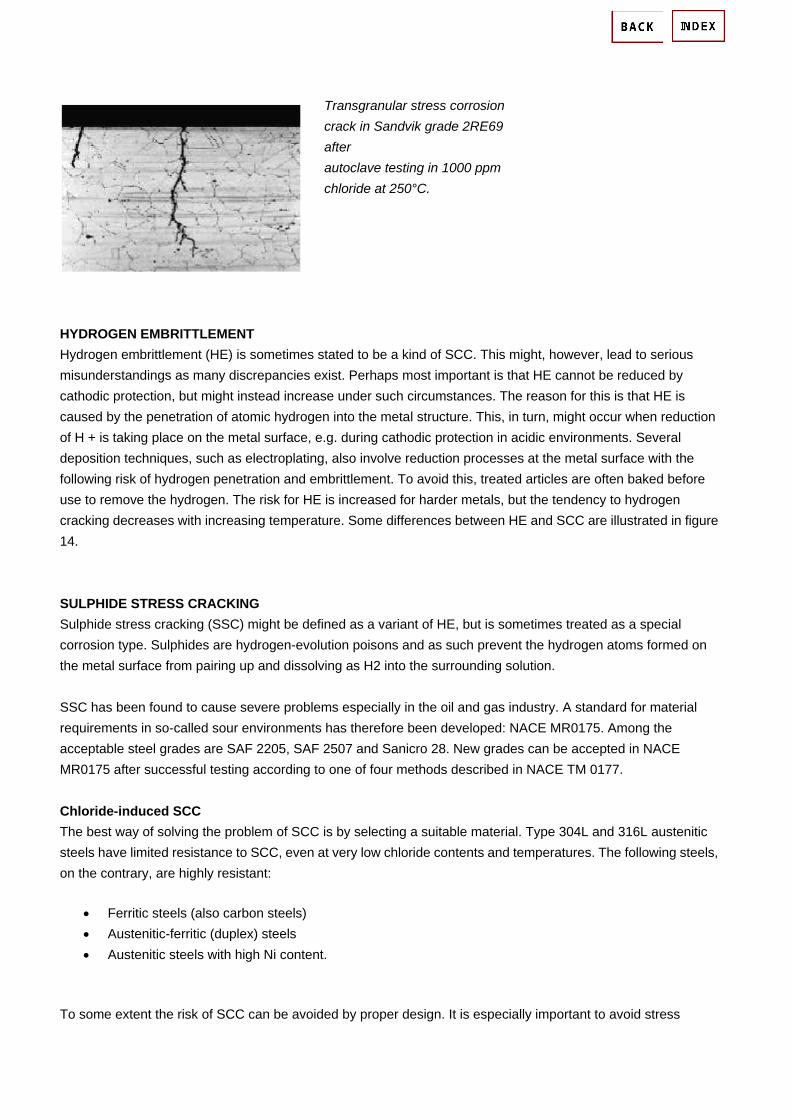
Transgranular stress corrosion crack in Sandvik grade 2RE69 after autoclave testing in 1000 ppm chloride at 250°C.
HYDROGEN EMBRITTLEMENT Hydrogen embrittlement (HE) is sometimes stated to be a kind of SCC. This might, however, lead to serious misunderstandings as many discrepancies exist. Perhaps most important is that HE cannot be reduced by cathodic protection, but might instead increase under such circumstances. The reason for this is that HE is caused by the penetration of atomic hydrogen into the metal structure. This, in turn, might occur when reduction of H + is taking place on the metal surface, e.g. during cathodic protection in acidic environments. Several deposition techniques, such as electroplating, also involve reduction processes at the metal surface with the following risk of hydrogen penetration and embrittlement. To avoid this, treated articles are often baked before use to remove the hydrogen. The risk for HE is increased for harder metals, but the tendency to hydrogen cracking decreases with increasing temperature. Some differences between HE and SCC are illustrated in figure 14. SULPHIDE STRESS CRACKING Sulphide stress cracking (SSC) might be defined as a variant of HE, but is sometimes treated as a special corrosion type. Sulphides are hydrogen-evolution poisons and as such prevent the hydrogen atoms formed on the metal surface from pairing up and dissolving as H2 into the surrounding solution. SSC has been found to cause severe problems especially in the oil and gas industry. A standard for material requirements in so-called sour environments has therefore been developed: NACE MR0175. Among the acceptable steel grades are SAF 2205, SAF 2507 and Sanicro 28. New grades can be accepted in NACE MR0175 after successful testing according to one of four methods described in NACE TM 0177. Chloride-induced SCC The best way of solving the problem of SCC is by selecting a suitable material. Type 304L and 316L austenitic steels have limited resistance to SCC, even at very low chloride contents and temperatures. The following steels, on the contrary, are highly resistant:
• Ferritic steels (also carbon steels) • Austenitic-ferritic (duplex) steels • Austenitic steels with high Ni content.
To some extent the risk of SCC can be avoided by proper design. It is especially important to avoid stress

concentration, which will occur at sharp edges and notches. Testing can be carried out in e.g. 40% CaCl2 or in chloride-containing water. The diagram below shows results from chloride solutions containing 8 ppm oxygen. Note that no cracking was observed in SAF 2507. H2S-induced SCC Within the oil and gas industry, the process fluids often contain a certain amount of hydrogen sulphide, H2S. Applications involving exposure to this type of process fluids are often referred to as sour service. When considering the corrosivity of a sour process fluid, the partial pressure of H2S is to be considered besides the pH value, the temperature, the oxygen and chloride contents as well as the presence of solid particles (such as sand). It has been shown that this type of corrosion attack is worst at temperatures around 80°C, but cracking may occur also at temperatures below 60°C. A high nickel content is favourable for a good resistance to this form of SCC and for most sour environments high nickel alloys are to be used. A Sandvik grade with very good resistance to sulphide-induced cracking is Sanicro 28. The duplex grades SAF 2205 and SAF 2507 have not as good resistance as the high nickel alloys, but can successfully be used at intermediate hydrogen-sulphide partial pressures. Testing can be carried out according to NACE TM0177 (5% NaCl and 0.5% acetic acid saturated with H2S). The diagram below shows results from this type of testing with SAF 2205 and SAF 2507. No cracking was observed on the SAF 2507 samples after the 720-hours test period. Note: Testing in NACE solution is carried out at an external laboratory, and it is both time consuming and expensive. Several of our standard grades as well as SAF 2205, SAF 2507 and Sanicro 28 are covered by the standard MR0175 and should not normally need further testing. Read more about the test in S-133.
1. SCC resistance in oxygen-bearing neutral solutions with various chloride contents. Testing time 1,000 hours. Applied stress equal to the 0.2% proof strength at testing temperature. 2. Constant-load SCC tests in NACE solution at room temperature (NACE TM0177).

Although looking as a piece of art, this SCC attack was devastating for the tube.
The photo was taken in a scanning electron microscope (SEM) and it shows a SCC crack with a magnification of 45 times.

"Stress Corrosion Cracking in Stainless Steel"
Question:
"We have experienced repeated failures on seal flush piping on the naphtha and distillate
reflux pumps in our Crude Fractionation Unit. The piping is currently constructed of 316L
tubing. The process stream in low in organic chlorides, but high in hydrogen sulphide.
Inspection of the failures(cracks) suggests stress corrosion cracking; likely sulphide induced. I
am considering replacing the stainless steel piping with either carbon steel, or 5% chromium
1/2 molybdenum. Do you have any thoughts or suggestions?I was not aware that h3S
increases the susceptability of austenitic stainless steels to chloride induced stress corrosion
cracking. This relates to another persistent problem that we have experienced; cracking of 347
valves in hydrotreating service. The valves that fail are typically small diameter, A182 TP347
forged steel valves. The service conditions are about 800°F and 2500psig. The fluid in the
piping circuits is heavy oil; high in sulfur, hydrogen and hydrogen sulphide. We currently
neutralize the piping circuits during turnarounds using a soda ash/sodium nitrite wash as per
NACE recomendations. This procedure was developed to prevent polythionic acid attack on
the stainless steels when the piping is exposed to oxygen. Although this does not specifically
address chloride contamination problems, it does help to flush contaminants high in chlorides
from the system. It also leaves a thin protective layer of crystalline soda ash/sodium nitrite on
the piping which helps to limit oxygen exposure to the piping. The reactor circuits(feed and
effluent) in our plant have been constructed with A297 HF Modified piping(cast and machined
347SS). The smaller diameter piping is typically A312 TP347 with A182 F347 fittings. We have
seen chloride induced stress corrosion cracking in valves, forged fittings and butt-welded
connections. The cracking of small diameter forged valve bodies(drains and vents) has been
the most common failure. Do you have any suggestions that may help to eliminate the
problems that we are experiencing?"

Answer:
You are probably correct with respect to chloride stress corrosion cracking being responsible
for failure of the 316 piping. Hydrogen sulfide significantly decreases the threshold quantities
of chlorides need to promote chloride SCC. (A laboratory analysis would easily verify your
theory of chloride SCC). The question of replacement metallurgy depends on the nature of
your process stream. The proper selection of carbon steel or a chromium-molybdenum low
alloy steel depends several factors, including amounts of hydrogen sulfide, sulfur and
temperature. The McConomy curves are a widely used reference for materials selection in
h3S environments. If the cracking has been correctly diagnosed as chloride stress corrosion
cracking, and the problem is confined to small drain, flush fittings, etc. you might consider
upgrading those specific components to an alloy not susceptible to chloride SCC while still
maintaining resistance to polythionic acid SCC, i.e., alloy 825 or something similar..
Stainless steel In metallurgy, stainless steel is defined as a ferrous alloy with a minimum of 10.5% chromium content.[1] The name originates from the fact that stainless steel does not stain, corrode or rust as easily as ordinary steel. This material is also called corrosion resistant steel when it is not detailed exactly to its alloy type and grade, particularly in the aviation industry. As such, there are now different and easily accessible grades and surface finishes of stainless steel, to suit the environment to which the material will be subjected to in its lifetime. Common uses of stainless steel are the everyday cutlery and watch straps.
Stainless steels have higher resistance to oxidation (rust) and corrosion in many natural and man made environments; however, it is important to select the correct type and grade of stainless steel for the particular application.
High oxidation resistance in air at ambient temperature is normally achieved with additions of a minimum of 13% (by weight) chromium, and up to 26% is used for harsh environments.[2] The chromium forms a passivation layer of chromium(III) oxide (Cr2O3) when exposed to oxygen. The layer is too thin to be visible, meaning the metal remains lustrous. It is, however, impervious to water and air, protecting the metal beneath. Also, this layer quickly reforms when the surface is scratched. This phenomenon is called passivation and is seen in other metals, such as aluminium and titanium. When stainless steel parts such as nuts and bolts are forced together, the oxide layer can be scraped off causing the parts to weld together. When disassembled, the welded material may be torn and pitted, an effect that is known as galling.
Nickel also contributes to passivation, as do other less commonly used ingredients such as molybdenum and vanadium.
Commercial value of stainless steel
Stainless steel's resistance to corrosion and staining, low maintenance, relative inexpense, and familiar luster make it an ideal base material for a host of commercial applications. There are over 150 grades of stainless steel, of which fifteen are most common. The alloy is milled into sheets, plates, bars, wire, and tubing to be used in cookware, cutlery, hardware, surgical instruments, major appliances, industrial equipment, a structural alloy in automotive and aerospace assembly and building material in skyscrapers and other large buildings. The one most noted automotive with stainless steel is the Delorean DMC-12, which was also featured in the hit film, Back To The Future.
Stainless steel is 100% recyclable. In fact, an average stainless steel object is composed of about 60% recycled material, 25% originating from end-of-life products and 35% coming from manufacturing processes.[4]
Corrosion

Even a high-quality alloy can corrode under certain conditions. Because these modes of corrosion are more exotic and their immediate results are less visible than rust, they often escape notice and cause problems among those who are not familiar with them.
Pitting corrosion
Passivation relies upon the tough layer of oxide described above. When deprived of oxygen (or when a salt such as chloride competes as an ion), stainless steel lacks the ability to re-form a passivating film. In the worst case, almost all of the surface will be protected, but tiny local fluctuations will degrade the oxide film in a few critical points. Corrosion at these points will be greatly amplified, and can cause corrosion pits of several types, depending upon conditions. While the corrosion pits only nucleate under fairly extreme circumstances, they can continue to grow even when conditions return to normal, since the interior of a pit is naturally deprived of oxygen. In extreme cases, the sharp tips of extremely long and narrow pits can cause stress concentration to the point that otherwise tough alloys can shatter, or a thin film pierced by an invisibly small hole can hide a thumb sized pit from view. These problems are especially dangerous because they are difficult to detect before a part or structure fails. Pitting remains among the most common and damaging forms of corrosion in stainless alloys, but it can be prevented by ensuring that the material is exposed to oxygen (for example, by eliminating crevices) and protected from chlorides wherever possible.
Pitting corrosion can occur when stainless steel is subjected to high concentration of Chloride ions (for example, sea water) and moderately high temperatures. A textbook example for this was a replica of the Jet d'Eau fountain in Geneva, ordered by an Arab Sheikh for installation in the Red Sea. The replica did not last long, because the engineers responsible failed to take into account the difference between the freshwater of Lake Geneva and the saltwater of the sea.
Rouging
Rouging is a very peculiar phenomenon, which occurs only on polished stainless steel surfaces with very low surface roughness in a pure water environment. This effect is mostly common in pharmaceutical industries. It is caused by the simple fact that pure water is lacking any ions and pulls the metal ions of the passive stainless steel surface into solution. Iron ions do not dissolve at neutral pH and will precipitate as an iron hydroxide film, which has a reddish colour, hence the name rouging.

Intergranular corrosion
Some compositions of stainless steel are prone to intergranular corrosion when exposed to certain environments. When heated to around 700 °C, chromium carbide forms at the intergranular boundaries, depleting the grain edges of chromium, impairing their corrosion resistance. Steel in such condition is called sensitized. Steels with carbon content 0.06% undergo sensitization in about 2 minutes, while steels with carbon content under 0.02% are not sensitive to it.
Intergranular corrosion
A special case of intergranular corrosion is called 'weld decay' or 'knifeline attack'(KLA). Due to the elevated temperatures of welding the stainless steel can be sensitized very locally along the weld. The chromium depletion creates a galvanic couple with the well-protected alloy nearby in highly corrosive environments. As the name 'knifeline attack' implies, this is limited to a small zone, often only a few micrometres across, which causes it to proceed more rapidly. This zone is very near the weld, making it even less noticeable[5].
It is possible to reclaim sensitized steel by heating it to above 1000 °C and holding at this temperature for a given period of time dependent on the mass of the piece, followed by quenching it in water. This process dissolves the carbide particles, then keeps them in solution.
It is also possible to stabilize the steel to avoid this effect and make it welding-friendly. Addition of titanium, niobium and/or tantalum serves this purpose; titanium carbide, niobium carbide and tantalum carbide form preferentially to chromium carbide, protecting the grains from chromium depletion. Use of extra-low carbon steels is another method and modern steel production usually ensures a carbon content of <0.03% at which level intergranular corrosion is not a problem. Light-gauge steel also does not tend to display this behavior, as the cooling after welding is too fast to cause effective carbide formation.
Crevice corrosion
In the presence of reducing acids or exposure to reducing atmosphere, the passivation layer protecting steel from corrosion can break down. This wear can also depend on the mechanical construction of the parts, eg. under gaskets, in sharp corners, or in incomplete welds. Such crevices may promote corrosion, if their size allows penetration of the corroding agent but not its free movement. The mechanism of crevice corrosion is similar to pitting corrosion, though it happens at lower temperatures.
Stress corrosion cracking
Stress corrosion cracking can be a severe form of stainless steel corrosion. It forms when the material is subjected to tensile stress and some corrosive environments, especially chloride-rich environments (sea water) at higher temperatures. The stresses can be a result of service loads, or can be caused by the type of assembly or residual stresses from fabrication (eg. cold working); residual stresses can be relieved by annealing. This limits the usefulness of stainless steels of the 300 series (304, 316) for containing water with higher than few ppm content of chlorides at temperatures above 50 °C. In more aggressive conditions, higher alloyed austenitic stainless steels (6% Mo grades) or Mo containing duplex stainless steels may be selected.
Stress corrosion cracking depends on the nickel content. High nickel content austenitic (non-magnetic) steels, which are the most resistant to other forms of corrosion, tend to be the most susceptible to stress corrosion.
Chlorine catalyzes the formation of hydrogen which hardens and embrittles the metal locally, causing concentration of the stress and a microscopic crack. The chlorine moves into the crack, continuing the process.
Sulphide stress cracking
Sulphide stress cracking is an important failure mode in the oil industry, where the steel comes into contact with liquids or gases with considerable hydrogen sulfide content, e.g., sour gas. It is influenced by the tensile stress and is worsened in the presence of chloride ions. Very high levels of hydrogen sulfide apparently inhibit the corrosion. Rising temperature increases the influence of chloride ions, but decreases the effect of sulfide, due to its increased mobility through the lattice; the most critical temperature range for sulphide stress cracking is between 60-100 °C.
Galvanic corrosion
Galvanic corrosion occurs when a galvanic cell is formed between two dissimilar metals. The resulting electrochemical potential then leads to formation of an electric current that leads to electrolytic dissolving of the less noble material. This effect can be prevented by electrical insulation of the materials, e.g. by using rubber or plastic sleeves or washers, keeping the parts dry so there is no electrolyte to form the cell, or keeping the size of the less-noble material significantly larger than the more noble ones (e.g. stainless-steel bolts in an aluminum block won't cause corrosion, but aluminum rivets on stainless steel sheet would rapidly corrode.)
If these options are not available to protect from galvanic corrosion, a sacrificial anode can be used to protect the less noble metal. For example, if a system is composed of 316 SS, a very noble alloy with a low galvanic potential, and a mild steel, a very active metal with high galvanic potential, the mild steel will corrode in the presence of an electrolyte such as salt water. If a sacrificial anode is used such as a Mil-Spec A-18001K zinc alloy, Mil-Spec A-24779(SH) aluminum alloy, or magnesium, these anodes will corrode instead, protecting the other metals in the system. The anode must be electrically connected to the protected metal(s) in order to be able to preserve them. This is common practice in the marine industry to protect ship equipment. Boats and vessels that are in salt water use either zinc alloy or aluminum alloy. If the boats are only in fresh water, a magnesium alloy is used. Magnesium has one of the highest galvanic potential of any metal. If it is used in

a saltwater application on a steel or aluminum hull boat, hydrogen bubbles will form under the paint, causing blistering and peeling.
Contact corrosion
Contact corrosion is a combination of galvanic corrosion and crevice corrosion, occurring where small particles of suitable foreign material are embedded to the stainless steel. Carbon steel is a very common contaminant here, coming from nearby grinding of carbon steel or use of tools contaminated with carbon steel particles. The particle forms a galvanic cell, and quickly corrodes away, but may leave a pit in the stainless steel from which pitting corrosion may rapidly progress. Some workshops therefore have separate areas and separate sets of tools for handling carbon steel and stainless steel, and care has to be exercised to prevent direct contact between stainless steel parts and carbon steel storage racks.
Particles of carbon steel can be removed from a contaminated part by passivation with dilute nitric acid, or by pickling with a mixture of hydrofluoric acid and nitric acid.
Types of stainless steel
There are different types of stainless steels: when nickel is added, for instance, the austenite structure of iron is stabilized. This crystal structure makes such steels non-magnetic and less brittle at low temperatures. For higher hardness and strength, carbon is added. When subjected to adequate heat treatment these steels are used as razor blades, cutlery, tools etc.
Significant quantities of manganese have been used in many stainless steel compositions. Manganese preserves an austenitic structure in the steel as does nickel, but at a lower cost.
Stainless steels are also classified by their crystalline structure:
• Austenitic, or 300 series, stainless steels comprise over 70% of total stainless steel production. They contain a maximum of 0.15% carbon, a minimum of 16% chromium and sufficient nickel and/or manganese to retain an austenitic structure at all temperatures from the cryogenic region to the melting point of the alloy. A typical composition of 18% chromium and 10% nickel, commonly known as 18/10 stainless is often used in flatware. Similarly 18/0 and 18/8 is also available. “Superaustenitic” stainless steels, such as alloy AL-6XN and 254SMO, exhibit great resistance to chloride pitting and crevice corrosion due to high Molybdenum contents (>6%) and nitrogen additions and the higher nickel content ensures better resistance to stress-corrosion cracking over the 300 series. The higher alloy content of "Superaustenitic" steels means they are fearsomely expensive and similar performance can usually be achieved using duplex steels at much lower cost.
• Ferritic stainless steels are highly corrosion resistant, but less durable than austenitic grades. They contain between 10.5% and 27% chromium and very little nickel, if any. Most compositions include molybdenum; some, aluminium or titanium. Common ferritic grades include 18Cr-2Mo, 26Cr-1Mo, 29Cr-4Mo, and 29Cr-4Mo-2Ni.

• Martensitic stainless steels are not as corrosion resistant as the other two classes, but are extremely strong and tough as well as highly machineable, and can be hardened by heat treatment. Martensitic stainless steel contains chromium (12-14%), molybdenum (0.2-1%), zero to less than 2% nickel, and about 0.1-1% carbon (giving it more hardness but making the material a bit more brittle). It is quenched and magnetic. It is also known as "series-00" steel.
• Precipitation-hardening martensitic stainless steels have corrosion resistance comparable to austenitic varieties, but can be precipitation hardened to even higher strengths than the other martensitic grades. The most common, 17-4PH, uses about 17% chromium and 4% nickel. There is a rising trend in defence budgets to opt for an ultra-high-strength stainless steel if possible in new projects as it is estimated that 2% of the US GDP is spent dealing with corrosion. The Lockheed-Martin JSF is the first aircraft to use a precipitation hardenable stainless steel - Carpenter Custom 465 - in its airframe.
• Duplex stainless steels have a mixed microstructure of austenite and ferrite, the aim being to produce a 50:50 mix although in commercial alloys the mix may be 40:60 respectively. Duplex steel have improved strength over austenitic stainless steels and also improved resistance to localised corrosion particularly pitting, crevice corrosion and stress corrosion cracking. They are characterised by high chromium (19-28%) and molybdenum (up to 5%) and lower nickel contents than austenitic stainless steels.

Comparison of standardized steels
EN-standard
Steel no. DIN
EN-standard
Steel name
ASTM/AISI
Steel type UNS
440A S44002
1.4112 440B S44004
1.4125 440C S44003
440F S44020
1.4016 X6Cr17 430
1.4512 X6CrTi12 409
1.4310 X10CrNi18-8 301
1.4318 X2CrNiN18-7 301LN
1.4307 X2CrNi18-9 304L S30403
1.4306 X2CrNi19-11 304L S30403
1.4311 X2CrNiN18-10 304LN S30453
1.4301 X5CrNi18-10 304 S30400
1.4948 X6CrNi18-11 304H S30409
1.4303 X5CrNi18 12 305
1.4541 X6CrNiTi18-10 321 S32100
1.4878 X12CrNiTi18-9 321H S32109
1.4404 X2CrNiMo17-12-2 316L S31603
1.4401 X5CrNiMo17-12-2 316 S31600
1.4406 X2CrNiMoN17-12-2 316LN S31653
1.4432 X2CrNiMo17-12-3 316L S31603
1.4435 X2CrNiMo18-14-3 316L S31603
1.4436 X3CrNiMo17-13-3 316 S31600
1.4571 X6CrNiMoTi17-12-2 316Ti S31635
1.4429 X2CrNiMoN17-13-3 316LN S31653
1.4438 X2CrNiMo18-15-4 317L S31703
1.4539 X1NiCrMoCu25-20-5 904L N08904
1.4547 X1CrNiMoCuN20-18-7 S31254
Stainless steel Grades [list is not exhaustive]
• 200 Series—austenitic chromium-nickel-manganese alloys • 300 Series—austenitic chromium-nickel alloys
o Type 301—highly ductile, for formed products. Also hardens rapidly during mechanical working. Good weldability. Better wear resistance and fatigue strength than 304.

o Type 302—same corrosion resistance as 304, with slightly higher strength due to additional carbon.
o Type 303—easier machining version of 304 via addition of sulfur and phosphorus. Also referred to as "A1" in accordance with International Organization for Standardization ISO 3506[6].
o Type 304—the most common grade; the classic 18/8 stainless steel. Also referred to as "A2" in accordance with International Organization for Standardization ISO 3506[7].
o Type 309— better temperature resistance than 304 o Type 316—the second most common grade (after 304); for food and surgical stainless steel
uses; Alloy addition of molybdenum prevents specific forms of corrosion. Also known as "marine grade" stainless steel due to its increased resistance to chloride corrosion compared to type 304. SS316 is often used for building nuclear reprocessing plants. Most watches that are made of stainless steel are made of this grade. Rolex is an exception in that they use Type 904L. 18/10 stainless often corresponds to this grade.[1] Also referred to as "A4" in accordance with International Organization for Standardization ISO 3506[8].
o Type 321— similar to 304 but lower risk of weld decay due to addition of titanium. See also 347 with addition of niobium for desensitization during welding.
• 400 Series—ferritic and martensitic chromium alloys o Type 408—heat-resistant; poor corrosion resistance; 11% chromium, 8% nickel. o Type 409—cheapest type; used for automobile exhausts; ferritic (iron/chromium only). o Type 410—martensitic (high-strength iron/chromium). Wear resistant, but less corrosion
resistant. o Type 416— easy to machine due to additional sulfur o Type 420—"Cutlery Grade" martensitic; similar to the Brearley's original "rustless steel".
Also known as "surgical steel". Excellent polishability. o Type 430—decorative, e.g., for automotive trim; ferritic. Good formability, but with reduced
temperature and corrosion resistance. o Type 440—a higher grade of cutlery steel, with more carbon in it, which allows for much
better edge retention when the steel is heat treated properly. It can be hardened to Rockwell 58 hardness, making it one of the hardest stainless steels. Also known as "razor blade steel". Available in three grades 440A, 440B, 440C (more common) and 440F (free machinable).
• 500 Series—heat resisting chromium alloys • 600 Series—martensitic precipitation hardening alloys
o Type 630—most common PH stainless, better known as 17-4; 17% chromium, 4% nickel
Stainless steel finishes

316L stainless steel, with an unpolished, mill finish.
Standard mill finishes can be applied to flat rolled stainless steel directly by the rollers and by mechanical abrasives. Steel is first rolled to size and thickness and then annealed to change the properties of the final material. Any oxidation that forms on the surface (scale) is removed by pickling, and the passivation layer is created on the surface. A final finish can then be applied to achieve the desired aesthetic appearance.
• No. 0 - Hot Rolled Annealed, thicker plates • No. 1 - Hot rolled, annealed and passivated • No, 2D - cold rolled, annealed, pickled and passivated • No, 2B - same as above with additional pass through polished rollers • No, 2BA - Bright Anealed (BA) same as above with highly polished rollers • No. 3 - coarse abrasive finish applied mechanically • No. 4 - brushed finish • No. 6 - matte finish • No. 7 - reflective finish • No. 8 - mirror finish
History
A few corrosion-resistant iron artifacts survive from antiquity. A famous (and very large) example is the Iron Pillar of Delhi, erected by order of Kumara Gupta I around the year AD 400. However, unlike stainless steel, these artifacts owe their durability not to chromium, but to their high phosphorus content, which together with favorable local weather conditions promotes the formation of a solid protective passivation layer of iron oxides and phosphates, rather than the non-protective, cracked rust layer that develops on most ironwork.
The corrosion resistance of iron-chromium alloys was first recognized in 1821 by the French metallurgist Pierre Berthier, who noted their resistance against attack by some acids and suggested their use in cutlery. However, the metallurgists of the 19th century were unable to produce the combination of low carbon and

high chromium found in most modern stainless steels, and the high-chromium alloys they could produce were too brittle to be of practical interest.
This situation changed in the late 1890s, when Hans Goldschmidt of Germany developed an aluminothermic (thermite) process for producing carbon-free chromium. In the years 1904–1911, several researchers, particularly Leon Guillet of France, prepared alloys that would today be considered stainless steel.
In Germany, Friedrich Krupp Germaniawerft built the 366-ton sailing-yacht "Germania" featuring a chrome-nickel steel hull in 1908. [2] In 1911, Philip Monnartz reported on the relationship between the chromium content and corrosion resistance. On October 17, 1912 Krupp engineers Benno Strauss and Eduard Maurer patented austenitic stainless steel. [3]
Similar industrial developments were taking place contemporaneously in the United States, where Christian Dantsizen and Frederick Becket were industrializing ferritic stainless.
However Harry Brearley of the Brown-Firth research laboratory in Sheffield, England is most commonly credited as the "inventor" of stainless steel, but many historians feel this is disputable. In 1913, while seeking an erosion-resistant alloy for gun barrels, he discovered and subsequently industrialized a martensitic stainless steel alloy.
Use in sculpture, building facades and building structures
• Stainless steel was particularly in vogue during the art deco period. The most famous example of this is the upper portion of the Chrysler Building (illustrated above). Diners and fast food restaurants feature large ornamental panels, stainless fixtures and furniture. Owing to the durability of the material, many of these buildings still retain their original and spectacular appearance.
• In recent years the forging of stainless steel has given rise to a fresh approach to architectural blacksmithing. The work of Giusseppe Lund illustrates this well. [4]
• Also pictured above, the Gateway Arch is clad entirely in stainless steel: 886 Tons (804 metric tonnes) of 1/4" (6.3 mm) plate, #3 Finish, Type 304. [5]
• Type 316 stainless is used on the exterior of both the Petronas Twin Towers and the Jin Mao Building, two of the world's tallest skyscrapers. [6]
• Stainless Steel is the fourth common material used in metal wall tiles, and is used for its corrosion resistance properties in kitchens and bathrooms. [7]
• Edmonton, Alberta, Canada uses North America's largest stainless steel building for its composter facility. The building is the size of 14 NHL hockey rinks.

Postweld heat treatment to avoid intergranular stress corrosion cracking of supermartensitic stainless steels
Abstract
Supermartensitic stainless steels (SMSS) are attractive materials for flowlines transporting produced fluids
with high levels of CO 2 and low levels of H 2 S. However, recent cracking of lean grade material in service
and both lean and high-alloy grades during qualification testing have revealed sensitivity to intergranular
stress corrosion cracking (IGSCC) at some girth welds although all flowlines in high alloy SMSS have
apparently had no such problems in service. One potential solution is to use a brief postweld heat treatment,
typically at around 630-650°C for five minutes, which has been shown to overcome susceptibility to IGSCC in
laboratory tests. The paper considers existing information on the effects of brief PWHT on welded SMSS,
presents additional data for a range of pipes and weld types and discusses the likely mechanism by which
PWHT may be effective in preventing IGSCC. It is concluded that a microstructural effect is probably
dominant. Based on this preliminary conclusion and a consideration of the potential detrimental effects of an
inappropriate PWHT cycle, the necessary control of the PWHT process is addressed and recommendations
are made with respect to application of PWHT, highlighting best practice based on current knowledge.
1. Introduction
Intergranular SCC of SMSS pipe girth welds represents an obstacle to the exploitation of these materials in
flowlines for some applications, although they are still being used extensively by some operators. It is
recognised that a reliable way to prevent susceptibility to IGSCC of as-welded SMSS via control of welding
parameters and without PWHT may still take some time to develop, assuming that it is possible. However,
experimental evidence to date suggests that the use of brief PWHT at around 650°C will eliminate sensitivity
to IGSCC. No examples of IGSCC have been reported after PWHT at around 650°C for 5 minutes. Such
PWHT is therefore an attractive interim solution to the problem, albeit one that will add to the cost of
producing welded fabrications. Nevertheless some flowlines are operating successfully without PWHT,
although the ability to do this will probably depend on the operating environment. It is noted that welded
SMSS is also susceptible to cracking in sour environments but this is by a different mechanism to the IGSCC
discussed here and PWHT does not prevent cracking in sour environments, although it may improve
resistance.

Several authors have previously examined the effects of PWHT on the properties of SMSS welds, although
only more recently has its effect on sensitivity to IGSCC been explored. The range of PWHT treatments
studied on actual welds is from 600-700°C for 3-5 minutes, although simulated HAZ studies have suggested
that a wider range of thermal cycles, from 550-700°C for 1 to 17 minutes may also be effective at eliminating
sensitivity to IGSCC. However, it should be noted that the heat treatment required to eliminate sensitivity to
IGSCC will presumably depend its severity and the composition of the steel, notably C and perhaps N content,
and the levels of other carbide/nitride forming elements such as Ti, Nb and Mo.
When specifying a PWHT cycle in practice, it is essential that it should not only provide acceptable IGSCC
properties but other mechanical and corrosion properties must also be acceptable after PWHT. Therefore this
study also examines effects of PWHT on microstructure, hardness and toughness.
2. Experimental work
2.1 Materials
Six low carbon martensitic stainless steel pipes with 10.9-13.5%Cr were selected, all of which could broadly
be considered as 'supermartensitic' but not all representing currently commercially available grades, Table 1.
Two of the steels were variants of the same grade, with very similar composition (C1 and C2). Nickel content
varied from 1.55-6.4% and Mo ranged from 0-2.5% for the steels examined.

Table 1
Chemical analyses of the materials used
2.2 Welding
Three types of girth weld were examined, (i) three automatic pulsed MIG welds made with superduplex solid
filler wire throughout (W1-W3), (ii) two automatic pulsed MIG welds made with approximately matching
composition metal cored filler wires (W4 and W5) and (iii) two manual welds made using the TIG process for
the root and second pass and the MMA process for the fill and cap passes, using superduplex consumables
(W6 and W7).
Table 2 lists the welding consumable analyses, which were either direct analyses of the solid wires or were
from all-weld metal pads deposited using the coated electrodes and the metal cored wires. Analyses were
obtained by OES and inert gas fusion for O and N.
Element, wt%
Pipe code C N Si Mn Cr Ni Mo Cu Ti
A (12Cr5Ni2Mo) 0.013 0.009 0.12 0.54 11.8 5.1 2.03 0.04 <0.005
B (12Cr6Ni2Mo) 0.010 0.011 0.17 0.18 12.4 5.8 2.18 0.03 0.020
C1 (12Cr6Ni2.5MoTi) 0.009 0.005 0.20 0.43 12.2 6.4 2.51 0.03 0.12
C2 (12Cr6Ni2.5MoTi) 0.010 0.007 0.26 0.46 12.2 6.5 2.48 0.03 0.09
D (13Cr5Ni1Mo) 0.013 0.006 0.16 0.65 13.5 5.1 0.78 0.03 0.088
E (11Cr1.5Ni0.5Cu) 0.010 0.006 0.18 1.14 10.9 1.6 <0.01 0.49 0.01
NA = not analysed

Table 2 Welding consumable analyses
Element, wt%
Consumable code Dia (mm) C Si Mn Cr Mo Ni Cu W N
C1 (SMSS, MCW) 1.2 0.009 0.67 1.22 11.9 1.49 6.6 0.48 NA 0.009
C2 (SMSS, MCW) 1.2 0.008 0.39 1.77 12.1 2.51 6.4 0.58 NA 0.009
C3 (SDSS, SW) 1.2 0.027 0.40 0.41 26.1 3.90 9.3 0.12 <0.05 0.23
C4 (SDSS, SW) 1.2 0.015 0.30 0.40 25.0 4.00 9.5 NA NA 0.24
C5 (SDSS, SW) 2.4 0.018 0.39 0.69 24.8 3.80 9.3 0.60 0.61 0.22
C6 (SDSS, CE) 2.5 0.030 0.32 0.90 24.9 3.65 9.4 0.79 0.68 0.24
C7 (SDSS, CE) 3.2 0.030 0.34 0.90 25.4 3.61 9.0 0.75 0.67 0.21
SMSS = supermartensitic stainless steel
SDSS = superduplex stainless steel
MCW = metal cored wire
SW = solid wire
CE = coated electrode
NA - not analysed
Table 3 summarises the welding matrix. All welding was in the 5G position (pipe horizontal, fixed). For the
automatic pulsed MIG welding, a copper backing shoe and Ar backing gas were used and interpass
temperature was restricted to <150°C, whilst pre-heat was just sufficient to remove moisture. Travel speed
was in the range 350-500mm/min and heat input approximately 0.5kJ/mm. An Ar/He/CO 2 /N 2 shielding gas
mixture was used for welding with the superduplex wires and Ar+0.5%CO 2 was used for the matching
composition wires. A narrow gap J preparation was used. For the manual welding, interpass temperature was
again <150°C, the heat input for the root and second pass was 1.1-1.5kJ/mm and for the fill and cap passes it
was 0.5-1.4kJ/mm. Argon shielding gas was used for TIG welding and Ar back purge gas was used
throughout. A 30° bevel was used with no root face and a 4mm root gap.

Table 3 Girth welding matrix
Welding process Welding consumable
Weld
code Pipe code Root
Fill and
cap Root Fill and cap
Shielding
gas PWHT
W1 A (12Cr5Ni2Mo) Pulsed
MIG
Pulsed
MIG
25%Cr wire C3 Ar/He/CO 2 /N
2
None
W1P A (12Cr5Ni2Mo) Pulsed
MIG
Pulsed
MIG
25%Cr wire C3 Ar/He/CO 2 /N
2
650°C/5min*
W2 B (12Cr6Ni2Mo) Pulsed
MIG
Pulsed
MIG
25%Cr wire C4 Ar/He/CO 2 /N
2
None
W2P B (12Cr6Ni2Mo) Pulsed
MIG
Pulsed
MIG
25%Cr wire C4 Ar/He/CO 2 /N
2
650°C/5min*
W3 C1
(12Cr6Ni2.5MoTi)
Pulsed
MIG
Pulsed
MIG
25%Cr wire C3 Ar/He/CO 2 /N
2
None
W3P C1
(12Cr6Ni2.5MoTi)
Pulsed
MIG
Pulsed
MIG
25%Cr wire C3 Ar/He/CO 2 /N
2
650°C/5min*
W4 D (13Cr5Ni1Mo) Pulsed
MIG
Pulsed
MIG
1.5%Mo SMSS wire (C1) Ar+0.5%CO 2 None
W4P D (13Cr5Ni1Mo) Pulsed
MIG
Pulsed
MIG
1.5%Mo SMSS wire (C1) Ar+0.5%CO 2 650°C/5min*
W5 B (12Cr6Ni2Mo) Pulsed
MIG
Pulsed
MIG
2.5%Mo SMSS wire (C2) Ar+0.5%CO 2 None
W5P B (12Cr6Ni2Mo) Pulsed
MIG
Pulsed
MIG
2.5%Mo SMSS wire (C2) Ar+0.5%CO 2 650°C/5min*

W6 E (11Cr1.5Ni0.5Cu) Manual
TIG
MMA SDSS wire
(C5)
SDSS CE
(C6,C7)
Ar None
W6P E (11Cr1.5Ni0.5Cu) Manual
TIG
MMA SDSS wire
(C5)
SDSS CE
(C6,C7)
Ar 650°C/5min
**
W7 C2
(12Cr6Ni2.5MoTi)
Manual
TIG
MMA SDSS wire
(C5)
SDSS CE
(C6,C7)
Ar None
W7P C2
(12Cr6Ni2.5MoTi)
Manual
TIG
MMA SDSS wire
(C5)
SDSS CE
(C6,C7)
Ar 650°C/5min
**
* induction heat treatment of whole pipe girth weld
** furnace heat treatment of piece cut from pipe girth weld
2.3 PWHT
Examples of each weld type were subjected to brief PWHT. For the pulsed MIG welds W1-W5, the PWHT
was applied on the whole weld by induction heating, whilst pieces from welds W6 and W7 were heat treated
in a furnace. The specified heat treatment cycle was rapid heating to 650°C, followed by holding for 5 minutes
and air cooling. A volume of metal around 40mm wide, including the weld metal and approximately 15-20mm
of pipe either side of the root and 10-15mm either side of the weld cap was heated by the induction coil.
Temperature was controlled via thermocouples on the weld metal cap and measurements were made also on
the root. Heating was fairly rapid to 600°C and then temperature rose to 650°C over about two minutes.
During the five minute hold period, the cap temperature remained between 640 and 657°C. The root
temperature was typically 15-35°C less than the cap temperature, i.e. 620-640°C, depending on the pipe wall
thickness. For furnace heat treatment, heating was fairly slow taking about 10 minutes to reach 650°C.
Temperature was again monitored by thermocouples, this time on the root weld metal. The welds were given
a 'P' designation after PWHT.

2.4 Weld characterisation
Sections were taken through the welds for microstructural examination and Vickers hardness measurement
(HV10) in the weld metal and HAZ both before and after PWHT.
2.5 Toughness testing
Charpy V-notch impact tests were performed on through-thickness notched specimens from weld W7
(12Cr6Ni2.5MoTi pipe welded with superduplex consumables) before and after PWHT, with the notch on the
weld metal centreline or at the fusionline mid-thickness position. Tests were performed over the temperature
range -80 to +40°C.
In addition, fracture toughness tests were performed to BS7448 part 1 at -20°C on Bx2B (11.5x23mm)
specimens from weld W7 both before and after PWHT, both given 1% local compression to reduce the effects
of residual stress. Specimens were through-thickness notched on the weld metal centreline or on the fusion
line mid-thickness position. A loading rate of 0.4mm/min was employed.
2.6 Corrosion testing
Four point bend tests were performed in two environments (i.e. 25%NaCl solutions acidified to calculated pH
= 3.3 and 4.5 respectively, Table 4) on 100x15x3mm specimens from each of the girth weld types W1-W6, in
both as-welded and PWHT conditions. Two specimen types were examined (i) with the root machined flush
and ground to a 600 grit finish and (ii) with the root in the as-welded condition. Both specimen types had
strain gauges applied (i) on the test face for flush ground specimens and (ii) on the non-test face for
specimens with the profile intact. Specimens were deflected to give a strain equivalent to 100% of the parent
material 0.2% proof stress in the HAZ. After deflection the specimens were placed in a nitrogen-blanketed
autoclave filled with deoxygenated test solution. The vessel was then heated to test temperature and finally
pressurised with the test gas. Test exposure was for 30 days. After test, specimens were examined visually
under a binocular microscope, photographed and, if cracking was not observed, they were sectioned
transverse to the weld at the mid-width position, to look for small cracks.

Table 4 Corrosion test environments
Code
Total pressure
(bar)
ppH 2 S
(bar)
ppCO 2
(bar)
NaCl
(%)
NaHCO 3
(ppm)
Temp
(°C) Calculated pH
Env. A 21.5 0 10 25 0 110 3.3
Env. B 21.5 0 10 25 500 120 4.5
3. Results
3.1 Weld characterisation
The HAZs were generally visibly tempered by PWHT, i.e. showed slightly greater etching response,
particularly for the lean grades D and E, but no other microstructural changes were observed optically. In
some areas, precipitation on HAZ prior austenite boundaries in steel C1 was visible at high magnification
after PWHT. Under a light microscope, this leads to a clear definition of the HAZ prior austenite grain
boundaries in the high temperature HAZ within about 150µm of the fusionline, Fig.1. The superduplex weld
metals showed evidence of precipitation of very fine secondary austenite after PWHT but no intermetallic
phases were observed, Fig.2.
Fig.1. HAZ of weld W3P (pipe C1,
12Cr6Ni2.5MoTi) after PWHT
Fig.2. Superduplex weld metal of weld W7P after PWHT.
The secondary austenite appears as very fine particles
between the larger primary austenite units

In general, the weld root/mid thickness gave higher maximum HAZ hardness than the weld cap, reflecting
effects of reheating/straining, Table 5. Maximum HAZ values, as-welded, were in the range 332-351 HV5,
with the highest hardness always being about 2mm from the fusion line. After brief induction PWHT at
620-660°C for 5 minutes, peak HAZ hardness was typically reduced at the root position, by up to 54 HV5 but
more typically by 10-15 HV5 for the higher alloy grades. The weld cap HAZs showed a mixed response with
hardening observed in some cases (up to +12 HV5) and softening (up to -26 HV5) in others.
Table 5 Maximum HAZ hardness change after induction PWHT at 650°C for five minutes
Maximum HAZ hardness
(HV5)
Weld code Pipe code Position As-welded After PWHT
Change in max hardness
(HV5)
Cap HAZ 330 330 0 W1/W1P A (12Cr5Ni2Mo)
Root HAZ 345 345 0
Cap HAZ 303 315 +12 W2/W2P B (12Cr6Ni2Mo)
Root HAZ 332 319 -13
Cap HAZ 315 304 -11 W3/W3P C1 (12Cr6Ni2.5MoTi)
Root HAZ 327 313 -14
Cap HAZ 345 330 -15 W4/W4P D (13Cr5Ni1Mo)
Root HAZ 351 327 -24
Cap HAZ 341 315 -26 W5/W5P B (12Cr6Ni2Mo)
Root HAZ 347 312 -35
Root HAZ 306 254 -54 W6/W6P E (11Cr1.5Ni0.5Cu)
Root WM 332 319 -13

Root HAZ 355 315 -40 W7/W7P C2 (12Cr6.5Ni2.5MoTi)
Root WM 308 301 -7
3.2 Toughness testing
Table 6 and Fig.3 present the results of the fracture toughness and impact tests respectively. Neither showed
a substantial reduction of properties after PWHT, although it is noted that the lowest impact values at -50°C
for both weld metal centreline and fusionline notch positions were after PWHT. Impact toughness for the
fusionline was 65-82J over the range -50 to 0°C, whilst CTOD at maximum load was 0.15-0.29mm at 20°C.
The corresponding figures for the weld metal centreline were 25-70J and 0.15-0.23mm.
Table 6 Fracture mechanics test results for superduplex stainless steel weld metal (all from weld W7,
tested at -20°C)
Samples Condition Notch positionMeasured CTOD*
( m), mm
W7-01 to 03 As-welded WMCL 0.21, 0.15, 0.22,
(0.19)
W7-04 to 06 PWHT WMCL 0.12, 0.20, 0.23
(0.18)
W7-07 to 09 As-welded FLMT 0.15, 0.20, 0.19
(0.18)
W7-10 to 12 PWHT FLMT 0.22, 0.29, 0.21
(0.24)
* Presented as individual values with average in parenthesis
WMCL = weld metal centreline
FLMT = fusionline mid-thickness

PWHT = 650°C for 5 minutes
Fig.3. Effect of PWHT at nominally 650°C for 5
minutes on impact toughness of HAZ and
superduplex weld metal in weld W7/W7P (pipe
C2, 12Cr6Ni2.5MoTi)
3.3 Corrosion testing
Table 7 lists the results of the SCC tests. None of the specimens with the root machined flush showed any
evidence of cracking in the environment A (calculated pH=3.3, 110°C) and no tests on such specimens were
performed in environment B. When specimens were tested with the root surface intact, most of the
specimens showed intergranular cracking in the HAZ, at a variety of locations in the HAZ ranging from
immediately adjacent to the fusionline (e.g. W3, steel C1, 12Cr6Ni2.5MoTi, superduplex wire) to about
0.5mm from the fusionline (W1, Steel A, 12Cr5Ni2Mo). No such cracking was found in any weld after PWHT.
There was also some variation in crack depth between specimens. In particular, W2 (pipe B, 12Cr6Ni2Mo,
welded with superduplex wire) showed very shallow cracking (25-30µm). Weld W5 (also pipe B, welded with
SMSS wire) showed no cracking on the section examined. The other specimens cracked through most of the
thickness. A second environment was examined (environment B), with pH raised to a calculated value of 4.5
by an addition of 500mg/l NaHCO 3 . Again similar trends were observed, i.e. as-welded specimens tended to
crack and PWHT specimens did not. Crack location was similar to that in the environment A. Weld W2 (pipe
B, 12Cr6Ni2Mo welded with superduplex wire) and W4 (pipe D, 13Cr5Ni1Mo, welded with matching
composition wire) showed no cracks and only shallow cracks were found in W5 (pipe B, 12Cr6Ni2Mo welded
with approximately matching composition wire).

Table 7 Results of stress corrosion cracking tests.
Weld
code Parent pipe
Root
consumable
Max
root
HAZ
HV10 PWHT
Machined
surface: Env. A
(pH = 3.3, 110°C)
Root intact:
Env. A (pH =
3.3, 110°C)
Root intact:
Env. B (pH =
4.5, 120°C)
W1 A (12Cr5Ni2Mo) 25Cr 345 No No cracks Cracks Cracks
W1P A (12Cr5Ni2Mo) 25Cr 345 Yes No cracks No cracks No cracks
W2 B (12Cr6Ni2Mo) 25Cr 332 No No cracks Small crack No cracks
W2P B (12Cr6Ni2Mo) 25Cr 319 Yes No cracks No cracks No cracks
W3 C1
(12Cr6Ni2.5MoTi)
25Cr 327 No No cracks Cracks Cracks
W3P C1
(12Cr6Ni2.5MoTi)
25Cr 313 Yes No cracks No cracks No cracks
W4 D (13Cr5Ni1Mo) 12Cr6.5Ni1.5Mo 351 No No cracks Cracks No cracks
W4P D (13Cr5Ni1Mo) 12Cr6.5Ni1.5Mo 327 Yes No cracks No cracks No cracks
W5 B (12Cr6Ni2Mo) 12Cr6.5Ni2.5Mo 347 No No cracks No cracks Shallow
cracks
W5P B (12Cr6Ni2Mo) 12Cr6.5Ni2.5Mo 312 Yes No cracks No cracks No cracks
Extensive, very shallow surface penetrations (about 5-10µm deep), with an intergranular morphology ( Fig.4),
were found in the HAZ and parent steel of welds W1 and W1P (pipe A, 12Cr5Ni2Mo, welded with
superduplex wire), the first of which was as-welded and the second had been given PWHT. Similar shallow
intergranular corrosion was observed in the HAZ and parent steel of W2, W5 and W5P (all in pipe B,
12Cr6Ni2Mo).

Fig.4. Shallow intergranular features on the surface of
specimen from weld W1P (pipe A, 12Cr5Ni2Mo) after test in
environment B
4.0 Discussion
4.1 Current Understanding of the Mechanism of IGSCC of Supermartensitic Stainless Steel
Cracking was at least partly intergranular with respect to prior austenite grain boundaries in most cases, e.g.
Fig.5, but some cracks had areas with an apparently transgranular morphology. Figure 6 shows a crack
running through an area with retained delta ferrite in the HAZ of weld W3, where the morphology appears to
be more transgranular although it is noted that the prior austenite grain structure is not clearly defined. All
other authors who have reported this cracking phenomenon have indicated an intergranular morphology. The
intergranular crack appearance suggests that the sensitisation mechanism is a consequence of the formation
of Cr-carbides and adjacent Cr-depleted zones, as in austenitic and ferritic stainless steels. However, there
are a number of differences between the sensitisation of the austenitic stainless steels and the ferritic
stainless steels, which are essentially single-phase throughout the welding thermal cycle, and the
supermartensitic grades, which undergo several phase changes during welding. For SMSS, IGSCC has been
reported to only occur in weld roots, [4] where multiple thermal cycles are experienced. This is not the case for
austenitic and ferritic grades, where only one thermal cycle is required. However, this observation does
support a Cr-carbide precipitation sensitisation mechanism for SMSS, as little or no carbide formation would
be expected to occur during one weld thermal cycle in material that has been transformed to austenite during
welding. This is due to the very low M s temperatures (around 200°C for the highest alloy grades).
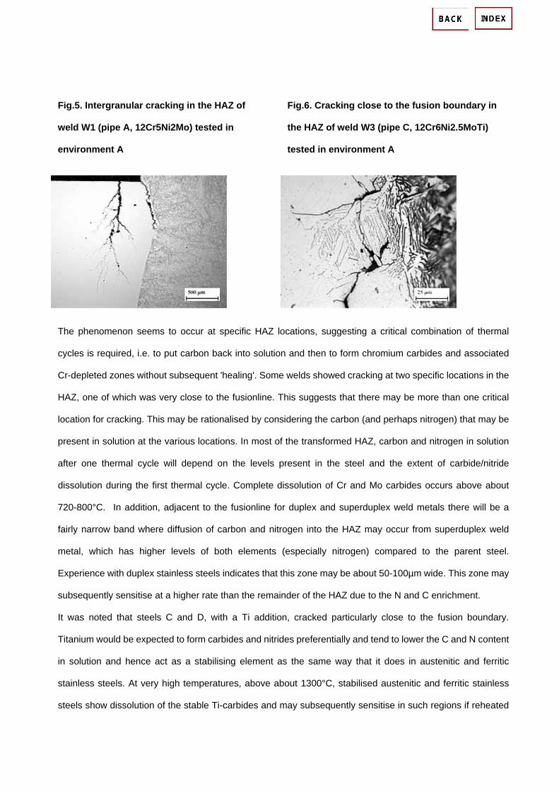
Fig.5. Intergranular cracking in the HAZ of
weld W1 (pipe A, 12Cr5Ni2Mo) tested in
environment A
Fig.6. Cracking close to the fusion boundary in
the HAZ of weld W3 (pipe C, 12Cr6Ni2.5MoTi)
tested in environment A
The phenomenon seems to occur at specific HAZ locations, suggesting a critical combination of thermal
cycles is required, i.e. to put carbon back into solution and then to form chromium carbides and associated
Cr-depleted zones without subsequent 'healing'. Some welds showed cracking at two specific locations in the
HAZ, one of which was very close to the fusionline. This suggests that there may be more than one critical
location for cracking. This may be rationalised by considering the carbon (and perhaps nitrogen) that may be
present in solution at the various locations. In most of the transformed HAZ, carbon and nitrogen in solution
after one thermal cycle will depend on the levels present in the steel and the extent of carbide/nitride
dissolution during the first thermal cycle. Complete dissolution of Cr and Mo carbides occurs above about
720-800°C. In addition, adjacent to the fusionline for duplex and superduplex weld metals there will be a
fairly narrow band where diffusion of carbon and nitrogen into the HAZ may occur from superduplex weld
metal, which has higher levels of both elements (especially nitrogen) compared to the parent steel.
Experience with duplex stainless steels indicates that this zone may be about 50-100µm wide. This zone may
subsequently sensitise at a higher rate than the remainder of the HAZ due to the N and C enrichment.
It was noted that steels C and D, with a Ti addition, cracked particularly close to the fusion boundary.
Titanium would be expected to form carbides and nitrides preferentially and tend to lower the C and N content
in solution and hence act as a stabilising element as the same way that it does in austenitic and ferritic
stainless steels. At very high temperatures, above about 1300°C, stabilised austenitic and ferritic stainless
steels show dissolution of the stable Ti-carbides and may subsequently sensitise in such regions if reheated

to temperatures around 500-600°C, which promote Cr-carbide formation, leading to so-called 'knifeline'
corrosion. Therefore, the location of cracking close to the fusionline in SMSS grades that contain Ti is
consistent with the temperature range over which such dissolution of Ti-carbides might be expected. These
facts all suggest a sensitisation mechanism that is related to the formation of Cr-depleted zones associated
with Cr-carbides. It is noted also that the region close to the fusion boundary also typically contains a small
fraction of retained delta ferrite within 100-200µm of the fusion boundary, which could have contributed to
cracking susceptibility, perhaps via precipitation of Cr-carbides on the ferrite-martensite boundaries. However,
no strong correlation between the location of delta ferrite and the IGSCC crack path was found.
This observation is supported by very fine scale chemical analysis in a transmission electron microscope,
which has confirmed the presence of Cr-carbides and Cr-depleted zones in lean grades. However, no such
evidence has been found for the high grades, so it is impossible at present to be conclusive for these grades.
Nevertheless, it seems unlikely that IGSCC of these two classes of SMSS would be a result of widely differing
mechanisms. In the absence of evidence that is inconsistent with such a mechanism, it is postulated that
sensitisation of high alloy SMSS grades is also a consequence of Cr-carbide precipitation, whilst recognising
that no positive proof has been obtained to date.
A mechanism of localised near-surface sensitisation has also been observed, associated with the formation
of Cr-oxide on the weld surface. The formation of the oxide is associated with prior austenite grain boundary
diffusion of chromium, which leads to the development of Cr-depleted regions adjacent to the near-surface
prior austenite grain boundaries. Shallow intergranular corrosion associated with this sensitised layer has
been observed in high alloy SMSS grades.
Bend specimens tested in hot acidic chloride media only cracked with the as-welded root and, hence, with
surface oxide and a stress concentrator. This has been observed by other authors although in highly acidic
solutions, smooth specimens have been found to crack. This indicates that the weld surface oxide or stress
concentration or both encourage crack initiation but are not essential. The effect of the oxide is presumably
related to the Cr-depletion adjacent to grain boundaries immediately beneath the surface. Not all weld
specimens cracked in the higher pH environment (B), suggesting a fairly strong effect of pH on IGSCC,
similar to the situation for austenitic stainless steels.
4.2 The beneficial effect of PWHT with respect to IGSCC

Postweld heat treatment clearly has a beneficial effect on the resistance of SMSS girth welds to IGSCC.
However, testing here was for a fairly short duration and longer term data are required to confirm its
applicability to long term service, particularly in the light of reservations expressed by one end user with a 30
day test duration for qualification of SMSS for sweet service. In the present work, one PWHT cycle has been
examined on girth welds, namely a nominal 650°C for five minutes although actual temperatures were
~620-660°C, with 620-640°C at the root. Assuming that the Cr-carbide precipitation theory of sensitisation of
SMSS to IGSCC is correct, the most likely mechanism by which PWHT is effective in eliminating sensitivity to
IGSCC is by allowing chromium back-diffusion into the chromium-depleted zones. The chromium-depleted
zone width has been estimated to be up to 20nm in lean grade material but may be <5nm in steel with about
6%Ni and 2%Mo. Hence, in order for PWHT to be effective, the time and temperature must be sufficient for
chromium to diffuse over a distance of this magnitude. Use of a simple x= Dt calculation, based on
published matrix diffusion coefficients in the range 4.9x10 -14 to 1.5x10 -13 cm 2 s -1 for chromium in iron with
10-20%Cr, extrapolated from higher temperature data, which presumably relates to an austenitic
microstructure, indicates a diffusion distance of about 40-70nm for five minutes at 650°C. Higher diffusion
rates would be expected in the martensite and ferrite phases. Hence, this very simple calculation supports
the proposed Cr-diffusion explanation of the effect of PWHT on eliminating sensitisation to IGSCC.
4.3 Avoiding potential detrimental effects of PWHT
In order for a PWHT cycle to be successfully applied to a SMSS weld, in addition to eliminating sensitivity to
IGSCC, it must also be such that it does not have any significantly detrimental effects on other weld
properties.
One undesirable effect of PWHT on the HAZ would be associated with heating to a temperature such that an
excessive amount of austenite re-forms, leading to formation of un-tempered martensite on subsequent
cooling. Un-tempered martensite has high hardness and low toughness in conventional martensitic stainless
steels, which have carbon contents in excess of 0.03%, although for the low carbon SMSS grades, these
effects are not pronounced and may not be significant. Examination of the effect of PWHT in simulated HAZs
showed that 650°C was typically the temperature giving most hardness reduction of the steels studied but
also showed substantial variation in response between SMSS grades, with some giving more hardness
reduction at 625°C. This indicates the importance of choosing PWHT for the specific steel in question,

although broadly similar behaviour is expected for all SMSS grades based on the data obtained here. The
reformed, stable austenite content was generally found to increase on tempering at 600-650°C, indicating
that Ac 1 was exceeded over this range, hence some virgin martensite formation is possible if the upper
temperature during PWHT is above this range. With induction heating, a temperature gradient develops
through the pipe wall thickness, with the outside being hotter than the inside. For wall thicknesses of
11-18mm, induction PWHT trials indicated that the root was typically 15-35°C cooler than the cap. The
greatest risk of un-tempered martensite formation and associated hardening is therefore in the weld cap,
whilst it is essential for eliminating sensitivity to IGSCC in the internal environment that the temperature at the
root is controlled. This requires that both root and cap temperatures are held within an acceptable range
during PWHT. The limiting upper temperature will vary from grade to grade but based on the current data,
which only extends to a cap temperature of up to 660°C, it is recommended that temperatures in excess of
660°C should be avoided. Further work is required to explore the suitability of PWHT temperatures exceeding
660°C.
Another potential detrimental effect of PWHT is that it will tend to increase oxidation of the weld area.
Oxidation during welding has been demonstrated to have a detrimental influence on the pitting resistance of
SMSS HAZs in mildly sour media and hence any further oxidation from PWHT might also be detrimental.
However, published work has indicated that PWHT at 650°C may be beneficial for service under mildly sour
conditions, presumably by lowering hardness, but it does not give immunity to cracking in sour media. Further
work is required to explore this issue, although use of an inert gas shield during PWHT would eliminate the
concern.
Detrimental microstructural effects at the edge of the PWHT zone, where intermediate temperatures will be
experienced, are not anticipated, provided that the whole of the weld HAZ is heat treated, i.e. that the
intermediate temperatures are experienced by parent steel. This assumes that the parent steel will have been
tempered such that the carbon content in solution is very low. Detrimental microstructural effects in the HAZ
and weld metal are of greater concern. These may include precipitation of (i) further carbides, e.g. on prior
austenite boundaries or within or on the interface of any delta ferrite retained in the HAZ and (ii) intermetallic
phase, secondary austenite or alpha prime phase in the delta ferrite in weld metal deposited with a duplex or
superduplex consumable. These precipitation reactions may act to lower corrosion resistance and toughness
in the weld metal or HAZ very close to the fusion line, although the present study showed that the toughness
effects are not significant for a high grade SMSS HAZ and superduplex weld metal subject to PWHT at 650°C

for 5 minutes. To avoid loss of toughness, it is recommended that the PWHT duration should not be
substantially longer than 5 minutes whilst recognising that longer PWHT may still give acceptable results for
many applications. Substantially shorter PWHT periods are not recommended due to the absence of data.
Sensitisation is not expected provided that the whole of the HAZ sees the intended PWHT temperature. No
loss of corrosion resistance associated with precipitation on delta ferrite in SMSS HAZs has been noted to
date, although one reference cites it as an issue for conventional 13%Cr 4%Ni steels, but does not indicate
the precise temperature range of concern, although it does state that tempering at around 600°C gives good
corrosion resistance, and hence problems are only likely to occur below this. Based on the results of the
present work, a suitable lower temperature limit of 620°C is suggested for the HAZ.
Although some precipitation occurred in superduplex weld metal during PWHT, this was apparently restricted
to the formation of secondary austenite. Secondary austenite tends to reduce corrosion resistance but this
should not be a problem when welding SMSS. This implies that, although PWHT of superduplex weld metal is
not normally considered advisable, in this case 5 minutes PWHT at 650°C does not seem to be detrimental. If
longer PWHT times or higher temperatures were used, some loss of toughness in superduplex weld metal
might occur, although this was not studied here.
5. Conclusions
1. The sensitisation of lean grade SMSS HAZs has been linked to the formation of Cr-carbides on
prior-austenite grain boundaries and adjacent Cr-depleted zones but this link has not been established
for the high alloy grades. Formation of Cr-depleted zones on prior-austenite boundaries immediately
underneath the welding oxide has been observed in high alloy grades. Hence some uncertainty remains
over the mechanism of IGSCC of high grade supermartensitic stainless steel and the effect of PWHT.
Nevertheless, there is a substantial body of information supporting a consistent beneficial effect of brief
PWHT for a broad range of supermartensitic grades.
2. It is recommended that PWHT should be applied to welds in supermartensitic stainless steel where there
is a risk of intergranular SCC in service, i.e. in hot acidic environments. A PWHT temperature of
620-650°C at the root is recommended and the heat treated zone should encompass the whole of the
weld metal and HAZ. The maximum allowable cap temperature has not been established but the current
work extended up to 660°C. Heating and cooling should be fairly rapid. The most appropriate PWHT

duration has not been established but there is fairly common agreement that 5 minutes is an appropriate
duration.
3. Whilst the beneficial effect of PWHT with respect to IGSCC has been demonstrated for 30 day exposure
tests, longer term data are required to confirm the applicability of the effect to long term service.
4. Due to the limited information available, the use of welded supermartensitic stainless steel in the PWHT
condition will require qualification on a case by case basis. The qualification programme should consider
the effects of PWHT on toughness and sour service performance, in addition to IGSCC. The qualification
process should consider the extremes of the range of PWHT thermal cycles that may be experienced, as
the acceptable range has not been established.
5. No substantial change in toughness of superduplex weld metal was observed for PWHT at 650°C for 5
minutes, although secondary austenite was formed. A small reduction of root HAZ hardness was
generally associated with PWHT.
6. Postweld heat treatment may also have detrimental effects if not adequately controlled, e.g. (i)
thickening of weld area oxides and associated loss of general/pitting corrosion resistance, (ii) formation
of virgin martensite in the HAZ and increased hardness leading to reduced toughness and resistance to
sour environments, (iii) loss of toughness in superduplex stainless steel weld metal, (iv) tempering of
HAZ at temperatures that could induce sensitisation to intergranular SCC if the heat treated area is not
wide enough.
7. The precise response to PWHT is specific to each individual grade of supermartensitic steel, although
the data indicate that all steels examined here were fairly similar and the beneficial effect of 5 minutes at
620-650°C, with respect to IGSCC, is applicable to 'lean' grades, with <1%Mo and 'high' grades with
>2%Mo both with and without Ti addition.

Corrosion of Aluminum and Its Alloys: Forms of Corrosion Abstract:
Corrosion is the chemical reaction of a metal, in this case aluminum, with its environment, which leads to the deterioration of the properties of metals, aluminum in this case. Aluminum is a very reactive metal, but it is also a passive metal. This contradictory nature is explainable because nascent aluminum reacts with oxygen or water and forms a coherent surface oxide which impedes further reaction of aluminum with the environment. Corrosion is the chemical reaction of a metal, in this case aluminum, with its environment, which leads to the deterioration of the properties of metals, aluminum in this case. Aluminum is a very reactive metal, but it is also a passive metal. This contradictory nature is explainable because nascent aluminum reacts with oxygen or water and forms a coherent surface oxide which impedes further reaction of aluminum with the environment.
Aluminum is chemically very reactive. For example, powdered aluminum is used as rocket propellant for propulsion of the space shuttle's solid fuel rockets. Additionally, the reaction of aluminum with water releases a tremendous amount of energy:
AI + 3H2O → AI(OH)3 + 3H2 ↑
Corrosion is the reaction of aluminum with water and the subsequent deterioration of its properties. Corrosion, by definition, is a slow process, requiring days or years to occur to a noticeable extent, as opposed to similar electrochemical reactions such as etching, brightening, or anodizing which occur in minutes or less.
Aluminum alloys may corrode via several different pathways. Recognizing the pathway or the forms of aluminum corrosion is an important step to determine the appropriate remedy for each probe.
Atmospheric Corrosion
Atmospheric corrosion is defined as the corrosion or degradation of material exposed to the air and its pollutants rather than immersed in a liquid. This has been identified as one of the oldest forms of corrosion and has been reported to account for more failures in terms of cost and tonnage than any other single environment. Many authors classify atmospheric corrosion under categories of dry, damp, and wet, thus emphasizing the different mechanisms of attack under increasing humidity or moisture.
Corrosivity of the atmosphere to metals varies greatly from one geographic location to another, depending on such weather factors as wind direction, precipitation and temperature changes, amount and type of urban and industrial pollutants, and proximity to natural bodies of water. Service life may also be affected by the design of the structure if weather conditions cause repeated moisture condensation in unsealed crevices or in channels with no provision for drainage.

Uniform Corrosion
General corrosion, or uniform corrosion, occurs in the solutions where pH is either very high or very low, or at high potentials in electrolytes with high chloride concentrations. In acidic (low pH) or alkaline (high pH) solutions, the aluminum oxide is unstable and thus non-protective.
Galvanic Corrosion
Economically, galvanic corrosion creates the largest number of corrosion problems for aluminum alloys. Galvanic corrosion, also known as dissimilar metal corrosion, occurs when aluminum is electrically connected to a more noble metal, and both are in contact with the same electrolyte.
Crevice Corrosion
Crevice corrosion requires the presence of a crevice, a salt water environment, oxygen (Fig. 1). The crevice can result from the overlap of two parts, or gap between a bolt and a structure. When aluminum is wetted with the saltwater and water enters the crevice, little happens initially. Over time, inside the crevice oxygen is consumed due to the dissolution and precipitation of aluminum.
Figure 1: Crevice corrosion can occur in a saltwater environment if the crevice becomes deaerated, and the oxygen reduction reaction occurs outside of the crevice mouth. Under these conditions, the crevice
becomes more acidic, and corrosion occurs at an increasing rate.
Pitting Corrosion
Corrosion of aluminum in the passive range is localized, usually manifested by random formation of pits. The pitting-potential principle establishes the conditions under which metals in the passive state are subject to corrosion by pitting.
Pitting corrosion is very similar to crevice corrosion. Pitting of aluminum alloys occurs if the electrolyte contains a low level of chloride anions, and if the alloy is at a potential above the "pitting potential." Pitting initiates at defects on the surface of the aluminum, such as at second phase particles or on grain boundaries.
Deposition Corrosion

In designing aluminum and aluminum alloys for satisfactory corrosion resistance, it is important to keep in mind that ions of several metals have reduction potentials that are more cathodic than the solution potential of aluminum and therefore can be reduced to metallic form by aluminum. For each chemical equivalent of so-called heavy-metal ions reduced, a chemical equivalent of aluminum is oxidized. Reduction of only a small amount of these ions can lead to severe localized corrosion of aluminum, because the metal reduced from them plates onto the aluminum and sets up galvanic cells.
The more important heavy metals are copper, lead, mercury, nickel, and tin. The effects of these metals on aluminum are of greatest concern in acidic solutions; in alkaline solutions, they have much lower solubilities and therefore much less severe effects.
Intergranular Corrosion
Intergranular (intercrystalline) corrosion is selective attack of grain boundaries or closely adjacent regions without appreciable attack of the grains themselves. Intergranular corrosion is a generic term that includes several variations associated with different metallic structures and thermomechanical treatments. Intergranular corrosion is caused by potential differences between the grain-boundary region and the adjacent grain bodies.
The location of the anodic path varies with the different alloy systems. In 2xxx series alloys, it is a narrow band on either side of the boundary that is depleted in copper; in 5xxx series alloys, it is the anodic constituent Mg2AI3 when that constituent forms a continuous path along a grain boundary; in copper-free 7xxx series alloys, it is generally considered to be the anodic zinc- and magnesium-bearing constituents on the grain boundary. The 6xxx series alloys generally resist this type of corrosion, although slight intergranular attack has been observed in aggressive environments.
Exfoliation Corrosion
Exfoliation corrosion in an aluminum alloy exposed to tropical marine environment. Also note the paint failures caused by corrosion of aluminium at the coating/aluminium interface.

Exfoliation corrosion is a special form of intergranular corrosion which occurs when the grains are flattened by heavy deformation during hot or cold rolling, and where no recrystallization has occurred. Exfoliation is characteristic for the 2000 (Al-Cu), 5000 (Al-Mg), and 7000 (Al-Zn-Mg) series alloys which have grain boundary precipitation or depleted grain boundary regions.
The remedy for exfoliation is similar to above for IG corrosion. To prevent the exfoliation of alloy 7075-T6, the newer alloy 7150-T77 can be substituted wherever 7075-T6 is used.
Erosion-Corrosion
Erosion-corrosion of aluminum occurs in high velocity water and is similar to jet-impingement corrosion. Erosion-corrosion of aluminum is very slow in pure water, but is accelerated at pH > 9, especially with high carbonate and high silica content of the water.
Aluminum is very stable is neutral water; however it will corrode in either acidic or alkaline waters. To prevent erosion-corrosion, one may change the water chemistry or reduce the velocity of the water, or both. For the water chemistry, the pH must be below 9, and the carbonate and the silica levels must be reduced.
Stress Corrosion Cracking (SCC)
Stress corrosion cracking (SCC) is the bane of aluminum alloys. SCC requires three simultaneous conditions, first a susceptible alloy, second a humid or water environment, and third a tensile stress which will open the crack and enable crack propagation. SCC can occur in two modes, intergranular stress corrosion cracking (IGSCC) which is the more common form, or transgranular SCC (TGSCC). In IGSCC, the crack follows the grain boundaries. In transgranular stress corrosion cracking (TGSCC), the cracks cut through the grains and are oblivious to the grain boundaries.
The general trend to use higher strength alloys peaked in 1950 with alloy 7178-T651 used on the Boeing 707, then the industry changed to using lower strength alloys. The yield strength of the upper wing skin did not exceed the 1950 level until the Boeing 777 in the 1990s. The reason lower strength alloys were selected for the Boeing 747 and the L-1011 was that the aircraft designers chose an alloy with better SCC resistance rather than the higher yield strength.
Corrosion Fatigue
Corrosion fatigue can occur when an aluminum structure is repeatedly stressed at low stress levels in a corrosive environment. A fatigue crack can initiate and propagate under the influence of the crack-opening stress and the environment. Similar striations may sometimes be found on corrosion fatigued samples, but often the subsequent crevice corrosion in the narrow fatigue crack dissolves them.
Fatigue strengths of aluminum alloys are lower in such corrosive environments as seawater and other salt solutions than in air, especially when evaluated by low-stress long-duration tests. Like SCC of aluminum alloys, corrosion fatigue requires the presence of water. In contrast to SCC, however, corrosion fatigue is not appreciably affected by test direction, because the fracture that results from this type of attack is

predominantly transgranular.
Filiform Corrosion
Filiform corrosion (also known as wormtrack corrosion) is a cosmetic problem for painted aluminum. Pinholes or defects in the paint from scratches or stone bruises can be the initiation site where corrosion begins with salt water pitting. Filiform corrosion requires chlorides for initiation and both high humidity and chlorides for the propagation of the track.
The propagation depends on where and how the alloy is used. The filament must be initiated by chlorides, and then it proceeds by a mechanism similar to crevice corrosion. The head is acidic, high in chlorides, and deaerated and is the anodic site. Oxygen and water vapor diffuse through the filiform tail, and drive the cathodic reaction. Filiform corrosion can be prevented by sealing defects with paint or wax, and keeping the relative humidity low.
Microbiological Induced Corrosion
Microbiological Induced Corrosion (MIC) applies to a corrosive situation which is caused or aggravated by the biological organisms. A classic case of MIC is the growth of fungus at the water/fuel interface in aluminum aircraft fuel tanks. The fungus consumes the high octane fuel, and excretes an acid which attacks and pits the aluminum fuel tank and causes leaking. The solution for this problem is to control the fuel quality and prevent water from entering or remaining in the fuel tanks. If fuel quality control is not feasible, then fungicides are sometimes added to the aircraft fuel.

* Publisher: Elsevier Science * Number Of Pages: 700 * Publication Date: 2004-12-16 * Sales Rank: 246595 * ISBN / ASIN: 0080444954 * EAN: 9780080444956 * Binding: Hardcover * Manufacturer: Elsevier Science * Studio: Elsevier Science * Average Rating: * Total Reviews:
Book Description: This book highlights the practical and general aspects of the corrosion of aluminium alloys with many illustrations and references. In addition to that, the first chapter allows the reader who is not very familiar with aluminium to understand the metallurgical, chemical and physical features of the aluminium alloys. The author Christian Vargel, has adopted a practitioner approach, based on the expertise and experience gained from a 40 year career in aluminium corrosion This approach is most suitable for assessing the corrosion resistance of aluminium- an assessment which is one of the main conditions for the development of many uses of aluminium in transport, construction, power transmission etc. * 600 bibliographic references provide a comprehensive guide to over 100 years of related study * Providing practical applications to the reader across many industries * Accessible to both the beginner and the expert download :
http://mihd.net/hl4ju8
http://rapidshare.com/files/8551893/e0080444954.pdf.html
Corrosion of Copper and Copper Alloys
In normal atmospheric exposure to carbonic acid (H2CO3) copper and copper alloys form a layer of copper carbonate - a green substance also called patina. This patina (CuCO3) actually serves to protect the copper underneath from further corrosion. The insoluble copper carbonate tightly adheres to the surface preventing further contact with acid rain. However, the patina is a pale and unsightly green that detracts from the appearance of many copper structures and monuments. If you have ever visited Charlottetown, Prince Edward Island you may be familiar with this as the War Memorial in the downtown area is heavily coated in patina. This reaction begins with the release of gaseous carbon dioxide into the atmosphere from respiration or in the form of emissions from industrial processes. The CO2 dissolves in atmospheric moisture to form carbonic acid:
CO2(gas) + H2O(liquid) H2CO3(aq)
The acidic properties of carbonic acid have no effect here as the H+(aq) do not take an active role in the reaction. The carbonate (CO32-) polyatomic ion is the reactive species that oxidizes the copper into patina and allows the hydrogen gas to escape:
H2CO3(aq) + Cu(solid) CuCO3(solid) + H2(gas)
Even though this reaction would slowly occur naturally, as the concentration of CO2 in the atmosphere increases from emissions the rate of this reaction increases. This shortens the longevity of the lustrous metal and hastens the restoration process that can be costly.
COPPER AND COPPER ALLOYS are widely used in many environments and applications because of their excellent corrosion resistance, which is coupled with combinations of other desirable properties, such as superior electrical and thermal conductivity, ease of fabricating and joining, wide range of attainable mechanical properties, and resistance to biofouling.
Copper corrodes at negligible rates in unpolluted air, water, and deaerated nonoxidizing acids. Copper alloy artifacts have been found in nearly pristine condition after having been buried in the earth for thousands of years, and copper roofing in rural atmospheres has been found to corrode at rates of less than 0.4 mm in 200 years.
Copper alloys resist many saline solutions, alkaline solutions, and organic chemicals. However, copper is susceptible to more rapid attack in oxidizing acids, oxidizing heavy-metal salts, sulfur, ammonia (NH3), and some sulfur and NH3 compounds.
Copper and copper alloys provide superior service in many of the applications included in the following general classifications:

Applications requiring resistance to atmospheric exposure, such as roofing and other architectural uses, hardware, building fronts, grille work, hand rails, lock bodies, doorknobs, and kick plates
Freshwater supply lines and plumbing fittings, for which superior resistance to corrosion by various types of waters and soils is important
Marine applications - most often freshwater and seawater supply lines, heat exchangers, condensers, shafting, valve stems, and marine hardware - in which resistance to seawater, hydrated salt deposits, and biofouling from marine organisms is important
Heat exchangers and condensers in marine service, steam power plants, and chemical process applications, as well as liquid-to-gas or gas-to-gas heat exchangers in which either process stream may contain a corrosive contaminant
Industrial and chemical plant process equipment involving exposure to a wide variety of organic and inorganic chemicals
Electrical wiring, hardware, and connectors; printed circuit boards; and electronic applications that require demanding combinations of electrical, thermal, and mechanical properties, such as semiconductor packages, lead frames, and connectors
Effects of alloy compositions on corrosion
Coppers and high-copper alloys (C 10100 - C 19600; C 80100 - C 82800) have similar corrosion resistance. They have excellent resistance to seawater corrosion and biofouling, but are susceptible to erosion-corrosion at high water velocities. The high-copper alloys are primarily used in applications that require enhanced mechanical performance, often at slightly elevated temperature, with good thermal or electrical conductivity. Processing for increased strength in the high-copper alloys generally improves their resistance to erosion-corrosion.
Brasses (C 20500 - C 28580) are basically copper-zinc alloys and are the most widely used group of copper alloys. The resistance of brasses to corrosion by aqueous solutions does not change markedly as long as the zinc content does not exceed about 15%. Above 15% Zn, dezincification may occur.
Susceptibility to stress-corrosion cracking (SCC) is significantly affected by zinc content; alloys that contain more zinc are more susceptible. Resistance increases substantially as zinc content decreases from 15% to 0%. Stress-corrosion cracking is practically unknown in commercial copper. Elements such as lead, tellurium, beryllium, chromium, phosphorus, and manganese have little or no effect on the corrosion resistance of coppers and binary copper-zinc alloys. These elements are added to enhance such mechanical properties as machinability, strength, and hardness.
Tin Brasses (C 40400 - C 49800; C 90200 - C 94500). Tin additions significantly increase the corrosion resistance of some brasses, especially resistance to dezincification.

Cast brasses for marine applications are also modified by the addition of tin, lead, and, sometimes, nickel. This group of alloys is known by various names, including composition bronze, ounce metal, and valve metal.
Aluminum Brasses (C66400-C69900). An important constituent of the corrosion film on a brass that contains few percents of aluminum in addition to copper and zinc is aluminum oxide (A1203), which markedly increases resistance to impingement attack in turbulent high-velocity saline water.
Phosphor Bronzes (C 50100 - C 52400). Addition of tin and phosphorus to copper produces good resistance to flowing seawater and to most nonoxidizing acids except hydrochloric (HCl). Alloys containing 8 to 10% Sn have high resistance to impingement attack. Phosphor bronzes are much less susceptible to SCC than brasses and are similar to copper in resistance to sulfur attack. Tin bronzes-alloys of copper and tin-tend to be used primarily in the cast form, in which they are modified by further alloy additions of lead, zinc, and nickel.
Copper Nickels (C 70000 - C 79900; C 96200 - C 96800). Alloy C71500 (Cu-30Ni) has the best general resistance to aqueous corrosion of all the commercially important copper alloys, but C70600 (Cu-3ONi) is often selected because it offers good resistance at lower cost. Both of these alloys, although well suited to applications in the chemical industry, have been most extensively used for condenser tubes and heat-exchanger tubes in recirculating steam systems. They are superior to coppers and to other copper alloys in resisting acid solutions and are highly resistant to SCC and impingement corrosion.
Nickel Silvers (C 73200 - C 79900; C 97300 - C 97800). The two most common nickel silvers are C75200 (65Cu-18Ni-17Zn) and C77000 (55Cu-18Ni-27Zn). They have good resistance to corrosion in both fresh and salt waters. Primarily because their relatively high nickel contents inhibit dezincification, C75200 and C77000 are usually much more resistant to corrosion in saline solutions than brasses of similar copper content.
Copper-silicon alloys (C 64700 - C66100; C 87300 - C 87900) generally have the same corrosion resistance as copper, but they have higher mechanical properties and superior weldability. These alloys appear to be much more resistant to SCC than the common brasses. Silicon bronzes are susceptible to embrittlement by high-pressure steam and should be tested for suitability in the service environment before being specified for components to be used at elevated temperature.
Aluminum bronzes (C 60600 - C 64400; C 95200 - C 95810) containing 5 to 12% Al have excellent resistance to impingement corrosion and high-temperature oxidation. Aluminum bronzes are used for beater bars and for blades in wood pulp machines because of their ability to withstand mechanical abrasion and chemical attack by sulfite solutions.
In the most of practical commercial applications, the corrosion characteristics of aluminum bronzes are primarily related to aluminum content. Alloys with up to 8% Al normally have completely face-centered cubic structures and a good resistance to corrosion attack. As aluminum con tent increases above 8%, duplex structures appear.

Depending on specific environmental conditions, phase or eutectoid structure in aluminum bronze can be selectively attacked by a mechanism similar to the dezincification of brasses. Proper quench-and-temper treatment of duplex alloys, such as C62400 and C95400, produces a tempered ( structure with reprecipitated acicular a crystals, a combination that is often superior in corrosion resistance to the normal annealed structures.
Nickel-aluminum bronzes are more complex in structure with the introduction of the K phase. Nickel appears to alter the corrosion characteristics of the phase to provide greater resistance to dealloying and cavitation-erosion in most liquids.
Aluminum bronzes are generally suitable for service in nonoxidizing mineral acids, such as phosphoric (H3PO4), sulfuric (H2SO4), and HCl; organic acids, such as lactic, acetic (CF3COOH), or oxalic; neutral saline solutions, such as sodium chloride (NaCI) or potassium chloride (KCl); alkalies, such as sodium hydroxide (NaOH), potassium hydroxide (KOH), and anhydrous ammonium hydroxide (NH4OH); and various natural waters including sea, brackish, and potable waters. Environments to be avoided include nitric acid (HNO3); some metallic salts, such as ferric chloride (FeCl3) and chromic acid (H2CrO4); moist chlorinated hydrocarbons; and moist HN3. Aeration can result in accelerated corrosion in many media that appear to be compatible.

1-1. Metal Corrosion
The open recirculating cooling water system for a building is mainly for air-conditioning system and the main construction materials are mild steel and copper alloys. Corrosion of metals reduces the life of the cooling systems. The corrosion products also precipitate on the heat exchangers and reduce heat transfer efficiency to increase energy loss. Corrosion of copper and copper alloys produces heat insulating thick black copper oxide on the surfaces. This copper oxide increasesenergy costs also.
1-2. Scale
In addition to the corrosion products which was mentioned before, some components in cooling water, such as calcium, magnesium and silica, precipitate on the heat transfer surfaces and cause serious problem of low heat transfer problem and excessive energy loss. Most of the heat exchangers for air -conditioning systems show 0.2 to 1mm thickness of scale before their annual chemical cleaning if they are not treated regularly by a proper scale inhibitor chemical product.
1-3. Microbial Fouling
The microbial fouling in an open recirculating cooling water system is caused by algae, slime bacteria, legionellar and fungi. Legionellar control is particullarly important for building cooling water treatment. Cooling efficiency of a cooling tower is significantly reduced by bio-fouling. Adhesion of algae or slime bacteria on the heat exchanger surfaces reduces heat transfer and can cause under-deposit corrosion.

Corrosion Resistance of Copper and Copper Alloys
Reprinted with permission by the Copper Development Association
An R indicates that the material is resistant to the named chemical up to the temperature shown, subject to limitations indicated by the footnotes.
An X indicates that the material is NOT RECOMMENDED.
Aluminium Bronze Brass (a) Copper Copper-Nickel 90/10
alloys (b)
Gunmetal and
Bronze (c)
Temperature, Celcius 20 60 100 20 60 100 20 60 100 20 60 100 20 60 100
Acetaldehyde R R R R R R R R R R R R R R R
Acetic acid (10%) R R R X X X R R R R R R R R R
Acetic acid (glac./anh.) R R R X X X R R R R R X R R R
Acetic anhydride R R R X X X R R R R R R R R X
Aceto-acetic ester R R R R (82) X X R R R R R R R R R
Acetone R R R R R R R R R R R R R R R
Other ketones R R R R R R R R R R R R R R R
Acetonitrile R (36) X X X X X R (36) X X R (36) X X R (36) X X
Acetylene X X X R R R (82) X X X X X X X X X
Acetyl salicylic acid R R R
No
data
No
data
No
data R (36) X X R R R R R R
Acid fumes R (2) R (2) R (2) X X X R (2) R (2) R (2) R (2) R (2) R (2) X X X
Alcohols (mostly fatty) R R R R R R R R R R R R R R R
Aliphatic esters R R R R R R R R R R R R R R R
Alkyl chlorides No
data
No
data
No
data X X X R R R R R R R R R
Alum R R R X X X R R R R R R R R R
Aluminium chloride R (20) R (20) X X X X R R R R R X R R R
Aluminium sulphate R R R
R
(119)
R
(119)X
R
(119)
R (20,
119)
R (20,
119) R R R
R
(119)
R
(119)
R
(119)
Ammonia, anhydrous R R R X X X R R R (83) R R R R R R
Ammonia, aqueous X X X X X X X X X X X X X X X
Ammonium chloride X X X X X X X X X X X X X X X
Amyl acetate R R R X X X R R R R R R R R R
Aniline X X X X X X X X X X X X X X X
Antimony trichloride No
data
No
data
No
data X X X
No
data No data No data No data No data No data R X X
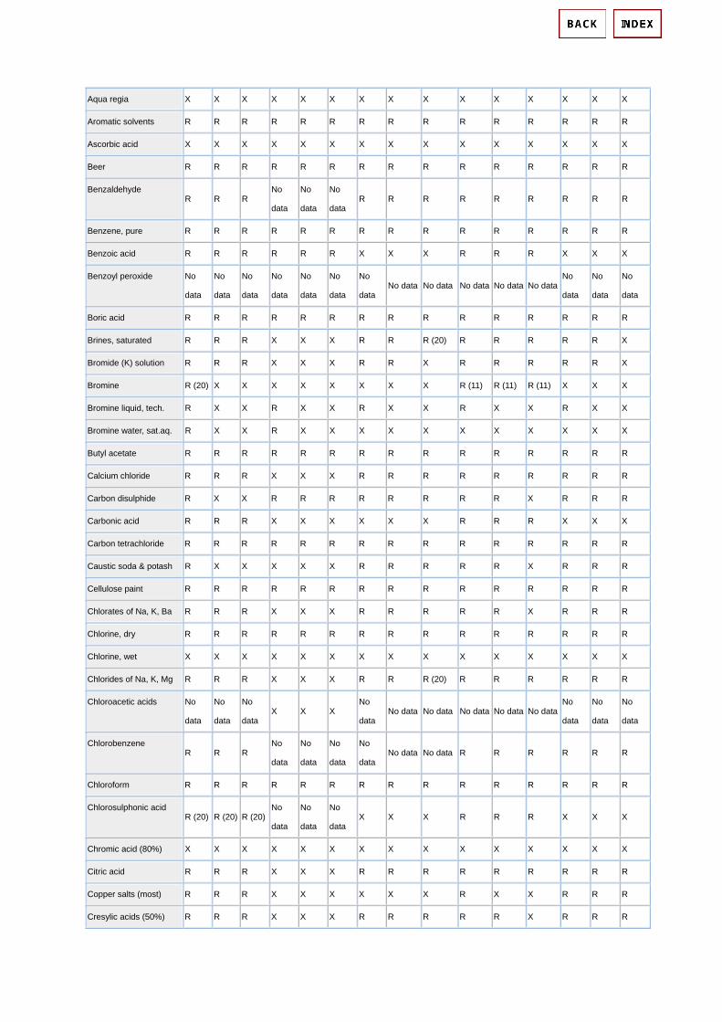
Aqua regia X X X X X X X X X X X X X X X
Aromatic solvents R R R R R R R R R R R R R R R
Ascorbic acid X X X X X X X X X X X X X X X
Beer R R R R R R R R R R R R R R R
Benzaldehyde R R R
No
data
No
data
No
data R R R R R R R R R
Benzene, pure R R R R R R R R R R R R R R R
Benzoic acid R R R R R R X X X R R R X X X
Benzoyl peroxide No
data
No
data
No
data
No
data
No
data
No
data
No
data No data No data No data No data No data
No
data
No
data
No
data
Boric acid R R R R R R R R R R R R R R R
Brines, saturated R R R X X X R R R (20) R R R R R X
Bromide (K) solution R R R X X X R R X R R R R R X
Bromine R (20) X X X X X X X X R (11) R (11) R (11) X X X
Bromine liquid, tech. R X X R X X R X X R X X R X X
Bromine water, sat.aq. R X X R X X X X X X X X X X X
Butyl acetate R R R R R R R R R R R R R R R
Calcium chloride R R R X X X R R R R R R R R R
Carbon disulphide R X X R R R R R R R R X R R R
Carbonic acid R R R X X X X X X R R R X X X
Carbon tetrachloride R R R R R R R R R R R R R R R
Caustic soda & potash R X X X X X R R R R R X R R R
Cellulose paint R R R R R R R R R R R R R R R
Chlorates of Na, K, Ba R R R X X X R R R R R X R R R
Chlorine, dry R R R R R R R R R R R R R R R
Chlorine, wet X X X X X X X X X X X X X X X
Chlorides of Na, K, Mg R R R X X X R R R (20) R R R R R R
Chloroacetic acids No
data
No
data
No
data X X X
No
data No data No data No data No data No data
No
data
No
data
No
data
Chlorobenzene R R R
No
data
No
data
No
data
No
data No data No data R R R R R R
Chloroform R R R R R R R R R R R R R R R
Chlorosulphonic acid R (20) R (20) R (20)
No
data
No
data
No
data X X X R R R X X X
Chromic acid (80%) X X X X X X X X X X X X X X X
Citric acid R R R X X X R R R R R R R R R
Copper salts (most) R R R X X X X X X R X X R R R
Cresylic acids (50%) R R R X X X R R R R R X R R R

Cyclohexane R R R R R R R R R R R R R R R
Detergents, synthetic No
data
No
data
No
data R R R R R R R R R R R R
Emulsifiers (all conc.) R R R
No
data
No
data
No
data R R R R R R
No
data
No
data
No
data
Esters R R R R R R R R R R R R R R R
Ether R R R R R R R R R R R R R R R
Fatty acids (>C6) R R R X X X R R R R R R R R R
Ferric chloride X X X X X X X X X X X X X X X
Ferrous sulphate R (20) R (20) R (20) X X X X X X R X X X X X
Fluorinated refrigerants R R R R R R R R R R R R R R R
Fluorine, dry R R R (11) X X X R R R R R R R R R
Fluorine, wet X X X X X X X X X X X X X X X
Fluorosilic acid X X X X X X X X X X X X X X X
Formaldehyde (40%) R R R R X X R R R R R R R R R
Formic acid R R R
No
data
No
data
No
data R R R R R R R R R
Fruit juices R R R X X X R R R R R R R R R
Gelatine R R R R R R R R R R R R R R R
Glycerine R R R R R R R R R R R R R R R
Glycols R R R R R R R R R R R R R R R
Glycol, ethylene R X X R X X R R R R (175) R (175) R (175) R R R
Glycollic acid R (36) X X R (36) X X R (36) X X R (36) X X R (36) X X
Hexamethylene diamine X X X X X X X X X X X X X X X
Hexamine X X X X X X X X X X X X X X X
Hydrazine X X X X X X X X X X X X X X X
Hydrobromic acid (50%) X X X X X X X X X X X X X X X
Hydrochloric acid (10%) R X X X X X X X X R X X X X X
Hydrochloric acid (conc.) R (62) X X X X X X X X X X X X X X
Hydrocyanic acid R (20) R (20) R (20) X X X X X X X X X X X X
Hydrofluoric acid (40%) R (62) X X X X X X X X X X X X X X
Hydrofluoric acid (75%) R (62) X X X X X X X X X X X X X X
Hydrogen peroxide
(30%) X X X X X X X X X R X X X X X
Hydrogen peroxide
(30-90%) X X X X X X X X X X X X X X X
Hydrogen sulphide R (11) R R R (11) R R R (11) R R R (11) R (11) R (11) R (11) R R
Hypochlorites R X X X X X X X X X X X X X X

Hypochlorite (Na
12-14%) R R R R R R R R R X X X X X X
Iso-butyl acetate R R X X X X R R X R R R R R R
Lactic acid (90%) No
data
No
data
No
data X X X X X X R R X R (4) R (4) X
Lead acetate X X X X X X X X X R R X X X X
Lead perchlorate R R R R R R R R R X X X X X X
Lime (CaO) No
data
No
data
No
data
No
data
No
data
No
data R R R R R R R R R
Maleic acid R X X R X X R (60) R (60) X R R X
No
data
No
data
No
data
Manganate, pot (K) R R R X X X X X X X X X R (60) R (60) X
Meat juices X X X X X X X X X No data No data No data X X X
Mercuric chloride X X X X X X X X X X X X X X X
Mercury R R R R R R R R R X X X X X X
Methanol R R R R (82) R (82) R (82) R R R R R R R R R
Methylene chloride R R X X X X X X X R R R R R R
Milk & milk products R R R X X X R R R R R R R R
Moist air R (30) R (30) R (30) R (30) R X R (30) R R R R R R R R
Molasses X X X X X X X X X R R R R (30) R R
Monoethanolamine R R R R R R R R R X X X X X X
Naphtha No
data
No
data
No
data
No
data
No
data
No
data R R R R R R R R R
Naphthalene No
data
No
data
No
data X X X X X X R R R
No
data
No
data
No
data
Nickel salts R (73) R (73) R (73) X X X X X X R R R R R R
Nitrates of Na, K, NH3 X X X X X X X X X R (73) R (73) X X X X
Nitric acid (<25%) X X X X X X X X X X X X X X X
Nitric acid (50%) X X X X X X X X X X X X X X X
Nitric acid (90%) X X X X X X X X X X X X X X X
Nitric acid, fuming R R R R R R R R R X X X X X X
Nitrite (Na) R R R R R R R R R R R R R R R
Nitrobenzine R X X R X X R X X R R R R R R
Oil, diesel R R R R R R R R R R X X R X X
Oils, essential R R X R R X R R X R R R R R R
Oils, lube + aromatic
ads. R R R R R R R R R R R X R R X
Oils, mineral R R R R R R R R R R R R R R R

Oils, vegetable & animal R R R
No
data
No
data
No
data R R R R R R R R R
Oxalic acid No
data
No
data
No
data
No
data
No
data
No
data
No
data No data No data R R R R R R
Ozone R R R R R R R R R No data No data No data
No
data
No
data
No
data
Paraffin wax X X X
No
data
No
data
No
data X X X R R R R R R
Perchloric acid R R R R R R R R R X X X X X X
Petroleum spirits R R R R R R R R R R R R R R R
Phenol R R R X X X R R R R R R R R R
Phosphoric acid (20%) R R R X X X X X X R R X X X X
Phosphoric acid (50%) R R R X X X X X X R R X X X X
Phosphoric acid (95%) R (11) R (11) R (11) X X X X X X R X X X X X
Phosphorus chlorides No
data
No
data
No
data X X X X X X R X X X X X
Phosphorous pentoxide R R R
No
data
No
data
No
data R R R No data No data No data X X X
Phthalic acid X X X X X X X X X R R R R R R
Picric acid No
data
No
data
No
data X X X X X X R R R R R R
Pyridine No
data
No
data
No
data
No
data
No
data
No
data
No
data No data No data No data No data No data X X X
Salicyl aldehyde R R R R (62) R R R R R No data No data No data
No
data
No
data
No
data
Sea water R R R
No
data
No
data
No
data R R R R R R R R R
Silicic acid R R R R R R R R R X X X
No
data
No
data
No
data
Silicone fluids X X X X X X X X X R R R R R R
Silver nitrate R R R (4) R R R R R R X X X X X X
Sodium carbonate X X X X X X X X X R R R R R R
Sodium peroxide R R R R R R R R R R X X X X X
Sodium silicate X X X X X X X X X R R R R R R
Sodium sulphide R (11) X X X X X X X X X X X X X X
Stannic chloride R R X
No
data
No
data
No
data R R R X X X X X X
Starch R R R R R R R R R R R R R R R
Sugar soln, syrups, jams No No No X X X X X X R R R R R R

data data data
Sulphamic acid R R R R R R R R R No data No data No data X X X
Sulphates (Na, K, Mg,
Ca) R R R X X X R R R R R R R R R
Suphites No
data
No
data
No
data
No
data
No
data
No
data X X X R R R R R R
Sulphonic acids X X X X X X X X X No data No data No data
No
data
No
data
No
data
Sulphur R R R R R R R R R X X X X X X
Sulphur dioxide, dry R R R X X X X X X R R X R R R
Sulphur dioxide, wet R R R X X X R (20) R (20) X X X X X X X
Sulphur dioxide, (96%) R
(11)b R R R (11) R R R (11) R R R R (20) X R (20) R (20) R (20)
Sulphur trioxide R R R X X X R R R R (11) R X R (11) R R
Sulphuric acid (<50%) R R (62) X X X X X X X R X X X X X
Sulphuric acid (70%) R (62) X X X X X X X X R X X X X X
Sulphuric acid (95%) X X X X X X X X X R X X X X X
Sulphuric acid, fuming X X X X X X X X X X X X X X X
Sulphur chlorides R R R
No
data
No
data
No
data R R R X X X X X X
Tallow R R R R R R R R R R R R
No
data
No
data
No
data
Tannic acid (10%) R R R R R R R R R R R R R R R
Tartaric acid R R R R R R R R R R R R R R R
Trichlorethylene R R X R R X R R X R R R R R R
Urea (30%) R R R X X X X X X R R X R R
No
data
Vinegar R (53) R X X X X R (53) R X R R R X X X
Water, distilled RR R R R R R R R R R R R R (53) R R
Water, soft R R R R R R R R R R R R R R R
Water, hard R R R R R R R R R R R R R R R
Wetting agents (to 5%) No
data
No
data
No
data
No
data
No
data
No
data R R R R R R R R R
Yeast R R R X X X X X X No data No data No data R R R
Zinc chloride X X X X X X X X X X X X X X X
Back to Top

Footnotes:
(a) Brass: Some type of brass have less corrosion resistance than is shown on the chart, others have more, e.g.
Aluminium brass.
(b) Copper-nickel alloys: Based on behaviour of Cu/Ni 90/10; 70/30 may be generally more resistant.
(c) Gunmetal: The data refer only to high tin gunmetals.
(2) Depending on the acid.
(4) Fair resistance.
(11) Anhydrous
(20) Not aerated solutions
(30) Depending on composition
(36) Over 85%.
(53) In absence of dissolved O2 and CO2
(60) May discolour liquid/ product
(62) Depending on type.
(73) Not ammonium.
(82) Provided more than 70% copper.
(83) Water less than 150ppm.
(119) Pure solution.
(175) With stabilizer
More reading:
http://www.hghouston.com/coppers/copper.html
Content: Copper and Copper Alloys
• Copper Corrosion Resistance Data
• Aluminum Bronze
• Brasses
• Copper Nickel Alloys
• Corrosion of Copper in Downhole Environments
http://www.copper.org/resources/properties/protection/homepage.html

Corrosion of Titanium and Titanium Alloys
Titanium alloys were originally developed in the early 1950s for aerospace applications, in which
their high strength-to-density ratios were especially attractive. Although titanium alloys are still
vital to the aerospace industry for these properties, recognition of the excellent resistance of
titanium to many highly corrosive environments, particularly oxidizing and chloride-containing
process streams, has led to widespread non-aerospace (industrial) applications.
Because of decreasing cost and the increasing availability of titanium alloy products, many
titanium alloys have become standard engineering materials for a host of common industrial
applications. In fact, a growing trend involves the use of high-strength aerospace-founded
titanium alloys for industrial service in which the combination of strength to density and corrosion
resistance properties is critical and desirable.
The excellent corrosion resistance of titanium alloys results from the formation of very stable,
continuous, highly adherent, and protective oxide films on metal surfaces. Because titanium metal
is highly reactive and has an extremely high affinity for oxygen, these beneficial surface oxide
films form spontaneously and instantly when fresh metal surfaces are exposed to air and/or
moisture. In fact, a damaged oxide film can generally reheal itself instantaneously if at least traces
of oxygen or water are present in the environment. However, anhydrous conditions in the absence
of a source of oxygen may result in titanium corrosion, because the protective film may not be
regenerated if damaged.
The nature, composition, and thickness of the protective surface oxides that form on titanium
alloys depend on environmental conditions. In most aqueous environments, the oxide is typically
TiO2, but may consist of mixtures of other titanium oxides, including TiO2, Ti2O3, and TiO.
High-temperature oxidation tends to promote the formation of the chemically resistant, highly
crystalline form of TiO, known as rutile, whereas lower temperatures often generate the more
amorphous form of TiO, anatase, or a mixture of rutile and anatase.
Although these naturally formed films are typically less than 10 nm thick and are invisible to the
eye, the TiO; oxide is highly chemically resistant and is attacked by very few substances, including
hot, concentrated HCl, H2SO4, NaOH, and (most notably) HF. This thin surface oxide is also a
highly effective barrier to hydrogen.
The methods of expanding the corrosion resistance of titanium into reducing environments
include:
• Increasing the surface oxide film thickness by anodizing or thermal oxidation
• Anodically polarizing the alloy (anodic protection) by impressed anodic current or galvanic
coupling with a more noble metal in order to maintain the surface oxide film
• Applying precious metal (or certain metal oxides) surface coatings
• Alloying titanium with certain elements

• Adding oxidizing species (inhibitors) to the reducing environment to permit oxide film
stabilization
Titanium alloys, like other metals, are subject to corrosion in certain environments. The primary
forms of corrosion that have been observed on these alloys include general corrosion, crevice
corrosion, anodic pitting, hydrogen damage, and SCC.
In any contemplated application of titanium, its susceptibility to degradation by any of these forms
of corrosion should be considered. In order to understand the advantages and limitations of
titanium alloys, each of these forms of corrosion will be explained. Although they are not common
limitations to titanium alloy performance, galvanic corrosion, corrosion fatigue, and
erosion-corrosion are included in the interest of completeness.
General corrosion is characterized by a relatively uniform attack over the exposed surface of the
metal. At times, general corrosion in aqueous media may take the form of mottled, severely
roughened metal surfaces that resemble localized attack. This often results from variations in the
corrosion rates of localized surface patches due to localized masking of metal surfaces by process
scales, corrosion products, or gas bubbles; such localized masking can prevent true uniform
surface attack.
Titanium alloys may be subject to localized attack in tight crevices exposed to hot (>70 oC)
chloride, bromide, iodide, fluoride, or sulfate-containing solutions. Crevices can stem from
adhering process stream deposits or scales, metal-to-metal joints (for example, poor weld joint
design or tube-to-tubesheet joints), and gasket-to-metal flange and other seal joints.
Pitting is defined as localized corrosion attack occurring on openly exposed metal surfaces in the
absence of any apparent crevices. This pitting occurs when the potential of the metal exceeds the
anodic breakdown potential of the metal oxide film in a given environment. When the anodic
breakdown potential of the metal is equal to or less than the corrosion potential under a given set
of conditions, spontaneous pitting can be expected.
Titanium alloys are widely used in hydrogen containing environments and under conditions in
which galvanic couples or cathodic charging causes hydrogen to be evolved on metal surfaces.
Although excellent performance is revealed for these alloys in most cases, hydrogen
embrittlement has been observed.
The surface oxide film of titanium is a highly effective barrier to hydrogen penetration. Traces of
moisture or oxygen in hydrogen-containing environments very effectively maintain this protective
film, thus avoiding or limiting hydrogen uptake. On the other hand, anhydrous hydrogen gas
atmospheres may lead to absorption, particularly as temperatures and pressures increase.
Stress-corrosion cracking (SCC) is a fracture, or cracking, phenomenon caused by the
combined action of tensile stress, a susceptible alloy, and a corrosive environment. The metal
normally shows no evidence of general corrosion attack, although slight localized attack in the
form of pitting may be visible. Usually, only specific combinations of metallurgical and

environmental conditions cause SCC. This is important because it is often possible to eliminate or
reduce SCC sensitivity by modifying either the metallurgical characteristics of the metal or the
makeup of the environment.
Another important characteristic of SCC is the requirement that tensile stress is present. These
stresses may be provided by cold work, residual stresses from fabrication, or externally applied
loads.
The key to understanding SCC of titanium alloys is the observation that no apparent corrosion,
either uniform or localized, usually precedes the cracking process. As a result, it can sometimes be
difficult to initiate cracking in laboratory tests by using conventional test techniques.
It is also important to distinguish between the two classes of titanium alloys. The first class, which
includes ASTM grades 1, 2, 7, 11 and 12, is immune to SCC except in a few specific environments.
These specific environments include anhydrous methanol/halide solutions, nitrogen tetroxide
(N2O4), and liquid or solid cadmium. The second class of titanium alloys, including the aerospace
titanium alloys, has been found to be susceptible to several additional environments, most notably
aqueous chloride solutions.
The coupling of titanium with dissimilar metals usually does not accelerate the corrosion of
titanium. The exception is in strongly reducing environments in which titanium is severely
corroding and not readily passivated. In this uncommon situation, accelerated corrosion may
occur when titanium is coupled to more noble metals. In its normal passive condition, materials
that exhibit more noble corrosion potentials beneficially influence titanium.
The general corrosion resistance of titanium can be improved or expanded by one or a
combination of the following strategies:
• Alloying
• Inhibitor additions to the environment
• Precious metal surface treatments
• Thermal oxidation
• Anodic protection.
Alloying. Perhaps the most effective and preferred means of extending resistance to general
corrosion in reducing environments has been by alloying titanium with certain elements. Beneficial
alloying elements include precious metals (>0.05 wt% Pd), nickel ( >= 0.5 wt%), and/or
molybdenum (>= 4 wt%). These additions facilitate cathodic depolarization by providing sites of
low hydrogen overvoltage, which shifts alloy potential in the noble direction where oxide film
passivation is possible. Relatively small concentrations of certain precious metals (of the order of
0.1 wt%) are sufficient to expand significantly the corrosion resistance of titanium in reducing acid
media.
These beneficial alloying additions have been incorporated into several commercially available
titanium alloys, including the titanium-palladium alloys (grades 7 and 11), Ti-0.3Mo-0.8Ni (grade

12), Ti-3Al-8V-6Cr-4Zr-4Mo, Ti-15Mo-5Zr, and Ti-6Al-2Sn-4Zr-6Mo. These alloys all offer
expanded application into hotter and/or stronger HCl, H2SO4, H3PO4, and other reducing acids as
compared to unalloyed titanium. The high-molybdenum alloys offer a unique combination of high
strength, low density, and superior corrosion resistance.
Fig 1. Corrosion of dissimilar metals coupled to titanium in flowing ambient-temperature seawater

Corrosion Resistance The corrosion resistance of titanium is well documented. A stable, substantially inert oxide film provides the material with outstanding resistance to corrosion in a wide range of aggressive media. Whenever fresh titanium is exposed to the atmosphere or to any environment containing oxygen, it immediately acquires a thin tenacious film of oxide. It is the presence of this surface film that confers on the material its excellent corrosion resistance. Provided that sufficient oxygen is present, the film is self healing and re-forms almost at once if mechanically damaged.
Oxidising and Non-Oxidising Environments
Since titanium depends for its passivity on the presence of an oxide film, it follows that it is significantly more resistant to corrosion in oxidising solutions than in non-oxidising media where high rates of attack can occur. Thus the material can be used in all strengths of aqueous nitric acid at temperatures up to the boiling point. Similarly, it is not attacked by wet chlorine gas and by solutions of chlorine compounds such as sodium chlorite and hypochlorite.
There is no evidence of pitting or stress corrosion cracking in aqueous solutions of inorganic metal chlorides. Titanium also has exceptional resistance to sea water even under high velocity conditions or in polluted water. While the material normally has a significant corrosion rate in media such as sulphuric or hydrochloric acids which produce hydrogen on reaction with the metal, the presence of a small amount of oxidising agent in the acid results in the formation of a passive film. Hence, titanium is resistant to attack in mixtures of strong sulphuric and nitric acids, hydrochloric and nitric acids and even in strong hydrochloric acid containing free chlorine. The presence in solution of cupric or ferric ions also reduces the corrosion rate, as does alloying with noble metals or the use of an anodic protection technique.
Formation of Protective Oxide Films
Protective oxide films on titanium are usually formed when the metal has access to water, even though this may only be present in trace quantities or in vapour form. Thus, if titanium is exposed to highly oxidising environments in the complete absence of water, rapid oxidation can occur and a violent, often pyrophoric, reaction results. Examples of this type of behaviour are found in reactions between titanium and dry nitric acid and between titanium and dry chlorine. However, the amount of moisture necessary to prevent attack under these conditions is small and can be as little as 50 ppm.
Summary of Corrosion Resistance
The corrosion resistance of commercially pure titanium to simple chemical environments is summarised in Table 1.

Table 1. Resistance of pure titanium to simple chemical reagents.
Reagent Concentration (% by wt.)
Temperature (°C)
Rating
Acetic Acid 5,25,50,75,99.5 Boiling A Acetic Anhydride 99 Boiling A Aluminium Chloride 5,10
25 100 100
A C
Ammonia, Anhydrous 100 40 A Ammonium Chloride 1,10,saturated 100 A Ammonium Hydroxide 28 Room,60,100 A Aqua Regia (1 HNO3:3 HCl) - Room,60 A Barium Chloride 5,20 100 A Benzene - Room A Benzoic Acid Saturated Room,60 A Boric Acid 10 Boiling A Bromine Liquid Room C Bromine-saturated Water - Room,60 A Calcium Chloride 5,10,25,28
73 100 177
A C
Calcium Hypochlorite 2,6 100 A Chlorine Gas, Dry - 30 C Chlorine Gas, Wet - 75 A Chromic Acid 10,50 Boiling A Citric Acid, Aerated 10,25,50 100 A Cupric Chloride 55 118 A Ethyl Alcohol 95 Boiling A Ethylene Dichloride 100 Boiling A Ferric Chloride 50 113,150 A Formic Acid, Aerated 10,25,50,90 100 A Formic Acid, Non-Aerated 10
25,50 Boiling Boiling
A C
Hydrobromic Acid 30 Room A Hydrochloric Acid 1,3
2,3 15,37
60 100 35
A C C
Hydrofluoric Acid 1 Room C Hydrogen Sulfide - 70 A Iodine - 130 C Lactic Acid 100 Boiling A Magnesium Chloride 5,20,42 Boiling A Magnesium Sulfate Saturated Room A Manganous Chloride 5,20 100 A Mercuric Chloride 1,5,10,Saturated 100 A

Methyl Alcohol 99 60 C Nickel Chloride 5,20 100 A Nitric Acid All
Red Fuming Boiling Room,50,70
A C
Oxalic Acid 0.5,1,5,10 0.5,1,5,10
35 60,100
A C
Phosphoric Acid 5,10,20,30 35-80 10
35 35 80
A B C
Potassium Chloride 36 111 A Potassium Hydroxide 10 Boiling A Sodium Chloride Saturated Room, 111 A Sodium Dichromate Saturated Room A Sodium Hydroxide 10
73 Boiling 113-129
A B
Sodium Hypochloride 10 g/l Cl2 Boiling A Sodium Nitrate Saturated Room A Sodium Phosphate Saturated Room A Sodium Sulphide Saturated Room A Sodium Sulphite Saturated Room A Stearic Acid 100 180 A Sulphur, Molten 100 240 A Sulphur Dioxide, Dry 100 Room,60 A Sulphur Dioxide + Water - Room,70 A Sulphuric Acid 1,3,5
10 20-50 1,5
35 35 35 Boiling
AB B C C
Tataric Acid 10,25,50 100 A Trichloroethylene - Boiling A Zinc Chloride 20,50,75
75 150 200
A B
Effect of Alloying Elements
Generally, titanium alloys that have been developed for high strength and good creep resistant properties have inferior corrosion resistance to the commercially pure material, but there are some alloying additions that can improve corrosion properties. By comparison with alloys for aerospace, there has only been a restricted amount of work carried out to develop titanium alloys for corrosion resistant applications. One of the most successful of these involves the addition of small amounts of palladium to the commercially pure material. This not only improves its resistance to reducing acids such as sulphuric, hydrochloric, and phosphoric but also raises the critical temperature at which crevice corrosion in sea water can occur. This principle of palladium additions is now being extended to some of the higher strength alloys in order to combine corrosion resistance with good tensile properties. Other corrosion resistant alloys that have been developed over the years include Ti-0.8%Ni-0.3%Mo as a possible substitute for Ti/Pd alloys, and Ti-6%Al-7%Nb which is used as a surgical

implant material.
Galvanic Corrosion
When designing equipment for the chemical or oil industries or for some general engineering applications it is essential to consider the deleterious galvanic effects that may result from contact between dissimilar metals. If two metals are coupled together in an electrolyte, the less noble or anodic member of the couple will normally tend to corrode, the extent of the attack depending upon the difference in electrode potential between the two materials and also on the relative anode to cathode area ratios. Titanium differs from most materials in that, if coupled to a more noble metal in an aggressive solution, the electrode potential of the titanium tends to be raised and the corrosion rate is reduced rather than increased.
As a practical example, consider the case of pipework systems handling seawater (see Figure 1). Ideally these would be fabricated entirely from titanium but where this is not possible, alloys which are galvanically near compatible with titanium such as Inconel 625, Hastelloy C, 254 SMO, Xeron 100 or composite materials may be selected to be in direct contact with titanium at joints. Although several of the highly alloyed stainless steels and nickel based alloys are only marginally less noble than titanium in their passive state, once they become active the rate of localised attack can be dramatic, leading to rapid failure.
Figure 1. Galvanic corrosion of titanium-dissimilar metal couples at different area ratios in static sea water.
In situations where it is not possible to avoid galvanic contact between titanium and a less noble metal, there are a number of possible techniques to reduce the risk of corrosion:
· Coating of the titanium in the vicinity of the joint to reduce the effective cathode to anode surface area ratio;

· Application of cathodic protection;
· Electrical insulation of the titanium by the use of non-conducting gaskets and sleeved bolts;
· Installation of short easily replaced flanged sacrificial heavier wall sections of the less noble metal;
· Chemical dosing.
Crevice Corrosion
Most metals are subject to increased corrosion in crevices formed between themselves and other metals or non-metals. The reason for this preferential corrosion is that, because of restriction in circulation of the solution, there is either a differential concentration effect or differential aeration within the crevice. This can lead to a difference in electrode potential between the metal in the crevice and that outside it, where free circulation of solution is possible. A galvanic reaction can then be set up between the two areas.
Titanium is particularly resistant to this form of attack and is only subject to it in certain specific instances. For example, corrosion has been reported in an application involving wet chlorine but attempts to reproduce it in the laboratory have been largely unsuccessful. This attack has been attributed to the fact that slow dehydration of the wet chlorine can occur in crevices where there is a large ratio of metal area to gas volume. Crevice corrosion under heat transfer conditions is possible in sodium chloride solutions at temperatures down to 70°C but the pH of the solution is important. This is illustrated in Figure 2.
Figure 2. Influence of temperature, concentration and pH on crevice and pitting corrosion of commercially
pure titanium in sea water and sodium chloride brines.

Effect of Crevice Size and Shape
With titanium, the shape and size of crevice appear to have a critical influence on corrosion behaviour. When the two surfaces are close together they are either not wetted by the corrodent or, if they are wetted initially, the flow of solution is restricted and corrosion is stifled before the titanium oxide film is disrupted. When the surfaces are too far apart, diffusion of oxygen is sufficiently rapid to passivate the material.
Crevice Corrosion Resistant Alloys
The use of titanium/palladium alloys virtually eliminates the risk of crevice corrosion in sea water. This is illustrated in Figure 3.
Figure 3. Influence of temperature, concentration and pH on crevice and pitting corrosion of
titanium/palladium in sea water and sodium chloride brines.
Stress Corrosion
Although titanium and its alloys are resistant to corrosion in many media, including aqueous solutions of chlorides, stress corrosion of commercially pure titanium and of titanium alloys can take place in a limited number of highly specific environments.
Red Fuming Nitric Acid Environments
The first reported instance of stress corrosion cracking of titanium was in red fuming nitric acid. Here, cracking

was mainly intergranular but the phenomenon only occurred under anhydrous conditions, the presence of as little as 1.5 to 2% water completely inhibiting the reaction. All titanium alloys are susceptible to stress corrosion in this environment but for some the presence of excess nitrogen dioxide is necessary while others can crack in the absence of this component.
Methanol Environments
The only other environment that has been shown to cause stress corrosion of commercially pure titanium as well as titanium alloys is methanol. Failure again is by intergranular cracking and the mechanism is more likely if bromine, chlorine, or iodine ions are present in the alcohol. Again the presence of a small amount of water will completely prevent attack, 4% giving immunity to all grades and all alloys.
Chlorinated Hydrocarbon Atmospheres
While commercially pure titanium is not affected, stress corrosion of some titanium alloys can take place in chlorinated hydrocarbons. It is known, for example, that on prolonged exposure at elevated temperatures in the presence of some metals, the vapours of trichlorethylene can partially decompose to form hydrochloric acid. This causes stress corrosion of certain titanium alloys, particularly those containing aluminium and care must be taken when degreasing these materials. However, even with these alloys the operation is perfectly safe if attention is paid to working conditions. The correct degreasants containing additions to prevent decomposition should be used and the time of contact between the titanium and the degreasant should not be excessively long.
Hot Salt Stress Corrosion Cracking
Although it has been demonstrated in laboratory tests that titanium alloys are susceptible to hot salt stress corrosion cracking, no service failures have ever been reported, even though titanium alloys have been used in aerospace applications at temperatures as high as 600°C. When cracking does take place it can either be intergranular or transgranular in form and all the commercially available alloys except the commercially pure grades are susceptible to some degree.
Pitting
Titanium and its alloys are extremely resistant to pitting attack in seawater and other chloride containing solutions at ambient and moderately elevated temperatures. However, if a titanium alloy sample containing an existing fatigue crack is loaded under plane strain conditions, the presence of seawater will reduce the resistance of the material to crack propagation. The susceptibility of titanium alloys to this form of cracking appears to be adversely affected by aluminium, tin and oxygen contents, whereas the presence of certain beta stabilisers such as niobium and tantalum reduces the risk of attack. Commercially pure grades are not affected at oxygen levels below 0.32%.
Erosion Resistance
Erosion is an accelerated form of attack usually associated with high water velocities and with local turbulence which removes the oxide from the surface of film forming metals thus exposing bare metal to the corrodent. As

a result of its ability to repair its protective oxide film quickly, titanium has an extremely high resistance to this form of attack. In pure sea water, for example, erosion is negligible at flow rates as high as 18 m s-1. It is even resistant to seawater containing sand and carborundum grit flowing at 2 m s-1. The erosion rate under these conditions corresponds to a penetration of only 1 mm in nearly eight years. It is notable, however, that with very coarse carborundum at higher speeds the erosion rate of titanium is higher than that of materials such as cupro-nickel. This is because, under these conditions, there is not sufficient time for the oxide film to reform and the underlying titanium is of lower hardness than cupro-nickel. These test conditions are very much more severe than those normally encountered in service, however, and it has been amply demonstrated that titanium is completely unaffected in condensers and coolers handling waters having a high sand content, whereas under the same conditions cupro-nickels can fail within 2 to 3 years.
Under those conditions where tubes have become blocked by extraneous matter, impingement attack causing rapid failure of copper base materials has not affected titanium. This has been substantiated in service and in experimental heat exchangers running under laboratory conditions at flow rates of at least 4 m s-1.
CORROSION PROPERTIES GENERAL Titanium and its alloys provide excellent resistance to general and localized attack under most oxidizing, neutral and inhibited reducing conditions in aqueous environments. They also remain passive under mildly reducing conditions, although they may be attacked by strongly reducing or complexing media. Titanium is especially known for its outstanding resistance to chlorides and other halides generally present in most process streams. Titanium's corrosion resistance is due to a stable, protective, strongly adherent oxide film which forms instantly when a fresh surface is exposed to air or moisture. This passive film is typically less than 250 A. (A, an angstrom, is 4 x 10^-9 in.) Film growth is accelerated under strongly oxidizing conditions such as in HNO3 and CrO3 (nitric acid, chromic acid), etc. media. The composition of this film varies from TiO2 at the surface to Ti2O3 to TiO at the metal interface. Oxidizing conditions promote the formation of TiO2. This film is transparent in its normal thin configuration and not detectable by visual means. A study of the corrosion resistance of titanium is basically a study of the properties of the oxide film. The oxide film on titanium is very stable and is attacked only by a few substances including hot concentrated reducing acids, most notably, hydrofluoric acid. Titanium is capable of healing this film almost instantaneously in every environment where a trace of moisture or oxygen is present because of titanium's strong affinity for oxygen. Anhydrous conditions in the absence of a source of oxygen should be avoided since the protective film may not be regenerated if damaged.

RESISTANCE TO WATERS
FRESH WATER - STEAM Titanium resists all forms of corrosive attack by fresh water and steam to temperatures as high as 600 degrees F (316 degrees C). The corrosion rate is very low and a slight weight gain is generally experienced. Titanium surfaces are likely to acquire a tarnished appearance in hot water or steam but will be free of corrosion. Some natural river waters contain manganese which deposits as manganese dioxide on heat exchanger surfaces. This is harmful and promotes pitting in both austenitic stainless steels and copper alloys. Chlorination treatments used to control sliming result in severe pitting and crevice corrosion on stainless steel surfaces. Titanium is immune to these forms of corrosion and is an ideal material for handling all natural waters. SEAWATER - GENERAL CORROSION Titanium resists corrosion by seawater to temperatures as high as 500 degrees F (260 degrees C). Titanium tubing which has been exposed to seawater for many years at depths of over a mile shows no measurable corrosion. It has provided over twenty five years of trouble-free seawater service for the chemical, oil refining and desalination industries. Pitting and crevice corrosion are totally absent, even when marine deposits form. The presence of sulfides in seawater does not affect the resistance of titanium to corrosion. Exposure of titanium to marine atmospheres or splash or tidal zones does not cause corrosion. EROSION Titanium has the ability to resist erosion by high velocity seawater. Velocities as high as 120 ft./sec. cause only minimal rise in the erosion rate. The presence of abrasive particles, such as sand, has only a small effect on the corrosion resistance of titanium under conditions that are extremely detrimental to copper and aluminum base alloys. Titanium is considered one of the best cavitation-resistant materials available for seawater service. STRESS-CORROSION CRACKING TIMETAL 35A and TIMETAL 50A are essentially immune to stress- corrosion cracking (SCC) in seawater. This has been confirmed many times. Other unalloyed titanium grades with an oxygen content greater than 0.25 wt.% may be susceptible to SCC under some conditions. CORROSION FATIGUE Titanium, unlike many other materials, does not suffer a significant loss of fatigue properties in seawater. In fatigue- limited applications, Boiler Code criteria or actual in situ fatigue testing should be considered. CREVICE CORROSION Crevice corrosion of unalloyed titanium may occur in seawater at temperatures above the boiling point. TIMETAL Code-12 (Grade 12) and TIMETAL 50A Pd (Grades 7 and 16) and 35A Pd (Grades 11 and 17) offer resistance to crevice corrosion in seawater at temperatures up to 500 degrees F (260 degrees C).
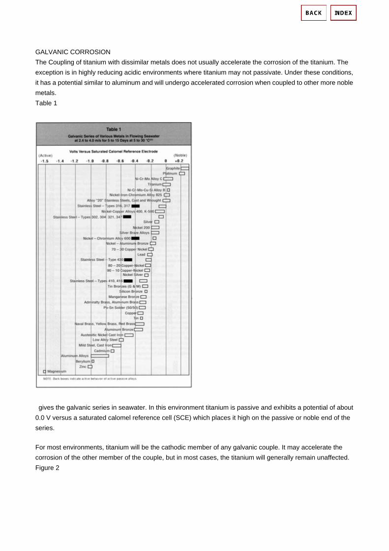
GALVANIC CORROSION The Coupling of titanium with dissimilar metals does not usually accelerate the corrosion of the titanium. The exception is in highly reducing acidic environments where titanium may not passivate. Under these conditions, it has a potential similar to aluminum and will undergo accelerated corrosion when coupled to other more noble metals. Table 1
gives the galvanic series in seawater. In this environment titanium is passive and exhibits a potential of about 0.0 V versus a saturated calomel reference cell (SCE) which places it high on the passive or noble end of the series.
For most environments, titanium will be the cathodic member of any galvanic couple. It may accelerate the corrosion of the other member of the couple, but in most cases, the titanium will generally remain unaffected. Figure 2

shows the accelerating effect that titanium has on the corrosion rate of various metals when they are galvanically coupled in seawater. If the area of the titanium exposed is small in relation to the area of the other metal, the effect on the corrosion rate is negligible. However, if the area of the titanium (cathode) greatly exceeds the area of the other metal (anode), severe corrosion of the other metal may result. Because titanium is the cathodic member, hydrogen may be evolved on its surface proportional to the galvanic current flow. This may result in the formation of surface hydride films that are generally stable and cause no problems, If the temperature is above 176 degrees F (80 degrees C), however, hydrogen may diffuse into the metal and cause hydride-related embrittlement.

In order to avoid problems with galvanic corrosion, it is best to construct equipment of a single metal. If this is not practical, use two metals that are close together in the galvanic series, insulate the joint or cathodically protect the less noble metal. If dissimilar metals are necessary, and since titanium is usually not attacked, construct the critical parts from titanium, and use large areas of the less noble metal and heavy sections to allow for increased corrosion.
More Reading:
Title: Fundamentals of Metallic Corrosion: Atmospheric and Media Corrosion of Metals
Division: General Chemical Engineering / CRC Press / 英文版
Author/Editor: Philip A. Schweitzer, P.E. Star:
ISBN: 0849382432
Introduce Date: 2007 年 05 月 05 日 19:48 , Release Date: 2007 年 05 月 05 日 19:51
Introducer: Metalcarbene , Rate: 1/108
Format: pdf (editorial)
Download http://www.ebookee.com.cn/Fundamentals-of-Metallic-Corrosion-Atmospheric-and-Media-Corrosion-of-Metals_141172.html

Cathodic Protection
This is an update of a DTI publication first issued in 1981. The
new version has been prepared by Eur Ing R. L. Kean of ARK
Corrosion Services and Mr K. G. Davies, Corrosion Engineer,
under contract from NPL for the Department of Trade and
Industry.
Contents page
Introduction 1
History 1
The Principles of Cathodic Protection 1
Sacrificial anodes 2
Impressed current 2
Advantages and Uses of Cathodic Protection 2
Pipelines
Storage tanks
Steel pilings
Reinforced concrete
Ships
Offshore structures
Basic Requirements for Cathodic Protection 3
Design Factors 4
Monitoring and Maintenance 6
Sources of advice 7
Further Information 7

Cathodic Protection
1 1
1.0 Introduction
This Guide describes the basic principles of cathodic protection,
the areas of use, and the general factors to be considered in the
choice and design of a system. It gives a basic introduction and
simple technical data on cathodic protection. Further assistance
and information may be gained from organisations listed in
Section 10, various independent or commercial consultants, and
product suppliers.
2.0 History
The first reported practical use of cathodic protection is
generally credited to Sir Humphrey Davy in the 1820s. Davy’s
advice was sought by the Royal Navy in investigating the
corrosion of copper sheeting used for cladding the hulls of naval
vessels. Davy found that he could preserve copper in seawater
by the attachment of small quantities of iron, zinc or tin. The
copper became, as Davy put it, “cathodically protected”. It was
quickly abandoned because by protecting the copper its anti-
fouling properties became retarded, hence reducing the
streamline of the ships, as they began to collect marine growths.
The most rapid development of cathodic-protection was made in
the United States of America and by 1945, the method was well
established to meet the requirements of the rapidly expanding
oil and natural gas industry, which wanted to benefit from the
advantages of using thin-walled steel pipes for underground
transmission.
In the United Kingdom, where low-pressure, thicker-walled cast-
iron pipes were used extensively, very little cathodic protection
was applied until the early 1950s. The increasing use of
cathodic protection in modern times has arisen, in part, from the
initial success of the method as used from 1952 onwards to
protect about 1000 miles of wartime fuel-line network. The
method is now well established and is used on a wide variety of
immersed and buried facilities and infrastructure, as well as
reinforced concrete structures, to provide corrosion control.
3.0 The Principles of Cathodic Protection
Metal that has been extracted from its primary ore (metal oxides
or other free radicals) has a natural tendency to revert to that
state under the action of oxygen and water. This action is called
corrosion and the most common example is the rusting of steel.
Corrosion is an electro-chemical process that involves the
passage of electrical currents on a micro or macro scale. The
change from the metallic to the combined form occurs by an
“anodic” reaction:
M → M+ + e-
(metal) (soluble salt) (electron)
A common example is:
Fe → Fe++ + 2e-
This reaction produces free electrons, which pass within the
metal to another site on the metal surface (the cathode), where
it is consumed by the cathodic reaction. In acid solutions the
cathodic reaction is:
2H+ + 2e- → H2 (hydrogen ions (gas) in solution)
In neutral solutions the cathodic reaction involves the
consumption of oxygen dissolved in the solution:
O2 + 2H2O + 4e- → 4OH- (alkali)
Corrosion thus occurs at the anode but not at the cathode
(unless the metal of the cathode is attacked by alkali).
Figure 1. Corrosion cell / Bimetallic corrosion
The anode and cathode in a corrosion process may be on two
different metals connected together forming a bimetallic couple,
or, as with rusting of steel, they may be close together on the
same metal surface.
This corrosion process is initially caused by:
Differerence in natural potential in galvanic (bimetallic) couples.
Metallurgical variations in the state of the metal at different
points on the surface.
Local differences in the environment, such as variations in the
supply of oxygen at the surface (oxygen rich areas become the
cathode and oxygen depleted areas become the anode).
Electron (e-) flow in metal
2M → 2M++ + 4e-
(corrosion)
O2 + 2H2O + 4e- → 4OH-

Cathodic Protection
2 2
The principle of cathodic protection is in connecting an external
anode to the metal to be protected and the passing of an
electrical dc current so that all areas of the metal surface
become cathodic and therefore do not corrode. The external
anode may be a galvanic anode, where the current is a result of
the potential difference between the two metals, or it may be an
impressed current anode, where the current is impressed from
an external dc power source. In electro-chemical terms, the
electrical potential between the metal and the electrolyte
solution with which it is in contact is made more negative, by the
supply of negative charged electrons, to a value at which the
corroding (anodic) reactions are stifled and only cathodic
reactions can take place. In the discussion that follows it is
assumed that the metal to be protected is carbon steel, which is
the most common material used in construction. The cathodic
protection of reinforcing carbon steel in reinforced concrete
structures can be applied in a similar manner.
Cathodic protection can be achieved in two ways:
- by the use of galvanic (sacrificial) anodes, or
- by “impressed” current.
Galvanic anode systems employ reactive metals as auxiliary
anodes that are directly electrically connected to the steel to be
protected. The difference in natural potentials between the
anode and the steel, as indicated by their relative positions in
the electro-chemical series, causes a positive current to flow in
the electrolyte, from the anode to the steel. Thus, the whole
surface of the steel becomes more negatively charged and
becomes the cathode. The metals commonly used, as
sacrificial anodes are aluminium, zinc and magnesium. These
metals are alloyed to improve the long-term performance and
dissolution characteristics.
Impressed-current systems employ inert (zero or low
dissolution) anodes and use an external source of dc power
(rectified ac) to impress a current from an external anode onto
the cathode surface.
The connections are similar for the application of cathodic
protection to metallic storage tanks, jetties, offshore structures
and reinforced concrete structures.
4.0 Advantages and Uses of Cathodic Protection
The main advantage of cathodic protection over other forms of
anti-corrosion treatment is that it is applied simply by
maintaining a dc circuit and its effectiveness may be monitored
continuously. Cathodic protection is commonly applied to a
coated structure to provide corrosion control to areas where the
coating may be damaged. It may be applied to existing
structures to prolong their life.
Specifying the use of cathodic protection initially will avoid the
need to provide a “corrosion allowance” to thin sections of
structures that may be costly to fabricate. It may be used to
afford security where even a small leak cannot be tolerated for
reasons of safety or environment. Cathodic protection can, in
principle, be applied to any metallic structure in contact with a
bulk electrolyte (including concrete). In practice, its main use is
to protect steel structures buried in soil or immersed in water. It
cannot be used to prevent atmospheric corrosion on metals.
However, it can be used to protect atmospherically exposed
and buried reinforced concrete from corrosion, as the concrete
itself contains sufficient moisture to act as the electrolyte.
Structures that are commonly protected by cathodic protection
are the exterior surfaces of:
Pipelines
Ships’ hulls
Storage tank bases
Jetties and harbour structures
Steel sheet, tubular and foundation pilings
Offshore platforms, floating and sub sea structures
Cathodic protection is also used to protect the internal surfaces
of:
Large diameter pipelines
Ship’s tanks (product and ballast)
Storage tanks (oil and water)
Water-circulating systems.
However, since an internal anode will seldom spread the
protection for a distance of more than two to five pipe-
diameters, the method is not usually practical, or suitable, for
the protection of small-bore pipework.

Cathodic Protection
3 3
Cathodic protection is applied to control the corrosion of steel
embedded in reinforced concrete structures (bridges, buildings,
port and harbour structures, etc.) – See Guide in Corrosion
Control, Corrosion and Protection of Steel in Concrete and it’s
Monitoring.
Cathodic protection can be applied to copper-based alloys in
water systems, and, exceptionally, to lead-sheathed cables and
to aluminium alloys, where cathodic potentials have to be very
carefully controlled.
5.0 Basic Requirements for Cathodic Protection
The essential features of cathodic protection to metals that are
surrounded by a conducting electrolyte, in each of the two types
of system are as follows:
a) A galvanic system requires:
i) Sacrificial anodes
ii) Direct welding to the structure or a conductor
connecting the anode to the structure
iii) Secure and minimum resistance connections
between conductor and structure, and between
conductor and anode.
b) An impressed-current system requires:
i) Inert anodes (clusters of which, connected together
often in a backfill, are called the “groundbed”).
ii) A dc power source.
iii) Electrically well insulated, minimum resistance and
secure conductors between anodes and power
source.
iv) Secure and minimum resistance connections
between power source and structure.
In both cases, fundamental design decisions must be made to
select the type of system and the most suitable type of anode
appropriate to that system. Also required, is the determination
of the size and number of the power sources, or sacrificial
anodes, and their distribution on the structure.
Other requirements that must be met to ensure that cathodic
protection is applied in the most economic and reliable manner
are:
a) Electrical continuity. The resistance of the conductor and
structure should be such as to minimise the potential drop
of the return protective currents through the structure.
b) Coatings. The provision of a protective/insulating coating
to the structure will greatly reduce the current demanded
for cathodic protection of the metallic surface. The use of a
well-applied and suitable coating, increases the effective
spread of cathodic protection current. A combination of
applying both a coating and cathodic protection will
normally result in the most practical and economic overall
protection system. Ideal coatings are those that have a
high electrical resistance, are continuous and will adhere
strongly to the surface to be protected. Other desirable
coating characteristics include; stability in the environment,
abrasion resistance, and compatibility with the alkaline
environment created or enhanced by cathodic protection.
c) Structure isolation. It is often desirable to limit the spread
of cathodic protection. For pipelines and tanks, this may be
achieved by the insertion of monolithic electrical isolation
joints in the structure. Insulating flange kits are sometimes
used though they often require regular maintenance.
Polarisation cells that restrict low voltage cathodic
protection dc currents, but allow passage of high voltage ac
currents, may be used to isolate low-resistance earthing
systems from a well-coated protected structure.
d) Test facilities. It is important to consider the location of test
facilities, test stations, corrosion monitoring coupons,
permanent half cells (reference electrodes), and the
manner that data can be routinely collected or viewed.
6.0 Design Factors
6.1 Initial considerations Modifications to the structure to incorporate requirements, such
as those discussed in section 5, are best made at the early
design and pre-construction phase of the structure. For
underground structures it may be necessary to visit the
proposed site, or for pipelines the proposed route, to obtain
additional information on low-resistivity areas, availability of
electric power, and the existence of stray dc current or other
possible interaction.

Cathodic Protection
4 4
It is common practice for a survey to be made before design.
This survey is often combined with a study to establish
economic justification for the recommended anti-corrosion
proposal while the principal data necessary for design (chemical
and physical) are also collected.
If the structure already exists, measurement of existing
structure-to-soil potentials is essential to give valuable
information as to which areas are anodic and which are
cathodic. In addition, with the application to the structure of
temporary cathodic-protection current, using any convenient dc
source and a temporary anode system (groundbed), a more
accurate assessment of current demand and the likely spread of
protection to the structure may be assessed.
Design of a cathodic-protection system for a new structure
should include the calculation of:
Current demand
Resistance to earth of the anodes
Quantity and location of anodes or anode systems
Electrical supply requirements
Test and monitoring facilities.
Project specifications and European or national guideline
documents should be consulted.
In the case of onshore pipelines and other structures,
negotiation with landowners, public authorities, or other
interested parties, for easements and wayleaves for
groundbeds, cable routes, transformer-rectifier sites, and
electricity supplies should also be undertaken at the design
stage.
6.2 Potential level and distribution In practice, the structure-to-electrolyte potentials are measured
using a standard half-cell (reference electrode). For example, a
common protection criterion used for steel in an aerobic
electrolyte of nearly neutral pH is a negative value of minus 850
mV. When exposed to sulphate-reducing bacteria, steel would
require a more negative potential of minus 950 mV. Both values
are with respect to a copper/copper sulphate half-cell. Ideally, to
attain a high degree of accuracy and in order to minimise
measurement errors, the half-cell should be very close to the
surface at which the potential is being measured.
The potential values measured on a cathodically protected
structure will be dependent on the anodic and cathodic
reactions, structural geometry, and internal electrical
resistance. However, the provision of a protective coating will
have by far the greatest effect on the potential for a given
applied current. The potentials will generally be most negative
at a point nearest to the anode or groundbed and, for pipelines,
will attenuate towards the natural corrosion potential as the
distance from the anode or groundbed increases.
An example of potential attenuation is that, in the case of a
power-impressed system, a single cathodic-protection
installation may supply cathodic protection to as much as
150 km of extremely well coated pipeline, whereas for similar-
sizes of bare (uncoated) pipelines it may be necessary to have
installations at only 2 km intervals.
6.3 Economics of decisions At the design stage of a cathodic-protection scheme, a decision
must be made as to whether the scheme will be a galvanic or
impressed-current system. In specific circumstances, the use
of both types of systems may be appropriate, but care is
required to avoid interaction between them.
Galvanic systems have the advantage of being –
a) simple to install
b) independent of a source of external electric power
c) suitable for localised protection
d) less liable to cause interaction on neighbouring
structures.
However, the current output available from the practical size
and weight of galvanic anodes is relatively small and depends
principally on the electrical resistivity of the electrolyte (local
environment if buried / submerged / concrete). Thus, galvanic
anodes of aluminium and zinc, which have similar driving emfs
to steel of approximately 0.5V, are limited to use in electrolytes
of less than 5 Ohm.m resistivity. The anodes are usually self-
regulating because their current output is usually less than their
maximum output capability and is controlled by the difference in
potential between the two metals. The current from the anodes
is not normally controllable; thus changes in the structure, such
as the deterioration of a coating, that causes an increase in
protection current demand, may necessitate the installation of
further sacrificial anodes to maintain protection.

Cathodic Protection
5 5
Impressed-current installations have the advantage of being –
a) able to supply a relatively large current
b) able to provide of high dc driving voltages (up to 50V).
Enables it to be used in most types of electrolytes
c) able to provide a flexible output that may accommodate
changes in, and additions to, the structure being
protected
Generally, however, care must be taken in the design to
minimise interaction on other structures and, if no ac supply is
available, an alternative power source (solar, diesel, etc.) is
required. Impressed current systems require regular
maintenance and monitoring.
Generally, galvanic systems have found favour for small well-
coated, low current demand, structures or for localised
protection. Impressed current schemes are utilised for large
complex structures, which may be of bare metal or poorly
coated. However, in North Sea offshore work, it has been found
cost effective to provide galvanic protection to large uncoated
platforms, and similar structures, where the initial cost of coating
and the cost of maintenance are very high. In addition, the
galvanic anodes offer easy to install robust systems, which
being independent of a power source, provide protection
immediately on “float-out” of the structure.
6.3 Problems to be avoided There are certain limitations to the use of cathodic protection.
Excessive negative potentials can cause accelerated corrosion
of lead and aluminium structures because of the alkaline
environments created at the cathode. These alkaline conditions
may also be detrimental to certain coating systems, and may
cause loss of adhesion of the coating. Hydrogen evolution at
the cathode surface may, on high-strength steels, result in
hydrogen embrittlement of the steel, with subsequent loss of
strength. On some high strength steels, this may lead to
catastrophic failures. It may also cause disbondment of
coatings; the coating would then act as an insulating shield to
the cathodic-protection currents.
Consideration must also be given to spark hazards created by
the introduction of electric currents into a structure situated in a
hazardous area. Generally sacrificial anode systems do not
cause problems, as they are self-regulating and are often
regarded as systems that can be ‘fit and forget’. They must,
however, be inspected at periodic intervals to ensure they are
capable of supplying continued protection.
Any secondary structure residing in the same electrolyte may
receive and discharge the cathodic protection direct current by
acting as an alternative low-resistance path (interaction).
Corrosion will be accelerated on the secondary structure at any
point where current is discharged to the electrolyte. This
phenomenon is called "stray current corrosion".
Interaction may occur, for example, on a ship that is moored
alongside a cathodically protected jetty, or on a pipeline or
metal-sheathed cable that crosses a cathodically protected
pipeline.
Interaction may be minimized by careful design of the cathodic
protection system. In particular, by design of a scheme to
operate at the lowest possible current density and by
maintaining good separation between the protected structure
and the secondary structure, and between the groundbeds or
anodes and the secondary structure.
It is an advantage of sacrificial-anode schemes that they are
not prone to creating severe interaction problems and therefore
they are popular for protection in congested and complex
locations.
Methods and procedures are available for overcoming
interaction, and testing should be carried out in the presence of
interested parties, so that the choice of remedial measures may
be agreed, if and when the acceptable limit of interaction is
exceeded.
6.4 Types of equipment Various galvanic anode alloys of magnesium, aluminium or zinc
are available in a variety of block, rod or wire forms. These
alloys are cast around steel inserts to enable fixing of the
anode and to maintain electrical continuity and mechanical
strength towards the end of the anode life. The insert may be
directly welded or bolted to the structure to be protected, or
anodes may be connected to the structure by means of an
insulated lead, usually of copper, as for onshore and offshore
pipelines.
Impressed-current groundbeds in soils have traditionally
consisted of high-silicon cast iron. However, mixed metal oxide
(MMO) anodes are becoming increasingly popular for all
environments because of their good mechanical and electrical

Cathodic Protection
6 6
characteristics and compact size. For seawater applications
and areas where chlorides are present, MMO anodes work well
as do high-silicon cast iron alloyed with chromium. Other
anodes consist of lead alloy and platinum formed in a thin layer
on a titanium or niobium base
There are many possible sources of dc power; the most popular
is the selenium plate or silicon-diode rectifier with transformer
unit in conjunction with an existing ac supply or diesel- or gas-
engine-driven alternator. For most applications, a constant dc
voltage or constant current systems are used.
In remote areas, power sources include thermo- electric
generators, closed-cycle vapour turbines, and solar or wind
generators. The latter two are used in conjunction with lead-
acid or similar storage batteries. The choice is dependent on
power requirements, maintenance capabilities, and
environmental conditions.
There are also automatic control units available that will adjust
current output in accordance with potential changes at a half
cell.
7.0 Monitoring and Maintenance
Cathodic-protection systems may be monitored effectively by
the measurement of structure-to-electrolyte potentials, using a
high input impedance voltmeter and suitable half-cell. The
standard practical half-cells are copper/copper sulphate,
silver/silver chloride/seawater, silver/silver chloride/ potassium
chloride and zinc.
Adjustments are made to the cathodic-protection current output
to ensure that protective potentials are maintained at a
sufficiently negative level as defined by the project specification.
The level of protection in soils and water is accepted at steel
potentials of minus 850 mV (wrt Cu/CuSO4) or minus 800 mV
(wrt Ag/AgCl/seawater).
Transformer rectifier outputs may be displayed by telemetry at
central control stations. Many cathodic protection systems are
increasingly being controlled and monitored by remote
computers and modem links. Other communication systems
that enable, for example, pipe-to- soil potentials to be monitored
from a helicopter or light aeroplane, are available.
Galvanic-anode outputs may also be monitored, as can
currents in electrical bonds between structures. Tests to
measure interaction are usually conducted annually where
areas are at risk or after adjustments to cathodic-protection
current output.
Maintenance includes the mechanical maintenance of power-
supply equipment and the maintenance of painted surfaces of
equipment.
It is good practice to inform all owners of cathodic protection
systems and infrastructure in the area of influence of any new
cathodic protection systems, or of significant changes to
existing systems, so that the effect on these facilities may be
assessed.
8.0 Sources of Advice
Corrosion/Cathodic Protection Consultants – Various listings.
Institute of Corrosion
Corrosion House, Vimy Court, Leighton Buzzard
Bedfordshire. LU7 1FG
National Association of Corrosion Engineers (NACE)
International
Houston, Texas, USA
Institute of Materials, Minerals and Mining
1 Carlton House Terrace, London. SW1Y 5DB
The Institution of Civil Engineers
One Great George Street, Westminster, London SW1P 3AA
Corrosion Protection Association (Reinforced Concrete)
Association House, 99 West Street, Farnham, Surrey GU9 7EN
The Society of Operations Engineers
22 Greencoat Place, London. SW1P 1PR
Galvanisers Association
6 Wren’s Court, 56 Victoria Road, Sutton Coldfield
West Midlands B72 1SY
Paint Research Association
8 Waldegrave Road, Teddington, Middlesex, TW11 8LD
Cathodic Protection
7 7
Pipeline Industries Guild
14/15 Belgrave Square, London SW1X 8PS
9.0 Further Information
The following references provide further information on cathodic
protection. Potential users are recommended to employ
qualified and experienced specialists to design and undertake
the work. The following handbook provides listings of various
manufacturers, suppliers, consultants, and contractors.
The Corrosion Handbook, 1999, (incorporating Corrosion
Prevention Directory), MPI Group, (Inst. of Materials, Inst. of
Corrosion)
Other useful Publications: J.H. Morgan 'Cathodic Protection' National Association of
Corrosion Engineers (NACE) 1987 2nd Edition.
Peabody’s Control of Pipeline Corrosion. (2nd edition, Ed by R
Bianchetti), NACE, Houston, 2000.
Corrosion and corrosion control. H H Uhlig, Wiley, New York,
1985 (3rd edition).
Corrosion. L L Shreir (2 vols), Newnes-Butterworth, 19 (3rd
edition).
Cathodic Protection Criteria - A Literature Survey' National
Association of Corrosion Engineers (NACE) 1989.
W.V. Baeckmann 'Handbook of Cathodic Corrosion Protection',
(3rd edition) Gulf Pub., 1997.
Standards BS 7361 Part 1 1991 'Cathodic Protection Part 1 - Code of
Practice for Land and Marine Applications' British Standards
Institution, U.K.
BS EN 12473 General principles of cathodic protection in sea
water.
BS EN 12474 Cathodic protection for submarine pipelines.
BS EN 12696 Cathodic protection of steel in concrete
Part 1 : Atmospherically exposed concrete
BS EN 12954 Cathodic protection of buried or immersed
metallic structures – General principles and application for
pipelines.
BS EN 13173 Cathodic protection for steel offshore floating
structures.
BS EN 13174 Cathodic protection for harbour installations.

Corrosion Prevention by Cathodic Protection
Billions of dollars are spent worldwide each year replacing industrial structures, equipment and municipal infrastructure that have prematurely failed or reached the end of their life cycle. Cathodic protection is a cost-effective means of extending the life of underground or submerged steel structures to ensure that the design life is attained or surpassed.
Levelton's professionals are engineers and technologists with advanced training from NACE International. As professionals, they have extensive experience and educational training for designing cathodic protection systems to best meet the specific needs of each unique situation they encounter. Levelton's engineers keep abreast of the latest technological advancements.
Cathodic protection applications are varied and diverse:
• Underground piping and tanks for water, petroleum, natural gas, sewage,
steam, chemical and petroleum products.
• Marine structures including docks, ships, piling, buoys, log lifts, barges and
sewage outfalls.
• Internal protection of tanks and piping.
• Concrete bridge decks, parkades, and piling.
• Hydraulic elevator cylinders.
• Above-ground tank bottoms.
Promo Rectifier
Pipe for Corrosion Prevention by Cathodic Protection

Providers of complete, comprehensive and cathodic protection consulting services:
• Design.
• System supply and installation.
• Cathodic protection surveys and system monitoring.
• System inspection and troubleshooting.
• Quality assurance and laboratory testing.
• Material sales.
Providers of complete project management services:
• Preparation of drawings.
• Preparation of specifications and tender documents.
• Evaluation of tenders and selection of a contractor.
• Quality assurance supervision.
• Cost management.
• System energization.
• Final acceptance testing.
Levelton Consultants Ltd. has successfully provided cathodic protection services to industrial, municipal, marine, and petroleum sectors in Canada and internationally for over 30 years. We participate in projects ranging from the simplest galvanic anode systems to the most complex impressed current installations.

Introduction to Cathodic Protection
Foreword
Corrosion or deterioration of metals has posed a problem to industry for many years. Of all the various anti-corrosion systems used, Cathodic Protection is one of the most efficient, being a positive and economical solution to the multiple corrosion problems encountered either on shore or offshore (marine environments).
When dissimilar metals are in electrical or physical contact (the former through an electrolyte), galvanic corrosion can take place. The process is akin to a simple DC cell in which the more active metal becomes the anode and corrodes, where as the less active metal becomes the cathode and is protected. The galvanic series shown below in Table 1 can be used to predict the metal which will corrode in contact with another metal, based on whether it is cathodic or anodic with respect to another. On top of the table are the "Noble" or cathodic (protected) metals and at the bottom, the more active or Anodic metals.
Table 1 Standard electromotive force series for selected metals
Metal-metal ion equilibrium (unit activity) Potential at 25 oC (77 oF), V
Ag/Ag+ +0.80
Cu/Cu2+ +0.34
H2/H+ (reference) 0
Fe/Fe2+ -0.44
Zn/Zn2+ -0.76
Al/Al3+ -1.66
Mg/Mg2+ -2.36
Cathodic Protection is an electrochemical means of corrosion control in which the oxidation reaction in a galvanic cell is concentrated at the anode and suppresses corrosion of the cathode in the same cell. Figure 1 shows a simple cathodic protection system. The steel pipeline is cathodically protected by its connection to a sacrificial magnesium anode buried in the same soil electrolyte.

Figure1
Cathodic protection was first developed by Sir Humphrey Davy in 1824 as a means of controlling corrosion on British naval ships. Virtually all modern pipelines are coated with an organic protective coating that is supplemented by cathodic protection systems sized to prevent corrosion at holidays (defects) in the protective coating. This combination of protective coating and cathodic protection is used on virtually all immersed or buried carbon steel structures, with the exception of offshore petroleum production platforms and reinforced concrete structures.
Fundamentals of Cathodic Protection Table1, shows the theoretical electrochemical potentials obtained by pure metals in 1 N solutions of their own ions. Figure2, shows two of these metals, iron and zinc, separately immersed in a weak mineral acid (or sea water). The chemical reactions that occur in Figure2 are:
Fe --> Fe2+ + 2e- Oxidation reaction
2H+ + 2e- Reduction reaction
2H+ + Fe --> Fe2+ + H2 Net reaction
Zn --> Zn2+ + 2e- Oxidation reaction
2H+ + 2e- --> H2 Reduction reaction
2H+ + Zn --> Zn2+ + H2 Net reaction
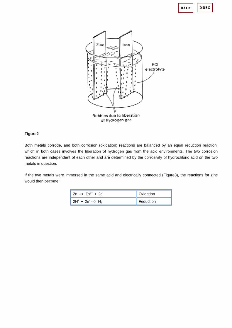
Figure2
Both metals corrode, and both corrosion (oxidation) reactions are balanced by an equal reduction reaction, which in both cases involves the liberation of hydrogen gas from the acid environments. The two corrosion reactions are independent of each other and are determined by the corrosivity of hydrochloric acid on the two metals in question.
If the two metals were immersed in the same acid and electrically connected (Figure3), the reactions for zinc would then become:
Zn --> Zn2+ + 2e- Oxidation
2H+ + 2e- --> H2 Reduction

Figure3
Almost all of the oxidation reaction (corrosion of zinc) has been concentrated at the zinc electrode (anode) in Figure3, and almost all of the reduction reaction (hydrogen liberation) has been concentrated at the iron electrode (cathode). The oxidation of the zinc anode in Figure3, is much faster than that in Figure2. At the same time, most of the corrosion of iron in Figure2, has stopped in Figure3. As shown schematically, the zinc anode in Figure2, has been used to cathodically protect the iron cathode in Figure3. Of course, some corrosion of the iron may still occur; whether or not this happens depends on the relative sizes of the zinc and iron electrodes. Some reduction of hydrogen may still occur on the zinc anode. The anode is the electrode at which a net oxidation reaction occurs, whereas cathodes are electrodes at which net reduction reactions occur. All cathodic protection systems require an anode, a cathode, an electric circuit between the anode and cathode, and an electrolyte. Thus, cathodic protection will not work on structures exposed to air environments. The air is a poor electrolyte, and it prevents current from flowing from the anode to the cathode. Cathodic Protection can be accomplished by two widely used methods:
1. By coupling a given structure (say Fe) with a more active metal such as zinc or magnesium. This produces a galvanic cell in which the active metal works as an anode and provides a flux of electrons to the structure, which then becomes the cathode. The cathode is protected and the anode progressively gets destroyed, and is hence, called a sacrificial anode.
2. The second method involves impressing a direct current between an inert anode and the structure to be protected. Since electrons flow to the structure, it is protected from becoming the source of electrons (anode). In
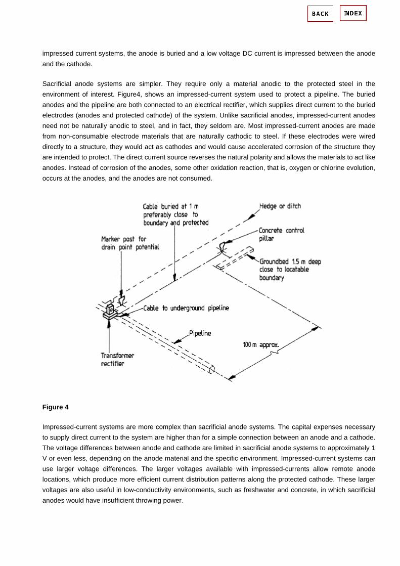
impressed current systems, the anode is buried and a low voltage DC current is impressed between the anode and the cathode.
Sacrificial anode systems are simpler. They require only a material anodic to the protected steel in the environment of interest. Figure4, shows an impressed-current system used to protect a pipeline. The buried anodes and the pipeline are both connected to an electrical rectifier, which supplies direct current to the buried electrodes (anodes and protected cathode) of the system. Unlike sacrificial anodes, impressed-current anodes need not be naturally anodic to steel, and in fact, they seldom are. Most impressed-current anodes are made from non-consumable electrode materials that are naturally cathodic to steel. If these electrodes were wired directly to a structure, they would act as cathodes and would cause accelerated corrosion of the structure they are intended to protect. The direct current source reverses the natural polarity and allows the materials to act like anodes. Instead of corrosion of the anodes, some other oxidation reaction, that is, oxygen or chlorine evolution, occurs at the anodes, and the anodes are not consumed.
Figure 4
Impressed-current systems are more complex than sacrificial anode systems. The capital expenses necessary to supply direct current to the system are higher than for a simple connection between an anode and a cathode. The voltage differences between anode and cathode are limited in sacrificial anode systems to approximately 1 V or even less, depending on the anode material and the specific environment. Impressed-current systems can use larger voltage differences. The larger voltages available with impressed-currents allow remote anode locations, which produce more efficient current distribution patterns along the protected cathode. These larger voltages are also useful in low-conductivity environments, such as freshwater and concrete, in which sacrificial anodes would have insufficient throwing power.

Cathodic Protection Monitoring of Offshore Pipelines and Structures in Alaskan Waters J. P. LaFontaine, J Britton Pipelines and structures located offshore of Alaska face unique challenges to monitoring cathodic protection. Advances in Cathodic Protection Monitoring technology are discussed. New portable ROV instrumentation as well as fixed monitoring of parameters affecting cathodic protection system performance are reviewed. Case histories from the southern coast of Alaska as well as Arctic waters are detailed. Introduction It is common knowledge that cathodic protection (CP) is necessary to limit corrosion on metallic structures in marine environments. Monitoring CP can provide valuable data to owners and operators regarding: 1. The level of protection. 2. The remaining service life of the system. 3. Improvements for future designs. In the environmentally sensitive coastal waters of Alaska, it is critical that the performance of the CP (cathodic protection) system on a structure or pipeline can be monitored. From the fast currents of Cook Inlet to the Frozen Beafort Sea the marine environment of Alaska presents many unique challenges from a cathodic protection standpoint. The current density required to achieve polarization on steel in Cook Inlet is over 6.5 times higher than that required in the Gulf of Mexico. In addition the cold temperatures of these waters are as much as 30% less conductive that ambient waters. The nearly year-round ice cover and permafrost make the Arctic one of the most challenging environments yet encountered by corrosion engineers. Monitoring - General The basic criteria for cathodic protection of steel in sea-water is that it is polarized to at least (-) 0.800 Volts vs. Ag/AgCl (silver / silver chloride) or (-) 0.850 Volts vs. Cu/CuSO4 (copper / copper sulfate). This value can be determined by employing either reference cell, but typically in sea-water silver / silver chloride is used. Measuring the potential will tell you if are currently protected. However measurement of other parameters is necessary to determine the remaining service life of your system. Among these are the current density pick-up on the steel and the anode current output. These values can be compared to design values to determine if the system is operating as expected. On coated structures i.e. pipelines, anode current output can be used to determine the efficiency of the coating. Cook Inlet Several factors make Cook Inlet one of the most corrosive marine environments for steel structures in the world: 1. Extreme tidal ranges create tidal currents as high as 8.7 knots (1). The high velocity water provides constant oxygen replenishment to the steel surface. In addition sand and other particulates are churned into the water column, in effect "blasting" the steel surface, preventing it from forming carbonate layers, which would otherwise decrease current demand. 2. The water temperatures are cold, ranging from 50 °F (10 °C) to 29 °F (-2 °C). The cold water has a high

dissolved O2 concentration, which further increases current density demand on the steel (1). 3. The resistivity of Cook Inlet water is as much as twice that of ambient 77 °F (25 °C) sea-water. This effect is a
result of the low temperature as well as fresh water input. It is imperative in such conditions that a comprehensive cathodic protection monitoring program is followed. Pipeline Surveys There are a number of critical aging pipelines in the Cook inlet that have only ever been surveyed using trailing wire type remote electrode techniques and some riser drop cell readings. It is now well accepted that these surveys give no detailed information regarding the true pipe potential unless the electrode position with relation to the pipeline is well known, and the system is corrected for the IR errors caused by the impressed current system. Many of the pipelines are installed using pull tubes so that even the drop cell readings are meaningless. Two or three electrode techniques would provide better data validity providing that periodic pipeline contacts can be made to re-calibrate the true remote pipeline potential (Figure 1). This can be difficult because most of the pipelines are concrete weight coated for stability and mechanical protection, so if the pipe doesn't have anodes (bracelets), there is
no way to calibrate unless concrete is removed. Figure 1. Offshore pipeline cathodic protection survey method. Potential Attenuation Modeling

Understanding and recent improvement in techniques has made modeling much more accurate, and if a few parameters can be measured on the line, predictive models can be used to estimate the worst case scenario of potential versus coating efficiency. Fixed or retrofitted permanent monitors can provide these reference points. This approach is particularly effective on pipelines that use impressed current. An example of a recent survey illustrates this approach (Figure 2). A predictive potential profile was determined before the pipeline was installed for the purposes of designing the CP system. After installation and start up the pipeline potential was measured at 5 locations. The original model was recalculated using the field measured endpoint potentials. The close agreement between the field measurements and the model confirm the validity of this approach.
Figure 2. Modeled potential profiles compared to actual field data on a marine pipeline. Production Facilities Economic and logistic drivers make fixed instrumentation preferable to surveys with portable instrumentation. The same extreme marine conditions that make cathodic protection a challenge in Cook Inlet also make diver and ROV work very difficult. This is particularly true on jackets. Impressed current CP (ICCP) systems or ICCP/galvanic anode hybrid systems are required to achieve the high current demands in Cook Inlet. Fixed reference electrodes distributed across the structure are critical to evaluating system performance. Such an approach was used on the Marathon Steelhead platform. This four-pile structure was set in 183-ft. (55.5 M) of sea-water. An array of Ag/AgCl and Zinc reference electrodes were installed down both sides of one leg at 20-ft. intervals. By monitoring the steel potential with such an array, the current output from the ICCP system can be optimized. On Steelhead the initial current output was 2100 A. After 30 days however it was determined that to

achieve the proper potentials, output could be lowered to 960 A. After two years of service output was lowered to 628 A. The monitoring system allowed frequent potential measurements to be made simultaneously at many locations. The Arctic Ocean A project to develop the Northstar oil field, located in the Beafort Sea, marked the first time in the Alaskan Arctic that a warm oil production pipeline, buried in the sea floor, has been used to transport oil and gas from a manmade offshore island (Figure 3). Fixed cathodic protection monitoring on this pipeline is a necessity due to environmental concerns and logistics.
Figure 3. General layout of the subsea portion of the Northstar pipeline. The overall strategy was to measure the effectiveness of the CP system with a combination of fixed monitors supplemented by a survey program. A sacrificial anode system was used on this line instead of impressed

current ground beds due to the high resistance of the permafrost. Near the shore crossing (Point Storkersen), the following instruments were installed: 1. Anode Monitor (Figure 4) 2. Current Density Monitors (Figure 5) 3. Permanent Reference Cell (Figure 6) 4. Monitoring Panel (Figure 7)
Figure 4. Schematic of monitored anode.
Figure 5. Schematic of the current density monitor.
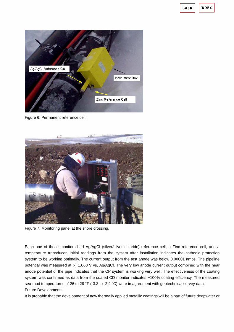
Figure 6. Permanent reference cell.
Figure 7. Monitoring panel at the shore crossing. Each one of these monitors had Ag/AgCl (silver/silver chloride) reference cell, a Zinc reference cell, and a temperature transducer. Initial readings from the system after installation indicates the cathodic protection system to be working optimally. The current output from the test anode was below 0.00001 amps. The pipeline potential was measured at (-) 1.068 V vs. Ag/AgCl. The very low anode current output combined with the near anode potential of the pipe indicates that the CP system is working very well. The effectiveness of the coating system was confirmed as data from the coated CD monitor indicates ~100% coating efficiency. The measured sea-mud temperatures of 26 to 28 °F (-3.3 to -2.2 °C) were in agreement with geotechnical survey data. Future Developments It is probable that the development of new thermally applied metallic coatings will be a part of future deepwater or

high temperature CP systems. Large capacity mid-depth systems will certainly shift more toward impressed current, as cost and flexibility become more important factors. The future success of these systems will depend largely on information gathered from monitoring systems installed on the early deployments of the technology. References 1. C.E. Hedborg, "Cathodic Protection in Cook Inlet Arctic Waters", Materials Performance, February 1991

Offshore Cathodic Protection 101 what it is, and how it works. Richard Baxter, Jim Britton
How Does Steel Corrode in Water?
To understand cathodic protection one must first understand the corrosion mechanism. For corrosion to
occur, three conditions must be present.
1. Two dissimilar metals
2. An electrolyte (water with any type of salt or salts dissolved in it)
3. A metal (conducting) path between the dissimilar metals
The two dissimilar metals may be totally different alloys, such as steel and aluminum, but are more usually
microscopic or macroscopic metallurgical differences on the surface of a single piece of steel.
If the above conditions exist, at the more active metal surface (in this case we will consider freely corroding
steel which is non uniform), the following reaction takes place at the more active sites: (two iron ions plus
four free electrons)
2Fe => 2Fe++ + 4e-
The free electrons travel through the metal path to the less active sites where the following reaction takes
place: (oxygen gas converted to oxygen ion - by combining with the four free electrons - which combines
with water to form hydroxyl ions)
O2 + 4e- + 2H20 => 4 OH-
Recombinations of these ions at the active surface produce the following reaction, which yields the iron
corrosion product ferrous hydroxide: (iron combining with oxygen and water to form ferrous hydroxide)
2Fe + O2 + 2H2O => 2Fe (OH)2
This reaction is more commonly described as 'current flow through the water from the anode (more active
site) to the cathode (less active site).
How Does Cathodic Protection Stop Corrosion?
Cathodic protection prevents corrosion by converting all of the anodic (active) sites on the metal surface to
cathodic (passive) sites by supplying electrical current (or free electrons) from an alternate source.
Usually this takes the form of galvanic anodes which are more active than steel. This practice is also referred
to as a sacrificial system, since the galvanic anodes sacrifice themselves to protect the structural steel or
pipeline from corrosion.

In the case of aluminum anodes, the reaction at the aluminum surface is: (four aluminum ions plus twelve
free electrons)
4Al => 4AL+++ + 12 e-
and at the steel surface, (oxygen gas converted to oxygen ions which combine with water to form hydroxyl
ions)
3O2 + 12e- + 6H20 => 12OH-
As long as the current (free electrons) is arriving at the cathode (steel) faster than oxygen is arriving, no
corrosion will occur.
Figure 1: Sacrificial anode system in seawater
Basic Considerations When Designing Sacrificial Anode Systems

The electrical current which an anode discharges is controlled by Ohm's law; that is:
I=E/R
I= Current flow in amps
E= Difference in potential between the anode and cathode in volts
R= Total circuit resistance in ohms
Initially current will be high because the difference in potential between the anode and cathode are high, but
as the potential difference decreases due to the effect of the current flow onto the cathode, current gradually
decreases due to the polarization of the cathode. The circuit resistance includes both the water path and the
metal path, including any cable in the circuit. The dominant value here is the resistance of the anode to the
seawater.
For most applications the metal resistance is so small compared to the water resistance that it can be ignored.
(Not true for sleds, or long pipelines protected from both ends). In general, long thin anodes have lower
resistance than short fat anodes. They will discharge more current, but will not last as long.
Therefore a cathodic protection designer must size the anodes so that they have the right shape and surface
area to discharge enough current to protect the structure and enough weight to last the desired lifetime
when discharging this current. As a general rule of thumb:
Length of the anode determines how much current the anode can produce, and consequently
how many square feet of steel can be protected.
Cross Section (Weight) determines how long the anode can sustain this level of protection.
Impressed Current Cathodic Protection Systems
Due to the high currents involved in many seawater systems it is not uncommon to use impressed current
systems. Impressed current systems use anodes of a type that are not easily dissolved into metallic ions, but
rather sustain an alternative reaction, oxidization of the dissolved chloride ions.
2Cl- => Cl2 + 2e-
Power is supplied by an external DC power unit..

Figure 2: Impressed current cathodic protection system in seawater
How Do We Know When We Have Enough Cathodic Protection?
We know whether or not we have enough current by measuring the potential of the steel against a standard
reference electrode, usually silver silver/chloride (Ag/AgCl sw.), but sometimes zinc (sw.).
Current flow onto any metal shifts its normal potential in the negative direction. History has shown that if steel
receives enough current to shift the potential to (-) 0.800 V vs. silver / silver chloride (Ag / AgCl), the corrosion
is essentially stopped.
Due to the nature of the films which form, the minimum (-0.800 V) potential is rarely the optimum potential,

and designers try to achieve a potential between (-) 0.950 V and (-) 1.000 V vs. Ag/AgCl sw.
Figure 3: Protected vs Unprotected structures as verified by cathodic protection potential
More reading: http://www.cathodicprotectionpapers.com/
Cathodic Protection:
More reading: http://corrosiontest.its.manchester.ac.uk/lecturenotes/JDS_Notes/cpindex.htm
Case Study:
Cathodic protection in concrete: http://www.concrete.cv.ic.ac.uk/research/Case/cathodic-protection/cp-main.htm
Standard:
Norsok Standard Cathodic Protection: http://www.standard.no/pronorm-3/data/f/0/01/36/8_10704_0/M-503.pdf

7 Terracon Place Winnipeg, MB Canada R2J 4B3 Tel: (204) 233-9138 Fax: (204) 233-9188 Email: [email protected]
pg2
Welcome to the Norscan community. Our newsletters address current issues that influence the high tech industry today, and provide value and solutions. We appreciate any comments or suggestions that our readership may have which can be forwarded to:
[email protected]. To unsubscribe to this newsletter, please use the above address.
With bandwidth demand increasing and the rising installation costs to install additional fiber cables to satisfy this need, more communication service providers are looking to extend the life expectancy of their existing outside plant. Selection of the fiber optic cable type plays an important role in how effective you will be in this endeavor...
NorscanREPORTT
HE
AUGUST 2008 Volume 2 Issue 2
pg6
...IN SHORTNews Update from Government Security NewsThe Federal Communications Commission has been given approval to require providers of wireline, wireless, paging, satellite and cable communications to submit explanatory reports to the FCC whenever their communications services have been seriously disrupted...
Cathodic Protection Theory:
Outside Plant Tone Condit ioningpg4
In previous Norscan newsletters we have mentioned a lot about conditioning the outside plant to accommodate central office monitoring and cable locate equipment. There seems to be some confusion as to the best practice available when conditioning the outside plant for cable locate applications – in particular when central office tone transmitters are installed....
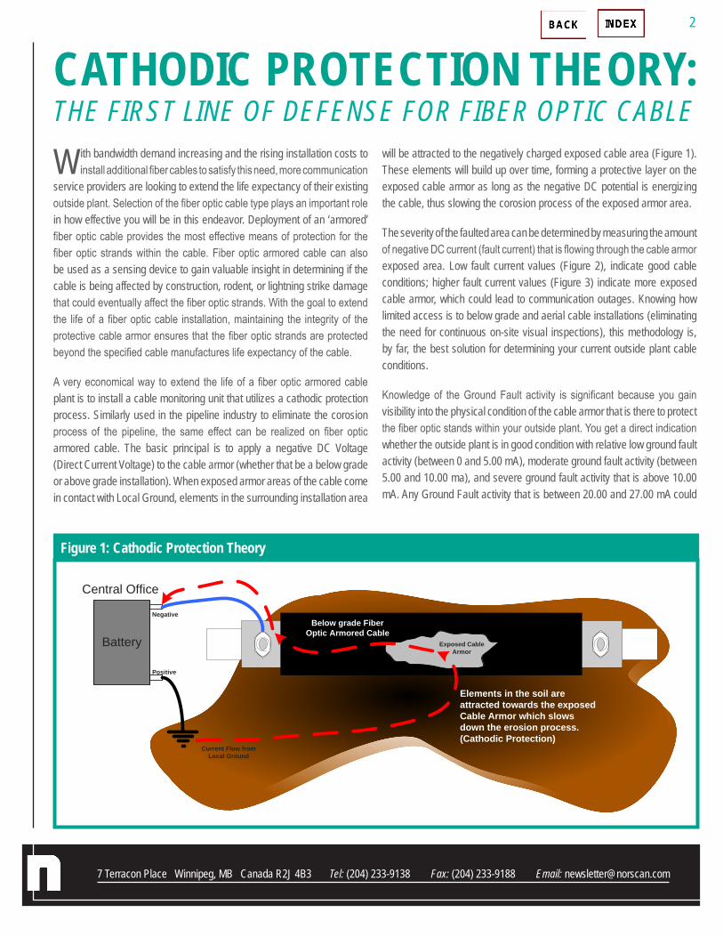
7 Terracon Place Winnipeg, MB Canada R2J 4B3 Tel: (204) 233-9138 Fax: (204) 233-9188 Email: [email protected]
With bandwidth demand increasing and the rising installation costs to install additional fiber cables to satisfy this need, more communication
service providers are looking to extend the life expectancy of their existing outside plant. Selection of the fiber optic cable type plays an important role in how effective you will be in this endeavor. Deployment of an ‘armored’ fiber optic cable provides the most effective means of protection for the fiber optic strands within the cable. Fiber optic armored cable can also be used as a sensing device to gain valuable insight in determining if the cable is being affected by construction, rodent, or lightning strike damage that could eventually affect the fiber optic strands. With the goal to extend the life of a fiber optic cable installation, maintaining the integrity of the protective cable armor ensures that the fiber optic strands are protected beyond the specified cable manufactures life expectancy of the cable.
A very economical way to extend the life of a fiber optic armored cable plant is to install a cable monitoring unit that utilizes a cathodic protection process. Similarly used in the pipeline industry to eliminate the corosion process of the pipeline, the same effect can be realized on fiber optic armored cable. The basic principal is to apply a negative DC Voltage (Direct Current Voltage) to the cable armor (whether that be a below grade or above grade installation). When exposed armor areas of the cable come in contact with Local Ground, elements in the surrounding installation area
will be attracted to the negatively charged exposed cable area (Figure 1). These elements will build up over time, forming a protective layer on the exposed cable armor as long as the negative DC potential is energizing the cable, thus slowing the corosion process of the exposed armor area.
The severity of the faulted area can be determined by measuring the amount of negative DC current (fault current) that is flowing through the cable armor exposed area. Low fault current values (Figure 2), indicate good cable conditions; higher fault current values (Figure 3) indicate more exposed cable armor, which could lead to communication outages. Knowing how limited access is to below grade and aerial cable installations (eliminating the need for continuous on-site visual inspections), this methodology is, by far, the best solution for determining your current outside plant cable conditions.
Knowledge of the Ground Fault activity is significant because you gain visibility into the physical condition of the cable armor that is there to protect the fiber optic stands within your outside plant. You get a direct indication whether the outside plant is in good condition with relative low ground fault activity (between 0 and 5.00 mA), moderate ground fault activity (between 5.00 and 10.00 ma), and severe ground fault activity that is above 10.00 mA. Any Ground Fault activity that is between 20.00 and 27.00 mA could
CATHODIC PROTECTION THEORY: THE FIRST LINE OF DEFENSE FOR FIBER OPTIC CABLE
First Line of defense for fiber optic cable!
With bandwidth demand increasing along with rising installation costs to install additional fiber cables to satisfy this need, more communication service provider are looking to extend the life expectancy of their existing outside plant. Selection of the fiber optic cable type plays an important role in how effective you will be in this endeavor. Deployment of an ‘armored’ fiber optic cable provides the most effective means of provides protection to the fiber optic strands within the cable. Fiber optic armored cable can also be used as a sensing device to gain valuable insight in determining if the cable is being affected by construction, rodent and lightning strike damage that could eventually affect the fiber optic strands. With the goal to extend the life of a fiber optic cable installation, maintaining the integrity of the protective cable armor ensures that the fiber optic strands are protected beyond the specified cable manufactures life expectancy of the cable.
A very economical way to extend the life of a fiber optic armored cable plant is to install a cable monitoring unit that utilizes a cathodic protection process. Similarly used in the pipeline industry to eliminate the erosion process of the pipeline the same effect can be realized on fiber optic armored cable. The basic principal is to apply a negative DC Voltage (Direct Current Voltage) to the cable armor whether that be a below grade or above grade installation. When exposed armor areas of the cable come in contact with Local Ground, elements in the surrounding installation area will be attracted to the negatively charged exposed cable area (Figure 1). These elements will build up over time forming a protective layer on the exposed cable armor as long as the negative DC potential is energizing the cable, thus slowing the erosion process of the exposed armor area.
Battery
Negative
Positive
Central Office
Current Flow from Local Ground
Exposed Cable Armor
Elements in the soil are attracted towards the exposed Cable Armor which slows down the erosion process. (Cathodic Protection)
Below grade Fiber Optic Armored Cable
Figure 1: Cathodic Protection Theory
The severity of the faulted area can be determined by measuring the amount of negative DC current (fault current) that is flowing through the cable armor exposed area. Low
Figure 1: Cathodic Protection Theory
2

7 Terracon Place Winnipeg, MB Canada R2J 4B3 Tel: (204) 233-9138 Fax: (204) 233-9188 Email: [email protected]
be indicating that something is seriously affecting the cable armor, which could eventually make its way to the fiber optic strands and cause an outage. Preemptive measures that are initiated to locate and repair the source of the exposed cable armor occurrences can avoid communication outages. Again, emphasizing the fact that if the cable armor is in good condition, so are the fiber strands within the cable.
Innovative Partnership cont’d...
Battery
Negative
Positive
Central Office
Current Flow from Local Ground
Exposed Cable Armor
Elements in the soil are attracted towards the exposed Cable Armor which slows down the erosion process. (Cathodic Protection)
Below grade Fiber Optic Armored Cable
HL
Large area of exposed Cable Armor, High ground fault activity.
Figure 2: Cathodic Protection Theory
Figure 3: Cathodic Protection Theory
3

7 Terracon Place Winnipeg, MB Canada R2J 4B3 Tel: (204) 233-9138 Fax: (204) 233-9188 Email: [email protected]
In previous Norscan newsletters we have mentioned a lot about conditioning the outside plant to accommodate central office monitoring
and cable locate equipment. There seems to be some confusion as to the best practice available when conditioning the outside plant for cable locate applications – in particular when central office tone transmitters are installed. When the cable conductor (cable armor, trace wire or copper pair) is not properly conditioned for tone locate applications, the results can seriously hamper the success of performing an accurate cable locate to all areas of the outside plant. The main areas of concern are a means of providing an adequate ground return path for the cable locate signal and achieving signal balance throughout all areas of the outside plant cable network. One method is to connect the cable conductor directly to Local Ground, often referred as Hard Grounding (Figure 1) the cable at each termination location. Although relatively easy to do, this methodology does not bode well for achieving optimum cable locate signals to all areas of the outside plant. Typically, what occurs is that most of the cable locate signal will be absorbed by the Hard Ground termination that is located closest to the transmitter location, leaving little, if any, tone signal for the rest of the cable network.
Some users have tried to balance their outside plant for tone signal distribution
using different values of resistance at termination locations, but to no avail. There are far too many variables that play into this method, such as the cable resistive loss of the cable conductor that is being used within the network and cable capacitance values, which vary if the cable is directly buried or in a conduit installation. Fortunately, Norscan has been studying cables and cable installations for many years and has come up with a very practical and efficient means for providing tone signal balance and distribution to all areas of the outside plant. The Norscan Line Termination Unit (LTU) is specifically designed to provide the required impedance path to ground for cable locate tones above 250 Hz (Figure 2).
This means the LTU is a self balancing ground return path device for all industrial standard cable locate transmitters manufactured today. There
are two model types: one is the 0K LTU used for single ended long haul cable installations and the other is the FC LTU or Fixed Current type used in branch cable networks. Both types can be incorporated into the same cable network to achieve the optimum in tone signal balance and distribution.
For single end long haul cable installations that are between 25 and 100 kms (15 and 60 miles), use the 0K LTU device. This LTU type will draw the optimum amount of tone signal to the termination location (Figure 3).
Outside Plant Tone Conditioning
FIGURE 2
LTU
4200 CMSCABLE MANAGEMENT SYSTEM
(CO)Transmitter
(Cable Locate Frequency)
Metallic Conductor(Armor, Tracewire or Copper Pair)
(Termination)0K LTU Ground
Return Path Device
100 kms - 60 mi.
Maximum Tone Signal is drawn to the termination location via the 0K LTU
Tone Signal Ground Return Path
FIGURE 3
FIGURE 1
Outside Plant Tone Conditioning
In previous Norscan newsletters we have mentioned a lot about conditioning the outside plant to accommodate central office monitoring and cable locate equipment. There seems to be some confusion as to the best practice available with regards to conditioning the outside plant for cable locate applications and in particular when central office tone transmitters are installed. When the cable conductor (cable armor, trace wire or copper pair) is not properly conditions for tone locate applications, the results can seriously hamper the success of performing an accurate cable locate to all areas of the outside plant. The main areas of concern are a means of providing an adequate ground return path for the cable locate signal and achieving signal balance throughout all areas of the outside plant cable network. One method is to connect the cable conductor directly to Local Ground or often referred to Hard Grounding (Figure 1) the cable at each termination location. Although relatively easy to do, this methodology does not bode well for achieving optimum cable locate signals to all areas of the outside plant. Typically what occurs is that most of the cable locate signal will be absorbed by the Hard Ground termination that is located closest to the transmitter location, leaving little if any tone signal for the rest of the cable network.
Figure 1: Hard Grounded Tone Signal Return
Some users have tried to balance there outside plant for tone signal distribution using different values of resistance at termination locations but to no avail. There are far too many variables that play into this method such as the cable resistive loss of the cable conductor that is being used within the network and cable capacitance values which vary if the cable is direct buried or in a conduit installation. Fortunately Norscan has been studied cables and cable installations for many years and has come up with a very practical and efficient means for providing tone signal balance and distribution to all areas of the outside plant. The Norscan Line Termination Unit (LTU) is specifically designed to provide the required impedance path to ground for cable locate tones above 250 Hz (Figure 2).
4

7 Terracon Place Winnipeg, MB Canada R2J 4B3 Tel: (204) 233-9138 Fax: (204) 233-9188 Email: [email protected]
Branch cable networks require even distribution of tone signals to all areas of the outside plant. The Fix Current LTU devices will ensure each branch receives an equal amount of locate current, which then allows for full tone signal distribution (Figure 4). Placement of the FC-LTU devices is at the
end of each branch line, which can be in a splice enclosure or remote building location. It is important to remember that the entire branch network accumulated distance (all cable segments added together) cannot exceed linear distances of 100 kms or 60 miles.
If there is a need on long haul installations to locate short spur lines that are connected to the main trunk line, a combination of Ok and FC LTU devices are used. An Ok-LTU device would be installed at the end of the main feed line to draw tone locate signal to that location. The short spur lines connected to the main feed line would be terminated with the FC LTU, allowing limited amounts of tone signal to pass to these branch cable locations (Figure 5).
Cable locating is a relatively straight forward application: energize a metallic conductor that is within a fiber optic cable with a cable locate frequency. Once energized, the cable can be located using a handheld receiver to pick up this signal, thus revealing the location and depth of the cable. The challenge
lies within how to energize the metallic conductor along with ensuring full distribution and balance of the cable locate frequency throughout the entire network. Signal distribution and balancing has more to do with how the cable is terminated (providing a ground return path for the cable locate
signal), rather than using hard grounding methods to provide ground return paths (which are the main cause of poor distribution and balancing). Line Termination Unit devices are an efficient, and flexible product that can provide optimum tone signal distribution and balance to your cable network.
FC-LTU
4200 CMSCABLE MANAGEMENT SYSTEM
(CO)Transmitter
(Cable Locate Frequency)
Metallic Conductor(Armor, Tracewire or Copper Pair)
(Termination)FC-LTU Ground
Return PathDevice
Tone Signal is distributed and balanced evenly throughout cable network via FC-LTU device
Tone Signal Ground Return Path
FC- LTU
FC-LTU
FIGURE 4
Ok-LTU
4200 CMSCABLE MANAGEMENT SYSTEM
(CO)Transmitter
(Cable Locate Frequency)
Metallic Conductor(Armor, Tracewire or Copper Pair)
(Termination)Ok-LTU Ground
Return PathDevice
Tone Signal is distributed/balanced on Long Haul lines with Short Spur lines using a
combination of 0K and FC LTUs
Tone Signal Return Path
FC- LTU
FC-LTU
Long Haul Line – 100 kms/60 miles
Short Spur Lines
FIGURE 5
Cont’d...Outside Plant Tone Conditioning
5

7 Terracon Place Winnipeg, MB Canada R2J 4B3 Tel: (204) 233-9138 Fax: (204) 233-9188 Email: [email protected]
By Jacob Goodwin, Editor-in-Chief
The Federal Communications Commission has been given approval to require providers of wireline, wireless, paging, satellite and cable
communications to submit explanatory reports to the FCC whenever their communications services have been seriously disrupted.
The new reporting requirement, which was approved by the Office of Management and Budget on February 19 and announced publicly on March 17, will enable the FCC to monitor the reliability and security of these communications services and take swift remedial action, if necessary.
“The reporting requirement is also essential to the FCC’s mission of ensuring that the public is protected from major disruptions to telephone services,” according to an internal FCC document prepared last December.
Under the FCC’s new policies, a communications carrier will be required to submit to the FCC a “bare-bones notification” of any “outage” (which it defines as a “significant degradation” of the carrier’s service) within two hours. The carrier must submit a more detailed “Initial Communications Outage Report” to the FCC within three days and a “Final Communications Outage Report” within 30 days.
In these reports, the carrier must identify the reporting entity, the date and time of the beginning of the outage, a brief description of the problem, the particular services affected, and the geographic area impacted by the outage.
The FCC noted in its internal document that the reports could contain what is called “Critical Infrastructure Information,” which would be shared with DHS officials “to protect the United States from terrorist activity and to otherwise protect domestic security.”
The FCC estimated that approximately 79 communications carriers would file a total of 4,819 such reports each year, consuming about two hours preparing reports for each separate outage. The commission calculated that carriers would spend close to $278,000 annually preparing such
outage reports and that the federal government would spend an additional $156,000 per year reviewing the submissions.
The FCC does not plan to publish the results of this new information collection process.
The reports will be received by the FCC’s Public Safety and Homeland Security Bureau, which will use them to help determine the state of network reliability and security.
Published March 17th, 2008 in Government Security Newshttp://www.gsnmagazine.com/cms/features/news-analysis/603.html
...IN SHORT
FCC: COMMUNICATIONS CARRIERS MUST NOW REPORT THEIR OUTAGES
6

M-503, Rev. 2, September 1997 page 1
NORSOK STANDARD
COMMON REQUIREMENTS
CATHODIC PROTECTION M-503
Rev. 2, September 1997
Please note that whilst every effort has been made to ensure the accuracy of the NORSOK standards neither OLF nor TBL or any of their members will assume liability for any use thereof.

M-503, Rev. 2, September 1997 page 2
FOREWORD INTRODUCTION 1 SCOPE 2 NORMATIVE REFERENCES 3 DEFINITIONS 4 CATHODIC PROTECTION DESIGN 4.1 General 4.2 Electrical continuity requirements 4.3 Mud zone 4.4 Protection of concrete structures 5 DESIGN PARAMETERS 5.1 Design life 5.2 Current density requirements 5.3 Coated surfaces 5.4 Mudmats, skirts and piles 5.5 Current drain to wells 5.6 Current drain to anchor chains 5.7 Pipelines 5.8 Electrolyte resistivities 5.9 Sacrificial anodes 6 ANODE MANUFACTURING 6.1 Pre-production test 6.2 Coating 6.3 Insert-steel materials 6.4 Aluminium anode/materials 6.5 Zinc anode/materials 7 ANODE INSPECTION, TESTING AND TOLERANCES 7.1 Steel inserts 7.2 Chemical analysis 7.3 Anode weight 7.4 Anode dimensions and straightness 7.5 Insert dimensions and position 7.6 Anode surface irregularities 7.7 Cracks 7.8 Internal defects, destructive testing 7.9 Electrochemical quality control testing

M-503, Rev. 2, September 1997 page 3
FOREWORD
NORSOK (The competitive standing of the Norwegian offshore sector) is the industry initiative to add value, reduce cost and lead time and remove unnecessary activities in offshore field developments and operations.
The NORSOK standards are developed by the Norwegian petroleum industry as a part of the NORSOK initiative and are jointly issued by OLF (The Norwegian Oil Industry Association) and TBL (Federation of Norwegian Engineering Industries). NORSOK standards are administered by NTS (Norwegian Technology Standards Institution).
The purpose of this industry standard is to replace the individual oil company specifications for use in existing and future petroleum industry developments, subject to the individual company's review and application.
The NORSOK standards make extensive references to international standards. Where relevant, the contents of this standard will be used to provide input to the international standardisation process. Subject to implementation into international standards, this NORSOK standard will be withdrawn.
INTRODUCTION
Revision 2 of this standard is made to reflect an agreement with the authorities regarding cathodic protection for large subsea pipeline systems.
1 SCOPE
This Standard gives requirements for cathodic protection design of submerged installations and seawater containing compartments, and manufacturing of sacrificial anodes.

M-503, Rev. 2, September 1997 page 4
2 NORMATIVE REFERENCES
The following standards include provisions which, through reference in this text, constitute provisions of this NORSOK standard. Latest issue of the references shall be used unless otherwise agreed. Other recognized standards may be used provided it can be shown that they meet or exceed the requirements of the standards referenced below.
ASTM D 1141 Specification for Substitute Ocean Water. AWS D1.1 Structural Welding Code - Steel. DNV RP B401 Cathodic Protection Design. EN 287 Approval testing of welders - Fusion welding - Part 1. EN 288 Specification and approval of welding procedures for metallic materials - Part 1,
2, 3. EN 10002 Metallic materials. Tensile testing. Part 1: Method of test (at ambient
temperature). EN 10204 Metallic products - Types of inspection documents. ISO 1461 Metallic coatings - Hot-dip galvanized coating on fabricated ferrous products -
Requirements. ISO 8501 Preparations of steel substrates before application of paints and related products
- Visual assessment of surface cleanliness. NORSOK M-501 Standard for Surface Preparation and Protective Coating. NORSOK M-505 Standard for Corrosion Monitoring Design (presently M-CR-505). NACE RP0387 Metallurgical and Inspection Requirements for Cast Sacrificial Anodes for
Offshore Applications. NACE RP0492 Metallurgical and Inspection Requirements for Offshore Pipeline Bracelet
Anodes. U.S. Mil. Spec. MIL-A-18001
Military Specification for Anodes, Corrosion preventive, Zinc; slab disc and rod shaped.
3 DEFINITIONS
Can Can requirements are conditional and indicates a possiblilty open to the user of the standard.
May May indicates a course of action that is permissible within the limits of the standard (a permission).
Normative references Shall mean normative in the application of NORSOK standards. Shall Shall is an absolute requirement which shall be followed strictly in order to
conform with the standard. Should Should is a recommendation. Alternative solutions having the same
functionality and quality are acceptable.

M-503, Rev. 2, September 1997 page 5
4 CATHODIC PROTECTION DESIGN
4.1 General
The cathodic protection system shall be designed with due regard to environmental conditions, neighbouring structures and other activities. The cathodic protection system design should be based on sacrificial anodes. Both stand-off, flush-mounted and bracelet anodes may be used. The exact location and distribution of the different types of anodes shall be part of the detailed corrosion protection design. The design shall be subject to verification at the end of the fabrication phase. When stand-off anodes are used precautions shall be taken in the installation and distribution of these anodes so they do not impede subsea intervention operations.
The cathodic protection system shall be capable of polarizing all submerged steel of the installations to a potential between -800 mV and -1050 mV vs the Ag/AgCl/seawater reference electrode, and to maintain the potential in this interval throughout the design life of the installations.
Recommendation: The use of impressed current cathodic protection systems can be considered for floating production units.
The CP system shall be designed for the lifetime of the installation using the calculation procedure described in DNV RP B401. Retrofitting can be planned for if this is documented to be cost effective. Computer models can be used in the detailed design to verify the protection of parts with complicated geometry e.g. in the pile area for jackets, conductor guide frames and J-tube bellmouths and to evaluate any interference effects between anodes and/or between structures.
In the design calculation, data given in clause 6 of this document shall be used. For calculation of surface areas, the latest revisions of drawings shall be used, and all areas below the mean water level shall be included. Reference to drawings and revision numbers shall be given.
Items covered in the design shall be listed, with description of surface treatment (bare, painted, rubber coated etc.). Items not covered in the design shall also be listed, i.e. temporary items to be removed. Items to which current drain is allowed shall be listed.
For high strength steel materials (minimum specified yield strength >700 MPa, maximum actual yield strength 950 Mpa) a special evaluation is required, with respect to hydrogen impact. The impact can be documented according to EN 10002.
Monitoring of cathodically protected structures shall be according to NORSOK Standard M-505, if used.
4.2 Electrical continuity requirements
All items to be protected shall be electrically connected and should have a welded or brazed connection to an anode. All bolted/clamped components with surface area exceeding 1 m2 shall have an all welded/brazed connection to an anode. For all bolted/clamped assemblies without an all welded/brazed electrical grounding, it shall be verified that the electric resistance is less than 0.10 ohm. Coating on contact surfaces shall be removed prior to assembly.

M-503, Rev. 2, September 1997 page 6
If the contact is made by using the copper cables welded/brazed at each end, these shall be stranded and have a minimum cross section of 16 mm2. The copper cable shall be brazed to the cable shoe.
4.3 Mud zone
Steel parts exposed to seabed mud shall be cathodically protected by sacrificial anodes, if possible installed in the submerged zone. Rock-dumping of pipelines shall be considered equivalent with mud zone exposure.
4.4 Protection of concrete structures
In order to obtain cathodic protection of embedded steel in contact with exposed items, all steel (embedded steel and exposed steel) shall be polarized. This polarization shall be achieved by sacrificial anodes.
The sacrificial anodes supplying current to the rebar system shall be mounted on permanent steel items or special embedment plates exposed to sea water and which are in electrical contact with the rebar system through a welded connection. It shall be verified by measurements that electrical continuity is achieved throughout the rebar system.
5 DESIGN PARAMETERS
5.1 Design life
The design life shall be as specified in the contract documents. Due regard shall be taken to the fabrication, outfitting and installation phase before normal production starts.
5.2 Current density requirements
The current densities to be used in the design are given in table 5.1. The current densities shall be used for steel, stainless steel, aluminium and other metallic materials.
Table 5.1 - Current densities in mA/m2 for cathodic protection design, valid for bare steel surface temperatures up to 25 °C.
Current Densities, mA/m²
Initial Mean Final
Southern North Sea (Up to 57 °N) 160 80 105
Northern North Sea (57 - 62 °N) 180 90 120
Norwegian Sea (62 °N - 68 °N) 200 100 130
Internally in flooded compartments 160 80 95
Pipelines if burial is specified 50 40 40
Sediments (mud) 25 20 20
For the first 20 meters below mean water level, the values in table 5.1 shall be increased by 10%.

M-503, Rev. 2, September 1997 page 7
On surfaces with operating temperatures exceeding 25°C, the current density shall be increased with 1 mA/m2 per °C difference between operating temperature and 25°C. This addition shall be made before any effect of coating is included.
For embedded steel in concrete structures the following current densities shall be used for the surface area of embedded steel. The values are applicable for initial, final and mean current densities.
Concrete seawater exposed on one side below -10 m: 2 mA/m2 embedded steel Concrete seawater exposed on both sides below -10 m: 1 mA/m2 embedded steel
For surfaces at elevation -10m to +5 m these values shall be increased by 50%.
For light weight aggregate concrete or other concrete grades with equivalent pore structure, the design current densities can be reduced by 30%.
When the actual embedded steel surface area (m2) to reinforced concrete volume (m3) ratio, B, exceeds 6, an adjustment factor 6/B may be applied to the design current densities.
5.3 Coated surfaces
For coated structures where the coatings are selected and applied according to NORSOK Standard M-501 Surface Preparation and Protective Coating, the current densities given in clause 5.1 may be multiplied by a factor given in table 5.2.
For design according to table 5.2 the initial current density ratio shall be assumed equal to 0.02.
Table 5.2 - Current density ratio for thin-film coated structures.
Design life, years Mean Final
10 0.05 0.10
20 0.10 0.20
30 0.18 0.40
40 0.28 0.65
50 0.40 1.00
For conductors and other components subjected to wear, the initial current density ratio should be given special consideration.

M-503, Rev. 2, September 1997 page 8
Table 5.3 - Current density ratio for pipeline coatings and pipeline heat insulation coatings.
Asphalt + concrete Rubber Polypropylene Design life, years Mean Final Mean Final Mean Final
10 0.023 0.026 0.012 0.014 0.018 0.021
20 0.033 0.052 0.017 0.029 0.030 0.048
30 0.052 0.095 0.026 0.060 0.048 0.088
40 0.070 0.140 0.039 0.099 0.067 0.132
50 0.090 0.170 0.056 0.150 0.085 0.160
The values in table 5.3 shall be used for pipelines and when these coatings are used on items other than pipelines. The coating quality should be according to commonly applied industry standards.
5.4 Mudmats, skirts and piles
In addition to current supply to the sea water exposed surfaces, extra anode capacity shall be included to supply current drain as follows:
• Surfaces of mudmats, skirts and piles exposed to sediments: 20 mA/m2 based on outer surface area.
• If the top end of the piles cannot be closed, the internal surface to be included in the design shall be calculated for the top 5 times the internal diameter. The current drain shall be based on sea water current density criteria.
5.5 Current drain to wells
In the design of the cathodic protection system 5 Amps per well shall be included for platform wells. For subsea wells the current addition shall be 8 Amps per well. The anodes for this current drain shall be installed on the structure (for platform completed wells) or the subsea equipment for subsea wells. Permanent electrical contact from the anodes to the wells must be secured.
5.6 Current drain to anchor chains
For anchor systems with mooring topside only, 30 m of each chain shall be accounted for in the cathodic protection design. For anchor system with mooring point below sea level, the seawater exposed chain section from sea level to mooring point and 30 m from mooring point shall be accounted for in the cathodic protection design for each chain.
5.7 Pipelines
Anode spacing should not exceed 200 m. Amount of anodes shall be increased by a factor of 2 for the first 500 m from platforms and subsea installations.
The current drain to the armour steel of flexible pipelines shall be included by 0.5 mA/m², related to outer surface area.

M-503, Rev. 2, September 1997 page 9
5.8 Electrolyte resistivities
Actually measured resistivities for seawater and bottom sediments/mud shall be used as far as possible. If such measured values are not available for the installation site, the seawater resistivity shall be set to 0.30 ohm m at all depths, and the seabed mud resistivity shall be taken as 1.30 ohm m.
5.9 Sacrificial anodes
5.9.1 Electrochemical properties
The sacrificial anodes shall comply with the requirements given in clause 6 and 7. For design purposes the data given in table 5.4 shall be used unless otherwise documented. If higher values for current capacity of aluminium anodes are documented, a lower amount of anode material can be used.
Table 5.4 - Design values for sacrificial anodes.
Seawater Sediments
Anode type Potential/mV Ag/AgCl/ Seawater
Current Capacity
Ah/kg
Potential/ mV Ag/AgCl/ Seawater
Current Capacity Ah/kg
Temperature limits °C
Aluminium -1050 2000 -1000 1730 1) Max. 30
Zinc, U.S. Mil Spec 18001 -1030 780 - 980
750
580
Max. 30
30-50
NOTE
1) At temperatures above 30°C, the design values given in DNV RP B401, shall be used.
5.9.2 Anode Shape and Utilization Factor
Stand-off anodes shall be used as far as possible with a minimum distance to the steel surface of 300 mm. The insert steel should protrude through the end faces. The utilization factor shall be 0.90.
Flush-mounted anodes except bracelets shall have a utilization factor of 0.90.
Bracelet anodes shall be designed in such a way that a utilization factor of minimum 0.80 can be achieved.
Bracelet anodes used on steel jackets to reduce wave loads shall be designed in such a way that the same utilization factor as for stand-off anodes (i.e. 0.90) can be achieved.

M-503, Rev. 2, September 1997 page 10
The dimensions and shape of insert steel and attachments shall be designed to withstand mechanical loads that may act on the anodes, for instance wave loads, loads by water currents or vibration caused by piling operations, or loads that will act on the anodes when penetrating into the sea bottom sediments.
When protecting a coated structure, the anode legs shall also be coated.
6 ANODE MANUFACTURING
6.1 Pre-production test
Prior to the commencement of the works, a preproduction test shall be carried out to ascertain that all moulds inserts, casting equipment and other components are in accordance with applicable codes of practice, governing drawings and data sheets. Test casting shall be carried out to demonstrate that all the specified requirements can be met. At least one test anode shall be inspected destructively as described in 7.8. For deliveries below 15 ton net alloy and/or a limited number of anodes, the extent of testing is subject to special agreement.
6.2 Coating
The exposed (external) surface of the anode shall be free from coating.
Flush mounted anodes shall be coated on the side facing the mounting surface. Bracelet anodes shall also be coated on the sides facing cement or lining. The coating shall be minimum 100 microns epoxy mastic.
6.3 Insert-steel materials
Inserts shall be fabricated from weldable structural steel plate/sections according to a recognized standard. Rimming steels shall not be used.
The carbon equivalent of insert materials shall be compatible with the structural elements to which it is attached, and not exceed a value of 0.41. The carbon equivalent value shall be calculated using the formula:
CE = C + +
+
The following carbon equivalent formula may be used as an alternative if all elements are not known.
CE = C + + 0.04
Certificate shall be according to EN 10204, 3.1B.

M-503, Rev. 2, September 1997 page 11
All fabrication welding of steel inserts shall be in accordance with relevant requirements of AWS D1.1 or an equivalent standard, and performed by welders qualified according to EN 287/AWS D1.1. Qualification of welding procedures shall be in accordance with the requirements of EN 288/AWS D1.1, or equivalent.
Insert steel for aluminium sacrificial anodes shall be blast cleaned to Sa 2½ ISO 8501-1 prior to casting. The cleanliness of the surface shall be maintained to casting commences.
Insert steel for zinc anodes shall be blast cleaned to minimum standard Sa 2 ½ ISO 8501-1 or galvanized according to ISO 1461 or equivalent. Rust discolouration and/or visual surface contamination of zinc coated surface shall not be permitted. The finish shall be maintained until casting.
6.4 Aluminium anode/materials
6.4.1 Chemical composition
The aluminium anode material shall be of the AlZnIn type conforming to table 6.1.
Table 6.1 - Chemical composition of aluminium anode materials.
ELEMENT MAX % MIN %
Zinc (Zn) Indium (In) Iron (Fe) Silicon (Si) Copper (Cu) Others (Each) Aluminium (Al)
5.5 0.040 0.09 0.10 0.005 0.02 Remainder
2.5 0.015 - - -
6.4.2 Electrochemical characteristics
The electrochemical properties shall be qualified according to DNV RP B401, Appendix B, Free running test. Closed circuit resistance shall be adjusted to give a nominal anodic current density of 1.0 ± 0.1 A/m2. Minimum 16 samples from full scale anodes shall be used.
The electrochemical characteristics shall be documented for seawater at 5 - 12°C. For the alloy specified in 6.4.1 the requirements in table 5.4 shall apply.
6.5 Zinc anode/materials
6.5.1 Chemical composition
The chemical composition of the material shall be in accordance with US Military Specification Mil - 18001. Other alloys can be used if properly documented.

M-503, Rev. 2, September 1997 page 12
6.5.2 Electrochemical characteristics
The electrochemical characteristics shall be documented for seawater and conform with the requirements in table 5.4.
7 ANODE INSPECTION, TESTING AND TOLERANCES
7.1 Steel inserts
All welds shall be visually inspected.
Required surface finish shall be verified by visual inspection immediately prior to casting.
7.2 Chemical analysis
Two samples from each batch shall be taken for chemical analysis.
The samples shall be taken in the beginning and at the end of casting from the pouring stream.
For smaller alloying furnaces (max 500 kg) it is acceptable to take one sample per batch. The sample shall be taken in the beginning of the first batch and at the end of the second batch, then in the beginning of the third batch and so on.
The samples shall be analyzed to verify required chemical composition.
All anodes from batches whose chemical composition do not meet the requirements stated in 6.4.1 and 6.5.1, respectively, shall be rejected.
7.3 Anode weight
Individual anodes of each type shall have a weight within +/- 3% of the nominal weight for anodes with total weight above 50 kg. Minimum 10% of the number of anodes shall be weighed, either individually or in small batches, to confirm general compliance with this requirement.
The total contract weight shall be no more than 2% above and not below the nominal contract weight.
7.4 Anode dimensions and straightness
7.4.1 Stand-off and flush
Dimensional tolerances shall conform to NACE RP0387.
7.4.2 Bracelet
Dimensional tolerances shall conform to NACE RP0492.

M-503, Rev. 2, September 1997 page 13
7.5 Insert dimensions and position
Tolerances on insert position within the anode shall be prepared by the anode manufacturer and comply with utilization factor requirements. Anode insert protrusions, fixing centers, and any other critical dimensions shall be measured.
7.6 Anode surface irregularities
Anode surface irregularities shall be according to NACE RP0387 and RP0492 with the following additional requirements.
• Shrinkage depressions which exposes the insert are not acceptable. • Cold shuts or surface laps shall not extend over a total length of more than 150 mm.
All anodes shall be inspected visually to confirm compliance with the above requirements.
7.7 Cracks
Zinc anodes shall be free from cracking.
Cracks can be accepted in aluminium anodes provided the cracks will not cause any mechanical failure during installation, transportation or service of the anode. The combination of cracks and lack of bond to the anode core is not accepted.
Cracks in the area where the anodes are not fully supported by the anode core are not acceptable.
1. Stand-off and flush anodes
• Cracks within the section of an anode supported by the insert are not acceptable if the length is more than 100 mm and/or the width more than 2 mm.
• Cracks penetrating to the steel inserts or through the anode are not permitted. • Maximum 10 cracks pr. anode.
2. Bracelet anodes
• For sections of anodic material not wholly supported by the anode insert, no visible cracks shall be permitted.
• Cracks penetrating to the steel inserts or through the anode are not permitted • Cracks with a length of more than 200 mm and/or width greater than 5 mm are not
acceptable
Provided the above is satisfied, the following cracks are acceptable in transverse direction:
• Cracks with a length of less than 50 mm and width less than 5 mm. • Cracks with a length between 50 mm and 200 mm and width less than 1 mm. • Cracks with a length of 50-200 mm shall be limited to 2 per half bracelet or 4 per anode. • Cracks which follow the longitudinal direction of the anodes shall not exceed 100 mm in
length or/and 1 mm in width.

M-503, Rev. 2, September 1997 page 14
3. Others
• Acceptance criteria for other anodes not defined above shall be established by the anode manufacturer.
7.8 Internal defects, destructive testing
At least two anodes of each size shall be subject to close inspection by destructive testing (sectioning) for lack of bond between the steel inserts and the anode material and to verify that the requirements of NACE RP0387 and RP0492 to internal defects are met. For smaller anode deliveries the extent of testing within each anode type/size shall take account of anode design and number of anodes. If one or both anodes fails, two additional anodes shall be subject to destructive testing. If these do not satisfy specified requirements, the whole anode lot shall be rejected.
For non-tubular cores (e.g. bracelet anodes) where prevention of voids may be particularly difficult, the limits shall be prepared by anode manufacturer and agreed with Purchaser prior to manufacture.
The insert position within the anode shall be confirmed by measurement on the cut faces.
7.9 Electrochemical quality control testing
The following shall be tested:
• Closed circuit potential. • Consumption rate. • Visual examination of corrosion pattern (uneven consumption, intergranular attack, etc.)
The tests are to be carried out for each 15 tonnes of anodes produced. The electrochemical test data shall be included in the material certificate.
The closed circuit potentials and the capacity shall comply with the criteria stated in table 7.1. or an agreed deviation based on the test method. For capacity of aluminium anodes single values down to 2500 Ah/Kg are acceptable, while average for each batch shall be minimum 2600 Ah/Kg.
The test procedure shall be according to DNV RP B 401, Appendix A. The test shall be carried out in natural seawater or artificial seawater according to ASTM D1141.
Table 7.1 - Requirements to electrochemical performance (production testing) at all current densities
Electrochemical Capacity
Average (Ah/kg)
Closed circuit potential, mV
(Ag/AgCl Seawater)
AlZnIn 2600* -1070
Zn 780 -1030
NOTE - * Single values of min. 2500 Ah/kg are acceptable.

ASTM - American Society for Testing and Materials
• B 117 - 97 Practice for Operating Salt Spray (Fog) Apparatus • C 876 - 91 Test Method for Half-Cell Potentials of Uncoated Reinforcing Steel in Concrete • G 1 - 90 Practice for Preparing, Cleaning, and Evaluating Corrosion Test Specimens • G 2 - 88 Test Method for Corrosion Testing of Products of Zirconium, Hafnium, and Their Alloys in
Water at 680oF or in Steam at 750oF • G 2M - 88 Test Method for Corrosion Testing of Products of Zirconium, Hafnium, and Their Alloys in
Water at 633oK or in Steam at 673oK [Metric] • G 3 - 89 Practice for Conventions Applicable to Electrochemical Measurements in Corrosion Testing • G 4 - 95 Guide for Conducting Corrosion Coupon Tests in Field Applications • G 5 - 94 Reference Test Method for Making Potentiostatic and Potentiodynamic Anodic Polarization
Measurements • G 15 - 97a Terminology Relating to Corrosion and Corrosion Testing • G 16 - 95 Guide for Applying Statistics to Analysis of Corrosion Data • G 28 - 97 Test Methods of Detecting Susceptibility to Intergranular Attack in Wrought, Nickel-Rich,
Chromium-Bearing Alloys • G 30 - 97 Practice for Making and Using U-Bend Stress-Corrosion Test Specimens • G 31 - 72 Practice for Laboratory Immersion Corrosion Testing of Metals • G 32 - 92 Test Method for Cavitation Erosion Using Vibratory Apparatus • G 33 - 88 Practice for Recording Data from Atmospheric Corrosion Tests of Metallic-Coated Steel
Specimens • G 34 - 97 Test Method for Exfoliation Corrosion Susceptibility in 2XXX and 7XXX Series Aluminum
Alloys (EXCO Test) • G 35 - 88 Practice for Determining the Susceptibility of Stainless Steels and Related
Nickel-Chromium-Iron Alloys to Stress-Corrosion Cracking in Polythionic Acids • G 36 - 94 Practice for Evaluating Stress-Corrosion-Cracking Resistance of Metals and Alloys in a
Boiling Magnesium Chloride Solution • G 37 - 90 Practice for Use of Mattsson's Solution of pH 7.2 to Evaluate the Stress-Corrosion Cracking
Susceptibility of Copper-Zinc Alloys • G 38 - 73 Practice for Making and Using C-Ring Stress-Corrosion Test Specimens • G 39 - 90 Practice for Preparation and Use of Bent-Beam Stress-Corrosion Test Specimens • G 40 - 98 Terminology Relating to Wear and Erosion • G 41 - 90 Practice for Determining Cracking Susceptibility of Metals Exposed Under Stress to a Hot
Salt Environment • G 44 - 94 Practice for Evaluating Stress Corrosion Cracking Resistance of Metals and Alloys by
Alternate Immersion in 3.5% Sodium Chloride Solution • G 46 - 94 Guide for Examination and Evaluation of Pitting Corrosion • G 47 - 90 Test Method for Determining Susceptibility to Stress-Corrosion Cracking of High-Strength
Aluminum Alloy Products • G 48 - 97 Test Methods for Pitting and Crevice Corrosion Resistance of Stainless Steels and Related
Alloys by Use of Ferric Chloride Solution • G 49 - 85 Practice for Preparation and Use of Direct Tension Stress-Corrosion Test Specimens

• G 50 - 76 Practice for Conducting Atmospheric Corrosion Tests on Metals • G 51 - 95 Test Method for Measuring pH of Soil for Use in Corrosion Testing • G 52 - 88 Practice for Exposing and Evaluating Metals and Alloys in Surface Seawater • G 54 - 84 Practice for Simple Static Oxidation Testing • G 56 - 82 Test Method for Abrasiveness of Ink-Impregnated Fabric Printer Ribbons • G 57 - 95a Test Method for Field Measurement of Soil Resistivity Using the Wenner Four-Electrode
Method • G 58 - 85 Practice for Preparation of Stress-Corrosion Test Specimens for Weldments • G 59 - 97 Practice for Conducting Potentiodynamic Polarization Resistance Measurements • G 60 - 95 Test Method for Conducting Cyclic Humidity Tests • G 61 - 86 Test Method for Conducting Cyclic Potentiodynamic Polarization Measurements for
Localized Corrosion Susceptibility of Iron-, Nickel-, or Cobalt-Based Alloys • G 64 - 91 Classification of Resistance to Stress-Corrosion Cracking of Heat-Treatable Aluminum
Alloys • G 65 - 94 Test Method for Measuring Abrasion Using the Dry Sand/Rubber Wheel Apparatus • G 66 - 95 Test Method for Visual Assessment of Exfoliation Corrosion Susceptibility of 5XXX Series
Aluminum Alloys (ASSET Test) • G 67 - 93 Test Method for Determining the Susceptibility to Intergranular Corrosion of 5XXX Series
Aluminum Alloys by Mass Loss After Exposure to Nitric Acid (NAMLT Test) • G 69 - 97 Practice for Measurement of Corrosion Potentials of Aluminum Alloys • G 71 - 81 Guide for Conducting and Evaluating Galvanic Corrosion Tests in Electrolytes • G 73 - 93 Practice for Liquid Impingement Erosion Testing • G 75 - 95 Test Method for Determination of Slurry Abrasivity (Miller Number) and Slurry Abrasion
Response of Materials (SAR Number) • G 76 - 95 Test Method for Conducting Erosion Tests by Solid Particle Impingement Using Gas Jets • G 77 - 97 Test Method for Ranking Resistance of Materials to Sliding Wear Using Block-on-Ring Wear
Test • G 78 - 95 Guide for Crevice Corrosion Testing of Iron-Base and Nickel-Base Stainless Alloys in
Seawater and Other Chloride-Containing Aqueous Environments • G 79 - 83 Practice for Evaluation of Metals Exposed to Carburization Environments • G 81 - 97a Test Method for Jaw Crusher Gouging Abrasion Test • G 82 - 83 Guide for Development and Use of a Galvanic Series for Predicting Galvanic Corrosion
Performance • G 83 - 96 Test Method for Wear Testing with a Crossed-Cylinder Apparatus • G 84 - 89 Practice for Measurement of Time-of-Wetness on Surfaces Exposed to Wetting Conditions
as in Atmospheric Corrosion Testing • G 85 - 94 Practice for Modified Salt Spray (Fog) Testing • G 87 - 97 Practice for Conducting Moist S02 Tests • G 91 - 97 Practice for Monitoring Atmospheric S02 Using the Suffation. Plate Technique • G 92 - 86 Practice for Characterization of Atmospheric Test Sites • G 96 - 90 Guide for On-Line Monitoring of Corrosion in Plant Equipment (Electrical and
Electrochemical Methods) • G 97 - 97 Test Method for Laboratory Evaluation of Magnesium Sacrificial Anode Test Specimens for
Underground Applications

• G 98 - 91 Test Method for Galling Resistance of Materials • G 99 - 95a Test Method for Wear Testing with a Pin-on-Disk Apparatus • G 100 - 89 Test Method for Conducting Cyclic Galvanostaircase Polarization • G 101 -97 Guide for Estimating the Atmospheric Corrosion Resistance of Low-Alloy Steels • G 102 - 89 (1994)` Practice for Calculation of Corrosion Rates and Related Information from
Electrochemical Measurements • G 103-97 Test Method for Performing a Stress-Corrosion Cracking Test of Low Copper Containing
AI-Zn-Mg Alloys in Boiling 6% Sodium Chloride Solution • G 104 -89 Test Method for Assessing Galvanic Corrosion Caused by the Atmosphere • G 105 - 89 Test Method for Conducting Wet Sand/Rubber Wheel Abrasion Tests • G 106 - 89 Practice for Verification of Algorithm and Equipment for Electrochemical Impedance
Measurements • G 107 -95 Guide for Formats for Collection and Compilation of Corrosion Data for Metals for
Computerized Database Input • G 108 -94 Test Method for Electrochemical Reactivation (EPR) for Detecting Sensitization of AISI
Type 304 and 304L Stainless Steels • G 109-92 Test Method for Determining the Effects of Chemical Admixtures on the Corrosion of
Embedded Steel Reinforcement in Concrete Exposed to Chloride Environments • G 110 - 92 Practice for Evaluating Intergranular Corrosion Resistance of Heat-Treatabie Aluminum
Alloys by Immersion in Sodium Chloride + Hydrogen Peroxide Solution • G 111 -97 Guide for Corrosion Tests in High-Temperature or High-Pressure Environment, or Both • G 112 - 92 (1997) Guide for Conducting Exfoliation Corrosion Tests in Aluminum Alloys • G 115 - 93f' Guide for Measuring and Reporting Friction Coefficients • G 116-93 Practice for Conducting Wire-on-Bolt Test for Atmospheric Galvanic Corrosion • G 117-93 Guide for Calculating and Reporting Measures of Precision Using Data From Interlaboratory
Wear or Erosion Tests • G 118-96 Guide for Recommended Format of Wear Test Data Suitable for Databases • G 119-93 Guide for Determining Synergism Between Wear and Corrosion • G 123-96 Test Method for Evaluating Stress-Corrosion Cracking of Stainless Alloys with Different
Nickel Content in Boiling Acidified Sodium Chloride Solution • G 129-95 Practice for Slow Strain Rate Testing to Evaluate the Susceptibility of Metallic Materials to
Environmentally Assisted Cracking • G 132-96 Test Method for Pin Abrasion Testing • G 133-95 Test Method for Linearly Reciprocating Ball-on-Flat Sliding Wear • G 134-95 Test Method for Erosion of Solid Materials by a Cavitating Liquid Jet • G 135-95 Guide for Computerized Exchange of Corrosion Data for Metals • G 137-97 Test Method for Ranking Resistance of Plastic Materials to Sliding Wear Using a
Block-on-Ring Configuration • G 139-96 Test Method for Determining Stress-Corrosion Cracking Resistance of Heat-Treatable
Aluminum Alloy Products Using Breaking Load Method • G 140-96 Test Method for Determining Atmospheric Chloride Deposition Rate by Wet Candle Method • G 142-96 Test Method for Determination of Susceptibility of Metals to Embrittlement in Hydrogen
Containing Environments at High Pressure, High Temperature, or Both • G 143-96 Test Method for Measurement of Web/Roller Friction Characteristics

• G 146-96 Practice for Evaluation of Disbonding of Bimetallic Stainless Alloy/Steel Plate for Use in High-Pressure, High-Temperature Refinery Hydrogen Service
• G 148-97 Practice for Evaluation of Hydrogen Uptake, Permeation, and Transport in Metals by an Electrochemical Technique
• G 149-97 Practice for Conducting the Washer Test for Atmospheric Galvanic Corrosion • G 150-97 Test Method for Electrochemical Critical Pitting Temperature Testing of Stainless Steels
NACE - National Association of Corrosion Engineers
• TM0170 Visual Standard for Surfaces of New Steel Airblast Cleaned with Sand Abrasive • TM0174 Laboratory Methods for the Evaluation of Protective Coatings Used as Lining Materials in
Immersion Service • TM0175 Visual Standard for Surfaces of New Steel Centrifugally Blast Cleaned with Steel Grit and
Shot • TM0183 Evaluation of Internal Plastic Coatings for Corrosion Control • TM0184 Accelerated Test Procedures for Screening Atmospheric Surface Coating Systems for
Offshore Platforms and Equipment • TM0185 Evaluation of Internal Plastic Coatings for Corrosion Control of Tubular Goods by Autoclave
Testing • TM0186 Holiday Detection of Internal Tubular Coatings of 10 to 30 mils (0.25 to 0.76 mm) Dry Film
Thickness • TM0375 Abrasion Resistance Testing of Thin Film Baked Coatings and Linings Using the Falling Sand
Method • TM0384 Holiday Detection of Internal Tubular Coatings of Less Than 10 mils (0.25 mm) Dry Film
Thickness • RP0172 Surface Preparation of Steel and Other Hard Materials by Water Blasting Prior to Coating or
Recoating • RP0178 Design, Fabrication, and Surface Finish of Metal Tanks and Vessels to be Lined for Chemical
Immersion Service • RP0184 Repair of Lining Systems • RP0188 Discontinuity (Holiday) Testing of Protective Coatings • RP0281 Method for Conducting Coating (Paint) Panel Evaluation Testing in Atmospheric Exposure • RP0287 Field Measurement of Surface Profile of Abrasive Blast Cleaned Steel Surfaces Using a
Replica Tape • RP0288 Inspection of Linings on Steel and Concrete • RP0372 Method for Lining Lease Production Tanks with Coal Tar Epoxy • RP0376 Monolithic Organic Corrosion Resistant Floor Surfacings • RP0386 Applications of a Coating System to Interior Surfaces of Covered Railroad Hopper Cars in
Plastic, Food and Chemical Service • RP0487 Considerations in the Selection and Evaluation of Interim Petroleum-Based Coatings

SSPC - Steel Structures Painting Council
• PA 1 Shop, Field, & Maintenance Painting • PA 2 Measurement of Dry Paint Thickness with Magnetic Gages • PA Guide 3 A Guide To Safety in Paint Application • PA Guide 4 A Guide to Maintenance Repainting with Oil Base or Alkyd Painting System • Guide to Vis 1 Pictorial Surface Preparation Standards for Painting Steel Surfaces • Guide to Vis 2 Standard Method of Evaluating Degree of Rusting on Painted Steel Surfaces • SP 1 Solvent Cleaning • SP 2 Hand Tool Cleaning • SP 3 Power Tool Cleaning • SP 5 White Metal Blast Cleaning • SP 6 Commercial Blast Cleaning • SP 7 Brush-Off Blast Cleaning • SP 8 Pickling • SP 10 Near-White Blast Cleaning • PS Guide 1.00 Guide for Selecting Oil Base Painting Systems • PS 1.04 Three-Coat Oil-Alkyd (Lead and Chromate Free) Painting System for Galvanized or
Non-Galvanized Steel (With Zinc Dust-Zinc Oxide Linseed Oil Primer) • PS 1.07 Three-Coat Oil Base Red Lead Painting System • PS 1.08 Four-Coat Oil Base Red Lead Painting System • PS 1.09 Three-Coat Oil Base Zinc Oxide Painting System (Without Lead or Chromate Pigment) • PS 1.10 Four-Coat Oil Base Zinc Oxide Painting System (Without Lead or Chromate Pigment) • PS 1.11 Three-Coat Oil Base Red Lead Painting System • PS 1.12 Three-Coat Oil Base Zinc Chromate Painting System • PS 1.13 One-Coat Oil Base Slow Drying Maintenance Painting System (Without Lead or Chromate
Pigment) • PS Guide 2.00 Guide for Selecting Alkyd Painting Systems • PS 2.03 Three-Coat Alkyd Painting System with Red Lead Iron Oxide Primer (For Weather Exposure) • PS 2.05 Three-Coat Alkyd Painting System for Unrusted Galvanized Steel (For Weather Exposure) • PS Guide 3.00 Guide for Selecting Phenolic Painting Systems • PS Guide 4.00 Guide for Selecting Vinyl Painting Systems • PS 4.01 Four-Coat Vinyl Painting System with Red Lead Primer (For Salt Water or Chemical Use) • PS 4.02 Four-Coat Vinyl Painting System (For Fresh Water, Chemical, and Corrosive Atmospheres) • PS 4.03 Three-Coat Vinyl Painting System with Wash Primer (For Salt Water and Weather Exposure) • PS 4.04 Four-Coat White or Colored Vinyl Painting System (For Fresh Water, Chemical, and
Corrosive Atmospheres) • PS 4.05 Three-Coat Vinyl Painting System with Wash Primer and Vinyl Alkyd Finish Coat (For
Atmospheric Exposure) • PS Guide 7.00 Guide for Selecting One-Coat Shop Painting System • PS 8.01 One-Coat Rust Preventive Painting System with Thick-Film Compounds • PS 9.01 Cold Applied Asphalt Mastic Painting Ssytem with Extra-Thick Film • PS 10.01 Hot Applied Coal Tar Enamel Painting System

• PS 10.02 Cold Applied Coal Tar Mastic Painting System • PS 11.01 Black (or Dark Red) Coal Tar Epoxy-Polyamide Painting System • PS Guide 12.00 Guide for Selecting Zinc-Rich Painting System • PS 12.01 One-Coat Zinc-Rich Painting System • PS 13.01 Epoxy-Polyamide Painting System • PS 14.01 Steel Joist Shop Painting System • PS Guide 15.00 Guide for Selecting Chlorinated Rubber Painting Systems • PS 16.01 Silicone Alkyd Painting System for New Steel • PS Guide 17.00 Guide for Selecting Urethane Painting Systems • PS 18.01 Three-Coat Latex Painting System • PS Guide 19.00 Guide for Selecting Painting Systems for Ship Bottoms • PS Guide 20.00 Guide for Selecting Painting Systems for Boottoppings • PS Guide 21.00 Guide for Selecting Painting Systems for Topsides • PS Guide 22.00 Guide for Selecting One-Coat Preconstruction or Prefabrication Painting Systems
API - American Petroleum Institute
• Publ 941 Steels for Hydrogen Service at Elevated Temperatures and Pressures in Petroleum Refineries and Petrochemical Plants
• Publ 942 Controlling Weld Hardness of Carbon Steel Refinery Equipment to Prevent Environmental Cracking
ASME - American Society of Mechanical Engineers
AWS - American Welding Society
BSI - British Standards Institution
CSA - Canadian Standards Association
DIN - Deutsches Institute for Normung
ISO - International Organization for Standardization
NIST - National Institute of Standards and Technology
Piper Alpha Videos: Production vs. Safety
http://www.youtube.com/v/XahGcezm3qM
http://v.blog.sohu.com/fo/v4/1263696
http://www.youtube.com/v/BdRcALtA8CE&hl=zh_CN&fs=1

Corrosion Slide Shows
Combat corrosion costs and wins: http://www.authorstream.com/player.swf?p=Barbara-36416-Frank-Garber-Presentation-Combat-Corrosion-Costsa
nd-win-Background-Summary-really-cost-Motor-Vehicles-as-Entertainment-ppt-powerpoint
Kinetic of reaction: http://www.mhhe.com/physsci/chemistry/essentialchemistry/flash/activa2.swf
Corrosive damage in metals and its prevention:
http://www.slideshare.net/tkgn/corrosive-damage-in-metals-its-prevention?type=powerpoint
Synthesis of reactions: http://www7.tltc.ttu.edu/kechambe/flash/reactionsv15.swf
Extraction of Aluminum:
http://www.sciencelessons.co.uk/flash/aluminium.swf

Redox reactions:
http://faculty.ksu.edu.sa/ALKHULAIWI/DocLib2/Electrochemistry.swf http://www.youtube.com/v/a6RR4kPsnlE&hl=zh_CN&fs=1
Electrolysis:
http://www.khayma.com/chim/electrolysis.swf http://www.edukate.net/ed1_files/electrolysis.swf
Iowa State University’s Science Animation
[ http://www.chem.iastate.edu/group/Greenbowe/sections/projectfolder/animationsindex.htm ]
Electrolysis videos: http://www.youtube.com/v/yMMrJTE3pyM&hl=zh_CN&fs=1 http://www.youtube.com/v/zhm0ozrpHJ8&hl=zh_CN&fs=1
http://www.youtube.com/v/lVK8RxkmOec&hl=zh_CN&fs=1
Galvanic or voltaic cells: http://www.kentchemistry.com/links/Redox/flash/halfcells.swf
http://www.mhhe.com/physsci/chemistry/essentialchemistry/flash/galvan5.swf http://education.uoit.ca/assets/Research~and~Teaching/Learning_objects/~voltaic_Zinc_Copper/zoltaic_zinc_lo.s
wf http://www.wainet.ne.jp/~yuasa/flash/EngVoltaic_Cell.swf
http://preparatorychemistry.com/Section_6_4.swf http://demo.ydp.com.pl/raw/malezja/t15/media/td_chem_t15_03_a02.swf

Recommended Reading:
Piracy Kill Creativity If you like the books please purchase genuine! 喜欢这本书的话,敬请买正版书本,有好的读者才会有优秀的作者-珍惜创作者的劳动
Anodic Protection Study Materials: An impressed current technique can be applied if the material passivates in the particular environment. in this
case the structure is made more anodic by drawing electrons out of it until it enters the passive region.
There are advantages to this such as the cost of running the system is cheaper. However, the disadvantages
are high such as more complicated control system, and a non safe system if the power fails or becomes
uncontrolled. If the environment changes then the system may not passivate the same way.
As a result, anodic protection is not very popular.
In circumstances where cathodic protection is not practical, such as in strongly alkaline or acidic
environments, anodic protection is a useful corrosion control technique. Specifically, in metal-environment
conditions where active-passive behaviour is demonstrated, anodic protection is usually effective. In practise,
the metal-environment potential is held in the passive region by polarizing the structure in the electropositive
direction. Historically, anodic protection has the widest application in the process industries and in particular
on mild or stainless steel equipment used for concentrated sulfuric acid storage. Equipment, such as pulp mill
digesters and recausticizing (white, green & black) liquor clarifiers and storage tanks have also been
effectively protected.
Application:
• Batch and continuous digesters
• Clarifiers and liquor storage tanks (white, green & black)
• Sulfuric acid storage tanks and piping
• Sulphuric acid cooler

Recommended Reading:
Piracy Kill Creativity If you like the books please purchase genuine! 喜欢这本书的话,敬请买正版书本,有好的读者才会有优秀的作者-珍惜创作者的劳动
http://electrochem.cwru.edu/ed/encycl/art-a02-anodizing.htm http://en.wikipedia.org/wiki/Anodizing
Corrosion Control by Anodic Protection
http://www.platinummetalsreview.com/pdf/pmr-v4-i3-086-091.pdf
http://materials.globalspec.com/Industrial-Directory/anodic_protection

1
ANODIC PROTECTION
Feasibility of anodic protection Feasibility of anodic protection is firstly demonstrated and tested by Edeleanu in 1954
Corrosion control of metal structure by impressedanodic current.
Interface potential of the structure is increased intopassive corrosion domain.
Protective film is formed on the surface of metalstructure which decrease the corrosion rate downto its passive current.to its passive current.
Can be applied for active-passive metals/alloysonly.

2
Anodic protection can decrease corrosion rate substantially.
Anodic protection of 304SS exposed to an aerated H2SO4 at 300C at 0.500 vs. SCE
Acid concentration, M
NaCl, M Cor. Rate μm/y (Unprotected)
Cor. Rate μm/y (Protected)
0.5 10-5 360 0.640.5 10-3 74 1.10 5 10 1 81 5 1
H2SO4 at 30 C at 0.500 vs. SCE
0.5 10-1 81 5.15 10-5 49000 0.415 10-3 29000 1.05 10-1 2000 5.3
Metals which can be passivated and de-activated
The metals which can be passivated by oxidation The metals which can be passivated by oxidation and activated by reduction are those which have a higher oxide less soluble than a lower oxide and will thus each corrosion domain forms an angle.
The lower the apex of this angle in the diagram (such as titanium chromium and tin etc ) the (such as titanium, chromium and tin etc.), the easier it will be to passivate the metal by oxidation and it will be difficult to reactivate the passivated metals by reduction.

3
Titanium and chromium can be passivated very easily and their passivationpassivation process will occur more often than not, spontaneously, even in the absence ofabsence of oxidizing agent.
Experimental potential - pH diagram for chromium

4
Anodic polarization curve of AISI 304 SS in 0.5 M H2SO4
Anodic protection parameters :
(can be obtained from anodic polarization measurement)
Range of potential in which metal is in passivation state (protection range)
Critical current density
Flade potentialFlade potential
Optimum potential for anodic protection is midway in the passive region

5
Flade potential (EF)pH059,0nEE O
FF −=
In which EFO : Flade potential at pH = 0
n : a constant (between 1 and 2) depends of metal composition and environment conditions Metals having EF < equilibrium potential of hydrogen evolution reaction (HER) can be passivated by non oxidizing acid (i e titanium)by non oxidizing acid (i.e. titanium)Increasing temperature will reduce the protection potential range and increase the critical current density and therefore anodic protection will be more difficult to be applied.
10
Parameters that should be considered for anodic protection
design (Flade potential is not included in the figure)

6
Influences of temperature and chloride concentration on anodic polarization curve of stainless steels
(schematic figure)
Anodic polarization curves of a mild steel in 10% sulfuric acid at 22 and 600C

7
For metals exposed in aggressive ions containing - environment g
Interface potential of metal should be :
Eprot>Elogam>Eflade
ll l l h l l hBasically : Eflade is equal or slightly lower than Epp.
Schematic figure of potential range for anodic protection of a stainless steel which is susceptible to pitting corrosion in an
environment containing aggressive ions

8
Increasing of chloride ions concentration results in a significant decrease of protection g ppotential range.
Consequently, in aggressive ions containing-environment anodic protection is applied only for metals which have relatively high protection potential and high pitting potential.
Increasing temperature leading to a decrease of Eprot
Schematic figure of anodic protection system for protecting inner surface of storage tank

9
CATHODES FOR ANODIC PROTECTION
Should be permanent and can be used as current ll t ith t i ifi t d d ticollector without any significant degradation.
Having large surface area in order to suppress cathodic overpotential.
Low cost.
Platinum clad brass can be used for anodic protection cathodes because this cathode has low overpotential and its degradation rate is very low, however it is very expensive.
Cathodes used in recent anodic protection systems

10
Comparison of anodic and cathodic protection :
Anodic protection
Cathodic protection
Applicability Active passive All metalsApplicability Active-passive metals only
All metals
Corrosives Weak to aggressive
Weak to moderate
Relative i t t t
High Lowinvestment costRelative operation cost
Very low Mediums to high
Equipment Potentiostat + cathode/s
Sacrificial anodes or DC power supply + ICCP anode/s
Throwing power
Very high Low to high
Significant of Often a direct Complex gapplied current measure of
protected corrosion rate
pDoes not indicate corrosion rate
Operating conditions
Can be accurately and
Must usually be determined by y
rapidly determined by electrochemical measurement
yempirical testing

11
Typical applications of anodic protection
Anodic protection has been applied to protect storage tanks, reactors, heat exchangers and transportation vessels for corrosive solutions.
Heat exchangers (tubes, spirals and plates types) including their anodic protection systems can be easily to purchase in the market.
i.e. AISI 316 SS HE is used to handle 96-98% sulfuric acidsolution at 1100C. Anodic protection decreases corrosionrate of the stainless steel, initially from 5mm/year down to0.025mm/year and therefore less contaminated sulfuricacid can be obtained.

12
DATAEffect of chromium content on critical current density
and Flade potential of iron exposed in 10% sulfuric acid.
Effects of nickel and chromium contents on critical current density passivation potential in 1N and 10 N H2SO4 containing
0.5 N K2SO4

13
Requirement of critical protection current densities for several austenitic stainless steels (18-20 Cr , 8-12
Ni) exposed in different electrolytes
Protection current density : current density required to maintain passivity
Effect of sulfuric acid concentration at 240C on the corrosion rate and critical current density of stainless steel

14
Effect of stirring of electrolyte on the corrosion rate and i t f t d it t i t i i itrequirement of current density to maintain passivity on a
stainless steel at 270C
Current density requirements for anodic
protection

15
Anodic Protection Using a Galvanic CathodeA cylindrical tank of 304 stainless steel for
storing deaerated sulfuric acid (pH=0) is found to corrode rapidly. To provide anodic found to corrode rapidly. To provide anodic protection, a galvanic cathode of platinum will be installed. The tank has a diameter of 5 m and the depth of acid is 5 m.
a. Draw a labeled sketch of the polarization diagram for the tank and calculate the passivation potential versus SHE.
b. What is the area of platinum required to ensure stable passivity?
c. What will the corrosion potential be when the tank achieves passivity?
Data:304 stainless steel:Ecor = -0.44 V vs SCEi = 10-3 A/cm2icor = 10-3 A/cm2
Tafel slope anodic = 0.07 V/decadeicrit = 1.4 x 10⁻² A/cm2
ipas = 4 x 10⁻⁷ A/cm2
H+ reduction on platinumi = 10-3 A/cm2i0 = 10-3 A/cm2
Tafel slope cathodic = 0.03 V/decade
SCE = +0.2416 V vs.SHE

CORROSION PREVENTION BY ELECTROCHEMICAL METHODS Introduction Corrosion can be prevented by application of electrochemistry principles. This basically falls into two distinct areas, sacrificial anodes and cathodic protection by impressed currents. Sacrificial Anodes. In this preventative technique, corrosion is allowed to occur on a piece of metal that is extraneous to the structure, for example, a zinc attached to a steel boat hull. The zinc corrodes in place of the steel hull. The principles behind this process were discussed previously and will not be repeated except to show the relevant Evans diagram.
Cathodic Reaction 1
Anodic Reaction 2
icorr 1+2
Ecorr 1+2
E (V)
log Current Density μA/cm
2
Cathode Reaction 3
Anode Reaction 3
Total Cathode 1+3
In this case the anode#3 was protected from corrosion by anode reaction #2. One initial principle is that the sacrificial material must have a potential lower than the material it is trying to protect. Simple examples of the application of this protection technique include:- Galvanized bolts, automobile steel and mail boxes, zincs placed outboard engines and steel boat hulls, aluminum blocks on oil rigs, etc. Typical coatings which work on this principle are:- zinc on steel, aluminum on steel, cadmium on steel. It should be remembered that cadmium is only slightly below steel in the galvanic series. As such it does not have much "Throwing power" which is the ability to protect over large distances.

The consumption rate of the anodes was measured at Key West. The table below lists some these rates.:- Material Rate(lb/amp.yr) Zn 24 Mg 17.5 Al-Zn-Sn 20-7 Al-Zn-In 8 Note that the rate of consumption depends on the material and the current flowing. To design for protection the approximate current per square foot required for protection should be known. Tables exist for this data. For example:- Environment Current Density for Protection mA/m2(mA/ft2) Immersed in Seawater Well Coated Poor Coating Uncoated Stationary 1-2 (0.1-0.2) 2-20(0.2-2) 20-30(2-3) Low Vel 1-3 f/s(0.3-1m/s) 2-5 5-20 50-100 Med Vel 3-7 f/s(1-2 m/s) 5-7 10-30 150-300 High Vel Turb flow 250-1000 250-1000 250-1000 Buried Underground. Soil resistivity Ω.m 0.5-5 5-15 15-40 1-2 0.5-1 0.1-0.05 Hot sulfuric acid tank 500,000 (50,000) Fresh water flowing pipes 50-100 (5-10) Water heaters slow flow 10-30 (1-3) Pilings in tidal seawater 60-80 (6-8) Reinforcing steel 1-5 (0.1-0.5) From this type of data the amps.yr data can be calculated to determine the size, separation and replacement time for sacrificial anodes. Testing indicated that the corrosion rate of buried galvanized pipe varied from 0.6 to 19.5oz/in2 depending on the soil type. In buried conditions the type of soil must be known so that accurate predictions can be made. Cathodic Protection by Impressed Current. The objective here is to ensure the component requiring protection is maintained in its cathodic region by the application of a voltage or cathodic current. The system is shown schematically below:-

Structure to protectAnode in impressed current system
DC rectifier- ve +ve
electrons
An anode is involved. In some cases the anode can be a consumable anode and manufactured from a cheap material such as scrap metal. In other cases, the anode should not be consumed if possible. Such a case is for cathodic protection of steel in reinforced concrete. Anodes cannot easily be replaced. The table above provides the required currents for protection. Typical anodes with consumption rates are shown below:-

Environment Anode Material Curr Den A/m2 Loss(lb/amp.yr) Seawater Pb-6%Sb-1%Ag 160-220 0.03-0.2 Pb-6%Sn-2%Ag 160-220 0.03-0.06 Pt on Ti,Nb or Ta 540-3200 0.008-0.016 Graphite 10-40 0.5-1.0 Fe-14.5Si-4.5%Cr 10-40 0.5-1.0 Lead 0.1-0.25 Scrap steel 20 Aluminum 10-12 The steel and aluminum are consumable anodes and so must be replaced at intervals. The platinum anode is usually a coating on another metal in the form of a mesh. An example will be shown in class. This mesh can be placed below the surface of concrete above the reinforcing steel. Usually experts are called in to design cathodic protection systems as a phenomena called stray currents can occur.
DC rectifier- ve +ve
electrons
This happens when a short circuit path is available between the anode and the cathode so that is carries current. An example would be the close proximity of another metal conductor to both the anode and cathode. The short circuiting component then corrodes instead of the anode.

Anodic protection. An impressed current technique can be applied if the material passivates in the particular environment. in this case the structure is made more anodic by drawing electrons out of it until it enters the passive region. There are advantages to this such as the cost of running the system is cheaper. However, the disadvantages are high such as more complicated control system, and a non safe system if the power fails or becomes uncontrolled. If the environment changes then the system may not passivate the same way. As a result, anodic protection is not very popular. Inhibitors. Inhibitors are used to reduce and block corrosion. They work by several different mechanisms, some of which will be presented here. Adsorption inhibitors. Adsorption inhibitors protect by adsorption on to the metal or metal oxide film exposed to electrolyte. Organic inhibitors are aliphatic and aromatic amines (N compounds), thiourea( S compounds) and aldehydes (O compounds). All these have a charged state, for example aliphatic amines have ammonium cations present, R3NH+. The S and O compounds have a negative charge on them. Thiourea bonds strongly to a metal by sharing its electrons with the metal surface. This blocks solvating water molecules and also stops hydrogen gas molecule formation. N and O compounds are less adsorbed on the metal surface than the S type compounds. They tend to select active anodic sites. The larger the molecule the greater the inhibition as they displace solvating water molecules. Poisons. These type of inhibitors block either of the hydrogen ion reduction or formation of hydroxyl ions cathodic reduction reactions. The hydrogen ion reduction reaction is inhibited by the group V metals or metalloids such as P, As or Sb. As2O3 is added at about 0.25M. The combination of hydrogen atoms to hydrogen molecules is blocked in a reaction of the form:-
AsO+ + 2Hads + e- -> As + H2O Alternatively:-
As2O3 + 6Hads -> 2As + 3H2O Scavengers Scavengers act to remove the oxygen preferentially before it can be used in the cathodic reactions. Two popular examples are hydrazine and the sulfite ion.
N2H4 + 5/2 O2 -> 2NO2- + 2H+ + H2O
SO32- + 1/2 O2 -> SO42-

Filming Inhibitors. The addition of specific ions with high redox reaction potentials will produce local reactions to form protective films. Two ions of this type are the chromate and nitrite ions. They have redox reactions:-
NO2- + 8H+ + 6e -> NH4+ +2H2O Eo = +0.9V
2CrO42- + 10H+ + 6e -> Cr2O3 + 5H2O Eo = +1.31V
Both these reactions induce iron to dissolve in the ferric state with 3+ rather than in the ferrous state as 2+. The ferric oxides are stable on the surface and block further corrosion.
Fe3+ + 3H2O -> Fe2O3 + 6H+ Vapor phase. These tend to be nitrites, carbonate and benzoate filming inhibitors attached to parachutes of an organic cation. An example is dicyclohexyl ammonium nitrite. The inhibitor evaporates onto the metal surface.

1
1
Cathodic and A
nodic Protection
2
IntroductionElectrochem
ical therm
odynamics
Electrochemical
kineticsC
orrosion rate m
easurements
Various forms of
corrosionC
orrosion mitigation
cathodic and anodic protectioncoatings and inhibitorsm
aterial selection and design
Cathodic protection
•one of the m
ost widely used m
ethods•
works alm
ost all the time on all
metals and environm
ents•
first used in 1820s to combat m
arine corrosion
•now
used primarily to coated protect
carbon steel in neutral environments
•exam
ples: pipelines, oil and gas w
ells, offshore structures, seagoing ship hulls, m
arine pilings, water
tanks, some chem
ical equipment
3
IntroductionElectrochem
ical therm
odynamics
Electrochemical
kineticsC
orrosion rate m
easurements
Various forms of
corrosionC
orrosion mitigation
cathodic and anodic protectioncoatings and inhibitorsm
aterial selection and design
Principles of cathodic protection:im
pressed current method
| potential / V +
H ++ e -H
log i/ (A m-2)
FeFe 2+
+ 2e
corrE
corri
ia ≈0
ic ≈iapplied
Eapplied
ca
capplied
ii
ii
≈−
=c
revapplied
EE
η−=
4
IntroductionElectrochem
ical therm
odynamics
Electrochemical
kineticsC
orrosion rate m
easurements
Various forms of
corrosionC
orrosion mitigation
cathodic and anodic protectioncoatings and inhibitorsm
aterial selection and design
Impressed current m
ethod•
example:
–m
ild steel in strong acid–
corrosion current: icorr ≈10 A/m
2
–corrosion rate: C
R≈
11.5 mm
/y–
apply cathodic polarization: ηc =120 m
V–
reduces corrosion current to: icorr ≈0.1 A/m
2
–reduces corrosion rate to: C
R≈
0.1 mm
/y–
impressed current density: iapplied ≈
150 A/m2
–im
pressed current per m2: Iapplied ≈
150 A–
not practical–
need coating–
hard to find one for strong acids

2
5
IntroductionElectrochem
ical therm
odynamics
Electrochemical
kineticsC
orrosion rate m
easurements
Various forms of
corrosionC
orrosion mitigation
cathodic and anodic protectioncoatings and inhibitorsm
aterial selection and design
Impressed current m
ethod:steel in neutral aerated w
ater
| potential / V +
log i/ (A m-2)
FeFe 2+
+ 2e
corrE
corri
ia ≈0
ic ≈iapplied
Eapplied
ca
capplied
ii
ii
≈−
=c
revapplied
EE
η−=
O2 + 2H
2O + 4e -
4OH
-
2H2O
+ 2e -H
2 + 2OH
-
6
IntroductionElectrochem
ical therm
odynamics
Electrochemical
kineticsC
orrosion rate m
easurements
Various forms of
corrosionC
orrosion mitigation
cathodic and anodic protectioncoatings and inhibitorsm
aterial selection and design
Impressed current m
ethod•exam
ple:–
mild steel in aerated neutral seaw
ater–
corrosion current: icorr ≈1 A/m
2
–corrosion rate: C
R≈
1.1 mm
/y–
apply cathodic polarization: ηc =120 m
V–
reduces corrosion current to: icorr ≈0.001 A/m
2
–reduces corrosion rate to: C
R≈
0.001 mm
/y–
impressed current density: iapplied ≈
1 A/m2
–im
pressed current per m2: Iapplied ≈
1 A–
practical–
works even better w
ith coating–
alkaline conditions lead to scale precipitation
7
IntroductionElectrochem
ical therm
odynamics
Electrochemical
kineticsC
orrosion rate m
easurements
Various forms of
corrosionC
orrosion mitigation
cathodic and anodic protectioncoatings and inhibitorsm
aterial selection and design
Impressed current m
ethod:steel in neutral aerated w
atercan one overdo it ?
| potential / V +
log i/ (A m-2) Fe
Fe 2++ 2e
corrE
corri
ia ≈0
ic ≈iapplied
Eapplied
O2 + 2H
2O + 4e -
4OH
-
2H2O
+ 2e -H
2 + 2OH
-
8
IntroductionElectrochem
ical therm
odynamics
Electrochemical
kineticsC
orrosion rate m
easurements
Various forms of
corrosionC
orrosion mitigation
cathodic and anodic protectioncoatings and inhibitorsm
aterial selection and design
Principles of cathodic protection:sacrificial anode m
ethod
| potential / V +
H ++ e -
H on C
u CuCu
2++ 2e -
log I/ A
ZnZn 2+
+ 2e
H++ e -
H on Zn
couplecorrEZncorrE
= total anodic
total cathodic=
ZncorrI
CucorrE
Cu
corrI
coupledZncorrI
,coupled
Cu
corrI
,

3
9
IntroductionElectrochem
ical therm
odynamics
Electrochemical
kineticsC
orrosion rate m
easurements
Various forms of
corrosionC
orrosion mitigation
cathodic and anodic protectioncoatings and inhibitorsm
aterial selection and design
Sacrificial anode method
•sacrificial anode continuously “consum
ed” by corrosion and needs replacem
ent•
good candidates:–
zinc: used broadly,e.g. galvanized zinc coating is a com
mon distributed sacrificial
anode for steel–
magnesium
: used for underground pipeline protection, i.e. in soil and other low
conductivity environm
ents–
aluminium
: improved life in seaw
ater and other high conductivity environm
ents because it polarizes less than zinc and m
agnesium10
IntroductionElectrochem
ical therm
odynamics
Electrochemical
kineticsC
orrosion rate m
easurements
Various forms of
corrosionC
orrosion mitigation
cathodic and anodic protectioncoatings and inhibitorsm
aterial selection and design
Solution resistance problem
| potential / V +
CuCu
2++ 2e -
log I/ A
ZnZn 2+
+ 2e
couplecorrE
= total anodic
total cathodic=
coupledZncorrI
,coupled
CucorrI
,
Ω,CucorrE
Ω ,ZncorrE
ΩR
Iapplied
coupledZncorrI
Ω ,coupled
CucorrI
Ω,
11
IntroductionElectrochem
ical therm
odynamics
Electrochemical
kineticsC
orrosion rate m
easurements
Various forms of
corrosionC
orrosion mitigation
cathodic and anodic protectioncoatings and inhibitorsm
aterial selection and design
Anodic protection by im
pressed current
| potential / V +
M
Mn+
+ne
-
Epp
icritlog (current density) / (A m
-2)
passiveactive pitting
Eapplied
corri
corri
corrE
12
IntroductionElectrochem
ical therm
odynamics
Electrochemical
kineticsC
orrosion rate m
easurements
Various forms of
corrosionC
orrosion mitigation
cathodic and anodic protectioncoatings and inhibitorsm
aterial selection and design
Anodic protection
•suitable for active-passive alloys (e.g. stainless steel, nickel alloys, titanium
)•
requires a broad potential range for passivity
•need sizable/expensive electrical equipm
ent•
risky if potential “slips” into the active/pitting region
•used often for very aggressive solutions w
hen other methods fail, e.g. for
protection of tanks storing of strong acids (e.g. sulphuric, phosphoric, nitric)

4
13
IntroductionElectrochem
ical therm
odynamics
Electrochemical
kineticsC
orrosion rate m
easurements
Various forms of
corrosionC
orrosion mitigation
cathodic and anodic protectioncoatings and inhibitorsm
aterial selection and design
Com
mon issues
•potentiostatic
vs. galvanostatic control•
reference electrodes•
current distribution and throwing pow
er•
complex geom
etry, crevices•
stray currents•
rectifiers•
cost

Corrosion Control by Anodic Protection By c. Edeleanu, M.A., Ph.D. Tube Investments Research Laboratories, Cambridge
It is well known that corrosion can somc- times be controlled by cathodic currents and, even with an elementary knowledge of electro- chemistry, it is easy to appreciate why this should be so. Corrosion involves the oxida- tion of the metal and it is reasonable to expect that cathodic polarisation, which discourages oxidation and favours reductions at the metal surface, should tend to cause protection. In fact, the position is somewhat more compli- cated and, in many cases, other factors override this apparently simple one.
It is not so well known that corrosion can also be prevented in suitable cases by anodic polarisation, and it is certainly very much more difficult to understand why this should be so from the somewhat oversimplified theory of corrosion which the non-specialist is bound to have. It is probably because of this that this method, which is extremely powerful and is often applicable just when cathodic protection is not possible, has not been easily accepted as a practical proposi- tion and is still regarded as only a laboratory curiosity. There is, it seems, a feeling, per- haps unconscious, that the method is basically unsound, and the purpose of the present paper is to explain, in as simple a way as possible, why anodic protection is possible, and when it may be expected to be useful.
General Principles in Corrosion Control
If the “brute force” methods of corrosion control such as plastic, glass or other coatings are neglected, there are two basic methods of corrosion control available. One is to reduce
The technique of cathodic protection is well known and has been widely applied to a number of corrosion problems. It is not so well known that corrosion can also be prevented in suitable cases by anodic protection, using a platinum electrode system. The author shows that, with adequate laboratory work before- hand and proper instrumentation, the use of anodic protection can make an efectiue contribution to the life of a
chemical plant.
Platinum Metals Rev., 1960, 4, (3), 86-91 86
the driving force available for corrosion to a minimum, and the other is to ensure that the corrosion product itself stifles the reaction by forming a suitably protective film.
Using the terminology devised by Pourbaix (I), we say that we make use of immunity in the first case while in the second we depend on passivity.
In practice we can achieve immunity by doing one or more of the following:
(I) Using a suitably noble metal
(2) Removing unnecessary oxidising agents (e.g. air)
(3) Adding a cathodic inhibitor (lessening the effectiveness of the oxidising agents)
(4) Applying cathodic protection
In chemical plant it is often not economic to use noble metals, and if the solutions are highly oxidising the other methods are in- applicable.

Passivity is achieved by: ( I ) Using a metal having an oxide (or other
similar corrosion product) which is virtually insoluble in the medium
(2) Ensuring that sufficient oxidising agent is always present for the oxide to be formed
(3) Applying anodic polarisation to main-
In principle therefore anodic protection has much in common with the practice of adding oxidising substances such as chromates or nitrites as inhibitors. Cathodic protection on the other hand is, in some ways, related to practices such as de-aeration.
The similarity can be taken further. In a metal,/solution system in which corrosion is low because of immunity, corrosion is gener- ally enhanced by either the addition of oxidising agents or by anodic polarisation, while in a case depending on passivity it is dangerous either to de-aerate or to apply cathodic currents.
tain the oxide in constant repair
Protection of Ferrous Materials in Acid Solutions
Anodic protection will probably prove most useful with iron-based alloys in acid solutions and for this reason this case has been selected as an example. Fig. I shows the Pourbaix diagram (I) for iron; the conditions for passivity and immunity are indicated. From this it will be seen that, in acid solutions, there is a considerable gap of potentials over which neither of these conditions is estab- lished and which should lead to heavy cor- rosion.
Lines A and B in this diagram refer to the lower and upper limits of stability of water. Above A water is oxidised to oxygen and below A it is reduced to hydrogen.
If we place iron in a strong acid solution we can in theory protect it cathodically by lowering its potential to the region of im- munity. However, since water is not stable at such low potentials, continuous and rapid hydrogen evolution will occur. This is not a
1.6
1.2
0 . 8
0 . 4 J 4 + 2 0 w c
-
- 0 . 4 2
- 0 . 8
IMMUNITY
- I - 2 i 1
Platinum Metals Rev., 1960, 4, (3 ) 87
Fig. 1 Pourbaix diagram .for iron in aqueous solutions
practical way of avoiding corrosion both because of the very heavy current require- ment and because there is little point in preventing corrosion if to do so we have to decompose the solution.
Raising the potential of iron by anodic polarisation or by the addition of a suitable oxidising agent to sufficiently high values for passivity does, on the other hand, seem to be a more promising way of avoiding corro- sion. This is particularly so since the area of passivity for iron, and especially for some of the iron-chromium alloys, is considerably larger than indicated by Fig. I which was obtained by calculation after making certain assumptions.
The actual relation between potential and corrosion rate at a given pH is shown dia- grammatically in a somewhat simplified manner in Fig. 2. This is an experimentally determinable curve for any given solution and alloy by using the potentiostatic techniques which are becoming widely used in corrosion studies (2). From Fig. 2, which is typical of many cases, it can be seen that once the potential is raised sufficiently to establish

passivity the corrosion rate falls to really negligible values. For example with iron in normal sulphuric acid the rate falls to approximately 0. I mgj cm2 ’day and the cur- rent density necessary to maintain passivity is 5 pA,lcm2. The rate of corrosion of passive iron in this acid is therefore negligible and iron could be a very satisfactory container material.
I t is important to appreciate at this stage that the rate of corrosion of a metal in a given acid solution is an accurately determinable property provided the potential is specified. The highly scattered and apparently meaning- less results often obtainable on conventional corrosion “test specimens” are entirely due to the potential wandering in an uncontrolled manner, but once results such as those in Fig. 2 have been obtained for a given metal’ solution system we can fully depend on them in practice, again provided we also ensure that the potential of the plant relative to the solu- tion is kept at the correct value. Alternatively we can monitor accurately the rate of corro- sion by measuring the potential and referring to Fig. 2.
CORROSION R A T E
Fig. 2 Relation between potential and corrosion rate for iron in sulphuric acid
Platinum Metals Rev., 1960, 4, (3 )
From the above it must have become obvious that anodic protection is simply a way of ensuring that the potential of the metal is kept sufficiently high for passivity to be stable.
Instrumentation If the potential of iron is raised appreciably
above line A in Fig. I , oxygen evolution takes place (i.e. the solution starts being decom- posed and current is wasted) so that this imposes an upper limit to the desirable potential. With the stainless steels oxygen is not generally evolved, but the corrosion rate increases above a certain potential so that again there is an upper limit for the potential, With titanium (3), and some other metals which form non-conductive films, there is generally much greater latitude and it is often possible to raise the potential by some tens of volts, but in these cases too the pro- tection can break down if the potential is raised sufficiently.
The important fact is that there is an upper, as well as a lower, limit to the range of potentials which give satisfactory results. This means that the instrument required for anodic protection is a “potentiostat” but the exact nature of the instrument depends greatly on the system.
If the range of satisfactory potentials is large, as with titanium, a very simple constant voltage device such as an accumulator or even a dry cell will meet the requirements. In such a case it can safely be assumed that the potential of the inert cathode will not wander by more than a few hundreds of millivolts no matter what the current may be, and if the potential between the cathode and the plant is kept sufficiently great there will be no danger that the potential of the plant will fall to the breakdown point. Cotton has in point of fact found this system completely satisfactory for titanium in hydrochloric acid.
This simple method should also be applic- able in certain cases for ferrous alloys, even though the useful potential range is only a few hundreds of millivolts but, in general, it
88

would be safer to use a true potentiostat. This instrument measures the potential of the plant against a standard electrode, and maintains it at the desired value by passing a polarising current through an inert auxiliary electrode.
There are numerous potentiostat circuits available and the laboratory types are fully electronic and can control potentials very accurately but have a rather low current out- put. For industrial use output is the main requirement, and a servo-operated instrument would be more satisfactory.
The cost of equipment for anodic protec- tion should not be high even if a true potentio- static system is called for but, if the method is to be used to best advantage, it is worth installing, at the same time, a monitoring system to provide a record of the performance of the plant from the corrosion point of view (4). This could also provide a warning should anything unforeseen occur.
The position is exactly analogous to the use of a temperature controller on, for in- stance, a furnace, which will protect the furnace from overheating, but, without a temperature recorder or at least an indicator, the system is incomplete.
Dangers and Limitations in the Application of Anodic Protection
The method is particularly suitable for application in the heavy chemical field, but the solutions handled in chemical plant differ so greatly that each case has to be studied on a laboratory scale before anodic protection can be safely applied.
This preliminary work must include a metallographic study, since there are various types of corrosion such as intercrystalline corrosion and selective attack that can limit the use of alloys to a smaller range of poten- tial than might be appreciated (5) .
The greatest danger comes, however, from the shape of the curve sketched in Fig. 2. In this it can be seen that at potentials just below those at which protection establishes
itself, the rate of corrosion is very high. In some cases this rate can be many orders of magnitude greater than that of the passive metal. If a vessel were to go active, in order to re-establish passivity the protective device would have to be able to supply a current equivalent to the highest possible rate of corrosion. This means that the potentiostat must be able to provide a current many orders of magnitude above that necessary for protection, and if it cannot it may lose control. This is the reason why monitoring is thought to be advisable. This danger may be one reason why the method has not found much support up to now. Serious as it is, it has certainly been overstated possibly because, in an effort PO demonstrate the spectacular possibilities of the method, the solution used in the first pilot plant experiments was one of the most difficult to handle (6). In that case the potentiostat available was highly in- adequate for the purpose (having been con- structed for laboratory studies on small specimens) and could supply a current great enough for protection, but there was little in hand to allow for even small local accidents. Nevertheless the plant ran successfully for many hundreds of hours. More recent American work (7, 8, 9) has shown that the risk is not unduly great, and with suitable instrumentation it should be possible to overcome this difficulty entirely.
It is not possible to enumerate all the limitations of the method but it is just worth pointing out that not all metals show an adequate range of passivity, and that with any given metal passivity will not be stable in all solutions. The method depends on an electrolytic current arriving at the metal so that it is inapplicable above the wash line in a vessel or in similar places.
Applications of Anodic Protection Although there have been some reports in
the technical press (9, 10) of the use of anodic protection, and there have been a few other trials, the method has as yet hardly been tried in practice.
Platinum Metals Rev., 1960, 4, (3 ) 89
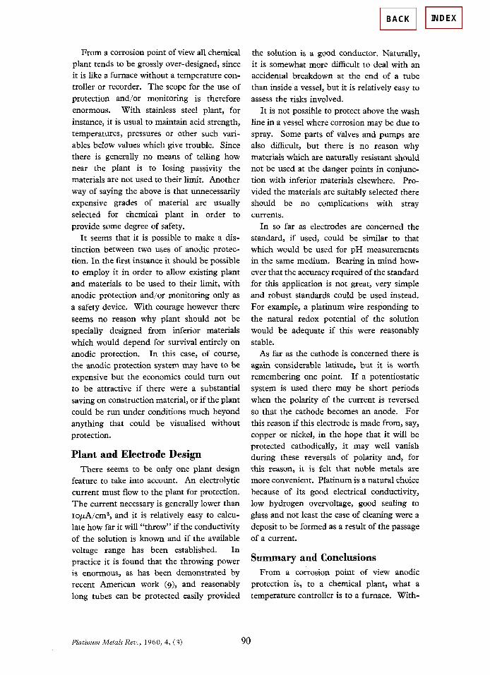
From a corrosion point of view all chemical plant tends to be grossly over-designed, since it is like a furnace without a temperature con- troller or recorder. The scope for the use of protection and/or monitoring is therefore enormous. With stainless steel plant, for instance, it is usual to maintain acid strength, temperatures, pressures or other such vari- ables below values which give trouble. Since there is generally no means of telling how near the plant is to losing passivity the materials are not used to their limit. Another way of saying the above is that unnecessarily expensive grades of material are usually selected for chemical plant in order to provide some degree of safety.
It seems that it is possible to make a dis- tinction between two uses of anodic protec- tion. In the first instance it should be possible to employ it in order to allow existing plant and materials to be used to their limit, with anodic protection and/or monitoring only as a safety device. With courage however there seems no reason why plant should not be specially designed from inferior materials which would depend for survival entirely on anodic protection. In this case, of course, the anodic protection system may have to be expensive but the economics could turn out to be attractive if there were a substantial saving on construction material, or if the plant could be run under conditions much beyond anything that could be visualised without protection.
Plant and Electrode Design There seems to be only one plant design
feature to take into account. An electrolytic current must flow to the plant for protection. The current necessary is generally lower than IopA/cm2, and it is relatively easy to calcu- late how far it will “throw” if the conductivity of the solution is known and if the available voltage range has been established. In practice it is found that the throwing power is enormous, as has been demonstrated by recent American work (9), and reasonably long tubes can be protected easily provided
the solution is a good conductor. Naturally, it is somewhat morc difficult to deal with an accidental breakdown at the end of a tube than inside a vessel, but it is relatively easy to assess the risks involved.
It is not possible to protect above the wash line in a vessel where corrosion may be due to spray. Some parts of valves and pumps are also difficult, but there is no reason why materials which are naturally resistant should not be used at the danger points in conjunc- tion with inferior materials elsewhere. Pro- vided the materials are suitably selected there should be no complications with stray currents. In so far as electrodes are concerned the
standard, if used, could be similar to that which would be used for pH measurements in the same medium. Bearing in mind how- ever that the accuracy required of the standard for this application is not great, very simple and robust standards could be used instead. For example, a platinum wire responding to the natural redox potential of the solution would be adequate if this were reasonably stable.
As far as the cathode is concerned there is again considerable latitude, but it is worth remembering one point. If a potentiostatic system is used there may be short periods when the polarity of the current is reversed so that the cathode becomes an anode. For this reason if this electrode is made from, say, copper or nickel, in the hope that it will be protected cathodically, it may well vanish during these reversals of polarity and, for this reason, it is felt that noble metals are more convenient. Platinum is a natural choice because of its good electrical conductivity, low hydrogen overvoltage, good sealing to glass and not least the ease of cleaning were a deposit to be formed as a result of the passage of a current.
Summary and Conclusions From a corrosion point of view anodic
protection is, to a chemical plant, what a temperature controller is to a furnace. With-
Platinum Metals Rev., 1960, 4, (3 ) 90
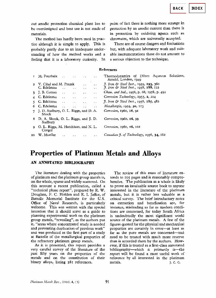
out anodic protection chemical plant has to be overdesigned and best use is not made of materials.
The method has hardly been used in prac- tice although it is simple to apply. This is probably partly due to an inadequate under- standing of how the method works and a feeling that it is a laboratory curiosity. In
point of fact there is nothing more strange in protection by an anodic current than there is in protection by oxidising agents such as chromates, which are universally accepted.
There are of course dangers and limitations but, with adequate laboratory work and suit- able instrumentations these do not amount to a serious objection to the technique.
References
I
2
3 4 5 6 7
8
9
I 0
M. Pourbaix .
V. Cihal and M. IPrazak . . . . C. Edeleanu . . . . . . . . J. B. Cotton . . . . . . . . C. Edeleanu . . . . . . . . C. Edeleanu . . . . . . . . C . Edeleanu . . , . . . . . J. D. Sudbury, 0. L. Riggs, and D. A.
Shock D. A. Shock, 0. L. Riggs, and J. D.
0. L. Riggs, M. 13utchison, and N. L.
W. Mueller . . . . . . . .
Sudbury
Conger
Thermodynamics of Dilute Aqueous Solutions,
J . Iron & Steel Znst., 1959, 193, 360 J. Iron & Steel Inst., 1958, 188, 122
Chem. and Znd., 1958, p. 68; 1958, p. 492 Corrosion Technology, 1955, 2, 204 J. Iron & Steel Inst., 1957, 185,482 Metallurgia, 1954, 50, 113 Corrosion, 1960, 16, 91
Corrosion, 1960, 16, 99
Corrosion, 1960, 16, 102
Canadian J. of Technology, 1956, 34, 162
Arnold, London, 1949
Properties of Platinum Metals and Alloys AN ANNOTATED BIBLIOGRAPHY
The literature dealing with the properties of platinum and the platinum group metals is, on the whole, sparse and widely scattered. On this account a recent publication, called a “technical phasc report”, prepared by R. W. Douglass, F. C. Holden and R. I. JafTee, of Battelle Memorial Institute for the U.S. Office of Naval Research, is particularly welcome. This was written with the special intention that it should serve as a guide to planning experimental work on the platinum group metals, “revealing”, as the authors put it, “areas where concentrated study is needed and preventing duplication of previous work” and was produced as the first part of a study at Battelle of the metallurgical properties of the refractory platinum group metals.
As it is presented, this report provides a very careful survey of the literature of the past fifty years on the properties of the metals and on the constitution of their binary alloys, listing 281 references.
Platinum Metals Rev., 1960, 4, (3 ) 91
The review of this mass of literature ex- tends to 105 pages and is reasonably compre- hensive. The publication as a whole is likely to prove an invaluable source book to anyone interested in the literature of the platinum metals, but it is rather less valuable as a critical survey. The brief introductory notes on extraction and benefication are, for instance, misleading as far as modem condi- tions are concerned, for today South Africa is undoubtedly the most significant world source of the platinum metals. A few of the figures quoted for the physical and mechanical properties are certainly in error-at least as far as the pure metals are concerned-and need to be treated with much more reserve than is accorded them by the authors. How- ever, if this is treated as a first-class annotated bibliography-which it primarily is-the report will be found a most useful work of reference by all interested in the platinum metals. J. C. C.

VIII-Metals-J-Corrosion protection-1_
CORROSION PROTECTION OF METALS
Two methods of combating corrosion which are widely used in New Zealand are cathodic protection and chemical inhibitors. Both methods depend on controlling the charge on the metal surface, and this can be monitored by measuring the potential of the metal. The conditions needed to stop corrosion can then be predicted from an electrochemical phase diagram. Cathodic protection is effected by forcing the potential to a negative region where the metal is completely stable. This can be done by using a sacrificial anode made from a more reactive metal, or using an external power supply to change the amount of charge on the metal surface. Cathodic protection is well suited to steel structures in marine or underground environments. There is a class of chemical inhibitors which work by removing electrons from the metal, thereby pushing the potential into a positive region where an oxide film spontaneously forms. This results in a stable, passive surface with a very low corrosion rate. Industries apply this technology in processes where the inhibitor can be conveniently added without causing environmental or health problems.
INTRODUCTION When iron or steel is exposed to atmospheric oxygen in the presence of water, the well-known rusting process takes place. The metal is degraded to form ferric rust, a red-brown compound, which is a sure sign of electrochemical oxidation of the underlying metal.
4Fe + 3O2 + 2H2O → 4FeO.OH (1) Nearly all metals, with the exception of gold and platinum, will corrode in an oxidising environment forming compounds such as oxides, hydroxides and sulphides. The degradation of metals by corrosion is a universal reaction, caused by the simple fact that the oxide of a metal has a much lower energy than the metal itself. Hence there is a strong driving force for the oxidation of metals. For example the familiar metal aluminium, which is used in aircraft, window frames and cooking utensils, is attacked by oxygen to form the oxide as follows:
4Al + 3O2 → 2Al2O3 (2) This reaction is strongly exothermic, releasing -1680 kilojoules per mole of oxide. In fact the driving force of the reaction is so great that powdered aluminium will burn to produce very high temperatures, sufficient to melt steel.
It is important to realise that corrosive attack on a metal can only occur at the surface of the metal, hence any modification of the surface or its environment can change the rate of reaction. Thus we have a basis for designing methods to protect metals from corrosion. A

VIII-Metals-J-Corrosion protection-2_
Table 1 - Corrosion protection techniques Concept
Industrial Process
Removal of oxidising agent
Boiler water treatment
Prevention of surface reaction
Cathodic protection - sacrificial anode - impressed current Anodic protection
Inhibition of surface reaction
Chemical inhibitors pH control
Protective coatings: a. Organic b. Metallic c. Non-metallic
Paint Claddings Electroplating Galvanising Metal spraying Anodising Conversion coatings
Modification of the metal
Alloys - stainless steel - cupronickel - high temperature alloys
Modification of surface conditions
Maintenance to remove corrosive agents Design to avoid crevices Design to avoid reactive metal combinations
number of such methods have been developed, and they are set out in Table 1. The table shows a variety of different concepts by which the surface reaction rate can be reduced. Each of these has given rise to a number of technologies, the majority of which are represented in New Zealand industry. In some cases these industries are on a very large scale. For example paint manufacture is a major chemical industry which consumes large quantities of solvents, resins and pigments. Most paint products in New Zealand are used in corrosion protection. Other major industries involved in corrosion control include electroplating, anodising, galvanising and the production of corrosion resistant alloys. In this article we will concentrate on two important methods of corrosion control used in New Zealand industry, namely cathodic protection and chemical inhibitors. Other types of corrosion control technology, such as electroplating and surface coatings, are covered elsewhere. THE CHEMISTRY OF CORROSION REACTIONS Corrosion reactions are electrochemical in nature. They involve the transfer of charged ions across the surface between a metal and the electrolyte solution in which it is immersed. There are two types of electrode reaction occurring at the metal surface: anodic and

VIII-Metals-J-Corrosion protection-3_
cathodic. Anodic reactions involve oxidation: electrons appear on the right hand side of the equation. For example metallic iron can produce ferrous ions by the anodic reaction:
Fe → Fe2+ + 2e- (3) In a solution with higher pH, the anodic reaction produces a surface film of ferric oxide according to reaction (4).
2Fe + 3H2O → Fe2O3 + 6H+ + 6e- (4) Cathodic reactions involve electrochemical reduction: electrons appear on the left hand side of the equation. In corrosion processes the most common cathodic reaction is the electrochemical reduction of dissolved oxygen according to the equation:
O2 + 2H2O + 4e- → 4OH- (5) Hence the reduction of oxygen at an electrode will cause a rise in pH due to hydroxide ion production. This can be important in some corrosion processes as will be explained later. The potential difference E across the interface between a metal and a solution is the key factor controlling both the products of an electrode reaction and rate at which they are formed. The potential difference itself is caused by layers of charges at the surface: electrons in the metal and excess anions or cations in the solution, as shown in Figure 1. This arrangement of charges is known as the double layer or the Helmholtz layer. It is found not only on metal surfaces but also on other surfaces in contact with solutions such as colloids and proteins. The state of charging of the Helmholtz layer and hence the magnitude of the potential E can be changed as a result of using an external electrical current or by electrode reactions such as those shown in equations (3) to (5). For example, in the presence of a high concentration of oxygen, the cathodic reaction will remove electrons from the metal surface hence making the metal more positively charged and increasing the potential E.
.e-
e-
e-
E
Metallic iron Water
Electronsforming surfacecharge
Excess cationsforming surfacecharge
Figure 1 - Electric double layer at ametal surface
The surface charge on the metal (electrons) is equal and opposite to the excess charge in the solution (cations). The potential difference, E, at the surface is created by the double layer.

VIII-Metals-J-Corrosion protection-4_
The role of the electrode potential E in defining the products of corrosion reactions can be readily seen in Figure 2. This figure shows the corrosion products as a function of electrode potential and pH for iron at room temperature in the presence of water as solvent. At negative potentials metallic iron itself is the stable form hence in this region no corrosion is possible, and this is referred to as the immunity condition. At higher potentials and acidic pH values ferrous ions will form giving rise to active corrosion. Ferric ions are produced only at high potentials above 0.7 V.
E / V
pH
Fe2O3
Fe3O4
Fe
Fe +2
Fe +3
Corrosion
Passivation
Immunity
0 5 10 15
-1
0
+1
Figure 2 - Iron equilibrium diagram
Iron at 25oC in water. The diagram shows the stable forms of the element as a function of E and pH. If the pH lies on the alkaline side of neutral then insoluble surface oxides will form. The oxide Fe3O4 , known as magnetite or black iron oxide, is produced at low electrode potentials. Low potentials are found in relatively stagnant conditions with a low oxygen partial pressure as in soil or inside boilers which have been treated to remove oxygen. The characteristic black surface of iron under these conditions is due to magnetite. At more positive potentials the oxide formed is Fe2O3 and this is usually present as a thin adherent film. Since this oxide forms at the surface, its presence acts to block the surface reactions and hence corrosion rates are reduced. This is called passivation and the oxide film on the surface is known as a passive layer. The corrosion rate is very low in the passivation region of the diagram. Diagrams of the type shown in Figure 2 are widely used in corrosion technology to predict the corrosion products which may be formed from a given metal under conditions specified by the axes of the figure. However the diagram does not tell the rate of corrosion which may be the most important information required in a practical situation. In order to understand the rate of the corrosion process we must examine the electrochemical polarisation curves of the electrode reactions which take place on the metal surface. Figure 3 shows the polarisation curve of iron in an acidic solution at room temperature. The rates of the electrode processes are controlled by the value of E. Thus, for a cathodic process in acidic solution producing hydrogen gas by the reduction of hydrogen ions, the more negative the electrode potential the greater the surface concentration of electrons and the faster the reaction rate.

VIII-Metals-J-Corrosion protection-5_
2H+ + 2e- → H2(g) (6)
Since the reaction rate is proportional to the flow of electrons (measured as a current I) the diagram shows the magnitude of I as a function of E.
Potential
ECORR
Fe2O3
O2
H2
Fe +2
PASSIVE
ACTIVE
CATHODIC
ICORR Current Figure 3- Polarisation of iron
The diagram shows how the potential, E, of the metal determines the electrochemical reaction rate and corrosion products.
Anodic reactions are accelerated by increasing potential in the positive sense as shown in the diagram. Ferrous ions are produced in the active state and this is the region in which corrosion will take place freely. At higher potentials the reaction passes into the passivation region (as shown in figure 2) and passivation occurs. This is observed as a very small current flowing in this region. The metal is protected by the passive film of ferric oxide on the surface. We see at very positive potentials that the passive electrode surface will act as an anode to oxidise water to oxygen gas, but this does not occur in normal corroding systems. To find the corrosion rate under normal conditions we look for the point on the diagram where the anodic and cathodic reactions intersect. At this point the rates of the anodic and cathodic reactions are equal and the system is behaving as a closed circuit with all the electrons produced in the anode reaction being consumed in the cathodic reaction. This is the situation for an electrically isolated structure made from the metal. The polarisation diagram can be used to predict changes of corrosion rate as will be discussed in the next section. CATHODIC PROTECTION The principle involved in cathodic protection is to change the electrode potential of the metallic article or structure so that it lies in the immunity region (shown in Figure 2).

VIII-Metals-J-Corrosion protection-6_
Within this region the metal is the stable form of the element and corrosion reactions are therefore impossible. Cathodic protection may be regarded as the most elegant form of corrosion protection because it renders the metal completely unreactive. It can however be fairly expensive in the consumption of electric power or the extra metals involved in controlling the potential within this region. There are two major methods of applying cathodic protection to a metal structure and these will be discussed below. In the case of iron or steel immersed in an aqueous solution the electrode potential should be about -700 mV (standard hydrogen electrode scale) or even more negative than this in order to ensure the structure remains in the immunity region. The metal surface under cathodic protection will be completely free from corrosion, but there may be some evolution of hydrogen gas according to equation (6). In seawater, calcareous deposits may form on the surface due to the increase in pH which occurs as a result of cathodic reactions. These deposits are composed of a mixture of calcium and magnesium basic carbonates, produced by precipitation from the localised zone of alkaline seawater close to the metal surface. Calcareous deposits of this type are found on the submerged steelwork supporting the Maui gas platform, which is located 30 km off the coast of Taranaki. (a) Impressed Current This technique is widely used for the protection of buried pipelines and the hulls of ships immersed in seawater. A d.c. electrical circuit is used to apply an electric current to the metallic structure. The negative terminal of the current source is connected to the metal requiring protection. The positive terminal is connected to an auxiliary anode immersed in the same medium to complete the circuit. The electric current charges the structure with excess electrons and hence changes the electrode potential in the negative direction until the immunity region is reached. It is important that the anode be completely separated from the cathode so that a true electric circuit is established with the current flow from the anode to the cathode taking place through the solution between those electrodes. Figure 4 shows the layout for a typical impressed current cathodic protection system. The function of the reference electrode is to monitor the electrode potential of the protected structure, in this case a buried pipeline, in order to ensure that the immunity region is reached. The reference electrode is designed to have a constant potential and no current passes through it. In the case of buried structures the most common reference electrode is Cu/CuSO4 (saturated), with a potential of +316 mV (standard hydrogen scale). The d.c. rectifier acts as the power supply and is adjusted so that the potential of the structure is sufficiently negative to reach the immunity region, as indicated by the reference electrode. It is usual to apply a surface coating or wrapping to the pipeline before cathodic protection is used. This will result in a much smaller consumption of electricity since most of the structure will be effectively protected by the coating. Special anode materials have been designed to withstand applied currents for very long periods. They normally consist of platinised titanium or lead alloys connected to an insulated cable positioned some distance from the structure itself. The buried anodes are distributed at intervals along the pipeline, normally several kilometres apart and several hundred metres from the nearest point of the pipeline.

VIII-Metals-J-Corrosion protection-7_
E Soil surface
AnodeCurrent
Cathode(i.e. buried pipe)
Referenceelectrode
DC rectifier
Figure 4 - Impressed current cathodic protection of a buried pipeline
A DC current passes between a buried anode and the pipeline. The pipeline is connected to the negative terminal, hence its potential becomes more negativ and it functions as the cathode.
Impressed current cathodic protection is a specialised technology and can be very effective if correctly designed and operated. Several warships operated by the Royal New Zealand Navy have impressed current systems for corrosion control. Other examples are the natural gas pipelines which distribute methane from the Kapuni and Maui fields. Impressed current cathodic protection is applied to gas pipelines in Auckland, with deep anode installations at the Auckland Domain and other points in the region. (b) Sacrificial Anode This technique is frequently used for ships in seawater and for offshore oil and gas production platforms such as the Maui gas platform operated by Shell BP Todd Oil Services Ltd. The principle here is to use a more reactive metal in contact with the steel structure to drive the potential in the negative direction until it reaches the immunity region. Figure 5 illustrates the principle. Zinc is often used as the sacrificial anode. In the absence of zinc the corrosion potential ECORR is given by the intersection of the anodic and cathodic curves. If a zinc electrode is now attached, it produces an anodic dissolution current at a more negative potential. The intersection with the cathodic curve now occurs at a more negative potential EPROT in the region in which the steel itself has a negligible corrosion rate. In practice a reference electrode is used to check that the steel structure has indeed reached the immunity region. A potential of around -900 mV with respect to the Ag/AgCl reference electrode in seawater is the criterion for immunity of the steel. In the case of the Maui platform it was not feasible to apply surface coatings to the steel structure before it was installed, hence the corrosion protection of the 6,000 tonnes of steel forming the tower depends entirely on cathodic protection by sacrificial anodes made from the aluminium alloy "Alanode". Some 580 tonnes of this alloy has been used to produce several hundred separate anodes attached to the legs and braces of the tower under the sea so as to give complete and uniform protection to all parts of the steel structure. Regular monitoring of the potential of the steel is carried out using submerged reference electrodes of Ag/AgCl. Aluminium is a sufficiently reactive metal to provide the required corrosion protection, but a small proportion of indium, about 0.1%, is included in the alloy to provide efficient anodic action. Pure aluminium alone has such a resistant oxide film that its reactivity

VIII-Metals-J-Corrosion protection-8_
Steel-anodic dissolution
Zinc-anodic dissolution
Oxygen-cathodicreduction
Current
Potential
ECORR
EPROT
Figure 5 - Cathodic protection by a sacrificial anode
The addition of a sacrificial zinc anode to a steel structure shifts the potential from ECORR to EPROT, where steel is protected from corrosion (anodic current for steel falls to zero).
is insufficient to properly protect the steel structure. CORROSION INHIBITORS It is well known in surface chemistry that surface reactions are strongly affected by the presence of foreign molecules. Corrosion processes, being surface reactions, can be controlled by compounds known as inhibitors which adsorb on the reacting metal surface. The term adsorption refers to molecules attached directly to the surface, normally only one molecular layer thick, and not penetrating into the bulk of the metal itself. The technique of adding inhibitors to the environment of a metal is a well known method of controlling corrosion in many branches of technology. A corrosion inhibitor may act in a number of ways: it may restrict the rate of the anodic process or the cathodic process by simply blocking active sites on the metal surface. Alternatively it may act by increasing the potential of the metal surface so that the metal enters the passivation region where a natural oxide film forms. A further mode of action of some inhibitors is that the inhibiting compound contributes to the formation of a thin layer on the surface which stifles the corrosion process. Table 2 shows some examples of common inhibitor systems classified by their modes of action. Adsorption inhibitors are used quite widely in many proprietary mixtures which are marketed to control corrosion. For example, radiator fluids in the cooling circuits of engines frequently contain amines such as hexylamine C6HI3NH2, or sodium benzoate. These act as inhibitors of the anodic reaction. Corrosion inhibitors are also used in the metal cleaning field. For example, it is possible to clean steel articles by immersion in sulfuric acid, H2SO4. The acid would normally attack the metal, causing corrosive loss. This can be minimised by adding antimony trichloride, SbCI3, a specific inhibitor for preventing the corrosion of steel in acidic media. Oxides and foreign metals such as zinc will readily dissolve in the presence of SbCl3 , which acts only on the steel itself. Amine inhibitors are sometimes present in volatile corrosion inhibitors. These are used in packaging materials to prevent corrosion of steel articles during transport. A good example is the wrapping used on automobile engines and other machinery during their shipment to New Zealand. The second class of inhibitors are those which cause the potential of the metals to rise into Table 2 - Corrosion inhibitors

VIII-Metals-J-Corrosion protection-9_
Mode of action Examples
Adsorption
amines thiourea
antimony trichloride benzoate
RNH2
NH2CSNH2 SbCl3
C6H5COO-
Passivating
nitrite chromate red lead
calcium plumbate
NO2
- CrO4
2- Pb3O4
Ca2PbO4
Surface layer
phosphate silicate
hydroxide bicarbonate
hexametaphosphate
H2PO4
- H2SiO4
2- OH-
HCO3-
Na6(PO3)6 the passivation region. They are all oxidising agents, containing elements in their higher oxidation states. For example nitrite, which is used as an additive in cooling fluid circuits for the control of corrosion of steel, is a mild oxidising agent which can raise the potential of steel into the passivation region. A traditional pigment used in paints is red lead, Pb3O4, containing lead in the tetravalent stale, and the formula can be written as plumbous plumbate Pb(II)2Pb(IV)O4. The plumbate ion is an active oxidising agent and serves to promote passivation of the underlying metal. The modern pigment calcium plumbate, often used in paint formulations, contains the same plumbate ion PbO4
4- in a different compound. Likewise zinc chromate ZnCrO4 is also widely used in corrosion control as a passivating inhibitor. The passivating inhibitors all share the common property of conferring protection on a metal by using its own natural oxide film. The last category of corrosion inhibitors are those which form a surface layer of a foreign chemical compound provided by the inhibitor itself. For example phosphate is widely used as an additive in boiler water or cooling circuits and in pickling baths for metals. Phosphate produces a surface layer of ferric phosphate FePO4 on steel which provides a measure of corrosion protection and is an excellent base for paints. Chromate is an extremely important industrial inhibitor in spite of its toxicity and unfavourable environmental problems. Chromate works in two ways, the high oxidation state Cr(VI) causes the metal to pass into the passivation region (see Figure 2) and the product of oxidation by chromate is chromic oxide Cr2O3 which itself forms an inert, relatively insoluble surface film. In practice chromate treatment of steels produces a mixed film of ferric and chromic oxides which is highly resistant to corrosion. An example of the use of chromate was the Marsden B thermal power station, now retired. Large quantities of cooling water are circulated in the plant and sodium chromate, added at a level of about 400 mg/L, was formerly used as a corrosion inhibitor. It proved to be very effective in protecting the steel; but changes in environmental regulations meant that it was no longer possible to permit discharge of chromium at a level above 5 µg/L. This ruled out the use of sodium chromate as an inhibitor at Marsden B and it was replaced by a new inhibitor system involving the use of an organic zinc phosphate mixture. Some of the other inhibitors listed in this category of surface film builders are very important industrially. The commercial inhibitor Calgon is a solution of sodium hexametaphosphate, a condensed phosphate polymer based on the unit (-PO3-)n.
VIII-Metals-J-Corrosion protection-10_
Hexametaphosphate functions as a corrosion inhibitor because it has a high affinity for metal cations such as calcium, zinc, copper and ferrous ions. Under some conditions it acts to dissolve substances containing these cations and hence has a cleaning effect, assisting the removal of scale deposits. But at the surface itself an insoluble layer of a ferrous hexametaphosphate is deposited and will act as a corrosion inhibitor. Calgon therefore is used as an inhibitor in potable water systems (drinking water) because it is non-toxic and is widely used in large institutions such as hotels and hospitals. We must not neglect to mention the simple hydroxide ion as a corrosion inhibitor. In the presence of hydroxide, and hence high pH, metal oxides and hydroxides are insoluble, and these are effective in controlling corrosion. For example, the common building material ferroconcrete involves placing highly alkaline fresh concrete (pH above 12) in contact with steel reinforcing. The high hydroxide concentration ensures effective corrosion inhibition by passivation of the steel surface, and a strong bond is formed between the concrete and the steel. CONCLUSION Corrosion can be controlled effectively by cathodic protection or inhibitors, provided the chemical and electrical conditions are monitored in a scientific manner. The same can be said for all of the anti-corrosion technologies listed in Table 1. The costs of stopping corrosion can be quite high, but these costs must be faced by many industries if they wish to achieve a high level of performance. The key factor is the scientific knowledge on which the technologies are based. Article written by Graeme Wright (Chemistry Department, University of Auckland)

ABSTRACT. Presented here are the re-sults from a series of experiments inwhich dissimilar metal welds were madeusing the gas tungsten arc weldingprocess with pure argon or argon-6% hy-drogen shielding gas. The objective wasto determine if cracking near the fusionboundary of dissimilar metal welds couldbe caused by hydrogen absorbed duringwelding and to characterize the mi-crostructures in which cracking oc-curred. Welds consisted of ER308 andER309LSi austenitic stainless steel andERNiCr-3 nickel-based filler metals de-posited on A36 steel base metal. Crack-ing was observed in welds made with allthree filler metals. A ferrofluid color met-allography technique revealed thatcracking was confined to regions in theweld metal containing martensite. Mi-crohardness indentations indicated thatmartensitic regions in which cracking oc-curred had hardness values from 400 to550 HV. Cracks did not extend into bulkweld metal with hardness less than 350HV. Martensite formed near the fusionboundary in all three filler metals due toregions of locally increased base metaldilution.
Introduction
Dissimilar metal welds are used ex-tensively in the power generation, petro-chemical and heavy fabrication indus-tries. Numerous instances of crackingalong the dissimilar metal fusion bound-ary have been reported, particularly incladding applications where a corrosion-resistant austenitic alloy is applied to aferritic structural steel. Often this crack-ing, or disbonding, has been associatedwith exposure to hydrogen in serviceand, as a result, the mechanism has beendescribed by various authors as a form ofhydrogen-induced cracking (Refs. 1–13).This type of cracking has been repro-duced in the laboratory by exposingaustenitic cladding to hydrogen, either inan autoclave or by cathodic charging(Refs. 1–3, 7, 8, 11–13).
In practice, however, this form of
cracking has occurred during fabrica-tion, prior to exposure to a hydrogen en-vironment. The fact that disbonding canoccur without prolonged exposure to hy-drogen in service suggests that either hy-drogen is not necessary for disbonding tooccur, or hydrogen absorbed duringwelding can cause cracking near the dis-similar metal fusion boundary.
The fusion boundary microstructurein dissimilar welds often possesses someunique features. Normal epitaxial nucle-ation during solidification along the fu-sion boundary gives rise to grain bound-aries that are continuous from the basemetal into weld metal across the fusionboundary. These boundaries are roughlyperpendicular to the fusion boundaryand have been referred to as “Type I”boundaries. In dissimilar welds, wherean austenitic weld metal and ferritic basemetal exist, a second type of boundarythat runs roughly parallel to the fusionboundary is often observed. This hasbeen referred to as a “Type II” boundary(Ref. 6). These boundaries typically haveno continuity across the fusion boundaryto grain boundaries in the base metal.Several investigators have reported thathydrogen-induced disbonding typicallyfollows Type II grain boundaries (Refs.1–4, 7, 8, 12,13). The disbonding phe-nomenon that occurs following fabrica-tion and prior to service has also been as-sociated with these Type II boundaries.
An additional complication inaustenitic/ferritic dissimilar welds is thedramatic transition in composition and
WELDING RESEARCH SUPPLEMENT | 31-s
RE
SE
AR
CH
/DE
VE
LO
PM
EN
T/R
ES
EA
RC
H/D
EV
EL
OP
ME
NT
/RE
SE
AR
CH
/DE
VE
LO
PM
EN
T/R
ES
EA
RC
H/D
EV
EL
OP
ME
NT
WELDING RESEARCHSUPPLEMENT TO THE WELDING JOURNAL, FEBRUARY 1999Sponsored by the American Welding Society and the Welding Research Council
Hydrogen-Induced Cracking along the FusionBoundary of Dissimilar Metal Welds
BY M. D. ROWE, T. W. NELSON AND J. C. LIPPOLD
The susceptibility of dissimilar austenitic/ferritic combinations to hydrogen-inducedcracking near the fusion boundary has been investigated
KEY WORDS
HydrogenWeld CrackingDissimilar MetalAustenitic StainlessFiller MetalsNickel-Based FillerGTAWMartensite
M. D. ROWE, T. W. NELSON and J. C. LIP-POLD were all with the Welding and JoiningMetallurgy Group, The Ohio State University,Columbus, Ohio, at the time this paper waswritten. Currently, M. D. ROWE is a graduatestudent at the Colorado School of Mines,Golden, Col., and T. W. NELSON is an Assis-tant Professor at Brigham Young University,Provo, Utah.

microstructure that occurs adjacent to thefusion boundary. This transition can be il-lustrated using the Schaeffler ConstitutionDiagram (Ref. 14). If a tie line is drawn onthis diagram (Fig. 1) from a ferritic steelbase metal to an austenitic stainless steelfiller metal (such as Type 308 or 309LSi)or a nickel-based filler metal (such as ER-NiCr-3), it can be seen that intermediatecompositions along the tie line betweenthe end points will promote martensiticand austenitic plus martensitic mi-crostructures. In practice this transitionoccurs over a very short distance (lessthan 1 mm) from the fusion boundary intothe weld metal, and results in a localizedmartensitic band along the fusion bound-ary. Cracking has been reported in themartensitic transition zone near the fu-sion boundary (Refs. 3, 12). Often, theType II boundaries described previouslyreside in this martensitic region.
In order to more carefully study the ef-fect of fusion boundary microstructureon hydrogen-induced cracking in dis-similar welds, a number of dissimilarwelds were made using variousaustenitic filler metals using both pureargon and Ar-6%H2 shielding gases.
The objective of these trials was toproduce hydrogen-induced cracking indissimilar metal welds by the addition ofhydrogen during welding, and to charac-terize the microstructures in whichcracking occurs. An understanding of thesusceptibility of dissimilar metal fusionboundary microstructures to hydrogen-induced cracking will contribute to anunderstanding of defect formation in dis-
similar metal welds and aid in develop-ment of sound welding procedures.
Experimental Procedure
Materials
The filler materials selected for this in-vestigation are commonly used in indus-try for dissimilar metal welding. Type308, 309LSi and ERNiCr-3 filler metalswere selected to cover a range of com-positions and microstructures. A36 steelwas selected as the base metal. Thechemical compositions of the materialsare listed in Table 1.
Welding Procedures
The gas tungsten arc welding (GTAW)process was selected because it allowsfor close control of dilution and the ad-dition of hydrogen through the shieldinggas. Shielding gases consisting of pureargon and Ar-6%H2 were used. Both amultipass and single-pass welding pro-cedure were developed to assess the ef-fect of hydrogen introduction through theshielding gas.
The multipass weld procedure joinedtwo 0.75 x 4 x 12 in. (19 x 102 x 305 mm)plates of A36 steel. Welding was per-formed along the 12-in. dimension. Theplates were restrained in a heavy fixtureto simulate actual high-restraint fabrica-tion conditions. Both ER308 and ERNiCr-3 filler metals were used to fill a standardV-groove joint geometry. The includedangle of the groove was 60 deg, and16–20 passes were required to fill thejoint with the welding conditions listed in
Table 2. Following welding, the weld-ment was left rigidly restrained for up tofour days, then inspected for crackingusing side-bend tests, and by sectioningand metallography.
A single-pass procedure followed byapplication of augmented strain by bend-ing was used to allow for greater controlof applied strain and to minimize the el-evated temperature diffusion of hydro-gen that occurs during a multipass pro-cedure. The single-pass welds weredeposited in a V-groove using the condi-tions listed in Table 2. Three percentstrain was applied by bending over afixed-radius die block in either the longi-tudinal or transverse direction with re-spect to the weld. Each test plate con-tained two welds deposited side by side;
32-s | FEBRUARY 1999
RE
SE
AR
CH
/DE
VE
LO
PM
EN
T/R
ES
EA
RC
H/D
EV
EL
OP
ME
NT
/RE
SE
AR
CH
/DE
VE
LO
PM
EN
T/R
ES
EA
RC
H/D
EV
EL
OP
ME
NT
Fig. 1 — Schaeffler constitution diagram (Ref. 14) showing predicted mi-crostructures and minimum dilutions necessary to form martensite for thefiller metal/base metal combinations used in this investigation.
Fig. 2 — Plan view, ER308 filler metal, longitudinal strain, 30% dilu-tion, Ar-6%H2 shielding gas, chromic acid/nital etch, showing crack-ing near the fusion boundary and associated with light-etching bandsin the weld metal.

one made with pure argon, the other withAr-6%H2 shielding gas. First, the pureargon weld was deposited, then the platewas cooled in water. Secondly, the Ar-6%H2 weld was deposited and the platewas cooled in water again. Finally, thewelds were ground flush with the surfaceof the plate and the augmented strain wasapplied within 5 min of extinguishing thearc. Crack propagation across the surfaceof the weld was monitored visually onsamples subjected to longitudinal strain.
Addition of hydrogen to the shieldinggas caused an increase in dilution(deeper penetration) for a given currentlevel. It was therefore necessary to use alower current with the Ar-6%H2 shield-ing gas to achieve a similar dilution aswelds made with pure argon. Dilutionwas controlled by making minor adjust-ments to the current levels listed in Table2. Metallographic cross sections wereprepared to assure that the dilution levelswere similar.
Microstructural Characterization
Microstructural characterization wasperformed using optical metallography,microhardness, energy dispersive X-rayspectroscopy (EDS) and dilution mea-surements. Because of the range of com-positions and microstructures a numberof chemical etchants were used, includ-ing 10% chromic acid (electrolytic), 5 gFeCl/90 mL methanol/2 mL HC1 (elec-trolytic) and 4% nital.
A ferrofluid technique was used toprovide contrast between martensite andaustenite in the weld metal. Ferrofluid is acolloidal suspension of ferromagnetic ironoxide particles. The ferrofluid is appliedwith an eye dropper onto the surface of thesample in either the as-polished conditionor after previous chemical etching, andthen gently rinsed in a bath of petroleum
ether to remove theexcess ferrofluid. Thesample was then re-moved from the petro-leum ether and al-lowed to dry. Theremnant magnetism ofany ferromagneticphases (ferrite andmartensite) attracts theiron oxide particles,but leaves the para-magnetic phase(austenite) free of par-ticles. The differencein ferrofluid deposi-tion produces a colorcontrast between fer-romagnetic phasesand paramagneticphases when viewedin an optical micro-scope. Ferrofluid has been successfullyused to provide contrast between ferriteand austenite in duplex stainless steels(Ref. 15) and between austenite andstrain-induced martensite in wroughtaustenitic stainless steels (Ref. 16).
Microhardness was used to study thetransition in microstructure at the fusionboundary. A diamond pyramid indenterwas used in conjunction with both 10-and 100-g loads. Plots of hardness vs. dis-tance from the fusion boundary wereused to support metallographic observa-tions and determine the width of the tran-sition region.
Weld metal dilution measurementswere made on the single-pass welds inorder to relate the predicted compositionto the microstructure of the weld metalfrom the Schaeffler diagram. To deter-mine dilution, an image of the weld crosssection was scanned into a computer,and a graphics software package wasused to measure the weld nugget area rel-
ative to the original V-groove dimension.The filler metal dilution is then given bythe area of base metal melted divided bythe nugget area.
WELDING RESEARCH SUPPLEMENT | 33-s
RE
SE
AR
CH
/DE
VE
LO
PM
EN
T/R
ES
EA
RC
H/D
EV
EL
OP
ME
NT
/RE
SE
AR
CH
/DE
VE
LO
PM
EN
T/R
ES
EA
RC
H/D
EV
EL
OP
ME
NT
Fig. 3 — Plan view, ER308 filler metal, transverse strain, Ar-6%H2shielding gas, chromic acid/ nital etch, showing cracking runningparallel to the fusion boundary.
Fig. 4 — Plan view, same weld that appears in Fig. 2 treated with ferrofluid on a polished surface. A — Cracking occurred in a region coloredstrongly by ferrofluid, indicating the presence of martensite; B — A+F indicates an austenite plus skeletal ferrite microstructure, A+M indicates anaustenite plus martensite microstructure.

Results
Multipass Weld Procedure
Side-bend tests and metallography re-vealed no cracking in any of the multi-pass welds made with ER308 and ErNiCr-3 filler metals. Metallography revealed amartensitic transition region near the fu-sion boundary in both welds with hard-ness in excess of 400 HV. More than anhour was required to complete a multi-pass weld, and upon completion, theplate temperature was in excess of 500°F(260°C). The time spent at elevated tem-perature was probably sufficient to allowhydrogen to diffuse away from the weldarea, leaving an insufficient concentra-tion to cause cracking. It is also possiblethat the residual stress from welding wasinsufficient to promote cracking. This
procedure was abandoned in favor of asingle-pass technique with application ofaugmented strain.
Single-Pass Weld Procedure
Cracking was observed in welds madewith each of the three filler metals usingAr-6%H2 shielding gas. Cracking was notobserved in any of the welds made withpure argon shielding gas. In welds madewith Ar-6%H2 shielding gas, cracking oc-curred within 5 to 30 min after aug-mented strain was applied. In welds madewith ER308 filler metal with dilution near40%, cracks propagated throughout theweld metal. When the dilution was re-duced to 30%, cracking was confined toa narrow region of the weld metal within1 to 1.5 mm of the fusion boundary.
With ER309LSi filler metal at 44% di-lution, cracking was also confined to
within 1 to 1.5 mm from the fusionboundary. With ERNiCr-3 filler metal at38% dilution, cracking was not visible tothe naked eye, but microscopic cracks ina narrow weld metal band 100 to 150 µmof the fusion boundary were revealed bymetallography.
ER308 Weld Deposits
The ER308 filler metal experiencedmore severe cracking for a given level ofdilution than the other two filler metals.Figure 2 shows the appearance of crack-ing in a weld made with the ER308 fillermetal and argon-6%H2 shielding gas afterlongitudinal bending. This weld had a rel-atively low dilution of 30%, promotingthe formation of austenite plus ferrite inthe bulk weld metal and partially marten-sitic microstructures in regions near thefusion boundary. Note that the cracks in
34-s | FEBRUARY 1999
RE
SE
AR
CH
/DE
VE
LO
PM
EN
T/R
ES
EA
RC
H/D
EV
EL
OP
ME
NT
/RE
SE
AR
CH
/DE
VE
LO
PM
EN
T/R
ES
EA
RC
H/D
EV
EL
OP
ME
NT
Fig. 5 — Plan view, Type 309LSi filler metal, longitudinal strain, 44% dilution, Ar-6%H2 shielding gas, chromic acid/nital etch. A — Cracking andhardness traverse near the fusion boundary; B — detail of crack tip that appears in (A) showing propagation path.
Fig. 6 — Plan view, same weld that appears in Fig. 5 treated with ferrofluid after chromic acid/nital etch. Martensitic regions are colored brown,austenitic regions remain white. A — Alternating bands of austenite and martensite are visible in the weld metal; B — crack near the fusion bound-ary. High hardness in the darker regions reflects the presence of martensite.

Fig. 2 are associated with light-etchingbands in the weld metal. Figure 3 showscracks propagating parallel to the fusionboundary in a sample subjected to trans-verse strain. Figure 4 shows the mi-crostructure of the weld, which appearsin Fig. 2 as revealed by ferrofluid appliedto the polished surface. The region nearthe fusion boundary where the crackingoccurred is strongly colored by ferrofluid(blue or purple) in Fig. 4A and has an av-erage hardness of 476 HV, which is sig-nificantly higher than the bulk weld metalaverage hardness of 311 HV.
The region near the center of Fig. 4Blabeled A+F has a microstructure ofaustenite plus skeletal ferrite, which istypical of ER308 weld deposits. Theaustenite is white or light brown whilethe ferrite is colored. The region labeledA+M has a microstructure of austeniteplus martensite. Hardness indentationsin Fig. 4B indicate that the region colored
by ferrofluid has a significantly higherhardness than the white region, which isconsistent with the presence of marten-site. When compared to Fig. 2, it wasfound that the light etching bands wherecracking initiated corresponded to theA+M regions in Fig. 4. It can be con-cluded from the high hardness and col-oration by ferrofluid that the cracking oc-curs in regions containing martensite.
ER309LSi Weld Deposits
Type 309LSi filler metal exhibited lesssevere cracking than Type 308 for a givendilution. Figure 5 shows cracking in a re-gion of high hardness near the fusionboundary in a weld made with Ar-6%H2shielding gas. The crack extends 600 µmaway from the fusion boundary. Figure5B shows the propagation path at the tipof the crack in Fig. 5A. Both intergranu-lar and transgranular propagation are ev-
ident. This is consistent with Savage, etal. (Ref. 17), who observed both inter-granular and transgranular propagationin experiments involving direct observa-tion of hydrogen-induced cracking. Thechromic acid etch does not clearly revealthe austenite plus martensite structurethrough which the crack propagates. Theaverage hardness in the crack region, asdetermined from the traverse shown inFig. 5A, is 431 HV, while the bulk weldmetal hardness is 239 HV.
Figure 6 shows the same weld thatappears in Fig. 5 treated with ferrofluidafter being etched with chromic acidand nital. Martensitic regions are brownwhile austenitic regions remain white.Hardness indentations indicate a signifi-cantly higher hardness in the regionscolored by ferrofluid, which is consistentwith the presence of martensite. Crack-ing is visible in the band of high hardnessmartensite in the weld metal adjacent to
WELDING RESEARCH SUPPLEMENT | 35-s
RE
SE
AR
CH
/DE
VE
LO
PM
EN
T/R
ES
EA
RC
H/D
EV
EL
OP
ME
NT
/RE
SE
AR
CH
/DE
VE
LO
PM
EN
T/R
ES
EA
RC
H/D
EV
EL
OP
ME
NT
Fig. 7 — Plan view, ER309LSi filler metal, longitudinal strain, 33% dilution, pure argon shielding gas, chromic acid/nital/ferrofluid. A — Mi-crostructure of mostly austenite with bands of martensite visible; B — bands of martensite near the fusion boundary.
Fig. 8 — Plan view, ER309LSi filler metal, longitudinal strain, 38% di-lution, Ar-6%H2 shielding gas, chromic acid/nital etch showing amartensitic region (dark gray) near the fusion boundary containing amicroscopic crack.
Fig. 9 — Plan view, same weld as Fig. 8, ferric chloride electrolyticetched revealed a martensitic microstructure near the fusion bound-ary and Type II grain boundaries.

the fusion boundary. At low magnifica-tion alternating bands of austenite andmartensite are visible in the weld metal,as shown in Fig. 6A. Figure 7 shows aweld made with pure argon shieldinggas having a lower dilution (33%) thanthe weld made with Ar-6%H2 shieldinggas (44%). Significantly less martensite isvisible in the bulk weld metal of thelower dilution weld, as predicted by theSchaeffler diagram in Fig. 1. However, aband of high-hardness martensite is pre-sent near the fusion boundary of bothwelds. The martensite occurs in bandsthat follow the shape of the solid/liquidinterface during solidification, as shownin Fig. 7A. Again, the difference in hard-ness between the austenite and marten-site bands is evident in Fig. 7B.
ERNiCr-3 Weld Deposits
ERNiCr-3 filler metal experienced theleast severe cracking of the three fillermetals, and formed the least amount ofmartensite at comparable dilutions. Fig-ure 8 shows a microscopic crack ap-proximately 110 µm long in a region ofmartensite, which appears a darker graycolor than the bulk weld metal. The av-erage hardness in the gray (martensitic)region of Fig. 8 is 462 HV, while the av-erage hardness in the adjacent austeniteis 206 HV. When treated with ferrofluid,the gray region was colored while theaustenitic bulk weld metal remainedwhite. When treated with a ferric chlo-ride etch (Fig. 9), a lathy microstructurewas revealed in the hard gray region nearthe fusion boundary, which is consistentwith the presence of martensite. The fer-ric chloride etch was also effective at re-vealing Type II grain boundaries, as indi-cated by the arrows in Fig. 9, which werenot revealed by the chromic acid etch.
A composition profile was measured
across the martensiticgray region, which ap-pears in Fig. 8, usingSEM/EDS. Local per-cent filler metal dilu-tion was calculatedusing the results of theEDS measurements forNi and Cr, as shown inFig. 10. The Schaefflerdiagram predicts thatthe minimum dilutionfrom A36 base metalto form martensite inERNiCr-3 weld metalis 78% and the mini-mum dilution to forma fully martensitic mi-crostructure is 84%,as shown in Fig. 1. Itcan be seen from Fig.
10 that the Schaeffler diagram predicts analmost fully martensitic microstructure inthe gray region where the crack appearsin Fig. 8.
Discussion
Cracking was observed in single-passwelds made with Ar-6%H2 shielding gasusing all three filler metals. Cracking wasnot observed in welds made with pureargon shielding gas; therefore it can beconcluded that the cracking was hydro-gen induced.
Cracking was always associated withregions of martensite near the fusionboundary. The ferrofluid color metallog-raphy technique revealed that the cracksoccurred in regions containing a ferro-magnetic constituent, which is consistentwith the presence of martensite. Micro-hardness indentations revealed that theregions where cracking occurred had ahardness significantly higher than that ofthe austenitic weld metal, which is alsoconsistent with the presence of marten-site. An electrolytic etchant consisting of5 g FeCl2, 90 mL methanol and 2 mL HClrevealed a martensitic microstructurenear the fusion boundary in the weldmade with ERNiCr-3 filler metal, asshown in Fig. 9.
Welds made with ERNiCr-3 andER309LSi filler metals exhibited lesscracking than welds made with 308 fillermetal. According to the Schaeffler dia-gram (Fig. 1), the minimum base metaldilution necessary to form martensite inthese filler metals is 16% for ER308, 33%for ER309LSi and 78% for ErNiCr-3. Fora given dilution, welds made with ER308filler metal contained the most marten-site and experienced the most severecracking. Low dilution welds made withER309LSi and ERNiCr-3 can only formcrack-susceptible martensite in select lo-
cations near the fusion boundary wherethe local dilution is higher than that of thebulk weld metal.
Locally increased dilution near the fu-sion boundary is most likely the result ofa stagnant fluid layer in the weld poolcontacting the solid base metal. Themartensitic regions may form by a mech-anism similar to the unmixed zone de-scribed by Savage and Szekeres (Ref. 18).The martensitic regions differ from an un-mixed zone in that they do not have thesame composition and microstructure asthe base metal. A true unmixed zoneseems unlikely to form in a dissimilarmetal weld because of the strong compo-sition gradient between the bulk weldmetal and the stagnant fluid layer whileboth are in the liquid state. Duvall andOwczarski concluded that diffusion fromthe bulk weld metal into the unmixedzone while both are liquid is feasible con-sidering the conditions of time, tempera-ture and distance in an arc weld (Ref. 19).
Although a lower heat input was usedfor the Ar-6%H2 welds than those madewith pure argon, the welds with hydrogenaddition had a somewhat higher dilution.Dilution levels for some of the pairs ofwelds (pure argon/Ar-6%H2) presented inthe results section are 28%/30% forER308, 33%/44% for ER309LSi and32%/38% for ERNiCr-3. The authors be-lieve that cracking was caused by hydro-gen addition and not by increased dilu-tion. The susceptible microstructure,which is the band of high hardnessmartensite near the fusion boundary, waspresent in all of the welds regardless ofwhether they were made with pure argonor Ar-6%H2. The fact that cracking onlyoccurred in welds made with hydrogenaddition, even though the susceptible mi-crostructure was present in both types ofwelds, indicates that the cracking was hy-drogen induced.
Cracking along Type II grain bound-aries is frequently reported in the litera-ture; however, it was not observed in thisinvestigation. Most of the experiments inthis investigation involved longitudinalbending, which does not place tensionacross the Type II grain boundaries. Lon-gitudinal bending is effective at deter-mining the width of the crack-susceptibleregion near the fusion boundary and therange of hardness in which cracks willpropagate, but not effective at determin-ing crack susceptibility of the Type IIboundaries.
Practical Implications
The results of this study have shownthat hydrogen introduced during weldingcan lead to hydrogen-induced cracking
36-s | FEBRUARY 1999
RE
SE
AR
CH
/DE
VE
LO
PM
EN
T/R
ES
EA
RC
H/D
EV
EL
OP
ME
NT
/RE
SE
AR
CH
/DE
VE
LO
PM
EN
T/R
ES
EA
RC
H/D
EV
EL
OP
ME
NT
Fig. 10 — Composition profile parallel to the hardness traverse acrossthe martensitic region that appears in Fig. 8.

in dissimilar welds between austeniticfiller metals and ferritic base metals. Hy-drogen in the welding arc is detrimentalin two ways: 1) it increases dilution bythe carbon steel base metal, increasingthe amount of martensite formed, and 2)it interacts with martensite under stress tocause cracking. The incidence of crack-ing was most pronounced in single-passwelds. This suggests that the use of mul-tipass techniques or thermal treatmentsthat allow for hydrogen diffusion willminimize cracking susceptibility. The useof low-hydrogen practice with dissimilarmetal welds is also suggested.
Cracking was always associated withhard, martensitic regions adjacent to thefusion boundary; therefore, minimizingthe compositional regime within whichmartensite can form will reduce suscep-tibility. As this study has shown, fillermetal selection can have a profound in-fluence on the tendency to form marten-site, with ER308 showing the strongesttendency and ERNiCr-3 the weakest. Re-ducing base metal dilution will also re-duce the tendency to form martensite inboth the bulk weld metal and along thefusion boundary, as illustrated by theSchaeffler diagram.
Finally, it is advisable to avoid stressconcentrations at the fusion boundary,such as undercut or a sharp toe angle, be-cause they locally increase applied stressand help to initiate hydrogen-inducedcracking. Since the most susceptible mi-crostructure forms in the vicinity of thefusion boundary, elimination of stressconcentrators at the toe or root of theweld is imperative.
Conclusions
1) Hydrogen-induced cracking wasobserved in high-hardness martensite(400 to 550 HV) near the dissimilar metalfusion boundary between ER308,ER309LSi and ERNiCr-3 filler metals andA36 steel base metal.
2) Cracking was observed in weldsmade with Ar-6%H2 shielding gas, butnot in welds made with pure argonshielding gas.
3) A ferrofluid color metallographytechnique revealed that cracking was al-ways confined to regions containingmartensite.
4) The severity of cracking observedin the filler metals tested was a functionof the minimum dilution to form marten-site on the Schaeffler diagram; ER308had the lowest minimum dilution to formmartensite and the most severe cracking,while ERNiCr-3 had the highest mini-mum dilution to form martensite and theleast severe cracking.
Microstructures near the fusionboundary cannot be predicted on theSchaeffler diagram using the bulk weldmetal dilution because of locally in-creased dilution near the fusion bound-ary. The tie line between the base metaland filler metal will allow the mi-crostructure of the fusion boundary tran-sition region to be approximated.
Acknowledgments
The authors would like to thank theOSU Engineering Experiment Station forproviding financial support for this pro-ject through the Senior Honors Fellow-ship Program.
References
1. Pressouyre, G., Chaillet, J., and Vallette,G. 1982. Parameters affecting the hydrogendisbonding of austenitic stainless claddedsteels. Proceedings of the First InternationalConference on Current Solutions to HydrogenProblems in Steels. Washington, D.C.
2. Matsuda, F., Nakagawa, H., and Tsuruta,S. 1986. Proposal of hydrogen blisteringmechanism associated with disbonding be-tween 2.25Cr-1Mo steel and Type 309 over-laid metal. Transactions of JWRI15(2):207–208.
3. Matsuda, F., and Nakagawa, H. 1984.Simulation test of disbonding between2.25%Cr-1%Mo steel and overlaid austeniticstainless steel by electrolytic hydrogen charg-ing technique. Transactions of JWRI 13(1):159–161.
4. Tanaka, O., Takeba, K., and Matsushita,Y. 1984. High speed overlay welding with stripelectrodes. Welding Review May, pp. 58–62.
5. Kinoshita, K., Itoh, H., Ebata, A., andHattori, T. 1985. Microscopical critical condi-tion for the initiation of disbonding of weldoverlaid pressure vessel steel. Transactions ofthe Iron and Steel Institute of Japan 24(6):505–512.
6. Asami, K., and Sakai, T. Hydrogen in-duced cracking at interface between stainlesssteel overlay weld metal and base metal inpressure vessel. Transactions of the Iron andSteel Institute of Japan 21(6).
7. Mirishage, N., Kume, R., and Okabayashi,H. 1985. Influence of low-temperature hydro-gen degassing on hydrogen-induced disbond-ing of cladding. Transactions of the Japan Weld-ing Society 16(1): 12–18.
8. Imanaka, T., Nakano, S., Shimomura, J.,and Yasuda, K. 1985. Hydrogen attack in Cr-Mo Steels and disbonding of austenitic stain-less weld overlay. Kawasaki Steel TechnicalReport No. 13. September. (Translation ofKawasaki Steel Giho 17[1]:84–92).
9. Welding process of overlay resistant todisbonding. 1987. Transactions of the Iron andSteel Institute of Japan 27(3).
10. Fuji, A., Kudo, E., Takahashi, T., andMano, K. 1986. Mechanical properties ofstainless steel overlay weld with resistance tohydrogen-induced disbonding. Transactionsof the Japan Welding Society 17(1): 27–32.
11. Hattori, T., and Fujita, T. 1986. Hydro-gen induced disbonding of stainless steel over-lay weld and its preventive measures. NipponKokan Technical Report, Overseas No. 47:17–22.
12. Blondeau, R., and Pressouyre, G.1982. Contribution to a solution to the dis-bonding problem in 2.25Cr-1Mo heavy wallreactors. Proceedings of the First InternationalConference on Current Solutions to HydrogenProblems in Steels. Washington, D.C.
13. Okada, H., and Naito, K. 1982. Hy-drogen-induced disbonding of stainless weldoverlay in hydrodesulfurizing reactor. Pro-ceedings of the First International Conferenceon Current Solutions to Hydrogen Problems inSteels. Washington, D.C.
14. Schaeffler, A. L. 1949. Constitution di-agram for stainless steel weld metal. MetalProgress 56(11): 680–680B.
15. Varol, I., Baeslack, W., and Lippold, J.1989. Characterization of weld solidificationcracking in a duplex stainless steel. Metallog-raphy 23: 1–19.
16. Gray, R. The detection of strain-induced martensite in Types 301, and 304stainless steels by epitaxial ferromagneticetching. Microstructure Science, Vol. 1. Eds.Robert J. Gray and James L. McCall, AmericanElseuier Publishing Co., Inc.
17. Savage, W., Nippes, E., and Homma,H. 1976. Hydrogen induced cracking in HY-80 steel weldments. Welding Journal 55(11):368-s to 376-s.
18. Savage, W., and Szekeres, E. 1967.Technical note: A mechanism for crack for-mation in HY-80 steel weldments. WeldingJournal 46(2): 94-s to 96-s.
19. Duvall, D., and Owczarski, W. 1968.Fusion-line composition gradients in an arc-welded alloy. Welding Journal 47(3): 115-s to120-s.
WELDING RESEARCH SUPPLEMENT | 37-s
RE
SE
AR
CH
/DE
VE
LO
PM
EN
T/R
ES
EA
RC
H/D
EV
EL
OP
ME
NT
/RE
SE
AR
CH
/DE
VE
LO
PM
EN
T/R
ES
EA
RC
H/D
EV
EL
OP
ME
NT

HYDROGEN EFFECTS IN MATENALS

HYDROGEN EFFECTS IN
Proceedings of the Fifth International Conference on the Effect of Hydrogen on the Behavior of Materials sponsored by the Structural Materials Division (SMD)
Mechanical Metallurgy and Corrosion & Environmental Effects Committees of The Minerals, Metals & Materials Society
held at Jackson Lake Lodge, Moran, Wyoming September 11-14, 1994
Edited by
Anthony W. Thompson Lawrence Berkeley Laboratory
Berkeley, California
and
Neville R. Moody Sandia National Laboratories
Livermore, California
A Publication of
TMS Minerals 0 Metals 0 ~ Z e r i a l s

A Publication of The Minerals, Metals & Materials Society 420 Commonwealth Drive
Warrendale, Pennsylvania 15086 (412) 776-9000
The Minerals, Metals & Materials Society is not responsible for statements or opinions and is absolved of liability due to misuse of information contained in this publication.
Printed in the United States of America Library of Congress Catalog Number 96-75439
ISBN Number 0-87339-334-1
Authorization to photocopy items for inter- nal or personal use, or the internal or per- sonal use of specific clients, is granted by The Minerals, Metals & Materials Society for us- ers registered with the Copyright Clearance Center (CCC) Transactional Reporting Serv-
copy is paid directly to Copyright Clearance
TMS ice, provided that the base fee of 53.00 per Minerals. Me,als. MaterBls
Center, 27 Congress Street, Salem, Massa- chusetts 01970. For those organizations that have been granted a photocopy license by Copyright Clearance Center, a separate sys- tem of payment has been arranged.
0 1996
If you are interested in purchasing a copy of this book, o r if y o u would like to receive the latest TMS publications catalog, please telephone 1-800-759-4867.
CONTENTS
... ........................................................................................................................ Foreword xlll
CONFERENCE KEYNOTE The Role of Hydrogen: Is The Story Any Clearer? ......................................................... 3
I. M. Bernstein
HYDROGEN INTERACTIONS .............................................................. Hydrogen-Dislocation Interactions (Keynote) 15
H. K. Birnbaum and P. Sofronis
.................... Hydrogen Interaction with 0-, I- , and 2- Dimensional Defects (Invited) 35 J. Gegner, G. Horz and R. Kirchheim
Deuterium and Tritium Applications to the Quantitative Study of Hydrogen Local Concentration in Metals and Related Embrittlement (Invited) ......................... 47
J. Ch&ne and A. M. Brass
Hydrogen Induced Embrittlement and the Effect of the Mobility of Hydrogen Atoms (Invited) ................................................................... 61
1.-S. Wang
Atomistic Calculations of Hydrogen Interactions with Ni3Al Grain Boundaries and Ni/Ni,Al Interfaces (Invited) .................................................... 77
M. I. Baskes,]. E.Angelo, andN. R. Moody
Bonding Strengths and Anomalous Hydrogen ................................................................... Absorption in Some Intermetallic Systems 9 1
I. Jacob
.......................... The Investigation of Hydrogen Redistribution Under a Tensile Load 97 B. K. Zuev and 0. K. Timonina
Characterization of Defects in Deuterium-implanted Beryllium ................................. 105 R. A. Anderl, A. B. Denison, S. Szpala, P. Asoka-Kumar, K. G. Lynn, and B. Nielsen
The Role of Traps in Determining the Resistance to Hydrogen Embrittlement ......... 115 B. G. Pound
Hydrogen Trapping and its Correlation to the Hydrogen Embrittlement Susceptibility of Al-Li-Cu-Zr Alloys ................................................... 13 1
S. W . Smith and J. R. Scully
The Interaction of Hydrogen with a P-Titanium Alloy .............................................. 143 H. Zhang, T. Lin, and R. Chang

O n the Mechanism of Hydrogen Interaction with Titanium at Temperatures from 300 to 373K and Pressures up to 150 MPa .................................... 153
Yu. I. Archakov and T. D. Aleferenko
Modeling the Segregation of Hydrogen to Lattice Defects in Nickel ......................... 161 J. E. Angelo, N. R. Moody, and M. I. Baskes
The Behavior of Impurity Hydrogen in Metallic Materials ......................................... 17 1 G. Itoh, H. Okada, and M. Kanno
Hydrogen Absorption in Metals During Electrolytic Processes ......................................................... and the Physical-Mechanical Properties of Steel 18 1
Yu. M. Loshkaryov, A. N. Baturin, and V. I. Korobov
PERMEATION The Effect of Surface on the Measurement of Hydrogen Transport in Iron with the Electrochemical Permeation Technique (Invited) ................................ 189
A. M. Brass and 1. Collet-Lacoste
Diffusion of Hydrogen in Titanium .............................................................................. 205 0. S. Abdul-Hamid and R. M. Latanision
Hydrogen Solubility in Ti-24A1-11 Nb ........................................................................ 2 15 M. G. Shanabarger, S. N. Sankaran, and A. W. Thompson
Hydrogen Solution and Diffusion in L1,-Ordered (Co, Fe),V Alloy ...................................................... and Their Roles in Environmental Embrittlement 223
C. Nishimura, M. Komaki, and M. Amano
Modeling of Hydrogen Transport in Cracking Metal Systems .................................... 233 J. P. Thomas and C. E. Chopin
Comparison of the High Temperature Hydrogen Transport Parameters for the Alloys Incoloy 909, Haynes 188, and Mo-7.5 Re ............................................ 243
M. G. Shanabarger
......................................................................... Deuterium Desorption from Beryllium 25 1 R. Bastasz, J. A. Whaley, T. J. Venhaus, and D. M. Manos
Hydrogen Transport Through Ti0 , Film Prepared by Plasma Enhanced Chemical Vapor Deposition (PECVD) Method ......................................... 261
S.-I. Pyun and Y.-G. Yoon
Measurements of Diffusion and Permeation for Protium in .................................................................. P-PdH and Modeling of Diffusion Process 27 1
J. ?. Hamilton and W. S. Swansiger
Investigation of a Hydrogen Charging Method on an Austenitic Structure ............... 283 C. Dagbert, M. Sehili, J. Galland, and L. Hyspecka
Thermal Desorption Analysis (TDA): Application in Quantitative Study of Hydrogen Trapping and Release Behavior .................................................... 293
E. Abramov and D. Eliezer

MECHANICAL PROPERTIES The Effect of Deformation Rates on Hydrogen Embrittlement ................................... 303
W. Dietzel and M. Pfuff
Hyrdrogen Attack in Creeping Polycrystals due to .................................................................................. Cavitation on Grain Boundaries 3 13
M. W. D. van der Burg and E. van der Giessen
The Effect of Hydrogen on the Fracture Behavior of Aluminum Titanium Metal Matrix Composites .......................................................... 323
G. Solovioff and D. Eliezer
Effect of Pressure and Temperature on Hydrogen .................................................... Environment Embrittlement of Incoloyo Alloy 909 33 1
R. K. Jacobs, A. K. Kuruvilla, T. Nguyentat, and P. Cowan
.................. Hydrogen Effects on Cyclic Deformation Behavior of a Low Alloy Steel 343 H. j. Maier, W. Popp, and H. Kaesche
The Relationship between Strain Rate, Hydrogen Content, and the Tensile Ductility of Uranium .......................................................................... 355
G. L. Powell
Influence of Strain Rate on Tensile Properties in High-pressure Hydrogen ............... 363 E. J. Veselyjr., R. K. Jacobs, M. C. Watwood, and W. B. McPherson
Void Formation in Hydrogen Charged Metals Induced by Plastic Deformation as the Initial Stage of Embrittlement .......................................... 375
Yu N. Jagodzinski, L. N. Larikov, and A. Yu. Smouk
CRACK GROWTH SUSCEPTIBILITY Fracture Toughness and Hydrogen assisted Crack Growth in Engineering Alloys (Keynote) ................................................................... 387
J. F. Knott
Modeling Hydrogen Environment-enhanced Fatigue Crack Growth in Al-Li-Cu-Zr (Keynote) .................................................................... 409
R. S. Piascik and R. P. Gangloff
Local Approach of Fracture in a Tempered Martensitic Steel Cathodically Hydrogenated at High pH ............................................................. 435
R. P. Hu, M. Habashi, G. Hu, and]. Galland
Cracking of a Hydrided Zirconium Alloy in Hydrogen ............................................... 445 1.-H. Huang and F.4. Jiang
Hydrogen Induced Damage in High Strength Pearlitic Steel: Micromechanical Effects and Continuum Mechanics Approach ............................... 455
J. Toribio, A. M. Lancha, and M. Elices
............................................................. The Hydrogen Embrittlement of Alloy X-750 465 D. M. Symons and A. W. Thompson
vii
Effects of Anisotropy on the Hydrogen Diffusivity and Fatigue Crack Propagation of a Banded Ferrite-Pearlite Steel ................................................. 475
L. Tau, S. L. I. Chan, and C. S. Shin
Influence of Water Vapor Pressure on Crack Growth Rate in 701 7-T65 1 Aluminum Alloy .......................................................................... 487
J. Ruiz and M. Elices
The Kinetics of Hydrogen Assisted Cracking of Metals .............................................. 497 A. G. 9. M. Sasse and V. J. Gadgil
FRACTURE MECHANISMS The Role of Hydrogen in Enhancing Plastic Instability and
..................................................... Degrading Fracture Toughness in Steels (Keynote) 507 J. P. Hirth
Hydrogen and Moisture-Induced Embrittlement of Nickel and Iron Aluminides (Invited) ......................................................................... 523
N. S. Stoloff
Hydrogen Induced Cracking Mechanisms - Are There Critical Experiments? (Invited) ................................................................. 539
W. W. Gerberich, P. G. Marsh, and]. W. Hoehn
Some Contribution to the Understanding of the Mechanism of Hydrogen Induced Cracking of Intermetallic Compounds (Invited) ........................................... 555
C.-M. Xiao, W.-Y. Chu, and F.-W. Zhu
A Theory for Hydrogen Embrittlement of Transition Metals and Their Alloys ......... 569 J. A. Lee
Microautoradiography of Fatigue Crack Growth in Low-Carbon Steel Using Tritiated Water Vapor ......................................................... 581
D. L. Davidson and J. B. Campbell
Effects of Internal Hydrogen on the Toughness and .................................................................... Fracture of Forged JBK-75 Stainless Steel 59 1
B. C. Odegard Jr., S. L. Robinson, and N. R. Moody
.................................................. Model for Plasticity-Enhanced Decohesion Fracture 599 C. Altstetter and D. Abraham
Advances in the Theory of Delayed Hydride Cracking in Zirconium Alloys ............. 6 1 1 S.-Q. Shi and M. P. Puls
High Resolution Fractography of Hydrogen-Assisted Fracture in Iron-3 wt.% Silicon ................................................................................... 623
T. 1. Marrow, M. Aindow, and J. F. Knott
viii

STRESS CORROSION CRACKING Distributions of Anodic and Cathodic Reaction Sites during Environmentally Assisted Cracking (Invited) ......................................... 635
B. G. Ateya and H. W. Pickering
Calculation Model of Hydrogen-Mechanical Crack Propagation in Metals under Corrosive Environment Effects .......................................................... 647
0. Andreykiv and N. Tymiak
The Effect of Hydrostatic Pressure on Hydrogen Permeation and ........................................................... Embrittlement of Structural Steels in Seawater 657
J. Woodward, R. P. M. Procter, and R. A. Coffis
The Effect of Microstructure on Hydrogen-induced Stress-Corrosion Cracking of Quenched and Tempered Steels ............................................................... 669
G. Echaniz, T. E. Perez, C. Pampillo, R. C. Newman, R. P. M. Procter, and G. W. Lorimer
Influence of the Ni-Content on the Cathodic and Corrosive Hydrogen Induced Cracking Behavior of Austenitic Alloys ........................................................ 679
K. Mummert, H. J. Engelmann, S. Schwarz, and M. Uhlemann
Hydrogen Embrittlement During Corrosion Fatigue of Duplex Stainless Steel .......... 689 K. N. Krishnan, J. F. Knott, and M. Strangwood
HYDROGEN IN TITANIUM ALLOYS Effect of High Temperature Hydrogen on Titanium Base Alloys (Keynote) .............. 699
H. G. Nelson
Hydrogen Effects in Titanium (Invited) ...................................................................... 7 19 F. H. Froes, D. Eliezer, and H. G. Nelson
Effect of Hydrogen o n the Microstructure and Mechanical Properties of the Ti Alloy: Ti-15Mo-3Nb-3A1-0.2Si ................................................... 735
D. A. Hardwick and D. G. Ulmer
Hydrogen Interactions and Embrittlement in Metastable Beta Ti-3A1-8V-6Cr-4Mo-4V .................................................................... 745
M. A. Gaudett, S. W. Smith, and J. R. Scully
Hydrogen Effects in Titanium Aluminide Alloys ...................................................... 755 D. Eliezer, F. H. Froes, C. Suryanarayana, and H. G. Nelson
Effects of Hydrogen-induced Phases on Mechanical Behavior of ............................................ the Ti-25A1-10Nb-3 Mo-1V Titanium Aluminide Alloy 765
X. Pierron and A. W. Thompson
Hydrogen Effects on Ti-22A1-27Nb ............................................................................. 7 77 D. Eliezer, A. Ben-Guigui, N. Stern, N. Eliaz, E. Abramov, and R. G. Rowe
The Effect of High Pressure Hydrogen Charging on Microstructure and ......................................... Mechanical Behavior of a Cast y+a, Titanium Aluminide 787
U. Habel, T. M. Pollock, and A. W. Thompson
Hydride Dissociation and Hydrogen Evolution from Cathodically ............................................................ Charged Gamma-Based Titanium Aluminides 799
A. Takasaki, Y. Furuya, K. Ojima, and Y. Taneda
Hydrides in High Pressure Hydrogen-charged TiAl Alloys ........................................ 809 K. Li, M. De Graef, T. M. Pollock, D. B. Allen, and A. W. Thompson
Influence of Hydride Precipitation on the Ductility of Titanium Under Stress Triaxiality ................................................................................ 819
J. Huez, A,-L. Helbert, I. Guillot, A. W. Thompson, and M. Clavel
The Effects of Hydrogen on the Stability of the ........................................................................ Orthorhombic Phase in Ti-24A1- 1 1Nb 83 1
D. B. Allen, A. W. Thompson, and M. De Graef
HYDROGEN IN STAINLESS STEELS AND SUPERALLOYS Effect of Internal Hydrogen on the Mixed-Mode 11111 Fracture Toughness of a FerriticiMartensitic Stainless Steel ..................................................... 843
H. Li, R. H. Jones, J. P. Hirth, and D. S. Gelles
Effects of Internal Helium on Tensile Properties of Austenitic Stainless Steels and Related Alloys at 820°C .............................................................. 855
W. C. Mosley
Mechanical Austenite Stability of Fe-Ni-Cr-Mn Stainless Steels ............................... 865 J. M. Larsen and A. W. Thompson
Tritium and Decay Helium Effects on the Fracture Toughness Properties of Types 316L, 304L, and 21Cr-6Ni-9Mn Stainless Steels .......................................... 873
M. J. Morgan and M. H. Tosten
Helium 3 Precipitation in Tritiated AISI 316 Stainless Steels .................................... 883 A. M. Brass, A. Chanfreau, and J. Chene
Phase Transformations and Relaxation Phenomena in Hydrogen-Charged CrNiMn and CrNi Stable Austenitic Stainless Steels ................................................ 893
V. G. Gavriljuk, H. Hanninen, S. Yu. Smouk, A. V. Tarasenko, A. S. Tereschchenko, and K. Ullakko
Hydrogen Effects on 316L Austenitic Stainless Steel: Mechanical Modeling of the DamagelFailure Process ................................................. 903
J. Toribio and A. Valiente
Hydrogen Degradation Mechanisms in Single Crystal Turbine Blade Alloys ............. 9 13 D. P. DeLuca and B. A. Cowles
Role of Microstructure on Hydrogen Embrittlement of Nickel Base Superalloy Single Crystals ........................................................................ 923
D. Roux, J. Chene, and A. M. Brass
....................................... Effect of Strain Rate on Hydrogen Embrittlement in Ni,A1 933 H. Li and T. K. Chaki
Influence of the Failure Mode on Fatigue Crack Growth Behavior in Single Crystal Superalloys ........................................................................ 943
J. Telesman, L. 1. Ghosh, and D. P. DeLuca
Internal Hydrogen Embrittlement at 300°C in Nickel Base Alloys 690 and 800 ....... 953 I. Lenartova, M. Habashi, and L. Hyspecka
Temperature Effects on Hydrogen-induced Cracking in an Iron-Based Superalloy .............................................................................................. 967
N. R. Moody, S. L. Robinson, J. E. Angelo, and M. W. Perra
Hydrogen Embrittlement in Duplex Steel Tempered Between 200°C and 1050°C and Cathodically Charged at 200°C ............................................ 979
F. lacoviello, M. Habashi, M. Cavallini, and J. Galland
ENGINEERING APPLICATIONS Catastrophes of Large Diameter Pipelines: The Role of Hydrogen Fields ................... 991
V. N. Polyakov
The Effect of Boron as a Micro-alloying Element on the Behavior of a 1038 Steel in a Hydrogen Environment .............................................. 1001
P. Bruzzoni, G. Domizzi, M. I. Luppo, D. Zalcman, and J. Overjero Garcia
NASA-HR-1, A New Hydrogen-resistant Fe-Ni-Base Superalloy ............................ 101 1 P. S. Chen, B. Panda, and B. N. Bhat
Hydrogenation Evolution of Steels under Friction in Synthetic Sea Water ............. 102 1 K. Bencherif, P. Manolatos, P. Ponthiaux, and J. Galland
NASA-23 for HEE Resistant Structural Applications .............................................. 1029 A. K. Kuruvilla, B. Panda, W. B. McPherson, and B. N. Bhat
Preventing Degradation and Predicting Response in Fracture Toughness of Ti-6A1-4V Fan Disks Using Hydrogen Measurements .......................................... 1039
M. A. Durfee
Effect of Hydrogen Exposure on a Cu-8 Cr-4 Nb Alloy for Rocket Motor Applications ........................................................................................ 1049
D. L. Ellis, A. K. Misra, and R. L. Dreshfield
Welding Tritium Exposed Stainless Steel .................................................................. 1057 W. R. Kanne jr.
Hydrogen Test Standardization of Low Cycle Fatigue Tests ...................................... 1065 W. B. McPherson and J. P. Strizak
.............................................................................................................. Author Index 1073

FOREWORD
In the five years since our previous conference addressed hydrogen effects o n material properties, there has been a significant amount of work that made another conference appropriate to assess progress. We chose to return to Jackson Lake Lodge, Wyoming, for the fourth time. T h e response was overwhelming with over 150 abstracts submitted. After a difficult selection process, the conference consisted of 1 18 presentations from 16 countries, divided into seven oral and three poster sessions. These sessions addressed hydrogen effects in metals and alloys, from permeation and effects o n properties to crack propagation and fracture. Keynote and invited speakers provided overviews of core topics and pressing issues. These were followed by contributed papers discussing these topics in depth as well as new results. Discussions after each presentation highlighted the controversial issues and defined our understanding of hydrogen effects. In that sense, this fifth international conference o n hydrogen in materials met our goals and was successful in its intentions.
T h e proceedings begins with an invited perspective of progress made in studying hydrogen effects over the last twenty years by I. M. Bernstein. T h e balance of the proceedings is then divided into ten areas that reflect the directions and issues which have been evident in hydrogen research for the past five years. T h e first two sections deal with the fundamental aspects of hydrogen permeation and interaction with defects in metals and alloys. These are followed by three sections addressing hydrogen effects o n crack growth susceptibility, stress corrosion cracking, and fracture. This is followed by a section providing a n overview of hydrogen effects on mechanical properties of metals and alloys, two sections o n hydrogen effects in titanium, stainless steels and superalloys, and two sections o n engineering alloys and applications. T h e emphasis o n titanium alloys, stainless steels, and superalloys reflects the strong focus in recent years o n hydrogen-resistant alloys required for aerospace applications in hydrogen environments. Comparison with previous conferences shows we have made progress in understanding hydrogen effects in these alloys as well as in all aspects of hydrogen effects o n material behavior. We hope the papers in these proceedings stimulate discussion of hydrogen interactions and mechanisms that control behavior of materials, and also help to stimulate, focus, and direct future research.
T h e papers in this volume have been reproduced directly from camera-ready manuscripts submitted by the authors for post-conference publication. Although it was possible to correct many grammatical and typographical errors, the number of corrections had to be minimized in the interest of economical publication. We hope that the readers view any errors in this light. Discussion during the conference was captured by written forms given to questioners, and then to speakers. Those which were completed and returned to us are included here.
T h e success of this conference was due to the efforts of many people to whom we are grateful. W e especially wish to thank R. H. Jones, who joined us o n the program committee, and H. G. Nelson and R. 0. Ritchie, who helped us obtain funding; their help was invaluable. Our appreciation is also given to R. H. Jones, D. Eliezer, N. Stoloff, H. G. Nelson, W. W. Gerberich, J . F. Knott, and R. P. Gangloff who served as session chairmen
xiii

and promoted lively discussions between all participants. Partial support funding was provided by grants from the National Science Foundation and from the Ames Research Center of the National Aeronautics and Space Administration, and without that support, the conference finances would have had to be much different,
W e thank a number of our colleagues at Sandia National Laboratories, the Lawrence Berkeley Laboratory, and University of California a t Berkeley who generously devoted their time and efforts. To Jim Angelo, Ben Odegard, and Steve Robinson from Sandia National Laboratories, we express our gratitude for their coordination and assistance with all program functions. We also extend our thanks to Tony Thompson's graduate students, David Allen, Xavier Pierron, and Kezhong Li, for their help a t the conference with forms for questions posed by the audience and for answers given by the speakers, which enabled us to include the discussions for many papers in these proceedings.
To our wives, JoAnne Moody and Mary Thompson, goes a special thanks, for they helped with registration, ensured that many activities for participants and their families ran smoothly, and provided support and encouragement to us through all phases of preparation for the conference. We also extend our gratitude to Carmella Orham who did a myriad of secretarial and typing tasks in support of the conference. Finally, we gratefully acknowledge the provision ofsupport, through availability ofboth people and resources, given generously by Sandia National Laboratories, the Lawrence Berkeley Laboratory, and University of California a t Berkeley, that made this conference a success.
Anthony W, Thompson Lawrence Berkeley Laboratory Berkeley, CA
Neville R. Moody Sandia National Laboratories Livermore, CA

AUTHORS
Abdul-Hamid, 0. S., 205 Abraham, D., 599 Abramov, E., 293, 777 Aindow, M., 623 Aleferenko, T. D., 153 Allen, D. B., 809, 831 Altstetter, C., 599 Amano, M., 223 Anderl, R. A., 105 Andreykiv, O., 647 Angelo, J. E., 77, 161, 967 Archakov, Yu. I., 153 Asoka-Kumar, P., 105 Ateya, B. G., 635
Baskes, M. I., 77, 161 Bastasz, R., 251 Baturin, A. N., 181 Ben-Guigui, A., 777 Bencherif, K., 1021 Bernstein, I. M., 3 Birnbaum, H. K., 15 Bhat, B. N., 101 1, 1029 Brass, A. M., 47, 189, 883, 923
Bruzzoni, P., 1001
Campbell, J. B., 581 Cavallini, M., 979 Chaki, T. K., 933 Chan, S. L. I., 475 Chanfreau, A., 883 Chang, R., 143 Chen, P. S., 1011 Chihe, J., 47, 883, 923 Chopin, C. E., 233 Chu, W.-Y., 555 Clavel, M., 819 Coffis, R. A., 657 Collet-Lacoste, J., 189 Cowan, P., 331 Cowles, B. A., 913
Dagbert, C., 283 Davidson, D. L., 581 De Graef, M., 809, 83 1 DeLuca, D. P., 9 13,943 Denison, A. B., 105 Dietzel, W., 303 Domizzi, G., 1001 Dreshfield, R. L., 1049 Durfee, M. A., 1039
Echaniz, G., 669 Eliaz, N., 777 Elices, M., 455 Elices, M., 487 Eliezer, D., 293 Eliezer, D., 323, 719, 755,
777 Ellis, D. L., 1049 Engelmann, H. J., 679
Froes, F. H., 719, 755 Furuya, Y., 799
Gadgil, V. J., 497 Galland, J., 283, 435, 979,
102 1 Gangloff, R. P., 409 Gaudett, M. A., 745 Gavriljuk, V. G., 893 Gegner, J., 35 Gelles, D. S., 843 Gerberich, W. W., 539 Ghosh, L. J., 943 Guillot, I., 819
Habashi, M., 435,953,979 Habel, U., 787 Hamilton, J . C., 27 1 Hanninen, H., 893 Hardwick, D. A., 735 Helbert, A.-L., 819 Hirth, J. P., 507, 843 Hoehn, J. W., 539
Horz, G., 35 Hu, G., 435 Hu, R. P., 435 Huang, J.-H., 445 Huez, J., 819 Hyspecka, L., 283, 953
Iacoviello, F., 979 Itoh, G., 171
Jacob, I., 91 Jacobs, R. K., 33 1, 363 Jagodzinski, Yu N., 375 Jiang, F.-I., 445 Jones, R. H., 843
Kaesche, H., 343 Kanne, W. R. Jr., 1057 Kanno, M., 171 Kirchheim, R., 35 Knott, J. F., 387, 623, 689 Komaki, M., 223 Korobov, V. I., 181 Krishnan, K. N., 689 Kuruvilla, A. K., 331, 1029
Lancha, A. M., 455 Larikov, L. N., 375 Larsen, J . M., 865 Latanision, R. M., 205 Lee, J. A., 569 Lenartova, I., 953 Li, H., 843, 933 Li, K., 809 Lin, T., 143 Lorimer, G. W., 669 Loshkaryov, Yu. M., 18 1 Luppo, M. I., 1001 Lynn, K. G., 105
Maier, H. J., 343 Manolatos, P., 1021 Manos, D. M., 25 1

Marrow, T. J., 623 Powell, G. L., 355 Marsh, P. G., 539 Procter, R. P. M., 657, 669 McPherson, W. B., 363, Puls, M. P., 61 1
1029, 1065 Pyun, S.-I., 261 Misra, A. K., 1049 Moody, N. R., 77, 161, 591, Robinson, S. L., 591, 967 967
Morgan, M. J . , 873 Mosley, W. C., 855 Mummert, K., 679
Nelson, H. G., 699, 719, 755
Newman, R. C., 669 Nguyentat, T., 33 1 Nielsen, B., 105 Nishimura, C., 223
Odegard, B. C. Jr., 591 Ojima, K., 799 Okada, H., 17 1 Overjero Garcia, J., 1001
Pampillo, C., 669 Panda, B., 1011, 1029 Perez, T. E,, 669 Perra, M. W., 967 Pfuff, M., 303 Piascik, R. S., 409 Pickering, H. W., 635 Pierron, X., 765 Pollock, T. M., 787, 809 Polyakov, V. N., 99 1 Ponthiaux, P., 1021 Popp, W., 343 Pound, B. G., 115
Roux, D., 923 Rowe, R. G., 777 Ruiz, J., 487
Sankaran, S. N., 215 Sasse, A. G. B. M., 497 Schwarz, S., 679 Scully, J . R., 131, 745 Sehili, M., 283 Shanabarger, M. G., 2 15,
243 Shi, S.-Q., 611 Shin, C. S., 475 Smith, S. W., 131, 745 Smouk, A. Yu., 375 Smouk, S. Yu., 893 Sofronis, P., 15 Solovioff, G., 323 Stem, N., 777 Stoloff, N. S., 523 Strangwood, M., 689 Strizak, J. P., 1065 Suryanarayana, C., 755 Swansiger, W. S., 27 1 Symons, D. M., 465 Szpala, S., 105
Takasaki, A., 799 Taneda, Y., 799 Tarasenko, A. V., 893
Tau, L., 475 Telesman, J., 943 Tereschchenko, A. S., 893 Thomas, J. P., 233 Thompson, A. W., 2 15,
465, 765, 787, 809, 819, 83 1,865
Timonina, 0. K,, 97 Toribio, J., 455, 903 Tosten, M. H., 873 Tymiak, N., 647
Uhlemann, M., 679 Ullakko, K., 893 Ulmer, D. G., 735
Valiente, A,, 903 van der Burg, M. W. D., 3 13
van der Giessen, E., 3 13 Venhaus, T. J., 25 1 Vesely, E. J. Jr., 363
Wang, 1.-S., 61 Watwood, M. C., 363 Whaley, J. A., 25 1 Woodward, J., 657
Xiao, C.-M., 555
Yoon, Y.-G., 261
Zalcman, D., 1001 Zhang, H., 143 Zhu, F.-W., 555 Zuev, B. K., 97
FERRITIC AND AUSTENITIC SINTERED STAINLESS STEELS FATIGUE CRACK PROPAGATION RESISTANCE: HYDROGEN
EMBRITTLEMENT INFLUENCE
F, Iacoviello, V. Di Cocco Di.M.S.A.T., Università di Cassino, Cassino (FR), ITALY
ABSTRACT
Stainless steels are widely used in many fields such as chemical, petrochemical, food and nuclear industries and they are characterized by physical, mechanical and corrosion resistance properties that depend on the microstructure and phase transformations: many intermetallic phases, carbides and nitrides precipitate at different tempering temperatures. Sintered stainless steels corrosion resistance and mechanical behavior are worst than that of either cast or rolled or wrought stainless steels: their use is mainly due to their economically attractive production cost and/or to their alternative manufacturing procedure (e.g. duplex stainless steels). In this work, the fatigue crack propagation resistance of two sintered stainless steels, respectively characterized by an austenitic and a ferritic microstructure, is investigated. Fatigue crack propagation tests are performed both in air and under hydrogen charging conditions, investigating the influence of the stress ratio (R= 0.1; 0.5; 0.75). Fatigue crack propagation micromechanisms are investigated by means of a scanning electron microscope (SEM) fracture surface analysis. Although the hydrogen physical behaviour is completely different in fcc and bcc structures, both the investigated austenitic and ferritic sintered stainless steels are susceptible to be embrittled by the hydrogen charging process, for all the investigated stress ratio values. SEM fracture surface analysis allows to identify different fatigue crack propagation mechanisms that are influenced both by the loading conditions (either ∆K and R values), by the steel microstructure and by the test environment.
1 INTRODUCTION Stainless steels obtained by means of the “traditional” metallurgy are susceptible to failure by hydrogen embrittlement under certain combinations of hydrogen charging, temperature and stress (Gibala [1]). Hydrogen sources could be related to a galvanic coupling with less noble metals (e.g. carbon steels), from cathodic protection, from welding operations and from localized corrosion. Considering that stainless steels are attractive materials for many applications (e.g. petrochemical industry, chemical and nuclear plants, marine environment, desalination etc.) and that they could be considered as critical with respect to the hydrogen embrittlement problem, it is necessary to assess their susceptibility to this damaging mechanism (Chêne [2]). Stainless steels are sometimes characterized by considerable difficulties from the manufacturing point of view (e.g. austenitic-ferritic duplex stainless steels , Datta [3]), and powder metallurgy offers an excellent alternative to produce these steels. Furthermore, sintered stainless steels allow a decreasing of the production costs, especially when a large number of identical pieces, usually characterized by a small size and a complex geometry, is produced (Otero [4]). Sintered duplex stainless steels are obviously characterized by the presence of micropores that depend on the sintering procedures (powders, sintering temperature and duration, etc.). These defects could influence the hydrogen embrittlement susceptibility, especially considering a crack growing under fatigue loading conditions.

Hydrogen is available on a metal surface from various sources. Considering an aqueous environment, all the corrosion mechanisms imply the existence of cathodic reactions and the possible hydrogen adsorption on metal surface (Chêne [5]):
H+ + e- + M↔ MHads (acid environments) H2O + e- + M↔ MHads + OH-
(alkaline environments) Then, adsorbed hydrogen contained in MHads species could be: • absorbed according to: MHads ↔ MHabs • recombined in molecular form according to: MHads + MHads ↔ H2 + 2M • desorbed according to: MHads + H+ + e- ↔ H2 + M The distribution of the absorbed hydrogen (MHabs) on the crack surface is influenced by many factors as the electrochemical environment at the crack tip (potential, pH, species concentrations, O2, etc) and the kinetics of the involved reactions. Transport rate of absorbed hydrogen from the crack surface into the material depends on the hydrogen physical behaviour in metals. The main aspects of this behaviour are (Johnson [6], Bernstein [7]): • hydrogen solubility; • hydrogen diffusivity; • hydrogen trapping. Both hydrogen solubility and diffusivity depend on the microstructure, on the temperature (at room temperature, the coefficient of hydrogen diffusion, DH, in body centered cubic lattice ranges between about 10-9 cm2s-1 and about 10-6 cm2s-1; these DH values can be obtained in a face centered cubic lattice only for higher temperatures, between 200°C and 600°C, Welding Institute [8]), on the stresses state and, finally, on the presence of lattice defects as vacancies, alloying elements, dislocations interfaces, microvoids and grain boundaries. External or internal stresses influence the hydrogen solubility and diffusivity in metals, depending on the consequent strain level. An elastic deformation field implies a solubility increase or a decrease respectively corresponding to a tensile or a compression stress state, while diffusion coefficients are not influenced by an elastic deformation field. A plastic deformation field implies a strong increase of the dislocations density: as a consequence, an evident increase of the hydrogen concentration is obtained according to a “trapping” mechanism. The so called “hydrogen trapping” phenomenon (Pressouyre [9, 10]) could be defined as the ability of hydrogen in solid solution to interact with all the microstructural defects, influencing both hydrogen physical behaviour (diffusivity and solubility) and metals mechanical behaviour (i.e. hydrogen induced crack or hydrogen embrittlement). Different traps classifications were proposed, depending on: • traps position (internal or external); • traps origin (connected to electric or chemical or elastic interactions); • traps physical characteristics (“attractive” traps as electrical or stress fields or temperature
gradients; “physical” traps as high angle grain boundaries or incoherent particle matrix or voids; “mixed” traps as edge dislocations);
• hydrogen-trap interaction energy, defining the concept of “reversible” or “irreversible” trap, that depends on the temperature (“reversible” traps release hydrogen continuously with the temperature increasing, while irreversible ones do so after a critical temperature is reached);
• traps dimension (zero-dimensional as interstitials or vacancies, mono-dimensional as dislocations, bi-dimensional as phases interfaces or grain boundaries, and three-dimensional as micropores).
Considering all the physical, chemical, metallurgical and mechanical parameters that influence the hydrogen charging, diffusion, solubility and trapping in metals, many hydrogen embrittlement models are available, but no one is applicable to all the possible conditions (Coudreuse [11]).

The analysis of the fatigue crack propagation resistance in air and under hydrogen charging conditions of sintered stainless steels should take into account both the microstructure (austenitic or ferritic grains) and the microvoids presence.
2 MATERIALS AND EXPERIMENTAL PROCEDURES Two sintered stainless steels are obtained considering AISI 316 LHC and AISI 434 LHC stainless steels powders (table 1). Sintering was performed at 1250°C, under vacuum, for 1 hour. Table 1: Stainless steels powders chemical compositions (wt%).
C Mo Ni Mn Cr Si Fe AISI 316 (ρ = 7.08 g/cm3) 0.019 2.28 12.75 0.17 16.3 0.87 Bal. AISI 434 (ρ = 7.16 g/cm3) 0.016 1.03 - 0.18 16.57 0.70 Bal.
Fatigue tests are perfomed using 10.5 mm thick CT (Compact Type) specimens, with the notch obtained via electroerosion. Sintered stainless steels fatigue crack propagation resistance areinvestigated according to E647 ASTM standard (ASTM [12]), using a computer controlled (100 kN) servohydraulic testing machine in constant load amplitude conditions, with a sinusoidal waveform. Tests are performed at room temperature, both in air, with a loading frequency of 30 Hz, and under hydrogen charging conditions (0.5 M H2SO4 + 0.01 M KSCN aqueous solution; applied potential = -0.7 V/SCE) with a loading frequency of 1 Hz, considering three different stress ratio values (e.g. R = Pmin/Pmax equal to 0.1, 0.5 and 0.75). Crack lengths are measured using a compliance method with a double cantilever crack mouth gauge and are controlled using an optical method with a 40x magnification. da/dN-∆K experimental results are interpolated considering the Paris law in the stage II of III (Paris [13]): da/dN = C ∆Km (1) where C and m are interpolation parameters. These parameters depend on material, structural state mechanical properties and environmental test conditions (Iost [14]). Main crack propagation micromechanisms are investigated by means both of a scanning electron microscope (SEM Philips with EDX) fracture surfaces analysis. Furthermore, an optical microscope (LOM, x200) fatigue crack path analysis is conducted with the same procedure followed in Iacoviello [15].
3 RESULTS Fatigue crack propagation results are shown in figures 1 and 2. Ferritic sintered stainless steel fatigue crack propagation (figure 1) is characterized by the decrease of the threshold values (∆Kth) and the increase of the crack growth rates with the increasing of the stress ratio (e.g. R). This result is obtained both considering air laboratory conditions and under hydrogen charging conditions. Differences between fatigue crack growth values under hydrogen charging conditions (e.g. (da/dN)H) and in air (e.g. (da/dN)A) decrease with the increase of ∆K values. On the other hand, the stress ratio influence is almost negligible. Austenitic sintered stainless steel (figure 2) is characterized by an evident influence of the stress ratio on the da/dN-∆K results that is analogous to the ferritic one, but differences between (da/dN)H and (da/dN)A are lower: these differences increase with the stress ratio, and, similarly to the ferritic steel, decrease with the increase of ∆K values. Paris relationship interpolation coefficients C and m are influenced by both the microstructure, and the loading and the test environment conditions (figure 3). For each investigated stainless steel and considered loading condition, m values obtained in air (e.g. mA) are systematically higher than the corresponding values obtained under hydrogen charging conditions

(e.g. mH). Considering that m parameter corresponds to the slope of the experimental points in the log(da/dN)-log(∆K) diagram, that differences between mA and mH are more evident for the ferritic sintered stainless steel with respect to the austenitic one and that, for both the investigated sintered stainless steels, differences between mA and mH depend on the stress ratio, it follows that the hydrogen embrittlement suscesceptibility of the ferritic sintered stainless steel is higher with respect to the austenitic one, with the hydrogen embrittlement susceptibility of the austenitic sintered stainless steel that is, however, not negligible.
1010-10
10-9
10-8
10-7
10-6
1x10⁻⁵
Sintered AISI 434 LHC
503
da/d
N[m
/cyc
le]
∆K [MPa m1/2]
In air R = 0.1 R = 0.5 R = 0.75
Under hydrogen charging conditions R = 0.1 R = 0.5 R = 0.75
Figure 1: Ferritic sintered stainless steel fatigue crack propagation (air and hydrogen charging conditions).
1010-10
10-9
10-8
10-7
10-6
1x10⁻⁵
503
Sintered AISI 316 LHC
da/d
N[m
/cyl
e]
∆K [MPa m1/2]
In air R = 0.1 R = 0.5 R = 0.75
Under hydrogen charging conditions R = 0.1 R = 0.5 R = 0.75
Figure 2: Austenitic sintered stainless steel fatigue crack propagation (air and hydrogen charging conditions).

4,5 5,0 5,5 6,0 6,5 7,0-15
-14
-13
-12
-11
0.75
0.75
0.75
0.75
0.5
0.5
0.5
0.5
0.1
0.1
0.1
0.1
logC
m
AISI 316 LHC in air under hydrogen charging
AISI 434 LHC in air under hydrogen charging
Figure 3: Paris relationship C and m interpolation parameters for the investigated sintered stainless steels, in air and under hydrogen charging conditions (different R values).
Figure 4: SEM fracture surface analysis (Ferritic stainless steel; hydrogen charge; R = 0.75; ∆K = 8 MPa√m)
Figure 5: LOM crack profile analysis: micropores distribution (austenitic stainless steel; R = 0.1; ∆K = 10 MPa√m)
SEM fracture surfaces analysis and LOM fracture profiles analysis allow identifying the influence of the steels microstructure on the fatigue crack propagation under hydrogen embrittlement conditions. The hydrogen embrittlement of the ferritic sintered stainless steel implies an increase of the importance of cleavage (figure 4, crack propagates form left to right). This is due to the high susceptibility to hydrogen embrittlement that characterizes the bcc lattice, due to the high diffusion coefficients and low solubility values, also at room temperature. Austenitic sintered stainless steel is also characterized by evident hydrogen embrittlement susceptibility, although the hydrogen diffusion coefficients are very low at room temperature. This is probably due to the micropores presence: in fact, in the region around the crack, LOM analysis shows an increase of micropores dimension for the steel under hydrogen charging condition (figure 5: crack profile and micropores distribution in air, on the left, and under hydrogen charging conditions, on the right). Hydrogen diffuses very slowly in the fcc lattice, but, when it finds a micropore, it is trapped very deeply. It

follows an increase of the hydrogen internal pressure, connected to the molecular hydrogen recombination, with a consequent crack growing due to the high hydrogen pressures (Coudreuse [11]).
4 CONCLUSIONS In this work, the fatigue crack propagation resistance of two sintered stainless steels, respectively characterized by an austenitic and a ferritic microstructure, is investigated both in air and under hydrogen charging conditions. Hydrogen embrittlement micromechanisms depend on the steels microstructure and on the micropores presence: ferritic sintered stainless steel hydrogen embrittlement is characterized by the increasing of the importance of cleavage. Austenitic sintered stainless steel is characterized by the interaction of the hydrogen with micropores. The following embrittlement micromechanism probably implies a molecular hydrogen recombination, with a consequent crack growing due to the high hydrogen pressures inside micropores.
5 REFERENCES [1] Gibala R., Kumnick A.J., Hydrogen trapping in iron and steels, Hydrogen embrittlement and stress corrosion cracking, edited by R. Gibala and R.F. Hehemann, 61-78, 1984. [2] Chêne J., Aucouturier M., Arnould-Laurent R., Tison P., Fidelle J.P., Hydrogen transport by dislocations and hydrogen embrittlement in stainless steels, 3rd International Conference on the effect of hydrogen on behaviour of materials, Jackson Lake, Wyoming USA, 26-31, 1980. [3] Datta P., Upadhyaya G.S., Sintered duplex stainless steels from premixes of 316L and 434L powders, Materials Chemistry and Physics, 67, 234-242, 2001. [4] Otero E., Pardo A., Utrilla M.V., Sàenz E., Alvarez J.F., Corrosion behaviour of AISI 304L and 316L prepared by powder metallurgy in the presence of sulphuric and phosphoric acid, Corrosion Science, 40, 8, 1421-1434, 1998. [5] Chêne J., Brass A.M., Interaction Hydrogène-Métal en relation avec le processus de corrosion sous contrainte, Corrosion sous contrainte, Edited by D. Desjardins and R. Oltra, Bombannes, 159-210, 1990 . [6] Johnson H.H., Overview on hydrogen degradation phenomena, Hydrogen embrittlement and stress corrosion cracking, edited by R. Gibala and R.F. Hehemann, 3-27, 1984. [7] Bernstein I.M., Thompson A.W., The role of microstructure in hydrogen embrittlement, Hydrogen embrittlement and stress corrosion cracking, edited by R. Gibala and R.F. Hehemann, 135-152, 1984. [8] The Welding Institute, Welding steels without hydrogen cracking, WI Publications, 1978. [9] Pressouyre G. M., Bernstein I. M., A quantitative analysis of hydrogen trapping, Metallurgical Transactions A, 9A, 1571-1580, 1978. [10] Pressouyre G.M., A classification of hydrogen traps, Metallurgical Transactions A, 10A, 1571-1573, 1979. [11] Coudreuse L., Fragilisation par l’hydrogène et corrosion sous contrainte, Corrosion sous contrainte, Edited by D. Desjardins and R. Oltra, Bombannes, 397-424, 1990. [12] ASTM Standard test Method for Measurements of fatigue crack growth rates (E647-93), Annual Book of ASTM Standards,1993, 0301, American Society for Testing and Materials. [13] Paris P.C., The trend of Engineering at the University of Washington, 1961, 13(1), 9. [14] Iost A., The effect of load ratio on the m-lnC relationship, Int. J. of Fatigue, 13, 25-32, 1991 [15] Iacoviello F., Di Cocco V., Cavallini M., Marcu T., Molinari A., Fatigue crack paths in sintered duplex stainless steels, International Conference on Fatigue Crack Paths, Parma, Italy, 15, 2003.
Janusz Ćwiek Gdańsk University of Technology, Department of Materials Science and Engineering, Gdańsk, Poland
HYDROGEN DELAYED CRACKING OF HIGH-STRENGTH WELDABLE STEELS
ABSTRACT
Hydrogen degradation of high-strength steel and their welded joints was evaluated under constant load mode in sea-water. Tests were carried out using round notched specimens in sea-water at open circuit potential and under cathodic polarisation. 14HNMBCu steel grade with minimum yield strength of 690 MPa, and their submerged arc welded (SAW) and shielded metal arc welded (SMAW) joints were examined. Presence or lack of delayed failure of samples was chosen as measures of hydrogen degradation. Fracture modes were investigated with the use of a scanning electron microscope (SEM). Keywords: hydrogen embrittlement; hydrogen delayed cracking; high-strength low-alloy steel; seawater; cathodic polarisation
INTRODUCTION
High-strength low-alloy (HSLA) steels have been widely used in construction of large scale welded-structures. The principal advantage of these steels are good combination of strength and toughness, but also their relatively good weldability. Therefore HSLA steels are suitable for application in: • civil engineering (buildings), • engineering structures, especially mining and dredging equipment, • bridges, • heavy duty trucks, earth moving equipment, and mobile cranes, • pressure vessels, • pipelines, • offshore facilities, • naval vessels and ships.
High-strength steels are produced as: quenched and tempered, direct quenched and tempered (the kind of TMCP - Thermo Mechanical Controlled Process), or precipitation hardened with copper. Especially, quenched and tempered steels are thought to be sensitive to hydrogen degradation. Significant limitation of use of extra high strength steels could be their hydrogen degradation. Since a hull of ship or offshore construction is cathodically protected against corrosion, usually by coupling with zinc, cathodic hydrogen is produced on surface and enters material. Several papers have reported hydrogen enhanced cracking of high-strength steels under cathodic charging. A decrease in KISCC value with more negative potentials has been observed [1].

6 ADVANCES IN MATERIALS SCIENCE, Vol. 5, No. 1 (6), March 2005
With respect to hydrogen stress cracking, most susceptible materials show a major effect of stress concentration (i.e. notches) and level of stress intensity, and tend to produce failures in a relatively short time below 1000 hours. Therefore tension, notched, and precracked specimens and fracture methods are widely utilised in the evaluation of hydrogen delayed cracking. The aim of the paper is to evaluate susceptibility to hydrogen delayed cracking of 14HNMBCu steel and its welded joints.
HYDROGEN DEGRADATION PHENOMENON
Synergic action of stress and environment may result in various types of degradation of metallic materials, including hydrogen-enhanced degradation. Harmful influence of hydrogen at temperatures below 200°C is expressed as low temperature hydrogen attack (LTHA). Hydrogen degrades properties of steels mainly by delayed cracking at stress below the yield strength and by the loss of ductility in a tensile test as reflected by decreased reduction in area which is generally called hydrogen embrittlement (HE). When local hydrogen concentration is high enough (approaching critical concentration) it may cause hydrogen induced cracking (HIC) or may manifest as advancement of crack propagation (crack has been initiated by mechanical damage or corrosion). Hydrogen effect is greater near room temperature and decreases with increasing strain rate. Hydrogen degradation is more pronounced with increasing hydrogen content or charging rate and with increasing strength of steel. With respect to microstructure of ferritic steels, susceptibility to hydrogen degradation increases successively for structures: spheroidised (with fine carbides) → quenched and tempered (Q&T) → normalised and tempered (e.g. ferrite with bainite) → normalised → untempered bainite → untempered martensite. Fine and rounder carbide shapes (Q&T or spheroidised structures) are more resistant than coarser and more angular ones (pearlite). However, coarse spheroidised structure was found to be more susceptible to hydrogen degradation than less tempered structure or fine-grained normalised structure. Hydrogen cracking may proceed by all microstructural modes, including: ductile fracture, quasicleavage, transgranular cleavage, and brittle intergranular fracture [2,3]
SOURCES OF HYDROGEN IN STEEL
The sources of hydrogen in steel are numerous: gaseous hydrogen, liberation of atomic hydrogen by the iron-water or iron-H2S reactions, decomposition of water molecules, electrolytic and corrosion processes including cathodic reaction. During pickling in mineral acids, cathodic electrolitical cleaning, cathodic polarisation protection, and zinc or cadmium plating hydrogen is formed. In all cases it is due to cathodic reduction. The anodic counter reaction in case of pickling is dissolution of metal that takes place at the same location as evolution of hydrogen. In case of electrolytic cleaning, cathodic polarisation or electrolytic plating, the counter reaction is formation of O2, taking place separately at the anodes:
in acidic medium 2H3O+ + 2e- → H2↑ + 2H2O (1) in alkaline medium 2H2O + 2e- → H2↑ + 2OH- (2)
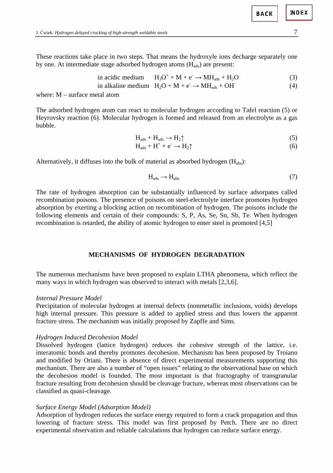
J. Ćwiek: Hydrogen delayed cracking of high-strength weldable steels 7
These reactions take place in two steps. That means the hydroxyle ions decharge separately one by one. At intermediate stage adsorbed hydrogen atoms (Hads) are present:
in acidic medium H3O+ + M + e- → MHads + H2O (3) in alkaline medium H2O + M + e- → MHads + OH- (4)
where: M – surface metal atom The adsorbed hydrogen atom can react to molecular hydrogen according to Tafel reaction (5) or Heyrovsky reaction (6). Molecular hydrogen is formed and released from an electrolyte as a gas bubble.
Hads + Hads → H2↑ (5) Hads + H+ + e- → H2↑ (6) Alternatively, it diffuses into the bulk of material as absorbed hydrogen (Habs): Hads → Habs (7) The rate of hydrogen absorption can be substantially influenced by surface adsorpates called recombination poisons. The presence of poisons on steel-electrolyte interface promotes hydrogen absorption by exerting a blocking action on recombination of hydrogen. The poisons include the following elements and certain of their compounds: S, P, As, Se, Sn, Sb, Te. When hydrogen recombination is retarded, the ability of atomic hydrogen to enter steel is promoted [4,5]
MECHANISMS OF HYDROGEN DEGRADATION
The numerous mechanisms have been proposed to explain LTHA phenomena, which reflect the many ways in which hydrogen was observed to interact with metals [2,3,6]. Internal Pressure Model Precipitation of molecular hydrogen at internal defects (nonmetallic inclusions, voids) develops high internal pressure. This pressure is added to applied stress and thus lowers the apparent fracture stress. The mechanism was initially proposed by Zapffe and Sims. Hydrogen Induced Decohesion Model Dissolved hydrogen (lattice hydrogen) reduces the cohesive strength of the lattice, i.e. interatomic bonds and thereby promotes decohesion. Mechanism has been proposed by Troiano and modified by Oriani. There is absence of direct experimental measurements supporting this mechanism. There are also a number of “open issues” relating to the observational base on which the decohesion model is founded. The most important is that fractography of transgranular fracture resulting from decohesion should be cleavage fracture, whereas most observations can be classified as quasi-cleavage. Surface Energy Model (Adsorption Model) Adsorption of hydrogen reduces the surface energy required to form a crack propagation and thus lowering of fracture stress. This model was first proposed by Petch. There are no direct experimental observation and reliable calculations that hydrogen can reduce surface energy.

8 ADVANCES IN MATERIALS SCIENCE, Vol. 5, No. 1 (6), March 2005
Adsorption Induced Localised Slip Model Adsorption of environmental hydrogen atoms at crack tip results in weakening of interatomic bonds facilitating dislocation injection from a crack tip and then crack growth by slip and formation of microvoids. Mechanism has been proposed by Lynch. Hydrogen Enhanced Localised Plasticity (HELP) Model Absorption of hydrogen and its solid solution facilitates dislocation motion or generation, or both. Mechanism first proposed by Beachem and developed by Birnbaum et al. In many cases, the definition of hydrogen-related fracture as a “brittle fracture” is based on loss of macroscopic ductility (e.g. decrease of reduction in area and elongation). Careful fractographic examinations with high resolution technique shows, that hydrogen embrittlement of steel is associated with locally enhanced plasticity at the crack tip. Distribution of hydrogen can be highly nonuniform under an applied stress. Thus, locally the flow stress can be reduced, resulting in localised deformation that leads to highly localised failure by ductile processes, while the macroscopic deformation remains small. In-situ transmission electron microscope (TEM) observations of deformation and fracture of samples in environmental cell gave evidence that HELP model is a viable failure mechanism for a large number of pure metals and alloys: Fe, austenitic stainless steels, Ni, Al, α-Ti alloys. The effect of hydrogen on fracture in TEM environmental cell was studied for static crack under stress. On adding hydrogen gas to the cell, dislocation sources began to operate and dislocations began to increase their velocities. Removal of hydrogen from the cell resulted in cessation of dislocation motion. This cycle could be repeated many times. Corrosion Enhanced Plasticity (CEP) Model This model takes into account the generation of vacancies due to localised anodic dissolution and hydrogen evolution by cathodic reaction at the freshly depasivated crack tip. Thus, corrosion produces enhanced localised plasticity. The activated dislocations along slip bands form pile-ups interacting with obstacles. The resulting high local stress can initiate cracking. Model was developed by Magnin et al. This model is applied mainly to passive metals and alloys like stainless steels, nickel and its alloys. Hydrogen Rich Phases Model This model implies formation of hydrogen rich phases – hydrides, whose mechanical properties differ from those of matrix. Cracking could proceed by the formation and cracking of brittle hydride near the crack tip. Model was generalised by Westlake. For iron it has been found that no stable hydrides are formed up to hydrogen pressure of 2 GPa, so this model is not valid for steel hydrogen degradation.
MATERIAL AND EXPERIMENTAL PROCEDURE
A quenched and tempered plate 12 mm in thickness made of 14HNMBCu steel grade – S690Q grade with minimum yield strength of 690 MPa according to PN-EN 10137-2 [7] was used. The chemical compositions of the tested steel is given in Table 1. Submerged arc welded (SAW) and shielded metal arc welded (SMAW) joints were prepared. Mechanical properties obtained from a tensile test performed according to PN-EN 10002-1 [8] are presented in Table 2.

J. Ćwiek: Hydrogen delayed cracking of high-strength weldable steels 9
Table 1. Chemical composition of steel plate (control analyse)
Chemical composition, wt % Steel grade C Si Mn P S Cr Ni Mo Cu Ti V Al B
14HNMBCu 0.13 0.21 0.83 0.001 0.005 0.43 0.74 0.40 0.25 0.004 0.05 0.02 0.002
Table 2. Mechanical properties (transverse direction) of steel plate and its welded joints
Steel grade Samples Yield Strength
MPa Tensile Strength
MPa Elongation
% Reduction in Area
%
Base metal 908 935 8.7 47.4
SAW 601 631 7.2 55.5
14HNMBCu SMAW 599 687 6.6 61.9
Microstructures of the steel plate and welded joints were examined with the use of the optical microscope LEICA MEF4M according to PN-EN 1321 [9]. Microstructure of the steels composed of low carbon tempered lath martensite. Microstructure of the welded joint was typical for extra high-strength low-alloy steel. Weld metal microstructure composed of acicular ferrite and bainite. Microstructure of regions of HAZ (coarse grained region, fine grained region, and intercritical region) consisted low carbon lath martensite with various prior austenite grains size respectively. In order to estimate the degree of hydrogen degradation of tested steel and its welded joints, the constant load test on round notched specimens 6 mm in diameter was conducted along with PN-EN 2832 [10]. The gauge length of samples was 50 mm. The geometry of a notch is presented in Fig. 1. For samples with welded joints, welds were placed in the centre of specimens and a notch was cut in the fusion line. All specimens were cut along the transverse direction. Tests were performed at room temperature in standard artificial sea-water grade A, prepared consistent with PN-66/C-06502 [11]. Tests in sea-water were conducted at open circuit potential and under cathodic polarisation with constant current densities chosen from the polarisation curves. The following cathodic currents were applied: 0.1; 1; 10 mA/cm2 giving cathodic hydrogen charging of specimens during a test. Minimum two samples were used for each test parameters. The constant load test was carried out with the use of a lever machine with leverage 25:1 and maximum load capacity of 20 kN. The machine was equipped with the environmental cell with platinum polarisation electrode (Fig. 2). Time to failure of specimen was recorded. When a sample did not fail within 200 hours, the test was finished and result was signed as negative (-) according to PN-EN 2832. When a sample failed premature (before 200 hours), the result was signed as positive (+). Presence or lack of delayed failure of samples was chosen as measures of hydrogen degradation – susceptibility or resistance to delayed hydrogen cracking. Applied loads were calculated as a ratio of actual force (F) to the maximum force (Fm) obtained from a tensile test. Tensile test was performed at slow strain rate 10-6 s-1 in air using the same notched samples as for the constant load test. Results of the constant load test are presented in Tables 3-5. Fracture surfaces of failed samples were investigated with the use of the scanning electron microscope (SEM) PHILIPS XL30 to determine mode of fracture. Results of fractographic observations are shown in Fig. 3-4.

10 ADVANCES IN MATERIALS SCIENCE, Vol. 5, No. 1 (6), March 2005
Fig. 1. The notch geometry of a specimen
Fig. 2. View of the lever machine with the environmental cell
Table 3. Resistance to delayed hydrogen cracking of 14HNMBCu steel under a constant load test in sea water
Applied relative load F/FmCathodic current density mA/cm2 0.84 0.88 0.92 0.96
open circuit potential – – – +
0,1 – – + +
1 – – + +
10 – + + + – means no failure within 200 hours and resistance to delayed hydrogen cracking + means premature failure and susceptibility to delayed hydrogen cracking

J. Ćwiek: Hydrogen delayed cracking of high-strength weldable steels 11
Table 4. Resistance to delayed hydrogen cracking of welded joints (SAW) of 14HNMBCu steel under a constant load test in sea water
Applied relative load F/FmCathodic current density mA/cm2 0.84 0.88 0.92 0.96
open circuit potential – – – +
0,1 – – – +
1 – – + +
10 – – + + – means no failure within 200 hours and resistance to delayed hydrogen cracking + means premature failure and susceptibility to delayed hydrogen cracking
Table 5. Resistance to delayed hydrogen cracking of welded joints (SMAW) of 14HNMBCu steel under a constant load test in sea water
Applied relative load F/FmCathodic current density mA/cm2 0.84 0.88 0.92 0.96
open circuit potential – – – +
0,1 – – + +
1 – + + +
10 – + + +
– means no failure within 200 hours and resistance to delayed hydrogen cracking + means premature failure and susceptibility to delayed hydrogen cracking
Fig. 3. SEM image of fracture surfaces of 14HNMBCu steel after a constant load test in seawater. Relative load F/Fm = 0.96, open circuit potential

12 ADVANCES IN MATERIALS SCIENCE, Vol. 5, No. 1 (6), March 2005
Fig. 4. SEM image of fracture surfaces of welded joint (SAW) of 14HNMBCu steel after a constant load test in seawater. Relative load F/Fm = 0.96, open circuit potential
DISCUSSION
Tables 3-5 present critical relative loads and cathodic current densities at which delayed hydrogen cracking occurs in 14HNMBCu steel and its welded joints. As it can be seen tested steel and its welded joints have high resistance to hydrogen degradation in seawater both at open circuit potential and cathodic polarisation. Additionally, high critical load at the level of 0,96 at open circuit potential shows that tested steel and its welded joints are not susceptible to pitting corrosion in seawater environment. Submerged arc welded joint (SAW) has higher resistance to hydrogen degradation than base metal. However, shielded metal arc welded (SMAW) joint is more susceptible than base metal. Differences in resistance to hydrogen delayed cracking could be explained by variations of microstructure present in steel and welded joints. The various microstructures result in different mechanical properties (strength, hardness) and different susceptibility to hydrogen degradation. Fractographic observations of failed samples revealed mixed fracture mode composed of ductile and quasicleavage fracture. Obtained results of constant load test and fractographic observations suggest that hydrogen-enhanced localised plasticity (HELP) model is more applicable mechanism of hydrogen degradation than others. Hydrogen delayed cracking occurs at load level as high as flow stress (yield strength) of tested steel and its welded joints. Ductile and quasicleavage fracture modes support suggestion that hydrogen interacts with dislocations and increase their mobility, and at the same time hydrogen is transported by mobile dislocations.

J. Ćwiek: Hydrogen delayed cracking of high-strength weldable steels 13
CONCLUSIONS
• High-strength low-alloy steel 14HNMBCu grade S690Q and its welded joints have high resistance to hydrogen delayed cracking in seawater environment.
• Submerged arc welded joint (SAW) has higher resistance to hydrogen degradation than base metal. However, shielded metal arc welded (SMAW) joint is more susceptible than base metal.
• Under the critical load and cathodic current density the notched samples premature failed. Hydrogen-enhanced localised plasticity (HELP) model is a viable degradation mechanism.
REFERENCES
1. Banerjee K., Chatterjee U. K., Hydrogen Embrittlement of a HSLA-100 Steel in Seawater, ISIJ Int. Vol. 39, No 1, 1999, pp. 47-55.
2. Zieliński A., Hydrogen Degradation of Nonferrus Metals and Alloys (in Polish), Gdańsk Scientific Society, Gdańsk 1999.
3. Timmins P. F., Solutions to Hydrogen Attack in Steels, AMS Int., 1997. 4. Śmiałowski M., Hydrogen in Steels, Pergamon Press, Oxford 1962. 5. Oriani R. A., Hirth J. P., Smialowski M. (ed.), Hydrogen Degradation of Ferrous Alloys, Noyes Publ.
Park, Ridge, USA, 1985. 6. Birnbaum H. K., Mechanisms of Hydrogen-Related Fracture of Metals, Proc. Int. Conf. „Environment-
Induced Cracking of Metals”, National Association of Corrosion Engineers, Houston, Texas, USA, 1988, pp. 21-29.
7. PN-EN 10137-2:2000. Plates and wide flats made of high yield strength structural steels in the quenched and tempered or precipitation hardened conditions – Delivery conditions for quenched and tempered steels.
8. PN-EN 10002-1:1998 Metallic materiale – Tensile testing – Part 1 – Metod of test at ambitne temperature.
9. PN-EN 1321:2000 Destructive tests on welds in metallic materialls – Macroscopic and microscopic examination of welds.
10. PN-EN 2832:2001 Aerospace series – Hydrogen embrittlement of steels – Notched specimen test. 11. PN-66/C-06502. Substitute sea water.
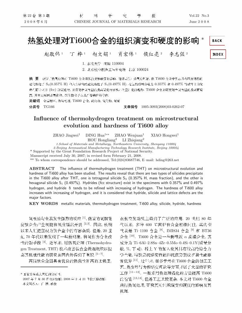
22 3 Vol.22 No.3
2 0 0 8 6 CHINESE JOURNAL OF MATERIALS RESEARCH June 2 0 0 8
Ti600 ∗
1 1 1 1 2 2
1. 110004
2. Æ 100024
Ti600 . : , Ti600 S3(0.357% H) S1(0.497% H). Æ 0.357% 0.497% (fcc) , . Ti600 , .
Æ , , Ti600 , , , !" TG166 #$" 1005-3093(2008)03-0262-07
Influence of thermohydrogen treatment on microstructuralevolution and hardness of Ti600 alloy
ZHAO Jingwei1 DING Hua1∗∗ ZHAO Wenjuan1 XIAO Hongwei1
HOU Hongliang2 LI Zhiqiang2
1.School of Materials and Metallurgy, Northeastern University, Shenyang 1100042.Beijing Aeronautical Manufacturing Technology Research Institute, Beijing 100024
* Supported by the Great Foundation Research Project of National Security.Manuscript received July 30, 2007; in revised form February 21, 2008.** To whom correspondence should be addressed, Tel:(024)83687746, E–mail: [email protected]
ABSTRACT The influence of thermohydrogen treatment (THT) on microstructural evolution andhardness of Ti600 alloy has been studied. The results reveal that there are two types of silicides precipitatein the Ti600 alloy after THT, one is tetragonal silicide S3 (0.357% H, mass fraction), and the other ishexagonal silicide S1 (0.497%). Hydrides (fcc structure) exist in the specimens with 0.357% and 0.497%
hydrogen, and hydride tends to be refined with increasing of hydrogen. The hardness of Ti600 alloyincreases with increasing of hydrogen, and it is considered that hydride, silicide and lattice defects are themajor factors.
KEY WORDS metallic materials, thermohydrogen treatment, Ti600 alloy, silicide, hydride, hardness
[1],
[2,3]. ,
!" #$. !, 20 "
! 70 #! $%, "&# !" [4]. $#, '%#& (Thermohydro-
gen Treatment, THT)%"#'&() #'(($ *))%$%$+ [5−7].
'&*",*% '&',
* +,(+-)-*',.
2007 - 7 . 30 .(+,.; 2008 - 2 . 21 .(+)/..
-*/+0: . /, 0,
*12/(1$%$30'. 20 "! 80 #
! , 10 600 2'&-4.", (3/
!4! Ti–1100 [8]5IMI834 [9] BT36
[10]. Ti600 !%0/$ α '&, (
67 Ti–6Al–2.8Sn–4Zr–0.5Mo–0.4Si–0.1Y($70, %, 12). 34 Y 52(*"6'13 , 58!749 758692 :;,Æ [11]. $#,:13* Ti6005;;
45%97849&6<=72$>;& [11−13]. %?@'%#&<=A#' Ti600
[13,14], !;4&6=#. B9C Ti600
>8%#&, (C():95'6;?((&.
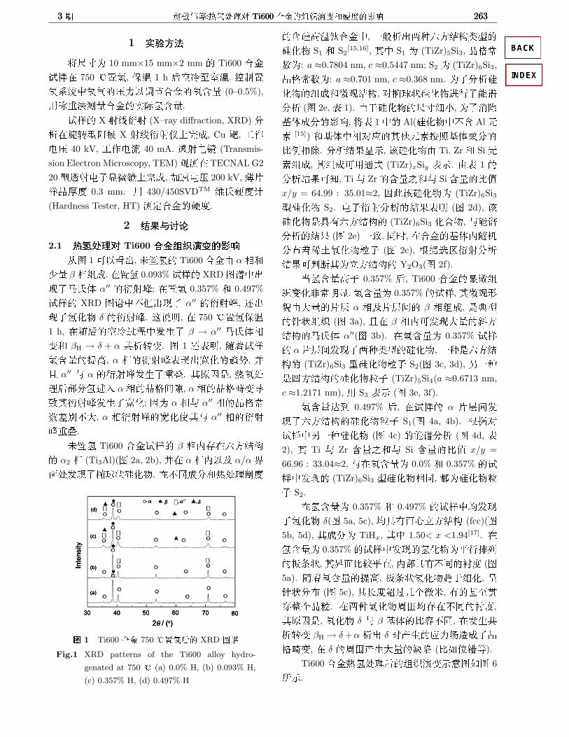
3 7@<D:89E:F Ti600 ABG89=HC:IG;> 2633 7@<D:89E:F Ti600 ABG89=HC:IG;> 2633 7@<D:89E:F Ti600 ABG89=HC:IG;> 263
1 %&'("JK 10 mm×15 mm×2 mm Ti600
?@* 750 2<, L& 1 h D2;=A&. E><BC!<D3 MFG (0–0.5%),
'N+AO=HG.
?@ X >EF> (X–ray diffraction, XRD)7
G*H?/I X >EF>@1J6, Cu P, ;&QD 40 kV, ;&Q? 40 mA. K>QI (Transmis-
sion Electron Microscopy, TEM)&O* TECNAL G2
20/K>QALI1J6, 5MQD 200 kV,R@
@AJ' 0.3 mm. ' 430/450SVDTM NB5'K(Hardness Tester, HT) OS5'.
2 )*+,-2.1 ./B0C Ti600 12345DE67
TO 1L MU,P< Ti600F α-
C β -(6.*< 0.093%?@ XRDOD!U$EBQ α′′ F>N; *< 0.357% 0.497%
?@ XRD OD!V U$ α′′ F>N, OU
$<R δ F>N. GSF, * 750 2<L&1 h, *TD2;PW!$ β → α′′ EBQ-
9 βH → δ + α QG?9. O 1 O4F, TH?@G#', α -F>N4UR<GH, X
I α′′ α F>N$+Y. (I!, %#
&DZ7>2 α-STUU, α-STV9[
(F>N$R<; α - α′′ -ST;
0\8V>, α -F>NR<( α′′ -F>
N+Y.
P< Ti600 ?@ β -)]*J=WX α2 - (Ti3Al)(O 2a, 2b), X* α-) ? α/α Y
7#$VKJZ<R. *V267%#&>'
8 1 Ti600 AB 750 ^K9[G XRD WL
Fig.1 XRD patterns of the Ti600 alloy hydro-
genated at 750 ^ (a) 0.0% H, (b) 0.093% H,
(c) 0.357% H, (d) 0.497% H
GZ'&!, %?GUM0J=WXN/Z<R S1 S2
[15,16], (! S1 (TiZr)5Si3, ST;
0: a ≈0.7804 nm, c ≈0.5447 nm; S2 (TiZr)6Si3,
ST;0: a ≈0.701 nm, c ≈0.368 nm. $7GZ
<R(6&WX, CVKJZ<R>8$D7G (O 2e,4 1). FLZ<RJKXY,$Z_
\Q676;,"4 1! Al(Z<R!VG AlM[ [15]) \Q!-C(\M[`N\Q67&O]_. 7GW^LP, _Z<RF Ti, Zr SiM[(6, ((6L']Q (TiZr)xSiy 4P. F4 1
7GW^LO, Ti ZrGP SiG&Qx/y = 64.99 : 35.01≈2, _Z<R (TiZr)6Si3/Z<R S2. QAF>7GW^4F (O 2d), _
Z<R!*"J=WX (TiZr)6Si3 <R, D7GW^ (O 2e) %. 2R, *\Q)T(7aH34^<RSA (O 2c), `a_TF>7G
W^LUb(V=WX Y2O3(O 2f).
cG'L 0.357% D, Ti600 L()9<:;FL.G 0.357%?@,(&7
WF>@d α -?@dU β -(6, !3/
RJ() (O 3a), I* β -)L>`=
WXEBQ α′′(O 3b). *G 0.357% ?@
α@dU$M0N/Z<R, %0!J=WX (TiZr)6Si3 /Z<RSA S2(O 3c, 3d), X%0!a=WXZ<RSA (TiZr)5Si4(a ≈0.6713 nm,
c ≈1.2171 nm), ' S3 4P (O 3e, 3f).
Ge% 0.497% D, *?@ α @dU
$J=WXZ<RSA S1(O 4a, 4b). `aC
?@!X%0Z<R (O 4c) D7G (O 4d, 4
2), ( Ti Zr GP Si G&Q x/y =
66.96 : 33.04≈2, *G 0.0% 0.357% ?
@! (TiZr)6Si3 /Z<R-2, fZ<RS
A S2.
*G 0.357% 0.497% ?@!b$<R δ(O 5a, 5c), b*"7bV=WX (fcc)(O
5b, 5d), (67 TiHx, (! 1.50< x <1.94[17]. *G 0.357%?@!<RY8Z[gcJ,(Y7&6YS, )Z*"V2h' (O
5a). THG#', gcJ<RGLX<, i
RJ7a (O 5c), ('jPcd\, "]=ekTdSS. *M0<RUdb]*V2h',
(I!, <R δ β \Q&^V2, *QG?9 βH → δ + α GU δ R3lV6$STV9, * δ Ud>_e (&`fm<).
Ti600%#&D():9PWO`O 6
gP.

264 22264 22264 22
8 2 9fah 0.0% b Ti600 ABG TEM XcFig.2 TEM micrographs of Ti600 alloy with 0.0% hydrogen. (a) α2; (b) SAED pattern of α2; (c) S2
and Y2O3; (d) SAED pattern of S2; (e) EDX spectrum of S2; (f) SAED pattern of Y2O3
Y 1 9fah 0.0% b Ti600 ABZghiGdLnjCk[ijTable 1 The compositions and modified compositions of silicide precipitated from Ti600 alloy with
0.0% hydrogen (\]lnl, %)
Al Ti Zr Si Sn x/y
Analysed result 1.52 38.08 25.25 34.12 1.03 —
Modified result — 39.08 25.91 35.01 — 1.86
2.2 ./B067 Ti600 129:;<=^E>0
*! H+ 7Q]* [18], >2_>$eAPUo3, mf$IAUk&',IA`9g3h$IA9g3$%#'. C Ti600 >8%#&, Ti
Zr *!9g3_, p>$ (TiZr)xSiy /
Z<R*\Q!7l>, 5M$Z<RG
U. * 750 2>8%#&, c?@G6q
(0.357%H) R, FL Ti Zr 9gOV:r7, *\Q!aGU$a=WX (TiZr)5Si4 /Z<R S3.
cGe% 0.497% H R, Ti Zr 9g3_
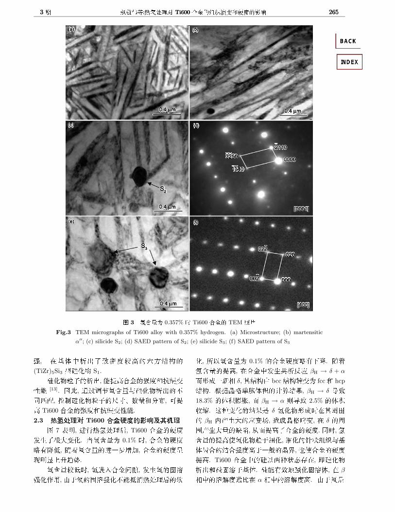
3 7@<D:89E:F Ti600 ABG89=HC:IG;> 2653 7@<D:89E:F Ti600 ABG89=HC:IG;> 2653 7@<D:89E:F Ti600 ABG89=HC:IG;> 265
8 3 9fah 0.357% b Ti600 ABG TEM XcFig.3 TEM micrographs of Ti600 alloy with 0.357% hydrogen. (a) Microstructure; (b) martensitic
α′′; (c) silicide S2; (d) SAED pattern of S2; (e) silicide S3; (f) SAED pattern of S3
, *\Q!GU$i'6'J=WX(TiZr)5Si3 /Z<R S1.
Z<RSAGU, #''749
[13]. , ]PMFGZ<RGUV2jk, E>Z<RSAJK507a, L#
' Ti600 '749 .
2.3 ./B0C Ti600 12?bE67@A>0O 7 4F, >8%#&D, Ti600 5'
$:>9<. cG 0.1% R, 5'l"mq, THG>%s_5, 5'iFL1mGH.
G6qR, >2UU, nh
<&',FLnh<VtZ%#&Dn
<, g G 0.1% 5'l"1m. THG#', *!QG βH → δ + α
u76%- δ,(WXF bccWX?9 fcc hcp
WX. `aSTvÆQoKnW^, βH → δ [18.3% Qooc, u βH → α d[ 2.5% Qo
op. G09<W^! δ <R76R*(Ud βH )>9l, V6STV9, * δ Ud>_e, Tu#'$5'. 2R,
G#'<RGLX<, X<RJ()\QwW''L%?SY, e5'#'. Ti600 !Z M0Jq]*, pZ<R
GUZnhL\Q. Z"rx<nhQ, * β
-!hq'f&* α -!hq''. FL!
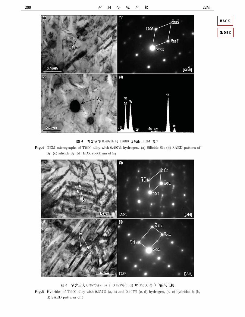
266 22266 22266 22
8 4 9fah 0.497% b Ti600 ABG TEM XcFig.4 TEM micrographs of Ti600 alloy with 0.497% hydrogen. (a) Silicide S1; (b) SAED pattern of
S1; (c) silicide S2; (d) EDX spectrum of S2
8 5 9fah 0.357%(a, b) C 0.497%(c, d) b Ti600 ABZG9hiFig.5 Hydrides of Ti600 alloy with 0.357% (a, b) and 0.497% (c, d) hydrogen, (a, c) hydrides δ; (b,
d) SAED patterns of δ

3 7@<D:89E:F Ti600 ABG89=HC:IG;> 2673 7@<D:89E:F Ti600 ABG89=HC:IG;> 2673 7@<D:89E:F Ti600 ABG89=HC:IG;> 267
Y 2 9fah 0.497% b Ti600 ABZghiGdLnjCk[ijTable 2 The compositions and modified compositions of silicide precipitated from Ti600 alloy with
0.497% hydrogen (\]lnl, %)
Al Ti Zr Si Sn x/y
Analysed result 1.55 41.41 23.91 32.23 0.91 —
Modified result — 42.45 24.51 33.04 — 2.03
8 6 Ti600 AB89E:[G89=HpgWFig.6 Microstructural evolution of Ti600 alloy after
THT
8 7 Ti600 AB:Ih9faGrsFig.7 Plot of hardness vs hydrogen contents of Ti600
alloy
β tSM[, C Ti600 >8%#&D, β -
GTHG#'u#', * β -!nhZIA_5. *\Q)nhZL76<u, <u
Cfmi/"jy&', >%s#'$5'. 2R, THG#', *\Q)ksGUS3(0.357% H), S1(0.497% H)<Z<RSA.&\Q<-, Z<RCfm*":zl&', Z<R
qg<!#'5'm%+nI. XI, *Z<RGU2R, >fmroLZ<RSA#,
C\Q5'#'e"6>&'. C Ti600>
8%#&D;sPW! β → α′′ EBQ-
9,*EBQ-9PW!>ST_ee\
Q5'>%s#'.
3 ) -%#&#'$ Ti5Zr * Ti600 !9g
3, p> (TiZr)xSiy /Z<R7l>, 5M
Z<RSAGU. cG6q (0.357% H) R,
*\Q!GUa=WXZ<RSA S3, cG
e% 0.497% R, *\QGU$i'6'J=WXZ<RSA S1. *G 0.357% 0.497%
!b$ fcc WX<R δ. G
0.357% R, <RigcJ, G#'<R
GLX<; *G6' (0.497% H) R, RJ<R'jPcd\. %#&Lo#' Ti600
5', (pnI!<R δ5Z<RSA ?ST_e]*.
q B # C1 R.J.Elias, H.L.Corso, J.L.Gervasoni, Fundamental aspects
of the Ti-H system theoretical and experimental be-
haviour, International Journal of Hydrogen Energy, 27,
91(2002)
2 G.M.Pressouyre, Trap theory of hydrogen embrittlement,
Acta Metallurgica, 28(7), 895(1980)
3 C.L.Briant, Z.F.Wang, N.Chollocoop, Hydrogen embrit-
tlement of commercial purity titanium, Corrosion Science,
44, 1875(2002)
4 B.A.Kolachev, A.V.Malkov, I.A.Vorobyov, The effect of
hydrogen alloying on workability of titanium alloys. in:
Titanium92 :Science and Technology, edited by F.
H.Froes and I. L. Caplan, 861(1993)
5 O.N.Senkov, F.H.Froes, Thermohydrogen processing of ti-
tanium alloys, Int. J. Hydrogen Energy, 24, 565(1999)
6 D.Eliezer, N.Eliaz, O.N.Senkov, F.H.Froes, Positive effects
of hydrogen in metals, Materials Science and Engineering
A, 280, 220(2000)
7 HOU Hongliang, LI Zhiqiang, WANG Yajun, GUAN
Qiao, Technology of hydrogen treatment for titanium alloy
and its application prospect, Chinese Journal of Nonfer-
rous Metal, 13(3), 533(2003)
(tut, urv, vwv, w w, sxxtuxy, +yy|, 13(3), 533(2003))
8 D.Weinem, J.Kumpfert, M.Peters, W.A.Kaysser, Process-
ing window of the near-α-titanium alloy TIMETAL-1100
to produce a fine-grained β-structure, Materials Science
and Engineering A, 206(1), 55(1996)

268 22268 22268 22
9 R.W.Evans, R.J.Hull, B.Wilshire, The effects of alpha-
case formation on the creep fracture properties of the high-
temperature titanium alloy IMI834, Journal of Materials
Processing Technology, 56(1-4), 492(1996)
10 V.Tetyukhin, I.Levin, V.Ilyenko, Heatresistant titanium
alloys with enhanced, heat resistance, thermal stabil-
ity, in: Titanium95: Science and Technology, edited
by P.A.Blenkinsop, W.J.Evans, H.M.Flower (UK, Cam-
bridge, The University Press, 1996) p.2430
11 HONG Quan, QI Yunlian, ZHAO Yongqing, YANG Guan-
jun, Effect of rolling process on microstructure and prop-
erties of Ti600 alloy plates, Rare Metal Materials and En-
gineering, 34(8), 1334(2005)
(z z, vÆ, wx|, zv, |y Ti600 , |z~, 34(8), 1334(2005))
12 QI Yunlian, Behavior and Processing Map of High Tem-
perature Titanium Alloy Ti600 (Northwestern Polytech-
nical University, Xi′an, 2007)
(vÆ, Ti600 DEFGHIJKLMNOPQRST ()y, (, 2007))
13 ZHANG Zhenqi, HONG Quan, YANG Guanjun, LUO
Guozhen, Research on microstructure of Ti600 alloy after
creep test, Journal of Materials Engineering, 10, 18(2000)
(|~, z z, zv, ~+, Ti600 ~sx , ~, 10, 18(2000))
14 ZHANG Zhenqi, LUO Guozhen, HONG Quan, YANG
Guanjun, Microstructures observation and mechanical
properties test of near alpha titanium alloy Ti600, Journal
of Aeronautical Materials, 19(4), 6(1999)
(|~, ~+, z z, zv, Ti600 z, ~y|, 19(4), 6(1999))
15 C.Ramachandra, A.K.Singh, G.M.K.Sarma, Microstruc-
tural characterisation of near-α titanium alloy Ti-6Al-4Sn-
4Zr-0.70Nb-0.50Mo-0.40Si, Metallurgical Transactions A,
24A, 1273(1993)
16 A.K.Singh, C.Ramachandra, Characterization of silicides
in high-temperature titanium alloys, Journal of Materials
Science, 32, 229(1997)
17 D.V.Schur, S.Yu. Zaginaichenko, Phase transformations
in titanium hydrides, Int. J. Hydrogen Energy, 21(11-12),
1121(1996)
18 R.A.Oriani, P.H Joseoguc, Equilibrium aspects of
hydrogen-induced cracking of steels, Acta Mettallurgica,
22, 1065(1974)

Hydrogen Permeability and Integrity of Hydrogen Transfer PipelinesS. S. Babu, M. Murugananth, Z. Feng, and M. L. SantellaMaterials Joining Group, Oak Ridge National Laboratory, Oak Ridge, TennesseeM. Quintana and P. NicholsonLincoln Electric Company, Cleveland, Ohio
BackgroundHydrogen production and supply methodologies are important for hydrogen based transportationinfrastructure. Transportation of hydrogen from reforming plants to dispensers includes liquid hydrogentransport through trucks and transportation of gaseous hydrogen through high-pressure pipelines. Arecent case study of hydrogen infrastructure development indicated that transfer of gaseous hydrogencould be a economical option if the flow rates of hydrogen can be increased from 1 million standard cubicfeet (scf) per day to 20 million scf per day in a 3 ft. diameter pipeline rated for 1000 psi pressure [1]. It isimportant to note that the flow rate is related to pressure differentials and the cross-sectional area of thepipes. Therefore, one could envision reduction of wall thickness and / or increase of pressure differentialto increase the flow rates in these pipes [2]. Under these circumstances, current mild-steel pipelineinfrastructure may prove inadequate and may require high strength steels.For example, one may consider replacing Grade A (API 5L specification) steels with Grade X-52 orGrade X-80 type steels. The X-52 and X-80 steels have higher manganese concentrations (1.3 to 1.8wt.% Mn) compared to Grade A (0.3 to 0.6 wt.% wt.% Mn). Due to increased manganese concentrations,these steels can readily form hard martensite under rapid weld cooling conditions in the heat-affected-zone (HAZ) region of the weld. If a filler wire with identical composition was used to join these steels,bainite and martensite microstructures may form in the weld metal (WM) region. Moreover, traditionalfusion welding processes such as submerged arc welding and manual metal arc welding also lead to highresidual stresses in the welded region. It is well known that with the presence of hard microstructure andhigh residual stress, the welds will be prone to hydrogen induced cracking (HIC) [3]. The HIC isenhanced with the presence of diffusible hydrogen. For many decades, the above problem has beenaddressed by careful choice of filler metal compositions to reduce the source of hydrogen and byemploying post-weld heat treatment to remove hydrogen. However, the application of high strength steelwelded pipes to hydrogen transport leads to new challenge as illustrated below.
In traditional piping applications of natural gas, the welded high strength steel piping is not exposed tovery high hydrogen pressures and therefore hydrogen pick up during service is not a major issue. In thepresent case, the inner surfaces of tubes are exposed to pure hydrogen at large pressures where as theouter surfaces of tubes are exposed to atmospheric pressure with low-partial pressure of hydrogen. Thisleads to a large chemical potential gradient for hydrogen diffusion from inner surface to outer surface.This will lead to a flux of hydrogen or permeation through the steel given by Fick’s first law [4, 5].
€
J∞ = −DΔcΔx
, (1)
where the
€
J∞ is the steady state flux of hydrogen, D is the diffusivity (1 X 10⁻⁵ cm-2s-1), and
€
Δc is theconcentration difference over
€
Δx distance. Using equation (1), and by assuming a concentrationdifference of 1 wt.PPM a steady state hydrogen flux is estimated to be 960 pL cm-2s-1. In hydrogentransfer applications; the above flux may be increased by many orders of magnitude. Under theseconditions, if the underlying microstructure in welded region is very hard and with the presence ofresidual stresses, the welded joints may exhibit HIC after certain service time. As a result, there is a needfor designing base metal composition (modified X-52 or X-80 compositions), filler metal composition

Fig. 1 Schematic diagram shows the hydrogen transport fromthe interior of the pipe through a steel microstructure andescape to the atmosphere. The hydrogen trapping sites (redcircles) and microstructure (background image from a weld)need to be designed for welds with good integrity forhydrogen transport.
(matching composition with hydrogen traps), welding process (to minimize the heat-affected-zone), andprocess parameters (minimize the residual stresses) for optimum performance of reduced HIC risk as wellas reduced hydrogen permeability.
Research ApproachThe goals of the research are to minimize the HIC in the base metal, HAZ, and WM regions whilereducing the steady state flux through the pipe. To reach this challenging goal, the proposed research willleverage extensive knowledge base that is available on hydrogen embrittlement phenomena and weldmicrostructure development in steels. With this knowledge, innovative process-material combinationswill be derived for high strength steel piping for high-pressure hydrogen transport. Three proposedresearch approaches are briefly discussed below.
Hydrogen Management: The firstphase of the research must considerthe hydrogen solubility into steel. Thehydrogen diffuses into steel in theform of monatomic hydrogen [see Fig.1]. On entering the steel, the hydrogenmay be present in two forms (1)trapped at sites like inclusions andgrain/phase boundaries and (2)diffusible form in the interstitialpositions within the ferrite lattice [6].The HIC is mostly caused by thediffusible hydrogen. Current researchin this area focuses on increasingtrapped hydrogen by increasing thenumber density of trapping sites. [7, 8,9, 10]. These trapping sites can be either reversible or irreversible [11, 12]. Recent research hascorrelated the weakly binding trapping sites to environmental degradation [13]. Moreover, the presenceof elastic stresses appears to increase the hydrogen permeation and plastic deformation appears to reducethe hydrogen permeation [14]. This reduction is related increased to dislocation density that acts astrapping sites for hydrogen. The above research shows that the hydrogen management can be achievedby careful control of microstructure in steels. In this ORNL will collaborate with Lincoln Electric onfiller metal design for the use in pipeline industries. This design will be focused on the various aspects ofhydrogen management and modifying the dynamic microstructure evolution. In this task, conventionalfusion welding processes including submerged arc welding, manual metal arc welding, gas metal arcwelding and flux cored arc welding processes will be considered and one of the ideal process will beselected as a candidate based on initial scoping studies.
Weld Stress Management: In the second phase, stresses that are present in the weld metal region.Recently, it has been shown that in the presence of stress fields around the crack tip, the presence ofdiffusible hydrogen. Recent in-situ TEM analyses have shown that diffusible hydrogen increases thevelocity of dislocations resulting in localized plasticity that leads to embrittlement [15]. It is well knownthat welding leads to large residual stresses and prolonged exposure to hydrogen rich atmosphere maylead to localized plasticity initiation even without any external load. Therefore, it is imperative that weldsare designed such a way that they do not lead to catastrophic cracking under service conditions. Thermalstress management in welds is an active research area and the existing knowledge base at ORNL will beleveraged in this research. State of the art thermo-mechanical-metallurgical models will be developedthat consider the interactions between thermal fields, dynamic microstructure evolution and effect oftemperature and microstructure on the thermophysical properties [16]. In addition, new fusion welding

processes, such as laser-assisted arc welding processes, will be considered to minimize the heat-affected-zone and to refine the weld metal microstructure [17].
Interface Barrier Design: In the final phase, it is possible to reduce the hydrogen concentration gradientby physically separating the steel and hydrogen rich atmosphere. This approach is currently being used inthe oil pipelines for avoiding the corrosion of exterior surfaces of pipelines by coating with epoxy resin.Similar approaches can be used on the interior of the pipelines to retard the absorption of hydrogen intothe steel, thus reducing the concentration gradient and peak concentration.Evaluation of Welds and Base Material: The welds produced in this study will be compared with theperformance of X-52 or X-80 line pipe steel. The evaluation will focus on microstructuralcharacterization, hydrogen permeability, toughness (under both hydrogen charged and unchargedcondition in both HAZ and WM region), and residual stress measurement. This task will utilize extensivecharacterization facilities that are available at ORNL.
DeliverablesAt the end of three-year research effort, this research will lead to following deliverables:
(1) A suitable welding process – process parameter – filler wire – physical interface barrier designfor welding high strength steel pipe lines
(2) A fundamental understanding of the effect of trapping sites and stresses on the hydrogenpermeability in welds
(3) A thermo-mechanical-metallurgical model to evaluate the hydrogen cracking sensitivity inpipelines as a function of composition and thermal cycles.
(4) The final knowledge base can be actually used as guidance for the production of base materialsteel composition that will improve the overall performance of pipeline (reduce leakage andminimize HIC), not only, in the welds.
Required Level of SupportWe envision the about outlined research would require three year research effort at a cost of $350 K peryear. The total cost of the research for three year would be $1,050 K. Some of the research will beperformed in collaboration with Lincoln Electric Corporation.
References
1. J. M. Ogden, “Developing an infrastructure for hydrogen vehicles: a Southern California casestudy,” International Journal of Hydrogen Energy, 1999, 24, 709-730.
2. F. Oney, T. N. Veziroglu, Z. Dulger, “Evaluation of pipeline transportation of hydrogen andnatural gas mixtures,” International Journal of Hydrogen Energy, 1994, 19, 813-822
3. ASM Hand Book Volume 6, “Welding, Brazing and Soldering,” ASM International, OH, 19934. J. Crank, “The Mathematics of Diffusion,” 2nd Edition, Oxford Science Publications. 1989.5. F. W. H. Dean, T. M. Smeeton and D. J. Fray, “Hydrogen permeation through mild steel in
temperature range 20 – 500°C measured by hydrogen collection method,” Materials Science andTechnology, 2002, 18, 851-855.
6. H. Asahi, D. Hirakami, and S. Yamasaki, “Hydrogen trapping behavior in vanadium added steel,”ISIJ International, 2003, 43, 527-533.
7. F. G. Wei, T. Hara, T. Tsuchida and K. Tsuzaki, “Hydrogen trapping in Quenched and Tempered0.42C-0.30Ti steel containing bimodally dispersed TiC Particles,” ISIJ International, 2003, 43,539-547.
8. T. Yokota and T. Shiraga, “Evaluation of hydrogen content trapped by vanadium precipitates in asteel,” ISIJ International, 2003, 43, 534-538.

9. S. Komazaki, A. Koyama, and T. Misawa, “Effect of morphology of copper precipitationparticles on hydrogen embrittlement behavior in Cu-added ultra low carbon steel,” MaterialsTransactions, 2002, 43, 2213-2218
10. M. C. Zhao, B. Tang, Y. Y. Shan, and K. Yang, “Role of microstructure on sulfide stress crackingin oil and gas pipeline steels,” Metall. Mater. Trans. A., 34A, 1089-1096.
11. T. Yamaguchi and M. Nagumo, “Simulation of hydrogen thermal desorption under reversibletrapping by lattice defects,” ISIJ International, 2003, 43, 514-519.
12. R. L. S. Thomas, J. R. Scully, and R. P, Gangloff, “Internal hydrogen embrittlement of ultrahigh-strength AERMET 100 steel,” Metall. Mater. Trans. A., 2003, 34, 327-344.
13. K. Takai and R. Watanuki, “Hydrogen in trapping states innocuous to environmental degradationof high strength steels,” ISIJ International, 2003, 43, 520-526
14. Y. Huang, A. Nakajima, A. Nishikata, and T. Tsuru, “Effect of mechanical deformation onpermeation of hydrogen in iron,” ISIJ International, 2003, 43, 548-554
15. P. Sofronis and I. M. Robertson, “Transmission electron microscopy observations andmicromechanical/continuum models for the effect of hydrogen on the mechanical behavior ofmetals,” Phil. Mag. A., 2002, 82, 3405-3413
16. Z. Feng, S. A. David, T. Zacharia, C. L. Tsai, “Quantification of thermomechanical conditions forweld solidification cracking,” Sci. Technol. Weld. Joining, 1997, 2, 11-19.
17. J. M. Vitek and S. A. David, Unpublished research, Oak Ridge National Laboratory, Oak Ridge,TN 37831-6096
Dissolved Oxygen and Corrosion It is virtually impossible to keep oxygen out of any tophole system. Downhole systems do not have oxygen, unless oxygen is injected with treating chemicals or other secondary recovery methos are used, such as firefloods. Oxygen from the air can react with iron sulfides to form iron oxides. The presence of iron oxides as corrosion by-products is a strong indication that oxygen corrosion is occurring in the system. If X-Ray Diffraction (XRD) finds magnetite (Fe3O4), hematite (Fe2O3), and / or akaganeite [Fe+3(O,OH,Cl)], which is an iron oxy chloride, it is a strong indication that oxygen corrosion is occurring. The topography of oxygen corrosion pits includes the following characteristics:
• round pits • shallow pits • sloping sidewalls • tend to grow into one another • bright red rust color
Oxygen is not determined directly by XRF, however, subtracting the sum of all the elements from 100% gives the oxygen level. Oxygen corrodes carbon steel forming iron oxides as the corrosion by-products. Oxygen corrosion is usually controlled by the addition of oxygen scavengers to the system. Oxygen scavengers help to reduce the oxygen level, and hence control Oxygen Corrosion. Note that the selection of a particular oxygen scavenger should be based on compatibility, cost, and other pertinent factors.
Dissolved oxygen can destroy the protective hydrogen film that can form of many metals and oxidize dissolved ions into insoluble forms. Deposits of rust in a plumbing system is such an example of differential aeration cells and accelerate corrosion.
Dissolved oxygen (DO) refers to the volume of oxygen that is contained in water. Oxygen enters the water by photosynthesis of aquatic biota and by the transfer of oxygen across the air-water interface. The amount of oxygen that can be held by the water depends on the water temperature, salinity, and pressure. Gas solubility increases with decreasing temperature (colder water holds more oxygen). Gas solubility increases with decreasing salinity (freshwater holds more oxygen than does saltwater). Both the partial pressure and the degree of saturation of oxygen will change with altitude . Finally, gas solubility decreases as pressure decreases. Thus, the amount of oxygen absorbed in water decreases as altitude increases because of the decrease in relative pressure.
In modern boiler systems, dissolved oxygen is handled by first mechanically removing most of the dissolved oxygen and then chemically scavenging the remainder. The mechanical degasification is typically carried out with vacuum degasifiers that reduce oxygen levels to less than 0.5-1.0 mg/L or with deaerating heaters that reduce oxygen concentration to the range of 0.005-0.010 mg/L. Even this small amount of oxygen is corrosive at boiler system temperatures and pressures.

Removal of the last traces of oxygen is accomplished by treating the water with a reducing agent that serves as an oxygen scavenger. Hydrazine and sulfite have been widely used for this purpose, but they have some shortcomings. Sodium sulfite, although an effective scavenger, is not recommended for use in systems operating above 1,000 psi because breakdown occurs to form corrosive hydrogen sulfide and sulfur dioxide. Also, sodium sulfite increases the amount of dissolved solids, as well as the conductivity, in the boiler water.
Hydrazine efficiently eliminates the residual oxygen by reacting with the oxygen to give water and gaseous nitrogen. Unfortunately, however, it has become widely recognized that hydrazine is an extremely toxic chemical. It is therefore desirable to provide alternate boiler water treatment chemicals which are generally free of the dangers inherent in the use of hydrazine, but which effectively scavenge oxygen and passivate steel surfaces under typical boiler conditions.
Erythorbic acid and its sodium salt are replacing sulfite and hydrazine as oxygen scavengers in boiler water treatment. Based upon the stoichiometric relationship, it should take about 13 parts of sodium erythorbate to react with one part of dissolved oxygen. Actual lab and field test data show that much less erythorbate is actually needed than theoretical to scavenge the oxygen. This result occurs because the erythorbate breakdown products accomplish further oxygen scavenging. Field trials in large utility boilers show the intermediate breakdown products to be lactic and glycolic acids. The ultimate breakdown product is CO2.
Effects of oxygen concentration and temperature on the corrosion of low-carbon steel pipes are indicated in the diagram below.

• 1 mm = 0.03937 in • T(oF) = [T(oC)](9/5) + 32

Oxygen Corrosion of Carbon Steel Boiler Tubes Corrosion Testing Laboratories, Inc. 60 Blue Hen Drive Newark, Delaware USA 19713 Phone: 1-302-454-8200 Condominium Complex Hot Water Boilers . 11 years old Oxygen Corrosion Background The condominium has two identical horizontally oriented hot water boilers, connected in parallel, for providing heat to the residences. As we understand, only one of the boilers (typically #1, set at 150°F) is normally used to provide heat; the other boiler (typically #2, set at 120°F) is kept warm to act as a backup in the event #1 boiler goes out of service. The boilers are connected in parallel with two chillers, which are themselves connected in parallel; therefore, the same water circuit is used for both heating and cooling. Nameplate information indicates that each boiler was manufactured 32 years ago. For each boiler, the maximum working pressure for use in hot water heating is shown as 100 lbs. Each boiler is comprised of a cylindrical central firebox surrounded by a tube-in-shell heat exchanger. Each boiler is fitted with 194 carbon steel tubes. The tubes are 2.5-inch outside diameter (OD) 0.135-inch wall thickness and are 13-feet, 10-inches long. The boiler #1 was completely retubed eleven years ago (#1) while boiler #2 was retubed ten years ago. The boiler tubes are rolled and welded into the return pass tube sheet (where the failures occur), but are only rolled into the tube sheet at the other end (where the burner is located). The boiler tubes are unsupported between the two tube sheets. For the past three years, one to three shutdowns have occurred each season to replace failed tubes. This season, nine shutdowns have occurred on #1 boiler and four shutdowns on #2 boiler. Reportedly, the tube failures have been identical: A waterside groove developed in the failed tubes at the return pass tube sheet, followed by through-wall cracking of the tubes. All failures have occurred in the lower quadrant of the heat exchanger, and most failures have typically occurred between the 10 and 2 o’clock position on the tubes. This heating season a heating riser piping replacement project has been underway which has necessitated draining and refilling parts of the heating/cooling circuit. In addition, the records of the firm that handles water treatment indicate that a recirculating pump was leaking, though the magnitude of the leak was not described. Findings Examination of Failed Boiler Tubes Ten (10), approximately 2-inch long, failed tube ends were provided to CTL for examination. Also provided was one (1) approximately 6-inch long tube end from the burner end of boiler (where no failures had occurred). Each tube end was a partial circumferential section, part of each tube having been cut away to facilitate removal from the boiler. Each of the failed tube ends displayed the groove and crack failure features, described above, immediately adjacent to the ½-inch wide band where the tube had been rolled into the tube sheet, Figure 1. On each tube the groove was approximately 1.5-inches long, extending only part way around the circumference. In each case, the groove appeared to be the result of corrosion, mainly due to its irregular surface, rather than mechanical deformation. Six (6) boiler tubes that had failed were available for examination at the condominium. It was noted that the general appearance of the tubes fell into two categories: Tubes that had a red, rusty appearance and tubes that had a black, shiny appearance. Closer examination of a rusty tube revealed the presence of significant pitting, accompanied by rust-colored mounds (known as “tubercles”) along its length, Figure 2.

Figure 1. End of boiler tube showing typical features of failure: groove and crack adjacent to band where tube was rolled into tubesheet.
Figure 2. Pits and tubercles observed on failed boiler tube examined at the condominium. Note rusty streaks oriented at right angles to the tube length, which indicate active corrosion under stagnant conditions.
Metallography One of the failed tube ends supplied to CTL was sectioned longitudinally through the groove and crack for metallographic examination. The presence of thick black oxide on the groove and parts of the crack surface, Figure 3, as well as lack of deformation in the microstructure, confirmed that corrosion was the cause of the grooving. Deformation of the microstructure at the crack surfaces indicated that the final failure was by ductile tearing. The microstructure itself consisted of pearlite in an equiaxed ferrite matrix, typical of low carbon steel, Figure 4. There were no indications of overheating of the tube.
Figure 3. Polished metallographic longitudinal cross-section showing oxide-filled groove and crack. Light-colored material indicated by white arrows is oxide. Yellow arrow indicates crevice attack on part of tube rolled into tube sheet. (18X Original Magnification)
Figure 4. Microstructure of failed tube showing pearlite in equiaxed ferrite matrix. (2% nital etch) (125X Original Magnification)

Review of Water Treatment Procedures CTL was provided with the records of eight (8) service calls made to the condominium by the water treatment provider within the last six months. The following items were noted: A steady drop in nitrite inhibitor levels from 840 ppm to approximately 300 ppm. Addition of molybdate inhibitor to the water treatment regimen to combat tuberculation. Recirculating pump leak thought to be responsible for a drop in nitrite inhibitor levels. The note of lower-than-expected nitrite levels possibly being the result of “water loss or oxygen in the system that is ‘eating-up’ the chemical.” Chemical Analysis of System Water A sample of water was obtained from #1 boiler during CTL’s visit. The sample was analyzed by CTL for dissolved oxygen, which had a concentration of 5ppm. Discussion The boiler tube failures were caused by oxygen corrosion of the tubes produced by dissolved oxygen in the boiler water. This was based on the rusty appearance of most of the failed tubes, the presence of pits and tubercles (classic oxygen corrosion features) along the lengths of some of the failed tubes, and the thick oxide present on the metallographically prepared failure site. Oxygen corrosion of the tubes at the failure locations led to the grooving described earlier. The groove reduced the tube wall thickness and subsequently acted as a stress-raiser during normal thermal cycling of the boiler. Stresses from thermal cycling eventually produced the final failure of the tubes by cracking. The reason the failures occurred at the return end of the boiler was that the tube sheet and tubes were hottest at this end, which produced localized boiling of the oxygen-laden water. Boiling of the water produced a scouring effect on protective oxide films, which led to localized grooving. (It cannot be ruled out that tubes outside this quadrant could also be damaged, although the corrosion may have been occurring at a slower rate. It is fairly certain, however, that other boiler tubes, besides the ones that failed, have suffered pitting and may have the groove damage.) It is possible that occluded cell (crevice) corrosion played a role in the grooving. In this scenario, a differential aeration cell is set up between the tube adjacent to the return end tube sheet and the tube just under the edge of the tube sheet (assuming leakage of boiler water under the tube sheet.). This cell will lead to corrosion of the tube just under the tube sheet, which accounts for the observed grooving. In fact, evidence of crevice corrosion is seen on the metallographic specimen (see Figure 5). Under normal (ideal) operating conditions boiler water is deaerated (i.e., less than 0.1 ppm). Under such conditions, low residual oxygen produces a layer of black iron oxide (magnetite), which protects steel tubing. Thermal cycling can fracture the magnetite layer, which exposes underlying bare steel to the boiler water. In the presence of excessive dissolved oxygen (greater than 2 ppm) in the boiler water, accelerated corrosion of the steel tubes occurs. Our analysis shows that the boiler water contained dissolved oxygen at levels greater than 5 ppm. Under the current situation, aeration of the boiler water occurred through the frequent additions of make-up water to the system after drain-downs for the riser replacement project and repairs to the boiler after tube failures, and as a result of the recirculator pump leakage noted in the water treatment records. The steady drop in nitrite inhibitor over the last 3 months without a simultaneous rise in nitrate levels (as indicated by our water tests) provides support for this assertion. If no make-up water had been added to the system, nitrate (oxidized nitrite) levels would be expected to be much higher than measured. The current water treatment regimen is inadequate to prevent oxygen corrosion; boiler tube failures will continue to occur as long as dissolved oxygen is present in the boiler water. Copyright 2005, All Rights Reserved

Corrosion Inhibitor overview
Corrosion is the industry from production to transmission, storage and processing to the prevailing serious
problem, how to effectively prevent or reduce the production equipment and pipeline corrosion, and is an
important research topic industrial one. The use of chemical corrosion inhibitor is to reduce and prevent
corrosion in the most effective way. 2 inhibitor mechanism of the role of corrosion inhibitors can delay,
prevent metal corrosion rate, the following types of theories to explain the mechanism of electrochemical
theoretical basis electrochemical anodic theory can be divided into inhibition and inhibition of corrosion
inhibitor cathode - corrosion inhibitors.
Corrosion Inhibitor include:
(1) 1,2,3-Benzotrialole (BTA) can be used together with many scale inhibitors and fungi disinfectants in
circulating cool water system, it has good corrosion inhibition effect in circulating cool water system.
(2) 2-Mercaptobenzothiazole (MBT) can be used as the copper corrosion inhibitor in circulating cool water
system. The mechanism is due to the chemical absorption of MBT on copper surface, or chelation reaction
between them.
(3) Methylbenzotriazole (TTA) can be used as corrosion inhibitor of copper and copper alloy, it also has
corrosion inhibition for black metals. This product is absorbed on metal surface to form a thin membrane to
protect copper and other metals from corrosion of air and other harmful subjects. The membrane is more
uniform. When used together with MBT, the effect is better.
(4) Corrosion Inhibitor for Hydrochloric Acid Cleaning is that the cleaning media is hydrochloric acid and
the cleaning object is black metals. It is suitable for acid cleaning of all types of high, medium and low
pressure boiler, large scale of equipment and pipelines.
(5) TH-503 Scale and Corrosion Inhibitor for Boiler can be used in water treatment of low pressure boiler.
Boilers include radiator, steam, locomotive, etc. TH-503 Scale and Corrosion Inhibitor for Boiler can also be
used as scale and corrosion inhibitor in situation of desalination plant, distillation and bus water tank.
(6) TH-504 Scale and Corrosion Inhibitor for Heating Water can be directly used as scale and corrosion
inhibitor for heating water. Because the process of softening is omitted, the cost for heating is largely
decreased, great economic and social profits to enterprises may be expected.
(7) TH-601 Scale and Corrosion Inhibitor for Iron & Steel Plant is built with organophosphoric acid,
polycarboxylic acid and carbon iron corrosion inhibitor, it can effectively chelate and disperse calcium
carbonate and calcium phosphate scales. TH-601 has good scale inhibition effect on steel & iron in open
wide circulating cool water system. It has the advantages of effective and strong corrosion inhibition.

(8) TH-604 Scale and Corrosion Inhibitor for Power Plant is built with organophosphoric acid,
polycarboxylic acid, carbon iron and copper corrosion inhibitor. TH-604 can effectively chelate and
disperse calcium carbonate, calcium sulfate and calcium phosphate scales. TH-604 has good scale inhibition
effect on steel & iron and copper. TH-604 is mainly used in circulating cool water system in power plant,
chemical plant, petrochemical, steel & iron. It has the advantages of effective and strong corrosion inhibition.
(9) TH-619B Scale and Corrosion Inhibitor is composed of organophosphoric acid, polycarboxylic acid,
sulfosalt copolym-ers, copper corrosion inhibitor, special surfactant, etc. The organophosphine acid forms
protection membrane and brings corrosion inhibition on metal surface.
(10) TH-628 Scale and Corrosion Inhibitor is composed of organophosphine acid, polycarboxylic acid,
sulfosalt copolymers and thiazole. It can chelate and disperse calcium carbonate and calcium phosphate
scales. TH-628 has good scale inhibition effect on steel & iron and copper. TH-628 can be operated under
high concentration index in power plant, chemical plant and central air conditioner.
(11) TH-682 Scale and Corrosion Inhibitor for low hardness water is a composite corrosion inhibitor by
inhibition of metal polarization. TH-682 has no contents of such noxious subjects as nitrite and chromate, no
pollution to environment, its corrosion ratio to carbon steel far lower than that of national standard.
Phosphonate Scale and Corrosion Inhibitor introduction
(1) 1,2,3-Benzotrialole (BTA)
BTA can be absorbed on metal surface and form a thin film to protect copper and other metals. BTA can be
used together with many scale inhibitors and fungi disinfectants in circulating cool water system, BTA has
good corrosion inhibition effect in circulating cool water system. The dosage of 2-4mg/L is preferred. This
product can also be used as anti-discolor agent, coating additives and luboil additive. 25kg in plastic barrel,
or confirmed by clients. Storage for six months in room shady and dry place.
(2) 2-Mercaptobenzothiazole (MBT)
MBT product can be used as the copper corrosion inhibitor in circulating cool water system. The mechanism
is due to the chemical absorption of MBT on copper surface, or chelation reaction between them. The dosage
of 4mg/L is preferred. This product can also be used as plasticizer and photometer for acid copper
plating.25kg in plastic barrel, or confirmed by clients. Storage for six months in room shady and dry place.
(3) Methylbenzotriazole (TTA)
TTA can be used as corrosion inhibitor of copper and copper alloy, it also has corrosion inhibition for black
metals. TTA is absorbed on metal surface to form a thin membrane to protect copper and other metals from

corrosion of air and other harmful subjects. The membrane is more uniform. When used together with MBT,
the effect is better.
First, dissolved with alcohol or alkali, then added into circulating water system, the dosage of 2-10mg/L is
preferred. If the metal is badly corroded, 5-10 times of normal dosage should be expected.
(4) Corrosion Inhibitor for Hydrochloric Acid Cleaning
Corrosion Inhibitor for Hydrochloric Acid Cleaning is a kind of imidazoline corrosion inhibitor. When
cleaning metal using hydrochloric acid, this product can effectively inhibit steel corrosion.
The condition for using this product is that the cleaning media is hydrochloric acid and the cleaning object is
black metals. It is suitable for acid cleaning of all types of high, medium and low pressure boiler, large scale of
equipment and pipelines. When the dosage is 1-3‰, The corrosion ratio will be lower than 1g/m2•h.
(5) TH-503 Scale and Corrosion Inhibitor
TH-503 is built with organophosphine and polycarboxylic acid. It has advantages of high efficiency of scale &
corrosion inhibition and good temperature tolerance. TH-503 can be used in water treatment of low pressure
boiler. Boilers include radiator, steam, locomotive, etc. This product can also be used as scale and corrosion
inhibitor in situation of desalination plant, distillation and bus water tank.
Add 200g per ton water of this product into boiler make-up water. During operation, blow-off every hour, 5-10
second each time. If the boiler has heavy scale, increase the quantity, and frequently blow-off. After 10-20
days' continuous operation, stop the boiler, open the handhole, remove the visible scale deposit to prevent
conduit blockage, then, the boiler may turn into normal operation again. TH-503 would be better if the
condense index of boiler water was controlled within 10. Other parameters may refer to related regulations
(boiler water pH10-12, for example). pH value should not be lower than 7.
The material of medicate tank should be in plastic, concrete tank should be pretreated by anticorrosion
method, otherwise, it will be eroded by the medicine, and the hardness will be increased much high. Total
hardness of boiler make-up water should be lower than 200mg/L. Once too high hardness is countered, lime
or other methods should be used to lower it.
(6) TH-504 Scale and Corrosion Inhibitor
TH-504 Scale and Corrosion Inhibitor is mainly composed of high efficient chelating agent. Through
reaction between chelating agent and metal surface, a protective film is formed. TH-504 Scale and
Corrosion Inhibitor has crystal distortion effect on calcium carbonate and calcium sulfate, thus the formed
scale cannot firmly absorb on vessel wall. This product has the advantages of high temperature tolerance,
high scale inhibition effect, hard to decomposed, free of carcinogenic substance such as sodium nitrite, full
organic composite, good bio-degradation property. TH-504 Scale and Corrosion Inhibitor is a kind of
environmental greenish scale and corrosion inhibitor for heating water.

TH-504 Scale and Corrosion Inhibitor can be directly used as scale and corrosion inhibitor for heating
water. Because the process of softening is omitted, the cost for heating is largely decreased, great economic
and social profits to enterprises may be expected.
According to water quality, 50-200g per ton water is preferred to the heating water system. If the make-up
water is in midway, add quantity in proportion.
(7) TH-601 Scale and Corrosion Inhibitor
TH-601 Scale and Corrosion Inhibitor is built with organophosphoric acid, polycarboxylic acid and carbon
iron corrosion inhibitor, it can effectively chelate and disperse calcium carbonate and calcium phosphate
scales. TH-601 Scale and Corrosion Inhibitor has good scale inhibition effect on steel & iron in open wide
circulating cool water system. It has the advantages of effective and strong corrosion inhibition.
Add TH-601 Scale and Corrosion Inhibitor into plastic pool (or box) every day, dilute with water and
continuously add into inlet of dosage pump or metering valve (outlet of collecting tank). Dosage of 5-20mg/L
is preferred (according to quantity of makeup water).
(8) TH-604 Scale and Corrosion Inhibitor
TH-604 Scale and Corrosion Inhibitor is built with organophosphoric acid, polycarboxylic acid, carbon iron
and copper corrosion inhibitor. TH-604 can effectively chelate and disperse calcium carbonate, calcium
sulfate and calcium phosphate scales. TH-604 Scale and Corrosion Inhibitorhas good scale inhibition
effect on steel & iron and copper. TH-604 Scale and Corrosion Inhibitor is mainly used in circulating cool
water system in power plant, chemical plant, petrochemical, steel & iron. It has the advantages of effective
and strong corrosion inhibition.
Add TH-604 Scale and Corrosion Inhibitor into plastic pool (or box) every day, dilute with water and
continuously add into inlet of dosage pump or metering valve (outlet of collecting tank). Dosage of 5-20ppm is
preferred (according to quantity of makeup water).
(9) TH-619B Scale and Corrosion Inhibitor
TH-619B Scale and Corrosion Inhibitor is composed of organophosphoric acid, polycarboxylic acid,
sulfosalt copolym-ers, copper corrosion inhibitor, special surfactant, etc. The organophosphine acid forms
protection membrane and brings corrosion inhibition on metal surface. TH-619B Scale and Corrosion
Inhibitor has good chelation and lattice distortion effect on calcium carbonate, calcium sulfate and calcium
phosphate. Through rational prescription, TH-619B has good synergistic effect, with high corrosion inhibition
ratio, high temperature tolerance, high scale inhibition ratio and not easy to degradation.
Add TH-619B into plastic pool (or box) every day, dilute with water and continuously add into inlet of dosage
pump or metering valve (outlet of collecting tank). The dosage of 5-30ppm is preferred.

(10) TH-628 Scale and Corrosion Inhibitor
TH-628 Scale and Corrosion Inhibitor is composed of organophosphine acid, polycarboxylic acid, sulfosalt
copolymers and thiazole. It can chelate and disperse calcium carbonate and calcium phosphate scales.
TH-628 has good scale inhibition effect on steel & iron and copper. TH-628 Scale and Corrosion Inhibitor
can be operated under high concentration index in power plant, chemical plant and central air conditioner.
Add TH-628 into plastic pool (or box) every day, dilute with water and continuously add into inlet of dosage
pump or metering valve (outlet of collecting tank). The dosage of 5-20ppm is preferred.
(11) TH-682 Scale and Corrosion Inhibitor
TH-682 Scale and Corrosion Inhibitor is built with surfactant, dispersant, corrosion inhibitor, etc. It is
suitable for system using soften water and other low hardness water as cool media. Because there are little
contents of Ca2+ and Mg2+ ions in soften water, scale cannot be formed. Many corrosion inhibitors use Ca2+
and Mg2+ ions in water system to form protection membrane on metal surface, but there are little contents of
Ca2+ and Mg2+ ions in soften water, the corrosion inhibition is a difficult question for soften water system.
Through experiments, we develop this greenish scale and corrosion inhibitor for soften water system. TH-682
Scale and Corrosion Inhibitor is a composite corrosion inhibitor by inhibition of metal polarization. TH-682
Scale and Corrosion Inhibitor has no contents of such noxious subjects as nitrite and chromate, no
pollution to environment, its corrosion ratio to carbon steel far lower than that of national standard.
Add TH-682 Scale and Corrosion Inhibitor into plastic pool (or box) every day, dilute with water and
continuously add into inlet of dosage pump or metering valve (outlet of collecting tank). The dosage of
30-70ppm is preferred.
More information of trade name products: http://www.sdtaihe.com/product-05.htm