
corrosion combat - International Certification Services
58
April 2014, Vol. 20 No.1 The threat of corrosion looms large every where. Unless, we all come together and do something about it. www.corcon.org C ORROSION C OMBAT C ORROSION C OMBAT
-
Upload
khangminh22 -
Category
Documents
-
view
0 -
download
0
Transcript of corrosion combat - International Certification Services

April 2014, Vol. 20 No.1
The threat of corrosion looms large everywhere.
Unless, we all come together and do something about it.
www.corcon.org
CORROSION COMBATCORROSION COMBAT


Message from NACE International Past President 3
Tushar Jhaveri
Message from Chairman NIGIS & CORCON 2014 5
Dr. Samir Degan
Editorial 7
Anil Bhardwaj
The 5-M Methodology to Control Internal Corrosion 9
of the Oil Transmission Pipelines
Sankara Papavinasam
CORCON 2013 – A Report 19
Corrosion Workshop – A Report 25
Coating Inspector Program - A Report 26
Atmospheric Corrosion Studies on Painted & Bare 29
Constructional Steels
Jayanta Kr Saha
Studies on Influence of alloy microstructure and 43
superficial coating of reactive oxides on the high
temperature corrosion behaviour of 2.25 Cr-1Mo
and 9Cr-1Mo steels in SO +O atmospheres 2 2
Debashis Ghosh and Swapan Kumar Mitra
CORSYM - A Report 51
International Corrosion Awareness Day - A Report 52
Corrosion Basics: Marine Environments 53
Cathodic Protection – A Report 54
INDEX
Corrosion Combat design & layout compiled by Rishikesh Mishra, Manager-Technical Services, NIGIS.
Letters to the editor are always welcome. We invite your suggestions, comments and views on the Newsletter
as well as articles for publications. To publish your article, submit it to [email protected]
Disclaimer : Articles and views expressed in this newsletter are opinions of the authors and do not necessarily
those of NIGIS.
Copyright : Copyright 2014 by NIGIS. Reproduction of the contents in whole or in part, is forbidden unless
written permission has been obtained from the publisher.
GOVERNING BOARD
R P Nagar
Trustee
Dr. Samir Degan
Chairman
Anand Kulkarni
Vice Chairman
R Radhakrishnan
Secretary
N Manohar Rao
Treasurer
EXECUTIVE COMMITTEE
Amrit Rekhi
Chairman – Programme
Dr. Vivekanand Kain
Chairman - Membership
V P Sastry
Chairman – Career Development
Dr. Anil Bhardwaj
Chairman – News Letter
B Ramakrishnan
Chairman – Arrangement
Dr. V S Raja
Chairman – Student Chapter
Dipen Jhaveri
Chairman – Publicity
Denzil Dcosta
Chairman- Activities
Mahesh Aradhye
Chairman – Library
Dr. D C Agarwal
Chairman – Defence Corrosion
Narendra Kumar
President – North Zone
Dr. U Kamachi Mudali
President – South Zone
Apr. 2014, Vol. 20 No.11
305 A, Galleria Hiranandani Gardens,
Powai, Mumbai - 400 076
Tel.: 91-22-2579 7354/930 Fax: 91-22-6692 1572
Email: [email protected] Website: www.naceindia.org

Jotun India Pvt. Ltd. 502, 5th Floor, Boston House, Suren Road, Andheri (E), Mumbai - 400 093.
Tel.: +91 22 6787 2100 E-mail: [email protected] Web: www.jotun.com
JOTATEMP 650JOTATEMP 650For preventing Corrosion
Under Insulation during construction,shut down or low temperature periods
Corrosion protection ofinsulated & non-insulated carbon steel
and stainless steel withdry operating surface temperatures*
*These can range from cryogenic to above 650ºC(intermittent 720ºC) and include cyclic services in
temperatures between -185ºC and 540ºC.

It truly has been a pleasure and honor to serve as President of NACE International for 2013-14.
It was a very hectic and exciting year as I and other members of the NACE leadership traveled the world
to meet with thousands of members, other corrosion organizations and NACE staff as we worked
together in our common goals to protect people, assets, and the environment from the detrimental
effects of corrosion. At the beginning of my term last March I hoped to see additional membership growth
in the year ahead, and in particular more involvement in global activities. NACE membership has grown
by more than 10% since then̶to nearly 34,000̶with 46% of members based outside the United States.
As set forth in the NACE 2013-2017 Strategic Plan, the organization is committed to globalization of its
activities and resources. NACE now has offices in Malaysia, Brazil, China, India, and Saudi Arabia, in
addition to the Houston, Texas-based headquarters. Other international activities include expansion of
our world-renowned education and training programs, conferences and seminars on leading corrosion
topics, partnerships with other corrosion entities, section and student section development, and
translations of technical resources such as standards, reports, books, course materials, and Web site
pages.
A major highlight this year was the opening of NACEʼs first education and training center outside of the
United States in Dubai, where the entire suite of NACE courses will be offered. The center is expected to
serve more than 1,000 students each year by providing courses on general corrosion, coatings, cathodic
protection, internal corrosion for pipelines, pipeline integrity management, and more.
To further strengthen NACEʼs global presence and provide current data on corrosion-related
expenditures, the NACE Board of Directors authorized a new cost of corrosion study to determine the
financial and societal impact of corrosion on industry sectors including infrastructure, manufacturing,
utilities, transportation, and government. The two-year study, led by NACE with participation from
industry partners worldwide, is now underway. We are very fortunate that our Past President Elaine
Bowman has accepted to associate with this important endeavor as our Project Manager. The study will
integrate research based on international, regional, and academic participation and will focus on
economic data to provide statistics and models that asset owners can use to implement asset
preservation, management, and/or replacement. This study is titled The IMPACT Study and will also
include data from India. I am very pleased that our Section is keenly involved to support this important
initiative.
I humbly thank all our section members for all their support and inspiration during my Presidency year
and acknowledge that I could contribute only because of your commitment and passion for our
association. Across NACE International, we are recognized as one of the most vibrant and active sections
only due to the tireless efforts and dedication of our members.
I look forward to you continuing contribution and the coming year is going to be very exciting and
challenging with all the activities planned by our Section.
Message
3Apr. 2014, Vol. 20 No.1
Tushar Jhaveri
President, NACE International
2013-2014


5Apr. 2014, Vol. 20 No.1
Dear Members:
NACE International Gateway India Sectionʼs premiere event CORCON will be held in Mumbai from 12th to
15th November 2014. This year we plan to have a wider participation from across academia and
industry, as well as participation from overseas.
I am pleased to inform you that the U.S. Department of Commercial Services has granted Trade Fair
Certification to CORCON 2014. This program is a cooperative arrangement between private trade show
organisers and the U.S. government to increase U.S. exports and expand U.S. participation in overseas
trade shows. This certification signals official U.S. Government support to CORCON to potential
exhibitors and visitors, to the Indian government and business community leaders, and to foreign
buyers/attendees – thus encouraging their support and participation. The program also standardises,
leverages, coordinates, and initiates US Department of Commerce support domestically and worldwide;
unifies U.S. participation, and institutionalises NIGIS and US Commercial Services responsibilities.
This year we also have the support of the Federation of Indian Chambers of Commerce and Industry
(FICCI). Established in 1927, FICCI is the largest and oldest apex business organisation in India. Its
history is closely interwoven with Indiaʼs struggle for independence, its industrialisation, and its
emergence as one of the most rapidly growing global economies. FICCI has contributed to this historical
process by encouraging debate, articulating the private sectorʼs views and influencing policy. A non-
government, not-for-profit organisation, FICCI is the voice of Indiaʼs business and industry. FICCI draws
its membership from the corporate sector, both private and public, including SMEs and MNCs; FICCI
enjoys an indirect membership of over 2,50,000 companies from various regional chambers of
commerce. As of January 2014, NACE International Gateway India Section is also a member of FICCI.
With the cost of corrosion world wide being over US$ one trillion today, we at NACE International believe
that at least a third of this cost can be saved by using available practices and technologies in our routine
working environments. Further costs can be reduced by incorporating corrosion prevention technologies
and practices in the design stage of the asset. Towards achieving this end, it is imperative to promote
interactions between people and organisations working in the field of corrosion. CORCON 2014 will
provide an ideal platform for these interactions and also spread the awareness of the scourge of
corrosion.
The CORCON organising committee is planning a mega event and we are confident that the delegates will
find participating in CORCON 2014 much more rewarding.
Your involvement at this premier event is essential for the success of CORCON 2014. Please support us to
accomplish our NACE International mission “Protecting people, assets and the environment from the
effects of corrosion”.
Be part of CORCON 2014 and let us save our people, assets and the environment from corrosion for the
common good. We look forward to your participation at CORCON 2014.
Message
Dr. Samir Degan
Chairman NIGIS & CORCON 2014


Dear Friends,
There was an underground pipeline network in a Gas Processing Complex. It was cathodically protected.
Since inception, a section of this pipeline network was under-protected. In spite of increase in current
from existing TR units, installation of new TR units and laying horizontal anode bed, the requisite
protection level could not be attained. A detailed survey revealed that a portion of the underground
pipeline was bare, which was draining current. Till the problem was diagnosed, a good sum was spent on
gratuitous measures.
A pipeline meant to transport refined products failed within a few months. The pipeline had railway
traction in parallel and current picked up from one substation drained elsewhere and resulted in leaks at
those drain points. This stray current was not considered in CP design. There is a view that this may be a
reason for frequent failure water pipelines in Mumbai (needs detailed investigations before concluding).
Premature leakage in pipelines has also been reported when they were idle for a few weeks or months
either after hydrotest or during service life. Such failures are due either to oxygen corrosion or MIC or
under-deposit corrosion.
A 161 km section of 36” dia, uncoated pipelines was completely immersed in seawater for 3 months.
157,000 kg of debris was removed during pigging cleaning.
In a condensate refinery, anodes were installed for protection of bottom of storage tanks. There was a
gap of 3 years between installation and commissioning of CP system. Leaks were reported in tank
bottoms when commissioning of the plant commenced.
Coating damage and inadequate cathodic protection caused the corrosion that left holes in the hull of a
brand-new $500 million Coast Guard cutter Stratton in the USA.
Bottom line of all these stories is – A Stitch in Time Saves Nine.
Anil Bhardwaj
Editor Corrosion Combat
Editorial
7Apr. 2014, Vol. 20 No.1


Introduction
Oil transmission pipelines provide link between
production facilities and refineries. Their safety
and reliability are extensively being scrutinized
by regulators, public, environmental groups, 1-5and media . Some stakeholders - based on
information from internet - are concerned that
the internal corrosion risk of oil transmission
pipelines is very high.
In order to provide confidence to the
stakeholders the corrosion professionals must:
• ensure that the risk due to internal corrosion
of oil transmission pipelines is low and
• demonstrate that the oil transmission
pipelines are continued to be operated at
that low risk level.
This short technical paper describes the 5-M
methodology to achieve both of the above
objectives. It should be noted that this paper
only presents a birds-eye view. Technical book
and courses are available to systematically 6implement this methodology .
5-M Methodology
The oil and gas industry is striving to reach “zero
failure”. The overall objective of the 5-M
methodology is to help the industry to attain this
goal. The 5-M methodology consists of five
individual elements : modeling, mitigation,
monitoring, maintenance and management.
This paper describes application of the 5-M
methodology to control internal corrosion of the
oil transmission pipelines.
Modeling
Primary function of modeling is to predict if a
given material is susceptible to a particular type
of corrosion in a given environment and to
estimate the rate at which the material would
corrode in that given environment. This
prediction may be based on laboratory
experiments and/or based on field experience.
Modelling helps the corrosion professionals to
establish corrosion allowance (i.e., material wall
thickness) and to decide if additional corrosion
control strategies are required.
In order to predict the susceptibility of oil
transmission pipelines two parameters are
essential:
• locations where water may accumulate
(without water corrosion does not take
place)
• pitting corrosion rate in those locations
where water accumulates.
An oil-transmission pipeline is defined as the
one packed with oil and with less volume of
basic sediment and water (BS&W). Regulations
and best practices in many parts of the world
require that BS&W value is kept low. For
example, the BS&W value in oil transmission
pipeline is typically less than 0.5 % in Canada
and less than 1.0 % in USA.
Obviously the number of locations for water
accumulation is low if the BS&W is low. NACE
SP0208, “Internal Corrosion Direct Assessment
Methodology for Liquid Petroleum Pipelines”
provides several models to predict locations of
water accumulation in oil transmission
pipelines.
Because of their non-polar nature, crude oils
cannot dissolve ionic water. However, at low
concentrations of water (such as found in the oil
transmission pipelines), crude oil can form
emulsion with water. There are two kinds of
emulsion: water-in-oil and oil-in-water.
• In water-in-oil emulsion, the non-ionic
(non-conducting) oil is the continuous
phase in which the ionic water is dispersed.
Therefore, corrosion does not occur in the
presence of water-in-oil emulsion.
• In oil-in-water emulsion, the ionic
(conducting) water is the continuous phase
in which the non-ionic oil is dispersed.
Therefore, corrosion occurs in the presence
of oil-in-water emulsion.
9Apr. 2014, Vol. 20 No.1
The 5-M Methodology to Control Internal Corrosion
of the Oil Transmission Pipelines
Sankara PapavinasamCorrMagnet Consulting Inc. Ontario, Canada


Based on extensive field experience it is
established that a minimum flow rate of 1 to
3m/s is required to maintain the water-in-oil
emulsion and to minimize formation of oil-in-
water emulsion (or free water). However the
type of emulsion and its stability depends on the
type of crude oil, composition of water,
operating pressure, pipel ine prof i le,
temperature, and flow rate.
The percentage ratio of water and oil at which
water-in-oil emulsion inverts into oil-in-water is
known as the “emulsion inversion point (EIP)”.
ASTM G205, “Standard Guide for Determining
Corrosiv i ty of Crude Oi ls” provides
methodologies to determine the type of
emulsion and EIP under pipeline operating
conditions.
The susceptibility to corrosion in the presence of
oil-in-water emulsion (or free water) depends
on the wettability:
• when the oil phase preferentially wets the
surface (oil-wet), corrosion does not take
place
• when the water phase preferentially wets
the surface (water-wet), corrosion takes
place; and
• when no phase preferentially wets the
surface (mixed-wet), corrosion may or may
not take place.
ASTM G205 provides methodologies to
determine the wettability under pipeline
operating conditions.
In the presence of oil-in-water emulsion (or free
water) on a water-wet surface, corrosion will
take place. The crude oil phase surrounding the
water phase may influence corrosion by
partitioning water-soluble species:
• If the water soluble species are corrosive in
nature, the corrosivity of the water phase
would be more than that observed without
oil phase.
• If water soluble species are inhibitive in
nature, the corrosivity of the water phase
would be less than that observed without oil
phase.
The corrosion takes place is not uniform, but
localized pitting corrosion. The localized pitting
corrosion rate depends on several parameters
including compositions of material (e.g., carbon
steel), crude oil, water, gas, and solid;
temperature; pressure, flow rate, and presence
of microbes. A field-validated model is available
to predict localized pitting corrosion rates based 7on readily available field operating parameters .
Mitigation
The objective of Step 2 – Mitigation - is to
develop a mitigation strategy if Step 1 (model)
predicts internal pitting corrosion rate is high,
i.e., at this pitting corrosion rate the minimum
thickness of material used as corrosion
allowance is inadequate.
Cleaning the pipeline using pigs followed by
addition of corrosion inhibitors is the most
common and the most cost-effective method to
mitigate internal pitting corrosion of oil
transmission pipelines.
Recently several standards have been
developed to evaluate corrosion inhibitors:
• ASTM G202, “Standard Test Method for
Using Atmospheric Pressure Rotating Cage”
• ASTM G184, “Standard Practice for
Evaluating and Qualifying Oil Field and
Refinery Inhibitors Using Rotating Cage”
• ASTM G185, “Standard Practice for
Evaluating and Qualifying Oil Field and
Refinery Inhibitors Using Rotating Cylinder
Electrode”
• ASTM G208, “Standard Practice for
Evaluating and Qualifying Oil Field and
Refinery Inhibitors Using Jet Impingement
Apparatus”
Using these standards most appropriate
corrosion inhibitors can be selected. An
appropriate inhibitor for a particular application
should not only have higher inhibitory efficiency
but also have other suitable properties. These
properties are known as secondary corrosion
inhibitor properties. They include water/oil
partitioning, solubility, emulsification tendency,
foam tendency, thermal stability, toxicity, and
compatibility with other additives and
materials. ASTM G170, “Standard Guide for
Evaluating and Qualifying Oil Field and Refinery
Corrosion Inhibitors in the Laboratory” provides
methodologies to evaluate these secondary
inhibitor properties.
Experience indicates that an integrated
program with both batch and continuous
treatments ensures successful application and
11Apr. 2014, Vol. 20 No.1

maintenance of an inhibitor film. Thus for best
protection the inhibitor application is carried out
in three steps:
1. Batch treatment at a higher concentration of
inhibitor over a short time span to establish
initial inhibitor film on the surface
2. Continuous application at medium
concentration to ensure integrity of the
inhibitor film on the surface
3. Continuous application at a lower
concentration to maintain the inhibitor film
on the surface.
Whatever may be the inhibitor application
methodology, it is important that the inhibitor is
available 100% of time. If the inhibitor is not
available 100% of the time, the corrosion rate
fluctuates between the uninhibited and
inhibited corrosion rate.
For practical reasons, the inhibitor need not be
available 100% of the time because of the
persistency of corrosion inhibitor, i.e., the
duration for which the inhibitor film is present
on the surface without damage. If the events
that make inhibitors not available can be
corrected within the duration of the film
persistency of corrosion inhibitors, they can be
considered as non-events. For example, if the
inhibitor persistency is 10 hours and if a failed
inhibitor injection pump is repaired and back on
service within 10 hours such an event is
considered as insignificant.
Monitoring
The objective of Step 3 - Monitoring - is to
ensure that the pipeline is performing in the way
the model (Step 1) predicts and that the
mitigation strategy (Step 2) is adequate.
Corrosion monitoring may occur in three
stages:
• In the laboratory at the design stage to
evaluate the suitability of a given material in
the anticipated environment. (This activity
is normally carried out in the “modeling”
step).
• In the field during operation the oil
transmission pipeline in monitored to
determine the actual corrosion rate and to
optimize pigging frequency, corrosion
inhibitor dosage, and inhibitor application
frequency.
• In the field during operation the oil
transmission pipeline is inspected to ensure
that the material is continued to be safe
under the field operating environment, i.e.,
to ensure that the corrosion allowance
thickness has not exceeded.
NACE Standard report 3T199, “Techniques for
Monitoring Corrosion and Related Parameters in
Field Applications”describes more than 40
different internal corrosion monitoring
techniques. A recent survey provides feedback
on various monitoring techniques currently 8being used in the oil transmission pipelines .
Maintenance
All strategies (selection of appropriate materials
that can withstand corrosion in a given
environment, development of appropriate
model to predict the behaviour of the system,
implementation of mitigation strategies to
control corrosion, and monitoring of system to
ensure that the corrosion of the system is under
control) would fail if a good maintenance
strategy was not developed and implemented.
A comprehensive and effective program
requires maintenance of five interdependent
entities:
• Equipment
• Workforce
• Data
• Communication, and
• Associated activities.
Management
Corporate management implements top-down
approach (risk-avoidance, goal-based,
financial-oriented) to minimize the risk from
corrosion. On the other hand, corrosion
professional estimates risk in bottom-up
approach (field-experience, fact-based,
technical-oriented). Corrosion management
provides vital and seamless link between top-
down corporate management approach and
bottom-up corrosion professional approach. In
a way, the corrosion management is a
combination of art and science to balance
financial and technical requirements.
Corrosion management is thus a systematic,
proactive, continuous, ongoing, technically
sound, and financially viable process of ensuring
that the people, infrastructure, and
13Apr. 2014, Vol. 20 No.1


environment are safe from corrosion. The
activities of corrosion management include:
• Evaluation and quantification of corrosion
risks during design, construction, operation,
shutdown, and abandonment stages, and
identification of factors causing, influencing,
and accelerating these corrosion risks.
• Establishment and implementation of
organizational structure, resources,
responsibilities, best practices, procedures,
and processes to mitigate and monitor
corrosion risks.
• Maintenance and dissemination of corporate
strategy, regulatory requirements, finance,
information affecting corrosion, and records
of corrosion control activities.
• Review the success of implementation of
corrosion control strategies and identify
opportunities for further correction and
improvement.
Implementation of 5-M Methodology to
Control Internal Corrosion
All 5 elements must be implemented to
effectively control internal corrosion of oil
transmission pipelines. In order to facilitate the
implementation of the 5-M methodology a 100-
point scoring system has been developed.
Ideally the risk from internal corrosion becomes
zero when the score reaches 100. Practically,
depending on the status of the oil transmission
pipelines one or two elements may be avoided,
i.e., the risk from internal corrosion is kept low
even when the score does not reach 100.
As illustrated in Table 1, for pipeline A
implementation of three of the five elements is
sufficient to reduce the risk from internal
corrosion to a low level. On the other hand, for
pipeline B implementation of three of the five
elements may not be sufficient to reduce the
risk from internal corrosion. By adequately
implementing additional elements the risk of
pipeline B can be reduced.
15Apr. 2014, Vol. 20 No.1
Table 1: Illustration for implementing 5-M methodology to control in internal corrosion
5-M element Pipeline A Pipeline B
Conditions 5-M element
score
Conditions 5-M element
score
Model Operates at less than
0.5% BS&W
Locations for water
accumulation
established and drippers
are placed to drain any
accumulated water
Water-in-oil emulsion
Oil-wet
Inhibitory oil
•
•
•
•
•
20/20 Operates at less than
5% BS&W
Locations for water
accumulation established
Oil-in-water emulsion
Wettability and inhibitory
nature of oil not known
•
•
•
•
15/20
Mitigation
Monitoring
Not implemented
Not implemented
0/20
0/20
Batch inhibitor treatment 20/20
0/20
•
Maintenance Drippers are regularly
drained to remove water
20/20 0/20•
Management 20/20 15/20Activities for internal
corrosion control
strategies implemented
The corrosion control
strategies periodically
reviewed and
corrections, if necessary,
are implemented
•
•
Activities for internal
corrosion control
strategies implemented
•
Corrosion risk 60/100 50/100Low• Likely high•


17Apr. 2014, Vol. 20 No.1
Summary
1. Regulatory, public, environmentalists, and
media attention on the operation of oil
transmission pipelines is at a higher level.
2. It is not only important to keep the risk due
to internal corrosion at a low level, but also
important to demonstrate that the risk is
kept at low level. The 5-M methodology has
been developed to achieve both these
objectives.
3. The five elements of the 5-M methodology
are: modelling, mitigation, monitoring,
maintenance, and management.
4. A scoring system has also been developed to
effectively and economically implement the
5-M methodology and to choose appropriate
cost-effective solutions to reduce internal
corrosion risk.
References
1. A.S. Swift, S. C. Lefkowitz, and E. Shope,
“Tar Sands Pipelines Safety Risks”, Natural
R e s o u r c e s D e f e n s e C o u n c i l ,
www.stopdirtyfuels.org, Feb, (2011).
2. Natural Resources Defense Council (NRDC)
March 2011, “Say No to Tar Sands Pipeline:
Proposed Keystone XL Project Would Deliver
Dirty Fuel at a High Cost”, Washington, D.C.
http://www.nrdc.org/land/files/
TarSandsPipeline4pgr.pdf.
3. Newspaper articles: Globe and Mail (Nov.23,
2012); Energy and Environment (Dec. 10,
2012); and National Post (Jan.14, 2013).
4. Canadian Senate Committee on “Safe
Transportation of Hydrocarbons”, Issue 36,
Evidence - Feb. 5, 2013,
http://www.parl.gc.ca/content/sen/
committee/411/ENEV/36EV-49937-e.HTM.
5. TRB special report 311: Effects of diluted
bitumen on crude oil transmission pipelines,
ISBN 978-0-309-28675-6,
The National Academy of Sciences,
Washington DC, 2013.
6. S. Papavinasam, “Corrosion Control in the
Oil and Gas Industry”, Gulf Professional
Publishing (Imprint of Elsevier) [In print,
publication anticipated in Fall 2013].
7. S. Papavinasam, A. Doiron, and
T. Panneerselvam, “Integration of Localized
Internal Pitting Corrosion and Flow Models”,
CORROSION 2012, Paper #23794, NACE
International, Houston, TX (2012).
8. S. Papavinasam, A. Doiron, and R.W. Revie,
“Industry Survey on Techniques to Monitor
Internal Corrosion”, Materials Performance,
51(2), 2012, p.34.
Author:
Sankara Papavinasm over the past two decades
(President of CorrMagnet Consulting Inc.) who
is a Fellow of NACE and ASTM International, has
led industry R&D projects of total value
exceeding $ 10MM, developed two software
products to predict internal corrosion of oil and
gas transmission pipelines, published more
than 100 papers, obtained two patents, led the
development of 6 ASTM standards, contributed
to the development of 4 NACE standards,
appeared in front of the Canadian Senate
Committee to explain internal corrosion control
practices in oil transmission pipelines,
presented at the National Academy of Sciences,
Washington DC on crude oil corrosivity and its
inhibitory nature under pipeline operating
condition, gave several media interviews, and
organized various conferences, seminars,
workshops, and sessions. He is currently
leading NACE TG 447 to develop a start-of-the-
art standard report on the selection of flow and
internal corrosion models (one key component
of this report is a table listing all key constituents
affecting internal corrosion of oil and gas
transmission pipelines) and writing a book
entitled: “Corrosion Control in the Oil and Gas
Industry”, (Elsevier Publishing, 2013). Dr.
Papavinasam also led a Pipeline Research
Council International (PRCI) co-funded project:
“Determine inhibitory and/or corrosive
properties of condensate”. The results from this
project were used to develop ASTM G205 which
is currently being used to evaluate corrosivity of
crude oils under pipeline operating conditions.
E-mail: [email protected]

Caltech Engineering Services offers new gelled permanent
Copper Copper-Sulphate reference cell to measure electrical
potentials for corrosion engineers. This electrode is
recommended for measurement of electric potentials of test
stations contact points for surveying purpose for buried
pipelines, tanks & underground structures.
Features: Rugged ultraviolet and chemically resistant inert
ceramic tubing. Continuous moisture retaining capability
with preheated uniform, controlled ceramic porosity.
Especially gel surrounding with copper wire reduces
electrical resistance and no requirement of moistening.
Excellent shelf life and highest sensing area allows
measurements with stability.
Long Life: Designed for 25 years long life reference cell.
Does not dry out in low humidity/ heat. Suitable for most of
the environments. Identified with Sr. Number.
Applications: Direct burial underground reference cell in soil
or costal area with or without chlorides are supplied with
30 feet (10 mts) 4mm sq. insulated copper wire is used to
connect the test station and reference cell. Additional cable
length can be supplied as per customer need.
Dimensions: 60mm OD x 400mm long (2.36” dia x 16” long) 48 Oz (1350 gms)
Stability: ± 5mv
Temperature: -15 to 90º C
Copper Copper-Sulphate Permanent Reference Cell
Fontana 104
For further detail contact:Caltech Engineering Services
D-104, Twin Arcade, Military Road, Marol, Andheri East, Mumbai 400059 IndiaTel: +91 22 65175309, 29204050, 29201454, Fax: +91 22 29250932, e-mail: [email protected]

Apr. 2014, Vol. 20 No.1
Every year corrosion researchers, scientists,
academics, and professionals attend the
CORCON conference and expo in India to
deliberate and learn the latest on corrosion
control system design, technology application
and asset maintenance to prevent corrosion
failures and losses. More than 700 people stattended CORCON 2013, the 21 annual
conference and expo held on September 30 to
October 3 at the Lalit Hotel in New Delhi.
Organized by the NACE International Gateway
India Section (NIGIS), the event featured
plenary lectures from leading corrosion experts,
symposia on 14 topics with over 26 sessions, a
poster presentation of technical papers, and six
Technical Interactive Forums (TIFs). Speakers
from industry and academia presented a total of
156 keynote, invited, and contributory talks
covering contemporary issues, developments,
technology and innovative practices.
Praful Patel, honourable minister of Heavy
Industries and Public Enterprises in the
Government of India, gave the inaugural speech
at the conference. In his address, he said,
“Corrosion is something we all recognize, but
some do not want to acknowledge or take action
on it. Corrosion affects the environment and
even human lives if not taken care of, especially
in sectors like marine, refineries and
automobiles. There are many corrosion
mitigating materials available now that were
not available in earlier times. Research and
development activities play a vital role in
developing new technologies and it should be a
continuous endeavour on the part of the
industry to adopt better corrosion control and
mitigation measures in order to save huge
direct and indirect corrosion-related expen-
ditures.”
NACE President Tushar Jhaveri, said, “There is a
lot of new infrastructure being developed all
around the world. It is essential that corrosion
prevention measures are considered right at the
planning stage itself. The cost of corrosion is as
high as 3% of a country's GDP. In some
countries like ours, it could be as high as 4 to 5%
of the GDP. Unfortunately, corrosion prevention
is not given the attention it requires, except in
high-risk areas like oil and gas pipelines, nuclear
power, thermal power etc.” He continued, “I
anticipate continued growth and progress in our
industry as we encourage new developments in
corrosion control, support important initiatives,
expand our global presence and increase
awareness about thecritical need for corrosion
control systems in every country and industry.
Participation in NACE activities has been
increasing significantly through the years. The
importance of our mission to protect people,
assets, and the environment from the effects of
corrosion is also very critical to our industry and
country as a whole. We need to convince all
stakeholders, including our government, that
controlling corrosion not only saves money, but
also saves lives.”
B.Narayan, Group President of Reliance
Industries, urged that corrosion must be fought
on a war footing. He further said that war
destroys, disease destroys, and corrosion
destroys. Therefore, corrosion must be taken
seriously, more so in India where awareness is
lacking as compared to other advanced
countries.
During his address, NACE Director and CORCON
Chairman Samir Degan said, CORCON 2013 has
received overwhelming response from a large
number of eminent specialists across industry,
R&D, and academia addressing such diverse
topics as corrosion in refinery, petrochemical,
chemical, and fertilizer industries; power plants
and utilities; military and aerospace systems;
marine and offshore systems; concrete corro-
sion; coatings and linings; cathodic and anodic
protection; materialsand composites; internal
corrosion of pipelines; residual life assessment
in industries; and others. This conference will
spread awareness about the menace of corro-
sion and the delegates will find the experience
very rewarding.”
The CORCON 2013 Expo had 65 booths
including a USA pavilion with several new
participants. Delegates Australia, China,
Denmark, Japan, Switzerland, the United
Kingdom, and the United States also attended
the conference and expo.
Every year, the NIGIS Corrosion Awareness
Awards are presented at CORCON to honour
and respect individuals and institutions for their
contributions to corrosion awareness and
developments in the field of corrosion science
and technology in India, and to commemorate
the Corrosion Awareness Day that has been
19
Report on
CORCON 2013 – Corrosion Conference and Expo
30 September – 3 October 2013

held since 1995. The section has so far
honoured 90 scientists, teachers, engineers,
and professionals; 33 students; and 20 public
and private sector laboratories. In 2013, these
awards were presented to the following
individuals:
• Excellence in Corrosion Science and
Technology award for an individual involved
in research and education: Mumtaz Ahmad
Quraishi, IIT (BHU), Varanasi
• Excellence in Corrosion Science and
Technology award for a person working in
the oil and gas sector: S.K. Srivastava, IEOT,
ONGC, Navi Mumbai
• Distinction in Corrosion Science &
Technology award for a person working in an
industrial organization: Ashish Khera, Allied
Engineers, New Delhi
• Distinction in Corrosion Science and
Technology award for a person involved in
research and education: M. Kiran Kumar,
BARC, Mumbai
• Meritorious Contribution award for a person
involved in research and development:
R Venkatesan, National Institute of Ocean
Technology, Chennai
• Meritorious Contribution award for a person
working in an industrial organization:
P M Fanse, Consultant, Vadodara
• NIGIS Award for Excellent Laboratory to
Welspun Corp Ltd., Mumbai
The receipts of Student Award for the Ph.D. and
M Tech degrees completed in 2012- 2013 were
Geogy Jiju Abraham, IIT Bombay, Mumbai and
Mohammad Umar Farooq Khan, IIT Bombay,
Mumbai respectively.
The Lifetime Achievement Award for a
distinguished senior citizen for his contributions
to the activities for the growth and development
of NACE International and NIGIS, corrosion
science and technology, and corrosion
awareness in India was presented to Dr. Baldev
Raj, who served has the Director of the Indira
Gandhi Centre for Atomic Research (IGCAR),
Kalpakkam.
rdOn the last day, 3 October, best technical oral
and poster papers, best stalls at the expo were
honoured and winners of these awards were :
20
Technical Sessions Paper and Author
Cathodic Protection AC & DC Interference and Mitigation measures taken in East
West Gas Pipeline of RGTIL
Alok Gurtu & Venkateshwara Reddy, RGTIL, Navi Mumbai
Coatings & Linings Use of Atlas cell test methodology to test selective linings
for high temperature crude oil storage.
Surojit B Mukherjee, Akzo Nobel, United Kingdom
Corrosion in Military &
Aerospace Systems
Correlation studies between the surface hierarchy of super
hydrophobic surfaces and mechanical properties of PU
based composite materials for ship hull applications
Comd B. Sabarish, DIAT, Pune
Corrosion in Refineries,
Petrochemicals, Chemicals
and Fertiliser Industries
Corrosion Threats to Refineries and Some Good Practices to
Mitigate Them
S K Bagchi, Oil Industry Safety Directorate, Noida
Failure analysis of a Crude Column Overhead Exchanger
Akhil Jaithlya, Mahendra Kumar Rastogi & Narendra Pandey,
BORL, Bina
Internal Corrosion of Pipeline Internal Corrosion in Cross Country Crude Oil Pipelines
Sanal S, Mohamed Babu M A & Arun K Soman, BPCL-Kochi
Refinery, Kochi
Marine and Offshore Corrosion Thermal Spray Aluminum Coating for Splash Zone
D. Nage, Larsen & Toubro, Mumbai
Apr. 2014, Vol. 20 No.1

The following exhibition stalls were adjudged as best in various categories:
12 Sqm – Winner
12 Sqm – Runner
9 Sqm – Winner
9 Sqm – Runner
Winoa Abrasives India Private Ltd.
Tinker & Rasor
Hi-Temp Coatings Technology
Denso GmbH
CORCON 2014 will be held in Hotel Hyatt, Santacruz (E), Mumbai, India, November 12 to 15, 2014.
Winner High temperature corrosion behaviour of Cr C -NiCr coating in molten 3 2
salt environment under cyclic condition at 900˚C
Deepa Mudgal, Surendra Singh & Satya Prakash, IIT Roorkee
st1 Runner up Electrochemical Impedance Study of High Nitrogen, Nickel and Manganese
free Austenitic Stainless Steel in Artificial Physiological Solutions
S.B. Arya, NITK Surathkal and V S Raja & A N Tiwari, IIT Bombay
nd2 Runner up Evaluation of Corrosion Resistance of Weathering and Carbon Steel
Exposed in Industrial-Marine-Urban Environment
P Dhaiveegan, N Rajendran, Anna University, N Elangovan, A M Jain College
and T Nishimura, NIMS, Japan
The following posters were awarded :
21
Technical Sessions Paper and Author
Materials & Composites Challenging Repairs completed to pipelines using composite sleeves
James Knights, Clock Spring Company, Great Britain
Microbial Corrosion and
Inhibitors
Power Plants and Utilities
Biodegradable Acid Corrosion Inhibitor for Filter Cake Removal System
Garima Misra, Halliburton, Pune
The oxidation behavior of aluminum coated T-91 alloy steel in high
temperature steam.
K B Gaonkar, K Singh, Sunil Kumar B, Vivekan and Kain, B Paul and
N Krishnamurthy, BARC, Mumbai
Reinforced Concrete Assessment of Chloride Induced Corrosion of Steel in Concrete
Using Half-Cell Potential and Resistivity Methods Bhaskar Sangoju,
B H Bharatkumar, CSIR-SERC, Chennai and Ravindra Gettu,
IIT Madras, Chennai
Research in Progress An environment friendly coating for Galvanised Steel
Akshya Kumar Guin, Manish Bhadu, Kedar Bhave &
Mohua Sinhababu, Tata Steel Ltd, Jamshedpur
Residual Life Assessment Fitness for Service Assessment of a Multilayered Hydrogen
Storage Bullet with Defects
Satya Pal Singh, Sova Bhattacharya, Kannan C, Brijesh Kumar,
Rajagopal S & Malhotra R K, IOCL, Faridabad
Student Session Pitting and exfoliation corrosion of retrogressed and re-aged
AA7085 sheet
Ajay Krishnan, & V S Raja,IIT Bombay, Riya Agrawal, VNIT,
Nagpur and A K Mukhopadhyay, DMRL, Hyderabad
Apr. 2014, Vol. 20 No.1

22
Honourable Minister Shri Praful Patel
lighting the lamp to inaugurate the conference.
Dr. Samir Degan, Chairman CORCON & NIGIS,
addressing the delegates during
his inaugural address
R D Goyal, Director (Projects) Gail (India) Ltd.
visiting the exhibition premises of the conference.
Dignitaries in the Dias releasing
the CORCON 2013 Technical Proceeding
Delegates during the inauguration session
Glimpses of CORCON 2013
Apr. 2014, Vol. 20 No.1
John McCaslin from the U.S. Department of
Commercial Services cuts the ceremonial ribbon
to the USA pavilion in the exhibition hall

23
CORCON dignitaries,
NACE International directors, and
staff pose at the podium
Panel Members during
Technical Interactive Forum:
Regulations and Standards in Pipelines
Neil G. Thompson,
Det Norske Veritas (USA), Inc.,
USA delivering Keynote talk
NACE President Tushar Jhaveri (right) presents
the Lifetime Achievement Award for 2013
to Baldev Raj on behalf of NIGIS
Cultural programme during the conference Certificates for best paper awards being
presented by Dr. Samir Degan
during valedictory function
Glimpses of CORCON 2013
Apr. 2014, Vol. 20 No.1

24Apr. 2014, Vol. 20 No.1

25
NACE International Gateway India Section
(NIGIS) and US Commercial Services (USCS)
jointly organized Corrosion Workshop with
Kanara Chambers Of Commerce, (KCCI),
Mangalore. Present were – Minister Commercial
Services Mr John M McCaslin, US Embassy from
Delhi; Mr Jim, Senior Consular USCS Chennai
and Mr Amin Kanara, President Chambers of
Commerce, Board Members of KCCI;
Ms Mehnaz Senior Officer from US Trade
Department (USTDA); Dr Samir Degan
Chairman NIGIS & Area Director NACE
International; Mr Upadhyay, Chairman MRPL;
S e n i o r G o v e r n m e n t o f f i c i a l s a n d
representatives from the industry and
academia like Mangalore Chemicals &
Fertilizers, Mangalore Port Trust; NIT, Suratkal.
The Cooperation with USCS is expected to will
give a great outreach globally to NIGIS. NIGIS
has similar sensitizing sessions on corrosion
A Report - Workshop on Corrosion
issues faced by industry planned across all 12
American Business Corners in India. More such
Business Corners are coming up in Ludhiana
and Vizag. After this alliance with USCS,
increased participation of US Companies is
expected at CORCON 2014 at Mumbai in
November.
The USCS is having Corrosion as nationwide
priority and running many parallel programs.
The IVLP program (International Visitor
Leadership Program) in the area of corrosion is
to take a fully sponsored delegation to US to
promote exchange of information and best
practices. This will have local involvement of
NIST, NACE & ANSI as well.
US Commercial Services is also looking at a
major standards event in India towards April-
May 2014 with focus on Corrosion Standards
involving BIS, ANSI and industry.
Dignitaries in the dias during
inauguration of the workshop.
Corrosion Awareness Session in Progress at
ABC Mangalore, KCCI
Announcement
We are pleased to inform you that NACE International Gateway India Section is a member of The
Federation of Indian Chambers of Commerce and Industry(FICCI) as of January 2014.
About FICCI:
Established in 1927, FICCI is the largest and oldest apex business organisation in India. Its history is
closely interwoven with Indiaʼs struggle for independence, its industrialization, and its emergence as
one of the most rapidly growing global economies. FICCI has contributed to this historical process by
encouraging debate, articulating the private sectorʼs views and influencing policy.
A non-government, not-for-profit organisation, FICCI is the voice of Indiaʼs business and industry.
FICCI draws its membership from the corporate sector, both private and public, including SMEs and
MNCs; FICCI enjoys an indirect membership of over 2,50,000 companies from various regional
chambers of commerce.

NACE International Gateway India Section
regularly organises certification courses
“Coating Inspector Program” Level I, II & Peer
Review of NACE International. NACE CIP
training programs are the best and most
comprehensive training programs in the
industrial coating business. The CIP certification
is recognised worldwide and has been approved
as a requirement for coating inspectors by the
International Maritime Organization (IMO).
CIP continues to initiate today's coatings
professionals into the world of corrosion control
by protective coatings, inspection of those
coatings, and coatings project awareness,
resulting in billions of dollars saved by reducing
costly mistakes.
The majority of coating failures are caused by
faulty surface preparation, application
technique, or selection of the wrong coating for
the intended service environment. Inspectors
ensure proper surface preparation and
application by verifying that the material is
properly applied via measurements and testes
during application and on the finished (cured)
26
NACE INTERNATIONAL CERTIFICATION COURSES
Course
No.
Course Period Venue No. of
Participants
1
2
3
4
5
6
7
8
CIP Level 1
CIP Level 1
CIP Level 2
CIP Level 1
CIP Level 2
CIP Level 1
CIP Level 2
CIP Level 1
7 – 12 October 2013
14 – 19 October 2013
21 – 26 October 2013
2 – 7 December 2013
9 – 14 December 2013
27 Jan to 1 Feb 2014
3 – 8 February 2014
10 – 15 February 2014
New Delhi
Mumbai
Mumbai
Mumbai
Mumbai
Mumbai
Mumbai
Vadodara
15
27
17
26
16
24
19
16
coating. Proper installation of a protective
coating system allows the system to achieve its
designed service life along with the associated
economic value and benefit.
Rework and replacement is expensive and can
be avoided with effective quality control by a
trained coating inspector. The inspector's role is
vital for any coatings job so that problems can
be identified before the project moves on to the
next step. This reduces the potential for
coatings failures that can result in costly repairs,
downtime, environmental issues and health
hazards.
NIGIS is organising first time PCS Level 1 and
PCS Level 2 during 7 – 12 July 2014 in India.
PCS 1 Basic Principles provides an introduction
of coatings and linings used to control corrosion
as well as the economic benefits of managing
them. This course defines and examines
common coatings used for corrosion control and
addresses when, how and why they should be
used while PCS 2 Advanced provides advanced-
level technology topics related to protective
coatings.
Apr. 2014, Vol. 20 No.1
NIGIS organized following certification course during the period October – February 2014 in India.

27
CIP Level 1 participants during 7 – 12 October 2013 CIP Level 1 participants during 27 Jan to 1 Feb 2014
CIP Level 1 participants during 14 – 19 October 2013 CIP Level 2 participants during 3 – 8 February 2014
CIP Level 2 participants during 21 – 26 October 2013 CIP Level 1 participants during 10 – 15 February 2014
Photographs of CIP Courses
Apr. 2014, Vol. 20 No.1


Introduction :
Mild steel (MS) has got versatile application as
structural steel for construction. But this is very
much prone to corrosion in industrial and
marine environments in presence of harmful
pollutants and other industrial effluents in
addition to normal humid atmosphere. MS
corrodes relatively faster and leads to colossal
loss in every year and to reduce this loss some
kind of protection in the form of paints and
coatings is always used. Addition of small % of
elements like Cu, Cr, P etc. in mild steel known
as weathering steel (WS) considerably
improves its corrosion resistance in industrial
and rural atmosphere. While the organic
coatings are invariably applied to MS structures,
WS is used with or without coatings. Engineers
and scientists all over the world are concerned
for much in depth research works at surface
engineering of atmospheric degradation of MS
and WS as well as improved formulation of
organic paints. Both painted and bare steel
panels were deployed at different climatic zones
of the country. Endeavours have been made for
better understanding of the degradation
process through various AC/DC electrochemical
test methods and surface characterization
through electron microscopy.
Experiments :
Two types of hot rolled structural steel sheets (5
mm thick) were taken for the experiments.
These were plain carbon steel (MS) and
weathering steel (WS). MS conforming to
standard [1] is the most common structural
steel and WS conforming to standard [2]
exhibits increased atmospheric corrosion
resistance compared to MS due to its chemical
composition as shown in table 1.
Paint systems used for experiments was zinc
phosphate primer (50% Zn as compound) with
micaceous iron oxide (MIO) as intermediate
coat followed by polyurethane (PU) as top coat
denoted as ZP. Test panels are deployed for
exposure based on manufacturers' catalogues
and standards [3]. The details of paint system
used is shown in table 2.
Aqueous solutions were used to simulate
specific conditions to carry out electrochemical
tests using Gamry Potentiostat on field exposed
panels. The test electrolytes are to simulate the
atmospheric conditions in the laboratory at
25±3ºC, neutral salt solution (3.5% NaCl,
pH∼6.7) and weakly alkaline solution
(0.1M Na SO + 0.1N NaCl, pH ∼ 8.5) to get 2 4
chloride and sulphate ions in the environment
for carrying out tests. Electrolyte used in SAEJ
2334 test was used to determine corrosion
performance for coating system as this solution
shows a high degree of correlation with field
service conditions [4].
Panels were deployed at three sites like Digha
denoted as P1, Chennai denoted as P2 and
Jamshedpur denoted as P3. The exposure sites
selected are : normal marine environment P1
characterized by proximity to ocean with salt
laden air and less polluted marine environment,
29
Atmospheric Corrosion Studies on Painted & Bare Constructional Steels
Dr Jayanta Kr Saha Institute for Steel Development & Growth, Kolkata
Table 1: Chemical Composition of Steels
Steels C
0.17
0.09
Mn
0.76
0.38
Cu
0.01
0.35
Cr
0.03
0.45
Ni
0.01
0.27
Si
0.01
0.41
S
0.01
0.01
P
0.01
0.11
MS
WS
Table 2: Paint Systems with Coating Thickness
System
ZP
Coat Name Description Coats DFT (μm)
Primer Coat
Intermediate Coat
Top Coat
Epoxy Zinc Phosphate
High Build Epoxy MIO
Aliphatic Acrylic PU
1x75
1x125
1x50
250
Apr. 2014, Vol. 20 No.1

SINCE 1956
OPTIMIZED SOLUTIONS IN
CATHODIC PROTECTION & NDT
FOR PIPELINES, PLANTS &
OFFSHORE STRUCTURES
PROTECTING YOUR ASSETS, GLOBALLY
Pipelines
Email : [email protected]
Website: www.ccs.co.in
An ISO 9001-2008 accredited company for Cathodic Protection & NDT
CORROSION CONTROL SERVICES (B) PVT. LTD.
405, Arun Chambers, Tardeo Road, Mumbai - 400 034
Tel No. +91-22-42129200 Fax No. +91-22-4212 9229
AC Mitigation
Refineries
Jetties Tanks
DC Mitigation

Table 4: Corrosion Rate in 3.5% NaCl Exposed for 42 month of MS and WS
Sites Panels I (µA/cm² )corr E (mV )corr
P1
P2
P3
MS
WS
MS
WS
MS
WS
63.80
103.3
45.32
45.52
30.77
27.89
-701.8
-643.9
-725.9
-656.2
-637.5
-524.9
31Apr. 2014, Vol. 20 No.1
Table 3: Meteorological Data of Exposure Sites
Exposure Site Details Digha (P1) Chennai (P2) Jamshedpur (P3)
Altitude (Ft)
Distance from Sea (km)
Av. Temp (°C) (min-max)
Av. RH (%) (min-max)
Av. Rainfall (mm)
2Salinity (mg) NaCl/100 cm /day
2SO (mg)/100 cm /day2
SL
0.1
25 (21-28)
63 (49-89)
1782
0.83
Trace
20
1.5
32 (30-35)
66 (30-100)
1084
0.42
16.5
1590
200
27 (8-47)
80 (33-98)
905
Trace
22
Table 4: Corrosion Rate (µm/y) of MS and WS Exposed at Sites
Exposure
months
Digha (P1) Chennai (P2) Jamshedpur (P3)
18
30
42
MS
24.1
24.2
26.4
MS
19.5
18.3
17.4
WS
20.2
19.1
18.2
WS
13.4
13.2
12.1
MS
13.6
12.4
12.3
WS
10.3
9.4
9.5
DC Corrosion: Polarisation tests were carried on bare MS and WS drawn from P1, P2 and P3 after 42
month atmospheric exposure in 3.5% NaCl solution and the corrosion rate (I ) is given in table 4.corr
Fig.1 Painted Panels at Exposure Site
2-P2 characterized by more SO with less salt 4
laden air and a polluted industrial environment, 2-P3 characterized by high SO with little salinity 4
selected as per standard [5]. The
meteorological data of the sites are given in
table 3.
Results:
Corrosion Rate: The exposed bare MS and WS
panels were drawn from the sites for corrosion
rate determination at different time interval.
Corrosion products were removed by pickling
solution and the respective corrosion rates
calculated by adopting standards [6&7] and the
values are given in table 4.

Bumi Armada is a Malaysia-based international offshore oil field services provider with presence in over 10 countries around the world and is listed on the Bursa Malaysia. With a fleet of over 40 OSVs, we are Malaysia’s largest owner and operator of offshore support vessels and the fifth largest owner and operator of Floating Production Storage and offloading (FPSO) vessels in the world.
Of our three operating FPSOs, two are located offshore Nigeria – Armada Perkasa and Armada Perdana, and the other, Armada TGT 1, offshore Vietnam. Two FPSOs, one each for India and Australia, and currently under conversion at the yard. Our company has a derrick lay barge, Armada Installer in the Caspian Sea and a newly acquired SURF vessel, Armada Hawk.
With more than 600 shore-based employees and access to over 1, 400 crew from more than 20 nationalities, we currently serve clients in Asia, Africa and Latin America.
Bumi Armada is a socially responsible company that has a firm commitment to local content, wherever we operate, through the creation of jobs, provision of training and tapping into local resources.
We have made a conscious effort to conduct and manage our business operations in a responsible manner with safety, reliability, good corporate governance and transparency as our overriding principles.
This philosophy has helped us to deliver on our promises – on time, within budget and most importantly of all, safely. We attribute our success to the trust our clients have in our brand. This trust has kept us “Knots Ahead of the Rest.”

33Apr. 2014, Vol. 20 No.1
EIS on Bare Panels: EIS was carried out in 0.1M
Na SO + 0.1N NaCl solution on uncoated MS 2 4
and WS drawn from sites after 42 month
atmospheric exposure. The results presented
are an average of three tests for each panel.
Data obtained from impedance Plots of MS & WS
exposed for 42 month are given in table 5.
EIS on Coated Panels: EIS was carried out in
3.5% NaCl solution exposed for 936 h on coated
ZP+MS and ZP+WS drawn from P1, P2 and P3
after 42 month of atmospheric exposure. Data
obtained from impedance plots of coated ZP +
MS & ZP + WS for P1, P2 and P3 are given in
table 6.
Rust Characterization by Raman Spectroscopy:
Rust phases of uncoated MS and WS panels
were identified through Raman spectroscopy
after 18 month and 42 month atmospheric
exposure for all the places P1, P2 and P3.
Raman shift values are given in table no 7, 8 & 9
respectively.
Table 5: EIS in 0.1M Na SO + 0.1N NaCl on MS and WS Exposed for 42 month2 4
Sites Panels Ru2ohm cm
P1
P2
P3
MS
WS
MS
WS
MS
WS
-32.39x10
-34.0 x10
-31.11x10
-32.5 x10
-36.52 x10
-31.44 x10
Rp2ohm cm
66.63 x10
62.66x10
53.95x10
72.48x10
26.66 x10
59.56x10
Rpo2ohm cm
313.64 x 10
219.21x10
355.61 x10
31.52 x10
426.75 x10
44.92 x10
Cc2F/cm
-920.84x10
-61.06x10
-828.00 x10
-61.43 x10
-513.91x10
-1277.73 x10
Cf2F/cm
-62.86 x10
-1150.76 x10
-68.30 x10
-1120.84 x10
-1242.12 x10
-1116.55x10
Fit
REAP
REAP
REAP
REAP
REAP
REAP
Table 6: EIS parameters of ZP+MS and ZP+WS in 3.5% NaCl Solution after Exposed for 42 month
Sites Panels Ru2ohm cm
P1
P2
P3
ZP+MS
ZP+WS
ZP+MS
ZP+WS
ZP+MS
ZP+WS
-220.09x10
-310.89x10
-377.35x10
-234.60x10
-396.73x10
-31.02x10
Rp2ohm cm
446.18x10
425.76x10
412.25x10
680.54x10
32.59x10
316.34x10
Rpo
ohm
29.39x10
9.03
423.68x10
624.22x10
359.42x10
731.85x10
Cc2F/cm
-83.45x10
-819.17x10
-1271.54x10
-1222.20x10
-92.11x10
-112.42x10
Cf2F/cm
-410.64x10
-358.33x10
-94.71x10
-1116.30x10
-62.58x10
-611.37x10
Fit
REAP
REAP
REAP
REAP
REAP
REAP
C : Double layer capacitancef

For over five decades now, Indian Oil has been advancing technologies to deliver superior products and services to millions of Indians across the country. In the process, earning their trust and building a reputation that is second to none. Today, as we focus our resources to emerge as the Energy of India, we are proud to have crossed another new milestone in our pursuit of excellence. Thank you India.
The only Indian company in the top 100 of the Fortune ‘Global 500’ listing.thIndian Oil. Ranked 98 in 2011.

35
Table 7 Phases by Raman Exposed after 18 month and 42 month at P1 of MS and WS
18 month 42 month
Panel Ref
MS
WS
Raman
Shift -1cm
Phase Published
Raman -1shift cm
1307.28
251.12
221.48
375.33
695.92
265.37
392.92
241.60
1292.10
491.01
FeOOH
FeOOH
FeOOH
FeOOH
FeOOH
Fe O2 3
FeOOH
FeOOH
FeOOH
Fe O2 3
1307
252
220
379
675
265
392
245
1307
497
8
8
9
8
10
11
10
12
8
12
Ref
11
14
11
10
8
8
11
14
8
-
Published
Raman -1shift cm
265
1322
386
386
654
255
1320
397
528
-
Phase
Fe O2 3
Fe O3 4
FeOOH
FeOOH
FeOOH
FeOOH
Fe2O3
FeOOH
FeOOH
-
Raman
Shift -1cm
261.22
1327.83
387.60
387.60
651.69
259.88
1314.28
398.12
528.32
-
Bold: strongest peak in spectrum, Underline: next strongest peek in spectrum.
Table 8 Phases by Raman Exposed after 18 month and 42 month at P2 of MS and WS
18 month 42 month
Panel Ref
MS
WS
Raman
Shift-1cm
Phase Published
Raman -1shift cm
390.62
298.92
686.51
549.08
267.71
384.40
210.81
1292.87
589.62
FeOOH
Fe O2 3
FeOOH
Fe O3 4
Fe O2 3
FeOOH
FeOOH
FeOOH
FeOOH
390
298
685
550
265
385
205
1307
580
11
13
11
14
11
9
11
8
Ref
-
-
-
-
[15]
[15]
13
8
12
Published
Raman -1shift cm
-
-
-
-
255
1307
655
386
532
Phase
-
-
-
-
FeOOH
FeOOH
FeOOH
FeOOH
Fe O3 4
Raman
Shift-1cm
-
-
-
-
259.00
1313.83
657.21
387.19
534.80
Table 9 Phases by Raman Exposed after 18 month and 42 month at P3 of MS and WS
18 month 42 month
Panel Ref
MS
WS
Raman
Shift -1cm
Phase Published
Raman -1shift cm
252.95
654.26
526.92
374.90
-
1323.19
1425.66
249.21
654.77
374.49
FeOOH
FeOOH
FeOOH
FeOOH
-
Fe O3 4
Fe O2 3
FeOOH
FeOOH
FeOOH
252
654
528
379
-
1322
1425
248
654
379
8
8
8
8
-
14
10
14
8
8
Ref
8
13
13
11
13
8
13
11
10
14
Published
Raman -1shift cm
1307
292
400
225
612
1307
292
225
400
485
Phase
FeOOH
Fe O2 3
FeOOH
Fe O2 3
Fe O2 3
FeOOH
Fe O2 3
Fe O2 3
FeOOH
FeOOH
Raman
Shift-1cm
1305.14
290.63
414.29
223.93
608.43
1302.04
290.81
225.87
408.20
484.20
Bold: strongest peak in spectrum, Underline: next strongest peek in spectrum.Apr. 2014, Vol. 20 No.1

An Enviable An Enviable track-record in track-record in
Engineering Engineering ExcellenceExcellence
Subsidiaries : CEIL, Mumbai | EILAP, Malaysia JVs : TEIL Projects Ltd., Noida | Jabal EILIOT Co. Ltd., Saudi Arabia
Engineers India Bhavan 1, Bhikaiji Cama Place, New Delhi - 110066 Website : www.engineersindia.com
Journey So Far
Modes of Contracts ManagedEPC/OBE | EPCM | FEED | PMC
Global Presence in Middle East, North Africa & South East Asia
59 Petroleum Refinery Projects (includes 10 Grassroot Refineries)
7 Petrochemical Complexes | 42 Pipeline Projects
36 Onshore Oil & Gas Processing Projects | 209 Offshore Platform Projects
28 Mining & Metallurgical Projects | 13 Storages & Terminals
8 Fertilizer Projects | 17 Turnkey (EPC) Contracts
29 Infrastructure Projects | 5 Nuclear Power Projects

Discussions:
Corrosion Rate: During the first 18 m of
exposure the corrosion rate of uncoated MS and
WS panels at P1 is higher with respect to P2 and
P3. This is due to the variation of relative
humidity is maximum at P1 and most
importantly is due to the presence of high
content of chloride ions at P1. For WS at P2 and
P3 corrosion rate progressively decreases with
time due to the availability of SO compared to 2
P1. At all sites corrosion of MS was found to be
higher than WS. MS recorded highest corrosion
rate at P1 followed by P2 and P3. Higher
corrosion rate of MS is due to formation of non
protective rust layer developed. Rusting on MS
is proceeding at a comparatively higher rate.
Lower corrosion rate on WS at P2 and P3
appears primarily due to availability of SO in the 2
environment. Formation of continuous rust
product causes a reduction in oxygen supply to
diffuse through rust deposits and reduces the
corrosion rate.
After 42 month exposure the corrosion rate is
stabilized at P2 and P3 but it continued at P1 on
WS. These phenomena may be primarily due
the atmospheric pollution and meteorological
conditions. The corrosion rate on WS is lower
due to presence of SO at P2 and P3 and the 2
steady state corrosion rate on WS (<12 µm/y) 2is achieved at SO (20-50 µg/100 cm ) which 2
is in accordance with the findings of Knotkova
[16] who reported that SO played an important 2
role for lowering corrosion rate on WS.
WS does not perform well at P1 due to presence
of Chloride ions and recorded higher corrosion
rate. The alloying elements perhaps makes it
more vulnerable. Similar findings for WS has
been reported by Madlangbayan et al. [17]. The
corrosion rate of WS is found lower than MS for
all the environments and shows stable corrosion
rate at P2 and P3.
DC Measurement: Corrosion rate of exposed
panels after 42 month exposure, data obtained
from the polarization diagrams in 3.5% NaCl
solution was found to be of the order of -6 210 A/cm for MS and WS at all sites. Such low
Icorr may be due to the formation of compact
rusts layers which are not allowing electrolytes
to go in except the holidays exposed on the
surface. Ecorr values for both the materials
were noblest at P3.
AC Impedance: EIS carried out in 0.1N NaCl +
0.1M Na SO solution on bare WS panels 2 4
exposed for 42 month at P2 recorded lower -8coating capacitance (Cc:28.00x10 ) & double
-11layer capacitance (Cf:20.8.4x10 ) and higher 7polariasation resistance (Rp:2.48x10 ) & pore
3resistance (Rpo:1.52x10 ). Identical trend is -12found at P3 with lower Cc (77.73x10 ) & Cf
-11 5(16.55x10 ) and higher Rp (9.56x10 ) & Rpo 4(4.92x10 ) with respect to exposure at P1 with
-6 -11higher Cc (1.06x10 ) & Cf (50.76x10 ) and 6 2lower Rp (2.66x10 ) & Rpo(19.21x10 ). Similar
trend was also noticed for MS. Rust coatings
formed showed REAP model fit and typical
electrical equivalent representative circuit.
Warburg diffusion (Wd) is visible on WS for all the
sites as per Nyquist plots and predominant at
P3. Phase angles are varying on WS at
P1 (-350), P2 (-210) and higher at P3 (-550).
For MS phase angles are at P1 (-310), P2 (-180)
and P3 (-180) which indicates none of the
interfaces showing ideal capacitive behaviour.
Both Nyquist and Bode plots fit well at low to
medium frequencies. In Nyquist plot of WS, Z img
increases at lower frequencies with respect to
MS and Wd is found in WS. Presence of Wd
indicates diffusion barrier to the flow of corrosive
ions. Kihira et al [18] and Nishimura et.al [19]
earlier reported same findings under such
condition where the impedance increased and
capacitance decreased on WS. Formation of
compact adherent corrosion products seems to be
the reason for higher values on WS at P2 and P3.
EIS of coated panels exposed to 42 month was done in slightly stronger corrosive media (3.5% NaCl). At P1 as per table ZP+MS show higher
6 2Rp(46.18x10 ) & Rpo(9.39x10 ) as compared 4to ZP+WS which shows lower Rp(25.76x10 ) &
Rpo(9.03) indicating higher degradation rate, -3though double layer capacitance (Cf:>10 )
-8developed at P1 and Cc (>10 ) reduced resulting in higher corrosion rate. Rpo drops at P1 due to the penetration of electrolyte through the coating to the substrate. ZP+WS at both P2,
6P3 is having higher Rp & Rpo(>10 ). This is possibly due to the formation of protective passive layer on WS substrate. The appearance of second time constant at P2 and P3 indicates the damage of barrier properties of paint film by the formation of double layer capacitance. REAP model fit is found suitable. All these corroborate the corrosion rate data as obtained show the impedance plots of ZP+MS for P2 and P3 respectively. After 42 month exposure, Rp has
37Apr. 2014, Vol. 20 No.1

WWexTech
Alon
BOILE
OILFIE
ng with thi
ER FIRESIDE T
ELD WATER I
is we also c
TREATMENT.
NJECTION CH
cater to:‐
HEMICALS.
CHLO
WAT
ORINE DIOXID
TER/SYSTEM
DE GENERAT
AUDIT & CON
CLEAAR, FLEXMAN
IBLE ANDNAGEME
D TRANSNT SOLU
SPARENTUTIONS
T WATERR
OR.
NSULTATION
MEMBRANEE PROTECTION CHEMICALS
COOLINGG WATER TREEATMENT
BBOILER WAT EER TREATMENNT
EFFLUENT & PRETREATMENT
.
SUGAAR PROCESSINNG CHEMICALS.
For mmore inforrmation coontact :
W
For m
Y
WEX TE(A
37-38, ‘BaPaud R
Tel: +91-20
more inform
Your partn
ECHNOAn ISO 9001andal-DhankRoad. Kothru0-25285635 /
Web site: wmation and en
ner in inn
OLOGIE1 : 2008 Co
kude Plaza’ , Oud, Pune - 41/ 36 / 37, Fax:www.wextechnquiries write
ovation a
ES PVT. ompany) Opp, PMT De11038. (INDIA: +91-20-2528h.co.in
e to info@we
and impro
LTD .
epot, A) 85639
extech.co.in
ovement

3 8come down to 10 from 10 due to degradation of surface with prolonged exposure.
Raman Spectroscopy: After 18 m exposure at P1 as per table Raman spectroscopy detected major peaks FeOOH (1307,252,379) and
FeOOH (675) on MS and Fe O , FeOOH 2 3
(392), FeOOH (245,1307) and Fe O on WS. 2 3
After 42 month exposure FeOOH (386),
FeOOH (386), FeOOH and Fe O were formed 2 3
on MS and FeOOH (255,528), Fe O and 2 3
FeOOH were found on WS. Non appreciable
changes in the molecular dipole moment explain the absence of FeOOH on WS [20].
After 18 m exposure at P2 as per table Raman spectroscopy could detect FeOOH, Fe O 2 3
and Fe O on MS and Fe O , FeOOH and 3 4 2 3
FeOOH, on WS and with further exposure to 42
month phases detected were FeOOH
(255,1307), FeOOH (655), FeOOH (386) and
Fe O on WS . The phases detected after 18 m of 3 4
exposure on MS by Raman spectroscopy were unstable, FeOOH and Fe O and the trend 3 4
continued even with higher exposure. Presence of stable amorphous FeOOH and absence of
porous FeOOH on WS shows less corrosion
rate than MS.
Raman spectroscopy after 18 m exposure at P3 as per table 4.6 detected only FeOOH on MS
and FeOOH, FeOOH, Fe O and Fe O on WS. 2 3 3 4
With further exposure to 42 month phases transformed to FeOOH, Fe O (292,225,612) 2 3
and FeOOH on MS and FeOOH, FeOOH,
Fe O (292,225,386) and FeOOH (400) 2 3
detected on WS. Thus WS shows better corrosion resistance than MS due to the presence of FeOOH phases at P2 and P3. From
the foregoing discussion on various types of phases present it is rather difficult to relate the rate of corrosion on the panels with the characteristics of the various phases present on panels. But still there is some evidence on the presence of FeOOH phases as the major
phases particularly on WS. As the time of exposure is increased as well as the severity of corrosive environment at P1 to P2 and P3. There is a tendency of FeOOH get converted to
FeOOH with time and reduction of severity of
corrosive environment. It is to be noted from corrosion rate data that the corrosion rate of WS is much less than that of MS under similar condition. The corrosion rate is decreased with time and decreased in severity of environments due to presence of high corrosion resistance phases. In this case it is the FeOOH which may
be responsible for decrease in corrosion rate.
FeOOH is a top layer of passive film as claimed
by most investigators [21, 22]. So the formation of stable high corrosion resistant passive layer may be the reason for substantial mitigation of corrosion rate when WS is exposed for prolonged time period in corrosive environment of P2 and P3.
Summary: The corrosion attack was severest at P1 followed by P2 and P3. Corrosion rate decreased with time and the rate of corrosion was lowest for WS at sites for all times. DC measurement on bare panels after 42 month exposure showed that corrosion was lowest at P3 on WS and also corrosion potential was noblest. In fact corrosion potential for all the cases was nobler for WS than MS. Corrosion rates of MS and WS at P2 were comparable whereas at P1 corrosion rate of MS was lower than WS. Apparently WS is more vulnerable to chloride ions and the product/rust of WS is also more vulnerable than MS. AC impedance data of uncoated 42 month exposure corroborated the DC test data and the rust product acquired good resemblance of coatings which can be compared with paint model.
WS is used to protect structures from atmospheric corrosion in specific environments. Rust layers on MS are not protective and are permeable to air and moisture. Protective impervious rust coatings are supposed to form on WS with time and sometimes unfavourable environments WS cannot be used. In an industrial atmosphere the weathering process is rapid than rural atmosphere, whereas in coastal environment, the protective layer does not form on conventional WS. On MS, major rust phase FeOOH transforms to the more stable FeOOH
with time whereas in WS after the same phase change, a continuous transformation of FeOOH to either protective Fe O or Fe O 2 3 2 3
along with amorphous FeOOH with increasing
exposure time takes place. On MS, this does not form in a continuous manner and the amorphous FeOOH formed are not protective
in nature for this reason. Presence of chlorides in the atmosphere aggravates corrosion of
2+ 3+steels leading to the formation of basic Fe , Fe chlorides, and FeOOH on MS. In case of WS,
exposure to coastal environment causes the formation of FeOOH, FeOOH, FeOOH, Fe O 3 4
and amorphous rust.
Organic coatings are used on steels to provide an effective barrier protection. With time organic coating systems acquire dielectric properties, which cause them to act as
39Apr. 2014, Vol. 20 No.1

AXSON FRANCE SAS - Etablissement AXSON AubevoyeZI A - Allée Paul Sabatier - BP 88 - 27940 Aubevoye - France
Téléphone : +33 (0)2 32 77 30 77 - Fax :+33 (0)2 32 53 08 [email protected] - www.axson.com
Protecting your assets remains our goal and supporting your business our mission

capacitors. Corrosion occurring at the metal surface has a polarization resistance related to the corrosion rate, and an electric double layer that also behaves as a capacitor. Rusting does not occur until the polarisation
6 2resistance fall below10 ohm.cm .
The studies revealed that WS exhibited more
pitting than on MS and deterioration of coated
panels was highest at P1. Chloride ions
accelerated corrosion at P1 and corrosion rate
on WS is almost equal with MS. WS showed
compact protective oxide film at P3 and its
corrosion rate was found lower than MS for all
the environments. Stable corrosion rate was
found at P2 and P3 on WS and presence of SO 2
helped to prevent deterioration of weathering
steels at these two sites. Performance of scribed
coated panels with MS substrate was inferior
with respect to WS substrate. Rust
morphologies on MS showed lot of voids and
micro cracks at all sites but compact, acicular
oxides were formed on WS at P2 and P3 sites.
Acknowledgement: Author is grateful to
Professor P. K. Mitra , Dept of Met & Mat Engg,
Jadavpur University & Dr. D. D. N. Singh, Sr.
Deputy Director & Head Surface Engineering
Dept of National Metallurgical Lab, Jamshedpur
for their help and support for carrying out this
work.
References
1. IS: 2062:2006: Hot Rolled Low, Medium
and High Tensile Structural Steel.
2. IS: 11587:2001: Structural Weather
Resistant Steels.
3. ISO 12944-5:1998: Corrosion Protection
of Steel Structures by Protection Paint
Systems.
4. SAE J 2334: Laboratory Test Procedure to
Determine Corrosion Performance of
Coating System
5. ASTM G 9:1993: Standard Practice for
Characterization of Atmospheric Test Sites
6. ASTM G101:1997: Standard Guide for
Estimating the Atmospheric Corrosion
Resistance of Low Alloy Steel
7. ASTM G33:2004: Standard Practice for
Recording Data from Atmospheric
Corrosion Tests of Metallic- Coated Steel
Specimens.
8. T.Ohtsuka, K.Kubo and N.Sato, Corrosion,
42(1986) p 476-481
9. J. Dunnwald & A. Otto, Corrosion Science,
29(1989) p 1167-1176
10. T.Ohtsuka, Materials Transctions, JIM,
37(1996) p 67th11. J.Gui & T.M.Devine, Proc of 12 Int.
Corrosion Congress, NACE, (1993) p 2052
12. R.J.Th ibeau, C.W.Brown & R.H.
Heidersbach, Applied Spectroscopy,
32(1978) p 532
13. N.Boucherit, P.Delicher, S.Joiret & A.Hugot,
Materials Science Forum, 51(1989) p 44
14. Basic Laser Raman Spectroscopy, J.Loader,
Heyden & Son, (1970)
15. C.W. Brown, R.H. Heidersbach, Applied
Spectroscopy, 32, 6(1978) p 532-532
16. M. Madlangbayan, N. Otsuki, T. Saito &
A.K. Min, Corrosion Beheviour of Coated
Steel Plates with Defects Exposed to
Marine Environment, J Soc. of Mat. Sc.,
Japan, 58,5(2009) p 437-442
17. D. Knotkova, Atmospheric Corrosion of
Metals, ASTM, STP, 767(1982) p 7
18. H.Kihira, S.Ito & T.Murata, Corrosion
Science, 31(1990) p 383-388
19. T.Nishimura, H.Katayama, K.Noda &
T.Kodama. Corrosion Science, 56(2000)
p 935.
20. J.R. Macdonald, J. Electrochemical Society,
223 (1987) p 25
21. N. Sato, An overview on Passivity of Metals,
Corrosion Science, 31(1990) p1
22. D. A. Jones, Principles and Prevention of
Corrosion, Prentice Hall, USA, (1996).
Author:
Dr.Jayanta Kr. Saha is with Institute for Steel Development & Growth, Kolkata as DGM (Tech) E-mail: [email protected]. His spearheading key areas to specify, sourcing, providing solutions for corrosion & fire protection, welding / fabrication of steel structures, performance evaluation of steel products. He has compiled twelve INSDAG publications for practicing Professionals on steel applications. Presently compiling two books on use of Stainless steel in construction segments & Fire Protection of Steel Structures. He did his Ph.D (Met E) from Jadavpur University, PG (Prodn E) from IIT, Madras & Graduation (Met E) from BE College (BESU). He did Basic Management course from Staff College, Bangalore. He is an IRCA, UK accredited lead auditor. Received Kansai Nerolac Award for pioneering work on corrosion of steel structures by SSPC and has an intl publication on Corrosion of Constructional Steels by Springer, USA(ISBN 978-81-322-0719-1). Has credit of 20 technical papers published in national, 5 papers in international journals and regularly contributing technical write ups in the core sector magazines. He is representing various national committee/councils like NCCI, BIS, IIM, ORSI, JU, BESU, NML etc and had been to several countries to share his pioneering work.
41Apr. 2014, Vol. 20 No.1

Canusa-CPS is the industry leader in eld-applied coatings for corrosion protection of both onshore and offshore pipelines. Our advanced technology heat-shrinkable sleeves, high-build liquid epoxy coatings and adhesive-based products provide excellent functionality through a broad range of applications and temperatures.
Canusa-CPS has supplied its leading products on numerous projects in India including the IOCL SMPL Debottlenecking Pipeline Project for Indian Oil Corporation Limited, which is currently under construction. It includes 56 km of 24" pipe and 327 km of 28" pipe. With our unparalleled package of products, services and equipment, Canusa-CPS continues to demonstrate its leadership in pipeline corrosion coating capabilities in India and around the world.
ShawCor – when you need to be sure
Advanced, eld-applied pipeline protection coatings
Canusa-CPS 9, C-2, Terrace View, Jeevan Bima Nagar, Borivli-West, Mumbai India 400103 • Tel: +91 9820263097 E: [email protected]
canusa.com shawcor.com
13-09-05 2:27 PM
For Marine Paint Requirements
Contact
CHUGOKU PAINTS (INDIA) PVT. LTD.
405, Raheja Chambers, Free Press Journal Marg, Nariman Point,
Mumbai – 400 021
Tel :- 022 43550600Fax :-022 43550625/22850025
Email :- [email protected] :- www.cmp.co.jp

Introduction:
The high temperature corrosion of Metals and
alloys in multi component gaseous atmospheres
has been the subject-of several studies because
of its practical importance in many industrial
applications. Combustion gases of fossil fuels
usually contain Oxygen, Sulfur, Carbon,
Nitrogen and alkali metals (Na, K). The
corrosion chemistry of metals and alloys
exposed to multicomponent environments is
complex, and present understanding of such
complex processes is very limited.
One of the most usual environments in which it
is possible to find oxygenated sulfur compounds
such as SO and SO is in conventional fossil-2 3
fuel-burning power plants. In this case,
combustion of the flammable material
(generally coal) is accomplished in an excess of
air, to assure reaction with the oxygen to form
SO (O +½S = SO ) and SO (SO +½S = SO ) 2 2 2 2 3 2 2 3
in an oxidizing atmosphere. Sulfidation in
oxidizing atmospheres is frequently accelerated
by the presence of other impurities like Sodium,
Potassium and Chlorides. PerKofstad in his
study of corrosion at high temperature, reviews
the behaviour of pure metal and binary alloys in
SO and SO + O atmospheres. The metals and 2 2 2
alloys exposed at high temperature generally
develop corrosion products in the form of oxides
and / or sulfides. The kinetics of the SO +½ 2
O = SO is relatively slow without catalysts. 2 3
Most of the tests were conducted in conjunction
with Pt- catalysts to obtain an equilibrium SO 3
partial pressure. SO is an important reactant in 3
the corrosion reaction involving SO gas. 2
Corrosion rate was found to be dependent on
the ratio of SO : O . When the ratio is 2:1, 2 2
which gives the highest partial pressure of SO . 3
The corrosion reaction is also temperature
dependent. Corrosion rate in SO atmosphere 2
normally increased with increasing temperature
until a maximum is reached. Further increases
in temperature results in a reduced corrosion
rate .
In the majority of conventional high temperature
alloy, Chromium is an important alloying element
which is expected to form Cr O Scales, thereby 2 3
providing corrosion protection. However, the
ability of these scales to prevent rapid attack by
contaminants, particularly sulfur is limited.
Aim and objectives of the present work:
Metallurgical Structure of metals and alloys
greatly influence the ultimate characteristics of
the scale formed in high temperature. Alloy
microstructure can play a role in oxidation
behaviour finds references in the past
literatures.
Thermo mechanical treatments that alloys
experience during fabrication (e.g. forging, hot
rolling) and welding and in high temperature
service, or those given to improve their
mechanical properties, can bring about
alterations in their microstructures. These
alterations may include precipitation of
beneficial elements (e.g. Cr) as secondary
phases or change in grain size that can influence
the corrosion resistance of the alloys. Klueh and
king have observed the importance of
microstructure dependent environmental effect
on the mechanical properties (e.g. creep
fracture) of the “Chrome-Moly” Steels.
Realizing the importance of structure property
correlation, the present investigation have been
carried out to understand the influence of a few
common variation in alloy microstructure on
high temperature corrosion behaviour of two
commercial varieties of ferritic steels, namely,
2.25Cr-1Mo Steel and 9 Cr-1Mo Steel in SO -O 2 2
environments (SO :O ratio of 2:1) at 1 atm 2 2
pressure.
Microstructural variations chosen for the
present study are as follows:
(I) Those caused due to TIG-Welding of
these steels. Weldments consist of
microstructurally different regions, viz,
Base metal, Heat affected zone (HAZ)
and weld metal.43
Apr. 2014, Vol. 20 No.1
“Studies on Influence of alloy microstructure and superficial coating of
reactive oxides on the high temperature corrosion behaviour of
2.25 Cr-1Mo and 9Cr-1Mo steels in SO +O atmospheres”2 2
Debashis Ghosh
CSIR-Central Mechanical Engineering Research Institute, Durgapur, India
Swapan Kumar Mitra
National Institute of Technology, Durgapur, India


(ii) Variation in grain size of the alloy.
(iii) Those caused due to variation of cold
deformation of the alloy.
Finally, an attempt was made to improve the
corrosion resistance of ferritic steel at high
temperature in SO +O environment by 2 2
superficial coating of reactive oxides
(like CeO , Y2O ).2 3
Experimental Set-up:
The experimental set up consists of horizontal
tube furnace, where SO and O cylinders are 2 2
connected for creating The environment. All the
tests were carried out in isothermal conditions.
The samples were exposed to a flowing mixed
gas of SO and O for different duration in a 2 2
horizontal quartz tube furnace. The SO + O 2 2
gas mixtures were prepared with the use of
calibrated flow meters before entering the
horizontal tube furnace. The gases were dried
over P O . The total flow rate of the gas mixtures 2 5
entering the furnace was approximately 80 ml/
min. The total pressure of the flowing gas was
maintained at 1 atm in all the cases.
As it is well known that the equilibrium of the
reaction SO +½ O = SO is slowly established, 2 2 3
a Pt-catalyst was used to ensure rapid
equilibration. The catalyst was made from
pt-mesh in the form a small bucket in which the
specimen was placed inside the furnace and the
weight change of the specimens were
measured by means of a digital electronic
balance with an accuracy of ± 0.01mg.
Material used:
Two types of 'chrome- moly' ferritic steels (2.25
Cr-1Mo and 9Cr-1Mo steels) in the form of
plates were used for the present study.
Results and Discussion:
The welding was performed by Auto TIG
welding machine (Model: Auto-TIG 3000PC).
The microstructural variations have been
observed during TIG welding of 2.25Cr-1Mo
and 9Cr-1Mo steels. The transverse section of
the weldments were cut and polished and then
etched with 2% nital for 20 seconds before they
were examined by optical microscope.
Microstructurally different regions, viz. base
metal (BM), heat affected zone (HAZ) and weld
metal (WM) were identified. Using a diamond-
coated wafering blade, specimens from weld
metal, HAZ and base metal were cut out from
the weldments.
Studies on TEM micrographs shows the
secondary carbides precipitates mainly Cr C at 23 6
the grain boundaries of the HAZ of 2.25Cr-1Mo
steel. However, secondary phases present in
the base metal and weld metal zone are MO C 2
and Fe C. Here chromium carbide precipitates 3
has not been observed.
The reaction kinetics of the three regions at
773K and 973 K for 2.25 Cr-1Mo steel are
shown respectively in Fig.1 and Fig.2. The
similar kinetic plots for 9Cr-1Mo steel at 973K is
represented in Fig.3.
Morphological variation, if any between the
scales developed over the base metal, HAZ and
weld metal were examined by Scanning
electron microscope (SEM).The surfaces and
cross-sections of the exposed specimens were
also examined by the energy dispersive analysis
of X-rays (EDX).
45Mar 2014, Vol. 20 No.1
0 20 40 60 80 100 120 1400
5
10
15
20
25
30
W
(mg
cm-2
)
Time ( Hours)
Base Metal
Weld Metal
HAZ
0 100 200 300 400 5000
9
18
27
36
Base Metal
Weld meta
HAZ
W
/mg
cm
-2
Time / Hour
0 20 40 60 80 100 1200
1
2
3
4
5
6
W
(mg
Cm
-2)
Time (Hours)
Base metal
Weld metal
HAZ
Fig. 3Fig. 2Fig. 1

Pipe and Cable Locators
E-Marker Locator Fiber Optic Locate System
CCTV Inspection System
Pipeline Defect Mapper Kit Metal Detector
CIPL / DCVG Survey Instrument
Analog DCVG Instrument Stationary Data Logger
GPS Current Interrupters
Portable Reference Cell Portable Emergency Light
Industrial Wireless Systems Surge Protection Devices Universal Remote Access Devices
Feel free to contact us for further information / assistance: GLOBAL INSTRUMENTS COMPANY N-150, SECTOR-12, PRATAP VIHAR, GHAZIABAD, UTTAR PRADESH, INDIA, PIN CODE: 201 009 PH. NO.: +91-120-2842077 / 2740092/ 2740177, M.: +91-99990 91983 / 9868703375 E-MAIL: [email protected], Website: www.gicgroup.co.in
stay ahead
With Corrosion, it’s what you
don’t see that matters.
Honeywell�s Predict® 6.0 software is designed to predict carbon steel corrosion in CO2 and H2S oil/gas environments by capturing the effects of critical environmental and operating parameters that infuence corrosion rates. Using extensive laboratory data and corrosion research, it enables users to predict and control corrosion to extend asset service life, mitigate production losses and comply with regulations.
Move from scheduled to predictive maintenance with confdence, knowing you can make informed fnancial and engineering decisions built on real material performance data. Try Predict 6.0 for free today.
Try it free! For more information visit http://hwll.co/predict
©2013 Honeywell International, Inc. All right reserved.
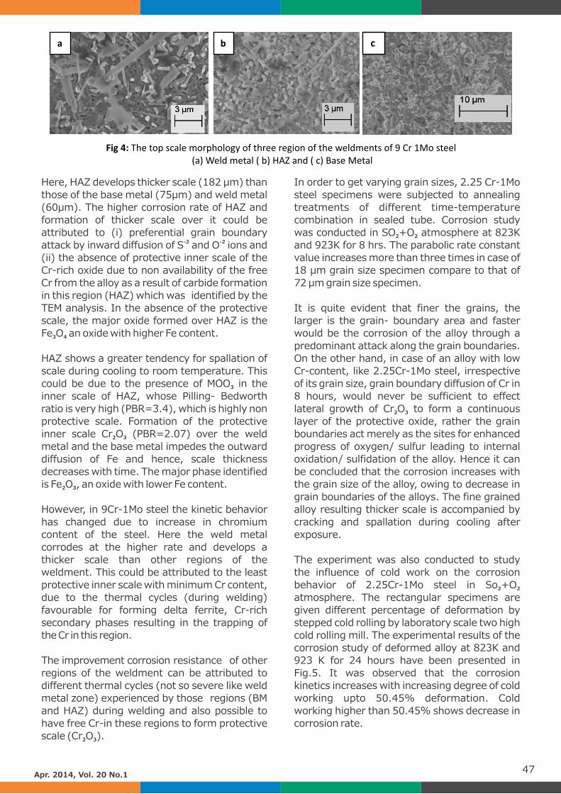
Here, HAZ develops thicker scale (182 µm) than
those of the base metal (75µm) and weld metal
(60µm). The higher corrosion rate of HAZ and
formation of thicker scale over it could be
attributed to (i) preferential grain boundary -2 -2attack by inward diffusion of S and O ions and
(ii) the absence of protective inner scale of the
Cr-rich oxide due to non availability of the free
Cr from the alloy as a result of carbide formation
in this region (HAZ) which was identified by the
TEM analysis. In the absence of the protective
scale, the major oxide formed over HAZ is the
Fe O an oxide with higher Fe content.3 4
HAZ shows a greater tendency for spallation of
scale during cooling to room temperature. This
could be due to the presence of MOO in the 3
inner scale of HAZ, whose Pilling- Bedworth
ratio is very high (PBR=3.4), which is highly non
protective scale. Formation of the protective
inner scale Cr O (PBR=2.07) over the weld 2 3
metal and the base metal impedes the outward
diffusion of Fe and hence, scale thickness
decreases with time. The major phase identified
is Fe O , an oxide with lower Fe content.2 3
However, in 9Cr-1Mo steel the kinetic behavior
has changed due to increase in chromium
content of the steel. Here the weld metal
corrodes at the higher rate and develops a
thicker scale than other regions of the
weldment. This could be attributed to the least
protective inner scale with minimum Cr content,
due to the thermal cycles (during welding)
favourable for forming delta ferrite, Cr-rich
secondary phases resulting in the trapping of
the Cr in this region.
The improvement corrosion resistance of other
regions of the weldment can be attributed to
different thermal cycles (not so severe like weld
metal zone) experienced by those regions (BM
and HAZ) during welding and also possible to
have free Cr-in these regions to form protective
scale (Cr O ).2 3
In order to get varying grain sizes, 2.25 Cr-1Mo
steel specimens were subjected to annealing
treatments of different time-temperature
combination in sealed tube. Corrosion study
was conducted in SO +O atmosphere at 823K 2 2
and 923K for 8 hrs. The parabolic rate constant
value increases more than three times in case of
18 µm grain size specimen compare to that of
72 µm grain size specimen.
It is quite evident that finer the grains, the
larger is the grain- boundary area and faster
would be the corrosion of the alloy through a
predominant attack along the grain boundaries.
On the other hand, in case of an alloy with low
Cr-content, like 2.25Cr-1Mo steel, irrespective
of its grain size, grain boundary diffusion of Cr in
8 hours, would never be sufficient to effect
lateral growth of Cr O to form a continuous 2 3
layer of the protective oxide, rather the grain
boundaries act merely as the sites for enhanced
progress of oxygen/ sulfur leading to internal
oxidation/ sulfidation of the alloy. Hence it can
be concluded that the corrosion increases with
the grain size of the alloy, owing to decrease in
grain boundaries of the alloys. The fine grained
alloy resulting thicker scale is accompanied by
cracking and spallation during cooling after
exposure.
The experiment was also conducted to study
the influence of cold work on the corrosion
behavior of 2.25Cr-1Mo steel in So +O 2 2
atmosphere. The rectangular specimens are
given different percentage of deformation by
stepped cold rolling by laboratory scale two high
cold rolling mill. The experimental results of the
corrosion study of deformed alloy at 823K and
923 K for 24 hours have been presented in
Fig.5. It was observed that the corrosion
kinetics increases with increasing degree of cold
working upto 50.45% deformation. Cold
working higher than 50.45% shows decrease in
corrosion rate.
47Apr. 2014, Vol. 20 No.1
a b c
Fig 4: The top scale morphology of three region of the weldments of 9 Cr 1Mo steel (a) Weld metal ( b) HAZ and ( c) Base Metal
The search for cleaner energy begins with long lasting materials.Wherever our partners are, we will be there with
stainless steel and high performance alloys
designed to meet the most extreme demands
under the harshest conditions. Because the
frst step towards a world that lasts forever is
making today’s energy solutions as dependable
and sustainable as possible.
Focusing on the future is a key component of successful
asset management. Quest Integrity Group has invested
heavily in advancing NDT technology to capture high
quality, repeatable data with 100% coverage. Paired with
our advanced engineering assessment capabilities, clients
take full advantage of the comprehensive data gathered
by our proprietary inspection tools.
The result - we provide actionable information
to confdently guide future operating and asset
management decisions.
Innovation Powersthe Future.
www.QuestIntegrity.com +1 253 893 7070
A TEAM Industrial Services Company

Fig 5: Parabolic rate constant at different
percentage of cold work
Due to cold work the concentration of defects in
the alloy is increased in the oxide/ sulfide layer
(Corrosion product). This may results in an
increased amount of defect too, creating easy
diffusion paths in the oxide layer itself and as a
consequence a faster corrosion rate is observed
up to 50.45% cold deformation. Actually, the
mechanism proposed that cold working
provides sinks for cation vacancies (V" ) flowing M
in ward to the oxide/alloy interface thereby
minimizing interfacial detachment. Otherwise,
the pores and voids at the oxide / alloy interface
slows the corrosion rate by impeding the metal
transfer from the substrate.
For samples of cold working higher than
50.45%, recrystallization took place, which
causes a reduction in the dislocation density and
the formation of very small stain free new
grains. Here, also due to higher cold deformation
some Cr-will diffuse out of the matrix, leading to
Cr-concentration within the inner-Oxide/Sulfide
layer. This also reduces the outward iron
diffusion and the inward oxygen/sulfur
diffusion, thereby prevent the corrosion process.
Finally, to prevent the high temperature
corrosion of 2.25 Cr-1 Mo steel in SO +O 2 2
environments, the pre-corrosion treatment like
pre-oxidation and superficial coatings of CeO2
and Y O oxides were conducted. The 2 3
experimental results are presented in Fig.6 and
Fig.7 for CeO and Y O coatings respectively. It 2 2 3
can be concluded that the CeO and Y O coated 2 2 3
alloy improve the corrosion resistance at high
temperature in SO +O environments to a 2 2
greater extent, compared to un-coated and pre-
oxides specimen owing to improvement in scale
adherence of the alloy. To extend the life time of
the scale, reactive oxide coating is always
beneficial for low alloy steel because of their
good Pilling Bedoworth ratio (PBR/CeO =1.09 2
and PBR/Y O =1.13).2 3
Authors:
Dr Debashis Ghosh is a principal scientist at
CSIR-Central Mechanical Engineering Research
I n s t i t u t e , D u r g a p u r , I n d i a ,
Email: dghosh@ cmeri.res.in. He has worked
in NDT & Metallurgy group since 1997. He has
recently developed a high temperature
corrosion laboratory for carrying out in depth
research in high temperature corrosion and its
protection of different industrial components.
His recent research interests are in developing
and characterizing protective ceramic oxide and
metallic coatings and its performance in high
temperature corrosion protection in different
aggressive environments. He has obtained his
PhD in Metallurgical and Materials Engineering
from National Institute of Technology (NIT)
Durgapur, India and has authored 14 nos
publications in International Journal. He is a
member of NACE international.
Dr Swapan Kumar Mitra is a renowned expert
in the field of high temperature corrosion and
corrosion protective coatings. He is professor in
Metallurgical and Materials engineering in
National Institute of Technology (NIT)
Durgapur, India, email: [email protected]
and is working at this institute for last 30 years.
He has done his phD from, Indian Institute of 49Apr. 2014, Vol. 20 No.1
0 20 40 60 80 100 120 140 1600
4
8
12
16
20
24
CeO2 treated (0.30 mg/cm2
)
CeO2 treated (0.15 mg/cm2
)
Preoxidized
W
/mg
Cm
-2
Time/hour
Uncoated
CeO2 treated (0.50 mg/cm2)
2.25 Cr-1 Mo steel
973K
Fig 6
0 20 40 60 80 100 120 140 1600
5
10
15
20
25
Y2O
3coated
(0.15 mg/cm-2)
Y2O
3coated
(0.25 mg/cm-2)
W
/mg
cm
-2
Time( Hours)
Uncoated
Fig 7

Our current business activities
R & D : Third Shell Global Centre for Innovation & Technology in Bangalore, the other two being in Houston and Amsterdam. Centre delivers high-end technical studies, projects and services for Shell worldwide, the region and India. Services span upstream, downstream, chemicals, gas and refinery operations & laboratories for downstream operations.
GAS: HaziraLNG PvtLtd (HLPL): Joint Venture between Shell (74%) and Total (26%) HaziraLNG receiving and re-gasification terminal Capacity 5 million tonnes of LNG per annum HaziraPorts PvtLtd. – (HPPL) Bulk container port operational since 2012
FINANCIAL BUSINESS SERVICES : Commenced Chennai-based financial operations since mid-2008 and now has a headcount of over 1800. Center provides a wide range of finance, accounting and other business and customer services to Shell operating companies globally
LUBRICANTS : A state-of-the-art lube-oil blending plant at Taloja, outside Mumbai, considered to be among the finest blending plants in Asia -manufacturing a range of branded lubricants such as Helix, Advance and Rimula, focused on the automotive and industrial sector
BITUMEN: High capacity plant 70,000 MTPA at Uluberia, West Bengal producing a range of Bitumen Specialty products such as Bitumen emulsions, Crumb Rubber Modified Bitumen (CRMB) and Polymer Modified Bitumen (PMB).
RETAIL: Only international company to be granted Government of India approval to retail fuel in India till date. License for 2000 fuel retail stations.
MARINE : Provides fuels, lubricants and related technical services to the shipping industry.
AVIATION : Joint Venture between Shell and MRPL serving a network of 12 airports.
LICENSING : Technical Services Agreement with major companies.
Royal Dutch Shell is one of the most diversified international oil company in India's energy sector with nearly US$1 billion invested. It is a major private sector supplier of crude products and chemicals to India. With over 3000 staff in India, Shell has a significant Technology center, a financial business services center and operates an LNG receiving and re-gasification terminal. It also has a downstream business marketing fuels, lubricants and speciality products.
SHELL IN INDIA

CORSYM'14
CORSYM'14 the International Corrosion Prevention Symposium for Research Scholars was held at
Victor Menezes Convention Center, Indian Institute of Technology, Bombay (IIT Bombay) on th st 20 and 21 Feb 2014. This event was organized and sponsored essentially by NACE India section,
NACE EAP rim area and co-sponsored by DST, DRDO, CSIR, BRNS and Outokumpo. The symposium
was well supported by Department of Metallurgical Engineering & Materials Science, Indian
Institute of Technology, Bombay.
CORSYM'14 had 2 essential distinguishing features which make it even more special than
CORSYM'13. The first one was that it included a 2 day workshop which provided the participants
hands on experience in various electrochemical DC and AC techniques for Corrosion analysis. The
second one was the participation of students all across Asia in the symposium and special lectures
by experts from five different countries.
The response to the workshop was truly overwhelming. Out of only from prospective participants
and due to logistics constraints it was only possible to have about 50 participants for the workshop.
The Participants included undergraduate and postgraduate students as well as faculty from the
universities and colleges all across India and they were 42 in number. These participants were
exposed to DC polarization and AC impedance techniques through lectures by Prof V.S. Raja (IIT
Bombay) and Prof. Nick Birbilis (Monash University, Australia) and later given hands-on training by
a group of enthusiastic research-volunteers of Aqueous Corrosion Laboratory of IITB Bombay.
The symposium was also met with tremendous response from students in India and abroad. Over
100 abstracts for oral and poster presentations were received and presented. The symposium
included 4 plenary and 4 keynote lectures on different aspects of corrosion by eminent experts of
Corrosion Science from India and abroad. The plenary and keynote speakers included Prof. T. Shoji
from Tohoku University, Japan, Prof Wan Ta Tsai and Prof Huang from Taiwan, Prof Nick Birbilis from
Monash University, Australia, Prof. K A Natrajan from IISc Bangalore, Dr Vivekananand Kain from
BARC, Dr. Daniel Blackwood from National University of Singapore and Dr Kamachi Mudali from
IGCAR Kalpakkam,.
Prof. Subhasis Choudhary- Deputy Director, Academic & Infrastructural affairs IIT Bombay, was the
chief guest to inaugurate the conference. Dr. Samir Degan, Area Director NACE EAP,
Mr. Tushar Jhaveri, President NACE International Prof. Raja, Chair CORSYM'14 and Mr. Ajay
Krishnan - Convener CORSYM'14 addressed the student delegates.
nd CORSYM 14 concluded with a one day Mumbai Darshan trip on 22 Feb for interested participants
which was sponsored by CORSYM-2014.
51Apr. 2014, Vol. 20 No.1
Dignitaries on the dias releasing
the symposium proceeding
Participants during the symposium.

The International Corrosion Awareness Day was celebrated at Federation House, FICCI, New Delhi thon 24 April with over 110 participants from industry, academia and government.
Important guests present were the Joint Secretary Dr. A.J.V. Prasad, Ministry of Chemicals, Government of India; Mr John McCaslin, Minister Counselor, United States Department of Commerce; Former Chairmans of ONGC Mr. S. Vasudeva and Mr. S.K. Manglik; Former Chairman of GAIL India Limited, Mr. C.R.Prasad; Director (R&D) Indian Oil Corporation Limited, Dr R.K. Malhotra; Director General Petrotech, Mr. Ashok Anand; Director Petrotech and Former Director (R&D) IOCL, Mr. Anand Kumar; Mr A. Prasad, Director General FICCI; Mr. Vinay Mathur, Dy Secretary General, FICCI; Mr. P.S. Singh, Head, Chemicals and Petrochemicals, FICCI.
Leadership from NACE included Ms. Elaine Bowman, Past President NACE International; Mr. Tushar Jhaveri, Immediate Past President NACE International; Dr. Samir Degan, Chairman NIGIS; Mr. Anand Kulkarni; Mr. Manohar Rao; Ms. Helena Seelinger; Mr Narendra Kumar; Dr. Kamachi Mudali and Dr. Anil Bhardwaj.
Highlights of the day were –
• The Impact Study was announced by Past President Elaine Bowman and an overview was
given to delegates present.
• NIGIS / FICCI MoU signed earlier announced. FICCI, established in 1927, is the largest
industry association and industry policy influencer in India.
• The MoA between NIGIS and United States Department of Commerce was signed. It was
exchanged by Mr John M McCaslin, Minister Counsellor and Dr Samir Degan, Chairman
NIGIS.
• FICCI announced their support to IMPACT study in INDIA.
• The Ministry of Chemicals, Government of India will also extend support along with FICCI as shared by the Joint Secretary (Chemicals) Dr. A.J.V. Prasad.
52Apr. 2014, Vol. 20 No.1
International Corrosion Awareness Day April 24th, 2014.
Function at Federation House, FICCI, New Delhi
Memorandum of Agreement between
NIGIS and USCS exchanged
NACE members & staff along with FICCI staff
at International Corrosion Awareness Day
Elaine Bowman presenting the IMPACT Study to the Audience

Marine atmospheres are severely corrosive
environments. The degree of severity, however,
depends on several variables. Humidity in a
marine atmosphere is generally high, but the
temperature is variable, depending on climate
(tropical, temperate, or arctic) and amount of
sunlight. Chloride content is also variable,
depending on the distance from the shoreline.
Three primary areas for corrosion of marine
structures can be isolated. The first is the
submerged area where corrosion is relatively
uniform from the mean low-tide area
downward. At greater depths, there is often a
large quantity of soluble oxygen in the water,
which means corrosion can readily occur. Tabel
1 shows factors that influence corrosion of steel
in seawater.
The second area is the tidal or splash zone. This
is an area of maximum corrosion because it is
alternatively exposed to seawater and air with
maximum oxygen content in the strong
electrolyte. The third area is that above the
splash zone. It is less corrosive than the splash
zone but is a very strong atmospheric corrosion
area, often characterized by large tubercles of
rust and deep pits.
53Apr. 2014, Vol. 20 No.1
Corrosion Basics: Marine Environments*
TABLE 1 – Corrosion Factors for Carbon Steel Immersed in Seawater
Factor in Seawater Effect on Iron and Steel
Chloride ion
Electrical
conductivity
Oxygen
Velocity
Temperature
Biofouling
Stress
Pollution
Silt and suspended
sediment
Film formation
Highly corrosive to ferrous metals. Carbon Steel and common
ferrous metals cannot be passivated. (Sea salt is 55% chloride)
High conductivity makes it possible for anodes and cathodes
to operate over long distance; thus, corrosion possibilities are
increased and total attack may be much greater than that for the
same structure in freshwater.
Steel corrosion, for the most part, is cathodically controlled. Oxygen, by
depolarizing the cathode, facilitates the attack; thus, high oxygen
content increases corrosiveness.
Corrosion rate is increased, especially in turbulent flow. Moving seawater
can destroy rust barrier and provide more oxygen. Impingement attack
tends to promote rapid penetration. Cavitation damage exposes a fresh
steel surface to further corrosion.
Increasing ambient temperature tends to accelerate attack. Heated
seawater may deposit protective scale or lose its oxygen; either or both
action tend to reduce attack.
Hard –shell animal fouling tends to reduce attack by restricting access of
oxygen. Bacteria participate in the corrosion reaction in some cases.
Cyclic stress sometimes accelerates failure of corroding steel member.
Tensile stresses near yield also promote failure in special situations.
Sulfides, which are normally present in polluted seawater, greatly
accelerate attack on steel. However, the low oxygen content of polluted
waters could favor reduced corrosion.
Erosion of the steel surface by suspended matter in the flowing seawater
greatly increases the tendency to corrode.
A coating of rust, or rust and mineral scale (calcium and magnesium
salts), interferes with the diffusion of oxygen to the cathode surface, thus
slowing attack.
Adapted from Corrosion Basics - An Introduction, National Association of Corrosion Engineers *

NACE International Gateway India Section
organised certification courses on Cathodic
Protection Tester, Cathodic Protection
Technic ian and Cathodic Protect ion
Technologist.
The CP program includes four certification
courses and moves from entry level (CP 1) to
the most knowledgeable and experienced
specialist level (CP 4). Each CP course is an
independent component of the program and
has a different skill and education level for entry,
taking into account the student's work
experience, and mathematics and science
background. The NACE Cathodic Protection
(CP) Training and Certification Program is a
comprehensive program designed for
individuals working in the field of cathodic
protection from the beginner to the specialist.
The CP 1 - Cathodic Protection Tester course
presents CP technology to students entering the
cathodic protection industry and responsible for
gathering and/or recording data for CP systems
or measuring the effectiveness of CP systems.
The CP 2 - Cathodic Protection Technician
course provides intermediate-level training in
Corrosion Theory and CP concepts, Types of CP
Systems, AC and DC stray current interference,
Field measurement techniques and CP Record
keeping. This course is for students with a
working knowledge of cathodic protection or for
those who have extensive cathodic protection
field experience with a technical background.
The CP 3 - Cathodic Protection Technologist
Course builds on the technology presented in
the CP – 2 Cathodic Protection Technician
course.
The CP 4 - Cathodic Protection Specialist
Course focuses on the principles and
procedures for CP design on a variety of
structures for both galvanic and impressed
current systems.
54
Course
No.Course Period
No. of
Participants
1.
2.
Cathodic Protection Tester (CP-1)
Cathodic Protection Technician (CP-2)
10 - 15 Feb 2014
17 – 22 Feb 2014
12
19
CP Level 1 participants from 10 - 15 Feb 2014 CP Level 2 participants from 17 - 22 Feb 2014
Apr. 2014, Vol. 20 No.1
NACE International Certification Cathodic Protection(CP) Program
NIGIS organized following certification course during the month of Feb 2014 in Mumbai, India.