Corrosion Control: Polyethylene Encasement
20
Strength and Durability for Life ® CORROSION CONTROL Polyethylene Encasement Last Revised: January 2017
-
Upload
khangminh22 -
Category
Documents
-
view
2 -
download
0
Transcript of Corrosion Control: Polyethylene Encasement

Strength and Durability for Life®
CORROSION CONTROL
Polyethylene Encasement
Last Revised: January 2017

2
Throughout more than 58 years of service in thousands of utilities in the United States and across the world, polyethylene encasement has proved an effective corrosion-protection system for millions of feet of Cast and Ductile Iron Pipe. V-Bio® Enhanced Polyethylene Encasement builds upon this proven method of corrosion control and provides the most advanced corrosion protection for Ductile Iron Pipe while still maintaining the ease of use we have come to expect from polyethylene encasement.
Polyethylene encasement involves simply wrapping the pipe with a tube or sheet of polyethylene immediately
before installing the pipe. It is easy for construction crews to install on-site and is by far the most economical way to
protect Ductile Iron Pipe. And, unlike cathodic protection systems and bonded coatings, polyethylene encasement
is a passive protection system, so it requires no monitoring, maintenance, or supervision once installed.
This brochure will briefly present the history and development of polyethylene encasement, explain how it protects
Ductile Iron Pipe, and highlight field investigations across the nation. It will also discuss polyethylene’s advantages over
other corrosion-protection methods, explain how to ascertain if protection is warranted, outline proper installation
procedures, and briefly review cost considerations when choosing a corrosion-protection system for Ductile Iron Pipe.
History and Development
Polyethylene encasement was first used experimentally in 1951 by the Cast Iron Pipe Research Association (CIPRA)*
and one of its member companies to protect a mechanical joint pipe assembly in a highly corrosive cinder fill
in Birmingham, Alabama. When examined two years later, the unprotected parts of the pipe showed significant
pitting due to corrosion. The glands, nuts, bolts, and portion of the pipe protected by polyethylene encasement
were in excellent condition.
Also in the early 1950s, CIPRA began an ongoing testing program, burying bare and polyethylene-encased Cast
Iron pipe specimens in highly corrosive muck in the Florida Everglades and later in a tidal salt marsh in Atlantic
City, New Jersey. The success of these early installations led to the development of an extensive, ongoing research
program that determined polyethylene encasement’s efficacy in providing a high degree of corrosion protection for
Cast and Ductile Iron Pipe in most soil environments.
By the late 1950s, successful results in CIPRA’s research program led to the first use of polyethylene encasement in
operating water systems in Lafourche Parish, Louisiana, and Philadelphia, Pennsylvania. And, in 1963, CIPRA continued
its research with the burial of polyethylene-encased Ductile Iron Pipe specimens in test sites in the Everglades and
Wisconsin Rapids, Wisconsin. Millions of feet of polyethylene-encased Cast and Ductile Iron Pipe have since been
installed in thousands of operating water systems across the United States and throughout the world.
Due to polyethylene encasement’s excellent success in actual field conditions, the first national standard, ANSI/
AWWA C105/A21.5, was adopted in 1972. The American Society for Testing and Materials issued a standard for
polyethylene (ASTM A674) in 1974. In 1981, Great Britain adopted a national standard. National and industry
standards in several other countries followed. An international standard for polyethylene sleeving (ISO 8180) was
adopted in 1985.
*The Cast Iron Pipe Research Association (CIPRA) became the Ductile Iron Pipe Research Association (DIPRA) in 1979.

3
Although most soil environments are not considered corrosive to Ductile Iron Pipe, soils in landfill sites such as the one pictured here are generally
considered corrosive. Other typically corrosive environments include swamps, peat bogs, expansive clays, and alkali soils.
©C
hu
ck S
eal

4
Laboratory tests indicate that the 4-mil HDCL and
the 8-mil LLD polyethylene may be more resistant
to construction damage than the old 8-mil LD
polyethylene. Tensile strength, impact strength and
puncture resistance of the 4-mil HDCL and the 8-mil
LLD polyethylene are typically greater because
of inherent differences in the materials. Based on
DIPRA’s laboratory and field research, either the
8-mil LLD or the 4-mil HDCL polyethylene material
is recommended in accordance with AWWA C105
Standard for corrosion protection of Ductile Iron
Pipe in aggressive environments.
How Polyethylene Encasement Protects
Ductile Iron Pipe
At the trench, crew members encase Ductile
Iron Pipe with a tube or sheet of polyethylene
immediately before installing the pipe. The
polyethylene acts as an unbonded film, which
prevents direct contact of the pipe with the
corrosive soil. It also effectively reduces the
electrolyte available to support corrosion activity
to any moisture that might be present in the
thin annular space between the pipe and the
polyethylene film.
Typically, some groundwater will seep beneath the
wrap. Although the entrapped water initially has the
corrosive characteris- tics of the surrounding soil,
the available dissolved oxygen supply beneath the
wrap is soon depleted and the oxidation process
stops long before any damage occurs. The water
enters a state of stagnant equilibrium, and a uniform
environment exists around the pipe.
The polyethylene film also retards the diffusion of
additional dissolved oxygen to the pipe surface and
the migration of cor- rosion products away from the
pipe surface.
The material requirement called for in AWWA C105
Standard when it was issued in 1972 was 8-mil,
low-density (LD) polyethylene. With the 1993
revision to this standard, the section on materials
was expanded to include 4-mil, high-density, cross-
laminated (HDCL) polyethylene.
HDCL polyethylene was first installed on an
operating pipeline in Aurora, Colorado, in 1981. In
1982, DIPRA began investigating the corrosion
protection afforded Ductile Iron Pipe by 4-mil HDCL
polyethylene encasement at its Logandale, Nevada,
test site. During the 1993 revision of AWWA C105,
the A21 Committee reviewed the test data on 4-mil
HDCL polyethylene and concluded that from all
indications, it provided comparable protection of
Ductile Iron Pipe to that afforded by the standard
8-mil LD polyethylene. Based on that conclusion,
the A21 Committee elected to incorporate the 4-mil
HDCL polyethylene into the standard.
With the 1993 revision of the standard, the section
on materials was also updated to include Class B
(colored) polyethylene to allow for color coding of
potable/reclaimed/wastewater pipelines as required
by many local/state regulatory agencies.
The 1999 revision of AWWA C105 included: (1) the
deletion of 8-mil LD polyethylene film, (2) the addition
of 8-mil linear low-density (LLD) polyethylene film,
and (3) the addition of impact, tear-resistant and
marking requirements for both materials (LLD and
HDCL). The revision benefitted the user by reflecting
an improved polyethylene material.
Since the standard was first published in 1972, the
polyethylene film industry has made a number
of technological advances. The LD film, which
continues to serve the industry well, had become
more difficult to obtain. Newer materials, such as
LLD film, which replaced the LD film, are readily
available, much stronger, and more resistant to
damage. The material requirements for the LLD film
were closely patterned after the Australian Standard
for Polyethylene Sleeving for Ductile Iron Pipelines
(AS 3680) where the material has been in use for
several years.
Standards for Polyethylene Encasement
ANSI/AWWA C105/A21.5: United States 1972
ASTM A674: United States 1974
JDPA Z 2005: Japan 1975
BS6076: Great Britain 1981
ISO 8180: International 1985
DIN 30 674, Part 5: Republic of Germany 1985
A.S. 3680 and A.S. 3681: Australia 1989

5
raised over the years with the use of polyethylene
encasement; the potential influence of anaerobic
bacteria through micro-biologically influenced
corrosion (MIC) and the possibility of corrosion
occurring under intact polywrap.
V-Bio Enhanced Polyethylene Encasement consists
of three layers of co-extruded linear low density
polyethylene (LLDPE) film that are fused into
one. The inner layer that will be in contact with
the pipe is infused with a proprietary blend of
an anti-microbial additive to mitigate MIC and a
volatile corrosion inhibitor (VCI) to control galvanic
corrosion underneath the wrap. V-Bio® Enhanced
Polyethylene Encasement protects against corrosion
without involving the consumption of either the
anti-microbial or the volatile corrosion inhibitor,
meaning its enhanced properties will not wear out.
V-Bio® Enhanced Polyethylene Encasement follows
and meets all requirements of the AWWA C105
standard. It is installed the same way using the same
methods as regular polyethylene encasement and
as with any protective measure proper installation
is vital to its success. With V-Bio® Enhanced
Polyethylene Encasement it is essential to maintain
intimate contact of the encasement to the pipe to
optimize the performance of the infused additives.
Advantages of Polyethylene Encasement
Polyethylene’s excellent dielectric properties enable it
to effectively shield the pipe from low-level stray direct
current. Also, because polyethylene provides a uniform
environment for the pipe underneath the wrap, local
galvanic corrosion cells are virtually eliminated as the
oxygen is consumed. With the use of V-Bio® Enhanced
Polyethylene Encasement galvanic corrosion cells are
non-existent thanks to the corrosion inhibitor infused
into the inner layer.
Pinholes in the loose wrapping material do not
significantly diminish its protective ability. And,
unlike bonded coatings, polyethylene has the
ability to protect the pipe without the formation of
concentration cells at coating holidays.
Polyethylene encasement is easy to install and requires
no additional manpower or special equipment.
Construction crew members simply slip the
polyethylene over the pipe as they install it.
Polyethylene encasement is not designed to be a
watertight system. Yet, once installed, the weight of
the earth backfill and surrounding soil prevents any
significant exchange of groundwater between the
wrap and the pipe.
As with any corrosion-protection system, proper installation is important
to polyethylene encasement’s success. Polyethylene encasement should
be carefully installed following one of three installation methods outlined
in ANSI/AWWA C105/A21.5.
How V-Bio® Enhanced Polyethylene Encasement
Protects Ductile Iron Pipe
V-Bio® Enhanced Polyethylene Encasement
The development of V-Bio® Enhanced Polyethylene
Encasement began in 2002 and the first installations
for field testing were at DIPRA test sites in 2014. The
goal of V-Bio® Enhanced Polyethylene Encasement
was to address two concerns that had been
ANSI/AWWA C105/A21.5: United States 1972
ASTM A674: United States 1974
JDPA Z 2005: Japan 1975
BS6076: Great Britain 1981
ISO 8180: International 1985
DIN 30 674, Part 5: Republic of Germany 1985
A.S. 3680 and A.S. 3681: Australia 1989
©C
hu
ck S
eal

6
Compared to cathodic protection and bonded
coatings, polyethylene and V-Bio® Enhanced
Polyethylene Encasement is very inexpensive. The
initial cost of material and installation is very low —
only pennies per foot in most sizes. In fact, many
utilities that install their own pipe assign no installation
cost for the encasement, reporting that the material
costs as little as a few cents per inch- diameter per foot
for polyethylene encasement.
Both Polyethylene and V-Bio® Enhanced Polyethylene
Encasement is are field- applied, so the pipe doesn’t
require special handling or packaging during shipment.
And, because installation is on site, damage is less
likely than on factory-applied coatings. If damaged, the
polyethylene encasement is easy and simple to repair
at the job site with polyethylene compatible adhesive
tape.
Because polyethylene is a passive system of protection,
it requires no expensive maintenance or monitoring
and costs nothing to operate once installed
Polyethylene Encasement
• Is inexpensive.
• Is easy to install.
• Requires no additional manpower.
• Requires no maintenance or monitoring.
• Costs nothing to operate.
• Doesn’t deteriorate underground.
• Is easily repaired with polyethylene adhesive tape
if damaged.
• Doesn’t require any special handling or packaging
during shipment.
• V-Bio® Enhanced Polyethylene Encasement
eliminates galvanic corrosion cells.
• Protects the pipe without the formation of
concentration cells at coating holidays.
How to Identify Corrosive Environments
It is important to identify potentially corrosive
environments prior to pipeline installation because,
once a pipeline is installed, it is both costly and
difficult to retrofit with corrosion protection measures.
Although Ductile Iron Pipe possesses good
resistance to corrosion and needs no additional
protection in most soils, experience has shown that
external corrosion protection is warranted in certain
soil environments. Examples include soils with
low resistivities, anaerobic bacteria, differences in
composition, and differential aeration around the pipe.
Dissimilar metals and external stray direct currents
may also necessitate additional corrosion protection.
Soils contaminated by coal mine wastes, cinders,
refuse, or salts also are generally considered
corrosive. So are certain naturally occurring
environments, such as swamps, peat bogs,
expansive clays, and alkali soils. And soils in wet,
low-lying areas are generally considered more
corrosive than those in well-drained areas.
Previously the 10 point soil evaluation procedure was
recommended for identifying corrosive environments
but it has been replaced with The Design Decision
Model™. The DDM™ was developed jointly between
DIPRA and Corrpro. It builds upon the proven 10 point
system to provide the most accurate soil evaluation
for Ductile Iron Pipe possible.

7
*Ten points–corrosive to Ductile Iron Pipe. Protection is indicated.
**Based on water-saturated soil box. This method is designed to obtain the
lowest–and most accurate–resistivity reading.
***If sulfides are present and low (<100 mv) or negative redox-potential
results are obtained, 3 points should be given for this range.
Note: DIPRA recommends that the soil sample used in the 10-point
evaluation be taken at pipe depth rather than at the surface. Soil
corrosivity readings can vary substantially from the surface to pipe depth.
Soil Test Evaluation for Ductile Iron Pipe
(10-Point System)*
Soil Characteristics Points
Resistivity (ohm-cm)**
< 1,500 10
≥1,500–1,800 8
> 1,800—2,100 5
> 2,100—2,500 2
>2,500—3,000 1
> 3,000 0
pH
0–2 5
2–4 3
4–6.5 0
6.5–7.5 0***
7.5–8.5 0
> 8.5 3
Redox Potential
> + 100 mv 0
+50 to +100 mv 3.5
0 to +50 mv 4
Negative 5
Sulfides
Positive 3.5
Trace 2
Negative 0
Moisture
Poor drainage, continuously wet 2
Fair drainage, generally moist 1
Good drainage, generally dry 0
10-Point Soil Evaluation Procedure
Although several evaluation procedures have
been used to predict conditions corrosive to
underground piping, the 10-point soil evaluation
procedure instituted by CIPRA in 1964 is most
often recommended for Ductile Iron Pipe. Included
in the Appendix to the ANSI/AWWA C105/A21.5
Standard, the 10-point system has proved invaluable
in surveying more than 100 million feet of proposed
pipeline installations to determine soil corrosivity.
The evaluation procedure is based upon information
drawn from five tests and observations:
• Soil resistivity
• pH
• Oxidation-reduction (redox) potential
• Sulfides
• Moisture
For a given soil sample, each parameter is evaluated
and assigned points according to its contribution to
corrosivity. The points for all five areas are totaled,
and if the sum is 10 or more, the soil is considered
corrosive to Ductile Iron Pipe, and protective
measures should be taken.
In addition, potential for stray direct current
corrosion should also be considered as part of
the evaluation. Notes on previous experience with
underground structures in the area are also very
important in predicting soil corrosivity.
It is important to note that the 10-point system, like
any evaluation procedure, is intended as a guide in
determining a soil’s potential to corrode Ductile Iron
Pipe. It should be used only by qualified engineers or
technicians experienced in soil analysis and evaluation.

8
The Design Decision Model™
The DDM™ is a risk matrix concept that incorporates
an evaluation of the likelihood of corrosion along
a proposed Ductile Iron Pipeline route and the
consequences that may result from a corrosionrelated
problem. In this way, a utility is provided with a
recommendation for corrosion control that is best
suited for the particular installation under design.
Recommendations range from simply installing the
Ductile Iron Pipe as-manufactured with its protective
standard shop coating and annealing oxide layer,
to encasing the pipe in polyethylene, to providing
cathodic protection currents to control the rate of
corrosion.
Figure 1 shows that the recommendations for
corrosion control result from obtaining a point
count for both Likelihood and Consequence Factors.
Entering the graph at the appropriate points, a color-
coded intersection is found that establishes the
appropriate corrosion mitigation recommendation.
As enumerated in Figure 1, the methods include:
1. Installing the pipe as-manufactured with its
protective standard shop coating/annealing oxide
system.
2. Encasing the pipe in polyethylene.
3. Encasing the pipe in polyethylene or encasing the
pipe and providing bonded joints.
4. Encasing the pipe in polyethylene and providing
bonded joints or providing life-extension cathodic
protection currents, with or without encasement.
5. Cathodic protection.
Likelihood Factors
Using the 10-Point System as described in Appendix
A of ANSI/AWWA C105/A21.51 as a basis, the DDM™
evaluates the following factors in determining the
likelihood that corrosion could be a problem for a
proposed Ductile Iron Pipeline:
• Resistivity
• Sulfides
• Moisture Content
• Redox Potential
• Ground Water Influence
• Bi-metallic Considerations
• pH
• Known Corrosive Environments
• Chlorides
Of the above, resistivity, pH,
redox, sulfides, and moisture
content are criteria that carry
over from the 10-Point Soil
Evaluation System that the
Ductile Iron Pipe industry
has used for decades. For a
discussion of the importance
of these factors in contribution
to a corrosion cell, please refer
to Appendix A of ANSI/AWWA
C105/A21.5.
Consequence Factors
Consequence factors relate to operational reliability
and the difficulties that may exist in affecting a repair
to a Ductile Iron Pipeline. The following core factors
are used to establish those consequences:
• The diameter of the pipe.
• The location of the pipe.
• The depth of cover.
• Whether an alternative supply of water is available.
These factors are used to evaluate access to the pipe
at a particular location and the relative difficulty in
affecting repairs. Access can be categorized as good,
with minimal traffic considerations, typical excavation
depths, the availability of an alternative supply of
water, etc., or increasingly more difficult where
depth of cover, right-of-way considerations, utility
congestion, or unstable soil conditions may have an
impact on repair efforts.
Likelihood
Conse
quences
4 Encasing the pipe in polyethylene and providing bonded joints or providing life-extension cathodic protection currents, with or without encasement. 5 Cathodic protection.
Installing the pipe as-manufactured with its protective standard shop coating/annealing oxide system. 2 Encasing the pipe in polyethylene. 3 Encasing the pipe in polyethylene or encasing the pipe and providing bonded joints.
Taking the results from the Likelihood and Consequence Factors made at discrete locations along the pipe, the two-dimensional DDM™ grid is used to find a recommended mitigation method at each location.
1

9
27 Years
MERRITT ISLAND, FL
24-inch Cast Iron pipe encased in loose 8-mil polyethylene.
Installed 1963. Inspected 1990.
Soil Analysis:
Description: Gray and black loamy sand.
Resistivity: 1,120 ohm-cm (10)*
pH: 7.1 (3)
Redox: -20 mv (5)
Sulfides: Positive (3.5)
Moisture: Saturated (2)
Soil Condition: Corrosive (23.5)
Condition of Pipe and Encasement: Excellent
30 Years
PHILADELPHIA, PA
12-inch Cast Iron Pipe encased in loose 8-mil polyethylene.
Installed 1959. Inspected 1989.
Soil Analysis:
Description: Landfill area-brownish red clayey silts and
dark gray organic clays with organic materials and
petroleum and paper wastes
Resistivity: 2,400 to 5,600 ohm-cm (2)
pH: 3.9 to 6.2 (3)
Redox: +67 to +69 mv (3.5)
Sulfides: Positive (3.5)
Moisture: Moist to saturated (2)
Soil Condition: Corrosive (14)
Condition of Pipe and Encasement: Very good
20 Years
WATERFORD, MI
8-inch Ductile Iron Pipe encased in loose 8-mil polyethylene
Installed 1975. Inspected 1995.
Soil Analysis:
Description: Black and gray silty clay
Resistivity: 960 ohm-cm (10)
pH: 7.5 (3)
Redox: +23 mv (3.5)
Sulfides: Positive (3.5)
Moisture: Saturated (2)
Soil Condition: Corrosive (22)
Condition of Pipe and Encasement:Excellent
10 Years
OGDEN, UT
16-inch Ductile Iron Pipe encased in loose 8-mil polyethylene
Installed 1979. Inspected 1989.
Soil Analysis:
Description: Dark gray silty clay
Resistivity: 192 ohm-cm (10)
pH: 7.9 (0)
Redox: -165 mv (5)
Sulfides: Positive (3.5)
Moisture: Saturated (2)
Soil Condition: Corrosive (20.5)
Condition of Pipe and Encasement: Excellent
* Numbers in parentheses indicate point count per Soil Test Evaluation procedure outlined in Appendix A of ANSI/AWWA C105/A21.5. See table on page 7 of this brochure for explanation.
10
18 Years
MITCHELL, SD
12-inch Cast Iron pipe encased in loose 8-mil polyethylene.
Installed 1963. Inspected 1981.
Soil Analysis:
Description: Brown clay and sand with cinders present.
Resistivity: 840 ohm-cm (10)
pH: 7.1 (0)
Redox: +450 mv (0)
Sulfides: Trace (2)
Moisture: Moist (1)
Soil Condition: Corrosive (13)
Condition of Pipe and Encasement: Excellent
15 Years
OMAHA, NE
12-inch Cast Iron pipe encased in loose 8-mil polyethylene.
Installed 1974. Inspected 1989.
Soil Analysis:
Description: Gray clay
Resistivity: 600 ohm-cm (10)*
pH: 7.4 (3)
Redox: +90 mv (3.5)
Sulfides: positive (3.5)
Moisture: Wet (2)
Soil Condition: Corrosive (22)
Condition of Pipe and Encasement: Excellent
21 Years
DETROIT, MI
8-inch Ductile Iron Pipe encased in loose 8-mil polyethylene.
Installed 1974. Inspected 1995.
Soil Analysis:
Description: Gray and black silty clay
Resistivity: 1,320 ohm-cm (10)
pH: 7.4 (3)
Redox: -113 mv (5)
Sulfides: Positive (3.5)
Moisture: Saturated (2)
Soil Condition: Corrosive (23.5)
Condition of Pipe and Encasement: Excellent
21 Years
CHARLESTON, SC
24-inch Ductile Iron Pipe encased in loose 8-mil polyethylene.
Installed 1967. Inspected 1988.
Soil Analysis:
Description: Gray sand and clay with organic muck in
reclaimed marsh subjected to fluctuating water table due
to coastal tidal effect.
Resistivity: 560 ohm-cm (10)
pH: 6.9 (3)
Redox: -132 mv (5)
Sulfides: Positive (3.5)
Moisture: Saturated (2)
Soil Condition: Corrosive (23.5)
Condition of Pipe and Encasement: Excellent
* Numbers in parentheses indicate point count per Soil Test Evaluation procedure outlined in Appendix A of ANSI/AWWA C105/A21.5. See table on page 7 of this brochure for explanation.

11
15 Years
SYRACUSE, NY
8-inch Ductile Iron Pipe encased in loose 8-mil polyethylene.
Installed 1988. Inspected 2003.
Soil Analysis:
Description: Dark, organic brown clay
Resistivity: 410 ohm-cm (10)
pH: 6.9 (3)
Redox: -40 mv (5)
Sulfides: Positive (3.5)
Moisture: Saturated (2)
Soil Condition: Corrosive (23.5)
Condition of Pipe and Encasement: Excellent
9 Years
JACKSON, MS
8-inch Ductile Iron Pipe encased in loose 8-mil polyethylene.
Installed 1977. Inspected 1986.
Soil Analysis:
Description: Mixture of organic clay and brown silty clay
Resistivity: 880 ohm-cm (10)
pH: 4.4 (0)
Redox: -150 mv (5)
Sulfides: Positive (3.5)
Moisture: Saturated (2)
Soil Condition: Corrosive (20.5)
Condition of Pipe and Encasement: Excellent
30 Years
FAYETTEVILLE, AR
12-inch Gray Iron pipe encased in loose 8-mil polyethylene
Installed 1973. Inspected 2003.
Soil Analysis:
Description: Dark gray clay
Resistivity: 1,600 ohm-cm (8)
pH: 6.8 (3)
Redox: -100 mv (5)
Sulfides: Positive (3.5)
Moisture: Saturated (2)
Soil Condition: Corrosive (21.5)
Condition of Pipe and Encasement: Excellent
14 Years
LITTLE ROCK, AR
30-inch Ductile Iron Pipe encased in loose 8-mil polyethylene
Installed 1972. Inspected 1986.
Soil Analysis:
Description: Dark reddish and grayish brown clay
Resistivity: 600 ohm-cm (10)
pH: 6.9 (3)
Redox: +40 mv (4)
Sulfides: Trace (2)
Moisture: Saturated (2)
Soil Condition: Corrosive (21)
Condition of Pipe and Encasement: Excellent
* Numbers in parentheses indicate point count per Soil Test Evaluation procedure outlined in Appendix A of ANSI/AWWA C105/A21.5. See table on page 7 of this brochure for explanation.

12
20 Years
MONTGOMERY, AL
36-inch Ductile Iron Pipe encased in loose 8-mil polyethylene.
Installed 1982. Inspected 2002.
Soil Analysis:
Description: Reddish brown clayey sand
Resistivity: 172 ohm-cm (10)*
pH: 8.7 (3)
Redox: +30 mv (4)
Sulfides: Negative (0)
Moisture: Saturated (2)
Soil Condition: Corrosive (19)
Condition of Pipe and Encasement: Excellent
36 Years
LATHAM, NY
6-inch Ductile Iron Pipe encased in loose 8-mil polyethylene.
Installed 1962. Inspected 1998.
Soil Analysis:
Description: Dark brown stiff clay
Resistivity: 600 ohm-cm (10)
pH: 7.1 (0)
Redox: +200 mv (0)
Sulfides: Negative (0)
Moisture: Saturated (2)
Soil Condition: Corrosive (12)
Condition of Pipe and Encasement: Excellent
40 Years
LAFOURCHE PARISH, LA
4-inch Cast Iron pipe encased in loose 8-mil polyethylene.
Installed 1958. Inspected 1998.
Soil Analysis:
Description: Gray clay with black organics
Resistivity: 520 ohm-cm (10)
pH: 6.3 (0)
Redox: -50 mv (5)
Sulfides: Positive (3.5)
Moisture: Saturated (2)
Soil Condition: Corrosive (20.5)
Condition of Pipe and Encasement: Excellent
16 Years
ST. GEORGE, UT
12-inch Ductile Iron Pipe encased in loose 8-mil polyethylene.
Installed 1968. Inspected 1984.
Soil Analysis:
Description: Dark gray clayey silt
Resistivity: 720 ohm-cm (10)
pH: 7.3 (0)
Redox: +110 mv (0)
Sulfides: Negative (0)
Moisture: Saturated (2)
Soil Condition: Corrosive (12)
Condition of Pipe and Encasement: Excellent
* Numbers in parentheses indicate point count per Soil Test Evaluation procedure outlined in Appendix A of ANSI/AWWA C105/A21.5. See table on page 7 of this brochure for explanation.
13
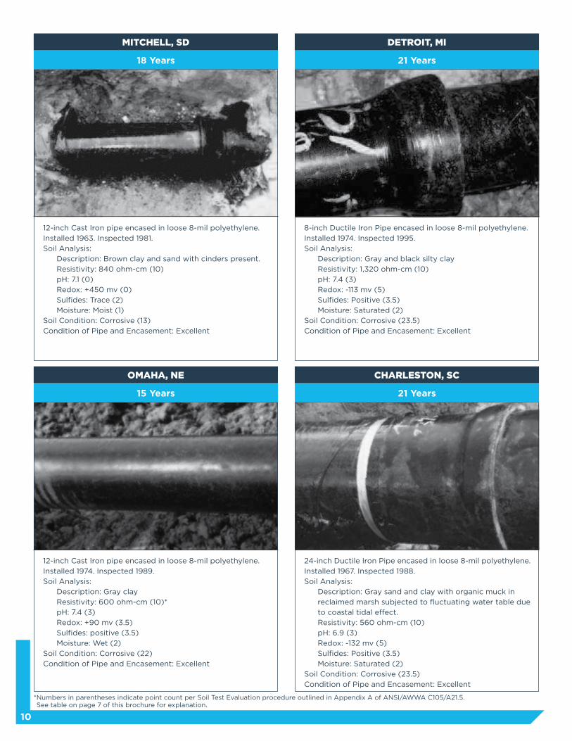
18 Years
CITY OF ORANGE, CA
6-inch Cast Iron pipe encased in loose 8-mil polyethylene.
Installed 1969. Inspected 1987.
Soil Analysis:
Description: Brown silty clay
Resistivity: 640 ohm-cm (10)
pH: 6.3 (0)
Redox: +170 mv (0)
Sulfides: Negative (0)
Moisture: Saturated (2)
Soil Condition: Corrosive (12)
Condition of Pipe and Encasement: Excellent
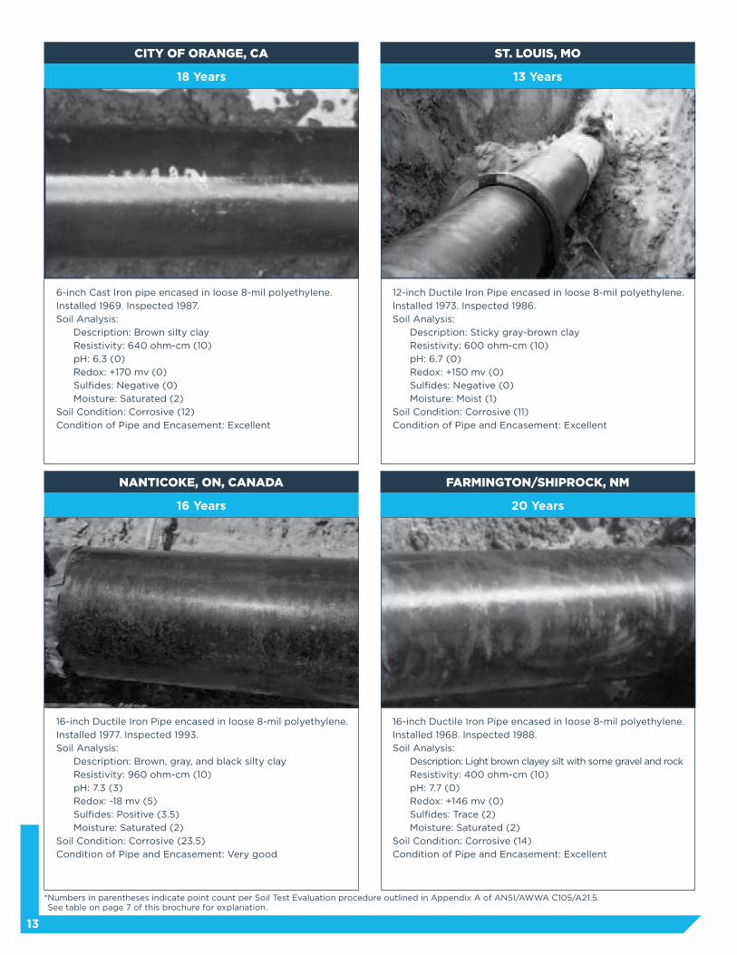
16 Years
NANTICOKE, ON, CANADA
16-inch Ductile Iron Pipe encased in loose 8-mil polyethylene.
Installed 1977. Inspected 1993.
Soil Analysis:
Description: Brown, gray, and black silty clay
Resistivity: 960 ohm-cm (10)
pH: 7.3 (3)
Redox: -18 mv (5)
Sulfides: Positive (3.5)
Moisture: Saturated (2)
Soil Condition: Corrosive (23.5)
Condition of Pipe and Encasement: Very good
13 Years
ST. LOUIS, MO
12-inch Ductile Iron Pipe encased in loose 8-mil polyethylene.
Installed 1973. Inspected 1986.
Soil Analysis:
Description: Sticky gray-brown clay
Resistivity: 600 ohm-cm (10)
pH: 6.7 (0)
Redox: +150 mv (0)
Sulfides: Negative (0)
Moisture: Moist (1)
Soil Condition: Corrosive (11)
Condition of Pipe and Encasement: Excellent
20 Years
FARMINGTON/SHIPROCK, NM
16-inch Ductile Iron Pipe encased in loose 8-mil polyethylene.
Installed 1968. Inspected 1988.
Soil Analysis:
Description: Light brown clayey silt with some gravel and rock
Resistivity: 400 ohm-cm (10)
pH: 7.7 (0)
Redox: +146 mv (0)
Sulfides: Trace (2)
Moisture: Saturated (2)
Soil Condition: Corrosive (14)
Condition of Pipe and Encasement: Excellent
* Numbers in parentheses indicate point count per Soil Test Evaluation procedure outlined in Appendix A of ANSI/AWWA C105/A21.5. See table on page 7 of this brochure for explanation.

14
Proper Installation of Polyethylene Encasement
As with any corrosion-protection system,
proper installation is important to polyethylene
encasement’s success. Care taken during installation
is as important as the installation method itself.
The few known failures of polyethylene-encased
Cast and Ductile Iron Pipe have generally been
due to improper installation or poor workmanship.
The ANSI/AWWA C105/A21.5 Standard outlines
three methods of installing polyethylene sleeving.
Methods A and B use polyethylene tubes, and
Method C uses polyethylene sheets. Method A uses
one length of polyethylene tube, overlapped at the
joints, for each length of pipe. Because installation
is faster and easier, most utilities and contractors
choose some form of Method A. Method B uses a
length of polyethylene tube for the barrel of the
pipe and a separate length of polyethylene tube or
sheet for the joints. The national standard does not
recommend Method B for bolted-type joints unless
an additional layer of polyethylene is provided over
the joint area as in Methods A and C. In Method C,
each section of pipe is completely wrapped with a
flat polyethylene sheet.
ANSI/AWWA C105/A21.5 Installation Methods
Method A
In this method, which is preferred by most
utilities and contractors, one length of
polyethylene tube, overlapped at the joints, is
used for each length of pipe.
Method C
Each section of pipe is completely wrapped with
a flat polyethylene sheet.
Method B
A length of polyethylene tube is used for
the barrel of the pipe and separate length of
polyethylene tube or sheets are used for the
joints. Note: Method B is not recommended
for bolted type joints unless additional layer of
polyethylene is provided over the joint area as in
Methods A and C.
15
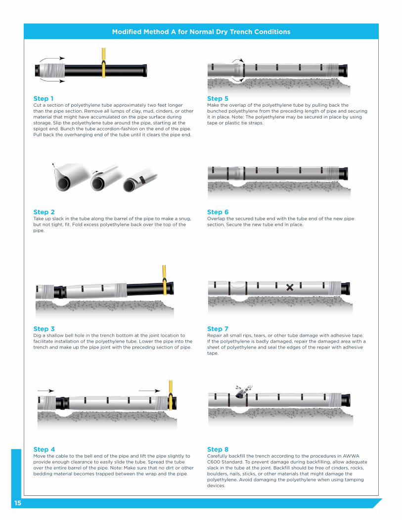
Modified Method A for Normal Dry Trench Conditions
Step 1Cut a section of polyethylene tube approximately two feet longer than the pipe section. Remove all lumps of clay, mud, cinders, or other material that might have accumulated on the pipe surface during storage. Slip the polyethylene tube around the pipe, starting at the spigot end. Bunch the tube accordion-fashion on the end of the pipe. Pull back the overhanging end of the tube until it clears the pipe end.
Step 5Make the overlap of the polyethylene tube by pulling back the bunched polyethylene from the preceding length of pipe and securing it in place. Note: The polyethylene may be secured in place by using tape or plastic tie straps.
Step 2Take up slack in the tube along the barrel of the pipe to make a snug, but not tight, fit. Fold excess polyethylene back over the top of the pipe.
Step 6Overlap the secured tube end with the tube end of the new pipe section. Secure the new tube end in place.
Step 3Dig a shallow bell hole in the trench bottom at the joint location to facilitate installation of the polyethylene tube. Lower the pipe into the trench and make up the pipe joint with the preceding section of pipe.
Step 7Repair all small rips, tears, or other tube damage with adhesive tape. If the polyethylene is badly damaged, repair the damaged area with a sheet of polyethylene and seal the edges of the repair with adhesive tape.
Step 4Move the cable to the bell end of the pipe and lift the pipe slightly to provide enough clearance to easily slide the tube. Spread the tube over the entire barrel of the pipe. Note: Make sure that no dirt or other bedding material becomes trapped between the wrap and the pipe.
Step 8Carefully backfill the trench according to the procedures in AWWA C600 Standard. To prevent damage during backfilling, allow adequate slack in the tube at the joint. Backfill should be free of cinders, rocks, boulders, nails, sticks, or other materials that might damage the polyethylene. Avoid damaging the polyethylene when using tamping devices.

16
Appurtenances
Pipe-Shaped Appurtenances Cover bends, reducers, offsets, and other pipe-shaped
appurtenances in the same manner as the pipe.
Odd-Shaped Appurtenances Wrap odd-shaped appurtenances such as valves,
tees, and crosses with a flat sheet or split length of
polyethylene tube by passing the sheet under and
then over the appurtenance and bringing it together
around the body of the appurtenance. Make seams
by bringing the edges of the polyethylene together,
folding over twice, and taping them down.
Joints Overlap joints as in normal installation; then tape
the polyethylene securely in place at valve stems
and other penetrations. When bolted-type joints are
used, care should always be taken to prevent bolts
or other sharp edges of the joint configuration from
penetrating the wrap.
Branches, Blowoffs, Air Valves To provide openings for branches, blowoffs,
air valves, and similar appurtenances, make an
X-shaped cut in the polyethylene and temporarily
fold back the film. After installing the appurtenance,
tape the slack securely to the appurtenance and
repair the cut and any other damaged areas in the
polyethylene with tape.
Service Taps The preferred method of tapping polyethylene-
encased Ductile Iron Pipe involves wrapping two
or three layers of polyethylene adhesive tape
completely around the pipe to cover the area where
the tapping machine and chain will be mounted.
Then install the corporation stop directly through
the tape and polyethylene. After the tap is made
inspect the entire circumferential area for damage
and make any necessary repairs.
In wet, sloppy trench conditions, the pipe should be completely covered by the polyethylene tube before it is lowered in to the trench. This alternate method is illustrated below.
Step 1Cut the polyethylene tube to a length approximately two feet longer than that of the pipe section. Slip the tube over the pipe.
Step 2Spread the tube over the entire barrel of the pipe, pushing back both ends of the tube until they clear both pipe ends. Make sure the tube is entered on the pipe to provide a one-foot overlap each end.
If you have any problems or questions about installing polyethylene encasement, contact DIPRA or one of its member companies.
Step 3Take up slack in the tube to make a snug, but not tight, fit. (see previous page.) Circumferential wraps of tape or plastic tie straps should be placed at 2-foot intervals along the barrel of the pipe to help minimize the space between the polyethylene and the pipe. Wrap a piece of tape or plastic tie strap completely around the pipe at each end to seal the polyethylene, leaving ends free to overlap the adjoining sections of pipe.
Step 4: Lower pipe into the trench and make up the pipe joint. Be careful not to damage the polyethylene when handling or jointing the pipe. Complete the installation following dry condition Steps 4,5 (taking care to seal ends of overlap by wrapping tape or plastic tie straps completely around the pipe at each end), 8, and 9 on previous page. Note: When lifting polyethylene-encased pipe, use a fabric-type sling or suitable padded cable or chain to prevent damage to the polyethylene.
Alternate Method A for Wet Trench Conditions
17
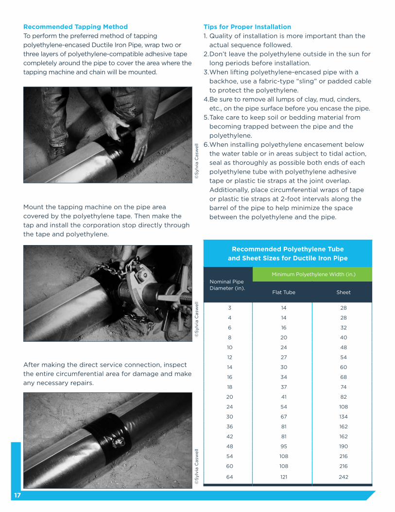
Mount the tapping machine on the pipe area
covered by the polyethylene tape. Then make the
tap and install the corporation stop directly through
the tape and polyethylene.
After making the direct service connection, inspect
the entire circumferential area for damage and make
any necessary repairs.
Recommended Tapping Method
To perform the preferred method of tapping
polyethylene-encased Ductile Iron Pipe, wrap two or
three layers of polyethylene-compatible adhesive tape
completely around the pipe to cover the area where the
tapping machine and chain will be mounted.
©S
ylv
ia C
asw
ell
©S
ylv
ia C
asw
ell
©S
ylv
ia C
asw
ell
Tips for Proper Installation
1. Quality of installation is more important than the
actual sequence followed.
2. Don’t leave the polyethylene outside in the sun for
long periods before installation.
3. When lifting polyethylene-encased pipe with a
backhoe, use a fabric-type “sling” or padded cable
to protect the polyethylene.
4. Be sure to remove all lumps of clay, mud, cinders,
etc., on the pipe surface before you encase the pipe.
5. Take care to keep soil or bedding material from
becoming trapped between the pipe and the
polyethylene.
6. When installing polyethylene encasement below
the water table or in areas subject to tidal action,
seal as thoroughly as possible both ends of each
polyethylene tube with polyethylene adhesive
tape or plastic tie straps at the joint overlap.
Additionally, place circumferential wraps of tape
or plastic tie straps at 2-foot intervals along the
barrel of the pipe to help minimize the space
between the polyethylene and the pipe.
Recommended Polyethylene Tube
and Sheet Sizes for Ductile Iron Pipe
Nominal Pipe Diameter (in).
Minimum Polyethylene Width (in.)
Flat Tube Sheet
3 14 28
4 14 28
6 16 32
8 20 40
10 24 48
12 27 54
14 30 60
16 34 68
18 37 74
20 41 82
24 54 108
30 67 134
36 81 162
42 81 162
48 95 190
54 108 216
60 108 216
64 121 242

18
Cost Considerations
Polyethylene encasement is more cost effective when compared to alternative corrosion-control systems like
bonded coatings and cathodic protection.
According to costs outlined in a 1985 U.S. Army Corps of Engineers Technical Report, installing a 16-mil thick
coating of coal tar epoxy is five times the cost of installing polyethylene encasement. And, this figure doesn’t
include the additional costs of packaging, handling, transportation, and inspection.
Compared to polyethylene encasement, cathodic protection is very expensive to install. According to the
same Corps of Engineers’ report, the cost to install an impressed-current cathodic protection system on
12-inch Ductile Iron Pipe is five times the cost of polyethylene encasement. The cost to install a sacrificial-
anode system is approximately 30 times the cost of polyethylene. These figures don’t include the ongoing
maintenance expense required by both systems, which, over the life of the systems, are often much greater
than initial design and installation costs.
©R
an
dy U
sed
om

19
Conclusion
There is no perfect system of corrosion protection for buried metallic pipelines. Failures have been
documented with all types of corrosion-protection systems, including cathodic protection. Cathodic
protection is very expensive to install and maintain and can also damage nearby pipelines through stray
current interference. Bonded coatings are also expensive. Plus, they can be easily damaged during shipping,
handling, and installation and are costly and difficult to repair in the field.
Polyethylene encasement also has limitations — and it is not universally applicable for all Ductile Iron
Pipelines where corrosion protection is warranted. There are instances where it is not feasible to install
polyethylene encasement due to unusual construction conditions. Additionally, in certain high-density stray
current environments and in a “uniquely severe environment,” as defined in Appendix “A” of ANSI/AWWA
C105/A21.5, the sleeving alone might not provide the degree of protection needed. In such cases, DIPRA
sometimes recommends alternative methods of corrosion protection. And, as with all corrosion control
methods, the success of polyethylene encasement is dependent upon proper installation procedures.
Since the early 1950s, DIPRA has researched numerous methods of corrosion protection for Gray and Ductile
Iron Pipe, including hundreds of investigations in the laboratory, in field test sites, and in operating water
systems throughout the United States. New types of polyethylene, various external pipe coatings, and the
use of select backfill have also been investigated. More than 58 years of experience have demonstrated
polyethylene encasement’s effectiveness in protecting Cast and Ductile Iron Pipe in a broad range of
soil conditions. Properly installed polyethylene encasement can effectively eliminate the vast majority of
corrosion problems encountered by most utilities. Based on numerous laboratory and field test results,
DIPRA continues to recommend polyethylene encasement as the most economical and effective method of
protecting Ductile Iron Pipe in most corrosive environments.
For Further Information
• American National Standard for Polyethylene Encasement for Ductile-Iron Pipe Systems. ANSI/AWWA
C105/A21.5- 99. American Water Works Association, Denver, Colorado.
• John C. Anderson, Polyethylene Encasement for Protection of Ductile Iron Pipe in Corrosive Environments,
Ductile Iron Pipe Research Association, Birmingham, Alabama.
• A. Michael Horton, “Protecting Pipe With Polyethylene Encasement,” 1951- 1988, Waterworld News, May/
June 1988, pp. 26-28.
• Andrew B. Malizio, “Pipe Digs Show Effectiveness of Poly Sheet Encasement,” Water Engineering &
Management, October 1986.
• Troy F. Stroud, “Corrosion Control Methods for Ductile Iron Pipe,” Waterworld News, July/August 1989,
American Water Works Association, Denver, Colorado.
• Troy F. Stroud, “Corrosion Control Measures For Ductile Iron Pipe,” Paper No. 585, National Association of
Corrosion Engineers Corrosion 89 Conference, New Orleans, Louisiana, April 18, 1989.
• Troy F. Stroud, “Polyethylene Encasement versus Cathodic Protection: A View on Corrosion Protection,”
Ductile Iron Pipe News, Spring/Summer 1988, pp. 8-11.
• Ernest F. Wagner, “Loose Plastic Film Wrap as Cast-Iron Pipe Protection,” Journal American Works
Association Vol. 56, No. 3, March 1964.
• T.M. Walski, “Cost of Water Distribution System Infrastructure Rehabilitation, Repair, and Replacement,”
Technical Report EL-85-5. U.S. Army Corps of Engineers, Department of the Army, Washington, D.C., March 1985.
• W. Harry Smith, “Corrosion Prevention with Loose Polyethylene Encasement,” Water & Sewage Works, May 1982.
• L. Gregg Horn, “The Design Decision Model™ For Corrosion Control of Ductile Iron Pipeline,” Ductile Iron
Pipe Research Association, Birmingham, AL.

Strength and Durability for Life®
Ductile Iron Pipe Research Association
An association of quality producers dedicated to the highest pipe standards through a program of continuing research and service to water and wastewater professionals.
P.O. Box 190306 Birmingham, AL 35219 205.402.8700 Telwww.dipra.org
Social Media
Get in the flow with Ductile Iron Pipe by connecting with us on Facebook, Twitter, and LinkedIn.
Visit our website, www.dipra.org/videos, and click on the YouTube icon for informational videos on Ductile Iron Pipe’s ease of use, economic benefits, strength and durability, advantages over PVC, and more.
Copyright © 2017 by Ductile Iron Pipe Research Association
Member Companies
AMERICAN Ductile Iron PipeP.O. Box 2727Birmingham, Alabama 35202-2727
Canada Pipe Company, Ltd.1757 Burlington Street EastHamilton, Ontario L8N 3R5 Canada
McWane DuctileP.O. Box 6001Coshocton, Ohio 43812-6001
United States Pipe and Foundry CompanyTwo Chase Corporate DriveSuite 200Birmingham, Alabama 35244
Ductile Iron Pipe is
For more information contact DIPRA or any of its member companies.