PLC Automated Control for Anti-corrosion Process ... - IJARSE
10
599 | Page PLC Automated Control for Anti-corrosion Process and Substation Maintenance Ajay Khambe 1 , Sandeep Kudal 2 , Shital Nilpankar 3 , Rajashri Gharpankar 4 , Snehal Patil 5 , Harshad Narke 6 , Sachin Kamble 7 1, 3, 4,5,6,7 UG Student, 2 Asst. Professor, Electrical Engineering Department, AMGOI, Vathar, Kolhapur, (India) ABSTRACT The proposed system provides an analysis of simulation and components required for the anti-corrosion process with the help of the PLC (Programmable Logic Controller). In this paper, automation control process is carried out for anti-corrosion purpose. The manual process is very complicated and time consuming. This paper also introduces the anti-corrosion coating technique. Here the characteristics and application of PLC automated control for anti-corrosion process using seven phosphate techniques is applied. Further the technique could be applied to the automation of substation maintenance. Keywords-Phosphating, Automation and PLC kit, Pre-treatment. I. INTRODUCTION It is very important that the metal is prevented from corrosion. The loss of metals due to corrosion has become very big problem in industries. The pre-treatment process is carried out for cleaning of the metal equipment. The phosphate process is carried out manually. It is very non-efficient and the time consuming process. The automation of seven phosphate process must be done so that large number of metal equipment can be get coated and prevented from corrosion [1-2].The chemical cleaning of metals has number of advantages over mechanical cleaning methods. Metal equipment typically gets both organic and inorganic objects deposited on it, coming from various lubricating oils, corroding metals, deposited products, deposits from hard water etc. [3] Pre- treatment methods of metal object prior to powder coating are divided into two types, chromating and Phosphating[4]. Automatic control is the use of various control system for operating equipment [5]. More often the systems are incorporated with Allen Bradley software of PLC. The PLC programming of ladder logics is implemented. The large number of input and output of PLC will be used in this system control large number of tanks and hoist [6]. The sensors sense the presence of water, liquid and presence of an object [7]. A programmable logic controller is an industrial digital computer. PLC can range from small building brick devices with ten of inputs and outputs, in housing integral with the processor, to large rack-mounted modular devices with a count of thousands of I/O, and which are often networked to other PLC and SCADA system [8]. SCADA is a control system architecture that uses computers, networked data communication. They can control
-
Upload
khangminh22 -
Category
Documents
-
view
3 -
download
0
Transcript of PLC Automated Control for Anti-corrosion Process ... - IJARSE
599 | P a g e
PLC Automated Control for Anti-corrosion Process and
Substation Maintenance
Ajay Khambe1, Sandeep Kudal
2, Shital Nilpankar
3,
Rajashri Gharpankar4, Snehal Patil
5, Harshad Narke
6, Sachin Kamble
7 1, 3, 4,5,6,7
UG Student, 2Asst. Professor,
Electrical Engineering Department, AMGOI, Vathar, Kolhapur, (India)
ABSTRACT
The proposed system provides an analysis of simulation and components required for the anti-corrosion process
with the help of the PLC (Programmable Logic Controller). In this paper, automation control process is carried
out for anti-corrosion purpose. The manual process is very complicated and time consuming. This paper also
introduces the anti-corrosion coating technique. Here the characteristics and application of PLC automated
control for anti-corrosion process using seven phosphate techniques is applied. Further the technique could be
applied to the automation of substation maintenance.
Keywords-Phosphating, Automation and PLC kit, Pre-treatment.
I. INTRODUCTION
It is very important that the metal is prevented from corrosion. The loss of metals due to corrosion has become
very big problem in industries. The pre-treatment process is carried out for cleaning of the metal equipment. The
phosphate process is carried out manually. It is very non-efficient and the time consuming process. The
automation of seven phosphate process must be done so that large number of metal equipment can be get coated
and prevented from corrosion [1-2].The chemical cleaning of metals has number of advantages over mechanical
cleaning methods. Metal equipment typically gets both organic and inorganic objects deposited on it, coming
from various lubricating oils, corroding metals, deposited products, deposits from hard water etc. [3] Pre-
treatment methods of metal object prior to powder coating are divided into two types, chromating and
Phosphating[4]. Automatic control is the use of various control system for operating equipment [5]. More often
the systems are incorporated with Allen Bradley software of PLC. The PLC programming of ladder logics is
implemented. The large number of input and output of PLC will be used in this system control large number of
tanks and hoist [6]. The sensors sense the presence of water, liquid and presence of an object [7]. A
programmable logic controller is an industrial digital computer. PLC can range from small building brick
devices with ten of inputs and outputs, in housing integral with the processor, to large rack-mounted modular
devices with a count of thousands of I/O, and which are often networked to other PLC and SCADA system [8].
SCADA is a control system architecture that uses computers, networked data communication. They can control
600 | P a g e
large scale processes that can include multiple sites, and work over large distance [9]. Some work shows the
design and implementation of a controller based on fuzzy logic using PLC as a processing element [10].
The proposed system provides an analysis of simulation and component required for the implementation of an
automated level control of system using PLC. Three level sensors are used to provide the level data to the PLC.
The PLC is used to take the required decision and thereby turning forward, reverse, up and down positioning of
the hoist of the motor. The proposed system can be divided into two modules-sensing and implementation.
II. SYSTEM DATA DISCRIPTION
The system can divided into three main parts:
A. Anti-corrosion process
B. PLC (programmable logic controller)
C. Relay and Motor
A. ANTI-CORROSION PROCESS
Before the powder coating is applied on any object, it is advisable to undergo pre-treatment in order to enhance
the durability of powder coating. Pre-treatment methods of metal object prior to powder coating are divided into
two types, Phosphating and Chromating. Here we use the Phosphating process.
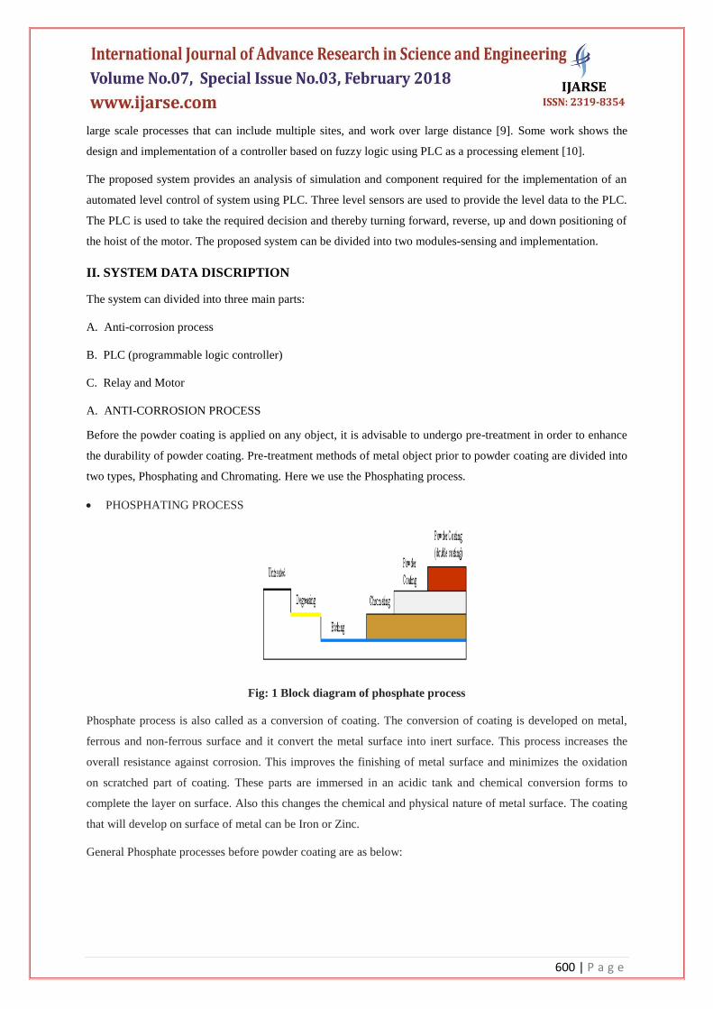
PHOSPHATING PROCESS
Fig: 1 Block diagram of phosphate process
Phosphate process is also called as a conversion of coating. The conversion of coating is developed on metal,
ferrous and non-ferrous surface and it convert the metal surface into inert surface. This process increases the
overall resistance against corrosion. This improves the finishing of metal surface and minimizes the oxidation
on scratched part of coating. These parts are immersed in an acidic tank and chemical conversion forms to
complete the layer on surface. Also this changes the chemical and physical nature of metal surface. The coating
that will develop on surface of metal can be Iron or Zinc.
General Phosphate processes before powder coating are as below:

601 | P a g e
[i] DEGREASING
In the degreasing process remove grease, oil and other surface dirt on the metal surface. For cleaning
temperature is used between 50oC to 70
oC and their duration of time is about 3 to 4 minutes and higher depends
on surface condition.
[ii] RINSING
To removal of chemicals from metal surface and prevent dust and dirt, we usually use the rinsing step. This step
is used after each process step. In this step regular water is used and it is normally good after the first pre-
treatment steps. Conductivity of rinsing water does not exceed 30 microsecond/cm. The temperature of water in
rinsing step after phosphate should not exceed than 50oC, rinsing duration is generally few minutes.
[iii] ETCHING
The purpose of etching process is to remove the natural oxide layer on the metal surface. To protect the metal
surface from attack during the process inhibiters are added. The temperature between 50oC to 70
oCand duration
about 3 to 4 minutes and higher depends on surface condition.
[iv] RINSING
This loosens deposits and removes chemical and gets metal ready for next stage. Also in this process, the layer
of phosphate is fixed on the metal. The duration is about 3 to 4 minutes and this process is done under normal
room temperature.
[v] DEOXIDISATION
In this deoxidization process, any insoluble particles from etching process are removed. To remove the smut we
usually dip in an acidic solution. The dipping process about 30sec. to 5min. under normal room temperature.
[vi] DRYING
Before powder coating; after the phosphate and rinsing process, the metal profile should be completely dried.
The temperature for the drying step should not too high. When drying temperature exceeds their limits the poor
corrosive resistance is obtained.
B. PLC (Programmable Logic Controller)
Fig: 2 Block diagram of PLC.
602 | P a g e
The fig.2 serves as the main control unit of the system. The ladder logic is implemented in Allen Bradley‟s
Micrologix1200. On the basis of this logic the PLC takes its decisions. The 24V DC supply is given to the PLC
by using the SMPS. Here we use the Allen Bradley‟s Micrologix 1200. It is attached in industry; can automate
and monitor a large number of tanks. PLC is interfaced by to the computer via P.M.DC Motor. Our aim is to
make pretreatment process of 7 phosphate technique fully automated. This demo model will have two 24 volt
P.M. DC Motors which will perform up-down and to-from motion according to the time. Automation of
pretreatment process is done for Normal Load (In this type motor will carry single bucket at a time.)
C. RELAY AND MOTOR
A relay is an electrically operated switch. This relay is a static relay their output is connected to the motor. The
relay converts the DC output of PLC into a signal corresponding to effectively control the motor being used.
This motor is a P.M.DC Motor.
Here P.M.DC Motor is interfaced with the PLC and this is connected to the hoist for up-down and forward-
reverse positioning purpose.
III. DESIGN AND IMPLEMENTATION
The P.M.DC Motor is interfaced with the PLC programming. The output of motor is given to the hoist for up-
down and forward-reverse positioning. Provision of manual start or stop switch is incorporated which will
totally overcome the automatic system. The Proximity Sensor is used to sense the presence of metal object.
The implementation is divided into two parts:
A. Software Design
B. Hardware Design
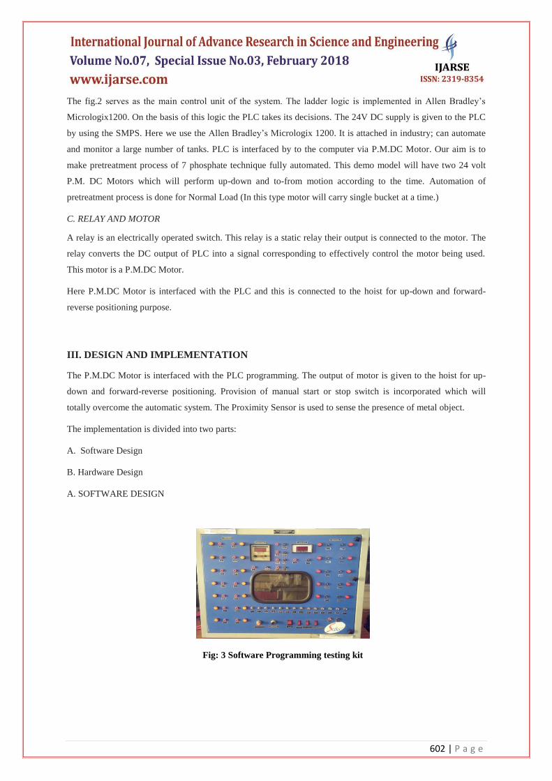
A. SOFTWARE DESIGN
Fig: 3 Software Programming testing kit

603 | P a g e
In the software the ladder programing is used. In the software contains the two rail named as power rail and
load rail. In this two rail the software programing is established .The programming is done in RS LOGIX
STARTER software. By using testing kit (fig.3) the program is tested.
LADDER PROGRAMMING
Fig: 4 ladder logic cycle 1
Fig: 5 ladder logics cycle 2
Fig: 6 Ladder Logics cycle 3
The symbol used in the ladder logic is shown in the above three fig. 4, 5, 6 and this show the time based motion
control. The Ladder Programming contains two RUNGS. According to logic various types of timers, counters,
input & outputs are used.
604 | P a g e
B. HARDWARE DESIGN
The hardware design is divided into two parts i.e. manual and automatic.
The manual process is having two parts i.e. Mechanical structure and Electrical structure as shown in below
fig.7. Manual process carried out with help of two or more peoples which undesirably engages more labors to
this process. As well as increase in number of labors increases the possibility of human error which should be
avoided for better accuracy and perfection.
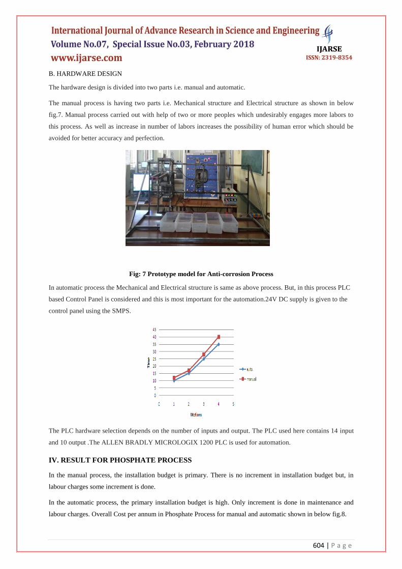
Fig: 7 Prototype model for Anti-corrosion Process
In automatic process the Mechanical and Electrical structure is same as above process. But, in this process PLC
based Control Panel is considered and this is most important for the automation.24V DC supply is given to the
control panel using the SMPS.
The PLC hardware selection depends on the number of inputs and output. The PLC used here contains 14 input
and 10 output .The ALLEN BRADLY MICROLOGIX 1200 PLC is used for automation.
IV. RESULT FOR PHOSPHATE PROCESS
In the manual process, the installation budget is primary. There is no increment in installation budget but, in
labour charges some increment is done.
In the automatic process, the primary installation budget is high. Only increment is done in maintenance and
labour charges. Overall Cost per annum in Phosphate Process for manual and automatic shown in below fig.8.
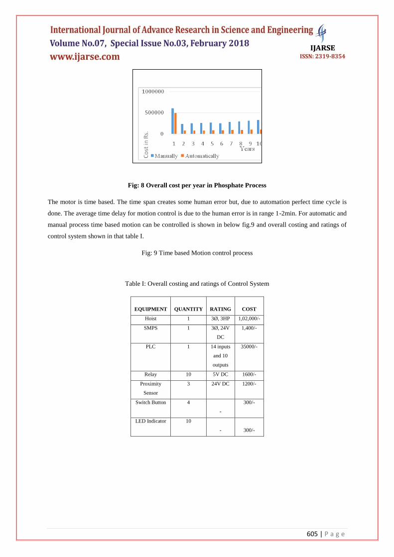
605 | P a g e
Fig: 8 Overall cost per year in Phosphate Process
The motor is time based. The time span creates some human error but, due to automation perfect time cycle is
done. The average time delay for motion control is due to the human error is in range 1-2min. For automatic and
manual process time based motion can be controlled is shown in below fig.9 and overall costing and ratings of
control system shown in that table I.
Fig: 9 Time based Motion control process
Table I: Overall costing and ratings of Control System
EQUIPMENT
QUANTITY
RATING
COST
Hoist 1 3Ø, 3HP 1,02,000/-
SMPS 1 3Ø, 24V
DC
1,400/-
PLC 1 14 inputs
and 10
outputs
35000/-
Relay 10 5V DC 1600/-
Proximity
Sensor
3 24V DC 1200/-
Switch Button 4
-
300/-
LED Indicator 10
-
300/-
606 | P a g e
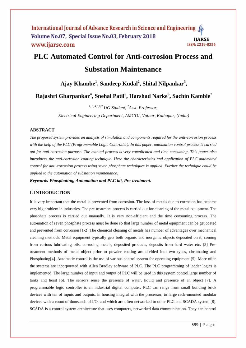
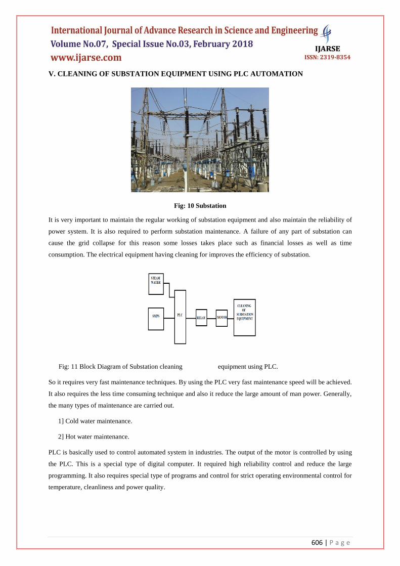
V. CLEANING OF SUBSTATION EQUIPMENT USING PLC AUTOMATION
Fig: 10 Substation
It is very important to maintain the regular working of substation equipment and also maintain the reliability of
power system. It is also required to perform substation maintenance. A failure of any part of substation can
cause the grid collapse for this reason some losses takes place such as financial losses as well as time
consumption. The electrical equipment having cleaning for improves the efficiency of substation.
Fig: 11 Block Diagram of Substation cleaning equipment using PLC.
So it requires very fast maintenance techniques. By using the PLC very fast maintenance speed will be achieved.
It also requires the less time consuming technique and also it reduce the large amount of man power. Generally,
the many types of maintenance are carried out.
1] Cold water maintenance.
2] Hot water maintenance.
PLC is basically used to control automated system in industries. The output of the motor is controlled by using
the PLC. This is a special type of digital computer. It required high reliability control and reduce the large
programming. It also requires special type of programs and control for strict operating environmental control for
temperature, cleanliness and power quality.
607 | P a g e
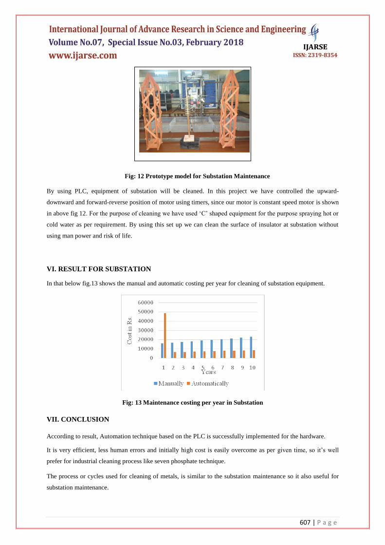
Fig: 12 Prototype model for Substation Maintenance
By using PLC, equipment of substation will be cleaned. In this project we have controlled the upward-
downward and forward-reverse position of motor using timers, since our motor is constant speed motor is shown
in above fig 12. For the purpose of cleaning we have used „C‟ shaped equipment for the purpose spraying hot or
cold water as per requirement. By using this set up we can clean the surface of insulator at substation without
using man power and risk of life.
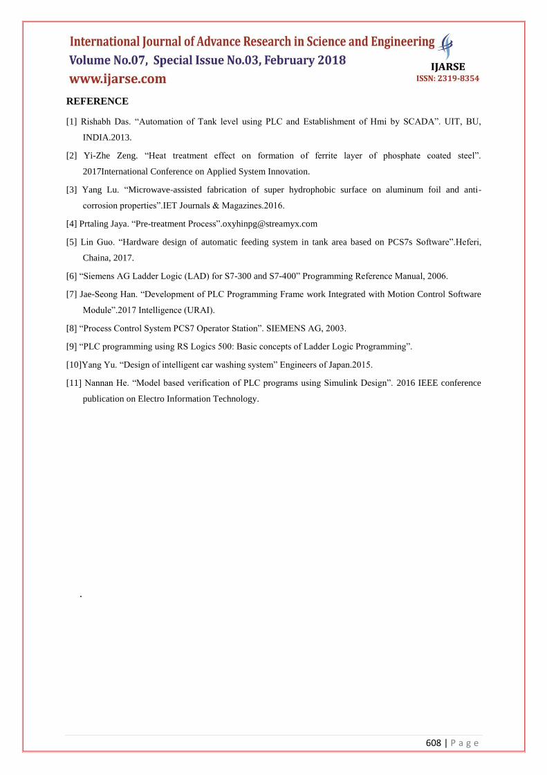
VI. RESULT FOR SUBSTATION
In that below fig.13 shows the manual and automatic costing per year for cleaning of substation equipment.
Fig: 13 Maintenance costing per year in Substation
VII. CONCLUSION
According to result, Automation technique based on the PLC is successfully implemented for the hardware.
It is very efficient, less human errors and initially high cost is easily overcome as per given time, so it‟s well
prefer for industrial cleaning process like seven phosphate technique.
The process or cycles used for cleaning of metals, is similar to the substation maintenance so it also useful for
substation maintenance.
608 | P a g e
REFERENCE
[1] Rishabh Das. “Automation of Tank level using PLC and Establishment of Hmi by SCADA”. UIT, BU,
INDIA.2013.
[2] Yi-Zhe Zeng. “Heat treatment effect on formation of ferrite layer of phosphate coated steel”.
2017International Conference on Applied System Innovation.
[3] Yang Lu. “Microwave-assisted fabrication of super hydrophobic surface on aluminum foil and anti-
corrosion properties”.IET Journals & Magazines.2016.
[4] Prtaling Jaya. “Pre-treatment Process”[email protected]
[5] Lin Guo. “Hardware design of automatic feeding system in tank area based on PCS7s Software”.Heferi,
Chaina, 2017.
[6] “Siemens AG Ladder Logic (LAD) for S7-300 and S7-400” Programming Reference Manual, 2006.
[7] Jae-Seong Han. “Development of PLC Programming Frame work Integrated with Motion Control Software
Module”.2017 Intelligence (URAI).
[8] “Process Control System PCS7 Operator Station”. SIEMENS AG, 2003.
[9] “PLC programming using RS Logics 500: Basic concepts of Ladder Logic Programming”.
[10]Yang Yu. “Design of intelligent car washing system” Engineers of Japan.2015.
[11] Nannan He. “Model based verification of PLC programs using Simulink Design”. 2016 IEEE conference
publication on Electro Information Technology.
.