CDA3000-PLC - eTranstechnik
76
H1 H2 H3 X4 X2 X1 X3 ACHTUNG Kondensatorent- ladezeit >3 Min. Betriebsanleitung beachten! WARNING capacitor disscharge time >3 minutes. Pay attention to the operation manual! ATTENTION temps de decharge du condensteur >3 min. observer le mode dèmploi! ! L3 U V W RB+ RB L- L1 L2 ANTRIEBSTECHNIK D- 35633 Lahnau Type: CDA32.004,C1.0 In: 230 V + 15/-20% 50/60 Hz 1,7 kVA 3x0-230 V 4 A 0,75 kW 0-400 Hz Out: SN.: 99120442 VT505W shift 1 D E F 4 M N O 7 V W X 2 G H I 5 P Q R 8 Y - Z 3 J K L 6 S T U 9 + / = Enter 0 A B C . ± VT150W F1 F6 F2 F7 F3 F8 F4 F9 F5 F10 Info Help start enter stop return Hz 1 2 CDA3000-PLC Sub-automation unit with c-line DRIVES EN EN FR IT ES System manual
-
Upload
khangminh22 -
Category
Documents
-
view
0 -
download
0
Transcript of CDA3000-PLC - eTranstechnik

H1 H2 H3
X4
X2X1
X3
ACHTUNGKondensatorent-ladezeit >3 Min.Betriebsanleitungbeachten!
WARNINGcapacitor disschargetime >3 minutes.Pay attention to theoperation manual!
ATTENTIONtemps de dechargedu condensteur>3 min. observer lemode dèmploi!
!
L3
U
V
W
RB+
RB
L-
L1
L2
AN
TRIE
BS
TEC
HN
IKD
- 35
633
Lah
nau
Typ
e:C
DA
32.0
04,C
1.0
In:
230
V
+ 1
5/-2
0%50
/60
Hz
1,7
kVA
3x0-
230
V 4
A0,
75 k
W 0
-400
Hz
Ou
t:
SN
.:
991
2044
2
VT505W
shift
1
D
E
F
4
M
N
O
7
V
W
X
2
G
H
I
5
P
Q
R
8
Y
-
Z
3
J
K
L
6
S
T
U
9
+
/
=
Enter0
A
B
C
.±
Space
VT150W
F1
F6
F2
F7
F3
F8
F4
F9
F5
F10
Info
Help
PgUp
PgDn
Esc
Clr
Parameter
startenter
stopreturn
VAL
Hz
12
CDA3000-PLC
Sub-automation unitwith c-line DRIVES
EN
EN
FR
IT
ES
System manual

System manual CDA3000-PLC
Id.-No.: 0840.12B.1
Stand: 05/.2003
Valid from CDA3000-software version V700.10
We reserve the right to make technical changes.

How to use this guide
1 Introduction
2 System survey
3 Sub-automatisation units
4 Commissioning of PLC-system
5 Order data of system components
1
2
3
4
5
Directory
Sub-automatisation unit with c-line DRIVES

Pictographs
Attention! Faulty operation can cause damage or mal-function of the drive system.
Here you will find further comparable applications.
The symbol stands for hurdles and barriers, which have to be cleared during realization of the concept.
Note: What you have to know, information in short form.
Sub-atuomatisation unit with c-line DRIVES

1 Introduction1.1 Thinking in machine sub-automation units ...........1-2
1.2 Typical machine sub-automation units .................1-4
2 System survey2.1 Software package CDA3000, PLC ...........................2-22.1.1 PLC-Editor ...........................................................2-22.1.2 PLC-Firmware ....................................................2-112.1.3 DRIVEMANAGER .....................................................2-20
2.2 Operator panels for c-line DRIVES .........................2-21
2.3 SMARTCARD / KEYPAD ..............................................2-31
2.4 Training .................................................................2-32
2.5 Service-know-how for your projects ...................2-34
3 Sub-automation units3.1 Time-controlled luggage belt-drive .......................3-2
3.2 Drill feed unit ...........................................................3-4
3.3 Shredder with overload detection ..........................3-7
3.4 Unwinder for wire .................................................3-11
3.5 Diameter depending speed control ......................3-13
3.6 Simple positioning drive with PLC_3 ...................3-15
4 Commissioning of PLC-system4.1 First commissioningCDA3000, PLC ........................4-1
4.2 First commissioning of operator panels .......................................................4-4
4.2.1 Configuration of RS232-interface .........................4-44.2.2 Configuration of CANopen-network .......................4-6
5 Order data of system components
Sub-automatisation unit with c-line DRIVES


1
2
3
4
5
A
1 Introduction
Due to the increased pressure to reduce costs a new slogan is born in theautomation industry. Sub-automation unit - a catchword, which will beused more and more. What is the difference between this solution andothers, what are the advantages?
This manual clears these and other questions. It is made for all users ofinverters and servocontrollers as well as for people technically interested,looking for new solutions. Salespeople, specialists and executives will getan impression of new economic solutions.
The manual includes the following five ranges:
Chapter 1: General introduction
Chapter 2: System survey
Chapter 3: Sub-automation units
Chapter 4: Commissioning of PLC-systems
Chapter 4: Order data of system components
Sub-automatisation unit with c-line DRIVES 1-1

1 Introduction
1.1 Thinking in machine sub-automation units
Thinking in machine sub-automation units requires in the drive units afree-programmable core inside, named PLC. Because the contribution tothe solution of sub-automation units depends more and more on the flexi-bility of the PLC-user plattform within the drive system. Finally, only thesoftware offers the „intelliegence“ and so the method to get over themotion solution.
Seeing driving problems from a process oriented standpoint, always thecomplete system has to be taken into consideration. Large complexmachines and instruments have to be disassembled in small clear sub-automation units. In machine sub-automation units, doing a job automati-cally and inevitably following to a set procedure. Normally such sub-auto-mation units reflect the mechanical and electrical construction unit.
Please note at realization of new solutions that the procedure of sub-automation units is enclosed. That means that a changing of conditionscannot be made directly via an other sub-automation unit, it can onlyadjusted via a „clear defined interface“.
picture 1.1 PLC-user plattform
BASIC FIRMWARE
HARDWARE - PLATFORM
T1 T2T3 T ... n
M1
F
P2
10
b1
T
D
S3
SM1
S1RNOK
S2
W1 P1
S1
10V
P2
10Vb1
ω
ω
X
M1
PLC - USER PLATFORM
machine sub-automation unit
X1
L3
U
V
W
RB+
RB
L-
L1
L2
H1 H2 H3
X4
X2
X3
!
ANTRIEBSTECHNIK
SN.:000.000.00000000
Typ:
Netz:
Ausg.:
D-35633 Lahnau
M2
W1 S2
S1
S3
M1
b1
1-2Sub-automatisation unit with c-line DRIVES

1 Introduction
1
2
3
4
5
A
Special at this solution is that the sub-automation unit can be used inother machine types, requiring the same sub-automation unit, withoutchanging the program.
Coupling of sub-automation units to one „function unit“ allows the co-ordi-nation of complex procedures. In the function unit one of the sub-automa-tion units manages the coordination of the whole function unit as well.However, the function of other sub-automation units will be required viathe already mentioned „clear defined interface“.
picture 1.2 sub-automation unit - drill unit
picture 1.3 function unit - drilling appliance
M2
W1
S2
S1
S3
M1
b1
W1 M3
M1
S2
S1
M2
b1
S4S3
Sub-automatisation unit with c-line DRIVES 1-3

1 Introduction
The complete automatic process is clearly structured resp. is divided inclosed machine sub-automation units. Sub-automation units, allowingunitizing of machine types and having a high reusability. Serial commis-sioning can be made without special knowledge or PC, simply via SMART-CARD - plug-in, load and run.
1.2 Typical machine sub-automation units
The already cleared machine sub-automation units can typically dividedin three groups:
I/O-oriented sub-automation unit
Motion solutions, processes are mainly defined by means of I/O-signals.Typical applications are: advance unit for drilling or sinking, belt and car-riage drives, drives for doors and gates as well as pump stations with floatswitches.
Time-controlled sub-automation unit
Motion solutions, processes are mainly time-controlled. Typical applicati-ons are: melting and mixing plants for paints and other materials, differentcentrifuges as well as mills and shredder.
Controlled sub-automation unit
Motion solutions, for controlling process variables like torque, traction,pressure, temperature or position. Typical applications are wobbler anddancer control for winders, block-protection for shredder, simple posi-tioning jobs for drives, rotating, as well as drives for doors and gates andthe classic pressure, temperature and flow control.
1-4Sub-automatisation unit with c-line DRIVES

1
2
3
4
5
A
2 System survey
The system consists of the following components:
• Drive CDA3000 with accessories and option modules
• Software package CDA3000-PLC
• Different operator panels with accessories
picture 2.1CDA3000-PLC System survey
KEYPADKP200-XL
Communication module- PROFIBUS-DP via CM-DPV1- CANopen via CM-CAN1
SMARTCARDSC-XL
PLC-Program-Editor
12
3132
3334
3521
2223
2425
2627
2829
301
2
12
Parameter
startenter
stopreturn
VAL
Hz
ShiftF2 F3 F4F1
Esc
Help
InfoF5
VT50
SN
.: 0
0230
1271
!
VT505W
shift
1
D
E
F
4
M
N
O
7
V
W
X
2
G
H
I
5
P
Q
R
8
Y
-
Z
3
J
K
L
6
S
T
U
9
+
/
=
Enter0
A
B
C
.±
Space
VT150W
F1
F6
F2
F7
F3
F8
F4
F9
F5
F10
Info
Help
PgUp
PgDn
Esc
Clr
Integrated PLC
control functions
Operator-Panels
User modules- I/O-Module (8E/4A) UM-8I4O
Programming system forOperator-Panels
Sub-automatisation unit with c-line DRIVES 2-1

2 System survey
2.1 Software pak-kage CDA3000, PLC
The software package CDA3000-PLC consists of three parts:
• PLC-program editor on CD-ROM. The PLC-editor is additionally to the DRIVEMANAGER. On CD-ROM you will find this system manual as well as PLC and device standard software. Furthermore it incl. additional product documentation (user manual CDA3000, communication modules)
• PLC-device firmware V700.xx for CDA3000
• DRIVEMANAGER V3.20 (or higher version) on CD-ROM.
2.1.1 PLC-Editor The PLC-program editor will be delivered on a separate CD-ROM asinstallation version. In German and English available.
The PLC-editor is part of the DRIVEMANAGER and so it can only be usedwith DRIVEMANAGER. This presumes that a DRIVEMANAGER with versionV3.20 and higher is installed on the PC.
The PLC-editor is only necessary for the engineering resp. first commis-sioning, a serial commissioning of the drive controller will be made viaDRIVEMANAGER-data set or SMARTCARD.
picture 2.2 PLC-editor
2-2Sub-automatisation unit with c-line DRIVES

2 System survey
1
2
3
4
5
A
The PLC-program editor offers the following functions:
• Program production
− Editor for program production
− Generating a text declaration file <project name>.txt for varia-bles to show application specific texts in the DRIVEMANAGER.
− Syntax check of command code
− Renumbering of line numbers
• Program-Handling
− Load/Save/Print/New production of programs
− Load/Save a program from/in the connected driveLoad/Save a program from/in the DRIVEMANAGER data set
• Online-Help for PLC-Editor and for command syntax with examples
All PLC-functions are selectable via function switches (buttons)
New
pro
gram
Open
pro
gram
as
file
Save
pro
gram
as
file
*.pl
c
Cut t
ext
Copy
text
Past
e te
xt
Undo
Sear
ch/R
epla
ce
Prin
t pro
gram
Onlin
e he
lp
Prog
ram
syn
tax
chec
k
Renu
mbe
ring
of li
ne n
umbe
rs
Load
pro
gram
from
dat
a se
t
Save
pro
gram
in d
ata
set
Load
pro
gram
from
dev
ice
Save
pro
gram
in d
evic
e
Sub-automatisation unit with c-line DRIVES 2-3

2 System survey
PLC-Program process A program is divided in two parts:
1. Text declaration for used variables, flags, counter and timer
2. PLC-program
The Text declaration is for marking of used variables, counters andtimers in the PLC-program with the application specific function. A text filewill be generated out of the text declaration, evaluated in the DRIVEMANA-GER, shows the parameters with application specific texts.
The text declaration starts with the designator, obtains the the projectname of the text declaration file (for details see „PLC-program data“).
%TEXT (project name) ; Start text declaration
An assignation of the parameter texts follows:
DEF M000 = setpoint_OKDEF H000 = reference_pos_1DEF H001 = reference_pos_2DEF H002 = actual_posDEF H003 = Zero correction
End of the text declaration always with:
END
The text declaration is optional. Non-declared PLC-parameters will not besaved in the text file resp. displayed with its number in the DRIVEMANA-GER.
The PLC-program attach to the text declaration. It contains a programhead, the true program part and the program end.
The program head consists of a line, includes the program number (hereonly %P00 possible):
%P00
The lines of the program part are called command lines. The number ofthe sets, which can be saved in the CDA3000, is limited to 254 (N001 ...N254). Each command line consists of line number, command and ope-rand. Via semicolon a command can be inserted.
picture 2.3 Indication of PLC-parameters with application specific texts
2-4Sub-automatisation unit with c-line DRIVES
2 System survey
1
2
3
4
5
A
N030 SET M000 = 0; Setpoint not defined
Program ends always with line (without line number):
END
For program examples see chapter 3 or already installed DRIVEMANAGER-directory„..\userdata\PLC“.
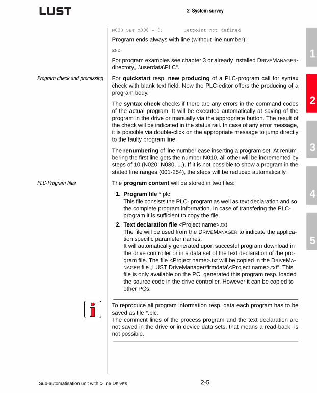
Program check and processing For quickstart resp. new producing of a PLC-program call for syntaxcheck with blank text field. Now the PLC-editor offers the producing of aprogram body.
The syntax check checks if there are any errors in the command codesof the actual program. It will be executed automatically at saving of theprogram in the drive or manually via the appropriate button. The result ofthe check will be indicated in the status rail. In case of any error message,it is possible via double-click on the appropriate message to jump directlyto the faulty program line.
The renumbering of line number ease inserting a program set. At renum-bering the first line gets the number N010, all other will be incremented bysteps of 10 (N020, N030, ...). If it is not possible to show a program in thestated line ranges (001-254), the steps will be reduced automatically.
PLC-Program files The program content will be stored in two files:
1. Program file *.plcThis file consists the PLC- program as well as text declaration and so the complete program information. In case of transfering the PLC-program it is sufficient to copy the file.
2. Text declaration file <Project name>.txtThe file will be used from the DRIVEMANAGER to indicate the applica-tion specific parameter names. It will automatically generated upon succesful program download in the drive controller or in a data set of the text declaration of the pro-gram file. The file <Project name>.txt will be copied in the DRIVEMA-NAGER file „LUST DriveManager\firmdata\<Project name>.txt“. This file is only available on the PC, generated this program resp. loaded the source code in the drive controller. However it can be copied to other PCs.
To reproduce all program information resp. data each program has to besaved as file *.plc.The comment lines of the process program and the text declaration arenot saved in the drive or in device data sets, that means a read-back isnot possible.
Sub-automatisation unit with c-line DRIVES 2-5

2 System survey
There are 3 ways to open an available PLC-program:
• Double-click on file *.plc. Then DRIVEMANAGER opens and it starts the PLC-editor and opens the program.
• Opening via DRIVEMANAGER menu „File/Open/PLC-process program ...“
• Opening via already started PLC-editor
picture 2.4 Open PLC-program via DRIVEMANAGER
2-6Sub-automatisation unit with c-line DRIVES

2 System survey
1
2
3
4
5
A
PLC-command syntax .
Command
Operand Note
Jump command
JMP Ny/END Absolute jump
(Ippi = 0/1) Ny/END Condition of input
(Oppi = 0/1) Ny/END Condition of output
(Mxxx = 0/1, = != Myyy) Ny/END Condition of flag
(Mxxx & | ^ Ippi) Ny/END Logical link flag-input
(Mxxx & | ^ Ippi) Ny/END Logical link flag-output
(Cxx = != 0 .. 255) Ny/END Counter status
(Zxx = != 0) Ny/END Timer status
(Hxxx = != 0, = != < <= > >= Hyyy) Ny/END Size of integer variables
(Fxxx = != 0.0, = != < <= > >= Fyyy) Ny/END
Size of floating point variables
Set commands
SET Oppi = 0/1, Mxxx Set output diretly or with flag
Mxxx = 0/1, Ippi, Oppi, Myyy, M[Cxx] Set flag
Mxxx = Hyyy Set flag (LSB of Hyyy)
M[Cxx] = Mxxx Set flag (indicated)
Mxxx & | ^ Myyy Logical link of flag
Cxx = d, Cyy, Hyyy Set counter
Cxx + - d, Hyyy Calculate counter
Zxx = d, Hyyy Set timer
Hxxx = z, Hyyy, H[Cyy], Fyyy, Cyy, Zyy, PARA[n, i], PARA[n], PARA[Hxxx,Hyyy], PARA[Hxxx]
Set variableAt processes with floating point variables the value range will be limited automatically. No error mes-sage follows.
H[Cxx] = Hyyy Set variable (indicated)
Hxxx & | ^ Hyyy Logical link of variables
Hxxx << >> b, Hyyy Move variable
Hxxx + - * : % z, Hyyy Calculate variable
Hxxx = ABS Hyyy Built variable amount
Fxxx = f, Hyyy, F[Cyy], Fyyy, PARA[n, i], PARA[n], PARA[Hxxx,Hyyy], PARA[Hxxx]
Set floating point variable. At proces-ses with floating point variables the value range will be limited automati-cally. No error message follows.
F[Cxx] = Fyyy Set floating point variable (indicated)
Fxxx + - * : f, Fyyy Calculate floating point variable
Fxxx = ROUND Fyyy Round floating point variable
Fxxx = ABS Fyyy Built floating point amount
Sub-automatisation unit with c-line DRIVES 2-7

2 System survey
SETPARA[n, i], PARA[n], PARA[Hxxx,Hyyy], PARA[Hxxx] = Hyyy, Fyyy
Set parameter
BRKPT = 0 Deactivate brakepoint logic
BRKPT = 1 Activate brakepoint logic
Hxxx = OUTPUT, INPUTRead variables with image of output resp. input
Hxxx, Fxxx = ACTFRQ Read actual frequency [Hz]
Hxxx, Fxxx = ACTSPEED Read actual speed [rpm]
Hxxx, Fxxx = ACTPOS Read actual position [Incr]
Hxxx, Fxxx = REFPOS Read reference position [Incr]
Hxxx, Fxxx = ACTTORQUE Read actual torque [Nm]
Hxxx, Fxxx = ACTCURRENT Read actual current (effective) [A]
Hxxx = OSA0Read analog output value 0 - 1023 = 0V - 10V
Hxxx = ISA0Read analog input ISA0 -512 - 511 = -10V - +10V
Hxxx = ISA1Read analog input ISA1 0 - 1023 = 0V - +10V
OUTPUT = HyyySet output imageOnly outputs with set function selec-tor will be set FOxxx=PLC.
OSA0 = Hyyy
Set analog output0 - 1023 = 0V - 10VCondition: function selector 200-FOSA0 = PLC
REFFRQ = Hyyy, Fyyy
Write frequency reference to FOPT1Reference is only active if reference selector is set to 280-RSSL1=FOPT1 or 281-RSSL2=FOPT1.
INPOSWND = HxxxSet reference reached window [incr] (Default 100 incr.)
INPOSTIME = HxxxSet reference reached time [ms] (Default 20 ms)
Mxxx = STA_ERRRead error status(1 -> error)
Mxxx = STA_WRNRead warning-status(1 -> warning)
Mxxx = STA_ERR_WRNRead error/warning status(1 -> error/warning)
Mxxx = STA_ROT_R Motor turns right (1)
Mxxx = STA_ROT_L Motor turns left (1)
Mxxx = STA_ROT_0 Motor standstill (1)
Command
Operand Note
2-8Sub-automatisation unit with c-line DRIVES

2 System survey
1
2
3
4
5
A
SET Mxxx = STA_ACTIV Motor/Control active (1)
Mxxx = STA_LIMIT Limitation (1)
Mxxx = STA_REF Reference reached (1)
Mxxx = STA_BRAKECondition brake(1 -> Brake active)
Mxxx = STA_OFF Condition de-energized (1)
Mxxx = STA_C_RDY Condition control ready (1)
Mxxx = STA_WUV Warning undervoltage (1)
Mxxx = STA_WOV Warning overvoltage (1)
Mxxx = STA_ WIIT Warning I2*t (1)
Mxxx = STA_WOTM Warning overtemperature motor (1)
Mxxx = STA_WOTI Warning heat sink temperature (1)
Mxxx = STA_WOTD Warning interior temperature (1)
Mxxx = STA_WIS Warning apparent current - limit (1)
Mxxx = STA_WFOUT Warning output frequency - limit (1)
Mxxx = STA_WFDIGWarning reference of master faulty (1)
Mxxx = STA_ WIT Warning I*t (1)
Mxxx = STA_ WTQWarning torque (only FOR and SFC) (1)
ENCTRL = 0/1; MyyyStop/start control (Mxxx = 0/1)Execution of function only if control location CLSEL=PLC is set.
INV = 0/1; Myyy Invert reference
PCTRL = 0/1, Myyy Activate position controller
BRAKE = 0/1, MyyyBrake motor to 0 Hz (1, Mxxx = 1)
ERR = 0/1, MyyyRelease error switch-off(1, Mxxx = 1)
Sub program call
CALL NySub program call to line NyMax. nesting depth: 255
RET Reset to line of sub program call
Wait commands
WAIT d, HxxxWaiting time in ms (0 ... 4.294.967.295 ms)
WAIT PAR Wait until parameter is written.
Go commands (only for positioning control)
GO W A HxxxGo absolutely by value Hxxx and wait for program processing until target position is reached.
Command
Operand Note
Sub-automatisation unit with c-line DRIVES 2-9

2 System survey
Syntax of command index:
GO W R HxxxGo relative by value Hxxx and wait for program processing until target position is reached.
A HxxxGo absolutely by value of Hxxx (pro-gram processing continuous)
A HxxxGo relatively by value of Hxxx (pro-gram processing continuous)
0Referencing to 0 (reference position =actual positon=0)
0+HxxxReferencing to Hxxx (reference posi-tion=actual position=0)
Further commands
NOP Instruction without function
INV Oppi, Mxxx, Hxxx Inverting
ENDFinish program, all following lines will be ignored. Do not enter a line number.
BRKPT
SET BRKPT=1:Sets a breakpoint in the program lineSET BRKPT=0:no function
Command
Operand Note
Cxx, Cyy Counter index 00-10
Hxxx, HyyyInteger-Variable index 000-127
Fxxx, FyyyFloating-Point-Variable indes 000-127
Zxx, Zyy Timer index 00-10
Ny line number 001-254
PARA[n, i]Parameter number n 000-999Parameter index i 000-255
Mxxx, Myyy Flag index 000-255
Ippi, OppiInputsppi = A00, A01 S00-S03, E00-E07
OppiOutputsppi = S00-S02, E00-E03
b Value 1-32
dStatus of a counter
0 ... 255 (8 bit)
dStatus of a timer
0 ... 4.294.967.295 (32 bit)
fFloating point value
(32 bit)
zInteger value
±2147483648 (32 bit)
2-10Sub-automatisation unit with c-line DRIVES

2 System survey
1
2
3
4
5
A
2.1.2 PLC-Firmware
PLC-functionality Firmware CDA3000-PLC with software version number V700.xx is suita-ble for the frequency inverter CDA3000. It contains a routine for sequen-tial processing of a user-programmed procedure.
Number of programs in drive memory: 1Number of commandlines per program: 254Process time per command line: 1 ms
The process program allows:
• Start of motor control
• Reference pre-set for motor control
• Set/Read analog and digital inputs/oputputs
• Read/Write parameters
• Mathematical operations (+,-,*, :, modulo, abs, round)
• Timer and counter functions
• Simple positioning control with frequency acceleration ramps over the reference structure.
Basic software Basis of the PLC-software is the standard software V3.50-01 ofCDA3000. The defined functions of V3.50-01 (s. CDA3000 applicationmanual 07/2002) are applicable in the PLC-execution up to the followingexceptions resp. changes:
• No 4 USER-data setsThe device firmware includes one data set only. So a switching bet-ween them is not possible. The known pre-set solutions with USER data set switch-over are not applicable. Characteristic data set swit-ching is available.
• Integrated CANopen-protocolThe system bus will be extended by the CANopen-protocol. Operation with CANLUST-protocoll is also possible. So the CANopen-link via communication module CM-CAN1 can be realised. The requested CAN-protocol can be set via parameter 654-PRSEL (CLUST/COPEN).Communication module CM-CAN2 (CANopen with setting the address via coding switch) and CM-DPV1 (Profibus DP-V1) can be used alternatively.
• Motor identification not applicableThe automatic identification of asynchronous motors are not part of the PLC-firmware. Motor identification can be executed with the stan-dard firmware V3.50-01. The identified data set can be used in the PLC-firmware.
Sub-automatisation unit with c-line DRIVES 2-11

2 System survey
PLC-Parameters All PLC-control commands are mapped via parameters. They are subjectto the already known data set handling of CDA3000. The parameters canbe processed via DRIVEMANAGER in the PLC-function window (s. picture2.5).
New ist, that the whole PLC-program is saved as machine code in twoparameters. These parameters are included in the device data set andcan be load resp. saved during the data set handling via DRIVEMANAGER
or at serial commissioning via SMARTCARD SC-XL.
Para-meters
Description
452-PLCCT
Starting conditions of the process controlParameter PLCCT defines starting position of the process program.
TERM(0)PLC-start via terminal Function selector of an input has to be set to Fixxx = PLCGO. (0 -> Stop program, 1 -> Start program)
PARA(1)PLC-start via parameterManual changing of operating status PLCST
AUTO(2)PLC-start automatically on power on, parameter operating status has to be set to GO
CTRL(3)PLC-start simultaneous on enable controlPLC-stop simultaneous on disable control
450-PLCST
Operation status of process control This parameter allows start/stop (depending on parameter 452-PLCCT=PARA) resp. shows the actual operating status of the process program.
OFF(0) PLC-switch-off/switched-off process program
GO(1) PLC-start/process program processing
BRKPT(2)
PLC-Interruption of process programWith GO the operation continuous. Independent from the control location it is possible to interrupt (BRKPT) resp. finish (OFF) the pro-cess program via parameter at every time. Restart process program from line of interruption with GO, if the condition of the control loaca-tion is still given (e.g. terminal is still set). In case of a changed con-dition, set parameter to OFF.
451-PLCPL
Current program line. Shows the current processed program line. The line number can be seen in the digital oscilloscope, too.
454-PLCSN
Start at program line (0 = first program line). Program processing starts at the line, mentioned in PLCSN. It is convenient, if there are different independent routines are available in one program.
list 2.1 Parameters of PLC
2-12Sub-automatisation unit with c-line DRIVES

2 System survey
1
2
3
4
5
A
455-PLCBN
Interrupt program at line x (Breakpoint). Program will be interrupted at line, mentioned in PLCBN; parameter 450-PLCST is going to status BRKPT. Restart of program with 450-PLCST=GO(1)
461-PLC_M
Flag (0/1)Access to process program M000...M255
460-PLC_H
Integer variables (32 bit)
Value range from 2-31 to 231. In case of a link with floating point variables or parameters the part after the decimal place will not be considered. No rounding will be made.Access to process program H000...H127
465-PLC_F
Floating point variables Access to process program F000...F127
Value range: -3,37x1038 to 3,37x1038
462-PLC_Z
Timer (32 bit) Time basis 1 msAccess to process program Z00...Z11Timer will be set to a value and returns to 0.
463-PLC_C
Counter for indicated addressing (8 bit)Access to process program C00...C10
466-PLC_I
Code of digital and analog inputs (bit coded)The code is also readable in the program as special variable INPUT.ISD00-ISD03 Bit 0 - Bit 3IED00-IED07 Bit 4 - Bit 11ISA00 - ISA01 Bit 12 - Bit 13
464-PLC_O
Code of digital outputs (bit coded)The code is also writable in the program as special variable OUTPUT.OSD00-OSD02 Bit 0 - Bit 2OED00-OED03 Bit 4 - Bit 6In order to set outputs out of the program the corresponding function selector has to be set to FOxxx = PLC.
468- PLCPJ
Name of PLC-program (project name)Project name will be defined during building the process program (text declara-tion). The name describes directly the text declaration file (project name.txt)(max. 32 figures without special characters, blanks will be ignored)
Para-meters
Description
list 2.1 Parameters of PLC
Sub-automatisation unit with c-line DRIVES 2-13

2 System survey
An easy setting of the a.m. parameters allows the PLC-function window(expanded main window -> PLC or via „basic settings/PLC“ according toselected PLC-preset-solution):
picture 2.5 DRIVEMANAGER - PLC-function window
2-14Sub-automatisation unit with c-line DRIVES

2 System survey
1
2
3
4
5
A
Pre-set solutions Special pre-set solutions are included in the fimware to optimize parame-ter setting of PLC-applications:
PLC_1 - PLC-start via terminal, analog reference & fixed fre-quency
Function:
• Analog speed pre-set for two rotation directions via ISA0
• Switching-over to fixed frequency via input ISD02
• Start PLC-program via ISD03
• Motor control via inputs ISD00/01
• All further I/O’s are available at the PLC-process program.
PLC_2 - PLC-autostart, motor- & I/O-control via PLC
Function:
• Motor control via PLC
• PLC-process program starts automatically on „power-on“
picture 2.6 Terminal assignment PLC_1
X2 X2
+24V
H1
S1
S2
K0OSD02/1420
19
18
17
16
15
14
13
12
11
10
9
8
7
6
5
4
3
2
1
Des. Des.
OSD02/11
OSD02/12
DGND
OSD01
OSD00
DGND
+24 V
ISD03
ISD02
Ready message Start/Stop anti-clockwise
Start/Stop clockwise
Power stage hardware
enable
ENPO
STL
STR
N1
R1
>10 kΩ
-
+
+24 V
+24 V
ISA00
ISA01
ISD01
ISD00
ENPO
OSA00
AGND
+10 V Ref.
Reference reached
start PLC
select fixed frequency
Actual frequency
0...10V = 0...FMAX
Reference -10V...+10V
M3~
~-
K1Motor holding brake
Sub-automatisation unit with c-line DRIVES 2-15

2 System survey
• All further I/O’s are available at the PLC-process program.
Motor control will be controlled from the PLC-program. Independent fromthe selected control mode VFC, SFC or FOR.
Start motor control:
N010 SET ENCTRL=0 ; Switch-off motor controlN020 SET ENCTRL=1 ; Switch-on motor control
Condition: Control location selector 260-CLSEL=PLC (control via processprogram). Is already adjusted at pre-set PLC_2 .
Reference assingment:
N030 SET REFFRQ=H000 ; Frequency reference ; (Value without decimal place)
N040 SET REFFRQ=F010 ; Frequency reference ; (Value as floating point number)
Condition: Parameter of reference selector must be set to FOPT1 (280-RSSL1=FOPT1 oder 281-RSSL2=FOPT1). That means reference chan-nel FOPT1 will be used via PLC-program at PLC-software for referenceset. At pre-setting PLC_2 (280-RSSL1=FOPT1) it is already adjusted .
picture 2.7 Terminal assignment PLC_2
X2 X2
OSD02/1420
19
18
17
16
15
14
13
12
11
10
9
8
7
6
5
4
3
2
1
Des. Des.
OSD02/11
OSD02/12
DGND
OSD01
OSD00
DGND
+24 V
ISD03
ISD02
Power stage hardware
enable
ENPO
+24 V
+24 V
ISA00
ISA01
ISD01
ISD00
ENPO
OSA00
AGND
+10 V Ref.
K0
Ready message
2-16Sub-automatisation unit with c-line DRIVES

2 System survey
1
2
3
4
5
A
PLC_3 PLC-position control
Function:
• Position control with PLC-program and control via inputs ISD01 (start positioning - reference 2) and ISA01 (start homing mode)
• Control mode FOR
• Encoder evaluation via ISD02/03
• Motor control via input ISD00
• All further I/O’s are available at the PLC-process program.
For the complete function you have to download the additional PLC-pro-gram „PLC_3_position control.plc“. See DRIVEMANAGER-directory „..\user-data\PLC“ ab.
In control mode FOR control of rotor position is possible, too. The positioncontrol is suitable for slow changing processes. Therefore a P-controllerwill be connected in series to the reference path in the known CDA3000reference structure.
picture 2.8 Terminal assignment PLC_3
picture 2.9 Position control with PLC-process program
M3~
~-
+24V
K1
H1
N2
track B
track A
K0OSD02/1420
19
18
17
16
15
14
13
12
11
10
9
8
7
6
5
4
3
2
1
X2 Des. X2 Des.
OSD02/11
OSD02/12
DGND
OSD01
OSD00
DGND
+24 V
ISD03
ISD02
Ready message
Encoder
Start positioning
Start homing mode
Start/Stop control
Power stage
hardware enable
ENPO
STL
STR
N1
-
+
+24 V
+24 V
ISA00
ISA01
ISD01
ISD00
ENPO
OSA00
AGND
+10 V Ref.
Reference
reached
motor holding brake Actual frequency
0...10V = 0...FMAX
Not assigned
- PCG
PCTRL = 0
0 HzFOPT1
REFPOS [incr]
ACTPOS
CDA3000Reference structure
+
REFFRQ [Hz]
CDA3000Motor controlPosition controller
Sub-automatisation unit with c-line DRIVES 2-17

2 System survey
Switch-on/off the position controller via the following commands:
N010 SET PCTRL = 1 ; Activate position controllerN020 SET PCTRL = 0 ; Deactivate position controller
The P-gain 819-PCG of the position controller is adjustable by theDRIVEMANAGER (Function window „basic setting“) or via parameteraccess in the process program.
Functions like homing mode, jog mode and cam switch are not part of thefirmware. However, they can be realised with a PLC-program (sub-pro-gram).
A position profile generator is not included. That means the position con-troller sends a step signal to the reference structure resp. speed control-ler. Via suitable parameter setting of the acceleration ramps of the refe-rence structures it can be straightened. An overswinging in the targetposition is possible.
The pre-set solution PLC_3 will also be described in chapter 3.6. asexample.
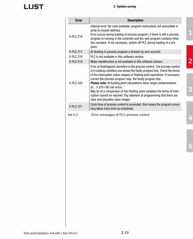
PLC-error messages The process control generates different error messages, collected in list2.2.
Error Description
E-PLC 210 Error actuated via PLC (SET ERR = 1, Mxxx mit Mxxx = 1).
E-PLC 211Error at sub-program calls / reset via CALL / RET.Stack underflow: unexpected RET w/o previous CALL.Stack overflow: max. nesting scopes (250 CALLs) reached.
E-PLC 212
Error at writing parameters (buffer full).Writing out of the interrupt via a buffer with max. 30 entries, whereas the buffer itself will be handled in the main loop. Receiving this message means that the buffer limit is reached, that means the main loop could not process all parameter assignments.Command WAIT PAR effects in stopping the program processing as long as all parameters are written and the buffer is empty.In case of too many parameter accesses (more than 30 continuous para-meter accesses) or during backup of parameter writing access at the fur-ther program processing an WAIT PAR should be effected intermediately.
E-PLC 213Error at writing parameters.Parameter does not exist, no field parameter, value range default, value not writable, etc.
E-PLC 214Error at reading parameters. Parameter does not exist or no field parameter..
E-PLC 215 Internal error: No code available or program instructions not executable.
list 2.2 Error messages of PLC-process control
2-18Sub-automatisation unit with c-line DRIVES
2 System survey
1
2
3
4
5
A
E-PLC 216
Internal error: No code available, program instructions not executable or jump to unused address.Error occurs during loading of process program, if there is still a process program is running in the controller and the new program contains other line numbers. If not necessary, switch-off PLC during loading of a pro-gram.
E-PLC 217 At dividing in process program a division by zero occured.
E-PLC 218 PLC is not available in this software version.
E-PLC 219 Motor identification is not available in this software version.
E-PLC 220
Error at floatingpoint operation in the process control. The process control is in waiting condition ans shows the faulty program line. Check the terms of the interruption (value ranges) at floating point operations. If necessary correct the process program resp. the faulty program line.Please note: At floating point calculations value range contaminations (0... 3.37E+38) can occur.May be at a comparison of two floating point variables the terms of inter-ruption cannot be reached. Pay attention at programming that there are clear and plausible value ranges.
E-PLC 221Cycle time of process control is exceeded, that means the program proce-sing takes more time as scheduled.
Error Description
list 2.2 Error messages of PLC-process control
Sub-automatisation unit with c-line DRIVES 2-19

2 System survey
2.1.3 DRIVEMANAGER PLC-software as well as PLC-editor can be operated resp. parameterscan be set with each DRIVEMANAGER-version from V3.20. With theDRIVEMANAGER a serial commissioning of the CDA3000-PLC is possiblewith only one device data set.
Condition is an installed DRIVEMANAGER for working with PLC-functiona-lity resp. PLC-editor, because it is integrated. Parallel working with theDRIVEMANAGER and the PLC-editor functions is possible.
picture 2.10DRIVEMANAGER-main window for CDA3000
2-20Sub-automatisation unit with c-line DRIVES

2 System survey
1
2
3
4
5
A
2.2 Operator panels for c-line DRIVES
With the graduated raw of operator panels high-quality, efficient, multipleuse products are available for the system. They guarantee a high-opera-ting comfort and a high-functionality and are equipped with an attractivedesign, too.
• Presentation of texts, picture, bargraphs, bitmap-pictures and inciting graphics*
• Recipe management*
• Saving of files to avoid unautorised access via passwords
• Indication of system messages
• Indication of warning messages*
• Communication via bus systems LUSTBUS (RS232) or CANopen*
• Free-programmable function buttons
• Individual possibilities of labelling via slide-in strip*
• Clearly-presented multilingual programming software
* however not available at all types
Four different operator panels are available:
ShiftF2 F3 F4F1
Esc
Help
InfoF5
VT50
shift
1
D
E
F
4
M
N
O
7
V
W
X
2
G
H
I
5
P
Q
R
8
Y
-
Z
3
J
K
L
6
S
T
U
9
+
/
=
Enter0
A
B
C
.±
Space
VT150W
F1
F6
F2
F7
F3
F8
F4
F9
F5
F10
Info
Help
PgUp
PgDn
Esc
Clr
VT505W
VT155
VT150WText display,
4x20 characters, 25 buttons
VT050 Text display,
2x20 characters, 8 buttons
VT505WTouch-Screen, 4 blue levels,
320x240 pixel (5,6“)VT155W
Touch-Screen, 4 grey levels, 240x128 pixel
Sub-automatisation unit with c-line DRIVES 2-21

2 System survey
Further displays as well as customized operator panels are availableupon request.
operator panels can be used for operating and parameter setting of drivecontrollers of c-line Drives:
• CDA3000 (Standard, HF, PLC)
• CDD3000
• CTC3000
Interfaces The operator panels are available with serial LUSTBUS Interface RS232 orwith a CANopen interface. At some panels we differ between programmingand communicating interface.
At communication interface RS232 (LustBus-interface) a Peer-to-Peercommunication between axis controller and operator panel is possible.This connection is suited for single axis drives. Programming of the panelis also done via RS232-interface.
When connecting the operator panel via serial RS232-interface the ser-vice interface (e.g. for PC-tool DriveManager) is not longer resp. can onlybe used with disconnected operator panel.
Assignment of the connecting cable is shown in picture 2.11.
For the connection there are cord sets in length of 3 m (OPK-RS03) and5 m (OPK-RS05) at disposal.
With an integrated communication interface CANopen in the operatorpanel an autonomous network operation with one operator panel and thedrive controllers of c-line-DRIVES is possible. The operator panel set theparameters for all controllers, connected to the bus. For programming thepanel a serial RS232-interface is available.
picture 2.11 RS232-connection of operator panels
RxD
TxD
RTS
CTS
GND
3
2
7
25
TxD
RxD
GND
2
3
5
4
5
15
18
max. 5m
VT-Site D-Sub
25-pole plug
c-line DRIVES D-Sub
9-pole plug
2-22Sub-automatisation unit with c-line DRIVES

2 System survey
1
2
3
4
5
A
The CANopen-interface of operator panels has a master slave structure
(s. picture 2.12).
It is the job of the operator panels (Master) to initialise and to reconfigurethe drive controllers (Slaves); furthermore it is necessary for the control ofthe communication status of the devices in the network. For communica-tion the slave-devices have to be initialized (operating status) and para-meters have to be set from the master-device.
Technical data VT050
picture 2.12CANopen-network with operator panel
Slave
Master
Adress 1 2 127 128
Adress Adress Adress
Article code of panel: Characteristics of panel:
VT050 00000N
VT050 000CNN
Display
Type Text LCD
Background lighting LED
Lines and characters 2 x 20
Representional format [mm] 73,5 x 11,5
Character matrix in text mode [Pixel] 5 x 7
Size of characters [mm] 3,2 x 5,5
Contrast adjustment Trim pot
Character sets ASCII, Katakana
Keyboard
System-/ Function-/Alphanumerical keys 8 / 5 / -
User memory
Project (Flash EPROM) [kB] 256 kB
Interfaces
Sub-automatisation unit with c-line DRIVES 2-23

2 System survey
Serial port MSP (25 pin female) RS232/RS422/RS485/TTY 20 mA
Serial port ASP-8 ( pin female) RS232
Networks
Integrated CANopen
Characteristics
Project-languages 4
Password-level /Bit-Password - / 8 bit
Pages/pages-help 127 / 127
Variables per page 8
Variable formDEC, HEX, BIN, BCD, ASCII,
Floating Point
Dynamic texts Depending on size of project
memory
ISA-alarms/information messages - / 128
Alarm buffer -
Recipes -
Dimensions
Outer W x H x D [mm] 166 x 86 x 41
Mounting frame W x H [mm] 157 x 77
Technical data
Power supply 24 Vdc (18 .. 32 Vdc)
Power absorbed at 24 Vdc 5 W
Protection fuse5 x 20 mm - 315 mA (Fine wire
fuse type F)
Protection level IP65 (Front)
Working temperature 0 .. +50°C
Storage and transportion temperature -20°C .. +60°C
Humidity <85%
Weight 0,5 kg
Certifications and approvals CE, RINA (UL upon request)
Article code of panel: Characteristics of panel:
VT050 00000N
VT050 000CNN
2-24Sub-automatisation unit with c-line DRIVES
2 System survey
1
2
3
4
5
A
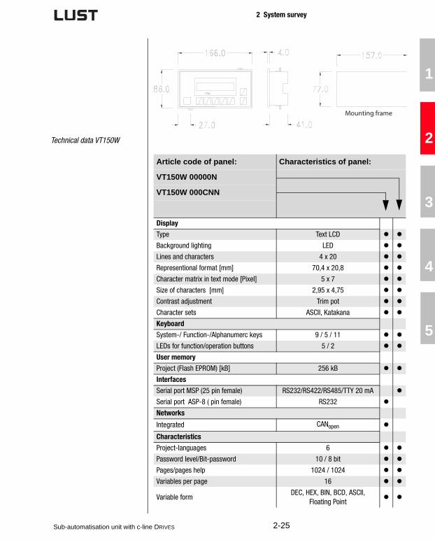
Technical data VT150W
Mounting frame
Article code of panel: Characteristics of panel:
VT150W 00000N
VT150W 000CNN
Display
Type Text LCD
Background lighting LED
Lines and characters 4 x 20
Representional format [mm] 70,4 x 20,8
Character matrix in text mode [Pixel] 5 x 7
Size of characters [mm] 2,95 x 4,75
Contrast adjustment Trim pot
Character sets ASCII, Katakana
Keyboard
System-/ Function-/Alphanumerc keys 9 / 5 / 11
LEDs for function/operation buttons 5 / 2
User memory
Project (Flash EPROM) [kB] 256 kB
Interfaces
Serial port MSP (25 pin female) RS232/RS422/RS485/TTY 20 mA
Serial port ASP-8 ( pin female) RS232
Networks
Integrated CANopen
Characteristics
Project-languages 6
Password level/Bit-password 10 / 8 bit
Pages/pages help 1024 / 1024
Variables per page 16
Variable formDEC, HEX, BIN, BCD, ASCII,
Floating Point
Sub-automatisation unit with c-line DRIVES 2-25

2 System survey
Dynamic texts Depending on size of project
memory
ISA-Alarms/Information messages - / 1024
Alarm buffer -
Recipes -
Dimensions
Outer W x H x D [mm] 148 x 188 x 41
Mounting frame W x H [mm] 123 x 175
Technical data
Ppower supply 24 Vdc (18 .. 32 Vdc)
Power absorbed at 24 Vdc 15 W
Protection fuse5 x 20 mm - 800 mA (Fine wire
fuse type F)
Protection level IP65 (Front)
Working temperature 0 .. +50°C
Storage and transportion temperature -20°C .. +60°C
Humidity <85%
Weight 0,7 kg
Certificates and approvals CE
Article code of panel: Characteristics of panel:
VT150W 00000N
VT150W 000CNN
Mounting frame
2-26Sub-automatisation unit with c-line DRIVES

2 System survey
1
2
3
4
5
A
Technical data VT505W
Article code of panel: Characteristics of panel:
VT505W 00000N
VT505W 000CNN
Display
Type Graphic, LCD 4 blue levels STN
Touch Screen Matrix 20 x 16
Background lighting CCFL-tube
Lifetime [hours] 15000
Resolution 320 x 240 (5,6“)
LInes and characters 16x40 / 8x20 / 4x10
Representional format [mm] 115,2 x 86,4 (5,6“)
Character matrix in text mode [Pixel] 8x15 / 16x30 / 32 x 60
Size of characters [mm] x1 / x2 / x4 2,8x5,2 / 5,6x10,4 / 11,2x20,8
Contrast adjustment Software
Character sets programmable sets
User memory
Project (Flash EPROM) [kB] 512 kB
Data storage (Flash EPROM) [kB] 16 kB
Interfaces
Serial port MSP (25 pin female) RS232/RS422/RS485/TTY 20 mA
Networks
Integrated CANopen
Characteristics
Multilingual texts 4
Password-level /Bit-Password 10 / 8 bit
Pages/pages help 64 / 64
Variables per page 24
Variable formDEC, HEX, BIN, BCD, ASCII,
Floating Point
Dynamic texts / picture indexDepending on size of project
memory
ISA-Alarms/Information messages - / 256
Alarm buffer -
Recipes (number of/variables per recipe) 128 / 256
Bar graphs per page 24
Project picturesBMP, JPG; TIFF, PSD, WMF, PNG,
EPS, ...
Clock Software (w/o buffer battery)
Sub-automatisation unit with c-line DRIVES 2-27

2 System survey
Dimensions
Outer W x H x D [mm] 210 x 158 x 54
Mounting frame W x H [mm] 198 x 148
Technical data
Power supply 24 Vdc (18 .. 32 Vdc)
Power absorbed at 24 Vdc 10 W
Protection fuse5 x 20 mm - 800 mA (Fine wire
fuse type F)
Protection level IP65 (Front)
Working temperature 0 .. +50°C
Storage and transportation temperature -20°C .. +60°C
Humidity <85%
Weight 1,4 kg
Certificates and approvals CE
Article code of panel: Characteristics of panel:
VT505W 00000N
VT505W 000CNN
Mounting frame
2-28Sub-automatisation unit with c-line DRIVES

2 System survey
1
2
3
4
5
A
Technical data VT155W
Article code of panel: Characteristics of panel:
VT155W 00000N
VT155W 000CNN
Display
Type Graphic, LCD 4 grey levels STN
Touch Screen Analog/20x8 (12x16 pixel)
Background lighting LED
Resolution 240x128 pixel
Lines and characters 16x40 / 8x20 / 4x10
Representional format [mm] 94,5x54,5
Character matrix in text mode [Pixel] 6x8 / 12x16 / 24x32
Size of characters [mm] x1 / x2 / x4 2,3x5,2 / 4,6x5,8 / 9,1x11,7
Contrast adjustment Software
Character sets Programmable sets
User memory
Project (Flash EPROM) [kB] 640 kB
Data storage (Flash EPROM) [kB] 16 kB + 8 kB (Alarm buffer)
Interfaces
Serial port MSP (25 pin female) RS232/RS422/RS485/TTY 20 mA
Serial port Port ASP (8 pin female) RS232
Networks
Integrated CANopen
Characteristics
Project-languages 4
Password-level /Bit-Password 10 / 8 bit
Pages/pages help 64 / 64
Variables per pages 32
Variable formDEC, HEX, BIN, BCD, ASCII,
Floating Point
Dynamic texts/picture indexDepending on size of project
memory
ISA-Alarms/Information messages 256 / 256
Alarm buffer 220
Recipes (number of/variables per recipe) 128 / 256
Bar graphs per page 32
Project picturesBMP, JPG; TIFF, PSD, WMF, PNG,
EPS, ...
Clock Hardware (with Supercapacitor)
Sub-automatisation unit with c-line DRIVES 2-29

2 System survey
Dimensions
Outer W x H x D [mm] 166 x 100 x 43,6
Mounting frame W x H [mm] 157 x 91
Technical data
Power supply 24 Vdc (18 .. 32 Vdc)
Power absorbed at 24 Vdc 10 W
Protection fuse5 x 20 mm - 800 mA (Fine wire
fuse type F)
Protection level IP65 (Front)
Working temperature 0 .. +50°C
Storage and transportation temperature -20°C .. +60°C
Humidity <85%
Weight 0,5 kg
Certificates and approvals CE (UL upon request)
Article code of panel: Characteristics of panel:
VT155W 00000N
VT155W 000CNN
Mounting frame
2-30Sub-automatisation unit with c-line DRIVES

2 System survey
1
2
3
4
5
A
Programming operator panels Programming of operator panels by means of a graphic PC-user inter-face. Only one software for all operator panels. The CD-ROM softwarepackage VTWINCD includes:
• Programming software in 5 languages
• Suitable for operating system Windows 95/98/NT/2000/ME/XP
• Software- and hardware-manuals in 5 languages
For the programming of operator panels various programming cablesresp. adapters are available. The following list 2.3 shows which cable isneeded for a defined panel (X).
2.3 SMARTCARD / KEYPAD
For serial commissioning we recommend SMARTCARD SC-XL. It has alarge data storage, so that the PLC-program with all PLC-configurationparameters can be saved.
The SMARTCARD SC-XL is no replacement for the card SC. The SMART-CARD SC (A028.V01.1) used up to now cannot be used any longer, due toa loss of memory capacity. An error at the KEYPAD is indicated whentrying to write on such a card.
To support the SMARTCARD SC-XL the KEYPAD KP200-XL will be used.The KP200-XL is compatible with the functions of the KP200(0840.0000). The SMARTCARD SC (A028.V01.1) will also be supported bythe KP200-XL.
Parallel to the already used KP200 we offer the KP200-XL, which has tobe ordered with a separate article number.
Attention: The CDA3000-PLC-operation with KEYPAD KP200 and/or SMARTCARD SC can cause malfunction and is not allowed.
Programming cable
CVCOM 11102
Programming adapter
CVCOM 25F8M
VT050 00000N X
VT050 000CNN X X
VT150W 00000N X
VT150W 000CNN X X
VT505W 00000N X
VT505W 000CNN X
VT155W 00000N X X (optional)
VT155W 000CNN X X
list 2.3 Using program cables
Sub-automatisation unit with c-line DRIVES 2-31
2 System survey
2.4 Training To introduce the CDA3000-PLC system we offer different trainings. Trai-nings methods are lectures, discussions, demonstrations and practicalexamples.
Training how to program CDA3000-PLC
Target: Learning how to handle and program the CDA-PLC software
Contents: • Chracteristics, efficiency, application limits of the PLC-function.
• Making of process programs with PLC
− PLC-Program editor− Survey of command sets− PLC-parameter setting
• Commissioning of CDA3000-PLC
• Possibilities of use and training examples
Conditions: • Experience in working with inverter drive systems CDA3000 and DRIVEMANAGER
• MS-Windows system-knowledge
Date: 1 day seminar
Time: 8.00 a.m. to 5.00 p.m.
Location: Lust Antriebstechnik GmbH, Lahnau
Number of participants:
6-10 Persons
Instructors: Andreas Kling, Jörg Brinkemper
Languages: German or English
2-32Sub-automatisation unit with c-line DRIVES

2 System survey
1
2
3
4
5
A
Handling and programming of operator panels
Target: Learning how to handle and program Lust-opera-tor panels
Contents: • Survey of operator panel components
• Characteristics and efficiency of operator panels
• Connection of operator panels with the drive controller
• Configuration and programming of operator panels
• Possibilities to use and training examples
Conditions: • Experience in working with the inverter drive system CDA3000 and DRIVEMANAGER
• MS-Windows system-knowledges
Date:
Time:
Location:
Number of
participants:
Instructors:
Language: German or English
— in
preparation —
Sub-automatisation unit with c-line DRIVES 2-33

2 System survey
2.5 Service-know-how for your projects
Use the know-how of our qualified application engineers. Get decisiveadvantages to realize efficient sub-automation units with our experience.Solutions, made exactly for your requirements, your demands.
Compatibility from the beginning:
• Projectmanagement
− Work out project order
− Detailed project planning
− Execution of project
− Sorted finishing of the project and saving the knowledge
• Engineering
− Analysis of the conceptual formulation
− Concipate and design of the system
− Apply the components for the system
− Introduction of different solution opportunities
• Service of making software
− Making of PLC- or operator panel software acc. to specification
− Test the software in the system
− Transfer of software incl. all documents
• Commissioning of a sub-automation unit
− Prepare the commissioning resp. function test
− Commissioning of the system at site
− Making of commissioning protocol with all measuring data
Use our experience of over 30 years and together we will find a solutionfor your complex jobs.
2-34Sub-automatisation unit with c-line DRIVES
1
2
3
4
5
A
3 Sub-automation units
By the mentioned examples in this chapter it deals only with programmingexercises for the CDA3000-PLC. Neither the conceptional formulation northe solutions are checked under safety specifications.
The examples show which solutions are possible with integratedsequence control and how a typical program looks like. The mentionedprograms are saved in the DRIVEMANAGER sub-directory „userdata/PLC“.
You will agree that under these circumstances Lust AntriebstechnikGmbH is not responsible and cannot assume any liability for using thisprograms or parts of it.
Sub-automatisation unit with c-line DRIVES 3-1

3 Sub-automation units
3.1 Time-control-led luggage belt-drive
Description of the function
If the luggage interrupts the light beam of the light-barrier L1, the con-veyor belt FB starts. Max. conveyor speed will be pre-selected via poten-tiometer P1.
Cycle length of conveyor FB will be set by means of potentiometer P2. Ifthe time set with potentiometer F2 is passed, the inverter M1, FU1 will beswitched-off and the belt runs off.
Technology scheme
picture4.1 Time-controlled luggage belt-drive
FBRB
M1
FU1
CDA3000/PLC
H1 H2 H3
!
P1
L1
P2
(v) (t)
3-2Sub-automatisation unit with c-line DRIVES

3 Sub-automation units
1
2
3
4
5
A
Process program; Process programme for CDA-PLC, example luggage belt-drive
;Initialisation;Reference setpoint via analog input ISA0 with caling in the device parameters
%TEXT(luggage belt)DEF H000=max_cycle lengthDEF H001=auxiliary variableDEF H002=analog inputEND
%P00N010 SET H000=20000; max. value cycle length in msN020 SET H001=H000; auxiliary variableN021 SET H001:1023; resolution of analog input 10Bit
N050 JMP (IS00=0) N050; wait for release signal; of light barrier N060 SET ENCTRL=1; start control
;Read timer value of analog input ISA1N070 SET H002=ISA1; analog value in H002N075 SET H002*H001; Calculate resolution of analog input
;Initialise timerN080 SET Z00=H002N085 JMP (Z00!=0) N085; wait for timer run-off
;Stop controlN090 SET ENCTRL = 0
N100 JMP N020; jump backEND
Further typical applications are melting and mixing plants for paints andother materials as well as centrifuges, mills and shredder.
Sub-automatisation unit with c-line DRIVES 3-3

3 Sub-automation units
3.2 Drill feed unit The drilling appliance consists of a drilling spindle, feed unit and conveyorunit. In the following we like to explain the sub-automation unit „drilling“and with it spindle and feeding drive.
Basic position
The drilling unit is in basic position, if
• the feed unit is above (S1 damped)
• the drilling appliance is free (S3 not damped)
• spindle M1, FU1 is switched-off.
Description of the function
If the workpiece W1 is in the drilling appliance (S3 damped) and the startbutton b1 is pressed, the drilling unit receives okay for processing.
The drilling spindle M1,FU1 runs to the working speed. If drilling spindleM1,FU1 reaches the working speed, the drilling unit sinks over the fee-ding drive M2,FU2.
Approaching the lower sensor (S2) the point of reversal is reached. Thefeeding drive M2,FU2 reverses, so that the drilling spindle runs in basicposition again.
Approaching the upper sensor (S1) the feeding drive M2,FU2 and the dril-ling spindle M1,FU1 stop automatically. The workpiece will be carried viaconveyor unit and the process can start again.
Set spindle speed and feeding speed via operator panel OP.
3-4Sub-automatisation unit with c-line DRIVES

3 Sub-automation units
1
2
3
4
5
A
Technology scheme
Process program;Program example feed unit
;Inputs:;M001=Start feed;IS01=Pre-stop opener;IS02=Upper limit switch opener;IS03=Lower limit switch closer
%TEXT (feed)DEF H000 = Reference_0DEF H001 = Timer_1DEF M002 = InitialisationDEF H002 = Quick-jog frequencyDEF H003 = Slow-jog frequencyDEF H004 = Waiting timeDEF H010 = Quick-jog_positiveDEF H011 = Quick-jog_negativeDEF H012 = Slow-jog_positiveDEF H013 = Slow-jog_negativeDEF M001 = Start motion
picture4.2 Drill feed unit
SN
.:
0023
0127
1
!
SN
.:
0023
0127
1
!
FU1 FU2 OP
CDA3000,HF CDA3000 + PLC
M2
W1
S2
S1
S3
ShiftF2 F3 F4F1
Esc
Help
InfoF5
VT50
M1
b1
Sub-automatisation unit with c-line DRIVES 3-5
3 Sub-automation units
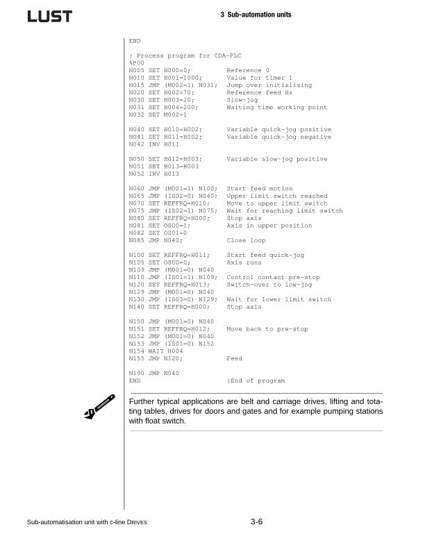
END
; Process program for CDA-PLC%P00N005 SET H000=0; Reference 0N010 SET H001=1000; Value for timer 1N015 JMP (M002=1) N031; Jump over initialisingN020 SET H002=70; Reference feed HzN030 SET H003=20; Slow-jogN031 SET H004=200; Waiting time working pointN032 SET M002=1
N040 SET H010=H002; Variable quick-jog positiveN041 SET H011=H002; Variable quick-jog negativeN042 INV H011
N050 SET H012=H003; Variable slow-jog positiveN051 SET H013=H003N052 INV H013
N060 JMP (M001=1) N100; Start feed motionN065 JMP (IS02=0) N040; Upper limit switch reachedN070 SET REFFRQ=H010; Move to upper limit switchN075 JMP (IS02=1) N075; Wait for reaching limit switchN080 SET REFFRQ=H000; Stop axisN081 SET OS00=1; Axis in upper positionN082 SET OS01=0N085 JMP N040; Close loop
N100 SET REFFRQ=H011; Start feed quick-jogN105 SET OS00=0; Axis runsN109 JMP (M001=0) N040N110 JMP (IS01=1) N109; Control contact pre-stopN120 SET REFFRQ=H013; Switch-over to low-jogN129 JMP (M001=0) N040N130 JMP (IS03=0) N129; Wait for lower limit switchN140 SET REFFRQ=H000; Stop axis
N150 JMP (M001=0) N040N151 SET REFFRQ=H012; Move back to pre-stopN152 JMP (M001=0) N040N153 JMP (IS01=0) N152N154 WAIT H004N155 JMP N120; Feed
N190 JMP N040END ;End of program
Further typical applications are belt and carriage drives, lifting and tota-ting tables, drives for doors and gates and for example pumping stationswith float switch.
3-6Sub-automatisation unit with c-line DRIVES

3 Sub-automation units
1
2
3
4
5
A
3.3 Shredder with overload detec-tion
Shredder (hacking machines) are used in various applications, forexample in the food industry, construction industry or in offices. Fre-quently, problems during this process are caused by blocking of the drive.
The example shows a shredder with overload detection and automaticfree-running (back-off) of the roller at blocking. The user can have aneffect on this behaviour by means of setting the parameters of the over-load detection. Therefore the user set the time of reaction at overload,minimum time for overload and the number of free-running trials perrecipe management.
Description of the function
Upon actuating the drive FU1,M1 via button b1 the rollers of the shredderrotate with an adjustable fixed frequency in forward direction A. During theprocess the PLC of FU1 manages the control of the motor current I up toa settable threshold. In case of exceeding the reference, that means atoverloading or blocking or the roller, the drive stops as soon as the setoverload time is exceeded. After a set time a backwards rotation of theroller in direction B will be initiated (free-running). The period of rotatingbackwards can be controlled via PLC-time as well. After the backwardrotation the standard operation in direction A will be actuated again. Thedrive stops, if it deals with an multiple overload (quantity can be set inPLC) of the time, set in parameters.
Via the operator panel OP and by means of recipe management all timerand threshold values will be set depending on the material, shall beshreddered.
Sub-automatisation unit with c-line DRIVES 3-7

3 Sub-automation units
Technology scheme
Process program; Process program for CDA shredder
; Inputs; IS00 - Start control; IS01 - Start process program
;Ausgänge; OS00 - Warning overload; OS01 - Reference reached; OS02 - S-RDY
%TEXT(Shredder)DEF H001 = Timer_overloadDEF H002 = Break time_overloadDEF H003 = Reversing timeDEF H004 = Timer_repeatDEF H005 = Counter_reverseDEF H006 = max_repeatsDEF H010 = Reference_processDEF H011 = Reference reverseDEF F000 = Actual_apparent currentDEF F001 = Threshold value
picture4.3 Shredder with overload detection
M1
b1
SN
.:
0023
0127
1
!
CDA3000
+ PLC
FU1 OP
VT505W
B
A
B
A
PLC
t
I
3-8Sub-automatisation unit with c-line DRIVES

3 Sub-automation units
1
2
3
4
5
A
END
%P00 ;InitN005 SET H001 = 500; Reaction time at overload (ms), Z000N010 SET H002 = 500; Break time at overload (ms)N015 SET H003 = 3000; Reversing time (ms)N020 SET H004 = 20000; Timer repeats reverseN025 SET H005 = 0; Counter reverse trialsN030 SET H006 = 3; Max. value counterN035 SET H010 = 50; Reference forward (Hz)N040 SET H011 = -20; Reference reverse (Hz)
N045 SET F000 = 0; actual apparent currentN050 SET F001 = 1; Threshold overload
;HauptprogrammN055 SET H005 = 0N060 SET Z001 = H004; Timer repeats reverseN065 SET REFFRQ = H010; Forward
N070 SET F000 = PARA[408]; Call for apparent currentN075 JMP (Z001 = 0) N055; Time repeats resetN080 JMP (F000 < F001) N070
N085 SET Z000 = H001; Timer reaction time overload
N090 SET F000 = PARA[408]; Call for apparanet current
N095 JMP (F000 < F001) N070; Overload gone?N100 JMP (Z000 != 0) N090; Timer runs off?
N105 SET REFFRQ = H000; Stop driveN110 WAIT H002 ; Wait break time
N115 JMP (H005 = H006) N145; Reverse to often
N120 SET REFFRQ = H011; Reference reverseN125 SET H005 + 1; Counter reverseN130 WAIT H003 ; Reverse timeN135 WAIT H002 ; Break time
N140 JMP N065 ; Jump back to forward
N145 NOPEND ; End of program
An other possibility to solve this applications shows the following pro-gram- The process is modified a little bit compared with the a.m. descrip-tion of the function.
; PLC-program for shredder
;parameter; 270-FFIX1 = Reference forward; 271-FFIX2 = Reference reverse; Zeile 55 Special function warning current
; inputs; IS00 - Start forward; IS01 - Start reverse
Sub-automatisation unit with c-line DRIVES 3-9
3 Sub-automation units
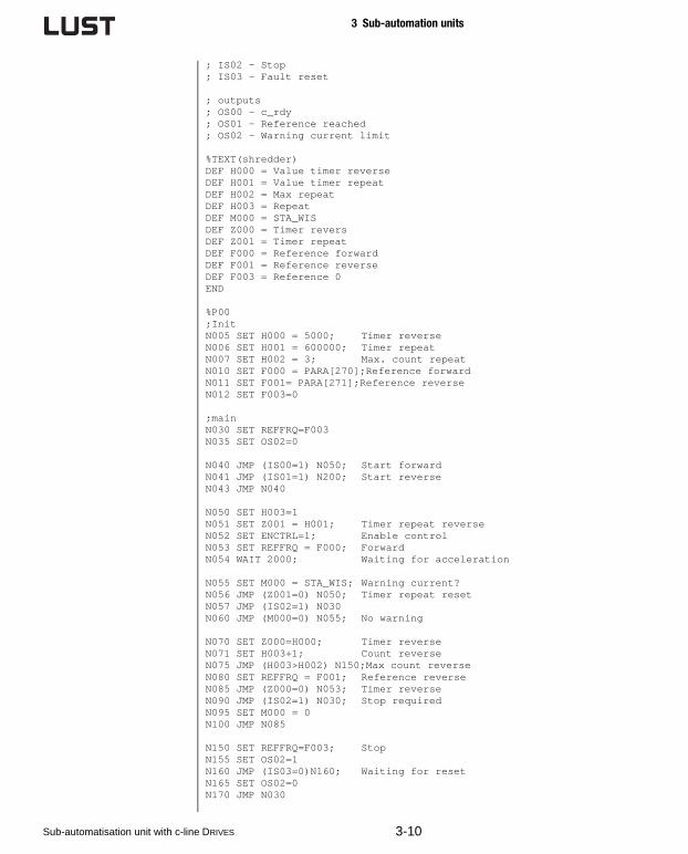
; IS02 - Stop; IS03 - Fault reset
; outputs; OS00 - c_rdy; OS01 - Reference reached; OS02 - Warning current limit
%TEXT(shredder)DEF H000 = Value timer reverseDEF H001 = Value timer repeatDEF H002 = Max repeatDEF H003 = RepeatDEF M000 = STA_WISDEF Z000 = Timer reversDEF Z001 = Timer repeatDEF F000 = Reference forwardDEF F001 = Reference reverseDEF F003 = Reference 0END
%P00;InitN005 SET H000 = 5000; Timer reverseN006 SET H001 = 600000; Timer repeatN007 SET H002 = 3; Max. count repeatN010 SET F000 = PARA[270];Reference forwardN011 SET F001= PARA[271];Reference reverseN012 SET F003=0
;mainN030 SET REFFRQ=F003N035 SET OS02=0
N040 JMP (IS00=1) N050; Start forwardN041 JMP (IS01=1) N200; Start reverseN043 JMP N040
N050 SET H003=1N051 SET Z001 = H001; Timer repeat reverseN052 SET ENCTRL=1; Enable controlN053 SET REFFRQ = F000; ForwardN054 WAIT 2000; Waiting for acceleration
N055 SET M000 = STA_WIS; Warning current?N056 JMP (Z001=0) N050; Timer repeat resetN057 JMP (IS02=1) N030N060 JMP (M000=0) N055; No warning
N070 SET Z000=H000; Timer reverseN071 SET H003+1; Count reverseN075 JMP (H003>H002) N150;Max count reverseN080 SET REFFRQ = F001; Reference reverseN085 JMP (Z000=0) N053; Timer reverseN090 JMP (IS02=1) N030; Stop requiredN095 SET M000 = 0N100 JMP N085
N150 SET REFFRQ=F003; StopN155 SET OS02=1N160 JMP (IS03=0)N160; Waiting for resetN165 SET OS02=0N170 JMP N030
3-10Sub-automatisation unit with c-line DRIVES

3 Sub-automation units
1
2
3
4
5
A
N200 SET ENCTRL=1; Enable controlN201 SET REFFRQ = F001; Start reverseN210 JMP (IS02=1) N030; Stop requiredN220 JMP N210END ;End of program
Further typical applications are block-protection controls for mixing plants,mills and shredder.
3.4 Unwinder for wire
The unwinding process, described herein, supplies materials to a dry orwet wire drawing machine. The solution of the sub-automation unit inclu-des the integration of the drive solution in the automatic process and theset-up mode.
Description of the function
The stripping speed will be controlled via unit FU1, M1 resp. implementedprocess controller and a feedback via dancer T. For mounting a new wireroller at the mandrel D a set-up mode is implemented in order to ease thework of the operator. The set-up mode will be activated at standstill viabutton b1 resp. control input IS02 at the frequency inverter FU1.
During set-up mode the drive FU1, M1 runs to a fixed speed and controlsthe motor current. The motor current is as long under the set limit as thetapped at the shaft drive takes-over the coil. After that the drive FU1, M1stops immediately, so that the operator can fix the coil at the driving shaft.
Via controlling the dancer position P2 in automatic operation it is possibleto detect when the wire will drop-off and the drive control FU1, M1 will beactivated automatically.
Sub-automatisation unit with c-line DRIVES 3-11

3 Sub-automation units
Technology scheme
Process program; Process program for CDA-PLC, unwinder ; (Winder with dancer control);Dancer control via process controller in firmware
%TEXT(Winder)DEF H001=Threshold valueDEF H002=Waiting timeDEF H000=Analog valueDEF M001=Warning_currentEND
%P00;InitialisingN010 SET H001=10; Threshold value dancerN011 SET H002=500; Waiting time start in ms
;MainprogramN020 JMP (IS02=1) N100; Set-up mode with fixed frequencyN030 SET H000=ISA0; Control dancer excursionN035 JMP (H000<H001) N020;Start at excursion of dancer
;Control processN050 SET ENCTRL=1; Release controlN060 SET H000=ISA0; Control dancer excursionN065 JMP (H000>H001) N060;Stop at final position dancerN070 SET ENCTRL=0; Control offN080 JMP N020
picture4.4 Unwinder for wire
M1
SN
.:
00
23
01
27
1
!
FU1
F
P2
10
b1
T
D
3-12Sub-automatisation unit with c-line DRIVES
3 Sub-automation units
1
2
3
4
5
A
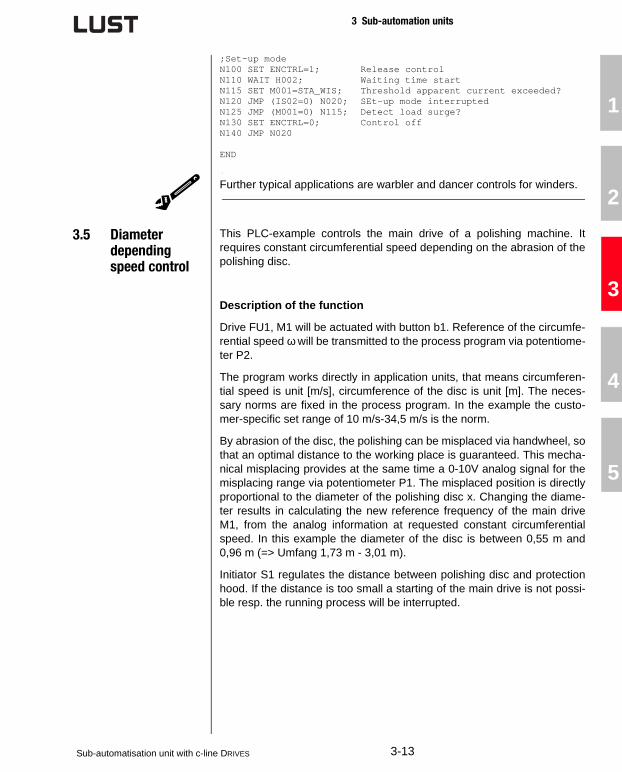
;Set-up modeN100 SET ENCTRL=1; Release controlN110 WAIT H002; Waiting time startN115 SET M001=STA_WIS; Threshold apparent current exceeded?N120 JMP (IS02=0) N020; SEt-up mode interruptedN125 JMP (M001=0) N115; Detect load surge?N130 SET ENCTRL=0; Control offN140 JMP N020
END
Further typical applications are warbler and dancer controls for winders.
3.5 Diameter depending speed control
This PLC-example controls the main drive of a polishing machine. Itrequires constant circumferential speed depending on the abrasion of thepolishing disc.
Description of the function
Drive FU1, M1 will be actuated with button b1. Reference of the circumfe-rential speed ω will be transmitted to the process program via potentiome-ter P2.
The program works directly in application units, that means circumferen-tial speed is unit [m/s], circumference of the disc is unit [m]. The neces-sary norms are fixed in the process program. In the example the custo-mer-specific set range of 10 m/s-34,5 m/s is the norm.
By abrasion of the disc, the polishing can be misplaced via handwheel, sothat an optimal distance to the working place is guaranteed. This mecha-nical misplacing provides at the same time a 0-10V analog signal for themisplacing range via potentiometer P1. The misplaced position is directlyproportional to the diameter of the polishing disc x. Changing the diame-ter results in calculating the new reference frequency of the main driveM1, from the analog information at requested constant circumferentialspeed. In this example the diameter of the disc is between 0,55 m and0,96 m (=> Umfang 1,73 m - 3,01 m).
Initiator S1 regulates the distance between polishing disc and protectionhood. If the distance is too small a starting of the main drive is not possi-ble resp. the running process will be interrupted.
Sub-automatisation unit with c-line DRIVES 3-13

3 Sub-automation units
Technology scheme
Process program; Process program for CDA-PLC polishing disc; Information:; Speed reference via ISA0, with the following customer-specific; settings:; 0V = 10m/s; 10V = 34,5m/s -> Delta = 24,5m/s -> Resolution 2,45m/s/V;; Circumference reference via potentiometer at ISA1, with the ; following customer specific settings:; 0V -> 0,96m => 3,01m max. circumference; 10V -> 0,55m => 1,73m min circumference -> Delta = 1,28m -> ; Resolution 0,128m/V;;%TEXT(Polishing disc)DEF F000=Analog value0DEF F003=Analog value1DEF F002=Reference_m_pro_sDEF F005=Circumference_mDEF F007=Reference r_p_mDEF F009=Reference_in_HzEND
;F002=ISA0 Reference im m/s, auxiliary variables (F000-001);F005=ISA1 Actual value in m, auxiliary variables (F003-004)
%P00;Reference and actual value regulation
picture4.5 Diameter-depending speed control
SN
.:
0023
0127
1
!
FU1
P1
S1
10V
P2
10V
b1
ω
ω
X
CDA3000
+ PLC
M1
3-14Sub-automatisation unit with c-line DRIVES

3 Sub-automation units
1
2
3
4
5
A
N010 SET F000=PARA[416]; Call for analog value 0N015 SET F000*2.45; Scaling in m/sN020 SET F001=F000N021 SET F001+10; Reference in m/s +Offset 10m/sN022 SET F002=F001; Save reference
N030 SET F003=PARA[417]; Call for analog value 1N035 SET F003*0.128; Scaling in mN040 SET F004=3.01; max. circumference = 3.01mN041 SET F004-F003; Actual value circumference in mN042 SET F005=F004; Actual circumference in m
;Calculating reference in m/sN050 SET F006=F002N055 SET F006*60; Calculate m/minN065 SET F006:F005; Calculate in rpm at the discN070 SET F007=F006; Save reference in F007
;Calculating speed -> frequencyN100 SET F008=F007; Call for speedN110 SET F008*2; Consider gear ratio 1:2 N115 SET F008:20; Calculate frequency of rotary field: ; f=n*pp/60, pp=3N120 SET F009=F008; Save Reference in Hz
N150 SET REFFRQ=F009; Pre-set frequency reference
N250 JMP N010END ;End of program
Further typical applications are winding drives with diameter control.
3.6 Simple posi-tioning drive with PLC_3
The example refers to the pre-set solution PLC_3 (position control with PLC-process program). Workpiece positioning via feed drive. Set para-meters for the both reference positions via operator panel.
Basic position
The used CDA3000, PLC has an process control for the position control.Feed drive is in basic position if
• homing mode is released via button b1 and executed. Homing mode gives the absolute position to the feed. Homing mode is not mentio-ned in this program example. In this program at homing mode the actual axis position will be set as homing position.
• feed carriage reaches no limit switch S1, S2.
Sub-automatisation unit with c-line DRIVES 3-15

3 Sub-automation units
Description of the function
If the material is on the carriage as well as reference positions 1 and 2are set via operator panel OP homing can be start via button b1. Aftersuccessful homing the carriage runs automatically in the rest position 1.Via button b2 the feed to position 2 can be actuated. Positioning of mate-rial via drive M1 resp. moving forward by the set lift length. If the positionPos. 2 is reached and button b2 is resetted carriage moves back to restposition Pos. 1.
Technology scheme
Process program; PLC_3 - position-control, control via terminal;; The position control is started via terminal.; The position control toggles between 2 position.; The PLC-program runs if motor control is activ.
;-----------------------------------------------%TEXT(PLC_3_position_control)DEF M000 = Homing_OK
DEF H000 = Reference_pos_1DEF H001 = Reference_pos_2DEF H002 = Actual_posDEF H003 = Zero correction
picture4.6 Feed drive with PLC-position control
W1 M1
b1
SN
.:
0023
0127
1
!
CDA3000
+ PLC
shift
1
D
E
F
4
M
N
O
7
V
W
X
2
G
H
I
5
P
Q
R
8
Y
-
Z
3
J
K
L
6
S
T
U
9
+
/
=
Enter0
A
B
C
.±
Space
VT150W
F1
F6
F2
F7
F3
F8
F4
F9
F5
F10
Info
Help
PgUp
PgDn
Esc
Clr
OP
VT150
Po
s. 1--
Po
s. 2--
S1 RNOK S2
b2
3-16Sub-automatisation unit with c-line DRIVES

3 Sub-automation units
1
2
3
4
5
A
END
;-----------------------------------------------%P00; Initialisation of reference position ; deactivated -> reference positions should not set at every ; start of motor control; N010 SET H000 = 0;; N020 SET H001 = 655360; 10 U * 65536 Inkr.
; Homing requested?N030 SET M000 = 0; Zero position not definedN040 JMP (IA00 = 0) N060; ISA0=0: start positioning
; ISA0=1: start homingN050 CALL N140 ; Call sub-routine homing mode
; Main program positioningN060 JMP (M000 = 0) N040; Return while homing is not ; finished
; Selection of reference positionN070 JMP (IS01 = 1) N110; Select position 2 if IS01=1
; Select position 1N080 GO W A H000 ; Absolut positioning with H000 ; and wait while reference is rea; chedN090 SET H002 = ACTPOS; Read actual positionN100 JMP N060 ; Return
; Select position 2N110 GO W A H001 ; Absolute positioning with H001 ; and wait while reference is rea; chedN120 SET H002 = ACTPOS; Read actual positionN130 JMP N060 ; Return
;-----------------------------------------------; Sub-routine homing modeN140 SET PCTRL = 1; Switch on position controlN150 GO 0 + H003N160 SET M000 = 1; Homing OK (finished suc; cessfully)N170 RET
END ; End of program
Typical applications are simple positioning controls for drives of doors andgates, belts, carriages and material gripper feeds, etc.
Sub-automatisation unit with c-line DRIVES 3-17

3 Sub-automation units
3-18Sub-automatisation unit with c-line DRIVES
4 Commissioning of PLC-system
1
2
3
4
5
A
4 Commissioning of PLC-system
The following commissionings are described in this chapter:
• First commissioning of CDA3000 with PLC-firmware
• First commissioning of operator panels at the drive controller
The serial commissioning of a frequency inverter with PLC-function isidentically with the standard serial commissioning. This form of the com-missioning is described in the operating manual of CDA3000.
4.1 First commissioningCDA3000, PLC
For the first commissioning the mentioned devices, assembly groups orknowledges are necessary:
• Frequency inverter CDA3000 with standard software V3.50-01 or higher
• CD-ROM for DRIVEMANAGER and PLC-editor
• Serial interface cable CCD-SUB90x
• Experience with the handling of inverter drive system CDA3000 and DRIVEMANAGER
Strategy:
1. Installation of software DRIVEMANAGER V3.20 (or higher)
For operating the PLC-editor a DRIVEMANAGER-Version from V3.20 isnecessary.
Please find information to the installation of the software in the docu-mentation of the DRIVEMANAGER.
2. Installation of PLC-editor
Please take care that the DRIVEMANAGER is closed before installationof the PLC-editor. The PLC-editor is an additional module for theDRIVEMANAGER, which has to be installed additionally.
3. Connect CDA3000 via serial interface (RS232) to the PC
4. Starting of the software DRIVEMANAGER
This process searches automatically for connected inverters anddescription of the device will be read into.
5. Installation of PLC-software
The installation of the firmware is only necessary, if there is not yet aPLC-software version V700.xx available at the device. Please findinformation to the actual firmware of the connected device in theDRIVEMANAGER main window in menu „actual values“.
Sub-automatisation unit with c-line DRIVES 4-1

4 Commissioning of PLC-system
Note: A motoridentification is not included in the PLC-firmware.On demand it can be executed with the help of a standardsoftware (e.g. V3.50-01, at PLC-editor-CD-ROM in direc-tory "Firmware\Std-Firmware"). After that the identifiedand at the PC stored dataset can be loaded on a devicewith PLC-firmware
The PLC-software and the DRIVEMANAGER-text files can be find onthe PLC-editor-CD-ROM in sub-directory "Firmware\PLC-Firmware".
At DRIVEMANAGER-version smaller than V3.20-00 (z.B. V3.10 orV3.20-98) copy the DRIVEMANAGER-text files in the DRIVEMANAGER-file (C:\program files\Lust Antriebstechnik GmbH):- 3_700_*.pit to „Lust DriveManager\language\001\“- 3000_ERR.txt to „Lust DriveManager\language\001\“- 3_700_*.mcw to „Lust DriveManager\firmdata\“
Install the PLC-software on the frequency inverter via menu „Extras/Load device software“.
An succesful „Download“ effects in an automatic reset of the fre-quency inverter as well as a read into of the device description.
6. First commissioning
The PLC-software includes no motoridentification. If an exact settingof the motor data is necessary (e.g. at control modes SFC or FOR)start the first commissioning with loading a data set with correspon-ding motor adjustments.
Further steps of the first commissioning of the drive controller will beexecuted as described in the manual of CDA3000.
4-2Sub-automatisation unit with c-line DRIVES

4 Commissioning of PLC-system
1
2
3
4
5
A
7. Programming of PLC-functions
Select „PLC...“ in the main windows of the DRIVEMANAGER. With thisfunction mask all functions and terms of the PLC can be program-med and tested.
8. PLC-program-editor
With button "PLC-program-editor..." you are able to write a PLC-pro-gram or to load one in the device. Functions and command syntaxcan be find in the online help or in this system manual.
picture 4.7 PLC-main window
Sub-automatisation unit with c-line DRIVES 4-3

4 Commissioning of PLC-system
4.2 First commis-sioning of operator panels
This chapter describes basically the configuration of the communicationinterface between operator panel and drive. The application specific pro-gramming of each operator panel is describee in the operator panel soft-ware manual (included on VTWINCD CD-ROM).
Condition for the programming of operator panels is an installed versionof the VTWIN software on your PC.
4.2.1 Configuration of RS232-interface
1. Installation of RS232-driver for LustBus-protocol
If the VTWIN software does not include the Lust-specific softwaredriver for communication via serial RS232-interface (e. G. V4.50 orV4.64), follow the stated steps:
- Close VTWIN application
- Extract the driver package *.zip. At VTWIN-Version V4.64 the driveris stored on the CD-ROM in the directory „Lust driver“.
- Replace VTWINDEV.DBR in VTWIN- installation directory (e.g. B. C.\Program files\ESA\VTWIN)
- Copy LUSTBUS.BIN in sub-directory firmware
2. Start VTWIN
3. Select a new project.
At first select type of operator panel, shall be programmed:
Selected operator panel and bus-interface will be indicated in projectwindow.
Type NameVTWIN
VT050 00000N VT50 (Rev.2 )
VT150W 00000N VT150W
VT505W 00000N VT505W
VT155W 00000NVT155W
orVT155W (Porträt)
4-4Sub-automatisation unit with c-line DRIVES

4 Commissioning of PLC-system
1
2
3
4
5
A
4. Select a drive controller
Open directory „MOTOR DRIVE/LUST“ in component window. Drawthe icon of drive controller „c-line Drive“ to the interface-icon (MSP orASP) in the project window. If Lust directory is missing please installthe driver as described in 1.). Now the drive is physically connectedwith the operator panel.
5. Setting of RS232-interface Baud rate
Open via double-click on the interface icon (MSP or ASP) the window„port properties“ and set the Baud rate to 19200 bit/s. This Baud rate must be set in the drive, too. Therefore start theDRIVEMANAGER and open in menu „communication“ the bus-configu-ration. Save the settings in the drive.
6. Setting of device name and address
Open via double-click on the drive icon the window „device proper-ties“. The device address must (always) be set to 1. Furthermore thesymbolic name of the drive controller can be changed.
7. Programming of operator panels
Open via double-click on operator panel icon in project window theprogram application. For programming use the software manual ofthe operator panels (available on VTWIN CD-ROM ).
picture 4.8 Configuration of operator panel with RS232-interface
Sub-automatisation unit with c-line DRIVES 4-5

4 Commissioning of PLC-system
4.2.2 Configuration of CANopen-net-work
Conditions for bus-operation:
• Drive is equiped with CAN-module (CANopen-protocol)
• Drive is connected with the operator panel via CAN-Bus
• Parameters of the fieldbus interface are set correctly in the connec-ted drive (e.g. Bus-protocol, Baud rate, device addresses)
1. Start VTWIN
2. Select a new project.
At first select type of operator panel, shall be programmed:
Selected operator panel and bus-interface will be indicated in projectwindow.
3. Select drive
Open directory „CANOPEN/ESA ELLETRONICA“ in component win-dow. Draw icon „CANopen Master“ to the interface-icon FIELDNETWORK (CAN)) in the project window. The drive controller is nowphysically connected to the operator panel. It is possible to install upto 127 drives of c-line to the bus. .
Type NameVTWIN
VT050 000CNN VT50 (CAN NETWORK)
VT150W 000CNN VT150W (CAN NETWORK)
VT505W 000CNN VT505W CAN
VT155W 000CNNVT155W CAN
orVT155W (Porträt) CAN
picture 4.9 Configuration of operator panels with CANopen-network
4-6Sub-automatisation unit with c-line DRIVES
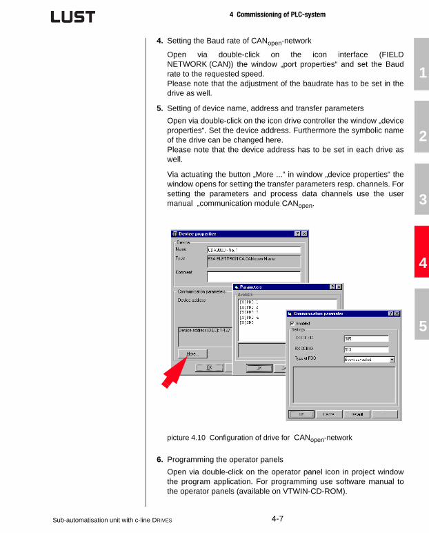
4 Commissioning of PLC-system
1
2
3
4
5
A
4. Setting the Baud rate of CANopen-network
Open via double-click on the icon interface (FIELDNETWORK (CAN)) the window „port properties“ and set the Baudrate to the requested speed. Please note that the adjustment of the baudrate has to be set in thedrive as well.
5. Setting of device name, address and transfer parameters
Open via double-click on the icon drive controller the window „deviceproperties“. Set the device address. Furthermore the symbolic nameof the drive can be changed here. Please note that the device address has to be set in each drive aswell.
Via actuating the button „More ...“ in window „device properties“ thewindow opens for setting the transfer parameters resp. channels. Forsetting the parameters and process data channels use the usermanual „communication module CANopen.
6. Programming the operator panels
Open via double-click on the operator panel icon in project windowthe program application. For programming use software manual tothe operator panels (available on VTWIN-CD-ROM).
picture 4.10 Configuration of drive for CANopen-network
Sub-automatisation unit with c-line DRIVES 4-7

4 Commissioning of PLC-system
4-8Sub-automatisation unit with c-line DRIVES

1
2
3
4
5
A
5 Order data of system components
Order codes for PLC-software package
Order codes for user and communication modules
Order codes for manual operating unit
Order designation Short description Article no.
PLC-Editor
CD-ROM incl. - PLC-Program editor- PLC-Training program- System manual CDA3000-PLC- Firmware CDA3000-PLC- Licence PLC-Editor
0842.V11.1
DRIVEMANAGER V3.20DriveManager full version on CD-ROM
0842.V08.2
DRIVEMANAGER V3.20, TESTDriveManager-180-days-testver-sion on CD-ROM
0842.V09.2
Order designation Short description Article no.
CM-CAN1 Communication module for CANopen 0916.0001
CM-DPV1Communication module for Profibus DP-V1Supports CDA3000-PLC
0916.0003.10916.0000.1 (with-GSD)
Order designation Short description Article no.
KP200-XL
KEYPAD KP200 for parameter setting and serial commissioning of CDA3000-PLC with SMARTCARD SC-XL
SC-XLSMARTCARD with large EEPROM-memory for saving PLC-Data
Sub-automatisation unit with c-line DRIVES 5-1

5 Order data of system components
Order codes for Operator Panel and accessories
Bestell-bezeichnung
Kurzbeschreibung Artikelnummer
VT050 00000N operator panel VT50 (RS232) 1002.0001.0
VT050 000CNN operator panel VT50 (CANopen) 1002.0002.0
VT150W 00000N operator panel VT150 (RS232) 1002.0003.0
VT150W 000CNN operator panel VT150 (CANopen) 1002.0004.0
VT505W 00000N operator panel VT505 (RS232) 1002.0005.0
VT505W000CNN operator panel VT505 (CANopen) 1002.0006.0
VT155W 00000N operator panel VT155 (RS232) 1002.0007.0
VT155W000CNN operator panel VT155 (CANopen) 1002.0008.0
VTWINCD
Software package VTWIN to pro-gram the operator panels- CD-ROM (Software, Manuals, 5 languages)
1002.0011.0
CVCOM 11102Programming cablePC 9-polig-MSP 25-polesnecessary for all operator panels
1002.0009
CVCOM 25F8M
Programming cable adapterPC 25-poles-ASP 8-poles DINNecessary for- VT050 000CNN- VT150W 000CNN- VT505W 000CNN- VT155W 00000N- VT155W 000CNNCVCOM 11102 must be available!
1002.0010
OPK-RS03
Serial RS232-interface cable to con-nect the drive controller to the opera-tor panel. Suitable for- VT050 00000N- VT150W 00000N- VT505W 00000N- VT155W 00000NLength 3 m
in preparation
OPK-RS05
Serial RS232-interface cable to con-nect the drive controller to the opera-tor panel. Suitable for- VT050 00000N- VT150W 00000N- VT505W 00000N- VT155W 00000NLänge 5 m
in preparation
5-2Sub-automatisation unit with c-line DRIVES

5 Order data of system components
1
2
3
4
5
A
Order codes for trainings and services
Order designation Explanation Net price
PLC-Projectmanagement8 hours incl. post-processing without travel costs
on request
PLC-Engineering8 hours incl. post-processing without travel costs
on request
PLC-Software producing8 hours incl. post-processing without travel costs
on request
PLC-Commissioning8 hours incl. post-processing without travel costs
on request
PLC-Training1 dayincl. records, snacks
on request
PLC-Training, Licence1 dayincl. records, snacksPLC-Editor-Licence
on request
OP-Training1,5 dayseincl. records, snacks
on request
OP-Training, Licence1,5 dayseincl. records, snacks,VTWINKIT with licence
on request
Sub-automatisation unit with c-line DRIVES 5-3

5 Order data of system components
5-4Sub-automatisation unit with c-line DRIVES


Lust Antriebstechnik GmbHGewerbestrasse 5-9 • D-35633 LahnauTel. 0 64 41 / 9 66-0 • Fax 0 64 41 / 9 66-137Internet: http://www.lust-tec.de • e-mail: [email protected]
ID no.: 0840.12B.1 • 05/2003Technische Änderungen vorbehalten.We reserve the right to make technical changes.