
INTRODUCTION OF PLC • PLC (Programmable Logic Control)
22
INTRODUCTION OF PLC PLC (Programmable Logic Control) : Programmable logic controllers (PLCs) have been an integral part of factory automation and industrial process control for decades. PLCs control a wide array of applications from simple lighting functions to environmental systems to chemical processing plants. These systems perform many functions, providing a variety of analog and digital input and output interfaces; signal processing; data conversion; and various communication protocols. All of the PLC's components and functions are centered around the controller, which is programmed for a specific task. Advantages of PLC 1. Flexibility: One single Programmable Logic Controller can easily run many machines. 2. Correcting Errors: In old days, with wired relay-type panels, any program alterations required time for rewiring of panels and devices. With PLC control any change in circuit design or sequence is as simple as retyping the logic. Correcting errors in PLC is extremely short and cost effective. 3. Space Efficient: Today's Programmable Logic Control memory is getting bigger and bigger this means that we can generate more and more contacts, coils, timers, sequencers, counters and so on. We can have thousands of contact timers and counters in a single PLC. Imagine what it would be like to have so many things in one panel. 4. Low Cost: Prices of Programmable Logic Controllers vary from few hundreds to few thousands. This is nothing compared to the prices of the contact and coils and timers that you would pay to match the same things. Add to that the installation cost, the shipping cost and so on. 5. Testing: A Programmable Logic Control program can be tested and evaluated in a lab. The program can be tested, validated and corrected saving very valuable time. 6. Visual observation: When running a PLC program a visual operation can be seen on the screen. Hence troubleshooting a circuit is really quick, easy and simple.
-
Upload
khangminh22 -
Category
Documents
-
view
0 -
download
0
Transcript of INTRODUCTION OF PLC • PLC (Programmable Logic Control)

INTRODUCTION OF PLC
PLC (Programmable Logic Control) :
Programmable logic controllers (PLCs) have been an integral part of
factory automation and industrial process control for decades. PLCs control
a wide array of applications from simple lighting functions to environmental
systems to chemical processing plants. These systems perform many
functions, providing a variety of analog and digital input and output
interfaces; signal processing; data conversion; and various communication
protocols. All of the PLC's components and functions are centered around
the controller, which is programmed for a specific task.
Advantages of PLC
1. Flexibility: One single Programmable Logic Controller can easily run many machines.
2. Correcting Errors: In old days, with wired relay-type panels, any program alterations required time for rewiring of panels and devices. With PLC control any change in circuit design or sequence is as simple as retyping the logic. Correcting errors in PLC is extremely short and cost effective.
3. Space Efficient: Today's Programmable Logic Control memory is getting bigger and bigger this means that we can generate more and more contacts, coils, timers, sequencers, counters and so on. We can have thousands of contact timers and counters in a single PLC. Imagine what it would be like to have so many things in one panel.
4. Low Cost: Prices of Programmable Logic Controllers vary from few hundreds to few thousands. This is nothing compared to the prices of the contact and coils and timers that you would pay to match the same things. Add to that the installation cost, the shipping cost and so on.
5. Testing: A Programmable Logic Control program can be tested and evaluated in a lab. The program can be tested, validated and corrected saving very valuable time.
6. Visual observation: When running a PLC program a visual operation can be seen on the screen. Hence troubleshooting a circuit is really quick, easy and simple.
Disadvantages of PLC
1. There's too much work required in connecting wires.
2.There’s difficulty with changes or replacements.
3. It's always difficult to find errors; And require skilful work force.
4. When a problem occurs, hold-up time is indefinite, usually long.
Application of PLC
1. Application of PLC in Glass Industry
From the year 1980 the Programmable-logic controllers are in use in the glass industry, and they are assembled bit by bit. PLCs are used mainly in every procedure and workshop for controlling the material ratio, processing of flat glasses, etc. 2. Applications of PLC in Cement Industry
Along with the best-quality raw materials, the accurate data regarding process variables, especially during mixing processes within the kiln, ensures that the output provided should be of the best possible quality. 3. Production machine
Controls and monitor automatic production machines like – packaging machines at high efficiency rates.
4. Conveyor System Control all sequential operations, alarms and safety logics
5. IC Engine Monitoring Acquires and analysis the data recorded from the sensor located at the internet combustion engine.
6. Paint Spraying Control the printing sequence in auto manufacturing.

7. Loading and unloading of alloy Control and Monitors the quantity of coil, iron core and limestone to be melted.
8. Power plant system Monitor and control burning rates, temperature generated sequencing of valves and analog controller jet valves.
Basic Operation of PLC
A PLC is a centralised digital computer used for automation of
electromechanical process.
The basic parts of PLC architecture are:
1. Input module
2. Output scan
3. CPU (Central Processing Unit)
4. Memory
5. Power supply
6. Monitoring
7. Display
8. Rachas or chasis
Input Module: Input devices, such as switches, can be manipulated to
give the open and closed contact conditions and the corresponding LED on
the input module observed. It should be illuminated when the input is
closed and not illuminated when it is open. Failure of an LED to illuminate
could be because the input device is not correctly operating, there are
incorrect wiring connections to the input module, the input device is not
correctly powered, or the LED or input module is defective. For output
devices that can be safely started, push buttons might have been installed
so that each output could be tested.
Output Module: Output modules convert control signals from the CPU
into digital or analog values that can be used to control
various output devices. The programming device is used to enter or
change the PLCs program or to monitor or change stored values.
CPU: The processor unit or central processing unit (CPU) is the unit
containing the microprocessor. This unit interprets the input signals and
carries out the control actions according to the program stored in its
memory, communicating the decisions as action signals to the outputs.
Memory: The memory unit is where the program containing the control
actions to be exercised by the microprocessor is stored and where the data
is stored from the input for processing and for the output.
Two types of memory
1. Program memory (user memory)
2. Storage memory (data memory)
Power supply: The power supply unit is needed to convert the mains AC
voltage to the low DC voltage (5 V) necessary for the processor and the
circuits in the input and output interface modules

PLC Operation:
When the PLC id power On , the processor checks for memory , input
output device before the actual start of execution of user program . During
PLC operation CPU read the input status, execute the user ladder program
stored in system memory and output the data to output device and repeat
the same program again and again. This processing technique is called
PLC scanning.
PLC scanning operation is divided into three parts :
A) Input scan
B) Output scan
c) Program scan

Data File memory
Output image status bit: This file store the status of discrete output
terminals .during program scan, this data is updated and at the end of
program scan, It is transferred to real world outputs.

Input Image status file: This file store the status of input terminal of the
controller.
Status file: This file is store controller operation status, error codes,
arithmetic status bits etc. this file is useful for troubleshooting controller and
program operation.
Bit file: This file is used for internal relay logic storage.
Timer File: This file stores the timer status bits, present value and
accumulated value of each timer .Each timer uses three word memory.
Counter file: This file is stores the counter status bit, preset value and
accumulated value of each counter. Each counter uses three word
memory.
Control file: This file stores the length, pointer, position and status bits for
instruction such as shift register and sequencer.
Integer data file: This file stores numeric value or bit information.
Floating point file : Some PLC can also uses floating point values .This
file is used to solve numeric values in floating point notation.
User defined file: This memory area can be used by a user for any of the
above types of file. Some PLC can work with string data values which are
also defined in this area.
Input/output Modules :
The input output modules works as an interface between the processor
and the real world devices like a switches, lamps, Contractor etc. attached
to the PLC.
The input output, modules can be divided into three categories:
1. Discrete input /output modules
2. Analog input/output modules
3. Register modules

Sourcing and sinking input output
The terms sourcing and sinking are used to describe the way in which
DC devices are connected to a PLC. With sourcing, using the
conventional current flow direction as from positive to negative, an input
device receives current from the input module, that is, the input module
is the source of the current. With sinking, using the conventional current
flow direction, an input device supplies current to the input module, that
is, the input module is the sink for the current. If the current flows from
the output module to an output load, the output module is referred to as
sourcing .If the current flows to the output module from an output load,
the output module is referred to as sinking.
Ladder diagram: Ladder logic diagram are normally use in PLC to
write program instruction ladder languages uses input and output
symbols and is a graphic base language. The ladder diagram
represents program steps using Input and Output symbols like in a
electrical relay diagram.
Bit instruction

Ladder diagram for Boolean Logic of input: In process control
application output condition may depend upon logic combination
(AND, OR, XOR, NAND, NOR) of inputs these logic combination can
be easily made in ladder diagram.
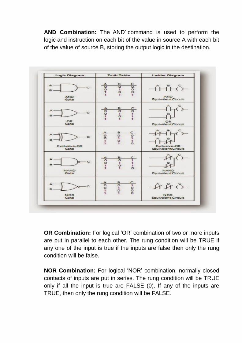
AND Combination: The ‘AND’ command is used to perform the
logic and instruction on each bit of the value in source A with each bit
of the value of source B, storing the output logic in the destination.
OR Combination: For logical ‘OR’ combination of two or more inputs
are put in parallel to each other. The rung condition will be TRUE if
any one of the input is true if the inputs are false then only the rung
condition will be false.
NOR Combination: For logical ‘NOR’ combination, normally closed
contacts of inputs are put in series. The rung condition will be TRUE
only if all the input is true are FALSE (0). If any of the inputs are
TRUE, then only the rung condition will be FALSE.
Timer: PLC timers are instructions that provide the same functions as on-delay and off-delay mechanical and electronic timing relays. A PLC timer provides a preset delay to the control actions.
D15 D14 D13 D7
Word 0 EN TT DN INTERNAL USE
Word 1 PRESET VALUE ( PRE)
Word 2 ACCUMULATED VALUE
Timer Address Format
In general, there are three types of PLC timer delays, ON-delay timer, OFF-delay timer and retentive timer on.
The terms represented in the timer block in the PLC are a Preset value which means the delay period of the timer, an Accumulated value which is the current delay of the timer.
A timer begins the counting on time-based intervals and continues until the accumulated value equals the preset value. When the accumulated value equals the preset time the output will be energized. Then the timer sets the output.
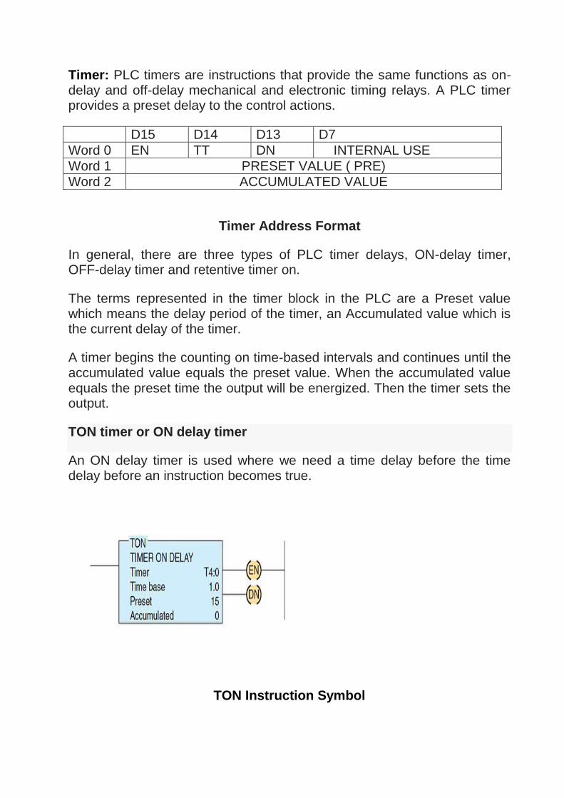
TON timer or ON delay timer
An ON delay timer is used where we need a time delay before the time delay before an instruction becomes true.
TON Instruction Symbol
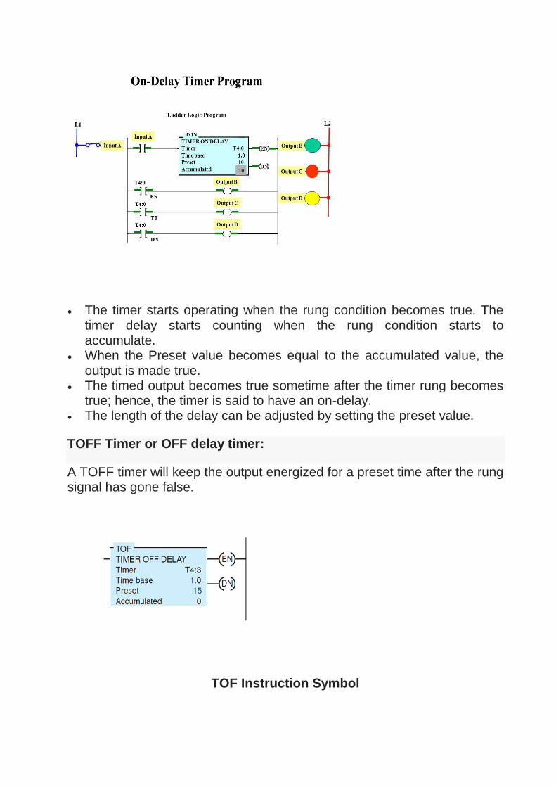
The timer starts operating when the rung condition becomes true. The timer delay starts counting when the rung condition starts to accumulate.
When the Preset value becomes equal to the accumulated value, the output is made true.
The timed output becomes true sometime after the timer rung becomes true; hence, the timer is said to have an on-delay.
The length of the delay can be adjusted by setting the preset value.
TOFF Timer or OFF delay timer:
A TOFF timer will keep the output energized for a preset time after the rung signal has gone false.
TOF Instruction Symbol
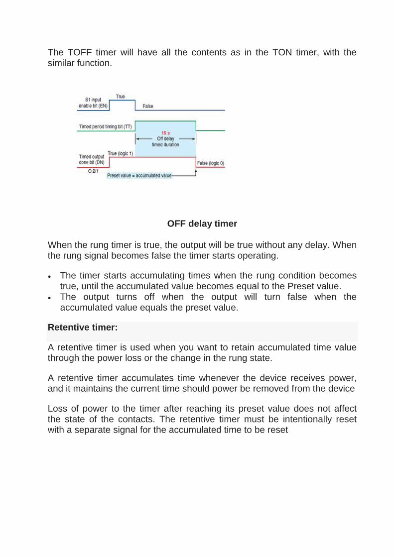
The TOFF timer will have all the contents as in the TON timer, with the similar function.
OFF delay timer
When the rung timer is true, the output will be true without any delay. When the rung signal becomes false the timer starts operating.
The timer starts accumulating times when the rung condition becomes true, until the accumulated value becomes equal to the Preset value.
The output turns off when the output will turn false when the accumulated value equals the preset value.
Retentive timer:
A retentive timer is used when you want to retain accumulated time value through the power loss or the change in the rung state.
A retentive timer accumulates time whenever the device receives power, and it maintains the current time should power be removed from the device
Loss of power to the timer after reaching its preset value does not affect the state of the contacts. The retentive timer must be intentionally reset with a separate signal for the accumulated time to be reset

Counter: Counters are PLC instruction that either increment or decrement or decrement the integer value when the input line make True from False. The counter which increment value is known as Up counters and Down counters decrement the integer values on a trigger. Both the Up and Down counter starts counting on one trigger.
The Up-Down counter has two input triggers one for Up counting and other for Down counting.
D15 D14 D13 D12 D11 D7
Word 0 EN TT DN OV UN INTERNAL USE
Word 1 PRESET VALUE ( PRE)
Word 2 ACCUMULATED VALUE
Counter Address Format

Up counter:
Up counter counts a value from the current value when a signal arrives at the input CU. R is the reset input and PV the preset value. The counter counts up until the count reaches the preset value.
Whenever the input CU value changes from 0 to 1 the counter increment 1 from the preset value. When the input value reaches the preset value the output turns ON. The counter preset value is user defined.
Down counter:
Each time the input CD turns ON the counter decrement one from the preset value. Whenever LD (load) input becomes high then the preset value is reloaded to the counter from the current value.
Whenever the input CD value changes from 0 to 1 the counter decrement 1 from the preset value.

Up/Down counter:
The Up/Down Counter work as both the up counter and the down counter. The up/down counter has input for both the Up counter and Down counter operation CU and CD. And has both the inputs R and LD also.zero and LD load the load the pressed value to the counter ignoring the current counter value.
The two input value has two corresponding output lines for CD and CU.
DCS (Distributed Control System) :
In recent years, the use of smart devices and field buses makes distributed control system (DCS) to be prominent in large and complex industrial processes as compared to the former centralized control system. This distribution of control system architecture around the plant has led to produce more efficient ways to improve reliability of control, process quality and plant efficiency.Nowadays, distributed control system has been found in many industrial fields such as chemical plants, oil and gas industries, food processing units, nuclear power plants, water management systems, automobile industries, etc
A distributed control system (DCS) is a specially designed automated control system that consists of geographically distributed control elements over the plant or control area. It differs from the centralized control system wherein a single controller at central location handles the control function, but in DCS each process element or machine or group of machines is controlled by a dedicated controller. DCS consists of a large number of local controllers in various sections of plant control area and are connected via a high speed communication network.
In DCS control system, data acquisition and control functions are carried through a number of DCS controllers which are microprocessor based units distributed functionally and geographically over the plant and are situated near area where control or data gathering functions being performed as shown in the figure above. These controllers able to communicate among themselves and also with other controllers like supervisory terminals, operator terminals, historians, etc.
Distributed individual automatic controllers are connected to field devices such as sensors and actuators. These controllers ensure the sharing of gathered data to other hierarchal controllers via different field buses. Different field buses or standard communication protocols are used for

establishing the communication between the controllers. Some of these include Profibus, HART, arc net, Modbus, etc.
DCS is most suited for large-scale processing or manufacturing plants wherein a large number of continuous control loops are to be monitored and controlled. The main advantage of dividing control tasks for distributed controllers is that if any part of DCS fails, the plant can continue to operate irrespective of failed section.
You may also read: What Exactly Is A Smart Grid?
Architecture of Distributed Control System As the name suggests, DCS has three main qualities. The first one is the distribution of various control functions into relatively small sets of subsystems, which are of semiautonomous, and are interconnected through a high speed communication bus. Some of these functions include data acquisition, data presentation, process control, process supervision, reporting information, storing and retrieval of information.
The second attribute of DCS is the automation of manufacturing process by integrating advanced control strategies. And the third characteristic is the arranging the things as a system. DCS organizes the entire control structure as a single automation system where various subsystems are unified through a proper command structure and information flow.
These attributes of DCS can be observed in its architecture shown in the diagram below. The basic elements comprised in a DCS include engineering workstation, operating station or HMI, process control unit or local control unit, smart devices, and communication system.
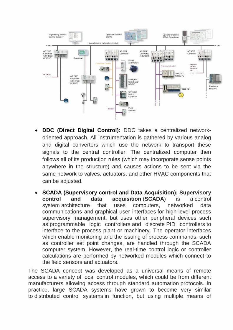
DDC (Direct Digital Control): DDC takes a centralized network-
oriented approach. All instrumentation is gathered by various analog
and digital converters which use the network to transport these
signals to the central controller. The centralized computer then
follows all of its production rules (which may incorporate sense points
anywhere in the structure) and causes actions to be sent via the
same network to valves, actuators, and other HVAC components that
can be adjusted.
SCADA (Supervisory control and Data Acquisition): Supervisory control and data acquisition (SCADA) is a control system architecture that uses computers, networked data communications and graphical user interfaces for high-level process supervisory management, but uses other peripheral devices such as programmable logic controllers and discrete PID controllers to interface to the process plant or machinery. The operator interfaces which enable monitoring and the issuing of process commands, such as controller set point changes, are handled through the SCADA computer system. However, the real-time control logic or controller calculations are performed by networked modules which connect to the field sensors and actuators.
The SCADA concept was developed as a universal means of remote access to a variety of local control modules, which could be from different manufacturers allowing access through standard automation protocols. In practice, large SCADA systems have grown to become very similar to distributed control systems in function, but using multiple means of
interfacing with the plant. They can control large-scale processes that can include multiple sites, and work over large distances as well as small distance.[1] It is one of the most commonly-used types of industrial control systems; however there are concerns about SCADA systems being vulnerable to cyberwarfare/cyberterrorism attacks.
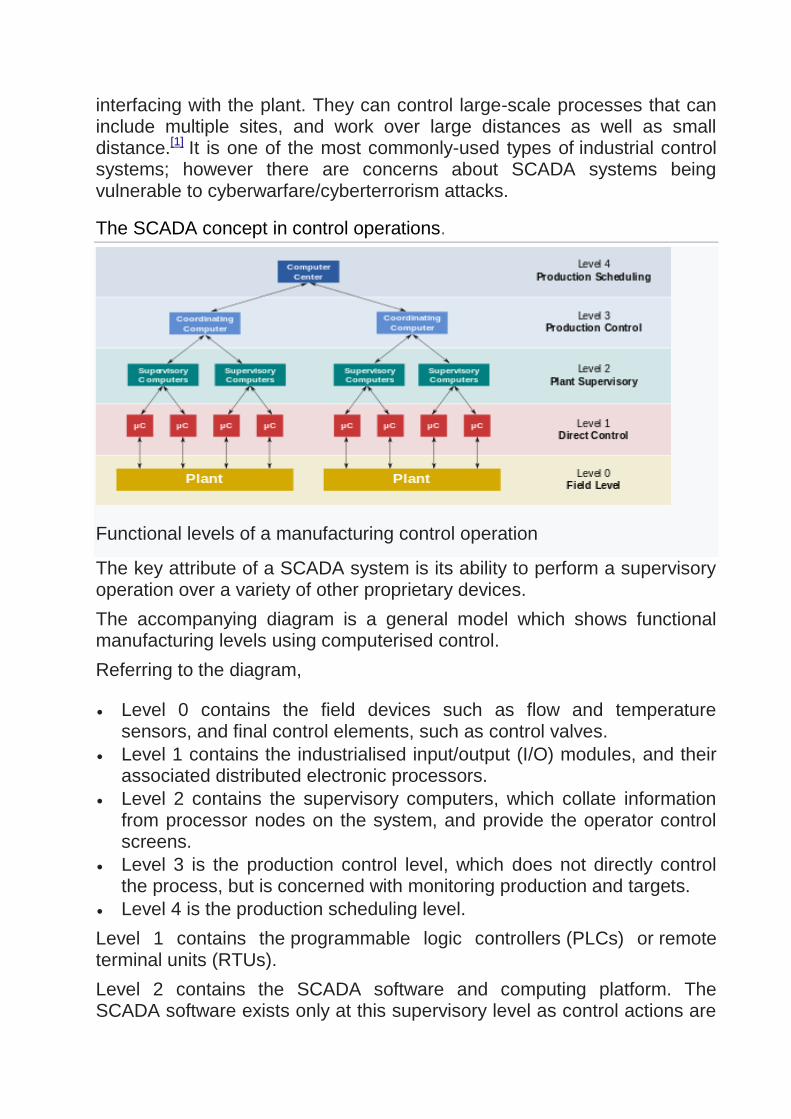
The SCADA concept in control operations.
Functional levels of a manufacturing control operation
The key attribute of a SCADA system is its ability to perform a supervisory operation over a variety of other proprietary devices.
The accompanying diagram is a general model which shows functional manufacturing levels using computerised control.
Referring to the diagram,
Level 0 contains the field devices such as flow and temperature sensors, and final control elements, such as control valves.
Level 1 contains the industrialised input/output (I/O) modules, and their associated distributed electronic processors.
Level 2 contains the supervisory computers, which collate information from processor nodes on the system, and provide the operator control screens.
Level 3 is the production control level, which does not directly control the process, but is concerned with monitoring production and targets.
Level 4 is the production scheduling level.
Level 1 contains the programmable logic controllers (PLCs) or remote terminal units (RTUs).
Level 2 contains the SCADA software and computing platform. The SCADA software exists only at this supervisory level as control actions are

performed automatically by RTUs or PLCs. SCADA control functions are usually restricted to basic overriding or supervisory level intervention. For example, a PLC may control the flow of cooling water through part of an industrial process to a set point level, but the SCADA system software will allow operators to change the set points for the flow. The SCADA also enables alarm conditions, such as loss of flow or high temperature, to be displayed and recorded. A feedback control loop is directly controlled by the RTU or PLC, but the SCADA software monitors the overall performance of the loop.
Levels 3 and 4 are not strictly process control in the traditional sense, but are where production control and scheduling takes place.
Data acquisition begins at the RTU or PLC level and includes instrumentation readings and equipment status reports that are communicated to level 2 SCADA as required. Data is then compiled and formatted in such a way that a control room operator using the HMI (Human Machine Interface) can make supervisory decisions to adjust or override normal RTU (PLC) controls. Data may also be fed to a historian, often built on a commodity database management system, to allow trending and other analytical auditing.
SCADA systems typically use a tag database, which contains data elements called tags or points, which relate to specific instrumentation or actuators within the process system according to such as the Piping and instrumentation diagram. Data is accumulated against these unique process control equipment tag references.
Examples of use
Example of SCADA used in office environment to remotely monitor a
process
Both large and small systems can be built using the SCADA concept. These systems can range from just tens to thousands of control loops, depending on the application. Example processes include industrial, infrastructure, and facility-based processes, as described below:
Industrial processes include manufacturing, Process control, power generation, fabrication, and refining, and may run in continuous, batch, repetitive, or discrete modes.
Infrastructure processes may be public or private, and include water treatment and distribution, wastewater collection and treatment, oil and gas pipelines, electric power transmission and distribution, and wind farms.
Facility processes, including buildings, airports, ships, and space stations. They monitor and control heating, ventilation, and air conditioning systems (HVAC), access, and energy consumption.
However, SCADA systems may have security vulnerabilities, so the systems should be evaluated to identify risks and solutions implemented to mitigate those risks.
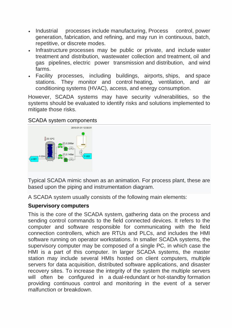
SCADA system components
Typical SCADA mimic shown as an animation. For process plant, these are
based upon the piping and instrumentation diagram.
A SCADA system usually consists of the following main elements:
Supervisory computers
This is the core of the SCADA system, gathering data on the process and sending control commands to the field connected devices. It refers to the computer and software responsible for communicating with the field connection controllers, which are RTUs and PLCs, and includes the HMI software running on operator workstations. In smaller SCADA systems, the supervisory computer may be composed of a single PC, in which case the HMI is a part of this computer. In larger SCADA systems, the master station may include several HMIs hosted on client computers, multiple servers for data acquisition, distributed software applications, and disaster recovery sites. To increase the integrity of the system the multiple servers will often be configured in a dual-redundant or hot-standby formation providing continuous control and monitoring in the event of a server malfunction or breakdown.

Differentiate between SCADA and DCS
SCADA DCS
1. It is Supervisory Control and Data Acquisition.
It is Distributed Control System.
2. SCADA is most used for wide area eg. 10 Km and more.
DCS is used for specific wide
area within a specific boundary.
3. SCADA is preferred for applications that are spread such a wide geographic location.
DCS is used to handle operations on a single location.
4. SCADA is used to control very big plant.
DCS is used to control and monitor small no. of equipment’s in a field.
5. SCADA have more than one DB( Data Base)
DCS have almost one
DB( Data Base)
6. SCADA is expected to separate despite failure of field communications.
DCS operation stations are always connected to its I/O.
7. SCADA was more for data gathering.
DCS was more for controlled processes
8. SCADA generally supports storing of data base.
DCS does not support data base.
9. SCADA is not confined in a factory or industrial.
DCS is more confined in a factory or industrial.
10. SCADA system is more flexible.
DCS system integrated.


