Remote Control Laboratory Using EJS Applets and TwinCAT Programmable Logic Controllers
9
156 IEEE TRANSACTIONS ON EDUCATION, VOL. 56, NO. 2, MAY 2013 Remote Control Laboratory Using EJS Applets and TwinCAT Programmable Logic Controllers Eva Besada-Portas, José A. Lopez-Orozco, Member, IEEE, Luis de la Torre, and Jesus M. de la Cruz, Member, IEEE Abstract—This paper presents a new methodology to develop remote laboratories for systems engineering and automation con- trol courses, based on the combined use of TwinCAT, a labora- tory Java server application, and Easy Java Simulations (EJS). The TwinCAT system is used to close the control loop for the se- lected plants by means of programmable logic controllers (PLCs) deployed in PCs with the TwinCAT run-time tool. EJS is used to develop the laboratory front-end applets that let teachers and stu- dents parametrize and observe the behavior of the PLCs from any computer. The laboratory Java server application establishes the connection between the EJS applets and the PLCs, fulfilling the TwinCAT connection requirements while ensuring an individual- ized access to each PLC. This paper also shows how the practical work in some undergraduate control courses at the Complutense University of Madrid, Spain, already uses the TwinCAT PLC + Java server + EJS applet strategy to provide real-time support to the controllers, remote individualized access to the experiments, and a user-friendly graphic controller interface for the students. Index Terms—Control education, Easy Java Simulations, indus- trial programmable logic controllers (PLCs), real-time controllers, remote laboratories. I. INTRODUCTION W EB-BASED laboratories are well established as a learning/teaching resource in several scientific and technical disciplines since they help to illustrate phenomena that require costly or difficult-to-assemble equipment [1], [2]. These come in two forms: the simulated experiment and its real (remotely controlled) counterpart. Both serve important educational purposes, but the second cannot always be replaced by the first. This is especially true in some fields such as control engineering, where observing the actual behavior and response of the real physical elements is crucial [3]. In such areas of study, remote laboratories provide a much better complement to traditional hands-on experiments. Manuscript received March 29, 2012; accepted May 18, 2012. Date of pub- lication June 19, 2012; date of current version May 01, 2013. This work was supported by the Spanish National Research Project DPI2009-14552 and the University Complutense of Madrid Innovation Education Project PIMCD-2010/ 2011-211. E. Besada-Portas, J. A. Lopez-Orozco, and J. M. de la Cruz are with the Computer Architecture and Automatic Department, University Complutense of Madrid, Madrid 28040, Spain (e-mail: [email protected]; jalo@dacya. ucm.es; [email protected]). L. de la Torre is with the Computer Science and Automatic Department, Spanish Open Univerisity, Madrid 28040, Spain (e-mail: [email protected]. es). Color versions of one or more of the figures in this paper are available online at http://ieeexplore.ieee.org. Digital Object Identifier 10.1109/TE.2012.2204754 In addition, traditional laboratories may sometimes not be used to an extent consistent with their costs [4]. By allowing re- mote access to these laboratories, their frequency of use can be increased thanks to the creation of networks of educational insti- tutions interested in the same shared experiments. Although the economic aspect is important, there are other benefits to these laboratories: an improved accessibility with respect to their tra- ditional counterparts (remote use allows even handicapped stu- dents to access them from home); their increased availability (thanks to their capability to operate 24 h a day without constant supervision); and the safety of the devices (being software-con- trolled for remote use). In summary, the two main benefits of using real-time remote laboratories are the ease of experimentation and the elimination of equipment constraints. As a result, students can: 1) interact with the system, changing parameters as desired; 2) observe the results of their manipulations; 3) measure real data; 4) per- form an almost unlimited amount of experiments; 5) study phe- nomena that would not be possible to investigate in a traditional (hands-on) laboratory; and 6) be offered a wide range of exper- iments, including those subject to real-time constraints—an im- portant topic in control engineering. However, transforming an existing local laboratory into a Web-based laboratory requires teachers to tackle all the difficulties associated with making ex- periments available via the Internet. In particular, they have to create interactive graphical user interfaces (GUIs) for the system that can be deployed via the Internet in the form of dedi- cated plugins such as Java applets, Flash, ActiveX, and the like. Typical remote experiments in control engineering are a system to control water level in a tank [5]–[8], a heat ex- changer [9], and the control of position and/or velocity of a servo motor [7], [10]. All of these use expensive, and sometimes difficult-to-assemble, didactical setups and focus on tuning the parameters of the PID controller to achieve a fine control of the real plant. Additionally, no published studies consider real-time specifications since the experiments selected did not require them. However, using methodologies that do not take into account this possibility limits the range of experiments that can be set up. Although some work has been done to achieve real-time control in remote experimentation [11], this is still an active issue with no easy solution. LabView [12] and TwinCAT [13] are two of the most pop- ular software tools for controlling local hardware, even when real-time operations are needed. These, however, do not pro- vide a complete standalone solution for designing and deploying remote laboratories since they lack a GUI that could be used, via the Internet and on the client side, for communicating and for controlling students’ access to the software to control the 0018-9359/$31.00 © 2012 IEEE
-
Upload
independent -
Category
Documents
-
view
0 -
download
0
Transcript of Remote Control Laboratory Using EJS Applets and TwinCAT Programmable Logic Controllers

156 IEEE TRANSACTIONS ON EDUCATION, VOL. 56, NO. 2, MAY 2013
Remote Control Laboratory Using EJS Applets andTwinCAT Programmable Logic Controllers
Eva Besada-Portas, José A. Lopez-Orozco, Member, IEEE, Luis de la Torre, and Jesus M. de la Cruz, Member, IEEE
Abstract—This paper presents a new methodology to developremote laboratories for systems engineering and automation con-trol courses, based on the combined use of TwinCAT, a labora-tory Java server application, and Easy Java Simulations (EJS).The TwinCAT system is used to close the control loop for the se-lected plants by means of programmable logic controllers (PLCs)deployed in PCs with the TwinCAT run-time tool. EJS is used todevelop the laboratory front-end applets that let teachers and stu-dents parametrize and observe the behavior of the PLCs from anycomputer. The laboratory Java server application establishes theconnection between the EJS applets and the PLCs, fulfilling theTwinCAT connection requirements while ensuring an individual-ized access to each PLC. This paper also shows how the practicalwork in some undergraduate control courses at the ComplutenseUniversity of Madrid, Spain, already uses the TwinCAT PLC +Java server + EJS applet strategy to provide real-time support tothe controllers, remote individualized access to the experiments,and a user-friendly graphic controller interface for the students.
Index Terms—Control education, Easy Java Simulations, indus-trial programmable logic controllers (PLCs), real-time controllers,remote laboratories.
I. INTRODUCTION
W EB-BASED laboratories are well established as alearning/teaching resource in several scientific and
technical disciplines since they help to illustrate phenomenathat require costly or difficult-to-assemble equipment [1], [2].These come in two forms: the simulated experiment and itsreal (remotely controlled) counterpart. Both serve importanteducational purposes, but the second cannot always be replacedby the first. This is especially true in some fields such as controlengineering, where observing the actual behavior and responseof the real physical elements is crucial [3]. In such areas ofstudy, remote laboratories provide a much better complementto traditional hands-on experiments.
Manuscript received March 29, 2012; accepted May 18, 2012. Date of pub-lication June 19, 2012; date of current version May 01, 2013. This work wassupported by the Spanish National Research Project DPI2009-14552 and theUniversity Complutense ofMadrid Innovation Education Project PIMCD-2010/2011-211.E. Besada-Portas, J. A. Lopez-Orozco, and J. M. de la Cruz are with the
Computer Architecture and Automatic Department, University Complutenseof Madrid, Madrid 28040, Spain (e-mail: [email protected]; [email protected]; [email protected]).L. de la Torre is with the Computer Science and Automatic Department,
Spanish Open Univerisity, Madrid 28040, Spain (e-mail: [email protected]).Color versions of one or more of the figures in this paper are available online
at http://ieeexplore.ieee.org.Digital Object Identifier 10.1109/TE.2012.2204754
In addition, traditional laboratories may sometimes not beused to an extent consistent with their costs [4]. By allowing re-mote access to these laboratories, their frequency of use can beincreased thanks to the creation of networks of educational insti-tutions interested in the same shared experiments. Although theeconomic aspect is important, there are other benefits to theselaboratories: an improved accessibility with respect to their tra-ditional counterparts (remote use allows even handicapped stu-dents to access them from home); their increased availability(thanks to their capability to operate 24 h a day without constantsupervision); and the safety of the devices (being software-con-trolled for remote use).In summary, the two main benefits of using real-time remote
laboratories are the ease of experimentation and the eliminationof equipment constraints. As a result, students can: 1) interactwith the system, changing parameters as desired; 2) observethe results of their manipulations; 3) measure real data; 4) per-form an almost unlimited amount of experiments; 5) study phe-nomena that would not be possible to investigate in a traditional(hands-on) laboratory; and 6) be offered a wide range of exper-iments, including those subject to real-time constraints—an im-portant topic in control engineering. However, transforming anexisting local laboratory into a Web-based laboratory requiresteachers to tackle all the difficulties associated with making ex-periments available via the Internet. In particular, they haveto create interactive graphical user interfaces (GUIs) for thesystem that can be deployed via the Internet in the form of dedi-cated plugins such as Java applets, Flash, ActiveX, and the like.Typical remote experiments in control engineering are a
system to control water level in a tank [5]–[8], a heat ex-changer [9], and the control of position and/or velocity of aservo motor [7], [10]. All of these use expensive, and sometimesdifficult-to-assemble, didactical setups and focus on tuningthe parameters of the PID controller to achieve a fine controlof the real plant. Additionally, no published studies considerreal-time specifications since the experiments selected did notrequire them. However, using methodologies that do not takeinto account this possibility limits the range of experiments thatcan be set up. Although some work has been done to achievereal-time control in remote experimentation [11], this is still anactive issue with no easy solution.LabView [12] and TwinCAT [13] are two of the most pop-
ular software tools for controlling local hardware, even whenreal-time operations are needed. These, however, do not pro-vide a complete standalone solution for designing and deployingremote laboratories since they lack a GUI that could be used,via the Internet and on the client side, for communicating andfor controlling students’ access to the software to control the
0018-9359/$31.00 © 2012 IEEE

BESADA-PORTAS et al.: REMOTE CONTROL LAB USING EJS APPLETS AND TwinCAT PROGRAMMABLE LOGIC CONTROLLERS 157
Fig. 1. Relationships between the remote laboratory elements.
hardware on the server side. Even though previous studies de-veloped solutions for LabView [in [10] Easy Java Simulations(EJS) is used as the client GUI that communicates with the Lab-View control software, while in [14], AJAX is used to create aWeb client GUI], to the best of the authors’ knowledge, onlythe study in [15] analyzes the possibilities of connecting theTwinCAT system with an EJS GUI through the Internet. Thispaper extends that work by presenting the methodology devel-oped to create an EJS- and TwinCAT-based control laboratoryfor students, illustrating its main characteristics using the Com-plutense University of Madrid (UCM) EJS-TwinCAT controllaboratory,1, and analyzing its pedagogical benefits.In short, this paper presents a new methodology for devel-
oping and deploying real-time remote laboratories by using twosoftware tools well known in control engineering and education:the TwinCAT system by Beckhoff and EJS. Combining thesetools allows instructors to easily prepare real experiments withTwinCAT programmable logic controllers (PLCs) and allowsstudents to parametrize and observe the controller’s behavior inuser-friendly GUIs implemented as EJS applets.The rest of this paper is organized as follows. Section II
presents the software tools and elements used for creatingand deploying the remote laboratories and explains how theycommunicate and interact to provide the desired service.Section III presents a control laboratory, set up according tothe proposed methodology, and the resultant student feedback.Finally, Section IV draws conclusions.
II. LABORATORY ELEMENTS
This section explains the characteristics of the main elementsof the remote control laboratory presented here and highlightsthe most relevant features of the tools supported by the proposedmethodology. In short, the TwinCAT PLCs, run-time system,and data communication library (Section II-A) are needed toprogram and run the controllers and to support the exchangeof information with them; the EJS applets (Section II-B) offerstudents a laboratory GUI that can be run on any PC with Javasupport; and the laboratory Java server application and com-munication libraries (Section II-C) handle the access to, and thecommunication between, the EJS applets and the running PLCs.Fig. 1 shows the relationships between all these elements, andSection II-D summarizes their installation requirements.
1All the software elements developed to support the remote UCMEJS-TwinCAT control laboratory described in this paper can be downloadedfrom [16].
Fig. 2. TwinCAT system possibilities. (a) Local. (c) Remote.
A. TwinCAT: PLCs, Run-Time System, and DataCommunication Library
The TwinCAT system by Bechkoff [13] is a powerful toolused to develop software for different types of industrial con-trollers, run the developed software on properly configured PCs,and observe or modify the values of the controller variablesduring its execution. To that end, it supports the developmentof PLC programs using multiple languages of the IEC 6113-3standard; it converts a Windows PC, connected to various ter-minals or cards via various buses (such as EtherCAT, EtherNETand CAN), into a real time system to deploy and execute severalof these controllers; it can make an online graphical representa-tion of the evolution of the selected controller variables; and itprovides data communication libraries in various programminglanguages to be able to exchange data between the controllersand other Windows applications.The programming, configuration, visualization, and data
communication tools of the TwinCAT system can be locallyor remotely used, as Fig. 2 shows. In the local case, all theTwinCAT tools (including the TwinCAT run-time system), thePLCs’ code, and the user’s Windows applications that com-municate with the PLCs are executed in the local/deploymentPC. In the remote case, the PLCs and the TwinCAT run-timetool are run on the local/deployment PC, and the remainingTwinCAT tools and Windows applications on the remote PC.Therefore, the TwinCAT system itself allows the remote setupof a network of PLCs that control in real time the physical sys-tems covered in systems engineering and automation courses,and the remote observation of the evolution of the physicalsystem and controller by visualizing a selected group of PLCvariables.The wide spectrum of possibilities supported by the different
TwinCAT tools can, however, be overwhelming for the stu-dents of introductory control courses. Moreover, in order tolet students modify the PLCs’ parameters remotely using the

158 IEEE TRANSACTIONS ON EDUCATION, VOL. 56, NO. 2, MAY 2013
TwinCAT system: 1) the whole system has to be installed on theremote PCs; and 2) the remote and local/deploying PCs haveto undergo a previous registration step to provide the remotePC’s information to the deploying PCs, and vice versa. Thisdouble registration step, which protects the deployment run-time system from unauthorized remote reprogrammings and re-configurations, is also required to be able to use the data commu-nication libraries from a Windows application on a remote PC.However, it does not prevent the deployment run-time systemfrom being simultaneously accessed from several remote PCs,which would be undesirable in a student laboratory.Toovercome theTwinCATinstallationdifficulties, simplify its
use, and take advantage of its real-time PLC-running capability,the remote control laboratory proposed is based on PLCs thatare: 1) programmed and deployed in the TwinCAT run-timesystemby the instructors, and 2) parametrized and observed fromEJS applets by the students. To avoid the double registrationstep and manage the individualized PLC access, the EJSapplets and PLCs communicate through a laboratory Javaserver application that, when the PLCs are available, usesTCP sockets and the TwinCAT data communication libraryto exchange information with the EJS applets and the PLCs.Hence, this approach only uses the following elements ofTwinCAT: the PLC programing and system configuration tools(to develop and deploy the controllers); the run-time system(to ensure the real-time performance of the PLCs); and the datacommunication library (to let the server application accessthe PLC variables).
B. EJS Applets
Easy Java Simulations [17], [18] is a freeware, open-sourcetool developed in Java to help users with low programmingskills create discrete computer simulations in a simple, graph-ical and intuitive way.EJS simulations are defined in two main steps: 1) the specifi-
cation of theModel to be simulated, in terms of the variables thathold the system state, and their relationships expressed as com-puter algorithms, according to EJS’s built-in simulation mech-anisms; and 2) the construction of the View, which is the simu-lation GUI that shows the model state and that contains user-in-teractive elements to modify the model behavior. Finally, EJSdeploys the simulations either as Java applets or as Web pagesthat embed the Java applets and that contain the informationprovided by the EJS users in the EJS simulation authoring anddescription areas.EJS is also a very helpful tool for defining the GUI of any type
of Java applet that interacts with and controls any other appli-cation. To follow this strategy, the applet developers use: 1) theinteractive elements of the View to control the other applicationby means of calls to the functions that communicate, under theuser request, the applet and the controlled application, and 2) theModel definition to periodically call those functions that let theapplet perform the necessary periodic actions and communica-tions over the controlled application.The remote control laboratory presented in this paper follows
this second strategy to develop user-friendly EJS applets that:1) interact with and parametrize the behavior of the PLCs usingthe interactive elements of the applet View, and 2) represent the
evolution of those PLC variables whose values are periodicallyobtained as defined in the applet Model. In other words, the EJSapplets of the remote control laboratory do not themselves carryout any simulation; instead they only interact, through an inter-mediate laboratory server JAVA application, with the TwinCATPLCs. Therefore, by using EJS applets the remote control labo-ratory mainly benefits from the EJS authoring, documentation,and View definition facilities.
C. Laboratory Java Server Application and CommunicationLibraries
In order to simplify the development of new experiments andmanage the PLC access from the laboratory EJS applets run-ning on any remote PC, the laboratory Java server applicationcommunicates with the EJS applets and the PLCs using a stan-dardized communication protocol implemented by the functionsof two laboratory JAVA communication libraries, which respec-tively encapsulate the necessary TCP and TwinCAT communi-cation function calls. This section describes the main features ofthese elements, developed using Java to maintain the program-ming language of the EJS applets throughout the majority of thelaboratory elements.1) Laboratory Server-PLC Communication Library: The
communication between the laboratory server application andthe PLCs is supported at the inner programming level by theTwinCAT communication library and at the outer level bythe developed laboratory server-PLC communication library.The inner TwinCAT communication library provides func-tions to directly read/write PLC memory regions (definedby their starting position and number of bytes) and performthe data-type conversions (such as floats to arrays of bytes,and vice versa) required before/after each memory write/readoperation. Therefore, its direct use requires a knowledge ofthe PLCs memory map. The outer laboratory server-PLC com-munication library developed encapsulates all the TwinCATread, write, and data-conversion function calls that are requiredto start/stop/reset the running of the PLC programs over thedeployment PCs, and read/write the values of the PLC variablesgiven their PLC names. The start/stop/reset functions carry outthe operation that writes the variable in charge of configuringthe PLC running status. The read/write functions developedimplement a standardized access to different types of PLC vari-ables, using an input string that concatenates the PLC variablename (PLC program name + “.” + variable name) with as manysubstrings as necessary to represent the various types of basicvariables it contains, the number of elements of each type, andoptionally, in the write operation, the values of the elements.The read operation returns a string that concatenates only thevariable name and the values of all its fields. This way ofproceeding, illustrated in the examples2 of Fig. 3, is especiallyuseful in the proposed laboratory, as it minimizes the number ofcommunications between the laboratory server application and
2In Fig. 3, the examples of calls to the functions of the laboratory server-PLCcommunication library are represented in italic letters above the instructionblocks, which show the inner TwinCAT communication library + conversionfunctions that have to be called to carry out the functionality of the outerfunction. The elements in the shaded block at the right show the PLC vari-ables/memory that are accessed, via the inner TwinCAT communication librarycalls, by the proposed examples.

BESADA-PORTAS et al.: REMOTE CONTROL LAB USING EJS APPLETS AND TwinCAT PROGRAMMABLE LOGIC CONTROLLERS 159
Fig. 3. Laboratory server-PLC communication library.
the PLCs by accessing complex PLC structured informationin a single multiple-byte PLC memory read/write operation.Finally, although the laboratory server-PLC communicationlibrary has been designed to simplify the communication be-tween the server and PLC, it can be used from any other JAVAapplication, providing that the PC where the application runshas also undergone the double TwinCAT registration step.2) Laboratory EJS Applet-Server Communication Library:
The functions of this library encapsulate the required function-ality to establish the connection and perform the communica-tion between the EJS applet and the server application by meansof TCP sockets and text messages. The first message from theEJS applet to the server specifies the type of experiment to con-nect to, while the remaining messages specify the type of oper-ation (read/write/start/stop/reset) to be performed in the PLC,and optionally, in the write/read operations, the variables toaccess information. This information maintains the text struc-ture used in the laboratory server-PLC communication library(see Section II-C.1), but excludes the PLC program name + “.”initial substring to let the server associate each experimentalsystem with its corresponding PLC program, which is espe-cially useful when there are several physical systems availablefor the same experiment. Furthermore, the information for mul-tiple PLC variables can be concatenated in the same read/writeEJS applet-server message, as the examples3 in Fig. 4 illustrate.
3In Fig. 4, the examples of calls to the functions of the laboratory EJS ap-plet-server communication library appear in bold text immediately above theoutlined blocks of instructions, which show the server-PLC communication li-brary + division functions that have to be called by the server application tocarry out the functionality of the outer function.
Fig. 4. Laboratory EJS applet-server communication library.
Therefore, the server has to be in charge of separating the in-formation of each variable, performing as many server-PLCread/write operations as variables specified in the message, andoptionally, in the read case, concatenating the read informationfor all the requested variables. Finally, it is worth highlightingthat although this way of structuring the read/write informa-tion minimizes the number of EJS applet-server and server-PLCcommunications, it forces the EJS applet to build read/writemessages that enclose the structure of the PLC variables and tointerpret the returned read messages. In order to further simplifythis communication process, the EJS applets make use of addi-tional Java classes that are associated with each PLC variableaccessed by the EJS applet, whose methods include the requiredfunctionality to build and interpret the messages properly.4
3) Laboratory Server Application: The laboratory server ap-plication is in charge of managing the EJS-PLC access and offorwarding the EJS applet orders to their corresponding PLCsand the PLC replies to the EJS applets.The EJS-PLC access management side performs several
roles: It supports the setup of a remote laboratory with multiplephysical systems controlled by PLC programs deployed onmultiple PCs and PLC running ports; lets the same EJS appletaccess to any of the physical systems controlled by one of thePLC programs associated with its corresponding experiment;ensures exclusive access to the PLC programs and physicalsystems; and limits the experimental time of the studentsduring each connection. To achieve these tasks, the server:1) determines which active unconnected PLC program can be
4In other words, the additional Java classes are used to generate, using the datastored in their EJS variables, the bolded call messages of Fig. 4 sent to the PLCusing the laboratory EJS applet-Server communication library functions and tofill the values of the EJS variables using the information provided in the returnedanswers. The actual EJS code can be seen in the examples downloadable from[16].

160 IEEE TRANSACTIONS ON EDUCATION, VOL. 56, NO. 2, MAY 2013
associated with a running EJS applet, using the type of experi-ment requested by the first EJS applet message and the contactinformation of the experimental PLC (list of PLC deploymentPCs, PLC running ports, PLC program names, and timeoutvalues for each experiment) provided in an XML file; 2) rejectsthe connection when none of the PLC programs correspondingto the EJS applet are available/unconnected; and 3) disconnectsthe PLC from an EJS applet when the connection time hasexpired or when the server application receives a supervisordisconnection request.When the connection is successfully established, the labo-
ratory server communication functionality is in charge of re-ceiving/interpreting the text messages sent by the EJS applet, ofperforming the corresponding laboratory server-PLCs commu-nication library read/write/start/stop/reset function calls to ac-cess the memory regions of the variables of the PLC programthat the server application has associated with the EJS applet,and of returning the messages associated with these functioncalls to the EJS applet.5
The higher-level behavior of the JAVA server application isdiagramed in Fig. 5: After opening the communication socket,it waits until the socket is used by any running EJS applet (theclient) to start the thread that performs all the communicationbetween the trying-to-connect EJS applet and the server. Thethread starts searching for an available PLC program to asso-ciate with the first EJS applet experiment namemessage. If noneis available, it sends a nonavailable message to the EJS appletand ends. If one is available, it marks it as unavailable, estab-lishes the connection with the selected PLC program, and entersand stays in the message-receiving loop (where it waits and re-ceives the EJS text orders/requests, communicates them to thePLC using the library server-PLC functions and returns the PLCinformation to the EJS applet) until it receives the EJS applet“END” connection message or the PLC program is deactivatedby a supervisor disconnection request. If another EJS applet triesto connect, it opens a new thread that carries out the previous op-erations, taking into account the current PLC availability.
D. Laboratory Elements Installation Requirements
This section discusses the installation requirements for thelaboratory elements described above.The PLC programs have to be deployed and executed onWin-
dows-based PCs, installed with the TwinCAT run-time system,and connected to the physical systems to be controlled. They canalso be programed and deployed from anyWindows PCwith theTwinCAT system that has been registered among the deployingPCs. The laboratory JAVA server application and server-PLClibrary can run on any Windows PC that: 1) has been registeredamong the deploying PCs, and 2) has two TwinCAT dynamic li-braries and has the Java run-time environment installed. Finally,
5In order to carry out the read/write orders, the server has to separate thestructured text information associated with each of the variables contained inthe message and concatenate the PLC name + “.” substring at the beginning ofthe text of each variable before read/write its PLCmemory region. Furthermore,in the read orders, it has to concatenate the text information associated with allthe accessed variables before forwarding this information to the EJS applet. Thismethodology lets the same EJS applet parametrize/observe the evolution of anyof the PLC programs associated with the experiment name indicated by the EJSapplet initial message.
Fig. 5. Java server application schematized behavior.
the EJS applets and EJS applet-server library can be run fromany PC counting with the Java run-time.Therefore, the laboratory elements can be distributed ac-
cording to Fig. 1, or following other distributions. For instance,in order to avoid the need for the server PC, the server applica-tion can be placed on one of the deploying PCs. Furthermore,the EJS applet can be run from any PC, including the PC wherethe server application is being run or any of the deploying PCs.
III. APPLICATION EXAMPLE: THE UCM REMOTEEJS-TWINCAT CONTROL LABORATORY
The methodology presented in this paper has been applied todevelop the remote control laboratory used in the 2011–2012offerings of the undergraduate courses of Control Systems(102931, 112453, and 190950) and Digital Control (106154)in the Physics, Electrical Engineering, and Computer Sciencedegree programs at the UCM. This section outlines the experi-ments of this remote laboratory, describes its specific softwareelements, analyzes its pedagogical influence on the ControlSystems course, and describes some possible extensions of thelab.
A. Experiments Description
In the UCM Control Systems and Digital Control courses,students develop their abilities to design various types ofcontrollers. The UCM remote control laboratory gives themthe opportunity of applying, to the Feedback 33–100 dc en-gine and a reconfigurable analog circuit able to implementvarious systems, the following controllers: an estimator and
BESADA-PORTAS et al.: REMOTE CONTROL LAB USING EJS APPLETS AND TwinCAT PROGRAMMABLE LOGIC CONTROLLERS 161
state feedback (ESF) controller with feed-forward and integralaction; a two-degrees-of-freedom (2-DOF) controller; and aproportional/integral/differential (PID) controller. The ESFcontroller design is carried out in the continuous and discretedomain by selecting the eigenvalues of the close loop systemthat fulfill some time domain specifications or by using linearquadratic optimization [19]. The 2-DOF controller is deter-mined in the discrete domain using pole-placement design withinput-output descriptors [20]. The PID controller is tuned usingthe open-loop response to a unit step input or the closed-loopfrequency response [19], and then discretized and implementedas given in [20]. The Feedback 33–100 dc engine contains apower amplifier driving a dc motor and sensors providing therotation speed and angular position of the motor. The analogcircuit system is configured as a single-input/single-outputsecond-order system with two real poles.The students’ task in the lab is to apply all of these design
strategies to determine the parameters of the three types of con-trollers for both systems. The UCMEJS-TwinCAT control labo-ratory lets them test, observe, and analyze the effects of their de-signs both remotely and in the lab itself. This has the advantageof allowing students to prepare the experiments at home, carrythem out in the hands-on sessions, and try new parametrizationsafterwards.
B. Specific Software Elements
The specific software elements of the UCM remote controllaboratory consist of one PLC program, one server XML con-figuration file, and two EJS applets.6
The PLC program, written in Structured Text, periodicallycalculates the control signal applied to the plant to which it isconnected, taking into account the plant output and/or referencesignal and the values stored in the PLC structures that param-etrize the program behavior. This PLC program can generatedifferent types of references (sinusoidal, square, triangular) orobtain its value from an additional external input. It can also ei-ther close the control loop with the control signal obtained fromits ESF, 2-DOF, or PID functions, or open the loop, applying thereference signal directly, when the controller works in manualmode. The PLC structures define all these reference/controllerpossibilities, as well as the parameters of the internal referencesand controllers. The PLC program also uses a timer to determinewhen the output of the plant has to be read and when the controlsignal has to be updated and applied, and another timer to deter-mine when the internal reference has to change its value. Finally,this unique PLC program is replicated and deployed to variousports of the TwinCAT run-time system of a C6920 Beckhoff in-dustrial PC, assigning the PLC external input/output signals tothe analog output/input signals of the plants (dc motor/ analogreconfigurable circuit) under control.The server XML configuration file lists the routing informa-
tion for the ports of the TwinCAT run-time system where threereplicates of the PLC program have been deployed, groupedaccordingly to the types of plants they control: one dc motorand two reconfigurable circuits. The entries in the list associ-ated with each experiment also contain the session timeout and,
6The applets were developed using EJS ver. 4.3.3, and the PLCs were pro-grammed and deployed using TwinCAT ver. 2.11.
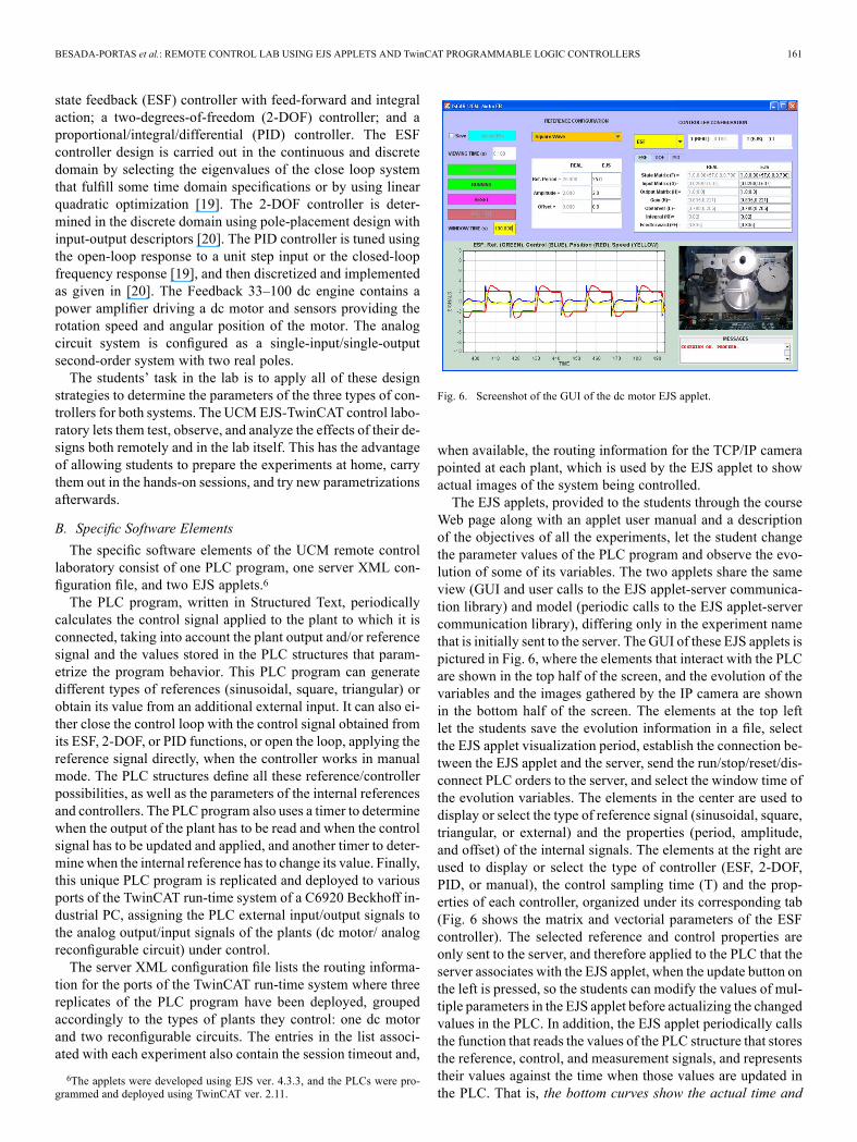
Fig. 6. Screenshot of the GUI of the dc motor EJS applet.
when available, the routing information for the TCP/IP camerapointed at each plant, which is used by the EJS applet to showactual images of the system being controlled.The EJS applets, provided to the students through the course
Web page along with an applet user manual and a descriptionof the objectives of all the experiments, let the student changethe parameter values of the PLC program and observe the evo-lution of some of its variables. The two applets share the sameview (GUI and user calls to the EJS applet-server communica-tion library) and model (periodic calls to the EJS applet-servercommunication library), differing only in the experiment namethat is initially sent to the server. The GUI of these EJS applets ispictured in Fig. 6, where the elements that interact with the PLCare shown in the top half of the screen, and the evolution of thevariables and the images gathered by the IP camera are shownin the bottom half of the screen. The elements at the top leftlet the students save the evolution information in a file, selectthe EJS applet visualization period, establish the connection be-tween the EJS applet and the server, send the run/stop/reset/dis-connect PLC orders to the server, and select the window time ofthe evolution variables. The elements in the center are used todisplay or select the type of reference signal (sinusoidal, square,triangular, or external) and the properties (period, amplitude,and offset) of the internal signals. The elements at the right areused to display or select the type of controller (ESF, 2-DOF,PID, or manual), the control sampling time (T) and the prop-erties of each controller, organized under its corresponding tab(Fig. 6 shows the matrix and vectorial parameters of the ESFcontroller). The selected reference and control properties areonly sent to the server, and therefore applied to the PLC that theserver associates with the EJS applet, when the update button onthe left is pressed, so the students can modify the values of mul-tiple parameters in the EJS applet before actualizing the changedvalues in the PLC. In addition, the EJS applet periodically callsthe function that reads the values of the PLC structure that storesthe reference, control, and measurement signals, and representstheir values against the time when those values are updated inthe PLC. That is, the bottom curves show the actual time and

162 IEEE TRANSACTIONS ON EDUCATION, VOL. 56, NO. 2, MAY 2013
TABLE ISTUDENTS SURVEY RESULTS
signal values of the PLC. Finally, the message area at the bottomleft displays information related to the EJS connection status.
C. Validating the UCM EJS-PLC Lab as an Educational Tool
In order to evaluate the pedagogical benefits of using theUCM EJS-PLC lab, the feedback of two different groups of un-dergraduate students of the Control Systems course has beencollected and analyzed. The first group consists of the studentsof the 2010–2011 academic year, who during that academic yeardid not have access to the UCM EJS-PLC Lab. Therefore theyhad to design the controllers and apply them to the plants, withthe support of the teacher in charge of the hands-on lab, usingthe TwinCAT programming and run-time environment locallyand directly. The second group consists of the students of the2011–2012 academic year, who were able to run the experi-ments using the UCM EJS-PLC lab both remotely and in thehands-on lab sessions. Hence, the second group experienced thetool presented in this paper as an educational tool in the course;while the first group was recontacted one year later to test thetool voluntarily to provide feedback.The survey was conducted among the 7 students of the first
group who were willing to try the tool and the 10 of the secondgroup who were attending the course. Students were asked to re-spond to the questions7 presented in Table I on a range from 2to 2, indicating strong disagreement ( 2), a neutral attitude (0),or strong agreement ( 2). The mean and standard deviationsfor each question (Q1–Q8) and group of students is shown inFig. 7.The results clearly show that both groups of students had a
positive experience using the UCM EJS-PLC lab, as only a fewstudents answered the questions with a weak negative ( 1) orindifferent (0) answer. Moreover, the students of the first groupare more positive about questions Q1–Q4, and the students ofthe second group are more positive about questions Q5–Q7.Thus, the first group of students have a higher appreciation forthe freedom of preparing the experiments anywhere, the remotevisualization of the images of the plant, and the impact that ex-perimenting freely would have had on their understanding of thesubject. This could be because they would have liked to have
7Both groups were asked questions Q1–Q7 (in the conditional tense for thefirst group). Only the first group responded to question Q8 because the secondgroup has never seen the TwinCAT developing tools.
Fig. 7. Statistical analysis of the student survey results.
been able to use this tool in the academic year they took theControl System course, as their positive answer to Q8 corrob-orates. In contrast, those students who used the tool during acomplete course show a higher interest in knowing what is be-hind the tool and in using it during the experiments and in othercourses. This could be due to their higher familiarity with thetool, while their curiosity could have been aroused by their lackof knowledge of the complexity of the TwinCAT system that ishidden by the EJS applet front end.In addition to the survey, the students were also asked to pro-
vide any other type of feedback they considered relevant to im-prove or to use the tool. Only one student of the second groupprovided this type of feedback (suggesting improvements in theGUI of the applet), but almost all the students of the first groupdid. Their comments really show how much they believe thatthey would have benefited from preparing the experiments athome with the tool, and that they also want a hands-on labo-ratory season where the instructors, in person, explain in detailwhat the systems are doing. In other words, they seemed reallyconcerned about the fact that the remote lab could be used as asubstitute for, and not as a complement to, the hands-on lab.The teachers agree with this point of view, and thus they in-
tend to use the tool to let the students prepare the work at home

BESADA-PORTAS et al.: REMOTE CONTROL LAB USING EJS APPLETS AND TwinCAT PROGRAMMABLE LOGIC CONTROLLERS 163
and to continue trying as many additional experiments as theywant after a hands-on session. Moreover, taking into accountthe interest that the second group has shown in the tools usedto develop the UCM EJS-PLC lab, the instructors are also plan-ning to spend a final lab session to explain to the students howthe TwinCAT PLC closes the real-time control loop over theselected plant and how the EJS applet lets them observe andmodify the behavior of the PLC, and therefore the behavior ofthe plant. The lab can thus be used indirectly to introduce sometopics that appear in advanced control courses with the purposeof motivating students to enroll in them.
D. Possible Extensions of the UCM EJS-PLC Lab
The successful results of the lab, supported by the enthusiasmof the course professors, is leading the authors to plan the devel-opment of some new control experiments that could be carriedout remotely, using the strategy presented in this paper, for fu-ture courses.Moreover, as far as the input/output PLC signals applied to
the plant are of the same type as those used to control the dcmotor or reconfigurable circuit, the same EJS applet and PLCcode can be used to control the new systems by reassigning,with the TwinCAT System Manager, the input/ouput PLC sig-nals to other ports or card terminals. This philosophy can beapplied to virtualize some of the experiments in speed and po-sition control with the G36A transducer trainer by ElettronicaVeneta [21] that the UCM already has. There are further plansto virtualize different types of controllers for the UCM verticalrotor system [22], which will require a PLC program that com-municates with the motors and some ultrasonic sensors via theI2C protocol.Additionally, the possibility of executing multiple tasks and
running several PLCs on the same PC means that multiple con-trol systems could be connected, or that some tasks could beused to simulate the behavior of the system in the PLC to com-pare simulated and real experiments carried out in the PLCs.Furthermore, control experiments relying on multitasking ele-ments, multirate or aperiodic event-based behaviors, or numer-ical controllers (NCs) and computing NCs (CNCs) processescan also be considered, thanks to the TwinCAT’s capability tohandle these types of processes.
IV. CONCLUSION
This paper presents a new methodology to develop remoteexperiments for the control subjects of System Engineering andAutomatica, based on the combined use of TwinCAT PLCs andEJS applets. The first elements are used to program the controltask and run them in real time over a TwinCAT run-time system.The second are used to provide access to the parametrization andevolution variables of the PLCs, by means of different typesof calls to an intermediate Java application. This intermediateapplication is in charge of managing the EJS-PLC access and ofsupporting the exchange of information between the EJS appletsand the PLCs.The proposed methodology combines the EJS facilities to
quickly develop interactive applets (that can run in any PC withthe Java run-time) with the TwinCAT capabilities to develop and
deploy real-time controllers whose variables can be accessed,when required, from an external (and optionally remote) appli-cation. Hence, the teachers use the TwinCAT system to imple-ment real-time controllers for different types of systems and EJSto quickly develop student-friendly applets to remotely accessthe information of the controllers. The intermediate applicationis required to access the PLCs from a properly configured PC(the server) and to avoid several students gaining simultaneousaccess to them.The paper also introduces, as an application example, the
UCM remote EJS-TwinCAT control laboratory used in two un-dergraduate Control courses at the University Complutense ofMadrid and validates the applicability of the approach based onstudent feedback. The plants and controllers developed so farshow the potential of the methodology, which offers a great op-portunity to develop new control experiments for different typesof systems and controllers, exploiting all the possibilities (mul-titasking, multirate, aperiodicity, NC and CNC, etc.) that the un-derlying TwinCAT system offers.
ACKNOWLEDGMENT
The authors want to thank to D. Sanchez Foces and F. Mar-quez Vidal for their support in setting up the experiments in thelabs. Additionally, they also want to thank all the students whocompleted the questionnaire, especially those of the 2010–2011course who volunteered to provide the comparative information.
REFERENCES[1] G. Chang, Z. Yeh, H. Chang, and S. Pan, “Teaching photonics labora-
tory using remote-control web technologies,” IEEE Trans. Educ., vol.48, no. 4, pp. 642–651, Nov. 2005.
[2] S. Sivakumar, W. Robertson, M. Artimy, and N. Aslam, “AWeb-basedremote interactive laboratory for internetworking education,” IEEETrans. Educ., vol. 48, no. 4, pp. 586–598, Nov. 2005.
[3] B. Alhalabi, D. Marcovitz, K. Hamza, and S. Hsu, “Remote labs: Aninnovative leap in the world of distance education,” in Proc. 5th IFACSymp. Adv. Control Educ., 2000, pp. 1–6.
[4] C. Gravier, J. Fayolle, B. Bayard, M. Ates, and J. Lardon, “State ofthe art about remote laboratories paradigms—Foundations of ongoingmutations,” Int. J. Online Eng., vol. 4, pp. 1–9, 2008.
[5] R. Dormido, H. Vargas, N. Duro, J. Sanchez, S. Dormido-Canto, G.Farias, F. Esquembre, and R. Dormido, “Development of a Web-basedcontrol laboratory for automation technicians: The three-tank system,”IEEE Trans. Educ., vol. 51, no. 1, pp. 35–44, Feb. 2008.
[6] M. Stefanovic, V. Cvijetkovic, M. Matijevic, and V. Simic, “A Lab-view-based remote laboratory experiments for control engineering ed-ucation,” Comput. Appl. Eng. Educ., vol. 19, pp. 538–549, 2011.
[7] M. Casini, D. Prattichizzo, and A. Vicino, “The automatic controltelelab: A user-friendly interface for distance learning,” IEEE Trans.Educ., vol. 46, no. 2, pp. 252–257, May 2003.
[8] A. Grau and Y. Bolea, The International Federation of Automatic Con-trol, “Remote laboratory for control engineering degree,” in Proc. 17thWorld Congress, Seoul, Korea, 2008, pp. 13629–13633.
[9] C. Lazar and S. Carari, “A remote-control engineering laboratory,”IEEE Trans. Ind. Electron., vol. 55, no. 6, pp. 2368–2375, Jun. 2008.
[10] H. Vargas, J. Sanchez, N. Duro, R. Dormido, S. Dormido-Canto, G.Farias, and S. Dormido, “A systematic two-layer approach to developweb-based experimentation environments for control engineering ed-ucation,” Intell. Autom. Soft Comput., vol. 14, pp. 505–524, 2008.
[11] G. Farias, A. Cervin, K. Årzén, S. Dormido, and F. Esquembre, “Mul-titasking real-time control systems in Easy Java Simulations,” in Proc.17th IFAC World Congress, 2008, pp. 1–6.
[12] National Instruments Corporation, Austin, TX, “Labview Webpage,” Accessed Jun. 1, 2012 [Online]. Available: http://www.ni.com/labview/
[13] Beckhoff Automation GmbH, Verl, Germany, “Beckhoff Web page,”Accessed Jun. 1, 2012 [Online]. Available: http://www.beckhoff.de/

164 IEEE TRANSACTIONS ON EDUCATION, VOL. 56, NO. 2, MAY 2013
[14] S. Dutta, S. Prakash, and D. Estrada, “A Web service and interface forremote electronic device characterization,” IEEE Trans. Educ., vol. 54,no. 4, pp. 646–651, Nov. 2011.
[15] E. Besada-Portas, J. A. Lopez-Orozco, L. de la Torre, and J. M. de laCruz, “EasyJava Simulations meets TwinCAT: Remote real-time con-trol experiments using programmable logic controllers,” in Proc. 9thIFAC Symp. Adv. Control Educ., 2012, pp. 294–299.
[16] Complutense University ofMadrid,Madrid, Spain, “ISCAR laboratoryWeb page,” Accessed Jun. 1, 2012 [Online]. Available: http://www.dacya.ucm.es/isalab
[17] “EJS Web page,” Accessed Jun. 1, 2012 [Online]. Available: http://www.um.es/fem/EjsWiki/
[18] F. Esquembre, “Easy Java Simulations: A software tool to create sci-entific simulations in Java,” Comput. Phys. Commun., vol. 156, no. 6,pp. 199–204, Jan. 2004.
[19] K. J. Astrom and R. M. Murray, Feedback Systems: An Introductionfor Scientists and Engineers. Princeton, NJ: Princeton Univ. Press,2008.
[20] B. Wittenmark, K. L. Astrom, and K. Arzen, “Computer control: Anoverview,” Instituto Tecnologico de Lund, Lund, Sweden, IFAC Pro-fessional Brief, 2002.
[21] Elettronica Veneta, Motta di Livenza, Italy, “Elettronica VenetaWeb page,” Accessed Jun. 1, 2012 [Online]. Available: http://www.elettronicaveneta.com/education
[22] D. Sánchez-Benítez, E. Besada-Portas, J. M. de la Cruz, and G. Pajares,“Vertical rotor for the implementation of control laws,” in Proc. 9thIFAC Symp. Adv. Control Educ., 2012, pp. 224–229.
Eva Besada-Portas was born in Madrid, Spain, in 1974. She received theM.Sc. degree in physics and Ph.D. degree in computer engineering from theComplutense University of Madrid (UCM), Madrid, Spain, in 1997 and 2004,respectively.She has been an Assistant Professor with the Department of Computer Archi-
tecture and Automatic Control, UCM, since 2005. She was also a Post-doctoralVisiting Researcher with the Department of Computer Science, University ofNew Mexico, Albuquerque, from 2006 to 2010. Her research interests are inoptimal control, evolutionary algorithms, UAVs, multisensor fusion systems,and machine learning techniques.
José A. Lopez-Orozco (M’02) received the M.Sc. and Ph.D. degrees in physicsfrom the Complutense University ofMadrid (UCM),Madrid, Spain, in 1991 and1999, respectively.In 1992, he joined the Department of Computer Architecture and Automatic
Control, UCM, as a Teaching Assistant and later as an Assistant Professor. Since2002, he has been an Associate Professor. His current research interests includeapplications of automatic control, artificial neural networks, robotics, and mul-tisensor fusion systems.
Luis de la Torre received the M.Sc. degree in physics, with specialization inelectronic devices and automatic control, from the Complutense University ofMadrid (UCM), Madrid, Spain, in 2008.He is an Assistant Professor with the Department of Computer Sciences Au-
tomatic and Control, UNED (Open University of Spain), Madrid, Spain, wherehe began the Ph.D. degree in systems engineering and automatic control in 2008.He previously joined the Department of Computers Architecture and AutomaticControl, Complutense University of Madrid (UCM), Madrid, Spain, as a Re-search Fellow in 2007, while he was finishing the M.Sc. degree. His researchinterests are in evolutionary algorithms, UAVs, path planning, remote and vir-tual laboratories, and distance education.
Jesus M. de la Cruz (M’80) received the M.Sc. and Ph.D. degrees in physicsfrom the Complutense University of Madrid (UCM), Madrid, Spain, in 1979and 1984, respectively.From 1985 to 1990, he held teaching appointments with the UCM and the
Open University of Spain (UNED), Madrid, Spain. From 1990 to 1992, he waswith the Department of Electronics, Cantabria University of Santander, San-tander, Spain. In October 1992, he joined the Department of Computer Archi-tecture and Automatic Control, UCM, where he was the Dean from 1997 to2001 and is currently a Full Professor and the Head of the Automatic Controland Robotics Group. His current research interests include broad aspects of au-tomatic control and its applications, real-time control, optimization, statisticallearning, and robotics.Dr. de la Cruz has been the Chair of the Spanish Chapter of the IEEE Oceanic
Engineering Society.