Lab 10 Data Manipulation.pdf - Programmable Logic Controllers
23
Lab 10 Programmable Logic Controllers Lab 10 Data Manipulation
-
Upload
khangminh22 -
Category
Documents
-
view
4 -
download
0
Transcript of Lab 10 Data Manipulation.pdf - Programmable Logic Controllers

Chapter
Lab 10
Programmable Logic Controllers
Lab 10 Data Manipulation

Data Manipulation
Reading DataStoring DataRetrieving DataMoving from one file to anotherCopying DataModifying the dataApplying Math functionsApplying Comparing FunctionsLoading and reading FilesSending data over Ether-Net
Manipulations of Data Examples of Data

Data Manipulation
Data Manipulation is Mostly at the word level.
Data can be Bits or Words
If data is greater than a bit (0 or 1)data will be a word. (16 Bits)
The PLC Memory is 16 bits (0-15) Memory can be viewed in Binary, BCD/HEX, or Decimal.
Bit Level:
Bit I:0/5 or Bit I:0.0/5
Word Level
Word I:0.0 or O:7.0

Bit Level: Input a bit for a pushbutton I:0/5
Word Level: Needs more than one bit. The number 7 from a thumbwheel switch in binary (BCD) requires the word level.
111 = 7
Word I:0.0
Bit I:0/5orBit I:0.0/5
Data Manipulation

Data Manipulation – Compare Instructions
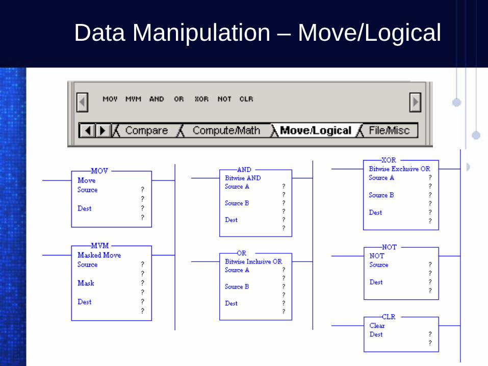
Data Manipulation – Move/Logical

Data Manipulation – File/Misc.
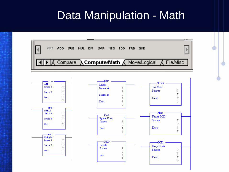
Data Manipulation - Math

Data Manipulation
Chapter
Lab 10-1
Programmable Logic Controllers
Loading a Counter (with Thumbwheel Switch)
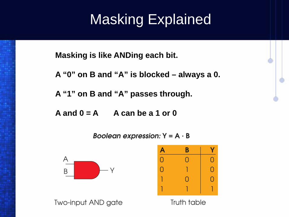
Masking Explained
Masking is like ANDing each bit.
A “0” on B and “A” is blocked – always a 0.
A “1” on B and “A” passes through.
A and 0 = A A can be a 1 or 0

Masking Explained
<- Data (263 decimal)
<- Mask Word (000F)
<- Result (7 decimal)
Several Instructions such as the Mask Move instruction, Sequencer Instructions, File instructions, Etc have the ability to block bits of data using MASKING. In the example below, a thumbwheel switch is set to 7, however switch 8 is on making the data 263. Masking blocks the switch.

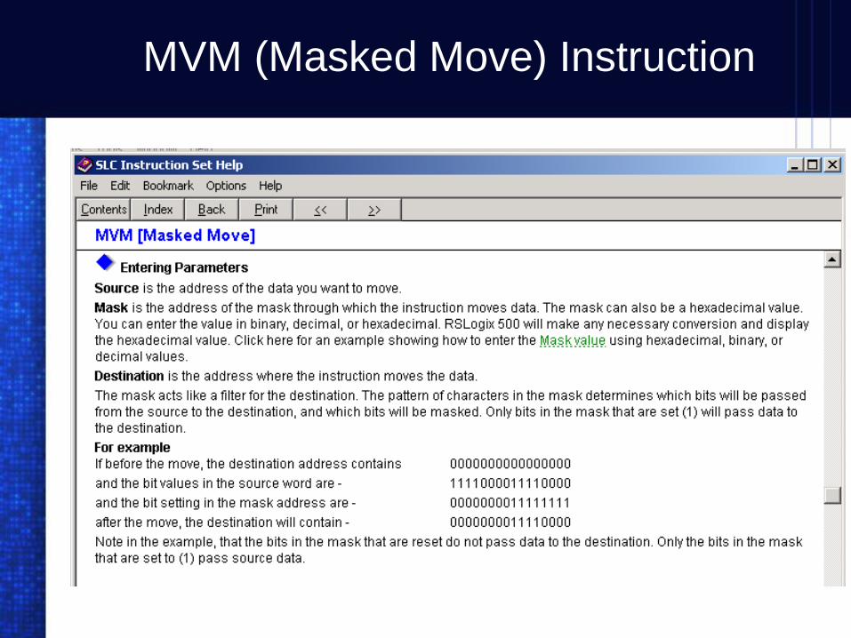
MVM (Masked Move) Instruction
MVM (Masked Move) Instruction

The Move (MOV) and Masked Move (MVM) Instruction

Load a Counter with the Thumbwheel Switch
Thumbwheel Switch wired to slot 0 word 0
Mask allows only bits 0,1,2,3 to be moved
Move TW Switch data into preset of counter

Chapter
Lab 10-2
Programmable Logic Controllers
Loading a Counter (with a Pushbutton)

Load a Timer with a Pushbutton Switch
Pulse Counter
Move Counter ACC value to Timer PRE value
Turn on Timer
Turn on a light when the timer is done
Reset Timer

Chapter
Lab 10-3
Programmable Logic Controllers
Loading 2 Timers with one Thumbwheel Switch

Load Two Timers with One Thumbwheel Switch
Set Thumbwheel then pressThe press pushbutton #6 to move thumbwheel data to T4:0.pre
Set Thumbwheel then pressThe press pushbutton #7 to move thumbwheel data to T4:1.pre
Turn on switch 8 to starts timers generating a pulse train.
Note: Using only one decimal digit on the thumbwheel switch the range of timing is 1-9 seconds each.

Chapter
Lab 10-4
Programmable Logic Controllers
Compare Instructions

Compare Instructions Controlling a Sequence
Time driven sequence using one timer, LIM. EQU, GTR & GEQ
Presenter
Presentation Notes
This is a time driven sequence that control two cylinders using Greater than, Less than, Limit Test, and Equal instructions. Rung 1: Turn on the switch and the timer starts incrementing every second. Rung 2: the light will be on for the first 6 seconds. Rung 3: The single solenoid valve extents piston one for seconds 1-3 then retracts. Rung 4: Piston two extends on the 4 second and stays extended for second 5. Rung 5: on the 6 second, piston 2 retracts. Rung 6: The 2nd light comes on for the 7th second. Rung 7: the 3rd light comes on for the 8th second. Rung 8: the 4th light comes on for the 9th second. Rung 9: The 5th light links on and off until the timer reaches 10 seconds or greater.
Chapter
The End
Lab 10 Data Manipulation
Programmable Logic Controllers