Twido - Programmable Controllers - Alameda Electrical ...
200
31003914 00 Twido Programmable Controllers Hardware Reference Guide TWD USE 10AE Version 1.0
-
Upload
khangminh22 -
Category
Documents
-
view
0 -
download
0
Transcript of Twido - Programmable Controllers - Alameda Electrical ...

3100
3914
00
TwidoProgrammable ControllersHardware Reference GuideTWD USE 10AE Version 1.0

2 TWD USE 10AE 05/2002
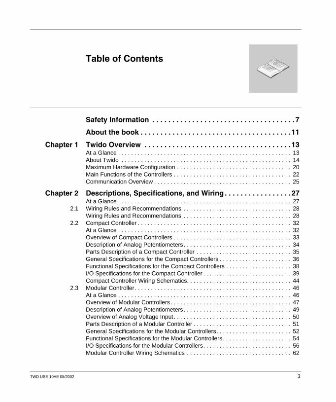
Table of Contents
Safety Information . . . . . . . . . . . . . . . . . . . . . . . . . . . . . . . . . . . . 7
About the book . . . . . . . . . . . . . . . . . . . . . . . . . . . . . . . . . . . . . .11
Chapter 1 Twido Overview . . . . . . . . . . . . . . . . . . . . . . . . . . . . . . . . . . . . . 13At a Glance . . . . . . . . . . . . . . . . . . . . . . . . . . . . . . . . . . . . . . . . . . . . . . . . . . . . . 13About Twido . . . . . . . . . . . . . . . . . . . . . . . . . . . . . . . . . . . . . . . . . . . . . . . . . . . . 14Maximum Hardware Configuration . . . . . . . . . . . . . . . . . . . . . . . . . . . . . . . . . . . 20Main Functions of the Controllers . . . . . . . . . . . . . . . . . . . . . . . . . . . . . . . . . . . . 22Communication Overview . . . . . . . . . . . . . . . . . . . . . . . . . . . . . . . . . . . . . . . . . . 25
Chapter 2 Descriptions, Specifications, and Wiring . . . . . . . . . . . . . . . . .27At a Glance . . . . . . . . . . . . . . . . . . . . . . . . . . . . . . . . . . . . . . . . . . . . . . . . . . . . . 27
2.1 Wiring Rules and Recommendations . . . . . . . . . . . . . . . . . . . . . . . . . . . . . . . . . 28Wiring Rules and Recommendations . . . . . . . . . . . . . . . . . . . . . . . . . . . . . . . . . 28
2.2 Compact Controller . . . . . . . . . . . . . . . . . . . . . . . . . . . . . . . . . . . . . . . . . . . . . . . 32At a Glance . . . . . . . . . . . . . . . . . . . . . . . . . . . . . . . . . . . . . . . . . . . . . . . . . . . . . 32Overview of Compact Controllers . . . . . . . . . . . . . . . . . . . . . . . . . . . . . . . . . . . . 33Description of Analog Potentiometers . . . . . . . . . . . . . . . . . . . . . . . . . . . . . . . . . 34Parts Description of a Compact Controller . . . . . . . . . . . . . . . . . . . . . . . . . . . . . 35General Specifications for the Compact Controllers . . . . . . . . . . . . . . . . . . . . . . 36Functional Specifications for the Compact Controllers . . . . . . . . . . . . . . . . . . . . 38I/O Specifications for the Compact Controller . . . . . . . . . . . . . . . . . . . . . . . . . . . 39Compact Controller Wiring Schematics. . . . . . . . . . . . . . . . . . . . . . . . . . . . . . . . 44
2.3 Modular Controller. . . . . . . . . . . . . . . . . . . . . . . . . . . . . . . . . . . . . . . . . . . . . . . . 46At a Glance . . . . . . . . . . . . . . . . . . . . . . . . . . . . . . . . . . . . . . . . . . . . . . . . . . . . . 46Overview of Modular Controllers . . . . . . . . . . . . . . . . . . . . . . . . . . . . . . . . . . . . . 47Description of Analog Potentiometers . . . . . . . . . . . . . . . . . . . . . . . . . . . . . . . . . 49Overview of Analog Voltage Input . . . . . . . . . . . . . . . . . . . . . . . . . . . . . . . . . . . . 50Parts Description of a Modular Controller . . . . . . . . . . . . . . . . . . . . . . . . . . . . . . 51General Specifications for the Modular Controllers. . . . . . . . . . . . . . . . . . . . . . . 52Functional Specifications for the Modular Controllers . . . . . . . . . . . . . . . . . . . . . 54I/O Specifications for the Modular Controllers. . . . . . . . . . . . . . . . . . . . . . . . . . . 56Modular Controller Wiring Schematics . . . . . . . . . . . . . . . . . . . . . . . . . . . . . . . . 62
TWD USE 10AE 05/2002 3

2.4 Digital I/O Modules. . . . . . . . . . . . . . . . . . . . . . . . . . . . . . . . . . . . . . . . . . . . . . . . 67At a Glance . . . . . . . . . . . . . . . . . . . . . . . . . . . . . . . . . . . . . . . . . . . . . . . . . . . . . 67Overview of Digital I/O Modules. . . . . . . . . . . . . . . . . . . . . . . . . . . . . . . . . . . . . . 68Parts Description of Digital I/O Modules . . . . . . . . . . . . . . . . . . . . . . . . . . . . . . . 71Specifications for the Digital I/O Modules . . . . . . . . . . . . . . . . . . . . . . . . . . . . . . 73Digital I/O Module Wiring Schematics . . . . . . . . . . . . . . . . . . . . . . . . . . . . . . . . . 84
2.5 Analog I/O Modules . . . . . . . . . . . . . . . . . . . . . . . . . . . . . . . . . . . . . . . . . . . . . . . 94At a Glance . . . . . . . . . . . . . . . . . . . . . . . . . . . . . . . . . . . . . . . . . . . . . . . . . . . . . 94Overview of Analog I/O Modules . . . . . . . . . . . . . . . . . . . . . . . . . . . . . . . . . . . . . 95Parts Description of Analog I/O Modules. . . . . . . . . . . . . . . . . . . . . . . . . . . . . . . 96General Specifications for the Analog I/O Module. . . . . . . . . . . . . . . . . . . . . . . . 97I/O Specifications for the Analog I/O Module. . . . . . . . . . . . . . . . . . . . . . . . . . . . 98Analog I/O Modules Wiring Schematics. . . . . . . . . . . . . . . . . . . . . . . . . . . . . . . 103
2.6 Communication Options. . . . . . . . . . . . . . . . . . . . . . . . . . . . . . . . . . . . . . . . . . . 106At a Glance . . . . . . . . . . . . . . . . . . . . . . . . . . . . . . . . . . . . . . . . . . . . . . . . . . . . 106Overview of Communication Adapters and Expansion Modules . . . . . . . . . . . . 107Parts Description of Communication Adapters and Expansion Modules. . . . . . 108Specifications for Communication Adapters and Expansion Modules. . . . . . . . 110
2.7 Operator Display Options. . . . . . . . . . . . . . . . . . . . . . . . . . . . . . . . . . . . . . . . . . 111At a Glance . . . . . . . . . . . . . . . . . . . . . . . . . . . . . . . . . . . . . . . . . . . . . . . . . . . . 111Overview of Operator Display Modules and Expansion Modules . . . . . . . . . . . 112Parts Description of Operator Display Module and Expansion Module . . . . . . . 113Specifications for Operator Display Modules and Expansion Modules . . . . . . . 115
2.8 Options. . . . . . . . . . . . . . . . . . . . . . . . . . . . . . . . . . . . . . . . . . . . . . . . . . . . . . . . 116At a Glance . . . . . . . . . . . . . . . . . . . . . . . . . . . . . . . . . . . . . . . . . . . . . . . . . . . . 116Overview of the Options. . . . . . . . . . . . . . . . . . . . . . . . . . . . . . . . . . . . . . . . . . . 117Specifications for the Options . . . . . . . . . . . . . . . . . . . . . . . . . . . . . . . . . . . . . . 118
2.9 TeleFast Cable Systems . . . . . . . . . . . . . . . . . . . . . . . . . . . . . . . . . . . . . . . . . . 119At a Glance . . . . . . . . . . . . . . . . . . . . . . . . . . . . . . . . . . . . . . . . . . . . . . . . . . . . 119Overview of the Twido TeleFast Cable System Kits . . . . . . . . . . . . . . . . . . . . . 120Specifications for the TeleFast Bases . . . . . . . . . . . . . . . . . . . . . . . . . . . . . . . . 122Twido TeleFast Wiring Schematics . . . . . . . . . . . . . . . . . . . . . . . . . . . . . . . . . . 123Wiring Specifications for the TeleFast Cables . . . . . . . . . . . . . . . . . . . . . . . . . . 125
Chapter 3 Installation . . . . . . . . . . . . . . . . . . . . . . . . . . . . . . . . . . . . . . . . 131At a Glance . . . . . . . . . . . . . . . . . . . . . . . . . . . . . . . . . . . . . . . . . . . . . . . . . . . . 131Dimensions of the Compact Controllers . . . . . . . . . . . . . . . . . . . . . . . . . . . . . . 132Dimensions for the Modular Controllers. . . . . . . . . . . . . . . . . . . . . . . . . . . . . . . 134Dimensions for the Digital and Analog I/O Modules . . . . . . . . . . . . . . . . . . . . . 136Dimensions for the Operator Display Module, Operator Display Expansion Module, and Communication Expansion Modules. . . . . . . . . . . . . . . . . . . . . . . 139Dimensions of the TeleFast Bases . . . . . . . . . . . . . . . . . . . . . . . . . . . . . . . . . . 141Installation Preparation . . . . . . . . . . . . . . . . . . . . . . . . . . . . . . . . . . . . . . . . . . . 143Controller and Expansion I/O Module Mounting Positions. . . . . . . . . . . . . . . . . 144How to Assemble an Expansion I/O Module to a Controller . . . . . . . . . . . . . . . 146
4 TWD USE 10AE 05/2002

How to Disassemble an Expansion I/O Module from a Controller . . . . . . . . . . 148How to Install and Remove the Operator Display Module and Operator Display Expansion Module. . . . . . . . . . . . . . . . . . . . . . . . . . . . . . . . . 149How to Install and Remove a Communication Adapter and Expansion Module 153How to Install a Memory or RTC Cartridge . . . . . . . . . . . . . . . . . . . . . . . . . . . . 157How to Remove a Terminal Block. . . . . . . . . . . . . . . . . . . . . . . . . . . . . . . . . . . 159How to Install and Remove a Controller and Expansion I/O Module from a DIN Rail . . . . . . . . . . . . . . . . . . . . . . . . . . . . . . . . . . . . . . . . . . . . . . . . . . . . . 160How to Direct Mount on a Panel Surface . . . . . . . . . . . . . . . . . . . . . . . . . . . . . 163Minimum Clearances for Controllers and Expansion I/O Modules in a Control Panel . . . . . . . . . . . . . . . . . . . . . . . . . . . . . . . . . . . . . . . . . . . . . . . . . 167How to Connect the Power Supply . . . . . . . . . . . . . . . . . . . . . . . . . . . . . . . . . . 169
Chapter 4 Special Functions . . . . . . . . . . . . . . . . . . . . . . . . . . . . . . . . . . .173At a Glance . . . . . . . . . . . . . . . . . . . . . . . . . . . . . . . . . . . . . . . . . . . . . . . . . . . . 173RUN/STOP Input. . . . . . . . . . . . . . . . . . . . . . . . . . . . . . . . . . . . . . . . . . . . . . . . 174Controller Status Output . . . . . . . . . . . . . . . . . . . . . . . . . . . . . . . . . . . . . . . . . . 174Latching Input . . . . . . . . . . . . . . . . . . . . . . . . . . . . . . . . . . . . . . . . . . . . . . . . . . 174Fast Counting . . . . . . . . . . . . . . . . . . . . . . . . . . . . . . . . . . . . . . . . . . . . . . . . . . 175Very Fast Counters . . . . . . . . . . . . . . . . . . . . . . . . . . . . . . . . . . . . . . . . . . . . . . 176Pulse (PLS) Generator Output . . . . . . . . . . . . . . . . . . . . . . . . . . . . . . . . . . . . . 178Pulse Width Modulation (PWM) Output. . . . . . . . . . . . . . . . . . . . . . . . . . . . . . . 178
Chapter 5 Powering-Up and Troubleshooting. . . . . . . . . . . . . . . . . . . . . 179At a Glance . . . . . . . . . . . . . . . . . . . . . . . . . . . . . . . . . . . . . . . . . . . . . . . . . . . . 179Procedure for First Time Power-Up of a Controller . . . . . . . . . . . . . . . . . . . . . . 180Checking I/O Connections on the Base Controller . . . . . . . . . . . . . . . . . . . . . . 181Troubleshooting Using the Controller’s LEDs . . . . . . . . . . . . . . . . . . . . . . . . . . 182
Chapter 6 Agency Compliance . . . . . . . . . . . . . . . . . . . . . . . . . . . . . . . . . 183Agency Requirements. . . . . . . . . . . . . . . . . . . . . . . . . . . . . . . . . . . . . . . . . . . . 183
Appendices . . . . . . . . . . . . . . . . . . . . . . . . . . . . . . . . . . . . . . . . . . . . . 185At a Glance . . . . . . . . . . . . . . . . . . . . . . . . . . . . . . . . . . . . . . . . . . . . . . . . . . . . 185
Appendix A IEC Symbols . . . . . . . . . . . . . . . . . . . . . . . . . . . . . . . . . . . . . . .187Glossary of Symbols . . . . . . . . . . . . . . . . . . . . . . . . . . . . . . . . . . . . . . . . . . . . . 187
Glossary . . . . . . . . . . . . . . . . . . . . . . . . . . . . . . . . . . . . . . . . . . . . . 189
Index . . . . . . . . . . . . . . . . . . . . . . . . . . . . . . . . . . . . . . . . . . . . . 195
TWD USE 10AE 05/2002 5

6 TWD USE 10AE 05/2002

§
Safety InformationImportant Information
NOTICE Read these instructions carefully, and look at the equipment to become familiar with the device before trying to install, operate, or maintain it. The following special messages may appear throughout this documentation or on the equipment to warn of potential hazards or to call attention to information that clarifies or simplifies a procedure.
The addition of this symbol to a Danger or Warning safety label indicatesthat an electrical hazard exists, which will result in personal injury if theinstructions are not followed.This is the safety alert symbol. It is used to alert you to potential personalinjury hazards. Obey all safety messages that follow this symbol to avoidpossible injury or death.
DANGER indicates an imminently hazardous situation, which, if not avoided, will result in death, serious injury, or equipment damage.
DANGER
WARNINGWARNING indicates a potentially hazardous situation, which, if not avoided, can result in death, serious injury, or equipment damage.
CAUTIONCAUTION indicates a potentially hazardous situation, which, if not avoided, can result in injury or equipment damage.
TWD USE 10AE 05/2002 7

Safety Information
PLEASE NOTE Electrical equipment should be serviced only by qualified personnel. No responsi-bility is assumed by Schneider Electric for any consequences arising out of the use of this material. This document is not intended as an instruction manual for untrained persons. Assembly and installation instructions are provided in the Twido Hardware Reference Guide, TWD USE 10AE.© 2002 Schneider Electric All Rights Reserved
Additional Safety Information
Those responsible for the application, implementation or use of this product must ensure that the necessary design considerations have been incorporated into each application, completely adhering to applicable laws, performance and safety requirements, regulations, codes and standards.
8 TWD USE 10AE 05/2002

Safety Information
General Warnings and Cautions WARNING
EXPLOSION HAZARD
l Substitution of components may impair suitability for Class I, Div 2 compliance.
l Do not disconnect equipment unless power has been switched off or the area is known to be non-hazardous.
Failure to observe this precaution can result in severe injury or equipment damage.
WARNING
UNINTENDED EQUIPMENT OPERATION
l Turn power off before installing, removing, wiring, or maintaining.l This product is not intended for use in safety critical machine
functions. Where personnel and or equipment hazards exist, use appropriate hard-wired safety interlocks.
l Do not disassemble, repair, or modify the modules.l This controller is designed for use within an enclosure.l Install the modules in the operating environment conditions
described.l Use the sensor power supply only for supplying power to sensors
connected to the module.l Use an IEC60127-approved fuse on the power line and output circuit
to meet voltage and current requirements. Recommended fuse: Liitlefuse 5x20 mm slowblow type 218000 series/Type T.
Failure to observe this precaution can result in severe injury or equipment damage.
TWD USE 10AE 05/2002 9

Safety Information
10 TWD USE 10AE 05/2002

About the book
At a Glance
Document Scope This manual provides parts descriptions, specifications, wiring schematics, installation, set up, and troubleshooting information for all Twido products.
Validity Note The information in this manual is applicable only for Twido products.
Product Related Warnings
Schneider Electric assumes no responsibility for any errors that appear in this document. No part of this document may be reproduced in any form or means, including electronic, without prior written permission of Schneider Electric.
TWD USE 10AE 05/2002 11

About the book
12 TWD USE 10AE 05/2002
TWD USE 10AE 05/2002
1
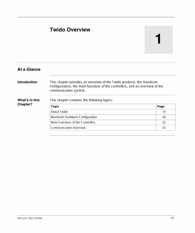
Twido OverviewAt a Glance
Introduction This chapter provides an overview of the Twido products, the maximum configurations, the main functions of the controllers, and an overview of the communication system.
What’s in this Chapter?
This chapter contains the following topics:
Topic Page
About Twido 14
Maximum Hardware Configuration 20
Main Functions of the Controllers 22
Communication Overview 25
13

Twido Overview
About Twido
Introduction The Twido controller is available in two models:l Compactl ModularThe Compact controller is available with:l 10 I/Ol 16 I/Ol 24 I/OThe Modular controller is available with:l 20 I/Ol 40 I/OAdditional I/O can be added to the controllers using expansion I/O modules. There are:l 14 digital or relay I/O modulesl 4 analog I/O modulesThere are also several options that can be added to the base controllers:l Memory cartridgesl Real-Time Clock (RTC) cartridgel Communication adaptersl Communication expansion modules (Modular controller only)l Operator display module (Compact controller only)l Operator display expansion module (Modular controller only)l Input simulatorsl Programming cablesl Digital I/O cablesl TeleFast cable system kits with I/O interfaces
14 TWD USE 10AE 05/2002
Twido Overview
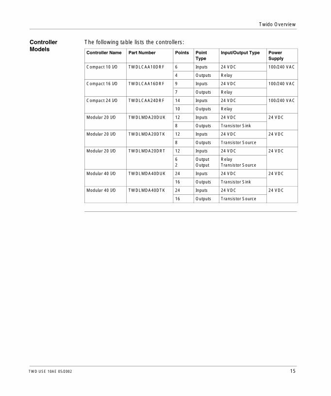
Controller Models
The following table lists the controllers:
Controller Name Part Number Points PointType
Input/Output Type Power Supply
Compact 10 I/O TWDLCAA10DRF 6 Inputs 24 VDC 100/240 VAC
4 Outputs Relay
Compact 16 I/O TWDLCAA16DRF 9 Inputs 24 VDC 100/240 VAC
7 Outputs Relay
Compact 24 I/O TWDLCAA24DRF 14 Inputs 24 VDC 100/240 VAC
10 Outputs Relay
Modular 20 I/O TWDLMDA20DUK 12 Inputs 24 VDC 24 VDC
8 Outputs Transistor Sink
Modular 20 I/O TWDLMDA20DTK 12 Inputs 24 VDC 24 VDC
8 Outputs Transistor Source
Modular 20 I/O TWDLMDA20DRT 12 Inputs 24 VDC 24 VDC
62
OutputOutput
Relay Transistor Source
Modular 40 I/O TWDLMDA40DUK 24 Inputs 24 VDC 24 VDC
16 Outputs Transistor Sink
Modular 40 I/O TWDLMDA40DTK 24 Inputs 24 VDC 24 VDC
16 Outputs Transistor Source
TWD USE 10AE 05/2002 15

Twido Overview
Digital Expansion I/O Modules
The following table lists the digital and relay expansion I/O modules:
Module Name Part Number Points PointType
Input/Output Type
Terminal Type
Input Modules
8-point Input TWDDDI8DT 8 Inputs 24 VDC Removable terminal block
16-point Input TWDDDI16DT 16 Inputs 24 VDC Removable terminal block
16-point Input TWDDDI16DK 16 Inputs 24 VDC Connector
32-point Input TWDDDI32DK 32 Inputs 24 VDC Connector
Output Modules
8-point Output TWDDD08UT 8 Outputs Transistor Sink Removable terminal block
8-point Output TWDDD08TT 8 Outputs Transistor Source Removable terminal block
8-point Output TWDDRA8RT 8 Outputs Relay Removable terminal block
16-point Output TWDDRA16RT 16 Outputs Relay Removable terminal block
16-point Output TWDDDO16UK 16 Outputs Transistor Sink Connector
16-point Output TWDDDO16TK 16 Outputs Transistor Source Connector
32-point Output TWDDDO32UK 32 Outputs Transistor Sink Connector
32-point Output TWDDDO32TK 32 Outputs Transistor Source Connector
Mixed Modules
4-point Input/ 4-point Output
TWDDMM8DRT 4 Inputs 24 VDC Removable terminal block4 Outputs Relay
16-point Input/8-point Output
TWDDMM24DRF 16 Inputs 24 VDC Non-removable terminal block
8 Outputs Relay
16 TWD USE 10AE 05/2002
Twido Overview
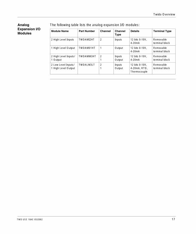
Analog Expansion I/O Modules
The following table lists the analog expansion I/O modules:
Module Name Part Number Channel ChannelType
Details Terminal Type
2 High Level Inputs TWDAMI2HT 2 Inputs 12 bits 0-10V, 4-20mA
Removable terminal block
1 High Level Output TWDAM01HT 1 Output 12 bits 0-10V, 4-20mA
Removable terminal block
2 High Level Inputs/1 Output
TWDAMM3HT 21
InputsOutput
12 bits 0-10V, 4-20mA
Removable terminal block
2 Low Level Inputs/1 High Level Output
TWDALM3LT 21
InputsOutput
12 bits 0-10V, 4-20mA, RTD, Thermocouple
Removable terminal block
TWD USE 10AE 05/2002 17

Twido Overview
Options The following table lists the options:
Option Name Part Number
Operator display module TWDXCPODC
Operator display expansion module TWDXCPODM
RTC cartridge TWDXCPRTC
Memory cartridge 32 K EEPROM TWDXCPMFK32
Memory cartridge 64 K EEPROM TWDXCPMFK64
Communication adapter, RS485, miniDIN TWDNAC485D
Communication adapter, RS232, miniDIN TWDNAC232D
Communication adapter, RS485, terminal TWDNAC485T
Communication expansion module, RS485, miniDIN TWDNOZ485D
Communication expansion module, RS232, miniDIN TWDNOZ232D
Communication expansion module, RS485, terminal TWDNOZ485T
6-point Input simulator TWDXSIM6
9-point Input simulator TWDXSIM9
14-point Input simulator TWDXSIM14
5 mounting strips TWDDXMT5
2 terminal blocks (10 positions) TWDFTB2T10
2 terminal blocks (11 positions) TWDFTB2T11
2 terminal blocks (13 positions) TWDFTB2T13
2 terminal blocks (16 positions) TWDFTB2T16T
2 connectors (20 pin) TWDFCN2K20
2 connectors (26 pin) TWDFCN2K26
18 TWD USE 10AE 05/2002

Twido Overview
Cables The following table lists the cables:
Cable Name Part Number
Programming Cables
PC to controller programming cable TSXPCX1031
Mini-DIN to free wire communication cable TSXCX100
Digital I/O Cables
3 meter, connector for controller to free wire TWDFCW30M
5 meter, connector for controller to free wire TWDFCW50M
3 meter, connector for expansion I/O module to free wire TWDFCW30K
5 meter, connector for expansion I/O module to free wire TWDFCW50K
TeleFast Cable System Kits with I/O Interfaces
Cabling kit, 16 input TeleFast base, 1 meter cable TWDFST16D10
Cabling kit, 16 input TeleFast base, 2 meter cable TWDFST16D20
Cabling kit, 16 output relay TeleFast base, 1 meter cable TWDFST16R10
Cabling kit, 16 output relay TeleFast base, 2 meter cable TWDFST16R20
Cabling kit, 16 input/8 output relay TeleFast base, 1 meter cable TWDFST20DR10
Cabling kit, 16 input/8 output relay TeleFast base, 2 meter cable TWDFST20DR20
TWD USE 10AE 05/2002 19

Twido Overview
Maximum Hardware Configuration
Introduction This section provides the maximum hardware configurations for each controller.
Maximum Hardware Configurations
The following table lists the maximum number of configuration items for each controller:
Controller Item Compact Controller Modular Controller
TWD... LCAA10DRF LCAA16DRF LCAA24DRF LMDA20DUKLMDA20DTK
LMDA20DRT LMDA40DUKLMDA40DTK
Base digital inputs 6 9 14 12 12 24
Base digital outputs 4 7 10 8 8 16
Max Expansion I/O modules - digital or analog
0 0 4 4 7 7
Max digital inputs (controller I/O + exp I/O)
6 9 14+(4x32)=142
12+(4x32)=140
12+(7x32)=236
24+(7x32)=248
Max digital outputs (controller I/O + exp I/O)
4 7 10+(2x32)=74
8+(4x32)=36
8+(7x32)=232
16+(7x32)=240
Max digital I/O (controller I/O + exp I/O)
10 16 24+(4x32)=152
20+(4x32)=148
20+(7x32)=244
40+(7x32)=264
Max relay points 4 base only 7 base only 10 base + 32 expansion
64 expansion only
6 base + 96expansion
96 expansion only
Potentiometers 1 1 2 1 1 1
Built-in analog inputs
0 0 0 1 1 1
Max analog I/O (controller I/O + exp I/O)
0 In/0 Out 0 In/0 Out 8 In/4 Out 9 In/4 Out 15 In/7 Out 15 In/7 Out
Remote controllers 7 7 7 7 7 7
Serial ports 1 2 2 2 2 2
Cartridge slots 1 1 1 2 2 2
Largest application/backup size (KB)
8 16 32 32 64 64
20 TWD USE 10AE 05/2002

Twido Overview
Optional memory cartridge (KB)
321 321 321 32 or 64 32 or 64 32 or 64
Optional RTC cartridge
yes1 yes1 yes1 yes yes yes
Optional Operator Display
yes yes yes yes2 yes2 yes2
Optional 2nd port no yes yes yes2 yes2 yes2
Controller Item Compact Controller Modular Controller
TWD... LCAA10DRF LCAA16DRF LCAA24DRF LMDA20DUKLMDA20DTK
LMDA20DRT LMDA40DUKLMDA40DTK
Note: 1. A Compact controller can have either a memory cartridge or an RTC cartridge.2. A Modular controller can have either an Operator Display expansion module
(with an optional communication adapter) or a communication expansion module.
TWD USE 10AE 05/2002 21

Twido Overview
Main Functions of the Controllers
Introduction By default all I/O on the controllers are configured as digital I/O. However, certain I/O can be assigned to specific tasks during configuration such as:l RUN/STOP inputl Latching inputsl Fast counters:
l Single up/down counters - 5 kHz (1-phase)l Very fast counters - 20 kHz up/down counting (two-phase)
l Controller status outputl Pulse Width Modulation (PWM)l Pulse (PLS) generator outputTwido controllers are programmed using TwidoSoft which enables the following functions to be used:l PWMl PLSl Fast counters and very fast counters
22 TWD USE 10AE 05/2002

Twido Overview
Main Functions The following table lists the main functions of the controllers:
Function Description
Scanning Normal (cyclical) or periodic (constant) (2 to 150 ms)
Execution time 0.14 µs to 0.9 µs for a list instruction
Memory capacity
Data: 1500 memory words for all controllers, 128 memory bits for TWDLCAA10DRF and TWDLCAA16DRF, 256 memory bits for all other controllers.
Program:Compact 10 I/O controller: 700 list instructionsCompact 16 I/O controller: 2000 list instructionsCompact 24 I/O and Modular 20 I/O controllers: 3000 list instructionsModular 20 Relay and 40 I/O controllers: 6000 list instructions (with a 64 K cartridge otherwise 3000 list instructions)
RAM backup By lithium secondary battery. Backup duration is approximately 30 days (typical) at 25°C (77°F) after battery is fully charged. The charging time is 15 hours for charging from 0% to 90% of full charge. Battery life is 5 years when charging for 9 hours and discharging for 15 hours. The battery cannot be replaced.
Programming port
EIA RS-485
Expansion I/O modules
Compact 10 and 16 I/O controllers: no expansion modulesCompact 24 and Modular 20 I/O controllers: up to 4 expansion I/O modulesModular 20 Relay and 40 I/O controllers: up to 7 expansion I/O modules
Remote controllers
Up to 7 per controller.Maximum distance between controllers: 50 m (164 feet).Maximum length of entire network 200 m (650 feet).
Modbus link Non-isolated EIA RS-485 type, maximum length limit to 200 m. ASCII or RTU mode.
Remote link Remote link communications
Dedicated function blocks
PWM/PLS All Modular controllers: 2
Fast counters
Very fast counters
All Compact controllers: 3All Modular controllers: 2All Compact controllers: 1All Modular controllers: 2
Potentiometers Compact controller 24 I/O: 2All other controllers: 1
Built-in analog channel
Compact controllers: noneModular controllers: 1 Input
TWD USE 10AE 05/2002 23

Twido Overview
Programmable input filter
Input filter time can be changed during configurationNo filtering or filtering at 3 ms or 12 msI/O points are configured in groups
Special I/O Inputs RUN/STOP: Any one of the base inputs
Latching: up to 4 inputs (%I0.2 to %I0.5)
Built-in analog input connected to %I0.0 according to frequency meter
Fast counter: 5 kHz maximumVery fast counter: 20 kHz maximumFrequency meter: 1 kHz to 20 kHz maximum
Outputs Controller status output: 1 of 3 outputs (%Q0.1 to %Q0.3)
PLS: 27.4 kHz maximum
PWM: 20 kHz maximum
Function Description
24 TWD USE 10AE 05/2002

Twido Overview
Communication Overview
Introduction Twido controllers have one, or an optional second, serial port that is used for real-time or system management services. The real-time services provide data distribution functions for exchanging data with I/O devices and messaging functions for communicating to external devices. System management services manage and configure the controller through TwidoSoft. Either serial port is used for any of these services but only serial port 1 is for communicating with TwidoSoft. To provide these services, there are three protocols available on each controller:l Remote Link (RTU and ASCII)l Modbusl ASCII
Communications Architecture
The following diagram shows a communication architecture with all three protocols.
Remote Link Protocol
The Remote Link protocol is a high-speed master/slave bus designed to communicate a small amount of data between the Master controller and up to seven Remote Slave controllers. Application or I/O data is transferred, depending on the configuration of the Remote controller. A combination of Remote controller types is possible where some can be Remote I/O and some can be Peer controllers.
ASCII
Modbus - master
Modbus - slave
Remote Link
Remote I/O Mastercontroller or
Peer controller
Remote I/O or Peer controller
Remote I/O or Peer controller
TwidoSoft
1 2... 7
(Slave controller) (Slave controller) (Slave controller)
TWD USE 10AE 05/2002 25

Twido Overview
Modbus Protocol The Modbus protocol is a master/slave protocol that allows for one master to request responses from slaves or to take action based on the request. The master can address individual slaves or can initiate a broadcast message to all slaves. Slaves return a message (response) to queries that are addressed to them individually. Responses are not returned to broadcast queries from the master.Modbus Master Mode - The Modbus master mode allows the controller to initiate a Modbus query transmission, with a response expected from a Modbus slave.Modbus Slave Mode - The Modbus slave mode allows the controller to respond to Modbus queries from a Modbus master and is the default communications mode if no communication is configured.
ASCII Protocol The ASCII protocol allows communication between the controller and a simple device such as a printer.
26 TWD USE 10AE 05/2002

TWD USE 10AE 05/2002
2
Descriptions, Specifications, and WiringAt a Glance
Introduction This chapter provides wiring rules and recommendations, overviews, parts descriptions, specifications, and wiring schematics for the Twido products.
What’s in this Chapter?
This chapter contains the following sections:
Section Topic Page
2.1 Wiring Rules and Recommendations 28
2.2 Compact Controller 32
2.3 Modular Controller 46
2.4 Digital I/O Modules 67
2.5 Analog I/O Modules 94
2.6 Communication Options 106
2.7 Operator Display Options 111
2.8 Options 116
2.9 TeleFast Cable Systems 119
27

Descriptions, Specifications, and Wiring
2.1 Wiring Rules and Recommendations
Wiring Rules and Recommendations
Introduction There are several rules that must be followed when wiring a controller or module. Recommendations, when needed, are provided on how to comply with the rules.
DANGER
ELECTRIC SHOCK
l Be sure to remove ALL power from ALL devices before connecting or disconnecting inputs or outputs to any terminal or installing or removing any hardware.
l Be sure to connect the grounding wire to a proper ground.
Failure to observe this precaution will result in death or serious injury.
WARNING
FAILURE OF OUTPUTS
If outputs should fail, outputs may remain on or off. Where personnel and or equipment hazards exist, use appropriate hard-wired safety interlocks.
Failure to observe this precaution can result in severe injury or equipment damage.
28 TWD USE 10AE 05/2002
Descriptions, Specifications, and Wiring
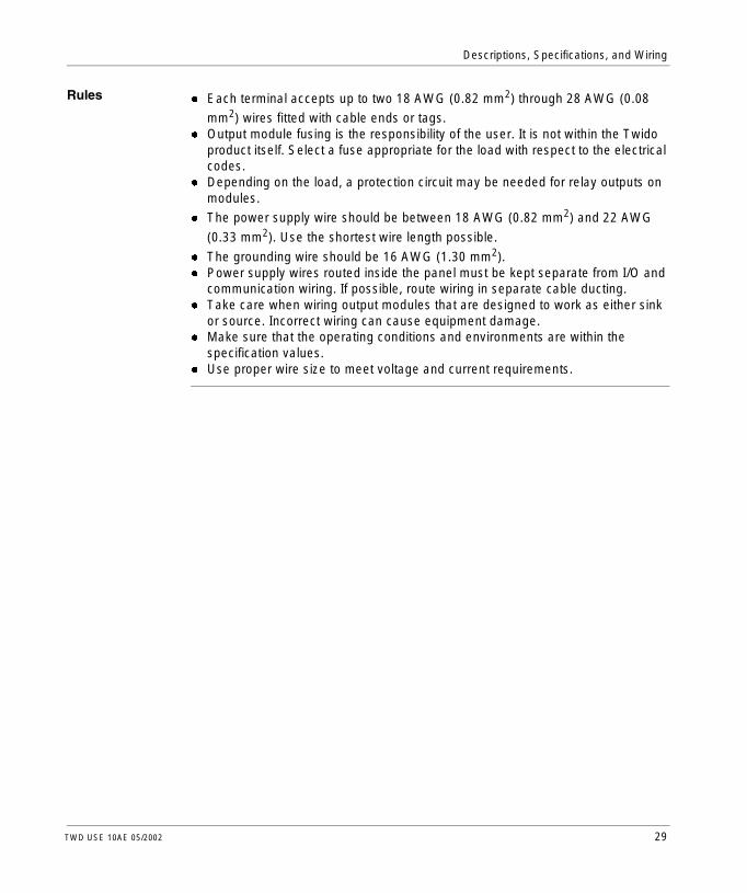
Rulesl Each terminal accepts up to two 18 AWG (0.82 mm2) through 28 AWG (0.08
mm2) wires fitted with cable ends or tags.l Output module fusing is the responsibility of the user. It is not within the Twido
product itself. Select a fuse appropriate for the load with respect to the electrical codes.
l Depending on the load, a protection circuit may be needed for relay outputs on modules.
l The power supply wire should be between 18 AWG (0.82 mm2) and 22 AWG
(0.33 mm2). Use the shortest wire length possible.
l The grounding wire should be 16 AWG (1.30 mm2).l Power supply wires routed inside the panel must be kept separate from I/O and
communication wiring. If possible, route wiring in separate cable ducting.l Take care when wiring output modules that are designed to work as either sink
or source. Incorrect wiring can cause equipment damage.l Make sure that the operating conditions and environments are within the
specification values.l Use proper wire size to meet voltage and current requirements.
TWD USE 10AE 05/2002 29

Descriptions, Specifications, and Wiring
Contact Protection Circuit for Relay and Transistor Outputs
Depending on the load, a protection circuit may be needed for the relay output on the controllers and certain modules. Choose a protection circuit, from the following diagrams, according to the power supply. Connect the protection circuit to the outside of the controller or relay output module. Protection Circuit A: This protection circuit can be used when the load impedance is smaller than the RC impedance in an AC load power circuit.
l C represents a value from 0.1 to 1 µF.l R represents a resistor of approximately the same resistance value as the load.Protection Circuit B: This protection circuit can be used for both AC and DC load power circuits.
l C represents a value from 0.1 to 1 µF.l R represents a resistor of approximately the same resistance value as the load.Protection Circuit C: This protection circuit can be used for DC load power circuits.
Use a diode with the following ratings:l Reverse withstand voltage: power voltage of the load circuit x 10.l Forward current: more than the load current.
Inductive Load
C
R
~
Output Q
COM
Inductive Load
CR
~
Output Q
COM or +-
Inductive LoadOutput Q
COM+-
30 TWD USE 10AE 05/2002
Descriptions, Specifications, and Wiring
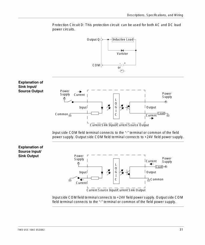
Protection Circuit D: This protection circuit can be used for both AC and DC load power circuits.
Explanation of Sink Input/Source Output
Input side COM field terminal connects to the “-” terminal or common of the field power supply. Output side COM field terminal connects to +24V field power supply.
Explanation of Source Input/Sink Output
Input side COM field terminal connects to +24V field power supply. Output side COM field terminal connects to the “-” terminal or common of the field power supply.
Inductive LoadOutput Q
COM+-
~or
Varistor
+
-
Current
LOGIC
+
-Load
Current
OutputInput
PowerSupply
Current Sink Input/Current Source Output
PowerSupply
Common
+
-Current
LOGIC
+
-
Load
Common
Current
OutputInput
PowerSupply
Current Source Input/Current Sink Output
PowerSupply
TWD USE 10AE 05/2002 31

Descriptions, Specifications, and Wiring
2.2 Compact Controller
At a Glance
Introduction This section provides an overview, parts description, specifications, and wiring schematics of the Compact controllers.
What’s in this Section?
This section contains the following topics:
Topic Page
Overview of Compact Controllers 33
Description of Analog Potentiometers 34
Parts Description of a Compact Controller 35
General Specifications for the Compact Controllers 36
Functional Specifications for the Compact Controllers 38
I/O Specifications for the Compact Controller 39
Compact Controller Wiring Schematics 44
32 TWD USE 10AE 05/2002

Descriptions, Specifications, and Wiring
Overview of Compact Controllers
Introduction The following section provides an overview of the Compact controllers.
Illustrations The following illustrations are the Compact controllers:
Controller Type Illustration
The Compact 10 I/O controller:l has 6 digital inputs and 4 relay outputsl has 1 potentiometerl has 1 integrated serial portl accepts one optional cartridge (RTC or
memory - 32 KB only)l accepts an optional operator display
module
The Compact 16 I/O controller:l has 9 digital inputs and 7 relay outputsl has 1 potentiometerl has 1 integrated serial portl has a slot for an additional serial portl accepts one optional cartridge (RTC or
memory - 32 KB only)l accepts an optional operator display
module
The Compact 24 I/O controller:l has 14 digital inputs and 10 relay outputsl has 2 potentiometersl has 1 integrated serial portl has a slot for an additional serial portl accepts up to 4 expansion I/O modulesl accepts one optional cartridge (RTC or
memory - 32 KB only)l accepts an optional operator display
module
TWDLCAA10DRF
TWDLCAA16DRF
TWDLCAA24DRF
TWD USE 10AE 05/2002 33

Descriptions, Specifications, and Wiring
Description of Analog Potentiometers
Introduction The following section describes the analog potentiometer on the Compact controllers.
Description The TWDLCAA10DRF controller and TWDLCAA16DRF controller have one analog potentiometer. The TWDLCAA24DRF controller has two analog potentiometers. The first analog potentiometer can be set to a value between 0 and 1023. For the TWDLCAA24DRF, the second potentiometer can be set between 0 and 511. The value is stored in system words and is updated in every scan. For more information on setting the analog potentiometer, see the Twido Software Reference Guide.
Analog Potentiometer on a Compact Controller
The following figure shows the analog potentiometers on a Compact controller. This figure is the TWDLCAA24DRF controller.
Legend
1
2
Label Description
1 Analog potentiometer 1
2 Analog potentiometer 2
34 TWD USE 10AE 05/2002

Descriptions, Specifications, and Wiring
Parts Description of a Compact Controller
Introduction The following section describes the parts of a Compact controller. Your controller may differ from the illustrations but the parts will be the same.
Parts Description of a Compact Controller
The following figure shows the parts of a Compact controller. This figure is the TWDLCAA24DRF controller.
Legend
121
3
4
6
7
9
10
13
14
52
11
8
Label Description
1 Mounting hole
2 Terminal cover
3 Hinged lid
4 Removable cover to operator display connector
5 Expansion connector - only on the TWDLCAA24DRF
6 Sensor power terminals
7 Serial port 1
8 Analog potentiometers - TWDLCAA10DRF and TWDLCAA16DRF have one
9 Serial port 2 connector - TWDLCAA10DRF does not have one
10 100 to 240 VAC power supply terminals
11 Cartridge connector - located on the bottom of the controller
12 Input terminals
13 LEDs
14 Output terminals
TWD USE 10AE 05/2002 35

Descriptions, Specifications, and Wiring
General Specifications for the Compact Controllers
Introduction This section provides general specifications for the Compact controllers.
Normal Operating Specifications
Compact Controller TWDLCAA10DRF TWDLCAA16DRF TWDLCAA24DRF
Operating temperature 0 to 55°C (32°F to 131°F) operating ambient temperature
Storage temperature -25°C to +70°C (-13°F to 158°F)
Relative humidity Level RH1, 30 to 95% (non-condensing)
Pollution degree 2 (IEC60664)
Degree of protection IP20
Corrosion immunity Free from corrosive gases
Altitude Operation: 0 to 2,000 m (0 to 6,565 ft)Transport: 0 to 3,000 m (0 to 9,840 ft)
Vibration resistance When mounted on a DIN rail: 10 to 57 Hz amplitude 0.075 mm, 57 to 150 Hz acceleration
9.8 ms2 (1G), 2 hours per axis on each of three mutually perpendicular axes.When mounted on a panel surface: 2 to 25 Hz amplitude 1.6 mm, 25 to 100 Hz acceleration
39.2 ms2 (4G) Lloyd’s 90 min per axis on each of three mutually perpendicular axes.
Shock resistance 147 ms2 (15G), 11 ms duration, 3 shocks per axis, on three mutually perpendicular axes (IEC 61131)
Weight 230 g 250 g 305 g
36 TWD USE 10AE 05/2002

Descriptions, Specifications, and Wiring
Power Supply Specifications
Compact Controller TWDLCAA10DRF TWDLCAA16DRF TWDLCAA24DRF
Rated power voltage 100 to 240 VAC
Allowable voltage range 85 to 264 VAC
Rated power frequency 50/60 Hz (47 to 63 Hz)
Maximum input current 0.25 A (85 VAC) 0.30 A (85 VAC) 0.45 A (85 VAC)
Maximum power consumption
30 VA (264 VAC), 20 VA (100 VAC)This controller’s power consumption includes 250 mA sensor power.
31 VA (264 VAC), 22 VA (100 VAC)This controller’s power consumption includes 250 mA sensor power.
40 VA (264 VAC), 33 VA (100 VAC)This controller plus 4 I/O modules’ power consumption includes 250 mA sensor power.
Allowable momentary power interruption
20 ms (at the rated inputs and outputs) (IEC61131)
Dielectric strength Between power and ground terminals: 1,500 VAC, 1 minBetween I/O and ground terminals: 1,500 VAC, 1 min
Insulation resistance Between power and ground terminals: 10 MΩ minimum (500 VDC)Between I/O and ground terminals: 10 MΩ minimum (500 VDC)
Noise resistance AC power terminals: 1.5 kV, 50 ns to 1 µsI/O terminals (coupling clamp): 1.5 kV, 50 ns to 1 µs
Inrush current 35 A maximum 35 A maximum 40 A maximum
Grounding wire UL1007 16 AWG (1.30 mm2)
Power supply wire UL1015 22 AWG (0.33 mm2), UL1007 18 AWG (0.82 mm2)
Effect of improper power supply connection
Reverse polarity: normal operationImproper voltage or frequency: permanent damage may be causedImproper lead connection: permanent damage may be caused
TWD USE 10AE 05/2002 37

Descriptions, Specifications, and Wiring
Functional Specifications for the Compact Controllers
Introduction This section provides functional specifications for the Compact controllers.
Communication Function Specifications
Built-in Function Specifications
Communication Port
Port 1 (RS485) Port 2 (RS232)Communication Adapter:TWDNAC232D
Port 2 (RS485)Communication Adapters:TWDNAC485DTWDNAC485T
Standards RS485 RS232 RS485
Max baud rate PC link: 19,200 bpsRemote link: 38,400 bps
19,200 bps PC link: 19,200 bpsRemote link: 38,400 bps
Maintenance communication (PC link)
Possible Possible Possible
ASCII communication
Possible Possible Possible
Remote communication
7 possible Not possible 7 Possible
Maximum cable length
Maximum distance between controllers: 50 m (164 feet).
Maximum distance between controllers: 50 m (164 feet).
Maximum distance between controllers: 50 m (164 feet).
Isolation between internal circuit and communication port
Not isolated Not isolated Not isolated
Sensor power supply Output voltage/current 24 VDC (+10% to -15%), 250 mA
Overload detection Not available
Isolation Isolated from the internal circuit
38 TWD USE 10AE 05/2002
Descriptions, Specifications, and Wiring
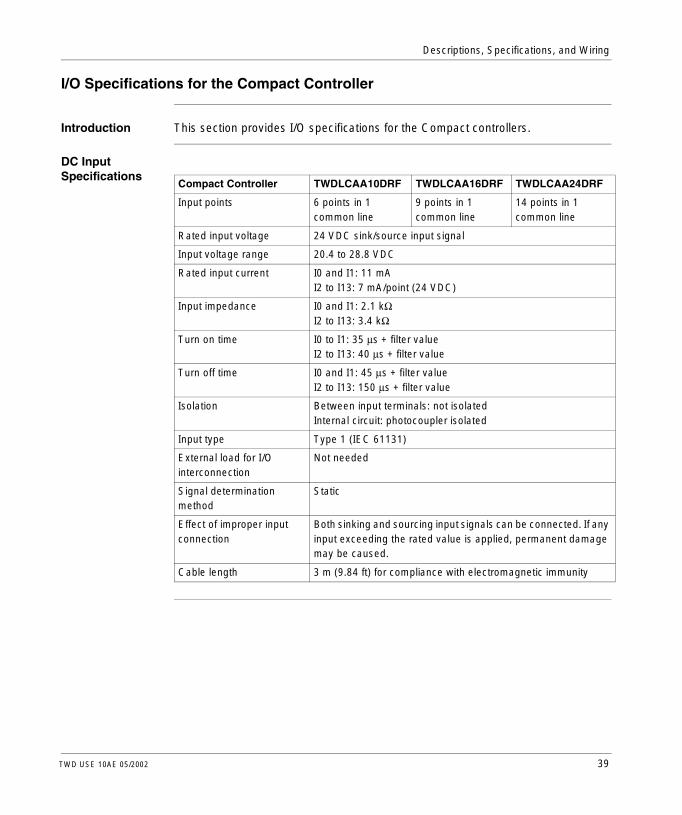
I/O Specifications for the Compact Controller
Introduction This section provides I/O specifications for the Compact controllers.
DC Input Specifications
Compact Controller TWDLCAA10DRF TWDLCAA16DRF TWDLCAA24DRF
Input points 6 points in 1 common line
9 points in 1 common line
14 points in 1 common line
Rated input voltage 24 VDC sink/source input signal
Input voltage range 20.4 to 28.8 VDC
Rated input current I0 and I1: 11 mAI2 to I13: 7 mA/point (24 VDC)
Input impedance I0 and I1: 2.1 kΩI2 to I13: 3.4 kΩ
Turn on time I0 to I1: 35 µs + filter valueI2 to I13: 40 µs + filter value
Turn off time I0 and I1: 45 µs + filter valueI2 to I13: 150 µs + filter value
Isolation Between input terminals: not isolatedInternal circuit: photocoupler isolated
Input type Type 1 (IEC 61131)
External load for I/O interconnection
Not needed
Signal determination method
Static
Effect of improper input connection
Both sinking and sourcing input signals can be connected. If any input exceeding the rated value is applied, permanent damage may be caused.
Cable length 3 m (9.84 ft) for compliance with electromagnetic immunity
TWD USE 10AE 05/2002 39

Descriptions, Specifications, and Wiring
Input Operating Range
The input operating range of the Type 1 (IEC 61131-2) input module is shown below.
Input Internal Circuit
The input internal circuit is shown below.
ON Area
Transition
OFF Area
28.8
15
5
0
24
1.2 11.3 13.86.5Input Current (mA)
Inpu
t Vol
tage
(D
C)
Area
ON Area
Transition
OFF Area
28.8
15
5
0
24
1.2 7.0 8.44.2Input Current (mA)
Inpu
t Vol
tage
(D
C)
Area
Inputs I2 to I13Inputs I0 and I1
Inte
rnal
Circ
uitInput
COM
Inte
rnal
Circ
uit
Input
COM
3.3 kΩ
Inputs I0 and I1 Inputs I2 to I13
1.8 kΩ
Latching or High SpeedSink or Source Inputs
Standard Sink or Source Input
40 TWD USE 10AE 05/2002
Descriptions, Specifications, and Wiring
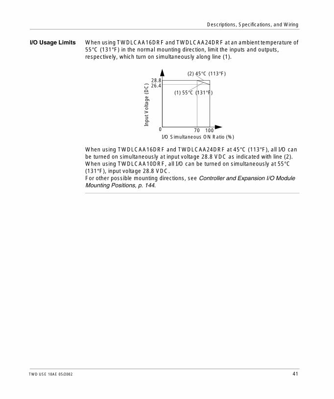
I/O Usage Limits When using TWDLCAA16DRF and TWDLCAA24DRF at an ambient temperature of 55°C (131°F) in the normal mounting direction, limit the inputs and outputs, respectively, which turn on simultaneously along line (1).
When using TWDLCAA16DRF and TWDLCAA24DRF at 45°C (113°F), all I/O can be turned on simultaneously at input voltage 28.8 VDC as indicated with line (2).When using TWDLCAA10DRF, all I/O can be turned on simultaneously at 55°C (131°F), input voltage 28.8 VDC.For other possible mounting directions, see Controller and Expansion I/O Module Mounting Positions, p. 144.
I/O Simultaneous ON Ratio (%)
Inpu
t Vol
tage
(D
C) 28.8
26.4
0 70 100
(2) 45°C (113°F)
(1) 55°C (131°F)
TWD USE 10AE 05/2002 41

Descriptions, Specifications, and Wiring
Relay Output Specifications
Output Delay The output delay is shown below.
Compact Controller TWDLCAA10DRF TWDLCAA16DRF TWDLCAA24DRF
Output points 4 points 7 points 10 points
Output points per common line: COM0
3 NO contacts 4 NO contacts 4 NO contacts
Output points per common line: COM1
1 NO contacts 2 NO contacts 4 NO contacts
Output points per common line: COM2
— 1 NO contacts 1 NO contacts
Output points per common line: COM3
— — 1 NO contacts
Maximum load current 2 A per point8 A per common line
Minimum switching load 0.1 mA/0.1 VDC (reference value)
Initial contact resistance 30 mΩ maximum
Electrical life 100,000 operations minimum (rated load 1,800 operations/h)
Mechanical life 20,000,000 operations minimum (rated load 18,000 operations/h)Internal circuit: photocoupler isolated
Rated load (resistive/inductive)
240 VAC/2 A, 30 VDC/2 A
Dielectric strength Between output to internal circuit: 1,500 VAC, 1 minBetween output to terminals (COMs): 1,500 VAC, 1 min
OFF delay: 10 ms maximum
ON
OFF
ON
OFF
Command
Output Relay Status
Chatter: 6 ms maximumON delay: 6 ms maximum
42 TWD USE 10AE 05/2002

Descriptions, Specifications, and Wiring
Relay Output Contact
The relay output contact is shown below.
Internal Circuit
NoLEDQx (Load)
COM
Field Terminal
TWD USE 10AE 05/2002 43
Descriptions, Specifications, and Wiring
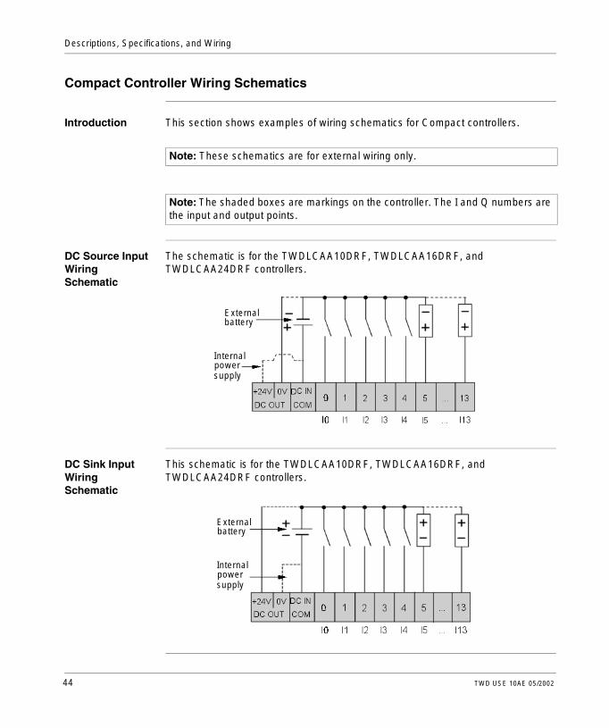
Compact Controller Wiring Schematics
Introduction This section shows examples of wiring schematics for Compact controllers.
DC Source Input Wiring Schematic
The schematic is for the TWDLCAA10DRF, TWDLCAA16DRF, and TWDLCAA24DRF controllers.
DC Sink Input Wiring Schematic
This schematic is for the TWDLCAA10DRF, TWDLCAA16DRF, and TWDLCAA24DRF controllers.
Note: These schematics are for external wiring only.
Note: The shaded boxes are markings on the controller. The I and Q numbers are the input and output points.
External battery
Internal powersupply
External battery
Internal powersupply
44 TWD USE 10AE 05/2002

Descriptions, Specifications, and Wiring
AC Power and Relay Output Wiring Schematic
This schematic is for the TWDLCAA10DRF controller.
This schematic is for the TWDLCAA16DRF controller.
This schematic is for the TWDLCAA24DRF controller.
TWD USE 10AE 05/2002 45

Descriptions, Specifications, and Wiring
2.3 Modular Controller
At a Glance
Introduction This section provides an overview, parts description, specifications, and wiring schematics of the Modular controllers.
What’s in this Section?
This section contains the following topics:
Topic Page
Overview of Modular Controllers 47
Description of Analog Potentiometers 49
Overview of Analog Voltage Input 50
Parts Description of a Modular Controller 51
General Specifications for the Modular Controllers 52
Functional Specifications for the Modular Controllers 54
I/O Specifications for the Modular Controllers 56
Modular Controller Wiring Schematics 62
46 TWD USE 10AE 05/2002

Descriptions, Specifications, and Wiring
Overview of Modular Controllers
Introduction The following section provides an overview of the Modular controllers.
Illustrations The following illustrations are the Modular controllers.
Controller Type Illustration
The Modular 20 I/O controller:l is available in two models: with transistor
source outputs (TWDLMDA20DTK) or with transistor sink outputs (TWDLMDA20DUK)
l has 12 digital inputs and 8 transistor source or sink outputs
l has 1 analog voltage input connectorl has 1 analog potentiometerl has 1 integrated serial portl has a connector for wiringl accepts up to 4 expansion I/O modulesl accepts both optional cartridges (RTC
and memory - 32 KB or 64 KB)l accepts either an optional operator
display expansion module or an optional communication expansion module
The Modular 20 I/O controller:l has 12 digital inputs, 6 relay outputs, and
2 transistor source outputsl has 1 analog voltage input connectorl has 1 analog potentiometerl has 1 integrated serial portl has a terminal block for wiringl accepts up to 7 expansion I/O modulesl accepts both optional cartridges (RTC
and memory - 32 KB or 64 KB)l accepts either an optional operator
display expansion module or an optional communication expansion module
TWDLMDA20DUKTWDLMDA20DTK
TWDLMDA20DRT
TWD USE 10AE 05/2002 47

Descriptions, Specifications, and Wiring
The Modular 40 I/O controller:l is available in two models: with transistor
source outputs (TWDLMDA40DTK) or with transistor sink outputs (TWDLMDA40DUK)
l has 24 digital inputs and 16 transistor source or sink outputs
l has 1 analog voltage input connectorl has 1 analog potentiometerl has 1 integrated serial portl has a connector for wiringl accepts up to 7 expansion I/O modulesl accepts both optional cartridges (RTC
and memory - 32 KB or 64 KB)l accepts either an optional operator
display expansion module or an optional communication expansion module
Controller Type Illustration
TWDLMDA40DUKTWDLMDA40DTK
48 TWD USE 10AE 05/2002
Descriptions, Specifications, and Wiring
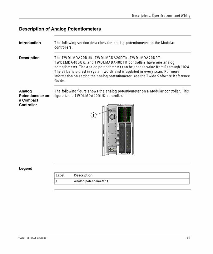
Description of Analog Potentiometers
Introduction The following section describes the analog potentiometer on the Modular controllers.
Description The TWDLMDA20DUK, TWDLMADA20DTK, TWDLMDA20DRT, TWDLMDA40DUK, and TWDLMADA40DTK controllers have one analog potentiometer. The analog potentiometer can be set at a value from 0 through 1024. The value is stored in system words and is updated in every scan. For more information on setting the analog potentiometer, see the Twido Software Reference Guide.
Analog Potentiometer on a Compact Controller
The following figure shows the analog potentiometer on a Modular controller. This figure is the TWDLMDA40DUK controller.
Legend
1
Label Description
1 Analog potentiometer 1
TWD USE 10AE 05/2002 49

Descriptions, Specifications, and Wiring
Overview of Analog Voltage Input
Introduction The following section describes the analog voltage input on the Modular controllers.
Description All Modular controllers have one analog voltage input. The analog voltage input connects an analog voltage source of 0 through 10 VDC. The analog voltage is converted to a value of 0 through 512 and is stored in a system word.
50 TWD USE 10AE 05/2002

Descriptions, Specifications, and Wiring
Parts Description of a Modular Controller
Introduction The following section describes the parts of a Modular controller. Your controller may differ from the illustrations but the parts will be the same.
Parts Description of a Modular Controller
The following figure shows the parts of a Modular controller. This figure is the Modular 40 I/O controller.
Legend
1
2
3
4
5
6
7
9
8
10 not shown, left side of controller
Label Description
1 Hinged lid
2 Expansion connector
3 Analog potentiometer
4 Serial port 1
5 Cartridge covers
6 24 VDC power supply terminals
7 Analog voltage input connector
8 LEDs
9 I/O terminals
10 Communication connector
TWD USE 10AE 05/2002 51
Descriptions, Specifications, and Wiring
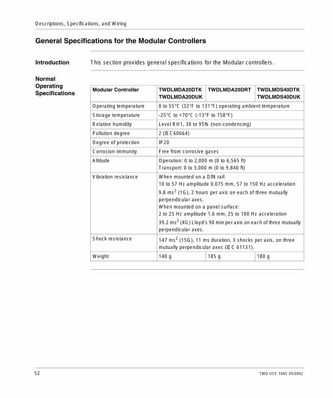
General Specifications for the Modular Controllers
Introduction This section provides general specifications for the Modular controllers.
Normal Operating Specifications
Modular Controller TWDLMDA20DTKTWDLMDA20DUK
TWDLMDA20DRT TWDLMDS40DTKTWDLMDS40DUK
Operating temperature 0 to 55°C (32°F to 131°F) operating ambient temperature
Storage temperature -25°C to +70°C (-13°F to 158°F)
Relative humidity Level RH1, 30 to 95% (non-condensing)
Pollution degree 2 (IEC60664)
Degree of protection IP20
Corrosion immunity Free from corrosive gases
Altitude Operation: 0 to 2,000 m (0 to 6,565 ft)Transport: 0 to 3,000 m (0 to 9,840 ft)
Vibration resistance When mounted on a DIN rail:10 to 57 Hz amplitude 0.075 mm, 57 to 150 Hz acceleration
9.8 ms2 (1G), 2 hours per axis on each of three mutually perpendicular axes.When mounted on a panel surface:2 to 25 Hz amplitude 1.6 mm, 25 to 100 Hz acceleration
39.2 ms2 (4G) Lloyd’s 90 min per axis on each of three mutually perpendicular axes.
Shock resistance 147 ms2 (15G), 11 ms duration, 3 shocks per axis, on three mutually perpendicular axes (IEC 61131).
Weight 140 g 185 g 180 g
52 TWD USE 10AE 05/2002

Descriptions, Specifications, and Wiring
Power Supply Specifications
Modular Controller TWDLMDA20DTKTWDLMDA20DUK
TWDLMDA20DRT TWDLMDS40DTKTWDLMDS40DUK
Rated power voltage 24 VDC
Allowable voltage range 20.4 to 26.4 VDC (including ripple)
Maximum input current Controller plus 4 I/O Modules
Controller plus 7 I/O Modules
15 W (26.4 VDC) 19 W (26.4 VDC) 19 W (26.4 VDC)
Allowable momentary power interruption
10 ms (at 24 VDC)
Dielectric strength Between power and ground terminals: 500 VAC, 1 minBetween I/O and ground terminals: 1,500 VAC, 1 min
Insulation resistance Between power and ground terminals: 10 MΩ minimum (500 VDC)Between I/O and ground terminals: 10 MΩ minimum (500 VDC)
Noise resistance DC power terminals: 1.0 kV, 50 ns to 1 µsI/O terminals (coupling clamp): 1.5 kV, 50 ns to 1 µs
Inrush current 50 A maximum (24 VDC)
Grounding wire UL1015 22 AWG (0.33 mm2), UL1007 18 AWG (0.82 mm2)
Power supply wire UL1015 22 AWG (0.33 mm2), UL1007 18 AWG (0.82 mm2)
Effect of improper power supply connection
Reverse polarity: no operation, no damageImproper voltage or frequency: permanent damage may be causedImproper lead connection: permanent damage may be caused
TWD USE 10AE 05/2002 53

Descriptions, Specifications, and Wiring
Functional Specifications for the Modular Controllers
Introduction This section provides functional specifications for the Modular controllers.
Communication Function Specifications
Communication Port
Port 1 (RS485) Port 2 (RS232)Communication Expansion Module (TWDNOZ232D)orOperator Display Expansion Module (TWDXCPODM)with CommunicationAdapter (TWDNAC232D)
Port 2 (RS485)Communication Expansion Modules(TWDNOZ485D) or(TWDNOZ485T)orOperator Display Expansion Module (TWDXCPODM)with CommunicationAdapter (TWDNAC485D) or (TWDNAC485T)
Standards RS485 RS232 RS485
Maximum baud rate
PC link: 19,200 bpsRemote link: 38,400 bps
19,200 bps PC link: 19,200 bpsRemote link: 38,400 bps
Maintenance communication (PC link)
Possible Possible Possible
ASCII communication
Possible Possible Possible
Remote communication
7 possible Not possible 7 Possible
Maximum cable length
Maximum distance between controllers: 50 m (164 feet).
Maximum distance between controllers: 50 m (164 feet).
Maximum distance between controllers: 50 m (164 feet).
Isolation between internal circuit and communication port
Not isolated Not isolated Not isolated
54 TWD USE 10AE 05/2002

Descriptions, Specifications, and Wiring
Built-in Function Specifications
Analog voltage input Quantity 1 point
Input voltage range 0 to 10 VDC
Input impedance Approximately 100 kΩ
Data range 0 to 512
PWM/PLS output Quantity 2 points
Maximum frequency 20 kHz
TWD USE 10AE 05/2002 55

Descriptions, Specifications, and Wiring
I/O Specifications for the Modular Controllers
Introduction This section provides I/O specifications for the Modular controllers.
DC Input Specifications
Modular Controller TWDLMDA20DUKTWDLMDA20DTK
TWDLMDA20DRT TWDLMDA40DUKTWDLMDA40DTK
Input points 12 points in 1 common line
12 points in 1 common line
24 points in 2 common lines
Rated input voltage 24 VDC sink/source input signal
Input voltage range 20.4 to 26.4 VDC
Rated input current I0, I1, I6, I7: 5 mA/point (24 VDC)I2 to I5, I8 to I23: 7 mA/point (24 VDC)
Input impedance I0, I1, I6, I7: 5.7 kΩI2 to I5, I8 to I23: 3.4 kΩ
Turn on time I0 to I7: 35 µs + filter valueI8 to I23: 40 µs + filter value
Turn off time I0, I1, I6, I7: 45 µs + filter valueI2 to I5, I8 to I23: 150 µs + filter value
Isolation Between input terminals: not isolatedInternal circuit: photocoupler isolated
Input type Type 1 (IEC 61131)
External load for I/O interconnection
Not needed
Signal determination method
Static
Effect of improper input connection
Both sinking and sourcing input signals can be connected. If any input exceeding the rated value is applied, permanent damage may be caused.
Cable length 3m (9.84 ft) for compliance with electromagnetic immunity
Connector insertion/removal durability
100 times minimum
56 TWD USE 10AE 05/2002

Descriptions, Specifications, and Wiring
Input Operating Range
The input operating range of the Type 1 (IEC 61131-2) input module is shown below.
Input Internal Circuit
The input internal circuit is shown below.
ON Area
Transition
OFF Area
26.4
15
5
0
24
1.2 11.3 12.46.5Input Current (mA)
Inpu
t Vol
tage
(D
C)
Area
ON Area
Transition
OFF Area
26.4
15
5
0
24
1.2 7 7.74.2Input Current (mA)
Inpu
t Vol
tage
(D
C)
Area
Inputs I2 to I5, I8 to I23Inputs I0, I1, I6, and I7
Inte
rnal
Circ
uitInput
COM
Inte
rnal
Circ
uit
Input
COM
3.3kΩ
Inputs I0, I1, I6, and I7 Inputs I2 to I5, I8 to I234.7 kΩ
Latching or High SpeedSink or Source Inputs
Standard Sink or Source Input
TWD USE 10AE 05/2002 57

Descriptions, Specifications, and Wiring
I/O Usage Limits When using TWDLMDA20DUK and TWDLMDA20DTK at an ambient temperature of 55°C (131°F) in the normal mounting direction, limit the inputs and outputs, respectively, which turn on simultaneously along line (1).
When using TWDLMDA40DUK and TWDLMDA40DTK limit the inputs and outputs, respectively, which turn on simultaneously along line (2).When using at 40°C (104°F) all I/O can be turned on simultaneously at 26.4 VDC as indicated with line (3).When using TWDLMDA20DRT all I/O can be turned on simultaneously at 55°C (131°F), input voltage 26.4 VDC.
80I/O Simultaneous ON Ratio (%)
Inpu
t Vol
tage
(D
C) 26.4
24.0
0 70 100
(3) 40°C (104°F)
(2) 55°C (131°F)
(1) 55°C (131°F)
6050
58 TWD USE 10AE 05/2002
Descriptions, Specifications, and Wiring
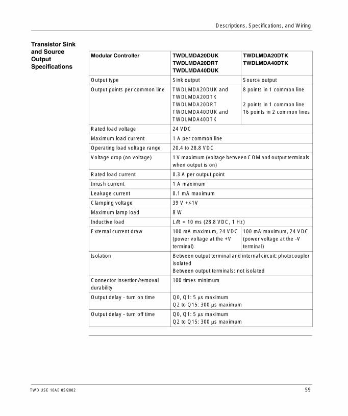
Transistor Sink and Source Output Specifications
Modular Controller TWDLMDA20DUKTWDLMDA20DRTTWDLMDA40DUK
TWDLMDA20DTKTWDLMDA40DTK
Output type Sink output Source output
Output points per common line TWDLMDA20DUK and TWDLMDA20DTKTWDLMDA20DRTTWDLMDA40DUK and TWDLMDA40DTK
8 points in 1 common line
2 points in 1 common line16 points in 2 common lines
Rated load voltage 24 VDC
Maximum load current 1 A per common line
Operating load voltage range 20.4 to 28.8 VDC
Voltage drop (on voltage) 1 V maximum (voltage between COM and output terminals when output is on)
Rated load current 0.3 A per output point
Inrush current 1 A maximum
Leakage current 0.1 mA maximum
Clamping voltage 39 V +/-1V
Maximum lamp load 8 W
Inductive load L/R = 10 ms (28.8 VDC, 1 Hz)
External current draw 100 mA maximum, 24 VDC(power voltage at the +V terminal)
100 mA maximum, 24 VDC(power voltage at the -V terminal)
Isolation Between output terminal and internal circuit: photocoupler isolated Between output terminals: not isolated
Connector insertion/removal durability
100 times minimum
Output delay - turn on time Q0, Q1: 5 µs maximumQ2 to Q15: 300 µs maximum
Output delay - turn off time Q0, Q1: 5 µs maximumQ2 to Q15: 300 µs maximum
TWD USE 10AE 05/2002 59

Descriptions, Specifications, and Wiring
Relay Output Specifications
Output Delay The output delay is shown below.
Modular Controller TWDLMDA20DRT
Number of outputs 8 points including 6 relay and 2 transistor source outputs
Output points per common line - COM0 2 points
Output points per common line - COM1 3 NO contacts
Output points per common line - COM2 2 NO contacts
Output points per common line - COM3 1 NO contacts
Maximum load current 2 A per point8 A per common line
Minimum switching load 0.1 mA/0.1 VDC (reference value)
Initial contact resistance 30 mΩ maximum
Electrical life 100,000 operations minimum (rated load 1,800 operations/h)
Mechanical life 20,000,000 operations minimum (rated load 18,000 operations/h)
Rated load (resistive/inductive) 240 VAC/2 A, 30 VDC/2 A
Dielectric strength Between output to internal circuit: 1,500 VAC, 1 minBetween output to terminals (COMs): 1,500 VAC, 1 min
Connector insertion/removal durability 100 times minimum
OFF delay: 10 ms maximum
ON
OFF
ON
OFF
Command
Output Relay Status
Chatter: 6 ms maximumON delay: 6 ms maximum
60 TWD USE 10AE 05/2002

Descriptions, Specifications, and Wiring
Relay Output Contact
The relay output contact is shown below.
Transistor Source Output Contact
The transistor source output contact is shown below.
Transistor Sink Output Contact
The transistor sink output contact is shown below.
Internal Circuit
NoLEDQx (Load)
COM
Field Terminal
Internal
P-chan
LED
Q Output
COM (+24V)
+
V+ (COM)
Internal
N-chanQ Output
COM (COM)
+
V+ (+24V)
TWD USE 10AE 05/2002 61

Descriptions, Specifications, and Wiring
Modular Controller Wiring Schematics
Introduction This section shows examples of wiring schematics for the Modular controllers.
TWDLMDA20-DUK Wiring Schematic
This schematic is for the TWDLMDA20DUK controller with connector.
l The COM(-) terminals are connected together internally.l The COM and COM(-) terminals are not connected together internally.l The +V terminals are connected together internally.l Connect a fuse that is appropriate for the load.
Note: These schematics are for external wiring only.
Note: The shaded boxes are markings on the controller. The I and Q numbers are the input and output points.
Source input wiring
Sink output wiring
62 TWD USE 10AE 05/2002

Descriptions, Specifications, and Wiring
TWDLMDA20-DTK Wiring Schematic
This schematic is for the TWDLMDA20DTK controller with connector.
l The COM(+) terminals are connected together internally.l The COM and COM(+) terminals are not connected together internally.l The -V terminals are connected together internally.l Connect a fuse that is appropriate for the load.
Source output wiring
Sink input wiring
TWD USE 10AE 05/2002 63

Descriptions, Specifications, and Wiring
TWDLMDA20-DRT Wiring Schematic
This schematic is for the TWDLMDA20DRT controller with terminal block.
l Output points 0 and 1 are transistor source outputs, all other output points are relay.
l The COM terminals are not connected together internally.l Connect a fuse that is appropriate for the load.
Sink input wiring
Source output wiring
Relay output wiring
Relay output wiring
Relay output wiring
64 TWD USE 10AE 05/2002

Descriptions, Specifications, and Wiring
TWDLMDA40-DUK Wiring Schematic
This schematic is for the TWDLMDA40DUK controller with connector.
l The terminals on CN1 and CN2 are not connected together internally.l The COM(-) terminals are connected together internally.l The COM and COM(-) terminals are not connected together internally.l The +V terminals are connected together internally.l Connect a fuse that is appropriate for the load.
Source input wiring
Source input wiring
Sink output wiring
Sink output wiring
CN1
CN2
Q3
Q1
Q2
Q4
Q5
Q0
Q6
Q7
COM(-)
+V
+V
COM(-)
COM(-)
25
1
L
L
L
L
L
L
L
L
26
2
I3
I1
I2
I4
I5
I0
I6
I7
I8
I11
COM
I9
I10
Q11
Q9
Q10
Q12
Q13
Q8
Q14
Q15
COM(-)
+V
+V
COM(-)
COM(-)
25
1
L
L
L
L
L
L
L
L
26
2
I15
I13
I14
I16
I17
I12
I18
I19
I20
I23
COM
I21
I22
TWD USE 10AE 05/2002 65

Descriptions, Specifications, and Wiring
TWDLMDA40-DTK Wiring Schematic
This schematic is for the TWDLMDA40DTK controller with connector.
l The terminals on CN1 and CN2 are not connected together internally.l The COM(+) terminals are connected together internally.l The COM and COM(+) terminals are not connected together internally.l The -V terminals are connected together internally.l Connect a fuse that is appropriate for the load.
Sink input wiring
Sink input wiring
Source
Source
output wiring
output wiring
66 TWD USE 10AE 05/2002
Descriptions, Specifications, and Wiring
2.4 Digital I/O Modules
At a Glance
Introduction This section provides an overview, specifications, and wiring schematics of the digital I/O modules.
What’s in this Section?
This section contains the following topics:
Topic Page
Overview of Digital I/O Modules 68
Parts Description of Digital I/O Modules 71
Specifications for the Digital I/O Modules 73
Digital I/O Module Wiring Schematics 84
TWD USE 10AE 05/2002 67

Descriptions, Specifications, and Wiring
Overview of Digital I/O Modules
Introduction The following section provides an overview of the digital I/O modules.
Illustrations The following illustrations are the digital input, output, and mixed I/O modules.
Controller Type Illustration
There are 4 digital input modules: l 8-point module with a terminal block
(TWDDDI8DT)l 16-point module with a terminal block
(TWDDDI16DT)l 16-point module with a connector
(TWDDDI16DK)l 32-point module with a connector
(TWDDDI32DK)These modules can be attached to any controller except the Compact 10 I/O and 16 I/O controllers.
TWDDDI8DTTWDDDI16DT TWDDDI32DK
TWDDDI16DK
68 TWD USE 10AE 05/2002
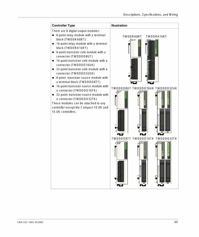
Descriptions, Specifications, and Wiring
There are 8 digital output modules: l 8-point relay module with a terminal
block (TWDDRA8RT)l 16-point relay module with a terminal
block (TWDDRA16RT)l 8-point transistor sink module with a
connector (TWDDDO8UT)l 16-point transistor sink module with a
connector (TWDDDO16UK)l 32-point transistor sink module with a
connector (TWDDDO32UK)l 8-point transistor source module with
a terminal block (TWDDDO8TT)l 16-point transistor source module with
a connector (TWDDDO16TK)l 32-point transistor source module with
a connector (TWDDDO32TK)These modules can be attached to any controller except the Compact 10 I/O and 16 I/O controllers.
Controller Type Illustration
TWDDRA8RT TWDDRA16RT
TWDDDO8UT TWDDDO16UK TWDDDO32UK
TWDDDO8TT TWDDDO16TK TWDDDO32TK
TWD USE 10AE 05/2002 69

Descriptions, Specifications, and Wiring
There are 2 digital mixed input and output modules: l 4-point input/4-point output module
with a terminal block (TWDDMM8RT)l 16-point input/8-point output module
with a wire-clamp terminal block (TWDDMM24DRF)
These modules can be attached to any controller except the Compact 10 I/O and 16 I/O controllers.
Controller Type Illustration
TWDDMM8RT TWDDMM24DRF
70 TWD USE 10AE 05/2002

Descriptions, Specifications, and Wiring
Parts Description of Digital I/O Modules
Introduction The following section describes the parts of a digital I/O module with a terminal block and with a connector. Your I/O module may differ from the illustrations but the parts will be the same.
Parts Description of a Digital I/O Module with a Terminal Block
The following figure shows the parts of a digital I/O module with a terminal block. This figure is the TWDDDIO8DT module.
Legend
2
14
53
Label Description
1 Expansion connector - one on each side, right side not shown
2 Terminal block
3 Latch button
4 LEDs
5 Clamp
TWD USE 10AE 05/2002 71

Descriptions, Specifications, and Wiring
Parts Description of a Digital I/O Module with a Connector
The following figure shows the parts of a digital I/O module with a connector. This figure is the TWDDDO16TK module.
Legend
2
4
53
1
Label Description
1 Expansion connector - one on each side, right side not shown
2 Connector
3 Latch button
4 LEDs
5 Clamp
72 TWD USE 10AE 05/2002

Descriptions, Specifications, and Wiring
Specifications for the Digital I/O Modules
Introduction This section is specifications for the digital I/O modules.
TWDDDI8DT, TWDDDI16DT, TWDDDI16DK, and TWDDDI32DK Specifications
Type Number TWDDDI8DT TWDDDI16DT TWDDDI16DK TWDDDI32DK
Input points 8 points in 1 common line
16 points in 1 common line
16 points in 1 common line
32 points in 2 common lines
Rated input voltage 24 VDC sink/source input signal
Input voltage range 20.4 to 28.8 VDC
Rated input current 7 mA/point (24 VDC) 5 mA/point (24 VDC)
Input impedance 3.4 kΩ 4.4 kΩ
Turn on time (24 VDC)
4 ms
Turn off time (24 VDC)
4 ms
Isolation Between input terminals: not isolatedInternal circuit: photocoupler isolated
External load for I/O interconnection
Not needed
Signal determination method
Static
Effect of improper input connection
Both sinking and sourcing input signals can be connected. If any input exceeding the rated value is applied, permanent damage may be caused.
Cable length 3m (9.84 ft) in compliance with electromagnetic immunity
Connector insertion/removal durability
100 times minimum
Internal current draw - all inputs on
25 mA (5 VDC)0 mA (24 VDC)
40 mA (5 VDC)0 mA (24 VDC)
35 mA (5 VDC)0 mA (24 VDC)
65 mA (5 VDC)0 mA (24 VDC)
Internal current draw - all inputs off
5 mA (5 VDC)0 mA (24 VDC)
5 mA (5 VDC)0 mA (24 VDC)
5 mA (5 VDC)0 mA (24 VDC)
10 mA (5 VDC)0 mA (24 VDC)
Weight 85 g 100 g 65 g 100 g
TWD USE 10AE 05/2002 73

Descriptions, Specifications, and Wiring
TWDDDI8DT, TWDDDI16DT, TWDDDI16DK, and TWDDDI32DK Operating Range
The input operating range of the Type 1 (IEC 61131-2) input module is shown below.
TWDDDI8DT, TWDDDI16DT, TWDDDI16DK, and TWDDDI32DK Internal Circuit
The input internal circuit is shown below.
ON Area
Transition
OFF Area
28.8
15
5
0
24
1.2 7.0 8.44.2Input Current (mA)
Inpu
t Vol
tage
(D
C)
Area
ON Area
Transition
OFF Area
28.8
15
5
0
24
0.9 5.3 6.43.2Input Current (mA)
Inpu
t Vol
tage
(D
C)
Area
TWDDDI8DT and TWDDDI16DT TWDDDI16DK and TWDDDI32DK
Inte
rnal
Circ
uit
Input
COM
4.3 kΩ
TWDDDI8DT and TWDDDI16DT TWDDDI16DK and TWDDDI32DKIn
tern
al C
ircui
t
Input
COM
3.3 kΩ
Standard Sink or Source Input
74 TWD USE 10AE 05/2002

Descriptions, Specifications, and Wiring
TWDDDI8DT, TWDDDI16DT, TWDDDI16DK, and TWDDDI32DK Usage Limits
When using TWDDDI16DT at 55°C (131°F) in the normal mounting direction, limit the inputs which turn on simultaneously along line (1). At 45°C (113°F), all inputs can be turned on simultaneously at 28.8 VDC as indicated with line (2).
When using TWDDDI16DK and TWDDDI32DK at 55°C (131°F), limit the inputs which turn on simultaneously on each connector line (3). At 30°C (86°F), all inputs can be turned on simultaneously at 28.8 VDC as indicated with line (4).
When using TWDDDI8DT, all inputs can be turned on simultaneously at 55°C (131°F), input voltage 28.8 VDC.
Input Simultaneous ON Ratio (%)
Inpu
t Vol
tage
(V
DC
) 28.8
0 70 100
(2) 45°C (113°F)
(1) 55°C (131°F)26.4
Input Simultaneous ON Ratio (%)
Inpu
t Vol
tage
(V
DC
) 28.826.4
0 70 100
(4) 30°C (86°F)
(3) 55°C (131°F)
50 90
24.0
TWD USE 10AE 05/2002 75

Descriptions, Specifications, and Wiring
TWDDRA8RT and TWDDRA16RT Specifications
CAUTION
Possible current overload
Size wire accordingly.
Failure to observe this precaution can result in injury or equipment damage.
Type Number TWDDRA8RT TWDDRA16RT
Output points and common lines 8 NO contacts in 2 common lines
16 NO contacts in 2 common lines
Maximum load current 2 A per point
7 A per common line 8 A per common line
Minimum switching load 0.1 mA/0.1 VDC (reference value)
Initial contact resistance 30 mΩ maximum
Electrical life 100,000 operations minimum (rated load 1,800 operations/hour)
Mechanical life 20,000,000 operations minimum (rated load 18,000 operations/hour)
Rated load (resistive/inductive) 240 VAC/2 A, 30 VDC/2 A
Dielectric strength Between output and terminals: 1,500 VAC, 1 minuteBetween output terminal and internal circuit: 1,500 VAC, 1 minuteBetween output terminals (COMs): 1,500 VAC, 1 minute
Connector insertion/removal durability
100 times minimum
Internal current draw - all outputs on
30 mA (5 VDC)40 mA (24 VDC)
45 mA (5 VDC)75 mA (24 VDC)
Internal current draw - all outputs off
5 mA (5 VDC)0 mA (24 VDC)
5 mA (5 VDC)0 mA (24 VDC)
Weight 110 g 145 g
76 TWD USE 10AE 05/2002

Descriptions, Specifications, and Wiring
TWDDRA8RT and TWDDRA16RT Delay
The output delay is shown below.
OFF delay: 10 ms maximum
ON
OFF
ON
OFF
Command
Output Relay Status
Chatter: 6 ms maximumON delay: 6 ms maximum
TWD USE 10AE 05/2002 77

Descriptions, Specifications, and Wiring
TWDDDO8UT, TWDDDO16UK, and TWDDDO32UK Specifications
Type Number TWDDDO8UT TWDDDO16UK TWDDDO32UK
Output type Transistor sink output
Output points per common line 8 points in 1 common line
16 points in 1 common line
32 points in 2 common lines
Rated load voltage 24 VDC
Operating load voltage range 20.4 to 28.8 VDC
Rated load current 0.3 A per output point
0.1 A per output point
Maximum load current 0.36 A per output point 3 A per common line
0.12 A per output point1 A per common line
Voltage drop (on voltage) 1 V maximum (voltage between COM and output terminals when output is on)
Inrush current 1 A maximum
Leakage current 0.1 A maximum
Clamping voltage 39 V +/-1V
Maximum lamp load 8 W
Inductive load L/R = 10 ms (28.8 VDC, 1 Hz)
External current draw 100 mA maximum, 24 VDC(power voltage at the +V terminal)
Isolation Between output terminal and internal circuit: photocoupler isolated Between output terminals: not isolated
Connector insertion/removal durability
100 times minimum
Internal current draw - all outputs on
10 mA (5 VDC)20 mA (24 VDC)
10 mA (5 VDC)40 mA (24 VDC)
20 mA (5 VDC)70 mA (24 VDC)
Internal current draw - all outputs off
5 mA (5 V DC)0 mA (24 V DC)
5 mA (5 V DC)0 mA (24 V DC)
10 mA (5 V DC)0 mA (24 V DC)
Output delay Turn on time: 300 µs maximumTurn off time: 300 µs maximum
Weight 85 g 70 g 105 g
78 TWD USE 10AE 05/2002

Descriptions, Specifications, and Wiring
TWDDDO8TT, TWDDDO16TK, and TWDDDO32TK Specifications
Type Number TWDDDO8TT TWDDDO16TK TWDDDO32TK
Output type Transistor source output
Output points per common Line 8 points in 1 common line
16 points in 1 common line
32 points in 2 common lines
Rated load voltage 24 VDC
Operating load voltage range 20.4 to 28.8 VDC
Rated load current 0.3 A per output point
0.1 A per output point
Maximum load current 0.36 A per output point 3 A per common line
0.12 A per output point1 A per common line
Voltage drop (on voltage) 1 V maximum (voltage between COM and output terminals when output is on)
Inrush current 1 A maximum
Leakage current 0.1 mA maximum
Clamping voltage 39 V +/-1V
Maximum lamp load 8 W
Inductive load L/R = 10 ms (28.8 VDC, 1 Hz)
External current draw 100 mA maximum, 24 VDC(power voltage at the +V terminal)
Isolation Between output terminal and internal circuit: photocoupler isolated Between output terminals: not isolated
Connector insertion/removal durability
100 times minimum
Internal current draw - all outputs on
10 mA (5 VDC)20 mA (24 VDC)
10 mA (5 VDC)40 mA (24 VDC)
20 mA (5 VDC)70 mA (24 VDC)
Internal current draw - all outputs off
5 mA (5 VDC)0 mA (24 VDC)
5 mA (5 VDC)0 mA (24 VDC)
10 mA (5 VDC)0 mA (24 VDC)
Output delay Turn on time: 300 µs maximumTurn off time: 300 µs maximum
Weight 85 g 70 g 105 g
TWD USE 10AE 05/2002 79
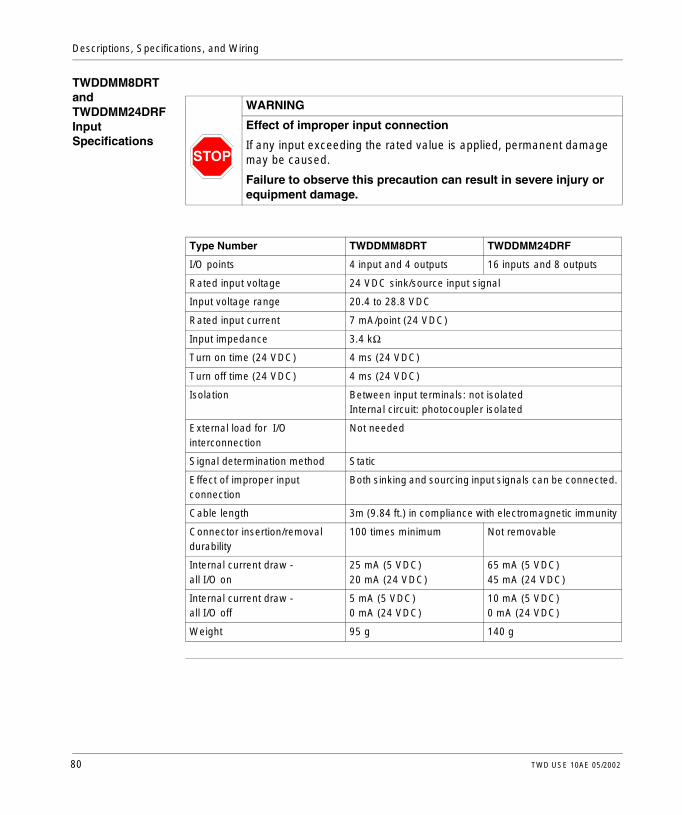
Descriptions, Specifications, and Wiring
TWDDMM8DRT and TWDDMM24DRF Input Specifications
WARNING
Effect of improper input connection
If any input exceeding the rated value is applied, permanent damage may be caused.
Failure to observe this precaution can result in severe injury or equipment damage.
Type Number TWDDMM8DRT TWDDMM24DRF
I/O points 4 input and 4 outputs 16 inputs and 8 outputs
Rated input voltage 24 VDC sink/source input signal
Input voltage range 20.4 to 28.8 VDC
Rated input current 7 mA/point (24 VDC)
Input impedance 3.4 kΩ
Turn on time (24 VDC) 4 ms (24 VDC)
Turn off time (24 VDC) 4 ms (24 VDC)
Isolation Between input terminals: not isolatedInternal circuit: photocoupler isolated
External load for I/O interconnection
Not needed
Signal determination method Static
Effect of improper input connection
Both sinking and sourcing input signals can be connected.
Cable length 3m (9.84 ft.) in compliance with electromagnetic immunity
Connector insertion/removal durability
100 times minimum Not removable
Internal current draw - all I/O on
25 mA (5 VDC)20 mA (24 VDC)
65 mA (5 VDC)45 mA (24 VDC)
Internal current draw - all I/O off
5 mA (5 VDC)0 mA (24 VDC)
10 mA (5 VDC)0 mA (24 VDC)
Weight 95 g 140 g
80 TWD USE 10AE 05/2002

Descriptions, Specifications, and Wiring
TWDDMM8DRT and TWDDMM24DRF Input Operating Range
The input operating range of the Type 1 (IEC 61131-2) input module is shown below.
TWDDMM8DRT and TWDDMM24DRF Input Internal Circuit
The input internal circuit is shown below.
TWDDMM8DRT and TWDDMM24DRF Usage Limits
When using TWDDMM24DRF at an ambient temperature of 55°C (131°F) in the normal mounting direction, limit the inputs and outputs, respectively, which turn on simultaneously along line (1). At 45°C (113°F), all inputs and outputs can be turned on simultaneously at 28.8 VDC as indicated with line (2).
When using TWDDMM8DRT, all inputs and outputs can be turned on simultaneously at 55°C (131°F), input voltage 28.8 VDC.
ON Area
Transition
OFF Area
28.8
15
5
0
24
1.2 7.0 8.44.2Input Current (mA)
Inpu
t Vol
tage
(V
DC
)
Area
Inte
rnal
Circ
uit
Input
COM
3.3 kΩ
Standard Sink or Source Input
Input Simultaneous ON Ratio (%)
Inpu
t Vol
tage
(V
DC
) 28.8
0 80 100
(2) 45°C (113°F)
(1) 55°C (131°F)26.4
TWD USE 10AE 05/2002 81

Descriptions, Specifications, and Wiring
TWDDMM8DRT and TWDDMM24DRF Output Specifications
TWDDMM8DRT and TWDDMM24DR Output Delay
The output delay is shown below.
Relay Output Contact
The relay output contact is shown below.
Type Number TWDDMM8DRT TWDDMM24DRF
Output points and common lines 4 NO contacts in 1 common line
8 NO contacts in 2 common lines
Maximum load current 2 A per point7 A per common line
Minimum switching load 0.1 mA/0.1 VDC (reference value)
Initial contact resistance 30 mΩ maximum
Electrical life 100,000 operations minimum (rated load 1,800 operations/hour)
Mechanical life 20,000,000 operations minimum (rated load 18,000 operations/hour)
Rated load (resistive/inductive) 240 VAC/2 A, 30 VDC/2 A
Dielectric strength Between output and terminals: 1,500 VAC, 1 minuteBetween output terminal and internal circuit: 1,500 VAC, 1 minuteBetween output terminals (COMs): 1,500 VAC, 1 minute
OFF delay: 10 ms maximum
ON
OFF
ON
OFF
Command
Output Relay Status
Chatter: 6 ms maximumON delay: 6 ms maximum
Internal Circuit
NoLEDQx (Load)
COM
Field Terminal
82 TWD USE 10AE 05/2002

Descriptions, Specifications, and Wiring
Transistor Source Output Contact
The transistor source output contact is shown below.
Transistor Sink Output Contact
The transistor sink output contact is shown below.
Internal
P-chan
LED
Q Output
COM (+24V)
+
V+ (COM)
Internal
N-chanQ Output
COM (COM)
+
V+ (+24V)
TWD USE 10AE 05/2002 83
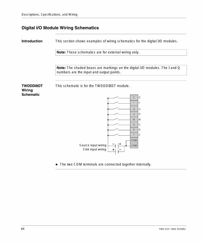
Descriptions, Specifications, and Wiring
Digital I/O Module Wiring Schematics
Introduction This section shows examples of wiring schematics for the digital I/O modules.
TWDDDI8DT Wiring Schematic
This schematic is for the TWDDDI8DT module.
l The two COM terminals are connected together internally.
Note: These schematics are for external wiring only.
Note: The shaded boxes are markings on the digital I/O modules. The I and Q numbers are the input and output points.
Source input wiringSink input wiring
84 TWD USE 10AE 05/2002

Descriptions, Specifications, and Wiring
TWDDDI16DT Wiring Schematic
This schematic is for the TWDDDI16DT module.
l The four COM terminals are connected together internally.
TWDDDI16DK Wiring Schematic
This schematic is for the TWDDDI16DK module.
Source input wiringSink input wiring
Source input wiringSink input wiring Sink input wiring
Source input wiring
TWD USE 10AE 05/2002 85

Descriptions, Specifications, and Wiring
TWDDDI32DK Wiring Schematic
This schematic is for the TWDDDI32DK module.
l The COM0 terminals are connected together internally. l The COM1 terminals are connected together internally.l The COM0 and COM1 terminals are not connected together internally.
Source input wiringSink input wiring Sink input wiring
Source input wiring
Source input wiringSink input wiring Sink input wiring
Source input wiring
Sink input wiring
86 TWD USE 10AE 05/2002

Descriptions, Specifications, and Wiring
TWDDRA8RT Wiring Schematic
This schematic is for the TWDDRA8RT module.
l The COM0 and COM1 terminals are not connected together internally.l Connect an appropriate fuse for the load.
Relay output wiring
TWD USE 10AE 05/2002 87

Descriptions, Specifications, and Wiring
TWDDRA16RT Wiring Schematic
This schematic is for the TWDDRA16RT module.
l The COM0 terminals are connected together internally. l The COM1 terminals are connected together internally.l The COM0 and COM1 terminals are not connected together internally.l Connect an appropriate fuse for the load.
Relay output wiring
88 TWD USE 10AE 05/2002

Descriptions, Specifications, and Wiring
TWDDDO8UT Wiring Schematic
This schematic is for TWDDDO8UT module.
l Connect an appropriate fuse for the load.
TWDDDO16UK Wiring Schematic
This schematic is for the TWDDDO16UK module.
l The COM(-) terminals are connected together internally. l The +V terminals are connected together internally.l Connect an appropriate fuse for the load.
Sink output wiring
Sink output wiring Sink output wiring
TWD USE 10AE 05/2002 89

Descriptions, Specifications, and Wiring
TWDDDO32UK Wiring Schematic
This schematic is for the TWDDDO32UK module.
l Terminals on CN1 and CN2 are not connected together internally. l The COM0(-) terminals are connected together internally.l The COM1(-) terminals are connected together internally.l The +V0 terminals are connected together internally.l The +V1 terminals are connected together internally.l Connect an appropriate fuse for the load.
Sink output wiring Sink output wiring
Sink output wiring Sink output wiring
90 TWD USE 10AE 05/2002

Descriptions, Specifications, and Wiring
TWDDDO8TT Wiring Schematic
This schematic is for the TWDDDO8TT module.
l Connect an appropriate fuse for the load.
TWDDDO16TK Wiring Schematic
This schematic is for the TWDDDO16TK module.
l The COM(+) terminals are connected together internally. l The -V terminals are connected together internally.l Connect an appropriate fuse for the load.
Source output wiring
Source output wiringSource output wiring
TWD USE 10AE 05/2002 91

Descriptions, Specifications, and Wiring
TWDDDO32TK Wiring Schematic
This schematic is for the TWDDDO32TK module.
l Terminals CN1 and CN2 are not connected together internally. l The COM0(+) terminals are connected together internally.l The COM1(+) terminals are connected together internally.l The -V0 terminals are connected together internally.l The -V1 terminals are connected together internally.l Connect an appropriate fuse for the load.
Source Source output wiringoutput wiring
Source Source output wiringoutput wiring
92 TWD USE 10AE 05/2002

Descriptions, Specifications, and Wiring
TWDDMM8DRT Wiring Schematic
This schematic is the TWDDMM8DRT module.
l The COM0 and COM1 terminals are not connected together internally.
TWDDMM24DRF Wiring Schematic
This schematic is for the TWDDMM24DRF module.
l The COM0, COM1 and COM2 terminals are not connected together internally.l Connect an appropriate fuse for the load.
Source input wiringSink input wiring
Relay output wiring
Relay output wiring
Source input wiringSink input wiring
TWD USE 10AE 05/2002 93
Descriptions, Specifications, and Wiring
2.5 Analog I/O Modules
At a Glance
Introduction This section provides an overview, specifications, and wiring schematics of the analog I/O modules.
What’s in this Section?
This section contains the following topics:
Topic Page
Overview of Analog I/O Modules 95
Parts Description of Analog I/O Modules 96
General Specifications for the Analog I/O Module 97
I/O Specifications for the Analog I/O Module 98
Analog I/O Modules Wiring Schematics 103
94 TWD USE 10AE 05/2002

Descriptions, Specifications, and Wiring
Overview of Analog I/O Modules
Introduction The following section provides an overview of the analog I/O modules.
Illustrations The following illustrations are the analog I/O modules.
Controller Type Illustration
These 2 analog I/O modules are: l 2-point input/1-point output module with
a terminal block, accepts thermocouple and resistance thermometer signals (TWDALM3LT)
l 2-point input/1-point output module with a terminal block (TWDAMM3HT)
These modules can be attached to any controller except the Compact 10 I/O and 16 I/O controllers.
These 2 analog I/O modules are:l 2-point input module with a terminal
block (TWDAMI2HT)l 1-point output module with a terminal
block (TWDAMO11HT)These modules can be attached to any controller except the Compact 10 I/O and 16 I/O controllers.
TWDALM3LT TWDAMM3HT
TWDAMI2HT TWDAMO11HT
TWD USE 10AE 05/2002 95

Descriptions, Specifications, and Wiring
Parts Description of Analog I/O Modules
Introduction The following section describes the parts of an analog I/O module. Your I/O module may differ from the illustrations but the parts will be the same.
Parts Description of an Analog I/O Module
The following figure shows the parts of an analog I/O module. This figure is the TWDALM3LT module.
Legend
2
1
4
53
Label Description
1 Expansion connector - one on each side, right side not shown
2 Removable terminal block
3 Latch button
4 LEDs
5 Clamp
96 TWD USE 10AE 05/2002

Descriptions, Specifications, and Wiring
General Specifications for the Analog I/O Module
Introduction This section is general specifications for analog I/O modules.
General Specifications
Type Number TWDALM3LT TWDAMM3HT TWDAMI2HT TWDAMO1HT
Rated power voltage 24 VDC
Allowable voltage range
20.4 to 28.8 VDC
Connector insertion/removal durability
100 times minimum
Internal current draw - internal power
50 mA (5 VDC)0 mA (24 VDC)
Internal current draw - external power
40 mA (24 VDC) 40 mA (24 VDC) 40 mA (24 VDC)
Weight 85 g
TWD USE 10AE 05/2002 97
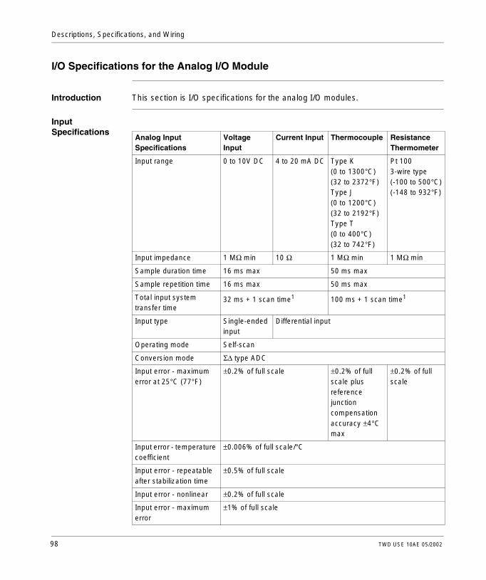
Descriptions, Specifications, and Wiring
I/O Specifications for the Analog I/O Module
Introduction This section is I/O specifications for the analog I/O modules.
Input Specifications
Analog Input Specifications
Voltage Input
Current Input Thermocouple Resistance Thermometer
Input range 0 to 10V DC 4 to 20 mA DC Type K (0 to 1300°C)(32 to 2372°F)Type J (0 to 1200°C)(32 to 2192°F)Type T(0 to 400°C)(32 to 742°F)
Pt 1003-wire type(-100 to 500°C)(-148 to 932°F)
Input impedance 1 MΩ min 10 Ω 1 MΩ min 1 MΩ min
Sample duration time 16 ms max 50 ms max
Sample repetition time 16 ms max 50 ms max
Total input system transfer time
32 ms + 1 scan time1 100 ms + 1 scan time1
Input type Single-ended input
Differential input
Operating mode Self-scan
Conversion mode Σ∆ type ADC
Input error - maximum error at 25°C (77°F)
±0.2% of full scale ±0.2% of full scale plus reference junction compensation accuracy ±4°C max
±0.2% of full scale
Input error - temperature coefficient
±0.006% of full scale/°C
Input error - repeatable after stabilization time
±0.5% of full scale
Input error - nonlinear ±0.2% of full scale
Input error - maximum error
±1% of full scale
98 TWD USE 10AE 05/2002

Descriptions, Specifications, and Wiring
Digital resolution 4096 increments (12 bits)
Input value of LSB 2.5 mV 4 µA K: 0.325°C (32.59°F)J: 0.300°C (32.54°F)T: 0.100°C (32.18°F)
0.15°C (32.27°F)
Data type in application program
0 to 4095 (12-bit data)
-32768 to 32767 (optional range designation)2
Monotonicity Yes
Input data out of range Detectable3
Noise resistance - maximum temporary deviation during electrical noise tests
±3% maximum when a 500V clamp voltage is applied to the power and I/O wiring
Accuracy is not assured when noise is applied
Noise resistance - common mode characteristics
Common mode reject ration (CMRR): -50 dB
Noise resistance - common mode voltage
16 VDC
Noise resistance - input filter
No
Noise resistance - cable Twisted-pair shielded cable is recommended for improved noise immunity
—
Noise resistance - crosstalk
2 LSB maximum
Dielectric strength 500 V between input and power circuit
Type of protection Photocoupler between input and internal circuit
Maximum permanent allowed overload (no damage)
13 VDC 40 mA DC —
Selection of analog input signal type
Using software programming
Calibration or verification to maintain rated accuracy
Approximately 10 years
Analog Input Specifications
Voltage Input
Current Input Thermocouple Resistance Thermometer
TWD USE 10AE 05/2002 99

Descriptions, Specifications, and Wiring
Note: 1. Total input system transfer time = sample repetition x 2 + 1 scan time.2. The 12-bit data (0 to 4095) processed in the Analog I/O module can be linear-
converted to a value between -32768 and 32767. The optional range designation and analog I/O data minimum and maximum values can be selected using data registers allocated to analog I/O modules.
3. When an error is detected, a corresponding error code is stored to a data register allocated to analog I/O operating status.
100 TWD USE 10AE 05/2002

Descriptions, Specifications, and Wiring
Output Specifications
Analog Input Specifications Voltage output Current Output
Output range 0 to 10 VDC 4 to 20 mA DC
Load impedance 2 kΩ minimum 300 Ω maximum
Application load type Resistive load
Settling time 20 ms
Total output system transfer Time
20 ms + 1 scan time
Output error - maximum error at 25°C (77°F)
±0.2% of full scale
Output error - temperature coefficient
±0.015% of full scale/°C
Output error - repeatable after stabilization time
±0.5% of full scale
Output error - output voltage drop
±1% of full scale
Output error - nonlinear ±0.2% of full scale
Output error - output ripple 1 LSB maximum
Output error - overshoot 0%
Output error - total error ±1% of full scale
Digital resolution 4096 increments (12 bits)
Output value of LSB 2.5 mV 4 µA
Data type in application program 0 to 4095 (12-bit data)
-32768 to 32767 (optional range designation)1
Monotonicity Yes
Current loop open — Detectable2
Noise resistance - maximum temporary deviation during electrical noise tests
±3% maximum when a 500 V clamp voltage is applied to the power and I/O wiring
Noise resistance - cable Twisted-pair shielded cable is recommended for improved noise immunity
Noise resistance - crosstalk No crosstalk because of 1 channel output
Dielectric strength 500 V between output and power circuit
Type of protection Photocoupler between output and internal circuit
Selection of analog input signal type
Using software programming
TWD USE 10AE 05/2002 101
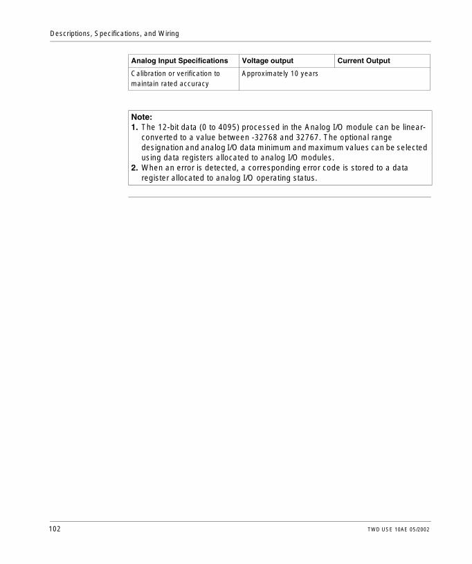
Descriptions, Specifications, and Wiring
Calibration or verification to maintain rated accuracy
Approximately 10 years
Note: 1. The 12-bit data (0 to 4095) processed in the Analog I/O module can be linear-
converted to a value between -32768 and 32767. The optional range designation and analog I/O data minimum and maximum values can be selected using data registers allocated to analog I/O modules.
2. When an error is detected, a corresponding error code is stored to a data register allocated to analog I/O operating status.
Analog Input Specifications Voltage output Current Output
102 TWD USE 10AE 05/2002

Descriptions, Specifications, and Wiring
Analog I/O Modules Wiring Schematics
Introduction This section shows examples of wiring schematics for the Analog I/O modules.
TWDALM3LT Wiring Schematic
This schematic is for the TWDALM3LT module.
l Connect a fuse appropriate for the applied voltage and current draw, at the position shown in the diagram.
l When connecting an RTD, connect the three wires to terminals A, B’, and B of input channel 0 or 1.
l When connecting a thermocouple, connect the two wires to terminals B’ and B of input channel 0 or 1.
l Do not connect any wiring to unused channels.l Do not connect the thermocouple to a hazardous voltage (60 VDC or 42.4 V peak
or higher).
Thermocouple
RTD
Analog voltage/current input device
TWD USE 10AE 05/2002 103

Descriptions, Specifications, and Wiring
TWDAMM3HT Wiring Schematic
This schematic is for the TWDAMM3HT module.
l Connect a fuse appropriate for the applied voltage and current draw, at the position shown in the diagram.
l Do not connect any wiring to unused channels.
TWDAMI2HT Wiring Schematic
This schematic is for the TWDAMI2HT module.
l Connect a fuse appropriate for the applied voltage and current draw, at the position shown in the diagram.
l Do not connect any wiring to unused channels.
Analog voltage/current output device
Analog voltage/current output device
Analog voltage/current input device
Analog voltage/current output device
Analog voltage/current output device
104 TWD USE 10AE 05/2002

Descriptions, Specifications, and Wiring
TWDAMO1HT Wiring Schematic
This schematic is for the TWDAMO1HT module.
l Connect a fuse appropriate for the applied voltage and current draw, at the position shown in the diagram.
l Do not connect any wiring to unused channels.
Analog voltage/current input device
TWD USE 10AE 05/2002 105

Descriptions, Specifications, and Wiring
2.6 Communication Options
At a Glance
Introduction This section provides an overview, parts description, and specifications of the communication options.
What’s in this Section?
This section contains the following topics:
Topic Page
Overview of Communication Adapters and Expansion Modules 107
Parts Description of Communication Adapters and Expansion Modules 108
Specifications for Communication Adapters and Expansion Modules 110
106 TWD USE 10AE 05/2002

Descriptions, Specifications, and Wiring
Overview of Communication Adapters and Expansion Modules
Introduction The following section provides an overview of the TWDNAC232D, TWDNAC485D, and TWDNAC485T communication adapters and the TWDNOZ232D, TWDNOZ485D, and TWDNOZ485T communication expansion modules.
Overview All Twido controllers have one RS485 communication serial port 1. In addition, TWDLCAA16DRF and TWDLCAA24DRF controllers have a serial port 2 connector for an optional second RS485 or RS232 serial port. An optional communication adapter (TWDNAC232D, TWDNAC485D, and TWDNAC485T) is available to install on the serial port 2 connector. The TWDLCAA10DRF does not have a serial port 2 connector. A communication expansion module (TWDNOZ232D, TWDNOZ485D, and TWDNOZ485T) is available to attach to any Modular controller for an optional second RS485 or RS232 serial port. Also, an operator display expansion module (TWDXCPODM) is available to attach to a Modular controller where an optional communication adapter (TWDNAC232D, TWDNAC485D, and TWDNAC485T) can be installed to the serial port 2 connector on the operator display expansion module. The RS485 serial port 2 is used for maintenance communication and remote link communication. The RS232 serial port 2 is used for user communication and ASCII device communication.
TWD USE 10AE 05/2002 107

Descriptions, Specifications, and Wiring
Parts Description of Communication Adapters and Expansion Modules
Introduction The following section describes the parts of the TWDNAC232D, TWDNAC485D, and TWDNAC485T communication adapters and the TWDNOZ232D, TWDNOZ485D, and TWDNOZ485T communication expansion modules.
Parts Description of a Communication Adapter
The following figure shows the parts of the TWDNAC232D, TWDNAC485D, and TWDNAC485T communication adapters.
Legend
1
2
1
2
TWDNAC485T TWDNAC232DTWDNAC485D
Label Part Description
1 Serial port 2 Adds an optional second RS485 or RS232 serial port.
2 Connector Connects to the serial port 2 connector on TWDXCPODM operator display expansion module or TWDLCAA16DRF and TWDLCAA24DRF controllers.
108 TWD USE 10AE 05/2002

Descriptions, Specifications, and Wiring
Parts Description of a Communication Expansion Module
The following figure shows the parts of the TWDNOZ232D, TWDNOZ485D, and TWDNOZ485T communication expansion modules.
Legend
TWDNOZ485TTWDNOZ232DTWDNOZ485D
2
3
4
5 5
1
Label Part Description
1 Hinged door Opens to access the serial port 2.
2 Clamp Secures the module to a DIN rail.
3 Latch button Holds/releases the module from a controller.
4 Communication connector Connects to a Modular controller.
5 Serial port 2 Adds an optional second RS485 or RS232 serial port to a Modular controller.
TWD USE 10AE 05/2002 109

Descriptions, Specifications, and Wiring
Specifications for Communication Adapters and Expansion Modules
Introduction This section is specifications for the TWDNAC232D, TWDNAC485D, and TWDNAC485T communication adapters and the TWDNOZ232D, TWDNOZ485D, and TWDNOZ485T communication expansion modules.
Communication Adapter and Expansion Module Specifications
The following table describes the communication adapter and expansion module specifications.
Part Number TWDNAC232DTWDNOZ232D
TWDNAC485DTWDNOZ485D
TWDNAC485TTWDNOZ485T
Standards RS232 RS485 RS485
Maximum baud rate
19,200 bps PC Link: 19,200 bpsRemote Link: 38,400 bps
PC Link: 19,200 bpsRemote Link: 38,400 bps
Maintenance communication (PC Link)
Possible Possible Possible
ASCII communication
Possible Possible Possible
Remote link communication
Not possible 7 possible 7 Possible
Maximum cable length
Maximum distance between controllers: 50 m (164 feet).
Maximum distance between controllers: 50 m (164 feet).
Maximum distance between controllers: 50 m (164 feet).
Isolation between internal circuit and communication port
Not isolated Not isolated Not isolated
110 TWD USE 10AE 05/2002

Descriptions, Specifications, and Wiring
2.7 Operator Display Options
At a Glance
Introduction This section provides an overview, parts description, and specifications of the operator display options.
What’s in this Section?
This section contains the following topics:
Topic Page
Overview of Operator Display Modules and Expansion Modules 112
Parts Description of Operator Display Module and Expansion Module 113
Specifications for Operator Display Modules and Expansion Modules 115
TWD USE 10AE 05/2002 111
Descriptions, Specifications, and Wiring
Overview of Operator Display Modules and Expansion Modules
Introduction The following section provides an overview of the TWDXCPODC operator display module and the TWDXCPODM operator display expansion module.
Overview The operator display is an optional module that can be added to any of the controllers. It is installed into a Compact controller as a operator display module (TWDXCPODC) and it is assembled to a Modular controller using the operator display expansion module (TWDXCPODM). See How to Install and Remove the Operator Display Module and Operator Display Expansion Module, p. 149.The operator display provides the following services:l Displays the controller state informationl Allows the user to control the controllerl Allows the user to monitor and tune application data objectsThe operator display has two states:l Display state - Displays datal Edit state - Allows the user to change data
112 TWD USE 10AE 05/2002

Descriptions, Specifications, and Wiring
Parts Description of Operator Display Module and Expansion Module
Introduction The following section describes the parts of the TWDXCPODC operator display module and the TWDXCPODM operator display expansion module.
Parts Description of a Operator Display Module
The following figure shows the parts of the TWDXCPODC operator display module.
Legend
3
1
2
4
5
6
Label Part Description
1 Display screen Shows menus, operands, and data.
2 ESC button In Edit state - Returns to the previous display state and rejects changes made by the user.
3 Up arrow button In Edit state - Changes the current edit element to the next value.
4 Right arrow button In Display state - Advances to the next display state.In Edit state - Advances to the next editing element. The current editing element blinks.
5 MOD/ENTER button In Display state - Works in MOD function, goes to the corresponding edit state.In Edit state - Works in ENTER function, returns to previous display state and accepts changes made by the user.
6 Operator display connector
Connects to the Compact controller.
TWD USE 10AE 05/2002 113

Descriptions, Specifications, and Wiring
Parts Description of a Operator Display Expansion Module
The following figure shows the parts of the TWDXCPODM operator display expansion module.
Legend
3
1
2
4
5
6
7 9
10
8
Label Part Description
1 Display screen Shows menus, operands, and data.
2 ESC button In Edit state - Returns to the previous display state and rejects changes made by the user.
3 Up arrow button In Edit state - Changes the current edit element to the next value.
4 Right arrow button In Display state - Advances to the next display state.In Edit state - Advances to the next editing element. The current editing element blinks.
5 MOD/ENTER button In Display state - Works in MOD function, goes to the corresponding edit state.In Edit state - Works in ENTER function, returns to previous display state and accepts changes made by the user.
6 Operator display connector
Connects to a Modular controller.
7 Hinged door Opens to access the serial port 2.
8 Latch button Holds/releases the module from a controller.
9 Clamp Secures the module to a DIN rail.
10 Serial port 2 connector Connects to the connector on an optional TWDNAC232D, TWDNAC485D, or TWDNAC485T communication adapter.
114 TWD USE 10AE 05/2002

Descriptions, Specifications, and Wiring
Specifications for Operator Display Modules and Expansion Modules
Introduction This section is specifications for the TWDXCPODC operator display module and the TWDXCPODM operator display expansion module.
Operator Display Module Specifications
The following table describes the operator display module specifications.
Operator Display Expansion Module Specifications
The following table describes the operator display expansion module specifications.
Part Number TWDXCPODC
Power voltage 5 VDC (supplied from the controller)
Internal current draw 200 mA DC
Weight 20 g
Part Number TWDXCPODM
Weight 78 g
TWD USE 10AE 05/2002 115

Descriptions, Specifications, and Wiring
2.8 Options
At a Glance
Introduction This section provides an overview and specifications of the options.
What’s in this Section?
This section contains the following topics:
Topic Page
Overview of the Options 117
Specifications for the Options 118
116 TWD USE 10AE 05/2002
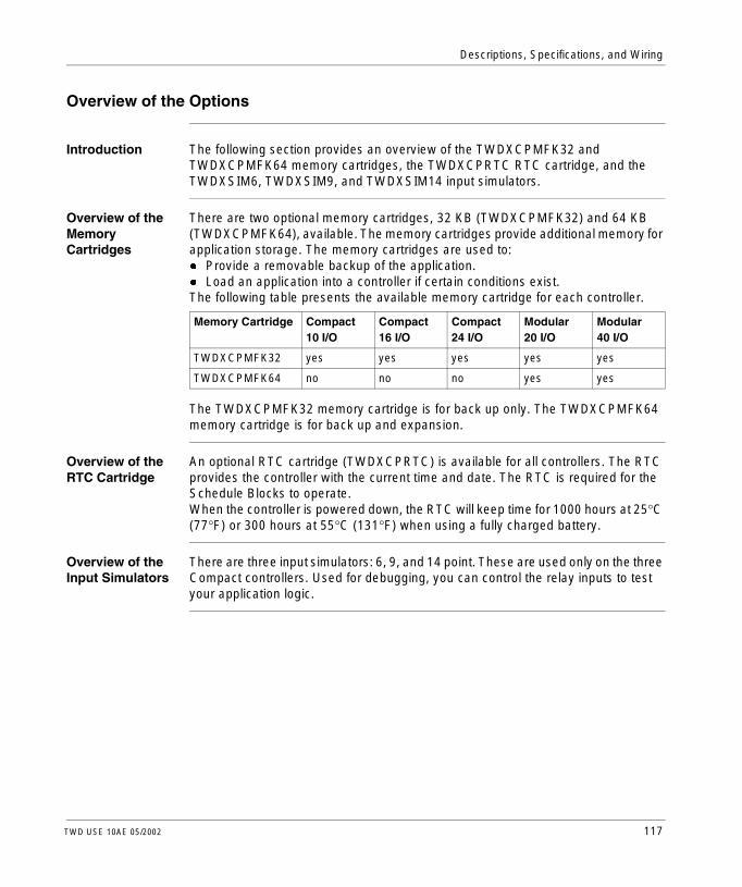
Descriptions, Specifications, and Wiring
Overview of the Options
Introduction The following section provides an overview of the TWDXCPMFK32 and TWDXCPMFK64 memory cartridges, the TWDXCPRTC RTC cartridge, and the TWDXSIM6, TWDXSIM9, and TWDXSIM14 input simulators.
Overview of the Memory Cartridges
There are two optional memory cartridges, 32 KB (TWDXCPMFK32) and 64 KB (TWDXCPMFK64), available. The memory cartridges provide additional memory for application storage. The memory cartridges are used to:l Provide a removable backup of the application.l Load an application into a controller if certain conditions exist.The following table presents the available memory cartridge for each controller.
The TWDXCPMFK32 memory cartridge is for back up only. The TWDXCPMFK64 memory cartridge is for back up and expansion.
Overview of the RTC Cartridge
An optional RTC cartridge (TWDXCPRTC) is available for all controllers. The RTC provides the controller with the current time and date. The RTC is required for the Schedule Blocks to operate.When the controller is powered down, the RTC will keep time for 1000 hours at 25°C (77°F) or 300 hours at 55°C (131°F) when using a fully charged battery.
Overview of the Input Simulators
There are three input simulators: 6, 9, and 14 point. These are used only on the three Compact controllers. Used for debugging, you can control the relay inputs to test your application logic.
Memory Cartridge Compact 10 I/O
Compact 16 I/O
Compact 24 I/O
Modular 20 I/O
Modular 40 I/O
TWDXCPMFK32 yes yes yes yes yes
TWDXCPMFK64 no no no yes yes
TWD USE 10AE 05/2002 117
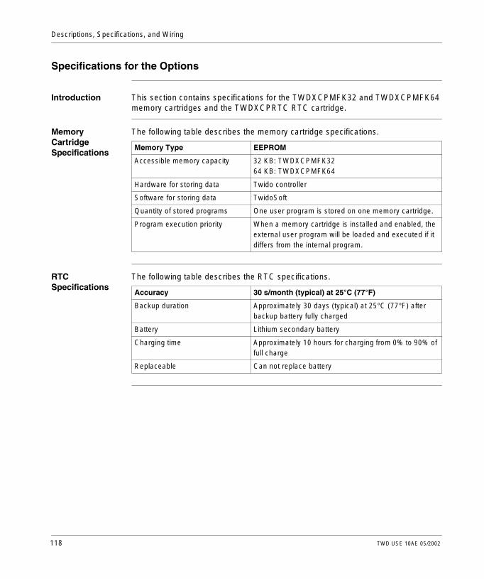
Descriptions, Specifications, and Wiring
Specifications for the Options
Introduction This section contains specifications for the TWDXCPMFK32 and TWDXCPMFK64 memory cartridges and the TWDXCPRTC RTC cartridge.
Memory Cartridge Specifications
The following table describes the memory cartridge specifications.
RTC Specifications
The following table describes the RTC specifications.
Memory Type EEPROM
Accessible memory capacity 32 KB: TWDXCPMFK3264 KB: TWDXCPMFK64
Hardware for storing data Twido controller
Software for storing data TwidoSoft
Quantity of stored programs One user program is stored on one memory cartridge.
Program execution priority When a memory cartridge is installed and enabled, the external user program will be loaded and executed if it differs from the internal program.
Accuracy 30 s/month (typical) at 25°C (77°F)
Backup duration Approximately 30 days (typical) at 25°C (77°F) after backup battery fully charged
Battery Lithium secondary battery
Charging time Approximately 10 hours for charging from 0% to 90% of full charge
Replaceable Can not replace battery
118 TWD USE 10AE 05/2002

Descriptions, Specifications, and Wiring
2.9 TeleFast Cable Systems
At a Glance
Introduction This section provides an overview, specifications, base wiring schematics, and cable wiring specifications of the TeleFast cable systems.
What’s in this Section?
This section contains the following topics:
Topic Page
Overview of the Twido TeleFast Cable System Kits 120
Specifications for the TeleFast Bases 122
Twido TeleFast Wiring Schematics 123
Wiring Specifications for the TeleFast Cables 125
TWD USE 10AE 05/2002 119

Descriptions, Specifications, and Wiring
Overview of the Twido TeleFast Cable System Kits
Introduction The following section provides an overview of the TWDFST16D10, TWDFST16D20, TWDFST16R10, TWDFST16R20, TWDFST20DR10, and TWDFST20DR20 Fast Cable Systems.
Overview of the Fast Cable Systems
The following table lists the TeleFast Cable System kits and their contents.
Fast Cable System Kits
Cable Part Number
Cable Description TeleFast Base TeleFast Base Description
Kit for TWDDDI16DK or TWDDDI32DK - 16 Input Sink
TWDFST16D10 ABF-TE20EP100 1 meter interconnect ABE7H20E000 16-point Input
TWDFST16D20 ABF-TE20EP200 2 meter interconnect ABE7H20E000 16-point Input
Kit for TWDDDO16TK or TWDDDO32TK - 16 Output Source
TWDFST16R10 ABF-TE20SP100 1 meter interconnect ABE7R16S111 16-point Output Relay
TWDFST16R20 ABF-TE20SP200 2 meter interconnect ABE7R16S111 16-point Output Relay
Kit for TWDLMDA20DTK or TWDLMDA40DTK - 16 Input Sink/8 Output Source
TWDFST20DR10 ABF-TP26MP100 1 meter interconnect ABE7H20E000ABE7R08S111
16-point Input8-point Output Relay
TWDFST20DR20 ABF-TP26MP200 2 meter interconnect ABE7H20E000ABE7R08S111
16-point Input8-point Output Relay
120 TWD USE 10AE 05/2002

Descriptions, Specifications, and Wiring
Illustration The following illustration shows the Twido TeleFast cable system kits.
Kits Kits Kits
TWD USE 10AE 05/2002 121

Descriptions, Specifications, and Wiring
Specifications for the TeleFast Bases
Introduction This section provides specifications for the ABE7R08S111, ABE7R16S111, and ABE7H20E000 TeleFast bases.
ABE7H20E000 Specifications
See Catalog 8501CT9801, “TeleFast 2 Prewiring System” for more specifications on this Telefast bases.
ABE7R08S111 and ABE7R16S111 Specifications
See Catalog 8501CT9801, “TeleFast 2 Prewiring System” for more specifications on these Telefast bases.
Passive Input TeleFast Base ABE7H20E000
Number of channels 16
Input type Sink Input
Base power supply 20.4 - 26.4 VDC
Supply protection 1 A Fast Blow
Input current 7 mA
Number of inputs per COM 16
Isolation None (passive)
Relay Output TeleFast Base ABE7R08S111 ABE7R16S111
Number of channels 8 16
Base DC power 20.4 - 28.8 VDC
Supply protection 1 A Fast Blow
Output contacts 8 NO 16 NO
Maximum VAC 250 VAC @ 50-60 Hz
Maximum VDC 30 VDC
Number of channels per COM 4 8
Max contact current 2 A
Max current per module 12 A
Isolation outputs to internal circuitry 2 K VAC
122 TWD USE 10AE 05/2002
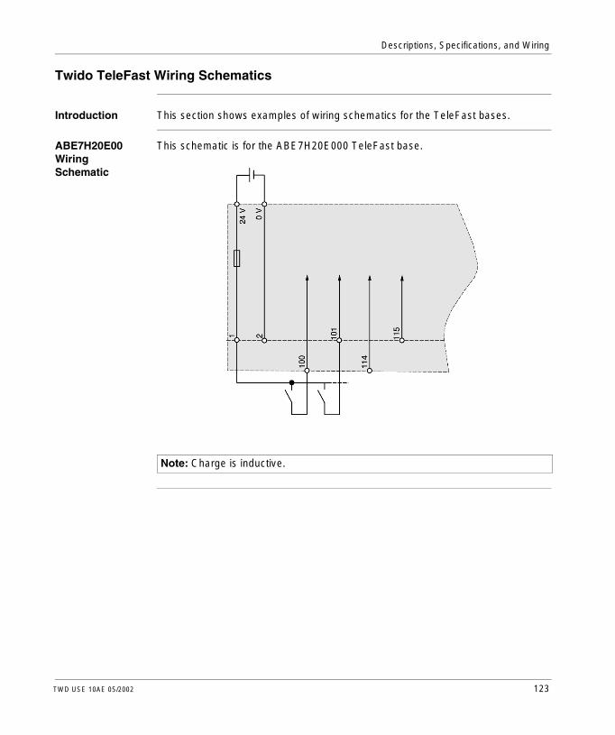
Descriptions, Specifications, and Wiring
Twido TeleFast Wiring Schematics
Introduction This section shows examples of wiring schematics for the TeleFast bases.
ABE7H20E00 Wiring Schematic
This schematic is for the ABE7H20E000 TeleFast base.
Note: Charge is inductive.
TWD USE 10AE 05/2002 123

Descriptions, Specifications, and Wiring
ABE7R08S111 Wiring Schematic
This schematic is for the ABE7R08S111 TeleFast base.
ABE7R16S111 Wiring Schematic
This schematic is for the ABE7R16S111 TeleFast base.
124 TWD USE 10AE 05/2002

Descriptions, Specifications, and Wiring
Wiring Specifications for the TeleFast Cables
Introduction This section provides cable wiring specifications for the ABF-TE20EP100/200, ABF-TE20SP100/200, ABF-TP26MP100/200, TWDFCW30K/50K, and TWDFCW30M/50M TeleFast cables.
ABF-TE20EP100/200
The following table provides specifications for the ABF-TE20EP100/200 sink input cable wiring.
TwidoSignal Name
TwidoPin Number
ABE7H20E000Pin Number
ABE7H20E200 Signal Name
NC 1 NC
NC 2 NC
COM 3 20 COM
COM 4 18 COM
I15 5 16 I15
I7 6 8 I7
I14 7 15 I14
I6 8 7 I6
I13 9 14 I13
I5 10 6 I5
I12 11 13 I12
I4 12 5 I4
I11 13 12 I11
I3 14 4 I3
I10 15 11 I10
I2 16 3 I2
I9 17 10 I9
I1 18 2 I1
I8 19 9 I8
I0 20 1 I0
TWD USE 10AE 05/2002 125

Descriptions, Specifications, and Wiring
ABF-TE20SP100/200
The following table provides specifications for the ABF-TE20SP100/200 source cable wiring.
TwidoSignal Name
TwidoPin Number
ABE7R16S111Pin Number
ABE7R16S111Signal Name
V+ 1 20 COM
V+ 2 18 COM
COM 3 I7 V+
COM 4 19 V+
Q15 5 16 Q15
Q7 6 8 Q7
Q14 7 15 Q14
Q6 8 7 Q6
Q13 9 14 Q13
Q5 10 6 Q5
Q12 11 13 Q12
Q4 12 5 Q4
Q11 13 12 Q11
Q3 14 4 Q3
Q10 15 11 Q10
Q2 16 3 Q2
Q9 17 10 Q9
Q1 18 2 Q1
Q8 19 9 Q8
Q0 20 1 Q0
126 TWD USE 10AE 05/2002

Descriptions, Specifications, and Wiring
ABF-TP26MP100/200
The following table provides specifications for the ABF-TP26MP100/200 sink/source cable wiring.
TwidoSignal Name
TwidoPin Number
ABE7R08S111Pin Number
ABE7R08S111Signal Name
ABE7R08S111Pin Number
ABE7R08S111Signal Name
V+ 1 18 COM
COM 2 18 or 20 COM
V+ 3 20 COM
I11 4 12 I11
COM 5 17 V+
I10 6 11 I10
COM 7 19 V+
I9 8 10 I9
COM 9 -- -- -- --
I8 10 10 I9
Q7 11 8 Q7
I7 12 8 I7
Q6 13 7 Q6
I6 14 7 I6
Q5 15 6 Q5
I5 16 6 I5
Q4 17 5 Q4
I4 18 5 I4
Q3 19 4 Q3
I3 20 4 I3
Q2 21 3 Q2
I2 22 3 I2
Q1 23 2 Q1
I1 24 2 I1
Q0 25 1 Q0
I0 26 1 I0
TWD USE 10AE 05/2002 127

Descriptions, Specifications, and Wiring
TWDFCW30K/50K
The following table provides specifications for the TWDFCW30K/50K with free wires for 20-pin Modular controller.
Illustration
Pin Connector ATwido Connector Side
Wire Color
1 White
2 Brown
3 Green
4 Yellow
5 Grey
6 Pink
7 Blue
8 Red
9 Black
10 Violet
11 Grey/Pink
12 Red/Blue
13 White/Green
14 Brown/Green
15 White/Yellow
16 Yellow/Brown
17 White/Grey
18 Grey/Brown
19 White/Pink
20 Pink/Brown
128 TWD USE 10AE 05/2002
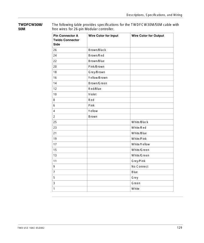
Descriptions, Specifications, and Wiring
TWDFCW30M/50M
The following table provides specifications for the TWDFCW30M/50M cable with free wires for 26-pin Modular controller.
Pin Connector ATwido Connector Side
Wire Color for Input Wire Color for Output
26 Brown/Black
24 Brown/Red
22 Brown/Blue
20 Pink/Brown
18 Grey/Brown
16 Yellow/Brown
14 Brown/Green
12 Red/Blue
10 Violet
8 Red
6 Pink
4 Yellow
2 Brown
25 White/Black
23 White/Red
21 White/Blue
19 White/Pink
17 White/Yellow
15 White/Green
13 White/Green
11 Grey/Pink
9 No Connect
7 Blue
5 Grey
3 Green
1 White
TWD USE 10AE 05/2002 129

Descriptions, Specifications, and Wiring
Illustration
Input
Output
130 TWD USE 10AE 05/2002

TWD USE 10AE 05/2002
3
InstallationAt a Glance
Introduction This chapter provides dimensions, installation, and mounting instructions for the controllers, digital and analog expansion I/O modules, and options.
What’s in this Chapter?
This chapter contains the following topics:
Topic Page
Dimensions of the Compact Controllers 132
Dimensions for the Modular Controllers 134
Dimensions for the Digital and Analog I/O Modules 136
Dimensions for the Operator Display Module, Operator Display Expansion Module, and Communication Expansion Modules
139
Dimensions of the TeleFast Bases 141
Installation Preparation 143
Controller and Expansion I/O Module Mounting Positions 144
How to Assemble an Expansion I/O Module to a Controller 146
How to Disassemble an Expansion I/O Module from a Controller 148
How to Install and Remove the Operator Display Module and Operator Display Expansion Module
149
How to Install and Remove a Communication Adapter and Expansion Module 153
How to Install a Memory or RTC Cartridge 157
How to Remove a Terminal Block 159
How to Install and Remove a Controller and Expansion I/O Module from a DIN Rail 160
How to Direct Mount on a Panel Surface 163
Minimum Clearances for Controllers and Expansion I/O Modules in a Control Panel 167
How to Connect the Power Supply 169
131

Installation
Dimensions of the Compact Controllers
Introduction The following section shows the dimensions for all Compact controllers.
TWDLCAA10-DRF and TWDLCAA16-DRF
The following diagrams show the dimensions for the TWDLCAA10DRF and TWDLCAA16DRF Compact controllers.
Note: * 8.5 mm (0.33 in) when the clamp is pulled out.
80.0 mm (3.17 in)
90.0 mm(3.54 in)
4.5 mm*(0.18 in)
70.0 mm (2.78 in)
132 TWD USE 10AE 05/2002
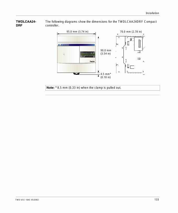
Installation
TWDLCAA24-DRF
The following diagrams show the dimensions for the TWDLCAA24DRF Compact controller.
Note: * 8.5 mm (0.33 in) when the clamp is pulled out.
95.0 mm (3.74 in)
90.0 mm(3.54 in)
4.5 mm*(0.18 in)
70.0 mm (2.78 in)
TWD USE 10AE 05/2002 133
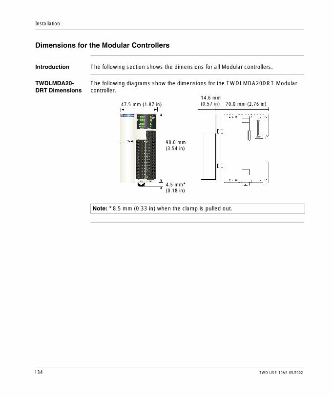
Installation
Dimensions for the Modular Controllers
Introduction The following section shows the dimensions for all Modular controllers.
TWDLMDA20-DRT Dimensions
The following diagrams show the dimensions for the TWDLMDA20DRT Modular controller.
Note: * 8.5 mm (0.33 in) when the clamp is pulled out.
47.5 mm (1.87 in)
90.0 mm(3.54 in)
4.5 mm*(0.18 in)
14.6 mm(0.57 in) 70.0 mm (2.76 in)
134 TWD USE 10AE 05/2002

Installation
TWDLMDA20-DUK and TWDLMDA20-DTK Dimensions
The following diagrams show the dimensions for the TWDLMDA20DUK and TWDLMDA20DTK Modular controllers.
TWDLMDA40-DUK and TWDLMDA40-DTK Dimensions
The following diagrams show the dimensions for the TWDLMDA40DUK and TWDLMDA40DTK Modular controllers.
Note: * 8.5 mm (0.33 in) when the clamp is pulled out.
11.3 mm(0.44 in) 70.0 mm (2.76 in)35.4 mm (1.39 in)
90.0 mm(3.54 in)
4.5 mm*(0.18 in)
Note: * 8.5 mm (0.33 in) when the clamp is pulled out.
47.5 mm (1.87 in)
90.0 mm(3.54 in)
4.5 mm*(0.18 in)
11.3 mm(0.44 in) 70.0 mm (2.76 in)
TWD USE 10AE 05/2002 135

Installation
Dimensions for the Digital and Analog I/O Modules
Introduction The following section shows the dimensions for all digital and analog I/O modules.
Digital I/O and Analog Modules
The following diagrams show the dimensions for the TWDDDI8DT, TWDDRA8RT, TWDDDO8TT, TWDDDO8UT, TWDDMM8DRT digital I/O modules and TWDALM3LT, TWDAMM3HT, TWDAMI2HT, and TWDAMO1HT analog I/O modules.
Note: * 8.5 mm (0.33 in) when the clamp is pulled out.
90.0 mm(3.54 in)
4.5 mm*(0.18 in)
3.8 mm(0.15 in)
23.5 mm(0.93 in)
14.6 mm(0.57 in) 70.0 mm (2.76 in)
136 TWD USE 10AE 05/2002

Installation
Digital I/O Modules
The following diagrams show the dimensions for the TWDDDI16DT and TWDDRA16RT digital I/O modules.
Digital I/O Modules
The following diagram show the dimensions for the TWDDMM24DRF digital I/O module.
Note: * 8.5 mm (0.33 in) when the clamp is pulled out.
3.8 mm(0.15 in)
23.5 mm(0.93 in)
14.6 mm(0.57 in) 70.0 mm (2.76 in)
90.0 mm(3.54 in)
4.5 mm*(0.18 in)
Note: * 8.5 mm (0.33 in) when the clamp is pulled out.
3.8 mm(0.15 in)
39.1 mm(1.54 in)
90.0 mm(3.54 in)
4.5 mm*(0.18 in)
1.0 mm(0.04 in) 70.0 mm (2.76 in)
TWD USE 10AE 05/2002 137

Installation
Digital I/O Modules
The following diagrams show the dimensions for the TWDDDI16DK, TWDDDO16TK, and TWDDDO16UK digital I/O modules.
Digital I/O Modules
The following diagrams show the dimensions for the TWDDDI32DK, TWDDDO32TK, and TWDDDO32UK digital I/O modules.
Note: * 8.5 mm (0.33 in) when the clamp is pulled out.
3.8 mm(0.15 in)
17.6 mm(0.69 in)
90.0 mm(3.54 in)
4.5 mm*(0.18 in)
11.3 mm(0.44 in) 70.0 mm (2.76 in)
Note: * 8.5 mm (0.33 in) when the clamp is pulled out.
11.3 mm(0.44 in) 70.0 mm (2.76 in)
3.8 mm(0.15 in)
29.7 mm(1.17 in)
90.0 mm(3.54 in)
4.5 mm*(0.18 in)
138 TWD USE 10AE 05/2002
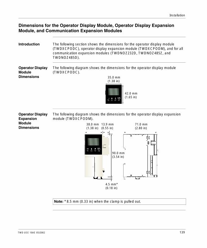
Installation
Dimensions for the Operator Display Module, Operator Display Expansion Module, and Communication Expansion Modules
Introduction The following section shows the dimensions for the operator display module (TWDXCPODC), operator display expansion module (TWDXCPODM), and for all communication expansion modules (TWDNOZ232D, TWDNOZ485Z, and TWDNOZ485D).
Operator Display Module Dimensions
The following diagram shows the dimensions for the operator display module (TWDXCPODC).
Operator Display Expansion Module Dimensions
The following diagram shows the dimensions for the operator display expansion module (TWDXCPODM).
35.0 mm
42.0 mm(1.65 in)
(1.38 in)
Note: * 8.5 mm (0.33 in) when the clamp is pulled out.
38.0 mm(1.38 in)
13.9 mm(0.55 in)
90.0 mm(3.54 in)
71.0 mm(2.80 in)
4.5 mm*(0.18 in)
TWD USE 10AE 05/2002 139

Installation
Communication Expansion Module Dimensions
The following diagram shows the dimensions for all communication expansion modules (TWDNOZ232D, TWDNOZ485Z, and TWDNOZ485D).
Note: * 8.5 mm (0.33 in) when the clamp is pulled out.
38.0 mm(1.38 in)
13.9 mm(0.55 in)
90.0 mm(3.54 in)
71.0 mm(2.80 in)
4.5 mm*(0.18 in)
140 TWD USE 10AE 05/2002

Installation
Dimensions of the TeleFast Bases
Introduction The following section shows the dimensions for the TeleFast bases.
ABE7H20E000 The following diagrams show the dimensions for the ABE7H20E000 Input TeleFast base.
ABE7R08S111 The following diagrams show the dimension for the ABE7R08S111 Relay TeleFast base.
59 mm (2.32 in)
68 mm (2.68 in)
15 mm (0.59 in)
56 mm(2.20 in)
35 mm(1.38 in)
67 mm(2.64 in)
55 mm (2.17 in)
58 mm (2.28 in)
67 mm (2.64 in)
15 mm (0.59 in)
35 mm(1.38 in)
58 mm(2.28 in)
84 mm (3.31 in)
70 mm(2.76 in)
TWD USE 10AE 05/2002 141

Installation
ABE7R16S111 The following diagrams show the dimensions for the ABE7R16S111 Relay TeleFast base.
58 mm (2.28 in)
67 mm (2.64 in)
15 mm (0.59 in)
35 mm(1.38 in)
58 mm(2.28 in)
125 mm (4.93 in)
82 mm(3.23 in)
70 mm(2.76 in)
142 TWD USE 10AE 05/2002

Installation
Installation Preparation
Introduction The following section provides information on preparation for all Twido controllers and expansion I/O modules.
Before Starting Before installing any of the Twido products read the Safety Information at the beginning of this book.
CAUTION
EQUIPMENT DAMAGE
Before removing any module or adapter, turn off the power to the controller. Otherwise, the module, adapter, or controller may be damaged, or the controller may not operate correctly.
Failure to observe this precaution can result in injury or equipment damage.
Note: All options and expansion I/O modules should be installed before assembling and installing a Twido system on a DIN rail, to a mounting plate, or in a control panel. The Twido system should be removed from a DIN rail, a mounting plate, or a control panel before disassembling the modules.
TWD USE 10AE 05/2002 143

Installation
Controller and Expansion I/O Module Mounting Positions
Introduction This section shows the correct and incorrect mounting positions for all controllers and expansion I/O modules.
Correct Mounting Position for all Controllers and Expansion I/O Modules
Controllers and expansion I/O modules must be mounted horizontally on a vertical plane as shown in the figures below.
Note: Keep adequate spacing for proper ventilation and to maintain an ambient temperature between 0°C (32°F) and 55°C (131°F).
Compact controller with an expansion I/O module
Modular controller with an expansion I/O module
144 TWD USE 10AE 05/2002

Installation
Correct and Incorrect Mounting Positions for the Compact Controller
A Compact controller should only be positioned as shown in “Correct Mounting Position for all Controllers with Expansion I/O Modules” figure. When the ambient temperature is 35°C (95°F) or below, the Compact controller can also be mounted upright on a horizontal plane as shown in (1). When the ambient temperature is 40°C (113°F) or below, the Compact controller can also be mounted sideways on a vertical place as shown in figure (2). Figure (3) shows an incorrect mounting position.
Incorrect Mounting Positions for the Modular Controllers
A Modular controller should only be positioned as shown in “Mounting Position for all Controllers and Expansion I/O Modules” figure. The figures below show the incorrect mounting positions for all Modular controllers.
1 2 3
CAUTION
Placing heat generating devices near the controller system
Do not place heat generating devices such as transformers and power supplies underneath the controllers or expansion I/O modules.
Failure to observe this precaution can result in injury or equipment damage.
TWD USE 10AE 05/2002 145

Installation
How to Assemble an Expansion I/O Module to a Controller
Introduction This section shows how to assemble an expansion I/O module to a controller. This procedure is for the Compact and Modular controllers. Your controller and expansion I/O module may differ from the illustrations in this procedure.
CAUTION
UNEXPECTED EQUIPMENT OPERATION
l If you change the hardware configuration of the I/O expansion bus and do not update the software to reflect that change, the expansion bus will no longer operate.
l Be advised that the local base inputs and outputs will continue to operate.
Failure to observe this precaution can result in injury or equipment damage.
146 TWD USE 10AE 05/2002

Installation
Assembling an Expansion I/O Module to a Controller
The following procedure shows how to assemble a controller and expansion I/O module together.
Step Action
1 Remove the expansion connector cover from the controller.
2 Make sure the black latch button on the I/O module is in the up position.
3 Align the connector on the left side of the expansion I/O module to the connector on the right side of the controller.
4 Press the expansion I/O module to the controller until it “clicks” into place.
5 Push down the black latch button on the top of the expansion I/O module to lock the module to the Compact controller.
TWD USE 10AE 05/2002 147

Installation
How to Disassemble an Expansion I/O Module from a Controller
Introduction This section shows how to disassemble an expansion I/O module from a controller. This procedure is for both Compact and Modular controllers. Your controller and expansion I/O module may differ from the illustrations in these procedures but the basic mechanism procedures are applicable.
Disassembling an Expansion I/O Module from a Controller
The following procedure shows how to disassemble an expansion I/O module from a controller.
Step Action
1 Remove the assembled controller and expansion I/O module from the DIN rail before disassembling them. See How to Install and Remove a Controller and Expansion I/O Module from a DIN Rail, p. 160.
2 Push up the black latch from the bottom of the expansion I/O module to disengage it from the controller.
3 Pull apart the controller and expansion I/O module.
148 TWD USE 10AE 05/2002

Installation
How to Install and Remove the Operator Display Module and Operator Display Expansion Module
Introduction This section shows how to install and remove the TWDXCPODC operator display module and the TWDXCPODM operator display expansion module.
Installing the Operator Display Module into a Compact Controller
The following procedure shows how to install the TWDXCPODC operator display module into a Compact controller.
Step Action
1 Remove the operator display connector cover on the Compact controller.
2 Locate the operator display connector inside the Compact controller.
TWD USE 10AE 05/2002 149

Installation
3 Push the operator display module into the operator display connector in the Compact controller until it “clicks”.
Step Action
150 TWD USE 10AE 05/2002

Installation
Assembling the Operator Display Expansion Module to a Modular Controller
The following procedure shows how to assemble the TWDXCPODM operator display expansion module to a Modular controller.
Step Action
1 Remove the communication connector cover on the left side of the Modular controller.
2 Make sure the black latch button on the operator display expansion module is in the up position.
3 Align the connector opening on the left side of the Modular controller to the connector on the right side of the operator display expansion module.
4 Press the operator display expansion module to the Modular controller until it “clicks” into place.
5 Push down the black latch button on the top of the operator display expansion module to lock the module to the Modular controller.
TWD USE 10AE 05/2002 151

Installation
Removing the Operator Display Expansion Module from a Modular Controller
To remove the TWDXCPODM operator display expansion module from a Modular controller see How to Disassemble an Expansion I/O Module from a Controller, p. 148.
152 TWD USE 10AE 05/2002

Installation
How to Install and Remove a Communication Adapter and Expansion Module
Introduction This section shows how to install and remove the TWDNAC232D, TWDNAC485D, or TWDNAC485T communication adapter into a Compact controller’s port 2 and in a TWDXCPODM operator display expansion module. This section also shows how to assemble and disassemble the TWDNOZ232D, TWDNOZ485D, and TWDNOZ485T communication expansion module to a Modular controller. Your controller may differ from the illustrations in these procedures but the basic mechanism procedures are applicable.
Installing the Communication Adapter into a Compact Controller’s Port 2
The following procedure shows how to install the TWDNAC232D, TWDNAC485D, or TWDNAC485T communication adapter into a Compact controller’s port 2.
Step Action
1 Open the hinged lid.
2 Remove the cartridge cover located on the bottom of the Compact controller.
3 Push the communication adapter’s connector into the Compact controller’s port 2 connector until it “clicks”.
4 Look in the opening at the bottom of the Compact controller where the cartridge cover resided and make sure the communication adapter’s connector is seated in the Compact controller’s port 2 connector. Adjust the adapter if it is not seated correctly.
5 Attach the cartridge cover.
or
TWD USE 10AE 05/2002 153

Installation
Installing a Communication Adapter in the Operator Display Expansion Module
The following procedure shows how to install the TWDNAC232D, TWDNAC485D, or TWDNAC485T communication adapter in a TWDXCPODM operator display expansion module.
Step Action
1 Open the hinged lid.
2 Push the communication adapter’s connector into the operator display expansion module’s connector until it “clicks”.
3 Close the hinged lid.
or
154 TWD USE 10AE 05/2002

Installation
Assembling a Communication Expansion Module to a Modular Controller
The following procedure shows how to assemble the TWDNOZ485D, TWDNOZ232D, or TWDNOZ485T communication expansion module to a Modular controller.
Step Action
1 Remove the communication connector cover on the left side of the Modular controller.
2 Make sure the black latch button on the communication expansion module is in the up position.
3 Align the connector opening on the left side of the Modular controller to the connector on the right side of the communication expansion module.
4 Press the communication expansion module to the Modular controller until it “clicks” into place.
5 Push down the black latch button on the top of the communication expansion module to lock the module to the Modular controller.
TWD USE 10AE 05/2002 155

Installation
Disassembling a Communication Expansion Module from a Modular Controller
To disassemble a communication expansion module from a Modular controller, see How to Disassemble an Expansion I/O Module from a Controller, p. 148.
156 TWD USE 10AE 05/2002

Installation
How to Install a Memory or RTC Cartridge
Introduction This section shows how to install the TWDXCPMFK32 memory cartridge in a Compact controller, the TWDXCPMFK32 or TWDXCPMFK64 memory cartridge in a Modular controller, and the TWDXCPRTC RTC cartridge in a Compact controller and Modular controller.
Installing a Cartridge in a Compact Controller
The following procedure shows how to install the TWDXCPMFK32 memory or the TWDXCPRTC RTC cartridge in a Compact controller. Only one of these cartridges can be installed in the Compact controller.
CAUTION
EQUIPMENT DAMAGE
When handling the cartridges, do not touch the pins. The cartridge’s electrical elements are sensitive to static electricity. Use proper ESD procedures when handling a cartridge.
Failure to observe this precaution can result in injury or equipment damage.
Step Action
1 Open bottom terminal cover.
2 Remove the cartridge cover.
3 Push the cartridge into the cartridge connector until it “clicks”.
4 Close the terminal cover.
TWD USE 10AE 05/2002 157

Installation
Installing a Cartridge in a Modular Controller
The following procedure shows how to install the TWDXCPMFK32 or TWDXCPMFK64 memory cartridge or the TWDXCPRTC RTC cartridge in a Modular controller. Only one RTC cartridge can be installed. A memory cartridge and an RTC cartridge can be installed at the same time.
Step Action
1 Open the hinged door.
2 Remove the cartridge cover by holding and pulling the opposite edges of the cover until it is out.
3 Push the cartridge into the Modular controller’s connector until it “clicks”.
4 Close the hinged door.
158 TWD USE 10AE 05/2002

Installation
How to Remove a Terminal Block
Introduction This section shows how to remove a terminal block from the TWDLMDA20DRT Modular controller.
Removing a Terminal Block
The following procedure shows how to remove a terminal block from the TWDLMDA20DRT Modular controller.
Step Action
1 Power off to the Modular controller and disconnect all wires.Note: The terminal block on the left (1) must be removed before the terminal block on the right (2).
2 Remove terminal block (1) by holding the center of the terminal block and pulling it out straight.
3 Repeat step 2 to remove terminal block (2).
21
TWD USE 10AE 05/2002 159

Installation
How to Install and Remove a Controller and Expansion I/O Module from a DIN Rail
Introduction This section shows how to install and remove controllers and expansion I/O modules from a DIN rail. Your controller and expansion I/O module may differ from the illustrations in these procedures but the basic mechanism procedures are applicable.
CAUTION
Pulling the terminal block out from the top or bottom of the block
Do not pull the terminal block out from the top or bottom of the block.
Failure to observe this precaution can result in injury or equipment damage.
Note: When mounting controllers on a DIN rail, use two end stops, type AB1-AB8P35 or equivalent.
160 TWD USE 10AE 05/2002

Installation
Installing a Controller and Expansion I/O Module to a DIN Rail
The following procedure shows how to install a controller and expansion I/O module to a DIN rail.
Step Action
1 Fasten the DIN rail to a panel using screws.
2 Pull out the clamp at the bottom of the controller and expansion I/O module.
3 Put the top groove of the controller and expansion I/O module on the DIN rail and press the modules toward the DIN rail.
4 Push the clamp into the DIN rail.
5 Place mounting clips on both sides of the modules to prevent the system from moving sideways.
Groove
35 mm wide DIN rail
Clamp
TWD USE 10AE 05/2002 161

Installation
Removing a Controller and Expansion I/O Module from a DIN Rail
The following procedure shows how to remove a controller and expansion I/O module from a DIN rail.
Step Action
1 Insert a flat screwdriver into the slot in the clamp.
2 Pull out the clamp.
3 Pull the controller and expansion I/O module off the DIN rail from the bottom.
Clamp
162 TWD USE 10AE 05/2002

Installation
How to Direct Mount on a Panel Surface
Introduction This section shows how to install mounting strips directly on controllers, expansion I/O modules, operator display expansion module, and communication expansion modules. This section also provides mounting hole layouts for each controller and module. Your controller or module may differ from the illustrations in these procedures but the basic mechanism procedures are applicable.
Installing a Mounting Strip
The following procedure shows how to install a mounting strip.
Mounting Hole Layout for Compact Controllers
The following diagram shows the mounting hole layout for all the Compact controllers.
Step Action
1 Remove the clamp from the back side of the module by pushing the clamp inward.
2 Insert the mounting strip, with the hook entering last, into the slot where the clamp was removed.
3 Slide the mounting strip into the slot until the hook enters into the recess in the module.
3.15 in
3.27 in
2.68 in
3.54 in
2 x Ø4.3 3.74 in
3.27 in
2 x Ø4.3
TWDLCAA10DRFTWDLCAA16DRF
TWDLCAA24DRF
80.0 mm
90.0 mm
68.0 mm
83.0 mm
83.0 mm
3.27 in83.0 mm
3.54 in90.0 mm
95.0 mm
TWD USE 10AE 05/2002 163

Installation
Mounting Hole Layout for Modular Controllers
The following diagram shows the mounting hole layout for all the Modular controllers.
2 x Ø4.3
TWDLMDA20DUKTWDLMDA20DTK
TWDLMDA20DRTTWDLMDA40DUKTWDLMDA40DUK
3.54 in90.0 mm
3.0 mm
4.06 in103.0 mm
1.39 in35.4 mm
0.95 in24.1 mm
2 x Ø4.3
3.54 in90.0 mm
3.0 mm
4.06 in103.0 mm
1.87 in47.5 mm
0.95 in24.1 mm
164 TWD USE 10AE 05/2002

Installation
Mounting Hole Layout for Expansion I/O Modules
The following diagram shows the mounting hole layout for the expansion I/O modules.
2 x Ø4.3
3.54 in90.0 mm
3.0 mm
0.93 in23.5 mm
0.25 in6.3 mm
4.06 in103.0 mm
2 x Ø4.3
3.54 in90.0 mm
3.0 mm
0.69 in17.6 mm
0.25 in6.3 mm
4.06 in103.0 mm
TWDDDI8DTTWDDDI16DTTWDDRA8RTTWDDRA16RTTWDDDO8UTTWDDDO8TT
TWDDMM8DRTTWDALM3LTTWDAMM3HTTWDAMI2HTTWDAMO1HT
TWDDDI16DKTWDDDO16TKTWDDDO16UK
2 x Ø4.3
3.54 in90.0 mm
3.0 mm
29.7 mm0.25 in6.3 mm
4.06 in103.0 mm
TWDDDI32DKTWDDDO32TKTWDDDO32UK
1.17 in
2 x Ø4.3
3.54 in90.0 mm
3.0 mm
39.1 mm0.25 in6.3 mm
4.06 in103.0 mm
TWDDDO32UK
1.54 in
TWD USE 10AE 05/2002 165

Installation
Mounting Hole Layout for Communication Expansion and Operator Display Expansion Modules
The following diagram shows the mounting hole layout for the communication expansion and operator display expansion modules.
2 x Ø4.3
3.54 in90.0 mm
3.0 mm
0.89 in22.5 mm
0.25 in6.3 mm
4.06 in103.0 mm
TWDNOZ485DTWDNOZ232DTWDNOZ485T
2 x Ø4.3
3.54 in90.0 mm
3.0 mm
38.0 mm0.25 in6.3 mm
4.06 in103.0 mm
TWDXCPODM
1.50 in
166 TWD USE 10AE 05/2002

Installation
Minimum Clearances for Controllers and Expansion I/O Modules in a Control Panel
Introduction This section provides the minimum clearances for controllers and expansion I/O modules in a control panel.
Minimum Clearances for a Compact Controller and Expansion I/O Modules
In order to maintain a natural circulation of air around the Compact controller and expansion I/O modules in a control panel, observe the minimum clearances shown in the figures below.
20 mm (0.79 in)
20 mm (0.79 in)
40 mm(1.57 in)
40 mm(1.57 in)
20 mm (0.79 in)
80 mm(3.15 in)
Wiring Duct
Front Panel
20 mm (0.79 in)
TWD USE 10AE 05/2002 167

Installation
Minimum Clearances for a Modular Controller and Expansion I/O Modules
In order to maintain a natural circulation of air around the Modular controller and expansion I/O modules in a control panel, observe the minimum clearances shown in the figures below.
20 mm (0.79 in)
20 mm (0.79 in)
40 mm(1.57 in)
40 mm(1.57 in)
Wiring Duct
20 mm (0.79 in)
20 mm (0.79 in)
80 mm(3.15 in)
Front Panel
168 TWD USE 10AE 05/2002
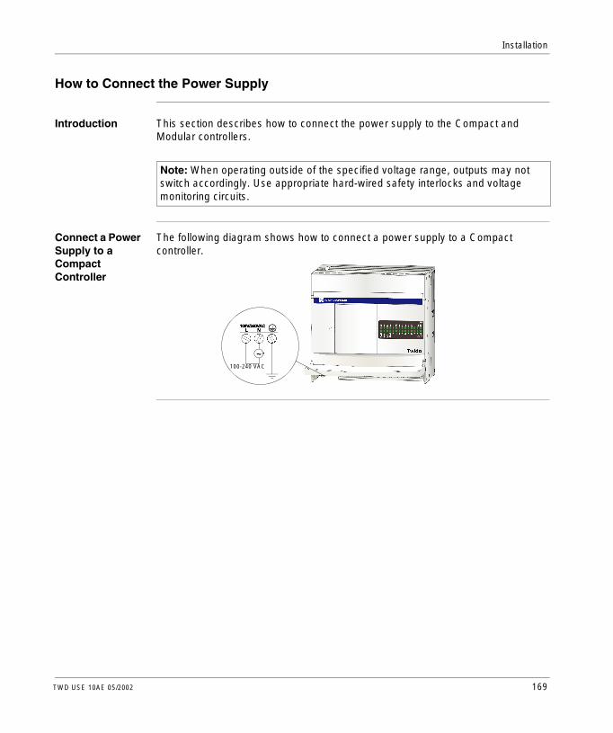
Installation
How to Connect the Power Supply
Introduction This section describes how to connect the power supply to the Compact and Modular controllers.
Connect a Power Supply to a Compact Controller
The following diagram shows how to connect a power supply to a Compact controller.
Note: When operating outside of the specified voltage range, outputs may not switch accordingly. Use appropriate hard-wired safety interlocks and voltage monitoring circuits.
~100-240 VAC
TWD USE 10AE 05/2002 169

Installation
Compact Controller Power Supply Specifications
The following table provides power supply information for the Compact controller.
Connect a Power Supply to a Modular Controller
The following diagram shows how to connect a power supply to a Modular controller.
Item Specifications
Power supply voltage
Rated power voltage: 100 to 240 VACAllowable range: 85 to 264 VACFailure - depends on quantity of used input and output points. Generally, failure is detected when voltage drops below 85 VAC, stopping operation to prevent malfunction.Note: Momentary power interruption for 20 ms or less at 100 to 240 VAC is not recognized as failure.
Inrush current flow at power-up
TWDLCAA10DRF and TWDLCAA16DRF: 35 A maximumTWDLCAA24DRF: 40 A maximum
Power supply wiring
UL1015 AWG22 (0.64 mm2) or UL1007 AWG18 (1.02 mm2)Make the power supply wiring as short as possible.
Ground wiring
UL1007 AWG16 (1.30 mm2)Do not connect ground wire in common with ground wire of motor equipment.
24 VDC
+
-
170 TWD USE 10AE 05/2002

Installation
Modular Controller Power Supply Specifications
The following table provides power supply information for the Modular controller.
Item Specifications
Power supply voltage
Rated power voltage: 24 VDCAllowable range: 20.4 to 26.4 VDCFailure - depends on quantity of used input and output points. Generally, failure is detected when voltage drops below 20.4 VDC, stopping operation to prevent malfunction.Note: Momentary power interruption for 10 ms or less at 24 VDC is not recognized as failure.
Inrush current flow at power-up
50 A maximum
Power supply wiring
UL1015 AWG22 (0.64 mm2) or UL1007 AWG18 (1.02 mm2)Make the power supply wiring as short as possible.
Ground wiring
UL1015 AWG22 (0.64 mm2) or UL1007 AWG18 (1.02 mm2)Do not connect ground wire in common with ground wire of motor equipment.
TWD USE 10AE 05/2002 171

Installation
172 TWD USE 10AE 05/2002

TWD USE 10AE 05/2002
4
Special FunctionsAt a Glance
Introduction This chapter provides an introduction and I/O assignments for the Twido controllers’ special functions. For information on configuring and using these special functions see the Twido Software Reference Guide.
What’s in this Chapter?
This chapter contains the following topics:
Topic Page
RUN/STOP Input 174
Controller Status Output 174
Latching Input 174
Fast Counting 175
Very Fast Counters 176
Pulse (PLS) Generator Output 178
Pulse Width Modulation (PWM) Output 178
173

Special Functions
RUN/STOP Input
Introduction This section provides basic information on the RUN/STOP input special function.
Principle The RUN/STOP input is a special function that can be assigned to any one of the base controller inputs. This function is used to start or stop a program.
Determining the State of Run/Stop Input
At power up, if configured, the controller state is set by the Run/Stop input:l if RUN/STOP input is at state 0, controller is in STOP mode.l if RUN/STOP input is at state 1, controller is in RUN mode.While the controller is powered, a rising edge on the RUN/STOP input state sets the controller to RUN. The controller is stopped if the RUN/STOP input is at 0. If the RUN/STOP input is at 0, a RUN command from a connected PC is ignored by the controller.
Controller Status Output
Introduction This section provides basic information on the controller status output special function.
Principle The controller status output is a special function that can be assigned to one of three outputs (%Q0.0.1 and %Q0.0.3) on a base or a remote controller. At power up, if there is no controller error see Troubleshooting Using the Controller’s LEDs, p. 182, the controller status output changes to 1. This function can be used in safety circuits external to the controller, for example, to control:l The power supply to the output devices.l The controller power supply.
Latching Input
Introduction This section provides basic information on the latching inputs special function.
Principle The latching inputs is a special function that can be assigned to one of four inputs (%I0.0.2 to %I0.0.5) on a base or a remote controller. This function is used to memorize any pulse with a duration less than the controller scan time. When a pulse is shorter than one scan and has a value greater than or equal to 100 µs, the controller latches the pulse, which is then updated in the next scan.
174 TWD USE 10AE 05/2002

Special Functions
Fast Counting
Introduction This section provides basic information on the fast counting special function.
Principle The base controllers have two fast counter types:l A single up counter with a maximum frequency of 5 kHz.l A single down counter with a maximum frequency of 5 kHz.The single up counter and single down counter functions enable counting or down counting of pulses (rising edges) on a digital I/O. Compact controllers can have 3 fast counters. Modular controllers can have 2 fast counters.
Digital I/O Assignment for a Fast Counter
The digital I/O assignment for fast counters depends on whether digital I/O was assigned for the optional pre-set and catch inputs on the very fast counters. See Very Fast Counters, p. 176 for more information.
TWD USE 10AE 05/2002 175

Special Functions
Very Fast Counters
Introduction This section provides basic information on the very fast counting special function.
Principle The base controllers have five very fast counter types:l An up/down counter with a maximum frequency of 20 kHz. l An up/down 2-phase counter with a maximum frequency of 20 kHz.l A single up counter with a maximum frequency of 20 kHz.l A single down counter with a maximum frequency of 20 kHz.l A frequency meter with a maximum frequency of 20 kHz.The up/down counter, up/down 2-phase counter, single up counter, and single down counter functions enable counting of pulses from 0 to 65535. The frequency meter function measures the frequency of a periodic signal in Hz.
Digital I/O Assignment for a Very Fast Counter on all Controllers
The following tables lists the assigned I/O for one very fast counter on all controllers models.
Functions First Input (pulses)
Second Input (pulses or Up/Down)
Preset Input
Catch Input
First Reflex Output
Second Reflex Output
Up/down counter %I0.0.1(pulses)
%I0.0.0* %I0.0.2** %I0.0.3** %Q0.0.2** %Q0.0.3**
Up/down 2-phase counter
%I0.0.1(pulses Phase A)
%I0.0.0(pulses Phase B)
%I0.0.2** %I0.0.3** %Q0.0.2** %Q0.0.3**
Single up counter %I0.0.1(pulses)
Not used %I0.0.2** %I0.0.3** %Q0.0.2** %Q0.0.3**
Single down Counter
%I0.0.1(pulses)
Not used %I0.0.2** %I0.0.3** %Q0.0.2** %Q0.0.3**
Frequency meter %I0.0.1(pulses)
Not used Not used Not used Not used Not used
Note: l * Indicates Up/Downl ** Optional use
176 TWD USE 10AE 05/2002

Special Functions
Digital I/O Assignment for the Other Very Fast Counter on Modular Controllers
The following tables lists the assigned I/O for the other very fast counter on Modular controllers only.
Functions First Input (pulses)
Second Input (pulses or Up/Down)
Preset Input
Catch Input
First Reflex Output
Second Reflex Output
Up/down counter %I0.0.7(pulses)
%I0.0.6* %I0.0.5** %I0.0.4** %Q0.0.4** %Q0.0.5**
Up/down 2-phase counter
%I0.0.7(pulses Phase A)
%I0.0.6(pulses Phase B)
%I0.0.5** %I0.0.4** %Q0.0.4** %Q0.0.5**
Single up counter %I0.0.7(pulses)
Not used %I0.0.5** %I0.0.4** %Q0.0.4** %Q0.0.5**
Single down counter
%I0.0.7(pulses)
Not used %I0.0.5** %I0.0.4** %Q0.0.4** %Q0.0.5**
Frequency meter %I0.0.7(pulses)
Not used Not used Not used Not used Not used
Note: l * Indicates up/downl ** Optional use
TWD USE 10AE 05/2002 177

Special Functions
Pulse (PLS) Generator Output
Introduction This section provides basic information on the PLS special function.
Principle The PLS is a special function that can be assigned to output %Q0.0.0 or %Q0.0.1 on a base or a peer controller. A user-defined function block generates a signal on output %Q0.0.0 or %Q0.0.1. This signal has a variable period but has a constant duty cycle, or on to off ratio of 50% of the period.
Pulse Width Modulation (PWM) Output
Introduction This section provides basic information on the PWM special function.
Principle The PWM is a special function that can be assigned to output %Q0.0.0 or %Q0.0.1 on a base or a peer controller. A user-defined function block generates a signal on output %Q0.00 or %Q0.0.1. This signal has a constant period with the possibility of varying the duty cycle, or on to off ratio. This function can be used to manage analog output modules.
178 TWD USE 10AE 05/2002

TWD USE 10AE 05/2002
5
Powering-Up and TroubleshootingAt a Glance
Introduction This chapter provides the procedure for the first time a controller is powered-up, checking the I/O connections, and troubleshooting the controller using the LEDs.
What’s in this Chapter?
This chapter contains the following topics:
Topic Page
Procedure for First Time Power-Up of a Controller 180
Checking I/O Connections on the Base Controller 181
Troubleshooting Using the Controller’s LEDs 182
179

Power-Up and Troubleshoot
Procedure for First Time Power-Up of a Controller
Introduction This section explains powering-up a controller for the first time.
Power-Up Self Diagnostics
At power-up, the firmware will perform tests to ensure the proper functioning of the controller. Each major hardware component is tested for consistency. This includes the on-board PROM and RAM. Later in the booting sequence, the application is tested, using a checksum, before it can be executed.
First Time Power-Up Procedure
There are four status LEDs that signify the state and condition of the controller. The LED labeled PWR directly monitors the power supplied to the controller. It can not be changed by the application and can not be modified by the executive firmware.The first time the controller is powered up, it will be in a non-configured state with no application programming present. This state is indicated by a blinking ERR LED. If the ERR LED is not blinking or if any of the Input/Output LEDs are illuminated, without the presence of an external signal, see Troubleshooting Using the Controller’s LEDs, p. 182.
180 TWD USE 10AE 05/2002

Power-Up and Troubleshoot
Checking I/O Connections on the Base Controller
Introduction This section provides a procedure for checking the I/O connections.
Checking I/O Connections Procedure
The following procedure ensures that the I/O connections are connected:
WARNING
Unintended operation of external equipment
Avoid unintended operation of external equipment. Make sure that:l Power fuses are removed from the motor controls.l Pneumatic and hydraulic inputs are closed.
Failure to observe this precaution can result in severe injury or equipment damage.
Step Action
1 To test the I/O connections, the controller needs to be in the non-configured state. To accomplish this:l If an Operator Display is attached, press ESC to power cycle the controller.
After the controller restarts, the Operator Displays indicates “NCF”.l From TwidoSoft, issue the erase command from the Controller menu.
2 With the controller in the non-configured state, change system bit %S8 to 0. At state 0, the controller outputs are kept in their existing state.
3 Check the inputs by activating each external sensor. To accomplish this:l Check that each of the input LEDs for the corresponding bit changes state.l Using TwidoSoft's Operate Controller dialog, check that each of the input
LEDs for the corresponding bit changes state.
4 Check the outputs by setting the bit corresponding to each output state to 1. To accomplish this:l Check that each of the output LEDs for the corresponding bit changes state.l Using TwidoSoft's Operate Controller dialog, check that each of the output
LEDs for the corresponding bit changes state.
5 To complete this procedure, change system bit %S8 to 1. This is automatically accomplished by downloading a valid user application.
TWD USE 10AE 05/2002 181

Power-Up and Troubleshoot
Troubleshooting Using the Controller’s LEDs
Introduction This section provides information on the controller’s operating status and troubleshooting using the LEDs.
Status of the Controller
The following table displays the different LED states on a base controller, peer controller, and remote controller.
Status of the Digital I/O Module
LED Status Base Controller or Peer Controller Remote Controller
RUNgreen
Application not executed
Controller is in STOP mode or execution fault
Controller is in RUN mode
Incorrectly or not connected
Same as base controller
Same as base controller
ERRred
OK
Application not executable
Internal faults (watchdog, etc.)
OK
N/A
Same as base controller
STATgreen
Controlled by the user or application through system bit %S69
N/A
Controlled by the user or application through system bit %S69
Same as base controller
N/A
Same as base controller
IlluminatedFlashingOff
LED Status Digital I/O Module
I/O LEDs I/O not active
I/O active
IlluminatedOff
182 TWD USE 10AE 05/2002

TWD USE 10AE 05/2002
6
Agency ComplianceAgency Requirements
Introduction This section provides agency standards for the Twido products.
Standards Twido controllers comply with the main national and international standards concerning electronic industrial control devices.The following are specific controller requirements:l EN61131-2 (IEC61131-2)l UL508l UL1604/CSA 213 Class I Division 2 Groups A, B, C, D
183

Agency Compliance
184 TWD USE 10AE 05/2002

Appendices
At a Glance
Introduction This appendix provides information on common IEC symbols used in this manual.
What’s in this Appendix?
The appendix contains the following chapters:
Chapter Chapter name Page
A IEC Symbols 187
TWD USE 10AE 05/2002 185

Appendices
186 TWD USE 10AE 05/2002

A
IEC Symbols
Glossary of Symbols
Introduction This section contains illustrations and definitions of common IEC symbols used in describing Twido wiring schematics.
TWD USE 10AE 05/2002 187

IEC Symbols
Symbols Common IEC symbols are illustrated and defined in the table below:
Fuse
Load
AC power
DC power
Digital sensor/input, for example, contact, switch, initiator, light barrier, and so on.
Earth ground
2-wire sensor
Thermocouple element
L
~+ _
+_
+_ +_
188 TWD USE 10AE 05/2002

Glossary
Analog Potentiometer
Can be used to preset a value for an analog timer. All Modular controllers and Compact 10 and 16 I/O controllers have one potentiometer. The Compact 24 I/O controller has two.
Analog Voltage Input Connector
Connects an analog voltage source of 0 through 10 VDC. The analog voltage is converted to a digital value and is stored in a system word.
Cartridge Connector
A connector to attach an optional memory cartridge or an RTC.
Catch Input Ensures reception of short input pulses (rising pulse of 40 µs or falling pulse of 150 µs minimum) from sensors without regard to the scan time.
Communication Adapter
An optional cartridge that can be attached to any Compact controller or Operator Display Expansion Module to provide an optional Serial Port 2.
Communication Expansion Module
An optional module that can be attached to any Modular controllers communications expansion bus to provide an optional Serial Port 2.
A
C
TWD USE 10AE 05/2002 189

Glossary
Controller Status Output
A special function. This function is used in safety circuits, external to the controller, to control the power supply to the output devices or the controller power supply.
ERR LED An LED that illuminates when an error occurs in the controller.
Expansion Connector
A connector to attach expansion I/O modules.
Expansion Cover A cover to protect the expansion connector.
Expansion I/O Module
Either a digital or analog module that adds additional I/O to the base controller.
Fast Counting A special function, it is available as a single up counter and single down counter. These functions enable up counting or down counting of pulses (rising edges) on a digital I/O. Compact controllers can have three fast counters. Modular controllers can have two fast counters.
Free Wire The end of a digital I/O cable that does not have a connector. The internal wires are exposed. This scheme provides connectivity from Modular I/O to discrete I/O points.
I/O Input/Output.
I/O Terminals Terminals on all Modular controllers and expansion I/O modules used to connect input and output signals. The input terminals accept both sink and source DC input signals. The output terminals are either transistor source or sink or relay contacts.
IN LED An LED that illuminates when a corresponding input is on. All modules have IN Leds.
E
F
I
190 TWD USE 10AE 05/2002

Glossary
Input Filter A special function that rejects input noises. This function is useful for eliminating input noises and chatter in limit switches. All inputs provide a level of input filtering using the hardware. Additional filtering using the software is also configurable through TwidoSoft.
Input Simulators An optional accessory for Compact controllers that is used for debugging. It can simulate input sensors to test application logic.
Input Terminals Terminals on the top of all Compact controllers used to connect input signals from input devices such as sensors, push buttons, and limit switches. The input terminals accept both sink and source DC input signals.
Latching Input A special function. This function is used to memorize any pulse with a duration less than the controller scan time. When a pulse is shorter than one scan and has a value greater than or equal to 100 s, the controller latches the pulse, which is then updated in the next scan.
Memory Cartridge
An optional cartridge available in two sizes: 32 KB and 64 KB (64 KB not available on Compact). It can be added to any controller for removable backup of applications or to load an application, if certain conditions exist.
Modbus Master Mode
Allows the controller to initiate a Modbus query transmission, with a response expected from a Modbus slave.
Modbus Slave Mode
Allows the controller to respond to Modbus queries from a Modbus master and is the default communications mode if no communication is configured.
Operator Display Expansion Module
An optional module that can be attached to any Modular controller to display program information.
L
M
O
TWD USE 10AE 05/2002 191

Glossary
Operator Display Module
An optional module that can be attached to any Compact controller to display program information.
OUT LED An LED that illuminates when a corresponding output is on. All modules have OUT Leds.
Output Terminals
Terminals on the bottom of all Compact controllers used to connect output signals from output devices such as electromechanical relays and solenoid valves. The internal output relay contact is rated up to 240 VAC/2A or 30 VDC/2A.
PLS A special function. This user-defined function block generates a signal on output %Q0.0.0 or %Q0.0.1. This signal has a variable period but has a constant duty cycle, or on to off ratio of 50% of the period.
Power Supply Terminals
The power supply is connected to these terminals to provide power to the controller. The power voltage for a Compact controller is 100-240 VAC and 24 VDC for a Modular controller.
PWM A special function. This user-defined function block generates a signal on output %Q0.00 or %Q0.0.1. This signal has a constant period with the possibility of varying the duty cycle, or on to off ratio. This function can be used to manage analog output modules.
PWR LED An LED that illuminates when power is supplied to the controller.
Removable Cover
A cover on all Compact controllers that can be removed to install an optional Operator Display.
RTC Real-Time Clock.
RUN LED An LED that illuminates when the controller is executing a program.
P
R
192 TWD USE 10AE 05/2002

Glossary
Sensor Power Terminals
Supplies power to the field side sensors (24 VDC, 250 mA). Output terminals are only intended for input devices and should not be used as a source for driving external loads.
Serial Port 1 An EIA RS-485 connector used to download and monitor the controller operation using TwidoSoft. Can also be configured as EIA RS-232.
Serial Port 2 An optional port that can be configured as either EIA RS-232 or EIA RS-485.
STAT LED An LED that blinks on and off to indicate a specific status of the user program.
Terminal Cover A cover on all Compact controllers to protect the input and output terminals.
Very Fast Counting
A special function it is available as an up/down counter, an up/down 2-phase counter, a single up counter, a single down counter, and frequency meter. The counter functions enable counting of pulses from 0 to 65535. The frequency meter function measures the frequency of a periodic signal in Hz.
S
T
V
TWD USE 10AE 05/2002 193

Glossary
194 TWD USE 10AE 05/2002

CBAIndex
AAccessories, 18Adding a second serial port
Compact, 153Modular, 154
Agency requirements, 183Analog I/O modules
Input specifications, 98Mounting positions, 144Output specifications, 101Overview, 95Parts description, 96Specifications, 17, 97Wiring schematics, 103
Analog potentiometers, 34Parts description, 49
Analog voltage input, 23Overview, 50
ASCII protocol, 26Assembling
Communication expansion module, 153Operator display expansion module, 151
BBuilt-in functions
Compact specifications, 38Modular specifications, 55
TWD USE 10AE 05/2002
CCables, 14, 19, 120Checking I/O connections, 181Communication adapters
Installing in a Compact, 153Installing in a operator display expansion module, 154Overview, 107Parts description, 108Specifications, 110
Communication architecture, 25Communication expansion modules
Assembling to a Modular, 155Dimensions, 140Disassembling from a Modular, 156Mounting hole layout, 166Overview, 107Parts description, 109Specifications, 110
Communication functionsCompact specifications, 38Modular specifications, 54
CompactConnect a power supply, 169DC input specifications, 39Dimensions, 132I/O usage limits, 41Input internal circuit, 40Installing a communication adapter, 153Installing a memory cartridge, 157
195

Index
Installing an operator display module, 149Installing an RTC, 157Minimum clearance, 167Mounting hole layout, 163Normal operating specifications, 36Operating range, 40Output delay, 42Overview, 33Parts description, 35Power supply specifications, 37, 170Relay output contact, 43Relay output specifications, 42Wiring schematics, 44
ConfigurationCompact, 20Hardware, 20Modular, 20
Connect a power supplyCompact, 169Modular, 170
Controller status output, 174Controllers
Analog potentiometers, 34Assembling to a communication expansion module, 155Assembling to an expansion I/O module, 146Compact, 14Dimensions, 132, 134Disassembling from a communication expansion module, 156Disassembling from an expansion I/O module, 148Functions, 22Installing a communication adapter, 153Installing in a DIN rail, 161Minimum clearance, 167Modular, 14Mounting positions, 144Parts description, 35, 51Removing from a DIN rail, 162Specifications, 15Status, 182Wiring schematics, 44, 62
196
CountersFast counters, 175Very fast, 176
DDedicated function blocks, 23Determining the state of Run/Stop input, 174Digital I/O assignment
Controller status output, 174Fast counters, 175Latching input, 174PLS, 178PWM, 178RUN/STOP input, 174Very fast counters, 176, 177
Digital I/O cables, 14Digital I/O modules
Dimensions, 136, 137, 138I/O usage limits, 75, 81Input internal circuit, 81Internal circuit, 74Mounting positions, 144Operating range, 74, 81Output delay, 77, 82Overview, 68Parts description, 71Relay output contact, 82Specifications, 16, 73, 76, 78, 79, 80, 82Status, 182Transistor sink output contact, 83Transistor source output contact, 83Wiring schematics, 84
DimensionsCommunication expansion module, 140Controller, 134Digital I/O modules, 136, 137, 138Modular, 134Operator display expansion module, 139Operator display module, 139
DisassemblingCommunication expansion module, 153
TWD USE 10AE 05/2002

Index
EExecution time, 23Expansion I/O modules
Assembling to a controller, 146Disassembling from a controller, 148Mounting hole layout, 165
Expansion I/O Modules Analog I/O modules, 73Expansion I/O Modules Digital I/O modules, 73
FFast counters, 175First time power-up procedure, 180
II/O connections
Checking, 181I/O modules
Analog, 14Digital, 14
I/O specificationsCompact controller, 39
I/O usage limitsCompact controllers, 41Digital I/O modules, 75, 81Modular controllers, 58
IEC symbols, 187Input internal circuit
Compact controllers, 40Digital I/O modules, 81Modular controllers, 57
Input simulatorsOverview, 117
Installation in a DIN rail, 161Installation preparation, 143Installing
Communication adapter, 153Memory cartridge, 157Operator display module, 149
Internal circuitDigital I/O modules, 74
TWD USE 10AE 05/2002
LLatching input, 174LED
Status, 182
MMain functions, 22Maximum hardware configuration, 20Memory capacity, 23Memory cartridge
Installing in a Compact, 157Installing in a Modular, 158Overview, 117Specifications, 118
Minimum clearanceCompact, 167Controllers, 167Modular, 168
ModbusMaster mode, 26Protocol, 26Slave mode, 26
ModularAssembling to a communication expansion module, 155Connect a power supply, 170DC input specifications, 56Dimensions, 134Disassembling from a communication expansion module, 156
197

Index
I/O usage limits, 58Input internal circuit, 57Installing a memory cartridge, 158Installing an RTC, 158Minimum clearance, 168Mounting hole layout, 164Normal operating specifications, 52Operating range, 57Output delay, 60Overview, 47Parts description, 51Power supply specifications, 53, 171Relay output contact, 61Relay output specifications, 60Removing the terminal block, 159Transistor sink output specifications, 59Transistor source output contact, 61Transistor source output specifications, 59Wiring schematics, 62
Modular controllersTransistor sink output contact, 61
Mounting hole layoutCommunication expansion modules, 166Compact controller, 163Expansion I/O modules, 165Modular controller, 164Operator display expansion module, 166
OOperating range
Compact controllers, 40Digital I/O modules, 74, 81Modular controllers, 57
Operator display expansion moduleAssembling, 151Dimensions, 139Installing a communication adapter, 154Mounting hole layout, 166Overview, 112Parts description, 114Specifications, 115
198
Operator display moduleDimensions, 139Installing in a Compact, 149Overview, 112Parts description, 113Specifications, 115
Options, 14Communication adapters, 18Communication expansion modules, 18Connectors, 18Input simulators, 18Memory cartridges, 18Operator display expansion module, 18Operator display module, 18Overview, 117RTC, 18Specifications, 118Terminal blocks, 18
Output delayCompact controllers, 42Digital I/O modules, 77, 82Modular controllers, 60
OverviewAnalog I/O module, 95Communication adapters, 107Communication expansion modules, 107Compact, 33Digital I/O module, 68Input simulators, 117Memory cartridge, 117Modular, 47Operator display expansion module, 112Operator display module, 112Options, 117RTC, 117
PParts description
Analog I/O modules, 96Analog potentiometer on Compact controller, 34
TWD USE 10AE 05/2002
Index
Analog potentiometer on Modular controller, 49Communication adapters, 108Communication expansion modules, 109Controllers, 51Digital I/O modules, 71Modular, 51Operator display expansion module, 114Operator display module, 113
PLS, 178Potentiometers, 23Power supply
Specifications, 170, 171Power-up self diagnostics, 180Programming cables, 14, 19Programming port, 23Protocols, 25Pulse generator output, 178Pulse width modulation, 178PWM, 178
RRAM backup, 23Read before starting, 143Relay output contact
Compact controllers, 43Digital I/O modules, 82Modular controllers, 61
Remote controllers, 23Remote link protocol, 25Removing
Terminal block, 159RTC
Installing in a Compact, 157Installing in a Modular, 158Overview, 117Specifications, 118
RUN/STOP input, 174
SScanning, 23Single counter
Down, 175Up, 175
TWD USE 10AE 05/2002
Special functionsController status output, 174Fast counters, 175Latching input, 174PLS, 178PWM, 178RUN/STOP input, 174Very fast counters, 176
Special I/O, 24Specifications
Analog I/O module input, 98Analog I/O module output, 101Analog I/O modules, 17, 97Communication adapters, 110Communication expansion modules, 110Compact built-in functions, 38Compact communication functions, 38Compact DC input, 39Compact normal operating, 36Compact power supply, 37Compact relay output, 42Controllers, 15Digital I/O modules, 16, 73, 76, 78, 79, 80, 82Memory cartridges, 118Modular built-in functions, 55Modular communication functions, 54Modular DC input, 56Modular normal operating, 52Modular power supply, 53Modular relay output, 60Modular transistor sink output, 59Modular transistor source output, 59Operator display expansion module, 115Operator display module, 115Power supply, 170, 171RTC, 118
Standards, 183Starting, 143Status
Controller, 182Digital I/O module, 182LED, 182
Symbols, 187
199
Index
TTeleFast
Bases, 120Cable systems, 14, 120Dimensions, 141Specifications, 122Wiring schematics, 123
Transistor sink output contactDigital I/O modules, 83Modular controllers, 61
Transistor source output contactDigital I/O modules, 83Modular controllers, 61
Troubleshooting, 180Using LEDs, 182
UUnintended operation of external equipment, 181
VVery fast counters, 176
WWiring schematics
Analog I/O modules, 103Compact, 44Controller, 44, 62Digital I/O modules, 84Modular, 62TeleFast bases, 123
200
TWD USE 10AE 05/2002