Venting Controllers/Positioners – understanding natural gas ...
Upload
khangminh22Category
view
0download
0
MICROLOGIX PROGRAMMABLE CONTROLLERS
SELECTION GUIDE
BULLETIN 1761 - MicroLogix 1000
BULLETIN 1763 - MicroLogix 1100
BULLETIN 1762 - MicroLogix 1200
BULLETIN 1766 - MicroLogix 1400
BULLETIN 1764 - MicroLogix 1500


Publication 1761-SG001F-EN-P - March 2011
MicroLogix Programmable Controllers Overview 3
MicroLogix Programmable Controllers Overview
The MicroLogix family of controllers provides five levels of control. Small on size, big on performance, the MicroLogix 1000 controller offers control capabilities in an affordable, compact package. The MicroLogix 1200 controller is small enough to fit in tight spaces, but powerful enough to accommodate a broad range of applications. Designed to grow as your needs grow, the MicroLogix 1500 controller helps you achieve high-level control in a variety of applications. The MicroLogix family’s newest members, the MicroLogix 1100 and 1400 controllers, further enhance the MicroLogix family by expanding the application coverage area while offering great new features at an affordable price.
MicroLogix 1000 Controller
Based on the architecture of the market-leading SLC 500 controller family, the MicroLogix 1000 controller brings high-speed, powerful instructions and flexible communication to applications that demand compact, cost-effective solutions.
The MicroLogix 1000 controller is available in 10-point, 16-point, or 32-point digital I/O versions. Analog versions are also available with 20 digital I/O points, with 4 analog inputs (2 voltage and 2 current) and 1 analog output (configurable for either voltage or current).
The analog I/O circuitry for the MicroLogix 1000 controller is embedded into the base controller, not accomplished through add-on modules: so, it provides very high-speed, cost-effective analog performance.
The MicroLogix 1000 controller uses Rockwell Software RSLogix 500 and RSMicro programming software and shares a common instruction set with the MicroLogix and SLC 500 families of controllers.

Publication 1761-SG001F-EN-P - March 2011
4 MicroLogix Programmable Controllers Overview
Advantages for the MicroLogix 1000 Controllers
• Preconfigured 1 KB program and data memory to ease configuration (for example, preconfigured bit, integer, timers, and counters).
• Fast processing allows for typical throughput time of 1.5 ms for a 500-instruction program.
• Built-in EEPROM memory retains all of your ladder logic and data if the controller loses power, eliminating the need for battery back-up or separate memory module.
• Multiple input commons lets you use the controller for either sinking or sourcing input devices and multiple output commons provide isolation in multi-voltage output applications.
• RS-232 communication channel allows for simple connectivity to a personal computer for program upload, download, and monitoring by using multiple protocols, including DF1 full-duplex.
• RTU slave protocol supports using DF1 half-duplex allows up to 254 slave nodes to communicate with a single master by using radio modems, leased-line modems, or satellite uplinks.
• Peer-to-peer messaging capability that lets you network up to 32 controllers on a DH-485 network by (using a 1761-NET-AIC module).
• Advanced communication networks, including DeviceNet and EtherNet/IP, through the 1761-NET-DNI and 1761-NET-ENI communication modules.
• Controllers that have 24V DC inputs include a built-in, high-speed counter (6.6 kHz).• Adjustable DC input filters let you customize the input response time and noise
rejection to meet your application needs.• Regulatory agency certifications for world-wide market (CE, C-Tick, UL, and c-UL,
including Class I Division 2 Hazardous Location).

Publication 1761-SG001F-EN-P - March 2011
MicroLogix Programmable Controllers Overview 5
MicroLogix 1100 Controller
The MicroLogix 1100 controller is designed to broaden application coverage through embedded analog inputs, Ethernet communication, and visualization capabilities. MicroLogix 1100 controllers maintain the same critical features you have come to expect from the MicroLogix family, and expand that capability to include true online editing. MicroLogix 1100 controllers complement our low-end controllers for applications that require up to 144 digital I/O.
Each MicroLogix 1100 controller contains 2 embedded analog inputs, with 10 digital inputs and 6 digital outputs. The controller can also expand its I/O capabilities by using the same modules as the MicroLogix 1200 controller. Up to four of the 1762 I/O modules can be used with a single MicroLogix 1100 controller.
Using the latest version of our world-class RSLogix 500 programming software, the MicroLogix 1100 controller can be programmed with an instruction set that is common with the MicroLogix and SLC 500 families of controllers. RSLogix 500 Starter, Standard, and Professional applications all support the MicroLogix 1100 controller, including its online editing capabilities. In addition, the new RSLogix Micro Starter and Developer software provide MicroLogix only programming at a lower cost.
Each controller supports a built-in RS-232/RS-485 combo port for serial and networked communication and a second built-in EtherNet/IP port, which supports Ethernet peer-to-peer messaging.
An embedded LCD screen lets you monitor controller and I/O status, as well as make changes to bit and integer data.
Advantages for the MicroLogix 1100 Controllers
• Large 8 KB memory (4 KB user program with 4 KB user data) to solve a variety of applications.
• True online editing allows tuning of program, including PID, without going offline.• Support for MicroLogix 1100 controller online editing in all current versions of
RSLogix 500 and RSLogix Micro Starter and Developer software.• Mode switch for Run/Remote/Program.• Time-based or event-triggered data logging capability stores controller data records
with optional time stamp in a separate 128 Kbyte memory area for later analysis (for example, trending and I/O status during alarm condition data).
• Recipe storage (up to 64 KB that is deducted from Data Logging memory) that is accessible by your ladder program, enabling quick and easy batch changes of program data for timers, counters, and other data types.
• High performance expansion I/O options (up to four 1762 I/O modules, in any combination).
• Four high-speed inputs (except 1763-L16AWA controller) that can be used individually as latching (pulse-catch) inputs, event interrupts, or alternately combined as one 40 kHz high-speed counter featuring 8 modes of operation.
• Two built-in 0...10V DC analog inputs with 10-bit resolution (not isolated).

Publication 1761-SG001F-EN-P - March 2011
6 MicroLogix Programmable Controllers Overview
• Two high-speed outputs that can be configured as 40 kHz pulse train output (PTO) or as pulse width modulated (PWM) outputs (catalog number 1763-L16BBB only).
• Multiple input commons let you use the controller for either sinking or sourcing input devices, and multiple output commons provide individual isolation in multi-voltage output applications.
• One, 1 ms, selectable timed interrupt (STI).• High-resolution, 1 ms timers.• Communication Channel 0 provides isolated RS-232 or RS-485 electrical
compatibility (selectable through the choice of communication cables).• Through RS-232, we support all serial protocols.• Through RS-485, we support direct interface to DH-485, DF1 half-duplex
master/slave, ASCII, and Modbus RTU master/slave networks (without an external electrical interface converter).
• Communication Channel 1 consists of an embedded RJ45 port that supports EtherNet/IP network for peer-to-peer messaging. This 10/100 Mbps port supports BOOTP and DHCP.
• Communication toggle selection that allows the controller's Channel 0 port to toggle between user-configured communication parameters and factory default settings for an easy way to switch from Modbus RTU or ASCII protocols (which do not support programming) to DF1 full-duplex (to upload/download, monitor, or edit your program). So a programming computer is able to connect to a controller with an unknown or incorrect communication-parameter settings for troubleshooting.
• Embedded real-time clock.• Embedded web server with email functionality.• Optional memory module for external program backup, for program transport, and
transfer to another controller. Program and data in the controller is also battery backed for secure storage.
• Data file download protection prevents critical user data from being altered via program downloads from programming computers or memory modules.
• Built-in LCD provides access to 48 bits and 48 integers that can be changed, or optionally protected, for monitor only access by an operator.
• LCD instruction allows the controller to output messages to the LCD, and optionally receive user input.
• IP address can be monitored directly through the built-in LCD.• Two built-in digital trim potentiometers.• 32-bit signed integer math.• Floating-point and double-integer data file support.• Built-in PID capabilities.• Finger-safe terminal blocks meet global safety standards.• Regulatory agency certifications for world-wide market (CE, C-Tick, UL, and c-UL,
including Class 1 Division 2 Hazardous Location).

Publication 1761-SG001F-EN-P - March 2011
MicroLogix Programmable Controllers Overview 7
MicroLogix 1200 Controller
The MicroLogix 1200 controller provides more computing power and flexibility than the MicroLogix 1000 controller to solve a variety of application needs.
Available in 24- and 40-point versions, the I/O count can be expanded by using rackless I/O modules. This results in larger control systems, greater application flexibility and expandability at a lower cost and reduced parts inventory.
A field-upgradable flash operating system that helps to make sure you will always be up-to-date with the latest features, without having to replace hardware. The controller can be easily updated with the latest firmware via a website download.

Publication 1761-SG001F-EN-P - March 2011
8 MicroLogix Programmable Controllers Overview
Advantages for the MicroLogix 1200 Controller
• Large 6 KB memory (4 KB User Program with 2 KB User Data) to solve a variety of applications.
• High performance expansion I/O options (up to six modules depending on current/power budget).
• Four high-speed inputs (for controllers with 24V DC inputs) that can be used individually as latching (pulse-catch) inputs, event interrupts,or alternately combined as one 20 kHz high-speed counter featuring eight modes of operation.
• One high-speed output that can be configured as 20 kHz pulse train output (PTO) or as pulse width modulated (PWM) output (availableon controllers with embedded 24V DC outputs).
• One, 1 ms, selectable timed interrupt (STI).• High-resolution, 1 ms timers.• The same advanced communication options as the MicroLogix 1000 controller,
including peer-to-peer and SCADA/RTU networks, DF1 full-duplex, DF1 half-duplex slave, DH-485, DeviceNet and EtherNet/IP , plus DF1 half-duplex master, Modbus master and slave, and DF1 radio modem protocols.
• ASCII read/write capability.• An additional Programming/HMI Port, providing connectivity to a DF1 full-duplex
compatible device such as an operator interface or programming terminal (MicroLogix 1200R controllers only, catalog number 1762-LxxxxxR).
• Communication toggle pushbutton that allows the controller's Channel 0 port to toggle between user configured communication parameters and factory default settings for an easy means to switch from Modbus RTU or ASCII protocols (which do not support programming) to DF1 full-duplex (to upload/download, monitor, or edit your program), so a programming computer is able to connect to a controller with an unknown or incorrect communication parameter settings for troubleshooting.
• Optional real-time clock, to allow control to be based on actual time of day, day of week, or other calendar related timing.
• Optional memory module, for external program backup, transport and transfer to another controller. Control program and data are securely backed up to internal flash memory when power is not applied.
• Data file download protection prevents critical user data from being altered via program downloads from programming computers or memory modules.
• Two built-in analog trim potentiometers.• 32-bit signed integer math.• Floating-point and double integer data file support.• Built-in PID capabilities.• Finger-safe terminal blocks meet global safety standards.• Removable terminal blocks on 40-point controllers allow pre-wiring.• Regulatory agency certifications for world-wide market (CE, C-Tick, UL, c-UL,
including Class 1 Division 2 Hazardous Location).

Publication 1761-SG001F-EN-P - March 2011
MicroLogix Programmable Controllers Overview 9
MicroLogix 1400 Controller
The MicroLogix 1400 controller is our newest family of controllers to join the popular MicroLogix 1000, MicroLogix 1100, MicroLogix 1200, and MicroLogix 1500 controllers, and is designed to broaden application coverage through available embedded analog inputs, Ethernet communication, faster high-speed counter (HSC), and pulse train output (PTO) capabilities. MicroLogix 1400 controllers maintain the same critical features you have come to expect from the MicroLogix 1100 controller, and expands that capability with more I/O, faster HSC/PTO, and an additional serial port. MicroLogix 1400 controllers complement our low-end controllers for applications that require up to 256 digital I/O.
Each MicroLogix 1400 controller includes 20 digital inputs and 12 digital outputs. In addition, several models include 4 embedded analog inputs and 2 embedded analog outputs. The controller can also expand its I/O capabilities by using the same modules as the MicroLogix 1100 and 1200 controllers. Up to 7 of the 1762 I/O modules can be used with a single MicroLogix 1400 controller.
Using the latest version of our world-class RSLogix 500 programming software, the MicroLogix 1400 controller can be programmed with an instruction set that is common with the MicroLogix 1000, MicroLogix 1100, MicroLogix 1200, MicroLogix 1500, and SLC 500 families of controllers. RSLogix 500 Starter, Standard, and Professional applications, as well as RSLogix Micro software, all support the MicroLogix 1400 controller, including its online editing capabilities.
Each controller has 2 serial ports with DF1/DH485/Modbus RTU/DNP3/ASCII protocol support and a built-in Ethernet port, which supports EtherNet/IP, Modbus TCP/IP and DNP3 over IP.
An embedded LCD screen lets you monitor controller and I/O status, as well as make changes to bit and integer data.

Publication 1761-SG001F-EN-P - March 2011
10 MicroLogix Programmable Controllers Overview
Advantages for the MicroLogix 1400 Controller
• Large memory (10 KB user program with 10 KB user data) to solve a variety of applications.
• True online editing allows tuning of program, including PID, without going offline.• Support for MicroLogix 1400 controller online editing in RSLogix 500 Professional,
Standard, and Starter software version 8.1 and later, as well as RSLogix Micro. • Mode switch for Run/Remote/Program through LCD keypad operation.• Time-based or event-triggered data logging capability stores controller data records
with optional time stamp in a separate 128 Kbyte memory area for later analysis (for example, trending and I/O status during alarm condition data).
• Recipe storage (up to 64 KB that is deducted from Data Logging memory) that is accessible by your ladder program, enabling quick and easy batch changes of program data for timers, counters, and other data types.
• High performance expansion I/O options (up to seven 1762 I/O modules, in any combination).
• Twelve high-speed inputs (except 1766-L32AWA and 1766-L32AWAA controllers) that can be used individually as latching (pulse-catch) inputs, event interrupts, or alternately combined as three 100 kHz high-speed counters featuring 10 modes of operation.
• Two available built-in 0...10V DC analog outputs (for controllers with analog I/O options) with 12-bit resolution (not isolated).
• Three high-speed outputs that can be configured as 100 kHz pulse train output (PTO) or 40 kHz as pulse width modulated (PWM) outputs (only on 1766-L32BXB and 1766-L32BXBA controllers).
• Multiple input commons let you use the controller for either sinking or sourcing input devices, and multiple output commons provide individual isolation in multi-voltage output applications.
• One, 1 ms, selectable timed interrupt (STI).• High-resolution, 1 ms timers.• Communication Channel 0 provides isolated RS-232 or RS-485 electrical
compatibility (selectable through the choice of communication cables).• Through RS-232, we support all serial protocols.• Through RS-485, we support direct interface to DH-485, DF1 half-duplex
master/slave, ASCII, and Modbus RTU master/slave networks, DNP 3 slave using the 1763-NC interface (1761-NET-AIC interface is not required).
• Communication Channel 1 consists of an embedded RJ45 port that supports EtherNet/IP, Modbus TCP/IP and DNP3 over IP. This 10/100 Mbps port supports BOOTP and DHCP.
• Communication channel 2 provides a 9-pin, non-isolated RS-232 port supporting all serial protocols.
• Communication toggle selection that allows the controller's Channel 0 port to toggle between user-configured communication parameters and factory default settings for an easy way to switch from Modbus RTU or ASCII protocols (which do not support programming) to DF1 full-duplex (to upload/download, monitor, or edit your program). So a programming computer is able to connect to a controller with an unknown or incorrect communication-parameter settings for troubleshooting.
• Embedded real-time clock.• Embedded web server with email functionality.
Publication 1761-SG001F-EN-P - March 2011
MicroLogix Programmable Controllers Overview 11
• Optional memory module for external program backup, for program transport, and transfer to another controller. Program and data in the controller is also battery backed for secure storage.
• Data file download protection prevents critical user data from being altered via program downloads from programming computers or memory modules.
• Built-in LCD provides access to binary and integer files that can be changed, or optionally protected, for monitor only access by an operator.
• LCD instruction allows the controller to output messages to the LCD, and optionally receive user input.
• IP address can be monitored and configured directly through the built-in LCD.• Two built-in digital trim potentiometers.• 32-bit signed integer math.• Floating-point and double-integer data file support.• Built-in PID capabilities.• Finger-safe removable terminal blocks meet global safety standards.• Customizable OEM logos on the LCD display.• Regulatory agency certifications for world-wide market (CE, C-Tick, cUL, and UL
including Class 1 Division 2 Hazardous Location, where product is marked(1)).
(1) See the Product Certification link at http://www.ab.com for Declaration of Conformity, Certificates, and other certification details.
Publication 1761-SG001F-EN-P - March 2011
12 MicroLogix Programmable Controllers Overview
MicroLogix 1500 Controller
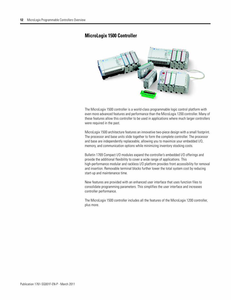
The MicroLogix 1500 controller is a world-class programmable logic control platform with even more advanced features and performance than the MicroLogix 1200 controller. Many of these features allow this controller to be used in applications where much larger controllers were required in the past.
MicroLogix 1500 architecture features an innovative two-piece design with a small footprint. The processor and base units slide together to form the complete controller. The processor and base are independently replaceable, allowing you to maximize your embedded I/O, memory, and communication options while minimizing inventory stocking costs.
Bulletin 1769 Compact I/O modules expand the controller’s embedded I/O offerings and provide the additional flexibility to cover a wide range of applications. This high-performance modular and rackless I/O platform provides front accessibility for removal and insertion. Removable terminal blocks further lower the total system cost by reducing start-up and maintenance time.
New features are provided with an enhanced user interface that uses function files to consolidate programming parameters. This simplifies the user interface and increases controller performance.
The MicroLogix 1500 controller includes all the features of the MicroLogix 1200 controller, plus more.

Publication 1761-SG001F-EN-P - March 2011
MicroLogix Programmable Controllers Overview 13
Advantages for the MicroLogix 1500 Controller(in addition to MicroLogix 1200 controller features)
• Large memory to solve a variety of applications. 1764-LSP: 7 KB user program capacity (3.65 KB User Program with 4 KB User Data)1764-LRP:14 KB user program capacity (10 KB User Program with 4 KB User Data)
• Mode switch for Run/Remote/Program.• MicroLogix 1500 controllers using the 1764-LRP processor, can perform time based or
event triggered data logging. This allows the controller to store data records with optional time stamp in a separate 48 Kbyte memory area for later analysis (for example, trending and I/O status during alarm condition data).
• Recipe storage (up to 48 KB that is deducted from Data Logging memory), that is accessible by your ladder program, enabling quick and easy batch changes of program data for timers, counters, and other data types.).
• High performance expansion I/O options (up to 16 modules by using an additional bank of expansion I/O and expansion power supply).
• There is an additional Channel 1 configurable isolated RS-232 communication port on the 1764-LRP processor (for peer-to-peer and SCADA/RTU networks, DH-485, DeviceNet and EtherNet/IP).
• Battery for nonvolatile user program and user data (built-in and optional replacement).
• Optional data access tool (1764-DAT) allows a user to change integer and bit values within the controller, or optionally protect these elements for monitor only.
• Eight high-speed inputs (for controllers with 24V DC inputs) that can be used individually as latching (pulse-catch) inputs, event interrupts, or alternately combined in groups of four (0...3, and 4...7) as two 20 kHz high-speed counters featuring eight modes of operation.
• Two high-speed outputs that can be configured as 20 kHz pulse train output (PTO) or as pulse width modulated (PWM) outputs (available on controllers with embedded 24V DC outputs).
• Removable terminal blocks on all MicroLogix 1500 base units and I/O modules enable pre-wiring.

Publication 1761-SG001F-EN-P - March 2011
14 MicroLogix Controller System-selection Checklist
MicroLogix Controller System-selection Checklist
Use the following checklist as a guide to completing your own system specification. Skip any sections that do not apply.
✔ Step See
1 Select Family: MicroLogix 1000, 1200 or 1500 Controller
• controller family - based on memory, I/O, added functionality, programming instructions and dimensions
• consider future expansion requirements• consider requirement for online editing• consider the need for networked communication
page 17
Select Family: MicroLogix 1100 or 1400 Controller
• controller family - based on memory, I/O, added functionality, programming instructions and dimensions
• consider future expansion requirements• consider requirement for online editing• consider the need for networked communication
page 21
2 Select Communication
• communication network - based on application requirementscommunication network - based on application requirements
• communication interface device - if required
page 33
3 Select Programming Tools and Software
• programming tools - hand-held programmer with optional memory module (available for MicroLogix 1000 only)
• software - the appropriate RSLogix package for your application
page 38
4 Select Network and Programming Cablescables - review device port identification to find cable in the selection chart)
page 39
5 Select MicroLogix 1000 Controllerscontroller - review power and I/O configurations to select a controller catalog number; see power
supply and I/O specification for more detailed information
page 41
6 Select MicroLogix 1100 Controllers
• controller - review power and I/O configurations to select a controller catalog number; see power supply and I/O specification for more detailed information
• accessories - memory modules
page 46
7 Select MicroLogix 1100 Expansion I/OI/O modules - digital, analog, and temperature
page 50
8 Select MicroLogix 1200 Controllers
• controller - review power and I/O configurations to select a controller catalog number; see power supply and I/O specifications for more detailed information
• accessories - memory and real-time clock modules
page 58
9 Select MicroLogix 1200 Expansion I/O
• I/O modules - digital, analog, and temperature• perform system expansion calculations
page 61
10 Select MicroLogix 1400 Controllers
• I/O modules - digital, analog, and temperature• perform system expansion calculations
page 64
11 Select MicroLogix 1400 Expansion I/OI/O modules - digital, analog, and temperature
page 69
12 Select MicroLogix 1500 Controllers
• base unit - review power and I/O configurations to select a catalog number; see power supply and I/O specifications for more detailed information
• processor - see notes at Step 1• accessories - data access tool; real-time clock and memory modules
page 70
13 Select MicroLogix 1500 System Expansion Components
• I/O modules - digital, analog, temperature and high-speed counter• communication modules - DPI SCANport and DeviceNet• power supplies, cables and end caps• perform system expansion calculations
page 74
Publication 1761-SG001F-EN-P - March 2011
MicroLogix Controller System-selection Checklist 15
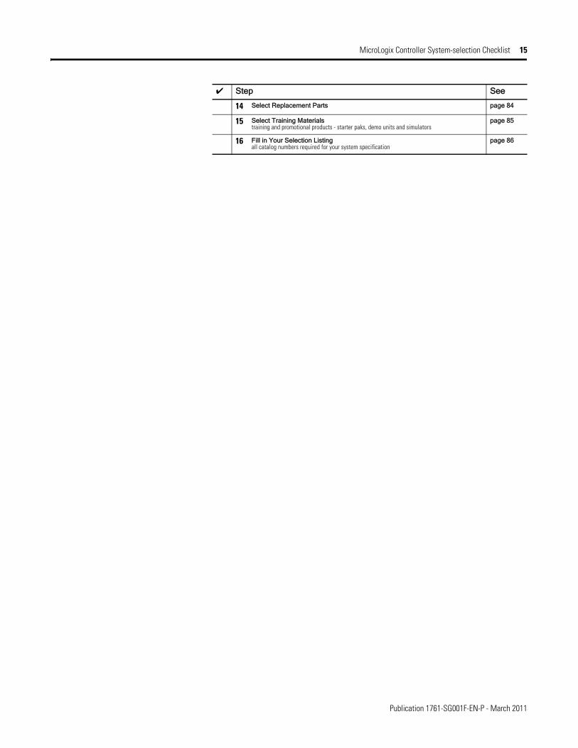
14 Select Replacement Parts page 84
15 Select Training Materialstraining and promotional products - starter paks, demo units and simulators
page 85
16 Fill in Your Selection Listingall catalog numbers required for your system specification
page 86
✔ Step See
Publication 1761-SG001F-EN-P - March 2011
16 Select a MicroLogix Controller
Select a MicroLogix Controller
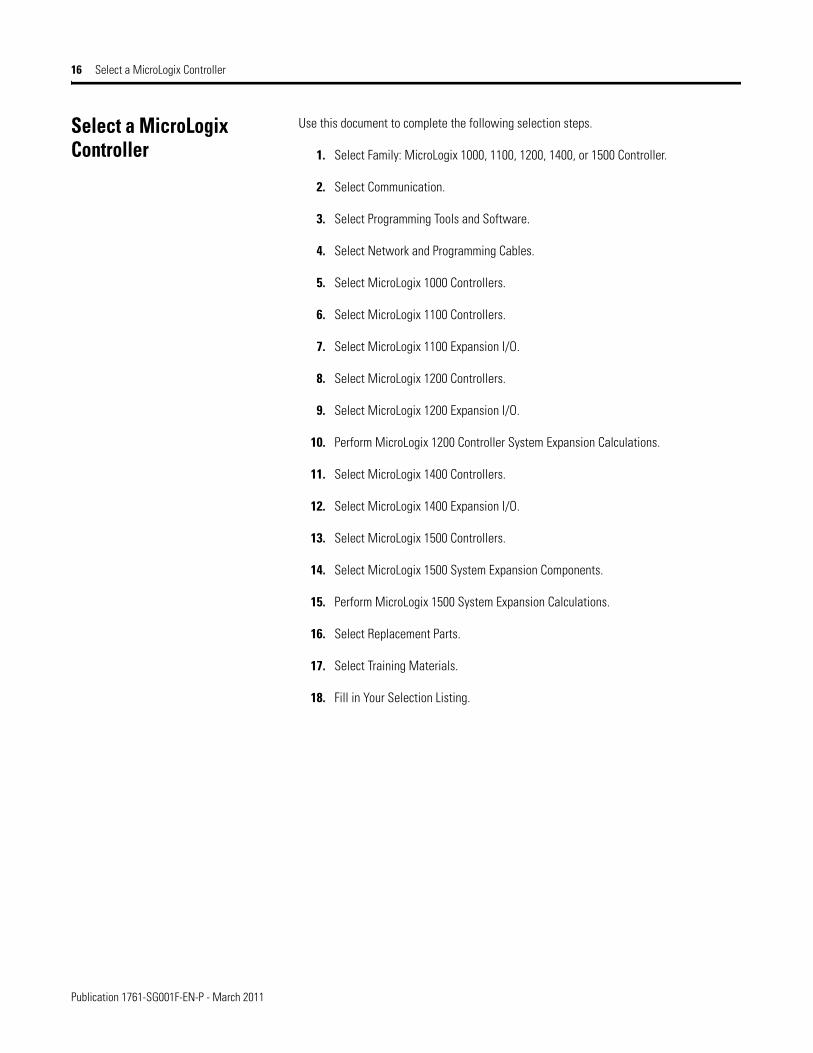
Use this document to complete the following selection steps.
1. Select Family: MicroLogix 1000, 1100, 1200, 1400, or 1500 Controller.
2. Select Communication.
3. Select Programming Tools and Software.
4. Select Network and Programming Cables.
5. Select MicroLogix 1000 Controllers.
6. Select MicroLogix 1100 Controllers.
7. Select MicroLogix 1100 Expansion I/O.
8. Select MicroLogix 1200 Controllers.
9. Select MicroLogix 1200 Expansion I/O.
10. Perform MicroLogix 1200 Controller System Expansion Calculations.
11. Select MicroLogix 1400 Controllers.
12. Select MicroLogix 1400 Expansion I/O.
13. Select MicroLogix 1500 Controllers.
14. Select MicroLogix 1500 System Expansion Components.
15. Perform MicroLogix 1500 System Expansion Calculations.
16. Select Replacement Parts.
17. Select Training Materials.
18. Fill in Your Selection Listing.

Publication 1761-SG001F-EN-P - March 2011
Select Family: MicroLogix 1000, 1200 or 1500 Controller 17
Select Family: MicroLogix 1000, 1200 or 1500 Controller
Review the Features, Programming Instructions, Controller Specifications, and Controller Dimensions to determine which level of MicroLogix controller is required.
Features
Step 1 - Select:
• controller family - based on memory, I/O, added functionality, programming instructions and dimensions
• consider future expansion requirements• consider requirement for online editing• consider the need for networked
communication
MicroLogix Controllers Feature Comparison Chart
Controller MicroLogix 1000 MicroLogix 1200/1200R
MicroLogix 15001764-LSP, 1764-LRP
Bulletin Number 1761 1762 1764Memory (in user words) User Program/User DataUp to 1 KB 1 KB combined
(preconfigured)Up to 6 KB 4 KB/2 KB
Up to 7 KB 3.6 KB/4 KB 1764-LSP
Up to 8 KB
Up to 14 KB 10 KB/4 KB 1764-LRP
Online editing
Nonvolatile program and data EEPROM Flash Battery back-up static RAM
Memory Module (for program back-up and transport)
Through hand-held programmer
Optional Optional
I/OEmbedded Digital I/O, max 32 40 28
Embedded Analog I/O Two current and two voltage inputs with one current or voltage output on 20 pt. controllers
Local Expansion I/O, max None 96 512
Thermocouple/RTD None Expansion Expansion
Networked Expansion I/O, max None None DeviceNet network using 1769-SDN scanner can own 63 slave devices (such as a 1769-ADN adapter with up to 30 I/O modules per 1769-ADN adapter)
Added FunctionalityTrim Potentiometers 2 2
PID ✓ ✓
High Speed Counters (embedded)
One @ 6.6 kHz One @ 20 kHz Two @ 20 kHz
High Speed Counters (expansion)
with 1769-HSC counterWith two quadrature or four pulse/count @ 1 MHz
Real Time Clock Optional Optional
Motion: Pulse Width Modulated 1 @ 20 kHz 2 @ 20 kHz
Motion: Pulse Train Outputs 1 @ 20 kHz 2 @ 20 kHz
Data Access Tool Optional
Data Logging 48 KB
Recipe Storage Uses user program memory or 48 KB data logging memory
Floating Point Math ✓ ✓
ProgrammingWindows - RSLogix 500/Micro Software
✓ ✓ ✓
Hand-held Programmer ✓
Communication

Publication 1761-SG001F-EN-P - March 2011
18 Select Family: MicroLogix 1000, 1200 or 1500 Controller
Programming InstructionsMicroLogix controllers have the range of functionality necessary to address diverse applications. The controllers use the following types of instructions:
• Basic instructions (for example, Examine if On, Examine if Off)• Data Comparison instructions (for example, Equal, Greater than or Equal, Less than or
Equal)• Data Manipulation instructions (for example, Copy, Move)• Math instructions (for example, Add, Subtract, Multiply)• Program Flow Control instructions (for example, Jump, Subroutine)• Application Specific instructions (for example, Programmable Limit Switch,
Sequencer)• High-speed Counter instruction • High-speed pulse train output (PTO) and pulse width modulated (PWM) instructions
(for MicroLogix 1200 and 1500 controllers only)• Communication instruction (including ASCII for MicroLogix 1200 and 1500 controllers
only)• Recipe instruction (MicroLogix 1500 controllers only)• Data Logging instruction (MicroLogix 1500 1764-LRP processor only)
RS-232 Ports (1) 8-pin mini DIN (1) 8-pin mini DIN(1) 8-pin mini DIN Programming/HMI
(1) 8-pin mini DIN(1) 9-pin D-shell
DeviceNet Peer-to-Peer Messaging, slave I/O
With 1761-NET-DNI With 1761-NET-DNI With 1761-NET-DNIWith 1769-SDN
DeviceNet Scanner With 1769-SDN
EtherNet/IP With 1761-NET-ENI or 1761-NET-ENIW
With 1761-NET-ENI or 1761-NET-ENIW
With 1761-NET-ENI or 1761-NET-ENIW
Web Server Capabilities With 1761-NET-ENIW With 1761-NET-ENIW With 1761-NET-ENIW
DH-485 Network with 1761-NET-AIC
Network with 1761-NET-AIC
Network with 1761-NET-AIC
SCADA RTU - DF1 half-duplex slave
✓ ✓ ✓
SCADA RTU - DF1 radio modem ✓ ✓
SCADA RTU - Modbus RTU slave ✓ ✓
SCADA RTU - Modbus RTU master
✓ ✓
ASCII - Read/Write ✓ ✓
Operating Power120/240V AC ✓ ✓ ✓
24V DC ✓ ✓ ✓
12V DC
Agency CertificationsCE, C-Tick, UL, and C-UL (including Class I, Division 2 Hazardous Location)
✓ ✓ ✓
MicroLogix Controllers Feature Comparison Chart
Controller MicroLogix 1000 MicroLogix 1200/1200R
MicroLogix 15001764-LSP, 1764-LRP
Bulletin Number 1761 1762 1764

Publication 1761-SG001F-EN-P - March 2011
Select Family: MicroLogix 1000, 1200 or 1500 Controller 19
Controller Specifications
Controller General Specifications
Attribute MicroLogix 1000(Bulletin 1761)
MicroLogix 1200(Bulletin 1762)
MicroLogix 1500(Bulletin 1764)
Memory Size and Type 1 KB EEPROM (approximately 737 instruction words, 437 data words)
6 KB flash memory: 4 KB user program, 2 KB user data
1764-LSP processor: 7 KB user memory (total user program plus data)
1764-LRP processor: 14 KB user memory (total user program plus data)
Data Elements 512 internal bits, 40 timers, 32 counters, 16 control files, 105 integer files, 33 diagnostic status
configurable, user-defined file structure, 2 KB max data size
configurable, user-defined file structure, 4 KB max data size
Throughput 1.5 ms (for a typical 500-instruction program)(1)
2 ms (for a typical 1 KB word user program)(2)
1 ms (for a typical 1 KB word user program)(2)
(1) A typical program contains 360 contacts, 125 coils, 7 timers, 3 counters, and 5 comparison instructions.
(2) A typical user program contains bit, timer, counter, math, and file instructions.
Environmental Specifications and Certifications
Attribute 1761 Controllers 1762 Controllers 1764 Controllers
Operating Temperature Horizontal mounting: 0…55 °C (32…131 °F)
Vertical mounting(1): 0 °C…45 °C (32 °F…113 °F) for digital I/O, 0 °C…40 °C (32 °F…104 °F) for analog I/O
0…55 °C (32…131 °F) 0…55 °C (32…131 °F)
Storage Temperature -40…85 °C (-40…185 °F) -40…85 °C (-40…185 °F) -40…85 °C (-40…185 °F)(2)
Relative Humidity 5…95%, noncondensing 5…95%, noncondensing 5…95%, noncondensing
Vibration Operating: 5 Hz…2 kHz, 0.381 mm (0.015 in.) peak-to-peak, 2.5 g panel mounted(3), 1 hr per axisNonoperating: 5 Hz…2 kHz, 0.762 mm (0.030 in.) peak-to-peak, 5 g, 1 hr per axis
10…500 Hz, 5 g, 0.030 in. max peak-to-peak, 2 hours each axis (Relay Operation: 1.5 g)
10…500 Hz, 5 g, 0.030 in. max peak-to-peak (Relay Operation: 2 g)
Shock, Operating 10 and 16 Point Controllers:
10 g peak acceleration (7.5 g DIN rail mounted) (11 ± 1 ms duration) 3 times each direction, each axis
32 Point and Analog Controllers:7.5 g peak acceleration (5.0 g DIN rail mounted) (11 ± 1 ms duration) 3 times each direction, each axis
30 g; 3 pulses each direction, each axis (Relay Operation: 7 g)
without Data Access Tool installed:
30 g panel mounted (15 g DIN Rail mounted)Relay operation: 7.5 g panel mounted (5 g DIN Rail mounted)
with Data Access Tool installed:20 g panel mounted (15 g DIN Rail mounted)Relay operation: 7.5 g panel mounted (5 g DIN Rail mounted)

Publication 1761-SG001F-EN-P - March 2011
20 Select Family: MicroLogix 1000, 1200 or 1500 Controller
Shock, Nonoperating 10 and 16 Point Controllers:
20g peak acceleration (11 ± 1 ms duration), 3 times each direction, each axis
32 Point and Analog Controllers:20g peak acceleration (11 ± 1 ms duration), 3 times each direction, each axis
50 g panel mounted (40 g DIN Rail mounted); 3 pulses each direction, each axis
without Data Access Tool installed:
40 g panel mounted (30 g DIN Rail mounted)
with Data Access Tool installed:30 g panel mounted (20 g DIN Rail mounted)
Agency Certification • UL Listed Industrial Control Equipment for use in Class 1, Division 2, Hazardous Locations, Groups A, B, C, D
• C-UL Listed Industrial Control Equipment for use in Canada
• CE marked for all applicable directives
• C-Tick marked for all applicable acts
Electrical/EMC The controller has passed testing at the following level
ESD Immunity EN 61000-4-28 kV
EN 61000-4-24 kV contact, 8 kV air, 4 kV indirect
Radiated Immunity
Radiated RF Immunity EN 61000-4-310 V/m, 27…1000 MHz, 3 V/m, 87…108 MHz, 174…230 MHz, and 470…790 MHz
EN 61000-4-310 V/m, 80…1000 MHz, 80% amplitude modulation, +900 MHz keyed carrier
Electronic Fast Transient/Burst (EFT/B) Immunity
EN 61000-4-4Power Supply, I/O: 2 kVCommunication: 1 kV
EN 61000-4-4Power Supply, I/O: 2 kV, 5 kHzCommunication Cable: 1 kV, 5 kHz
Surge Transient Immunity
EN 61000-4-5Communication: 1 kV galvanic gunI/O: 2 kV CM (Common mode), 1 kV DM (Differential mode)AC Power Supply: 4 kV CM (Common mode), 1 kV DM (Differential mode)
EN 61000-4-5Communication: 1 kV galvanic gunI/O: 2 kV CM (common mode), 1 kV DM (differential mode)AC Power Supply: 4 kV CM (Common mode), 2 kV DM (Differential mode)DC Power Supply: 500V CM (Common mode), 500V DM (Differential mode)
Conducted RF Immunity EN 61000-4-6Power Supply, I/O: 10V, 150 kHz…30 MHzCommunication Cable 3V
EN 61000-4-6Power Supply, I/O: 10VCommunication Cable 3V
(1) DC input voltage derated linearly from 30 °C (86 °F) (30…26.4V).
(2) Recommended storage temperature for maximum battery life (5 years typical with normal operating/storage conditions) of Real-time Clock modules is -40…40 °C (-40…104 °F). Battery life can be significantly shorter at elevated temperatures. Applies to 1762-RTC, 1762-MM1RTC, 1764-RTC, 1764-MM1RTC, and 1764-MM2RTC devices.
(3) DIN rail mounted controller is 1 g.
Environmental Specifications and Certifications
Attribute 1761 Controllers 1762 Controllers 1764 Controllers

Publication 1761-SG001F-EN-P - March 2011
Select Family: MicroLogix 1100 or 1400 Controller 21
Select Family: MicroLogix 1100 or 1400 Controller
Review the Features, Programming Instructions, Controller Specifications, and Controller Dimensions to determine which level of MicroLogix controller is required.
Features
Step 1 - Select:
• controller family - based on memory, I/O, added functionality, programming instructions and dimensions
• consider future expansion requirements• consider requirement for online editing• consider the need for networked
communication
MicroLogix Controllers Feature Comparison Chart
Controller MicroLogix 1100 MicroLogix 1400Bulletin Number 1763 1766Memory (in user words) User Program/User DataUp to 1 KB
Up to 6 KB
Up to 7 KB
Up to 8 KB 4 KB/4 KB
Up to 14 KB
Up to 20 KB 10 KB/10 KB
Online editing ✓ ✓
Nonvolatile program and data Battery back-up static RAM Battery back-up static RAM
Memory Module (for program back-up and transport)
Optional Optional
I/OEmbedded Digital I/O, max 16 32
Embedded Analog I/O Two 0…10V DC inputs on all controllers Four 0…10V DC inputs on some controllersTwo 0...10V DC outputs on some controllers
Local Expansion I/O, max 144 256
Thermocouple/RTD Expansion Expansion
Added FunctionalityTrim Potentiometers Two (digital) Two (digital)
PID ✓ ✓
High Speed Counters (embedded)
One @ 40 kHz Up to six @ 100 kHz
Real Time Clock ✓ ✓
Motion: Pulse Width Modulated 2 @ 40 kHz 3 @ 40 kHz
Motion: Pulse Train Outputs 2 @ 40 kHz 3 @ 100 kHz
Data Access Tool ✓ ✓
Data Logging 128 KB 128 KB
Recipe Storage Uses up to 64 KB data logging memory Uses up to 64 KB data logging memory
Floating Point Math ✓ ✓
ProgrammingWindows - RSLogix 500 Software
✓ ✓
RSLogix Micro ✓ ✓
CommunicationRS-232 Ports (1) 8-pin mini DIN (1) 8-pin mini DIN
(1) 9-pin D-shellDeviceNet Peer-to-Peer Messaging, slave I/O
With 1761-NET-DNI With 1761-NET-DNI
EtherNet/IP ✓ ✓
Web Server Capabilities ✓ ✓
DH-485 Network with 1763-NC01 Network with 1763-NC01

Publication 1761-SG001F-EN-P - March 2011
22 Select Family: MicroLogix 1100 or 1400 Controller
Programming InstructionsMicroLogix controllers have the range of functionality necessary to address diverse applications. The controllers use the following types of instructions:
• Basic instructions (for example, Examine if On, Examine if Off)• Data Comparison instructions (for example, Equal, Greater than or Equal, Less than or
Equal)• Data Manipulation instructions (for example, Copy, Move)• Math instructions (for example, Add, Subtract, Multiply)• Program Flow Control instructions (for example, Jump, Subroutine)• Application Specific instructions (for example, Programmable Limit Switch,
Sequencer)• High-speed Counter instruction • High-speed pulse train output (PTO) and pulse width modulated (PWM) instructions • Communication instruction including ASCII• Recipe instruction • Data Logging instruction• LCD instruction• Trigonometry instructions (MicroLogix 1400 controllers only)
• Advanced math instructions (for example, xy, compute - MicroLogix 1400 controllers only)
• Advanced timing instructions (for example, Read High-speed clock, compute time difference - MicroLogix 1400 controllers only)
SCADA RTU - DF1 half-duplex master/slave
✓ ✓
SCADA RTU - DF1 radio modem ✓ ✓
SCADA RTU - Modbus RTU slave ✓ ✓
SCADA RTU - Modbus RTU master
✓ ✓
SCADA RTU - DNP3 slave ✓
ASCII - Read/Write ✓ ✓
DNP3 over IP ✓
Modbus TCP/IP ✓
Operating Power120/240V AC ✓ ✓
24V DC ✓ ✓
12V DC ✓
Agency CertificationsCE, C-Tick, UL, and C-UL (including Class I, Division 2 Hazardous Location)(1)
✓ ✓
(1) See the Product Certification link at http://www.ab.com for Declarations of Conformity, Certificates, and other certification details.
MicroLogix Controllers Feature Comparison Chart
Controller MicroLogix 1100 MicroLogix 1400Bulletin Number 1763 1766

Publication 1761-SG001F-EN-P - March 2011
Select Family: MicroLogix 1100 or 1400 Controller 23
Controller Specifications
Controller General Specifications
Attribute MicroLogix 1100(Bulletin 1763)
MicroLogix 1400(Bulletin 1766)
Memory Size and Type 8 KB battery backed RAM:4 K user program, 4 K user data
20 KB battery backed RAM:10 K user program, 10 K user data
Data Elements configurable, user defined file structure, 4 KB max data size
configurable, user defined file structure, 10 KB max data size
Throughput 1.5 ms (for a typical 1 KB word user program)(1)
(1) A typical user program contains bit, timer, counter, math, and file instructions.
0.7 ms (for a typical 1 KB word user program)(1)
Environmental Specifications and Certifications
Attribute 1763 Controllers 1766 Controllers
Operating Temperature -20…65 °C (-4…149 °F) -20…60 °C (-4…140 °F)
Storage Temperature -40…85 °C (-40…185 °F) -40…85 °C (-40…185 °F)
Relative Humidity 5…95%, noncondensing 5…95%, noncondensing
Vibration 10…500 Hz, 5 g, 0.015 in. max peak-to-peak, (Relay Operation: 1.5 g)
10…500 Hz, 3 g, 0.015 in. max peak-to-peak
Shock, Operating 30 g; 3 pulses each direction, each axis (Relay Operation: 7 g)
30 g; 3 pulses each direction, each axis
Shock, Nonoperating 50 g panel mounted (40 g Din Rail mounted); 3 pulses each direction, each axis
50 g panel mounted (40 g Din Rail mounted); 3 pulses each direction, each axis
Agency Certification • UL Listed Industrial Control Equipment for use in Class 1, Division 2, Hazardous Locations, Groups A, B, C, D
• C-UL Listed Industrial Control Equipment for use in Canada
• CE marked for all applicable directives
• C-Tick marked for all applicable acts
• UL Listed Industrial Control Equipment for use in Class 1, Division 2, Hazardous Locations, Groups A, B, C, D
• C-UL Listed Industrial Control Equipment for use in Canada
• CE marked for all applicable directives
• C-Tick marked for all applicable acts
Electrical/EMC
ESD Immunity EN 61000-4-24 kV contact, 8 kV air, 4 kV indirect
EN 61000-4-24 kV contact, 8 kV air
Radiated Immunity ENV 5020410 V/m, 1000 MHz
Radiated RF Immunity EN 61000-4-310V/m, 26...1000 MHz (alternatively, 80...1000 MHz), 80% amplitude modulation, +900 MHz keyed carrier
EN 61000-4-310V/m, 26...1000 MHz (alternatively, 80...1000 MHz), 80% amplitude modulation, +900 MHz keyed carrier

Publication 1761-SG001F-EN-P - March 2011
24 Select Family: MicroLogix 1100 or 1400 Controller
Electronic Fast Transient/Burst (EFT/B) Immunity
EN 61000-4-42 kV, 5 kHzcommunication cable such as EtherNet, RS-232, and RS-485: 1 kV, 5 kHz
EN 61000-4-42 kV, 5 kHzcommunication cable such as EtherNet, RS-232, and RS-485: 1 kV, 5 kHz
Surge Transient Immunity
EN 61000-4-5Unshielded communication cable: 2 kV CM (common mode), 1 kV DM (differential mode)Shielded communication cable: 1 kV galvanic gunI/O: 2 kV CM (common mode), 1 kV DM (differential mode)AC Power Supply Input: 4 kV CM (common mode), 2 kV DM (differential mode)DC Power Supply Input: 500V CM (common mode), 500V DM (differential mode)AC/DC Auxiliary Output: 500V CM (common mode), 500V DM (differential mode)
EN 61000-4-5±1 kV line-line (DM) and ±2 kV line-earth (CM) on AC power ports±1 kV line-line (DM) and ±2 kV line-earth (CM) on signal ports±1 kV line-earth (CM) on communication ports
Conducted RF Immunity EN 61000-4-610V, 150 kHz...80 MHz
EN 61000-4-610V, 150 kHz...80 MHz
Conducted Emissions EN 55011AC Power Supply Input: 150 kHz...30 MHz
EN 55011AC Power Supply Input: 150 kHz...30 MHz
Radiated Emissions EN 5501130...1000 MHz
EN 5501130...1000 MHz
Line Related Tests EN 61000-4-11AC Power Supply Input:voltage drop: -30% for 10 ms, -60% for 100 msvoltage interrupt: at voltage greater than -95% for 5 s. voltage fluctuation: +10% for 15 minutes, -10% for 15 minutesDC Power Supply Input:voltage fluctuation: +20% for 15 minutes, -20% for 15 minutes
EN 61000-4-1160% dip for 10 periods on AC supply ports30% dips for 25 periods at 0× and 180× on AC supply ports100% dip for 250 periods at 0× and 180× on AC supply ports100% dip for 0.5 periods, arbitrary angle, on AC supply ports
Environmental Specifications and Certifications
Attribute 1763 Controllers 1766 Controllers
Publication 1761-SG001F-EN-P - March 2011
Select Family: MicroLogix 1100 or 1400 Controller 25
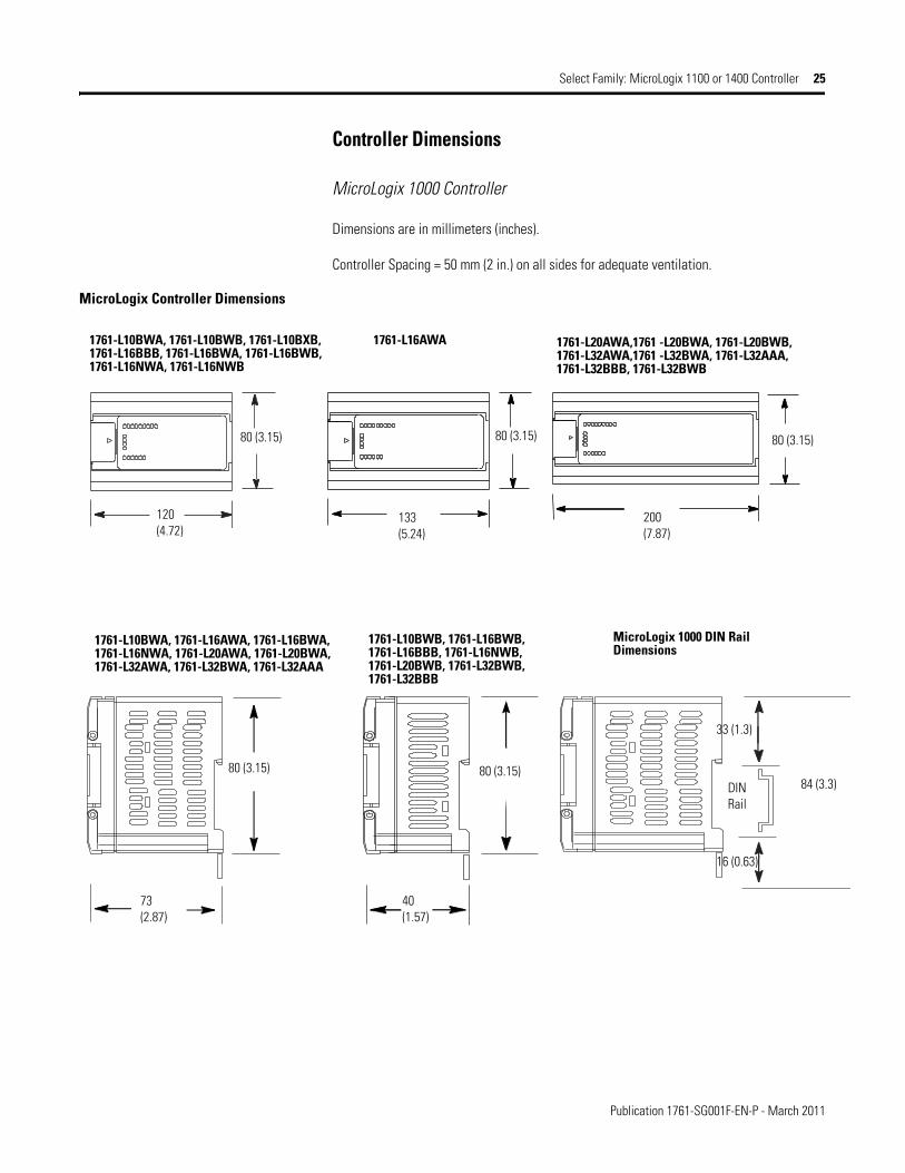
Controller Dimensions
MicroLogix 1000 Controller
Dimensions are in millimeters (inches).
Controller Spacing = 50 mm (2 in.) on all sides for adequate ventilation.
MicroLogix Controller Dimensions
80 (3.15)
120(4.72)
80 (3.15)
133(5.24)
80 (3.15)
200(7.87)
1761-L16AWA1761-L10BWA, 1761-L10BWB, 1761-L10BXB, 1761-L16BBB, 1761-L16BWA, 1761-L16BWB, 1761-L16NWA, 1761-L16NWB
1761-L20AWA,1761 -L20BWA, 1761-L20BWB, 1761-L32AWA,1761 -L32BWA, 1761-L32AAA, 1761-L32BBB, 1761-L32BWB
80 (3.15)80 (3.15)
MicroLogix 1000 DIN Rail Dimensions
73(2.87)
40(1.57)
33 (1.3)
16 (0.63)
84 (3.3)DINRail
1761-L10BWA, 1761-L16AWA, 1761-L16BWA, 1761-L16NWA, 1761-L20AWA, 1761-L20BWA, 1761-L32AWA, 1761-L32BWA, 1761-L32AAA
1761-L10BWB, 1761-L16BWB, 1761-L16BBB, 1761-L16NWB, 1761-L20BWB, 1761-L32BWB, 1761-L32BBB

Publication 1761-SG001F-EN-P - March 2011
26 Select Family: MicroLogix 1100 or 1400 Controller
MicroLogix 1100 Controller
Dimensions are in millimeters (inches).
Controller Spacing = 50 mm (2 in.) on all sides for adequate ventilation.
MicroLogix 1100 Controller Dimension Drawing
1762 Expansion I/O Module Dimension Drawing
MicroLogix 1100 Controller Dimensions
Dimension 1763-L16AWA, 1763-L16BWA, 1763-L16BBB, 1763-L16DWD
A 90 mm (3.5 in.)
B 110 mm (4.33 in.)
C 87 mm (3.43 in.)
1762 Expansion I/O Dimensions
Dimension Expansion I/O Module
A 90 mm (3.5 in.)
B 40 mm (1.57 in.)
C 87 mm (3.43 in.)
C
BA
A
B
C

Publication 1761-SG001F-EN-P - March 2011
Select Family: MicroLogix 1100 or 1400 Controller 27
Controller Spacing
The controller mounts horizontally, with the expansion I/O extending to the right of the controller. Allow 50 mm (2 in.) of space on all but the right side for adequate ventilation, as shown below.
DIN Rail Mounting
The maximum extension of the latch is 14 mm (0.55 in.) in the open position. A flat-blade screwdriver is required for removal of the controller. The controller can be mounted to EN50022-35 x 7.5 or EN50022-35 x 15 DIN rails. DIN rail mounting dimensions are shown below.
DIN Rail Mounting Dimensions
Dimension Height
A 90 mm (3.5 in.)
B 27.5 mm (1.08 in.)
C 27.5 mm (1.08 in.)
ESC OK
A
B
C

Publication 1761-SG001F-EN-P - March 2011
28 Select Family: MicroLogix 1100 or 1400 Controller
MicroLogix 1200 Controller
Dimensions are in millimeters (inches).
Controller Spacing = 50 mm (2 in.) on all sides for adequate ventilation.
MicroLogix 1200 Controller Dimension Drawing
1762 Expansion I/O Dimensions
Controller Dimensions
Dimension 1762-L24AWA1762-L24AWAR
1762-L24BWA1762-L24BWAR
1762-L24BXB1762-L24BXBR
1762-L40AWA1762-L40AWAR
1762-L40BWA1762-L40BWAR
1762-L40BXB1762-L40BXBR
A 90 mm (3.5 in.) 90 mm (3.5 in.)
B 110 mm (4.33 in.) 160 mm (6.30 in.)
C 87 mm (3.43 in.) 87 mm (3.43 in.)
C
B
A
C
BA
1762-L24AWA, 1762-L24BWA, 1762-L24BXB1762-L24AWAR, 1762-L24BWAR, 1762-L24BXBR
1762-L40AWA, 1762-L40BWA, 1762-L40BXB1762-L24AWAR, 1762-L24BWAR, 1762-L24BXBR
A
B
C
1762 I/O Dimensions
Dimension Expansion I/O Module
A 90 mm (3.5 in.)
B 40 mm (1.57 in.)
C 87 mm (3.43 in.)
Publication 1761-SG001F-EN-P - March 2011
Select Family: MicroLogix 1100 or 1400 Controller 29
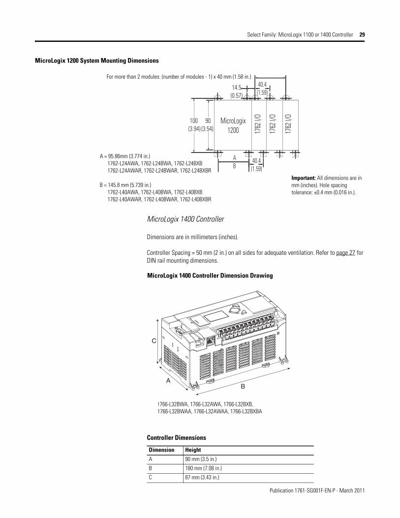
MicroLogix 1200 System Mounting Dimensions
MicroLogix 1400 Controller
Dimensions are in millimeters (inches).
Controller Spacing = 50 mm (2 in.) on all sides for adequate ventilation. Refer to page 27 for DIN rail mounting dimensions.
MicroLogix 1400 Controller Dimension Drawing
90(3.54)
100(3.94)
40.4(1.59)
AB
40.4(1.59)
14.5(0.57)
MicroLogix1200 17
62 I/
O
1762
I/O
1762
I/O
For more than 2 modules: (number of modules - 1) x 40 mm (1.58 in.)
Important: All dimensions are in mm (inches). Hole spacing tolerance: ±0.4 mm (0.016 in.).
A = 95.86mm (3.774 in.) 1762-L24AWA, 1762-L24BWA, 1762-L24BXB 1762-L24AWAR, 1762-L24BWAR, 1762-L24BXBR
B = 145.8 mm (5.739 in.) 1762-L40AWA, 1762-L40BWA, 1762-L40BXB 1762-L40AWAR, 1762-L40BWAR, 1762-L40BXBR
Controller Dimensions
Dimension Height
A 90 mm (3.5 in.)
B 180 mm (7.08 in.)
C 87 mm (3.43 in.)
C
BA
1766-L32BWA, 1766-L32AWA, 1766-L32BXB, 1766-L32BWAA, 1766-L32AWAA, 1766-L32BXBA

Publication 1761-SG001F-EN-P - March 2011
30 Select Family: MicroLogix 1100 or 1400 Controller
1762 Expansion I/O Dimensions
MicroLogix 1400 System Mounting Dimension
A
B
C
1762 I/O Dimensions
Dimension Expansion I/O Module
A 90 mm (3.5 in.)
B 40 mm (1.57 in.)
C 87 mm (3.43 in.)
1766-L32AWA, 1766-L32AWAA1766-L32BWA, 1766-L32BWAA1766-L32BXB, 1766-L32BXBA
100.0 mm(3.93 in.)
180.0 mm(7.08 in.)
165.8 mm(6.52 in.)
25.81 mm(1.016 in.)
0.164

Publication 1761-SG001F-EN-P - March 2011
Select Family: MicroLogix 1100 or 1400 Controller 31
MicroLogix 1500 Controller
Dimensions are in millimeters (inches).
Hole spacing tolerance: ±0.04 mm (0.016 in.).
Controller Spacing = 50 mm (2 in.) on all sides for adequate ventilation.
Compact I/O System with MicroLogix 1500 Base Unit and Processor
132
mm
(5.
19 in
)
122.
6 m
m (
4.83
in)
118
mm
(4.
65 in
)
147.
4 m
m (
5.81
in)
14.7 mm(0.58 in)
35 mm(1.38 in)
168 mm(6.62 in)
147 mm(5.79 in)
35 mm(1.38 in)
13.5 mm(0.53 in)
59 m
m(2
.32
in)
59 m
m(2
.32
in)
28.5 mm(1.12 in)
DIN Rail Center Line
Mounting Hole Dimension
controller depth = 87 mm (3.43 in.)

Publication 1761-SG001F-EN-P - March 2011
32 Select Family: MicroLogix 1100 or 1400 Controller
Expansion Bank with Power Supply, Expansion Cable, and End Cap
Spacing for Single-wide and One and One-half-wide Modules
Panel Mounting Using the Dimensional Template:
Important: Overall hole spacing tolerance: ±0.4 mm (0.016 in.).
Locate holes every 17.5 mm (0.689 in.) to allow for a mix of single-wide (for example 1769-IQ16 module) and one-and-one-half-wide modules (for example 1769-OA16 module).
132
mm
(5.
19 in
)
122.
6 m
m (
4.83
in)
118
mm
(4.
65 in
)
147.
4 m
m (
5.81
in)
14.7 mm(0.58 in)
35 mm(1.38 in)
35 mm(1.38 in)
28.5 mm(1.12 in)
35 mm(1.38 in)
70 mm(2.76 in)
35 mm(1.38 in)
35 mm(1.38 in)
35 mm(1.38 in)
59 m
m(2
.32
in)
59 m
m(2
.32
in)
DIN Rail Center Line
Mounting Hole Dimension
controller depth = 87 mm (3.43 in.)Expansion Cable connector and End Cap have identical dimensions.
Host
Con
trolle
r
Spacing for single-wide modules 35 mm (1.378 in.)
Spacing from controller to first I/O mounting hole 35 mm (1.378 in.)
Spacing for one-and-a half-wide modules 52.5 mm (2.067 in.)

Publication 1761-SG001F-EN-P - March 2011
Select Communication 33
Select Communication Communication Networks
MicroLogix controllers allow you to choose the network that best meets your needs.• Channel 0 Isolated RS-232/RS-485 Combo port (MicroLogix 1100 and 1400
controllers only)• EtherNet/IP port (MicroLogix 1100 and 1400 controllers only)• DNP3 over IP (MicroLogix 1400 controller only)• Modbus TCP/IP (MicroLogix 1400 controller only)• For RS-232 communication:
• 300, 600, 1200, 4800, 9600 bps; 19.2 and 38.4 Kbps• RTS/CTS hardware handshake signals• Connection to DH-485, DeviceNet and Ethernet networks through the
1761-NET-AIC, 1761-NET-DNI and 1761-NET-ENI interface modules, respectively (MicroLogix 1500 controllers also connect to DeviceNet network via the 1769-SDN DeviceNet Scanner Module)
• Connection to modems for remote communication• ASCII messaging provides dial-out capability (except MicroLogix 1000 controller)• DF1 half-duplex slave• DF1 half-duplex master (except MicroLogix 1000 controller)• DNP3 slave (MicroLogix 1400 controller only)• Modbus RTU master/slave through the 1761-NET-AIC module (MicroLogix 1100
and 1400 controllers also connect to Modbus RTU master/slave directly through 1763-NC01 cable to Channel 0)
Important: The MicroLogix 1100 and 1400 controllers do not provide 24V DC power for network interface whereas all other MicroLogix controllers do. The 24V DC comms power must be provided externally when 1761-NET-AIC or 1761-NET-ENI or 1761-NET-ENIW modules are used with a MicroLogix 1100 and 1400 controller. MicroLogix 1100 and 1400 controllers provide direct connection to RS-485 networks by using the same pins used by other MicroLogix controllers for 24V DC communication power.
Step 2 - Select:
• communication network - based on application requirements
• communication interface device - if required
• record your selection in the Selection Record (starts on page 86)
Publication 1761-SG001F-EN-P - March 2011
34 Select Communication
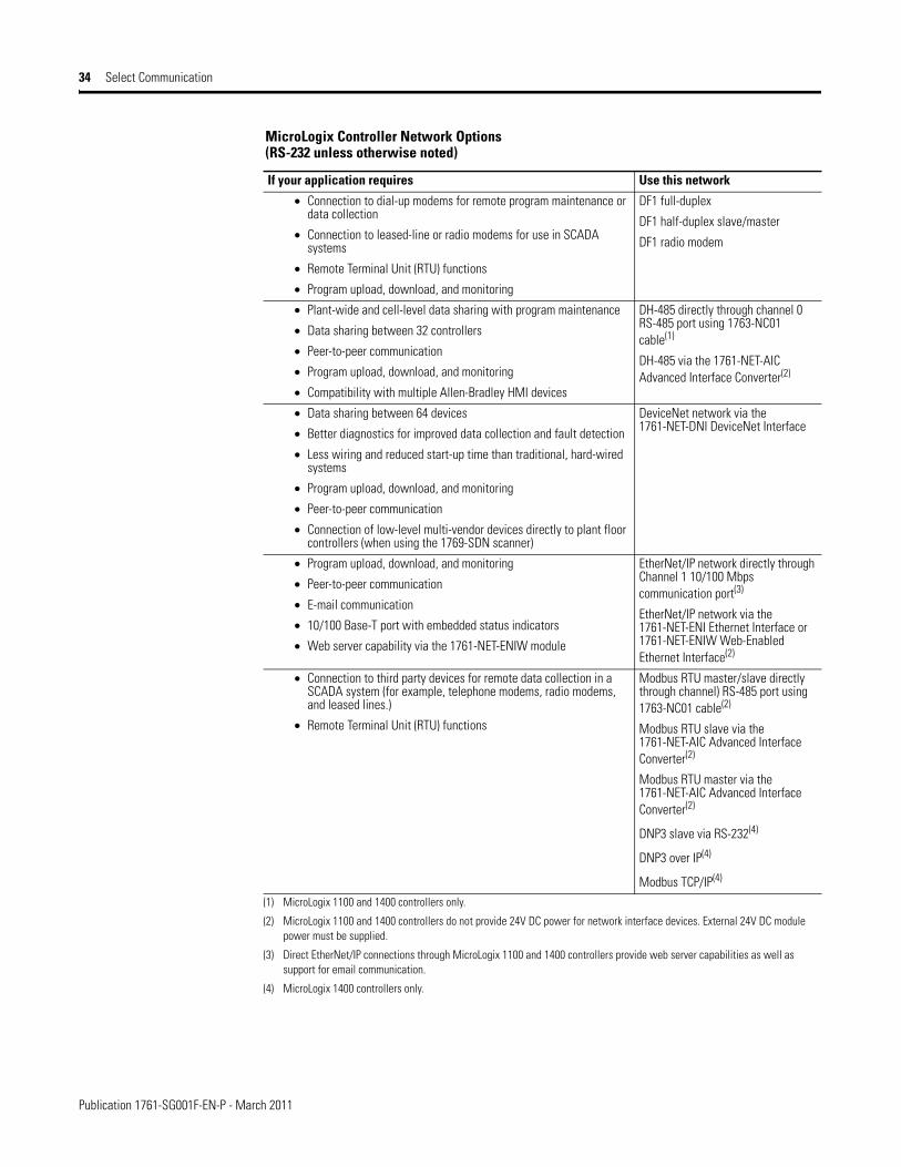
MicroLogix Controller Network Options (RS-232 unless otherwise noted)
If your application requires Use this network
• Connection to dial-up modems for remote program maintenance or data collection
• Connection to leased-line or radio modems for use in SCADA systems
• Remote Terminal Unit (RTU) functions
• Program upload, download, and monitoring
DF1 full-duplex
DF1 half-duplex slave/master
DF1 radio modem
• Plant-wide and cell-level data sharing with program maintenance
• Data sharing between 32 controllers
• Peer-to-peer communication
• Program upload, download, and monitoring
• Compatibility with multiple Allen-Bradley HMI devices
DH-485 directly through channel 0 RS-485 port using 1763-NC01 cable(1)
DH-485 via the 1761-NET-AIC Advanced Interface Converter(2)
• Data sharing between 64 devices
• Better diagnostics for improved data collection and fault detection
• Less wiring and reduced start-up time than traditional, hard-wired systems
• Program upload, download, and monitoring
• Peer-to-peer communication
• Connection of low-level multi-vendor devices directly to plant floor controllers (when using the 1769-SDN scanner)
DeviceNet network via the 1761-NET-DNI DeviceNet Interface
• Program upload, download, and monitoring
• Peer-to-peer communication
• E-mail communication
• 10/100 Base-T port with embedded status indicators
• Web server capability via the 1761-NET-ENIW module
EtherNet/IP network directly through Channel 1 10/100 Mbps communication port(3)
EtherNet/IP network via the 1761-NET-ENI Ethernet Interface or 1761-NET-ENIW Web-Enabled Ethernet Interface(2)
• Connection to third party devices for remote data collection in a SCADA system (for example, telephone modems, radio modems, and leased lines.)
• Remote Terminal Unit (RTU) functions
Modbus RTU master/slave directly through channel) RS-485 port using 1763-NC01 cable(2)
Modbus RTU slave via the 1761-NET-AIC Advanced Interface Converter(2)
Modbus RTU master via the 1761-NET-AIC Advanced Interface Converter(2)
DNP3 slave via RS-232(4)
DNP3 over IP(4)
Modbus TCP/IP(4)
(1) MicroLogix 1100 and 1400 controllers only.
(2) MicroLogix 1100 and 1400 controllers do not provide 24V DC power for network interface devices. External 24V DC module power must be supplied.
(3) Direct EtherNet/IP connections through MicroLogix 1100 and 1400 controllers provide web server capabilities as well as support for email communication.
(4) MicroLogix 1400 controllers only.

Publication 1761-SG001F-EN-P - March 2011
Select Communication 35
MicroLogix Network Interface Devices
The following information describes the functionality of the MicroLogix interface modules. For most applications, the embedded RS-485 and Ethernet/IP functionality of the MicroLogix 1100 and 1400 communication ports replaces the 1761-NET-AIC, 1761-NET-ENI, and the 1761-NET ENIW (or AIC+, ENI, and ENIW) modules.
The network interface devices can be mounted on a panel or DIN rail.
AIC+ Advanced Interface Converter (Catalog Number 1761-NET-AIC)
The AIC+ is an isolated, RS-232 to RS-485 electrical signal converter for supporting serial, half-duplex, multi-drop protocols, such as:
• DH-485.• DF1 half-duplex master/slave.• Modbus RTU (a single master can communicate with a maximum of 31 slave
devices).
Since RS-232 ports can only be connected point-to-point between two devices, an AIC+ (or similar device) is required whenever a MicroLogix controller is configured for one of these protocols and needs to communicate with more than one other device at a time. The AIC+ also provides electrical isolation between each of its three ports for a more stable network and protection for connected devices.
When using the 1763-NC01 cable, the MicroLogix 1100 and 1400 controller provides isolated connection to RS-485 networks directly from the Channel 0 combo port.
Any MicroLogix controller can connect to either of the two RS-232 ports on the AIC+. When Channel 0 on a MicroLogix controller is connected to Port 2 (RS-232 8-pin mini-DIN) of the AIC+, the interface module can draw its power from the MicroLogix controller. In all other cases, including using MicroLogix 1100 and 1400 controllers, the AIC+ must be powered from an external, 24V DC power supply. The AIC+ can also be used as an RS-232 to RS-485 converter and port isolator for any other Allen-Bradley controller or terminal with an RS-232 port.
Since the AIC+ is not a protocol converter, all devices connected to a single AIC+ (or a network of AIC+s) must be configured for the same communication protocol.
DH-485 Network Specifications
Attribute 1761-NET-AIC
Number of Nodes, max 32 per multidrop network
Length, max 1219 m (4000 ft) per multidrop network

Publication 1761-SG001F-EN-P - March 2011
36 Select Communication
DNI DeviceNet Interface (1761-NET-DNI)
DNI capabilities:• Peer-to-peer messaging between Allen-Bradley controllers and other devices using
the DF1 full-duplex protocol• Programming and online monitoring over the DeviceNet network• With a DNI connected to a modem, you can dial in to any other DNI-controller
combination on DeviceNet• Other DeviceNet products can send explicit (Get or Set) messages with the DNI at
any time• The controller can initiate an explicit message to a UCMM (Unconnected Message
Manager) compatible device on DeviceNet
ENI Ethernet Interface (1761-NET-ENI) and ENIW Ethernet Interface with Web Server Capabilities (1761-NET-ENIW)
The ENI provides EtherNet/IP connectivity for all MicroLogix controllers and other DF1 full-duplex devices. The ENI lets you easily connect a MicroLogix controller to a new or existing Ethernet network to update/download programs, communicate between controllers, and generate e-mail messages via SMTP (simple mail transport protocol).
The ENIW adds web server capabilities, enabling the display of 4 standard data web pages with user-configurable data descriptions, and 10 user-configurable web-page links on the ENIW home page.
MicroLogix 1100 and 1400 controllers also provide EtherNet/IP connectivity, web server, and email capabilities directly through Channel 1.
DeviceNet Specifications
Attribute 1761-NET-DNI
Number of Nodes, max 64
Length, max 500 m @ 125 Kbps or 100 m @ 500 Kbps
DeviceNet Agency Certification ODVA conformance 2.0-A12
Ethernet Specifications
Attribute 1761-NET-ENI
Communication Rate 100 MHz (series C and D), 10 MHz (series A and B)
Connector 100Base-T (series C and D), 10Base-T (series A and B)

Publication 1761-SG001F-EN-P - March 2011
Select Communication 37
AIC+, DNI, and ENI /ENIW Specifications
Network Interface Devices Dimensions
Network Modules Specifications
Attribute 1761-NET-AIC 1761-NET-DNI 1761-NET-ENI, 1761-NET-ENIW
Power Supply DC Voltage Range(1)
20.4…28.8V DC 11…25V DC 20.4…26.4V DC
Backplane Current (mA) at 24V
120 mA 200 mA 50 mA
Inrush Current, max 200 mA 400 mA 200 mA
Isolation Voltage 500V DC for 1 minute 500V DC for one minute 710V DC for one minute
Operating Temperature 0…60 °C (32…140 °F)
Storage Temperature -40…85 °C (-40…185 °F)
Relative Humidity 5…95% noncondensing
Vibration operating: 10…500 Hz, 5.0 g, 0.030 in. peak-to-peak, 2 hour each axis
operating: 5…2000 Hz, 2.5 g, 0.015 in. peak-to-peak, 1 hour each axis
nonoperating: 5…2000 Hz, 5.0g, 0.030 in. peak-to-peak, 1 hour each axis
operating: 10…500 Hz, 5.0 g, 0.030 in. peak-to-peak, 2 hour each axis
Shock, Operating 30 g, ±3 times each axis 30 g, ±3 times each axis 30 g, ±3 times each axis
Shock, Nonoperating 50 g, ±3 times each axis 50 g, ±3 times each axis 35 g (DIN rail mount) 50 g (panel mount) ±3 times each axis
Certifications • UL Listed Industrial Control Equipment for use in Class 1, Division 2, Hazardous Locations, Groups A, B, C, D
• C-UL Listed Industrial Control Equipment for use in Canada
• CE marked for all applicable directives
• C-Tick marked for all applicable acts (1) When the device is connected to a MicroLogix 1000, 1200, or 1500 controller, power is provided by the MicroLogix controller’s communication port. Power is not supplied
by the MicroLogix 1100 and 1400 controllers. External 24V DC module power must be supplied.
27.7 mm(1.09 in.)
107 mm(4.20 in.)
118 mm(4.64 in.)
52.07 mm(2.05 in.)
6.6 mm(0.26 in.)
AIC+ only
64.8 mm(2.55 in.)
71.4 mm(2.81 in.) AIC
Allow 15 mm (0.6 in.) for DIN rail latchmovement during installation and re-moval.

Publication 1761-SG001F-EN-P - March 2011
38 Select Programming Tools and Software
Select Programming Tools and Software
Programming Software
The RSLogix 500 and RSLogix Micro ladder-logic programming packages help you maximize performance, save project development time, and improve productivity. These products have been developed to operate on Windows operating systems. RSLogix 500 software can be used for programming both the SLC 500 and MicroLogix controller families. RSLogix Micro software is for programming MicroLogix controller families only.
Hand-Held Programmer (MicroLogix 1000 controller only)
The 1761-HHP-B30 lets you create, edit, monitor, and troubleshoot Instruction List (Boolean) programs for your MicroLogix 1000 controller. This device also lets you store programs and to transfer programs through the use of an optional removable memory module.
There are 2 memory modules:• 1761-HHM-K08 - 8 KB, stores 1 program.• 1761-HHM-K64 - 64 KB, stores 8 programs.
Step 3 - Select:
• programming tools - hand-held programmer with optional memory module (available for MicroLogix 1000 only)
• software - the appropriate RSLogix package for your application
• record your selection in the Selection Record (starts on page 86)
RSLogix 500 and RSLogix Micro Selection Chart
Cat. No. Description
9324-RL0100ENE RSLogix 500 Starter Edition Programming Software for MicroLogix controller families. (CD-ROM)
9324-RL0300ENE RSLogix 500 Standard Edition Programming Software for SLC 500 and MicroLogix controller families. (CD-ROM)
9324-RL0700NXENE RSLogix 500 Professional Edition. CD-ROM also includes RSLogix Emulate 500, RSNetworx for DeviceNet and RSNetworx for ControlNet software.
9324-RLM0100ENE RSLogix Micro Starter software
9324-RLM0800ENE RSLogix Micro Developer software
TIP Download Free Lite Version of RSLogix Micro Starter Software
Now you can download free RSLogix Micro Starter Lite software and RSLinx Lite software to program, upload, and download all MicroLogix 1000 and MicroLogix 1100 controllers.
RSLogix Micro Starter Lite software, when used together with RSLinx Lite software, is fully-functional with all MicroLogix 1000 and MicroLogix 1100 controllers.
Go to http:www.ab.com/programmablecontrol/plc/micrologix/downloads.html for details.

Publication 1761-SG001F-EN-P - March 2011
Select Network and Programming Cables 39
Select Network and Programming Cables
Cables come in several lengths and connector styles to provide connectivity between MicroLogix controllers and other devices. MicroLogix 1200 controllers require series C versions of all 1761 cables.
Network Cable Selection
Network Interface Devices Communication Port Identification
Step 4 - Select:
• cables - review device port identification to find cable in the selection chart)
• record your selection in the Selection Record (starts on page 86)
Controller and PC Port Identification
Device Communication Port Description Connector Type
MicroLogix 1000 Communication Port (Channel 0) with 24V DC power for communication device 8-pin Mini DIN
MicroLogix 1100RS-232/RS-485 Communication Port (Channel 0, no 24V DC power for communication Interface Modules)
8-pin Mini DIN (isolated)
10/100Mbps EtherNet/IP Communication Port (Channel 1) RJ-45
MicroLogix 1200 Communication Port (Channel 0) with 24V DC power for communication device 8-pin Mini DIN
MicroLogix 1200R Programming/HMI Port (no 24V DC power) 8-pin Mini DIN
MicroLogix 1400
RS-232/RS-485 Communication Port (Channel 0, no 24V DC power for communication Interface Modules)
8-pin Mini DIN (isolated)
10/100Mbps EtherNet/IP Communication Port (Channel 1) RJ-45
Communication Port (Channel 2) 9-pin D Shell
MicroLogix 1500 Base Unit Communication Port (Channel 0) with 24V DC power for communication device 8-pin Mini DIN
MicroLogix 1500 with 1764-LRP Processor
Processor Communication Port (Channel 1) 9-Pin D Shell (isolated)
Personal ComputerPersonal Computer Serial Communication Port 9-Pin D Shell
Personal Computer Ethernet Communication Port RJ-45
NODE
DANGER
GND
TX/RX
V±
CAN_L
SHIELDCAN_H
V+
NET
MOD
ETHERNET
FAULT
RS232
NET
TX/RXTX/RX
PWR
CABLE
EXTERNAL
IP
RS-2328-Pin Mini DINEthernet
RS-2328-Pin Mini DIN
RS-2328-Pin Mini DIN
RS-2329-Pin D Shell
DeviceNet
DH-485
Important: The AIC+ is recommendedfor isolation purposes when the con-troller and an operator interface deviceare not using the same power supply.
AIC+ DNI ENI/ENIW

Publication 1761-SG001F-EN-P - March 2011
40 Select Network and Programming Cables
Programming Cable Selection
1747-UIC Universal Serial Bus to DH-485 Interface Converter
This device allows a computer with a USB port to interface to DH-485 ports on an SLC 500, MicroLogix, or other Rockwell Automation controllers and on PanelView terminals. The 1747-UIC features a USB connector as well as both an RS-232 and an RS-485 port. Use the RS-232 port to connect to SLC 5/03, 5/04, 5/05 (Channel 0), MicroLogix, CompactLogix, FlexLogix, ControlLogix controllers, PanelView 300 or higher terminals, or the AIC+ interface. Use the RS-485 port to connect to SLC 5/01, 5/02, 5/03 controllers (Channel 1), PanelView 300 or higher terminals, or the 1747-AIC isolated link coupler.
Network Cable Selection Chart
Connectors Length Cat. No. Connectors Length Cat. No.
8-pin Mini DIN to 8-pin Mini DIN 0.5 m (1.5 ft) 1761-CBL-AM00(1) 8-pin Mini DIN to 9-pin D Shell 5 m (16 ft) 2711-CBL-PM05
8-pin Mini DIN to 8-pin Mini DIN 2 m (6.5 ft) 1761-CBL-HM02(1) 8-pin Mini DIN to 9-pin D Shell 10 m (32 ft) 2711-CBL-PM10
8-pin Mini DIN to 8-pin Mini DIN 5 m (16 ft) 2711-CBL-HM05 6-pin Phoenix to RJ45 (DH-485) 3 m (10 ft) 1761-CBL-AS03
8-pin Mini DIN to 8-pin Mini DIN 10 m (32 ft) 2711-CBL-HM10 6-pin Phoenix to RJ45 (DH-485) 9 m (30 ft) 1761-CBL-AS09
9-pin D Shell to 9-pin D Shell 0.5 m (1.5 ft) 1761-CBL-AC00 8-pin Mini DIN to 8-pin Mini DIN 15 m (49.2 ft) 2707-NC9(1)
9-pin D Shell to 9-pin D Shell 3 m (10 ft) 1747-CP3 8-pin Mini DIN to 6-pin DH-485 terminal
30 cm (11.8in.)
1763-NC01 series A
8-pin Mini DIN to 9-pin D Shell 0.5 m (1.5 ft) 1761-CBL-AP00(1) RJ-45 to RJ-45 100 m (328 ft), max
Ethernet Cable(2)
8-pin Mini DIN to 9-pin D Shell 2 m (6.5 ft) 1761-CBL-PM02(1)
(1) Series C or later for Class 1 Div 2 applications.
(2) Commercially available.
Programming Cable Selection Chart - Programming Device to Controller
Programming Device MicroLogix 1000, 1100, 1200, 1400, and 1500Channel 0 (8-pin Mini DIN)
MicroLogix 1200 Programming/HMI Port(8-pin Mini DIN)
MicroLogix 1100 and 1400Channel 1 (RJ-45)
MicroLogix 1400 Channel 2
MicroLogix 1500 with 1764-LRP ProcessorChannel 1 (9-pin RS-232)
Cat. No. Length Cat. No. Length Cat. No. Length
Personal Computer (9-pin D Shell) 1761-CBL-PM02 2 m (6.5 ft) --- 1747-CP3 3m (10 ft)
Personal Computer (RJ-45) --- Ethernet Cable(1) 100 m (328 ft), max
---
Hand-Held Programmer (1761-HHP) 1761-CBL-HM02 2 m (6.5 ft) --- ---(1) Commercially available.
USB to DH-485 Interface Converter Specifications
Cat. No. 1747-UIC
USB Power Consumption <100 mA (low power)
USB Speed USB 1.1 (12 Mbps)
DH-485 Baud Rate 19.2 Kbps
Publication 1761-SG001F-EN-P - March 2011
Select MicroLogix 1000 Controllers 41
Programming Cable Selection Chart - Programming Device to AIC+ (DH-485 only)
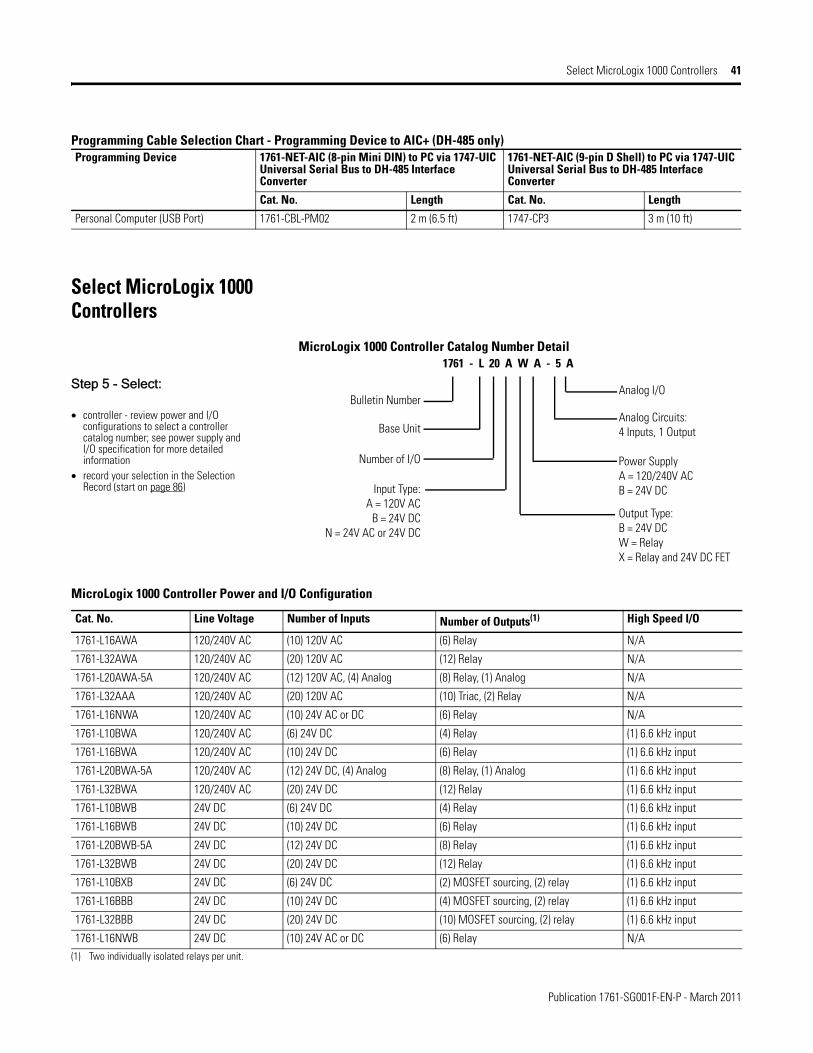
Select MicroLogix 1000 Controllers
MicroLogix 1000 Controller Catalog Number Detail
Programming Device 1761-NET-AIC (8-pin Mini DIN) to PC via 1747-UIC Universal Serial Bus to DH-485 Interface Converter
1761-NET-AIC (9-pin D Shell) to PC via 1747-UIC Universal Serial Bus to DH-485 Interface Converter
Cat. No. Length Cat. No. Length
Personal Computer (USB Port) 1761-CBL-PM02 2 m (6.5 ft) 1747-CP3 3 m (10 ft)
Step 5 - Select:
• controller - review power and I/O configurations to select a controller catalog number; see power supply and I/O specification for more detailed information
• record your selection in the Selection Record (start on page 86)
1761 - L 20 A W A - 5 A
Analog I/O
Analog Circuits:4 Inputs, 1 Output
Power Supply A = 120/240V ACB = 24V DC
Output Type:B = 24V DCW = RelayX = Relay and 24V DC FET
Bulletin Number
Base Unit
Number of I/O
Input Type: A = 120V AC
B = 24V DCN = 24V AC or 24V DC
MicroLogix 1000 Controller Power and I/O Configuration
Cat. No. Line Voltage Number of Inputs Number of Outputs(1) High Speed I/O
1761-L16AWA 120/240V AC (10) 120V AC (6) Relay N/A
1761-L32AWA 120/240V AC (20) 120V AC (12) Relay N/A
1761-L20AWA-5A 120/240V AC (12) 120V AC, (4) Analog (8) Relay, (1) Analog N/A
1761-L32AAA 120/240V AC (20) 120V AC (10) Triac, (2) Relay N/A
1761-L16NWA 120/240V AC (10) 24V AC or DC (6) Relay N/A
1761-L10BWA 120/240V AC (6) 24V DC (4) Relay (1) 6.6 kHz input
1761-L16BWA 120/240V AC (10) 24V DC (6) Relay (1) 6.6 kHz input
1761-L20BWA-5A 120/240V AC (12) 24V DC, (4) Analog (8) Relay, (1) Analog (1) 6.6 kHz input
1761-L32BWA 120/240V AC (20) 24V DC (12) Relay (1) 6.6 kHz input
1761-L10BWB 24V DC (6) 24V DC (4) Relay (1) 6.6 kHz input
1761-L16BWB 24V DC (10) 24V DC (6) Relay (1) 6.6 kHz input
1761-L20BWB-5A 24V DC (12) 24V DC (8) Relay (1) 6.6 kHz input
1761-L32BWB 24V DC (20) 24V DC (12) Relay (1) 6.6 kHz input
1761-L10BXB 24V DC (6) 24V DC (2) MOSFET sourcing, (2) relay (1) 6.6 kHz input
1761-L16BBB 24V DC (10) 24V DC (4) MOSFET sourcing, (2) relay (1) 6.6 kHz input
1761-L32BBB 24V DC (20) 24V DC (10) MOSFET sourcing, (2) relay (1) 6.6 kHz input
1761-L16NWB 24V DC (10) 24V AC or DC (6) Relay N/A(1) Two individually isolated relays per unit.
Publication 1761-SG001F-EN-P - March 2011
42 Select MicroLogix 1000 Controllers
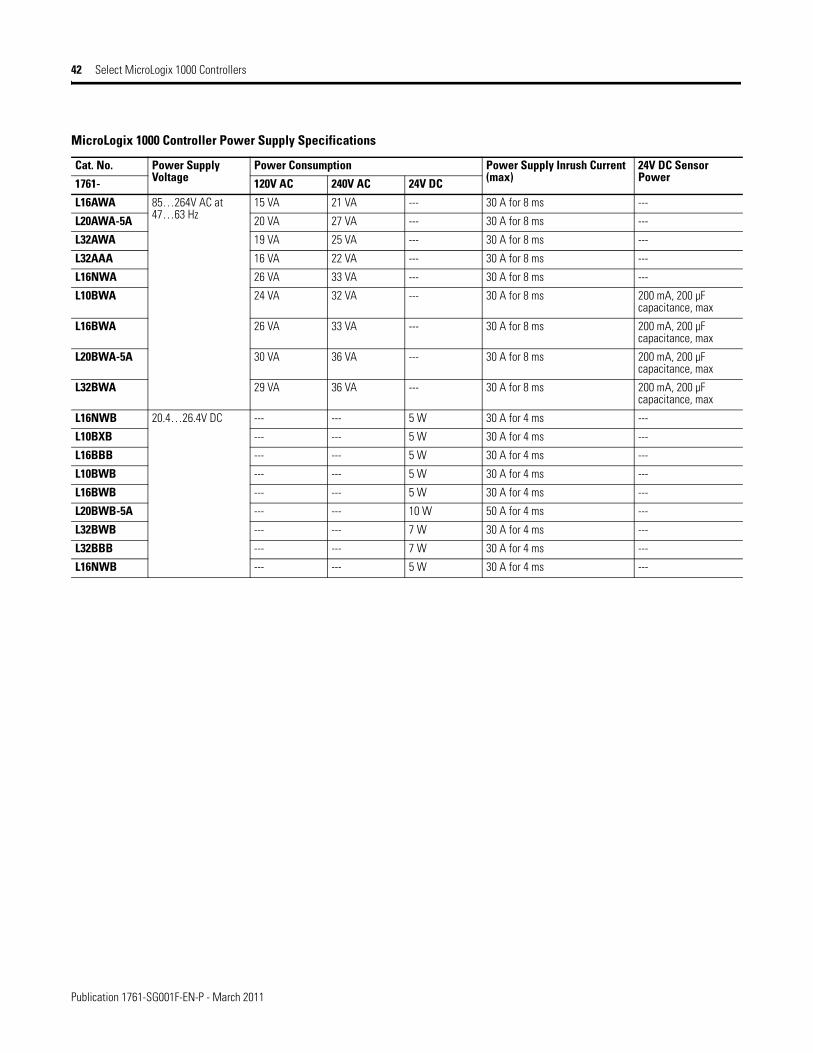
MicroLogix 1000 Controller Power Supply Specifications
Cat. No. Power Supply Voltage
Power Consumption Power Supply Inrush Current (max)
24V DC Sensor Power1761- 120V AC 240V AC 24V DC
L16AWA 85…264V AC at 47…63 Hz
15 VA 21 VA --- 30 A for 8 ms ---
L20AWA-5A 20 VA 27 VA --- 30 A for 8 ms ---
L32AWA 19 VA 25 VA --- 30 A for 8 ms ---
L32AAA 16 VA 22 VA --- 30 A for 8 ms ---
L16NWA 26 VA 33 VA --- 30 A for 8 ms ---
L10BWA 24 VA 32 VA --- 30 A for 8 ms 200 mA, 200 µF capacitance, max
L16BWA 26 VA 33 VA --- 30 A for 8 ms 200 mA, 200 µF capacitance, max
L20BWA-5A 30 VA 36 VA --- 30 A for 8 ms 200 mA, 200 µF capacitance, max
L32BWA 29 VA 36 VA --- 30 A for 8 ms 200 mA, 200 µF capacitance, max
L16NWB 20.4…26.4V DC --- --- 5 W 30 A for 4 ms ---
L10BXB --- --- 5 W 30 A for 4 ms ---
L16BBB --- --- 5 W 30 A for 4 ms ---
L10BWB --- --- 5 W 30 A for 4 ms ---
L16BWB --- --- 5 W 30 A for 4 ms ---
L20BWB-5A --- --- 10 W 50 A for 4 ms ---
L32BWB --- --- 7 W 30 A for 4 ms ---
L32BBB --- --- 7 W 30 A for 4 ms ---
L16NWB --- --- 5 W 30 A for 4 ms ---

Publication 1761-SG001F-EN-P - March 2011
Select MicroLogix 1000 Controllers 43
MicroLogix 1000 Controller DC Input Power Requirements Based on I/O Usage
1761-L10BWB Typical Power Requirements
0
1
2
3
4
5
6
0 2 4 6 8 10
I/O Points Used
Inpu
t Pow
er R
equi
red
at
24Vd
c (W
atts
)
1761-L10BXB, -L16BBB, Typical Power Requirements
0
1
2
3
4
5
6
7
0 2 4 6 8 10 12 14 16
I/O Points Used
Inpu
t Pow
er R
equi
red
at
24Vd
c (W
atts
)1761-L16BWB Typical Power Requirements
0
1
2
3
4
5
6
7
0 2 4 6 8 10 12 14 16
I/O Points Used
Inpu
t Pow
er R
equi
red
at
24Vd
c (W
atts
)
1761-L32BBB Typical Power Requirements
0123456789
10
0 4 8 12 16 20 24 28 32
I/O Points Used
Inpu
t Pow
er R
equi
red
at
24Vd
c (W
atts
)
1761-L32BWB Typical Power Requirements
0
2
4
6
8
10
12
0 4 8 12 16 20 24 28 32
I/O Points Used
Inpu
t Pow
er R
equi
red
at
24Vd
c (W
atts
)
1761-L20BWB-5A Typical Power Requirements
0123456789
10
0 2 4 6 8 10 12 14 16 18 20
I/O Points Used
Inpu
t Pow
er R
equi
red
at
24Vd
c (W
atts
)

Publication 1761-SG001F-EN-P - March 2011
44 Select MicroLogix 1000 Controllers
MicroLogix 1000 Controller Digital Input Specifications
Attribute 120/240V AC Controllers 24V DC Controllers 24V AC ControllersOn-state Voltage Range 79…132V AC 14…26.4V DC max @ 55 °C (131 °F)
14…30.0V DC max @ 30 °C (86 °F)18…26.4V AC @ 55 °C (131 °F)18…30V AC @ 30 °C (86 °F)
Off-state Voltage Range 0…20V AC 0…5V DC 0…3V AC
Operating Frequency(1) 47…63 Hz standard inputs: 1.0 kHz, max
high-speed inputs: 6.6 kHz, max
47…63 Hz
Signal Delay, max ON Delay = 20 msOFF Delay = 20 ms
standard inputs: selectable from 0.5 to 16 mshigh-speed inputs: selectable from 0.075 to 16 ms
ON Delay = 20 ms, maxOFF Delay = 20 ms, max
On-state Current, min 5.0 mA at 79V AC @ 47 Hz 2.5 mA @ 14V DC 3.0 mA @ 18V ACOn-state Current, nom 12.0 mA at 120V AC @ 60 Hz 8.0 mA @ 24V DC 8.0 mA @ 24V ACOn-state Current, max 16.0 mA at 132V AC @ 63 Hz 12.0 mA @ 30V DC 12 mA @ 30V ACOff-state Leakage Current, max 2.5 mA 1.5 mA 1.0 mAImpedance, nom 12 kΩ at 50 Hz, 10 kΩ at 60 Hz 3 kΩ 3 kΩInrush Current, max 250 mA, max(2) --- ---
(1) 1761-L16NWA and 1761-L16NWB controllers do not support high-speed inputs even when using 24V DC inputs.
(2) To reduce the inrush maximum to 35 mA, apply a 6.8 kΩ, 5 W resistor in series with the input. The on-state voltage increases to 92V AC as a result.
MicroLogix 1000 Controller Digital Output Specifications
Attribute Relay FET TriacOperating Voltage Range 5…125V DC
5…264V AC
20.4…26.4V DC 85…264V AC
Continuous Current per Point, max See MicroLogix 1500 Controller Relay Contact Rating on page 72.
1.0 A @ 55 °C (131 °F)1.5 A @ 30 °C (86 °F)
0.5 A @ 55 °C (131 °F)1.0 A @ 30 °C (86 °F)
Continuous Current per Common, max 8.0 A 3 A for L10BBB and L16BBB6 A for L32BBB
6 A
Continuous Current per Controller, max 1440 VA 3 A for L10BBB and L16BBB6 A for L32BBB
1440 VA
On-state Current, min 10.0 mA 1 mA 10.0 mAOff-state Leakage Current, max 0 mA 1 mA 2 mA at 132V AC
4.5 mA at 264V ACSignal Delay, max - resistive load ON Delay = 10 ms
OFF Delay = 10 msON Delay = 0.1 msOFF Delay = 1 ms
ON Delay = 8.8 ms at 60 HzON Delay = 10.6 ms at 50 HzOFF Delay = 11.0 ms
Surge Current per Point (peak) N/A 4 A for 10 ms(1) 10 A for 25 ms(1)
(1) Repeatability is once every 2 seconds @ 55 °C (131 °F).
MicroLogix 1000 Controller Relay Contact Rating
Voltage, max Amperes Amperes Continuous VoltamperesMake Break Make Break
240V AC 7.5 A 0.75 A 2.5 A 1800 VA 180 VA120V AC 15 A 1.5 A125V DC 0.22 A(1) 1.0 A 28 VA
24V DC 1.2 A(1) 2.0 A
(1) For DC voltage applications, the make/break ampere rating for relay contacts can be determined by dividing 28 VA by the applied DC voltage. For example, 28 VA/48V DC = 0.58 A. For DC voltage applications less than 48V, the make/break ratings for relay contacts cannot exceed 2 A. For DC voltage applications greater than 48V, the make/break ratings for relay contact cannot exceed 1 A.
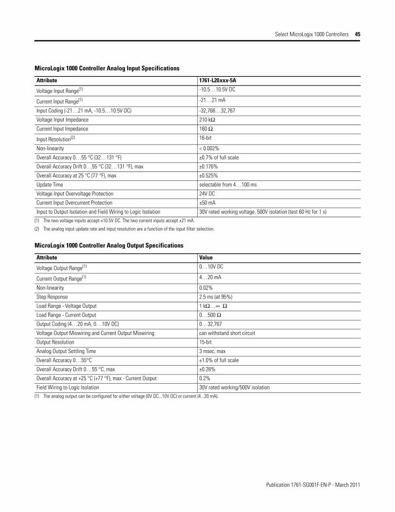
Publication 1761-SG001F-EN-P - March 2011
Select MicroLogix 1000 Controllers 45
MicroLogix 1000 Controller Analog Input Specifications
Attribute 1761-L20xxx-5A
Voltage Input Range(1) -10.5…10.5V DC
Current Input Range(1) -21…21 mA
Input Coding (-21…21 mA, -10.5…10.5V DC) -32,768…32,767
Voltage Input Impedance 210 kΩCurrent Input Impedance 160 Ω
Input Resolution(2) 16-bit
Non-linearity < 0.002%
Overall Accuracy 0…55 °C (32…131 °F) ±0.7% of full scale
Overall Accuracy Drift 0…55 °C (32…131 °F), max ±0.176%
Overall Accuracy at 25 °C (77 °F), max ±0.525%
Update Time selectable from 4…100 ms
Voltage Input Overvoltage Protection 24V DC
Current Input Overcurrent Protection ±50 mA
Input to Output Isolation and Field Wiring to Logic Isolation 30V rated working voltage, 500V isolation (test 60 Hz for 1 s)(1) The two voltage inputs accept ±10.5V DC. The two current inputs accept ±21 mA.
(2) The analog input update rate and input resolution are a function of the input filter selection.
MicroLogix 1000 Controller Analog Output Specifications
Attribute Value
Voltage Output Range(1) 0…10V DC
Current Output Range(1) 4…20 mA
Non-linearity 0.02%
Step Response 2.5 ms (at 95%)
Load Range - Voltage Output 1 kΩ…∞ ΩLoad Range - Current Output 0…500 ΩOutput Coding (4…20 mA, 0…10V DC) 0…32,767
Voltage Output Miswiring and Current Output Miswiring can withstand short circuit
Output Resolution 15-bit
Analog Output Settling Time 3 msec, max
Overall Accuracy 0…55°C ±1.0% of full scale
Overall Accuracy Drift 0…55 °C, max ±0.28%
Overall Accuracy at +25 °C (+77 °F), max - Current Output 0.2%
Field Wiring to Logic Isolation 30V rated working/500V isolation(1) The analog output can be configured for either voltage (0V DC...10V DC) or current (4...20 mA).

Publication 1761-SG001F-EN-P - March 2011
46 Select MicroLogix 1100 Controllers
Select MicroLogix 1100 Controllers
MicroLogix 1100 Base Units
The base unit houses embedded inputs, outputs, power supply, and communication ports. The base unit also provides the interface to expansion I/O when required by an application.
MicroLogix 1100 Controller Catalog Number DetailStep 6 - Select:
• controller - review power and I/O configurations to select a controller catalog number; see power supply and I/O specification for more detailed information
• accessories - memory modules• record your selection in the Selection
Record (starts on page 86)
MicroLogix 1100 Controller Power and I/O Configuration
Cat. No. Line Voltage Number of Inputs Number of Outputs High Speed I/O
1763-L16AWA 120/240V AC (10) 120V AC(2) Analog Voltage
(6) Individually Isolated Relay
None
1763-L16BWA 120/240V AC (6) 24V DC(4) Fast 24V DC(2) Analog Voltage
(6) Individually Isolated Relay
(4) 40 kHZ input
1763-L16BBB 24V DC (6) 24V DC(4) Fast 24V DC(2) Analog Voltage
(2) Individually Isolated Relay(2) 24V DC FET(2) Fast 24V DC FET
(4) 40 kHZ input(2) 40 kHZ output
1763-L16DWD 12...24V DC (6) 12V DC/24V DC(4) Fast 12V DC/24V DC(2) Analog Voltage
(6) Individually Isolated Relay
(4) 40 kHZ input
1763 - L 16 A W A
Power Supply A = 120/240V ACB = 24V DCD = 12...24V DC
Input Type:A = 120V AC
B = 24V DCD = 12...24V DC
Bulletin Number
Number of I/O Output Type:B = Relay/24V DCW = Relay
Base Unit
MicroLogix 1100 Controller Power Supply Specifications
Attribute 1763-L16AWA 1763-L16BWA 1763-L16BBB 1763-L16DWD
Power Supply Voltage 85…264V AC @ 47…63 Hz 20.4…26.4V DC Class 2 SELV
12…24V DC (-15%, 10%) Class 2 SELV
Power Consumption 46 VA 52 VA 6...30 W 6...30 W
Power Supply Inrush Current, max
120V AC: 25 A for 8 ms240V AC: 40 A for 4 ms
24V DC: 15 A for 20 ms 24V DC: 15 A for 20 ms
24V DC Sensor Power --- 250 mA, 400µF capacitance, max
--- ---
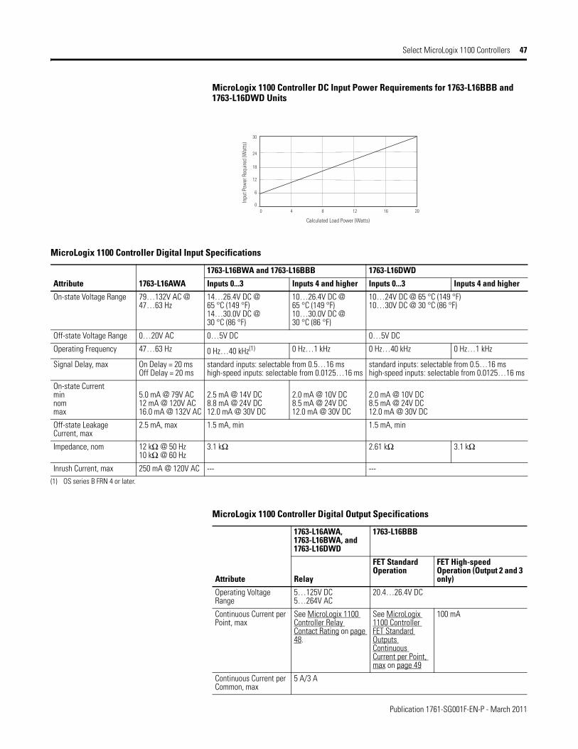
Publication 1761-SG001F-EN-P - March 2011
Select MicroLogix 1100 Controllers 47
MicroLogix 1100 Controller DC Input Power Requirements for 1763-L16BBB and 1763-L16DWD Units
Calculated Load Power (Watts)
Inpu
t Pow
er R
equi
red
(Wat
ts)
0 4 8 12 16 200
6
12
18
24
30
MicroLogix 1100 Controller Digital Input Specifications
Attribute 1763-L16AWA
1763-L16BWA and 1763-L16BBB 1763-L16DWD
Inputs 0...3 Inputs 4 and higher Inputs 0...3 Inputs 4 and higher
On-state Voltage Range 79…132V AC @ 47…63 Hz
14…26.4V DC @ 65 °C (149 °F)14…30.0V DC @ 30 °C (86 °F)
10…26.4V DC @65 °C (149 °F)10…30.0V DC @30 °C (86 °F)
10…24V DC @ 65 °C (149 °F)10…30V DC @ 30 °C (86 °F)
Off-state Voltage Range 0…20V AC 0…5V DC 0…5V DC
Operating Frequency 47…63 Hz 0 Hz…40 kHz(1) 0 Hz…1 kHz 0 Hz…40 kHz 0 Hz…1 kHz
Signal Delay, max On Delay = 20 msOff Delay = 20 ms
standard inputs: selectable from 0.5…16 mshigh-speed inputs: selectable from 0.0125…16 ms
standard inputs: selectable from 0.5…16 mshigh-speed inputs: selectable from 0.0125…16 ms
On-state Currentminnommax
5.0 mA @ 79V AC12 mA @ 120V AC16.0 mA @ 132V AC
2.5 mA @ 14V DC8.8 mA @ 24V DC12.0 mA @ 30V DC
2.0 mA @ 10V DC8.5 mA @ 24V DC12.0 mA @ 30V DC
2.0 mA @ 10V DC8.5 mA @ 24V DC12.0 mA @ 30V DC
Off-state Leakage Current, max
2.5 mA, max 1.5 mA, min 1.5 mA, min
Impedance, nom 12 kΩ @ 50 Hz10 kΩ @ 60 Hz
3.1 kΩ 2.61 kΩ 3.1 kΩ
Inrush Current, max 250 mA @ 120V AC --- ---(1) OS series B FRN 4 or later.
MicroLogix 1100 Controller Digital Output Specifications
Attribute
1763-L16AWA, 1763-L16BWA, and 1763-L16DWD
1763-L16BBB
Relay
FET Standard Operation
FET High-speed Operation (Output 2 and 3 only)
Operating Voltage Range
5…125V DC5…264V AC
20.4…26.4V DC
Continuous Current per Point, max
See MicroLogix 1100 Controller Relay Contact Rating on page 48.
See MicroLogix 1100 Controller FET Standard Outputs Continuous Current per Point, max on page 49
100 mA
Continuous Current per Common, max
5 A/3 A

Publication 1761-SG001F-EN-P - March 2011
48 Select MicroLogix 1100 Controllers
Continuous Current per Controller, max
30 A or total of per-point loads, whichever is less at 150V, max20 A or total of per-point loads, whichever is less at 240V, max
On-state Current, min 10.0 mA 1 mA 10.0 mA
Off-state Leakage Current, max
0 mA 1 mA
Signal Delay, max - resistive load
On Delay = 10 msOff Delay = 10 ms
On Delay = 0.1 msOff Delay = 1.0 ms
On Delay = 6 µsOff Delay = 18 µs
Surge Current per Point (peak)
--- 4 A for 10 ms (repeatability is once every 2 s @ 65 °C (149 °F), once every 1 s @ 30 °C (86 °F)
MicroLogix 1100 Controller Analog Input Specifications
Attribute 1763-L16AWA, 1763-L16BWA, 1763-L16BBB, 1763-L16DWD
Voltage Input Range 0…10V DC
Input Coding (0…10V DC) 0…1023
Voltage Impedance 210 kΩInput Resolution 10-bit
Non-linearity (in percent full scale) ±0.5%
Overall Accuracy ±0.5% full scale at -20…65 °C (-4…149 °F)
Update Time 100/20/16.67/4 ms (selectable)
Voltage Input Overvoltage Protection 10.5V DC
Field Wiring to Logic Isolation Non-isolated with logic
MicroLogix 1100 Controller Relay Contact Rating
Voltage, max
Amperes Amperes Continuous
Voltamperes
Make Break Make Break
240V AC 15.0 A 1.5 A5.0 A/3.0 A 3600 VA 360 VA
120V AC 30 A 3.0 A
125V DC 0.22 A 1.0 A28 VA
24 V DC 1.2 A 2.0 A
MicroLogix 1100 Controller Digital Output Specifications
Attribute
1763-L16AWA, 1763-L16BWA, and 1763-L16DWD
1763-L16BBB
Relay
FET Standard Operation
FET High-speed Operation (Output 2 and 3 only)

Publication 1761-SG001F-EN-P - March 2011
Select MicroLogix 1100 Controllers 49
MicroLogix 1100 Controller FET Standard Outputs Continuous Current per Point, max
0.5
10°C(50°F)
30°C(86°F)
50°C(122°F)
1.5A, 70°C (158°F)
3.0A, 30°C (86°F)
70°C(158°F)
80°C(176°F)
1.0
1.5
2.0
2.5
3.0
3.5
4.0
0.25
10°C(50°F)
30°C(86°F)
50°C(122°F)
0.75A, 70°C (158°F)
Curr
ent (
Am
ps)
Curr
ent (
Am
ps)
FET Current per Point(1763-L16BBB)
FET Total Current(1763-L16BBB)
erutarepmeTerutarepmeT
1.5A, 30°C (86°F)
70°C(158°F)
80°C(176°F)
0.5
0.75
1.0
1.25
1.5
1.75
2.0

Publication 1761-SG001F-EN-P - March 2011
50 Select MicroLogix 1100 Expansion I/O
MicroLogix 1100 Memory Module (1763-MM1)
The controller is shipped with a memory module port cover in place. You can order the memory module to provide removable backup of your User Program and User Data, or to transport your program between controllers.
Memory modules allow:• user programs and data to be store as backup.• transport programs for use with other controllers.• special safety/security features for press control and other critical applications.• auto-recovery, through a power cycle, after a controller fault.• comparison of programs.• data file and memory module write protection.• removal/insertion under power.
Select MicroLogix 1100 Expansion I/O
MicroLogix 1100 controllers expand by using the same 1762 I/O platform as MicroLogix 1200 controllers. The 1762 I/O expansion modules provide superior functionality in a small sized low-cost package. A variety of modules complement and extend the capabilities of MicroLogix 1100 controllers by maximizing the flexibility of I/O count and type.
The MicroLogix 1100 system design allows modules to be either DIN-rail or panel mounted. The DIN latches and screw mounting holes are an integral part of the package design.
Controller I/O can be expanded by using up to four 1762 I/O modules.
Advantages
• Rackless design, eliminating added system costs and inventory• Small footprint with high density I/O, minimizing panel space requirements• Integral high-performance I/O bus• Software keying to prevent incorrect positioning within the system• Feature-rich I/O functionality addresses a wide range of applications• AC/DC relay, 24V DC, 120V AC and 240V AC voltages• Thermocouple/mV and RTD/Resistance temperature input modules
Step 7 - Select:
• I/O modules - digital, analog, and temperature
• record your selections in the Selection Record (start on page 86)

Publication 1761-SG001F-EN-P - March 2011
Select MicroLogix 1100 Expansion I/O 51
Available Modules
1762 Expansion I/O Modules
Cat. No. Description
Digital
1762-IA8 8-Point 120V AC Input Module
1762-IQ8 8-Point Sink/Source 24V DC Input Module
1762-IQ8OW6 8 Point Sink/Source 24V DC Input/6-Point AC/DC Relay Output Combination Module
1762-IQ16 16-Point Sink/Source 24V DC Input Module
1762-OA8 8-Point 120/240V AC Triac Output Module
1762-OB8 8-Point Sourcing 24V DC Output Module
1762-OB16 16-Point Sourcing 24V DC Output Module
1762-OW8 8-Point AC/DC Relay Output Module
1762-OW16 16-Point AC/DC Relay Output Module
1762-OX6I 6-Point Isolated AC/DC Relay Output Module
1762-OV32T 32-Point Solid State 24V DC Sink Output Module
1762-OB32T 32-Point Solid State 24V DC Source Output Module
1762-IQ32T 32-Point DC Input Module
Analog
1762-IF4 4-Channel Voltage/Current Analog Input Module
1762-OF4 4-Channel Voltage/Current Analog Output Module
1762-IF2OF2 Combination 2-Channel Input 2-Channel Output Voltage/Current Analog Module
Specialty
1762-IR4 4-Channel RTD/Resistance Input Module
1762-IT4 4-Channel Thermocouple/mV Input Module

Publication 1761-SG001F-EN-P - March 2011
52 Select MicroLogix 1100 Expansion I/O
1762 Digital I/O
1762 Digital Expansion Input Modules Specifications
Attribute 1762-IA8 1762-IQ8 1762-IQ8OW6 (inputs) 1762-IQ16 1762-IQ32T
Voltage Category 100/120V AC 24V DC (sink/source)(1) 24V DC (sink/source)(1) 24V DC (sink/source)(1) 24V DC sink/source(1)
Operating Voltage Range
79…132V AC @ 47…63 Hz
10…26.4V DC @ 55 °C (131 °F)10…30V DC @ 30 °C (86 °F)
10…26.4V DC @ 65 °C (149 °F)10…30V DC @ 30 °C (86 °F)
10…26.4V DC 10…30V DC (3)(2)
10...26.4V DC10...30V DC
Number of Inputs 8 8 8 16 32
Number of Commons 1 1 inputs: 2outputs: 1
2 4
Bus Current Draw, max
50 mA @ 5V DC (0.25 W)
50 mA @ 5V DC (0.25 W)
110 mA @ 5V DC (0.55 W)80 mA @ 24V DC (1.92 W)
70 mA @ 5V DC (0.35 W) (3)
170 mA @ 5V DC0 mA @ 24V DC
Heat Dissipation, max
2.0 Total Watts 3.7 Total Watts 5.0 Total Watts @ 30V4.4 Total Watts @ 26.4V
5.4 Total Watts @ 30V4.3 Total Watts @ 26.4V (3)
5.4 Total Watts @ 26.4V6.8 Total Watts @ 30.0V
Signal Delay, max On Delay: 20.0 msOff Delay: 20.0 ms
On Delay: 8.0 msOff Delay: 8.0 ms
On Delay: 8.0 msOff Delay: 8.0 ms
On Delay: 8.0 msOff Delay: 8.0 ms
On Delay: 8.0 msOff Delay: 8.0 ms
Off-state Voltage, max
20V AC 5V DC 5V DC 5V DC 5V DC
Off-state Leakage Current, max
2.5 mA 1.5 mA 1.5 mA 1.5 mA 1.0 mA
On-state Voltage, min
79V AC, min, 132V AC, max
10V DC 10V DC 10V DC 10V DC
On-state Currentminnommax
5.0 mA @ 79V AC 47 Hz12.0 mA @ 120V AC 60 Hz16.0 mA @ 132V AC 63 Hz
2.0 mA @ 10V DC8.0 mA @ 24V DC12.0 mA @ 30V DC
2.0 mA @ 10V DC8.0 mA @ 24V DC12.0 mA @ 30V DC
2.0 mA @ 10V DC8.0 mA @ 24V DC12.0 mA @ 30V DC
1.6 mA @ 10V DC (min)2 mA @ 15V DC (min)5.7 mA @ 26.4V DC (max)6.5 mA @ 30.0V DC (max)
Inrush Current, max 250 mA --- 250 mA --- --

Publication 1761-SG001F-EN-P - March 2011
Select MicroLogix 1100 Expansion I/O 53
Impedance, nom 12 kΩ @ 50 Hz10 kΩ @ 60 Hz
3 kΩ 3 kΩ 3 kΩ 4.7 kΩ
Isolated Groups Group 1: inputs 0…7 (internally connected commons)
Group 1: inputs 0…7 (internally connected commons)
Group 1: inputs 0…3Group 2: inputs 4…7Group 3: outputs 0…5
Group 1: inputs 0…7Group 2: inputs 8…15
Group 1: Inputs 0...7Group 2 : Inputs 8...15Group 3 : Inputs 16...23Group 4 : Inputs 24...31
Input Group to Backplane Isolation
Verified by one of the following dielectric tests:
1517V AC for 1 s or 2145V DC for 1 s132V AC working voltage (IEC Class 2 reinforced insulation)
Verified by one of the following dielectric tests:
1200V AC for 1 s or 1697V DC for 1 s75V DC working voltage (IEC Class 2 reinforced insulation)
Verified by one of the following dielectric tests:
Input Group to Backplane isolation - 1200V AC for 1 s or 1697V DC for 1 s75V DC working voltage (IEC Class 2 reinforced insulation)
Output Group to Backplane isolation - 1836V AC for 1 s or 2596V DC for 1 s265V AC working voltage (IEC Class 2 reinforced insulation)
Input Group to Output Group isolation - 1836V AC for 1 s or 2596V DC for 1 s265V AC working voltage (basic insulation)150V AC working voltage (IEC Class 2 reinforced insulation)
Verified by one of the following dielectric tests:
1200V AC for 1 s or 1697V DC for 1 s75V DC working voltage (IEC Class 2 reinforced insulation)
Verified by one of the following dielectric tests:
1,200V AC for 2 s or 1,697V DC for 2 s
75V DC working voltage (IEC Class 2 reinforced insulation)
(1) Sinking/Sourcing Inputs - Sourcing/sinking describes the current flow between the I/O module and the field device. Sourcing I/O circuits supply (source) current to sinking field devices. Sinking I/O circuits are driven by a current sourcing field device. Field devices connected to the negative side (DC Common) of the field power supply are sinking field devices. Field devices connected to the positive side (+V) of the field supply are sourcing field devices.
(2) Refer to Publication 1762-IN10, MicroLogix 1762-IQ16 DC Input Module Installation Instructions, for the derating chart.
(3) Only applicable to Series B I/O modules
Attribute 1762-IA8 1762-IQ8 1762-IQ8OW6 (inputs) 1762-IQ16 1762-IQ32T
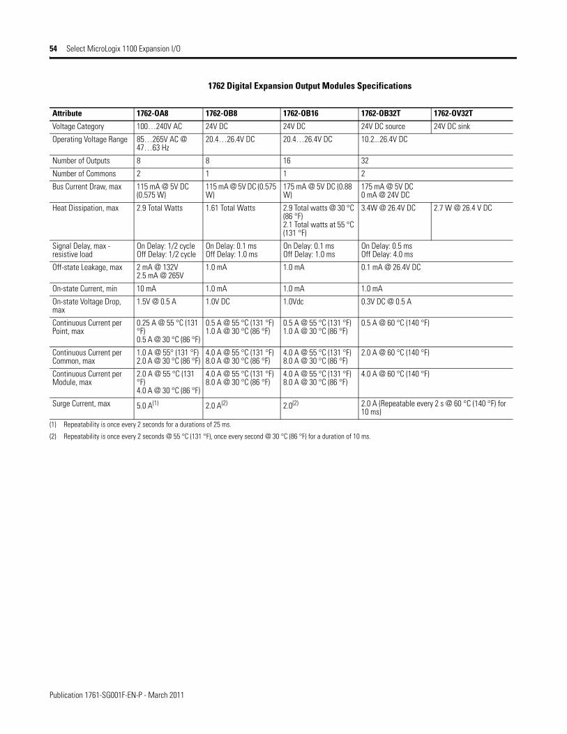
Publication 1761-SG001F-EN-P - March 2011
54 Select MicroLogix 1100 Expansion I/O
1762 Digital Expansion Output Modules Specifications
Attribute 1762-OA8 1762-OB8 1762-OB16 1762-OB32T 1762-OV32T
Voltage Category 100…240V AC 24V DC 24V DC 24V DC source 24V DC sink
Operating Voltage Range 85…265V AC @ 47…63 Hz
20.4…26.4V DC 20.4…26.4V DC 10.2...26.4V DC
Number of Outputs 8 8 16 32
Number of Commons 2 1 1 2
Bus Current Draw, max 115 mA @ 5V DC (0.575 W)
115 mA @ 5V DC (0.575 W)
175 mA @ 5V DC (0.88 W)
175 mA @ 5V DC0 mA @ 24V DC
Heat Dissipation, max 2.9 Total Watts 1.61 Total Watts 2.9 Total watts @ 30 °C (86 °F)2.1 Total watts at 55 °C (131 °F)
3.4W @ 26.4V DC 2.7 W @ 26.4 V DC
Signal Delay, max - resistive load
On Delay: 1/2 cycleOff Delay: 1/2 cycle
On Delay: 0.1 msOff Delay: 1.0 ms
On Delay: 0.1 msOff Delay: 1.0 ms
On Delay: 0.5 msOff Delay: 4.0 ms
Off-state Leakage, max 2 mA @ 132V2.5 mA @ 265V
1.0 mA 1.0 mA 0.1 mA @ 26.4V DC
On-state Current, min 10 mA 1.0 mA 1.0 mA 1.0 mA
On-state Voltage Drop, max
1.5V @ 0.5 A 1.0V DC 1.0Vdc 0.3V DC @ 0.5 A
Continuous Current per Point, max
0.25 A @ 55 °C (131 °F)0.5 A @ 30 °C (86 °F)
0.5 A @ 55 °C (131 °F)1.0 A @ 30 °C (86 °F)
0.5 A @ 55 °C (131 °F)1.0 A @ 30 °C (86 °F)
0.5 A @ 60 °C (140 °F)
Continuous Current per Common, max
1.0 A @ 55° (131 °F)2.0 A @ 30 °C (86 °F)
4.0 A @ 55 °C (131 °F)8.0 A @ 30 °C (86 °F)
4.0 A @ 55 °C (131 °F)8.0 A @ 30 °C (86 °F)
2.0 A @ 60 °C (140 °F)
Continuous Current per Module, max
2.0 A @ 55 °C (131 °F)4.0 A @ 30 °C (86 °F)
4.0 A @ 55 °C (131 °F)8.0 A @ 30 °C (86 °F)
4.0 A @ 55 °C (131 °F)8.0 A @ 30 °C (86 °F)
4.0 A @ 60 °C (140 °F)
Surge Current, max 5.0 A(1) 2.0 A(2) 2.0(2) 2.0 A (Repeatable every 2 s @ 60 °C (140 °F) for 10 ms)
(1) Repeatability is once every 2 seconds for a durations of 25 ms.
(2) Repeatability is once every 2 seconds @ 55 °C (131 °F), once every second @ 30 °C (86 °F) for a duration of 10 ms.

Publication 1761-SG001F-EN-P - March 2011
Select MicroLogix 1100 Expansion I/O 55
1762 Digital Expansion Relay Output Modules Specifications
1762 Analog Modules
1762 Analog Expansion Modules Common Specifications
Attribute 1762-IQ8OW6 (outputs) 1762-OW8 1762-OW16 1762-OX6I
Voltage Category AC/DC normally open relay AC/DC normally open relay AC/DC normally open relay AC/DC Type C Relay
Operating Voltage Range 5…265V AC5…125V DC
5…265V AC5…125V DC
5…265V AC5…125V DC
5…265V AC5…125V DC
Number of Outputs 6 8 16 6 (N.C., N.O.)
Number of Commons inputs: 2outputs: 1
2 2 6
Bus Current Draw, max 110 mA @ 5V DC (0.55 W)80 mA @ 24V DC (1.92 W)
80 mA @ 5V DC (0.40 W)90 mA @ 24V DC (2.16 W)
140 mA @ 5V DC (0.70 W)180 mA @ 24V DC (4.32 W) (1)
(1) Only applicable to Series B I/O modules
110 mA @ 5V DC (0.55 W)110 mA @ 24V DC (2.64 W)
Heat Dissipation, max 5.0 Total Watts @ 30V4.4 Total Watts @ 26.4V
2.9 Total Watts 6.1 Watts (1) 2.8 Watts
Signal Delay, max - resistive load On Delay: 10 msOff Delay: 10 ms
On Delay: 10 msOff Delay: 10 ms
On Delay: 10 msOff Delay: 10 ms
On Delay: 10 ms Off Delay: 20 ms
Off-state Leakage, max 0 mA 0 mA 0 mA 0 mA
On-state Current, min 10 mA @ 5V DC 10 mA @ 5V DC 10 mA 100 mA
On-state Voltage Drop, max N/A N/A N/A N/A
Continuous Current per Point, max 2.5 A (Also see MicroLogix 1500 Controller Relay Contact Rating on page 72.) 7 A (Also see MicroLogix 1500 Controller Relay Contact Rating on page 72.)
Continuous Current per Common, max 8 A 8 A 8 A 7 A (Also see MicroLogix 1500 Controller Relay Contact Rating on page 72.)
Continuous Current per Module, max 8 A 16 A 16 A 30 A
Surge Current, max See MicroLogix 1500 Controller Relay Contact Rating on page 72.
Attribute 1762-IF4 1762-IF2OF2 1762-OF4
Bus Current Draw, max 40 mA @ 5V DC50 mA @ 24V DC
40 mA @ 5V DC105 mA @ 24V DC
40 mA @ 5V DC165 mA @ 24V DC
Analog Normal Operating Range Voltage: -10…10V DCCurrent: 4…20 mA
Voltage: 0…10V DCCurrent: 4…20 mA
Voltage: 0…0V DCCurrent: 4…20 mA
Full Scale(1) Analog Ranges Voltage: -10.5…10.5V DCCurrent: -21…21 mA
Voltage: 0…0.5V DCCurrent: 0…21 mA
Voltage: 0…0.5V DCCurrent: 0…21 mA
Resolution 15 bits (bipolar) (2) 12 bits (unipolar) 12 bits (unipolar)
Repeatability(3) ±0.12% (2) ±0.12% (2) ±0.12% (2)
Input and Output Group to System Isolation
30V AC/30V DC rated working voltage(4) (N.E.C. Class 2 required)(IEC Class 2 reinforced insulation) type test: 500V AC or 707V DC for 1 minute
30V AC/30V DC rated working voltage(IEC Class 2 reinforced insulation) type test: 500V AC or 707V DC for 1 minute
(1) The over- or under-range flag is set when the normal operating range is exceeded. The module continues to convert the analog input up to the maximum full scale range.(2) Only applicable to Series B I/O modules.
(3) Repeatability is the ability of the input module to register the same reading in successive measurements for the same input signal.

Publication 1761-SG001F-EN-P - March 2011
56 Select MicroLogix 1100 Expansion I/O
1762 Analog Expansion Input Modules Specifications
1762 Analog Expansion Output Modules Specifications
(4) Rated working voltage is the maximum continuous voltage that can be applied at the terminals with respect to Earth ground.
Attribute 1762-IF4 1762-IF2OF2
Number of Inputs 4 differential (bipolar) 2 differential (unipolar)
Update Time (typical) 130, 250, 290, 450, 530 ms (selectable) 2.5 ms
A/D Converter Type Successive approximation Successive approximation
Common Mode Voltage Range(1) ±27V ±27V
Common Mode Rejection(2) > 55 dB @ 50 and 60 Hz > 55 dB @ 50 and 60 Hz
Non-linearity (in percent full scale) ±0.12% (2) ±0.12% (2)
Typical Overall Accuracy(3) ±0.32% full scale @ -20…65 °C (-4…149 °F)(4) ±0.24% full scale @ 25 °C (77 °F)
±0.55% full scale @ -20…65 °C (-4…149 °F)(4)
±0.3% full scale @ 25 °C (77 °F)
Input Impedance Voltage Terminal: 200 kΩ, Current Terminal: 275 Ω Voltage Terminal: 200 kΩ, Current Terminal: 250 Ω Current Input Protection ±32 mA ±32 mA
Voltage Input Protection ±30V ±30V
Channel Diagnostics Over or under range or open circuit condition by bit reporting for analog inputs.(1) For proper operation, both the plus and minus input terminals must be within ±27V of analog common.(2) Vcm = 1 Vpk-pk AC.
(3) Vcm = 0 (includes offset, gain, non-linearity and repeatability error terms).
(4) Only applicable to Series B I/O modules
Attribute 1762-IF2OF2 1762-OF4
Number of Outputs 2 single-ended (unipolar) 4 single-ended (unipolar)(2)
Update Time (typical) 4.5 ms 2.5 ms
D/A Converter Type Resistor string R-2R Ladder Voltage Switching
Resistive Load on Current Output 0…500 Ω (includes wire resistance) 0…500 Ω (includes wire resistance)
Load Range on Voltage Output > 1 kΩ > 1 kΩReactive Load, Current Output < 0.1 mH < 0.1 mH
Reactive Load, Voltage Output < 1 μF < 1 μF
Typical Overall Accuracy(1) ±1.17% full scale @ -20…65 °C (-4…149 °F) (2), ±0.5% full scale @ 25 °C (77 °F)
±1.17% full scale @ -20…65 °C (-4…149 °F)(2) ±0.5% full scale @ 25°C
Output Ripple, range 0…500 Hz (referred to output range)
< ±0.1% < ±0.1%
Non-linearity (in percent full scale) < ±0.59%(2) < ±0.59%(2)
Open and Short-circuit Protection Continuous Continuous
Output Protection ±32 mA ±32 mA(1) Includes offset, gain, non-linearity and repeatability error terms.(2) Only applicable to Series B I/O modules.
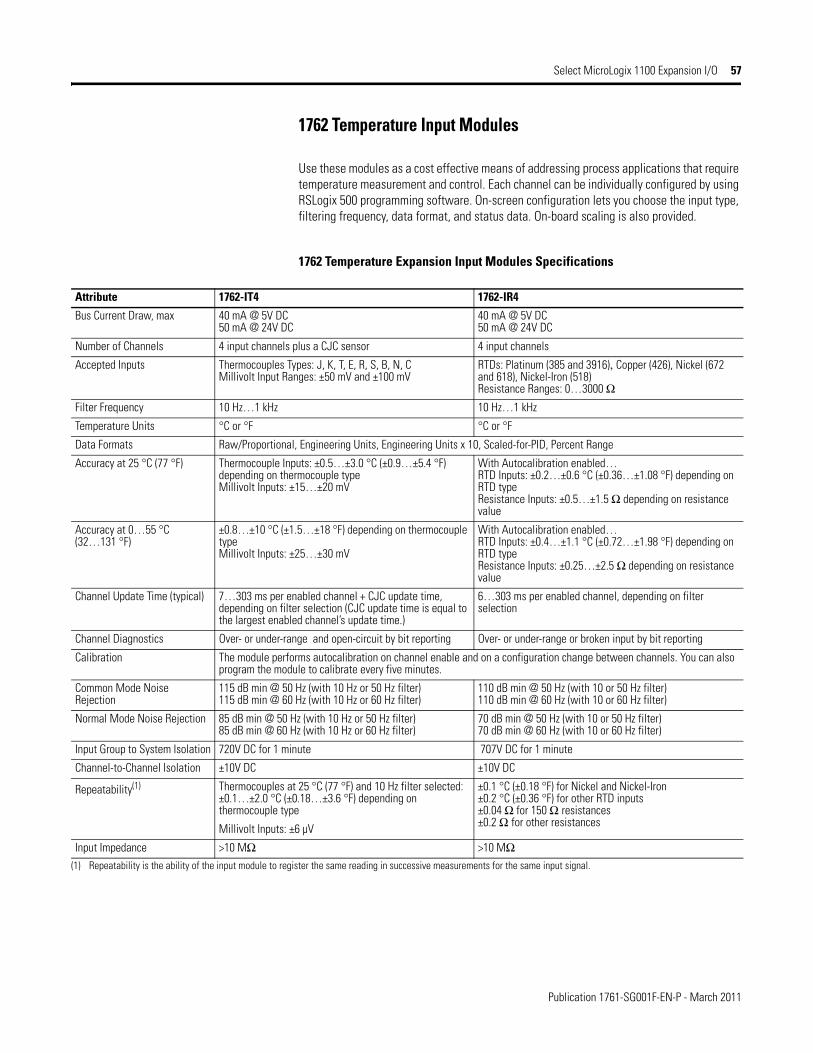
Publication 1761-SG001F-EN-P - March 2011
Select MicroLogix 1100 Expansion I/O 57
1762 Temperature Input Modules
Use these modules as a cost effective means of addressing process applications that require temperature measurement and control. Each channel can be individually configured by using RSLogix 500 programming software. On-screen configuration lets you choose the input type, filtering frequency, data format, and status data. On-board scaling is also provided.
1762 Temperature Expansion Input Modules Specifications
Attribute 1762-IT4 1762-IR4
Bus Current Draw, max 40 mA @ 5V DC50 mA @ 24V DC
40 mA @ 5V DC50 mA @ 24V DC
Number of Channels 4 input channels plus a CJC sensor 4 input channels
Accepted Inputs Thermocouples Types: J, K, T, E, R, S, B, N, CMillivolt Input Ranges: ±50 mV and ±100 mV
RTDs: Platinum (385 and 3916), Copper (426), Nickel (672 and 618), Nickel-Iron (518)Resistance Ranges: 0…3000 Ω
Filter Frequency 10 Hz…1 kHz 10 Hz…1 kHz
Temperature Units °C or °F °C or °F
Data Formats Raw/Proportional, Engineering Units, Engineering Units x 10, Scaled-for-PID, Percent Range
Accuracy at 25 °C (77 °F) Thermocouple Inputs: ±0.5…±3.0 °C (±0.9…±5.4 °F) depending on thermocouple typeMillivolt Inputs: ±15…±20 mV
With Autocalibration enabled…RTD Inputs: ±0.2…±0.6 °C (±0.36…±1.08 °F) depending on RTD typeResistance Inputs: ±0.5…±1.5 Ω depending on resistance value
Accuracy at 0…55 °C (32…131 °F)
±0.8…±10 °C (±1.5…±18 °F) depending on thermocouple typeMillivolt Inputs: ±25…±30 mV
With Autocalibration enabled…RTD Inputs: ±0.4…±1.1 °C (±0.72…±1.98 °F) depending on RTD typeResistance Inputs: ±0.25…±2.5 Ω depending on resistance value
Channel Update Time (typical) 7…303 ms per enabled channel + CJC update time, depending on filter selection (CJC update time is equal to the largest enabled channel’s update time.)
6…303 ms per enabled channel, depending on filter selection
Channel Diagnostics Over- or under-range and open-circuit by bit reporting Over- or under-range or broken input by bit reporting
Calibration The module performs autocalibration on channel enable and on a configuration change between channels. You can also program the module to calibrate every five minutes.
Common Mode Noise Rejection
115 dB min @ 50 Hz (with 10 Hz or 50 Hz filter)115 dB min @ 60 Hz (with 10 Hz or 60 Hz filter)
110 dB min @ 50 Hz (with 10 or 50 Hz filter)110 dB min @ 60 Hz (with 10 or 60 Hz filter)
Normal Mode Noise Rejection 85 dB min @ 50 Hz (with 10 Hz or 50 Hz filter)85 dB min @ 60 Hz (with 10 Hz or 60 Hz filter)
70 dB min @ 50 Hz (with 10 or 50 Hz filter)70 dB min @ 60 Hz (with 10 or 60 Hz filter)
Input Group to System Isolation 720V DC for 1 minute 707V DC for 1 minute
Channel-to-Channel Isolation ±10V DC ±10V DC
Repeatability(1) Thermocouples at 25 °C (77 °F) and 10 Hz filter selected: ±0.1…±2.0 °C (±0.18…±3.6 °F) depending on thermocouple type
Millivolt Inputs: ±6 µV
±0.1 °C (±0.18 °F) for Nickel and Nickel-Iron±0.2 °C (±0.36 °F) for other RTD inputs±0.04 Ω for 150 Ω resistances±0.2 Ω for other resistances
Input Impedance >10 MΩ >10 MΩ(1) Repeatability is the ability of the input module to register the same reading in successive measurements for the same input signal.

Publication 1761-SG001F-EN-P - March 2011
58 Select MicroLogix 1200 Controllers
Select MicroLogix 1200 Controllers
MicroLogix 1200 Controllers Catalog Number Detail
Step 8 - Select:
• controller - review power and I/O configurations to select a controller catalog number; see power supply and I/O specifications for more detailed information
• accessories - memory and real-time clock modules
• record your selections in the Selection Record (start on page 86)
Power Supply A = 120/240V ACB = 24V DC
Output Type:W = RelayX = Relay/24V DC FET
Bulletin Number
Base Unit
Number of I/O
Input Type:A = 120V AC
B = 24V DC
Programming/HMI Port R = EquippedNone = Not Equipped
1762 - L 24 A W A R
MicroLogix 1200 Controller Power and I/O Configuration
Cat. No. Line Voltage Number of Inputs Number of Outputs High Speed I/O
1762-L24AWA, -L24AWAR 120/240V AC (14) 120V AC (10) Relay N/A
1762-L40AWA, -L40AWAR 120/240V AC (24) 120V AC (16) Relay N/A
1762-L24BWA, -L24BWAR 120/240V AC (10) Standard 24V DC(4) Fast 24V DC
(10) Relay (4) 20 kHz input
1762-L40BWA, -L40BWAR 120/240V AC (20) Standard 24V DC(4) Fast 24V DC
(16) Relay (4) 20 kHz input
1762-L24BXB, -L24BXBR 24V DC (10) Standard 24V DC(4) Fast 24V DC
(5) Relay(4) Standard 24V DC FET(1) Fast 24V DC FET
(4) 20 kHz input(1) 20 kHz output
1762-L40BXB, -L40BXBR 24V DC (20) Standard 24V DC(4) Fast 24V DC
(8) Relay(7) Standard 24V DC FET(1) Fast 24V DC FET
(4) 20 kHz input(1) 20 kHz output
MicroLogix 1200 Controller Power Supply Specifications
Attribute 1762-
L24AWA, L24AWAR
L40AWA, L40AWAR
L24BWA, L24BWAR
L40BWA,L40BWAR
L24BXB, L24BXBR
L40BXB, L40BXBR
Power Supply Voltage 85…265V AC @ 47…63 Hz 20.4…26.4V DC Class 2 SELV
Power Consumption 68 VA 80 VA 70 VA 82 VA 27 W 40 W
Power Supply Inrush Current, max
120V AC: 25 A for 8 ms240V AC: 40 A for 4 ms
24V DC: 15 A for 20 ms
24V DC:15 A for 30 ms
Load Current(1), max
5V DC 400 mA 600 mA 400 mA 600 mA 400 mA 600 mA
24V DC 350 mA 500 mA 350 mA 500 mA 350 mA 500 mA
Load Power, max 10.4 W 15 W 12 W 16 W 10.4 W 15 W
24V DC Sensor Power --- --- 250 mA, 400 µF capacitance, max
400 mA, 400 µF capacitance, max
--- ---
(1) See Perform MicroLogix 1200 Controller System Expansion Calculations on page 62 for an example system validation worksheet to calculate expansion I/O power usage.

Publication 1761-SG001F-EN-P - March 2011
Select MicroLogix 1200 Controllers 59
MicroLogix 1200 Controller DC Input Power Requirements for BXB Units
1762-L24BXB, 1762-L24BXBR Typical Power Requirements
0
5
10
15
20
0 2 4 6 8 10
Calculated Load Power (Watts)
Inpu
t Pow
er R
equi
red
at
24Vd
c (W
atts
)
1762-L40BXB, 1762-L40BXBR Typical Power Requirements
0
5
10
15
20
25
30
0 2 4 6 8 10 12 14
Calculated Load Power (Watts)
Inpu
t Pow
er R
equi
red
at
24Vd
c (W
atts
)
MicroLogix 1200 Controller Input Specifications
Attribute 1762-L24AWA, 1762-L24AWAR1762-L40AWA, 1762-L40AWAR
1762-L24BWA, 1762-L24BXB, 1762-L40BWA, 1762-L40BXB1762-L24BWAR, 1762-L24BXBR, 1762-L40BWAR, 1762-L40BXBR
Inputs 0 through 3 Inputs 4 and higher
On-state Voltage Range 79…132V AC @ 47 Hz…63 Hz 14…26.4V DC @ 55 °C (131 °F)14…30.0V DC @ 30 °C (86 °F)
10…26.4V DC @ 55 °C (131 °F)10…30.0V DC @ 30 °C (86 °F)
Off-state Voltage Range 0…20V AC 0…5V DC
Operating Frequency N/A 0 Hz…20 kHz 0 Hz…1 kHz(scan time dependent)
Signal Delay, max ON Delay = 20 msOFF Delay = 20 ms
Standard inputs: selectable from 0.5…16 mshigh-speed inputs: selectable from 0.025…16 ms
On-state Current:minnommax
5.0 mA @ 79V AC12 mA @ 120V AC16.0 mA @ 132V AC
2.5 mA @ 14V DC7.3 mA @ 24V DC12.0 mA @ 30V DC
2.0 mA @ 10V DC8.9 mA @ 24V DC12.0 mA @ 30V DC
Off-state Leakage Current, max 2.5 mA, max 1.5 mA, min
Impedance, nom 12 kΩ @ 50 Hz10 kΩ @ 60 Hz
3.3 kΩ 2.7 kΩ
Inrush Current, max 250 mA at 120V AC ---

Publication 1761-SG001F-EN-P - March 2011
60 Select MicroLogix 1200 Controllers
MicroLogix 1200 Controller FET Standard Outputs Continuous Current per Point, max
MicroLogix 1200 Controller Digital Output Specifications
Attribute 1762-
L24AWA, L24BWA, L24BXB,L40AWA, L40BWA, L40BXB,L24AWAR, L24BWAR, L24BXBR,L40AWAR, L40BWAR, L40BXBR
L24BXB, L40BXBL24BXBR, L40BXBR
Relay FET Standard Operation FET High-speed Operation (Output 2 only)
Operating Voltage Range 5…125V DC5…264V AC
21.6…27.6V DC 21.6…27.6V DC
Continuous Current per Point, max See MicroLogix 1500 Controller Relay Contact Rating on page 72.
See below, MicroLogix 1200 Controller FET Standard Outputs Continuous Current per Point, max.
100 mA
Continuous Current per Common, max 8.0 A 7.5 A for L24BXB, L24BXBR8.0 A for L40BXB, L40BXBR
Continuous Current per Controller, max 30 A or total of per-point loads, whichever is less at 150V max20 A or total of per-point loads, whichever is less at 240V max
On-state Current, min 10.0 mA 1 mA 10.0 mA
Off-state Leakage Current, max 0 mA 1 mA
Signal Delay, max - resistive load ON Delay = 10 msOFF Delay = 10 ms
ON Delay = 0.1 msOFF Delay = 1.0 ms
ON Delay = 6 µsOFF Delay = 18 µs
Surge Current per Point (peak) --- 4 A for 10 ms(1)
(1) Repeatability is once every 2 seconds @ 55 °C (131 °F), once every 1 second @ 30 °C (86 °F).
MicroLogix 1200 Controller Relay Contact Rating
Voltage, max Amperes Amperes Continuous Voltamperes
Make Break Make Break
240V AC 7.5 A 0.75 A 2.5 A 1800 VA 180 VA
120V AC 15 A 1.5 A
125V DC 0.22 A(1) 1.0 A 28 VA
24V DC 1.2 A(1) 2.0 A
(1) For DC voltage applications, the make/break ampere rating for relay contacts can be determined by dividing 28 VA by the applied DC voltage. For example, 28 VA/48V DC = 0.58 A. For DC voltage applications less than 48V, the make/break ratings for relay contacts cannot exceed 2 A. For DC voltage applications greater than 48V, the make/break ratings for relay contact cannot exceed 1 A.
0.25
10˚C(50˚F)
30˚C(86˚F)
50˚C(122˚F)
1.0A, 55˚C (131˚F)
1.5A, 30˚C (86˚F)
70˚C(158˚F)
0.5
0.75
1.0
1.25
1.5
1.75
2.0
1.0
10˚C(50˚F)
30˚C(86˚F)
50˚C(122˚F)
5.5A, 55˚C (131˚F)
8A, 30˚C (86˚F)
70˚C(158˚F)
2.0
3.0
4.0
5.0
6.0
7.0
8.0
9.0
FET Current per Common(1762-L40BXB and L40BXBR)
Curre
nt (A
mps
)
Curre
nt (A
mps
)
TemperatureTemperature
Valid Range Valid Range
FET Current per Point(1762-L24BXB, L40BXB, L24BXBR, L40BXBR)

Publication 1761-SG001F-EN-P - March 2011
Select MicroLogix 1200 Expansion I/O 61
MicroLogix 1200 Memory and Real-Time Clock Modules
The controller is shipped with a memory module port cover in place. You can order the memory module, real-time clock, or combination module to suit your needs.
Real-time Clock (1762-RTC)
• Allows for time/date scheduling• Self-contained battery provides long-term time base
Memory Module (1762-MM1)
• User program and data back-up• Program compare• Data file protection• Memory module write protection• Removal/insertion under power
Combination Memory and Real-time Clock Module (1762-MM1RTC)
Provides all real-time clock and memory back-up functions of the 1762-RTC and 1762-MM1 modules
Select MicroLogix 1200 Expansion I/O
MicroLogix 1200 controllers expand by using the same 1762 I/O platform as MicroLogix 1100 controllers. The 1762 I/O expansion modules provide superior functionality in a small sized low-cost package. A variety of modules complement and extend the capabilities of MicroLogix 1200 controllers by maximizing the flexibility of I/O count and type.
The MicroLogix 1200 system design allows modules to be either DIN rail or panel mounted. The DIN latches and screw mounting holes are an integral part of the package design.
Controller I/O can be expanded by using up to six expansion modules per controller (depending on power budget).
See Select MicroLogix 1100 Expansion I/O on page 50 for available modules and specifications.
1762 Expansion I/O Modules Connected to a MicroLogix 1200 Controller
Step 9 - Select:
• I/O modules - digital, analog, and temperature
• perform system expansion calculations• record your selections in the Selection
Record (start on page 86)

Publication 1761-SG001F-EN-P - March 2011
62 Perform MicroLogix 1200 Controller System Expansion Calculations
Perform MicroLogix 1200 Controller System Expansion Calculations
A download is also available for system validation. On the Internet, go to http://www.ab.com/micrologix.
To have a valid system, both current and power requirements must be satisfied. Use the following worksheets to make your calculations.
Follow these steps to verify the controller power supply loading.
1. Use the following table to select the components for your system. Do not exceed the MAXIMUM LIMIT for the number of I/O modules.
2. Fill in the current amounts and add up the TOTAL CALCULATED CURRENT.
MicroLogix 1200 Controller Power Supply Loading - Calculate System Current
Cat. No. Bus Current Draw Attribute Calculated Current for System
at 5V DC (mA) at 24V DC (mA) at 5V DC (mA) at 24V DC (mA)
1761-NET-AIC(1)(2) 0 120(2)
1761-NET-ENI, 1761-NET-ENIW(1)(2) 0 100(2)
2707-MVH232 or 2707-MVP232(1)(2) 0 80(2)
Cat. No. n = Number of Modules(6 max)
A B n x A n x B
1762-IA8 50 0
1762-IQ8 50 0
1762-IQ8OW6 110 80
1762-IQ16 (Series A) 60 0
1762-OA8 115 0
1762-OB8 115 0
1762-OB16 175 0
1762-OW8 80 90
1762-OW16 (Series A) 120 140
1762-OX6I 110 110
1762-IF2OF2 40 105
1762-IF4 40 50
1762-OF4 40 165
1762-IR4 40 50
1762-IT4 40 50
1762-OV32T 175 0
1762-OB32T 175 0
1762-IQ32T 170 0
1762-IQ16 (Series B) 70 0
1762-OW16 (Series B) 140 180
TOTAL MODULES: TOTAL CALCULATED CURRENT: (C) (D)
For 1762-L24BWA, 1762-L40BWA, 1762-L24BWAR, and 1762-L40BWAR only, add sum of any User 24V DC Sensor Current
(E)
(1) These are optional accessories. Current is consumed only if the accessory is installed.
(2) Current for the 1761-NET-AIC or 1761-NET-ENI(W) can be supplied by the controller’s communication port or from an external 24V DC source. No current is consumed from the controller when a user-suppled, external source is used. If an external source is to be used, do not select the device here. The current for a 2707-MVH232 or 2707-MVP232 MicroView Operator Interface is supplied from the controller’s communication port, if directly connected.
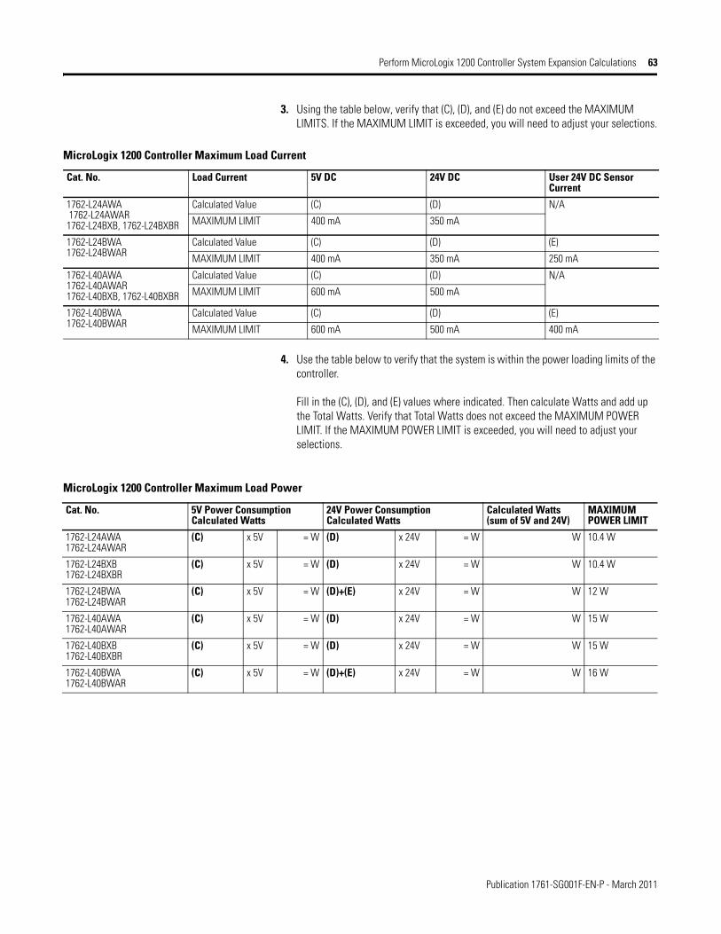
Publication 1761-SG001F-EN-P - March 2011
Perform MicroLogix 1200 Controller System Expansion Calculations 63
3. Using the table below, verify that (C), (D), and (E) do not exceed the MAXIMUM LIMITS. If the MAXIMUM LIMIT is exceeded, you will need to adjust your selections.
4. Use the table below to verify that the system is within the power loading limits of the controller.
Fill in the (C), (D), and (E) values where indicated. Then calculate Watts and add up the Total Watts. Verify that Total Watts does not exceed the MAXIMUM POWER LIMIT. If the MAXIMUM POWER LIMIT is exceeded, you will need to adjust your selections.
MicroLogix 1200 Controller Maximum Load Current
Cat. No. Load Current 5V DC 24V DC User 24V DC Sensor Current
1762-L24AWA 1762-L24AWAR1762-L24BXB, 1762-L24BXBR
Calculated Value (C) (D) N/A
MAXIMUM LIMIT 400 mA 350 mA
1762-L24BWA1762-L24BWAR
Calculated Value (C) (D) (E)
MAXIMUM LIMIT 400 mA 350 mA 250 mA
1762-L40AWA1762-L40AWAR1762-L40BXB, 1762-L40BXBR
Calculated Value (C) (D) N/A
MAXIMUM LIMIT 600 mA 500 mA
1762-L40BWA1762-L40BWAR
Calculated Value (C) (D) (E)
MAXIMUM LIMIT 600 mA 500 mA 400 mA
MicroLogix 1200 Controller Maximum Load Power
Cat. No. 5V Power ConsumptionCalculated Watts
24V Power ConsumptionCalculated Watts
Calculated Watts(sum of 5V and 24V)
MAXIMUM POWER LIMIT
1762-L24AWA 1762-L24AWAR
(C) x 5V = W (D) x 24V = W W 10.4 W
1762-L24BXB1762-L24BXBR
(C) x 5V = W (D) x 24V = W W 10.4 W
1762-L24BWA 1762-L24BWAR
(C) x 5V = W (D)+(E) x 24V = W W 12 W
1762-L40AWA 1762-L40AWAR
(C) x 5V = W (D) x 24V = W W 15 W
1762-L40BXB 1762-L40BXBR
(C) x 5V = W (D) x 24V = W W 15 W
1762-L40BWA 1762-L40BWAR
(C) x 5V = W (D)+(E) x 24V = W W 16 W

Publication 1761-SG001F-EN-P - March 2011
64 Select MicroLogix 1400 Controllers
Select MicroLogix 1400 Controllers
MicroLogix 1400 Base Units
The base unit houses embedded inputs, outputs, power supply, and communication ports. The base unit also provides the interface to expansion I/O when required by an application.
MicroLogix 1400 Controller Catalog Number DetailStep 10 - Select:
• controller - review power and I/O configurations to select a controller catalog number; see power supply and I/O specification for more detailed information
• accessories - memory modules• record your selection in the Selection
Record (starts on page 86)
MicroLogix 1400 Controller Power and I/O Configuration
Cat. No. Line Voltage Number of Inputs Number of Outputs Embedded Analog I/O
1766-L32BWA 120/240V AC (12) Fast 24V DC(8) Normal 24V DC
(12) Relay ---
1766-L32AWA 120/240V AC (20) 120V AC (12) Relay ---
1766-L32BXB 24V DC (12) Fast 24V DC(8) Normal 24V DC
(6) Relay(3) Fast 24V DC(3) Normal 24V DC
---
1766-L32BWAA 120/240V AC (12) Fast 24V DC(8) Normal 24V DC
(12) Relay (4) Voltage Inputs(2) Voltage Outputs
1766-L32AWAA 120/240V AC (20) 120V AC (12) Relay (4) Voltage Inputs(2) Voltage Outputs
1766-L32BXBA 24V DC (12) Fast 24V DC(8) Normal 24V DC
(6) Relay(3) Fast 24V DC(3) Normal 24V DC
(4) Voltage Inputs(2) Voltage Outputs
Power Supply A = 120/240V ACB = 24V DC
Output Type:W = RelayX = Relay/24V DC FET
Bulletin Number
Base Unit
Number of I/O
Input Type:A = 120V AC
B = 24V DC
Analog I/OA = availableNone = not available
1766 - L 32 B W A A
MicroLogix 1400 Controller Power Supply Specifications
Attribute 1766-L32AWA, 1766-L32AWAA
1766-L32BWA, 1766-L32BWAA
1766-L32BXB, 1766-L32BXBA
Power Supply Voltage 100...240V AC (-15%, 10%) at 47...63 Hz 24V DC (-15%, 10%) Class 2 SELV

Publication 1761-SG001F-EN-P - March 2011
Select MicroLogix 1400 Controllers 65
MicroLogix 1400 Controller DC Input Power Requirements for 1766-L32BXB and 1766-L32BXBA Units
Power Consumption 100 VA 120 VA 7.5...53 W
Power Supply Inrush Current, max
120V AC: 25 A for 8 ms240V AC: 40 A for 4 ms
24V DC: 15 A for 20 ms
24V DC Sensor Power --- 24V DC at 250 mA, 400µF capacitance, max
---
MicroLogix 1400 Controller Power Supply Specifications
Attribute 1766-L32AWA, 1766-L32AWAA
1766-L32BWA, 1766-L32BWAA
1766-L32BXB, 1766-L32BXBA
1766-L32BXBA Input Power versus 1762 Bus Load
0
10
20
30
40
50
60
5 15 25 35
1762 Bus Load (W)
24V
DC
Pow
er S
uppl
y In
put
Pow
er (W
)

Publication 1761-SG001F-EN-P - March 2011
66 Select MicroLogix 1400 Controllers
MicroLogix 1400 Controller Digital Input Specifications
Attribute 1766-L32AWA, 1766-L32AWAA
1766-L32BWA, 1766-L32BWAA, 1766-L32BXB, 1766-L32BXBA
Inputs 0...11 (12 high-speed DC inputs) Inputs 12 and above (8 standard DC inputs)
On-state Voltage Range 79...132V AC 4.5...24V DC 4.5...26.4V DC at 60 °C (140 °F)4.5...30V DC at 30 °C (86 °F)
10...24V DC 10...26.4V DC at 60 °C (140 °F)10...30V DC at 30 °C (86 °F)
Off-state Voltage Range 0...20V AC 0...1.5V DC 0...5V DC
Operating Frequency 47...63 Hz 0 Hz...100 kHz 0 Hz...1 kHz (scan time dependent)
On-state Currentminnommax
5.0 mA @ 79 V AC12 mA @ 120 V AC16.0 mA @ 132 V AC
7.1 mA @ 4.5V DC9.9 mA @ 24V DC10.5 mA @ 30V DC
3.2 mA @ 10V DC5.3 mA @ 24V DC5.5 mA @ 30V DC
Off-state Leakage Current, max
2.5 mA, max 0.2 mA, max 1.5 mA, max
Impedance, nom 12 kΩ at 50 Hz10 kΩ at 60 Hz
2.4 kΩ 4.5 kΩ
Inrush Current, max 250 mA
MicroLogix 1400 Controller Analog Input Specifications
Attribute Value
Voltage Input Range 0...10.0V DC - 1 LSB
Type of Data 12-bit unsigned integer
Input Coding (0…10V DC) 0...4095
Voltage Impedance >199 kΩInput Resolution 12 bit
Non-linearity (in percent full scale) ±0.5% of full scale
Overall Accuracy ±1.0% of full scale
Update Time 100/20/16.67/4 ms (selectable)
Voltage Input Overvoltage Protection 10.5 V DC
Field Wiring to Logic Isolation Non-isolated with internal logic
MicroLogix 1400 Controller Analog Output Specifications
Attribute Value
Voltage Output Range 0...10.0V DC - 1 LSB
Type of Data 12-bit unsigned integer
Step Response 2.5 ms @ 95%
Output Coding (0...10V DC) 0...4095
Load Range Voltage Output >1 kΩOutput Resolution 12 bit
Analog Output Setting Time 3 ms, max
Overall Accuracy ±1.0% of full scale
Electrical Isolation Non-isolated with internal logic
Cable Length 30 m (98 ft) shielded cable

Publication 1761-SG001F-EN-P - March 2011
Select MicroLogix 1400 Controllers 67
Specifications for MicroLogix 1400 Controller Outputs in Hazardous locations (Class 1, Division 2, Groups A, B, C, D)
Relay and FET Outputs
Attribute 1766-L32AWA, 1766-L32AWAA, 1766-L32BWA, 1766-L32BWAA
1766-L32BXB, 1766-L32BXBA
Controlled Load, max 1440 VA 1080 VA
Continuous Current, max
Current per Channel and Group Common 2.5 A per channel8 A max channel 8...11 common
2.5 A per channel
Current per Controller @ 150V, max 28 A or total of per-point loads, whichever is less
@ 240V, max 20 A or total of per-point loads, whichever is less
Relay Outputs
Attribute Value
Turn On Time/Turn Off Time 10 ms, max(1)
(1) Scan time dependent.
Load Current 10 mA
Relay Contact Rating
Voltage, max
Amperes Amperes Continuous
Voltamperes
Make Break Make Break
240V AC 7.5 A 0.75 A2.5 A 1800 VA 180 VA
120V AC 15 A 1.5 A
250V DC 0.11 A 1.0 A 28 VA
125V DC 0.22 A 1.0 A 28 VA
1766-L32BXB, 1766-L32BXBA FET Outputs
Attribute General Operation High-speed Operation (outputs 2, 3, and 4 only)(1)
Power Supply Voltage (Class 2) 24V DC (-15%, +10%)
On-state Voltage Dropat maximum load currentat maximum surge current
1V DC2.5V DC
Not ApplicableNot Applicable
Current Rating per Pointmaximum loadminimum loadmaximum leakage
See chart1.0 mA1.0 mA
100 mA20 mA1.0 mA
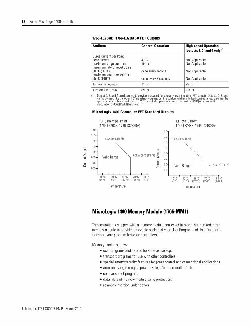
Publication 1761-SG001F-EN-P - March 2011
68 Select MicroLogix 1400 Controllers
MicroLogix 1400 Controller FET Standard Outputs
MicroLogix 1400 Memory Module (1766-MM1)
The controller is shipped with a memory module port cover in place. You can order the memory module to provide removable backup of your User Program and User Data, or to transport your program between controllers.
Memory modules allow:• user programs and data to be store as backup.• transport programs for use with other controllers.• special safety/security features for press control and other critical applications.• auto-recovery, through a power cycle, after a controller fault.• comparison of programs.• data file and memory module write protection.• removal/insertion under power.
Surge Current per Pointpeak currentmaximum surge durationmaximum rate of repetition at 30 °C (86 °F)maximum rate of repetition at 65 °C (149 °F)
4.0 A10 ms
once every second
once every 2 seconds
Not ApplicableNot Applicable
Not Applicable
Not Applicable
Turn-on Time, max 11 µs 28 ns
Turn-off Time, max 89 µs 2.3 µs(1) Output 2, 3, and 4 are designed to provide increased functionality over the other FET outputs. Outputs 2, 3, and
4 may be used like the other FET transistor outputs, but in addition, within a limited current range, they may be operated at a higher speed. Outputs 2, 3, and 4 also provide a pulse train output (PTO) or pulse width modulation output (PWM) function.
1766-L32BXB, 1766-L32BXBA FET Outputs
Attribute General Operation High-speed Operation (outputs 2, 3, and 4 only)(1)
1.0
10 °C(50 °F)
30 °C(86 °F)
50 °C(122 °F)
3.0 A, 60 °C (140 °F)
6.0 A, 30 °C (86 °F)
70 °C(158 °F)
80 °C(176 °F)
2.0
3.0
4.0
5.0
6.0
7.0
8.0
0.25
10 °C(50 °F)
30 °C(86 °F)
50 °C(122 °F)
0.75 A, 60 °C (140 °F)
1.5 A, 30 °C (86 °F)
70 °C(158 °F)
80 °C(176 °F)
0.5
0.75
1.0
1.25
1.5
1.75
2.0
FET Total Current(1766-L32BXB, 1766-L32BXBA)
Curre
nt (A
mps
)
Curre
nt (A
mps
)
TemperatureTemperature
Valid Range
Valid Range
FET Current per Point(1766-L32BXB, 1766-L32BXBA)

Publication 1761-SG001F-EN-P - March 2011
Select MicroLogix 1400 Expansion I/O 69
Select MicroLogix 1400 Expansion I/O
MicroLogix 1400 controllers expand by using the same 1762 I/O platform as MicroLogix 1100 controllers. The 1762 I/O expansion modules provide superior functionality in a small sized low-cost package. A variety of modules complement and extend the capabilities of MicroLogix 1400 controllers by maximizing the flexibility of I/O count and type.
The MicroLogix 1400 system design allows modules to be either DIN rail or panel mounted. The DIN latches and screw mounting holes are an integral part of the package design.
Controller I/O can be expanded by using up to seven expansion modules per controller.
See Select MicroLogix 1100 Expansion I/O on page 50 for available modules and specifications.
1762 Expansion I/O Modules Connected to a MicroLogix 1400 Controller
Step 11 - Select:
• I/O modules - digital, analog, and temperature
• record your selections in the Selection Record (start on page 86)

Publication 1761-SG001F-EN-P - March 2011
70 Select MicroLogix 1500 Controllers
Select MicroLogix 1500 Controllers
MicroLogix 1500 Base Units
The base unit houses embedded inputs, outputs, power supply, and the channel 0 communication port. The base unit also provides the interface to expansion I/O when required by an application.
MicroLogix 1500 Controller Catalog Number Detail
Step 12 - Select:
• base unit - review power and I/O configurations to select a catalog number; see power supply and I/O specifications for more detailed information
• processor - see notes at Step 1• accessories - data access tool; real-time
clock and memory modules• record your selections in the Selection
Record (start on page 86)
1764 - 24 A W A
Power Supply A = 120/240V ACB = 24V DC
Output Type:W = RelayX = Relay/24V DC FET
Bulletin Number
Number of I/O
Input Type: A = 120V AC
B = 24V DC
MicroLogix 1500 Controller Power and I/O Configuration
Cat. No. Line Voltage Number of Inputs Number of Outputs High Speed I/O
1764-24AWA 120/240V AC (12) 120V AC (12) Relay, 2 isolated relays per unit N/A
1764-24BWA 120/240V AC (8) Standard 24V DC(4) Fast 24V DC
(12) Relay, 2 isolated relays per unit (4) 20 kHz input
1764-28BXB 24V DC (8) Standard 24V DC(8) Fast 24V DC
(6) Relay, 2 isolated relays per unit(4) Standard 24V DC FET(2) Fast 24V DC FET
(8) 20 kHz input(2) 20 kHz output
MicroLogix 1500 Base Unit Power Supply Specifications
Attribute 1764-24AWA 1764-24BWA 1764-28BXB
Power Supply Voltage 85…265V AC at 47…63 Hz 85…265V AC at 47…63 Hz 20.4…30V DC
Power Consumption 70 VA 88 VA 30 W
Power Supply Inrush Current, max 120V AC: 25 A for 8 ms240V AC: 40 A for 4 ms
120V AC: 25 A for 8 ms240V AC: 40 A for 4 ms
24V DC: 4 A for 150 ms
Load Current(1), max 5V DC 2250 mA 2250 mA(2) 2250 mA
24V DC 400 mA 400 mA(2) 400 mA
Load Power, max 16 W 22 W 16 W
24V DC Sensor Power N/A 400 mA(2), 400 µF capacitance, max N/A
(1) See Perform MicroLogix 1500 System Expansion Calculations on page 78 for an example system validation worksheet to calculate expansion I/O power usage.
(2) Do not allow the total load power consumed by the 5V DC, 24V DC, and sensor power outputs to exceed 22 W.

Publication 1761-SG001F-EN-P - March 2011
Select MicroLogix 1500 Controllers 71
Choosing a Power Supply for the 1764-28BXB
This figure contains information for selecting a power supply for applications using a 1764-28BXB base unit. Use the worksheets on page 78 to calculate the total power (Watts) consumed by the system. With that information, use the graphs below to choose a power supply. You can use either current or power, depending on how the power supply is rated.
0
0.2
0.4
0.6
0.8
1
1.2
1.4
0 2 4 6 8 10 12 14 16 18Inpu
t Cur
rent
Req
uire
d at
24V
DC
Calculated Load Power (Watts)
Input Current Required Input Power Required
0
5
10
15
20
25
30
0 2 4 6 8 10 12 14 16 18In
put P
ower
Req
uire
d (W
atts
)
Calculated Load Power (Watts)
MicroLogix 1500 Base Unit Input Specifications
Attribute 1764-24AWA 1764-24BWA and 1764-28BXB
Inputs 0...7 Inputs 8 and Higher
On-state Voltage Range 79…132V AC at 47 Hz…63 Hz 14…30.0 V DC at 30 °C (86 °F)14…26.4 V DC at 55 °C (131 °F)
10…30.0 V DC at 30 °C (86 °F)10…26.4 V DC at 55 °C (131 °F)
Off-state Voltage Range 0…20V AC 0 to 5V DC 0…5V DC
Operating Frequency N/A 1 kHz…20 kHz 1 Hz…500 Hz
Signal Delay ON Delay = 20 msOFF Delay = 20 ms
standard inputs: selectable from 0.5 to 16 mshigh-speed inputs: selectable from 0.025 to 16 ms
On-state Currentminnommax
5.0 mA at 79V AC12.0 mA at 120V AC16.0 mA at 132V AC
2.5 mA at 14V DC7.3 mA at 24V DC12.0 mA at 30V DC
2.0 mA at 10V DC8.9 mA at 24V DC12.0 mA at 30V DC
Off-state Leakage Current 2.5 mA, min 1.5 mA, min 1.5 mA, min
Impedance, nom 12 kΩ at 50 hZ10 kΩ at 60 Hz
3.3 kΩ 2.7 kΩ
Inrush Current, max 250 mA at 120V AC N/A N/A

Publication 1761-SG001F-EN-P - March 2011
72 Select MicroLogix 1500 Controllers
MicroLogix 1500 Processors
In the controller system, the processor unit provides logic processing, trim potentiometers, Run/Remote/Program mode switch, communication toggle push button and (using the 1764-LRP processor) an electrically isolated RS-232 port. The processor also provides the interface to the DAT, real-time clock, and memory modules.
There are two processor units: 1764-LSP and 1764-LRP.
MicroLogix 1500 Base Unit Output Specifications
Attribute 1764-24AWA,1764 -24BWA, 1764-28BXB
1764-28BXB
Relay FET Standard Operation FET High-speed Operation
(Outputs 2 and 3 only)
Operating Voltage Range 5…125V DC5…264V AC
20.4…26.4V DC
Continuous Current per Point, max See MicroLogix 1500 Controller Relay Contact Rating on page 72.
1 A @ 55 °C (131 °F)1.5 A @ 30 °C (86 °F)
100 mA
Continuous Current per Common, max 8.0 A 6.0 A
Continuous Current per Controller, max 24 A @ 150V20 A @ 240V
18 A @ 150V18 A @ 240V
On-state Current, min 5.0 mA @ 79V AC 2.5 mA @ 14V DC 2.0 mA at 10V DC
Off-state Leakage Current, max 0 mA 1 mA
Signal Delay, max - resistive load ON Delay = 10 msOFF Delay = 10 ms
ON Delay = 0.1 msOFF Delay = 1.0 ms
ON Delay = 6 µsOFF Delay = 18 µs
Surge Current per Point (peak) N/A 4 A for 10 ms(1)
(1) Repeatability is once every 2 seconds at 55 °C (131 °F), once every 1 second at 30 °C (86 °F).
MicroLogix 1500 Controller Relay Contact Rating
Voltage, max Amperes Amperes Continuous
Voltamperes
Make Break Make Break
240V AC 7.5 A 0.75 A 2.5 A 1800 VA 180 VA
120V AC 15 A 1.5 A
125V DC 0.22 A(1)
(1) For DC voltage applications, the make/break ampere rating for relay contacts can be determined by dividing 28 VA by the applied DC voltage. For example, 28 VA/48V DC = 0.58 A. For DC voltage applications less than 48V, the make/break ratings for relay contacts cannot exceed 2 A. For DC voltage applications greater than 48V, the make/break ratings for relay contact cannot exceed 1 A.
1.0 A 28 VA
24V DC 1.2 A(1) 2.0 A

Publication 1761-SG001F-EN-P - March 2011
Select MicroLogix 1500 Controllers 73
MicroLogix 1500 Data Access Tool (1764-DAT)
The DAT plug-in tool provides an interface for on-the-fly data monitoring and adjustments. The DAT has five primary features:
• Direct access to 48 bit elements• Direct access to 48 integer elements• Two function keys• Display of controller faults• Removal and insertion under power
MicroLogix 1500 Real-Time Clock and Memory Modules
These optional modules attach to the processor unit. Both types of modules can be inserted or removed while the unit is under power.
1764 Real-Time Clock Modules
Real-time clock modules establish a time-base for controller functions that need to be coordinated with real-time events. They provide year, month, day of month, day of week, hour, minute, and second information to the controller by using the RTC function file.
1764 Memory Modules
Memory modules allow:• user programs and data to be stored as backup.• transport programs for use with other controllers.• safety/security for press control and other critical applications.• auto recovery, through a power cycle, after a controller fault.• comparison of programs.• data file and memory module write protection.
MicroLogix 1500 Memory and Real-Time Clock Modules
Cat. No. Description
1764-RTC MicroLogix 1500 Real-Time Clock Module
1764-MM1 MicroLogix 1500 8 KB Memory Module
1764-MM1RTC MicroLogix 1500 8 KB Memory Module with Real-Time Clock
1764-MM2(1)
(1) Use with the 1764-LRP processor to support larger program and data requirements.
MicroLogix 1500 16 KB Memory Module
1764-MM2RTC(1) MicroLogix 1500 16 KB Memory Module with Real-Time Clock
1764-MM3(2)
(2) The 1764-MM3xxx modules have the same user memory as the 1764-MM2xxx modules except recipe data size. Recipe data which was stored to the Data Log Queue are in the MicroLogix 1500 LRP can be stored to the 1764-MM3xxx modules. There is no difference in functionality between the 1764-MM2xxx and 1764-MM3xxx modules except the 1764-MM3xxx modules can save recipe data from the Data Log Queue area.
MicroLogix 1500 16 KB Memory Module
1764-MM3RTC(2) MicroLogix 1500 16 KB Memory Module with Real-Time Clock

Publication 1761-SG001F-EN-P - March 2011
74 Select MicroLogix 1500 System Expansion Components
Select MicroLogix 1500 System Expansion Components
To increase your I/O options, you can connect an additional bank of I/O to your MicroLogix 1500 controller. An I/O bank is a group of I/O modules connected directly to one another. Banks are separated by cables.
In a MicroLogix 1500 system, a maximum of one 1769 Expansion cable can be used, allowing for two banks of I/O modules (one connected directly to the controller and the other connected via the cable). Each I/O bank requires its own power supply (Bank 0 uses the controller’s embedded power supply).
Only one power supply (embedded or expansion) can be used on an I/O bank. The expansion power supply cannot be connected directly to a controller. It must be connected by using one of the expansion cables.
Refer to the Compact I/O Selection Guide, publication 1769-SG002, to select the 1769 I/O modules and communication modules that you need. On the Internet, go to http://www.ab.com/micrologix and navigate to MicroLogix 1500 downloads.
The following section of this document, 1769 Compact Expansion I/O and Communication Modules, provides information for choosing Compact I/O expansion options.
Basically, you select the I/O options you need and then verify that the selections do not exceed the available power in the system. As shown above, the power can be provided from the Base Unit or an expansion power supply.
After reviewing the I/O options, use the worksheets in the Perform MicroLogix 1500 System Expansion Calculations section on page 78 to list your I/O choices and determine the system power requirements. The worksheets will let you know if the system is within allowable limits.
A download is also available for system validation. On the Internet, go to http://www.ab.com/micrologix and navigate to MicroLogix 1500 downloads.
Step 13 - Select:
• I/O modules - digital, analog, temperature and high-speed counter
• communication modules - DPI SCANport and DeviceNet
• power supplies, cables and end caps • perform system expansion calculations • record your selections in the Selection
Record (start on page 86)
Expansion I/O Bank 0
1769-CRRx(1) Expansion Cable
Expansion I/O Bank 1
1769-ECL End Cap
ExpansionI/O Bank 0
ExpansionI/O Bank 1
1769-CRLx(1) Expansion Cable
(1) The x in this catalog number can be either a 1 or a 3 representing the length of the cable: 1 = 1 ft (305 mm) and 3 = 3.28 ft (1 m).
Vertical OrientationHorizontal Orientation

Publication 1761-SG001F-EN-P - March 2011
Select MicroLogix 1500 System Expansion Components 75
1769 Compact Expansion I/O and Communication Modules
High-density Bulletin 1769 Compact I/O rackless expansion modules offer superior functionality and high value at a competitive price. With a variety of modules, they complement and extend the capabilities of the MicroLogix 1500 controller by maximizing flexibility of the I/O count and type.
Up to 16 modules can be used in a MicroLogix 1500 system when using a series B Base Unit (up to 8 for series A) dependent on power requirements. In addition to staying within the power limits, the modules must be distributed within the system by using the following limitations:
• a maximum of 8 modules can be connected directly to the Base Unit• a maximum of 8 modules can be connected to each side of the Expansion Power
Supply
The compact I/O system provides an excellent platform for future enhancements, so you can easily choose the level of control as your application needs grow.
Advantages
• Modular system• Feature-rich I/O to address a wide range of applications• Rackless design reduces system components• Small footprint shrinks panel space requirements• Front insertion and removal reduces assembly and replacement time• Unique tongue-and-groove interlocking case design in order to have a strong,
mechanical connection between modules• Software keying prevents incorrect module placement within a system• Digital I/O modules available with AC/DC relay, 24V DC, and 120/240V AC voltages• Analog I/O modules configurable for voltage or current• Thermocouple, RTD, and High-speed Counter input modules• DPI/SCANport Module provides connection to PowerFlex 7 Class drives, other
DPI-based Host devices, and SCANport-based Host devices such as 1305 and 1336 PLUS II drives.
• DeviceNet adapter and scanner communication modules

Publication 1761-SG001F-EN-P - March 2011
76 Select MicroLogix 1500 System Expansion Components
1769 Compact Power Supplies, Expansion Cables, and End Caps
Power Supplies
Using an expansion I/O power supply increases the system’s capacity for adding expansion I/O modules.
1769 Compact Power Supplies Specifications
Attribute 1769-PA2 1769-PB2 1769-PA4 1769-PB4
Input Voltage, nom 120V AC or 240V AC 24V DC 120V AC or 240V AC 24V DC
Input Voltage Range 85…265V AC 19.2…31.2V DC 85…265V AC 19.2…32V DC
Line Requirement, max 100 VA @ 120V AC130 VA @ 240V AC
50 VA @ 24V DC 200 VA @ 120V AC240 VA @ 240V AC
100 VA @ 24V DC
Output Bus Current Capacity (0°...55 °C) (32°...131 °F)
2 A @ 5V DC0.8 A @ 24V DC
4 A @ 5V DC2 A @ 24V DC
24V DC User Power Capacity (0°...55 °C) (32°...131 °F)
250 mA N/A N/A N/A
Inrush, max 25 A at 132V AC, 10 Ω source impedance
40 A at 265V AC, 10 Ω source impedance
30 A at 31.2V DC 25 A at 132V AC, 10 Ω source impedance
40 A at 265V AC, 10 Ω source impedance
30 A at 31.2V DC
Line Loss Ride Through 10 ms, min...10 s, max 5 ms, min,...10 s, max
Load Current, min 0 mA at 5V DC; 0 mA at 24V DC
Short Circuit Protection Front Access Fuse (replacement part number: Wickmann 19195-3.15A, Wickmann 19343-1.6A, or Wickmann 19181-4A)
Front Access Fuse (replacement part number: Wickmann 19193-6.3A)
Front Access Fuse (replacement part number: Wickmann 19195-3.15A or Wickmann 19181-4A)
Front Access Fuse (replacement part number: Wickmann 19193-6.3A)
Bus Overvoltage Protection for both +5V DC and for +24V DC
Isolation Voltage(input power to 1769 bus)Verified by one of these dielectric tests
1836V AC for 1 s or 2596V DC for 1 sor265V Working Voltage (IEC Class 1 - grounding required)
1200V AC for 1 s or 1697V DC for 1 sor75V Working Voltage (IEC Class 1 - grounding required)
1836V AC for 1 s or 2596V DC for 1 sor265V Working Voltage (IEC Class 1 - grounding required)
1200V AC for 1 s or 1697V DC for 1 sor75V Working Voltage (IEC Class 1 - grounding required)
Power Supply Distance Rating 8 (up to eight I/O modules can be connected on either side of the power supply for a maximum of 16 modules)
Certifications UL 508, CSA (Class I, Division 2, Group A, B, C, D), CE

Publication 1761-SG001F-EN-P - March 2011
Select MicroLogix 1500 System Expansion Components 77
Expansion Cables
Expansion cables are required when adding a second bank of I/O modules. They are connected from the right side of the controller bank to either the left or right side of the expansion bank.
End Caps
In every expansion I/O system, an end cap must be used to terminate the end of the serial communication bus. The end cap is connected to the last I/O module in the system.
1769 Compact Expansion Cables Selection Chart
Cable Type Length Cat. No.
right bank-to-right bank 305 mm (1 ft) 1769-CRR1
right bank-to-right bank 1 m (3.28 ft) 1769-CRR3
right bank-to-left bank 305 mm (1 ft) 1769-CRL1
right bank-to-left bank 1 m (3.28 ft) 1769-CRL3
1769 Compact End Caps Selection Chart
End Cap Cat. No.
right end cap 1769-ECR
left end cap 1769-ECL

Publication 1761-SG001F-EN-P - March 2011
78 Perform MicroLogix 1500 System Expansion Calculations
Perform MicroLogix 1500 System Expansion Calculations
A download is also available for system validation. On the Internet, go to http://www.ab.com/micrologix and navigate to MicroLogix 1500.
The procedure in this publication consists of:• Select System Devices• Verifying the System Loading• Selecting Expansion Cables and End Caps
Select System Devices
1. Use the table below to select the processor and optional communication or display devices. Enter a 1 in the Select Devices column.
2. Enter the current draw values in the Calculated Current for System columns. If an external power supply will be used to power communication devices, do not include their current draw values in this calculation. Add up the current draw values to determine the SUBTOTAL1 values.
Selecting Hardware: MicroLogix 1500 Base Unit and Communication/Display Devices
Cat. No. Select Device(s)
Bus Current Draw Attribute Calculated Current for System
at 5V DC (mA) at 24V DC (mA) at 5V DC (mA) at 24V DC (mA)
Choose a Processor, LSP or LRP:
1764-LSP 300 0
1764-LRP 380 0
1764-DAT(1) optional 350 0
Communication/Display Devices, optional, one only max:
1761-NET-AIC(1)(2) 0 120
1761-NET-ENI, 1761-NET-ENIW(1)(2)
0 100
2707-MVH232, 2707-MVP232(1)(2)
0 80
SUBTOTAL1 (A1) (B1)(1) These are optional accessories. Current is consumed only if the accessory is installed.
(2) Current for the 1761-NET-AIC and 1761-NET-ENI(W) devices can be supplied by controller communication port or from an external 24V DC source. No current is consumed from the controller when a user-supplied, external source is used. If an external source is to be used, do not select the device here. The current for a 2707-MVH232 or 2707-MVP232 MicroView Operator Interface is supplied from the controller communication port, when directly connected.

Publication 1761-SG001F-EN-P - March 2011
Perform MicroLogix 1500 System Expansion Calculations 79
3. Use the table on page 80 to select the I/O modules. Enter the number of modules in either the Base Unit Expansion or the Bank 1 column.
Depending on its configuration, the 1769-SDN can transfer large amounts of data into and out of the controller I/O image tables. Care should be taken when using more than three of these modules to verify that they are optimally configured. This will allow for the maximum available 4 KB data table size will not be exceeded. Refer to the 1769-SDN User Manual for more details.
4. Enter the current draw values in the Calculated Current columns. Add up the current draw values to determine the SUBTOTAL2 values.
5. Verify that the total number of modules does not exceed the system limits.
IMPORTANT When planning the system layout, keep in mind that each module has a Power Supply Distance Rating. This is the maximum distance an I/O module can be located from the power supply. For most modules, the rating is 8. For the 1769-HSC and 1769-SDN, the rating is 4. For the 1769-SM1, the rating is 6

Publication 1761-SG001F-EN-P - March 2011
80 Perform MicroLogix 1500 System Expansion Calculations
Selecting Hardware: 1769 Compact Expansion I/O
Select I/O Modules for Each Bank Bus Current Draw Attribute (mA)
Calculate Current DrawExpansion I/O Modules
Base Unit Expansion
Bank 1 Calculated Current for Base Unit Expansion (mA)
Calculated Current for Bank 1 Power Supply (mA)
n1 n2 X Y n1 x X n1 x Y n2 x X n2 x YCat. No. Number of Modules(1) at 5V DC at 24V DC at 5V DC at 24V DC at 5V DC at 24V DC
1769-ASCII 500 01769-BOOLEAN 220 01769-IA16 115 01769-IA8I 90 01769-IF4 (series A) 120 1501769-IF4 (series B) 120 601769-IF4I 145 1251769-IF4XOF2 120 1601769-IF4FX0F2F 220 1201769-IF8 120 701769-IF16C 190 701769-IF16V 190 701769-IG16 120 01769-IM12 100 01769-IQ16 115 01769-IQ16F 110 01769-IQ32 170 01769-IQ32T 170 01769-IQ6XOW4 105 501769-IR6 100 451769-IT6 100 401769-OA8 145 01769-OA16 225 01769-OB8 145 01769-OB16 200 01769-OB16P 160 01769-OB32 300 01769-OB32T 220 01769-OF2 (series A) 120 2001769-OF2 (series B) 120 1201769-OF4 120 1701769-OF4CI 145 1401769-OF4VI 145 751769-OF8C 145 1601769-OF8V 145 1251769-OG16 200 0
1769-OV16 200 01769-OV32T 200 01769-OW8 125 1001769-OW8I 125 1001769-OW16 205 180

Publication 1761-SG001F-EN-P - March 2011
Perform MicroLogix 1500 System Expansion Calculations 81
1769-HSC(2) 425 0
1769-SDN(2) 440 0
1769-SM1(3) 280 0
1769-SM2(2) 350 0
TOTAL MODULES: SUBTOTAL2: (A2) (B2) (C) (D)(1) Up to 16 modules can be used in a MicroLogix 1500 system when using a series B Base Unit and series C processor (up to 8 for series A base units).
A maximum of 8 modules can be connected directly to the Base Unit.A maximum of 8 modules can be connected to each side of the Expansion Power Supply.
(2) The 1769-ASCII, 1769-HSC, 1769-SDN, and 1769-SM2 modules have a power supply distance rating of 4. They can have no more than 3 modules between them and the MicroLogix 1500 Base Unit or Expansion Power Supply.
(3) The 1769-SM1 module has a power supply distance rating of 6. They can have no more than 5 modules between it and the MicroLogix 1500 Base Unit or Expansion Power Supply.
Selecting Hardware: 1769 Compact Expansion I/O
Select I/O Modules for Each Bank Bus Current Draw Attribute (mA)
Calculate Current DrawExpansion I/O Modules
Base Unit Expansion
Bank 1 Calculated Current for Base Unit Expansion (mA)
Calculated Current for Bank 1 Power Supply (mA)
n1 n2 X Y n1 x X n1 x Y n2 x X n2 x YCat. No. Number of Modules(1) at 5V DC at 24V DC at 5V DC at 24V DC at 5V DC at 24V DC
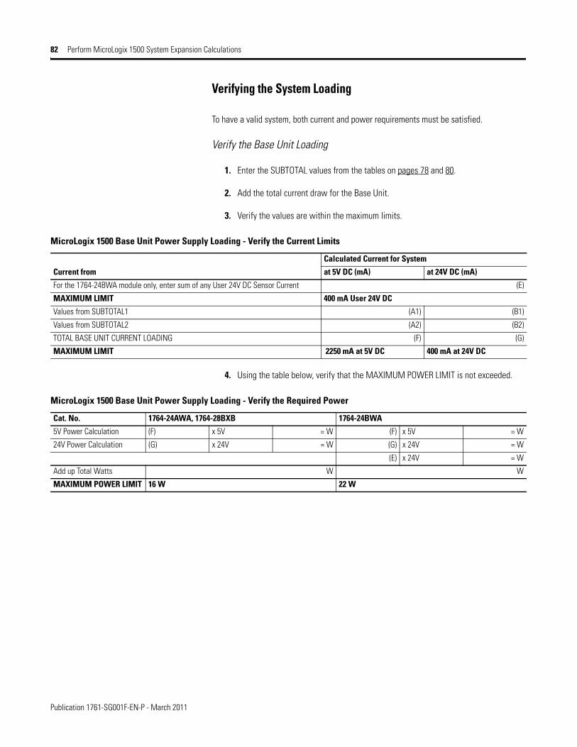
Publication 1761-SG001F-EN-P - March 2011
82 Perform MicroLogix 1500 System Expansion Calculations
Verifying the System Loading
To have a valid system, both current and power requirements must be satisfied.
Verify the Base Unit Loading
1. Enter the SUBTOTAL values from the tables on pages 78 and 80.
2. Add the total current draw for the Base Unit.
3. Verify the values are within the maximum limits.
4. Using the table below, verify that the MAXIMUM POWER LIMIT is not exceeded.
MicroLogix 1500 Base Unit Power Supply Loading - Verify the Current Limits
Current from
Calculated Current for System
at 5V DC (mA) at 24V DC (mA)
For the 1764-24BWA module only, enter sum of any User 24V DC Sensor Current (E)
MAXIMUM LIMIT 400 mA User 24V DC
Values from SUBTOTAL1 (A1) (B1)
Values from SUBTOTAL2 (A2) (B2)
TOTAL BASE UNIT CURRENT LOADING (F) (G)
MAXIMUM LIMIT 2250 mA at 5V DC 400 mA at 24V DC
MicroLogix 1500 Base Unit Power Supply Loading - Verify the Required Power
Cat. No. 1764-24AWA, 1764-28BXB 1764-24BWA
5V Power Calculation (F) x 5V = W (F) x 5V = W
24V Power Calculation (G) x 24V = W (G) x 24V = W
(E) x 24V = W
Add up Total Watts W W
MAXIMUM POWER LIMIT 16 W 22 W

Publication 1761-SG001F-EN-P - March 2011
Perform MicroLogix 1500 System Expansion Calculations 83
Verifying the Expansion Power Supply Loading
Using the values from SUBTOTAL2, verify that the system loading and I/O distribution are within the limits shown below. Consider future expansion when selecting a power supply.
Selecting Expansion Cables and End Caps
Any system using Compact I/O components must have an end cap. If I/O Bank 1 is used, an expansion cable is also required. Use the information on page 77 to make your selection from the table below.
Bank 1 Power Supply Loading - Verify the Current Limits
Attribute Cat. No. Calculated Current for System 24V DC User Output Capacityat 5V DC (mA) at 24V DC (mA)
Values from SUBTOTAL2 (on page 81): (C) (D)
MAXIMUM CURRENT LIMIT 1769-PA2 2000 800 250 mA
1769-PA4 4000 2000 N/A
1769-PB2 2000 800
1769-PB4 4000 2000
I/O Distribution - Distribute I/O modules such that the current consumed from either the left side or the right side of the power supply never exceeds the following values:
1769-PA2 2000 800 250 mA
1769-PA4 2000 1000
1769-PB2 2000 800
1769-PB4 2000 1000
Select End Cap and Expansion Cable
Type of System Requirement Cat. No. Selected
Base Unit with Compact I/O only right end cap 1769-ECR
Base Unit with Compact I/O and Bank 1, horizontal orientation right-to-left expansion cable 1769-CRL1, 1769-CRL3
right end cap 1769-ECR
Base Unit with Compact I/O and Bank 1, vertical orientation right-to-right expansion cable 1769-CRL1, 1769-CRL3
left end cap 1769-ECL

Publication 1761-SG001F-EN-P - March 2011
84 Select Replacement Parts
Select Replacement Parts
MicroLogix 1000 Replacement Parts
Description Cat. No.
Terminal Cover Doors for 1761-L32AWA, -L32BWA, or -L32AAA (2 doors per package) 1761-RPL-T32X
Replacement Terminal Block — 6-position DH-485 plug/connector used with the 1761-NET-AIC. 1746-RT30
Replacement Terminal Block — 5-position DeviceNet plug/connector used with the 1761-NET-DNI. 1761-RPL-RT00
MicroLogix 1100 Replacement Part
Description Cat. No.
Replacement Battery 1763-BA
MicroLogix 1200 Replacement Parts
Description Cat. No.
Replacement Removable Terminal Block — (1) 25-pt double row, (1) 29-point double row for 1762-L40AWA and -L40BWA 1762-RPLRTB40
Step 14 - Select:
• replacement parts• record your selections in the Selection
Record (start on page 86)
MicroLogix 1400 Replacement Parts
Description Cat. No.
Replacement Battery 1747-BA
Replacement Removable Terminal Block — (1) 25-pt double row, (1) 29-point double row for all 1766-L32xxxx 1762-RPLRTB40
MicroLogix 1500 Replacement Parts
Description Cat. No.
Replacement Terminal Block — 17-pt for 1764-24AWA and 1764-24BWA inputs 1764-RPLTB1
Replacement Terminal Block — 21-pt for 1764-28BXB inputs and outputs for all base units 1764-RPLTB2
Replacement Battery 1747-BA
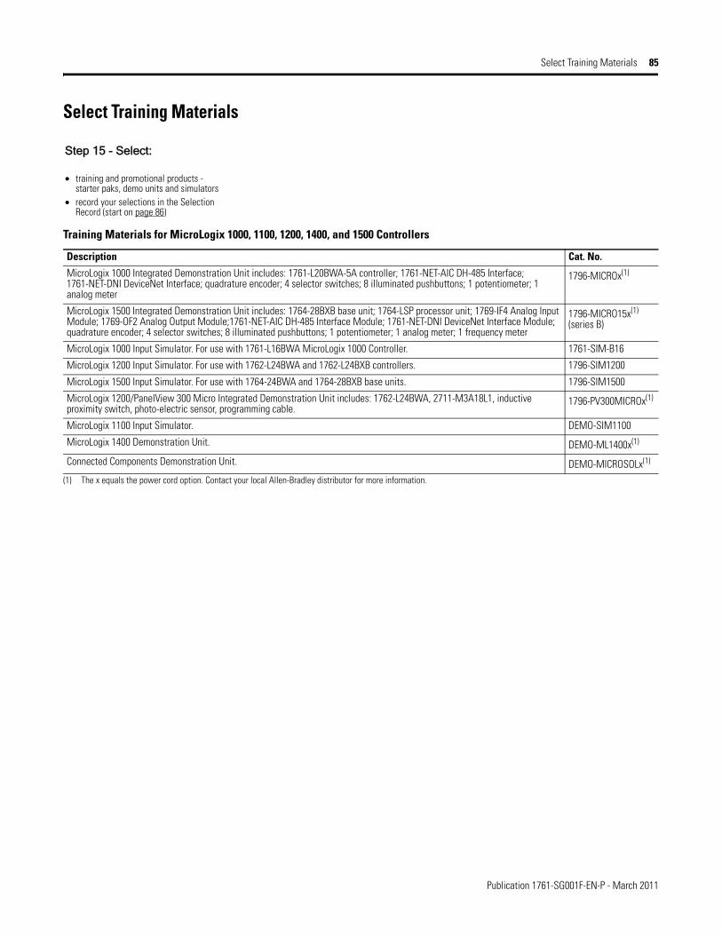
Publication 1761-SG001F-EN-P - March 2011
Select Training Materials 85
Select Training Materials
Training Materials for MicroLogix 1000, 1100, 1200, 1400, and 1500 Controllers
Description Cat. No.
MicroLogix 1000 Integrated Demonstration Unit includes: 1761-L20BWA-5A controller; 1761-NET-AIC DH-485 Interface; 1761-NET-DNI DeviceNet Interface; quadrature encoder; 4 selector switches; 8 illuminated pushbuttons; 1 potentiometer; 1 analog meter
1796-MICROx(1)
(1) The x equals the power cord option. Contact your local Allen-Bradley distributor for more information.
MicroLogix 1500 Integrated Demonstration Unit includes: 1764-28BXB base unit; 1764-LSP processor unit; 1769-IF4 Analog Input Module; 1769-OF2 Analog Output Module;1761-NET-AIC DH-485 Interface Module; 1761-NET-DNI DeviceNet Interface Module; quadrature encoder; 4 selector switches; 8 illuminated pushbuttons; 1 potentiometer; 1 analog meter; 1 frequency meter
1796-MICRO15x(1) (series B)
MicroLogix 1000 Input Simulator. For use with 1761-L16BWA MicroLogix 1000 Controller. 1761-SIM-B16
MicroLogix 1200 Input Simulator. For use with 1762-L24BWA and 1762-L24BXB controllers. 1796-SIM1200
MicroLogix 1500 Input Simulator. For use with 1764-24BWA and 1764-28BXB base units. 1796-SIM1500
MicroLogix 1200/PanelView 300 Micro Integrated Demonstration Unit includes: 1762-L24BWA, 2711-M3A18L1, inductive proximity switch, photo-electric sensor, programming cable.
1796-PV300MICROx(1)
MicroLogix 1100 Input Simulator. DEMO-SIM1100
MicroLogix 1400 Demonstration Unit. DEMO-ML1400x(1)
Connected Components Demonstration Unit. DEMO-MICROSOLx(1)
Step 15 - Select:
• training and promotional products - starter paks, demo units and simulators
• record your selections in the Selection Record (start on page 86)

Publication 1761-SG001F-EN-P - March 2011
86 Fill in Your Selection Listing
Fill in Your Selection Listing
Step 16 - Select:
• all catalog numbers required for your system specification
Master List of Catalog Numbers
Cat. No. Description Quantity Selected
MicroLogix 1000 Controllers
1761-L10BWA MicroLogix 1000 10-Point AC Controller
1761-L10BWB MicroLogix 1000 10-Point DC Controller
1761-L10BXB MicroLogix 1000 10-Point DC Controller
1761-L16AWA MicroLogix 1000 16-Point AC Controller
1761-L16BBB MicroLogix 1000 16-Point DC Controller
1761-L16BWA MicroLogix 1000 16-Point AC Controller
1761-L16BWB MicroLogix 1000 16-Point DC Controller
1761-L16NWA MicroLogix 1000 16-Point AC Controller
1761-L16NWB MicroLogix 1000 16-Point DC Controller
1761-L20AWA-5A MicroLogix 1000 25-Point AC Controller with Analog
1761-L20BWA-5A MicroLogix 1000 25-Point AC Controller with Analog
1761-L20BWB-5A MicroLogix 1000 25-Point DC Controller with Analog
1761-L32AAA MicroLogix 1000 32-Point AC Controller
1761-L32AWA MicroLogix 1000 32-Point AC Controller
1761-L32BBB MicroLogix 1000 32-Point DC Controller
1761-L32BWA MicroLogix 1000 32-Point AC Controller
1761-L32BWB MicroLogix 1000 32-Point DC Controller
MicroLogix 1100 Controllers and Accessories
1763-L16AWA MicroLogix 1100 16-Point AC Controller
1763-L16BWA MicroLogix 1100 16-Point AC Controller
1763-L16BBB MicroLogix 1100 16-Point DC Controller
1763-L16DWD MicroLogix 1100 16-Point DC Controller
1763-MM1 MicroLogix 1100 Memory Module
MicroLogix 1200 Controllers and Accessories
1762-L24AWA MicroLogix 1200 24-Point AC Controller
1762-L24AWAR MicroLogix 1200 24-Point AC Controller with Programming/HMI Port
1762-L24BWA MicroLogix 1200 24-Point AC Controller
1762-L24BWAR MicroLogix 1200 24-Point AC Controller with Programming/HMI Port
1762-L24BXB MicroLogix 1200 24-Point DC Controller
1762-L24BXBR MicroLogix 1200 24-Point DC Controller with Programming/HMI Port
1762-L40AWA MicroLogix 1200 40-Point AC Controller
1762-L40AWAR MicroLogix 1200 40-Point AC Controller with Programming/HMI Port

Publication 1761-SG001F-EN-P - March 2011
Fill in Your Selection Listing 87
1762-L40BWA MicroLogix 1200 40-Point AC Controller
1762-L40BWAR MicroLogix 1200 40-Point AC Controller with Programming/HMI Port
1762-L40BXB MicroLogix 1200 40-Point DC Controller
1762-L40BXBR MicroLogix 1200 40-Point DC Controller with Programming/HMI Port
1762-MM1 MicroLogix 1200 Memory Module
1762-MM1RTC MicroLogix 1200 Memory Module with Real-Time Clock
1762-RTC MicroLogix 1200 Real-Time Clock Module
MicroLogix 1100/1200/1400 I/O
1762-IA8 8-Point 120V AC Input Module
1762-IF2OF2 Combination 2-Channel Input 2-Channel Output Voltage/Current Analog Module
1762-IF4 4-Channel Voltage/Current Analog Input Module
1762-IQ16 16-Point Sink/Source 24V DC Input Module
1762-IQ8 8-Point Sink/Source 24V DC Input Module
1762-IQ8OW6 8 Point Sink/Source 24V DC Input/6-Point AC/DC Relay Output Combination Module
1762-IR4 4-Channel RTD/Resistance Input Module
1762-IT4 4-Channel Thermocouple/mV Input Module
1762-OA8 8-Point 120/240V AC Triac Output Module
1762-OB16 16-Point Sourcing 24V DC Output Module
1762-OB8 8-Point Sourcing 24V DC Output Module
1762-OF4 4-Channel Voltage/Current Analog Output Module
1762-OW16 16-Point AC/DC Relay Output Module
1762-OW8 8-Point AC/DC Relay Output Module
1762-OX6I 6-Point Isolated AC/DC Relay Output Module
1762-OV32T Solid State 24V DC Sink Output Module
1762-OB32T Solid State 24V DC Source Output Module
1762-IQ32T DC Input Module
MicroLogix 1400 Controllers and Accessories
1766-L32BWA MicroLogix 1400 32-point AC controller
1766-L32AWA MicroLogix 1400 32-point AC controller
1766-L32BXB MicroLogix 1400 32-point DC controller
1766-L32BWAA MicroLogix 1400 32-point AC controller with Analog
1766-L32AWAA MicroLogix 1400 32-point AC controller with Analog
1766-L32BXBA MicroLogix 1400 32-point DC controller with Analog
1766-MM1 MicroLogix 1400 Memory Module
MicroLogix 1500 Controllers and Accessories
1764-24AWA MicroLogix 1500 24-Point AC Base Unit
1764-24BWA MicroLogix 1500 24-Point AC Base Unit
1764-28BXB MicroLogix 1500 28-Point DC Base Unit
1764-DAT MicroLogix Data Access Tool
1764-LRP MicroLogix 1500 Processor Unit with RS-232 Port
1764-LSP MicroLogix 1500 Processor Unit
1764-MM1 MicroLogix 1500 8 KB Memory Module
1764-MM1RTC MicroLogix 1500 8 KB Memory Module with Real-Time Clock
1764-MM2 MicroLogix 1500 16 KB Memory Module
Master List of Catalog Numbers
Cat. No. Description Quantity Selected
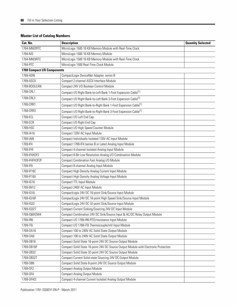
Publication 1761-SG001F-EN-P - March 2011
88 Fill in Your Selection Listing
1764-MM2RTC MicroLogix 1500 16 KB Memory Module with Real-Time Clock
1764-M3 MicroLogix 1500 16 KB Memory Module
1764-MM3RTC MicroLogix 1500 16 KB Memory Module with Real-Time Clock
1764-RTC MicroLogix 1500 Real-Time Clock Module
1769 Compact I/O Components
1769-ADN CompactLogix DeviceNet Adapter, series B
1769-ASCII Compact 2-channel ASCII Interface Module
1769-BOOLEAN Compact 24V I/O Boolean Control Module
1769-CRL1 Compact I/O Right Bank-to-Left Bank 1-Foot Expansion Cable(1)
1769-CRL3 Compact I/O Right Bank-to-Left Bank 3-Foot Expansion Cable(1)
1769-CRR1 Compact I/O Right Bank-to-Right Bank 1-Foot Expansion Cable(1)
1769-CRR3 Compact I/O Right Bank-to-Right Bank 3-Foot Expansion Cable(1)
1769-ECL Compact I/O Left End Cap
1769-ECR Compact I/O Right End Cap
1769-HSC Compact I/O High Speed Counter Module
1769-IA16 Compact 120V AC Input Module
1769-IA8I Compact Individually Isolated 120V AC Input Module
1769-IF4 Compact 1769-IF4 (series B or Later) Analog Input Module
1769-IF4I Compact 4-channel Isolated Analog Input Module
1769-IF4XOF2 Compact 8-Bit Low Resolution Analog I/O Combination Module
1769-IF4FXOF2F Compact Combination Fast Analog I/O Module
1769-IF8 Compact 8-channel Analog Input Module
1769-IF16C Compact High Density Analog Current Input Module
1769-IF16V Compact High Density Analog Voltage Input Module
1769-IG16 Compact TTL Input Module
1769-IM12 Compact 240V AC Input Module
1769-IQ16 CompactLogix 24V DC 16-point Sink/Source Input Module
1769-IQ16F CompactLogix 24V DC 16-point High Speed Sink/Source Input Module
1769-IQ32 CompactLogix 24V DC 32-point Sink/Source Input Module
1769-IQ32T Compact Current Sinking/Sourcing 24V DC Input Module
1769-IQ6XOW4 Compact Combination 24V DC Sink/Source Input & AC/DC Relay Output Module
1769-IR6 Compact I/O 1769-IR6 RTD/resistance Input Module
1769-IT6 Compact I/O 1769-IT6 Thermocouple/mV Input Module
1769-OA16 Compact 100 to 240V AC Solid State Output Module
1769-OA8 Compact 100 to 240V AC Solid State Output Module
1769-OB16 Compact Solid State 16-point 24V DC Source Output Module
1769-OB16P Compact Solid State 16-point 24V DC Source Output Module with Electronic Protection
1769-OB32 Compact Solid State 32-point 24V DC Source Output Module
1769-OB32T Compact Current Solid-state Sourcing 24V DC Output Module
1769-OB8 Compact Solid State 8-point 24V DC Source Output Module
1769-OF2 Compact Analog Output Module
1769-OF4 Compact Analog Output Module
1769-OF4CI Compact 4-channel Current Isolated Analog Output Module
Master List of Catalog Numbers
Cat. No. Description Quantity Selected
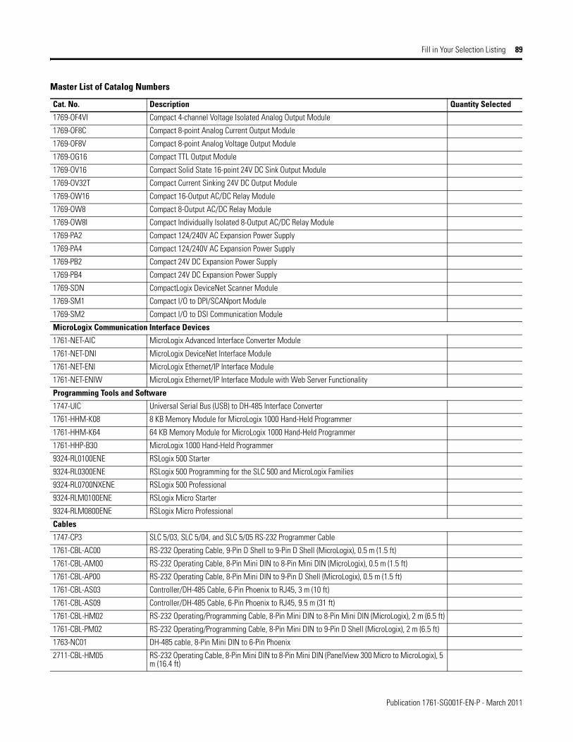
Publication 1761-SG001F-EN-P - March 2011
Fill in Your Selection Listing 89
1769-OF4VI Compact 4-channel Voltage Isolated Analog Output Module
1769-OF8C Compact 8-point Analog Current Output Module
1769-OF8V Compact 8-point Analog Voltage Output Module
1769-OG16 Compact TTL Output Module
1769-OV16 Compact Solid State 16-point 24V DC Sink Output Module
1769-OV32T Compact Current Sinking 24V DC Output Module
1769-OW16 Compact 16-Output AC/DC Relay Module
1769-OW8 Compact 8-Output AC/DC Relay Module
1769-OW8I Compact Individually Isolated 8-Output AC/DC Relay Module
1769-PA2 Compact 124/240V AC Expansion Power Supply
1769-PA4 Compact 124/240V AC Expansion Power Supply
1769-PB2 Compact 24V DC Expansion Power Supply
1769-PB4 Compact 24V DC Expansion Power Supply
1769-SDN CompactLogix DeviceNet Scanner Module
1769-SM1 Compact I/O to DPI/SCANport Module
1769-SM2 Compact I/O to DSI Communication Module
MicroLogix Communication Interface Devices
1761-NET-AIC MicroLogix Advanced Interface Converter Module
1761-NET-DNI MicroLogix DeviceNet Interface Module
1761-NET-ENI MicroLogix Ethernet/IP Interface Module
1761-NET-ENIW MicroLogix Ethernet/IP Interface Module with Web Server Functionality
Programming Tools and Software
1747-UIC Universal Serial Bus (USB) to DH-485 Interface Converter
1761-HHM-K08 8 KB Memory Module for MicroLogix 1000 Hand-Held Programmer
1761-HHM-K64 64 KB Memory Module for MicroLogix 1000 Hand-Held Programmer
1761-HHP-B30 MicroLogix 1000 Hand-Held Programmer
9324-RL0100ENE RSLogix 500 Starter
9324-RL0300ENE RSLogix 500 Programming for the SLC 500 and MicroLogix Families
9324-RL0700NXENE RSLogix 500 Professional
9324-RLM0100ENE RSLogix Micro Starter
9324-RLM0800ENE RSLogix Micro Professional
Cables
1747-CP3 SLC 5/03, SLC 5/04, and SLC 5/05 RS-232 Programmer Cable
1761-CBL-AC00 RS-232 Operating Cable, 9-Pin D Shell to 9-Pin D Shell (MicroLogix), 0.5 m (1.5 ft)
1761-CBL-AM00 RS-232 Operating Cable, 8-Pin Mini DIN to 8-Pin Mini DIN (MicroLogix), 0.5 m (1.5 ft)
1761-CBL-AP00 RS-232 Operating Cable, 8-Pin Mini DIN to 9-Pin D Shell (MicroLogix), 0.5 m (1.5 ft)
1761-CBL-AS03 Controller/DH-485 Cable, 6-Pin Phoenix to RJ45, 3 m (10 ft)
1761-CBL-AS09 Controller/DH-485 Cable, 6-Pin Phoenix to RJ45, 9.5 m (31 ft)
1761-CBL-HM02 RS-232 Operating/Programming Cable, 8-Pin Mini DIN to 8-Pin Mini DIN (MicroLogix), 2 m (6.5 ft)
1761-CBL-PM02 RS-232 Operating/Programming Cable, 8-Pin Mini DIN to 9-Pin D Shell (MicroLogix), 2 m (6.5 ft)
1763-NC01 DH-485 cable, 8-Pin Mini DIN to 6-Pin Phoenix
2711-CBL-HM05 RS-232 Operating Cable, 8-Pin Mini DIN to 8-Pin Mini DIN (PanelView 300 Micro to MicroLogix), 5 m (16.4 ft)
Master List of Catalog Numbers
Cat. No. Description Quantity Selected

Publication 1761-SG001F-EN-P - March 2011
90 For More Information
For More Information Visit the MicroLogix website at http://www.ab.com/micrologix to learn more about MicroLogix products and download MicroLogix software utilities and firmware updates. Software utilities are available for configuring the DNI and ENI network interface devices. System validation worksheets are available to determine I/O power usage.
You can view or download publications at http://literature.rockwellautomation.com. To order paper copies of technical documentation, contact your local Rockwell Automation distributor or sales representative.
2711-CBL-HM10 RS-232 Operating Cable, 8-Pin Mini DIN to 8-Pin Mini DIN (PanelView 300 Micro to MicroLogix), 10 m (32.7 ft)
2711-CBL-PM05 RS-232 Operating/Programming Cable, 9-Pin D Shell to 8-Pin Mini DIN (PanelView 300 Micro to SLC or PLC), 5 m (16.4 ft)
2711-CBL-PM10 RS-232 Operating/Programming Cable, 9-Pin D Shell to 8-Pin Mini DIN (PanelView 300 Micro to SLC or PLC), 10 m (32.7 ft)
Replacement Parts
1747-BA Lithium Battery (For RAM Memory Retention) for MicroLogix 1400/1500 controllers
1761-RPL-RT00 Replacement Terminal Block for 1761-NET-DNI, 5-position DeviceNet plug/connector
1761-RPL-T32X Terminal Cover Doors for 1761-L32AWA, 1761-L32BWA, 1761-L32AAA, 1761-L32BWB, or 1761-L32BBB (2 doors per package)
1761-RT30 Replacement Terminal Block for 1761-NET-AIC, 6-position DH-485 plug/connector
1762-RPLRTB40 Replacement Terminal Block for all 1762-L40xxxx and all 1766-L32xxxx Controllers
1763-BA Lithium Battery for MicroLogix 1100 controllers
1764-RPLTB2 21-Point Replacement Terminal Block for 1764-28BXB MicroLogix 1500 Base Unit(1) Approximate cable length is measured from end-to-end of the cable only.
Master List of Catalog Numbers
Cat. No. Description Quantity Selected

Publication 1761-SG001F-EN-P - March 2011
For More Information 91
Notes:

Rockwell Otomasyon Ticaret A.Ş., Kar Plaza İş Merkezi E Blok Kat:6 34752 İçerenköy, İstanbul, Tel: +90 (216) 5698400
Publication 1761-SG001F-EN-P - March 2011 92Copyright © 2011 Rockwell Automation, Inc. All rights reserved. Printed in the U.S.A.
Rockwell Automation Support
Rockwell Automation provides technical information on the Web to assist you in using its products. At http://www.rockwellautomation.com/support/, you can find technical manuals, a knowledge base of FAQs, technical and application notes, sample code and links to software service packs, and a MySupport feature that you can customize to make thebest use of these tools.
For an additional level of technical phone support for installation, configuration, and troubleshooting, we offer TechConnect support programs. For more information, contact your local distributor or Rockwell Automation representative, or visit http://www.rockwellautomation.com/support/.
Installation Assistance
If you experience a problem within the first 24 hours of installation, review the information that is contained in this manual.You can contact Customer Support for initial help in getting your product up and running.
New Product Satisfaction Return
Rockwell Automation tests all of its products to ensure that they are fully operational when shipped from the manufacturing facility. However, if your product is not functioning and needs to be returned, follow these procedures.
Documentation Feedback
Your comments will help us serve your documentation needs better. If you have any suggestions on how to improve this document, complete this form, publication RA-DU002, available at http://www.rockwellautomation.com/literature/.
Allen-Bradley, MicroLogix, SLC, SLC 5/03, SLC 500, CompactLogix, ControlLogix, FlexLogix, PowerFlex, PanelView, RSLogix, RSLogix 500, RSNetWorx for ControlNet,
RSNetWorx for DeviceNet, Rockwell Automation, and Rockwell Software are trademarks of Rockwell Automation, Inc.
Trademarks not belonging to Rockwell Automation are property of their respective companies.
United States or Canada 1.440.646.3434
Outside United States or Canada
Use the Worldwide Locator at http://www.rockwellautomation.com/support/americas/phone_en.html, or contact your local Rockwell Automation representative.
United States Contact your distributor. You must provide a Customer Support case number (call the phone number above to obtain one) to your distributor to complete the return process.
Outside United States Please contact your local Rockwell Automation representative for the return procedure.
Copyright © 2022 FDOKUMEN