Investigation of electron-beam welding in wrought Inconel 706—experimental and numerical analysis
12
Materials Science and Engineering A 392 (2005) 94–105 Investigation of electron-beam welding in wrought Inconel 706—experimental and numerical analysis Paolo Ferro a,∗ , Andrea Zambon b , Franco Bonollo a a Department of Management and Engineering, University of Padova, Stradella S. Nicola, 3 I-36100 Vicenza, Italy b DIMEG, University of Padova, Via Marzolo, 9 I-35131 Padova, Italy Received 9 June 2004; received in revised form 30 August 2004; accepted 19 October 2004 Abstract Electron-beam welding (EBW) is commonly employed in the aeroengine industry for the welding of high integrity components, fabricated from high-strength superalloys. For such applications, it is important to predict distortions and residual stresses induced by the process. Melt run trials have been carried out on nickel-base superalloy Inconel 706 plates using the EBW technique in order to analyse the effects of welding parameters on geometrical characteristics and microstructure of the bead. Butt-welded plates have been then investigated by means of tensile tests, microstructural analysis, and X-ray diffraction measurements. A finite element model of the process has been set up using an uncoupled thermal–mechanical analysis. The heat source was modelled using a superimposition of a spherical and a conical shape heat source with Gaussian power density distribution in order to reproduce the nail shape of the fusion zone (FZ). The parameters of the source were chosen so that the model would match with experimentally determined weld pool shape and temperatures, measured with thermocouples. Subsequently, the thermal analysis was used to drive the non-linear mechanical analysis. The predicted residual stresses were then compared with X-ray diffraction measurements. It was found that the correct thermal and residual stresses prediction is influenced by the shape of the fusion zone, the highest thermal tensile stress arising under the nailhead of the fusion zone where microfissuring can be observed. © 2004 Elsevier B.V. All rights reserved. Keywords: Electron-beam welding; Wrought Ni-base alloys; Finite element analysis 1. Introduction Nickel-base superalloys for aerospace and industrial ap- plications are of great interest in the materials research field. Their creep and oxidation resistance properties make them the base material for aero-engine components in hot sec- tions, such as turbine discs, blades and casings. In such appli- cations, the possibility to assemble different parts by weld- ing is a fundamental task for the design and industrialisation of these products. Thus, the study of the weldability of this kind of material is of primary importance in order to obtain sound welds. Their hot cracking sensitivity, arising from a synergy of phenomena such as wide solidification temper- ature interval, chemical composition and thermal stresses, ∗ Corresponding author. Tel.: +39 0444 998743; fax: +39 0444 998888. E-mail address: [email protected] (P. Ferro). is the most important problem to solve since it enormously compromises the low cycle fatigue resistance [1]. For this reason, high power density welding technologies [2–4], with a particular attention to electron-beam welding (EBW), are the most favourite. In fact, they ensure a minimum size of the fusion zone (FZ) as well as of the heat-affected zone (HAZ) and a reduction in distortion and residual stresses. In partic- ular, the high vacuum, which characterises the EBW, avoids material contamination and yields deep penetration. Experi- mental results carried out on a limited number of nickel-base alloys [4–6], showed that it is possible to obtain sound welds by optimising the welding speed, pre-heating, beam focus and welding current. Thanks to computer development, it is possible to avoid expensive experimental work, which un- til now has been carried out for this aim, and use numerical simulation for predicting the stress evolution during welding [7,8]. 0921-5093/$ – see front matter © 2004 Elsevier B.V. All rights reserved. doi:10.1016/j.msea.2004.10.039
Transcript of Investigation of electron-beam welding in wrought Inconel 706—experimental and numerical analysis
Materials Science and Engineering A 392 (2005) 94–105
Investigation of electron-beam welding in wrought Inconel706—experimental and numerical analysis
Paolo Ferroa,∗, Andrea Zambonb, Franco Bonolloa
a Department of Management and Engineering, University of Padova, Stradella S. Nicola, 3 I-36100 Vicenza, Italyb DIMEG, University of Padova, Via Marzolo, 9 I-35131 Padova, Italy
Received 9 June 2004; received in revised form 30 August 2004; accepted 19 October 2004
Abstract
Electron-beam welding (EBW) is commonly employed in the aeroengine industry for the welding of high integrity components, fabricatedfrom high-strength superalloys. For such applications, it is important to predict distortions and residual stresses induced by the process. Meltrun trials have been carried out on nickel-base superalloy Inconel 706 plates using the EBW technique in order to analyse the effects ofwelding parameters on geometrical characteristics and microstructure of the bead. Butt-welded plates have been then investigated by meanso up using anu e heat sourcew ource werec rmocouples.S en comparedw hape of thef d.©
K
1
pTttciokssa
usly
aref theAZ)artic-oidsperi-aselds
ocus, it isun-ricaling
0d
f tensile tests, microstructural analysis, and X-ray diffraction measurements. A finite element model of the process has been setncoupled thermal–mechanical analysis. The heat source was modelled using a superimposition of a spherical and a conical shapith Gaussian power density distribution in order to reproduce the nail shape of the fusion zone (FZ). The parameters of the shosen so that the model would match with experimentally determined weld pool shape and temperatures, measured with theubsequently, the thermal analysis was used to drive the non-linear mechanical analysis. The predicted residual stresses were thith X-ray diffraction measurements. It was found that the correct thermal and residual stresses prediction is influenced by the s
usion zone, the highest thermal tensile stress arising under the nailhead of the fusion zone where microfissuring can be observe2004 Elsevier B.V. All rights reserved.
eywords:Electron-beam welding; Wrought Ni-base alloys; Finite element analysis
. Introduction
Nickel-base superalloys for aerospace and industrial ap-lications are of great interest in the materials research field.heir creep and oxidation resistance properties make them
he base material for aero-engine components in hot sec-ions, such as turbine discs, blades and casings. In such appli-ations, the possibility to assemble different parts by weld-ng is a fundamental task for the design and industrialisationf these products. Thus, the study of the weldability of thisind of material is of primary importance in order to obtainound welds. Their hot cracking sensitivity, arising from aynergy of phenomena such as wide solidification temper-ture interval, chemical composition and thermal stresses,
∗ Corresponding author. Tel.: +39 0444 998743; fax: +39 0444 998888.E-mail address:[email protected] (P. Ferro).
is the most important problem to solve since it enormocompromises the low cycle fatigue resistance[1]. For thisreason, high power density welding technologies[2–4], witha particular attention to electron-beam welding (EBW),the most favourite. In fact, they ensure a minimum size ofusion zone (FZ) as well as of the heat-affected zone (Hand a reduction in distortion and residual stresses. In pular, the high vacuum, which characterises the EBW, avmaterial contamination and yields deep penetration. Exmental results carried out on a limited number of nickel-balloys[4–6], showed that it is possible to obtain sound weby optimising the welding speed, pre-heating, beam fand welding current. Thanks to computer developmentpossible to avoid expensive experimental work, whichtil now has been carried out for this aim, and use numesimulation for predicting the stress evolution during weld[7,8].
921-5093/$ – see front matter © 2004 Elsevier B.V. All rights reserved.oi:10.1016/j.msea.2004.10.039
P. Ferro et al. / Materials Science and Engineering A 392 (2005) 94–105 95
A typical keyhole weld is usually accompanied by a dis-tinct ‘nailhead’ appearance at the top. The first attempts tomodel this shape were analytical.
Klykow et al. [9] combined a depth source, which de-scribes the keyhole effects and the energy related transfer,and a surface source, representing the plume radiation on theworkpiece surface. Both sources had a Gaussian power dis-tribution. Here, it was found that, in laser welding, plasmamay be regarded as an independent heat source in the surfaceor immersed, and the laser beam as a volume source resultingin a dagger shape form of the penetration zone.
Steen et al.[10] combined the point and line source ofRosenthal[11] to model more effectively a keyhole weld andestimate the power actually absorbed by the weld. The linesource represents absorption down the keyhole and the pointsource represents the plasma radiation from the plume. It wassuggested that the melt width in the lower part of the weld isdirectly proportional to the strength of the line source.
Bonollo et al.[12] studied the effect of the operative pres-sure on the weld beads of different materials, welded usinga CO2 laser beam. An analytical model of the process wasdeveloped using two heat sources which allowed the quantita-tive evaluation of the power distribution between the keyholeand the plume. Experimental and analytical results were ingood agreement.
as eld-i Theh wasr inedf
oft ange.B iduals ason,n nicalc dingt r den-s n-t ent,a nail’s mena
ows uma e topsw holea n oft f theF risingf
ld-c ngw de-v sal
and longitudinal stresses as a function of weld cooling. Crack-ing at a position will be promoted if a weak microstructureand/or a sufficiently high tensile stress exists. However, themodel does not consider the correct FZ shape of the bead andthe 3D distribution of the stress field.
Dye et al.[17] proposed a numerical method for the pre-diction of the processing conditions which are liable for pro-ducing defects during welding such as constitutional liqua-tion, solidification cracking and a centreline grain formation.In particular, solidification cracking is assumed to arise dueto the generation of a positive transverse stress at the pointbehind the heat source where the liquid fraction is still signif-icant. The model was applied to TIG welding of Inconel 718using a semi-analytical solution for the temperature field anda thermal elasto-plastic analysis in two-dimension, assuminga state of plane stress. In such a way, the real shape of theFZ through the thickness and thus the stress component inz-direction was neglected. For this reason, the model is notsuitable for the prediction of microfissures formation alongthe thickness.
Due to the recent development of the high power densitywelding technologies, a lack of knowledge is still presentin the specific literature on EBW process applied to alloysystems such as Nickel-base superalloys.
Mayor[18] investigated the characteristics of Inconel 718a -arcw siles ermale ffectt duc-i rties.T level,h eral,s tures.I wasf a re-s
k-i d toI ro-c Ni-b ases (44,5 be-i alcu-l ea de-c e re-s tionc duet f thea
e in-v eld-i orksc
Instead of using two sources, Binda et al.[13] proposedemi-empirical model of the temperature field in laser wng, based on a modification of the Rosenthal solution.ypothesis of a constant heat rate along the thicknesseplaced by a generic unknown function, to be determrom experimental data.
All the analytical models do not consider the variationhe thermal properties with temperature and phase chesides, they are not able to predict the thermal and restress fields induced by the welding process. For this reumerical models which combined the thermo–mechaomputation were developed. In high power density welechnology, a conical source shape with Gaussian poweity distribution is often used[7,14]. Though the experimeal and numerical results are in sufficient overall agreemsingle source is insufficient to reproduce the correct ‘
hape of the fusion zone and thus the local stress developt the FZ–HAZ interface.
Du et al.[15], developed a mathematical model for flimulation of full penetration laser beam welding of titanilloy. The model is based on a plane heat source on thurface and a cylindrical heat source along thez-direction,hich take into account the plasma effects and the keybsorption. The model, based on the numerical solutio
he fluid mechanics equations, gave a good prediction oZ shape but was not used for the stress evaluation a
rom the welding process.Nickel-base superalloys suffer, above all, from we
racking tendency[5]. The idea to correlate weld crackiith the stress–strain evolution during weld cooling waseloped by Feng et al.[16]. They considered only transver
t
nd 706 joints, though welded by GTAW (gas tungstenelding), finding an excellent weldability and good tentrength at both room and elevated temperature. The thffects of welding operations have been observed to a
he desirable structure of the heat-treatable alloys by prong heat-affected zones with poor stress-rupture propehe properties are substantially restored to the requiredowever, by post-weld heat-treatment involving, in genolution and ageing treatments at conventional temperan this case, age hardening treatment following weldingound to be more than adequate, without a need forolution treatment.
Kayano et al.[19] found a higher solidification cracng susceptibility of Inconel 706 specimens comparenconel 718 specimens welded by non-filler TIG arc pess. To prevent solidification cracking in Inconel 706ase superalloy weld metal, modified Inconel 706 Ni-bamples were prepared with three different Ni contents5 and 65 mass% Ni), the remaining alloying elements
ng kept constant as much as possible. Thermocalc cations of the ‘liquidus’ and ‘solidus’ temperatures of thlloys showed that the solidification temperature rangereased with an increasing Ni content. Based on thesults, it was concluded that improvement of the solidificaracking susceptibility with an increasing Ni content iso a decrease in the solidification temperature range olloys.
It can be pointed out that only few researchers havestigated in the past the effects of high power density wng techniques on Ni-base wrought superalloys. Some wan be found about laser welds in wrought Waspaloy[2] but
96 P. Ferro et al. / Materials Science and Engineering A 392 (2005) 94–105
specific information on the high-energy beam welding of In-conel 706 alloy have not yet fully established.
In this work, a numerical model of EBW of Inconel 706 hasbeen developed. The phenomenological approach proposedis based on the calibration of the source parameters, on the ba-sis of some penetration tests, and temperature measurementsby means of thermocouples. Microscopy examinations wereused for the investigation of the possible defects and obser-vation of the fusion zone shape and dimension. Tensile testswere carried out in order to evaluate the mechanical prop-erties of welded and parent material specimens and residualstresses were measured by the X-ray diffraction technique.
The numerical model has been characterised by the use oftwo power density distribution functions for the simulationof the ‘nail’ shape of the fusion zone. It was found that the 3Dthermal and residual stress field was strongly influenced bythe shape of the fusion zone, demonstrating that the higheststresses arise under the nailhead where microfissures appear.Experimental and calculated results were in good agreement.
Table 1Measured chemical composition of the standard Inconel 706 used in the test(wt.%)
Ni Bal.Cr 15.93Fe 38.15NTCAMSCPSCMT
The analyses in this investigation were performed with thefinite element code SYSWELD 2002®.
2. Material and experimental procedure
Nickel-base superalloys are commonly used in the agedstate. The base material Inconel 706, whose chemical com-position is summarised inTable 1, was taken from a tur-bine engine disc which had been working for a long time at600–650◦C and thus it showed an overaged equiaxed mi-crostructure characterised byδ-phase and carbide precipi-tates.
Melt run trials have been carried out on a plate of10 mm× 50 mm× 100 mm with various welding parameterssuch as current, pre-heating, focal position and oscillation ofthe electron beam. The pressure in the welding chamber was1× 10−3 mbar and the welding speed was fixed to 10 mm/s.A summary of the welding parameters, together with the ob-tained fusion zone dimensions, is given inTable 2.
K-type thermocouples were used for the temperature mea-surements in the arrangement shown inFig. 1. Optimal pro-cess parameters obtained in the melt run trials were chosen.According to examinations of the transverse section of thewelds obtained from the melt run trials, optimal process pa-r tra-t idthr
ith-o owedi d toa t freedt f heatt r-d idual
TE
B
)
1 –2 –3 )4
b 2.335i 1.63o 0.0839l 0.261n 0.041i 0.072u 0.018
0.00390.00430.011
o 0.0611a 0.013
able 2lectron beam melt run trials (constant voltage, 150 kW)
ead Process parameters
Focus (mm) Current (mA) Oscillation
+2 10 –−20 15 –+5 10 500 Hz circular (Ø 1 mm
−123 5 – 2Fig. 1. Thermocouple arrange
ameters were identified, which would allow full peneion, no defects (i.e., microfissures) and a low depth-to-watio.
Five-millimetre thick sheets were then butt welded, wut lateral constraints, using the welding parameters sh
n Table 3. Fig. 2 shows the clamping arrangement uselign the plates. The screws were not tightened so thaisplacement was possible inx-direction (Fig. 2). Prior to
he welding, the plates were subjected to a stress reliereatment (950◦C for 15 min, in argon protective gas) in oer to eliminate, as far as possible, the pre-existing res
Bead geometry
Pre-heating (◦C) Area (mm2) Depth (mm) Width max (mm
7.2 6.2 3.411.0 5.7 4.5
– 7.3 3.1 4.125 4.1 2.9 3.2
ment for the welding trials.

P. Ferro et al. / Materials Science and Engineering A 392 (2005) 94–105 97
Table 3Welding parameters
Focalisation (mm) 2Current (mA) 11Oscillation noWelding speed (mm/s) 10Pre-heating no
Fig. 2. Clamping arrangement.
Fig. 3. Geometry of the butt-welded sheets (mm).
stresses. A 3-mm support of the same material was posi-tioned under the bead in order to avoid the loss of meltedalloy from the bottom, as shown inFig. 3. The residual stressdeterminations were carried out on the surface of the weldedsamples, on top of the bead, in the HAZ, and in the base metal(BM). Moreover, they were performed on the top surface inthe middle of the weld run. Such measures were carried outby X-ray diffraction, according to the well-known “sin2Ψ ”method[20], using the Cr K� radiation, diffracted by{2 2 0}planes. Tensile tests were finally performed on welded andparent metal specimens of 5 mm× 10 mm sections in order toevaluate the mechanical resistance of the joint, in comparisonwith the base material.
3. Experimental results and discussion
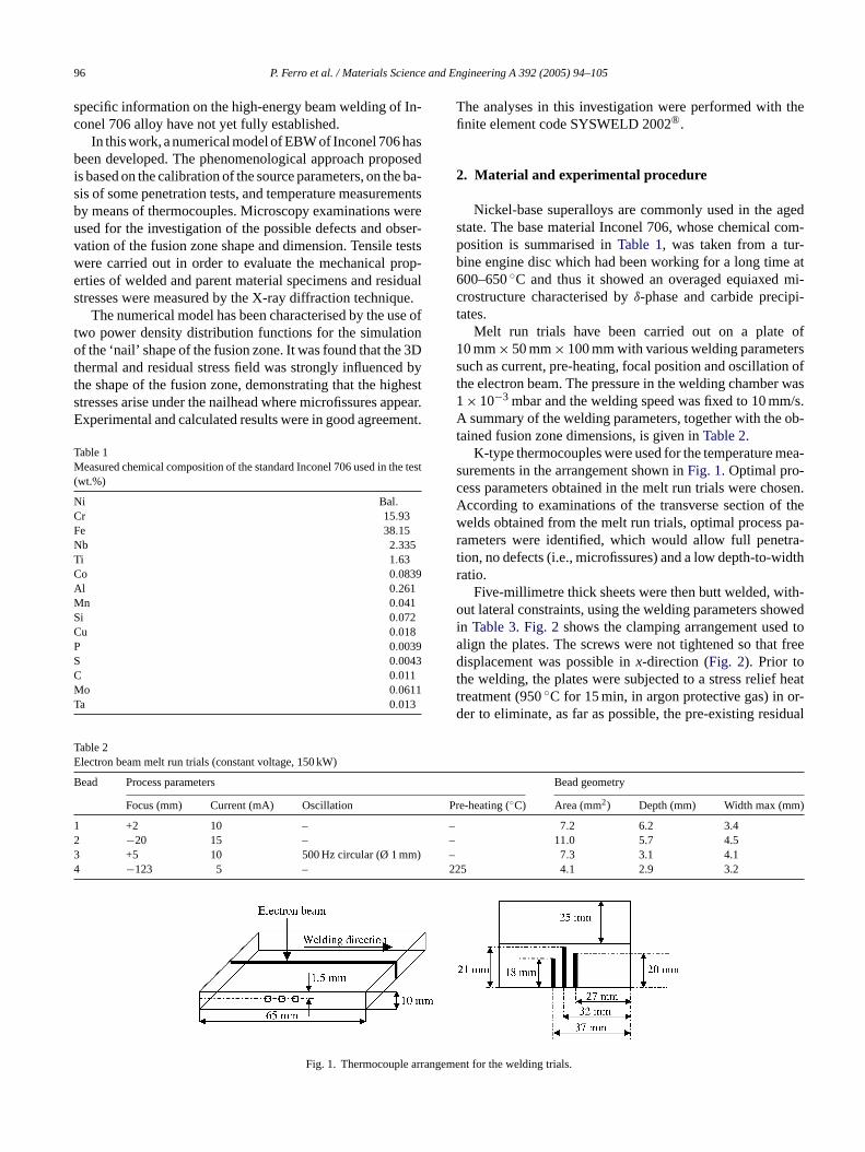
The major defects observed on the beads of the melt runtrials were microfissures occurring at the grain boundaries
in the heat-affected zone (Fig. 4). They were concentratedunder the nailhead of the bead and caused above all by thehigh thermal stresses arising during the cooling in that zone.Parameters used for the bead 1 (Table 2) resulted in the highestdepth-to-width ratio and integrity of the joint and were thusused for the welding of 5 mm thick plates (Fig. 5).
High heating and cooling rates, typical of such weldingtechnology, can be observed in the temperature–time curvesrepresented inFig. 6 [7]. These profiles were measured 3.1,4.1 and 6.1 mm far from the fusion line. Note, in particular,that after the passage of the electron beam (within a minute),the welded plate reaches a uniform temperature. This satu-ration temperature can be used to estimate the thermal effi-ciency of the process[7]. If the heat is assumed to be retainedby the plate, none being lost by radiation to the surroundingor jigging arrangement, the thermal efficiency is
η = vCpXZ(Tsat− T0)
VI(1)
wherev is the traverse speed,Cp the volumetric heat capacity,V the accelerating voltage,I the welding current andT0 is theinitial temperature of the plate. The termZ is the thicknessof the plate andX its width. Table 4shows the parametersused in Eq.(1). The value of the weld efficiency determinedin this manner was (0.8± 0.1) in good agreement with thato
dingg utt-w ringw theyo freel inedw iduals byXc ratelyl raintc inalr etal.N ressm ectra( un-s eingt turale
d com-p ue tot ismss
4
ary,fi ary
btained by Roberts et al.[7].Residual stresses are strongly influenced by wel
eometry and clamping conditions. In particular, for belded joints, the presence of lateral constraints duelding, promotes large transversal stress becauseffer resistance to the FZ shrinkage. On the contrary, a
ateral FZ shrinkage arises in butt-welded plates obtaithout lateral constraints and thus the transversal restress are very low[21]. Residual stress measurements-ray diffraction, summarised inTable 5 [22], showed aompressive transversal stress on the bead and modeow values in the parent metal according to the constondition used during welding. Compressive longitudesidual stresses arise near the HAZ and in the base mo reliable results were obtained for the longitudinal steasurements of FZ because most of the diffraction sp
for this position and in the longitudinal direction) wereuitable for a trustworthy peak position determination, bhe intensity too weak as a consequence of strong texffects.
The results of tensile tests, summarised inTable 6, show aecrease of the weld specimen’s strength of about 20%ared with the base material. This decrease is probably d
he loss in the FZ and HAZ of the strengthening mechanuch as precipitation hardening.
. Numerical model
When a welding simulation is performed, it is necessrst of all, to ask which physical phenomenon is of prim
98 P. Ferro et al. / Materials Science and Engineering A 392 (2005) 94–105
Fig. 4. Microfissures occurring at the grain boundaries under the nail head of bead 3 (seeTable 2).
interest. It may be an ‘a priori’ prediction of the weld poolshape or the evaporation rate of solute from the melt pool.If the thermal and residual stresses and deformations have tobe foreseen, without solving the laws of fluid mechanics, aphenomenological method based on the utilisation of powerdensity distribution functions can be used[8].
4.1. Thermal model
A schematic representation of the EBW process is shownin Fig. 7. For the symmetry of the geometry and loads, onlyone of the two welded plates was modeled. Radiative heat losswas taken into account by means of the Stefan–Boltzmann
hs of th
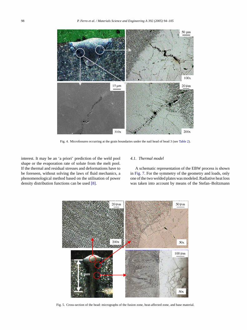
Fig. 5. Cross-section of the bead: micrograp e fusion zone, heat-affected zone, and base material.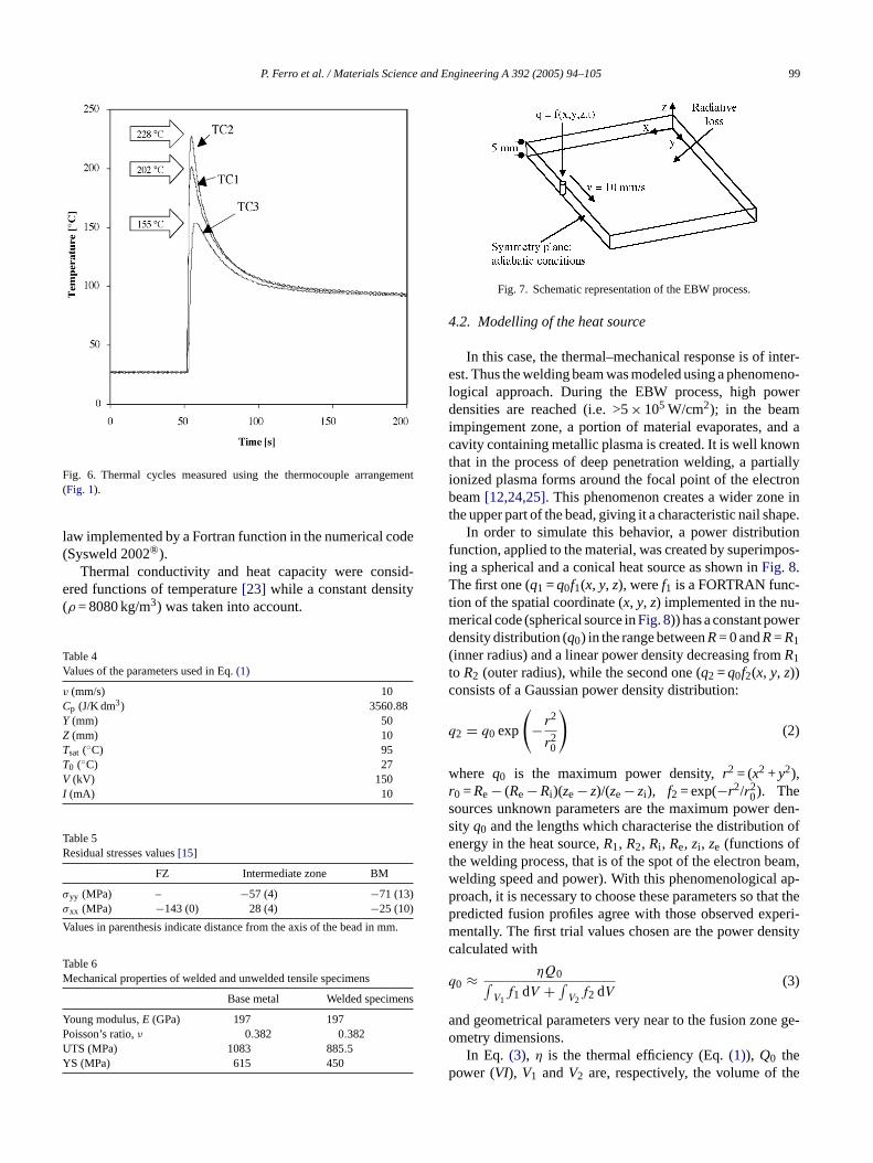
P. Ferro et al. / Materials Science and Engineering A 392 (2005) 94–105 99
Fig. 6. Thermal cycles measured using the thermocouple arrangement(Fig. 1).
law implemented by a Fortran function in the numerical code(Sysweld 2002®).
Thermal conductivity and heat capacity were consid-ered functions of temperature[23] while a constant density(ρ = 8080 kg/m3) was taken into account.
Table 4Values of the parameters used in Eq.(1)
v (mm/s) 10Cp (J/K dm3) 3560.88Y (mm) 50Z (mm) 10Tsat (◦C) 95T0 (◦C) 27V (kV) 150I (mA) 10
Table 5Residual stresses values[15]
FZ Intermediate zone BM
σyy (MPa) – −57 (4) −71 (13)σxx (MPa) −143 (0) 28 (4) −25 (10)
Values in parenthesis indicate distance from the axis of the bead in mm.
Table 6M
ns
YPUY
Fig. 7. Schematic representation of the EBW process.
4.2. Modelling of the heat source
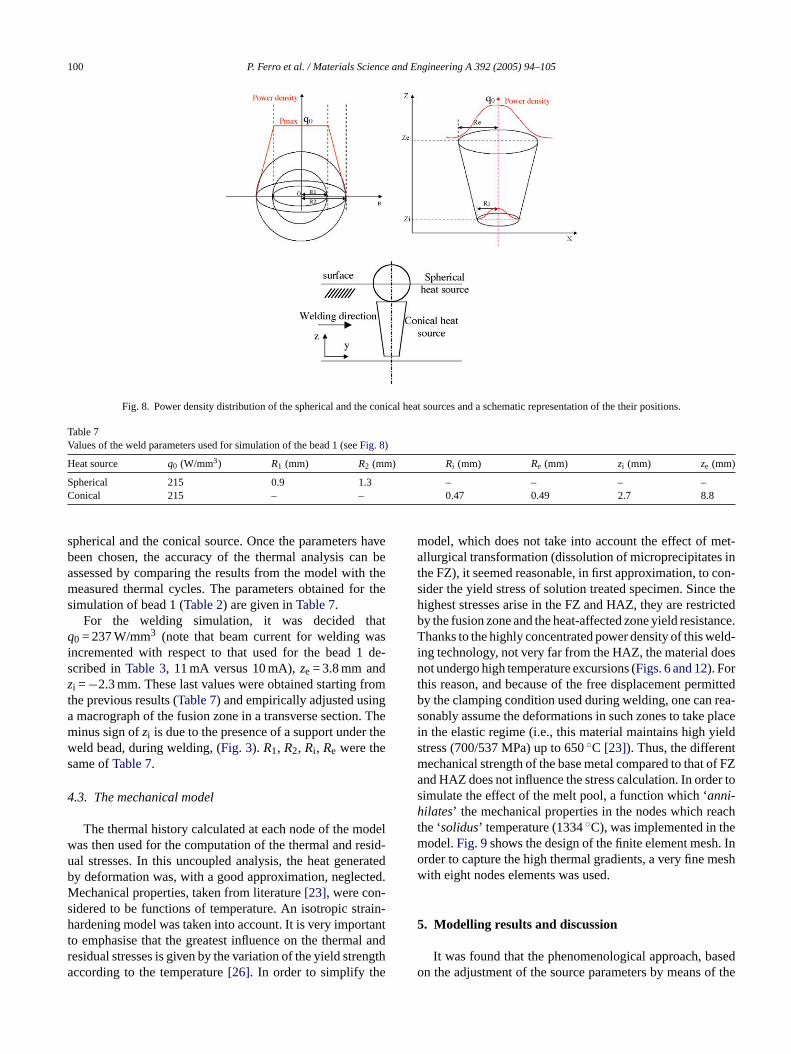
In this case, the thermal–mechanical response is of inter-est. Thus the welding beam was modeled using a phenomeno-logical approach. During the EBW process, high powerdensities are reached (i.e. >5× 10⁵ W/cm2); in the beamimpingement zone, a portion of material evaporates, and acavity containing metallic plasma is created. It is well knownthat in the process of deep penetration welding, a partiallyionized plasma forms around the focal point of the electronbeam[12,24,25]. This phenomenon creates a wider zone inthe upper part of the bead, giving it a characteristic nail shape.
In order to simulate this behavior, a power distributionfunction, applied to the material, was created by superimpos-ing a spherical and a conical heat source as shown inFig. 8.The first one (q1 =q0f1(x, y, z), weref1 is a FORTRAN func-tion of the spatial coordinate (x, y, z) implemented in the nu-merical code (spherical source inFig. 8)) has a constant powerdensity distribution (q0) in the range betweenR= 0 andR=R1(inner radius) and a linear power density decreasing fromR1toR2 (outer radius), while the second one (q2 =q0f2(x, y, z))consists of a Gaussian power density distribution:
q2 = q0 exp
(− r2
r20
)(2)
wrs den-s n ofet eam,w l ap-p hat thep peri-m nsityc
q
a e ge-o
p he
echanical properties of welded and unwelded tensile specimens
Base metal Welded specime
oung modulus,E (GPa) 197 197oisson’s ratio,ν 0.382 0.382TS (MPa) 1083 885.5S (MPa) 615 450
here q0 is the maximum power density,r2 = (x2 +y2),0 =Re− (Re−Ri )(ze− z)/(ze− zi ), f2 = exp(−r2/r2
0). Theources unknown parameters are the maximum powerity q0 and the lengths which characterise the distributionergy in the heat source,R1, R2, Ri , Re, zi , ze (functions of
he welding process, that is of the spot of the electron belding speed and power). With this phenomenologicaroach, it is necessary to choose these parameters so tredicted fusion profiles agree with those observed exentally. The first trial values chosen are the power de
alculated with
0 ≈ ηQ0∫V1
f1 dV + ∫V2
f2 dV(3)
nd geometrical parameters very near to the fusion zonmetry dimensions.
In Eq. (3), η is the thermal efficiency (Eq.(1)), Q0 theower (VI), V1 andV2 are, respectively, the volume of t
100 P. Ferro et al. / Materials Science and Engineering A 392 (2005) 94–105
Fig. 8. Power density distribution of the spherical and the conical heat sources and a schematic representation of the their positions.
Table 7Values of the weld parameters used for simulation of the bead 1 (seeFig. 8)
Heat source q0 (W/mm3) R1 (mm) R2 (mm) Ri (mm) Re (mm) zi (mm) ze (mm)
Spherical 215 0.9 1.3 – – – –Conical 215 – – 0.47 0.49 2.7 8.8
spherical and the conical source. Once the parameters havebeen chosen, the accuracy of the thermal analysis can beassessed by comparing the results from the model with themeasured thermal cycles. The parameters obtained for thesimulation of bead 1 (Table 2) are given inTable 7.
For the welding simulation, it was decided thatq0 = 237 W/mm3 (note that beam current for welding wasincremented with respect to that used for the bead 1 de-scribed inTable 3, 11 mA versus 10 mA),ze = 3.8 mm andzi =−2.3 mm. These last values were obtained starting fromthe previous results (Table 7) and empirically adjusted usinga macrograph of the fusion zone in a transverse section. Theminus sign ofzi is due to the presence of a support under theweld bead, during welding, (Fig. 3). R1, R2, Ri , Re were thesame ofTable 7.
4.3. The mechanical model
The thermal history calculated at each node of the modelwas then used for the computation of the thermal and resid-ual stresses. In this uncoupled analysis, the heat generatedby deformation was, with a good approximation, neglected.Mechanical properties, taken from literature[23], were con-sidered to be functions of temperature. An isotropic strain-hardening model was taken into account. It is very importantt l andr ngtha
model, which does not take into account the effect of met-allurgical transformation (dissolution of microprecipitates inthe FZ), it seemed reasonable, in first approximation, to con-sider the yield stress of solution treated specimen. Since thehighest stresses arise in the FZ and HAZ, they are restrictedby the fusion zone and the heat-affected zone yield resistance.Thanks to the highly concentrated power density of this weld-ing technology, not very far from the HAZ, the material doesnot undergo high temperature excursions (Figs. 6 and 12). Forthis reason, and because of the free displacement permittedby the clamping condition used during welding, one can rea-sonably assume the deformations in such zones to take placein the elastic regime (i.e., this material maintains high yieldstress (700/537 MPa) up to 650◦C [23]). Thus, the differentmechanical strength of the base metal compared to that of FZand HAZ does not influence the stress calculation. In order tosimulate the effect of the melt pool, a function which ‘anni-hilates’ the mechanical properties in the nodes which reachthe ‘solidus’ temperature (1334◦C), was implemented in themodel.Fig. 9shows the design of the finite element mesh. Inorder to capture the high thermal gradients, a very fine meshwith eight nodes elements was used.
5. Modelling results and discussion
asedo of the
o emphasise that the greatest influence on the thermaesidual stresses is given by the variation of the yield streccording to the temperature[26]. In order to simplify the
It was found that the phenomenological approach, bn the adjustment of the source parameters by means
P. Ferro et al. / Materials Science and Engineering A 392 (2005) 94–105 101
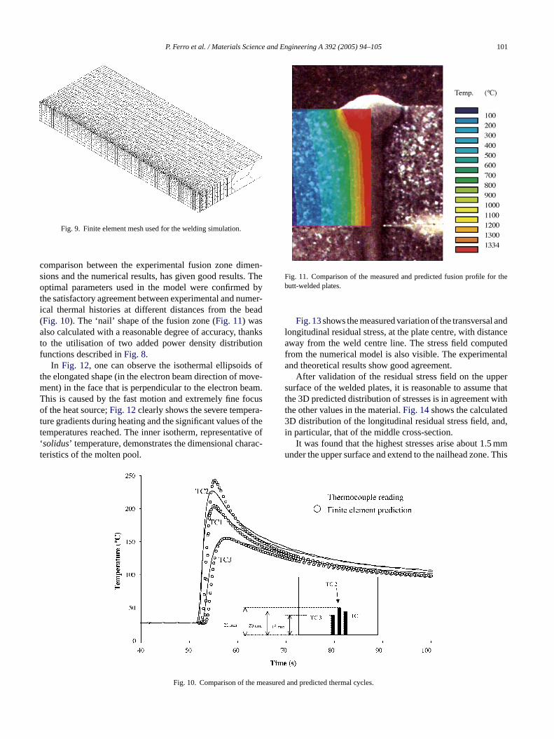
Fig. 9. Finite element mesh used for the welding simulation.
comparison between the experimental fusion zone dimen-sions and the numerical results, has given good results. Theoptimal parameters used in the model were confirmed bythe satisfactory agreement between experimental and numer-ical thermal histories at different distances from the bead(Fig. 10). The ‘nail’ shape of the fusion zone (Fig. 11) wasalso calculated with a reasonable degree of accuracy, thanksto the utilisation of two added power density distributionfunctions described inFig. 8.
In Fig. 12, one can observe the isothermal ellipsoids ofthe elongated shape (in the electron beam direction of move-ment) in the face that is perpendicular to the electron beam.This is caused by the fast motion and extremely fine focusof the heat source;Fig. 12clearly shows the severe tempera-ture gradients during heating and the significant values of thetemperatures reached. The inner isotherm, representative of‘solidus’ temperature, demonstrates the dimensional charac-teristics of the molten pool.
Fig. 11. Comparison of the measured and predicted fusion profile for thebutt-welded plates.
Fig. 13shows the measured variation of the transversal andlongitudinal residual stress, at the plate centre, with distanceaway from the weld centre line. The stress field computedfrom the numerical model is also visible. The experimentaland theoretical results show good agreement.
After validation of the residual stress field on the uppersurface of the welded plates, it is reasonable to assume thatthe 3D predicted distribution of stresses is in agreement withthe other values in the material.Fig. 14shows the calculated3D distribution of the longitudinal residual stress field, and,in particular, that of the middle cross-section.
It was found that the highest stresses arise about 1.5 mmunder the upper surface and extend to the nailhead zone. This
measu
Fig. 10. Comparison of the red and predicted thermal cycles.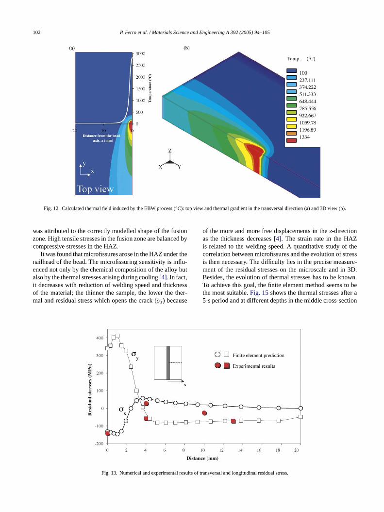
102 P. Ferro et al. / Materials Science and Engineering A 392 (2005) 94–105
Fig. 12. Calculated thermal field induced by the EBW process (◦C): top view and thermal gradient in the transversal direction (a) and 3D view (b).
was attributed to the correctly modelled shape of the fusionzone. High tensile stresses in the fusion zone are balanced bycompressive stresses in the HAZ.
It was found that microfissures arose in the HAZ under thenailhead of the bead. The microfissuring sensitivity is influ-enced not only by the chemical composition of the alloy butalso by the thermal stresses arising during cooling[4]. In fact,it decreases with reduction of welding speed and thicknessof the material; the thinner the sample, the lower the ther-mal and residual stress which opens the crack (σz) because
of the more and more free displacements in thez-directionas the thickness decreases[4]. The strain rate in the HAZis related to the welding speed. A quantitative study of thecorrelation between microfissures and the evolution of stressis then necessary. The difficulty lies in the precise measure-ment of the residual stresses on the microscale and in 3D.Besides, the evolution of thermal stresses has to be known.To achieve this goal, the finite element method seems to bethe most suitable.Fig. 15shows the thermal stresses after a5-s period and at different depths in the middle cross-section
esults o
Fig. 13. Numerical and experimental r f transversal and longitudinal residual stress.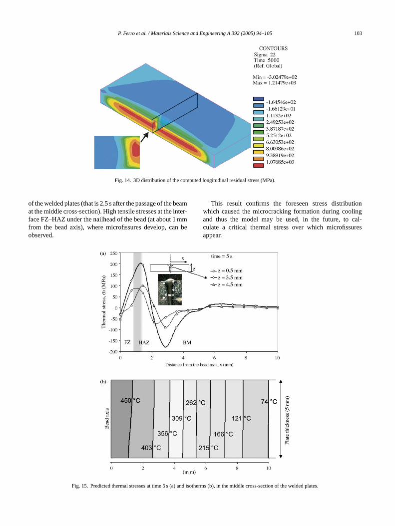
P. Ferro et al. / Materials Science and Engineering A 392 (2005) 94–105 103
Fig. 14. 3D distribution of the computed longitudinal residual stress (MPa).
of the welded plates (that is 2.5 s after the passage of the beamat the middle cross-section). High tensile stresses at the inter-face FZ–HAZ under the nailhead of the bead (at about 1 mmfrom the bead axis), where microfissures develop, can beobserved.
This result confirms the foreseen stress distributionwhich caused the microcracking formation during coolingand thus the model may be used, in the future, to cal-culate a critical thermal stress over which microfissuresappear.
Fig. 15. Predicted thermal stresses at time 5 s (a) and iso
therms (b), in the middle cross-section of the welded plates.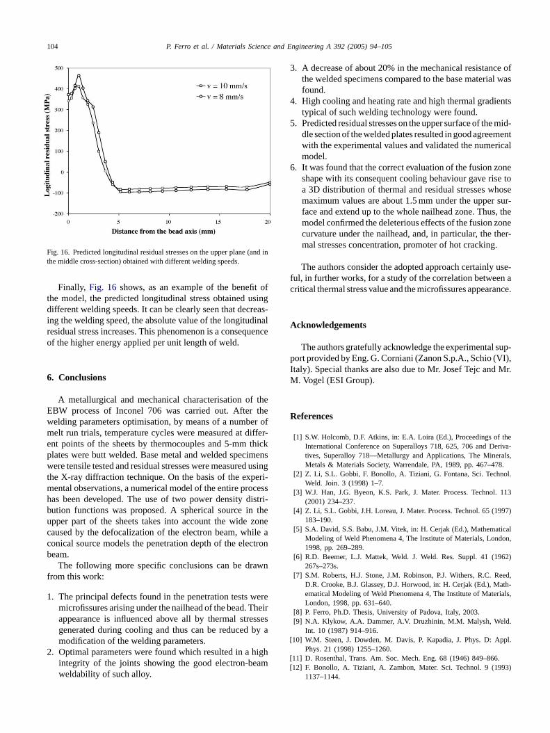
104 P. Ferro et al. / Materials Science and Engineering A 392 (2005) 94–105
Fig. 16. Predicted longitudinal residual stresses on the upper plane (and inthe middle cross-section) obtained with different welding speeds.
Finally, Fig. 16 shows, as an example of the benefit ofthe model, the predicted longitudinal stress obtained usingdifferent welding speeds. It can be clearly seen that decreas-ing the welding speed, the absolute value of the longitudinalresidual stress increases. This phenomenon is a consequenceof the higher energy applied per unit length of weld.
6. Conclusions
A metallurgical and mechanical characterisation of theEBW process of Inconel 706 was carried out. After thewelding parameters optimisation, by means of a number ofmelt run trials, temperature cycles were measured at differ-ent points of the sheets by thermocouples and 5-mm thickplates were butt welded. Base metal and welded specimenswere tensile tested and residual stresses were measured usinthe X-ray diffraction technique. On the basis of the experi-mental observations, a numerical model of the entire processhas been developed. The use of two power density distri-bution functions was proposed. A spherical source in theupper part of the sheets takes into account the wide zonecaused by the defocalization of the electron beam, while aconical source models the penetration depth of the electronbeam.
wnf
1 wereheirssesby a
2 higham
3. A decrease of about 20% in the mechanical resistance ofthe welded specimens compared to the base material wasfound.
4. High cooling and heating rate and high thermal gradientstypical of such welding technology were found.
5. Predicted residual stresses on the upper surface of the mid-dle section of the welded plates resulted in good agreementwith the experimental values and validated the numericalmodel.
6. It was found that the correct evaluation of the fusion zoneshape with its consequent cooling behaviour gave rise toa 3D distribution of thermal and residual stresses whosemaximum values are about 1.5 mm under the upper sur-face and extend up to the whole nailhead zone. Thus, themodel confirmed the deleterious effects of the fusion zonecurvature under the nailhead, and, in particular, the ther-mal stresses concentration, promoter of hot cracking.
The authors consider the adopted approach certainly use-ful, in further works, for a study of the correlation between acritical thermal stress value and the microfissures appearance.
Acknowledgements
sup-p VI),I Mr.M
R
theeriva-als,8.ol.
. 113
997)
icaldon,
962)
eed,ath-rials,
.
[ ppl.
[ .[ 93)
The following more specific conclusions can be drarom this work:
. The principal defects found in the penetration testsmicrofissures arising under the nailhead of the bead. Tappearance is influenced above all by thermal stregenerated during cooling and thus can be reducedmodification of the welding parameters.
. Optimal parameters were found which resulted in aintegrity of the joints showing the good electron-beweldability of such alloy.
g
The authors gratefully acknowledge the experimentalort provided by Eng. G. Corniani (Zanon S.p.A., Schio (
taly). Special thanks are also due to Mr. Josef Tejc and. Vogel (ESI Group).
eferences
[1] S.W. Holcomb, D.F. Atkins, in: E.A. Loira (Ed.), Proceedings ofInternational Conference on Superalloys 718, 625, 706 and Dtives, Superalloy 718—Metallurgy and Applications, The MinerMetals & Materials Society, Warrendale, PA, 1989, pp. 467–47
[2] Z. Li, S.L. Gobbi, F. Bonollo, A. Tiziani, G. Fontana, Sci. TechnWeld. Join. 3 (1998) 1–7.
[3] W.J. Han, J.G. Byeon, K.S. Park, J. Mater. Process. Technol(2001) 234–237.
[4] Z. Li, S.L. Gobbi, J.H. Loreau, J. Mater. Process. Technol. 65 (1183–190.
[5] S.A. David, S.S. Babu, J.M. Vitek, in: H. Cerjak (Ed.), MathematModeling of Weld Phenomena 4, The Institute of Materials, Lon1998, pp. 269–289.
[6] R.D. Beemer, L.J. Mattek, Weld. J. Weld. Res. Suppl. 41 (1267s–273s.
[7] S.M. Roberts, H.J. Stone, J.M. Robinson, P.J. Withers, R.C. RD.R. Crooke, B.J. Glassey, D.J. Horwood, in: H. Cerjak (Ed.), Mematical Modeling of Weld Phenomena 4, The Institute of MateLondon, 1998, pp. 631–640.
[8] P. Ferro, Ph.D. Thesis, University of Padova, Italy, 2003.[9] N.A. Klykow, A.A. Dammer, A.V. Druzhinin, M.M. Malysh, Weld
Int. 10 (1987) 914–916.10] W.M. Steen, J. Dowden, M. Davis, P. Kapadia, J. Phys. D: A
Phys. 21 (1998) 1255–1260.11] D. Rosenthal, Trans. Am. Soc. Mech. Eng. 68 (1946) 849–86612] F. Bonollo, A. Tiziani, A. Zambon, Mater. Sci. Technol. 9 (19
1137–1144.
P. Ferro et al. / Materials Science and Engineering A 392 (2005) 94–105 105
[13] B. Binda, E. Capello, B. Previstali, J. Mater. Process. Technol.155–156 (2004) 1235–1241.
[14] S.A. Tsirkas, P. Papanikos, Th. Kermanidis, J. Mater. Process. Tech-nol. 134 (2003) 59–69.
[15] H. Du, L. Hu, J. Liu, X. Hu, Comput. Mater. Sci. 29 (2004) 419–427.[16] Z. Feng, S.A. David, T. Zacharia, C.L. Tsai, Sci. Technol. Weld.
Join. 2 (1997) 11–19.[17] D. Dye, O. Hunziker, R.C. Reed, Acta Mater. 49 (2001) 683–697.[18] R.A. Mayor, Weld. J. Weld. Res. Suppl. 55 (1976) 269s–275s.[19] R. Kayano, T. Ishiguro, Weld. Int. 13 (1999) 430–439.[20] I.C. Noyan, J.B. Cohen, Residual Stress—Measurement by Diffrac-
tion and Interpretation, Springer-Verlag, Berlin, 1987, p. 122.
[21] T.-L. Teng, C.-C. Lin, Int. J. Press. Vessels Piping 75 (1998)857–864.
[22] G. Bicego, Degree Thesis, DTG University of Padova, 2002.[23] Special Metals Corporation, Technical Bulletin ‘Inconel Alloy 706’,
http://www.specialmetals.com.[24] F. Bonollo, A. Tiziani, S. Gobbi, L. Zhang, Proceedings of the Fourth
European Conference on Advanced Materials and Processes, EURO-MAT ‘95’, AIM, Milan, Italy, 1995, pp. 561–564.
[25] A. Tiziani, A. Zambon, F. Bonollo, M. Cantello, in: S.K.Ghosh (Ed.), Proceeding Conference “Laser 5”, London, IITTInternational—Gournay sur Marne, France, 1989, pp. 75–89.
[26] X.K. Zhu, Y.J. Chao, Comput. Struct. 80 (2002) 967–976.