Intergranular fracture in irradiated Inconel X-750 containing very high concentrations of helium and...
8
Intergranular fracture in irradiated Inconel X-750 containing very high concentrations of helium and hydrogen Colin D. Judge a,⇑ , Nicolas Gauquelin b , Lori Walters c , Mike Wright c , James I. Cole d , James Madden d , Gianluigi A. Botton b , Malcolm Griffiths c a Atomic Energy of Canada Limited, Chalk River, Ontario, Canada b McMaster University, Hamilton, Ontario, Canada c Atomic Energy of Canada Limited, Canada d Idaho National Laboratory, Idaho Falls, ID, USA article info Article history: Received 31 March 2014 Accepted 7 October 2014 Available online 1 November 2014 abstract In recent years, it has been observed that Inconel X-750 spacers in CANDU reactors exhibits lower ductility with reduced load carrying capacity following irradiation in a reactor environment. The fracture behaviour of ex-service material was also found to be entirely intergranular at high doses. The thermal- ized flux spectrum in a CANDU reactor leads to transmutation of 58 Ni to 59 Ni. The 59 Ni itself has unusually high thermal neutron reaction cross-sections of the type: (n, c), (n, p), and (n, a). The latter two reactions, in particular, contribute to a significant enhancement of the atomic displacements in addition to creating high concentrations of hydrogen and helium within the material. Microstructural examinations by transmission electron microscopy (TEM) have confirmed the presence of helium bubbles in the matrix and aligned along grain boundaries and matrix–precipitate interfaces. Helium bubble size and density are found to be highly dependent on the irradiation temperature and material microstructure; the bubbles are larger within grain boundary precipitates. TEM specimens extracted from fracture surfaces and crack tips provide information that is consistent with crack propagation along grain boundaries due to the presence of He bubbles. Ó 2014 Published by Elsevier B.V. 1. Introduction Modern CANDU Ò1 reactors employ tight fitting springs (spacers) to provide support to the hot pressure tube, separating it from the cold calandria tube. The CANDU design enables removal/replace- ment of individual fuel channels as necessary 2 . On removal, Inconel 3 X-750 spacers are intact and appear to be in good physical condition. Post-irradiation examination and testing shows that the ductility is reduced and the component has a reduced load carrying capacity compared to the as-installed condition. The fracture behaviour of ex-service material was found to be entirely intergranular after approximately 10 years of service. The material is embrittled following irradiation [1]. In previous work, material with moderate levels of displacements per atom (dpa) and helium concentrations, examined with transmission electron microscopy (TEM), [1] have shown a high density of helium bubbles within the matrix and aligned along grain boundaries. No link has been made between these bubbles and the reduced ductility of the spacers; however, this is hypothe- sized as the leading contributor. This paper presents additional TEM results from material irradiated up to approximately 55 displace- ments per atom (dpa) and 18,000 appm He. Foils have been extracted directly from an intergranular fracture surface. Bright field TEM, electron diffraction, and Electron Energy Loss Spectroscopy (EELS) mapping have been used to characterize the irradiated Inconel X-750. 2. Experimental Procedure 2.1. Material Tight-fitting CANDU spacers are fabricated from Inconel X-750, a precipitation hardened variant of Alloy-600. The chemical composi- tion and heat treatment of Inconel X-750 spacer material is outlined in Table 1. The starting microstructure consists primarily of gamma prime, c 0 ((Ni 3 (Ti, Al)) secondary precipitates within the matrix 4 http://dx.doi.org/10.1016/j.jnucmat.2014.10.008 0022-3115/Ó 2014 Published by Elsevier B.V. ⇑ Corresponding author. Tel.: +1 613 584 3311x46781. E-mail address: [email protected] (C.D. Judge). 1 CANDU is a registered trademark of Atomic Energy of Canada Limited. 2 When the fuel channel is removed, there is an opportunity to test and examine the spacers. 3 Inconel is a registered trademark of Special Metals Corporation. 4 Gamma prime has not been observed on grain boundaries in the unirradiated material. Journal of Nuclear Materials 457 (2015) 165–172 Contents lists available at ScienceDirect Journal of Nuclear Materials journal homepage: www.elsevier.com/locate/jnucmat
Transcript of Intergranular fracture in irradiated Inconel X-750 containing very high concentrations of helium and...
Journal of Nuclear Materials 457 (2015) 165–172
Contents lists available at ScienceDirect
Journal of Nuclear Materials
journal homepage: www.elsevier .com/ locate / jnucmat
Intergranular fracture in irradiated Inconel X-750 containing very highconcentrations of helium and hydrogen
http://dx.doi.org/10.1016/j.jnucmat.2014.10.0080022-3115/� 2014 Published by Elsevier B.V.
⇑ Corresponding author. Tel.: +1 613 584 3311x46781.E-mail address: [email protected] (C.D. Judge).
1 CANDU is a registered trademark of Atomic Energy of Canada Limited.2 When the fuel channel is removed, there is an opportunity to test and examine
the spacers.3 Inconel is a registered trademark of Special Metals Corporation.
4 Gamma prime has not been observed on grain boundaries in the unimaterial.
Colin D. Judge a,⇑, Nicolas Gauquelin b, Lori Walters c, Mike Wright c, James I. Cole d, James Madden d,Gianluigi A. Botton b, Malcolm Griffiths c
a Atomic Energy of Canada Limited, Chalk River, Ontario, Canadab McMaster University, Hamilton, Ontario, Canadac Atomic Energy of Canada Limited, Canadad Idaho National Laboratory, Idaho Falls, ID, USA
a r t i c l e i n f o
Article history:Received 31 March 2014Accepted 7 October 2014Available online 1 November 2014
a b s t r a c t
In recent years, it has been observed that Inconel X-750 spacers in CANDU reactors exhibits lowerductility with reduced load carrying capacity following irradiation in a reactor environment. The fracturebehaviour of ex-service material was also found to be entirely intergranular at high doses. The thermal-ized flux spectrum in a CANDU reactor leads to transmutation of 58Ni to 59Ni. The 59Ni itself has unusuallyhigh thermal neutron reaction cross-sections of the type: (n, c), (n, p), and (n, a). The latter two reactions,in particular, contribute to a significant enhancement of the atomic displacements in addition to creatinghigh concentrations of hydrogen and helium within the material. Microstructural examinations bytransmission electron microscopy (TEM) have confirmed the presence of helium bubbles in the matrixand aligned along grain boundaries and matrix–precipitate interfaces. Helium bubble size and densityare found to be highly dependent on the irradiation temperature and material microstructure; thebubbles are larger within grain boundary precipitates. TEM specimens extracted from fracture surfacesand crack tips provide information that is consistent with crack propagation along grain boundariesdue to the presence of He bubbles.
� 2014 Published by Elsevier B.V.
1. Introduction
Modern CANDU�1 reactors employ tight fitting springs (spacers)to provide support to the hot pressure tube, separating it from thecold calandria tube. The CANDU design enables removal/replace-ment of individual fuel channels as necessary2. On removal, Inconel3
X-750 spacers are intact and appear to be in good physical condition.Post-irradiation examination and testing shows that the ductility isreduced and the component has a reduced load carrying capacitycompared to the as-installed condition. The fracture behaviour ofex-service material was found to be entirely intergranular afterapproximately 10 years of service. The material is embrittledfollowing irradiation [1]. In previous work, material with moderatelevels of displacements per atom (dpa) and helium concentrations,examined with transmission electron microscopy (TEM), [1] have
shown a high density of helium bubbles within the matrix and alignedalong grain boundaries. No link has been made between these bubblesand the reduced ductility of the spacers; however, this is hypothe-sized as the leading contributor. This paper presents additional TEMresults from material irradiated up to approximately 55 displace-ments per atom (dpa) and 18,000 appm He. Foils have been extracteddirectly from an intergranular fracture surface. Bright field TEM,electron diffraction, and Electron Energy Loss Spectroscopy (EELS)mapping have been used to characterize the irradiated Inconel X-750.
2. Experimental Procedure
2.1. Material
Tight-fitting CANDU spacers are fabricated from Inconel X-750, aprecipitation hardened variant of Alloy-600. The chemical composi-tion and heat treatment of Inconel X-750 spacer material is outlinedin Table 1. The starting microstructure consists primarily of gammaprime, c0 ((Ni3(Ti, Al)) secondary precipitates within the matrix4
rradiated

Table 1Chemical composition in wt.% and heat treatment of Inconel X-750.
Element Concentration
Aluminum 0.40–1.00% % by wtCarbon 0.08% maximum % by wtCobalt 1.00% maximum % by wtChromium 14.00–17.00% % by wtCopper 0.50% maximum % by wtIron 5.00–9.00% % by wtManganese 1.0% maximum % by wtNiobium 1.20% maximum % by wtNickel 70.00% minimum % by wtSulfur 0.01% maximum % by wtSilicon 0.50% maximum % by wtTantalum 1.20% maximum % by wtTitanium 2.25–2.75 % by wtBalance [none specified]Other elements Nb + Ta 0.70–1.20Solution treatment 1093–1204 �C, no hold time specifiedPrecipitation hardening 732 ± 14 �C, hold for 16 ± ½ h, air cool
Calandria TubeDry Annulus
GasSpacer (Garter
spring)
Fuel Bundle Pressure Tube
Fig. 1. Cross section schematic of a fuel channel in a CANDU reactor.
Fig. 2. Relative neutron spectra experienced by the CANDU Inconel X-750 Spacerfor an average CANDU channel power [1].
166 C.D. Judge et al. / Journal of Nuclear Materials 457 (2015) 165–172
and a high density of grain boundary precipitates which are predom-inantly Cr23C6 carbides [2]. Other precipitates found within themicrostructure are; (Ti, Nb)C found within the matrix and along grainboundaries, and Ni3Ti, g-phase, observed on grain boundaries. Bothof these precipitates have a relatively low density in comparison withCr23C6 carbides. For more details on the unirradiated microstructure,please see ref [2]. Fig. 1 shows a cross section schematic of a typicalCANDU fuel channel. The spacers separate the hot pressure tube(operating at 260–310 �C) from the cold calandria tube (operatingat 60–80 �C). The spacers become pinched between the pressure tubeand calandria tube as a result of gravity induced creep and sag. Therespective temperatures of the spacers have been estimated betweenabout 120 �C at the point of pinching and 330 �C at the furthest loca-tion from the point of contact with the calandria tube. The spacersachieve higher temperatures than the contacting pressure tube as aresult of nuclear heating.
Fig. 3. DPA calculations for an average bundle power CANDU channel [1].
2.2. In-service damage and helium/hydrogen production
Radiation damage of most in-reactor components is primarilycaused by direct collisions of high energy neutrons (E > 1 MeV).In CANDU reactors, many of the structural components arefabricated from Zr. Collisions of fast neutrons in these componentstypically results in approximately 1 dpa for every year of service, orapproximately 25 dpa by end-of-design-life conditions [1]. How-ever, in Ni rich components this direct damage is supplementedby more than a factor of two due to the broad thermal neutronspectrum causing transmutations by the absorption of neutrons[3–11]. A typical neutron energy spectrum for an average CANDUchannel power is shown in Fig. 2 [1]. The intense thermal neutron
spectrum leads to large amounts of thermal neutron absorptionand transmutation of Ni by the following reactions:
58Niþ n! 59Niþ c
59Niþ n! 56Feþ 4He
59Niþ n! 59CoþH
59Niþ n! 60Niþ c
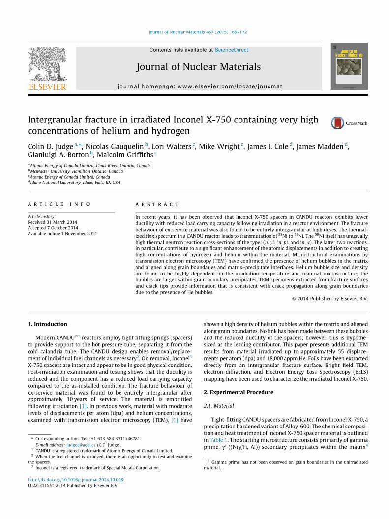
The naturally occurring 58Ni transmutes to 59Ni with neutronabsorption and the 59Ni subsequently undergoes (n, c), (n, p) and(n, a) reactions as noted above. These reactions also create displace-ment damage (from the ejected particle and atomic recoil) in addi-tion to the fast neutron damage previously noted. Ni and otheralloying elements such as Cr and Fe have large (n, p) and (n, a)cross-sections for higher energy neutrons [9]. Considering onlythe damage produced by fast neutrons and the contribution dueto the production of 59Ni, the (n, a) reaction has the largest contri-bution to displacement damage, Fig. 3. The 59Ni reaction also pro-duces a high concentration of both hydrogen and helium in thematerial, Fig. 4. In this case, the He produced as a result of the59Ni effect is close to the total He produced, taking into accountall reactions, but the H is only about one half of the expected total.The He content has been experimentally verified by isotope-dilu-tion gas mass spectrometry following vaporization [12] of speci-mens from ex-service spacers; however, the H content was in theorder of the background of the technique (i.e., bulk H is no longerretained within the material). By end-of-life, an average CANDUreactor spacer will have generated approximately 20,000 appm He(2 at.%), and 5000 appm H. In Ni rich alloys, materials with highHe and H content have shown evidence of embrittlement and inter-granular fracture [13–15].
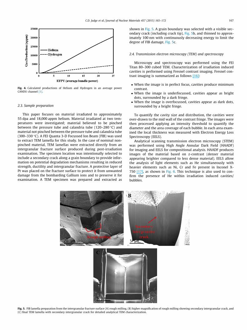
Fig. 4. Calculated productions of Helium and Hydrogen in an average powerCANDU channel [1].
C.D. Judge et al. / Journal of Nuclear Materials 457 (2015) 165–172 167
2.3. Sample preparation
This paper focuses on material irradiated to approximately55 dpa and 18,000 appm helium. Material irradiated at two tem-peratures were investigated; material believed to be pinchedbetween the pressure tube and calandria tube (120–280 �C) andmaterial not pinched between the pressure tube and calandria tube(300–330 �C). A FEI Quanta 3-D Focussed Ion Beam (FIB) was usedto extract TEM lamella for this study. In the case of nominal non-pinched material, TEM lamellas were extracted directly from anintergranular fracture surface produced during post-irradiationexamination. The specimen location was intentionally selected toinclude a secondary crack along a grain boundary to provide infor-mation on potential degradation mechanisms resulting in reducedstrength, ductility and intergranular fracture. A protective layer ofPt was placed on the fracture surface to protect it from unwanteddamage from the bombarding Gallium ions and to preserve it forexamination. A TEM specimen was prepared and extracted as
Rough milling
A B
C
Fig. 5. FIB lamella preparation from the intergranular fracture surface (A) rough milling, ((C) final TEM lamella with secondary intergranular crack for detailed analytical TEM ch
shown in Fig. 5. A grain boundary was selected with a visible sec-ondary crack (including crack tip), Fig. 5b, and thinned to approx-imately 100 nm with continuously decreasing energy to limit thedegree of FIB damage, Fig. 5c.
2.4. Transmission electron microscopy (TEM) and spectroscopy
Microscopy and spectroscopy was performed using the FEITitan 80–300 cubed TEM. Characterization of irradiation inducedcavities is performed using Fresnel contrast imaging. Fresnel con-trast imaging is summarized as follows [16]:
� When the image is in perfect focus, cavities produce minimumcontrast.� When the image is underfocussed, cavities appear as bright
dots, surrounded by a dark fringe.� When the image is overfocussed, cavities appear as dark dots,
surrounded by a bright fringe.
To quantify the cavity size and distribution, the cavities wereover-drawn to the mid wall of the contrast fringe. The images werethen processed applying an intensity threshold to quantify thediameter and the area coverage of each bubble. In each area exam-ined the local thickness was measured with Electron Energy LossSpectroscopy (EELS).
Analytical scanning transmission electron microscopy (STEM)was performed using High Angle Annular Dark Field (HAADF)for imaging and EELS for compositional analysis. HAADF producesimages of the material based on z-contrast (denser materialappearing brighter compared to less dense material). EELS allowthe analysis of light elements such as He simultaneously withheavier elements such as Ni, Cr and Fe present in Inconel X-750 [17], as shown in Fig. 6. This technique is also used to con-firm the presence of He within irradiation induced cavities/bubbles.
Secondary intergranular
crack
B) higher magnification of rough milling showing secondary intergranular crack, andaracterization.

Electron Energy Loss, eV
Cou
nts
Ti - L2,3 Fe - L2,3
Cr - L2,3
Ni - L2,3
C - k
Ti, Cr, Ni, Fe M2,3
Plasmon peak
He - k
Zero loss peak ‘elastic’
Fig. 6. An electron energy-loss spectrum for Inconel X-750 including the baseelements, Ti, Cr, Ni and Fe, in addition to noting the complicated location of the He-k edge.
Fig. 8. Bubble size and density distribution for material irradiated at 120–280 �Cand material irradiated at 300–330 �C with �55 dpa and 18,000 appm He.
Grain Boundary
Matrix-Precipitate Interface
Fig. 9. TEM micrograph in the underfocussed condition (�500 nm) showing bubblealignment on grain boundaries and matrix–precipitate interface after irradiated at300–330 �C to �55 dpa and 18,000 appm He.
168 C.D. Judge et al. / Journal of Nuclear Materials 457 (2015) 165–172
3. Results
3.1. Helium bubble characterization
Helium bubbles from two distinct temperature regions frommaterial irradiated to approximately 55 dpa and 18,000 appmhelium were imaged in the TEM in the under-focused condition,Fig. 7. The relative size and density of bubbles from the twotemperatures regions are plotted in Fig. 8. These measurementswere obtained from the same ex-service spacer (i.e., the mainexperimental variable is temperature). As shown in Fig. 8, the sizeand density of bubbles is highly dependent on the in-service tem-perature; the material with larger bubbles and lower density beingfrom ‘‘hot’’ locations (300–330 �C) and the material with smallerbubbles and higher density being from ‘‘cold’’ locations (120–280 �C).
Not only are the bubbles found within the matrix, but they arealso found in high concentration at sinks such as grain boundariesand precipitate interfaces as shown in Fig. 9. Helium bubble align-ment at boundaries and precipitate interfaces may be responsiblefor the intergranular fracture mode, decreased ductility andembrittlement of irradiated Inconel X-750 spacers similar to otherreactor components such as 316 stainless steel thimble tubes [13].
To confirm the presence of He within bubbles compared to thematrix, EELS spectrum images were acquired for an area containingtwo 5 nm bubbles. This approach is similar to that previously per-formed by Fréchard et al. [18]; however no attempts have beenmade to relate the He density to bubble pressure in the currentstudy. Fig. 10 shows an EELS spectrum taken from two locations:
Fig. 7. TEM Fresnel contrast imaging in the underfocus condition (�500 nm) for materia280 �C material and (B) 300–330 �C.
inside and outside of a bubble. A clear He K-edge at approximately22 eV is found within the 5 nm He bubble. The He K-edge map,shown in Fig. 11b, was extracted using a second order log-polynomialbackground subtraction method with an energy window of22–26 eV. Fig. 11a shows the simultaneously recorded HAADFimage where bubbles appear darker as they are less dense comparedto the matrix. The location of high He concentration coincides with
l with �55 dpa and 18,000 appm He and reactor operating temperature of (A) 120–

Plasmon Peak
He K-edge
Fig. 10. EELS spectrum from region within a bubble (solid line) and region outsideof bubble (dashed line).
HAADF Cr-M2,3 Ti-M2,3 Ni-M2,3 Cr-Ti-Ni
Fig. 12. Low-loss EELS measurements of a secondary crack tip from ex-servicespacer with �55 dpa and 18,000 appm helium at a step size of 6 nm and electronenergy dispersion of 0.1 eV. The maps shown are the HAADF image, Cr M2,3 (red), TiM2,3 (green), Ni M2,3 (blue) and Red–Green–Blue (Cr–Ti–Ni) composite maps. Apower law background model was applied for all maps. (For interpretation of thereferences to color in this figure legend, the reader is referred to the web version ofthis article.)
C.D. Judge et al. / Journal of Nuclear Materials 457 (2015) 165–172 169
the bubble location in the HAADF image and provides verification ofthe existence of He within the irradiation induced bubbles in ex-ser-vice Inconel X-750 spacers.
3.2. Intergranular cracking characterization
3.2.1. Low loss EELS analysisEELS spectrum imaging was further used to analyse the chemical
composition of structures within grain boundaries on an intergran-ular fracture. A low loss EELS map of the secondary crack tip wascollected to identify any grain boundary carbides or precipitates.A power law background model was applied to extract the Ti, Crand Ni M2,3 edges. The low-loss energy region of the EELS spectrumis subject to important overlaps between edges, making accuratebackground subtraction difficult, nevertheless useful for a qualita-tive estimation of composition. Fig. 12 shows a HAADF image over-view of the characterized region, the Cr, Ti, and Ni maps, and a red–green-blue (RGB) composite of Cr–Ti–Ni respectively. The dark ver-tical shadow down the crack tip is a common defect associated withFIB damage (it is not a feature of the fracture, but rather thicknesscontrast associated with preferential FIB milling). The crack propa-gates along the grain boundary, linking between grain boundaryprecipitates. The fact that the crack went around, rather thanthrough the precipitates indicates that the crack propagates alongthe boundary, and is not directly influenced by brittle precipitatesat the boundary. There are regions enriched in both Cr and Ti onthe intergranular fracture. The Cr rich regions are likely Cr23C6 car-bides common in unirradiated Inconel X-750 [2]. The locations of Tienrichment at the grain boundary were not associated with loca-tions of precipitates. It should be noted that these locations aredirectly adjacent to the Cr23C6 carbides, and it is possible that these
Fig. 11. Matrix helium filled bubbles from material irradiated at 300–330 �C to �55 dp26 eV).
regions are simply depleted of Cr as a result of the initial heat treat-ment. The Ti enrichment may be a result of the subsequent irradi-ation similar to the observations in Inconel alloys irradiated in afast reactor environment at 450–735 �C [19,20]. In that study itwas postulated that Ti segregating to grain boundaries may resultin embrittlement from precipitation of brittle gamma prime and/or eta phases. With no precipitates observed at regions of Tienrichment, it can be concluded that these phases do not formunder CANDU operating conditions. This may be a result of the rel-ative low temperatures and extremely high sink density related toHe bubbles which act to suppress elemental segregation. Similarly,no (Ti, Nb)C carbides were observed in this region.
a and 18,000 appm helium shown in (A) TEM HAADF and (B) He k-edge map (22–

HAADF
Cr-L2,3 Ti- L2,3 Ni- L2,3 Cr-Ti-Ni
He bubbles
0 . 05 µm
Fig. 13. Core-loss EELS measurements of a secondary crack tip from ex-servicespacer with �55 dpa and 18,000 appm helium at a step size of 3 nm and electronenergy dispersion of 0.5 eV.
Cr-L2,3 Ti-L2
A
C D
Fig. 14. g-phase precipitate with local bubbles larger compared to matrix. (A) TEM micmicrograph showing qualitative bubble size difference, (C) EELS core loss map of Cr L2,3 (color in this figure legend, the reader is referred to the web version of this article.)
Fig. 15. Helium bubble size and density from within the g-phase compared to thesurrounding matrix in material with �55 dpa and 18,000 appm helium irradiated at120-280 �C.
170 C.D. Judge et al. / Journal of Nuclear Materials 457 (2015) 165–172
3.2.2. Core-loss EELS analysisHigher resolution core-loss elemental maps were then collected
specifically at the crack tip and are shown in Fig. 13, whichpresents the HAADF overview image of the crack tip, the Cr, Ti,Ni L2,3 maps and RGB composite of Cr–Ti–Ni elemental maps. Withcore loss maps, it is possible to distinguish the individual elementsand extract a representative background from the spectrum givinghigher confidence in the elemental maps produced due to thegreater separation between the characteristic edges of the consid-ered elements. The core-loss maps confirm the evidence collectedwithin the low-loss mapping, that the intergranular fractureappears to propagate around and along the grain boundary linkingbetween grain boundary precipitates. A higher magnification of theHAADF image in Fig. 13 gives the first direct evidence linking crackpropagation down a boundary with grain boundary He bubbles.
,3 Ni-L2,3
E
B
rograph imaged in the overfocussed condition (+500 nm), (B) higher magnificationred), (D) Ti L2,3 (green), and (E) Ni L2,3 (blue). (For interpretation of the references to

Cr – L2,3 Ti – L2,3 Ni – L2,3 C – K
A
Cr23C6
B
Fig. 16. Grain boundary Cr23C6 carbide in material irradiated to �55 dpa and18,000 appm helium at 300–330 �C. (A) TEM micrograph imaged in the overfo-cussed condition (+500 nm) and (B) EELS mapping of Cr L2,3 (red), Ti L2,3 (green), NiL2,3 (blue) and C k (yellow). (For interpretation of the references to color in thisfigure legend, the reader is referred to the web version of this article.)
Fig. 17. Helium bubble size distribution from within a Cr23C6 carbide compared tothe matrix in material irradiated with �55 dpa and 18,000 appm helium irradiatedat 300–330 �C.
Cavities and protrusions indicative of removed and remaining grain
boundary precipitates on intergranular fracture
C.D. Judge et al. / Journal of Nuclear Materials 457 (2015) 165–172 171
3.3. Secondary precipitates
It was previously shown (Figs. 7 and 8) that irradiation temper-ature influences the size and density of He bubbles within thematrix. It is important to note some of the other contributing fac-tors influencing bubble size and density. Local inhomogeneities inthe form of grain boundary precipitates lead to local differences inhelium bubble size and density within the irradiated material. Asan example, a grain boundary g-phase (Ni3Ti) precipitate is char-acterized, Fig. 14. The precipitate has been identified through EELSmapping of Cr, Ti and Ni L2,3 edges5. Electron diffraction analysis onthe particle confirms a hexagonal close packed structure consistentwith g-phase. This precipitate was observed in material with55 dpa and 18,000 appm and an irradiation temperature representa-tive of pinched material (120–280 �C). As this phase has been iden-tified in the unirradiated material [2], we assume that the precipitatewas present since fabrication and not a result of the irradiation. Thehigher magnification bright field image in Fig. 14b qualitativelyshows the bubble size and density difference between the matrixand the precipitate. Quantitative analyses of the bubble size anddensity distributions for this precipitate are shown in Fig. 15. Thissize difference is an indication of different material properties inthe matrix compared with the precipitate. Not all precipitates willhave the same effect on bubble size and density. This g-phase pre-cipitate was chosen to highlight the impact of local inhomogeneities
5 The low Cr concentration within the precipitate in Fig. 14 gives confidence thatthis precipitate was fully cross sectioned during FIB preparation, and no matrixmaterial is either above or below the precipitate in the field of view ofcharacterization.
on the bubble size and density. The more abundant Cr23C6 carbideprecipitates located at grain boundaries have a smaller bubble sizeand higher density as compared to the matrix. This observationcould not be verified for material irradiated at 120–280 �C as thebulk matrix helium bubbles are already quite small, and thedifference less pronounced, however; material irradiated at300–330 �C shows the difference clearly, Fig. 16. Because the densityof bubbles is quite high within the carbide, too much overlap ofhelium bubbles exists to obtain an accurate bubble density, how-ever; the size distribution of the bubbles in the carbide comparedto the matrix is shown in Fig. 17.
4. Discussion
As shown in Fig. 9, grain boundaries are decorated with a highdensity of nano-sized He bubbles. According to [13], the grainboundary bubbles are believed to be responsible for the embrittle-ment and fracture of reactor components made of 316SS. This is con-sistent with our observations on ex-service Inconel X-750 presentedwithin this paper. The current high resolution information confirmsthat intergranular fracture propagates along grain boundaries and
Fig. 18. SEM fractography of a material with �55 dpa and 18,000 appm heliumirradiated at 300–330 �C. The intergranular fracture surface shows featuresindicative of pull out and remaining grain boundary precipitates.

172 C.D. Judge et al. / Journal of Nuclear Materials 457 (2015) 165–172
along the surfaces of the grain boundary carbides and precipitates asshown in Figs. 12 and 13. The size features of the grain boundary pre-cipitates are on the same scale as the protrusions and cavitiesobserved over the entire fracture surface (refer to Fig. 18 for refer-ence). This evidence suggests that the grain boundary embrittle-ment is due to a decrease in boundary strength resulting fromhelium bubble decoration on boundaries and matrix–precipitateinterfaces rather than a decoration of a brittle phase on boundariesas has been observed in other Ni based alloys irradiated at highertemperatures (450–735 �C) [19,20].
Materials thermally aged with carbides present on grain bound-aries are susceptible to hydrogen embrittlement [14,15]. Carbidesare intentionally designed to be on grain boundaries to decreasethe relative susceptibility to stress corrosion cracking (SCC) in water[21]; however, incoherent carbides maybe strong hydrogen trapsites and may promote hydrogen segregation to grain boundaries.Increased hydrogen concentrations at grain boundaries are reportedto promote intergranular fracture [14]. As shown in Fig. 4, approxi-mately 5000 appm of hydrogen is produced by end of life in an aver-age power CANDU channel spacer by 59Ni transmutation. Hotvacuum extraction mass spectrometry [12] measurements of ex-service spacer material indicate that most of the hydrogen is notretained inside the material (only traces within detection limits ofthe measurement). It is possible, however, that strong traps suchas grain boundary carbides may locally retain trace hydrogen con-centrations. Even very low, but local concentrations of hydrogenmay have deleterious effects on grain boundary embrittlement[14,15], thus this effect cannot be ruled out.
5. Conclusions
Microstructural characterization of ex-service Inconel X-750indicates a high density of nano-sized bubbles within the matrixand aligned along grain boundaries and matrix–precipitate inter-faces. Larger bubbles compared to the matrix are present in andon the surface of some grain boundary precipitates. A TEM speci-men prepared directly from an intergranular fracture surface givesdirect evidence linking crack propagation to grain boundary Hebubbles.
Acknowledgements
The authors would like to thank D. Lewis, R. Beier, and C. LeMoinefor their assistance sectioning spacers in the Atomic Energy of Can-ada Limited hot cells. The author would also like to thank the tech-nical staff at Idaho National Laboratory and the Center of AdvancedEnergy Studies in Idaho Falls, and the technical staff at the CanadianCentre of Electron Microscopy at McMaster University for theirtechnical assistance and guidance during this investigation. G.A.
Botton and N. Gauquelin are grateful to ORF-RE ‘‘Nuclear Ontario’’project for partial funding of this work. The CCEM is a national facil-ity supported by NSERC and McMaster University.
This work was performed under a Collaborative Research andDevelopment Agreement (CRADA) No. 11-CR-16 between BattelleEnergy Alliance (through the Advanced Test Reactor National Sci-entific User Facility) and Atomic Energy of Canada Limited. Theauthors would also like to thank the CANDU Owners Group(COG) for financial support for some of this work, and permissionto use the data.
References
[1] C.D. Judge, M. Griffiths, L. Walters, M. Wright, G.A. Bickel, O.T. Woo, M. Stewart,S.R. Douglas, F. Garner, Embrittlement of Nickel Alloys in a Candu⁄ ReactorEnvironment, in: T. Yamamoto (Ed.), Effects of Radiation on Nuclear Materials,vol. 25, ASTM International, Anaheim, CA, 2012, pp. 161–175.
[2] O.T. Woo, C.D. Judge, H. Nordin, D. Finlayson, C. Andrei, The microstructure ofunirradiated and neutron irradiated Inconel X-750, in: Microscopy andMicroanalysis, Nashville, Tennessee, 2011, p. 011.
[3] L.K. Mansur, J. Nucl. Mater. 206 (2–3) (1993) 306–323.[4] F. Garner, M. Griffiths, L.R. Greenwood, Enhancement of irradiation creep of
nickel-bearing alloys in thermalized neutron spectra characteristic of Lwr andCandu Reactors, in: T. Yamamoto (Ed.), Effects of Radiation on NuclearMaterials, vol. 25, ASTM International, Anaheim, CA, 2012.
[5] D.G. Doran, N.J. Graves, ASTM, 1976, STP 611, pp. 564–482.[6] M.J. Norgett, M.T. Robinson, I.M. Torrens, Nucl. Eng. Des. 33 (1975) 50–54.[7] H. Farrar, B.M. Oliver, J. Vac. Sci. Technol. (A4) (1989) 1740.[8] F. Garner, L.R. Greenwood, B.M. Oliver, in: A Re-Evaluation of Helium/Dpa and
Hydrogen/Dpa Ratios for Fast Reactor and Thermal Reactor Data Used inFission-Fusion Correlations, Proceedings of a Technical Committee meetingheld in Obnisk, Russian Federation, 16–19 June 1997; 1997.
[9] L.R. Greenwood, F.A. Garner, J. Nucl. Mater. 233–237 (1996) 1530–1534. Part 2(0).
[10] L.R. Greenwood, F. Garner, B.M. Oliver, M.L. Grossbeck, W.G. Wolfer, J. ASTMInt. 1 (4) (2004).
[11] L.R. Greenwood, J. Nucl. Mater. 115 (2–3) (1983) 137–142.[12] G.A. Bickel, L.W. Green, M.W.D. James, T.G. Lamarche, P.K. Leeson, H. Michel, J.
Nucl. Mater. 306 (1) (2002) 21–29.[13] D.J. Edwards, F.A. Garner, S.M. Bruemmer, P. Efsing, J. Nucl. Mater. 384 (3)
(2009) 249–255.[14] G.A. Young, N. Lewis, M. Hanson, W. Matuszyk, B. Wiersma, S.C. Gonzalez,
KAPL Report LM-01K034; Microstructurat and Microchemical Characterizationof Dual Step Aged Alloy X-750 and Its Relationship to EnvironmentallyAssisted Cracking; May 2001.
[15] M. Hasegawa, M. Osawa, A. Natori, Japanese Buth with English Titles forFigures, vol. 65, Tetsu To Hagane, Japan, 1979.
[16] Williams, D.B. and Carter, C.B., Transmission Electron Microscopy. New York,vol. 3, 1996.
[17] R.F. Egerton, Electron Energy-Loss Spectroscopy, third ed., Springer, 2011.[18] S. Fréchard, M. Walls, M. Kociak, J.P. Chevalier, J. Henry, D. Gorse, J. Nucl. Mater.
393 (1) (2009) 102–107.[19] W.J.S. Yang, D.S. Gelles, J.L. Straalsund, R. Bajaj, J. Nucl. Mater. 132 (3) (1985)
249–265.[20] A.F. Rowcliffe, L.K. Mansur, D.T. Hoelzer, R.K. Nanstad, J. Nucl. Mater. 392 (2)
(2009) 341–352.[21] Grove, C.A. and Petzold, L.D. In Mechanisms of Stress Corrosion Cracking of
Alloy X-750 in High Purity Water, International Conference on Corrosion ofNickel Base Alloys, Cincinnati, Ohio, Octobter 23–25, 1984; ASM: Cincinnati,Ohio, 1985.