Fieldbus Independent I/O Modules Stepper Controller 750 ...
272
Fieldbus Independent I/O Modules Stepper Controller 750-670 Manual Version 1.0.3
-
Upload
khangminh22 -
Category
Documents
-
view
2 -
download
0
Transcript of Fieldbus Independent I/O Modules Stepper Controller 750 ...

Fieldbus Independent I/O Modules
Stepper Controller 750-670
Manual
Version 1.0.3

ii • General
WAGO-I/O-SYSTEM 750 I/O Modules
Copyright 2011 by WAGO Kontakttechnik GmbH & Co. KG All rights reserved.
WAGO Kontakttechnik GmbH & Co. KG Hansastraße 27 D-32423 Minden
Phone: +49 (0) 571/8 87 – 0 Fax: +49 (0) 571/8 87 – 1 69
E-Mail: [email protected]
Web: http://www.wago.com
Technical Support Phone: +49 (0) 571/8 87 – 5 55 Fax: +49 (0) 571/8 87 – 85 55
E-Mail: [email protected]
Every conceivable measure has been taken to ensure the correctness and com-pleteness of this documentation. However, as errors can never be fully ex-cluded, we would appreciate any information or ideas at any time.
E-Mail: [email protected]
We wish to point out that the software and hardware terms as well as the trademarks of companies used and/or mentioned in the present manual are generally trademark or patent protected.

0BImportant Notes • 3
3BLegal Bases
WAGO-I/O-SYSTEM 750 I/O Modules
CONTENT
1 Important Notes .......................................................................................... 8 1.1 Legal Bases............................................................................................... 8 1.1.1 Copyright ............................................................................................. 8 1.1.2 Personnel Qualifications...................................................................... 8 1.1.3 Use of the 750 Series in Compliance with Underlying Provisions ..... 9 1.1.4 Technical Condition of Specified Devices .......................................... 9 1.2 Standards and Guidelines for Operating the 750 Series......................... 10 1.3 Symbols .................................................................................................. 11 1.4 Safety Information.................................................................................. 12 1.5 Font Conventions ................................................................................... 13 1.6 Number Notation.................................................................................... 13 1.7 Scope ...................................................................................................... 13
2 I/O Modules ............................................................................................... 14 2.1 Special Modules ..................................................................................... 14 2.1.1 General Description........................................................................... 14 2.1.1.1 Safety Information ........................................................................ 14 2.1.1.2 Structure of Positioning Controller............................................... 15 2.1.1.2.1 Control Section......................................................................... 15 2.1.1.2.2 Power Section........................................................................... 16 2.1.1.2.3 Drive......................................................................................... 16 2.1.1.2.4 Mechanical Section .................................................................. 17 2.1.1.3 Positioning .................................................................................... 18 2.1.1.3.1 Absolute Positioning ................................................................ 18 2.1.1.3.2 Relative Positioning ................................................................. 19 2.1.1.3.3 On-the-Fly Positioning............................................................. 20 2.1.1.3.4 Referencing .............................................................................. 21 2.1.1.3.5 Jogging Mode........................................................................... 21 2.1.1.3.6 Rotary Axis .............................................................................. 22 2.1.1.3.7 Types of Acceleration .............................................................. 23 2.1.1.3.7.1 Constant Acceleration ......................................................... 23 2.1.1.3.7.2 Linear Acceleration ............................................................. 24 2.1.1.3.7.3 sin²*t Acceleration............................................................... 25 2.1.1.3.7.4 Adjustable Acceleration ...................................................... 26 2.1.1.4 Current Control ............................................................................. 28 2.1.1.5 Rotational speed............................................................................ 29 2.1.1.6 Camshaft controller....................................................................... 30 2.1.1.7 Frequency modulation .................................................................. 31 2.1.1.8 PWM ............................................................................................. 32 2.1.1.9 Single Shot .................................................................................... 33 2.1.1.10 Brake Control................................................................................ 34 2.1.1.11 Command tables............................................................................ 35 2.1.2 750-670 [Stepper Controller]............................................................. 37 2.1.2.1 View.............................................................................................. 37 2.1.2.2 Description.................................................................................... 37 2.1.2.3 Connection Elements .................................................................... 43

4 • 0BImportant Notes
3BLegal Bases
WAGO-I/O-SYSTEM 750 I/O Modules
2.1.2.4 Indicators....................................................................................... 43 2.1.2.5 Operating Elements.......................................................................45 2.1.2.6 Schematic Diagram....................................................................... 45 2.1.2.7 Technical Data .............................................................................. 46 2.1.2.8 Process Image ............................................................................... 48 2.1.2.8.1 Overview ..................................................................................48 2.1.2.8.2 Control Byte 0, Status Byte 0...................................................49 2.1.2.8.3 Cyclic Process Image ...............................................................50 2.1.2.8.4 Mailbox Process Image ............................................................51 2.1.2.9 Mailbox Mode...............................................................................53 2.1.2.10 Table Manager ..............................................................................53 2.1.2.10.1 Download ................................................................................. 54 2.1.2.10.2 Control...................................................................................... 55 2.1.2.11 Configuration ................................................................................ 55 2.1.2.11.1 Configuration Table .................................................................56 2.1.2.11.1.1 Configuration of Basic Parameters......................................57 2.1.2.11.2 Configuration using Control Byte C2 ...................................... 61 2.1.2.11.2.1 Frequency Prescaler.............................................................61 2.1.2.11.2.2 Acceleration Factor .............................................................62 2.1.2.11.3 Configuration via Mailbox Mode............................................. 63 2.1.2.11.4 Digital Signals and Signal Linking ..........................................63 2.1.2.11.4.1 Linking of Bits.....................................................................64 2.1.2.11.4.2 Special Bits: ZERO, ONE, MZERO and MONE................ 68 2.1.2.11.4.3 Filters, Low Pass, Timers and Counters .............................. 68 2.1.2.11.5 Move Commands ..................................................................... 74 2.1.2.11.6 Scaling, Number Ranges and Units..........................................75 2.1.2.11.6.1 Internal Units of Measure.................................................... 75 2.1.2.11.6.2 External Units of Measure...................................................78 2.1.2.12 Positioning .................................................................................... 78 2.1.2.12.1 Operation via Cyclic Process Image ........................................78 2.1.2.12.1.1 Selecting a Mode ................................................................. 79 2.1.2.12.1.2 Ending a Mode .................................................................... 79 2.1.2.12.1.3 Sequence Diagram for Selection and Ending of Modes...... 80 2.1.2.12.1.4 Positioning Mode................................................................. 81 2.1.2.12.1.5 Referencing Mode ...............................................................90 2.1.2.12.1.6 Jog and Stepping Mode ....................................................... 97 2.1.2.12.1.7 Move program mode ........................................................... 99 2.1.2.12.2 Move Mode via Mailbox........................................................104 2.1.2.12.2.1 Move Commands............................................................... 104 2.1.2.12.3 Limiting of Moving Range..................................................... 104 2.1.2.12.3.1 Hardware Limit Switch .....................................................104 2.1.2.12.3.2 Software Limit Switch....................................................... 105 2.1.2.13 Expanded Positioning Functions................................................. 106 2.1.2.13.1 Rotary Axis ............................................................................106 2.1.2.13.1.1 Relative Positioning........................................................... 107 2.1.2.13.1.2 Absolute Positioning ......................................................... 107 2.1.2.13.2 Camshaft................................................................................. 107 2.1.2.13.3 Position Table......................................................................... 109 2.1.2.13.3.1 Teaching of Positions ........................................................ 109

0BImportant Notes • 5
3BLegal Bases
WAGO-I/O-SYSTEM 750 I/O Modules
2.1.2.13.4 Control of a Motor Brake....................................................... 109 2.1.2.14 Other Applications ...................................................................... 110 2.1.2.14.1 Speed Control......................................................................... 110 2.1.2.14.1.1 Velocity Control Process Image........................................ 111 2.1.2.14.2 PWM ...................................................................................... 116 2.1.2.14.2.1 PWM Process Image ......................................................... 117 2.1.2.14.3 Pulse Chain............................................................................. 118 2.1.2.14.3.1 Pulse Chain Process Image................................................ 119 2.1.2.14.4 Single Shot ............................................................................. 123 2.1.2.14.4.1 Single Shot Process Image ................................................ 124 2.1.2.15 Advanced Diagnostics ................................................................ 129 2.1.2.15.1 Internal Status Variables ........................................................ 129 2.1.2.15.2 Data Recorder......................................................................... 129 2.1.2.16 Connection Examples ................................................................. 131 2.1.2.16.1 RS422 CLK/DIR Interface..................................................... 131 2.1.2.16.2 5 V CLK/DIR Interface (s.e.)................................................. 132 2.1.2.16.3 24 V CLK/DIR Interface (s.e.)............................................... 132 2.1.2.16.4 Connection at Positive Switching Inputs ............................... 133 2.1.2.16.5 Connection at Negative Switching Inputs.............................. 135
3 Appendix .................................................................................................. 136 3.1 Mailbox Commands ............................................................................. 136 3.1.1 Overview of Mailbox Commands ................................................... 136 3.1.2 Overview of Mailbox Commands, Sorted by Opcodes ................... 138 3.1.3 Overview of Mailbox Commands, Sorted by Functions ................. 139 3.1.4 Reference Commands – Mailbox Commands ................................. 140 3.1.4.1 General commands...................................................................... 140 3.1.4.1.1 IDLE (0x00) ........................................................................... 140 3.1.4.2 Move Commands ........................................................................ 141 3.1.4.2.1 DRIVE_COMMAND (0x40)................................................. 141 3.1.4.3 Download Commands................................................................. 142 3.1.4.3.1 DLD_START (0x41) ............................................................. 142 3.1.4.3.2 DLD_CONT (0x42) ............................................................... 145 3.1.4.3.3 DLD_END (0x43).................................................................. 148 3.1.4.4 Table Management Commands .................................................. 149 3.1.4.4.1 TABLE_ERASE (0x44)......................................................... 149 3.1.4.4.2 TABLE_COPY (0x45)........................................................... 151 3.1.4.4.3 TABLE_START (0x46)......................................................... 154 3.1.4.4.4 TABLE_STOP (0x48)............................................................ 155 3.1.4.4.5 TABLE_GET_ACTIVE (0x4F)............................................. 156 3.1.4.5 Diagnostics Commands .............................................................. 157 3.1.4.5.1 DIAG_RD_ERROR (0x49) ................................................... 157 3.1.4.5.2 DIAG_QUIT_ERROR (0x4A) .............................................. 158 3.1.4.5.3 DIAG_RD_VAR (0x4C)........................................................ 159 3.1.4.5.4 DIAG_RD_BIT (0x4D) ......................................................... 160 3.1.4.5.5 DIAG_QUERY_STORAGE (0x4E)...................................... 161 3.1.4.6 Configuration Table Commands................................................. 162 3.1.4.6.1 CONFIG_SET_PTR (0x50)................................................... 162 3.1.4.6.2 CONFIG_WR (0x51)............................................................. 163

6 • 0BImportant Notes
3BLegal Bases
WAGO-I/O-SYSTEM 750 I/O Modules
3.1.4.6.3 CONFIG_RD (0x52).............................................................. 164 3.1.4.6.4 CONFIG_SAVE (0x53) .........................................................165 3.1.4.6.5 CONFIG_RESTORE (0x54).................................................. 166 3.1.4.7 Position table commands ............................................................168 3.1.4.7.1 POS_TABLE_CREATE (0x5C)............................................ 168 3.1.4.7.2 POS_TABLE_SET_PTR (0x5D)........................................... 169 3.1.4.7.3 POS_TABLE_WR (0x5E) ..................................................... 170 3.1.4.7.4 POS_TABLE_TEACH (0x5F) ..............................................171 3.2 Commands for Move Mode.................................................................. 173 3.2.1 Overview of Commands for Move Mode........................................ 173 3.2.2 Overview of Move Mode Commands, Sorted by Opcodes............. 176 3.2.3 Overview of Move Mode Commands, Sorted by Function............. 178 3.2.4 Reference Commands for Move Mode............................................180 3.2.4.1 Setpoint commands ..................................................................... 180 3.2.4.1.1 MOVE (0x02) ........................................................................ 180 3.2.4.1.2 MOVE_IMMEDIATE (0x03)................................................ 181 3.2.4.1.3 MOVE_TABLE (0x04).......................................................... 182 3.2.4.1.4 MOVE_TABLE_IMMEDIATE (0x05)................................. 183 3.2.4.1.5 MOVE_REL (0x06)............................................................... 184 3.2.4.1.6 MOVE_TABLE_REL (0x08) ................................................ 185 3.2.4.1.7 SPEED (0x10) ........................................................................186 3.2.4.1.8 SPEED_IMMEDIATE (0x11) ............................................... 187 3.2.4.1.9 STOP_FAST (0x18)............................................................... 188 3.2.4.1.10 STOP_NO_RAMP (0x19) .....................................................189 3.2.4.1.11 START_REFERENCING (0x20) .......................................... 190 3.2.4.1.12 SET_ACC_MODE (0x21) .....................................................191 3.2.4.1.13 SET_ACC (0x22)................................................................... 193 3.2.4.1.14 SET_ACC_PARAM_UP (0x23)............................................ 194 3.2.4.1.15 SET_ACC_PARAM_DOWN (0x24) .................................... 195 3.2.4.1.16 SET_VELOCITY (0x25) ....................................................... 196 3.2.4.1.17 SET_VELOCITY_TARGET (0x2B)..................................... 197 3.2.4.1.18 SET_ACTUALPOSITON (0x2E).......................................... 198 3.2.4.1.19 SET_ACTUALPOSITION_ZERO (0x2F) ............................ 199 3.2.4.1.20 SET_CURRENT (0x39) ........................................................ 200 3.2.4.2 Math commands..........................................................................201 3.2.4.2.1 VAR_SET (0x50)................................................................... 201 3.2.4.2.2 VAR_INC (0x51)................................................................... 202 3.2.4.2.3 VAR_DEC (0x52).................................................................. 203 3.2.4.2.4 VAR_ADD (0x53) ................................................................. 204 3.2.4.2.5 VAR_SUB (0x54) .................................................................. 205 3.2.4.2.6 VAR_MUL (0x55)................................................................. 206 3.2.4.2.7 VAR_COPY (0x56) ............................................................... 207 3.2.4.2.8 VAR_DIV (0x57)................................................................... 208 3.2.4.3 Wait Commands..........................................................................209 3.2.4.3.1 WAIT_TIME (0x70) .............................................................. 209 3.2.4.3.2 WAIT_TEST_BIT (0x71)...................................................... 210 3.2.4.4 Auxiliary Commands ..................................................................211 3.2.4.4.1 WR_BIT (0x78) ..................................................................... 211 3.2.4.4.2 NOP (0xF0) ............................................................................ 212

0BImportant Notes • 7
3BLegal Bases
WAGO-I/O-SYSTEM 750 I/O Modules
3.2.4.4.3 PROG_STOP (0xF1).............................................................. 213 3.2.4.4.4 PROG_END (0x00 oder 0xFF).............................................. 214 3.2.4.4.5 GOTO (0xF5)......................................................................... 215 3.2.4.4.6 GOTO_IF (0xF6) ................................................................... 216 3.2.4.4.7 GOTO_IF_NOT (0xF7) ......................................................... 217 3.2.4.4.8 GOTO_LABEL (0xF8) .......................................................... 218 3.2.4.4.9 GOTO_LABEL_IF (0xF9) .................................................... 219 3.2.4.4.10 GOTO_LABEL_IF_NOT (0xFA) ......................................... 220 3.2.4.4.11 LABEL (0xFB) ...................................................................... 221 3.3 Error Blink Codes................................................................................. 222 3.3.1 Overview of Error Blink Codes....................................................... 223 3.4 Bit field for I/O driver .......................................................................... 234 3.5 Configuration Variables ....................................................................... 255 3.6 Internal Status Variables ...................................................................... 267

8 • Copyright
Safety Information
WAGO-I/O-SYSTEM 750 I/O Modules
1 Important Notes
This section includes an overall summary of the most important safety requirements and notes that are mentioned in each individual section. To protect your health and prevent damage to devices as well, it is imperative to read and carefully follow the safety guidelines.
1.1 Legal Bases
1.1.1 Copyright
This Manual, including all figures and illustrations, is copyright-protected. Any further use of this Manual by third parties that violate pertinent copyright provisions is prohibited. Reproduction, translation, electronic and phototechnical filing/archiving (e.g., photocopying) as well as any amendments require the written consent of WAGO Kontakttechnik GmbH & Co. KG, Minden, Germany. Non-observance will involve the right to assert damage claims.
WAGO Kontakttechnik GmbH & Co. KG reserves the right to provide for any alterations or modifications that serve to increase the efficiency of technical progress. WAGO Kontakttechnik GmbH & Co. KG owns all rights arising from the granting of patents or from the legal protection of utility patents. Third-party products are always mentioned without any reference to patent rights. Thus, the existence of such rights cannot be excluded.
1.1.2 Personnel Qualifications
The use of the product described in this Manual requires special personnel qualifications, as shown in the following table:
Activity Electrical specialist Instructed personnel*)
Specialists**) having qualifications in PLC programming
Assembly X X
Commissioning X X
Programming X
Maintenance X X
Troubleshooting X
Disassembly X X
*) Instructed persons have been trained by qualified personnel or electrical specialists.
**) A specialist is a person, who – thanks to technical training – has the qualification, know- ledge and expertise to meet the required specifications of this work and to identify any po- tential hazardous situation in the above listed fields of activity.

Use of the 750 Series in Compliance with Underlying Provisions • 9
Safety Information
WAGO-I/O-SYSTEM 750 I/O Modules
All responsible persons have to familiarize themselves with the underlying legal standards to be applied. WAGO Kontakttechnik GmbH & Co. KG does not assume any liability whatsoever resulting from improper handling and damage incurred to both WAGO´s own and third-party products by disregarding detailed information in this Manual.
1.1.3 Use of the 750 Series in Compliance with Underlying Provisions
Couplers, controllers and I/O modules found in the modular WAGO-I/O-SYSTEM 750 receive digital and analog signals from sensors and transmit them to the actuators or higher-level control systems. Using programmable controllers, the signals can also be (pre-)processed.
The components have been developed for use in an environment that meets the IP20 protection class criteria. Protection against finger injury and solid impurities up to 12.5 mm diameter is assured; protection against water damage is not ensured. Unless otherwise specified, operation of the components in wet and dusty environments is prohibited.
1.1.4 Technical Condition of Specified Devices
The components to be supplied Ex Works, are equipped with hardware and software configurations, which meet the individual application requirements. Changes in hardware, software and firmware are permitted exclusively within the framework of the various alternatives that are documented in the specific manuals. WAGO Kontakttechnik GmbH & Co. KG will be exempted from any liability in case of changes in hardware or software as well as to non-compliant usage of components.
Please send your request for modified and new hardware or software configurations directly to WAGO Kontakttechnik GmbH & Co. KG.

10 • Technical Condition of Specified Devices
Safety Information
WAGO-I/O-SYSTEM 750 I/O Modules
1.2 Standards and Guidelines for Operating the 750 Series
Please adhere to the standards and guidelines required for the use of your system:
The data and power lines shall be connected and installed in compliance with the standards required to avoid failures on your system and to substantially minimize any imminently hazardous situations resulting in personal injury.
For assembly, start-up, maintenance and troubleshooting, adhere to the specific accident prevention provisions which apply to your system (e.g. BGV A 3, "Electrical Installations and Equipment").
Emergency stop functions and equipment shall not be made ineffective. See relevant standards (e.g. DIN EN 418).
The equipment of your system shall be conform to EMC guidelines so that any electromagnetic interferences will be eliminated.
Operating 750 Series components in home applications without further measures is permitted only if they meet the emission limits (emissions of interference) in compliance with EN 61000-6-3. You will find the detailed information in section "WAGO-I/O-SYSTEM 750" "System Description" "Technical Data".
Please observe the safety precautions against electrostatic discharge in accordance with DIN EN 61340-5-1/-3. When handling the modules, please ensure that environmental factors (persons, working place and packaging) are well grounded.
The valid standards and guidelines applicable for the installation of switch cabinets shall be adhered to.

Technical Condition of Specified Devices • 11
Safety Information
WAGO-I/O-SYSTEM 750 I/O Modules
1.3 Symbols
Danger Always observe this information to protect persons from injury.
Warning Always observe this information to prevent damage to the device.
Attention Marginal conditions that must always be observed to ensure smooth and efficient operation.
ESD (Electrostatic Discharge) Warning of damage to the components through electrostatic discharge. Observe the precautionary measure for handling components at risk of electrostatic discharge.
Note Make important notes that are to be complied with so that a trouble-free and efficient device operation can be guaranteed.
Additional Information References to additional literature, manuals, data sheets and internet pages.

12 • Technical Condition of Specified Devices
Safety Information
WAGO-I/O-SYSTEM 750 I/O Modules
1.4 Safety Information
When connecting the device to your installation and during operation, the following safety notes must be observed:
Danger The WAGO-I/O-SYSTEM 750 and its components are an open system. It must only be assembled in housings, cabinets or in electrical operation rooms. Access is only permitted via a key or tool to authorized qualified personnel.
Danger All power sources to the device must always be switched off before carrying out any installation, repair or maintenance work.
Warning Replace defective or damaged device/module (e.g. in the event of deformed contacts), as the functionality of field bus station in question can no longer be ensured on a long-term basis.
Warning The components are not resistant against materials having seeping and insulating properties. Belonging to this group of materials is: e.g. aerosols, silicones, triglycerides (found in some hand creams). If it cannot be ruled out that these materials appear in the component environment, then the components must be installed in an enclosure that is resistant against the above mentioned materials. Clean tools and materials are generally required to operate the device/module.
Warning Soiled contacts must be cleaned using oil-free compressed air or with ethyl alcohol and leather cloths.
Warning Do not use contact sprays, which could possibly impair the functioning of the contact area.
Warning Avoid reverse polarity of data and power lines, as this may damage the devices.
ESD (Electrostatic Discharge) The devices are equipped with electronic components that may be destroyed by electrostatic discharge when touched.

Technical Condition of Specified Devices • 13
Safety Information
WAGO-I/O-SYSTEM 750 I/O Modules
Warning For components with ETHERNET/RJ-45 connectors: Only for use in LAN, not for connection to telecommunication circuits.
1.5 Font Conventions
italic Names of paths and data files are marked in italic-type. e.g.: C:\Programs\WAGO-IO-CHECK
italic Menu items are marked in italic-type, bold letters. e.g.: Save
\ A backslash between two names characterizes the selection of a menu point from a menu. e.g.: File \ New
END Pushbuttons are marked as bold with small capitals e.g.: ENTER
< > Keys are marked bold within angle brackets e.g.: <F5>
Courier The print font for program codes is Courier. e.g.: END_VAR
1.6 Number Notation
Number code Example Note
Decimal 100 Normal notation
Hexadecimal 0x64 C notation
Binary '100' '0110.0100'
In quotation marks, nibble separated with dots (.)
1.7 Scope
This manual describes the Special Module 750-670 Stepper Controller of the modular WAGO-I/O-SYSTEM 750.
Handling, assembly and start-up are described in the manual of the Fieldbus Coupler. Therefore this documentation is valid only in the connection with the appropriate manual.

14 • General Description
Safety Information
WAGO-I/O-SYSTEM 750 I/O Modules
2 I/O Modules
2.1 Special Modules
2.1.1 General Description
2.1.1.1 Safety Information
Observe the following information and safety notices to prevent injury and/or equipment.
Danger Take appropriate measures, such as cordoning off appropriate areas with screens/enclosures, to prevent bodily contact with the system’s moving parts.
Danger Enact and install an EMERGENCY OFF procedure and system that adheres to locally valid regulations and applicable engineering practices.
Notice Install appropriate hardware limit switches that can directly disengage power to the system if a restricted area of movement has been breached.
Notice Install appropriate equipment to protect motors and power electronics, such as motor circuit breakers or fuses.

General Description • 15
Structure of Positioning Controller
WAGO-I/O-SYSTEM 750 I/O Modules
2.1.1.2 Structure of Positioning Controller
The following figure illustrates the structure of a typical positioning controller, along with its basic elements:
Control section, Power section, Drive section, Mechanical section.
SPS
M
Mechanicalsection
Drive Softwarelimit switch
Control Stepper module750-67x
Coupler/Controller750-xxx
Power section Net
Safetydevice
Emergency Off
Power level
Hardwarelimit switch
Net
Fig. 2.1.1-1: Structure of position control system g067x00e
2.1.1.2.1 Control Section
The control section consists of a PLC for process control and stepper module 750-67x for positioning, FM and PWM functions.

16 • General Description
Structure of Positioning Controller
WAGO-I/O-SYSTEM 750 I/O Modules
2.1.1.2.2 Power Section
The power stage generates drive currents from the pulses for the specific motor. Any type of output stage equipped with a pulse direction or incremental encoder interface can be used with the 750-670 stepper module This also allows output stages for 3- or 5-pole stepper motors, DC or AC servo motors to be used. Stepper modules 750-671, -672 and -673 are equipped with an integrated output stage for regulating 2-phase stepper motors.
2.1.1.2.3 Drive
Stepper motors are simple and economical drives that execute highly precise tasks for a wide range of applications.
The shaft of a stepper motor rotates by a defined angle at each pulse; a rapid succession of pulses transforms the stepping motion into a continuous turning motion. The stepper motor’s natural resonance is suppressed largely by high-revolution microstepping, which produces extremely smooth operation. This is characteristic of WAGO modules 750-671, -672 and –673, which feature 64-fold microstepping.
The figures below illustrate possible types of connections for stepper motors:
4-wire--engine bipolar 6-wire-motor bipolarin series operated
8-wire--motor bipolarin series operated 8-wire-motor bipolar
parallel operated Fig. 2.1.1-2: Types of connections for stepper motors g067x02e

General Description • 17
Structure of Positioning Controller
WAGO-I/O-SYSTEM 750 I/O Modules
The following must be considered when selecting an appropriate motor:
type of connection and number of phases required torque progression over speed required motor current winding resistance motor inductance.
The application dictates the torque progression and speed; experience has shown that a torque margin of approx. 25 %, depending on the mechanical system properties, is useful. This should be considered when accounting for any dynamic effects (resonance in mechanical systems).
The positioning process sequences also determine both the average and peak power supplied to the motor; special attention must be given to the total power loss and motor temperature.
Depending on the motor model and design, a corresponding current must be present in order to be transferred from the output stage into the motor. The required voltage depends on the winding resistance, motor inductance and speed (anti-EMC). It may be necessary to have considerably higher voltage levels for the specific current level, particularly at high speeds, than that specified by the motor data. The manufacturer-provided motor data is based on motor standstill (ohmic winding resistance). The power output stages for stepper modules 750-671, -672 and –673 are equipped with power control systems. For example, it is possible to run 12 V motors with 24 V supply systems as long as the current, power loss and motor temperature remain within acceptable limits. Consult the motor manufacturer with any questions/concerns.
2.1.1.2.4 Mechanical Section
Motor data can be calculated based on the requirements for the load to be moved, and any additional bearings, transmissions, deflection systems, damping elements, etc. that may be required. Important parameters here are:
moment of inertia starting torque holding torque torque at the maximum required speed, cycle times for positioning requisite acceleration required torque (where applicable) when passing through mechanical
resonance fields - particularly when mechanical components such as long drive belts, spring elements or vibration buffers (couplings) are used.
Please note that there must be no step losses if the required mechanical torque does not exceed the torque supplied by the motor (taking inertia into account).

18 • General Description
Positioning
WAGO-I/O-SYSTEM 750 I/O Modules
2.1.1.3 Positioning
A distinction is made here between absolute and relative positioning. Additionally, a difference is also made between a reference run and the Jog mode.
2.1.1.3.1 Absolute Positioning
Positioning from the absolute position X to absolute position Y.
0X
Y
Pa
th
Ve
loc
ity
Time Fig. 2.1.1-3: Absolute positioning g067x03e
Potential applications:
Positioning shafts Transfer carriages Pick & Place

General Description • 19
Positioning
WAGO-I/O-SYSTEM 750 I/O Modules
2.1.1.3.2 Relative Positioning
Positioning from absolute position X to absolute position Y by the difference x; it is also possible as a command during positioning (on the fly).
0
x x x x
X
Y1
Y2
Y3
Y4
0
x x x x
X
Y1
Y2
Y3
Y4P
ath
Ve
loc
ity
New command
New command
Time
Fig. 2.1.1-4: Relative positioning g067x02e
Potential applications:
Incremental dimensions Variable reference points

20 • General Description
Positioning
WAGO-I/O-SYSTEM 750 I/O Modules
2.1.1.3.3 On-the-Fly Positioning
Termination of ongoing positioning (such as Move to Y) and execution of the new positioning command (Move to Y-n).
Y
Y-n
Pa
thin
ste
ps
Path over time
Velocity over timeTime in s
Valo
cit
yin
ste
ps
/s
Time in s
Abort of the currentcommand and positioningto new value
Fig. 2.1.1-5: On-the-fly positioning g067x05e
Potential applications:
Event-dependent changing of target position Collision avoidance Process optimization

General Description • 21
Positioning
WAGO-I/O-SYSTEM 750 I/O Modules
2.1.1.3.4 Referencing
Referencing is the setup of a measuring system. A distinction is drawn here between referencing to a limit switch and referencing to a special reference switch. A high degree of reproducible accuracy is essential for referencing. Referencing should always be performed from the same end.
Referencing involves searching for the reference switch at the set setup speed and then moving toward that point from the correct end of any position with the movement range.
E2RefE1
Tim
e
Wait fornext command
Startreferencing
Path Fig. 2.1.1-6: Referencing g067x09e
The reference value (usually 0) is accepted at the corresponding edge.
2.1.1.3.5 Jogging Mode
The drive is run at the setup speed via defined input, or a control bit, as long as either the input is active or the bit is set. A time limit can be activated for the moving process.

22 • General Description
Positioning
WAGO-I/O-SYSTEM 750 I/O Modules
2.1.1.3.6 Rotary Axis
The value range (such as -10000 ... +10000) is converted for rotation (360°) around either a real or virtual axis for a rotary axis. Overrun is automatically taken into account; i.e., when 360° is exceeded, counting restarts at 0°. Based on the example values, after exceeding the +10000 position, the next position would be -10000.
Potential applications:
Belt control Label control Control of rotary tables

General Description • 23
Positioning
WAGO-I/O-SYSTEM 750 I/O Modules
2.1.1.3.7 Types of Acceleration
2.1.1.3.7.1 Constant Acceleration
Acceleration has a constant value during the acceleration phase. Both the onset and completion of acceleration phase jolt the mechanical system; this phenomenon is comparable to the jolt a vehicle experiences when stepping on/stepping off the accelerator.
a
a
v
s
j j
jj
Acce
lera
tio
n(a
)
Ve
locity
(v)
Pa
th(s
)
Sh
ock
(j)
Time
Fig. 2.1.1-7: Constant acceleration g067x06e
Potential applications:
Peak acceleration at specified acceleration value, Linear path/time response.

24 • General Description
Positioning
WAGO-I/O-SYSTEM 750 I/O Modules
2.1.1.3.7.2 Linear Acceleration
Acceleration increases and decreases during the acceleration phase with a linear gradient, reducing the jolt experienced by the mechanical system.
a
a
v
s
j
j
Accele
ration
(a)
Velo
city
(v)
Path
(s)
Shock
(j)
Time
Fig. 2.1.1-8: Linear acceleration g067x07e
Potential applications:
Soft start (jolt reduction) Reduction of step losses Linear (constant) acceleration moment Maximum acceleration, particularly with flexible drive systems (belts)

General Description • 25
Positioning
WAGO-I/O-SYSTEM 750 I/O Modules
2.1.1.3.7.3 sin²*t Acceleration
The acceleration value progresses according to a sin²*t curve during the acceleration phase. This minimizes the jolt experienced by the mechanical system, reducing any remaining harmonic waves present during linear acceleration.
a
a
v
s
j
j
Acce
lera
tio
n(a
)
Ve
locity
(v)
Pa
th(s
)
Sh
ock
(j)
Time
Fig. 2.1.1-9: sin²*t acceleration g067x08e
Potential applications:
Soft start (jolt reduction) Reduction of step losses Maximum acceleration, particularly with flexible drive systems (belts)

26 • General Description
Positioning
WAGO-I/O-SYSTEM 750 I/O Modules
2.1.1.3.7.4 Adjustable Acceleration
The acceleration and brake ramps can be adjusted individually.
a
a
v
s
j
j
j
j
Acce
lera
tio
n(a
)
Ve
locity
(v)
Pa
th(s
)
Sh
ock
(j)
Time
Fig. 2.1.1-10: Adjustable acceleration g067x28e
Potential applications:
Defining if the acceleration must be done with or against additional external torques
Asymmetric retaining forces of toolings (grippers)

General Description • 27
Positioning
WAGO-I/O-SYSTEM 750 I/O Modules
The acceleration can be defined as
Acceleration time Acceleration path or Acceleration (steps/s2)
Potential applications:
Cycle-time dependent applications Simple path calculation Definition of acceleration torques

28 • General Description
Current Control
WAGO-I/O-SYSTEM 750 I/O Modules
2.1.1.4 Current Control
The current depends on:
Acceleration Constant speed Delay Stop (holding torque)
The current is adjustable in % of the nominal value.
Values to 150 % are possible (Boost)!
-100 %
50 %
-100 %
100 %
150 %
10 %
-10 %
Ve
loc
ity
ins
tep
s/s
Velocity over time
Time in s Fig. 2.1.1-11: Current Control g067x31e
Potential applications:
Power loss limitation Torque control

General Description • 29
Rotational speed
WAGO-I/O-SYSTEM 750 I/O Modules
2.1.1.5 Rotational speed
The rotational speed is regulated by speed control. Achieving a specified position is not relevant here.
Potential applications:
Simple interfaces for ready-made application programs Belt drives, conveyor systems

30 • General Description
Camshaft controller
WAGO-I/O-SYSTEM 750 I/O Modules
2.1.1.6 Camshaft controller
The camshaft controller allows to set an output or bits in a position window. The position window can be defined absolutely or relatively
Set output/bit from Xn to Yn Set output/bit von Xn to ΔYn
Ve
loc
ity
ins
tep
s/s
Velocity over time
Time in s Fig. 2.1.1-12: Camshaft controller g067x32e
Potential applications:
Setting of glue dots Length feeding Stamp positions Tool operation

General Description • 31
Frequency modulation
WAGO-I/O-SYSTEM 750 I/O Modules
2.1.1.7 Frequency modulation
The frequency can be set directly and be changed during operation.
The pulse duty factor is fixed at 50 %.
Maximum frequency: 500 kHz
0
Out A
f
Ou
tA
Out A
Fre
qu
en
cy
(f)
Time (t) Fig. 2.1.1-13: Frequency modulation g067x34e
Potential applications:
Rotational speed setting Digital set point value transmission

32 • General Description
PWM
WAGO-I/O-SYSTEM 750 I/O Modules
2.1.1.8 PWM
The frequency is preset and constant.
The pulse duty factor is variable and can be adjusted between 0 % and 100 %.
0
Out A
10 %
20 %
50 %
Ou
tA
PW
M
Pulse duty factor
Time (t) Fig. 2.1.1-14: PWM g067x36e
Potential applications:
Temperature control Power control Lamp control Defining rotational speed with current control for drives

General Description • 33
Single Shot
WAGO-I/O-SYSTEM 750 I/O Modules
2.1.1.9 Single Shot
The pulse duration is preset.
Only one pulse is generated.
The time from the activating event up to the pulse generation is adjustable.
0
Out A
Ou
tA
Pulse duration
Adjustabletrigger delay
Releasingevent
Pulserelease
Time (t)
Fig. 2.1.1-15: Single Shot g067x37e
Potential applications:
Valve opening times Power control Precise opening times

34 • General Description
Brake Control
WAGO-I/O-SYSTEM 750 I/O Modules
2.1.1.10 Brake Control
Brake OFF (Output=1) ΔtOff before the start of the positioning.
Brake ON (Output=0) ΔtOn before reaching the target position.
If the brake was switched on, the execution of the next positioning is delayed by ΔtOff.
0X
Y BreakON (mech.)
BrakeON (el.)
BrakeOFF (el.)
BreakOFF (mech.)
toff ton
s
v
Pa
th(s
)
Ve
loc
ity
(v)
Time (t) Fig. 2.1.1-16: Brake Control g067x33e
Potential applications:
Lifting axis Parking brakes

General Description • 35
Command tables
WAGO-I/O-SYSTEM 750 I/O Modules
2.1.1.11 Command tables
In the command tables, a complex positioning sequence can be stored and executed independently according to the appropriate sequential list of individual commands.
The command sequence can be changed or stopped depending on external or internal (PLC) events.
The possible operatings mode are:
Cyclic (Repeat after End Of List) Event driven (Digital, analog, time, command) Direct adressable (Start command at any position of the active list) Jumps to other entry of list On the fly (Cancel actual & execute other command)
Two tables are available that can alternately be switched over: An offline table (program run) and an online table (program up-/download).

36 • General Description
Command tables
WAGO-I/O-SYSTEM 750 I/O Modules
Path over time
Path
inste
ps
Time in sVelocity over time
Velo
cit
yin
ste
ps/s
Time in s Fig. 2.1.1-17: Command tables g067x29e
Potential applications:
Relieving the PLC Reduction of response times Encapsulating the application

750-670 [Stepper Controller] • 37
View
WAGO-I/O-SYSTEM 750 I/O Modules
2.1.2 750-670 [Stepper Controller]
2.1.2.1 View
DI1+
13 14
GND
A1 A2
B1 B2
750-670
DI2+
DI-
Status
DI-
A1
B1
GND
A2
B2
DI1+ DI2+
Data contacts
Power jumper contacts Fig. 2.1.2-1: View g067000e
2.1.2.2 Description
The stepper controller 750-670 is an intelligent controller for regulating different drive power circuits equipped with a pulse direction interface or an incremental encoder input. This allows stepper output modules for 2, 3 and 5-pole motors and power modules for DC or AC servos to be used. RS422 or TTL and 24 V and 20 mA interfaces can be used with this controller. The unit's high output frequency enables stepper output stages with microstepping resolution to be used without any problem. In addition, this module can also be used as a high-precision frequency or pulse width modulator. Two configurable inputs for Start/Stop, limit switches, reference cams, Jog/Tip, etc., are evaluated directly and without any further delay by the internal software.
Versatile functions, such as positioning with different acceleration slopes, command tables, camshaft controller, auto referencing and other event-dependent properties provide this controller with a wide spectrum of possible uses
Five different applications are implemented in the stepper controller 750-670.
Positioning, Speed control, PWM, Pulse chain and Single Shot.

38 • 750-670 [Stepper Controller]
Description
WAGO-I/O-SYSTEM 750 I/O Modules
Stepper module
Positioning PWM Puls chain Single Shot
Individualcommands
Program
Position
Referencing
JogMode
Move commandvia Mailbox
Move program
Automaticexecution
of individualcommands
Program
Frequency-/Speedcontrol application
Referencing
JogMode
Move commandvia Mailbox
Move commandvia Mailbox
PWM Puls chain Single Shot
Program
Move commandvia Mailbox
Move commandvia Mailbox
Rotary axis
RelativePositioning
AbsolutePositioning
Camshaft
Brakecontrol
Rotary axis
Camshaft
Brakecontrol
Velocitycontrol
Individualcommands
Individualcommands
Individualcommands
Individualcommands
Move program
Automaticexecution
of individualcommands
Move program
Automaticexecution
of individualcommands
Fig. 2.1.2-2: Stepper controller applications and operating modes g067020e
There are five operating modes available in each of the applications Positioning and Velocity Control:
Positioning and velocity definition, Referencing, Jog Mode, Move command via Mailbox, Move program.
There are three modes available in the PWM application:
PWM mode, Move command via Mailbox, Move program.

750-670 [Stepper Controller] • 39
Description
WAGO-I/O-SYSTEM 750 I/O Modules
The following modes are available in the Pulse Chain application:
Pulse chain.
The following modes are available in the Single Shot application:
Single Shot.
The stepper controller function is defined by various tables, with the configuration table and the Bit I/O table playing a particularly important role.
Configuration table
Bit I/O table
Move program table
Position table
Camshaft table
MailboxProcess image
Fig. 2.1.2-3: Tables in the stepper controller g067x01e
The stepper controller is equipped with two digital 24 V inputs DI1+ and DI2, with the reference potential DI-, enabling connection of two-wire sensors or switches.
Input DI1+ is used as the enable input and input DI2+ as the reference input for standard applications; these inputs can also be assigned to dedicated applications and to other functions.
In addition, the stepper module is also provided with two difference outputs A1, A2 and B1, B2 with the reference potential GND for connecting devices with TTL, RS422 or optocoupler inputs up to 24 V.
The outputs are short-circuit proof.
Difference output A1, A2 is used as the frequency output and difference output B1, B2 as the direction output in standard applications; these outputs can also be assigned to dedicated applications and to other functions.
The signal status for the digital inputs and the power supply status are each indicated by a dedicated green LED. Two yellow LEDs, one green LED and one red LED indicate the active mode, status, readiness for operation and errors in the standard applications.
Field and system signals are electrically isolated.
The individual I/O modules can be arranged in any combination when configuring the fieldbus node. An arrangement in groups is not necessary.

40 • 750-670 [Stepper Controller]
Description
WAGO-I/O-SYSTEM 750 I/O Modules
The stepper controller receives the 24 V supply voltage for the field level via an upstream I/O module or a supply module. Power connections are made automatically from module to module via the internal power jumper contacts when snapped onto the DIN rail.
Caution The current at the power jumper contacts may be a maximum of 10 A. When configuring the system ensure that this total current is not exceeded. If this should happen, an additional supply module has to be used.

750-670 [Stepper Controller] • 41
Description
WAGO-I/O-SYSTEM 750 I/O Modules
The stepper controller can be operated at the following WAGO I/O SYSTEM 750 couplers and controllers:
Bus system Coupler/Controller Item No. Hard- ware vers.
Soft- ware vers.
Max. number of modules
750-341 03 06 8 Fieldbus coupler
750-342 04 17 3
750-841 03 17 16
750-842 04 12 8
750-843 12 01 8
750-871 03 05 16
ETHERNET TCP/IP
Programmable fieldbus controller
750-873 02 02 16
750-337 09 10 8 Fieldbus coupler
750-338 02 16 8
750-347 01 04 1
750-347 01 06 2
750-348 01 04 1
ECO Fieldbus coupler
750-348 01 06 2
750-837 07 12 8
CANopen
Programmable Fieldbus controller
750-838 02 12 8
Fieldbus coupler 750-306 12 4J 8
ECO Fieldbus coupler 750-346 02 07 2
DeviceNet
Programmable fieldbus controller
750-806 04 09 8
Fieldbus coupler 750-319 xx 05 3 LON
Programmable fieldbus controller
750-819 xx 09 8
750-303 xx from 08 3 Fieldbus coupler
750-333 12 from 07 8
ECO Fieldbus coupler 750-343 03 from 06 2
PROFIBUS
Programmable fieldbus controller
750-833 16 10 8
Powerlink Fieldbus coupler 750-350 07 01 8
BACnet Programmable fieldbus controller
750-830 01 01 8
KNX Programmable fieldbus controller
750-849 xx 04 16
SERCOS III Feldbuskoppler 750-351 02 03 08

42 • 750-670 [Stepper Controller]
Description
WAGO-I/O-SYSTEM 750 I/O Modules
Bus system Coupler/Controller Item No. Hard- ware vers.
Soft- ware vers.
Max. number of modules
IPC 758-870/
000-xxx
10 03 16
IPC 758-874/
000-xxx
10 03 16
IPC 758-875/
000-xxx
10 03 16
WAGO-IPC
IPC 758-876/
000-xxx
10 03 16
Other couplers/controllers upon request
Notes The following must be observed when using the stepper module with CANopen bus couplers 750-337, 750-338, 750-837, 750-838, 750-347 and 750-348. The CANopen master accesses the mailbox and process data in the coupler/controller using process data objects (PDOs). In the default configuration the stepper module data are mapped in consecutive PDOs, with each PDO able to accommodate up to eight (8) bytes of data. The 12-byte process image for the stepper module contains 2 PDOs, one with 8 and one with 4 bytes. Problem: The specified and actual values for the positioning data is distributed among 2 PDOs during positioning using the cycling process image, which could result in the data not being transferred consistently. Remedy: - For positioning via the Mailbox mode, the mailbox data are transferred consistently in PDO1 and the control bits in PDO2. - Use of 16-bit specified/actual values or - Omission of "on-the-fly" specified/actual values, i.e. initiation of the function only after setting of the specified values or reading out of the 24-bit actual values has been fully completed and only in the "Standstill" status.

750-670 [Stepper Controller] • 43
Connection Elements
WAGO-I/O-SYSTEM 750 I/O Modules
2.1.2.3 Connection Elements
Connection Designation Standard configuration *)
DI1+ Digital input 1 Enable input
DI2+ Digital input 2 Referencing input
DI- 0 V for DI1+ and
DI2+
Reference potential for Enable and Referencing
input (electrically isolated from all other potentials)
GND 0 V for A1, A2,
B1 and B2
Reference potential for Frequency and Direction
outputs (electrically isolated from all other potentials)
A1 Digital output 1 Frequency output
A2 Complementary output for digital
output 1
Complementary output for frequency output
B1 Digital output 2 Direction output
DI1+
GND
A1 A2
B1 B2
750-670
DI-
DI2+
DI2+
A1
B1
GND
A2
B2
DI1+ DI-
Fig. 2.1.2-4: Connecting elements g067003x B2
Complementary output for digital
output 2
Complementary input for Direction output
*) The given configuration applies only to standard applications. Adaptation for other applications is described in the corresponding sections.
2.1.2.4 Indicators
LED Link Designation Status Function
off Input DI 1: Signal level (0) A fixed
Status DI 1 green Input DI 1: Signal level (1)
off Input DI 2: Signal level (0) B fixed
Status DI 2 green Input DI 2: Signal level (1)
off No system voltage present
13 14 E
F
G
H
A
B
C
Fig. 2.1.2-5: Indicators g067002x C fixed
Status System voltage green System voltage present

44 • 750-670 [Stepper Controller]
Indicators
WAGO-I/O-SYSTEM 750 I/O Modules
LED Link Designation Status Function
Busy The selected operating mode is active and not yet finished. This operating mode may have been discontinued.
off Positioning not active, drive motionless
Positioning
yellow Positioning active, drive in operation
off Move program not active. Move program yellow Move program active
off Referencing not active, drive motionless
Referencing
yellow Referencing active, drive in operation
off Jog mode not active.
Jog Mode yellow
Jog mode active, motor has been started using Direction_Pos or Direction_Neg. LED flashes briefly
off Mailbox active, but no command active, drive motionless.
E Busy
Mailbox mode
yellow Mailbox active, and command active, drive in operation.
off No Move program being processed
F M_Program_AC
K
Move program yellow
A Move program is currently in progress.
off
The bit Stop1_N or Stop2_N is 0. In addition, the motor is at standstill and frequency output is 0. Startup using Start is not possible. G
Stop_N_ACK
Drive Stop inverted
green The bits Stop1_N and Stop2_N are both set to 1, or the drive is braking the unit.
red flashing 10 Hz
Write access to EEPROM
13 14 E
F
G
H
A
B
C
Fig. 2.1.2-6: Indicators g067002x
H Error
Write access to EEPROM/
Error code Group error
red, Blink-code
Group error, Error message (cf. Chapter 3.3, “Error Blink Codes”) issued

750-670 [Stepper Controller] • 45
Operating Elements
WAGO-I/O-SYSTEM 750 I/O Modules
2.1.2.5 Operating Elements
The stepper controller 750-670 is not equipped with any operating elements. Changes to the configuration or parameters are made using the higher-order control too, or the WAGO-I/O-CHECK configuration tool.
2.1.2.6 Schematic Diagram
1
2
3
4
5
6
7
8
DI1+
DI2+
A1
B1
24 V
0 V
DI-
GND
A2
B2
24 V
0 V
10 nF
10 nF
750-670
A1
DI-DI2+
DI1+
DC
DC
A2
B1
B2
GND
DI1
DI2
Uv
4,7 nF
Logic
Run
Move program
Release
Error
Fig. 2.1.2-7: Schematic diagram g067001e

46 • 750-670 [Stepper Controller]
Technical Data
WAGO-I/O-SYSTEM 750 I/O Modules
2.1.2.7 Technical Data
Inputs
Number of inputs 2 (DI1+, DI2+)
Input voltage DC -3 V ... 30 V
Signal voltage (0) DC -3 V ... +5 V
Signal voltage (1) DC 15 V ... 30 V
Input filter 100 μs
Input current typ. 2.8 mA
Outputs
Number of outputs 2 Difference outputs A1, A2 and B1, B2 (1 channel)
Operating modes Positioning, Referencing, Jog Mode, Move program
Travel 23 Bit + sign
Speed 15 bit and 16 bit prescaler
Resolution
Acceleration 15 bit and 16 bit prescaler
TTL 5 V active, single-ended
RS422 5 V active, differential
Signal voltage
Opto-coupler 0 V ... 24 V passive, n-switching output
Type of load TTL, RS 422 and opto-coupler input
Total output current max. 30 mA, short-circuit protected
Output frequency 200 μHz ... 500 kHz
Tastverhältnis 50 % (in Stepping mode)
Module Specific Data
Voltage supply via system voltage internal bus (5 V DC) and power jumper contacts (24 V DC)
Current consumption (system voltage 5 V DC) ca.
98 mA
Current consumption (power jumper contacts 24 V DC) ca.
0 mA + load
Voltage via power jumper contacts 24 V DC (-15 % ... +20 %)
Current via power jumper contacts max. 10 A
Electrical isolation 500 V system voltage / field level (power jumper contacts)
Data width, internal 12 bytes input/output
Dimensions W x H* x D * (from upper edge of rail)
12 mm x 64 mm x 100 mm
Weight approx. 50 g

750-670 [Stepper Controller] • 47
Technical Data
WAGO-I/O-SYSTEM 750 I/O Modules
Standards and directives (seeChapter 2.2 in manual on coupler / controller)
EMC Immunity to interference in acc. with EN 61000-6-2 (2001)
EMC Emission of interference in acc. with EN 61000-6-3 (2001)
Approvals (See Chapter 2.2 of the Coupler/Controller Manual)
CULUS (UL508)
Conformity marking

48 • 750-670 [Stepper Controller]
Process Image
WAGO-I/O-SYSTEM 750 I/O Modules
2.1.2.8 Process Image
The 750-670 I/O module provides the fieldbus coupler/controller 12 bytes input and output process image via 1 logical channel. The data to be sent and received are stored in up to 7 output bytes (D0 … D6) and 7 input bytes (D0 … D6), depending on the operating mode. Output byte D0 and input byte D0 are reserved and have no function assigned. 1 I/O module control and status byte (C0, S0) and 3 application control and status bytes (C1 ... C3, S1 ... S3) provide the control of the data flow.
Please note Mapping the process data of some I/O modules or their variations into the process image is specific for the fieldbus coupler/controller used. You will find both this information and the specific configuration of the relevant control/status bytes in the Chapter on "Fieldbus Specific Configuration of Process Data" which describes the process image of the particular coupler/controller.
2.1.2.8.1 Overview
A basic distinction is drawn between the cyclic process image and the mailbox process image.
Cyclic process image (Mailbox deactivated)
Mailbox process image (Mailbox activated)
Off- set
Input Data Output Data Output Data Input Data
0 Status byte S0 Control byte C0 Status byte S0 Control byte C0
1 Reserved Reserved Reserved Reserved
2
3
4
5
6
7
Mailbox MB0 ... MB5
Mailbox MB0 ... MB5
8
Process data D0 ... D6
Process data D0 ... D6
Reserved Reserved
9 Status byte S3 Control byte C3 Status byte S3 Control byte C3
10 Status byte S2 Control byte C2 Status byte S2 Control byte C2
11 Status byte S1 Control byte C1 Status byte S1 Control byte C1
Switching between the two process images is conducted through bit 5 in the control byte (C0 (C0.5). Activation of the mailbox is acknowledged by bit 5 of the status byte S0 (S0.5).

750-670 [Stepper Controller] • 49
Process Image
WAGO-I/O-SYSTEM 750 I/O Modules
2.1.2.8.2 Control Byte 0, Status Byte 0
Control byte C0
Bit 7 Bit 6 Bit 5 Bit 4 Bit 3 Bit 2 Bit 1 Bit 0
0 0 MBX 0 0 0 0 0 Mailbox mode 0: Mailbox deactivated.
MBX
1: Mailbox activated. 0 Reserved
Status byte S0
Bit 7 Bit 6 Bit 5 Bit 4 Bit 3 Bit 2 Bit 1 Bit 0
0 ERR MBX X X X X X Mailbox mode 0: Mailbox deactivated.
MBX
1: Mailbox activated. Error signaling ERR (Status byte 0, Bit 6) follows the general error bit Error (Status byte 2, Bit 7). ERR can be enabled via a bit in the configuration table. ERR is not enabled in the default state. This means that errors will not result in a bit being set. 0: No error present.
ERR
1: Error present. X Reserved
Configuration of the control and status bytes C1 ... C3 and S1 ... S3 depends on the set operating mode; this is described in the associated sections.

50 • 750-670 [Stepper Controller]
Process Image
WAGO-I/O-SYSTEM 750 I/O Modules
2.1.2.8.3 Cyclic Process Image
The process image appears as follows when the mailbox is deactivated (C0.5 = 0):
Off- set
Input Data Output Data
0 S0 Status byte S0 C0 Control byte C0
1 Reserved Reserved
2 D0 Process data D0 Process data
3 D1 Process data D1 Process data
4 D2 Process data D2 Process data
5 D3 Process data D3 Process data
6 D4 Process data D4 Process data
7 D5 Process data D5 Process data
8 D6 Process data D6 Process data
9 S3 Status byte S3 C3 Control byte C3
10 S2 Status byte S2 C2 Control byte C2
11 S1 Status byte S1 C1 Control byte C1
The configuration of the process data depends on the set operating mode; this is described in the associated sections.
A basic distinction is drawn between the following process images:
- Positioning, - Jogging, - Move program, - Velocity, - PWM, - Pulse chains, - Single Shot.

750-670 [Stepper Controller] • 51
Process Image
WAGO-I/O-SYSTEM 750 I/O Modules
2.1.2.8.4 Mailbox Process Image
The process image appears as follows when the mailbox is activated (C0.5 = 1):
Off- set
Input Data Output Data
0 S0 Status byte S0 C0 Control byte C0
1 Reserved Reserved
2 MB0 Opcode MB0 Opcode
3 MB1 Status_Mbx MB1 Control_Mbx
4 MB2 Reply
Parameter byte 1 MB2
Request Parameter byte 1
5 MB3 Reply
Parameter byte 2 MB3
Request Parameter byte 2
6 MB4 Reply
Parameter byte 3 MB4
Request Parameter byte 3
7 MB5 Reply
Parameter byte 4 MB5
Request Parameter byte 4
8 Reserved Reserved
9 S3 Status byte S3 C3 Control byte C3
10 S2 Status byte S2 C2 Control byte C2
11 S1 Status byte S1 C1 Control byte C1
The individual applications can be set using opcodes.
Opcodes are assigned to different topical areas and are described in the sections that follow.
The control byte and status byte for the mailbox have the following function:
Control_MBX
Bit 7 Bit 6 Bit 5 Bit 4 Bit 3 Bit 2 Bit 1 Bit 0
Toggle-Flag
0 0 0 0 0 0 0
Toggle-Flag If the data that have been written to the mailbox are to be accepted, the status of this bit is changed. Data is also accepted when an opcode is specified that is different from the previous one. Therefore: First write the data and then the opcode!
0 Reserved

52 • 750-670 [Stepper Controller]
Process Image
WAGO-I/O-SYSTEM 750 I/O Modules
Status_MBX
Bit 7 Bit 6 Bit 5 Bit 4 Bit 3 Bit 2 Bit 1 Bit 0
Toggle-Flag
Return-Code
Return-Code The return code indicates whether the last command has been executed without any errors. If so, a value of 0 is returned. When the return code provides a value other than 0, you must check the corresponding opcode. The return messages are then individual.
Toggle Flag The mailbox is evaluated when the status of the toggle flag is different in the Control_MBX. The status of the bit is then also changed.

750-670 [Stepper Controller] • 53
Mailbox Mode
WAGO-I/O-SYSTEM 750 I/O Modules
2.1.2.9 Mailbox Mode
The mailbox expands the application range considerably.
The mailbox is activated when bit 5 of the control byte C0 is set to 1. Activation of the mailbox is acknowledged by bit 5 of the status byte S0.
Note The Mailbox mode is not selected automatically when the mailbox is activated in the coupler/controller! Bit 7 of control byte C1 must be set to 1 for this.
2.1.2.10 Table Manager
Access to the tables is handled using the Table Manager. Possible types of tables:
Move programs,
Positioning of camshaft,
Target positions,
Configuration,
Data recorder.
Several tables may exist at different storage locations for one type of table. The storage location is addresses using an index.
Index Storage location
0: not available / no table active / Factory Default for configuration / EEPROM
1: RAM 1
2: RAM 2
Exceptions to this are: Configuration and the data recorder use RAM1 exclusively. The data from the data recorder can not be copied to the EEPROM.
One table of each type of table can be activated and this is then evaluated in the Move mode.
One table of each type can be saved to the EEPROM. Tables in the EEPROM can not be activated, but only copied to a RAM table. If a table is present in the EEPROM, it will be copied automatically to RAM1 and RAM2 following a reset and is activated such that it can be directly executed in RAM1. The tables are loaded from the control system by download. The following rules apply to downloading:

54 • 750-670 [Stepper Controller]
Table Manager
WAGO-I/O-SYSTEM 750 I/O Modules
A download is always conducted only into one table in the RAM.
A download is only permitted when the target table is not active.
The download is checked for consistency using a checksum. If the checksum is not correct, the table that has been loaded is marked as invalid.
Tables may be copied. The following rules apply to copying of tables:
The target table must be blank. Tables in the RAM can not be deleted using the command TBL_ERA.
Copying is only permitted when the target table is not active.
The Table Manager detects whether a table is blank, valid or invalid (for example during a download or after a faulted download). This information is retained for each table in a status byte.
Access to a table (except for Configuration), including by other program modules, can be performed using the Table Manager. Depending on the table type, the following access options are available:
Downloading of a table,
Copying of a table,
Deleting of a / all tables,
Activating a table,
Writing / Teaching of an element (position table only).
The position table stores target positions that can be queried using special commands. This position table enables target positions to be edited and taught, without having to change the Move program.
The table for the camshaft stores a bit sample that is output as a function of the position. Activation of a different table for the camshaft is performed immediately.
The table for configuration stores a data field that contains configuration data.
2.1.2.10.1 Download
Table download is performed to implement a transport layer for transferring relatively large data volumes via the I/O bus. The data blocks that are to be transferred are fragmented into 4-byte blocks, which are then transferred to the module at each I/O module cycle. These data bytes are embedded in the mailbox and can be transferred simultaneously with the process data, ensuring control over this process while also in this mode.

750-670 [Stepper Controller] • 55
Configuration
WAGO-I/O-SYSTEM 750 I/O Modules
A download is basically broken down into 3 phases:
1. Preparation for download using the command DLD_START 2. Transfer of data using the command DLD_CONT 3. Conclusion of download using the command DLD_END.
These commands are elucidated in the appendix.
2.1.2.10.2 Control
After downloading of tables types:
Move program, Camshaft Position table
the tables, and the associated functions, must be enabled.
The camshaft is always active after this. The Move program is active after this and can also be halted again,
contrary to the camshaft.
These commands are elucidated in the appendix.
2.1.2.11 Configuration
The response of the stepper module is essentially determined by the settings in the configuration table. The configuration table is broken down into two sectors: Addresses 0 ... 127 directly describe the corresponding parameters, whereas addresses above 128 are interpreted as indicators. These indicators point to sources in the bit I/O table and are assigned to fixed targets in the same table. The bit I/O table is broken down into two sectors: Addresses 0 ... 127 describe the data sources; addresses 128 ... 255 described the targets to which the indicator can point.
0
127
128
508
...
...
128
255
...
0
...
127
Configuration table
Parameter
Pointeron
sources
Bit-I/O-Tabelle
Sources
Targets
configurable allocation
fixed allocation Fig. 2.1.2-8: Configuration and bit I/O tables g067x30e

56 • 750-670 [Stepper Controller]
Configuration
WAGO-I/O-SYSTEM 750 I/O Modules
2.1.2.11.1 Configuration Table
The table below shows an excerpt from the configuration table.
Configuration variable
Offset (Dec.)
Bit Offs.
Data type
Default Range Description
User_Conf_Id 0 UINT16 0 0 ... 50000 Data set numbers can be freely assigned by the user. Numbers above 50000 are reserved.
ConfVersion 2 UINT8 4 0 ... 254 Configuration version number
Switching of applications. The appropriate process image is activated when a new application is selected.
0: Reserved
1: Positioning controller
2: Velocity control Frequency output pulse duration modulation
3: Pulse chain
Application_Selector
3 UINT8 1 0 ... 4
4: Single Shot
Freq_Div 4 UINT16 200 4 ... 65535 Sets the prescaler for the maximum velocity
Acc_Fact 6 UINT16 80 1 ... 65535 Sets factor for maximum acceleration

750-670 [Stepper Controller] • 57
Configuration
WAGO-I/O-SYSTEM 750 I/O Modules
2.1.2.11.1.1 Configuration of Basic Parameters
2.1.2.11.1.1.1 Application Selection
Application_Selector, Offset 0, Range [0 ... 4]
The Application_Selector determines the basic function:
Value Application
0 Reserved
1 Positioning controller
2 Velocity control/Frequency output/PWM
3 Pulse chain
4 Single Shot
2.1.2.11.1.1.2 Prescaler for Maximum Velocity
Freq_Div, Offset 4, Range [4 ... 65335]
The maximum output frequency is derived from an internal 2 MHz cycle by a prescaler. When the smallest possible prescaler (4) is selected, a maximum frequency of 500,000 Hz is yielded.
2.1.2.11.1.1.3 Factor for Maximum Acceleration
Acc_Fact, Offset 6, Range [1 ... 65535]
Acceleration is given in steps/s². The specified value is multiplied by the acceleration factor (Acc_multiplier) and then divided by the frequency prescaler (Freq_Prescaler).
a=acceleration value * Acc_multiplier/Freq_Prescaler
Acceleration value: Setting via the process image, or parameter in an opcode.
2.1.2.11.1.1.4 Reference Run
Reference_Offset, Offset 108, Range [±8388607]
Position of reference switch.
Reference_Mode, Offset 112
Mode for referencing on start of a reference run using the control bit M_Reference. At the start of a reference run via the mailbox using the Move command START_REFERENCING, the call parameters are used (and NOT the following configuration bits).

58 • 750-670 [Stepper Controller]
Configuration
WAGO-I/O-SYSTEM 750 I/O Modules
Bit 1:
0: Reference run to reference switch
1: Reference run to limit switch
Bit 2:
0: Reference run to negative end of a reference switch
1: Reference run to positive end of a reference switch
Bit 3 ... 7: Reserved
2.1.2.11.1.1.5 Jog Mode
Acc_Fact, Offset 44, Range [1 ... 25000]
Default setup speed. The current moving speed is used when this parameter is 0.
Acc_Fact, Offset 62, Range [0 ... 32767]
Acceleration for Jog mode and Referencing.
2.1.2.11.1.1.6 Ramps
Acceleration_Stop_Fast, Offset 46, Range [0 ... 32767]
Default acceleration for STOP mode; the current acceleration is used when this parameter is 0.
Acceleration_RampUp, Offset 48, Range [0 ... 32767]
Default acceleration for acceleration phase.
Acceleration_RampDown, Offset 50, Range [0 ... 32767]
Default acceleration for delay phase.
Acceleration_RampUp_Param, Offset 52, Range [0 ... 16777216]
Default acceleration time or acceleration path
Acceleration_RampDown_Param, Offset 56, Range [0 ... 16777216]
Default deceleration time or deceleration path
Acceleration_Modes, Offset 60

750-670 [Stepper Controller] • 59
Configuration
WAGO-I/O-SYSTEM 750 I/O Modules
Bit 0 ... 1: AccType (Acceleration type)
0: constant acceleration
1: linear rise in acceleration; the period for acceleration increase is Acceleration_RampUp_Param
2: sin2 rise in acceleration; the period for acceleration increase is Acceleration_RampUp_Param
3: Reserved
Bit 2 ... 3: AccParam (Acceleration parameter)
0: no modification
1: Acceleration_RampUp_Param interpreted as the acceleration period
2: Acceleration_RampUp_Param interpreted as the acceleration path
3: Reserved
Bit 4 ... 5: DecType (Deceleration type)
0: constant acceleration
1: linear rise in acceleration; the period for acceleration increase is Acceleration_RampUp_Param
2: sin2 acceleration; the period for acceleration increase is Acceleration_RampUp_Param
3: Reserved
Bit 6 ... 7: DecParam (Deceleration parameter)
0: no modification
1: Acceleration_RampUp_Param interpreted as the acceleration period
2: Acceleration_RampUp_Param interpreted as the acceleration path
3: Reserved
2.1.2.11.1.1.7 Scaling Factors
Pos_Mult, Offset 20, Range [1 ... 65535] Pos_Div, Offset 22, Range [1 ... 65535]
Scaling factors for position.
Speed_Mult, Offset 28, Range [1 ... 65535] Speed_Div, Offset 30, Range [1 ... 65535]
Scaling factors for speed.
Acc_Mult, Offset 32, Range [1 ... 65535] Acc_Div, Offset 34, Range [1 ... 65535]
Scaling factors for acceleration.

60 • 750-670 [Stepper Controller]
Configuration
WAGO-I/O-SYSTEM 750 I/O Modules
2.1.2.11.1.1.8 Brake
Braketime_Turn_On, Offset 100, Range [1 ... 8388607]
Activation time for brake in [ms].
Braketime_Turn_Off, Offset 104, Range [0 ... 8388607]
Switch-off time for brake in [ms].
2.1.2.11.1.1.9 Hardware/Software Configuration
HwSwConfig, Offset 19
Bit 0: Output_Type
0: Clock/Direction
1: Signals A and B, shifted by 90°
Bit 1: Rerserved
Bit 2: Drive_Direction (Direction of rotation inversion)
0: Output signal processed directly
1: Output signal: Direction of rotation inverted
Bit 3 … 6: Reserved
Bit 7: Program_Autostart (Move program Autostart – Normal mode)
0: Move program activated only via Move program or Mailbox mode.
1: Move program activated immediately after startup, see description.

750-670 [Stepper Controller] • 61
Configuration
WAGO-I/O-SYSTEM 750 I/O Modules
2.1.2.11.2 Configuration using Control Byte C2
The following values can be configured using the control byte C2 in the standard configuration.
2.1.2.11.2.1 Frequency Prescaler
The values for the frequency prescaler (Freq_Prescaler) are determined by the bits Freq_Range_Sel in control byte 2 (C2.0 and C2.1). If both of these bits are zero (0), the value for the parameter Freq_Div in the configuration table is used.
Freq_Range_Sel '00' '01' '10' '11'
Freq_Prescaler (frequency prescaler)
Freq_Div <> 0: Parameter Freq_Div from configuration table Freq_Div = 0: 200
80 20 4
fp,max Freq_Div <> 0: 2 MHz / Freq_Div Freq_Div = 0: 10 kHz
25 kHz 100 kHz 500 kHz
Note If Freq_Range_Sel = 0 and configuration parameter Freq_Div = 0, the variable Freq_Prescaler is set to 200.
The moving speed is determined by the pulse frequency (fp), which is determined by the output data Velocity (D0 and D1) and by the prescaler Freq_Prescaler.
fp = Velocity * 80 / Freq_Prescaler [Hz]
The acceptable velocity range is 1 … 25000. The setting for the pulse frequency in [Hz] is given by selecting Freq_Prescaler = 80.
Note The bits Freq_Range_Sel may only be modified when the control system is deactivated! These bits are therefore only accepted when Enable is not set.

62 • 750-670 [Stepper Controller]
Configuration
WAGO-I/O-SYSTEM 750 I/O Modules
2.1.2.11.2.2 Acceleration Factor
The value for the acceleration factor (Acc_Multiplier) is determined by the bits Acc_Range_Sel in control byte 2 (C2.2 and C2.3). If both of these bits are zero (0), the value for the parameter Acc_Fact in the configuration table is used.
Acc_Range_Sel '00' '01' '10' '11'
Acc_Multiplier (acceleration factor)
Acc_Fact <> 0: Parameter Acc_Fact from configuration table Acc_Fact = 0: 8
80 800 8000
Acceleration period T to fmax at max. acceleration 32767
Acc_Fact <> 0: Setting from configuration Acc_Fact = 0: 7600 ms
760 ms 76 ms 7.6 ms
Note If Acc_Range_Sel = 0 and configuration parameter Acc_Fact = 0, the variable Acc_Multiplier is set to 8.
Acceleration is determined by the output data Acceleration (D2 and D3) and the prescaler Freq_Prescaler and by the acceleration factor Acc_Multiplier.
a = Acceleration * Acc_Multiplier / Freq_Prescaler [Hz/s]
The permissible acceleration range is 1 … 32767. Acceleration is set in [Hz/s] when the acceleration factor Acc_Multiplier is selected equal to the prescaler Freq_Prescaler.
Note The bits Acc_Range_Sel may only be modified when the control system is deactivated! These bits are therefore only accepted when Enable is not set.

750-670 [Stepper Controller] • 63
Configuration
WAGO-I/O-SYSTEM 750 I/O Modules
2.1.2.11.3 Configuration via Mailbox Mode
The configuration data set elements are determined by an address. This address is yielded from the table assignment and may be greater than one byte; in this case the byte with the lowest value will be present at the specified address. The size of the element must also be given for unique access to an element.
The table containing the configuration values is given in the appendix in Chapter 3.5, “Configuration Variables”.
The complete data set is loaded to the RAM on a download and is then saved to the EEPROM; a module warm start is then carried out. The download is conducted using the commands DLD_START, DLD_CONT and DLD_END. These commands are explained in Chapter 2.1.2.10, “Table Manager”.
The writing procedure to the EEPROM is signaled by LED H.
The download is conducted by the table manager. The configuration data set is not saved to the EEPROM until successful completion of the download. A warm start is carried out subsequently, regardless of whether the download was successful.
The Reset status bit is set after the warm start; this must be canceled using the Reset_Quit control bit. Only then is the module operational again.
As an alternative to this, individual parameters can be specifically modified while the module is in operation.
This requires the diagnostics opcodes (see Chapter 2.1.2.15, ”Advanced Diagnostics”).
If a valid configuration data set is available in the EEPROM after power-on, reset or a warm start of the module, this data set is loaded to the RAM; if not, the factory default data set is loaded, i.e. the module is restored to the WAGO as-delivered status.
2.1.2.11.4 Digital Signals and Signal Linking
The vital binary signals are addressed by central access functions. This permits easy, external access to all bits and allows linking of the bits to one another to be parameterized. Access to individual bits is performed using an index 0 … 255.
A bit function is defined by the function unit that sets the bit (source) and the function unit that reacts to this bit (target). Only the source is defined for output bits, and only the target for control bits. Only status bits have set links between two function units; they can, however, also be queries as output bits for further processing. Bit for which the source is not fixed are designated as linkable bits.

64 • 750-670 [Stepper Controller]
Configuration
WAGO-I/O-SYSTEM 750 I/O Modules
The universal filter functions FILT1 ... FILT8 possess a special status. The inputs for these filter functions are linkable bits that can be linked to any other bit. A query of these bits, on the other hand, provides information about the status of the filter. As a result, these bits represent a function between inputs and outputs.
The table containing the available bits is given in the appendix in Chapter 3.4, “Bit field for I/O driver”.
The following conventions apply:
Source bits are assigned numbers 0 to 127 and may not be used as target bits. A source bit may reference several target bits.
Target bits are assigned numbers 128 to 255 and may also be used as source bits. Target bits have exactly one source.
References are stored in the configuration table. The names of the table entries correspond to those in the bit table. The prefix Ptr is placed in front of the identifier.
The standard link between the source and target is entered in the column "Target/Source". This corresponds to the WAGO default settings (FACTORY_DEFAULT).
2.1.2.11.4.1 Linking of Bits
The expanded parameters are set using pointers (indices). The address for these pointers indicates a corresponding address in the bit I/O field. Allocation using names is also provided. "Ptr_nnn" indicates the variable "nnn".
Actual allocation is conducted using the content of the pointer.
The figure below illustrates allocation with an example of motor shutdown using Stop1_N and Stop2_N.

750-670 [Stepper Controller] • 65
Configuration
WAGO-I/O-SYSTEM 750 I/O Modules
508 Unused_508 0x0000
KBUS_CTRL1_1
194
65
Ptr_Stop1_N 48
Input1
177
48
Ptr_Stop2_N 65
ZERO
0
0
DataSetNr 0x0000
255
194
177
INT
Stop1_N
Stop2_N
Name Name
Offset Name
DI1
Bit table Bit tableConfiguration table
Source DestinationPointer
Bit-no. Bit-no.
Value
Internal bus
Motor cutoff
configurable allocation fixed allocation
Fig. 2.1.2-9: Linking of bits p067x18e
Index Ptr_Stop1_N has a value of 48 (0x30), thus assigning Input1 to the Stop1_N variable. Index Ptr_Stop2_N has a value of 65 (0x41), thus assigning control bit C1.1 to the Stop2_N variable.
The table excerpts given below show the corresponding entries for the configuration and bit I/O table.
Address Configuration variable Dec. Hex.
Data type
Default Range Description
…
Ptr_Stop2_N 177 0xB1 UINT8 0x41 0 ... 255 Source for linkable bit 0xB1
…
Ptr_Stop1_N 194 0xC2 UINT8 0x30 0 ... 255 Source for linkable bit 0xC2
…
Bit number Default allocation
Name Dec. Hex.
Type Target/Source
Bit no.
Description
…
Input1 48 0x30 SRC KBUS_ST3_0 Stop1_N
0x90 0xC2
Input 1
…
KBUS_CTRL1_1
65 0x41 SRC Stop2_N 0xB1 Internal bus control byte 1 bit 1
…

66 • 750-670 [Stepper Controller]
Configuration
WAGO-I/O-SYSTEM 750 I/O Modules
Bit number Default allocation
Name Dec. Hex.
Type Target/Source
Bit no.
Description
Stop2_N 177 0xB1 DST/ SRC
KBUS_ CTRL1_1
0x41 Drive Stop 2 inverted
…
Stop1_N 194 0xC2 DST/ SRC
Input1 0x30 Drive Stop 1 inverted
…
Linkable bits can be programmed for any source. This "linkability" enables flexible configuration and flexible arrangement of module terminal assignments. For example, the Start linkable bit can be set to the Input 1 fixed bit.
Note A linkable bit can also be linked to another linkable bit, but the maximum number of nesting levels is four (4). Too many nesting levels will yield an ambiguous result and the error ERR_LINK_NESTING will be issued.
Note The nesting levels are not checked until the system run time.
Linking of bits is performed in the device configuration and can only be changed by reconfiguration. An exception to this rule are the bits that are linked to MZERO and MONE. These bits can be set or reset as often as required during operation using mailbox commands of the Move program.
The example below provides an illustration of this:
Input 2 is normally set as the reference input. However, in a certain application is may be more advantageous to use Input 2 for specifying the direction of movement for the Jog mode. Moreover, a "1" at the input should signify that the motor is moving in a positive direction.
The address and length of the configuration variables are given in the appendix in Chapter 3.5, “Configuration Variables”.

750-670 [Stepper Controller] • 67
Configuration
WAGO-I/O-SYSTEM 750 I/O Modules
Address Configuration variable Dec. Hex.
Data type
Default Range Description
…
Ptr_FILT1 168 0xA8 UINT8 0x00 0 ... 255 Source for linkable bit 0xA8
...
Ptr_Direction_ Neg
187 0xBB UINT8 0x53 0 ... 255 Source for linkable bit 0xBB
…
Filter1_Function 224 0xE0 UINT8 0 0 ... 11 Function of filter: 1 = inversion
…
The bits required for this are given in the appendix in Chapter 3.4,”Bit field for I/O driver”.
Bit number Default allocation
Name Dec. Hex.
Type Target/Source
Bit no.
Description
…
Input2 49 0x31 SRC KBUS_ST3_1 Set_Reference
0x91 0xBC
Input 2
…
FILT1 168 0xA8 FILT ZERO 0x00 Timer / Filter 1
…
Direction_ Neg
187 0xBB DST/ SRC
KBUS_CTRL3_3
0x53 Move in negative direction.
…
A prerequisite for this is that the mailbox has already been activated. This is explained in Chapter 2.1.2.9, “Mailbox Mode”.
Applying the procedure described above, the bits for the standard configuration control and status bytes can also be modified.
Attention Any change to the standard configuration will nullify the description given for the changed items.
Unassigned linkable bits can be linked to the constant bits ZERO or ONE.

68 • 750-670 [Stepper Controller]
Configuration
WAGO-I/O-SYSTEM 750 I/O Modules
2.1.2.11.4.2 Special Bits: ZERO, ONE, MZERO and MONE
The ZERO and ONE bits are fixed. The ZERO bit is always deleted and has a value of 0, the ONE bit is always set and has a value of 1. Linkable bits can be set to a fixed value using ZERO and ONE bits.
The MZERO and MONE bits have the same function, but also possess an additional function when they are the source for linkable bits. The status of linkable bits is given by the source bit. As a result, linkable bits can not be changed by commands or access functions. An exception to this rule are the linkable bits that are linked to MZERO and MONE. A bit that is linked to MZERO is first deleted after a reset, but can be manipulated as required using the mailbox command or the Move program. A bit that is linked to MONE is initially set after a reset and is otherwise treated the same as a bit linked to MZERO.
2.1.2.11.4.3 Filters, Low Pass, Timers and Counters
The filter is configured using the table with the configuration values (see Chapter 3.5, “Configuration Variables”).

750-670 [Stepper Controller] • 69
Configuration
WAGO-I/O-SYSTEM 750 I/O Modules
Eight (8) special bits are defined that can implement the following functions:
1. Inverting,
2. Starting edge filter,
3. Low pass,
4. Pulse extension,
5. Monoflop, not retriggerable,
6. Pulse delay,
7. Math,
8. Counter, up,
9. Counter, up, stop at overrun,
10. Counter, down,
11. Counter, down, stop at overrun.
The functions Inverting and Starting edge filter react to the linkable input bit and trigger the output immediately.
The functions Low pass, Pulse extension, Monoflop and Pulse delay react to the linkable input bit and trigger the output in accordance with the selected function at a time constant for which parameters can be assigned. This time can be set between 0 … 16777215 ms.
Fig. 2.1.2-10: Inverting p067020x
There are two statuses for the starting edge filter: After a reset this filter is in the Wait status, as long as the input is active. The output provides the value zero. As soon as the input signal is zero for the first time the filter switches to

70 • 750-670 [Stepper Controller]
Configuration
WAGO-I/O-SYSTEM 750 I/O Modules
its operating status and the input signal is passed on to the output without being changed. An operational change back to the Wait status is not provided.
Fig. 2.1.2-11: Starting edge filter p067021x
The Low pass does not accept any change of the input signal until the new status is constant during the runtime.
Fig. 2.1.2-12: Low pass 500ms p067022x

750-670 [Stepper Controller] • 71
Configuration
WAGO-I/O-SYSTEM 750 I/O Modules
Pulse extension sets the output on an input 01 edge. The output is reset when the set time expires after the 10 edge. Retriggering during the runtime is possible.
Fig. 2.1.2-13: Pulse extension 500ms p067023x
The monoflop function sets the output on an input 01 edge. The output is reset after the set time expires. Retriggering during the runtime is not possible.
Fig. 2.1.2-14: Monoflop 500ms not retriggerable, with short input pulse p067024x

72 • 750-670 [Stepper Controller]
Configuration
WAGO-I/O-SYSTEM 750 I/O Modules
Fig. 2.1.2-15: Monoflop 500ms not retriggerable, with long input pulse p067025x
Pulse extension sets the output when the set time has expired after an input 01 edge. The output is reset as soon as the input is deactivated. The output is not reset if the input is deactivated before the set time expires.
Fig. 2.1.2-16: Pulse delay 500ms p067026x

750-670 [Stepper Controller] • 73
Configuration
WAGO-I/O-SYSTEM 750 I/O Modules
Application example: Filters connected in series: Monoflop 500ms, inverting and a second monoflop 100ms.
Fig. 2.1.2-17: Filters connected in series: Monoflop 500ms, Inverting and second monoflop 100ms p067027x
The math function reacts independently of the input bit. The value for this value can only be set to a value, incremented or decremented using commands. These commands can be transferred in the mode "Mailbox Move command", or processed as a component of the downloaded program in the mode "Program mode". The output is set when the counter has a value other than zero and is reset when the filter reaches zero. The commands for modifying the filter can only be used in the function "Math" or "Counters".
In the mode "Counter, up" / "Counter, down" the filter value is raised or lowered by one for each 01 edge of the filter input. The maximum counting frequency for external signals is 1 kHz; internal signals are normally evaluated once per program cycle.
The mode "Counter, up, stop" / "Counter, down, stop" behaves in the same manner as "Counter, up" / "Counter, down", except that counting is halted when the filter value reaches zero. What this also means is that the filter value must have a starting value other than zero, with subsequent counting then performed to zero.

74 • 750-670 [Stepper Controller]
Configuration
WAGO-I/O-SYSTEM 750 I/O Modules
2.1.2.11.5 Move Commands
These commands are classified as follows:
Table commands Move Commands Auxiliary commands
In addition to pure Move commands, auxiliary commands and table commands are also accepted. The Move commands are passed along to the command interpreter. The table commands and auxiliary commands are required exclusively for the Move program mode.
A process is started using Move commands; there is no waiting for the end of the process (such as reaching a target).
Most commands are processed directly, except for the following cases:
Move commands are not started until the previous Move command has reached its target. Table processing is interrupted in this case until the target is reached.
An exception here are the direct Move commands _IMM (immediate), which discontinue the Move command currently in progress and are directly processed.
Commands that wait on an event are repeated until the event occurs.
The Move command manager decides from which source the Move commands are to be accepted. Potential sources are:
Status control, Limit switches, Move commands via mailbox commands, Positioning, Referencing, Jog mode, Program mode.
Status control and limit switches are handled with priority; they can only execute commands for braking the drive. Switching between the other setpoint sources is performed by selecting the corresponding mode.
A Move program is used to execute individual movements one after the other. Some values can also be set using the Move program.
There are two ways of processing a Move program:
Program mode: The individual commands are compiled and loaded to the module by

750-670 [Stepper Controller] • 75
Configuration
WAGO-I/O-SYSTEM 750 I/O Modules
download. The Move program can then be executed there through the Program mode (see Chapter 2.1.2.12.1.7, “Move program mode”)
Move task via mailbox: The module can be operated via the mailbox using the move commands. Movement can be made directly to different positions. This command is accepted only when the mode "Move task via mailbox"(Chapter 2.1.2.12.2, ”Move Mode via Mailbox”) has been activated.
Each individual step in the Move program has the following format:
Byte Meaning
1 Command
2 Data 1
3 Data 2
4 Data 3
The individual commands are elucidated in the appendix in Chapter 3.2, “Commands for Move Mode”.
2.1.2.11.6 Scaling, Number Ranges and Units
Stepper drives rotate at a defined angle on each pulse. The software is oriented toward this pulse output and the internal unit of measure for the position is, accordingly, a "step". Velocity and acceleration are derived form this. The interface enables adaptation and conversion to application-specific units (path in m, mm, degrees, and velocities in m/s, degrees/s).
2.1.2.11.6.1 Internal Units of Measure
2.1.2.11.6.1.1 Time
On account of the periodical processing employed, time is measured in TICKS, with a TICK being the duration of one scan interval. A TICK is equal to one millisecond. Physical units based on time are converted accordingly.
2.1.2.11.6.1.2 Travel
The travel, or path, is measured in "steps". The number range is 24 bits, including sign.
Position range: -8388608 ... +8388607, Presentation in two's complement.
2.1.2.11.6.1.3 Velocity
Velocity is measured in "steps per unit of time", with the range being ±15 bits.

76 • 750-670 [Stepper Controller]
Configuration
WAGO-I/O-SYSTEM 750 I/O Modules
Velocity range: Velocity min ... Velocity max = -25000 ... +25000.
The maximum pulse rate is 500000 Hz. This frequency is derived from an internal 2 MHz cycle by a prescaler. Parameters can be assigned to the prescaler, with the permissible range being Freq_Prescaler = 4 ... 65535.
The maximum pulse rate fmax is calculated by:
fmax = 25000 / (12,5 ms * Freq_Prescaler) = 2 MHz / Freq_Prescaler = 500000 Hz … 30.5 Hz
Resolution = 1 / (12,5 ms * Freq_Prescaler) = 80 Hz / Freq_Prescaler = 20 Hz … 1.2 mHz
Freq_Prescaler fmax: maximum velocity/frequency
Frequency resolution
4 500000 Hz 20 Hz
80 25000 Hz 1 Hz
65535 30,5 Hz 1,2 mHz
To ensure the highest degree of accuracy, the value Freq_Prescaler should be set for the smallest whole value at the greatest speed required by the motor.
For example, if a stepper motor is to operate at 200 steps and 64 microsteps at speeds between 0 … 20 s-1 , a Freq_Prescaler range of 4 ... 7 is possible. A setting of Freq_Prescaler = 7 provides the highest degree of accuracy and frequency resolution.
Freq_Prescaler = 2000000 Hz / fmax
with fmax = Speed * Number of steps * Microsteps = n * Z * M yields:
Freq_Prescaler = 2000000 Hz / (n * Z * M) = 2000000 / (20 * 200 * 64) = 7.8125
At this selected Freq_Prescaler, the module can output a maximum pulse frequency of 285714.29 Hz at a setpoint of 0 … 25000, which corresponds to a motor speed of 22.32 Hz. For a specified speed of exactly 20 Hz, a setpoint of

750-670 [Stepper Controller] • 77
Configuration
WAGO-I/O-SYSTEM 750 I/O Modules
Velocity = (f / fmax) * Velocity_max = (n * Z * M / fmax) *25000
= (n * Z * M / (2000000 / Freq_Prescaler)) *25000
= 20 Hz * 200 * 64 * 7 * 25000 / 2000000 = 22400
must be specified in the process image.
Alternatively, an attempt can also be made to achieve a decadic relationship between the setting and the motor speed by selecting a different Freq_Prescaler. For example, Freq_Prescaler could also be selected as 6, in which case the module could output a maximum pulse frequency of 333333,3 Hz at a setpoint of 0 … 25000, which corresponds to a motor speed of 26,04 Hz. For a speed of 20 Hz a setpoint of
20 Hz * 200 * 64 * 6 * 25000 / 2000000 = 19200 <~> 20000 – 4 %
must be specified. Here, the setting is nearly 100 times the motor speed.
At a setting of Freq_Prescaler = 80, the numerical speed value is equal to the output frequency in [Hz].
These values can also be specified using user-specific units that can be defined. For this, the specified data for speed is multiplied by a factor Speed_Mult prior to internal processing and then divided by a factor Speed_Div. If the internal external or external internal conversion violates the permissible value range, the error message 1513 (UNITS_SPEED_INT_RESULT) or 1514 (UNITS_SPEED_USER_RESULT) is issued.
2.1.2.11.6.1.4 Acceleration
The prescaler for velocity also figures into the definition for acceleration. Acceleration is given as
(Steps / s2) * Acc_Multiplier / Freq_Prescaler.
The initial factor Acc_Multiplier is determined such that the highest and lowest required acceleration can be easily specified.
Acceleration is scaled to [Hz/s] for Acc_Multiplier = 1 and Freq_Prescaler = 1.
These values can also be specified using user-specific units that can be defined. For this, the specified data for acceleration is multiplied by a factor Acc_Mult prior to internal processing and then divided by a factor Acc_Div. If the internal external or external internal conversion violates the permissible value range, the error message 1515 (UNITS_ACC_INT_RESULT) or 1516 (UNITS_ACC_USER_RESULT) is issued.

78 • 750-670 [Stepper Controller]
Positioning
WAGO-I/O-SYSTEM 750 I/O Modules
2.1.2.11.6.2 External Units of Measure
Internal representation can also be converted to application-specific units using conversion factors. Conversion is performed by multiplying by a configurable factor (*_MULT) and then dividing by a configurable factor (*_DIV). This way, fractions can be set with high accuracy within a wide range. These factors are explained in greater detail in the following sections.
2.1.2.11.6.2.1 Path
The setting data for the positions are multiplied by the configuration factor Pos_Mult prior to internal processing and then divided by the configuration factor Pos_Div.
For example, is a step (or microstep) corresponds to travel of 0.12 mm, the setting can be given in µm by selecting Pos_Mult = 1 and Pos_Div = 120, or in mm by selecting Pos_Mult = 25 and Pos_Div = 3.
If the internal external or external internal conversion violates the permissible value range, the error message 1511 (UNITS_POS_INT_RESULT) or 1516 (UNITS_POS_USER_RESULT) is issued.
2.1.2.11.6.2.2 Velocity
The setting data for velocity are multiplied by the configuration factor Speed_Mult prior to internal processing and then divided by the configuration factor SPEED_DIV and the prescaler Freq_Prescaler.
If the internal external or external internal conversion violates the permissible value range, the error message 1513 (UNITS_SPEED_INT_RESULT) or 1514 (UNITS_SPEED_USER_RESULT) is issued.
2.1.2.11.6.2.3 Acceleration
The setting data for acceleration are multiplied by the configuration factor Acc_Mult prior to internal processing and then divided by the configuration factor Acc_Div.
If the internal external or external internal conversion violates the permissible value range, the error message 1515 (UNITS_ACC_INT_RESULT) or 1516 (UNITS_ACC_USER_RESULT) is issued.
2.1.2.12 Positioning
2.1.2.12.1 Operation via Cyclic Process Image
Different operating modes are available with the stepper modules. These are described in the following sections.

750-670 [Stepper Controller] • 79
Positioning
WAGO-I/O-SYSTEM 750 I/O Modules
The application Stepper positioning control is selected using the configuration parameter Application_Selector = 1.
2.1.2.12.1.1 Selecting a Mode
A mode can only be selected when the module is ready for operation and no other mode is active. This is the case when the status bits Ready and Stop_N_ACK are active and Start_ACK and Start are not active. If these condition is not fulfilled, but a mode request bit is nevertheless set, mode selection is delayed until this condition is fulfilled. This ensures that any tasks already in progress are ended properly.
A mode is selected by setting the mode request bit. If a mode is already active, setting of a further mode request bit has no function; the old mode (in progress) is continued.
Selection of a mode is confirmed by the associated mode status bit *_ACK.
2.1.2.12.1.2 Ending a Mode
A mode is ended when the associated mode request bit is canceled. If the drive is still in motion, it is then braked at the acceleration Acceleration_Stop_Fast. The assigned mode status bit will not be canceled until the drive comes to a standstill.
The Standstill status bit is set when the drive is motionless.
A mode is also ended when Stop_N_ACK is reset. If the drive is still in motion, it is then braked at the acceleration Acceleration_Stop_Fast. The assigned mode status bit will not be canceled until the drive comes to a standstill.
A mode is also ended when Ready is reset. Velocity is set immediately to zero, regardless of the status of the drive. The assigned mode status bit is canceled immediately. This procedure poses the risk of losing control over the drive and allowing the motor to run down in an uncontrolled manner, in particular at loads with high moments of inertia. This is also normally associated with step losses, meaning a reference run must subsequently be started.

80 • 750-670 [Stepper Controller]
Positioning
WAGO-I/O-SYSTEM 750 I/O Modules
2.1.2.12.1.3 Sequence Diagram for Selection and Ending of Modes
high
low
high
low
low
low
high
high
high
high
high
low
low
low
high
high
high
low
low
low
Ready
Error_Quit
Error
Stop1_N *)
Stop2_N
Stop_N_ACK
Start
Start_ACK
high
high
low
low
(1) (2) (3) (4) (6)(5)
t
high
low
Busyhigh
low
(7) (8) (9) (10)(11)(12)
Enable
M_Operation modet1
M_Operation mode1_ACK
M_Operation2
M_Operation2_ACK
*) In the standard configuration linked on Di1 Fig. 2.1.2-18: Sequence diagram for Positioning g067x20e
(1) The module is ready for operation when no error is present after setting of Enable.
(2) An operating mode can be selected when Stop_N_ACK has been set.
(3) Mode 1 is selected.
(4) Mode 1 has been accepted by the module.
(5) The drive is started by the Start rising edge in Mode 1.
(6) Start can be canceled if the Start_ACK bit has been set.
(7) Mode 1 is ended. The drive is run down to standstill.
(8) Mode 1 is ended. The drive is motionless.
(9) Mode 2 is selected.
(10) Mode 2 has been accepted by the module.
(11) The drive is started by the Start rising edge in Mode 1.
(12) Start can be canceled if the Start_ACK bit has been set.

750-670 [Stepper Controller] • 81
Positioning
WAGO-I/O-SYSTEM 750 I/O Modules
2.1.2.12.1.4 Positioning Mode
The Positioning mode is possibly only when the Mailbox is deactivated.
First, the mode must be activated using M_Positioning. The Positioning mode is active when the M_Positioning_ACK bit is set. Then, the following setpoints can be specified:
Velocity, Acceleration, Absolute position.
The permissible velocity range is 1 … 25000. A velocity equal to 0, velocities greater than 25000 and negative velocities are not permitted and will result in an error message.
The permissible acceleration range is 1 … 32767. An acceleration equal to 0 and negative acceleration are not permitted and will result in an error message.
The setpoints are not accepted until a rising edge of Start. The drive starts up, or frequency is output, directly after the setpoints are accepted. The bit On_Target is canceled immediately and is not reset until the final position has been reached.
The Busy bit is set from the time when the setpoints are accepted until the target is reached.
New setpoints can be activated during the run by a new rising edge of Start. Movement is made toward the new position immediately at the new velocity and acceleration. Movement toward the old position is not continued (on-the-fly change). This function also allows you to change only the velocity or acceleration during an ongoing process.
Attention With linear sin2 acceleration, the "on the fly" set point value can only be taken over when the drive is running at v = const.With constant acceleration the new set up value is taken over during the ramps.
The special features associated with limit switches and the Jog and Referencing modes are described in the corresponding sections.

82 • 750-670 [Stepper Controller]
Positioning
WAGO-I/O-SYSTEM 750 I/O Modules
2.1.2.12.1.4.1 Positioning Process Image
The Positioning process image represents the standard configuration for stepper positioning control and is shown in the following tables.
Off set
Input Data Output Data
0 S0 Status byte S0 C0 Control byte C0
1 Reserved Reserved
2 D0 Actual Velocity L D0 Velocity L
3 D1 Actual Velocity H D1 Velocity H
4 D2 Reserved D2 Acceleration L
5 D3 Reserved D3 Acceleration H
6 D4 Actual position L D4 Target position L
7 D5 Actual position M D5 Target position M
8 D6 Actual position H D6 Target position H
9 S3 Status byte S3 C3 Control byte C3
10 S2 Status byte S2 C2 Control byte C2
11 S1 Status byte S1 C1 Control byte C1

750-670 [Stepper Controller] • 83
Positioning
WAGO-I/O-SYSTEM 750 I/O Modules
Control byte C1
Bit 7 Bit 6 Bit 5 Bit 4 Bit 3 Bit 2 Bit 1 Bit 0
M_DriveByMBX
M_Jog M_Reference
M_Program
M_Positioning
Start Stop2_N Enable
Module enable
0: The module is blocked. When this bit is reset during ongoing operation, frequency output is immediately set to 0. This bit terminates the current operating mode.
Enable
1: The module is enabled and can be started when the corresponding return message is also available in the status.
Stopping of drive. This bit can be used to stop the drive from the control system. This bit must be set to activate an operating mode. The return message is transmitted via the Stop_N_ACK bit. 0: Current is being supplied to the motor, but it is at standstill. If the motor is still
turning it is put into standstill by the STOP acceleration command Acceleration_Stop_Fast. The motor current can be raised using the parameter Current_Ratio_Stop. The motor can not be started up.
Stop2_N
1: The drive may be started. Startup of drive. The drives, or frequency output, is started in the selected mode on a positive edge. If the edge is not accepted (in the Jog or Mailbox mode), an error message is generated.
The drive is started accordingly on the rising edge. Positioning The specified setpoints have been accepted from the
process image. Movement is made directly to the new target position, even if the drive is already turning. A previously calculated movement sequence is started immediately when the PreCalc_ACK bit is set (on the fly).
Move program: The current Move program is started by the first command for the Move program. If a Move program is already running, it will be restarted at the first command.
Referencing The reference run is started. Jog Mode No effect. The drive is started in the Jog mode only
when the pushbutton Direction_Pos or Direction_Neg is actuated. An error message is generated.
Start
01:
Mailbox Mode May not be set when the mailbox is active Otherwise, an error message will be generated. Various commands can be issued via the mailbox as soon as the Mailbox mode is activated.
Positioning Mode The mailbox may not be active in this mode. 0: The Positioning mode is not active (selected).
M_Positioning
1: The Positioning mode has been selected. Move program mode 0: The Move program mode is not active (selected).
M_Program
1: The Move program mode has been selected. Referencing mode. 0: The Referencing mode is not active (selected).
M_Reference
1: The Referencing mode is selected. Jog mode The drive can be run manually at the setup speed when the Jog mode is active. Control is implemented using Direction_Pos and Direction_Neg. 0: The Jog mode is not active (selected).
M_Jog
1: The Jog mode has been selected. Move commands via mailbox mode. In this mode, all movement commands are issued directly via the mailbox. 0: The Move commands via mailbox mode is not active (selected).
M_DriveByMBX
1: The Move commands via mailbox mode is active (selected).

84 • 750-670 [Stepper Controller]
Positioning
WAGO-I/O-SYSTEM 750 I/O Modules
Status byte S1
Bit 7 Bit 6 Bit 5 Bit 4 Bit 3 Bit 2 Bit 1 Bit 0
M_DriveByMBX_
ACK
M_Jog_ACK
M_Reference_AC
K
M_Program_ACK
M_Positioning_A
CK
Start_ACK
Stop_N_ACK
Ready
Ready for operation 0: The module is not ready for operation. Either a corresponding request is present via
Enable, or an error has resulted in cancellation of Ready. When the bit switches from 1 to 0 the output stage is deactivated, or the output frequency is set to 0.
Ready
1: Readiness for operation has been requested via Enable and no error is present. Acknowledge request bit Stop2_N. 0: The control system has reset the request bit Stop2_N
or the Enable input has a (1) signal or the drive is motionless. The drive can not be started up using the Start control bit in this status.
Stop_N_ACK
1: The control system has set the request bit Stop2_N and the Enable input has a (1) signal or the drive is being braked.
Start sequence in the operating mode. 0: This bit is also set to 0 when the Start request is canceled.
The rising edge function is a function of the selected operating mode. Positioning The specified setpoints have been accepted from the process
image. Movement is made directly to the new target position, even if the drive is already turning. When PreCalc_ACK is set, the movement sequence has already been precalculated and will not be started immediately (on the fly).
Move program: The Move program is started. If a Move program is already running, it will be restarted at the first command.
Referencing The reference run is started. If the reference run is still in operation, the (new) setpoints are again accepted and calculated (same procedure as for positioning). The reference run is then restarted.
Jog Mode No effect. Handshake not performed. The drive is started using the pushbutton Direction_Pos or Direction_Neg.
Start_ACK
1:
Mailbox Mode No effect. Handshake not performed. Various commands can be issued via the mailbox as soon as the Mailbox mode is activated.
Positioning mode active 0: The Positioning mode is not active (selected).
M_Positioning_ACK
1: The Positioning mode has been selected. Movement is made to the active setpoint on the next rising edge for Start.
Move program mode active 0: The Move program mode is not active (selected).
M_Program_ACK
1: The Move program mode has been selected. The Move program is started with the first command on the next rising edge for Start.
Referencing mode active. 0: The Referencing mode is not active (selected).
M_Reference_ACK
1: The Referencing mode is selected. The drive is started at the setup speed on the next rising edge for Start.
Jog mode active 0: The Jog mode is not active (selected).
M_Jog_ACK
1: The Jog mode has been selected. Move commands via mailbox mode active. In this mode, all movement commands are selected directly via the mailbox. 0: The Move commands via mailbox mode is not active (selected).
M_DriveByMBX_ACK
1: The Move commands via mailbox mode is active (selected).

750-670 [Stepper Controller] • 85
Positioning
WAGO-I/O-SYSTEM 750 I/O Modules
Control byte C2
Bit 7 Bit 6 Bit 5 Bit 4 Bit 3 Bit 2 Bit 1 Bit 0
Error_Quit
PreCalc X X Acc_Range_Sel Freq_Range_Sel
Select frequency prescaler. The prescaler Frq_Prescaler can be set for frequency using these two bits when the module is to be operated without configuration via the mailbox. These values are accepted only when Enable is set to 0. '00': The Freq_Prescaler prescaler is loaded with the parameter Freq_Div from the
current configuration data set. Freq_Div <> 0: Freq_Prescaler = Freq_Div, fmax = 2 MHz / Freq_Div Freq_Div = 0: Freq_Prescaler = 200, fmax = 10 kHz
'01': Freq_Prescaler = 80 fmax = 25 kHz '10': Freq_Prescaler = 20 fmax = 100 kHz
Freq_Range_Sel
'11': Freq_Prescaler = 4 fmax = 500 kHz Select acceleration factor. These two bits are used to set the Acc_Multiplier factor for acceleration. These values are accepted only when Enable is set to 0. '00': The factor Acc_Multiplier is loaded with the parameter Acc_Fact from the current
configuration data set. Acc_Fact <> 0: Acc_Multiplier = Acc_Fact Acc_Fact = 0: Acc_Multiplier 8, T = 7600ms
'01': Acc_Multiplier = 80 T = 760 ms '10': Acc_Multiplier = 800 T = 76 ms
Acc_Range_Sel
'11': Acc_Multiplier = 8000 T = 7.6 ms Precalculation for movement sequence The setpoints are taken from the process image and, where required, a movement sequence precalculated. 0: Each setpoint that is transmitted via cyclic telegram traffic must be accepted and
processed. Any precalculated movement sequence is rejected. A movement sequence can be calculated and started using Start.
PreCalc
1: The setpoints from the cyclic telegram traffic are to be ignored and the setpoint saved for the 01 edge used instead. If the starting speed is zero, a movement sequence will be calculated in advance using this setpoint; this sequence can then be started with the normal delay using Start.
Error_Quit Acknowledge error. All errors that are present are acknowledged at the rising edge from 0 to 1. After acknowledgement, the error switches to 0, or a new error is present:
X Reserved

86 • 750-670 [Stepper Controller]
Positioning
WAGO-I/O-SYSTEM 750 I/O Modules
Status byte S2
Bit 7 Bit 6 Bit 5 Bit 4 Bit 3 Bit 2 Bit 1 Bit 0
Error PreCalc_ACK
Reference_OK
Direction On_Speed
StandStill Busy On_Target
Target reached. The significance of this bit depends on the selected operating mode. 0: A new mode will be selected, or a movement made to a new position.
Positioning: The defined position has been reached. Move program: The current Move program has been concluded successfully. Referencing: The reference point has been moved to and set successfully. Jog Mode: The bit is not used in this mode and remains at 0.
On_Target
1:
Mailbox mode: Function of mailbox command. Move command being executed. The selected mode is active and a task has been started; the drive is rotating, or frequency output is not equal to 0. 0: The mode has been ended. Operation is completed successfully only when the
On_Target bit is set. Positioning: Movement being made toward specified position. Move program: The current Move program is being executed. Referencing: Movement made toward reference point. Jog Mode: The drive has been started up using the pushbutton and is
rotating.
Busy
1:
Mailbox mode: Function of mailbox command. Drive at standstill, or frequency output at 0. 0: Motor is turning.
StandStill
1: Motor at standstill. Running speed achieved. 0: The drive has not reached its setpoint speed.
On_Speed
1: The drive has reached its setpoint speed. Direction of rotation. This bit is valid only when StandStill is 0. 0: Drive moving in the negative direction.
Direction
1: Drive moving in the positive direction. Referencing OK Set when reference run has been successfully concluded 0: A reference run has been started.
Reference_OK
1: The reference point has been successfully located in the reference run mode. Status; precalculation for movement sequence concluded This bit acknowledges the request for a precalculation using PreCalc. 0: Precalculation not yet completed, or no request received.
PreCalc_ACK
1: Precalculation completed. Common error for module An error can/must be acknowledged using Error_Quit. 0: No error present for the drive.
Error
1: Error present for the drive.

750-670 [Stepper Controller] • 87
Positioning
WAGO-I/O-SYSTEM 750 I/O Modules
Control byte C3
Bit 7 Bit 6 Bit 5 Bit 4 Bit 3 Bit 2 Bit 1 Bit 0
Reset_Quit
SetupSpeed_Activ
e
LimitSwitch_Neg
LimitSwitch_Pos
Direction_Neg
Direction_Pos
0 0
Move in positive direction. This bit is required for the Jog mode. When this mode has been selected, the drive is controlled using these bits. In the Reference run mode this bit defines that the reference switch be searched for in a positive direction. 0: Drive not to move in a positive direction.
Direction_Pos
1: Drive should move in a positive direction. The drive is deactivated when the bit Direction_Neg is set at the same time.
Move in negative direction. This bit is required for the Jog mode. When this mode has been selected, the drive is controlled using these bits. In the Reference run mode this bit defines that the reference switch be searched for in a negative direction. 0: Drive not to move in a negative direction.
Direction_Neg
1: Drive should move in a negative direction. The drive is deactivated when the bit Direction_Pos is set at the same time.
Limit switch moving range limit in positive direction This bit is linked to the internal bus.
0: The positive direction limit switch is not actuated.
LimitSwitch_Pos
1: The positive direction limit switch is actuated. The drive is being run down. Limit switch moving range limit in negative direction This bit is linked to the internal bus.
0: The negative direction limit switch is not actuated.
LimitSwitch_Neg
1: The negative direction limit switch is actuated. The drive is being run down. Velocity limited to setup speed in all modes. When the bit SetupSpeed_Active_ACK is set the drive speed is limited to the defined setup speed. 0: Limiting not active
SetupSpeed_Active
1: Limiting active Reset acknowledgement A Power-on reset or a warm start of the module can be detected by the control system with the Reset status bit; this must be acknowledged using Reset_Quit. This also occurs after saving the user configuration to the EEPROM. Volatile data, parameters and tables for the module may be inconsistent and must be reloaded to ensure proper operation. 0: Function not defined.
Reset_Quit
1: The Reset signal is reset. 0 Reserved

88 • 750-670 [Stepper Controller]
Positioning
WAGO-I/O-SYSTEM 750 I/O Modules
Status byte S3
Bit 7 Bit 6 Bit 5 Bit 4 Bit 3 Bit 2 Bit 1 Bit 0
Reset SetupSpeed_Active_ACK
X X X X Input2 Input1
Status for Input 1 In the default setting, input DI1 is linked with the motor shutdown circuit. Shutdown can be performed via DI1 or through the control system. 0: Current is being supplied to the motor, but it is at standstill.
If the motor is still turning it is put into standstill by the STOP acceleration command. The motor can not be started up. This is signaled via bit Stop_N_ACK.
Input1
1: The drive may be started. Status for Input 2 Input DI2 is used as the reference input in the default settings. 0: The reference switch is not actuated.
Input2
1: The reference switch is actuated. Setup speed active. Velocity limited to setup speed in all modes. Acceleration is not limited. The currently valid acceleration value is accepted. 0: Limiting not active
SetupSpeed_Active_ACK
1: Limiting active The drive speed is limited to the parameterized setup speed. Module has performed a reset. A module reset can be detected by the controller with this bit. The bit is set after a reset and is confirmed and deleted by Reset_Quit. 0: No reset since last confirmation.
Reset
1: A reset has been carried out but not yet confirmed with Reset_Quit. A Power-on reset or a warm start of the module can be detected by the control system with the Reset status bit; this must be acknowledged using Reset_Quit. This also occurs after saving the user configuration to the EEPROM. Volatile data, parameters and tables for the module may be inconsistent and must be reloaded to ensure proper operation.
X Reserved

750-670 [Stepper Controller] • 89
Positioning
WAGO-I/O-SYSTEM 750 I/O Modules
2.1.2.12.1.4.2 Sequence Diagram for Positioning
high
low
high
low
low
low
high
high
high
high
high
low
low
low
high
high
high
low
low
low
Enable
Ready
Error_Quit
Error
Stop1_N
Stop2_N
Stop_N_ACK
Start
Start_ACK
high
high
low
low
(1) (2) (3) (4) (6)
On_Target
(5)
Command[]=1
t
Command_ACK[]=1
(7) (8) (9)
high
lowBusy
Fig. 2.1.2-19: Sequence diagram for positioning g067x21x
(1) The module is ready for operation when no error is present after setting of Enable.
(2) An operating mode can be selected when Stop_N_ACK has been set.
(3) Positioning mode is selected.
(4) The Positioning mode has been accepted by the module.
(5) The drive is started by the Start rising edge.
(6) The setpoint from the process image is accepted and movement made toward the target position. Start can be canceled after Start_ACK has been set.
(7) The drive has reached its target position.
(8) The drive is restarted by the Start rising edge.
(9) The current setpoint from the process image is accepted, the patch recalculated and movement made toward the target position, where applicable, on the fly. Start can be canceled after Start_ACK has been set.

90 • 750-670 [Stepper Controller]
Positioning
WAGO-I/O-SYSTEM 750 I/O Modules
2.1.2.12.1.5 Referencing Mode
First, the mode must be activated using M_Reference. The Referencing mode is active when the M_Reference_ACK bit is set.
The bit Direction_Neg must also be set if the reference run is to be started in a negative direction, or the Direction_Pos bit set when the reference run is to be started in the positive direction. Direction for reference switch and information detailing whether movement is to be made to the reference switch or a limit switch, specified by the Reference_Mode configuration parameter.
If a reference run is started via the mailbox with the move command START_REFERENCING, the starting direction, moving direction for the reference switch and the information specifying whether movement is to be made toward a reference switch or limit switch, are transferred as parameters.
The reference run is always performed at the setup speed SpeedSetup and at the setup acceleration SetupAcceleration.
Note The referencing speed should be low so as to take the mechanical requirements into account (such as length of limit switch cams, residual travel after final shutdown, etc).
The reference run is started by the Start rising edge. The drive starts up, or frequency is output, directly after the setpoints are accepted. The On_Target bit is canceled immediately and is not set again.
The Busy bit is set from the time of start until the reference run is completed.
If a limit switch is recognized before the reference switch is reached, the reference run is continued in the opposite direction. If a limit switch is again recognized before a reference switch, the reference process is terminated and an error message generated.
If the drive is at a limit switch it will not move further. In the Mailbox mode the call of the command START_REFERENCING is acknowledged by error message 23. No error message is issued in the Referencing mode. In this case, the ERR_RANGE_NEG, or ERR_RANGE_POS bit is set and can then be evaluated.
2.1.2.12.1.5.1 Referencing Process Image
The Referencing process image corresponds to that for Positioning, see Chapter 2.1.2.12.1.4.1, “Positioning Process Image”.

750-670 [Stepper Controller] • 91
Positioning
WAGO-I/O-SYSTEM 750 I/O Modules
2.1.2.12.1.5.2 Sequence Diagram for Referencing
high
low
high
low
low
low
high
high
high
high
high
low
low
low
high
high
high
low
low
low
Enable
Ready
Error_Quit
Error
Stop1_N
Stop2_N
Stop_N_ACK
Start
Start_ACK
high
high
low
low
(1) (2) (3) (4) (6)
On_Target
(5)
Command[]=4
t
Command_ACK[]=4
(7)
high
lowBusy
Fig. 2.1.2-20: Sequence diagram for referencing g067x23x
(1) The module is ready for operation when no error is present after setting of Enable.
(2) An operating mode can be selected when Stop_N_ACK has been set.
(3) Referencing mode is selected.
(4) The Referencing mode has been accepted by the module.
(5) The drive is started by the Start rising edge.
(6) The reference run is started. Start can be canceled if Start_ACK has been set.
(7) The reference point has been moved to and set.

92 • 750-670 [Stepper Controller]
Positioning
WAGO-I/O-SYSTEM 750 I/O Modules
2.1.2.12.1.5.3 Start Parameters for Referencing Mode
Referencing to positive end of reference switch, starting in negative direction
Operating mode
Referencing, M_Reference = 1
Mailbox, Command START_ REFERENCING
Note
Reference_Mode, Bit 0
0 Parameter 3 Bit 0 0 Referencing to reference switch
Direction_Pos 0
Direction_Neg 1 Parameter 3 Bit 1 0 Start in negative direction
Reference_Mode, Bit 1
1 Parameter 3 Bit 2 1 Referencing to positive end
End
Start
Limit switchnegative
Referenceswitch
Limit switchpositive
Fig. 2.1.2-21: Referencing to positive end of reference switch, with start in negative direction from positive movement range g067x10e
Start
End
Limit switchnegative
Referenceswitch
Limit switchpositive
Fig. 2.1.2-22: Referencing to positive end of reference switch, with start in negative direction from negative movement range g067x14e
Start
Limit switchnegative
Referenceswitch
Limit switchpositive
Fig. 2.1.2-23: Referencing to positive end of reference switch with start in negative direction from limit switch g067x13e

750-670 [Stepper Controller] • 93
Positioning
WAGO-I/O-SYSTEM 750 I/O Modules
Note The drive is not started on a start from the limit switch. In the Mailbox mode the error message 23 is generated on calling of command START_REFERENCING. No error message is generated in the Referencing mode. The Bit ERR_RANGE_POS or ERR_RANGE_NEG bit is set!
Referencing to negative end of reference switch, starting in negative direction
Operating mode
Referencing, M_Reference = 1
Mailbox, Command START_ REFERENCING
Note
Reference_Mode, Bit 0
0 Parameter 3 Bit 0 0 Referencing to reference switch
Direction_Pos 0
Direction_Neg 1 Parameter 3 Bit 1 0 Start in negative direction
Reference_Mode, Bit 1
0 Parameter 3 Bit 2 0 Referencing to negative end
Start
End
Limit switchnegative
Referenceswitch
Limit switchpositive
Fig. 2.1.2-24: Referencing to negative end of reference switch with start in negative direction from positive movement range g067x11e
Start
End
Limit switchnegative
Referenceswitch
Limit switchpositive
Fig. 2.1.2-25: Referencing to negative end of reference switch with start in negative direction from negative movement range g067x12e

94 • 750-670 [Stepper Controller]
Positioning
WAGO-I/O-SYSTEM 750 I/O Modules
Start
End
Limit switchnegative
Referenceswitch
Limit switchpositive
Fig. 2.1.2-26: Referencing to negative end of reference switch with start in negative direction from reference switch g067x15e
Note: On a start from the reference switch, the starting direction is reversed by the module to first ensure that the reference switch is free.
Referencing to positive end of reference switch, starting in positive direction
Operating mode
Referencing, M_Reference = 1
Mailbox, Command START_ REFERENCING
Note
Reference_Mode, Bit 0
0 Parameter 3 Bit 0 0 Referencing to reference switch
Direction_Pos 1
Direction_Neg 0 Parameter 3 Bit 1 1 Start in positive direction
Reference_Mode, Bit 1
1 Parameter 3 Bit 2 1 Referencing to positive end
Start
End
Limit switchnegative
Referenceswitch
Limit switchpositive
Fig. 2.1.2-27: Referencing to positive end of reference switch with start in positive direction from positive movement range g067x16e

750-670 [Stepper Controller] • 95
Positioning
WAGO-I/O-SYSTEM 750 I/O Modules
Start
Limit switchnegative
Reference switchnot found
Limit switchpositive
End (ERROR_SWITCH_NOT_FOUND)
Fig. 2.1.2-28: Referencing to positive end of reference switch with start in positive direction from positive movement range, reference switch not found g067x38e
Referencing of limit switch with start in negative direction
Operating mode
Referencing, M_Reference = 1
Mailbox, Command START_ REFERENCING
Note
Reference_Mode, Bit 0
1 Parameter 3 Bit 0 0 Referencing to limit switch
Direction_Pos 0
Direction_Neg 1 Parameter 3 Bit 1 0 Start in negative direction
Reference_Mode, Bit 1
x
Start
Limit switchnegative
Limit switchpositive
End
Fig. 2.1.2-29: Referencing to limit switch with start in negative direction from positive limit switch g067x39e
Start
End
Limit switchnegative
Limit switchpositive
Fig. 2.1.2-30: Referencing to negative limit switch with start in negative direction from positive movement range g067x40e

96 • 750-670 [Stepper Controller]
Positioning
WAGO-I/O-SYSTEM 750 I/O Modules
Start = End
Limit switchnegative
Limit switchpositive
Fig. 2.1.2-31: Referencing to limit switch with start in negative direction from negative limit switch g067x15e

750-670 [Stepper Controller] • 97
Positioning
WAGO-I/O-SYSTEM 750 I/O Modules
2.1.2.12.1.6 Jog and Stepping Mode
The drive can be run manually at the defined setup speed when the Jog mode is active. Control is implemented via Direction_Pos or Direction_Neg. The two control bits are locked against each other. The run is ended when the set timeout period (stepping mode) expires via the process image. A timeout of zero allows unlimited movement, as long as Direction_Pos or Direction_Neg is set (Jog mode).
If the setup speed is parameterized as zero, the Jog mode is run at speed 1.
If movement is made to a limit switch during the Jog mode, the drive will stop. After that, movement can only be made away from the limit switch.
The drive stops when it leaves the movement range defined by the parameter Drive_Range_Neg and Drive_Range_Pos. The drive can then be operated outside the movement range using a repeated JOG command.
2.1.2.12.1.6.1 Jog and Stepping Mode Process Image
This process image is different from the standard configuration for stepper positioning control and is shown in the table below.
Off set
Input Data Output Data
0 S0 Status byte S0 C0 Control byte C0
1 Reserved Reserved
2 D0 Current velocity (LSB) D0 Reserved
3 D1 Current velocity (MSB) D1 Reserved
4 D2 Reserved D2 Timeout (LSB)
5 D3 Reserved D3 Timeout (MSB)
6 D4 Current position (LSB) D4 Reserved
7 D5 Current position D5 Reserved
8 D6 Current position (MSB) D6 Reserved
9 S3 Status byte S3 C3 Control byte C3
10 S2 Status byte S2 C2 Control byte C2
11 S1 Status byte S1 C1 Control byte C1
The function of the control and status bytes corresponds to the standard configuration for stepper positioning control given in Chapter 2.1.2.12.1.4.1.

98 • 750-670 [Stepper Controller]
Positioning
WAGO-I/O-SYSTEM 750 I/O Modules
2.1.2.12.1.6.2 Sequence Diagram for Jog and Stepping Mode
high
low
high
low
low
low
high
high
high
high
high
low
low
low
high
high
high
low
low
low
Enable
Ready
Error_Quit
Error
Stop1_N
Stop2_N
Stop_N_ACK
Start
Start_ACK
high
high
low
low
(1) (2) (3) (4) (6)(5)
M_JogMode
t
M_JogMode_ACK
(7) (8)
Busy
Fig. 2.1.2-32: Sequence diagram, JogMode g067x24x
(1) The module is ready for operation when no error is present after setting of Enable.
(2) An operating mode can be selected when Stop_N_ACK has been set.
(3) The Jog mode is selected.
(4) The Jog mode has been accepted by the module.
(5) The drive is activated by the Start rising edge.
(6) The Jog mode is activated, the drive can be started using the pushbutton Direction_Pos and Direction_Neg. Start can be canceled if Start_ACK has been set.
(7) The drive is restarted by the Start rising edge.
(8) The Jog mode is activated, the drive can be started using the pushbutton Direction_Pos and Direction_Neg. Start can be canceled if Start_ACK has been set.

750-670 [Stepper Controller] • 99
Positioning
WAGO-I/O-SYSTEM 750 I/O Modules
2.1.2.12.1.7 Move program mode
A Move program can be downloaded to the I/O module via the mailbox.
The available commands for this are given in the Chapter 3.2, “Commands for Move Mode”.
First, the mode must be activated using M_Program. The Move program mode is active when the M_Program_ACK bit is set.
The Move program is started on a rising edge.
The address for the first command to be executed is given via the process image.
The Program_Running bit is set from the time of start to the end of the program. This bit can be queried using the mailbox command GET_BIT.
The On_Target and Busy bits are controlled by the individual program commands.
When the bit SetupSpeed_Active_ACK is set at the same time for setup, speed is limited to the defined setup speed.

100 • 750-670 [Stepper Controller]
Positioning
WAGO-I/O-SYSTEM 750 I/O Modules
2.1.2.12.1.7.1 Move Program Process Image
This process image is different from the standard configuration for stepper positioning control and is shown in the table below.
Off set
Input Data Output Data
0 S0 Status byte S0 C0 Control byte C0
1 Reserved Reserved
2 D0 Current velocity (LSB) D0 Reserved
3 D1 Current velocity (MSB) D1 Reserved
4 D2
Current value for command counter (LSB)
D2 Starting value for command counter (LSB)
5 D3
Current value for command counter (MSB)
D3 Starting value for command counter (MSB)
6 D4 Current position (LSB) D4 Reserved
7 D5 Current position D5 Reserved
8 D6 Current position (MSB) D6 Reserved
9 S3 Status byte S3 C3 Control byte C3
10 S2 Status byte S2 C2 Control byte C2
11 S1 Status byte S1 C1 Control byte C1
The function of the control and status bytes corresponds to the standard configuration for stepper positioning control given in Chapter 2.1.2.12.1.4.1, “Positioning Process Image”.

750-670 [Stepper Controller] • 101
Positioning
WAGO-I/O-SYSTEM 750 I/O Modules
2.1.2.12.1.7.2 Sequence Diagram for Move Program
high
low
high
low
low
low
high
high
high
high
high
low
low
low
high
high
high
low
low
low
Enable
Ready
Error_Quit
Error
Stop1_N
Stop2_N
Stop_N_ACK
Start
Start_ACK
high
high
low
low
(1) (2) (3) (4) (6)
On_Target
(5)
M_Program
t
M_Program_ACK
(7) (8) (9)
high
lowBusy
Fig. 2.1.2-33: Sequence diagram, Move program g067x22x
(1) The module is ready for operation when no error is present after setting of Enable.
(2) An operating mode can be selected when Stop_N_ACK has been set.
(3) The Move program mode is selected.
(4) The Move program mode has been accepted by the module.
(5) The drive is started by the Start rising edge.
(6) The Move program is started on the first command. Start can be canceled if Start_ACK has been set.
(7) The current Move program has reached its last position.
(8) The drive is restarted by the Start rising edge.
(9) The Move program in progress will be terminated and the drive set to standstill. The Move program is then restarted on the first command. Start can be canceled if Start_ACK has been set.

102 • 750-670 [Stepper Controller]
Positioning
WAGO-I/O-SYSTEM 750 I/O Modules
2.1.2.12.1.7.3 Example of Move Program
In this example of a Move program, first the velocity (20000) and then the acceleration (3000) is set. After this, a "True" signal is anticipated at Input 1 on line 2. If the signal is "True", movement is made to Position 1 (specified position = 65065) and then the system waits for a "False" signal at input 1 on line 4. If the "False" signal is received, movement is made to Position 2 (specified position = 0). The system then returns to line 2 of the Move program, i.e. it waits for a "True" signal at Input 1.
Opcode Data (LSB)
Data Data (MSB)
Line in the Move table MB2 MB3 MB4 MB5
Meaning
0 0x25 0x20 0x4E 0x00 Set velocity to 20000
1 0x22 0xB8 0x0B 0x00 Set acceleration to 3000
2 0x71 0x30 0x01 0x00 Query, Input 1 = "1"
3 0x02 0x20 0xFE 0x00 Move to position 65065
4 0x71 0x30 0x00 0x00 Query, Input 1 = "0"
5 0x02 0x00 0x00 0x00 Move to position 0
6 0xF5 0x02 0x00 0x00 Go to line 2
7 0x70 0xD0 0x07 0x00 Wait 2000 ms

750-670 [Stepper Controller] • 103
Positioning
WAGO-I/O-SYSTEM 750 I/O Modules
2.1.2.12.1.7.4 Autostart
An existing Move program is started automatically after a module reset when the configuration bit HwSwConfig.Program_AutoStart (Bit 7) is set.
Prerequisites for successful automatic start:
Valid Move program present in EEPROM,
The HwSwConfig.Program_AutoStart bit is set in the configuration,
The Rest status bit is set and has not yet been canceled,
The Ready status bit is set,
The Stop_N_ACK status bit is set.
A Move program started by HwSwConfig.Program_AutoStart can be ended by canceling Reset. The bit is reset by Reset_Quit.
A Move program is started only one time after each reset by HwSwConfig.Program_AutoStart.
A Move program started with HwSwConfig.Program_AutoStart is always started at an address of 0.

104 • 750-670 [Stepper Controller]
Positioning
WAGO-I/O-SYSTEM 750 I/O Modules
2.1.2.12.2 Move Mode via Mailbox
The mailbox must first be displayed. This is described in Chapter 2.1.2.9, “Mailbox Mode”.
After that, the Move commands via mailbox mode must be activated. This is accomplished by setting bit 7 in the control byte C1.
Only then can Move commands be specified.
2.1.2.12.2.1 Move Commands
The module can be operated via the mailbox using the move commands. Movement can be made directly to different positions. This command is accepted only when the mode Move mode via mailbox has been activated.
The available commands for move find you in the appendix in chapter 3.2, “Commands for Move Mode”.
2.1.2.12.3 Limiting of Moving Range
2.1.2.12.3.1 Hardware Limit Switch
The hardware limit switches are active in the Positioning and Velocity control applications. These devices limit the movement path.
Any allocation of limits switches to the direction of movement must be maintained. The LimitSwitch_Neg hardware limit switch restricts the movement range to smaller positions, i.e. in the negative direction. The LimitSwitch_Pos hardware limit switch restricts the movement range to larger positions, i.e. in the positive direction.
Positioning
If movement is made to a limit switch in the Positioning mode, the drive will brake the movement until standstill using the defined deceleration Acceleration_Stop_Fast. The drive can only be started in the Jog and Referencing modes when it is located at a limit switch.
Jog Mode
If movement is made to a limit switch in the Jog mode, the drive will brake the movement until standstill using the defined deceleration Acceleration_Stop_Fast. The drive can then be moved away from the limit switch by pressing the "Jog" button Direction_Neg or Direction_Pos again; from the positive limit switch in a negative direction and from the negative limit switch in a positive direction. The drive will brake movement again until standstill using the defined deceleration Acceleration_Stop_Fast as soon as it moves away from the limit

750-670 [Stepper Controller] • 105
Positioning
WAGO-I/O-SYSTEM 750 I/O Modules
switch. The drive is then no longer located at the limit switch and can be run in any mode without any restrictions.
Referencing
Attention During the reference run, limiting of the moving range is not evaluated by the software limit switch! This may result in damage to the system if proper functioning of the hardware limit switch is not ensured!
If the drive is located at a limit switch in the Referencing mode to a reference switch, it can only be started in the Jog or Referencing mode. Only a negative direction of movement is possible from the positive limit switch and vice versa.
If a reference run has been made to a limit switch in the Referencing mode, the drive will end up at the limit switch and a special operating mode will be activated. In this special mode the drive can be moved away from the limit switch in any arbitrary mode, with the positive limit switch only permitting movement in a negative direction and the negative limit switch in a positive direction. The special mode is terminated 100 ms after the drive leaves the limit switch.
2.1.2.12.3.2 Software Limit Switch
The permissible movement range of the drive is limited by the hardware limit switch. Options are also available, however, for restricting the permissible movement range using limits that can be parameterized (software limit switches), for example if no hardware limit switches are available.
Note Evaluation of the hardware limit switches has priority over evaluation of the software limit switches.
The software limit switches are defined by the limits Drive_Range_Neg and Drive_Range_Pos in the Configuration table. The limit Drive_Range_Neg restricts the range to smaller positions, i.e. in the negative direction, while Drive_Range_Pos restricts the range for larger positions, i.e. in the positive direction.
The software limit switches are only active in the Positioning and Move program via mailbox modes, as well as some subfunctions being available in the Jog mode. The switches are not evaluated in other modes.

106 • 750-670 [Stepper Controller]
Expanded Positioning Functions
WAGO-I/O-SYSTEM 750 I/O Modules
Attention During a reference run, limiting of the moving range is not evaluated by the software limit switch! This may result in damage to the system if proper functioning of the hardware limit switch is not ensured!
The limits Drive_Range_Neg and Drive_Range_Pos define the permissible range of movement. If one of these defined limits is violated, the associated bit is set. The default setting is Drive_Range_Neg = 0x800001 and Drive_Range_Pos = 0x7FFFFF.
If movement is made beyond a defined movement range, the drive is brought to standstill using the defined deceleration Acceleration_Stop_Fast and, after that, only those directions of movement accepted that move the unit back into the permissible range; the exception here is the Jog mode.
In the Jog mode the drive is brought to a standstill each time it attempts to move out of the permissible range. In this mode the drive can also be operated outside the movement range defined by the software limit switches with repeated JOG commands. The software limit switches are not active again until the drive is back within the defined range.
2.1.2.13 Expanded Positioning Functions
2.1.2.13.1 Rotary Axis
The "Rotary axis" function is activated by the parameter Rotary_Axis_Period being written with a value other than zero. If the Rotary_Axis_Period parameter is zero, a linear and limited movement range is assumed.
The position is repeated with a rotary axis every 2π or 360°. The Rotary_Axis_Period parameter indicates how many motor steps correspond to one rotation around the axis by 2π or 360.
The actual value for rotary axis is always within the range 0 … Rotary_Axis_Period. This ensures that no internal overrun occurs with relative motion repeated any number of times.

750-670 [Stepper Controller] • 107
Expanded Positioning Functions
WAGO-I/O-SYSTEM 750 I/O Modules
Parameter Linear axis Rotary axis
Rotary_Axis_Period 0 Microsteps per revolution > 0
Working range Drive_Range_Neg … Drive_Range_Pos
Limited to Drive_Range_Neg … Drive_Range_Pos when Drive_Range_Neg >=0 or Drive_Range_Pos < Rotary_Axis_Period, otherwise unrestricted
Actual value Working range 0 … Rotary_Axis_Period, periodic
Setpoint value Working range Absolute Positioning: 0 … Rotary_Axis_Period
Relative Positioning: -8388607 … 8388607. Can be repeated any number of times. No internal overrun
The setpoint setting distinguishes between absolute and relative positioning.
2.1.2.13.1.1 Relative Positioning
The target position is added to the current position for relative positioning. The "Rotary axis" mode is initially ignored during calculation of the position; as a result, the "virtual target" may lie outside the range 0 … 2π. This allows relative positioning to be performed over several revolutions. The actual value, however, is reported only within the range 0 … 2π; the number of completed revolutions can not be determined.
The direction of movement depends on the sign for the relative setpoint.
2.1.2.13.1.2 Absolute Positioning
The target position is always within the range 0 … 2π for absolute positioning. A setpoint defined outside of this range will result in an error.
On a movement task from standstill, the system determines in what direction the target can be reached in the shortest time.
For a positioning movement at a starting velocity, or target velocity, the direction of movement that requires no, or the fewest, changes in direction will be selected.
Absolute positioning permits braking at a certain velocity setting to a precisely defined spot (e.g. coil end that is to be stopped exactly at an attitude angle of 0 from full speed, only possible via mailbox!).
2.1.2.13.2 Camshaft
The camshaft provides pulses as a function of position for nine (9) channels CAM1 … CAM9. Up to 50 switching positions can be freely defined through channels 1 … 8. Channel CAM9, on the other hand, supplies a periodic signal as a function of position.

108 • 750-670 [Stepper Controller]
Expanded Positioning Functions
WAGO-I/O-SYSTEM 750 I/O Modules
Parameterization of channels 1 ... 8 is performed using a table containing 50 entries. Each entry consists of a position xp (24-bit) and a bit sample (8-bit). The bit samples each describe the position of the eight output channels CAM1 … CAM8, which is valid starting from the assigned position xp up to the next larger position entry xp+1.
The table entries are arranged according to ascending positions.
The bit sample for the first entry is output for lesser entries.
The configuration assigns Channel 9 the starting position, the cam width and the repeat cycle.
The activated camshaft is always active, independent of the Move mode, with the exception of the reset status.
In contrast to other setpoints, the switching positions for the camshaft are always given in "microsteps". Conversion from or to other user-specific units is not provided for.
The Camshaft table can not be edited in the module, but must be downloaded completely.
Example: Eight (8) entries are to be loaded to the camshaft table.
Step No. CAM Position Outputs
8 7 6 5 4 3 2 1 Byte 4 MB5
Byte 3 MB4
Byte 2 MB3
Byte 1 MB 3
1 1 0 0 0 0 1 0 0 0x00 0x2e 0xe0 0x84
2 0 1 0 0 0 1 0 0 0x00 0x5d 0xc0 0x44
3 0 0 1 0 0 0 1 0 0x00 0xbb 0x80 0x22
4 0 0 0 1 0 0 1 0 0x01 0x77 0x00 0x12
5 0 0 0 0 1 0 0 0 0x01 0xd4 0xc0 0x08
6 0 1 0 0 0 1 0 0 0x02 0x90 0x40 0x44
7 0 1 0 0 0 0 1 0 0x07 0xb0 0xc0 0x42
8 0 1 0 0 0 0 0 1 0x07 0xdf 0xa0 0x41
The portion of the table highlighted in gray must be downloaded to the module.
The checksum for the table must also be calculated. To do this, the sum is taken over all the bytes. Here, the checksum is 0xb0d.
Opcodes given in Chapter 3.1.4.4, „Table Management Commands“ are required for downloading.

750-670 [Stepper Controller] • 109
Expanded Positioning Functions
WAGO-I/O-SYSTEM 750 I/O Modules
The corresponding opcodes have been adapted in the following table for this case. For the complete scope and explanations, refer to the sections cited above.
2.1.2.13.3 Position Table
The position table enables a set Move program sequence containing variable positions to be run.
Up to 50 positions can be stored in the position table that can be queried by Move commands. The position table entries can be evaluated on the basis of absolute or relative Move commands.
The position table can be downloaded. As an alternative to this, individual entries can be written or "taught" as absolute or relative positions with the current position.
2.1.2.13.3.1 Teaching of Positions
Teaching of positions using the mailbox command POS_TABLE_TEACH allows the current actual value to the saved in the position table so that it is available as a target for a Move task.
The current actual value can be saved as the reference point for relative travel measurement.
The soft limit switches Drive_Range_Pos and Drive_Range_Neg can also be taught.
2.1.2.13.4 Control of a Motor Brake
Control of the motor brake is conducted using the Brake bit (see Chapter 3.4, “Bit field for I/O driver”). This bit is only available as an internal bit, as this module is not equipped with digital outputs. Nevertheless, reconfiguration can be performed to redirect this bit to a bit in the input process image that is not needed.
Control of this bit is performed from two OR-linked sources. On the one hand, the Brake bit is set automatically as soon as the drive is running and is canceled as soon as the drive is at standstill. Defining of automatic control is performed using the configuration parameters Braketime_Turn_On and Braketime_Turn_Off. The Brake bit is then activated directly after the start of a move command. If the bit has not been set, execution of the move command will, however, be delayed by the Braketime_Turn_On time. The configuration parameter Braketime_Turn_Off defines the deactivation time for the Brake bit. This bit is deactivated before the target is reached by the Braketime_Turn_Off time. The brake can be controlled directly with this bit. The brake is released when the bit is set, and is applied when the bit is canceled.

110 • 750-670 [Stepper Controller]
Other Applications
WAGO-I/O-SYSTEM 750 I/O Modules
S
R
Q
/Q
SET
CLR
>=1
Braketime_Turn_Off
BitBrake_Manual
BitBrake
Braketime_Turn_On
BitStart
DelayStart for the
target position
First shutdownBit StandStill
Fig. 2.1.2-34: Control of motor brake g067x17e
As an alternative, the brake can also be operated independently using the Brake_Manual bit (see Chapter 3.4, “Bit field for I/O driver”). This bit can be set and canceled externally and can also, for example, be linked to a camshaft channel so that it is switched as a function of position.
2.1.2.14 Other Applications
Other applications can be configured by modifying the stepper positioning control system.
2.1.2.14.1 Speed Control
The Frequency/Speed Control application represents a variant of Stepper control. All the functions for Stepper control can still be utilized. The basic difference is the modified process image which permits frequency and speed to be specified. Speed corresponds directly to the output frequency and the frequency ramps to acceleration.
In this application the module can be used as a universal frequency generator.
Frequency generation is provided with one output channel and a cycle signal, along with a sign signal.
The output may also be switched to an "incremental encoder simulation", for outputting two square-wave signals offset by 90°.
The frequency/speed control system generates a definable output frequency. As with Step positioning, this frequency can be specified using the process image, the Jog mode, the Move task via mailbox and by the Program mode.
The frequency/speed control application is only feasible with the function "Rotary shaft". If the rotary shaft configuration value does not have a parameter of zero, a value of 100000 is assumed.
The frequency/speed control application is selected using the configuration parameters Application_Selector = 2 and PWM Period = 0.

750-670 [Stepper Controller] • 111
Other Applications
WAGO-I/O-SYSTEM 750 I/O Modules
All of the Stepper control functions can still be utilized. The basic difference is that the Positioning/Stepper control mode is replaced with a Speed set mode. Merely the speed and acceleration setting are evaluated for this in the process image.
Position acquisition is executed in the background in the frequency/speed control application. To prevent this from triggering a shutdown via the soft limit switches with Drive_Range_Pos or Drive_Range_Neg, the parameters Rotary_Axis_Period are used and parameters provided or simulated for a rotary axis. If parameters have been provided for the value Rotary_Axis_Period, this value is used for the rotary axis.
Step positioning/Stepper control contains a detailed description of this (selection of mode using M_Positioning and accepting of setpoints with Start).
The frequency/speed control application essentially influences speed interpretation in the process image and the evaluation of Rotary_Axis_Period. Otherwise, the complete functions of other modes, such as Jog mode, Referencing, Move task via mailbox and Program mode can be utilized.
2.1.2.14.1.1 Velocity Control Process Image
This process image is different from the standard configuration for stepper positioning control and is shown in the tables below.
Off set
Input Data Output Data
0 S0 Status byte S0 C0 Control byte C0
1 Reserved Reserved
2 D0 Actual Velocity L D0 Velocity L
3 D1 Actual Velocity H D1 Velocity H
4 D2 Reserved D2 Acceleration L
5 D3 Reserved D3 Acceleration H
6 D4 Actual position L D4 Reserved
7 D5 Actual position M D5 Reserved
8 D6 Actual position H D6 Reserved
9 S3 Status byte S3 C3 Control byte C3
10 S2 Status byte S2 C2 Control byte C2
11 S1 Status byte S1 C1 Control byte C1
The function of the bits in control bytes C1 ... C3 and in status bytes S1 … S3 are determined by the Frequency/Speed control application. When switchover is made to this application, the linked locations for the old application are retained. The meaning of the bits for the standard configuration are explained below.

112 • 750-670 [Stepper Controller]
Other Applications
WAGO-I/O-SYSTEM 750 I/O Modules
Control byte C1
Bit 7 Bit 6 Bit 5 Bit 4 Bit 3 Bit 2 Bit 1 Bit 0
M_DriveByMBX
M_Jog M_Reference
M_Program
M_SpeedControl
Start Stop2_N Enable
Module enable 0: The module is blocked. When this bit is reset during ongoing operation, frequency
output is immediately set to 0 for module. The power output stage is deactivated This bit terminates the current operating mode.
Enable
1: The module is enabled and can be started when the corresponding return message is also available in the status.
Shutdown of drive. This bit can be used to deactivate the drive from the control system. This bit must be set to activate an operating mode. The return message is transmitted via the Stop_N_ACK bit. 0: Current is being supplied to the motor, but it is at standstill. If the motor is still
turning it is put into standstill by the STOP acceleration command. The motor can not be started up.
Stop2_N
1: The drive may be started. The drive, or frequency output, is started in the selected mode on a positive edge. An error message is generated if the edge is not accepted.
The drive is started accordingly on the rising edge.
Start
01: Positioning is conducted to the current setpoint given in the process image. Movement is made directly to the new target velocity, even if the drive is already turning. A previously calculated movement sequence is started immediately when the PreCalc_ACK bit is set (on the fly).
Frequency/Speed control mode The mailbox may not be active in this mode. 0: The Frequency/Speed mode is not active (selected).
M_SpeedControl
1: The Frequency/Speed mode is active (selected). Move program mode 0: The Move program mode is not active (selected).
M_Program
1: The Move program mode has been selected. Referencing mode. 0: The Referencing mode is not active (selected).
M_Reference
1: The Referencing mode is selected. Jog mode The drive can be run manually at the setup speed when the Jog mode is active. Control is implemented using Direction_Pos and Direction_Neg. 0: The Jog mode is not active (selected).
M_Jog
1: The Jog mode has been selected. Move commands via mailbox mode. In this mode, all movement commands are issued directly via the mailbox. 0: The Move commands via mailbox mode is not active (selected).
M_DriveByMBX
1: The Move commands via mailbox mode is active (selected).

750-670 [Stepper Controller] • 113
Other Applications
WAGO-I/O-SYSTEM 750 I/O Modules
Status byte S1
Bit 7 Bit 6 Bit 5 Bit 4 Bit 3 Bit 2 Bit 1 Bit 0
M_DriveByMBX_
ACK
M_Jog_ACK
M_Reference_AC
K
M_Program_ACK
M_SpeedControl_
ACK
Start_ACK
Stop_N_ACK
Ready
Ready for operation 0: The module is not ready for operation. Either a corresponding request is present via
Enable, or an error has resulted in cancellation of Ready. When the bit switches from 1 to 0 the output stage is deactivated, or the output frequency is set to 0.
Ready
1: Readiness for operation has been requested via Enable and no error is present. Status of drive, or acknowledgement of request bit Stop_N 0: The control system has reset the request bit Stop2_N
or the Enable input has no (1) signal or the generator is not in operation. Start can not be used for startup in this status.
Stop_N_ACK
1: The control system has set the request bit Stop2_N and the Enable input has a (1) signal or the drive is being braked.
Start sequence in the operating mode. 0: This bit is also set to 0 when the Start request is canceled.
Start_ACK
1: The specified setpoints have been accepted from the process image. Movement is made directly to the new target position, even if the drive is already turning. When PreCalc_ACK is set, the movement sequence has already been precalculated and will not be started immediately (on the fly).
Acknowledge Frequency/Speed control mode 0: The Frequency/Speed mode is not active (selected).
M_SpeedControl_ACK
1: The Frequency/Speed mode is active (selected). Frequency output is started on the next rising edge.
Move program mode active 0: The Move program mode is not active (selected).
M_Program_ACK
1: The Move program mode has been selected. The Move program is started with the first command on the next rising edge for Start.
Referencing mode active. 0: The Referencing mode is not active (selected).
M_Reference_ACK
1: The Referencing mode is selected. The drive is started at the setup speed on the next rising edge for Start.
Jog mode active 0: The Jog mode is not active (selected).
M_Jog_ACK
1: The Jog mode has been selected. Move commands via mailbox mode active. In this mode, all movement commands are selected directly via the mailbox. 0: The Move commands via mailbox mode is not active (selected).
M_DriveByMBX_ACK
1: The Move commands via mailbox mode is active (selected).

114 • 750-670 [Stepper Controller]
Other Applications
WAGO-I/O-SYSTEM 750 I/O Modules
Control byte C2
Bit 7 Bit 6 Bit 5 Bit 4 Bit 3 Bit 2 Bit 1 Bit 0
Error_Quit
PreCalc 0 0 Acc_Range_Sel Freq_Range_Sel
Select frequency prescaler. The prescaler Freq_Prescaler can be set for the velocity setting using these two bits when the module is to be operated via the mailbox without configuration. The values will only be accepted when Enable is set to 0. '00': The Freq_Prescaler prescaler is loaded with the parameter Freq_Div from the
current configuration data set. '01': Freq_Prescaler = 80 Fmax = 25 kHz '10': Freq_Prescaler = 20 Fmax = 100 kHz
Freq_Range_Sel
'11': Freq_Prescaler = 4 Fmax = 500 kHz Select acceleration factor. These two bits are used to set the Acc_Multiplier factor for acceleration. These values are accepted only when Enable is set to 0. '00': The factor Acc_Multiplier is loaded with the parameter Acc_Fact from the current
configuration data set. '01': Acc_Multiplier = 80 T = 760 ms '10': Acc_Multiplier = 800 T = 76 ms
Acc_Range_Sel
'11': Acc_Multiplier = 8000 T = 7.6 ms Precalculation for movement sequence The setpoints are taken from the process image and, where required, a movement sequence precalculated. 0: Each setpoint that is transmitted via cyclic telegram traffic must be accepted and
processed. Any precalculated movement sequence is rejected. A movement sequence can be calculated and started using Start.
PreCalc
1: The setpoints from the cyclic telegram traffic are to be ignored and the setpoint saved for the 01 edge used instead. If the starting speed is zero, a movement sequence will be calculated in advance using this setpoint; this sequence can then be started with the normal delay using Start.
Error_Quit Acknowledge error. All errors that are present are acknowledged at the rising edge from 0 to 1. After acknowledgement, the error switches to 0, or a new error is present:
0 Reserved
Status byte S2
Bit 7 Bit 6 Bit 5 Bit 4 Bit 3 Bit 2 Bit 1 Bit 0
Error PreCalc_ACK
X Direction On_Speed
StandStill Busy X
Specified speed not yet reached. 0: Specified speed reached.
Busy
1: Specified speed not yet reached. Drive at standstill, or frequency output at 0. 0: Motor is turning.
StandStill
1: Motor at standstill. Running speed achieved. 0: The drive has not reached its setpoint speed.
On_Speed
1: The drive has reached its setpoint speed. Direction of rotation. This bit is valid only when StandStill is 0. 0: Drive moving in the negative direction.
Direction
1: Drive moving in the positive direction. Status for precalculation for movement sequence This bit acknowledges the request for a precalculation using PreCalc. 0: Precalculation not yet completed, or no request received.
PreCalc_ACK
1: Precalculation completed. Drive error status. An error can be acknowledged using Error_Quit. 0: No error present for the drive.
Error
1: Error present for the drive. X Reserved

750-670 [Stepper Controller] • 115
Other Applications
WAGO-I/O-SYSTEM 750 I/O Modules
Control byte C3
Bit 7 Bit 6 Bit 5 Bit 4 Bit 3 Bit 2 Bit 1 Bit 0
Reset_Quit
SetupSpeed_Activ
e
LimitSwitch_Neg
LimitSwitch_Pos
0 0 0 0
Limit switch input on movement in positive direction. This bit is linked to the internal bus.
0: The positive direction limit switch is not actuated.
LimitSwitch_Pos
1: The positive direction limit switch is actuated. The drive is being run down. Limit switch input on movement in negative direction. This bit is linked to the internal bus. 0: The negative direction limit switch is not actuated.
LimitSwitch_Neg
1: The negative direction limit switch is actuated. The drive is being run down. Velocity limited to setup speed in all modes. When the bit SetupSpeed_Active_ACK is set the drive speed is limited to the defined setup speed. 0: Limiting not active
SetupSpeed_Active
1: Limiting active Reset acknowledgement 0: Function not defined.
Reset_Quit
1: The Reset signal is reset. 0 Reserved
Status byte S3
Bit 7 Bit 6 Bit 5 Bit 4 Bit 3 Bit 2 Bit 1 Bit 0
Reset SetupSpeed_Active_ACK
X X X X X Input1
In the default setting, input DI1 is linked with the motor shutdown circuit. Shutdown can be performed via DI1 or through the control system. 0: Current is being supplied to the motor, but it is at standstill. If the motor is still
turning it is put into standstill by the STOP acceleration command. The motor can not be started up. This is signaled via bit Stop_N_ACK.
Input1
1: The drive may be started. Velocity limited to setup speed in all modes.
0: Limiting not active
SetupSpeed_Active_ACK
1: Limiting active The drive speed is limited to the parameterized setup speed. A module reset can be detected by the controller with this bit. The bit is set after a reset and is confirmed and deleted by Reset_Quit. 0: No reset since last confirmation.
Reset
1: A reset has been carried out but not yet confirmed with Reset_Quit. Volatile data, parameters and tables for the module may be inconsistent and must be reloaded.
X Reserved

116 • 750-670 [Stepper Controller]
Other Applications
WAGO-I/O-SYSTEM 750 I/O Modules
2.1.2.14.2 PWM
The PWM application generates a pulse width modulation that can be specified by the process image at a constant cycle duration. Pulse width modulation can be defined by the process image, by the Jog mode, by the Move task via mailbox and by the program mode. The cycle duration is defined by the configuration parameter PWM_Period and can be modified if required during ongoing operation via the mailbox.
This application represents a variant of the Frequency Speed Control application. A set frequency is output and the value DutyCycle interpreted from the process image as the pulse duty factor.
The application PWM can also be selected using the configuration parameter Applicatio_Selector = 2. In addition, the parameter PWM_Period must also be set to a value greater than zero (0). This parameter PWM_Period determines the cycle duration in µs and switches the output from frequency to PWM output.
In this case, the logic circuit for frequency generation is reconfigured such that a constant frequency is output that can always be specified and the output value for the frequency/speed control system is interpreted as the pulse duty factor. A speed setting of 0 ... 10000 corresponds here to a pulse duty factor of 0 ... 100 %. Frequency setpoints less than zero will generate a pulse duty factor of 0 %; setpoints greater than 1000 will generate a pulse duty factor of 100 %.
The frequency setpoint given in the process image is interpreted as the pulse duty factor in this application, with the frequency setpoint range 0 … 10000 being portrayed as 0 … 100 %. Frequency setpoints less than zero will generate a pulse duty factor of 0 %; setpoints greater than 1000 will generate a pulse duty factor of 100 %.
The two index module output channels provide the same PWM, with channel B providing an inverted signal.
The PWM application essentially influences the interpretation of velocity in the process image and the configuration of the output driver. Otherwise, the complete functions for other operating modes, such as Jog mode, Referencing, Move task via mailbox and Program mode, can also be utilized, with the velocity request being transformed into an equivalent PWM.

750-670 [Stepper Controller] • 117
Other Applications
WAGO-I/O-SYSTEM 750 I/O Modules
Parameter Value range
Frequency 0.01 Hz ... 500 kHz
Frequency resolution Selected pulse duration ±1 µs
Frequency accuracy 100 ppm for the selected frequency
Jitter (frequency independently) 62,5 ns
Pulse duty factor 0 … 100 % ±1 µs
On the basis of the close relationship between PWM and frequency/speed control, movement is made to a new setpoint via a ramp. As with frequency/speed control, this ramp is determined by acceleration in the process image and the acceleration factor Acc_Range_Sel.
The setpoint is ramped when PWM is started. Even with very rapid ramps, the first value is also obtained from the beginning of the ramp. In addition, PWM does not accept a new setpoint until the end of the current cycle. The result is that the PWM output reacts only after two PWM cycles at the earliest.
2.1.2.14.2.1 PWM Process Image
The Referencing process image corresponds to that for the Velocity control mode, see Chapter 2.1.2.14.1.1, “Velocity Control Process Image”.

118 • 750-670 [Stepper Controller]
Other Applications
WAGO-I/O-SYSTEM 750 I/O Modules
2.1.2.14.3 Pulse Chain
The Pulse Chain application is set by setting the configuration parameter Application_Selector = 3.
The Pulse Chain application generates an 8-bit pulse chain one time after each trigger event, or periodically, for up to 50 switching events.
The setting to determine whether only one run is made, or repeated periodically, is made using Direction_Pos. If Direction_Pos is set to 0, the pulse chain is executed until the Enable signal is canceled. The pulse chain is executed only one time when the Direction_Pos bit is set.
The camshaft function is re-interpreted in this application, as it supplies time-based instead of position-based pulses. This is accomplished by programming frequency generation with a definable frequency. The patch signal is interpreted as a time value on the basis of a set frequency.
The output bits 0 and 1 for the camshaft are switched to the two module output channels in the Pulse Chain application. All camshaft output bits 0 ... 7 can be queried via the internal bus.
The activation and deactivation times for the individual pulses are based on the starting time and may be freely assigned. Setting of the switching times is performed with 23 bits, without sign. The set frequency is used to determine the resolution. This may be a minimum of 1 ms at 1000 Hz and, for example, 1 s at 1 Hz. A frequency greater than 1000 Hz is not meaningful here, as output is performed with a time resolution of 1 ms frames. This means that times up to 8388 seconds, or 97 days, can be specified.
The first entry must contain an arbitrary negative time; this entry defines the output status prior to starting of the pulse chain. All other entries must contain positive times. Moreover, the table entries must be sorted by ascending times. The last entry in the table defines the end of the pulse chain. The bit sample for the last entry is ignored, as the starting status is restored on completion of the pulse chain.
Pulses are output with a jitter of 500 µs.
The setting for the pulse chain corresponds to that for the camshaft, with the positions being interpreted as switching times.
The configuration must be changed in order to activate the pulse chain generator. This is accomplished using the configuration for Application_Selector.
The bits Enable, Stop1_N, Stop2_N and M_Positioning must be set to start a pulse chain.

750-670 [Stepper Controller] • 119
Other Applications
WAGO-I/O-SYSTEM 750 I/O Modules
A new process image is available after activating the pulse chain generator mode.
2.1.2.14.3.1 Pulse Chain Process Image
This process image is different from the standard configuration for stepper positioning control and is shown in the table below.
Off set
Input Data Output Data
0 S0 Status byte S0 C0 Control byte C0
1 Reserved Reserved
2 D0 Current cycle time (LSB) D0 Cycle time (LSB)
3 D1 Current cycle time (MSB) D1 Cycle time (MSB)
4 D2 Reserved D2 Reserved
5 D3 Reserved D3 Reserved
6 D4 Cycles since start (LSB) D4 Reserved
7 D5 Cycles since start D5 Reserved
8 D6 Cycles since start (MSB) D6 Reserved
9 S3 Status byte S3 C3 Control byte C3
10 S2 Status byte S2 C2 Control byte C2
11 S1 Status byte S1 C1 Control byte C1
The function of the bits in control bytes C1 ... C3 and in status bytes S1 … S3 are determined by the Pulse Chain application. When switchover is made to this application, the links for the old application are retained. The meaning of the bits for the standard configuration are explained below.

120 • 750-670 [Stepper Controller]
Other Applications
WAGO-I/O-SYSTEM 750 I/O Modules
Control byte C1
Bit 7 Bit 6 Bit 5 Bit 4 Bit 3 Bit 2 Bit 1 Bit 0
0 0 0 0 M_Pulstrain
Start Stop2_N Enable
Module enable Contrary to Enable_Drive, this bit must be set to activate an operating mode. 0: The module is blocked. When this bit is reset during ongoing operation, frequency
output is immediately set to 0. This bit terminates the current operating mode.
Enable
1: The module is enabled and can be started when the corresponding return message is also available in the status.
Drive Stop 2 inverted This bit can be used to deactivate the drive from the control system. This bit must be set to activate an operating mode. The return message is transmitted via the Stop_N_ACK bit. Stop1_N and Stop2_N are always taken into account at that bit. 0: Current is being supplied to the motor, but it is at standstill. If the motor is still
turning it is put into standstill by the STOP acceleration command. The motor can not be started up.
Stop2_N
1: The drive may be started. The pulse train is started on a positive edge. An error message is generated if the edge is not accepted.
Start
01: The pulse train is started on a rising edge. Pulse Chain mode The mailbox may not be active in this mode. 0: The Pulse Chain mode is not active (selected).
M_Pulstrain
1: The Pulse Chain mode is selected. 0 Reserved
Status byte S1
Bit 7 Bit 6 Bit 5 Bit 4 Bit 3 Bit 2 Bit 1 Bit 0
X X X X M_Pulstrain_ACK
Start_ACK
Stop_N_ACK
Ready
Ready for operation 0: The module is not ready for operation. Either a corresponding request is present via
Enable, or an error has resulted in cancellation of Ready. When the bit switches from 1 to 0 the output stage is deactivated, or the output frequency is set to 0.
Ready
1: Readiness for operation has been requested via Enable and no error is present. Drive Stop inverted 0: The bit Stop1_N or Stop2_N is set to 0. The motor, or frequency output is also set to
0 (StandStill set to 1). Start can not be used to start up the unit.
Stop_N_ACK
1: The bits Stop1_N and Stop2_N are both set to 1, or the drive is braking the unit. Start pulse chain sequence. 0: This bit is also set to 0 when the Start request is canceled.
Start_ACK
1: Start accepted. The bit M_Pulsetrain_ACK is evaluated on a rising edge Acknowledge Pulse Chain mode 0: The Pulse Chain mode is not active (selected).
M_Pulstrain_ACK
1: The Pulse Chain mode is selected. Pulse output is started on the next rising edge. X Reserved

750-670 [Stepper Controller] • 121
Other Applications
WAGO-I/O-SYSTEM 750 I/O Modules
Control byte C2
Bit 7 Bit 6 Bit 5 Bit 4 Bit 3 Bit 2 Bit 1 Bit 0
Error_Quit
PreCalc 0 0 0 0 0 0
Precalculation for movement sequence The setpoints are taken from the process image and, where required, a movement sequence precalculated. 0: Each setpoint that is transmitted via cyclic telegram traffic must be accepted and
processed. Any precalculated movement sequence is rejected. A movement sequence can be calculated and started using Start.
PreCalc
1: The setpoints from the cyclic telegram traffic are to be ignored and the setpoint saved for the 01 edge used instead. If the starting speed is zero, a movement sequence will be calculated in advance using this setpoint; this sequence can then be started with the normal delay using Start.
Error_Quit Acknowledge error. All errors that are present are acknowledged at the rising edge from 0 to 1. After acknowledgement, the error switches to 0, or a new error is present:
0 Reserved
Status byte S2
Bit 7 Bit 6 Bit 5 Bit 4 Bit 3 Bit 2 Bit 1 Bit 0
Error PreCalc_ACK
Reference_OK
X X X Busy On_Target
Pulse chain has been terminated. 0: Pulse chain has not yet been terminated.
On_Target
1: Pulse chain has been terminated. Pulse chain running. 0: Pulse chain not running.
Busy
1: Pulse chain running. Run pulse chain one time. This bit is evaluated only on a rising edge of Start. 0: The pulse chain is executed continuously.
Reference_OK
1: The pulse chain is executed one time only. Status for precalculation for movement sequence This bit acknowledges the request for a precalculation using PreCalc. 0: Precalculation not yet completed, or no request received.
PreCalc_ACK
1: Precalculation completed. Drive error status. An error can be acknowledged using Error_Quit. 0: No error present for the drive.
Error
1: Error present for the drive. X Reserved
Control byte C3
Bit 7 Bit 6 Bit 5 Bit 4 Bit 3 Bit 2 Bit 1 Bit 0
Reset_Quit
0 0 0 0 Direction_Pos
0 0
Single execution of pulse chain. This bit is queried one time only on a rising edge of Start.
0: The pulse chain is run until the Enable is canceled.
Direction_Pos
1: The pulse chain is executed one time only. Reset acknowledgement 0: Function not defined.
Reset_Quit
1: The Reset signal is reset. 0 Reserved

122 • 750-670 [Stepper Controller]
Other Applications
WAGO-I/O-SYSTEM 750 I/O Modules
Status byte S3
Bit 7 Bit 6 Bit 5 Bit 4 Bit 3 Bit 2 Bit 1 Bit 0
Reset X X X X X X Input1 In the default setting, input DI1 is linked with the motor shutdown circuit. Shutdown can be performed via DI1 or through the control system. 0: No pulses are generated. If pulses are being generated and this bit is canceled, pulse
output is terminated. Output can no longer be started. This is signaled via status bit Stop_N_ACK.
Input1
1: Pulse output can be started. A module reset can be detected by the controller with this bit. The bit is set after a reset and is confirmed and deleted by Reset_Quit. 0: No reset since last confirmation.
Reset
1: A reset has been carried out but not yet confirmed with Reset_Quit. Volatile data, parameters and tables for the module may be inconsistent and must be reloaded.
X Reserved

750-670 [Stepper Controller] • 123
Other Applications
WAGO-I/O-SYSTEM 750 I/O Modules
2.1.2.14.4 Single Shot
The Single Shot application is set by setting the configuration parameter Application_Selector = 4.
This application generates a single pulse to both outputs after each common trigger event. The delay variable between trigger event and the pulse and the pulse duration variable can be set separately for both channels.
The output bits 0 and 1 for the camshaft are switched to the two module output channels in the Single Shot application.
The units for delay and pulse duration are specified via the process image.
Times between 1 ms and 16711 s can be specified.
Meaning Value range
Delay for Channel A 1 … 255
Pulse duration for Ch. A
1 … 255
Delay for Channel B 1 … 255
Pulse duration for Ch. A
1 … 255
Time (Stretch) factor 1 … 65535
The times are yielded from the set value, multiplied by the time factor in ms.
The trigger event is the rising edge of Start. This process is retriggerable. The bits Enable, Stop1_N, Stop2_N and M_Positioning must be set to start pulse output.
Note As an alternative to the Single Shot application, the fitler/timer functions can also be used regardless of the application to obtain the same results (see Chapter 2.1.2.11.4.3, “Filters, Low Pass, Timers and Counters”).

124 • 750-670 [Stepper Controller]
Other Applications
WAGO-I/O-SYSTEM 750 I/O Modules
2.1.2.14.4.1 Single Shot Process Image
This process image is different from the standard configuration for stepper positioning control and is shown in the table below.
Off set
Input Data Output Data
0 S0 Statusbyte S0 C0 Controlbyte C0
1 Reserved Reserved
2 D0 Reserved D0 PulseDelay Channel A
3 D1 Reserved D1 PulseDuration Channel A
4 D2 Reserved D2 PulseDelay Channel B
5 D3 Reserved D3 PulseDuration Channel B
6 D4 Reserved D4 StretchFactor L
7 D5 Reserved D5 StretchFactor H
8 D6 Reserved D6 Reserved
9 S3 Status byte S3 C3 Control byte C3
10 S2 Status byte S2 C2 Control byte C2
11 S1 Status byte S1 C1 Control byte C1
The function of the bits in control bytes C1 ... C3 and in status bytes S1 … S3 are determined by the Single Shot application. When switchover is made to this application, the linked locations for the old application are retained. The meaning of the bits for the standard configuration are explained below.

750-670 [Stepper Controller] • 125
Other Applications
WAGO-I/O-SYSTEM 750 I/O Modules
Control byte C1
Bit 7 Bit 6 Bit 5 Bit 4 Bit 3 Bit 2 Bit 1 Bit 0
0 0 0 0 M_SingleShot
Start Stop2_N Enable
Module enable Contrary to Enable_Drive, this bit must be set to activate an operating mode. 0: The module is blocked. When this bit is reset during ongoing operation, frequency or
pulse output is immediately set to 0. This bit terminates the current operating mode.
Enable
1: The module is enabled and can be started when the corresponding return message is also available in the status.
Drive Stop 2 inverted This bit can be used to deactivate pulse output from the control system. This bit must be set to activate an operating mode. The return message is transmitted via the Stop_N_ACK bit. Stop1_N and Stop2_N are always taken into account at that bit. 0: No pulses can be output.
Stop2_N
1: Pulse output can be started. Pulse output is started on a positive edge. An error message is generated if the edge is not accepted.
Start
01: Pulse output is started on a rising edge. Single Shot mode The mailbox may not be active in this mode. 0: The Single Shot mode is not active (selected).
M_SingleShot
1: The Single Shot mode is selected. 0 Reserved
Status byte S1
Bit 7 Bit 6 Bit 5 Bit 4 Bit 3 Bit 2 Bit 1 Bit 0
X X X X M_SingleShot_AC
K
Start_ACK
Stop_N_ACK
Ready
Ready for operation 0: The module is not ready for operation. Either a corresponding request is present via
Enable, or an error has resulted in cancellation of Ready. When the bit switches from 1 to 0 the output stage is deactivated, or the output frequency is set to 0.
Ready
1: Readiness for operation has been requested via Enable and no error is present. Drive Stop inverted 0: The bit Stop1_N or Stop2_N is set to 0. The motor, or frequency output is also set to
0 (Standstill set to 1). Start can not be used to start up the unit.
Stop_N_ACK
1: The bits Stop1_N and Stop2_N are both set to 1, or the drive is braking the unit. Pulse output sequence started. 0: This bit is also set to 0 when the Start request is canceled.
Start_ACK
1: Start accepted. The bit M_SingleShot_ACK is evaluated on a rising edge Single Shot mode acknowledge. 0: The Single Shot mode is not active (selected).
M_SingleShot_ACK
1: The Single Shot mode is selected. Pulse output is started on the next rising edge. X Reserved

126 • 750-670 [Stepper Controller]
Other Applications
WAGO-I/O-SYSTEM 750 I/O Modules
Control byte C2
Bit 7 Bit 6 Bit 5 Bit 4 Bit 3 Bit 2 Bit 1 Bit 0
Error_Quit
PreCalc 0 0 0 0 0 0
Precalculation for movement sequence The setpoints are taken from the process image and, where required, a movement sequence precalculated. 0: Each setpoint that is transmitted via cyclic telegram traffic must be accepted and
processed. Any precalculated movement sequence is rejected. A movement sequence can be calculated and started using Start.
PreCalc
1: The setpoints from the cyclic telegram traffic are to be ignored and the setpoint saved for the 01 edge used instead. If the starting speed is zero, a movement sequence will be calculated in advance using this setpoint; this sequence can then be started with the normal delay using Start.
Error_Quit Acknowledge error. All errors that are present are acknowledged at the rising edge from 0 to 1. After acknowledgement, the error switches to 0, or a new error is present:
0 Reserved
Status byte S2
Bit 7 Bit 6 Bit 5 Bit 4 Bit 3 Bit 2 Bit 1 Bit 0
Error PreCalc_ACK
X X X X Busy On_Target
Pulse output has been ended. 0: Pulse output has not yet been ended.
On_Target
1: Pulse output has been ended. Pulse output in progress. 0: Pulse output not in progress.
Busy
1: Pulse output in progress. Status for precalculation for movement sequence This bit acknowledges the request for a precalculation using PreCalc. 0: Precalculation not yet completed, or no request received.
PreCalc_ACK
1: Precalculation completed. Drive error status. An error can be acknowledged using Error_Quit. 0: No error present for the drive.
Error
1: Error present for the drive. X Reserved
Control byte C3
Bit 7 Bit 6 Bit 5 Bit 4 Bit 3 Bit 2 Bit 1 Bit 0
Reset_Quit
0 0 0 0 0 0 0
Reset acknowledgement 0: Function not defined.
Reset_Quit
1: The Reset signal is reset. 0 Reserved

750-670 [Stepper Controller] • 127
Other Applications
WAGO-I/O-SYSTEM 750 I/O Modules
Status byte S3
Bit 7 Bit 6 Bit 5 Bit 4 Bit 3 Bit 2 Bit 1 Bit 0
Reset X X X X X X Input1 In the default setting, input DI1 is linked with the motor shutdown circuit. Shutdown can be performed via DI1 or through the control system. 0: No pulses are generated. If pulses are being generated and this bit is canceled, pulse
output is terminated. Output can no longer be started. This is signaled via status bit Stop_N_ACK.
Input1
1: Pulse output can be started. A module reset can be detected by the controller with this bit. The bit is set after a reset and is confirmed and deleted by Reset_Quit. 0: No reset since last confirmation.
Reset
1: A reset has been carried out but not yet confirmed with Reset_Quit. Volatile data, parameters and tables for the module may be inconsistent and must be reloaded.
X Reserved

128 • 750-670 [Stepper Controller]
Other Applications
WAGO-I/O-SYSTEM 750 I/O Modules
2.1.2.14.4.1.1 Sequence Diagram for Single Shot
high
low
high
low
low
low
high
high
high
high
high
low
low
low
high
high
high
low
low
low
Enable
Ready
Error_Quit
Error
Stop1_N
Stop2_N
Stop_N_Ack
Start
Start_ACK
high
high
low
low
(1) (2) (3) (4) (6)
On_Target
(5)
M_SingleShot
t
M_SingleShot_ACK
(7) (8) (9) (10)
Busy
low
low
low
high
high
high
Outp. Ch. A
Outp. Ch. B
PulseDelayCh. A
PulseDurationCh. APulseDelay
Ch. B
PulseDurationCh. B
Fig. 2.1.2-35: Sequence diagram, Single Shot g067x22x
(1) The module is ready for operation when no error is present after setting of Enable.
(2) An operating mode can be selected when Stop_N_ACK has been set.
(3) The Single Shot mode is selected.
(4) The Single Shot mode has been accepted by the module.
(5) The drive is started by the Start rising edge.
(6) Pulse output is started. Start can be canceled if Start_ACK has been set.
(7) Output channel A is activated after expiration of PulseDelay Ch. A.
(8) Output channel A is deactivated after expiration of PulseDuration Ch. A.
(9) Output channel B is activated after expiration of PulseDelay Ch. B.
(10) Output channel B is activated after expiration of PulseDuration Ch. B.

750-670 [Stepper Controller] • 129
Advanced Diagnostics
WAGO-I/O-SYSTEM 750 I/O Modules
2.1.2.15 Advanced Diagnostics
The diagnostics commands allow internal module information to be accessed. This includes:
Error status of the device, Variables and status bits, Password, Configuration table and Position table.
The commands are elucidated in the appendix in Chapter 3.1.4.5, “Diagnostics Commands”.
2.1.2.15.1 Internal Status Variables
The module is provided with internal status variable that can be read out using the mailbox command DIAG_RD_VAR. These variables can also be acquired automatically by a data recorder.
The variable number determines the source to be read from.
Variable number Source
0… 0x1000: defined variables are read (see also Chapter 3.6, “Internal Status Variables”)
0x1000…0x1100: defined bits 0 … 0x100 are read (see also Chapter 3.4, “Bit field for I/O driver”)
The status variables are elucidated in the appendix in Chapter 3.6, „Internal Status Variables“.
2.1.2.15.2 Data Recorder
The data recorder allows two internal variable to be recorded in a definable time frame for later analysis. 500 values are recorded each time.
The configuration values Trace_Var1 and Trace_Var2 contain the index for the variables to be recorded (see Chapter 3.6, “Internal Status Variables”). The configuration value Trace_MsecCycleTime denotes the scan (cycle) time in ms.
Configuration value Meaning
Trace_Var1 Index for first recording variable
Trace_Var2 Index for second recording variable
Trace_MsecCycleTime Scan time in ms

130 • 750-670 [Stepper Controller]
Advanced Diagnostics
WAGO-I/O-SYSTEM 750 I/O Modules
The Trace_Stored bit indicates that a complete data set has been recorded.
A 01 edge of Trace_Trigger initiates recording when the Trace_Armed bit is set.
A traced (recorded) data set can be read out using an upload command from the table manager (see Chapter 2.1.2.10, “Table Manager”).
Bits deleted set
Trace_Stored Data set not yet available a data set has been saved
Trace_Trigger 0 1 edge starts recording
Trace_Armed Triggering is blocked; an existing data set is not overwritten
Triggering active; recording is started by the next triggering event
The internal bits (see Chapter 3.4, “Bit field for I/O driver”) can be used as triggering sources. This is accomplished by entering the corresponding link in the configuration table. The control system can also initiate recording using the mailbox commands GET_BIT and SET_BIT. The trigger bits must be linked to the MONE internal bit for this.

750-670 [Stepper Controller] • 131
Connection Examples
WAGO-I/O-SYSTEM 750 I/O Modules
2.1.2.16 Connection Examples
2.1.2.16.1 RS422 CLK/DIR Interface
The connector assignment shown here corresponds to the connector assignment for standard programming.
DI-DI1+
GNDDI2+
A2
B1
/CLK
GND
CLK
B2
A1
/DIR
DIR+
-
+
-U
24 V
750-670
Z0
Z0
Input forexternal releaseewith 24 V switched!
DIN rail Chassis Fig. 2.1.2-36: RS422 CLK/DIR interface g067004e
The correlation between the possible transmission rate and line length is shown in the figure below.
100 1k 10k 100k 1M 10M3
30
300
3000
Lin
ele
ngth
(m)
Transmission rate (bps) Fig. 2.1.2-37: Relationship between line length and transmission rate for RS422 g067030e
Note The two lines should be terminated with a Z0 = 120 Ohm resistor to prevent any reflection.
Note A GND connection is required to prevent circulating current in the screen.

132 • 750-670 [Stepper Controller]
Connection Examples
WAGO-I/O-SYSTEM 750 I/O Modules
2.1.2.16.2 5 V CLK/DIR Interface (s.e.)
The connector assignment shown here corresponds to the connector assignment for standard programming.
DI-DI1+
GNDDI2+
A2
B1
GND
CLK
B2
A1
DIR
U24 V
750-670
Connect shield externally!!
Input forexternal releaseewith 24 V switched!
Fig. 2.1.2-38: 5 V CLK/DIR interface (s.e.) g067005e
2.1.2.16.3 24 V CLK/DIR Interface (s.e.)
The connector assignment shown here corresponds to the connector assignment for standard programming.
DI-DI1+
GNDDI2+
A2
B1
GND
/CLK
B2
A1
/DIR
Rv
Rv
Uv24 V
Rv =20 mA
Uvtyp.
U24 V
750-670
Connect shield externally!!
Input forexternal releaseewith 24 V switched!
Fig. 2.1.2-39: 24 V CLK/DIR interface (s.e.) g067006e

750-670 [Stepper Controller] • 133
Connection Examples
WAGO-I/O-SYSTEM 750 I/O Modules
2.1.2.16.4 Connection at Positive Switching Inputs
Outputs A2 and B2 are designed as open-drain outputs and can therefore not directly activate p-switching digital inputs. A pull-up resistor must be activated externally for this case that ensures that the 1 status is generated. (Only the output branch is shown in the figure.) The 0 status occurs when the internal MOSFET assumes control. Current through the MOSFET may not exceed 30 mA.
DI-DI1+
GNDDI2+
A2
B1 B2
A1
RvU24 V
UvDI
Ie
Ue
750-670
Connect shield externally!!
Connect like A2
Input forexternal releasewith 24 V switched!
Fig. 2.1.2-40: Connection at positive switching input g067008e
Example of dimensioning for series resistors:
Supply voltage is 24 V, with a tolerance of -15 … +20 %. A digital input is used which requires a current of 3 mA at 15 V (1 status). This value corresponds to an input resistance of 5 kΩ. These values are given in the data sheet, or can be determined by appropriate measurement.
Equation symbol
Variable Value
Uv_nenn Rated voltage 24 V
Uv_min Rated voltage –15 % 20.4 V
Uv_max Rated voltage +20 % 28.8 V
Iout Max. output current at 0 status 30 mA
Ue Min. input voltage for 1 status 15 V
Ie Input current for 1 status at Ue 3 mA

134 • 750-670 [Stepper Controller]
Connection Examples
WAGO-I/O-SYSTEM 750 I/O Modules
Value of the series resistance Rs for 3 mA at 15 V and input with minimum supply voltage:
(the output of 750-670 is highly resistive)
Rs = Urs / Idi = ( Us_min - Ui ) / Ii = ( 0.85 * Us_nom - Ui ) / Ii
Rs = (0.85 * 24 V – 15 V) / 3 mA = 1800 W
Value of the output current Io at condition 0 and input with maximum supply voltage:
(the output of 750-670 is low reisistive)
Io = Us_max(1.2 * Us_nom) / Rs
Io = 1.2 * 24 V / 1800 W = 16 mA < 30 mA OK
Result:
The maximum permissible output current of 30 mA is not exceeded.
If Io > 30 mA, either a level converter must be added or an n-switching digital input must be used.

750-670 [Stepper Controller] • 135
Connection Examples
WAGO-I/O-SYSTEM 750 I/O Modules
2.1.2.16.5 Connection at Negative Switching Inputs
Outputs A2 and B2 are designed as open-drain outputs and can therefore directly activate n-switching digital inputs. Only one branch is shown the figure. The 0 status occurs when the internal MOSFET assumes control. Current through the MOSFET may not exceed 30 mA.
DI-DI1+
GNDDI2+
A2
B1
Uv
DI
B2
A1
U24 V
Ie
750-670
Connect shield externally!!
Connect like A2
Input forexternal releasewith 24 V switched!
Fig. 2.1.2-41: Connection at negative switching input g067007e
Example for determining the maximum current:
Supply voltage is 24 V, with a tolerance of –15 % … +20 %. Maximum current flows at a voltage of 28.8 V. This value is given in the data sheet, or can be determined by appropriate measurement. The following estimate can also be made: A digital input is used which requires a current of 3 mA at 15 V (1 status), according to the data sheet. This value corresponds to an input resistance of 5 kΩ. At 28.8 V a current of I = 28.8 V / 5 kΩ = 5.8 mA would flow. Result: The maximum permissible output current of 30 mA is not exceeded. The digital input can be set.

136 • Overview of Mailbox Commands
Connection Examples
WAGO-I/O-SYSTEM 750 I/O Modules
3 Appendix
3.1 Mailbox Commands
3.1.1 Overview of Mailbox Commands
Function Opcode Meaning Page
General commands
IDLE 0x00 No task 140
Drive commands
DRIVE_COMMAND 0x40 Command for Move mode 141
Download command
DLD_START 0x41 Download Start 142
DLD_CONT 0x42 Download Continue 145
DLD_END 0x43 Completion of download 148
Table management commands
TABLE_ERASE 0x44 Tables will be deleted. 149
TABLE_COPY 0x45 Tables will be copied. 151
TABLE_START 0x46 Table is activated 154
TABLE_STOP 0x48 Ends table processing 155
TABLE_GET_ACTIVE 0x4F Determine active table 156
Diagnostics commands
DIAG_RD_ERROR 0x49 Information about error retrieved from error memory
157
DIAG_QUIT_ERROR 0x4A Terminates a device error condition 158
DIAG_RD_VAR 0x4C Read out internal variable 159
DIAG_RD_BIT 0x4D Read out internal bit 160
DIAG_QUERY_ STORAGE
0x4E Read out storage process status bit 161
Configuration table commands
CONFIG_SET_PTR 0x50 Set address for data access to the configuration
162
CONFIG_WR 0x51 Write access to configuration value 163
CONFIG_RD 0x52 Read access to configuration value 164
CONFIG_SAVE 0x53 Saves the current RAM configuration 165
CONFIG_RESTORE 0x54 Restores the configuration 166

Overview of Mailbox Commands • 137
Connection Examples
WAGO-I/O-SYSTEM 750 I/O Modules
Function Opcode Meaning Page
Position table commands
POS_TABLE_CREATE 0x5C Generates a position table in the RAM. 168
POS_TABLE_SET_PTR 0x5D Sets an index for the subsequent entry to be written with POS_TABLE_WR in the position table
169
POS_TABLE_WR 0x5E Writes an entry to the active position table
170
POS_TABLE_TEACH 0x5F Writes the current position to the active position table
171

138 • Overview of Mailbox Commands, Sorted by Opcodes
Connection Examples
WAGO-I/O-SYSTEM 750 I/O Modules
3.1.2 Overview of Mailbox Commands, Sorted by Opcodes
Function Opcode Meaning Page
IDLE 0x00 No task 140
DRIVE_COMMAND 0x40 Command for Move mode 141
DLD_START 0x41 Download Start 142
DLD_CONT 0x42 Download Continue 145
DLD_END 0x43 Completion of download ... 148
TABLE_ERASE 0x44 Tables being deleted ..... 149
TABLE_COPY 0x45 Tables being copied ... 151
TABLE_START 0x46 Activates a table 154
TABLE_STOP 0x48 Ends table processing 155
DIAG_RD_ERROR 0x49 Information about error retrieved from error memory
157
DIAG_QUIT_ERROR 0x4A Terminates a device error condition 158
DIAG_RD_VAR 0x4C Read out internal variable 159
DIAG_RD_BIT 0x4D Read out internal bit 160
DIAG_QUERY_ STORAGE
0x4E Read out storage process status bit 161
TABLE_GET_ACTIVE 0x4F Determine active table 156
CONFIG_SET_PTR 0x50 Set address for data access to the configuration
162
CONFIG_WR 0x51 Write access to configuration value 163
CONFIG_RD 0x52 Read access to configuration value 164
CONFIG_SAVE 0x53 Saves the current RAM configuration 165
CONFIG_RESTORE 0x54 Restores the configuration 166
POS_TABLE_CREATE 0x5C Generates a position table in the RAM. 168
POS_TABLE_SET_PTR 0x5D Sets an index for the subsequent entry to be written with POS_TABLE_WR in the position table
169
POS_TABLE_WR 0x5E Writes an entry to the active position table
170
POS_TABLE_TEACH 0x5F Writes the current position to the active position table
171

Overview of Mailbox Commands, Sorted by Functions • 139
Connection Examples
WAGO-I/O-SYSTEM 750 I/O Modules
3.1.3 Overview of Mailbox Commands, Sorted by Functions
Function Opcode Meaning Page
CONFIG_RD 0x52 Read access to configuration value 164
CONFIG_RESTORE 0x54 Restores the configuration 166
CONFIG_SAVE 0x53 Saves the current RAM configuration 165
CONFIG_SET_PTR 0x50 Set address for data access to the configuration
162
CONFIG_WR 0x51 Write access to configuration value 163
DIAG_QUERY_ STORAGE
0x4E Read out storage process status bit 161
DIAG_QUIT_ERROR 0x4A Terminates a device error condition 158
DIAG_RD_BIT 0x4D Read out internal bit 160
DIAG_RD_ERROR 0x49 Information about error retrieved from error memory
157
DIAG_RD_VAR 0x4C Read out internal variable 159
DLD_CONT 0x42 Download Continue 145
DLD_END 0x43 Completion of download ... 148
DLD_START 0x41 Download Start 142
DRIVE_COMMAND 0x40 Command for Move mode 141
IDLE 0x00 No task 140
POS_TABLE_CREATE 0x5C Generates a position table in the RAM. 168
POS_TABLE_SET_PTR 0x5D Sets an index for the subsequent entry to be written with POS_TABLE_WR in the position table
169
POS_TABLE_TEACH 0x5F Writes the current position to the active position table
171
POS_TABLE_WR 0x5E Writes an entry to the active position table
170
TABLE_COPY 0x45 Tables being copied ... 151
TABLE_ERASE 0x44 Tables being deleted ..... 149
TABLE_GET_ACTIVE 0x4F Determine active table 156
TABLE_START 0x46 Activates a table 154
TABLE_STOP 0x48 Ends table processing 155

140 • Reference Commands – Mailbox Commands
General commands
WAGO-I/O-SYSTEM 750 I/O Modules
3.1.4 Reference Commands – Mailbox Commands
3.1.4.1 General commands
3.1.4.1.1 IDLE (0x00)
No task is performed if the value for "Opcode" is 0.
Request
Byte 27 26 25 24 23 22 21 20
MB0 0x00
MB1 T -
MB2 Reserved
MB3 Reserved
MB4 Reserved
MB5 Reserved
Response
Byte 27 26 25 24 23 22 21 20
MB0 0x00
MB1 T Return Code
MB2 Reserved
MB3 Reserved
MB4 Reserved
MB5 Reserved
0x00: OK Return Code
0x01: General error

Reference Commands – Mailbox Commands • 141
Move Commands
WAGO-I/O-SYSTEM 750 I/O Modules
3.1.4.2 Move Commands
3.1.4.2.1 DRIVE_COMMAND (0x40)
The module can be operated via the mailbox using the move commands. Movement can be made directly to different positions. This command is accepted only when the mode "Move task via mailbox"(chapter 2.1.2.12.2, „Move Mode via Mailbox“) has been activated.
The commands available for the Move mode are described in chapter 3.2, “3.2”.
Request
Byte 27 26 25 24 23 22 21 20
MB0 0x40
MB1 T -
MB2 Command
MB3 Data 1
MB4 Data 2
MB5 Data 3
Response
Byte 27 26 25 24 23 22 21 20
MB0 0x40
MB1 T Return Code
MB2 Command
MB3 Data 1
MB4 Data 2
MB5 Data 3
0x00: OK
0x01: General error
0x11: The last command is still being executed
0x12: Command not accepted, for example, when a Move command has not yet been completed.
0x13: Unknown command
Return Code
0x23: Access denied

142 • Reference Commands – Mailbox Commands
Download Commands
WAGO-I/O-SYSTEM 750 I/O Modules
3.1.4.3 Download Commands
3.1.4.3.1 DLD_START (0x41)
Download Start
Tables are always loaded into RAM (1 or 2) first. The cursor is first placed on the first entry. Only one table can be loaded at any one time; any previous, incomplete download is canceled and becomes invalid. Direct transfer to / from the EEPROM is not possible (see also TABLE_COPY). Download to the same RAM sector is rejected with an error message when a move program table is still active. Camshaft and position tables can also be overwritten when they are active.
Default assignment
The default assignment for moving curve tables is PROG_END (0x00). Camshaft tables have the default assignment 0x80000000 (invalid position). The default assignment for position tables is 0.
Configuration tables
The EEPROM version number is expected in byte 5 during download of a configuration table. A complete table, with 128 data values, 32 bit each, is always expected.
Download formats (see also Request Data 4)
Expanded 32-bit down-/upload
A DLD_CONT must be used for an 8-bit command / data sample and for a 32-bit data entry / position entry in the table when downloading a Move program / a camshaft table. MB 4…6 are ignored for an 8-bit command / data sample.
Compressed 24-bit down-/upload
When downloading a Move program / a camshaft table, those items are transferred with a DLD_CONT command for an 8-bit command / data sample and a 24-bit date entry / position entry.

Reference Commands – Mailbox Commands • 143
Download Commands
WAGO-I/O-SYSTEM 750 I/O Modules
Maximum number of data sets (see also Request, Byte 5 and 6)
Table Type
Max. number of data sets
Move program: 1 400
Camshaft 2 50
Position table 3 50
Configuration 4 128
Trace 5 1000
Request
Byte 27 26 25 24 23 22 21 20
MB0 0x41
MB1 T -
MB2 Storage location
MB3 Table type
MB4 Number of data (LSB)
MB5 Transfer Number of data (MSB)
0: Reserved
1: RAM Table 1
2: RAM Table 2
Table type 1, 2, 3
3 ... 255: Reserved
0: Reserved
1: RAM Table 1
Storage location
Table type 4, 5
2 ... 255: Reserved
0: Reserved
1: Move program:
2: Camshaft
3: Position table
4: Configuration data set, User configuration
Table type
5: Trace
0: 24-bit data download
1: 24-bit data upload
2: 32-bit data download
3: 32-bit data upload
Transfer
4 ... 255: Reserved

144 • Reference Commands – Mailbox Commands
Download Commands
WAGO-I/O-SYSTEM 750 I/O Modules
Response
Byte 27 26 25 24 23 22 21 20
MB0 0x41
MB1 T Return Code
MB2 Status
MB3 Reserved
MB4 Number of data sets
MB5 EEPROM version number
0x00: OK
0x30: Table being used
Return Code
0x31: General error
0: Download/Upload can be started Status
1: Error; Download/Upload not possible

Reference Commands – Mailbox Commands • 145
Download Commands
WAGO-I/O-SYSTEM 750 I/O Modules
3.1.4.3.2 DLD_CONT (0x42)
Download Continue
An entry is written to the selected table. The cursor is then moved to the next element. The request data are ignored for an upload. An error is returned when it is detected during a download that a transmitted Move table command is invalid, or if camshaft entries are transmitted NOT in ascending order. The data that has been transmitted will not be corrected. The table can not be valid with DLD_END however.
Download formats:
Expanded 32-bit down-/upload
A DLD_CONT must be used for an 8-bit command / data sample and for a 32-bit data entry / position entry in the table when downloading a Move program / a camshaft table. MB 4 … 6 are ignored for an 8-bit command / data sample.
Move program table (Type 01)
Step MB2 MB3 MB4 MB5
1.1 Command 1 Reserved Reserved Reserved
1.2 Data 1 (LSB) Data 1 Data 1 Data 1 (MSB)
2.1 Command 2 Reserved Reserved Reserved
2.2 Data 2 (LSB) Data 2 Data 2 Data 2 (MSB)
…
Camshaft Table (Type 02)
Step MB2 MB3 MB4 MB5
1.1 Bit sample 1 Reserved Reserved Reserved
1.2 Position 1 (LSB) Position 1 Position 1 Position 1 (MSB)
2.1 Bit sample 2 Reserved Reserved Reserved
2.2 Position 2 (LSB) Position 2 Position 2 Position 2 (MSB)
…
Compressed 24-bit down-/upload
When downloading a Move program / a camshaft table, those items are transferred with a DLD_CONT command for an 8-bit command / data sample and a 24-bit date entry / position entry:

146 • Reference Commands – Mailbox Commands
Download Commands
WAGO-I/O-SYSTEM 750 I/O Modules
Move program table (Type 01)
Step MB2 MB3 MB4 MB5
1 Command 1 Data 1 (LSB) Data 1 Data 1 (MSB)
2 Command 2 Data 2 (LSB) Data 2 Data 2 (MSB)
…
Camshaft Table (Type 02)
Step MB2 MB3 MB4 MB5
1 Bit sample 1 Position 1 (LSB) Position 1 Position 1 (MSB)
2 Bit sample 2 Position 2 (LSB) Position 2 Position 2 (MSB)
…
Only 32-bit data exists for the position tables (Type 03) and the configuration data set (Type 04). Therefore, only the 32-bit down-/upload are given for both types of tables.
Request
Byte 27 26 25 24 23 22 21 20
MB0 0x42
MB1 T -
MB2 Data
MB3 Data
MB4 Data
MB5 Data

Reference Commands – Mailbox Commands • 147
Download Commands
WAGO-I/O-SYSTEM 750 I/O Modules
Response
Byte 27 26 25 24 23 22 21 20
MB0 0x42
MB1 T Return Code
MB2 Data
MB3 Data
MB4 Data
MB5 Data
0x00: OK
0x31: Upload/Download not started, or all data have already been transferred
Return Code
0x38: Transferred data set corrupt

148 • Reference Commands – Mailbox Commands
Download Commands
WAGO-I/O-SYSTEM 750 I/O Modules
3.1.4.3.3 DLD_END (0x43)
End of Download
The download is completed and the stepper module checks the checksum. If the checksum is not OK, the table is invalid and can not be activated. The checksum is the sum of all data transferred with DLD_CONT. Summation is performed at 8 bits, with the 4 bytes that were transferred with DLD_CONT each being taken as 8-bit values. The difference between the sum of all transferred data and the checksum must therefore be zero. The request data are ignored for an upload. If a configuration table is transferred, saving to EEPROM is performed automatically (but only when saving has been completed successfully), with a subsequent warm start (even if the transfer was faulted) that re-initializes all software modules. The Reset status bit is set after the warm start; this must be canceled using Reset_Quit. Only then is the module operational again. After a successful download of a Move program to RAM Table 1, that table is automatically activated. (only when no other table is active however, see also TABLE_START)
Request
Byte 27 26 25 24 23 22 21 20
MB0 0x43
MB1 T -
MB2 Checksum for transferred data (LSB)
MB3 Checksum for transferred data
MB4 Checksum for transferred data
MB5 Checksum for transferred data (MSB)
Response
Byte 27 26 25 24 23 22 21 20
MB0 0x43
MB1 T Return Code
MB2 Checksum for stored data (LSB)
MB3 Checksum for stored data
MB4 Checksum for stored data
MB5 Checksum for stored data (MSB)
0x00: OK Return Code
0x31: General error

Reference Commands – Mailbox Commands • 149
Table Management Commands
WAGO-I/O-SYSTEM 750 I/O Modules
3.1.4.4 Table Management Commands
3.1.4.4.1 TABLE_ERASE (0x44)
Tables are deleted by setting their status to invalid. An active table can not be deleted. A table can not be deleted during ongoing transfer using DLD_START, DLD_CONT or DLD_END.
Deleting of an EEPROM table is performed in the background, independently of processing of the table command (see also DIAG_QUERY_STORAGE). The "FACTORY_DEFAULT" configuration contained in the EEPROM can not be deleted (not even when using 255 as byte 2). "FACTORY_DEFAULT" may only be overwritten.
Request
Byte 27 26 25 24 23 22 21 20
MB0 0x44
MB1 T -
MB2 Storage location
MB3 Table type
MB4 Reserved
MB5 Reserved
0: EEPROM table
1: RAM Table 1
2: RAM Table 2
Storage location
3 ... 255: Reserved
0: Reserved
1: Move program:
2: Camshaft
3: Position table
4: Configuration data set, User configuration
Table type
5 ... 255: Reserved

150 • Reference Commands – Mailbox Commands
Table Management Commands
WAGO-I/O-SYSTEM 750 I/O Modules
Response
Byte 27 26 25 24 23 22 21 20
MB0 0x44
MB1 T Return Code
MB2 Status
MB3 Reserved
MB4 Reserved
MB5 Reserved
0x00: OK
0x30: Table active
Return Code
0x31: General error
0: Successfully deleted Status
1: Deleting aborted
R/W Read/WriteERA EraseCPY Copy
EEPROM
WAGO Factory User
RAM2
User
RAM2
User
R/W +ERA +CPY
R/W + ERA + CPY
R/W +ERA +CPY
RAM1
User
SAVE / RESTORE
RESTORE
Table manager
Move program
Position
Camshaft
ConfigurationConfiguration
Move program
Position
Camshaft
Move program
Position
Camshaft
Data recorder
Configuration
Fig. 3.1.4-1: Table manager g067120e

Reference Commands – Mailbox Commands • 151
Table Management Commands
WAGO-I/O-SYSTEM 750 I/O Modules
3.1.4.4.2 TABLE_COPY (0x45)
Tables will be copied.
The target may not be identical to the source.
A table can not be specified either as the target nor as the source of the copying command when transfer using DLD_START, DLD_CONT or DLD_END has not been completed. Writing of the EEPROM is performed in the background, independent of processing of the table command (see also DIAG_QUERY_STORAGE).
The tables located in the EEPROM are always copied to RAM 1 when the system is started up. This command can not be used for copying out of the EEPROM.
A configuration table can not be copied with this command (see also CFG_SAVE, CONFIG_RESTORE).
Copying options:
1. RAM RAM
2. RAM EERPOM

152 • Reference Commands – Mailbox Commands
Table Management Commands
WAGO-I/O-SYSTEM 750 I/O Modules
Request
Byte 27 26 25 24 23 22 21 20
MB0 0x44
MB1 T -
MB2 Table type
MB3 Data source
MB4 Storage target
MB5 Reserved
0: Reserved
1: Move program:
2: Camshaft
3: Position table
4: Reserved
5: Status query for a previous copying process (see also DIAG_QUERY_STORAGE)
Table type
6 ... 255: Reserved
0: Reserved
1: RAM Table 1
2: RAM Table 2
Data source
3 ... 255: Reserved
0: EEPROM table
1: RAM Table 1
2: RAM Table 2
Storage target
3 ... 255: Reserved

Reference Commands – Mailbox Commands • 153
Table Management Commands
WAGO-I/O-SYSTEM 750 I/O Modules
Response
Byte 27 26 25 24 23 22 21 20
MB0 0x44
MB1 T Return Code
MB2 Status
MB3 Reserved
MB4 Reserved
MB5 Reserved
0x00: OK
0x31: General error
0x33: Copying process still active
0x34: EEPROM copying process aborted
Return Code
0x35: Target table not empty
0: Successfully copied Status
1: Copying aborted

154 • Reference Commands – Mailbox Commands
Table Management Commands
WAGO-I/O-SYSTEM 750 I/O Modules
3.1.4.4.3 TABLE_START (0x46)
Activates a table Only a valid table can be activated (transfer using DLD_START, DLD_CONT and DLD_END completed successfully and checksum valid). This command can only be used after the Move program has been stopped.
Request
Byte 27 26 25 24 23 22 21 20
MB0 0x46
MB1 T -
MB2 Storage location
MB3 Table type
MB4 Reserved
MB5 Reserved
0: No table
1: RAM Table 1
2: RAM Table 2
Storage location
3 ... 255: Reserved
0: Reserved
1: Move program:
2: Camshaft
3: Position table
Table type
4 ... 255: Reserved
Response
Byte 27 26 25 24 23 22 21 20
MB0 0x46
MB1 T Return Code
MB2 Status
MB3 Reserved
MB4 Reserved
MB5 Reserved
0x00: OK Return Code
0x31: General error
0: Successfully activated Status
1: Activation aborted

Reference Commands – Mailbox Commands • 155
Table Management Commands
WAGO-I/O-SYSTEM 750 I/O Modules
3.1.4.4.4 TABLE_STOP (0x48)
Ends table processing; after this, the STOP_FAST command is executed internally in the system.
Request
Byte 27 26 25 24 23 22 21 20
MB0 0x48
MB1 T -
MB2 Reserved
MB3 Reserved
MB4 Reserved
MB5 Reserved
Response
Byte 27 26 25 24 23 22 21 20
MB0 0x48
MB1 T Return Code
MB2 Status
MB3 Reserved
MB4 Reserved
MB5 Reserved
0x00: OK
0x01: General error
0x11: The last command is still being executed
0x12: Command not accepted, for example, when a Move command has not yet been completed.
Return Code (error code for previous command SPEED_ STOP_ IMM)
0x23: Access denied
Status exact error code, when return code <> 0

156 • Reference Commands – Mailbox Commands
Table Management Commands
WAGO-I/O-SYSTEM 750 I/O Modules
3.1.4.4.5 TABLE_GET_ACTIVE (0x4F)
Determine the active table.
Request
Byte 27 26 25 24 23 22 21 20
MB0 0x4F
MB1 T -
MB2 Table type
MB3 Reserved
MB4 Reserved
MB5 Reserved
0: Reserved
1: Move program:
2: Camshaft
3: Position table
4: Configuration data set, User configuration
Table type
5 ... 255: Reserved
Response
Byte 27 26 25 24 23 22 21 20
MB0 0x4F
MB1 T Return Code
MB2 Status
MB3 Reserved
MB4 Reserved
MB5 Reserved
0x00: OK Return Code
0x31: Invalid table type
0: No table active (even when 0x31 returned)
1: RAM Table 1 active
2: RAM Table 2 active
Table type 1, 2, 3
3 … 255: Reserved
0: Reserved (even when 0x31 returned)
1: User data set active
2: Factory default active
Status
Table type 4
3 … 255: Reserved

Reference Commands – Mailbox Commands • 157
Diagnostics Commands
WAGO-I/O-SYSTEM 750 I/O Modules
3.1.4.5 Diagnostics Commands
3.1.4.5.1 DIAG_RD_ERROR (0x49)
Information about error is retrieved from the error memory.
Request
Byte 27 26 25 24 23 22 21 20
MB0 0x49
MB1 T -
MB2 Reserved
MB3 Reserved
MB4 Reserved
MB5 Reserved
Response
Byte 27 26 25 24 23 22 21 20
MB0 0x49
MB1 T Return Code
MB2 Error code (LSB)
MB3 Error code (MSB)
MB4 Extra information (LSB)
MB5 Extra information (MSB)
Return Code
0x00: OK

158 • Reference Commands – Mailbox Commands
Diagnostics Commands
WAGO-I/O-SYSTEM 750 I/O Modules
3.1.4.5.2 DIAG_QUIT_ERROR (0x4A)
Terminates a device error condition.
Request
Byte 27 26 25 24 23 22 21 20
MB0 0x4A
MB1 T -
MB2 Reserved
MB3 Reserved
MB4 Reserved
MB5 Reserved
Response
Byte 27 26 25 24 23 22 21 20
MB0 0x4A
MB1 T Return Code
MB2 Reserved
MB3 Reserved
MB4 Reserved
MB5 Reserved
Return Code
0x00: OK

Reference Commands – Mailbox Commands • 159
Diagnostics Commands
WAGO-I/O-SYSTEM 750 I/O Modules
3.1.4.5.3 DIAG_RD_VAR (0x4C)
Read out status variable. The variable number determines the source to be read from.
Request
Byte 27 26 25 24 23 22 21 20
MB0 0x4C
MB1 T -
MB2 Variable number
MB3 Reserved
MB4 Reserved
MB5 Reserved
0 … 0x1000:
predefined variables are read (see chapter 3.6, “Internal Status Variables”)
0x1000 … 0x1100:
predefined bits 0 ….. 0x100 are read (see chapter 3.4, “Bit field for I/O driver
“)
0x40000000 … 0x40004000:
Direct reading out of RAM
0xE0000000 … 0xE0200000:
Direct reading out of controller periphery
Variable number
0xFFE00000 … 0xFFFFFFFF:
Direct reading out of controller periphery
Response
Byte 27 26 25 24 23 22 21 20
MB0 0x4C
MB1 T Return Code
MB2 Variable (LSB)
MB3 Variable
MB4 Variable
MB5 Variable (MSB)
Return Code
0x00: OK

160 • Reference Commands – Mailbox Commands
Diagnostics Commands
WAGO-I/O-SYSTEM 750 I/O Modules
3.1.4.5.4 DIAG_RD_BIT (0x4D)
Read out status bit (see also chapter 3.4, “Bit field for I/O driver
”).
Request
Byte 27 26 25 24 23 22 21 20
MB0 0x4D
MB1 T -
MB2 Bit number
MB3 Reserved
MB4 Reserved
MB5 Reserved
Bit number 0 ... 255: Specifies which predefined bit is being requested.
Response
Byte 27 26 25 24 23 22 21 20
MB0 0x4D
MB1 T Return Code
MB2 Status
MB3 Reserved
MB4 Reserved
MB5 Reserved
Return Code
0x00: OK
0: Bit deleted Status
1: Bit set

Reference Commands – Mailbox Commands • 161
Diagnostics Commands
WAGO-I/O-SYSTEM 750 I/O Modules
3.1.4.5.5 DIAG_QUERY_STORAGE (0x4E)
Read out storage process status bit
Request
Byte 27 26 25 24 23 22 21 20
MB0 0x4E
MB1 T -
MB2 Reserved
MB3 Reserved
MB4 Reserved
MB5 Reserved
Response
Byte 27 26 25 24 23 22 21 20
MB0 0x4E
MB1 T Return Code
MB2 Status
MB3 Reserved
MB4 Reserved
MB5 Reserved
Return Code
0x00: OK
0: Storing completed Status
1 ... 255: Storing in progress

162 • Reference Commands – Mailbox Commands
Configuration Table Commands
WAGO-I/O-SYSTEM 750 I/O Modules
3.1.4.6 Configuration Table Commands
3.1.4.6.1 CONFIG_SET_PTR (0x50)
Set address for data access to the configuration, see chapter 2.1.2.11.1, “Configuration Table”. The specified address is the same as the byte address.
Request
Byte 27 26 25 24 23 22 21 20
MB0 0x50
MB1 T -
MB2 Address (LSB)
MB3 Address (MSB)
MB4 Number of bytes
MB5 Reserved
0: Reserved
1 ... 4: Number of bytes that are written for access with Config_WR.
Number of bytes
5 ... 255: Reserved
Response
Byte 27 26 25 24 23 22 21 20
MB0 0x50
MB1 T Return Code
MB2 Reserved
MB3 Reserved
MB4 Reserved
MB5 Reserved
0x00: OK Return Code
0x23: Access denied; invalid number of bytes or invalid index

Reference Commands – Mailbox Commands • 163
Configuration Table Commands
WAGO-I/O-SYSTEM 750 I/O Modules
3.1.4.6.2 CONFIG_WR (0x51)
Write access to configuration value.
Request
Byte 27 26 25 24 23 22 21 20
MB0 0x51
MB1 T -
MB2 Data (LSB)
MB3 Data
MB4 Data
MB5 Data (MSB)
Response
Byte 27 26 25 24 23 22 21 20
MB0 0x51
MB1 T Return Code
MB2 Reserved
MB3 Reserved
MB4 Reserved
MB5 Reserved
0x00: OK Return Code
0x23: Access denied

164 • Reference Commands – Mailbox Commands
Configuration Table Commands
WAGO-I/O-SYSTEM 750 I/O Modules
3.1.4.6.3 CONFIG_RD (0x52)
Read access to configuration value. The value 0 is returned when invalid access size specified.
Request
Byte 27 26 25 24 23 22 21 20
MB0 0x52
MB1 T -
MB2 Address (LSB)
MB3 Address (MSB)
MB4 Number of bytes
MB5 Reserved
0: Reserved
1 ... 4: Number of bytes that are written for access with Config_RD.
Number of bytes
5 ... 255: Reserved
Response
Byte 27 26 25 24 23 22 21 20
MB0 0x52
MB1 T Return Code
MB2 Data (LSB)
MB3 Data
MB4 Data
MB5 Data (MSB)
Return Code
0x00: OK

Reference Commands – Mailbox Commands • 165
Configuration Table Commands
WAGO-I/O-SYSTEM 750 I/O Modules
3.1.4.6.4 CONFIG_SAVE (0x53)
Saves the current RAM configuration in the EEPROM. The configuration is saved as a user data set in the EEPROM with password 0x0001. The configuration is saved as RACTORY_DEFAULT in the EEPROM with password 0xE17E. At the same time, EEPROM sectors of the module registry set are also saved. A FACTORY_DEFAULT data set that has been saved can never be deleted again, only overwritten. This function does not wait for the saving process to be completed. This can be determined with DIAG_QUERY_STORAGE. Complete activation of the saved data set is conducted only after a (manual) restart of the module. The Reset status bit is set after the warm start; this must be canceled using Reset_Quit. Only then is the module operational again.
Request
Byte 27 26 25 24 23 22 21 20
MB0 0x53
MB1 T -
MB2 Password (LSB)
MB3 Password
MB4 Password
MB5 Password (MSB)
Response
Byte 27 26 25 24 23 22 21 20
MB0 0x53
MB1 T Return Code
MB2 Reserved
MB3 Reserved
MB4 Reserved
MB5 Reserved
0x00: OK Return Code
0x31: Fault

166 • Reference Commands – Mailbox Commands
Configuration Table Commands
WAGO-I/O-SYSTEM 750 I/O Modules
3.1.4.6.5 CONFIG_RESTORE (0x54)
The configuration is restored and the user data set overwritten. A warm start is carried out after the command has been successfully executed to ensure that all data is accepted.
Warning During warm start the mailbox data are undefined. They may be evaluated only again if the status bit Reset signals the end of warm start.
Request
Byte 27 26 25 24 23 22 21 20
MB0 0x54
MB1 T -
MB2 Restore
MB3 Warm start
MB4 Reserved
MB5 Reserved
0: Reserved
1: Last saved user data set loaded from EEPROM
2: User data set overwritten with FACTORY_DEFAULT
Restore
3 ... 255: Reserved
0: User data set overwritten and warm start carried out
1: The required data set is only loaded to the RAM, without a warm start being performed. Error 2821 = CFG_FACTORY_LOAD is reported. A warm start is carried out only when this error is acknowledged, with the original configuration being restored.
Warm start
2 ... 255: Reserved

Reference Commands – Mailbox Commands • 167
Configuration Table Commands
WAGO-I/O-SYSTEM 750 I/O Modules
Response
Byte 27 26 25 24 23 22 21 20
MB0 0x54
MB1 T Return Code
MB2 Reserved
MB3 Reserved
MB4 Reserved
MB5 Reserved
0x00: OK Return Code
0x31: Fault

168 • Reference Commands – Mailbox Commands
Position table commands
WAGO-I/O-SYSTEM 750 I/O Modules
3.1.4.7 Position table commands
3.1.4.7.1 POS_TABLE_CREATE (0x5C)
Generates a position table in the RAM. The table status is set to "valid".
Request
Byte 27 26 25 24 23 22 21 20
MB0 0x5C
MB1 T -
MB2 Storage location
MB3 Number of elements
MB4 Initialization
MB5 Reserved
0: Reserved
1: RAM Table 1
2: RAM Table 2
Storage location
3 ... 255: Reserved
1 … 50: Number of elements Number of elements
51 … 255: Reserved
0: Install table completely with 0x80000000 Initialization
1: Expand existing table (all existing entries are retained). Is executed only when the new size is larger than the existing table!
Response
Byte 27 26 25 24 23 22 21 20
MB0 0x5C
MB1 T Return Code
MB2 Status
MB3 Reserved
MB4 Reserved
MB5 Reserved
0x00: OK
0x32: Invalid table specified
Return Code
0x3A: Invalid number of elements
0: Initialization successful Status
1: Initialization aborted

Reference Commands – Mailbox Commands • 169
Position table commands
WAGO-I/O-SYSTEM 750 I/O Modules
3.1.4.7.2 POS_TABLE_SET_PTR (0x5D)
Sets an index for the subsequent entry to be written with POS_TABLE_WR in the active position table.
Request
Byte 27 26 25 24 23 22 21 20
MB0 0x5D
MB1 T -
MB2 Index
MB3 Reserved
MB4 Reserved
MB5 Reserved
0 ... 49: Index Index
50 ... 255: Reserved
Response
Byte 27 26 25 24 23 22 21 20
MB0 0x5D
MB1 T Return Code
MB2 Status
MB3 Reserved
MB4 Reserved
MB5 Reserved
0x00: OK Return Code
0x37: Table does not exist, or index not assigned
0: Successfully indexed Status
1: Indexing aborted

170 • Reference Commands – Mailbox Commands
Position table commands
WAGO-I/O-SYSTEM 750 I/O Modules
3.1.4.7.3 POS_TABLE_WR (0x5E)
Writes an entry to the active position table. The table index that was last set using POS_TABLE_SET_PTR is always overwritten.
Request
Byte 27 26 25 24 23 22 21 20
MB0 0x5E
MB1 T -
MB2 Save value (LSB)
MB3 Save value
MB4 Save value
MB5 Save value (MSB)
Response
Byte 27 26 25 24 23 22 21 20
MB0 0x5E
MB1 T Return Code
MB2 Status
MB3 Reserved
MB4 Reserved
MB5 Reserved
0x00: OK Return Code
0x37: Table does not exist, or index not set
0: Writing completed successfully Status
1: Writing aborted

Reference Commands – Mailbox Commands • 171
Position table commands
WAGO-I/O-SYSTEM 750 I/O Modules
3.1.4.7.4 POS_TABLE_TEACH (0x5F)
Writes the current position to the active position table.
Request
Byte 27 26 25 24 23 22 21 20
MB0 0x5F
MB1 T -
MB2 Target for measured value
MB3 Measurement
MB4 Reserved
MB5 Reserved
0 ... 49: Index at which the current position in the currently active position table is to be filed (see also TABLE_START)
-1 (0xFF): Save current position as negative limit Drive_Range_Neg (see configuration table)
-2 (0xFE): Save current position as positive limit Drive_Range_Pos (see configuration table)
-3 (0xFD): The current position is the zero point for a relevant measurement
Target for measured value
50 ... 252: Reserved
0: Absolute measurement: Save current position
1: Relative measurement: Zero point for relative measurement – save current position
Measurement
2 ... 255: Reserved

172 • Reference Commands – Mailbox Commands
Position table commands
WAGO-I/O-SYSTEM 750 I/O Modules
Response
Byte 27 26 25 24 23 22 21 20
MB0 0x5F
MB1 T Return Code
MB2 Status
MB3 Reserved
MB4 Reserved
MB5 Reserved
0x00: OK Return Code
0x37: Table or specified index does not exist
0: Writing completed successfully Status
1: Writing aborted

Overview of Commands for Move Mode • 173
Position table commands
WAGO-I/O-SYSTEM 750 I/O Modules
3.2 Commands for Move Mode
3.2.1 Overview of Commands for Move Mode
Function Opcode Meaning Page
Setpoint commands
MOVE 0x02 Each MOVE command starts one positioning process.
180
MOVE_IMMEDIATE 0x03 Each MOVE command starts one positioning process.
181
MOVE_TABLE 0x04 Each MOVE command starts one positioning process.
182
MOVE_TABLE_ IMMEDIATE
0x05 Each MOVE command starts one positioning process.
183
MOVE_REL 0x06 Each MOVE command starts one positioning process.
184
MOVE_TABLE_REL 0x08 Each MOVE command starts one positioning process.
185
SPEED 0x10 The SPEED commands run the drive up to a defined speed.
186
SPEED_IMMEDIATE 0x11 The SPEED commands run the drive up to a defined speed.
187
STOP_FAST 0x18 The SPEED commands run the drive to a defined speed.
188
STOP_NO_RAMP 0x19 The SPEED commands run the drive to a defined speed.
189
START_REFERENCING 0x20 Starts a reference run. 190
SET_ACC_MODE 0x21 Sets the acceleration and deceleration mode.
191
SET_ACC 0x22 Sets acceleration and/or delay; valid as of the next positioning process.
193
SET_ACC_PARAM_UP 0x23 Set the Acc_ParamUp parameter for acceleration; valid as of the next positioning process.
194
SET_ACC_PARAM_ DOWN
0x24 Set the Acc_ParamDown parameter for delay (deceleration); valid as of the next positioning process.
195
SET_VELOCITY 0x25 Sets the positioning speed; valid as of the next positioning process.
196
SET_VELOCITY_ TARGET
0x2B
Velocity to target position. Valid only for the next positioning process and is then reset automatically to zero after the next positioning process.
197
SET_ACTUALPOSITON 0x2E The current position is applied to the transferred value.
198

174 • Overview of Commands for Move Mode
Position table commands
WAGO-I/O-SYSTEM 750 I/O Modules
Function Opcode Meaning Page
SET_ACTUALPOSITION_ZERO
0x2F The current position is set to zero 199
SET_CURRENT 0x39 Sets the motor current for drive movement.
200
Math commands
VAR_SET 0x50 Sets one of the variables FILT1 ... FILT8 to the specified value
201
VAR_INC 0x51 Adds the specified value to one of the variables FILT1 … FILT8.
202
VAR_DEC 0x52 Subtracts the specified value from one of the variables FILT1 … FILT8.
203
VAR_ADD 0x53 Adds two variables and writes the results to a third variable.
204
VAR_SUB 0x54 Subtracts two variables and writes the results to a third variable.
205
VAR_MUL 0x55 Multiplies one variable by another one and writes the results to a third variable.
206
VAR_COPY 0x56 Copes one variable to another variable. 207
VAR_DIV 0x57 Divides one variable by another one and writes the results to a third variable.
208
WAIT_TIME 0x70 Waits a defined time period before processing the next command.
209
WAIT_TEST_BIT 0x71 Before processing the next command waits until the specified bit has the status 0 or 1.
210
Auxiliary commands
WR_BIT 0x78 Sets a bit to 0 or 1. 211
NOP 0xF0 No function 212
PROG_STOP 0xF1 Ends table processing. 213
PROG_END 0x00 or 0xFF
End of table. 214
GOTO 0xF5 Continues table process at the addressed entry.
215
GOTO_IF 0xF6 If a bit has been set, table processing is continued at the addressed entry; otherwise from the next entry.
216
GOTO_IF_NOT 0xF7 If a bit has been deleted, table processing is continued at the addressed entry; otherwise from the next entry.
217
GOTO_LABEL 0xF8 Continues table process from a defined label.
218
GOTO_LABEL_IF 0xF9 Continues table processing for a defined label if a bit has been set.
219

Overview of Commands for Move Mode • 175
Position table commands
WAGO-I/O-SYSTEM 750 I/O Modules
Function Opcode Meaning Page
GOTO_LABEL_IF_NOT 0xFA Continues table processing for a defined label if a bit has been deleted.
220
LABEL 0xFB Defines a label for a step target 221

176 • Overview of Move Mode Commands, Sorted by Opcodes
Position table commands
WAGO-I/O-SYSTEM 750 I/O Modules
3.2.2 Overview of Move Mode Commands, Sorted by Opcodes
Function Opcode Meaning Page
PROG_END 0x00 or 0xFF
End of table. 214
MOVE 0x02 Each MOVE command starts one positioning process.
180
MOVE_IMMEDIATE 0x03 Each MOVE command starts one positioning process.
181
MOVE_TABLE 0x04 Each MOVE command starts one positioning process.
182
MOVE_TABLE_ IMMEDIATE
0x05 Each MOVE command starts one positioning process.
183
MOVE_REL 0x06 Each MOVE command starts one positioning process.
184
MOVE_TABLE_REL 0x08 Each MOVE command starts one positioning process.
185
SPEED 0x10 The SPEED commands run the drive up to a defined speed.
186
SPEED_IMMEDIATE 0x11 The SPEED commands run the drive up to a defined speed.
187
STOP_FAST 0x18 The SPEED commands run the drive to a defined speed.
188
STOP_NO_RAMP 0x19 The SPEED commands run the drive to a defined speed.
189
START_REFERENCING 0x20 Starts a reference run. 190
SET_ACC_MODE 0x21 Sets the acceleration and deceleration mode.
191
SET_ACC 0x22 Sets acceleration and/or delay; valid as of the next positioning process.
193
SET_ACC_PARAM_UP 0x23 Set the Acc_ParamUp parameter for acceleration; valid as of the next positioning process.
194
SET_ACC_PARAM_ DOWN
0x24 Set the Acc_ParamDown parameter for delay (deceleration); valid as of the next positioning process.
195
SET_VELOCITY 0x25 Sets the positioning speed; valid as of the next positioning process.
196
SET_VELOCITY_ TARGET
0x2B
Velocity to target position. Valid only for the next positioning process and is then reset automatically to zero after the next positioning process.
197
SET_ACTUALPOSITON 0x2E The current position is applied to the transferred value.
198
SET_ACTUALPOSITION_ZERO
0x2F The current position is set to zero 199

Overview of Move Mode Commands, Sorted by Opcodes • 177
Position table commands
WAGO-I/O-SYSTEM 750 I/O Modules
Function Opcode Meaning Page
SET_CURRENT 0x39 Sets the motor current for drive movement.
200
VAR_SET 0x50 Sets one of the variables FILT1 ... FILT8 to the specified value
201
VAR_INC 0x51 Adds the specified value to one of the variables FILT1 … FILT8.
202
VAR_DEC 0x52 Subtracts the specified value from one of the variables FILT1 … FILT8.
203
VAR_ADD 0x53 Adds two variables and writes the results to a third variable.
204
VAR_SUB 0x54 Subtracts two variables and writes the results to a third variable.
205
VAR_MUL 0x55 Multiplies one variable by another one and writes the results to a third variable.
206
VAR_COPY 0x56 Copes one variable to another variable. 207
VAR_DIV 0x57 Divides one variable by another one and writes the results to a third variable.
208
WAIT_TIME 0x70 Waits a defined time period before processing the next command.
209
WAIT_TEST_BIT 0x71 Before processing the next command waits until the specified bit has the status 0 or 1.
210
WR_BIT 0x78 Sets a bit to 0 or 1. 211
NOP 0xF0 No function 212
PROG_STOP 0xF1 Ends table processing. 213
GOTO 0xF5 Continues table process at the addressed entry.
215
GOTO_IF 0xF6 If a bit has been set, table processing is continued at the addressed entry; otherwise from the next entry.
216
GOTO_IF_NOT 0xF7 If a bit has been deleted, table processing is continued at the addressed entry; otherwise from the next entry.
217
GOTO_LABEL 0xF8 Continues table process from a defined label.
218
GOTO_LABEL_IF 0xF9 Continues table processing for a defined label if a bit has been set.
219
GOTO_LABEL_IF_NOT 0xFA Continues table processing for a defined label if a bit has been deleted.
220
LABEL 0xFB Defines a label for a step target 221

178 • Overview of Move Mode Commands, Sorted by Function
Position table commands
WAGO-I/O-SYSTEM 750 I/O Modules
3.2.3 Overview of Move Mode Commands, Sorted by Function
Function Opcode Meaning Page
GOTO 0xF5 Continues table process at the addressed entry.
215
GOTO_IF 0xF6 If a bit has been set, table processing is continued at the addressed entry; otherwise from the next entry.
216
GOTO_IF_NOT 0xF7 If a bit has been deleted, table processing is continued at the addressed entry; otherwise from the next entry.
217
GOTO_LABEL 0xF8 Continues table processing from a defined label.
218
GOTO_LABEL_IF 0xF9 Continues table processing for a defined label if a bit has been set.
219
GOTO_LABEL_IF_NOT 0xFA Continues table processing for a defined label if a bit has been deleted.
220
LABEL 0xFB Defines a label for a step target 221
MOVE 0x02 Each MOVE command starts one positioning process.
180
MOVE_IMMEDIATE 0x03 Each MOVE command starts one positioning process.
181
MOVE_REL 0x06 Each MOVE command starts one positioning process.
184
MOVE_TABLE 0x04 Each MOVE command starts one positioning process.
182
MOVE_TABLE_ IMMEDIATE
0x05 Each MOVE command starts one positioning process.
183
MOVE_TABLE_REL 0x08 Each MOVE command starts one positioning process.
185
NOP 0xF0 No function 212
PROG_END 0x00 or 0xFF
End of table. 214
PROG_STOP 0xF1 Ends table processing. 213
SET_ACC 0x22 Sets acceleration and/or delay; valid as of the next positioning process.
193
SET_ACC_ PARAM_DOWN
0x24 Set the Acc_ParamDown parameter for delay (deceleration); valid as of the next positioning process.
195
SET_ACC_PARAM_UP 0x23 Set the Acc_ParamUp parameter for acceleration; valid as of the next positioning process.
194
SET_ACC_MODE 0x21 Sets the acceleration and deceleration mode.
191
SET_ACTUALPOSITION_ZERO
0x2F The current position is set to zero 199

Overview of Move Mode Commands, Sorted by Function • 179
Position table commands
WAGO-I/O-SYSTEM 750 I/O Modules
Function Opcode Meaning Page
SET_ACTUALPOSITON 0x2E The current position is applied to the transferred value.
198
SET_CURRENT 0x39 Sets the motor current for drive movement.
200
SET_VELOCITY 0x25 Sets the positioning speed; valid as of the next positioning process.
196
SET_VELOCITY_ TARGET
0x2B
Velocity to target position. Valid only for the next positioning process and is then reset automatically to zero after the next positioning process.
197
SPEED 0x10 The SPEED commands run the drive to a defined speed.
186
SPEED_IMMEDIATE 0x11 The SPEED commands run the drive to a defined speed.
187
START_REFERENCING 0x20 Starts a reference run. 190
STOP_FAST 0x18 The SPEED commands run the drive to a defined speed.
188
STOP_NO_RAMP 0x19 The SPEED commands run the drive to a defined speed.
189
VAR_ADD 0x53 Adds two variables and writes the results to a third variable.
204
VAR_COPY 0x56 Copes one variable to another variable. 207
VAR_DEC 0x52 Subtracts the specified value from one of the variables FILT1 … FILT8.
203
VAR_DIV 0x57 Divides one variable by another one and writes the results to a third variable.
208
VAR_INC 0x51 Adds the specified value to one of the variables FILT1 … FILT8.
202
VAR_MUL 0x55 Multiplies one variable by another one and writes the results to a third variable.
206
VAR_SET 0x50 Sets one of the variables FILT1 ... FILT8 to the specified value
201
VAR_SUB 0x54 Subtracts two variables and writes the results to a third variable.
205
WAIT_TEST_BIT 0x71 Before processing the next command waits until the specified bit has the status 0 or 1.
210
WAIT_TIME 0x70 Waits a defined time period before processing the next command.
209
WR_BIT 0x78 Sets a bit to 0 or 1. 211

180 • Reference Commands for Move Mode
Setpoint commands
WAGO-I/O-SYSTEM 750 I/O Modules
3.2.4 Reference Commands for Move Mode
3.2.4.1 Setpoint commands
3.2.4.1.1 MOVE (0x02)
Starts a positioning process. This command immediately deletes the "On_Target" bit and sets that bit when the target position is reached. This command is accepted only when the last positioning process has been completed and the "On_Target" bit has been set. The acceleration and velocity specified by SET_ACC (0x22) and SET_VELOCITY (0x25) are used for positioning commands.
Request
Byte 27 26 25 24 23 22 21 20
MB0 0x40
MB1 T -
MB2 0x02
MB3 Position (LSB)
MB4 Position
MB5 Position (MSB)
Response
Byte 27 26 25 24 23 22 21 20
MB0 0x40
MB1 T Return Code
MB2 0x02
MB3 Reserved
MB4 Reserved
MB5 Reserved

Reference Commands for Move Mode • 181
Setpoint commands
WAGO-I/O-SYSTEM 750 I/O Modules
3.2.4.1.2 MOVE_IMMEDIATE (0x03)
Starts a positioning process. This command immediately deletes the "On_Target" bit and sets that bit when the target position is reached. This command will interrupt any positioning process that may already be in progress and immediately starts a new positioning process. The acceleration and velocity specified by SET_ACC (0x22) and SET_VELOCITY (0x25) are used for positioning commands.
Request
Byte 27 26 25 24 23 22 21 20
MB0 0x40
MB1 T -
MB2 0x03
MB3 Position (LSB)
MB4 Position
MB5 Position (MSB)
Response
Byte 27 26 25 24 23 22 21 20
MB0 0x40
MB1 T Return Code
MB2 0x03
MB3 Reserved
MB4 Reserved
MB5 Reserved

182 • Reference Commands for Move Mode
Setpoint commands
WAGO-I/O-SYSTEM 750 I/O Modules
3.2.4.1.3 MOVE_TABLE (0x04)
Starts a positioning process. This command immediately deletes the "On_Target" bit and sets that bit when the target position is reached. This command is accepted only when the last positioning process has been completed and the "On_Target" bit has been set. This command reads the target position from the specified location in a separate position table. The acceleration and velocity specified by SET_ACC (0x22) and SET_VELOCITY (0x25) are used for positioning commands.
Request
Byte 27 26 25 24 23 22 21 20
MB0 0x40
MB1 T -
MB2 0x04
MB3 No. of table entry with target position
MB4 Reserved SRC
MB5 Reserved
0: Read out from position table. SRC
1: Read out from variables FILT1 ... FILT8.
Response
Byte 27 26 25 24 23 22 21 20
MB0 0x40
MB1 T Return Code
MB2 0x04
MB3 Reserved
MB4 Reserved
MB5 Reserved

Reference Commands for Move Mode • 183
Setpoint commands
WAGO-I/O-SYSTEM 750 I/O Modules
3.2.4.1.4 MOVE_TABLE_IMMEDIATE (0x05)
Starts a positioning process. This command immediately deletes the "On_Target" bit and sets that bit when the target position is reached. This command will interrupt any positioning process that may already be in progress and immediately starts a new positioning process. This command reads the target position from the specified location in a separate position table. The acceleration and velocity specified by SET_ACC (0x22) and SET_VELOCITY (0x25) are used for positioning commands.
Request
Byte 27 26 25 24 23 22 21 20
MB0 0x40
MB1 T -
MB2 0x05
MB3 No. of table entry with target position
MB4 Reserved SRC
MB5 Reserved
0: Read out from position table. SRC
1: Read out from variables FILT1 ... FILT8.
Response
Byte 27 26 25 24 23 22 21 20
MB0 0x40
MB1 T Return Code
MB2 0x05
MB3 Reserved
MB4 Reserved
MB5 Reserved

184 • Reference Commands for Move Mode
Setpoint commands
WAGO-I/O-SYSTEM 750 I/O Modules
3.2.4.1.5 MOVE_REL (0x06)
Starts a positioning process. This command immediately deletes the "On_Target" bit and sets that bit when the target position is reached. This command is accepted only when the last positioning process has been completed and the "On_Target" bit has been set. This command calculates the target position relative to the last accepted target (if available), or to the current position. The acceleration and velocity specified by SET_ACC (0x22) and SET_VELOCITY (0x25) are used for positioning commands.
Request
Byte 27 26 25 24 23 22 21 20
MB0 0x40
MB1 T -
MB2 0x06
MB3 Position (LSB)
MB4 Position
MB5 Position (MSB)
Antwort
Byte 27 26 25 24 23 22 21 20
MB0 0x40
MB1 T Return Code
MB2 0x06
MB3 Reserved
MB4 Reserved
MB5 Reserved

Reference Commands for Move Mode • 185
Setpoint commands
WAGO-I/O-SYSTEM 750 I/O Modules
3.2.4.1.6 MOVE_TABLE_REL (0x08)
Starts a positioning process. This command immediately deletes the "On_Target" bit and sets that bit when the target position is reached. This command is accepted only when the last positioning process has been completed and the "On_Target" bit has been set. This command reads the target position from the specified location in a separate position table. This command calculates the target position relative to the last accepted target (if available), or to the current position. The acceleration and velocity specified by SET_ACC (0x22) and SET_VELOCITY (0x25) are used for positioning commands.
Request
Byte 27 26 25 24 23 22 21 20
MB0 0x40
MB1 T -
MB2 0x08
MB3 No. of table entry with target position
MB4 Reserved SRC
MB5 Reserved
0: Read out from position table. SRC
1: Read out from variables FILT1 ... FILT8.
Response
Byte 27 26 25 24 23 22 21 20
MB0 0x40
MB1 T Return Code
MB2 0x08
MB3 Reserved
MB4 Reserved
MB5 Reserved

186 • Reference Commands for Move Mode
Setpoint commands
WAGO-I/O-SYSTEM 750 I/O Modules
3.2.4.1.7 SPEED (0x10)
Runs the drive up to a defined speed. On execution of this command, the "On_Target" bit is deleted immediately and then set when the target speed is reached. This command does NOT set the positioning speed! SET_VELOCITY (0x25) must be used for that. The SPEED command is accepted only when the last process has been completed and the "On_Target" bit has been set.
Speed range: -25000 … 25000.
Request
Byte 27 26 25 24 23 22 21 20
MB0 0x40
MB1 T -
MB2 0x10
MB3 Speed (LSB)
MB4 Speed (MSB)
MB5 Reserved
Response
Byte 27 26 25 24 23 22 21 20
MB0 0x40
MB1 T Return Code
MB2 0x10
MB3 Reserved
MB4 Reserved
MB5 Reserved

Reference Commands for Move Mode • 187
Setpoint commands
WAGO-I/O-SYSTEM 750 I/O Modules
3.2.4.1.8 SPEED_IMMEDIATE (0x11)
Runs the drive up to a defined speed. On execution of this command, the "On_Target" bit is deleted immediately and then set when the target speed is reached. This command does NOT set the positioning speed! SET_VELOCITY (0x25) must be used for that. This command will interrupt any process that may already be in operation and immediately starts speed control.
Speed range: -25000 … 25000.
Request
Byte 27 26 25 24 23 22 21 20
MB0 0x40
MB1 T -
MB2 0x11
MB3 Speed (LSB)
MB4 Speed (MSB)
MB5 Reserved
Response
Byte 27 26 25 24 23 22 21 20
MB0 0x40
MB1 T Return Code
MB2 0x11
MB3 Reserved
MB4 Reserved
MB5 Reserved

188 • Reference Commands for Move Mode
Setpoint commands
WAGO-I/O-SYSTEM 750 I/O Modules
3.2.4.1.9 STOP_FAST (0x18)
Brakes the drive directly with the acceleration command SET_ACC_STOP down to standstill. Internal processing is structured such that this command is given priority. All other commands are discontinued immediately, in particular in the Mailbox mode. This command is also initiated internally when a stop condition is present, such as limit switch or stop input.
Request
Byte 27 26 25 24 23 22 21 20
MB0 0x40
MB1 T -
MB2 0x18
MB3 Reserved
MB4 Reserved
MB5 Reserved
Response
Byte 27 26 25 24 23 22 21 20
MB0 0x40
MB1 T Return Code
MB2 0x18
MB3 Reserved
MB4 Reserved
MB5 Reserved

Reference Commands for Move Mode • 189
Setpoint commands
WAGO-I/O-SYSTEM 750 I/O Modules
3.2.4.1.10 STOP_NO_RAMP (0x19)
Sets the output frequency immediately to zero. Internal processing is structured such that this command is given priority. All other commands are discontinued immediately, in particular in the Mailbox mode. This command has priority over STOP_FAST. This command is also initiated internally when Enable has not been set.
Request
Byte 27 26 25 24 23 22 21 20
MB0 0x40
MB1 T -
MB2 0x19
MB3 Reserved
MB4 Reserved
MB5 Reserved
Response
Byte 27 26 25 24 23 22 21 20
MB0 0x40
MB1 T Return Code
MB2 0x19
MB3 Reserved
MB4 Reserved
MB5 Reserved

190 • Reference Commands for Move Mode
Setpoint commands
WAGO-I/O-SYSTEM 750 I/O Modules
3.2.4.1.11 START_REFERENCING (0x20)
Starts a reference run. This command immediately deletes the bits On_Target and Reference_OK and sets them when the reference value is reached. The Busy bit is set during a reference run.
The reference run is always performed at the setup speed SpeedSetup and at the setup acceleration SetupAcceleration.
Request
Byte 27 26 25 24 23 22 21 20
MB0 0x40
MB1 T -
MB2 0x20
MB3 Reserved
MB4 Reserved
MB5 Reserved DIR STD SWT
0: Reference run to reference switch: SWT
1: Reference run to limit switch:
If SWT = 0, then STD indicates the starting direction, if SWT = 1, then STD specifies the limit switch.
0: Starting direction negative / negative limit switch:
STD
1: Starting direction positive / positive limit switch:
DIR is evaluated only when SWT = 1.
0: Reference run started from negative end.
DIR
1: Reference run started from positive end.
Response
Byte 27 26 25 24 23 22 21 20
MB0 0x40
MB1 T Return Code
MB2 0x20
MB3 Reserved
MB4 Reserved
MB5 Reserved

Reference Commands for Move Mode • 191
Setpoint commands
WAGO-I/O-SYSTEM 750 I/O Modules
3.2.4.1.12 SET_ACC_MODE (0x21)
Set the type of acceleration and delay; valid as of the next positioning process.
Request
Byte 27 26 25 24 23 22 21 20
MB0 0x40
MB1 T -
MB2 0x21
MB3 DEC_M DEC_T ACC_M ACC_T
MB4 Reserved
MB5 Reserved
0: constant acceleration
1: linear increase in acceleration With ACC_M = 0, the period for acceleration increase is Acc_ParamUp, the increase in acceleration is calculated at ACC_M <> 0.
2: sin^2 increase in acceleration With ACC_M = 0, the period for acceleration increase is Acc_ParamUp, the increase in acceleration is calculated at ACC_M <> 0.
ACC_T
3: Reserved
0: no modification
1: Acc_ParamUp interpreted as the acceleration period
2: Acc_ParamUp interpreted as the acceleration path
ACC_M
3: Reserved
0: constant deceleration
1: linear deceleration With DEC_M = 0, the period for deceleration is Acc_ParamDown, the increase in deceleration is calculated at DEC_M <> 0.
2: sin^2 deceleration With DEC_M = 0, the period for deceleration is Acc_ParamDown, the increase in deceleration is calculated at DEC_M <> 0.
DEC_T
3: Reserved
0: no modification
1: Acc_ParamDown interpreted as the deceleration period
2: Acc_ParamDown interpreted as the deceleration path
DEC_M
3: Reserved

192 • Reference Commands for Move Mode
Setpoint commands
WAGO-I/O-SYSTEM 750 I/O Modules
Response
Byte 27 26 25 24 23 22 21 20
MB0 0x40
MB1 T Return Code
MB2 0x21
MB3 Reserved
MB4 Reserved
MB5 Reserved

Reference Commands for Move Mode • 193
Setpoint commands
WAGO-I/O-SYSTEM 750 I/O Modules
3.2.4.1.13 SET_ACC (0x22)
Sets the type and rate of acceleration; valid as of the next positioning process (see also positioning commands MOVE…, 0x02, 0x03, 0x04, 0x05, 0x06, 0x08)
Acceleration range: 1 … 32767.
Request
Byte 27 26 25 24 23 22 21 20
MB0 0x40
MB1 T -
MB2 0x22
MB3 Acceleration (LSB)
MB4 Acceleration (MSB)
MB5 Reserved SEL
0: Sets the value for acceleration and brake phase.
1: Sets the value for acceleration phase only.
2: Sets the value for brake phase only.
SEL
3: Sets the value for acceleration and brake phase.
Response
Byte 27 26 25 24 23 22 21 20
MB0 0x40
MB1 T Return Code
MB2 0x22
MB3 Reserved
MB4 Reserved
MB5 Reserved

194 • Reference Commands for Move Mode
Setpoint commands
WAGO-I/O-SYSTEM 750 I/O Modules
3.2.4.1.14 SET_ACC_PARAM_UP (0x23)
Set the Acc_ParamUp parameter for acceleration; valid as of the next positioning process.
The function for the acceleration parameter as a function of the set acceleration modification is shown in the following table.
Acceleration modification (SET_ACC_MODE ACC_M)
Acceleration parameter Acc_ParamUp
none Time constant for acceleration increase with linear or sin2*t acceleration
constant acceleration period Acceleration time
constant acceleration path Acceleration path
Acceleration parameter range: 1 … 16777215.
Request
Byte 27 26 25 24 23 22 21 20
MB0 0x40
MB1 T -
MB2 0x23
MB3 Acceleration parameter (LSB)
MB4 Acceleration parameter
MB5 Acceleration parameter (MSB)
Response
Byte 27 26 25 24 23 22 21 20
MB0 0x40
MB1 T Return Code
MB2 0x23
MB3 Reserved
MB4 Reserved
MB5 Reserved

Reference Commands for Move Mode • 195
Setpoint commands
WAGO-I/O-SYSTEM 750 I/O Modules
3.2.4.1.15 SET_ACC_PARAM_DOWN (0x24)
Set the Acc_ParamDown parameter for delay (deceleration); valid as of the next positioning process.
The function for the delay parameter as a function of the set delay modification is shown in the following table.
Deceleration modification (SET_ACC_MODE DEC_M)
Delay parameter Acc_ParamDown
none Time constant for deceleration increase with linear or sin2*t deceleration
constant delay period Delay time
constant delay path Delay path
Request
Byte 27 26 25 24 23 22 21 20
MB0 0x40
MB1 T -
MB2 0x24
MB3 Deceleration parameter (LSB)
MB4 Deceleration parameter
MB5 Deceleration parameter (MSB)
Response
Byte 27 26 25 24 23 22 21 20
MB0 0x40
MB1 T Return Code
MB2 0x24
MB3 Reserved
MB4 Reserved
MB5 Reserved

196 • Reference Commands for Move Mode
Setpoint commands
WAGO-I/O-SYSTEM 750 I/O Modules
3.2.4.1.16 SET_VELOCITY (0x25)
Sets the positioning velocity; valid as of the next positioning command (see also positioning commands MOVE…, 0x02, 0x03, 0x04, 0x05, 0x06, 0x08)
Velocity range: 1 … 25000.
Request
Byte 27 26 25 24 23 22 21 20
MB0 0x40
MB1 T -
MB2 0x25
MB3 Velocity (LSB)
MB4 Velocity (MSB)
MB5 Reserved
Response
Byte 27 26 25 24 23 22 21 20
MB0 0x40
MB1 T Return Code
MB2 0x25
MB3 Reserved
MB4 Reserved
MB5 Reserved

Reference Commands for Move Mode • 197
Setpoint commands
WAGO-I/O-SYSTEM 750 I/O Modules
3.2.4.1.17 SET_VELOCITY_TARGET (0x2B)
Sets the target velocity for the next positioning process. The target velocity is automatically reset to zero after the next positioning process.
Velocity range: 1 … 25000.
Request
Byte 27 26 25 24 23 22 21 20
MB0 0x40
MB1 T -
MB2 0x2B
MB3 Velocity (LSB)
MB4 Velocity (MSB)
MB5 Reserved
Response
Byte 27 26 25 24 23 22 21 20
MB0 0x40
MB1 T Return Code
MB2 0x2B
MB3 Reserved
MB4 Reserved
MB5 Reserved

198 • Reference Commands for Move Mode
Setpoint commands
WAGO-I/O-SYSTEM 750 I/O Modules
3.2.4.1.18 SET_ACTUALPOSITON (0x2E)
The current position is set to the transferred value. The logical zero point is modified accordingly for this.
The position is given as a 24-bit value, including sign.
Request
Byte 27 26 25 24 23 22 21 20
MB0 0x40
MB1 T -
MB2 0x2E
MB3 Position (LSB)
MB4 Position
MB5 Position (MSB)
Response
Byte 27 26 25 24 23 22 21 20
MB0 0x40
MB1 T Return Code
MB2 0x2E
MB3 Reserved
MB4 Reserved
MB5 Reserved

Reference Commands for Move Mode • 199
Setpoint commands
WAGO-I/O-SYSTEM 750 I/O Modules
3.2.4.1.19 SET_ACTUALPOSITION_ZERO (0x2F)
Sets the position of the logical zero point to the current position.
Request
Byte 27 26 25 24 23 22 21 20
MB0 0x40
MB1 T -
MB2 0x2F
MB3 Reserved
MB4 Reserved
MB5 Reserved
Response
Byte 27 26 25 24 23 22 21 20
MB0 0x40
MB1 T Return Code
MB2 0x2F
MB3 Reserved
MB4 Reserved
MB5 Reserved

200 • Reference Commands for Move Mode
Setpoint commands
WAGO-I/O-SYSTEM 750 I/O Modules
3.2.4.1.20 SET_CURRENT (0x39)
Sets the motor current for drive movement.
The corresponding bit in the valid range must be set to 1 for the working range for which the motor current is to be set. Several bits can be set simultaneously. If the corresponding bit is set to 0, the value for the motor current valid up to then is retained for this range.
Motor current range: 0 … 150 % module rated current
Request
Byte 27 26 25 24 23 22 21 20
MB0 0x40
MB1 T -
MB2 0x39
MB3 Motor current
MB4 Reserved Valid range
MB5 Reserved
Bit 0: Set motor current for standstill
Bit 1: Set motor current for acceleration
Bit 2: Set motor current for drive movement
Valid range
Bit 3: Set motor current for deceleration
Response
Byte 27 26 25 24 23 22 21 20
MB0 0x40
MB1 T Return Code
MB2 0x39
MB3 Reserved
MB4 Reserved
MB5 Reserved

Reference Commands for Move Mode • 201
Math commands
WAGO-I/O-SYSTEM 750 I/O Modules
3.2.4.2 Math commands
3.2.4.2.1 VAR_SET (0x50)
Sets a variable to the defined value.
Request
Byte 27 26 25 24 23 22 21 20
MB0 0x40
MB1 T -
MB2 0x50
MB3 1 … 8 (corresponds to FILT1 … FILT8)
MB4 16 bit value (LSB)
MB5 16 bit value (MSB)
Response
Byte 27 26 25 24 23 22 21 20
MB0 0x40
MB1 T Return Code
MB2 0x50
MB3 Reserved
MB4 Reserved
MB5 Reserved

202 • Reference Commands for Move Mode
Math commands
WAGO-I/O-SYSTEM 750 I/O Modules
3.2.4.2.2 VAR_INC (0x51)
Adds the given value to a variable.
Request
Byte 27 26 25 24 23 22 21 20
MB0 0x40
MB1 T -
MB2 0x51
MB3 1 … 8 (corresponds to FILT1 … FILT8)
MB4 16 bit value (LSB)
MB5 16 bit value (MSB)
Response
Byte 27 26 25 24 23 22 21 20
MB0 0x40
MB1 T Return Code
MB2 0x51
MB3 Reserved
MB4 Reserved
MB5 Reserved

Reference Commands for Move Mode • 203
Math commands
WAGO-I/O-SYSTEM 750 I/O Modules
3.2.4.2.3 VAR_DEC (0x52)
Subtracts the given value from a variable.
Request
Byte 27 26 25 24 23 22 21 20
MB0 0x40
MB1 T -
MB2 0x52
MB3 1 … 8 (corresponds to FILT1 … FILT8)
MB4 16 bit value (LSB)
MB5 16 bit value (MSB)
Response
Byte 27 26 25 24 23 22 21 20
MB0 0x40
MB1 T Return Code
MB2 0x52
MB3 Reserved
MB4 Reserved
MB5 Reserved

204 • Reference Commands for Move Mode
Math commands
WAGO-I/O-SYSTEM 750 I/O Modules
3.2.4.2.4 VAR_ADD (0x53)
Adds two variables and writes the results to a third variable.
Request
Byte 27 26 25 24 23 22 21 20
MB0 0x40
MB1 T -
MB2 0x53
MB3 Result (1 … 8 corresponds to FILT1 … FILT8)
MB4 Summand 2 (1 … 8 corresponds to FILT1 … FILT8)
MB5 Summand 1 (1 … 8 corresponds to FILT1 … FILT8)
Response
Byte 27 26 25 24 23 22 21 20
MB0 0x40
MB1 T Return Code
MB2 0x53
MB3 Reserved
MB4 Reserved
MB5 Reserved

Reference Commands for Move Mode • 205
Math commands
WAGO-I/O-SYSTEM 750 I/O Modules
3.2.4.2.5 VAR_SUB (0x54)
Subtracts one variable from another one and writes the results to a third variable.
Request
Byte 27 26 25 24 23 22 21 20
MB0 0x40
MB1 T -
MB2 0x54
MB3 Difference (1 … 8 corresponds to FILT1 … FILT8)
MB4 Minuend (1 … 8 corresponds to FILT1 … FILT8)
MB5 Subtrahend (1 … 8 corresponds to FILT1 … FILT8)
Response
Byte 27 26 25 24 23 22 21 20
MB0 0x40
MB1 T Return Code
MB2 0x54
MB3 Reserved
MB4 Reserved
MB5 Reserved

206 • Reference Commands for Move Mode
Math commands
WAGO-I/O-SYSTEM 750 I/O Modules
3.2.4.2.6 VAR_MUL (0x55)
Multiplies one variable by another one and writes the results to a third variable.
Request
Byte 27 26 25 24 23 22 21 20
MB0 0x40
MB1 T -
MB2 0x55
MB3 Product (1 … 8 corresponds to FILT1 … FILT8)
MB4 Multiplicand 2 (1 … 8 corresponds to FILT1 … FILT8)
MB5 Multiplicand 1 (1 … 8 corresponds to FILT1 … FILT8)
Response
Byte 27 26 25 24 23 22 21 20
MB0 0x40
MB1 T Return Code
MB2 0x55
MB3 Reserved
MB4 Reserved
MB5 Reserved

Reference Commands for Move Mode • 207
Math commands
WAGO-I/O-SYSTEM 750 I/O Modules
3.2.4.2.7 VAR_COPY (0x56)
Copes one variable to another variable.
Request
Byte 27 26 25 24 23 22 21 20
MB0 0x40
MB1 T -
MB2 0x56
MB3 Target (1 … 8 corresponds to FILT1 … FILT8)
MB4 Source (1 … 8 corresponds to FILT1 … FILT8)
MB5 Reserved
Response
Byte 27 26 25 24 23 22 21 20
MB0 0x40
MB1 T Return Code
MB2 0x56
MB3 Reserved
MB4 Reserved
MB5 Reserved

208 • Reference Commands for Move Mode
Math commands
WAGO-I/O-SYSTEM 750 I/O Modules
3.2.4.2.8 VAR_DIV (0x57)
Divides one variable by another one and writes the results to a third variable.
Request
Byte 27 26 25 24 23 22 21 20
MB0 0x40
MB1 T -
MB2 0x57
MB3 Quotient (1 … 8 corresponds to FILT1 … FILT8)
MB4 Dividend (1 … 8 corresponds to FILT1 … FILT8)
MB5 Divisor (1 … 8 corresponds to FILT1 … FILT8)
Response
Byte 27 26 25 24 23 22 21 20
MB0 0x40
MB1 T Return Code
MB2 0x57
MB3 Reserved
MB4 Reserved
MB5 Reserved

Reference Commands for Move Mode • 209
Wait Commands
WAGO-I/O-SYSTEM 750 I/O Modules
3.2.4.3 Wait Commands
3.2.4.3.1 WAIT_TIME (0x70)
Waits a defined time period before processing the next command.
Waiting time range: 0 … 16777215 ms.
Request
Byte 27 26 25 24 23 22 21 20
MB0 0x40
MB1 T -
MB2 0x70
MB3 Waiting time (LSB)
MB4 Waiting time
MB5 Waiting time (MSB)
Response
Byte 27 26 25 24 23 22 21 20
MB0 0x40
MB1 T Return Code
MB2 0x70
MB3 Reserved
MB4 Reserved
MB5 Reserved

210 • Reference Commands for Move Mode
Wait Commands
WAGO-I/O-SYSTEM 750 I/O Modules
3.2.4.3.2 WAIT_TEST_BIT (0x71)
Before processing the next command waits until the specified bit has the specified status 0 or 1. Refer to Chapter 3.4, “Bit field for I/O driver” for the bit number.
Request
Byte 27 26 25 24 23 22 21 20
MB0 0x40
MB1 T -
MB2 0x71
MB3 Bit No.
MB4 Specified status of bit (0 or 1)
MB5 Reserved
Response
Byte 27 26 25 24 23 22 21 20
MB0 0x40
MB1 T Return Code
MB2 0x71
MB3 Reserved
MB4 Reserved
MB5 Reserved

Reference Commands for Move Mode • 211
Auxiliary Commands
WAGO-I/O-SYSTEM 750 I/O Modules
3.2.4.4 Auxiliary Commands
3.2.4.4.1 WR_BIT (0x78)
Sets a bit B to 0 or 1. Refer to Chapter 3.4, “Bit field for I/O driver” for the bit number.
Request
Byte 27 26 25 24 23 22 21 20
MB0 0x40
MB1 T -
MB2 0x78
MB3 Bit No.
MB4 Specified status of bit (0 or 1)
MB5 Reserved
Response
Byte 27 26 25 24 23 22 21 20
MB0 0x40
MB1 T Return Code
MB2 0x78
MB3 Reserved
MB4 Reserved
MB5 Reserved

212 • Reference Commands for Move Mode
Auxiliary Commands
WAGO-I/O-SYSTEM 750 I/O Modules
3.2.4.4.2 NOP (0xF0)
Function not defined.
Request
Byte 27 26 25 24 23 22 21 20
MB0 0x40
MB1 T -
MB2 0xF0
MB3 Reserved
MB4 Reserved
MB5 Reserved
Response
Byte 27 26 25 24 23 22 21 20
MB0 0x40
MB1 T Return Code
MB2 0xF0
MB3 Reserved
MB4 Reserved
MB5 Reserved

Reference Commands for Move Mode • 213
Auxiliary Commands
WAGO-I/O-SYSTEM 750 I/O Modules
3.2.4.4.3 PROG_STOP (0xF1)
Ends table processing. Sets velocity to zero, deactivates the output stage and ends table processing.
Request
Byte 27 26 25 24 23 22 21 20
MB0 0x40
MB1 T -
MB2 0xF1
MB3 Error message
MB4 Reserved
MB5 Reserved
0: No error message
1 ... 8: Error message ERROR_TBL_PROGRAM_STOP1 ... 8
Error message
9 ... 255 Reserved
Response
Byte 27 26 25 24 23 22 21 20
MB0 0x40
MB1 T Return Code
MB2 0xF1
MB3 Reserved
MB4 Reserved
MB5 Reserved

214 • Reference Commands for Move Mode
Auxiliary Commands
WAGO-I/O-SYSTEM 750 I/O Modules
3.2.4.4.4 PROG_END (0x00 oder 0xFF)
End of table (default command for a blank / deleted table). Sets velocity to zero, deactivates the output stage, ends table processing and reports the error ERR_PROG_END.
Request
Byte 27 26 25 24 23 22 21 20
MB0 0x40
MB1 T -
MB2 0x00 or 0xFF
MB3 Reserved
MB4 Reserved
MB5 Reserved
Response
Byte 27 26 25 24 23 22 21 20
MB0 0x40
MB1 T Return Code
MB2 0x00 or 0xFF
MB3 Reserved
MB4 Reserved
MB5 Reserved

Reference Commands for Move Mode • 215
Auxiliary Commands
WAGO-I/O-SYSTEM 750 I/O Modules
3.2.4.4.5 GOTO (0xF5)
Continues table processing at the addressed entry.
Command number range: 1 … 500
Request
Byte 27 26 25 24 23 22 21 20
MB0 0x40
MB1 T -
MB2 0xF5
MB3 Number of next command (LSB)
MB4 Number of next command (MSB)
MB5 Reserved
Response
Byte 27 26 25 24 23 22 21 20
MB0 0x40
MB1 T Return Code
MB2 0xF5
MB3 Reserved
MB4 Reserved
MB5 Reserved

216 • Reference Commands for Move Mode
Auxiliary Commands
WAGO-I/O-SYSTEM 750 I/O Modules
3.2.4.4.6 GOTO_IF (0xF6)
If a bit has been set, table processing is continued at the addressed entry; otherwise the next table entry is used.
Command number range: 1 … 500
Request
Byte 27 26 25 24 23 22 21 20
MB0 0x40
MB1 T -
MB2 0xF6
MB3 Number of next command (LSB)
MB4 Number of next command (MSB)
MB5 Number of bit to be checked
Response
Byte 27 26 25 24 23 22 21 20
MB0 0x40
MB1 T Return Code
MB2 0xF6
MB3 Reserved
MB4 Reserved
MB5 Reserved

Reference Commands for Move Mode • 217
Auxiliary Commands
WAGO-I/O-SYSTEM 750 I/O Modules
3.2.4.4.7 GOTO_IF_NOT (0xF7)
If a bit has not been set, table processing is continued at the addressed entry; otherwise the next table entry is used.
Command number range: 1 … 500
Request
Byte 27 26 25 24 23 22 21 20
MB0 0x40
MB1 T -
MB2 0xF7
MB3 Number of next command (LSB)
MB4 Number of next command (MSB)
MB5 Number of bit to be checked
Response
Byte 27 26 25 24 23 22 21 20
MB0 0x40
MB1 T Return Code
MB2 0xF7
MB3 Reserved
MB4 Reserved
MB5 Reserved

218 • Reference Commands for Move Mode
Auxiliary Commands
WAGO-I/O-SYSTEM 750 I/O Modules
3.2.4.4.8 GOTO_LABEL (0xF8)
Continues table processing at the addressed entry.
Label number range: 1 … 65536
Request
Byte 27 26 25 24 23 22 21 20
MB0 0x40
MB1 T -
MB2 0xF8
MB3 Label number (LSB)
MB4 Label number (MSB)
MB5 Reserved
Response
Byte 27 26 25 24 23 22 21 20
MB0 0x40
MB1 T Return Code
MB2 0xF8
MB3 Reserved
MB4 Reserved
MB5 Reserved

Reference Commands for Move Mode • 219
Auxiliary Commands
WAGO-I/O-SYSTEM 750 I/O Modules
3.2.4.4.9 GOTO_LABEL_IF (0xF9)
If a bit has been set, table processing is continued at the addressed entry; otherwise the next table entry is used.
Label number range: 1 … 65536
Request
Byte 27 26 25 24 23 22 21 20
MB0 0x40
MB1 T -
MB2 0xF9
MB3 Label number (LSB)
MB4 Label number (MSB)
MB5 Number of bit to be checked
Response
Byte 27 26 25 24 23 22 21 20
MB0 0x40
MB1 T Return Code
MB2 0xF9
MB3 Reserved
MB4 Reserved
MB5 Reserved

220 • Reference Commands for Move Mode
Auxiliary Commands
WAGO-I/O-SYSTEM 750 I/O Modules
3.2.4.4.10 GOTO_LABEL_IF_NOT (0xFA)
If a bit has not been set, table processing is continued at the addressed entry; otherwise the next table entry is used.
Label number range: 1 … 65536
Request
Byte 27 26 25 24 23 22 21 20
MB0 0x40
MB1 T -
MB2 0xFA
MB3 Label number (LSB)
MB4 Label number (MSB)
MB5 Number of bit to be checked
Response
Byte 27 26 25 24 23 22 21 20
MB0 0x40
MB1 T Return Code
MB2 0xFA
MB3 Reserved
MB4 Reserved
MB5 Reserved

Reference Commands for Move Mode • 221
Auxiliary Commands
WAGO-I/O-SYSTEM 750 I/O Modules
3.2.4.4.11 LABEL (0xFB)
Defines a label as a step target for a GOTO command; no further function. If more than one identical label numbers are defined, the one at the lowest address in the table shall be valid.
Label number range: 1 … 65536
Request
Byte 27 26 25 24 23 22 21 20
MB0 0x40
MB1 T -
MB2 0xFB
MB3 Label number (LSB)
MB4 Label number (MSB)
MB5 Reserved
Response
Byte 27 26 25 24 23 22 21 20
MB0 0x40
MB1 T Return Code
MB2 0xFB
MB3 Reserved
MB4 Reserved
MB5 Reserved

222 • Reference Commands for Move Mode
Auxiliary Commands
WAGO-I/O-SYSTEM 750 I/O Modules
3.3 Error Blink Codes
The fault message consists of a 4-place digit. The error display starts with the first blinking sequence (approx. 10 Hz). After a short break, the second blinking sequence starts (approx. 2 Hz). This sequence represents the highest digit for the 4-place error code. All of the other digits then appear at 1 second intervals, down to the lowest value digit. The blinking sequence is then repeated.
Errors with numbers of type "1nnn" can be acknowledged, with no further reactions to follow. Errors with numbers of type "2nnn" can be acknowledged, after which a warm start is carried out. Errors with numbers of type "3nnn" can not be acknowledged; the fieldbus node goes into the "Stop" status. The node must then be restarted.
Errors can also be reported in status byte S0, bit 6 (ERR) and thus initiate an acyclic diagnostics message. This bit is addressed continuously as long as the error is present. Enabling for the indication is set using the configuration parameter Error_Notification Bit 0. This bit has the following meaning:
0: Errors are not reported via status byte S0, bit 6 (ERR). 1: Errors are reported via status byte S0, bit 6 (ERR).
An explanation of the individual error numbers is given in the following table.

Overview of Error Blink Codes • 223
Auxiliary Commands
WAGO-I/O-SYSTEM 750 I/O Modules
3.3.1 Overview of Error Blink Codes
Error No.
Name Description Possible cause/Remedy
1111 CI_UNKNOWN COMMAND
INT
1112 CI_UNKNOWN COMMAND2
Unknown command A Drive command was received with an unknown command. Check command (and possibly the move program)
1113 CI_ERR1 Unknown command, like Error 1112
Same as for Error 1112
1114 CI_NOT IMPLEMENTED
Command not implemented
Command has been prepared but has not (yet) been implemented, otherwise same as Error 1112
1115 CI_COMMAND_ DENIED
Could not execute command
It was not possible to execute a command, as the marginal conditions do not permit it. (incorrect mode, incorrect parameter, .... for this command)
1116 CI_SPEED1 Configuration: Invalid maximum frequency
Unacceptable value specified for maximum frequency
1117 CI_SPEED2 Invalid frequency value Unacceptable value specified for set frequency
1118 CI_SPEED3 internal
1121 CI_ACC1 Invalid acceleration value
Check the specified acceleration value (configuration, Move program, process data ….)
1122 CI_ACC2 Invalid acceleration value
Same as for Error 1121
1123 CI_ ROUNDARYSHAFT_ SETPOINT
Operation with rotary shaft: absolute position setpoint output of rotary shaft range
During operation with the rotary shaft, the absolute position must lie within the range 0 … RotaryShaftRange. Check the position data and parameters for the rotary shaft.
1124 CI_POS_TABLE Invalid table selected for positioning to position table
Check Parameter 2 for a command "MOVE_L"

224 • Overview of Error Blink Codes
Auxiliary Commands
WAGO-I/O-SYSTEM 750 I/O Modules
Error No.
Name Description Possible cause/Remedy
1125 CI_SET_POS Actual value can not be set (e.g. while positioning task in progress)
The drive must be motionless for one SET_POS command.
1141 CM_UNKNOWN_ CMDSOURCE
internal
1142 CM_AUTOSTART_ NOT_POSSIBLE
Autostart of a Move program not possible (not available)
Load the Move program to the module, or de-activate the autostart.
1161 CONFIG_WRITE_ SIZE
Invalid size specified for writing of the configuration
An attempt was made to enter an element into the configuration with a length less than 1 byte or greater than 4 bytes.
1162 CONFIG_ WRONGPASSWORD
Password not accepted Specify a correct password
1211 CTRLOUT_FREF Configuration: Invalid maximum frequency
The maximum frequency must be between 1…..25000
1212 CTRLOUT_F_FREF Maximum frequency reached
An attempt was made to specify a frequency that is greater than the maximum frequency. Check the specified target frequency and the maximum frequency values.
1213 CTRLOUT_ CURRENT_SCALE
Configuration: Invalid rated current
Incorrect rated motor current specified. Check the configuration.
1214 CTRLOUT_ OPERATION_MODE
Configuration: The selected application is not present in this module.
Check the configuration value for Mode 1.
1215 CTRLOUTP_CURR_PARAM
Configuration: Password for current regulation does not agree with the current regulation parameters.
Configuration: Check the parameters for current regulation with the password for current regulation.
1216 CTRLOUTP_F_DIV Configuration: Frequency prescaler faulted
Configuration: Check parameters for frequency prescaler
1217 CTRLOUT_ CURRENT_FACTOR
Current setting incorrect (greater than 150%)
Invalid parameterization for current setting, check configuration, check Move program of Mailbox commands where applicable

Overview of Error Blink Codes • 225
Auxiliary Commands
WAGO-I/O-SYSTEM 750 I/O Modules
Error No.
Name Description Possible cause/Remedy
1241 IO_BITINDEX TOLARGE
Access to non-available bit (internal)
Configuration, check Move program and Mailbox commands for incorrect bit addresses
1242 IO_ILLEGAL_ USERBITNR
Bit can not be modified by user
An attempt was made to change a bit not linked to MZERO or MONE using the Move program of Mailbox command
1243 IO_USERBIT_ READONLY
Bit can not be written Bit not authorized for external write access
1245 IO_RECURSIVE_ LINK
Excessive nesting for linked bit
A linkable bit was linked to a linkable bit that was linked to a linkable bit; a linkable bit may be linked to itself.
1246 IO_TIMER_1 Configuration: Filter function not defined
Check configuration for filter functions
1247 IO_UNKNOWN_ TIMER
Filter with this number not available
Check configuration for filter functions
1248 IO_TIMERMODE Filter function does not permit write access
The current filter function configuration does not permit writing of the filter
1249 IO_BITNOT IMPLEMENTED
Requested bit not implemented (internal)
A bit being used can not be queried (internal error)
1311 TBL_PROGRAM_ STOP1
Move program terminated with error message 1
Check the termination condition of the Move program
1312 TBL_PROGRAM_ STOP2
Move program terminated with error message 2
Check the termination condition of the Move program
1313 TBL_PROGRAM_ STOP3
Move program terminated with error message 3
Check the termination condition of the Move program
1314 TBL_PROGRAM_ STOP4
Move program terminated with error message 4
Check the termination condition of the Move program
1315 TBL_PROGRAM_ STOP5
Move program terminated with error message 5
Check the termination condition of the Move program
1316 TBL_PROGRAM_ STOP6
Move program terminated with error message 6
Check the termination condition of the Move program

226 • Overview of Error Blink Codes
Auxiliary Commands
WAGO-I/O-SYSTEM 750 I/O Modules
Error No.
Name Description Possible cause/Remedy
1317 TBL_PROGRAM_ STOP7
Move program terminated with error message 7
Check the termination condition of the Move program
1319 TBL_PROGRAM_ END
Move program not ended properly
Move program ended without the regular Stop command
1321 TBL_UNKNOWN_ CMD
Unknown command for table processing (internal)
(internal)
1322 TBL_ LABELNOTFOUND
Label not available as step target in Move program
Check the definition of the label in the Move program
1322 TBL_ LABELNOTFOUND
Label not available as step target in Move program
Check the definition of the label in the Move program
1323 TBL_ENDOFTABLE Step target outside of the Move program
Check the step targets in the Move program
1331 TBL_CAM9PARMS Configuration: Invalid parameter for camshaft channel 9
Check configuration for camshaft channel 9, the cycle may not be 0
1332 TBL_INDEX_OUT_ OF_RANGE
Table access outside of table
Check the tables and table access
1333 TBL_INVALID Access to invalid table Check access to tables
1334 TBL_COPY_FAILED Version can not be written to EEPROM
EEPROM defective
1351 OPC_START START command not accepted
Start may only be set when a mode is active
1352 OPC_TBL_START Move program can not be started (not available)
Move program can not be started (not available)
1353 INV_CONTR_IN_ PULSE_MODE
Mode not available in selected application
Check the activation of the modes and configuration for Application_Selector
1353 INV_CONTR_IN_ PULSE_MODE
Mode not available in selected application
Check the activation of the modes and configuration for Application_Selector
1354 OPC_ MULTIMODE_1
Multiple modes selected Selection of mode is ambiguous
1355 OPC_ MULTIMODE_2
Multiple modes selected Selection of mode is ambiguous
1356 OPC_WHOOPS1 Unknown mode selected (internal)
Unknown mode selected (internal)

Overview of Error Blink Codes • 227
Auxiliary Commands
WAGO-I/O-SYSTEM 750 I/O Modules
Error No.
Name Description Possible cause/Remedy
1411 PARTMODL_ CURRENT
internal internal
1412 PARTMODL_ CURRENT_SET
Could not execute current setting
Check parameter for Move command SET_CURRENT
1413 PARTMODL_ CURRENT_TIME
Time limit reached for overcurrent
The drive has been operated too long at a current >150%. Check move profile and current setting.
1414 PARTMODL_ FIFONOTREADY
internal internal
1415 PARTMODL_ POSITION_RANGE
The movement calculator has determined partial movement that exceeds the internal 32-bit position range.
Check movement parameters. This error occurs on unrealistic settings for velocity, acceleration or positions. With extreme parameters, braking from a high speed, for example, at the lowest deceleration yields a brake path that far exceeds the internal value range.
1416 PARTMODL_ SPEED_RANGE
The movement calculator has determined partial movement that exceeds the permissible velocity range.
Check the specified velocities
1417 PARTMODL_ INTERN1
Unknown status of internal FIFO: internal
internal
1431 PROT_REF_DIR Reference run without direction setting
The reference run via the process image must be informed of the starting direction through C3_Setup_Dir_Neg or C3_Setup_Dir_Pos.
1432 PULSE_TRAIN_NO_CAM_ACTIVE
Pulse chain generator can not be started if the camshaft is not defined
Download the definition for the pulse chain from the camshaft table
1433 PROT_UNKNOW_ MODE
No application selected Check configuration for Application_Selector
1434 PROT_TEST_MODE Special function, integration test, active
The modules are switched to the test mode via register 32
1451 REF_SWITCH_NOT_FOUND
Reference contact not found
Check reference switch

228 • Overview of Error Blink Codes
Auxiliary Commands
WAGO-I/O-SYSTEM 750 I/O Modules
Error No.
Name Description Possible cause/Remedy
1452 REF_LIM_SWITCH Reference switch not clearly identified on start of reference run
Both limit switches active simultaneously during search for reference switch
1453 REF_SPEED Speed setting missing for reference run
Referencing speed of 0 is unacceptable
1454 REF_START_DIR_ LIMIT
Reference run to limit switch: Limit switch already actuated
Reference run to limit switch: Limit switch already actuated
1455 ERROR_REF_LIM_ SWITCH_NOT_ EXPECTED
Reference run: Unexpected limit switch
Check limit switch wiring; was the reference run started beyond the limit switch?
1511 UNITS_POS_INT_ RESULT
Conversion of position from user-specific unit to internal unit: Range exceeded
Configuration: Check units conversion
1512 UNITS_POS_USER_RESULT
Conversion of position from internal unit to user-specific unit: Range exceeded
Configuration: Check units conversion
1513 UNITS_SPEED_INT_RESULT
Conversion of speed from user-specific unit to internal unit: Range exceeded
Configuration: Check units conversion
1514 UNITS_SPEED_ USER_RESULT
Conversion of speed from internal unit to user-specific unit: Range exceeded
Configuration: Check units conversion
1515 UNITS_ACC_INT_ RESULT
Conversion of acceleration from user-specific unit to internal unit: Range exceeded
Configuration: Check units conversion
1516 UNITS_ACC_USER_RESULT
Conversion of acceleration from internal unit to user-specific unit: Range exceeded
Configuration: Check units conversion
1517 UNITS_PARAM_ ZERO
Parameter for conversion is zero
Configuration: Units conversion: Divisor is zero
1521 SYS_MODE Configuration: Application can not be executed at this module. (Module 2, 3, 4 only for stepper position control or frequency control)
Check configuration for Application_Selector

Overview of Error Blink Codes • 229
Auxiliary Commands
WAGO-I/O-SYSTEM 750 I/O Modules
Error No.
Name Description Possible cause/Remedy
1551 MCALC_SPEED1 internal internal
1552 MCALC_SPEED2 internal internal
1553 MCALC_SPEED3 internal internal
1554 MCALC_ACC1 During the ramp run at a defined ramp time the movement calculator has determined partial movement that exceeds the internal value range for acceleration
Adapt ramp time setting as appropriate
1555 MCALC_ACC2 same as MCALC_ACC1 same as MCALC_ACC1
1556 MCALC_ACC3 During the ramp run at a defined ramp path the movement calculator has determined partial movement that exceeds the internal value range for acceleration
Adapt ramp path setting as appropriate
1557 MCALC_PARA The movement calculator has received invalid parameters
Check all parameters; Acceleration, moving velocity, ramp time, ramp path, ramp type, starting position, target position
1561 MCALC_TIME1 Internal range exceeded for moving time
internal *
1562 MCALC_TIME2 The movement calculator has determined partial movement that exceeds the internal time range (>500 h).
Check movement parameters. This error occurs on unrealistic settings for velocity, acceleration or positions. With extreme parameters, moving at the lowest acceleration, for example, yields a movement time that far exceeds the internal value range of 2^31ms.
1563 MCALC_TIME3 Internal range exceeded for moving time
internal *
1564 MCALC_TIME4 The movement calculator has determined a movement sequence that exceeds the internal time range (>500 h).
Check movement parameters. This error occurs on unrealistic settings for velocity, acceleration or positions. With extreme parameters, moving at the lowest acceleration, for example, yields a movement time that far exceeds the internal value range of 2^31ms.

230 • Overview of Error Blink Codes
Auxiliary Commands
WAGO-I/O-SYSTEM 750 I/O Modules
Error No.
Name Description Possible cause/Remedy
1565 MCALC_DIST1 Internal range exceeded for movement path
internal *
1566 MCALC_DIST2 Internal range exceeded for movement path
internal *
1567 MCALC_DIST3 same as PARTMODL_ POSITION_RANGE
same as PARTMODL_ POSITION_RANGE
1568 MCALC_DIST4 Internal range exceeded for movement path
internal *
1569 MCALC_DIST5 same as PARTMODL_ POSITION_RANGE
same as PARTMODL_ POSITION_RANGE
1571 MCALC_MOVE1 internal: Movement calculator can find no solution
internal
1572 MCALC_MOVE2 internal: Movement calculator can find no solution
internal
1573 MCALC_MOVE3 internal: Movement calculator can find no solution
internal
1611 ERR_ILLEGAL_ ERRORCODE
Invalid error code to be reported
internal
1911 COMMAND_IS_ RUNNING
Command can not be executed, as another command is currently being processed
internal
1912 HIGH_PRIO_ COMMAND_IS_ RUNNING
Command can not be executed, as another command of higher priority is currently being processed
internal
1931 PARTMODL_ LIMITSWITCH
Command can not be executed, as a limit switch is active
Move drive away from limit switch
2811 KBUS internal internal *
2821 CFG_FACTORY_ LOAD
A Factory_Default data set has been copied for upload to RAM
A CONFIG_RESTORE command has been executed without a warm start. The module is not operational is this state. Conduct a warm start or Power-on reset
2831 MEASURE_ERR1 internal: Unknown hardware
internal

Overview of Error Blink Codes • 231
Auxiliary Commands
WAGO-I/O-SYSTEM 750 I/O Modules
Error No.
Name Description Possible cause/Remedy
2832 MEASURE_ERR2 same as MEASURE_ERR1
internal
2833 MCALC_INTERN1 internal: Error in path calculation
internal
2834 MCALC_INTERN2 internal: Error in path calculation
internal
2835 MCALC_INTERN3 intern: unknown acceleration profile
internal
2836 MCALC_INTERN4 MCALC_INTERN3 internal
2837 MCALC_INTERN5 MCALC_INTERN3 internal
2838 MCALC_INTERN6 MCALC_INTERN3 internal
2839 MCALC_INTERN7 MCALC_INTERN3 internal
2841 MCALC_INTERN8 MCALC_INTERN3 internal
2842 MCALC_INTERN9 MCALC_INTERN3 internal
2843 MCALC_INTERN10 MCALC_INTERN3 internal
2844 MCALC_INTERN11 MCALC_INTERN3 internal
2845 MCALC_BUFFER_ FULL
internal: buffer overflow internal
2846 MOVECALC_ACC2 internal internal
2863 TEST_EERPOM_ FAILURE
Self test: EEPROM faulted
Hardware defective
2864 TEST_CPLD_ FAILURE
Self test: CPLD faulted Hardware defective
2865 TEST_INVALID_ MODULE
Self test: Unknown hardware
Hardware defective
2866 GENERIC_TEST Self test: Wrong hardware
Hardware defective
2871 RS232_TX_ TIMEOUT
internal: Timeout at debug interface
internal
2881 SYS_IDLE_ RECURSIVE
internal: internal
2882 SYS_SPI_ TIMEOUT
internal: internal

232 • Overview of Error Blink Codes
Auxiliary Commands
WAGO-I/O-SYSTEM 750 I/O Modules
Error No.
Name Description Possible cause/Remedy
2891 VERSION_ UNKNOWN_IDENT
Unknown hardware Hardware defective
2892 VERSION_NOT_ COMPATIBLE_HW
Hardware not compatible with software
Hardware defective
2893 ERROR_VERSION_NOT_COMPATIBLE_CPLD
This software checked the CPLD version and reported to inconsistency the error
Module send to manufature
3111 INT_KBUS internal internal
3112 INT_WATCHDOG internal: Watchdog internal
3113 INT_SPURIOUS internal internal
3114 INT_UNUSED internal internal
3115 INT_FIQ internal internal
3116 INT_SWI internal internal
3117 INT_UNDEF_INST internal internal
3118 INT_FETCH internal internal
3119 INT_DATA_ACESS internal internal
3121 INT_ROM_ISR internal internal
3122 INT_STACK_ OVERFLOW
internal internal
3142 SYS_PLL_NOT_ LOCKED
internal internal
3143 SYS_ADC_ TIMEOUT
internal internal
3144 SYSTEMEXIT internal internal
3155 ERR_ILLEGAL_ ERRORCODE
Invalid error code to be reported
internal
3166 OPC_ MULTIMODE_1
internal internal *
3167 OPC_ MULTIMODE_2
internal internal *
3168 OPC_WHOOPS1 internal internal *
3179 TBL_COPY_FAILED Error while writing to EEPROM
internal *
3211 PARTMODL_ FIFONOTREADY
internal internal *

Overview of Error Blink Codes • 233
Auxiliary Commands
WAGO-I/O-SYSTEM 750 I/O Modules
Error No.
Name Description Possible cause/Remedy
3212 PARTMODL_ POSITION_RANGE
internal internal *
3213 PARTMODL_ SPEED_RANGE
internal internal *
3214 PARTMODL_ INTERN1
internal internal *
3215 PARTMODL_ERR4 internal internal *
3216 PARTMODL_ERR5 internal internal *
3231 TBL_INVALID internal internal *
3232 TBL_CP2EEPROM_ FAIL
internal internal *
3233 TBL_COPY_ INVALID
internal internal *
3234 TBL_UNKNOWN_ TTYPE
internal internal *
3271 TEST_FLASH Program memory checksum corrupted
internal
3272 TEST_FLASH_ CRCGEN
Program memory checksum not available
internal
3273 TEST_EERPOM_ FAILURE
Self test: EEPROM faulted
internal
3274 TEST_CPLD_ FAILURE
Self test: CPLD faulted internal
3275 TEST_INVALID_ MODULE
Self test: Unknown hardware
internal
3276 GENERIC_TEST Self test: Wrong hardware
internal

234 • Overview of Error Blink Codes
Auxiliary Commands
WAGO-I/O-SYSTEM 750 I/O Modules
3.4 Bit field for I/O driver
The bit functions described in this table refer to the stepper positioning controller standard application.
If the bits have a different function with other applications, this is noted in the description for the specific application.
The following conventions apply:
Source bits are assigned numbers 0 to 127 and may not be used as target bits. A source bit may reference several target bits.
Target bits are assigned numbers 128 to 255 and may also be used as source bits. Target bits have exactly one source.
References are stored in the configuration table. The names of the table entries correspond to those in the bit table. The prefix Ptr is placed in front of the identifier.
The standard link between the source and target is entered in the column "Target/Source". This corresponds to the WAGO default settings (FACTORY_DEFAULT_1).
Bit number Default Name
Dec. Hex. Type
Target/Source Bit no.Description
ZERO 0 0x00 SRC 0 - Bit always (false 0)
ONE 1 0x01 SRC 1 - Bit always (true 1)
MZERO 2 0x02 SRC 0 - A bit that is linked to MZERO is first false after a reset, but can be manipulated as required using the mailbox command or the Move program.
MONE 3 0x03 SRC 1 - A bit that is linked to MZERO is first true after a reset, but can be manipulated as required using the mailbox command or the Move program.
The controller with this bit can detect a module reset. The bit is true after a reset and is confirmed and false by Reset_Quit.
0: No reset since last confirmation.
Reset 4 0x04 SRC KBUS_ST3_7 0x97
1: A reset has been carried out but not yet confirmed with Reset_Quit. Parameters, data or tables not stored in the EEPROM are no longer valid.
5 0x05

Overview of Error Blink Codes • 235
Auxiliary Commands
WAGO-I/O-SYSTEM 750 I/O Modules
Bit number Default Name
Dec. Hex. Type
Target/Source Bit no.Description
I/O module communication active
0: No I/O module communication for more than 100 ms
KBUS_ Active
6 0x06 SRC - -
1: I/O module communication present
7 0x07
The significance of this bit depends on the selected operating mode.
Step positioning:
0: The defined position has not been reached.
1: The defined position has been reached.
Move program:
0: The Move program was not terminated by the PROG_STOP drive command.
1: The Move program was terminated by the PROG_STOP drive command.
Reference run:
0: The bit is set to 0 when the reference run is started.
1: Not used.
Jog Mode:
0: The bit is set to 0 when the Jog mode is started.
1: Not used.
Mailbox mode:
0: Moving to a new position.
On_Target 8 0x08 SRC KBUS_ST2_0 OUT1
0x88 0xA0
1: The current command has been successfully concluded.

236 • Overview of Error Blink Codes
Auxiliary Commands
WAGO-I/O-SYSTEM 750 I/O Modules
Bit number Default Name
Dec. Hex. Type
Target/Source Bit no.Description
Busy: The selected operating mode is active and not yet finished. This operating mode may have been discontinued.
Step positioning:
0: Step positioning not running.
1: Step positioning running.
Move program:
0: The Move program is not running.
1: The Move program is running.
Reference run:
0: Reference run not in operation.
1: Reference run in operation.
Jog Mode:
0: Motor at standstill.
1: The Jog mode is running; i.e., the motor has been started using Direction_Pos or Direction_Neg.
Mailbox mode:
0: No command is active.
Busy 9 0x09 SRC KBUS_ST2_1 LED E
0x89 0xD0
1: A command is active.
Drive at standstill, or frequency output at 0.
0: Motor is turning.
StandStill 10 0x0A SRC KBUS_ST2_2 0x8A
1: Motor at standstill.
Running speed achieved.
0: The drive has not reached its setpoint speed.
On_Speed 11 0x0B SRC KBUS_ST2_3 0x8B
1: The drive has reached its setpoint speed.
Direction of rotation is valid only when StandStill is not set to 1.
0: Drive moving in the negative direction.
Direction 12 0x0C SRC KBUS_ST2_4 0x8C
1: Drive moving in the positive direction.

Overview of Error Blink Codes • 237
Auxiliary Commands
WAGO-I/O-SYSTEM 750 I/O Modules
Bit number Default Name
Dec. Hex. Type
Target/Source Bit no.Description
Set when reference run has been successfully concluded
0: This bit is at 0 when the module is activated. Additionally, it is also set to 0 when the reference run is started.
Reference_ OK
13 0x0D SRC KBUS_ST2_5 0x8D
1: The reference point has been successfully located in the reference run mode.
Setpoints from Mode 2.2 saved. This bit is set when the setpoint save mode has been requested with PreCalc and precalculation of a movement has been successfully completed.
0: Precalculation not yet performed.
PreCalc_Ack 14 0x0E SRC KBUS_ST2_6 0x8E
1: Precalculation performed.
Drive error status. An error can be acknowledged using Error_Quit.
0: No error present for the drive.
Error 15 0x0F SRC KBUS_ST2_7 OUT2
0x8F 0xA1
1: Error present for the drive.
Ready for operation
0: The module is not ready for operation. Either a corresponding request is present via Enable, or an error has resulted in cancellation of Ready. When the bit switches from 1 to 0 the output stage is deactivated, or the output frequency is set to 0.
Ready 16 0x10 SRC KBUS_ST1_0 0x80
1: Readiness for operation has been requested via Enable and no error is present.
Drive Stop inverted
0: The bit Stop1_N or Stop2_N is set to 0. The motor, or frequency output for module 1 750-670, is also set to 0 (StandStill set to 1). Start cannot be used to start-up the unit.
Stop_N_ACK
17 0x11 SRC KBUS_ST1_1 LED G
0x81 0xD2
1: The bits Stop1_N and Stop2_N are both set to 1, or the drive is braking the unit.

238 • Overview of Error Blink Codes
Auxiliary Commands
WAGO-I/O-SYSTEM 750 I/O Modules
Bit number Default Name
Dec. Hex. Type
Target/Source Bit no.Description
Start sequence in the operating mode.
0: This bit is also set to 0 when the Start request is canceled.
1: The rising edge function is a function of the selected operating mode.
M_Positioning (step positioning) The currently specified setpoint in the Mode 2.2 process image has been assumed. Movement is made directly to the new target position, even if the drive is already turning, (Change on the fly) when PreCalc_Ack is set, the movement sequence has already been precalculated and will not be started immediately.
M_Program (MOVE program) The Move program is started. If a Move program is already running, it will be restarted at the first command.
M_Reference (Reference run) The reference run is being started. If the reference run is still in operation, the (new) setpoints are again accepted and calculated (same procedure as for step positioning). The reference run is then restarted.
M_Jog (JogMode) No effect. The drive is started using the pushbutton Direction_Pos or Direction_Neg.
Start_ACK 18 0x12 SRC KBUS_ST1_2 0x82
M_DriveByMbx (Mailbox mode) No effect. Various commands can be issued via mailbox as soon as the Mailbox mode is activated.
Step positioning mode
0: The Step positioning mode is not active (selected).
M_ Positioning_ ACK
19 0x13 SRC KBUS_ST1_3 0x83
1: The Step positioning mode is active. Movement is made to the active setpoint on the next rising edge for Start.

Overview of Error Blink Codes • 239
Auxiliary Commands
WAGO-I/O-SYSTEM 750 I/O Modules
Bit number Default Name
Dec. Hex. Type
Target/Source Bit no.Description
Move program mode
0: The Move program mode is not active (selected).
M_Program_ACK
20 0x14 SRC KBUS_ST1_4 0x84
1: The Move program mode is active. The Move program is started with the first command on the next rising edge for Start.
Reference run mode
0: The Reference run mode is not active (selected).
M_ Reference_ ACK
21 0x15 SRC KBUS_ST1_5 0x85
1: The Reference run mode is active and the drive is started at the setup speed on the next rising edge for Start.
Jog mode
0: The Jog mode is not active (selected).
M_Jog_ACK 22 0x16 SRC KBUS_ST1_6 0x86
1: The Jog mode is active.
Mailbox mode
0: The Mailbox mode is not active (selected).
M_DriveByMbx_ACK
23 0x17 SRC KBUS_ST1_7 0x87
1: The Mailbox mode is active.
Brake
0: The brake is not released.
Brake 24 0x18 SRC - -
1: The brake is released.
ERR_Code 25 0x19 SRC LED H 0xD3 This bit is normally linked with an LED. If an error is present, it is output as a blink code.
Setup mode is active. When this bit is set the drive speed is limited to the defined setup speed. Acceleration is not limited. The currently valid acceleration value is applied.
0: Setup mode is not active.
SetupSpeed_Active_ACK
26 0x1A SRC KBUS_ST3_6 0x96
1: Setup mode is active.
Program Running
27 0x1B SRC A Move program is currently in progress.
Ramp_Up 28 0x1C SRC - - Set during the acceleration phase
Ramp_Down 29 0x1D SRC - - Set during the deceleration phase
30 0x1E
31 0x1F

240 • Overview of Error Blink Codes
Auxiliary Commands
WAGO-I/O-SYSTEM 750 I/O Modules
Bit number Default Name
Dec. Hex. Type
Target/Source Bit no.Description
Trace_Stored 32 0x20 SRC - - This bit is set when all 200 data sets TRACE_VARI/2 have been saved in the Trace table. Trace_Stored is cleared each time trace recording is started (01 to Trace_Trigger when Trace_Armed is also set). A trace can be read out using the table commands DLD_START, DLD_CONT and DLD_END.
33 0x21
34 0x22
35 0x23
36 0x24
37 0x25
38 0x26
39 0x27
Moving range exceeded when moving in negative direction.
0: The bottom limit for the movement range has not been violated.
Err_Range_ Neg
40 0x28 SRC - -
1: The bottom limit for the movement range has been violated.
Moving range exceeded when moving in positive direction.
0: The top limit for the movement range has not been violated.
Err_Range_ Pos
41 0x29 SRC - -
1: The top limit for the movement range has been violated.
Err_Range 42 0x2A SRC - - Parameter is set when it has been detected by Err_Range_Neg, Err_Range_Pos, LimitSwitch_Pos or LimitSwitch_Neg that the permissible movement range has been violated.
43 0x2B
44 0x2C
45 0x2D
46 0x2E
CAM9 47 0x2F SRC - - Camshaft 9
Input1 48 0x30 SRC KBUS_ST3_0 Stop1_N
0x90 0xC2
Input 1
Input2 49 0x31 SRC KBUS_ST3_1 Set_Reference
0x91 0xBC
Input 2
50 0x32

Overview of Error Blink Codes • 241
Auxiliary Commands
WAGO-I/O-SYSTEM 750 I/O Modules
Bit number Default Name
Dec. Hex. Type
Target/Source Bit no.Description
51 0x33
52 0x34
53 0x35
54 0x36
55 0x37
CAM1 56 0x38 SRC - - Camshaft 1
CAM2 57 0x39 SRC - - Camshaft 2
CAM3 58 0x3A SRC - - Camshaft 3
CAM4 59 0x3B SRC - - Camshaft 4
CAM5 60 0x3C SRC - - Camshaft 5
CAM6 61 0x3D SRC - - Camshaft 6
CAM7 62 0x3E SRC - - Camshaft 7
CAM8 63 0x3F SRC - - Camshaft 8
KBUS_ CTRL1_0
64 0x40 SRC Enable 0xB0 Internal bus control byte 1 bit 0
KBUS_ CTRL1_1
65 0x41 SRC Stop2_N 0xB1 Internal bus control byte 1 bit 1
KBUS_ CTRL1_2
66 0x42 SRC Start 0xB2 Internal bus control byte 1 bit 2
KBUS_ CTRL1_3
67 0x43 SRC M_Positioning 0xB3 Internal bus control byte 1 bit 3
KBUS_ CTRL1_4
68 0x44 SRC M_Program 0xB4 Internal bus control byte 1 bit 4
KBUS_ CTRL1_5
69 0x45 SRC M_Reference 0xB5 Internal bus control byte 1 bit 5
KBUS_ CTRL1_6
70 0x46 SRC M_Jog 0xB6 Internal bus control byte 1 bit 6
KBUS_ CTRL1_7
71 0x47 SRC M_DriveBxMbx
0xB7 Internal bus control byte 1 bit 7
KBUS_ CTRL2_0
72 0x48 SRC Freq_Range_Sel_0
0xC4 Internal bus control byte 2 bit 0
KBUS_ CTRL2_1
73 0x49 SRC Freq_Range_Sel_1
0xC5 Internal bus control byte 2 bit 1
KBUS_ CTRL2_2
74 0x4A SRC Acc_Range_Sel_0
0xC6 Internal bus control byte 2 bit 2
KBUS_ CTRL2_3
75 0x4B SRC Acc_Range_Sel_1
0xC7 Internal bus control byte 2 bit 3
KBUS_ CTRL2_4
76 0x4C SRC - - Internal bus control byte 2 bit 4

242 • Overview of Error Blink Codes
Auxiliary Commands
WAGO-I/O-SYSTEM 750 I/O Modules
Bit number Default Name
Dec. Hex. Type
Target/Source Bit no.Description
KBUS_ CTRL2_5
77 0x4D SRC - - Internal bus control byte 2 bit 5
KBUS_ CTRL2_6
78 0x4E SRC PreCalc 0xBD Internal bus control byte 2 bit 6
KBUS_ CTRL2_7
79 0x4F SRC Error_Quit 0xBF Internal bus control byte 2 bit 7
KBUS_ CTRL3_0
80 0x50 SRC Set_Actual_Pos
0xC8 Internal bus control byte 3 bit 0
KBUS_ CTRL3_1
81 0x51 SRC - - Internal bus control byte 3 bit 1
KBUS_ CTRL3_2
82 0x52 SRC Direction_Pos 0xBA Internal bus control byte 3 bit 2
KBUS_ CTRL3_3
83 0x53 SRC Direction_Neg 0xBB Internal bus control byte 3 bit 3
KBUS_ CTRL3_4
84 0x54 SRC LimitSwitch_Pos
0xC0 Internal bus control byte 3 bit 4
KBUS_ CTRL3_5
85 0x55 SRC LimitSwitch_Neg
0xC1 Internal bus control byte 3 bit 5
KBUS_ CTRL3_6
86 0x56 SRC SetupSpeed_Active
0xBE Internal bus control byte 3 bit 6
KBUS_ CTRL3_7
87 0x57 SRC Reset_Quit 0xB9 Internal bus control byte 3 bit 7
88 0x58
89 0x59
90 0x5A
91 0x5B
92 0x5C
93 0x5D
94 0x5E
95 0x5F
96 0x60
97 0x61
98 0x62
99 0x63
100 0x64
101 0x65
102 0x66
103 0x67
104 0x68

Overview of Error Blink Codes • 243
Auxiliary Commands
WAGO-I/O-SYSTEM 750 I/O Modules
Bit number Default Name
Dec. Hex. Type
Target/Source Bit no.Description
105 0x69
106 0x6A
107 0x6B
108 0x6C
109 0x6D
110 0x6E
111 0x6F
112 0x70
113 0x71
114 0x72
115 0x73
116 0x74
117 0x75
118 0x76
119 0x77
120 0x78
121 0x79
122 0x7A
123 0x7B
124 0x7C
125 0x7D
126 0x7E
127 0x7F
KBUS_ ST1_0
128 0x80 DST/ SRC
Ready 0x10 Internal bus status byte 1 bit 0
KBUS_ ST1_1
129 0x81 DST/ SRC
Stop_N_ACK 0x11 Internal bus status byte 1 bit 1
KBUS_ ST1_2
130 0x82 DST/ SRC
Start_ACK 0x12 Internal bus status byte 1 bit 2
KBUS_ ST1_3
131 0x83 DST/ SRC
M_Positioning_ACK
0x13 Internal bus status byte 1 bit 3
KBUS_ ST1_4
132 0x84 DST/ SRC
M_Program_ACK
0x14 Internal bus status byte 1 bit 4
KBUS_ ST1_5
133 0x85 DST/ SRC
M_Reference_ACK
0x15 Internal bus status byte 1 bit 5
KBUS_ ST1_6
134 0x86 DST/ SRC
M_Jog_ACK 0x16 Internal bus status byte 1 bit 6

244 • Overview of Error Blink Codes
Auxiliary Commands
WAGO-I/O-SYSTEM 750 I/O Modules
Bit number Default Name
Dec. Hex. Type
Target/Source Bit no.Description
KBUS_ ST1_7
135 0x87 DST/ SRC
M_DriveByMbx_ACK
0x17 Internal bus status byte 1 bit 7
KBUS_ ST2_0
136 0x88 DST/ SRC
On_Target 0x08 Internal bus status byte 2 bit 0
KBUS_ ST2_1
137 0x89 DST/ SRC
Busy 0x09 Internal bus status byte 2 bit 1
KBUS_ ST2_2
138 0x8A DST/ SRC
StandStill 0x0A Internal bus status byte 2 bit 2
KBUS_ ST2_3
139 0x8B DST/ SRC
On_Speed 0x0B Internal bus status byte 2 bit 3
KBUS_ ST2_4
140 0x8C DST/ SRC
Direction 0x0C Internal bus status byte 2 bit 4
KBUS_ ST2_5
141 0x8D DST/ SRC
Reference_OK 0x0D Internal bus status byte 2 bit 5
KBUS_ ST2_6
142 0x8E DST/ SRC
PreCalc_ACK 0x0E Internal bus status byte 2 bit 6
KBUS_ ST2_7
143 0x8F DST/ SRC
Error 0x0F Internal bus status byte 2 bit 7
KBUS_ ST3_0
144 0x90 DST/ SRC
Input1 0x30 Internal bus status byte 3 bit 0
KBUS_ ST3_1
145 0x91 DST/ SRC
Input2 0x31 Internal bus status byte 3 bit 1
KBUS_ ST3_2
146 0x92 DST/ SRC
Input3 0x32 Internal bus status byte 3 bit 2
KBUS_ ST3_3
147 0x93 DST/ SRC
Input4 0x33 Internal bus status byte 3 bit 3
KBUS_ ST3_4
148 0x94 DST/ SRC
Input5 0x34 Internal bus status byte 3 bit 4
KBUS_ ST3_5
149 0x95 DST/ SRC
Input6 0x35 Internal bus status byte 3 bit 5
KBUS_ ST3_6
150 0x96 DST/ SRC
SetupSpeed_Active_ACK
0x1A Internal bus status byte 3 bit 6
KBUS_ ST3_7
151 0x97 DST/ SRC
Reset 0x04 Internal bus status byte 3 bit 7
152 0x98
153 0x99
154 0x9A
155 0x9B
156 0x9C
157 0x9D
158 0x9E

Overview of Error Blink Codes • 245
Auxiliary Commands
WAGO-I/O-SYSTEM 750 I/O Modules
Bit number Default Name
Dec. Hex. Type
Target/Source Bit no.Description
159 0x9F
160 0xA0
161 0xA1
162 0xA2
163 0xA3
164 0xA4
165 0xA5
166 0xA6
167 0xA7
FILT1 168 0xA8 FILT ZERO 0x00 Timer / Filter 1
FILT2 169 0xA9 FILT ZERO 0x00 Timer / Filter 2
FILT3 170 0xAA FILT ZERO 0x00 Timer / Filter 3
FILT4 171 0xAB FILT ZERO 0x00 Timer / Filter 4
0: The value for the timer or filter is equal to 0
FILT5 172 0xAC FILT ZERO 0x00 Timer / Filter 5
FILT6 173 0xAD FILT ZERO 0x00 Timer / Filter 6
FILT7 174 0xAE FILT ZERO 0x00 Timer / Filter 7
FILT8 175 0xAF FILT ZERO 0x00 Timer / Filter 8
1: The value for the timer or filter is not equal to 0
Module enable
0: The module is not enabled. When this bit is reset during ongoing operation, frequency output is immediately set to 0.
Enable 176 0xB0 DST/ SRC
KBUS_CTRL1_0
0x40
1: The module is enabled and can be started when the corresponding return message is also available in the status.

246 • Overview of Error Blink Codes
Auxiliary Commands
WAGO-I/O-SYSTEM 750 I/O Modules
Bit number Default Name
Dec. Hex. Type
Target/Source Bit no.Description
Drive Stop 2 inverted This bit can be used to deactivate the drive from the control system. The acknowledgement is transmitted via Stop_N_ACK bit. Stop1_N and Stop2_N are always taken into account at that bit.
0: Current is supplied to the motor, but it is at standstill. If the motor is still turning it is put into standstill by the STOP acceleration command. The motor cannot be started-up.
Stop2_N 177 0xB1 DST/ SRC
KBUS_CTRL1_1
0x41
1: The drive may be started.
The drive, or frequency output, is started in the selected mode on the positive edge. If the edge is not accepted (in the Jog or Mailbox mode), an error message is generated.
01: The drive is started accordingly on the rising edge.
M_Positioning (step positioning): Positioning is conducted to the current setpoint given in the process image, Mode 2.2. Movement is made directly to the new target position, even if the drive is already turning. (Change on the fly) A previously calculated movement sequence is started immediately when PreCalc_ACK bit is set.
M_Program (Move program): The current Move program is started by the first command for the Move program. If a Move program is already running, it will be restarted at the first command.
M_Reference (Reference run): The reference run is started.
M_Jog (JogMode): No effect. The drive is started only when the pushbutton Direction_Pos or Direction_Neg is actuated.
Start 178 0xB2 DST/ SRC
KBUS_CTRL1_2
0x42
M_DriveByMbx (Mailbox mode): May not be set when the mailbox has not been activated; otherwise an error message is issued. Various commands can be issued via mailbox as soon as the Mailbox mode is activated.

Overview of Error Blink Codes • 247
Auxiliary Commands
WAGO-I/O-SYSTEM 750 I/O Modules
Bit number Default Name
Dec. Hex. Type
Target/Source Bit no.Description
Step positioning mode The mailbox may not be active in this mode.
0: The Step positioning mode is not active (selected).
M_ Positioning
179 0xB3 DST/ SRC
KBUS_CTRL1_3
0x43
1: The Step positioning mode is selected.
Move program mode
0: The Move program mode is not active (selected).
M_Program 180 0xB4 DST/ SRC
KBUS_CTRL1_4
0x44
1: The Move program mode has been selected.
Reference run mode
0: The Reference run mode is not active (selected).
M_Reference 181 0xB5 DST/ SRC
KBUS_CTRL1_5
0x45
1: The Reference run mode has been selected.
Jog mode The drive can be run manually at the setup speed when the Jog mode is active. Control is implemented using Direction_Pos and Direction_Neg.
0: The Jog mode is not active (selected).
M_Jog 182 0xB6 DST/ SRC
KBUS_CTRL1_6
0x46
1: The Jog mode has been selected.
Mailbox mode In this mode, all movement commands are issued directly via mailbox.
0: The Mailbox mode is not active (selected).
M_DriveByMbx
183 0xB7 DST/ SRC
KBUS_CTRL1_7
0x47
1: The Mailbox mode has been selected.
184 0xB8
Reset acknowledgement
0: Function not defined.
Reset_Quit 185 0xB9 DST/ SRC
KBUS_CTRL3_7
0x57
1: The Reset signal is reset.

248 • Overview of Error Blink Codes
Auxiliary Commands
WAGO-I/O-SYSTEM 750 I/O Modules
Bit number Default Name
Dec. Hex. Type
Target/Source Bit no.Description
Move in positive direction. This bit is required for the Jog mode. When this mode has been selected, the drive is controlled using these bits. In the Reference run mode this bit defines that the reference switch be searched for in a positive direction.
0: Drive not to move in a positive direction.
Direction_ Pos
186 0xBA DST/ SRC
KBUS_CTRL3_2
0x52
1: Drive should move in a positive direction. The drive is deactivated when the bit Direction_Neg is set at the same time.
Move in negative direction. This bit is required for the Jog mode. When this mode has been selected, the drive is controlled using these bits. In the Reference run mode this bit defines that the reference switch be searched for in a negative direction.
0: Drive not to move in a negative direction.
Direction_ Neg
187 0xBB DST/ SRC
KBUS_CTRL3_3
0x53
1: Drive should move in a negative direction. The drive is deactivated when the bit Direction_Pos is set at the same time.
Reference input Input 2 is set to this bit in the standard configuration.
0: The reference switch is not actuated.
Set_ Reference
188 0xBC DST/ SRC
Input2 0x31
1: The reference switch is actuated.

Overview of Error Blink Codes • 249
Auxiliary Commands
WAGO-I/O-SYSTEM 750 I/O Modules
Bit number Default Name
Dec. Hex. Type
Target/Source Bit no.Description
Save setpoints from Module 2.2 and, where applicable, calculate a movement sequence in advance.
0: Each setpoint that is transmitted via cyclic telegram traffic must be accepted and processed. Any precalculated movement sequence is rejected. A movement sequence can be calculated and started using Start.
PreCalc 189 0xBD DST/ SRC
KBUS_CTRL2_6
0x4E
1: The setpoints from the cyclic telegram traffic are ignored and the setpoint saved for the 01 edge used instead. If the starting speed is zero, a movement sequence will be calculated in advance using this setpoint; this sequence can then be started with the normal delay using Start.
Setup mode selected. When the bit SetupSpeed_Active_ACK is set the drive speed is limited to the defined setup speed.
0: Setup mode not selected.
Setup_ Speed_Active
190 0xBE DST/ SRC
KBUS_CTRL3_6
0x56
1: Setup mode selected.
Error_Quit 191 0xBF DST/ SRC
KBUS_CTRL2_7
0x4F Acknowledge error. All errors that are present are acknowledged at the rising edge from 0 to 1. After acknowledgement, the error switches to 0, or a new error is present.
Limit switch input on movement in positive direction. This bit is linked to the internal bus.
0: The positive direction limit switch is not actuated.
LimitSwitch_ Pos
192 0xC0 DST/ SRC
KBUS_CTRL3_4
1: The positive direction limit switch is actuated. The drive is being run down.

250 • Overview of Error Blink Codes
Auxiliary Commands
WAGO-I/O-SYSTEM 750 I/O Modules
Bit number Default Name
Dec. Hex. Type
Target/Source Bit no.Description
Limit switch input on movement in negative direction. This bit is linked to the internal bus.
0: The negative direction limit switch is not actuated.
LimitSwitch_ Neg
193 0xC1 DST/ SRC
KBUS_CTRL3_5
1: The negative direction limit switch is actuated. The drive is being run down.
Drive Stop 1 inverted This bit is linked to Input 1 of the module. The return message is transmitted via Stop_N_ACK bit. Stop1_N and Stop2_N are always taken into account at that bit.
0: Current is being supplied to the motor, but it is at standstill. If the motor is still turning it is put into standstill by the STOP acceleration command. The motor cannot be started-up.
Stop1_N 194 0xC2 DST/ SRC
Input1 0x30
1: The drive may be started.
Brake_ Manual
195 0xC3 DST/ SRC
ZERO 0x00 Manual control of brake

Overview of Error Blink Codes • 251
Auxiliary Commands
WAGO-I/O-SYSTEM 750 I/O Modules
Bit number Default Name
Dec. Hex. Type
Target/Source Bit no.Description
Freq_Range_ Sel_0
196 0xC4 DST/ SRC
KBUS_CTRL2_0
0x48 Configuration of velocity prescaler: The Freq-Prescaler prescaler for velocity is set using these two bits. These values are accepted only when Enable is set to 0.
Freq_ Range_Sel_0
Freq_ Range_ Sel_1
0 0 The Freq_Prescaler prescaler is loaded with the parameter Freq_Div from the current configuration data set (*).
0 1 Freq_Prescaler = 80 Fmax = 25 kHz
1 0 Freq_Prescaler = 20 Fmax = 100 kHz
1 1 Freq_Prescaler = 4 Fmax = 500 kHz
Freq_Range_ Sel_1
197 0xC5 DST/ SRC
KBUS_CTRL2_1
0x49
(*) If the parameter Freq_Div in the configuration data set has been assigned a value of zero, the prescaler will be set to Freq_Prescaler = 200 (Fmax = 10 kHz) for Freq_Range_Sel_0 = 0 and Freq_Range_Sel_1 = 0.

252 • Overview of Error Blink Codes
Auxiliary Commands
WAGO-I/O-SYSTEM 750 I/O Modules
Bit number Default Name
Dec. Hex. Type
Target/Source Bit no.Description
Acc_Range_ Sel_0
198 0xC6 DST/ SRC
KBUS_CTRL2_0
0x48 Configuration factor Acceleration. These two bits are used to set the ACC_Multiplier factor for acceleration. These values are accepted only when Enable is set to 0.
Acc_ Range_Sel_0
Acc_ Range_Sel_1
0 0 The factor Acc_Multiplier is loaded with the parameter Acc_Fact from the current configuration data set (*).
0 1 Acc_Multiplier = 80 T = 760 ms
1 0 Acc_Multiplier = 800 T = 76 ms
1 1 Acc_Multiplier = 8000 T = 7.6 ms
Acc_Range_ Sel_1
199 0xC7 DST/ SRC
KBUS_CTRL2_1
0x49
(*) If the parameter Acc_Fact in the configuration data set has been assigned a value of zero, the factor is set to Acc_Multiplier = 8 (T = 7.6s) for Acc_Range_Sel_0 = 0 and Acc_Range_Sel_1 = 0.
Set_Actual_ POS
200 0xC8 DST/ SRC
KBUS_CTRL3_0
0x50 The actual value is set to the reference position (configuration parameter Reference_Offset) on a rising edge from the bit Set_Actual_POS. This function cannot be performed while a positioning run is ongoing.
201 0xC9
202 0xCA
203 0xCB
204 0xCC
205 0xCD
206 0xCE
207 0xCF
LED E 208 0xD0 DST/ SRC
Busy 0x09 LED E
LED F 209 0xD1 DST/ SRC
M_Program_ACK
0x1B LED F

Overview of Error Blink Codes • 253
Auxiliary Commands
WAGO-I/O-SYSTEM 750 I/O Modules
Bit number Default Name
Dec. Hex. Type
Target/Source Bit no.Description
LED G 210 0xD2 DST/ SRC
On_Speed 0x0B LED G
LED H 211 0xD3 DST/ SRC
ERR_Code 0x19 LED H
212 0xD4
213 0xD5
214 0xD6
215 0xD7
216 0xD8
217 0xD9
218 0xDA
219 0xDB
220 0xDC
221 0xDD
Trace_ Trigger
222 0xDE DST/ SRC
Busy 0x09 A trace is started with a positive edge when Trace_Armed is set. The Trace_Var1/2 variables given in the configuration are recorded using the time frame specified in Trace_MsecCycleTime.
Trace_ Armed
223 0xDF DST/ SRC
MONE 0x03 Activation of trace.
224 0xE0
225 0xE1
226 0xE2
227 0xE3
228 0xE4
229 0xE5
230 0xE6
231 0xE7
232 0xE8
233 0xE9
234 0xEA
235 0xEB
236 0xEC
237 0xED
238 0xEE
239 0xEF

254 • Overview of Error Blink Codes
Auxiliary Commands
WAGO-I/O-SYSTEM 750 I/O Modules
Bit number Default Name
Dec. Hex. Type
Target/Source Bit no.Description
240 0xF0
241 0xF1
242 0xF2
243 0xF3
244 0xF4
245 0xF5
246 0xF6
247 0xF7
248 0xF8
249 0xF9
250 0xFA
251 0xFB
252 0xFC
253 0xFD
254 0xFE
255 0xFF

Overview of Error Blink Codes • 255
Auxiliary Commands
WAGO-I/O-SYSTEM 750 I/O Modules
3.5 Configuration Variables
Address Configuration variable
Dec. Hex.
Data type
Default Range Description
User_Conf_Id 0 0x00 UINT16 0 0 ... 50000 The user can freely assign data set numbers. However, numbers greater then 50000 are reserved.
ConfVersion 2 0x02 UINT8 4 0 ... 254 Configuration version number
Switching of applications. The appropriate process image is activated when a new application is selected.
0: Reserved
1: Positioning controller
2: Velocity control Frequency output Pulse duration modulation
3: Pulse chain
Application_ Selector
3 0x03 UINT8 1 0 ... 4
4: Single Shot
Freq_Div 4 0x04 UINT16 200 4 ... 65535 Sets the prescaler for maximum velocity
Acc_Fact 6 0x06 UINT16 80 1 ... 65535 Sets factor for maximum acceleration
Reserved_14 14 0x0E UINT8 Reserved
Current_Ratio_ StandStill
15 0x0F UINT8 33 0 ... 150 Current factor at standstill in [%], based on motor rated current "Current"
Current_Ratio_ RampUp
16 0x10 UINT8 120 0 ... 150 Current factor for ramp-up in [%], based on motor rated current "Current"
Current_Ratio_ Drive
17 0x11 UINT8 50 0 ... 150 Current factor for drive in [%], based on motor rated current "Current"
Current_Ratio_ RampDown
18 0x12 UINT8 90 0 ... 150 Current factor for ramp-down in [%], based on motor rated current "Current"
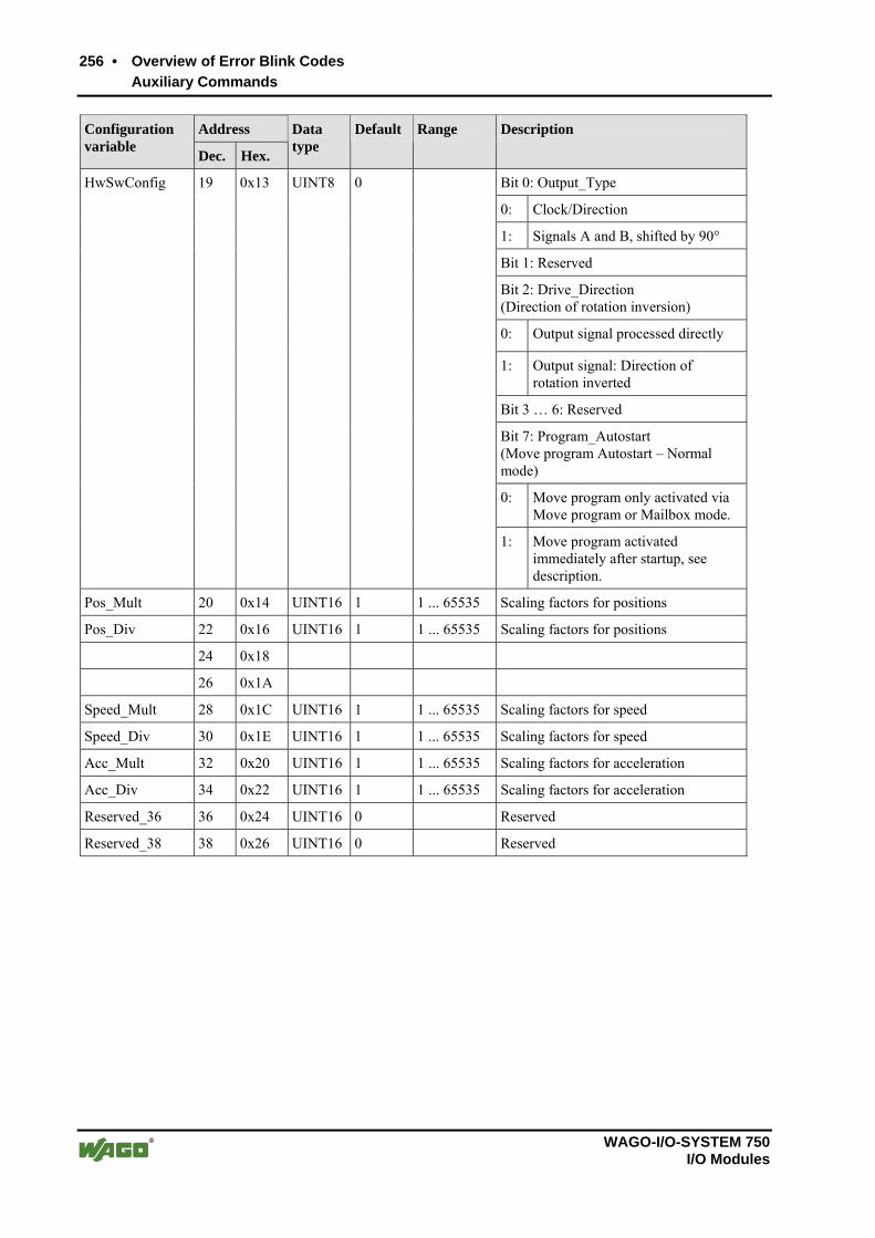
256 • Overview of Error Blink Codes
Auxiliary Commands
WAGO-I/O-SYSTEM 750 I/O Modules
Address Configuration variable
Dec. Hex.
Data type
Default Range Description
Bit 0: Output_Type
0: Clock/Direction
1: Signals A and B, shifted by 90°
Bit 1: Reserved
Bit 2: Drive_Direction (Direction of rotation inversion)
0: Output signal processed directly
1: Output signal: Direction of rotation inverted
Bit 3 … 6: Reserved
Bit 7: Program_Autostart (Move program Autostart – Normal mode)
0: Move program only activated via Move program or Mailbox mode.
HwSwConfig 19 0x13 UINT8 0
1: Move program activated immediately after startup, see description.
Pos_Mult 20 0x14 UINT16 1 1 ... 65535 Scaling factors for positions
Pos_Div 22 0x16 UINT16 1 1 ... 65535 Scaling factors for positions
24 0x18
26 0x1A
Speed_Mult 28 0x1C UINT16 1 1 ... 65535 Scaling factors for speed
Speed_Div 30 0x1E UINT16 1 1 ... 65535 Scaling factors for speed
Acc_Mult 32 0x20 UINT16 1 1 ... 65535 Scaling factors for acceleration
Acc_Div 34 0x22 UINT16 1 1 ... 65535 Scaling factors for acceleration
Reserved_36 36 0x24 UINT16 0 Reserved
Reserved_38 38 0x26 UINT16 0 Reserved

Overview of Error Blink Codes • 257
Auxiliary Commands
WAGO-I/O-SYSTEM 750 I/O Modules
Address Configuration variable
Dec. Hex.
Data type
Default Range Description
Speed 40 0x28 INT16 10 1 ... 25000 Default speed
Speed_Limit 42 0x2A INT16 25000 1 ... 25000 Default maximum speed; the drive is switched off if this speed is exceeded
SetupSpeed 44 0x2C INT16 100 1 ... 25000 Default setup speed; the current moving speed is used when this parameter is 0.
Acceleration_ Stop_Fast
46 0x2E INT16 1000 0 ... 32767 Default acceleration for STOP mode; the current acceleration is used when this parameter is 0.
Acceleration_ RampUp
48 0x30 INT16 10 0 ... 32767 Default acceleration for acceleration phase
Acceleration_ RampDown
50 0x32 INT16 10 0 ... 32767 Default acceleration for deceleration phase
Acceleration_ RampUp_Param
52 0x34 INT32 300 0 ... 16777216
Default acceleration time or acceleration path
Acceleration_ RampDown_ Param
56 0x38 INT32 300 0 ... 16777216
Default deceleration time or deceleration path

258 • Overview of Error Blink Codes
Auxiliary Commands
WAGO-I/O-SYSTEM 750 I/O Modules
Address Configuration variable
Dec. Hex.
Data type
Default Range Description
Bit 0 ... 1: AccType (Acceleration type)
0: Constant acceleration
1: Linear rise in acceleration; the period for acceleration increase is Acceleration_RampUp_Param
2: Sin2 rise in acceleration; the period for acceleration increase is Acceleration_RampUp_Param
3: Reserved
Bit 2 ... 3: AccParam (Acceleration parameter)
0: No modification
1: Acceleration_RampUp_Param interpreted as the acceleration period
2: Acceleration_RampUp_Param interpreted as the acceleration path
3: Reserved
Bit 4 ... 5: DecType (Deceleration type)
0: Constant acceleration
1: Linear rise in acceleration; the period for acceleration increase is Acceleration_RampUp_Param
2: Sin2 rise in acceleration; the period for acceleration increase is Acceleration_RampUp_Param
3: Reserved
Bit 6..7: DecParam (Deceleration parameter)
0: No modification
1: Acceleration_RampUp_Param interpreted as the acceleration period
2: Acceleration_RampUp_Param interpreted as the acceleration path
Acceleration_ Modes
60 0x3C UINT8 0
3: Reserved
Current_Ratio_ Stop
61 0x3D UINT8 100 0 ... 150 Current factor for STOP mode in [%], based on motor rated current "Current"

Overview of Error Blink Codes • 259
Auxiliary Commands
WAGO-I/O-SYSTEM 750 I/O Modules
Address Configuration variable
Dec. Hex.
Data type
Default Range Description
Setup Acceleration
62 0x3E UINT16 10 0 ... 32767 Acceleration for JOG and Reference mode
Rotary_Axis_ Period
64 0x40 INT32 0 0 ... 16777216
Sets the period P for a rotary axis; zero is entered here for a linear axis.
Drive_Range_ Neg
68 0x44 INT32 -0x7fffff 0 Acceptable moving range in negative direction
Drive_Range_ Pos
72 0x48 INT32 0x7fffff 0 Acceptable moving range in positive direction
Reserved_76 76 0x4C UINT32 0 Reserved
Reserved_80 80 0x50 UINT32 0 Reserved
PWM_Period 84 0x54 UINT32 0 0 ... 4294967295
In the Frequency output / Pulse duration modulation mode Period duration for PWM in [µs]
Camshaft_Ch9_ Start
88 0x58 INT32 0 ±8388607 Camshaft channel 9 position, starting edge
Camshaft_Ch9_ Period
92 0x5B INT32 100 1 ... 8388607
Camshaft channel 9 period
Camshaft_Ch9_ Pulsewidth
96 0x60 INT32 50 0 ... 8388607
Camshaft channel 9 pulse width
Braketime_Turn_ On
100 0x64 UINT32 0 1 ... 8388607
Starting time for brake in [ms]
Braketime_Turn_ Off
104 0x68 UINT32 0 0 ... 8388607
Switch-off time for brake in [ms]
Reference_Offset 108 0x6C UINT32 0 ±8388607 Position of reference switch
Mode for reference run at the start of a reference run via control byte C1_M_Reference (for starting a reference run using the move command START_REFERENCING, call parameters are used, but not the following configuration bits)
Bit 0:
0: Reference run to reference switch
1: Reference run to limit switch
Bit 1:
0: Reference run to negative end of a reference switch
1: Reference run to positive end of a reference switch
Reference_Mode 112 0x70 UINT8 0
Bit 2..7: Reserved

260 • Overview of Error Blink Codes
Auxiliary Commands
WAGO-I/O-SYSTEM 750 I/O Modules
Address Configuration variable
Dec. Hex.
Data type
Default Range Description
Bit 0: Mode (Enable group error for acyclic diagnostics)
0: Errors are not reported via internal bus status bit S0.6
1: Errors are reported via internal bus status bit S0.6
Error_ Notification
113 0x71 UINT8 0
Bit 1..7: Reserved
Reserved_114 114 0x72 INT16 0 Reserved
Reserved_116 116 0x74 INT32 0 Reserved
Reserved_120 120 0x78 INT32 0 Reserved
Reserved_124 124 0x7C INT32 0 Reserved
Ptr_KBUS_ ST1_0
128 0x80 UINT8 0x10 0 ... 255 Source for linkable bit 0x80
Ptr_KBUS_ ST1_1
129 0x81 UINT8 0x11 0 ... 255 Source for linkable bit 0x81
Ptr_KBUS_ ST1_2
130 0x82 UINT8 0x12 0 ... 255 Source for linkable bit 0x82
Ptr_KBUS_ ST1_3
131 0x83 UINT8 0x13 0 ... 255 Source for linkable bit 0x83
Ptr_KBUS_ ST1_4
132 0x84 UINT8 0x14 0 ... 255 Source for linkable bit 0x84
Ptr_KBUS_ ST1_5
133 0x85 UINT8 0x15 0 ... 255 Source for linkable bit 0x85
Ptr_KBUS_ ST1_6
134 0x86 UINT8 0x16 0 ... 255 Source for linkable bit 0x86
Ptr_KBUS_ ST1_7
135 0x87 UINT8 0x17 0 ... 255 Source for linkable bit 0x87
Ptr_KBUS_ ST2_0
136 0x88 UINT8 0x08 0 ... 255 Source for linkable bit 0x88
Ptr_KBUS_ ST2_1
137 0x89 UINT8 0x09 0 ... 255 Source for linkable bit 0x89
Ptr_KBUS_ ST2_2
138 0x8A UINT8 0x0A 0 ... 255 Source for linkable bit 0x8A
Ptr_KBUS_ ST2_3
139 0x8B UINT8 0x0B 0 ... 255 Source for linkable bit 0x8B
Ptr_KBUS_ ST2_4
140 0x8C UINT8 0x0C 0 ... 255 Source for linkable bit 0x8C
Ptr_KBUS_ ST2_5
141 0x8D UINT8 0x0D 0 ... 255 Source for linkable bit 0x8D
Ptr_KBUS_ ST2_6
142 0x8E UINT8 0x0E 0 ... 255 Source for linkable bit 0x8E

Overview of Error Blink Codes • 261
Auxiliary Commands
WAGO-I/O-SYSTEM 750 I/O Modules
Address Configuration variable
Dec. Hex.
Data type
Default Range Description
Ptr_KBUS_ ST2_7
143 0x8F UINT8 0x0F 0 ... 255 Source for linkable bit 0x8F
Ptr_KBUS_ ST3_0
144 0x90 UINT8 0x30 0 ... 255 Source for linkable bit 0x90
Ptr_KBUS_ ST3_1
145 0x91 UINT8 0x31 0 ... 255 Source for linkable bit 0x91
Ptr_KBUS_ ST3_2
146 0x92 UINT8 0x32 0 ... 255 Source for linkable bit 0x92
Ptr_KBUS_ ST3_3
147 0x93 UINT8 0x33 0 ... 255 Source for linkable bit 0x93
Ptr_KBUS_ ST3_4
148 0x94 UINT8 0x34 0 ... 255 Source for linkable bit 0x94
Ptr_KBUS_ ST3_5
149 0x95 UINT8 0x35 0 ... 255 Source for linkable bit 0x95
Ptr_KBUS_ ST3_6
150 0x96 UINT8 0x1A 0 ... 255 Source for linkable bit 0x96
Ptr_KBUS_ ST3_7
151 0x97 UINT8 0x04 0 ... 255 Source for linkable bit 0x97
Reserved_152 152 0x98 UINT8 0x00 0 ... 255 Source for linkable bit Bit 0x98
Reserved_153 153 0x99 UINT8 0x00 0 ... 255 Source for linkable bit 0x99
Reserved_154 154 0x9A UINT8 0x00 0 ... 255 Source for linkable bit it 0x9A
Reserved_155 155 0x9B UINT8 0x00 0 ... 255 Source for linkable bit 0x9B
Reserved_156 156 0x9C UINT8 0x00 0 ... 255 Source for linkable bit 0x9C
Reserved_157 157 0x9D UINT8 0x00 0 ... 255 Source for linkable bit 0x9D
Reserved_158 158 0x9E UINT8 0x00 0 ... 255 Source for linkable bit 0x9E
Reserved_159 159 0x9F UINT8 0x00 0 ... 255 Source for linkable bit 0x9F
Ptr_OUT1 160 0xA0 UINT8 0x08 0 ... 255 Source for linkable bit 0xA0
Ptr_OUT2 161 0xA1 UINT8 0x0F 0 ... 255 Source for linkable bit 0xA1
Reserved_162 162 0xA2 UINT8 0x00 0 ... 255 Source for linkable bit 0xA2
Reserved_163 163 0xA3 UINT8 0x00 0 ... 255 Source for linkable bit 0xA3
Reserved_164 164 0xA4 UINT8 0x00 0 ... 255 Source for linkable bit 0xA4
Reserved_165 165 0xA5 UINT8 0x00 0 ... 255 Source for linkable bit 0xA5
Reserved_166 166 0xA6 UINT8 0x00 0 ... 255 Source for linkable bit 0xA6
Reserved_167 167 0xA7 UINT8 0x00 0 ... 255 Source for linkable bit 0xA7
Ptr_FILT1 168 0xA8 UINT8 0x00 0 ... 255 Source for linkable bit 0xA8
Ptr_FILT2 169 0xA9 UINT8 0x00 0 ... 255 Source for linkable bit 0xA9
Ptr_FILT3 170 0xAA UINT8 0x00 0 ... 255 Source for linkable bit 0xAA
Ptr_FILT4 171 0xAB UINT8 0x00 0 ... 255 Source for linkable bit 0xAB
Ptr_FILT5 172 0xAC UINT8 0x00 0 ... 255 Source for linkable bit 0xAC

262 • Overview of Error Blink Codes
Auxiliary Commands
WAGO-I/O-SYSTEM 750 I/O Modules
Address Configuration variable
Dec. Hex.
Data type
Default Range Description
Ptr_FILT6 173 0xAD UINT8 0x00 0 ... 255 Source for linkable bit 0xAD
Ptr_FILT7 174 0xAE UINT8 0x00 0 ... 255 Source for linkable bit 0xAE
Ptr_FILT8 175 0xAF UINT8 0x00 0 ... 255 Source for linkable bit 0xAF
Ptr_Enable 176 0xB0 UINT8 0x40 0 ... 255 Source for linkable bit 0xB0
Ptr_Stop2_N 177 0xB1 UINT8 0x41 0 ... 255 Source for linkable bit 0xB1
Ptr_Start 178 0xB2 UINT8 0x42 0 ... 255 Source for linkable bit 0xB2
Ptr_M_ Positioning
179 0xB3 UINT8 0x43 0 ... 255 Source for linkable bit 0xB3
Ptr_M_Program 180 0xB4 UINT8 0x44 0 ... 255 Source for linkable bit 0xB4
Ptr_M_Reference 181 0xB5 UINT8 0x45 0 ... 255 Source for linkable bit 0xB5
Ptr_M_Jog 182 0xB6 UINT8 0x46 0 ... 255 Source for linkable bit 0xB6
Ptr_M_ DriveByMbx
183 0xB7 UINT8 0x47 0 ... 255 Source for linkable bit 0xB7
Ptr_Enable_ Drive
184 0xB8 UINT8 0x01 0 ... 255 Source for linkable bit 0xB8
Ptr_Reset_ Quit
185 0xB9 UINT8 0x57 0 ... 255 Source for linkable bit 0xB9
Ptr_Direction_ Pos
186 0xBA UINT8 0x52 0 ... 255 Source for linkable bit 0xBA
Ptr_Direction_ Neg
187 0xBB UINT8 0x53 0 ... 255 Source for linkable bit 0xBB
Ptr_Set_ Reference
188 0xBC UINT8 0x31 0 ... 255 Source for linkable bit 0xBC
Ptr_PreCalc 189 0xBD UINT8 0x4E 0 ... 255 Source for linkable bit 0xBD
Ptr_SetupSpeed_ Active
190 0xBE UINT8 0x56 0 ... 255 Source for linkable bit 0xBE
Ptr_Error_Quit 191 0xBF UINT8 0x4F 0 ... 255 Source for linkable bit 0xBF
Ptr_ LimitSwitch_ Pos
192 0xC0 UINT8 0x54 0 ... 255 Source for linkable bit 0xC0
Ptr_ LimitSwitch_ Neg
193 0xC1 UINT8 0x55 0 ... 255 Source for linkable bit 0xC1
Ptr_Stop1_N 194 0xC2 UINT8 0x30 0 ... 255 Source for linkable bit 0xC2
Reserved_195 195 0xC3 UINT8 0x00 0 ... 255 Source for linkable bit it 0xC3
Ptr_Freq_Range_ Sel_0
196 0xC4 UINT8 0x48 0 ... 255 Source for linkable bit 0xC4
Ptr_Freq_Range_ Sel_1
197 0xC5 UINT8 0x49 0 ... 255 Source for linkable bit 0xC5
Ptr_Acc_Range_ Sel_0
198 0xC6 UINT8 0x4A 0 ... 255 Source for linkable bit 0xC6

Overview of Error Blink Codes • 263
Auxiliary Commands
WAGO-I/O-SYSTEM 750 I/O Modules
Address Configuration variable
Dec. Hex.
Data type
Default Range Description
Ptr_Acc_Range_ Sel_1
199 0xC7 UINT8 0x4B 0 ... 255 Source for linkable bit 0xC7
Ptr_Set_Actual_ POS
200 0xC8 UINT8 0x50 0 ... 255 Source for linkable bit 0xC8
Reserved_201 201 0xC9 UINT8 0x00 0 ... 255 Source for linkable bit 0xC9
Reserved_202 202 0xCA UINT8 0x00 0 ... 255 Source for linkable bit 0xCA
Reserved_203 203 0xCB UINT8 0x00 0 ... 255 Source for linkable bit 0xCB
Reserved_204 204 0xCC UINT8 0x00 0 ... 255 Source for linkable bit 0xCC
Reserved_205 205 0xCD UINT8 0x00 0 ... 255 Source for linkable bit 0xCD
Reserved_206 206 0xCE UINT8 0x00 0 ... 255 Source for linkable bit 0xCE
Reserved_207 207 0xCF UINT8 0x00 0 ... 255 Source for linkable bit 0xCF
Ptr_LED_E 208 0xD0 UINT8 0x09 0 ... 255 Source for linkable bit 0xD0
Ptr_LED_F 209 0xD1 UINT8 0x1B 0 ... 255 Source for linkable bit 0xD1
Ptr_LED_G 210 0xD2 UINT8 0x11 0 ... 255 Source for linkable bit 0xD2
Ptr_LED_H 211 0xD3 UINT8 0x19 0 ... 255 Source for linkable bit 0xD3
Reserved_212 212 0xD4 UINT8 0x00 0 ... 255 Source for linkable bit 0xD4
Reserved_213 213 0xD5 UINT8 0x00 0 ... 255 Source for linkable bit 0xD5
Reserved_214 214 0xD6 UINT8 0x00 0 ... 255 Source for linkable bit 0xD6
Reserved_215 215 0xD7 UINT8 0x00 0 ... 255 Source for linkable bit 0xD7
Reserved_216 216 0xD8 UINT8 0x00 0 ... 255 Source for linkable bit 0xD8
Reserved_217 217 0xD9 UINT8 0x00 0 ... 255 Source for linkable bit 0xD9
Reserved_218 218 0xDA UINT8 0x00 0 ... 255 Source for linkable bit 0xDA
Reserved_219 219 0xDB UINT8 0x00 0 ... 255 Source for linkable bit 0xDB
Reserved_220 220 0xDC UINT8 0x00 0 ... 255 Source for linkable bit 0xDC
Reserved_221 221 0xDD UINT8 0x00 0 ... 255 Source for linkable bit 0xDD
Ptr_Trace_ Trigger
222 0xDE UINT8 0x09 0 ... 255 Source for linkable bit 0xDE
Ptr_Trace_ Armed
223 0xDF UINT8 0x03 0 ... 255 Source for linkable bit 0xDF

264 • Overview of Error Blink Codes
Auxiliary Commands
WAGO-I/O-SYSTEM 750 I/O Modules
Address Configuration variable
Dec. Hex.
Data type
Default Range Description
Filter Function:
0: No filtering
1: Inversion
2: Detection of starting edge
3: Low pass
4: Pulse extension
5: One-shot
6: Delay
7: Math
8: Incrementing counter
9: Incrementing counter to zero
10: Decrementing counter
Filter1_Function 224 0xE0 UINT8 0 0 ... 11
11: Decrementing counter to zero
Filter2_Function 225 0xE1 UINT8 0 0 ... 11 Function of filter: see Filter1_Function
Filter3_Function 226 0xE2 UINT8 0 0 ... 11 Function of filter: see Filter1_Function
Filter4_Function 227 0xE3 UINT8 0 0 ... 11 Function of filter: see Filter1_Function
Filter5_Function 228 0xE4 UINT8 0 0 ... 11 Function of filter: see Filter1_Function
Filter6_Function 229 0xE5 UINT8 0 0 ... 11 Function of filter: see Filter1_Function
Filter7_Function 230 0xE6 UINT8 0 0 ... 11 Function of filter: see Filter1_Function
Filter8_Function 231 0xE7 UINT8 0 0 ... 11 Function of filter: see Filter1_Function
Filter1_Time 232 0xE8 UINT32 0 0 ... 16777215
Filter Time constant in [ms]
Filter2_Time 236 0xEB UINT32 0 0 ... 16777215
Filter Time constant in [ms]
Filter3_Time 240 0xF0 UINT32 0 0 ... 16777215
Filter Time constant in [ms]
Filter4_Time 244 0xF4 UINT32 0 0 ... 16777215
Filter Time constant in [ms]
Filter5_Time 248 0xF8 UINT32 0 0 ... 16777215
Filter Time constant in [ms]
FIlter6_Time 252 0xFC UINT32 0 0 ... 16777215
Filter Time constant in [ms]
Filter7_Time 256 0x100 UINT32 0 0 ... 16777215
Filter Time constant in [ms]

Overview of Error Blink Codes • 265
Auxiliary Commands
WAGO-I/O-SYSTEM 750 I/O Modules
Address Configuration variable
Dec. Hex.
Data type
Default Range Description
Filter8_Time 260 0x104 UINT32 0 0 ... 16777215
Filter Time constant in [ms]
TraceVar1 264 0x108 UINT32 1 Variable number 1 for trace memory
TraceVar2 268 0x10C UINT32 2 Variable number 2 for trace memory
TraceMsecCycleTime
272 0x110 UINT32 1 0 ... 16777215
Cycle time for recording the variables given in TraceVar1/2 in [ms]
Reserved_276 276 0x114 UINT32 0 Reserved
Reserved_280 280 0x118 UINT32 0 Reserved
Reserved_284 284 0x11C UINT32 0 Reserved
Reserved_288 288 0x120 UINT32 0 Reserved
Reserved_292 292 0x124 UINT32 0 Reserved
Reserved_296 296 0x128 UINT32 0 Reserved
Reserved_300 300 0x12C UINT32 0 Reserved
Reserved_304 304 0x130 UINT32 0 Reserved
Reserved_308 308 0x134 UINT32 0 Reserved
Reserved_312 312 0x138 UINT32 0 Reserved
Reserved_316 316 0x13C UINT32 0 Reserved
Reserved_320 320 0x140 UINT32 0 Reserved
Reserved_324 324 0x144 UINT32 0 Reserved
Reserved_328 328 0x148 UINT32 0 Reserved
Reserved_332 332 0x14C UINT32 0 Reserved
Reserved_336 336 0x150 UINT32 0 Reserved
Reserved_340 340 0x154 UINT32 0 Reserved
Reserved_344 344 0x158 UINT32 0 Reserved
Reserved_348 348 0x15C UINT32 0 Reserved
Reserved_352 352 0x160 UINT32 0 Reserved
Reserved_356 356 0x164 UINT32 0 Reserved
Reserved_360 360 0x168 UINT32 0 Reserved
Reserved_364 364 0x16C UINT32 0 Reserved
Reserved_368 368 0x170 UINT32 0 Reserved
Reserved_372 372 0x174 UINT32 0 Reserved
Reserved_376 376 0x178 UINT32 0 Reserved
Reserved_380 380 0x17C UINT32 0 Reserved
Reserved_384 384 0x180 UINT32 0 Reserved
Reserved_388 388 0x184 UINT32 0 Reserved
Reserved_392 392 0x188 UINT32 0 Reserved

266 • Overview of Error Blink Codes
Auxiliary Commands
WAGO-I/O-SYSTEM 750 I/O Modules
Address Configuration variable
Dec. Hex.
Data type
Default Range Description
Reserved_396 396 0x18C UINT32 0 Reserved
Reserved_400 400 0x190 UINT32 0 Reserved
Reserved_404 404 0x194 UINT32 0 Reserved
Reserved_408 408 0x198 UINT32 0 Reserved
Reserved_412 412 0x19C UINT32 0 Reserved
Reserved_416 416 0x1A0 UINT32 0 Reserved
Reserved_420 420 0x1A4 UINT32 0 Reserved
Reserved_424 424 0x1A8 UINT32 0 Reserved
Reserved_428 428 0x1AC UINT32 0 Reserved
Reserved_432 432 0x1B0 UINT32 0 Reserved
Reserved_436 436 0x1B4 UINT32 0 Reserved
Reserved_440 440 0x1B8 UINT32 0 Reserved
Reserved_444 444 0x1BC UINT32 0 Reserved
Reserved_448 448 0x1C0 UINT32 0 Reserved
Reserved_452 452 0x1C4 UINT32 0 Reserved
Reserved_456 456 0x1C8 UINT32 0 Reserved
Reserved_460 460 0x1CC UINT32 0 Reserved
Reserved_464 464 0x1D0 UINT32 0 Reserved
Reserved_468 468 0x1D4 UINT32 0 Reserved
Reserved_472 472 0x1D8 UINT32 0 Reserved
Reserved_476 476 0x1DC UINT32 0 Reserved
Reserved_480 480 0x1E0 UINT32 0 Reserved
Reserved_484 484 0x1E4 UINT32 0 Reserved
Reserved_488 488 0x1E8 UINT32 0 Reserved
Reserved_492 492 0x1EC UINT32 0 Reserved
Reserved_496 496 0x1F0 UINT32 0 Reserved
Reserved_500 500 0x1F4 UINT32 0 Reserved
Reserved_504 504 0x1F8 UINT32 0 Reserved
Reserved_508 508 0x1FC UINT32 0 Reserved

Overview of Error Blink Codes • 267
Auxiliary Commands
WAGO-I/O-SYSTEM 750 I/O Modules
3.6 Internal Status Variables
Index
Dec. Hex.
Variable Value
0 0x00 Time since start of program [ms]
1 0x01 Current position (measured value) [user unit]
2 0x02 Current output frequency [user unit]
3 0x03 Number of status variables
4 0x04 0
5 0x05 0
6 0x06 0
7 0x07 0
8 0x08 Software Version ASCII
9 0x09 HardwareVersion
2: Module 750-670
4: Module 750-671
8: Module 750-672
10 0x0A HardwareIdent
16: Module 750-673
11 0x0B CompilationMonth mmmm ASCII
12 0x0C CompilationDayYear ddyy ASCII
13 0x0D Compilationtime hhmm ASCII
1: no CPLD
2: CPLD not recognized
3: CPLD Type 3
14 0x0E CPLD
4: CPLD Type 4
15 0x0F Expecting configuration version
16 0x10 Version of current configuration
17 0x11 0
18 0x12 0
19 0x13 0
20 0x14 0
21 0x15 0
22 0x16 0
23 0x17 PARTMODEL status
24 0x18 Specified position for position encoder
25 0x19 Specified velocity for position encoder
26 0x1A Current position (internal measured value)

268 • Overview of Error Blink Codes
Auxiliary Commands
WAGO-I/O-SYSTEM 750 I/O Modules
Index
Dec. Hex.
Variable Value
27 0x1B Current position (internal offset)
28 0x1C Current position (internal OffsetSampled)
29 0x1D Current position (internal LastPosition)
30 0x1E Last target position
31 0x1F Acceleration factor
32 0x20 Position error
33 0x21 Current output frequency (internal)
34 0x22 Current position (internal CPLD emulation)
35 0x23 0
36 0x24 0
37 0x25 0
38 0x26 0
39 0x27 0
40 0x28 0
41 0x29 Move program command counter
42 0x2A EEPROM status
43 0x2B Specified velocity
44 0x2C Maximum velocity
45 0x2D Final velocity
46 0x2E 0
47 0x2F Stop deceleration
48 0x30 Priority of current command (internal)
49 0x31 Current acceleration
50 0x32 Current deceleration
51 0x33 Acceleration modification (path, time)
52 0x34 Deceleration modification (path, time)
53 0x35 Ramp mode
54 0x36 Maximum velocity (internal)
55 0x37 Prescaler velocity
56 0x38 Present current factor
57 0x39 Original status for camshaft 1 ... 9
58 0x3A Reference run status
59 0x3B Reference run limit switch contact status
60 0x3C Referencing speed (internal)
61 0x3D Reference run: Creep speed

Overview of Error Blink Codes • 269
Auxiliary Commands
WAGO-I/O-SYSTEM 750 I/O Modules
Index
Dec. Hex.
Variable Value
62 0x3E 0
63 0x3F 0
64 0x40 Fast timer min. computing time [us]
65 0x41 Fast timer max. computing time [us]
66 0x42 Fast timer avg. computing time [us]
67 0x43 Main loop min. computing time [us]
68 0x44 Main loop max. computing time [us]
69 0x45 Main loop avg. computing time [us]
70 0x46 Main timer min. computing time [us]
71 0x47 Main timer max. computing time [us]
72 0x48 Main timer avg. computing time [us]
73 0x49 Background min. computing time [us]
74 0x4A Background max. computing time [us]
75 0x4B Background avg. computing time [us]
76 0x4C Aux. timer min. computing time [us]
77 0x4D Aux. timer max. computing time [us]
78 0x4E Aux. timer avg. computing time [us]
79 0x4F WA200 Interrupt min. computing time [us]
80 0x50 WA200 Interrupt max. computing time [us]
81 0x51 WA200 Interrupt avg. computing time [us]
82 0x52 WA200 Interrupt min. period [us]
83 0x53 WA200 Interrupt max. period [us]
84 0x54 WA200 Interrupt avg. period [us]
85 0x55 Internal bus interrupt min. period [us]
86 0x56 Internal bus interrupt max. period [us]
87 0x57 Internal bus interrupt avg. period [us]
88 0x58 0
89 0x59 0
90 0x5A 0
91 0x5B Status variable Filter1
92 0x5C Status variable Filter2
93 0x5D Status variable Filter3
94 0x5E Status variable Filter4
95 0x5F Status variable Filter5
96 0x60 Status variable Filter6

270 • Overview of Error Blink Codes
Auxiliary Commands
WAGO-I/O-SYSTEM 750 I/O Modules
Index
Dec. Hex.
Variable Value
97 0x61 Status variable Filter7
98 0x62 Status variable Filter8
99 0x63 0

Overview of Error Blink Codes • 271
Auxiliary Commands
WAGO-I/O-SYSTEM 750 I/O Modules

WAGO Kontakttechnik GmbH & Co. KG Postfach 2880 • D-32385 Minden Hansastraße 27 • D-32423 Minden Phone: 05 71/8 87 – 0 Fax: 05 71/8 87 – 1 69 E-Mail: [email protected] Internet: http://www.wago.com