
MODULES 6 Air system
55
AIR SYSTEM AIR SYSTEM
Transcript of MODULES 6 Air system

AIR SYSTEM
AIR SYSTEM

AIR SYSTEM
AIR SYSTEM REQUIREMENTS
The air system is required to supply filtered, smooth flowing air to the gas generator for combustion and cooling with minimal pressure drop to allow full power operation
Air to provide Power Turbine rim cooling during operation
Air to Power Turbine seal during operation
Auxiliary air to provide GG 05 module cooling for ESD
Auxiliary air to provide Power Turbine seal air during startup and shutdown
Deliver excess air from Gas Generator to safe atmosphere. (Bleed Air)
Filtered air to cool and ventilate equipment enclosures
Filtered air for combustion

AIR SYSTEM
1. INLET AIR SYSTEM (INCUDING VENTILATION)
2. BLEED AIR SYSTEM
3. POWER TURBINE SEAL AIR SYSTEM
4. POWER TURBINE RIM COOLING AIR SYSTEM
5. INSTRUMENT AIR SYSTEM
6. EXHAUST GAS SYSTEM.
THE PACKAGE AIR SYSTEM CAN BE DIVIDED INTO SIX SEPARATE SUB SYSTEMS
AIR SYSTEM
INLET AIR SYSTEM & VENTILATION

AIR SYSTEM
• Air filters operate in many different environments and are exposed to many different types of contaminants.
• Air filters respond differently to different types of contaminants.
• The total environmental challenge to an air filter includes many factors that interact– Particles, gasses, relative humidity, temperature, vibration
• Filtration needs vary by application.
AIR FILTRATION BASICS
AIR SYSTEM
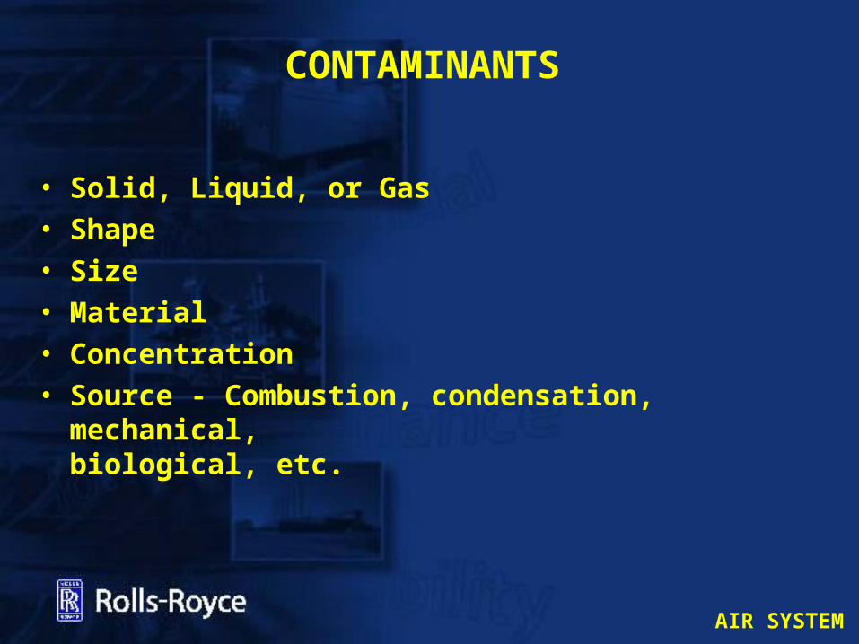
• Solid, Liquid, or Gas• Shape • Size• Material• Concentration• Source - Combustion, condensation, mechanical, biological, etc.
CONTAMINANTS
AIR SYSTEM
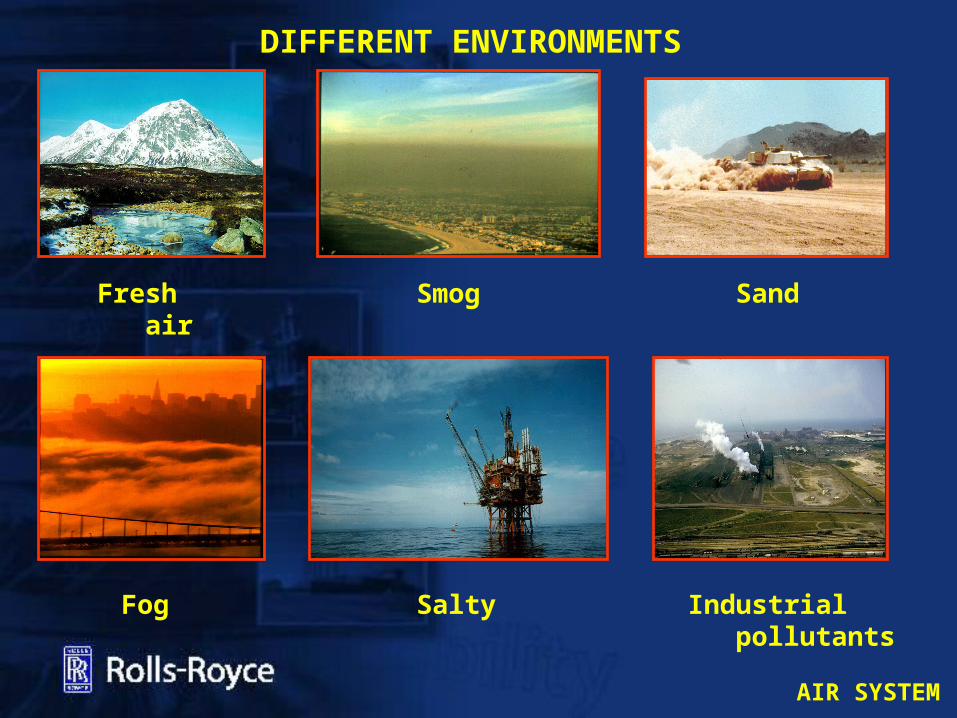
DIFFERENT ENVIRONMENTS
Smog
Industrial pollutants
Fog
Fresh air
Sand
Salty
AIR SYSTEM
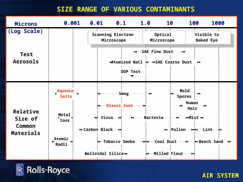
Microns(Log Scale)
0.001 0.01 0.1 1.0 10 100 1000
HumanHair
SAE Fine Dust
SAE Coarse Dust
Mist
Tobacco Smoke Coal Dust
Milled Flour
Pollen
BacteriaVirus
Colloidal Silica
Carbon Black
Diesel Soot
AqueousSalts
MetalIons
AtomicRadii
RelativeSize ofCommon
Materials
DOP Test
Beach Sand
Lint
Atomized NaCl
Scanning ElectronMicroscope
OpticalMicroscope
Visible toNaked Eye
TestAerosols
MoldSporesSmog
SIZE RANGE OF VARIOUS CONTAMINANTS

AIR SYSTEM
• Erosion: the abrasive removal from the compressor
blades and guide vanes. Typically 10 um particles and larger.• Fouling:
Accumulated deposits of hardened airborne particles that alter the profile of the rotor and stator vanes causing a reduction in operating efficiency.• Corrosion:
Chemical reaction between ingested airborne particles and turbine components.
WHY DO TURBINES NEED CLEAN AIR?

AIR SYSTEM
WRONG FILTER SELECTION OR LACK OF MAINTENANCE
CORRECT FILTER SELECTION AND WELL
MAINTAINED

AIR SYSTEM
Inertia Dusty and Sandy areas
High Efficiency with coalescerSalt Water Mist
Pulse cleaning
INLET FILTER TYPES

AIR SYSTEM
TYPICAL PULSE FILTER ARRANGEMENT

AIR SYSTEM
PULSE FILTER ELEMENTS
AIR SYSTEM
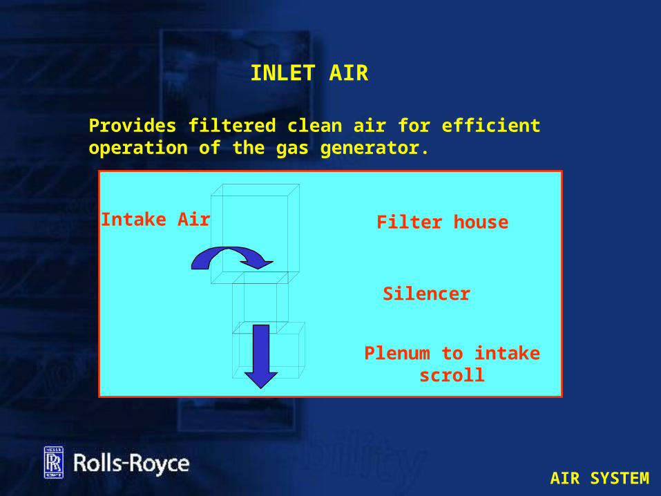
INLET AIR
Provides filtered clean air for efficientoperation of the gas generator.
Filter house
Silencer
Plenum to intake scroll
Intake Air

AIR SYSTEM
INLET SILENCER
AIR SYSTEM
VENTILATION AIR SYSTEM – MAIN FUNCTIONS
• Maintains turbine enclosure temperature at a tolerable level.
• Provides cooling for exposed high temperature machinery surfaces.
• Prevents built-up of gas or fumes within enclosure.
• Maintains positive/negative pressure in the GG enclosure dependant on package type
• Provide Dampers to contain extinguishant in the event of a fire

AIR SYSTEM
VENTILATION AIR FLOW
COMBUSTION AIR FLOW
MOISTURE SEPARATORS
VENTILATION FILTERS
COMBUSTION AIR FILTERS
MALAMPAYA INSTALLATION

AIR SYSTEM
VENTILATION EXHAUST DUCTING

AIR SYSTEM
BLEED AIR SYSTEM
AIR SYSTEM
GAS GENERATOR AIRFLOW CONTROLS
• One stage of Variable inlet Guide Vanes
• Bleed Valves
• 05 module air Cooling Air (Davis Valve)
AIR SYSTEM
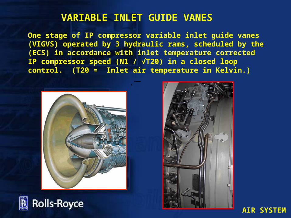
One stage of IP compressor variable inlet guide vanes (VIGVS) operated by 3 hydraulic rams, scheduled by the (ECS) in accordance with inlet temperature corrected IP compressor speed (N1 / √T20) in a closed loop control. (T20 = Inlet air temperature in Kelvin.)
VARIABLE INLET GUIDE VANES
AIR SYSTEM
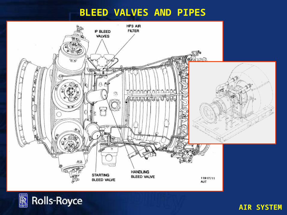
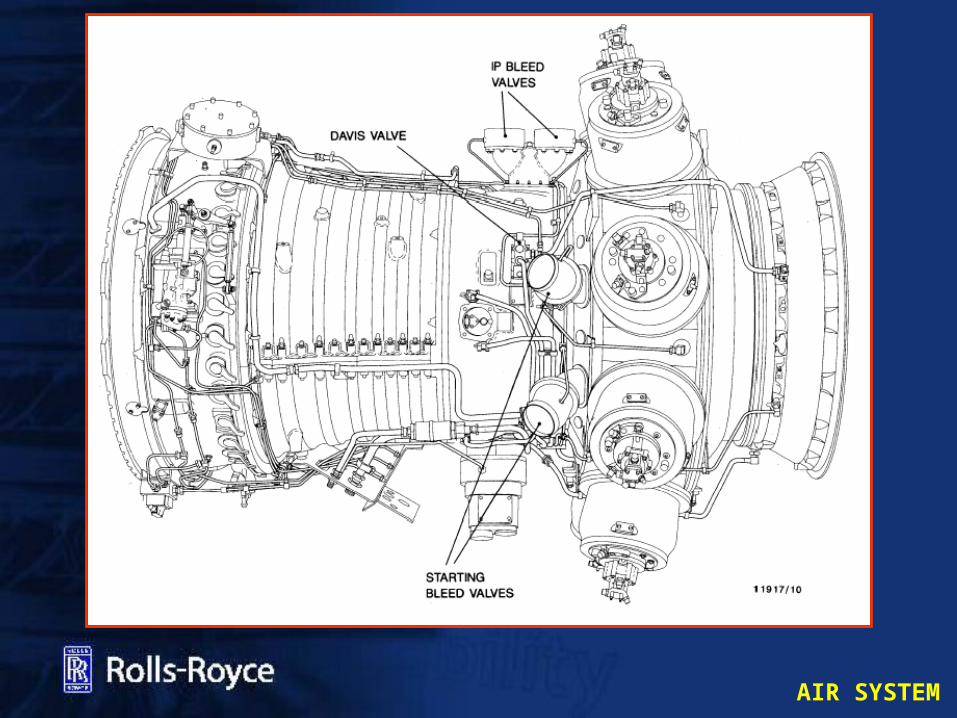
BLEED VALVES AND PIPES
AIR SYSTEM
AIR SYSTEM
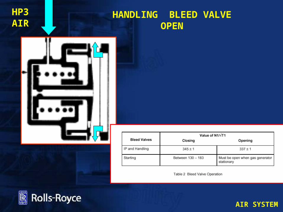
BLEED VALVESThe basic function is to prevent GG compressor surge and / or stall by venting excess air using bleed off valves (BOV´s) during starting and stopping to improve the operational efficiency at low load conditions.• 2 IP handling bleed valves spilling IP stage 7 air scheduled to open and close by the (ECS) in accordance with a corrected I.P. compressor speed
• 1 HP handling bleed valve spilling P263 air scheduled to open and close by the (ECS) in accordance with a corrected IP compressor speed
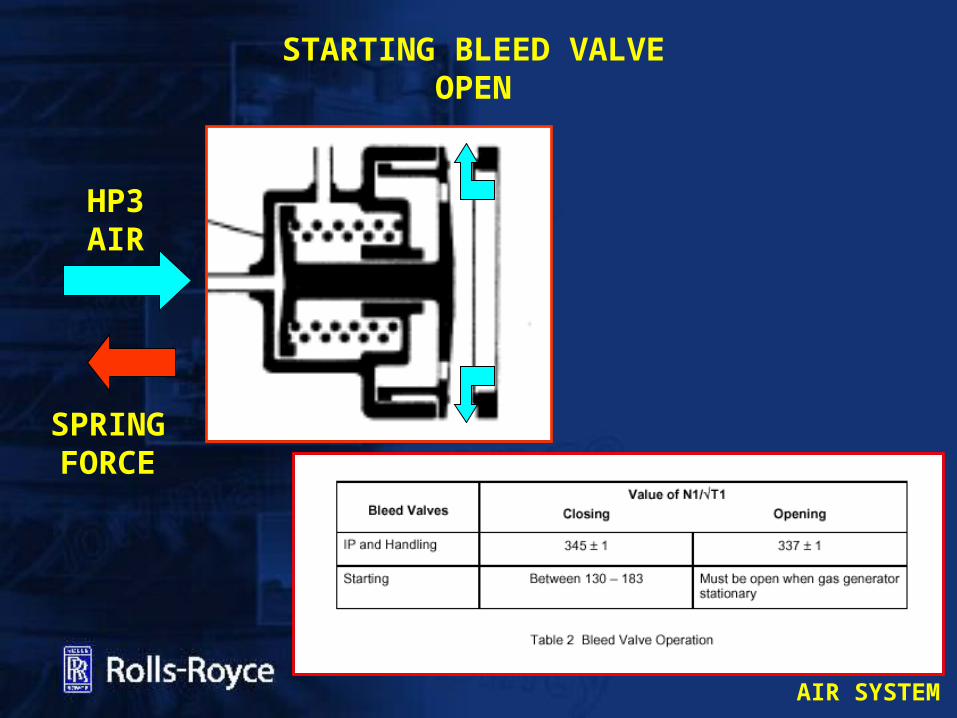
ECS to close valves at a non-dimensional IP speed of 345 +/-1 rising and open them at 337 +/-1 falling
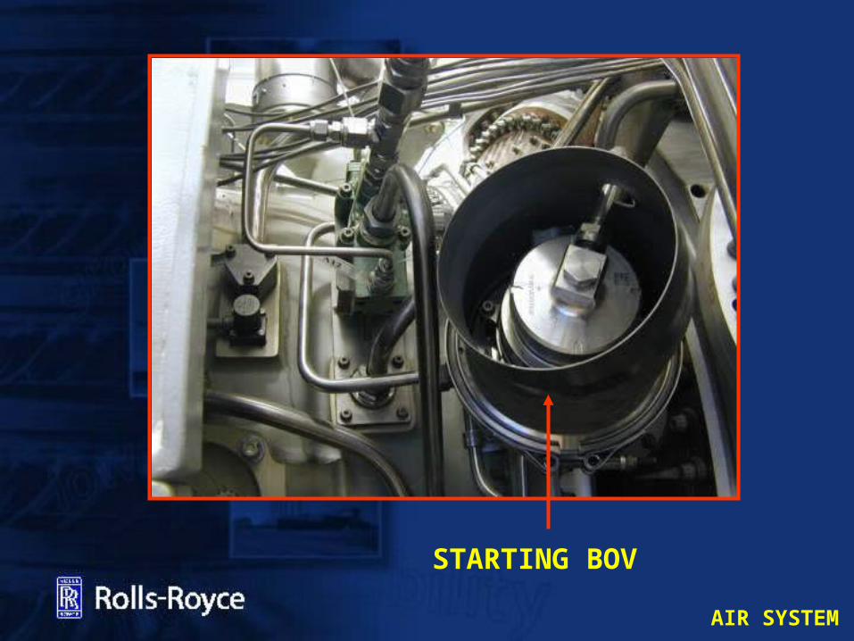
• 3 starting bleed valves spills P263 air during the starting cycle onlyScheduled by P263 air

AIR SYSTEM
AIR SYSTEM
STARTING BOV
AIR SYSTEM
STARTING BLEED VALVEOPEN
HP3 AIR
SPRING FORCE
AIR SYSTEM
HANDLING BLEED VALVEOPEN
HP3 AIR

AIR SYSTEM
HP3 HANDLING BLEED VALVE
HP3 SOLENOID

AIR SYSTEM
VIEWED FROM REAR
HANDLING BOV SOL (GGBV)
IP7 BOV
IP7 BOV
HP3 FILTER
HP3 ENGINE TAKEOFF
STARTING BOV
STARTING BOV
STARTING BOV
HP HANDLING
BOV
HP3 SOL(GGSBV)
HP3 SOL(GGSBV)
HP 3 EMERGENCY SHUTDOWN SOLENOIDS
AIR SYSTEM
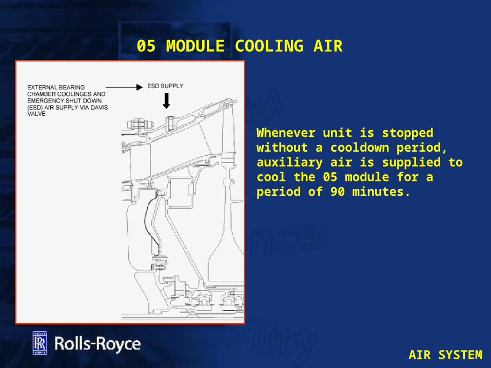
05 MODULE COOLING AIR
Whenever unit is stopped without a cooldown period, auxiliary air is supplied to cool the 05 module for a period of 90 minutes.

AIR SYSTEM
DAVIS VALVE
AIR SYSTEM
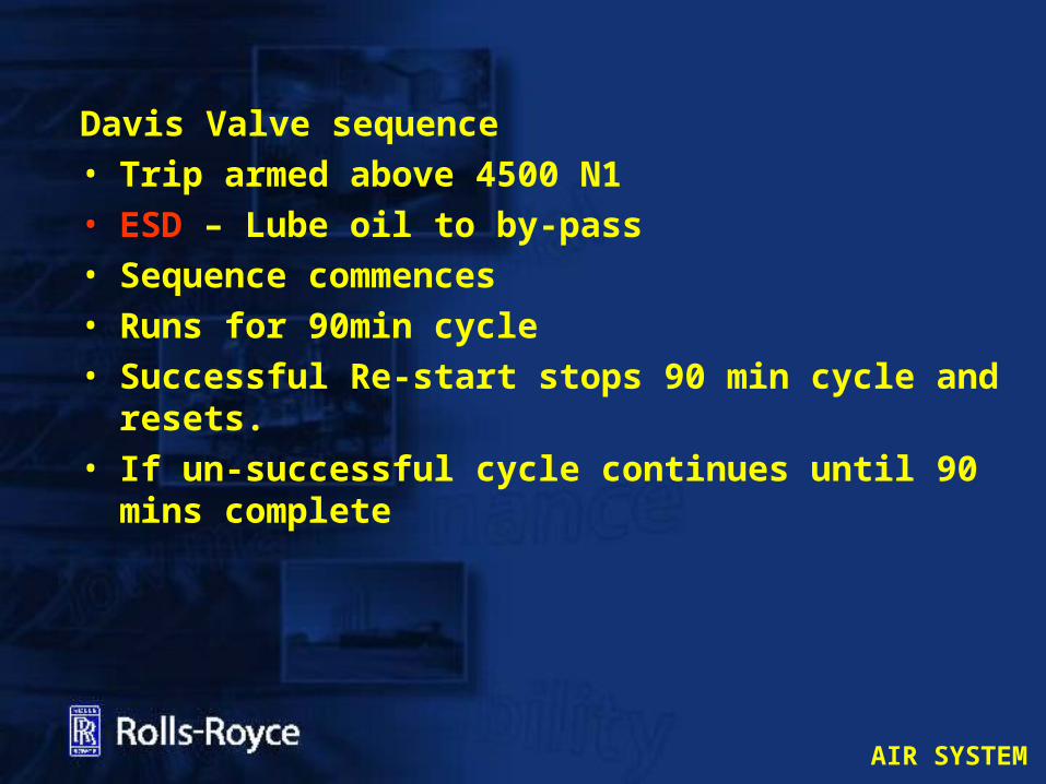
Davis Valve sequence• Trip armed above 4500 N1• ESD – Lube oil to by-pass• Sequence commences• Runs for 90min cycle• Successful Re-start stops 90 min cycle and resets.
• If un-successful cycle continues until 90 mins complete
AIR SYSTEM
POWER TURBINE COOLING AND SEALING
AIR SYSTEM
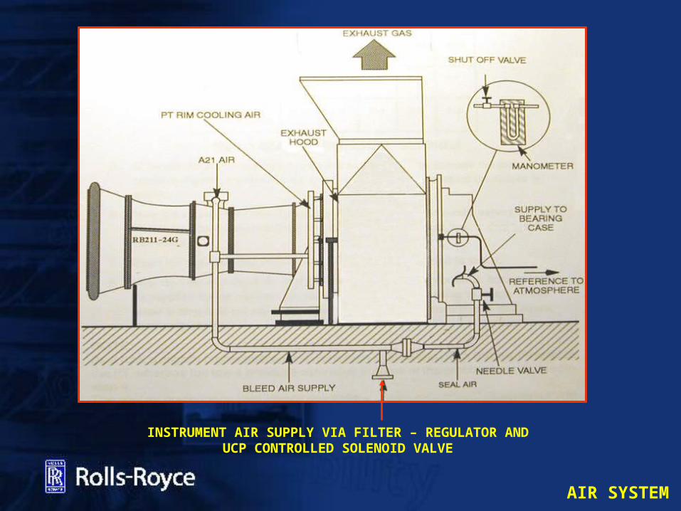
INSTRUMENT AIR SUPPLY VIA FILTER – REGULATOR AND UCP CONTROLLED SOLENOID VALVE

AIR SYSTEM
POWER TURBINE SEAL AIR SYSTEM
AIR SYSTEM
POWER TURBINE SEALING AIR
Air from the gas generator compressor IP 7th stage is used for the power turbine labyrinth seal to prevent:
• Bearing case oil entering the exhaust stream during operation which may cause Smokey Exhaust and undesirable oil consumption
• Excessive air flow out of coupling vent and Oil mist coming out the vent
During starting and Postlube Auxiliary air will be required to provide sealing air.

AIR SYSTEM
AIR SYSTEM
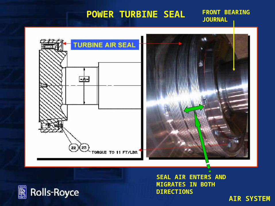
POWER TURBINE SEAL
SEAL AIR ENTERS AND MIGRATES IN BOTH DIRECTIONS
FRONT BEARING JOURNAL
AIR SYSTEM
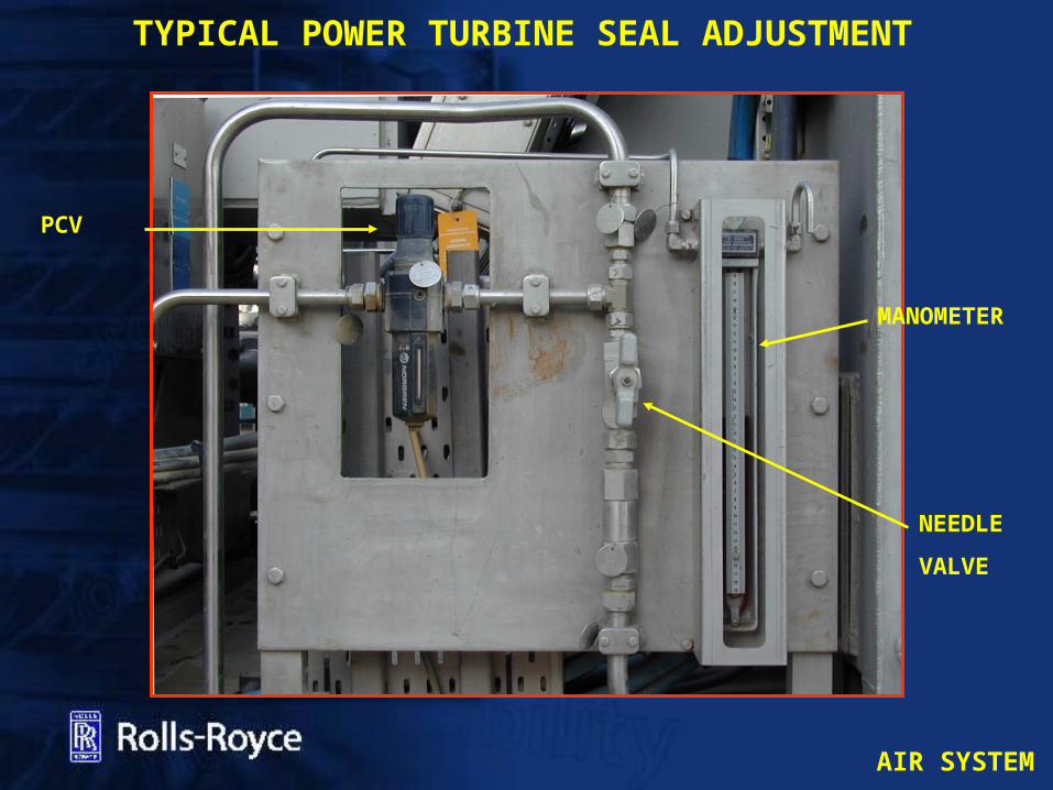
TYPICAL POWER TURBINE SEAL ADJUSTMENT
NEEDLEVALVE
PCV
MANOMETER
AIR SYSTEM
POWER TURBINE RIM COOLING AIR SYSTEM
AIR SYSTEM
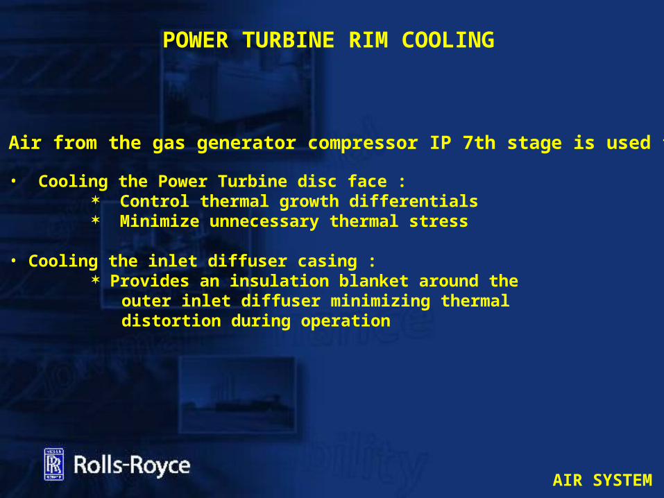
POWER TURBINE RIM COOLING
Air from the gas generator compressor IP 7th stage is used for:
• Cooling the Power Turbine disc face : Control thermal growth differentials Minimize unnecessary thermal stress
• Cooling the inlet diffuser casing : Provides an insulation blanket around the outer inlet diffuser minimizing thermal distortion during operation

AIR SYSTEM
POWER TURBINE RIM COOLING MANIFOLDS

AIR SYSTEM
POWER TURBINE RIM COOLING
SUPPLY TO 2ND STAGE HAS 12.7 MM ORIFICE

AIR SYSTEM
INSTRUMENT AIR SYSTEM
AIR SYSTEM
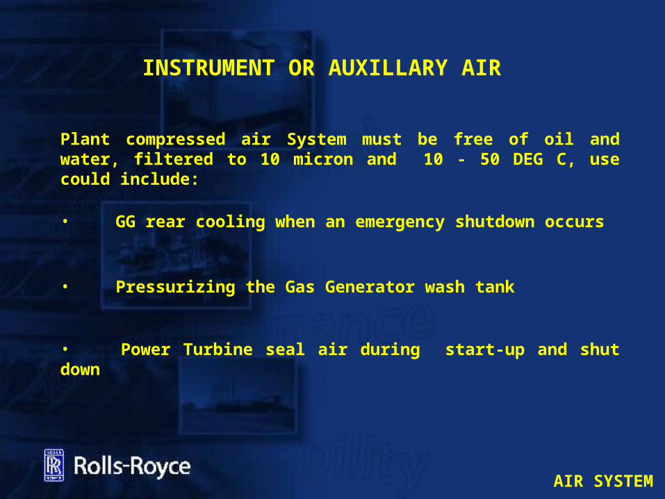
INSTRUMENT OR AUXILLARY AIR
Plant compressed air System must be free of oil and water, filtered to 10 micron and 10 - 50 DEG C, use could include:
• GG rear cooling when an emergency shutdown occurs
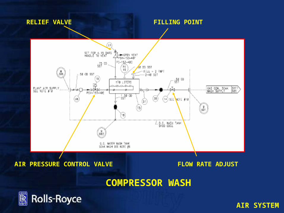
• Pressurizing the Gas Generator wash tank
• Power Turbine seal air during start-up and shut down
AIR SYSTEM
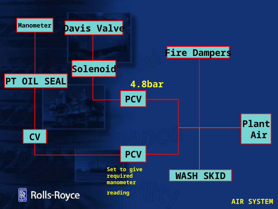
Fire Dampers
PCV4.8bar
Solenoid
Davis Valve
Plant Air
PT OIL SEAL
PCVSet to give required manometer reading
CV
WASH SKID
Manometer
AIR SYSTEM
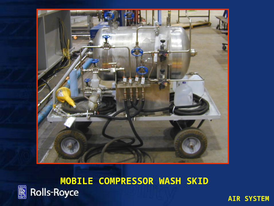
MOBILE COMPRESSOR WASH SKID
AIR SYSTEM
COMPRESSOR WASH
FLOW RATE ADJUST
RELIEF VALVE
AIR PRESSURE CONTROL VALVE
FILLING POINT

AIR SYSTEM
EXHAUST GAS SYSTEM

AIR SYSTEM
EXHAUST GASSES
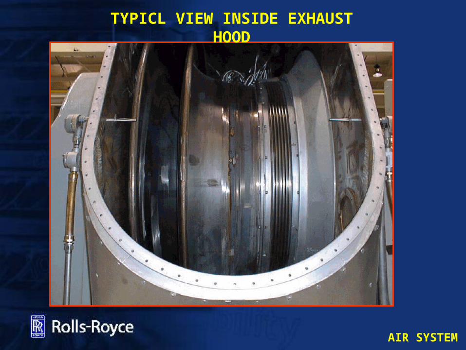
The Exhaust hood collects the exhaust gas from the Power Turbine and directs it to a safe atmosphere, via ducting silencer and exhaust plenum. The exhaust system may contain waste heat recovery equipment.
Options for:
• Left• Right• Straight
AIR SYSTEM
TYPICL VIEW INSIDE EXHAUST HOOD
AIR SYSTEM
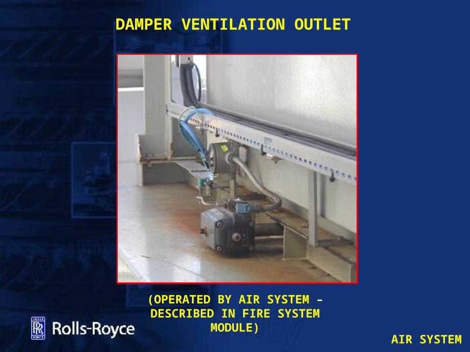
DAMPER VENTILATION OUTLET
(OPERATED BY AIR SYSTEM – DESCRIBED IN FIRE SYSTEM
MODULE)
AIR SYSTEM
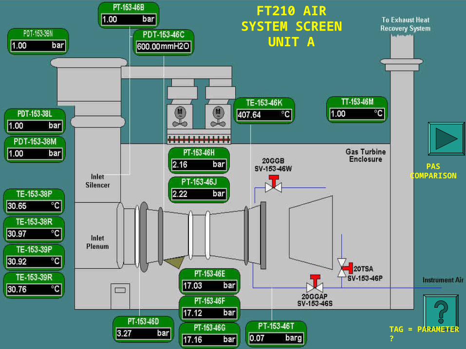
FT210 AIR SYSTEM SCREEN
UNIT A
PAS COMPARISON
TAG = PARAMETER ?

AIR SYSTEM
End