MAX-6 - u-blox 6 GPS Modules
21
MAX-6 u-blox 6 GPS Modules Data Sheet Abstract Technical data sheet describing the ultra miniature u-blox 6 based MAX-6 series of GPS modules. These compact u-blox6 GPS receivers provide high performance and a high level of integration capability in a tiny package. This makes them perfectly suited for end products with strict size and cost requirements. 10.1 x 9.7 x 2.5 mm locate, communicate, accelerate www.u-blox.com
-
Upload
khangminh22 -
Category
Documents
-
view
0 -
download
0
Transcript of MAX-6 - u-blox 6 GPS Modules
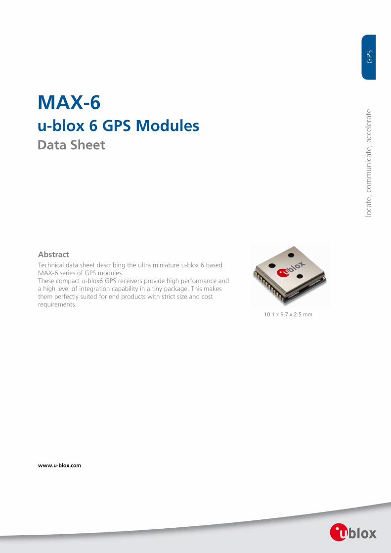
MAX-6 u-blox 6 GPS Modules Data Sheet
Abstract
Technical data sheet describing the ultra miniature u-blox 6 based
MAX-6 series of GPS modules. These compact u-blox6 GPS receivers provide high performance and
a high level of integration capability in a tiny package. This makes
them perfectly suited for end products with strict size and cost requirements.
10.1 x 9.7 x 2.5 mm
loca
te,
com
mu
nic
ate
, acc
ele
rate
www.u-blox.com
MAX-6 - Data Sheet
GPS.G6-HW-10106-B Page 2 of 21
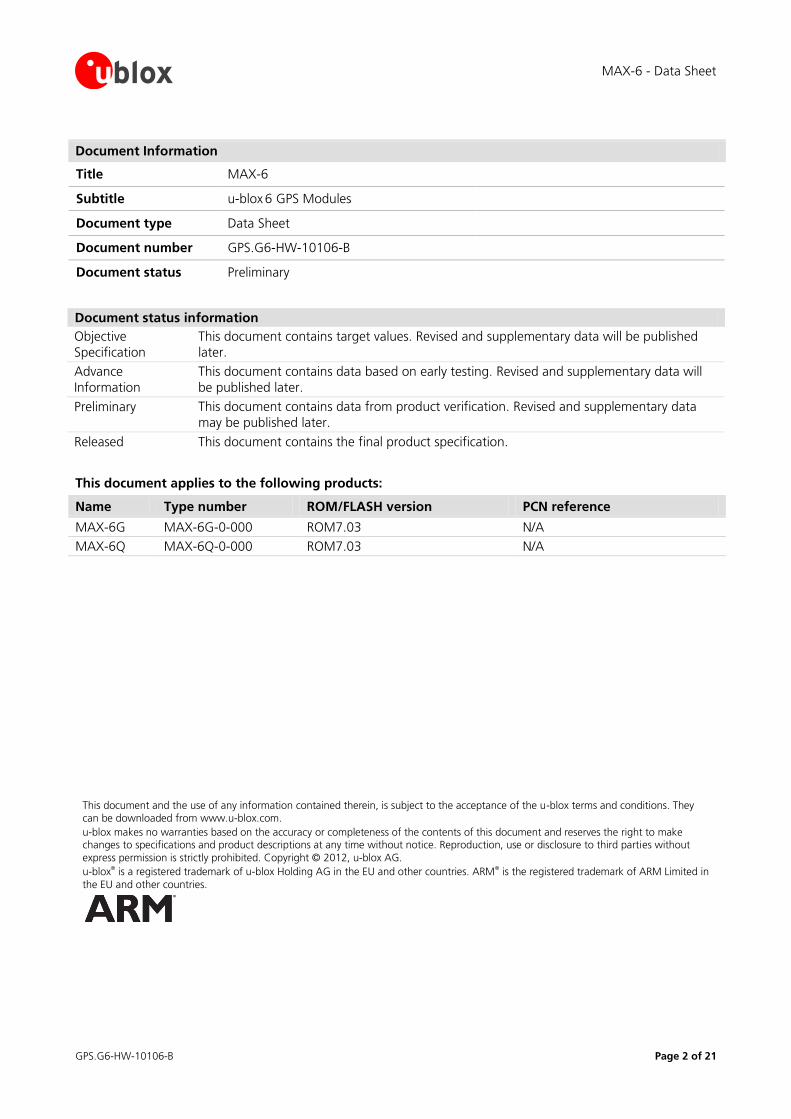
Document Information
Title MAX-6
Subtitle u-blox 6 GPS Modules
Document type Data Sheet
Document number GPS.G6-HW-10106-B
Document status Preliminary
Document status information
Objective
Specification
This document contains target values. Revised and supplementary data will be published
later.
Advance
Information
This document contains data based on early testing. Revised and supplementary data will
be published later.
Preliminary This document contains data from product verification. Revised and supplementary data
may be published later.
Released This document contains the final product specification.
This document applies to the following products:
Name Type number ROM/FLASH version PCN reference
MAX-6G MAX-6G-0-000 ROM7.03 N/A
MAX-6Q MAX-6Q-0-000 ROM7.03 N/A
This document and the use of any information contained therein, is subject to the acceptance of the u-blox terms and conditions. They can be downloaded from www.u-blox.com.
u-blox makes no warranties based on the accuracy or completeness of the contents of this document and reserves the right to make changes to specifications and product descriptions at any time without notice. Reproduction, use or disclosure to third parties without
express permission is strictly prohibited. Copyright © 2012, u-blox AG.
u-blox® is a registered trademark of u-blox Holding AG in the EU and other countries. ARM
® is the registered trademark of ARM Limited in
the EU and other countries.

MAX-6 - Data Sheet
GPS.G6-HW-10106-B Preliminary Page 3 of 21
Contents
Contents .............................................................................................................................. 3
1 Functional description .................................................................................................. 5
1.1 Overview .............................................................................................................................................. 5
1.2 Product features ................................................................................................................................... 5
1.3 GPS performance .................................................................................................................................. 6
1.4 Block diagram ....................................................................................................................................... 7
1.5 Assisted GPS (A-GPS) ............................................................................................................................ 7
1.6 AssistNow Autonomous ....................................................................................................................... 7
1.7 Protocols and interfaces ........................................................................................................................ 8
1.7.1 UART ............................................................................................................................................. 8
1.7.2 Display Data Channel (DDC) .......................................................................................................... 8
1.7.3 Data ready indication: TX Ready .................................................................................................... 8
1.7.4 VDCC_IO ....................................................................................................................................... 8
1.8 Antenna ............................................................................................................................................... 8
1.8.1 Active antenna control (ANTON).................................................................................................... 9
1.9 Power Management ............................................................................................................................. 9
1.9.1 Maximum Performance Mode ....................................................................................................... 9
1.9.2 Eco Mode ...................................................................................................................................... 9
1.9.3 Power Save Mode ......................................................................................................................... 9
1.10 Design-in .......................................................................................................................................... 9
2 Pin Definition .............................................................................................................. 10
2.1 Pin assignment ................................................................................................................................... 10
3 Electrical specifications .............................................................................................. 11
3.1 Absolute maximum ratings ................................................................................................................. 11
3.2 Operating conditions .......................................................................................................................... 12
3.3 Indicative power requirements ............................................................................................................ 13
4 Mechanical specifications .......................................................................................... 14
5 Qualification and certification ................................................................................... 15
5.1 Reliability tests .................................................................................................................................... 15
5.2 Approvals ........................................................................................................................................... 15
6 Product handling & soldering .................................................................................... 15
6.1 Packaging ........................................................................................................................................... 15
6.1.1 Reels ........................................................................................................................................... 15
6.1.2 Tapes .......................................................................................................................................... 16
6.2 Moisture Sensitivity Levels ................................................................................................................... 17
6.3 Reflow soldering ................................................................................................................................. 17
MAX-6 - Data Sheet
GPS.G6-HW-10106-B Preliminary Page 4 of 21
6.4 ESD handling precautions ................................................................................................................... 17
7 Default settings .......................................................................................................... 18
8 Labeling and ordering information ........................................................................... 19
8.1 Product labeling .................................................................................................................................. 19
8.2 Explanation of codes........................................................................................................................... 19
8.3 Ordering information .......................................................................................................................... 19
Related documents........................................................................................................... 20
Revision history ................................................................................................................ 20
Contact .............................................................................................................................. 21
MAX-6 - Data Sheet
GPS.G6-HW-10106-B Preliminary Page 5 of 21
1 Functional description
1.1 Overview
The MAX-6 module series brings the high performance of the u-blox 6 position engine in the ultra miniature
MAX form factor. These receivers provide high performance and a high level of integration capability in a tiny
package. This makes them perfectly suited for mass-market end products with strict size and cost requirements.
The 50-channel u-blox 6 positioning engine boasts a Time-To-First-Fix (TTFF) of under 1 second. The dedicated
acquisition engine, with over 2 million correlators, is capable of massive parallel time/frequency space searches,
enabling it to find satellites instantly. Innovative design and technology suppresses interference sources and mitigates multipath effects, giving MAX-6 GPS receivers excellent navigation performance even in the most
challenging environments.
MAX-6 allows simple integration with u-blox wireless modules. All MAX-6 modules are manufactured in ISO/TS 16949 certified sites.
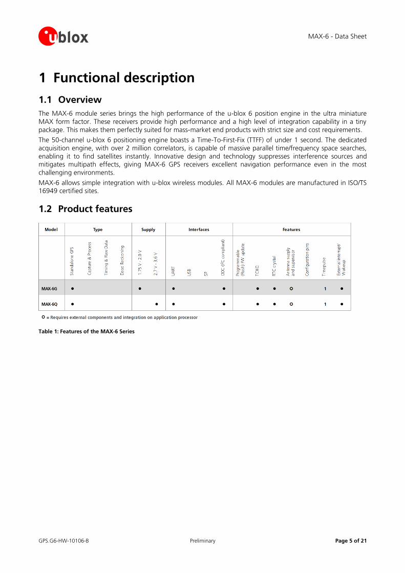
1.2 Product features
Table 1: Features of the MAX-6 Series
MAX-6 - Data Sheet
GPS.G6-HW-10106-B Preliminary Page 6 of 21
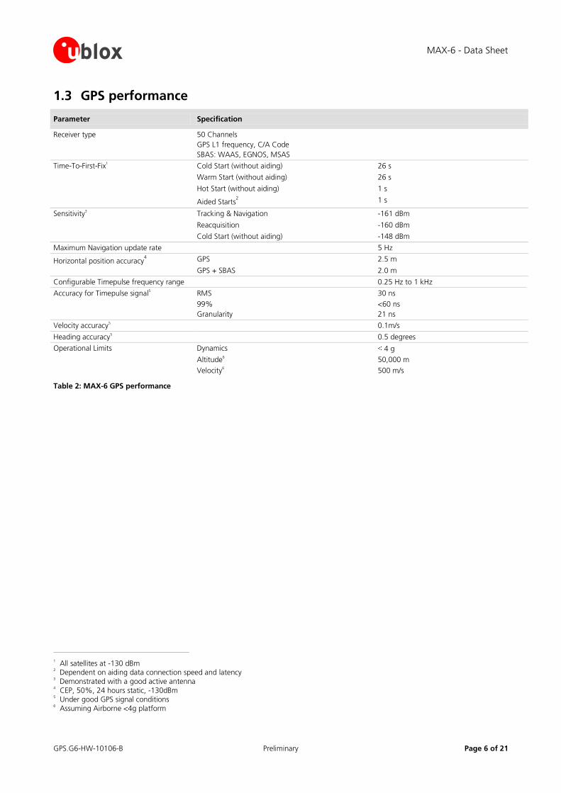
1.3 GPS performance
Parameter Specification
Receiver type 50 Channels
GPS L1 frequency, C/A Code
SBAS: WAAS, EGNOS, MSAS
Time-To-First-Fix1 Cold Start (without aiding) 26 s
Warm Start (without aiding) 26 s
Hot Start (without aiding) 1 s
Aided Starts2 1 s
Sensitivity3 Tracking & Navigation -161 dBm
Reacquisition -160 dBm
Cold Start (without aiding) -148 dBm
Maximum Navigation update rate 5 Hz
Horizontal position accuracy4 GPS 2.5 m
GPS + SBAS 2.0 m
Configurable Timepulse frequency range 0.25 Hz to 1 kHz
Accuracy for Timepulse signal5 RMS 30 ns
99%
Granularity
<60 ns
21 ns
Velocity accuracy5 0.1m/s
Heading accuracy5 0.5 degrees
Operational Limits Dynamics 4 g
Altitude6 50,000 m
Velocity6 500 m/s
Table 2: MAX-6 GPS performance
1 All satellites at -130 dBm
2 Dependent on aiding data connection speed and latency
3 Demonstrated with a good active antenna
4 CEP, 50%, 24 hours static, -130dBm
5 Under good GPS signal conditions
6 Assuming Airborne <4g platform

MAX-6 - Data Sheet
GPS.G6-HW-10106-B Preliminary Page 7 of 21
1.4 Block diagram
Figure 1: Block diagram (For available options refer to the product features table in section 1.2)c
1.5 Assisted GPS (A-GPS)
Supply of aiding information like ephemeris, almanac, rough last position and time and satellite status and an
optional time synchronization signal will reduce time to first fix significantly and improve the acquisition
sensitivity. All MAX-6 modules support the u-blox AssistNow Online and AssistNow Offline
A-GPS services
7 and
are OMA SUPL compliant.
1.6 AssistNow Autonomous
AssistNow Autonomous provides functionality similar to Assisted-GPS without the need for a host or external network connection. Based on previously broadcast satellite ephemeris data downloaded to and stored by the
GPS receiver, AssistNow Autonomous automatically generates accurate satellite orbital data (“AssistNow
Autonomous data”) that is usable for future GPS position fixes. AssistNow Autonomous data is reliable for up to 3 days after initial capture.
u-blox’ AssistNow Autonomous benefits are:
Faster position fix particularly under weak signal conditions
No connectivity required
Complementary with AssistNow Online and Offline services
No integration effort, calculations are done in the background
For more details see the u-blox 6 Receiver Description including Protocol Specification [2].
7 AssistNow Offline equires external memory on the Host
MAX-6 - Data Sheet
GPS.G6-HW-10106-B Preliminary Page 8 of 21
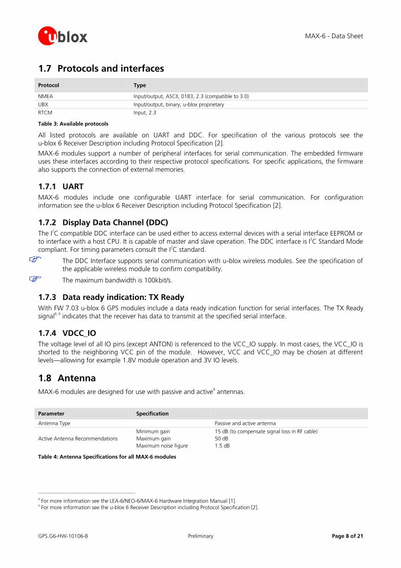
1.7 Protocols and interfaces
Protocol Type
NMEA Input/output, ASCII, 0183, 2.3 (compatible to 3.0)
UBX Input/output, binary, u-blox proprietary
RTCM Input, 2.3
Table 3: Available protocols
All listed protocols are available on UART and DDC. For specification of the various protocols see the
u-blox 6 Receiver Description including Protocol Specification [2].
MAX-6 modules support a number of peripheral interfaces for serial communication. The embedded firmware uses these interfaces according to their respective protocol specifications. For specific applications, the firmware
also supports the connection of external memories.
1.7.1 UART
MAX-6 modules include one configurable UART interface for serial communication. For configuration
information see the u-blox 6 Receiver Description including Protocol Specification [2].
1.7.2 Display Data Channel (DDC)
The I2C compatible DDC interface can be used either to access external devices with a serial interface EEPROM or
to interface with a host CPU. It is capable of master and slave operation. The DDC interface is I2C Standard Mode
compliant. For timing parameters consult the I2C standard.
The DDC Interface supports serial communication with u-blox wireless modules. See the specification of
the applicable wireless module to confirm compatibility.
The maximum bandwidth is 100kbit/s.
1.7.3 Data ready indication: TX Ready
With FW 7.03 u-blox 6 GPS modules include a data ready indication function for serial interfaces. The TX Ready signal
8, 9 indicates that the receiver has data to transmit at the specified serial interface.
1.7.4 VDCC_IO
The voltage level of all IO pins (except ANTON) is referenced to the VCC_IO supply. In most cases, the VCC_IO is shorted to the neighboring VCC pin of the module. However, VCC and VCC_IO may be chosen at different
levels—allowing for example 1.8V module operation and 3V IO levels.
1.8 Antenna
MAX-6 modules are designed for use with passive and active8 antennas.
Parameter Specification
Antenna Type Passive and active antenna
Active Antenna Recommendations
Minimum gain
Maximum gain
Maximum noise figure
15 dB (to compensate signal loss in RF cable)
50 dB
1.5 dB
Table 4: Antenna Specifications for all MAX-6 modules
8 For more information see the LEA-6/NEO-6/MAX-6 Hardware Integration Manual [1].
9 For more information see the u-blox 6 Receiver Description including Protocol Specification [2].

MAX-6 - Data Sheet
GPS.G6-HW-10106-B Preliminary Page 9 of 21
1.8.1 Active antenna control (ANTON)
The ANTON Pin can be used to turn on and off an external LNA or an active antenna. This reduces power
consumption in Power Save Mode (Backup mode) 10
.
1.9 Power Management
u-blox receivers support different power modes. These modes represent strategies11 of how to control the
acquisition and tracking engines in order to achieve either the best possible performance or good performance with reduced power consumption.
For more information about power management strategies, see the u-blox 6 Receiver Description including Protocol Specification [2].
1.9.1 Maximum Performance Mode
During a Cold start, a receiver in Maximum Performance Mode continuously deploys the acquisition engine to
search for all satellites. Once the receiver has a position fix (or if pre-positioning information is available), the
acquisition engine continues to be used to search for all visible satellites that are not being tracked.
1.9.2 Eco Mode
During a Cold start, a receiver in Eco Mode works exactly as in Maximum Performance Mode. Once a position
can be calculated and a sufficient number of satellites are being tracked, the acquisition engine is powered off resulting in significant power savings. The tracking engine continuously tracks acquired satellites and acquires
other available or emerging satellites.
Note that even if the acquisition engine is powered off, satellites continue to be acquired.
1.9.3 Power Save Mode
Power Save Mode (PSM) allows a reduction in system power consumption by selectively switching parts of the
receiver on and off.
1.10 Design-in
In order to obtain the necessary information to conduct a proper design-in, u-blox strongly recommends
consulting the LEA-6/NEO-6/MAX-6 Hardware Integration Manual [1].
10 For more information see the LEA-6/NEO-6/MAX-6 Hardware Integration Manual [1].
11 For more information see the u-blox 6 Receiver Description including Protocol Specification [2].
MAX-6 - Data Sheet
GPS.G6-HW-10106-B Preliminary Page 10 of 21
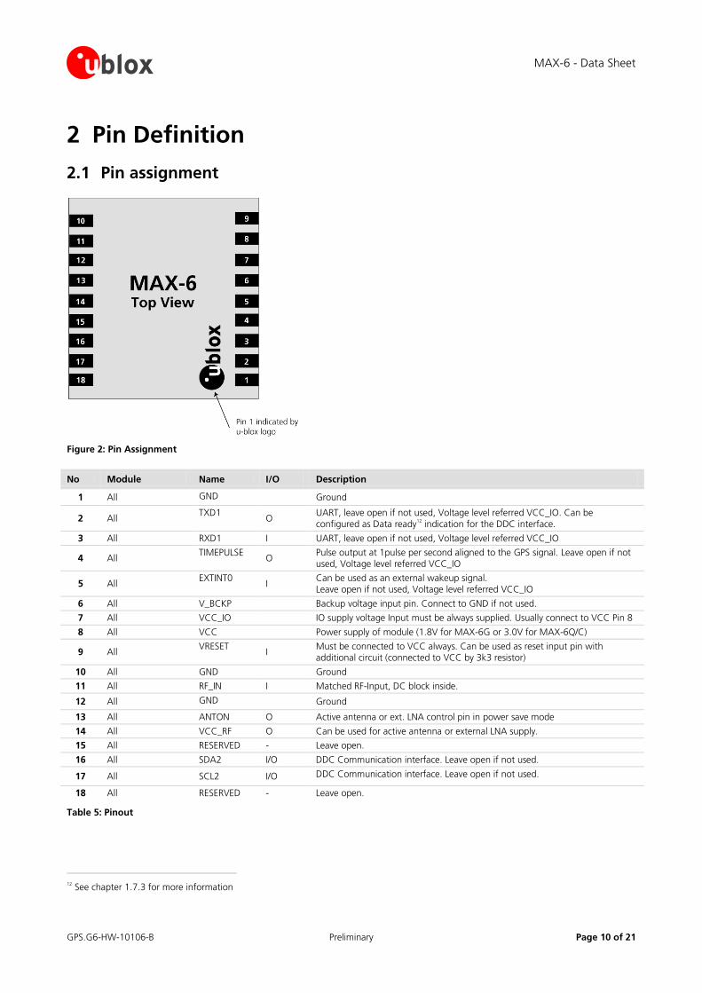
2 Pin Definition
2.1 Pin assignment
Figure 2: Pin Assignment
No Module Name I/O Description
1 All GND Ground
2 All TXD1
O UART, leave open if not used, Voltage level referred VCC_IO. Can be configured as Data ready
12 indication for the DDC interface.
3 All RXD1 I UART, leave open if not used, Voltage level referred VCC_IO
4 All TIMEPULSE
O Pulse output at 1pulse per second aligned to the GPS signal. Leave open if not used, Voltage level referred VCC_IO
5 All EXTINT0
I Can be used as an external wakeup signal. Leave open if not used, Voltage level referred VCC_IO
6 All V_BCKP Backup voltage input pin. Connect to GND if not used.
7 All VCC_IO IO supply voltage Input must be always supplied. Usually connect to VCC Pin 8
8 All VCC Power supply of module (1.8V for MAX-6G or 3.0V for MAX-6Q/C)
9 All VRESET
I Must be connected to VCC always. Can be used as reset input pin with additional circuit (connected to VCC by 3k3 resistor)
10 All GND Ground
11 All RF_IN I Matched RF-Input, DC block inside.
12 All GND Ground
13 All ANTON O Active antenna or ext. LNA control pin in power save mode
14 All VCC_RF O Can be used for active antenna or external LNA supply.
15 All RESERVED - Leave open.
16 All SDA2 I/O DDC Communication interface. Leave open if not used.
17 All SCL2 I/O DDC Communication interface. Leave open if not used.
18 All RESERVED - Leave open.
Table 5: Pinout
12 See chapter 1.7.3 for more information
MAX-6 - Data Sheet
GPS.G6-HW-10106-B Preliminary Page 11 of 21
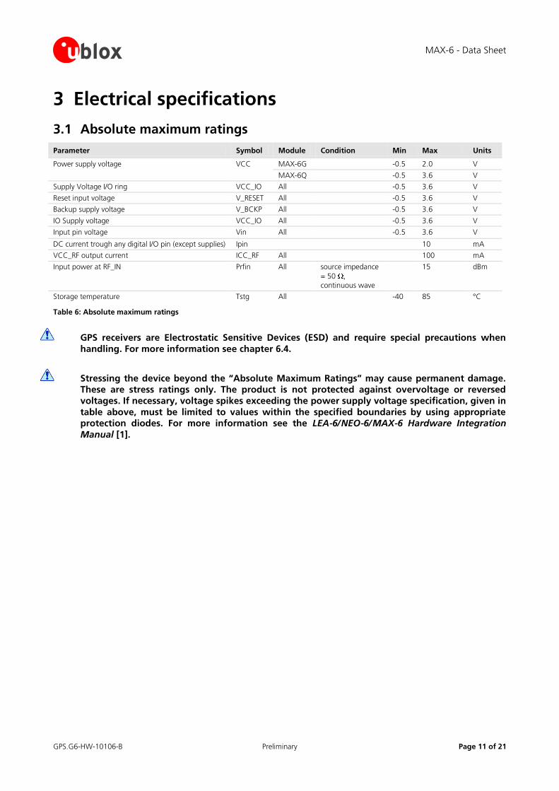
3 Electrical specifications
3.1 Absolute maximum ratings
Parameter Symbol Module Condition Min Max Units
Power supply voltage VCC MAX-6G -0.5 2.0 V
MAX-6Q -0.5 3.6 V
Supply Voltage I/O ring VCC_IO All -0.5 3.6 V
Reset input voltage V_RESET All -0.5 3.6 V
Backup supply voltage V_BCKP All -0.5 3.6 V
IO Supply voltage VCC_IO All -0.5 3.6 V
Input pin voltage Vin All -0.5 3.6 V
DC current trough any digital I/O pin (except supplies) Ipin 10 mA
VCC_RF output current ICC_RF All 100 mA
Input power at RF_IN Prfin All source impedance
= 50 ,
continuous wave
15 dBm
Storage temperature Tstg All -40 85 °C
Table 6: Absolute maximum ratings
GPS receivers are Electrostatic Sensitive Devices (ESD) and require special precautions when
handling. For more information see chapter 6.4.
Stressing the device beyond the “Absolute Maximum Ratings” may cause permanent damage. These are stress ratings only. The product is not protected against overvoltage or reversed
voltages. If necessary, voltage spikes exceeding the power supply voltage specification, given in
table above, must be limited to values within the specified boundaries by using appropriate protection diodes. For more information see the LEA-6/NEO-6/MAX-6 Hardware Integration
Manual [1].

MAX-6 - Data Sheet
GPS.G6-HW-10106-B Preliminary Page 12 of 21
3.2 Operating conditions
All specifications are at an ambient temperature of 25°C.
Parameter Symbol Module Min Typ Max Units Condition
Power supply voltage VCC MAX-6G 1.75 1.8 2.0 V
MAX-6Q 2.5 3.0 3.6 V
Supply Voltage I/O ring VCC_IO All 1.65 3.0 3.6 V
Backup battery voltage V_BCKP All 1.4 3.6 V
Backup battery current I_BCKP All 22 µA V_BCKP = 1.8 V, VCC_IO = 0V
Input pin voltage range Vin All 0 VCC_IO V
Digital IO Pin Low level input voltage Vil All 0 0.2*VCC_IO V
Digital IO Pin High level input voltage Vih All 0.7*VCC_IO VCC_IO V
Digital IO Pin Low level output voltage Vol All 0.4 V Iol=4mA
Digital IO Pin High level output voltage Voh All VCC_IO -0.4V V Ioh=4mA
ANTON Pin Low level output voltage All 0 0.2*VCC_RF Iol=4uA
ANTON Pin High level output voltage All 0.7*VCC_RF VCC_RF Ioh=4uA
VCC_RF voltage VCC_RF All VCC-0.1 V
VCC_RF output current ICC_RF All 50 mA
Antenna gain Gant All 50 dB
Receiver Chain Noise Figure NFtot All 3.2 dB
Operating temperature Topr All -40 85 °C
Table 7: Operating conditions
Operation beyond the specified operating conditions can affect device reliability.
MAX-6 - Data Sheet
GPS.G6-HW-10106-B Preliminary Page 13 of 21
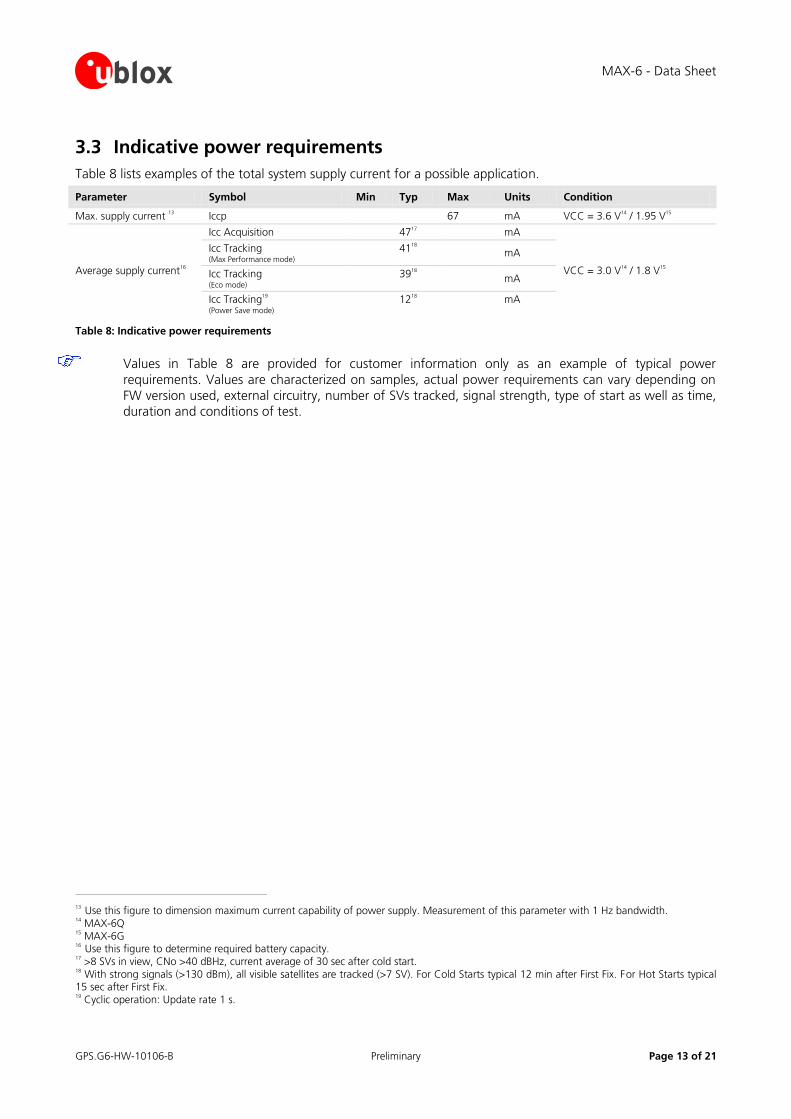
3.3 Indicative power requirements
Table 8 lists examples of the total system supply current for a possible application.
Parameter Symbol Min Typ Max Units Condition
Max. supply current 13 Iccp 67 mA VCC = 3.6 V
14 / 1.95 V
15
Average supply current16
Icc Acquisition 4717 mA
VCC = 3.0 V14 / 1.8 V
15
Icc Tracking (Max Performance mode)
4118 mA
Icc Tracking (Eco mode)
3918 mA
Icc Tracking19
(Power Save mode) 12
18 mA
Table 8: Indicative power requirements
Values in Table 8 are provided for customer information only as an example of typical power
requirements. Values are characterized on samples, actual power requirements can vary depending on
FW version used, external circuitry, number of SVs tracked, signal strength, type of start as well as time, duration and conditions of test.
13 Use this figure to dimension maximum current capability of power supply. Measurement of this parameter with 1 Hz bandwidth.
14 MAX-6Q
15 MAX-6G
16 Use this figure to determine required battery capacity.
17 >8 SVs in view, CNo >40 dBHz, current average of 30 sec after cold start.
18 With strong signals (>130 dBm), all visible satellites are tracked (>7 SV). For Cold Starts typical 12 min after First Fix. For Hot Starts typical
15 sec after First Fix. 19 Cyclic operation: Update rate 1 s.
MAX-6 - Data Sheet
GPS.G6-HW-10106-B Preliminary Page 14 of 21
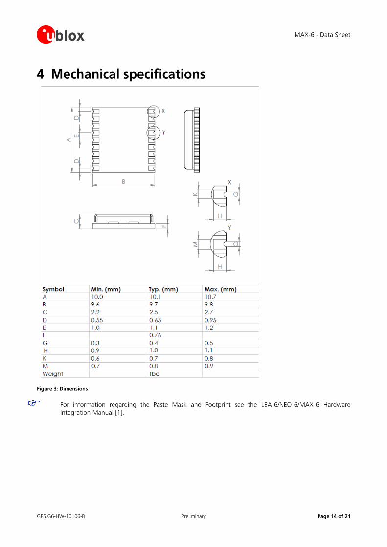
4 Mechanical specifications
Figure 3: Dimensions
For information regarding the Paste Mask and Footprint see the LEA-6/NEO-6/MAX-6 Hardware Integration Manual [1].
MAX-6 - Data Sheet
GPS.G6-HW-10106-B Preliminary Page 15 of 21
5 Qualification and certification
5.1 Reliability tests
Tests for product family qualifications according to ISO 16750 "Road vehicles - environmental conditions and
testing for electrical and electronic equipment”, and appropriate standards.
5.2 Approvals
Products marked with this lead-free symbol on the product label comply with the Directive
2002/95/EC of the European Parliament and the Council on the Restriction of Use of
certain Hazardous Substances in Electrical and Electronic Equipment (RoHS).
All u-blox 6 GPS modules are RoHS compliant.
6 Product handling & soldering
6.1 Packaging
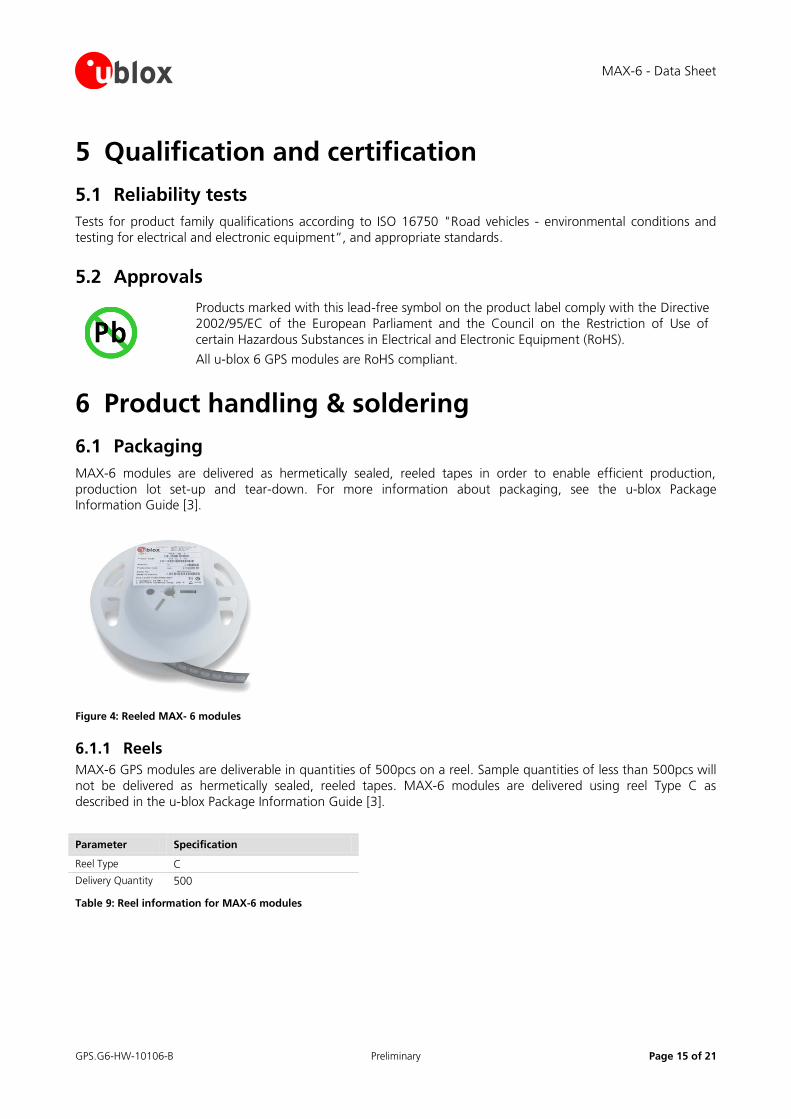
MAX-6 modules are delivered as hermetically sealed, reeled tapes in order to enable efficient production,
production lot set-up and tear-down. For more information about packaging, see the u-blox Package Information Guide [3].
Figure 4: Reeled MAX- 6 modules
6.1.1 Reels
MAX-6 GPS modules are deliverable in quantities of 500pcs on a reel. Sample quantities of less than 500pcs will
not be delivered as hermetically sealed, reeled tapes. MAX-6 modules are delivered using reel Type C as
described in the u-blox Package Information Guide [3].
Parameter Specification
Reel Type C
Delivery Quantity 500
Table 9: Reel information for MAX-6 modules
MAX-6 - Data Sheet
GPS.G6-HW-10106-B Preliminary Page 16 of 21
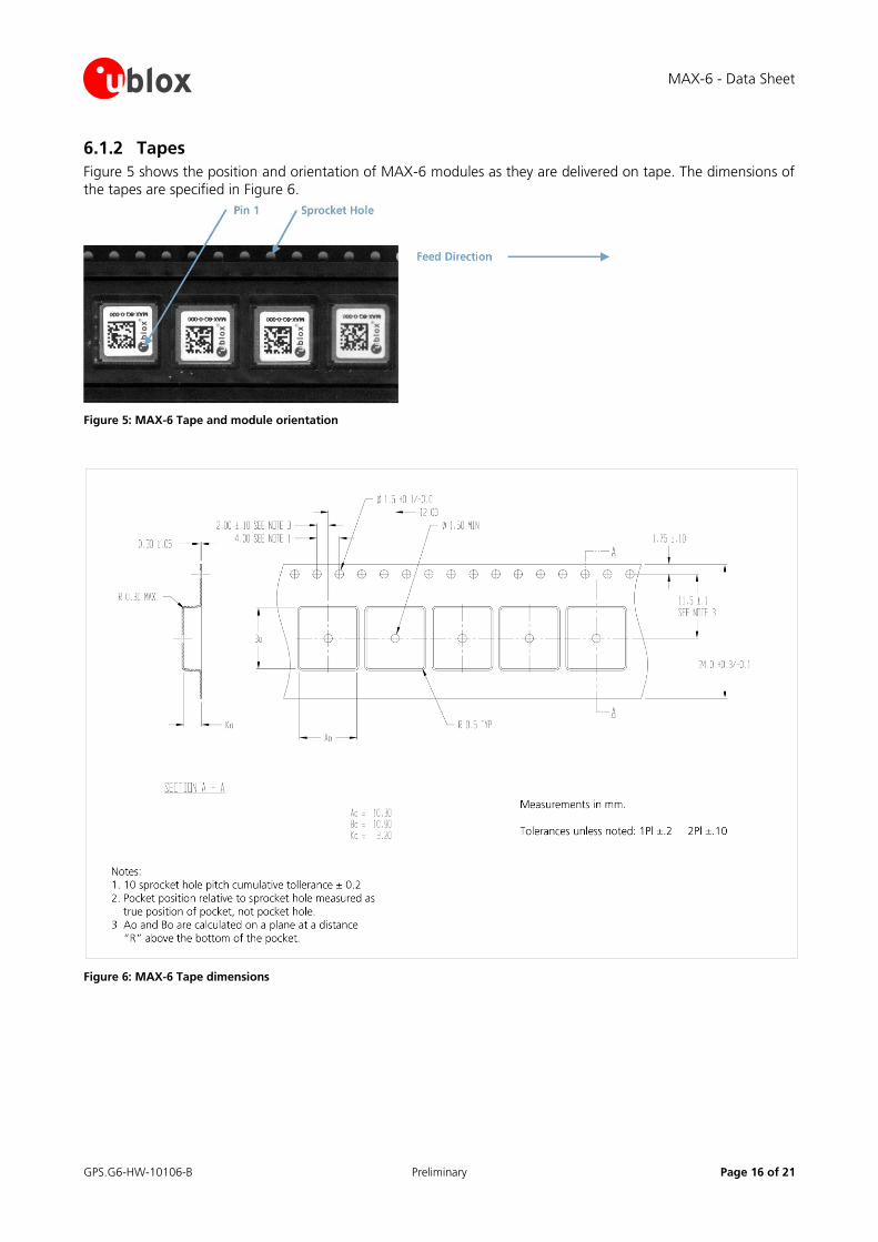
6.1.2 Tapes
Figure 5 shows the position and orientation of MAX-6 modules as they are delivered on tape. The dimensions of
the tapes are specified in Figure 6.
Figure 5: MAX-6 Tape and module orientation
Figure 6: MAX-6 Tape dimensions

MAX-6 - Data Sheet
GPS.G6-HW-10106-B Preliminary Page 17 of 21
6.2 Moisture Sensitivity Levels
MAX-6 modules are Moisture Sensitive Devices (MSD) in accordance to the IPC/JEDEC
specification.
MAX-6 modules are rated at MSL level 4. For more information regarding moisture sensitivity levels, labeling, storage and drying see the u-blox Package Information Guide [3].
For MSL standard see IPC/JEDEC J-STD-020, which can be downloaded from www.jedec.org.
6.3 Reflow soldering
Reflow profiles are to be selected according to u-blox recommendations (see LEA-6/NEO-6/MAX-6 Hardware Integration Manual [1]).
6.4 ESD handling precautions
MAX-6 modules contain highly sensitive electronic circuitry and are Electrostatic Sensitive Devices (ESD). Observe precautions for handling! Failure to observe
these precautions can result in severe damage to the GPS receiver!
GPS receivers are Electrostatic Sensitive Devices (ESD) and require special precautions when handling. Particular
care must be exercised when handling patch antennas, due to the risk of electrostatic charges. In addition to
standard ESD safety practices, the following measures should be taken into account whenever handling the receiver:
Unless there is a galvanic coupling between the local GND (i.e. the
work table) and the PCB GND, then the first point of contact when handling the PCB must always be between the local GND and PCB
GND.
Before mounting an antenna patch, connect ground of the device
When handling the RF pin, do not come into contact with any
charged capacitors and be careful when contacting materials that
can develop charges (e.g. patch antenna ~10pF, coax cable ~50-80pF/m, soldering iron, …)
To prevent electrostatic discharge through the RF input, do not
touch any exposed antenna area. If there is any risk that such
exposed antenna area is touched in non ESD protected work area, implement proper ESD protection measures in the design.
When soldering RF connectors and patch antennas to the receiver’s RF pin, make sure to use an ESD safe soldering iron (tip).
MAX-6 - Data Sheet
GPS.G6-HW-10106-B Preliminary Page 18 of 21
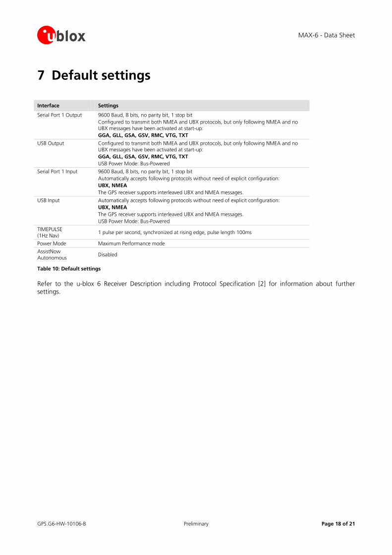
7 Default settings
Interface Settings
Serial Port 1 Output
9600 Baud, 8 bits, no parity bit, 1 stop bit
Configured to transmit both NMEA and UBX protocols, but only following NMEA and no UBX messages have been activated at start-up:
GGA, GLL, GSA, GSV, RMC, VTG, TXT
USB Output Configured to transmit both NMEA and UBX protocols, but only following NMEA and no UBX messages have been activated at start-up:
GGA, GLL, GSA, GSV, RMC, VTG, TXT
USB Power Mode: Bus-Powered
Serial Port 1 Input 9600 Baud, 8 bits, no parity bit, 1 stop bit
Automatically accepts following protocols without need of explicit configuration:
UBX, NMEA
The GPS receiver supports interleaved UBX and NMEA messages.
USB Input Automatically accepts following protocols without need of explicit configuration:
UBX, NMEA
The GPS receiver supports interleaved UBX and NMEA messages.
USB Power Mode: Bus-Powered
TIMEPULSE (1Hz Nav)
1 pulse per second, synchronized at rising edge, pulse length 100ms
Power Mode Maximum Performance mode
AssistNow Autonomous
Disabled
Table 10: Default settings
Refer to the u-blox 6 Receiver Description including Protocol Specification [2] for information about further
settings.
MAX-6 - Data Sheet
GPS.G6-HW-10106-B Preliminary Page 19 of 21
8 Labeling and ordering information
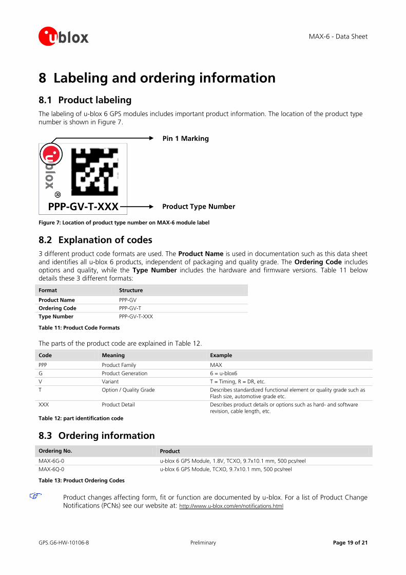
8.1 Product labeling
The labeling of u-blox 6 GPS modules includes important product information. The location of the product type
number is shown in Figure 7.
Figure 7: Location of product type number on MAX-6 module label
8.2 Explanation of codes
3 different product code formats are used. The Product Name is used in documentation such as this data sheet
and identifies all u-blox 6 products, independent of packaging and quality grade. The Ordering Code includes
options and quality, while the Type Number includes the hardware and firmware versions. Table 11 below details these 3 different formats:
Format Structure
Product Name PPP-GV
Ordering Code PPP-GV-T
Type Number PPP-GV-T-XXX
Table 11: Product Code Formats
The parts of the product code are explained in Table 12.
Code Meaning Example
PPP Product Family MAX
G Product Generation 6 = u-blox6
V Variant T = Timing, R = DR, etc.
T Option / Quality Grade Describes standardized functional element or quality grade such as Flash size, automotive grade etc.
XXX Product Detail Describes product details or options such as hard- and software revision, cable length, etc.
Table 12: part identification code
8.3 Ordering information
Ordering No. Product
MAX-6G-0 u-blox 6 GPS Module, 1.8V, TCXO, 9.7x10.1 mm, 500 pcs/reel
MAX-6Q-0 u-blox 6 GPS Module, TCXO, 9.7x10.1 mm, 500 pcs/reel
Table 13: Product Ordering Codes
Product changes affecting form, fit or function are documented by u-blox. For a list of Product Change
Notifications (PCNs) see our website at: http://www.u-blox.com/en/notifications.html
MAX-6 - Data Sheet
GPS.G6-HW-10106-B Preliminary Page 20 of 21
Related documents [1] LEA-6/NEO-6/MAX-6 Hardware Integration Manual , Docu. No GPS.G6-HW-09007
[2] u-blox 6 Receiver Description including Protocol Specification, Docu. No GPS-SW-09017
[3] u-blox Package Information Guide, Docu. No GPS-X-11004
All these documents are available on our homepage (http://www.u-blox.com).
For regular updates to u-blox documentation and to receive product change notifications please register
on our homepage.
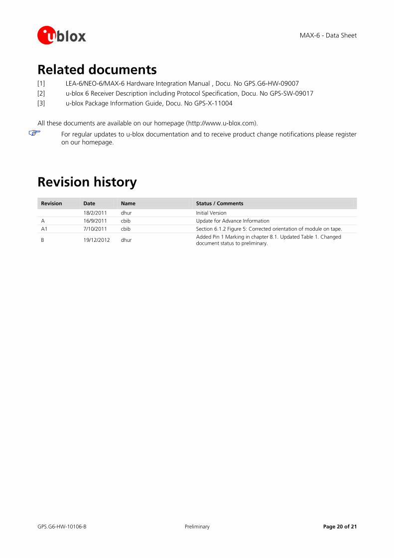
Revision history
Revision Date Name Status / Comments
18/2/2011 dhur Initial Version
A 16/9/2011 cbib Update for Advance Information
A1 7/10/2011 cbib Section 6.1.2 Figure 5: Corrected orientation of module on tape.
B 19/12/2012 dhur Added Pin 1 Marking in chapter 8.1. Updated Table 1. Changed document status to preliminary.
MAX-6 - Data Sheet
GPS.G6-HW-10106-B Preliminary Page 21 of 21
Contact For complete contact information visit us at www.u-blox.com
Headquarters
u-blox AG
Zuercherstrasse 68
CH-8800 Thalwil
Switzerland
Phone: +41 44 722 74 44
Fax: +41 44 722 74 47
E-mail: [email protected]
Offices
North, Central and South America
u-blox America, Inc.
Phone: +1 (703) 483 3180
E-mail: [email protected]
Regional Office West Coast:
Phone: +1 (703) 483 3184
E-mail: [email protected]
Technical Support:
Phone: +1 (703) 483 3185
E-mail: [email protected]
Europe, Middle East, Africa
u-blox AG
Phone: +41 44 722 74 44
E-mail: [email protected]
Technical Support:
Phone: +41 44 722 74 44
E-mail: [email protected]
Asia, Australia, Pacific
u-blox Singapore Pte. Ltd.
Phone: +65 6734 3811
E-mail: [email protected]
Support: [email protected]
Regional Office China:
Phone: +86 10 68 133 545
E-mail: [email protected] Support: [email protected]
Regional Office Japan:
Phone: +81 3 5775 3850 E-mail: [email protected]
Support: [email protected]
Regional Office Korea:
Phone: +82 2 542 0861 E-mail: [email protected]
Support: [email protected]
Regional Office Taiwan:
Phone: +886 2 2657 1090
E-mail: [email protected]
Support: [email protected]