Solicitation 82-20 Fire Station #6 Outside Air HVAC Upgrades ...
205
Solicitation 82-20 Fire Station #6 Outside Air HVAC Upgrades Bid Designation: Public City of Richardson Bid 82-20 City of Richardson 8/5/2020 9:16 AM p. 1
-
Upload
khangminh22 -
Category
Documents
-
view
2 -
download
0
Transcript of Solicitation 82-20 Fire Station #6 Outside Air HVAC Upgrades ...

Solicitation 82-20
Fire Station #6 Outside Air HVAC Upgrades
Bid Designation: Public
City of Richardson
Bid 82-20City of Richardson
8/5/2020 9:16 AM p. 1

Bid 82-20Fire Station #6 Outside Air HVAC Upgrades
Bid Number 82-20
Bid Title Fire Station #6 Outside Air HVAC Upgrades
Expected Expenditure $50,000.00 (This price is expected - not guaranteed)
Bid Start Date Aug 5, 2020 10:12:56 AM CDT
Bid End Date Aug 27, 2020 2:00:00 PM CDT
Question & AnswerEnd Date
Aug 19, 2020 4:00:00 PM CDT
Bid Contact Rachel Holt
Contract Duration 95 days
Contract Renewal Not Applicable
Prices Good for 30 days
Pre-Bid Conference Aug 17, 2020 2:00:00 PM CDT (Online)Attendance is optional
Bid Comments Please see the attached bid book for details.
Access the pre-bid WebEx meeting here . Access code: 146 990 3010 . Meeting password: AZjWq9Y6ET2
Access the Bid Opening WebEx meeting here. Access code: 146 493 2097 . Meeting password: 5MRjEDPaq43
Item Response Form
Item 82-20-01-01 - Fire Station #6 Outside Air HVAC Updates
Quantity 1 each
Unit Price
Delivery Location City of Richardson City of Richardson 411 W. Arapaho Road Richardson TX 75080 Qty 1
Expected Expenditure $50,000.00
DescriptionPlease see attached bid book for details.
Bid 82-20City of Richardson
8/5/2020 9:16 AM p. 2

SPECIFICATIONS AND CONTRACT DOCUMENTS
FOR
Fire Station #6 Outside Air HVAC Upgrades Project Bid No. 82-20
Prepared By: Ray Ginther, City of Richardson
MEP: S.E. Scott and Associates, P.O. Box 78657, Horseshoe Bay, TX 78657 Architect: DWC Engineering, LLC, 227 Ridgewood, Carrollton, TX 75006
Prepared For: CITY OF RICHARDSON
411 W. ARAPAHO ROAD, SUITE 204 RICHARDSON, TEXAS 75080
August 2020
Bid 82-20City of Richardson
8/5/2020 9:16 AM p. 3

Accommodation requests for persons with disabilities should be made by contacting ADA Coordinator via email at [email protected], or by appointment at 411 W. Arapaho Road, Richardson, TX 75080.
NOTICE TO CONTRACTORS CITY OF RICHARDSON
Fire Station #6 Outside Air HVAC Upgrades
Bid No. 82-20
Electronic bids through BidSync.com or sealed bids shall be addressed to the Purchasing Manager and received in the Purchasing Department located in the City Hall/Civic Center Building at 411 West Arapaho Road, Suite 101, Richardson, Texas 75080, prior to 2:00 p.m. on Thursday, August 27th, 2020. Bids will be opened and read aloud at 2:30 p.m. the same day via WebEx, for furnishing all labor, materials, tools and equipment, and performing all work required including all appurtenances for:
Outside Air HVAC upgrades (demolition and new installation of mechanical equipment) at Fire Station #6.
Bids shall be accompanied by a certified or cashier's check on a state or national bank in an amount not less than five percent (5%) of the possible total of the bid submitted, payable without recourse to the City of Richardson, Texas, or an acceptable bid bond for the same amount from a reliable surety company as a guarantee that the bidder will enter into a contract and execute required Performance and Payment Bonds within ten (10) days after notice of award of the contract.
The successful contractor must furnish a Performance Bond upon the form provided in the amount of one hundred percent (100%) of the contract price, a material and labor Payment Bond upon the form provided in the amount of one hundred percent (100%) of the contract price, and a Maintenance Bond upon the form provided in the amount of one hundred percent (100%) of the contract price, from a surety authorized under the laws of the State of Texas to act as a surety on bonds for principals within ten (10) days after the notice of award of the contract.
The right is reserved, as the interest of the Owner may require, to reject any and all bids, to waive any informality in the bids received, and to select the bid best suited to the Owner's best interest. The successful contractor must have completed a minimum of three similar projects within the last five years.
The construction is expected to take ninety five (95) calendar days.
A set of plans, specifications and bid documents will be available beginning at 12:00 p.m. on Wednesday, August 5th, 2020. Documents are available at no charge through BidSync.com, or from the Capital Projects Department, Suite 204, for a NON-REFUNDABLE FEE OF Twenty-five Dollars ($25.00) per CD, payable to the City of Richardson, accompanied by the contractor's name, address, phone number, email address and FAX number. Maximum of two sets or CDs per contractor.
A voluntary pre-bid meeting will be held Monday,August 17th, 2020 at 2:00 PM via WebEx.
By:/s/Paul Voelker, Mayor City of Richardson P. O. Box 830309
Richardson, Texas 75083
Bid 82-20City of Richardson
8/5/2020 9:16 AM p. 4

BS-1
Fire Station #6 Outside Air HVAC Upgrades Project
BID NO. 82‐20 CONTRACT BID SCHEDULE
‐I‐t‐e‐‐m‐‐‐‐‐‐‐‐Q‐‐‐u‐‐a‐‐n‐t‐‐i‐t‐y‐‐‐‐‐‐‐‐‐‐‐U‐‐‐n‐‐i‐t‐‐‐‐‐‐‐‐‐I‐t‐e‐‐m‐‐‐‐D‐‐e‐‐s‐c‐‐r‐i‐p‐‐t‐i‐o‐‐n‐‐‐&‐‐‐C‐‐o‐‐s‐‐t‐‐i‐n‐‐W‐‐‐‐o‐‐r‐d‐‐s‐‐‐‐‐‐‐‐‐‐‐‐‐‐‐‐‐‐‐‐U‐‐‐n‐‐i‐t‐‐C‐‐o‐‐s‐t‐‐‐‐‐‐‐‐‐‐‐‐‐T‐‐o‐‐t‐a‐‐l‐‐C‐‐o‐‐s‐t‐‐‐‐‐‐‐‐‐‐‐‐
1 1 LS Mobilization $ $
Dollars
Cents
‐‐‐‐‐‐‐‐‐‐‐‐‐‐‐‐‐‐‐‐‐‐‐‐‐‐‐‐‐‐‐‐‐‐‐‐‐‐‐‐‐‐‐‐‐‐‐‐‐‐‐‐‐‐‐‐‐‐‐‐‐‐‐‐‐‐‐‐‐‐‐‐‐‐‐‐‐‐‐‐‐‐‐‐‐‐‐‐‐‐‐‐‐‐‐‐‐‐‐‐‐‐‐‐‐‐‐‐‐‐‐‐‐‐‐‐‐‐‐‐‐‐‐‐‐‐‐‐‐‐‐‐‐‐‐‐‐‐‐‐‐‐‐‐‐‐‐‐‐‐‐‐‐‐‐‐‐‐‐‐‐‐‐‐‐‐‐‐‐‐
2 1 LS Demolition of Existing
Equipment, complete $ $
Dollars
Cents
‐‐‐‐‐‐‐‐‐‐‐‐‐‐‐‐‐‐‐‐‐‐‐‐‐‐‐‐‐‐‐‐‐‐‐‐‐‐‐‐‐‐‐‐‐‐‐‐‐‐‐‐‐‐‐‐‐‐‐‐‐‐‐‐‐‐‐‐‐‐‐‐‐‐‐‐‐‐‐‐‐‐‐‐‐‐‐‐‐‐‐‐‐‐‐‐‐‐‐‐‐‐‐‐‐‐‐‐‐‐‐‐‐‐‐‐‐‐‐‐‐‐‐‐‐‐‐‐‐‐‐‐‐‐‐‐‐‐‐‐‐‐‐‐‐‐‐‐‐‐‐‐‐‐‐‐‐‐‐‐‐‐‐‐‐‐‐‐‐‐
3 1 LS Installation of CU‐1,
complete
$ $
Dollars
Cents
‐‐‐‐‐‐‐‐‐‐‐‐‐‐‐‐‐‐‐‐‐‐‐‐‐‐‐‐‐‐‐‐‐‐‐‐‐‐‐‐‐‐‐‐‐‐‐‐‐‐‐‐‐‐‐‐‐‐‐‐‐‐‐‐‐‐‐‐‐‐‐‐‐‐‐‐‐‐‐‐‐‐‐‐‐‐‐‐‐‐‐‐‐‐‐‐‐‐‐‐‐‐‐‐‐‐‐‐‐‐‐‐‐‐‐‐‐‐‐‐‐‐‐‐‐‐‐‐‐‐‐‐‐‐‐‐‐‐‐‐‐‐‐‐‐‐‐‐‐‐‐‐‐‐‐‐‐‐‐‐‐‐‐‐‐‐‐‐‐‐
4 1 LS Installation of FC‐3, complete $ $
Dollars
Cents
‐‐‐‐‐‐‐‐‐‐‐‐‐‐‐‐‐‐‐‐‐‐‐‐‐‐‐‐‐‐‐‐‐‐‐‐‐‐‐‐‐‐‐‐‐‐‐‐‐‐‐‐‐‐‐‐‐‐‐‐‐‐‐‐‐‐‐‐‐‐‐‐‐‐‐‐‐‐‐‐‐‐‐‐‐‐‐‐‐‐‐‐‐‐‐‐‐‐‐‐‐‐‐‐‐‐‐‐‐‐‐‐‐‐‐‐‐‐‐‐‐‐‐‐‐‐‐‐‐‐‐‐‐‐‐‐‐‐‐‐‐‐‐‐‐‐‐‐‐‐‐‐‐‐‐‐‐‐‐‐‐‐‐‐‐‐‐‐‐‐
5 1 LS Installation of CU‐3, complete $ $
Dollars
Cents
‐‐‐‐‐‐‐‐‐‐‐‐‐‐‐‐‐‐‐‐‐‐‐‐‐‐‐‐‐‐‐‐‐‐‐‐‐‐‐‐‐‐‐‐‐‐‐‐‐‐‐‐‐‐‐‐‐‐‐‐‐‐‐‐‐‐‐‐‐‐‐‐‐‐‐‐‐‐‐‐‐‐‐‐‐‐‐‐‐‐‐‐‐‐‐‐‐‐‐‐‐‐‐‐‐‐‐‐‐‐‐‐‐‐‐‐‐‐‐‐‐‐‐‐‐‐‐‐‐‐‐‐‐‐‐‐‐‐‐‐‐‐‐‐‐‐‐‐‐‐‐‐‐‐‐‐‐‐‐‐‐‐‐‐‐‐‐‐‐‐
6 1 LS Installation of FC‐4, complete $ $
Dollars
Cents
‐‐‐‐‐‐‐‐‐‐‐‐‐‐‐‐‐‐‐‐‐‐‐‐‐‐‐‐‐‐‐‐‐‐‐‐‐‐‐‐‐‐‐‐‐‐‐‐‐‐‐‐‐‐‐‐‐‐‐‐‐‐‐‐‐‐‐‐‐‐‐‐‐‐‐‐‐‐‐‐‐‐‐‐‐‐‐‐‐‐‐‐‐‐‐‐‐‐‐‐‐‐‐‐‐‐‐‐‐‐‐‐‐‐‐‐‐‐‐‐‐‐‐‐‐‐‐‐‐‐‐‐‐‐‐‐‐‐‐‐‐‐‐‐‐‐‐‐‐‐‐‐‐‐‐‐‐‐‐‐‐‐‐‐‐‐‐‐‐‐
Bid 82-20City of Richardson
8/5/2020 9:16 AM p. 5

BS-2
Fire Station #6 Outside Air HVAC Upgrades Project
BID NO. 82‐20 CONTRACT BID SCHEDULE
‐I‐t‐e‐‐m‐‐‐‐‐‐‐‐Q‐‐‐u‐‐a‐‐n‐t‐‐i‐t‐y‐‐‐‐‐‐‐‐‐‐‐U‐‐‐n‐‐i‐t‐‐‐‐‐I‐t‐e‐‐m‐‐‐‐D‐‐e‐‐s‐c‐‐r‐i‐p‐‐t‐i‐o‐‐n‐‐‐&‐‐‐C‐‐o‐‐s‐‐t‐‐i‐n‐‐W‐‐‐‐o‐‐r‐d‐‐s‐‐‐‐‐‐‐‐‐‐‐‐‐‐‐‐‐‐‐‐U‐‐‐n‐‐i‐t‐‐C‐‐o‐‐s‐t‐‐‐‐‐‐‐‐T‐‐o‐‐t‐a‐‐l‐‐C‐‐o‐‐s‐t‐‐‐‐‐‐‐‐‐‐‐‐
7 1 LS Installation of CU‐4,
complete
$ $
Dollars
Cents
‐‐‐‐‐‐‐‐‐‐‐‐‐‐‐‐‐‐‐‐‐‐‐‐‐‐‐‐‐‐‐‐‐‐‐‐‐‐‐‐‐‐‐‐‐‐‐‐‐‐‐‐‐‐‐‐‐‐‐‐‐‐‐‐‐‐‐‐‐‐‐‐‐‐‐‐‐‐‐‐‐‐‐‐‐‐‐‐‐‐‐‐‐‐‐‐‐‐‐‐‐‐‐‐‐‐‐‐‐‐‐‐‐‐‐‐‐‐‐‐‐‐‐‐‐‐‐‐‐‐‐‐‐‐‐‐‐‐‐‐‐‐‐‐‐‐‐‐‐‐‐‐‐‐‐‐‐‐‐‐‐‐‐‐‐‐‐‐‐‐
8 1 LS Installation of FC‐5,
complete
$ $
Dollars
Cents
‐‐‐‐‐‐‐‐‐‐‐‐‐‐‐‐‐‐‐‐‐‐‐‐‐‐‐‐‐‐‐‐‐‐‐‐‐‐‐‐‐‐‐‐‐‐‐‐‐‐‐‐‐‐‐‐‐‐‐‐‐‐‐‐‐‐‐‐‐‐‐‐‐‐‐‐‐‐‐‐‐‐‐‐‐‐‐‐‐‐‐‐‐‐‐‐‐‐‐‐‐‐‐‐‐‐‐‐‐‐‐‐‐‐‐‐‐‐‐‐‐‐‐‐‐‐‐‐‐‐‐‐‐‐‐‐‐‐‐‐‐‐‐‐‐‐‐‐‐‐‐‐‐‐‐‐‐‐‐‐‐‐‐‐‐‐‐‐‐‐
9 1 LS Installation of CU‐5, complete $ $
Dollars
Cents
‐‐‐‐‐‐‐‐‐‐‐‐‐‐‐‐‐‐‐‐‐‐‐‐‐‐‐‐‐‐‐‐‐‐‐‐‐‐‐‐‐‐‐‐‐‐‐‐‐‐‐‐‐‐‐‐‐‐‐‐‐‐‐‐‐‐‐‐‐‐‐‐‐‐‐‐‐‐‐‐‐‐‐‐‐‐‐‐‐‐‐‐‐‐‐‐‐‐‐‐‐‐‐‐‐‐‐‐‐‐‐‐‐‐‐‐‐‐‐‐‐‐‐‐‐‐‐‐‐‐‐‐‐‐‐‐‐‐‐‐‐‐‐‐‐‐‐‐‐‐‐‐‐‐‐‐‐‐‐‐‐‐‐‐‐‐‐‐‐‐
10 1 LS Construction contingency $ $
Dollars
Cents
‐‐‐‐‐‐‐‐‐‐‐‐‐‐‐‐‐‐‐‐‐‐‐‐‐‐‐‐‐‐‐‐‐‐‐‐‐‐‐‐‐‐‐‐‐‐‐‐‐‐‐‐‐‐‐‐‐‐‐‐‐‐‐‐‐‐‐‐‐‐‐‐‐‐‐‐‐‐‐‐‐‐‐‐‐‐‐‐‐‐‐‐‐‐‐‐‐‐‐‐‐‐‐‐‐‐‐‐‐‐‐‐‐‐‐‐‐‐‐‐‐‐‐‐‐‐‐‐‐‐‐‐‐‐‐‐‐‐‐‐‐‐‐‐‐‐‐‐‐‐‐‐‐‐‐‐‐‐‐‐‐‐‐‐‐‐‐‐‐‐
TOTAL BASE BID AMOUNT $
LABOR AND MATERIAL BREAKDOWN
(a) Total cost of materials incorporated into work. $
(b) Total cost of materials purchased or leased for $
use, but not incorporated into work (including
sales or use tax).
(c) Total cost of labor, overhead, profit and other $
reasonable incidental costs of the work.
NOT TO EXCEED TOTAL BASE BID AMOUNT $
10,000 10,000
Zero
Ten thousand
Bid 82-20City of Richardson
8/5/2020 9:16 AM p. 6

BS-3
Fire Station #6 Outside Air HVAC Upgrades Project
BID NO. 82‐20 ALTERNATE #1 BID SCHEDULE
‐I‐t‐e‐‐m‐‐‐‐‐‐‐‐Q‐‐‐u‐‐a‐‐n‐t‐‐i‐t‐y‐‐‐‐‐‐‐‐‐‐‐U‐‐‐n‐‐i‐t‐‐‐‐‐I‐t‐e‐‐m‐‐‐‐D‐‐e‐‐s‐c‐‐r‐i‐p‐‐t‐i‐o‐‐n‐‐‐&‐‐‐C‐‐o‐‐s‐‐t‐‐i‐n‐‐W‐‐‐‐o‐‐r‐d‐‐s‐‐‐‐‐‐‐‐‐‐‐‐‐‐‐‐‐‐‐‐U‐‐‐n‐‐i‐t‐‐C‐‐o‐‐s‐t‐‐‐‐‐‐‐‐T‐‐o‐‐t‐a‐‐l‐‐C‐‐o‐‐s‐t‐‐‐‐‐‐‐‐‐‐‐‐
1 1 LS Installation of CU‐1,
complete
$ $
Dollars
Cents
‐‐‐‐‐‐‐‐‐‐‐‐‐‐‐‐‐‐‐‐‐‐‐‐‐‐‐‐‐‐‐‐‐‐‐‐‐‐‐‐‐‐‐‐‐‐‐‐‐‐‐‐‐‐‐‐‐‐‐‐‐‐‐‐‐‐‐‐‐‐‐‐‐‐‐‐‐‐‐‐‐‐‐‐‐‐‐‐‐‐‐‐‐‐‐‐‐‐‐‐‐‐‐‐‐‐‐‐‐‐‐‐‐‐‐‐‐‐‐‐‐‐‐‐‐‐‐‐‐‐‐‐‐‐‐‐‐‐‐‐‐‐‐‐‐‐‐‐‐‐‐‐‐‐‐‐‐‐‐‐‐‐‐‐‐‐‐‐‐‐
TOTAL ALTERNATE #1 BID AMOUNT $
LABOR AND MATERIAL BREAKDOWN
(d) Total cost of materials incorporated into work. $
(e) Total cost of materials purchased or leased for $
use, but not incorporated into work (including
sales or use tax).
(f) Total cost of labor, overhead, profit and other $
reasonable incidental costs of the work.
NOT TO EXCEED ALTERNATE #1 TOTAL $
Bid 82-20City of Richardson
8/5/2020 9:16 AM p. 7

BS-4
Fire Station #6 Outside Air HVAC Upgrades Project
BID NO. 82‐20 ALTERNATE #2 BID SCHEDULE
‐I‐t‐e‐‐m‐‐‐‐‐‐‐‐Q‐‐‐u‐‐a‐‐n‐t‐‐i‐t‐y‐‐‐‐‐‐‐‐‐‐‐U‐‐‐n‐‐i‐t‐‐‐‐‐I‐t‐e‐‐m‐‐‐‐D‐‐e‐‐s‐c‐‐r‐i‐p‐‐t‐i‐o‐‐n‐‐‐&‐‐‐C‐‐o‐‐s‐‐t‐‐i‐n‐‐W‐‐‐‐o‐‐r‐d‐‐s‐‐‐‐‐‐‐‐‐‐‐‐‐‐‐‐‐‐‐‐U‐‐‐n‐‐i‐t‐‐C‐‐o‐‐s‐t‐‐‐‐‐‐‐‐T‐‐o‐‐t‐a‐‐l‐‐C‐‐o‐‐s‐t‐‐‐‐‐‐‐‐‐‐‐‐
7 1 LS Replacement of E‐CU‐1,
complete
$ $
Dollars
Cents
‐‐‐‐‐‐‐‐‐‐‐‐‐‐‐‐‐‐‐‐‐‐‐‐‐‐‐‐‐‐‐‐‐‐‐‐‐‐‐‐‐‐‐‐‐‐‐‐‐‐‐‐‐‐‐‐‐‐‐‐‐‐‐‐‐‐‐‐‐‐‐‐‐‐‐‐‐‐‐‐‐‐‐‐‐‐‐‐‐‐‐‐‐‐‐‐‐‐‐‐‐‐‐‐‐‐‐‐‐‐‐‐‐‐‐‐‐‐‐‐‐‐‐‐‐‐‐‐‐‐‐‐‐‐‐‐‐‐‐‐‐‐‐‐‐‐‐‐‐‐‐‐‐‐‐‐‐‐‐‐‐‐‐‐‐‐‐‐‐‐
TOTAL ALTERNATE #2 BID AMOUNT $
LABOR AND MATERIAL BREAKDOWN
(g) Total cost of materials incorporated into work. $
(h) Total cost of materials purchased or leased for $
use, but not incorporated into work (including
sales or use tax).
(i) Total cost of labor, overhead, profit and other $
reasonable incidental costs of the work.
NOT TO EXCEED ALTERNATE #2 TOTAL $
Bid 82-20City of Richardson
8/5/2020 9:16 AM p. 8

Fire Station #6 Outside Air HVAC Upgrades Project
BID NO. 82‐20 BID SUMMARY
TOTAL BASE BID $
TOTAL BASE BID+ADDITIVE ALTERNATIVE #1 $
TOTAL BASE BID+ADDITIVE ALTERNATIVE #2 $
TOTAL BASE BID+ADDITIVE ALTERNATIVE #1&2 $
BS-5
Bid 82-20City of Richardson
8/5/2020 9:16 AM p. 9

PROPOSAL TO
THE CITY OF RICHARDSON, TEXAS
Performing All Work Required for the Construction of the
Fire Station #6 Outside Air HVAC Upgrades
Bid No. 82-20
The undersigned as bidder, declares that the only person or parties interested in this Proposal as principals are those named herein, that this Proposal is made without collusion with any other person, firm or corporation; that he has without collusion with any other person, firm or corporation; that he has carefully examined the form of contract, Notice to Contractors, specifications and the plans therein referred to and has carefully examined the locations, conditions, and classes of materials of the proposed work, and agrees that he will provide all the necessary labor, machinery, tools, apparatus, and other items incidental to construction, and will do all the work and furnish all the materials called for in the contract and specifications in the manner prescribed therein and according to the requirements of the Engineer as therein set forth.
It is understood that the following quantities of work to be done at unit prices are approximate only and are intended principally to serve as a guide in evaluating bids.
It is further agreed that the quantities of work to be at unit prices and material to be furnished may be increased or diminished as may be considered necessary, in the opinion of the Engineer, to complete the work fully as planned and contemplated, and that all quantities of work whether increased or decreased are to be performed at the unit prices set forth below except as provided for in the specifications.
It is further agreed that the lump sum prices may be increased to cover additional work ordered by the Engineer, but not shown on the plans or required by the specifications in accordance with the provisions of the Special Conditions. Similarly, they may be decreased to cover deletion of work so ordered.
Bid Bond is required for this project. If required, the Bid Bond will be in the amount of five percent (5%) Dollars ($ ).
The bid security accompanying this Proposal shall be returned to the bidder, unless, in case of the acceptance of the Proposal, the bidder shall fail to execute a contract and a Performance Bond within ten (10) days after its acceptance, in which case the bid security shall become property of the Owner, and shall be considered as payment for damages due to delay and other inconveniences suffered by the Owner on account of such failure by the bidder. It is understood that the Owner reserves the rights to reject any and all bids and to waive any informality in the bids received.
CPT-Prop1
Bid 82-20City of Richardson
8/5/2020 9:16 AM p. 10

INSURANCE REQUIREMENTS
A. Contractor’s Insurance Requirements.
1. Before contractor performs any work or delivers any material to the project, contractor shall provide owner certificates of insurance and include, as reasonably available and upon written request of the owner, complete signed copies of all policies and exclusions to owner evidencing that the insurance is in full force and effect. Contractor shall at all times and at contractor’s expense be covered with liability insurance covering all work and the work of others for which it is legally liable with the following limits:
☒ Worker’s Compensation Statutory
☒ Employer’s Liability $1,000,000
☒ Commercial General Liability, written on an Insurance Services Office occurrence form including completed operations ISO (2004 or equally as broad) including premises/operations coverage, broad form property damage coverage, products and completed operations coverage and broad form contractual liability coverage, with no subsidence or soils, foundations, or building settlement exclusions or limitations and must include a per project general aggregate endorsement
$1 Million Per Occurrence, and $2 Million Aggregate; $2 Million products and completed operations Aggregate
☒ Auto Liability Owned, Non Owned, Hired including
☐ Broadened Pollution endorsement
$1,000,000
☐ Umbrella $2,000,000 ☐
$5,000,000 ☐
$25,000,000 ☐
☐ Professional Liability $5,000,000
☐ Contractor Pollution Liability $5,000,000
☐ Cyber Liability/Technology E&O $2,000,000
Statutory workers’ compensation insurance and employer’s liability with limits $1 million bodily injury each accident, $1 million bodily injury by disease each employee, $1 million bodily injury by disease policy limit with respect to its employees in connection with this contract. Policy shall include the following extensions, if applicable: voluntary compensation, alternate employers endorsement for employee leasing/temporary employees, and waiver of subrogation in favor of City of Richardson.
Bid 82-20City of Richardson
8/5/2020 9:16 AM p. 11

2. Commercial general liability limits referenced above covering claims for death or bodily injury, or damage to property and loss of use thereof, arising from or in connection with the services provided under this agreement for both ongoing operations and completed operations. The policies shall contain xcu coverage, cross liability clause, independent contractor’s liability, broad named insured wording, unintentional errors and omissions and notice and knowledge of occurrence, blanket contractual liability including the indemnification set out in this agreement
3. Commercial general liability policy shall be endorsed to eliminate any exclusions or limitations to owner taking actions under the policy, including any “insured versus insured” limitation with respect to claims by or against contractor and other matters in which contractor may be an adverse party. Commercial General Liability should also eliminate any exclusion concerning care, custody, and control when city property is in their care. Additionally, contractor’s commercial general liability policy, but not the umbrella or excess policy, shall include a “per project” general aggregate endorsement.
4. Automobile liability insurance in limits as stated above covering autos owned, leased, or hired by contractor or its agents, servants, or employees performing work or services in connection with this agreement. Further, Auto Liability should also eliminate any exclusion concerning care, custody, and control when city property is in their care. Auto liability insurance shall include Broadened Pollution endorsement if hauling any pollutants onto City property for any reason.
5. The insurance limits for commercial general liability or automobile liability may be provided through a combination of primary and excess policies. Excess policies shall be on a following form basis.
6. Commercial general liability, including completed operations, all business automobile liability insurance and excess or umbrella insurance, shall name the City of Richardson, its officers, agents and employees as additional insureds utilizing the ISO CG 2010 04 13 and CG 2037 04 13 or equivalent. COPIES OF THESE ENDORSEMENTS ARE TO BE ATTACHED TO PROOF OF INSURANCE PROVIDED TO THE CITY.
7. Professional liability insurance covering professional’s/contractor’s liability for any professional acts, errors, and omissions for which contractor is legally liable in completion of this agreement, in an amount of $5 million each loss/$5 million policy aggregate if applicable.
8. Contractor’s pollution legal liability insurance in an amount of $5 million each loss/$5 million policy aggregate with the following endorsements/extensions of coverage: fungi mold, microbial matter coverage, transportation of hazardous materials, and coverage at disposal sites if applicable.
B. General requirements for all insurance policies to be maintained. The following additional specifications shall apply to each of the policies providing any of the insurance coverages required in this exhibit.
Bid 82-20City of Richardson
8/5/2020 9:16 AM p. 12

1. No act or omission of any insurance agent or broker shall relieve contractor of any of their obligations under this exhibit.
2. Contractor shall be responsible for all deductibles of all required insurances under this section regardless of the nature of the loss. Contractor acknowledges that owner has the right, but not the obligation, to withhold payments owed to contractor as security in the event that contractor fails to provide adequate proof of satisfactory payment of any deductibles owed or expected to come due.
3. All insurance maintained by contractor and any subcontractor shall be endorsed or otherwise include a waiver of subrogation in the favor of the City.
4. Contractor shall cause such coverages called for in the contract documents to be provided on a “primary” basis, regardless of any other insurance the City may elect to purchase and maintain. Accordingly, no liability coverage maintained by the City shall be subject to an “excess,” “contributory,” or “pro rata” type of other insurance clause. Contractor shall not commence work under this contract until it has obtained all insurance required hereunder and acceptable certificates of insurance (or, if requested by the City in writing in lieu of a certificate, signed copies of the insurance policies when reasonably available) evidencing such insurance have been submitted and approved by owner.
The date of all coverages required by this exhibit shall be the effective date of the contract and include all work. The commercial general liability, completed operations liability, and umbrella/excess coverages shall remain in effect annually, maintaining all requirements as included in this agreement, for a minimum time to conform with the period of repose as set out by the State of Texas, following completion of all work by contractor. CONTINUED PROOF OF INSURANCE MUST BE PROVIDED TO THE CITY.
5. All insurance provided by contractor shall be with authorized insurance companies that have an A M Best rating of at least A-VII.
6. Each policy shall be endorsed to require the insurer to give the City at least thirty (30) days advance written notice of the insurer’s intention to cancel or otherwise terminate the policy, suspend or terminate any coverage under the policy, or reduce any policy limits, increase any policy deductibles or materially alter any terms or conditions, of the policy or a renewal policy issued by the same insurer. Contractor shall likewise give the City at least thirty (30) days advance written notice of any insurer’s intention to cancel or otherwise terminate any policy, suspend or terminate any coverage under any policy, or reduce any policy limits, increase any policy deductibles or
Bid 82-20City of Richardson
8/5/2020 9:16 AM p. 13

materially alter any terms or conditions, of any policy or any renewal policy issued by the same insurer.
7. Upon receipt of any notice of cancellation or reduction in coverage, contractor shall within thirty (30) days procure other policies of insurance that are in accordance with terms of this contract, and deliver evidence of coverage that these are in full force and effect, and if contractor fails to provide and deliver acceptable policies, or satisfactory evidence thereof, then at the City’s option and after 10 days written notice to the contractor, the City may obtain such insurance at the cost and expense of contractor.
8. Any limitations contained within contractor’s insurance shall in no way limit, at any time during or following the project, the obligations of contractor with respect to its duties and obligations, including but not limited to its defense and indemnity obligations owed to owner as specified in the contract documents.
C. Property insurance (NOT APPLICABLE)
1. Unless specifically provided by the City, Contractor shall purchase and maintain “builder’s risk” property insurance, or comparable coverage, for the full replacement cost value thereof, for (i) the work that is to be done, and (ii) all materials to be incorporated in the work whether or not title has been acquired by the City. Such insurance shall not cover any property owned, leased, or otherwise used in connection with the work by contractor, contractor’s sub contractors, or the agents or employees of them. This insurance shall include the interests of the City, contractor, and sub-contractors and shall provide coverage against loss for “direct physical damage” (previously known as “all risk” coverage) for all property in or on the job site or within off-premises storage to be installed in or on the job site.
2. If by the terms of the property insurance there is a deductible amount, in the event of a loss covered by the insurance, contractor shall be responsible for all deductibles per occurrence which shall be considered a cost of the work and shall not exceed $25,000.
3. The City and contractor waive all rights against (1) each other and any of their sub contractors, agents, and employees, each of the other, and (2) the City’s separate contractors, if any, and any of their sub contractors, agents, and employees, for damages caused by fire or other causes of loss to the extent covered by property insurance obtained pursuant to this section or other property insurance applicable to the work. The City or contractor, as appropriate, shall require of the City’s separate contractors, if any, and the sub contractors, agents, and employees of any of them, by appropriate agreements, written where legally required for validity, similar waivers each in favor of other parties enumerated herein.
Bid 82-20City of Richardson
8/5/2020 9:16 AM p. 14

Questionnaire Page 1
CONTRACTOR QUESTIONNAIRE
1. Company’s Legal Name
2. Check Appropriate
Individual Registered Limited Liability Partnership Corporation
S Corporation General Partnership
Limited Liability Company (LLC)
3. ( ) Post Office Box Zip Code Area Code Telephone Number
Street Address City State Zip Code
( ) E- mail address Area Code Fax Number
4. Provide your Texas Payee I.D. No. (if available)
Is your Company authorized to do business in the State of Texas? (Please check one) □ Yes □ No
5. Provide your Dun and Bradstreet No. (if available)
6. Provide date of incorporation (if corporation) or date business established
7. Complete the information which applies to your business entity in the space provided:a. The name of the owner of the individual business entity whether operating under an assumed
name or own name.b. The names of all the general partners of a partnership.c. The names and titles of all corporate officers (or members/managers of LLC).
8. Give names and addresses of all affiliated and/or subsidiary companies
Limited Partnership
-
-
Bid 82-20City of Richardson
8/5/2020 9:16 AM p. 15

Questionnaire Page 2
9. Give the name and the percentage owned of each individual or entity owning five percent or more of yourbusiness.
10. Have you ever failed to complete any work awarded to you?If so, please explain where and why on a separate attachment
11. By separate attachment please furnish the following:a. List of six larger items of equipment which you own or which are available by renting, along with
the source.b. Detailed resume of your experience showing similar projects to the project you have bid on, along
with names, phone numbers, and addresses of a person familiar with the work described.c. Financial statements are being requested to determine the eligibility of a bidder to receive a contract.
Financial statements shall be composed of a balance sheet, income statement, and appropriatesupporting schedules, such as note disclosures or cash flows, as of the end of the company’s mostrecent fiscal year. Financial statements are to be audited, reviewed, or compiled by an independentCertified Public Accountant. Pro-forma financial statements will not be accepted by the City.All financial statements are considered confidential information, are reviewed by a member of theCity of Richardson Finance Division, and will be returned to the bidder/proposer upon request.
d. The name, address, and contact persons of the bonding and insurance companies you propose to use.e. Provide name, address, and phone number of subcontractors, and work to be performed by each.
The Contractor shall return this completed form, along with all necessary attachments, within ten (10) calendar days.
The undersigned bidder certifies that the bidder’s firm and all persons associated therewith in the capacity of owner, partner, stockholder, director, officer, manager, auditor, or any position involving the administration of any part of the firm’s operations have not been indicted, convicted, or had a civil judgment rendered against it or any person indicated above by a court of competent jurisdiction in any matter involving fraud or official misconduct within the past three years. (If so, explain on separate attachment)
The undersigned authorizes the City of Richardson to verify any and all information provided as determined necessary. In addition, the undersigned bidder understands that failure to provide the requested information, or false information on this form or related attachments may result in the bidder being disqualified.
Signature
Print Name
Title
Yes No
Bid 82-20City of Richardson
8/5/2020 9:16 AM p. 16

Questionnaire Page 3
ACKNOWLEDGMENT
Before me, the undersigned authority, a Notary Public, on this day personally appeared
who, being by me duly sworn, upon oath says that
he/she is qualified and authorized to make affidavit for and on behalf of
and is fully cognizant of
the facts herein set out and affirms to the truth and accuracy of the certifications made herein by
signing above.
GIVEN UNDER MY HAND AND SEAL OF OFFICE,
This day of , 20 .
Notary Public, in and for the State of Texas.
Completed questionnaire, with original signatures and attachments shall be returned to:
Contract Administrator City of Richardson – Capital Projects Department 411 W. Arapaho Road, Suite 204 Richardson, TX 75080-4551
Bid 82-20City of Richardson
8/5/2020 9:16 AM p. 17

CONFLICT OF INTEREST QUESTIONNAIRE
Chapter 176 Texas Local Government Code requires the public disclosure of certain information concerning persons doing business or seeking to do business with the City, including family, business, and financial relationships such persons may have with City officers and employees involved in the planning, recommending, selecting, and contracting of a vendor for this procurement.
For a copy of Form CIQ and CIS:
http://www.ethics.state.tx.us/filinginfo/conflict_forms.htm
The Bidder acknowledges by doing business or seeking to do business with the City that he/she has been notified of the requirements under Chapter 176 of the Texas Local Government Code and that he/she is solely responsible for complying with the terms and conditions therein. Furthermore, any individual or business entity seeking to do business with the City who does not comply with this practice may risk award consideration of any City contract.
For a listing of current City Officers:
www.cor.net/modules/showdocument.aspx?documentid=9001
Bid 82-20City of Richardson
8/5/2020 9:16 AM p. 18

CERTIFICATE OF INTERESTED PARTIES
Texas Government Code section 2252.908 provides that a governmental entity or state agency may not enter into certain contracts with a business entity unless the business entity submits a disclosure of interested parties form to the governmental entity or state agency at the time the business entity submits the signed contract to the governmental entity or state agency. The form discloses any interested parties who have a controlling interest (10% or more ownership) in the business entity and those who actively participate in facilitating the contract or negotiate the terms of the contract (broker, intermediary, advisor, and/or attorney), if any.
The Texas Ethics Commission was required to adopt rules necessary to implement that law, prescribe the disclosure of interested parties form, and post a copy of the form on the commission’s website. The commission adopted the Certificate of Interested Parties form (Form 1295) on October 5, 2015 and new rules (Chapter 46) on November 30, 2015.
The successful Bidder will be required to submit a signed 1295 form to the City prior to the award of this bid and/or prior to signing a contract with the City. The successful Bidder will be required to download the form via the Texas Ethics Commission’s website at:
https://www.ethics.state.tx.us/whatsnew/elf_info_form1295.htm
The “identification number” to be used on the 1295 form for this procurement is:
Bid No.
All prospective Bidders shall familiarize themselves with this requirement and agree to provide the completed Form 1295 if selected as the successful Bidder for this procurement.
Bid 82-20City of Richardson
8/5/2020 9:16 AM p. 19

Owner/ Contractor Construction Agreement Ed. 10-18 19.89260
CPT-OwnrCntr1
Agreement Page 1
CONSTRUCTION CONTRACT AGREEMENT
STATE OF TEXAS § § KNOW ALL MEN BY THESE PRESENTS:
COUNTY OF DALLAS §
THIS CONTRACT is made and entered into on , by and between the City of Richardson, Texas (hereinafter referred to as "OWNER") and (hereinafter referred to as "CONTRACTOR"). In consideration of the mutual covenants hereinafter set forth, the OWNER and CONTRACTOR agree as follows:
Article I. Work The CONTRACTOR shall perform all of the work as specified in the Contract
Documents. The work is generally described as follows:
Fire Station #6 Outside Air HVAC Upgrades Project No. 82-20
Plans and Specifications prepared by:
S.E. Scott and Associates, P.O. Box 78657, Horseshoe Bay, TX 78657 DWC Engineering, LLC, 227 Ridgewood, Carrollton, TX 75006
All extra work shall be performed as specified or indicated in the Contract Documents; and, at the CONTRACTOR’S own cost and expense, the CONTRACTOR shall furnish all the materials, supplies, machinery, equipment, tools, superintendence, labor, insurance, and other accessories and services as may be necessary in order to complete the construction, as described above and in accordance with the Contract Documents unless otherwise agreed to by the OWNER.
Article II. Contract Documents
The Contract Documents may only be altered, amended or modified as provided in the General Provisions (or Conditions). The Contract Documents consist of: this written agreement setting forth the work to be performed; advertisement, if any; instructions to bidders, if any; proposal; addendum; specifications, including the general, special, and technical conditions, provisions, plans, or working drawings; any supplemental changes or agreements pertaining to the work or materials thereof; bonds; the Standard Specifications for Public Works Construction published by the North Central Texas Council of Governments, as amended; the City of Richardson Standard Construction Details and Specifications, as amended; and any additional documents incorporated by reference. These form the Contract Documents and all are as fully a part of the Contract as if attached to this agreement or repeated herein.
Bid 82-20City of Richardson
8/5/2020 9:16 AM p. 20

Owner/ Contractor Construction Agreement Ed. 10-18 19.89260
CPT-OwnrCntr1
Agreement Page 2
Article III. Contract Time
The CONTRACTOR shall perform and complete all the items of work listed and referred to in the Contract Documents within ninety five (95) calendar days. All limitation of time set forth herein are material and are of the essence of this Contract.
Article IV. Contract Price
The OWNER shall pay the CONTRACTOR for completion of the work in accordance with the Contract Documents using current funds. Such payments shall be subject to the General and Special Specifications to the Contract, as contained in the Contract Documents.
Article V. Debts
The OWNER may, at its option, offset any amounts due and payable under this Contract against any debt (including taxes) lawfully due to OWNER from CONTRACTOR, regardless of whether the amount due arises pursuant to the terms of this Contract or otherwise and regardless of whether or not the debt due to OWNER has been reduced to judgment by a court.
Article VI. Debarment and Suspension In accordance with 2 CFR section 180.300, the principal of this contract as described in
2 CFR section 180.995 being duly sworn or under penalty of perjury under the laws of the United States, certifies that neither this company nor its principals are presently debarred, suspended, proposed for debarment, declared ineligible or voluntarily excluded from participation in this transaction by any federal department or agency, the State of Texas or any of its departments or agencies. If during the contract period the principal becomes debarred, suspended, proposed for debarment, declared ineligible or voluntarily excluded from participation, the principal shall immediately inform the City of Richardson. For contracts that are financed by Federal or State grants, the principal agrees that this section will be enforced on each of its subcontractors and will inform the City of Richardson of any violations of this section by subcontractors to the contract. The certification in this section is a material representation of fact relied upon by the City in entering into this contract.
Article VII. Miscellaneous Provisions
The terms used in this Contract shall have the same meaning as designated in the General Provisions of the Standard Specifications for Public Works Construction, North Central Texas Council of Governments, as amended. The Contract Documents, which constitute the entire agreement between the OWNER and CONTRACTOR, are listed in Article II. No assignment by either party hereto of any rights under or interests in the Contract Documents will be binding on the other party hereto without the written consent of the party sought to be bound. The OWNER and CONTRACTOR each binds itself, its partners, successors, assigns, and legal representatives hereto to the covenants, agreements, and obligations contained in the Contract Documents.
Bid 82-20City of Richardson
8/5/2020 9:16 AM p. 21

Owner/ Contractor Construction Agreement Ed. 10-18 19.89260
CPT-OwnrCntr1
Agreement Page 3
Article VIII. Prohibition of Boycott Israel
CONTRACTOR verifies that it does not Boycott Israel and agrees that during the term of this Contract will not Boycott Israel as that term is defined in Texas Government Code Section 808.001, as amended. This section does not apply if the CONTRACTOR is a sole proprietor, a non-profit entity or a governmental entity; and only applies if: (i) the CONTRACTOR has ten (10) or more fulltime employees and (ii) this Contract has a value of $100,000.00 or more to be paid under the terms of this Contract.
IN WITNESS WHEREOF, the OWNER and CONTRACTOR have executed this
Contract in duplicate and on the date aforementioned. All portions of the Contract Documents have been signed or identified by the OWNER and CONTRACTOR.
CONTRACTOR: OWNER:
By:__________________________ By:________________________
Title: Deputy City Manager
ATTEST:
By:
Printed Name:
Bid 82-20City of Richardson
8/5/2020 9:16 AM p. 22

PERFORMANCE BOND
STATE OF TEXAS § § KNOW ALL MEN BY THESE PRESENTS: COUNTIES OF DALLAS AND COLLIN §
THAT of the City of , County, State of Texas, and (as Principal), and (as “Surety”), authorized under the laws of the State of Texas to act as a surety on bonds for principals, are held and firmly bound unto the City of Richardson, Texas (the "City") in the penal sum of $ (not less than 100% of the approximate total amount of the contract as evidenced in the proposal) for the payment whereof, the said Principal and Surety bind themselves, and their heirs, administrators, executors, successors and assigns, jointly and severally, by these presents: Fire Station #6 Outside Air HVAC Upgrades Project Bid No. 82-20
WHEREAS, the Principal has entered into a certain written contract with the City of Richardson, Texas, dated the day of , 2020, to which said contract is hereby referred to and made a part hereof and as fully and to the same extent as if copied at length herein.
NOW, THEREFORE, the condition of this obligation is such that if the said Principal fully and faithfully executes the work and performance of the contract in accordance with the plans, specifications, and contract documents, including any extensions, modifications, and change orders thereof, and according to the true intent and meaning of said contract and the plans and specification hereto annexed, then this obligation shall be void; otherwise, to remain in full force and effect.
PROVIDED, HOWEVER, that this Bond is executed pursuant to the provisions of Chapter 2253, Texas Government Code, as amended, and all liabilities on this bond shall be determined in accordance with the provisions of said Code and Chapter to the same extend as if it were fully copied at length herein.
Surety, for value received, stipulates and agrees that this Bond and the penal sum herein shall automatically be increased by the amount of any change order or supplemental agreement which increases the contract price with or without notice to the Surety and that no change, extension of time, alteration, or addition to the terms of the contract, or to the work performed thereunder, or the plans, specifications, or drawings accompanying the same shall in any way affect its obligation on this bond, and it does hereby waive notice of any such change, extension of time, alteration, or addition to the terms of the contract or to the work to be performed thereunder.
Surety acknowledges and represents that it is duly authorized to do business in the State of Texas, that it is authorized and admitted to write surety bonds in the State of Texas, and that its obligations under this bond are intended to be in all respects in full and complete compliance with every law, charter, rule or regulation that this bond may be subject to. If the Surety’s obligation under this bond is in an amount in excess of ten percent (10%) of Surety’s capital and surplus, Surety shall immediately upon the effective date of this bond furnish written certification to City that the Surety has reinsured the portion of risk that exceeds ten percent (10%) of the Surety’s capital and surplus with one or more reinsurers who are duly authorized, accredited or trusteed to do business in the State of Texas. In addition to the foregoing, If this bond is in an amount in excess of $100,000, the Surety also warrants and represents that it holds a certificate from the United States Secretary of the Treasury to qualify as a surety on obligations permitted or required under federal law or that it has obtained reinsurance for any liability in excess of $100,000 from a reinsurer that is authorized and admitted as a reinsurer in the State of Texas and is the holder of a certificate of authority from the United States Secretary of the Treasury to qualify as a surety or reinsurer on obligations permitted or required under federal law. In such event, the Surety shall also furnish to the City immediately upon the effective date of this bond a list of companies which includes the Surety or reinsurer holding such certificates of authority as acceptable sureties and reinsurers on federal bonds published in the Federal Register by the United States Department of the Treasury.
Bid 82-20City of Richardson
8/5/2020 9:16 AM p. 23

PERFORMANCE BOND PAGE 2
IN WITNESS WHEREOF, the said Principal and Surety have signed and sealed this instrument on this the day of , 2020.
PRINCIPAL:
By:
Title:
Company:
Address:
SURETY:
Title: Attorney-In-Fact
Company:
Address:
The name, address, and phone number of the Resident Agent of Surety is:
Bid 82-20City of Richardson
8/5/2020 9:16 AM p. 24

PAYMENT BOND
STATE OF TEXAS § § KNOW ALL MEN BY THESE PRESENTS: COUNTIES OF DALLAS AND COLLIN §
THAT of the City of , County, State of Texas, and (as Principal), and (as “Surety”), authorized under the laws of the State of Texas to act as a surety on bonds for principals, are held and firmly bound unto the City of Richardson, Texas (the "City") in the penal sum of $ (not less than 100% of the approximate total amount of the contract as evidenced in the proposal) for the payment whereof, the said Principal and Surety bind themselves, and their heirs, administrators, executors, successors and assigns, jointly and severally, by these presents: Fire Station #6 Outside Air HVAC Upgrades Project Bid No. 82-20
WHEREAS, the Principal has entered into a certain written contract with the City of Richardson, Texas, dated the day of , 2020, to which said contract is hereby referred to and made a part hereof and as fully and to the same extent as if copied at length herein.
NOW, THEREFORE, the Principal and Surety, jointly and severally, bind themselves, their heirs, executors, administrators, successors, and assigns to the Owner to pay for all labor and materials of any kind or nature furnished to and for the Project which constitutes the subject of the Contract made a part hereof by any and all persons, entities or companies who have a direct contractual relationship with Principal. The condition of this obligation is such that the Bond guarantees the full and proper protection of and payment to all claimants supplying labor, material and services in the prosecution of the work provided for in said Contract and is for the use and benefit of each claimant, and that should the Principal faithfully perform said Contract, promptly make payment for all sums due for said labor, materials and equipment, and indemnify, defend and hold harmless the City from and against any and all claims, demands, liens, causes of action and suits by any person, entity or company furnishing labor, materials or equipment to or for the Project, then this obligation shall be null and void; otherwise, to remain in full force and effect.
PROVIDED, HOWEVER, that this Bond is executed pursuant to the provisions of Chapter 2253 of the Texas Government Code, as amended, and all liabilities on this Bond shall be determined in accordance with the provisions of said Code and Chapter and each and every law, charter, rule or regulation that this Bond may be subject, to the same extend as if it were fully copied at length herein.
Surety, for value received, stipulates and agrees that this Bond and the penal sum herein shall automatically be increased by the amount of any change order or supplemental agreement which increases the contract price with or without notice to the Surety and that no change, extension of time, alteration, or addition to the terms of the contract, or to the work performed thereunder, or the plans, specifications, or drawings accompanying the same shall in any way affect its obligation on this Bond, and it does hereby waive notice of any such change, extension of time, alteration, or addition to the terms of the contract or to the work to be performed thereunder.
Surety acknowledges and represents that it is duly authorized to do business in the State of Texas, that it is authorized and admitted to write surety bonds in the State of Texas, and that its obligations under this bond are intended to be in all respects in full and complete compliance with every law, charter, rule or regulation that this bond may be subject to. If the Surety’s obligation under this bond is in an amount in excess of ten percent (10%) of Surety’s capital and surplus, Surety shall immediately upon the effective date of this bond
Bid 82-20City of Richardson
8/5/2020 9:16 AM p. 25

PAYMENT BOND PAGE 2
furnish written certification to City that the Surety has reinsured the portion of risk that exceeds ten percent (10%) of the Surety’s capital and surplus with one or more reinsurers who are duly authorized, accredited or trusteed to do business in the State of Texas. In addition to the foregoing, If this bond is in an amount in excess of $100,000, the Surety also warrants and represents that it holds a certificate from the United States Secretary of the Treasury to qualify as a surety on obligations permitted or required under federal law or that it has obtained reinsurance for any liability in excess of $100,000 from a reinsurer that is authorized and admitted as a reinsurer in the State of Texas and is the holder of a certificate of authority from the United States Secretary of the Treasury to qualify as a surety or reinsurer on obligations permitted or required under federal law. In such event, the Surety shall also furnish to the City immediately upon the effective date of this bond a list of companies which includes the Surety or reinsurer holding such certificates of authority as acceptable sureties and reinsurers on federal bonds published in the Federal Register by the United States Department of the Treasury.
IN WITNESS WHEREOF, the said Principal and Surety have signed and sealed this instrument on this the day of , 2020.
PRINCIPAL:
By:
Title:
Company:
Address:
SURETY:
Title: Attorney-In-Fact
Company:
Address:
The name, address, and phone number of the Resident Agent of Surety is:
Bid 82-20City of Richardson
8/5/2020 9:16 AM p. 26

MAINTENANCE BOND
STATE OF TEXAS § § KNOW ALL MEN BY THESE PRESENTS: COUNTIES OF DALLAS AND COLLIN §
THAT of the City of , County, State of Texas, and (as Principal), and (as “Surety”), authorized under the laws of the State of Texas to act as a surety on bonds for principals, are held and firmly bound unto the City of Richardson, Texas (the "City") in the penal sum of $ (not less than 100% of the approximate total amount of the contract as evidenced in the proposal) for the payment whereof, the said Principal and Surety bind themselves, and their heirs, administrators, executors, successors and assigns, jointly and severally, by these presents: Fire Station #6 Outside Air HVAC Upgrades ProjectBid No. 82-20
WHEREAS, the Principal has entered into a certain written contract with the City of Richardson, Texas, dated the day of , 2020, to which said contract is hereby referred to and made a part hereof and as fully and to the same extent as if copied at length herein.
NOW, THEREFORE, the Principal in said Contract and herein, binds itself to use first class materials and workmanship and of such kind and quality that for a period of two (2) years from the completion and final acceptance of the improvements by the City, the said improvements shall require no repairs, the necessity for which shall be occasioned by defects in workmanship or materials and during the period of two (2) years following the date of the final acceptance of the work by the City, the Contractor binds itself to repair or reconstruct the said improvements in whole or in part at any time within said period and that it will, upon receiving notice, repair or reconstruct said improvements from the date of such notice as the City shall determine to be necessary. If said Contractor does not repair or reconstruct the improvements within the time period designated then the City shall be entitled to have said repairs made and charge said Contractor and/or Surety the cost of same under the terms of this Maintenance Bond.
NOW, THEREFORE, the condition of this obligation is such that the Surety guarantees: that the Project against defective workmanship and materials during the maintenance period set forth herein; that Contractor shall keep and perform its said work and keep the same in repair for the said maintenance period of two (2) years, as provided; and, that Contractor holds harmless and indemnifies said City from any claim or liability for personal injury or property damage caused by and occurring during the performance of said maintenance and repair operation, then these presents shall be null and void and have no further effect, but if default shall be made by said work or materials or Contractor, then these presents shall remain in full force and effect, and the said City shall have and recover from the said Contractor and Surety, jointly and severally, their heirs, administrators, executors, successors and assigns, all damages, costs and expenses. And in this regard, Contractor and Surety, jointly and severally, bind themselves, their heirs, executors, administrators, successors, and assigns to the Owner.
PROVIDED, HOWEVER, that Surety acknowledges and represents that it is duly authorized to do business in the State of Texas, that it is authorized and admitted to write surety bonds in the State of Texas, and that its obligations under this Bond are intended to be in all respects in full and complete compliance with every law, charter, rule or regulation that this Bond may be subject to. If the Surety’s obligation under this Bond is in an amount in excess of ten percent (10%) of Surety’s capital and surplus, Surety shall immediately upon the effective date of this Bond furnish written certification to City that the Surety has reinsured the portion of risk that exceeds ten percent (10%) of the Surety’s capital and surplus with one or more reinsurers who are duly authorized, accredited or trusteed to do business in the State of Texas. In addition to the foregoing, If this Bond is in an amount in excess of $100,000, the Surety also warrants and represents that it holds a certificate from the United States Secretary of the Treasury to qualify as a surety on obligations permitted or required under federal law or that it has obtained reinsurance for any liability in excess of $100,000 from a reinsurer that is authorized and admitted as a reinsurer in the State of Texas and is the holder of a certificate of authority from the United States Secretary of the Treasury to qualify as a surety or reinsurer on obligations permitted or required under federal law. In such event, the Surety shall also furnish to the City immediately upon the effective date of this Bond a list of companies which includes the Surety or reinsurer holding such certificates of authority as acceptable sureties and reinsurers on federal bonds published in the Federal Register by the United States Department of the Treasury.
Bid 82-20City of Richardson
8/5/2020 9:16 AM p. 27

MAINTENANCE BOND PAGE 2
IN WITNESS WHEREOF, the said Principal and Surety have signed and sealed this instrument on
this the day of , 2020.
PRINCIPAL:
By:
Title:
Company:
Address:
SURETY:
Title: Attorney-In-Fact
Company:
Address:
The name, address, and phone number of the Resident Agent of Surety is:
Bid 82-20City of Richardson
8/5/2020 9:16 AM p. 28

GENERAL SPECIFICIATIONS
TABLE OF CONTENTS
GS.1 CONTROL OF WORK 2
GS.2 CONTRACT DRAWINGS AND SPECIFICATIONS 2
GS.3 BID SCHEDULE FORM 2
GS.4 AWARD OF CONTRACT 2
GS.5 PERMITS AND RIGHTS-OF-WAY 3
GS.6 PROSECUTION OF THE WORK 3
GS.7 SAFETY REQUIREMENTS 3
GS.8 WAGE RATE 3
GS.9 PARTIAL PAYMENTS/FINAL PAYMENT 3
GS.10 WORKERS’ COMPENSATION – INSURANCE COVERAGE 4
GS.11 CONSTRUCTION CONTINGENCY 5
GS.12 LIQUIDATED DAMAGES – TIME IS OF THE ESSENCE 5
GS.13 BLASTING 6
GS.14 INDEMNITY AND DISCLAIMER 6
GS.15 SEVERABILITY 7
Bid 82-20City of Richardson
8/5/2020 9:16 AM p. 29

General Specifications Page 2
GS.1 CONTROL OF WORK
Standard Specifications for Public Works Construction Item 105.1.1 ‘Priority of Contract Documents’ shall be deleted and
replaced with the following:
In case of conflict between Contract documents, priority of interpretation shall be in the following order: signed
agreement (or Contract), performance and payment bonds, proposal, special specifications (or conditions), general
specifications, advertisement for bids (or invitation to bidders, or request for proposals), project (Plan or Contract)
drawings, City of Richardson Standard Construction Details, the Standard Specifications for Public Works
Construction – North Central Texas, other referenced specifications (including, but not limited, to the latest edition of
the Texas Department of Transportation (TxDOT) Standard Specifications for Construction of Highways, Streets and
Bridges and the Texas Manual on Uniform Traffic Control Devices). See also Item 105.1.3 Contract Drawings and
Specifications, Item 105.1.6. Errors and Corrections in Drawings and Specifications, Item 104.3. Disputed Work and
Claims for Additional Compensation, and Item 105.7. OWNER’S Representatives.
It shall be the responsibility of the CONTRACTOR to become familiar with the referenced specifications and details. In the
event the CONTRACTOR discovers a discrepancy between specifications, the CONTRACTOR shall notify the OWNER, in
writing, and request a clarification. When in conflict, the provisions of this contract shall prevail and shall be deemed
controlling over the Standard Specifications for Public Works Construction and the Standard Specifications for Construction of
Highways, Streets and Bridges.
Whenever, in these Specifications or on the Plans for the work, the terms or descriptions of various qualities relative to finish
workmanship, or other qualities of similar kind cannot, because of their nature, be specifically and briefly described and are
customarily described in general terms, the OWNER shall be the final judge as to whether or not the workmanship so described
is being performed in accordance with the intent of the Plans and Specifications therefore, and the work shall be completed in
accordance with his interpretation of the meaning of such words, terms or clauses.
GS.2 CONTRACT DRAWINGS AND SPECIFICATIONS
The CONTRACTOR in Standard Specifications for Public Works Construction-Item 105.1.3 shall be considered the
CONTRACTOR that has executed this Contract with the Owner. For the purpose of bidding on the project, information
including: forms, contract, bonds, plans and specifications may be obtained through Bidsync.com at no charge; at the office of
the City Engineer, Richardson Civic Center/City Hall, 411 West Arapaho Road, Room 204, Richardson, Texas, UPON
TENDER OF A NON-REFUNDABLE FEE OF TWENTY FIVE DOLLARS ($25.00) per CD.
GS.3 BID SCHEDULE FORM
A computer generated form may be submitted in lieu of the enclosed bid schedule. The form must be 8-½” x 11” in size and
must be attached to the signature page of the Contract Bid Schedule. This form will be made part of the proposal and contract
documents. This option is for the convenience of the CONTRACTOR, and no wording in the form shall modify or amend the
wording in the contract documents. The computer form shall present each item in the order and number shown in the City of
Richardson Bid Schedule and shall include the following items:
Item Number
Quantity
Unit of Measure
Description
Unit Price
Extended Amount
The City of Richardson Bid Summary Sheet, including labor and materials breakdown, shall be filled out in its entirety.
GS.4 AWARD OF CONTRACT
Standard Specifications for Public Works Construction-Item 103.2 ‘Award of Contract’ shall be modified to include the
following:
The Owner reserves the right to accept or reject any or all of the bid alternates, where applicable. The Contract will
be awarded based upon the combination of base bid and alternates most advantageous to the Owner. The
CONTRACTOR must provide bids for all alternates in order for the bid package to remain complete and be
considered for award.
Bid 82-20City of Richardson
8/5/2020 9:16 AM p. 30

General Specifications Page 3
Prior to the awarding of any contract, the Owner may require the bidders to submit a completed City of Richardson
Confidential Contractor Questionnaire. The Questionnaire includes, but is not limited to, references, safety record,
work history, and a certified financial statement. Upon review of the completed questionnaire, the City of Richardson
City Engineer will determine the CONTRACTOR’S eligibility for award of the Project. If the CONTRACTOR
would like to review the submittal requirements stated in the City of Richardson Confidential Contractor
Questionnaire, it is available upon request at the office of the City Engineer.
GS.5 PERMITS AND RIGHTS-OF-WAY
The Owner has provided rights-of-way or easements as shown on the plans for the purpose of construction without cost to the
CONTRACTOR. The CONTRACTOR, at his expense, shall secure additional work or storage area desired by the
CONTRACTOR and not provided for by the Owner. A copy of the agreement must be provided to the OWNER prior to
construction. It shall be the responsibility of the CONTRACTOR, prior to the initiation of construction on easements through
private property, to inform the property owner of his intent to begin construction. Before beginning construction in areas of
public dedication, the CONTRACTOR shall inform the agency having jurisdiction in the area forty-eight (48) hours prior to
initiation of the work.
GS.6 PROSECUTION OF THE WORK
Standard Specification Item 108.2, Paragraphs 2 and 3, are deleted and replaced with the following:
Work shall be done between the hours of 7:00 AM and 6:00 PM Monday through Friday, Saturday work, if approved,
shall not commence until 9:00 AM. No work shall be done on nights, Saturdays, Sundays, or regular holidays, unless
written permission is given by the Owner. The owner reserves the right to suspend the CONTRACTOR’S permission
to work on nights, Saturdays, Sundays, or regular holidays at their discretion. No additional days will be added to the
contract if the Owner chooses to suspend work on the days specified above. Requests for Saturday work must be
submitted by 12:00 noon the previous Thursday.
Where the contract time is expressed as calendar days or a specific date, the concept of “working days” shall not be relevant to
the Contract.
Any work done without proper inspection is subject to removal and replacement at the direction of the OWNER.
GS.7 SAFETY REQUIREMENTS
The CONTRACTOR has full responsibility for the safety of workers and for all damages to personal property caused by its
operations. The CONTRACTOR is responsible for following all Federal, State, and Local Regulations and Guidelines with
regards to worker and public safety. Unless otherwise indicated on the proposal, the necessary tools, equipment, procedures,
etc. for following the appropriate regulations and guidelines will be considered subsidiary to other bid items.
GS.8_WAGE_RATE
The CONTRACTOR shall comply in all respects with all requirements imposed by any laws, ordinances or resolutions applicable to the Project with regard to the minimum prevailing wage rates for all classes of employees, laborers, subcontractors, mechanics, workmen and persons furnishing labor and services to the Project. The City of Richardson has adopted, via Resolution No. 20-04 of the City Council, the US Department of Labor prevailing wage rates for Dallas County (classes TX14, TX17, TX18, TX24, TX25, TX33, TX34, TX51, & TX55), as may be amended from time to time. Detailed wage rates by class of laborer can be found at the BLS.gov website (https://www.bls.gov/oes/current/oes_4800002. htm#47-0000). The CONTRACTOR shall pay not less than the minimum wage rates established thereby for each class, craft, or type of labor, workman, or mechanic employed in the execution of this Contract. Upon request by the Owner, CONTRACTOR shall make available for inspection and copying its books and records, including but not limited to its payroll records, account information and other documents as may be required by the Owner to insure compliance with this provision.
GS.9 PARTIAL PAYMENTS/FINAL PAYMENT
The next to last sentence in the second paragraph of Standard Specification Item 109.5.1 reading, “Payment shall be made by
the owner about thirty (30) days after the receipt of the estimate from the Contractor,” shall be deleted and replaced with the
following:
The OWNER shall mail payment to the CONTRACTOR within fifteen (15) days after the monthly estimate has been
reconciled and signed by the CONTRACTOR and OWNER for the amount which is owed, less required retainage and
any outstanding debt due the OWNER from the CONTRACTOR
An updated construction schedule, showing completion by the contract time, on a form approved by the City, shall be
submitted with the CONTRACTOR’S pay request. The revised schedule shall be dated and signed by the CONTRACTOR. If
requesting payment for materials on hand, the CONTRACTOR must submit invoices, prior to payment, to the City. Failure to
Bid 82-20City of Richardson
8/5/2020 9:16 AM p. 31

General Specifications Page 4
submit the required information may allow the Owner to withhold payment according to Standard Specifications for Public
Works Construction Items 109.4 and 109.5.
Standard Specifications Item 109.5.4 “Final Payment” shall be modified to include the following requirement before final
payment is made.
The CONTRACTOR shall provide to the OWNER a set of As-Built plans showing all changes, modifications,
deletions and additions to the plans, which have occurred during the project.
GS.10 WORKERS’ COMPENSATION – INSURANCE COVERAGE
A. Definitions:
Certificate of Coverage (“certificate”) – A copy of a certificate of insurance, a certificate of authority to self-insure
issued by the commission, or a coverage agreement (TWCC-81, TWCC-82, TWCC-83, or TWCC-84), showing
statutory workers’ compensation insurance coverage for the person’s or entity’s employees providing services on a
project, for the duration of the project.
Duration of the Project – Includes the time from the beginning of the work on the project until the
CONTRACTOR’S/person’s work on the project has been completed and accepted by the governmental entity.
Persons providing services on the project (“Subcontractor” in Section §406.096 of the Texas Labor Code, as
amended) – includes all persons or entities performing all or part of the services the CONTRACTOR has undertaken
to perform on the project, regardless of whether that person contracted directly with the CONTRACTOR and
regardless of whether that person has employees. This includes, without limitation, independent contractors,
subcontractors, leasing companies, motor carriers, owner-operators, employees of any such entity, or employees of
any entity which furnishes persons to provide services on the project. “Services” include, without limitation,
providing, hauling, or delivering equipment or materials, or providing labor, transportation, or other service related to
a project. “Services” does not include activities unrelated to the project, such as food/beverage vendors, office supply
deliveries, and delivery of portable toilets.
B. The CONTRACTOR shall provide coverage, based on proper reporting of classification codes and payroll amounts
and filing of any coverage agreements, which meets the statutory requirements of Texas Labor Code, Section 401.011
(44), as amended for all employees of the CONTRACTOR providing services on the project, for the duration of the
project.
C. The CONTRACTOR must provide a certificate of coverage to the governmental entity prior to being awarded the
contract.
D. If the coverage period shown on the CONTRACTOR’S current certificate of coverage ends during the duration of the
project, the CONTRACTOR must, prior to the end of the coverage period, file a new certificate of coverage with the
governmental entity showing that coverage has been extended.
E. The CONTRACTOR shall obtain from each person providing services on a project, and provide to the governmental
entity:
a. a certificate of coverage, prior to that person beginning work on the project, so the governmental entity will
have on file certificates of coverage showing coverage for all persons providing services on the project; and
b. no later than seven (7) days after receipt by the CONTRACTOR, a new certificate of coverage showing
extension of coverage, if the coverage period shown on the current certificate of coverage ends during the
duration of the project.
F. The CONTRACTOR shall retain all required certificates of coverage for the duration of the project and for one year
thereafter.
G. The CONTRACTOR shall notify the governmental entity in writing by certified mail or personal delivery, within ten
(10) days after the CONTRACTOR knew or should have known, of any change that materially affects the provision of
coverage of any person providing services on the project.
H. The CONTRACTOR shall post on each project site a notice, in the text, form and manner prescribed by the Texas
Workers’ Compensation Commission, informing all persons providing services on the project that they are required to
be covered, and stating how a person may verify coverage and report lack of coverage.
Bid 82-20City of Richardson
8/5/2020 9:16 AM p. 32

General Specifications Page 5
I. The CONTRACTOR shall contractually require each person with whom it contracts to provide services on a project,
to:
a. provide coverage, based on proper reporting of classification codes and payroll amounts and filing of any
coverage agreements, which meets the statutory requirements of Texas Labor Code, Section 401.011 (44), as
amended for all of its employees providing services on the project, for the duration of the project;
b. provide to the CONTRACTOR, prior to that person beginning work on the project, a certificate of coverage
showing that coverage is being provided for all employees of the person providing services on the project, for
the duration of the project;
c. provide the CONTRACTOR, prior to the end of the coverage period, a new certificate of coverage showing
extension of coverage, if the coverage period shown on the current certificate of coverage ends during the
duration of the project;
d. obtain from each other person with whom it contracts, and provide to the CONTRACTOR;
i. a certificate of coverage, prior to the other person beginning work on the project; and
ii. a new certificate of coverage showing extension of coverage, prior the end of the coverage period, if
the coverage period shown on the current certificate of coverage ends during the duration of the
project;
e. retain all required certificates of coverage on file for the duration of the project and for one year thereafter;
f. notify the governmental entity in writing by certified mail or personal delivery, within ten (10) days after the
person knew or should have known, of any change that materially affects the provision of coverage of any
person providing services on the project, and
g. contractually require each person with whom it contracts, to perform as required by paragraphs (a)-(g), with
the certificates of coverage to be provided to the person for whom they are providing services.
J. By signing this contract or providing or causing to be provided a certificate of coverage, the CONTRACTOR is
representing to the governmental entity that all employees of the CONTRACTOR who will provide services on the
project will be covered by workers’ compensation coverage for the duration of the project, that the coverage will be
based on proper reporting of classification codes and payroll amounts, and that all coverage agreements will be filed
with the appropriate insurance carrier or, in the case of a self-insured, with the commission’s Division of Self-
Insurance Regulation. Providing false or misleading information may subject the CONTRACTOR to administrative
penalties, criminal penalties, civil penalties, or other civil actions.
K. The CONTRACTOR’S failure to comply with any of these provisions is a breach of contract by the CONTRACTOR
which entitles the governmental entity to declare the contract void if the CONTRACTOR does not remedy the breach
within the (10) days after receipt of notice of breach from the governmental entity.
L. Notwithstanding any contrary provision contained in GS.10, a motor carrier (defined as an individual, association,
corporation, or other legal entity that controls, operates, or directs the operation of one or more vehicles that transport
persons or cargo over a road or highway in Texas) required to register under Section 643.051 of the Texas
Transportation Code, as amended shall protect its employees by obtaining worker’s compensation insurance coverage
as defined under the Texas Worker’s Compensation Act (Subtitle A, Title 5, Labor Code) or accidental insurance
coverage in an amount fixed by the Texas Department of Transportation from a reliable insurance company or
companies authorized to write such policies in Texas approved by the Texas Department of Transportation.
GS.11 CONSTRUCTION CONTINGENCY
The construction contingency item shall be used at the discretion of the Owner to pay the CONTRACTOR for unforeseen
items or additional quantities necessary to construct the project in accordance with the intent of the contract documents. No
portion of the construction contingency shall be paid to the CONTRACTOR, nor shall any extra work be performed by the
CONTRACTOR without authorization from the Owner. The Owner shall retain all construction contingency moneys not used
during the construction of the project.
GS.12 LIQUIDATED DAMAGES – TIME IS OF THE ESSENCE
This project is to be completed in the contract time specified. The time of completion is of the essence of this contract. The
North Central Texas Council of Governments Standard Specifications for Public Works Construction will be used to determine
and apply liquidated damages. No claim shall be made by the contractor to the owner, and no damages, costs or extra
compensation shall be allowed or paid by the owner to the contractor for any delay or hindrance from any cause in the progress
of completion of the work for this contract. The contractor’s sole remedy in the event of any delay or hindrance shall be to
request time extensions by written change orders as provided for in Section 108.8 of the Standard Specifications for Public
Bid 82-20City of Richardson
8/5/2020 9:16 AM p. 33

General Specifications Page 6
Works Construction or as otherwise provided in this contract. Should the contractor be delayed by an act of the owner or the
owner’s representatives or employees, or should the owner order a stoppage of the work for sufficient cause, an extension of
time shall be granted by the owner by written authorization upon written application, which extension shall not be
unreasonably denied, to compensate for the delay.
GS.13 BLASTING
Standard Specification Item 203.5.7.1.- ‘Blasting’ shall be deleted and replaced with the following:
The use of explosives will not be allowed
GS.14 INDEMNITY AND DISCLAIMER
OWNER SHALL NOT BE LIABLE FOR ANY BODILY INJURY TO, OR DEATH OF ANY PERSON,
OR PROPERTY DAMAGE INCLUDING THE LOSS OF USE OF PROPERTY ARISING FORM THE
SERVICES OR WORK PROVIDED BY CONTRACTOR PURSUANT TO THIS CONTRACT.
CONTRACTOR HEREBY WAIVES ALL CLAIMS AGAINST OWNER, ITS OFFICERS, AGENTS
AND EMPLOYEES (COLLECTIVELY REFERRED TO IN THIS SECTION AS “OWNER”) FOR
DAMAGE TO ANY PROPERTY OR INJURY TO, OR DEATH OF ANY PERSON, ARISING FROM
THE CONTRACTOR’S OBLIGATIONS UNDER THIS CONTRACT, THE PERFORMANCE OF THIS
CONTRACT BY THE CONTRACTOR, ITS AGENTS, EMPLOYEES, SUBCONTRACTORS AND
ANY ENTITY OVER WHICH CONTRACTOR EXERCISES CONTROL EXCLUDING DAMAGE TO
OR LOSS OF USE OF ANY PROPERTY, OR INJURY TO, OR DEATH OF ANY PERSON CAUSED
BY THE NEGLIGENCE, OR WILLFUL MISCONDUCT OF OWNER OR FROM A BREACH OF
OWNER’S OBLIGATIONS UNDER THIS CONTRACT.
TO THE FULLEST EXTENT PERMITTED BY LAW AND EXCEPT AS OTHERWISE PROVIDED
HEREIN, CONTRACTOR SHALL INDEMNIFY, HOLD HARMLESS AND DEFEND THE OWNER
FROM AND AGAINST ALL CLAIMS, DAMAGES, LOSSES AND EXPENSES, SUITS, ACTIONS,
EXPENSES, COSTS AND REASONMABLE ATTORNEYS’ FEES, ARISING OUT OF, OR
RESULTING FROM BODILY INJURY TO, OR DEATH OF A PERSON, OR PROEPRTY DAMAGE,
INCLUDING THE LOSS OF USE OF PROPERTY, ARISING OR ALLGED TO ARISE OUT OF OR IN
ANY WAY RELATED TO THE PERFORMANCE OF THIS CONTRACT BY THE CONTRACTOR,
ITS AGENTS, EMPLOYEES, SUBCONTRACTORS AND ANY ENTITY OVER WHICH
CONTRACTOR EXERCISES CONTROL, OR DUE TO THE VIOLATION OF ANY ORDINANCE,
REGULATION, STATUTE, OR OTHER LEGAL REQUIREMENT BY CONTRACTOR, IT’S
AGENTS, EMPLOYEES, SUBCONTRACTORS, OR ANY OF THEIR AGENTS AND EMPLOYEES,
BUT ONLY TO THE EXTENT CAUSED BY ANY INTENTIONAL OR NEGLIGENT ACT OR
OMISSSION OF THE CONTRACTOR, IT’S AGENTS, EMPLOYYES, SUBCONTRACTORS, ANY
ENTITY OVER WHICH CONTRACTOR EXERCISES CONTROL, OR ANYONE DIRECTLY OR
INDIRECTLY EMPLOYED BY THE CONTRACTOR, IT’S CONTRACTOR OR ANYONE FOR
WHOSE ACTS THE CONTRACTOR OR SUBCONTRACTOR MAY BE LIABLE.
WITHOUT LIMITING THE FOREGOING, AND TO THE FULLEST EXTENT PERMITTED BY LAW,
CONTRACTOR HEREBY INDEMNIFIES AND HOLDS HARMLESS THE OWNER FROM AND
AGAINST ALL CLAIMS, DAMAGES, LOSSES, COSTS, AND EXPENSES, INCLUDING BUT NOT
LIMITED TO REASONABLE ATTORNEYS’ FEES, ARISING OUT OF OR RESULTING FROM
BODILY INJURY TO, OR SICKNESS, DISEASE OR DEATH OF, ANY EMPLOYEE, AGENT OR
REPRESETATIVE OF CONTRACTOR, IT’S SUBCONTRACTORS, ANY ENTITY OVER WHICH
CONTRACTOR EXERCISES CONTROL, OR ANYONE DIRECTLY OR INDIRECTLY EMPLOYED
BY THE CONTRACTOR, (EXCLUDING ANY CLAIM, DAMAGE, LOSS OR EXPENSE IS CAUSED
BY THE NEGLIGENCE OR WILFUL MISCONMDUCT OF THE OWNER). WITH REGARD TO
CLAIMS AGAINST ANY PARTY SEEKING INDEMNITY UNDER THIS CONTRACT WHICH ARE
Bid 82-20City of Richardson
8/5/2020 9:16 AM p. 34

General Specifications Page 7
MADE BY AN EMPLOYEE OF THE CONTRACTOR, IT’S SUBCONTRACTOR OR ANYONE
DIRECTLY OR INDIRECTLY EMPLOYED OR CONTROLLED BY THE CONTRACTOR, IT’S
SUBCONTRACTOR OR ANYONE FOR WHOSE ACTS THE CONTRACTOR OR SUB-
CONTRACTOR MAY BE LIABLE, THE INDEMNIFICATION OBLIGATION UNDER THIS
CONTRACT SHALL NOT BE LIMITED BY ANY LIMITATION ON AMOUNT OR TYPE OF
DAMAGES, COMPENSATION OR BENEFITS PAYABLE BY OR FOR THE CONTRACTOR, IT’S
SUBCONTRACTOR OR ANY OTHER EMPLOYER UNDER WORKERS COMPENSATION ACTS,
DISABILITY BENEFIT ACTS OR OTHER SIMILAR EMPLOYEE BENEFIT ACTS. CONTRACTOR
SHALL PROCURE LIABILITY INSURANCE COVERING CONTRACTOR’S OBLIGATIONS
UNDER THIS SECTION.
IN ADDITION TO THE INDEMNIFICATION PROVIDED ABOVE, THE CONTRACTOR HEREBY
INDEMNIFIES, AND HOLDS HARMLESS THE OWNER FROM AND AGAINST ANY CLAIM,
DAMAGE, LOSS, OR EXPENSE AND REASONABLE ATTORNEYS’ FEES ARISING OUT OF OR
RELATING TO ANY CLAIM AGAINST THE OWNER ASSERTING INFRINGEMENT OR ALLEGED
INFRINGEMENT OF A PATENT, TRADEMARK, COPYRIGHT OR OTHER INTELLECTUAL
PROPERTY RIGHT IN CONNECTION WITH THE INSTRUMENTS OF SERVICE FURNISHED BY
OR THROUGH THE CONTRACTOR, IT’S SUBCONTRACTORS OR IT’S CONSULTANTS, EXCEPT
TO THE EXTENT THE INFRINGEMENT IS CAUSED BY THE NEGLIGENT ACTS OR OMISSIONS
OF THE OWNER.
IT IS AGREED WITH RESPECT TO ANY LEGAL LIMITATIONS NOW OR HEREAFTER IN
EFFECT AND AFFECTING THE VALIDITY OR ENFORCEABILITY OF THE INDEMNIFICATION
OBLIGATIONS UNDER THIS CONTRACT, SUCH LEGAL LIMITATIONS ARE MADE A PART OF
THE CONTRACTUAL OBLIGATIONS AND SHALL OPERATE TO AMEND THE OBLIGATIONS
TO THE MINIMUM EXTENT NECESSARY TO BRING THE PROVISION INTO CONFORMITY
WITH THE REQUIREMENTS OF SUCH LIMITATIONS, AND AS SO MODIFIED, THE
OBLIGATIONS SHALL CONTINUE IN FULL FORCE AND EFFECT. SHOULD ANY PROVISION
OR ANY PART OF ANY PROVISION OF THIS CONTRACT BE HELD INVALID,
UNENFORCEABLE OR CONTRARY TO PUBLIC POLICY, LAW, STATUTE OR ORDINANCE,
THEN THE REMAINDER OF THE PROVISION, PARAGRAPH, THIS SECTION AND/ OR THIS
CONTRACT SHALL NOT BE AFFECTED THEREBY AND SHALL REMAIN VALID AND FULLY
ENFORCEABLE.
INDEMNIFIED ITEMS SHALL INCLUDE REASONABLE ATTORNEYS’ FEES AND COSTS,
COURT COSTS, AND SETTLEMENT COSTS IN PROPORTION TO THE CONTRACTOR’S
LIABILITY.
THE CONTRACTOR’S OBLIGATIONS UNDER THIS SECTION SHALL NOT BE LIMITED TO THE
LIMITS OF COVERAGE OF INSURANCE MAINTAINED OR REQUIRED TO BE MAINTAINED BY
CONTRACTOR UNDER THIS CONTRACT.
THE INDEMNIFICATION OBLIGATIONS CONTAINED IN THIS CONTRACT SHALL SURVIVE
THE COMPLETION OR ABANDONMENT OF THE WORK OR SERVICES PROVIDED PURSUANT
TO THIS CONTRACT AND THE TERMINATION OF THE CONTRACT FOR A PERIOD OF FOUR
(4) YEARS.
GS.15 SEVERABILITY
The provisions of this contract are herein declared to be severable; in any event that any term, provision, or part hereof is
determined to be invalid, void or unenforceable, such determination shall not affect the validity of enforceability of the
remaining terms, provisions and parts, and this contract shall be read as if the invalid, void or unenforceable portion had not
been included herein.
Bid 82-20City of Richardson
8/5/2020 9:16 AM p. 35

06/29/2020
MECHANICAL ENGINEER
S.E. SCOTT AND ASSOCIATES LLC
CONSULTING ENGINEERS
Email: [email protected]
Horseshoe Bay, Texas 78657
817-988-6009
PO Box 7689
TEXAS REGISTERED ENGINEERING FIRM F-3313
MC
PHASE
06/29/20 F-3313
FOR CONSTRUCTION
PLAN INDEX
M 0.00
SHEET # DESCRIPTION
ME 1.10
M 4.00
MECHANICAL: MECHANICAL INFORMATION
MECHANICAL: FIRST FLOOR - EXISTING MECHANICAL
MECHANICAL: MECHANICAL SCHEDULES / DETAILS
MD 1.10 MECHANICAL: FIRST FLOOR - MECHANICAL DEMOLITION
M 1.10 MECHANICAL: FIRST FLOOR - NEW MECHANICAL
MC MECHANICAL: COVER
RICHARDSON FIRE STATION #6
3591 PARK VISTA RD., RICHARDSON, TEXAS 75082
OUTSIDE AIR HVAC UPGRADES
CITY OF RICHARDSON
411 W. ARAPAHO RD.
RICHARDSON, TX 75080
CONTACT: RAY GINTHER
PHONE: (972)744-4280 EMAIL: [email protected]
OWNER:
PROJECT:
MECHANICAL ENGINEER
S.E. SCOTT AND ASSOCIATES LLC
CONSULTING ENGINEERS
Email: [email protected]
Horseshoe Bay, Texas 78657
817-988-6009
PO Box 7689
TEXAS REGISTERED ENGINEERING FIRM F-3313
E 1.02 ELECTRICAL: SCHEDULES / SPECIFICATIONS
E 1.01 ELECTRICAL: FIRST FLOOR
ELECTRICAL ENGINEER
DWC ENGINEERING LLC
Email: [email protected]
Carrollton, Texas 75006
214-212-7027
2217 Ridgewood
TEXAS REGISTERED ENGINEERING FIRM 16143
Bid 82-20City of Richardson
8/5/2020 9:16 AM p. 36

DISCIPLINE SHEET TYPE
DESIGNATION ALTERNATE DESIGNATION
DRAWING NUMBER CONVENTION
GRAPHIC SYMBOLS
PIPING ABBREVIATIONS
HVAC SYMBOL LEGEND
MISCELLANEOUS SYMBOLS
GENERAL ABBREVIATIONS
GENERAL NOTES
RAG
(3)"A"24''x24"
200 CFM
MECHANICAL ENGINEER
1
MECHANICAL INFORMATION PLAN
S.E. SCOTT AND ASSOCIATES LLC
CONSULTING ENGINEERS
Email: [email protected]
Horseshoe Bay, Texas 78657
817-988-6009
PO Box 7689
TEXAS REGISTERED ENGINEERING FIRM F-3313
M0.00
PHASE
FOR CONSTRUCTION06/29/2020
06/29/20 F-3313
Bid 82-20City of Richardson
8/5/2020 9:16 AM p. 37

NORTH
LOBBY
101
TOILET
102
120
WATCH
106
DAYROOM
106
KITCHEN
107
PHY FIT
109
DORM
119
CAPTAINS
OFF
115
TRAINING
104
CAPTAIN
118
DECON
126
TOILET
117
GEAR
125
APPARATUS
BAY
124
FEMALE
MEN
121
SHOWER
122
1
FIRST FLOOR PLAN - EXISTING MECHANICAL
MECHANICAL ENGINEER
S.E. SCOTT AND ASSOCIATES LLC
CONSULTING ENGINEERS
Email: [email protected]
Horseshoe Bay, Texas 78657
817-988-6009
PO Box 7689
TEXAS REGISTERED ENGINEERING FIRM F-3313
ME1.10
PHASE
FOR CONSTRUCTION
GENERAL HVAC CONSTRUCTION PLAN SHEET NOTES
1. All contractors and trades are to review all plan sheets thoroughly. All of
the plans sheets for each of the divisions have interrelated aspects of work.
Contractors will be held liable for failure to fully examine all of the plans
and the various scopes of work therein.
2. The floor plan/background sheets have been developed from incomplete
sets of previous plans in various states of condition that were made
available to the engineers. These plans are not assumed to be fully
complete and fully accurate in regards to the true as built/project site
conditions. Existing system/duct locations, orientation, and installation
may differ to that shown on these plans. Full on site verification of all
aspects of the existing installation/plans for the development of the new
construction plans was not possible due to constraints and limitations.
3. Due to the limitations of plans to fully represent all of the actual
site/project conditions, all aspects of the demolition and design plans are to
be field verified as a part of the project. Contractors are responsible to
contact the engineers to coordinate/resolve any discrepancies,
unaccounted for conditions, deficiencies, and unforeseen complications
encountered in the course of this project.
4. The plans represent a workable design to achieve the desired design
results. As the Demo phase of the construction occurs, the possibility of
alternates to the Construction Drawings may become apparent. If there
are alternates to the design that maintain the design results, of equal or
improved quality, and keeping or reducing cost, then the contractor is to
consult with the engineers for their accecptance/approval.
5. The plans and notes cannot give full detail into the best
procedures/aspects for this type of project. The contractors are to consult
with the engineers through the whole work process as needed.
6. During the demolition phase it may be discovered that the existing
mechanical equipment platforms, angle iron, all thread rod, beam clamps,
supports, hangers, safety pans, etc. in the building may be reusable for the
installation of the new mechanical equipment and related components. The
Mechanical Contractor is to examine the condition of those items for reuse
and contact the Mechanical Engineer with a list of items to be inspected.
After inspection, the Mechanical Engineer will provide an acceptance
and/or rejection of items that are to be reused.
7. The design intent of these plans is to provide supplemental cooling
capability for the Kitchen and Physcial Fitness, to re-establish outside air
intake to FC-1 and FC-2 (which had previously been demolished), and to
install a new system to serve a new created Captain's Quarters/Office
zone. This design intent is according to the direction of the City's
Representative(s).The scope of the engineering work for this project is only
to increase cooling capacity as has been requested of the Engineer.
8. All Controls, controls sequencing, controls design and specifications are
to be coordinated between the Mechanical Contractor, the City's
Representative, and the Controls Contractor (Climatec). Integration of the
new equipment with the existing and is to be performed so as to make
complete and functioning systems. Controls system design is to be
submitted to the Mechanical Engineer for review.
9. Mechanical Contractor is to perform start up and commissioning of the
systems in coordination with the Controls Contractor. Testing and Air
Balancing is to be performed by a contractor selected by the
Owner/Owner's Representative.
GENERAL NOTES - EXISTING HVAC
1. Existing mechanical plans, sheet ME1.10, is for general reference
purposes. Actual HVAC equipment, elements, and associated locations
and conditions are to be field verified as needed for the execution of the
scope of work and completion of the project.
06/29/2020
06/29/20 F-3313
Bid 82-20City of Richardson
8/5/2020 9:16 AM p. 38

NORTHNORTH
LOBBY
101
TOILET
102
120
WATCH
106
DAYROOM
106
KITCHEN
107
PHY FIT
109
DORM
119
CAPTAINS
OFF
115
TRAINING
104
CAPTAIN
118
DECON
126
TOILET
117
GEAR
125
APPARATUS
BAY
124
FEMALE
MEN
121
SHOWER
122
1
FIRST FLOOR PLAN - MECHANICAL DEMOLITION
MECHANICAL ENGINEER
S.E. SCOTT AND ASSOCIATES LLC
CONSULTING ENGINEERS
Email: [email protected]
Horseshoe Bay, Texas 78657
817-988-6009
PO Box 7689
TEXAS REGISTERED ENGINEERING FIRM F-3313
MD1.10
PHASE
FOR CONSTRUCTION
HVAC DEMOLITION NOTES BY SYMBOL " ":
1
Existing duct to remain, typical.
Existing Fan Coil and related elements to remain in use. Aspects of the
system to be modified and system is included in scope work. See all plans
and notes for additional information.
2
3
4
Existing duct to be demolished in a safe and code approved manner.
Patch and seal duct and plenums as required for demolition of existing
duct and installation of new duct. Coordinate in the field with all M series
plan sheets for the appropriate lengths of duct to be removed to achieve
the new system modifications. See all plans and notes for additional
information.
Existing grilles and diffusers to remain in use, typical.
Existing grilles and diffusers to be demolished and replaced with new,
typical.
5
Return air grille location to be relocated. Extend new duct and install new
grille to new location, see M1.10 plan sheet. Existing grille to be
demolished and return air duct boot opening to be covered with a metal
plate painted to match ceiling
6
Existing condensing unit to be demolished as a part of Alternate #1 if
accepted.
7
GENERAL HVAC CONSTRUCTION PLAN SHEET NOTES
1. All contractors and trades are to review all plan sheets thoroughly. All of
the plans sheets for each of the divisions have interrelated aspects of work.
Contractors will be held liable for failure to fully examine all of the plans
and the various scopes of work therein.
2. The floor plan/background sheets have been developed from incomplete
sets of previous plans in various states of condition that were made
available to the engineers. These plans are not assumed to be fully
complete and fully accurate in regards to the true as built/project site
conditions. Existing system/duct locations, orientation, and installation
may differ to that shown on these plans. Full on site verification of all
aspects of the existing installation/plans for the development of the new
construction plans was not possible due to constraints and limitations.
3. Due to the limitations of plans to fully represent all of the actual
site/project conditions, all aspects of the demolition and design plans are to
be field verified as a part of the project. Contractors are responsible to
contact the engineers to coordinate/resolve any discrepancies,
unaccounted for conditions, deficiencies, and unforeseen complications
encountered in the course of this project.
4. The plans represent a workable design to achieve the desired design
results. As the Demo phase of the construction occurs, the possibility of
alternates to the Construction Drawings may become apparent. If there
are alternates to the design that maintain the design results, of equal or
improved quality, and keeping or reducing cost, then the contractor is to
consult with the engineers for their accecptance/approval.
5. The plans and notes cannot give full detail into the best
procedures/aspects for this type of project. The contractors are to consult
with the engineers through the whole work process as needed.
6. During the demolition phase it may be discovered that the existing
mechanical equipment platforms, angle iron, all thread rod, beam clamps,
supports, hangers, safety pans, etc. in the building may be reusable for the
installation of the new mechanical equipment and related components. The
Mechanical Contractor is to examine the condition of those items for reuse
and contact the Mechanical Engineer with a list of items to be inspected.
After inspection, the Mechanical Engineer will provide an acceptance
and/or rejection of items that are to be reused.
7. The design intent of these plans is to provide supplemental cooling
capability for the Kitchen and Physcial Fitness, to re-establish outside air
intake to FC-1 and FC-2 (which had previously been demolished), and to
install a new system to serve a new created Captain's Quarters/Office
zone. This design intent is according to the direction of the City's
Representative(s).The scope of the engineering work for this project is only
to increase cooling capacity as has been requested of the Engineer.
8. All Controls, controls sequencing, controls design and specifications are
to be coordinated between the Mechanical Contractor, the City's
Representative, and the Controls Contractor (Climatec). Integration of the
new equipment with the existing and is to be performed so as to make
complete and functioning systems. Controls system design is to be
submitted to the Mechanical Engineer for review.
9. Mechanical Contractor is to perform start up and commissioning of the
systems in coordination with the Controls Contractor. Testing and Air
Balancing is to be performed by a contractor selected by the
Owner/Owner's Representative.
06/29/2020
06/29/20 F-3313
Bid 82-20City of Richardson
8/5/2020 9:16 AM p. 39

NORTH
E-CU-1
CU-2
CU-4
CU-3
160 CFM
240 CFM
240 CFM
160 CFM
240 CFM
240 CFM
240 CFM
240 CFM
240 CFM
240 CFM
240 CFM
240 CFM
100 CFM
140 CFM
240 CFM
RAG
"A"
24''x24"
TYPICAL
GM
SAG
"B"
24''x24"
TYPICAL
TAG
"C"
30''x4"
-
NORTH
LOBBY
101
TOILET
102
120
WATCH
106
DAYROOM
106
KITCHEN
107
PHY FIT
109
DORM
119
CAPTAINS
OFF
115
TRAINING
104
CAPTAIN
118
DECON
126
TOILET
117
GEAR
125
APPARATUS
BAY
124
FEMALE
MEN
121
SHOWER
122
1
FIRST FLOOR PLAN - NEW MECHANICAL
MECHANICAL ENGINEER
S.E. SCOTT AND ASSOCIATES LLC
CONSULTING ENGINEERS
Email: [email protected]
Horseshoe Bay, Texas 78657
817-988-6009
PO Box 7689
TEXAS REGISTERED ENGINEERING FIRM F-3313
M1.10
PHASE
FOR CONSTRUCTION
GENERAL HVAC CONSTRUCTION PLAN SHEET NOTES
1. All contractors and trades are to review all plan sheets thoroughly. All of
the plans sheets for each of the divisions have interrelated aspects of work.
Contractors will be held liable for failure to fully examine all of the plans
and the various scopes of work therein.
2. The floor plan/background sheets have been developed from incomplete
sets of previous plans in various states of condition that were made
available to the engineers. These plans are not assumed to be fully
complete and fully accurate in regards to the true as built/project site
conditions. Existing system/duct locations, orientation, and installation
may differ to that shown on these plans. Full on site verification of all
aspects of the existing installation/plans for the development of the new
construction plans was not possible due to constraints and limitations.
3. Due to the limitations of plans to fully represent all of the actual
site/project conditions, all aspects of the demolition and design plans are to
be field verified as a part of the project. Contractors are responsible to
contact the engineers to coordinate/resolve any discrepancies,
unaccounted for conditions, deficiencies, and unforeseen complications
encountered in the course of this project.
4. The plans represent a workable design to achieve the desired design
results. As the Demo phase of the construction occurs, the possibility of
alternates to the Construction Drawings may become apparent. If there
are alternates to the design that maintain the design results, of equal or
improved quality, and keeping or reducing cost, then the contractor is to
consult with the engineers for their accecptance/approval.
5. The plans and notes cannot give full detail into the best
procedures/aspects for this type of project. The contractors are to consult
with the engineers through the whole work process as needed.
6. During the demolition phase it may be discovered that the existing
mechanical equipment platforms, angle iron, all thread rod, beam clamps,
supports, hangers, safety pans, etc. in the building may be reusable for the
installation of the new mechanical equipment and related components. The
Mechanical Contractor is to examine the condition of those items for reuse
and contact the Mechanical Engineer with a list of items to be inspected.
After inspection, the Mechanical Engineer will provide an acceptance
and/or rejection of items that are to be reused.
7. The design intent of these plans is to provide supplemental cooling
capability for the Kitchen and Physcial Fitness, to re-establish outside air
intake to FC-1 and FC-2 (which had previously been demolished), and to
install a new system to serve a new created Captain's Quarters/Office
zone. This design intent is according to the direction of the City's
Representative(s).The scope of the engineering work for this project is only
to increase cooling capacity as has been requested of the Engineer.
8. All Controls, controls sequencing, controls design and specifications are
to be coordinated between the Mechanical Contractor, the City's
Representative, and the Controls Contractor (Climatec). Integration of the
new equipment with the existing and is to be performed so as to make
complete and functioning systems. Controls system design is to be
submitted to the Mechanical Engineer for review.
9. Mechanical Contractor is to perform start up and commissioning of the
systems in coordination with the Controls Contractor. Testing and Air
Balancing is to be performed by a contractor selected by the
Owner/Owner's Representative.
All duct to require thorough coordination in regards to field routing,
installation, and size. Coordinate with Mechanical Engineer and other
trades as required to ensure proper duct routing and any adjusted duct
sizing (if necessary).
HVAC NOTES BY SYMBOL " ":
8
7
6
5
4
3
1
1 1/2" liner in both supply and return duct for total length of rectangular
duct. Rectangular duct dimensions are outside dimensions for new
rectangular duct. All internal and external R-values for duct to be in
accordance with Inernational/Local codes and at least a minimum value of
R-8. All rectangular duct fittings to have turning vanes. Provide paint grip
metal for all visible duct and paint to match architectural conditions as
required. Typical of all systems unless otherwise noted. All rectangular
duct sizes shown are O.D. (OUTSIDE DIMENSION) unless otherwise
noted.
All duct to be low pressure sheetmetal duct. Fabricate according to latest
SMACNA standards and in accordance with all applicable codes.
2
Provide balancing dampers for all supply diffusers, typical. Inspect all
existing diffusers and associated branch duct to verify existing dampers.
Install new balancing dampers for all existing diffusers that currently do not
have an existing damper.
All round duct to have 2'' external wrap insulation. All R-values for duct
insulation to be in accordance with Inernational/Local codes and at least a
minimum value of R-6. Paint all visible duct to match architectural
conditions (flat black or other) as required, typical.
Existing air conditioning equipment FC-1 and FC-2 to have return air
smoke detectors if not installed. Field verify the existence of operable
smoke detectors and install new as needed. HVAC Contractor to provide
smoke detectors and low voltage wiring, typical.
Install condensate piping, minimum 3/4", from new equipment to an
approved location. Insulate condensate piping within building space.
Provide condensate pumps an as needed. Provide a condensate line float
switch to deenergize the new systems in case of drain failure.
9
14
13
12
Coordinate the location of the mechanical equipment as needed to ensure
the structural integrity of the installation. Field verify all structural elements
to avoid any conflicts.
For FC-5:
Install with 1-5/8" unistrut and 3/8" allthread rod. Extend/span across 3
joists/rafters, minimum. Provide supports with isolation. minimum 1" thick,
rubber in shear, high density material or spring isolators.
Return grille / replacement return grille. Existing to have been demolished
in demolition phase.
11
Electrical Contractor to install all disconnects, relays, and power wiring for
all HVAC equipment. Electrical Contractor to coordinate exact
requirements with the Mechanical Contractor prior to installation.
Existing Bunk Room wall to be modified by Owner/Representative to allow
for transfer air. Mechanical Contractor to in stall a through the wall transfer
grille, approximate size of 30"x4". Field verify exact size / coordinate sizing
and grille selection with the Owner/Representative.
New supply register / replacement supply resister. Existing to have been
demolished in demolition phase.
10
Install a programmable thermostat with automatic changeover. Install at to
handicap accessibility standards/codes, approximately 48" A.F.F.
Coordinate the the integration of the new HVAC systems with the Controls
Contractor. Controls Contractor to install Climatec Alerton controls for the
new systems. Existing thermostats to be integrated with Alerton controls.
16
17 Coordinate the location of the new condensing units with
Owner/Representative maintaining maunufacturer's installation instructions
and clearances. Field verify all sizes, elements, exact conditions before
proceeding with units installation to avoid any conflicts. Coordinate/consult
with the Mechanical Engineer for any adjustments (if necessary).
All refrigerant piping to be sized according to manufacturer's guidelines
(and long line guidelines where required). All piping to be installed on
unistrut with unistrut clamps and rubber EPDM clamp cushion and/or
MAPA rollers. Provide a wall colored cover for exposed refrigerant piping
on exterior walls. Seal holes for refrigerant piping thru wall weather tight to
complete installation. Install CU-5 on equipment pad.Install CU-3 and CU-4
on a mini split double stack stand with equipment pad or on individual
equipment pads per coordination with the Owner/Representative.
Install new 10" outside air (OA) duct with motorized damper for FC-1 and
FC-2 to return air plenum(s). Extend new OA duct across and up thru roof.
Provide collar and cap for with flashing and make weather tight/seal to
complete installation. Coordinate with Owner/Representative for preferred
location of holes through roof. Field coordinate outside air duct connection
to return air plenum in the field for best routing.
Existing duct to remain, typical.18
Existing grilles/diffusers to remain, typical.19
Existing flue pipes to remain in use.
20
Existing twinned systems to remain in use with duct modifications as
shown.
21
Existing condensing unit (CU-1) to remain. Existing CU-2 to remain or be
replaced as per bid Alternate #2. See note 25 and new equipment
schedule.
22
Existing refrigerant piping for CU-1 and CU-2 to be installed on unistrut
with unistrut clamps and rubber EPDM clamp cushion and/or MAPA rollers.
Re-insulate the suction piping for CU-1 and CU-2 the full length for all the
existing piping. Provide a wall colored cover for exposed refrigerant piping
on exterior walls. Provide and install new equipment pad for existing CU-1
and CU-2. See schedules for general equipment pad
description/specification.
23
Coordinate all grille/diffuser (air devices) locations with architectural ceiling
plan or floor plan, typical. Install new air devices as shown.
15 Extend new duct to existing duct as shown for new return air grille.
Transition new duct to existing as required for connection. Field verify all
duct locations and sizing.
Alternate #2:
Existing condesning unit (CU-2) to be replaced with new, see
schedule.Existing system refrigerant (R-22) to be recovered. Existing
refrigerant piping to be purged of all refrigerant and oil as required
according to the manufacturer's directions. New condesnsing unit to be
R410A. Replace with new expansion valves. Existing furnaces and
evaporator coils (FC-2) to be remain in use. Provide and install new
concrete pad. To be priced separately as Alternate #2.
25
Alternate #1:
Mechanical Contractor to install a new, code compliant plywood
access/maintenance platform for new FC-5. Pricing for maintenace
platform to be priced separately as Alternate #1.
24
Approximate location of existing irrigation and sprinkler head.
Owner/Represntative to make arrangements with Irrigation Contractor or
other to reroute and relocate irrigation as needed to accommodate new
CU-5.
26
Approximate location of existing soffit vent. Soffit vent to demolished. Install
an outside air intake vent sized to soffit opening. Extend a new 4" outside
air intake duct from FC-5 to intake vent and connect. Seal vent and make
weather tight.
27
06/29/2020
06/29/20 F-3313
Bid 82-20City of Richardson
8/5/2020 9:16 AM p. 40

HEATING INPUT, MBH OR KW
HEATING OUTPUT, MBH OR KW
POWER INPUT KW
MCA
MINIMUM EFF., AFUE %
STAGES OF HEATING
REMARKS
VOLTAGE
HVAC SCHEDULE - NEW EQUIPMENT
MODEL NO.
MANUFACTURER
DESIGNATION
MOTOR HP, FAN
O.A. TEMP., DEG F
EXTERNAL STATIC PRES., IN. W.G.
ENTERING AIR, DB/WB DEG. F
TYPE OF HEATING
TOTAL CAPACITY, MBH
STAGES OF COOLING
SENSIBLE CAPACITY, MBH
WEIGHT, LBS
OUTSIDE AIR, CFM
SUPPLY AIR, CFM
MIN. EER
SERVING
MANUFACTURE YEAR
SERIAL NO.
1. R-410A REFRIGERANT
2. REPLACEMENT OF CU TO BE INCLUDED AS ALTERNATE #1
3. HAIL GUARD (IF NOT STANDARD)
4. PROGRAMMABLE TSTAT
5. NON FUSED DISCONNECT
6. HIGH/LOW PRESSURE SWITCH
7. BACNET COMPATIBLE CONTROLS
8. CONDENSATE PUMP
9. CONCRETE CU PAD (APPROVED BY OWNER REP)
10. 4" OUTSUDE AIR INTAKE
11. CONDENSING UNIT EQUIPMENT PAD TO BE SIMILAR TO DIVERSITECH REINFORCED ULTRALIGHT CONCRETE EQUIPMENT PAD OR BETTER. SIZED TO
EXTEND A MINIMUM OF TWO INCHES GREATER THAN EQUIPMENT SUPPORTED. COORDINATE SELECTION WITH OWNER/REPRESENTATIVE.
NOTE: CARRIER EQUIPMENT HAS BEEN SCHEDULED FOR DESIGN PURPOSES. TRANE OR OTHER REPUTABLE MANUFACTURERS WILL ALSO BE
CONSIDERED. OTHER EQUIPMENT MAKES/BRANDS ARE ACCEPTABLE AT THE OWNER'S DISCRETION.
MOCP
COLOR
COMMENTS
MODEL
STYLE
SIZE
HVAC GRILLE SCHEDULE
A
MARK
TITUSMANUFACTURER
DESIGNATION
TMS
CEILING MOUNTED/LAY IN
SEE PLANS
-
LOUVER FACE, STEEL
CONSTRUCTION, INSULATE TOP
OF REGISTER. COLOR
SELECTED BY OWNER/PAINT TO
ARCHITECTURAL
REQUIREMENTS.
SEE PLANS
50F
TITUS
-
FOR RETURN, TRANSFER, AND
EXHAUST GRILLES. CEILIING
MOUNTED WITH SHEETROCK
FRAME AS NEEDED, EXTRUDED
ALUMINUM FRAME WITH
FLANGE, 1" ALUMINUM
EGGCRATE CORE. COLOR
SELECTED BY OWNER/PAINT TO
ARCHITECTURAL
REQUIREMENTS.
LAY-IN
B
FC-4
-
36 MBH
-
-
208/230-60-1
64
1200
.4
80/67
95
-
-
HEAT PUMP
13
36.4
CARRIER
RAV-SP360UT-UL
SEE PLANS
NEW
-
-
-
-
-
1,4,8,7
CU-4
-
36 MBH
-
24
208/230-60-1
-
-
80/67
95
-
-
HEAT PUMP
13
36.4
CARRIER
RAV-SP360AT2-UL
SEE PLANS
NEW
-
-
-
-
-
1,3,5,7,9
226
- 40
FC-3
-
25 MBH
-
-
208/230-60-1
800
.4
80/67
95
-
-
HEAT PUMP
12.5
23.0
CARRIER
40MAQB24-3
SEE PLANS
NEW
-
-
-
-
-
1,4,7,8
40
-
CU-3
-
25 MBH
-
15
208/230-60-1
138
-
-
80/67
95
-
-
HEAT PUMP
12.5
23.0
CARRIER
38MAQB24-3
SEE PLANS
NEW
-
-
-
-
-
1,3,5,7,9
25
HEATING INPUT, MBH OR KW
HEATING OUTPUT, MBH OR KW
MIN. CIRCUIT AMPS
MAX OVERCURRENT PROTECTION
MINIMUM EFF., AFUE %
STAGES OF HEATING
REMARKS
VOLTAGE
HVAC SCHEDULE - EXISTING EQUIPMENT
MODEL NO.
MANUFACTURER
DESIGNATION
MOTOR HP, FAN
O.A. TEMP., DEG F
EXTERNAL STATIC PRES., IN. W.G.
ENTERING AIR, DB/WB DEG. F
TYPE OF HEATING
TOTAL CAPACITY, MBH
STAGES OF COOLING
SENSIBLE CAPACITY, MBH
WEIGHT, LBS
OUTSIDE AIR, CFM
SUPPLY AIR, CFM
MIN. EER
SERVING
E-FC-1
1
-
-
-
-
-
2,400
-
80/67
95
480
-
GAS
-
72
-
-
SEE PLANS
MANUFACTURE YEAR EXISTING
SERIAL NO. -
-
-
-
1. EXISTING TO REMAIN IN USE.
2. EXISTING TO BE REPLACED IN ALTERNATE #2.
-
1
E-CU-1
-
-
25.8
35
208/230-60-3
-
-
-
80/67
95
-
-
-
-
72
CARRIER
38ARZ007
SEE PLANS
EXISTING
0908G30087
-
-
-
-
2
E-FC-2
-
-
-
-
-
-
2,400
-
80/67
95
480
-
GAS
-
72
-
-
SEE PLANS
EXISTING
-
-
1
-
-
1
E-CU-2
-
-
30.2
50
208/230-60-3
-
-
-
80/67
95
-
-
-
-
72
LENNOX
YCJD76S43S3A
SEE PLANS
EXISTING
W1D5639667
-
1
-
-
1
FLA / LRA
CU-1
-
-
-
28
208/230-60-3
-
-
80/67
95
-
-
-
11.5
72
CARRIER
38AUZA07A0A5
SEE PLANS
NEW
-
-
-
-
-
1,2,3,5,6,7,9
330
35
RIGID/RECT. DUCT TAP TO SINGLE DIFFUSER
SPLITTER DAMPER
BRANCH TAKE - OFF
TURNING VANE
ELBOW
01
GRILL TAP
02
FLEXIBLE DUCT TAP
03
FLEX DUCT CONNECTION AT SUPPLY AIR DIFFUSER
06
ROUND DUCT TAP (ALTERNATE)
05
DIFFUSER INSTALLATION
04
FLEXIBLE CONNECTION INSTALLATION
07
DUCTWORK CONNECTION DETAILS
08
DUCTWORK CONSTRUCTION DETAILS
09
AHU CONDENSATE DRAIN PIPING
11
HORIZONTAL FC/AHU
10
FC-5
-
25 MBH
-
-
208/230-60-1
60
800
.4
80/67
95
-
-
HEAT PUMP
12.5
23.0
CARRIER
40MQB24D-3
SEE PLANS
NEW
-
-
-
-
-
1,4,7,8,10
CU-5
-
25 MBH
-
15
208/230-60-1
-
-
80/67
95
-
-
HEAT PUMP
12.5
23.0
CARRIER
38MAQB24-3
SEE PLANS
NEW
-
-
-
-
-
1,3,5,7,9
140
- 25
C
SEE PLANS
355RL
TITUS
-
FOR TRANSFER. STEEL
CONSTRUCT WITH FLANGE, 1/2"
BLADE SPACING, 35 DEGREE
FIXED DEFLECTION. . COLOR
SELECTED BY OWNERPAINT TO
ARCHITECTURAL
REQUIREMENTS.
SIDEWALL
1
MECHANICAL SCHEDULES/DETAILS
MECHANICAL ENGINEER
S.E. SCOTT AND ASSOCIATES LLC
CONSULTING ENGINEERS
Email: [email protected]
Horseshoe Bay, Texas 78657
817-988-6009
PO Box 7689
TEXAS REGISTERED ENGINEERING FIRM F-3313
M4.00
PHASE
FOR CONSTRUCTION06/29/2020
06/29/20 F-3313
Bid 82-20City of Richardson
8/5/2020 9:16 AM p. 41

MECHANICAL ENGINEER
S.E. SCOTT AND ASSOCIATES LLC
CONSULTING ENGINEERS
Email: [email protected]
Horseshoe Bay, Texas 78657
817-988-6009
PO Box 7689
TEXAS REGISTERED ENGINEERING FIRM F-3313
CITY OF RICHARDSON - FIRE STATION #6
3591 PARK VISTA RD., RICHARDSON, TEXAS 75082
06/29/2020 FOR CONSTRUCTION & PERMINT
DWC ENGINEERING, LLC
2217 RIDGEWOOD, CARROLLTON, TX 75006
214-202-7027 TX FIRM #16143
ELECTRICAL ENGINEER
E1.01
FIRST FLOOR PLAN - ELECTRICAL
Bid 82-20City of Richardson
8/5/2020 9:16 AM p. 42
AutoCAD SHX Text
EXISTING
AutoCAD SHX Text
PANEL 'LE1'
AutoCAD SHX Text
EXISTING
AutoCAD SHX Text
PANEL 'LE2'
AutoCAD SHX Text
EXISTING
AutoCAD SHX Text
MAIN PANEL
AutoCAD SHX Text
'MDP'
AutoCAD SHX Text
A
AutoCAD SHX Text
T
AutoCAD SHX Text
S
AutoCAD SHX Text
EXISTING AUTO
AutoCAD SHX Text
TRANSFORMER SWITCH
AutoCAD SHX Text
EXISTING
AutoCAD SHX Text
PANEL 'LB'
AutoCAD SHX Text
EXISTING
AutoCAD SHX Text
PANEL 'LA2'
AutoCAD SHX Text
EXISTING
AutoCAD SHX Text
PANEL 'LA1'
AutoCAD SHX Text
LA2-81/83
AutoCAD SHX Text
INSTALL NEW GFI/WP
AutoCAD SHX Text
MAINT. RECEPT.-CONN.
AutoCAD SHX Text
TO LOCAL CIRCUIT
AutoCAD SHX Text
NEW COND.
AutoCAD SHX Text
UNIT CU-5
AutoCAD SHX Text
NEW FAN
AutoCAD SHX Text
COIL FC-5
AutoCAD SHX Text
EXISTING FAN COIL FC-1
AutoCAD SHX Text
TO REMAIN
AutoCAD SHX Text
EXIST. FAN
AutoCAD SHX Text
COIL FC-2
AutoCAD SHX Text
TO REMAIN
AutoCAD SHX Text
NEW FAN
AutoCAD SHX Text
COIL FC-3
AutoCAD SHX Text
CU-2
AutoCAD SHX Text
CU-1
AutoCAD SHX Text
EXISTING
AutoCAD SHX Text
COND. UNIT
AutoCAD SHX Text
CU-2 TO
AutoCAD SHX Text
REMAIN
AutoCAD SHX Text
LA2-47/49/51
AutoCAD SHX Text
LA2-73/75
AutoCAD SHX Text
CU-3
AutoCAD SHX Text
CU-3
AutoCAD SHX Text
LA2-77/79
AutoCAD SHX Text
NEW COND.
AutoCAD SHX Text
UNIT C-4
AutoCAD SHX Text
NEW COND.
AutoCAD SHX Text
UNIT C-3
AutoCAD SHX Text
NEW FAN
AutoCAD SHX Text
COIL FC-4
AutoCAD SHX Text
GEN.
AutoCAD SHX Text
EXISTING COND. UNIT
AutoCAD SHX Text
CU-1 TO BE REPLACED
AutoCAD SHX Text
(ALT. BID)
AutoCAD SHX Text
APPROX. LOC. OF
AutoCAD SHX Text
EXISTING STANDBY
AutoCAD SHX Text
GENERATOR TO
AutoCAD SHX Text
REMAIN
AutoCAD SHX Text
TR
AutoCAD SHX Text
EXISTING ONCOR
AutoCAD SHX Text
TRANSFORMER
AutoCAD SHX Text
(APPROX. LOCATION)
AutoCAD SHX Text
NOTE #4
AutoCAD SHX Text
NOTE #4
AutoCAD SHX Text
NOTE #4
AutoCAD SHX Text
1. THE BASIC SCOPE OF WORK IS TO ADD (3) NEW AIR THE BASIC SCOPE OF WORK IS TO ADD (3) NEW AIR CONDITIONING UNITS CU-3, CU-4, AND CU-5 WITH FAN COIL UNITS; AND TO REPLACE EXISTING CONDENSING UNIT CU-1 WITH NEW UNIT. 2. THE ELECTRICAL SERVICE AND DISTRIBUTION EQUIPMENT ARE THE ELECTRICAL SERVICE AND DISTRIBUTION EQUIPMENT ARE EXISTING TO REMAIN AND HAS THE CAPACITY TO ADD THE NEW AIR CONDITIONING UNITS TO PANEL LA2. REFER TO THE PANEL SCHEDULE. 3. NEW CONDENSING UNIT CU-1 WILL REQUIRE A NEW CIRCUIT NEW CONDENSING UNIT CU-1 WILL REQUIRE A NEW CIRCUIT BREAKER IN PANEL LA2 AND THE FEEDER SHALL BE VERIFIED TO BE IN GOOD CONDITION. REPLACE CONDUCTORS IF REQUIRED. 4. THE MECHANICAL CONTRACTOR SHALL INSTALL THE NEW LINE THE MECHANICAL CONTRACTOR SHALL INSTALL THE NEW LINE SETS/ELECTRICAL CONDUCTOR BETWEEN THE EXTERIOR UNITS AND THE INDOOR UNITS.
AutoCAD SHX Text
DESIGN NARRATIVE AND GENERAL SCOPE OF WORK
AutoCAD SHX Text
DRAWN:
AutoCAD SHX Text
CHECKED:
AutoCAD SHX Text
DESIGNED:
AutoCAD SHX Text
SHEET
AutoCAD SHX Text
PROJECT No.
AutoCAD SHX Text
SHEET
AutoCAD SHX Text
OF
AutoCAD SHX Text
BAR IS ONE INCH
AutoCAD SHX Text
LONG ON ORIGINAL
AutoCAD SHX Text
DRAWING. CHECK
AutoCAD SHX Text
SCALE AND ADJUST
AutoCAD SHX Text
ACCORDINGLY.
AutoCAD SHX Text
ONE INCH
AutoCAD SHX Text
DATE
AutoCAD SHX Text
REVISION
AutoCAD SHX Text
BY
AutoCAD SHX Text
No.
AutoCAD SHX Text
PROJECT PHASE:
AutoCAD SHX Text
6/29/20
AutoCAD SHX Text
2
AutoCAD SHX Text
1
AutoCAD SHX Text
SCALE:
AutoCAD SHX Text
1
AutoCAD SHX Text
%%UFLOOR PLAN - ELECTRICAL
AutoCAD SHX Text
1/8"=1'-0"

MECHANICAL ENGINEER
S.E. SCOTT AND ASSOCIATES LLC
CONSULTING ENGINEERS
Email: [email protected]
Horseshoe Bay, Texas 78657
817-988-6009
PO Box 7689
TEXAS REGISTERED ENGINEERING FIRM F-3313
CITY OF RICHARDSON - FIRE STATION #6
3591 PARK VISTA RD., RICHARDSON, TEXAS 75082
06/29/2020 FOR CONSTRUCTION & PERMINT
DWC ENGINEERING, LLC
2217 RIDGEWOOD, CARROLLTON, TX 75006
214-202-7027 TX FIRM #16143
ELECTRICAL ENGINEER
E1.02
ELECTRICAL SCHEDULES & SPECIFICATIONS
Bid 82-20City of Richardson
8/5/2020 9:16 AM p. 43
AutoCAD SHX Text
FEEDER
AutoCAD SHX Text
SERVES
AutoCAD SHX Text
KVA
AutoCAD SHX Text
KVA
AutoCAD SHX Text
SERVES
AutoCAD SHX Text
%%CA
AutoCAD SHX Text
FEEDER
AutoCAD SHX Text
TRIP
AutoCAD SHX Text
56
AutoCAD SHX Text
55
AutoCAD SHX Text
66
AutoCAD SHX Text
65
AutoCAD SHX Text
58
AutoCAD SHX Text
60
AutoCAD SHX Text
62
AutoCAD SHX Text
64
AutoCAD SHX Text
57
AutoCAD SHX Text
59
AutoCAD SHX Text
61
AutoCAD SHX Text
63
AutoCAD SHX Text
%%CB
AutoCAD SHX Text
%%CC
AutoCAD SHX Text
48
AutoCAD SHX Text
50
AutoCAD SHX Text
52
AutoCAD SHX Text
54
AutoCAD SHX Text
47
AutoCAD SHX Text
49
AutoCAD SHX Text
51
AutoCAD SHX Text
53
AutoCAD SHX Text
44
AutoCAD SHX Text
46
AutoCAD SHX Text
43
AutoCAD SHX Text
45
AutoCAD SHX Text
%%CA
AutoCAD SHX Text
TRIP
AutoCAD SHX Text
%%CC
AutoCAD SHX Text
%%CB
AutoCAD SHX Text
PANEL
AutoCAD SHX Text
VOLTS
AutoCAD SHX Text
AMPS RMS SYM I.C. SERIES RATING
AutoCAD SHX Text
INTEGRATED EQUIPMENT RATING
AutoCAD SHX Text
WIRE
AutoCAD SHX Text
PHASE
AutoCAD SHX Text
AMPS MAIN
AutoCAD SHX Text
ACTIVE
AutoCAD SHX Text
'LA2'
AutoCAD SHX Text
120/208
AutoCAD SHX Text
3
AutoCAD SHX Text
4
AutoCAD SHX Text
300
AutoCAD SHX Text
LUGS ONLY
AutoCAD SHX Text
65,000
AutoCAD SHX Text
EXIST. CU-1
AutoCAD SHX Text
3
AutoCAD SHX Text
35
AutoCAD SHX Text
3.4
AutoCAD SHX Text
3#10,#10G
AutoCAD SHX Text
SPACE ONLY
AutoCAD SHX Text
ACTIVE
AutoCAD SHX Text
3.4
AutoCAD SHX Text
3.4
AutoCAD SHX Text
72
AutoCAD SHX Text
71
AutoCAD SHX Text
68
AutoCAD SHX Text
70
AutoCAD SHX Text
67
AutoCAD SHX Text
69
AutoCAD SHX Text
78
AutoCAD SHX Text
77
AutoCAD SHX Text
74
AutoCAD SHX Text
76
AutoCAD SHX Text
73
AutoCAD SHX Text
75
AutoCAD SHX Text
84
AutoCAD SHX Text
83
AutoCAD SHX Text
80
AutoCAD SHX Text
82
AutoCAD SHX Text
79
AutoCAD SHX Text
81
AutoCAD SHX Text
SPACE ONLY
AutoCAD SHX Text
NOT TO SCALE
AutoCAD SHX Text
1
AutoCAD SHX Text
%%UELECTRICAL RISER DIAGRAM
AutoCAD SHX Text
M
AutoCAD SHX Text
MAIN PANEL MDP 500A. MCB
AutoCAD SHX Text
ATS
AutoCAD SHX Text
250
AutoCAD SHX Text
AMP
AutoCAD SHX Text
250 AMP
AutoCAD SHX Text
300 AMP
AutoCAD SHX Text
PNL. LEI 250 A. MCB
AutoCAD SHX Text
PNL. LE2
AutoCAD SHX Text
EMERGENCY
AutoCAD SHX Text
LOADS
AutoCAD SHX Text
PNL. LA2
AutoCAD SHX Text
PNL. LA1 300A. MLO
AutoCAD SHX Text
NORMAL
AutoCAD SHX Text
LOADS
AutoCAD SHX Text
PNL. LB1 50A. MCB
AutoCAD SHX Text
NEW FEEDERS TO
AutoCAD SHX Text
AIR COND. UNITS
AutoCAD SHX Text
(SEE PANEL SCHEDULE)
AutoCAD SHX Text
TO NEW
AutoCAD SHX Text
A/C UNITS
AutoCAD SHX Text
KITCHEN
AutoCAD SHX Text
EQPT.
AutoCAD SHX Text
3"C-4#250 KCMIL, #4G
AutoCAD SHX Text
60 AMP
AutoCAD SHX Text
ONCOR TRANSF. 120/208V. 3 ,4W
AutoCAD SHX Text
STANDBY GEN. 60KW/75KW 120/208V. 3 , 4W
AutoCAD SHX Text
(2)3"C. EA. WITH
AutoCAD SHX Text
4#350 KCMIL
AutoCAD SHX Text
ALL SERVICE AND DISTRIBUTION
AutoCAD SHX Text
EQUIPMENT/PANELBOARDS ARE
AutoCAD SHX Text
EXISTING TO REMAIN. POWER
AutoCAD SHX Text
NEW LOADS FROM PANEL LA2
AutoCAD SHX Text
NOTE:
AutoCAD SHX Text
G21. GROUNDING: ALL CIRCUITS SHALL BE RUN WITH A MINIMUM #12 AWG INSULATED GROUNDING: ALL CIRCUITS SHALL BE RUN WITH A MINIMUM #12 AWG INSULATED GREEN COPPER GROUND WIRE, UNLESS OTHER WIRE SIZE IS NOTED. G22. PVC CONDUIT: PVC CONDUIT, MINIMUM SCHEDULE 40, IS ACCEPTABLE ONLY FOR PVC CONDUIT: PVC CONDUIT, MINIMUM SCHEDULE 40, IS ACCEPTABLE ONLY FOR USE BELOW GRADE AND ONLY WHEN INSTALLED WITH WIDE RADIUS RIGID STEEL TURNS. G23. NOT USED. NOT USED. G24. OVERCURRENT PROTECTION DEVICES: OVERCURRENT PROTECTION DEVICES: A. CIRCUIT BREAKERS: ALL BRANCH CIRCUIT OVERCURRENT PROTECTION CIRCUIT BREAKERS: ALL BRANCH CIRCUIT OVERCURRENT PROTECTION DEVICES (CIRCUIT BREAKERS) SHALL BE INVERSE TIME THERMAL MAGNETIC CIRCUIT BREAKERS, RATED 20 AMPERES, UNLESS OTHER AMPACITY IS NOTED. MULTI-POLE BREAKERS SHALL BE INTEGRAL UNITS. USE OF HANDLE TIES IS NOT ACCEPTABLE. FAULT CURRENT INTERRUPTION RATING OF NEW CIRCUIT BREAKERS SHALL MATCH EXISTING BREAKERS IN EXISTING PANELBOARDS. G25. PENETRATIONS: COORDINATE FLOOR PENETRATIONS WITH ENGINEER. ALL PENETRATIONS: COORDINATE FLOOR PENETRATIONS WITH ENGINEER. ALL PENETRATIONS THROUGH FIRE RATED SLABS AND PARTITIONS SHALL BE FIREPROOFED TO THE SAME OR GREATER RATING THAN THAT OF THE SLAB OR PARTITION. WHERE CONFLICTS OCCUR, NOTIFY ENGINEER. COORDINATE WITH ALL LOCAL REGULATIONS AND ORDINANCES. G26. PROJECT RECORD DOCUMENTS: UPON COMPLETION OF WORK, PREPARE LIGHTING PROJECT RECORD DOCUMENTS: UPON COMPLETION OF WORK, PREPARE LIGHTING AND POWER PROJECT RECORD DOCUMENTS ("AS-BUILTS") ON A SUITABLE REPRODUCIBLE MEDIUM OR IN ELECTRONIC FORMAT. PRESENT COMPLETED DRAWINGS TO GENERAL CONTRACTOR. "AS-BUILT" DRAWINGS SHALL INCLUDE ALL BRANCH CIRCUIT WORK, ALL PANELBOARD INFORMATION AVAILABLE, FINAL SWITCHING, AND ALL SUBMITTAL AND SHOP DRAWING MATERIALS. G27. WARRANTY: WARRANT ALL MATERIALS, EQUIPMENT AND INSTALLATION FOR A WARRANTY: WARRANT ALL MATERIALS, EQUIPMENT AND INSTALLATION FOR A PERIOD OF ONE YEAR FROM DATE OF ACCEPTANCE BY G.C.
AutoCAD SHX Text
ELECTRICAL GENERAL SPECIFICATION NOTES G1. CONTRACTOR RESPONSIBILITY: THE ELECTRICAL NOTES, SPECIFICATIONS AND CONTRACTOR RESPONSIBILITY: THE ELECTRICAL NOTES, SPECIFICATIONS AND PLANS ("THE DOCUMENTS") ADDRESS THE REQUIREMENTS AND RESPONSIBILITIES OF THE ELECTRICAL CONTRACTOR. UNLESS NOTED OTHERWISE, THE ELECTRICAL CONTRACTOR IS RESPONSIBLE FOR ALL WORK OF AN ELECTRICAL NATURE. THE TERM "PROVIDE" USED IN THESE DOCUMENTS SHALL BE DEFINED AS "FURNISH AND INSTALL." G2. COMPLETE SYSTEMS: PROVIDE LABOR, MATERIALS, EQUIPMENT AND COMPLETE SYSTEMS: PROVIDE LABOR, MATERIALS, EQUIPMENT AND TRANSPORTATION TO RECEIVE, INSTALL, ADJUST AND PUT INTO OPERATION COMPLETE ELECTRICAL SYSTEMS IN ACCORDANCE WITH THE INTENT OF THE CONTRACT DOCUMENTS. PROVIDE PRODUCTS NOT MENTIONED BUT OBVIOUSLY NECESSARY AND INCIDENTAL TO THE COMPLETION OF THIS WORK. G3. SCOPE: WORK SHALL INCLUDE, BUT NOT BE LIMITED TO THE FOLLOWING: SCOPE: WORK SHALL INCLUDE, BUT NOT BE LIMITED TO THE FOLLOWING: COORDINATION WITH OTHER TRADES, POWER DISTRIBUTION TO AIR CONDITIOING UNITS. G4. UTILITIES: COORDINATE WITH ALL BUILDING SERVICES AS REQUIRED. NOTIFY UTILITIES: COORDINATE WITH ALL BUILDING SERVICES AS REQUIRED. NOTIFY OWNER OF COMMENCEMENT OF WORK. MAKE ALL ARRANGEMENTS FOR TEMPORARY SERVICES. PROVIDE ALL WORK AND MATERIALS NECESSARY TO COMPLY WITH ALL OWNER REGULATIONS AND REQUIREMENTS. G5. TEMPORARY POWER: ELECTRICAL CONTRACTOR TO FURNISH TEMPORARY TEMPORARY POWER: ELECTRICAL CONTRACTOR TO FURNISH TEMPORARY ELECTRICAL WIRING WITH GROUND FAULT PROTECTION TO BE USED DURING CONSTRUCTION - NO EXCEPTIONS. REMOVE ALL TEMPORARY WIRING WHEN PERMANENT WIRING IS AVAILABLE. G6. PERMITS: OBTAIN ALL NECESSARY PERMITS TO BEGIN AND CONTINUE WITH PERMITS: OBTAIN ALL NECESSARY PERMITS TO BEGIN AND CONTINUE WITH WORK. PAY ALL ASSOCIATED FEES FOR PERMITS AND OTHER MUNICIPAL AND GOVERNING REQUIREMENTS. G7. EXPERIENCE: ALL WORK DONE SHALL BE PERFORMED BY QUALIFIED EXPERIENCE: ALL WORK DONE SHALL BE PERFORMED BY QUALIFIED ELECTRICIANS UNDER THE SUPERVISION AND DIRECTION OF A SUPERINTENDENT HAVING SUCCESSFUL EXPERIENCE INSTALLING AND SUPERVISING EQUIPMENT AND SYSTEMS OF SIMILAR TYPE AND SIZE AS INDICATED BY CONTRACT DOCUMENTS. G8. REGULATIONS: ALL WORK SHALL BE PERFORMED IN ACCORDANCE WITH REGULATIONS: ALL WORK SHALL BE PERFORMED IN ACCORDANCE WITH CURRENT RULES, REGULATIONS AND INDUSTRY STANDARDS OF THE NATIONAL ELECTRICAL CODE (NEC), UL, NEMA, NFPA, OSHA, NATIONAL ELECTRICAL SAFETY CODE, TAS/ADA AND ANY LOCAL CODES, LAWS OR ORDINANCES. IN THE EVENT THAT A DISCREPANCY IS FOUND IN THE CONTRACT DOCUMENTS, THE ENGINEER SHALL BE NOTIFIED IMMEDIATELY. G9. COSTS AND CONDITIONS: EXAMINE AND BECOME FAMILIAR WITH ALL CONTRACT COSTS AND CONDITIONS: EXAMINE AND BECOME FAMILIAR WITH ALL CONTRACT DOCUMENTS IN THEIR ENTIRETY. SURVEY THE PROJECT AND BECOME FAMILIAR WITH EXISTING CONDITIONS AND SCOPE OF WORK. ALL COSTS SUBMITTED SHALL BE BASED ON A THOROUGH KNOWLEDGE OF ALL WORK AND MATERIALS REQUIRED. ANY ADDITIONAL COSTS DUE TO FAILURE TO COMPLY WITH THIS REQUIREMENT SHALL BE THE RESPONSIBILITY OF THE CONTRACTOR. G10. SPECIFICATIONS: BECOME FAMILIAR WITH ALL SPECIFICATIONS, INSTALLATION SPECIFICATIONS: BECOME FAMILIAR WITH ALL SPECIFICATIONS, INSTALLATION REQUIREMENTS AND EQUIPMENT REQUIREMENTS PRIOR TO ANY EQUIPMENT PURCHASE OR INSTALLATION. REFERENCE SPECIFICATIONS FOR DEVICES, MATERIALS AND WORKMANSHIP REQUIREMENTS. ADDITIONAL REQUIREMENTS ARE GIVEN IN THESE NOTES AND THE DRAWINGS. THERE SHALL BE NO DEVIATIONS FROM SPECIFICATIONS WITHOUT THE APPROVAL OF THE OWNER AND ENGINEER. G11. COORDINATION: COORDINATE WORK AND SCHEDULING WITH ALL OTHER TRADES. COORDINATION: COORDINATE WORK AND SCHEDULING WITH ALL OTHER TRADES. GIVE SPECIAL CONSIDERATION TO COORDINATING INSTALLATION OF PLUMBING PIPING AND DUCTWORK. G12. PRODUCTS: ALL PRODUCTS AS NOTED SHALL BE NEW, U.L. APPROVED AND OF PRODUCTS: ALL PRODUCTS AS NOTED SHALL BE NEW, U.L. APPROVED AND OF A SPECIFICATION GRADE. PROVIDE THE STANDARD PRODUCTS OF MANUFACTURERS REGULARLY ENGAGED IN THE PRODUCTION OF SPECIFIED PRODUCTS, UNLESS OTHERWISE REQUIRED BY DRAWINGS. ALL PRODUCTS SHALL BE CONSTRUCTED AND INSTALLED IN ACCORDANCE WITH NATIONALLY RECOGNIZED AND ACCEPTED STANDARDS AND PROCEDURES. COMPLY WITH ALL MANUFACTURERS' REQUIREMENTS AND RECOMMENDATIONS. CONTRACTOR SHALL NOT MAKE PRODUCT SUBSTITUTIONS WITHOUT PRIOR APPROVAL. G13. IDENTIFICATION: ALL ELECTRICAL DISTRIBUTION EQUIPMENT, PANELBOARDS AND IDENTIFICATION: ALL ELECTRICAL DISTRIBUTION EQUIPMENT, PANELBOARDS AND OTHER ENCLOSED EQUIPMENT SHALL BE IDENTIFIED AS INDICATED IN THE CONTRACT DOCUMENTS. G14. BRANCH CIRCUIT IDENTIFICATION: EACH BRANCH CIRCUIT OVERCURRENT BRANCH CIRCUIT IDENTIFICATION: EACH BRANCH CIRCUIT OVERCURRENT PROTECTION DEVICE SHALL BE IDENTIFIED BY CIRCUIT NUMBER AND SCHEDULED INSIDE PANEL DOOR. G15. WIRING: ALL CONDUCTORS CARRYING GREATER THAN 50 VOLTS SHALL BE WIRING: ALL CONDUCTORS CARRYING GREATER THAN 50 VOLTS SHALL BE MINIMUM #12 AWG, SOLID COPPER, SOFT DRAWN OF 98% CONDUCTIVITY, UNLESS NOTED OTHERWISE. CONDUCTORS OF SIZE #8 AWG OR LARGER SHALL BE CONCENTRIC LAY STRANDED. PROVIDE MINIMUM #14 AWG CONDUCTORS, CARRYING LESS THAN LINE VOLTAGE, FOR COMMUNICATIONS, CONTROLS OR LOW VOLTAGE LIGHTING, UNLESS NOTED OTHERWISE. G16. CABLES: TYPE NM (ROMEX) AND MC CABLES MAY NOT BE USED. ALL NEW CABLES: TYPE NM (ROMEX) AND MC CABLES MAY NOT BE USED. ALL NEW CONDUCTORS SHALL BE INSTALLED IN CONDUIT. CONTRACTOR SHALL VERIFY SHALL VERIFY REQUIREMENTS WITH THE CITY OF RICHARDSON. CITY OF RICHARDSON. . G17. INSULATION: PROVIDE TYPE THWN OR THHN, TYPE INSULATIONS. COORDINATE INSULATION: PROVIDE TYPE THWN OR THHN, TYPE INSULATIONS. COORDINATE INSULATION TYPES WITH CONDITIONS, NEC REQUIREMENTS AND CONDUIT FILL REQUIREMENTS. ALL WIRING SIZES ARE BASED ON 60C OR 75C INSULATION ACCORDING TO CURRENT, REGARDLESS OF ACTUAL INSULATION USED. G18. NEUTRALS: DO NOT SHARE NEUTRALS. SIZE ALL NEUTRALS FULL. PROVIDE NEUTRALS: DO NOT SHARE NEUTRALS. SIZE ALL NEUTRALS FULL. PROVIDE OVERSIZED NEUTRALS FOR FEEDERS AND SEPARATE NEUTRALS FOR BRANCH CIRCUITS SERVING EQUIPMENT PRODUCING ADVERSE HARMONICS. G19. COLORS: COLORS:
AutoCAD SHX Text
%%U120/208V - 3 PHASE-4 WIRE
AutoCAD SHX Text
PHASE A - BLACK
AutoCAD SHX Text
PHASE C - RED
AutoCAD SHX Text
NEUTRAL - WHITE
AutoCAD SHX Text
GROUND - GREEN
AutoCAD SHX Text
G28.DISCONNECT SWITCHES: PROVIDE HEAVY DUTY RATED DISCONNECT SWITCHES, DISCONNECT SWITCHES: PROVIDE HEAVY DUTY RATED DISCONNECT SWITCHES, FUSED OR NONFUSED AS NOTED, AND VOLTAGE AS APPROPRIATE OR INDICATED ON PLANS, RATED AT 200,000 AIC.
AutoCAD SHX Text
EXISTING PANELBOARD
AutoCAD SHX Text
ACTIVE
AutoCAD SHX Text
ACTIVE
AutoCAD SHX Text
REPLACE WITH NEW
AutoCAD SHX Text
ACTIVE
AutoCAD SHX Text
ACTIVE
AutoCAD SHX Text
ACTIVE
AutoCAD SHX Text
ACTIVE
AutoCAD SHX Text
SPACE ONLY
AutoCAD SHX Text
SPACE ONLY
AutoCAD SHX Text
SPACE ONLY
AutoCAD SHX Text
SPACE ONLY
AutoCAD SHX Text
SPACE ONLY
AutoCAD SHX Text
COND. UNIT C-3
AutoCAD SHX Text
COND. UNIT C-4
AutoCAD SHX Text
COND. UNIT C-5
AutoCAD SHX Text
2#10,#10G
AutoCAD SHX Text
2#10,#10G
AutoCAD SHX Text
2#10,#10G
AutoCAD SHX Text
2
AutoCAD SHX Text
25
AutoCAD SHX Text
2
AutoCAD SHX Text
40
AutoCAD SHX Text
2
AutoCAD SHX Text
25
AutoCAD SHX Text
1.7
AutoCAD SHX Text
1.7
AutoCAD SHX Text
2.5
AutoCAD SHX Text
2.5
AutoCAD SHX Text
1.7
AutoCAD SHX Text
1.7
AutoCAD SHX Text
ACTIVE
AutoCAD SHX Text
ACTIVE
AutoCAD SHX Text
ACTIVE
AutoCAD SHX Text
ACTIVE
AutoCAD SHX Text
ACTIVE
AutoCAD SHX Text
ACTIVE
AutoCAD SHX Text
ACTIVE
AutoCAD SHX Text
ACTIVE
AutoCAD SHX Text
ACTIVE
AutoCAD SHX Text
ACTIVE
AutoCAD SHX Text
ACTIVE
AutoCAD SHX Text
ACTIVE
AutoCAD SHX Text
ACTIVE
AutoCAD SHX Text
ACTIVE
AutoCAD SHX Text
SPACE ONLY
AutoCAD SHX Text
SPACE ONLY
AutoCAD SHX Text
SPACE ONLY
AutoCAD SHX Text
SPACE ONLY
AutoCAD SHX Text
SPACE ONLY
AutoCAD SHX Text
THE CALCULATED MAX. EXISTING LOAD FOR PANEL LA IS 158 AMPS
AutoCAD SHX Text
NEW C/B
AutoCAD SHX Text
&
AutoCAD SHX Text
CONDUCTORS
AutoCAD SHX Text
NEW
AutoCAD SHX Text
NEW
AutoCAD SHX Text
NEW
AutoCAD SHX Text
THE EXISTING 500 AMP SERVICE IS ADEQUATE
AutoCAD SHX Text
THE SERVICE AND DISTRIBUTION IS 120/208V., 3%%C, 4W
AutoCAD SHX Text
ELECTRICAL LOAD ANALYSIS
AutoCAD SHX Text
TOTAL:
AutoCAD SHX Text
50.4
AutoCAD SHX Text
DESCRIPTION
AutoCAD SHX Text
AIR CONDITIONING
AutoCAD SHX Text
PER ONCOR
AutoCAD SHX Text
EXISTING PEAK LOAD
AutoCAD SHX Text
LOAD
AutoCAD SHX Text
39.0
AutoCAD SHX Text
LOAD KVA
AutoCAD SHX Text
CONNECTED
AutoCAD SHX Text
-
AutoCAD SHX Text
60.4
AutoCAD SHX Text
LOAD KVA
AutoCAD SHX Text
1.25
AutoCAD SHX Text
49.0
AutoCAD SHX Text
DEMAND
AutoCAD SHX Text
FACTOR
AutoCAD SHX Text
DEMAND
AutoCAD SHX Text
136.0
AutoCAD SHX Text
LOAD AMPS
AutoCAD SHX Text
DEMAND
AutoCAD SHX Text
NEW ADDITIONAL
AutoCAD SHX Text
11.4
AutoCAD SHX Text
1.0
AutoCAD SHX Text
32.0
AutoCAD SHX Text
168.0
AutoCAD SHX Text
11.4
AutoCAD SHX Text
THE EXISTING FEEDER TO PANEL LA IS ADEQUATE
AutoCAD SHX Text
PHASE B - BLUE
AutoCAD SHX Text
DRAWN:
AutoCAD SHX Text
CHECKED:
AutoCAD SHX Text
DESIGNED:
AutoCAD SHX Text
SHEET
AutoCAD SHX Text
PROJECT No.
AutoCAD SHX Text
SHEET
AutoCAD SHX Text
OF
AutoCAD SHX Text
BAR IS ONE INCH
AutoCAD SHX Text
LONG ON ORIGINAL
AutoCAD SHX Text
DRAWING. CHECK
AutoCAD SHX Text
SCALE AND ADJUST
AutoCAD SHX Text
ACCORDINGLY.
AutoCAD SHX Text
ONE INCH
AutoCAD SHX Text
DATE
AutoCAD SHX Text
REVISION
AutoCAD SHX Text
BY
AutoCAD SHX Text
No.
AutoCAD SHX Text
PROJECT PHASE:
AutoCAD SHX Text
6/29/20
AutoCAD SHX Text
2
AutoCAD SHX Text
2

Mechanical Compliance Certificate
Project Title:
2015 IECC
Project Type: Alteration
Location: Richardson, Texas
Climate Zone: 3a
Construction Site: Owner/Agent: Designer/Contractor:
Project Information
Energy Code:
Fire Station #6 - OA HVAC Modifications
Mechanical Systems List
Quantity System Type & Description
Heating: 1 each - Central Furnace, Gas, Capacity = 144 kBtu/h
Proposed Efficiency = 80.00% Et, Required Efficiency: 80.00 % Et or 80% AFUE
Cooling: 1 each - Split System, Capacity = 72 kBtu/h, Air-Cooled Condenser, No Economizer, Economizer exception: None
Proposed Efficiency = 11.50 EER, Required Efficiency: 11.00 EER + 12.6 IEER
Fan System: None
1 CU-1 (Single Zone):
Split System Heat Pump
Heating Mode: Capacity = 25 kBtu/h,
Proposed Efficiency = 8.20 HSPF, Required Efficiency = 8.20 HSPF
Cooling Mode: Capacity = 23 kBtu/h,
Proposed Efficiency = 14.00 SEER, Required Efficiency: 14.00 SEER
Fan System: None
1 FC-3 / CU-3 (Single Zone):
Split System Heat Pump
Heating Mode: Capacity = 36 kBtu/h,
Proposed Efficiency = 8.20 HSPF, Required Efficiency = 8.20 HSPF
Cooling Mode: Capacity = 36 kBtu/h,
Proposed Efficiency = 14.00 SEER, Required Efficiency: 14.00 SEER
Fan System: None
1 FC-4 / CU-4 (Single Zone):
Split System Heat Pump
Heating Mode: Capacity = 25 kBtu/h,
Proposed Efficiency = 8.20 HSPF, Required Efficiency = 8.20 HSPF
Cooling Mode: Capacity = 23 kBtu/h,
Proposed Efficiency = 14.00 SEER, Required Efficiency: 14.00 SEER
Fan System: None
1 FC-5 / CU-5 (Single Zone):
Mechanical Compliance Statement
Bid 82-20City of Richardson
8/5/2020 9:16 AM p. 44

June 29, 2020Branden B Scott - Designer
Bid 82-20City of Richardson
8/5/2020 9:16 AM p. 45

Product Data
38AUZ / 38AUD60 Hz Air Cooled Condensing UnitPuronr (R---410A) Refrigerant6 to 20 Nominal Tons
C09227
38AUZ07--14 shown
the environmentally sound refrigerant
Carrier’s air-cooled air conditioning split systems:
S provide a logical solution for commercial needs
S have a rugged, dependable construction
S are available in single and circuit scroll compressorcapacity control
S have cooling capability up to 125_F (52_C) ambient
and down to 40_F (4_C) ambient standard
FEATURES / BENEFITS
The Gemini 38AU series outdoor air cooled condensingunits matched with Carrier’s 40RU series indoor airhandlers offer a wide variety of options for your HVACapplication needs. Whether it’s first cost with the 38AUsingle compressor models or superior part loadperformance from the two compressor models, this seriesis designed for long, dependable operation as a rooftop oron-the-ground installation. All Gemini 38AU and 40RUseries units use environmentally sound Puron R--410Arefrigerant. Together, they create a reliable split systemthat provides easy solutions to a wide range ofcommercial HVAC needs.
Constructed for long life
The 38AUZ single circuit and 38AUD dual circuit, scrollcompressor models are designed and built to last. Thehigh efficient designed outdoor coil construction allowsfor a more efficient design in a smaller cabinet size thatutilizes an overall reduction in refrigerant charge. Whereconditions require, special coil coating coil protectionoption is available. Cabinets are constructed of prepaintedgalvanized steel, delivering unparalleled protection fromthe environment. Inside and outside surfaces are protectedto ensure long life, good looks, and reliable operation.Safety controls are used for enhanced system protectionand reliability.
Each unit utilizes the Comfort Alert diagnostic andtroubleshoot control system. This protects the unitsoperation and provides valuable diagnostic informationwhen required.
Bid 82-20City of Richardson
8/5/2020 9:16 AM p. 46

2
FEATURES AND BENEFITS (cont.)Factory-installed options (FIOPs)
Certified and pre--engineered factory-installed options(FIOPs) allow units to be installed in less time, therebyreducing installed cost. FIOPs include:
S low ambient controls which provide cooling operationdown to --20_F (--29_C) ambient temperatures
S non-fused disconnect
S 115-v GFI (ground fault interrupter) convenience outlet,powered and non--powered available
S special coil coating coil protection
S louvered hail guard
Efficient operation
These air cooled condensing units will provide EER’s upto 11.5 which meets ASHRAE 90.1 efficiency levels. The38AU dual compressor models provide two (2) stages ofcooling for remarkable partial load performance.
This high efficiency will help reduce overall operatingcost and energy consumption.
Controls for performance dependability
The 38AU condensing units offer operating controls andcomponents designed for performance dependability. Thehigh efficiency hermetic scroll compressor is engineeredfor long life and durability. The compressors includevibration isolation for quiet operation. The high-pressureswitch protects the entire refrigeration system fromabnormally high operating pressures. A low-pressureswitch protects the system from loss of charge. Theseunits also include anti-short-cycling protection, whichhelps to protect the units against compressor failure.
All units include a crankcase heater to eliminate liquidslugging at start-up. Each unit comes standard with theComfort Alertt control system. This provides:
S System Go LED indicator
S Fault LED indicator
S Compressor fault LED indicator
S Phase loss protection
S Phase reversal protection
S Safety pressure indicator
S Anti--short cycle protection
The latest safety standards for 38AUZ/D units are assuredthrough UL, Canada approvals.
Innovative Carrier 40RU packaged airhandlers are custom matched to 38AUZ/Dcondensing unitsInformation on matching 40RU DX packaged air handlerfollows for convenience. See separate product data formore details. The 40RU Series has excellent fanperformance, efficient direct-expansion (DX) coils, aunique combination of indoor-air quality features, and iseasy to install. Its versatility and state-of-the-art features
help to ensure economical performance of the split systemboth now and in the future.
Indoor--air quality (IAQ) features
The unique combination of IAQ features in the 40RUSeries air handlers help to ensure that only clean, fresh,conditioned air is delivered to the occupied space.
Direct-expansion (DX) 4 row cooling coils prevent thebuild-up of humidity in the room, even during part-loadconditions.
Standard 2-in. (51mm) disposable filters remove dust andairborne particles from the occupied space for cleaner air.
The pitched, non-corroding drain pan can be adjusted fora right-hand or left-hand connection to suit manyapplications and provide positive drainage and preventstanding condensate.
The accessory economizer can provide ventilation air toimprove indoor-air quality by using demand controlventilation. When used in conjunction with CarrierComfort System and CO2 sensors, the economizer admitsfresh outdoor air to replace stale, recirculated indoor air.
Economy
The 40RU Series packaged air handlers provide reducedinstallation expense and energy-efficient performance.
Quick installation is ensured by the multipoise design.Units can be installed in either the horizontal or verticalconfiguration without modifications. Fan motors andcontactors are pre--wired and thermostatic expansionvalves (TXVs) are factory-installed on all 40RU models.
High efficiency, precision-balanced fans minimize airturbulence, surging, and unbalanced operation, cuttingoperation expenses.
The economizer accessory precisely controls the blend ofoutdoor air and room air to achieve comfort levels. Whenthe outside air enthalpy is suitable, outside air damperscan fully open to provide “free” cooling withoutenergizing mechanical cooling.
Rugged dependability
The 40RU series units are made to last. The die-formedgalvanized steel panels ensure structural integrity underall operating conditions. Galvanized steel fan housings aresecurely mounted to a die-formed galvanized steel fandeck.
Rugged pillow-block bearings (40RU14) are securelyfastened to the solid steel fan shaft with split collets andclamp locking devices. Smaller unit sizes have spider-typebearings.
38AU
Bid 82-20City of Richardson
8/5/2020 9:16 AM p. 47

3
FEATURES AND BENEFITS (cont.)Coil flexibility
Model 40RU direct- expansion coils have galvanized steelcasings; inlet and outlet connections are on the same end.The coils are designed for use with Puron (R--410A)refrigerant and have 3/8-in. diameter copper tubesmechanically bonded to aluminum sine-wave fins. Thecoils include matched, factory-installed thermostaticexpansion valves (TXVs) with matching distributornozzles and offers a removable power element andextended connections.
Easier installation and service
The multipoise design and component layout ensuresquick unit installation and operation. Units can beconverted from horizontal to vertical operation by simplyrepositioning the unit. Drain pan connections areduplicated on both sides of the unit. The filters, motor,drive, TXVs, and coil connections are all easily accessedby removing a single side panel.
TABLE OF CONTENTS
PAGE
FEATURES / BENEFITS 1. . . . . . . . . . . . . . . . . . . . . . . .
MODEL NUMBER NOMENCLATURE 4. . . . . . . . . . . .
AHRI CAPACITY RATINGS 5. . . . . . . . . . . . . . . . . . . . .
SOUND POWER LEVELS 5. . . . . . . . . . . . . . . . . . . . . . .
PHYSICAL DATA 6. . . . . . . . . . . . . . . . . . . . . . . . . . . . . .
DIMENSIONS 8. . . . . . . . . . . . . . . . . . . . . . . . . . . . . . . . .
OPTIONS AND ACCESSORIES 11. . . . . . . . . . . . . . . . .
SELECTION PROCEDURE 15. . . . . . . . . . . . . . . . . . . . .
TYPICAL WIRING SCHEMATIC 16. . . . . . . . . . . . . . . .
PERFORMANCE DATA 18. . . . . . . . . . . . . . . . . . . . . . . .
ELECTRICAL DATA 43. . . . . . . . . . . . . . . . . . . . . . . . . .
APPLICATION DATA 48. . . . . . . . . . . . . . . . . . . . . . . . .
TYPICAL PIPING AND WIRING 53. . . . . . . . . . . . . . . .
GUIDE SPECIFICATIONS 57. . . . . . . . . . . . . . . . . . . . . .
38AU
Bid 82-20City of Richardson
8/5/2020 9:16 AM p. 48

4
MODEL NUMBER NOMENCLATURE1 2 3 4 5 6 7 8 9 10 11 12 13 14 15 16 17 18
3 8 A U Z A 1 4 A 0 G 6 -- 0 A 0 A 0_____________ ____
Model Type Brand / Packaging38AU = Air Cooled Cond. Unit 0 = StandardPuronr R---410A Refrigerant 1 = LTL
Type of Coil Electrical OptionsD = Dual Circuit, A/C Scroll Compressor A = NoneZ = Single Circuit, A/C Scroll Compressor C = Non---Fused Disconnect
Refrigerant Options Service OptionsA = None 0 = NoneB = Low Ambient 1 = Un---powered Convenience Outlet
2 = Powered Convenience OutletNominal Tonnage07 = 6 Tons Factory Assigned08 = 7.5 Tons A = Default12 = 10 Tons14 = 12.5 Tons Base Unit Controls16 = 15 Tons 0 = Electro---Mechanical Controls25 = 20 Tons
Design RevFactory Assigned --- = Catalog Model NumberA = Default
VoltageFactory Assigned 1 = 575/3/600 = Default 5 = 208/230/3/60
6 = 460/3/60
Coil Options (Condenser)With Round Tube/Plate Fin DesignA = Al/Cu StandardB = Pre Coat Al/CuC = E---Coat Al/CuE = Cu/CuM = Al/Cu Standard with louvered hail guardN = Pre Coat Al/Cu with louvered hail guardP = E---Coat Al/Cu with louvered hail guardR = Cu/Cu --- Louvered hail guardCoil Options (Condenser)With All Aluminium --- NOVATION Design (07---16 sizes)G = Al/Al StandardK = E---Coat Al/AlT = Al/Al with louvered hail guardW = E---Coat Al/Al with louvered hail guard
the environmentally sound refrigerant
Use of the AHRI CertifiedTM Mark indicates amanufacturer’s participation in the program For verification of certification for individual products, go to www.ahridirectory.org.
Certified to ISO 9001
38AUZ --- 6 to 12.5 Ton38AUD --- 10 to12.5 Ton 38AUD/Z --- 15 to 20 Ton
38AU
Bid 82-20City of Richardson
8/5/2020 9:16 AM p. 49

5
AHRI* CAPACITY RATINGS
UNIT COOLINGCIRCUITS
COMPRESSORSNOM.
CAPACITY(TONS)
NET COOLINGCAPACITY(MBH)
TOTALPOWER(kW)
EER IEER
38AUZ07/40RU07 1 1 6 71.0 6.2 11.5 12.238AUZ08/40RU08 1 1 7.5 92.0 8.2 11.2 11.838AUZ12/40RU12 1 1 10 117.0 10.4 11.2 12.038AUZ14/40RU14 1 1 12.5 148.0 13.5 11.0 12.038AUZ16/40RU16 1* 2 15 184.0 16.4 11.2 13.238AUZ25/40RU25 1* 2 20 240.0 21.8 11.0 11.2
* Single circuit with two (tandem) compressors. See application tip #38TIP---10---03 for staging capabilities.
UNIT COOLINGCIRCUITS
COMPRESSORSNOM.
CAPACITY(TONS)
NET COOLINGCAPACITY(MBH)
TOTALPOWER(kW)
EER IEER
38AUD12/40RU12 2 2 10 117.0 10.4 11.2 11.638AUD14/40RU14 2 2 12.5 148.0 13.5 11.0 12.038AUD16/40RU16 2 2 15 184.0 16.4 11.2 11.838AUD25/40RU25 2 2 20 240.0 21.8 11.0 11.2
LEGENDAHRI --- Air Conditioning, Heating and Refrigeration
InstituteASHRAE --- American Society of Heating, Refrigerating
and Air Conditioning, Inc.EER --- Energy Efficiency RatioIEER --- Integrated Energy Efficiency Ratio
NOTES1. Rated in accordance with AHRI Standard 340/360, as
appropriate.2. Ratings are based on:
Cooling Standard: 80_F (27_C) db, 67_F (19_C) wbindoor air temp and 95_F (35_C) db outdoor air temp.IEER Standard: 80_F (27_C) db, 67_F (19_C) wb indoorair temp and 4 various outdoor temperatures.
3. All units comply with ASHRAE 90.1 Energy Standard forminimum EER and IEER requirements.
SOUND POWER LEVELS, dB
UNITCOOLINGCIRCUITS
OUTDOOR SOUND (dB)A---WEIGHTED 63 125 250 500 1000 2000 4000 8000
NOVATION --- All Aluminum Coil Design38AUZ07 1 82 86.4 86.0 79.2 80.2 77.6 72.0 67.9 62.338AUZ08 1 82 86.8 85.7 80.3 80.3 77.7 72.3 70.2 65.438AUZ12 1 82 82.8 81.5 79.2 79.4 76.2 72.3 69.4 64.238AUZ14 1 82 82.9 78.5 77.0 77.0 75.6 75.9 72.3 70.938AUZ16 1 80 90.3 81.8 78.0 76.7 75.2 70.5 66.4 61.938AUZ25 1 85 91.0 85.0 80.0 86.0 79.0 73.0 68.0 63.038AUD12 2 82 85.2 84.0 81.0 79.5 76.6 72.4 69.3 69.538AUD14 2 82 84.7 79.8 78.8 77.6 77.0 72.5 70.3 67.338AUD16 2 80 90.3 81.8 78.0 76.7 75.2 70.5 66.4 61.938AUD25 2 85 91.0 85.0 80.0 86.0 79.0 73.0 68.0 63.0
RTPF --- Round Tube/Plate Fin Coil Design38AUZ07 1 85 89.3 85.0 82.0 82.7 80.2 75.2 71.0 66.038AUZ08 1 85 89.3 85.0 82.0 82.7 80.2 75.2 71.0 66.038AUZ12 1 83 86.6 81.9 85.7 80.0 77.1 74.6 69.2 65.838AUD12 2 84 86.3 85.8 81.4 81.9 79.5 75.1 71.9 68.938AUD14 2 83 81.7 80.9 82.2 80.4 78.2 73.6 69.7 65.438AUZ16 2 83 86.7 81.2 78.9 80.4 78.0 74.2 70.2 65.038AUD16 2 83 86.7 81.2 78.9 80.4 78.0 74.2 70.2 65.038AUZ25 2 85 91.0 85.0 80.0 86.0 79.0 73.0 68.0 63.038AUD25 2 85 91.0 85.0 80.0 86.0 79.0 73.0 68.0 63.0
LEGENDdB = DecibelNOTE: Outdoor sound data is measure in accordance with AHRI standard 270---2008.
38AU
Bid 82-20City of Richardson
8/5/2020 9:16 AM p. 50

6
PHYSICAL DATASingle Circuit Models with NOVATION --- All Aluminum Coil Design
38AUZ07 38AUZ08 38AUZ12 38AUZ14 38AUZ16Refrigeration System
# Circuits / # Comp. / Type 1 / 1 / Scroll 1 / 1 / Scroll 1 / 1 / Scroll 1 / 1 / Scroll 1 / 2 /ScrollR ---410A charge A/B (lbs) 4.4 4.9 6.3 7.3 12.2System charge w/ fan coil 8.4 10.2 13.8 18.0 24.6
Metering device TXV TXV TXV TXV TXVHigh---press. Trip / Reset (psig) 630 / 505 630 / 505 630 / 505 630 / 505 630 / 505Low---press. Trip / Reset (psig) 54 / 117 54 / 117 54 / 117 54 / 117 54 / 117
Cond. CoilMaterial (Fin/Tube) Al/Al Al/Al Al/Al Al/Al Al/Al
Coil type Novation Novation Novation Novation NovationRows / FPI 1 / 20.3 1 / 20.3 1 / 20.3 1 / 20.3 1 / 20.3
Total face area (ft2) 17.5 20.5 25.0 31.8 25.0 x 2Cond. fan / motor
Qty / Motor drive type 2 / direct 2 / direct 2 / direct 2 / direct 3 / directMotor HP / RPM 1/4 / 1100 1/4 / 1100 1/4 / 1100 1/4 / 1100 1/4 / 1100Fan diameter (in) 22 22 22 22 22
Nominal Airflow (cfm) 6,000 6,000 6,000 6,000 10,000Watts (total) 610 610 610 610 970
Note: 38AUZ25 model is not available with NOVATION coil.
Single Circuit Models with RTPF --- Round Tube/Plate Fin Coil Design38AUZ07 38AUZ08 38AUZ12 38AUZ14 38AUZ16 38AUZ25
Refrigeration System# Circuits / # Comp. / Type 1 / 1 / Scroll 1 / 1 / Scroll 1 / 1 / Scroll 1 / 1 / Scroll 1 / 2 / Scroll 1 / 2 / ScrollR ---410a charge A/B (lbs) 11.0 13.0 16.0 32.0 32.0 28.0
System charge w/ fan coil* 14.0 17.0 20.0 N/A 43.0 38.0Metering device TXV TXV TXV TXV TXV TXV
High---press. Trip / Reset (psig) 630 / 505 630 / 505 630 / 505 630 / 505 630 / 505 630 / 505Low---press. Trip / Reset (psig) 54 / 117 54 / 117 54 / 117 54 / 117 54 / 117 54 / 117
Cond. CoilMaterial (Fin/Tube) Al/Cu Al/Cu Al/Cu Al/Cu Al/Cu Al/Cu
Coil type RTPF RTPF RTPF RTPF RTPF RTPFRows / FPI 2 / 17 2 / 17 2 / 17 3 / 17 2 / 17 2 / 17
Total face area (ft2) 17.5 17.5 25.1 31.8 23.5 x 2 25.0 x 2Cond. fan / motor
Qty / Motor drive type 2 / direct 2 / direct 2 / direct 2 / direct 3 / direct 4 / directMotor HP / RPM 1/4 / 1100 1/4 / 1100 1/4 / 1100 1/4 / 1100 1/4 / 1100 1/4 / 1100Fan diameter (in) 22 22 22 22 22 22
Nominal Airflow (cfm) 6,000 6,000 6,000 6,000 9,000 12,000Watts (total) 610 610 610 610 970 1150
* Approximate system charge with about 25 ft piping of sizes indicated with matched 40RU
38AU
Bid 82-20City of Richardson
8/5/2020 9:16 AM p. 51

7
PHYSICAL DATA (CONT.)Dual Circuit Models with NOVATION --- All Aluminum Coil Design
38AUD12 38AUD14 38AUD16Refrigeration System
# Circuits / # Comp. / Type 2 / 2 /Scroll 2 / 2 /Scroll 2 / 2 /ScrollR---410A charge A/B (lbs) 3.0 /3.1 3.7/3.9 6.1/6.1System charge w/ fan coil 7.4 / 7.4 10.8 / 10.8 12.0/12.0
Metering device TXV TXV TXVHigh---press. Trip / Reset (psig) 630 / 505 630 / 505 630 / 505Low---press. Trip / Reset (psig) 54 / 117 54 / 117 54 / 117
Cond. CoilMaterial (Fin/Tube) Al/Al Al/Al Al/Al
Coil type Novation Novation NovationRows / FPI 1 / 20.3 1 / 20.3 1 / 20.3
Total face area (ft2) 25.0 31.8 25.0 x 2Cond. fan / motor
Qty / Motor drive type 2 / direct 2 / direct 3 / directMotor HP / RPM 1/4 / 1100 1/4 / 1100 1/4 / 1100Fan diameter (in) 22 22 22
Nominal Airflow (cfm) 6,000 6,000 10,000Watts (total) 610 610 970
Note: 38AUD25 model is not available with NOVATION coil.
Dual Circuit Models with RTPF --- Round Tube/Plate Fin Coil Design38AUD12 38AUD14 38AUD16 38AUD25
Refrigeration System# Circuits / # Comp. / Type 2 / 2 / Scroll 2 / 2 /Scroll 2 / 2 / Scroll 2 / 2 / ScrollR ---410a charge A/B (lbs) 8.0 / 8.0 16.0 / 16.0 16.0 / 16.0 14.0 / 14.0
System charge w/ fan coil* 11.0 / 11.0 22.0 / 22.0 22.0 / 22.0 19.0 / 19.0Metering device TXV TXV TXV TXV
High---press. Trip / Reset (psig) 630 / 505 630 / 505 630 / 505 630 / 505Low---press. Trip / Reset (psig) 54 / 117 54 / 117 54 / 117 54 / 117
Cond. CoilMaterial (Fin/Tube) Al/Cu Al/Cu Al/Cu Al/Cu
Coil type RTPF RTPF RTPF RTPFRows / FPI 2 / 17 3 / 17 2 / 17 2 / 17
total face area (ft2) 25.1 31.8 23.5 x 2 25.0 x 2Cond. fan / motor
Qty / Motor drive type 2 / direct 2 / direct 3 / direct 4 / directMotor HP / RPM 1/4 / 1100 1/4 / 1100 1/4 / 1100 1/4 / 1100Fan diameter (in) 22 22 22 22
Nominal Airflow (cfm) 6,000 6,000 9,000 12,000Watts (total) 610 610 970 1150
* Approximate system charge with about 25 ft piping of sizes indicated with matched 40RU
38AU
Bid 82-20City of Richardson
8/5/2020 9:16 AM p. 52

8
DIMENSIONS
C101209A
38AU
Bid 82-20City of Richardson
8/5/2020 9:16 AM p. 53

9
DIMENSIONS (cont.)
C101210
38AU
Bid 82-20City of Richardson
8/5/2020 9:16 AM p. 54

10
DIMENSIONS (cont.)
C101211
38AU
Bid 82-20City of Richardson
8/5/2020 9:16 AM p. 55

11
OPTIONS AND ACCESSORIES38AUZ/D OPTIONS AND ACCESSORIES
ITEM OPTION* ACCESSORY†Disconnect Switch (non-fused)} XSpecial---coated Coil Protection XConvenience Outlet (115-v)** XLow Ambient TemperatureMotorMaster Ir Control X X
Wired Condenser Coil Grille (Novation 07 ---14 models only) XLouvered Hail Guard X XProgrammable Thermostats X
* Factory-installed option.† Field-installed accessory.} Non--- fused disconnect switch cannot be used when unit MOCP electrical rating exceeds 80 amps.** Powered and non---powered versions available
38AUZ/38AUD factory-installed options
CONDENSER COIL OPTIONSCoil Coating Application -- Novation Coils
Coil DescriptionEnvironment
StandardNon---Corrosive Mild Coastal
ModerateCoastal
SevereCoastal Industrial
Industrial &Coastal
Alum Fin / Alum Tube XE---Coated Al / Al X X X X XNOTE: E---Coat is only available and must be used in any non---standard environment listed above.
Coil Coating Application -- Round Tube/Plate Fin Coils(07,08, 12, 16, 25 models)
Enviro---Shield™ DescriptionEnvironment
StandardNon---Corrosive Mild Coastal
ModerateCoastal
SevereCoastal Industrial
Industrial &Coastal
Alum Fin / Cu Tube XPre---Coated Al / Cu XE---Coated Al / Cu X XCu / Cu X XNOTE: Refer to the Guide Specifications for further detail.
E-coated aluminum-fin coils have a flexible and durableepoxy coating uniformly applied to all coil surfaces.Unlike brittle phenolic dip and bake coatings, E-coatingprovides superior protection with unmatched flexibility,edge coverage, metal adhesion, thermal performance, andmost importantly, corrosion resistance.
E-coated coils provide this protection since all coilsurfaces are completely encapsulated from environmentalcontamination. This coating is especially suitable inindustrial environments.
Pre--coated coils (RTPF coils only) provide protection inmild coastal environments.
–20_F (–29_C) low-ambient temperature kit option(MotorMaster Ir) controls outdoor-fan motor operationto maintain the correct head pressure at low outdoorambient temperatures.
Louvered hail guard package protects coils againstdamage from flying debris and hail.
115-v convenience outlet is used to power electric drills,lights, and refrigerant recovery machines. This means thata separate 115-v power supply is no longer necessary.
Non-fused disconnect switch is used to remove powerlocally at the condensing unit. This switch also includes apower lockout capability to protect the service person.This lockout switch saves the service person time andeffort because there is no need to access a distantdisconnect switch while servicing the unit.
38AU
Bid 82-20City of Richardson
8/5/2020 9:16 AM p. 56

12
OPTIONS AND ACCESSORIES (cont.)
LOW AMBIENT CONTROL(FACTORY-INSTALLED ORFIELD-INSTALLED)
FACTORY-INSTALLEDCONVENIENCE OUTLE(powered and non-powered)
T FACTORY-INSTALLEDDISCONNECT SWITCH
FACTORY-INSTALLEDCOIL PROTECTION
OPTIONAL
OPTIONAL
C101216
38AUZ/D field-installed accessories
–20_F (–29_C) low-ambient temperature kit accessory(MotorMaster Ir) controls outdoor-fan motor operationto maintain the correct head pressure at low outdoorambient temperatures.
Louvered hail guard package protects coils againstdamage from flying debris and hail.
Condenser coil grille package protects condensing unitcoil from impact by large objects and vandalism.
Carrier’s line of thermostats provide bothprogrammable and non-programmable capability with thenew Debonairr line of commercial programmablethermostats. The Commercial Electronic thermostatsprovide 7-day programmable capability for economicalapplications.
40RU OPTIONS AND ACCESSORIES
ITEM OPTION* ACCESSORY†Alternate Fan Motors XAlternate Drives XCO2 Sensors XCondensate Drain Trap XDischarge Plenum XEconomizer XElectric Heat XHot Water Heating Coils XOverhead Suspension Package XPrepainted Units XReturn Air Grille XSteam Heating Coil XSubbase XUV-C Germicidal Lamp** X
* Factory-installed option.† Field-installed accessory.** Contact application engineer.
40RU factory-installed options
Alternate fan motors and drives are available to providethe widest possible range of performance.
Units constructed of prepainted steel are available fromthe factory for applications that require painted units. Unitcolor is American Sterling Gray.
40RU field-installed accessories
Two-row hot water coils have 5/8-in. diameter coppertubes mechanically bonded to aluminum plate fins. Coilshave non-ferrous headers.
One-row steam coil has 1-in. OD copper tube andaluminum fins. The Inner Distributing Tube (IDT) designprovides uniform temperatures across the coil face. TheIDT steam coils are especially suited to applicationswhere sub-freezing air enters the unit.
Electric resistance heat coils have an open-wire designand are mounted in a rigid frame. Safety cutouts for hightemperature conditions are standard.
Economizer (enthalpy controlled) provides ventilationair and provides “free” cooling if the outside ambienttemperature and humidity are suitable. The economizercan also be used in conjunction with Carrier ComfortSystem thermostats and CO2 sensors to help meet indoorair quality requirements. The economizer can be used inboth vertical and horizontal positions.
Discharge plenum directs the air discharge into theoccupied space; integral horizontal and vertical louversenable redirection of airflow. This accessory is availableunpainted or painted.
Return-air grille provides a protective barrier over thereturn-air opening and gives a finished appearance to unitsinstalled in the occupied space. This accessory is availableunpainted or painted.
Subbase provides a stable, raised platform and room forcondensate drain connection for floor-mounted units. Thisaccessory is available unpainted or painted.
38AU
Bid 82-20City of Richardson
8/5/2020 9:16 AM p. 57

13
OPTIONS AND ACCESSORIES (cont.)Overhead suspension package includes necessarybrackets to support units in horizontal installations.
CO2 sensors can be used in conjunction with theeconomizer accessory to help meet indoor air qualityrequirements. The sensor signals the economizer to openwhen the CO2 level in the space exceeds the setpoint. ACarrier Comfort System programmable thermostat canalso be used to override the sensor if the outside-airtemperature is too high or too low.
Condensate drain trap includes an overflow shutoffswitch that can be wired to turn off the unit if the trapbecomes plugged. The kit also includes a wire harnessthat can be connected to an alarm if desired. Thetransparent trap is designed for easy service andmaintenance.
UV-C germicidal lamps kill mold and fungus that maygrow on evaporator coil and condensate pan surfaces. Theuse of UV-C germicidal lamps eliminates the foul odorsthat result from mold and fungus growth. These lampsalso provide a self-cleaning function for the evaporatorcoil and drain pan. Contact application engineer for info.
38AU
Bid 82-20City of Richardson
8/5/2020 9:16 AM p. 58

14
OPTIONS AND ACCESSORIES (cont.)
ECONOMIZER
UV-C GERMICIDAL LAMPS
DISCHARGEPLENUM
RETURN-AIRGRILLE
SUBBASEFANCOILUNIT
FAN COILUNIT
HOT WATER ORSTEAM COIL
40RU WITH DISCHARGE PLENUMRETURN-AIR GRILLE AND SUBBASE 40RU WITH HOT WATER OR STEAM COIL
40RU WITH ECONOMIZERAND UV-C GERMICIDAL LAMPS 40RU WITH CONDENSATE TRAP
C09038
38AU
Bid 82-20City of Richardson
8/5/2020 9:16 AM p. 59

15
SELECTION PROCEDURECombination ratings for 38AUZ/D units matched with40RU Series air handlers are in this book. If unit is usedwith an air handler, use the Carrier Electronic CatalogAHU (Air-Handling Unit) selection program to obtaincombined ratings.
I. Determine cooling load, evaporator-airtemperature, and quantity.
Given:
Total Cooling CapacityRequired (TC) 121,000 Btuh. . . . . . . . . . . . . . . . . . .
Sensible Heat CapacityRequired (SHC) 95,000 Btuh. . . . . . . . . . . . . . . . . . .
Compressor Type Scroll. . . . . . . . . . . . . . . . . . . . . . . . .
Temperature Air EnteringCondenser (Edb) 95_F. . . . . . . . . . . . . . . . . . . . . . . . .
Temperature Air EnteringEvaporator (db/wb) 80_F db, 67_F wb. . . . . . . . . . . .
Evaporator Air Quantity 4,000 cfm. . . . . . . . . . . . . . . . .
External Static Pressure 0.4 in. wg. . . . . . . . . . . . . . . . .
Length of InterconnectingRefrigerant Piping 25 ft (Linear). . . . . . . . . . . . . . . . .
Power Supply (V-Ph-Hz) 208/230-3-60. . . . . . . . . . . . .
II. Select condensing unit air-handler combination.For this example, select a 38AUZ12 matched with a40RU012 coil. This 38AUZ12/40RU12 condensing unitair-handler combination provides 122,000 Btuh of totalcooling capacity and 97,200 Btuh of sensible capacity atthe given conditions. If other temperatures or airflowvalues are required, interpolate the values from thecombination ratings.
III. Determine sizes of liquid and suction lines.Enter Refrigerant Piping Sizes table. The sizes shownare based on an equivalent length of pipe. Thisequivalent length is equal to the linear length of pipeindicated at the top of each sizing column, plus a 50%allowance for fitting losses. (For a more accuratedetermination of actual equivalent length in place ofusing the estimated 50% value, refer to Carrier SystemDesign Manual.) For this example, note in the linearlength column that the proper pipe size is 1/2 in. for theliquid line and 13/8 in. for the suction line.For extended line lengths over 100 feet, contact yourCarrier representative or application engineer.
IV. Determine fan rpm and bhp (brake horsepower).Refer to the 40RU Air Handler Catalog -- FanPerformance table. Enter the Air Handler FanPerformance table at 40RU12 at 4000 cfm and move tothe External Static Pressure (ESP) column. Note that theconditions require 803 rpm at 1.77 bhp.
V. Determine motor and drive.Enter the Fan Motor Data tables and find the standardmotor for 40RU12 unit rated at 2.4 Hp. Since the bhprequired is 1.77, a standard motor satisfies therequirement and should be used.Next, find the type of drive that satisfies the 803 rpmrequirement in the Drive Data tables. For the 40RU012unit, the Standard Drive table shows an rpm range of666-863. Since the rpm required is 803, the standarddrive satisfies the requirement and should be used.
CONTROLS
Operating sequences
When the wall thermostat calls for cooling, terminals Gand Y1 are energized. As a result, the indoor fan contactor(IFC) and the compressor contactor (C1) are energized,causing the indoor fan motor (IFM), compressor #1, andoutdoor fans (OFM) to start. The field--supplied andfield--installed liquid line valve also opens, allowing thesystem to function in Cooling mode.
If the unit has 2 stages of cooling, the wall thermostat willadditionally energize Y2. The Y2 signal will energizecompressor contactor #2 (C2), causing compressor #2 tostart.
Regardless of the number of stages, the field--suppliedliquid line valve shall opens and the outdoor fanmotors(OFM) runs continuously while unit is cooling.
When cooling demand decrease, the thermostat willde--energize Y2. Y2 signal will de--energize compressorcontactor #2 (C2), causing compressor #2 to stop.
When cooling demand has been satisfied, the thermostatwill de--energize Y1, and G terminals. Y1 and G signalwill de--energize compressor contactor #1 (C1), causingcompressor #1 to stop. If the wall thermostat is set tocontinuous (CONT), the indoor fan motor will continueto operate. Otherwise, the indoor fan motor will stop.
The outdoor fan motors (OFM) will turn off andfield--supplied liquid line valve shall close , minimizingthe potential for refrigerant migration.
38AU
Bid 82-20City of Richardson
8/5/2020 9:16 AM p. 60

16
TYPICAL WIRING SCHEMATIC
C09624
Typical 38AUZ*16 Single Circuit
38AU
Bid 82-20City of Richardson
8/5/2020 9:16 AM p. 61

17
TYPICAL WIRING SCHEMATIC (cont.)
C09627
Typical 38AUD*16 Dual Circuit
38AU
Bid 82-20City of Richardson
8/5/2020 9:16 AM p. 62

18
PERFORMANCE DATA
38AUZ07 CONDENSER ONLY RATINGS
SST (_F)AIR TEMPERATURE ENTERING CONDENSER (_F)
80 85 95 100 105 115
20TC 46.7 45.1 41.7 39.8 37.9 33.9kW 4.04 4.27 4.77 5.04 5.32 5.93SDT 91.6 96.4 105.9 110.6 115.3 124.7
25TC 51.8 50.2 46.5 44.6 42.6 38.4kW 4.06 4.29 4.79 5.05 5.33 5.95SDT 92.7 97.5 106.9 111.6 116.3 125.6
30TC 57.0 55.2 51.4 49.4 47.3 42.9kW 4.07 4.30 4.80 5.07 5.35 5.96SDT 93.9 98.6 108.1 112.7 117.4 126.7
35TC 62.7 60.8 56.8 54.6 52.4 47.8kW 4.09 4.32 4.81 5.08 5.36 5.98SDT 95.1 99.8 109.2 113.9 118.6 127.8
40TC 68.7 66.7 62.5 60.2 57.9 53.0kW 4.11 4.34 4.83 5.10 5.38 5.99SDT 96.5 101.1 110.5 115.1 119.7 128.8
45TC 75.2 73.1 68.5 66.2 63.7 58.6kW 4.13 4.36 4.84 5.10 5.38 5.99SDT 97.9 102.5 111.8 116.3 120.9 129.9
50TC 82.2 79.9 75.1 72.5 69.9 64.4kW 4.15 4.37 4.85 5.12 5.39 6.00SDT 99.4 104.0 113.1 117.6 122.2 131.1
NOTE:Condensing unit only ratings are at 45_F SST and 95_F entering---air temperature. EER = 13.1
38AUZ08 CONDENSER ONLY RATINGS
SST (_F)AIR TEMPERATURE ENTERING CONDENSER (_F)
80 85 95 100 105 115
20TC 65.2 63.2 59.1 57.0 54.8 50.5kW 5.04 5.33 5.98 6.34 6.73 7.60SDT 95.3 100.2 109.8 114.7 119.5 129.2
25TC 71.5 69.4 65.0 62.8 60.5 55.9kW 5.12 5.42 6.07 6.42 6.81 7.66SDT 96.4 101.2 110.8 115.6 120.4 129.9
30TC 77.8 75.5 70.9 68.5 66.2 61.3kW 5.22 5.51 6.16 6.51 6.89 7.74SDT 97.6 102.4 111.9 116.6 121.3 130.7
35TC 84.8 82.4 77.5 75.0 72.4 67.2kW 5.32 5.61 6.26 6.61 6.99 7.83SDT 98.8 103.5 112.9 117.6 122.3 131.6
40TC 92.3 89.7 84.5 81.8 79.0 73.5kW 5.44 5.73 6.37 6.72 7.10 7.94SDT 100.1 104.8 114.2 118.8 123.5 132.7
45TC 100.3 97.5 91.9 89.0 86.1 80.1kW 5.57 5.86 6.50 6.85 7.23 8.07SDT 101.6 106.2 115.5 120.2 124.8 133.9
50TC 108.7 105.8 99.8 96.7 93.6 87.3kW 5.71 6.00 6.64 7.00 7.38 8.21SDT 103.1 107.8 117.0 121.6 126.2 135.3
NOTE:Condensing unit only ratings are at 45_F SST and 95_F entering---air temperature. EER = 13.0LEGEND:kW --- Compressor PowerSDT --- Saturated Discharge Temperature at Compressor (_F)SST --- Saturated Suction Temperature (_F)TC --- Gross Cooling Capacity (1000 Btuh)
38AU
Bid 82-20City of Richardson
8/5/2020 9:16 AM p. 63

19
PERFORMANCE DATA (cont.)
38AUZ12 CONDENSER ONLY RATINGS
SST (_F)AIR TEMPERATURE ENTERING CONDENSER (_F)
80 85 95 100 105 115
20TC 78.0 75.4 70.1 67.3 64.6 58.9kW 6.03 6.44 7.31 7.76 8.23 9.21SDT 94.0 98.7 108.2 113.0 117.7 127.2
25TC 86.4 83.6 77.9 74.9 72.0 66.0kW 6.11 6.53 7.41 7.87 8.36 9.36SDT 95.2 100.0 109.4 114.2 118.9 128.2
30TC 94.7 91.8 85.6 82.5 79.4 73.0kW 6.20 6.62 7.51 7.98 8.47 9.49SDT 96.6 101.3 110.7 115.4 120.0 129.2
35TC 104.0 100.8 94.3 90.9 87.6 80.7kW 6.30 6.71 7.61 8.09 8.58 9.62SDT 98.1 102.7 112.0 116.6 121.2 130.4
40TC 113.9 110.4 103.4 99.9 96.2 88.9kW 6.39 6.81 7.71 8.20 8.70 9.75SDT 99.5 104.2 113.4 117.9 122.5 131.6
45TC 124.3 120.6 113.1 109.2 105.4 97.5kW 6.49 6.92 7.83 8.32 8.82 9.89SDT 101.1 105.7 114.8 119.4 123.9 132.9
50TC 135.4 131.4 123.3 119.2 115.0 106.5kW 6.61 7.04 7.96 8.45 8.96 10.03SDT 102.8 107.3 116.4 120.9 125.4 134.3
NOTE:Condensing unit only ratings are at 45_F SST and 95_F entering---air temperature. EER = 13.5
38AUD12 Dual Circuit CONDENSER ONLY RATINGS
SST (_F)AIR TEMP ENT CONDENSER (_F)
85 95 100 105 115 120
20TC 75.29 69.95 67.18 64.32 58.42 55.21kW 6.88 7.89 8.43 8.96 10.04 10.53SDT 102.3 111.4 116.1 120.5 129.6 133.7
25TC 83.12 77.31 74.32 71.28 64.99 61.76kW 6.97 7.98 8.53 9.07 10.18 10.73SDT 103.6 112.6 117.3 121.8 130.7 135.1
30TC 91.41 85.21 81.99 78.76 72.08 68.58kW 7.06 8.08 8.63 9.18 10.31 10.87SDT 104.9 114.0 118.5 122.9 131.8 136.1
35TC 100.35 93.69 90.26 86.76 85.11 75.65kW 7.15 8.18 8.73 9.29 10.42 10.99SDT 106.3 115.2 119.8 124.2 132.9 137.1
40TC 109.90 102.58 98.84 95.06 87.13 83.07kW 7.25 8.29 8.83 9.39 10.54 11.12SDT 107.6 116.6 121.0 125.4 134.0 138.2
45TC 119.86 111.84 107.74 103.56 95.02 90.54kW 7.36 8.39 8.93 9.49 10.64 11.22SDT 109.0 117.9 122.3 126.6 135.1 139.2
50TC 130.20 121.39 116.90 112.33 103.07 98.17kW 7.48 8.51 9.04 9.60 10.75 11.33SDT 110.5 119.2 123.5 127.8 136.2 140.2
NOTE:Condensing unit only ratings are at 45_F SST and 95_F entering---air temperature. EER = 13.0LEGEND:kW --- Compressor PowerSDT --- Saturated Discharge Temperature at Compressor (_F)SST --- Saturated Suction Temperature (_F)TC --- Gross Cooling Capacity (1000 Btuh)
38AU
Bid 82-20City of Richardson
8/5/2020 9:16 AM p. 64

20
PERFORMANCE DATA (cont.)
38AUZ14 CONDENSER ONLY RATINGS
SST (_F)AIR TEMPERATURE ENTERING CONDENSER (_F)
80 85 95 100 105 115
20TC 100.8 97.4 90.3 86.6 83.0 75.5kW 8.48 8.97 10.00 10.53 11.07 12.19SDT 98.0 102.6 111.8 116.4 120.9 130.0
25TC 111.8 108.1 100.5 96.6 92.7 84.7kW 8.66 9.15 10.20 10.75 11.31 12.47SDT 99.6 104.1 113.2 117.7 122.3 131.3
30TC 122.9 118.9 110.7 106.6 102.4 93.9kW 8.84 9.35 10.41 10.97 11.55 12.75SDT 101.3 105.8 114.8 119.3 123.8 132.7
35TC 134.9 130.6 121.9 117.4 113.0 103.8kW 9.05 9.55 10.64 11.21 11.80 13.03SDT 103.1 107.6 116.5 120.9 125.4 134.2
40TC 147.7 143.0 133.7 128.9 124.1 114.3kW 9.27 9.78 10.88 11.47 12.07 13.32SDT 105.1 109.5 118.3 122.8 127.1 135.8
45TC 161.1 156.2 146.1 141.0 135.8 125.4kW 9.51 10.03 11.15 11.73 12.34 13.61SDT 107.2 111.6 120.3 124.7 129.0 137.5
50TC 175.4 170.1 159.3 153.8 148.3 137.1kW 9.78 10.30 11.42 12.02 12.63 13.92SDT 109.5 113.8 122.4 126.7 130.9 139.4
NOTE:Condensing unit only ratings are at 45_F SST and 95_F entering---air temperature. EER = 12.0
38AUD14 Dual Circuit CONDENSER ONLY RATINGS
SST (_F)AIR TEMP ENT CONDENSER (_F)
85 95 100 105 115 120
20TC 93.24 86.18 82.60 78.94 71.54 67.78kW 9.22 10.36 10.96 11.56 12.76 13.37SDT 104.4 113.3 117.8 122.2 130.9 135.2
25TC 103.39 95.91 92.05 88.15 80.16 76.08kW 9.42 10.60 11.21 11.83 13.10 13.73SDT 106.1 114.9 119.3 123.7 132.3 136.6
30TC 114.29 106.19 102.04 97.79 89.15 84.74kW 9.63 10.84 11.46 12.10 13.41 14.07SDT 107.8 116.6 120.9 125.3 133.8 138.0
35TC 125.69 116.93 112.44 107.84 105.72 93.69kW 9.84 11.07 11.71 12.36 13.70 14.38SDT 109.5 118.2 122.6 126.8 135.2 139.4
40TC 137.57 128.07 123.21 118.21 108.08 102.90kW 10.05 11.30 11.95 12.61 13.98 14.68SDT 111.3 119.9 124.2 128.4 136.7 140.8
45TC 149.86 139.53 134.26 128.83 117.83 112.22kW 10.27 11.53 12.18 12.85 14.24 14.95SDT 113.1 121.6 125.8 130.0 138.1 142.1
50TC 162.51 151.29 145.56 139.64 127.71 121.55kW 10.50 11.76 12.42 13.09 14.48 15.20SDT 114.9 123.3 127.5 131.6 139.6 143.5
NOTE:Condensing unit only ratings are at 45_F SST and 95_F entering---air temperature. EER = 13.0LEGEND:kW --- Compressor PowerSDT --- Saturated Discharge Temperature at Compressor (_F)SST --- Saturated Suction Temperature (_F)TC --- Gross Cooling Capacity (1000 Btuh)
38AU
Bid 82-20City of Richardson
8/5/2020 9:16 AM p. 65

21
PERFORMANCE DATA (cont.)
38AUZ16 CONDENSER ONLY RATINGS
SST (_F)AIR TEMPERATURE ENTERING CONDENSER (_F)
80 85 95 105 115 125
20TC 125.5 121.8 114.2 106.6 99.7 79.7kW 10.5 11.2 12.6 14.2 16.0 17.5SDT 98.6 103.4 113.0 122.7 134.9 136.0
25TC 138.7 134.7 126.5 118.1 109.3 98.5kW 10.7 11.4 12.8 14.3 16.0 17.9SDT 100.0 104.7 114.2 123.6 132.9 140.5
30TC 152.9 148.6 139.8 130.7 120.9 104.9kW 10.9 11.6 13.0 14.6 16.2 17.8SDT 101.4 106.2 115.5 125.0 133.6 139.4
35TC 168.2 163.5 154.1 144.2 133.6 121.2kW 11.2 11.8 13.2 14.8 16.5 18.1SDT 102.9 107.5 117.0 126.2 134.8 142.1
40TC 184.9 179.4 169.3 158.7 147.6 135.1kW 11.5 12.0 13.5 15.1 16.8 18.5SDT 105.2 108.9 118.5 127.7 136.7 144.5
45TC 202.1 196.7 185.7 174.3 162.5 150.4kW 11.7 12.4 13.9 15.6 17.5 19.6SDT 106.4 111.2 120.9 130.7 140.4 150.2
50TC 220.6 214.7 202.1 190.0 174.6 159.6kW 11.9 12.6 13.9 15.4 16.9 18.5SDT 107.2 111.7 120.4 129.4 136.9 144.9
NOTE:Condensing unit only ratings are at 45_F SST and 95_F entering---air temperature. EER = 12.7
38AUD16 Dual Circuit CONDENSER ONLY RATINGS
SST (_F)AIR TEMPERATURE ENTERING CONDENSER (_F)
80 85 95 105 115 125
20TC 127.6 123.7 116.0 108.1 99.7 90.2kW 10.0 10.6 11.9 13.4 14.9 16.6SDT 96.0 100.5 109.8 119.2 128.3 137.0
25TC 140.9 136.7 128.3 119.5 110.4 101.2kW 10.0 10.6 11.9 13.4 14.9 16.6SDT 96.0 100.5 109.8 119.2 128.3 137.0
30TC 155.0 150.5 141.3 132.0 122.3 111.4kW 10.4 11.0 12.3 13.7 15.3 17.0SDT 98.7 103.3 112.4 121.5 130.6 139.1
35TC 170.1 165.3 155.4 145.2 134.4 123.3kW 10.6 11.2 12.5 14.0 15.5 17.2SDT 100.1 104.7 113.8 122.8 131.7 140.4
40TC 186.3 181.0 170.3 159.0 147.3 134.9kW 10.8 11.4 12.8 14.2 15.8 17.4SDT 101.6 106.1 115.1 124.0 132.8 141.4
45TC 203.4 197.6 185.7 173.5 160.6 147.2kW 11.1 11.7 13.0 14.4 16.0 17.6SDT 103.2 107.6 116.5 125.4 134.0 142.5
50TC 221.4 214.9 202.0 188.6 174.5 159.7kW 11.4 12.0 13.3 14.7 16.2 17.9SDT 104.8 109.2 118.0 126.7 135.2 143.5
NOTE:Condensing unit only ratings are at 45_F SST and 95_F entering---air temperature. EER = 13.0LEGEND:kW --- Compressor PowerSDT --- Saturated Discharge Temperature at Compressor (_F)SST --- Saturated Suction Temperature (_F)TC --- Gross Cooling Capacity (1000 Btuh)
38AU
Bid 82-20City of Richardson
8/5/2020 9:16 AM p. 66

22
PERFORMANCE DATA (cont.)
38AUZ25 CONDENSER ONLY RATINGS
SST (_F)AIR TEMPERATURE ENTERING CONDENSER (_F)
80 85 95 105 115 125
20TC 159.2 154.5 144.5 133.9 122.5 110.2kW 13.0 13.7 15.3 17.1 19.2 21.5SDT 97.3 101.8 110.6 119.3 127.9 136.5
25TC 176.1 171.0 160.2 148.8 136.5 123.2kW 13.2 14.0 15.6 17.4 19.5 21.8SDT 98.9 103.3 112.0 120.7 129.2 137.6
30TC 194.2 188.6 176.9 164.5 151.3 136.9kW 13.5 14.3 15.9 17.7 19.7 22.0SDT 100.6 104.9 113.6 122.1 130.5 138.8
35TC 213.5 207.4 194.7 181.2 166.8 151.2kW 13.8 14.6 16.2 18.0 20.0 22.3SDT 102.4 106.7 115.2 123.6 131.9 140.1
40TC 234.1 227.4 213.5 198.8 183.1 166.1kW 14.2 14.9 16.5 18.3 20.3 22.6SDT 104.3 108.5 116.9 125.2 133.3 141.4
45TC 255.9 248.6 233.3 217.3 200.1 181.7kW 14.6 15.3 16.9 18.7 20.7 22.9SDT 106.3 110.5 118.7 126.8 134.9 142.7
50TC 279.0 270.9 254.2 236.7 218.1 197.8kW 15.1 15.8 17.3 19.1 21.1 23.2SDT 108.5 112.5 120.6 128.6 136.5 144.1
NOTE:Condensing unit only ratings are at 45_F SST and 95_F entering---air temperature. EER = 12.9
38AUD25 Dual Circuit CONDENSER ONLY RATINGS
SST (_F)AIR TEMPERATURE ENTERING CONDENSER (_F)
80 85 95 105 115 125
20TC 160.3 155.5 145.3 134.3 122.5 109.6kW 12.7 13.4 15.0 16.8 18.8 21.1SDT 97.0 101.5 110.3 119.1 127.7 136.3
25TC 177.2 171.9 160.8 149.0 136.3 122.3kW 12.7 13.4 15.0 16.8 18.8 21.1SDT 97.0 101.5 110.3 119.1 127.7 136.3
30TC 195.1 189.4 177.4 164.5 150.7 135.6kW 13.2 13.9 15.5 17.3 19.3 21.5SDT 100.3 104.6 113.3 121.8 130.3 138.6
35TC 214.3 208.0 194.9 180.9 165.9 149.5kW 13.5 14.3 15.8 17.6 19.6 21.8SDT 102.1 106.3 114.9 123.3 131.7 139.8
40TC 234.6 227.7 213.4 198.2 181.7 163.9kW 13.9 14.6 16.2 17.9 19.9 22.1SDT 104.0 108.2 116.6 124.9 133.1 141.1
45TC 256.3 258.7 242.3 224.9 206.2 186.1kW 14.3 15.2 16.7 18.5 20.4 22.5SDT 106.0 111.1 119.2 127.4 135.4 143.1
50TC 279.1 272.0 254.7 236.3 216.6 195.4kW 14.7 15.5 17.0 18.7 20.6 22.7SDT 108.1 112.3 120.4 128.4 136.4 143.9
NOTE:Condensing unit only ratings are at 45_F SST and 95_F entering---air temperature. EER = 13.0LEGEND:kW --- Compressor PowerSDT --- Saturated Discharge Temperature at Compressor (_F)SST --- Saturated Suction Temperature (_F)TC --- Gross Cooling Capacity (1000 Btuh)
38AU
Bid 82-20City of Richardson
8/5/2020 9:16 AM p. 67

23
PERFORMANCE DATA (cont.)
38AUZ07 -- 40RUA07 COMBINATION RATINGSAMBIENT TEMPERATURE
85 95 105 115 125EA (db) EA (db) EA (db) EA (db) EA (db)
75 80 85 75 80 85 75 80 85 75 80 85 75 80 85
1800
Cfm
EA(wb)
58THC 65.8 65.8 74.1 63.4 63.4 71.4 60.7 60.7 68.3 58.3 58.3 65.7 54.7 54.7 61.6SHC 57.4 65.8 74.1 55.3 63.4 71.4 53.0 60.7 68.3 50.9 58.3 65.7 47.8 54.7 61.6
62THC 68.1 68.1 70.7 65.2 65.2 69.2 62.0 62.0 67.6 58.1 58.1 65.7 54.6 54.6 55.4SHC 51.9 61.3 70.7 50.4 59.8 69.2 48.9 58.3 67.6 47.1 56.4 65.7 36.3 45.9 55.4
67THC 74.0 74.0 74.0 70.9 70.9 70.9 67.3 67.3 67.3 63.4 63.4 63.4 56.7 56.7 56.7SHC 42.3 51.8 61.3 41.0 50.5 59.9 39.5 49.0 58.4 37.9 47.3 56.8 35.3 44.9 54.4
72THC 80.7 80.7 80.7 77.3 77.3 77.3 73.6 73.6 73.6 69.4 69.4 69.4 63.2 63.2 63.2SHC 32.7 42.2 51.8 31.4 40.9 50.4 30.0 39.5 49.0 28.4 37.9 47.4 26.2 35.7 45.3
76THC --- 86.2 86.2 --- 82.6 82.6 --- 78.6 78.6 --- 74.3 74.3 --- 70.7 70.7SHC --- 34.5 44.3 --- 33.2 43.0 --- 31.8 41.6 --- 30.3 40.0 --- 29.0 38.7
2100
Cfm
EA(wb)
58THC 69.0 69.0 77.8 66.5 66.5 74.9 63.7 63.7 71.8 61.2 61.2 69.0 --- --- ---SHC 60.3 69.0 77.8 58.0 66.5 74.9 55.6 63.7 71.8 53.5 61.2 69.0 --- --- ---
62THC 70.2 70.2 77.1 67.2 67.2 75.5 64.0 64.0 73.6 60.4 60.4 70.7 --- --- ---SHC 55.7 66.4 77.1 54.2 64.8 75.5 52.5 63.0 73.6 50.2 60.4 70.7 --- --- ---
67THC 75.9 75.9 75.9 72.6 72.6 72.6 68.9 68.9 68.9 64.8 64.8 64.8 59.1 59.1 59.9SHC 44.8 55.7 66.5 43.4 54.3 65.1 41.9 52.8 63.6 40.3 51.1 62.0 38.1 49.0 59.9
72THC 82.5 82.5 82.5 79.0 79.0 79.0 75.2 75.2 75.2 70.9 70.9 70.9 63.9 63.9 63.9SHC 33.7 44.6 55.5 32.4 43.3 54.2 31.0 41.8 52.7 29.4 40.3 51.1 26.9 37.9 48.8
76THC --- 88.1 88.1 --- 84.3 84.3 --- 80.2 80.2 --- 75.5 75.5 --- 71.8 71.8SHC --- 35.8 47.0 --- 34.5 45.6 --- 33.0 44.2 --- 31.4 42.5 --- 30.2 41.2
2400
Cfm
EA(wb)
58THC 71.7 71.7 80.8 69.0 69.0 77.8 66.1 66.1 74.5 62.6 62.6 70.6 58.9 58.9 66.3SHC 62.6 71.7 80.8 60.3 69.0 77.8 57.7 66.1 74.5 54.7 62.6 70.6 51.4 58.9 66.3
62THC 72.0 72.0 82.7 69.1 69.1 80.8 66.2 66.2 77.4 63.0 63.0 73.6 --- --- ---SHC 59.0 70.9 82.7 57.4 69.1 80.8 55.0 66.2 77.4 52.3 63.0 73.6 --- --- ---
67THC 77.3 77.3 77.3 74.0 74.0 74.0 70.2 70.2 70.2 66.1 66.1 66.9 62.5 62.5 65.0SHC 47.1 59.3 71.5 45.7 57.9 70.1 44.2 56.4 68.6 42.6 54.7 66.9 41.0 53.0 65.0
72THC 84.0 84.0 84.0 80.4 80.4 80.4 76.4 76.4 76.4 71.8 71.8 71.8 67.5 67.5 67.5SHC 34.6 46.9 59.1 33.3 45.5 57.8 31.9 44.1 56.3 30.2 42.4 54.6 28.7 40.8 52.9
76THC --- 89.5 89.5 --- 85.7 85.7 --- 81.4 81.4 --- 76.7 76.7 --- --- ---SHC --- 36.9 49.4 --- 35.6 48.1 --- 34.2 46.6 --- 32.6 45.0 --- --- ---
2700
Cfm
EA(wb)
58THC 73.9 73.9 83.3 71.2 71.2 80.2 68.1 68.1 76.7 64.8 64.8 73.0 58.6 58.6 66.0SHC 64.6 73.9 83.3 62.2 71.2 80.2 59.5 68.1 76.7 56.5 64.8 73.0 51.2 58.6 66.0
62THC 74.0 74.0 86.5 71.3 71.3 83.3 68.2 68.2 79.7 64.8 64.8 75.8 --- --- ---SHC 61.5 74.0 86.5 59.2 71.3 83.3 56.6 68.2 79.7 53.8 64.8 75.8 --- --- ---
67THC 78.5 78.5 78.5 75.1 75.1 75.1 71.2 71.2 73.2 67.0 67.0 71.5 63.2 63.2 69.4SHC 49.3 62.7 76.2 47.9 61.3 74.8 46.4 59.8 73.2 44.7 58.1 71.5 43.0 56.2 69.4
72THC 85.1 85.1 85.1 81.4 81.4 81.4 77.3 77.3 77.3 72.6 72.6 72.6 65.3 65.3 65.3SHC 35.5 49.0 62.5 34.2 47.6 61.1 32.7 46.1 59.6 31.1 44.5 57.9 28.6 42.2 55.7
76THC --- 90.7 90.7 --- 86.7 86.7 --- 82.3 82.3 --- --- --- --- --- ---SHC --- 38.1 51.8 --- 36.7 50.4 --- 35.3 48.9 --- --- --- --- --- ---
3000
Cfm
EA(wb)
58THC 75.9 75.9 85.5 73.0 73.0 82.3 69.8 69.8 78.7 66.3 66.3 74.7 62.4 62.4 70.4SHC 66.3 75.9 85.5 63.8 73.0 82.3 61.0 69.8 78.7 57.9 66.3 74.7 54.5 62.4 70.4
62THC 75.9 75.9 88.8 73.1 73.1 85.4 69.9 69.9 81.7 66.4 66.4 77.6 60.2 60.2 70.4SHC 63.1 75.9 88.8 60.7 73.1 85.4 58.0 69.9 81.7 55.1 66.4 77.6 50.0 60.2 70.4
67THC 79.5 79.5 80.7 76.0 76.0 79.3 72.1 72.1 77.6 67.9 67.9 75.7 63.7 63.7 73.5SHC 51.4 66.0 80.7 49.9 64.6 79.3 48.4 63.0 77.6 46.7 61.2 75.7 44.8 59.2 73.5
72THC 86.1 86.1 86.1 82.3 82.3 82.3 78.0 78.0 78.0 73.3 73.3 73.3 69.6 69.6 69.6SHC 36.3 51.0 65.8 35.0 49.7 64.4 33.5 48.1 62.8 31.9 46.5 61.1 30.5 44.9 59.3
76THC --- 91.6 91.6 --- 87.6 87.6 --- --- --- --- --- --- --- --- ---SHC --- 39.1 54.0 --- 37.8 52.7 --- --- --- --- --- --- --- --- ---
--- Not operationalTHC --- Total Cooling Capacity, Gross (1,000 Btuh)SHC --- Sensible Cooling Capacity, Gross (1,000 Btuh)
38AU
Bid 82-20City of Richardson
8/5/2020 9:16 AM p. 68

24
PERFORMANCE DATA (cont.)
38AUZ07 -- 40RUA08 COMBINATION RATINGSAMBIENT TEMPERATURE
85 95 105 115 125EA (db) EA (db) EA (db) EA (db) EA (db)
75 80 85 75 80 85 75 80 85 75 80 85 75 80 85
2250
Cfm
EA(wb)
58THC 71.6 71.6 80.7 69.1 69.1 77.9 66.2 66.2 74.6 63.2 63.2 72.2 --- --- ---SHC 62.5 71.6 80.7 60.3 69.1 77.9 57.8 66.2 74.6 55.0 63.2 72.2 --- --- ---
62THC 72.5 72.5 81.5 69.6 69.6 79.6 66.6 66.6 76.6 63.2 63.2 73.2 --- --- ---SHC 58.5 70.0 81.5 56.9 68.2 79.6 54.6 65.6 76.6 52.1 62.7 73.2 --- --- ---
67THC 78.1 78.1 78.1 74.8 74.8 74.8 71.2 71.2 71.2 67.0 67.0 67.7 60.9 60.9 64.5SHC 46.9 58.7 70.5 45.6 57.4 69.1 44.1 55.9 67.6 42.4 54.2 66.0 40.1 52.0 63.8
72THC 84.9 84.9 84.9 81.4 81.4 81.4 77.4 77.4 77.4 73.1 73.1 73.1 68.9 68.9 68.9SHC 34.9 46.7 58.6 33.6 45.4 57.3 32.1 43.9 55.8 30.5 42.3 54.1 29.0 40.7 52.5
76THC --- 90.6 90.6 --- 86.9 86.9 --- 82.5 82.5 --- 77.1 77.1 --- --- ---SHC --- 37.1 49.1 --- 35.9 47.9 --- 33.5 43.4 --- 31.9 41.8 --- --- ---
2600
Cfm
EA(wb)
58THC 74.8 74.8 84.2 72.1 72.1 81.3 69.0 69.0 77.8 65.7 65.7 74.0 62.2 62.2 70.0SHC 65.3 74.8 84.2 62.9 72.1 81.3 60.3 69.0 77.8 57.3 65.7 74.0 54.3 62.2 70.0
62THC 74.9 74.9 87.2 72.1 72.1 84.3 69.1 69.1 80.8 65.7 65.7 76.8 61.7 61.7 72.1SHC 62.0 74.6 87.2 60.0 72.1 84.3 57.4 69.1 80.8 54.6 65.7 76.8 51.2 61.7 72.1
67THC 79.8 79.8 79.8 76.3 76.3 76.4 72.6 72.6 74.2 68.4 68.4 71.9 63.9 63.9 69.8SHC 49.7 63.1 76.5 48.3 61.8 75.1 46.8 60.2 73.6 45.1 58.5 71.9 43.3 56.5 69.8
72THC 86.5 86.5 86.5 82.9 82.9 82.9 78.8 78.8 78.8 74.3 74.3 74.3 69.5 69.5 69.5SHC 36.0 49.4 62.9 34.7 48.1 61.6 33.2 46.6 60.1 31.6 45.0 58.4 29.9 43.3 56.7
76THC --- 92.3 92.3 --- 87.7 87.7 --- --- --- --- --- --- --- --- ---SHC --- 38.5 52.2 --- 36.5 49.2 --- --- --- --- --- --- --- --- ---
3000
Cfm
EA(wb)
58THC 77.6 77.6 87.4 74.8 74.8 84.2 71.5 71.5 80.6 67.9 67.9 76.5 64.9 64.9 73.1SHC 67.7 77.6 87.4 65.3 74.8 84.2 62.5 71.5 80.6 59.3 67.9 76.5 56.7 64.9 73.1
62THC 77.7 77.7 90.8 74.8 74.8 87.5 71.6 71.6 83.7 67.9 67.9 79.4 64.9 64.9 75.9SHC 64.5 77.7 90.8 62.1 74.8 87.5 59.5 71.6 83.7 56.4 67.9 79.4 53.9 64.9 75.9
67THC 81.2 81.2 83.0 77.7 77.7 81.6 73.9 73.9 80.0 69.6 69.6 78.0 65.3 65.3 74.4SHC 52.7 67.8 83.0 51.3 66.4 81.6 49.8 64.9 80.0 48.0 63.0 78.0 44.5 59.4 74.4
72THC 87.9 87.9 87.9 84.2 84.2 84.2 80.0 80.0 80.0 75.3 75.3 75.3 70.2 70.2 70.2SHC 37.1 52.3 67.6 35.8 51.0 66.2 34.3 49.5 64.7 32.7 47.9 63.0 31.0 46.1 61.2
76THC --- --- --- --- --- --- --- --- --- --- --- --- --- --- ---SHC --- --- --- --- --- --- --- --- --- --- --- --- --- --- ---
3400
Cfm
EA(wb)
58THC 79.7 79.7 89.8 76.8 76.8 86.4 73.4 73.4 82.7 69.6 69.6 78.4 64.8 64.8 73.0SHC 69.6 79.7 89.8 67.0 76.8 86.4 64.1 73.4 82.7 60.8 69.6 78.4 56.6 64.8 73.0
62THC 79.8 79.8 93.3 76.8 76.8 89.8 73.5 73.5 85.9 69.7 69.7 81.4 65.6 65.6 76.8SHC 66.3 79.8 93.3 63.8 76.8 89.8 61.0 73.5 85.9 57.8 69.7 81.4 54.5 65.6 76.8
67THC 82.3 82.3 88.8 78.8 78.8 87.3 74.9 74.9 85.5 70.6 70.6 83.2 --- --- ---SHC 55.4 72.1 88.8 53.9 70.6 87.3 52.4 68.9 85.5 50.5 66.8 83.2 --- --- ---
72THC 88.9 88.9 88.9 85.1 85.1 85.1 80.8 80.8 80.8 76.1 76.1 76.1 --- --- ---SHC 38.2 55.0 71.9 36.9 53.7 70.5 35.4 52.2 69.0 33.8 50.5 67.3 --- --- ---
76THC --- --- --- --- --- --- --- --- --- --- --- --- --- --- ---SHC --- --- --- --- --- --- --- --- --- --- --- --- --- --- ---
3750
Cfm
EA(wb)
58THC 81.5 81.5 91.9 78.5 78.5 88.4 75.0 75.0 84.5 71.1 71.1 80.1 64.7 64.7 72.9SHC 71.2 81.5 91.9 68.5 78.5 88.4 65.5 75.0 84.5 62.1 71.1 80.1 56.5 64.7 72.9
62THC 81.6 81.6 95.4 78.5 78.5 91.8 75.1 75.1 87.8 71.2 71.2 83.2 66.3 66.3 77.5SHC 67.8 81.6 95.4 65.2 78.5 91.8 62.4 75.1 87.8 59.1 71.2 83.2 55.1 66.3 77.5
67THC 83.2 83.2 93.9 79.7 79.7 92.2 75.8 75.8 90.3 71.5 71.5 87.7 --- --- ---SHC 57.7 75.8 93.9 56.2 74.2 92.2 54.6 72.4 90.3 52.6 70.2 87.7 --- --- ---
72THC 89.7 89.7 89.7 85.8 85.8 85.8 81.5 81.5 81.5 76.8 76.8 76.8 --- --- ---SHC 39.1 57.4 75.7 37.8 56.0 74.3 36.3 54.5 72.7 34.7 52.8 71.0 --- --- ---
76THC --- --- --- --- --- --- --- --- --- --- --- --- --- --- ---SHC --- --- --- --- --- --- --- --- --- --- --- --- --- --- ---
--- Not operationalTHC --- Total Cooling Capacity, Gross (1,000 Btuh)SHC --- Sensible Cooling Capacity, Gross (1,000 Btuh)
38AU
Bid 82-20City of Richardson
8/5/2020 9:16 AM p. 69

25
PERFORMANCE DATA (cont.)
38AUZ08 -- 40RUA08 COMBINATION RATINGSAMBIENT TEMPERATURE
85 95 105 115 125EA (db) EA (db) EA (db) EA (db) EA (db)
75 80 85 75 80 85 75 80 85 75 80 85 75 80 85
2250
Cfm
EA(wb)
58THC 84.6 84.6 95.4 81.7 81.7 92.1 78.5 78.5 88.5 75.5 75.5 85.1 70.7 70.7 79.7SHC 73.9 84.6 95.4 71.3 81.7 92.1 68.5 78.5 88.5 65.9 75.5 85.1 61.7 70.7 79.7
62THC 88.2 88.2 89.4 84.6 84.6 87.6 80.7 80.7 85.6 76.9 76.9 83.6 73.2 73.2 81.3SHC 66.1 77.7 89.4 64.3 75.9 87.6 62.4 74.0 85.6 60.5 72.0 83.6 58.5 69.9 81.3
67THC 95.5 95.5 95.5 91.5 91.5 91.5 87.3 87.3 87.3 82.7 82.7 82.7 76.1 76.1 76.1SHC 54.1 65.8 77.5 52.3 64.1 75.8 50.5 62.2 74.0 48.6 60.3 72.0 46.0 57.8 69.5
72THC 103.4 103.4 103.4 99.2 99.2 99.2 94.6 94.6 94.6 89.6 89.6 89.6 82.3 82.3 82.3SHC 41.8 53.7 65.5 40.2 52.0 63.8 38.4 50.2 62.0 36.6 48.3 60.1 33.8 45.6 57.4
76THC --- 109.9 109.9 --- 105.4 105.4 --- 100.6 100.6 --- 95.3 95.3 --- 87.8 87.8SHC --- 43.9 56.2 --- 42.3 54.7 --- 40.6 52.8 --- 38.7 50.9 --- 36.1 48.3
2625
Cfm
EA(wb)
58THC 88.7 88.7 99.9 85.6 85.6 96.4 82.1 82.1 92.5 78.7 78.7 88.7 75.4 75.4 85.0SHC 77.4 88.7 99.9 74.7 85.6 96.4 71.7 82.1 92.5 68.8 78.7 88.7 65.8 75.4 85.0
62THC 90.7 90.7 97.2 87.0 87.0 95.3 83.0 83.0 93.1 78.9 78.9 90.6 75.3 75.3 86.4SHC 70.7 84.0 97.2 68.8 82.1 95.3 66.9 80.0 93.1 64.7 77.6 90.6 61.7 74.0 86.4
67THC 97.8 97.8 97.8 93.7 93.7 93.7 89.2 89.2 89.2 84.4 84.4 84.4 76.7 76.7 76.7SHC 57.0 70.4 83.8 55.3 68.7 82.1 53.4 66.8 80.2 51.5 64.8 78.2 48.6 62.0 75.5
72THC 105.7 105.7 105.7 101.3 101.3 101.3 96.5 96.5 96.5 91.5 91.5 91.5 86.2 86.2 86.2SHC 43.0 56.5 70.0 41.4 54.9 68.3 39.6 53.0 66.5 37.8 51.2 64.5 35.8 49.2 62.5
76THC --- 112.2 112.2 --- 107.6 107.6 --- 102.5 102.5 --- 97.0 97.0 --- --- ---SHC --- 45.4 59.5 --- 43.8 57.8 --- 42.0 55.9 --- 40.2 54.0 --- --- ---
3000
Cfm
EA(wb)
58THC 92.0 92.0 103.7 88.7 88.7 99.9 85.1 85.1 95.9 81.2 81.2 91.5 76.0 76.0 85.7SHC 80.3 92.0 103.7 77.4 88.7 99.9 74.3 85.1 95.9 70.9 81.2 91.5 66.4 76.0 85.7
62THC 92.9 92.9 104.3 89.2 89.2 102.0 85.1 85.1 99.5 81.4 81.4 95.1 --- --- ---SHC 74.9 89.6 104.3 72.9 87.4 102.0 70.7 85.1 99.5 67.6 81.4 95.1 --- --- ---
67THC 99.6 99.6 99.6 95.3 95.3 95.3 90.8 90.8 90.8 86.0 86.0 86.0 79.1 79.1 81.7SHC 59.7 74.7 89.8 58.0 73.0 88.0 56.1 71.1 86.1 54.2 69.1 84.1 51.7 66.7 81.7
72THC 107.5 107.5 107.5 103.0 103.0 103.0 98.0 98.0 98.0 92.9 92.9 92.9 88.0 88.0 88.0SHC 44.1 59.2 74.3 42.5 57.5 72.6 40.7 55.7 70.7 38.8 53.8 68.7 37.0 51.8 66.7
76THC --- 114.0 114.0 --- 109.1 109.1 --- 103.9 103.9 --- 98.3 98.3 --- --- ---SHC --- 46.9 62.4 --- 45.2 60.7 --- 43.4 58.8 --- 41.5 56.8 --- --- ---
3375
Cfm
EA(wb)
58THC 94.8 94.8 106.8 91.3 91.3 102.9 87.5 87.5 98.6 83.4 83.4 94.0 77.9 77.9 87.8SHC 82.8 94.8 106.8 79.7 91.3 102.9 76.4 87.5 98.6 72.9 83.4 94.0 68.0 77.9 87.8
62THC 94.8 94.8 110.9 91.4 91.4 106.8 87.6 87.6 102.4 83.5 83.5 97.6 79.3 79.3 92.7SHC 78.8 94.8 110.9 75.9 91.4 106.8 72.8 87.6 102.4 69.3 83.5 97.6 65.9 79.3 92.7
67THC 101.0 101.0 101.0 96.6 96.6 96.6 92.0 92.0 92.0 87.0 87.0 89.6 82.8 82.8 87.3SHC 62.3 78.9 95.4 60.6 77.1 93.7 58.7 75.2 91.7 56.7 73.2 89.6 54.8 71.0 87.3
72THC 108.9 108.9 108.9 104.3 104.3 104.3 99.2 99.2 99.2 93.8 93.8 93.8 86.1 86.1 86.1SHC 45.2 61.7 78.3 43.5 60.0 76.6 41.7 58.2 74.7 39.7 56.2 72.6 37.1 53.6 70.0
76THC --- 115.4 115.4 --- 110.4 110.4 --- 105.1 105.1 --- 99.3 99.3 --- 92.2 92.2SHC --- 48.2 65.2 --- 46.5 63.4 --- 44.7 61.6 --- 42.7 59.5 --- 40.4 57.1
3750
Cfm
EA(wb)
58THC 97.1 97.1 109.5 93.5 93.5 105.4 89.6 89.6 101.0 85.3 85.3 96.1 --- --- ---SHC 84.8 97.1 109.5 81.7 93.5 105.4 78.2 89.6 101.0 74.5 85.3 96.1 --- --- ---
62THC 97.2 97.2 113.7 93.6 93.6 109.5 89.7 89.7 104.8 85.5 85.5 100.0 78.2 78.2 91.4SHC 80.8 97.2 113.7 77.8 93.6 109.5 74.5 89.7 104.8 71.1 85.5 100.0 64.9 78.2 91.4
67THC 102.2 102.2 102.2 97.7 97.7 99.0 93.1 93.1 97.0 88.1 88.1 94.8 --- --- ---SHC 64.8 82.8 100.8 63.0 81.0 99.0 61.1 79.1 97.0 59.1 77.0 94.8 --- --- ---
72THC 110.1 110.1 110.1 105.3 105.3 105.3 100.2 100.2 100.2 94.7 94.7 94.7 90.0 90.0 90.0SHC 46.1 64.2 82.2 44.4 62.4 80.4 42.6 60.5 78.4 40.7 58.5 76.4 38.9 56.6 74.2
76THC --- 116.5 116.5 --- 111.5 111.5 --- 106.0 106.0 --- 100.1 100.1 --- 90.8 90.8SHC --- 49.4 67.8 --- 47.7 66.0 --- 45.9 64.1 --- 43.9 62.0 --- 40.8 58.8
--- Not operationalTHC --- Total Cooling Capacity, Gross (1,000 Btuh)SHC --- Sensible Cooling Capacity, Gross (1,000 Btuh)
38AU
Bid 82-20City of Richardson
8/5/2020 9:16 AM p. 70

26
PERFORMANCE DATA (cont.)
38AUZ08 -- 40RUA12 COMBINATION RATINGSAMBIENT TEMPERATURE
85 95 105 115 125EA (db) EA (db) EA (db) EA (db) EA (db)
75 80 85 75 80 85 75 80 85 75 80 85 75 80 85
3000
Cfm
EA(wb)
58THC 93.7 93.7 105.5 90.3 90.3 101.8 86.7 86.7 97.7 82.7 82.7 93.2 --- --- ---SHC 81.8 93.7 105.5 78.9 90.3 101.8 75.7 86.7 97.7 72.2 82.7 93.2 --- --- ---
62THC 94.5 94.5 106.5 90.8 90.8 104.2 86.8 86.8 101.5 83.0 83.0 97.0 78.0 78.0 91.2SHC 76.4 91.4 106.5 74.4 89.3 104.2 72.1 86.8 101.5 68.9 83.0 97.0 64.8 78.0 91.2
67THC 101.3 101.3 101.3 97.0 97.0 97.0 92.4 92.4 92.4 87.7 87.7 87.7 80.4 80.4 83.5SHC 60.9 76.3 91.7 59.2 74.5 89.9 57.3 72.7 88.0 55.4 70.7 86.0 52.7 68.1 83.5
72THC 109.4 109.4 109.4 104.9 104.9 104.9 100.0 100.0 100.0 94.7 94.7 94.7 87.1 87.1 87.1SHC 44.9 60.4 75.8 43.3 58.7 74.1 41.5 56.9 72.2 39.6 54.9 70.2 36.9 52.2 67.6
76THC --- 116.1 116.1 --- 111.3 111.3 --- 106.1 106.1 --- 100.4 100.4 --- --- ---SHC --- 47.7 63.5 --- 46.0 61.8 --- 44.3 60.0 --- 42.3 57.9 --- --- ---
3500
Cfm
EA(wb)
58THC 97.4 97.4 109.7 93.9 93.9 105.8 90.0 90.0 101.4 85.9 85.9 96.8 79.7 79.7 89.8SHC 85.0 97.4 109.7 82.0 93.9 105.8 78.6 90.0 101.4 75.0 85.9 96.8 69.6 79.7 89.8
62THC 97.5 97.5 114.0 93.9 93.9 109.9 90.1 90.1 105.4 86.0 86.0 100.5 82.6 82.6 96.6SHC 81.0 97.5 114.0 78.0 93.9 109.9 74.8 90.1 105.4 71.4 86.0 100.5 68.6 82.6 96.6
67THC 103.2 103.2 103.2 98.8 98.8 98.8 94.2 94.2 95.8 89.1 89.1 93.7 82.7 82.7 91.4SHC 64.5 82.1 99.6 62.8 80.3 97.8 60.9 78.4 95.8 58.9 76.3 93.7 56.5 73.9 91.4
72THC 111.2 111.2 111.2 106.6 106.6 106.6 101.6 101.6 101.6 96.2 96.2 96.2 88.8 88.8 88.8SHC 46.3 63.9 81.4 44.7 62.2 79.7 42.9 60.3 77.8 40.9 58.3 75.8 38.4 55.8 73.2
76THC --- 117.9 117.9 --- 113.0 113.0 --- 107.6 107.6 --- 101.8 101.8 --- --- ---SHC --- 49.5 67.4 --- 47.8 65.6 --- 46.0 63.7 --- 44.0 61.6 --- --- ---
4000
Cfm
EA(wb)
58THC 100.4 100.4 113.1 96.7 96.7 109.0 92.7 92.7 104.5 88.4 88.4 99.6 82.0 82.0 92.4SHC 87.7 100.4 113.1 84.4 96.7 109.0 80.9 92.7 104.5 77.2 88.4 99.6 71.6 82.0 92.4
62THC 100.4 100.4 117.4 96.8 96.8 113.2 92.8 92.8 108.5 88.4 88.4 103.4 81.7 81.7 95.5SHC 83.4 100.4 117.4 80.4 96.8 113.2 77.1 92.8 108.5 73.5 88.4 103.4 67.8 81.7 95.5
67THC 104.7 104.7 107.0 100.3 100.3 105.1 95.5 95.5 103.1 90.4 90.4 100.8 82.8 82.8 94.5SHC 67.9 87.5 107.0 66.1 85.6 105.1 64.2 83.6 103.1 62.2 81.5 100.8 54.7 74.6 94.5
72THC 112.7 112.7 112.7 108.0 108.0 108.0 102.8 102.8 102.8 97.3 97.3 97.3 89.9 89.9 89.9SHC 47.7 67.2 86.7 46.0 65.5 84.9 44.1 63.6 83.0 42.2 61.6 80.9 39.7 59.0 78.4
76THC --- 119.4 119.4 --- 114.3 114.3 --- 108.7 108.7 --- 103.0 103.0 --- 94.3 94.3SHC --- 51.2 71.0 --- 49.5 69.2 --- 47.6 67.2 --- 45.6 65.1 --- 42.8 62.0
4500
Cfm
EA(wb)
58THC 102.7 102.7 115.7 98.9 98.9 111.5 94.8 94.8 106.8 90.3 90.3 101.7 85.1 85.1 95.9SHC 89.7 102.7 115.7 86.3 98.9 111.5 82.7 94.8 106.8 78.9 90.3 101.7 74.3 85.1 95.9
62THC 102.8 102.8 120.2 99.0 99.0 115.7 94.8 94.8 110.9 90.3 90.3 105.6 83.6 83.6 97.8SHC 85.4 102.8 120.2 82.2 99.0 115.7 78.8 94.8 110.9 75.1 90.3 105.6 69.5 83.6 97.8
67THC 105.9 105.9 113.8 101.5 101.5 111.7 96.7 96.7 109.5 91.6 91.6 106.8 84.0 84.0 100.0SHC 71.0 92.4 113.8 69.2 90.5 111.7 67.2 88.3 109.5 65.0 85.9 106.8 57.0 76.0 100.0
72THC 113.8 113.8 113.8 109.0 109.0 109.0 103.7 103.7 103.7 98.1 98.1 98.1 89.5 89.5 89.5SHC 48.9 70.3 91.7 47.2 68.6 89.9 45.3 66.6 87.9 43.4 64.6 85.7 40.6 61.8 83.1
76THC --- 120.4 120.4 --- 115.3 115.3 --- 109.6 109.6 --- 103.9 103.9 --- --- ---SHC --- 52.7 74.3 --- 51.0 72.4 --- 49.1 70.3 --- 47.1 68.1 --- --- ---
5000
Cfm
EA(wb)
58THC 105.0 105.0 118.3 101.0 101.0 113.9 96.8 96.8 109.0 92.1 92.1 103.8 88.1 88.1 99.3SHC 91.7 105.0 118.3 88.2 101.0 113.9 84.5 96.8 109.0 80.5 92.1 103.8 76.9 88.1 99.3
62THC 105.1 105.1 122.9 101.1 101.1 118.2 96.8 96.8 113.2 92.2 92.2 107.8 85.5 85.5 100.0SHC 87.3 105.1 122.9 84.0 101.1 118.2 80.4 96.8 113.2 76.6 92.2 107.8 71.1 85.5 100.0
67THC 107.1 107.1 120.5 102.6 102.6 118.3 97.8 97.8 115.8 92.7 92.7 112.8 --- --- ---SHC 74.1 97.3 120.5 72.2 95.3 118.3 70.1 93.0 115.8 67.8 90.3 112.8 --- --- ---
72THC 114.9 114.9 114.9 109.9 109.9 109.9 104.6 104.6 104.6 98.9 98.9 98.9 --- --- ---SHC 50.1 73.4 96.7 48.4 71.6 94.8 46.5 69.6 92.7 44.6 67.5 90.5 --- --- ---
76THC --- 121.4 121.4 --- 116.2 116.2 --- 110.4 110.4 --- 104.7 104.7 --- --- ---SHC --- 54.2 77.5 --- 52.4 75.6 --- 50.5 73.4 --- 48.5 71.1 --- --- ---
--- Not operationalTHC --- Total Cooling Capacity, Gross (1,000 Btuh)SHC --- Sensible Cooling Capacity, Gross (1,000 Btuh)
38AU
Bid 82-20City of Richardson
8/5/2020 9:16 AM p. 71

27
PERFORMANCE DATA (cont.)
38AUZ12 -- 40RUA12 COMBINATION RATINGSAMBIENT TEMPERATURE
85 95 105 115 125EA (db) EA (db) EA (db) EA (db) EA (db)
75 80 85 75 80 85 75 80 85 75 80 85 75 80 85
3000
Cfm
EA(wb)
58THC 110.5 110.5 121.5 106.2 106.2 117.1 101.6 101.6 112.4 96.9 96.9 107.5 92.5 92.5 102.9SHC 99.4 110.5 121.5 95.3 106.2 117.1 90.9 101.6 112.4 86.3 96.9 107.5 82.0 92.5 102.9
62THC 114.0 114.0 114.0 108.8 108.8 111.4 103.3 103.3 108.7 97.6 97.6 105.6 91.2 91.2 101.6SHC 92.3 103.2 114.0 89.9 100.6 111.4 87.3 98.0 108.7 84.5 95.1 105.6 80.8 91.2 101.6
67THC 123.2 123.2 123.2 117.4 117.4 117.4 111.5 111.5 111.5 105.1 105.1 105.1 --- --- ---SHC 76.4 86.8 97.2 74.1 84.4 94.7 71.7 81.9 92.1 69.1 79.3 89.4 --- --- ---
72THC 133.0 133.0 133.0 126.8 126.8 126.8 120.4 120.4 120.4 113.5 113.5 113.5 106.0 106.0 106.0SHC 60.2 70.1 79.9 57.9 67.7 77.5 55.6 65.3 74.9 53.2 62.7 72.3 50.5 60.0 69.4
76THC --- 140.7 140.7 --- 134.2 134.2 --- 127.6 127.6 --- 120.2 120.2 --- 112.3 112.3SHC --- 56.4 65.8 --- 54.1 63.4 --- 51.8 61.0 --- 49.3 58.4 --- 46.6 55.6
3500
Cfm
EA(wb)
58THC 115.8 115.8 128.4 111.2 111.2 123.6 106.3 106.3 118.6 101.1 101.1 113.2 94.3 94.3 106.2SHC 103.3 115.8 128.4 98.8 111.2 123.6 94.1 106.3 118.6 89.0 101.1 113.2 82.5 94.3 106.2
62THC 117.4 117.4 124.5 112.0 112.0 121.6 106.6 106.6 118.3 101.1 101.1 113.2 93.0 93.0 104.8SHC 99.5 112.0 124.5 96.9 109.2 121.6 93.8 106.0 118.3 89.0 101.1 113.2 81.2 93.0 104.8
67THC 126.1 126.1 126.1 120.0 120.0 120.0 113.8 113.8 113.8 107.2 107.2 107.2 101.0 101.0 101.0SHC 81.5 93.4 105.4 79.1 91.0 102.8 76.7 88.4 100.2 74.1 85.8 97.4 71.6 83.2 94.7
72THC 135.6 135.6 135.6 129.2 129.2 129.2 122.6 122.6 122.6 115.5 115.5 115.5 108.0 108.0 108.0SHC 62.8 74.1 85.4 60.5 71.7 82.9 58.2 69.3 80.4 55.7 66.7 77.7 53.2 64.0 74.9
76THC --- 143.2 143.2 --- 136.5 136.5 --- 129.7 129.7 --- 122.1 122.1 --- --- ---SHC --- 58.4 69.2 --- 56.1 66.8 --- 53.8 64.4 --- 51.3 61.8 --- --- ---
4000
Cfm
EA(wb)
58THC 120.2 120.2 134.3 115.3 115.3 129.2 110.1 110.1 123.8 104.5 104.5 118.0 97.1 97.1 110.4SHC 106.1 120.2 134.3 101.4 115.3 129.2 96.4 110.1 123.8 91.0 104.5 118.0 83.9 97.1 110.4
62THC 120.5 120.5 133.7 115.3 115.3 129.2 110.2 110.2 123.9 104.6 104.6 118.1 97.0 97.0 110.3SHC 105.6 119.7 133.7 101.4 115.3 129.2 96.5 110.2 123.9 91.1 104.6 118.1 83.8 97.0 110.3
67THC 128.2 128.2 128.2 122.0 122.0 122.0 115.6 115.6 115.6 108.8 108.8 108.8 101.3 101.3 102.0SHC 86.2 99.7 113.2 83.9 97.2 110.6 81.4 94.7 108.0 78.8 92.0 105.1 76.0 89.0 102.0
72THC 137.6 137.6 137.6 131.0 131.0 131.0 124.2 124.2 124.2 116.9 116.9 116.9 109.3 109.3 109.3SHC 65.2 78.0 90.7 62.9 75.6 88.2 60.6 73.1 85.7 58.1 70.6 83.0 55.6 67.8 80.1
76THC --- 145.0 145.0 --- 138.2 138.2 --- 131.2 131.2 --- --- --- --- --- ---SHC --- 60.3 72.5 --- 58.1 70.1 --- 55.8 67.7 --- --- --- --- --- ---
4500
Cfm
EA(wb)
58THC 123.8 123.8 139.3 118.6 118.6 134.0 113.2 113.2 128.4 107.3 107.3 122.2 102.3 102.3 117.1SHC 108.2 123.8 139.3 103.2 118.6 134.0 98.0 113.2 128.4 92.4 107.3 122.2 87.6 102.3 117.1
62THC 123.9 123.9 139.4 118.7 118.7 134.1 113.3 113.3 128.4 107.4 107.4 122.3 101.8 101.8 116.5SHC 108.3 123.9 139.4 103.3 118.7 134.1 98.1 113.3 128.4 92.5 107.4 122.3 87.1 101.8 116.5
67THC 130.0 130.0 130.0 123.6 123.6 123.6 117.1 117.1 117.1 110.2 110.2 112.5 102.8 102.8 109.3SHC 90.8 105.8 120.9 88.3 103.2 118.2 85.8 100.6 115.4 83.2 97.8 112.5 80.3 94.8 109.3
72THC 139.1 139.1 139.1 132.4 132.4 132.4 125.5 125.5 125.5 118.1 118.1 118.1 110.3 110.3 110.3SHC 67.4 81.7 95.9 65.2 79.3 93.3 62.9 76.8 90.8 60.4 74.2 88.1 57.8 71.5 85.2
76THC --- 146.4 146.4 --- 139.6 139.6 --- --- --- --- --- --- --- --- ---SHC --- 62.2 75.7 --- 59.9 73.3 --- --- --- --- --- --- --- --- ---
5000
Cfm
EA(wb)
58THC 126.8 126.8 143.8 121.4 121.4 138.2 115.8 115.8 132.3 109.8 109.8 126.1 103.0 103.0 119.1SHC 109.8 126.8 143.8 104.5 121.4 138.2 99.2 115.8 132.3 93.4 109.8 126.1 86.9 103.0 119.1
62THC 126.9 126.9 143.9 121.4 121.4 138.2 115.9 115.9 132.4 109.8 109.8 126.2 103.1 103.1 119.2SHC 109.8 126.9 143.9 104.6 121.4 138.2 99.3 115.9 132.4 93.5 109.8 126.2 87.0 103.1 119.2
67THC 131.4 131.4 131.4 125.0 125.0 125.5 118.4 118.4 122.7 111.5 111.5 119.6 104.1 104.1 116.1SHC 95.1 111.7 128.2 92.6 109.1 125.5 90.1 106.4 122.7 87.3 103.4 119.6 84.2 100.1 116.1
72THC 140.3 140.3 140.3 133.5 133.5 133.5 126.6 126.6 126.6 119.0 119.0 119.0 111.1 111.1 111.1SHC 69.6 85.3 100.9 67.4 82.9 98.4 65.1 80.5 95.9 62.6 77.9 93.2 60.0 75.1 90.3
76THC --- 147.6 147.6 --- --- --- --- --- --- --- --- --- --- --- ---SHC --- 64.0 78.8 --- --- --- --- --- --- --- --- --- --- --- ---
--- Not operationalTHC --- Total Cooling Capacity, Gross (1,000 Btuh)SHC --- Sensible Cooling Capacity, Gross (1,000 Btuh)
38AU
Bid 82-20City of Richardson
8/5/2020 9:16 AM p. 72

28
PERFORMANCE DATA (cont.)
38AUZ12 -- 40RUA14 COMBINATION RATINGSAMBIENT TEMPERATURE
85 95 105 115 125EA (db) EA (db) EA (db) EA (db) EA (db)
75 80 85 75 80 85 75 80 85 75 80 85 75 80 85
3750
Cfm
EA(wb)
58THC 119.7 119.7 132.9 115.2 115.2 128.3 110.5 110.5 123.4 105.3 105.3 118.0 97.9 97.9 110.4SHC 106.5 119.7 132.9 102.2 115.2 128.3 97.6 110.5 123.4 92.6 105.3 118.0 85.5 97.9 110.4
62THC 121.2 121.2 130.3 116.0 116.0 127.0 110.8 110.8 122.9 105.4 105.4 118.1 98.7 98.7 111.1SHC 104.0 117.2 130.3 101.0 114.0 127.0 97.2 110.1 122.9 92.7 105.4 118.1 86.2 98.7 111.1
67THC 130.0 130.0 130.0 124.4 124.4 124.4 118.5 118.5 118.5 112.0 112.0 112.0 104.9 104.9 104.9SHC 85.3 97.8 110.3 83.1 95.5 108.0 80.8 93.1 105.5 78.3 90.5 102.7 75.6 87.7 99.8
72THC 139.4 139.4 139.4 133.7 133.7 133.7 127.7 127.7 127.7 120.9 120.9 120.9 113.5 113.5 113.5SHC 65.3 77.1 88.8 63.3 75.0 86.7 61.2 72.8 84.4 58.9 70.4 81.8 56.3 67.7 79.0
76THC --- --- --- --- --- --- --- --- --- --- --- --- --- --- ---SHC --- --- --- --- --- --- --- --- --- --- --- --- --- --- ---
4300
Cfm
EA(wb)
58THC 124.1 124.1 138.8 119.4 119.4 134.1 114.5 114.5 128.9 109.0 109.0 123.2 100.5 100.5 114.4SHC 109.2 124.1 138.8 104.8 119.4 134.1 100.0 114.5 128.9 94.8 109.0 123.2 86.6 100.5 114.4
62THC 124.5 124.5 138.3 119.5 119.5 134.1 114.5 114.5 128.9 109.1 109.1 123.3 101.0 101.0 114.9SHC 108.7 123.5 138.3 104.9 119.5 134.1 100.1 114.5 128.9 94.9 109.1 123.3 87.1 101.0 114.9
67THC 132.1 132.1 132.1 126.4 126.4 126.4 120.4 120.4 121.1 113.8 113.8 115.6 106.5 106.5 109.5SHC 90.7 104.9 119.0 88.5 102.5 116.6 86.1 100.1 114.1 83.6 97.4 111.2 80.7 94.5 108.1
72THC 141.3 141.3 141.3 135.5 135.5 135.5 129.5 129.5 129.5 122.6 122.6 122.6 114.3 114.3 114.3SHC 68.1 81.4 94.7 66.1 79.3 92.6 64.0 77.1 90.3 61.7 74.7 87.7 57.6 69.7 81.7
76THC --- --- --- --- --- --- --- --- --- --- --- --- --- --- ---SHC --- --- --- --- --- --- --- --- --- --- --- --- --- --- ---
5000
Cfm
EA(wb)
58THC 128.9 128.9 145.7 124.1 124.1 140.7 118.9 118.9 135.3 113.2 113.2 129.3 106.8 106.8 122.7SHC 112.1 128.9 145.7 107.5 124.1 140.7 102.5 118.9 135.3 97.0 113.2 129.3 90.9 106.8 122.7
62THC 129.0 129.0 145.8 124.2 124.2 140.7 119.0 119.0 135.3 113.3 113.3 129.4 106.8 106.8 122.7SHC 112.2 129.0 145.8 107.6 124.2 140.7 102.6 119.0 135.3 97.1 113.3 129.4 91.0 106.8 122.7
67THC 134.4 134.4 134.4 128.6 128.6 128.6 122.5 122.5 124.7 115.8 115.8 121.8 108.4 108.4 118.5SHC 97.3 113.6 129.8 95.1 111.2 127.4 92.7 108.7 124.7 90.1 105.9 121.8 87.0 102.8 118.5
72THC 143.4 143.4 143.4 137.5 137.5 137.5 131.3 131.3 131.3 124.3 124.3 124.3 --- --- ---SHC 71.6 86.8 102.0 69.6 84.7 99.9 67.5 82.6 97.6 65.2 80.1 95.0 --- --- ---
76THC --- --- --- --- --- --- --- --- --- --- --- --- --- --- ---SHC --- --- --- --- --- --- --- --- --- --- --- --- --- --- ---
5700
Cfm
EA(wb)
58THC 132.3 132.3 151.0 127.3 127.3 145.8 122.0 122.0 140.3 116.1 116.1 134.1 109.5 109.5 127.2SHC 113.6 132.3 151.0 108.8 127.3 145.8 103.7 122.0 140.3 98.1 116.1 134.1 91.8 109.5 127.2
62THC 132.4 132.4 151.1 127.4 127.4 145.9 122.1 122.1 140.3 116.2 116.2 134.2 109.5 109.5 127.3SHC 113.7 132.4 151.1 108.9 127.4 145.9 103.8 122.1 140.3 98.1 116.2 134.2 91.8 109.5 127.3
67THC 136.0 136.0 141.8 130.2 130.2 137.7 124.1 124.1 134.2 117.4 117.4 130.6 110.3 110.3 125.5SHC 103.2 121.5 139.8 100.8 119.0 137.2 98.1 116.1 134.2 94.9 112.7 130.6 90.2 107.8 125.5
72THC 144.7 144.7 144.7 138.8 138.8 138.8 132.0 132.0 140.6 126.0 126.0 133.0 --- --- ---SHC 74.8 92.0 109.1 72.8 89.9 107.0 71.4 88.0 81.8 68.7 85.2 101.8 --- --- ---
76THC --- --- --- --- --- --- --- --- --- --- --- --- --- --- ---SHC --- --- --- --- --- --- --- --- --- --- --- --- --- --- ---
6250
Cfm
EA(wb)
58THC 134.9 134.9 155.1 129.8 129.8 149.8 124.4 124.4 144.2 118.3 118.3 137.8 111.6 111.6 130.8SHC 114.7 134.9 155.1 109.9 129.8 149.8 104.7 124.4 144.2 98.9 118.3 137.8 92.5 111.6 130.8
62THC 135.0 135.0 155.2 129.9 129.9 149.9 124.5 124.5 144.2 118.4 118.4 137.9 111.7 111.7 130.9SHC 114.8 135.0 155.2 109.9 129.9 149.9 104.7 124.5 144.2 98.9 118.4 137.9 92.5 111.7 130.9
67THC 137.2 137.2 147.6 131.4 131.4 144.9 125.3 125.3 141.6 118.7 118.7 137.5 111.8 111.8 131.0SHC 107.8 127.7 147.6 105.3 125.1 144.9 102.4 122.0 141.6 98.6 118.1 137.5 92.7 111.8 131.0
72THC 145.7 145.7 145.7 139.9 139.9 139.9 --- --- --- --- --- --- --- --- ---SHC 77.3 96.0 114.7 75.4 94.0 112.6 --- --- --- --- --- --- --- --- ---
76THC --- --- --- --- --- --- --- --- --- --- --- --- --- --- ---SHC --- --- --- --- --- --- --- --- --- --- --- --- --- --- ---
--- Not operationalTHC --- Total Cooling Capacity, Gross (1,000 Btuh)SHC --- Sensible Cooling Capacity, Gross (1,000 Btuh)
38AU
Bid 82-20City of Richardson
8/5/2020 9:16 AM p. 73

29
PERFORMANCE DATA (cont.)
38AUD12 -- 40RUA12 COMBINATION RATINGSAMBIENT TEMPERATURE
85 95 105 115 125EA (db) EA (db) EA (db) EA (db) EA (db)
75 80 85 75 80 85 75 80 85 75 80 85 75 80 85
3000
Cfm
EA(wb)
58THC 111.6 111.6 125.3 107.3 107.3 120.5 102.6 102.6 115.2 97.3 97.3 109.4 91.7 91.7 103.0SHC 97.9 111.6 125.3 94.1 107.3 120.5 89.9 102.6 115.2 85.3 97.3 109.4 80.3 91.7 103.0
62THC 115.9 115.9 119.8 110.5 110.5 117.1 104.8 104.8 114.2 98.3 98.3 110.7 92.4 92.4 106.2SHC 88.6 104.2 119.8 86.0 101.5 117.1 83.2 98.7 114.2 79.9 95.3 110.7 76.2 91.2 106.2
67THC 125.6 125.6 125.6 119.9 119.9 119.9 113.7 113.7 113.7 107.1 107.1 107.1 99.6 99.6 99.6SHC 71.9 87.6 103.3 69.4 85.1 100.8 66.8 82.5 98.1 63.9 79.6 95.3 60.8 76.5 92.2
72THC 135.6 135.6 135.6 129.6 129.6 129.6 123.1 123.1 123.1 116.1 116.1 116.1 108.4 108.4 108.4SHC 55.0 70.8 86.6 52.6 68.4 84.2 50.1 65.9 81.7 47.4 63.2 79.0 44.5 60.3 76.1
76THC --- 143.6 143.6 --- 137.4 137.4 --- 130.7 130.7 --- 123.3 123.3 --- 115.2 115.2SHC --- 57.3 73.6 --- 55.1 71.4 --- 52.7 68.9 --- 50.1 66.2 --- 47.4 63.4
3500
Cfm
EA(wb)
58THC 117.1 117.1 131.6 112.5 112.5 126.4 107.5 107.5 120.8 102.0 102.0 114.7 95.7 95.7 107.7SHC 102.6 117.1 131.6 98.6 112.5 126.4 94.2 107.5 120.8 89.4 102.0 114.7 83.8 95.7 107.7
62THC 119.3 119.3 130.8 113.8 113.8 127.8 108.1 108.1 123.7 102.1 102.1 119.1 95.7 95.7 111.7SHC 95.1 112.9 130.8 92.3 110.0 127.8 88.9 106.3 123.7 85.1 102.1 119.1 79.7 95.7 111.7
67THC 128.8 128.8 128.8 122.8 122.8 122.8 116.4 116.4 116.4 109.5 109.5 109.5 101.9 101.9 101.9SHC 76.0 94.1 112.2 73.5 91.6 109.7 70.8 88.9 107.0 68.0 86.1 104.2 64.9 82.9 101.0
72THC 138.6 138.6 138.6 132.5 132.5 132.5 125.8 125.8 125.8 118.4 118.4 118.4 110.5 110.5 110.5SHC 56.5 74.8 93.0 54.2 72.4 90.6 51.7 69.9 88.1 48.9 67.1 85.3 46.0 64.2 82.4
76THC --- 146.6 146.6 --- 140.2 140.2 --- 133.2 133.2 --- 125.6 125.6 --- --- ---SHC --- 59.4 78.0 --- 57.1 75.7 --- 54.7 73.3 --- 52.2 70.6 --- --- ---
4000
Cfm
EA(wb)
58THC 121.6 121.6 136.6 116.7 116.7 131.2 111.4 111.4 125.3 105.7 105.7 118.9 99.2 99.2 111.7SHC 106.5 121.6 136.6 102.2 116.7 131.2 97.6 111.4 125.3 92.5 105.7 118.9 86.8 99.2 111.7
62THC 122.2 122.2 140.3 117.0 117.0 135.6 111.4 111.4 130.0 105.7 105.7 123.4 99.2 99.2 115.9SHC 100.7 120.5 140.3 97.0 116.3 135.6 92.8 111.4 130.0 88.0 105.7 123.4 82.6 99.2 115.9
67THC 131.1 131.1 131.1 125.0 125.0 125.0 118.5 118.5 118.5 111.4 111.4 112.6 103.7 103.7 109.4SHC 79.9 100.4 120.8 77.4 97.8 118.3 74.7 95.1 115.6 71.8 92.2 112.6 68.7 89.0 109.4
72THC 140.9 140.9 140.9 134.6 134.6 134.6 127.7 127.7 127.7 120.3 120.3 120.3 112.1 112.1 112.1SHC 57.9 78.6 99.2 55.6 76.2 96.8 53.1 73.7 94.2 50.4 70.9 91.5 47.5 68.0 88.5
76THC --- 148.8 148.8 --- 142.3 142.3 --- 135.2 135.2 --- --- --- --- --- ---SHC --- 61.3 82.2 --- 59.1 80.0 --- 56.7 77.5 --- --- --- --- --- ---
4500
Cfm
EA(wb)
58THC 125.3 125.3 140.9 120.2 120.2 135.3 114.8 114.8 129.1 108.8 108.8 122.4 102.4 102.4 115.2SHC 109.7 125.3 140.9 105.2 120.2 135.3 100.4 114.8 129.1 95.2 108.8 122.4 89.5 102.4 115.2
62THC 125.3 125.3 146.2 120.2 120.2 140.3 114.7 114.7 134.0 108.8 108.8 127.1 102.4 102.4 119.6SHC 104.4 125.3 146.2 100.1 120.2 140.3 95.5 114.7 134.0 90.5 108.8 127.1 85.1 102.4 119.6
67THC 133.0 133.0 133.0 126.8 126.8 126.8 120.1 120.1 123.8 112.9 112.9 120.7 105.1 105.1 117.3SHC 83.6 106.4 129.2 81.1 103.8 126.6 78.3 101.0 123.8 75.4 98.0 120.7 72.2 94.8 117.3
72THC 142.8 142.8 142.8 136.3 136.3 136.3 129.3 129.3 129.3 121.7 121.7 121.7 113.3 113.3 113.3SHC 59.3 82.2 105.1 57.0 79.9 102.8 54.4 77.3 100.2 51.7 74.6 97.5 48.8 71.6 94.5
76THC --- 150.5 150.5 --- 143.9 143.9 --- --- --- --- --- --- --- --- ---SHC --- 63.1 86.4 --- 60.9 84.1 --- --- --- --- --- --- --- --- ---
5000
Cfm
EA(wb)
58THC 128.4 128.4 144.5 123.2 123.2 138.7 117.6 117.6 132.3 111.4 111.4 125.4 104.7 104.7 117.9SHC 112.4 128.4 144.5 107.8 123.2 138.7 102.8 117.6 132.3 97.4 111.4 125.4 91.5 104.7 117.9
62THC 128.4 128.4 149.9 123.2 123.2 143.9 117.5 117.5 137.3 111.4 111.4 130.2 104.7 104.7 122.4SHC 106.9 128.4 149.9 102.5 123.2 143.9 97.8 117.5 137.3 92.6 111.4 130.2 87.0 104.7 122.4
67THC 134.6 134.6 137.2 128.3 128.3 134.5 121.5 121.5 131.6 114.2 114.2 128.3 106.3 106.3 124.6SHC 87.1 112.2 137.2 84.6 109.5 134.5 81.8 106.7 131.6 78.8 103.6 128.3 75.5 100.1 124.6
72THC 144.2 144.2 144.2 137.7 137.7 137.7 130.6 130.6 130.6 122.8 122.8 122.8 114.4 114.4 114.4SHC 60.6 85.8 111.0 58.3 83.5 108.6 55.8 80.9 106.1 53.0 78.2 103.3 50.1 75.2 100.3
76THC --- 151.9 151.9 --- --- --- --- --- --- --- --- --- --- --- ---SHC --- 64.9 90.4 --- --- --- --- --- --- --- --- --- --- --- ---
--- Not operationalTHC --- Total Cooling Capacity, Gross (1,000 Btuh)SHC --- Sensible Cooling Capacity, Gross (1,000 Btuh)
38AU
Bid 82-20City of Richardson
8/5/2020 9:16 AM p. 74

30
PERFORMANCE DATA (cont.)
38AUD12 -- 40RUA14 COMBINATION RATINGSAMBIENT TEMPERATURE
85 95 105 115 125EA (db) EA (db) EA (db) EA (db) EA (db)
75 80 85 75 80 85 75 80 85 75 80 85 75 80 85
3750
Cfm
EA(wb)
58THC 118.1 118.1 133.1 113.8 113.8 128.3 109.1 109.1 123.0 103.9 103.9 117.1 98.2 98.2 110.7SHC 103.1 118.1 133.1 99.4 113.8 128.3 95.3 109.1 123.0 90.7 103.9 117.1 85.8 98.2 110.7
62THC 120.1 120.1 133.8 115.0 115.0 130.9 109.5 109.5 127.1 104.1 104.1 121.7 98.3 98.3 115.0SHC 96.2 115.0 133.8 93.6 112.3 130.9 90.5 108.8 127.1 86.4 104.1 121.7 81.7 98.3 115.0
67THC 130.2 130.2 130.2 124.8 124.8 124.8 118.7 118.7 118.7 112.0 112.0 112.0 104.6 104.6 105.5SHC 77.7 96.9 116.0 75.5 94.6 113.8 73.0 92.2 111.3 70.4 89.5 108.6 67.4 86.4 105.5
72THC 140.9 140.9 140.9 135.4 135.4 135.4 129.2 129.2 129.2 122.3 122.3 122.3 114.6 114.6 114.6SHC 58.0 77.3 96.6 56.0 75.3 94.5 53.7 73.0 92.2 51.2 70.4 89.7 48.4 67.6 86.8
76THC --- 149.8 149.8 --- 144.2 144.2 --- 137.8 137.8 --- 130.6 130.6 --- 122.6 122.6SHC --- 61.4 81.1 --- 59.4 79.1 --- 57.3 76.9 --- 54.9 74.5 --- 52.2 71.7
4300
Cfm
EA(wb)
58THC 122.7 122.7 138.2 118.2 118.2 133.2 113.3 113.3 127.7 107.9 107.9 121.5 101.8 101.8 114.7SHC 107.1 122.7 138.2 103.3 118.2 133.2 98.9 113.3 127.7 94.1 107.9 121.5 88.9 101.8 114.7
62THC 123.2 123.2 142.6 118.4 118.4 138.1 113.4 113.4 132.5 108.0 108.0 126.2 101.9 101.9 119.1SHC 101.5 122.0 142.6 98.2 118.1 138.1 94.1 113.3 132.5 89.7 108.0 126.2 84.6 101.9 119.1
67THC 132.3 132.3 132.3 126.8 126.8 126.8 120.6 120.6 121.3 113.8 113.8 118.1 106.3 106.3 114.4SHC 81.8 103.6 125.2 79.6 101.3 123.0 77.1 98.8 120.5 74.4 96.0 117.7 71.4 92.9 114.4
72THC 143.1 143.1 143.1 137.4 137.4 137.4 131.0 131.0 131.0 124.0 124.0 124.0 116.1 116.1 116.1SHC 59.7 81.4 103.3 57.7 79.4 101.2 55.4 77.1 98.9 52.9 74.6 96.3 50.1 71.8 93.5
76THC --- --- --- --- --- --- --- --- --- --- --- --- --- --- ---SHC --- --- --- --- --- --- --- --- --- --- --- --- --- --- ---
5000
Cfm
EA(wb)
58THC 127.4 127.4 143.6 122.8 122.8 138.4 117.7 117.7 132.6 111.9 111.9 126.1 105.5 105.5 118.9SHC 111.3 127.4 143.6 107.2 122.8 138.4 102.7 117.7 132.6 97.7 111.9 126.1 92.1 105.5 118.9
62THC 127.5 127.5 149.1 122.9 122.9 143.7 117.7 117.7 137.7 112.0 112.0 131.0 105.6 105.6 123.5SHC 105.9 127.5 149.1 102.1 122.9 143.7 97.8 117.7 137.7 93.0 112.0 131.0 87.7 105.6 123.5
67THC 134.4 134.4 136.4 128.9 128.9 134.1 122.6 122.6 131.4 115.7 115.7 128.4 108.0 108.0 124.8SHC 86.9 111.7 136.4 84.7 109.4 134.1 82.2 106.8 131.4 79.3 103.8 128.4 76.2 100.5 124.8
72THC 145.1 145.1 145.1 139.4 139.4 139.4 132.9 132.9 132.9 125.7 125.7 125.7 117.6 117.6 117.6SHC 61.7 86.6 111.5 59.6 84.6 109.5 57.4 82.3 107.2 54.8 79.7 104.6 52.1 76.9 101.7
76THC --- --- --- --- --- --- --- --- --- --- --- --- --- --- ---SHC --- --- --- --- --- --- --- --- --- --- --- --- --- --- ---
5700
Cfm
EA(wb)
58THC 131.2 131.2 147.9 126.4 126.4 142.4 121.1 121.1 136.4 115.1 115.1 129.8 108.5 108.5 122.4SHC 114.5 131.2 147.9 110.3 126.4 142.4 105.7 121.1 136.4 100.5 115.1 129.8 94.8 108.5 122.4
62THC 131.3 131.3 153.5 126.5 126.5 148.0 121.2 121.2 141.7 115.2 115.2 134.7 108.6 108.6 127.1SHC 109.0 131.3 153.5 105.1 126.5 148.0 100.6 121.2 141.7 95.7 115.2 134.7 90.3 108.6 127.1
67THC 136.1 136.1 146.9 130.5 130.5 144.4 124.2 124.2 141.6 117.2 117.2 138.0 109.6 109.6 133.8SHC 91.6 119.3 146.9 89.3 116.9 144.4 86.7 114.2 141.6 83.8 111.0 138.0 80.2 107.0 133.8
72THC 146.6 146.6 146.6 140.9 140.9 140.9 134.2 134.2 134.2 126.9 126.9 126.9 118.7 118.7 118.7SHC 63.5 91.5 119.6 61.5 89.5 117.5 59.3 87.2 115.2 56.7 84.6 112.6 54.0 81.8 109.7
76THC --- --- --- --- --- --- --- --- --- --- --- --- --- --- ---SHC --- --- --- --- --- --- --- --- --- --- --- --- --- --- ---
6250
Cfm
EA(wb)
58THC 133.5 133.5 150.5 128.7 128.7 145.0 123.3 123.3 138.9 117.2 117.2 132.1 110.5 110.5 124.5SHC 116.6 133.5 150.5 112.4 128.7 145.0 107.6 123.3 138.9 102.3 117.2 132.1 96.4 110.5 124.5
62THC 133.6 133.6 156.3 128.8 128.8 150.6 123.3 123.3 144.2 117.3 117.3 137.1 110.5 110.5 129.2SHC 111.0 133.6 156.3 107.0 128.8 150.6 102.5 123.3 144.2 97.4 117.3 137.1 91.8 110.5 129.2
67THC 137.1 137.1 154.6 131.5 131.5 151.9 125.1 125.1 148.6 118.2 118.2 144.5 110.8 110.8 138.2SHC 95.1 124.8 154.6 92.7 122.3 151.9 89.9 119.3 148.6 86.7 115.6 144.5 82.4 110.3 138.2
72THC 147.5 147.5 147.5 141.7 141.7 141.7 135.0 135.0 135.0 127.6 127.6 127.6 119.4 119.4 119.4SHC 65.0 95.3 125.6 63.0 93.3 123.6 60.7 91.0 121.2 58.2 88.4 118.6 55.4 85.6 115.8
76THC --- --- --- --- --- --- --- --- --- --- --- --- --- --- ---SHC --- --- --- --- --- --- --- --- --- --- --- --- --- --- ---
--- Not operationalTHC --- Total Cooling Capacity, Gross (1,000 Btuh)SHC --- Sensible Cooling Capacity, Gross (1,000 Btuh)
38AU
Bid 82-20City of Richardson
8/5/2020 9:16 AM p. 75

31
PERFORMANCE DATA (cont.)
38AUZ14 -- 40RUA14 COMBINATION RATINGSAMBIENT TEMPERATURE
85 95 105 115 125EA (db) EA (db) EA (db) EA (db) EA (db)
75 80 85 75 80 85 75 80 85 75 80 85 75 80 85
3750
Cfm
EA(wb)
58THC 138.4 138.4 152.4 133.2 133.2 147.0 127.6 127.6 141.2 121.6 121.6 135.0 113.3 113.3 126.5SHC 124.5 138.4 152.4 119.4 133.2 147.0 114.0 127.6 141.2 108.2 121.6 135.0 100.2 113.3 126.5
62THC 144.5 144.5 144.5 137.9 137.9 138.9 131.0 131.0 135.4 123.7 123.7 131.6 --- --- ---SHC 114.9 128.6 142.3 111.8 125.4 138.9 108.6 122.0 135.4 105.0 118.3 131.6 --- --- ---
67THC 156.4 156.4 156.4 149.4 149.4 149.4 141.9 141.9 141.9 134.0 134.0 134.0 125.3 125.3 125.3SHC 95.6 108.7 121.7 92.7 105.7 118.6 89.7 102.5 115.3 86.5 99.2 111.9 83.1 95.7 108.2
72THC 168.6 168.6 168.6 161.2 161.2 161.2 153.4 153.4 153.4 144.8 144.8 144.8 135.6 135.6 135.6SHC 75.7 88.1 100.4 73.0 85.2 97.5 70.1 82.2 94.3 67.0 79.0 91.0 63.8 75.6 87.4
76THC --- 178.5 178.5 --- 170.8 170.8 --- 162.6 162.6 --- 153.6 153.6 --- 143.9 143.9SHC --- 71.4 83.2 --- 68.7 80.3 --- 65.8 77.3 --- 62.7 74.0 --- 59.4 70.6
4375
Cfm
EA(wb)
58THC 145.4 145.4 161.2 139.7 139.7 155.4 133.7 133.7 149.2 127.3 127.3 142.6 121.3 121.3 136.3SHC 129.5 145.4 161.2 124.0 139.7 155.4 118.3 133.7 149.2 112.1 127.3 142.6 106.3 121.3 136.3
62THC 148.6 148.6 155.2 141.9 141.9 151.6 134.8 134.8 147.6 127.5 127.5 142.8 121.2 121.2 136.1SHC 123.8 139.5 155.2 120.5 136.0 151.6 116.8 132.2 147.6 112.3 127.5 142.8 106.1 121.1 136.1
67THC 160.2 160.2 160.2 152.9 152.9 152.9 145.2 145.2 145.2 136.9 136.9 136.9 127.9 127.9 127.9SHC 101.9 116.9 131.8 99.0 113.8 128.7 96.0 110.7 125.4 92.8 107.3 121.9 89.3 103.7 118.1
72THC 172.3 172.3 172.3 164.7 164.7 164.7 156.5 156.5 156.5 147.7 147.7 147.7 138.1 138.1 138.1SHC 79.0 93.2 107.3 76.3 90.3 104.3 73.4 87.3 101.1 70.3 84.0 97.8 67.0 80.6 94.2
76THC --- 182.1 182.1 --- 174.2 174.2 --- 165.6 165.6 --- 156.4 156.4 --- 146.3 146.3SHC --- 74.0 87.5 --- 71.3 84.6 --- 68.4 81.5 --- 65.3 78.3 --- 61.9 74.8
5000
Cfm
EA(wb)
58THC 151.0 151.0 168.8 145.0 145.0 162.6 138.7 138.7 156.0 131.9 131.9 149.0 124.6 124.6 141.4SHC 133.2 151.0 168.8 127.5 145.0 162.6 121.4 138.7 156.0 114.9 131.9 149.0 107.9 124.6 141.4
62THC 152.2 152.2 166.8 145.3 145.3 162.8 138.9 138.9 156.2 132.0 132.0 149.1 124.7 124.7 141.5SHC 131.5 149.1 166.8 127.8 145.3 162.8 121.5 138.9 156.2 115.0 132.0 149.1 107.9 124.7 141.5
67THC 163.1 163.1 163.1 155.6 155.6 155.6 147.6 147.6 147.6 139.1 139.1 139.1 130.1 130.1 130.1SHC 107.9 124.8 141.6 105.0 121.7 138.5 101.9 118.5 135.1 98.6 115.1 131.5 95.1 111.4 127.7
72THC 175.0 175.0 175.0 167.3 167.3 167.3 158.8 158.8 158.8 149.8 149.8 149.8 140.0 140.0 140.0SHC 82.1 98.0 113.9 79.4 95.2 111.0 76.5 92.1 107.8 73.4 88.9 104.4 70.1 85.4 100.7
76THC --- 184.8 184.8 --- 176.6 176.6 --- 167.9 167.9 --- 158.4 158.4 --- --- ---SHC --- 76.5 91.6 --- 73.8 88.8 --- 70.8 85.7 --- 67.7 82.4 --- --- ---
5625
Cfm
EA(wb)
58THC 155.6 155.6 175.2 149.4 149.4 168.8 142.8 142.8 161.9 135.7 135.7 154.5 127.9 127.9 146.4SHC 136.0 155.6 175.2 130.0 149.4 168.8 123.7 142.8 161.9 116.8 135.7 154.5 109.4 127.9 146.4
62THC 155.7 155.7 175.3 149.5 149.5 168.8 142.9 142.9 162.0 135.8 135.8 154.6 128.0 128.0 146.5SHC 136.1 155.7 175.3 130.1 149.5 168.8 123.8 142.9 162.0 117.0 135.8 154.6 109.5 128.0 146.5
67THC 165.3 165.3 165.3 157.8 157.8 157.8 149.6 149.6 149.6 140.9 140.9 140.9 131.7 131.7 136.8SHC 113.6 132.4 151.2 110.7 129.3 148.0 107.5 126.0 144.5 104.1 122.5 140.8 100.5 118.6 136.8
72THC 177.3 177.3 177.3 169.3 169.3 169.3 160.7 160.7 160.7 151.5 151.5 151.5 141.6 141.6 141.6SHC 85.0 102.7 120.5 82.3 99.9 117.4 79.4 96.8 114.2 76.3 93.6 110.8 73.0 90.1 107.2
76THC --- 187.0 187.0 --- 178.7 178.7 --- 169.7 169.7 --- --- --- --- --- ---SHC --- 78.9 95.7 --- 76.2 92.8 --- 73.2 89.8 --- --- --- --- --- ---
6250
Cfm
EA(wb)
58THC 159.5 159.5 180.9 153.1 153.1 174.3 146.2 146.2 167.1 138.9 138.9 159.5 131.0 131.0 151.2SHC 138.0 159.5 180.9 131.9 153.1 174.3 125.3 146.2 167.1 118.3 138.9 159.5 110.7 131.0 151.2
62THC 159.6 159.6 181.0 153.2 153.2 174.4 146.3 146.3 167.2 139.0 139.0 159.5 131.0 131.0 151.2SHC 138.2 159.6 181.0 132.0 153.2 174.4 125.5 146.3 167.2 118.4 139.0 159.5 110.7 131.0 151.2
67THC 167.2 167.2 167.2 159.5 159.5 159.5 151.2 151.2 153.5 142.5 142.5 149.6 133.1 133.1 145.3SHC 119.0 139.7 160.4 116.0 136.6 157.1 112.8 133.1 153.5 109.2 129.4 149.6 105.3 125.3 145.3
72THC 179.0 179.0 179.0 170.9 170.9 170.9 162.2 162.2 162.2 152.8 152.8 152.8 142.6 142.6 142.6SHC 87.9 107.4 126.8 85.1 104.5 123.8 82.2 101.4 120.6 79.1 98.2 117.2 75.9 94.7 113.5
76THC --- 188.7 188.7 --- 180.2 180.2 --- --- --- --- --- --- --- --- ---SHC --- 81.3 99.8 --- 78.5 96.9 --- --- --- --- --- --- --- --- ---
--- Not operationalTHC --- Total Cooling Capacity, Gross (1,000 Btuh)SHC --- Sensible Cooling Capacity, Gross (1,000 Btuh)
38AU
Bid 82-20City of Richardson
8/5/2020 9:16 AM p. 76

32
PERFORMANCE DATA (cont.)
38AUZ14 -- 40RUA16 COMBINATION RATINGSAMBIENT TEMPERATURE
85 95 105 115 125EA (db) EA (db) EA (db) EA (db) EA (db)
75 80 85 75 80 85 75 80 85 75 80 85 75 80 85
4500
Cfm
EA(wb)
58THC 149.9 149.9 166.0 144.0 144.0 160.0 137.7 137.7 153.4 130.8 130.8 146.3 122.9 122.9 138.1SHC 133.8 149.9 166.0 128.1 144.0 160.0 122.0 137.7 153.4 115.3 130.8 146.3 107.8 122.9 138.1
62THC 152.8 152.8 160.5 145.8 145.8 156.7 138.6 138.6 152.1 131.1 131.1 146.5 122.0 122.0 137.1SHC 128.7 144.6 160.5 125.2 141.0 156.7 120.8 136.5 152.1 115.6 131.1 146.5 106.8 122.0 137.1
67THC 164.6 164.6 164.6 157.1 157.1 157.1 149.0 149.0 149.0 140.3 140.3 140.3 --- --- ---SHC 105.8 120.9 136.1 102.8 117.8 132.9 99.7 114.5 129.5 96.2 111.0 125.8 --- --- ---
72THC 176.9 176.9 176.9 169.1 169.1 169.1 160.6 160.6 160.6 151.4 151.4 151.4 --- --- ---SHC 81.9 96.2 110.5 79.1 93.3 107.5 76.1 90.1 104.2 72.9 86.7 100.7 --- --- ---
76THC --- 187.1 187.1 --- 179.0 179.0 --- 169.7 169.7 --- --- --- --- --- ---SHC --- 76.2 89.7 --- 73.4 86.9 --- 69.9 82.9 --- --- --- --- --- ---
5300
Cfm
EA(wb)
58THC 156.6 156.6 175.0 150.4 150.4 168.6 143.7 143.7 161.7 136.4 136.4 154.1 124.7 124.7 141.2SHC 138.2 156.6 175.0 132.2 150.4 168.6 125.8 143.7 161.7 118.8 136.4 154.1 108.2 124.7 141.2
62THC 157.6 157.6 173.5 150.7 150.7 168.8 143.8 143.8 161.7 136.5 136.5 154.2 125.1 125.1 141.6SHC 136.9 155.2 173.5 132.5 150.7 168.8 125.9 143.8 161.7 118.9 136.5 154.2 108.6 125.1 141.6
67THC 167.9 167.9 167.9 160.2 160.2 160.2 151.8 151.8 152.2 142.9 142.9 144.4 --- --- ---SHC 113.4 131.0 148.5 110.5 127.9 145.3 107.3 124.5 141.7 103.8 120.9 138.0 --- --- ---
72THC 180.2 180.2 180.2 172.1 172.1 172.1 163.4 163.4 163.4 153.9 153.9 153.9 --- --- ---SHC 85.9 102.4 118.8 83.1 99.5 115.8 80.1 96.3 112.5 76.9 92.9 109.0 --- --- ---
76THC --- 189.4 189.4 --- 181.2 181.2 --- --- --- --- --- --- --- --- ---SHC --- 78.2 93.1 --- 75.5 90.3 --- --- --- --- --- --- --- --- ---
6000
Cfm
EA(wb)
58THC 161.3 161.3 181.5 154.9 154.9 174.9 147.8 147.8 167.6 140.3 140.3 159.7 --- --- ---SHC 141.1 161.3 181.5 134.9 154.9 174.9 128.1 147.8 167.6 120.9 140.3 159.7 --- --- ---
62THC 161.7 161.7 181.1 155.0 155.0 175.0 148.0 148.0 167.7 140.4 140.4 159.8 --- --- ---SHC 140.7 160.9 181.1 135.0 155.0 175.0 128.2 148.0 167.7 121.0 140.4 159.8 --- --- ---
67THC 170.1 170.1 170.1 162.3 162.3 162.3 153.8 153.8 155.1 144.7 144.7 149.9 --- --- ---SHC 119.6 139.1 158.6 116.6 136.0 155.3 113.3 132.5 151.6 109.7 128.7 147.7 --- --- ---
72THC 182.3 182.3 182.3 174.1 174.1 174.1 165.2 165.2 165.2 155.4 155.4 155.4 --- --- ---SHC 89.1 107.4 125.7 86.3 104.5 122.7 83.3 101.3 119.4 80.1 97.9 115.8 --- --- ---
76THC --- --- --- --- --- --- --- --- --- --- --- --- --- --- ---SHC --- --- --- --- --- --- --- --- --- --- --- --- --- --- ---
6800
Cfm
EA(wb)
58THC 166.2 166.2 188.7 159.5 159.5 181.8 152.2 152.2 174.2 144.3 144.3 165.9 --- --- ---SHC 143.6 166.2 188.7 137.2 159.5 181.8 130.2 152.2 174.2 122.6 144.3 165.9 --- --- ---
62THC 166.3 166.3 188.8 159.6 159.6 181.9 152.3 152.3 174.3 144.4 144.4 166.0 --- --- ---SHC 143.8 166.3 188.8 137.4 159.6 181.9 130.3 152.3 174.3 122.7 144.4 166.0 --- --- ---
67THC 172.4 172.4 175.3 164.5 164.5 169.2 155.9 155.9 163.4 146.7 146.7 159.1 --- --- ---SHC 126.9 148.8 170.7 123.8 145.5 167.3 120.3 141.9 163.4 116.3 137.6 159.1 --- --- ---
72THC 184.4 184.4 184.4 176.1 176.1 176.1 167.0 167.0 167.0 157.1 157.1 157.1 --- --- ---SHC 93.0 113.5 134.1 90.2 110.6 131.1 87.2 107.5 127.8 84.0 104.1 124.2 --- --- ---
76THC --- --- --- --- --- --- --- --- --- --- --- --- --- --- ---SHC --- --- --- --- --- --- --- --- --- --- --- --- --- --- ---
7500
Cfm
EA(wb)
58THC 170.1 170.1 194.7 163.2 163.2 187.6 155.7 155.7 179.7 147.5 147.5 171.2 --- --- ---SHC 145.4 170.1 194.7 138.8 163.2 187.6 131.6 155.7 179.7 123.8 147.5 171.2 --- --- ---
62THC 170.2 170.2 194.8 163.3 163.3 187.7 155.8 155.8 179.8 147.6 147.6 171.3 --- --- ---SHC 145.6 170.2 194.8 139.0 163.3 187.7 131.7 155.8 179.8 123.9 147.6 171.3 --- --- ---
67THC 174.3 174.3 181.8 166.3 166.3 178.1 157.7 157.7 174.0 148.4 148.4 169.1 --- --- ---SHC 133.4 157.6 181.8 130.1 154.1 178.1 126.4 150.2 174.0 122.0 145.5 169.1 --- --- ---
72THC 186.0 186.0 186.0 177.6 177.6 177.6 168.4 168.4 168.4 158.4 158.4 158.4 --- --- ---SHC 96.5 119.2 141.9 93.8 116.3 138.9 90.8 113.2 135.6 87.6 109.8 132.0 --- --- ---
76THC --- --- --- --- --- --- --- --- --- --- --- --- --- --- ---SHC --- --- --- --- --- --- --- --- --- --- --- --- --- --- ---
--- Not operationalTHC --- Total Cooling Capacity, Gross (1,000 Btuh)SHC --- Sensible Cooling Capacity, Gross (1,000 Btuh)
38AU
Bid 82-20City of Richardson
8/5/2020 9:16 AM p. 77

33
PERFORMANCE DATA (cont.)
38AUD14 -- 40RUA14 COMBINATION RATINGSAMBIENT TEMPERATURE
85 95 105 115 125EA (db) EA (db) EA (db) EA (db) EA (db)
75 80 85 75 80 85 75 80 85 75 80 85 75 80 85
3750
Cfm
EA(wb)
58THC 137.2 137.2 152.7 132.4 132.4 147.9 127.1 127.1 142.6 121.2 121.2 136.7 114.7 114.7 130.2SHC 121.7 137.2 152.7 117.0 132.4 147.9 111.6 127.1 142.6 105.8 121.2 136.7 99.3 114.7 130.2
62THC 143.2 143.2 143.2 137.3 137.3 140.1 130.6 130.6 136.8 123.3 123.3 133.1 115.5 115.5 128.8SHC 112.0 127.5 142.9 109.1 124.6 140.1 105.9 121.3 136.8 102.2 117.7 133.1 97.9 113.3 128.8
67THC 154.9 154.9 154.9 148.6 148.6 148.6 141.6 141.6 141.6 133.9 133.9 133.9 125.4 125.4 125.4SHC 91.1 106.5 122.0 88.4 103.9 119.4 85.5 101.0 116.5 82.3 97.8 113.3 78.9 94.3 109.8
72THC 166.4 166.4 166.4 160.0 160.0 160.0 152.9 152.9 152.9 144.8 144.8 144.8 135.8 135.8 135.8SHC 69.8 85.3 100.7 67.4 82.9 98.4 64.8 80.3 95.7 61.8 77.3 92.8 58.6 74.0 89.5
76THC --- 175.4 175.4 --- 169.0 169.0 --- 161.5 161.5 --- 153.2 153.2 --- --- ---SHC --- 67.2 82.7 --- 65.5 81.0 --- 63.3 78.8 --- 60.7 76.2 --- --- ---
4375
Cfm
EA(wb)
58THC 143.6 143.6 161.7 138.6 138.6 156.7 133.0 133.0 151.0 126.7 126.7 144.8 119.9 119.9 137.9SHC 125.6 143.6 161.7 120.6 138.6 156.7 114.9 133.0 151.0 108.7 126.7 144.8 101.8 119.9 137.9
62THC 147.0 147.0 155.9 140.8 140.8 152.8 134.1 134.1 149.0 127.7 127.7 141.1 120.7 120.7 134.7SHC 119.8 137.9 155.9 116.7 134.7 152.8 112.9 130.9 149.0 105.0 123.1 141.1 98.6 116.6 134.7
67THC 158.8 158.8 158.8 152.3 152.3 152.3 145.0 145.0 145.0 137.0 137.0 137.0 128.1 128.1 128.1SHC 96.4 114.4 132.5 93.7 111.8 129.8 90.8 108.9 126.9 87.6 105.6 123.7 84.1 102.1 120.2
72THC 170.6 170.6 170.6 163.9 163.9 163.9 156.3 156.3 156.3 147.8 147.8 147.8 138.6 138.6 138.6SHC 72.3 90.3 108.4 69.8 87.9 105.9 67.1 85.1 103.2 64.1 82.1 100.2 60.8 78.8 96.9
76THC --- 179.7 179.7 --- 172.7 172.7 --- 165.0 165.0 --- --- --- --- --- ---SHC --- 70.7 88.7 --- 68.5 86.6 --- 66.1 84.1 --- --- --- --- --- ---
5000
Cfm
EA(wb)
58THC 148.9 148.9 169.6 143.7 143.7 164.3 137.8 137.8 158.4 131.3 131.3 151.9 124.0 124.0 144.7SHC 128.3 148.9 169.6 123.1 143.7 164.3 117.2 137.8 158.4 110.6 131.3 151.9 103.4 124.0 144.7
62THC 149.9 149.9 167.0 144.2 144.2 160.8 138.6 138.6 154.4 131.8 131.8 149.5 124.0 124.0 144.7SHC 125.8 146.4 167.0 119.6 140.2 160.8 113.1 133.8 154.4 108.3 128.9 149.5 103.4 124.0 144.7
67THC 161.8 161.8 161.8 155.1 155.1 155.1 147.6 147.6 147.6 139.3 139.3 139.3 130.2 130.2 130.2SHC 101.4 122.0 142.6 98.7 119.3 139.9 95.7 116.3 137.0 92.4 113.0 133.7 88.8 109.5 130.1
72THC 173.7 173.7 173.7 166.7 166.7 166.7 158.9 158.9 158.9 150.2 150.2 150.2 140.7 140.7 140.7SHC 74.4 95.0 115.7 71.9 92.5 113.2 69.2 89.8 110.4 66.1 86.7 107.4 62.8 83.4 104.1
76THC --- 183.0 183.0 --- 175.8 175.8 --- --- --- --- --- --- --- --- ---SHC --- 73.4 94.1 --- 71.2 91.8 --- --- --- --- --- --- --- --- ---
5625
Cfm
EA(wb)
58THC 153.5 153.5 176.7 148.0 148.0 171.2 141.9 141.9 165.1 135.1 135.1 158.3 127.5 127.5 150.8SHC 130.2 153.5 176.7 124.8 148.0 171.2 118.7 141.9 165.1 111.9 135.1 158.3 104.3 127.5 150.8
62THC 153.9 153.9 171.9 148.3 148.3 168.2 141.9 141.9 165.0 135.1 135.1 158.3 127.5 127.5 150.7SHC 125.5 148.7 171.9 121.8 145.0 168.2 118.6 141.8 165.0 111.9 135.1 158.3 104.3 127.5 150.7
67THC 164.1 164.1 164.1 157.3 157.3 157.3 149.7 149.7 149.7 141.2 141.2 143.4 131.9 131.9 139.7SHC 106.0 129.2 152.4 103.3 126.5 149.7 100.3 123.5 146.7 97.0 120.2 143.4 93.3 116.5 139.7
72THC 176.2 176.2 176.2 169.0 169.0 169.0 161.0 161.0 161.0 152.1 152.1 152.1 142.4 142.4 142.4SHC 76.4 99.6 122.8 73.8 97.1 120.3 71.1 94.3 117.5 68.0 91.2 114.4 64.7 87.9 111.1
76THC --- --- --- --- --- --- --- --- --- --- --- --- --- --- ---SHC --- --- --- --- --- --- --- --- --- --- --- --- --- --- ---
6250
Cfm
EA(wb)
58THC 157.3 157.3 183.1 151.7 151.7 177.5 145.4 145.4 171.2 138.3 138.3 164.1 130.5 130.5 156.3SHC 131.6 157.3 183.1 125.9 151.7 177.5 119.6 145.4 171.2 112.5 138.3 164.1 104.7 130.5 156.3
62THC 157.3 157.3 183.1 151.7 151.7 177.5 145.4 145.4 171.1 138.3 138.3 164.1 130.5 130.5 156.3SHC 131.6 157.3 183.1 125.9 151.7 177.5 119.6 145.4 171.1 112.5 138.3 164.1 104.7 130.5 156.3
67THC 166.1 166.1 166.1 159.2 159.2 159.3 151.3 151.3 156.2 142.7 142.7 152.8 133.2 133.2 149.0SHC 110.5 136.3 162.0 107.8 133.5 159.3 104.7 130.5 156.2 101.3 127.0 152.8 97.4 123.2 149.0
72THC 178.3 178.3 178.3 170.9 170.9 170.9 162.7 162.7 162.7 153.7 153.7 153.7 143.8 143.8 143.8SHC 78.1 103.9 129.7 75.6 101.4 127.2 72.8 98.6 124.4 69.8 95.5 121.3 66.4 92.2 118.0
76THC --- --- --- --- --- --- --- --- --- --- --- --- --- --- ---SHC --- --- --- --- --- --- --- --- --- --- --- --- --- --- ---
--- Not operationalTHC --- Total Cooling Capacity, Gross (1,000 Btuh)SHC --- Sensible Cooling Capacity, Gross (1,000 Btuh)
38AU
Bid 82-20City of Richardson
8/5/2020 9:16 AM p. 78

34
PERFORMANCE DATA (cont.)
38AUD14 -- 40RUA16 COMBINATION RATINGSAMBIENT TEMPERATURE
85 95 105 115 125EA (db) EA (db) EA (db) EA (db) EA (db)
75 80 85 75 80 85 75 80 85 75 80 85 75 80 85
4500
Cfm
EA(wb)
58THC 145.6 145.6 164.1 140.4 140.4 158.2 134.6 134.6 151.7 128.4 128.4 144.6 121.6 121.6 137.0SHC 127.1 145.6 164.1 122.5 140.4 158.2 117.5 134.6 151.7 112.1 128.4 144.6 106.2 121.6 137.0
62THC 149.1 149.1 162.7 142.7 142.7 159.2 135.8 135.8 155.2 128.8 128.8 149.6 121.7 121.7 142.3SHC 117.6 140.1 162.7 114.5 136.8 159.2 110.9 133.1 155.2 106.4 128.0 149.6 101.1 121.7 142.3
67THC 161.2 161.2 161.2 154.4 154.4 154.4 147.0 147.0 147.0 138.8 138.8 138.8 130.1 130.1 130.1SHC 94.6 117.4 140.3 91.8 114.6 137.5 88.8 111.6 134.5 85.6 108.4 131.2 82.1 104.9 127.7
72THC 174.0 174.0 174.0 167.0 167.0 167.0 159.1 159.1 159.1 150.6 150.6 150.6 141.2 141.2 141.2SHC 70.0 93.0 116.1 67.4 90.4 113.4 64.6 87.6 110.6 61.6 84.5 107.5 58.3 81.2 104.1
76THC --- 184.6 184.6 --- 177.3 177.3 --- 169.1 169.1 --- 160.1 160.1 --- 150.3 150.3SHC --- 72.9 96.6 --- 70.5 94.0 --- 67.7 91.2 --- 64.8 88.2 --- 61.6 85.0
5300
Cfm
EA(wb)
58THC 152.7 152.7 172.0 147.0 147.0 165.7 140.9 140.9 158.8 134.3 134.3 151.3 127.0 127.0 143.1SHC 133.2 152.7 172.0 128.4 147.0 165.7 123.1 140.9 158.8 117.3 134.3 151.3 110.8 127.0 143.1
62THC 153.6 153.6 176.8 147.4 147.4 171.5 141.0 141.0 165.0 134.4 134.4 157.2 127.1 127.1 148.6SHC 126.2 151.5 176.8 122.0 146.8 171.5 117.2 141.0 165.0 111.6 134.4 157.2 105.6 127.1 148.6
67THC 164.9 164.9 164.9 157.8 157.8 157.9 150.2 150.2 150.6 141.7 141.7 144.5 132.6 132.6 140.7SHC 100.8 127.3 153.7 98.0 124.5 150.9 95.0 121.4 147.8 91.7 118.1 144.5 88.1 114.4 140.7
72THC 177.6 177.6 177.6 170.3 170.3 170.3 162.2 162.2 162.2 153.3 153.3 153.3 143.7 143.7 143.7SHC 72.4 99.1 125.7 69.9 96.5 123.1 67.0 93.7 120.2 64.0 90.6 117.1 60.6 87.2 113.7
76THC --- 188.2 188.2 --- 180.6 180.6 --- 172.1 172.1 --- 162.9 162.9 --- 152.8 152.8SHC --- 76.0 103.2 --- 73.5 100.6 --- 70.8 97.9 --- 67.9 94.9 --- 64.7 91.6
6000
Cfm
EA(wb)
58THC 157.7 157.7 177.7 151.8 151.8 171.1 145.5 145.5 163.9 138.5 138.5 156.1 130.9 130.9 147.5SHC 137.6 157.7 177.7 132.6 151.8 171.1 127.0 145.5 163.9 120.9 138.5 156.1 114.3 130.9 147.5
62THC 157.8 157.8 184.5 152.0 152.0 177.7 145.6 145.6 170.2 138.6 138.6 162.1 131.0 131.0 153.2SHC 131.1 157.8 184.5 126.2 152.0 177.7 120.9 145.6 170.2 115.1 138.6 162.1 108.8 131.0 153.2
67THC 167.2 167.2 167.2 160.1 160.1 162.1 152.3 152.3 158.9 143.7 143.7 155.3 134.6 134.6 151.3SHC 105.9 135.5 165.0 103.1 132.6 162.1 100.0 129.5 158.9 96.7 126.0 155.3 93.0 122.1 151.3
72THC 180.0 180.0 180.0 172.6 172.6 172.6 164.3 164.3 164.3 155.3 155.3 155.3 145.4 145.4 145.4SHC 74.5 104.3 134.0 72.0 101.6 131.3 69.1 98.8 128.4 66.1 95.7 125.3 62.7 92.3 121.9
76THC --- 190.6 190.6 --- 182.8 182.8 --- 174.2 174.2 --- 164.8 164.8 --- 154.6 154.6SHC --- 78.6 108.9 --- 76.1 106.3 --- 73.4 103.5 --- 70.5 100.5 --- 67.3 97.3
6800
Cfm
EA(wb)
58THC 162.2 162.2 182.9 156.2 156.2 176.1 149.6 149.6 168.6 142.4 142.4 160.4 134.5 134.5 151.5SHC 141.7 162.2 182.9 136.4 156.2 176.1 130.7 149.6 168.6 124.3 142.4 160.4 117.4 134.5 151.5
62THC 162.4 162.4 190.0 156.3 156.3 182.9 149.7 149.7 175.1 142.5 142.5 166.6 134.6 134.6 157.3SHC 134.9 162.4 190.0 129.9 156.3 182.9 124.4 149.7 175.1 118.4 142.5 166.6 111.8 134.6 157.3
67THC 169.5 169.5 177.2 162.2 162.2 174.2 154.3 154.3 170.7 145.7 145.7 166.7 136.4 136.4 162.1SHC 111.5 144.4 177.2 108.6 141.4 174.2 105.5 138.1 170.7 101.9 134.4 166.7 98.1 130.0 162.1
72THC 182.2 182.2 182.2 174.6 174.6 174.6 166.2 166.2 166.2 157.0 157.0 157.0 146.9 146.9 146.9SHC 76.8 109.9 143.1 74.2 107.3 140.5 71.4 104.4 137.6 68.3 101.3 134.5 65.0 97.9 131.0
76THC --- --- --- --- --- --- --- --- --- --- --- --- --- --- ---SHC --- --- --- --- --- --- --- --- --- --- --- --- --- --- ---
7500
Cfm
EA(wb)
58THC 165.7 165.7 186.8 159.6 159.6 179.8 152.7 152.7 172.1 145.2 145.2 163.7 137.1 137.1 154.5SHC 144.7 165.7 186.8 139.3 159.6 179.8 133.4 152.7 172.1 126.8 145.2 163.7 119.7 137.1 154.5
62THC 165.9 165.9 193.9 159.6 159.6 186.7 152.8 152.8 178.7 145.3 145.3 169.9 137.2 137.2 160.4SHC 137.8 165.9 193.9 132.6 159.6 186.7 126.9 152.8 178.7 120.7 145.3 169.9 113.9 137.2 160.4
67THC 171.2 171.2 187.4 163.9 163.9 184.1 155.9 155.9 180.3 147.2 147.2 175.8 137.9 137.9 170.1SHC 116.2 151.8 187.4 113.2 148.7 184.1 109.9 145.1 180.3 106.2 141.0 175.8 101.8 135.9 170.1
72THC 183.8 183.8 183.8 176.0 176.0 176.0 167.5 167.5 167.5 158.2 158.2 158.2 148.0 148.0 148.0SHC 78.7 114.8 150.9 76.1 112.2 148.3 73.3 109.3 145.4 70.2 106.2 142.2 66.9 102.8 138.7
76THC --- --- --- --- --- --- --- --- --- --- --- --- --- --- ---SHC --- --- --- --- --- --- --- --- --- --- --- --- --- --- ---
--- Not operationalTHC --- Total Cooling Capacity, Gross (1,000 Btuh)SHC --- Sensible Cooling Capacity, Gross (1,000 Btuh)
38AU
Bid 82-20City of Richardson
8/5/2020 9:16 AM p. 79

35
PERFORMANCE DATA (cont.)
38AUZ16 -- 40RUA16 COMBINATION RATINGSAMBIENT TEMPERATURE
85 95 105 115 125EA (db) EA (db) EA (db) EA (db) EA (db)
75 80 85 75 80 85 75 80 85 75 80 85 75 80 85
4500
Cfm
EA(wb)
58THC 169.9 169.9 190.5 164.1 164.1 184.2 157.5 157.5 176.8 151.4 151.4 170.0 --- --- ---SHC 148.9 169.7 190.5 143.9 164.1 184.2 138.1 157.5 176.8 132.7 151.4 170.0 --- --- ---
62THC 178.8 178.8 178.8 171.5 171.5 174.3 163.3 163.3 170.5 155.3 155.3 166.3 146.7 146.7 161.9SHC 133.1 155.4 177.8 129.5 151.9 174.3 125.7 148.1 170.5 121.7 144.0 166.3 117.4 139.7 161.9
67THC 193.8 193.8 193.8 186.0 186.0 186.0 177.5 177.5 177.5 168.6 168.6 168.6 --- --- ---SHC 108.6 130.7 152.8 105.2 127.4 149.5 101.6 123.8 146.0 97.8 120.1 142.4 --- --- ---
72THC 210.1 210.1 210.1 201.7 201.7 201.7 192.6 192.6 192.6 182.7 182.7 182.7 --- --- ---SHC 85.0 106.1 127.1 81.6 103.0 124.3 77.9 99.5 121.1 74.0 95.9 117.7 --- --- ---
76THC --- 223.4 223.4 --- 215.0 215.0 --- 205.5 205.5 --- 194.8 194.8 --- --- ---SHC --- 86.6 111.3 --- 82.8 107.5 --- 79.6 104.3 --- 76.5 101.3 --- --- ---
5250
Cfm
EA(wb)
58THC 178.2 178.2 200.2 172.0 172.0 193.3 164.8 164.8 185.2 158.4 158.4 178.0 150.6 150.6 169.3SHC 156.3 178.2 200.2 150.8 172.0 193.3 144.4 164.8 185.2 138.7 158.4 178.0 131.9 150.6 169.3
62THC 184.0 184.0 193.8 176.0 176.0 189.8 167.6 167.6 185.5 159.7 159.7 180.7 151.0 151.0 174.3SHC 142.4 168.1 193.8 138.5 164.1 189.8 134.4 160.0 185.5 130.1 155.4 180.7 124.8 149.6 174.3
67THC 199.0 199.0 199.0 190.8 190.8 190.8 181.6 181.6 181.6 172.6 172.6 172.6 --- --- ---SHC 114.5 140.0 165.6 111.0 136.6 162.2 107.2 132.9 158.6 103.5 129.2 154.9 --- --- ---
72THC 215.3 215.3 215.3 206.5 206.5 206.5 196.9 196.9 196.9 186.7 186.7 186.7 --- --- ---SHC 87.1 111.9 136.7 83.7 108.7 133.7 80.0 105.2 130.3 76.2 101.4 126.7 --- --- ---
76THC --- 229.0 229.0 --- 219.8 219.8 --- 209.6 209.6 --- 198.7 198.7 --- --- ---SHC --- 89.0 117.8 --- 86.3 115.2 --- 83.2 105.2 --- 79.7 103.1 --- --- ---
6000
Cfm
EA(wb)
58THC 185.2 185.2 208.1 178.7 178.7 200.8 170.9 170.9 192.2 164.2 164.2 184.6 156.1 156.1 175.6SHC 162.2 185.2 208.1 156.5 178.7 200.8 149.6 170.9 192.2 143.7 164.2 184.6 136.6 156.1 175.6
62THC 188.1 188.1 208.1 180.3 180.3 203.5 --- --- --- 164.5 164.5 189.5 156.3 156.3 181.6SHC 150.7 179.4 208.1 146.6 175.1 203.5 --- --- --- 135.6 162.5 189.5 129.7 155.6 181.6
67THC 203.1 203.1 203.1 194.6 194.6 194.6 185.6 185.6 185.6 175.8 175.8 175.8 --- --- ---SHC 120.0 148.9 177.8 116.6 145.5 174.4 112.8 141.8 170.8 108.9 137.9 166.9 --- --- ---
72THC 219.3 219.3 219.3 210.2 210.2 210.2 200.2 200.2 200.2 189.8 189.8 189.8 --- --- ---SHC 89.2 117.4 145.7 85.8 114.2 142.6 82.0 110.6 139.1 78.2 106.8 135.5 --- --- ---
76THC --- 232.9 232.9 --- 223.4 223.4 --- 213.1 213.1 --- 201.9 201.9 --- --- ---SHC --- 92.4 116.9 --- 89.4 115.2 --- 86.2 112.9 --- 82.6 110.0 --- --- ---
6750
Cfm
EA(wb)
58THC 191.0 191.0 214.8 184.2 184.2 207.2 176.6 176.6 198.6 169.0 169.0 190.1 160.6 160.6 180.7SHC 167.3 191.0 214.8 161.2 184.2 207.2 154.5 176.6 198.6 147.8 169.0 190.1 140.5 160.6 180.7
62THC 192.1 192.1 219.7 184.5 184.5 212.5 177.8 177.8 202.9 168.9 168.9 197.3 160.6 160.6 187.6SHC 157.7 188.7 219.7 152.1 182.3 212.5 145.5 174.2 202.9 140.6 168.9 197.3 133.6 160.6 187.6
67THC 206.4 206.4 206.4 197.7 197.7 197.7 188.2 188.2 188.2 178.4 178.4 178.5 --- --- ---SHC 125.4 157.5 189.7 121.8 154.0 186.2 118.0 150.2 182.5 114.1 146.3 178.5 --- --- ---
72THC 222.5 222.5 222.5 213.1 213.1 213.1 203.1 203.1 203.1 192.4 192.4 192.4 --- --- ---SHC 91.1 122.7 154.3 87.7 119.4 151.1 84.0 115.8 147.5 80.2 112.1 144.0 --- --- ---
76THC --- 236.1 236.1 --- 226.5 226.5 --- 215.9 215.9 --- 204.4 204.4 --- --- ---SHC --- 95.3 124.6 --- 92.3 122.2 --- 89.0 119.5 --- 85.4 116.3 --- --- ---
7500
Cfm
EA(wb)
58THC 196.0 196.0 220.5 189.0 189.0 212.6 181.2 181.2 204.0 173.1 173.1 194.8 --- --- ---SHC 171.5 196.0 220.5 165.3 189.0 212.6 158.5 181.2 204.0 151.4 173.1 194.8 --- --- ---
62THC 196.1 196.1 228.2 189.0 189.0 220.6 182.3 182.3 207.2 173.1 173.1 202.2 --- --- ---SHC 162.9 195.5 228.2 157.3 189.0 220.6 148.6 177.9 207.2 144.0 173.1 202.2 --- --- ---
67THC 209.1 209.1 209.1 200.2 200.2 200.2 190.5 190.5 193.8 180.5 180.5 189.7 --- --- ---SHC 130.5 165.8 201.1 126.9 162.2 197.6 123.1 158.4 193.8 119.1 154.4 189.7 --- --- ---
72THC 225.2 225.2 225.2 215.6 215.6 215.6 205.4 205.4 205.4 194.4 194.4 194.4 --- --- ---SHC 93.0 127.9 162.7 89.6 124.5 159.4 85.9 120.9 155.9 82.0 117.1 152.2 --- --- ---
76THC --- 238.9 238.9 --- 229.0 229.0 --- 218.1 218.1 --- 206.4 206.4 --- --- ---SHC --- 98.1 131.2 --- 95.0 128.6 --- 91.6 125.6 --- 88.0 122.3 --- --- ---
--- Not operationalTHC --- Total Cooling Capacity, Gross (1,000 Btuh)SHC --- Sensible Cooling Capacity, Gross (1,000 Btuh)
38AU
Bid 82-20City of Richardson
8/5/2020 9:16 AM p. 80

36
PERFORMANCE DATA (cont.)
38AUZ16 -- 40RUA25 COMBINATION RATINGSAMBIENT TEMPERATURE
85 95 105 115 125EA (db) EA (db) EA (db) EA (db) EA (db)
75 80 85 75 80 85 75 80 85 75 80 85 75 80 85
6000
Cfm
EA(wb)
58THC 188.1 188.1 211.9 181.9 181.9 205.0 175.2 175.2 197.4 167.8 167.8 189.1 159.7 159.7 180.0SHC 164.2 188.1 211.9 158.8 181.9 205.0 153.0 175.2 197.4 146.5 167.8 189.1 139.4 159.7 180.0
62THC 189.5 189.5 216.5 182.5 182.5 212.0 175.4 175.4 205.1 168.0 168.0 196.4 159.8 159.8 186.9SHC 154.7 185.6 216.5 150.8 181.4 212.0 145.7 175.4 205.1 139.5 168.0 196.4 132.7 159.8 186.9
67THC 203.3 203.3 203.3 195.6 195.6 195.6 187.2 187.2 187.2 177.9 177.9 177.9 167.8 167.8 172.0SHC 123.2 154.9 186.5 120.1 151.7 183.3 116.7 148.3 179.9 113.0 144.6 176.1 109.0 140.5 172.0
72THC 218.9 218.9 218.9 210.9 210.9 210.9 202.0 202.0 202.0 192.1 192.1 192.1 181.3 181.3 181.3SHC 90.2 122.0 153.8 87.2 119.0 150.8 84.0 115.8 147.5 80.5 112.2 143.9 76.7 108.3 140.0
76THC --- 232.4 232.4 --- 224.0 224.0 --- 214.7 214.7 --- --- --- --- --- ---SHC --- 95.8 128.2 --- 92.9 125.2 --- 89.8 122.0 --- --- --- --- --- ---
7000
Cfm
EA(wb)
58THC 195.8 195.8 220.6 189.4 189.4 213.4 182.3 182.3 205.4 174.5 174.5 196.6 165.8 165.8 186.9SHC 171.0 195.8 220.6 165.3 189.4 213.4 159.1 182.3 205.4 152.4 174.5 196.6 144.8 165.8 186.9
62THC 196.0 196.0 229.2 189.5 189.5 221.6 182.4 182.4 213.3 174.6 174.6 204.2 166.0 166.0 194.1SHC 162.8 196.0 229.2 157.4 189.5 221.6 151.5 182.4 213.3 145.1 174.6 204.2 137.9 166.0 194.1
67THC 207.2 207.2 207.2 199.2 199.2 201.0 190.5 190.5 197.4 181.1 181.1 193.5 170.7 170.7 189.2SHC 131.3 167.8 204.3 128.1 164.6 201.0 124.6 161.0 197.4 120.9 157.2 193.5 116.8 153.0 189.2
72THC 222.7 222.7 222.7 214.4 214.4 214.4 205.4 205.4 205.4 195.2 195.2 195.2 184.1 184.1 184.1SHC 93.3 130.0 166.6 90.3 127.0 163.6 87.1 123.7 160.3 83.6 120.1 156.7 79.7 116.2 152.7
76THC --- 236.5 236.5 --- --- --- --- --- --- --- --- --- --- --- ---SHC --- 100.0 137.1 --- --- --- --- --- --- --- --- --- --- --- ---
8000
Cfm
EA(wb)
58THC 202.0 202.0 227.6 195.3 195.3 220.1 187.9 187.9 211.8 179.8 179.8 202.6 170.7 170.7 192.4SHC 176.4 202.0 227.6 170.5 195.3 220.1 164.1 187.9 211.8 157.0 179.8 202.6 149.1 170.7 192.4
62THC 202.1 202.1 236.4 195.4 195.4 228.5 188.0 188.0 219.9 179.9 179.9 210.4 170.8 170.8 199.8SHC 167.9 202.1 236.4 162.3 195.4 228.5 156.2 188.0 219.9 149.4 179.9 210.4 141.9 170.8 199.8
67THC 210.1 210.1 221.2 202.1 202.1 217.8 193.3 193.3 214.0 183.7 183.7 209.7 173.2 173.2 204.8SHC 138.9 180.0 221.2 135.7 176.7 217.8 132.2 173.1 214.0 128.3 169.0 209.7 124.0 164.4 204.8
72THC 225.7 225.7 225.7 217.3 217.3 217.3 207.9 207.9 207.9 197.6 197.6 197.6 186.2 186.2 186.2SHC 96.3 137.7 179.1 93.4 134.7 176.1 90.1 131.4 172.8 86.6 127.8 169.1 82.7 123.9 165.1
76THC --- --- --- --- --- --- --- --- --- --- --- --- --- --- ---SHC --- --- --- --- --- --- --- --- --- --- --- --- --- --- ---
9000
Cfm
EA(wb)
58THC 207.1 207.1 233.4 200.2 200.2 225.6 192.6 192.6 217.0 184.1 184.1 207.4 174.8 174.8 196.9SHC 180.8 207.1 233.4 174.8 200.2 225.6 168.2 192.6 217.0 160.7 184.1 207.4 152.6 174.8 196.9
62THC 207.2 207.2 242.3 200.3 200.3 234.2 192.7 192.7 225.3 184.2 184.2 215.4 174.9 174.9 204.5SHC 172.1 207.2 242.3 166.4 200.3 234.2 160.1 192.7 225.3 153.0 184.2 215.4 145.3 174.9 204.5
67THC 212.6 212.6 237.2 204.5 204.5 233.5 195.6 195.6 229.3 186.0 186.0 224.4 175.5 175.5 217.9SHC 146.2 191.7 237.2 142.9 188.2 233.5 139.2 184.3 229.3 135.1 179.7 224.4 130.1 174.0 217.9
72THC 228.0 228.0 228.0 219.4 219.4 219.4 209.9 209.9 209.9 199.5 199.5 199.5 187.9 187.9 187.9SHC 99.2 145.3 191.4 96.3 142.3 188.3 93.0 139.0 184.9 89.5 135.4 181.2 85.6 131.4 177.2
76THC --- --- --- --- --- --- --- --- --- --- --- --- --- --- ---SHC --- --- --- --- --- --- --- --- --- --- --- --- --- --- ---
10,000
Cfm
EA(wb)
58THC 211.4 211.4 238.2 204.3 204.3 230.2 196.4 196.4 221.4 187.8 187.8 211.6 178.1 178.1 200.7SHC 184.6 211.4 238.2 178.4 204.3 230.2 171.5 196.4 221.4 164.0 187.8 211.6 155.5 178.1 200.7
62THC 211.5 211.5 247.3 204.4 204.4 239.0 196.6 196.6 229.8 187.9 187.9 219.7 178.2 178.2 208.3SHC 175.7 211.5 247.3 169.8 204.4 239.0 163.3 196.6 229.8 156.1 187.9 219.7 148.0 178.2 208.3
67THC 214.6 214.6 251.9 206.6 206.6 247.8 197.8 197.8 242.7 188.2 188.2 235.9 178.3 178.3 223.5SHC 152.9 202.4 251.9 149.4 198.6 247.8 145.4 194.0 242.7 140.5 188.2 235.9 133.1 178.3 223.5
72THC 229.9 229.9 229.9 221.2 221.2 221.2 211.6 211.6 211.6 201.0 201.0 201.0 --- --- ---SHC 102.1 152.7 203.3 99.1 149.7 200.2 95.9 146.4 196.9 92.3 142.7 193.1 --- --- ---
76THC --- --- --- --- --- --- --- --- --- --- --- --- --- --- ---SHC --- --- --- --- --- --- --- --- --- --- --- --- --- --- ---
--- Not operationalTHC --- Total Cooling Capacity, Gross (1,000 Btuh)SHC --- Sensible Cooling Capacity, Gross (1,000 Btuh)
38AU
Bid 82-20City of Richardson
8/5/2020 9:16 AM p. 81

37
PERFORMANCE DATA (cont.)
38AUD16 -- 40RUA16 COMBINATION RATINGSAMBIENT TEMPERATURE
85 95 105 115 125EA (db) EA (db) EA (db) EA (db) EA (db)
75 80 85 75 80 85 75 80 85 75 80 85 75 80 85
4500
Cfm
EA(wb)
58THC 168.2 168.2 185.7 161.9 161.9 181.8 156.0 156.0 175.2 149.4 149.4 167.8 143.0 143.0 160.7SHC 145.7 165.7 185.7 142.0 161.9 181.8 136.7 156.0 175.2 130.9 149.4 167.8 125.3 143.0 160.7
62THC 176.6 176.6 176.6 169.7 169.7 172.9 162.2 162.2 169.3 153.7 153.7 165.1 145.0 145.0 160.6SHC 131.8 154.0 176.2 128.4 150.7 172.9 124.8 147.0 169.3 120.7 142.9 165.1 116.4 138.5 160.6
67THC 192.7 192.7 192.7 185.3 185.3 185.3 177.2 177.2 177.2 168.0 168.0 168.0 158.8 158.8 158.8SHC 108.2 130.1 151.9 104.9 126.9 148.9 101.5 123.5 145.5 97.6 119.7 141.8 93.7 115.9 138.1
72THC 210.4 210.4 210.4 202.4 202.4 202.4 193.7 193.7 193.7 184.1 184.1 184.1 173.7 173.7 173.7SHC 85.4 106.0 126.6 82.1 103.1 124.0 78.6 99.8 121.1 74.9 96.3 117.8 70.9 92.5 114.2
76THC --- 224.8 224.8 --- 216.8 216.8 --- 207.7 207.7 --- 197.7 197.7 --- 186.5 186.5SHC --- 86.9 111.7 --- 83.2 107.9 --- 80.0 104.8 --- 77.2 102.0 --- 73.8 96.1
5250
Cfm
EA(wb)
58THC 175.7 175.7 197.4 169.9 169.9 190.9 163.6 163.6 183.9 157.0 157.0 176.5 148.9 148.9 167.4SHC 154.0 175.7 197.4 148.9 169.9 190.9 143.3 163.6 183.9 137.5 157.0 176.5 130.3 148.9 167.4
62THC 181.7 181.7 192.0 174.2 174.2 188.1 166.6 166.6 184.0 157.8 157.8 179.0 149.9 149.9 172.2SHC 141.0 166.5 192.0 137.2 162.7 188.1 133.4 158.7 184.0 128.8 153.9 179.0 123.4 147.8 172.2
67THC 198.0 198.0 198.0 190.1 190.1 190.1 181.6 181.6 181.6 172.0 172.0 172.0 162.6 162.6 162.6SHC 114.1 139.4 164.7 110.7 136.1 161.5 107.2 132.6 158.1 103.3 128.8 154.3 99.4 124.9 150.4
72THC 215.8 215.8 215.8 207.4 207.4 207.4 198.2 198.2 198.2 188.3 188.3 188.3 177.5 177.5 177.5SHC 87.6 112.0 136.4 84.4 108.9 133.5 80.8 105.6 130.4 77.1 102.0 127.0 73.1 98.2 123.3
76THC --- 230.9 230.9 --- 222.1 222.1 --- 212.5 212.5 --- 202.0 202.0 --- 190.4 190.4SHC --- 89.4 118.3 --- 86.8 115.7 --- 83.9 109.4 --- 80.7 103.0 --- 77.0 100.5
6000
Cfm
EA(wb)
58THC 182.7 182.7 205.3 176.5 176.5 198.5 169.9 169.9 191.0 162.2 162.2 182.4 154.7 154.7 174.0SHC 160.0 182.7 205.3 154.6 176.5 198.5 148.7 169.9 191.0 142.0 162.2 182.4 135.3 154.7 174.0
62THC 185.8 185.8 205.9 178.6 178.6 200.2 170.8 170.8 195.6 163.3 163.3 186.9 155.9 155.9 177.2SHC 149.1 177.5 205.9 144.4 172.3 200.2 140.3 167.9 195.6 134.0 160.5 186.9 127.2 152.2 177.2
67THC 202.0 202.0 202.0 193.9 193.9 193.9 185.0 185.0 185.0 175.4 175.4 175.4 165.2 165.2 165.2SHC 119.6 148.2 176.9 116.3 144.9 173.6 112.6 141.3 170.1 108.7 137.5 166.3 104.6 133.4 162.2
72THC 219.9 219.9 219.9 211.2 211.2 211.2 201.7 201.7 201.7 191.8 191.8 191.8 180.4 180.4 180.4SHC 89.8 117.6 145.4 86.5 114.5 142.5 82.9 111.1 139.2 79.2 107.3 135.4 75.1 103.6 132.0
76THC --- 235.1 235.1 --- 226.2 226.2 --- 216.2 216.2 --- 205.2 205.2 --- 193.3 193.3SHC --- 92.9 121.7 --- 90.2 114.7 --- 87.1 112.8 --- 83.7 110.2 --- 79.9 107.2
6750
Cfm
EA(wb)
58THC 188.5 188.5 212.0 182.1 182.1 204.8 175.1 175.1 197.0 167.0 167.0 187.9 159.2 159.2 179.2SHC 165.0 188.5 212.0 159.4 182.1 204.8 153.2 175.1 197.0 146.1 167.0 187.9 139.2 159.2 179.2
62THC 189.7 189.7 216.7 183.3 183.3 208.6 176.4 176.4 200.6 168.7 168.7 191.6 159.2 159.2 185.9SHC 155.5 186.1 216.7 149.8 179.2 208.6 144.0 172.3 200.6 137.5 164.6 191.6 132.4 159.2 185.9
67THC 205.3 205.3 205.3 196.8 196.8 196.8 187.8 187.8 187.8 178.1 178.1 178.1 167.5 167.5 173.4SHC 124.9 156.7 188.6 121.5 153.3 185.2 117.8 149.7 181.6 113.9 145.7 177.6 109.6 141.5 173.4
72THC 223.3 223.3 223.3 214.3 214.3 214.3 204.6 204.6 204.6 194.2 194.2 194.2 182.6 182.6 182.6SHC 91.8 122.9 154.0 88.5 119.7 151.0 84.9 116.3 147.7 81.2 112.7 144.2 77.1 108.7 140.3
76THC --- 238.8 238.8 --- 229.4 229.4 --- 219.1 219.1 --- 207.9 207.9 --- 195.4 195.4SHC --- 96.1 124.2 --- 93.2 122.1 --- 90.0 119.6 --- 86.5 116.7 --- 82.6 113.3
7500
Cfm
EA(wb)
58THC 193.5 193.5 217.7 186.9 186.9 210.2 179.6 179.6 202.1 171.5 171.5 193.1 163.1 163.1 183.6SHC 169.3 193.5 217.7 163.5 186.9 210.2 157.1 179.6 202.1 150.0 171.5 193.1 142.6 163.1 183.6
62THC 194.9 194.9 221.2 188.2 188.2 213.2 180.1 180.1 207.5 171.5 171.5 200.4 163.1 163.1 190.6SHC 158.8 190.0 221.2 153.1 183.2 213.2 148.3 177.9 207.5 142.6 171.5 200.4 135.6 163.1 190.6
67THC 207.9 207.9 207.9 199.3 199.3 199.3 190.0 190.0 192.6 180.1 180.1 188.7 169.2 169.2 184.2SHC 129.9 164.9 199.8 126.4 161.4 196.4 122.7 157.7 192.6 118.7 153.7 188.7 114.4 149.3 184.2
72THC 226.0 226.0 226.0 216.9 216.9 216.9 207.0 207.0 207.0 196.3 196.3 196.3 184.4 184.4 184.4SHC 93.7 128.1 162.4 90.4 124.9 159.3 86.9 121.5 156.0 83.1 117.7 152.4 78.9 113.6 148.4
76THC --- 241.7 241.7 --- 232.1 232.1 --- 221.6 221.6 --- 210.1 210.1 --- 197.2 197.2SHC --- 98.9 131.0 --- 96.0 128.6 --- 92.7 125.9 --- 89.2 122.7 --- 85.2 119.2
--- Not operationalTHC --- Total Cooling Capacity, Gross (1,000 Btuh)SHC --- Sensible Cooling Capacity, Gross (1,000 Btuh)
38AU
Bid 82-20City of Richardson
8/5/2020 9:16 AM p. 82

38
PERFORMANCE DATA (cont.)
38AUD16 -- 40RUA25 COMBINATION RATINGSAMBIENT TEMPERATURE
85 95 105 115 125EA (db) EA (db) EA (db) EA (db) EA (db)
75 80 85 75 80 85 75 80 85 75 80 85 75 80 85
6000
Cfm
EA(wb)
58THC 189.5 189.5 213.0 182.9 182.9 205.6 175.8 175.8 197.7 168.1 168.1 189.0 159.8 159.8 179.8SHC 166.0 189.5 213.0 160.2 182.9 205.6 154.0 175.8 197.7 147.1 168.1 189.0 139.9 159.8 179.8
62THC 191.7 191.7 215.9 184.0 184.0 211.1 176.3 176.3 203.9 168.3 168.3 196.3 159.8 159.8 186.5SHC 155.8 185.8 215.9 151.6 181.3 211.1 146.0 174.9 203.9 140.1 168.2 196.3 133.1 159.8 186.5
67THC 207.6 207.6 207.6 199.1 199.1 199.1 189.8 189.8 189.8 180.1 180.1 180.1 169.2 169.2 170.3SHC 124.8 155.7 186.5 121.3 152.1 182.9 117.4 148.2 179.0 113.5 144.3 175.1 108.9 139.6 170.3
72THC 225.6 225.6 225.6 216.6 216.6 216.6 206.8 206.8 206.8 196.1 196.1 196.1 184.7 184.7 184.7SHC 92.7 123.8 154.8 89.3 120.4 151.4 85.7 116.7 147.7 81.8 112.7 143.7 77.6 108.5 139.5
76THC --- 240.7 240.7 --- 231.2 231.2 --- 220.8 220.8 --- 209.6 209.6 --- --- ---SHC --- 98.4 130.4 --- 95.2 127.1 --- 91.6 123.4 --- 87.8 119.4 --- --- ---
7000
Cfm
EA(wb)
58THC 197.6 197.6 222.2 190.6 190.6 214.3 183.0 183.0 205.9 174.8 174.8 196.7 165.9 165.9 186.6SHC 173.0 197.6 222.2 166.8 190.6 214.3 160.1 183.0 205.9 152.9 174.8 196.7 145.2 165.9 186.6
62THC 197.6 197.6 230.6 190.6 190.6 222.5 183.0 183.0 213.6 174.8 174.8 204.1 165.8 165.8 193.7SHC 164.6 197.6 230.6 158.8 190.6 222.5 152.3 183.0 213.6 145.5 174.8 204.1 138.0 165.8 193.7
67THC 211.7 211.7 211.7 202.9 202.9 202.9 193.4 193.4 195.5 183.1 183.1 191.2 172.1 172.1 186.3SHC 132.4 167.8 203.3 128.7 164.1 199.6 124.8 160.2 195.5 120.6 155.9 191.2 116.0 151.2 186.3
72THC 229.8 229.8 229.8 220.5 220.5 220.5 210.3 210.3 210.3 199.3 199.3 199.3 187.6 187.6 187.6SHC 95.6 131.3 167.0 92.2 127.9 163.6 88.5 124.2 159.8 84.6 120.1 155.7 80.4 115.8 151.3
76THC --- 245.1 245.1 --- 235.3 235.3 --- 224.5 224.5 --- --- --- --- --- ---SHC --- 102.4 138.9 --- 99.1 135.5 --- 95.5 131.8 --- --- --- --- --- ---
8000
Cfm
EA(wb)
58THC 204.0 204.0 229.5 196.7 196.7 221.4 188.8 188.8 212.5 180.1 180.1 202.8 170.9 170.9 192.3SHC 178.5 204.0 229.5 172.1 196.7 221.4 165.1 188.8 212.5 157.5 180.1 202.8 149.4 170.9 192.3
62THC 204.0 204.0 238.2 196.6 196.6 229.7 188.7 188.7 220.5 180.2 180.2 210.5 170.8 170.8 199.6SHC 169.8 204.0 238.2 163.6 196.6 229.7 157.0 188.7 220.5 149.8 180.2 210.5 142.0 170.8 199.6
67THC 214.7 214.7 219.1 205.8 205.8 215.2 196.1 196.1 211.0 185.7 185.7 206.3 174.5 174.5 201.0SHC 139.4 179.2 219.1 135.7 175.5 215.2 131.7 171.3 211.0 127.3 166.8 206.3 122.6 161.8 201.0
72THC 232.9 232.9 232.9 223.4 223.4 223.4 213.0 213.0 213.0 201.7 201.7 201.7 189.2 189.2 189.2SHC 98.4 138.6 178.8 94.9 135.1 175.3 91.2 131.3 171.4 87.2 127.2 167.3 82.8 122.8 162.7
76THC --- 248.6 248.6 --- --- --- --- --- --- --- --- --- --- --- ---SHC --- 106.2 147.2 --- --- --- --- --- --- --- --- --- --- --- ---
9000
Cfm
EA(wb)
58THC 209.3 209.3 235.6 201.8 201.8 227.2 193.6 193.6 217.9 184.6 184.6 207.9 174.9 174.9 197.0SHC 183.0 209.3 235.6 176.5 201.8 227.2 169.2 193.6 217.9 161.3 184.6 207.9 152.8 174.9 197.0
62THC 209.3 209.3 244.5 201.7 201.7 235.7 193.5 193.5 226.2 184.6 184.6 215.8 174.9 174.9 204.5SHC 174.1 209.3 244.5 167.8 201.7 235.7 160.9 193.5 226.2 153.4 184.6 215.8 145.3 174.9 204.5
67THC 217.2 217.2 234.0 208.2 208.2 230.1 198.2 198.2 225.4 187.7 187.7 220.1 176.6 176.6 213.6SHC 145.9 190.0 234.0 142.2 186.1 230.1 138.0 181.7 225.4 133.4 176.7 220.1 128.2 170.9 213.6
72THC 235.4 235.4 235.4 225.7 225.7 225.7 215.1 215.1 215.1 203.7 203.7 203.7 191.4 191.4 191.4SHC 100.9 145.5 190.0 97.5 142.0 186.5 93.7 138.1 182.6 89.7 134.0 178.3 85.4 129.6 173.7
76THC --- --- --- --- --- --- --- --- --- --- --- --- --- --- ---SHC --- --- --- --- --- --- --- --- --- --- --- --- --- --- ---
10,000
Cfm
EA(wb)
58THC 213.8 213.8 240.8 206.1 206.1 232.1 197.6 197.6 222.6 188.3 188.3 212.1 178.4 178.4 201.0SHC 186.9 213.8 240.8 180.1 206.1 232.1 172.7 197.6 222.6 164.5 188.3 212.1 155.8 178.4 201.0
62THC 213.8 213.8 249.9 206.0 206.0 240.8 197.6 197.6 231.0 188.3 188.3 220.3 178.3 178.3 208.6SHC 177.8 213.8 249.9 171.2 206.0 240.8 164.1 197.6 231.0 156.4 188.3 220.3 148.0 178.3 208.6
67THC 219.3 219.3 248.2 210.1 210.1 243.6 200.2 200.2 238.3 189.7 189.7 232.2 178.9 178.9 222.0SHC 152.2 200.2 248.2 148.2 195.9 243.6 143.7 191.0 238.3 138.8 185.5 232.2 132.0 177.0 222.0
72THC 237.4 237.4 237.4 227.6 227.6 227.6 216.8 216.8 216.8 205.2 205.2 205.2 192.7 192.7 192.7SHC 103.4 152.2 201.1 99.9 148.7 197.5 96.1 144.8 193.5 92.1 140.7 189.2 87.7 136.1 184.5
76THC --- --- --- --- --- --- --- --- --- --- --- --- --- --- ---SHC --- --- --- --- --- --- --- --- --- --- --- --- --- --- ---
--- Not operationalTHC --- Total Cooling Capacity, Gross (1,000 Btuh)SHC --- Sensible Cooling Capacity, Gross (1,000 Btuh)
38AU
Bid 82-20City of Richardson
8/5/2020 9:16 AM p. 83

39
PERFORMANCE DATA (cont.)
38AUZ25 -- 40RUA25 COMBINATION RATINGSAMBIENT TEMPERATURE
85 95 105 115 125EA (db) EA (db) EA (db) EA (db) EA (db)
75 80 85 75 80 85 75 80 85 75 80 85 75 80 85
6000
Cfm
EA(wb)
58THC 221.5 221.5 248.3 213.5 213.5 239.8 204.9 204.9 230.0 195.3 195.3 219.4 184.5 184.5 207.4SHC 194.2 221.2 248.3 187.3 213.5 239.8 179.7 204.9 230.0 171.2 195.3 219.4 161.7 184.5 207.4
62THC 232.4 232.4 232.9 222.4 222.4 228.1 211.4 211.4 222.6 199.4 199.4 216.7 186.5 186.5 209.6SHC 173.9 203.4 232.9 169.1 198.6 228.1 163.7 193.2 222.6 157.9 187.3 216.7 151.3 180.5 209.6
67THC 251.7 251.7 251.7 240.8 240.8 240.8 228.9 228.9 228.9 215.9 215.9 215.9 201.6 201.6 201.6SHC 141.6 170.7 199.8 136.8 166.0 195.3 131.7 161.1 190.4 126.2 155.6 185.0 120.3 149.7 179.2
72THC 272.8 272.8 272.8 260.8 260.8 260.8 247.6 247.6 247.6 233.4 233.4 233.4 217.8 217.8 217.8SHC 110.4 138.3 166.1 105.5 133.8 162.0 100.3 128.9 157.5 94.8 123.6 152.4 88.9 117.9 147.0
76THC --- 290.9 290.9 --- 278.1 278.1 --- 263.7 263.7 --- 248.5 248.5 --- 231.6 231.6SHC --- 111.5 144.5 --- 106.8 139.8 --- 103.0 136.0 --- 98.3 123.1 --- 92.9 120.2
7000
Cfm
EA(wb)
58THC 232.1 232.1 260.6 223.5 223.5 251.1 214.2 214.2 240.7 203.9 203.9 229.2 192.4 192.4 216.4SHC 203.5 232.1 260.6 195.9 223.5 251.1 187.7 214.2 240.7 178.6 203.9 229.2 168.5 192.4 216.4
62THC 238.9 238.9 253.7 228.3 228.3 248.2 217.1 217.1 242.1 205.0 205.0 234.5 192.8 192.8 222.1SHC 186.0 219.8 253.7 180.8 214.5 248.2 175.1 208.6 242.1 168.4 201.5 234.5 159.1 190.6 222.1
67THC 258.3 258.3 258.3 246.8 246.8 246.8 234.4 234.4 234.4 220.8 220.8 220.8 205.9 205.9 205.9SHC 149.2 182.8 216.5 144.4 178.1 211.8 139.2 173.0 206.7 133.6 167.4 201.2 127.5 161.4 195.3
72THC 279.3 279.3 279.3 266.7 266.7 266.7 253.0 253.0 253.0 238.3 238.3 238.3 222.0 222.0 222.0SHC 113.2 145.9 178.5 108.3 141.2 174.1 103.1 136.3 169.4 97.6 130.9 164.2 91.5 125.1 158.6
76THC --- 297.5 297.5 --- 283.8 283.8 --- 269.2 269.2 --- 253.2 253.2 --- 235.5 235.5SHC --- 116.1 154.6 --- 112.0 138.2 --- 107.4 137.4 --- 102.4 133.9 --- 96.7 129.1
8000
Cfm
EA(wb)
58THC 240.8 240.8 270.6 231.8 231.8 260.5 221.8 221.8 249.4 210.9 210.9 237.2 198.8 198.8 223.6SHC 211.0 240.8 270.6 203.0 231.8 260.5 194.2 221.8 249.4 184.6 210.9 237.2 173.9 198.8 223.6
62THC 244.2 244.2 271.9 233.5 233.5 265.4 222.6 222.6 255.7 211.0 211.0 245.3 198.8 198.8 232.0SHC 196.6 234.3 271.9 190.9 228.2 265.4 183.3 219.5 255.7 175.2 210.2 245.3 165.5 198.8 232.0
67THC 263.5 263.5 263.5 251.6 251.6 251.6 238.7 238.7 238.7 224.6 224.6 224.6 209.2 209.2 210.8SHC 156.4 194.4 232.4 151.5 189.6 227.6 146.3 184.4 222.4 140.6 178.7 216.9 134.5 172.6 210.8
72THC 284.4 284.4 284.4 271.3 271.3 271.3 257.3 257.3 257.3 242.0 242.0 242.0 225.4 225.4 225.4SHC 115.9 153.0 190.2 110.9 148.3 185.7 105.8 143.3 180.9 100.2 137.9 175.6 94.2 132.0 169.9
76THC --- 302.5 302.5 --- 288.4 288.4 --- 273.4 273.4 --- 256.8 256.8 --- --- ---SHC --- 120.4 153.1 --- 116.0 150.4 --- 111.3 146.9 --- 106.0 142.5 --- --- ---
9000
Cfm
EA(wb)
58THC 248.2 248.2 279.1 238.7 238.7 268.5 228.3 228.3 256.8 216.8 216.8 244.0 204.1 204.1 229.7SHC 217.4 248.2 279.1 209.0 238.7 268.5 199.8 228.3 256.8 189.7 216.8 244.0 178.5 204.1 229.7
62THC 249.3 249.3 285.8 238.9 238.9 277.7 228.3 228.3 266.5 216.8 216.8 253.2 204.1 204.1 238.4SHC 204.9 245.4 285.8 198.4 238.0 277.7 190.1 228.3 266.5 180.4 216.8 253.2 169.8 204.1 238.4
67THC 267.7 267.7 267.7 255.5 255.5 255.5 242.2 242.2 242.2 227.7 227.7 232.0 212.0 212.0 225.6SHC 163.4 205.6 247.7 158.4 200.6 242.9 153.1 195.3 237.6 147.3 189.7 232.0 141.1 183.4 225.6
72THC 288.5 288.5 288.5 275.2 275.2 275.2 260.8 260.8 260.8 245.1 245.1 245.1 228.1 228.1 228.1SHC 118.4 159.9 201.4 113.5 155.2 196.8 108.3 150.1 191.9 102.7 144.6 186.5 96.6 138.7 180.7
76THC --- 306.6 306.6 --- 292.3 292.3 --- 276.7 276.7 --- --- --- --- --- ---SHC --- 124.2 162.9 --- 119.7 159.4 --- 114.8 155.2 --- --- --- --- --- ---
10,000
Cfm
EA(wb)
58THC 254.7 254.7 286.5 244.7 244.7 275.3 233.9 233.9 263.2 221.9 221.9 249.8 208.7 208.7 234.9SHC 222.9 254.7 286.5 214.1 244.7 275.3 204.6 233.9 263.2 194.0 221.9 249.8 182.5 208.7 234.9
62THC 254.6 254.6 297.3 244.8 244.8 285.3 233.9 233.9 273.1 221.9 221.9 259.2 208.6 208.6 243.8SHC 212.0 254.6 297.3 203.4 244.4 285.3 194.6 233.9 273.1 184.5 221.9 259.2 173.4 208.6 243.8
67THC 271.3 271.3 271.3 258.7 258.7 258.7 245.1 245.1 252.3 230.3 230.3 246.7 214.0 214.0 239.7SHC 170.0 216.4 262.7 165.0 211.4 257.7 159.6 206.0 252.3 153.9 200.3 246.7 147.3 193.5 239.7
72THC 292.0 292.0 292.0 278.4 278.4 278.4 263.7 263.7 263.7 247.4 247.4 247.4 230.0 230.0 230.0SHC 120.9 166.6 212.3 116.0 161.8 207.6 110.7 156.7 202.6 105.0 151.0 197.1 98.9 145.1 191.2
76THC --- 310.1 310.1 --- 295.3 295.3 --- --- --- --- --- --- --- --- ---SHC --- 127.8 171.4 --- 123.2 167.5 --- --- --- --- --- --- --- --- ---
--- Not operationalTHC --- Total Cooling Capacity, Gross (1,000 Btuh)SHC --- Sensible Cooling Capacity, Gross (1,000 Btuh)
38AU
Bid 82-20City of Richardson
8/5/2020 9:16 AM p. 84

40
PERFORMANCE DATA (cont.)
38AUZ25-- 40RUA28 COMBINATION RATINGSAMBIENT TEMPERATURE
85 95 105 115 125EA (db) EA (db) EA (db) EA (db) EA (db)
75 80 85 75 80 85 75 80 85 75 80 85 75 80 85
7500
Cfm
EA(wb)
58THC 236.2 236.2 266.2 228.0 228.0 256.9 219.0 219.0 246.7 209.0 209.0 235.5 198.1 198.1 223.2SHC 206.3 236.2 266.2 199.0 228.0 256.9 191.2 219.0 246.7 182.5 209.0 235.5 172.9 198.1 223.2
62THC 241.6 241.6 264.9 231.6 231.6 259.3 220.9 220.9 252.9 209.4 209.4 244.9 198.2 198.2 231.8SHC 191.3 228.1 264.9 186.2 222.8 259.3 180.6 216.7 252.9 173.9 209.4 244.9 164.7 198.2 231.8
67THC 262.3 262.3 262.3 251.0 251.0 251.0 238.9 238.9 238.9 225.7 225.7 225.7 211.4 211.4 211.4SHC 154.6 192.0 229.4 149.9 187.3 224.6 145.0 182.3 219.6 139.6 176.9 214.2 133.9 171.1 208.4
72THC 284.6 284.6 284.6 272.4 272.4 272.4 259.2 259.2 259.2 244.7 244.7 244.7 229.2 229.2 229.2SHC 116.2 153.9 191.6 111.6 149.3 186.9 106.8 144.3 181.9 101.5 139.0 176.4 95.9 133.3 170.7
76THC --- 303.1 303.1 --- 289.9 289.9 --- 275.8 275.8 --- 260.4 260.4 --- --- ---SHC --- 123.4 162.7 --- 118.8 157.9 --- 114.0 152.8 --- 108.7 147.3 --- --- ---
8750
Cfm
EA(wb)
58THC 247.1 247.1 278.5 238.2 238.2 268.4 228.5 228.5 257.5 217.8 217.8 245.4 206.1 206.1 232.2SHC 215.7 247.1 278.5 208.0 238.2 268.4 199.5 228.5 257.5 190.2 217.8 245.4 179.9 206.1 232.2
62THC 248.7 248.7 286.9 238.6 238.6 279.1 228.7 228.7 267.4 218.0 218.0 254.9 206.2 206.2 241.2SHC 204.5 245.7 286.9 198.2 238.6 279.1 189.9 228.7 267.4 181.1 218.0 254.9 171.3 206.2 241.2
67THC 268.2 268.2 268.2 256.5 256.5 256.5 243.9 243.9 243.9 230.1 230.1 234.0 215.3 215.3 227.8SHC 164.0 206.9 249.7 159.3 202.1 244.9 154.2 197.0 239.7 148.7 191.4 234.0 142.8 185.3 227.8
72THC 290.8 290.8 290.8 277.9 277.9 277.9 264.2 264.2 264.2 249.2 249.2 249.2 233.1 233.1 233.1SHC 120.1 163.2 206.3 115.4 158.5 201.5 110.5 153.4 196.4 105.1 148.0 190.9 99.4 142.2 184.9
76THC --- 309.2 309.2 --- 295.5 295.5 --- 280.8 280.8 --- --- --- --- --- ---SHC --- 128.3 172.8 --- 123.7 168.0 --- 118.7 162.8 --- --- --- --- --- ---
10,000
Cfm
EA(wb)
58THC 255.9 255.9 288.4 246.5 246.5 277.8 236.2 236.2 266.1 224.9 224.9 253.4 212.5 212.5 239.4SHC 223.5 255.9 288.4 215.2 246.5 277.8 206.2 236.2 266.1 196.3 224.9 253.4 185.5 212.5 239.4
62THC 256.1 256.1 299.5 246.7 246.7 288.4 236.3 236.3 276.4 225.0 225.0 263.1 212.6 212.6 248.6SHC 212.7 256.1 299.5 204.9 246.7 288.4 196.3 236.3 276.4 186.9 225.0 263.1 176.6 212.6 248.6
67THC 272.9 272.9 272.9 260.7 260.7 264.2 247.7 247.7 258.7 233.6 233.6 252.6 218.5 218.5 245.9SHC 173.0 221.1 269.2 168.1 216.1 264.2 162.9 210.8 258.7 157.2 204.9 252.6 151.1 198.5 245.9
72THC 295.5 295.5 295.5 282.2 282.2 282.2 268.1 268.1 268.1 252.7 252.7 252.7 236.1 236.1 236.1SHC 123.7 172.1 220.4 119.0 167.3 215.5 114.0 162.2 210.3 108.6 156.6 204.7 102.8 150.7 198.6
76THC --- 314.0 314.0 --- 299.8 299.8 --- --- --- --- --- --- --- --- ---SHC --- 133.0 182.6 --- 128.2 177.7 --- --- --- --- --- --- --- --- ---
11,250
Cfm
EA(wb)
58THC 263.3 263.3 296.8 253.4 253.4 285.5 242.6 242.6 273.4 230.7 230.7 260.0 217.7 217.7 245.4SHC 229.9 263.3 296.8 221.2 253.4 285.5 211.8 242.6 273.4 201.5 230.7 260.0 190.1 217.7 245.4
62THC 263.5 263.5 308.1 253.6 253.6 296.5 242.8 242.8 283.9 230.9 230.9 270.0 217.9 217.9 254.8SHC 218.9 263.5 308.1 210.6 253.6 296.5 201.7 242.8 283.9 191.8 230.9 270.0 181.0 217.9 254.8
67THC 276.6 276.6 287.7 264.2 264.2 282.3 250.9 250.9 276.5 236.5 236.5 269.8 221.3 221.3 262.1SHC 181.4 234.6 287.7 176.4 229.4 282.3 171.1 223.8 276.5 165.2 217.5 269.8 158.6 210.3 262.1
72THC 299.3 299.3 299.3 285.7 285.7 285.7 271.2 271.2 271.2 255.4 255.4 255.4 238.5 238.5 238.5SHC 127.2 180.6 234.1 122.4 175.7 229.1 117.3 170.6 223.8 111.9 165.0 218.0 106.1 159.0 211.9
76THC --- --- --- --- --- --- --- --- --- --- --- --- --- --- ---SHC --- --- --- --- --- --- --- --- --- --- --- --- --- --- ---
12,500
Cfm
EA(wb)
58THC 269.7 269.7 303.9 259.3 259.3 292.2 248.1 248.1 279.5 235.7 235.7 265.6 222.2 222.2 250.4SHC 235.5 269.7 303.9 226.4 259.3 292.2 216.6 248.1 279.5 205.8 235.7 265.6 194.1 222.2 250.4
62THC 269.8 269.8 315.5 259.4 259.4 303.4 248.2 248.2 290.2 235.8 235.8 275.7 222.4 222.4 260.0SHC 224.2 269.8 315.5 215.5 259.4 303.4 206.2 248.2 290.2 195.9 235.8 275.7 184.7 222.4 260.0
67THC 279.8 279.8 305.1 267.1 267.1 299.3 253.7 253.7 292.8 239.2 239.2 285.1 223.8 223.8 275.5SHC 189.4 247.2 305.1 184.3 241.8 299.3 178.6 235.7 292.8 172.3 228.7 285.1 164.9 220.2 275.5
72THC 302.4 302.4 302.4 288.5 288.5 288.5 273.7 273.7 273.7 257.7 257.7 257.7 240.4 240.4 240.4SHC 130.5 188.9 247.3 125.7 184.0 242.3 120.6 178.7 236.9 115.1 173.1 231.0 109.2 167.0 224.7
76THC --- --- --- --- --- --- --- --- --- --- --- --- --- --- ---SHC --- --- --- --- --- --- --- --- --- --- --- --- --- --- ---
--- Not operationalTHC --- Total Cooling Capacity, Gross (1,000 Btuh)SHC --- Sensible Cooling Capacity, Gross (1,000 Btuh)
38AU
Bid 82-20City of Richardson
8/5/2020 9:16 AM p. 85

41
PERFORMANCE DATA (cont.)
38AUD25-- 40RUA25 COMBINATION RATINGSAMBIENT TEMPERATURE
85 95 105 115 125EA (db) EA (db) EA (db) EA (db) EA (db)
75 80 85 75 80 85 75 80 85 75 80 85 75 80 85
6000
Cfm
EA(wb)
58THC 220.0 220.0 247.0 212.1 212.1 238.2 203.4 203.4 228.5 193.7 193.7 217.7 182.8 182.8 205.5SHC 193.0 220.0 247.0 186.0 212.1 238.2 178.3 203.4 228.5 169.8 193.7 217.7 160.1 182.8 205.5
62THC 230.1 230.1 234.9 220.0 220.0 230.0 209.0 209.0 224.6 197.0 197.0 218.3 183.9 183.9 210.5SHC 174.4 204.7 234.9 169.6 199.8 230.0 164.2 194.4 224.6 158.2 188.3 218.3 151.2 180.8 210.5
67THC 251.0 251.0 251.0 239.9 239.9 239.9 227.9 227.9 227.9 214.6 214.6 214.6 199.9 199.9 199.9SHC 142.4 172.3 202.2 137.6 167.6 197.6 132.5 162.6 192.7 126.9 157.1 187.3 120.9 151.1 181.3
72THC 274.2 274.2 274.2 262.0 262.0 262.0 248.7 248.7 248.7 234.1 234.1 234.1 217.9 217.9 217.9SHC 111.3 140.1 168.9 106.4 135.5 164.6 101.2 130.6 160.0 95.6 125.2 154.8 89.5 119.3 149.1
76THC --- 294.4 294.4 --- 281.0 281.0 --- 266.4 266.4 --- 250.7 250.7 --- 233.4 233.4SHC --- 113.0 146.0 --- 108.7 141.7 --- 104.6 133.3 --- 99.7 126.2 --- 94.1 122.4
7000
Cfm
EA(wb)
58THC 230.8 230.8 259.3 222.2 222.2 249.7 212.8 212.8 239.2 202.3 202.3 227.5 190.6 190.6 214.4SHC 202.3 230.8 259.3 194.7 222.2 249.7 186.4 212.8 239.2 177.2 202.3 227.5 166.9 190.6 214.4
62THC 236.4 236.4 255.9 225.9 225.9 250.3 215.3 215.3 241.3 203.8 203.8 231.2 191.3 191.3 220.8SHC 186.6 221.3 255.9 181.4 215.8 250.3 174.2 207.7 241.3 166.3 198.7 231.2 158.0 189.4 220.8
67THC 257.6 257.6 257.6 245.9 245.9 245.9 233.2 233.2 233.2 219.3 219.3 219.3 204.0 204.0 204.0SHC 150.4 185.0 219.6 145.5 180.2 214.9 140.3 175.0 209.8 134.6 169.4 204.2 128.4 163.2 198.1
72THC 281.0 281.0 281.0 268.1 268.1 268.1 254.2 254.2 254.2 238.8 238.8 238.8 222.0 222.0 222.0SHC 114.4 148.1 181.8 109.5 143.4 177.3 104.2 138.4 172.5 98.5 132.8 167.2 92.3 126.8 161.3
76THC --- 301.1 301.1 --- 287.2 287.2 --- 272.2 272.2 --- 255.7 255.7 --- --- ---SHC --- 118.2 151.3 --- 113.9 143.1 --- 109.2 140.7 --- 104.0 136.6 --- --- ---
8000
Cfm
EA(wb)
58THC 239.6 239.6 269.4 230.5 230.5 259.2 220.5 220.5 248.0 209.4 209.4 235.6 197.0 197.0 221.7SHC 209.9 239.6 269.4 201.8 230.5 259.2 193.0 220.5 248.0 183.3 209.4 235.6 172.3 197.0 221.7
62THC 241.9 241.9 274.0 232.2 232.2 263.9 222.0 222.0 253.2 210.1 210.1 242.3 197.0 197.0 230.1SHC 197.3 235.6 274.0 189.6 226.8 263.9 181.7 217.5 253.2 173.3 207.8 242.3 163.9 197.0 230.1
67THC 262.7 262.7 262.7 250.5 250.5 250.5 237.3 237.3 237.3 222.9 222.9 222.9 207.1 207.1 214.0SHC 158.0 197.1 236.3 153.0 192.2 231.4 147.6 186.9 226.1 141.8 181.1 220.3 135.5 174.7 214.0
72THC 286.3 286.3 286.3 272.8 272.8 272.8 258.4 258.4 258.4 242.5 242.5 242.5 225.1 225.1 225.1SHC 117.4 155.7 194.1 112.4 150.9 189.5 107.1 145.8 184.5 101.3 140.1 179.0 95.1 134.0 173.0
76THC --- 306.6 306.6 --- 292.0 292.0 --- 276.5 276.5 --- --- --- --- --- ---SHC --- 122.8 157.5 --- 118.2 154.2 --- 113.3 150.2 --- --- --- --- --- ---
9000
Cfm
EA(wb)
58THC 247.2 247.2 278.0 237.6 237.6 267.3 227.1 227.1 255.5 215.4 215.4 242.4 202.4 202.4 227.8SHC 216.4 247.2 278.0 207.9 237.6 267.3 198.7 227.1 255.5 188.4 215.4 242.4 176.9 202.4 227.8
62THC 249.4 249.4 281.3 239.3 239.3 272.2 227.9 227.9 262.4 215.4 215.4 251.6 202.3 202.3 236.4SHC 202.5 241.9 281.3 195.4 233.8 272.2 187.7 225.1 262.4 179.2 215.4 251.6 168.3 202.3 236.4
67THC 266.8 266.8 266.8 254.2 254.2 254.2 240.6 240.6 241.9 225.9 225.9 235.9 209.5 209.5 229.3SHC 165.2 208.8 252.4 160.1 203.8 247.4 154.7 198.3 241.9 148.7 192.3 235.9 142.2 185.7 229.3
72THC 290.4 290.4 290.4 276.6 276.6 276.6 261.8 261.8 261.8 245.4 245.4 245.4 227.6 227.6 227.6SHC 120.1 163.0 205.9 115.1 158.2 201.2 109.8 152.9 196.1 103.9 147.2 190.5 97.6 141.0 184.4
76THC --- 310.7 310.7 --- 295.9 295.9 --- --- --- --- --- --- --- --- ---SHC --- 126.7 167.1 --- 122.1 163.2 --- --- --- --- --- --- --- --- ---
10,000
Cfm
EA(wb)
58THC 253.7 253.7 285.4 243.7 243.7 274.2 232.7 232.7 261.9 220.5 220.5 248.2 206.9 206.9 233.0SHC 221.9 253.7 285.4 213.1 243.7 274.2 203.5 232.7 261.9 192.7 220.5 248.2 180.8 206.9 233.0
62THC 255.5 255.5 290.4 244.0 244.0 282.1 232.6 232.6 271.8 220.5 220.5 257.6 206.9 206.9 241.9SHC 208.4 249.4 290.4 201.5 241.8 282.1 193.5 232.6 271.8 183.3 220.5 257.6 171.9 206.9 241.9
67THC 270.1 270.1 270.1 257.2 257.2 262.7 243.3 243.3 257.0 228.0 228.0 250.8 211.4 211.4 243.3SHC 172.1 220.0 267.8 166.9 214.8 262.7 161.4 209.2 257.0 155.2 203.0 250.8 148.3 195.8 243.3
72THC 293.9 293.9 293.9 279.7 279.7 279.7 264.4 264.4 264.4 247.8 247.8 247.8 229.6 229.6 229.6SHC 122.8 170.1 217.4 117.7 165.1 212.5 112.3 159.8 207.3 106.4 154.0 201.6 100.1 147.8 195.4
76THC --- 314.3 314.3 --- 299.1 299.1 --- --- --- --- --- --- --- --- ---SHC --- 130.6 175.9 --- 125.8 171.7 --- --- --- --- --- --- --- --- ---
--- Not operationalTHC --- Total Cooling Capacity, Gross (1,000 Btuh)SHC --- Sensible Cooling Capacity, Gross (1,000 Btuh)
38AU
Bid 82-20City of Richardson
8/5/2020 9:16 AM p. 86

42
PERFORMANCE DATA (cont.)
38AUD25-- 40RUA28 COMBINATION RATINGSAMBIENT TEMPERATURE
85 95 105 115 125EA (db) EA (db) EA (db) EA (db) EA (db)
75 80 85 75 80 85 75 80 85 75 80 85 75 80 85
7500
Cfm
EA(wb)
58THC 237.5 237.5 261.6 228.5 228.5 251.7 218.7 218.7 240.9 207.7 207.7 228.8 195.9 195.9 215.8SHC 213.4 237.5 261.6 205.3 228.5 251.7 196.5 218.7 240.9 186.6 207.7 228.8 176.0 195.9 215.8
62THC 241.6 241.6 261.6 230.8 230.8 255.7 220.1 220.1 246.2 207.9 207.9 236.1 196.1 196.1 222.6SHC 201.2 231.4 261.6 195.7 225.7 255.7 188.0 217.1 246.2 179.8 207.9 236.1 169.5 196.1 222.6
67THC 262.2 262.2 262.2 250.1 250.1 250.1 237.0 237.0 237.0 222.5 222.5 222.5 207.4 207.4 207.4SHC 163.9 194.6 225.3 158.9 189.6 220.3 153.6 184.2 214.9 147.7 178.3 208.9 141.6 172.2 202.7
72THC 285.5 285.5 285.5 272.2 272.2 272.2 257.9 257.9 257.9 242.1 242.1 242.1 225.6 225.6 225.6SHC 125.1 156.0 186.9 120.2 151.0 181.9 114.9 145.7 176.5 109.2 139.9 170.6 103.2 133.8 164.5
76THC --- 305.5 305.5 --- 291.1 291.1 --- --- --- --- --- --- --- --- ---SHC --- 124.9 156.9 --- 120.0 151.8 --- --- --- --- --- --- --- --- ---
8750
Cfm
EA(wb)
58THC 248.0 248.0 273.2 238.3 238.3 262.5 227.7 227.7 250.8 215.9 215.9 237.8 203.3 203.3 223.9SHC 222.8 248.0 273.2 214.1 238.3 262.5 204.6 227.7 250.8 194.0 215.9 237.8 182.6 203.3 223.9
62THC 249.2 249.2 280.0 238.6 238.6 270.9 227.9 227.9 258.8 216.1 216.1 245.4 203.4 203.4 231.0SHC 213.6 246.8 280.0 206.3 238.6 270.9 197.0 227.9 258.8 186.8 216.1 245.4 175.8 203.4 231.0
67THC 267.7 267.7 267.7 254.9 254.9 254.9 241.2 241.2 241.2 226.3 226.3 228.3 210.6 210.6 221.6SHC 174.8 210.1 245.4 169.7 204.9 240.2 164.2 199.3 234.5 158.2 193.2 228.3 151.8 186.7 221.6
72THC 291.3 291.3 291.3 277.3 277.3 277.3 262.4 262.4 262.4 246.1 246.1 246.1 228.9 228.9 228.9SHC 130.3 165.7 201.2 125.2 160.6 196.0 119.9 155.2 190.5 114.0 149.2 184.4 108.0 143.1 178.1
76THC --- 311.4 311.4 --- --- --- --- --- --- --- --- --- --- --- ---SHC --- 130.1 166.5 --- --- --- --- --- --- --- --- --- --- --- ---
10,000
Cfm
EA(wb)
58THC 256.5 256.5 282.5 246.1 246.1 271.1 234.9 234.9 258.8 222.4 222.4 245.0 209.1 209.1 230.4SHC 230.4 256.5 282.5 221.2 246.1 271.1 211.1 234.9 258.8 199.9 222.4 245.0 187.9 209.1 230.4
62THC 256.7 256.7 291.5 246.3 246.3 279.7 235.1 235.1 267.0 222.6 222.6 252.8 209.3 209.3 237.6SHC 221.9 256.7 291.5 213.0 246.3 279.7 203.2 235.1 267.0 192.4 222.6 252.8 180.9 209.3 237.6
67THC 271.7 271.7 271.7 258.6 258.6 259.0 244.6 244.6 253.0 229.2 229.2 246.3 213.3 213.3 238.9SHC 185.1 224.9 264.6 179.8 219.4 259.0 174.1 213.6 253.0 167.8 207.1 246.3 161.1 200.0 238.9
72THC 295.6 295.6 295.6 281.2 281.2 281.2 265.8 265.8 265.8 249.0 249.0 249.0 --- --- ---SHC 135.2 175.0 214.9 130.0 169.8 209.6 124.6 164.2 203.9 118.6 158.2 197.7 --- --- ---
76THC --- --- --- --- --- --- --- --- --- --- --- --- --- --- ---SHC --- --- --- --- --- --- --- --- --- --- --- --- --- --- ---
11,250
Cfm
EA(wb)
58THC 263.5 263.5 290.3 252.7 252.7 278.3 240.9 240.9 265.3 227.9 227.9 251.0 214.0 214.0 235.7SHC 236.8 263.5 290.3 227.0 252.7 278.3 216.4 240.9 265.3 204.7 227.9 251.0 192.2 214.0 235.7
62THC 263.7 263.7 299.5 252.9 252.9 287.1 241.1 241.1 273.7 228.0 228.0 258.9 214.1 214.1 243.1SHC 228.0 263.7 299.5 218.6 252.9 287.1 208.4 241.1 273.7 197.1 228.0 258.9 185.1 214.1 243.1
67THC 275.0 275.0 282.7 261.6 261.6 276.8 247.2 247.2 270.3 231.8 231.8 262.6 216.0 216.0 251.8SHC 194.9 238.8 282.7 189.4 233.1 276.8 183.4 226.8 270.3 176.6 219.6 262.6 168.2 210.0 251.8
72THC 299.0 299.0 299.0 284.2 284.2 284.2 268.4 268.4 268.4 251.3 251.3 251.3 --- --- ---SHC 139.8 184.0 228.1 134.6 178.7 222.7 129.0 173.0 216.9 123.1 166.8 210.6 --- --- ---
76THC --- --- --- --- --- --- --- --- --- --- --- --- --- --- ---SHC --- --- --- --- --- --- --- --- --- --- --- --- --- --- ---
12,500
Cfm
EA(wb)
58THC 269.5 269.5 296.9 258.2 258.2 284.4 245.9 245.9 270.9 232.4 232.4 256.0 218.0 218.0 240.1SHC 242.2 269.5 296.9 232.0 258.2 284.4 221.0 245.9 270.9 208.8 232.4 256.0 195.9 218.0 240.1
62THC 269.7 269.7 306.3 258.4 258.4 293.4 246.1 246.1 279.4 232.5 232.5 264.0 218.1 218.1 247.6SHC 233.2 269.7 306.3 223.4 258.4 293.4 212.8 246.1 279.4 201.0 232.5 264.0 188.6 218.1 247.6
67THC 277.8 277.8 299.7 264.1 264.1 293.2 249.7 249.7 285.6 234.5 234.5 274.3 218.8 218.8 261.2SHC 204.0 251.8 299.7 198.2 245.7 293.2 191.6 238.6 285.6 183.1 228.7 274.3 173.4 217.3 261.2
72THC 301.7 301.7 301.7 286.6 286.6 286.6 270.5 270.5 270.5 --- --- --- --- --- ---SHC 144.3 192.6 241.0 139.0 187.2 235.5 133.4 181.5 229.6 --- --- --- --- --- ---
76THC --- --- --- --- --- --- --- --- --- --- --- --- --- --- ---SHC --- --- --- --- --- --- --- --- --- --- --- --- --- --- ---
--- Not operationalTHC --- Total Cooling Capacity, Gross (1,000 Btuh)SHC --- Sensible Cooling Capacity, Gross (1,000 Btuh)
38AU
Bid 82-20City of Richardson
8/5/2020 9:16 AM p. 87

43
ELECTRICAL DATA
38AUZ07 COOLING WITHOUT POWERED CONVENIENCE OUTLET
V---Ph---HzVOLTAGE RANGE COMP 1 OFM (ea) POWER SUPPLYMIN MAX RLA LRA WATTS FLA MCA Fuse
208/230---3---60 187 253 19 123 325 1.5 26.8 45460---3---60 414 506 9.7 62 325 0.8 13.7 20575---3---60 518 633 7.4 50 325 0.7 10.7 15
38AUZ07 COOLING WITH POWERED CONVENIENCE OUTLET
V---Ph---HzVOLTAGE RANGE COMP 1 OFM (ea) POWER SUPPLYMIN MAX RLA LRA WATTS FLA MCA Fuse
208/230---3---60 187 253 19 123 325 1.5 31.6 50460---3---60 414 506 9.7 62 325 0.8 15.9 25575---3---60 518 633 7.4 50 325 0.7 12.4 15
38AUZ08 COOLING WITHOUT POWERED CONVENIENCE OUTLET
V---Ph---HzVOLTAGE RANGE COMP 1 OFM (ea) POWER SUPPLYMIN MAX RLA LRA WATTS FLA MCA Fuse
208/230---3---60 187 253 25 164 325 1.5 34.3 50460---3---60 414 506 12.2 100 325 0.8 16.9 25575---3---60 518 633 9.0 78 325 0.7 12.7 20
38AUZ08 COOLING WITH POWERED CONVENIENCE OUTLET
V---Ph---HzVOLTAGE RANGE COMP 1 OFM (ea) POWER SUPPLYMIN MAX RLA LRA WATTS FLA MCA Fuse
208/230---3---60 187 253 25 164 325 1.5 39.1 60460---3---60 414 506 12.2 100 325 0.8 19.1 30575---3---60 518 633 9.0 78 325 0.7 14.4 20
38AU
Bid 82-20City of Richardson
8/5/2020 9:16 AM p. 88

44
ELECTRICAL DATA (cont.)
38AUZ12 COOLING WITHOUT POWERED CONVENIENCE OUTLET
V---Ph---HzVOLTAGE RANGE COMP 1 OFM (ea) POWER SUPPLYMIN MAX RLA LRA WATTS FLA MCA Fuse
208/230---3---60 187 253 30.1 225 325 1.5 40.6 60460---3---60 414 506 16.7 114 325 0.8 22.5 30575---3---60 518 633 12.2 80 325 0.7 16.7 25
38AUZ12 COOLING WITH POWERED CONVENIENCE OUTLET
V---Ph---HzVOLTAGE RANGE COMP 1 OFM (ea) POWER SUPPLYMIN MAX RLA LRA WATTS FLA MCA Fuse
208/230---3---60 187 253 30.1 225 325 1.5 45.4 60460---3---60 414 506 16.7 114 325 0.8 24.7 30575---3---60 518 633 12.2 80 325 0.7 18.4 30
38AUD12 COOLING WITHOUT POWERED CONVENIENCE OUTLET
V---Ph---HzVOLTAGE RANGE COMP 1 COMP 2 OFM (ea) POWER SUPPLYMIN MAX RLA LRA RLA LRA WATTS FLA MCA Fuse
208/230---3---60 187 253 15.9 110 15.9 110 325 1.5 38.8 50460---3---60 414 506 7.7 52 7.7 52 325 0.8 18.9 25575---3---60 518 633 5.7 39 5.7 39 325 0.7 14.2 20
38AUD12 COOLING WITH POWERED CONVENIENCE OUTLET
V---Ph---HzVOLTAGE RANGE COMP 1 COMP 2 OFM (ea) POWER SUPPLYMIN MAX RLA LRA RLA LRA WATTS FLA MCA Fuse
208/230---3---60 187 253 15.9 110 15.9 110 325 1.5 43.6 50460---3---60 414 506 7.7 52 7.7 52 325 0.8 21.1 25575---3---60 518 633 5.7 39 5.7 39 325 0.7 15.9 20
38AU
Bid 82-20City of Richardson
8/5/2020 9:16 AM p. 89

45
ELECTRICAL DATA (cont.)
38AUZ14 COOLING WITHOUT POWERED CONVENIENCE OUTLET
V---Ph---HzVOLTAGE RANGE COMP 1 OFM (ea) POWER SUPPLYMIN MAX RLA LRA WATTS FLA MCA Fuse
208/230---3---60 187 253 48.1 245 325 1.5 63.1 80460---3---60 414 506 18.6 125 325 0.8 24.9 30575---3---60 518 633 14.7 100 325 0.7 19.8 30
38AUZ14 COOLING WITH POWERED CONVENIENCE OUTLET
V---Ph---HzVOLTAGE RANGE COMP 1 OFM (ea) POWER SUPPLYMIN MAX RLA LRA WATTS FLA MCA Fuse
208/230---3---60 187 253 48.1 245 325 1.5 67.9 80460---3---60 414 506 18.6 125 325 0.8 27.1 45575---3---60 518 633 14.7 100 325 0.7 21.5 30
38AUD14 COOLING WITHOUT POWERED CONVENIENCE OUTLET
V---Ph---HzVOLTAGE RANGE COMP 1 COMP 2 OFM (ea) POWER SUPPLYMIN MAX RLA LRA RLA LRA WATTS FLA MCA Fuse
208/230---3---60 187 253 22.40 149 22.40 149 325 1.5 53.4 60460---3---60 414 506 10.6 75 10.6 75 325 0.8 25.5 30575---3---60 518 633 7.7 54 7.7 54 325 0.7 18.7 25
38AUD14 COOLING WITH POWERED CONVENIENCE OUTLET
V---Ph---HzVOLTAGE RANGE COMP 1 COMP 2 OFM (ea) POWER SUPPLYMIN MAX RLA LRA RLA LRA WATTS FLA MCA Fuse
208/230---3---60 187 253 22.40 149 22.40 149 325 1.5 58.2 80460---3---60 414 506 10.6 75 10.6 75 325 0.8 27.7 35575---3---60 518 633 7.7 54 7.7 54 325 0.7 20.4 25
38AU
Bid 82-20City of Richardson
8/5/2020 9:16 AM p. 90

46
ELECTRICAL DATA (cont.)
38AUZ16 COOLING WITHOUT POWERED CONVENIENCE OUTLET
V---Ph---HzVOLTAGE RANGE COMP 1 COMP 2 OFM (ea) POWER SUPPLYMIN MAX RLA LRA RLA LRA WATTS FLA MCA Fuse
208/230---3---60 187 253 25 164 25 164 325 1.5 60.8 80460---3---60 414 506 12.2 100 12.2 100 325 0.8 29.9 40575---3---60 518 633 9 78 9 78 325 0.7 22.4 30
38AUZ16 COOLING WITH POWERED CONVENIENCE OUTLET
V---Ph---HzVOLTAGE RANGE COMP 1 COMP 2 OFM (ea) POWER SUPPLYMIN MAX RLA LRA RLA LRA WATTS FLA MCA Fuse
208/230---3---60 187 253 25 164 25 164 325 1.5 66.6 90460---3---60 414 506 12.2 100 12.2 100 325 0.8 32.1 40575---3---60 518 633 9 78 9 78 325 0.7 24.1 30
38AUD16 COOLING WITHOUT POWERED CONVENIENCE OUTLET
V---Ph---HzVOLTAGE RANGE COMP 1 COMP 2 OFM (ea) POWER SUPPLYMIN MAX RLA LRA RLA LRA WATTS FLA MCA Fuse
208/230---3---60 187 253 25 164 25 164 325 1.5 60.7 80460---3---60 414 506 12.2 100 12.2 100 325 0.8 29.8 40575---3---60 518 633 9 78 9 78 325 0.6 22.0 30
38AUD16 COOLING WITH POWERED CONVENIENCE OUTLET
V---Ph---HzVOLTAGE RANGE COMP 1 COMP 2 OFM (ea) POWER SUPPLYMIN MAX RLA LRA RLA LRA WATTS FLA MCA Fuse
208/230---3---60 187 253 25 164 25 164 325 1.5 65.6 90460---3---60 414 506 12.2 100 12.2 100 325 0.8 32.1 40575---3---60 518 633 9 78 9 78 325 0.7 24.1 30
38AU
Bid 82-20City of Richardson
8/5/2020 9:16 AM p. 91

47
ELECTRICAL DATA (cont.)
38AUZ25 COOLING WITHOUT POWERED CONVENIENCE OUTLET
V---Ph---HzVOLTAGE RANGE COMP 1 COMP 2 OFM (ea) POWER SUPPLYMIN MAX RLA LRA RLA LRA WATTS FLA MCA Fuse
208/230---3---60 187 253 30.1 225 30.1 225 325 1.5 73.7 100460---3---60 414 506 16.7 114 16.7 114 325 0.8 40.8 50575---3---60 518 633 12.2 80 12.2 80 325 0.7 30.3 40
38AUZ25 COOLING WITH POWERED CONVENIENCE OUTLET
V---Ph---HzVOLTAGE RANGE COMP 1 COMP 2 OFM (ea) POWER SUPPLYMIN MAX RLA LRA RLA LRA WATTS FLA MCA Fuse
208/230---3---60 187 253 30.1 225 30.1 225 325 1.5 78.5 100460---3---60 414 506 16.7 114 16.7 114 325 0.8 43.0 50575---3---60 518 633 12.2 80 12.2 80 325 0.7 32.0 40
38AUD25 COOLING WITHOUT POWERED CONVENIENCE OUTLET
V---Ph---HzVOLTAGE RANGE COMP 1 COMP 2 OFM (ea) POWER SUPPLYMIN MAX RLA LRA RLA LRA WATTS FLA MCA Fuse
208/230---3---60 187 253 30.1 225 30.1 225 325 1.5 73.7 100460---3---60 414 506 16.7 114 16.7 114 325 0.8 40.8 50575---3---60 518 633 12.2 80 12.2 80 325 0.7 30.3 40
38AUD25 COOLING WITH POWERED CONVENIENCE OUTLET
V---Ph---HzVOLTAGE RANGE COMP 1 COMP 2 OFM (ea) POWER SUPPLYMIN MAX RLA LRA RLA LRA WATTS FLA MCA Fuse
208/230---3---60 187 253 30.1 225 30.1 225 325 1.5 78.5 100460---3---60 414 506 16.7 114 16.7 114 325 0.8 43.0 50575---3---60 518 633 12.2 80 12.2 80 325 0.7 32.0 40
38AU
Bid 82-20City of Richardson
8/5/2020 9:16 AM p. 92

48
APPLICATION DATAOperating limits
Maximum outdoor temperature 125_F. . . . . . . . . . . . . . . .
Minimum return-air temperature (40RUA) 55_F. . . . . . .
Maximum return-air temperature (40RUA) 95_F. . . . . . .
Range of acceptable saturationsuction temperature 20 to 50_F. . . . . . . . . . . . . . . . . . .
Maximum discharge temperature 275_F. . . . . . . . . . . . . .
Minimum discharge superheat 60_F. . . . . . . . . . . . . . . . .
NOTES:
1. Select air handler at no less than 300 cfm/ton (nomin-al condensing unit capacity).
2. Total combined draw of the field-supplied liquid linesolenoid valve and air handler fan contactor must notexceed 22 va. If the specified va must be exceeded,use a remote relay to control the load.
MINIMUM OUTDOOR-AIR OPERATING TEMPERATURE
UNIT38AU
MINIMUM OUTDOOR TEMP (_F)Std With MotorMaster I® Control†
Z07 35
–20
Z08 35Z12 35Z14 35Z16 35Z25 35D12 35D14 35D16 35D25 35
† Wind baffles (field-supplied and field-installed) are re-commended for all units with MotorMaster Ir control.Refer to Low Ambient Temperature Control InstallationInstructions for additional information.
Refrigerant pipingIMPORTANT: Do not bury refrigerant pipingunderground.
It is recommended that the refrigerant piping for allcommercial split systems include a liquid line solenoidvalve, a liquid line filter drier and a sight glass.
For refrigerant lines longer than 75 lineal ft, a liquid linesolenoid valve installed at the indoor unit and a suctionaccumulator are required. Refer to the RefrigerantSpecialties Part Numbers table.
REFRIGERANT SPECIALTIES PART NUMBERS
LIQUID LINESIZE (in.)
LIQUID LINESOLENOID VALVE (LLSV)
LLSVCOIL
SIGHTGLASS
3/8 EF680033 EF680037 KM6800081/2 EF680035 EF680037 KM6800045/8 EF680036 EF680037 KM680005
NOTE: 38AUD units require TWO sets of parts.
Puron-duty Filter Drier(s)
Model-Size Qty Liquid Line OD Desiccant VolumePart
Number Ref
38AUZ*07 1 3/8-in 8 cu. in. KH43LG091
38AUZ*08 1 1/2-in 16 cu. in. KH43LG085
38AUZ*12 1 1/2-in 16 cu. in. KH43LG085
38AUZ*14 1 5/8-in 16 cu. in. KH43LG086
38AUZ*16 1 5/8-in 30 cu. in. KH43LG087
38AUZ*25 1 5/8-in 30 cu. in. KH43LG087
38AUD*12 2 3/8-in 8 cu. in. KH43LG091
38AUD*14 2 1/2-in 16 cu. in. KH43LG085
38AUD*16 2 1/2-in 16 cu. in. KH43LG085
38AUD*25 2 1/2-in 16 cu. in. KH43LG085
38AU
Bid 82-20City of Richardson
8/5/2020 9:16 AM p. 93

49
38AUZ 07-14 PIPING RECOMMENDATIONS (SINGLE-CIRCUIT UNIT)
R---410A Equivalent Length
Ft 0---38 38---75 75---113 113---150 150---188
m 0---12 12---23 23---34 34---46 46---57
Model
Linear LengthFt 0---25 25---50 50---75 75---100 100---125m 0---8 8---15 15---23 23---30 30---38
38AUZ*07 Liquid Line 3/8 3/8 1/2 1/2 1/2 5/8 1/2 5/8Max Lift (ft)Novation 25 42 50 75 90 100 86 101RTPF 25 50 50 75 100 100 125 125
Suction Line 7/8 7/8 7/8 1 1/8 1 1/8 1 1/8 1 1/8Charge (lbs)Novation 8.4 9.6 11.1 13.1 15.0 18.8 16.9 22.6RTPF 14.0 15.2 16.7 18.6 20.6 24.4 22.5 28.2
38AUZ*08 Liquid Line 1/2 1/2 1/2 1/2 1/2Max Lift (ft)Novation 25 50 75 100 112RTPF 25 50 75 100 93
Suction Line 7/8 1 1/8 1 1/8 1 1/8 1 1/8 1 1/8Charge (lbs)Novation 11.8 12.9 14.9 16.8 18.7RTPF 18.6 19.7 21.7 23.8 25.5
38AUZ*12 Liquid Line 1/2 1/2 1/2 5/8 1/2 5/8 1/2 5/8Max Lift (ft)Novation 25 50 48 73 54 87 43 84RTPF 25 50 57 75 61 100 47 99
Suction Line 1 1/8 1 1/8 1 1/8 1 1/8 1 3/8 1 1/8 1 3/8Charge (lbs)Novation 13.4 15.4 17.3 20.1 20.0 23.7 22.1 26.8RTPF 19.8 21.8 23.5 26.2 26.2 29.9 DNU 33.0
38AUZ*14 Liquid Line 1/2 1/2 5/8 1/2 5/8 5/8 3/4 5/8 3/4Max Lift (ft)Novation 25 50 50 45 75 100 100 95 107RTPF 25 50 NR 75 NR 100 NR 125 NR
Suction Line 1 1/8 1 1/8 1 3/8 1 3/8 1 3/8Charge (lbs)Novation 16.9 18.8 20.7 21.3 24.1 27.2 32.2 30.2 36.5RTPF 46.0 47.9 NR 50.4 NR 56.3 NR 59.3 NR
Legend:
EquivalentLength Equivalent tubing length, including effects of refrigeration specialties devices
Linear Length Linear tubing length, feet
Liquid Line Tubing size, inches OD.
Max Lift Maximum liquid lift (indoor unit ABOVE outdoor unit only), at maximum permitted liquid line pressure dropS Linear Length Less than 75 ft (23 m): Minimum 2.0° F subcooling entering TXVS Linear Length Greater than 75 ft (23m): Minimum 0.5° F subcooling entering TXV
Suction Line Tube size, inches ODSee highlighted: Do not use with RTPF coil model
Charge Charge Quantity, lbs. Calculated for both liquid line sizes (where applicable), but only with larger suction line size(where applicable)
DNU Do Not Use (pressure drop exceeds available subcooling in this model)
NOTE: For applications with equivalent length greater than 188 ft (57 m) and/0r linear length greater than 125 ft (38 m),contact your local Carrier representative.
38AU
Bid 82-20City of Richardson
8/5/2020 9:16 AM p. 94

50
38AUZ 16-25 PIPING RECOMMENDATIONS (SINGLE-CIRCUIT UNIT)
R-410A Equivalent Length
Ft 0-38 38-75 75-113 113-150 150-188
m 0-12 12-23 23-34 34-46 46-57
Model
Linear Length
Ft 0-25 25-50 50-75 75-100 100-125
m 0-8 8-15 15-23 23-30 30-38
38AUZ*16 Liquid Line 5/8 5/8 5/8 5/8 5/8Max Lift 25 50 75 100 125
Suction Line 1-1/8 1-3/8 1-3/8 1-3/8 1-3/8 1-5/8Charge (lbs)
Novation 24.3 27.5 30.6 33.7 37.8
RTPF 42.7 45.9 49.0 52.1 56.2
38AUZ*25 Liquid Line 5/8 5/8 5/8 5/8 5/8Max Lift 25 50 71 77 63
Suction Line 1-1/8 1-3/8 1-3/8 1-3/8 1-5/8 1-5/8 1-5/8Charge (lbs) 37.8 40.8 44.6 47.8 51.1
Legend:
EquivalentLength Equivalent tubing length, including effects of refrigeration specialties devices
Linear Length Typical linear tubing length, (50% added to linear to define Equivalent Length for this table)
Liquid Line Tubing size, inches OD.
Max Lift Maximum liquid lift (indoor unit ABOVE outdoor unit only), at maximum permitted liquid line pressure drop —S Linear Length Less than 75 ft (23 m): Minimum 2.0° F subcooling entering TXVS Linear Length Greater than 75 ft (23m): Minimum 0.5° F subcooling entering TXV
Suction Line Tube size, inches OD
Charge Charge Quantity, lbs. Calculated for both liquid line sizes (where applicable), but only with larger suction line size(where applicable)
NOTE: For applications with equivalent length greater than 188 ft (57 m) and/0r linear length greater than 125 ft (38 m),contact your local Carrier representative.
38AU
Bid 82-20City of Richardson
8/5/2020 9:16 AM p. 95
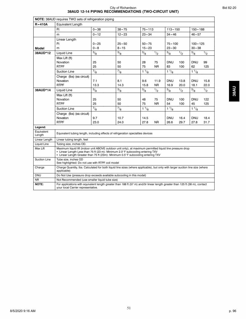
51
38AUD 12-14 PIPING RECOMMENDATIONS (TWO-CIRCUIT UNIT)
NOTE: 38AUD requires TWO sets of refrigeration piping
R---410A Equivalent Length
Ft 0---38 38---75 75---113 113---150 150---188
m 0---12 12---23 23---34 34---46 46---57
Model
Linear LengthFt 0---25 25---50 50---75 75---100 100---125m 0---8 8---15 15---23 23---30 30---38
38AUD*12 Liquid Line 3/8 3/8 3/8 1/2 3/8 1/2 3/8 1/2Max Lift (ft)Novation 25 50 28 75 DNU 100 DNU 99RTPF 25 50 75 NR 83 100 62 125
Suction Line 7/8 7/8 1 1/8 1 1/8 1 1/8Charge (lbs) (ea circuit)Novation 7.1 8.1 9.6 11.9 DNU 13.8 DNU 15.8RTPF 13.3 14.3 15.8 NR 16.9 20.0 18.1 22.0
38AUD*14 Liquid Line 3/8 3/8 3/8 1/2 3/8 1/2 3/8 1/2Max Lift (ft)Novation 25 50 48 75 DNU 100 DNU 122RTPF 25 50 75 NR 54 100 45 125
Suction Line 7/8 7/8 1 1/8 1 1/8 1 1/8Charge (lbs) (ea circuit)Novation 9.7 10.7 14.5 DNU 16.4 DNU 18.4RTPF 23.0 24.0 27.8 NR 26.6 29.7 27.8 31.7
Legend:
EquivalentLength Equivalent tubing length, including effects of refrigeration specialties devices
Linear Length Linear tubing length, feet
Liquid Line Tubing size, inches OD.
Max Lift Maximum liquid lift (indoor unit ABOVE outdoor unit only), at maximum permitted liquid line pressure dropS Linear Length Less than 75 ft (23 m): Minimum 2.0° F subcooling entering TXVS Linear Length Greater than 75 ft (23m): Minimum 0.5° F subcooling entering TXV
Suction Line Tube size, inches ODSee highlighted: Do not use with RTPF coil model
Charge Charge Quantity, lbs. Calculated for both liquid line sizes (where applicable), but only with larger suction line size (whereapplicable)
DNU Do Not Use (pressure drop exceeds available subcooling in this model)
NR Not Recommended (use smaller liquid tube size)
NOTE: For applications with equivalent length greater than 188 ft (57 m) and/0r linear length greater than 125 ft (38 m), contactyour local Carrier representative.
38AU
Bid 82-20City of Richardson
8/5/2020 9:16 AM p. 96

52
38AUD 16-25 PIPING RECOMMENDATIONS (TWO-CIRCUIT UNIT)
NOTE: 38AUD requires TWO sets of refrigeration piping
R-410A Equivalent Length
Ft 0-38 38-75 75-113 113-150 150-188
m 0-12 12-23 23-34 34-46 46-57
Model
Linear Length
Ft 0-25 25-50 50-75 75-100 100-125
m 0-8 8-15 15-23 23-30 30-38
38AUD*16 Liquid Line 1/2 1/2 1/2 1/2 1/2Max Lift 25 50 75 100 125
Suction Line 7/8 11/8 11/8 11/8 11/8Charge ea. (lbs)
Novation 11.7 13.8 15.7 17.6 19.6
RTPF 21.7 23.8 25.7 27.6 29.6
38AUD*25 Liquid Line 1/2 1/2 1/2 5/8 1/2 5/8 1/2 5/8Max Lift 25 50 54 75 60 99 46 95
Suction Line 11/8 11/8 11/8 11/8 13/8 13/8Charge (lbs) 1
219.318.3
21.020.3
23.022.0
26.025.0
25.924.9
29.728.7
28.027.0
32.731.7
Legend:
EquivalentLength Equivalent tubing length, including effects of refrigeration specialties devices
Linear Length Typical linear tubing length (50% added to linear to define Equivalent Length for this table)
Liquid Line Tubing size, inches OD.
Max Lift Maximum liquid lift (indoor unit ABOVE outdoor unit only), at maximum permitted liquid line pressure drop —S Linear Length Less than 75 ft (23 m): Minimum 2.0° F subcooling entering TXVS Linear Length Greater than 75 ft (23m): Minimum 0.5° F subcooling entering TXV
Suction Line Tube size, inches OD
Charge Charge Quantity, lbs. Calculated for both liquid line sizes (where applicable), but only with larger suction line size(where applicable)
NOTE: For applications with equivalent length greater than 188 ft (57 m) and/0r linear length greater than 125 ft (38 m),contact your local Bryant representative.
38AU
Bid 82-20City of Richardson
8/5/2020 9:16 AM p. 97

53
TYPICAL PIPING AND WIRING
Roof Installation and a Ceiling--Mounted Fan Coil
WEATHERPROOFFUSED DISCONNECT*PER NEC
FIELD-SUPPLIEDPOWER
INSULATEDVAPORLINE
POWER WIRES
CONTROLWIRES
INDOORTHERMOSTAT†
OUTDOOR
MOISTUREINDICATORSIGHT GLASS*
ELECTRICHEATERACCESSORY
INDOORUNIT
LIQUIDLINE
FILTERDRIER*
CONDENSATE DRAIN
POWER WIRES
FUSED DISCONNECTPER NEC
TO OPEN SIGHTDRAIN
LLSV*
UNIT
C09054
LEGEND:NEC --- National Electrical CodeTXV --- Thermostatic Expansion Valve* Field---supplied{ Double riser may be required. Consult condensing unit product data catalog for details.NOTES:1. All piping must follow standard refrigerant piping techniques. Refer to Carrier System Design Manual for details.2. All wiring must comply with the applicable local and national codes.3. Wiring and piping shown are general points-of-connection guides only and are not intended for, or to include all details for,
a specific installation.4. Liquid line solenoid valve (solenoid drop control) is recommended to prevent refrigerant migration to the compressor.5. Internal factory-supplied TXVs not shown.
38AU
Bid 82-20City of Richardson
8/5/2020 9:16 AM p. 98

54
TYPICAL PIPING AND WIRING (CONT.)
Roof Installation and a Vertical Discharge Fan Coil
LEGEND
*Field supplied.
DIAM — DiameterNEC — National Electrical CodeTXV — Thermostatic Expansion Valve
Piping
NOTES:1. All piping must follow standard refrigerant piping techniques. Refer to Carrier Sys-
tem Design Manual for details.2. All wiring must comply with applicable local and national codes.3. Wiring and piping shown are general points-of-connection guides only and are not
intended for, or to include all details for, a specific installation.4. Filter driers must be bi-flow type suited for heat pump duty.5. Internal factory-supplied TXVs and check valves not shown.
C101129
38AU
Bid 82-20City of Richardson
8/5/2020 9:16 AM p. 99

55
TYPICAL PIPING AND WIRING (CONT.)
Ground Level Installation and Vertical Discharge Fan Coil
NOTES:1. All piping must follow standard refrigerant piping techniques. Refer to Carrier System
Design Manual for details.2. All wiring must comply with the applicable local and national codes.3. Wiring and piping shown are general points-of-connection guides only and are not
intended for, or to include all details for, a specific installation.4. Liquid line solenoid valve (solenoid drop control) is recommended to prevent refrigerant
migration to the compressor.5. Internal factory-supplied TXVs not shown.
LEGEND
*Field supplied.
DIAM— DiameterNEC — National Electrical CodeTXV — Thermostatic Expansion Valve
Piping
C101130
38AU
Bid 82-20City of Richardson
8/5/2020 9:16 AM p. 100

56
TYPICAL PIPING AND WIRING (CONT.)
Dual Condensing Units and a Dual Circuit Fan
RETURNAIR
SUBBASEACCESSORY
15 DIAMMIN
40RMQ024UNIT
ELECTRICHEATERACCESSORY
24 VCONTROLWIRE
BULB CAPILLARYTUBES
10 DIAMMIN
CONDENSATEDRAIN
8 DIAMSMIN
DISCONNECTPER NEC*
INSULATEDVAPOR LINE
SIGHT GLASS*
FILTER DRIER*
INSULATEDVAPOR LINE
LIQUIDLINE
HEAT PUMPUNIT B
FUSEDDISCONNECTPER NEC†
WEATHERPROOF
POWER WIRES
FIELDSUPPLIEDPOWER
FUSEDDISCONNECT†PER NEC
WEATHERPROOF HEAT PUMPUNIT A
LIQUIDLINE
FIELDSUPPLIEDPOWER
POWERWIRES
BIFLOW LIQUIDLINE SOLENOIDVALVE*
BIFLOW LIQUID LINE SOLENOID VALVE*
LEGEND
*Field supplied.†Field supplied; not required if FIOP disconnect is supplied.
DIAM — DiameterNEC — National Electrical CodeTXV — Thermostatic Expansion Valve
Piping
NOTES:1. All piping must follow standard refrigerant piping techniques. Refer to Carrier System
Design Manual for details.2. All wiring must comply with applicable local and national codes.3. Wiring and piping shown are general points-of-connection guides only and are not
intended for, or to include all details for, a specific installation.4. Filter driers must be bi-flow type suited for heat pump duty.5. Heat Pump Unit A should be the first on, last off and be connected to the lower half of
the coil.6. Internal factory-supplied TXVs and check valves not shown.
C101131
38AU
Bid 82-20City of Richardson
8/5/2020 9:16 AM p. 101

57
GUIDE SPECIFICATIONS
Commercial Air-Cooled Condensing Units
HVAC Guide Specifications
Size Range: 6 to 20 Tons, Nominal
Carrier Model Numbers: 38AUZ, Single Circuit (07 - 25 Models) 38AUD, Dual Circuit (12 -- 25 Models)
Part 1 — General
1.01 SYSTEM DESCRIPTION
Outdoor-mounted, air-cooled condensing unit suitable for on-the-ground or rooftop installation. Unit shall consist of ahermetic scroll air-conditioning compressor(s) assembly, an air-cooled coil, propeller-type condenser fans, and a controlbox. Unit shall discharge supply air upward as shown on contract drawings. Unit shall be used in a refrigeration circuitmatched with a packaged air-handling unit.
1.02 QUALITY ASSURANCE
A. Unit shall be rated in accordance with AHRI Standard 360.B. Unit construction shall comply with ANSI/ASHRAE 15 safety code latest revision and comply with NEC.C. Unit shall be constructed in accordance with UL 1995 standard and shall carry the UL and UL, Canada label.D. Unit cabinet shall be capable of withstanding 500-hour salt spray exposure per ASTM B117 (scribed specimen).E. Air-cooled condenser coils for hermetic scroll compressor units (38AUZ) and 38AUD shall be leak tested at 150
psig, and pressure tested at 650 psig.F. Unit shall be manufactured in a facility registered to ISO 9001:2000 manufacturing quality standard.
1.03 DELIVERY, STORAGE, AND HANDLING
Unit shall be shipped as single package only, and shall be stored and handled according to unit manufacturer’srecommendations.
1.04 WARRANTY (FOR INCLUSION BY SPECIFYING ENGINEER.)
Part 2 — Products
2.01 EQUIPMENT
A. General:Factory-assembled, single piece, air-cooled condensing unit. Contained within the unit enclosure shall be all factorywiring, piping, controls, compressor, holding charge, and special features required prior to field start-up.
B. Unit Cabinet:1. Unit cabinet shall be constructed of galvanized steel, bonderized and coated with a prepainted baked enamel fin-
ish.2. A heavy-gauge roll-formed perimeter base rail with forklift slots and lifting holes shall be provided to facilitate
rigging.C. Condenser Fans:1. Condenser fans shall be direct driven, propeller type, discharging air vertically upward.2. Fan blades shall be balanced.3. Condenser fan discharge openings shall be equipped with PVC-coated steel wire safety guards.4. Condenser fan and motor shaft shall be corrosion resistant.D. Compressor:1. Compressor shall be of the hermetic scroll type .2. Compressor shall be mounted on rubber grommets.3. Compressors shall include overload protection.4. Compressors shall be equipped with a crankcase heater.5. Compressor shall be equipped with internal high pressure and high temperature protection.6. 38AUZ*16 and 25 sizes shall use two scroll compressors manifold together.E. Condenser Coils:1. Standard Aluminum fin -- Copper Tube Coils:
a. Standard evaporator and condenser coils shall have aluminum lanced plate fins mechanically bonded to seam-less internally grooved copper tubes with all joints brazed.
38AU
Bid 82-20City of Richardson
8/5/2020 9:16 AM p. 102

58
b. Evaporator coils shall be leak tested to 150 psig, pressure tested to 450 psig, and qualified to UL 1995 bursttest at 1775 psig.
c. Condenser coils shall be leak tested to 150 psig, pressure tested to 650 psig, and qualified to UL 1995 bursttest at 1980 psig.
2. Optional Pre--coated aluminum--fin condenser coils:a. Shall have a durable epoxy--phenolic coating to provide protection in mildly corrosive coastal environments.b. Coating shall be applied to the aluminum fin stock prior to the fin stamping process to create an inert barrier
between the aluminum fin and copper tube.c. Epoxy--phenolic barrier shall minimize galvanic action between dissimilar metals.
3. Optional Copper--fin evaporator and condenser coils:a. Shall be constructed of copper fins mechanically bonded to copper tubes and copper tube sheets.b. Galvanized steel tube sheets shall not be acceptable.c. A polymer strip shall prevent coil assembly from contacting the sheet metal coil pan to minimize potential for
galvanic corrosion between coil and pan.4. Optional E--coated aluminum--fin evaporator and condenser coils:
a. Shall have a flexible epoxy polymer coating uniformly applied to all coil surface areas without materialbridging between fins.
b. Coating process shall ensure complete coil encapsulation of tubes, fins and headers.c. Color shall be high gloss black with gloss per ASTM D523--89.d. Uniform dry film thickness from 0.8 to 1.2 mil on all surface areas including fin edges.e. Superior hardness characteristics of 2H per ASTM D3363--92A and cross--hatch adhesion of 4B--5B per ASTM
D3359--93.f. Impact resistance shall be up to 160 in.--lb (ASTM D2794--93).g. Humidity and water immersion resistance shall be up to minimum 1000 and 250 hours respectively (ASTM
D2247--92 and ASTM D870--92).h. Corrosion durability shall be confirmed through testing to be no less than 1000 hours salt spray per ASTM
B117--90.5. Standard All Aluminum Novation Coils:
a. Standard condenser coils shall have all aluminum Novation Heat Exchanger Technology design consisting ofaluminum multi port flat tube design and aluminum fin. Coils shall be a furnace brazed design and containepoxy lined shrink wrap on all aluminum to copper connections.
b. Condenser coils shall be leak tested to 150 psig, pressure tested to 650 psig, and qualified to UL 1995 bursttest at 1980 psig.
6. Optional E--coated aluminum--fin, aluminum tube condenser coils:a. Shall have a flexible epoxy polymer coating uniformly applied to all coil external surface areas without mater-
ial bridging between fins or louvers.b. Coating process shall ensure complete coil encapsulation, including all exposed fin edges.c. E--coat thickness of 0.8 to 1.2 mil with top coat having a uniform dry film thickness from 1.0 to 2.0 mil on all
external coil surface areas, including fin edges, shall be provided.d. Shall have superior hardness characteristics of 2H per ASTM D3363--00 and cross--hatch adhesion of 4B--5B
per ASTM D3359--02.e. Shall have superior impact resistance with no cracking, chipping or peeling per NSF/ANSI 51--2002 Method
10.2.F. Refrigeration Components:
Refrigeration circuit components shall include liquid line service valve, suction line service valve, a full charge ofcompressor oil, and a partial holding charge of refrigerant.
G. Controls and Safeties:1. Minimum control functions shall include:
f. Control wire terminal blocks.g. Compressor lockout on auto-reset safety until reset from thermostat.h. Each unit shall utilize the Comfort Alertt Diagnostic Board that provides:
(1.) System Pressure Trip fault code indication(2.) Short Cycling fault code indication(3.) Locked Rotor fault code indication(4.) Open Circuit fault code indication
38AU
Bid 82-20City of Richardson
8/5/2020 9:16 AM p. 103

59
(5.) Reverse Phase 3 fault code indication(6.) Welded Contactor fault code indication(7.) Low Voltage fault code indication(8.) Anti--short cycle protection(9.) Phase reversal protection
2. Minimum safety devices which are equipped with automatic reset (after resetting first at thermostat), shall in-clude:a. High discharge pressure cutout.b. Low pressure cutout.
H. Operating Characteristics:1. The capacity of the condensing unit shall meet or exceed _____ Btuh at a suction temperature of ______F. The
power consumption at full load shall not exceed _____ kW.2. The combination of the condensing unit and the evaporator or fan coil unit shall have a total net cooling capacity
of _____ Btuh or greater at conditions of _____ cfm entering-air temperature at the evaporator at ______F wetbulb and ______F dry bulb, and air entering the condensing unit at ______F.
3. The system shall have an EER of _____ Btuh/Watt or greater at standard AHRI conditions.4. Standard unit shall be capable to operate up to 125_F (52_C) and down to 40_F (4_C)I. Electrical Requirements:1. Nominal unit electrical characteristics shall be _____ v, 3-ph, 60 Hz. The unit shall be capable of satisfactory
operation within voltage limits of ____ v to _____ v.2. Unit electrical power shall be single-point connection.3. Unit control circuit shall contain a 24-v transformer for unit control.J. Special Features:1. Low-Ambient Temperature Control:
A low-ambient temperature control shall be available as a factory-installed option or as a field-installed accessory.This low-ambient control shall regulate speed of the condenser-fan motors in response to the saturated condensingtemperature of the unit. The control shall maintain correct condensing pressure at outdoor temperatures down to–20_F (--29_C).
2. Unit-Mounted, Non-Fused Disconnect Switch:Switch shall be factory-installed and internally mounted. NEC and UL-approved non-fused switch shall provideunit power shutoff. Switch shall be accessible from outside the unit and shall provide power off lockout capability.Non--fused disconnect switch cannot be used when unit MOCP electrical rating exceeds 80 amps.
3. Convenience Outlet:Outlet shall be factory-installed and internally mounted with easily accessible 115-v female receptacle. Outletshall include 15 amp GFI (ground fault interrupter) receptacle with independent fuse protection. Voltage requiredto operate convenience outlet shall be provided by a factory-installed step-down transformer. Outlet shall be ac-cessible from outside the unit.
4. Thermostat Controls:a. Programmable multi-stage thermostat shall have 7-day clock, holiday scheduling, large backlit display, remote
sensor capability, and Title 24 compliance.b. Commercial Electronic Thermostat shall have 7-day time clock, auto-changeover, multi-stage capability, and
large LCD (liquid crystal display) temperature display.5. Louvered hail Guard Package:
Louvered hail guard package shall protect coils against damage from hail and other flying debris.6. Condenser Coil Grille (Novation coil models 07--14):
Grille shall add decorative appearance to unit and protect condenser coil from large objects and vandalism.
38AU
Bid 82-20City of Richardson
8/5/2020 9:16 AM p. 104

60
Copyright 2011 Carrier Corp. D 7310 W. Morris St. D Indianapolis, IN 46231 Printed in U.S.A. Edition Date: 03/11
Manufacturer reserves the right to change, at any time, specifications and designs without notice and without obligations.
Catalog No: 38AU---04PD
Replaces: 38AU---03PD
38AU
Bid 82-20City of Richardson
8/5/2020 9:16 AM p. 105

Product Data
40MB*D / 38MAQ / 38MBQDucted Split SystemSizes 09 to 48
INDUSTRY LEADINGFEATURES / BENEFITS
A PERFECT BALANCE BETWEENBUDGET LIMITS, ENERGY SAVINGS ANDCOMFORT.The 40MBD series ducted split systems are a matched combinationof an outdoor condensing unit and an indoor fan coil unitconnected only by refrigerant tubing and wires.
The fan coil is mounted in the ceiling. This selection of fan coilspermits creative solutions to design problems such as:
S Add- ons to current space (an office or family roomaddition)
S Special space requirements
S When changes in the load cannot be handled by theexisting system.
S Historical renovations or any application wherepreserving the look of the original structure is essential.
These compact indoor fan coil units take up very little space abovethe ceiling. Advanced system components incorporate innovativetechnology to provide reliable cooling performance at low soundlevels.
Bid 82-20City of Richardson
8/5/2020 9:16 AM p. 106

2
LOW SOUND LEVELSWhen sound ordinances and proximity to neighbors demand quietoperation, the 38MAQ unit is the right choice: The advanced,horizontal airflow design distributes air more evenly over the coil.
SECURE OPERATIONIf security is an issue, outdoor and indoor units are connected onlyby refrigerant piping and wiring to prevent intruders fromcrawling through ductwork. In addition, since 38MAQ units canbe installed close to an outside wall, coils are protected fromvandals and severe weather.
FAST INSTALLATIONThis compact ducted split system is simple to install. A mountingbracket and duct work is needed for the indoor units, and onlywire and piping need to be run between indoor and outdoor units.These units are fast and easy to install ensuring minimaldisruption to customers in the home or workplace. This makes the40MBD / 38MAQ / 38MBQ ducted split systems the equipmentof choice, especially in retrofit situations.
SIMPLE SERVICING ANDMAINTENANCERemoving the top panel on outdoor units provides immediateaccess to the control compartment, providing a service technicianaccess to check unit operation. In addition, the draw- thru design ofthe outdoor section means that dirt accumulates on the outsidesurface of the coil. Coils can be cleaned quickly from the insideusing a pressure hose and detergent.On all indoor units, service and maintenance expense is reduceddue to easy accessible service panels. In addition, these ductedsystems have extensive self- diagnostics to assist introubleshooting.
BUILT-IN RELIABILITYDucted split system indoor and outdoor units are designed toprovide years of trouble- free operation.The ducted indoor units include protection against freeze- up andhigh evaporator temperatures on heat pumps.
The condensing units on heat pumps are protected by a threeminute time delay before the compressor will start the over- currentprotection and the high temperature protection.
INDIVIDUAL ROOM COMFORTMaximum comfort is provided because each space can becontrolled individually based on usage pattern. The air sweepfeature provided permits optimal room air mixing to eliminate hotand cold spots for occupant comfort. In addition, year- roundcomfort can be provided with heat pumps.
ECONOMICAL OPERATIONThe ducted split system design allows individual or multi- roomheating or cooling when required. There is no need to run largesupply- air fans or chilled water pumps to handle a few spaceswith unique load patterns.
EASY-TO-USE CONTROLSThe ducted units have microprocessor- based controls to providethe ultimate in comfort and efficiency. The user friendly wiredand wireless remote control provides the interface between userand the unit.
CONDENSATE PUMPFactory installed condensate pump on the ducted fan coil providesinstallation flexibility.
STANDARDWIRED CONTROLLER
AGENCY LISTINGSAll systems are listed with AHRI (Air Conditioning, Heating &Refrigeration Institute), and ETL.
Bid 82-20City of Richardson
8/5/2020 9:16 AM p. 107

3
MODEL NUMBER NOMENCLATURE
BQ D
MAXIMUM NUMBER OF FAN COIL UNITS THATCAN BE CONNECTED TO THE OUTDOOR UNITB=1:1
SYSTEM TYPEQ = HEAT PUMP
NOT USED
INDOOR UNIT
40 MB 309
40= FAN COIL UNIT
MB = MODELVOLTAGE3 = 208/230- 1- 60
NOMINAL CAPACITY09 - 3/4 TON12 - 1 TON18 - 1- 1/2 TONS24 - 2 TONS36 - 3 TONS48 - 4 TONS
INDOOR FAN COIL TYPE
D = DUCTED
- -
BQ -
MAXIMUM NUMBER OF FAN COIL UNITS THATCAN BE CONNECTED TO THE OUTDOOR UNITB=1:1
SYSTEM TYPEQ = HEAT PUMP
NOT USED
OUTDOOR UNIT
38 MA 309
38 = OUTDOOR UNIT
MA = MODEL SIZES 09- 24MB = MODEL SIZES 36- 48
VOLTAGE3 = 208/230- 1- 60
NOMINAL CAPACITY09 - 3/4 TON12 - 1 TON18 - 1- 1/2 TONS24 - 2 TONS36 - 3 TONS48 - 4 TONS
UNIT TYPE
- = OUTDOOR UNIT
- -
Use of the AHRI CertifiedTM Mark indicates amanufacturer’s participation in the program For verification of certification for individual products, go to www.ahridirectory.org.
Bid 82-20City of Richardson
8/5/2020 9:16 AM p. 108

4
STANDARD FEATURES AND ACCESSORIESEase Of InstallationMounting Brackets SLow Voltage Controls S
Comfort FeaturesMicroprocessor Controls SWired Remote Control SWireless Remote Control SAutomatic Horizontal Air Sweep SAir Direction Control SAuto Restart Function SCold Blow Protection On Heat Pumps SFreeze Protection Mode On Heat Pumps STurbo Mode SSilence Mode SAuto Changeover On Heat Pumps SFollow Me S
Energy Saving FeaturesSleep Mode SStop/Start Timer S46° F Heating Mode (Heating Setback) S
Safety And Reliability3 Minute Time Delay For Compressor SOver Current Protection For Compressor SIndoor Coil Freeze Protection SIndoor Coil High Temp Protection in Heating Mode SCondenser High Temp Protection in Cooling Mode S
Ease Of Service And MaintenanceCleanable Filters SDiagnostics SLiquid Line Pressure Taps S
Application FlexibilityCondensate Pumps SCrankcase Heater S
LegendS StandardA Accessory
OUTDOOR UNITSCrankcase HeaterStandard on all unit sizes. Heater clamps around compressor oilstump.
Bid 82-20City of Richardson
8/5/2020 9:16 AM p. 109

5
DIMENSIONS - INDOOR
Fig. 1 – Indoor unit
Outline dimensions Air outlet opening size Air return opening sizeHanger
Brackets Refrigerant Pipe Locations
Size A B C D E F G H I J K L M H1 H2 W1 W2
927.6(700)
8.2(210)
25(635)
22.4(570) 2.5 (65)
19.4(493) 1.3 (35)
4.6(119)
23.4(595)
7.8(200) 3.1 (80)
29.1(740)
13.8(350)
4.7(120)
5.6(143) 3.7 (95)
5.9(150)
1227.6(700)
8.2(210)
25(635)
22.4(570) 2.5 (65)
19.4(493) 1.3 (35)
4.6(119)
23.4(595)
7.8(200) 3.1 (80)
29.1(740)
13.8(350)
4.7(120)
5.6(143) 3.7 (95)
5.9(150)
1836.2(920)
8.2(210)
25(635)
22.4(570) 2.5 (65)
19.4(493) 1.3 (35)
4.6(119)
32.0(815)
7.8(200) 3.1 (80)
37.8(960)
13.8(350)
4.7(120)
5.6(143) 3.7 (95)
5.9(150)
2436.2(920)
10.6(270)
25(635)
22.4(570) 2.5 (65)
19.4(493) 1.3 (35)
7.0(179)
32.0(815)
10.2(260) 0.7 (20)
37.8(960)
13.8(350)
4.7(120)
5.6(143) 3.7 (95)
5.9(150)
3644.8
(1140)10.6(270)
30.5(775)
27.9(710) 2.5 (65)
36.7(933) 1.3 (35)
7.0(179)
40.7(1035)
10.2(260) 1.7 (45)
48.8(1240)
19.7(500)
4.7(120)
5.6(143) 3.7 (95)
5.9(150)
4847.2
(1200)11.8(300)
34.1(865)
31.4(800) 3.1 (80)
38.1(968) 1.5 (40)
8.0(204)
43.0(1094)
11.3(288) 1.7 (45)
48.8(1240)
19.7(500)
6.9(175)
7.8(198)
6.1(155)
8.3(210)
Bid 82-20City of Richardson
8/5/2020 9:16 AM p. 110

6
DIMENSIONS - OUTDOOR
Fig. 2 – Outdoor unit
Unit Size W in (mm) D in (mm) H in (mm) L1 in (mm) L2 in (mm)Operating
Weight lb (kg)
9K 31.8(810) 12.2(310) 21.9(558) 21.6(549) 12.8(325) 82.4(37.4)
12K 31.8(810) 12.2(310) 21.9(558) 21.6(549) 12.8(325) 82.4(37.4)
18K 33.2(845) 12.6(320) 27.5(700) 22.0(560) 13.1(405) 102.5(46.5)
24K 37.2(945) 15.5(395) 31.8(810) 25.2(640) 15.9(405) 137.5(62.4)
36K 37.2(945) 15.5(395) 31.8(810) 25.2(640) 15.9(405) 137.5(62.4)
48K 36.93(938) 15.4(392) 53.9(1369) 24.9(634) 15.9(404) 220(100)
Bid 82-20City of Richardson
8/5/2020 9:16 AM p. 111

7
CLEARANCES - INDOOR
7.874in(200mm) 11.811in(300mm)
23.622in x 23.622in(600mm x 600mm)
Fig. 3 – Indoor Unit Clearance
CLEARANCES - OUTDOOR
A
D B
Air-outlet
Air-inlet
C
E
Fig. 4 – Clearances Outdoor
UNITMinimum Value
in. (mm)A 24 (609)B 24 (609)C 24 (609)D 4 (101)E 4 (101)
Bid 82-20City of Richardson
8/5/2020 9:16 AM p. 112

8
SPECIFICATIONS
System
Size 9 12 18 24 36 48
Outdoor Model 38MAQB09---3 38MAQB12---3 38MAQB18---3 38MAQB24---3 38MBQB36---3 38MBQB48---3
Indoor Model 40MBQB09D--3 40MBQB12D--3 40MBQB18D--3 40MBQB24D--3 40MBQB36D--3 40MBQB48D--3
Energy Star YES YES YES YES NO NO
Performance
Cooling Rated Capacity Btu/h 9,000 11,000 16,000 23,000 36,000 48,000
Cooling Cap. Range Min - Max Btu/h 3,500~11,000 4,000~13,000 4,500~18,000 5,500~24,500 8,500~38,000 9,000~50,000
SEER 19.0 18.0 18.5 19.0 15.5 16.5
EER 13.5 12.5 12.5 12.5 8.5 8.2
Heating Rated Capacity Btu/h 10,000 11,800 18,000 24,400 38,000 50,000
Heating Cap. Range Min - Max Btu/h 4,500~11,500 5,000~13,500 5,500~19,000 6,000~26,000 9,500~50,000 10,000~55,000
HSPF 9.6 9.0 9.6 10.5 10.5 10.0
ControlsWireless Remote Controller (°F/°C Convertible) Standard
Wired Remote Controller (°F/°C Convertible) Standard
OperatingRange
Cooling Outdoor DB Min - Max °F 4~122 4~122 4~122 4~122 4~122 4~122
Heating Outdoor DB Min - Max °F 4~86 4~86 4~86 4~86 4~86 4~86
Piping
Total Piping Length Ft. 82 82 98 98 213 213
Piping Lift* Ft. 32 32 65 65 98 98
Pipe Connection Size - Liquid In. 1/4 1/4 1/4 3/8 3/8 3/8
Pipe Connection Size - Suction In. 3/8 1/2 1/2 5/8 5/8 5/8
Refrigerant
Type R410A
Design Pressure PSIG 550 550 550 550 550 550
Metering Device Capillary Tube in Outdoor Unit
Charge Lbs. 2.76 2.76 4.19 5.18 7.5 9.48
Outdoorcoil
Face Area Sq. Ft. 9.2 9.2 16.0 21.1 8.2 14.1
No. Rows 2 2 2 3 2.6 2.0
Fins per inch 21 21 18 18 17 17.0
Circuits 4 4 6 8 6 10.0
Indoor Coil
Face Area Sq. Ft. 1.4 1.4 1.4 2.0 3.5 4.2
No. Rows 3 3 3 4 4 4
Fins per inch 16 16 16 16 16 16
Circuits 4 4 4 6 8 8
Compressor
Type Hermetic Rotary DC Inverter Compressor
Model ASM98D1UFZA ASM108D1UFZA ASM135D23UFZ DA250S2C-30MT TNB306FPGMC-L MNB36FAAMC-L
Oil Type VG74 VG74 VG74 VG74 FV50S FV50S
Oil Charge Fl. Oz. 12.5 12.5 15.2 27.7 36.2 47.3
Rated Current RLA 5.3 5.7 7.3 8.8 13.5 13.5
Electrical
Voltage, Phase, Cycle V/Ph/Hz 208/230-1-60 208/230-1-60 208/230-1-60 208/230-1-60 208/230-1-60 208/230-1-60
Power Supply Indoor unit powered from outdoor unit
MCA A. 15 15 15 15 30 35
MOCP - Fuse Rating A. 15 15 20 25 50 55
Outdoor
Unit Width In. 31.9 31.9 33.3 37.2 37.2 36.9
Unit Height In. 22.0 22.0 27.6 31.9 31.9 53.9
Unit Depth In. 12.2 12.2 12.6 15.6 15.6 15.4
Net Weight Lbs. 82.4 82.4 120.5 134.0 160.9 220.0
Airflow CFM 945 945 1050 1390 2940 4240
Sound Pressure dB(A) 56 56 59 62 65 65
Indoor
Unit Width In. 27.6 27.6 36.2 36.2 44.9 47.2
Unit Height In. 8.3 8.3 8.3 10.6 10.6 11.8
Unit Depth In. 25.0 25.0 25.0 25.0 30.5 34.1
Net Weight Lbs. 39.9 39.9 50.7 57.3 77.2 99.2
Number of Fan Speeds 3 3 3 3 3 3
Airflow (lowest to highest) CFM 290/340/380 290/340/380 400/440/480 590/650/810 680/940/1180 940/1180/1470
Sound Pressure (lowest to highest) dB(A) 30/33/36 30/34/38 34/37/38 43/45/48 46/50/52 41/44/46
Max Static Pressure In.WG. 0.16 0.16 0.28 0.28 0.32 0.40
Bid 82-20City of Richardson
8/5/2020 9:16 AM p. 113

9
COOLING PERFORMANCE DATAModel
Cooling Outdoor conditions (DB)Indoor Conditions
77F(25C) 86F(30C) 95F(35C) 104F(40C) 113F(45C) 122F(50C)
9
DB WB
69.8F(21C) 59F(15C)TC 7.41 7.82 9.73 8.34 6.12 5.1SC 6.64 6.69 8.18 7.37 4.36 3.74
Input 0.35 0.54 0.81 0.8 0.75 0.75
75.2F(24C) 62.6F(17C)TC 7.76 9.16 9.89 8.62 6.92 5.83SC 3.58 8.11 6.27 5.52 4.85 4.29
Input 0.35 0.54 0.81 0.8 0.75 0.75
80.6F(27C) 66.2F(19C)TC 8.21 9.22 10.41 9.27 7.32 6SC 7.39 5.88 8.22 7.79 5.11 4.37
Input 0.35 0.75 0.82 0.81 0.75 0.75
89.6F(32C) 73.4F(23C)TC 8.41 9.72 11.59 10.22 8.82 7.51SC 3.68 5.76 6.9 6.2 5.55 5
Input 0.36 0.56 0.83 0.82 0.76 0.77
12
69.8F(21C) 59F(15C)TC 8.21 11.75 11.42 9 7.85 6.68SC 7.06 9.05 8.68 7.38 6.42 5.58
Input 0.38 0.8 1.04 0.87 0.82 0.81
75.2F(24C) 62.6F(17C)TC 8.42 11.84 12.01 9.35 8.32 7.34SC 7.28 8.69 8.66 7.62 6.53 5.81
Input 0.57 0.94 1.25 1.27 0.98 0.94
80.6F(27C) 66.2F(19C)TC 8.81 11.95 12.23 9.69 8.87 7.95SC 7.49 8.32 8.63 7.85 6.64 6.04
Input 0.39 0.75 1.06 0.89 0.85 0.82
89.6F(32C) 73.4F(23C)TC 9.01 12.15 12.43 9.89 9.07 8.15SC 7.7 8.53 8.84 8.06 6.85 6.25
Input 0.4 0.97 1.3 1.34 0.92 0.85
18
69.8F(21C) 59F(15C)TC 12.58 15.24 16.25 11.04 8.32 6.78SC 8.34 10.3 10.6 7.93 6.18 5.16
Input 0.58 0.93 1.53 1.2 1.42 1.32
75.2F(24C) 62.6F(17C)TC 13.48 16.41 16.66 12.3 9.43 7.74SC 8.85 10.94 11.35 8.62 6.87 5.91
Input 0.57 0.93 1.56 1.22 1.45 1.35
80.6F(27C) 66.2F(19C)TC 14.43 18.04 18.37 13.35 9.97 7.96SC 9.59 11.95 12.37 9.28 7.23 6.02
Input 0.57 0.94 1.59 1.24 1.48 1.38
89.6F(32C) 73.4F(23C)TC 14.7 19.03 20.18 15.36 12.02 9.97SC 9.08 11.72 12.5 9.69 7.85 6.89
Input 0.6 0.97 1.62 1.27 1.51 1.41
24
69.8F(21C) 59F(15C)TC 19.5 20.69 21.43 18.05 14.27 13.32SC 15.15 15.61 15.49 14.23 10.03 8.78
Input 1.2 1.88 2.29 2.14 1.9 1.86
75.2F(24C) 62.6F(17C)TC 20.01 21.21 22.31 18.51 15.08 13.3SC 15.25 15.71 15.59 14.33 10.13 8.88
Input 1.2 1.87 2.3 2.21 2.14 1.92
80.6F(27C) 66.2F(19C)TC 20.54 21.75 23.21 18.98 15.91 13.3SC 15.35 15.81 15.69 14.43 10.23 8.98
Input 1.21 1.86 2.31 2.26 2.16 1.93
89.6F(32C) 73.4F(23C)TC 20.61 22.94 24.4 21.84 19.17 16.66SC 15.58 16.04 15.92 14.66 10.46 9.21
Input 1.22 1.87 2.34 2.33 2.32 1.96
36
69.8F(21C) 59F(15C)TC 31.83 34.35 30.88 26.58 22.28 17.98SC 25.53 26.76 25.25 23.31 18.05 13.66
Input 2.71 3.85 3.89 3.68 3.47 3.26
75.2F(24C) 62.6F(17C)TC 34.39 37.02 33.71 29.08 24.45 19.82SC 26.33 27.54 26.22 24.37 18.75 14.2
Input 2.74 3.92 3.94 3.74 3.54 3.34
80.6F(27C) 66.2F(19C)TC 36.95 39.7 36.55 31.59 26.63 21.67SC 27.12 28.31 27.19 25.43 19.44 14.74
Input 2.77 3.98 4 3.8 3.61 3.42
89.6F(32C) 73.4F(23C)TC 37.68 40.49 37.28 32.22 27.16 22.1SC 27.66 28.87 27.73 25.94 19.83 15.04
Input 2.83 4.04 4.07 3.86 3.67 3.49
48
69.8F(21C) 59F(15C)TC 38.16 36.31 34.96 25.91 21.78 17.81SC 29 28.36 27.69 23.66 18.08 13.94
Input 3.3 3.69 4.53 3.25 3.12 3.03
75.2F(24C) 62.6F(17C)TC 41.23 39.58 38.4 29.21 24.48 19.83SC 30.07 29.47 28.91 25.1 20.61 14.61
Input 3.4 3.75 4.62 3.31 3.15 2.97
80.6F(27C) 66.2F(19C)TC 44.3 42.86 41.84 32.51 27.18 21.85SC 31.14 30.58 30.13 26.55 23.13 15.29
Input 3.5 3.82 4.72 3.36 3.18 2.92
89.6F(32C) 73.4F(23C)TC 45.18 43.72 42.68 33.16 27.72 22.29SC 32.07 21.49 31.03 27.34 23.82 15.74
Input 3.57 3.89 4.81 3.42 3.24 2.97
LEGENDDB - Dry BulbWB - Wet BulbTC - Total Net Cooling Capacity (1000 Btu/hour)SC - Sensible Capacity (1000 Btu/hour)Input - Total Power (kW)
Bid 82-20City of Richardson
8/5/2020 9:16 AM p. 114

10
HEATING PERFORMANCE DATA
ModelHeating Outdoor conditions (DB)
Indoor Conditions DB 53.6F(12C) 44.6F(7C) 39.2F(4C) 32F(0C) 24.8F(-4C) 19.4F(-7C) 17F(-8C) 5F(-15C)
9
59F(15C)TH 11.18 11.08 10.89 10.65 9.87 9.11 8.27 6.71
Input 0.73 0.79 1.04 1.01 0.96 0.9 0.84 0.8
64.4F(18C)TH 11.06 10.82 10.65 10.54 9.63 8.84 8.01 5.46
Input 0.78 0.8 1.08 1.03 0.98 0.94 0.9 0.82
69F(20.5C)TH 10.84 10.55 10.48 10.32 9.43 8.55 7.95 4.29
Input 0.8 0.81 1.11 1.05 1 0.98 0.96 0.84
71.6F(22C)TH 10.62 10.32 10.21 10.11 9.23 8.41 7.89 4.11
Input 0.82 0.83 1.15 1.07 1.02 1.02 0.92 0.86
12
59F(15C)TH 11.78 12.72 12.42 11.32 10.4 9.54 8.9 5.75
Input 0.79 1.01 1.05 1.1 1.02 1 0.98 0.83
64.4F(18C)TH 12.05 12.65 12.32 11.34 10.3 9.32 8.81 6.14
Input 0.83 1.37 1.4 1.26 1.22 1.27 1.01 0.91
69F(20.5C)TH 12.27 12.6 12.12 11.32 10.2 9.12 8.43 6.49
Input 0.83 1.1 1.12 1.19 1.19 1.25 1.03 0.98
71.6F(22C)TH 11.14 12.41 12.01 11.21 10 9.02 8.21 6.01
Input 0.85 1.15 1.16 1.21 1.23 1.31 1.05 1
18
59F(15C)TH 23.16 20.54 19.42 17.56 16.5 14.28 12.08 9.39
Input 1.58 1.49 1.48 1.58 1.46 1.4 1.35 1.21
64.4F(18C)TH 22.41 20.08 18.66 16.89 16.1 13.94 12.06 9.16
Input 1.62 1.55 1.55 1.61 1.52 1.45 1.4 1.29
69F(20.5C)TH 21.71 19.67 17.93 16.26 15.6 13.62 12.07 8.95
Input 1.67 1.62 1.63 1.65 1.58 1.5 1.45 1.38
71.6F(22C)TH 21.01 18.97 17.23 15.56 14.9 12.92 11.37 8.25
Input 1.72 1.67 1.68 1.7 1.63 1.55 1.5 1.43
24
59F(15C)TH 28.6 27.79 25.85 23.56 23.4 23.22 23.16 18.93
Input 2 2.25 2.24 2.21 2.2 2.23 2.24 2.17
64.4F(18C)TH 27.62 27.61 24.52 23.54 23.4 22.52 20.45 17.45
Input 2.24 2.45 2.35 2.35 2.32 2.23 2.21 2.16
69F(20.5C)TH 29.09 29.25 26.75 24.63 23 21.85 19.61 16.38
Input 2.39 2.74 2.64 2.58 2.42 2.25 2.2 2.18
71.6F(22C)TH 26.87 27.52 24.21 23.41 22.5 21.67 19.54 16.24
Input 2 2.25 2.24 2.21 2.2 2.23 2.24 2.17
36
59F(15C)TH 51.98 50.41 44.98 37.74 36.3 35.22 34.87 27.92
Input 3.85 4.31 4.09 3.83 3.89 3.94 3.95 3.71
64.4F(18C)TH 49.72 49.76 45.75 40.41 36.9 34.3 33.43 26.79
Input 3.83 4.53 4.36 4.16 4.01 3.9 3.87 3.6
69F(20.5C)TH 47.47 49.1 46.52 43.08 37.5 33.38 32 25.66
Input 3.82 4.76 4.64 4.49 4.14 3.88 3.8 3.49
71.6F(22C)TH 46.56 48.84 46.82 44.14 37.8 33.01 31.42 25.2
Input 3.81 4.85 4.74 4.62 4.19 3.87 3.76 3.44
48
59F(15C)TH 58.98 58.14 53.9 48.25 36.7 35.34 34.38 28.09
Input 4.33 4.89 4.9 4.9 4.43 4.46 4.46 4.13
64.4F(18C)TH 56.5 53.86 51.15 47.54 37.1 34.77 33.57 27.45
Input 4.51 4.72 4.87 5.06 4.7 4.6 4.57 4.23
69F(20.5C)TH 54.39 50.22 48.81 46.94 37.4 34.27 32.89 26.91
Input 4.67 4.57 4.84 5.2 4.93 4.72 4.66 4.31
71.6F(22C)TH 53.19 48.16 47.48 46.59 37.6 33.98 32.5 26.6
Input 4.75 4.48 4.82 5.27 5.05 4.78 4.71 4.35
LEGENDDB - Dry BulbTH - Total Net Heating Capacity (1000 Btu/hour)Input - Total Power (kW)
Bid 82-20City of Richardson
8/5/2020 9:16 AM p. 115

11
FAN AND MOTOR SPECIFICATIONSSystem size
DUCTED
9K 12K 18K 24K 36K 48K
Indoor fan
material ABS ABS ABS ABS ABS ABS
Type LX-140*150*12-41J LX-140*150*12-41J LX-142*180*12-42J LX-188*190*12-40J LX-188*190*12-40J LX-188*190*12-40J
Diameter inch 5.5 5.5 5.6 7.4 7.4 7.4
Height inch 5.9 5.9 7.1 7.5 19.3 19.3
Indoor fan motor
Model WZDK55-38GS-W WZDK55-38GS-W WZDK90-38GS-W WZDK90-38GS-W WZDK150-38GS-W WZDK240-38GS-W
Type DC DC DC DC DC DC
Phase 3 3 3 3 3 3
FLA 1.03 1.03 0.83 0.83 1.263 2.23
Insulation class E E E E E E
Safe class IPX0 IPX0 IPX0 IPX0 IPX0 IPX0
Input W 118 118 143 143 167 276
Output W 55 55 90 90 150 240
Range of current Amps 1.03±10% 1.03±10% 1.15±10% 1.15±10% 1.263±10% 2.23±10%
Rated current Amps 1.03 1.03 0.83 0.83 1.263 2.23
Rated HP HP 0.073 0.073 0.12 0.12 0.2 0.32
Speed rev/min 1100/950/800 1150/1000/900 1100/1050/880/820 1030/880/800 1120/1000/860 1040/950/830
Rated RPM rev/min 1450 1450 1200 1200 1180 1200
Max. input W 118 118 143 143 167 276
Outdoor fan
material AS AS AS AS AS AS
Type ZL-421*117*8-3K ZL-421*117*8-3K ZL-460*180*10-3N ZL-560*139*12-3KN ZL-560*139*12-3KN ZL-525*135*12-3KFN
Diameter inch 16.5 16.5 18 22 22 20.7
Height inch 4.6 4.6 7.1 5.5 5.5 5.3
Outdoor fan motor
Model WZDK40-38G-W-1 WZDK40-38G-W-1 ZKFN-50-8-2 WZDK120-38G-1 WZDK120-38G-W WZDK85-38G
Phase DC DC DC DC DC DC
FLA 3 3 3 3 3 3
Type 0.42 0.42 0.85 0.47 1.21 0.33
Insulation class E E E E E E
Safe class IPX0 IPX0 IPX0 IPX0 IPX0 IPX0
Input W 46 46 103 145 150 98
Output W 40 40 50 120 120 85
Range of current Amps 0.42±10% 0.42±10% 0.85±10% 0.47±10% 1.21±10% 0.33±10%
Rated current Amps 0.42 0.42 0.85 0.47 1.21 0.33
Rated HP HP 0.053 0.053 0.067 0.16 0.16 0.11
Speed rev/min 800/700/600 800/700/600 800/700/600 850/750/700 950/850/750 950/850/750
Rated RPM rev/min 900 900 800 1050 1050 850
Max. input W 46 46 103 145 150 98
Bid 82-20City of Richardson
8/5/2020 9:16 AM p. 116

12
APPLICATION DATAUNIT SELECTIONSelect equipment to either match or be slightly less than anticipatedpeak load. This provides better humidity control, fewer unit cycles,and less part- load operation.For units used in spaces with high sensible loads, base equipmentselection on unit sensible load, not on total anticipated load. Adjustfor anticipated room wet bulb temperature to avoid undersizingequipment.
UNIT MOUNTING (INDOOR)Refer to unit Installation Instructions for further details.Unit leveling - For reliable operation, units should be level in allplanes.
Clearance - Provide adequate clearance for airflow as shown inFig. 3.Unit location - Select a location which will provide the best aircirculation for the room.These units should be positioned as accessible as possible abovethe ceiling. The unit return and discharge should not be obstructedby furniture, curtains, or anything which may cause unit shortcycling or air recirculation. Duct the unit in the middle of theselected wall (if possible). Duct towards an outside wall, ifavailable, to make piping easier, and place the unit so it faces thenormal location of room occupants.
UNIT MOUNTING (OUTDOOR)Refer to unit Installation Instructions for further details.Unit leveling - For reliable operation, units should be level in allplanes.Clearance - Minimum clearance, as shown in Fig. 5, must beprovided for airflow. The condensing units are designed forfree- blow application. Air inlets and outlets should not berestricted.Unit location - A location which is convenient to installation andnot exposed to strong wind.A location which can bear the weight of outdoor unit and wherethe outdoor unit can be mounted in a level position.
Do not install the indoor or outdoor units in a location with specialenvironmental conditions. For those applications, contact yourCarrier representative.
MOUNTINGRefer to unit Installation Instructions for further details.
SUPPORTAdequate support must be provided to support the weight of all fancoils. Refer to the Physical Data section for fan coil weights, andthe base unit dimensional drawings for the location of mountingbrackets.
SYSTEM OPERATING CONDITIONSOperating RangeMin / Max °F (°C)
Cooling Heating
Outdoor DB 4 / 122 (-20 / 50) 4 / 86 (-20 / 30)
Indoor DB 63 / 90 (17 / 32) 32 / 86 (0 / 30)
Indoor WB 59 / 84 (15 / 29)
Non-Operating Temperature RangeMin / Max °F (°C)
Indoor/Outdoor DB 32 / 86 (0 / 30)
NOTE: Reference the Product Installation Instructions for more information.
METERING DEVICESThese units have capillary tube metering devices in the outdoorunit.
DRAIN CONNECTIONSInstall drains to meet local sanitation codes. Standard ducted fancoil unit condensate pumps have a maximum lift of 29.5in(750mm).
REFRIGERANT LINESGeneral refrigerant line sizing:
1. The 38MAQ & 38MBQ units are shipped with a fullcharge of R410A refrigerant. All charges, line sizing, andcapacities are based on runs of 25 ft (7.6 m). For runs over25 ft (7.6 m), consult long- line section on this page forproper charge adjustments.
2. Refrigerant lines should not be buried in the ground. If it isnecessary to bury the lines, not more than 36- in (914 mm)should be buried. Provide a minimum 6- in (152 mm)vertical rise to the service valves to prevent refrigerantmigration.
3. Both lines must be insulated. Use a minimum of 1/2- in.(12.7 mm) thick insulation. Closed- cell insulation isrecommended in all long- line applications.
4. Special consideration should be given to isolatinginterconnecting tubing from the building structure. Isolatethe tubing so that vibration or noise is not transmitted intothe structure.
Long Line Applications, 38MAQ & 38MBQ Units:1. No change in line sizing is required.
2. Add refrigerant per table below.
ADDITIONAL CHARGE TABLE
UnitSize
Total LineLength ft Additional Charge, oz/ft. Ft (m)
Min Max10-25
(3-8)
>25-82
(8-25)
>82-98
(25-30)>98-213(30-65)
9
10
82
None
0.2712
1898
0.43 0.4324
36213 0.43
48
Bid 82-20City of Richardson
8/5/2020 9:16 AM p. 117

13
WIRINGRecommended Connection Method for Power andCommunication Wiring (To minimize communication wiringinterference)
Power Wiring:The main power is supplied to the outdoor unit. The field suppliedconnecting cable from the outdoor unit to indoor unit consists ofthree (3) wires and provides the power for the indoor unit. Twowires are high voltage AC power and one is a ground wire.
Consult your local building codes and the NEC (NationalElectrical Code) or CEC (Canadian Electrical Code) for specialrequirements.
All wires must be sized per NEC or CEC and local codes. UseElectrical Data table MCA (minimum circuit amps) and MOCP(maximum over current protection) to correctly size the wires andthe disconnect fuse or breakers respectively.
Per caution note, only copper conductors with a minimum 300 voltrating and 2/64- inch thick insulation must be used.
Communication Wiring:A separate shielded copper conductor only, with a minimum 300volt rating and 2/64- inch thick insulation, must be used as thecommunication wire from the outdoor unit to the indoor unit.
To minimize voltage drop, the factory recommended wire size is14/3 stranded with a ground. In special cases where there is highelectrical interference, please use a separate shielded 16GAstranded control wire.
Alternate Connection Method for Power and CommunicationWiring (May not prevent communication wiring interference)The main power is supplied to the outdoor unit. The fieldsupplied connecting cable from the outdoor unit to indoor unitconsists of four (4) wires and provides the power andcommunication signals for the indoor unit. Two conductors are forpower wiring (L1/L2, or L/N), one is a ground wire, and one is aDC communication wire.
Consult your local building codes and the NEC (NationalElectrical Code) or CEC (Canadian Electrical Code) for specialrequirements. All power wires must be sized per NEC or CECand local codes. Use Electrical Data table MCA (minimum circuitamps) and MOCP (maximum over current protection) to correctlysize the wires and the disconnect fuse or breakers respectively.Per caution note, only copper conductors with a minimum 300 voltrating and 2/64- inch thick insulation must be used.
CAUTION!
EQUIPMENT DAMAGE HAZARD
Failure to follow this caution may result in equipmentdamage or improper operation.
S Wires should be sized based on NEC and local codes.
S Use copper conductors only with a minimum 300 voltrating and 2/64 inch thick insulation.
CAUTION!
EQUIPMENT DAMAGE HAZARD
Failure to follow this caution may result in equipmentdamage or improper operation.S Be sure to comply with local codes while running wire
from indoor unit to outdoor unit.S Every wire must be connected firmly. Loose wiring
may cause terminal to overheat or result in unitmalfunction. A fire hazard may also exist. Therefore,be sure all wiring is tightly connected.
S No wire should be allowed to touch refrigerant tubing,compressor or any moving parts.
S Disconnecting means must be provided and shall belocated within sight and readily accessible from the airconditioner.
S Connecting cable with conduit shall be routed throughhole in the conduit panel.
The main power is supplied to the outdoor unit. the field suppliedconnecting cable from the outdoor unit to indoor unit consists offour wires and provides the power for the indoor unit as well as thecommunication signal between the outdoor unit and indoor unit.Two wires are high voltage AC power (L1 and L2), one is aground wire, and one is a DC communication wire.
CONTROL SYSTEMThe 40MB*D unit is equipped with a microprocessor control toperform two functions:
1. Provide safety for the system
2. Control the system and provide optimum levels of comfortand efficiency
The main microprocessor is located on the control board of thefan coil unit (outdoor units have a microprocessor too) withthermistors located in the fan coil air inlet and on the indoor coil.Heat pump units have a thermistor on the outdoor coil. Thesethermistors monitor the system operation to maintain the unitwithin acceptable parameters and control the operating mode.
WIRELESS REMOTE CONTROL
Fig. 5 – Wireless remote control
1. A wireless remote control is supplied for system operationfor system operation of all ducted units.
2. Each battery operated wireless (infrared) remote controlmay be used to control more than one unit.
WIRED REMOTE CONTROLP/N KSACN0101CAC
1. Optional wired remote controller usedfor system operation of all ductedunits.
2. Kit includes a wired remote controllerand a connecting cable.
3. Connect with wire terminal betweenremote controller and indoor unit.
4. Display in _F or _C and temperatureincrements every 1_F or every 1_C.
Bid 82-20City of Richardson
8/5/2020 9:16 AM p. 118

14
AIR FLOW DATASystem size 9 12 18 24 36 48
Indoor (CFM)High 380 380 480 810 1180 1470
Medium 340 340 440 650 940 1180Low 290 290 400 590 680 940
Outdoor (CFM) 945 945 1050 1390 2940 4240
SOUND PRESSURESystem size 9 12 18 24 36 48
Cooling operation Indoor SoundPressure dBa (L/M/H) 30/33/36 30/34/38 34/37/38 43/45/48 46/50/52 41/44/46
Heating operation Indoor SoundPressure dBa (L/M/H) 30/33/36 30/34/38 34/37/39 44/45/48 46/49/51 40/43/45
Outdoor sound pressure level dBa 55.5 56 59 62 65 65
SOUND POWERSystem size 9 12 18 24 36 48
Cooling operation Indoor Sound Power dBa (L/M/H) 39/42/45 39/43/47 43/46/48 53/55/58 56/60/62 51/54/56Heating operation Indoor Sound Power dBa (L/M/H) 39/42/45 39/43/47 43/46/48 54/55/58 56/59/61 50/53/55
Outdoor sound power level dBa 65 66 69 72 75 75
ELECTRICAL DATAUNITSIZE
OPER. VOLTAGEMAX / MIN* COMPRESSOR OUTDOOR FAN INDOOR FAN MCA
MAX FUSECB AMP
253 / 187
V-PH-HZ RLA V-PH-HZ FLA HP W V-PH-HZ FLA HP W
9
208-230/1/60
5.3
208-230/1/60
3 0.053 40
208-230/1/60
1.03 0.07 55 15 1512 5.7 3 0.053 40 1.03 0.07 55 15 1518 7.3 3 0.067 50 0.83 0.12 90 15 2024 8.8 3 0.16 120 0.83 0.12 90 15 2536 13.5 3 0.16 120 1.263 0.2 150 30 5048 13.4 3 0.11 85 2.23 0.32 240 35 55
*Permissible limits of the voltage range at which the unit will operate satisfactorily.LEGENDFLA - Full Load AmpsLRA - Locked Rotor AmpsMCA - Minimum Circuit AmpsRLA - Rated Load Amps
Bid 82-20City of Richardson
8/5/2020 9:16 AM p. 119

15
FAN AND MOTOR SPECIFICATIONSSystem size 9 12 18 24 36 48
Indoorfan
material ABS ABS ABS ABS ABS ABSType LX-140*150*12-41J LX-140*150*12-41J LX-142*180*12-42J LX-188*190*12-40J LX-188*190*12-40J LX-188*190*12-40J
Diameter inch 140 140 142 188 188 188Height inch 150 150 180 190 490 490
Indoorfan
motor
Model WZDK55-38GS-W WZDK55-38GS-W WZDK90-38GS-W WZDK90-38GS-W WZDK150-38GS-W WZDK240-38GS-WType DC DC DC DC DC DC
Phase 3 3 3 3 3 3FLA 1.03 1.03 0.83 0.83 1.263 2.23
Insulation class E E E E E ESafeclass IPX0 IPX0 IPX0 IPX0 IPX0 IPX0
Input W 118 118 143 143 167 276Output W 55 55 90 90 150 240
Range ofcurrent Amps 1.03±10% 1.03±10% 1.15±10% 1.15±10% 1.263±10% 2.23±10%
Ratedcurrent Amps 1.03 1.03 0.83 0.83 1.263 2.23
Rated HP HP 0.073 0.073 0.12 0.12 0.2 0.32Speed rev/min 1100/950/800 1150/1000/900 1100/1050/880/820 1030/880/800 1120/1000/860 1040/950/830RatedRPM rev/min 1450 1450 1200 1200 1180 1200
Max.input W 118 118 143 143 167 276
Outdoorfan
material AS AS AS AS AS ASType ZL-421*117*8-3K ZL-421*117*8-3K ZL-460*180*10-3N ZL-560*139*12-3KN ZL-560*139*12-3KN ZL-525*135*12-3KFN
Diameter inch 421 421 460 560 560 525Height inch 117 117 180 139 139 135
Outdoorfan
motor
Model WZDK40-38G-W-1 WZDK40-38G-W-1 ZKFN-50-8-2 WZDK120-38G-1 WZDK120-38G-W WZDK85-38GPhase DC DC DC DC DC DCFLA 3 3 3 3 3 3Type 0.42 0.42 0.85 0.47 1.21 0.33
Insulation class E E E E E ESafeclass IPX0 IPX0 IPX0 IPX0 IPX0 IPX0
Input W 46 46 103 145 150 98Output W 40 40 50 120 120 85
Range ofcurrent Amps 0.42±10% 0.42±10% 0.85±10% 0.47±10% 1.21±10% 0.33±10%
Ratedcurrent Amps 0.42 0.42 0.85 0.47 1.21 0.33
Rated HP HP 0.053 0.053 0.067 0.16 0.16 0.11Speed rev/min 800/700/600 800/700/600 800/700/600 850/750/700 950/850/750 950/850/750RatedRPM rev/min 900 900 800 1050 1050 850
Max.input W 46 46 103 145 150 98
Bid 82-20City of Richardson
8/5/2020 9:16 AM p. 120

16
FAN PERFORMANCESStatic pressure curve (static pressure deducted)
9~12K
471/800
412/700
235/400
177/300
Low speed
Air volume(CFM/m³/h)
Ext
erna
l sta
tic p
ress
ure
(in∙W
G/P
a)
High speedMid speed
294/500
353/600
530/900
0.04/10
0.08/20
0.12/30
0.16/40
0.2/50
0.24/60
0.28/70
0.32/80
0.36/90
in∙WG/Pa
in∙WG/Pa
in∙WG/Pa
0
Super high speed
Ext
erna
l sta
tic p
ress
ure
(in∙W
G/P
a)
Ext
erna
l sta
tic p
ress
ure
(in∙W
G/P
a)
18K
Air volume(CFM/m³/h)
0.04/10
0.08/20
0.12/30
0.16/40
0.2/50
0.24/60
0.28/70
0.32/80
0.36/90
706/1200
Mid speed
High speed
647/1100
589/1000
530/900
471/800
412/700
353/600
Low speed
118/200
117/300
235/400
294/500
Super high speed
Air volume(CFM/m³/h)
0.04/10
0.08/20
0.12/30
0.16/40
0.2/50
0.24/60
0.28/70
0.32/80
0.36/90
24K
Mid speedHigh speed
Low speed
412/700
883/1500
706/1200
647/1100
589/1000
530/900
471/800
765/1300
824/1400
Super high speed
Fig. 6 – Fan performances
Bid 82-20City of Richardson
8/5/2020 9:16 AM p. 121

17
Air volume(CFM/m³/h) Air volume(CFM/m³/h)
0.04/10
0.08/20
0.12/30
0.16/40
0.2/50
0.24/60
0.28/70
0.32/80
0.36/90
36K 48K
1413/2400
1295/2200
942/1600
824/1400
Low speed
647/1100
Ext
erna
l sta
tic p
ress
ure
(in∙W
G/P
a)
High speed
Mid speed
706/1200
1059/1800
1177/2000
Super high speed
1825/3100
1648/2800
1118/1900
942/1600
Low speed
589/1000
Ext
erna
l sta
tic p
ress
ure
(in∙W
G/P
a)
High speed
Mid speed
765/1300
1295/2200
1471/2500
Super high speed
0.04/10
0.08/20
0.12/30
0.16/40
0.2/50
0.24/60
0.28/70
0.32/80
0.36/90
0.4/100
0.44/110
0.48/120
in∙WG/Pa in∙WG/Pa
Fig. 7 – Fan performances
Bid 82-20City of Richardson
8/5/2020 9:16 AM p. 122

18
WIRING DIAGRAMS
Fig. 8 – Wiring Diagram Sizes 09 - 12
Indoor unit Outdoor unit
CODE PART NAME CODE PART NAME
CN1 Input: 230VAC High voltage Connection of the terminal CN7、CN8 Input: 230V High voltage
CN2 Input: 230VAC High voltage Connection of the terminal CN2 Output: Connection of the high voltage
CN3/CN26 Output: 0V Connection of the earth CN3、CN4 Output: High voltage for 4-way control
CN5 Output: 0-5VDC Connection of the Water level switch CN11、CN16 Output: 230V High voltage for HEATER
CN6 Output: 5VDC Connection of the Room and Pipe temperature CN5 Output: Pulse(0-320V) for DC FAN
CN8/CN18 Output: 320VDC High voltage Connection of the Reactor CN12、CN13 Output: Connection of the high voltage
CN9 Output: 5VDC Connection of the CCM U V W Output: Pulse(0-320V) for compressor
CN10(CN10A) Output: 12VDC Connection of the Display board CN10 Input:Pin1 (5V) Pin2(0-5V)
CN11/CN14 Output: 220VAC High voltage Connection of the New Fan CN1 Input:Pin3-4 (5V) Pin2(0V),Pin1,Pin5(0-5V)
CN13 Output: 220VAC High voltage Connection of the Pump CN18Output:Pin 5&6 (12V) Pin1-Pin4:Pulse
waveform,(0-12V)
CN15 Output: 320VDC High voltage Connection of the Fan board
CN23 Output: 1-12VDC Connection of the Remote switch
CN33 Output: 0V Connection of the Alarm
CN40 Output: 12VDC Connection of the Wire controller
CN41 Output: 24VDC Between CN2 Connection of the S signal
Bid 82-20City of Richardson
8/5/2020 9:16 AM p. 123

19
Fig. 9 – Wiring Diagram Size 18
Indoor unit Outdoor unit
CODE PART NAME CODE PART NAME
CN1 Input: 230VAC High voltage Connection of the terminal CN7、CN8 Input: 230V High voltage
CN2 Input: 230VAC High voltage Connection of the terminal CN2 Output: Connection of the high voltage
CN3/CN26 Output: 0V Connection of the earth CN3、CN4 Output: High voltage for 4-way control
CN5 Output: 0-5VDC Connection of the Water level switch CN11、CN16 Output: 230V High voltage for HEATER
CN6 Output: 5VDC Connection of the Room and Pipe temperature CN5 Output: Pulse(0-320V) for DC FAN
CN8/CN18 Output: 320VDC High voltage Connection of the Reactor CN12、CN13 Output: Connection of the high voltage
CN9 Output: 5VDC Connection of the CCM U V W Output: Pulse(0-320V) for compressor
CN10(CN10A) Output: 12VDC Connection of the Display board CN10 Input:Pin1 (5V) Pin2(0-5V)
CN11/CN14 Output: 220VAC High voltage Connection of the New Fan CN1 Input:Pin3-4 (5V) Pin2(0V),Pin1,Pin5(0-5V)
CN13 Output: 220VAC High voltage Connection of the Pump CN18Output:Pin5&6(12V) Pin1-Pin4:Pulse
waveform,(0-12V)
CN15 Output: 320VDC High voltage Connection of the Fan board
CN23 Output: 1-12VDC Connection of the Remote switch
CN33 Output: 0V Connection of the Alarm
CN40 Output: 12VDC Connection of the Wire controller
CN41 Output: 24VDC Between CN2 Connection of the S signal
Bid 82-20City of Richardson
8/5/2020 9:16 AM p. 124

20
Fig. 10 – Wiring Diagram Size 24
Indoor unit Outdoor unitCODE PART NAME CODE PART NAME
CN1 Input: 230VAC High voltage Connection of the terminal CN17Input:Pin4-5 (3.3V) (T4)
Pin2(0V),Pin1,Pin3(0-3.3V) (T3)
CN2 Input: 230VAC High voltage Connection of the terminal CN7 Input:Pin1 (3.3V) Pin2(0-3.3V) (TP)CN3/CN26 Output: 0V Connection of the earth CN5,CN6 Output:230V High voltage for heater1 control
CN5 Output: 0-5VDC Connection of the Water level switch CN8,CN9 Output:230V High voltage for heater2 control
CN6Output: 5VDC Connection of the Room and Pipe
temperatureCN2,CN3 (IPM
BOARD)Output: Connection of the high voltage
(REACTOR)
CN8/CN18 Output: 320VDC High voltage Connection of the Reactor CN3 (MAIN BOARD) Input:230V High voltage (L)CN9 Output: 5VDC Connection of the CCM CN4 Input:230V High voltage (N)
CN10(CN10A) Output: 12VDC Connection of the Display board P-1 Connection to the earth (GND)CN11/CN14 Output: 220VAC High voltage Connection of the New Fan CN10 Output: Connection of the high voltage (S)
CN13 Output: 220VAC High voltage Connection of the PumpCN1,CN2 (MAIN
BOARD) Output: High voltage for 4-way control
CN15Output: 320VDC High voltage Connection of the Fan
board CN37 Output: Pulse(0-320V) for DC FAN
CN23 Output: 1-12VDC Connection of the Remote switch U V W Output: Pulse(0-320V) for COMPRESSORSCN33 Output: 0V Connection of the AlarmCN40 Output: 12VDC Connection of the Wire controllerCN41 Output: 24VDC Between CN2 Connection of the S signal
Bid 82-20City of Richardson
8/5/2020 9:16 AM p. 125

21
Fig. 11 – Wiring Diagram Size 36Indoor unit Outdoor unit(main board)
CODE PART NAME PART NAME PART NAME
CN1Input: 230VAC High voltage Connection of the
terminalCN1,CN2 Power input: 230V AC
CN2Input: 230VAC High voltage Connection of the
terminalCN3,CN22 Output: High voltage for 4-way control (230V AC)
CN3 Output: 0V Connection of the earth CN4,CN40 Output: High voltage for HEAT_Y control(230V AC)
CN5Output: 0-5VDC Connection of the Water level
switchCN5,CN6 Output: Power output to DRIVER BOARD (230V AC)
CN6Output: 5VDC Connection of the Room and Pipe
temperatureCN7 Input: Communication Main board and IPM Board,Pin1(12V DC),Pin2(5V DC )
CN7Output: 5VDC Connection of the Outer Pipe
temperatureCN8,CN33 Input: Temperature sensor (5V DC)
CN9Output: 5VDC Connection of the CCM and
RS-485CN9 Input: Pressure test (5V DC)
CN10(CN10A) Output: 12VDC Connection of the Display board CN10,CN44 Output: High voltage for HEAT_D control (230V AC)
CN13Output: 220VAC High voltage Connection of the
PumpCN11,CN12 Output: Pulse(0-380VDC) for DC FAN
CN15Output: 320VDC High voltage Connection of the
Fan boardCN20 Output: PMV control,Pin5(12V DC),Pin6(12V DC)
CN23Output: 1-12VDC Connection of the Remote
switchCN34 Communication to indoor unit,Pin1(5V DC),Pin3(5V DC)
CN33 Output: 0V Connection of the Alarm CN41,CN42,CN43 Output: Power output for AC fan motor (230V AC)
CN40 Output: 12VDC Connection of the Wire controller P-1 Connection to the earth
Outdoor unit(Driver board)
PART NAME PART NAME
U V W Output: Pulse(0-380VDC) for COMPRESSOR
CN7 Output: Pulse(0-380VDC) for DC FAN
CN51,CN52 Output: Connect PFC Inductance, high DC Voltage
CN53,CN54 Input: Power input for DRIVER BOARD (230V AC)
CN55 Output: Communication IPM Board and Main board,Pin1(12V DC),Pin2(5V DC )
Bid 82-20City of Richardson
8/5/2020 9:16 AM p. 126

22
Fig. 12 – Wiring Diagram Size 48CODE PART NAME Outdoor unit (main board)
Indoor unit CN1,CN3 Power input: 230V AC
CN1Input: 230VAC High voltage Connection of the
terminalCN2,CN4 Output: Power output for DRIVER BOARD (230V AC)
CN2Input: 230VAC High voltage Connection of the
terminalCN5 Input: Communication Main board and IPM Board, Pin1(5V DC )
CN3 Output: 0V Connection of the earth CN6 Input: DC FAN motor1 and DC FAN motor2 control, (Pin7 5V DC)
CN5Output: 0-5VDC Connection of the Water level
switchCN8,CN9,CN12 Input: Temperature sensor (5V DC)
CN6Output: 5VDC Connection of the Room and Pipe
temperatureCN10 Input: Pressure test (5V DC)
CN7Output: 5VDC Connection of the Outer Pipe
temperatureCN15 Output: PMV control,Pin5(12V DC),Pin6(12V DC)
CN9Output: 5VDC Connection of the CCM and
RS-485CN17,CN18 Output: High voltage for 4-way(SV) control (230V AC)
CN10(CN10A) Output: 12VDC Connection of the Display board CN19,CN20 Output: High voltage for HEAT_D control (230V AC)
CN13Output: 220VAC High voltage Connection of the
PumpCN22 Communication to indoor unit,Pin1(5V DC),Pin3(5V DC)
CN15Output: 320VDC High voltage Connection of the
Fan boardCN24,CN25 Output: High voltage for HEAT_Y control(230V AC)
CN23Output: 1-12VDC Connection of the Remote
switchCN27、CN32、CN34,CN28、
CN31、CN36Output: Power output for AC FAN motor1 and AC FAN motor2 (230V AC)
CN33 Output: 0V Connection of the Alarm CN39 Output: L2 for AC FAN、SV and HEAT ,High voltage (AC)
CN40 Output: 12VDC Connection of the Wire controller P-6 Connection to the earth
Outdoor unit (Driver board)
U V W Output: Pulse(0-380VDC) for COMPRESSOR
CN6 ,CN8 Input: Power input for DRIVER BOARD (200-320V DC )
CN3 Output: Connect PFC Inductance, high DC voltage
CN7,CN11Output: DC FAN motor1 and DC FAN motor2 control (Pin1 310V or 380V
DC)CN9 Output: Communication Main board and IPM Board Pin7(5V DC )
CN55 Output: Communication IPM Board and Main board Pin1(12V DC )
CN14、CN15-- CN39, Output: High DC voltage (310V or 380V DC)
Bid 82-20City of Richardson
8/5/2020 9:16 AM p. 127

23
GUIDE SPECIFICATIONSINDOOR CEILING-MOUNTED DUCTLESS UNITS
Size Range: 3/4 to 4 Ton Nominal Cooling and Heating CapacityCarrier Model Number: 40MB*D
PART 1 - GENERAL1.01 System DescriptionIndoor, ceiling-mounted, direct- expansion fan coils are matchedwith cooling only or heat pump outdoor unit .
1.02 Agency ListingsUnit shall be rated per AHRI Standards 210/240 and listed in theAHRI directory as a matched system.
1.03 Delivery, Storage, And HandlingUnits shall be stored and handled per unit manufacturer’srecommendations.
1.04 Warranty (For Inclusion By SpecifyingEngineer)
PART 2 - PRODUCTS2.01 EquipmentA. General:Indoor, direct- expansion, ceiling-mounted fan coil. Unit shall becomplete with cooling/heating coil, fan, fan motor, pipingconnectors, electrical controls, microprocessor control system, andintegral temperature sensing.B. Unit Cabinet:Unit cabinet shall be constructed of galvanized steel. Cabinet shallbe fully insulated for improved thermal and acoustic performance.
C. Fans:Fan shall be tangential direct- drive blower type with air intake atthe rear or bottom of the unit and discharge at the front.D. Coil:Coil shall be copper tube with aluminum fins and galvanized steeltube sheets. Fins shall be bonded to the tubes by mechanicalexpansion. A drip pan under the coil shall have a factory installedcondensate pump and drain connection for hose attachment toremove condensate.E. Motors:Motors shall be open drip- proof, permanently lubricated ballbearing with inherent overload protection. Fan motors shall be4- speed.
F. Controls:Controls shall consist of a microprocessor- based control systemwhich shall control space temperature, determine optimum fanspeed, and run self diagnostics. The temperature control rangeshall be from 62_F to 86_F (17_C to 30_C) in increments of 1_For 1_C, and have 46_F Heating Mode (Heating Setback). Thewireless remote controller shall have the ability to act as thetemperature sensing location for room comfort.
The unit shall have the following functions as a minimum:1. An automatic restart after power failure at the sameoperating conditions as at failure.
2. A timer function to provide a minimum 24- hour timercycle for system Auto Start/Stop.
3. Temperature- sensing controls shall sense return airtemperature.
4. Indoor coil freeze protection.
5. Wireless infrared remote control to enter set points andoperating conditions.
6. Dehumidification mode shall provide increased latentremoval capability by modulating system operation and setpoint temperature.
7. Fan- only operation to provide room air circulation when nocooling is required.
8. Diagnostics shall provide continuous checks of unitoperation and warn of possible malfunctions. Errormessages shall be displayed at the unit.
9. Fan speed control shall be user- selectable: high, medium,low, or microprocessor controlled automatic operationduring all operating modes.
10. Automatic heating- to- cooling changeover in heat pumpmode. Control shall include deadband to prevent rapidmode cycling between heating and cooling.
11. Indoor coil high temperature protection shall be provided todetect excessive indoor discharge temperature when unit isin heat pump mode.
G. Electrical Requirements:Indoor fan motor to operate on 208- 230V. Power is supplied fromthe outdoor unit.H. Operating Characteristics:The 40MBD system shall have a minimum SEER (SeasonalEnergy Efficiency Ratio) and HSPF at AHRI conditions, as listedon the specifications table.
I. Refrigerant Lines:All units should have refrigerant lines that can be oriented toconnect from the left, right or back of unit. Both refrigerant linesneed to be insulated.
Bid 82-20City of Richardson
8/5/2020 9:16 AM p. 128

24
GUIDE SPECIFICATIONSHORIZONTAL DISCHARGE OUTDOOR UNITS
Size Range: 3/4 to 4 Ton Nominal Cooling and Heating CapacityCarrier Model Number: 38MAQ/38MBQ
PART 1 - GENERAL1.01 System DescriptionA. Outdoor air- cooled split system compressor sections suitable
for on- the- ground, rooftop, wall hung or balcony mounting.Units shall consist of a rotary compressor, an air- cooled coil,propeller- type draw- through outdoor fan, reversing valve(HP), accumulator (HP units), metering device(s), and controlbox. Units shall discharge air horizontally as shown on thecontract drawings. Units shall function as the outdoorcomponent of an air- to- air cooling only, or heat pump system.
B. Units shall be used in a refrigeration circuit matched to ductlessheat pump fan coil units.
1.02 Agency ListingsA. Unit construction shall comply with ANSI/ASHRAE 15, latest
revision, and with the NEC.
B. Units shall be evaluated in accordance with UL standard 1995.
C. Units shall be listed in the CEC directory.
D. Unit cabinet shall be capable of withstanding 500- hour saltspray test per Federal Test Standard No. 141 (method 6061).
E. Air- cooled condenser coils shall be leak tested at 550 psig.
1.03 Delivery, Storage, And HandlingUnits shall be shipped in one piece and shall be stored and handledper unit manufacturer’s recommendations.
1.04 Warranty (For Inclusion By SpecifyingEngineer)
PART 2 - PRODUCTS2.01 EquipmentA. General:Factory assembled, single piece, air- cooled outdoor unit.Contained within the unit enclosure shall be all factory wiring,piping, controls, and the compressor.B. Unit Cabinet:
1. Unit cabinet shall be constructed of galvanized steel,bonderized and coated with a baked- enamel finish oninside and outside.
2. Unit access panels shall be removable with minimal screwsand shall provide full access to the compressor, fan, andcontrol components.
3. Outdoor compartment shall be isolated and have an acousticlining to assure quiet operation.
C. Fans:1. Outdoor fans shall be direct- drive propeller type, and shalldischarge air horizontally. Fans shall draw air through theoutdoor coil.
2. Outdoor fan motors shall be totally- enclosed, single phasemotors with class B insulation and permanently- lubricated
ball bearings. Motor shall be protected by internal thermaloverload protection.
3. Shaft shall have inherent corrosion resistance.
4. Fan blades shall be non metallic and shall be statically anddynamically balanced.
5. Outdoor fan openings shall be equipped with PVCmetal/mesh coated protection grille over fan.
D. Compressor:1. Compressor shall be fully hermetic rotary type.
2. Compressor shall be equipped with oil system, operating oilcharge, and motor. Internal overloads shall protect thecompressor from over- temperature and over- current.
3. Motor shall be NEMA rated class F, suitable for operationin a refrigerant atmosphere.
4. Compressor assembly shall be installed on rubber vibrationisolators.
5. Compressors shall be single phase.
E. Outdoor Coil:Coil shall be constructed of aluminum fins mechanically bonded toseamless copper tubes, which are cleaned, dehydrated, and sealed.F. Refrigeration Components:Refrigerant circuit components shall include brass external liquidline service valve with service gage port connections, suction lineservice valve with service gage connection port, service gage portconnections on compressor suction and discharge lines withSchrader type fittings with brass caps, accumulator, reversingvalve.G. Controls and Safeties:Operating controls and safeties shall be factory selected, assembled,and tested. The minimum control functions shall include thefollowing:
1. Controls:
a. A time delay control sequence is provided standard throughthe fan coil board.
b. Automatic outdoor- fan motor protection.
2. Safeties:
a. System diagnostics.
b. Compressor motor current and temperature overloadprotection.
c. Outdoor fan failure protection.
H. Electrical Requirements:1. Unit shall operate 208- 230v.
2. Unit electrical power shall be a single point connection.
3. Unit Control voltage to the indoor fan coil shall be 0- 15VDC.
4. All power and control wiring must be installed per NECand all local electrical codes.
5. Unit shall have high- and low- voltage terminal blockconnections.
Copyright 2015 Carrier Corp. D 7310 W. Morris St. D Indianapolis, IN 46231 Edition Date: 03/15
Manufacturer reserves the right to change, at any time, specifications and designs without notice and without obligations.
Catalog No: 38- 40MBD- 01PD
Replaces: NEW
Bid 82-20City of Richardson
8/5/2020 9:16 AM p. 129

Toshiba XXXXXXX(X/X)
SUPER DIGITAL INVERTER
Indoor Unit
Model name:
4-way Air Discharge Cassette Type
RAV-SP180UT-ULRAV-SP240UT-ULRAV-SP300UT-ULRAV-SP360UT-ULRAV-SP420UT-UL
Ceiling Type
RAV-SP180CT-ULRAV-SP240CT-ULRAV-SP300CT-ULRAV-SP360CT-ULRAV-SP420CT-UL
High-wall Type
RAV-SP180KRT-ULRAV-SP240KRT-UL
ENGINEERING DATABOOK
Owner’s ManualAir conditioner (Split type) 1 English
Manuel du proprietaireClimatiseur (Type split) 23 Français
E08-361
Outdoor Unit
Model name:
RAV-SP180AT-ULRAV-SP240AT-ULRAV-SP300AT-ULRAV-SP360AT-ULRAV-SP420AT-UL
+00E08-361_01EN.book Page 1 Tuesday, March 2, 2010 6:28 PM
Bid 82-20City of Richardson
8/5/2020 9:16 AM p. 130

Toshiba XXXXXXX(X/X)
– 1 –
SUPER DIGITAL INVERTER ENGINEERING DATABOOK
Contents
1. OVERVIEW . . . . . . . . . . . . . . . . . . . . . . . . . . . . . . . . . . . . . . . . . . . . . . . . . . . . . . . . . . . 3
2. 4-WAY CASSETTE TYPE. . . . . . . . . . . . . . . . . . . . . . . . . . . . . . . . . . . . . . . . . . . . . . . . 5
3. CEILING TYPE . . . . . . . . . . . . . . . . . . . . . . . . . . . . . . . . . . . . . . . . . . . . . . . . . . . . . . . 17
4. HIGH WALL TYPE . . . . . . . . . . . . . . . . . . . . . . . . . . . . . . . . . . . . . . . . . . . . . . . . . . . . 28
5. OUTDOOR UNIT. . . . . . . . . . . . . . . . . . . . . . . . . . . . . . . . . . . . . . . . . . . . . . . . . . . . . . 37
6. CONTROLLER . . . . . . . . . . . . . . . . . . . . . . . . . . . . . . . . . . . . . . . . . . . . . . . . . . . . . . . 54
1-EN
+00E08-361_01EN.book Page 1 Tuesday, March 2, 2010 6:28 PM
Bid 82-20City of Richardson
8/5/2020 9:16 AM p. 131

2
Toshiba
SUPER DIGITAL INVERTER ENGINEERING DATABOOK
Contents
1. OVERVIEW . . . . . . . . . . . . . . . . . . . . . . . . . . . . . . . . . . . . . . . . . . . . . . . . . . . . . . . . . . . 3
1-1. Feature and Benefits. . . . . . . . . . . . . . . . . . . . . . . . . . . . . . . . . . . . . . . . . . . . . . . . . . . . . . .3
1-2. Line up . . . . . . . . . . . . . . . . . . . . . . . . . . . . . . . . . . . . . . . . . . . . . . . . . . . . . . . . . . . . . . . . .3
+00E08-361_01EN.book Page 2 Tuesday, March 2, 2010 6:28 PM
Bid 82-20City of Richardson
8/5/2020 9:16 AM p. 132

3
Toshiba
SUPER DIGITAL INVERTER ENGINEERING DATABOOK
1. OVERVIEW1-1. Feature and Benefits
1-2. Line up
+00E08-361_01EN.book Page 3 Tuesday, March 2, 2010 6:28 PM
Bid 82-20City of Richardson
8/5/2020 9:16 AM p. 133

4
Toshiba
SUPER DIGITAL INVERTER ENGINEERING DATABOOK
Contents
2. 4-WAY CASSETTE TYPE. . . . . . . . . . . . . . . . . . . . . . . . . . . . . . . . . . . . . . . . . . . . . . . . 5
2-1. Specifications . . . . . . . . . . . . . . . . . . . . . . . . . . . . . . . . . . . . . . . . . . . . . . . . . . . . . . . . . . . .5
2-2. Dimension . . . . . . . . . . . . . . . . . . . . . . . . . . . . . . . . . . . . . . . . . . . . . . . . . . . . . . . . . . . . . . .6
2-3. Wiring Diagram . . . . . . . . . . . . . . . . . . . . . . . . . . . . . . . . . . . . . . . . . . . . . . . . . . . . . . . . . . .9
2-4. Sensible capacity table . . . . . . . . . . . . . . . . . . . . . . . . . . . . . . . . . . . . . . . . . . . . . . . . . . . .10
2-5. Capacity / Input change characteristic . . . . . . . . . . . . . . . . . . . . . . . . . . . . . . . . . . . . . . . .11
2-6. Air speed characteristics . . . . . . . . . . . . . . . . . . . . . . . . . . . . . . . . . . . . . . . . . . . . . . . . . . .12
2-7. Sound characteristics (NC curve) . . . . . . . . . . . . . . . . . . . . . . . . . . . . . . . . . . . . . . . . . . . .13
2-8. Accessory . . . . . . . . . . . . . . . . . . . . . . . . . . . . . . . . . . . . . . . . . . . . . . . . . . . . . . . . . . . . . .15
+00E08-361_01EN.book Page 4 Tuesday, March 2, 2010 6:28 PM
Bid 82-20City of Richardson
8/5/2020 9:16 AM p. 134

5
Toshiba
SUPER DIGITAL INVERTER ENGINEERING DATABOOK
2. 4-WAY CASSETTE TYPE2-1. Specifications❚ 4-way cassette USA
Syst
em
Size 018 024 030 036 042
Outdoor Model RAV-SP180AT2-UL RAV-SP240AT2-UL RAV-SP300AT2-UL RAV-SP360AT2-UL RAV-SP420AT2-UL
Indoor Model RAV-SP180UT-UL RAV-SP240UT-UL RAV-SP300UT-UL RAV-SP360UT-UL RAV-SP420CT-UL
Perfo
rman
ce
Cooling Rated Capacity (Btu/h) 19000 25000 32000 36400 40500
SEER 20.5 20.7 21.0 21.0 19.0
EER 10.7 11.0 14.0 13.0 11.5
Heating Rated Capacity (Btu/h) 18800 26000 33400 36000 46000
HSPF 11.5 9.5 11.0 11.9 10.3
Con
trols
Wireless (°C, °F, Convertible) °F °F °F °F °F
Wireless Range ft. 23 23 23 23 23
IR or RF IR IR IR IR IR
Wired (°C, °F, Convertible) °F °F °F °F °F
Ope
ratin
g R
ange
Cooling
Outdoor Min - Max DB (°F) *1 23 to 109 23 to 109 23 to 109 23 to 109 23 to 109
Indoor Min - Max DB (°F) 70 to 89 70 to 89 70 to 89 70 to 89 70 to 89
Indoor Min - Max WB (°F) 59 to 75 59 to 75 59 to 75 59 to 75 59 to 75
HeatingOutdoor WB Min - Max (°F) -4 to 59 -4 to 59 -4 to 59 -4 to 59 -4 to 59
Indoor DB Min - Max (°F) 59 to 86 59 to 86 59 to 86 59 to 86 59 to 86
Pipi
ng
Standard Piping Length (ft.) 25 25 25 25 25
Min. Piping Length (ft.) 16'5'' 16'5'' 9'8'' 9'8'' 9'8''
Max. Piping Length (ft.) 164'1'' 164'1'' 246'1'' 246'1'' 246'1''
Lift (Outdoor below Indoor) (ft.) 98'5'' 98'5'' 98'5'' 98'5'' 98'5''
Lift (Outdoor above Indoor) (ft.) 98'5'' 98'5'' 98'5'' 98'5'' 98'5''
Gas Pipe (size/connection type) 1/2" 5/8" 5/8" 5/8" 5/8"
Liquid Pipe (size/connection type) 1/4" 3/8" 3/8" 3/8" 3/8"
Additional refrigerant charge under long piping connection0.22oz/ft
(65'7'' to 164'1'')0.43oz/ft
(98'5'' to 164'1'')0.43oz/ft
(98'5'' to 246'1'')0.43oz/ft
(98'5'' to 246'1'')0.43oz/ft
(98'5'' to 246'1'')
Outdoor Model Piping Orientation
Side Yes Yes Yes Yes Yes
Back Yes Yes Yes Yes Yes
Bottom Yes Yes Yes Yes Yes
Drain Pump Lift33.5
(from the bottom of ceiling)33.5
(from the bottom of ceiling)33.5
(from the bottom of ceiling)33.5
(from the bottom of ceiling)33.5
(from the bottom of ceiling)
Elec
trica
l
Voltage 208/230-1-60 208/230-1-60 208/230-1-60 208/230-1-60 208/230-1-60
Indoor Unit Connected from Outdoor (Yes/No) Yes Yes Yes Yes Yes
Number Of Conductors Between Indoor and Outdoor Units 4 4 4 4 4
Type of Wire (Shielded - yes or no) No No No No No
Cooling Power Consumption (W) 1776 2273 2286 2800 3522
Heating Power Consumption (W) 1430 2270 2240 2770 3720
Cooling Running Current (A) 7.91 10.25 10.30 12.47 15.71
Heating Running Current (A) 6.36 10.20 10.10 12.32 16.56
Maximum Current Amps (A) 17 24 24 24 24
Maximum Over Protection Device Amps (A)*2 30 40 40 40 40
Breaker (A) 20 25 25 25 25
Out
door
Dimensions
Height (in.) 21.7 35.0 52.8 52.8 52.8
Width (in.) 30.7 35.4 35.4 35.4 35.4
Length (in.) 11.4 12.6 12.6 12.6 12.6
Weight-Net/Gross (lbs.) 98/105 144.5/157 211.5/226 211.5/226 211.5/226
Refrigerant charged (lbs.) 3.1 4.6 6.8 6.8 6.8
Variable Speed Outdoor Motor (Yes/No) Yes Yes Yes Yes Yes
AppearanceSilky shade
(Muncel 1Y8.5/0.5)Silky shade
(Muncel 1Y8.5/0.5)Silky shade
(Muncel 1Y8.5/0.5)Silky shade
(Muncel 1Y8.5/0.5)Silky shade
(Muncel 1Y8.5/0.5)
Sound Pressure (dB (A)) 48/49 49/50 50/51 52/52 52/52
Comp
resso
r
Type Hermetic compressor Hermetic compressor Hermetic compressor Hermetic compressor Hermetic compressor
Motor (kw) 1.1 2 3.75 3.75 3.75
Indo
or
Dimensions
Width (in.) 33.1 33.1 33.1 33.1 33.1
Height (in.) 10.1 10.1 12.6 12.6 12.6
Length (in.) 33.1 33.1 33.1 33.1 33.1
Weight-Net/Gross (lbs.) 44/53 44/53 53/64 53/64 53/64
Number of Fan Speeds 3 , Auto 3 , Auto 3 , Auto 3 , Auto 3 , Auto
Sound Pressure at Different Speeds (dB (A)) (H/M/L) 37/35/34 39/35/34 46/40/36 47/41/38 47/41/38
Air flow DRY (CFM) (H/M/L) 600/500/450 700/550/460 1150/820/670 1200/820/700 1200/820/700
Glile
Model name RBC-U31PG(W)-UL RBC-U31PG(W)-UL RBC-U31PG(W)-UL RBC-U31PG(W)-UL RBC-U31PG(W)-UL
Dimensions
Width (in.) 37.4 37.4 37.4 37.4 37.4
Height (in.) 1.2 1.2 1.2 1.2 1.2
Length (in.) 37.4 37.4 37.4 37.4 37.4
Weight -Net/Gross (lbs.) 10/15.5 10/15.5 10/15.5 10/15.5 10/15.5
Appearance moon white 2.5GY9.0/0.5 moon white 2.5GY9.0/0.5 moon white 2.5GY9.0/0.5 moon white 2.5GY9.0/0.5 moon white 2.5GY9.0/0.5
Note : Rated conditions Cooling : Indoor air temperature 80F(27C) DB / 67 (19C)WB, Outdoor air temperature 95F(35C)DB
Heating : Indoor air temperature 70F(21C)DB, Outdoor air temperature 47F(8C)DB/43F(6C)WB
+00E08-361_01EN.book Page 5 Tuesday, March 2, 2010 6:28 PM
Bid 82-20City of Richardson
8/5/2020 9:16 AM p. 135

6
Toshiba
SUPER DIGITAL INVERTER ENGINEERING DATABOOK
2-2. DimensionRAV-SP180UT-UL
Unit:in(mm)
33.9" to 35.8"(860 to 910) Ceiling open dimension
13.3"(337.5)
5.1"
(129
)
37.4"(950) Panel external dimension
30.7"(780) Hanging bolt pitch
12.7"(323)
33.1"(840) Unit external dimension
14.7"(372.5)
7.2"(185)
45
6.4"
(163
.5)
Han
ging
bol
t 3/8
"(M
10)
(To
be p
rocu
red
loca
lly)
10.1"(256)
5.2"(132)
5.1"(129)
3.0"(77)
0.6"
(16.
5)
1.2"(30)
0.5"(12)
Indo
or u
nit
Cei
ling
pane
l
Cei
ling
botto
msu
rfac
e
Kno
ckou
t squ
are
hole
Cei
ling
botto
msu
rfac
e
Cei
ling
pane
l(S
old
sepa
rate
ly)
Cei
ling
botto
msu
rfac
e
18.9
"(48
0)7.
7"(1
96.5
)
7.4"
(187
)
6.1"
(155
)
1.1"
(28.
5)
2.4"
(61)
1.3"
(32)
2.2"
(57)
1.4"(35)
15.1
"(38
4)
4.7"(120)
4.0"(101)
Z v
iew
2.5" (6
4)
4.1"(105)
13.8
"(35
1)
2.9"(74)
10.1
"(25
6.5)
4.1"
(105
)
8.8"
(223
.5)
37.4
"(95
0) P
anel
ext
erna
l dim
ensi
on
squa
re h
ole
Z16
.4"(
416.
5)
39.4"(1000)or more
Dra
in-u
p st
andi
ng-u
p si
ze
33.9
" to
35.
8"(8
60 to
910
) C
eilin
g op
en d
imen
sion
Spa
ce r
equi
red
for
inst
alla
tion
0.6"(15)or more
39.4
"(10
00)
or m
ore
0.6"(15)or more
11.8
"(30
0)or
less
Stand-up33.5"(850) or less
Indo
or u
nit
Cei
ling
botto
msu
rfac
e
Stand-up26.0"(661)
or less
Dra
in p
ipe
conn
ectin
g po
rt
7.4"
(189
)C
eilin
gbo
ttom
surf
ace
39.4
"(10
00)
or m
ore
4.1"(105)
2.9"(74)
3.0"(77)
5.1"(129)
Ele
ctric
part
s bo
x
33.1
"(84
0) U
nit e
xter
nal d
imen
sion
1.4"
(35)
4.7"
(120
)4.
0"(1
01)
5.1"
(129
)
0.2"(5)
3.0"
(77)
14.3"(362.5)
18.9"(480)
10.6"(269)
9.3"(235)
2.9"
(74)
4.1"
(105
)
4.1"(105)
6.9"(175)
16.1
"(40
8)
Cei
ling
botto
msu
rfac
e
3.1"
(80)
8.2"
(207
.5)
4.1"(105)
9.4"
(240
)
11.3
"(2
87.5
)4.
1"(1
05)
5.3"
(135
)4.
1"(1
05)
7.9"(200)
4.4"
(112
)
6.8"
(172
)
1.7"
(42)
2.3"
(58)
15.6"(397.5)
9.5"(241.5)
1.6"
(40)
9.9"(251)11.1"(281)12.0"(306)
4.1"(105)
2.0"(50)1.2"(30)
1.6"
(41)
6.1"
(156
)
2.9"
(74)
4.1"
(105
)3.
0"(7
7)
4.2"(106.5)
2.8"(72)
Hol
e fo
r re
mot
eco
ntro
ller
wire
s
Con
duit
hole
(Kno
ckou
t)
Che
ck p
ort A
Cei
ling
botto
m s
urfa
ceB
e su
re to
set
a c
heck
por
t Aat
the
posi
tion
of th
e fig
ure
belo
w.
7.9"
(200
)
(
17.
7"(4
50))
Che
ck p
ort B
Whe
n a
fres
h-ai
r in
let b
ox is
in
stal
led,
mak
e ch
eck
port
B
at th
e si
de o
f the
fres
h-ai
r in
let b
ox.
Hol
e fo
r po
wer
supp
ly c
able
Kno
ckou
t
Ref
riger
ant p
ipe
conn
ectin
g po
rt(L
iqui
d)
1/4
"(6.
4)
Ref
riger
ant p
ipe
conn
ectin
g po
rt(G
as)
1
/2"(
12.7
)
6.4"
(162
)
Kno
ckou
t squ
are
hole
For
2-
5
.9"(
150)
Kno
ckou
t squ
are
hole
For
5
.9"(
150)
(
17.
7"(4
50))
Kno
ckou
t for
sim
ple
OA
For
3
.9"(
100)
Kno
ckou
t squ
are
hole
For
5
.9"(
150)
Kno
ckou
t squ
are
hole
For
5
.9"(
150)
6.4"
(162
)
27.2
±0.8
"(69
0) H
angi
ng b
olt p
itch
+00E08-361_01EN.book Page 6 Tuesday, March 2, 2010 6:28 PM
Bid 82-20City of Richardson
8/5/2020 9:16 AM p. 136

7
Toshiba
SUPER DIGITAL INVERTER ENGINEERING DATABOOK
RAV-SP240UT-ULUnit:in(mm)
Z
Cei
ling
botto
msu
rfac
e 4.0"
(101
)4.
7"(1
20)
3.0"
(77)
0.2"(5)
5.1"
(129
)
Kno
ckou
tsq
uare
hol
e
4.1"
(105
)2.
9"(7
4)
7.2"(185)
14.7"(372.5)
33.1"(840) Unit external dimension
9.3"(235)
18.9"(480)
4.1"(105)
6.9"(175)
14.3"(362.5)
1.4"
(35)
2.2"
(57)
1.3"
(32)
2.4"
(61)
1.1"
(28.
5)
2.5" (6
4)
6.1"
(155
)
7.4"
(187
)
Cei
ling
botto
msu
rfac
e
Z v
iew
Cei
ling
botto
msu
rfac
e Cei
ling
pane
l
0.5"(12)
Indo
or u
nit
Kno
ckou
t squ
are
hole
Cei
ling
botto
msu
rfac
e
Cei
ling
pane
l(S
old
sepa
rate
ly)
1.2"(30)
4.0"(101)
4.7"(120)
0.6"
(16.
5)
3.0"(77)
5.1"(129)
5.2"(132)
10.1"(256)
Han
ging
bol
t 3/8
"(M
10)
(To
be p
rocu
red
loca
lly)
4.1"(105)
6.4"
(163
.5)
7.7"
(196
.5)
18.9
"(48
0)
10.1
"(25
6.5)
8.8"
(223
.5)
2.9"(74)
15.1
"(38
4)13
.8"(
351)
4.1"
(105
)
1.4"(35)
37.4
"(95
0) P
anel
ext
erna
l dim
ensi
on
16.4
"(41
6.5)
12.7"(323)
30.7"(780) Hanging bolt pitch
37.4"(950) Panel external dimension
Ele
ctric
part
s bo
x16
.1"(
408)
10.6"(269)4.1"(105)
33.1
"(84
0) U
nit e
xter
nal d
imen
sion
8.2"
(207
.5)
4.1"
(105
)5.
3"(1
35)
4.1"
(105
)11
.3"
(287
.5)
9.4"
(240
)
3.1"
(80)
5.1"(129)
Cei
ling
botto
m s
urfa
ce
3.0"(77)
2.9"(74)
4.1"(105)
Con
duit
hole
(Kno
ckou
t)
Hol
e fo
r re
mot
eco
ntro
ller
wire
s
2.3"
(58) 1.7"
(42)
6.8"
(172
)
4.4"
(112
)
12.0"(306)11.1"(281)9.9"(251)
1.6"
(40)
3.0"
(77) 1.2"(30)
2.0"(50)
Cei
ling
botto
msu
rfac
e
5.1"
(129
)
7.4"
(189
)
6.1"
(156
)1.
6"(4
1)
2.9"
(74)
4.1"
(105
)
Dra
in p
ipe
conn
ectin
g po
rt
13.3"(337.5)4.1"
(105)
4.2"(106.5)
2.8"(72) 9.5"(241.5)
15.6"(397.5)
Indo
or u
nit
Cei
ling
botto
msu
rfac
e
Dra
in-u
p st
andi
ng-u
p si
zeStand-up33.5"(850) or less
Stand-up26.0"(661)
or less
11.8
"(30
0)or
less
Spa
ce r
equi
red
for
inst
alla
tion
39.4"(1000)or more
0.6"(15)or more
39.4
"(10
00)
or m
ore
0.6"(15)or more
39.4
"(10
00)
or m
ore
33.9
" to
35.
8"(8
60 to
910
) C
eilin
g op
en d
imen
sion
33.9" to 35.8"(860 to 910) Ceiling open dimension
7.9"(200)
Che
ck p
ort A
(
17.
7"(4
50))
Che
ck p
ort B
Whe
n a
fres
h-ai
r in
let b
ox is
in
stal
led,
mak
e ch
eck
port
B
at th
e si
de o
f the
fres
h-ai
r in
let b
ox.
7.9"
(200
)
Be
sure
to s
et a
che
ck p
ort A
at th
e po
sitio
n of
the
figur
e be
low
.
Hol
e fo
r po
wer
supp
ly c
able
(
17.
7"(4
50))
45
6.4"
(162
)R
efrig
eran
t pip
eco
nnec
ting
port
(Liq
uid)
3
/8"(
9.5)
Ref
riger
ant p
ipe
conn
ectin
g po
rt(G
as)
5
/8"(
15.9
)
Kno
ckou
t squ
are
hole
For
2-
5.
9"(1
50)
Kno
ckou
t squ
are
hole
For
5
.9"(
150)6.
4"(1
62)
Kno
ckou
t for
sim
ple
OA
For
3
.9"(
100)
Kno
ckou
t squ
are
hole
For
5
.9"(
150)
27.2
±0.8
"(69
0) H
angi
ng b
olt p
itch
Kno
ckou
t squ
are
hole
For
5
.9"(
150)
+00E08-361_01EN.book Page 7 Tuesday, March 2, 2010 6:28 PM
Bid 82-20City of Richardson
8/5/2020 9:16 AM p. 137

8
Toshiba
SUPER DIGITAL INVERTER ENGINEERING DATABOOK
RAV-SP300UT-UL, RAV-SP360UT-UL, RAV-SP420UT-ULUnit:in(mm)
14.3"(362.5)
9.5"(241.5)
15.6"(397.5)
3.0"
(77)
18.9"(480)
33.9" to 35.8"(860 to 910) Ceiling open dimension
33.1"(840) Unit external dimension
37.4"(950) Panel external dimension
30.7"(780) Hanging bolt pitch
5.1"(129)
4.1"(105)
7.2"(183)
5.2"(132)
12.6"(319)
0.5"(12)
Z v
iew
3.0"(77)
1.2"(30)
4.0"(101)
0.6"
(16.
5)
14.7"(372.5)
7.2"(185)
7.4"
(187
)
6.1"
(155
)
1.1"
(28.
5)
2.4"
(61)
1.3"
(32)
2.2"
(57)
2.5" (6
4)
Kno
ckou
t
3.0"
(77)
5.4"
(137
)4.
1"(1
05)
9.3"(235)
0.2"(5)
5.1"
(129
)
4.1"(105)
16.4
"(41
6.5)
5.4"(137)
13.8
"(35
1)
18.9
"(48
0)
10.1
"(25
6.5)
37.4
"(95
0) P
anel
ext
erna
l dim
ensi
on
7.7"
(196
.5)
15.1
"(38
4)
1.4"(35)
4.1"
(105
)
8.8"
(223
.5)
Z
6.4"
(163
.5)
10.6"(269)
12.7"(323)
39.4"(1000)or more
Spa
ce r
equi
red
for
inst
alla
tion
Dra
in-u
p st
andi
ng-u
p si
ze
33.9
" to
35.
8"(8
60 to
910
) C
eilin
g op
en d
imen
sion
5.1"
(129
)7.
4"(1
89)
13.3"(337.5)
0.6"(15)or more
11.8
"(30
0)or
less
Stand-up26.0"(661)
or less
Stand-up33.5"(850) or less
39.4
"(10
00)
or m
ore
1.2"(30)
5.4"
(137
)4.
1"(1
05)
4.1"(105)
2.8"(72)
4.2"(106.5)
1.4"
(35)
7.2"
(183
)4.
0"(1
01)
6.9"(175)
11.3
"(2
87.5
)4.
1"(1
05)
5.3"
(135
)4.
1"(1
05)
8.2"
(207
.5)
9.4"
(240
)
3.1"
(80)
33.1
"(84
0) U
nit e
xter
nal d
imen
sion
16.1
"(40
8)
5.4"(137)
4.1"(105)
3.0"(77)
4.1"(105)
5.1"(129)
4.4"
(112
)
6.8"
(172
)
1.7"
(42)
6.1"
(156
)4.
1"(1
04)
2.0"(50)
Cei
ling
botto
msu
rfac
e squa
re h
ole
Cei
ling
botto
msu
rfac
e
Indo
or u
nit
Cei
ling
botto
msu
rfac
e Cei
ling
pane
l
Cei
ling
botto
msu
rfac
e
Kno
ckou
t squ
are
hole
Cei
ling
pane
l(S
old
sepa
rate
ly)
Han
ging
bol
t 3/8
"(M
10)
(To
be p
rocu
red
loca
lly)
Ele
ctric
part
s bo
x
Cei
ling
botto
m s
urfa
ce
6.4"
(162
)
Cei
ling
botto
msu
rfac
e
Dra
in p
ipe
conn
ectin
g po
rt
Indo
or u
nit
Cei
ling
botto
msu
rfac
e
39.4
"(10
00)
or m
ore
0.6"(15)or more
2.3"
(58) 1.
6"(4
0)
9.9"(251)11.1"(281)12.0"(306)H
ole
for
rem
ote
cont
rolle
r w
ires
Con
duit
hole
(Kno
ckou
t)
Hol
e fo
r po
wer
supp
ly c
able
7.9"(200)
Che
ck p
ort A
Be
sure
to s
et a
che
ck p
ort A
at th
e po
sitio
n of
the
figur
e be
low
.
(
17.7
"(45
0))
Che
ck p
ort B
Whe
n a
fres
h-ai
r in
let b
ox is
in
stal
led,
mak
e ch
eck
port
B
at th
e si
de o
f the
fres
h-ai
r in
let b
ox.
7.9"
(200
)
45
Ref
riger
ant p
ipe
conn
ectin
g po
rt(L
iqui
d)
3/8
"(9.
5)
Ref
riger
ant p
ipe
conn
ectin
g po
rt(G
as)
5
/8"(
15.9
)
6.4"
(162
)
Kno
ckou
t squ
are
hole
For
2-
5.
9"(1
50)
Kno
ckou
t squ
are
hole
For
5
.9"(
150)
27.2
±0.8
"(69
0) H
angi
ng b
olt p
itch
Kno
ckou
t squ
are
hole
For
5
.9"(
150)
Kno
ckou
t for
sim
ple
OA
For
3
.9"(
100)
Kno
ckou
t squ
are
hole
For
5
.9"(
150)
(
17.7
"(45
0))
+00E08-361_01EN.book Page 8 Tuesday, March 2, 2010 6:28 PM
Bid 82-20City of Richardson
8/5/2020 9:16 AM p. 138

9
Toshiba
SUPER DIGITAL INVERTER ENGINEERING DATABOOK
2-3. Wiring Diagram
Indo
or te
mp
sens
or
Louv
er m
otor
Tem
p se
nsor
Flo
at s
witc
hD
rain
pum
p m
otor
Par
ts N
ame
Fan
Mot
or
TC
,TC
J
DM
FS
LM1,
2,3,
4
FM TA
Sym
bol
1.
ind
icat
es th
e te
rmin
al b
lock
.
Let
ter
at in
side
indi
cate
s th
e te
rmin
al n
umbe
r.2.
A d
otte
d lin
e an
d br
oken
line
indi
cate
the
w
iring
at s
ite.
3.
in
dica
tes
the
cont
rol P
.C.b
oard
.
(BLU
)
Fus
e
250V
T3.
15A
(FA
ND
RIV
E)
1
Low
vol
tage
Out
door
uni
t
eart
h sc
rew
Out
door
uni
tL1S
L2
CN
001(
WH
I)
Con
trol
ler
Wire
less
Rem
ote
Ada
pter
for
Con
trol
ler
Wire
d R
emot
e
CN
309
(YE
L)
WH
IB
LKB
LK
BA
3 3
(BLU
)2
1 1
(WH
I)C
N66
2C
N41
13
1 12 2
BLK
5(Y
EL)
21
34
(T10
)
CN
61(W
HI)
62
1CN
32
1 3 5
Hig
h vo
ltage
Indo
or u
nit
eart
h sc
rew
L1
208/
230-
1-60
SL2
BLK
RE
D
WH
I
Mot
or d
rive
Fus
e
3
P01
BLK
CN
67(B
LK)
5
250V
1
F01
T6.
3A
circ
uit
F02
CN
334
(WH
I)
21
21
133
15
(WH
I)3
CN
333
53
FM
MC
C-1
570
21
(BLU
)
Con
nect
ion
Inte
rfac
e(O
ptio
n)
cent
ral r
emot
eco
ntro
ller
Term
inal
for
U3
U4
5 5 55
MC
C-1
440
P.C
.boa
rd
CN
51(R
ED
) CN
401
2
2211
4433
(WH
I)2
31
65
4
CN
60(W
HI)
2 21 1
3 34 4
CN
50(B
LU)
13
42C
N20
(WH
I)5
21CN
70C
N80
(GR
N)
(RE
D)
2
(EX
CT
)1
1
CN
73
32
CN
508
(RE
D)1 2
53
13
55
13
15
31
(Hig
h W
all S
ettin
g)
for
Indo
or U
nit
Con
trol
P.C
.boa
rd
DC
7Vsu
pply
Pow
er
circ
uit
DC
20V
DC
15V
DC
12V
4
CN
510
(WH
I)
65
23
41
23
15
64
1211
89
107
89
711
1210
23
15
41
(WH
I)2
3
1817
1415
1613
1415
1317
1816
2019
2019
51
43
2(R
ED
)5
23
1
CN
104
2 21 21(B
LK)
(CH
K)
(DIS
P)
CN
72
CN
71
CN
519
(WH
I)2 3 42 1
12
SW
501
ON
CN
102
(RE
D)
CN
101
2 1
(YE
L)2 1
TC
TC
J
TA
1
21
CN
504
(WH
I)
21
23
1 CN
34(R
ED
)1
31
(BLK
)5
4
DM
FS
LM4
4
LM1
24
LM3
2
LM2 4
22
4
+00E08-361_01EN.book Page 9 Tuesday, March 2, 2010 6:28 PM
Bid 82-20City of Richardson
8/5/2020 9:16 AM p. 139

10
Toshiba
SUPER DIGITAL INVERTER ENGINEERING DATABOOK
2-4. Sensible Capacity Table
unit size
outdoor air temp.
DB
57 WB68 DB
59 WB71 DB
61 WB73 DB
63 WB76 DB
64 WB79 DB
66 WB81 DB
68 WB82 DB
72 WB86 DB
75 WB90 DB
TC SHC TC SHC TC SHC TC SHC TC SHC TC SHC TC SHC TC SHC TC SHC
18k
50.0 17800 12500 18800 13200 19700 13800 20400 14300 21100 14800 21700 15200 22300 15600 23600 16500 24700 17300
54.0 17700 12400 18700 13100 19600 13700 20300 14200 21000 14700 21600 15100 22200 15500 23500 16500 24600 17200
57.0 17700 12400 18600 13000 19500 13700 20200 14100 20900 14600 21500 15100 22100 15500 23400 16400 24500 17200
61.0 17500 12300 18400 12900 19300 13500 20000 14000 20700 14500 21300 14900 21900 15300 23200 16200 24300 17000
64.0 17300 12100 18200 12700 19100 13400 19800 13900 20500 14400 21100 14800 21700 15200 23000 16100 24000 16800
68.0 17200 12000 18100 12700 19000 13300 19700 13800 20400 14300 21000 14700 21600 15100 22900 16000 23900 16700
70.0 17200 12000 18100 12700 19000 13300 19600 13700 20300 14200 20900 14600 21500 15100 22800 16000 23800 16700
73.0 17000 11900 17900 12500 18800 13200 19400 13600 20100 14100 20700 14500 21300 14900 22500 15800 23600 16500
77.0 16800 11800 17600 12300 18500 13000 19200 13400 19800 13900 20400 14300 21000 14700 22200 15500 23200 16200
81.0 16600 11600 17500 12300 18300 12800 19000 13300 19600 13700 20200 14100 20800 14600 22000 15400 23000 16100
84.0 16300 11400 17200 12000 18100 12700 18700 13100 19300 13500 19900 13900 20500 14400 21700 15200 22700 15900
88.0 16100 11300 16900 11800 17800 12500 18400 12900 19000 13300 19600 13700 20200 14100 21400 15000 22300 15600
91.0 15900 11100 16700 11700 17500 12300 18100 12700 18700 13100 19300 13500 19900 13900 21000 14700 22000 15400
95.0 15600 10900 16400 11500 17200 12000 17800 12500 18500 13000 19000 13300 19500 13700 20700 14500 21600 15100
99.0 15300 10700 16100 11300 16900 11800 17500 12300 18100 12700 18600 13000 19100 13400 20300 14200 21200 14800
102.0 15000 10500 15800 11100 16600 11600 17200 12000 17800 12500 18300 12800 18800 13200 19900 13900 20800 14600
106.0 13100 9200 13800 9700 14500 10200 15000 10500 15500 10900 16000 11200 16500 11600 17400 12200 18200 12700
109.0 12700 8900 13400 9400 14100 9900 14600 10200 15100 10600 15500 10900 15900 11100 16900 11800 17700 12400
unit size
outdoor air temp.
DB
57 WB68 DB
59 WB71 DB
61 WB73 DB
63 WB76 DB
64 WB79 DB
66 WB81 DB
68 WB82 DB
72 WB86 DB
75 WB90 DB
TC SHC TC SHC TC SHC TC SHC TC SHC TC SHC TC SHC TC SHC TC SHC
24k
50.0 23500 15500 24700 16300 25900 17100 26900 17800 27800 18300 28600 18900 29400 19400 31200 20600 32600 21500
54.0 23300 15400 24500 16200 25800 17000 26700 17600 27600 18200 28400 18700 29200 19300 30900 20400 32400 21400
57.0 23200 15300 24400 16100 25600 16900 26500 17500 27400 18100 28200 18600 29000 19100 30700 20300 32100 21200
61.0 23000 15200 24200 16000 25400 16800 26300 17400 27200 18000 28000 18500 28800 19000 30500 20100 31900 21100
64.0 22800 15000 24000 15800 25200 16600 26100 17200 27000 17800 27800 18300 28600 18900 30300 20000 31700 20900
68.0 22700 15000 23900 15800 25000 16500 25900 17100 26800 17700 27600 18200 28400 18700 30100 19900 31400 20700
70.0 22600 14900 23800 15700 24900 16400 25800 17000 26700 17600 27500 18200 28300 18700 30000 19800 31300 20700
73.0 22300 14700 23500 15500 24700 16300 25500 16800 26400 17400 27200 18000 28000 18500 29600 19500 31000 20500
77.0 22100 14600 23200 15300 24400 16100 25300 16700 26100 17200 26900 17800 27700 18300 29300 19300 30600 20200
81.0 21800 14400 23000 15200 24100 15900 25000 16500 25800 17000 26600 17600 27400 18100 29000 19100 30300 20000
84.0 21500 14200 22600 14900 23800 15700 24600 16200 25500 16800 26200 17300 26900 17800 28500 18800 29800 19700
88.0 21200 14000 22300 14700 23400 15400 24200 16000 25100 16600 25800 17000 26500 17500 28100 18500 29400 19400
91.0 20900 13800 22000 14500 23000 15200 23900 15800 24700 16300 25400 16800 26100 17200 27700 18300 28900 19100
95.0 20500 13500 21600 14300 22700 15000 23500 15500 24300 16000 25000 16500 25700 17000 27200 18000 28500 18800
99.0 20100 13300 21200 14000 22200 14700 23000 15200 23800 15700 24500 16200 25200 16600 26700 17600 27900 18400
102.0 19700 13000 20700 13700 21800 14400 22500 14900 23300 15400 24000 15800 24700 16300 26100 17200 27300 18000
106.0 17200 11400 18100 11900 19000 12500 19700 13000 20400 13500 21000 13900 21600 14300 22900 15100 23900 15800
109.0 16800 11100 17600 11600 18500 12200 19200 12700 19800 13100 20400 13500 21000 13900 22200 14700 23200 15300
unit size
outdoor air temp.
DB
57 WB68 DB
59 WB71 DB
61 WB73 DB
63 WB76 DB
64 WB79 DB
66 WB81 DB
68 WB82 DB
72 WB86 DB
75 WB90 DB
TC SHC TC SHC TC SHC TC SHC TC SHC TC SHC TC SHC TC SHC TC SHC
30k
50.0 30100 22300 31600 23400 33200 24600 34400 25500 35600 26400 36600 27100 37600 27800 39868 26313 41698 27521
54.0 29900 22100 31500 23300 33000 24400 34200 25300 35400 26200 36400 27000 37400 27700 39651 26169 41471 27371
57.0 29700 22000 31200 23100 32700 24200 33900 25100 35100 26000 36100 26700 37100 27500 39324 25954 41129 27145
61.0 29500 21800 31000 23000 32600 24100 33700 25000 34900 25800 35900 26600 36900 27300 39106 25810 40901 26995
64.0 29200 21600 30800 22800 32300 23900 33400 24700 34600 25600 35600 26400 36600 27100 38779 25594 40559 26769
68.0 29000 21500 30500 22600 32000 23700 33200 24600 34300 25400 35300 26100 36300 26900 38452 25379 40217 26543
70.0 28800 21300 30300 22400 31800 23600 33000 24400 34100 25300 35100 26000 36100 26700 38234 25235 39989 26393
73.0 28600 21200 30100 22300 31600 23400 32700 24200 33800 25000 34800 25800 35800 26500 37908 25019 39648 26167
77.0 28300 21000 29700 22000 31200 23100 32300 23900 33400 24700 34400 25500 35400 26200 37472 24731 39192 25867
81.0 27900 20700 29400 21800 30800 23600 22800 31900 33000 24400 34000 25200 35000 25900 37036 24444 38736 25566
84.0 27500 20400 29000 21500 30400 22500 31500 23300 32500 24100 33500 24800 34500 25600 36492 24084 38167 25190
88.0 27200 20100 28600 21200 30000 22200 31100 23000 32200 23800 33100 24500 34000 25200 36056 23797 37711 24889
91.0 26700 19800 28100 20800 29500 21800 30500 22600 31600 23400 32500 24100 33400 24700 35402 23365 37027 24438
95.0 26300 19500 27700 20500 29000 21500 30100 22300 31100 23000 32000 23700 32900 24400 34858 23006 36458 24062
99.0 25800 19100 27100 20100 28500 21100 29500 21800 30500 22600 31400 23300 32300 23900 34204 22575 35774 23611
102.0 25300 18700 26600 19700 27900 20700 28900 21400 29900 22100 30800 22800 31700 23500 33550 22143 35090 23160
106.0 22100 16400 23200 17200 24400 18100 25300 18700 26100 19300 26900 19900 27700 20500 29302 19339 30647 20227
109.0 21400 15800 22600 16700 23700 17600 24500 18100 25400 18800 26100 19300 26800 19800 28431 18764 29736 19626
+00E08-361_01EN.book Page 10 Tuesday, March 2, 2010 6:28 PM
Bid 82-20City of Richardson
8/5/2020 9:16 AM p. 140

11
Toshiba
SUPER DIGITAL INVERTER ENGINEERING DATABOOK
TC:Total Capacity [Btu/h]SHC:Sensible Heat Capacity [Btu/h]
2-5. Capacity / Input Change Characteristic
unit size
outdoor air temp.
DB
57 WB68 DB
59 WB71 DB
61 WB73 DB
63 WB76 DB
64 WB79 DB
66 WB81 DB
68 WB82 DB
72 WB86 DB
75 WB90 DB
TC SHC TC SHC TC SHC TC SHC TC SHC TC SHC TC SHC TC SHC TC SHC
36k
50.0 34200 24200 36000 25500 37700 26700 39100 27700 40400 28600 41600 29500 42800 30300 45300 32100 47400 33600
54.0 34000 24100 35800 25400 37600 26700 38900 27600 40200 28500 41400 29300 42600 30200 45100 32000 47200 33500
57.0 33800 24000 35500 25200 37300 26400 38600 27400 39900 28300 41100 29100 42300 30000 44800 31800 46800 33200
61.0 33500 23700 35300 25000 37000 26200 38300 27100 39600 28100 40800 28900 42000 29800 44400 31500 46500 33000
64.0 33300 23600 35000 24800 36700 26000 38000 26900 39300 27900 40500 28700 41700 29600 44100 31300 46100 32700
68.0 32900 23300 34700 24600 36400 25800 37700 26700 39000 27600 40100 28400 41200 29200 43700 31000 45700 32400
70.0 32900 23300 34600 24500 36300 25700 37600 26700 38900 27600 40000 28400 41100 29100 43600 30900 45600 32300
73.0 32500 23000 34200 24200 35900 25400 37200 26400 38500 27300 39600 28100 40700 28800 43100 30500 45100 32000
77.0 32100 22800 33800 24000 35500 25200 36700 26000 38000 26900 39100 27700 40200 28500 42600 30200 44500 31500
81.0 31800 22500 33400 23700 35100 24900 36300 25700 37600 26700 38700 27400 39800 28200 42200 29900 44100 31300
84.0 31300 22200 32900 23300 34600 24500 35800 25400 37000 26200 38100 27000 39200 27800 41500 29400 43400 30800
88.0 30900 21900 32500 23000 34100 24200 35300 25000 36500 25900 37600 26700 38700 27400 41000 29100 42800 30300
91.0 30400 21500 32000 22700 33600 23800 34800 24700 35900 25400 37000 26200 38100 27000 40300 28600 42200 29900
95.0 29900 21200 31500 22300 33000 23400 34200 24200 35400 25100 36400 25800 37400 26500 39700 28100 41500 29400
99.0 29300 20800 30900 21900 32400 23000 33500 23700 34700 24600 35700 25300 36700 26000 38900 27600 40700 28800
102.0 28700 20300 30200 21400 31700 22500 32900 23300 34000 24100 35000 24800 36000 25500 38100 27000 39900 28300
106.0 25100 17800 26400 18700 27800 19700 28700 20300 29700 21100 30600 21700 31500 22300 33300 23600 34900 24700
109.0 24400 17300 25700 18200 26900 19100 27900 19800 28900 20500 29700 21100 30500 21600 32400 23000 33800 24000
unit size
outdoor air temp.
DB
57 WB68 DB
59 WB71 DB
61 WB73 DB
63 WB76 DB
64 WB79 DB
66 WB81 DB
68 WB82 DB
72 WB86 DB
75 WB90 DB
TC SHC TC SHC TC SHC TC SHC TC SHC TC SHC TC SHC TC SHC TC SHC
42k
50.0 38000 26200 40000 27600 42000 28900 43500 30000 45000 31000 46300 31900 47600 32800 50400 34700 52700 36300
54.0 37800 26000 39800 27400 41700 28700 43200 29800 44700 30800 46000 31700 47300 32600 50100 34500 52400 36100
57.0 37500 25800 39500 27200 41500 28600 42900 29600 44400 30600 45700 31500 47000 32400 49800 34300 52100 35900
61.0 37300 25700 39200 27000 41200 28400 42600 29300 44100 30400 45400 31300 46700 32200 49500 34100 51700 35600
64.0 37000 25500 38900 26800 40800 28100 42300 29100 43700 30100 45000 31000 46300 31900 49000 33800 51300 35300
68.0 36700 25300 38600 26600 40500 27900 42000 28900 43400 29900 44700 30800 46000 31700 48700 33500 50900 35100
70.0 36600 25200 38500 26500 40400 27800 41800 28800 43200 29800 44500 30700 45800 31600 48500 33400 50700 34900
73.0 36100 24900 38000 26200 39900 27500 41300 28500 42700 29400 44000 30300 45300 31200 47900 33000 50100 34500
77.0 35700 24600 37600 25900 39500 27200 40900 28200 42300 29100 43500 30000 44700 30800 47400 32700 49600 34200
81.0 35300 24300 37200 25600 39000 26900 40400 27800 41800 28800 43000 29600 44200 30400 46800 32200 49000 33800
84.0 34900 24000 36700 25300 38500 26500 39900 27500 41200 28400 42444 29200 43700 30100 46200 31800 48400 33300
88.0 34300 23600 36100 24900 37900 26100 39300 27100 40600 28000 41800 28800 43000 29600 45500 31300 47600 32800
91.0 33800 23300 35600 24500 37400 25800 38700 26700 40000 27600 41200 28400 42400 29200 44900 30900 46900 32300
95.0 33300 22900 35000 24100 36700 25300 38000 26200 39300 27100 40500 27900 41700 28700 44100 30400 46100 31800
99.0 32600 22500 34300 23600 36000 24800 37300 25700 38600 26600 39700 27300 40800 28100 43200 29800 45200 31100
102.0 32000 22000 33600 23100 35300 24300 36500 25100 37800 26000 38900 26800 40000 27600 42400 29200 44300 30500
106.0 27900 19200 29400 20300 30800 21200 31900 22000 33000 22700 34000 23400 35000 24100 37000 25500 38700 26700
109.0 27200 18700 28600 19700 30000 20700 31100 21400 32200 22200 33100 22800 34000 23400 36100 24900 37700 26000
+00E08-361_01EN.book Page 11 Tuesday, March 2, 2010 6:28 PM
Bid 82-20City of Richardson
8/5/2020 9:16 AM p. 141

12
Toshiba
SUPER DIGITAL INVERTER ENGINEERING DATABOOK
2-6. Air Speed Characteristics
RAV-SP180UT-UL RAV-SP240UT-UL
RAV-SP300UT-UL RAV-SP360UT-UL, RAV-SP420UT-UL
RAV-SP360UT-UL, RAV-SP420UT-UL(High Ceiling)
1 2 3 4 5
1
2
2.8m
0
0.7m/s
0.5m/s
0.3m/s
Horizonal distance (m)
Cei
ling
heig
ht (
m)
1 2 3 4 5
1
2
3.0m
0
0.7m/s
0.5m/s
0.3m/s
Horizonal distance (m)
Cei
ling
heig
ht (
m)
1 2 3 4 5
1
2
3
3.9m
0
0.7m/s
0.5m/s
0.3m/s
Horizonal distance (m)
Cei
ling
heig
ht (
m)
3.9m
1 2 3 4 5
1
2
3
0
0.7m/s
0.5m/s
0.3m/s
Horizonal distance (m)
Cei
ling
heig
ht (
m)
Horizonal distance (m)0 1 2 3 4 5
1
2
3
4
4.5m
0.7m/s
0.5m/s
0.3m/s
Cei
ling
heig
ht (
m)
+00E08-361_01EN.book Page 12 Tuesday, March 2, 2010 6:28 PM
Bid 82-20City of Richardson
8/5/2020 9:16 AM p. 142

13
Toshiba
SUPER DIGITAL INVERTER ENGINEERING DATABOOK
2-7. Sound Characteristics (NC curve)❚ 4-Way Cassette Type[Measuring location]
RAV-SP180UT-UL RAV-SP240UT-ULFan tap H M L Fan tap H M L
Sound pressure level (dB(A))
37 35 34Sound pressure level
(dB(A))39 35 34
RAV-SP300UT-UL RAV-SP360UT-ULFan tap H M L Fan tap H M L
Sound pressure level (dB(A))
46 40 36Sound pressure level
(dB(A))47 41 38
Microphone
5ft
10
20
30
40
50
60
70
20-75 75-150 150-300 300-600 600-1200 1200-2400 2400-4800 4800-10000
Octave band center frequency (Hz)
Oct
ave
ba
nd
so
un
d p
ress
ure
leve
l (dB
)
L
H
M
NC-50NC-50
NC-40NC-40
NC-30NC-30
NC-20NC-20
Approximate threshold ofApproximate threshold ofhearing for continuous noisehearing for continuous noise
L
H
M
NC-50
NC-40
NC-30
NC-20
Approximate threshold ofhearing for continuous noise
10
20
30
40
50
60
70
20-75 75-150 150-300 300-600 600-1200 1200-2400 2400-4800 4800-10000
Octave band center frequency (Hz)
Oct
ave
band
so
und
pres
sure
leve
l (dB
)
L
H
M
NC-50NC-50
NC-40NC-40
NC-30NC-30
NC-20NC-20
Approximate threshold ofApproximate threshold ofhearing for continuous noisehearing for continuous noise
L
H
M
NC-50
NC-40
NC-30
NC-20
Approximate threshold ofhearing for continuous noise
10
20
30
40
50
60
70
20-75 75-150 150-300 300-600 600-1200 1200-2400 2400-4800 4800-10000
Octave band center frequency (Hz)
Oct
ave
band
sou
nd p
ress
ure
leve
l (dB
)
L
H
M
NC-50NC-50
NC-40NC-40
NC-30NC-30
NC-20NC-20
Approximate threshold ofApproximate threshold ofhearing for continuous noisehearing for continuous noise
L
H
M
NC-50
NC-40
NC-30
NC-20
Approximate threshold ofhearing for continuous noise
10
20
30
40
50
60
70
20-75 75-150 150-300 300-600 600-1200 1200-2400 2400-4800 4800-10000
Octave band center frequency (Hz)
Oct
ave
band
sou
nd p
ress
ure
leve
l (dB
)
NC-50NC-50
NC-40NC-40
NC-30NC-30
NC-20NC-20
Approximate threshold ofApproximate threshold ofhearing for continuous noisehearing for continuous noise
L
H
M
NC-50
NC-40
NC-30
NC-20
Approximate threshold ofhearing for continuous noise
L
H
M
+00E08-361_01EN.book Page 13 Tuesday, March 2, 2010 6:28 PM
Bid 82-20City of Richardson
8/5/2020 9:16 AM p. 143

14
Toshiba
SUPER DIGITAL INVERTER ENGINEERING DATABOOK
RAV-SP420UT-ULFan tap H M L
Sound pressure level (dB(A))
47 41 38
10
20
30
40
50
60
70
20-75 75-150 150-300 300-600 600-1200 1200-2400 2400-4800 4800-10000
Octave band center frequency (Hz)
Oct
ave
band
sou
nd p
ress
ure
leve
l (dB
)
L
H
M
NC-50NC-50
NC-40NC-40
NC-30NC-30
NC-20NC-20Approximate threshold ofApproximate threshold ofhearing for continuous noisehearing for continuous noise
L
H
M
NC-50
NC-40
NC-30
NC-20Approximate threshold ofhearing for continuous noise
+00E08-361_01EN.book Page 14 Tuesday, March 2, 2010 6:28 PM
Bid 82-20City of Richardson
8/5/2020 9:16 AM p. 144

15
Toshiba
SUPER DIGITAL INVERTER ENGINEERING DATABOOK
2-8. Accessory
+00E08-361_01EN.book Page 15 Tuesday, March 2, 2010 6:28 PM
Bid 82-20City of Richardson
8/5/2020 9:16 AM p. 145

16
Toshiba
SUPER DIGITAL INVERTER ENGINEERING DATABOOK
Contents
3. CEILING TYPE . . . . . . . . . . . . . . . . . . . . . . . . . . . . . . . . . . . . . . . . . . . . . . . . . . . . . . . 17
3-1. Specifications . . . . . . . . . . . . . . . . . . . . . . . . . . . . . . . . . . . . . . . . . . . . . . . . . . . . . . . . . . .17
3-2. Dimension . . . . . . . . . . . . . . . . . . . . . . . . . . . . . . . . . . . . . . . . . . . . . . . . . . . . . . . . . . . . . .18
3-3. Wiring diagram . . . . . . . . . . . . . . . . . . . . . . . . . . . . . . . . . . . . . . . . . . . . . . . . . . . . . . . . . .21
3-4. Sensible capacity table . . . . . . . . . . . . . . . . . . . . . . . . . . . . . . . . . . . . . . . . . . . . . . . . . . . .22
3-5. Capacity / Input change characteristic . . . . . . . . . . . . . . . . . . . . . . . . . . . . . . . . . . . . . . . .23
3-6. Air speed characteristics . . . . . . . . . . . . . . . . . . . . . . . . . . . . . . . . . . . . . . . . . . . . . . . . . . .24
3-7. Sound characteristics (NC curve) . . . . . . . . . . . . . . . . . . . . . . . . . . . . . . . . . . . . . . . . . . . .25
3-8. Accessory . . . . . . . . . . . . . . . . . . . . . . . . . . . . . . . . . . . . . . . . . . . . . . . . . . . . . . . . . . . . . .26
+00E08-361_01EN.book Page 16 Tuesday, March 2, 2010 6:28 PM
Bid 82-20City of Richardson
8/5/2020 9:16 AM p. 146

17
Toshiba
SUPER DIGITAL INVERTER ENGINEERING DATABOOK
3. CEILING TYPE3-1. Specifications❚ Ceiling USA
* 1 When installed a duct or wind shield so that it is not affected by the wind. The minimum outside temperature will be 5°F* 2 UL value
Syst
em
Size 018 024 030 036 042
Outdoor Model RAV-SP180AT2-UL RAV-SP240AT2-UL RAV-SP300AT2-UL RAV-SP360AT2-UL RAV-SP420AT2-UL
Indoor Model RAV-SP180CT-UL RAV-SP240CT-UL RAV-SP300CT-UL RAV-SP360CT-UL RAV-SP420CT-UL
Perfo
rman
ce
Cooling Rated Capacity (Btu/h) 17000 23600 30000 36000 41000
SEER 17.00 19.50 20.6 20.4 18.8
EER 8.6 9.0 13.0 12.0 9.7
Heating Rated Capacity (Btu/h) 19000 28800 29800 38000 44500
HSPF 10.8 10.30 8.5 11.00 11.00
Con
trols
Wireless (°C, °F, Convertible) °F °F °F °F °F
Wireless Range ft. 23 23 23 23 23
IR or RF IR IR IR IR IR
Wired (°C, °F, Convertible) °F °F °F °F °F
Ope
ratin
g R
ange
Cooling
Outdoor Min - Max DB (°F) *1 23 to 109 23 to 109 23 to 109 23 to 109 23 to 109
Indoor Min - Max DB (°F) 70 to 89 70 to 89 70 to 89 70 to 89 70 to 89
Indoor Min - Max WB (°F) 59 to 75 59 to 75 59 to 75 59 to 75 59 to 75
HeatingOutdoor WB Min - Max (°F) -4 to 59 -4 to 59 -4 to 59 -4 to 59 -4 to 59
Indoor DB Min - Max (°F) 59 to 86 59 to 86 59 to 86 59 to 86 59 to 86
Pipi
ng
Standard Piping Length (ft.) 25 25 25 25 25
Min. Piping Length (ft.) 16'5'' 16'5'' 9'8'' 9'8'' 9'8''
Max. Piping Length (ft.) 164'1'' 164'1'' 246'1'' 246'1'' 246'1''
Lift (Outdoor below Indoor) (ft.) 98'5'' 98'5'' 98'5'' 98'5'' 98'5''
Lift (Outdoor above Indoor) (ft.) 98'5'' 98'5'' 98'5'' 98'5'' 98'5''
Gas Pipe (size/connection type) 1/2" 5/8" 5/8" 5/8" 5/8"
Liquid Pipe (size/connection type) 1/4" 3/8" 3/8" 3/8" 3/8"
Additional refrigerant charge under long piping connection0.22oz/ft
(65'7''ft to 164'1''ft)0.43oz/ft
(98'5''ft to 164'1''ft)0.43oz/ft
(98'5''ft to 246'1''ft)0.43oz/ft
(98'5''ft to 246'1''ft)0.43oz/ft
(98'5''ft to 246'1''ft)
Indoor Unit Piping Orientation
Back Yes Yes Yes Yes Yes
Left – – – – –
Right Yes Yes Yes Yes Yes
Top Yes Yes Yes Yes Yes
Outdoor Model Piping Orientation
Side Yes Yes Yes Yes Yes
Back No Yes Yes Yes Yes
Bottom No Yes Yes Yes Yes
Drain Pump Lift – – – – –
Drain Pump Lift (with a part of sold separately) (in.)23.8
(from product top)23.8
(from product top)23.8
(from product top)23.8
(from product top)23.8
(from product top)
Elec
trica
l
Voltage 208/230-1-60 208/230-1-60 208/230-1-60 208/230-1-60 208/230-1-60
Indoor Unit Connected from Outdoor (Yes/No) Yes Yes Yes Yes Yes
Number Of Conductors Between Indoor and Outdoor Units 4 4 4 4 4
Type of Wire (Shielded - yes or no) No No No No No
Cooling Power Consumption (W) 1977 2622 2308 3000 4227
Heating Power Consumption 1790 2840 2390 3210 3940
Cooling Running Current (A) 8.86 11.88 10.50 13.66 18.94
Heating Running Current (A) 12.74 12.74 10.71 14.34 17.58
Maximum Current Amps (A) 17 24 24 24 24
Maximum Over Protection Device Amps (A)*2 30 40 40 40 40
Breaker (A) 20 25 25 25 25
Out
door
Dimensions
Height (in.) 21.7 35.0 52.8 52.8 52.8
Width (in.) 30.7 35.4 35.4 35.4 35.4
Length (in.) 11.4 12.6 12.6 12.6 12.6
Weight-Net/Gross (lbs.) 98/105 144.5/157 211.5/226 211.5/226 211.5/226
Refrigerant charged (lbs.) 3.1 4.6 6.8 6.8 6.8
Variable Speed Outdoor Motor (Yes/No) Yes Yes Yes Yes Yes
AppearanceSilky shade
(Muncel 1Y8.5/0.5)Silky shade
(Muncel 1Y8.5/0.5)Silky shade
(Muncel 1Y8.5/0.5)Silky shade
(Muncel 1Y8.5/0.5)Silky shade
(Muncel 1Y8.5/0.5)
Sound Pressure (dB (A)) 48/49 49/50 50/51 52/52 52/52
Comp
resso
r Type Hermetic compressor Hermetic compressor Hermetic compressor Hermetic compressor Hermetic compressor
Motor (kW) 1.1 2.0 3.75 3.75 3.75
Indo
or
Dimensions
Width (in.) 35.8 46.5 62.8 62.8 62.8
Height (in.) 8.3 8.3 8.3 8.3 8.3
Length (in.) 26.8 26.8 26.8 26.8 26.8
Weight-Net/Gross (lbs.) 46/60 55/75 73/95 73/95 73/95
Appearance shine white 10Y9.3/0.4 shine white 10Y9.3/0.4 shine white 10Y9.3/0.4 shine white 10Y9.3/0.4 shine white 10Y9.3/0.4
Number of Fan Speeds 3 , Auto 3 , Auto 3 , Auto 3 , Auto 3 , Auto
Sound Pressure at Different Speeds (dB (A)) 40/37/34 42/40/37 45/42/38 47/44/40 47/44/40
Air flow DRY (CFM) (H/M/L) 410/360/320 590/530/470 860/750/660 950/820/730 950/820/730
+00E08-361_01EN.book Page 17 Tuesday, March 2, 2010 6:28 PM
Bid 82-20City of Richardson
8/5/2020 9:16 AM p. 147

18
Toshiba
SUPER DIGITAL INVERTER ENGINEERING DATABOOK
3-2. DimensionRAV-SP180CT-UL
Unit:in(mm)
Wire
less
sen
sor
mou
ntin
g se
ctio
n
35.8
"(91
0)
Han
ging
bol
tC
eilin
g
Uni
t
surf
ace
Within2.0"(50)
3.0"
(75)
3.8"
(97)
5.7"
(146
)
conn
ectin
g po
rt
1/4
"(6.
4)(L
iqui
d si
de)
Left
drai
n si
ze
(Hanging position)
3.3"
(84)
6.7"(170) 12.6"(320)
33.7
"(85
5)(H
angi
ng p
ositi
on)
Dra
in p
ipe
Con
nect
ing
port
Upp
er p
ipe
draw
-out
por
t(K
nock
out)
Hol
e fo
r re
mot
e co
ntro
ller
wire
s(K
nock
out)
4.3"
(110
)3.0"
(76)
8.5"
(216
)
2.8"(70)
2.1"(53)
1.5"
(39)
2.0"
(52)
5.1"(130)
2.0"(50)
(Hol
e fo
r po
wer
sup
ply
cabl
e, k
nock
out)
Con
duit
hole
Dra
in p
ort V
P20
(Inn
er d
ia.
1.0
"(26
), h
ose
supp
lied)
Pip
e dr
aw-o
ut p
ort(
Kno
ckou
t)
8.5"(216)(Gas pipe)
4.1"
(105
)
6.6"
(167
)
8.3"
(210
)
26.8"(680)
5.6"(141)
4.5"(114)
7.9"(200)(Liquid pipe)
(Fro
nt s
ide
to b
e po
sitio
ned
horiz
onta
lly.)
9.8"
(250
) or
mor
e9.
8"(2
50)
or m
ore
19.7"(500)or more
Spa
ce r
equi
red
for
inst
alla
tion
and
serv
icin
g
Kno
ckou
t hol
e
3.6"
(92)
Pip
ing
hole
on
the
wal
l( 3
.9"(
100)
hol
e)
Hol
e fo
r re
mot
e co
ntro
ller
wire
s
Con
duit
hole
(Hol
e fo
r po
wer
sup
ply
cabl
e)
Con
duit
hole
(Kno
ckou
t)
5.7"(145)
5.3"
(135
)7.
8"(1
97)
10.3
"(26
2)
12.4
"(31
6)3.5"(90)
1.3"(32)
3.6"(92)
Left
drai
n pi
pedr
aw-o
ut p
ort(
Kno
ckou
t)
6.7"(171)
3.3"
(84)
conn
ectin
g po
rt
(Gas
sid
e)
Ref
riger
ant p
ipe
1/2"
(12.
7)
Ref
riger
ant p
ipe
1.2"
(31)
+00E08-361_01EN.book Page 18 Tuesday, March 2, 2010 6:28 PM
Bid 82-20City of Richardson
8/5/2020 9:16 AM p. 148

19
Toshiba
SUPER DIGITAL INVERTER ENGINEERING DATABOOK
RAV-SP240CT-ULUnit:in(mm)
Wire
less
sen
sor
mou
ntin
g se
ctio
n
46.5
"(11
80)
Han
ging
bol
tC
eilin
g
Uni
t
surf
ace
Within2.0"(50)
Left
drai
n si
ze
(Hanging position)
3.3"
(84)
6.7"(170) 12.6"(320)
Upp
er p
ipe
draw
-out
por
t(K
nock
out)
Hol
e fo
r re
mot
e co
ntro
ller
wire
s(K
nock
out)
4.3"
(110
)3.0"
(76)
8.5"
(216
)
2.8"(70)
2.1"(53)
1.5"
(39)
2.0"
(52)
5.1"(130)
2.0"(50)
(Hol
e fo
r po
wer
sup
ply
cabl
e, k
nock
out)
Con
duit
hole
Dra
in p
ipe
Con
nect
ing
port
3.0"
(75)
3.8"
(97)
5.7"
(146
)R
efrig
eran
t pip
e co
nnec
ting
port
5
/8"(
15.9
)
Ref
riger
ant p
ipe
conn
ectin
g po
rt
3/8
"(9.
5)(L
iqui
d si
de)
(Gas
sid
e)
44.3
"(11
25)(
Han
ging
pos
ition
)
Dra
in p
ort V
P20
(Inn
er d
ia.
1.0
"(26
), h
ose
supp
lied)
Pip
e dr
aw-o
ut p
ort(
Kno
ckou
t)
8.5"(216)(Gas pipe)
4.1"
(105
)
6.6"
(167
)
8.3"
(210
)
26.8"(680)
5.6"(141)
4.5"(114)
7.9"(200)(Liquid pipe)
(Fro
nt s
ide
to b
e po
sitio
ned
horiz
onta
lly.)
9.8"
(250
) or
mor
e9.
8"(2
50)
or m
ore
19.7"(500)or more
Left
drai
n pi
pedr
aw-o
ut p
ort(
Kno
ckou
t)
6.7"(171)
3.3"
(84)
Kno
ckou
t hol
e
3.6"
(92)
Pip
ing
hole
on
the
wal
l( 3
.9"(
100)
hol
e)
Spa
ce r
equi
red
for
inst
alla
tion
and
serv
icin
g
Con
duit
hole
(Hol
e fo
r po
wer
sup
ply
cabl
e)
Con
duit
hole
(Kno
ckou
t)
5.7"(145)
5.3"
(135
)7.
8"(1
97)
10.3
"(26
2)
12.4
"(31
6)3.5"(90)
1.3"(32)
3.6"(92)
Hol
e fo
r re
mot
e co
ntro
ller
wire
s
1.2"
(31)
+00E08-361_01EN.book Page 19 Tuesday, March 2, 2010 6:28 PM
Bid 82-20City of Richardson
8/5/2020 9:16 AM p. 149

20
Toshiba
SUPER DIGITAL INVERTER ENGINEERING DATABOOK
RAV-SP300CT-UL, RAV-SP360CT-UL, RAV-SP420CT-ULUnit:in(mm)
Dra
in p
ort V
P20
(Inn
er d
ia.
1.0
"(26
), h
ose
supp
lied)
Dra
in p
ipe
Wire
less
sen
sor
mou
ntin
g se
ctio
n
Upp
er p
ipe
draw
-out
por
t(K
nock
out)
Hol
e fo
r re
mot
e co
ntro
ller
wire
s(K
nock
out)
Ref
riger
ant p
ipe
conn
ectin
g po
rt
5/8
"(15
.9)
Ref
riger
ant p
ipe
conn
ectin
g po
rt
3/8
"(9.
5)
Left
drai
n si
ze
Han
ging
bol
tC
eilin
g
Uni
t
(Han
ging
pos
ition
)
Kno
ckou
t hol
e
3.6"
(92)
Pip
ing
hole
on
the
wal
l( 3
.9"(
100)
hol
e)
Left
drai
n pi
pe
Spa
ce r
equi
red
for
inst
alla
tion
and
serv
icin
g
Con
duit
hole
(Hol
e fo
r po
wer
sup
ply
cabl
e)
Con
duit
hole
(Kno
ckou
t)
(Fro
nt s
ide
to b
e po
sitio
ned
horiz
onta
lly.)
Pip
e dr
aw-o
ut p
ort(
Kno
ckou
t)
surf
ace
(Liq
uid
side
)
(Gas
sid
e)
draw
-out
por
t(K
nock
out)
Con
nect
ing
port
8.5"(216)(Gas pipe)
(Hanging position)
3.3"
(84)
6.7"(170) 12.6"(320)
4.3"
(110
)3.0"
(76)
8.5"
(216
)
2.8"(70)
2.1"(53)
1.5"
(39)
2.0"
(52)
5.1"(130)
2.0"(50)
60.6
"(15
40)
Within2.0"(50)
3.0"
(75)
3.8"
(97)
5.7"
(146
)
62.8
"(15
95)
4.1"
(105
)
6.6"
(167
)
8.3"
(210
)
26.8"(680)
5.6"(141)
4.5"(114)
7.9"(200)(Liquid pipe)
9.8"
(250
) or
mor
e9.
8"(2
50)
or m
ore
5.7"(145)
5.3"
(135
)7.
8"(1
97)
10.3
"(26
2)
12.4
"(31
6)3.5"(90)
1.3"(32)
3.6"(92)
6.7"(171)
3.3"
(84)
(Hol
e fo
r po
wer
sup
ply
cabl
e, k
nock
out)
Con
duit
hole
19.7"(500)or more
Hol
e fo
r re
mot
e co
ntro
ller
wire
s
1.2"
(31)
+00E08-361_01EN.book Page 20 Tuesday, March 2, 2010 6:28 PM
Bid 82-20City of Richardson
8/5/2020 9:16 AM p. 150

21
Toshiba
SUPER DIGITAL INVERTER ENGINEERING DATABOOK
3-3. Wiring Diagram
2. A
dot
ted
line
and
brok
en li
ne in
dica
tes
3.
i
ndic
ates
the
cont
rol P
.C.b
oard
.
Lette
r at
insi
de in
dica
tes
the
term
inal
num
ber.
1.
ind
icat
es th
e te
rmin
al b
lock
.
the
wiri
ng a
t site
.
CO
LOR
IDE
NT
IFIC
AT
ION
RE
D:R
ED
WH
I:WH
ITE
YE
L:Y
ELL
OW
BLU
:BLU
EB
LK:B
LAC
KG
RY
:GR
AY
PN
K:P
INK
OR
N:O
RA
NG
EG
RN
:GR
EE
NB
RW
:BR
OW
N
Sym
bol
DP
TA
TC
TC
J
RY
302
CX
Par
ts N
ame
Dra
in p
ump
mot
or
Indo
or te
mp.
sens
or
Tem
p D
sens
or
Tem
p s
enso
r
Dra
in c
ontr
ol r
elay
Cap
acito
r
(YE
L)C
N61
Con
trol
P.C
. Boa
rd fo
r In
door
Uni
t
Pow
er s
uppl
y cu
rcui
t
WH
I
RE
D
208/
230-
1-60
Rea
ctor
Out
door
uni
t
Out
door
uni
t ea
rth
scre
w
Indo
or u
nit
eart
h sc
rew
Hig
h vo
ltage
L2L2
L1L1
SS
WHI
CX RED
WHI
BLK
RED
BLK
BLK
Ada
pter
for
Con
trol
ler
Wire
less
Rem
ote
Low
vol
tage
WH
I
CN
001(
WH
I)
Con
nect
or
Con
trol
ler
Wire
d R
emot
e
BA
Con
nect
ion
Inte
rfac
e"1
:1 M
odel
"
11
MC
C14
40
CN
40(B
LU)
2 21 1
BLK
CN
51(R
ED
)
U3
U4
(Opt
ion)
1 12 2
3322
544
5
(WH
I)C
N33
4
(BLU
)C
N41
CN
304
WH
I
Clo
sed-
end
12
Con
nect
orC
lose
d-en
d
31
(BLK
)
CN
66
P30
1
(WH
I)1 2
BLK
1 1
CN
67
T6.
3A
250V
533 51
1
(GR
Y)
3
F30
1F
use
(SO
LD S
EP
AR
AT
ELY
)D
RA
IN P
UM
P
DP
RY
302
RY
303
3
1311
54
54
Mot
or d
rive
1
curc
uit
13 3
21
3
CN309
(YEL)
33(W
HI)
CN
50
2244
55T
101
2
Fus
e F
302
T3.
15A
250
V
Fan
mot
or
32
11
31
13
(WH
I)5
CN
333
5
FLO
AT
SW
ITC
H(S
OLD
SE
PA
RA
TE
LY)
(WH
I)C
N33
MC
C-1
402
(FA
ND
RIV
E)
34
56
2(W
HI)
CN
32
11
DC
12V
DC
7V
DC
15V
DC
20V
(WH
I)C
N60
23
45
632
14
5
Louv
er
3 3 3
mot
or
2 2
1 1
21
4 4
5 5
45
CN
80(G
RN
)
CN
70
CN
73(R
ED
)
(WH
I)
(BLU
)C
N20
12
34
(EX
CT
)
5
22 111 32
CN
104
(YE
L)
CN
101
(RE
D)
(BLK
)
CN
102
12
31
3(R
ED
) 221
1221
121 2
1
TC
TC
J
TA
1
CN
341
(RE
D)
23
switc
h
CN
343
Flo
at
+00E08-361_01EN.book Page 21 Tuesday, March 2, 2010 6:28 PM
Bid 82-20City of Richardson
8/5/2020 9:16 AM p. 151

22
Toshiba
SUPER DIGITAL INVERTER ENGINEERING DATABOOK
3-4. Sensible Capacity Table
unit size
outdoor air temp.
DB
57 WB68 DB
59 WB71 DB
61 WB73 DB
63 WB76 DB
64 WB79 DB
66 WB81 DB
68 WB82 DB
72 WB86 DB
75 WB90 DB
TC SHC TC SHC TC SHC TC SHC TC SHC TC SHC TC SHC TC SHC TC SHC
18k
50.0 15900 9500 16800 10100 17600 10600 18200 10900 18800 11300 19400 11600 20000 12000 21100 12700 22100 13300
54.0 15900 9500 16700 10000 17500 10500 18100 10900 18700 11200 19300 11600 19900 11900 21000 12600 22000 13200
57.0 15800 9500 16600 10000 17400 10400 18000 10800 18700 11200 19200 11500 19700 11800 20900 12500 21900 13100
61.0 15700 9400 16500 9900 17300 10400 17900 10700 18600 11200 19100 11500 19600 11800 20800 12500 21800 13100
64.0 15500 9300 16300 9800 17100 10300 17800 10700 18400 11000 18900 11300 19400 11600 20600 12400 21500 12900
68.0 15400 9200 16200 9700 17100 10300 17700 10600 18300 11000 18800 11300 19300 11600 20500 12300 21400 12800
70.0 15400 9200 16200 9700 17000 10200 17600 10600 18200 10900 18700 11200 19200 11500 20400 12200 21300 12800
73.0 15200 9100 16000 9600 16800 10100 17400 10400 18000 10800 18500 11100 19000 11400 20200 12100 21100 12700
77.0 15000 9000 15800 9500 16600 10000 17200 10300 17800 10700 18300 11000 18800 11300 19900 11900 20800 12500
81.0 14900 8900 15600 9400 16400 9800 17000 10200 17600 10600 18100 10900 18600 11200 19700 11800 20600 12400
84.0 14600 8800 15400 9200 16100 9700 16700 10000 17300 10400 17800 10700 18300 11000 19400 11600 20300 12200
88.0 14500 8700 15200 9100 16000 9600 16500 9900 17100 10300 17600 10600 18100 10900 19200 11500 20100 12100
91.0 14200 8500 15000 9000 15700 9400 16200 9700 16800 10100 17300 10400 17800 10700 18800 11300 19700 11800
95.0 14000 8400 14700 8800 15400 9200 16000 9600 16500 9900 17000 10200 17500 10500 18500 11100 19400 11600
99.0 13700 8200 14400 8600 15100 9100 15700 9400 16200 9700 16700 10000 17200 10300 18200 10900 19000 11400
102.0 13400 8000 14100 8500 14800 8900 15300 9200 15800 9500 16300 9800 16800 10100 17800 10700 18600 11200
106.0 11700 7000 12400 7400 13000 7800 13400 8000 13900 8300 14300 8600 14700 8800 15600 9400 16300 9800
109.0 11400 6800 12000 7200 12600 7600 13100 7900 13500 8100 13900 8300 14300 8600 15100 9100 15800 9500
unit size
outdoor air temp.
DB
57 WB68 DB
59 WB71 DB
61 WB73 DB
63 WB76 DB
64 WB79 DB
66 WB81 DB
68 WB82 DB
72 WB86 DB
75 WB90 DB
TC SHC TC SHC TC SHC TC SHC TC SHC TC SHC TC SHC TC SHC TC SHC
24k
50.0 22200 13700 23300 14400 24500 15200 25400 15700 26200 16200 27000 16700 27800 17200 29400 18200 30800 19100
54.0 22000 13600 23200 14400 24300 15000 25200 15600 26000 16100 26800 16600 27600 17100 29200 18100 30500 18900
57.0 21800 13500 23000 14200 24100 14900 25000 15500 25800 16000 26600 16500 27400 17000 29000 17900 30300 18700
61.0 21800 13500 22900 14200 24000 14800 24900 15400 25700 15900 26500 16400 27300 16900 28900 17900 30200 18700
64.0 21500 13300 22600 14000 23800 14700 24600 15200 25500 15800 26200 16200 26900 16600 28500 17600 29800 18400
68.0 21400 13200 22500 13900 23600 14600 24400 15100 25300 15700 26000 16100 26700 16500 28300 17500 29600 18300
70.0 21300 13200 22400 13900 23500 14500 24300 15000 25200 15600 25900 16000 26600 16500 28200 17400 29500 18300
73.0 21100 13100 22200 13700 23300 14400 24100 14900 25000 15500 25700 15900 26400 16300 28000 17300 29300 18100
77.0 20900 12900 22000 13600 23000 14200 23900 14800 24700 15300 25400 15700 26100 16100 27700 17100 28900 17900
81.0 20600 12700 21700 13400 22800 14100 23600 14600 24400 15100 25100 15500 25800 16000 27300 16900 28600 17700
84.0 20300 12600 21300 13200 22400 13900 23200 14400 24000 14800 24700 15300 25400 15700 26900 16600 28100 17400
88.0 20000 12400 21100 13100 22100 13700 22900 14200 23700 14700 24400 15100 25100 15500 26600 16500 27800 17200
91.0 19700 12200 20700 12800 21800 13500 22500 13900 23300 14400 24000 14800 24700 15300 26100 16100 27300 16900
95.0 19400 12000 20400 12600 21400 13200 22200 13700 22900 14200 23600 14600 24300 15000 25700 15900 26900 16600
99.0 19100 11800 20100 12400 21000 13000 21800 13500 22500 13900 23200 14400 23900 14800 25300 15700 26400 16300
102.0 18600 11500 19600 12100 20600 12700 21300 13200 22100 13700 22700 14000 23300 14400 24700 15300 25900 16000
106.0 16300 10100 17100 10600 18000 11100 18600 11500 19200 11900 19800 12200 20400 12600 21600 13400 22600 14000
109.0 15900 9800 16700 10300 17500 10800 18100 11200 18700 11600 19300 11900 19900 12300 21000 13000 22000 13600
unit size
outdoor air temp.
DB
57 WB68 DB
59 WB71 DB
61 WB73 DB
63 WB76 DB
64 WB79 DB
66 WB81 DB
68 WB82 DB
72 WB86 DB
75 WB90 DB
TC SHC TC SHC TC SHC TC SHC TC SHC TC SHC TC SHC TC SHC TC SHC
30k
50.0 28200 18900 29600 19800 31100 20800 32200 21600 33300 22300 34300 23000 35300 23700 37363 23114 39100 24200
54.0 28000 18800 29500 19800 30900 20700 32000 21400 33100 22200 34100 22800 35100 23500 37145 22980 38900 24100
57.0 27800 18600 29300 19600 30800 20600 31800 21300 32900 22000 33900 22700 34900 23400 36927 22845 38600 23900
61.0 27600 18500 29000 19400 30500 20400 31600 21200 32600 21800 33600 22500 34600 23200 36600 22643 38300 23700
64.0 27400 18400 28900 19400 30300 20300 31400 21000 32400 21700 33400 22400 34400 23000 36383 22508 38100 23600
68.0 27200 18200 28600 19200 30000 20100 31100 20800 32200 21600 33100 22200 34000 22800 36056 22306 37700 23300
70.0 27000 18100 28400 19000 29800 20000 30900 20700 32000 21400 32900 22000 33800 22600 35838 22171 37500 23200
73.0 26800 18000 28200 18900 29600 19800 30600 20500 31700 21200 32600 21800 33500 22400 35511 21969 37100 23000
77.0 26500 17800 27900 18700 29300 19600 30300 20300 31400 21000 32300 21600 33200 22200 35184 21767 36800 22800
81.0 26200 17600 27600 18500 28900 19400 30000 20100 31000 20800 31900 21400 32800 22000 34749 21497 36300 22500
84.0 25800 17300 27100 18200 28500 19100 29500 19800 30500 20400 31400 21000 32300 21600 34204 21160 35800 22100
88.0 25500 17100 26800 18000 28100 18800 29100 19500 30100 20200 31000 20800 31900 21400 33768 20891 35300 21800
91.0 25100 16800 26400 17700 27700 18600 28600 19200 29600 19800 30500 20400 31400 21000 33224 20554 34700 21500
95.0 24600 16500 25900 17400 27200 18200 28200 18900 29100 19500 30000 20100 30900 20700 32679 20217 34200 21200
99.0 24100 16100 25400 17000 26700 17900 27600 18500 28600 19200 29400 19700 30200 20200 32025 19812 33500 20700
102.0 23700 15900 24900 16700 26100 17500 27100 18200 28000 18800 28800 19300 29600 19800 31372 19408 32800 20300
106.0 20700 13900 21800 14600 22900 15300 23700 15900 24500 16400 25200 16900 25900 17400 27450 16982 28710 17761
109.0 20100 13500 21200 14200 22200 14900 23000 15400 23800 15900 24500 16400 25200 16900 26688 16510 27913 17268
+00E08-361_01EN.book Page 22 Tuesday, March 2, 2010 6:28 PM
Bid 82-20City of Richardson
8/5/2020 9:16 AM p. 152

23
Toshiba
SUPER DIGITAL INVERTER ENGINEERING DATABOOK
TC:Total Capacity [Btu/h]SHC:Sensible Heat Capacity [Btu/h]
3-5. Capacity / Input Change Characteristic
unit size
outdoor air temp.
DB
57 WB68 DB
59 WB71 DB
61 WB73 DB
63 WB76 DB
64 WB79 DB
66 WB81 DB
68 WB82 DB
72 WB86 DB
75 WB90 DB
TC SHC TC SHC TC SHC TC SHC TC SHC TC SHC TC SHC TC SHC TC SHC
36k
50.0 33800 22000 35500 23100 37300 24200 38600 25100 39900 25900 41100 26700 42300 27500 44800 29100 46800 30400
54.0 33600 21800 35300 22900 37100 24100 38400 25000 39700 25800 40900 26600 42100 27400 44600 29000 46600 30300
57.0 33300 21600 35100 22800 36800 23900 38100 24800 39400 25600 40600 26400 41800 27200 44200 28700 46300 30100
61.0 33200 21600 34900 22700 36600 23800 37900 24600 39200 25500 40400 26300 41600 27000 44000 28600 46000 29900
64.0 32900 21400 34600 22500 36300 23600 37600 24400 38900 25300 40000 26000 41100 26700 43600 28300 45600 29600
68.0 32600 21200 34300 22300 36000 23400 37300 24200 38600 25100 39700 25800 40800 26500 43200 28100 45200 29400
70.0 32400 21100 34100 22200 35800 23300 37100 24100 38400 25000 39500 25700 40600 26400 43000 28000 45000 29300
73.0 32100 20900 33800 22000 35500 23100 36700 23900 38000 24700 39100 25400 40200 26100 42600 27700 44500 28900
77.0 31800 20700 33400 21700 35100 22800 36300 23600 37600 24400 38700 25200 39800 25900 42200 27400 44100 28700
81.0 31400 20400 33000 21500 34700 22600 35900 23300 37100 24100 38200 24800 39300 25500 41600 27000 43500 28300
84.0 31000 20200 32600 21200 34200 22200 35400 23000 36600 23800 37700 24500 38800 25200 41100 26700 43000 28000
88.0 30600 19900 32200 20900 33700 21900 34900 22700 36100 23500 37200 24200 38300 24900 40500 26300 42400 27600
91.0 30100 19600 31600 20500 33200 21600 34400 22400 35600 23100 36600 23800 37600 24400 39900 25900 41700 27100
95.0 29600 19200 31100 20200 32700 21300 33800 22000 35000 22800 36000 23400 37000 24100 39200 25500 41000 26700
99.0 29000 18900 30500 19800 32000 20800 33200 21600 34300 22300 35300 22900 36300 23600 38500 25000 40200 26100
102.0 28400 18500 29900 19400 31400 20400 32500 21100 33600 21800 34600 22500 35600 23100 37700 24500 39400 25600
106.0 24800 16100 26100 17000 27400 17800 28400 18500 29300 19000 30200 19600 31100 20200 32900 21400 34400 22400
109.0 24100 15700 25400 16500 26700 17400 27600 17900 28600 18600 29400 19100 30200 19600 32000 20800 33500 21800
unit size
outdoor air temp.
DB
57 WB68 DB
59 WB71 DB
61 WB73 DB
63 WB76 DB
64 WB79 DB
66 WB81 DB
68 WB82 DB
72 WB86 DB
75 WB90 DB
TC SHC TC SHC TC SHC TC SHC TC SHC TC SHC TC SHC TC SHC TC SHC
42k
50.0 38500 25100 40500 26400 42500 27700 44100 28700 45600 29700 46900 30500 48200 31400 51100 33300 53400 34800
54.0 38300 24900 40300 26200 42300 27500 43800 28500 45300 29500 46600 30300 47900 31200 50800 33100 53100 34600
57.0 38000 24700 40000 26000 42000 27400 43500 28300 45000 29300 46300 30200 47600 31000 50400 32800 52700 34300
61.0 37800 24600 39800 25900 41700 27200 43200 28100 44700 29100 46000 30000 47300 30800 50100 32600 52400 34100
64.0 37500 24400 39400 25700 41400 27000 42800 27900 44300 28800 45600 29700 46900 30500 49700 32400 52000 33900
68.0 37100 24200 39100 25500 41000 26700 42500 27700 43900 28600 45200 29400 46500 30300 49200 32000 51500 33500
70.0 37000 24100 38900 25300 40800 26600 42300 27500 43700 28500 45000 29300 46300 30200 49000 31900 51300 33400
73.0 36600 23800 38500 25100 40500 26400 41900 27300 43300 28200 44600 29000 45900 29900 48600 31600 50800 33100
77.0 36200 23600 38100 24800 40000 26000 41400 27000 42800 27900 44100 28700 45400 29600 48000 31300 50200 32700
81.0 35700 23200 37600 24500 39500 25700 40900 26600 42300 27500 43500 28300 44700 29100 47400 30900 49600 32300
84.0 35300 23000 37100 24200 39000 25400 40400 26300 41700 27200 42968 28000 44200 28800 46800 30500 49000 31900
88.0 34800 22700 36600 23800 38500 25100 39800 25900 41200 26800 42400 27600 43600 28400 46200 30100 48300 31500
91.0 34300 22300 36000 23400 37800 24600 39200 25500 40500 26400 41700 27200 42900 27900 45400 29600 47500 30900
95.0 33700 21900 35400 23100 37200 24200 38500 25100 39800 25900 41000 26700 42200 27500 44700 29100 46700 30400
99.0 33000 21500 34700 22600 36500 23800 37800 24600 39100 25500 40200 26200 41300 26900 43800 28500 45800 29800
102.0 32400 21100 34100 22200 35700 23200 37000 24100 38300 24900 39400 25700 40500 26400 42900 27900 44900 29200
106.0 28300 18400 29700 19300 31200 20300 32300 21000 33400 21800 34400 22400 35400 23100 37500 24400 39200 25500
109.0 27500 17900 29000 18900 30400 19800 31500 20500 32500 21200 33500 21800 34500 22500 36500 23800 38200 24900
+00E08-361_01EN.book Page 23 Tuesday, March 2, 2010 6:28 PM
Bid 82-20City of Richardson
8/5/2020 9:16 AM p. 153

24
Toshiba
SUPER DIGITAL INVERTER ENGINEERING DATABOOK
3-6. Air Speed Characteristics
RAV-SP180CT-UL RAV-SP240CT-UL
RAV-SP300CT-UL RAV-SP360CT-UL, RAV-SP420CT-UL
Cei
ling
heig
ht (
m)
1.5m/s
1.0m/s
0.5m/s
Horizonal distance (m)
Cei
ling
heig
ht (
m)
1.5m/s
1.0m/s
0.5m/s
Horizonal distance (m)
Cei
ling
heig
ht (
m) 2.0m/s
1.5m/s
1.0m/s
0.5m/s
Horizonal distance (m)
Cei
ling
heig
ht (
m)
2.0m/s
1.5m/s
1.0m/s
0.5m/s
Horizonal distance (m)
+00E08-361_01EN.book Page 24 Tuesday, March 2, 2010 6:28 PM
Bid 82-20City of Richardson
8/5/2020 9:16 AM p. 154

25
Toshiba
SUPER DIGITAL INVERTER ENGINEERING DATABOOK
3-7. Sound Characteristics (NC curve)❚ Ceiling Type[Measuring location]
RAV-SP180CT-UL RAV-SP240CT-ULFan tap H M L Fan tap H M L
Sound pressure level (dB(A))
40 37 34Sound pressure level
(dB(A))42 40 37
RAV-SP300CT-UL RAV-SP360CT-ULFan tap H M L Fan tap H M L
Sound pressure level (dB(A))
45 42 38Sound pressure level
(dB(A))47 44 40
3.3ft
Microphone
3.3ft
10
20
30
40
50
60
70
20-75 75-150 150-300 300-600 600-1200 1200-2400 2400-4800 4800-10000
Octave band center frequency (Hz)
Oct
ave
band
so
und
pres
sure
leve
l (dB
)
L
H
M
NC-50NC-50
NC-40NC-40
NC-30NC-30
NC-20NC-20
Approximate threshold ofApproximate threshold ofhearing for continuous noisehearing for continuous noise
L
H
M
NC-50
NC-40
NC-30
NC-20
Approximate threshold ofhearing for continuous noise
10
20
30
40
50
60
70
20-75 75-150 150-300 300-600 600-1200 1200-2400 2400-4800 4800-10000
Octave band center frequency (Hz)
Oct
ave
band
sou
nd p
ress
ure
leve
l (dB
)
L
H
M
NC-50NC-50
NC-40NC-40
NC-30NC-30
NC-20NC-20Approximate threshold ofApproximate threshold ofhearing for continuous noisehearing for continuous noise
L
H
M
NC-50
NC-40
NC-30
NC-20Approximate threshold ofhearing for continuous noise
10
20
30
40
50
60
70
20-75 75-150 150-300 300-600 600-1200 1200-2400 2400-4800 4800-10000
Octave band center frequency (Hz)
Oct
ave
band
sou
nd p
ress
ure
leve
l (dB
)
L
H
M
NC-50NC-50
NC-40NC-40
NC-30NC-30
NC-20NC-20
Approximate threshold ofApproximate threshold ofhearing for continuous noisehearing for continuous noise
L
H
M
NC-50
NC-40
NC-30
NC-20
Approximate threshold ofhearing for continuous noise
+00E08-361_01EN.book Page 25 Tuesday, March 2, 2010 6:28 PM
Bid 82-20City of Richardson
8/5/2020 9:16 AM p. 155

26
Toshiba
SUPER DIGITAL INVERTER ENGINEERING DATABOOK
3-8. Accessory
RAV-SP420CT-ULFan tap H M L
Sound pressure level (dB(A))
47 44 40
10
20
30
40
50
60
70
20-75 75-150 150-300 300-600 600-1200 1200-2400 2400-4800 4800-10000
Octave band center frequency (Hz)
Oct
ave
band
sou
nd p
ress
ure
leve
l (dB
)
L
H
M
NC-50NC-50
NC-40NC-40
NC-30NC-30
NC-20NC-20Approximate threshold ofApproximate threshold ofhearing for continuous noisehearing for continuous noise
L
H
M
NC-50
NC-40
NC-30
NC-20Approximate threshold ofhearing for continuous noise
+00E08-361_01EN.book Page 26 Tuesday, March 2, 2010 6:28 PM
Bid 82-20City of Richardson
8/5/2020 9:16 AM p. 156

27
Toshiba
SUPER DIGITAL INVERTER ENGINEERING DATABOOK
Contents
4. HIGH WALL TYPE. . . . . . . . . . . . . . . . . . . . . . . . . . . . . . . . . . . . . . . . . . . . . . . . . . . . . 28
4-1. Specifications . . . . . . . . . . . . . . . . . . . . . . . . . . . . . . . . . . . . . . . . . . . . . . . . . . . . . . . . . . .28
4-2. Dimension . . . . . . . . . . . . . . . . . . . . . . . . . . . . . . . . . . . . . . . . . . . . . . . . . . . . . . . . . . . . . .29
4-3. Wiring Diagram . . . . . . . . . . . . . . . . . . . . . . . . . . . . . . . . . . . . . . . . . . . . . . . . . . . . . . . . . .31
4-4. Sensible Capacity Table . . . . . . . . . . . . . . . . . . . . . . . . . . . . . . . . . . . . . . . . . . . . . . . . . . .32
4-5. Capacity / Input Change Characteristic. . . . . . . . . . . . . . . . . . . . . . . . . . . . . . . . . . . . . . . .32
4-6. Air Speed Characteristics . . . . . . . . . . . . . . . . . . . . . . . . . . . . . . . . . . . . . . . . . . . . . . . . . .33
4-7. Sound Characteristics (NC curve). . . . . . . . . . . . . . . . . . . . . . . . . . . . . . . . . . . . . . . . . . . .34
4-8. Accessory . . . . . . . . . . . . . . . . . . . . . . . . . . . . . . . . . . . . . . . . . . . . . . . . . . . . . . . . . . . . . .35
+00E08-361_01EN.book Page 27 Tuesday, March 2, 2010 6:28 PM
Bid 82-20City of Richardson
8/5/2020 9:16 AM p. 157

28
Toshiba
SUPER DIGITAL INVERTER ENGINEERING DATABOOK
4. HIGH WALL TYPE4-1. Specifications❚ Highwall USA
* 1 When installed a duct or wind shield so that it is not affected by the wind. The minimum outside temperature will be 5°F* 2 UL value
Sys
tem Size 018 024
Outdoor Model RAV-SP180AT2-UL RAV-SP240AT2-UL
Indoor Model RAV-SP180KRT-UL RAV-SP240KRT-UL
Per
form
ance
Cooling Rated Capacity (Btu/h) 18000 25000
SEER 19.5 16.7
EER 10.0 9.1
Heating Rated Capacity (Btu/h) 19000 26400
HSPF 11.5 9.8
Co
ntro
ls
Wireless (°C, °F, Convertible) Convertible Convertible
Wireless Range (ft.) 23 23
IR or RF IR IR
Wired (°C, °F, Convertible) °F °F
Oper
ating
Ran
ge
Cooling
Outdoor Min - Max DB (°F) *1 23 to 109 23 to 109
Indoor Min - Max DB (°F) 70 to 89 69 to 89
Indoor Min - Max WB (°F) 59 to 75 59 to 75
HeatingOutdoor WB Min - Max (°F) -4 to 59 -4 to 59
Indoor DB Min -Max (°F) 59 to 86 59 to 86
Pip
ing
Standard Piping Length (ft.) 25 25
Min. Piping Length (ft.) 16'5'' 16'5''
Max. Piping Length (ft.) 164'1'' 164'1''
Lift (Outdoor below Indoor) (ft.) 98'5'' 98'5''
Lift (Outdoor above Indoor) (ft.) 98'5'' 98'5''
Gas Pipe (size/connection type) 1/2" 5/8"
Liquid Pipe (size/connection type) 1/4" 3/8"
Additional refrigerant charge under long piping connection 0.22oz/ft (65'7'' to 164'1'') 0.43oz/ft (98'5'' to 164'1'')
Indoor Model Piping Orientation
Left Back Yes Yes
Right Back Yes Yes
Left Bottom Yes Yes
Right Bottom Yes Yes
Left Yes Yes
Outdoor Model Piping Orientation
Side Yes Yes
Back No Yes
Bottom No Yes
Drain Pump Lift (in.) – –
Ele
ctri
cal
Voltage 208/230-1-60 208/230-1-60
Indoor Unit Connected from Outdoor (Yes/No) Yes Yes
Number Of Conductors Between Indoor and Outdoor Units 4 4
Type of Wire (Shielded - yes or no)
Cooling Power Consumption (W) 1800 2747
Heating Power Consumption 1710 2780
Cooling Running Current (A) 7.96 12.20
Heating Running Current (A) 7.53 12.52
Maximum Current Amps (A) 17 24
Maximum Over Protection Device Amps (A)*2 30 40
Breaker (A) 20 25
Ou
tdo
or
Dimensions
Height (in.) 21.7 35.0
Width (in.) 30.7 35.4
Length (in.) 11.4 12.6
Weight -Net/Gross (lbs.) 98/105 144.5/157
Refrigerant charged (lbs.) 3.1 4.6
Variable Speed Outdoor Motor (Yes/No) Yes Yes
Appearance Silky shade (Muncel 1Y8.5/0.5) Silky shade (Muncel 1Y8.5/0.5)
Sound Pressure (dB (A)) 48/49 49/50
Comp
resso
r
Type Hermetic compressor Hermetic compressor
Motor 1.1 2.0
Indo
or
Dimensions
Width (in.) 9 9
Height (in.) 12.6 12.6
Length (in.) 41.3 41.3
Weight -Net/Gross (lbs.) 31/36 31/36
Appearance Moon White (2.5GY9.0/0.5) Moon White (2.5GY9.0/0.5)
Sound Pressure at Different Speeds (dB (A)) 43/41/38 46/41/38
Air flow DRY (CFM) (H/M/L) 490/430/400 560/460/410
+00E08-361_01EN.book Page 28 Tuesday, March 2, 2010 6:28 PM
Bid 82-20City of Richardson
8/5/2020 9:16 AM p. 158

29
Toshiba
SUPER DIGITAL INVERTER ENGINEERING DATABOOK
4-2. DimensionRAV-SP180KRT-UL
Unit:in(mm)
2.9"(73.5)
0.3"(7)
2.0"
(50)
Fro
nt p
anel
41.3
"(10
50)
12.6"(320)A
ir fil
ter
Air
inle
t
Hea
t exc
hang
er
9.0"
(228
)
2.9"(73.5)0.3"(7)
2.0"
(50)
2.0"(50)
2.8"
(72)
3.1"
(78)
5.2"
(132
)22
.4"(
568)
7.9"
(200
)5.
9"(1
50)
Inst
alla
tion
plat
e ha
nger
Inst
alla
tion
plat
e ha
nger
Con
nect
ing
pipe
13.
4"(0
.34m
)D
rain
hos
e 19
.7"(
0.5m
)
Con
nect
ing
pipe
12.
3"(0
.49m
)
1/2"
(12.
7mm
)
1/4"
(6.3
5mm
)
Wire
less
rem
ote
cont
rolle
r
2.2"
(56)
0.9"
(24)6.2"(157)
3.2"
(82)
0.9"
(26)
6.4"(163)
Rem
ote
cont
rolle
r ho
lder
3.3"
(85)
8.5"
(215
)8.
5"(2
15)
9.3"
(235
)9.
3"(2
35)
0.9"
(23)
5.2"
(132
)30
.9"(
786)
5.2"
(132
)
1.6"(40)
12.6"(316)
1.6"(40)
1.9"
(47)
8.5"
(215
.5)
10.3
"(26
2.5)
10.3
"(26
2.5)
6.0"
(153
.5)
4.3"
(109
)
Han
ger
Han
ger
Han
ger
Cen
ter
line
Inst
ralla
tion
plat
e ou
tline
Spa
ce r
equi
red
for
inst
alla
tion
and
serv
icin
g
BC
A
C6.
7"(1
70)
or m
ore
33.5
"(85
0) o
r m
ore
BF
or e
xcha
nge
of c
ross
flow
fan
2.0"
(50)
or
mor
eA
Dis
tanc
eC
omm
ents
Kno
ck o
ut s
yste
mK
nock
out
sys
tem
Kno
ck o
ut s
yste
m
1.6"
(40)
1.0"(32)
Hol
e fo
r po
wer
sup
ply
cabl
e
CA
UT
ION
Con
nect
ing
pipe
can
not b
e co
nnec
ted
to th
e rig
ht s
ide
of th
e in
door
uni
t whe
n co
ndui
t pip
e is
use
d.W
hen
conn
ectin
g pi
pe is
con
nect
ed o
n th
e le
ft or
bot
tom
of t
he in
door
uni
t, co
nnec
t the
co
ndui
t pip
e on
oth
er s
ide.
+00E08-361_01EN.book Page 29 Tuesday, March 2, 2010 6:28 PM
Bid 82-20City of Richardson
8/5/2020 9:16 AM p. 159

30
Toshiba
SUPER DIGITAL INVERTER ENGINEERING DATABOOK
RAV-SP240KRT-ULUnit:in(mm)
2.9"(73.5)
0.3"(7)
2.0"
(50)
Fro
nt p
anel
41.3
"(10
50)
12.6"(320)
Air
filte
rA
ir in
let
Hea
t exc
hang
er
9.0"
(228
)
2.9"(73.5)0.3"(7)
2.0"
(50)
2.0"(50)
2.8"
(72)
3.1"
(78)
5.2"
(132
)22
.4"(
568)
7.9"
(200
)5.
9"(1
50)
Inst
alla
tion
plat
e ha
nger
Inst
alla
tion
plat
e ha
nger
Con
nect
ing
pipe
13.
4"(0
.34m
)D
rain
hos
e 19
.7"(
0.5m
)
Con
nect
ing
pipe
12.
3"(0
.49m
)
5/8"
(15.
9mm
)
3/8"
(9.5
2mm
)
Wire
less
rem
ote
cont
rolle
r
2.2"
(56)
0.9"
(24)6.2"(157)
3.2"
(82)
0.9"
(26)
6.4"(163)
Rem
ote
cont
rolle
r ho
lder
3.3"
(85)
8.5"
(215
)8.
5"(2
15)
9.3"
(235
)9.
3"(2
35)
0.9"
(23)
5.2"
(132
)30
.9"(
786)
5.2"
(132
)
1.6"(40)
12.6"(316)
1.6"(40)
1.9"
(47)
8.5"
(215
.5)
10.3
"(26
2.5)
10.3
"(26
2.5)
6.0"
(153
.5)
4.3"
(109
)
Han
ger
Han
ger
Han
ger
Cen
ter
line
Inst
ralla
tion
plat
e ou
tline
Spa
ce r
equi
red
for
inst
alla
tion
and
serv
icin
g
BC
A
C6.
7"(1
70)
or m
ore
33.5
"(85
0) o
r m
ore
BF
or e
xcha
nge
of c
ross
flow
fan
2.0"
(50)
or
mor
eA
Dis
tanc
eC
omm
ents
Kno
ck o
ut s
yste
mK
nock
out
sys
tem
Kno
ck o
ut s
yste
m
Hol
e fo
r po
wer
sup
ply
cabl
e1.0"(32)
1.6"
(40)
CA
UT
ION
Con
nect
ing
pipe
can
not b
e co
nnec
ted
to th
e rig
ht s
ide
of th
e in
door
uni
t whe
n co
ndui
t pip
e is
use
d.W
hen
conn
ectin
g pi
pe is
con
nect
ed o
n th
e le
ft or
bot
tom
of t
he in
door
uni
t, co
nnec
t the
co
ndui
t pip
e on
oth
er s
ide.
+00E08-361_01EN.book Page 30 Tuesday, March 2, 2010 6:28 PM
Bid 82-20City of Richardson
8/5/2020 9:16 AM p. 160

31
Toshiba
SUPER DIGITAL INVERTER ENGINEERING DATABOOK
4-3. Wiring Diagram
BLU
E1
1U
3C
N50
(BLU
)C
N40
(BLU
)C
N10
1
(GR
N)
CN
103
CN
102
(YE
L)
CN
41(B
LU)
CN
100
(BR
W)
(WH
I)C
N10
4
HIG
H V
OLT
AG
E
L2L2
HE
AT
E
XC
HA
NG
ER
OU
TD
OO
RU
NIT
EA
RT
HS
CR
EW
L1
IND
OO
RU
NIT
EA
RT
HS
CR
EW
L1
GR
N &
YE
L(W
HI)
INF
RA
RE
D R
AY
S R
EC
EIV
EA
ND
IND
ICA
TIO
N P
AR
TS
CN
213(
WH
I)
S
OU
TD
OO
RU
NIT
(MC
C-5
044)
911
108
36
54
72
CN
81(B
LK)
T3.
15A
250
V
BLK
55
208/
230-
1-601
S(Y
EL)
CN
309
(BLK
)C
N67
33
21
WH
I
RE
D
311 3
F30
1 F
US
E
3 3BLU
45
12 2
95
87
61010
78
94 4
Con
trol
P.C
boa
rd fo
r in
door
uni
t
4
CN
61(Y
EL)
(MC
C-1
510)
12
32
1FA
N D
RIV
E
1
(WH
I)C
N32
56
OP
TIO
NP
NL/
EM
G
(WH
I)C
N60
CN
80(G
RN
)
(BLU
)C
N82
CN
210
(WH
I)
DC
0V
CIR
CU
ITS
UP
PLY
PO
WE
RD
C7V
DC
12V
(WH
I)C
N33
CN
44(B
RW
)
DC
15V
BLK
WH
I2
AD
AP
TE
R F
OR
WIR
ELE
SS
RE
MO
TE
CO
NT
RO
LLE
R(S
tand
alon
e R
ecei
ver
Type
)
1 2B
LKB
LK1 2
BLK
BLK
2121
EX
CH
AN
GE
RS
EN
SO
R(T
CJ)
HE
AT
(TA
)S
EN
SO
RT
HE
RM
OC
N00
1(W
HI)
LOW
VO
LTA
GE
BLK
BLK
1T
F
3
HE
AT
SE
NS
OR
EX
CH
AN
GE
R
(TC
)
BLU
WH
I
BLK
22 3 1
123U
4 AB
WIR
ED
RE
MO
TE
CO
NT
RO
LLE
R
HB
SC
N22
SF
BLK
FAN
5 566BLU
YEL
34 4
3
WHIBLK
MO
TO
R
44
YEL
6 655
YELYELYEL
1 1
RED
22WHI
331
12
MO
TO
RLO
UV
ER
TE
RM
INA
L F
OR
CE
NT
RA
L R
EM
OT
EC
ON
TR
OLL
ER
BLUBLU
BLUBLUBLUWHI
83
65
47
2
43
21
56
32
1
1 21 221
12
12
46
52
31
45
23
1
31
25
4
1.
in
dica
tes
the
term
inal
blo
ck.
Le
tter
at in
side
indi
cate
s th
e te
rmin
al n
umbe
r.2.
A d
otte
d lin
e an
d br
oken
line
indi
cate
the
w
iring
at s
ite.
3.
in
dica
tes
the
cont
rol P
.C.b
oard
.
BR
W :
BR
OW
NC
OLO
R ID
EN
TIF
ICA
TIO
N
GR
N :
GR
EE
N
GR
N&
YE
L : G
RE
EN
&O
RN
: O
RA
NG
EP
NK
: P
INK
GR
Y :
GR
AY
BLK
: B
LAC
KB
LU :
BLU
EY
EL
: YE
LLO
WW
HI :
WH
ITE
YE
LLO
W
RE
D :
RE
D
+00E08-361_01EN.book Page 31 Tuesday, March 2, 2010 6:28 PM
Bid 82-20City of Richardson
8/5/2020 9:16 AM p. 161

32
Toshiba
SUPER DIGITAL INVERTER ENGINEERING DATABOOK
4-4. Sensible Capacity Table
TC:Total Capacity [Btu/h]SHC:Sensible Heat Capacity [Btu/h]
4-5. Capacity / Input Change Characteristic
unit size
outdoor air temp.
DB
57 WB68 DB
59 WB71 DB
61 WB73 DB
63 WB76 DB
64 WB79 DB
66 WB81 DB
68 WB82 DB
72 WB86 DB
75 WB90 DB
TC SHC TC SHC TC SHC TC SHC TC SHC TC SHC TC SHC TC SHC TC SHC
18k
50.0 16900 11500 17800 12100 18700 12700 19300 13100 20000 13600 20600 14000 21200 14400 22400 15200 23500 15900
54.0 16800 11400 17600 11900 18500 12500 19200 13000 19800 13400 20400 13800 21000 14200 22200 15000 23200 15700
57.0 16700 11300 17500 11900 18400 12500 19100 12900 19700 13400 20300 13800 20900 14200 22100 15000 23100 15700
61.0 16600 11300 17500 11900 18300 12400 19000 12900 19600 13300 20200 13700 20800 14100 22000 14900 23000 15600
64.0 16400 11100 17300 11700 18100 12300 18800 12700 19400 13100 20000 13600 20600 14000 21800 14800 22800 15500
68.0 16300 11000 17200 11700 18100 12300 18700 12700 19300 13100 19900 13500 20500 13900 21700 14700 22700 15400
70.0 16300 11000 17100 11600 18000 12200 18600 12600 19200 13000 19800 13400 20400 13800 21600 14600 22600 15300
73.0 16100 10900 16900 11500 17800 12100 18400 12500 19000 12900 19600 13300 20200 13700 21400 14500 22300 15100
77.0 15900 10800 16800 11400 17600 11900 18200 12300 18800 12700 19400 13100 20000 13600 21100 14300 22100 15000
81.0 15700 10600 16500 11200 17300 11700 17900 12100 18600 12600 19100 12900 19600 13300 20800 14100 21800 14800
84.0 15500 10500 16300 11000 17100 11600 17800 12100 18400 12500 18900 12800 19400 13100 20600 14000 21500 14600
88.0 15300 10400 16100 10900 16900 11500 17500 11900 18100 12300 18600 12600 19100 12900 20300 13800 21200 14400
91.0 15000 10200 15800 10700 16600 11300 17200 11700 17800 12100 18300 12400 18800 12700 19900 13500 20800 14100
95.0 14800 10000 15600 10600 16300 11000 16900 11500 17500 11900 18000 12200 18500 12500 19600 13300 20500 13900
99.0 14500 9800 15300 10400 16100 10900 16600 11300 17200 11700 17700 12000 18200 12300 19300 13100 20200 13700
102.0 14200 9600 15000 10200 15700 10600 16200 11000 16800 11400 17300 11700 17800 12100 18800 12700 19700 13400
106.0 12400 8400 13100 8900 13700 9300 14200 9600 14700 10000 15100 10200 15500 10500 16400 11100 17200 11700
109.0 12100 8200 12700 8600 13300 9000 13800 9400 14300 9700 14700 10000 15100 10200 16000 10800 16700 11300
unit size
outdoor air temp.
DB
57 WB68 DB
59 WB71 DB
61 WB73 DB
63 WB76 DB
64 WB79 DB
66 WB81 DB
68 WB82 DB
72 WB86 DB
75 WB90 DB
TC SHC TC SHC TC SHC TC SHC TC SHC TC SHC TC SHC TC SHC TC SHC
24k
50.0 23500 14900 24700 15600 25900 16400 26900 17000 27800 17600 28600 18100 29400 18600 31200 19700 32600 20600
54.0 23300 14700 24500 15500 25800 16300 26700 16900 27600 17400 28400 17900 29200 18500 30900 19500 32400 20500
57.0 23200 14700 24400 15400 25600 16200 26500 16700 27400 17300 28200 17800 29000 18300 30700 19400 32100 20300
61.0 23000 14500 24200 15300 25400 16100 26300 16600 27200 17200 28000 17700 28800 18200 30500 19300 31900 20200
64.0 22800 14400 24000 15200 25200 15900 26100 16500 27000 17100 27800 17600 28600 18100 30300 19100 31700 20000
68.0 22700 14300 23900 15100 25000 15800 25900 16400 26800 16900 27600 17400 28400 17900 30100 19000 31400 19800
70.0 22600 14300 23800 15000 24900 15700 25800 16300 26700 16900 27500 17400 28300 17900 30000 19000 31300 19800
73.0 22300 14100 23500 14900 24700 15600 25500 16100 26400 16700 27200 17200 28000 17700 29600 18700 31000 19600
77.0 22100 14000 23200 14700 24400 15400 25300 16000 26100 16500 26900 17000 27700 17500 29300 18500 30600 19300
81.0 21800 13800 23000 14500 24100 15200 25000 15800 25800 16300 26600 16800 27400 17300 29000 18300 30300 19100
84.0 21500 13600 22600 14300 23800 15000 24600 15500 25500 16100 26200 16600 26900 17000 28500 18000 29800 18800
88.0 21200 13400 22300 14100 23400 14800 24200 15300 25100 15900 25800 16300 26500 16700 28100 17800 29400 18600
91.0 20900 13200 22000 13900 23000 14500 23900 15100 24700 15600 25400 16100 26100 16500 27700 17500 28900 18300
95.0 20500 13000 21600 13700 22700 14300 23500 14900 24300 15400 25000 15800 25700 16200 27200 17200 28500 18000
99.0 20100 12700 21200 13400 22200 14000 23000 14500 23800 15000 24500 15500 25200 15900 26700 27900 17600 19700
102.0 19700 12500 20700 13100 21800 13800 22500 14200 23300 14700 24000 15200 24700 15600 26100 16500 27300 17300
106.0 17200 10900 18100 11400 19000 12000 19700 12500 20400 12900 21000 13300 21600 13700 22900 14500 23900 15100
109.0 16800 10600 17600 11100 18500 11700 19200 12100 19800 12500 20400 12900 21000 13300 22200 14000 23200 14700
+00E08-361_01EN.book Page 32 Tuesday, March 2, 2010 6:28 PM
Bid 82-20City of Richardson
8/5/2020 9:16 AM p. 162

33
Toshiba
SUPER DIGITAL INVERTER ENGINEERING DATABOOK
4-6. Air Speed Characteristics❚ Air Speed Distribution
RAV-SP180KRT-UL
RAV-SP240KRT-UL
Cooling Heating
Cooling Heating
3.5m/s3.5m/s3.0m/s3.0m/s
2.5m/s2.5m/s2.0m/s2.0m/s
1.5m/s1.5m/s
1.0m/s1.0m/s
0.5m/s0.5m/s
2.5
2.0
1.5
1.0
0.5
0.00.0 0.5 1.0 1.5 2.0 2.5 3.0 3.5 4.0 4.5
Horizontal distance [m]
Hei
ght [
m]
3.5m/s3.0m/s
2.5m/s2.0m/s
1.5m/s
1.0m/s
0.5m/s
2.5m/s2.5m/s
2.0m/s2.0m/s
1.5m/s1.5m/s
1.0m/s1.0m/s 0.5m/s0.5m/s
2.5
2.0
1.5
1.0
0.5
0.00.0 0.5 1.0 1.5 2.0 2.5 3.0 3.5 4.0 4.5
Horizontal distance [m]H
eigh
t [m
] 2.5m/s
2.0m/s
1.5m/s
1.0m/s 0.5m/s
3.5m/s3.5m/s
3.0m/s3.0m/s2.5m/s2.5m/s
2.0m/s2.0m/s1.5m/s1.5m/s
1.0m/s1.0m/s
0.5m/s0.5m/s
2.5
2.0
1.5
1.0
0.5
0.00.0 0.5 1.0 1.5 2.0 2.5 3.0 3.5 4.0 4.5
Horizontal distance [m]
Hei
ght [
m]
3.5m/s
3.0m/s2.5m/s
2.0m/s1.5m/s
1.0m/s
0.5m/s
3.0m/s3.0m/s
2.5m/s2.5m/s
2.0m/s2.0m/s
1.5m/s1.5m/s
1.0m/s1.0m/s 0.5m/s0.5m/s
3.0m/s
2.5m/s
2.0m/s
1.5m/s
1.0m/s 0.5m/s
2.5
2.0
1.5
1.0
0.5
0.00.0 0.5 1.0 1.5 2.0 2.5 3.0 3.5 4.0 4.5
Horizontal distance [m]
Hei
ght [
m]
+00E08-361_01EN.book Page 33 Tuesday, March 2, 2010 6:28 PM
Bid 82-20City of Richardson
8/5/2020 9:16 AM p. 163

34
Toshiba
SUPER DIGITAL INVERTER ENGINEERING DATABOOK
4-7. Sound Characteristics (NC curve)❚ High Wall Type[Measuring location]
RAV-SP180KRT-UL RAV-SP240KRT-ULFan tap H M L Fan tap H M L
Sound pressure level (dB(A))
43 41 38Sound pressure level
(dB(A))46 41 38
1m
Microphone
1m
10
20
30
40
50
60
70
63 125 250 500 1000 2000 4000 8000
Octave band center frequency (Hz)
Oct
ave
band
sou
nd p
ress
ure
leve
l (dB
)
L
H
M
NC-50NC-50
NC-40NC-40
NC-30NC-30
NC-20NC-20
Approximate threshold ofApproximate threshold ofhearing for continuous noisehearing for continuous noise
L
H
M
NC-50
NC-40
NC-30
NC-20
Approximate threshold ofhearing for continuous noise
10
20
30
40
50
60
70
63 125 250 500 1000 2000 4000 8000
Octave band center frequency (Hz)
Oct
ave
band
sou
nd p
ress
ure
leve
l (dB
)
L
H
M
NC-50NC-50
NC-40NC-40
NC-30NC-30
NC-20NC-20Approximate threshold ofApproximate threshold ofhearing for continuous noisehearing for continuous noise
L
H
M
NC-50
NC-40
NC-30
NC-20Approximate threshold ofhearing for continuous noise
+00E08-361_01EN.book Page 34 Tuesday, March 2, 2010 6:28 PM
Bid 82-20City of Richardson
8/5/2020 9:16 AM p. 164

35
Toshiba
SUPER DIGITAL INVERTER ENGINEERING DATABOOK
4-8. Accessory
+00E08-361_01EN.book Page 35 Tuesday, March 2, 2010 6:28 PM
Bid 82-20City of Richardson
8/5/2020 9:16 AM p. 165

36
Toshiba
SUPER DIGITAL INVERTER ENGINEERING DATABOOK
Contents
5. OUTDOOR UNIT. . . . . . . . . . . . . . . . . . . . . . . . . . . . . . . . . . . . . . . . . . . . . . . . . . . . . . 37
5-1. Dimension . . . . . . . . . . . . . . . . . . . . . . . . . . . . . . . . . . . . . . . . . . . . . . . . . . . . . . . . . . . . . .37
5-2. Wiring Diagram . . . . . . . . . . . . . . . . . . . . . . . . . . . . . . . . . . . . . . . . . . . . . . . . . . . . . . . . . .40
5-3. Wiring Design . . . . . . . . . . . . . . . . . . . . . . . . . . . . . . . . . . . . . . . . . . . . . . . . . . . . . . . . . . .43
5-4. Refrigerant Cycle Diagram . . . . . . . . . . . . . . . . . . . . . . . . . . . . . . . . . . . . . . . . . . . . . . . . .44
5-5. Sound Characteristics (NC curve). . . . . . . . . . . . . . . . . . . . . . . . . . . . . . . . . . . . . . . . . . . .48
5-6. Piping Design . . . . . . . . . . . . . . . . . . . . . . . . . . . . . . . . . . . . . . . . . . . . . . . . . . . . . . . . . . .48
5-7. Capacity Correction. . . . . . . . . . . . . . . . . . . . . . . . . . . . . . . . . . . . . . . . . . . . . . . . . . . . . . .49
5-8. Operation Temperature Range . . . . . . . . . . . . . . . . . . . . . . . . . . . . . . . . . . . . . . . . . . . . . .51
+00E08-361_01EN.book Page 36 Tuesday, March 2, 2010 6:28 PM
Bid 82-20City of Richardson
8/5/2020 9:16 AM p. 166

37
Toshiba
SUPER DIGITAL INVERTER ENGINEERING DATABOOK
5. OUTDOOR UNIT5-1. DimensionRAV-SP180AT2-UL
Unit:in(mm)
2.8”
(70
)
1.3”
(32
)
23.6
” (6
00)
23.6
” (6
00)
R0.
6” (
15)
R0.
6” (
15)
2-Ø
0.2”
(6)
hol
e2-
Ø0.
3” (
6) h
ole
Ø0.
4” (
11)×
0.6”
(14
)U
-sha
pe h
ole
Ø0.
4” (
11)×
0.6”
(14
)U
-sha
pe h
ole
Pro
duct
exte
rnal
line
Prp
duct
ex
tern
al li
ne
2.1”
(54
)
2.1”
(54
)
1.5”
(38
)
1.5”
(38
)
0.4”
(11
)
19.7
” (5
00)
2.7”
(69
)
0.9”
(22
)
10”
(255
)6.
2” (
157)
13.5
” (3
42)
3.1”
(79
)
5.7”
(14
5)
Ref
rige
rant
pip
e co
nnec
ting
port
(Ø0.
6” (
6.4)
flar
e at
liqu
id s
ide)
Ref
rige
rant
pip
e co
nnec
ting
port
(Ø0.
5” (
12.7
) fla
re a
t gas
sid
e)
6.1”
(15
5)
19.1
” (4
86)
23.6
” (6
00)
Dra
in h
ole(
Ø1”
(25
))
3.5”
(90
) 2.1”
(54
)23
.6”
(600
)
5.9”
(150
)or
mor
e
5.9”
(15
0)or
mor
e 19.7
” (50
0)or
mor
e
11.8
” (3
00)
or m
ore
4.3”
(10
8)4.
9” (
125)
B le
gs
A le
gs
4.3”
(10
8)
Cha
rge
port
1” (
26)
30.7
” (7
80)
Dis
char
ge g
uard
Det
ails
of A
legs
Det
ails
of B
legs
Dis
char
ge g
uide
mou
ntin
g ho
le(4
-Ø1.
8” (
4.5)
em
boss
ing)
Spa
ce r
equi
red
for
serv
ice
U-s
hape
hol
e(F
or Ø
0.3”
(8)
-0.4
” (1
0)
a
ncho
r bo
lts)
2-Ø
0.4”
(11
)×0.
6” (
14)
long
hol
e(F
or Ø
0.3”
(8)
-0.4
” (1
0) a
ncho
r bo
lts)
2-Ø
0.4”
(11
)×0.
6” (
14)
U-s
hape
hol
es(F
or Ø
0.3”
(8)
-0.4
” (
10)
anch
or b
olts
)
2-Ø
0.4”
(11
)×0.
6” (
14)
long
hol
e(F
or Ø
0.3”
(8)
-0.4
” (1
0) a
ncho
r bo
lts)
(Min
imum
di
stan
ceup
to w
all)
Dis
char
ge p
ort
Dis
char
ge p
ort
Suc
tion
port
8-Ø
0.2”
(6)
hol
e(F
or fi
out
door
uni
t)
2-Ø
0.4”
(11
)-0.
6” (
14)
0.8” (21)
12.6” (320)
12” (306)
11.4” (290)
2.4” (60)
1.2” (30)
12.6” (320)
(Long hole pitch For anchor bolt)
Ø0.2” (6) hole pitch
0.3” (8)21.7” (550)
19.1” (486) 1.3” (33)
12.6” (320)
12.6” (320)
17.7” (449) 2” (51)
3.5” (88)
5.6” (141)
0.8” (21)2” (53)
0.6” (16)
0.2” (5)
5.8”
(14
7)
1.2”
(30
)
Dra
in h
ole
(2-Ø
0.7”
(20
)×3.
5” (
88)
long
hol
e)
+00E08-361_01EN.book Page 37 Tuesday, March 2, 2010 6:28 PM
Bid 82-20City of Richardson
8/5/2020 9:16 AM p. 167

38
Toshiba
SUPER DIGITAL INVERTER ENGINEERING DATABOOK
RAV-SP240AT2-ULUnit:in(mm)
3.0"
(75)
2.8"
(70)
15.0
"(38
0)
1.8"(46)
6.7"(170)
4.7"(118)
15.1
"(38
3)
2.9"(74)5.0"(128)
5-dr
ain
hole
0
.8"(
20)
~ 3
.5"(
88)
bur
ring
hole
A le
gs
23.6
"(60
0)5.
9"(1
50)
B le
gs2.
4"(6
0)7.
9"(2
00)
0.5"
(12)
1.6"(40)
Det
ails
of A
legs
Det
ails
of B
legs
1.6"(40)1
Nam
eN
ote
0.7"(17.5) 14.4"(365) 0.7"(17.5)
2.1"(54)
1.9"(48) 1.5"
(39)
3.8"
(96)
1.2"
(30)
9.7"(247)
10.0"(255)
7"(1
78)
7"(1
78)
2.4"
(60)
2.7"
(68)
20.4
"(51
8)
7"(1
78)
12.9
"(32
7)
21.0"(534)
22.9"(581) 5.8"(148)
6.5"(165)
35.4
"(90
0)12
.6"(
320)
35.0"(890)
15.7
"(40
0)
3.7"(95) 2.2"(55)
0.5"
(12)
2.5"
(64)
1 3.4"(85)2.0"(50)
2.2"(56)5.1"(130)
0.7"
(18)
2.3"
(58)
3.9"
(99)
1
2
Con
duit
hole
20.
9"(2
2) H
ole
Dra
in h
ole
(1.
0"(2
5) b
urrin
g ho
le)
1.3"(34)
Air
inle
t
por
t
Air
inle
t
por
t
Air
outle
tpo
rt
Mou
ntin
g ho
le s
old
sepa
rate
ly(1
2 -
0.
1"(3
) em
boss
)
Ref
riger
ant p
ipe
conn
ectin
g po
rt0.
4"(9
.5)
flare
at l
iqui
d si
de
Ref
riger
ant p
ipe
conn
ectin
g po
rt
0.6"
(15.
9) fl
are
at g
as s
ide
0.3"
(7)
3.3"
(83)
2.6"(65)0.3"(7)
Z v
iew
s
Z
Kno
ckou
t for
dow
nwar
d pi
ping
Ref
riger
ant p
ipin
g ho
le
Mou
ntin
g bo
lt ho
leM
ount
ing
bolt
hole
1.0"(24)
21.7
"(55
0)2.
0"(5
2)
+00E08-361_01EN.book Page 38 Tuesday, March 2, 2010 6:28 PM
Bid 82-20City of Richardson
8/5/2020 9:16 AM p. 168

39
Toshiba
SUPER DIGITAL INVERTER ENGINEERING DATABOOK
RAV-SP300AT2-UL, RAV-SP360AT2-UL, RAV-SP420AT2-ULUnit:in(mm)
( 1
.0"(
25)
burr
ing
hole
)
B le
gs
Dra
in h
ole
5.0"(128)
2.4"
(60)
7.9"
(200
)
15.0
"(38
0)
Air
inle
t
14.4"(365)
2.9"(74)4.6"(118)
5-dr
ain
hole
0
.8"(
20)
~ 3
.5"(
88)
bur
ring
hole
Air
inle
t
por
t
2.8"
(70)
23.6
"(60
0)
15.1
"(38
3)
port
Air
outle
tA
legs
3.8"
(96)
1.5"
(39)
6.7"(170)
1.3"(34)
1.8"(46)
3.0"
(75)
1.9"(48)
2.1"(54)
p
ort
35.4
"(90
0)
2
5.1"(130)
2.0"(50)
3.9"
(99)
0.7"
(18)
2.2"(56)
3.4"(85)
1
2.3"
(58)
15.7
"(40
0)
2.2"(55)3.7"(95)
0.5"
(12)
1
2.5"
(64)Nam
e
1.6"(40)
1.6"(40)
Mou
ntin
g bo
lt ho
le
Con
duit
hole
21
0.5"
(12)
Mou
ntin
g bo
lt ho
le
0.9"
(22)
Hol
e
Not
e
Z
2.6"(65)0.3"(7)
0.3"
(7)
3.3"
(83)
Z v
iew
s
Kno
ckou
t for
dow
nwar
d pi
ping
24.1"(613)
23.8"(605)
Ref
riger
ant p
ipe
conn
ectin
g po
rt
Ref
riger
ant p
ipe
conn
ectin
g po
rt
12.6
"(32
0)
52.8"(1340)
21.0"(534)
22.9"(581)22.9"(581)4.8"(121)
2.9"(74)
25.8"(655) 14.2"(360)
3.3"(85)
2.7"(70)
21.0"(534)
(24
-
0.1"
(3)
embo
ss)
Mou
ntin
g ho
le s
old
sepa
rate
ly
20.4
"(51
8)
7"(1
78)
7"(1
78)
2.7"
(68)
2.4"
(60)
7"(1
78)
12.9
"(32
7)21.7
"(55
0)2.
0"(5
2)
1.2"
(30)
Ref
riger
ant p
ipin
g ho
le
0.7"(17.5)0.7"(17.5)
5.9"
(150
)
1.0"(24)
sgel B fo sliate
Dsgel
A fo sliateD
+00E08-361_01EN.book Page 39 Tuesday, March 2, 2010 6:28 PM
Bid 82-20City of Richardson
8/5/2020 9:16 AM p. 169

40
Toshiba
SUPER DIGITAL INVERTER ENGINEERING DATABOOK
5-2. Wiring DiagramRAV-SP180AT2-UL
ColorIdentificationBLK : BLACKBLU : BLUERED : REDGRY : GRAYPNK : PINKGRN : GREENWHI : WHITEBRN : BROWNORN : ORANGEYEL : YELLOWPUR : PURPLE
NOTECM : CompressorPMV : Pulse Motor ValveFM : Fan MotorTE : Heat Exchanger Temp. SensorTD : Discharge Temp. SensorTO : Outdoor Temp. SensorTS : Suction Temp. SensorIGBT : Insulated Gate Bipolar TransistorDB : RectifierCT : Curreut Transformer49C : Compressor Case ThermostatHP SW : High pressure switch
CAUTION : HIGH VOLTAGE
The high voltage circuit is incorporated.Be careful to do the check service, as the electric shock may be caused in case of touching parts on the P.C. board by hand.
The 4-way valve coil is turned on while the cooling operation
Varistor
Varistor
L1
For optional P.C. Board
P.C. Board(MCC-5009)
P34
P35
P18
P19
P08
P11
P32 CN701
WH
I
RE
D
WH
I
P31 P30
BLK
OR
N
BLK
WH
I
P7 P03 P10 P02 CN806P33
P20
P21
P22
P23
P24
P25YEL
YEL
BRN
YEL
ORN
DB01
DB02
Relay
Q404
Q200~205IGBT
Q300~305MOS-FET
R221
REDCompressor
WHI
BLK
P04
P05
P0621
23 3
1
12
12
23
21 1
3
56
4 4
6
23
21 1
3
23
1 1
2 21 1
3
23
1 1
3
CMCN300
CN700
CN603
CN602
CN601
CN600
CN500
BLK
WHI
ORN49C
BLK
RED
Fan motor
FM
Pulsemotor valve
PMV
HP SW
R220
R219
L03 C13
C12 C14
R321
R320
R319
Surgeabsorber
F03Fuse, T3.15A
AC250V
F01Fuse, T25A
AC250V
Powerrelay
Reactor
Reactor
CT
12
12
1
1 2 3 4 5
212
11
3
S L2L1L2L1
322
11
33
Reactor
TS(Suction pipe temp. sensor)
TD(Discharge pipe temp. sensor)
TO(Outdoor temp. sensor)
TE(Condenser pipe temp. sensor)
11
22
Coil for4-way valve
To indoor Power supply208/230-1-60
CN605BLK
SW802
MCC-1530
Sub P.C. Board
RE
D PUR
GRN/YEL
WH
I
BLK
22
11
33
3
1 1
3
3
1 1
3
High voltage
1. indicates the terminal block. Alphanumeric characters in the cycle indicate the terminal No.2. The two-dot chain line indicates the wiring procured locally.3. indicates the P.C. board.4. For the indoor unit circuit, refer to the wiring diagram of the indoor unit.
+00E08-361_01EN.book Page 40 Tuesday, March 2, 2010 6:28 PM
Bid 82-20City of Richardson
8/5/2020 9:16 AM p. 170

41
Toshiba
SUPER DIGITAL INVERTER ENGINEERING DATABOOK
RAV-SP240AT2-UL
ColorIdentification
BLK : BLACKBLU : BLUERED : REDGRY : GRAYWHI : WHITEYEL : YELLOW
Control P.C. BoardMCC-1571
U)IHW()YRG()YRG( (WHI)
P04 P05 P06 P07
P09
P02P01
CN201 CN202CN200
HP SW
TL
(RED) (WHI) (BLK)
(BLK)
(RED) (WHI)
(GR
Y)
(WH
I)
(RE
D)
(BLK
)
rotcaeRrotcaeR
1 1
2 2
1
2
3
4
5
6
1 1
2 2
TO1 1
2 2
TE1 1
2 2
TD1 1
2
3 3
TS1 1
2
1 2 3 4 5 6
1 2 3
1 3
4
1 4
1 4
1 7
716
3 3
V W
CM
L/F
49C
1 1
2 2
CN300(WHI)
CN690(RED)
CN609(BLU)
CN610(YEL)
CN604(WHI)
CN603(WHI)
CN602(YEL)
CN601(WHI)
CN600(WHI)
CN710(WHI) CN704
(BLU)
RY704SW802
SW803
1ON
CN701(WHI)
CN04(WHI)
1 1
2 2
33
Fuse, F03T10A, 250V~
Fuse, F01T25A, 250V~
L1 L2L1 L2 S
L1 L2 S
Outdoor unit
Indoor unit
Earthscrew
Power supply208/230-1-60
Earthscrew
Earthscrew
3 5
53
20SFPMW
23
41ON
23
4
SW804 SW801 SW8001ON
23
4
1. indicates the terminal block. Alphanumeric characters in the cycle indicate the terminal No.2. The two-dot chain line indicates the wiring procured locally.3. indicates the P.C. board.4. For the indoor unit circuit, refer to the wiring diagram of the indoor unit.
FM
High voltage
SymbolCMFM
PMVTDTSTETLTO
20SF49C
HP SWRYL/F
Parts nameCompressorFan MotorPulse Motor ValvePipe temp. sensor (Discharge)Pipe temp. sensor (Suction)Heat exchanger sensor 1Heat exchanger sensor 2Outside temp. sensor4-way valve coilCompressor case thermostatHigh pressure switchRelayLine Filter
+00E08-361_01EN.book Page 41 Tuesday, March 2, 2010 6:28 PM
Bid 82-20City of Richardson
8/5/2020 9:16 AM p. 171

42
Toshiba
SUPER DIGITAL INVERTER ENGINEERING DATABOOK
RAV-SP300AT2-UL, RAV-SP360AT2-UL, RAV-SP420AT2-UL
ColorIdentification
BLK : BLACKBLU : BLUERED : REDGRY : GRAYWHI : WHITEYEL : YELLOW
Control P.C. BoardMCC-1570
U)IHW()YRG()YRG( (WHI)
CN400(WHI)
P04 P05 P06 P07
P09
P02P01
CN201 CN202CN200
49C
TL
(RED) (WHI) (BLK)
(BLK)
(RED) (WHI)
(GR
Y)
(WH
I)
(RE
D)
(BLK
)
ReactorReactor
1 1
1 1
2 2
2 2
1 1
2 2
1
2
3
4
5
6
1 1
2 2
33
TO1 1
2 2
TE1 1
2 2
TD1 1
2
3 3
TS1 1
2
1 2 3 4 5 6
1 2 3
1 3
4
1 4
1 4
1 7
716
3 3
V W
CM
L/F
FM01
CN300(WHI)
CN609(BLU)
CN690(RED)
CN610(YEL)
CN604(WHI)
CN603(WHI)
CN602(YEL)
CN601(WHI)
CN600(WHI)
CN710(WHI)
CN704(BLU)
RY704SW802
SW803
1ON
CN701(WHI)
CN04(WHI)
1 1
2 2
33
Fuse, F03T10A, 250V~
Fuse, F01T25A, 250V~
L1 L2L1 L2 S
L1 L2 S
Outdoor unit
Indoor unit
1. indicates the terminal block. Alphanumeric characters in the cycle indicate the terminal No.2. The two-dot chain line indicates the wiring procured locally.3. indicates the P.C. board.4. For the indoor unit circuit, refer to the wiring diagram of the indoor unit.
Earthscrew
Power supply208/230-1-60
Earthscrew
Earthscrew
3 5
53
20SFPMW
FM022
34
1ON
23
4
SW804 SW801 SW800
1ON
23
4
HP SW
SymbolCM
FM01, 02PMVTDTSTETLTO
20SF49C
HP SWRYL/F
Parts nameCompressorFan MotorPulse Motor ValvePipe temp. sensor (Discharge)Pipe temp. sensor (Suction)Heat exchanger sensor 1Heat exchanger sensor 2Outside temp. sensor4-way valve coilCompressor case thermostatHigh pressure switchRelayLine Filter
High voltage
+00E08-361_01EN.book Page 42 Tuesday, March 2, 2010 6:28 PM
Bid 82-20City of Richardson
8/5/2020 9:16 AM p. 172

43
Toshiba
SUPER DIGITAL INVERTER ENGINEERING DATABOOK
5-3. Wiring Design
+00E08-361_01EN.book Page 43 Tuesday, March 2, 2010 6:28 PM
Bid 82-20City of Richardson
8/5/2020 9:16 AM p. 173

44
Toshiba
SUPER DIGITAL INVERTER ENGINEERING DATABOOK
5-4. Refrigerant Cycle Diagram❚ Indoor Unit• Single type (Combination of 1 indoor unit and 1 outdoor unit)
Dimension table
Indoor unitOuter diameter of refrigerant pipe
Gas side ØA Liquid side ØB
RAV-SP180AT2-UL 1/2” (12.7) 1/4” (6.4)
RAV-SP240, 300, 360, 420AT2-UL 5/8” (15.9) 3/8” (9.5)
(Indoor unit)
Refrigerant pipe at liquid side (Outer dia : ØB)
Refrigerant pipe at gas side (Outer dia : ØA)
Distributor (Strainer incorporated)
Strainer
HeatingCooling
TCJ sensor
TC sensor
Air heatexchanger
To outdoor unit To outdoor unit
+00E08-361_01EN.book Page 44 Tuesday, March 2, 2010 6:28 PM
Bid 82-20City of Richardson
8/5/2020 9:16 AM p. 174

45
Toshiba
SUPER DIGITAL INVERTER ENGINEERING DATABOOK
❚ Outdoor Unit
RAV-SP180AT2-UL
Pressure Pipe surface temperature °F (°C)Compressor
drive revolutionfrequency
(rps)
Indoor fan
Indoor/Outdoor temp. conditions (DB/WB) °F °C)(psi) (MPa) Discharge Suction Indoor heat
exchanger
Outdoor heat
exchanger
Pd Ps Pd Ps (TD) (TS) (TC) (TE) Indoor Outdoor
Cooling
Standard 416.2 145.0 2.87 1.00161.6(72)
60.8(16)
55.4(13)
107.6(42)
58 HIGH80.6/66.2(27/19)
95/–(35/–)
Overload 517.7 159.5 3.57 1.10190.4(88)
68(20)
66.2(19)
125.6(52)
65 HIGH89.6/75.2(32/24)
109.4/–(43/–)
Low load 248.0 110.2 1.71 0.76113.0(45)
53.6(12)
44.6( 7)
55.4(13)
30 LOW64.4/59.9(18/15.5)
23/–(–5/–)
Heating
Standard 327.7 98.6 2.26 0.68150.8(66)
42.8( 6)
98.6(37)
37.4( 3)
64 HIGH68/–
(20/–)44.6/42.8
(7/6)
Overload 471.3 165.3 3.25 1.14172.4(78)
68.0(20)
127.4(53)
60.8(16)
30 LOW86/–
(30/–)75.2/64.4(24/18)
Low load 290.0 36.3 2.00 0.25172.4(78)
–0.4(–18)
93.2 (34)
–0.4(–18)
88 HIGH59/–
(15/–)5/–
(–15/–)
TE sensor
TO sensor
TSsensor
TDsensor
Heat exchangerØ8 ripple, 2 rows, 20 stagesFP1.3, flat fin
Accumulator(1L)
Rotary compressor(DA150A1F-21F)
Strainer
Refrigerant pipe at liquid side Ø6.4Packed valve
Refrigerant pipe at gas side Ø12.7Packed valve
Distributor
In cooling operationIn heating operation
4-way valve(STF-0213Z)
2-step mufflerØ25 × 200L
MufflerØ31.75 × 200L
MufflerØ19.05 × 160L
PMV(Pulse Motor Valve)(CAM-B30YGTF-2)
+00E08-361_01EN.book Page 45 Tuesday, March 2, 2010 6:28 PM
Bid 82-20City of Richardson
8/5/2020 9:16 AM p. 175

46
Toshiba
SUPER DIGITAL INVERTER ENGINEERING DATABOOK
RAV-SP240AT2-UL
Pressure Pipe surface temperature °F (°C)Compressor
drive revolutionfrequency
(rps)
Indoor fan
Indoor/Outdoor temp. conditions (DB/WB) °F °C)(psi) (MPa) Discharge Suction Indoor heat
exchanger
Outdoor heat
exchanger
Pd Ps Pd Ps (TD) (TS) (TC) (TE) Indoor Outdoor
Cooling
Standard 404.6 129.1 2.79 0.89158.0(70)
55.4(13)
51.8(11)
102.2(39)
58.2 HIGH80.6/66.2(27/19)
95/–(35/–)
Overload 511.9 155.2 3.53 1.07177.8(81)
62.6(17)
57.2(14)
118.4(48)
65.0 HIGH89.6/75.2(32/24)
109.4/–(43/–)
Low load 248.0 104.4 1.71 0.72107.6(42)
44.6( 7)
37.4( 3)
64.4(18)
30.0 LOW64.4/59.9(18/15.5)
23/–(–5/–)
Heating
Standard 384.3 98.6 2.65 0.68165.2(74)
39.2( 4)
111.2(44)
37.4( 3)
61.5 HIGH68
(20/–)44.6/42.8
(7/6)
Overload 464.0 161.0 3.2 1.11168.8(76)
66.2(19)
125.6(52)
59(15)
28.0 LOW86/–
(30/–)75.2/64.4(24/18)
Low load 337.9 30.5 2.33 0.21199.4(93)
–0.4(–18)
87.8(31)
–4(–20)
99.6 HIGH59/–
(15/–)5/–
(–15/–)
Capillary
Refrigerant pipe at liquid side Ø9.5Packed valve
Refrigerant pipe at gas side Ø15.9Ball valve
Strainer
Strainer
TDsensor
TS sensorTO sensor TL sensor
TE sensor
Heat exchangerØ8, 2 rows, 34 stages
FP1.45, flat finAccumulator(1.8L)
AccumulatorSub-ass’y
Rotary compressor(DA220A2F-22L)
In cooling operationIn heating operation
4-way valve(STF-0218G)
Ø25 × L180
Ø2 × Ø3 × 600L
Ø2 × Ø3 × 550L
Ø2 × Ø3 × 450L
Ø2 × Ø3 × 450L
Ø25 × L210
MufflerMufflerMuffler
PMV(Pulse Motor Valve)(CAM-B30YGTF-2)
+00E08-361_01EN.book Page 46 Tuesday, March 2, 2010 6:28 PM
Bid 82-20City of Richardson
8/5/2020 9:16 AM p. 176

47
Toshiba
SUPER DIGITAL INVERTER ENGINEERING DATABOOK
RAV-SP300AT2-UL, RAV-SP360AT2-UL, RAV-SP420AT2-UL
RAV-SP300AT2-UL
* This compressor has 4-pole motor. The value when compressor frequency (Hz) is measured by a clamp meter becomes 2 times of No. of compressor revolutions (rps).
Pressure Pipe surface temperature °F (°C)Compressor
drive revolutionfrequency
(rps)
Indoor fan
Indoor/Outdoor temp. conditions (DB/WB) °F °C)(psi) (MPa) Discharge Suction Indoor heat
exchangerOutdoor heat
exchanger
Pd Ps Pd Ps (TD) (TS) (TC) (TL) (TE) Indoor Outdoor
Cooling
Standard 372.7 143.6 2.57 0.99150.8(66)
57.2(14)
53.6(12)
111.2(44)
104.0(38)
38 HIGH80.6/66.2(27/19)
95/–(35/–)
Overload 478.5 158.1 3.30 1.09172.4(78)
48.2( 9)
55.4(13)
120.2(49)
109.4(43)
53 HIGH89.6/75.2(32/24)
109.4/–(43/–)
Low load 252.3 108.8 1.74 0.75114.8(46)
44.6( 7)
41.0( 5)
89.6(32)
77.0(25)
21 LOW64.4/59.9(18/15.5)
23/–(–5/–)
Heating
Standard 336.4 105.9 2.32 0.73149.0(65)
37.4( 3)
102.2(39)
35.6( 2)
37.4( 3)
43 HIGH68/–
(20/–)44.6/42.8
(7/6)
Overload 466.9 169.7 3.22 1.17163.4(73)
66.2(19)
129.2(54)
57.2(14)
59.0(15)
26 LOW86/–
(30/–)75.2/64.4(24/18)
Low load 314.7 43.5 2.17 0.30188.6(87)
5(–15)
100.4(38)
6.8(–14)
8.6(–13)
71 HIGH59/–
(15/–)5/–
(–15/–)
In cooling operationIn heating operation
Ø25 × L180
Ø25 × L210
TS sensorTO sensor
TE sensor
TD sensor
TL sensor
Cooling: High pressureHeating: Low pressure
Cooling: Low pressureHeating: High pressure
Check joint
Heat exchangerØ8, 2 rows, 52 stagesFP1.45, flat fin
Accumulator(2500cc)
Rotary compressor(DA422A3F-25M)
PMV
CapillaryØ4 ×Ø3 (6 pcs.)
Strainer
Strainer
Refrigerant pipe at liquid side Ø9.5Packed valve
Refrigerant pipe at gas side Ø15.9Ball valve
Distributor
MufflerMufflerMuffler
+00E08-361_01EN.book Page 47 Tuesday, March 2, 2010 6:28 PM
Bid 82-20City of Richardson
8/5/2020 9:16 AM p. 177

48
Toshiba
SUPER DIGITAL INVERTER ENGINEERING DATABOOK
RAV-SP360AT2-UL, RAV-SP420AT2-UL
* This compressor has 4-pole motor. The value when compressor frequency (Hz) is measured by a clamp meter becomes 2 times of No. of compressor revolutions (rps).
5-5. Sound Characteristics (NC curve)
5-6. Piping Design
Pressure Pipe surface temperature °F (°C)Compressor
drive revolutionfrequency
(rps)
Indoor fan
Indoor/Outdoor temp. conditions (DB/WB) °F °C)(psi) (MPa) Discharge Suction Indoor heat
exchangerOutdoor heat
exchanger
Pd Ps Pd Ps (TD) (TS) (TC) (TL) (TE) Indoor Outdoor
Cooling
Standard 394.4 130.5 2.72 0.90163.4(73)
53.6(12)
50(10)
114.8(46)
100.4(38)
51 HIGH80.6/66.2(27/19)
95/–(35/–)
Overload 484.3 155.2 3.34 1.07176.0(80)
48.2( 9)
55.4(13)
123.8(51)
113.0(45)
55 HIGH89.6/75.2(32/24)
109.4/–(43/–)
Low load 253.8 110.2 1.75 0.76116.6(47)
46.4( 8)
42.8( 6)
91.4(33)
77.0(25)
21 LOW64.4/59.9(18/15.5)
23/–(–5/–)
Heating
Standard 375.6 100.1 2.59 0.69167(45)
37.4( 3)
109.4(43)
35.6( 2)
35.6( 2)
53 HIGH68/–
(20/–)44.6/42.8
(7/6)
Overload 453.9 152.3 3.13 1.05161.6(72)
60.8(16)
127.4(53)
53.6(12)
55.4(13)
26 LOW86/–
(30/–)75.2/64.4(24/18)
Low load 348.0 30.45 2.40 0.21206.6(97)
–7.6(–22)
107.6(42)
–2.2(–19)
–0.4(–18)
90 HIGH59/–
(15/–)5/–
(–15/–)
+00E08-361_01EN.book Page 48 Tuesday, March 2, 2010 6:28 PM
Bid 82-20City of Richardson
8/5/2020 9:16 AM p. 178

49
Toshiba
SUPER DIGITAL INVERTER ENGINEERING DATABOOK
5-7. Capacity CorrectionConnecting pipe length and lift difference between indoor units vs. capacity correction value
RAV-SP180AT2-UL[Cooling]
[Heating]
RAV-SP240AT2-UL[Cooling]
[Heating]
90%
100%
99%
98%
97%
96%
95%
94%
93%
92%
91%
-15
-10-5
0
510
15
20
25
30
-20-25
-30
Hei
ght o
f Out
door
uni
t H
(m)
Pipe length (m)
0 5 10 15 20 25 30 35 40 45 50
90%
100%
99%
98%
97%
96%
95%
94%
93%
92%
91%
-15
-10-5
0
510
15
20
25
30
-20-25
-30
Hei
ght o
f Out
door
uni
t H
(m)
Pipe length (m)
0 5 10 15 20 25 30 35 40 45 5090
%
100%
99%
98%
97%
96%
95%
94%
93%
92%
91%
-15
-10-5
0
510
15
20
25
30
-20-25
-30
Hei
ght o
f Out
door
uni
t H
(m)
Pipe length (m)
0 5 10 15 20 25 30 35 40 45 50
100%
99%
98%
97%
96%
95%
94%
93%
-15
-10-5
0
510
15
20
25
30
-20-25
-30
Hei
ght o
f Out
door
uni
t H
(m)
Pipe length (m)
0 5 10 15 20 25 30 35 40 45 50
+00E08-361_01EN.book Page 49 Tuesday, March 2, 2010 6:28 PM
Bid 82-20City of Richardson
8/5/2020 9:16 AM p. 179

50
Toshiba
SUPER DIGITAL INVERTER ENGINEERING DATABOOK
RAV-SP300AT2-UL, RAV-SP360AT2-UL, RAV-SP420AT2-UL[Cooling]
[Heating]
Hig
ht o
f Out
door
uni
t H(m
)
Pipe length (m)
30
25
20
15
10
5
0
-10
-15
-20
-25
-30
-5
0 5 10 15 20 25 30 35 40 45 50 55 60 65 70 75
100%
99%
98%
97%
96%
95%
94%
93%
92%
91%
90%
89%
Hig
ht o
f Out
door
uni
t H(m
)
-5
30
25
20
15
10
5
0
-10
-15
-20
-25
-30
Pipe length (m)
0 5 10 15 20 25 30 35 40 45 50 55 60 65 70 75
100%
99%
98%
97%
96%
95%
94%
93%
92%
91%
90%
89%
88%
87%
86%
85%
+00E08-361_01EN.book Page 50 Tuesday, March 2, 2010 6:28 PM
Bid 82-20City of Richardson
8/5/2020 9:16 AM p. 180

51
Toshiba
SUPER DIGITAL INVERTER ENGINEERING DATABOOK
5-8. Operation Temperature Range❚ Cooling
110
100
90
80
Out
door
air
dry
bul
b te
mp
. ( F
) 70
60
50
40
30
20
10
040 50 60 70 80 90
Indoor air wet bulb temp. ( F)
23
5
59 82
109
When outside temperature conditions are 23 °F (-5°C) or lower and unit is running in cooling mode.
Usable range (in pull down)
Continuously operable range
+00E08-361_01EN.book Page 51 Tuesday, March 2, 2010 6:28 PM
Bid 82-20City of Richardson
8/5/2020 9:16 AM p. 181
52
Toshiba
SUPER DIGITAL INVERTER ENGINEERING DATABOOK
❚ HeatingO
utd
oor
air
dry
bu
lb te
mp
. ( F
)
60
50
40
30
20
10
040 50 60 70 80 90
Indoor air wet bulb temp. ( F)
59 86
Usable range (in warming-up)
Continuously operable range
+00E08-361_01EN.book Page 52 Tuesday, March 2, 2010 6:28 PM
Bid 82-20City of Richardson
8/5/2020 9:16 AM p. 182

53
Toshiba
SUPER DIGITAL INVERTER ENGINEERING DATABOOK
Contents
6. CONTROLLER . . . . . . . . . . . . . . . . . . . . . . . . . . . . . . . . . . . . . . . . . . . . . . . . . . . . . . . 54
+00E08-361_01EN.book Page 53 Tuesday, March 2, 2010 6:28 PM
Bid 82-20City of Richardson
8/5/2020 9:16 AM p. 183

54
Toshiba
SUPER DIGITAL INVERTER ENGINEERING DATABOOK
6. CONTROLLERIndoor unit
4-Way Cassette TypeRAV-SP**0UT-UL
Ceiling TypeRAV-SP**0CT-UL
High-Wall TypeRAV-SP**0KRT-UL
Remote controller
RBC-AMT32UL
Wired remote controller
RBC-AS21UL
Simple wired remote controller
TBC-AX31U(W)-UL
Wireless remote controller kit
— —
RBC-AX22CUL
Wireless remote controller kit
— —
TCB-AX21UL
Wireless remote controller kit
RBC-AMS41UL
Remote controller with schedule timert
4-Way Cassette Type Ceiling Type High-Wall Type
Group control
+00E08-361_01EN.book Page 54 Tuesday, March 2, 2010 6:28 PM
Bid 82-20City of Richardson
8/5/2020 9:16 AM p. 184

Toshiba XXXXXXX(X/X)
+00E08-361_01EN.book Page 27 Tuesday, March 2, 2010 6:28 PM
Bid 82-20City of Richardson
8/5/2020 9:16 AM p. 185

Product Data
40MAQ / 38MAQHigh- Wall Ductless Split SystemSizes 09 to 30
INDUSTRY LEADINGFEATURES / BENEFITS
A PERFECT BALANCE BETWEENBUDGET LIMITS, ENERGY SAVINGS ANDCOMFORT.The 38/40MAQ series ductless split systems are a matchedcombination of an outdoor condensing unit and an indoor fan coilunit connected only by refrigerant tubing and wires.
The fan coil is mounted on the wall, near the ceiling. Thisselection of fan coils permits creative solutions to design problemssuch as:
S Add- ons to current space (an office or family roomaddition)
S Special space requirements
S When changes in the load cannot be handled by theexisting system.
S When adding air conditioning to spaces that are heatedby hydronic or electric heat and have no ductwork.
S Historical renovations or any application wherepreserving the look of the original structure is essential.
The ideal compliment to your ducted system when it isimpractical or prohibitively expensive to use ductwork.
These compact indoor fan coil units take up very little space in theroom and do not obstruct windows. The fan coils are attractivelystyled to blend with most room decors. Advanced systemcomponents incorporate innovative technology to provide reliablecooling performance at low sound levels.
Bid 82-20City of Richardson
8/5/2020 9:16 AM p. 186

2
LOW SOUND LEVELSWhen noise is a concern, the ductless split systems are the answer.The indoor units are whisper quiet. There are no compressorsindoors, either in the conditioned space or directly over it, andthere is none of the noise usually generated by air being forcedthrough ductwork.When sound ordinances and proximity to neighbors demand quietoperation, the 38MAQ unit is the right choice: The advanced,horizontal airflow design distributes air more evenly over the coil.
SECURE OPERATIONIf security is an issue, outdoor and indoor units are connected onlyby refrigerant piping and wiring to prevent intruders fromcrawling through ductwork. In addition, since 38MAQ units canbe installed close to an outside wall, coils are protected fromvandals and severe weather.
FAST INSTALLATIONThis compact ductless split system is simple to install. Amounting bracket is standard with the indoor units and only wireand piping need to be run between indoor and outdoor units.These units are fast and easy to install ensuring minimaldisruption to customers in the home or workplace. This makes the38/40MAQ ductless split systems the equipment of choice,especially in retrofit situations.
SIMPLE SERVICING ANDMAINTENANCERemoving the top panel on outdoor units provides immediateaccess to the control compartment, providing a service technicianaccess to check unit operation. In addition, the draw- thru design ofthe outdoor section means that dirt accumulates on the outsidesurface of the coil. Coils can be cleaned quickly from the insideusing a pressure hose and detergent.On all indoor units, service and maintenance expense is reduceddue to easy- to- use cleanable filters. In addition, these high wallsystems have extensive self- diagnostics to assist introubleshooting.
BUILT-IN RELIABILITYDuctless split system indoor and outdoor units are designed toprovide years of trouble- free operation.The high wall indoor units include protection against freeze- upand high evaporator temperatures on heat pumps.
The condensing units on heat pumps are protected by a threeminute time delay before the compressor will start the over- currentprotection and the high temperature protection.
INDIVIDUAL ROOM COMFORTMaximum comfort is provided because each space can becontrolled individually based on usage pattern. The air sweepfeature provided permits optimal room air mixing to eliminate hotand cold spots for occupant comfort. In addition, year- roundcomfort can be provided with heat pumps.
ECONOMICAL OPERATIONThe ductless split system design allows individual room heating orcooling when required. There is no need to run large supply- airfans or chilled water pumps to handle a few spaces with uniqueload patterns. In addition, because air is moved only in the spacerequired, no energy is wasted moving air through ducts.
EASY-TO-USE CONTROLSThe high-wall units have microprocessor- based controls toprovide the ultimate in comfort and efficiency. The user friendlywireless remote control provides the interface between user andthe unit.
ACCESSORIESCustomizing these ductless split systems to your application iseasily accomplished.Adding a condensate pump accessory to the high wall fan coilprovides installation flexibility.
OPTIONAL WIRED CONTROLLER
AGENCY LISTINGSAll systems are listed with AHRI (Air Conditioning, Heating &Refrigeration Institute), and ETL.
Bid 82-20City of Richardson
8/5/2020 9:16 AM p. 187

3
MODEL NUMBER NOMENCLATURE
BQ B
MAXIMUM NUMBER OF FAN COIL UNITS THATCAN BE CONNECTED TO THE OUTDOOR UNITB=1:1
SYSTEM TYPEQ = HEAT PUMP
NOT USED
INDOOR UNIT
40 MA 309
40= FAN COIL UNIT
MA = MODEL
VOLTAGE1 =115- 1- 603 = 208/230- 1- 60
NOMINAL CAPACITY09 - 3/4 TON12 - 1 TON18 - 1- 1/2 TONS24 - 2 TONS30 - 2- 1/2 TONS
INDOOR FAN COIL TYPE
B= HIGH- WALL
- -
BQ -
MAXIMUM NUMBER OF FAN COIL UNITS THATCAN BE CONNECTED TO THE OUTDOOR UNITB=1:1
SYSTEM TYPEQ = HEAT PUMP
NOT USED
OUTDOOR UNIT
38 MA 309
38 = OUTDOOR UNIT
MA = MODEL
VOLTAGE1 =115- 1- 603 = 208/230- 1- 60
NOMINAL CAPACITY09 - 3/4 TON12 - 1 TON18 - 1- 1/2 TONS24 - 2 TONS30 - 2- 1/2 TONS
UNIT TYPE
- = OUTDOOR UNIT
- -
Use of the AHRI CertifiedTM Mark indicates amanufacturer’s participation in the program For verification of certification for individual products, go to www.ahridirectory.org.
Bid 82-20City of Richardson
8/5/2020 9:16 AM p. 188

4
STANDARD FEATURES AND ACCESSORIESEase Of InstallationMounting Brackets SLow Voltage Controls S
Comfort FeaturesMicroprocessor Controls SWired Remote Control AWireless Remote Control SAutomatic Horizontal Air Sweep SAir Direction Control SAuto Restart Function SCold Blow Protection On Heat Pumps SFreeze Protection Mode On Heat Pumps STurbo Mode SSilence Mode SAuto Changeover On Heat Pumps SFollow Me S
Energy Saving FeaturesSleep Mode SStop/Start Timer S46° F Heating Mode (Heating Setback) S
Safety And Reliability3 Minute Time Delay For Compressor SOver Current Protection For Compressor SIndoor Coil Freeze Protection SIndoor Coil High Temp Protection in Heating Mode SCondenser High Temp Protection in Cooling Mode S
Ease Of Service And MaintenanceCleanable Filters SDiagnostics SLiquid Line Pressure Taps S
Application FlexibilityCondensate Pumps ACrankcase Heater S
LegendS StandardA Accessory
INDOOR UNITS
Fig. 1 – Condensate Pump Accessory
On high wall fan coils, the condensate pump has a lift capabilityof 12 ft (3.6 m) on the discharge side with the pump mounted inthe fan coil or 6 ft (1.8 m) on the suction side if the pump isremote mounted. The pump is recommended when adequate drainline pitch cannot be provided, or when the condensate must moveup to exit.NOTE: An external 115v power source will be required to run thepump on unit sizes 9k and 12k.
OUTDOOR UNITSCrankcase HeaterStandard on all unit sizes. Heater clamps around compressor oilstump.
Bid 82-20City of Richardson
8/5/2020 9:16 AM p. 189

5
DIMENSIONS - INDOOR
Fig. 2 – Indoor unit
Unit Size W in (mm) D in (mm) H in (mm) Operating Weight lb (kg)
9K/12K 32.9 (835) 7.8 (198) 11.0 (280) 19.2 (8.7)
18K 39.0 (990) 8.6 (218) 12.4 (315) 26.5 (12.0)
24K/30K 46.7 (1186) 10.2 (258) 13.4 (343) 40.8 (18.5)
DIMENSIONS - OUTDOOR
Fig. 3 – Outdoor unit
Model W in (mm) D in (mm) H in (mm) L1 in (mm) L2 in (mm)Operating
Weight lb (kg)
9K/12K 32.0 (810) 12.2 (310) 22.0 (558) 20.9 (530) 11.4 (290) 82.5 (37.4)
18K 32.3 (845) 12.6 (320) 27.6 (700) 22.1 (560) 13.2 (335) 102.5 (46.5)
24K 37.2 (945) 15.6 (395) 31.9 (810) 25.1 (640) 15.9 (405) 137.6 (62.4)
30K 37.2 (945) 15.6 (395) 31.9 (810) 25.1 (640) 15.9 (405) 157.6 (71.5)
Bid 82-20City of Richardson
8/5/2020 9:16 AM p. 190

6
CLEARANCES - INDOOR
6" (0.15m) min.
5"(0.13m)
min.
6'
5"(0.13m)
min.
(1.8m)
CEILING
FLOOR
Fig. 4 – Indoor Unit Clearance
CLEARANCES - OUTDOOR
A
D B
Air-outlet
Air-inlet
C
E
Fig. 5 – Clearances Outdoor
UNIT Minimum Valuein. (mm)
A 24 (609)B 24 (609)C 24 (609)D 4 (101)E 4 (101)
Bid 82-20City of Richardson
8/5/2020 9:16 AM p. 191

7
SPECIFICATIONS - HEAT PUMP UNITS (MAQ SERIES)
System
Size 9 12 9 12 18 24 30
Outdoor Model 38MAQB09---1 38MAQB12---1 38MAQB09---3 38MAQB12---3 38MAQB18---3 38MAQB24---3 38MAQB30---3
Indoor Model 40MAQB09B--1 40MAQB12B--1 40MAQB09B--3 40MAQB12B--3 40MAQB18B--3 40MAQB24B--3 40MAQB30B--3
Energy Star YES YES YES YES YES YES NO
Perfor-mance
Cooling Rated Capacity Btu/h 9,000 12,000 9,000 12,000 17,500 23,000 30,000
Cooling Cap. Range Min - Max Btu/h 3500~11000 4000~13000 3500~11000 4000~13000 4500~18000 5500~23500 8000~30500
SEER 23.5 21.5 23.5 21.5 19.5 20.0 16.5
EER 14.5 13 14.5 13 12.5 12.5 9.5
Heating Rated Capacity Btu/h 10,000 12,000 10,000 12,000 18,000 25,000 32,000
Heating Cap. Range Min - Max Btu/h 4,500~11,500 5,000~13,500 4,500~11,500 5,000~13,500 5,500~19,000 6,000~26,000 9,000~34,000
HSPF 10.0 10.0 10.0 10.0 9.6 10.0 9.6
COP W/W 3.36 3.22 3.66 3.36 3.36 3.22 2.92
ControlsWireless Remote Controller (°F/°C Convertible) Standard
Wired Remote Controller (°F/°C Convertible) Optional
OperatingRange
Cooling Outdoor DB Min - Max °F 4~122 4~122 4~122 4~122 4~122 4~122 4~122
Heating Outdoor DB Min - Max °F 4~86 4~86 4~86 4~86 4~86 4~86 4~86
Cooling Indoor DB Min -Max °F 63~90 63~90 63~90 63~90 63~90 63~90 63~90
Heating Indoor DB Min -Max °F 32~86 32~86 32~86 32~86 32~86 32~86 32~86
Piping
Total Piping Length Ft. 82 82 82 82 98 98 164
Piping Lift* Ft. 32 32 32 32 65 65 82
Pipe Connection Size - Liquid In. 1/4 1/4 1/4 1/4 1/4 3/8 3/8
Pipe Connection Size - Suction In. 3/8 1/2 3/8 1/2 1/2 5/8 5/8
Refrigerant
Type R410A
Design Pressure PSIG 550 550 550 550 550 550 550
Metering Device Capillary Tube in Outdoor Unit
Charge Lb. 2.76 2.76 2.76 2.76 4.19 5.18 6.62
OutdoorCoil
Face Area Sq. Ft. 9.2 9.2 9.2 9.2 16.0 21.1 17.2
No. Rows 2 2 2 2 2 3 3
Fins per inch 21 21 21 21 18 18 17
Circuits 4 4 4 4 6 8 6
Indoor Coil
Face Area (sq. ft.) Sq. Ft. 2.2 2.2 2.2 2.2 2.6 3.7 3.7
No. Rows 2 2 2 2 2 3 3
Fins per inch 20 20 20 20 20 18 18
Circuits 3 3 3 3 4 7 7
Compres-sor
Type Hermetic Rotary DC Inverter Compressor
Model ASM98D1UFZA ASM108D1UFZA ASM98D1UFZA ASM108D1UFZA ASM135D23UFZ DA250S2C-30MT TNB306FPGMC-L
Oil Type VG74 VG74 VG74 VG74 VG74 VG74 FV50S
Oil Charge Fl. Oz. 12.5 12.5 12.5 12.5 15.2 27.7 36.2
Rated Current RLA 5.3 5.7 5.3 5.7 7.3 8.8 13.5
Electrical
Voltage, Phase, Cycle V/Ph/Hz 115-1-60 115-1-60 208/230-1-60 208/230-1-60 208/230-1-60 208/230-1-60 208/230-1-60
Power Supply Indoor unit powered from outdoor unit
MCA A. 15 15 15 15 15 15 20
MOCP - Fuse Rating A. 20 20 15 15 20 25 30
Outdoor
Unit Width In. 31.9 31.9 .9 31.9 33.3 37.2 37.2
Unit Height In. 22.0 22.0 .0 22.0 .6 31.9 31.9Unit Depth In. 12.2 12.2 .2 12.2 .6 15.6 15.6Net Weight Lbs. 82.5 82.5 82.5 82.5 102.5 137.6 157.6
Airflow CFM 1200 1200 1200 1200 1390 2130 2130
Sound Pressure dB(A) 56 56 56 56 59 60 63
Indoor
Unit Width In. 32.9 32.9 32.9 32.9 39.0 46.7 46.7
Unit Height In. 11.0 11.0 11.0 11.0 12.4 13.4 13.4
Unit Depth In. 7.8 7.8 7.8 7.8 8.6 10.2 10.2
Net Weight Lbs. 19.2 19.2 19.2 19.2 26.5 40.1 40.1
Number of Fan Speeds 4 4 4 4 4 4 4
Airflow (lowest to highest) CFM 210/290/360/380 210/300/360/380 210/290/360/380 210/300/360/380 310/450/650/680 520/620/780/870 520/620/780/870
Sound Pressure (lowest to highest) dB(A) 27/34/42 27/34/42 27/34/42 27/34/42 33/40/46 39/45/50 39/45/50
Air throw Data Ft. 23 23 23 23 30 36 36
Condensing unit above or below indoor unit
Bid 82-20City of Richardson
8/5/2020 9:16 AM p. 192

8
COOLING PERFORMANCE DATA - 38/40MAQ (HEAT PUMP)Model
38-40MAQCooling Outdoor conditions (DB)
Indoor Conditions DB Indoor Conditions WB (BTU/h) 77F(25C) 86F(30C) 95F(35C) 104F(40C) 113F(45C) 122F(50C)
09(115V)
69.8F(21C) 59F(15C)TC 7.43 7.83 9.74 8.38 6.11 5.11SC 6.68 6.69 8.18 7.37 4.36 3.74
Input 0.35 0.54 0.81 0.8 0.75 0.75
75.2F(24C) 62.6F(17C)TC 7.78 9.14 9.89 8.65 6.92 5.83SC 3.58 8.11 6.27 5.52 4.85 4.29
Input 0.35 0.54 0.81 0.8 0.75 0.75
80.6F(27C) 66.2F(19C)TC 8.21 9.22 10.41 9.27 7.32 6SC 7.39 5.88 8.22 7.79 5.11 4.37
Input 0.35 0.75 0.82 0.81 0.75 0.75
89.6F(32C) 73.4F(23C)TC 8.41 9.72 11.59 10.22 8.82 7.51SC 3.68 5.76 6.9 6.2 5.55 5
Input 0.36 0.56 0.83 0.82 0.76 0.77
12(115V)
69.8F(21C) 59F(15C)TC 8.21 11.75 11.42 9 7.85 6.68SC 7.06 9.05 8.68 7.38 6.42 5.58
Input 0.38 0.8 1.04 0.87 0.82 0.81
75.2F(24C) 62.6F(17C)TC 8.42 11.84 12.01 9.35 8.32 7.34SC 7.28 8.69 8.66 7.62 6.53 5.81
Input 0.57 0.94 1.25 1.27 0.98 0.94
80.6F(27C) 66.2F(19C)TC 8.81 11.95 12.23 9.69 8.87 7.95SC 7.49 8.32 8.63 7.85 6.64 6.04
Input 0.39 0.75 1.06 0.89 0.85 0.82
89.6F(32C) 73.4F(23C)TC 9.01 12.15 12.43 9.89 9.07 8.15SC 7.7 8.53 8.84 8.06 6.85 6.25
Input 0.4 0.97 1.3 1.34 0.92 0.85
09(208-230V)
69.8F(21C) 59F(15C)TC 7.41 7.82 9.73 8.34 6.12 5.1SC 6.64 6.69 8.18 7.37 4.36 3.74
Input 0.35 0.54 0.81 0.8 0.75 0.75
75.2F(24C) 62.6F(17C)TC 7.76 9.16 9.89 8.62 6.92 5.83SC 3.58 8.11 6.27 5.52 4.85 4.29
Input 0.35 0.54 0.81 0.8 0.75 0.75
80.6F(27C) 66.2F(19C)TC 8.21 9.22 10.41 9.27 7.32 6SC 7.39 5.88 8.22 7.79 5.11 4.37
Input 0.35 0.75 0.82 0.81 0.75 0.75
89.6F(32C) 73.4F(23C)TC 8.41 9.72 11.59 10.22 8.82 7.51SC 3.68 5.76 6.9 6.2 5.55 5
Input 0.36 0.56 0.83 0.82 0.76 0.77
12(208-230V)
69.8F(21C) 59F(15C)TC 8.21 11.75 11.42 9 7.85 6.68SC 7.06 9.05 8.68 7.38 6.42 5.58
Input 0.38 0.8 1.04 0.87 0.82 0.81
75.2F(24C) 62.6F(17C)TC 8.42 11.84 12.01 9.35 8.32 7.34SC 7.28 8.69 8.66 7.62 6.53 5.81
Input 0.57 0.94 1.25 1.27 0.98 0.94
80.6F(27C) 66.2F(19C)TC 8.81 11.95 12.23 9.69 8.87 7.95SC 7.49 8.32 8.63 7.85 6.64 6.04
Input 0.39 0.75 1.06 0.89 0.85 0.82
89.6F(32C) 73.4F(23C)TC 9.01 12.15 12.43 9.89 9.07 8.15SC 7.7 8.53 8.84 8.06 6.85 6.25
Input 0.4 0.97 1.3 1.34 0.92 0.85
18(208-230V)
69.8F(21C) 59F(15C)TC 12.58 15.24 16.25 11.04 8.32 6.78SC 8.34 10.3 10.6 7.93 6.18 5.16
Input 0.58 0.93 1.53 1.2 1.42 1.32
75.2F(24C) 62.6F(17C)TC 13.48 16.41 16.66 12.3 9.43 7.74SC 8.85 10.94 11.35 8.62 6.87 5.91
Input 0.57 0.93 1.56 1.22 1.45 1.35
80.6F(27C) 66.2F(19C)TC 14.43 18.04 18.37 13.35 9.97 7.96SC 9.59 11.95 12.37 9.28 7.23 6.02
Input 0.57 0.94 1.59 1.24 1.48 1.38
89.6F(32C) 73.4F(23C)TC 14.7 19.03 20.18 15.36 12.02 9.97SC 9.08 11.72 12.5 9.69 7.85 6.89
Input 0.6 0.97 1.62 1.27 1.51 1.41
24(208-230V)
69.8F(21C) 59F(15C)TC 19.5 20.69 21.43 18.05 14.27 13.32SC 15.15 15.61 15.49 14.23 10.03 8.78
Input 1.2 1.88 2.29 2.14 1.9 1.86
75.2F(24C) 62.6F(17C)TC 20.01 21.21 22.31 18.51 15.08 13.3SC 15.25 15.71 15.59 14.33 10.13 8.88
Input 1.2 1.87 2.3 2.21 2.14 1.92
80.6F(27C) 66.2F(19C)TC 20.54 21.75 23.21 18.98 15.91 13.3SC 15.35 15.81 15.69 14.43 10.23 8.98
Input 1.21 1.86 2.31 2.26 2.16 1.93
89.6F(32C) 73.4F(23C)TC 20.61 22.94 24.4 21.84 19.17 16.66SC 15.58 16.04 15.92 14.66 10.46 9.21
Input 1.22 1.87 2.34 2.33 2.32 1.96
30(208-230V)
69.8F(21C) 59F(15C)TC 27.33 27.43 27.51 22.77 18.29 17.32SC 19.4 19.48 19.56 17.21 16.32 15.28
Input 2.28 3.29 3.63 3.11 2.35 2.25
75.2F(24C) 62.6F(17C)TC 29.41 30.01 29.82 24.53 20.71 18.24SC 19.95 20.47 20.07 17.73 17.24 16.29
Input 2.31 3.32 3.68 3.17 2.41 2.31
80.6F(27C) 66.2F(19C)TC 31.57 32.68 32.21 26.37 23.2 19.21SC 20.55 21.52 20.65 18.3 18.21 17.35
Input 2.35 3.35 3.74 3.23 2.47 2.38
89.6F(32C) 73.4F(23C)TC 32.6 33.71 33.24 27.4 24.23 20.24SC 20.9 21.87 21 18.65 18.56 17.7
Input 2.42 3.42 3.81 3.3 2.54 2.45
LEGENDDB - Dry BulbWB - Wet BulbTC - Total Net Cooling Capacity (1000 Btu/hour)SC - Sensible Capacity (1000 Btu/hour)Input - Total Power (kW)
Bid 82-20City of Richardson
8/5/2020 9:16 AM p. 193

9
HEATING PERFORMANCE DATA - - 38/40MAQ (HEAT PUMP)Model
38-40MAQ
Heating Outdoor conditions (DB)
Indoor Conditions DB 53.6F(12C) 44.6F(7C) 39.2F(4C) 32F(0C) 24.8F(-4C) 19.4F(-7C) 17F(-8C) 5F(-15C)
09(115V)
59F(15C)TH 11.2 11.1 10.89 10.65 9.87 9.11 8.27 6.71
Input 0.73 0.79 1.04 1.01 0.96 0.9 0.84 0.8
64.4F(18C)TH 11.1 10.8 10.65 10.54 9.63 8.84 8.01 5.46
Input 0.78 0.8 1.08 1.03 0.98 0.94 0.9 0.82
69F(20.5C)TH 10.8 10.6 10.48 10.32 9.43 8.55 7.95 4.29
Input 0.8 0.81 1.11 1.05 1 0.98 0.96 0.84
71.6F(22C)TH 10.6 10.3 10.21 10.11 9.23 8.41 7.89 4.11
Input 0.82 0.83 1.15 1.07 1.02 1.02 0.92 0.86
12(115V)
59F(15C)TH 11.8 12.7 12.42 11.32 10.4 9.54 8.9 5.75
Input 0.79 1.01 1.05 1.1 1.02 1 0.98 0.83
64.4F(18C)TH 12.1 12.7 12.32 11.34 10.32 9.32 8.81 6.14
Input 0.83 1.37 1.4 1.26 1.22 1.27 1.01 0.91
69F(20.5C)TH 12.3 12.6 12.12 11.32 10.21 9.12 8.43 6.49
Input 0.83 1.1 1.12 1.19 1.19 1.25 1.03 0.98
71.6F(22C)TH 11.1 12.4 12.01 11.21 10.01 9.02 8.21 6.01
Input 0.85 1.15 1.16 1.21 1.23 1.31 1.05 1
09(208-230V)
59F(15C) TH 11.2 11.1 10.89 10.65 9.87 9.11 8.27 6.71
Input 0.73 0.79 1.04 1.01 0.96 0.9 0.84 0.8
64.4F(18C)TH 11.1 10.8 10.65 10.54 9.63 8.84 8.01 5.46
Input 0.78 0.8 1.08 1.03 0.98 0.94 0.9 0.82
69F(20.5C)TH 10.8 10.6 10.48 10.32 9.43 8.55 7.95 4.29
Input 0.8 0.81 1.11 1.05 1 0.98 0.96 0.84
71.6F(22C)TH 10.6 10.3 10.21 10.11 9.23 8.41 7.89 4.11
Input 0.82 0.83 1.15 1.07 1.02 1.02 0.92 0.86
12(208-230V)
59F(15C) TH 11.8 12.7 12.42 11.32 10.4 9.54 8.9 5.75
Input 0.79 1.01 1.05 1.1 1.02 1 0.98 0.83
64.4F(18C) TH 12.1 12.7 12.32 11.34 10.32 9.32 8.81 6.14
Input 0.83 1.37 1.4 1.26 1.22 1.27 1.01 0.91
69F(20.5C) TH 12.3 12.6 12.12 11.32 10.21 9.12 8.43 6.49
Input 0.83 1.1 1.12 1.19 1.19 1.25 1.03 0.98
71.6F(22C) TH 11.1 12.4 12.01 11.21 10.01 9.02 8.21 6.01
Input 0.85 1.15 1.16 1.21 1.23 1.31 1.05 1
18(208-230V)
59F(15C) TH 23.2 20.5 19.42 17.56 16.52 14.28 12.08 9.39
Input 1.58 1.49 1.48 1.58 1.46 1.4 1.35 1.21
64.4F(18C) TH 22.4 20.1 18.66 16.89 16.05 13.94 12.06 9.16
Input 1.62 1.55 1.55 1.61 1.52 1.45 1.4 1.29
69F(20.5C) TH 21.7 19.7 17.93 16.26 15.62 13.62 12.07 8.95
Input 1.67 1.62 1.63 1.65 1.58 1.5 1.45 1.38
71.6F(22C) TH 21 19 17.23 15.56 14.92 12.92 11.37 8.25
Input 1.72 1.67 1.68 1.7 1.63 1.55 1.5 1.43
24(208-230V)
59F(15C) TH 28.6 27.8 25.85 23.56 23.42 23.22 23.16 18.93
Input 2 2.25 2.24 2.21 2.2 2.23 2.24 2.17
64.4F(18C)TH 27.6 27.6 24.52 23.54 23.4 22.52 20.45 17.45
Input 2.24 2.45 2.35 2.35 2.32 2.23 2.21 2.16
69F(20.5C)TH 29.1 29.3 26.75 24.63 22.98 21.85 19.61 16.38
Input 2.39 2.74 2.64 2.58 2.42 2.25 2.2 2.18
71.6F(22C)TH 26.9 27.5 24.21 23.41 22.54 21.67 19.54 16.24
Input 2 2.25 2.24 2.21 2.2 2.23 2.24 2.17
30(208-230V)
59F(15C)TH 43 41.2 37.52 34.65 32.32 30.65 28.84 20.51
Input 3.79 3.99 3.69 3.43 3.2 2.96 2.82 2.61
64.4F(18C)TH 39.6 39.9 36.55 33.84 30.95 28.58 26.47 19.96
Input 3.35 4.23 3.85 3.65 3.24 3.11 3.04 2.76
69F(20.5C)TH 36.3 38.6 35.62 33.07 29.62 26.54 24.13 19.43
Input 3.45 4.46 4.01 3.9 3.31 3.2 3.16 2.89
71.6F(22C)TH 32.9 35.2 32.22 29.67 26.22 23.14 20.73 16.03
Input 3.68 4.69 4.24 4.13 3.54 3.43 3.39 3.12
LEGENDDB - Dry BulbWB - Wet BulbTH - Total Net Heating Capacity (1000 Btu/hour)Input - Total Power (kW)
Bid 82-20City of Richardson
8/5/2020 9:16 AM p. 194

10
APPLICATION DATAUNIT SELECTIONSelect equipment to either match or be slightly less than anticipatedpeak load. This provides better humidity control, fewer unit cycles,and less part- load operation.For units used in spaces with high sensible loads, base equipmentselection on unit sensible load, not on total anticipated load. Adjustfor anticipated room wet bulb temperature to avoid undersizingequipment.
UNIT MOUNTING (INDOOR)Refer to unit Installation Instructions for further details.Unit leveling - For reliable operation, units should be level in allplanes.
Clearance - Provide adequate clearance for airflow as shown inFig. 2.Unit location - Select a location which will provide the best aircirculation for the room.These units should be positioned as high as possible on the wall forbest air circulation. The unit return and discharge should not beobstructed by furniture, curtains, or anything which may cause unitshort cycling or air recirculation. Place the unit in the middle of theselected wall (if possible). Use an outside wall, if available, tomake piping easier, and place the unit so it faces the normallocation of room occupants.
UNIT MOUNTING (OUTDOOR)Refer to unit Installation Instructions for further details.Unit leveling - For reliable operation, units should be level in allplanes.Clearance - Minimum clearance, as shown in Fig. 3, must beprovided for airflow. The condensing units are designed forfree- blow application. Air inlets and outlets should not berestricted.Unit location - A location which is convenient to installation andnot exposed to strong wind.A location which can bear the weight of outdoor unit and wherethe outdoor unit can be mounted in a level position.
Do not install the indoor or outdoor units in a location with specialenvironmental conditions. For those applications, contact yourCarrier representative.
MOUNTING TEMPLATERefer to unit Installation Instructions for further details.The fan coil units are furnished with mounting to mark the locationof the wiring, and refrigeration line hole locations.
SUPPORTAdequate support must be provided to support the weight of all fancoils. Refer to the Physical Data section for fan coil weights, andthe base unit dimensional drawings for the location of mountingbrackets.
SYSTEM OPERATING CONDITIONSOperating RangeMin / Max °F (°C)
Cooling Heating
Outdoor DB 4 / 122 (-20 / 50) 4 / 86 (-20 / 30)
Indoor DB 63 / 90 (17 / 32) 32 / 86 (0 / 30)
Indoor WB 59 / 84 (15 / 29)
Non-Operating Temperature RangeMin / Max °F (°C)
Indoor/Outdoor DB 32 / 86 (0 / 30)
NOTE: Reference the Product Installation Instructions for more information.
METERING DEVICESThese units have capillary tube metering devices in the outdoorunit.
DRAIN CONNECTIONSInstall drains to meet local sanitation codes. If adequate gravitydrainage cannot be provided, unit should be equipped withaccessory condensate pump. High wall fan coil unit condensatepumps have a maximum lift of 10’ (3.05 m) for 9k and 12k unitsand 25’ (7.62 m) for 18k and 30k units.See physical dimension tables for drain sizes.NOTE: High wall fan coil units have internal condensate traps.A trap is not required.
Drain connections may be routed through alternate locations onmost fan coils as shown in Fig. 4.
Pipe holder
Pipe cover
Right piping
Left piping
Pipe cover
Right back piping
Left back piping
1 2
3
4
A14349Fig. 6 – Piping Locations
REFRIGERANT LINESGeneral refrigerant line sizing:
1. The 38MAQ units are shipped with a full charge ofR410A refrigerant. All charges, line sizing, and capacitiesare based on runs of 25 ft (7.6 m). For runs over 25 ft (7.6m), consult long- line section on this page for propercharge adjustments.
2. Refrigerant lines should not be buried in the ground. If it isnecessary to bury the lines, not more than 36- in (914 mm)should be buried. Provide a minimum 6- in (152 mm)vertical rise to the service valves to prevent refrigerantmigration.
3. Both lines must be insulated. Use a minimum of 1/2- in.(12.7 mm) thick insulation. Closed- cell insulation isrecommended in all long- line applications.
4. Special consideration should be given to isolatinginterconnecting tubing from the building structure. Isolatethe tubing so that vibration or noise is not transmitted intothe structure.
Long Line Applications, 38MAQ Units:1. No change in line sizing is required.
2. Add refrigerant per table below.
ADDITIONAL CHARGE TABLE
UnitSize
Total LineLength ft
Additional Charge, oz/ft.ft (m)
Min Max10 - 25(3 - 8)
>25 - 82(8 - 25)
>82 - 164(25 - 50)
9
10
82
None0.1612
18 9824 0.32 0.3230 164
Bid 82-20City of Richardson
8/5/2020 9:16 AM p. 195

11
WIRINGRecommended Connection Method for Power and Communi-cation Wiring (To minimize communication wiring interfer-ence)
Power Wiring:The main power is supplied to the outdoor unit. The field suppliedconnecting cable from the outdoor unit to indoor unit consists ofthree (3) wires and provides the power for the indoor unit. Twowires are high voltage AC power and one is a ground wire.
Consult your local building codes and the NEC (NationalElectrical Code) or CEC (Canadian Electrical Code) for specialrequirements.
All wires must be sized per NEC or CEC and local codes. UseElectrical Data table MCA (minimum circuit amps) and MOCP(maximum over current protection) to correctly size the wires andthe disconnect fuse or breakers respectively.
Per caution note, only copper conductors with a minimum 300 voltrating and 2/64- inch thick insulation must be used.
Communication Wiring:A separate shielded copper conductor only, with a minimum 300volt rating and 2/64- inch thick insulation, must be used as thecommunication wire from the outdoor unit to the indoor unit.
To minimize voltage drop, the factory recommended wire size is14/3 stranded with a ground. In special cases where there is highelectrical interference, please use a separate shielded 16GAstranded control wire.
Alternate Connection Method for Power and CommunicationWiring (May not prevent communication wiring interference)The main power is supplied to the outdoor unit. The fieldsupplied connecting cable from the outdoor unit to indoor unitconsists of four (4) wires and provides the power andcommunication signals for the indoor unit. Two conductors are forpower wiring (L1/L2, or L/N), one is a ground wire, and one is aDC communication wire.
Consult your local building codes and the NEC (NationalElectrical Code) or CEC (Canadian Electrical Code) for specialrequirements. All power wires must be sized per NEC or CECand local codes. Use Electrical Data table MCA (minimum circuitamps) and MOCP (maximum over current protection) to correctlysize the wires and the disconnect fuse or breakers respectively.Per caution note, only copper conductors with a minimum 300 voltrating and 2/64- inch thick insulation must be used.
CAUTION!
EQUIPMENT DAMAGE HAZARD
Failure to follow this caution may result in equipmentdamage or improper operation.
S Wires should be sized based on NEC and local codes.
S Use copper conductors only with a minimum 300 voltrating and 2/64 inch thick insulation.
CAUTION!
EQUIPMENT DAMAGE HAZARD
Failure to follow this caution may result in equipmentdamage or improper operation.S Be sure to comply with local codes while running wire
from indoor unit to outdoor unit.S Every wire must be connected firmly. Loose wiring
may cause terminal to overheat or result in unitmalfunction. A fire hazard may also exist. Therefore,be sure all wiring is tightly connected.
S No wire should be allowed to touch refrigerant tubing,compressor or any moving parts.
S Disconnecting means must be provided and shall belocated within sight and readily accessible from the airconditioner.
S Connecting cable with conduit shall be routed throughhole in the conduit panel.
The main power is supplied to the outdoor unit. the field suppliedconnecting cable from the outdoor unit to indoor unit consists offour wires and provides the power for the indoor unit as well as thecommunication signal between the outdoor unit and indoor unit.Two wires are high voltage AC power (L1 and L2), one is aground wire, and one is a DC communication wire.
CONTROL SYSTEMThe 40MAQ unit is equipped with a microprocessor control toperform two functions:
1. Provide safety for the system
2. Control the system and provide optimum levels of comfortand efficiency
The main microprocessor is located on the control board of thefan coil unit (outdoor units have a microprocessor too) withthermistors located in the fan coil air inlet and on the indoor coil.Heat pump units have a thermistor on the outdoor coil. Thesethermistors monitor the system operation to maintain the unitwithin acceptable parameters and control the operating mode.
WIRELESS REMOTE CONTROL
Fig. 7 – Wireless remote control
1. A wireless remote control is supplied for system operationfor system operation of all high-wall units.
2. Each battery operated wireless (infrared) remote controlmay be used to control more than one unit.
WIRED REMOTE CONTROL (OPTIONAL)P/N KSACN0101CAC
1. Optional wired remote controller usedfor system operation of all high-wallunits.
2. Kit includes a wired remote controllerand a connecting cable.
3. Connect with wire terminal betweenremote controller and indoor unit.
4. Display in _F or _C and temperatureincrements every 1_F or every 1_C.
Bid 82-20City of Richardson
8/5/2020 9:16 AM p. 196

12
AIR FLOW DATASYSTEM SIZE 9K 12K 9K 12K 18K 24K 30K
(115V) (115V) (208-230V) (208-230V) (208-230V) (208-230V) (208-230V)
Indoor (CFM)
Turbo 380 380 380 380 680 870 870
High 360 360 360 360 650 780 780
Medium 290 300 290 300 450 620 620
Low 210 210 210 210 310 520 520
Outdoor(CFM)
1200 1200 1200 1200 1390 2130 2130
AIR THROW DATA
Unit Capacity Max Approximate Air Throw ft. (m) Approximate Air Throw ft. (m) range
9K, 12K 23 (7) 11 (3.5) - 23 (7)
18K 30 (9) 13 (4) - 30 (9)
24K 36 (11) 16 (5) - 36 (11)
30K 36 (11) 16 (5) - 36 (11)
SOUND PRESSURE
System Size9K 12K 9K 12K 18K 24K 30K
(115V) (115V) (208-230V) (208-230V) (208-230V) (208-230V) (208-230V)
Indoor Sound Pressure cooling mode (atdifferent speeds) dBa 42/34/27 42/34/27 42/34/27 42/34/27 46.5/40/33 50/45/39 50/45/39
Indoor Sound Pressure heating mode (atdifferent speeds) dBa 40/33/26 41/34/27 40/33/26 41/34/27 45/39/32 47/44/38 47/44/38
Outdoor sound pressure level dBa 55.5 56 55.5 56 59 60 63
ELECTRICAL DATAUNITSIZE
OPER. VOLTAGEMAX / MIN*
COMPRESSOR OUTDOOR FAN INDOOR FANMCA
MAX FUSECB AMPV/PH/HZ RLA V/PH/HZ FLA HP W V/PH/HZ FLA HP W
9K127 / 104 115/1/60
5.3115/1/60 0.14 0.053 40 115/1/60 0.17 0.027 20 15 20
12K 5.7
9K
253 / 187 208-230/1/60
5.3
208-230/1/60
0.42 0.053 40
208-230/1/60
0.07 0.027 20 1515
12K 5.70 0.42 0.053 40 0.07 0.027 20 1515
18K 7.3 0.95 0.067 50 0.17 0.077 58 15 20
24K 8.8 0.47 0.16 120 0.23 0.080 60 15 25
30K 13.5 1.21 0.16 120 0.23 0.080 60 20 30*Permissible limits of the voltage range at which the unit will operate satisfactorily.LEGENDFLA - Full Load AmpsMCA - Minimum Circuit AmpsRLA - Rated Load Amps
Bid 82-20City of Richardson
8/5/2020 9:16 AM p. 197

13
FAN AND MOTOR SPECIFICATIONS
System size9K 12K 9K 12K 18K 24K 30K
(115V) (115V) (208-230V) (208-230V) (208-230V) (208-230V) (208-230V)
Indoor fanmaterial AS AS AS AS AS AS AS
Type GL-98*655-N GL-98*655-N GL-98*655-N GL-98*655-N GL-107.5*760-IN GL-118*895-IN GL-118*895-IN
Indoor fanDiameter inch 3.8 3.8 3.8 3.8 4.2 4.6 4.6
Height inch 25.8 25.8 25.8 25.8 30 35.2 35.2
Outdoorfan
material AS AS AS AS AS AS AS
Type ZL-421*117*8-3K ZL-421*117*8-3K ZL-421*117*8-3K ZL-421*117*8-3K ZL-460*180*10-3N ZL-560*139*12-3KN ZL-560*139*12-3KN
Diameter inch 16.5 16.5 16.5 16.5 18.1 22 22
Height inch 4.6 4.6 4.6 4.6 7 5.5 5.5
Indoor fanmotor
Model WZDK20-38M WZDK20-38M WZDK20-38G WZDK20-38G WZDK58-38G WZDK60-38G WZDK60-38G
Type DC DC DC DC DC DC DC
Phase 3 3 3 3 3 3 3
FLA 0.17 0.17 0.07 0.07 0.17 0.23 0.23
Insulation class E E E E E E E
Safe class IPX0 IPX0 IPX0 IPX0 IPX0 IPX0 IPX0
Input W 25 25 22 22 52 72 72
Output W 20 20 20 20 58 60 60
Range of cur-rent
Amps 0.17±10% 0.17±10% 0.07±10% 0.07±10% 0.17±10% 0.23±10% 0.23±10%
Rated current Amps 0.17 0.17 0.07 0.07 0.17 0.23 0.23
Rated HP HP 0.027 0.027 0.027 0.027 0.077 0.08 0.08
Speedrev/min
1300/1170/900/700 1300/1170/900/700 1300/1170/900/700 1300/1170/900/700 1300/1170/900/700 1250/1200/1100/900 250/1200/1100/900
Rated RPMrev/min
1350 1350 1350 1350 1350 1350 1350
Max. input W 25 25 22 22 52 72 72
Outdoorfan motor
Model WZDK40-38G-1 WZDK40-38G-1 WZDK40-38G-W-1 WZDK40-38G-W-1 ZKFN-50-8-2 WZDK120-38G-1 WZDK120-38G-W
Phase 3 3 3 3 3 3 3
FLA 0.14 0.14 0.42 0.42 0.95 0.47 1.21
Type DC DC DC DC DC DC DC
Insulation class E E E E E E E
Safe class IPX0 IPX0 IPX0 IPX0 IPX0 IPX0 IPX0
Input W 42 42 46 46 116 145 150
Output W 40 40 40 40 50 120 120
Range of cur-rent
Amps 0.14±10% 0.14±10% 0.42±10% 0.42±10% 0.95±10% 0.47±10% 1.21±10%
Rated current Amps 0.14 0.14 0.42 0.42 0.95 0.47 1.21
Rated HP HP 0.053 0.053 0.053 0.053 0.067 0.16 0.16
Speedrev/min
800/700/600 800/700/600 800/700/600 800/700/600 800/700/600 850/750/700 850/800/750
Rated RPMrev/min
900 900 900 900 900 1050 1050
Max. input W 42 42 46 46 116 145 150
Bid 82-20City of Richardson
8/5/2020 9:16 AM p. 198

14
Fig. 8 – Wiring Diagram 38/40MAQ09 / 38/40MAQ12 (115V)
INDOOR UNIT CONTROL BOARDINPUT or OUTPUT VALUE
L_IN Power Voltage:AC 115VCN11 Power Voltage:AC115VCN16 Relative to the N terminal voltage:DC 24VCN15 Maximum voltage:DC5VCN6 Maximum output voltage:AC115VCN4 Indoor fan interface,Maximum voltage:DC310VCN5 Stepper motor interface,Maximum voltage between the lines:DC12VP_1 GroundCN8 Room temperature sensor interface,maximum voltage:DC5VCN9 Pipe temperature sensor interface,maximum voltage:DC5VCN10A Display interface,maximum voltage between the lines:DC5VCN14 Stepper motor interface (optional),maximum voltage between the lines:DC12V
OUTDOOR UNIT CONTROL BOARD
CODE PART NAMECN1 Output:Pin5&6(12V) Pin1- Pin4:Pulse waveform,(0- 12V)CN15 Input:Pin1-Pin2(0- 1.8V)CN16 Input: Pin1,Pin3 ,Pin4,Pin5(0- 1.8V)CN19 Output:Pin1- Pin5(0- 115V High voltage)CN31,CN33 Output:115VAC High voltageCN32,CN34 Output:115 VAC High voltageCN26,CN28 Output:115 VAC for 4- way controlCN4 Input:115 VAC High voltageCN5 Input:115 VAC High voltageCN6 Connection to the earthCN7 Output: Connection of the high voltageCN8,CN9 Output: High voltageCN36,CN37 Output: High voltageN- B Output: High voltageU V W Output: Pulse(0- 320VDC)
Bid 82-20City of Richardson
8/5/2020 9:16 AM p. 199

15
Fig. 9 – Wiring Diagram 38/40MAQ09 / 38/40MAQ12 (208- 230V)
INDOOR UNIT CONTROL BOARD
INPUT or OUTPUT VALUEL_IN Power Voltage:AC 230VCN11 Power Voltage:AC230VCN16 Relative to the N terminal voltage:DC 24VCN15 Maximum voltage:DC5VCN6 Maximum output voltage:AC230VCN4 Indoor fan interface, Maximum voltage:DC310VCN5 Stepper motor interface, Maximum voltage between the lines:DC12VP_1 GroundCN8 Room temperature sensor interface, maximum voltage:DC5VCN9 Pipe temperature sensor interface,maximum voltage:DC5VCN10A Display interface, maximum voltage between the lines:DC5VCN14 Stepper motor interface (optional), maximum voltage between the lines:DC12V
OUTDOOR UNIT CONTROL BOARDINPUT or OUTPUT VALUE
CN31 Output:Pin5&6(12V) Pin1- Pin4:Pulse waveform,(0- 12V)CN21 Input:Pin3- 4 (3.3V) Pin2(0V),Pin1,Pin5(0- 3.3V)CN22 Input:Pin1 (3.3V) Pin2(0- 3.3V)CN37 Output: 230VAC High voltageCN9- 1,CN32- 1 Output: Connection of the high voltageCN1 Input:230VAC High voltageCN2 Input:230 VAC High voltageCN3 Connection to the earthCN16 Output: Connection of the high voltageCN26,CN27 Output: High voltage for 4- way controlCN7 Output: Pulse(0- 320VDC) for DC FANU V W Output: Pulse(0- 320VDC) for COMPRESSOR
Bid 82-20City of Richardson
8/5/2020 9:16 AM p. 200

16
Fig. 10 – Wiring Diagram 38/40MAQ18 (208- 230V)
INDOOR UNIT CONTROL BOARDINPUT or OUTPUT VALUE
L_IN Power Voltage:AC 230VCN11 Power Voltage:AC230VCN16 Relative to the N terminal voltage:DC 24VCN15 Maximum voltage:DC5VCN6 Maximum output voltage:AC230VCN4 Indoor fan interface,Maximum voltage:DC310VCN5 Stepper motor interface,Maximum voltage between the lines:DC12VP_1 GroundCN8 Room temperature sensor interface,maximum voltage:DC5VCN9 Pipe temperature sensor interface,maximum voltage:DC5VCN10A Display interface,maximum voltage between the lines:DC5VCN14 Stepper motor interface (optional),maximum voltage between the lines:DC12V
OUTDOOR UNIT CONTROL BOARDINPUT or OUTPUT VALUE
CN7、CN8 Input: 230V High voltageCN2 Output: Connection of the high voltageCN3、CN4 Output: High voltage for 4- way controlCN11、CN16 Output: 230V High voltage for HEATERCN5 Output: Pulse(0- 320V) for DC FANCN12、CN13 Output: Connection of the high voltageU V W Output: Pulse(0- 320V) for compressorCN10 Input:Pin1 (5V) Pin2(0- 5V)CN1 Input:Pin3- 4 (5V) Pin2(0V),Pin1,Pin5(0- 5V)CN18 Output:Pin5&6(12V) Pin1- Pin4:Pulse waveform,(0- 12V)
Bid 82-20City of Richardson
8/5/2020 9:16 AM p. 201

17
Fig. 11 – Wiring Diagram 38/40MAQ24 (208- 230V)
INDOOR UNIT CONTROL BOARDINPUT or OUTPUT VALUE
L_IN Power Voltage :AC 230V
CN11 Power Voltage :AC230V
CN16 Relative to the N terminal voltage:DC 24V
CN15 Maximum voltage:DC5V
CN6 Maximum output voltage :AC230V
CN4 Indoor fan interface,Maximum voltage:DC310V
CN5 Stepper motor interface,Maximum voltage between the lines:DC12V
P_1 Ground
CN8 Room temperature sensor interface,maximum voltage:DC5V
CN9 Pipe temperature sensor interface,maximum voltage:DC5V
CN10A Display interface,maximum voltage between the lines:DC5V
CN14 Stepper motor interface (optional),maximum voltage between the lines:DC12V
INDOOR UNIT CONTROL BOARDINPUT or OUTPUT VALUE
L_IN Power Voltage:AC 230VCN11 Power Voltage:AC230VCN16 Relative to the N terminal voltage:DC 24VCN15 Maximum voltage:DC5VCN6 Maximum output voltage:AC230VCN4 Indoor fan interface,Maximum voltage:DC310VCN5 Stepper motor interface,Maximum voltage between the lines:DC12VP_1 GroundCN8 Room temperature sensor interface,maximum voltage:DC5VCN9 Pipe temperature sensor interface,maximum voltage:DC5VCN10A Display interface,maximum voltage between the lines:DC5VCN14 Stepper motor interface (optional),maximum voltage between the lines:DC12V
Bid 82-20City of Richardson
8/5/2020 9:16 AM p. 202

18
Fig. 12 – Wiring Diagram 38/40MAQ30 (208- 230V)
INDOOR UNIT CONTROL BOARDINPUT or OUTPUT VALUE
L_IN Power Voltage:AC 230VCN11 Power Voltage:AC230VCN16 Relative to the N terminal voltage:DC 24VCN15 Maximum voltage:DC5VCN6 Maximum output voltage:AC230VCN4 Indoor fan interface,Maximum voltage:DC310VCN5 Stepper motor interface,Maximum voltage between the lines:DC12VP_1 GroundCN8 Room temperature sensor interface,maximum voltage:DC5VCN9 Pipe temperature sensor interface,maximum voltage:DC5VCN10A Display interface,maximum voltage between the lines:DC5VCN14 Stepper motor interface (optional),maximum voltage between the lines:DC12V
OUTDOOR UNIT CONTROL BOARDINPUT or OUTPUT VALUE
CN1、CN2 Input: 230V High voltageS Output: Connection of the high voltageCN11、CN12 Output: Pulse(0- 320V) for DC FANCN33 Input:Pin1 (5V) Pin2(0- 5V)CN3、CN22 Output: High voltage for 4- way controlCN4、CN40 Output: 230V High voltage for HEATER1CN10、CN44 Output: 230V High voltage for HEATER2CN8 Input:Pin3- 4 (5V) Pin2(0V),Pin1,Pin5(0- 5V)CN9 Input:Pin1~3 (0V) Pin2~4(0- 5V)CN51 CN52 Output: Connection of the high voltageU V W Output: Pulse(0- 380V) for compressor
Bid 82-20City of Richardson
8/5/2020 9:16 AM p. 203

19
GUIDE SPECIFICATIONSINDOORWALL-MOUNTED DUCTLESS UNITS
Size Range: 3/4 to 2 1/2 Ton Nominal Cooling and Heating CapacityCarrier Model Number: 40MAQ
PART 1 - GENERAL1.01 System DescriptionIndoor, wall-mounted, direct- expansion fan coils are matched withcooling only or heat pump outdoor unit .
1.02 Agency ListingsUnit shall be rated per AHRI Standards 210/240 and listed in theAHRI directory as a matched system.
1.03 Delivery, Storage, And HandlingUnits shall be stored and handled per unit manufacturer’srecommendations.
1.04 Warranty (For Inclusion By SpecifyingEngineer)
PART 2 - PRODUCTS2.01 EquipmentA. General:Indoor, direct- expansion, wall-mounted fan coil. Unit shall becomplete with cooling/heating coil, fan, fan motor, pipingconnectors, electrical controls, microprocessor control system, andintegral temperature sensing. Unit shall be furnished with integralwall mounting bracket and mounting hardware.
B. Unit Cabinet:Cabinet discharge and inlet grilles shall be attractively styled,high- impact polystyrene. Cabinet shall be fully insulated forimproved thermal and acoustic performance.C. Fans:
1. Fan shall be tangential direct- drive blower type with airintake at the top of the unit and discharge at the bottomfront. Automatic, motor- driven vertical air sweep shall beprovided standard.
2. Air sweep operation shall be user selectable. The verticalsweep may be adjusted (using the remote control) and thehorizontal air direction may be set manually.
D. Coil:Coil shall be copper tube with aluminum fins and galvanized steeltube sheets. Fins shall be bonded to the tubes by mechanicalexpansion. A drip pan under the coil shall have a drain connectionfor hose attachment to remove condensate. Condensate pan shallhave internal trap.E. Motors:Motors shall be open drip- proof, permanently lubricated ballbearing with inherent overload protection. Fan motors shall be4- speed.
F. Controls:Controls shall consist of a microprocessor- based control systemwhich shall control space temperature, determine optimum fanspeed, and run self diagnostics. The temperature control rangeshall be from 62_F to 86_F (17_C to 30_C) in increments of 1_For 1_C, and have 46_F Heating Mode (Heating Setback). Thewireless remote controller shall have the ability to act as thetemperature sensing location for room comfort.
The unit shall have the following functions as a minimum:1. An automatic restart after power failure at the sameoperating conditions as at failure.
2. A timer function to provide a minimum 24- hour timercycle for system Auto Start/Stop.
3. Temperature- sensing controls shall sense return airtemperature.
4. Indoor coil freeze protection.
5. Wireless infrared remote control to enter set points andoperating conditions.
6. Automatic air sweep control to provide on or off activationof air sweep louvers.
7. Dehumidification mode shall provide increased latentremoval capability by modulating system operation and setpoint temperature.
8. Fan- only operation to provide room air circulation when nocooling is required.
9. Diagnostics shall provide continuous checks of unitoperation and warn of possible malfunctions. Errormessages shall be displayed at the unit.
10. Fan speed control shall be user- selectable: high, medium,low, or microprocessor controlled automatic operationduring all operating modes.
11. Automatic heating- to- cooling changeover in heat pumpmode. Control shall include deadband to prevent rapidmode cycling between heating and cooling.
12. Indoor coil high temperature protection shall be provided todetect excessive indoor discharge temperature when unit isin heat pump mode.
G. Filters:Unit shall have filter track with factory- supplied cleanable filters.H. Electrical Requirements:Indoor fan motor to operate on 115V on model sizes 09- 12 and on208- 230V on model sizes 09- 30, as specified. Power is suppliedfrom the outdoor unit.I. Operating Characteristics:The 40MAQ system shall have a minimum SEER (SeasonalEnergy Efficiency Ratio) and HSPF at AHRI conditions, as listedon the specifications table.J. Refrigerant Lines:All units should have refrigerant lines that can be oriented toconnect from the left, right or back of unit. Both refrigerant linesneed to be insulated.
K. Special Features (Field Installed):1. Condensate Pump:- The condensate pump shall remove condensate from thedrain pan when gravity drainage cannot be used. Pumpshall be designed for quiet operation. Pump shall consist oftwo parts: an internal reservoir/sensor assembly, and aremote sound- shielded pump assembly. A liquid levelsensor in the reservoir shall stop cooling operation if theliquid level in the reservoir is unacceptable.
Bid 82-20City of Richardson
8/5/2020 9:16 AM p. 204

20
GUIDE SPECIFICATIONSHORIZONTAL DISCHARGE OUTDOOR UNITS
Size Range: 3/4 to 2 1/2 Ton Nominal Cooling and Heating CapacityCarrier Model Number: 38MAQ
PART 1 - GENERAL1.01 System DescriptionA. Outdoor air- cooled split system compressor sections suitable
for on- the- ground, rooftop, wall hung or balcony mounting.Units shall consist of a rotary compressor, an air- cooled coil,propeller- type draw- through outdoor fan, reversing valve(HP), accumulator (HP units), metering device(s), and controlbox. Units shall discharge air horizontally as shown on thecontract drawings. Units shall function as the outdoorcomponent of an air- to- air cooling only, or heat pump system.
B. Units shall be used in a refrigeration circuit matched to ductlesscooling only or heat pump fan coil units.
1.02 Agency ListingsA. Unit construction shall comply with ANSI/ASHRAE 15, latest
revision, and with the NEC.
B. Units shall be evaluated in accordance with UL standard 1995.
C. Units shall be listed in the CEC directory.
D. Unit cabinet shall be capable of withstanding 500- hour saltspray test per Federal Test Standard No. 141 (method 6061).
E. Air- cooled condenser coils shall be leak tested at 550 psig.
1.03 Delivery, Storage, And HandlingUnits shall be shipped in one piece and shall be stored and handledper unit manufacturer’s recommendations.
1.04 Warranty (For Inclusion By SpecifyingEngineer)
PART 2 - PRODUCTS2.01 EquipmentA. General:Factory assembled, single piece, air- cooled outdoor unit.Contained within the unit enclosure shall be all factory wiring,piping, controls, and the compressor.B. Unit Cabinet:
1. Unit cabinet shall be constructed of galvanized steel,bonderized and coated with a baked- enamel finish oninside and outside.
2. Unit access panels shall be removable with minimal screwsand shall provide full access to the compressor, fan, andcontrol components.
3. Outdoor compartment shall be isolated and have an acousticlining to assure quiet operation.
C. Fans:1. Outdoor fans shall be direct- drive propeller type, and shalldischarge air horizontally. Fans shall draw air through theoutdoor coil.
2. Outdoor fan motors shall be totally- enclosed, single phasemotors with class B insulation and permanently- lubricatedball bearings. Motor shall be protected by internal thermaloverload protection.
3. Shaft shall have inherent corrosion resistance.
4. Fan blades shall be non metallic and shall be statically anddynamically balanced.
5. Outdoor fan openings shall be equipped with PVCmetal/mesh coated protection grille over fan.
D. Compressor:1. Compressor shall be fully hermetic rotary type.
2. Compressor shall be equipped with oil system, operating oilcharge, and motor. Internal overloads shall protect thecompressor from over- temperature and over- current.
3. Motor shall be NEMA rated class F, suitable for operationin a refrigerant atmosphere.
4. Compressor assembly shall be installed on rubber vibrationisolators.
5. Compressors shall be single phase.
E. Outdoor Coil:Coil shall be constructed of aluminum fins mechanically bonded toseamless copper tubes, which are cleaned, dehydrated, and sealed.
F. Refrigeration Components:Refrigerant circuit components shall include brass external liquidline service valve with service gage port connections, suction lineservice valve with service gage connection port, service gage portconnections on compressor suction and discharge lines withSchrader type fittings with brass caps, accumulator, reversingvalve.G. Controls and Safeties:Operating controls and safeties shall be factory selected, assembled,and tested. The minimum control functions shall include thefollowing:
1. Controls:
a. A time delay control sequence is provided standard throughthe fan coil board.
b. Automatic outdoor- fan motor protection.
2. Safeties:
a. System diagnostics.
b. Compressor motor current and temperature overloadprotection.
c. Outdoor fan failure protection.
H. Electrical Requirements:1. Unit shall operate on single- phase, 60 Hz power at 115 vfor unit sizes 09- 12 and 208- 230v for unit sizes 09, 12,18, 24, and 30, as specified.
2. Unit electrical power shall be a single point connection.
3. Unit Control voltage to the indoor fan coil shall be 0- 15VDC.
4. All power and control wiring must be installed per NECand all local electrical codes.
5. Unit shall have high- and low- voltage terminal blockconnections.
Copyright 2015 Carrier Corp. D 7310 W. Morris St. D Indianapolis, IN 46231 Edition Date: 02/15
Manufacturer reserves the right to change, at any time, specifications and designs without notice and without obligations.
Catalog No: 38- 40MA- 01PD
Replaces: NEW
Bid 82-20City of Richardson
8/5/2020 9:16 AM p. 205