HVAC Design.pdf
448
HVAC Design Preface Using This Guide What's New? Getting Started Entering the Workbench Set Correct Working Units and Grid Changing the Current Axis Creating a Run Placing a Part on a Run Saving Documents Updating Documents User Tasks Managing HVAC Lines Creating a Line ID Querying a Line ID or its Members Select/Filter Line IDs Transfer Members of a Line ID Deleting a Line ID Renaming a Line ID Modifying the Properties of a Line ID Merging Line IDs Importing Line IDs Routing Runs Routing a Run Branching a Run Routing from the End of a Routable Route a Run Within a Pathway Routing a Run at a Slope Auto-route Between Equipment Routing from an Item Reservation Routing from a Section at the End of an HVAC Part Display Information About Routables Checking Turn Radius Errors Routing Flexibles Managing Local Slack Modifying Runs Using the Definition Dialog Box Changing a Section Changing the Angle of a Segment
-
Upload
khangminh22 -
Category
Documents
-
view
0 -
download
0
Transcript of HVAC Design.pdf
HVAC Design
Preface
Using This Guide
What's New?
Getting Started
Entering the Workbench Set Correct Working Units and Grid Changing the Current Axis Creating a Run Placing a Part on a Run Saving Documents Updating Documents
User Tasks
Managing HVAC Lines Creating a Line ID Querying a Line ID or its Members Select/Filter Line IDs Transfer Members of a Line ID Deleting a Line ID Renaming a Line ID Modifying the Properties of a Line ID Merging Line IDs Importing Line IDs
Routing Runs Routing a Run Branching a Run Routing from the End of a Routable Route a Run Within a Pathway Routing a Run at a Slope Auto-route Between Equipment Routing from an Item Reservation Routing from a Section at the End of an HVAC Part Display Information About Routables Checking Turn Radius Errors Routing Flexibles Managing Local Slack
Modifying Runs Using the Definition Dialog Box Changing a Section Changing the Angle of a Segment

Moving Nodes Align Adjacent Segments Make Segment Parallel to Reference Plane Make Segment Parallel to Compass Base Plane Make Segment Parallel to Z Axis Fit Segment for Parts Assembly Position Segment Relative to a Plane Create an Offset Connection Between Segments Create a Closed Loop Run Open a Closed Run Adjust Extremities of a Run Transfer Run to Another Document
Connecting Elements Connecting Parts Disconnecting Parts Connections Between Work Packages Managing Publications
Manipulating Objects Search for Objects in a Document Aligning Elements Distributing Elements Rotate Resource Using the Definition Dialog Box Snap Resources Together Quick Snap Resources Snap and Rotate a Resource Using Offset Planes and Advanced Offset Planes Generating Detail Information Disable/Enable Manipulation Handles Using Quick Translate to Move Objects Move/Rotate In-Line Parts Hide/Show Connectors Activating the Product or Parent
Query/Modify Properties of an Object Edit or Display Properties of an Object Filter Shown Properties of an Object Rename an Object Changing the Size or Spec of a Part Assigning Values to Parts
Placing & Modifying an HVAC Part Placing Parts Switching Graphic Representations Rotate an HVAC Part Flipping a Part Inserting a Part Between Two Parts Placing Transitional Objects On a Run Detecting Clash in Parts Placement Placing a Part in a Sub-document
Analyzing Networks Analyze Network for Connections Viewing Related Objects

Managing Fabrications Creating a Fabrication Modify the Properties of a Fabrication Select/Query a Fabrication or its Members Add/Remove Members in a Fabrication Rename a Fabrication Deleting a Fabrication
Flow Direction Displaying Flow Direction Changing the Flow Direction Display Connector Flow Direction
Routing Tasks Aligning a Run to an Existing Surface Routing in 3D with the Compass Routing at an Offset of a Routable Route a Run Along a Spline Fixing Broken Routables Edgeline: Routing Parallel to a Run
Building HVAC Parts Create HVAC Part with Specified Type Define Graphic Representations for a Part Defining the Part Type Define Properties for a Part Associate Specifications to a Connector Change the Parameters of a Part Building a New Unique Reference Requirements for Building Parts Creating a Light Object
Using ENOVIA Creating a Product Importing a Product Using Work Packages Saving a Work Package Organizing Work Packages
Creating and Modifying Connectors Create Connectors Use the Compass to Manipulate Connectors Modifying or Deleting Connectors Creating Duplicate Connectors Using the Plane Manipulator
Transferring a Document to Another Site Defining HVAC Sections
Placing a Section at the End of a Part Modify a Section Query a Section
Penetration Management Usage Querying for Penetrations Create a Cutout Sketch Adding an Object to a Penetration
Drawing Production

Drawing Production Settings Generating a Drawing
Hole Placement Placing a Hole on a Part Modifying a Hole Querying Hole Properties
Schematic Driven Design Placing Parts Using a Schematic Creating a Run Using a Schematic Analyzing Schematic Driven Design
Migrating V4 Models to V5 Creating a Directory Structure Exporting the V4 Project Registration Model Exporting the V5 Feature Dictionary Comparing the XML Output Importing the XML Output Creating/Modifying Setup Data Migrating the V4 Model Migrating V4 Parts to V5
Customizing
Customizing Settings General Settings Display Settings Design Criteria Settings Standards
Project Resource Management Using the PRM Command Understanding Project Resource Management Checking a PRM File for Errors
Feature Dictionary: Creating Classes and Attributes Comparing Feature Dictionaries Defining User Names for Classes & Attributes Mapping the Functional Physical Classes Opening a Document Without CATfct File
Cache Mode Working in Cache Mode
Penetration Management Penetration Management Setup
Creating Reports Defining the Report Format Generating a Report Generating a Report from a Macro Creating a Toolbar Shortcut for a Macro
Catalogs Creating a Catalog Modifying a Catalog Creating Sub-Catalogs Creating a Specifications Catalog (Parametric)
Standards and Design Rules

Creating and Modifying Standards Rules Overview Modifying Design Rules Adding an Attribute to a Standard Adding an Attribute to General Design Rules Modifying the Object Naming Rules Add Computed Attribute to Object Name Computed Attributes (3-D) Adding a New Part Size
Using Knowledgeware Checks Using Knowledgeware Packages Importing Checks from Knowledgeware Opening a Sample Document Checking a Document for Design Errors
Line ID Catalogs Displaying Line ID Properties in Catalog Modifying/Updating a Lines Catalog
Defining Options Finding Sample Data on Various Platforms Specifications Tree
Working with ENOVIA Setup for Enovia Using Catalogs Resources That Must be Placed in ENOVIA
Workbench Description
Design Create Toolbar Fabricate Toolbar Build Create Toolbar HVAC Line Management Toolbar Design Modify Toolbar General Environment Toolbar General Design Toolbar Rename Toolbar
Glossary
Index

PrefaceThe HVAC Design product provides customers with a complete set of tools to create, modify, analyze and manage physical designs of HVAC systems using industry standard conventions, terminology, and practices. The tools are focused on creating an intelligent HVAC layout that captures the design intent.
Intelligent HVAC design allows users to create and validate their designs more productively and, in addition, reuse the captured intelligence for downstream design processes.
The product supports the definition of HVAC configurations. This involves general layout tools for intelligent placement of parts. Specifically, a full set of routing and parts placement methods are provided and the user can choose the methodology that is right for a given situation. Specification driven design is available to ensure compliance with the project standard. Function driven design is used to ensure that the design intent is available for any modification scenario.
In addition, full capabilities are provided to quickly query design information, and generate appropriate report information. These design tools are provided via a highly intuitive and productive interface that allows the user to create, modify, and manage designs quickly.
The product includes comprehensive and flexible setup functions that will provide a rapid way to define project standards and catalogs that get the users into production quickly. This product comes with a starter HVAC parts catalog.
Together with other products, the HVAC Design product gives users the power to manage their HVAC systems from initial design to ship or plant operations, in a completely flexible way.
Using This Guide

Using This GuideThis book describes how to use the HVAC Design product. Before you read it, you should be familiar with basic Version 5 concepts such as document windows, standard tool bars, and view tool bars.
To get the most out of this guide, start with the tutorial in the Getting Started section.
The remaining sections of the book describe in detail the procedures for using all of the features of the HVAC Design product. The procedures are divided into user tasks and customization sections.
What's New?
New Functionality
There is an explanation on opening a document without the associated CATfct file. A task for validating run turns and checking turn radius errors is included.A chart lists the requirements for building various types of parts. These pertain to geometrical requirements, properties, override parameters and connector type.The process for modifying a Lines catalog is explained. catalogs need to be updated in this release to reflect changes made to lines (more attributes are displayed in catalogs). Set up changes are also required to enable display of these attributes in catalogs.Methodology for adding a new nominal size to a part is explained.The penetration management tasks have been revised where they existed, new sections have been added, and penetration management is available in more products now.You can use computed attributes in the names of objects, when you use the object naming rules to define your own naming convention.A tool allows you to check for certain errors in the entries in the project resource management file.Recommendations are included for improving performance, and using certain functions, while working in cache mode.An explanation is provided of ways in which connections can be established between work packages.Tools for managing publications and cross document connections have been added.
Enhanced Functionality
A button in the Place Part dialog box allows multi-placement of parts.A button in the Resize/Respec dialog box allows you to check for turn radius errors.The process for modifying the parts catalog has changed, and includes support for ENOVIA.Parts placement now offers placement selection options.Routing a Run: Select Mode buttons allow you to select where you want to route from.The automatic parts rule can be used as a specification related rule also.The functions associated with managing line IDs have been modified with the addition of new capability, which enhances the filtering ability. Some new tasks have also been added and are referred to in the section above. Schematic driven routing now allows you to route through hangers. You can also display the From/To objects in the specifications tree.
Getting StartedThe following short tutorial provides an introduction to the HVAC Design product, It is intended to give you a feel for the product's capabilities in a few step-by-step scenarios, which are listed below.
Entering the WorkbenchSet Correct Working Units and Grid
Changing the Current AxisCreating a Run
Placing a Part on a RunSaving Documents
Updating Documents
These tasks can be completed in about 15 minutes.
Certain functions will not work without setting up directory paths and options. The system administrator should refer to the tasks under Understanding Project Resource Management as well as platform dependent sample data in Finding sample data on various platforms.
The task Setting Up the Application (in the Customizing section) describes the various steps you have to take, and the order in which you have to do them, to set up HVAC Design.
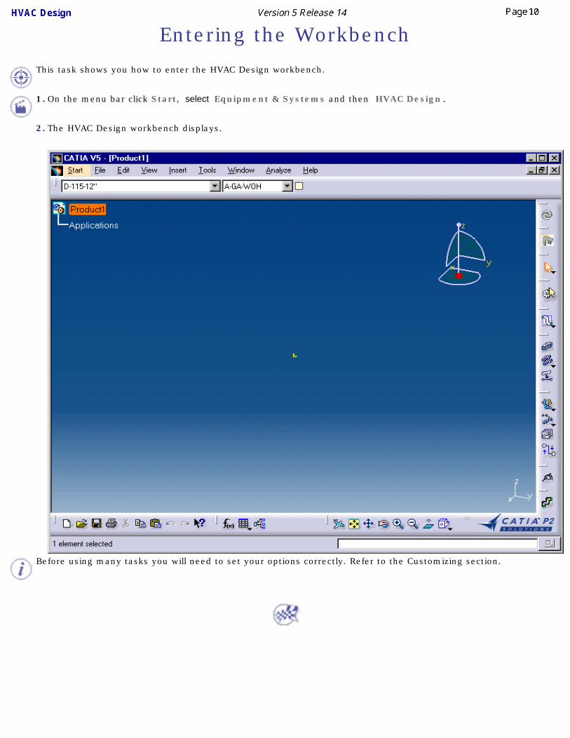
Entering the Workbench
This task shows you how to enter the HVAC Design workbench.
1. On the menu bar click Start, select Equipment & Systems and then HVAC Design.
2. The HVAC Design workbench displays.
Before using many tasks you will need to set your options correctly. Refer to the Customizing section.
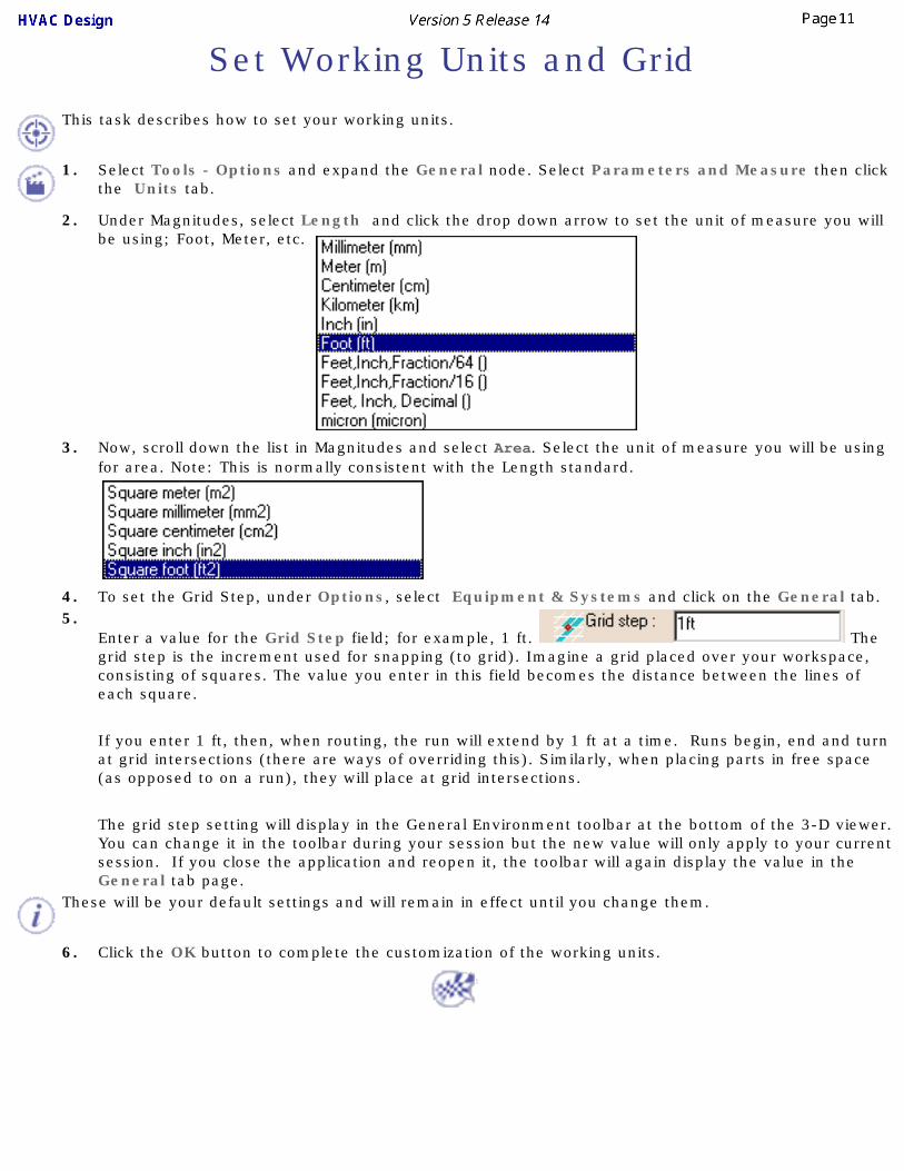
Set Working Units and Grid
This task describes how to set your working units.
1. Select Tools - Options and expand the General node. Select Parameters and Measure then click the Units tab.
2. Under Magnitudes, select Length and click the drop down arrow to set the unit of measure you will be using; Foot, Meter, etc.
3. Now, scroll down the list in Magnitudes and select Area. Select the unit of measure you will be using for area. Note: This is normally consistent with the Length standard.
4. To set the Grid Step, under Options, select Equipment & Systems and click on the General tab.5.
Enter a value for the Grid Step field; for example, 1 ft. The grid step is the increment used for snapping (to grid). Imagine a grid placed over your workspace, consisting of squares. The value you enter in this field becomes the distance between the lines of each square.
If you enter 1 ft, then, when routing, the run will extend by 1 ft at a time. Runs begin, end and turn at grid intersections (there are ways of overriding this). Similarly, when placing parts in free space (as opposed to on a run), they will place at grid intersections.
The grid step setting will display in the General Environment toolbar at the bottom of the 3-D viewer. You can change it in the toolbar during your session but the new value will only apply to your current session. If you close the application and reopen it, the toolbar will again display the value in the General tab page.
These will be your default settings and will remain in effect until you change them.
6. Click the OK button to complete the customization of the working units.

Changing the Current Axis
This task shows you how to change the current axis.
When you activate an object, the current axis is reset to the axis of that object. Changing the current axis changes the reference point by which elements are routed and placed.
1. Click the Change Current Axis icon .2. Select the object you want to use as a reference.
The axis for the selected object is displayed.3. You can also change the current axis and place the compass on the object. The compass allows you
to manipulate that object. To do this click the Change Current Axis and Snap Compass button and select the object. The axis and compass are both placed.

Creating a Run
This task describes how to create a run. When you create a run you "reserve" space in your work area so that you can later place ducts and parts. In the example below you will create a run in "free space". In actual practice you will create runs in a much more controlled environment - the deck of a ship, or floor of a house, for instance. In the example below it does not matter where you begin or end a run - but when you are working on a project you will have to start and end at specific places, and your run will have to be a certain size and shape. For more information on runs and routing see Routing a Run.
You will learn more about line IDs later, but you should know that a run is associated with a line ID.
A line ID is an organizational element that identifies the type and nominal size of the run (e.g., HVAC, 10 in.) but may also include attributes such as duct specification, material category, design temperature and pressure, flow rate, etc. These properties of the line ID ensure that the parts you place meet the requirements of the line ID and the intended design. Thus, when you make a run it is part of a line ID.
The line ID of your run is displayed on the upper toolbar on the left hand side.
To learn more, including how to select a line ID, see Managing HVAC Lines.
1.Click the Route a Run button . The Run dialog box opens.
Note: If the Design Rule: Multiple Rule Found dialog box opens, this means there is more than one type of run to choose from. For example, there could be multiple choices for Turn Radius, Diameter Factor or Number of Miter Cuts. For this scenario the choice is unimportant because you are learning the fundamentals of creating a basic run. Select from the table and click OK.
2.
In the Run dialog box select either Point-To-Point or Orthogonal for the routing Mode. 3. In HVAC Design, the Section Type buttons appear in the Run dialog box
. The section choices are No Section, Rectangular Section, Round Section, Flat Oval Section or Radius Corner Section. Leave this set to Rectangular Section.
Click the Section button and make sure the display setting is set to Solid . Click OK in the Section dialog box.
This returns you to the Run dialog box. Section dimensions, Turn radius and Minimum length fields display the default values of the line ID being used.
For more information on the settings and options used in the Run and Section dialog boxes see Routing a Run.

4. To begin your run, click at any point, move the pointer in any direction, and click again. This is the first segment of the run. Now move the pointer to the next position and click. Create a simple run with three segments as show below.
5. Double click to complete routing. The run displays as a solid.
6. You have created a run with three segments. You are now ready to place ducts and other parts in it.
Placing a Part on a Run
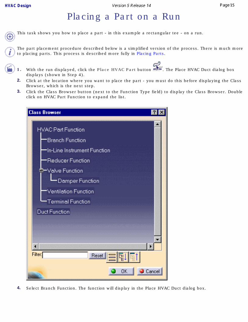
This task shows you how to place a part - in this example a rectangular tee - on a run.
The part placement procedure described below is a simplified version of the process. There is much more to placing parts. This process is described more fully in Placing Parts.
1. With the run displayed, click the Place HVAC Part button . The Place HVAC Duct dialog box
displays (shown in Step 4).2. Click at the location where you want to place the part - you must do this before displaying the Class
Browser, which is the next step.3. Click the Class Browser button (next to the Function Type field) to display the Class Browser. Double
click on HVAC Part Function to expand the list.
4. Select Branch Function. The function will display in the Place HVAC Duct dialog box.
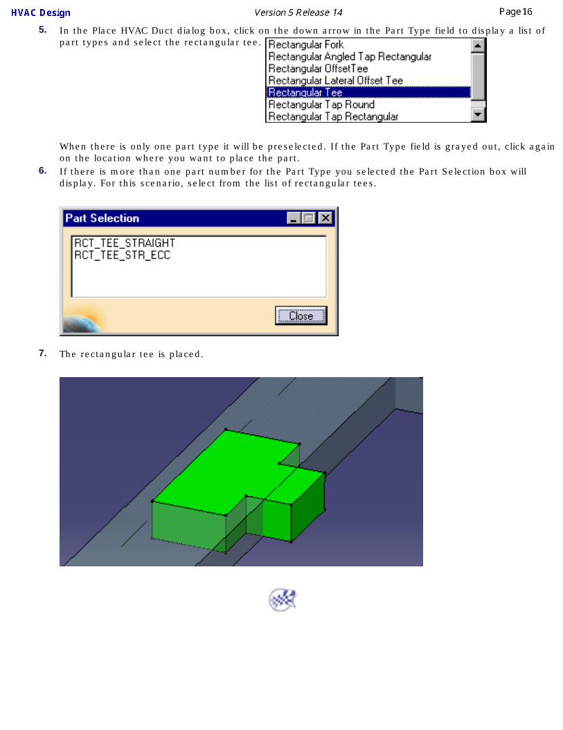
5. In the Place HVAC Duct dialog box, click on the down arrow in the Part Type field to display a list of part types and select the rectangular tee.
When there is only one part type it will be preselected. If the Part Type field is grayed out, click again on the location where you want to place the part.
6. If there is more than one part number for the Part Type you selected the Part Selection box will display. For this scenario, select from the list of rectangular tees.
7. The rectangular tee is placed.

Saving Documents
This task contains recommendations on saving your documents.
Ways in which documents are saved are explained in the Infrastructure User's Guide - Creating, Opening and Saving Documents. You must read that documentation because the various methods are not explained here. This task simply suggests the methodology you should follow in specific circumstances.
1. If you are saving a document to a local machine or network drive it is recommended that you use the "Save Management" command initially. The Propagate Directory command (which is in the Save Management dialog box) should not be used routinely. It is meant to be used in specific circumstances, such as when you want to place all the contents of a document in one directory before sending it to another location.
2. If you are saving a document to another site or network you should use the "Send To" command. In this case, you should be careful about the links for documents such as resolved parts folder or line ID. These links could change to reflect the local network drive to which the documents have been sent. You should make sure they point to the original location - using the Reset button in the Save Management dialog box is one way of doing this.
3. You should check the active document before you execute the Save command . The root product must be the active document if you want to save everything under it.
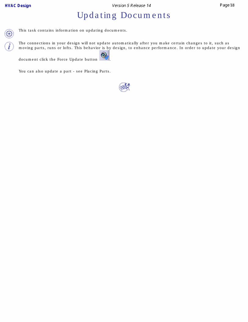
Updating Documents
This task contains information on updating documents.
The connections in your design will not update automatically after you make certain changes to it, such as moving parts, runs or lofts. This behavior is by design, to enhance performance. In order to update your design
document click the Force Update button .
You can also update a part - see Placing Parts.

User TasksThe tasks for creating documents using the HVAC Design product are explained here.
Managing HVAC LinesRouting Runs
Modifying RunsConnecting ElementsManipulating Objects
Query/Modify Properties of an ObjectPlacing & Modifying an HVAC Part
Analyzing NetworksManaging Fabrications
Flow DirectionRouting Tasks
Building HVAC PartsUsing ENOVIA
Creating and Modifying ConnectorsTransferring a Document to Another Site
Defining HVAC SectionsPenetration Management Usage
Drawing ProductionHole Placement
Schematic Driven DesignMigrating V4 Models to V5

Managing HVAC LinesMethods of managing HVAC lines are discussed in this section.
Also see the Customizing section for information about Line ID catalogs.
Creating a Line IDQuerying a Line ID or its Members
Select/Filter Line IDsTransfer Members of a Line ID
Deleting a Line IDRenaming a Line ID
Modifying the Properties of a Line IDMerging Line IDs
Importing Line IDs

Creating a Line IDThis task describes how to create a line ID.
You need to create a line ID before you can begin routing and placing components and equipment. A line ID is a mechanism for identifying and organizing ducting or piping segments and the components and equipment you place in them. When you create a line ID you also assign characteristics; material, size, pressure attributes, heat tolerance and so on.
The line ID displays in the specifications tree as an organizational element. The routes you create and the components you place under it, will appear in the specifications tree and will also display as a 3D image. The line ID will appear in the specifications tree with the name you assigned it or its default name. Each run segment you route will show as ArrRunX, X being a unique number assigned in sequence. Components and equipment will show as YYYFunction.X, YYY being a component name and X being a unique number, i.e. PumpFunction.1.
To store line IDs that you create, the default directory as defined in the Project Management resources must be set for read/write file permission. Contact your system administrator to add line IDs or directories for line lists. Also see the Customizing section for information about Line ID catalogs.1.
Click the Create Line ID button . The Create Line ID dialog box displays.
2. Enter a name for your new ducting line in the Line ID field or you can accept the default name by clicking Set to default.
3. The Line ID Filename field is only available if you have set an option. Click Tools - Options, select Equipment and Systems and the Design Criteria field, and check the option User Defined Filename. To explain what this is, every time you create a line ID, this application creates a system file for it. Normally this file is named in such a way that users cannot recognize it. If you want to give this file your own name then enter it in this field.
In creating a new line ID you need to establish certain properties for the line ID that will affect the line you are creating. You may enter all known characteristics for the new ducting segment but at a minimum you must assign values for Duct specification properties.4. Click the Properties button to open the Properties dialogue box. Click the HVAC tab and, using the
drop-down arrows, select from the choices available or enter your own in the fields available to assign properties to the line ID you are creating.
In HVAC Design the Duct Specification and Insulation Specification include default values for certain attributes. When you select a Duct Specification and Insulation Specification from the drop-down menu (see below), notice that certain fields are propagated with default values associated with that specification. These attributes can be changed as needed.

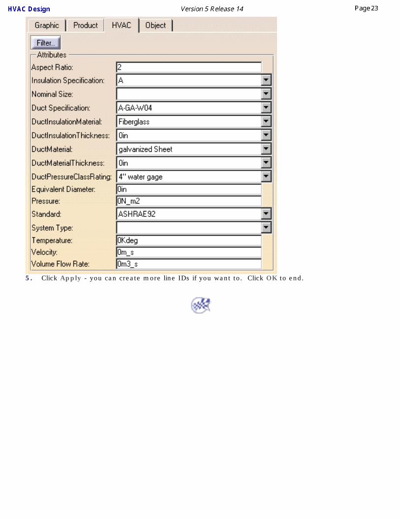
5. Click Apply - you can create more line IDs if you want to. Click OK to end.

Querying a Line ID or its Members
This task shows you how to query a Line ID or its members.
When you query a member you are asking which line ID it belongs to. When you query a line ID you are asking which members belong to it.
1.Click the Select/Query Line ID button . The Selecting/Query Line ID dialog box appears.
2. Use the Sort and Filter options as needed. Under Filter, select the Local option if you want to filter line IDs in the document. Select All if you want to filter all line IDs available to you. The Filter String field allows you to enter a line ID name - you can use wild cards. Clicking the Filter Attributes button brings up the Line Attribute Filter dialog box. See Select/Filter Line IDs to learn more about filtering.
3. To perform a query, click a line ID in the Filtered Line ID list. The members of that line ID will be highlighted. To query a member click on it in the document. All members that belong to the same line ID will be highlighted and the line ID will be highlighted in the dialog box.


Select/Filter Line IDs
This task shows you how to select a line ID or its members, and to filter for line IDs. Piping lines are used in the illustration below - the process is the same for other types of line.
You can edit the properties of line IDs or their members after selecting them. You must make some setup changes if you want to see all properties of a line. See Displaying Line ID Properties in a Catalog to learn how to do it.1.
Click the Select/Query Line ID button . The Select/Query Line ID dialog box displays.
2. Use the Sort and Filter options if you need to. Under Filter, select the Local option if you only want to filter line IDs in the document. Select All if you want to filter all line IDs available to you. Use of the Filter Attributes button is explained below.
3. If you are selecting members then select Line ID Members under Selection Type. If you want to select a line ID then select Line ID.

4. Click to select a line ID in the Line ID list or click on one of the members. Either the line ID or the members will be selected, depending on the selection you made in Step 2.
5. Click the Filter Attributes button is you want to filter for line IDs. The Line Attribute Filter dialog box displays.

6.● Click the drop down arrow in the Attributes field to select a property. Name is selected in the image
above.
● Click the drop down arrow in the Operators field to select an operator. Most are obvious, such as == (equal to) or > (greater than). the operator *= means you are using a wild card. If you select this operator and enter U8 in the Values field then the function will filter for all lines beginning with U8.
● Select or enter a value in the Values field. This is the value that the function will filter for. Click Add when you have defined your query to add it to the Composed Query window.
● The And/Or buttons let you further refine your search. You can click the And button to add another query to your search.
● Clicking the Eraser button removes a query from the Composed Query window.
● The Filter String field allows you to enter a line ID name - you can use wild cards.

Transfer Members of a Line ID
This task shows you how to transfer members from one line ID to another line ID.
1.With your document open, click the Transfer Line ID button . The Transfer Members of Line IDs dialog box displays, showing all the line IDs contained in your document.
2. Select the line ID to which you want to transfer a member. (When you select a line ID all members that belong to it are highlighted.)
3. Click on the member that you want to transfer. It will be transferred to the line ID you had selected.4. You can also use a feature called multi-select to transfer several members at one time. To do this:

5. Select the members you want to transfer by clicking and dragging. They will change color once they are selected.
6. Click the Transfer Line ID button. The Transfer Members of Line IDs dialog box appears.7. Select the line ID to which you want to transfer the members. You will be alerted that you are about
to transfer the members.
8. Click OK. The members will be transferred.The line ID and member must be compatible for the transfer to take place.

Deleting a Line ID
This task shows you how to delete a Line ID.
1.Click the Delete Line ID button . The Delete Line ID dialog box displays, showing all the line IDs contained in your document.
2. Select the line ID that you want to delete. (When you select a line ID all members that belong to it are highlighted.)
3. Click OK. If the line ID you selected has members a message will display alerting you that all members belonging to that line ID will be deleted.
4. Click OK. The line ID and all its members will be deleted.

Only line IDs contained in your document will be deleted. The same line ID used in other documents will not be deleted unless you open those documents and follow the steps given above.
Renaming a Line ID
This task shows you how to rename a Line ID.
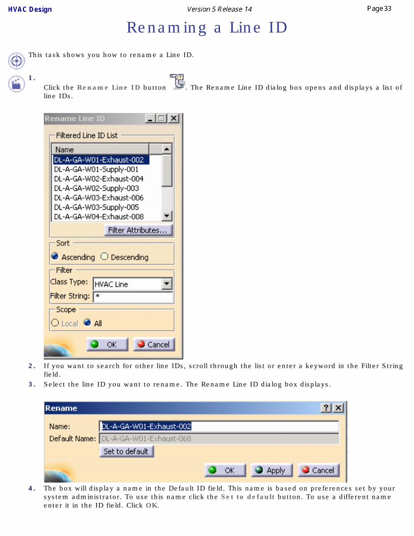
1.Click the Rename Line ID button . The Rename Line ID dialog box opens and displays a list of line IDs.
2. If you want to search for other line IDs, scroll through the list or enter a keyword in the Filter String field.
3. Select the line ID you want to rename. The Rename Line ID dialog box displays.
4. The box will display a name in the Default ID field. This name is based on preferences set by your system administrator. To use this name click the Set to default button. To use a different name enter it in the ID field. Click OK.

5. Click OK again in the Rename Line ID box. The line ID will be renamed.

Modifying the Properties of a Line ID
This task shows you how to modify the properties of a Line ID.
1.With your document open, click the Select/Query Line ID button . The Select/Query Line ID dialog box displays, showing all the line IDs contained in your document.
2. Select the line ID whose properties you want to modify.3. Under Selection Type select Line ID.4. Click the Properties button. The Properties dialog box will display.5. Enter your changes and click OK.

Merging Line IDs
This task shows you how to merge the members of one line ID into another line ID.
1.With your document open, click the Merge Line ID button . The Merge Line IDs dialog box displays, showing all the line IDs contained in your document.

2. Select the line ID you want to merge. All members that belong to that line ID will be selected. The lower field will display the line IDs to which it can be merged.
3. Select the line ID into which you want to merge and click OK. All members of the first line ID will merge into the line ID you selected, and the first line ID will be deleted.
You cannot merge incompatible line IDs. Also, members of the line ID that was merged into another will assume the properties of the line ID into which they were merged.

Importing Line IDs
This task shows how to import and/or update HVAC Line IDs.
The Import Line ID feature offers the user the utility of importing Line IDs from existing databases in other CAD software products. The Update feature allows you to update the properties of existing line IDs with properties contained in an XML import file.
Installation of the Document Type Definition (DTD) and knowledge of XML are prerequisite to using this feature. The file format for the Line ID XML Import File resides in the DTD.
The location of the DTD and sample XML file is platform dependent. In Windows the path for the DTD is ...\intel_a\startup\EquipmentAndSystems\HVAC\SampleData\PlantShipLineIDImport.dtd.
For the XML file, the path is...\intel_a\startup\EquipmentAndSystems\HVAC\SampleData\HVACLineIDImportsample.xml.
The paths for the other platforms are identical with the exception of the platform identifier. Shown below are the platforms with their respective identifiers.
● Windows: ...\intel_a\
● AIX: .../aix_a/
● HPUX: .../hpux_a/
● IRIX: .../irix_a/
● SOLARIS: .../solaris_a/
In all cases, copy the PlantShipLineIDImport.dtd and the HVACLineIDImportsample.xml file to a local directory with 'write access'.
In the following scenario both the sample XML file and the DTD have been copied to a user Temp directory.
A portion of the sample XML file is shown below:
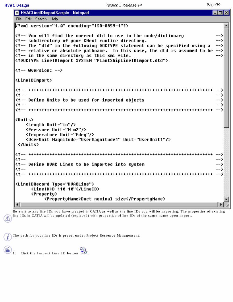
Be alert to any line IDs you have created in CATIA as well as the line IDs you will be importing. The properties of existing line IDs in CATIA will be updated (replaced) with properties of line IDs of the same name upon import.
The path for your line IDs is preset under Project Resource Management.
1. Click the Import Line ID button .

2.
The Line ID Import/Update dialog box opens. Click to open the file. This will cause the subroutine to run which will generate the line IDs from the XML file. Note that under Files of type, only XML files may be displayed and opened.
3. When the routine is complete, the Results Summary will display.

4. Click View output file to view the Line ID Import/Update Report for the sample case below.

5.You can verify that the new line IDs have been imported by clicking the Select/Query Line ID button . The Select/Query Line ID dialog box opens showing the updated and imported line IDs.

Routing RunsRouting runs, including routing runs in special circumstances, are explained here.
Routing a RunBranching a Run
Routing from the End of a RoutableRoute a Run Within a Pathway
Routing a Run at a SlopeAuto-route Between Equipment
Routing from an Item ReservationRouting from a Section at the End of an HVAC Part
Display Information About RoutablesChecking Turn Radius Errors
Routing FlexiblesManaging Local Slack

Routing a RunThis task shows you how to create a run.
You can begin routing a run from: ● Space.
● An object, such as a duct.
● The end of a run or middle of a run.
● A point.
● Connectors.
● Item reservation face.
1.
Click the Route a Run button .
The Run dialog box is displayed.

2. Define the routing mode for the run:
Point-to-point: routing will be directly between two points indicated by clicking.
Orthogonal: routing between two points will proceed first in the X direction, then in the Y direction.
Slope routing: see Slope Routing.
Directional routing: see Routing with a Compass.
Edgeline: see Edgeline Routing.

Branch at Center: see Branching a Run.
Click one of the Select Mode buttons - the default is No Filter.
No Filter: No filters are applied and you can route from any routable object or in space.
In Space: Routing will be in space. This is useful when you have a large object in the background, such as a ship structure, and you want to be able to route in space.
Only Part Connectors: Select this to be able to route from part or equipment connectors only.
Section dimensions, Turn radius and Minimum length fields display the values given to the Line ID being used. Click the Section icon. The Display buttons allow you to select a display mode of Line/Curve or Solid. Click the Display Centerline button to show the centerline of the run. This will appear as a dashed yellow line. In addition a blue line will appear to display the Set Point setting. This feature works in both the Line/Curve and Solid display modes.
3. Define the Section parameters:
a. Select the Section Type button.
The Section dialog box displays.

Select the Set Point, enter the Envelope dimensions (if applicable) and select a display. Click OK.
b. In the Run dialog box, define the section type and corresponding parameters for each of them:
No Section
Rectangular. Enter or select the:
● Inside Height
● Inside Width
Circular
● Inside Diameter
Flat Oval
● Inside Height

● Inside Width
Radius Corner
● Inside Height
● Inside Width
● Radius Corner
Instead of entering the type of run, the set point and the height, width or diameter in the Section dialog box, you can select an existing run in your document. Once selected, the Section dialog box will display the values for that run. To select, click on the Run button and then click on the run whose values you want as the default. Make sure the entire run is selected - not just a segment or a node. It will be easier to select the run in the specifications tree.
4. Enter values for the minimum length and turn radius.
If you enter a minimum length or turn radius you will not be able to route correctly unless these values are satisfied. For instance, if you enter a minimum length of 10 feet, you will not be able to complete a segment that is 5 feet. In the illustration below, the green line shows the minimum segment length that will be created, even if you try to make a shorter segment, because the minimum length you entered is longer than the segment you are now trying to create. Similarly, if you enter a value for the turn radius, your run will automatically be adjusted to satisfy the defined turn radius.
5. Click in the drawing to define the routing points.6. Double-click on the last point to stop routing.
You can also click OK in the Run dialog box to stop routing. Click Cancel to abort your routing.
7.
Click on the Close Loop symbol that shows at the beginning of the run if you want to create a closed loop run. In a closed loop run the ends of the run are joined.

8.
When starting a run from a part, a run that is a continuation of an existing run, or if branching from an existing run use the following buttons as needed:
Get Line ID from Selection: gets the line ID from the run or part you are routing from.
Get Line Size/Spec from Selection: gets the size and spec from the run or part you are routing from.
9.
The Change to Schematic Mode button lets you toggle between schematic and non-schematic mode. You will exit the command when you click this button and need to click the Route Run command again.
Branching a RunThis task explains how to branch a run from any of these elements:
● Another run
● Boundary
● Contour
● Pathway
If the "source" element (i.e., the element from which the run branches) is moved or resized, the run is adjusted accordingly.1. With your document open, select the Route a Run button.
The Routing dialog box is displayed.2. Define the parameters for the run.
See Routing a Run for instructions.3. Select the element from which you want to route the run and begin routing.
4.
If you want to branch from the center of the segment, click the Branch at Center button in the Run dialog box. The branch will begin from the center of the segment, irrespective of the point in the segment that you route from.
If you want to create a run that "branches" from the end of a run, see Routing from the End of a Routable.

Routing from the End of a Routable
This task explains how to route from the end of a routable.
If you route an element with the same type and parameter values as the "source" element (i.e., the element from which the routable is routed), you can specify whether the new element is a continuation of the source element or a separate element. If you want to use the "Continue" option, be sure that the parent for the source element is active before you begin.
1.
Select the Route a Run button .
The Routing dialog box is displayed.
2. Define the routing parameters.
See Routing a Run for instructions.
3. Move the pointer to the end from which you want to route. When a green arrow appears, click and
begin to route. Double click to end routing.
4. Once you begin routing the following buttons are added to the Routing dialog box:
Continue Routing: If you select this the run you create will be part of the run from which you are routing.
Create New Route: If you select this the run you create will be a new run.

5. When starting a run that is a continuation of an existing run, a branch from an existing run, or routing from an object or equipment (nozzle) use either or both of the following buttons as applicable:
Get Size/Spec from Selection: If you select this button the run you create will be a new run but will assume the size and specification attributes of the run or object you are routing from.
Get Line ID from Selection: If you select this button the run you create will assume the same line ID as the run or object from which you are routing. If you de-select it, the new run will belong to the line ID displayed in the menu bar.

Route a Run Within a Pathway
This task shows you how to route a run within a pathway.
1.With your pathway document open, click the Route Thru a Pathway button.
2.From the Section dialog box, select the type of run, the set point and other options.
3.Click on the pathway in which you want to route your run. This displays set points on the pathway. Select a position for the run by clicking on one of the points. For example, if you select Top Center the run will align to the top center of the pathway. You can click Apply in the Run dialog box to see how the run looks and to try different positions. Click OK when you are finished.
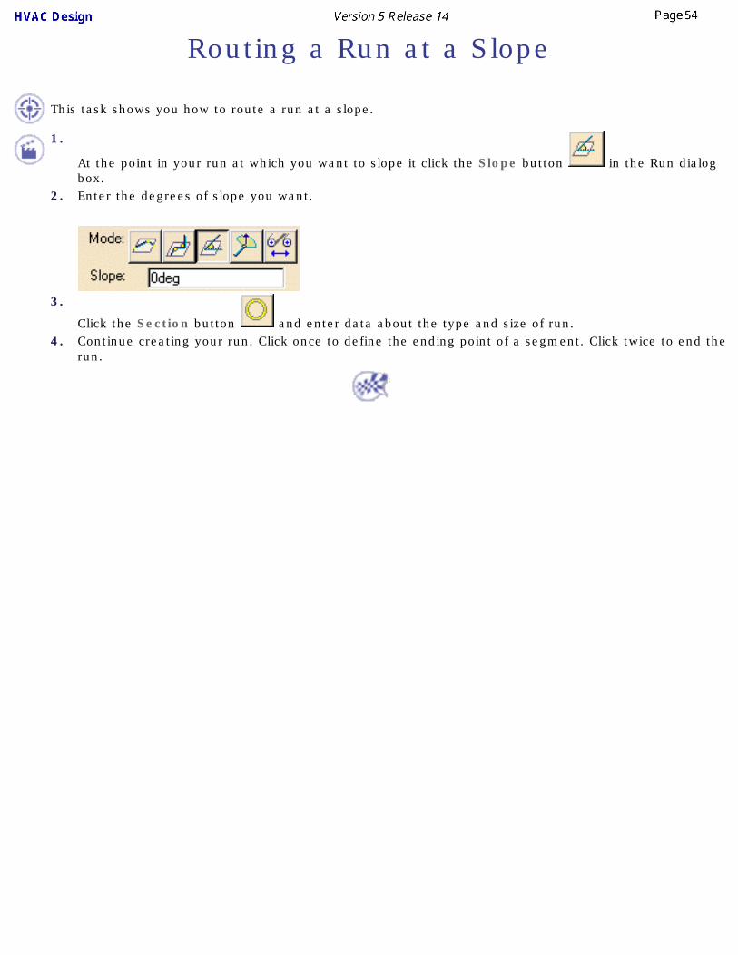
Routing a Run at a Slope
This task shows you how to route a run at a slope.
1.
At the point in your run at which you want to slope it click the Slope button in the Run dialog box.
2. Enter the degrees of slope you want.
3.
Click the Section button and enter data about the type and size of run.4. Continue creating your run. Click once to define the ending point of a segment. Click twice to end the
run.
Auto-route Between Equipment
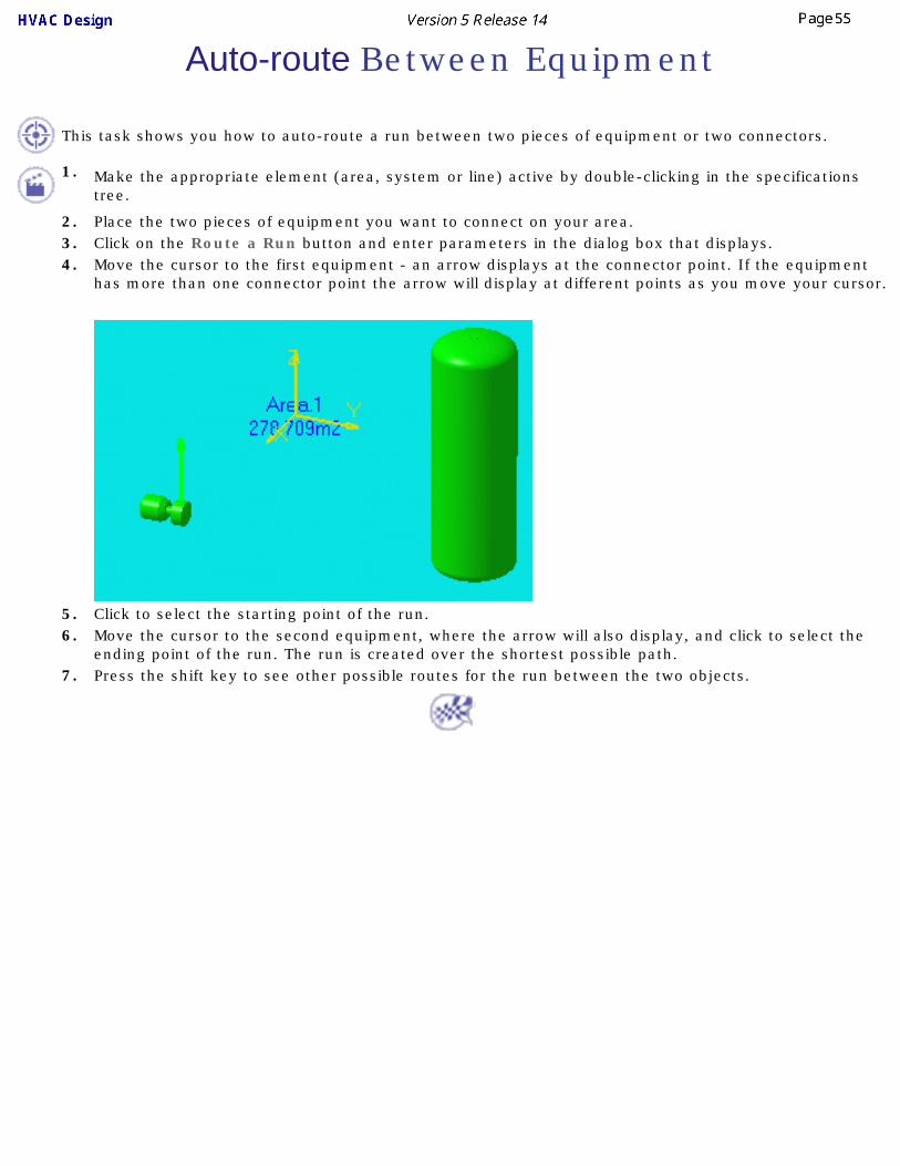
This task shows you how to auto-route a run between two pieces of equipment or two connectors.
1. Make the appropriate element (area, system or line) active by double-clicking in the specifications tree.
2. Place the two pieces of equipment you want to connect on your area.3. Click on the Route a Run button and enter parameters in the dialog box that displays.4. Move the cursor to the first equipment - an arrow displays at the connector point. If the equipment
has more than one connector point the arrow will display at different points as you move your cursor.
5. Click to select the starting point of the run.6. Move the cursor to the second equipment, where the arrow will also display, and click to select the
ending point of the run. The run is created over the shortest possible path.7. Press the shift key to see other possible routes for the run between the two objects.
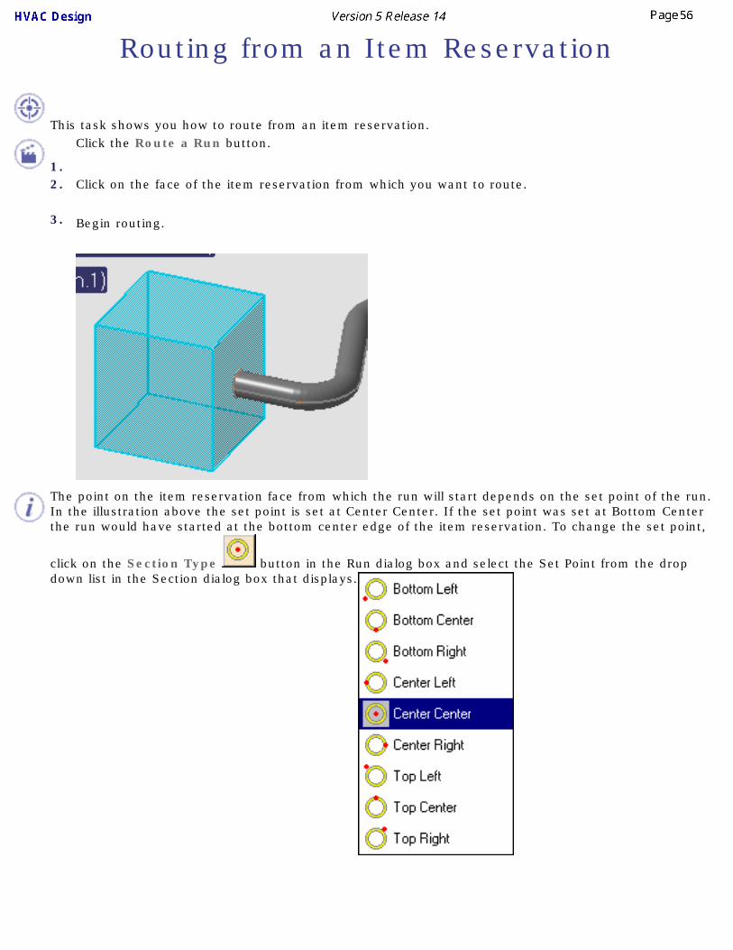
Routing from an Item Reservation
This task shows you how to route from an item reservation.
1.
Click the Route a Run button.
2. Click on the face of the item reservation from which you want to route.
3. Begin routing.
The point on the item reservation face from which the run will start depends on the set point of the run. In the illustration above the set point is set at Center Center. If the set point was set at Bottom Center the run would have started at the bottom center edge of the item reservation. To change the set point,
click on the Section Type button in the Run dialog box and select the Set Point from the drop down list in the Section dialog box that displays.

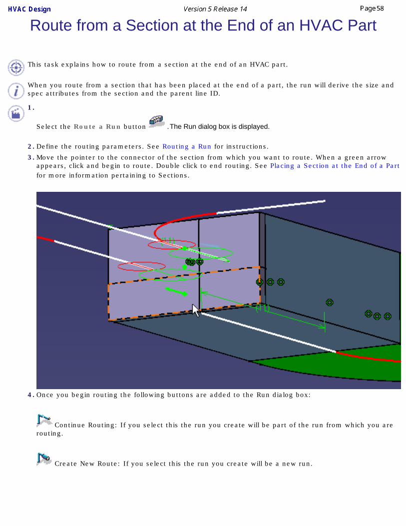
Route from a Section at the End of an HVAC Part
This task explains how to route from a section at the end of an HVAC part.
When you route from a section that has been placed at the end of a part, the run will derive the size and spec attributes from the section and the parent line ID.
1.
Select the Route a Run button .The Run dialog box is displayed.
2. Define the routing parameters. See Routing a Run for instructions.
3. Move the pointer to the connector of the section from which you want to route. When a green arrow appears, click and begin to route. Double click to end routing. See Placing a Section at the End of a Part for more information pertaining to Sections.
4. Once you begin routing the following buttons are added to the Run dialog box:
Continue Routing: If you select this the run you create will be part of the run from which you are routing.
Create New Route: If you select this the run you create will be a new run.

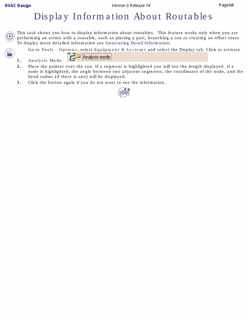
Display Information About Routables
This task shows you how to display information about routables. This feature works only when you are performing an action with a routable, such as placing a part, branching a run or creating an offset route. To display more detailed information see Generating Detail Information.
1.
Go to Tools - Options, select Equipment & Systems and select the Display tab. Click to activate
Analysis Mode. 2. Place the pointer over the run. If a segment is highlighted you will see the length displayed. If a
node is highlighted, the angle between two adjacent segments, the coordinates of the node, and the bend radius (if there is one) will be displayed.
3. Click the button again if you do not want to see the information.

Checking Turn Radius Errors This task shows you how to check your document for turn errors. This command determines if any of the turns have values that are in violation of the parameters as defined in the Turn Design Rule. See also Using the Definition Dialog Box.
1.
With your document open click the Validate Run Turns button . The Validate Run Turns dialog box displays.
If a run is already selected it will display in the window.2. Select one of the options:
● Current selection lets you select runs in your document.
● All runs under the active parent in the specifications tree.
● All runs created under a particular Line.
3.After you make your selection, the runs will display in the window in the Turn Rule Used column with their status indicated by a YES or NO - NO means one or more turns in that run does not conform to the turn rules.
If you click the Select All NO button then all runs that are in violation of the turn rules will be selected.

4.Select the run you want to validate in the dialog box window - the run will highlight in the viewer. Click the Run Details
button to see information about the run in the Run Details dialog box.
If you want to reset some of the turns in a run then select them in the Run Details dialog box and click the Reset Run
Turns button . The turn radius for the selected turns will be reset according to the design rules. If the line has more than one turn radius or diameter factor then the Multiple Rule Found dialog box will display. Select one of the values - it will apply to the selected turns.
5.If you want to reset all the turns in a run then select the run in the Validate Run Turns dialog box and click the Reset Run Turns button. (If the line has more than one turn radius or diameter factor then the Multiple Rule Found dialog box will display. Select one of the values.) All turns in the run will be reset according to the design rule.

Routing Flexibles
This task shows you how to route using flexibles.
Flexibles can be routed in space, from another part (tube, conduit or waveguide) or from an item reservation (you may need to add a connector). When you route a flexible you are placing the actual part, such as a tube. A run is not created when you route a flexible, which is why they cannot be routed from a run. To route from a run you must put a part at the end node of the run.
The first and last points of a flexible tube can either be a 3D point in space, an indication point, or a connector that contains a datum point. The inner points can be a 3D point selection or an indication in space on the current compass plane.1.
To begin routing in space, click the Flexible Routing button . The Flexible Routing dialog box opens.
● Check the Spec driven box if you want your selected specifications catalog to apply.
● Check the diameter factor box and enter a value - this will define the bend radius (the bend radius will be the factor multiplied by the part size). If you do not check this box then the bend radius will be derived from the bending rule table.
● Select a mode. The Length mode is used when you know the distance between two points (or use a grid) and want to specify a length. The Slack mode gives you slack. You can enter a value in the Slack % field. If you select the Bend mode then the bend radius will equal the value in the

Bend radius field and, in addition, the run will find the shortest route between two points.
● If you check the Ignore Slack checkbox when routing then that particular segment will have no slack in it. This option can only be used a segment at a time while routing.
● Enter values in the Straight Length at Ends fields. You can have a specified straight length at the ends, such as where a tube connects to an object. If you do not specify a straight length then the tube may angle out from the object, instead of being straight.
2. Click in space where you want to begin your route and click two more points to create a simple run. Click Apply. Your flexible run should look similar to this.
3. In the Build Mode panel of the Flexible Tube Routing dialog box, change the value in the Slack % field to 20 and click Apply.
The tube adjusts to reflect the additional slack. Note that the selected points remain in position. Now, change the Mode to Length to increase the value and click Apply. Now the slack value will increase and the run will be updated. To adjust the slack of a segment see the section on Managing Local Slack.

4 Create another flexible route and connect it at a sharp angle to the first run. We have made the first run red for illustration purposes.
5 To resolve the misalignment of the two splines, double click the spline on the run you wish to correct. In this case we will correct the blue run. Part Design will open. Double click the spline again. The Spline Definition dialog box opens displaying the points of the spline.
The Spline Definition dialog box will list the points of the run. The last point will be highlighted when the dialog box opens though it may not be the point you want to edit.
The first point (Point 1) contains the data that determines the flexible's shape. Do not delete this point.6. Select the point you want to edit in the Spline Definition dialog box. The points are numbered in the
order they were placed. In this case, Point 4 is the point we will edit.

7. Zoom in as necessary to select the face of the route you want to align with and click when the Face/Rib.1/Double cue appears. The Tangents Dir value for Point 4 will display Surface.1.

8. Click Apply. The tangent will become normal to the face and the splines will be aligned.
9.When you click Apply you can continue correcting other connections. Click OK when finished.

Managing Local Slack
This task shows you how to manage local slack. When you manage local slack, you adjust the slack of a segment of a flexible tube, conduit or waveguide.
In the following scenario we have created an item reservation with connectors on either end and then routed a flexible through it. The inherent slack in the flexible route has caused the second segment to exceed the boundary of the item reservation.
1.
With your document open select the flexible route and click the Manage Local Slack button . The Local Slack Management box will open and the route will highlight red.
To manage the slack of a given segment, click the starting point and ending point of the segment you want to adjust.
Click the Ignore slack button . The slack for the segment will be reduced to 0 and the segment will become straight.
To increase slack to a segment, click the Add slack button . The Slack Definition field will become active so that you can edit the length. The value in the Slack Definition field is the length that will be added to the flexible, thus increasing its slack. You may also enter a negative value to decrease the slack.2. Select the points on both ends of the segment you want to adjust; in this case the segment in the
item reservation.

3. Click the Ignore Slack button. The segment has become straight and is now within the limits of the item reservation.
4. Click Apply if you have more segments to adjust; or click OK to close the Local Slack Management box.

Modifying RunsRuns can be modified in the following ways.
Using the Definition Dialog BoxChanging a Section
Changing the Angle of a SegmentMoving Nodes
Align Adjacent SegmentsMake Segment Parallel to Reference Plane
Make Segment Parallel to Compass Base PlaneMake Segment Parallel to Z AxisFit Segment for Parts Assembly
Position Segment Relative to a PlaneCreate an Offset Connection Between Segments
Create a Closed Loop RunOpen a Closed Run
Adjust Extremities of a RunTransfer Run to Another Document

Using the Definition Dialog Box
This task gives you an overview of the definition dialog box. You can make modifications to a routable using the functions contained in this box. Specific task-oriented modifications are explained elsewhere in this section.You should be familiar with the concepts explained in Routing a Run to be able to take full advantage of these functions. Note that some applications, like Systems Routing, do not utilize design rules and the no-rule conditions apply to them.
1. Right click on a routable and, in the drop down menus that display, select the routable (in this case Run-0049 object) and then Definition.
2. This brings up the Definition dialog box.
3. The Name field allows you to change the routable's instance name.4. The Section button lets you change section parameters, as explained in Routing a Run.
5. Click one of the Turn Type buttons if you want to change the turn type. ● No Turn: The turn radius for all turns is changed to 0. The Turn Radius field is not displayed.
● Uniform Turn: All turns in the run have the same turn radius.
● Mixed Turn: Turns in the run can have different turn radius.
6.
The Press to Use Rule button indicates if you are using the design rules. In the image above it is on, which is why the Turn Radius and Minimum Length fields are grayed out. You can click the button to go to a no-rule state, in which case the Turn Radius and Minimum Length fields will no longer be grayed out. See Routing a Run for more information.

7.
The Display Error Report button is green when there is no error in the run. It turns red when you insert a value or make some other change to cause an error. Click the button to display a report. This error function checks to make sure that the turn radius and minimum length conform to the design rule.
8. The Turn Radius field displays the turn radius. To change it you need to display the Node Definition dialog box (see Moving Nodes) and enter a value. If you introduce an invalid turn radius, by entering a value in the Node Definition dialog box, then the Display Error Report button will turn red. (You can also introduce a turn radius error by shortening the length of one or both segments.) A red arc will also display on your run. The ends of the arc are the minimum point to which each segment should be routed for a valid turn. In the example below, the segment is not long enough to support the turn radius value entered by the user.
9. The Node Edit Table button displays a table containing node values - see Moving Nodes.
10. The Minimum Length field displays the minimum length of each segment. You cannot change the value in this field if you are using design rules.
11. The Total Length field displays the total length of the run. You cannot change the value in this field.

Changing a Section
This task explains how to change parameters that control how the section of an element is displayed.
1. Place your cursor over the element and click the right mouse button.
2.From the pull-down menu, select the element or object you want to modify and select Definition. The Run Definition dialog box is displayed.
3. Click the Section button to set the desired section shape to No section, Rectangle, Round, Flat Oval, Radius Corner or Double Ridge.
When defining the Section parameters the section Types that are available depend on which workbench you are in. For example, Piping Design, Tubing Design and Conduit Design use only the round section while Systems Routing offers all section types.
4.If you select Rectangular Section, you can define or change these parameters:
● Set Point
● Height
● Width
● Display
If you select Round Section, you can define or change these parameters:
● Set Point
● Diameter
● Display
If you select Flat Oval Section, you can define or change these parameters:
● Set Point
● Height
● Width
● Display
If you select Radius Corner Section, you can define or change these parameters:
● Set Point
● Height
● Width

● Display
● Radius Corner
If you select Double Ridge Section, you can define or change these parameters:
● Set Point
● Height
● Width
● Display
5. Click OK on the Section dialog box and OK on the Definition box to complete the change..

Changing the Angle of a Segment
This task shows you how to change the angle of a pathway, boundary, or run segment.
1. Place your cursor over the element and click the right mouse button.
2. From the pull-down menu, select the element, or object, you want to modify and select Definition. The Run Definition dialog box is displayed.
3. Place the cursor over the support line for that element and click the right mouse button.
4. Select Definition from the pop-menu. The Segment Definition dialog box is displayed.
5. Specify a new value for the Turn Angle. A line is displayed in the drawing to show the new position for the segment.
6. Select OK on the Segment Definition dialog box.
7. Select OK on the Run Definition dialog box to complete the change.
8. To align a section's normal with the compass Z axis: ● Bring up the Definition box for the section.
● Place the compass on a 3-D element and adjust the Z axis to the angle you want.
● Right click on the segment. A pop-up menu will show.
● Click on Rotate section to compass Z direction. The normal of the section will rotate to align with the Z axis, as shown in the image below.

Moving or Deleting a NodeThis task shows you how to move the nodes on a path reservation, boundary, or run. In the example below a node will be moved in a pipe run.
1. Place your mouse pointer over the element and click the right mouse button.
2. From the menu that displays, select the element you want to modify, in this case pipe run.1 object, and select the Definition option. This will bring up the Definition dialog box. Symbols are displayed on the pipe run to show the location of nodes: asterisks represent non-connected nodes, and Os (circles) represent connected nodes.

3. To move a node by entering coordinates, do one of the following: ● Right-click the node symbol and select Definition from the pop-up menu.
The Node Definition dialog box displays.
● Key in new values for X, Y, or Z.
● Click OK in the Node Definition dialog box.
ORBring up the (run) Definition dialog box and click the Node Edit Table button to display the Node Edit Table and make changes to values in the table.
4.To move the node using the cursor, place the cursor over the node symbol and drag it to a new
location. See below.
A line is displayed to show the new location for the segment.

5. Click OK in the Definition dialog box to complete the change.
A node will move parallel to the compass base plane, which is normally XY. To move a node vertical to the base, change the compass base to the XZ plane.
6. To move a node parallel to the compass Z axis. ● Bring up the Definition box for the routable.
● Place the compass on a 3-D object where it can be manipulated. Change the Z axis to the desired direction.
● Click on the square around the node and move it with the mouse button depressed. It will only move parallel to the compass Z axis. If you click on the node itself you will be able to move it in any direction.
7. To move a node of a routable to the origin of the compass. This allows you to move the compass to a specific point on a routable or resource, and then move the node to it. To do this:
● Bring up the Definition box for the routable which has the node you want to move.
● Move the compass to the point where you want the node to move.
● Bring up the Definition box for the node that will be moved.
● Click the Compass Origin button . The node will move to the compass base, as shown in the image.

8. To delete a node right-click on the node and select Delete Node from the pop-up menu that displays.

Align Adjacent Segments
This task shows you how to align adjacent segments which have become out of alignment. Segments can get out of alignment when a node is moved in a non-planar manner. In the illustration below the joints marked in red have been moved out of alignment.
1. Bring up the Definition dialog box for the run.
2. Right click on the segment half closest to the misaligned joint. If more than one joint is misaligned click on a segment half closest to one of the end joints. A drop down menu will appear.
3. Click on Align adjacent segments in the drop down menu. All segments will align beginning at the joint closest to the segment handle you selected. Segments will align in one direction only. If there are other misaligned segments in the run then you may have to repeat the operation.

Make Segment Parallel to Reference Plane
This task shows you how to make a segment of a run parallel to a reference plane.
You can place the Offset Plane on a surface to make it the reference plane, and then make a segment of a run parallel to the reference plane. In the illustration below, a reference plane will be placed on a face of the item reservation, and a segment made parallel to it.
1.
Click on the Offset Plane button and then on the face where you want to place it. A square
shows on the face. 2. Bring up the Definition dialog box for the run.3. Bring up the Definition dialog box again, this time for the segment half you are interested in. See
note below.Each segment is divided into two halves, which become visible when you bring up the Definition dialog box for the run. It is important to select the segment half correctly because the segment will pivot at the node closest to the segment half you select.

4.
Click on the Reference Plane button in the Segment Definition dialog box. The segment will pivot - at the node closest to the segment half you selected - to become parallel with the reference plane.
In the illustration above, the portion in red was the segment half selected. If the half to the left of it had been selected then the segment would have pivoted at the node to the left of it, as shown below.
5. Click OK and then OK again in the Definition dialog box.

Make Segment Parallel to Compass Base Plane
This task shows you how to make a segment of a run parallel to the compass base plane. Also see Make segment parallel to reference plane.
1. Drag the compass and place it on the surface to which you want to align the segment.
2. Bring up the Definition dialog box for the run.3. Bring up the Definition dialog box again, this time for the segment half you are interested in. See
note below.Each segment is divided into two halves, which become visible when you bring up the Definition dialog box for the run. It is important to select the correct half, because the segment will pivot at the node closest to the segment half you select.4.
Click on the Compass Base Plane button. The segment will pivot - at the node closest to the segment half you selected - to become parallel with the reference plane.

In the illustration above, the portion in red was the segment half selected. If the half to the left of it had been selected then the segment would have pivoted at the node to the left of it, as shown below.
Make Segment Parallel to Z Axis
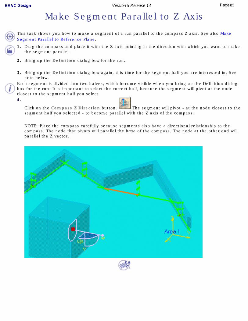
This task shows you how to make a segment of a run parallel to the compass Z axis. See also Make Segment Parallel to Reference Plane.
1. Drag the compass and place it with the Z axis pointing in the direction with which you want to make the segment parallel.
2. Bring up the Definition dialog box for the run.
3. Bring up the Definition dialog box again, this time for the segment half you are interested in. See note below.
Each segment is divided into two halves, which become visible when you bring up the Definition dialog box for the run. It is important to select the correct half, because the segment will pivot at the node closest to the segment half you select.4.
Click on the Compass Z Direction button. The segment will pivot - at the node closest to the segment half you selected - to become parallel with the Z axis of the compass.
NOTE: Place the compass carefully because segments also have a directional relationship to the compass. The node that pivots will parallel the base of the compass. The node at the other end will parallel the Z vector.

Fit Segment for Parts Assembly
This task shows you how to adjust a segment for parts assembly purposes. It can be used to move one part next to another, or to place two bends next to each other to create a U. In this example the segment half to the right will be shortened so that the elbow is placed against the tee.1. Bring up the Definition dialog box for the routable.
2. Right-click on the segment half that you want to shorten. A drop down menu will display.

3. Click Adjust to fit. The elbow will move flush against the tee.
The same command can be used to create a U. If you have a segment with bends at the two ends and you use the command described above, the segment will shorten so that the two bends are adjacent. It will not work if there are no bends.
If you have two connected parts, like a valve and a flange, and you want to move both after they have been placed, select both first. Then, when you move any one part both will move together.

Position a Segment Relative to Plane or Another Segment
This task shows you how to position a routable segment so that it is a defined distance away from a reference plane or from another segment. This function can be used to make a segment clear an existing structure or in situations where it is necessary to position a segment a specified distance from another object or segment. See also Edgeline Routing.
1. In the example below, the routable is colliding with the beam. The task is to move the segment up so that it passes just over the beam.
2.
Place the offset plane on top of the beam and bring up the Definition dialog box for the routable.
3. Right-click on the segment you want to move. A drop down menu will display. Select Offset segment.

4. Select Offset segment. The Offset segment dialog box will appear.
5. Select Make segment parallel to reference plane and then select one of the buttons, Outside edge to reference plane or Center line to reference plane. See Step 9 to offset to another segment.

6. Enter a distance in the Offset field. If you enter 0 the routable will be placed on top of the beam if you have selected Outside edge to reference plane. If you select Center line to reference plane then entering 0 in the Offset field will place the center line of the routable on top of the beam.
7.
Click the Offset to far side or Offset to near side button. These buttons will place the routable on either side of the reference plane.
8. Click Preview if you want to preview, then click OK and then OK again in the Definition dialog box. The run segment will be placed on top of the beam.
9. To position a segment a certain distance from another segment, select the Offset to another segment option and click the segment to which you want to offset. Click one of the three buttons: Outside edge to outside edge, Center line to center line or Center line to outside edge.

Create an Offset Connection Between Segments
This task shows you how to create an offset connection between two segments. Creating this connection makes a master-slave relationship between the two and maintains a fixed distance between them.
If you create the connection only between two segments, the two will maintain the offset if you move one. But other segments of the slave routable may change in length to allow the offset to be maintained between the two segments that have a connection. If you do not want this to happen you can create a connection between the other segments too.1.
Click the Create an offset segment connection button . The Run dialog box displays.
2. Select the segment you want to be the slave. The first segment you select becomes the slave, while the second becomes the master.
3. Select the second segment. The compass displays and you can see a connector line between the two.
4. Enter the offset distance and select your offset between options in the Run box. You can choose to have the offset connection between the:
● Outside edge to outside edge
● Centerline to centerline
● Outside edge to centerline

5. To create a connection between other segments of the same two routables select other segments in the same sequence given above.
6. Click OK. The connections will be created.7. To modify the connection, select the slave run, click the Create offset segment connection
button , select the slave segment and enter your changes.8. To delete offset connections select the slave routable, right click, then click on the line corresponding
to the routable and click Delete offset connections. All connections between the two routables will be deleted.

Create a Closed Loop RunThis task shows you how to modify an existing run in order to create a closed loop run. In a closed loop run the ends of the run are joined. There are two ways of turning an existing run into a closed loop run. Both are explained below. 1.
Click on the Route a Run button and continue routing from the end of the run. 2.
Click the Continue Routing button in the Run dialog box.3. Click on the other end of the run when finished. The ends of the run will join . 4. In the second method, right-click on the run and, in the drop down box that appears, click on the line that describes
the run, in this case Run.1 Object. 5. Another drop down menu will display. Click on Close Route.
6. The two ends of the run will join. An open end run and closed loop run are shown below.


Open a Closed Run
This task shows you how to open a closed run.
You can only open a closed run at a node.
1. Bring up the Definition dialog box for the run.
2. Click the right mouse button on the node where you want the run to be opened. This will display a drop down box.
3. Click on Open. The run will open at the node.


Adjust the Extremity of a Run
This task shows you how to move or adjust the extremity of a run.
You can use two methods to move the extremities of a run. One utilizes the Definition dialog box. The other uses the Adjust Run Extremity command. Both are described here.
1. To adjust using the Definition dialog box, right click on the segment whose extremity you want to adjust. From the menu, select the object, in this case 'Run2.1 object' and then select Definition. The run will be highlighted as shown below and the Definition dialog box will open.
2. Click and drag the connector symbol at the end of the section to reposition it. The image below shows the repositioned extremity. Notice that the Total length in the Definition dialog box has changed to reflect the adjusted length.

3. Click Apply and OK. The run will now extend to the selected position.
4. The other method uses the Adjust Run Extremity command. With your document open, click the Adjust Run
Extremity button . The Adjust Run Extremity dialog box displays.

5. Select the run extremity you want to adjust. The run is highlighted and the Adjust Options become available.
6. Click the down arrow in the Adjust Options field and select one of the options. You can:● Move to connector: Move the extremity to a connector.
● Move to point: Move it to a point on a part or equipment. You see the points as you move your pointer over the part.
● Move to x ,y, z coordinate: Move to a specific coordinate. Enter the coordinates in the fields that display.
● Move to run and keep alignment: Move to another run - the extremity is moved to that plane, not connected.
● Move to part and keep alignment: Move to a part - the extremity is moved to that plane, not connected.
7. Click OK to end.
Transfer Run to Another Document
This task shows you how to transfer a run to another document. You can use this function to transfer a run to documents or work packages that are under the same Product.
This command will only work if you do not have any parts placed on the run.
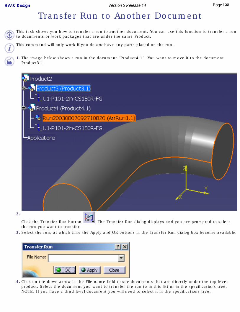
1. The image below shows a run in the document "Product4.1". You want to move it to the document Product3.1.
2.
Click the Transfer Run button . The Transfer Run dialog displays and you are prompted to select the run you want to transfer.
3. Select the run, at which time the Apply and OK buttons in the Transfer Run dialog box become available.
4. Click on the down arrow in the File name field to see documents that are directly under the top level product. Select the document you want to transfer the run to in this list or in the specifications tree. NOTE: If you have a third level document you will need to select it in the specifications tree.

5. Click Apply or OK. The run is transferred to the document you selected.

Connecting ElementsThis task explains how to connect and disconnect elements.
Connecting PartsDisconnecting Parts
Connecting Parts
This task shows you how to connect two or more parts or runs.
You can use this function to connect parts or runs.
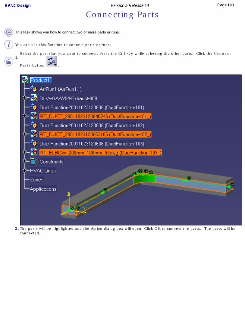
1.Select the part that you want to connect. Press the Ctrl key while selecting the other parts. Click the Connect
Parts button .
2. The parts will be highlighted and the Action dialog box will open. Click OK to connect the parts. The parts will be connected.

3. To verify that the the parts are connected, use the Analyze Networks function. Select the Path tab. Select the extremities of the range of parts you connected. The From Object and To Object fields will display the parts selected and the Current Path field will show 1, indicating that the three items are connected.
4. You can also connect by clicking the Connect button and selecting the connectors on two parts. In this case the first part you select becomes slave to the second part.

Disconnecting Parts
This task shows you how to disconnect two parts or runs.
1.In the specifications tree, select the part that you want to disconnect. Press the Ctrl key while selecting the other parts.
Click the Disconnect Parts button .
2. The parts will be highlighted and the Action dialog box will open. Click OK to disconnect the parts. The parts are disconnected.
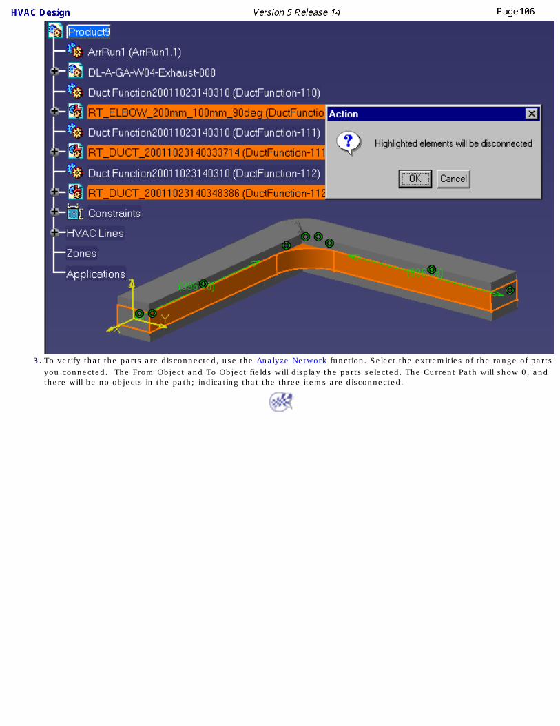
3. To verify that the parts are disconnected, use the Analyze Network function. Select the extremities of the range of parts you connected. The From Object and To Object fields will display the parts selected. The Current Path will show 0, and there will be no objects in the path; indicating that the three items are disconnected.

Connections Between Work Packages
This task explains the ways you can establish connections between work packages. You should also refer to the following tasks for more information: Using Work Packages, Understanding Project Resource Management, and Managing Publications.
The system manages connections between elements within your design. As you place parts or route elements within your design, the system automatically creates connections between them. When these elements are in different work packages then the system also needs a way of identifying the work package containing the linked element.
When connections are being established between elements in different work packages, the system may use one of two link mechanisms, based on the environment and user options set in the Project Resource Management file. The two mechanisms used for cross work package connections are:
● Publication based connections
● Document based connections
Publication based linking enables effective configuration management, revision management and concurrent engineering support. Publication based connections are established through a publication and can easily be replaced by new configurations or revisions of a work package. The connection is resolved dynamically as work packages are loaded into a session.
Document based connections use a more direct linking mechanism. This allows the linked document to be identified more easily, but it does not easily support relinking to a new configuration or revision.
In publication based linking, connection information is added to both work packages, establishing a one way or two way link. A two way link is established when the system has Write access to both work packages. If it has Write access to one of the work packages it will establish a one way connection from the work package to which it has access. Users can convert a one way link to a two way link if they have Write access to the necessary work package, using the Cross Document Connections command. It is recommended that a two way connection be established to ensure complete network connectivity for downstream processes such as From-To analysis.
In the case of document based connections, the connection is stored in the parent document of the two work packages. In this case, a two way connection is always established.

Managing Publications
This task explains ways you can manage publications. You should also refer to the following tasks for more information: Using Work Packages and Connections Between Work Packages.
Publications are used to identify work packages that have linked elements, for instance, when a vessel is in one work package and the pipe routed from it in another. In such cases publications are automatically created and used to track connected elements. Using the Manage Logical Publications command, and an associated command, Cross Document Connections, you can manage the publications. Both are explained below.
1.Select the work package for which you want to manage publications and click Tools - Manage Logical Publications in the menubar. The Manage Logical Publications dialog box displays, with all publications in the document listed. The box shows the publication name, the element to which it is associated, the associated connector and whether it is linked or unlinked.
2. You can perform the following functions (you must have Write access to the work package):● Rename: To rename, double click on a publication and enter the new name.
● Reset: Click the Reset button to reset to the original publication name.
● Delete: Select a publication and click the Delete button.

3. To use the cross document connections command, select a work package and click Analyze - Cross Document Connections in the menubar. The Cross Document Connections dialog box displays, showing the publications in the document.
4. The buttons become available when you select a publication. In the image above, the symbol in the Link Type column shows the publication has a two way connection. You can perform the following functions (some functions require Write access to both work packages):
● Remove Link: This will remove a connection one way and the following symbol will display.
● Add Link: When you have a one way connection, click this button to make it a two way connection.
● Disconnect: Click this button to remove the connection.
● Use the Reframe, Select All or Clear Selection buttons as needed.
You can also use the Connect Parts and Disconnect Parts commands to add or remove connections.

Manipulating ObjectsThis section explains some ways in which objects and resources are manipulated.
Search for Objects in a DocumentAligning Elements
Distributing ElementsRotate Resource Using the Definition Dialog Box
Snap Resources TogetherQuick Snap Resources
Snap and Rotate a ResourceUsing Offset Planes and Advanced Offset Planes
Generating Detail InformationDisable/Enable Manipulation Handles
Using Quick Translate to Move ObjectsMove/Rotate In-Line Parts
Hide/Show ConnectorsActivating the Product or Parent

Search for Objects in a DocumentYou can search for objects in a diagram by using the Edit - Search command. This will display the Search dialog box.
Under Workbench select your workbench. Under Type select the type of object you are searching for. Detailed instructions on using the Search function can be found in the Infrastructure User Guide under Basic Tasks - Selecting Objects.

Aligning Elements
This task shows you how to align elements in your layout.
You can align the center or the sides of an element to a user defined reference plane that you define. You can also rotate an element to align it with a reference plane.
1. Select the element(s) that you want to align.
2. Select the icon for the type of alignment you want to perform:
Align Sides: aligns the sides of two or more elements
Align Center: aligns along the centerlines of two or more elements
Rotate to Align: rotates elements on the axis to align them
Align Planes: aligns selected planes
Distribute: See Distributing elements
3. Define the plane to use as a reference for the alignment. If you have an offset plane already defined it will be used as the reference plane. If you do not already have the offset plane defined do the following:
a. Place your cursor over a geometric element that defines the plane (e.g., a construction plane, boundary, area contour, item reservation).
As you move the cursor, a small white rectangle is displayed to show the selectable planes, as shown below. A line normal to the rectangle shows the direction in which the alignment would be performed.

If you do not see the white rectangle, zoom out from the drawing. The white rectangle cannot be displayed if the element under your cursor is displayed too small.
b. Click to select the plane.
The selected elements are aligned along the plane.
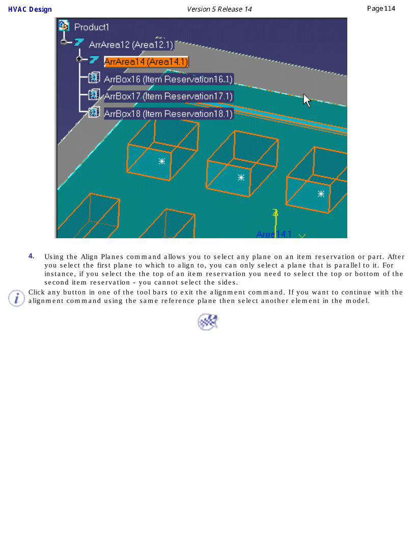
4. Using the Align Planes command allows you to select any plane on an item reservation or part. After you select the first plane to which to align to, you can only select a plane that is parallel to it. For instance, if you select the the top of an item reservation you need to select the top or bottom of the second item reservation - you cannot select the sides.
Click any button in one of the tool bars to exit the alignment command. If you want to continue with the alignment command using the same reference plane then select another element in the model.

Distributing Elements
This task shows you how to distribute elements within parameters that you define.
1. Select the elements you want to move.
2.
Select the Distribute icon .3. Define a reference plane for the distribution by doing the following:
a. Place your cursor over a geometric element that defines the plane (e.g., a construction plane, boundary, area contour, item reservation).
As you move the cursor, a small white rectangle is displayed to show the selectable planes, as shown below. A line perpendicular to the rectangle shows the direction in which the distribution would be performed.
If you do not see the white rectangle, zoom out from the drawing. The white rectangle cannot be displayed if the element under your cursor is displayed too small.

b. Click to select the plane.
The selected elements are distributed along a line perpendicular to the plane, as shown below.

Rotate Resource Using the Definition Dialog Box
This task shows you how to rotate a catalog resource by entering into the definition dialog box the number of degrees that you want it to rotate on its vertical axis..
1. Click on the resource.
2. Click Edit-Definition in the menu bar. This displays the Product Definition dialog box. (You can also press Cntrl-Enter to display the box.)
3. Enter the degrees in the Rotation field.4. Click Apply and the resource will rotate on its vertical axis.

Snap Resources Together
This task shows you how to snap two resources together.
Resources can be joined at existing connectors, you can create new connectors to join them, or you can snap them together without using connectors. All procedures are described below, beginning with the procedure for snapping resources in which you create connectors.
1. To snap resources together by creating new connectors, click the Snap button .
2. Click one of the resources you want to snap together. The resource changes color and the Define Reference Plane (From) dialog box displays.

By default the Define Plane button is selected, allowing you to select a plane for the connector you will create.
See Creating Connectors for information about using the Define Plane functions.
The two resources will have a Master-Slave relationship to each other - but only if you choose to add a constraint (see below). If you add a constraint the first object you select becomes the slave, and the second object becomes the master.
Also note that the first resource you select will move to snap - the second resource you select remains stationary.3. Select the second resource. The Define Reference Plane (To) box will display - make your selections
as explained above. You can also select an existing connector. Click OK when done. The two resources will snap together and the Constraint Options dialog box will display.
4. You can clear the Align, Face and Orientation check boxes and click OK if you want the two resources to remain snapped together without any new connectors being created.
To add one or more constraints - which will also result in creating connectors - follow the steps given below.
5. Make your selections in the Snap Options box.
Align: You can increase distance between the two resources, but if you change the alignment the

slave will snap back to the original alignment. In the image below the distance is increased but the alignment remains the same.
Face: The two resources will maintain the face if you move one of them. In the image below the two maintain the same face, though the alignment has changed.
Orientation: The two connectors will maintain the same orientation if you move them, i.e. the red arrows visible in the connectors will align. It is therefore important to make sure that the red arrows in the connectors are pointed correctly and oriented correctly with reference to the part. The red arrow is usually set to the "Up" position of the resource, which means that on both resources they should point in the Up direction. If the red arrow points "down" in one resource and "up" in the other, then the resources will snap together incorrectly. You can toggle the position of the red arrow by clicking on the green arrow that is parallel to the plane.
Fix in space: If you select this option the position of the master resource is fixed - if it is moved it will snap back to its original position.
Attach: Checking this option allows you to attach the two objects.
Place manipulator at snapped location: Check this if you want to rotate the snapped object after placing it. The manipulator is placed on the object if you check this. You can then click on the bottom curve of the manipulator (see image below) and rotate the object. It will rotate in increments, based on the value entered in the Snap Angle field. In the image above it is 45 degrees.

To remove a constraint select it in the specifications tree and delete it. To remove the 'Fix in space' option right click on the Fix line in the specifications tree, click Properties, go to the Constraints tab, and uncheck the Fix in space box.6. Click OK when done.
7. To snap resources together using preexisting connectors:
a. Click the Snap button.b. Move the pointer over the first resource - the connectors will display. Select the connector.c. Move the pointer over the second resource - the connectors will display. Select the connector
and the two resources will snap together.d. The Snap Options box will display. Make your selections and click OK.
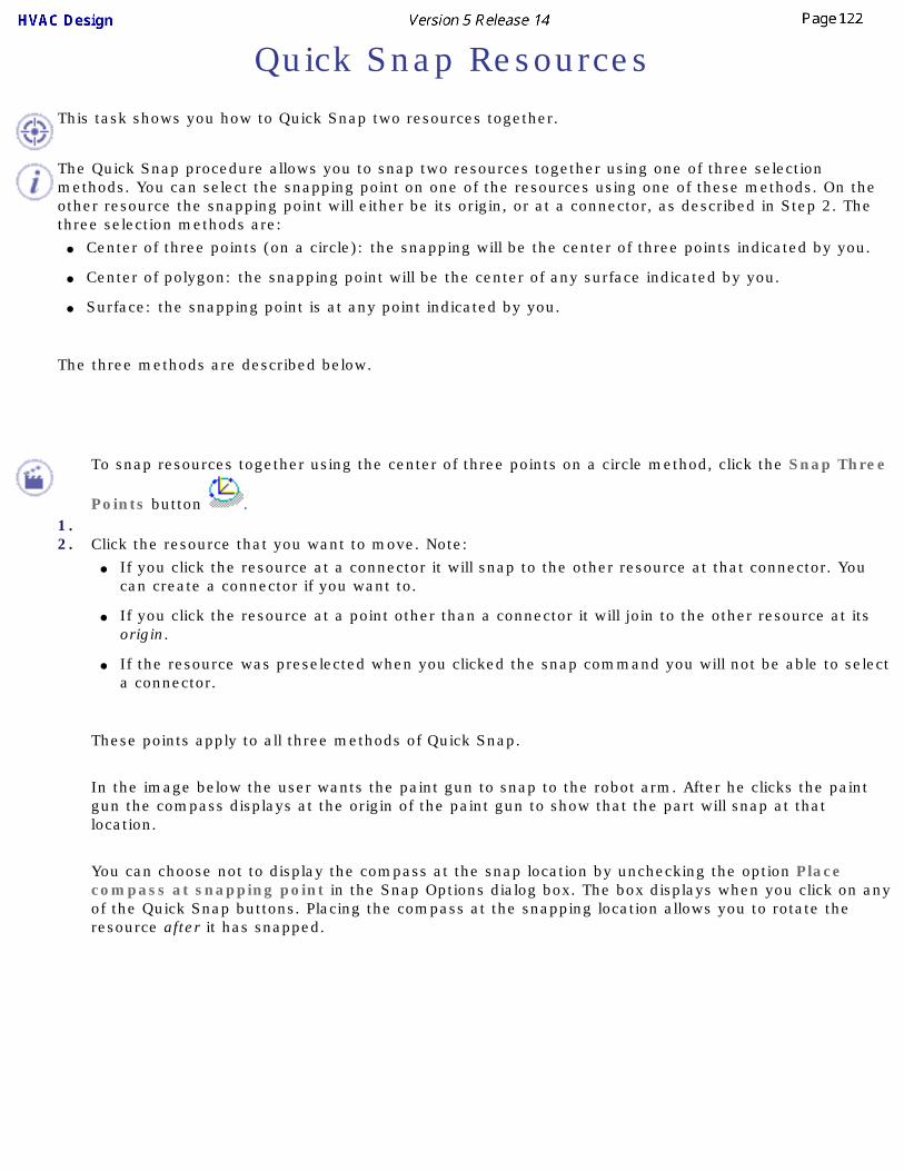
Quick Snap ResourcesThis task shows you how to Quick Snap two resources together.
The Quick Snap procedure allows you to snap two resources together using one of three selection methods. You can select the snapping point on one of the resources using one of these methods. On the other resource the snapping point will either be its origin, or at a connector, as described in Step 2. The three selection methods are:
● Center of three points (on a circle): the snapping will be the center of three points indicated by you.
● Center of polygon: the snapping point will be the center of any surface indicated by you.
● Surface: the snapping point is at any point indicated by you.
The three methods are described below.
1.
To snap resources together using the center of three points on a circle method, click the Snap Three
Points button .
2. Click the resource that you want to move. Note: ● If you click the resource at a connector it will snap to the other resource at that connector. You
can create a connector if you want to.
● If you click the resource at a point other than a connector it will join to the other resource at its origin.
● If the resource was preselected when you clicked the snap command you will not be able to select a connector.
These points apply to all three methods of Quick Snap.
In the image below the user wants the paint gun to snap to the robot arm. After he clicks the paint gun the compass displays at the origin of the paint gun to show that the part will snap at that location.
You can choose not to display the compass at the snap location by unchecking the option Place compass at snapping point in the Snap Options dialog box. The box displays when you click on any of the Quick Snap buttons. Placing the compass at the snapping location allows you to rotate the resource after it has snapped.
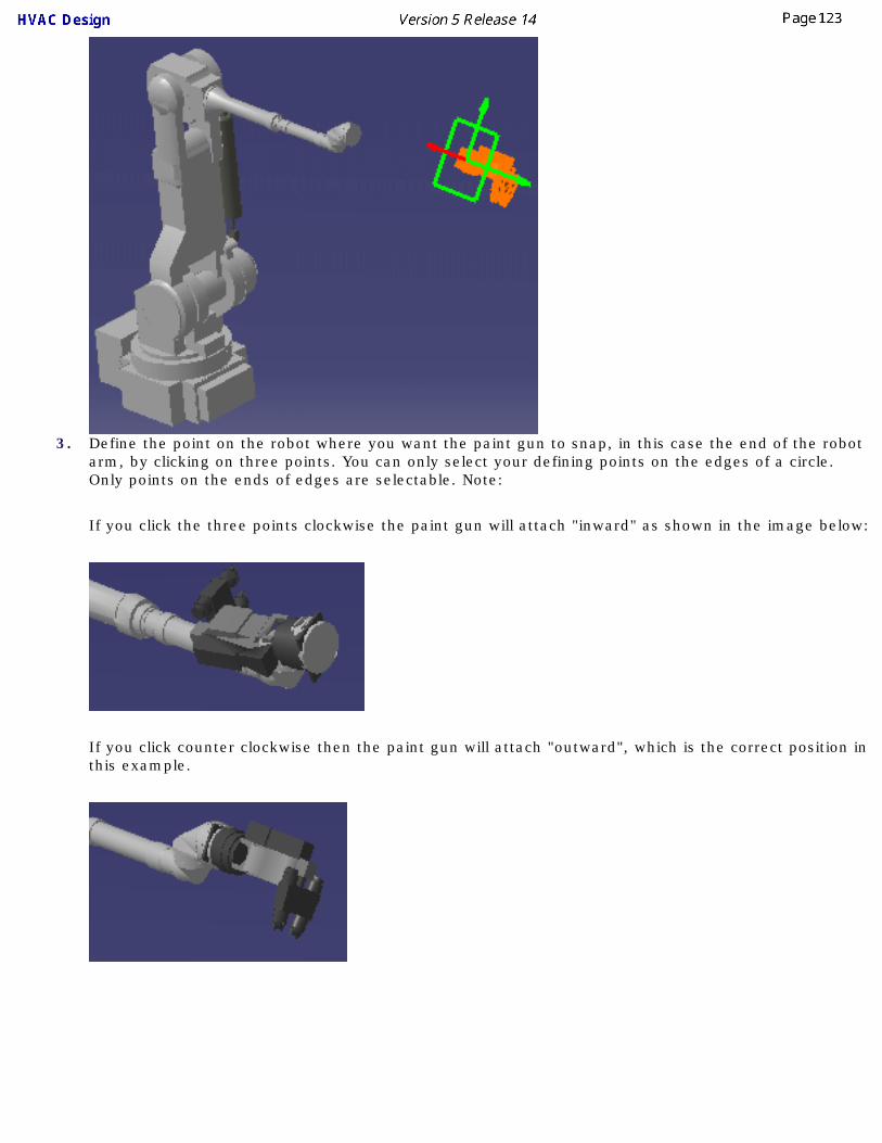
3. Define the point on the robot where you want the paint gun to snap, in this case the end of the robot arm, by clicking on three points. You can only select your defining points on the edges of a circle. Only points on the ends of edges are selectable. Note:
If you click the three points clockwise the paint gun will attach "inward" as shown in the image below:
If you click counter clockwise then the paint gun will attach "outward", which is the correct position in this example.

4.To Quick Snap using the center of polygon method, click the Snap Center of Polygon button and perform the action detailed in Step 2.
5. Select the snapping point on the second resource by clicking on a surface. The resource will be placed in the center of the polygon.
6.To Quick Snap using the surface method, click the Snap Surface button and perform the action detailed in Step 2.
7. Select the snapping point on the second resource by clicking on any surface. The resource will be placed at the point you click.
If you double click a command you will be in repeat mode. This allows you to snap a resource to a different location, using a different selection method if you want.

Snap and Rotate a Resource This task shows you how to rotate a resource after snapping it to another resource.
1. With both resources on the screen, click on the Snap button and then on a resource. The orientation symbol will appear.
2. Click on the second resource. A white square will appear. Move the pointer over the resource and click when the white square is at the location where you want to snap the two resources. The orientation symbol will appear at the location and the Define Reference Plane dialog box will display.

3.Click on the Define plane using compass button . The compass will be placed at the location where you want to snap the two resources.
4. Click OK on the Define Reference Plane box. The two resources will snap together.
5.
Click on the Select button to exit the Snap command. Click on the resource you want to rotate, then grab one of the handles on the compass with your pointer and move it. Different handles will move/rotate the resource in different directions.
You can also double click on the compass to bring up the Compass Manipulation dialog box and enter the required figure in the Angle field. Click on the + or - sign next to the Z axis to rotate it.

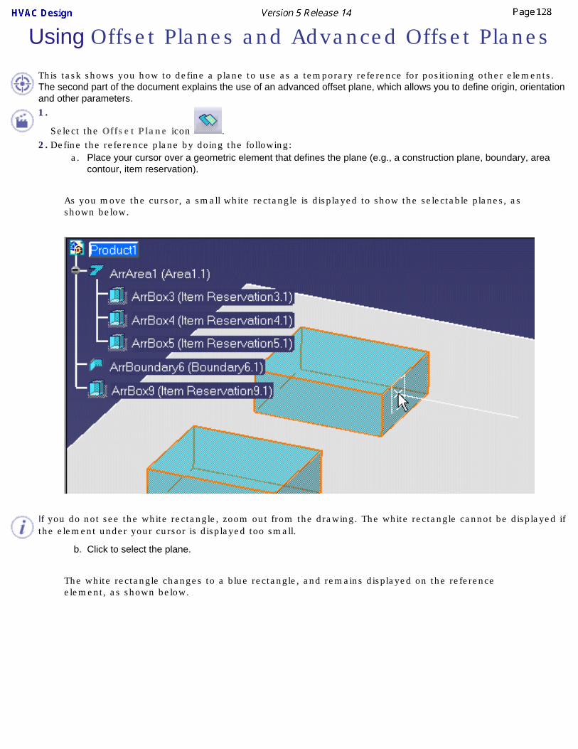
Using Offset Planes and Advanced Offset Planes
This task shows you how to define a plane to use as a temporary reference for positioning other elements. The second part of the document explains the use of an advanced offset plane, which allows you to define origin, orientation and other parameters.1.
Select the Offset Plane icon .2. Define the reference plane by doing the following:
a. Place your cursor over a geometric element that defines the plane (e.g., a construction plane, boundary, area contour, item reservation).
As you move the cursor, a small white rectangle is displayed to show the selectable planes, as shown below.
If you do not see the white rectangle, zoom out from the drawing. The white rectangle cannot be displayed if the element under your cursor is displayed too small.
b. Click to select the plane.
The white rectangle changes to a blue rectangle, and remains displayed on the reference element, as shown below.

The reference plane can now be used as a reference to position other elements.
3. Use the advanced offset plane feature to set your plane reference, origin and orientation settings as follows:
a. Click the Advanced Offset Plane button. The Define Plane dialog box will display.
b. The Define Plane button is selected by default. However, you can select any button in the Define Plane box. Click when you have found a location. The plane manipulator displays.
Click on the buttons in the Define Plane dialog box to make your selections. See Creating Connectors on using the buttons.
c. Click OK when done. The reference plane will be created.

Generating Detail Information
This task shows you how to display detailed information about objects as you move the pointer over them.
The Analyze Item command displays information about an object when the pointer passes over it. This information can include line IDs, nominal size of runs and parts, XYZ coordinates of connectors, etc. The type of information shown will depend on the object and the product you are using. See also Display Information About Routables.
From Release 13 the angle of routables from the x,y,z axis will also display, as in the image below.
1.
With your document open, click the Analyze Item button .2. Move the pointer in the document highlighting various objects. Attributes and their values are
displayed, depending on the type of object highlighted. In the illustration below the pointer is on a tubing tee.
3. When you click again the feature will be disabled.


Disabling/Enabling Manipulation Handles
This task shows you how to disable or enable manipulator handles using the Toggle Manipulator Handle Mode command.
The default is for the manipulation handles to be enabled. If you are working on a large document, however, displaying the handles on each part can take up time. If you do not need the handles then you can use this feature to disable the display. It is a toggle button, so clicking it again will enable the handles. This feature can be used with parts placed in-line or in free space.
1.To disable display of the manipulation 'handles' click the Toggle Manipulation Handle Mode button
. To enable them again click the button once more. The handles look like a green box on parts placed in free space. On parts placed in line they look like the image below.

Using Quick Translate to Move Objects
This task shows you how to use the Quick Translate command to move elements.
This function allows the user to transfer an element relative to a location on another element by any of the following alignment methods:
● Point-to-Point
● Point-to-Line
● Point-to-Plane
● Plane-to-Plane
● Plane-to-Point
● Line-to-Point
An object or element moved using this command does not rotate.
This function works with parts placed in a run only before the pipes, tubes have been placed. The placing of such objects prevents the part, e.g., a valve, from moving.
1.
With your document open, click the Quick Translate button . The Translate dialog box opens. Depending upon which From element you select the available To elements will either be greyed out or become active.

2. Select the type of transfer, Point-to-Point, Point-to-Plane, etc. Using the Point-to-Point method as an example, select a point on the From element, a valve, in your document and select a point on the To element, the nozzle on the sea pump.
3. The transfer occurs when you click on the To element. Click the Update button, if necessary. The valve has moved to align with the nozzle.
4. The function works similarly with the other From/To selection methods and may be applied as the design dictates.

Move/Rotate In-Line Parts
This task shows you how to move or rotate an inline part. This function gives the user the ability to move an in-line object that has been placed. Piping parts are used here for illustration purposes - the procedure is the same for other types of parts.Open a product having the conditions described above, or (with Autoparts disabled) create a simple run, place a valve and a pipe.
1.
To move or rotate a part click the Move/Rotate Part on the Run button . The Move/Rotate
dialog box appears. Two buttons in the Move/Rotate dialog box allow you to move (offset) , or
rotate physical parts.
2.
To move the part, click the Move Physical Part button .
Select the part; it will highlight orange. An offset plane will appear on one end of the inline pipe.
The Offset Value field will open permitting you to enter the desired offset value
. The offset is measured from the end of the inline bendable (where the offset plane appears).

The Toggle offset plane button opposite the Offset value field allows you to toggle the offset plane to either end of the segment so that you can make measured movements of the part in either direction.
If you already know the amount of offset required, enter it in the Offset value field and click OK. The part will be moved. If no other move operations are to be performed, click OK in the Move/Rotate dialog box.
3.
Click the Rotate Physical Parts button .
Select the part you want to rotate; it will highlight orange.
The Angle Value field will open permitting you to enter a value for the degree of rotation.
This can be either a positive or a negative value.
Enter the desired degree of rotation, e.g., 90 deg, and click OK. The part will be rotated.
If no other rotate operations are to be performed, click OK in the Move/Rotate dialog box.You can rotate an inline part using the compass or set the angle of rotation by aligning it with a line or point on another object.

4.
To rotate an inline part using the compass, click the Rotate Physical Parts button . Select the part you want to rotate, e.g., the valve; it will highlight orange.
Place the compass on the valve as shown and drag the compass. The valve will rotate and the Angle Value field will continually update the angle of rotation as you move the compass.
5. To rotate an inline part by aligning it with a line or point on another object, we must create the other object.
Open the Plant Layout workbench by going to Start - AEC Plant - Plant Layout. Create an item reservation next to the objects created in the previous steps.
Now, click the Rotate Physical Parts button . Select the part you want to rotate, e.g., the valve; it will highlight orange. Place the compass on the valve as shown and drag the compass. The valve will rotate to align with the location of the compass on the item reservation. Click OK to close the Move/Rotate dialog box.

Repeat the command and select the valve so that it is highlighted and select a line on the item reservation. The valve will rotate to align with the selection. Similarly, select a point (green dot) to align with.
If no other rotate operations are to be performed, click OK in the Move/Rotate dialog box.

Show/Hide Connectors
This task shows you how to hide or show connectors.
Connectors may be hard to select during certain processes, such as when you are in cache mode, or trying to select a connector in a hole. This step makes them visible so that you can select easily.
1.
Click the Show/Hide Connector button . This button may be located in the lower toolbar. 2. Select the part whose connectors you want shown. The connectors display.
3. To hide the connectors, click the Show/Hide Connector button and select the part again.

Activating the Product/Product Parent
This task shows you how to activate the product or product's parent.
This command can be useful when you have numerous objects and/or documents displayed in the specifications tree. It helps you activate an object, or locate the parent to which an object belongs.
1.
Click the button Activate Product's Parent . The Activate Product dialog box displays.
2. If you want to activate an object then click on the object, in the specifications tree or viewer. If you want to activate the object's parent, then click the checkbox Activate Product's Parent and select the object. The parent will be selected and highlighted in the specifications tree.

Query or Modify the Properties of an ObjectThis section explains ways of querying and modifying the properties of objects.
Edit or Display Properties of an ObjectFilter Shown Properties of an Object
Rename an ObjectChanging the Size or Spec of a Part
Assigning Values to Parts

Edit or Display Properties of an Object This task shows you how to edit or display the properties of an object.
1. Select the component.
2. Click Edit - Properties or, as an alternative, right-click and select Properties. The Properties dialog box appears with the properties displayed under various tabs.
The Properties dialog box will display tabs, most of which are used in all products. The Graphic tab allows you to change the appearance of the object. Under the Product tab you can include additional descriptive and historical data and make changes, such as renaming, to the basic Product in the specifications tree. See Infrastructure documentation (Basic Tasks - Manipulating Objects - Displaying and Editing Graphic Properties) and Product Structure documentation (User's Tasks - Modifying Component Properties) for more information. Click the More button if you want to see other tabs.3. Enter values in the fields as desired and click OK. The properties will be edited.4. Click OK to end.Some objects have discrete values - which means you may only select certain values. In that case you will be able to display a drop-down box and select one of the values in it.
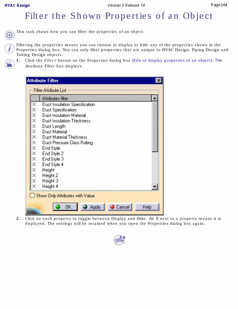
Filter the Shown Properties of an Object
This task shows how you can filter the properties of an object.
Filtering the properties means you can choose to display or hide any of the properties shown in the Properties dialog box. You can only filter properties that are unique to HVAC Design, Piping Design and Tubing Design objects.1. Click the Filter button on the Properties dialog box (Edit or display properties of an object). The
Attribute Filter box displays.
2. Click on each property to toggle between Display and Hide. An X next to a property means it is displayed. The settings will be retained when you open the Properties dialog box again.

Renaming Objects
This task shows you how to rename objects.
1.With your document open, select the object and click the Rename ID button . The Rename dialog box displays. In the view below you can see that the ID field is displaying the name assigned by the application; in this case, DuctFunction-072.
2. If you wish to rename the object (or instance) enter the new name in the ID field. To revert to the Default ID click on the Set to default button.
3. If you want to rename additional objects click Apply and continue renaming.4. Click OK when finished. The objects will be renamed.
Using this command to rename an object does not rename all instances of that object. If you have placed an object more than once in a document and want to rename all of them, you will have to rename each one, individually.

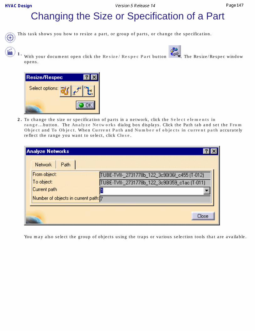
Changing the Size or Specification of a PartThis task shows you how to resize a part, or group of parts, or change the specification.
1. With your document open click the Resize/Respec Part button . The Resize/Respec window opens.
2. To change the size or specification of parts in a network, click the Select elements in range...button. The Analyze Networks dialog box displays. Click the Path tab and set the From Object and To Object. When Current Path and Number of objects in current path accurately reflect the range you want to select, click Close.
You may also select the group of objects using the traps or various selection tools that are available.

The Resize/Respec dialog box opens when you close the Analyze Networks box, allowing you to make changes to the parts in the network. Select Resize Run if you want a run to be resized. Select Validate Turns if you want to check for turn radius errors.
The Specification tab will not display if you are not using a specification - in that case only the Size tab displays. For a round object you will get the nominal size field; for a rectangular object you will get height and width fields. Also note that in HVAC Design you will get a Material field under the Specification tab. This allows you to change the material (the wall thickness may also change when you change the material, based on your rules tables).
3.
To change the size or spec of all members of a line ID click the Select Line IDs to Resize/Respec
button . The Select/Query Line ID dialog box will display. Under Filter, set the Scope to Local and select the Line ID. The objects will highlight. Click OK and the Resize/Respec dialog box will open (as shown above). Make the changes as necessary in the Nominal Size and Specification tabs.
4To change the size or spec of members of a Spool, click the Select Spool to Resize/Respec button
; select the spool and click OK. With the Resize/Respec dialog box open, proceed as above, making the desired changes for Nominal Size and Specification.
5To change the size or spec of a single part select it in the document or from the specification tree and click the Resize/Respec button. The Resize/Respec dialog box will open. Select the Nominal Size tab or Specification tab and make your changes.

Assigning Values to Parts
This task shows you how values are assigned to parts that you have placed.
Placed parts get their values from various sources, a list of which is provided below. This task explains the rules that govern how these values are assigned to parts. Users may need to know this information so that they can assign attributes in such a way that the parts they place obtain the correct values. In most cases this follows a standard pattern, but some users may need to change the way in which values are assigned in order to meet special needs. Only values are derived, not the attributes. An attribute must be defined on both the part and the 'parent' object or a value cannot be assigned.
Values can be assigned to a placed part from the following seven sources:
● From the part itself.
● A run.
● A connector.
● Based on a specifications catalog.
● A line.
● From a 2-D function (in the case of schematic driven design only).
● Defined by the user.
1.If a value has been assigned to an attribute during part build time, then that value will be used when the part is placed. Examples of attributes whose values are defined in the part are: material category, material code, part numbers.
2. If a part is placed on a run:
A bendable part will pick up the bend radius and the nominal size values from the run. Other parts will pick up the nominal size value only.
3. If you select a connector before placing a part then the values will be derived from the connector. The image below shows a connector with attributes and values displayed.
If the valve shown above had already been placed on a run, and you selected the run before placing a new part, then that new part would have derived values from the run.
In the HVAC Design application, if you select a connector to place a new part, then the values will actually be assigned to the new part. In other applications you will be provided with a part that matches the nominal size and other attribute values.
Some of the attributes typically defined on a connector are those displayed above: wall thickness, rating, end style and nominal size.
4. If you are selecting parts from a specifications catalog:
If the part being placed does not have an attribute value defined, then the value will be obtained from the specification.
If the value is defined in both the specification and on the part then the value on the part will remain unchanged.
5. When you are placing a part as part of a line:
If the part does not have an attribute value defined, then the value will be obtained from the line.
If the value is defined on both the line and the part then the value on the part will remain unchanged.
Attributes that are typically defined on the line are: insulation specification, insulation thickness, temperature and pressure.
6. In schematic driven design:
If the value is not defined on the physical part then it will be obtained from the function.
If the value is defined on the the function and the physical part then the value on the physical part will remain unchanged.
7. User defined:
During part build time some attributes can be defined as override parameters, which means the user defines the value. For such attributes, users will be prompted to define values at parts placement time.
8. The application attempts to determine values in the order given above - if the part itself does not have a value it will examine the line, then the run and so on.

Placing & Modifying an HVAC PartWays of placing and modifying an HVAC part are discussed in this section.
Placing PartsSwitching Graphic Representations
Rotate an HVAC PartFlipping a Part
Inserting a Part Between Two PartsPlacing Transitional Objects On a RunDetecting Clash in Parts PlacementPlacing a Part in a Sub-document

Placing Parts
This task shows you how to place a part on a run. This function allows you to filter (or search) a catalog for parts that meet the criteria that you specify. You are presented with a list of parts that meet these criteria so that you can select the part that you want to place.
The same procedure is used for placing parts at a location other than a run.
See also Detecting Clash in Parts Placement and Placing Parts Using a Schematic.
Note that this application incorporates intelligent design functions. This means that during the design process the application ensures your design meets a selection of criteria. These criteria are established by Design Rules. For instance, the design rules will match the threaded end of a pipe to the threaded end of a part. (You can override the design rules if necessary.) There are certain general design rules that apply to all parts you place. Other rules apply to parts you place from a specifications catalog or a standard. Theoretically you can create a new standard and not incorporate any design rules. However, your parts will not place correctly if you do so.
The standard and specifications catalog that you use for parts placement must be defined in the setup data. See Understanding Project Resource Management.
1. With the run displayed, click the Place HVAC Part button . The Place HVAC Duct dialog box
displays. (In the image below the user has already made some selections.)
The first row of buttons provides you with placement options. This can aid you in selecting a placement location in a busy document. Move the cursor over the button to see its name.
● Select or Indicate: This is the default selection and allows you to select or indicate a placement location.
● Select Run Only: You can only select a run.
● Select Connector Only: Allows you to select a part connector only. First select a part - all

connectors display - then select the connector.
● Indicate On Local XY Plane: You can select a location that is on the XY plane of the local axis of the document.
● Indicate on Compass Plane: You can select a location that is on the compass plane. If the compass is inactive then the local plane will be used.
● Select Surface: Select a surface and then select a location.
● Use Compass Z for Placement Up Orientation: The part will align itself with the compass Z direction, and not the default 'up' direction of the part. In the image below the valve on the left shows the default up direction, the valve on the right aligns to the compass Z direction.
2. Select a location for the part - you must do this before the Class Browser will display. See below if you want to multi-place parts.
You may want to place the same part in more than one location - for instance you have a run with several bends and you want to place an elbow at each bend. You can multi-place parts in one of two ways. Before you select a location (Step 3) click the Multi-Place Parts button. Or do a Shift-Click when you select the location. Now when you select a part it will be placed at all compatible locations. This works with elbows and ducts.3. If the Clear Filter button is enabled it means that values from a previous part placement exist in the
Filter Definition dialog box. (See Step 4.) Click the button if you want to clear these values.
4. If you want to change the values of one or more properties of the part you want to filter for, then click the Filter Definition button to display the Filter Definition dialog box. Select the property whose value you want to change and then select the new value from the drop down box in the Discrete field. (The Discrete field will display after you select a property.) This new value will appear in the Override value column. The values in the Override value column will be used when searching for parts in the catalog.
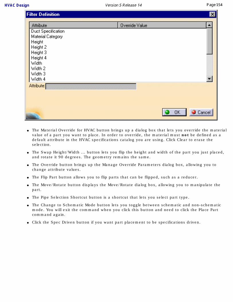
● The Material Override for HVAC button brings up a dialog box that lets you override the material value of a part you want to place. In order to override, the material must not be defined as a default attribute in the HVAC specifications catalog you are using. Click Clear to erase the selection.
● The Swap Height/Width ... button lets you flip the height and width of the part you just placed, and rotate it 90 degrees. The geometry remains the same.
● The Override button brings up the Manage Override Parameters dialog box, allowing you to change attribute values.
● The Flip Part button allows you to flip parts that can be flipped, such as a reducer.
● The Move/Rotate button displays the Move/Rotate dialog box, allowing you to manipulate the part.
● The Pipe Selection Shortcut button is a shortcut that lets you select part type.
● The Change to Schematic Mode button lets you toggle between schematic and non-schematic mode. You will exit the command when you click this button and need to click the Place Part command again.
● Click the Spec Driven button if you want part placement to be specifications driven.

5. Click the Class Browser button to display the Class Browser. Double click on HVAC Part Function to expand the list.
6. Select a function and click OK. The function will display in the Place HVAC Duct dialog box.
7. In the Place HVAC Duct dialog box, click on the down arrow in the Part Type field to display a list of part types (if there is more than one) and select the part type you want. If there is only one part type it will be preselected for placement. If the Part Type field is grayed out then click again on the location where you want to place the part.

8. The Part Selection box will display after you select a part type - if there is more than one selection. It will not display if there is only one selection available to you.
If the part you want to place can be created as a light object, you will be able to differentiate between heavy and light sample parts. Heavy parts are identified by the letters HV in the part name. Light parts do not have any designation.
9. Select the part you want to place and click where you want to place it. The part will be placed. In the image below a rectangular elbow and straight duct have been placed on a run. If there is only one selection available to you then click after Step 5.

To ensure correct placement of ducts in a run you should first place all the in-line components and then place the ducts.
You can choose to display or hide a "preview" of the part you are placing. To do this click on Tools - Options and select Equipment & Systems and the General tab. Check or uncheck the box Display image while placing catalog object in 3D viewer to obtain the effect you want.
By default, when you click (in free space) to place a part the center of that part will be placed at that location. The center is determined by the application by drawing a box around the part and selecting the center of the base of the box. You can also choose to place the origin of the part at the point where you click. To do this click on Tools - Options, select Equipment & Systems and the General tab. Check the box Place at component's origin when placing in free space.
After you move or modify a run or part, click the Update Part button and select a part to update that part, or select the run to update the run. You only need to do this if the application does not update the object.
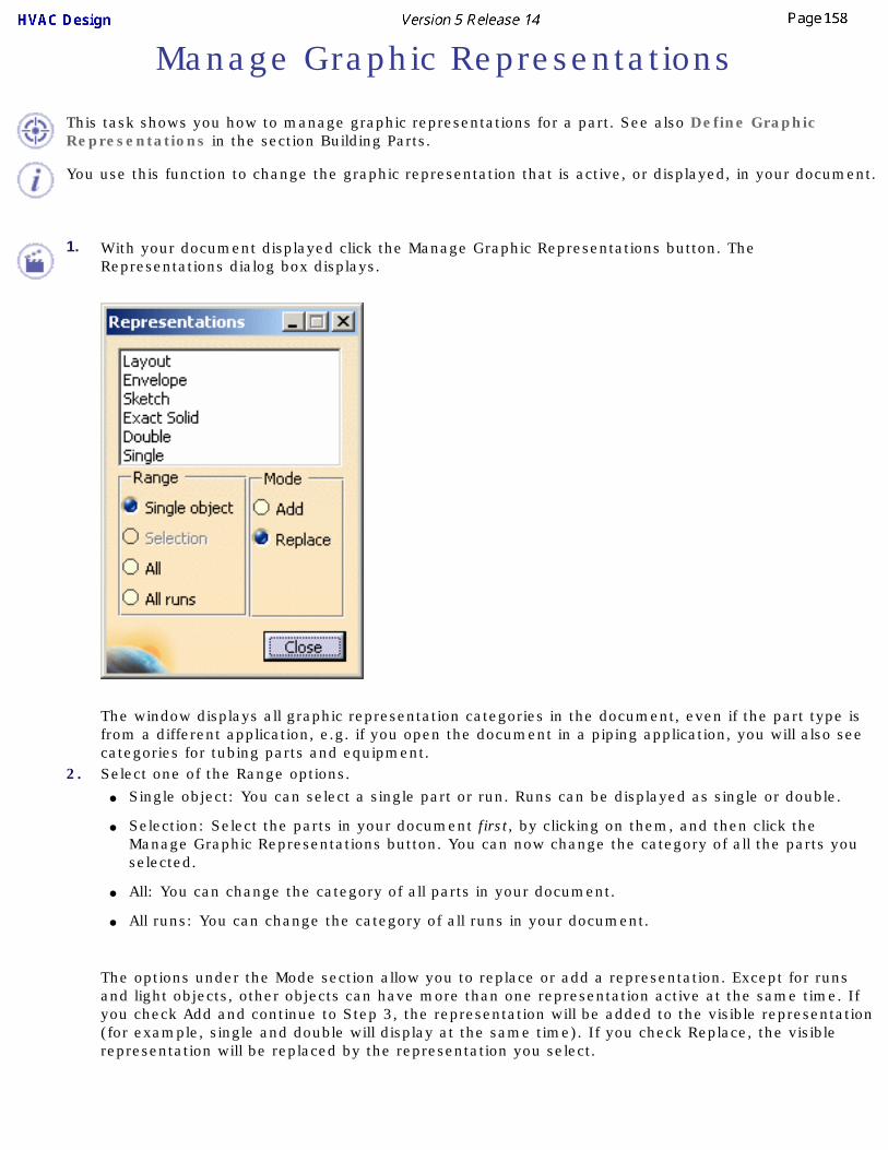
Manage Graphic Representations
This task shows you how to manage graphic representations for a part. See also Define Graphic Representations in the section Building Parts.
You use this function to change the graphic representation that is active, or displayed, in your document.
1. With your document displayed click the Manage Graphic Representations button. The Representations dialog box displays.
The window displays all graphic representation categories in the document, even if the part type is from a different application, e.g. if you open the document in a piping application, you will also see categories for tubing parts and equipment.
2. Select one of the Range options. ● Single object: You can select a single part or run. Runs can be displayed as single or double.
● Selection: Select the parts in your document first, by clicking on them, and then click the Manage Graphic Representations button. You can now change the category of all the parts you selected.
● All: You can change the category of all parts in your document.
● All runs: You can change the category of all runs in your document.
The options under the Mode section allow you to replace or add a representation. Except for runs and light objects, other objects can have more than one representation active at the same time. If you check Add and continue to Step 3, the representation will be added to the visible representation (for example, single and double will display at the same time). If you check Replace, the visible representation will be replaced by the representation you select.

3. Change the graphic representation that is active by selecting a different category in the window. Based on what you selected under Range, one object, more than one selected objects or all objects in your document will change to the newly selected category. The images below show a valve as double, and envelope.

Rotate an HVAC PartThis task shows you how to rotate an HVAC part.
An HVAC part can only be rotated if it is in free space - connected components cannot be rotated.
1. With your component displayed, click and drag the compass and place it on the part you want to rotate.
2. Move the pointer to the highlight the compass for the desired direction of rotation.
3. At this point there are two methods of rotating the part. If you know the exact amount of rotation required, double click on the highlighted arc (visible in Step 2). The Compass Manipulation dialog box opens. Enter the exact amount of rotation in the desired axis; in this case the Y axis. Click Apply new position and then Close.

The alternate method is to grab the compass and rotate the part to the desired degree of rotation.

Flipping a PartThis task shows you how to flip a ducting part. "Flipping" here means connecting the part by using a different connector than the one currently used.
1.Click the Flip Part Position button and then click on the part you want to flip. You can repeat this step to keep trying out all the connectors on the part. In the image below, the tee has three connectors. This step has been used twice to try out all the connectors.
Some parts cannot be flipped. In such cases you will get an error message.

Inserting a Part Between Two Parts
This task shows you how to insert a part.
This procedure is used for inserting a part, such as a tee, at a location on a duct, for instance. This effectively splits the duct into two parts.
1. With the run displayed, click on the Place HVAC Part button . The Part Placement dialog box displays. Click the Class Browser button and navigate to the type of part you want to place. See Placing a Part on a Run.
2. Select the part you want to place and click where you want to place it. The part will be placed. In the image below a tee has been inserted in a straight duct.

3. You can adjust the location of the part once it is placed. If not already activated, click the Toggle
Manipulation Handle Mode button , then click on the dot and drag the part along the run to the desired location. Click the Update button when finished.

Placing Transitional Objects on a Run
This task discusses "transitional" objects placed on a run.
For purposes of discussion, transitional objects are defined by any one of three criteria: ● Objects that transition a change in size (e.g., 2in to 1in reducer)
● Objects that transition a change in shape (e.g., round duct to rectangular)
● Objects that transition a change in alignment (e.g., twisted section)
Transitional part types are reducers, transitions, and twisting parts. When placed on a run, these transitional objects split the run. In the following scenario we will use the Piping Design application to illustrate this function.
1.Create a simple run and click the Place Part button . The Place Part dialog box opens.
2.Select the run, then click the Browser button opposite the Function type field. The Class Browser opens.
3. Expand Piping Part Function and select Reducer Function.
4. Under Part Type, select Eccentric Reducer.
5. In the Part Selection dialog box, select a Part Number that is appropriate for the size of the run. For example, if you created a 2 in. run, select REDECC-WM-BW-2in-1in.
6. Place the part and notice that now there are two runs of different sizes. In the specifications tree, note that in addition to the Reducer Function and Reducer, there is also a second Run.


Detecting Clash in Parts Placement
This task shows how you can detect clashes between parts when you are moving parts in a document.
This function only works when you are placing/moving parts in free space. It will not work if the parts have been placed on a run, for instance. Three modes are available: Clash Detection Off; Clash Detection On, and Clash Detection Stop.
1.
To turn clash detection off click the Clash Detection (off) button . This is the default mode.
2.
To turn clash detection on click the Clash Detection (On) button . When you move a part in such a way that it interferes with another part, a red outline will display, as in the images below. (If your part displays red highlights and you want to change the color you can do so by clicking Tools-Options-Display and selecting another color.)
3.
To change to the stop mode click the Clash Detection (Stop) button . When this mode is on you will not be able to move a part to a position in which it interferes with another part. In the first image below the pump has been stopped because it interferes with the heat exchanger. However, when the user moves his pointer to the other side, and there is enough room for the pump, the pump will appear on the other side of the exchanger.

Placing a Part in a Sub-document
This task shows you how to place a part under the active parent, such as in a sub-document.
When you place a part on a routable, it will place in the same document to which the routable belongs. This command can be used to place a part in a document that is different from the one to which a routable belongs. This will only work for documents that are sub-documents of the one to which the routable belongs. You cannot use it to place a part in a document that is at a higher level.
The sub-document in which you want to place the part should be the active document - activate it by double clicking or any other means.1. With the routable on which you want to place the part displayed, click the button Place New Part
Under Active Parent .2. The part will place on the routable and will show in the specifications under the document you
selected. In the image below, the run is in the document Product2, but the valve placed on it is in the sub-document Product3.

Analyzing NetworksThis section discusses ways in which you can analyze networks.
Analyze Network for ConnectionsViewing Related Objects

Analyze Network for Connections
This task shows you how to analyze a network for connections.
This function will show you all objects connected to any selected object. You can also use it to view all possible paths between two selected objects.
1. To see all objects connected to any selected object, click Analyze - Networks in the menu bar, with your document open. The Analyze Networks dialog box will display.
2. Select the Network tab and then select the object whose connections you want to see. The entire network will highlight and the Analyze Networks box will display the number of objects there are in the network. In the image below the smaller run is not highlighted because it is not connected to the bigger run.

3. To see all possible paths between two objects click the Path tab in the Analyze Networks box, then click the two objects. If there is a path between the two objects, it will highlight. If there are two or more possible paths, the Current Path field in the Analyze Networks box will display how many paths there are when you click on the down arrow. To see another path (if there is one) select it in the Current Path field.


Viewing Related Objects
This task shows you how to view all the objects related to a selected object. "Related" refers to objects that are directly connected, as well as objects that are an organizational element, such as line IDs.
To use this function properly you must disable the Automatic Expand option for the specifications tree. To do this click Tools - Options, go to General - Display and then the Tree tab, and uncheck Automatic Expand.1. With your document open, click Analyze - Related Objects in the menu bar. The Current Selection
Panel will display (see below).
2. Make sure the View related objects option is checked, and select the object whose relatives you want to see. All objects related to the selected object will display in the Current Selection Panel.
3. You can also select one of the related objects shown in the Current Selection Panel to see which objects they are related to.

4. If you check Reframe on selection and then click on one of the objects in the Current Selection Panel, the object will display in your screen even if it was not currently showing.
5. Checking the Freeze box will freeze the contents of the Current Selection Panel and it will no longer be updated.

Managing FabricationsThe following section explains ways of managing fabrications in an HVAC line.
Creating a FabricationModify the Properties of a Fabrication
Select/Query a Fabrication or its MembersAdd/Remove Members in a Fabrication
Rename a FabricationDeleting a Fabrication
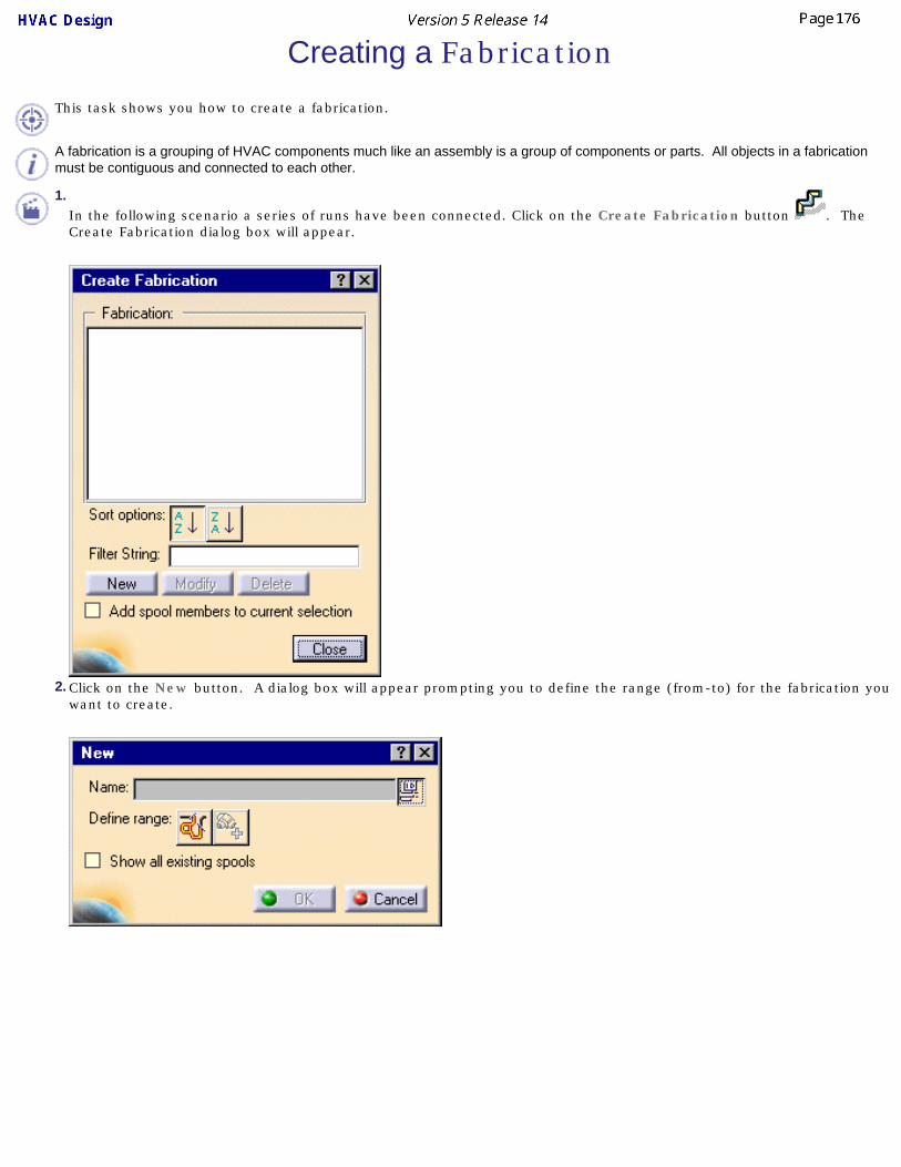
Creating a Fabrication
This task shows you how to create a fabrication.
A fabrication is a grouping of HVAC components much like an assembly is a group of components or parts. All objects in a fabrication must be contiguous and connected to each other.
1.In the following scenario a series of runs have been connected. Click on the Create Fabrication button . The Create Fabrication dialog box will appear.
2. Click on the New button. A dialog box will appear prompting you to define the range (from-to) for the fabrication you want to create.

3.Click the Define elements in range button . The Analyze Networks dialog box will open.
4. Click on the Path tab and select the From and To objects of the fabrication you want to create. The image below shows the selected fabrication.
5. The fabrication is highlighted in the 3D viewer as are its members in the specification tree. The Analyze Networks dialog box displays
the From object and To object as well as the Number of objects in the current path.

6.Click the Close button on the Analyze Networks dialog box.
7. The New dialog box opens again allowing you to name the fabrication you just created. You may accept the default name or assign a
name of your choosing. Click on the Use ID Schema button to activate the Name field and enter the name for the fabrication. Click on the Use ID Schema button if you want to revert to the name assigned by the application. When finished, click OK. The fabrication is created.
Click the Append current selection button to add another range of elements to the current selection.8. You can click the Show all fabrications feature in the New dialog box shown in Step 2. All fabrications in your document will be
highlighted.Click again on the Create Fabrication button to see the list of fabrications you have created.

Modify the Properties of a Fabrication
This task shows how to modify the properties of a fabrication.
1. With the part displayed, click on Edit in the menu bar, or right-click on the fabrication in the Specifications tree and select Properties. The Properties dialog box displays.

The Properties dialog box will display tabs, most of which are used in all products. The Graphic tab allows you to change the appearance of the object. Under the Product tab you can include additional descriptive and historical data and make changes, such as renaming, to the basic Product in the specifications tree. See Infrastructure documentation ( Basic Tasks - Manipulating Objects - Displaying and Editing Graphic Properties) and Product Structure documentation (User's Tasks - Modifying Component Properties) for more information. Click the More button if you want to see other tabs.3. Click on the Product tab to display properties and enter the values and information in the fields provided. 4. Click Apply or OK. The properties will be edited.Some objects have discrete values - which means you may only select certain values. In that case you will be able to display a drop-down box and select one of the values in it.
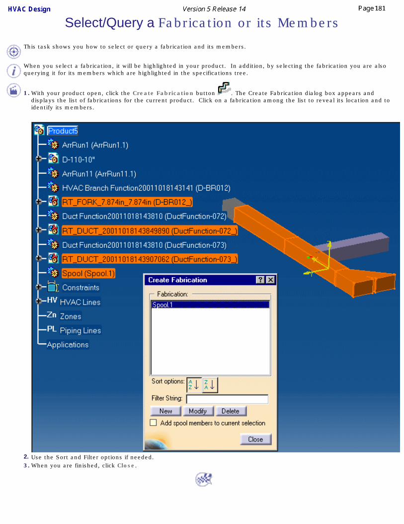
Select/Query a Fabrication or its Members
This task shows you how to select or query a fabrication and its members.
When you select a fabrication, it will be highlighted in your product. In addition, by selecting the fabrication you are also querying it for its members which are highlighted in the specifications tree.
1. With your product open, click the Create Fabrication button . The Create Fabrication dialog box appears and
displays the list of fabrications for the current product. Click on a fabrication among the list to reveal its location and to identify its members.
2. Use the Sort and Filter options if needed. 3. When you are finished, click Close.


Add/Remove Members in a FabricationThis task shows you how to modify a
1. With your document open select the fabrication you want to modify and click the Modify button.
2. The Modify dialog box displays. You can redefine, extend the range to add additional members, or
remove members from the fabrication.
When modifying a fabrication, your options are limited to extending its range to include additional members or removing members. Remember that members may only be removed from the ends of a fabrication. The 'Remove members' feature will only let you remove members from the end of the fabrication.

3. Click to activate the Show all fabrications option. This will highlight all fabrications in the product.
4. To remove a member select the Remove members option. Click on either the Keep all elements on first
half button or the Keep all elements on second half button depending on which end you want to remove members from. If you clicked on Keep all members on second half, you will remove members, one at a time, from the first half (end) of the fabrication. Clicking on the Keep all members on first half button will remove members beginning at the other end of the fabrication. In the view below, members have been removed from the first half of Fabrication-003.

5. To add a member to the fabrication, activate the Define new range feature and click on the Define
elements in range button . The Analyze Network dialog box displays. Under the Path tab the range is undefined. Reselect the beginning and end of the fabrication to add the members.
6. The new members are added to Fabrication-003.
7. Click OK and then Close the Create Fabrication dialog box.

Renaming a FabricationThis task shows you how to rename a fabrication.
1.Click the Create Fabrication button to bring up the dialog box showing the list of fabrications in the current document. Select the fabrication you want to rename and click on the Modify button. The Modify dialog box will display.
2. Enter the new name for the fabrication and press Enter. 3. When finished click OK. The fabrication will be renamed.
4. To revert to the default naming convention click on the Use ID Schema button .

Deleting a FabricationThis task shows you how to delete a fabrication.
1. Click the Create Fabrication button to bring up the dialog box showing the list of spools in the current document.
2. Select the fabrication you want to delete and click the Delete button.3. When finished click Close. The fabrication will be deleted.

Flow DirectionThis section discusses management of flow direction.
Displaying Flow DirectionChanging the Flow Direction
Display Connector Flow Direction

Displaying Flow Direction
This task shows you how to display the flow direction.
1.With your document displayed click the Manage Flows button . The Manage Flows box displays.
2. Click one of the buttons in the Manage Flows box to set the Selection mode. You can set the flow for selected elements in range, for a spool (if defined), or for a line ID.
3.Click the Select Elements button . The Analyze Networks dialog box displays. Click the first and last objects in the range whose flow you want displayed. Make sure you click the part, and not just the run. The objects you selected will display in the Analyze Networks box in the From Object and To Object fields.
4. Close the Analyze Networks box. The flow direction will display. (The Flow Options box will also display - you use it to change flow direction as explained in Changing the Flow Direction.)
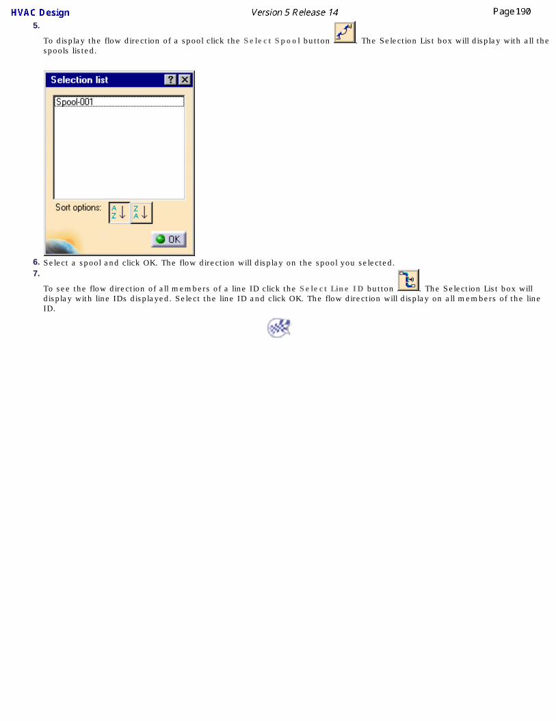
5.
To display the flow direction of a spool click the Select Spool button . The Selection List box will display with all the spools listed.
6. Select a spool and click OK. The flow direction will display on the spool you selected.7.
To see the flow direction of all members of a line ID click the Select Line ID button . The Selection List box will display with line IDs displayed. Select the line ID and click OK. The flow direction will display on all members of the line ID.

Changing the Flow Direction
This task shows you how to change the flow direction.
1. With the flow direction displayed, as explained in Displaying Flow Direction, select the Single Element option in the Flow Options box.
2. Click on one of the flow direction arrows so that it points in the direction you want. In the image below the flow direction of the
last arrow has changed.
3. Click the option All connected elements to one direction in the Flow Options box and then click the flow direction arrow again. All parts connected to it (in the range that you selected) will change flow direction to the same direction as the selected arrow.
The flow direction will not change in a tee, or beyond a tee, even though it is connected and within your selected range.
If the flow capability was defined when a part was built, you will not be able to change its flow direction using this command.


Display Connector Flow Direction
This task shows you how to display the flow direction of a connector.
1.
Click the Analyze Item button .
2. Move your pointer to a connector. If the flow direction has been defined for that connector then a blue arrow will display, showing the direction of flow. If flow direction has not been defined then an arrow of a different color (usually green) will display.

Routing TasksThis section explains some routing tasks that are in addition to the ones explained in the Basic Tasks section.
Aligning a Run to an Existing SurfaceRouting in 3D with the Compass
Routing at an Offset of a RoutableRoute a Run Along a Spline
Fixing Broken RoutablesEdgeline: Routing Parallel to a Run

Aligning a Run to an Existing Surface
This task shows how to align a run to an existing surface or edge while in directional routing mode.
This function uses the compass to align a run to the surface or edge. It is assumed that you have taken the steps necessary to start a run. See Routing a Run on an Area.
1.In the directional routing mode move the compass that shows at the end of the run to the edge whose angle you want to emulate.
2. The Z axis of the compass (it may read W) assumes the angle of the edge against which it is held.
3. At the same time the last segment of your run assumes the angle of the compass' Z axis.4. Click once at the end of the segment to move the compass back to it. You can repeat the action
to make the run align with any other edge or surface in the area.5. Double click to end the run.
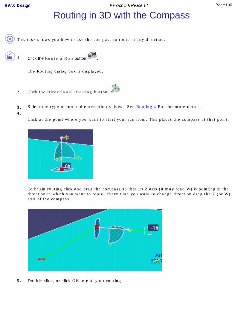
Routing in 3D with the Compass
This task shows you how to use the compass to route in any direction.
1. Click the Route a Run button .
The Routing dialog box is displayed.
2. Click the Directional Routing button.
3. Select the type of run and enter other values. See Routing a Run for more details.
4.Click at the point where you want to start your run from. This places the compass at that point.
To begin routing click and drag the compass so that its Z axis (it may read W) is pointing in the direction in which you want to route. Every time you want to change direction drag the Z (or W) axis of the compass.
5. Double click, or click OK to end your routing.

You can also double click on the compass to bring up the Compass Manipulation dialog box, which allows you to enter values to modify compass direction and/or location.

Routing at an Offset of a Routable
This task shows you how to route a run at an offset of a routable. This function allows you to create a run parallel to an existing run a defined distance apart.
1.Click the Create an Offset Route button .
2. Select a segment of the run to which you want an offset. The compass is placed on the segment.3. The direction in which the Z axis of the compass is pointed determines where the new run will be placed: you can place the
new run or runs to the inside, to the outside or stacked on top of the existing run by adjusting the compass.4. Enter your options in the Run dialog box.5.
Click either the Constant Radius or Constant Clearance button. If you click the Constant Radius button the radius of the turns will be maintained but the offset distance will vary. If you click the Constant Clearance button the offset distance will be maintained but the radius of the turns will change. Click OK. The new runs will be created.
A negative offset may be entered to offset in the opposite direction to the compass Z direction.
In the illustration below the runs have been created with the Constant Clearance option.
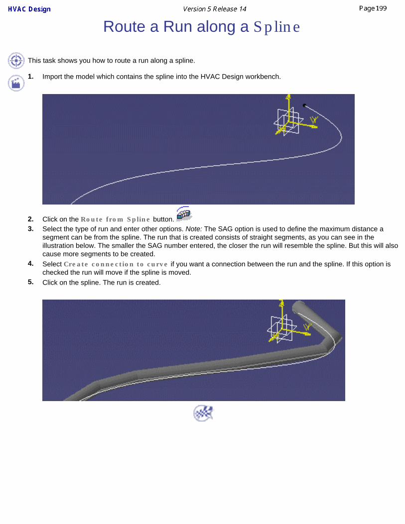
Route a Run along a Spline
This task shows you how to route a run along a spline.
1. Import the model which contains the spline into the HVAC Design workbench.
2. Click on the Route from Spline button. 3. Select the type of run and enter other options. Note: The SAG option is used to define the maximum distance a
segment can be from the spline. The run that is created consists of straight segments, as you can see in the illustration below. The smaller the SAG number entered, the closer the run will resemble the spline. But this will also cause more segments to be created.
4. Select Create connection to curve if you want a connection between the run and the spline. If this option is checked the run will move if the spline is moved.
5. Click on the spline. The run is created.

Fixing Broken RoutablesThis task shows you how to fix - or rejoin - routables in which segments have become separated. In the illustration below, the dotted line - the broken routable indicator - shows that a run has become separated at that point.
You can re-join the run in one of several ways, depending on the nature of the break and your requirements. The methods are as follows:1. Bring up the Definition dialog box for the run, then place the mouse pointer over the broken routable indicator and click the right mouse button. This will display a pop-up
menu. Click Create Segment.
2. Bring up the Definition dialog box, then drag one of the segment handles to re-join the run.

3. Bring up the Definition dialog box. An arrow will display at each end of the broken routable indicator. Drag one of the arrows (depending on circumstances) to re-join the run. In the illustration below, one segment of the run has been moved to connect to the portion of the run still connected to the pump.
4. In certain cases you will see the Auto Route option beneath the Create Segment option in the pop-up menu (See Step 1). This happens when a segment connecting two parallel routables (which are on different X-Y planes) is broken.
● Select Auto Route. The Auto Route dialog box will display.
● Click the Toggle Next Solution button . Options for re-joining the run will be shown as a dotted line.
● Click OK to make your selection.


Edgeline: Routing Parallel to a Run
This task shows you how to route parallel to, or at an offset of, a routable. See also Routing at an Offset of a Routable and Position Segment Relative to a Plane.
This function is used when you have an existing run and want to route parallel to it, or at a certain clearance from it. It is sometimes known as edgeline routing. You can also place an offset plane on a surface and use it as a reference point.
1.Display the run you want to route parallel to and click on the Route a Run button . The Run dialog box displays.
2.Click on the Edgeline button . The Distance field will display and the Offset and Clearance
buttons will appear on the Run dialog box.
If you click the Offset button the distance between the two runs will be measured from centerline to centerline. If you click the Clearance button the distance between the two nearest edges will be measured. If there is a part on a HVAC, piping or tubing line the distance will be measured from the part. If there is no part the distance will be measured from the line.

3. Enter the distance between the two runs. If you enter 0 and click the clearance button, the two runs will touch at the edges.
4. Click at the starting point. The compass will display at that point.
5.Move the compass so that the Z axis points in the direction that you want to route, which should be in the direction of the run that you want to parallel. You can do this by moving it manually, or by clicking the second mouse button once and then toggling the shift key.
6. Once you have the direction selected, route toward the run you want to parallel. Once the centerline of the target run is highlighted you can press the Shift key to toggle between various "solutions," or various sides. In the images below there are only two solutions and you can route on two sides of the target run.
7. Select the target run after you have decided which side you are routing on.
8. Begin routing and double click to end. The finished run is shown below.

You can place an offset plane on a surface and use it as a reference to route parallel to, or to keep a certain clearance from. After placing the offset plane use the procedure described above.

Building HVAC PartsThis section explains ways of creating and using resources.
Create HVAC Part with Specified TypeDefine Graphic Representations for a Part
Defining the Part TypeDefine Properties for a Part
Associate Specifications to a ConnectorChange the Parameters of a PartBuilding a New Unique ReferenceRequirements for Building Parts
Creating a Light Object
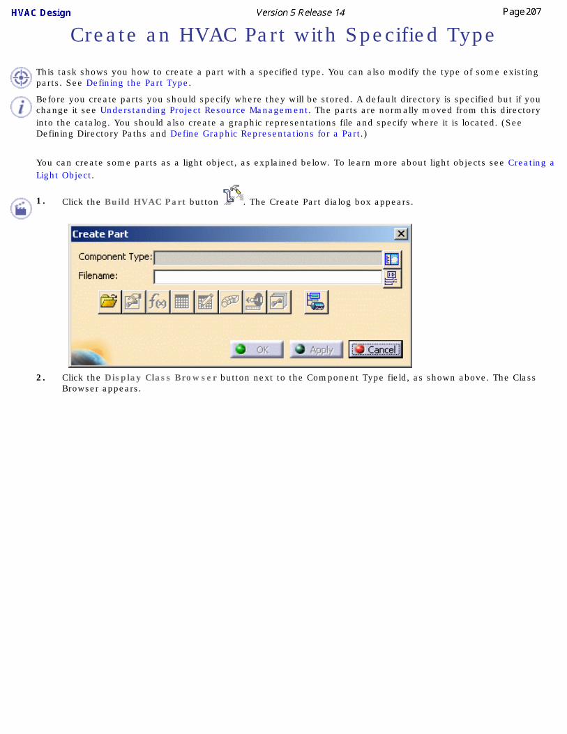
Create an HVAC Part with Specified Type
This task shows you how to create a part with a specified type. You can also modify the type of some existing parts. See Defining the Part Type.
Before you create parts you should specify where they will be stored. A default directory is specified but if you change it see Understanding Project Resource Management. The parts are normally moved from this directory into the catalog. You should also create a graphic representations file and specify where it is located. (See Defining Directory Paths and Define Graphic Representations for a Part.)
You can create some parts as a light object, as explained below. To learn more about light objects see Creating a Light Object.
1. Click the Build HVAC Part button . The Create Part dialog box appears.
2. Click the Display Class Browser button next to the Component Type field, as shown above. The Class
Browser appears.

3. The Class Browser allows you to select the type of part you want to create. Navigate to the type you want by clicking on the "plus" sign next to each directory, or by using the three navigation buttons at the bottom. You can also filter for certain types. For instance, you can enter "duct" in the Filter field and press Enter to see all duct types. Click OK after making your selection.
Certain parts can be created as light objects - as of R13 these were weld, straight routable part and bendable. If you select one of these types in the class browser then the Create Part dialog box will display a checkbox "Make
light object" . The default is checked. If you do not want to create a part as a light object then uncheck this.4. The File Open button is used to bring up a part, say, if you did not finish creating it and had to close the
application. Using the File Open button you can navigate to the directory where the part is stored.
5.
The Define Properties button brings up the Properties box, allowing you to change properties if needed.

6.
The Override Parameters button button brings up a dialog box which allows you to override a parameter. When you click on a parameter on the left side of the box and then click on the arrow to bring it on the right side, that means the parameter can be overridden. (See Change the Parameters of a Part.) When you place this part the application will try to determine a value for that parameter. If it cannot, you will be asked to enter one.
7.Click the Design Table button to create a design table and associate it to the part you are creating. For more information on this see the Infrastructure document - Advanced Tasks - Using Knowledgeware Capabilities.
8.
Click the Formula button to create formulas and parameters. See the Knowledgeware document mentioned above for more information.
9.
The Define Connectors button allows you to add connectors.10.
The Define Connector Specifications button lets you associate specifications to connectors.
11.
The Manage Representation button lets you create and manage graphic representations.
12.Click the Define ID Schema button next to the Symbol Name field if you want the application to generate a name for the part.
13.
The Set Type button lets you define the type of the part.

14. Enter a name for the part in the Symbol Name field and hit Enter. Click Apply or OK. The part will be created. In the illustration below it has been named Rect Mitrd Elbow1.
The part has been created but it still does not have a graphic representation - it has no "looks". You will learn how to create one or more graphic representations for the part in subsequent tasks.
If you are creating a part as a light object you do not need to create geometry or graphic representations. Instead you can save the part.
15. You must save the part to the directory specified in your Options dialog box. Double click on the part (Rect Mitrd Elbow1 in the image above) to make it active and then use the File menu to save it.

Define Graphic Representations for a Part
This task shows you how to create multiple graphic representations for a part.
Once you have created a part and specified a type, you can create one or more graphic representations, i.e., create the body of the part. You can define multiple graphic representations when you need to show more than one graphic of the same component. For instance, you may need to show a pipe as "double", which is like a 3D version, as "single", which means represented by a single line, or "envelope", which also includes the working area needed around the pipe or equipment. These three categories are included with this application. A fourth category is also included, "exact", which is normally used for detailed representation and is used mostly for parts. You can create these three graphics of the same pipe and place whichever one you prefer in a document.
Before you create multiple representations you should set up a Graphic Representations file. (See Understanding Project Resource Management for how to do this.) A Graphic Representations file allows you to classify each graphic that you create into a specific category. In addition to the four categories that come with the application and that were described above, you can create categories based on your specific needs. 1. When you create a part as explained in Create HVAC part with specified type, it is given the first classification
listed in your Graphic Representations file. In this example it is Double as shown in the illustration below. To start making graphic representations for the part, you will first create a graphic for the Double representation that you have already created. To do this double click on Elbow1 to bring up the Part Design product. (Not all users may have a license for Part Design - contact your system administrator.)
2. Create your part (in this case an elbow) using Part Design. (See Part Design documentation if you need help.)
You have now created the Double graphic representation of the part.

3. To create a second graphic representation, double click on Elbow1 (Elbow1.1) to return to HVAC Design.
4.Click on the Build HVAC Part button to display the Create Part dialog box and click on the elbow to make it active. The buttons at the bottom of the Create Part dialog box will become active.
5.Click on the Manage Representations button . The Manage Graphic Representations dialog box will display.
6. The Defined column shows which representations exist for the part. If a name has No against it you can create a representation by clicking on No. It will change to Yes and the graphic name will be added to the specifications tree. You now need to create a body for it, as described above. In the illustration below you can see both double and single representations. The single representation is the white line running through the 3D elbow.

Use the Associate button to change the name you have already assigned to a graphic representation. To do this, select the graphic name you want to change to in the Manage Graphic Representations dialog box, click the Associate button and select the graphic, either in the viewer or in the specifications tree.
7. After you have added one or more graphic representations for that part, return to Part Design to create the graphic, as explained above.

Defining the Part TypeThis task shows you how to define a part type.
You can only define the type of a part that does not already have a type assigned to it. This means that the part must be newly created, or it should be an existing part that has no type assigned (such as a CATPart from a product such as Systems Routing). Piping Design is used as an example here. Substitute directories as needed.
1. Click the Set Object Type button . The Set Object Type dialog box displays.
2. Click the Open Existing Part button next to the Filename field and navigate to the part you want to modify. Click Open on the File Selection dialog box. The file will display in the Filename field.
3. Click the Display Class Browser button next to the Component Type field. The Class Browser will display.
4. Expand the tree in the Class Browser and select the part type that you want to assign to the part. Click OK. The type will be assigned.
5. Click OK in the Set Object Type dialog box.
At this point a copy of the part is saved in the CATTemp directory under C:\..\..\Local Settings\Application Data\DassaultSystemes.
Proceed with the Build Part cycle, i.e., Define Properties, Formulas, associate a Design Table, manage Override Parameters, Define Connectors, Associate Specifications to the Connectors, and Manage Graphic Representations (as applicable).

6. To save the part, activate the part level in your product, then click File - Save As.
Save the part in \..\..\intel_a\startup\EquipmentAndSystems\Piping\PipingDesign\ComponentCatalogs\Parametric. (Replace Piping\PipingDesign with the workbench you are in.)
7. FOR EQUIPMENT ARRANGEMENT ONLY
You can select the part in your document to bring up the Class Browser. This will only work if the part you select has not had a type assigned to it, such as when you are building the part. Also, note that when you use this method of assigning a type you will only be able to assign the Resource type. You will not be able to select any other type. To follow this procedure, click the Set Object Type button (in the Create Part dialog box or in the toolbar). The Set Object Type dialog box displays. Click the part to display the Class Browser and select the type. You can continue building the part.


Define Properties for a Part
This task shows you how to add properties to a part.
1. With the part displayed click on the Build HVAC Part button to display the Create Part dialog
box and then click on the Define Properties button . The Define Properties dialog box will display.

2. Click on the HVAC tab to display properties and enter the values you want.
3. Click Apply or OK.

Associate Specifications to a Connector
This task shows you how to associate specifications to a connector.
You must associate specifications to a connector for the following attributes. ● Endstyle
● Nominal size
● Rating
● Schedule
● Wall thickness
"Associating specifications" here means that you must enter how many sizes each of these attributes has. The reason for this is explained below. You can see from the image of the reducer below that because of its shape it is going to have two nominal sizes. The other attributes may have one or more entries. to a connector in these fields because a compatibility check is done when you place a part and these fields must have data or you will get an error message. Of course, you will also get an error message if the compatibility check determines that the part is incompatible in the situation where you are trying to place it - the wall thickness or the size do not match, for instance.
You do not need to enter the size of the part, only how many sizes each of these attributes has. You must enter 1 if it has only one size. When you are placing the part at design time, the application will determine how many sizes you specified for, say nominal size. If you specified one size, it will determine what this size should be by examining the situation in which the part is being placed and then look at tables to determine whether you included that size in your catalog.

1. With the part displayed click on the Build HVAC Part button . The Create Part dialog box will display.
2.Select the part and click on the Define Connector Specifications button . The Connector Specifications dialog box will display. In the illustration below, it shows columns for two connectors because there are two connectors on the reducer.

3. Enter your specifications by selecting the number in the drop down box next to each attribute. Click the Auto Assign button to assign the values to the connectors. They will display in the box as shown below.
4. You can modify the associated specifications by selecting in the Specification field. Select the attribute you want to modify and then select the number in the Specification field. For instance, if you want to change Connector 2 to Nominal size instead of Nominal size_2, select it and then select Nominal size in the Specification field.
5. Click OK when you have finished.
You must save the file to the directory in which you store the parts that you create. See Create a HVAC Part with Specified Type.

Change the Parameters of a Part
This task shows you how to change the parameters of a part.
1. Select a part, in this case an elbow at the end of an HVAC duct, and click the Edit Part
Parameters button . The Manage Override Parameters dialog box displays.
2. The box displays parameters that can be overridden for the part you selected. In this case, we will override the Angle parameter. Parameters that can be overridden are assigned to a part when you build a part of a specified type.

3. When you select the parameter the current value appears in the = box next to Edit value of the current parameter.
4. Enter the new value, for example 60deg, and click Apply. The angle of the elbow will be updated to 60 degrees.
5. Click OK to close the dialog box.
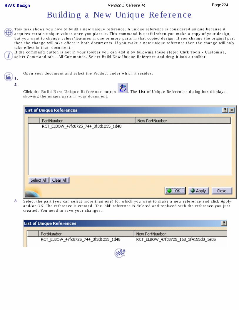
Building a New Unique ReferenceThis task shows you how to build a new unique reference. A unique reference is considered unique because it acquires certain unique values once you place it. This command is useful when you make a copy of your design, but you want to change values/features in one or more parts in that copied design. If you change the original part then the change will take effect in both documents. If you make a new unique reference then the change will only take effect in that document.If the command button is not in your toolbar you can add it by following these steps: Click Tools - Customize, select Command tab - All Commands. Select Build New Unique Reference and drag it into a toolbar.
1.Open your document and select the Product under which it resides.
2.
Click the Build New Unique Reference button . The List of Unique References dialog box displays, showing the unique parts in your document.
3. Select the part (you can select more than one) for which you want to make a new reference and click Apply and/or OK. The reference is created. The 'old' reference is deleted and replaced with the reference you just created. You need to save your changes.

Requirements for Building Parts This task lists certain requirements for building parts. You should incorporate these when you are building parts, or part behavior will not be as expected. Instructions for building parts are given elsewhere in this manual, including in the section Building Parts. Connectors are explained in the section Connectors. Instructions for using the Part Design product are given in the Part Design User Guide. The column headings below mean:
● Part Type: The part type to which the requirements apply.
● Geometrical requirements: The requirements you must incorporate when you are creating the geometry for the part.
● Properties: The requirements you must incorporate when defining these properties.
● Override parameters: The properties shown here must be defined as override.
● Connector type: The type of geometry needed for creating connectors.
Part Type Geometrical Requirements Properties Override
Parameters Connector Type
Straight
(stretchable)
Regular object: ● No requirements
Light object:
● No geometry required
● No requirements Piping: ● PipeLength
HVAC:
● Diameter
● Width
● Height
● DuctLength
Regular object: ● Use existing
geometry
Light object:
● Define new geometry
Bendable/Flexible
Regular object: ● PartBody named
using the default representation name (i.e. "Double")
● Profile sketch and Rib feature need to exist in the primary PartBody.
● PartBody named "Hidden"
● Spine sketch needs to exist in the "Hidden"
● OpenBody named "RibPath" which will be empty
● No requirements Piping: ● No override
parameters
HVAC:
● Diameter
● New geometry
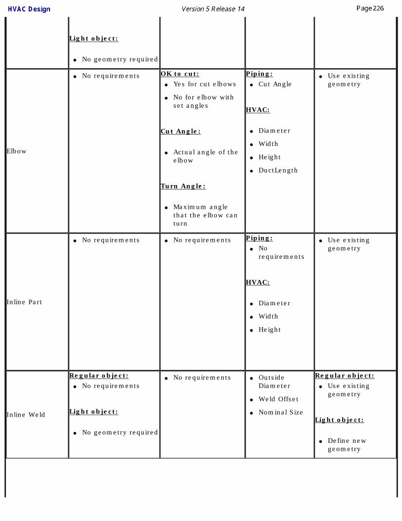
Light object:
● No geometry required
Elbow
● No requirements OK to cut: ● Yes for cut elbows
● No for elbow with set angles
Cut Angle:
● Actual angle of the elbow
Turn Angle:
● Maximum angle that the elbow can turn
Piping: ● Cut Angle
HVAC:
● Diameter
● Width
● Height
● DuctLength
● Use existing geometry
Inline Part
● No requirements ● No requirements Piping: ● No
requirements
HVAC:
● Diameter
● Width
● Height
● Use existing geometry
Inline Weld
Regular object: ● No requirements
Light object:
● No geometry required
● No requirements ● Outside Diameter
● Weld Offset
● Nominal Size
Regular object: ● Use existing
geometry
Light object:
● Define new geometry

Branch Weld
Regular object: ● No requirements
Light object:
● No geometry required
● No requirements ● Outside Diameter
● Outside Diameter2
● Weld Offset
● Nominal Size
● Nominal Size2
Regular object: ● Use existing
geometry
Light object:
● New geometry

Creating a Light ObjectThis task explains what a light object is and how you should use it. The procedure for creating a light object is explained in Create a Part with Specified Type in the section Building Parts.
You should build a part as a light object in order to save disk space and ensure faster loading of your documents.
1. As of Release 13 only three types of objects can be created as light objects. These are:● Weld
● Straight routable part (round or rectangular)
● Bendable (round or rectangular)
Only parts that are meant to be placed as unique references should be created as light objects. The reason is that when you place a "heavy" part (refers to a parametric part that is not created as a light object) in your document, you end up creating a separate sub-document for each unique reference. This is not the case when you place a resolved part - the placed part simply points to the catalog and a unique document is not necessary.
The light object approach applies the concept of a resolved part to a unique reference. When you build a part as a light object you do not create the geometry or graphic representation (using the Parts Design application) of the part. Instead you build the part, designate it as a light object, as described the section Building Parts, and place it in a catalog. When you place the part in a document this application will automatically create the visualization for it.
You should also note that differing lengths of a placed light object do not result in the creation of a separate document for each placement. As an example, when you first place a 10-inch pipe in a document, a separate sub-document is created for that part. However, when you place a 10-inch pipe again in the same document - whatever the length - a separate sub-document is not created. All instances of a 10-inch pipe will refer to the first document that was created.
You cannot change an existing "heavy" part into a light object. It must be initially created as a light object.

Using ENOVIAThe following information is provided as a brief understanding of the ENOVIA environment and what is needed to work with ENOVIA in conjunction with the CATIA Engineering and System suite of products. Please refer to ENOVIA documentation for more detailed information on specific ENOVIA usage and functionality.
The ENOVIA, CATIA and DELMIA products based on Dassault Systemes' industry-renowned V5 enterprise architecture provide a complete solution for customer PLM requirements.
The ENOVIA product line provides the PDM component of the overall solution. With the ENOVIA product, users can effectively manage the entire product life cycle of their data, including data management, work flow management, people and organization management, and many other aspects of their product and business.
Creating a ProductImporting a ProductUsing Work Packages
Saving a Work PackageOrganizing Work Packages
Also refer to information in the Customizing section.

Creating a ProductThis task explains how you should create a product. ENOVIA and CATIA should be running and connected.
You should be in the ENOVIA home page .You should familiarize yourself with the directory structure in ENOVIA. At the top level you will have a directory called product class root - this usually encompasses all the activity in your company. Under this you may have several product class directories. Under the product class will be the product directories. Product displays in this application, the other two are only displayed in ENOVIA. Users will mostly interact with the product. It is created at individual project level - in a shipyard it will be created for each ship that is designed - and work packages, explained later in this section, are created under the product. The product class directories may not be created in smaller projects, but the product class root and the product directories should always exist. 1. Information about creating all three levels is provided in ENOVIA documentation. Briefly, to create a
product you should be in the Product Class View.
Right click on the product class, select New and then Product in the menus that display. Enter a name for the product in the product ID field. Add to the Name and Description fields for informational purposes if you want. The newly created directory displays in the Product Class View.
2. Click the Save button to save your changes.A Characteristics window displays after you create a directory. You do not need to enter any information in it. Read the ENOVIA user guide to learn more about this window.

Importing a ProductThis task explains how you import a product, and work packages, from ENOVIA.
You need to import the product because you will be creating work packages under it. The top level directories - product class root and product class - remain in ENOVIA, only the product is imported. You must import the product (and existing work packages) each time you start a new session.
1. In the Product Editor, right click on the product and select Send To - XXX, XXX being the application you are sending it to (such as CATIA V5). The product displays in the specifications tree.
2. You also need to import all the work packages that you need from ENOVIA to this application each time you start a new session. The process is as described above (select the document
associated with the work package and go to Step 2 above). Note that if you send a work package then the product is also sent - you do not need to send both.
You can use filters to determine which work packages you need. It is best, though not essential, to import all the work packages that you need in one operation.

Using Work PackagesThis task explains the concept of work packages and how to create them. You can save work packages in an ENOVIA database, or save them to a local drive or server. You should also refer to Connections Between Work Packages and Managing Publications.Work packages are necessary for efficient data organization and concurrent engineering. The biggest benefit, perhaps, is that they allow you to organize data in easily manageable units. Concurrent engineering refers to the practice of having several people, maybe even hundreds, work on the same project. If the design is created in one document then only one person can work on it. Creating several work packages provides the answer, by creating several documents under one root document.
Each document (or work package) contains the portion of design that one person is working on - such as placing equipment in one compartment of a ship. "Publications" are automatically (see below) created at the locations at which different documents connect. Each work package thus 'knows' where it belongs within the product. If something is moved - say equipment to which a run connects - then the user will be alerted about it. The steps central to using work packages are explained below.
Work packages must be organized in a certain way. See Organizing Work Packages to learn how to do it.1. CREATE A WORK PACKAGE: To create a work package, select the product and, in the menubar,
click Insert - New Product. In the simple example below two work packages have been created. One contains the equipment and the other contains the run and piping that connect the two pieces of equipment. Thus, the person who owns the equipment work package can open the document at the same time that the piping engineer is working on his work package.
2. ADD DOCUMENTS: However, in order to be able to route from the equipment, the piping engineer will need to be able to see the equipment. In order to do this the piping engineer will need to import the equipment document. See Importing a Product for more information. Once he has imported both documents he can make the piping document active and begin routing in it. When he saves, the piping information will be saved in the piping document.
3. PUBLISH CONNECTORS: As stated earlier, publications need to be created so that a connection can be established to objects in other work packages. To take the example given above, the piping engineer has both documents open, but he has write access only to the piping document, which he created. When he routes between the equipment publications are only created in his own document. Publications are needed so that the connections between components are retained. To ensure that publications are created even when someone without write access to a document connects equipment, connectors must be published. In this case the equipment engineer needs to publish the connectors on the equipment in his document so that when the piping engineer creates runs publications are created on the equipment also. In most cases this is done when the part is placed, because most parts do not exist in isolation and need to be connected to something. To learn how to create connectors and publish/unpublish them see Creating Connectors.

Saving a Work Package This task gives a brief explanation about a simple save operation after creating or working on work packages. To learn more about the Save operation, and what the various options mean, you must see ENOVIA documentation. 1.
Click the Save in ENOVIA LCA Server button . The Save in ENOVIA dialog box displays.2. Click OK to save the work package.

Organizing Work PackagesThis task explains how you should organize the work packages that you create.
This type of organization is usually done by an administrator. See ENOVIA documentation for more information on components.
1.Work packages must always be created at the same level in the specifications tree, under the Product. However, users can create "components" using the Component Editor, and group work packages under these components.
2.To create a component, expand your tree in the Product Editor so that the Product is visible. Right click on the Product, select Send To and then Component Editor. The Component Editor opens with your Product visible.
3.Right click on the Product and select Insert Child. In the Product pane that displays, make sure Generic Component is selected in the Type field. Enter a name for the component in the Product Component ID field, in this example PipingComponent. Make entries in the Name and Description fields (for informational purposes) if you want to, and click Add or OK. The component you created displays under the Product.
Make entries in the Name and Description fields (for informational purposes) if you want to, and click Add or OK. The component you created displays under the Product.
4.Save your changes.

5.When you open the Product Editor again you will see three columns, with the first column showing the product and the newly created components, the second column showing the work packages and components, and the last column showing characteristics - if you select an object. If you do not see work packages in the second column then right-click on the product and select Open Assembly in Instance View.
6.To group one or more work packages under the component, right click on a work package and select Copy.
7.Next, right click on a component, and select Special Paste - Link. The work package will be grouped under that component.
8.Save your changes.

Creating and Modifying ConnectorsThis section explains ways of creating, modifying and deleting connectors.
Create ConnectorsUse the Compass to Manipulate Connectors
Modifying or Deleting ConnectorsCreating Duplicate ConnectorsUsing the Plane Manipulator

Create Connectors This task shows you how to create a connector. Connectors can only be created on objects that have existing geometry that satisfies the rules of connector creation. If existing geometry is not present, you will have to create the geometry.
1. If the resource is not active, make it active by double-clicking in the specifications tree.
2. Click the Build Connector button. This will bring up the Manage Connectors dialog box.The Manage Connectors dialog box will list all connectors on the selected part. To see a connector and its associated geometry on the part, select a connector from the list.
Adding a connector is explained below; Delete, Modify and Duplicate are explained elsewhere in this section. To Publish a connector means you are allowing people who do not have write access to your document to establish a connection. This is explained further in Using Work Packages. You can Publish or Unpublish connectors using the two buttons.
3. Click the Add button. The Add Connectors box displays.

Select the type of connector - piping, HVAC, etc.
In some applications the flow direction field will be available. The piping (or tubing) part connector has flow direction built in and you must select a flow direction also from the drop down menu. The mechanical part connector has no flow direction.
Another type of connector - the nozzle connector - will be available if you are placing a connector on a nozzle. A nozzle connector must be placed on the end of the nozzle that connects to equipment. A part connector is placed on the end that connects to the pipe or duct.
An electrical part connector should only be placed on a socket. The electrical part connector should be placed on the end of the socket that connects to equipment. A cableway part connector should be placed on the free end of the socket that does not connect to equipment.
When you are placing a connector on a Bendable, such as a bendable pipe, you must use the Define New Geometry option. You must not use existing geometry to place the connector.
You can name each connector by selecting in the Name field. This is useful for some functions, such as designing using a schematic.
The concept of Publishing or Unpublishing a connector is explained above. Check the checkbox as necessary.

Face, orientation and alignment are explained below.The orientation, alignment and face must be defined correctly before a connector can be created. To explain what these are, the face is the surface to which you attach a connector. As an example, if you want to attach a clock to your office wall, the wall is the face. You want the numeral "12" to be up, so you orient the clock accordingly. This is the orientation. The alignment is the direction in which the clock face is pointed - normally it would be perpendicular to the wall. When creating a connector, the alignment always has to be perpendicular to the face.
The face is generally defined using a face of the part, such as the end of a pipe. Alignment is usually defined using a line, such as the not-shown line along the centerline of a pipe. Orientation is defined using the xy plane, or another plane or face to define an "up" direction.
In the illustration below the Z axis indicates the alignment of the connector. It also indicates the direction in which routing will occur. The X and Y axis together define the orientation. They are useful when attaching two resources.
It is necessary to select geometry in the part to which you want to attach a connector so that these three characteristics are correctly defined. If the part does not have the necessary geometry then you must create it.4. If you want to create a connector using the part's existing geometry click the Use existing geometry
option.
Click the Select Face button to select a face. Selectable faces will highlight as you move your pointer over the part.
Click this button to select the alignment. You will only be able to indicate the alignment by selecting a line - from the construction geometry, or elsewhere in the part if there is one. You can only select a line that is perpendicular to the face plane.
Click this button to select the orientation. You will only be able to select a plane that is

perpendicular to the face you selected.
Some connector types require you to place a datum point. The datum point is placed by clicking this button and then clicking a 3-D point on the part. The datum point is used as follows:
● Lofted reservation section: Datum is used to define where the spline will start and end when creating lofted reservations.
● Tubing & waveguide parts: Datum is used to define where the spline will start and end when creating flexible tubes.
● Hangers: See Hanger Design documentation.
You can display the part construction geometry, if there is any, to make it easier to select existing geometry. Do this by:
● Right click on the part entry in the specifications tree.
● Click Hide/Show. The part will disappear from the screen.
● Click the Swap Visible Space button . The part will reappear on your screen with the construction geometry visible. Clicking the button again will toggle you back.
5. The fields under Classify Connector will become available after you have successfully selected the geometry explained in Step 4. Click on the down arrows to make your selection.
Select a type.
For Flow direction, select In, Out, InOut or None.
Select the Face type. A Hole connection allows a routable to pass through it - it is useful for placing parts like clamps along a run without cutting a tube. A Face connection will stop a routable and not allow it to pass through.
Select an alignment.
Choose an orientation: Circular will allow the connector to attach to another connector at any orientation; round ducts and pipes, for instance, do not need a well-defined "up" direction because they can rotate. A Rectangular orientation is used for parts like rectangular ducts; they do not have a strict ''up" direction. Up allows the connector to attach to another connector or part in the up position: horizontal trays, for instance, require a well-defined "up" position. You can also use the "up" orientation for a hole connector. In the image below, the connector on the right has the up orientation, the connector on the left does not.

The number in the Number field is assigned by the application. This can be significant because when you are creating a new connector, you have the option of using the alignment and orientation used in the previous connector after you select the face. You can choose to do this, or select a new alignment and/or orientation.
6. Click OK. The new connector will be listed in the Manage Connectors box.
7. To define new geometry for placing a connector, select the option Define new geometry, then click
on the Select plane button . The Define Plane box will display.
8. Use the functions provided by the Define Plane box to reposition the connector, if necessary, as explained below. (The colors of the buttons may be slightly different in some applications.)
Click the Define Plane button to redefine the plane as well as the origin by clicking once on the face.
Click the Define Plane using Compass button to redefine the plane using the compass.
Click the Define 3-point Plane button to define the plane by clicking on any three points with your pointer. The connector will be placed on the first point you click.
Click the Define Line-Point Plane button to select the plane by clicking on a point and a line, like an edge. The connector will be placed on the first point you click.
Click the Define Line-Line button to select the plane by clicking on two lines. The plane will be defined by the first line selected. But if the two lines are parallel the plane will be defined as the plane in which both lines exist.

Click the Define plane at center of circle button to select the plane by clicking three points on the edge of a circle. This method is used for multi-CAD documents, usually for CGR circles. You can click at points where two lines meet or in the center of a face. The Z axis of the plane manipulator will be placed according to the right hand rule. If you click clockwise the Z axis will point into the object. If you click counter clockwise the Z axis will point out from the object.
Click the Define plane at product origin button and then the object to place the plane manipulator on the origin of the object. The plane manipulator axis will match that of the product.
Click the Define Orientation button to change the orientation. Click the button and then click a point or a line. If you click a point the X axis will point to it. If you click a line the X axis will become parallel to the line.
Use the Move Origin buttons to define the plane. Define Origin at Plane or Compass allows you to define the origin using the compass or plane command. You use the compass or plane as the base
plane along which the origin can be selected. Define Origin at Point or Center of Face lets you
select the origin by clicking on a point or face. Define Origin at Center of Circle allows to select the origin by clicking at three points - the origin will be placed in the center of an imaginary circle drawn using those three points. The plane and orientation will not change when using this command.
9. Click OK. The connector will be placed and the Add Connector dialog box will display again.<
10. Make your selections in the fields under Classify Connector as described in Step 5. Click OK.

Using the Compass to Manipulate Connectors
This task shows you how to use the compass to manipulate connectors placed on resolved parts.
You can use the compass to manipulate connectors placed on resolved parts only. Use this method when adding a new connector, or by using the Modify command. Both are explained below.
1. To manipulate while adding a connector, drag the compass and place it over the connector while the Define Plane box is displayed.
2. To manipulate using the Modify command, select the resource, click the Manage Connectors button and, in the Manage Connectors dialog box, select the connector in the connectors list. Click the Modify button.
3. The Modify Connectors box will display. You can now drag the compass and place it over the connector.
4. Click on one of the handles on the compass and manipulate the connector to the desired position. You can change alignment, orientation and origin using the compass.
5. Click OK on the Modify Connector or the Define Plane dialog box when done. Remove the compass from the
connector by dragging it to the axis.

Modifying or Deleting Connectors
This task shows you how to modify or delete connectors.
You will not be able to modify or delete a connector that has constraints or connections.
1. To delete a connector select the resource by double clicking in the specifications tree and click the Build Connectors button. This will display the Manage Connectors dialog box.
2. Select the connector in the connectors list and click the Delete button. The connector will be deleted.3. To modify a connector click the Modify button in the Manage Connectors box. The Modify
Connectors dialog box displays.
4. Follow the procedures described in Step 4 and subsequent of Creating Connectors.

Creating Duplicate Connectors
This task shows you how to create one or more duplicate connectors.
You can only make duplicate connectors on a resolved part. Connectors can only be duplicated on the same part.
1.With your resolved part displayed, click the Build Connectors button. This will open the Manage Connectors dialog box.
2. Select the part. This will display all connectors on it and also display a list in the dialog box.
3. Select the connector you want to duplicate and click Duplicate in the Manage Connectors dialog box. The Duplicate Connectors dialog box displays.
4. Enter the spacing between the connectors and the number of connectors you want.

5. Drag the compass and place it on a surface with the Z axis pointing toward the direction in which you want the new connectors located. The two illustrations below show how you can change the location of the new connectors by changing the direction of the Z axis.
6. Click OK.

Using the Plane ManipulatorThis task shows you how to use the plane manipulator.
You can use the plane manipulator to change the orientation, alignment, plane and location of the plane you propose to create. The X and Y axis indicate the orientation and the Z axis indicates the alignment. For example, if you create a connector and route from it, routing will occur in the direction indicated by the Z axis.
1. To change the orientation of an axis, click on the dot at the end of it. It will flip 180 degrees.
2. To move the manipulator along any axis, click and drag on that axis. The manipulator will move and the distance will display.
3. Click on the origin (red square) and drag to move the manipulator to a new plane.4. To change the orientation you can also click and drag any of the arcs in the manipulator to rotate it.
It will rotate in increments, which is 15 degrees in the image below.
To change the degree of rotation click Tools-Options, select Equipments & Systems and select the General tab. Enter the degree of rotation in the Snap Angle field. For instance, if you enter 45, the manipulator will snap in increments of 45 degrees, counting its starting position as 0. It will snap to the nearest 45 degree step - if you move it to 88 degrees from its starting position it will snap to 90 degrees.


Transferring a Document to Another SiteDocuments can be transferred to other computers or networks. However, there are some factors you need to consider to ensure that the documents display correctly. You must either transfer the following to the new computer or network, or ensure that they can be accessed from there:
● Line IDs used in the document. Each line ID you create has a file associated with it. These may be in the default directory, or your system administrator may have designated a different directory. To find out which directory it is click on Tools - Project Management select the Browse tab and scroll to the directory under Resources for your application.
● Resolved parts. These may be in the default directory, or your system administrator may have designated a different directory. To find out which directory it is click Tools - Project Management select the Browse tab and scroll to the directory under Resources for your application.
● The setup data, such as that relating to standards, specifications catalog and design rules. If you want to make changes to the document at the new site then you must also move the relevant catalogs. If you only want to view it then you do not need to move the catalogs. To find out more about setup data read Understanding Project Resource Management.

Defining HVAC SectionsThis section explains defining, modifying and querying sections at the end of HVAC parts.
Placing a Section at the End of a PartModify a SectionQuery a Section

Placing a Section at the End of a Part
This task shows how to define and place a section at the end of a HVAC part.
When you define and place an HVAC section you are dividing (splitting) the duct end section so as to add smaller runs and ducts that run in different directions, like branching. There is no length (or depth) parameter to a section although it appears so when placed in your document.
1.
With your HVAC document open, click the Place Section button . The Section Parts dialog box opens displaying choices for either Horizontal (RCT_SECTION_HS) or Vertical (RCT_SECTION_VS) sections of the (rectangular) duct. Select the vertical or horizontal section and click on the end of the duct when the green arrow (connector) appears.
2. With the new section displayed and the green arrow still visible, the Manage Override Parameters dialog box will open. You can make changes to the parameters shown. The width ratio shown (0.6), reflects a 60/40 split of the duct section. The width ratio (vertical section) or height ratio (horizontal section) can be changed to obtain the desired section.

3. Make your changes and click OK. The section is placed. To further divide the duct, place another section, this time a horizontal section, over the previous one.
4. Click OK when finished.When placed, the section has connectors for each portion from which you can continue routing. In the view above (right) there are four connectors available.

Modify a Section
This task shows you how to modify a section.
1. With your document open, select the section you want to modify from the document or from the specification tree.
2.Click the Edit Part Parameters button . The Manage Override Parameters dialog box opens.
3. Make the necessary changes to Width/Height Ratio, Material Thickness and Insulation Thickness.
4. Click OK when finished. The section is modified.

Query a Section
This task shows you how to query a section.
When you query a section, as with other objects you are querying its properties.
1. Select the section from the document or from the specification tree and right click to open the drop down menu and select Properties.
2. The Properties dialog box opens. Click the various tabs to obtain the desired information. The Object tab includes information regarding the section's parent Line ID.

Penetration Management UsageThis section discusses penetration management; which refers to the process of routing a pipe or a duct - as an example - through a structure. If you are working with a ship, for instance, you may need to create penetrations through bulkheads, move objects, or reroute your pipe or duct, in order to do so. The penetration management function works within the ENOVIA environment only - and you must be in the ENOVIA Product Structure.
You must take certain setup steps before using the function. See Penetration Management Setup to learn how to set up the function.
Querying for PenetrationsCreate a Cutout Sketch
Adding an Object to a Penetration

Querying for Penetrations
This task shows you how to query your document to identify penetrations and cutout solutions. Within the overall design process, querying is done after a penetration request has been created, to determine what these requests are. The subsequent step will be to create cutout sketches.There are two methods for querying penetrations. You can query locally by selecting the object (bulkhead, plate, etc.); or select the product in the specifications tree, which will generate a list of all penetrations in the product and all sub-tier products in your document.
1.
With your document open, click on the Penetration Management button . The Penetration Management dialog box opens. Select the object which is being penetrated.
2. The object you selected will appear in the Selected object to query field. The Penetration Management dialog box lists the penetrations associated with the object you have selected and the current status. To retrieve geometry that has not been loaded from ENOVIA, select the penetrations
you want to query, then click the Load Geometry button . The list of penetrations will be updated.

3. To create a cutout sketch you will select one or more penetrations from the list. This process is explained in Creating a Cutout Sketch.

Creating a Cutout Sketch
This task shows how to create a cutout sketch for a penetration.
The sketch may be created using penetration design rules, by selecting from a list of cutout shapes, or by creating the cutout manually. When creating a cutout using design rules, the cutout shape and clearance are defined by penetration cutout rules and the penetration shapes catalog.
1. Select the penetration from the Penetration Management dialog box. The related objects highlight in your document, and will be used in calculating the penetration location.
2.
Click the Create Cutout Sketch button and the Create Cutout Sketch box will display. Select the Rules tab is you want to use the design rules to create a cutout sketch.

The Create Cutout Sketch dialog box displays the shape and size for the proposed sketch, as computed by the design rules. Click OK if you accept it.
3. If, instead, you want to select a sketch from a catalog, then select the Standard Catalog tab and the
Catalog Browser button .
The Catalog Browser displays. Select a sketch to place it.

4. If you want to create a sketch then select the Manual Sketch tab. The Sketcher will open. Create your sketch and click the Exit Workbench button. The sketch will be placed.
5. The Place on Side buttons allow you to place the cutout sketch on one side or the other of a
structure, and is used for visibility purposes. 6. Click OK. You must save the document before you can take the next step.

Adding an Object to a Penetration
This task shows you how to add an object to a penetration.
By adding an object to a penetration you are associating the cutout sketch you created earlier to the penetration record. Before you take this step you must save the document in ENOVIA.
1. With your document open click the Penetration Management button and query the penetrations. The Penetration Management dialog box will open listing the active penetrations. Select the penetration for which you want to add an object.
2.
Click the Add Object to Penetration button . The Add Objects to Penetration dialog box opens displaying the Penetration ID you selected.
3. Select the cutout sketch(es) in your document, or from the specifications tree, that you want to add to the penetration and click OK. The objects are added.
4. Click OK to close the Penetration Management dialog box.


Drawing Production This section explains how to customize and create a 2-D drawing from a 3-D document. It differs from the function "creating isometric drawings" in that the drawing production function allows you to customize the way your 2-D drawing will appear. Another significant difference is that a drawing produced using this function is created to scale.
Drawing Production SettingsGenerating a Drawing

Drawing Production Settings
This task shows you how to change the settings that affect the appearance of your 2-D drawing.
Unlike earlier versions, the appearance of the 2-D drawings that you generate using this function is now controlled by entries in a file, which is in XML format. You need to use a text editor to open this file and change the entries (it is recommended that you make a copy and change that). You will be able to generate drawings with the default settings - you only need to change them if you want to customize. This task explains how to find the file and how its contents are set up.
You need to make sure of a setting before you can use this process. Go to Tools - Options - Mechanical Design - Drafting, open the Administration tab, and uncheck the option Generative View Style.
1. The default file provided with this application is called EquipmentAndSystems-3-DLayout.xml. It is located in the directory ...intel_a\resources\standard\generativeparameters.
It is recommended that you make a copy of the default file to make changes in and replace the default file with your copy. Do not change the location or file name.
2. The first part of the file, between the lines "Drafting application parameters" and "End of Drafting parameters" refers to options in the Drafting application. The Drawing Production function uses the Drafting application to generate 2-D drawings, and a fuller explanation will be found in Drafting documentation. These entries are:
AxisLines, CenterLines, Fillets, HiddenLines, Threads, 3DPoints, Wireframe, Using3DColors, Using3DSpec.
The possible values for all of these (except Fillets) are Yes or No. For Fillets the values are: none, boundaries, symbolic, original edges, projected original edges.
3. The remainder of the file is organized by application, each one contained within the headings "Start Application XXX" and "End Application XXX". The entries relating to Piping Design are explained below. Other applications have similar entries.
The drawing production function allows you to create up to three graphic representations for each object. Mirroring this, in the default file each application is divided into four sections. The first section under each application contains settings that apply to all the graphic representations you may create in your 2-D drawing. Following this section are settings for individual graphic representations, identified by GR_1, GR_2 and GR_3.

4. The entries in the top section under each application are:● Visible: Yes means this type of part (i.e. piping part) will be generated in the drawing. No means
it will not be generated.
● Color: The RGB value of the color of the generated part.
● LineType: The value showing line type - bold, dashed etc. This is further explained in the Drafting application documentation.
● EndStyleSymbol: Yes means an end style symbol will be displayed in the drawing for each piping part.
● FabricationBreakSymbol: Yes means a symbol will display at the ends of each spool.
● CornerBendPoint: If set to Yes, the intersection of adjacent pipe and tube segments will display a point.
The following entries do not apply to all applications:
● FB-Dimension: When set to Yes, you can get information on the actual dimensions (as it applies to the 3-D part) of a part in a 2-D drawing, using the Technological Feature Dimension function.
● CenterofGravitySymbol: A symbol is displayed at a part's center of gravity when set to Yes.
5 Entries defining individual graphic representations are:
Single (double, envelope, etc.): Type of graphic representation. If you do not want a representation to display enter the words _NoGeneration after it, like Double_NoGeneration.
MaxNominalSize: Pipes larger than this value will not be generated in the 2-D drawing. No entry means there is no limit.
MinNominalSize: Pipes smaller than this value will not be generated in the 2-D drawing. No entry means there is no limit.
LineGapping: Yes means line gapping will display.
LineGappingValue: The length of a gap in a line at a point where it is crossed by another line, in millimeters.
CenterLines: Yes means a center line will display (available in objects with a "double" graphic representation),
CenterLinesExtensionLength: The length by which a center line will extend beyond a pipe.
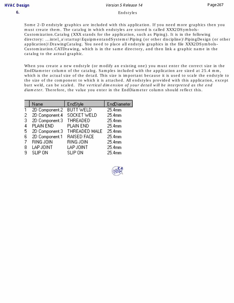
6. Endstyles
Some 2-D endstyle graphics are included with this application. If you need more graphics then you must create them. The catalog in which endstyles are stored is called XXX2DSymbols-Customization.Catalog (XXX stands for the application, such as Piping). It is in the following directory: ...intel_a\startup\EquipmentandSystems\Piping (or other discipline)\PipingDesign (or other application)\DrawingCatalog. You need to place all endstyle graphics in the file XXX2DSymbols-Customization.CATDrawing, which is in the same directory, and then link a graphic name in the catalog to the actual graphic.
When you create a new endstyle (or modify an existing one) you must enter the correct size in the EndDiameter column of the catalog. Samples included with the application are sized at 25.4 mm, which is the actual size of the detail. This size is important because it is used to scale the endstyle to the size of the component to which it is attached. All endstyles provided with this application, except butt weld, can be scaled. The vertical dimension of your detail will be interpreted as the end diameter. Therefore, the value you enter in the EndDiameter column should reflect this.

Generating a Drawing
This task shows you how to generate a 2-D drawing from a 3-D document.
Piping parts have been used in this task. The procedure is the same for all types of parts.
You need to make sure of a setting before you can use this process. Go to Tools - Options - Mechanical Design - Drafting, open the Administration tab, and uncheck the option Generative View Style.1. Open the 3-D document from which you want to generate a drawing.
2. On the menu bar, click Start - Mechanical Design - Drafting. The New Drawing box will display. Click OK.
3. A new drawing will open. Click Windows - Tile Vertically so that you can view both your documents.4. Select a view for your document. In the image below, the Front View has been selected by clicking
the Front View button . You should select a view that allows you to best manipulate and view your document.
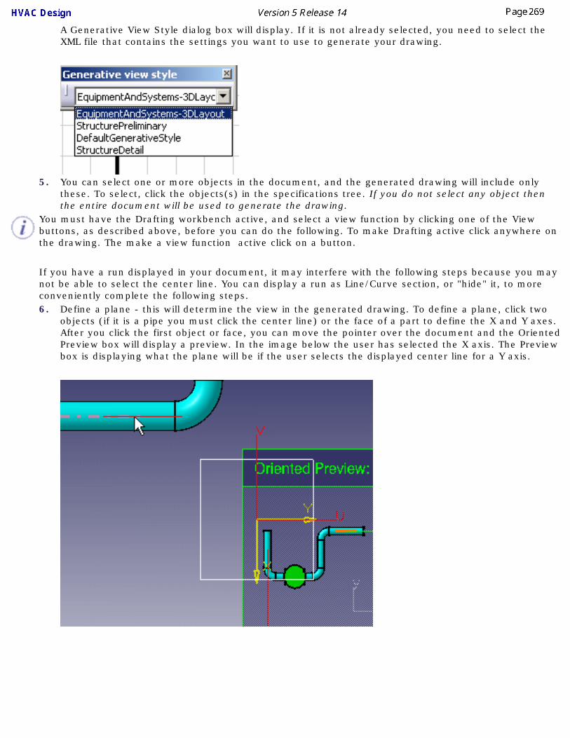
A Generative View Style dialog box will display. If it is not already selected, you need to select the XML file that contains the settings you want to use to generate your drawing.
5. You can select one or more objects in the document, and the generated drawing will include only these. To select, click the objects(s) in the specifications tree. If you do not select any object then the entire document will be used to generate the drawing.
You must have the Drafting workbench active, and select a view function by clicking one of the View buttons, as described above, before you can do the following. To make Drafting active click anywhere on the drawing. The make a view function active click on a button.
If you have a run displayed in your document, it may interfere with the following steps because you may not be able to select the center line. You can display a run as Line/Curve section, or "hide" it, to more conveniently complete the following steps.6. Define a plane - this will determine the view in the generated drawing. To define a plane, click two
objects (if it is a pipe you must click the center line) or the face of a part to define the X and Y axes. After you click the first object or face, you can move the pointer over the document and the Oriented Preview box will display a preview. In the image below the user has selected the X axis. The Preview box is displaying what the plane will be if the user selects the displayed center line for a Y axis.
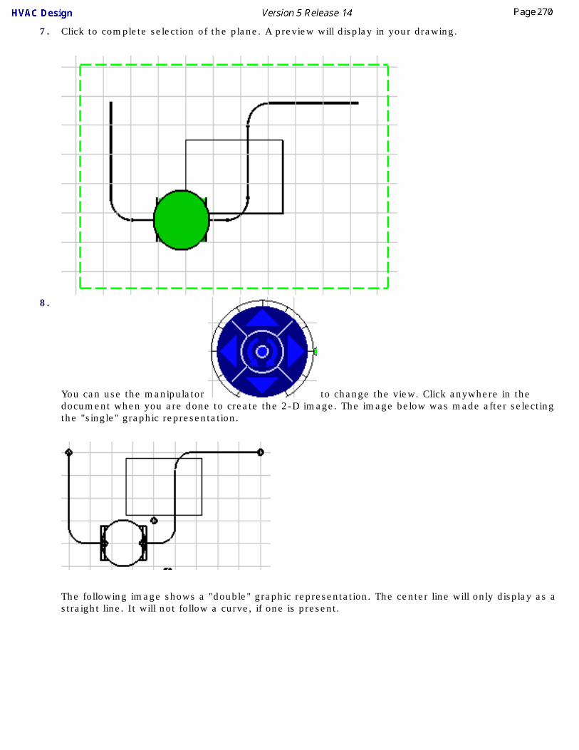
7. Click to complete selection of the plane. A preview will display in your drawing.
8.
You can use the manipulator to change the view. Click anywhere in the document when you are done to create the 2-D image. The image below was made after selecting the "single" graphic representation.
The following image shows a "double" graphic representation. The center line will only display as a straight line. It will not follow a curve, if one is present.

You can get more information on manipulating 2-D drawings in Drafting documentation.

Hole PlacementThis section explains placing, defining, modifying and querying holes on parts.
Placing a Hole on a PartModifying a Hole
Querying Hole Properties

Placing a Hole on a Part
This task shows how to define and place a hole on a part.
When you place a hole you are creating a point from which to route so as to add a run and smaller duct, pipe or tube. When you define the hole you are editing certain default parameters such as the diameter, orientation and tangent direction to meet the requirements of the hole you want to create and route from. There is no length (or depth) parameter to a hole although it appears so when placed in your document.
When defining and placing a hole you should set the connector display options. Go to Tools - Options - Equipment & Systems. Select the Display tab, scroll down to 3D Viewer Display Options and check the Part connections and Part connectors options.1.
With your document open, click the Place Hole button . The Hole Parts dialog box opens displaying choices for round or rectangular holes on either round or rectangular ducts or pipes.
2. Select the desired hole type. The tangent-plane appears as a visual aid. Move it to the location you have chosen for the hole and click.

3. When you click to place the hole the Manage Override Parameters dialog box opens displaying the list of parameters that you can edit.
5. Edit the parameters as necessary to meet the intended design. Click Apply after you edit each
parameter to update the product.6. When finished editing the parameters click OK. The hole is placed. To modify the hole further, see
Modifying a Hole.
When placed, the hole has a connector from which you can continue routing.

Modifying a Hole
This task shows you how to modify a hole that has been placed on a part.
1. With your document open, select the hole you want to modify in the document or in the specifications tree.
2.Click the Edit Part Parameters button . The Manage Override Parameters dialog box opens.
For rectangular parts, i.e. ducts, the hole is placed on the Side: Top, Bottom, Left or Right. When placing a hole on round parts such as tubes, pipes or round ducts the hole placement surface parameter is the Orientation Angle.
Tangent Angle is used only with holes placed on round parts. Set this to change the tangent of the connector for subsequent routing. When set to zero, the tangent angle will be the same as the orientation angle.
The Inset is the origin of the hole. Making this a positive value, say 1 inch, 'insets' the origin of the hole into the part 1 inch below the surface. A negative value will raise the origin of the hole above the part surface. This is parameter used for both round and rectangular parts. (After 'insetting' the hole in the part you will not be able to select it in the 3D viewer. Click the Edit Part Parameters button and select the hole from the specifications tree.)
Center Offset is used when placing a hole on a rectangular part. Set this value to adjust the side-to-side location of the hole.
For rectangular hole parts the hole size is modified using the Height and Width parameters.
3.Make the necessary changes to the parameters and click Apply to see the effect.
4. Click OK when finished. The hole is modified.

Querying Hole Properties
This task shows you how to query a hole.
When you query a hole, as with other objects, you are querying its properties.
1. Select the hole in the document or in the specifications tree. Right click to display the drop down menu and select Properties.
2. The Properties dialog box opens. Click the various tabs to obtain the desired information. The Object tab includes information regarding the hole's parent Line ID.


Schematic Driven DesignThis section discusses ways of creating a 3-D document from a schematic.
When you are creating the 3-D document you must follow this placing order: place your major equipment, place nozzles on them, create the runs, place primary parts such as valves and, lastly, place the secondary parts such as pipes, flanges etc.
You must also set the Schematic Driven flag. Click Tools - Options, select Equipment & Systems, click the Design Criteria tab and check the Schematic Driven box.
Placing Parts Using a SchematicCreating a Run Using a SchematicAnalyzing Schematic Driven Design
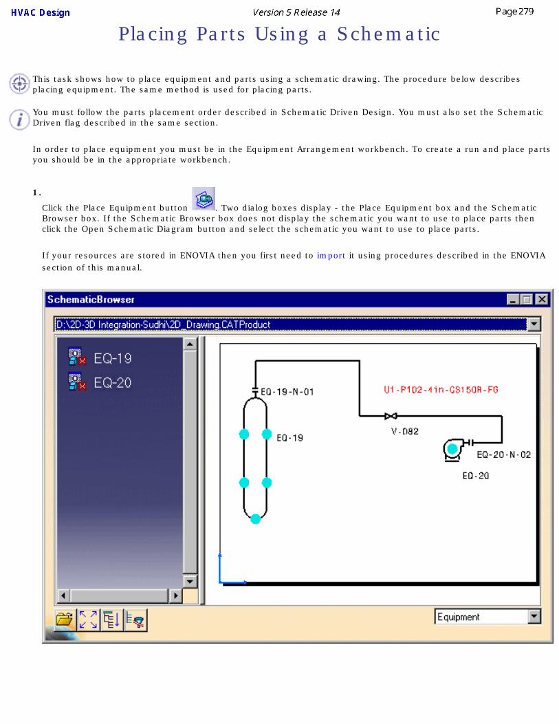
Placing Parts Using a Schematic
This task shows how to place equipment and parts using a schematic drawing. The procedure below describes placing equipment. The same method is used for placing parts.
You must follow the parts placement order described in Schematic Driven Design. You must also set the Schematic Driven flag described in the same section.
In order to place equipment you must be in the Equipment Arrangement workbench. To create a run and place parts you should be in the appropriate workbench.
1.
Click the Place Equipment button . Two dialog boxes display - the Place Equipment box and the Schematic Browser box. If the Schematic Browser box does not display the schematic you want to use to place parts then click the Open Schematic Diagram button and select the schematic you want to use to place parts.
If your resources are stored in ENOVIA then you first need to import it using procedures described in the ENOVIA section of this manual.

2.Click the equipment you want to place first, in this case EQ-19.
NOTE: Use of the Select Mode buttons is explained in Placing Parts. Refer to that task.
● If the equipment you selected has a part number defined then you do not have to do anything more than place it.
● If the Part Type was not defined (it will display in the Place Equipment box), then you need to click on the down arrow in the Part Type field and select a part type.
● If the Clear Filter button is enabled it means that values from a previous part placement exist in the Filter Definition dialog box. (See Step 5.) Click the button if you want to clear these values.
● If you want to change the values of one or more properties of the part you want to filter for, then click the Filter Definition button to display the Filter Definition dialog box. Select the property whose value you want to change and then select the new value from the drop down box in the Value field. (The Value field will display after you select a property.) This new value will appear in the Override value column. The values in the Override value column will be used when searching for parts in the catalog.
● The Override button brings up the Manage Override Parameters dialog box, allowing you to change attribute values.
● The Flip Part button allows you to flip parts that can be flipped, such as a reducer.
● The Move/Rotate button displays the Move/Rotate dialog box, allowing you to manipulate the part.
● The Pipe Selection and Pipe Segment Shortcut buttons are shortcuts that let you select part type.
● The Change to Schematic Mode button lets you toggle between schematic and non-schematic mode. You will exit the command when you click this button and need to click the Place Part command again.
3.After you define the Part Type, the Part Selection box will display and you can select a part. If both Function Type and Part Type were defined then the Part Selection box will display when you click on any equipment in the schematic and you can select the part.

4.Click in your 3-D document to place the equipment.
Parts and equipment have "ordered placement" capability. To give an example, in the image below if you have placed the valves 1 and 3, then valve 2 will only place between those two. You will not be able to place it to the right of valve 3.
5.Using the procedure described above, continue to place all equipment and nozzles you want to from the schematic.
If you assigned names to connectors when you added them (both in the 3-D and schematic application) then your 3-D nozzles will be placed at the correct connector on the equipment - the nozzle will place on the connector which has the same name as the connector in the schematic application.

Creating a Run Using a Schematic
This task shows how to create a run using a schematic drawing.
You must follow the parts placement order described in Schematic Driven Design. You must also set the Schematic Driven flag described in the same section.
In order to place equipment you must be in the Equipment Arrangement workbench. To create a run and place parts you should be in the appropriate workbench.
1.
Click the Route Run button . The Run dialog box displays.

Note: Some of the buttons display after you have selected a run.
2.In the schematic displayed in the Run box, click on the run you want to create. The 3-D viewer will show a possible route.
The function can distinguish the schematic objects (equipment and nozzles only) between which the run existed, and select their 3-D equivalents to route between.

3. Click the Shift key to see other possible routes between the two pieces of equipment. Clicking the Shift key will bring you back to the route first suggested. You can also click the Display Alternate Path
button . 4. Select From/To or Logical Line by clicking on the down arrow. This affects the display of objects in
the specifications tree, and the Route Through Hangers option (see below). If you select Logical Line only the logical line will display in the tree. If you select From/To then the objects routed from and to will also display.
5. Once you have a route you want to accept click again in the schematic and the run will be created.
If you named the connectors when you created them (in both the schematic and 3-D applications) then the run will be created between connectors that have the same name as in the schematic.
6.
Click the Route Through Hangers button if you want to route through one or more hangers.
Click the button and then select the hangers you want to route through. The Route Through Hangers button is only available when you select From/To in the field (see Step 4).
The Run dialog box displays other options. These are regular Routing options that are explained in
Routing a Run, and allow you to route as you would normally. The Reframe button allows you to zoom in on an object in the 3-D viewer.
FOR HVAC DESIGN ONLY
The Ductulator button displays in the Type field if the 2D segment you select has the Equivalent Diameter property defined and valuated.
The Ductulator is a tool for calculating the area of a rectangular or square duct that is equivalent to the diameter of a given round duct. It enables you to place the correct-sized duct. Click the Ductulator button to being up the Duct Size Computation dialog box.
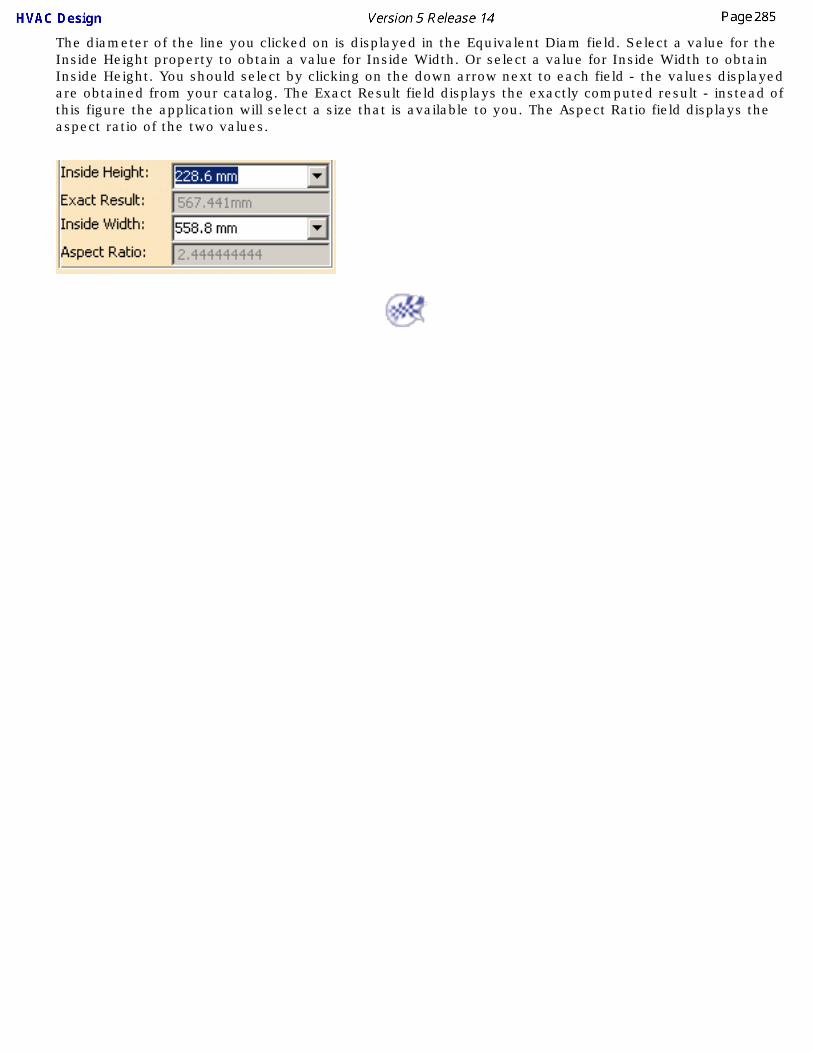
The diameter of the line you clicked on is displayed in the Equivalent Diam field. Select a value for the Inside Height property to obtain a value for Inside Width. Or select a value for Inside Width to obtain Inside Height. You should select by clicking on the down arrow next to each field - the values displayed are obtained from your catalog. The Exact Result field displays the exactly computed result - instead of this figure the application will select a size that is available to you. The Aspect Ratio field displays the aspect ratio of the two values.
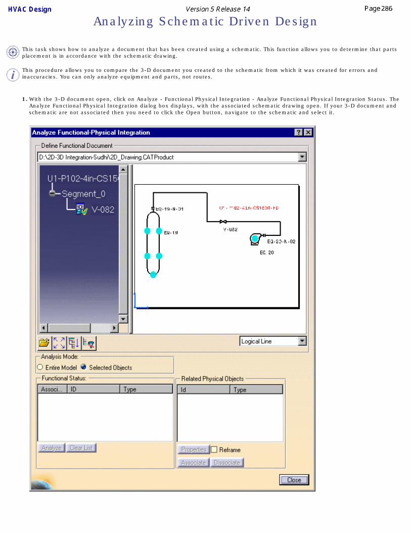
Analyzing Schematic Driven Design
This task shows how to analyze a document that has been created using a schematic. This function allows you to determine that parts placement is in accordance with the schematic drawing.
This procedure allows you to compare the 3-D document you created to the schematic from which it was created for errors and inaccuracies. You can only analyze equipment and parts, not routes.
1. With the 3-D document open, click on Analyze - Functional Physical Integration - Analyze Functional Physical Integration Status. The Analyze Functional Physical Integration dialog box displays, with the associated schematic drawing open. If your 3-D document and schematic are not associated then you need to click the Open button, navigate to the schematic and select it.

The buttons below the tree are used to open a document or manage the display of the tree and schematic. You can click on the down arrow next to the field that reads Logical Line to select another element, which will then display in the tree.
2.Click the Selected Objects option and click on a part in the schematic. Information about the part will appear in the Functional Status window. If the schematic function is associated with a 3-D part then the relevant information will display in the Related Physical Objects window. The two can be dissociated by clicking on the Dissociate button.
3. If the schematic function you clicked is not associated with an object in the 3-D document then the Related Physical Objects window will suggest 3-D objects to which it can be associated, if there are any. In the image below Vessel Function can be associated with two objects in the 3-D document. If you want to associate it then select an object and click the Associate button.
You can also associate a schematic function with a 3-D object by using the Analyze function in the menu bar. With your 3-D document open click Analyze - Functional Physical Integration - Associate Functional Physical Objects. The Associate Functional Physical Objects window will display. Click the Open button to open the schematic you want to use, and select the function you want to associate. The window will display the 3-D objects you can associate to. Select one and click Apply and OK.
You can create an Exception for certain objects, in which case you will not be able to associate to them. These objects will also be overlooked by the Analyze function. With your 3-D document open, click Analyze - Functional Physical Integration - Manage Exceptions. The Exception Manager will display. Select the object for which you want to create an exception and click Create. You can use the same procedure to remove the Exception.
4. Use the Clear List button to clear the entries in the Functional Status window. Select an entry and click Properties if you want to see its properties.
5. Click Analyze. The Inconsistencies dialog box displays, listing any errors. In the illustration below the entries indicate that the valve is not connected to the tank or the pump - only a run is present, there are no pipes or elbows.


Migrating V4 Models to V5This section discusses migration of V4 models to V5.
To explain the process briefly, you have to convert the classes and attributes in your V4 Project Registration Model to an XML file and ftp it to a V5 directory. You have to do the same with the classes and attributes in your V5 Feature Dictionary.
A tool compares these two XML files and another tool then imports the classes and attributes that do not exist in V5 and makes them available to you in V5.
You also have to copy standard and specifications data to V5 and edit it as needed.
Make sure the project resource management file is pointing to the correct location of all resources.
To learn how to customize line thickness, see documentation for Interactive Drafting in the section Advanced Tasks/Manage Standards. Once defined, line thickness is applied to elements as a property.
Create a directory structure if you plan to store your migrated data in a location other than the location in which the sample data is stored. You also need to create/modify setup data, which is explained in this section.
Creating a Directory StructureExporting the V4 Project Registration Model
Exporting the V5 Feature DictionaryComparing the XML OutputImporting the XML Output
Creating/Modifying Setup DataMigrating the V4 ModelMigrating V4 Parts to V5
Creating a Directory Structure
This task shows you how to create directories for your migrated V4 data.
Data that you migrate from V4 into V5 will usually be stored in directories that are separate from the directories in which V5 generated data is stored. Sample directories are included with this application for storing migrated data. The default location is: ...intel_a\startup\EquipmentandSystems\MigrationDirectory\XXX where XXX is a discipline like Tubing or Piping.
You can continue using the sample directories if you want. However, if you choose to store your data elsewhere you should take the following steps.
1. Create a directory and give it any suitable name.
2. Create a DiscreteValues directory under it and move into it the data from the sample DiscreteValues directory.
3. Create directories for all the disciplines that are of interest to you (Piping, HVAC, etc.). Recreate the directory structure under them as it exists under MigrationDirectory. You do not need to move the sample data - sample catalog, sample specifications, etc. - into your newly created directories if you do not intend to use it.
4. Change the entries in your project resource management (PRM) file to reflect the new location of your data. The sample PRM file points to the default locations. Most entries are under the heading AEC Migration Discipline Resources.

Exporting the V4 Project Registration Data
This task shows how to convert class and attribute data from the V4 Project Registration Model to XML format, in preparation for importing it to V5.
You need to convert the classes and attributes in the V4 Project Registration Model to XML format and export it to a V5 directory so that they can be compared with the classes and attributes that exist in the V5 Feature Dictionary, and later imported into it.
You do not need to do this if you did not make any modifications to your V4 Project Registration Model - that is, you did not define classes and attributes of your own.
1. You can convert (and export) all the classes and attributes in the Project Registration Model or you can convert classes and attributes by context. If you convert by context you will only convert those that are associated with the context you select, such as HVAC or Process. To convert by context you should either be in the application that sets the context, or click Context - Discipline/Role/Workshop in the menu bar. The Context Definition box will display.
2. Select the context you want. In the image above the context Process Discipline is selected.

3. You now need to change a setting. Click Settings - User Interface Level in the menu bar to display the AEC Frame User Interface Mode box.
4. In the Display Information On field select Current Context Only. If you have not selected a context then select All Project.
5. Now you need to enter the command that will create the XML file. In the key-in line enter /aecrprj and hit Enter. The Report the Project Registration box displays.
6. Enter the directory in which you want to save the XML file and check the line Report All Data in One File. Click OK. The XML file will be generated and stored in the directory you specified.
If you specified All Project then the file name will be Preg_All.xml. If you specified a context then the name will be related to that context.
NOTE: An html file will also be generated. You do not need this file and can delete it.7. Place the XML file in the directory
...intel_a\startup\EquipmentandSystems\MigrationDirectory\dictionary\V4_Exported_XML so that it is available to your V5 applications.
The V4 project registration model must be moved to the following directory, by ftp or any other method: ...intel_a\startup\AEC\preg. The project registration model is used by both Plant and Ship Review applications and by the migration process.

Exporting V5 Feature Dictionary DataThis task shows how to export V5 Feature Dictionary data to XML format and make it available for comparison with the XML file of V4 Project Registration Model data. This process is also used when comparing two V5 feature dictionaries.
As part of the process of converting a V4 model to V5, you need to convert class and attribute data in a V5 Feature Dictionary to XML format. The XML file will be placed in a specific directory at a location where it will be available to your V5 applications.
When you use this command then all the feature dictionaries listed in your project resource management (PRM) file will be "exported" - in actual fact the classes and attributes they contain will be converted to XML format for further processing. To determine the location of the CATfct files, the application examines the entry "ImporterCATfcts" in the PRM file. This entry should indicate the location of your CATfct files. If left blank the default location is: ...intel_a\resources\graphic. The sample PRM files provided with this application are in: ...intel_a\startup\EquipmentandSystems\ProjectData.
This step is not needed if you did not define new classes and attributes in V4.
1. Change to the directory ...intel_a\code\bin at a command prompt and take the following steps:
If you changed the location of your installation execute:
set CATDisciplinePath=XXX\startup\EquipmentandSystems\ProjectData
set AECMIGR_PROJECT=Project where XXX is the directory path to your installation.
If you want to use a PRM file with a name other than "Project" then change the word "Project" to the name of your file (AECMIGR_PROJECT=XXX).
Execute: catstart.exe -run CATAecDictionaryExporter.exe -env DefaultEnvironment -direnv ...\application data\ DassaultSystemes\CATEnv. The Data Export Application dialog box displays.

2. The Choose Modeler for Export window displays all the modelers available to you. Simply put, a modeler contains the list of applications whose CATfct files will be exported. The PlantShip Modeler seen here includes all plant-ship applications as of R10. Select the modeler you need. Even if an entry is highlighted, as in the image above, you should click on it.
3. In the Output File field browse to or enter the directory path and name of the file where you want the XML output to be placed. If you select an existing file then it will be overwritten. If you enter the name of a file that does not exist then a new file will be created.
4. Once you have filled in these fields the Export button will become available. Click on it to generate the XML content. A message will inform you when the process is complete. The image below shows an excerpt from a generated XML file.
5. Click Quit when you are finished.The next step will be to compare the classes and attributes contained in the V4 and V5 XML files.

Comparing the XML Output
This task shows how to compare the V4 and V5 classes and attributes. This task should be performed after you have exported the V4 project registration model and the V5 feature dictionary.
Your goal is to have a mapping table that shows the V4 classes and attributes you want to import and their corresponding V5 classes and attributes. Once you have converted and exported the V4 and V5 classes and attributes, the two must be compared to determine which ones do not exist in V5. This is done by a tool developed for the purpose. Once you have run this tool it will produce three files which tell you: which classes have problems (do not exist in the mapping table or the XML file of V5 classes), which classes need to be added to V5 and an overall report of what the tool has performed.
This step is not needed if you did not define new classes and attributes in V4.
Before you begin this process you must set the directory path - this tells the tool the directory path in your installation. Open a command prompt and move to the directory intel_a\code\bin.
● In Windows, press Enter after typing: set AECMIGR_DIRECTORYPATH= XXX\startup\EquipmentandSystems\MigrationDirectory where XXX is the directory path to your installation.
● Do the same in Unix, but replace "set" with "export".
● The user can check the current path by executing the comparator, or executing CATAecDictionaryComparator -h. The comparator will show the path as the first line of output.
1. To run the tool open a command prompt, change to the directory ...intel_a\code\bin, and enter the following: CATAecDictionaryComparator -i (V4file) (V5file) -m (name of mapping table) -o (name for output)
Where:
● (V4file) is the XML file which contains the V4 classes. It must include the XML extension.
● (V5file) is the XML file which contains the V5 classes. It must include the XML extension.
● (name of mapping table) is the name of the mapping table against which you want to compare. The default mapping table provided with this application is V4ToV5ObjectMapping.csv. You must include the .csv extension. The mapping table is in the following directory: intel_a\startup\EquipmentAndSystems\MigrationDiretory\Dictionary\Mapping Table.
● (name for output) is the name for the three output files. If you enter the name MAR, for instance, then three files will be produced: MAR.html, MAR.xml and MAR.csv.
An entry may look like this: CATAecDictionaryComparator -i Preg_ALL.xml catpiping.xml -m V4toV5ObjectMapping.csv -o MAR
2. When the tool (called Comparator) has finished running it will produce three reports and place them in the following directories: XML and CSV files in intel_a\startup\EquipmentandSystems\MigrationDirectory\Dictionary\DDL_Files and the HTML file in ...\Reports.
Open the HTML file in a Web browser to see a full report. The report begins with a table of contents that is hyperlinked to the entries. (The names in parentheses are internal names.) The entries in the report are color coded as follows:
● Green: No action was taken. The V4 class appears in the mapping table and the XML file of V5 classes.
● Blue: The V4 class appears in the mapping table, but not in the V5 XML file.
● Red: The V4 class was not found in the mapping table or V5 XML file.
● Orange: V5 mapping does not exist in the mapping table ("no mapping"), or is badly mapped.

3. Open the XML file (using a text editor like Wordpad) to see a list of the classes that do not exist in the V5 feature dictionaries and can be imported.
<Class
Name="PipingPartFunc"
DisplayName="Piping Part Function"
Superclass="Component_Function"
Creator="System"
Domain="PIP"
UUID="b7acacd1_83_3a707981_10">4. Open the CSV file using Microsoft Excel. It will look similar to the image below, except that it will not have the entries shown in the first line (shaded red).

In the first three columns this table displays existing classes in V4. You should fill in the 4th, 5th and 6th columns with whatever you want the corresponding entry to be in V5. In column 7 you should enter the domain, or application. (PIP=Piping Design, PID= Piping and Instrumentation Diagrams, EQT= Equipment Design, HVA=HVAC Design, etc.)
An asterisk in the Attribute column indicates that the entry is a class. If it has attributes then the lines that follow it will list the attributes under the same class name. In the example above, Line 2 shows a class. Lines 3, 4 and 5 show that the entries are attributes of the class Piping Line and are called Size, Part Description and Design Speed.
NOTE: V5 entries should refer to the internal name of the class or parent. The internal name is the name within the application and is not the one the user sees. Frequently it is similar, though, and the class name Piping Line may have the internal name PipingLine. You can find the internal name by looking at the V5 XML file where it's referred to as Name and Superclass.
5. Once you have entered the information you need to copy and paste it into the mapping table - in the current example it is V4ToV5ObjectMapping.csv, found in intel_a\startup\EquipmentandSystems\MigrationDirectory\Dictionary\MappingTable. However, you should not directly modify the table the table with the .csv extension. In this same directory you will find a table with the same name but with the extension .xls. Modify this table, save it, and then save it again as a .csv file also. It is faster for this application to read .csv files.
6. If you have V4 classes and attributes that do not have equivalent classes and attributes in V5 then you must repeat the steps explained in Importing the XML Output.
You can repeat these steps as many times as you want - until you are satisfied that your mapping table has all the V4 classes and attributes you want and the corresponding V5 classes and attributes.

Importing the XML Output
This task shows you how to import the class and attribute data in the XML output file after the comparing process, as explained in Comparing the XML Output.
The xxx.XML file that is generated at the end of the comparing process contains the list of V4 classes and attributes that do not exist in V5 and that need to be added to the CATfct files. The entries will be added to the relevant CATfct file - if the class and attribute belong to the V4 HVAC discipline then they will be added to the V5 HVAC CATfct file. The importing process described here creates these classes and attributes in V5 using the Feature Dictionary.
This step is not needed if you did not define new classes and attributes in V4.
1. Change to the directory intel_a\code\bin at a command prompt and execute the following: catstart.exe -run CATAecDictionaryImporter.exe -env DefaultEnvironment -direnv ...\application data\ DassaultSystemes\CATEnv. The Data Import Application dialog box displays.
2. The Choose Modeler for Import window displays all the modelers available to you. Simply put, a
modeler contains the list of applications whose CATfct files will be updated with new classes, if there are any. The PlantShip Modeler seen here includes all plant-ship applications as of R10. Select the modeler you need. Even if an entry is highlighted, as in the image above, you should click on it.
3. In the Input File field browse to or enter the name of the XML file that was output by the comparing process (Comparing the XML Output). The file is placed in the directory: intel_a\startup\EquipmentandSystems\MigrationDirectory\Dictionary\DDL_Files.
4. Once you have filled in these fields the Import button will become available. Click on it to begin the importing process. Your existing CATfct files will not be overwritten. If they do not contain a class or attribute that exists in the XML file then it will be added. The process will create a new CATfct file if something is added to it. The new file name will contain the word "new". If an existing CATfct file to which an entry was added was named XXX.CATfct, then the new file will be XXX_new.CATfct You should examine the new file and rename it as necessary - in most cases you will want it to have the original name, XXX.CATfct.

5. A report appears in the Data Import Application dialog box window at the end of the process, listing all classes and attributes that were added.
6. Click Quit when you are finished.

Creating/Modifying Setup DataThis task shows you how to create or modify setup data that is needed to use your migrated V4 models.
Data that you migrate from V4 into V5 will usually be stored in directories that are separate from the directories in which V5 generated data is stored. Sample directories are included with this application for storing migrated data. The default location is: ...\intel_a\startup\EquipmentandSystems\MigrationDirectory\XXX where XXX is a discipline like Tubing or HVAC.
You need to create the following setup data in the directory that you use to store your resources, and which is referenced in the project resource management file. If you continue to use the sample directories the changes should be made there, if you choose to create a new location, that is where the setup data should be added.
In the instructions below it is assumed that you have created a new location. If you continue to use the sample directories then you should adjust the instructions accordingly.1. Discrete Values
You will need a set of discrete value text files as a default set of possible values for HVAC attributes. You can copy these from the sample migrated HVAC discipline (intel_a\startup\EquipmentAndSystems\MigrationDirectory\DiscreteValues) into your own \DiscreteValues directory. You can throw away what you don't want, and edit what you want so you are satisfied with your set of text files.
Also, if you had user-defined attributes defined in your V4 Project Registration Model containing a discrete list of values, then you will need to create a discrete values text file in your \DiscreteValues directory containing the name of your mapped V5 attribute name and the values you want available in V5 for your user-defined attribute.
2. Design Rules
The sample HVAC discipline contains a directory called DesignRules. The sample migrated HVAC discipline also references the HVAC Design Rules. If you want to have your own design rules, then copy the design rules resources into your own \HVAC\DesignRules directory. Edit the contents of the text files as desired. Bring up the application and open each CATProduct document and link it (via Properties) to the correct text document - your text document in its new location. You link it by editing the properties (File Path) of the entries (e.g., Compatibility) under Relations. Then save each CATProduct document. When you are satisfied you have all of the design rule data you want, you are ready to edit the design rules catalog. Rename the design rules catalog you copied, as desired. Bring up the application again and edit your design rules catalog as needed. Take out previous entries ("Remove description") and add your own entries. Refer to the section Standards and Design Rules for more information.

3. Standards and Specifications
The sample migrated HVAC discipline contains all migrated standard and specification data from the V4 Ductwork Design product. You may borrow these resources and copy them into your own \HVAC directory, or use them as a guide as you make your own files. If you copy existing files, you may want to rename the standard and specification directories and files and edit the text files to put in your own names and data. Rename the CATProduct documents as desired. Do this for each of your standards and specifications. Bring up the application and open each CATProduct document and link it to the correct text document - your own text document. You link it by editing the properties (File Path) of the entries (e.g., HVACDuctFunc) under Relations. Then save each CATProduct document. Borrow additional standard and specification resources as desired from the sample HVAC disciplines, and rename and edit them as desired. When you are satisfied you have the entire standard and specification data you want, you are ready to edit the standards catalog and the specifications catalogs. Rename the catalogs you copied, as desired. Bring up the application again and edit your catalogs as needed. Take out previous entries ("Remove description") and add your own entries. In some cases, you will need to refer to your V4 data for some information. Refer to Standards and Design Rules for more information.
4. Parts Catalog
The sample migrated HVAC discipline contains V5 HVAC part replicas of V4 ductwork catalog parts and a V5 parts catalog referencing these parts. You can borrow this entire catalog and its parts. You can also recreate your own V4 parts in V5 and add them to the catalog. For fixed-size, non-parametric V4 parts, you can simply copy/paste the geometry to your V5 HVAC part.
5. HVAC Lines
V4 did not contain a pre-defined set of duct lines. However, as you migrate ductwork models, V4 duct lines are migrated to V5 HVAC Lines and added to the V5 HVAC Lines catalog. You may wish to copy the HVAC Lines catalog and lines from the sample HVAC catalog, or start your own HVAC Lines catalog. You should put the catalog into your \HVAC\SampleData\HVACLines directory. See Managing HVAC Lines for more information.
Migrating the V4 Model
This task shows how to migrate V4 models to V5. This task should only be attempted after all the other tasks in this section have been completed.
Before performing this task you should make sure that options are correctly set in your project resource management file. These options help you control which portions of a model you want to migrate - if you want to migrate only certain parts of it. If your V4 model has data from Piping and Instrumentation Diagrams, Piping Design, HVAC Design, Structures and Equipment Arrangement, you can decide which type of data you want to migrate by setting these options. If you choose to only migrate Tubing data, then you can do so. See Understanding Project Resource Management, AEC V4 V5 Migration section, on how to set the options. NOTE: The sample PRM file references "Big Scale" structures catalogs. Because of this you have to set the CATCGMBigScale variable to 1 before migrating structures models, shown below.1. Move your V4 model (by ftp or any other means) to the same platform as V5, in this case Windows.
2. Set the following variables. In Windows, open a command prompt window and change to the directory ...intel_a\code\command. Enter the following: set CATDisciplinePath=XXX\intel_a\startup\EquipmentandSystems\ProjectData where XXX is the directory path to your installation. In Unix use the command "export" instead of "set".
For Structures models only, you need to set the following: set CATCGMBigScale=1 (in Unix replace set with export).
The batch shells CATAECV4ToV5Migration.bat (Windows) and CATAECV4ToV5Migration.sh (Unix) assume you edited the project resource management (project.xml) file. If you copied and renamed it then you must edit this batch shell and replace "Project" with your own file name (as referenced by AECMIGR_PROJECT variable).
For Tubing Design use the batch shell CATAECV4ToV5MigrTubing.bat (.sh for Unix). For all other applications use the batch shell named above.
For Tubing Design, when migrating models, the project resource management file must reference a proper tube dimensions table in order to map outside diameter to nominal size. In the PRM file find the 'TubingDimensions' entry and correct the location if necessary.
3.At the ...intel_a\code\command prompt, enter CATAECV4ToV5Migration.bat (.sh for Unix) to execute a bat file. (For Tubing use the file named in Step 2). This will bring up the Migration Batch dialog box.

4. In the Target Directory field enter (or navigate to by clicking the button) the directory where the migrated V4 model will be stored.
5. Click the Browse File button and, in the box that displays, navigate to the directory where you stored your V4 models. Select (you can select more than one if you want to) a model and click Open. The V4 model will display in the V4 Documents to Migrate window of the Migration Batch dialog box. You can use the Remove button to remove files you do not want to migrate.
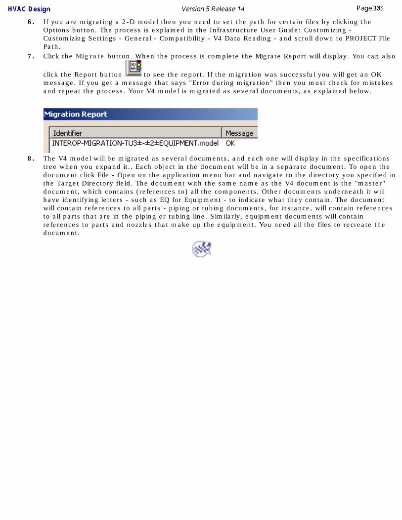
6. If you are migrating a 2-D model then you need to set the path for certain files by clicking the Options button. The process is explained in the Infrastructure User Guide: Customizing - Customizing Settings - General - Compatibility - V4 Data Reading - and scroll down to PROJECT File Path.
7. Click the Migrate button. When the process is complete the Migrate Report will display. You can also
click the Report button to see the report. If the migration was successful you will get an OK message. If you get a message that says "Error during migration" then you must check for mistakes and repeat the process. Your V4 model is migrated as several documents, as explained below.
8. The V4 model will be migrated as several documents, and each one will display in the specifications tree when you expand it.. Each object in the document will be in a separate document. To open the document click File - Open on the application menu bar and navigate to the directory you specified in the Target Directory field. The document with the same name as the V4 document is the "master" document, which contains (references to) all the components. Other documents underneath it will have identifying letters - such as EQ for Equipment - to indicate what they contain. The document will contain references to all parts - piping or tubing documents, for instance, will contain references to all parts that are in the piping or tubing line. Similarly, equipment documents will contain references to parts and nozzles that make up the equipment. You need all the files to recreate the document.

Migrating V4 Parts to V5
This task shows you how to migrate a non-parametric V4 part to V5.
This application comes with a sample catalog containing all the parametric parts that were in the V4 Ductwork sample catalog. However, non-parametric parts that users themselves created, and which they need in V5, must be migrated by them using the procedure described here. There is no procedure for migrating parametric V4 parts to V5, users need to recreate these. In the procedure below the geometry of a triangular access cover will be migrated to this application.
You need to set the following variable before bringing up the application. Enter at a command prompt: set CATDisciplinePath=XXX\intel_a\startup\EquipmentAndSystems\ProjectData where XXX is the directory path to your installation. You also need to click Tools - Project Management and select your project and discipline.1. Move the V4 model containing the part geometry you want to migrate into V5, using ftp or any other
method.
2. In V5, open the document you just migrated. If your V4 model had only one part it will have only one tab (with the part name) besides *Master and *Draft. Click on this tab to display the part. If it had more than one part then click on the tab that corresponds to the part you want to migrate. The part will display.
3. With this part displayed, open a new HVAC Design document and then click Window - Tile, horizontal or vertical, as you prefer.

4.Click the Build Part button . The Create Part dialog box displays.
5. Click on the button next to the Component Type field to display the Class browser.
6. Expand the HVAC Part category and select a part type for your part. It will display in the Component Type field.
7. Enter a name for the part in the Symbol Name field. For the sake of convenience. it is recommended that you use the same name the part had in V4. Press Enter and then click Apply. The part will display in the specifications tree. Do not click OK if you also want to create a single representation. If the V4 part had both double and single representations and you want to migrate the geometry of both, then you must now create a single representation also, as shown below.
8.After you click Apply (Step 7), the Manage Representations button will become active in the Create Part box. Click this button to display the Manage Graphic Representations dialog box. Check the Expand Representations checkbox.
Click on "no" next to Single, and under the Defined column. It will change to "yes", indicating that a single representation document has been created.

9. Both single and double representations will display in the specification tree, which should look like the image below.
10. Copy the geometry from your V4 part into this application using standard Copy - Paste procedure. Select the V4 part geometry (you can use a trap box), copy, double click on the part name in the specifications tree and paste it on the entry Double. The geometry is copied into the entry Double, unless it was a V4 solid, in which case a new body is added. You must hide the three planes - xy, yz, zx. Do the same for the single representation, pasting it on the entry PartBody and hide the planes. Save the part and shape documents you have just created. See Copying V4 Geometry to V5 for more information about copying geometry.
11. Connectors are not migrated. To add connectors to the part see Creating and Modifying Connectors.
12. Properties are not migrated. To add values for properties see Define Properties for a Part.
13. To add connector specifications see Associate Specifications to a Connector.
To add these parts to a catalog see Creating a Catalog and Modifying a Catalog.

CustomizingThis section describes ways in which you can customize the HVAC Design workbench. The task Setting Up the Application describes the various steps you have to take, and the order in which you have to do them, to set up HVAC Design.
Setting Up the ApplicationCustomizing Settings
Project Resource ManagementFeature Dictionary: Creating Classes and Attributes
Cache ModePenetration Management
Creating ReportsCatalogs
Standards and Design RulesUsing Knowledgeware Checks
Line ID CatalogsDefining Options
Working with ENOVIA
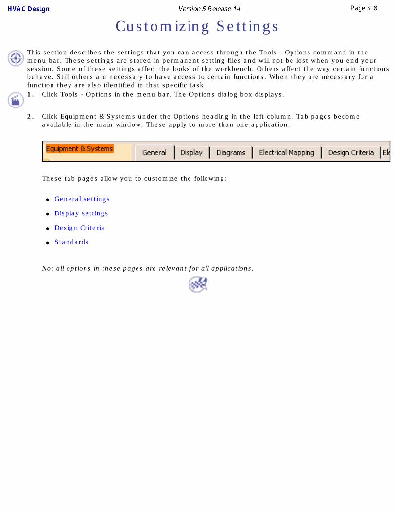
Customizing Settings
This section describes the settings that you can access through the Tools - Options command in the menu bar. These settings are stored in permanent setting files and will not be lost when you end your session. Some of these settings affect the looks of the workbench. Others affect the way certain functions behave. Still others are necessary to have access to certain functions. When they are necessary for a function they are also identified in that specific task.1. Click Tools - Options in the menu bar. The Options dialog box displays.
2. Click Equipment & Systems under the Options heading in the left column. Tab pages become available in the main window. These apply to more than one application.
These tab pages allow you to customize the following:
● General settings
● Display settings
● Design Criteria
● Standards
Not all options in these pages are relevant for all applications.

General Settings
This task is to inform you about the settings in the General tab.
The General tab provides settings for General Environment, Resolved Part Storage path, Resource Attributes and Catalog Placement Options.
1. Click Tools - Options - Equipment & Systems and select the General tab.
2. General Environment: ● Grid Step. This is the default grid step setting that displays in the General Environment toolbar at the bottom of the 3-D viewer.
Even if you change the value in the toolbar during your session, the value entered in the Grid Step field will re-appear when you open a new session. Enter your preference for the Grid Step. Note: The Units (unit of measure) is set in the Units tab under Tools - Options - General - Parameters and Measure. See also Set Correct Working Units and Grid.
● The Snap Angle sets the degree of rotation of the plane manipulator. See Using the Plane Manipulator for more information.
3. Resolved Part Storage for Spatial Objects: ● Directory. This is the location where resolved Spatial objects unique to the Plant Layout, Systems Routing and Systems Space
Reservations products are stored. Click the Open file button and navigate in the Resolved Part Storage Directory Browser window to set or change the location for the directory.

4. Resource Attributes: ● Automatic creation of resource attributes. Certain attributes accompany Spatial objects (those created in Plant Layout, Systems
Routing and Systems Space Reservations); objects such as item reservations, areas, runs, etc. These attributes, or properties, are generated specifically for the Delmia product line and cannot be assigned or changed in other product lines.
Although you will not be making use of these resource properties, their creation will have no affect on the product you are working in. If you do not want these properties to be created, uncheck the box Automatic creation of resource attributes and click OK.
5. Catalog Placement Options: ● Display image while placing catalog object in 3-D viewer. You can choose to hide or display a "preview" of the part you are
placing. Check or uncheck the box Display image while placing catalog object in 3D viewer to obtain the effect you want.
● Place at component's origin when placing in free space. By default, when you click (in free space) to place a part, the center of the part will be placed at that location. The application determines the center of the part by creating a box around it and selecting the center of the base of the box. You can also choose to place the origin of the part at the point where you click. To do this check the box Place at component's origin when placing in free space.

Display SettingsThis task is to inform you about the options available in the Display tab.
The Display tab provides display options for Analysis Mode, Specifications Tree, 3-D Viewer Display and Routable Display options.
1.Go to Tools - Options - Equipment & Systems and click the Display tab.
● Analysis Mode: Check the box in Analysis Mode to display information about routables. It works only when you are performing an action with a routable, such as placing a part, branching a run or creating an offset route.
● Specification Tree: In Application objects check the box Show application grouping to organize the objects in the tree by application, e.g. Piping objects, Equipment, etc. Under Spatial objects check the boxes of the items you want to appear in the specifications tree. Spatial objects may only be placed using the Systems Routing, Systems Space Reservation and Plant Layout workbenches.

● 3-D Viewer Display Options: Check or uncheck the boxes to set the connection and connector display options as desired. Set the color of the connection and connector symbols using the drop down color palette.
● Routable Display Options: Increase the Twist Smoothness Factor to increase the smoothness of a run at a twisting turn.

Design Criteria SettingsThis task is to inform you about the settings in the Design Criteria tab.
The Design Criteria tab allows you to toggle settings for ID Management, 3D Design, and 3D Placement.
1. Click Tools - Options - Equipment & Systems and select the Design Criteria tab.
● ID Management: Update ID on property change. When the object naming convention (ID schema) includes an attribute, e.g. nominal size, and you change its value using the Properties dialog box, the name of the object will change to reflect the new value of the attribute.
● 3D Design: Check Schematic Driven if you are placing parts from a schematic into a 3D design document. Used with Piping Design, Tubing Design, HVAC Design and Waveguide Design applications.
● 3D Placement Options: When the Place automatic parts box is checked you can place an object such as a valve (e.g., in Piping Design); the flanges, gaskets and welds will be placed automatically when you place the pipe.

Standards
The Standards tab allows you to define the default standard for the active product.
Standard Names
When you click the Standards tab, the only fields available to you will be that of the active product, in this case Piping Design, and Hanger Design, which is always available. The fields for other products will be grayed out.
Click the down arrow to display a list of available standards, and select the standard you want to use for your session.

Project Resource Management Users need to manage their resources in a way that is different from what they have been used to. Previously, system administrators could click Tools - Options in the menu bar, navigate to a tab and field, and enter information. Information such as directory paths for various resources without which the application cannot function - line list catalogs, user dictionaries, catalogs, etc.
The same information is still needed, but the way of entering it is different. Administrators can no longer enter it using the Tools - Options dialog boxes. Instead, they need to enter the information in one file, which is in XML format. What they enter will be visible in the Options dialog boxes, but it cannot be changed there.
Using the PRM CommandUnderstanding Project Resource Management
Checking PRM File for Errors
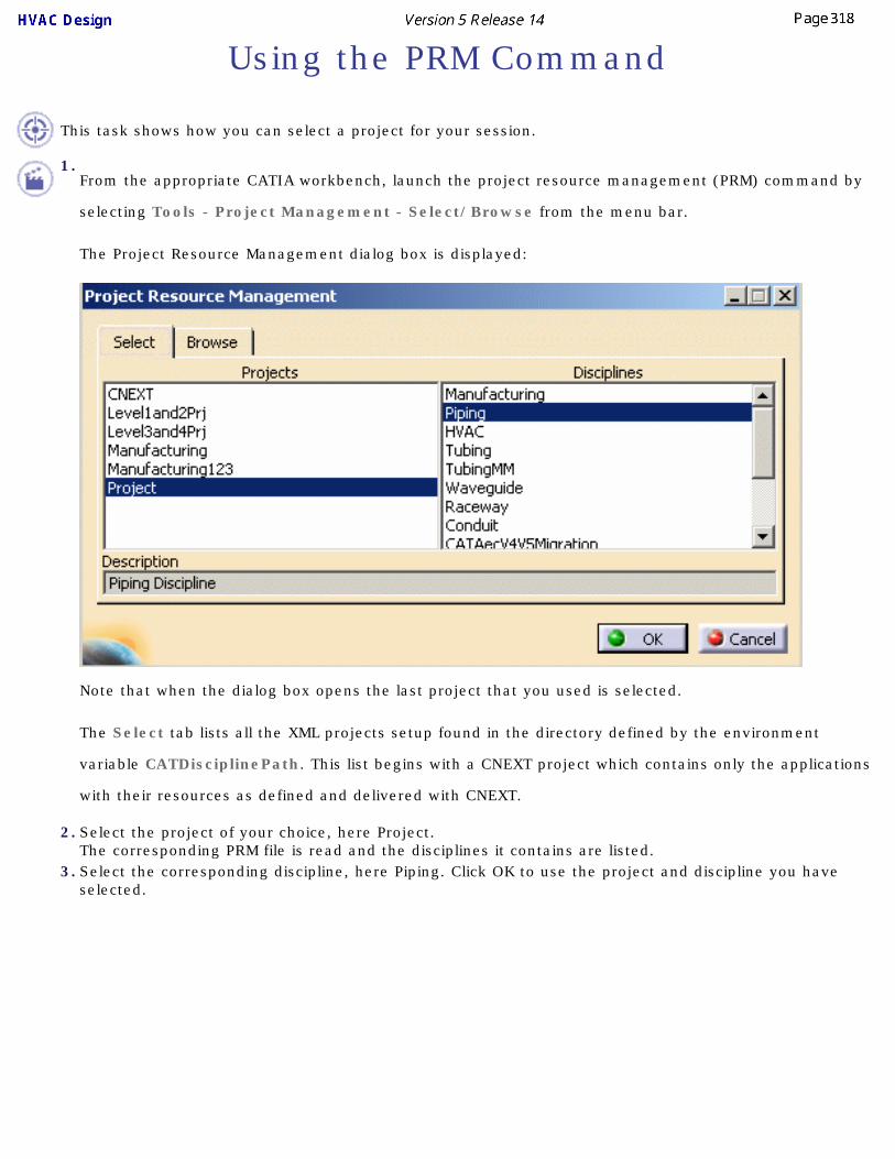
Using the PRM Command
This task shows how you can select a project for your session.
1.From the appropriate CATIA workbench, launch the project resource management (PRM) command by
selecting Tools - Project Management - Select/Browse from the menu bar.
The Project Resource Management dialog box is displayed:
Note that when the dialog box opens the last project that you used is selected.
The Select tab lists all the XML projects setup found in the directory defined by the environment
variable CATDisciplinePath. This list begins with a CNEXT project which contains only the applications
with their resources as defined and delivered with CNEXT.
2. Select the project of your choice, here Project.The corresponding PRM file is read and the disciplines it contains are listed.
3. Select the corresponding discipline, here Piping. Click OK to use the project and discipline you have selected.

4. The following step is used for informational purposes only - to see a list of resources for a particular discipline. To select a project you only need to take the steps explained above.
Select the Browse tab. Once a project and a discipline have been selected, the dialog box lists all the applications defined for the chosen discipline, the description of the active application, and the list of resources of that application. The list of resources displayed is always that for the active application.
You should also note that the applications displayed include the applications under that particular discipline, and any applications that are at the project level, which means above the discipline in the PRM hierarchy. In the example below, the Piping discipline displays Piping Design and PID, which are part of that discipline. It also displays the Equipment, Hanger Design and Penetration Management applications, because some of their resources have been placed at the project level. The reason for placing them at the project level is that most disciplines make use of these applications.
When the Project Resource Management dialog box first displays, as explained in Step 1, it may contain a third tab - XML Parsing Error. This indicates that there is an XML syntax error in the file that corresponds to the Project you have chosen.
Click the XML Parsing Error tab to display the error, as shown in the image below.

You will need to correct the PRM file to get rid of the error.
Errors in defining resources in the PRM file are explained in Checking a PRM File for Errors.

Understanding Project Resource ManagementThis task shows you how to manage project resources like catalogs and dictionaries. These changes can only be made at system administrator level.
The project resource management (PRM) file identifies resources (such as line list catalogs, user dictionaries, etc.) to the application. Specifically, the PRM file identifies each resource and its location (directory path). The PRM file also organizes the resources by discipline and application, associating resources to specific applications. Therefore, you get the correct resource, equipment catalog for instance, for the resource you are working in.
It's hierarchical structure allows you to share resources, so that you do not have to place duplicate copies of the same resource in several directories.
The PRM file is also used for certain other purposes, such as setting flags. These are explained below.
A sample file is provided with this application, and it is best to make a copy of it and edit it. The default location is ...intel_a\startup\EquipmentAnd Systems\ProjectData and the file is named Project.xml.
The application will function even if the user does not enter information particular to his site, but nothing can be saved. Therefore, the first task an administrator needs to do is enter information relevant to his site or project.1.If there is more than one project at your site you will need to make a project resource management file for
each project. You can name the file anything you want to and change its location too (see below). However, you must set the variable in the Environment Editor. You do this by opening the Environment Editor dialog box and entering against the line CATDisciplinePath the directory in which your project resource management files are:
If you have more than one project resource management file then by default the application will start with the file named Project.xml, if there is such a file, or the last file used. If you wish to select another resource management file you must open it by clicking Tools - Project Management. Go to the Select tab and select the file and discipline you need. This dialog box shows each resource available to you, unless the value of "Visible" (see below) against a resource or application is set to No.
2.The resource management file is organized into several sections to make it easier to manage and utilize resources. The image below shows its hierarchical structure, with an exception, which is explained below. "Other disciplines" refers to other disciplines like Tubing, or AEC V4 to V5 Migration Discipline, that are placed at the same level. They are not shown in this image for reasons of space.

The Project box refers to the project for which the PRM file has been created, and will frequently be identified by the file name. In this case it is Project.xml.
When you look at the Project.xml file you will see that the resource listings begin with project resources. Any resources you place under the heading Project Resources can be used by all applications that are included in the file. In the sample file you will see items like zones, feature dictionary and application-generated object names in this section. All disciplines and applications shown under project resources will be able to access the resources identified under the heading project resources.
The next level is the discipline level. All resources placed under a discipline, such as Piping, can be used by all the applications which are listed under it. In the example above, Piping Diagrams, Piping Design and Equipment applications are shown under the Piping Discipline. Resources such as various catalogs and report definitions are listed at the discipline level and can be accessed by all applications that belong to that discipline.
The next level of resource management is the application itself. Any resource referred to at this level can only be used by that application. Resources like catalogs, files that contain connector attributes and resolved parts directories are listed at this level.
Equipment Arrangement and Hanger Design have been placed under several disciplines. These applications are considered multi-discipline because their resources are used by all disciplines. When you are working in these disciplines you may need Equipment or Hanger resources. However, in different disciplines you may not use the same resources from Equipment Arrangement or Hanger Design and this structuring allows you to place different different resources under each discipline. For instance, under the Piping Discipline, Equipment Arrangement may have a different catalog (with Piping related equipment only) than under the HVAC Discipline.
Equipment and Hanger applications have also been placed at the project resource level, primarily to allow sharing of resources, under the headings "Equipment Application Resources" and "Hanger Design Application Resources."
To explain: If you are working in Piping Design you are in the Piping Discipline. You select the discipline by clicking Tools - Project Management, or simply by opening an application, which will activate the correct discipline. For this to happen your PRM file must be set up correctly.
Now, while in the piping workbench, you want to place equipment in your document, and you launch Equipment Arrangement. When you do so you will only have access to equipment resources that are identified in the PRM file under the piping discipline, for instance the "piping equipment catalog," containing piping related equipment. But let us assume that in your project you have certain types of equipment that are used by all disciplines. You can create a catalog that contains all this common equipment and identify it under "Equipment Application Resources" at the project level (it should not be identified under discipline also). When you do this you will have access to this catalog when you open Equipment Arrangement under any discipline.
Some applications have the entry "Visible = yes". If you set the value to No then this application cannot be used and will not be visible in the Tools - Project Management dialog box.
3. A resource entry looks like this:
<Resource Name="PipingIDSchema" Description="Piping ID Schema Directory">
<ID Type="Path" Driver="File" Location="..\..\EquipmentAndSystems\Piping\DataDictionary"/>
</Resource>
● You should not change the Resource Name, even if you replace a resource with a different one.
● You can change the Description if you want to - this is a brief explanation of the resource.
● The Type field refers to file type. If the Type field says Catia, it refers to a file type unique to Catia, such as .catalog. The type Misc is used for resources which are of a type not unique to Catia and must be opened in another way. The type Path is similar, except that in the Location field only the directory in which the resource is located is named.
● If your resources do not reside in Enovia, enter File in the Driver field. Define the Location field as follows: As shown in the resource example above, the location entry is relative - it is relative to the entry you made in the Environment Editor as shown in Step 1. The entry in the location field will be added to the entry you had in the Environment Editor and it is in that location that the application will look for the resource. Which is why it is preferable to enter absolute paths - including the drive letter - in the location field.
● If your resources are Enovia-based, enter EnoviaV5 in the Driver field. For Enovia-based resources, all you need to enter in the Location field is the file name of the resource without the file extension. For instance, the catalog PipingParts.catalog would be entered as PipingParts.
● The Location field is sometimes used to enter a value for a flag or behavior, such as 0 or 1, or True and False.
● Some resources have the entry "Visible = yes". If you set the value to No then this resource cannot be used and will not be visible in the Tools - Project Management dialog box.
● Some resources have the entry Access="RW" or "R". These refers to file permissions: read-write or read.
When you change from using file-based resources to Enovia-based resources: You must go through the PRM file and change the "Driver" and "Location" entries as noted above. This must be done for all resources that have been placed in the Enovia database.

4.The Project Resources listed in the sample Project.xml file are described in following sections, beginning with the resources referred to under Project Resources:
● ID schema resources: The "location" lists the directory where the rules for naming objects are stored. Use the default location provided in the sample file. You need to have this for every application you use. In addition, there is an entry for "MultiDisciplineIDSchema." This location is used for objects -such as zones - that are used by all disciplines.
● User dictionary resources: In the location field enter the name of the CATfct file for each application. You do not need to enter the location. The CATfct file is used to store all the classes and attributes created by you. The default names for CATfct files in each application are included in the sample project.xml file and you should use these names unless you have created a different CATfct file, or changed the default name. There is also a MultiDisciplineUserDictionary - this CATfct file can be referred to by all applications.
● Zones catalog: The zones that you create need to be stored in a catalog accessible to all users, because they are shared. The default location is CATMldZone.catalog. Even though zones are only created in schematic applications, other applications may use them when documents are moved from schematic to 3D. Enter a different name or location if you change them.
● Discrete values: Many attributes have discrete values and this directory is used to store them.
● Schematic driven flag: This is a flag that needs to be set for schematic driven routing and parts placement. If the value of "Location" is set to 0 then individual users can check or uncheck an option that allows schematic driven 3D design. If the value is set to 1 then the option "schematic driven" is always selected and users cannot uncheck it.
● Delete Part On Run: This entry is used to control whether all parts on a run will be deleted when you delete the run. If you enter the value of "Location" as 1 then the parts will be deleted. If you enter the value 0 then the parts will not be deleted when you delete the run.
● Graphic representations: When you create graphic representations for a part you need a file in which to store the categories (single, double, etc.). That file is created within an application, as you will see later. There is also a file under Project Resources because the categories must be available to all applications. If you add a new category you must include it in this file too. Enter a new location and file name if you want to change them.
● Penetration openings catalog: The profiles of the holes you may want to make through walls and partitions to pass pipes and ducts are noted in this catalog. If you make a new profile you must enter it here too. Enter a new location and file name if you want to change them.
● ID Sequence Number directory: The IDSequenceNumbers directory contains the last sequence number that was generated for an object. You should specify a location for it.
● Importer CATfcts: This lists the location of your CATfct files, and is used when migrating V4 models to V5. If you change the location of the CATfct files you must enter the new location in the "Location" field. You do not need to do anything if you continue to use the default location.
● Reference Grid System: Location of the CATPart that contains the reference grid definition used by applications. You need to modify this entry if you change the location of the CATPart or rename it.
● Discipline super class: This is a text file that lists the object classes that will be visible in a class browser when you are in the Equipment Arrangement workbench. You can have files at project, discipline and application level. The filter will only work with a user-generated PRM file.
● Computed attributes: This entry shows the location of the ComputedAttributes.txt file. The computed attributes contained in this file will display in the Properties dialog box. You can change the location of this file, and update the PRM file accordingly. You can also change the entries in the file.
● Unique reference part number options & partially resolved reference part number options: These two entries define how a placed part will be named. 'Unique reference' parts are those that have at least one property (or all properties) that can have infinite values. An HVAC duct is an example. 'Partially resolved' parts are those in which the values of all properties are defined by a design table. Valves are an example. In this entry, if you enter 1 in the Location field then the name of the placed part will be derived from the design table. If you enter 2 then the name will be derived from the object naming rules.
● Publication Based Connections: This entry controls whether publication based connections will be used when establishing connections between elements in different work packages. When this flag is on (the value in the Location field is 1), the system will use publication based link technology. This link technology

is intended to improve support for configuration management, revision management and concurrent engineering. When working in an ENOVIA environment, publication based connections are used for all cross document connections, regardless of the setting of this resource.
5.The next level, as explained above, is the Discipline level. Resources placed under the Discipline category can be used by all the applications in that discipline.
The sample Project.xml file places the following resources at the Discipline level. Each entry names the file and gives its default location. If you intend to use different resources, which is likely, then you must enter the new file name and location, as appropriate. The following resources are referenced, but not all disciplines will have all of these resources.
● Specifications catalog
● Insulation specifications catalog
● Material specifications catalog
● Standards catalog
● Design rules: You need to use the default location and file name
● Parts catalog name and location: contains parametric parts
● Piping lines shared catalog: The file where shared piping lines are stored and its location.
● Sample data directory: This is the location where the reports you run will be stored.
● Report definitions directory: The formats (definitions) you create for running reports are stored in this directory.
6.In addition to resources placed at the Project and Discipline levels, resources are also placed at the application level and are only available to the application under which they are placed. 2-D applications have all or most of the following resources.
● Component catalog: The parts catalog.
● Shared instrument lines catalog.
● Annotation catalog.
● Sample data directory: When you create graphic representations for a part you need a file in which to store the categories (open, closed, etc.). If you add a new category you must include it in this file too. Enter a new location and file name if you want to change them.
● Design rules for Equipment Arrangement: This is used when assigning a part type to a 2D part.
● The parts catalog for Equipment Arrangement: This is used when assigning a part type to a 2D part.
3-D applications will have most of the following resources or entries.
● Graphic representations file: When you create graphic representations for a part you need a file in which to store the categories (single, double, etc.). If you add a new category you must include it in this file too. Enter a new location and file name if you want to change them.
● Connector attributes file: This file lists the attributes that will be inherited (from the part) by a connector when you are placing it on a part. If you want to make changes to the attributes you want a connector to inherit you must do it in this file. Do not change the name or location of this file.
● Resolved parts: When you place a parametric part in a document it assumes specific dimensions. Once a part has specific dimensions it is placed in the Resolved Parts catalog. The location of the default Resolved Parts catalog is listed here.
● Design rules: You need to use the default location and file name.
● Parts catalog name and location: contains parametric parts

● Sample data directory: This is the location where the reports you run will be stored.
● Report definitions directory: The formats (definitions) you create for running reports are stored in this directory.
● Graphic Replacement True View Catalog: This is the catalog in which the 2-D equivalents of 3-D endstyles are stored. See Drawing Production for more information.
● Growth Factor: Some applications allow you to reserve space in some parts for future growth. You can, for instance, reserve space in a conduit for future growth. The space saved for future growth will be equal to the value you enter in the "Location" field. If you enter 0.2 it means that 20 percent of the space in a conduit will be reserved for future growth and you will only be allowed to use 80 percent of the space in it.
7.The AEC Migration Discipline refers to a product that enables you to migrate V4 models to V5. It has Piping Design, Piping and Instrumentation Diagrams, Equipment Arrangement, Tubing Design and HVAC Design resources under it.
Most resources have been described above and do not need further explanation. Enter the location and file names if they are different from those in the sample Project.xml file.
In addition, under the heading AEC V4 V5 Migration there are several options you should know about. They are explained below.
AEC V4 V5 Migration
There are several options that you need to set to True or False. The first several are about migrating data to Piping and Instrumentation Diagrams, Piping Design, Equipment Arrangement, Tubing Design and HVAC Design and Structures. If a V4 model has data of all these types, but you have set two of them to False, then you will only receive V5 data relating to the applications set to True. If you want data of all types to be migrated then you must set all the options to True.
Other options are:
● Create runs without parts: If set to True a run will be migrated without the parts.
● ImportPipingLine (or other type of line): If set to True a line will be created in the V5 Piping Line catalog if it does not exist. When set to False, the migration process will stop if the line does not exist in V5.
● Mapping Table: You need to enter the location and name of the migration mapping table if you change the default name or location.
● MigratedPIDNoShowSheetFormat: The sheet format (also known as title block) will not be visible if the value of "Location" is set to False.
● MigrateXXXWithMissingLines: If set to True the sheet will be migrated even if some Lines cannot be. If set to False the migration process will stop if missing lines are encountered.
● MigratedXXXSheetSize: Enter the size in the Location field: Letter, Legal, A0, ISO/A1, ISO/A2, ISO/A3, ISO/A4, ISO/A, ANSI/B, ANSI/C, ANSI/D, ANSI/E, ANSI/F, ANSI).
● MigrateEquipmentWithMissingGeometry: If set to True, Equipment with missing geometry will be migrated. If set to false, such equipment will not be migrated.
● MigrateObjectWithMissingAttributes: If set to True, objects will be migrated even if some of the attributes do not exist in V5.. If set to False, the objects will not be migrated if some of the attributes do not exist in V5.

8.In addition to some of the resources explained above, the Structure Discipline includes the following resources or entries:
● Sections catalog: If you change the default location of the AISC_BigScale catalog then enter the location in this entry. The location should include the directory AISC in which the catalog should reside, so that the path reads: ......AISC\AISC_BigScale.catalog.
● Structure sections path: This is the location of the directory where resolved structure sections are located before they are extruded for placement in a document.
● Structure Thickness List: This is the location of the thickness list sample file, which contains the list of thicknesses that can be applied to a plate.
● Structure openings catalog: Location of the openings parts catalog.
● Structure materials catalog: Location of the structure materials catalog.
● Structure detail design: Location of the catalog that contains user defined features.
● Naming section characteristics: Location of the NLS file that lists names of sections whose names should not be changed. This is for internal use. Do not change anything in this entry.
● Structure Functional Connections Catalog: Location of the Structure Functional Connections Catalog. This catalog contains the names of connection types between objects.
● Project Bounding Box: This specifies the dimensions of your project - if you are designing a ship then it will be set within these dimensions. You can define the unit used for measuring - the default is millimeter - and change the default values for each direction. The values are measured from the origin (000).
9.Make sure to save your changes.

Checking a PRM File for Errors
This task shows how you can check a project resource management (PRM) file for certain errors.
This tool will only check required and optional resources in the PRM file for errors. Required resources are those that the application needs, such as catalogs. Optional resources are those without which the application can still be used, and example is the ID sequencing number. There are other resources in the PRM file that are not checked at all - these are resources that add functionality to the application. Examples of these are flags that are set through the PRM file - these cannot be checked for errors because there is no way of telling what the user has set them to.
See Using the PRM Command for information about syntax errors in the PRM file.
The environment variable CATDisciplinePath should be defined to point to the directory where your PRM files are stored.1. Click Tools - Project Management - Validation in the menubar to bring up the Project Management Validation dialog box. The
image below shows part of it without any selections having been made. The active project, discipline and application will be selected by default when the dialog box opens.
2. Select a Project, Discipline and Application as necessary. If you select ALL in the Discipline and Application fields then the entire project resource management file will be checked (required and optional resources only).
3. Click Apply after you have made your selection. The dialog box will display the resources that have errors. The errors are explained below.
● If there are no errors then a message will state that all required - or optional - resources are okay, in the Status column.
● Select a resource to see more information about the error in the Selected Resource field below.
● Click on the column headings to sort by that heading.
● A Y in the Required column shows if a resource is required. No entry means it is an optional resource.

4. The errors are explained below. Also see the PRM task for more information.● Resource definition has incorrect type: The value of the 'Type' field in the resource's PRM entry is incorrect. The Type field
refers to file type. See the PRM task for more information.
● Resource not found in the project management xml file: There is no entry for the resource in the PRM file.
● Resource Data not found: The file or directory corresponding to the resource cannot be found at the location defined in the PRM file.
● Access specified for location for resource is not correct: Some entries have a field called 'Access'. This refers to the permissions set for the file corresponding to the resource. One common error is that some files need to have access set to RW (read-write) and not R (read only).
5. You can save the report. Click the Export button and enter a file name and location in the Save dialog box that displays. The file must be saved in .htm format.

Feature Dictionary: Creating Classes and Attributes
The feature dictionary editor allows you to create, delete and manage object classes. Object classes are classifications under which you create various objects, like components, for storing in the catalog. You may, for instance, want to have several object classes under valve_function, one of them being check_valve_function, and create various types of check valve functions under the class. Each of these check valve functions can have one or more physical parts under it. The physical parts are linked to the function in mapping tables in order to become available in the Class Browser during parts placement.
In addition to that documentation, you may want to learn how to define class names in a CATfct file.
Also refer to Understanding Project Resource Management.
If you choose to delete the sample CATfct file provided with this application and create a new one then any resource that uses attributes or subclasses will be unusable. You will need to create a new parts catalog, for instance, and add new parts in it.
You will not have this problem if you use the sample CATfct file to add classes to. You will learn more about these in this section.
Starting the Feature Dictionary EditorCreating a New Object Class
Adding Properties to an Object ClassDefining Discrete Values for a Property
Generating a ReportCreating a New Feature DictionaryOpening a Reference DictionaryComparing Feature Dictionaries
Defining Class Names in CATfct FileCreating the Mapping Tables
Opening a Document Without CATfct File

Comparing Feature Dictionaries
This task shows how to compare the classes and attributes in two feature dictionaries. A separate task allows you to import classes and attributes from one feature dictionary into another.
This task allows you to compare the classes and attributes in one feature dictionary to those in a second one. There can be several uses for this function, one of them being importing the classes and attributes that a subcontractor has added to a feature dictionary into the feature dictionary maintained by the main contractor.
Your goal is to have a mapping table that shows the classes and attributes in the feature dictionary you want to import and the classes and attributes in the feature dictionary you are comparing against. This is done by a tool developed for the purpose. Before you run this tool you must "export" both feature dictionaries, explained elsewhere. Exporting them converts them into XML format, which is needed to compare the two. Once you have exported them and run the comparing tool (called comparator) you will get three files which tell you: which classes have problems (do not exist in the mapping table or the XML file of your feature dictionary), which classes need to be added to your feature dictionary and an overall report of what the tool has performed.
Before you begin this process you must set the directory path - this tells the tool the directory path in your installation.
● In Windows, open a command prompt and press Enter after typing: set AECMIGR_DIRECTORYPATH= XXX\MigrationDirectory where XXX is the directory path to your installation.
● In Unix: export AECMIGR_DIRECTORYPATH= XXX/MigrationDirectory where XXX is the directory path to your installation.
● The user can check the current path by executing the comparator, or executing CATAecDictionaryComparator -h. The comparator will show the path as the first line of output.
1.Export your own feature dictionary (Dictionary_B) and the feature dictionary you want to compare against (Dictionary_A). The process is explained in Exporting the V5 Feature Dictionaries.
1.To run the tool enter the following at a DOS prompt: CATAecDictionaryComparator -i (Dictionary_A) (Dictionary_B) -m (name of mapping table) -o (name for output) -V5
Where:
● (Dictionary_A) is the XML file which contains the classes and attributes from the feature dictionary you are comparing against. It must include the XML extension.
● (Dictionary_B) is the XML file which contains classes and attributes from your feature dictionary. It must include the XML extension.
● (name of mapping table) is the name of the mapping table against which you want to compare. If you do not have a mapping table create an empty workbook using MS Excel, with a .csv extension. Enter the file name in this field - include the .csv extension. The mapping table should be in the following directory: intel_a\startup\EquipmentAndSystems\MigrationDirectory\Dictionary\Mapping Table.
● (name for output) is the name for the three output files. If you enter the name MAR, for instance, then three files will be produced: MAR.html, MAR.xml and MAR.csv.
An entry may look like this: CATAecDictionaryComparator -i Dictionary_A.xml Dictionary_B.xml -m V5toV5ObjectMapping.csv -o MAR

2.When the tool (called Comparator) has finished running it will produce three reports and place them in the following directories: XML and CSV files in intel_a\startup\EquipmentandSystems\MigrationDirectory\Dictionary\DDL_Files and the HTML file in ...\Reports.
Open the HTML file in a Web browser to see a full report. The report begins with a table of contents that is hyperlinked to the entries. (The names in parentheses are internal names.) The entries in the report are color coded as follows:
● Green: No action was taken. The class appears in the mapping table and the XML file of V5 classes.
● Blue: The class appears in the mapping table, but not in the XML file of your feature dictionary (Dictionary_B.
● Red: The class was not found in the mapping table or XML file of your feature dictionary (Dictionary_B).
● Orange: Mapping does not exist in the mapping table ("no mapping"), or is badly mapped.

3.Open the XML file (using a text editor like Wordpad) to see a list of the classes that do not exist in your feature dictionary and can be imported.
<Class
Name="PipingPartFunc"
DisplayName="Piping Part Function"
Superclass="Component_Function"
Creator="System"
Domain="PIP"
UUID="b7acacd1_83_3a707981_10">4.Open the CSV file using Microsoft Excel. It will look similar to the image below.
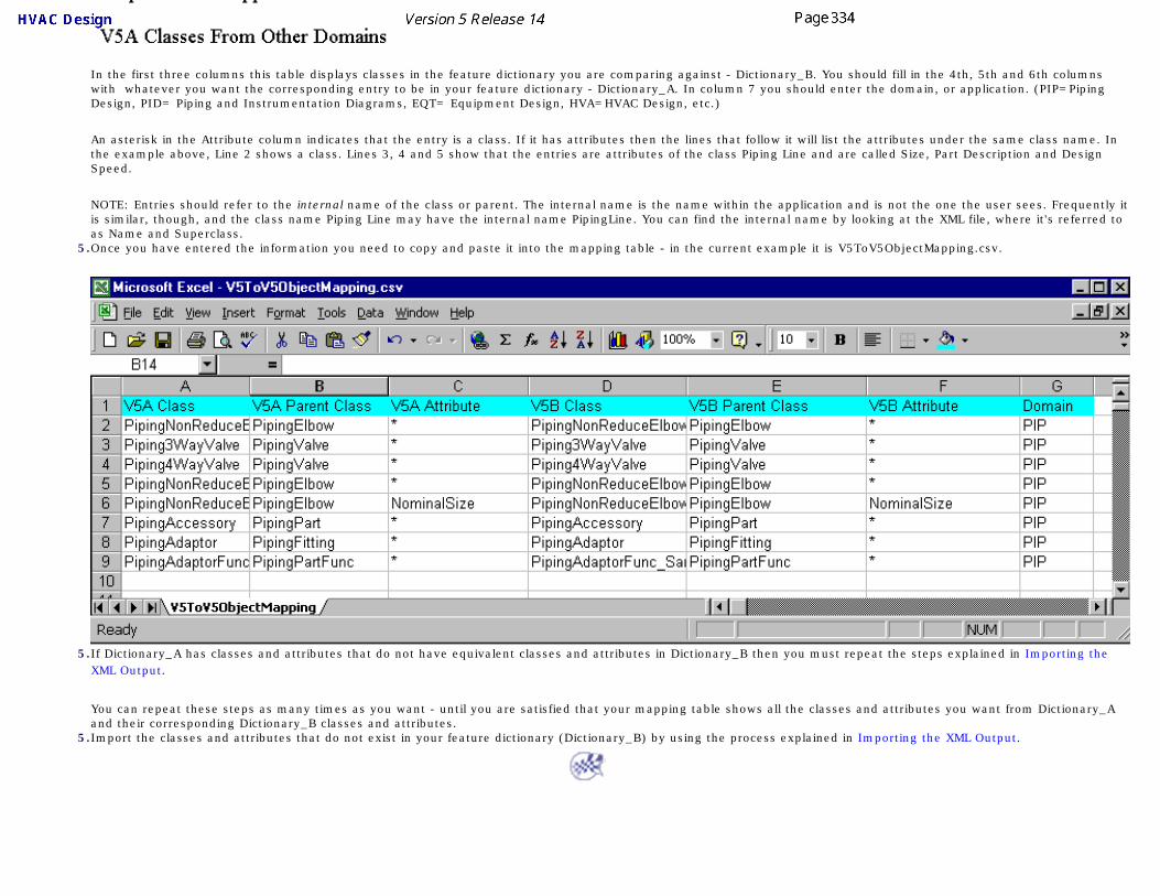
In the first three columns this table displays classes in the feature dictionary you are comparing against - Dictionary_B. You should fill in the 4th, 5th and 6th columns with whatever you want the corresponding entry to be in your feature dictionary - Dictionary_A. In column 7 you should enter the domain, or application. (PIP=Piping Design, PID= Piping and Instrumentation Diagrams, EQT= Equipment Design, HVA=HVAC Design, etc.)
An asterisk in the Attribute column indicates that the entry is a class. If it has attributes then the lines that follow it will list the attributes under the same class name. In the example above, Line 2 shows a class. Lines 3, 4 and 5 show that the entries are attributes of the class Piping Line and are called Size, Part Description and Design Speed.
NOTE: Entries should refer to the internal name of the class or parent. The internal name is the name within the application and is not the one the user sees. Frequently it is similar, though, and the class name Piping Line may have the internal name PipingLine. You can find the internal name by looking at the XML file, where it's referred to as Name and Superclass.
5.Once you have entered the information you need to copy and paste it into the mapping table - in the current example it is V5ToV5ObjectMapping.csv.
5.If Dictionary_A has classes and attributes that do not have equivalent classes and attributes in Dictionary_B then you must repeat the steps explained in Importing the XML Output.
You can repeat these steps as many times as you want - until you are satisfied that your mapping table shows all the classes and attributes you want from Dictionary_A and their corresponding Dictionary_B classes and attributes.
5.Import the classes and attributes that do not exist in your feature dictionary (Dictionary_B) by using the process explained in Importing the XML Output.
Defining User Names for Classes & Attributes You may need to change class or attribute names in the feature dictionary sometimes - to another language, for instance. Or, in the case of user created class names, you may want to add spaces or certain characters that this application does not permit normally. Ways of doing this are explained below.
You will come across references to the CATfct file elsewhere in the feature dictionary documentation. Briefly, the CATfct file is the file which stores the user-created classes that you see in each feature dictionary. The CATfct file must be kept in the default location, though you can change its name with a corresponding change in the project resource management file.
The basic classes - the classes that display when you create a new feature dictionary and that cannot be deleted - are stored in a .feat file.
CHANGING USER CLASS NAMES: The CATfct file is linked to another file which is of the type CATNls. The classes that you see in the feature dictionary are actually defined in the CATNls file. It is set up this way so that users can customize class names without having to change the dictionary.
When you add a new subclass you cannot use certain characters or even spaces. You cannot add the class Piping Valve - it has to be PipingValve. Only alphanumeric characters can be used, without any spaces.
If you want to override these restrictions you can create a CATNls file and enter your preferred names. The format of a CATNls file is reproduced below. To use your own name enter the subclass name as you created it in the first column, followed by your preferred name.
PipingValve = "Piping Valve";
PipingPipeFunc = "Pipe Function";
PipingPartFunc = "Piping Part Function";
If you create a new CATNls file you have to follow a naming convention so that the application can recognize it. If your feature dictionary is named CATPipinguser, then the CATNls file must have the name CATPipinguserNLS with the extension CATNls. Thus the file would be named CATPipinguserNLS.CATNls. All CATNls files must be stored in the directory ...intel_a\resources\msgcatalog.
CHANGING BASIC CLASS NAMES: Basic class names are those that you see when you create a new feature dictionary. These classes are stored in a .feat file, which in turn is linked to a CATNls file.
Feat files must be located in the directory ...intel_a\resources\graphic. The Piping Design file, for instance, is named CATPiping.feat. The corresponding CATNls file is in the directory ...intel_a\resources\msgcatalog. In the case of Piping Design the file is named CATPipingNLS.CATNls. The format of the file is as described above, and you need to change it in a similar manner.
CHANGING ATTRIBUTE NAMES: All attribute names are contained in the file CATPlantShipModelerAttrNLS.CATNls, which is in the directory ...intel_a\resources\msgcatalog. You cannot create a new file for attributes - you must use the existing file. Enter a name using the conventions described above.

Extreme caution must be used in changing names because all documents linked to them will be affected. It is recommended that the basic class names not be changed. For the same reason you should not delete attributes and classes.

Creating the Mapping Tables
This task shows you how to add new subclasses and physical parts. These are done through the addition of tables created in the appropriate directory. The process for HVAC Design is described here. The process is the same for other applications, just use the correct directories. Also note that the functions may be different in other applications.
When new object classes (subclasses) are added to the Feature Dictionary they must be "mapped" - the subclasses must be mapped to the physical part types. Only by mapping the new classes will they become available in the Browser during parts placement. For applications that use parametric parts the mapping is done by creating tables containing relevant data.
HVAC Design has four functions available to it, to which you can add object classes if you want to. You cannot add more functions. The four functions are: flat oval, rectangular corner, round and rectangular. Each of these is linked to object classes. The function 'Round', for instance, has six object classes: branch, branch connection, duct, inline, reducer and valve. This task shows you how to add an object class to a function. You can also add a physical part to one of the object classes.
You must follow the existing file naming convention and table structure.
1. The tables are contained in a specification. Using the sample specification A_GA_W01 as an example, the tables are in the directory ...intel_a\startup\EquipmentAndSystems\HVAC\MaterialSpecification\A-GA-W01. Each function has a CATProduct associated with it. The CATProduct files in turn are associated to the text tables that contain the data. To add an object class, create a file using a text editor like Notepad, and name it according to existing conventions. The file naming structure is (Specification)-FuncPhys(Function)-(Object Class).txt. For instance, if you are adding the object class 'terminus' to the function 'Round', and in the specification A-GA-W01, you would name the file A-GA-W01-FuncPhysRound-Terminus.txt.
2. Once you have created the file you can add data to it. The file contents should also follow the existing structure, as shown below.
Under FunctionName list the object class, add the minimum and maximum sizes you want, and list the physical parts to which the object class is linked. Do not change the table structure or column headings. Use the tab key to move between columns, and do not add leading or trailing spaces to your entries.
You need to create a file for each function to which you are adding the object class - the file name should reflect the function. If you are adding the object class terminus to all four HVAC functions then you will end up with four files having four different file names.

To add one or more physical parts to an object class, add a line to the table. 3. After creating the text file you should link it to the CATProduct. To link, drag the CATProduct file onto the viewer
and expand it in the specifications tree. (Your customizing settings need to be correct. Click Tools - Options - Infrastructure - Product Structure - Tree Customization and activate Parameters and Relations.)
4.
Click the Design Table button to bring up the Design Table dialog box.

5. Enter the function name in the Name field (it should be as entered in the CATfct file) and check the option Create a design table from a pre-existing file.
6. Click OK and, in the File Selection dialog box that displays, navigate to the file you created. Select the file and click Open.
7. In the design table that displays, uncheck the option Activity. Click OK. The text file is now linked to the CATProduct. You will need to repeat this step for all text files that you have created.
You must enter 'internal' function and part type names. To obtain the internal names open the feature dictionary in the feature dictionary editor and click the Generate Report button. Specify a location for the file. In the report, the name shown against 'Object Key' - under each function or part type - is the internal name that you need to use.

Opening a Document Without CATfct File
This task shows you how to open a design document without the associated CATfct file. This function can also be used to view a single part. You should only view the document using this process - you should not make modifications to it.
Examples from the Piping Design workbench are used here. The process is the same for other workbenches.This function can be useful in various situations. A common scenario is when one user sends a document to another user but does not send the relevant CATfct file. The document can be opened if it was created in Release 13 or later. But if it was created in an earlier release then the sender of the document must first take certain steps so that it can be opened without a CATfct file.1. If the document you want to open was created using a CATfct file from Release 13 or later then all you have to
do is click File - Open. If the document was created using a CATfct file from R12 or an earlier version then the document must first be 'cleaned' by the person who created it or who is sending it. To prepare the document, he will have to import the CATfct file from the earlier version into his own environment, and then perform a step that is known as 'cleaning' or upgrading the document. Those processes are explained below.
2. To import a CATfct file you should be in the version into which you want to import the file. Open the CATfct file by clicking File - Open and navigating to the file you want (it must be the CATfct file that applies to the document that is to be cleaned). The default location is ...intel_a\resources\graphic and the default name will be CATXXXSample.CATfct, where XXX is the product name, such as Piping or HVAC.
Click Tools - Upgrade CATfct (in the toolbar) to import the file. You have to save the file.3. After the current CATfct file has been upgraded with the earlier version, the document needs to be cleaned. To
clean the document, open it and click File - Desk.
4. Right click on the product (in this case test.CATProduct) and, in the drop down menu that displays, select CATDUAV5. The CATDUA V5 dialog box displays.
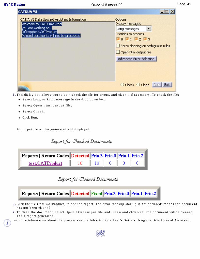
5. This dialog box allows you to both check the file for errors, and clean it if necessary. To check the file:● Select Long or Short message in the drop down box.
● Select Open html output file.
● Select Check.
● Click Run.
An output file will be generated and displayed.
6. Click the file (test.CATProduct) to see the report. The error "backup startup is not declared" means the document
has not been cleaned. 7. To clean the document, select Open html output file and Clean and click Run. The document will be cleaned
and a report generated. For more information about the process see the Infrastructure User's Guide - Using the Data Upward Assistant.

Cache ModeThis section discusses ways in which you can design efficiently in cache mode, as well as tips about using it.
Working in Cache Mode

Working in Cache Mode
This task discusses steps you should take to design efficiently in cache mode.
Cache mode refers to designing without loading all the technological data of objects in your document. It is recommended because it allows quicker loading of documents and execution of commands. However, you may need to take certain steps to design efficiently in this mode, which are discussed here. This task also explains ways of executing certain commands while in cache mode.
1. When you are using the command Place Object from Catalog while you are in cache mode you will not be able to place a part on a connector because connectors are not loaded. To change that part to
design mode click the Analyze Item button and then click the part. That part will be converted to design mode and connectors will be visible.
2. It is recommended that you redefine the location of the CATCache directory. This directory is used to store certain design elements (cgr files) that are used when visualizing a document in cache mode. If the file name of an element is too long then the visualization will not be correct - this is a Windows limitation. Because the full path name is used in the file name, you should redefine the location so that the path name is short - as short as you can make it. To redefine the path name click Tools - Options - Infrastructure - Product Structure and select the Cache Management tab. Enter the new path in the Path to the Local Cache field.
3. Wireframe geometry, such as the sections on trapeze hangers, are not visible in cache mode, which also means they cannot be selected. If you want to be able to see them in cache mode then check the option Save Lineic Elements in CGR. You can find it in Tools - Options - Infrastructure - Product Structure and the CGR Management tab.

Penetration ManagementThis section discusses penetration management setup. The penetration management function works within the ENOVIA environment only - and you must be in the ENOVIA Product Structure.
Penetration Management Setup

Penetration Management Setup
This task explains the setup process for defining a penetration cutout sketch, and identifies some of the processes involved. Penetration management uses design rules that are Knowledgeware-based. To modify the sample rules provided with this application, or to create new design rules, you must know how to use Knowledgeware. Read the documentation for that product to get more information. In addition, you must incorporate certain data particular to this application when creating new rules. That is explained below. You may also need to refer to ENOVIA-LCA documentation for ENOVIA-specific tasks.
If the Penetration Management Tools toolbar is not displayed then click View - Toolbars and select it.Penetration management refers to the process of routing a pipe or a duct - as an example - through a structure. If you are working with a ship, for instance, you may need to create penetrations through bulkheads, move objects, or reroute your pipe or duct, in order to do so. The penetration management function works within the ENOVIA environment only - you must be in the ENOVIA Product Structure.
1. Modify the project resource management (PRM) file to reflect the location/names of your resource files. The penetration function uses three PRM resources. The names are: PenetrationCutoutRules, PenetrationOpeningsCatalog, and PenetrationShapesCatalog. Sample rules and catalog are provided with this application. The location is ...intel_a\startup\components\PenetrationCatalog. See Understanding Project Resource Management for more information about the PRM file.
2. The outlines of openings are dependent on the shapes defined in the Penetration Shapes catalog. You cannot define an outline in the design rules that does not have a corresponding shape in the catalog. Shapes defined in the sample catalog are: oblong, round, rectangular, square and rectangular radius corner. You can change the values of the parameters of the shapes in the catalog, and you can add new shapes to it. You can remove, replace or rename the sample shapes.
Each shape is a parametric part created with the Part Design product, and is stored in the same directory as the catalog. The oblong shape document, for instance, is OblongShape.CATPart. See Part Design documentation for information about using that product.
To add a shape you must create it with Part Design and store it in the catalog using standard catalog building procedures. See Creating a Catalog and associated tasks in the Catalog section to learn more about creating and modifying catalogs. These are standard parametric parts and there are no special requirements for building them. When building new shapes you should note that the description name you use in the catalog is the name that will display when you are creating a cutout sketch.
3. Most penetration cutout designing will be done using the design rules, although you have the capability of manually defining cutouts, as explained later in this section. The rules work with the shapes in the catalog to determine the final size of the opening. You can add various parameters to the rules using Knowledgeware. However, the function of the sample rules supplied with this application is mainly to determine the shape of the outline, based on the shapes available in the catalog; and calculate the size of the opening. The cutout size is calculated from the sizes of the objects involved in the penetration, with the addition of required clearances.

4. Design rules can be modified, and new ones created, using Knowledgeware. However, there are certain points you must incorporate in a design rule for it to work correctly with this function. The following information is meant for an administrator, or whoever is creating the design rule. You can see examples in the sample rule, which is reproduced below. A penetration cutout rule should:
● Create a variable (defCutout) to hold the DefinePenetrationCutoutShape object, which will communicate the cutout definition to the penetration management command.
● Calculate the size of the cutout, using attributes of the penetrating and penetrated objects.
● The NewDefinePenetrationCutoutShape function creates the temporary object that holds the cutout definition. The penetrating object (p1) and penetrated object (p2) are specified.
● The ShapeName attribute selects the parametric part that defines the shape.
● The SkewTolerance attribute sets the allowed SkewTolerance for the penetration.
● The SetAttributeDimension function (or another SetAttributeXXX function) specifies a parameter name in the parametric part, and its value. This function is used repeatedly to set each parameter of the parametric part.
A sample rule is reproduced below:

Creating Custom ReportsThis section discusses ways in which you can customize your report generation.
Defining the Report FormatGenerating a Report
Generating a Report from a MacroCreating a Toolbar Shortcut for a Macro

Defining the Report Format
You use this function, together with the function described in Generating a Report, to get the values of properties of objects in a document. This task shows you how to define the report format.
Before you generate a report you need to define its format. This means deciding which properties you are interested in. This report format is kept in a file which you can use to generate reports from other documents.
To use this function you must first make sure of a setting. Click Tools - Options - General - Parameters and then click on the Knowledge tab. Under Language check Load extended language libraries.
1. Click Tools - Report - Define. The Report Definition dialog box displays.
2. Enter a report name and select a directory location. Enter a report title - you can select anything but you must enter a title.
3. Check the Show Inherited Attributes box if you want to.4. Click on the down arrow and select the dictionary related to your program.5. Select the type of object. The list of attributes you will see in Step 6 will depend on the type you
select here. However, when you generate a report you will get values for all objects in the document that have the attributes in your report format. If you want to limit the objects for which you get a report you must create a query (Step 8).
6. Select an attribute in the Attribute field and click the Add button. The attribute will be added in the window. Add as many attributes as you want to.
7. In the Program field you can select a program that will add certain information, such as Line ID, to the report.
8. You can further refine your report by using the Edit - Search function to define a query. This will allow you to generate a report on a narrower selection of check valve, say, of a certain size, instead of all check valves in your document. Detailed instructions on using the Search function can be found in the Infrastructure User Guide under Basic Tasks - Selecting Objects.

Generating a Report
This task explains how to generate a report listing values of selected properties. Before you do this you need to define the report format.
1. Click Tools - Report - Generate. The Generate Report dialog box displays.
2. Click the Open button and select the format you want to use for your report, in this case NewReport.3. If you had defined a query in your report format then check Objects From Predefined Query.4. If you select one or more objects in the document then check the option Currently Selected Objects.5. Check All Objects in Document if you want a report on all objects in your document.6. Click OK. The report will be generated. It shows values for all properties defined in your report format for all
objects in the document that have them. Where an object does not have a property the report displays asterisks.

7. Click Insert in Doc if you want to display these values in your document. They will only insert in a schematic drawing.
8. Click Save As to save the report. Specify a file name and location.

Generating a Report from a MacroThis task shows you how to create a new report that lists the attributes of an object. As an alternative you can use the methods described in Generating a Report and Defining the Report Format.
The report will list the values for attributes like pressure, length, diameter, open/close position etc. These values will only be displayed if they have been added to the object and if the attribute is included in the report.
1. Select the object for which you want to generate a report. You can select objects in the specifications tree or by using the Edit - Search command.
2. Click Tools-Macro-Macros. The Macro dialog box displays. If the file CATSchAttrValueWYSIWYG.CATScript is not displayed in the box then select External File in the Macro In field. Click Select and navigate to the directory Intel_a\code\command. Select the file named above and click Open. The file will display in the Macro dialog box.
If you want to edit the script that creates the report then click Edit. You will need to have some knowledge and experience of Visual Basic to edit scripts.

3. Select the file and click Run. The Report Generation dialog box will display, asking you to enter the name of a template. Four templates are provided with this application for four types of reports: Part, Instrument, FromTo (for lines) and Equipment. They reside in the Intel_a\code\command directory. Enter the full directory path, based on your setup, and change the last word to one of the four types mentioned above. Your selection will be based on the type of object for which you are seeking to generate a report.
4. Click OK. The report will appear in the form of an Excel spreadsheet. If the object has attributes associated with it, and these attributes are entered in the report, then they will display.
5. If an attribute is not entered in the report you can add it by clicking on an empty column and entering it.

Creating a Toolbar Shortcut for a MacroThis task shows you how to create a button in the toolbar to run a macro.
Macros are used to generate reports (see Generating a report). Creating a button for a macro in the toolbar automates part of the process involved in generating a report.
1. Click Tools-Customize. The Customize dialog box displays.
2. Select the Commands tab and select Macros in the left column. All macros are displayed in the right column.3. Click and drag the macro to the toolbar in which you want to place it. The toolbar will display a button that you can
click to generate the report.4. To customize the icon for the button you just created click on Show Properties and then on the Icon button.
Icons available to you will be displayed. After selecting the desired icon click Close.

CatalogsThe following tasks relate to using catalogs for the purpose of placing parts in the HVAC Design product.
Creating a CatalogModifying a Catalog
Creating Sub-CatalogsCreating a Specifications Catalog

Creating a Catalog
This task explains how to create a catalog. The Catalog facility is a standard facility provided with the V5 Product line. For detailed information regarding Catalogs, please see the Infrastructure documentation - Advanced Tasks - Using Catalogs.
If you are creating a catalog of resolved parts then it is recommended that have no more than about 500 documents in each catalog, so that performance does not suffer. In this case you may need to create several catalogs. To learn how to do this see Creating Sub-Catalogs. Catalogs that point to parametric parts are smaller, and you can have one catalog.
This task explains creation of the main catalog. Creation of the specifications catalog and standards is explained elsewhere (not all applications use them). Also, piping parts are used in this example. The procedure is the same for other types of parts (tubing, equipment, etc.).
You should be in the workbench (such as Piping Design) for which you want to create a catalog.1. Open the Catalog Editor by clicking on Start-Infrastructure-Catalog Editor. The Catalog Window opens with a basic
catalog structure in the left column. Catalogs are created analogous to books, with the book being at the top level, chapters under it, and, if necessary, sub-chapters under them, and with pages (or parts) at the lowest level. Each family contains references to one or more parts.
The illustration below shows the Catalog Editor. The column to the left is where your chapters and families are displayed. The column to the right will display parts when you click on a family.
2. Rename the root chapter (Chapter.1 above) to XXX Part to reflect the application you are working in. In the case of Piping Design, for instance, it will read Piping Part. If you do not do this you will have an extra level in the tree. To rename, right click on it, select Chapter.1 Object - Definition. Enter the new name in the dialog box that displays.

3. Select the chapter under which you want to create the catalog (in this case Piping Part). Click the Create/Modify Catalog
button . The Create/Modify Part Catalog dialog box displays.
4. Select the application in which you want to create the catalog by clicking the down arrow in the Application field.
If you want to add specific parts to your catalog then create a parts list file with a text editor. Enter the names of the parts you want to add, each name on a separate line. This is also the process used in modifying a catalog. The Attribute Filter field can be left blank, it is not needed for this process. If you want to have a log of the process then enter a file name in the Message Log field. The file will be created.

5. Click the button next to the Parts Directory field and navigate to the directory where your parts are stored. The default location is ...intel_a\startup\\EquipmentandSystems\XXX\XXXX\ComponentCatalogs\Parametric, where XXX\XXX is the application, such as Piping\PipingDesign. If you have both a Parametric and Resolved parts directory and you want to create catalogs for both then you need to run the command twice. Click OK to begin creating the catalog, which may take a few minutes. A dialog box will inform you of the progress. The image below shows part of a Piping Design catalog.
Chapters and families are displayed in the first column. The second column will display parts (often called descriptions) when you select a family. You can display different kinds of information by selecting the tabs (Reference, etc.) in the second column. The tab Generative Data is used for specifications catalogs.

The Keywords tab displays the keywords (attributes) associated to the object. In addition, each chapter may contain one or more keywords created by the application: as of Release 14 these were three: PartType, GenericList and ReferenceStatus. These are used by the application for specific purpose. Do not delete or modify them.
6. Save your changes.
You should become familiar with some of the terminology used with reference to catalogs. In the example above: ● The first entry (catalogX.catalog) is the file name. When you save the catalog you will give it a file name which will display
here.
● Piping Part is the root chapter.
● Branch, Elbows, Flanges, etc., are chapters.
● Tee, Elbow, Blind Flange, etc., are families.

Modifying a Catalog
This task explains how to modify a catalog.
Modifying refers to adding a new part you have created to a catalog, or updating a catalog after changing the attribute values of a part. In the example below a new part - belonging to a new chapter and family - will be added to a catalog.1. Place the part you created in the directory to which the catalog points. If you are modifying a part it will
already be in that directory.
2. Create a text file (give it any name you want), with a text editor like Wordpad, and enter the name of the new part you want to add or the part you have modified. In this example the part to be added is: M_EXPJNT_FL-RF.CATPart. Enter each part on a separate line.
3. Enter the workbench to which the catalog belongs. Click File - Open and navigate to the catalog you want to modify. It opens in the Catalog Editor.
4.
Click the Create/Modify Catalog button . The Create/Modify Part Catalog dialog box displays.
If you want to add parts only to existing chapters and families then check the Add Components to Existing Families checkbox. In the specifications tree, select the chapter or family to which you want to add (or modify) parts (you need to do this before you click the Create/Modify Catalog button). As an example, if you select the chapter Fitting shown in Step 8, then new parts will only be added to the existing five families shown. New families will not be created, even if your parts list contains them. Parts will not be added to any other chapter.
5. If the parts are stored on a file system then select File Base and follow the steps below. If they are stored in ENOVIA then select ENOVIA Base and enter the names of all parts in a text file as explained in Step 2. You can also load all parts in memory (if they are in the catalog), in which case they will display in the Select Documents window, and select the parts to process. (To load into memory, first open the catalog, then click File - Desk, all the lines display, select the lines, right-click on the selected line and select Open in the drop down menu.)
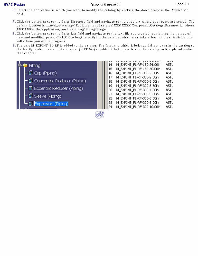
6. Select the application in which you want to modify the catalog by clicking the down arrow in the Application field.
7. Click the button next to the Parts Directory field and navigate to the directory where your parts are stored. The default location is ...intel_a\startup\\EquipmentandSystems\XXX\XXXX\ComponentCatalogs\Parametric, where XXX\XXX is the application, such as Piping\PipingDesign.
8. Click the button next to the Parts List field and navigate to the text file you created, containing the names of new and modified parts. Click OK to begin modifying the catalog, which may take a few minutes. A dialog box will inform you of the progress.
9. The part M_EXPJNT_FL-RF is added to the catalog. The family to which it belongs did not exist in the catalog so the family is also created. The chapter (FITTING) to which it belongs exists in the catalog so it is placed under that chapter.

Creating Sub-CatalogsThis task explains making sub-catalogs. You may need to create several catalogs if you are creating a catalog of resolved parts.
It is recommended that you keep the size of each catalog to about 500 documents. Most users will, therefore, need to create several catalogs if they are pointing to resolved parts. This task explains how to use sub-catalogs, and to view them all through one master catalog. The standard catalog creation facility is used to create the sub-catalogs. In fact, Steps 1 to 4 are exactly the same as described in the task Creating a Catalog. Creating a master catalog and linking it to the sub-catalogs involves an additional step that is also explained here.1.Open the Catalog Editor by clicking on Start-Infrastructure-Catalog Editor. The Catalog Window opens with a basic
catalog structure in the left column. Catalogs are created analogous to books, with the book being at the top level, chapters under it, and, if necessary, sub-chapters under them, and with pages (or parts) at the lowest level. Each family contains references to one or more parts.
The illustration below shows the Catalog Editor. The column to the left is where your chapters and families are displayed. The column to the right will display parts when you click on a family.
2.Rename the root chapter (Chapter.1 above) to XXX Part to reflect the application you are working in. In the case of Piping Design, for instance, it will read Piping Part. If you do not do this you will have an extra level in the tree. To rename, right click on it, select Chapter.1 Object - Definition. Enter the new name in the dialog box that displays.
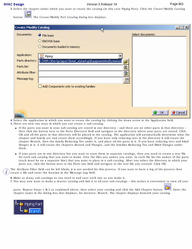
3.Select the chapter under which you want to create the catalog (in this case Piping Part). Click the Create/Modify Catalog
button . The Create/Modify Part Catalog dialog box displays.
4.Select the application in which you want to create the catalog by clicking the down arrow in the Application field.5.There are now two ways in which you can create a sub-catalog.
● If the parts you want in your sub-catalog are stored in one directory - and there are no other parts in that directory - then click the button next to the Parts Directory field and navigate to the directory where your parts are stored. Click OK and all the parts in that directory will be placed in the catalog. The application will automatically determine what the chapter and family are and create them accordingly. If you have only reducing tees in the directory it will create the chapter Branch, then the family Reducing Tee under it, and place all the parts in it. If you have reducing tees and blind flanges in it, it will create the chapters Branch and Flanges, and the families Reducing Tee and Blind Flanges under them.
● If your parts are in one directory but you want to store them in separate catalogs, then you need to create a text file for each sub-catalog that you want to make. Give the files any names you want. In each file list the names of the parts (each must be on a separate line) that you want to place in a sub-catalog. After you select the directory in which your parts are, click the button next to the Parts List field and navigate to the text file you created. Click OK.
The Attribute Filter field can be left blank, it is not needed for this process. If you want to have a log of the process then create a file and enter the location in the Message Log field.
6.Make as many sub-catalogs as you need to and save each one as you make it. 7.You may now want to make a master catalog and link it to all your sub-catalogs - this makes it convenient to view all your
parts. Repeat Steps 1 & 2 as explained above, then select your catalog and click the Add Chapter button . Enter the chapter name in the dialog box that displays, for instance, Branch. The chapter displays beneath your catalog.

8.Open the sub-catalog you want to link to in this application - Tile Vertically or Horizontally so that you can view both.
Select a chapter in your master catalog. Click the Add Link to Catalog button , and then select the family you want to link to in the sub-catalog. The family will display beneath the chapter in your master catalog. Add as many chapters and families as you want to and save the master catalog. In the image below both catalogs have been opened and tiled vertically.

Creating a Specifications Catalog
This task shows you how to create a specifications catalog for products that use parametric parts.An example from the HVAC Design workbench is used here. The process for other workbenches is the same - simply use the relevant CATfct file and terminology. For instance, in the Waveguide workbench you would use Waveguide Part instead of HVAC Part. If you are only familiar with a specifications catalog as used in Piping or Tubing, you should note that the process is somewhat different in applications where parametric parts are used, as in HVAC.
A specifications catalog allows you to specify which parts can be used for a certain project or part of a project. The main catalog typically contains parametric parts, and most values are applied at parts placement time - the size of a duct is derived from the run, for instance. However, in many circumstances you will only want to use parts that have certain properties - for instance, design considerations may require that only ducts with a nominal size between 4 and 8 inches be used. You achieve this by specifying in a specifications catalog what the properties (and values) should be for the parts you want to use. When you place parts using the specification, you will only be able to use parts that fall within your stated criteria. Using the example given above, even if a designer has a 10-inch run, he will not be able to place a 10-inch duct on it because the specification restricts duct size to between 4 and 8 inches.
Your specifications are defined in the rules tables. As explained below, typically you will create a specification named 'Default'. The rules contained in this specification apply to all the other specifications - if they are not defined in that specification. When you are placing a part using a particular specification, the application first determines if relevant rules are defined under that specification. If they are defined then it will use those rules. If they are not defined then it will use the rule under the Default specification.
So, you can specify a duct nominal size of between 2 and 12 inches in the default specification. In Spec A you want to restrict the size to between 2 and 6 inches, so you add a table restricting the user to that size. In Spec B you don't have any particular requirement, so you do not add any table and the application will then use the sizes as listed in the Default catalog.
When you use the provided template to create a specifications catalog you must use the rules supplied with this application. You can modify or delete them (see Modifying Design Rules) but you cannot add new rules.1. Click Start - Infrastructure - Catalog Editor to start the Catalog Editor.
2.
Open the CATfct file associated with your application. To do this, click the Open User Dictionary button to display the Open User Dictionary dialog box and navigate to the directory where your CATfct files are. The default location is intel_a\resources\graphic. In this example the CATHVACSample.CATfct file will be opened.

You can add default rules to your specifications catalog (explained below). These rules appear in a separate chapter named "Default". The rules in the Default chapter will apply to all specifications that you create. This saves you having to associate rules for each specification that you create.3.
Click the Add Catalog Template button . The Add Catalog Template dialog box displays, listing all CATfct files that are open. In the image below only one file is open.
4. Select the application (HVAC), and then click on the down arrow in the Template Type field and make your selection - in this case Material Specification. Enter a name for the specifications catalog in the Template Name field. If you are creating default rules you must enter the name Default. Click on the Browser button next to the Part Type field and make your selection. In this case it is HVAC Part because this is an HVAC specifications catalog. Click OK. The Default chapter and the default design rules display in the specifications tree. There will be differences in the rules that display in other applications like Waveguide.
In applications where you can create both a material specifications catalog and insulation specifications catalog, there may be differences in the design rules that appear in each type of catalog.

5. You now need to associate the actual design rules table (which is how design rules are defined) to each of the
design rules in the specifications tree. Double click on a rule and then click the Add Component button . The Description Definition dialog box displays.
6. Click the Select Document button. In the File Selection box that displays navigate to the directory where the design rules tables are. They are CATProduct type files. (From Release 13 you can link directly to the text tables that define each rule.) The default directory is intel_a\startup\EquipmentandSystems\XXX\Specification (where XXX is your application) and then the specification itself, say A-GA-W01. (These may be a further sub-directory, such as MaterialSpecification.) Open the A-GA-W01 directory and select the text file (or table) that corresponds to the rule that you double-clicked, in this case FunctionalPhysicalMappingRound. Click Open on the File Selection box and OK on the Description Definition box. The table will be associated with the rule and display in the Catalog Editor.
If you click on the Reference tab you will be able to see the full directory path. If you link to the CATProduct you will only see one file listed, as above. If you link to the text files then you will need to link to tables for each part type referenced by the rule: the sample part types are branch, branch connection, duct, inline, reducer and valve. So, if you were linking to the text files you would see six files listed above.
If you add new part types then you must link those to the rule.
Also, if you are linking to the text files then you must enter the actual function name in the Name field of the Description Definition dialog box (Step 5). You can see the function names in the CATProduct file associated with each rule.
7. Associate all the rules with the corresponding tables using the procedure described above.

8. After you have associated the rules in the Default catalog, you can create one or more specifications. To do this, use the Add Catalog Template command as explained in Step 3. Enter a name in the Chapter Definition dialog box, say TestSpec. Link the rules to tables that contain your data, following the process described above. If you do not need to have your own tables for any of the rules you can delete it. In the image below the user has chosen to delete most of the rules from the specification TestSpec.
Be careful when adding data to existing tables, or adding new tables. They must follow the existing structure. See Modifying Design Rules for more information.
9. Click OK to create the catalog. Save it when done.

Standards and Design Rules Ways of creating and modifying standards and design rules are discussed in this section.
Creating and Modifying StandardsRules Overview
Modifying Design RulesAdding an Attribute to a Standard
Adding an Attribute to General Design RulesModifying Object Naming Rules
Add Computed Attribute to Object NameComputed Attributes (3-D)
Adding a New Part Size

Creating and Modifying Standards
This task shows you how to create or modify standards. This task uses a piping standard as an example - the procedure is the same for other types of standard too. Substitute the appropriate application or directory.
The simplest explanation of a standard is that it is a collection of specifications. How detailed these specifications are, or which areas they apply to, can vary from standard to standard, and on users, who can modify the standards. You use a standard because it ensures that all the parts you place, and the manner in which you place them, will meet certain minimum requirements or be within a certain range. The specifications themselves apply to many different properties, such as material or pressure ranges, maximum bend angles, maximum or minimum length, etc.
When you decide to use a certain standard, such as ASTL, which is supplied with this application as a sample, you will only have access to specifications that meet that standard. You set the standard in the Project Resource Management file.
Almost all users will be creating their own standards. You can use a different directory location as long as you specify it in the project resource management file, but it is recommended that you keep the same directory structure as the samples. The samples are located in the ... intel_a\Startup\EquipmentAndSystems\Piping\Standards directory.
A standard basically consists of design rules and attributes. You can change the values in design rules tables, but you cannot add new rules or remove any existing ones. In earlier releases the design rules in a standards catalog pointed to CATProduct files, which in turn pointed to text tables. From Release 13 the design rules can point directly to the text files, rather than to CATProduct files only. You should, therefore, tailor the procedure described below to suit your catalog. For instance, if you do not intend to point to CATProduct files then Step 4 will not be necessary. 1. The first step in creating a new standard should be to create the specifications that the new standard will contain.
To do this, make a directory, say MAR, under the Standards directory and at the same level as the ASTL standard supplied with this application. Enter the directory name in upper case, even though Windows will display it in upper/lower case.
2. Copy all the files under ASTL into the new directory.
3. Edit all the text files - those of file type .txt - using a text editor like Notepad to reflect the values you want to define for your standard. The CATProduct file types should not be modified except as noted below. You should change the words ASTL in the file name to reflect your new standard, MAR, but do not change the rest of the file name. The table structure and column headings must not be modified. Use the tab key to move between columns, and do not add leading or trailing spaces to your entries.
This is also the step you follow when you need to modify the tables in an existing standard.4. If the design rules will point to CATProduct files: Change the prefix - ASTL - in the CATProduct-type files to reflect
your new standard. Change the CATProduct file's prefix in Windows Explorer. You also need to rename the file within the application. To do this open it in the application (see Step 12), right click on it in the specifications tree, and change the name in the Properties dialog box that displays. You also need to change the CATProduct files so that they point to the renamed table. And you need to change a reference in the catalog so that it points to the renamed CATProduct file. This is explained below. But first create the standard using the Catalog Editor as explained here.

5.
Click Start - Infrastructure - Catalog Editor to start the Catalog Editor. The Catalog Editor will display.
6.
Open the CATfct file associated with your application. To do this, click the Open User Dictionary button to display the Open User Dictionary dialog box and navigate to the directory where your CATfct files are. The default location is intel_a\resources\graphic. In this example the CATPipingSample.CATfct file will be opened. (CATfct files contain classes and attributes.)
7.
Click the Add Catalog Template button . The Add Catalog Template dialog box displays, listing all CATfct files that are open.

8. Select the application and click on the down arrow in the Template Type field to make your selection, in this case Standard. Enter a name for the standard. Click on the Browser button next to the Part Type field to display the Class Browser. Select the line Piping Part and click OK. Click OK on the Add Catalog Template dialog box, which should add the standard MAR to the specifications tree with the attributes displayed, as shown in the image below.
9. You now need to make sure the attributes that display in the application point to the text files (tables) you just
created. Double click on an attribute, say MaterialCode, and click on the Add Component button to display the Description Definition dialog box.
10. Click the Select Document button. In the File Selection box that displays navigate to the MAR directory you created in Step 1 and select the file that corresponds to the attribute that you double-clicked, in this case MaterialCode. Click Open on the File Selection box and OK on the Description Definition box. The table will be associated with the attribute. Do this for all the attributes as well as the design rules that appear at the end of the list.
You can link the design rules to corresponding text files using the method described above. If you do so you do not need to follow the steps given below. If you want to link design rules to a CATProduct then take the following steps.
11. You now need to point the CATProduct files in the MAR directory to the corresponding text file (table). And you need to change references in the new standard so that they point to the renamed CATProduct files.
To make these changes you need to change a setting in your Options. Click Tools - Options - Infrastructure, select Product Structure and click the Tree Customization tab. Under Specification Tree Order click on Relations so that Yes appears in the Activated column.
12. To point the .CATProduct files to the renamed text files, begin by opening the .CATProduct file in the application - one way is to drag the file from Windows Explorer onto the workbench. It will display in the specifications tree. In this example the file BendingRules will be changed - in the illustration below it has been opened.

13. Double click on the entry Bending Rules - make sure to click on the entry beneath Relations as shown above - to enter the Knowledge Advisor workbench.
14. Right click on BendingRules to bring up a menu and select Properties. The Properties dialog box will display.

15. Click on the button next to the File Path field, navigate to the renamed text file and select it. Click Open. Save your change.
You need to do this for each .CATProduct file.16. You now need to change the references in your new standard (MAR) so that they point to the CATProduct files. To
do this open MAR.catalog in the application by dragging it onto the workbench from Windows Explorer. The catalog can be found in the Standards directory.
17. The catalog will display in the Catalog Editor. Double click on the .CATProduct file - in this case BendingRules - to
make it active and then click the Add Component button to display the Description Definition dialog box.18. Click the Select Document button. In the File Selection box that displays navigate to the MAR directory you
created in Step 1 and select the CATProduct file that corresponds to the CATProduct that you double-clicked, in this case BendingRules. Click Open on the File Selection box and OK on the Description Definition box. The file will be associated with the CATProduct. Do this for all the CATProducts.
19. Click File - Save to save the changes once you are done.
The General Design Catalog
The General Design Catalog is used to store attributes whose values are the same in all standards. For instance, the pipe specification CS150R has the same value in all standards, because it is referring to a carbon steel pipe with a 150-pound rating. Another example: the attribute "okay to cut" has only two possible values, Yes or No, in all standards. The General Design Catalog was created so that you do not have to enter such attributes in all the standards you create, but instead enter them one time in this directory. The application will first check the standard to see if the attribute is located there and, if it does not find it, will refer to the General Design Catalog.
If you create a new standard, you need to incorporate it in the design rules or the new standard will be ignored by the rules. To incorporate it you must add the new standard in the appropriate column in the rules tables.

Rules Overview
This task provides an overview of the functions that use each design rule (as of R10). Click on the links to get more information. Not all products use each of these rules.
See Modifying Design Rules for links to an explanation of each of the rules, and to learn more about rules and how to modify them. 1. Compatibility Parts placement (catalog filtering)
Bending
● Values for attributes Bend Radius and Grip Length used by two Knowledge Expert rules. (See Using & Modifying Knowledgeware Rules.)
● Values for attribute Minimum Tangent Length is used in the routing a run function to establish the minimum length of a segment.
Length● Values for attribute Maximum Length used
by Knowledge Expert rule. (See Using & Modifying Knowledgeware Rules.)
Dimension
Used by the routing a run function. ● The Outside Diameter value is used to
determine the envelope size of a run.
● The Bend Diameter value is used to calculate the turn (bend) radius of a run and is displayed in the Run dialog box.
● The Wall Thickness values are used to determine wall thickness when placing a part.
Automatic Parts Parts PlacementISO Mapping rules - attributes, endstyles and symbols.
Isogen function - creating a 2-D drawing from a 3-D document.
End Dimension● Drawing Production
● Generating a bolt (bill of materials) report.
Bolting
● Bolt (bill of materials) report to obtain attribute values.
● Isogen, to obtain attribute values for the 2-D drawing.
Branching Parts placement. Filter for parts in a catalog when placing a part in a branch situation.
Shop Fabrication Outputs value which is picked up by the Welding Rule table.
Welding Parts placement, to determine type of weld to be placed between parts.

Turn
Used by the routing a run function. ● It is used to establish the bend radius of a
run if there is a value in the BendRadius column.
● If there is no value in the bend radius column then the bend radius is calculated by multiplying the value in the DiameterFactor column by the value in the Bend Diameter column of the Dimension design table.
● If the value in the NumberofMiterCuts column is other than 0 then elbows are mitered.
Insulation Parts Placement

Modifying Design Rules
This task shows you how to modify the design rules. Also see Understanding Project Resource Management.There are links at the end of this task explaining each design rule, and you can also consult a Design Rules Overview.
This application incorporates intelligent design functions. This means that as you design, the application ensures your designing meets certain criteria. These criteria are established by the design rules. For instance, the design rules will match the threaded end of a pipe to the threaded end of a part. (You can overrule the rules if you want.) The design rules in turn depend upon certain tables where the basic data is entered. You can modify or add to these tables if you want different or additional design rules. Typically, only the system administrator, or a designated person familiar with industry standards, will make such a change. The tables that come with the application are in the following directories: ...\intel_a\Startup\EquipmentAndSystems\XXX\DesignRules ; Standards and Specification (XXX stands for an application, such as Piping).
If you want to modify the general design rules, which apply to all designing, you must modify the tables in the DesignRules directory. For design rules particular to a standard, look for tables in the Standards directory; and for design rules particular to a specifications catalog, look for tables under the Specification directory. To explain further: General design rules apply to all designing. Design rules you place in a particular standard apply only when you use that standard during design time. It is done this way because values may vary from standard to standard. Design rules you place in a specifications catalog apply only when you use that specification.
In making changes you should not alter the structure beneath the EquipmentAndSystems directory.
NOTE: From Release 13 design rules catalogs can point directly to the text files that define a rule - these are the files referred to in Step 1 below. If a catalog points directly to a text file then, to modify, use the procedure in Step 1. If your catalog points to a CATProduct then you can follow both procedures: the one in Step 1, or the one described in Steps 2 & 3. 1. You should only modify the text files - those with a .txt extension. Files with a CATProduct or catalog extension should not be modified.
To modify, open the file with a text editor like Notepad and make your changes or additions. Do not change the table structure or column headings. Use the tab key to move between columns, and do not add leading or trailing spaces to your entries.
2. You can also modify the tables by opening them in the application. To do this drag onto the workbench the CATProduct file associated with the table you want to modify. If you want to modify the Piping-Compatibility.text table then drag the Piping-Compatibility.CATProduct file onto the workbench. Double click on the table in the specifications tree to bring up Knowledge Advisor.
3. Double click on the file again to display the Compatibility table. Click on the Edit table button to display the text file that you can modify. The rules explained in Step 1 apply. Save the changes you make to the text table. You do not need to save the CATProduct file.

4. Click on the links below to learn how each design rule functions. Not all rules apply to each application.
● Rules Overview
● Compatibility Rule
● Bending Rule
● Length Rule
● Dimension Rule
● Using & Modifying Knowledgeware Rules
● Automatic Parts Rule
● End Dimensions Rule
● Bolting Rule
● Branching Rule
● Shop Fabrication Rule
● Turn Rule
● HVAC Turn Rule
● Welding Rule
● Insulation Thickness
● ISO Attribute Mapping Rule
● ISO Endstyle Mapping Rule
● ISO Symbols Mapping Rule

Adding an Attribute to a Standard
This task shows you how to add an attribute to a standard.
You can only add an attribute that has discrete values.
1. Create a text file - with Notepad or another text editor - and enter values for the new attribute. Refer to one of the existing text files to see the format. Save the file in the directory where the other files are located. Give the file the same name as the attribute and follow the naming convention as evident in the existing files. The default location of the ASHRAE92 standard, which is provided with this application as a sample, is ...intel_a\Startup\EquipmentAndSystems\HVAC\Standards.
2. Now you need to add the attribute under the standard (which is ASHRAE92 in this example) and link it to the file you just saved. To do this open the HVACStandards.catalog in the application. (Use File-Open or drag it on to the workbench from Windows Explorer.)

3. Double click on the standard to which you want to add an attribute - in this case ASHRAE92 - to make
it active and click on the Add Family button . The Component Family Definition dialog box displays.
4. Enter a name for the new attribute. Under Type select Standard. Click OK. The new attribute will display in the list of attributes under ASHRAE92.
5.Double click NewAttribute to make it active and click the Add Component button . The Description Definition dialog box displays.
6. Click the Select Document button and, in the File Selection dialog box that displays, navigate to the file you created in Step 1. Select the file and click Open.
The values in the text file are now linked to the attribute you just created.

7. You can also use the procedure described above to create an attribute in the "default" directory.
Adding an Attribute to General Design Rules
This task shows you how to add an attribute to the general design rules.
Although examples from the Piping Design product are used in this task, the procedure is the same for all products that have this function - substitute the appropriate file or object when using another product.
In addition to design rules that are specific to a standard or to a specification catalog, this application has design rules that apply every time you are placing a part. Although you cannot add a new design rule, you can modify existing ones; and, you can add attributes for informational purposes to the Design Rules Catalog.
For instance, you can create an attribute called VendorName and link it to a list of approved vendor names. You can now assign a vendor name to an object at parts creation time; information that will always be available to the user.
When you want to add an attribute that doesn't change from one standard to the next you add it here under Discrete Values.
You may only add an attribute that has discrete values.1. Create a text file - with Notepad or another text editor - and enter values for the new attribute. Refer
to one of the existing text files to see the format. Save the file in the directory where the other files are located. Give the file the same name as the attribute and follow the naming convention as evident in the existing files. The default location of the DesignRules catalog is ...intel_a\Startup\EquipmentAndSystems\Piping\DesignRules
2. Now you need to add the attribute under the general design rules and link it to the file you just saved. To do this open the ...DesignRules catalog in the application. (Use File-Open or drag it on to the workbench from Windows Explorer.)

3. An attribute can only be added under the DiscreteValues column. Double click on it to make it active
and click on the Add Family button . The Component Family Definition dialog box displays.

4. Enter a name for the new attribute. Under Type select Standard. Click OK. The new attribute will display in the list of attributes under DiscreteValues.
5. Double click new attribute, in this case VendorName, to make it active and click the Add Component
button . The Description Definition dialog box displays.
6. Click the Select Document button and, in the File Selection dialog box that displays, navigate to the file you created in Step 1. Select the file and click Open.
The values in the text file are now linked to the attribute you just created. Save your changes.

Modifying the Object Naming Rules
This task shows you how to modify or define the object naming rules. See also Understanding Project Resource Management. Also see Add Computed Attribute to Object Name if you want to add a computed attribute.Examples from the Piping Design product are used in this task. The procedure is the same for all products that have this function - substitute the appropriate file or object when using another product.
Every object that you create (except a run), or part that you place, in your design document can be given a unique identifier. This identifier usually consists of a prefix that identifies the type of object or part it is, followed by a unique number. This enables users, for instance, to maintain a history of each part - when it was serviced, or repaired or replaced - and schedule servicing and replacement dates. When you create an object or place a part in your document the application will suggest a name for it - the default name. (In many cases you have the option of rejecting this name and entering a different name, or renaming it.) The default name is based on certain rules. A set of default rules is included with this application, but most users will want to modify these rules to suit their own requirements. You can modify or define the naming rules in the following way:1. Open the Feature Dictionary Editor. From the main menu, click Start - Infrastructure - Feature
Dictionary Editor.
2.
Click the Open User Dictionary button . The Open User Dictionary dialog box displays.

3. Navigate to the directory where your .CATfct files are stored. The default is .. intel_a\resources\graphic. The CATfct files contain a list of all the object classes. Select and open the file associated with the product you are working with, i.e. Piping or Tubing, etc. All the classes in the file are displayed in the Feature Dictionary.

4.
Select a class in the specifications tree and click the Define ID Schema button . The Define ID Schema dialog box will display.
If the class does not have object naming rules defined then the Inherited From field will indicate the parent from which they are derived. If the class has rules defined then the same class name will display, as in the image above. If no rules exist for this class then they will be created when you take the following steps.
5. You have two options In the ID usage field, Instance and Reference, and you usually have to define naming rules for each object using both options. The naming rules you define under the Instance option are used by the application when you are placing a part in a document.
The naming rules you define using the Reference option are used by the application when you build a component for placing in a catalog. Most users will define naming rules for an object using both options. Depending on your needs, you can choose to simplify the procedure by defining rules for the parent function, which is Piping Part Function in the example above, and these rules will be inherited by all the objects under it.
Select Yes or No for Sequence number. Yes or No cannot be selected if you have Reference as the ID usage. Minimum length refers to the number of digits in the numbering scheme. For instance, 3 means the number will show up as 001.
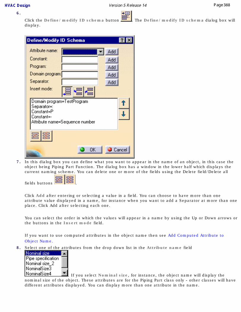
6.
Click the Define/modify ID schema button . The Define/modify ID schema dialog box will display.
7. In this dialog box you can define what you want to appear in the name of an object, in this case the object being Piping Part Function. The dialog box has a window in the lower half which displays the current naming scheme. You can delete one or more of the fields using the Delete field/Delete all
fields buttons .
Click Add after entering or selecting a value in a field. You can choose to have more than one attribute value displayed in a name, for instance when you want to add a Separator at more than one place. Click Add after selecting each one.
You can select the order in which the values will appear in a name by using the Up or Down arrows or the buttons in the Insert mode field.
If you want to use computed attributes in the object name then see Add Computed Attribute to Object Name.
8. Select one of the attributes from the drop down list in the Attribute name field
. If you select Nominal size, for instance, the object name will display the nominal size of the object. These attributes are for the Piping Part class only - other classes will have different attributes displayed. You can display more than one attribute in the name.

9. Enter any value you want displayed in the Constant field. If you enter PP (for Piping Part), all piping part names will display this value. You can add a constant to a name anywhere you require it. For instance, you may begin a name with PP, and end it with WR for a project name.
10. The Program field is used to execute a program that will then add a value to the name. You can create your own programs, but some sample programs are provided with the application and are listed below. Enter a program name in this field if you want it to be executed. For instance, if you enter CATPspEncSchedule in the field, then the short value of the Encoded Schedule attribute will be added to the name (the short value of Extra Strong is XS.). These programs are Standards-based and will execute based on the standard you have defined in your Options. The default standard is ASTL.
The following list shows the programs provided with the application as a sample, and the attributes they refer to:
● CATPspEncRating - Encoded Rating
● CATPspEncRating2 - Encoded Rating2
● CATPspEncRating3 - Encoded Rating3
● CATPspEncRating4 - Encoded Rating4
● CATPspEncNominalSize - Encoded Nominal Size
● CATPspEncNominalSize2 - Encoded Nominal Size2
● CATPspEncNominalSize3 - Encoded Nominal Size3
● CATPspEncNominalSize4 - Encoded Nominal Size4
● CATPspEncSchedule - Encoded Schedule
● CATPspEncMaterialCategory - Encoded MaterialCategory
● CATPspEncMaterialCode - Encoded MaterialCode
11. The Domain program field is used to execute a program that will add the name of the domain to which the object belongs. Domain in this case refers to an object to which the object to be named is connected. For instance, when naming a nozzle it is preferable to add the name of the equipment to which it is connected. One sample domain program is provided with the application, and provides this function: CATPspConnectedEquip.
12. The Separator field is used to add separators, such as a hyphen or semi colon, after the domain field.
13. Use the buttons in the Insert mode field to organize the name. Append field to list will move a field to the end of the name. The other buttons are used when you are adding a field, to position it in the name.
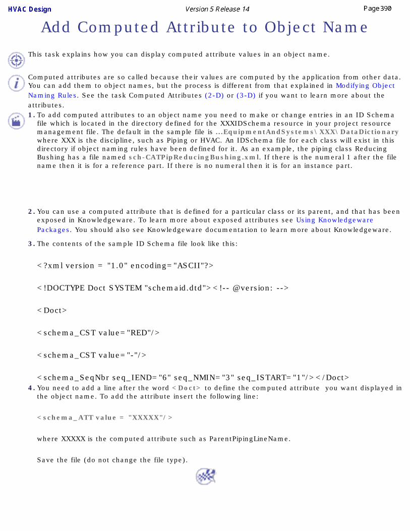
Add Computed Attribute to Object Name
This task explains how you can display computed attribute values in an object name.
Computed attributes are so called because their values are computed by the application from other data. You can add them to object names, but the process is different from that explained in Modifying Object Naming Rules. See the task Computed Attributes (2-D) or (3-D) if you want to learn more about the attributes.1. To add computed attributes to an object name you need to make or change entries in an ID Schema
file which is located in the directory defined for the XXXIDSchema resource in your project resource management file. The default in the sample file is ...EquipmentAndSystems\XXX\DataDictionary where XXX is the discipline, such as Piping or HVAC. An IDSchema file for each class will exist in this directory if object naming rules have been defined for it. As an example, the piping class Reducing Bushing has a file named sch-CATPipReducingBushing.xml. If there is the numeral 1 after the file name then it is for a reference part. If there is no numeral then it is for an instance part.
2. You can use a computed attribute that is defined for a particular class or its parent, and that has been exposed in Knowledgeware. To learn more about exposed attributes see Using Knowledgeware Packages. You should also see Knowledgeware documentation to learn more about Knowledgeware.
3. The contents of the sample ID Schema file look like this:
<?xml version = "1.0" encoding="ASCII"?>
<!DOCTYPE Doct SYSTEM "schemaid.dtd"><!-- @version: -->
<Doct>
<schema_CST value="RED"/>
<schema_CST value="-"/>
<schema_SeqNbr seq_IEND="6" seq_NMIN="3" seq_ISTART="1"/></Doct> 4. You need to add a line after the word <Doct> to define the computed attribute you want displayed in
the object name. To add the attribute insert the following line:
<schema_ATT value = "XXXXX"/>
where XXXXX is the computed attribute such as ParentPipingLineName.
Save the file (do not change the file type).

Computed Attributes (3-D)
A list of "computed" attributes is given here.
Computed attributes are so called because their values are computed by the application from other data.
All objects have certain attributes, such as nominal size. These attributes are either created by users through the Feature Dictionary, or are provided to users in the sample CATfct file that comes with the application (see Feature Dictionary documentation). There are certain other attributes that are not included in the CATfct file but are nevertheless available to users. Users can define checks and rules with them (if they have Knowledgeware installed). These attributes also display when using the edit-search or reports functions. A list of these attributes, with their meanings, is given below.
1. ClassName: The class name of the object, if there is one.
ParentPipingLineName: The name of the piping line of which the object is a member.
ParentICLoopName: The name of the I & C loop of which the object is a member.
ParentZoneNames: The IDs of the zones that an object is a member of, separated by commas.
ParentPipingSpoolName: The name of the spool of which the object is a member.
FromToTable: A list of the objects that are members of a line, between two selected points. Other piping lines that join the selected line are also included.
ConnectedEquipmentName: The equipment to which a nozzle is connected.
ParentHVACLineName: The name of the HVAC line of which the object is a member.
ParentHVACSpoolName: The name of the HVAC spool of which the object is a member.
ParentTubingLineName: The name of the tubing line of which the object is a member.
ParentTubingWeldedAssemblyName: The name of the tubing spool of which the object is a member.

Adding a New Part Size
This task explains how you can add a new nominal size to a part.
Part sizes available to you during part placement are governed by text tables contained within standards. You need to modify these tables as explained below. You also need to modify the part design table.
1. Open the file nominalsize.txt for the standard to which you want to add the size. The location of the sample file is ...intel_a\startup\EquipmentAndSystems\XXX\Standards\YYY where XXX is the application or discipline, such as Piping, and YYY is the standard, such as ASTL.
2. Add the nominal size to the file. Note that the size should be added in order, and should not be inserted just anywhere in the file. Also, follow the convention as you see it in the file. The two columns have the same value in different formats (e.g. .125 and 1/8in). The reason is that the first format is used where shorter text is needed, such as in file naming.
3. Add the size to the design table for the part. The design table is usually located in the same directory as the part. The location of the sample parts is ...intel_a\startup\EquipmentAndSystems\XXX\YYY\Componentcatalogs\Parametric where XXX and YYY are the discipline and application. Follow the convention as you see it in the file.
4. Modify your parts catalog and specifications catalog so that the new part size is available to you. The process of modifying the parts catalog is explained in Modifying a Catalog. Specifications catalogs are explained in Creating a Specifications Catalog. Steps 9 and 10 are relevant for modifying.
Depending on the part size that you are adding, and your specific setup data, the tables associated with the following may also need to be modified:
● Function physical mapping
● Turn Rule
● Bending Rule
● Length Rule
● Dimensions rules (pipe dimension, tube dimension, etc.)
● Bolting Rule
● Branching Rule
● Shop Fabrication Rule
● End Dimensions Rule

Using Knowledgeware ChecksThis section discusses checking a document for design errors using the Knowledgeware product.. You need to have Knowledgeware in order to use these functions fully. However, a sample file is provided with this application with checks incorporated. If you use this file to create your documents you do not have to obtain Knowledgeware in order to use these functions. But if you do not have Knowledgeware you will not be able to create new checks, you will not be able to edit them and you will not be able to import checks into a document.
Enough documentation is provided here to enable you to use the sample file. However, to be able to use all Knowledgeware function you need to refer to the documentation for that product.
Using Knowledgeware PackagesImporting Checks from Knowledgeware
Opening a Sample DocumentChecking a Document for Design Errors

Using Knowledgeware PackagesThis task shows you how to load and use Knowledgeware packages (may also be known as dictionaries). You should see Knowledgeware documentation if you want to learn more about it.
Knowledgeware provides certain functions that are used by all applications. In search and report definition functions, for instance, it allows users the capability of searching for objects, or defining how a report should be structured. This is achieved by 'exposing' objects and their attributes in Knowledgeware through the use of what are known as packages. A package is specific to an application or group of applications, and contains a list of objects and their attributes that have been exposed. The PlantShipLayout package, for instance, contains objects and attributes that are used by several applications, whereas the PipingLayout package contains the list of objects and attributes for piping applications. These packages must be loaded before you can use certain functions.
There is a setting you must enable before you can load and use these packages.
1.Click Tools - Options - General - Parameters and Measure and click on the Language tab. Under Language check Load extended language libraries. Either check All Packages, or uncheck this option and load the packages you will be using.
2. If you check All Packages then packages for all applications - including many you do not need - will be loaded, and may slow operations. You may instead want to load selected packages.

3. There are several ways in which you can view the contents of each package. One way is to open the
Knowledge Expert workbench, click the Expert Check button and click OK in the Check Editor
dialog box to display the Check Editor: XXXX dialog box. Click the Browser button to display the browser. This displays packages in the left column, objects in the middle column, and attributes (and programs) of the selected object in the third column. Check the Show Inherited Attributes checkbox if you need to.
4. Following is a list of packages used by Equipment & Systems applications:● PlantShipLayout - Several applications, should always be loaded.
● ProductPackage - All applications, should always be loaded.
● CompAccessLayout - Compartment & Access
● ElectricalShipbuilding - 2D electrical
● Conduitlayout - Raceway & Conduit Design
● EquipLayout - Equipment Arrangement
● HangerLayout - Hanger Design
● HVACLayout - HVAC applications
● InstrLayout - Several applications
● PipingLayout - Piping applications
● PlantArrangement - Plant layout
● RacewayLayout - Raceway & Conduit Design
● TubingLayout - Tubing applications
● WaveguideLayout - Waveguide applications


Importing Checks and Rules from Knowledgeware
This task shows you how to import checks (and rules) from Knowledgeware into your document. Obviously, you must have Knowledgeware installed to do so.
Before you can use this function you must make sure the settings are correct. Click Tools - Options - General - Parameters and Measure and click on the Language tab. Under Language check Load extended language libraries. Either check All Packages, or uncheck this option and load the packages you will be using.
A second setting you must make sure of is: Click Tools - Options - Infrastructure and click the Tree Customization tab. Activate Parameters and Relations.1. With your document open, make the root object in the specifications tree active, and then click Start -
Infrastructure - Knowledge Expert. The application will open and you will see new entries in the specifications tree. Now you have to import the sample checks and rules provided with this application.
2.
Click the Insert Rules button. The Load Report box will display. Navigate to the directory where the sample files are stored and import the files for the application you are running. The default directory and files you need to import are listed below:
For 3-D products like Piping Design: ...intel_a\startup\EquipmentAndSystems\MultiDiscipline\SampleData
Import the following files for Piping Design, HVAC Design and Tubing Design:
● PhysicalPartsConnectivityCheck.CATProduct
● PhysicalPartsInconsistentNameCheck.CATProduct
For diagrams products: intel_a\startup\EquipmentandSystems\your_application\DesignRules.
● For Piping & Instrumentation Diagrams, import PipingDiagramChecks.CATProduct and PipingDiagramRules.CATProduct.
● For HVAC Diagrams, import HVACDiagramChecks.CATProduct and HVACDiagramRules.CATProduct.
● For Waveguide Diagrams, import WaveguideDiagramChecks.CATProduct and WaveguideDiagramRules.CATProduct.
● For Tubing Diagrams, import TubingDiagramChecks.CATProduct and TubingDiagramRules.CATProduct.

3. The checks and rules you have imported will display in the specifications tree.
4. Double click on the root product in the specifications tree to exit Knowledgeware and return to your workbench.

Opening a Sample DocumentThis task shows you how to open the sample documents provided with this application. The sample documents have some checks and rules incorporated and you can use them without having Knowledgeware.
1.Click File - Open. The File Selection box will open.
2.Navigate to the directory where the sample files for the application you are running are stored by default. For diagrams products: intel_a\startup\EquipmentandSystems\your_application\DesignRules.
For 3-D products: ...intel_a\startup\EquipmentAndSystems\MultiDiscipline\SampleData3.See Importing Checks and Rules from Knowledgeware for a list of sample files. 4.When you open one of these document a message will display warning you that the file is Read Only. Click OK on the message box. The sample
file will open with all the checks and rules displayed in the specifications tree.
5.Make your changes and then use the File - Save As function to save the file and give it a new name.

Checking a Document for Design ErrorsThis task shows you how to check a document for design errors.
This function allows you to check the entire document for certain errors, such as unconnected elements. The full list of errors for which you can check is given below. The procedure is the same whether you have Knowledgeware installed, or you are using the sample files provided with this application.
1. With your document open, right click on the entry RuleBase in the specifications tree. In the drop down menu that displays, select RuleBase object. In the sub-menu that displays select Manual Complete Solve. Your document will be checked for design errors.

2. The checks which came up with errors will have a red button against them. The checks that had no errors will have a green button. In the image below the check Unconnected Elements failed, which means there is one or more element in your document that is not connected to anything.
3. To see which elements failed the check, right click on the check, in this case UnconnectedElem. In the drop down box that displays select UnconnectedElem object. In the sub-menu that shows select Highlight Failed Components. The failed elements will be highlighted in the specifications tree. Some elements will also highlight in the viewer.
4. For diagrams products you can check for the following errors using the sample file provided with this application:
General Design Checks have the following in addition to unconnected elements:
● Unconnected Coincident Element: Elements and connectors can be coincident, or occupying the same space, but not be connected to each other.
● Unconnected On/Off Sheet: On/Off sheet connectors in your document that are not linked to other documents.
● Flow Direction Conflict: Flow direction is not consistent in linked elements.
● Invalid Zone Boundary: A zone has a gap in the boundary.
● Invalid Part Type: Part type selected has invalid attributes.
● Invalid Part Number: Part type is incompatible with defined function.
● Undefined Part Number: No part number assigned.
Other checks are:
● Inconsistent Name Check: This application employs a naming convention. This error means that an element has been named in violation of the rules defined by you.
● Inconsistent Nominal Size: This signifies that elements of different nominal size have been connected.
● Inconsistent Pipe Spec Check: This signifies that elements with different specifications have been connected.

● Inconsistent Equiv Diameter Check: Ducts of different equivalent diameter have been connected.
● Out of Pipe Spec (for piping part functions only): Pipe specification is not derived from the line.
● Out of Duct Spec: Duct specification is not derived from the line.
For 3-D products you can perform the inconsistent name and unconnected element checks.

Line ID CatalogsThis section discusses steps needed for line IDs customization.
Displaying Line ID Properties in CatalogModifying/Updating a Lines Catalog

Displaying Line ID Properties in Catalog
This task explains how you can display line ID properties in the lines catalog. Taking the steps below also displays the properties in the Select/Query Line ID dialog box.
From Release 14 onward, all properties that have values can display in the lines catalog as catalog keywords. However, you must enable the display by taking the actions described here. If you do not do so then only two properties, as defined in the Attribute Filter file, will display.1. In order to enable the display of catalog keywords you need to make a change in the project resource
management (PRM) file, and enter the properties you want displayed in the Attribute Filter file. To change the PRM file, open it with a text editor and locate the resource LineIDAttributeFilter. The entry is at the application level: for Piping Design it is under the heading Piping Design Application. It reads:
<Resource Name="LineIDAttributeFilter" Visible="yes"> </Resource>
The entry will be commented out - disabled - in the sample PRM file you get with this application. To enable it remove the comment notation which is <!-- at the beginning of the entry and --> at the end of the entry.
Piping & Instrumentation Diagrams has a second entry at the application level - InstrumentLineAttributeFilter. You should enable this also if you intend to use filtering on instrument lines.
2. Once you have enabled it in the PRM file, you need to make appropriate entries in the Attribute Filter file. The sample file is located in the directory ...intel_a\startup\EquipmentAndSystems\XXX\SampleData where XXX is the discipline, like Piping. The file name is PipingLineAttributeFilter.txt. The sample file has only two entries - for Piping it is NominalSize and PipeSpecification, for HVAC it is EquivalentDiameter and DuctSpecification and so on. Open the file and add the properties that you want displayed in the catalog.
3. To recap, from Release 14, line properties will display in the catalog as keywords once you have:● Enabled the attribute filter resource in the PRM file.
● Added properties you want displayed in the attribute filter file.
● Valuated the properties.
● Updated the catalog.

Modifying/Updating a Lines Catalog
This task explains how to modify a lines catalog. Piping resources are used below - replace with the appropriate resource or directory in a different workbench.
You will need to modify the lines catalog if you want the catalog to display the attributes that have been added to line IDs from Release 14 onward.
You also need to update the catalog when you create a new line, or change the value of one of the attributes.1. Enter the workbench to which the catalog belongs. Click File - Open and navigate to the catalog you want to modify. It
opens in the Catalog Editor. The image below shows some of the lines and their attributes before updating.
2.
Click the Create/Modify Catalog button . The Create/Modify Part Catalog dialog box displays.
3. If the lines are stored on a file system then select File Base and follow the steps below. If they are stored in ENOVIA then select ENOVIA Base and enter the names of all lines in a text file as explained in Step 4. You can also load all lines in memory (if they are in the catalog), in which case they will display in the Select Documents window, and select the lines to process. (To load into memory, first open the catalog, then click File - Desk, all the lines display, select the lines, right-click on the selected line and select Open in the drop down menu.)
4. If you want to update all the lines then you do not need to take this step (unless you are using ENOVIA). This step is necessary only if you want to update some of the lines in the directory, or if you are using the ENOVIA Base option. Create a text file (give it any name you want), with a text editor like Wordpad, and enter the name of the new line you want to add or the line you have modified. Enter each line ID on a separate line. For ENOVIA-based you must enter the names of all lines you want to add or update.
5. Select the application in which you want to modify the catalog by clicking the down arrow in the Application field.
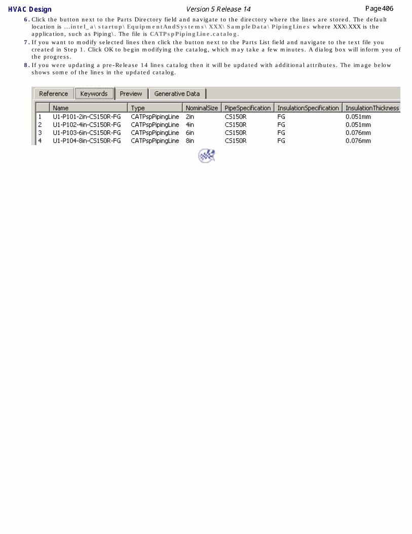
6. Click the button next to the Parts Directory field and navigate to the directory where the lines are stored. The default location is ...intel_a\startup\EquipmentAndSystems\XXX\SampleData\PipingLines where XXX\XXX is the application, such as Piping\. The file is CATPspPipingLine.catalog.
7. If you want to modify selected lines then click the button next to the Parts List field and navigate to the text file you created in Step 1. Click OK to begin modifying the catalog, which may take a few minutes. A dialog box will inform you of the progress.
8. If you were updating a pre-Release 14 lines catalog then it will be updated with additional attributes. The image below shows some of the lines in the updated catalog.

Defining OptionsThis section explains how to define some of your setup options.
Finding Sample Data on Various PlatformsSpecifications Tree

Finding Sample Data on Various Platforms
This task shows you how to find sample data that is provided with the application if you are using a platform other than Windows.
In Windows, catalogs and other sample data are usually stored in a subdirectory under intel_a. Intel_a in turn resides in whichever drive and directory you have installed the application in. Directory paths for sample data in this user guide refer to the intel_a directory. You can find the directories used in other platforms by referring to the list below.
● Windows: ...\intel_a\
● AIX: .../aix_a/
● HPUX: .../hpux_a/
● IRIX: .../irix_a/
● SOLARIS: .../solaris_a/

Changing Specifications Tree Setting
This task shows you how to change the specifications tree settings so that the objects in the tree display in an organized manner of your choice.
The default display setting for objects in the specifications tree is single-tier, and the objects appear in the order in which they were placed in the document.
By changing the Tools -> Options settings they can be organized in two ways, by product and, as an additional step, by application group also. If you do not check the option as described below you will be unable to collapse the specification tree display and it looks as shown below. After you check the Products option the objects will be organized under the Products node and the tree can be collapsed. The Products node is simply an organizational element. After you check the Application Grouping option the objects will be further grouped by type.
1. With your document open, go to Tools -> Options -> Infrastructure -> Product Structure
and click the Product Structure tab. Check to activate the Products option. The objects in the
specifications tree will be organized under the Products node.
2. To organize the specifications tree in application groups go to Tools -> Options -> Equipment
& Systems and click the Display tab.

Under Specifications Tree, activate the Show application grouping option: Objects in the
specifications tree will be organized under type of object. (You can expand the Products node to
see the ungrouped elements.)
When working with Design Rules such as Attribute Filters and FunctionPhysicalMapping, or during parts creation, turn on the Relations and Parameters options.
3. Go to Tools -> Options -> Infrastructure -> Product Structure and click the Tree
Customization tab.
The Specification Tree Order table displays: You can toggle any of the entries from Yes to No
and back by clicking in the Activated column.

Working with ENOVIAThis section discusses some of the set up and customizing processes for ENOVIA.
Setup for EnoviaUsing Catalogs
Resources in ENOVIA
Setting Up for ENOVIAThis task lists some of the options that need to be set, and steps that need to be taken, before using ENOVIA.
In general, you need to do the normal setup procedure when you use ENOVIA. However, there are some processes that are done differently and these are listed in this task. They are explained in more detail elsewhere in this section.1. Most project resources need to be saved in ENOVIA. The project resource management file needs to
be set up so that it is pointing to resources in ENOVIA.
2. Some options need to be set differently. Click Tools - Options to get to the Options dialog box and then:
● Select General and the Document tab. In the Linked Document Localization window select ENOVIA LCA and click the UP button. The ENOVIA LCA line should be the first in the list.
● Select Catalog Editor in the Infrastructure section. Check: Allow family component dynamic resolution in catalog. In the Folder field enter or navigate to the directory where resolved catalog parts will be generated. This only needs to be done before saving a resolved parts catalog in ENOVIA. You can leave the option checked.
3. Catalogs need to be saved in ENOVIA in a certain way. This is discussed elsewhere.

Using CatalogsThis task gives an overview of how catalogs must be stored and used in ENOVIA.
1. Catalogs that are stored in ENOVIA must point to parts that are resolved. This means that no design table can be associated with them, and all values must be defined.
2. Only catalogs with descriptions that point to CATPart or CATProduct documents should be stored in ENOVIA. Catalogs with descriptions that point to text files must be kept on disk. Examples are design rules and standards catalogs.
3. The entire master catalog should not be stored as one entity. Users should divide their catalogs so that there are no more than about 500 parts for each catalog.
Users should create a separate catalog for each family - gate valve, pipe with bends, etc. This is how the sample catalog provided with this application is organized. This type of organization is not only necessary to conserve memory resources, but is also easier to work with.
See Creating Sub-Catalogs to learn how you can do this.
Click here to see the list of resources that can be placed in ENOVIA.

Resources That Must be Placed in ENOVIAThe following resources - identified by discipline below - must be placed in ENOVIA. As of Release 13, resources not mentioned here should not be placed in ENOVIA.
HVAC Discipline
RESOURCE COMMENT
HVACParts.catalog
CATPspHVACLine.catalog
HVAC_ANSI.catalog Diagrams catalog
HVAC_ANSI_Equipment.catalog Diagrams catalog
HVAC_ANSI_HVACFunctions.catalog Diagrams catalog
HVAC_ANSI_Offsheets.catalog Diagrams catalog
Piping Discipline
RESOURCE COMMENT
PipingParts-Resolved.catalog
CATPspPipingLine.catalog
PID_ANSI.catalog Diagrams catalog
PID_ANSI_Equipment.catalog Diagrams catalog
PID_ANSI_Instruments.catalog Diagrams catalog
PID_ANSI_Offsheets.catalog Diagrams catalog
PID_ANSI_PipingFunctions.catalog Diagrams catalog
PipingSpecifications.catalog This catalog needs to be regenerated and pushed every time you modify the Piping Parts catalog.
PipingSpec_F-Master.catalog This catalog needs to be regenerated and pushed every time you modify the Piping Parts catalog.
Equipment Discipline
RESOURCE COMMENT
PipingEquipmentAndNozzle-Res.catalog
HVACEquipmentAndNozzle.catalog
TubingEquipmentAndNozzle-Res.catalog
WaveguideEquipmentAndNozzle-Res.catalog
ElectricalEquipmentAndComponent.catalog 3-D electrical catalog
Waveguide.catalog
Waveguide_Equipment.catalog
Waveguide_WaveguideFunction.catalog
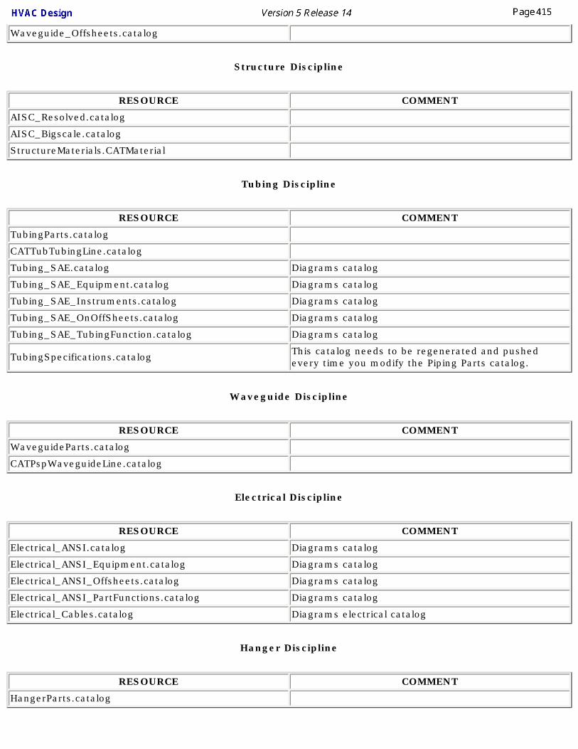
Waveguide_Offsheets.catalog
Structure Discipline
RESOURCE COMMENT
AISC_Resolved.catalog
AISC_Bigscale.catalog
StructureMaterials.CATMaterial
Tubing Discipline
RESOURCE COMMENT
TubingParts.catalog
CATTubTubingLine.catalog
Tubing_SAE.catalog Diagrams catalog
Tubing_SAE_Equipment.catalog Diagrams catalog
Tubing_SAE_Instruments.catalog Diagrams catalog
Tubing_SAE_OnOffSheets.catalog Diagrams catalog
Tubing_SAE_TubingFunction.catalog Diagrams catalog
TubingSpecifications.catalog This catalog needs to be regenerated and pushed every time you modify the Piping Parts catalog.
Waveguide Discipline
RESOURCE COMMENT
WaveguideParts.catalog
CATPspWaveguideLine.catalog
Electrical Discipline
RESOURCE COMMENT
Electrical_ANSI.catalog Diagrams catalog
Electrical_ANSI_Equipment.catalog Diagrams catalog
Electrical_ANSI_Offsheets.catalog Diagrams catalog
Electrical_ANSI_PartFunctions.catalog Diagrams catalog
Electrical_Cables.catalog Diagrams electrical catalog
Hanger Discipline
RESOURCE COMMENT
HangerParts.catalog

Conduit Discipline
RESOURCE COMMENT
ConduitParts.catalog
CATCndConduitLine.catalog
Raceway Discipline
RESOURCE COMMENT
RacewayParts.catalog
CATRwyRacewayLine.catalog
Other
RESOURCE COMMENT
CATMidZone.catalog
SpaceReservation.catalog
CompartmentAccess-Resolved.catalog
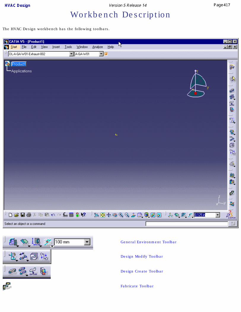
Workbench DescriptionThe HVAC Design workbench has the following toolbars.
General Environment Toolbar
Design Modify Toolbar
Design Create Toolbar
Fabricate Toolbar

Build Create Toolbar
HVAC Line Management Toolbar
General Design Toolbar
Rename Toolbar
Penetration Management Toolbar

Design Create ToolbarThe Design Create toolbar contains the following tools.
See Routing a Run
See Routing at an offset of a routable
See Route a run along a spline
See Route a run within a pathway
See Placing parts on a run
See Hole Placement
See Placing a Section at the End of a Part

Fabricate ToolbarThe Fabricate toolbar contains the following tools.
See Managing Fabrications

Build Create ToolbarThe Build Create toolbar contains the following tools.
See Building HVAC Parts
See Create Connectors

HVAC Line Management ToolbarThe HVAC Line Management toolbar contains the following tools.
See Create a Line ID
See Select a Line ID or Query a Line ID
See Transfer Members of a Line ID
See Rename a Line ID
See Delete a Line ID
See Merging Line IDs
See Import a Line ID

Design Modify ToolbarThe Design Modify Toolbar contains the following tools.
See Edit part parameters
See Flipping Elements
See Update Part
See Changing the Size or Spec of a Part
See Connect Parts
See Disconnect Parts
See Connect Runs
See Disconnect Runs
See Creating an offset Segment connection
See Create Graphics Representations
See Managing Flows

General Environment ToolbarThe General Environment Tool Bar contains the following tools:
See Generating Detail Information
See Changing the Current Axis.
See Using Offset Planes
See Advanced Offset Plane
See Manipulation Handle Mode
Toggle Dimming Mode
Snap to steps off current axis
Snap to steps off last position
Snap to XY construction plane
Snap to all construction planes
Snap to elevation (Z) construction plane
Snap to Drafting elements

General Design ToolbarThe General Design Toolbar contains the following tools.
Align Toolbar
Align Sides: See Aligning Elements
Align Center: See Aligning Elements
Rotate to Align: See Aligning Elements
See Distributing Elements
Align Planes: See Aligning Elements
Snap Toolbar
See Snap Resources Together
Snap Three Points: See Quick Snap Resources
Snap Center of Polygon: See Quick Snap Resources
Snap Surface: See Quick Snap Resources

Rename ToolbarThe Rename toolbar contains the following tools.
See Rename an Object
Glossary
A
annotation Used in schematic diagrams to annotate lines and components. Annotations may be entered manually, derived from an attribute, or placed by means of a text template as part of an annotations catalog.
ATS Annotation Tag Style. In schematic diagrams; employed when creating a text template.
attribute Characteristics of an object, such as length, flow rate, etc. Also referred to as property.
B
boundary A two or three dimensional reservation of space, used to separate or define portions of an area.
branch Routed object that is connected to another routed object at a mid-point between nodes.
branching The act of routing from an existing routable. The routing starts at a point between two nodes, not from a node.
C
catalog A collection of parts and parts component catalog data. There are several types of catalog, such as a specifications catalog, standard catalog.
child A status defining the genealogical relationship between two objects.closed loop run A run whose ends are joined to each other.compass A tool for defining direction.component group Used in schematic diagrams. Two or more connected components
assembled to make up an individual assembly that can be stored and placed from a catalog
conduit line A mechanism for identifying and organizing Conduit routes and the components placed in them. A line ID.
connector Location on a resource (components, parts, item reservation, etc.) used to attach other resources. Connectors can be created, modified or deleted.
constraint A geometric or dimension relation between two elements.contour The physical shape of an area.coordinates The XYZ locations.
D
definition The physical characteristics of an element. Changing the definition changes the shape of an element.

discrete values Values, usually of an attribute, that are pre-defined. Instead of entering a value you select a value in a drop-down box.
distribution system An object used for organizing and grouping elements, mainly routables and resources, that distribute some commodity (fluid, air, etc.).
document The file in which a drawing or a project is created, sometimes also referred to as model. Document is the preferred terminology.
downcomer The legs of a hanger.
E
element Any of the features contained in a document, such as component, line, etc.
F
fabrication Used in HVAC Design. A contiguous grouping of connected HVAC parts. Analogous to spools in Piping Design or welded assemblies in Tubing Design.
face A surface on an object, usually item reservation or part.feature dictionary The document in which object classes are defined.
G
grab A Windows feature for clicking and dragging.graphic representation A geometric representation of an object. An object may have multiple
graphic representations.
H
HVAC line A mechanism for identifying and organizing HVAC routes and the components placed in them. A line ID.
hanger Supports used for routing cables, pipes, etc.hole An opening through an object.
I
I & C loop Stands for Instrumentation & Control Loop. It is an object used for grouping and organizing instrumentation and control objects.
intel_a A Windows directory in which this application is stored and executed by default.
item reservation A two or three dimensional reservation of space, in which one or more objects can be placed.

L
line ID A mechanism for identifying and organizing routes and components. Conduit, HVAC, Piping, Raceway,Tubing lines and I & C loops are line IDs.
M
master The controlling object in a relationship. Such a relationship can be created between some objects.
member Belonging to or part of, as in belonging to a line ID.mirror
Nnode Symbols that mark the end of segments in routables. They can be used
to move or manipulate segments.
nozzle A piece of pipe welded to a piece of equipment or vessel with a flanged end to which a pipe can be connected.
O
object class An object class is the classification or type of object.offset plane A command used to define a reference plane.
P
parent A status defining the genealogical relationship between two objects.part The geometric representation of a 3D object.part types Object classes.path reservation A two or three dimensional reservation of space, in which assembly lines,
conveyor belts, etc., can later be created.pathway Path reservation.piping line A mechanism for identifying and organizing piping routes and the components
placed in them. A line ID.plane manipulator A geometric tool to change the orientation, alignment, plane and location
of a plane that is to be created.properties Characteristics of an object, such as length, flow rate, etc. Also referred
to as attribute.

R
raceway line A mechanism for identifying and organizing raceway routes and the components placed in them. A line ID.
reference plane A plane that has been defined as an aid to performing certain functions, such measuring distance.
routable Anything that can be routed, typically: run, path reservation and boundary.
run A two or three dimensional reservation of space, in which pipes and parts can later be placed.
S
scaling An operation that resizes features to a percentage of their initial sizes.set point The alignment point for a routable, such as run or path reservation, for
which a section is defined. The set point determines, for example, whether the routing line drawn for a boundary represents the bottom left, bottom right, or bottom center of the boundary. There are three possible set points for a boundary and nine possible set points for a path reservation and run.
slave The following object in a relationship. Such a relationship can be created between some objects.
snap Join, as in snap together. Also snap to a grid, in which the position of an object is automatically adjusted to a grid.
space reservation A two or three dimensional reservation of space, in which equipment, pipes and parts can later be placed.
specifications tree A graphic display of the organizational structure of all elements in a document.
spoolA grouping of objects. All objects in a spool must be contiguous and connected to each other.
standard A collection of specifications.support line A location on a routable used as a reference point for routing when the
centerline is not used. It is also used in placing parts. The support line is defined by the set point (see above).
system A mechanism for organizing and grouping elements, mainly routables and resources.
T
tubing line A mechanism for identifying and organizing tubing routes and the components placed in them. A line ID.
turn angle The angle formed between two lines.
W

waveguide line A mechanism for identifying and organizing waveguide routes and the components placed in them. A line ID.
welded assembly Used in Tubing Design. A contiguous grouping of connected tubing parts. Analogous to spools in Piping Design and fabrication in HVAC Design.

Index
Aactivate parent
add new nominal size
AIX, sample data
analyze related objects
attribute filter attributes
adding to a standard
adding to general design rules
associating to a connector
creating
generating report
attributes, computed axis
changing the current
Bbranching a run
building parts, requirements
Ccache mode
CATCache directory location
make wireframe geometry visible catalog
creating

creating sub-catalogs
modifying
specifications
terminology catalogs
updating line IDs
catalogs in ENOVIA
CATDUA V5
change axis & snap compass
changing the size or spec of a part checks
checking a document
importing from Knowledgeware
open a sample document
clash detection
class & attribute, user defined command
Activate Products Parent
Adjust Run Extremity
Align Center
Align Side
Align Two Planes
Analyze Item
Build Connectors
Build HVAC Part
Build New Unique Reference
Clash Detection (Off)
Clash Detection (On)
Clash Detection (Stop)
Connect Parts
Create an Offset Route
Create an Offset Segment Connection
Create Fabrication

Delete Line ID
Disconnect Parts
Distribute
Edit Part Parameters
Flexible Routing
Flip Part Position
Force Update
Import Line ID
Manage Flows
Manage Graphic Representations
Manage Local Slack
Merge Line ID
Move/Rotate Part on the Run
Penetration Management
Place Equipment/Part from schematic
Place Hole
Place HVAC Part
Place New Part Under Active Parent
Place Section
Quick Translate
Rename ID
Rename Line ID
Resize/Respec Part
Rotate to Align
Route a Run
Route a Run from schematic
Route from Spline
Route Thru a Pathway
Select/Query Line ID
Set Object Type
Snap
Snap Center of Polygon

Snap Surface
Snap Three Points
Transfer Line ID
Transfer Run
Update Part
Validate Run Turns compass
routing in 3D with
computed attributes
add to object name
connector flow direction
connectors
creating
duplicating
manipulating with compass
modifying or deleting
plane manipulator
create 3-D document from schematic
create new unique reference
creating a catalog
creating light objects
cross document connection
customizing settings
Ddatum point
defining plane delete
line ID
design rules
importing from Knowledgeware
Knowledgeware
open a sample document
Overview
design table dialog box
dictionary, Knowledgeware
display connectors
display values documents
saving
drawing production
generate drawing
settings
drawing, 3-D to 2-D
Ductulator
Eedit properties of an object
electrical part connector elements
aligning
distributing
end styles ENOVIA
setup Enovia
create a product
importing poduct
organizing work packages
save operation
saving work package
Enovia directory structure

ENOVIA, customizing
ENOVIA, user tasks
exception, schematic driven design extremity
adjusting the
Ffabrication
modify properties
select/query
feature dictionary
comparing
NLS name for class, attribute
open file without CATfct
Filter Attributes
filter for Line ID
filter shown properties flexible
manage local slack
routing
flip flow direction
change
connector
display
force update
Ggenerate drawing
generating reports

generative view style graphic representations
defining
manage grid step
setup
Hhole
modifying
placing on part
querying properties
HPUX, sample data
IImporting Line IDs
IRIX, sample data
KKnowledgeware
checking a document
importing checks
opening sample document
using packages
Knowledgeware checks
L

light object explained Line ID
attribute filter file/entry
changing size/spec of parts in
creating
customizing
deleting
displaying properties
filter attributes
filter/select
importing
merging
modifying the properties of
querying
rename
select/filter
updating catalog
line thickness
local slack
Mmacro
creating a toolbar shortcut for
manage publications
mapping subclasses
mapping table
merging line IDs migrating V4 models
directory structure
migrating V4 models to V5
modify the properties of a line ID

modifying a hole
move/rotate in-line parts
moving document multi-CAD document
defining plane for connector
Nnetwork
analyze
analyze for connections
changing size/spec of parts in
node edit table nodes
deleting
display coordinates of
moving
opening a closed run
nozzle connector
Oobject
auto-route between
edit or display properties of
filter properties of
generating report of
query for connections
renaming object class
managing
object naming rules

add computed attribute objects
search for offset connection
create between segments
offset planes
open file without CATfct options
defining
naming rules
Options settings
options settings
Options, settings
Ppackages, Knowledgeware
parent-child relationship part
flip parts
adding nominal size
associate specifications to
connecting
create
create graphic representation
creating light object
define properties
define type
disconnecting
inserting
light object
move in-line parts

multi-place
override parameters
place under active parent
place using schematic
placing
requirements for building
rotate in-line parts
rotating pathways
route within a
penetration management penetrations
add object
associate
creating cutout sketch
query for
setup piping lines
Comparator
plane manipulator
product parent project registration model
exporting
project resource management
Access field
checking errors
file
Location field
selecting project
Type field
Visible properties
edit or display

filtering
publication based connections in PRM
publications
publish connectors
Qquery a Line ID
query for penetrations
Quick Snap
Rrename
a Line ID
objects report
define format
generate
report, generating a reservation
routing from resource
Quick Snap
rotate using definition panel
snap and rotate
snap together resources
create parent-child relationship routable
display information about
fixing broken
route at an offset of

routing from end of routing
align to surface
along a spline
at a slope
at an offset of routable
auto-route
edgeline
edgeline to offset plane
from item reservation
in 3D
parallel to a run
run
using a schematic
within pathway
routing flexibles rules tables
design tables
modifying
run
changing a section
changing angle of segment
close
modifying
move or adjust extremity
open
single or double display
transfer
transitional objects
turn radius error
using definition dialog box runs
modifying

Ssample data
finding on various platforms
save documents schematic driven design
analyze
associate objects
create an Exception
place parts
routing
search command section
modify
place at end of part
query segment
fit for parts assembly segments
align adjacent
create an offset connection between
make parallel to compass base plane
make parallel to offset plane
make parallel to Z axis
position relative to a plane
selecting a Line ID
setup, application
show/hide connectors
slack, manage
Solaris, sample data specifications
associate to a connector

creating a catalog specifications catalog
adding specifications
default rules spool
add/remove members
changing size/spec of parts in
creating
deleting
renaming standards
adding an attribute
creating and modifying
selecting default
Ttoggle manipulator handle mode toolbars
Build Create
Design Create
Design Modify
Fabricate
General Design
General Environment
Piping Line Management
Rename Tools Options - Equipment and Systems
Standards transfer
multi-select to
transfer members of a line ID
transfer run

transferring document
transitional objects
turn errors
turn radius, invalid
Uunique reference
update connections
update part button
updating lines catalog
VV4 migration
migrating model
V4 migration, setup data V4 parts
migrating V4 to V5 integration
comparing outputs
exporting V4 classes
exporting V5 dictionary
import XML
migrating the model
viewing related objects
Wwork package
connections

cross document connection
manage publications workbench
description
entering the