SECTION 230800 - COMMISSIONING OF HVAC PART 1
312
UTRGV School of Medicine - Jackson Rd. 230800 UTRGV#PED 18-33 / BSG #1802 1 Commissioning of HVAC SECTION 230800 - COMMISSIONING OF HVAC PART 1 - GENERAL 1.1 RELATED DOCUMENTS A. Drawings and general provisions of the Contract, including General and Supplementary Conditions and other Division 01 Specification Sections, apply to this Section. 1.2 SUMMARY A. Section includes commissioning process requirements for the following MEP systems, assemblies, and equipment: 1. HVAC systems, including direct-expansion systems, DOAS, RTUs, split systems. 2. Distribution systems, including air distribution systems, exhaust systems. 3. Terminal and packaged units. 4. Controls and instrumentation, including BAS energy monitoring and control system. B. Related Requirements: 1. Section 019113 "General Commissioning Requirements" for general commissioning process requirements and Commissioning Coordinator responsibilities. 1.3 DEFINITIONS A. Refer to Section 019113 "General Commissioning Requirements" for additional definitions and assignment of responsibilities. B. BAS: Building automation system. C. DDC: Direct digital controls. D. "Systems," "Subsystems," "Equipment," and "Components": Where these terms are used together or separately, they shall mean "as-built" systems, subsystems, equipment, and components. E. TAB: Testing, adjusting, and balancing. F. Commissioning Authority (CxA): Independent agent hired by Owner and not associated with General Contractor or its subcontractors, Architect or its sub-consultants, or Construction Administrator or its staff or consultants. Under Owner’s direction, and not General Contractor’s direction, CA will direct and coordinate day-to-day commissioning activities without assuming oversight responsibilities. 1.4 CONTRACTOR’S RESPONSIBILITIES A. Refer to Section 019113 "General Commissioning Requirements". B. Perform commissioning tests at the direction of the CxA. C. Attend construction phase controls coordination meeting.
-
Upload
khangminh22 -
Category
Documents
-
view
1 -
download
0
Transcript of SECTION 230800 - COMMISSIONING OF HVAC PART 1

UTRGV School of Medicine - Jackson Rd. 230800 UTRGV#PED 18-33 / BSG #1802 1 Commissioning of HVAC
SECTION 230800 - COMMISSIONING OF HVAC
PART 1 - GENERAL
1.1 RELATED DOCUMENTS
A. Drawings and general provisions of the Contract, including General and Supplementary Conditions and other Division 01 Specification Sections, apply to this Section.
1.2 SUMMARY
A. Section includes commissioning process requirements for the following MEP systems, assemblies, and equipment: 1. HVAC systems, including direct-expansion systems, DOAS, RTUs, split systems. 2. Distribution systems, including air distribution systems, exhaust systems. 3. Terminal and packaged units. 4. Controls and instrumentation, including BAS energy monitoring and control system.
B. Related Requirements: 1. Section 019113 "General Commissioning Requirements" for general commissioning process
requirements and Commissioning Coordinator responsibilities.
1.3 DEFINITIONS
A. Refer to Section 019113 "General Commissioning Requirements" for additional definitions and assignment of responsibilities.
B. BAS: Building automation system.
C. DDC: Direct digital controls.
D. "Systems," "Subsystems," "Equipment," and "Components": Where these terms are used together or separately, they shall mean "as-built" systems, subsystems, equipment, and components.
E. TAB: Testing, adjusting, and balancing.
F. Commissioning Authority (CxA): Independent agent hired by Owner and not associated with General Contractor or its subcontractors, Architect or its sub-consultants, or Construction Administrator or its staff or consultants. Under Owner’s direction, and not General Contractor’s direction, CA will direct and coordinate day-to-day commissioning activities without assuming oversight responsibilities.
1.4 CONTRACTOR’S RESPONSIBILITIES
A. Refer to Section 019113 "General Commissioning Requirements".
B. Perform commissioning tests at the direction of the CxA.
C. Attend construction phase controls coordination meeting.

UTRGV School of Medicine - Jackson Rd. 230800 UTRGV#PED 18-33 / BSG #1802 2 Commissioning of HVAC
D. Attend testing, adjusting, and balancing review and coordination meeting.
E. Participate in mechanical systems, assemblies, equipment, and component maintenance orientation and inspection.
F. Provide information requested by the CxA for final commissioning documentation.
G. Provide measuring instruments and logging devices to record test data, and provide data acquisition equipment to record data for the complete range of testing for the required test period.
H. Provide Project-specific construction checklists and commissioning process test procedures for actual mechanical systems, assemblies, equipment, and components to be furnished and installed as part of the construction contract.
I. Direct and coordinate commissioning testing among subcontractors, suppliers, and vendors.
J. Verify testing, adjusting, and balancing of Work are complete.
K. Provide test data, inspection reports, and certificates in Systems Manual.
1.5 COMMISSIONING DOCUMENTATION
A. Provide the following information to the CxA for inclusion in the commissioning plan: 1. Plan for delivery and review of systems manuals, and other documents and reports. 2. Identification of installed systems, assemblies, equipment, and components including design
changes that occurred during the construction phase. 3. Process and schedule for completing construction checklists and manufacturer's pre-start and
startup checklists for mechanical systems, assemblies, equipment, and components to be verified and tested.
4. Certificate of completion certifying that installation, pre-start checks, and startup procedures have been completed.
5. Certificate of readiness certifying that mechanical systems, subsystems, equipment, and associated controls are ready for testing.
6. Test and inspection reports and certificates. 7. Corrective action documents. 8. Verification of testing, adjusting, and balancing reports.
1.6 INFORMATIONAL SUBMITTALS
A. Construction Checklists: See related Sections for technical requirements, and generate construction checklists for the following: 1. Vibration controls for MEP piping and equipment. 2. Instrumentation and control for MEP systems. 3. Condensate piping and accessories. 4. Refrigerant piping. 5. Metal ducts and accessories. 6. Fans. 7. Air-handling units and fan coil units. 8. Split System air conditioners.
B. Certificates of readiness.

UTRGV School of Medicine - Jackson Rd. 230800 UTRGV#PED 18-33 / BSG #1802 3 Commissioning of HVAC
C. Certificates of completion of installation, pre-start, and startup activities.
PART 2 - PRODUCTS (Not Used)
PART 3 - EXECUTION
3.1 GENERAL REQUIREMENTS
A. Refer to Section 019113 "General Commissioning Requirements".
3.2 SYSTEMS READINESS CHECKLISTS
A. Construction Checklists: Assist CxA in the preparation of detailed Systems Readiness checklists for systems, subsystems, equipment, and components.
1. Contributors to the development of checklists shall include, but are not limited to, the following:
a. Systems and equipment installers. b. TAB technicians. c. Instrumentation and controls installers.
B. Contractor shall conduct Systems Readiness Testing to document compliance with installation and Systems Readiness checklists prepared by Commissioning Authority for Division-23 items.
C. Refer to Section 019113 "General Commissioning Requirements" for issues relating to Systems Readiness checklists and testing, description of process, details on non-conformance issues relating to pre-functional checklists and test.
3.3 SYSTEM START-UP
A. Contractor is solely responsible for system start-up. CxA may, at his discretion, witness start up procedures, but will not perform any Functional Testing of systems until Contractor has completed start-up and resolved all operating deficiencies.
3.4 TESTING PREPARATION
A. Certify that systems, subsystems, and equipment have been installed, calibrated, and started and are operating according to the Contract Documents.
B. Certify that instrumentation and control systems have been completed and calibrated, that they are operating according to the Contract Documents and approved Shop Drawings and submittals, and that pretest set points have been recorded.
C. Certify that TAB procedures have been completed and that TAB reports have been submitted, discrepancies corrected, and corrective work approved.

UTRGV School of Medicine - Jackson Rd. 230800 UTRGV#PED 18-33 / BSG #1802 4 Commissioning of HVAC
D. Set systems, subsystems, and equipment into operating mode to be tested according to approved test procedures (e.g., normal shutdown, normal auto position, normal manual position, unoccupied cycle, emergency power, and alarm conditions).
3.5 TESTING AND BALANCING VERIFICATION
A. Prior to performance of testing and balancing Work, provide copies of reports, sample forms, checklists, and certificates to the CxA.
B. Provide technicians, instrumentation, and tools to verify testing and balancing of mechanical systems at the direction of the CxA.
1. The CxA will notify Contractor 4 days in advance of the date of field verification. Notice will not include data points to be verified.
2. The testing and balancing Subcontractor shall use the same instruments (by model and serial number) that were used when original data were collected.
3. Failure of an item includes, other than sound, a deviation of more than 10 percent. Failure of more than 10 percent of selected items shall result in rejection of final testing, adjusting, and balancing report. For sound pressure readings, a deviation of 3 dB shall result in rejection of final testing. Variations in background noise must be considered.
4. Remedy the deficiency and notify the CxA so verification of failed portions can be performed.
3.6 GENERAL TESTING REQUIREMENTS
A. Provide technicians, instrumentation, and tools to perform commissioning test at the direction of the CxA.
B. Scope of mechanical testing shall include entire HVAC installation, from central equipment for heat generation and refrigeration through distribution systems to each space served. Testing shall include measuring capacities and effectiveness of operational and control functions.
C. Test all operating modes, interlocks, control responses, and responses to abnormal or emergency conditions, and verify proper response of building automation system controllers and sensors.
D. Tests will be performed using design conditions whenever possible.
E. Simulated conditions may need to be imposed using an artificial load when it is not practical to test under design conditions. Before simulating conditions, calibrate testing instruments. Provide equipment to simulate loads. Set simulated conditions as directed by the Contracting Officer and document simulated conditions and methods of simulation. After tests, return settings to normal operating conditions.
F. The CxA may direct that set points be altered when simulating conditions is not practical.
G. The CxA may direct that sensor values be altered with a signal generator when design or simulating conditions and altering set points are not practical.
H. If tests cannot be completed because of a deficiency outside the scope of the mechanical system, document the deficiency and report it to the Owner. After deficiencies are resolved, reschedule tests.
I. If the testing plan indicates specific seasonal testing, complete appropriate initial performance tests and documentation and schedule seasonal tests.

UTRGV School of Medicine - Jackson Rd. 230800 UTRGV#PED 18-33 / BSG #1802 5 Commissioning of HVAC
3.7 GENERAL TESTING PROCEDURES FOR HVAC SYSTEMS, SUBSYSTEMS, AND EQUIPMENT
A. HVAC Instrumentation and Control System Testing: Contractor shall fully test operation of controls system prior to requesting Functional Testing with CxA. Point-to-point check out sheets and as-built control diagrams shall be provided to CxA so he may develop testing procedures.
B. Mechanical Subcontractor shall prepare a pipe system cleaning, flushing, and hydrostatic testing plan for piping systems. Provide cleaning, flushing, testing, and treating plan and final reports to the CxA.
C. HVAC Distribution System Testing: Provide technicians, instrumentation, tools, and equipment to test performance of air distribution systems; special exhaust; and other distribution systems, including HVAC terminal equipment and unitary equipment.
3.8 FUNCTIONAL TEST PROCEDURES FOR SYSTEMS TO BE COMMISSIONED
A. General
1. The following paragraphs outline the functional test procedures for the various Div. 23 items to be commissioned. Functional testing will take place only after System Readiness checklists have been completed, equipment has been started-up, TAB has been verified, and Contractor has certified that systems are ready for functional testing.
2. All systems controlled via the Building Automation System shall have all control points and sequences tested by Controls Contractor prior to requesting testing by Commissioning Authority.
3. Functional testing of HVAC systems shall include testing of the Building Automation System.
B. All Equipment:
1. Verify nameplate information (serial numbers, model numbers, etc.); verify that equipment capacity is in accordance with requirements of construction documents.
2. Verify unit runs smoothly and quietly. 3. Verify operation of safeties. 4. Verify electrical wiring and grounding is correct. 5. Verify maintenance and NEC clearances are maintained. 6. Verify Systems Readiness Checklists have been completed.
3.9 COMMISSIONING TESTS
A. Functional testing will be performed on all HVAC equipment, including but limited to the following: 1. DOAS, ERVs 2. RTUs 3. Split Systems 4. VAVs 5. Air distribution system 6. Building automation system
B. Sample requirements are as follows: 1. Record temperatures, pressures. 2. Record programmed setpoints (unocc/occ T, RH, CO2, runtime, safeties, alarms). 3. Record programmed schedules and interlocks. 4. Verify equipment installation 5. Verify equipment operation. 6. Verify electrical voltage and amperages are within tolerance.

UTRGV School of Medicine - Jackson Rd. 230800 UTRGV#PED 18-33 / BSG #1802 6 Commissioning of HVAC
7. Verify unit data in TAB report. 8. Verify alarms and safeties. 9. Verify all sequences. 10. Verify setpoint resets, adaptive controls for energy conservation.
C. Customized system readiness checklists and function testing requirements will be released after the submittal review phase.
3.10 TRAINING AND O&M MANUALS
A. Refer to Div. 23 specifications.
END OF SECTION 230800

UTRGV School of Medicine - Jackson Rd. 230900 UTRGV#PED 18-33 / BSG #1802 1 Instrumentation and Controls
SECTION 230900 – INSTRUMENTATION AND CONTROLS
PART 1 - GENERAL
1.1 RELATED DOCUMENTS
A. Drawings and general provisions of the Contract, including General and Supplementary Conditions and Division 1 Specification Sections, apply to this Section.
1.2 SUMMARY
A. This Section includes hardware and control sequence requirements for new HVAC systems. 1. Provide a new fully-integrated DDC system which operates in stand-alone mode. 2. Controls shall be fully accessible via the World Wide Web. 3. Integrate with unitary controllers at equipment via BACnet interface cards, and other hardware
and software necessary to meet specifications. 4. Reuse existing Central and Portable Operator Stations.
B. Scope of Work under this section includes, but is not limited to the following principal aspects:
1. Provide a system that is fully compatible with one of the BAS currently in place at the Owner’s Facilities. It is the Contractor's responsibility to verify that the system proposed is fully compatible with the existing versions of hardware and software currently in use. Include in proposal any costs associated with upgrades or revisions required to ensure compatibility. Include costs associated with gateways, LON or BACnet interface cards, and other software and hardware requirements that are required to integrate unitary controls with the BAS.
2. The new Building Automation System shall include the creation of custom 3D Thermographic floor plans and 3D equipment graphics. All graphic displays will reside on the new Web Server and be modified accordingly. Failure to mention any specific item or device does not relieve the Contractor of the responsibility for installing or integrating such device/peripheral in order to comply with the intent of the Drawings or this Specification.
3. BAS shall be fully accessible from the existing Central Operator’s Station (COS), without need for a second COS. All hardware and software necessary to ensure compatibility and accessibility shall be provided as part of the proposal.
4. Microprocessor Direct Digital Control (DDC), Process Control Units (PCUs) dedicated to achieve control sequences specified for MEP equipment such as rooftop air handlers, VFDs, split systems, and exhaust fans. System will operate in standalone mode -i.e. independently of communications with any other systems.
5. DDC system and associated temperature sensors to achieve space temperature control and communicate space conditions throughout the BAS.
6. Additional controller(s), hardware and software required to achieve operational sequences as specified for all other HVAC system components
7. Communications wiring and hardware to allow all new controllers to communicate amongst themselves and to existing Central Operator's Workstation via Owner’s communications network. Provide Web server, communications wiring, and access to the buildings existing Ethernet or Local Area Network for access to/from the World Wide Web.
8. The BAS shall be available via the World Wide Web, including the ability to change setpoints, perform overrides, view and change schedules, view and acknowledge alarms, and view historical information using a Web browser on any PC. Industry standard security protocols shall be implemented to provide adequate security and restrict access to authorized users only. Provide Web server, communications wiring, and access to the buildings Ethernet or Local Area Network for access to/from the World Wide Web.

UTRGV School of Medicine - Jackson Rd. 230900 UTRGV#PED 18-33 / BSG #1802 2 Instrumentation and Controls
9. Provide the following elements which may not be specifically referenced elsewhere but are required for a complete functional installation: a. Control and signal wiring. b. Transducers required to interface field devices with electronic logic elements, including
damper actuators not provided by AHU supplier. 10. Electrical requirements associated with work of this section. This includes the following:
a. Power supply wiring to control panels, field-devices, motor starters and other devices requiring power at 120 volts and higher.
b. Provide power for all damper-actuators including VAV boxes, and valve-actuators. c. Interlock wiring where required to achieve sequences.
11. Connect all safeties, alarms, and other control wiring which may have been disconnected during the course of construction.
12. UL listed plenum rated cable may be used above ceilings. Control wiring in exposed locations shall be in EMT conduit.
13. With equipment suppliers, coordinate factory-installation of any DDC related items, valves, dampers, actuators, communication cards, etc.
14. Provide all programming and user-friendly graphical interface to achieve specified sequences. All graphics pages must have units listed beside parameter values (e.g. sf, ppm, %, % of full speed, % open or % closed, etc.).
C. Controls Contractor is responsible for all aspects of work related to the complete operational installation of systems. Coordinate with Mechanical and Electrical Contractors prior to bid to coordinate responsibilities for providing and installing components required for Controls System. This includes but is not limited to: 1. Sensors and devices in distribution systems. 2. Electrical hardware and components to include 24V and 120V power for all control devices. 3. Dampers and duct devices. 4. VAV terminal controls. 5. End devices provided by equipment manufacturer. 6. Interface devices as required to interface with equipment control panels such as RTUs, VFDs,
CRAC units, split systems, etc.
1.3 GENERAL SYSTEM DESCRIPTION
A. The system shall be of modular design consisting of:
1. Process Control Units (PCU's) and field devices including all necessary sensors, relays, actuators, controllers, etc. to achieve individual air handler sequences in standalone mode. a. Each AHU shall have one or more dedicated PCUs installed in close physical proximity,
which will control AHU and all associated space temperatures, dampers, outside air units, and exhaust fans.
2. Terminal Unit Controllers (TUC’s) to control operation of individual air terminal devices. 3. Unit Control Modules (UCM’s) to control operation of zone variable volume dampers to meet
operational sequences. Each variable volume damper shown on mechanical drawings shall have an associated UCM.
4. Interface controllers as needed to coordinate communication between UCMs and PCUs. 5. Zone thermostats to have adjustable thumbwheel setpoint, on and cancel buttons, and
communication jack. 6. All sensors and devices required to achieve specified sequences. 7. A Local Area Network to allow information to be transmitted “globally” between all nodes of the
network. 8. Integration with the Owner’s router to allow for remote access of all points in the system via
internet connections. Integration with Existing Central Operator’s Station hardware and software.
B. The system shall permit expansion by installing additional control modules.

UTRGV School of Medicine - Jackson Rd. 230900 UTRGV#PED 18-33 / BSG #1802 3 Instrumentation and Controls
C. The system shall be provided with all software, hardware and devices required to achieve all control sequences specified as a minimum, and any special requirements to access data, change setpoints and perform functions specified.
1.4 CODE REQUIREMENTS
A. All equipment and material and its installation shall conform to the current requirements of the following authorities, and local amendments: 1. Occupational Safety and Health Act (OSHA) 2. International Electric Code (IEC) 3. International Fire Code 4. International Building Code 5. International Mechanical Code 6. International Plumbing Code 7. UL 916
B. Where two or more codes conflict, the most restrictive shall apply. Nothing in these specifications shall be construed to permit work not conforming to applicable codes.
1.5 QUALIFICATIONS
A. Manufacturer: Company specializing in manufacturing the products specified in this section, with a minimum of five years of documented recent experience.
B. Installer: Shall be a direct factory owned office of the manufacturer, for the brand or make of control equipment to be supplied. The contractor shall have a local office within a 150-mile radius of the jobsite, with engineers capable of providing instructions, routine maintenance, design services, programming, and emergency system service on staff. Installer shall have an effective response time of not more than 24 hours.
C. Installer shall have a minimum of five (5) years recent experience in the design and installation of comparable automation systems in the general area of this project, and make available evidence of this history.
D. System software design shall be under direct supervision of a Professional Engineer experienced in design of this work and licensed in the State of Texas.
E. Controls work shall be performed by programmers / technicians with a minimum of five years experience in similar projects. Project managers, programmers, and technicians performing work on this contract shall have a minimum of two years experience working with the contracting company.
F. Owner reserves the right to reject the assignment of project managers, programmers and technicians with inadequate experience, and to request assignment of other staff / personnel.
1.6 SUBMITTALS, DOCUMENTATION AND ACCEPTANCE
A. Submittals 1. A native pdf (searchable type) shall be submitted and shall consist of a complete list of equipment
and materials, including manufacturer's descriptive and technical literature, catalog cuts, and installation instructions. Shop drawings shall also include complete wiring, routing, schematic diagrams, tag number of devices, software descriptions, calculations, Input/Output Summaries, and any other details required to demonstrate how system will be installed. Drawings shall show

UTRGV School of Medicine - Jackson Rd. 230900 UTRGV#PED 18-33 / BSG #1802 4 Instrumentation and Controls
proposed layout and installation of components and the relationship to equipment being controlled.
2. Contractor shall provide a graphic flow diagram for each software program proposed. 3. No equipment shall be installed prior to approval of submittals. Shop drawings must be submitted
in advance to allow 15 days for Owner's review without negatively impacting proposed schedule. 4. Submittals which simply restate control sequences as written in specifications are not acceptable.
Submittals must include a restatement of sequences as they will actually be programmed. 5. As a submittal provide final proposed pdf color copy samples of EVERY type of control graphic
page that will be used (e.g. one typical of every RTU, DOAS, split system, etc.).
B. As-Built Drawings and Documentation 1. Contractor shall maintain a set of working drawings at the job-site at all times during construction.
This set of working drawings shall be updated to reflect any changes needed to accommodate field conditions.
2. Upon completion of work and prior to final inspection, drawings shall be updated and corrected to reflect true As-Built conditions. Contractor shall provide three sets of as-builts and shall keep one at the office.
3. Before final configuration, the contractor shall provide Input/Output summary forms to Owner that include: a. Description of all points. b. Listing of binary and analog hardware required to interface to the equipment for each
function. c. Listing of all application programs associated with each piece of equipment. d. Failure modes for control functions to be performed in case of failure.
C. Reference Manuals 1. Users Manual: shall contain as a minimum, an overview of the system, its organization, the
concepts of networking and central site/field hardware relationships as well as the following: a. Establishing setpoints and schedules b. Uploading and downloading software, setpoints, schedules, operating parameters and
status. c. Enabling alarms and messages d. Report generation e. Backing up software and data files
2. Engineering Manual: shall include detailed information on the following: a. Hardware: cut sheets and product descriptions b. Engineering: design requirements for initial installations and/or additions to existing
systems c. Installation: mounting and connection details for field hardware, accessories and central
site equipment d. Field hardware set-up, check-out and calibration routines e. Listing of basic terminology, standard alarms and messages, error messages and frequently
used commands 3. Software Manual: shall include, as a minimum, descriptions of the control software programs
used in the system. Descriptions shall include: a. Diagrams and listings showing maximum input/output point configurations for controlled
equipment b. A description of the control elements and sequences available for equipment c. A listing of information which is displayed to the operator for each piece of controlled
equipment d. A listing of the alarm and message conditions which may be detected for each piece of
controlled equipment and standard alarm and message texts which can be displayed when those conditions exist
e. A graphic flow diagram for each software application program provided as part of the project
D. Commissioning and Acceptance Test

UTRGV School of Medicine - Jackson Rd. 230900 UTRGV#PED 18-33 / BSG #1802 5 Instrumentation and Controls
1. Commissioning: Upon completion of hardware and software installation, contractor shall start-up the system and perform all necessary calibration, testing, and debugging operations. Contractor shall submit a written statement (and back-up data if requested) that all hardware and software has been fully tested and is ready for acceptance test.
2. An acceptance test shall be scheduled with Owner and Engineer upon submittal of Commissioning letter. During the Acceptance Test Temperature Controls Contractor shall demonstrate complete operation of the systems to Owner and Engineer.
3. 10% of controls cost will be withheld until documentation is provided that the Commissioning and Acceptance Test was carried out, and that it was verified by Engineer.
1.7 QUALITY ASSURANCE
A. Electrical Components, Devices, and Accessories: Listed and labeled as defined in NFPA 70, Article 100, by a testing agency acceptable to authorities having jurisdiction, and marked for intended use.
B. Comply with NFPA 90A, "Installation of Air Conditioning and Ventilation Systems."
1.8 COORDINATION
A. Coordinate location of thermostats, humidistats, and other exposed control sensors with plans and room details before installation.
B. Coordinate supply of conditioned electrical circuits for control units.
C. Coordinate equipment with Division 16 Section "Panelboards".
1.9 TRAINING
A. Training shall be scheduled with Owner upon completion of all items required under Paragraphs above.
B. No training shall take place prior to completion of As-Built Documentation, User / Reference Manuals, and completion of Commissioning and Acceptance Test. “Unofficial” training during installation does not count towards the Contractor’s responsibilities for training.
C. Training requirements are identified in Part 3 of this specifications.
D. Contractor will be in charge of maintaining the controls system until training is satisfactorily completed.
E. The project will not be considered Substantially Complete until DDC training is completed. 1. 5% of controls cost will be withheld until documentation is provided that the Training was carried
out, and that it was acceptable by the Owner.
1.10 MAINTENANCE
A. Manufacturer shall furnish a one-year maintenance contract consisting of 1 inspection of the DCC Control System. The total time for all visits shall be a minimum of 4 hours.
B. Written reports will be provided at the conclusion of every visit. These reports will include the purpose, activities, and results of the visit, plus any recommendations of possible Energy Management System improvements.
C. Provide on-line support throughout the 1st year warranty to include:

UTRGV School of Medicine - Jackson Rd. 230900 UTRGV#PED 18-33 / BSG #1802 6 Instrumentation and Controls
1. Receive regular emails with tips and suggestions for optimizing the EMS including up-to-the-minute software changes and a free software upgrade.
2. Provide direct email support to the factory technical support staff with rapid follow-up within 2 days.
3. Provide a Frequently Asked Questions (FAQ) section to find the answers that EMS users need.
1.11 WARRANTY
A. Contractor shall warrant that all systems, subsystems, component parts, and software are fully free from defective design, materials, and workmanship.
B. Work shall be guaranteed against defects and workmanship for a period of two (2) years from the date of CONTROLS FINAL ACCEPTANCE. Expressed warranties are conditionally based on the acceptance and on the requirement that the items covered within the guarantee are used and maintained in accordance with the manufacturer's recommendations. Replacement of defective or malfunctioning units shall include all necessary parts and labor.
C. The date of CONTROLS FINAL ACCEPTANCE commences 45 days after project final acceptance, provided controls systems have operated without failure during the 45 day period. If the control system failure occurs during the 45 day period (or successive one), the date of Controls Final Acceptance shall be reset to the date when the control system is fully / properly operational. This reset process shall perpetuate until the system properly operates without failure for 45 consecutive days. 1. The following procedures shall govern the guaranty period. Within thirty (30) days after the
Owner accepts the system, the Contractor shall initiate the guaranty period by formally transmitting to the Owner commencement notification of the period for the system(s), sub-system(s) and devices previously accepted. Guaranty notification will be formally transmitted in like manner for subsequent phases or portions thereof which remain incomplete at the time of initial notification.
1.12 CONTRACTOR RESPONSIBILITY
A. All control items, services, and work shown in specifications and drawings shall be provided by Controls Contractor either directly or by subcontract. These shall include, but are not necessarily limited to, the following: 1. Install control equipment incorporating DDC for energy management, equipment monitoring and
control, software, programming, including color graphic workstations. 2. Provide control relays and devices, air flow monitoring devices, pressure and temperature sensing
devices, dampers and actuators, etc. Controls contractor to supply and install following: a. thermostats and humidity sensors b. CO2 sensors
3. Unless otherwise noted, coordinate following items with Mechanical Contractor: a. dampers and actuators
4. Provide 120V power for direct digital control systems PCU's, and LCU's, as defined later in these specifications, and make final panel hook-up and all final electrical connections to each controller. Provide power for all damper-actuators including VAV boxes. a. Power circuit to PCU/LCU shall serve PCU/LCU and no other equipment. b. Use spares or provide new circuit breaker.
5. Provide all wiring and conduit for all DDC temperature controls, monitoring devices including DDC signal wiring.
6. Provide electrical work associated with control system and as called for on Drawings. a. Perform all wiring in accordance with all local and national codes. Provide all line voltage
wiring, concealed or exposed, in accordance with Div. 26. b. Provide all control relays.

UTRGV School of Medicine - Jackson Rd. 230900 UTRGV#PED 18-33 / BSG #1802 7 Instrumentation and Controls
c. Install surge transient protection shall be incorporated in design of system to protect electrical components in all DDC Controllers, Terminal Equipment Controllers and operator's workstations.
d. All low voltage electrical control wiring throughout the building when exposed shall be run in conduit in accordance with Division 26. All low voltage wiring run in concealed accessible areas shall be run using plenum rated wire only.
7. Provide all warranty related work, products, materials, and labor. 8. Provide all software programming. 9. Provide consulting services to Owner and Installing Contractor as required to resolve operating
problems after system installation. 10. Provide shop drawings indicating equipment locations, points allocation, and schematic wiring.
Submittals shall indicate all information pertinent to PCU locations, PCU capacity and spare points, input/output module configuration within PCUs, communication trunks, sensors, valves, pneumatic interface, wiring, and other pertinent equipment information requiring approval prior to field installation. Provide a DDC system riser diagram showing buildings, controller or device within each building, and listing equipment controlled or monitored by each.
11. Provide graphics programming, showing floor plans of all buildings, equipment locations, and operating parameters.
12. Provide commissioning of system. 13. Provide reference manuals.
a. Users Manual: shall contain as a minimum, an overview of the system, its organization, and the concepts of networking and central site/field hardware relationships.
b. Engineering Manual: shall include detailed information on the following: 1) As-built wiring diagrams 2) Hardware cutsheets and product descriptions 3) Engineering design requirements for initial installations and/or additions to existing
systems 4) Installation mounting and connection details for field hardware, accessories and
central site equipment 5) Field hardware set-up, check-out and calibration routines 6) COS set-up, software loading and check-out techniques 7) Listing of basic terminology, standard alarms and messages, error messages and
frequently used commands c. Program Manual: shall include, as a minimum, descriptions of the control software
programs used in the system. 14. Provide Owner training. 15. DDC warranty work.
B. The following equipment and services shall be coordinated with the Owner: 1. Network connections.
C. Coordinate with Mechanical Contractor. Mechanical Contractor provides: 1. Installation of control dampers, actuators and all manual dampers. 2. Temporary 24V thermostat for new equipment, if required. 3. Fan coil units with factory-installed dampers (where indicated). 4. Rooftop / AH units with factory-installed outside air damper actuator and controls.
1.13 EQUIPMENT AND SOFTWARE UPDATES / UPGRADES / REVISIONS
A. Equipment: All equipment, components, parts, materials, etc. provided shall be fully compatible with all other equipment provided at any other time throughout the warranty period. Should updated versions be provided that are not fully compatible with earlier equipment provided (e.g.: a requirement to add hardware or software "interfacing" between an earlier and later generation results in the system not being fully compatible), Controls contractor shall replace earlier equipment with the later version at no cost to Owner.

UTRGV School of Medicine - Jackson Rd. 230900 UTRGV#PED 18-33 / BSG #1802 8 Instrumentation and Controls
B. Software: If acceptable to the Owner, all software upgrades applicable to the system and offered by the manufacturer / contractor for this system shall be provided at no cost to the Owner throughout the warranty period. This no cost upgrade shall include installation, programming, modification to field equipment, data base revisions, etc. all as appropriate.
C. Revisions: Hardware / software revisions made related to refining sequences of control, adding/monitoring control points, or other similar operations shall be made with all "burn-in" performed at the contractor’s expense, throughout the warranty period.
PART 2 - PRODUCTS
2.1 MANUFACTURERS
A. Following Manufacturer’s are allowed to bid on this project: 1. Base Bid: Siemens 2. Alternate Bid as a separate line item: Johnson Controls 3. Other manufacturers shall obtain written authorization to bid from Owner.
2.2 SYSTEM OVERVIEW
A. The term AHU is intended to include AHUs, RTUs and FCUs scheduled and specified unless a clear distinction is made indicating reference to one or the other only.
B. This specification defines the minimum requirements for implementation of a Direct Digital Control (DDC) system to include control of HVAC systems serving Rooftop Units, individual space temperature, humidity and ventilation control.
C. System Concept
1. Provide a system consisting of standalone controllers which will achieve control sequences specified for new Air Handlers, condensing units, exhaust fans, and associated systems as required by sequences.
2. Provide local area network to allow peer-to-peer communication among all controllers installed as part of this project.
3. Provide interface to Central Operator's Station to allow for remote access to all points in the system under the same platform used to access controllers in other buildings via phone lines or Ethernet / world wide web.
D. General Product Description
1. Provide new control system components as follows: a. Stand-alone DDC Controllers (PCUs). b. Unitary Control Modules (UCMs). c. Zone Temperature Sensors. d. Transducers. e. Sensors and Field Devices. f. Control Dampers and Actuators.
2. The system shall be modular in nature and shall permit expansion of both capacity and functionality through the addition of sensors, actuators, DDC Controllers, Application Specific Controllers and operator devices.

UTRGV School of Medicine - Jackson Rd. 230900 UTRGV#PED 18-33 / BSG #1802 9 Instrumentation and Controls
3. System architecture shall eliminate dependence upon any single device for alarm reporting and control execution. Each DDC Controller shall operate independently by performing its own specified control, alarm management, operator I/O and data collection. The failure of any single component or network connection shall not interrupt the execution of control strategies at other operational devices.
4. DDC Controllers shall be able to access any data from, or send control commands and alarm reports directly to, any other DDC Controller or combination of controllers on the network without dependence upon a central processing device. DDC Controllers shall also be able to send alarm reports to multiple operator workstations without dependence upon a central processing device.
2.3 LOCAL AREA NETWORKS (LAN)
A. Controller LAN: Local Area Network (LAN) shall be installed to provide communication between the PCU's. The Controller LAN shall be based on a peer-to-peer, token passing technique with a data speed of not less than 19,200 baud. Systems which require a "master" communications controller or network manager for the Controller LAN are not acceptable. A break in the communication path shall be announced as an alarm and shall automatically initiate a LAN reconfiguration such that the remaining portions continue to function. No loss of control shall result from a break in the LAN.
B. Communications Techniques: The Controller LAN shall support node interface devices for access from workstation(s), which shall function as a “gateway” to convert, buffer, and filter the Controller LAN data for communications via Owner’s LAN. The gateways shall allow PC workstations to interface to the Controller LAN at any point on the network, without need to be connected to a PCU in order to communicate with the system.
C. Network Support: The “turnaround time” for a global point to be received by any node, including operator stations, shall be less than 3 seconds. The Controller LAN shall provide for automatic reconfiguration if any station is added or lost. Should the transmission cable be cut, the two sections shall reconfigure with no disruption to the system’s operation and without need for operator intervention.
D. Network Trees and Summaries: Provide automatic, on-line configuration summaries listing each device or node on each tier of the multi-tiered system architecture. Separate summaries shall be provided for: Controller LAN, Commercial LAN, UCM LAN. Each summary shall list the point address/name, the device type, the device name, the revision level, and the revision date.
2.4 BUILDING CONTROL UNIT(S)
A. General Description: The Building Control Module or Operator’s Panel provides monitoring and control of the DDC system from a central location. Central Control Panels are connected to the Building Control Module via a twisted pair of wires. Provide portable terminal if architecture does not require BCUs.
B. Building Control Module provides a 2-line by 40 character screen to display operator information, and a 16-button keypad for system interaction.
C. Building Control Module provides the following functions: 1. Setpoint Control: Allows operator to control setpoints for each sensor in the building, including
Occupied and Unoccupied heating and cooling setpoints. 2. Group Scheduling: Allowing zones to be scheduled in the occupied/unoccupied mode according
to space needs. 3. Daylight Savings Time: Automatic feature, also including leap year changes. 4. Holidays: Alows up to 24 holidays to be defined. 5. Timed Override: Temporarily place a group of zones in occupied mode for two hours.

UTRGV School of Medicine - Jackson Rd. 230900 UTRGV#PED 18-33 / BSG #1802 10 Instrumentation and Controls
6. Optimal Start: Optimally adjusts start times to ensure comfort by scheduled occupancy time. 7. Alarms: Displays temperature and system failure alarms and keeps a log of last 32 alarms. 8. Password Access: Panel guarded by a password to prevent access by unauthorized personnel. 9. Auto log-off: Panel automatically logs off if left inactive for over 5 minutes.
2.5 PROCESS CONTROL UNITS (PCU)
A. Install new controller(s) as required to accommodate new points and sequences, as per specifications below.
B. All points in the system shall be monitored and/or controlled through "intelligent" distributed Process Control Units (PCU). Each PCU in the system shall contain its own microprocessor and memory with a minimum 30 day battery backup. Each PCU in the system shall be a completely independent stand-alone "master" with its own hardware clock calendar and all firmware and software to maintain complete control on an independent basis. Each PCU shall include the following capabilities: 1. Acquire, process, and transfer information to the PC operator work stations or other PCU's on the
network. 2. Accept, process, and execute commands from the other PCU's or other input devices, or multiple
PC work stations. 3. Allow access to both data base and control functions by multiple work stations at the same time. 4. Record, evaluate, and report the changes of state and/or value that occur among points associated
with the PCU. If any operator work station or transmission network fails, but the power to the PCU does not, the PCU shall continue to perform all control functions associated with the points to which the PCU remains connected.
5. Specifically, a PCU shall contain memory and processing capability to perform in a stand-alone
mode: a. Scheduled start/stop b. Adaptive optimized start/stop c. Duty cycling d. Automatic temperature Control e. Demand control via a sliding window, predictive algorithm f. Event initiated control g. Calculated point h. Scanning and alarm processing i. Full Direct Digital Control j. Trend logging k. Global communications l. Maintenance scheduling m. Automatic and Adaptive tuning of PID loops
C. PCU Global Communications: Each PCU shall have the ability to transmit any or all I/O points as global points onto the network for use by other PCU's and to utilize data from other panels as part of its data base.
D. PCU Field Input/Output Capability: The following point types must be supported by the PCU's. 1. Discrete/digital input (contact status). 2. Discrete/digital output (maintained, momentary, dual momentary, floating). 3. Analog input (4-20 mA or 1-5 VDC with 12-bit A/D conversion resolution minimum). 4. Analog output (4-20mA and 0-10 VDC with 8-bit D/A resolution minimum). 5. Pulse input capable of accepting 10 pulses/second and accumulating total. 6. Pulse Width Modulation (PWM) output capable of producing a pulse anywhere between 0-655
seconds in duration with 0.01 second resolution. 7. Every digital output and analog output shall have an HOA switch inside the PCU initially set to
Auto. When manually set to the Hand position, the digital output will be kept "on" or the analog output shall be driven to one end of its throttling range. The opposite position will occur when

UTRGV School of Medicine - Jackson Rd. 230900 UTRGV#PED 18-33 / BSG #1802 11 Instrumentation and Controls
manually set to "off". Each Hand, Off, or Auto manual setting will be indicated at the central workstation for all outputs.
E. Each PCU shall have the ability to monitor, control or address not less than 300 data points.
F. PCU Point Scanning: It shall be possible to independently set the scan or execution speed for each point in the PCU to an operator selected time from 1 to 254 seconds.
G. PCU Upload/Download Capability: Each PCU shall be able to download from or upload to any PC operators work station. All point data shall be modifiable from any authorized PC operators work station and downloaded to the PCU over the Controller LAN. It shall not be necessary to enter parameters locally at the PCU for control programs to take effect. This upload/download shall be readily performed on a regular basis without interrupting the control functions in the PCU. All upload/downloads shall be performed without the operator workstation being taken "off-line", and shall be completed in no more than 15 seconds.
H. PCU Diagnostics: provide diagnostics which support the following dynamic (one second refresh) parameters:
* Processor loading * LAN Loading * Memory data
I. PCU Test Mode Operation: Each PCU shall have the ability to place input/output points in a test mode. The test mode shall allow control algorithms to be tested and developed on line without disrupting the field hardware and controlled environment. The treatment of all I/O points in the test mode shall be as follows: 1. Scanning and calculation of all input points in test mode shall be inhibited. Manual control of
input points in test mode will allow setting the analog or digital input point to an operator determined test value, which can be issued from any fixed or portable operator console.
2. It shall be possible to control all output points, but only the data base state/value shall be changed - the external field hardware is left unchanged. Failure to provide test mode capability will preclude acceptance.
J. PCU Local Operator Console (Handheld controller): Furnish at each PCU location provisions for connection of a local operator's console. If the console is not of the portable type, a permanent door mount type with display shall be provided at each PCU. If it is portable, then furnish one console for this project. The console shall be capable of full global communications with all PCU's on the Controller LAN when connected to any PCU on the Controller LAN. Systems not offering this global communication capability shall be unacceptable under this specification. It shall be possible to perform as a minimum the following functions through the local operator console: 1. Set/display date. 2. Set/display time. 3. Display the status or value of all points connected to the PCU or any other PCU on the Controller
LAN. 4. Control the outputs connected to the PCU or any other PCU on the Controller LAN. 5. Enable/disable any or all automatic control outputs. 6. Perform PCU diagnostic testing. 7. Place any or all points in "Test" mode. 8. Display PCU CPU "percentage processing time" so that system and PCU processor loading may
be determined. Also, display the amount of PCU programming memory available and the amount currently used.
9. Where a portable, laptop, or notebook PC is provided as the local operator console, the operator interface shall be identical to the primary PC work station, and require no additional training to operate.

UTRGV School of Medicine - Jackson Rd. 230900 UTRGV#PED 18-33 / BSG #1802 12 Instrumentation and Controls
2.6 UNIT CONTROL MODULES (UCMs)
A. General Description: 1. The Unit Control Module is the individual zone controller for the Variable Volume air dampers. A
unit control module shall be mounted on each individual zone damper. 2. Unit Control Module communicates with the AHU PCU to share current space requirements and
system modes. 3. Provide interface devices required to allow all UCMs and points associated with a given AHU, to
be directly connected to the particular PCU serving that AHU. 4. UCMs shall function standalone for the local loop functions of the variable volume dampers.
Complete PID algorithms shall reside and be executed at the UCM level. 5. UCM shall support, as a minimum, the following point types:
a. Digital input. b. Digital output. c. Analog input. d. Pulse input capable of accepting 5 pulses/second and accumulating total. e. Pulse Width Modulation (PWM) output capable of producing a pulse anywhere between 0
- 655 seconds in duration with 0.01 second modulation 6. UCM communicates with a matched Intelligent Thermostat (I/STAT) for space temperature
sensing. 7. UCM receives 24 VAC power, to be provided by Controls Contractor.
B. Function: 1. Microprocessor-based terminal unit controller provides pressure dependent flow control. Airflow
is controlled through direct digital control to maintain zone temperature setpoint. 2. UCM transmits the following information to Central Control Panel:
a. Active cooling temperature setpoint. b. Active heating temperature setpoint. c. Current air damper position. d. Current zone temperature. e. Unit heat status (On/Off).
3. UCM shall have a local integral 7-day start/stop schedule to be used as default if communications are lost with PCU/Interface.
C. RTU Ventilation Control: Space or duct CO2 sensors will communicate with UCMs and command RTU dampers to operate as required for ventilation.
D. RTU Dehumidification Control: Space RH sensors will communicate with UCMs and command RTU VFD to operate as required to maintain space conditions.
E. UCMs shall communicate with VAV PCMs as needed in order to achieve the following: 1. Scheduled occupied/unoccupied set points. 2. High and low limit alarms. 3. Unoccupied override. 4. Adjustable max/min damper positions.
2.7 TRANSDUCERS
A. Where analog outputs are required, they may be either direct outputs or may utilize Pulse Width Modulation transducers. In either case provide a gauge and analog feedback for pneumatic outputs. PWM to pneumatic, voltage, current, or resistance transducers may be used as long as they are of the same manufacturer as the control system. These transducers shall receive their PWM signal from the controller as a "setpoint" and retain the last "setpoint" until receiving another such signal from the controller, even if the controller is inoperative. Provide for local manual override of the transducer, if the controller is inoperative.

UTRGV School of Medicine - Jackson Rd. 230900 UTRGV#PED 18-33 / BSG #1802 13 Instrumentation and Controls
2.8 SENSORS & FIELD DEVICES
A. General: All sensors and field devices shall be of commercial grade quality and shall be installed according to the manufacturer's recommendations. Outdoor damper actuators shall be rated for exterior service and provided in weatherproof UV-inhibited housing.
B. Temperature Sensors (General) 1. All temperature inputs for the automation system shall be derived directly from analog inputs
from electronic temperature sensors. Transducing of pneumatic sensor signals shall not be acceptable.
2. Temperature sensing elements shall be RTD type, thermistor type, or solid state sensors, as specified in drawings or points list. All sensors of a particular type shall be from the same manufacturer.
3. Characteristics for temperature sensors: a. Interchangeability of +/- 0.2% at the reference temperature. b. Time constant response to temperature change shall be less than three seconds per degree
F. c. Sensors shall be linear, drift free, and require only a one time calibration. Sensing
elements shall be factory calibrated. d. The sensing elements shall be hermetically sealed. e. Additional linearizing, ranging, and lead length compensation may be accomplished in
software if required to meet the accuracies specified within. 4. Expected temperature sensor operating range and end to end accuracy, including errors associated
with sensor, transmitter (if applicable), leadwire and A/D conversion shall be as follows: Expected Sensor Sensed Element Oper. Range Accuracy
a. Return air 40 to 140 0.5˚F b. Indoor space temperature 40 to 90˚F 0.5˚F c. Outside air 0 to 125˚F 0.5˚F
C. Adjustable Limited Range Wall Temperature Sensors (Thermostats) 1. General: All wall sensors installed as part of this project shall have adjustable limited range
setpoint adjustment function. Following areas shall have sensors with override option in addition to adjustable setpoint range function: all sensors in Administration, Gym.
2. 10K-2-R-SOD (10K, DA, Cool / Warm, OVR). Override option shall be provided. 3. Setpoint limits shall be adjustable via the COS and password protected. 4. Unit shall have a built in processor and shall communicate with local controller. 5. Unit shall have an LCD display for space temperature and on / off state 6. Unit shall have a password protection function to restrict access to service mode. 7. Provide extra thermostats: 5 of each type.
D. Humidity Sensors: Bulk polymer sensor element. 1. Shall be installed in the space and not in ductwork unless specifically noted. Coordinate locations
of duct mounted sensors with Engineer. 2. Accuracy: 5 percent full range with linear output. 3. Room Sensors: With locking cover matching room thermostats, span of 25 to 90 percent relative
humidity. 4. Duct and Outside-Air Sensors: With element guard and mounting plate.
E. CO2 sensor shall monitor indoor carbon dioxide (CO2) levels in accordance with ASHRAE standard 62-2004, equivalent to Venostat Model 1071 with aspiration box Venostat 1501 or equal. 1. Sensor shall have a 4 - 20 mA linear output over a range of 0 - 5000 ppm of CO2. A SPDT shall
be provided for local control or alarm output. 2. Complete kit shall include optional aspiration box for mounting sensor inside return air duct. 3. Other features shall be as follows:
Power: 24VAC or DC at 400mA max. Measuring range: 0-2000 ppm

UTRGV School of Medicine - Jackson Rd. 230900 UTRGV#PED 18-33 / BSG #1802 14 Instrumentation and Controls
Accuracy: +/-5% of reading or +/- 100 ppm Analog output: 4-20 mA Control relay: N.O. SPST, 0.75 amp at 24VAC/VDC Operating temperature: 32° - 122°F Operating humidity: 5-95% non condensing Calibration adjustment: zero to span Min. req. calibration: One year Unit enclosure: UL fire rated Aspiration box: High impact styrene
F. Equipment operation sensors as follows: 1. Status Inputs for Electric Motors: Current-sensing relay with current transformers, adjustable and
set to 175 percent of rated motor current. 2. Electronic Valve/Damper Position Indication: Visual scale indicating percent of travel and 2- to
10-V dc, feedback signal.
G. Pressure Sensors: Pressure sensors and differential pressure sensors shall be piezo-resistive strain-gauge with temperature compensation. Sensors shall be selected to provide linear indication with an adequate span for the application. Sensor shall be 0 - 10 V or 4 - 20 mA. Insure sensors are rated to operate at temperature of sensed media. Sensors shall have an accuracy of 1% of full scale. Sensors shall accept overpressures of at least 120 psig, at any port, without damaging the sensor.
H. Motor On/Off Status: Unless otherwise specified, status shall be proven using current sensing relays connected at VFDs and calibrated for minimal operating speed.
I. Equipment on/off control shall use either momentary pulsed relays or magnetically latched relays, as appropriate for the equipment's control starter. Interfacing controls shall be configured such that in its last commanded state. All equipment safeties and interlocks shall remain active, and will not be bypassed by new EMS controls. For motors with VFDs provide On/Off Control as appropriate VFD terminals.
J. Watthour Transducers: Shall have an accuracy of +/- 2.5% at 0.5 power factor to 2.0% at 1 power factor for KW and KWH outputs. Output signals for KW and KWH shall be internally selectable without requiring the changing of current or potential transformers. Current and potential transformers shall be in accordance with ANSI C57.13.
K. Voltage Outputs: Variable voltage outputs shall provide a voltage signal from 0 to 20 volts. All voltage outputs shall be fuse protected against shorts to 120 volts AC and capable of withstanding a short ground indefinitely. All voltage outputs shall be protected against + or - 1500 volts, 50 microseconds transients. Voltage outputs shall have a resolution of 0.1 volts.
L. Current Outputs: Variable current outputs shall be a sinking type and shall provide 0 to 20 milliamps with a resolution of 0.1 mA and a compliance of 20 volts minimum. All current outputs shall be fuse protected to 120 volts AC and protected against + or - 1500 volts, 50 microsecond transients.
M. Hardware Overrides: A three position manual override switch shall allow selection of the ON, OFF, or AUTO outputs state for each output point. In addition, all analog output points shall be equipped with an override potentiometer to allow manual adjustment of the analog output signal over its full range, when the 3 position manual override switch is placed in the ON position.
N. Damper Actuators 1. Electronic direct-coupled actuation shall be provided. 2. The actuator shall be direct-coupled over the shaft, enabling it to be mounted directly to the
damper shaft without the need for connecting linkage. The fastening clamp assemble shall be of a 'V' bolt design with associated 'V' shaped toothed cradle attaching to the shaft for maximum strength and eliminating slippage. Spring return actuators shall have a 'V' clamp assembly of

UTRGV School of Medicine - Jackson Rd. 230900 UTRGV#PED 18-33 / BSG #1802 15 Instrumentation and Controls
sufficient size to be directly mounted to an integral jackshaft of up to 1.05 inches when the damper is constructed in this manner. Single bolt or screw type fasteners are not acceptable.
3. The actuator shall have electronic overload or digital rotation sensing circuitry to prevent damage to the actuator throughout the entire rotation of the actuator. Mechanical end switches or magnetic clutch to deactivate the actuator at the end of rotation are not acceptable.
4. For power failure/safety applications, an internal mechanical spring return mechanism shall be built into the actuator housing. Non-mechanical forms of fail-safe operation are not acceptable.
5. All spring return actuators shall be capable of both clockwise or counterclockwise spring return operation by simply changing the mounting orientation.
6. Proportional actuators shall accept a 0 to 10VDC or 0 to 20mA control input and provide a 2 to 10VDC or 4 to 20mA operating range. An actuator capable of accepting a pulse width modulating control signal and providing full proportional operation of the damper is acceptable. All actuators shall provide a 2 to 10VDC position feedback signal.
7. All 24VAC/DC actuators shall operate on Class 2 wiring and shall not require more than 10VA for AC or more than 8 watts for DC applications. Actuators operating on 120VAC power shall not require more than 10VA. Actuators operating on 230VAC shall not require more than 11VA.
8. All non-spring return actuators shall have an external manual gear release to allow manual positioning of the damper when the actuator is not powered. Spring return actuators with more than 60 in-lb torque shall have a manual crank for this purpose.
9. All modulating actuators shall have an external, built-in switch to allow reversing direction of rotation.
10. Actuators shall be provided with a conduit fitting and a minimum 3ft electrical cable and shall be pre wired to eliminate the necessity of opening the actuator housing to make electrical connections.
11. Actuators shall be Underwriters Laboratories Standard 873 listed and Canadian Standards Association Class 4813 02 certified as meeting correct safety requirements and recognized industry standards.
12. Actuators shall be designed for a minimum of 60,000 full stroke cycles at the actuator's rated torque and shall have a 2-year manufacturer's warranty, starting from the date of installation. Manufacturer shall be ISO9001 certified.
O. Field Testing and Programming Equipment: A portable laptop or notebook computer shall interface via standard push-in connection at an asynchronous serial port located at the Control modules and at selected enhanced zone temperature sensors as indicated on project plans. This portable unit shall be capable of full global communications with all Control modules connected within the respective network and shall provide functionally identical user interface to the Workstation, in non-graphic format. Units shall be able to interrogate all points and alter all programming.
2.9 UPS
A. Provide UPS at main controllers.
2.10 SURGE PROTECTION
A. Zener diodes, silicone avalanche diode, optical isolation, varistors, or combination thereof.
B. Transient protection 1. Communications LAN:
a. Provide surge protection equipment sized specifically for expected operating current of LAN.
b. Exceeds severity level 4 of IEC 801-4. c. Operating voltage: 12 volts. d. Maximum operating current: 200 mA e. Clamping action turn-on: 14.3 volts

UTRGV School of Medicine - Jackson Rd. 230900 UTRGV#PED 18-33 / BSG #1802 16 Instrumentation and Controls
f. Maximum clamping at 2 kW (8 x 20 microsecond wave): 22 volts g. Maximum surge voltage: 20 kV h. Maximum surge current (8 x 20 microsecond wave): 2.5 kA i. Current leakage at perating voltage: 5 microamps j. As manufactured by Surge Control Limited, SPR series, or approved equal.
2. Power supply: a. Provide surge protection equipment sized specifically for expected operating current of
DDC controller. b. Exceed recommendations for ANSI / IEEE C62.41-1991 Categories A3 and B3 and
UL1449. c. Design such that suppressor does not "wear out" with repeated surges. d. CSA certified and UL recognized. e. EMI / RFI filtering. f. Differential and common mode suppression and filtering. g. Less than 5 nanosecond response time. h. Maximum transient voltage 6 kV. i. Maximum transient current 3 kA. j. Minimum clamping turn-on, 210 volts. k. Maximum clamping voltage, (l-test):
1) line to neutral — 245 volts. 2) line to ground — 245 volts. 3) neutral to ground — 245 volts.
l. Maximum clamping voltage @ 3 kA: 1) line to neutral — 325 volts. 2) line to ground — 430 volts. 3) neutral to ground — 430 volts.
m. As manufactured by Surge Control Limited, SPP-1200 series, or approved equal.
C. Protective devices shall be continuous duty, automatic and self restoring.
2.11 PERSONAL COMPUTER OPERATOR WORKSTATION HARDWARE
A. Use Owner’s workstation, and install software as needed.
2.12 PORTABLE OPERATOR'S TERMINAL
A. Use Owner’s laptop computer, and install software as needed.
2.13 WEB SERVER OPERATOR INTERFACE
A. Furnish a Web Server to allow daily operations functions, using real-time system data, to be accomplished from any network connected web browser, from within the facility or in remote locations throughout the world.
B. Operators shall be able to utilize any commercially available browser such as Microsoft Internet Explorer or Netscape Navigator. No additional software shall have to be installed on the client PC for normal operation of the system.
C. All communications between the web browser and web server shall be encrypted using 128 bit SSL encryption.
D. Web server shall be able to be located on the Owner’s Intranet or on the Internet.

UTRGV School of Medicine - Jackson Rd. 230900 UTRGV#PED 18-33 / BSG #1802 17 Instrumentation and Controls
E. Web server shall have the ability to automatically obtain an IP (Internet Protocol) address using DHCP. Use of static IP addressing shall also be supported.
F. Web server will have adequate capacity to store and serve 500 user defined graphics.
G. Any unlimited number of users shall be able to access the web server. A minimum of 30 users shall be able to utilize this device at the same time.
H. BACnet. The Web Server shall support the BACnet Interoperable Building Blocks (BIBBS) for Read (Initiate) and Write (Execute) Services. These are the Data Sharing BIBBS as follows:
DS-RP-A,B DS-RPM-A DS-WP-A
DS-WPM-A
I. The Web browser client shall support Sun Microsystems Java 2 (JRE 1.4.0 or higher) plug-in.
J. Functionality: 1. Operators with proper security shall be able to:
a. View graphical information about a facility, change setpoints, and perform overrides. b. View and change schedules. c. View and acknowledge alarms. d. View historical information.
2. Operators shall be required to enter in a valid user name and password to access the system. The view of the system provided for the user will be customized based on user identity.
3. Operator security: Each operator shall be able to be assigned a unique user name and password. Users shall be assigned to view, view and edit or administrative capability. The Web server shall include industry standard security protocols to prohibit access by unauthorized users over the World Wide Web.
4. The web server shall display the same graphics that have been created for the Operators Workstation. Graphics shall be able to contain both static information such as floor-plans, equipment schematics, etc. as well as dynamic information including space temperatures, setpoints, equipment status etc.
5. All dynamic values shall be automatically refreshed every 10 seconds. The refresh of dynamic data shall not require a refresh of the static information on the graphic.
6. Operators with proper access shall be able to configure the web server using their web browser.
K. Web Server Hardware. 1. Provide a solid state web server. This device may not contain any moving parts including but not
limited to cooling fans, disk drives, CD Rom drives etc. 2. Web server hardware shall be wall mounted as shown on system drawings. 3. All user entered information (web pages, security, etc.) shall be stored in non-volatile memory.
System operational information and clock functions shall be backed up by battery or other device for a minimum of 72 hours.
PART 3 - EMS SOFTWARE
3.1 GENERAL
A. The existing Owner’s Central Operator’s Station shall be modified/upgraded/replaced as required to meet system functions specified herein.
B. Existing software includes a General Purpose Operating system, as well as Facility Management System Application software. All operational features of the existing Graphics User Interface shall remain

UTRGV School of Medicine - Jackson Rd. 230900 UTRGV#PED 18-33 / BSG #1802 18 Instrumentation and Controls
operational and expanded to include new equipment, controllers, and sequences. It is not the intent of this specification to request a new Central Operator’s Station or Operating System, unless required to comply with performance requirements.
C. Contractor shall provide all software required for efficient operation of all the automatic system functions required by this specification. Software shall be modular in design for flexibility in expansion or revision of the system. It is the intent of this specification to require provisions of a system which can be fully utilized by individuals with no, or limited, previous exposure to PC's and programming techniques and languages. If the system to be provided requires the use of any modified BASIC, "C", PASCAL, or DRUM Language program, or writing "line" programming statements to modify operation or strategy in the system, the vendor shall provide unlimited, no charge, software modification and support for the duration of the warranty period specified elsewhere. Systems which are factory programmed are unacceptable.
D. The software in the system shall consist of both "firmware" resident in the PCU's and "software" resident in the operator work stations. The architecture of the system, and the application software/firmware shall be distributed with no single system component responsible for a control function for the entire Controller LAN. Each PCU shall contain the necessary firmware and I/O capability to function independently in case of a network failure. No active energy management or environmental control sequences shall be resident in the PC work stations. All PC work stations shall be removable from the system without loss of control function - only alarm monitoring, long term history collection, and operator monitor/command/edit functions would be lost.
3.2 MINIMUM SOFTWARE PROGRAM REQUIREMENTS
A. General: 1. Control shall be performed by field programmable digital system controllers, microprocessor
based, which incorporate Direct Digital Control of all necessary automation functions, and provide for digital display and local adjustment of desired variables at the controllers. The digital system controllers shall perform full control automation functions regardless of the condition of communications with the Central Operator's Station.
2. Control Functions: Control algorithms shall be available and resident in digital system controllers to permit Proportional, Integral, and Derivative control modes in any combination required. Other control modes such as incremental, floating, or two position must also be available to fit the needs of the job. All control shall be performed in a digital manner using digital signals from the microprocessor based controllers converted through electronic circuitry for modulation of electric actuators. The controllers shall contain all necessary mathematical, logic, utility functions and all standard energy calculations and controls functions in ROM to be available in any combination for field programming the unit. These routines shall include but not be limited to: a. Math Routines b. Basic Arithmetic c. Binary Logic d. Relational Logic e. Fixed Formulae for Psychrometric Calculations f. Utility Routines for; process entry and exit, keyboard functions, variable adjustments, and
output alarm indication restart. g. Control routines for; signal compensation, loop control, energy conservation, timed
programming. 3. HVAC System Automation: The digital control system shall perform all the automation functions
necessary to operate HVAC system at optimal efficiency, and to allow operator to monitor its operation. These will include but not be limited to the functions listed below and described in following subsections. a. Historical Data Storage b. Variable Trending c. Interlock Program d. Custom Programming Language

UTRGV School of Medicine - Jackson Rd. 230900 UTRGV#PED 18-33 / BSG #1802 19 Instrumentation and Controls
e. Calculated Points f. Automatic Time Schedule Operation g. Optimal Start/Stop h. Customized HVAC System Control
B. Historical Data Storage (HDS): 1. Provide the capability to allow the User to create Historical Data files. The Historical Data files
shall automatically store operator selected data such as, change-of-states, operator acknowledgments, operator commands, logs and summaries.
2. The User shall size the Historical files at the time they are created. An advisory shall be automatically output when a file becomes 90% filled and data collection shall be suspended until the file is re-initialized.
3. The system as-provided shall have the capability for creating Historical Data Files for all the systems controlled.
C. Variable Trending 1. The system as-provided shall have the capability to sample, store and display point trend data.
The User shall have the ability to define a minimum of 100 individual points to be analyzed. These points may be physical hardware points and/or calculation resultants. The system as-provided shall have the capability of storing a minimum of 999 data samples for each trend point.
D. Interlock Program: 1. The system as-provided shall be capable of automatically issuing start and stop commands upon
the occurrence of change-of-state events. Each interlock program shall be triggered by one or more master points. The condition of the master points which trigger an interlock program (e.g. on, off, alarm, normal, etc.) shall be specified by the operator. Logical arrangements of multiple masters which trigger an interlock program, such as Boolean AND and OR functions, shall be provided. Slave points in an interlock program shall receive start or stop commands.
2. Provide the capability for a minimum of 100 interlock programs with capacity to support a minimum of 20 total slave points.
E. Custom Programming Language: 1. The EMS shall include a high level programming language which allows the User to write
programs (processes) for unique applications. The User shall have the capability to define, modify and delete processes on-line.
F. Calculated Point: 1. The system as-provided shall be capable of calculating analog values based on inputs from
monitored points, operator constants, or the results of previous calculations. The calculations will be performed continuously at an operator selected time interval. This feature will be used to provide such data as BTU rates, pressure/temperature compensated steam flow, equipment efficiency, etc. Provide the capability for a minimum of 100 calculated points.
2. The results of each calculation will appear as a standard analog point and have all the characteristics and capabilities of a standard analog point, including limits, assignment as inputs to other programs, etc. It shall be possible to group calculated points together with real points for system displays.
3. The system shall allow the following math functions to be used in calculations: + - * / > < square root
4. The system shall allow a minimum of 20 levels of parenthesis to be used in each calculation.
G. Automatic Time Schedule Operation (ATSO): 1. The system as-provided shall have the capability to automatically execute commands on a time-
of-day, day-of-week basis. There shall be eight (8) separate day types, Sunday through Saturday plus Holiday.
2. The system shall accept holiday schedules one (1) year in advance. 3. Each time program shall specify the time-of-day in one minute resolution, the days of the week,
plus the function to be executed.

UTRGV School of Medicine - Jackson Rd. 230900 UTRGV#PED 18-33 / BSG #1802 20 Instrumentation and Controls
4. Time-of-day schedules will be used to turn equipment on/off.
H. Optimal Start/Stop (OSS): 1. Provide a program which delays or advances the morning change-of-state of the HVAC system to
optimize system performance. In addition, the feature will advance or delay the evening change-of-state to the earliest possible moment without causing occupant discomfort.
2. The function shall use an adaptive modeling algorithm such that it automatically adjusts the change-of-state time of the HVAC system based on monitored rate-of-change of system thermal and electrical loads as well as outside air temperature and humidity conditions.
3. Initial times used to begin the Optimal Start/Stop routine shall be coordinated with Owner.
I. Customized HVAC System Control
J. See Section 230993 for specific control sequences applicable to each system component.
3.3 CENTRAL OPERATOR' STATION GRAPHICS SOFTWARE
A. Provide Central Operator's Station with software and hardware as needed to meet requirements specified herein.
B. Create custom 3D Thermographic floor plans and 3D equipment graphics. All graphic displays will reside on the new Web Server and be modified accordingly.
C. Under this project the controls contractor shall make modifications to include ALL existing features, plus the following additional graphics:
1. Floor Plan showing:
a. CO2, Temperature and humidity sensors and associated value. b. Setpoints for CO2, Temperature and humidity sensors and associated value. c. Location of each AHU/FCU with an indication of on/off status, mode of operation. d. Color graphic showing of space conditions are within or out of range.
D. Basic Interface Description 1. Operator workstation interface software shall minimize operator training through the use of
English language prompting, English language point identification and industry standard PC application software. The software shall provide, as a minimum, the following functionality: a. Graphical viewing and control of environment b. Scheduling and override of building operations c. Collection and analysis of historical data d. Definition and construction of dynamic color graphic displays e. Editing, programming, storage and downloading of controller databases
2. Provide a graphical user interface which shall minimize the use of a typewriter style keyboard through the use of a mouse or similar pointing device and "point and click" approach to menu selection. Users shall be able to start and stop equipment or change setpoints from graphical displays through the use of a mouse or similar pointing device. a. Provide functionality such that all operations can also be performed using the keyboard as
a backup interface device. b. Provide additional capability that allows at least 10 special function keys to perform often
used operations. 3. The software shall provide a multi-tasking type environment that allows the user to run several
applications simultaneously. The mouse shall be used to quickly select and switch between multiple applications. This shall be accomplished through the use of Microsoft Windows or similar industry standard software that supports concurrent viewing and controlling of systems operations.

UTRGV School of Medicine - Jackson Rd. 230900 UTRGV#PED 18-33 / BSG #1802 21 Instrumentation and Controls
a. Provide functionality such that any of the following may be performed simultaneously, and in any combination, via user-sized windows: 1) Dynamic color graphics and graphic control 2) Alarm management coordinated with section 2.04.E. 3) Time-of-day scheduling 4) Trend data definition and presentation 5) Graphic definition 6) Graphic construction
b. If the software is unable to display several different types of displays at the same time, the EMS contractor shall provide at least two operator workstations.
4. Multiple-level password access protection shall be provided to allow the user/manager to limit workstation control, display and data base manipulation capabilities as he deems appropriate for each user, based upon an assigned password.
a. A minimum of five levels of access shall be supported:
1) Level 1 = View all applications, but perform no database modifications 2) Level 2 = Custodial privileges plus the ability to acknowledge alarms 3) Level 3 = All privileges except system configuration 4) Level 4 = All configuration privileges except passwords 5) Level 5 = All privileges
b. A minimum of 50 unique passwords, including user initials, shall be supported. c. Operators will be able to perform only those commands available for their respective
passwords. Menu selections displayed shall be limited to only those items defined for the access level of the password used to log-on.
d. The system shall automatically generate a report of log-on/log-off time and system activity for each user.
e. User-definable, automatic log-off timers of from 5 to 60 minutes shall be provided to prevent operators from inadvertently leaving devices on-line.
5. Software shall allow the operator to perform commands including, but not limited to, the following: a. Start-up or shutdown selected equipment b. Adjust setpoints c. Add/modify/delete time programming d. Enable/disable process execution e. Lock/unlock alarm reporting for points f. Enable/disable totalization for points g. Enable/disable trending for points h. Override PID loop setpoints i. Enter temporary override schedules j. Define holiday schedules k. Change time/date l. Automatic daylight savings time adjustments m. Enter/modify analog alarm limits n. Enter/modify analog warning limits o. View limits p. Enable/disable demand limiting for each meter q. Enable/disable duty cycle for each load
6. Reports shall be generated and directed to either CRT displays, printers or disk. As a minimum, the system shall allow the user to easily obtain the following types of reports: a. A general listing of all points in the network b. List of all points currently in alarm c. List of all points currently in override status d. List of all disabled points e. List of all points currently locked out f. DDC Controller trend overflow warning g. List all weekly schedules h. List of holiday programming

UTRGV School of Medicine - Jackson Rd. 230900 UTRGV#PED 18-33 / BSG #1802 22 Instrumentation and Controls
i. List of limits and deadbands j. Summaries shall be provided for specific points, for a logical point group, for a user-
selected group or groups or for the entire facility without restriction due to the hardware configuration of the building automation system. Under no conditions shall the operator need to specify the address of the hardware controller to obtain system information.
E. Scheduling 1. Provide a graphical spreadsheet-type format for simplification of time-of-day scheduling and
overrides of building operations. Provide the following spreadsheet graphic types as a minimum: a. Weekly schedules b. Zone schedules c. Monthly calendars
2. Weekly schedules shall be provided for each building zone or piece of equipment with a specific occupancy schedule. Each schedule shall include columns for each day of the week as well as holiday and special day columns for alternate scheduling on user-defined days. Equipment scheduling shall be accomplished by simply inserting occupancy and vacancy times into appropriate information blocks on the graphic. In addition, temporary overrides and associated times may be inserted into blocks for modified operating schedules. After overrides have been executed, the original schedule will automatically be restored.
3. Zone schedules shall be provided for each building zone as previously described. Each schedule shall include all commandable points residing within the zone. Each point may have a unique schedule of operation relative to the zone' s occupancy schedule, allowing for sequential starting and control of equipment within the zone. Scheduling and rescheduling of points may be accomplished easily via the zone schedule graphic.
4. Monthly calendars for a 24-month period shall be provided which allow for simplified scheduling of holidays and special days in advance. Holidays and special days shall be user-selected with the pointing device and shall automatically reschedule equipment operation as previously defined on the weekly schedules.
F. Collection and Analysis of Historical Data 1. Provide trending capabilities that allow the user to easily monitor and preserve records of system
activity over an extended period of time. Any system point may be trended automatically at time-based intervals or changes of value, both of which shall be user definable. Trend data may be stored on hard disk for future diagnostics and reporting.
2. Trend data report graphics shall be provided to allow the user to view all trended point data. Reports may be customized to include individual points or pre-defined groups of at least 6 points. Provide additional functionality to allow any trended data to be transferred easily to an off-the-shelf spreadsheet package such as Lotus 1-2-3a. This shall allow the user to perform custom calculations such as energy usage, equipment efficiency and energy costs and shall allow for generation of these reports on high-quality plots, graphs and charts.
G. Color Graphics 1. System shall be provided with complete color graphics software package, such that graphics can
be created by user from time of software installation, without need for additional hardware or software.
2. Training course (see paragraph 1.10 above) shall include training in graphics production so that Owner may create his own graphics.
3. Each operator work station shall support not less than 1,000 separate graphic pages. Contractor shall include developed graphics as approved by the Owner's representative for this project. The following graphic pages shall be provided as a minimum: a. Index page of all graphics, with direct selection. b. Floor plan of the building, with zone temperatures (as applicable) and location of
equipment being controlled. Equipment that is ON will be in one color and OFF in another. DXF files shall be provided by Engineer.
c. Central Plant Plan showing locations and status of equipment. d. Central Plant Piping Schematic showing at least the following information; (1) status of
equipment; (2) speed of pumps; (3) water temperatures.

UTRGV School of Medicine - Jackson Rd. 230900 UTRGV#PED 18-33 / BSG #1802 23 Instrumentation and Controls
4. Graphics program shall be fully user interactive, full color, incorporating the following capabilities: a. up to 50 dynamic points of data per graphic page b. animated objects for discrete points to illustrate point status c. on-line 'draw' utility d. ability to import .PCX or .DXF file format graphics developed in third party programs e. The systems graphic software shall provide the following minimum features:
1) "Page Linking" such that it is possible to "zoom" into a specific AHU or any other page through a sequence of graphics without using anything but the system mouse.
2) Generate, store, and retrieve library symbols for use in generating graphic pages. 3) Fifty (50) dynamic points of data per graphic page. 4) Pixel level resolution. Graphics will be displayed on EGA monitors with a 640 X
350 resolution, and on VGA monitors with a 640 X 480 resolution, minimum. Color selections will be made from a color bar consisting of 16 colors, with adjacent text description.
5) Animated objects for discrete points (i.e., when a pump starts, the pipe fills with water or when a damper shuts it goes closed on the screen).
6) Analog bar graphs for analog points. The operator shall be able to locate up to 60 bar graphs per graphic page, with options as to bar graph color, dimensions, horizontal/vertical orientation, and limit values.
7) The real time value of each input or output from the DCU's DDC control block modules shall be displayable on the color graphic.
8) Provide for import of .PCX file format graphics developed in third party programs such as Paintbrush. Such imported graphics shall be used as a "backdrop", so that all other dynamic and animated system features may be superimposed on this graphic. Similarly, it shall be possible to import CAD type drawings, by first converting the CAD drawing from .DXF format to .PCX format.
9) The EMS contractor shall provide libraries of pre-engineered screens and symbols depicting standard air handling unit components (e.g., fans, cooling coils, filters, dampers, etc.), complete mechanical systems (e.g., constant volume-terminal reheat, VAV, etc.) and electrical symbols, so that Owner may develop graphics.
10) The graphic development package shall use a mouse or similar pointing device in conjunction with a drawing program to allow the user to perform the following: a) Define symbols b) Position and size symbols c) Define background screens d) Define connecting lines and curves e) Locate, orient and size descriptive text f) Define and display colors for all elements g) Establish correlation between symbols or text and associated system points
or other displays 11) System shall allow graphical displays to be created to represent any logical
grouping of system points or calculated data based upon building function, mechanical system, building layout or any other logical grouping of points which aids the operator in the analysis of the facility. To accomplish this, the user shall be able to build graphic displays that include point data from multiple DCU Controllers including Terminal Equipment Controllers used or DDC equipment.
H. System Configuration and Definition 1. All temperature and equipment control strategies and energy management routines shall be
definable by the operator. System definition and modification procedures shall not interfere with normal system operation and control.
2. The system shall be provided complete with all equipment and documentation necessary to allow an operator to independently perform the following functions: a. Add/delete/modify stand-alone DDC Controller panels b. Add/delete/modify operator workstations c. Add/delete/modify application specific controllers

UTRGV School of Medicine - Jackson Rd. 230900 UTRGV#PED 18-33 / BSG #1802 24 Instrumentation and Controls
d. Add/delete/modify points of any type and all associated point parameters and tuning constants
e. Add/delete/modify alarm reporting definition for points f. Add/delete/modify control loops g. Add/delete/modify energy management applications h. Add/delete/modify time and calendar-based programming i. Add/delete/modify totalization for points j. Add/delete/modify historical data trending for points k. Add/delete/modify custom control processes l. Add/delete/modify any and all graphic displays, symbols and cross-reference to point data m. Add/delete/modify dial-up telecommunication definition n. Add/delete/modify all operator passwords. Add/delete/modify alarm messages
3. Definition of operator device characteristics, DCU Controllers individual points, applications and control sequences shall be performed using instructive prompting software. a. Libraries of standard application modules such as temperature, humidity and static pressure
control may be used as "building blocks" in defining or creating new control sequences. In addition, the user shall have the capability to easily create and archive new modules and control sequences as desired via a word processing type format. Provide a library of standard forms to facilitate definition of point characteristics. Forms shall be self prompting and incorporate a fill-in-the-blank approach for definition of all parameters. The system shall immediately detect an improper entry and automatically display an error message explaining the nature of the mistake.
b. Inputs and outputs for any process shall not be restricted to a single DCU Controller, but shall be able to include data from any and all other network panels to allow the development of network-wide control strategies. Processes shall also allow the operator to use the results of one process as the input to any number of other processes (cascading).
c. Provide the capability to backup and store all system databases on the workstation hard disk. In addition, all database changes shall be performed while the workstation is on-line without disrupting other system operations. Changes shall be automatically recorded and downloaded to the appropriate DCU Controller. Similarly, changes made at the DCU Controllers shall be automatically uploaded to the workstation, ensuring system continuity. The user shall also have the option to selectively download changes as desired.
d. Provide context-sensitive help menus to provide instructions appropriate with operations and applications currently being performed.
I. Additional Workstation Software 1. Owner will provide a secure ID to access control system from the world-wide-web. 2. Provide automatic dial-up communications for buildings as specified. Automatic dial-up
communications shall include the following features as a minimum:
a. Dial-Out 1) Manual dial-out from the workstation to remote networks shall be accomplishable
using only a mouse to select and request the desire remote connection. b. Dial-In
1) Alarms shall automatically dial into the workstation for display at the terminal and for hard copy printout at the associated event printer.
2) Alarms shall, at the operator's option, dial into a stand-alone modem-printer to provide for real-time alarm printouts even when the workstation is off-line (such as when it is being used to run operator-selected 3rd party software).
3) Trend data shall be scheduled for automatic updating to the workstation at operator-selected times. The operator shall also have the option of manually collecting trend data at any time.
PART 4 - EXECUTION

UTRGV School of Medicine - Jackson Rd. 230900 UTRGV#PED 18-33 / BSG #1802 25 Instrumentation and Controls
4.1 INSTALLATION
A. Install in accordance with manufacturer's instructions.
B. Controls Contractor is responsible for complete operational installation of system, including, but not limited to the following: 1. Electrical power supply to all control system components, including but not limited to; controllers,
actuators, sensors, from dedicated circuits in electrical panels. 2. Complete installation of duct-mounted components, including but not limited to: temperature,
relative humidity, pressure, and CO2 sensors, and dampers/actuators. 3. Complete installation of pipe-mounted components, including but not limited to: control valves
and actuators, temperature sensors, pressure sensors.
C. All electrical material and installation shall be in accordance with local applicable codes and requirements of Division 26. All automation system equipment supplied shall be provided with adequate grounding in accordance with the manufacturer's specifications and suggested engineering applications procedures. These requirements shall include, but not be limited to: 1. A "clean earth ground" for all FCUs and central operator's station. 2. No "ground mixing" between equipment components. 3. Insulation of all panels from metal conduits. 4. Equal-potential grounding for equipment where required.
D. Contractor shall be responsible for securing all permits required for this aspect of the project.
E. Provide all controls points, temperature sensors, relays, actuators, and devices necessary to achieve operational sequences, whether explicitly called for or not in this specification. Coordinate with mechanical and electrical contractor to ensure all items are provided and installed.
4.2 PROGRAMMING
A. New software shall be developed and tested prior to completion of HVAC systems installation.
B. A preliminary software demonstration shall be conducted with Engineer prior to system installation to ensure that sequences are programmed as intended.
4.3 COMMISSIONING AND ACCEPTANCE TEST
A. Upon completion of system installation and programming, contractor shall conduct detailed testing and commissioning of all hardware and software, to include: 1. Cross-referencing every control point, sensor, controller, and devices to ensure they are properly
identified in software and written documentation. 2. Testing of alarm features to ensure that system responds to:
a. Out-of range values. b. Failure of equipment to respond to commanded state. c. Loss of communications. d. Controller failure.
3. Testing of control sequences using simulated values to verify proper operation under all possible conditions. Use simulated values as needed to explore “what-if” scenarios.
B. Upon completion of Commissioning, issue a letter to Owner and Engineer stating that the system is ready for a demonstration. Be prepared to demonstrate the following as a minimum: 1. Response to alarm conditions as above. 2. On/Off control sequences. 3. Zone dampers response to temperature swings.
UTRGV School of Medicine - Jackson Rd. 230900 UTRGV#PED 18-33 / BSG #1802 26 Instrumentation and Controls
4. AHU variable speed operation. 5. AHU damper controls.
C. Contractor shall set up trends and logs as requested by the Engineer or Owner, without any limits on the number of trends.
4.4 INSTRUCTION
A. After system Commissioning and Acceptance Test, and at such time as acceptable performance of the system software has been established, the Contractor shall arrange for operator instruction of Owner's designated personnel.
B. At a time mutually agreed upon during System commissioning, the Contractor shall arrange for 8 (EIGHT) hours of on-site instruction for up to four Owner's designated personnel on the operation of all control equipment installed. Operator orientation of the system shall include, but not be limited to, the overall operation program, equipment functions (both individually and as part of the total integrated system), commands, system generation, advisories, and appropriate operator intervention required in responding to the System's operation.
C. Reference Manuals prepared for this project by the Contractor according to requirements of Part 1 shall be used during the instruction. Six (6) copies of the Owner's Reference Manuals shall be provided.
D. Additional instruction time as deemed necessary by the Owner's authorized representative may be obtained from the Contractor on a negotiated basis with the Owner.
END OF SECTION 230900

UTRGV School of Medicine - Jackson Rd. 230993 UTRGV#PED 18-33 / BSG #1802 1 Sequence of Operations for HVAC Controls
SECTION 230993 - SEQUENCE OF OPERATIONS FOR HVAC CONTROLS
PART 1 - GENERAL
1.1 RELATED DOCUMENTS
A. Drawings and general provisions of the Contract, including General and Supplementary Conditions and Division 01 Specification Sections, apply to this Section.
B. Related Sections include the following: 1. Division 23 Section "Instrumentation and Control for HVAC" for control equipment and devices
and for submittal requirements. 2. Division 23 Sections for DOAS, DX RTUs, Split Systems.
1.2 ABBREVIATIONS
A. Abbreviations used in this specifications section:
1. BAS: Building Automation System 2. CO2: Carbon Dioxide 3. DAT: Discharge Air Temperature 4. DCV: Demand Control Ventilation 5. DDC: Direct Digital Control 6. DOAS: Dedicated Outside Air System 7. dP: differential Pressure 8. dT: differential Temperature 9. DX: Direct Expansion 10. EF: Exhaust fan 11. OA: Outside Air 12. RH: Relative Humidity 13. RTU: Rooftop Unit 14. TAB: Testing, Adjusting and Balancing
1.3 SUMMARY
A. This Section includes control sequences for HVAC systems, subsystems, and equipment. Provide controls and operating sequences for the following HVAC systems at UT-RGV School of Medicine: 1. DX packaged dedicated outside air system (DOAS) and DX packaged RTUs with VAV boxes.
a. Coordinate equipment controls with manufacturer. See Div. 23 specifications. b. Points include but are not limited to operating parameters such as heating, cooling and
dehumidification modes, and stages of cooling and heating, modulation of VFD, HGRH valves, supply fan and compressor speeds, and all adjustable setpoints.
c. We envision that DDC controls contractor will provide all controllers, sequences, etc. and take full control of all HVAC equipment as needed to achieve sequences and performance outlined here.
d. All parameters within integral unit controller (if provided), shall be readable by BAS. Points include but are not limited to operating parameters such as heating, cooling and dehumidification modes, and stages of cooling and heating, modulation of VFD, fan and compressor speeds, and all adjustable setpoints.
UTRGV School of Medicine - Jackson Rd. 230993 UTRGV#PED 18-33 / BSG #1802 2 Sequence of Operations for HVAC Controls
2. VAV boxes 3. DX split system unit. 4. Exhaust fan sequences for all exhaust fans in building. 5. Domestic Water Heaters. 6. Drinking fountains 7. Power monitoring
B. Prior to bidding, Controls contractor shall notify general, mechanical and electrical contractor of any work required for operational installation of controls devices that will not be conducted by Controls Contractor. This includes, but is not limited to: installation of controls devices and sensors, interface cards for DX equipment, VAV boxes, VFDS, as well as any needs for power wiring and/or conduit.
C. A list of the minimum number and type of control points required is given. Provide any additional points, sensors, gateways, interface cards, etc. as required to achieve sequences, whether specifically called for in Points List or not.
D. Provide all hardware, software, and labor required to achieve specified sequences.
E. Units or systems that are grouped together for purposes of sequence description are not meant to be controlled together. Each system shall have its own set of adjustable parameters and will respond only to values (space temperatures for example) associated with it. This means that one unit may be in heating mode while another with similar sequence may be in cooling mode.
1.4 EQUIPMENT TIME SCHEDULES
A. Contractor is responsible for programming schedules for all equipment and systems prior to turning system over to Owner at final system acceptance.
B. Request Owner’s input for on/off and optimum start/stop (OSS) programming for all equipment and systems, including both Normal and upcoming Holiday schedules, and Program holiday time schedules as per Owner’s direction.
C. Note that outside air dampers, exhaust fans, or various other specified equipment devices may have independent dedicated time schedule different from the equipment which they serve or are associated with. For example, distinct time schedules may be required for actual Occupied time (for instance, 8AM to 5:30PM) requiring ventilation versus required equipment start/stop times for comfort.
D. Equipment items having the same Off/Enable or Start/Stop times are not to be software interlinked such that one cannot be changed without changing the other. Each individual equipment item is to have its own individual programmable Off/Enable or Start/Stop scheduling capability.
E. Stagger AHU start times by a minimum of 20 seconds between starts.
F. Unoccupied hours, Off / Enable: 1. Enable cooling if space air temperature rises above 90˚F (adj.). Disable unit once temperature has
fallen to 85˚F (adj.) or below. 2. Enable heating if space air temperature drops below 45˚F (adj.). Disable unit once temperature
has risen to 55˚F (adj.). 3. Enable cooling if relative humidity rises above 60% (adj.). Disable unit once relative humidity
has fallen to 55% (adj.). 4. Unit shall run for a minimum of 30 min. (adj.) or until specified conditions are satisfied. 5. Issue Alarm if the unit has been in unoccupied mode for 4 hours (adj) and relative humidity rises
above 60% (adj.). This time delay should allow false alarms immediately after units are disabled.

UTRGV School of Medicine - Jackson Rd. 230993 UTRGV#PED 18-33 / BSG #1802 3 Sequence of Operations for HVAC Controls
6. Manual Override: Control may be manually overridden at the zone Thermostat, controller and the COS.
7. Hardware Interlocks: Controls shall not bypass any safeties or interlocks associated with fire protection shutdown.
1.5 SPACE TEMPERATURE SETPOINTS
A. Temperature and humidity setpoints and operating schedules listed in sequences of operations are initial values, based upon input from Owner’s representatives and common industry practice, and are not to be considered as final. Final setpoint and schedules must be programmed as per Owner’s direction, and in consultation with and with approval of Owner and/or Engineer and Testing and Balancing firm, regardless of schedules listed in this specification.
B. In consultation with Owner and/or Engineer, and Testing and Balancing firm, make minor revisions to operating sequences which will result in improved operation of systems.
1. Duct static pressure and hydronic system differential pressure setpoints may be listed in control sequences. These are initial estimated values. They must be modified based upon input from the Testing and Balancing firm to final values which are optimal settings for energy efficient operation of the system.
C. All adjustable setpoint temperature sensors / thermostats are to be software Locked from occupant adjustment, or limited as to the highest heating setpoint and lowest cooling setpoint which building occupants may choose. Initial values are listed in control sequences. Determine final limits in consultation with Owner and Engineer.
D. Whether in Occupied or Unoccupied mode, the active heating setpoint must always be lower than the active cooling setpoint by a minimum of 5F, or higher if called for in sequences. This differential is referred to as the “deadband”.
1. With exception of that required for dehumidification, no heating operation is to take place when room temperature is within deadband. Operation of reheat is to begin only when room temperature has fallen 1˚F below the heating setpoint.
2. Cooling operation within the deadband must be at an absolute minimum, ie. specified minimum air flow to provide necessary ventilation.
E. Room Temperature Setpoints
1. Allowable range for space temperature setpoints will be limited via control system.
a. Program temperature setpoints to be set only at the central operator station, and not be adjustable at the zone thermostat.
2. System is expected to maintain room temperature no more than 0.75F above cooling setpoint / below heating setpoint during ‘normal’ steady-state operating conditions.
3. Unless otherwise noted in drawings or operating sequences described below, program the following room temperature setpoints for all heating and cooling equipment.
a. Occupied Hours 1) Cooling setpoint = 74F 2) Heating setpoint = 69F
b. Unoccupied Hours

UTRGV School of Medicine - Jackson Rd. 230993 UTRGV#PED 18-33 / BSG #1802 4 Sequence of Operations for HVAC Controls
1) Cooling setpoint = 86F 2) Heating setpoint = 59F 3) Run unit for a minimum 20 minutes. Disable unit once temperature has fallen 3F
below Cooling or 3F above heating setpoint.
F. Room Relative Humidity (RH) Setpoints
1. System is expected to begin dehumidification sequence at 1% RH above setpoint. 2. Unless otherwise noted in drawings or operating sequences described below, program the
following room RH setpoints for all cooling equipment.
a. Occupied Hours 1) Cooling RH setpoint = 59% 2) Run unit for a minimum 20 minutes. Disable dehumidification mode once RH has
fallen 3% below setpoint.
b. Unoccupied Hours 1) Cooling setpoint = No Unoccupied RH control sequence required
1.6 BACNET CONNECTIONS
A. For equipment to which Bacnet connection is specified:
1. All points readable within equipment Bacnet register are to be communicated to and readable by BAS.
2. Provide a dedicated graphic page to display selected Bacnet points. Navigate to this dedicated graphic by clicking on the equipment icon.
3. The point descriptor text for all Bacnet points displayed on the dedicated Bacnet page are to have clear, unambiguous meaning; simply copying manufacturer’s text descriptor may not be acceptable. Supply manufacturer’s points text descriptors to Engineer for pre-approval. Revise descriptors if directed by Engineer.
4. Display all values with proper units (deg F, psig, etc.), truncated to decimal point accuracy commensurate with accuracy of sensor.
1.7 OUTDOOR AIR CONDITIONS
A. Outdoor air temperature and relative humidity are to be read from an Engineer-approved web-based weather service such as Accuweather.com. Update conditions at no longer than 30-minute intervals.
B. Display OA temperature and RH conditions on all graphics screens. Display values rounded to nearest whole number.
1.8 GENERAL
A. Individual sequence descriptions may list units to which sequence applies. Contractor must verify equipment quantities and unit types through drawings review and on-site inspections.

UTRGV School of Medicine - Jackson Rd. 230993 UTRGV#PED 18-33 / BSG #1802 5 Sequence of Operations for HVAC Controls
B. All setpoints used in controls sequences shall be user adjustable with a minimum of keystrokes.
C. Points lists have been provided as a general guideline, and are not all inclusive. Provide all points required for achievement of operating sequences.
D. All delays shall be operator adjustable. Program for a minimum delay between on/off commands for HVAC equipment to prevent short cycling.
E. Unless noted otherwise, program for minimum VFD speed of 30% of full 60hz speed.
F. Unless noted otherwise, close HVAC unit outside air dampers during all Unoccupied periods.
G. Economizer Operation:
1. Economizer operation is to be based upon a combination of space enthalpy and outside air enthalpy.
2. During Occupied periods when system is in cooling mode, place unit in Economizer mode when OA enthalpy is less than 23 Btu/lbm and outside air temperature dew point is less than 54F.
H. Optimum Start/Stop (OSS):
1. When this feature is Enabled, control system shall automatically calculate the optimal start time for each HVAC system or unit so that comfort conditions will be achieved by the scheduled Occupied time. Control system shall determine the optimal time for equipment shutdown so that comfort conditions may be maintained until scheduled off time with minimal energy use.
2. Coordinate with Owner for information on desired times for comfort conditions and whether OSS is to be Enabled.
I. Interlocks: 1. Hardware: Controls shall not bypass any safeties or interlocks associated with fire protection
shutdown. 2. Provide all hardware necessary to achieve software interlocks required for proper system
operation, including but not limited to control of dampers and exhaust fans. Coordinate with mechanical and electrical contractors.
J. Damper Actuators:
1. Do not provide physical linkage between OA and return air dampers. Do not control OA and return dampers in complementary fashion (i.e., where sum of % open values of each always add to 100%) unless specifically directed in operating sequence.
K. Operator Station Display: Indicate the following on operator workstation display terminal, as applicable per points list: 1. Building floor plan, indicating individual rooms, thermostat locations, and areas served by each
air handler, fan coil unit and rooftop unit. 2. Conditioned space air temperature, all zones. 3. Conditioned space air Base temperature setpoint, all zones. 4. Conditioned space air Actual temperature setpoint, all zones. 5. Distinguish different area(s) served by individual HVAC equipment items by use of color
variation or heavy lines on floor plans graphics page. 6. When a control point is in “Test” mode, graphic shall indicate the status such as “test” or
“manual”.

UTRGV School of Medicine - Jackson Rd. 230993 UTRGV#PED 18-33 / BSG #1802 6 Sequence of Operations for HVAC Controls
1.9 ALARMS
A. Provide minimum / maximum expected input values for all sensors. When any sensor gives a reading outside of these values, initiate an alarm at central operator station, and indicate alarm clearly on graphics screen where the parameter is displayed.
1. Expected maximum / minimum values:
a. Space temperature sensor: 100F / 40F. b. Outdoor air temperature sensor: 115F / 35F. c. RH sensor: 105% / 10%. d. CO2 sensor: 1500 ppm / 390 ppm.
2. When sensor readings are outside expected range, annunciate system alarm.
B. For all HVAC units, register alarms under the following conditions:
1. Discrepancy between actual and commanded state of operation. 2. Discharge air temperature from cooling or heating coil deviates from setpoint by more than 2F for
more than 10 minutes. 3. Low mixed air temperature (below 35F). 4. CO2 remains 75 ppm greater than setpoint for 30 consecutive minutes. 5. Unit has tripped on any safety (e.g., high static pressure, freezestat).
C. For all mechanical equipment, register alarms under the following conditions:
1. Discrepancy between actual and commanded state of operation.
D. Register alarms for other equipment (e.g. refrigerant monitor) when monitored alarm contacts close.
E. Provide additional alarm annunciation as described in sub-paragraphs below labeled “Alarms”.
F. Smoke Control: Smoke detector stops fan when products of combustion are detected in air stream.
1. Fan will be stopped directly via fire alarm system. 2. BAS is not required to monitor smoke detector status. 3. Stopping of fan by fire alarm system automatically signals alarm due to Command-Status
mismatch at BAS.
1.10 VARIABLE AIR VOLUME BOXES
A. VAV Terminal Air Units With Staged Electric Heat 1. Unit Start/Stop: Enable unit according to time schedules. 2. Provide heating and cooling temperature setpoints with a 5˚F deadband, min. 3. Allowable adjustable range settings shall be programmable only at the COS (and not at the zone
thermostat). 4. Room sensor reports temperature. System modulates VAV damper to maintain temperature set
point. 5. When room temperature is below cooling setpoint, damper shall be in minimum position. 6. If space CO2 level rises above setpoint for 15 min (adj.), gradually increase the minimum VAV
damper position. Revert to normal operation when CO2 level returns to normal. 7. When room temperature drops below heating setpoint, the following “energy conservation” resets
shall be implemented, before the electric heat is activated.

UTRGV School of Medicine - Jackson Rd. 230993 UTRGV#PED 18-33 / BSG #1802 7 Sequence of Operations for HVAC Controls
a. RTU DAT setpoint shall be gradually increased (1F/5min. adj), provided none of the VAVs served by the RTU are fully open.
b. If RTU compressors have staged down (off), and spaces are still overcooling, gradually (1F/5min. adj) increase the setpoint for DAT from DOAS.
c. As a last resort, use electric reheat. Damper shall be set to a preset heating setpoint (50% minimum, adj. initial setpoint). System modulates electric heater stages to maintain space temperature in heating mode.
8. Operator Workstation: Display the following data: a. Room(s) served. b. VAV box discharge air temperature c. Room temperature d. Room Base temperature cooling and heating set points e. Roof Effective cooling and heating set points f. Room CO2 (where called for; see plans) g. Room RH (where called for; see plans) h. Air-damper position as percent open i. Discharge air temperature of RTU serving VAV box (display as box inlet air temperature) j. Heater control, enabled stages. k. CFM (Minimum box CFM, maximum box CFM, heating box CFM).
B. Alarms: 1. Issue an alarm at Central Operator Station (COS) if systems fail to respond to commanded state,
and if space temperature or RH deviates more than 3˚F (adj) or 5% from their setpoints, or if CO2 is above setpoint.
2. Allow operator to enable/disable alarms.
1.11 CONTROL SEQUENCES FOR DX RTUS WITH DOAS
A. Ensure that provided sequences are coordinated with those specified in Div. 23, Section 237413 Packaged, Outdoor, Central-Station Air-Handling Units, Control Sequences.
B. Since units are served with DOAS the units shall be configured to provide energy efficiency features as shown in the DOAS and VAV sequences.
C. Fan Control: System starts fan to run continuously during occupied periods. 1. System cycles fan during unoccupied periods as required to maintain space temperature setpoints. 2. During occupied mode, VFD shall modulate fan speed to maintain a constant duct static pressure
as sensed by an electronic pressure sensor to be installed at a location close to the end of the ducting system (field coordinate with Engineer).
3. Upon high static reading (above 2.5”, adjustable), system shall issue an alarm at the Central Operator's Station and shut down the unit.
4. Signal alarm if fan fails to start as commanded.
D. Unoccupied Mode Enable/Disable: During unoccupied hours, enable unit operation and control under the conditions listed below. Unit shall run for a minimum of 30 minutes or until space conditions are satisfied.
E. Start-Up Operation: In the order of priority, start-up operation shall be commanded as follows: 1. System shall initiate unit and command to Cooling Mode any two spaces are above cooling
setpoint. 2. System shall initiate unit and command to Heating Mode, if all spaces are below heating setpoint,
and OAT is below 55F (adj).

UTRGV School of Medicine - Jackson Rd. 230993 UTRGV#PED 18-33 / BSG #1802 8 Sequence of Operations for HVAC Controls
F. Cooling Mode: 1. System modulates fan VFD to maintain duct static pressure setpoint. 2. System cycles cooling stages to maintain discharge air temperature setpoint (55F, adj.) 3. Temperature Reset:
a. If the critical VAV box (hottest zone) is less than 90% open, reset DAT higher gradually. Most critical VAV box should be fully open.
b. If zone temperature or RH in any space rises above setpoint, reset DAT lower gradually to the normal setpoint.
G. Dehumidification Mode: NA
H. Heating Mode (Electric): Heaters are provided at the VAV boxes. 1. Disable cooling mode if all zone temperature sensors are below cooling setpoint. Initiate
sequences to reset DOAS DAT. See DOAS sequences.
I. Ventilation (OA) Sequence: 1. Outside air is served via OA pretreatment unit. 2. Provide CO2 sensor in return air duct. 3. Provide motorized OA dampers on pre-treated OA duct connections. 4. Unoccupied Periods:
a. OA Damper Position: Closed. b. Coordinate OAD damper schedule with DOAS on/off schedule to prevent OADs from
closing if DOAS is ON. 5. If DOAS DAT is above 54F dewpoint, system shall issue alarm, and position OAD to minimum
position (10% higher CFM than exhaust air CFM from the same zone).
J. Alarms: 1. Discrepancy between actual and commanded state of operation. 2. Discharge air temperature deviates from setpoint by more than 3˚F for more than 30 minutes. 3. CO2 level is above 1200 ppm (adj). 4. Duct static pressure setpoint is not met for more than 3 minutes (adj.)
K. Safeties: 1. Smoke Control: Smoke detector, located in return air, stops fan when products of combustion are
detected in air stream. Stopping of fan automatically signals alarm. 2. High static pressure safety. 3. Freeze-stat safety.
L. Graphics Display: Indicate the following on display terminal for every unit: 1. Global Outside-air-temperature indication. 2. Global Outside-air-RH indication. 3. System graphic. 4. System occupied/unoccupied mode. 5. System on-off indication. 6. Fan status. 7. Fan speed. 8. System Heating / Cooling mode indication. 9. Cooling Stage 1 Compressor on-off indication. 10. Cooling Stage 2 Compressor on-off indication. 11. Compressor speed/staging. 12. Pre-treated Outside-air-temperature (supply from DOAS) indication. 13. Discharge air temperature setpoint (downstream of cooling coils). 14. Discharge air temperature indication (downstream of cooling coils). 15. Duct static pressure setpoint. 16. Duct static pressure.

UTRGV School of Medicine - Jackson Rd. 230993 UTRGV#PED 18-33 / BSG #1802 9 Sequence of Operations for HVAC Controls
17. VAV box designation, damper position and space temperature (critical zone) 18. Return temperature indication. 19. Return air relative humidity indication. 20. Return air CO2 level indication. 21. Outside-air-damper position. 22. OA damper command and indication
1.12 CONTROL SEQUENCES FOR DEDICATED OUTSIDE SYSTEMS (DOAS)
A. Control system shall be provided by BAS, and shall be similar to those provided by unit manufacturer. Coordinate sequences and safeties with Div. 23 Section for DOAS control.
B. BAS Interface between DOAS unitary controller and BAS controls shall have the following features: 1. Off/Enable: Program Off/Enable times as per Owner’s input. Each system will have a dedicated
time schedule available for programming by user. 2. Setpoint adjustment for unit discharge air temperature and cooling coil air temperature for
dehumidification.
C. Energy conservation design intent: The DOAS unit shall be programmed to achieve the energy conservation goals listed below. Allocate adequate number of hours to fine tune these sequences to achieve stable and energy efficient operation. 1. DOAS as Stage 1 cooling: Frequently cold and dry discharge air from the DOAS is capable of
meeting the building air conditioning loads. Do not program DOAS to supply neutral air temperature always. To the extent possible, DOAS shall operate to provide the first stage of cooling for the buildings.
2. DOAS supply temperature reset with hot gas reheat valve modulation: In the event spaces served by the DOAS systems start overcooling, the design intent is to use the free HGRH from the DOAS instead of using the electric reheat at the VAV boxes.
3. DOAS economizer mode: When conditions allow, DOAS shall provide free cooling to the building.
D. Unit Off/Enable: 1. Program Off/Enable times as per Owner’s input. 2. Signal alarm if fan fails to start as commanded.
E. Start-Up Operation: In the order of priority, start-up operation shall be commanded as follows: 1. By BAS: Start-stop and setpoints.
a. System shall initiate unit based on programmed off/enable time schedule. Preliminary recommended hours (8:00AM – 5:00PM, week days, adj).
b. During start-up, unit will be enabled in the cooling mode if outside air temperature dew point is 54 F (adjustable) or above. During normal cooling or dehumidification modes operation, DOAS DAT setpoint downstream of cooling coil shall be (Dew point 54.0F adj).
c. DOAS HGRH DAT setpoint programmable between 52F (adj) and 65F (adj). If majority of the units served by the DOAS are overcooling* or in heating mode, gradually reset discharge air temperature higher. Return to normal operation when majority of the units are in cooling mode again. Provide additional hours of programming for fine tuning discharge air temperature reset operation. 1) *Determination of whether there is overcooling of spaces served by DOAS:
a) If return air T in duct to the units is at or below setpoint (70F adj). b) If two or more VAV boxes are in electric reheat mode. c) OAT is less than 55F (adj.), and majority of VAV boxes are below cooling
setpoint.
UTRGV School of Medicine - Jackson Rd. 230993 UTRGV#PED 18-33 / BSG #1802 10 Sequence of Operations for HVAC Controls
d. When OAT is less than 54F (adj.), and majority of the units are in heating mode, gradually raise the unit discharge air temperature to 68F (adj).
2. By DOAS unitary controller: a. Cycle compressor stages, hot gas reheat valve, electric heater to maintain discharge air
setpoints that are communicated via BAS. 1) With modulating hot gas reheat, unit shall modulate cooling and hot-gas reheat as
efficiently as possible, to meet outside air humidity loads and prevent supply air temperature swings and overcooling of the space.
2) Unit shall modulate heating to based on supply air temperature. 3) When OAT and OARH allow, OAU shall operate in economizer mode (OA
enthalpy < 23 Btu/lb, adj). b. If hot gas reheat not capable of warming discharge air to setpoint, modulate electric heat to
do so. If after a predetermined period (15 minutes) hot gas reheat is incapable of warming discharge air to setpoint, modulate electric heat to meet setpoint.
F. Interlocks: 1. Interlocks: Controls shall not bypass any safeties on the units, or any safeties and interlocks
associated with fire protection shutdown. Provide all hardware necessary to achieve proper system operation. Coordinate with mechanical and electrical contractors, and equipment suppliers.
G. Alarms displayed by BAS: 1. Discrepancy between actual and commanded state of operation. 2. Discharge air temperature deviates from setpoint by 3˚F for more than 5 minutes. 3. Discharge air temperature downstream of Cooling Coil rises above 54F dewpoint (adj.) for more
than 2 minutes.
H. Operator Station Display: Indicate the following on operator workstation display terminal (if applicable) per each unit: 1. Outside-air-temperature indication. 2. Outside-air-RH indication. 3. System on-off indication. 4. System occupied/unoccupied mode. 5. System Heating / Cooling mode indication. 6. Supply fan status. 7. Air temperatures downstream of cooling coil. 8. Air temperatures downstream of hot gas reheat coil. 9. Air temperatures downstream of heating coil. 10. Discharge air temperature setpoint and indication. 11. Compressor stages. 12. Inverter scroll compressor capacity signal 13. Modulating hot gas reheat valve capacity signal. 14. Heater stages. 15. Economizer mode 16. Economizer setpoint adjustment 17. Time schedule for every piece of equipment.
I. Safeties: 1. Freeze-stat safety. 2. High temperature safety. 3. High dew point safety.
1.13 SMALL DX SYSTEM SEQUENCES
A. Applicable to DX FCUs and associated ACCUs that provide backup air-conditioning to Server Room.

UTRGV School of Medicine - Jackson Rd. 230993 UTRGV#PED 18-33 / BSG #1802 11 Sequence of Operations for HVAC Controls
B. Unit Default Mode: 1. If space temperature rises above cooling setpoint (adjustable), enable unit. 2. If space temperature drops below setpoint (adjustable), disable cooling. 3. Monitor unit status and space temperature. 4. Ventilation Modes: Not Applicable. 5. Provide motorized dampers on supply and return air grilles on ducts serving server room.
a. Dampers shall be normally open. b. When clean-agent fire suppression system is deployed, close dampers.
C. Alarms: 1. Issue an alarm at COS if systems fail to respond to commanded state, and if space temperature
deviates more than 3˚F (adjustable) from their set points. 2. Allow operator to enable/disable alarms.
D. Operator Workstation: Display the following data: 1. System graphic. 2. Unit commanded state 3. Unit status. 4. Space Temperature. 5. Status of motorized dampers on supply and return air grilles on ducts serving server room.
1.14 BUILDING EXHAUST FAN SCHEDULED CONTROL SEQUENCES
A. Sequence: 1. Every exhaust fan (EF) shall have enable/disable time schedule and status point.
a. In addition, fans have additional control requirements (such as toggle switches, occupancy based on/off). Refer to control notes on exhaust fan schedule.
2. Enable/disable EFs according to occupancy schedule. Occupancy times will be initially set-up for each fan and shall be completely operator adjustable for fans individually.
3. Exhaust fans shall have a dedicated time schedule (that is independent of AHU time schedule). Coordinate time schedules such that exhaust fans are operational only when associated outside air dampers are open. Under no circumstances should exhaust fans operate when associated AHUs are off and outside air dampers are closed.
B. Manual Override: Control may be manually overridden at the controller and at the COS. Control will remain in “Override” position for a pre-programmed time period (1 hour, adj).
C. Interlocks: 1. Hardware Interlocks: Controls shall not bypass any safeties or interlocks associated with fire
protection shutdown. 2. Software Interlocks: Provide all hardware necessary to achieve software interlocks required for
proper system operation. Coordinate with mechanical and electrical contractors.
D. Operator Workstation: Display the following data: 1. System graphic. 2. System occupied/unoccupied mode. 3. Fan on-off indication. 4. Fan status. 5. Associated AHU status.
E. Operator Workstation: Display System graphic, for each.

UTRGV School of Medicine - Jackson Rd. 230993 UTRGV#PED 18-33 / BSG #1802 12 Sequence of Operations for HVAC Controls
Point Name AI AO BI BO Trend Alarm Show On
Graphic
Fan Status X X X Fan Start/Stop X X
1.15 DOMESTIC WATER HEATER
A. Provide time schedules and optimal start/stop function for water heaters and related recirculation pumps.
B. Points List Point Type Description
DO WH Start/Stop DI WH Status DO Recirculation Pump
** See drawings for location. Controls contractor responsible for complete installation. Coordinate with supplier to ensure all points are monitored.
1.16 ELECTRIC DRINKING FOUNTAINS
A. Provide common time schedules for all electrical drinking fountains. Provide relays to control several fountains. Coordinate quantity and location with plans.
B. Points List Point Type Description
DO EDF Start/Stop
1.17 ELECTRIC METER MONITORING
A. Applies to Panels “MSB”. Prior to submittal phase coordinate and verify exact ID tags with Electrical.
B. All metering devices, PTs, CTs, miscellaneous hardware and software shall be provided by DDC Contractor.
C. Pulsed output relays for Kvarh, Kwh, and time shall be coordinated at electric meters, distribution panels, and switchboards. Coordinate with electric provider for information on pulsed outputs. Calculate all parameters indicated in Operator Station Display paragraph below which are not directly measured, based upon measured inputs from these three pulsed output relays. Coordinate installation and control with Div. 16.
D. Coordinate with electric provider to determine billing cycle / meter read dates, and translation values for pulsed outputs.
E. Points List
Point Type Description AI (See Note below **) kVA AI (See Note below **) kWh AI (See Note below **) PF

UTRGV School of Medicine - Jackson Rd. 230993 UTRGV#PED 18-33 / BSG #1802 13 Sequence of Operations for HVAC Controls
** Provide all necessary hardware such as CTs, multi-meter devices, etc.
F. Operator Station Display: Indicate the following on operator workstation display terminal: 1. kWh since start of monthly billing cycle. 2. kWh, year to date. 3. Peak KVA demand, year to date. 4. Current KVA demand. 5. Current kW demand. 6. Current Power Factor. 7. Peak KVA demand in current monthly billing cycle.
G. Trend and store the following measured and calculated parameters on a 15 minute basis: 1. kWh. 2. KVA demand. 3. kW demand. 4. Power Factor.
1.18 OTHER SEQUENCES
A. Operator Overrides: System shall allow operator to enable / disable unit and / or control / adjust all setpoints from COS.
B. Alarms: System shall issue alarm at COS upon failure of fan or failure to achieve setpoint within specified time (15 min. adj.)
C. Graphics pages must have units listed beside parameter values (e.g. ˚F, ppm, % Open, psi, etc.)
D. When parameters are in manual or test modes, graphics shall indicate that they are in test mode.
E. Provide up to 8 hours of programming to account for additional control sequences and fine-tuning above sequences, during the course of the project.
PART 2 - PRODUCTS (Not Applicable)
PART 3 - EXECUTION (Not Applicable)
END OF SECTION 230993

UTRGV School of Medicine - Jackson Rd. 232300 UTRGV#PED 18-33 / BSG #1802 1 Refrigerant Piping
SECTION 232300 - REFRIGERANT PIPING
PART 1 - GENERAL
1.1 RELATED DOCUMENTS
A. Drawings and general provisions of the Contract, including General and Supplementary Conditions and Division 01 Specification Sections, apply to this Section.
1.2 SUMMARY
A. Section Includes:
1. Refrigerant pipes and fittings. 2. Refrigerant piping valves and specialties. 3. Refrigerants.
1.3 ACTION SUBMITTALS
A. Product Data: For each type of valve and refrigerant piping specialty.
1. Include pressure drop, based on manufacturer's test data, for the following:
a. Thermostatic expansion valves. b. Solenoid valves. c. Hot-gas bypass valves. d. Filter dryers. e. Strainers. f. Pressure-regulating valves.
B. Shop Drawings:
1. Show layout of refrigerant piping and specialties, including pipe, tube, and fitting sizes; flow capacities; valve arrangements and locations; slopes of horizontal runs; oil traps; double risers; wall and floor penetrations; and equipment connection details.
2. Show piping size and piping layout, including oil traps, double risers, specialties, and pipe and tube sizes to accommodate, as a minimum, equipment provided, elevation difference between compressor and evaporator, and length of piping to ensure proper operation and compliance with warranties of connected equipment.
3. Show interface and spatial relationships between piping and equipment. 4. Shop Drawing Scale: 1/4 inch equals 1 foot.
1.4 INFORMATIONAL SUBMITTALS
A. Welding certificates.
B. Field quality-control reports.

UTRGV School of Medicine - Jackson Rd. 232300 UTRGV#PED 18-33 / BSG #1802 2 Refrigerant Piping
1.5 CLOSEOUT SUBMITTALS
A. Operation and Maintenance Data: For refrigerant valves and piping specialties to include in maintenance manuals.
1.6 QUALITY ASSURANCE
A. Welding Qualifications: Qualify procedures and personnel according to 2010 ASME Boiler and Pressure Vessel Code: Section IX, "Welding and Brazing Qualifications."
B. Comply with ASHRAE 15, "Safety Code for Refrigeration Systems."
C. Comply with ASME B31.5, "Refrigeration Piping and Heat Transfer Components."
1.7 PRODUCT STORAGE AND HANDLING
A. Store piping with end caps in place to ensure that piping interior and exterior are clean when installed.
PART 2 - PRODUCTS
2.1 PERFORMANCE REQUIREMENTS
A. Line Test Pressure for Refrigerant R-134a:
1. Suction Lines for Air-Conditioning Applications: 115 psig. 2. Suction Lines for Heat-Pump Applications: 225 psig. 3. Hot-Gas and Liquid Lines: 225 psig.
B. Line Test Pressure for Refrigerant R-407C:
1. Suction Lines for Air-Conditioning Applications: 230 psig. 2. Suction Lines for Heat-Pump Applications: 380 psig. 3. Hot-Gas and Liquid Lines: 380 psig.
C. Line Test Pressure for Refrigerant R-410A:
1. Suction Lines for Air-Conditioning Applications: 300 psig. 2. Suction Lines for Heat-Pump Applications: 535 psig. 3. Hot-Gas and Liquid Lines: 535 psig.
2.2 COPPER TUBE AND FITTINGS
A. Copper Tube: ASTM B 88, Type L, Type ACR.
B. Wrought-Copper Fittings: ASME B16.22.
C. Wrought-Copper Unions: ASME B16.22.
D. Brazing Filler Metals: AWS A5.8/A5.8M.

UTRGV School of Medicine - Jackson Rd. 232300 UTRGV#PED 18-33 / BSG #1802 3 Refrigerant Piping
E. Flexible Connectors:
1. Body: Tin-bronze bellows with woven, flexible, tinned-bronze-wire-reinforced protective jacket. 2. End Connections: Socket ends. 3. Offset Performance: Capable of minimum 3/4-inch misalignment in minimum 7-inch-long
assembly. 4. Working Pressure Rating: Factory test at minimum 500 psig. 5. Maximum Operating Temperature: 250 deg F.
2.3 VALVES AND SPECIALTIES
A. Diaphragm Packless Valves: 1. Body and Bonnet: Forged brass or cast bronze; globe design with straight-through or angle
pattern. 2. Diaphragm: Phosphor bronze and stainless steel with stainless-steel spring. 3. Operator: Rising stem and hand wheel. 4. Seat: Nylon. 5. End Connections: Socket, union, or flanged. 6. Working Pressure Rating: 500 psig. 7. Maximum Operating Temperature: 275 deg F.
B. Packed-Angle Valves: 1. Body and Bonnet: Forged brass or cast bronze. 2. Packing: Molded stem, back seating, and replaceable under pressure. 3. Operator: Rising stem. 4. Seat: Nonrotating, self-aligning polytetrafluoroethylene. 5. Seal Cap: Forged-brass or valox hex cap. 6. End Connections: Socket, union, threaded, or flanged. 7. Working Pressure Rating: 500 psig. 8. Maximum Operating Temperature: 275 deg F.
C. Check Valves: 1. Body: Ductile iron, forged brass, or cast bronze; globe pattern. 2. Bonnet: Bolted ductile iron, forged brass, or cast bronze; or brass hex plug. 3. Piston: Removable polytetrafluoroethylene seat. 4. Closing Spring: Stainless steel. 5. Manual Opening Stem: Seal cap, plated-steel stem, and graphite seal. 6. End Connections: Socket, union, threaded, or flanged. 7. Maximum Opening Pressure: 0.50 psig. 8. Working Pressure Rating: 500 psig. 9. Maximum Operating Temperature: 275 deg F.
D. Service Valves: 1. Body: Forged brass with brass cap including key end to remove core. 2. Core: Removable ball-type check valve with stainless-steel spring. 3. Seat: Polytetrafluoroethylene. 4. End Connections: Copper spring. 5. Working Pressure Rating: 500 psig.
E. Solenoid Valves: Comply with AHRI 760 and UL 429; listed and labeled by a National Recognized Testing Laboratory (NRTL). 1. Body and Bonnet: Plated steel. 2. Solenoid Tube, Plunger, Closing Spring, and Seat Orifice: Stainless steel. 3. Seat: Polytetrafluoroethylene.
UTRGV School of Medicine - Jackson Rd. 232300 UTRGV#PED 18-33 / BSG #1802 4 Refrigerant Piping
4. End Connections: Threaded. 5. Electrical: Molded, watertight coil in NEMA 250 enclosure of type required by location with 1/2-
inch conduit adapter, and 24-V ac coil. 6. Working Pressure Rating: 400 psig. 7. Maximum Operating Temperature: 240 deg F.
F. Safety Relief Valves: Comply with 2010 ASME Boiler and Pressure Vessel Code; listed and labeled by an NRTL. 1. Body and Bonnet: Ductile iron and steel, with neoprene O-ring seal. 2. Piston, Closing Spring, and Seat Insert: Stainless steel. 3. Seat: Polytetrafluoroethylene. 4. End Connections: Threaded. 5. Working Pressure Rating: 400 psig. 6. Maximum Operating Temperature: 240 deg F.
G. Thermostatic Expansion Valves: Comply with AHRI 750. 1. Body, Bonnet, and Seal Cap: Forged brass or steel. 2. Diaphragm, Piston, Closing Spring, and Seat Insert: Stainless steel. 3. Packing and Gaskets: Non-asbestos. 4. Capillary and Bulb: Copper tubing filled with refrigerant charge. 5. Suction Temperature: 40 deg F. 6. Reverse-flow option (for heat-pump applications). 7. End Connections: Socket, flare, or threaded union.
H. Hot-Gas Bypass Valves: Comply with UL 429; listed and labeled by an NRTL. 1. Body, Bonnet, and Seal Cap: Ductile iron or steel. 2. Diaphragm, Piston, Closing Spring, and Seat Insert: Stainless steel. 3. Packing and Gaskets: Non-asbestos. 4. Solenoid Tube, Plunger, Closing Spring, and Seat Orifice: Stainless steel. 5. Seat: Polytetrafluoroethylene. 6. Electrical: Molded, watertight coil in NEMA 250 enclosure of type required by location with 1/2-
inch conduit adapter and 24-V ac coil. 7. End Connections: Socket. 8. Throttling Range: Maximum 5 psig. 9. Working Pressure Rating: 500 psig. 10. Maximum Operating Temperature: 240 deg F.
I. Straight-Type Strainers: 1. Body: Welded steel with corrosion-resistant coating. 2. Screen: 100-mesh stainless steel. 3. End Connections: Socket or flare. 4. Working Pressure Rating: 500 psig. 5. Maximum Operating Temperature: 275 deg F.
J. Moisture/Liquid Indicators: 1. Body: Forged brass. 2. Window: Replaceable, clear, fused glass window with indicating element protected by filter
screen. 3. Indicator: Color coded to show moisture content in parts per million (ppm). 4. Minimum Moisture Indicator Sensitivity: Indicate moisture above 60 ppm. 5. End Connections: Socket or flare. 6. Working Pressure Rating: 500 psig. 7. Maximum Operating Temperature: 240 deg F.
K. Permanent Filter Dryers: Comply with AHRI 730.

UTRGV School of Medicine - Jackson Rd. 232300 UTRGV#PED 18-33 / BSG #1802 5 Refrigerant Piping
1. Body and Cover: Painted-steel shell. 2. Filter Media: 10 micron, pleated with integral end rings; stainless-steel support. 3. Desiccant Media: Activated alumina, charcoal. 4. Designed for reverse flow (for heat-pump applications). 5. End Connections: Socket. 6. Access Ports: NPS 1/4 connections at entering and leaving sides for pressure differential
measurement. 7. Working Pressure Rating: 500 psig. 8. Maximum Operating Temperature: 240 deg F.
L. Receivers: Comply with AHRI 495.
1. Comply with 2010 ASME Boiler and Pressure Vessel Code; listed and labeled by an NRTL. 2. Comply with UL 207; listed and labeled by an NRTL. 3. Body: Welded steel with corrosion-resistant coating. 4. Tappings: Inlet, outlet, liquid level indicator, and safety relief valve. 5. End Connections: Socket or threaded. 6. Working Pressure Rating: 500 psig. 7. Maximum Operating Temperature: 275 deg F.
M. Liquid Accumulators: Comply with AHRI 495. 1. Body: Welded steel with corrosion-resistant coating. 2. End Connections: Socket or threaded. 3. Working Pressure Rating: 500 psig. 4. Maximum Operating Temperature: 275 deg F.
2.4 REFRIGERANTS
A. Manufacturers: Subject to compliance with requirements, provide products by one of the following: 1. Arkema Inc. 2. DuPont Fluorochemicals Div. 3. Genetron Refrigerants; Honeywell International Inc. 4. Mexichem Fluor Inc.
B. ASHRAE 34, R-134a: Tetrafluoroethane.
C. ASHRAE 34, R-407C: Difluoromethane/Pentafluoroethane/1,1,1,2-Tetrafluoroethane.
D. ASHRAE 34, R-410A: Pentafluoroethane/Difluoromethane.
2.5 REFRIGERANT PIPING SUPPORT EXTERIOR TO BUILDING
A. Exterior: Pre-manufactured strut supports; 3/8” stainless steel threaded rods holding 7” long aluminum cross-strut, stainless steel bolts, 3” to 6” adjustable height, molded 33% fiberglass reinforced nylon support base; UV stabilized. MAPA Products, type MS-2 or MS-3.

UTRGV School of Medicine - Jackson Rd. 232300 UTRGV#PED 18-33 / BSG #1802 6 Refrigerant Piping
PART 3 - EXECUTION
3.1 PIPING APPLICATIONS
A. Suction Lines NPS 1-1/2 and Smaller for Conventional Air-Conditioning Applications: Copper, Type ACR, annealed-temper tubing and wrought-copper fittings with brazed joints.
B. Suction Lines NPS 2 to NPS 4 for Conventional Air-Conditioning Applications: Copper, Type ACR, drawn-temper tubing and wrought-copper fittings with brazed joints.
C. Hot-Gas and Liquid Lines, and Suction Lines for Heat-Pump Applications: Copper, Type ACR, annealed-temper tubing and wrought-copper fittings with brazed joints.
D. Safety-Relief-Valve Discharge Piping: Schedule 40, black-steel and wrought-steel fittings with welded joints.
E. Safety-Relief-Valve Discharge Piping: Copper, Type ACR, drawn-temper tubing and wrought-copper fittings with soldered joints.
F. Safety-Relief-Valve Discharge Piping: Copper, Type ACR, annealed-temper tubing and wrought-copper fittings with brazed joints.
3.2 VALVE AND SPECIALTY APPLICATIONS
A. Install diaphragm packless valves in suction and discharge lines of compressor.
B. Install service valves for gage taps at inlet and outlet of hot-gas bypass valves and strainers if they are not an integral part of valves and strainers.
C. Install a check valve at the compressor discharge and a liquid accumulator at the compressor suction connection.
D. Except as otherwise indicated, install diaphragm packless valves on inlet and outlet side of filter dryers.
E. Install a full-size, three-valve bypass around filter dryers.
F. Install solenoid valves upstream from each expansion valve and hot-gas bypass valve. Install solenoid valves in horizontal lines with coil at top.
G. Install thermostatic expansion valves as close as possible to distributors on evaporators.
1. Install valve so diaphragm case is warmer than bulb. 2. Secure bulb to clean, straight, horizontal section of suction line using two bulb straps. Do not
mount bulb in a trap or at bottom of the line. 3. If external equalizer lines are required, make connection where it will reflect suction-line pressure
at bulb location.
H. Install safety relief valves where required by 2010 ASME Boiler and Pressure Vessel Code. Pipe safety-relief-valve discharge line to outside according to ASHRAE 15.
I. Install moisture/liquid indicators in liquid line at the inlet of the thermostatic expansion valve or at the inlet of the evaporator coil capillary tube.

UTRGV School of Medicine - Jackson Rd. 232300 UTRGV#PED 18-33 / BSG #1802 7 Refrigerant Piping
J. Install strainers upstream from and adjacent to the following unless they are furnished as an integral assembly for the device being protected:
1. Solenoid valves. 2. Thermostatic expansion valves. 3. Hot-gas bypass valves. 4. Compressor.
K. Install filter dryers in liquid line between compressor and thermostatic expansion valve, and in the suction line at the compressor.
L. Install receivers sized to accommodate pump-down charge.
M. Install flexible connectors at compressors.
3.3 PIPING INSTALLATION
A. Drawing plans, schematics, and diagrams indicate general location and arrangement of piping systems; indicated locations and arrangements were used to size pipe and calculate friction loss, expansion, pump sizing, and other design considerations. Install piping as indicated unless deviations to layout are approved on Shop Drawings.
B. Install refrigerant piping according to ASHRAE 15.
C. Install piping in concealed locations unless otherwise indicated and except in equipment rooms and service areas.
D. Install piping indicated to be exposed and piping in equipment rooms and service areas at right angles or parallel to building walls. Diagonal runs are prohibited unless specifically indicated otherwise.
E. Install piping above accessible ceilings to allow sufficient space for ceiling panel removal.
F. Install piping adjacent to machines to allow service and maintenance.
G. Install piping free of sags and bends.
H. Install fittings for changes in direction and branch connections.
I. Select system components with pressure rating equal to or greater than system operating pressure.
J. Refer to Section 230923 "Direct Digital Control (DDC) System for HVAC" and Section 230993.11 "Sequence of Operations for HVAC DDC" for solenoid valve controllers, control wiring, and sequence of operation.
K. Install piping as short and direct as possible, with a minimum number of joints, elbows, and fittings.
L. Arrange piping to allow inspection and service of refrigeration equipment. Install valves and specialties in accessible locations to allow for service and inspection. Install access doors or panels as specified in Section 083113 "Access Doors and Frames" if valves or equipment requiring maintenance is concealed behind finished surfaces.
M. Install refrigerant piping in protective conduit where installed belowground.
N. Install refrigerant piping in rigid or flexible conduit in locations where exposed to mechanical injury.

UTRGV School of Medicine - Jackson Rd. 232300 UTRGV#PED 18-33 / BSG #1802 8 Refrigerant Piping
O. Slope refrigerant piping as follows:
1. Install horizontal hot-gas discharge piping with a uniform slope downward away from compressor. 2. Install horizontal suction lines with a uniform slope downward to compressor. 3. Install traps and double risers to entrain oil in vertical runs. 4. Liquid lines may be installed level.
P. When brazing or soldering, remove solenoid-valve coils and sight glasses; also remove valve stems, seats, and packing, and accessible internal parts of refrigerant specialties. Do not apply heat near expansion-valve bulb.
Q. Before installation of steel refrigerant piping, clean pipe and fittings using the following procedures:
1. Shot blast the interior of piping. 2. Remove coarse particles of dirt and dust by drawing a clean, lintless cloth through tubing by
means of a wire or electrician's tape. 3. Draw a clean, lintless cloth saturated with trichloroethylene through the tube or pipe. Continue this
procedure until cloth is not discolored by dirt. 4. Draw a clean, lintless cloth, saturated with compressor oil, squeezed dry, through the tube or pipe
to remove remaining lint. Inspect tube or pipe visually for remaining dirt and lint. 5. Finally, draw a clean, dry, lintless cloth through the tube or pipe. 6. Safety-relief-valve discharge piping is not required to be cleaned but is required to be open to
allow unrestricted flow.
R. Install piping with adequate clearance between pipe and adjacent walls and hangers or between pipes for insulation installation.
S. Identify refrigerant piping and valves according to Section 230553 "Identification for HVAC Piping and Equipment."
T. Install sleeves for piping penetrations of walls, ceilings, and floors. Comply with requirements for sleeves specified in Section 230517 "Sleeves and Sleeve Seals for HVAC Piping."
U. Install sleeve seals for piping penetrations of concrete walls and slabs. Comply with requirements for sleeve seals specified in Section 230517 "Sleeves and Sleeve Seals for HVAC Piping."
V. Install escutcheons for piping penetrations of walls, ceilings, and floors. Comply with requirements for escutcheons specified in Section 230518 "Escutcheons for HVAC Piping."
3.4 PIPE JOINT CONSTRUCTION
A. Ream ends of pipes and tubes and remove burrs. Bevel plain ends of steel pipe.
B. Remove scale, slag, dirt, and debris from inside and outside of pipe and fittings before assembly.
C. Fill pipe and fittings with an inert gas (nitrogen or carbon dioxide), during brazing or welding, to prevent scale formation.
D. Soldered Joints: Construct joints according to ASTM B 828 or CDA's "Copper Tube Handbook."
E. Brazed Joints: Construct joints according to AWS's "Brazing Handbook," Chapter "Pipe and Tube."
1. Use Type BCuP (copper-phosphorus) alloy for joining copper socket fittings with copper pipe. 2. Use Type BAg (cadmium-free silver) alloy for joining copper with bronze or steel.

UTRGV School of Medicine - Jackson Rd. 232300 UTRGV#PED 18-33 / BSG #1802 9 Refrigerant Piping
F. Threaded Joints: Thread steel pipe with tapered pipe threads according to ASME B1.20.1. Cut threads full and clean using sharp dies. Ream threaded pipe ends to remove burrs and to restore full ID. Join pipe fittings and valves as follows:
1. Apply appropriate tape or thread compound to external pipe threads unless dry-seal threading is specified.
2. Damaged Threads: Do not use pipe or pipe fittings with threads that are corroded or damaged. Do not use pipe sections that have cracked or open welds.
G. Welded Joints: Construct joints according to AWS D10.12M/D10.12.
H. Flanged Joints: Select appropriate gasket material, size, type, and thickness for service application. Install gasket concentrically positioned. Use suitable lubricants on bolt threads.
3.5 HANGERS AND SUPPORTS
A. Comply with requirements for pipe hangers and supports specified in Section 230529 "Hangers and Supports for HVAC Piping and Equipment."
B. Install the following pipe attachments:
1. Adjustable steel clevis hangers for individual horizontal runs less than 20 feet long. 2. Roller hangers and spring hangers for individual horizontal runs 20 feet or longer. 3. Pipe Roller: MSS SP-58, Type 44 for multiple horizontal piping 20 feet or longer, supported on a
trapeze. 4. Spring hangers to support vertical runs. 5. Copper-clad hangers and supports for hangers and supports in direct contact with copper pipe.
C. Install hangers for copper tubing with the following maximum spacing and minimum rod diameters:
1. NPS 1/2: Maximum span, 60 inches; minimum rod, 1/4 inch. 2. NPS 5/8: Maximum span, 60 inches; minimum rod, 1/4 inch. 3. NPS 1: Maximum span, 72 inches; minimum rod, 1/4 inch. 4. NPS 1-1/4: Maximum span, 96 inches; minimum rod, 3/8 inch. 5. NPS 1-1/2: Maximum span, 96 inches; minimum rod, 3/8 inch. 6. NPS 2: Maximum span, 96 inches; minimum rod, 3/8 inch. 7. NPS 2-1/2: Maximum span, 108 inches; minimum rod, 3/8 inch. 8. NPS 3: Maximum span, 10 feet; minimum rod, 3/8 inch. 9. NPS 4: Maximum span, 12 feet; minimum rod, 1/2 inch.
D. Support multifloor vertical runs at least at each floor.
3.6 FIELD QUALITY CONTROL
A. Perform the following tests and inspections:
1. Comply with ASME B31.5, Chapter VI. 2. Test refrigerant piping, specialties, and receivers. Isolate compressor, condenser, evaporator, and
safety devices from test pressure if they are not rated above the test pressure. 3. Test high- and low-pressure side piping of each system separately at not less than the pressures
indicated in "Performance Requirements" Article.
a. Fill system with nitrogen to the required test pressure.

UTRGV School of Medicine - Jackson Rd. 232300 UTRGV#PED 18-33 / BSG #1802 10 Refrigerant Piping
b. System shall maintain test pressure at the manifold gage throughout duration of test. c. Test joints and fittings with electronic leak detector or by brushing a small amount of soap
and glycerin solution over joints. d. Remake leaking joints using new materials, and retest until satisfactory results are
achieved.
B. Prepare test and inspection reports.
3.7 SYSTEM CHARGING
A. Charge system using the following procedures:
1. Install core in filter dryers after leak test but before evacuation. 2. Evacuate entire refrigerant system with a vacuum pump to 500 micrometers. If vacuum holds for
12 hours, system is ready for charging. 3. Break vacuum with refrigerant gas, allowing pressure to build up to 2 psig. 4. Charge system with a new filter-dryer core in charging line.
3.8 ADJUSTING
A. Adjust thermostatic expansion valve to obtain proper evaporator superheat.
B. Adjust high- and low-pressure switch settings to avoid short cycling in response to fluctuating suction pressure.
C. Adjust set-point temperature of air-conditioning or chilled-water controllers to the system design temperature.
D. Perform the following adjustments before operating the refrigeration system, according to manufacturer's written instructions:
1. Open shutoff valves in condenser water circuit. 2. Verify that compressor oil level is correct. 3. Open compressor suction and discharge valves. 4. Open refrigerant valves except bypass valves that are used for other purposes. 5. Check open compressor-motor alignment and verify lubrication for motors and bearings.
E. Replace core of replaceable filter dryer after system has been adjusted and after design flow rates and pressures are established.
END OF SECTION 232300

UTRGV School of Medicine - Jackson Rd. 232923 UTRGV#PED 18-33 / BSG #1802 1 Variable Frequency Drive
SECTION 232923 - VARIABLE FREQUENCY MOTOR CONTROLLERS
PART 1 - GENERAL
1.1 RELATED DOCUMENTS
A. Drawings and general provisions of the Contract, including General and Supplementary Conditions and Division 01 Specification Sections, apply to this Section.
1.2 SUMMARY
A. This Section includes solid-state, PWM, VFDs for speed control of three-phase, squirrel-cage induction motors.
B. Related Sections include the following: 1. Division 26 Section "Electrical Power Monitoring and Control" for monitoring and control of
motor circuits. 2. Division 26 Section "Transient Voltage Suppression" for low-voltage power, control, and
communication surge suppressors.
1.3 DEFINITIONS
A. BAS: Building Automation System.
B. IGBT: Integrated gate bipolar transistor.
C. LAN: Local area network.
D. PID: Control action, proportional plus integral plus derivative.
E. PWM: Pulse-width modulated.
F. VFD: Variable frequency drive.
1.4 REFERENCES
A. ANSI/NEMA ICS 6 – Enclosures for industrial control systems.
B. ANSI/UL 198C – High intensity capacity fuses; current limiting types.
C. NEMA ICS 2 – Industrial control devices, controllers, and assemblies.
D. NEMA KS 1 – Enclosed switches.
E. NEMA PB 1.1 – Instructions for safe installation, operation, and maintenance of panelboards rated 600 volts or less.
1.5 SUBMITTALS

UTRGV School of Medicine - Jackson Rd. 232923 UTRGV#PED 18-33 / BSG #1802 2 Variable Frequency Drive
A. Product Data: For each type of VFD, provide dimensions; mounting arrangements; location for conduit entries; shipping and operating weights; and manufacturer's technical data on features, performance, electrical ratings, characteristics, and finishes.
B. Shop Drawings: For each VFD. 1. Include dimensioned plans, elevations, sections, and details, including required clearances and
service space around equipment. Show tabulations of installed devices, equipment features, and ratings. Include the following: a. Each installed unit's type and details. b. Nameplate legends. c. Short-circuit current ratings of integrated unit.
2. Wiring Diagrams: Power, signal, and control wiring for VFD. Provide schematic wiring diagram for each type of VFD.
C. Manufacturer's field service report.
D. Operation and Maintenance Data: For VFDs, all installed devices, and components to include in emergency, operation, and maintenance manuals. Include routine maintenance requirements for VFDs and all installed components
1.6 QUALITY ASSURANCE
A. Source Limitations: Obtain VFDs of a single type through one source from a single manufacturer.
B. Electrical Components, Devices, and Accessories: Listed and labeled as defined in NFPA 70, Article 100, by a testing agency acceptable to authorities having jurisdiction, and marked for intended use.
C. Product Selection for Restricted Space: Drawings indicate maximum dimensions for VFDs, minimum clearances between VFDs, and adjacent surfaces and other items. Comply with indicated dimensions and clearances.
D. Comply with NFPA 70.
E. UL listed drive and UL-508 listed bypass/inverter assembly.
1.7 WARRANTY
A. Written warranty, signed by manufacturer. Manufacturer's standard form in which manufacturer agrees to replace components of units that fail in materials or workmanship within specified warranty period. Manufacturer will provide all labor required for replacement of materials, equipment, controls, and any other portion of complete assembly, as required. A factory-trained employee of manufacturer shall perform warranty work. 1. Warranty Period for VFD’s: Manufacturer's standard, but not less than three years from date of
Substantial Completion. 2. Warranty period will commence from the date of manufacturer’s startup.
B. For the duration of the warranty, local manufacturer’s representative must provide a response time of no more than 24 hours. Any failed VFD must be put back into automatic operation within this time period. Mere acknowledgement of a problem does not constitute an acceptable response.

UTRGV School of Medicine - Jackson Rd. 232923 UTRGV#PED 18-33 / BSG #1802 3 Variable Frequency Drive
1.8 SPARE PARTS
A. Spare Fuses: Furnish three spare fuses for each type and rating installed.
PART 2 - PRODUCTS
2.1 MANUFACTURERS
A. Manufacturers: Subject to compliance with requirements, provide products by one of the following: 1. Danfoss. 2. Yaskawa. 3. Other manufacturers may be accepted only with prior approval of Engineer, and only if they meet
all requirements of this specification. Provide request for substitution a minimum of 7 days prior to submission of bid.
B. Specific models proposed must have a continuous and proven track record of no less than 3 years.
2.2 VARIABLE FREQUENCY DRIVES
A. Description: NEMA ICS 2, IGBT, PWM, VFD; listed and labeled as a complete unit and arranged to provide variable speed of a NEMA MG 1, Design B, 3-phase, premium-efficiency induction motor by adjusting output voltage and frequency.
B. Design and Rating: Match load type such as fans, blowers, and pumps; and type of connection used between motor and load such as direct or through a power-transmission connection.
C. Output Rating: 3-phase; 6 to 60 Hz, with voltage proportional to frequency throughout voltage range.
D. Unit Operating Requirements:
1. Input ac voltage tolerance of 380 to 480 V, plus or minus 10 percent. 2. Input frequency tolerance of 60 Hz, plus or minus 6 percent. 3. Capable of driving full load, under the following conditions, without derating:
a. Ambient Temperature: 0 to 40 deg C. b. Humidity: Less than 90 percent (non-condensing). c. Altitude: 3300 feet (1000 m).
4. Minimum Efficiency: 96 percent at 60 Hz, full load. 5. Minimum Displacement Primary-Side Power Factor: 97 percent. 6. Overload Capability: 1.10 times the base load current for 60 seconds at 40˚C; 2.0 times the base
load current for 3 seconds at 40˚C. 7. Starting Torque: 100 percent of rated torque or as indicated. 8. Speed Regulation: Plus or minus 1 percent. 9. Isolated control interface to allow controller to follow control signal over an 11:1 speed range. 10. Continuous output current rating shall be no less than 100% of NEC motor amperage ratings. 11. Overload current capability of power cube at 40˚C shall equal or exceed 200% of NEC motor
amperage values for instantaneous trip, and 110% of NEC amperage for a minimum of sixty seconds, without damage to power cube.
12. Minimum 5% input impedance line reactor; comply with EN61000-3-2, or minimum 3% DC link reactor (also called inductive choke) connected to the DC bus between the rectifier and the PWM inverter.

UTRGV School of Medicine - Jackson Rd. 232923 UTRGV#PED 18-33 / BSG #1802 4 Variable Frequency Drive
E. Power Quality Issues
1. VFD must be capable of operating satisfactorily when connected to a bus supplying other solid state power conversion equipment which may be causing up to 10% total harmonic distortion and commutation notches up to 36,500 volt-microseconds, and when other VFDs are operating from the same bus.
2. VFD shall generate less than 3% total harmonic distortion back to the incoming power line at the point of common connection with sensitive equipment. A harmonic analysis shall be submitted with the approval drawings to verify compliance with the latest version of IEEE-519 voltage and current distortion limits as shown in table 10.2 and 10.3 at the point of common coupling (the consumer–utility interface or primary side of the main distribution transformer).
3. The system shall not produce spikes on the incoming line. 4. Any inverter that generates sufficient electrical line noise to interfere with the operation of
sensitive building equipment shall be field modified or replaced by the inverter supplier at no additional cost to the Owner.
5. Provide input line noise suppression with MOV's (metal oxide varistors) and snubber circuits to allow for operation on typical industrial or commercial power distribution systems. MOV's shall be provided across incoming line terminals and transistors to protect inverter from voltage surges and spikes.
6. The VFD shall not induce excessive power losses in motors. The worst case RMS motor line current measured at rated speed, torque, and voltage shall not exceed 1.05 times the rated RMS current for pure sine wave operation.
7. VFD must be capable of operating a motor satisfactorily with up to 300 feet of wiring between VFD and motor.
F. Diodes: Bridge rated for 1600 volts.
G. Internal Adjustability Capabilities:
1. Minimum Speed: 5 to 25 percent of maximum rpm. 2. Maximum Speed: 80 to 100 percent of maximum rpm. 3. Acceleration: 2 to a minimum of 22 seconds. 4. Deceleration: 2 to a minimum of 22 seconds. 5. Current Limit: 50 to a minimum of 110 percent of maximum rating.
H. Self-Protection and Reliability Features:
1. Input transient protection by means of surge suppressors. 2. Snubber networks to protect against malfunction due to system voltage transients. 3. Under- and overvoltage trips; inverter overtemperature, overload, and overcurrent trips. 4. Motor Overload Relay: Adjustable and capable of NEMA 250, Class 20 performance. 5. Notch filter to prevent operation of the controller-motor-load combination at a natural frequency
of the combination. 6. Instantaneous line-to-line and line-to-ground overcurrent trips. 7. Loss-of-phase protection. 8. Reverse-phase protection. 9. Short-circuit protection. 10. Motor overload. 11. Motor over-temperature fault. 12. Heat sink over temperature (Max. operating ambient: 104 degrees F) 13. Protect solid state inverter devices by limiting output current to 110% of inverter rating,
automatically prevent over-current trip due to momentary overload conditions.
I. Automatic Reset and Restart: To attempt three restarts after controller fault or on return of power after an interruption and before shutting down for manual reset or fault correction. Bidirectional auto-speed

UTRGV School of Medicine - Jackson Rd. 232923 UTRGV#PED 18-33 / BSG #1802 5 Variable Frequency Drive
search shall be capable of starting into rotating loads spinning in either direction and returning motor to set speed in proper direction, without damage to controller, motor, or load.
J. Power-Interruption Protection: To prevent motor from re-energizing after a power interruption until motor has stopped.
K. Torque Boost: Automatically vary starting and continuous torque to at least 1.5 times the minimum torque to insure high-starting torque and increased torque at slow speeds.
L. Motor Temperature Compensation at Slow Speeds: Adjustable current fall-back based on output frequency for temperature protection of self-cooled fan-ventilated motors at slow speeds.
M. Status Lights: Door-mounted LED indicators shall indicate the following conditions:
1. Power on. 2. Run. 3. Overvoltage. 4. Line fault. 5. Overcurrent. 6. External fault.
N. Panel-Mounted Operator Station: Start-stop and auto-manual selector switches with manual speed control potentiometer and elapsed time meter.
O. Indicating Devices: Meters or digital readout devices and selector switch, mounted flush in controller door and connected to indicate the following controller parameters:
1. Output frequency (Hz). 2. Motor speed (rpm). 3. Motor status (running, stop, fault). 4. Motor current (amperes). 5. Motor torque (percent). 6. Fault or alarming status (code). 7. PID feedback signal (percent). 8. DC-link voltage (VDC). 9. Set-point frequency (Hz). 10. Motor output voltage (V).
P. Control Signal Interface: Provide VFD with the following:
1. Provide communications devices as necessary to allow for connectivity to major automation systems.
2. VFD shall be provided with protocol information specific to Owner’s BAS control manufacturer and shall be pre-configured at the factory to provide automatic communications, without the need for field programming, via a single twisted pair wire.
a. The VFD shall allow the DDC system to control the drive’s digital and analog outputs and monitor all drive digital and analog inputs via the serial interface.
b. VFD is to support BACNet, LonWorks, and Modbus RTU. c. Serial communications capabilities include, but are not limited to: run/stop control, speed
set adjustment, proportional/integral or PID control adjustments, current limit and acceleration/deceleration time adjustments. The drive shall also have the capability of allowing the DDC system to monitor the following feedback signals: process variable,

UTRGV School of Medicine - Jackson Rd. 232923 UTRGV#PED 18-33 / BSG #1802 6 Variable Frequency Drive
output speed/frequency, current, torque, power (KW), operating hours, kilowatt hours; relay outputs, and diagnostic warning and fault information.
3. Remote Signal Inputs: Capability to accept any of the following speed-setting input signals from the BMS or other control systems: a. 0 to 10-V dc. b. 0-20 or 4-20 mA. c. Potentiometer using up/down digital inputs. d. Fixed frequencies using digital inputs. e. RS485. f. Keypad display for local hand operation.
4. Remote Indication Interface: A minimum of 2 dry circuit relay outputs (120-V ac, 1 A) for remote indication of the following: a. Motor running. b. Set-point speed reached. c. Fault and warning indication (over-temperature or over-current). d. PID high or low speed limits reached.
Q. Manual Bypass: Arrange magnetic contactor to safely transfer motor between controller output and bypass controller circuit when motor is at zero speed. Controller-off-bypass selector switch sets mode, and indicator lights give indication of mode selected. Unit shall be capable of stable operation (starting, stopping, and running), with motor completely disconnected from controller (no load).
R. Isolating Switch: Non-load-break switch arranged to isolate VFD and permit safe troubleshooting and testing, both energized and de-energized, while motor is operating in bypass mode.
S. Bypass Controller: 1. NEMA ICS 2, full-voltage, non-reversing enclosed controller with across-the-line starting
capability in manual-bypass mode. Provide motor overload protection under both modes of operation with control logic that allows common start-stop capability in either mode.
2. Bypass section is to be located in a metal enclosure separate from the drive section, and shall be constructed in such a manner that the inverter can be removed for repair while still operating the motor in the "bypass" mode without exposing personnel to any electrical voltage. VFD shall have inverter input power disconnect with door interlocked handle (lock out type) arranged to isolate VFD and permit safe troubleshooting & testing of inverter in when energized and/or de-energized, while motor is operating in bypass mode.
3. Manual bypass shall contain: a. A molded case circuit breaker or non-fused disconnect switch with door interlocked handle
(lock out type) that interrupts input power to both the bypass circuitry and the drive. b. A thermal overload to provide protection of motor in the bypass mode. c. A safety interlock circuit that disconnects power to the motor (regardless of the mode of
operation—“inverter” or “bypass”) in response to a signal from the thermal overload and/or external safety circuits.
d. Line voltage to 120/1 volt transformers, fused per NEC, to provide power to bypass control circuits. Transformer shall be sized to include additional 20VA capacity for use by EMS contractor. DC and/or solid-state bypass sources are not acceptable.
T. Non-fused input disconnect switch.
U. Where indicated, provide accessories for “Contactor Motor Selection with Bypass” that will allow the DDC system to remotely switch lead-lag motors.
2.3 ENCLOSURES

UTRGV School of Medicine - Jackson Rd. 232923 UTRGV#PED 18-33 / BSG #1802 7 Variable Frequency Drive
A. NEMA 4XSS for any VFD located outdoors.
B. NEMA 12, for all other VFDs located in unconditioned space (indoors).
C. NEMA 1, for all other VFDs located in conditioned space (indoors).
D. Metal inverter enclosure. Plastic and/or fiberglass enclosures are not acceptable.
2.4 FACTORY FINISHES
A. Finish: Manufacturer's standard paint applied to factory-assembled and -tested VFDs before shipping.
PART 3 - EXECUTION
3.1 EXAMINATION
A. Examine areas, surfaces, and substrates to receive VFDs for compliance with requirements, installation tolerances, and other conditions affecting performance.
B. Examine roughing-in for conduit systems to verify actual locations of conduit connections before VFD installation.
C. Proceed with installation only after unsatisfactory conditions have been corrected.
3.2 APPLICATIONS
A. Select features of each VFD to coordinate with ratings and characteristics of supply circuit and motor; required control sequence; and duty cycle of motor, drive, and load.
B. Select rating of controllers to suit motor controlled.
3.3 INSTALLATION
A. Anchor each VFD assembly to steel-channel sills arranged and sized according to manufacturer's written instructions. Attach by bolting. Level and grout sills flush with VFD mounting surface.
B. Controller Fuses: Install fuses in each fusible switch. Comply with requirements in Division 16 Section "Fuses."
C. Do not install incoming AC lines in same conduit as feeder lines to motor.
D. Do not install wiring runs between VFD and motor longer than recommended by manufacturer.
3.4 IDENTIFICATION
A. Identify VFDs, components, and control wiring according to Division 16 Section "Basic Electrical Materials and Methods"

UTRGV School of Medicine - Jackson Rd. 232923 UTRGV#PED 18-33 / BSG #1802 8 Variable Frequency Drive
3.5 CONNECTIONS
A. Ground equipment.
B. Tighten electrical connectors and terminals according to manufacturer's published torque-tightening values. If manufacturer's torque values are not indicated, use those specified in UL 486A and UL 486B.
3.6 FIELD QUALITY CONTROL
A. Prepare for acceptance tests as follows: 1. Test insulation resistance for each VFD element, bus, component, connecting supply, feeder, and
control circuit. 2. Test continuity of each circuit.
B. Testing: Perform the following field quality-control testing: 1. Perform each electrical test and visual and mechanical inspection stated in NETA ATS,
Sections 7.5, 7.6, and 7.16. Certify compliance with test parameters. 2. Correct malfunctioning units on-site, where possible, and retest to demonstrate compliance;
otherwise, replace with new units and retest.
C. Test Reports: Prepare a written report to record the following: 1. Test procedures used. 2. Test results that comply with requirements. 3. Test results that do not comply with requirements and corrective action taken to achieve
compliance with requirements.
3.7 STARTUP SERVICE
A. Engage a factory-authorized service representative to inspect field-assembled components and equipment installation, including pretesting and adjusting VFDs, and perform startup service.
B. Verify that electrical wiring installation complies with manufacturer's submittal and installation requirements in Division 16 Sections.
C. Complete installation and startup checks according to manufacturer's written instructions.
D. Upon successful completion of testing, submit written certification that drives are operating in accordance with Contract Documents, and within design operating limits of equipment. Notify Owner; include set points of adjustable devices, amperages recorded, and any other pertinent data. This information is to be included in the operation and maintenance manual.
3.8 ADJUSTING
A. Set field-adjustable switches and circuit-breaker trip ranges.
3.9 CLEANING
A. Clean VFDs internally, on completion of installation, according to manufacturer's written instructions. Vacuum dirt and debris; do not use compressed air to assist in cleaning.

UTRGV School of Medicine - Jackson Rd. 232923 UTRGV#PED 18-33 / BSG #1802 9 Variable Frequency Drive
3.10 DEMONSTRATION
A. Provide services of manufacturer trained employee(s) for minimum of three hours training. Demonstrate operation of controllers in the automatic, manual, and bypass modes.
END OF SECTION 23 29 23
UTRGV School of Medicine - Jackson Rd. 233113 UTRGV#PED 18-33 / BSG #1802 1 Metal Ducts
SECTION 233113 - METAL DUCTS
PART 1 - GENERAL
1.1 RELATED DOCUMENTS
A. Drawings and general provisions of the Contract, including General and Supplementary Conditions and Division 01 Specification Sections, apply to this Section.
1.2 SUMMARY
A. Section Includes: 1. Single-wall rectangular ducts and fittings. 2. Single-wall round ducts and fittings. 3. Sheet metal materials. 4. Duct liner. 5. Sealants and gaskets. 6. Hangers and supports.
B. Related Sections: 1. Section 230593 "Testing, Adjusting, and Balancing for HVAC" for testing, adjusting, and
balancing requirements for metal ducts. 2. Section 233300 "Air Duct Accessories" for dampers, sound-control devices, duct-mounting access
doors and panels, turning vanes, and flexible ducts.
1.3 PERFORMANCE REQUIREMENTS
A. Delegated Duct Design: Duct construction, including sheet metal thicknesses, seam and joint construction, reinforcements, and hangers and supports, shall comply with SMACNA's "HVAC Duct Construction Standards - Metal and Flexible" and performance requirements and design criteria indicated in "Duct Schedule" Article.
B. Structural Performance: Duct hangers and supports shall withstand the effects of gravity loads and stresses within limits and under conditions described in SMACNA's "HVAC Duct Construction Standards - Metal and Flexible"
C. Airstream Surfaces: Surfaces in contact with the airstream shall comply with requirements in ASHRAE 62.1.
D. Duct system design, as indicated, has been used to select size and type of air-moving and -distribution equipment and other air system components. Changes to layout or configuration of duct system must be specifically approved in writing by Architect. Accompany requests for layout modifications with calculations showing that proposed layout will provide original design results without increasing system total pressure.
1.4 ACTION SUBMITTALS
A. Product Data: For each type of the following products: 1. Liners and adhesives.

UTRGV School of Medicine - Jackson Rd. 233113 UTRGV#PED 18-33 / BSG #1802 2 Metal Ducts
2. Sealants and gaskets. 3. Fire-Stopping Materials.
B. Shop Drawings: 1. Fabrication, assembly, and installation, including plans, elevations, sections, components, and
attachments to other work. 2. Factory- and shop-fabricated ducts and fittings. 3. Duct layout indicating sizes, configuration, liner material, and static-pressure classes. 4. Elevation of top of ducts. 5. Dimensions of main duct runs from building grid lines. 6. Fittings. 7. Reinforcement and spacing. 8. Seam and joint construction. 9. Penetrations through fire-rated and other partitions. 10. Equipment installation based on equipment being used on Project. 11. Locations for duct accessories, including dampers, turning vanes, and access doors and panels. 12. Hangers and supports, including methods for duct and building attachment and vibration isolation.
C. Delegated-Design Submittal: 1. Sheet metal thicknesses. 2. Joint and seam construction and sealing. 3. Reinforcement details and spacing. 4. Materials, fabrication, assembly, and spacing of hangers and supports.
1.5 INFORMATIONAL SUBMITTALS
A. Coordination Drawings: Plans, drawn to scale, on which the following items are shown and coordinated with each other, using input from installers of the items involved: 1. Duct installation in congested spaces, indicating coordination with general construction, building
components, and other building services. Indicate proposed changes to duct layout. 2. Suspended ceiling components. 3. Structural members to which duct will be attached. 4. Size and location of initial access modules for acoustical tile. 5. Penetrations of smoke barriers and fire-rated construction. 6. Items penetrating finished ceiling including the following:
a. Lighting fixtures. b. Air outlets and inlets. c. Speakers. d. Sprinklers. e. Access panels. f. Perimeter moldings.
B. Welding certificates.
C. Field quality-control reports.
1.6 QUALITY ASSURANCE
A. Welding Qualifications: Qualify procedures and personnel according to AWS D1.1/D1.1M, "Structural Welding Code - Steel," for hangers and supports. AWS D9.1M/D9.1, "Sheet Metal Welding Code," for duct joint and seam welding.

UTRGV School of Medicine - Jackson Rd. 233113 UTRGV#PED 18-33 / BSG #1802 3 Metal Ducts
B. Welding Qualifications: Qualify procedures and personnel according to the following: 1. AWS D1.1/D1.1M, "Structural Welding Code - Steel," for hangers and supports. 2. AWS D9.1M/D9.1, "Sheet Metal Welding Code," for duct joint and seam welding.
C. ASHRAE Compliance: Applicable requirements in ASHRAE 62.1, Section 5 - "Systems and Equipment" and Section 7 - "Construction and System Start-up."
D. ASHRAE/IESNA Compliance: Applicable requirements in ASHRAE/IESNA 90.1, Section 6.4.4 - "HVAC System Construction and Insulation."
PART 2 - PRODUCTS
2.1 SINGLE-WALL RECTANGULAR DUCTS AND FITTINGS
A. General Fabrication Requirements: Comply with SMACNA's "HVAC Duct Construction Standards - Metal and Flexible" based on indicated static-pressure class unless otherwise indicated.
B. Transverse Joints: Select joint types and fabricate according to SMACNA's "HVAC Duct Construction Standards - Metal and Flexible," Figure 2-1, "Rectangular Duct/Transverse Joints," for static-pressure class, applicable sealing requirements, materials involved, duct-support intervals, and other provisions in SMACNA's "HVAC Duct Construction Standards - Metal and Flexible."
C. Longitudinal Seams: Select seam types and fabricate according to SMACNA's "HVAC Duct Construction Standards - Metal and Flexible," Figure 2-2, "Rectangular Duct/Longitudinal Seams," for static-pressure class, applicable sealing requirements, materials involved, duct-support intervals, and other provisions in SMACNA's "HVAC Duct Construction Standards - Metal and Flexible."
D. Elbows, Transitions, Offsets, Branch Connections, and Other Duct Construction: Select types and fabricate according to SMACNA's "HVAC Duct Construction Standards - Metal and Flexible," Chapter 4, "Fittings and Other Construction," for static-pressure class, applicable sealing requirements, materials involved, duct-support intervals, and other provisions in SMACNA's "HVAC Duct Construction Standards - Metal and Flexible."
2.2 SINGLE-WALL ROUND DUCTS AND FITTINGS
A. Round, Spiral Lock-Seam Ducts.
B. General Fabrication Requirements: Comply with SMACNA's "HVAC Duct Construction Standards - Metal and Flexible," Chapter 3, "Round, Oval, and Flexible Duct," based on indicated static-pressure class unless otherwise indicated. 1. Manufacturers:
a. Lindab Inc. b. McGill AirFlow LLC. c. SEMCO Incorporated. d. Sheet Metal Connectors, Inc. e. Spiral Manufacturing Co., Inc.
C. Flat-Oval Ducts: Indicated dimensions are the duct width (major dimension) and diameter of the round sides connecting the flat portions of the duct (minor dimension).
D. Duct Joints:

UTRGV School of Medicine - Jackson Rd. 233113 UTRGV#PED 18-33 / BSG #1802 4 Metal Ducts
1. Ducts up to 20 Inches in Diameter: Interior, center-beaded slip coupling, sealed before and after fastening, attached with sheet metal screws.
2. Ducts 21 to 72 Inchesin Diameter: Three-piece, gasketed, flanged joint consisting of two internal flanges with sealant and one external closure band with gasket.
3. Round Ducts: Prefabricated connection system consisting of double-lipped, EPDM rubber gasket. Manufacture ducts according to connection system manufacturer's tolerances. a. Manufacturers:
1) Ductmate Industries, Inc. 2) Lindab Inc.
E. 90-Degree Tees and Laterals and Conical Tees: Fabricate to comply with SMACNA's "HVAC Duct Construction Standards--Metal and Flexible," with metal thicknesses specified for longitudinal-seam straight ducts.
F. Diverging-Flow Fittings: Fabricate with reduced entrance to branch taps and with no excess material projecting from fitting onto branch tap entrance.
G. Fabricate elbows using die-formed, gored, pleated, or mitered construction. Unless elbow construction type is indicated, fabricate elbows as follows: 1. Mitered-Elbow Radius and Number of Pieces: Welded construction complying with SMACNA's
"HVAC Duct Construction Standards--Metal and Flexible," unless otherwise indicated. 2. Round Mitered Elbows with Aerofoil Vanes: Welded construction with the following metal
thickness for pressure classes from minus 2- to plus 2-inch wg: a. Ducts 3 to 36 Inches in Diameter: 0.034 inch. b. Ducts 37 to 50 Inches in Diameter: 0.040 inch.
3. 90-Degree, 2-Piece, Mitered Elbows: Use only for supply systems or for material-handling
Class A or B exhaust systems and only where space restrictions do not permit using radius elbows. Fabricate with single-thickness turning vanes.
4. Round Elbows 8 Inchesand Less in Diameter: Fabricate die-formed elbows for 45- and 90-degree elbows and pleated elbows for 30, 45, 60, and 90 degrees only. Fabricate nonstandard bend-angle configurations or nonstandard diameter elbows with gored construction.
5. Round Elbows 9 through 14 Inchesin Diameter: Fabricate gored or pleated elbows for 30, 45, 60, and 90 degrees unless space restrictions require mitered elbows. Fabricate nonstandard bend-angle configurations or nonstandard diameter elbows with gored construction.
6. Round Elbows Larger than 14 Inches in Diameter and All Flat-Oval Elbows: Fabricate gored elbows unless space restrictions require mitered elbows.
7. Die-Formed Elbows for Sizes through 8 Inches in Diameter and All Pressures 0.040 inch thick with 2-piece welded construction.
8. Round Gored-Elbow Metal Thickness: Same as non-elbow fittings specified above. 9. Pleated Elbows for Sizes through 14 Inchesin Diameter and Pressures through 10-Inch wg: 0.022
inch.
2.3 SHEET METAL MATERIALS
A. General Material Requirements: Comply with SMACNA's "HVAC Duct Construction Standards - Metal and Flexible" for acceptable materials, material thicknesses, and duct construction methods unless otherwise indicated. Sheet metal materials shall be free of pitting, seam marks, roller marks, stains, discolorations, and other imperfections.
B. Galvanized Sheet Steel: Comply with ASTM A 653/A 653M. 1. Galvanized Coating Designation: G90. 2. Finishes for Surfaces Exposed to View: Mill phosphatized.

UTRGV School of Medicine - Jackson Rd. 233113 UTRGV#PED 18-33 / BSG #1802 5 Metal Ducts
C. Carbon-Steel Sheets: Comply with ASTM A 1008/A 1008M, with oiled, matte finish for exposed ducts.
D. Stainless-Steel Sheets: Comply with ASTM A 480/A 480M, Type 304 or 316, as indicated in the "Duct Schedule" Article; cold rolled, annealed, sheet. Exposed surface finish shall be No. 2B, No. 2D, No. 3, or No. 4 as indicated in the "Duct Schedule" Article.
E. Reinforcement Shapes and Plates: ASTM A 36/A 36M, steel plates, shapes, and bars; black and galvanized. 1. Where black- and galvanized-steel shapes and plates are used to reinforce aluminum ducts, isolate
the different metals with butyl rubber, neoprene, or EPDM gasket materials.
F. Tie Rods: Galvanized steel, 1/4-inch minimum diameter for lengths 36 inches or less; 3/8-inch minimum diameter for lengths longer than 36 inches.
2.4 DUCT LINER
A. Fibrous-Glass Duct Liner: Comply with ASTM C 1071, NFPA 90A, or NFPA 90B; and with NAIMA AH124, "Fibrous Glass Duct Liner Standard." 1. Manufacturers:
a. Owens Corning’s Aeroflex Plus Duct Liner or Equal.
2. Materials: ASTM C 1071; surfaces exposed to airstream shall be coated to prevent erosion of glass fibers. a. Maximum Thermal Conductivity: b. Thickness: 1 inch for sound attenuation, and R8 for thermal insulation. c. Thermal Conductivity (k-Value): 0.26 at 75 deg Fmean temperature. d. Fire-Hazard Classification: Maximum flame-spread index of 25 and smoke-developed
index of 50 when tested according to ASTM E84. e. Water-Based Liner Adhesive: As recommended by insulation manufacturer and complying
with NFPA 90A or NFPA 90B. For indoor applications, use adhesive that has a VOC content of 80 g/L or less when calculated according to 40 CFR 59, Subpart D (EPA Method 24).
f. Mechanical Fasteners: Galvanized steel suitable for adhesive attachment, mechanical attachment, or welding attachment to duct without damaging liner when applied as recommended by manufacturer and without causing leakage in duct. 1) Tensile Strength: Indefinitely sustain a 50-lb-tensile, dead-load test perpendicular
to duct wall. 2) Fastener Pin Length: As required for thickness of insulation and without projecting
more than 1/8 inch into airstream. 3) Adhesive for Attaching Mechanical Fasteners: Comply with fire-hazard
classification of duct liner system.
3. Antimicrobial Erosion-Resistant Coating: Apply to the surface of the liner that will form the interior surface of the duct to act as a moisture repellent and erosion-resistant coating. Antimicrobial compound shall be tested for efficacy by an NRTL and registered by the EPA for use in HVAC systems.
2.5 SEALANT AND GASKETS
A. General Sealant and Gasket Requirements: Surface-burning characteristics for sealants and gaskets shall be a maximum flame-spread index of 25 and a maximum smoke-developed index of 50 when tested according to UL 723; certified by an NRTL.

UTRGV School of Medicine - Jackson Rd. 233113 UTRGV#PED 18-33 / BSG #1802 6 Metal Ducts
B. Two-Part Tape Sealing System: 1. Tape: Woven cotton fiber impregnated with mineral gypsum and modified acrylic/silicone
activator to react exothermically with tape to form hard, durable, airtight seal. 2. Tape Width: 4 inches. 3. Sealant: Modified styrene acrylic. 4. Water resistant. 5. Mold and mildew resistant. 6. Maximum Static-Pressure Class: 10-inch wg, positive and negative. 7. Service: Indoor and outdoor. 8. Service Temperature: Minus 40 to plus 200 deg F. 9. Substrate: Compatible with galvanized sheet steel (both PVC coated and bare), stainless steel, or
aluminum. 10. For indoor applications, sealant shall have a VOC content of 250 g/L or less when calculated
according to 40 CFR 59, Subpart D (EPA Method 24). 11. Sealant shall comply with the testing and product requirements of the California Department of
Health Services' "Standard Practice for the Testing of Volatile Organic Emissions from Various Sources Using Small-Scale Environmental Chambers."
C. Water-Based Joint and Seam Sealant: 1. Application Method: Brush on. 2. Solids Content: Minimum 65 percent. 3. Shore A Hardness: Minimum 20. 4. Water resistant. 5. Mold and mildew resistant. 6. VOC: Maximum 75 g/L (less water). 7. Maximum Static-Pressure Class: 10-inch wg, positive and negative. 8. Service: Indoor or outdoor. 9. Substrate: Compatible with galvanized sheet steel (both PVC coated and bare), stainless steel, or
aluminum sheets.
D. Flanged Joint Sealant: Comply with ASTM C 920. 1. General: Single-component, acid-curing, silicone, elastomeric. 2. Type: S. 3. Grade: NS. 4. Class: 25. 5. Use: O. 6. For indoor applications, sealant shall have a VOC content of 250 g/L or less when calculated
according to 40 CFR 59, Subpart D (EPA Method 24). 7. Sealant shall comply with the testing and product requirements of the California Department of
Health Services' "Standard Practice for the Testing of Volatile Organic Emissions from Various Sources Using Small-Scale Environmental Chambers."
E. Flange Gaskets: Butyl rubber, neoprene, or EPDM polymer with polyisobutylene plasticizer.
F. Round Duct Joint O-Ring Seals: 1. Seal shall provide maximum 3 cfm/100 sq. ft. at 1-inch wg and shall be rated for10-inch wg static-
pressure class, positive or negative. 2. EPDM O-ring to seal in concave bead in coupling or fitting spigot. 3. Double-lipped, EPDM O-ring seal, mechanically fastened to factory-fabricated couplings and
fitting spigots.

UTRGV School of Medicine - Jackson Rd. 233113 UTRGV#PED 18-33 / BSG #1802 7 Metal Ducts
2.6 HANGERS AND SUPPORTS
A. Hanger Rods for Noncorrosive Environments: Cadmium-plated steel rods and nuts.
B. Hanger Rods for Corrosive Environments: Electrogalvanized, all-thread rods or galvanized rods with threads painted with zinc-chromate primer after installation.
C. Strap and Rod Sizes: Comply with SMACNA's "HVAC Duct Construction Standards - Metal and Flexible," Table 5-1, "Rectangular Duct Hangers Minimum Size," and Table 5-2, "Minimum Hanger Sizes for Round Duct."
D. Steel Cables for Galvanized-Steel Ducts: Galvanized steel complying with ASTM A 603.
E. Steel Cables for Stainless-Steel Ducts: Stainless steel complying with ASTM A 492.
F. Steel Cable End Connections: Cadmium-plated steel assemblies with brackets, swivel, and bolts designed for duct hanger service; with an automatic-locking and clamping device.
G. Duct Attachments: Sheet metal screws, blind rivets, or self-tapping metal screws; compatible with duct materials.
H. Trapeze and Riser Supports: 1. Supports for Galvanized-Steel Ducts: Galvanized-steel shapes and plates. 2. Supports for Stainless-Steel Ducts: Stainless-steel shapes and plates. 3. Supports for Aluminum Ducts: Aluminum or galvanized steel coated with zinc chromate.
2.7 FIRE-STOPPING
A. Fire-Resistant Sealant: Provide two-part, foamed-in-place, fire-stopping silicone sealant, one-part elastomeric sealant, formulated for use in a through-penetration fire-stop system for filling openings around duct penetrations through walls and floors, having fire-resistance ratings indicated as established by testing identical assemblies per ASTM E 814 by Underwriters Laboratory, Inc. or other testing and inspecting agency acceptable to authorities having jurisdiction.
B. Products: Subject to compliance with requirements, products that may be incorporated in the Work are limited to, the following: 1. "Dow Corning Fire Stop Foam"; Dow Corning Corp. 2. "Dow Corning Fire Stop Sealant"; Dow Corning Corp. 3. "3M Fire Barrier Caulk CP-25"; Electrical Products Div./3M.
C. Seams and laps arranged on top of duct.
PART 3 - EXECUTION
3.1 DUCT INSTALLATION
A. Drawing plans, schematics, and diagrams indicate general location and arrangement of duct system. Indicated duct locations, configurations, and arrangements were used to size ducts and calculate friction loss for air-handling equipment sizing and for other design considerations. Install duct systems as indicated unless deviations to layout are approved on Shop Drawings and Coordination Drawings.

UTRGV School of Medicine - Jackson Rd. 233113 UTRGV#PED 18-33 / BSG #1802 8 Metal Ducts
B. Install ducts according to SMACNA's "HVAC Duct Construction Standards - Metal and Flexible" unless otherwise indicated.
C. Install round and flat-oval ducts in maximum practical lengths.
D. Install ducts with fewest possible joints.
E. Install factory- or shop-fabricated fittings for changes in direction, size, and shape and for branch connections.
F. Unless otherwise indicated, install ducts vertically and horizontally, and parallel and perpendicular to building lines.
G. Install ducts close to walls, overhead construction, columns, and other structural and permanent enclosure elements of building.
H. Install ducts with a clearance of 1 inch, plus allowance for insulation thickness.
I. Route ducts to avoid passing through transformer vaults and electrical equipment rooms and enclosures.
J. Where ducts pass through non-fire-rated interior partitions and exterior walls and are exposed to view, cover the opening between the partition and duct or duct insulation with sheet metal flanges of same metal thickness as the duct. Overlap openings on four sides by at least 1-1/2 inches.
K. Where ducts pass through fire-rated interior partitions and exterior walls, install fire dampers. Comply with requirements in Section 233300 "Air Duct Accessories" for fire and smoke dampers.
L. Protect duct interiors from moisture, construction debris and dust, and other foreign materials. Comply with SMACNA's "IAQ Guidelines for Occupied Buildings Under Construction," Appendix G, "Duct Cleanliness for New Construction Guidelines."
3.2 INSTALLATION OF EXPOSED DUCTWORK
A. Protect ducts exposed in finished spaces from being dented, scratched, or damaged.
B. Trim duct sealants flush with metal. Create a smooth and uniform exposed bead. Do not use two-part tape sealing system.
C. Grind welds to provide smooth surface free of burrs, sharp edges, and weld splatter. When welding stainless steel with a No. 3 or 4 finish, grind the welds flush, polish the exposed welds, and treat the welds to remove discoloration caused by welding.
D. Maintain consistency, symmetry, and uniformity in the arrangement and fabrication of fittings, hangers and supports, duct accessories, and air outlets.
E. Repair or replace damaged sections and finished work that does not comply with these requirements.
3.3 APPLICATION OF LINER IN RECTANGULAR DUCTS
A. Adhere a single layer of indicated thickness of duct liner with at least 90 percent adhesive coverage at liner contact surface area. Attaining indicated thickness with multiple layers of duct liner is prohibited.

UTRGV School of Medicine - Jackson Rd. 233113 UTRGV#PED 18-33 / BSG #1802 9 Metal Ducts
B. Apply adhesive to transverse edges of liner facing upstream that do not receive metal nosing.
C. Butt transverse joints without gaps and coat joint with adhesive.
D. Fold and compress liner in corners of rectangular ducts or cut and fit to ensure butted-edge overlapping.
E. Do not apply liner in rectangular ducts with longitudinal joints, except at corners of ducts, unless duct size and standard liner product dimensions make longitudinal joints necessary.
F. Apply adhesive coating on longitudinal seams in ducts with air velocity of 2500 fpm.
G. Secure liner with mechanical fasteners 4 inches from corners and at intervals not exceeding 12 inches transversely; at 3 inches from transverse joints and at intervals not exceeding 18 inches longitudinally.
H. Secure transversely oriented liner edges facing the airstream with metal nosings that have either channel or "Z" profiles or are integrally formed from duct wall. Fabricate edge facings at the following locations: 1. Fan discharges. 2. Intervals of lined duct preceding unlined duct. 3. Upstream edges of transverse joints in ducts where air velocities are greater than 2500 fpm or
where indicated.
I. Terminate inner ducts with buildouts attached to fire-damper sleeves, dampers, turning vane assemblies, or other devices. Fabricated buildouts (metal hat sections) or other buildout means are optional; when used, secure buildouts to duct walls with bolts, screws, rivets, or welds.
3.4 DUCT SEALING
A. Seal ducts for duct static-pressure, seal classes, and leakage classes specified in "Duct Schedule" Article according to SMACNA's "HVAC Duct Construction Standards - Metal and Flexible."
B. Seal ducts to the following seal classes according to SMACNA's "HVAC Duct Construction Standards - Metal and Flexible", and as defined below. 1. Comply with SMACNA's "HVAC Duct Construction Standards - Metal and Flexible." 2. All Ducts U.N.O: Seal Class A. 3. Unconditioned Space, Return-Air Ducts: Seal Class B. 4. Conditioned Space, Return-Air Ducts: Seal Class C.
3.5 HANGER AND SUPPORT INSTALLATION
A. Comply with SMACNA's "HVAC Duct Construction Standards - Metal and Flexible," Chapter 5, "Hangers and Supports."
B. Building Attachments: Concrete inserts, powder-actuated fasteners, or structural-steel fasteners appropriate for construction materials to which hangers are being attached. 1. Where practical, install concrete inserts before placing concrete. 2. Do not use powder-actuated concrete fasteners for lightweight-aggregate concretes or for slabs
less than 4 inches thick.
C. Hanger Spacing: Comply with SMACNA's "HVAC Duct Construction Standards - Metal and Flexible," Table 5-1, "Rectangular Duct Hangers Minimum Size," and Table 5-2, "Minimum Hanger Sizes for Round Duct," for maximum hanger spacing; install hangers and supports within 24 inches of each elbow and within 48 inches of each branch intersection.

UTRGV School of Medicine - Jackson Rd. 233113 UTRGV#PED 18-33 / BSG #1802 10 Metal Ducts
D. Hangers Exposed to View: Threaded rod and angle or channel supports.
E. Support vertical ducts with steel angles or channel secured to the sides of the duct with welds, bolts, sheet metal screws, or blind rivets; support at each floor and at a maximum intervals of 16 feet.
F. Install upper attachments to structures. Select and size upper attachments with pull-out, tension, and shear capacities appropriate for supported loads and building materials where used.
3.6 CONNECTIONS
A. Make connections to equipment with flexible connectors complying with Section 233300 "Air Duct Accessories."
B. Comply with SMACNA's "HVAC Duct Construction Standards - Metal and Flexible" for branch, outlet and inlet, and terminal unit connections.
3.7 PAINTING
A. Paint interior of metal ducts that are visible through registers and grilles and that do not have duct liner. Apply one coat of flat, black, latex paint over a compatible galvanized-steel primer. Paint materials and application requirements are specified in Division 9 Sections.
3.8 FIELD QUALITY CONTROL
A. Perform tests and inspections.
B. Leakage Tests: 1. Comply with requirements for Leakage Class A for sealing all ducts. Refer to SMACNA's
"HVAC Air Duct Leakage Test Manual." Submit a test report for each test. 2. Test the following systems:
a. Supply, Return, Exhaust, Outdoor Ducts with a Pressure Class of 2-Inch wg or Higher: Test representative duct sections, selected by Architect from sections installed, totaling no less than 50 percent of total installed duct area for each designated pressure class.
b. Engineer will randomly designate two supply duct systems for testing in accordance with Section 4 of SMACNA HVAC Air Duct Leakage Test Manual, current edition. If leakage test results exceed SMACNA allowable leakage rates, then additional two systems shall be tested. Supply duct test section shall include main trunk line from the mechanical room to the farthest VAV box. For systems without VAV boxes, main trunk shall be determined on site
3. Disassemble, reassemble, and seal segments of systems to accommodate leakage testing and for compliance with test requirements.
4. Test for leaks before applying external insulation. 5. Conduct tests at static pressures equal to maximum design pressure of system or section being
tested. If static-pressure classes are not indicated, test system at maximum system design pressure. Do not pressurize systems above maximum design operating pressure.
6. Give seven days' advance notice for testing.
C. Duct System Cleanliness Tests: 1. Visually inspect duct system to ensure that no visible contaminants are present.

UTRGV School of Medicine - Jackson Rd. 233113 UTRGV#PED 18-33 / BSG #1802 11 Metal Ducts
2. Test sections of metal duct system, chosen randomly by Owner, for cleanliness according to "Vacuum Test" in NADCA ACR, "Assessment, Cleaning and Restoration of HVAC Systems." a. Acceptable Cleanliness Level: Net weight of debris collected on the filter media shall not
exceed 0.75 mg/100 sq. cm.
D. Duct system will be considered defective if it does not pass tests and inspections.
E. Prepare test and inspection reports.
3.9 DUCT CLEANING
A. Clean new and existing duct system(s) before testing, adjusting, and balancing.
B. Use service openings for entry and inspection. 1. Create new openings and install access panels appropriate for duct static-pressure class if required
for cleaning access. Provide insulated panels for insulated or lined duct. Patch insulation and liner as recommended by duct liner manufacturer. Comply with Section 233300 "Air Duct Accessories" for access panels and doors.
2. Disconnect and reconnect flexible ducts as needed for cleaning and inspection. 3. Remove and reinstall ceiling to gain access during the cleaning process.
C. Particulate Collection and Odor Control: 1. When venting vacuuming system inside the building, use HEPA filtration with 99.97 percent
collection efficiency for 0.3-micron-size (or larger) particles. 2. When venting vacuuming system to outdoors, use filter to collect debris removed from HVAC
system, and locate exhaust downwind and away from air intakes and other points of entry into building.
D. Clean the following components by removing surface contaminants and deposits: 1. Air outlets and inlets (registers, grilles, and diffusers). 2. Supply, return, and exhaust fans including fan housings, plenums (except ceiling supply and return
plenums), scrolls, blades or vanes, shafts, baffles, dampers, and drive assemblies. 3. Air-handling unit internal surfaces and components including mixing box, coil section, air wash
systems, spray eliminators, condensate drain pans, humidifiers and dehumidifiers, filters and filter sections, and condensate collectors and drains.
4. Coils and related components. 5. Return-air ducts, dampers, actuators, and turning vanes except in ceiling plenums and mechanical
equipment rooms. 6. Supply-air ducts, dampers, actuators, and turning vanes. 7. Dedicated exhaust and ventilation components and makeup air systems.
E. Mechanical Cleaning Methodology: 1. Clean metal duct systems using mechanical cleaning methods that extract contaminants from
within duct systems and remove contaminants from building. 2. Use vacuum-collection devices that are operated continuously during cleaning. Connect vacuum
device to downstream end of duct sections so areas being cleaned are under negative pressure. 3. Use mechanical agitation to dislodge debris adhered to interior duct surfaces without damaging
integrity of metal ducts, duct liner, or duct accessories. 4. Clean fibrous-glass duct liner with HEPA vacuuming equipment; do not permit duct liner to get
wet. Replace fibrous-glass duct liner that is damaged, deteriorated, or delaminated or that has friable material, mold, or fungus growth.
5. Clean coils and coil drain pans according to NADCA 1992. Keep drain pan operational. Rinse coils with clean water to remove latent residues and cleaning materials; comb and straighten fins.

UTRGV School of Medicine - Jackson Rd. 233113 UTRGV#PED 18-33 / BSG #1802 12 Metal Ducts
6. Provide drainage and cleanup for wash-down procedures. 7. Antimicrobial Agents and Coatings: Apply EPA-registered antimicrobial agents if fungus is
present. Apply antimicrobial agents according to manufacturer's written instructions after removal of surface deposits and debris.
3.10 START UP
A. Air Balance: Comply with requirements in Section 230593 "Testing, Adjusting, and Balancing for HVAC."
3.11 DUCT SCHEDULE
A. Fabricate ducts with galvanized sheet steel except as otherwise indicated and as follows:
A. Supply Ducts: 1. Ducts Connected to Fan Coil Units, and Terminal Units:
a. Pressure Class: Positive 2-inch wg. b. Minimum SMACNA Seal Class: A
2. Ducts Connected to Constant-Volume Air-Handling Units a. Pressure Class: Positive 3-inch wg b. Minimum SMACNA Seal Class: A
3. Ducts Connected to Variable-Air-Volume Air-Handling Units: a. Pressure Class: Positive 4-inch wg. b. Minimum SMACNA Seal Class: A
B. Return Ducts: 1. Ducts Connected to Fan Coil Units, and Terminal Units
a. Pressure Class: Positive or negative 2-inch wg b. Minimum SMACNA Seal Class: B.
2. Ducts Connected to Air-Handling Units a. Pressure Class: Positive or negative 3-inch wg b. Minimum SMACNA Seal Class: B
C. Outdoor-Air (Not Filtered, Heated, or Cooled) Ducts: 1. Ducts Connected to AHUs, Fan Coil Units, Furnaces, Heat Pumps, and Terminal Units
a. Pressure Class: Positive or negative 2-inch wg b. Minimum SMACNA Seal Class: A
D. Exhaust Ducts: 1. Ducts Connected to Fans Exhausting (ASHRAE 62.1, Class 1 and 2) Air:
a. Pressure Class: Negative 2-inch wg b. Minimum SMACNA Seal Class: A
E. Outdoor-Air (Not Filtered, Heated, or Cooled) Ducts: 1. Ducts Connected to AHUs, Fan Coil Units, Furnaces, Heat Pumps, and Terminal Units
a. Pressure Class: Positive or negative 2-inch wg b. Minimum SMACNA Seal Class: A
F. Double-Wall Duct Interstitial Insulation: 1. Supply Air Ducts: 2 inches thick.
G. Elbow Configuration:

UTRGV School of Medicine - Jackson Rd. 233113 UTRGV#PED 18-33 / BSG #1802 13 Metal Ducts
1. Rectangular Duct: Comply with SMACNA's "HVAC Duct Construction Standards - Metal and Flexible," Figure 2-2, "Rectangular Elbows." a. Double Skin vaned elbows. See drawings.
2. Round Duct: Comply with SMACNA's "HVAC Duct Construction Standards - Metal and Flexible," Figure 3-3, "Round Duct Elbows." a. Minimum Radius-to-Diameter Ratio and Elbow Segments: Comply with SMACNA's
"HVAC Duct Construction Standards - Metal and Flexible," Table 3-1, "Mitered Elbows." Elbows with less than 90-degree change of direction have proportionately fewer segments. 1) Radius-to Diameter Ratio: 1.5.
b. Round Elbows, 12 Inches and Smaller in Diameter: Stamped or pleated. c. Round Elbows, 14 Inches and Larger in Diameter: Standing seam.
H. Branch Configuration: 1. Rectangular Duct: Comply with SMACNA's "HVAC Duct Construction Standards - Metal and
Flexible," Figure 4-6, "Branch Connection." a. Rectangular Main to Rectangular Branch: 45-degree entry. b. Rectangular Main to Round Branch: Spin in.
2. Round and Flat Oval: Comply with SMACNA's "HVAC Duct Construction Standards - Metal and Flexible," Figure 3-5, "90 Degree Tees and Laterals," and Figure 3-6, "Conical Tees." Saddle taps are permitted in existing duct. a. Velocity 1000 fpm or Lower: 90-degree tap. b. Velocity 1000 to 1500 fpm: Conical tap. c. Velocity 1500 fpm or Higher: 45-degree lateral.
END OF SECTION 233113

UTRGV School of Medicine - Jackson Rd. 233300 UTRGV#PED 18-33 / BSG #1802 1 Air Duct Accessories
SECTION 233300 - AIR DUCT ACCESSORIES
PART 1 - GENERAL
1.1 RELATED DOCUMENTS
A. Drawings and general provisions of the Contract, including General and Supplementary Conditions and Division 01 Specification Sections, apply to this Section.
1.2 SUMMARY
A. Section Includes: 1. Backdraft and pressure relief dampers. 2. Barometric relief dampers. 3. Manual volume dampers. 4. Control dampers. 5. Fire dampers. 6. Flange connectors. 7. Turning vanes. 8. Remote damper operators. 9. Duct-mounted access doors. 10. Flexible connectors. 11. Flexible ducts. 12. Duct accessory hardware.
1.3 ACTION SUBMITTALS
A. Product Data: For each type of product.
B. Shop Drawings: For duct accessories. Include plans, elevations, sections, details and attachments to other work. 1. Detail duct accessories fabrication and installation in ducts and other construction. Include
dimensions, weights, loads, and required clearances; and method of field assembly into duct systems and other construction. Include the following:
a. Special fittings. b. Manual volume damper installations. c. Control-damper installations. d. Fire-damper, ceiling, and corridor damper installations, including sleeves; and duct-
mounted access doors and remote damper operators. e. Wiring Diagrams: For power, signal, and control wiring.
1.4 INFORMATIONAL SUBMITTALS
A. Coordination Drawings: Reflected ceiling plans, drawn to scale, on which ceiling-mounted access panels and access doors required for access to duct accessories are shown and coordinated with each other, using input from Installers of the items involved.
B. Source quality-control reports.

UTRGV School of Medicine - Jackson Rd. 233300 UTRGV#PED 18-33 / BSG #1802 2 Air Duct Accessories
1.5 CLOSEOUT SUBMITTALS
A. Operation and Maintenance Data: For air duct accessories to include in operation and maintenance manuals.
1.6 MAINTENANCE MATERIAL SUBMITTALS
A. Furnish extra materials that match products installed and that are packaged with protective covering for storage and identified with labels describing contents. 1. Fusible Links: Furnish quantity equal to 10 percent of amount installed.
1.7 QUALITY ASSURANCE
A. Comply with NFPA 90A, "Installation of Air Conditioning and Ventilating Systems," and with NFPA 90B, "Installation of Warm Air Heating and Air Conditioning Systems."
B. Comply with AMCA 500-D testing for damper rating.
PART 2 - PRODUCTS
2.1 ASSEMBLY DESCRIPTION
A. Comply with NFPA 90A, "Installation of Air Conditioning and Ventilating Systems," and with NFPA 90B, "Installation of Warm Air Heating and Air Conditioning Systems."
B. Comply with SMACNA's "HVAC Duct Construction Standards - Metal and Flexible" for acceptable materials, material thicknesses, and duct construction methods unless otherwise indicated. Sheet metal materials shall be free of pitting, seam marks, roller marks, stains, discolorations, and other imperfections.
2.2 MATERIALS
A. Galvanized Sheet Steel: Comply with ASTM A 653/A 653M. 1. Galvanized Coating Designation: G90. 2. Exposed-Surface Finish: Mill phosphatized.
B. Stainless-Steel Sheets: Comply with ASTM A 480/A 480M, Type 304.
C. Aluminum Sheets: Comply with ASTM B 209, Alloy 3003, Temper H14; with mill finish for concealed ducts and standard, 1-side bright finish for exposed ducts.
D. Extruded Aluminum: Comply with ASTM B 221, Alloy 6063, Temper T6.
E. Reinforcement Shapes and Plates: Galvanized-steel reinforcement where installed on galvanized sheet metal ducts; compatible materials for aluminum and stainless-steel ducts.
F. Tie Rods: Galvanized steel, 1/4-inch minimum diameter for lengths 36 inches or less; 3/8-inch minimum diameter for lengths longer than 36 inches.

UTRGV School of Medicine - Jackson Rd. 233300 UTRGV#PED 18-33 / BSG #1802 3 Air Duct Accessories
2.3 BACKDRAFT AND PRESSURE RELIEF DAMPERS
A. Manufacturers: Subject to compliance with requirements, provide products by one of the following:
1. Greenheck Fan Corporation. 2. Nailor Industries Inc. 3. Pottorff. 4. Ruskin Company.
B. Description: Gravity balanced. Blades of maximum 6-inch width, with sealed edges, assembled in rattle-free manner, steel ball bearings, and axles.
C. Frame: Hat-shaped, 0.05-inch-thick, galvanized sheet steel, with welded corners and mounting flange.
D. Blades: Multiple single-piece blades, 0.050-inch-thick aluminum sheet with sealed edges.
E. Blade Action: Parallel.
F. Blade Seals: Neoprene, mechanically locked.
G. Blade Axles: 1. Material: Galvanized steel.
H. Tie Bars and Brackets: Galvanized steel.
I. Return Spring: Adjustable tension.
J. Accessories: 1. Adjustment device to permit setting for varying differential static pressure. 2. Counterweights and spring-assist kits for vertical airflow installations. 3. Electric actuators, where noted. 4. Chain pulls. 5. Screen Mounting: Front mounted in sleeve.
a. Sleeve Thickness: 20 gage minimum. b. Sleeve Length: 6 inches minimum.
6. Screen Mounting: Rear mounted. 7. Screen Material: Stainless steel. 8. Screen Type: Bird. 9. 90-degree stops.
2.4 MANUAL VOLUME DAMPERS
A. Standard, Steel, Manual Volume Dampers:
1. Manufacturers: Subject to compliance with requirements, provide products by one of the following:
a. Flexmaster U.S.A., Inc. b. McGill AirFlow LLC. c. Nailor Industries Inc. d. Pottorff. e. Ruskin Company.

UTRGV School of Medicine - Jackson Rd. 233300 UTRGV#PED 18-33 / BSG #1802 4 Air Duct Accessories
2. Standard leakage rating, with linkage outside airstream. 3. Suitable for horizontal or vertical applications. 4. Frames:
a. Frame: Hat-shaped, 0.094-inch-thick, galvanized sheet steel. b. Mitered and welded corners. c. Flanges for attaching to walls and flangeless frames for installing in ducts.
5. Blades:
a. Multiple or single blade. b. Parallel- or opposed-blade design. c. Stiffen damper blades for stability. d. Galvanized-steel, 0.064 inch thick.
6. Blade Axles: Galvanized steel. 7. Tie Bars and Brackets: Galvanized steel.
B. Standard, Aluminum, Manual Volume Dampers:
1. Manufacturers: Subject to compliance with requirements, provide products by one of the following:
a. McGill AirFlow LLC. b. Nailor Industries Inc. c. Pottorff. d. Ruskin Company.
2. Standard leakage rating, with linkage outside airstream. 3. Suitable for horizontal or vertical applications. 4. Frames: Hat-shaped, 0.10-inch-thick, aluminum sheet channels; frames with flanges for attaching
to walls and flangeless frames for installing in ducts. 5. Blades:
a. Multiple or single blade. b. Parallel- or opposed-blade design. c. Stiffen damper blades for stability. d. Roll-Formed Aluminum Blades: 0.10-inch-thick aluminum sheet. e. Extruded-Aluminum Blades: 0.050-inch-thick extruded aluminum.
6. Blade Axles: Galvanized steel. 7. Tie Bars and Brackets: Aluminum.
C. Low-Leakage, Steel, Manual Volume Dampers:
1. Manufacturers: Subject to compliance with requirements, provide products by one of the following:
a. Pottorff. b. Ruskin Company.
2. Comply with AMCA 500-D testing for damper rating. 3. Low-leakage rating, with linkage outside airstream, and bearing AMCA's Certified Ratings Seal
for both air performance and air leakage. 4. Suitable for horizontal or vertical applications.

UTRGV School of Medicine - Jackson Rd. 233300 UTRGV#PED 18-33 / BSG #1802 5 Air Duct Accessories
5. Frames:
a. Hat shaped. b. 0.094-inch-thick, galvanized sheet steel. c. Mitered and welded corners. d. Flanges for attaching to walls and flangeless frames for installing in ducts.
6. Blades:
a. Multiple or single blade. b. Parallel- or opposed-blade design. c. Stiffen damper blades for stability. d. Galvanized, roll-formed steel, 0.064 inch thick.
7. Blade Axles: Galvanized steel. 8. Blade Seals: Neoprene. 9. Tie Bars and Brackets: Galvanized steel. 10. Accessories:
a. Include locking device to hold single-blade dampers in a fixed position without vibration.
D. Low-Leakage, Aluminum, Manual Volume Dampers:
1. Manufacturers: Subject to compliance with requirements, provide products by one of the following:
a. Pottorff. b. Ruskin Company.
2. Comply with AMCA 500-D testing for damper rating. 3. Low-leakage rating, with linkage outside airstream, and bearing AMCA's Certified Ratings Seal
for both air performance and air leakage. 4. Suitable for horizontal or vertical applications. 5. Frames: Hat-shaped, 0.10-inch-thick, aluminum sheet channels; frames with flanges for attaching
to walls and flangeless frames for installing in ducts. 6. Blades:
a. Multiple or single blade. b. Parallel- or opposed-blade design. c. Roll-Formed Aluminum Blades: 0.10-inch-thick aluminum sheet. d. Extruded-Aluminum Blades: 0.050-inch-thick extruded aluminum.
7. Blade Axles: Galvanized steel. 8. Blade Seals: Neoprene. 9. Tie Bars and Brackets: Aluminum. 10. Accessories:
a. Include locking device to hold single-blade dampers in a fixed position without vibration.
E. Jackshaft: 1. Size: 1-inch diameter. 2. Material: Galvanized-steel pipe rotating within pipe-bearing assembly mounted on supports at
each mullion and at each end of multiple-damper assemblies. 3. Length and Number of Mountings: As required to connect linkage of each damper in multiple-
damper assembly.

UTRGV School of Medicine - Jackson Rd. 233300 UTRGV#PED 18-33 / BSG #1802 6 Air Duct Accessories
F. Damper Hardware: 1. Zinc-plated, die-cast core with dial and handle made of 3/32-inch-thick zinc-plated steel, and a
3/4-inch hexagon locking nut. 2. Include center hole to suit damper operating-rod size. 3. Include elevated platform for insulated duct mounting.
2.5 CONTROL DAMPERS
A. Manufacturers: Subject to compliance with requirements, provide products by one of the following:
1. Greenheck Fan Corporation. 2. Pottorff. 3. Ruskin Company. 4. Young Regulator Company.
B. Low-leakage rating, with linkage outside airstream, and bearing AMCA's Certified Ratings Seal for both air performance and air leakage.
C. Frames: 1. Hat shaped. 2. 0.094-inch-thick, galvanized sheet steel. 3. Mitered and welded corners.
D. Blades: 1. Multiple blade with maximum blade width of 6 inches. 2. Opposed-blade design. 3. Galvanized-steel. 4. 0.064 inch thick single skin. 5. Blade Edging: Closed-cell neoprene. 6. Blade Edging: Inflatable seal blade edging, or replaceable rubber seals.
E. Blade Axles: 1/2-inch-diameter; galvanized steel; blade-linkage hardware of zinc-plated steel and brass; ends sealed against blade bearings. 1. Operating Temperature Range: From minus 40 to plus 200 deg F.
F. Bearings: 1. Molded synthetic. 2. Dampers in ducts with pressure classes of 3-inch wg or less shall have axles full length of damper
blades and bearings at both ends of operating shaft. 3. Thrust bearings at each end of every blade.
2.6 FIRE DAMPERS
A. Manufacturers: Subject to compliance with requirements, provide products by one of the following:
1. Greenheck Fan Corporation. 2. Pottorff. 3. Ruskin Company.
B. Type: Dynamic; rated and labeled according to UL 555 by an NRTL.
C. Closing rating in ducts up to 4-inch wg static pressure class and minimum 2000-fpm velocity.

UTRGV School of Medicine - Jackson Rd. 233300 UTRGV#PED 18-33 / BSG #1802 7 Air Duct Accessories
D. Fire Rating: 1-1/2 hours.
E. Frame: Curtain type with blades outside airstream; fabricated with roll-formed, 0.034-inch-thick galvanized steel; with mitered and interlocking corners.
F. Mounting Sleeve: Factory- or field-installed, galvanized sheet steel. 1. Minimum Thickness: 0.138 inch thick, as indicated, and of length to suit application. 2. Exception: Omit sleeve where damper-frame width permits direct attachment of perimeter
mounting angles on each side of wall or floor; thickness of damper frame must comply with sleeve requirements.
G. Mounting Orientation: Vertical or horizontal as indicated.
H. Blades: Roll-formed, interlocking, 0.034-inch- thick, galvanized sheet steel. In place of interlocking blades, use full-length, 0.034-inch-thick, galvanized-steel blade connectors.
I. Horizontal Dampers: Include blade lock and stainless-steel closure spring.
J. Heat-Responsive Device: Replaceable, 165 deg F rated, fusible links.
2.7 FLANGE CONNECTORS
A. Manufacturers: Subject to compliance with requirements, provide products by one of the following:
1. Ductmate Industries, Inc. 2. Nexus PDQ. 3. Ward Industries, Inc.
B. Description: Factory-fabricated, slide-on transverse flange connectors, gaskets, and components.
C. Material: Galvanized steel.
D. Gage and Shape: Match connecting ductwork.
2.8 TURNING VANES
A. Manufacturers: Subject to compliance with requirements, provide products by one of the following:
1. Ductmate Industries, Inc. 2. METALAIRE, Inc. 3. SEMCO Incorporated. 4. Ward Industries, Inc.
B. Manufactured Turning Vanes for Metal Ducts: Curved blades of galvanized sheet steel; support with bars perpendicular to blades set; set into vane runners suitable for duct mounting. 1. Acoustic Turning Vanes: Fabricate airfoil-shaped aluminum extrusions with perforated faces and
fibrous-glass fill.
C. General Requirements: Comply with SMACNA's "HVAC Duct Construction Standards - Metal and Flexible"; Figures 4-3, "Vanes and Vane Runners," and 4-4, "Vane Support in Elbows."
D. Vane Construction: Double wall.

UTRGV School of Medicine - Jackson Rd. 233300 UTRGV#PED 18-33 / BSG #1802 8 Air Duct Accessories
2.9 REMOTE DAMPER OPERATORS
A. Manufacturers: Subject to compliance with requirements, provide products by one of the following:
1. Pottorff. 2. Young Regulator Company.
B. Description: Cable system designed for remote manual damper adjustment.
C. Tubing: Brass.
D. Cable: Stainless steel.
E. Wall-Box Cover-Plate Material: Stainless steel.
2.10 DUCT-MOUNTED ACCESS DOORS
A. Manufacturers: Subject to compliance with requirements, provide products by one of the following:
1. Flexmaster U.S.A., Inc. 2. Greenheck Fan Corporation. 3. Pottorff.
B. Duct-Mounted Access Doors: Fabricate access panels according to SMACNA's "HVAC Duct Construction Standards - Metal and Flexible"; Figures 7-2, "Duct Access Doors and Panels," and 7-3, "Access Doors - Round Duct." 1. Door:
a. Double wall, rectangular. b. Galvanized sheet metal with insulation fill and thickness as indicated for duct pressure
class. c. Vision panel. d. Hinges and Latches: 1-by-1-inch butt or piano hinge and cam latches. e. Fabricate doors airtight and suitable for duct pressure class.
2. Frame: Galvanized sheet steel, with bend-over tabs and foam gaskets.
2.11 FLEXIBLE CONNECTORS
A. Manufacturers: Subject to compliance with requirements, provide products by one of the following:
1. Ductmate Industries, Inc. 2. Duro Dyne Inc. 3. Ward Industries, Inc.
B. Materials: Flame-retardant or noncombustible fabrics.
C. Coatings and Adhesives: Comply with UL 181, Class 1.
D. Metal-Edged Connectors: Factory fabricated with a fabric strip 5-3/4 inches wide attached to two strips of 2-3/4-inch-wide, 0.028-inch-thick, galvanized sheet steel or 0.032-inch-thick aluminum sheets. Provide metal compatible with connected ducts.

UTRGV School of Medicine - Jackson Rd. 233300 UTRGV#PED 18-33 / BSG #1802 9 Air Duct Accessories
E. Indoor System, Flexible Connector Fabric: Glass fabric double coated with neoprene. 1. Minimum Weight: 26 oz./sq. yd.. 2. Tensile Strength: 480 lbf/inch in the warp and 360 lbf/inch in the filling. 3. Service Temperature: Minus 40 to plus 200 deg F.
F. Outdoor System, Flexible Connector Fabric: Glass fabric double coated with weatherproof, synthetic rubber resistant to UV rays and ozone. 1. Minimum Weight: 24 oz./sq. yd.. 2. Tensile Strength: 530 lbf/inch in the warp and 440 lbf/inch in the filling. 3. Service Temperature: Minus 50 to plus 250 deg F.
G. High-Temperature System, Flexible Connectors: Glass fabric coated with silicone rubber. 1. Minimum Weight: 16 oz./sq. yd.. 2. Tensile Strength: 285 lbf/inch in the warp and 185 lbf/inch in the filling. 3. Service Temperature: Minus 67 to plus 500 deg F.
H. High-Corrosive-Environment System, Flexible Connectors: Glass fabric with chemical-resistant coating. 1. Minimum Weight: 14 oz./sq. yd.. 2. Tensile Strength: 450 lbf/inch in the warp and 340 lbf/inch in the filling. 3. Service Temperature: Minus 67 to plus 500 deg F.
2.12 FLEXIBLE DUCTS
A. Manufacturers: Subject to compliance with requirements, provide products by the following:
1. Flexmaster U.S.A., Inc. 2. Thermaflex
A. Where acoustical flexible duct is shown on drawings, provide Flexmaster Type 8M (or Thermaflex M-KE) UL 181 Class I Air Duct or equal.
B. The duct shall be constructed of a CPE fabric supported by helical wound galvanized steel. The fabric shall be mechanically locked to the steel helix without the use of adhesives or chemicals.
C. The internal working pressure rating shall be at least 6” w.g. positive and 4” w.g. negative through 16” diameter, and 1” w.g. negative for 18” and 20” diameters, with a bursting pressure of at least 2 ½ time the working pressure.
D. The duct shall be rated for a velocity of at lease 4000 feet per minute.
E. The duct must be suitable for continuous operation at a temperature range of -20 F to +250 F.
F. Factory insulate the flexible duct with fiberglass insulation. The R-value shall be at least 8 at a mean temperature of 75 F.
G. Cover the insulation with a fire retardant metalized vapor barrier jacket reinforced with crosshatched scrim having a permeance of not greater than 0.05 perms when tested in accordance with ASTM E96, Procedure.
H. Sound attenuation Properties: Acoustical performance, when tested by an independent laboratory in accordance with the Air Diffusion Council’s Flexible Air Duct Test Code FD 72-R1, Section 3.0, Sound Properties, shall be as follows:
Octave Band 2 3 4 5 6 7 Hz. 125 250 500 1000 2000 4000

UTRGV School of Medicine - Jackson Rd. 233300 UTRGV#PED 18-33 / BSG #1802 10 Air Duct Accessories
6” diameter 7 31 40 38 40 27 8” diameter 13 29 36 35 38 22 12” diameter 21 28 29 33 26 12
I. Flexible Duct Connectors: 1. Clamps: Stainless-steel band with cadmium-plated hex screw to tighten band with a worm-gear
action in sizes 3 through 18 inches, to suit duct size.
2.13 DUCT ACCESSORY HARDWARE
A. Instrument Test Holes: Cast iron or cast aluminum to suit duct material, including screw cap and gasket. Size to allow insertion of pitot tube and other testing instruments and of length to suit duct-insulation thickness.
B. Adhesives: High strength, quick setting, neoprene based, waterproof, and resistant to gasoline and grease.
PART 3 - EXECUTION
3.1 INSTALLATION
A. Install duct accessories according to applicable details in SMACNA's "HVAC Duct Construction Standards - Metal and Flexible" for metal ducts and in NAIMA AH116, "Fibrous Glass Duct Construction Standards," for fibrous-glass ducts.
B. Install duct accessories of materials suited to duct materials; use galvanized-steel accessories in galvanized-steel and fibrous-glass ducts, stainless-steel accessories in stainless-steel ducts, and aluminum accessories in aluminum ducts.
C. Install backdraft dampers (control dampers for fans 2,000CFM and larger) at inlet of exhaust fans or exhaust ducts as close as possible to exhaust fan unless otherwise indicated.
D. Install volume dampers at points on supply, return, and exhaust systems where branches extend from larger ducts. Where dampers are installed in ducts having duct liner, install dampers with hat channels of same depth as liner, and terminate liner with nosing at hat channel. 1. Install steel volume dampers in steel ducts. 2. Install aluminum volume dampers in aluminum ducts.
E. Set dampers to fully open position before testing, adjusting, and balancing.
F. Install test holes at fan inlets and outlets and elsewhere as indicated.
G. Install fire and smoke dampers according to UL listing.
H. Install duct access doors on sides of ducts to allow for inspecting, adjusting, and maintaining accessories and equipment at the following locations: 1. On both sides of duct coils. 2. Upstream from duct filters. 3. At outdoor-air intakes and mixed-air plenums. 4. At drain pans and seals. 5. Downstream from manual volume dampers, control dampers, backdraft dampers, and equipment. 6. Adjacent to and close enough to fire or smoke dampers, to reset or reinstall fusible links. Access
doors for access to fire or smoke dampers having fusible links shall be pressure relief access doors

UTRGV School of Medicine - Jackson Rd. 233300 UTRGV#PED 18-33 / BSG #1802 11 Air Duct Accessories
and shall be outward operation for access doors installed upstream from dampers and inward operation for access doors installed downstream from dampers.
7. At each change in direction and at maximum 50-foot spacing. 8. Upstream from turning vanes. 9. Upstream or downstream from duct silencers. 10. Control devices requiring inspection. 11. Elsewhere as indicated.
I. Install access doors with swing against duct static pressure.
J. Access Door Sizes: 1. One-Hand or Inspection Access: 8 by 5 inches. 2. Two-Hand Access: 12 by 6 inches. 3. Head and Hand Access: 18 by 10 inches. 4. Head and Shoulders Access: 21 by 14 inches. 5. Body Access: 25 by 14 inches. 6. Body plus Ladder Access: 25 by 17 inches.
K. Label access doors according to Section 230553 "Identification for HVAC Piping and Equipment" to indicate the purpose of access door.
L. Install flexible connectors to connect ducts to equipment.
M. For fans developing static pressures of 5-inch wg and more, cover flexible connectors with loaded vinyl sheet held in place with metal straps.
N. Connect terminal units to supply ducts directly, and for fan powered boxes with maximum 12-inch lengths of flexible duct. Do not use flexible ducts to change directions.
O. Connect flexible ducts to metal ducts with stainless steel draw bands.
P. Install duct test holes where required for testing and balancing purposes.
3.2 FIELD QUALITY CONTROL
A. Tests and Inspections: 1. Operate dampers to verify full range of movement. 2. Inspect locations of access doors and verify that purpose of access door can be performed. 3. Operate fire, smoke, and combination fire and smoke dampers to verify full range of movement
and verify that proper heat-response device is installed. 4. Inspect turning vanes for proper and secure installation. 5. Operate remote damper operators to verify full range of movement of operator and damper.
END OF SECTION 233300

UTRGV School of Medicine - Jackson Rd. 233423 UTRGV#PED 18-33 / BSG #1802 1 HVAC Power Ventilators
SECTION 233423 - HVAC POWER VENTILATORS
PART 1 - GENERAL
1.1 RELATED DOCUMENTS
A. Drawings and general provisions of the Contract, including General and Supplementary Conditions and Division 01 Specification Sections, apply to this Section.
1.2 SUMMARY
A. Section Includes: 1. Ceiling-mounted ventilators. 2. In-line fans.
1.3 PERFORMANCE REQUIREMENTS
A. Project Altitude: Base fan-performance ratings on sea level.
B. Operating Limits: Classify according to AMCA 99.
1.4 ACTION SUBMITTALS
A. Product Data: For each type of product indicated. Include rated capacities, operating characteristics, and furnished specialties and accessories. Also include the following: 1. Certified fan performance curves with system operating conditions indicated. 2. Certified fan sound-power ratings. 3. Motor ratings and electrical characteristics, plus motor and electrical accessories. 4. Material thickness and finishes, including color charts. 5. Dampers, including housings, linkages, and operators. 6. Fan speed controllers. 7. Roof curbs.
B. Shop Drawings: Include plans, elevations, sections, details, and attachments to other work. 1. Detail equipment assemblies and indicate dimensions, weights, loads, required clearances, method
of field assembly, components, and location and size of each field connection. 2. Wiring Diagrams: For power, signal, and control wiring.
1.5 INFORMATIONAL SUBMITTALS
A. Coordination Drawings: Reflected ceiling plans and other details, drawn to scale, on which the following items are shown and coordinated with each other, using input from Installers of the items involved: 1. Framing and support members relative to duct penetrations. 2. Ceiling suspension assembly members. 3. Size and location of initial access modules for acoustical tile. 4. Ceiling-mounted items including light fixtures, diffusers, grilles, speakers, sprinklers, access
panels, and special moldings.

UTRGV School of Medicine - Jackson Rd. 233423 UTRGV#PED 18-33 / BSG #1802 2 HVAC Power Ventilators
B. Field quality-control reports.
1.6 CLOSEOUT SUBMITTALS
A. Operation and Maintenance Data: For power ventilators to include in emergency, operation, and maintenance manuals.
1.7 MAINTENANCE MATERIAL SUBMITTALS
A. Furnish extra materials that match products installed and that are packaged with protective covering for storage and identified with labels describing contents. 1. Belts: One set for each belt-driven unit.
1.8 QUALITY ASSURANCE
A. Electrical Components, Devices, and Accessories: Listed and labeled as defined in NFPA 70, by a qualified testing agency, and marked for intended location and application.
B. AMCA Compliance: Fans shall have AMCA-Certified performance ratings and shall bear the AMCA-Certified Ratings Seal.
C. UL Standards: Power ventilators shall comply with UL 705. Power ventilators for use for restaurant kitchen exhaust shall also comply with UL 762.
1.9 COORDINATION
A. Coordinate size and location of structural-steel support members.
B. Coordinate installation of roof curbs, equipment supports, and roof penetrations. These items are specified in Division 7 Section "Roof Accessories."
1.10 WARRANTY
A. General Warranty: The special warranty specified in this Article shall not deprive the Owner of other rights the Owner may have under other provisions of the Contract Documents and shall be in addition to, and run concurrent with, other warranties made by the Contractor under requirements of the Contract Documents.
B. Special Warranty: A written warranty, executed by Contractor and signed by manufacturer, agreeing to replace components that fail in materials and workmanship within the specified warranty period, provided manufacturer's written instructions for installation, operation, and maintenance have been followed.
1. Warranty Period: One (1) year parts and labor for fan and motor, including all components, from date of Substantial Completion.
1.11 EXTRA MATERIALS
A. Furnish extra materials described below that match products installed and that are packaged with protective covering for storage and identified with labels describing contents.

UTRGV School of Medicine - Jackson Rd. 233423 UTRGV#PED 18-33 / BSG #1802 3 HVAC Power Ventilators
1. Belts: One set for each belt-driven unit.
PART 2 - PRODUCTS
2.1 MANUFACTURERS
A. HVAC Power Ventilators: Subject to compliance with requirements, provide products by one of the following: 1. Loren Cook Company. 2. Greenheck Fan Corp. 3. New York Blower Company (The). 4. Penn Ventilation.
2.2 CEILING-MOUNTED VENTILATORS
A. Description: Centrifugal fans designed for installing in ceiling or wall or for concealed in-line applications.
B. Housing: Steel, lined with acoustical insulation.
C. Fan Wheel: Centrifugal forward curved type, injection molded of polypropylene resin for smaller fans, galvanized steel for larger fans.
D. Grille: Manufacturer’s standard Aluminum, louvered grille with flange on intake and thumbscrew attachment to fan housing.
E. Electrical Requirements: Junction box for electrical connection on housing and receptacle for motor plug-in.
F. Accessories: 1. Variable-Speed Controller: Solid-state control to reduce speed from 100 to less than 50 percent. 2. Manual Starter Switch: Single-pole rocker switch assembly with cover and pilot light. 3. Factory mounted disconnect 4. Stainless steel insect screen 5. Isolation: Rubber-in-shear vibration isolators. 6. Aluminum backdraft damper 7. Vibration isolator kit 8. Time-Delay Switch: See schedules for switch coordination. 9. See schedules for other options.
2.3 IN-LINE CENTRIFUGAL AND MIXED FLOW INLINE FANS
A. Description: In-line, centrifugal fans consisting of housing, wheel, outlet guide vanes, fan shaft, bearings, motor and disconnect switch, drive assembly, mounting brackets, and accessories.
B. Housing: Split, spun aluminum with aluminum straightening vanes, inlet and outlet flanges, and support bracket adaptable to floor, side wall, or ceiling mounting.
C. Direct-Driven Units: Motor encased in housing outside of airstream, factory wired to disconnect switch located on outside of fan housing.
UTRGV School of Medicine - Jackson Rd. 233423 UTRGV#PED 18-33 / BSG #1802 4 HVAC Power Ventilators
D. Belt-Driven Units: Motor mounted on adjustable base, with adjustable sheaves, enclosure around belts within fan housing, and lubricating tubes from fan bearings extended to outside of fan housing.
E. Fan Wheels: Aluminum, airfoil blades welded to aluminum hub.
F. Accessories: 1. Volume-Control Damper: Manually operated with quadrant lock, located in fan outlet. 2. Companion Flanges: For inlet and outlet duct connections. 3. Fan Guards: 1/2- by 1-inch mesh of galvanized steel in removable frame. Provide guard for inlet
or outlet for units not connected to ductwork. 4. Motor and Drive Cover (Belt Guard): Epoxy-coated steel. 5. Disconnect Switch: Nonfusible type, with thermal-overload protection mounted inside fan
housing, factory wired through an internal aluminum conduit. See schedules. 6. Motorized Dampers: Parallel-blade dampers mounted in curb base with electric actuator; wired to
close when fan stops. 7. See schedules for other options.
2.4 IN-LINE CENTRIFUGAL FANS
A. Description: In-line mounted, centrifugal fans that are UL 705 listed, AMCA certified.
B. Housing: 20 gauge galvanized steel and acoustically insulated. Blower and motor assembly mounted on 14 ga. reinforced channel, resiliently mounted fan. Inlet and outlet duct flanges, reinforced aluminum dampers with continuous aluminum hinge rods and brass bushings.
C. Wheels: twin DWDI centrifugal forward curved type, galvanized steel, balanced in accordance with AMCA Std 204-96 Balance Quality and Vibration Levels for Fans.
D. Motor: Totally enclosed with permanently lubricated bearing and built-in thermal overload protection.
E. Accessories: 1. Disconnect Switch: Nonfusible type, with thermal-overload protection mounted inside fan
housing, factory wired. 2. For two speed exhaust fans in science laboratories, do NOT include integral disconnect switch.
This will be provided by electrical. See schedules. 3. See schedules for other options.
2.5 SPARK RESISTANT FANS
A. For fume hood application, provide spark resistant fan per schedules.
2.6 MOTORS
A. Comply with NEMA designation, temperature rating, service factor, enclosure type, and efficiency requirements for motors specified in Section 230513 "Common Motor Requirements for HVAC Equipment." 1. Motor Sizes: Minimum size as indicated. If not indicated, large enough so driven load will not
require motor to operate in service factor range above 1.0.
B. Enclosure Type: Totally enclosed, fan cooled.

UTRGV School of Medicine - Jackson Rd. 233423 UTRGV#PED 18-33 / BSG #1802 5 HVAC Power Ventilators
2.7 SOURCE QUALITY CONTROL
A. Certify sound-power level ratings according to AMCA 301, "Methods for Calculating Fan Sound Ratings from Laboratory Test Data." Factory test fans according to AMCA 300, "Reverberant Room Method for Sound Testing of Fans." Label fans with the AMCA-Certified Ratings Seal.
B. Certify fan performance ratings, including flow rate, pressure, power, air density, speed of rotation, and efficiency by factory tests according to AMCA 210, "Laboratory Methods of Testing Fans for Aerodynamic Performance Rating." Label fans with the AMCA-Certified Ratings Seal.
PART 3 - EXECUTION
3.1 INSTALLATION
A. Install power ventilators level and plumb.
B. Ceiling Units: Suspend units from structure; use steel wire or metal straps.
C. Support suspended units from structure using threaded steel rods and spring hangers having a static deflection of 1 inch. Vibration-control devices are specified in Section 230548.13 "Vibration Controls for HVAC."
D. Install units with clearances for service and maintenance.
E. Label units according to requirements specified in Section 230553 "Identification for HVAC Piping and Equipment."
3.2 CONNECTIONS
A. Drawings indicate general arrangement of ducts and duct accessories. Make final duct connections with flexible connectors. Flexible connectors are specified in Section 233300 "Air Duct Accessories."
B. Install ducts adjacent to power ventilators to allow service and maintenance.
C. Ground equipment according to Section 260526 "Grounding and Bonding for Electrical Systems."
D. Connect wiring according to Section 260519 "Low-Voltage Electrical Power Conductors and Cables."
3.3 FIELD QUALITY CONTROL
A. Perform tests and inspections. 1. Verify that shipping, blocking, and bracing are removed. 2. Verify that unit is secure on mountings and supporting devices and that connections to ducts and
electrical components are complete. Verify that proper thermal-overload protection is installed in motors, starters, and disconnect switches.
3. Verify that cleaning and adjusting are complete. 4. Disconnect fan drive from motor, verify proper motor rotation direction, and verify fan wheel free
rotation and smooth bearing operation. Reconnect fan drive system, align and adjust belts, and install belt guards.
5. Adjust belt tension. 6. Adjust damper linkages for proper damper operation.

UTRGV School of Medicine - Jackson Rd. 233423 UTRGV#PED 18-33 / BSG #1802 6 HVAC Power Ventilators
7. Verify lubrication for bearings and other moving parts. 8. Verify that manual and automatic volume control and fire and smoke dampers in connected
ductwork systems are in fully open position. 9. Disable automatic temperature-control operators, energize motor and adjust fan to indicated rpm,
and measure and record motor voltage and amperage. 10. Shut unit down and reconnect automatic temperature-control operators. 11. Remove and replace malfunctioning units and retest as specified above.
B. Starting Procedures: 1. Energize motor and adjust fan to indicated rpm. 2. Measure and record motor voltage and amperage.
C. Operational Test: After electrical circuitry has been energized, start units to confirm proper motor rotation and unit operation. Remove malfunctioning units, replace with new units, and retest.
D. Test and adjust controls and safeties. Replace damaged and malfunctioning controls and equipment.
3.4 ADJUSTING
A. Adjust damper linkages for proper damper operation.
B. Adjust belt tension.
C. Comply with requirements in Section 230593 "Testing, Adjusting, and Balancing for HVAC" for testing, adjusting, and balancing procedures.
D. Replace fan and motor pulleys as required to achieve design airflow.
E. Lubricate bearings.
3.5 DEMONSTRATION
A. Train Owner's maintenance personnel to adjust, operate, and maintain power ventilators. 1. Train Owner's maintenance personnel on procedures and schedules for starting and stopping,
troubleshooting, servicing, and maintaining equipment and schedules. 2. Review data in maintenance manuals. Refer to Division 1 Section "Operation and Maintenance
Data." 3. Schedule training with Owner, through Architect, with at least seven days' advance notice.
END OF SECTION 233423

UTRGV School of Medicine - Jackson Rd. 233600 UTRGV#PED 18-33 / BSG #1802 1 Air Terminal Units
SECTION 233600 - AIR TERMINAL UNITS
PART 1 - GENERAL
1.1 RELATED DOCUMENTS
A. Drawings and general provisions of the Contract, including General and Supplementary Conditions and Division 01 Specification Sections, apply to this Section.
1.2 SUMMARY
A. Section Includes: Shutoff, single-duct air terminal units.
1.3 ACTION SUBMITTALS
A. Product Data: For each type of air terminal unit.
1. Include construction details, material descriptions, dimensions of individual components and profiles, and finishes for air terminal units.
2. Include rated capacities, operating characteristics, electrical characteristics, and furnished specialties and accessories.
B. Shop Drawings: For air terminal units.
1. Include plans, elevations, sections, and mounting details. 2. Include details of equipment assemblies. Indicate dimensions, weights, loads, required clearances,
method of field assembly, components, and location and size of each field connection. 3. Include diagrams for power, signal, and control wiring. 4. Hangers and supports, including methods for duct and building attachment and vibration isolation.
C. Delegated-Design Submittal:
1. Materials, fabrication, assembly, and spacing of hangers and supports.
1.4 INFORMATIONAL SUBMITTALS
A. Coordination Drawings: Reflected ceiling plans, drawn to scale, on which the following items are shown and coordinated with each other, using input from installers of the items involved:
1. Ceiling suspension assembly members. 2. Size and location of initial access modules for acoustic tile. 3. Ceiling-mounted items including lighting fixtures, diffusers, grilles, speakers, sprinklers, access
panels, and special moldings.
B. Field quality-control reports.

UTRGV School of Medicine - Jackson Rd. 233600 UTRGV#PED 18-33 / BSG #1802 2 Air Terminal Units
1.5 CLOSEOUT SUBMITTALS
A. Operation and Maintenance Data: For air terminal units to include in emergency, operation, and maintenance manuals.
1. In addition to items specified in Section 017823 "Operation and Maintenance Data," include the following:
a. Instructions for resetting minimum and maximum air volumes. b. Instructions for adjusting software set points.
1.6 MAINTENANCE MATERIAL SUBMITTALS
A. Furnish extra materials that match products installed and that are packaged with protective covering for storage and identified with labels describing contents.
PART 2 - PRODUCTS
2.1 SYSTEM DESCRIPTION
A. Electrical Components, Devices, and Accessories: Listed and labeled as defined in NFPA 70, by a qualified testing agency, and marked for intended location and application.
B. ASHRAE Compliance: Applicable requirements in ASHRAE 62.1, Section 5 - "Systems and Equipment" and Section 7 - "Construction and System Start-up."
C. ASHRAE Compliance: Applicable requirements in ASHRAE/IES 90.1, "Section 6 - Heating, Ventilating, and Air Conditioning."
2.2 SHUTOFF, SINGLE-DUCT AIR TERMINAL UNITS
A. Manufacturers: 1. Price. 2. Trane Co. (The); Worldwide Applied Systems Group. 3. Titus. 4. Krueger.
B. Configuration: Volume-damper assembly inside unit casing with control components inside a protective metal shroud.
C. Casing: 22 gage thick galvanized steel, single wall.
1. Casing Liner: Provide 1” thick insulation of fiberglass or all-natural fiber complying with NFPA 90A. The liner shall have a foil scrim barrier to prevent air and moisture from coming into contact with the insulation. Insulation shall be equal to Titus Eco-shield with foil. Closed cell/open cell foam liners are not acceptable.
2. Air Inlet: Round stub connection or S-slip and drive connections for duct attachment. 3. Air Outlet: S-slip and drive connections, size matching inlet size. 4. Access: Removable panels for access to parts requiring service, adjustment, or maintenance; with
airtight gasket.

UTRGV School of Medicine - Jackson Rd. 233600 UTRGV#PED 18-33 / BSG #1802 3 Air Terminal Units
5. Airstream Surfaces: Surfaces in contact with the airstream shall comply with requirements in ASHRAE 62.1.
A. Regulator Assembly: Extruded-aluminum or galvanized-steel components; key damper blades onto shaft with nylon-fitted pivot points located inside unit casing. 1. Automatic Flow-Control Assembly: Combined spring rates shall be matched for each volume-
regulator size with machined dashpot for stable operation. 2. Factory-calibrated and field-adjustable assembly with shaft extension for connection to externally
mounted control actuator.
B. Volume Damper: Galvanized steel with peripheral gasket and self-lubricating bearings.
1. Maximum Damper Leakage: AHRI 880 rated, 2 percent of nominal airflow at 3-inch wg inlet static pressure.
2. Damper Position: Normally open.
C. Attenuator Section: 22 gage sheet. 1. Provide a sound attenuator section between the damper assembly and electric heating section. 2. Attenuator Section Liner: Insulate per casing insulation requirements, the entire terminal unit
including heating and sound attenuator sections. 3. Airstream Surfaces: Surfaces in contact with the airstream shall comply with requirements in
ASHRAE 62.1.
D. Electric Heating Coil (where indicated in drawing schedules): Slip-in-type, open-coil design with integral control box factory wired and installed. Include the following features: 1. Primary automatic reset thermal cutout and secondary manual reset thermal cutout. 2. Nickel chrome 80/20 heating elements. 3. Proportional electronic airflow sensor for proof of flow, independent of duct static pressure. Shall
adjust heater capacity per available airflow. 4. Integral door interlock type disconnect switch. 5. Stages of heat that respond to DDC signal. 6. Magnetic contactor for each step of control (for three-phase coils). 7. Line terminal block.
E. Control devices shall be compatible with temperature controls system specified in Section 230923 "Direct Digital Control (DDC) System for HVAC." 1. Electronic Damper Actuator: 24 V, powered open, spring return.
2.3 SOURCE QUALITY CONTROL
A. Factory Tests: Test assembled air terminal units according to AHRI 880.
1. Label each air terminal unit with plan number, nominal airflow, maximum and minimum factory-set airflows, coil type, and AHRI certification seal.
PART 3 - EXECUTION
3.1 HANGER AND SUPPORT INSTALLATION
A. Comply with SMACNA's "HVAC Duct Construction Standards - Metal and Flexible," Ch. 5, "Hangers and Supports" and with Section 230529 "Hangers and Supports for HVAC Piping and Equipment."
UTRGV School of Medicine - Jackson Rd. 233600 UTRGV#PED 18-33 / BSG #1802 4 Air Terminal Units
B. Building Attachments: Concrete inserts, structural-steel fasteners appropriate for construction materials to which hangers are being attached.
1. Where practical, install concrete inserts before placing concrete.
C. Hangers Exposed to View: Threaded rod and angle or channel supports.
D. Install upper attachments to structures. Select and size upper attachments with pull-out, tension, and shear capacities appropriate for supported loads and building materials where used.
3.2 TERMINAL UNIT INSTALLATION
A. Install air terminal units according to NFPA 90A, "Standard for the Installation of Air Conditioning and Ventilating Systems."
B. Install air terminal units level and plumb. Maintain sufficient clearance for normal service and maintenance.
C. Install wall-mounted thermostats.
3.3 CONNECTIONS
A. Where installing piping adjacent to air terminal unit, allow space for service and maintenance.
B. Comply with requirements in Section 233113 "Metal Ducts" for connecting ducts to air terminal units.
C. Make connections to air terminal units with flexible connectors complying with requirements in Section 233300 "Air Duct Accessories."
3.4 IDENTIFICATION
A. Label each air terminal unit with plan number, nominal airflow, and maximum and minimum factory-set airflows. Comply with requirements in Section 230553 "Identification for HVAC Piping and Equipment" for equipment labels and warning signs and labels.
3.5 FIELD QUALITY CONTROL
A. Perform the following tests and inspections with the assistance of a factory-authorized service representative:
1. After installing air terminal units and after electrical circuitry has been energized, test for compliance with requirements.
2. Operational Test: After electrical circuitry has been energized, start units to confirm proper motor rotation and unit operation.
3. Test and adjust controls and safeties. Replace damaged and malfunctioning controls and equipment.
B. Air terminal unit will be considered defective if it does not pass tests and inspections.
C. Prepare test and inspection reports.

UTRGV School of Medicine - Jackson Rd. 233600 UTRGV#PED 18-33 / BSG #1802 5 Air Terminal Units
3.6 STARTUP SERVICE
A. Engage a factory-authorized service representative to perform startup service.
1. Complete installation and startup checks according to manufacturer's written instructions. 2. Verify that inlet duct connections are as recommended by air terminal unit manufacturer to
achieve proper performance. 3. Verify that controls and control enclosure are accessible. 4. Verify that control connections are complete. 5. Verify that nameplate and identification tag are visible. 6. Verify that controls respond to inputs as specified.
3.7 DEMONSTRATION
A. Engage a factory-authorized service representative to train Owner's maintenance personnel to adjust, operate, and maintain air terminal units.
END OF SECTION 233600

UTRGV School of Medicine - Jackson Rd. 237413 UTRGV#PED 18-33 / BSG #1802 1 Packaged, Outdoor, Central-Station Air-Handling Units
SECTION 237413 - PACKAGED, OUTDOOR, CENTRAL-STATION AIR-HANDLING UNITS
PART 1 - GENERAL
1.1 RELATED DOCUMENTS
A. Drawings and general provisions of the Contract, including General and Supplementary Conditions and Division 01 Specification Sections, apply to this Section.
1.2 SUMMARY
A. This Section includes high efficiency, packaged rooftop units with direct-expansion cooling, roof curbs, VFDs, with true VAV operation.
B. Where DOAS provides pretreated fresh air, seal OA opening of the unit with blank plate.
C. Refer to Div. 7 Specifications for roof curbs, restraints and attachments, and related delegated design scope of work.
1.3 PERFORMANCE REQUIREMENTS
A. Delegated Design: Design RTU supports to comply with wind performance requirements, including comprehensive engineering analysis by a qualified professional engineer, using performance requirements and design criteria indicated.
B. Wind-Restraint Performance rated for basic Wind Speed: Rated for location.
1.4 SUBMITTALS
A. Product Data: Include manufacturer's technical data for each model indicated, including rated capacities, dimensions, required clearances, characteristics, furnished specialties, and accessories.
B. Shop Drawings: Detail equipment assemblies and indicate dimensions, weights, loads, required clearances, method of field assembly, components, and location and size of each field connection. Prepare the following by or under the supervision of a qualified professional engineer:
1. Detail mounting, securing, and flashing of roof curb to roof structure. Indicate coordinating requirements with roof membrane system.
2. Structural members to which RTUs will be attached. 3. Roof openings 4. Roof curbs and flashing. 5. Wiring Diagrams: Power, signal, and control wiring.
C. Manufacturer Wind Loading Qualification Certification: Submit certification that specified equipment will withstand wind forces identified in "Performance Requirements" Article and in Division 23 Section "Vibration and Seismic Controls for HVAC Piping and Equipment."
1. Basis for Certification: Indicate whether withstand certification is based on actual test of assembled components or on calculations.

UTRGV School of Medicine - Jackson Rd. 237413 UTRGV#PED 18-33 / BSG #1802 2 Packaged, Outdoor, Central-Station Air-Handling Units
2. Dimensioned Outline Drawings of Equipment Unit: Identify center of wind force and locate and describe mounting and anchorage provisions.
3. Detailed description of equipment anchorage devices on which the certification is based and their installation requirements.
D. Field quality-control test reports.
E. Operation and Maintenance Data: For RTUs to include in emergency, operation, and maintenance manuals.
F. Warranty: Special warranty specified in this Section.
G. Certified Compliance Statement and shop drawings from a licensed PE for IBC. 1. Sealed shop drawings showing installation instructions and attachment of equipment to curb, and
curb to structure. Include quantity and type of restraining brackets/clips, screws, spacing, etc. 2. As a separate attachment provide sealed IBC compliant calculations for curbs and attachment.
1.5 QUALITY ASSURANCE
A. AHRI Compliance:
1. Comply with AHRI 210/240 and AHRI 340/360 for testing and rating energy efficiencies for RTUs.
2. Comply with AHRI 270 for testing and rating sound performance for RTUs.
B. ASHRAE Compliance:
1. Comply with ASHRAE 15 for refrigeration system safety. 2. Comply with ASHRAE 33 for methods of testing cooling and heating coils. 3. Comply with applicable requirements in ASHRAE 62.1-2004, Section 5 - "Systems and
Equipment" and Section 7 - "Construction and Startup."
C. ASHRAE/IESNA 90.1-2004 Compliance: Applicable requirements in ASHRAE/IESNA 90.1-2004, Section 6 - "Heating, Ventilating, and Air-Conditioning."
D. AHRI Certification: Units shall be AHRI certified and listed. Certification and listing shall be verified by AHRI website.
E. AHRI Compliance for Units with Capacities Less Than 135,000 Btuh: Rate rooftop air-conditioner capacity according to AHRI 210/240, "Unitary Air-Conditioning and Air-Source Heat Pump Equipment."
1. Sound Power Level Ratings: Comply with AHRI 270, "Sound Rating of Outdoor Unitary Equipment."
F. AHRI Compliance for Units with Capacities 135,000 Btuh and More: Rate rooftop air-conditioner capacity according to AHRI 340/360, "Commercial and Industrial Unitary Air-Conditioning and Heat Pump Equipment."
1. Sound Power Level Ratings: Comply with AHRI 270, "Sound Rating of Outdoor Unitary Equipment."
G. NFPA Compliance: Comply with NFPA 90A and NFPA 90B.
H. UL Compliance: Comply with UL 1995.

UTRGV School of Medicine - Jackson Rd. 237413 UTRGV#PED 18-33 / BSG #1802 3 Packaged, Outdoor, Central-Station Air-Handling Units
I. Electrical Components, Devices, and Accessories: Listed and labeled as defined in NFPA 70, Article 100, by a testing agency acceptable to authorities having jurisdiction, and marked for intended use.
J. International Building Code Compliance: Licensed Professional Engineer shall certify that the listed items are designed for and will withstand wind speed for the location of the project, per the relevant edition of International Building Code, ASCE Std 7, Texas Department of Insurance requirements. 1. Equipment curb/attachment for exterior and roof mounted equipment such as RTUs, ACCU, fans. 2. Attachment of equipment to curb/pad. 3. Attachment of curb/pad to building structure.
1.6 COORDINATION
A. Coordinate size, location, and installation of rooftop air-conditioner manufacturer's roof curbs and equipment supports with roof installer.
B. Coordinate installation of roof curbs, equipment supports, and roof penetrations.
1.7 WARRANTY
A. Special Warranty: Manufacturer's standard form in which manufacturer agrees to replace components of RTUs that fail in materials or workmanship within specified warranty period.
1. Warranty Period for Compressors: Manufacturer's standard, but not less than five years from date of startup.
2. Warranty Period for Integrated Control System: Manufacturer's standard, but not less than five years from date of startup.
3. Warranty Period for all other components (bumper-to-bumper): Manufacturer's standard, but not less than five years from date of startup.
1.8 EXTRA MATERIALS
A. Furnish extra materials described below that match products installed and that are packaged with protective covering for storage and identified with labels describing contents. 1. Filters: One set of filters for each unit.
PART 2 - PRODUCTS
2.1 MANUFACTURERS
A. Manufacturers: 1. Daikin (Basis of Design) 2. Johnson Controls Inc. (York) 3. Carrier 4. Substitutions: As indicated under the general and/or supplemental conditions of these
specifications. Mechanical contractor shall be responsible for electrical, mechanical, and structural changes when using a product other than the specified product. As built drawing changes is the responsibility of the mechanical contractor.

UTRGV School of Medicine - Jackson Rd. 237413 UTRGV#PED 18-33 / BSG #1802 4 Packaged, Outdoor, Central-Station Air-Handling Units
2.2 CONSTRUCTION
A. General Fabrication Requirements for Casings: Unit construction shall be double wall with G90 galvanized steel on both sides and a thermal break. Unit insulation shall have a minimum thermal resistance R13 for 16T and over, and 1” thick R8 insulation for less than 16T size. Foam insulation shall have a minimum density of 2 pounds/cubic foot and shall be tested in accordance with ASTM D-1929-11 for a minimum flash ignition temperature of 610°F. Access to filters, dampers, cooling coils, reheat coil, heaters, exhaust fans, return fans, energy recovery wheels, compressors, water-cooled condensers, and electrical and controls components shall be through hinged access doors with quarter turn, latches. Full length stainless steel piano hinges shall be included on the doors.
B. Provide knockouts for electrical and piping connections, exterior condensate drain connection, and lifting lugs. Exterior paint finish shall be capable of withstanding at least 750 hours, with no visible corrosive effects, when scratch tested in a salt spray and fog atmosphere in accordance with ASTM B 117-95 test procedure. Roof of the air tunnel shall be sloped to provide complete drainage. Cabinet shall have rain break overhangs above access doors.
C. Unit shall be designed to reduce air leakage and infiltration through the cabinet. Cabinet leakage shall not exceed 1% of total airflow when tested at 3 times the minimum external static pressure provided in AHRI Standard 340/360. Continuous sealing shall be included between panels and between access doors and openings to reduce air leakage. Refrigerant piping and electrical conduit through cabinet panels shall include sealing to reduce air leakage.
A. Supply Fan: Direct drive, unhoused, airfoil, centrifugal, plenum supply fan. Factory installed VARIABLE SPEED DRIVE or ECM motors to allow a true variable air volume operation based on static pressure sensing. 1. Motor: Inverter duty, premium efficiency, self-aligning, grease lubricated, ball or sleeve bearings
with external lubrication points rated for 200,000 hour service with external lubrication points. 2. Factory installed variable frequency drive (VFD) or ECM motor. 3. Provide internal spring isolation on fans with VFDs, or external spring rail isolators on roof curbs. 4. Provide totally enclosed fan motors
B. Condenser Fan: Propeller type, directly driven by motor. 1. Fan motors shall be an ECM, Electronically Commutated Motor for proportional control. The unit
controller shall proportionally control the speed of the condenser fan motors to maintain proper head pressure of the refrigerant circuit from ambient condition of 0~125°F. Mechanical cooling shall be provided to 0º F. The motor shall include thermal overload protection and protect the motor in the case of excessive motor temperatures. The motor shall have phase failure protection and prevent the motor from operation in the event of a loss of phase.
2. The condenser fan shall be low noise blade design. Fan blade design shall be a dynamic profile for low tip speed. Fan blade shall be of a composite material.
C. Refrigerant: R410A.
D. Evaporator Coils: Aluminum-plate fin and seamless copper tube in steel casing with equalizing-type vertical distributor. 1. Provide an independent expansion device for each refrigeration circuit. Factory pressure tested at
450 psig and leak tested at 200 psig. 2. Provide factory installed Electronic expansion valve (EXV) for each refrigerant circuit. Factory
pressure tested at 450 psig and leak tested at 200 psig. 3. Provide 304 stainless-steel drain pan under indoor coil. Galvanized steel drain pans are not
acceptable. 4. Provide stainless steel coil casing.
E. Condenser Coils: Coils shall be multi-pass and fabricated from aluminum microchannel tubes with equalizing-type vertical distributor.

UTRGV School of Medicine - Jackson Rd. 237413 UTRGV#PED 18-33 / BSG #1802 5 Packaged, Outdoor, Central-Station Air-Handling Units
1. Provide an independent expansion device for each refrigeration circuit. Factory pressure tested at 450 psig and leak tested at 200 psig.
2. Condenser coil shall be supplied with angled coils with vandal guards or hail guards. 3. Coil shall have a flexible, epoxy polymer e-coat uniformly applied to all coil surface areas without
material bridging between fins. Humidity and water immersion resistance shall be up to a minimum 1,000 and 250 hours respectively (ASTM D2247-92 and ASTM D870-92). Corrosion durability shall be confirmed through testing to no less than 6,000 hours salt spray per ASTM B117-90. Coated coils shall receive a spray-applied, UV-resistant polyurethane topcoat to prevent UV degradation of the e-coat. Coating shall carry a 5 year warranty, from the date of original equipment shipment from the factory.
F. Compressor: Scroll compressor with integral vibration isolators or rubber grommet mounts, internal overcurrent and overtemperature protection, integral centrifugal oil pump, suction gas cooled motor, internal pressure relief, and crankcase heater. 1. Units shall include an inverter driven variable speed scroll compressor on the lead refrigeration
circuit which shall be capable of modulation from 10-100% of its capacity for true variable load modulation.
G. Refrigeration System:
1. Compressor. 2. Condenser coil and fan. 3. Evaporator coil and fan. 4. Electronic expansion valve. 5. Refrigerant dryer. 6. High-pressure switch. 7. Low-pressure switch. 8. Thermostat for coil freeze-up protection during low-ambient temperature operation or loss of air. 9. Low-ambient switch. 10. Charge of refrigerant. 11. Timed Off Control: Automatic-reset control shuts compressor off after five minutes.
H. Pre-Filter: Galvanized steel with metal grid on outlet side for use with MERV 8 filter media, steel rod grid on inlet side, hinged access, and with pull and retaining handles.
I. Filter: 4” thick, MERV 14.
J. Dampers: Return- and outside-air dampers with neoprene seals, outside-air filter, bird screen and hood.
1. Damper Motor: Damper motor shall be direct coupled, gear driven, 24 volt, fully modulating (0-100%) design with adjustable minimum position.
2. Control: Electronic-control system with CO2 sensor to adjust outside air dampers. 3. Damper Assembly: Constructed of extruded aluminum, hollow core, airfoil blades with rubber
edge and end seals. Damper blades shall be gear driven and designed to have no more than 4 cfm of leakage per sq ft. at 1 in. w.g. air pressure differential across the damper. Dampers shall be compliant with ASHRAE 90.1 Energy Standard. Unit shall include outside air opening bird screen and outside air hood.
K. Power Connection: Provide for single connection of power to unit with factory installed, unit-mounted non-fused disconnect switch accessible from outside unit and control-circuit transformer with built-in circuit breaker. Coordinate provision of switch with Electrical, to ensure that at least one party provides it, and that it is not duplicated.
L. RTU to be provided with factory controller and BACNet card to communicate to building BAS system. Refer to construction documents for a list of points that must be available via BACNet to the controls

UTRGV School of Medicine - Jackson Rd. 237413 UTRGV#PED 18-33 / BSG #1802 6 Packaged, Outdoor, Central-Station Air-Handling Units
contractor. RTU manufacturer to provide controls support for coordination with Controls Contractor. Solid-state control board and components contain at least the following features:
1. Indoor fan on/off delay. 2. Service relay output. 3. Low-ambient control, allowing compressor operation down to 35 deg F. 4. Factory-installed indoor evaporator defrost control to prevent compressor slugging by interrupting
compressor operation. 5. Minimum run time. 6. Smoke alarm with smoke detector installed in return air for units larger than 2000 CFM. 7. Low-refrigerant pressure control.
M. Optional Accessories: 1. Terminal block for single point connection. 2. Copper condensate drain trap by contractor. 3. Louvered hail guards of steel, painted to match casing, or angled condenser coils with wire grille
security guards. 4. Coordinate controls and control sensors with DDC. 5. Condenser coil E-coating. 6. Adequate insulation on all cold surfaces to prevent condensation. 7. Factory mounted controller with full digital text display of sensor readings and diagnostics.
Coordinate with DDC. 8. Provide fully powered GFI receptacles.
N. Fan Motor: Comply with requirements in Division 23 Section "Common Motor Requirements for HVAC Equipment."
2.3 MOTORIZED OUTDOOR AIR DAMPER
A. Not Required since pre-treated OA will be provided by DOAS units.
2.4 ROOF CURBS
A. Roof Curb: Galvanized steel, 16 gauge zinc with corrosion-protection coating, supply and return air watertight gasketing, and factory-installed wood nailer; complying with NRCA standards; minimum height of 14 inches. 1. Curb Insulation and Adhesive: Comply with NFPA 90A or NFPA 90B.
a. Materials: ASTM C 1071, Type I or II. b. Thickness: 2 inches. c. All open areas between the supply and return air section shall be sound attenuated with
insulation and sheetrock layers by mechanical contractor, if sound levels are greater than that for basis of design.
Sound Power (db)
Frequency 63 Hz 125 Hz 250 Hz 500 Hz 1 kHz 2 kHz 4 kHz 8 kHz Inlet 75 74 82 74 69 68 63 60
Discharge 81 80 85 80 78 75 70 65 Radiated 88 88 84 81 79 74 67 60
d. Provide factory installed vibration isolation rails for units without internal spring vibration isolators on supply fans or digital scroll compressor units (if allowed to bid and in compliance with efficiency level specified).

UTRGV School of Medicine - Jackson Rd. 237413 UTRGV#PED 18-33 / BSG #1802 7 Packaged, Outdoor, Central-Station Air-Handling Units
2. Application: Factory applied with adhesive and mechanical fasteners to the internal surface of curb. a. Liner Adhesive: Comply with ASTM C 916, Type I. b. Mechanical Fasteners: Galvanized steel, suitable for adhesive attachment, mechanical
attachment, or welding attachment to duct without damaging liner when applied as recommended by manufacturer and without causing leakage in cabinet.
c. Liner materials applied in this location shall have air-stream surface coated with a temperature-resistant coating or faced with a plain or coated fibrous mat or fabric depending on service air velocity.
d. Liner Adhesive: Comply with ASTM C 916, Type I.
B. Wind Restraints: Metal brackets compatible with the curb and casing, painted to match RTU, used to anchor unit to the curb, and designed for loads at Project site.
2.5 CONTROLS
A. Unit controls shall be achieved through dedicated DDC programmable control modules as specified in Section 230900. Each unit shall have a dedicated controller capable of achieving control sequences in stand-alone mode.
B. AHU manufacturer shall coordinate with work of Section 230900 to ensure DDC system can fully interact with the AHU without compromising any of the system safeties or warranties, and achieve trouble-free smooth operation.
C. Control devices, including sensors, transmitters, relays, switches, thermostats, humidistats, detectors, operators, actuators, and valves, shall be coordinated to accomplish indicated control functions.
D. Phase and brown-out protection: Unit shall be provided with phase and brown out protection which shuts down all motors in the unit if the electrical phases are more that 10% out of balance on voltage, the voltage is more that 10% under design voltage, or on phase reversal.
E. Cooling and heating: 1. Shall have a low outdoor air temperature compressor lock out set point of 0°F for each compressor
circuit. This low outdoor temperature limit set point shall be adjustable from 80°F to 0°F. 2. Condenser fans, shall engage and modulate with a rise head pressure with their respective
compressor. 3. Shall support SCR modulating heating control from a factory installed DDC Controller without
the need for any additional controls.
PART 3 - EXECUTION
3.1 EXAMINATION
A. Examine substrates, areas, and conditions, with Installer present, for compliance with requirements for installation tolerances and other conditions affecting performance of RTUs.
B. Examine roughing-in for RTUs to verify actual locations of piping and duct connections before equipment installation.
C. Examine roofs for suitable conditions where RTUs will be installed.

UTRGV School of Medicine - Jackson Rd. 237413 UTRGV#PED 18-33 / BSG #1802 8 Packaged, Outdoor, Central-Station Air-Handling Units
D. Proceed with installation only after unsatisfactory conditions have been corrected.
3.2 INSTALLATION
A. Roof Curb: Install on roof structure, level and secure, according to Architectural and Roofing manufacturer’s recommendation. Install RTUs on curbs and coordinate roof penetrations and flashing with roof construction specified in Division 07 Section "Roof Accessories." Secure RTUs to upper curb rail, and secure curb base to roof framing with anchor bolts.
B. Install wind restraints according to manufacturer's written instructions.
3.3 CONNECTIONS
A. Install condensate drain, minimum connection size, with trap and indirect connection to nearest roof drain or area drain.
B. Install piping adjacent to RTUs to allow service and maintenance.
C. Duct installation requirements are specified in other Division 23 Sections. Drawings indicate the general arrangement of ducts. The following are specific connection requirements:
1. Install ducts to termination at top of roof curb. 2. Remove roof decking only as required for passage of ducts. Do not cut out decking under entire
roof curb. 3. Connect supply ducts to RTUs with flexible duct connectors specified in Division 23 Section "Air
Duct Accessories." 4. Terminate return-air duct through roof structure and insulate space between roof and bottom of
unit with 2-inch- thick, acoustic duct liner.
D. Electrical System Connections: Comply with applicable requirements in Division 26 Sections for power wiring, switches, and motor controls.
E. Ground equipment according to Division 26 Section "Grounding and Bonding."
F. Tighten electrical connectors and terminals according to manufacturer's published torque-tightening values. If manufacturer's torque values are not indicated, use those specified in UL 486A and UL 486B.
3.4 FIELD QUALITY CONTROL
A. Manufacturer's Field Service: Engage a factory-authorized service representative to inspect, test, and adjust components, assemblies, and equipment installations, including connections. Report results in writing.
B. Perform tests and inspections and prepare test reports.
1. Manufacturer's Field Service: Engage a factory-authorized service representative to inspect components, assemblies, and equipment installations, including connections, and to assist in testing. Report results in writing.
C. Tests and Inspections:

UTRGV School of Medicine - Jackson Rd. 237413 UTRGV#PED 18-33 / BSG #1802 9 Packaged, Outdoor, Central-Station Air-Handling Units
1. After installing RTUs and after electrical circuitry has been energized, test units for compliance with requirements.
2. Inspect for and remove shipping bolts, blocks, and tie-down straps. 3. Operational Test: After electrical circuitry has been energized, start units to confirm proper motor
rotation and unit operation. 4. Test and adjust controls and safeties. Replace damaged and malfunctioning controls and
equipment.
D. Remove and replace malfunctioning units and retest as specified above.
3.5 STARTUP SERVICE
A. Engage a factory-authorized service representative to perform startup service. The technician providing the startup must have proof of attending a factory training on the equipment being started.
B. Complete installation and startup checks according to manufacturer's written instructions and do the following:
1. Inspect for visible damage to unit casing. 2. Inspect for visible damage to compressor, coils, and fans. 3. Inspect internal insulation. 4. Verify that labels are clearly visible. 5. Verify that clearances have been provided for servicing. 6. Verify that controls are connected and operable. 7. Verify that filters are installed. 8. Clean condenser coil and inspect for construction debris. 9. Remove packing from vibration isolators. 10. Verify lubrication on fan and motor bearings. 11. Inspect fan-wheel rotation for movement in correct direction without vibration and binding. 12. Start unit according to manufacturer's written instructions.
a. Start refrigeration system. b. Complete startup sheets and attach copy with Contractor's startup report.
13. Inspect and record performance of interlocks and protective devices; verify sequences. 14. Operate unit for an initial period as recommended or required by manufacturer. 15. Calibrate sensors. 16. Adjust and inspect high-temperature limits. 17. Inspect outdoor-air dampers for proper stroke. 18. Start refrigeration system and measure and record the following when ambient is a minimum of 15
deg F above return-air temperature:
a. Coil leaving-air, dry- and wet-bulb temperatures. b. Coil entering-air, dry- and wet-bulb temperatures. c. Outdoor-air, dry-bulb temperature. d. Outdoor-air-coil, discharge-air, dry-bulb temperature.
19. Inspect controls for correct sequencing of heating, mixing dampers, refrigeration, and normal and emergency shutdown.
20. Measure and record the following minimum and maximum airflows. Plot fan volumes on fan curve.
a. Supply-air volume. b. Return-air volume.

UTRGV School of Medicine - Jackson Rd. 237413 UTRGV#PED 18-33 / BSG #1802 10 Packaged, Outdoor, Central-Station Air-Handling Units
c. Outdoor-air intake volume.
21. Simulate maximum cooling demand and inspect the following:
a. Compressor refrigerant suction and hot-gas pressures. b. Short circuiting of air through condenser coil or from condenser fans to outdoor-air intake.
22. Verify operation of remote panel including pilot-light operation and failure modes. Inspect the following:
a. High-temperature limit on heater. b. Low-temperature safety operation. c. Filter high-pressure differential alarm. d. Economizer to minimum outdoor-air changeover. e. Smoke and firestat alarms.
23. After startup and performance testing and prior to Substantial Completion, replace existing filters with new filters.
3.6 CLEANING AND ADJUSTING
A. Occupancy Adjustments: When requested within 12 months of date of Substantial Completion, provide on-site assistance in adjusting system to suit actual occupied conditions. Provide up to two visits to site during other-than-normal occupancy hours for this purpose.
B. After completing system installation and testing, adjusting, and balancing RTU and air-distribution systems, clean filter housings and install new filters.
3.7 DEMONSTRATION
A. Engage a factory-authorized service representative to train Owner's maintenance personnel to adjust, operate, and maintain RTUs. Refer to Division 01 Section "Demonstration and Training."
END OF SECTION 237413

UTRGV School of Medicine - Jackson Rd. 237433 UTRGV#PED 18-33 / BSG #1802 1 Dedicated Outdoor Air Units
SECTION 237433 - DEDICATED OUTDOOR-AIR UNITS
PART 1 - GENERAL
1.1 RELATED DOCUMENTS
A. Drawings and general provisions of the Contract, including General and Supplementary Conditions and Division 01 Specification Sections, apply to this Section.
1.2 SUMMARY
A. Section includes factory-packaged units capable of supplying up to 100 percent outdoor air and providing cooling and heating. DOAS unit includes high efficiency, packaged rooftop units with direct-expansion cooling, hot gas reheat coils, electric heaters in reheat position, variable speed drives, roof curbs, integral, temperature and economizer controls.
1.3 PERFORMANCE REQUIREMENTS
A. Delegated Design: Design RTU supports to comply with wind performance requirements, including comprehensive engineering analysis by a qualified professional engineer, using performance requirements and design criteria indicated.
B. Wind-Restraint Performance rated for basic Wind Speed: Rated for project location.
1.4 ACTION SUBMITTALS
A. Product Data: For each type of product. Include rated capacities, operating characteristics, and furnished specialties and accessories.
B. Shop Drawings:
1. Include plans, elevations, sections, and attachment details. 2. Include details of equipment assemblies. Indicate dimensions, weights, loads, required clearances,
method of field assembly, components, and location and size of each field connection. 3. Prepare the following by or under the supervision of a qualified professional engineer:
a. Mounting Details: For securing and flashing roof curb to roof structure. Indicate coordinating requirements with roof membrane system.
b. Include diagrams for power, signal, and control wiring.
C. Delegated-Design Submittal: For design of vibration isolation and wind restraints, including analysis data signed and sealed by the qualified professional engineer responsible for their preparation.
1. Unit fabrication and assembly details. 2. Vibration Isolation Base Details: Detail fabrication including anchorages and attachments to
structure and to supported equipment. Include adjustable motor bases, rails, and frames for equipment mounting.
3. Design Calculations:
UTRGV School of Medicine - Jackson Rd. 237433 UTRGV#PED 18-33 / BSG #1802 2 Dedicated Outdoor Air Units
a. Calculate requirements for selecting vibration isolators and wind restraints and for designing vibration isolation bases.
b. Indicate compliance with "Performance Requirements" article.
D. Manufacturer Wind Loading Qualification Certification: Submit certification that specified equipment will withstand wind forces identified in "Performance Requirements" Article, Division 7 and in Division 23 Section "Vibration and Seismic Controls for HVAC Piping and Equipment."
1. Basis for Certification: Indicate whether withstand certification is based on actual test of assembled components or on calculations.
2. Dimensioned Outline Drawings of Equipment Unit: Identify center of wind force and locate and describe mounting and anchorage provisions.
3. Detailed description of equipment anchorage devices on which the certification is based and their installation requirements.
1.5 INFORMATIONAL SUBMITTALS
A. Coordination Drawings: Roof-curb mounting details, drawn to scale, on which the following items are shown and coordinated with each other, using input from installers of the items involved:
1. Size and location of unit-mounted rails and anchor points and methods for anchoring units to roof curb.
2. Required roof penetrations for ducts, pipes, and electrical raceways, including size and location of each penetration.
B. Certified Compliance Statement and shop drawings from a licensed PE for IBC and TDI. 1. Sealed shop drawings showing installation instructions and attachment of equipment to curb, and
curb to structure. Include quantity and type of restraining brackets/clips, screws, spacing, etc. 2. As a separate attachment provide sealed IBC and TDI compliant calculations for curbs and
attachment.
C. Startup service reports.
D. Sample Warranty: For special warranty.
1.6 QUALITY ASSURANCE
A. AHRI Compliance:
1. Comply with AHRI 210/240 and AHRI 340/360 for testing and rating energy efficiencies for RTUs.
2. Comply with AHRI 270 for testing and rating sound performance for RTUs.
B. ASHRAE Compliance:
1. Comply with ASHRAE 15 for refrigeration system safety. 2. Comply with ASHRAE 33 for methods of testing cooling and heating coils. 3. Comply with applicable requirements in ASHRAE 62.1-2004, Section 5 - "Systems and
Equipment" and Section 7 - "Construction and Startup."
C. ASHRAE/IESNA 90.1-2004 Compliance: Applicable requirements in ASHRAE/IESNA 90.1-2004, Section 6 - "Heating, Ventilating, and Air-Conditioning."

UTRGV School of Medicine - Jackson Rd. 237433 UTRGV#PED 18-33 / BSG #1802 3 Dedicated Outdoor Air Units
D. AHRI Certification: Units shall be AHRI certified and listed. Certification and listing shall be verified by AHRI website.
E. AHRI Compliance for Units with Capacities 135,000 Btuh and More: Rate rooftop air-conditioner capacity according to AHRI 340/360, "Commercial and Industrial Unitary Air-Conditioning and Heat Pump Equipment."
1. Sound Power Level Ratings: Comply with AHRI 270, "Sound Rating of Outdoor Unitary Equipment."
F. NFPA Compliance: Comply with NFPA 90A and NFPA 90B.
G. UL Compliance: Comply with UL 1995.
H. Electrical Components, Devices, and Accessories: Listed and labeled as defined in NFPA 70, Article 100, by a testing agency acceptable to authorities having jurisdiction, and marked for intended use.
I. International Building Code and TDI Compliance: Licensed Professional Engineer shall certify that the listed items are designed for and will withstand wind speed for the location of the project, per the relevant edition of International Building Code, ASCE Std 7, Texas Department of Insurance requirements. 1. Equipment curb/attachment for exterior and roof mounted equipment such as RTUs, ACCU, fans. 2. Attachment of equipment to curb/pad. 3. Attachment of curb/pad to building structure.
1.7 CLOSEOUT SUBMITTALS
A. Operation and Maintenance Data: For units to include in emergency, operation, and maintenance manuals.
1.8 MAINTENANCE MATERIAL SUBMITTALS
A. Furnish extra materials that match products installed and that are packaged with protective covering for storage and identified with labels describing contents.
1. Fan Belts: One set for each belt-driven fan. 2. Filters: One set for each unit.
1.9 WARRANTY
A. Special Warranty: Manufacturer agrees to replace components of units that fail in materials or workmanship within specified warranty period.
1. Warranty Period for Compressors: Manufacturer's standard, but not less than five years from date of Substantial Completion.
2. Warranty Period for Integrated Control System: Manufacturer's standard, but not less than five years from date of Substantial Completion.
3. Warranty Period for Solid-State Ignition Modules: Manufacturer's standard, but not less than five years from date of Substantial Completion.
4. Warranty Period for all other components: Manufacturer's standard, but not less than five years from date of Substantial Completion.

UTRGV School of Medicine - Jackson Rd. 237433 UTRGV#PED 18-33 / BSG #1802 4 Dedicated Outdoor Air Units
PART 2 - PRODUCTS
2.1 MANUFACTURERS
A. Manufacturers: Subject to compliance with requirements, provide products by one of the following: 1. Daikin 2. Greenheck 3. AAON 4. Substitutions: As indicated under the general and/or supplemental conditions of these
specifications. Mechanical contractor shall be responsible for electrical, mechanical, and structural changes when using a product other than the specified product. As built drawing changes is the responsibility of the mechanical contractor.
2.2 PERFORMANCE REQUIREMENTS
A. General Fabrication Requirements: Comply with requirements in ASHRAE 62.1, Section 5 - "Systems and Equipment," and Section 7 - "Construction and System Start-up."
B. Delegated Design: Engage a qualified professional engineer, as defined in Div. 7 to design vibration isolation and wind restraints.
C. Wind-Restraint Performance:
1. Basic Wind Speed: Coordinate with Structural. 2. Building Classification Category: Coordinate with Structural. 3. Minimum 10 lb/sq. ft multiplied by the maximum area of unit projected on a vertical plane that is
normal to the wind direction and 45 degrees either side of normal.
D. Cabinet Thermal Performance:
1. Maximum Overall U-Value: Comply with requirements in ASHRAE/IESNA 90.1. 2. Include effects of metal-to-metal contact and thermal bridges in the calculations.
E. Cabinet Surface Condensation:
1. Cabinet shall have additional insulation and vapor seals if required to prevent condensation on the interior and exterior of the cabinet.
F. Maximum Cabinet Leakage: 0.5 percent of the total supply-air flow at a pressure rating equal to the fan shut-off pressure.
G. Cabinet Deflection Performance:
1. Walls and roof deflection shall be within L/240 of the span at the design working pressure equal to the fan shut-off pressure. Deflection limits shall be measured at any point on the surface.
2. Floor deflections shall be within L/240 of the span considering the worst-case condition caused by the following:
a. Service personnel. b. Internal components. c. Design working pressure defined for the walls and roof.

UTRGV School of Medicine - Jackson Rd. 237433 UTRGV#PED 18-33 / BSG #1802 5 Dedicated Outdoor Air Units
H. Electrical components, devices, and accessories: Listed and labeled as defined in NFPA 70, by a qualified testing agency, and marked for intended location and application.
I. Capacities and Characteristics: See schedules
2.3 CABINET
A. Construction: double wall.
B. Exterior Casing Material: Galvanized steel with paint finish.
C. Interior Casing Material: Galvanized.
D. Interior and Exterior Corrosion Protection Paint Finish: Paint finish shall meet or exceed 2500hour Salt Spray Test per ASTM B117 95, with no visible corrosive effect, when tested in a salt spray and fog atmosphere. Air tunnel, supply fans, and dampers shall be included in the corrosion protection.
E. Lifting and Handling Provisions: Factory-installed shipping skids and lifting lugs.
F. Base Rails: Galvanized-steel rails for mounting on roof curb or pad as indicated.
G. Access for Inspection, Cleaning, and Maintenance: Comply with requirements in ASHRAE 62.1.
1. Service Doors: Hinged access doors with gaskets. Material and construction of doors shall match material and construction of cabinet in which doors are installed.
H. Roof: Standing seam or membrane; sloped to drain water.
I. Floor: Reinforced, metal surface; reinforced to limit deflection when walked on by service personnel. Insulation shall be below metal walking surface.
J. Cabinet Insulation:
1. Type: foam insulation complying with ASTM D-1929-11. 2. Thickness: 1 inches R-8.
K. Condensate Drain Pans:
1. Shape: Rectangular, with 2 percent slope in at least two planes to direct water toward drain connection.
2. Size: Large enough to collect condensate from cooling coils including coil piping connections, coil headers, and return bends.
a. Length: Extend drain pan downstream from leaving face to comply with ASHRAE 62.1. b. Depth: A minimum of 2 inches deep.
3. Configuration: Double wall, with space between walls filled with foam insulation and moisture-tight seal.
4. Material: Stainless-steel sheet. 5. Drain Connection:
a. Located on one end of pan, at lowest point of pan. b. Terminated with threaded nipple.
6. Units with stacked coils shall have an intermediate drain pan to collect condensate from top coil.

UTRGV School of Medicine - Jackson Rd. 237433 UTRGV#PED 18-33 / BSG #1802 6 Dedicated Outdoor Air Units
L. Surfaces in Contact with Airstream: Comply with requirements in ASHRAE 62.1 for resistance to mold and erosion.
M. Roof Curb: Full-perimeter curb of sheet metal, minimum 18 inches high, with wood nailer, neoprene sealing strip, and welded Z-bar flashing.
1. Comply with requirements in "The NRCA Roofing Manual."
N. Service Doors: Access to filters, dampers, cooling coils, reheat coil, compressors, and electrical and controls components shall be through hinged access doors with quarter turn, zinc cast, lockable handles and neoprene gaskets. Full length stainless steel piano hinges shall be included on the doors.
2.4 SUPPLY FAN
A. Fan: Direct drive, unhoused, airfoil, centrifugal, plenum supply fan. Factory installed VARIABLE SPEED DRIVE or ECM motors to provide true variable air volume operation based on static pressure sensing.
B. Motor: TEFC, premium efficiency motor with a factory wired and mounted variable speed drive in RTU cabinet.
C. Drive: Direct drive only. Belt drive not permitted.
D. Factory installed variable frequency drive (VFD) with “classic” manual bypass or ECM motor. See Variable Frequency Drive specification section for VFD requirements.
E. Mounting: Fan wheel, motor, and drives shall be mounted on rubber isolators.
2.5 COILS
A. Capacity Ratings: Comply with ASHRAE 33 and ARI 410 and coil bearing the ARI label.
B. Coil Casing Material: Stainless steel.
C. Tube Material: Copper or aluminum microchannel.
D. Tube Header Material: Copper or aluminum microchannel.
E. Fin Material: Aluminum.
F. Fin and Tube Joints: Mechanical bond.
G. Leak Test: Coils shall be leak tested with air underwater.
H. Refrigerant Coil Capacity Reduction: Circuit coils for intertwined control.
I. Refrigerant Coil Suction and Distributor Header Materials: Seamless copper tube with brazed joints.
J. Coating: Phenolic epoxy corrosion-protection coating after assembly on condenser, evaporator and hot gas reheat coils. Minimum 6,000 hr ASTM B117 salt spray rating.

UTRGV School of Medicine - Jackson Rd. 237433 UTRGV#PED 18-33 / BSG #1802 7 Dedicated Outdoor Air Units
2.6 REFRIGERATION SYSTEM
A. Comply with requirements in ASHRAE 15, "Safety Standard for Refrigeration Systems."
B. Refrigerant Charge: Factory charged with refrigerant and filled with oil.
C. Compressors: Scroll compressor with integral vibration isolators or rubber grommet mounts, internal overcurrent and overtemperature protection, suction gas cooled motor, internal pressure relief, and crankcase heater. 1. Units shall include an inverter driven or variable capacity scroll compressor on both refrigeration
circuits and shall be capable of modulation from 10-100% of its capacity for true variable load modulation.
D. Refrigerant: R-410A.
1. Classified as Safety Group A1 according to ASHRAE 34. 2. Provide unit with operating charge of refrigerant.
E. Refrigeration System Specialties:
1. Electronic expansion valve. 2. Refrigerant dryer. 3. High-pressure switch. 4. Low-pressure switch. 5. Thermostat for coil freeze-up protection during low ambient temperature operation or loss of air. 6. Brass service valves installed in discharge and liquid lines. 7. Liquid sight glass. 8. Liquid line receivers. 9. Reversing valves. 10. Check valves. 11. Modulating hot gas reheat valves.
F. Capacity Control: 1. Unit shall include an inverter driven or variable capacity scroll compressor on all refrigeration
circuit(s) which shall be capable of modulation from 10-100% of its capacity.
G. Modulating Hot Gas Reheat Dehumidification: Lead refrigeration circuit(s) shall be provided with hot gas reheat coil, modulating valves, electronic controller, supply air temperature sensor and a dehumidification control signal terminal which allow the unit to have a dehumidification mode of operation, which includes supply air temperature control to prevent supply air temperature swings and overcooling of the space.
H. Refrigerant Coils: Evaporator, condenser, and reheat condenser coils shall be designed, tested, fabricated, and rated according to ARI 410 and ASHRAE 33. Coils shall be leak tested under water with air at 315 psig. Electronic expansion valve and hot gas reheat shall be factory piped. The expansion valve shall have adjustable superheat.
I. Evaporator, Condenser, and Hot Gas Reheat Coils (HGRH):
1. Capacity Reduction: Circuit coils for face control. 2. Tubes: Copper or aluminum microchannel. 3. Fins: Aluminum with minimum fin spacing of 0.071 inch. 4. Fin and Tube Joint: Mechanical bond. 5. Suction and Distributor: Seamless copper tube with brazed joints. 6. Source Quality Control: Test to 450 psig, and to 300 psig underwater.

UTRGV School of Medicine - Jackson Rd. 237433 UTRGV#PED 18-33 / BSG #1802 8 Dedicated Outdoor Air Units
7. Evaporator, hot gas reheat, and Condenser Coil Coating: Coil shall have a flexible epoxy polymer e-coat uniformly applied to all coil surface areas without material bridging between fins. Humidity and water immersion resistance shall be up to a minimum 1,000 and 250 hours respectively (ASTM D2247-92 and ASTM D870-92). Corrosion durability shall be confirmed through testing to no less than 6,000 hours salt spray per ASTM B117-90. Coated coils shall receive a spray-applied, UV-resistant polyurethane topcoat to prevent UV degradation of the e-coat. Coating shall carry a 5 year warranty, from the date of original equipment shipment from the factory.
J. Condenser Fan: Propeller type, directly driven by motor with first capacity stage shall be provided with on/off condenser fan cycling and adjustable compressor lockout to allow cooling operation down to 35°F. Condenser fans shall be VFD driven variable speed for condenser head pressure control. Factory provided and factory programmed VFDs or ECM shall continuously modulate the fan air flow to maintain head pressure at acceptable levels. Cooling operation shall be allowed down to 35°F with adjustable compressor lockouts.
K. Safety Controls:
1. Compressor motor and outside-coil fan motor low ambient lockout. 2. Overcurrent protection for compressor motor and outside-coil fan motors.
2.7 ELECTRIC-RESISTANCE HEATING COIL
A. UL Compliance: Comply with requirements in UL 1995, "Heating and Cooling Equipment."
B. Electric-Resistance Heating Elements:
1. Open Coiled Resistance Wire: 80 percent nickel and 20 percent chromium. 2. Supports and Insulation: Floating ceramic bushings recessed into casing openings; fastened to
supporting brackets and mounted in galvanized-steel frame. 3. Tubular-Steel Sheath: Compacted magnesium oxide powder. 4. Fins: Spiral-wound, copper-plated, steel fins continuously brazed to sheath. 5. Heating Capacity: Low density 35 W per sq. in., factory wired for single-point wiring connection;
with time delay for element staging and overcurrent- and overheat-protection devices. 6. Safety Controls:
a. Blower-motor interlock, air-pressure switch. b. Quiet mercury contactors. c. Time delay between steps. d. Integral, nonfused power disconnect switch.
2.8 OUTDOOR-AIR INTAKE HOOD
A. Type: Manufacturer's standard hood or louver.
B. Materials: Match cabinet.
C. Bird Screen: Comply with requirements in ASHRAE 62.1.
D. Configuration: Designed to inhibit wind-driven rain from entering unit.

UTRGV School of Medicine - Jackson Rd. 237433 UTRGV#PED 18-33 / BSG #1802 9 Dedicated Outdoor Air Units
2.9 OUTDOOR-AIR DAMPERS
A. All Dampers: Unit shall include 100% motor operated outside air damper assembly constructed of extruded aluminum, hollow core, airfoil blades with rubber edge and end seals. Damper blades shall be gear driven and designed to meet smoke damper Class-1 leakage specifications in accordance with U.L. 555S at 4 inches w.g. air pressure differential across the damper. Damper assembly shall be controlled by spring return, modulating actuator. Unit shall include outside air opening bird screen and outside air hood.
B. Damper Operators: Electric.
C. Economizer mode operation to meet IECC requirements.
2.10 FILTERS
A. Pre-Filter: Galvanized steel with metal grid on outlet side for use with MERV 8 filter media, steel rod grid on inlet side, hinged access, and with pull and retaining handles.
B. After Filter: 4” thick, MERV 14.
C. Comply with NFPA 90A.
A. Galvanized steel with metal grid on outlet side for use with MERV 8 filter media, steel rod grid on inlet side, hinged access, and with pull and retaining handles.
B. Mounting Frames:
1. Panel filters arranged for flat or angular orientation, with access doors on both sides of unit. Filters shall be removable from one side or from access plenum.
2. Extended surface filters arranged for flat orientation, removable from access plenum. 3. Galvanized or stainless steel with gaskets and fasteners, suitable for bolting together into built-up
filter banks with space for prefilter.
2.11 ELECTRICAL POWER CONNECTIONS
A. General Electrical Power Connection Requirements: Factory-installed and -wired switches, motor controllers, transformers, and other necessary electrical devices shall provide a single-point field power connection to unit.
B. Wiring: Numbered and color-coded to match wiring diagram.
C. Wiring Location: Install factory wiring outside an enclosure in a raceway.
D. Power Interface: Field power interface shall be to NEMA KS 1, heavy-duty, nonfused disconnect switch. Coordinate with Div. 26 construction documents.
E. Factory Wiring: Branch power circuit to each motor and to controls with one of the following disconnecting means:
1. NEMA KS 1, heavy-duty, fusible switch with rejection-type fuse clips rated for fuses. Select and size fuses to provide Type 2 protection according to IEC 60947-4-1.
F. Factory-Mounted, Overcurrent-Protection Service: For each motor.

UTRGV School of Medicine - Jackson Rd. 237433 UTRGV#PED 18-33 / BSG #1802 10 Dedicated Outdoor Air Units
G. Transformer: Factory mounted with primary and secondary fuses and sized with enough capacity to operate electrical load plus spare capacity.
H. Controls: Factory wire unit-mounted controls where indicated.
I. Control Relays: Auxiliary and adjustable time-delay relays.
2.12 CONTROLS
A. Control equipment and sequence of operation are specified in Section 230923 "Direct Digital Control (DDC) System for HVAC" and Section 230993.11 "Sequence of Operations for HVAC DDC."
B. Control Wiring: Factory wire connection for controls' power supply.
C. Control Devices: Sensors, transmitters, relays, switches, detectors, operators, actuators, and valves shall be manufacturer's standard items to accomplish indicated control functions.
D. Internally wired electrical controls shall include the compressor motor contactors or starters with thermal protection (auto-reset) on all inductive loads. Refrigerant controls are to include a high pressure control (manual-reset) low suction pressure control (auto-reset), field adjustable refrigerant system lockout and compressor anti-short cycle timer. Provide controls kit for field mounting and wiring to include blower motor and contactor.
E. Factory Installed Unit Controls: Solid-state control board and components with field-adjustable control parameters.
F. Remote and Unit-Mounted Status Panel:
1. Cooling/Off/Heating Controls: Control operational mode. 2. Damper Position: Indicate position of outdoor-air dampers in terms of percentage of outdoor air. 3. Status Lights:
a. Filter dirty. b. Fan operating. c. Cooling operating. d. Heating operating. e. Smoke alarm. f. General alarm.
4. Digital Numeric Display:
a. Outdoor airflow. b. Supply airflow. c. Outdoor dry-bulb temperature. d. Outdoor dew point temperature. e. Discharge air temperature. f. Discharge air relative humidity.
G. Control Dampers:
1. Damper Location: Factory installed inside unit for ease of blade axle and bushing service. Arrange dampers located in a mixing box to achieve convergent airflow to minimize stratification.

UTRGV School of Medicine - Jackson Rd. 237433 UTRGV#PED 18-33 / BSG #1802 11 Dedicated Outdoor Air Units
2. Damper Leakage: Comply with requirements in AMCA 500-D. Leakage shall not exceed 6.5 cfm per sq. ft. at a static-pressure differential of 4.0 inches water column when a torque of 5 inch pounds per sq. ft. is applied to the damper jackshaft.
3. Damper Rating: Rated for close-off pressure equal to the fan shutoff pressure. 4. Damper Label: Bear the AMCA seal for both air leakage and performance. 5. Blade Configuration: Unless otherwise indicated, use parallel blade configuration for two-position
control and equipment isolation service and use modulating control when mixing two airstreams. For other applications, use an opposed-blade configuration.
6. Damper Frame Material: Extruded aluminum. 7. Blade Type: hollow-shaped airfoil. 8. Blade Material: Extruded aluminum. 9. Maximum Blade Width: 6 inches. 10. Maximum Blade Length: 48 inches. 11. Blade Seals: Replaceable, continuous perimeter vinyl seals and jambs with stainless-steel
compression-type seals. 12. Bearings: Thrust bearings for vertical blade axles.
H. Damper Operators:
1. Factory-installed electric operator for each damper assembly with one operator for each damper assembly mounted to the damper frame.
2. Operator capable of shutoff against fan pressure and able to operate the damper with sufficient reserve power to achieve smooth modulating action and proper speed of response at the velocity and pressure conditions to which the damper is subjected.
3. Maximum Operating Time: Open or close damper 90 degrees in 60 seconds. 4. Adjustable Stops: For both maximum and minimum positions. 5. Position Indicator and Graduated Scale: Factory installed on each actuator with words "OPEN"
and "CLOSED," or similar identification, at travel limits. 6. Spring-return operator to fail-safe; either closed or open as required by application. 7. Operator Type: Direct coupled, designed for minimum 60,000 full-stroke cycles at rated torque. 8. Position feedback Signal: For remote monitoring of damper position. 9. Coupling: V-bolt and V-shaped, toothed cradle. 10. Circuitry: Electronic overload or digital rotation-sensing circuitry.
I. Refrigeration System Controls:
1. Unit-mounted enthalpy controller shall lock out refrigerant system when outdoor-air enthalpy is less than 28 Btu/lb of dry air or outdoor-air temperature is less than 60 deg F.
2. Outdoor-air sensor de-energizes dehumidifier operation when outdoor-air temperature is less than 55 deg F.
3. Relative-humidity sensor energizes dehumidifier operation when relative humidity is more than 50 percent.
J. Electric-Resistance Heat Controls:
1. Factory-mounted sensor in unit discharge with sensor adjustment located in control panel to control electric coil to maintain temperature.
2. Capacity Controls: Modulating SCR.
K. Smoke Alarm: Smoke detector installed in return air. Coordinate with fire alarm system.
L. DDC Temperature Control: Standalone control module for link between unit controls and DDC temperature-control system. Control module shall be compatible with control system specified in Section 230923 "Direct Digital Control (DDC) System for HVAC." Links shall include the following:

UTRGV School of Medicine - Jackson Rd. 237433 UTRGV#PED 18-33 / BSG #1802 12 Dedicated Outdoor Air Units
1. Start/stop interface relay, and relay to notify DDC temperature-control system alarm condition. 2. Hardware interface or additional sensors for the following:
a. Room temperature (average, minimum and maximum for zones). b. Discharge-air temperature. c. Refrigeration system operating. d. Heater operating. e. Constant and variable motor loads. f. Variable-frequency-controller operation. g. Cooling load. h. Economizer cycles. i. Air-distribution static pressure and ventilation-air volumes.
M. Interface with DDC System for HVAC: Factory-installed hardware and software to enable the DDC system for HVAC to monitor, control, and display unit status and alarms.
1. Hardwired Points:
a. Monitoring: On-off status, common trouble alarm. b. Control: On-off operation, supply temperature set-point adjustment.
2. ASHRAE 135 (BACnet) communication interface with the DDC system for HVAC shall enable the DDC system for HVAC operator to remotely control and monitor the unit from an operator workstation. Control features and monitoring points displayed locally at unit control panel shall be available through the DDC system for HVAC.
2.13 ACCESSORIES
A. Duplex Receptacle: Factory mounted in controls cabinet, with 20 amp 120 V GFI duplex receptacle and weatherproof cover.
B. Copper condensate drain trap.
C. Louvered hail guards of steel, painted to match casing, or Vee shaped condenser coils that are inherently guarded against hail.
D. Controls and control sensors.
E. 304 Stainless steel drain pans.
F. Evaporator, hot gas reheat, and Condenser coil coating: Factory applied flexible epoxy polymer corrosion-protection coating.
G. Adequate insulation on all cold surfaces to prevent condensation.
H. Hinged access doors with ¼ turn handles at filter, fan, controls/compressor sections.
I. Provide economizers controls to meet with requirements of IECC 2012.
J. Provide interface module with LCD screen and input keypad to access, unit configuration, setpoint adjustment, sensor status viewing, unit alarm viewing, and occupancy scheduling.
K. Wind Restraints: Metal brackets compatible with the curb and casing, painted to match RTU, used to anchor unit to the curb, and designed for loads at Project site.

UTRGV School of Medicine - Jackson Rd. 237433 UTRGV#PED 18-33 / BSG #1802 13 Dedicated Outdoor Air Units
PART 3 - EXECUTION
3.1 EXAMINATION
A. Examine substrates, areas, and conditions, with Installer present, for compliance with requirements for installation tolerances and other conditions affecting performance of the Work.
B. Examine roughing-in for piping, ducts, and electrical systems to verify actual locations of connections before equipment installation.
C. Examine roof curbs and equipment supports for suitable conditions where units will be installed.
D. Proceed with installation only after unsatisfactory conditions have been corrected.
3.2 INSTALLATION
A. Comply with manufacturer's rigging and installation instructions for unloading units and moving to final locations.
B. Curb Support: Install roof curb on roof structure according to "The NRCA Roofing Manual."
1. Install and secure units on curbs and coordinate roof penetrations and flashing with roof construction.
2. Coordinate size, installation, and structural capacity of roof curbs, equipment supports, and roof penetrations. These items are specified in Section 077200 "Roof Accessories."
3. Coordinate size, location, and installation of unit manufacturer's roof curbs and equipment supports with roof Installer.
C. Restrained Curb Support: Install restrained vibration isolation roof-curb rails on roof structure according to "The NRCA Roofing Manual."
D. Equipment Mounting: 1. Comply with requirements for vibration isolation devices specified in Section 230548.13
"Vibration Controls for HVAC."
E. Install wall- and duct-mounted sensors furnished by manufacturer for field installation. Install control wiring and make final connections to control devices and unit control panel.
F. Install separate devices furnished by manufacturer and not factory installed.
G. Install new filters at completion of equipment installation and before testing, adjusting, and balancing.
H. Install drain pipes from unit drain pans to sanitary drain.
1. Drain Piping: Drawn-temper copper water tubing complying with ASTM B 88, Type L, with soldered joints.
2. Drain Piping: Schedule 40 PVC pipe complying with ASTM D 1785, with solvent-welded fittings. 3. Pipe Size: Same size as condensate drain pan connection.
3.3 CONNECTIONS
A. Where installing piping adjacent to units, allow space for service and maintenance.

UTRGV School of Medicine - Jackson Rd. 237433 UTRGV#PED 18-33 / BSG #1802 14 Dedicated Outdoor Air Units
B. Duct Connections:
1. Comply with requirements in Section 233113 "Metal Ducts." 2. Drawings indicate the general arrangement of ducts. 3. Connect ducts to units with flexible duct connectors. Comply with requirements for flexible duct
connectors in Section 233300 "Air Duct Accessories."
C. Electrical Connections: Comply with requirements for power wiring, switches, and motor controls in electrical Sections.
1. Install electrical devices furnished by unit manufacturer but not factory mounted.
D. Install piping adjacent to RTUs to allow service and maintenance.
3.4 STARTUP SERVICE
A. Engage a factory-authorized service representative to perform startup service. The technician providing the startup must have proof of attending a factory training on the equipment being started.
1. Complete installation and startup checks according to manufacturer's written instructions. 2. Inspect units for visible damage to furnace combustion chamber.
3. Inspect units for visible damage to refrigerant compressor, condenser and evaporator coils, and fans.
4. Start refrigeration system when outdoor-air temperature is within normal operating limits and measure and record the following:
a. Cooling coil leaving-air, dry- and wet-bulb temperatures. b. Cooling coil entering-air, dry- and wet-bulb temperatures. c. Condenser coil entering-air dry-bulb temperature. d. Condenser coil leaving-air dry-bulb temperature.
5. Simulate maximum cooling demand and inspect the following:
a. Compressor refrigerant suction and hot-gas pressures. b. Short-circuiting of air through outside coil or from outside coil to outdoor-air intake.
6. Inspect casing insulation for integrity, moisture content, and adhesion. 7. Verify that clearances have been provided for servicing. 8. Verify that controls are connected and operable. 9. Verify that filters are installed. 10. Clean coils and inspect for construction debris. 11. Inspect and adjust vibration isolators and seismic restraints. 12. Verify bearing lubrication. 13. Clean fans and inspect fan-wheel rotation for movement in correct direction without vibration and
binding. 14. Adjust fan belts to proper alignment and tension. 15. Start unit. 16. Inspect and record performance of interlocks and protective devices including response to smoke
detectors by fan controls and fire alarm. 17. Operate unit for run-in period. 18. Calibrate controls. 19. Adjust and inspect high-temperature limits. 20. Inspect outdoor-air dampers for proper stroke and interlock with return-air dampers.

UTRGV School of Medicine - Jackson Rd. 237433 UTRGV#PED 18-33 / BSG #1802 15 Dedicated Outdoor Air Units
21. Verify operational sequence of controls. 22. Measure and record the following airflows. Plot fan volumes on fan curve.
a. Supply-air volume. b. Return-air flow. c. Outdoor-air flow.
B. After startup, change filters, verify bearing lubrication, and adjust belt tension.
C. Remove and replace components that do not properly operate and repeat startup procedures as specified above.
D. Prepare written report of the results of startup services.
3.5 ADJUSTING
A. Adjust initial temperature and humidity set points.
B. Set field-adjustable switches and circuit-breaker trip ranges as indicated.
C. Occupancy Adjustments: When requested within 12 months from date of Substantial Completion, provide on-site assistance in adjusting system to suit actual occupied conditions. Provide up to two visits to Project during other-than-normal occupancy hours for this purpose.
3.6 DEMONSTRATION
A. Engage a factory-authorized service representative to train Owner's maintenance personnel to adjust, operate, and maintain units.
END OF SECTION 237433

UTRGV School of Medicine - Jackson Rd. 238126 UTRGV#PED 18-33 / BSG #1802 1 Split-System Air-Conditioners
SECTION 238126 - SPLIT-SYSTEM AIR-CONDITIONERS
PART 1 - GENERAL
1.1 RELATED DOCUMENTS
A. Drawings and general provisions of the Contract, including General and Supplementary Conditions and Division 01 Specification Sections, apply to this Section.
1.2 SUMMARY
A. Section includes split-system air-conditioning units consisting of separate evaporator-fan and compressor-condenser components.
1.3 PERFORMANCE REQUIREMENTS
A. Delegated Design: Design ACCU supports to comply with wind performance requirements, including comprehensive engineering analysis by a qualified professional engineer, using performance requirements and design criteria indicated.
B. Wind-Restraint Performance rated for basic Wind Speed: Rated for the location.
1.4 SUBMITTALS
A. Product Data: Include rated capacities, operating characteristics, and furnished specialties and accessories. Include performance data in terms of capacities, outlet velocities, static pressures, sound power characteristics, motor requirements, and electrical characteristics.
B. Shop Drawings: Include plans, elevations, sections, details, and attachments to other work.
1. Detail equipment assemblies and indicate dimensions, weights, loads, required clearances, method of field assembly, components, and location and size of each field connection.
2. Wiring Diagrams: For power, signal, and control wiring.
C. Manufacturer Wind Loading Qualification Certification: Submit certification that specified equipment will withstand wind forces identified in "Performance Requirements" Article, Division 7 and in Division 23 Section "Vibration and Seismic Controls for HVAC Piping and Equipment." 1. Basis for Certification: Indicate whether withstand certification is based on actual test of
assembled components or on calculations. 2. Dimensioned Outline Drawings of Equipment Unit: Identify center of wind force and locate and
describe mounting and anchorage provisions. 3. Detailed description of equipment anchorage devices on which the certification is based and their
installation requirements.
D. Field quality-control reports.
E. Operation and Maintenance Data: For split-system air-conditioning units to include in emergency, operation, and maintenance manuals.

UTRGV School of Medicine - Jackson Rd. 238126 UTRGV#PED 18-33 / BSG #1802 2 Split-System Air-Conditioners
F. Warranty: Sample of special warranty.
G. Certified Compliance Statement and shop drawings from a licensed PE for IBC and TDI. 1. Sealed shop drawings showing installation instructions and attachment of equipment to curb, and
curb to structure. Include quantity and type of restraining brackets/clips, screws, spacing, etc. 2. As a separate attachment provide sealed IBC and TDI compliant calculations for curbs and
attachment.
1.5 QUALITY ASSURANCE
A. Electrical Components, Devices, and Accessories: Listed and labeled as defined in NFPA 70, by a qualified testing agency, and marked for intended location and application.
B. ASHRAE Compliance:
1. Fabricate and label refrigeration system to comply with ASHRAE 15, "Safety Standard for Refrigeration Systems."
2. ASHRAE Compliance: Applicable requirements in ASHRAE 62.1-2004, Section 4 - "Outdoor Air Quality," Section 5 - "Systems and Equipment," Section 6 - " Procedures," and Section 7 - "Construction and System Start-Up."
C. ASHRAE/IESNA Compliance: Applicable requirements in ASHRAE/IESNA 90.1-2004.
D. International Building Code and TDI Compliance: Licensed Professional Engineer shall certify that the listed items are designed for and will withstand wind speed for the location of the project, per the relevant edition of International Building Code, ASCE Std 7, Texas Department of Insurance requirements. 1. Equipment curb/attachment for exterior and roof mounted equipment such as RTUs, ACCU, fans. 2. Attachment of equipment to curb/pad. 3. Attachment of curb/pad to building structure.
1.6 COORDINATION
A. Coordinate sizes and locations of concrete bases with actual equipment provided. Cast anchor-bolt inserts into bases. Concrete, reinforcement, and formwork are specified in Division 03 Section "Cast-in-Place Concrete."
1.7 WARRANTY
A. Special Warranty: Manufacturer's standard form in which manufacturer agrees to repair or replace components of split-system air-conditioning units that fail in materials or workmanship within specified warranty period. Warranty period to commence from the date of equipment start-up. 1. Warranty Period:
a. For Compressor: Five year(s) from date of Substantial Completion. b. For Parts and Labor: One year(s) from date of Substantial Completion.
1.8 EXTRA MATERIALS
A. Furnish extra materials that match products installed and that are packaged with protective covering for storage and identified with labels describing contents. 1. Filters: One set for each air-handling unit.

UTRGV School of Medicine - Jackson Rd. 238126 UTRGV#PED 18-33 / BSG #1802 3 Split-System Air-Conditioners
2. Fan Belts: One set for each air-handling unit fan.
PART 2 - PRODUCTS
2.1 MANUFACTURERS
A. Manufacturers: Subject to compliance with requirements, provide products by one of the following: 1. Trane. 2. Carrier Corporation; Home Comfort and HVAC Building & Industrial Systems. 3. Lennox International Inc. 4. YORK; a Johnson Controls company.
2.2 INDOOR UNITS 5 TONS OR LESS
A. Vertical, Evaporator-Fan Components: An assembly including cabinet, filter, chassis, coil, drain pan, fan, and motor in blow-through configuration with direct-expansion cooling coil, and electric heating coil, where scheduled.
B. Cabinet: Covers and access panels shall be manufactured of 20 gauge pre- painted, galvanized sheet metal. Cabinet walls shall have insulated panels, fabricated to allow removal for access to internal parts and components. Units shall be designed and equipped for installation indoors.
C. Chassis: Unit structural members shall be manufactured of 16 gauge pre-painted, galvanized sheet metal. Removable panels for servicing, and insulation on back of panel. 1. Insulation: Standard insulation or minimum 1”, whichever is greater.
D. Refrigerant Coil: Copper tube, with mechanically bonded aluminum fins, complying with ARI 210/240, and with thermal-expansion valve.
E. Reheat Coil: If scheduled, unit shall include a hot gas reheat coil with a modulating reheat control valve and an electronic controller. The valve position shall be controlled to provide a specific supply air temperature setpoint that is set on the control board or sent to the control board by a remote 0-10 Vdc signal.
F. Electric Coil: If scheduled, helical, nickel-chrome, resistance-wire heating elements with refractory ceramic support bushings; automatic-reset thermal cutout; built-in magnetic contactors; manual-reset thermal cutout; airflow proving device; and one-time fuses in terminal box for over-current protection.
G. Fan Motors: Comply with requirements in Division 23 Section "Common Motor Requirements for HVAC Equipment." 1. Special Motor Features: Multi-tapped, multi-speed with internal thermal protection and
permanent lubrication. 2. Comply with NEMA designation, temperature rating, service factor, enclosure type, and efficiency
requirements specified in Division 23 Section "Common Motor Requirements for HVAC Equipment."
3. Enclosure Type: Totally enclosed, fan cooled. 4. NEMA Premium (TM) efficient motors as defined in NEMA MG 1. 5. Controllers, Electrical Devices, and Wiring: Comply with requirements for electrical devices and
connections specified in Division 26 Sections. 6. Mount unit-mounted disconnect switches on unit.
UTRGV School of Medicine - Jackson Rd. 238126 UTRGV#PED 18-33 / BSG #1802 4 Split-System Air-Conditioners
H. Airstream Surfaces: Surfaces in contact with the airstream shall comply with requirements in ASHRAE 62.1-2004.
I. Condensate Drain Pans: 1. Fabricated with slope in at least two planes to collect condensate from cooling coils (including coil
piping connections, coil headers, and return bends) and humidifiers, and to direct water toward drain connection. a. Length: Extend drain pan downstream from leaving face to comply with ASHRAE 62.1-
2004. b. Depth: A minimum of 1 inch deep. c. Stainless-steel sheet or non-corrosive plastic, insulated. d. Drain Connection: Located at lowest point of pan and sized to prevent overflow.
Terminate with threaded nipple on one end of pan. 2. Air Filtration Section:
a. General Requirements for Air Filtration Section: 1) Comply with NFPA 90A. 2) Minimum Arrestance: According to ASHRAE 52.1 and MERV according to
ASHRAE 52.2. 3) Filter-Holding Frames: Arranged for flat or angular orientation, with access doors
on both sides of unit. Filters shall be removable from one side or lifted out from access plenum.
b. Filters: 1) Factory-fabricated, viscous-coated, flat-panel type. 2) Thickness: 2 inches. 3) Merv according to ASHRAE 52.2: 8. 4) Media: Interlaced glass fibers sprayed with nonflammable adhesive and
antimicrobial agent. 5) Frame: Galvanized steel, with metal grid on outlet side, steel rod grid on inlet side,
and hinged; with pull and retaining handles.
2.3 OUTDOOR UNITS (5 TONS OR LESS)
A. Air-Cooled, Compressor-Condenser Components: 1. Casing: Corrosion free pre-painted steel cabinet, finished with baked enamel, with removable
panels for access to controls, weep holes for water drainage, and mounting holes in base. Provide brass service valves, fittings, and gage ports on exterior of casing.
2. Compressor: Hermetically sealed with crankcase heater and mounted on vibration isolation device. Compressor motor shall have thermal- and current-sensitive overload devices, start capacitor, relay, and contactor.
a. Compressor Type: Scroll, mounted on rubber mounts for vibration isolation. b. Two-stage (where scheduled) compressor motor with manual-reset high-pressure switch
and automatic-reset low-pressure switch. c. Refrigerant Charge: R-407C or R-410A. d. Refrigerant Coil: Copper tube, with mechanically bonded aluminum fins and liquid
subcooler. Comply with ARI 210/240. e. Internal excessive current and temperature protection.
3. Fan: Aluminum-propeller type, directly connected to motor. 4. Motor: Permanently lubricated, with integral thermal-overload protection.

UTRGV School of Medicine - Jackson Rd. 238126 UTRGV#PED 18-33 / BSG #1802 5 Split-System Air-Conditioners
2.4 ACCESSORIES
A. Programmable Thermidistat with the following features: 1. Compressor time delay. 2. 24-hour time control of system stop and start. 3. Liquid-crystal display indicating temperature and RH, set-point temperature and RH, time setting,
operating mode, and fan speed.
B. Other: 1. Direct driven ECM fan motor, and with built in dehumidification sequence option for indoor units. 2. Low Ambient Controller: Cycles condenser fan to permit operation down to 35 deg F with time-
delay relay to bypass low-pressure switch. 3. Package with refrigerant circuit suction and discharge gauges, and service valves. 4. Automatic-reset timer to prevent rapid cycling of compressor. 5. Site glass, filter-dryer. 6. High-Pressure Switch: Automatic-reset switch cycles compressor off on high refrigerant pressure. 7. Low-Pressure Switch: Automatic-reset switch cycles compressor off on low refrigerant pressure. 8. Thermostatic expansion valve to match with existing Evaporator Coil, if existing is incompatible. 9. Time-Delay Relay: Continues operation of evaporator fan after compressor shuts off. 10. Evaporator defrost controller. 11. Liquid line solenoid valves, electric unloaders, factory/field installed accumulators to accomplish
stages of unloading. 12. See drawing schedules.
C. Unit Casing: Galvanized steel, finished with paint finish capable of withstanding at least 1000 hours when tested in salt spray atmosphere (ASTM B 117- 95 test procedure); with removable panels for access to controls, weep holes for water drainage, and mounting holes in base. Mount service valves, fittings, and gage ports on exterior of casing. 1. Condenser coil louvered hail guard to protect coil from physical damage. 2. Condenser coil coating: epoxy coat or Energy Guard 3. Wind Restraints: Metal brackets compatible with the curb and casing, painted to match RTU,
used to anchor unit to the curb, and designed for loads at Project site.
PART 3 - EXECUTION
3.1 INSTALLATION
A. Install units level and plumb.
B. Install evaporator-fan components using manufacturer's standard mounting devices securely fastened to building structure.
C. Install ground-mounted, compressor-condenser components on 4-inch- thick, reinforced concrete base that is 4 inches larger, on each side, than unit. Concrete, reinforcement, and formwork are specified in Division 03 Section "Cast-in-Place Concrete." Coordinate anchor installation with concrete base.
D. Install and connect refrigerant tubing to component's quick-connect fittings. Install tubing to allow access to unit.
E. Provide auxiliary drain pans with float switches to disable fans. Provide drain piping with stop valves from pans to floor drains.
UTRGV School of Medicine - Jackson Rd. 238126 UTRGV#PED 18-33 / BSG #1802 6 Split-System Air-Conditioners
3.2 CONNECTIONS
A. Piping installation requirements are specified in other Division 23 Sections. Drawings indicate general arrangement of piping, fittings, and specialties.
B. Where piping is installed adjacent to unit, allow space for service and maintenance of unit.
C. Duct Connections: Duct installation requirements are specified in Division 15 Section "Metal Ducts." Drawings indicate the general arrangement of ducts. Connect supply and return ducts to split-system air-conditioning units with flexible duct connectors. Flexible duct connectors are specified in Division 15 Section "Duct Accessories."
D. Ground equipment according to Division 16 Section "Grounding and Bonding."
E. Electrical Connections: Comply with requirements in Division 16 Sections for power wiring, switches, and motor controls.
3.3 FIELD QUALITY CONTROL
A. Manufacturer's Field Service: Engage a factory-authorized service representative to inspect, test, and adjust components, assemblies, and equipment installations, including connections.
B. Tests and Inspections:
1. Leak Test: After installation, charge system and test for leaks. Repair leaks and retest until no leaks exist.
2. Operational Test: After electrical circuitry has been energized, start units to confirm proper motor rotation and unit operation.
3. Test and adjust controls and safeties. Replace damaged and malfunctioning controls and equipment.
C. Remove and replace malfunctioning units and retest as specified above.
D. Prepare test and inspection reports.
3.4 STARTUP SERVICE
A. Engage a factory-authorized service representative to perform startup service.
B. Verify that air-conditioning units are installed and connected according to manufacturer's written instructions and the Contract Documents. 1. Verify that shipping, blocking, and bracing are removed. 2. Verify that unit is secure on mountings and supporting devices and that connections to piping,
ducts, and electrical systems are complete. Verify that proper thermal-overload protection is installed in motors, controllers, and switches.
3. Verify proper motor rotation direction, free fan wheel rotation, and smooth bearing operations. Reconnect fan drive system, align belts, and install belt guards.
4. Verify that bearings, pulleys, belts, and other moving parts are lubricated with factory-recommended lubricants.
5. Verify that outdoor- and return-air mixing dampers open and close, and maintain minimum outdoor-air setting.
6. Comb coil fins for parallel orientation.

UTRGV School of Medicine - Jackson Rd. 238126 UTRGV#PED 18-33 / BSG #1802 7 Split-System Air-Conditioners
7. Verify that proper thermal-overload protection is installed for electric coils. 8. Install new, clean filters. 9. Verify that manual and automatic volume control and fire and smoke dampers in connected 10. Energize motor; verify proper operation of motor, drive system, and fan wheel. Adjust fan to
indicated rpm. Replace fan and motor pulleys as required to achieve design conditions. 11. Measure and record motor electrical values for voltage and amperage.
C. Verify that electrical wiring installation complies with manufacturer's submittal and installation requirements in Division 26 Sections.
D. Complete installation and startup checks according to manufacturer's written instructions.
E. After startup service and performance test, change filters.
F. Manually operate dampers from fully closed to fully open position and record fan performance.
3.5 DEMONSTRATION
A. Engage a factory-authorized service representative to train Owner's maintenance personnel to adjust, operate, and maintain units.
END OF SECTION 238126

UTRGV School of Medicine - Jackson Rd. 260010 UTRGV#PED 18-33 / BSG #1802 1 Summary of Work
SECTION 260010 - SUMMARY OF ELECTRICAL WORK PART 1 - GENERAL 1.1 RELATED DOCUMENTS
A. Drawings and general provisions of the Contract, including General and Supplementary Conditions,
Division 1 Specification Sections and other Division 26 Specification Sections, apply to this Section. 1.2 WORK COVERED BY CONTRACT DOCUMENTS
A. The following Summary of Work is intended as an aid to achieve an understanding of the various
elements of work included in the project, as is not intended to be all-inclusive. Detailed descriptions of work and requirements are given in drawings and specifications.
B. Scope of Work:
1. General: The “UTRGV School of Medicine - Jackson Rd” consists of a finish-out, approximate 17,847 ft2. This building will generally be operated from 7:00am to 6:00pm. (Monday through Friday) with occasional after hours and weekends use.
2. Electrical: Provide all materials and labor associated with complete operational electrical distribution system. Major items of work include, but are not limited to:
(a) Electrical service:
(i) A utility pad mount transformer concrete pad exists as well as a wiring trough. See electrical riser diagram. Coordinate with utility company to ensure pad mount meets their latest requirements.
(b) Lighting systems: Interior lighting system shall consist of LED type. Exterior lighting is existing to remain as is.
(c) Lighting controls (switches, occupancy sensors, etc.): provide as noted on plans specifications. It’s the intent for them to be wired to automatically control the luminaires in their respective areas.
(d) Commissioning: Provide for the lighting equipment and lighting controls as required per IECC 2015.
(e) Power systems: Provide miscellaneous duplex receptacles, duplex receptacles for computer terminals, duplex receptacles for flat screens connections for office furniture, and power for H.V.A.C., medical and plumbing equipment.
(f) Fire Alarm System:
(i) Provide an addressable control panel with manual and automatic initiation devices. Indicating devices shall also be provided to comply with TDLR. It shall be interfaced with UTRGV main campus system.
(ii) Fully coordinate with the Access Control Contractor for the Fire Alarm interfacing.
(g) Communication and data processing equipment: Provide cabling, connectors, patch panels, racks, etc.
(h) Multimedia system: Provide rough-ins for multimedia outlets and volume controllers. Connectors, cabling and outlets by owner.

UTRGV School of Medicine - Jackson Rd. 260010 UTRGV#PED 18-33 / BSG #1802 2 Summary of Work
(i) Intrusion Detection System: It shall consist of a control panel, keypads, glass break sensors, motion detectors and magnetic contacts as noted on drawings. It shall be monitored by the UTRGV main campus police department.
(j) Building access: Provide card readers, release buttons, software programming and equipment including power to secured doors, power supplies and raceways for wiring. Electric strikes and electrified hardware provide by door hardware sub-contractor.
(k) CCTV: Provide data connectors for cameras. Cameras and equipment by owner.
(l) Commissioning: Provide for the lighting equipment and lighting controls as required per IECC 2015.
1.3 ALLOWANCES
A. Electrical: See Division 1 for electrical allowances.
1.4 COORDINATION
A. All electrical work shall be done under sub-contract to a General Contractor, who ultimately responsible for the entire project. Electrical Contractor shall coordinate all work through General Contractor, even in areas where only electrical work is to take place.
B. All questions, requests for information, submittals, and correspondence from the Electrical Contractor shall be submitted via the General Contractor, who will forward to the Architect, who will then forward to the Engineer.
C. Electrical Contractor shall not make any changes to design without written authorization from the Engineer. If changes are requested by the Owner, Architect, General Contractor, Suppliers, Manufacturers, or any others, Contractor should issue a written RFI for response by the Engineer.
D. Electrical Contractor shall issue seven (7) days written notice prior to any activities that require the presence of the Engineer at the job-site. This applies to all inspections required by specifications, and particularly to those where work will be covered (underground raceways, electrical raceways above ceiling).
E. Cooperate fully with other contractors so that work under those contracts may be carried out smoothly, without interfering with or delaying work under this Contract.
F. Fully coordinate with Mechanical Contractor for providing power to HVAC systems and plumbing equipment.
G. Fully coordinate with the Furniture Contractor for the pre-wired furniture installation.
H. Fully coordinate with the Medical Equipment Supplier for the installation/connection.
I. Issue written notification of the following tasks and allow five (5) days for Engineer to respond and schedule an inspection as required:
1. Upon completion of underground raceways installation and prior to covering up. 2. Upon completion of installing all raceways, labeling all j-boxes and prior to suspended ceiling
installation. 3. Upon completion of pulling all wiring, making all terminations, labeling and color-coding wires at
the panelboards/switchboards and prior to installing their covers. 4. When ready to request manufacturer’s start-up of each piece of equipment. 5. When ready to conduct complete Fire Alarm, and Intrusion Detection demonstration. 6. When ready for Substantial Completion Inspection. 7. When ready for Final Inspection.
Failure to issue written notification may result in work having to be redone to allow for proper
inspection. It is this contractor’s responsibility to make sure Engineer receives notification. J. CCTV, building access, and intrusion detection systems, voice-data communications systems: this work
shall be fully coordinated with owner.

UTRGV School of Medicine - Jackson Rd. 260010 UTRGV#PED 18-33 / BSG #1802 3 Summary of Work
1.5 UTILITIES
1. Coordinate with power, water, telephone, cable and gas utilities to locate all utilities prior to digging in any area.
2. Obtain any approvals required from utilities to relocate utilities. 3. Cost of relocating or bypassing utilities indicated on drawings shall be included in Base Bid. 4. Coordinate with utility for electrical service. Base bid shall include all costs associated with
service connection, including permit fees.
1.6 CONTRACTOR USE OF PREMISES A. Use of the Site: Limit use of the premises to work in areas indicated. Confine operations to areas
within contract limits indicated. Do not disturb portions of the site beyond the areas in which the Work is indicated. 1. Owner Occupancy: Allow for Owner occupancy and use by the public. 2. Driveways and Entrances: Keep driveways and entrances serving the premises, clear and
available to the Owner, the Owner's employees, and emergency vehicles at all time. Do not use these areas for parking or storage of materials. Schedule deliveries to minimize space and time requirements for storage of materials and equipment on-site.
B. Site Safety: Take every precaution to ensure the site does not present a threat to the safety of occupants
and/or workers. Minimal safety requirements include, but are not limited to the following: 1. Temporary fencing around construction areas. 2. Yellow caution tape and construction barricades along open trenches during the day. Trenches
shall be covered at night and warning lights provided on construction barricades. 3. Temporary fencing around equipment while site work is in progress.
C. Work shall take place with minimal disruption to Owner's operations in areas surrounding the job site.
1.7 SUBMITTALS -Special Requirements
A. Manufacturer's standard dimensioned drawings, performance and product data shall be edited to delete reference to equipment, features, or information, which is not applicable to the equipment being supplied for this project. Including Bill or List of Materials.
B. Faxes and copies of faxes are not acceptable. C. Electrical Submittals shall be submitted electronically. Please organize the files as noted below (PDF
format - searchable). Files would need to be properly identified (cover letter, stamped, etc.) from the general contractor.
1. Miscellaneous Electrical
a. 260519 Low-Voltage Electrical Power Conductors and Cables b. 260526 Grounding and Bonding for Electrical Systems c. 260529 Hangers and Supports for Electrical Systems d. 260533 Raceways and Boxes for Electrical Systems e. 260536 Cable Trays f. 260553 Identification for Electrical Systems g. 260544 Sleeves and Sleeve Seals for Electrical Raceways and Cabling h. 262726 Wiring Devices i. 264210 Utility Entrance
2. Electrical Gear a. 262416 Panelboards b. 262813 Fuses c. 262816 Enclosed Switches and Circuit Breakers

UTRGV School of Medicine - Jackson Rd. 260010 UTRGV#PED 18-33 / BSG #1802 4 Summary of Work
d. 264313 Surge Protection for Low-Voltage Electrical Power Circuit
3. Light Fixtures a. 265116 Interior Lighting b. 265219 Emergency and Exit Lighting c. 265621 Exterior Lighting d. 260923 Light Control Devices e. 260943.23 Relay Based Lighting Control
4. Special Systems: a. 267210 Fire Alarm System b. 267240 Intrusion Detection System c. 269750 Voice and Data Communications d. 269751 Access Control
5. Electrical Commissioning a. 260800 Commissioning for Electrical Systems
E. Individual submittals shall not be reviewed until a complete package is received. F. Allow two weeks for initial submittal review by Engineer, from the day it is received at the Engineer's
office. G. Allow one week for review of resubmittals by Engineer. H. All submittal review comments shall be forwarded by Engineer to Architect, who will then distribute as
per Division 1.
1.8 SCHEDULE OF VALUES -Special Requirements
A. Electrical Contractor shall submit a Schedule of Values reflecting the total value of Electrical Work in the Contract and broken down into the following items as a minimum, with a line item for Materials/Equipment and another for Labor.
ELECTRICAL 1. Electrical gear. 2. Electrical coordination and arch flash study. 4. Interior raceways including wiring. 5. Interior Light fixtures 6. Exterior light fixtures 7. Wiring devices. 8. Fire alarm system 9. Intrusion detection. 10. Voice and Data Communications 11. Building Access control 12. Commissioning 13. Administrative and project management.
1.9 CODE COMPLIANCE:
The design for this project is based on: 1. Occupational Safety and Health Act (OSHA) 2. National Electric Code (NEC) 3. National Fire Code 4. International Building Code 5. UL 916 6. Local ordinances
END OF SECTION 260010

UTRGV School of Medicine - Jackson Rd. UTRGV#PED 18-33 / BSG #1802 1
260519 Low-Voltage Electrical Power Conductors and
Cables
SECTION 260519 - LOW-VOLTAGE ELECTRICAL POWER CONDUCTORS AND CABLES
PART 1 - GENERAL
1.1 RELATED DOCUMENTS
A. Drawings and general provisions of the Contract, including General and Supplementary Conditions and Division 01 Specification Sections, apply to this Section.
1.2 SUMMARY
A. Section Includes:
1. Building wires and cables rated 600 V and less. 2. Connectors, splices, and terminations rated 600 V and less.
1.3 ACTION SUBMITTALS
A. Product Data: For each type of product.
1.4 INFORMATIONAL SUBMITTALS
A. Qualification Data: For testing agency.
B. Field quality-control reports.
1.5 QUALITY ASSURANCE
A. Testing Agency Qualifications: Member Company of NETA or an NRTL.
PART 2 - PRODUCTS
2.1 CONDUCTORS AND CABLES
A. Manufacturer:
1. Senator Wire & Cable Company. 2. Southwire Company. 3. Encore Wire
B. Copper Conductors: Comply with NEMA WC 70/ICEA S-95-658.
C. Conductor Insulation: Comply with NEMA WC 70/ICEA S-95-658 for Type THHN/THWN-2, Type XHHW-2 and Type SO.

UTRGV School of Medicine - Jackson Rd. UTRGV#PED 18-33 / BSG #1802 2
260519 Low-Voltage Electrical Power Conductors and
Cables
D. Multiconductor Cable: Comply with NEMA WC 70/ICEA S-95-658 for metal-clad cable, Type MC and Type SO with ground wire.
2.2 CONNECTORS AND SPLICES
A. Manufacturers:
1. AFC Cable Systems, Inc. 2. AMP Incorporated/Tyco International. 3. Hubbell/Anderson. 4. O-Z/Gedney; EGS Electrical Group LLC. 5. 3M Company; Electrical Products Division.
B. Description: Factory-fabricated connectors and splices of size, ampacity rating, material, type, and class for application and service indicated.
2.3 SYSTEM DESCRIPTION
A. Electrical Components, Devices, and Accessories: Listed and labeled as defined in NFPA 70, by a qualified testing agency, and marked for intended location and application.
B. Comply with NFPA 70.
PART 3 - EXECUTION
3.1 CONDUCTOR MATERIAL APPLICATIONS
A. Feeders: Copper. Solid for No. 10 AWG and smaller; stranded for No. 8 AWG and larger.
B. Branch Circuits: Copper. Solid for No. 10 AWG and smaller; stranded for No. 8 AWG and larger, except VFC cable, which shall be extra flexible stranded.
3.2 CONDUCTOR INSULATION AND MULTICONDUCTOR CABLE APPLICATIONS AND WIRING METHODS
A. Service Entrance: Type XHHW-2, single conductors in raceway.
B. Exposed Feeders: Type THHN/THWN-2, single conductors in raceway.
C. Feeders Concealed in Ceilings, Walls, Partitions, and Crawlspaces: Type THHN/THWN-2, single conductors in raceway.
D. Feeders Concealed in Concrete, below Slabs-on-Grade, and underground: Type THHN/THWN-2, single conductors in raceway.
E. Exposed Branch Circuits, Including in Crawlspaces: Type THHN/THWN-2, single conductors in raceway.
F. Branch Circuits Concealed in Ceilings, Walls, and Partitions: Type THHN/THWN-2, single conductors in raceway.

UTRGV School of Medicine - Jackson Rd. UTRGV#PED 18-33 / BSG #1802 3
260519 Low-Voltage Electrical Power Conductors and
Cables
G. Branch Circuits Concealed in Concrete, below Slabs-on-Grade, and underground: Type THHN/THWN-2, single conductors in raceway.
H. Branch Circuits Installed below Raised Flooring: Type THHN/THWN-2, single conductors in raceway.
3.3 INSTALLATION OF CONDUCTORS AND CABLES
A. Conceal cables in finished walls, ceilings, and floors unless otherwise indicated.
B. Complete raceway installation between conductor and cable termination points according to Section 260533 "Raceways and Boxes for Electrical Systems" prior to pulling conductors and cables.
C. Use manufacturer-approved pulling compound or lubricant where necessary; compound used must not deteriorate conductor or insulation. Do not exceed manufacturer's recommended maximum pulling tensions and sidewall pressure values.
D. Use pulling means, including fish tape, cable, rope, and basket-weave wire/cable grips, which will not damage cables or raceway.
E. Install exposed cables parallel and perpendicular to surfaces of exposed structural members, and follow surface contours where possible.
F. Support cables according to Section 260529 "Hangers and Supports for Electrical Systems."
3.4 CONNECTIONS
A. Tighten electrical connectors and terminals according to manufacturer's published torque-tightening values. If manufacturer's torque values are not indicated, use those specified in UL 486A-486B.
B. Make splices, terminations, and taps that are compatible with conductor material and that possess equivalent or better mechanical strength and insulation ratings than unspliced conductors.
1. Use oxide inhibitor in each splice, termination, and tap for aluminum conductors.
C. Wiring at Outlets: Install conductor at each outlet, with at least 6 inches of slack.
3.5 IDENTIFICATION
A. Identify and color-code conductors and cables according to Section 260553 "Identification for Electrical Systems."
B. Identify each spare conductor at each end with identity number and location of other end of conductor, and identify as spare conductor.
3.6 SLEEVE AND SLEEVE-SEAL INSTALLATION FOR ELECTRICAL PENETRATIONS
A. Install sleeves and sleeve seals at penetrations of exterior floor and wall assemblies. Comply with requirements in Section 260544 "Sleeves and Sleeve Seals for Electrical Raceways and Cabling."

UTRGV School of Medicine - Jackson Rd. UTRGV#PED 18-33 / BSG #1802 4
260519 Low-Voltage Electrical Power Conductors and
Cables
3.7 FIRESTOPPING
A. Apply firestopping to electrical penetrations of fire-rated floor and wall assemblies to restore original fire-resistance rating of assembly according to Section 078413 "Penetration Firestopping."
3.8 FIELD QUALITY CONTROL
A. Perform the following tests and inspections:
1. After installing conductors and cables and before electrical circuitry has been energized, test service entrance and feeder conductors and conductors feeding the following critical equipment and services for compliance with requirements.
a. MDF and IDF equipment feeder/branch circuit.
2. Perform each visual and mechanical inspection and electrical test stated in NETA Acceptance Testing Specification. Certify compliance with test parameters.
3. Infrared Scanning: After Substantial Completion, but not more than 60 days after Final Acceptance, perform an infrared scan of each splice in conductors No. 3 AWG and larger. Remove box and equipment covers so splices are accessible to portable scanner. Correct deficiencies determined during the scan.
a. Follow-up Infrared Scanning: Perform an additional follow-up infrared scan of each splice 11 months after date of Substantial Completion.
b. Instrument: Use an infrared scanning device designed to measure temperature or to detect significant deviations from normal values. Provide calibration record for device.
c. Record of Infrared Scanning: Prepare a certified report that identifies splices checked and that describes scanning results. Include notation of deficiencies detected, remedial action taken, and observations after remedial action.
B. Test and Inspection Reports: Prepare a written report to record the following:
1. Procedures used. 2. Results that comply with requirements. 3. Results that do not comply with requirements and corrective action taken to achieve compliance
with requirements.
C. Cables will be considered defective if they do not pass tests and inspections.
END OF SECTION 260519

UTRGV School of Medicine - Jackson Rd. UTRGV#PED 18-33 / BSG #1802 1
260526 Grounding and Bonding for
Electrical Systems
SECTION 260526 - GROUNDING AND BONDING FOR ELECTRICAL SYSTEMS
PART 1 - GENERAL
1.1 RELATED DOCUMENTS
A. Drawings and general provisions of the Contract, including General and Supplementary Conditions and Division 01 Specification Sections, apply to this Section.
1.2 SUMMARY
A. Section includes grounding and bonding systems and equipment.
B. Section includes grounding and bonding systems and equipment, plus the following special applications:
1. Underground distribution grounding. 2. Ground bonding common with lightning protection system. 3. Foundation steel electrodes.
1.3 ACTION SUBMITTALS
A. Product Data: For each type of product indicated.
1.4 INFORMATIONAL SUBMITTALS
A. As-Built Data: Plans showing dimensioned as-built locations of grounding features specified in "Field Quality Control" Article.
B. Field quality-control reports.
1.5 CLOSEOUT SUBMITTALS
A. Operation and Maintenance Data: For grounding to include in emergency, operation, and maintenance manuals.
1. In addition to items specified in Section "Operation and Maintenance Data," include the following:
a. Instructions for periodic testing and inspection of grounding features at ground rings and grounding connections for separately derived systems based on and NFPA 70B.
1.6 QUALITY ASSURANCE
A. Electrical Components, Devices, and Accessories: Listed and labeled as defined in NFPA 70, by a qualified testing agency, and marked for intended location and application.
B. Comply with UL 467 for grounding and bonding materials and equipment.

UTRGV School of Medicine - Jackson Rd. UTRGV#PED 18-33 / BSG #1802 2
260526 Grounding and Bonding for
Electrical Systems
PART 2 - PRODUCTS
2.1 CONDUCTORS
A. Insulated Conductors: tinned-copper wire or cable insulated for 600 V unless otherwise required by applicable Code or authorities having jurisdiction.
B. Bare Copper Conductors:
1. Solid Conductors: ASTM B 3. 2. Stranded Conductors: ASTM B 8. 3. Tinned Conductors: ASTM B 33. 4. Bonding Cable: 28 kcmil, 14 strands of No. 17 AWG conductor, 1/4 inch in diameter. 5. Bonding Conductor: No. 4 or No. 6 AWG, stranded conductor. 6. Bonding Jumper: Copper tape, braided conductors terminated with copper ferrules; 1-5/8 inches
wide and 1/16 inch thick. 7. Tinned Bonding Jumper: Tinned-copper tape, braided conductors terminated with copper ferrules;
1-5/8 inches wide and 1/16 inch thick.
C. Grounding Bus: Predrilled rectangular bars of annealed copper, 1/4 by 4 inches in cross section, with 9/32-inch holes spaced 1-1/8 inches apart. Stand-off insulators for mounting shall comply with UL 891 for use in switchboards, 600 V and shall be Lexan or PVC, impulse tested at 5000 V.
2.2 CONNECTORS
A. Listed and labeled by an NRTL acceptable to authorities having jurisdiction for applications in which used and for specific types, sizes, and combinations of conductors and other items connected.
B. Bolted Connectors for Conductors and Pipes: Copper or copper alloy.
C. Welded Connectors: Exothermic-welding kits of types recommended by kit manufacturer for materials being joined and installation conditions.
D. Bus-Bar Connectors: Mechanical type, cast silicon bronze, solderless exothermic-type wire terminals, and long-barrel, two-bolt connection to ground bus bar.
PART 3 - EXECUTION
3.1 APPLICATIONS
A. Conductors: Install solid conductor for No. 10 AWG and smaller, and stranded conductors for No. 8 AWG and larger unless otherwise indicated.
B. Grounding Bus: Install in electrical equipment rooms, in rooms housing service equipment, and elsewhere as indicated.
1. Install bus horizontally, on insulated spacers 2 inches minimum from wall, 6 inches above finished floor unless otherwise indicated.
2. Where indicated on both sides of doorways, route bus up to top of door frame, across top of doorway, and down; connect to horizontal bus.
C. Conductor Terminations and Connections:

UTRGV School of Medicine - Jackson Rd. UTRGV#PED 18-33 / BSG #1802 3
260526 Grounding and Bonding for
Electrical Systems
1. Pipe and Equipment Grounding Conductor Terminations: Bolted connectors. 2. Underground Connections: Welded connectors except at test wells and as otherwise indicated. 3. Connections to Ground Rods at Test Wells: Bolted connectors. 4. Connections to Structural Steel: Welded connectors.
3.2 GROUNDING AT THE SERVICE
A. Equipment grounding conductors and grounding electrode conductors shall be connected to the ground bus. Install a main bonding jumper between the neutral and ground buses.
3.3 EQUIPMENT GROUNDING
A. Install insulated equipment grounding conductors with all feeders and branch circuits.
B. Install insulated equipment grounding conductors with the following items, in addition to those required by NFPA 70:
1. Feeders and branch circuits. 2. Lighting circuits. 3. Receptacle circuits. 4. Single-phase motor and appliance branch circuits. 5. Three-phase motor and appliance branch circuits. 6. Flexible raceway runs. 7. Metal-clad cable runs.
C. Water Heater and Heat-Tracing Cables: Install a separate insulated equipment grounding conductor to each electric water heater and heat-tracing cable. Bond conductor to heater units, piping, connected equipment, and components.
3.4 INSTALLATION
A. Grounding Conductors: Route along shortest and straightest paths possible unless otherwise indicated or required by Code. Avoid obstructing access or placing conductors where they may be subjected to strain, impact, or damage.
B. Ground Bonding Common with Lightning Protection System: Comply with NFPA 780 and UL 96 when interconnecting with lightning protection system. Bond electrical power system ground directly to lightning protection system grounding conductor at closest point to electrical service grounding electrode. Use bonding conductor sized same as system grounding electrode conductor, and install in conduit.
C. Bonding Straps and Jumpers: Install in locations accessible for inspection and maintenance except where routed through short lengths of conduit.
1. Bonding to Structure: Bond straps directly to basic structure, taking care not to penetrate any adjacent parts.
2. Bonding to Equipment Mounted on Vibration Isolation Hangers and Supports: Install bonding so vibration is not transmitted to rigidly mounted equipment.
3. Use exothermic-welded connectors for outdoor locations; if a disconnect-type connection is required, use a bolted clamp.
D. Grounding and Bonding for Piping:

UTRGV School of Medicine - Jackson Rd. UTRGV#PED 18-33 / BSG #1802 4
260526 Grounding and Bonding for
Electrical Systems
1. Metal Water Service Pipe: Install insulated copper grounding conductors, in conduit, from building's main service equipment, or grounding bus, to main metal water service entrances to building. Connect grounding conductors to main metal water service pipes; use a bolted clamp connector or bolt a lug-type connector to a pipe flange by using one of the lug bolts of the flange. Where a dielectric main water fitting is installed, connect grounding conductor on street side of fitting. Bond metal grounding conductor conduit or sleeve to conductor at each end.
2. Water Meter Piping: Use braided-type bonding jumpers to electrically bypass water meters. Connect to pipe with a bolted connector.
3. Bond each aboveground portion of gas piping system downstream from equipment shutoff valve.
3.5 FIELD QUALITY CONTROL
A. Tests and Inspections:
1. After installing grounding system but before permanent electrical circuits have been energized, test for compliance with requirements.
2. Inspect physical and mechanical condition. Verify tightness of accessible, bolted, electrical connections with a calibrated torque wrench according to manufacturer's written instructions.
3. Test completed grounding system at each location where a maximum ground-resistance level is specified, at service disconnect enclosure grounding terminal, at individual ground rods. Make tests at ground rods before any conductors are connected.
a. Measure ground resistance no fewer than two full days after last trace of precipitation and without soil being moistened by any means other than natural drainage or seepage and without chemical treatment or other artificial means of reducing natural ground resistance.
b. Perform tests by fall-of-potential method according to IEEE 81.
4. Prepare dimensioned Drawings locating each, ground rod and ground-rod assembly, and other grounding electrodes. Identify each by letter in alphabetical order, and key to the record of tests and observations. Include the number of rods driven and their depth at each location, and include observations of weather and other phenomena that may affect test results. Describe measures taken to improve test results.
B. Grounding system will be considered defective if it does not pass tests and inspections.
C. Prepare test and inspection reports.
D. Report measured ground resistances that exceed the following values:
1. Power and Lighting Equipment or System with Capacity of 500 kVA and less: 10 ohms. 2. Power and Lighting Equipment or System with Capacity of 500 to 1000 kVA: 5 ohms. 3. Power and Lighting Equipment or System with Capacity More Than 1000 kVA: 3 ohms. 4. Power Distribution Units or Panelboards Serving Electronic Equipment: 3 ohm(s).
E. Excessive Ground Resistance: If resistance to ground exceeds specified values, notify Architect promptly and include recommendations to reduce ground resistance.
END OF SECTION 260526

UTRGV School of Medicine - Jackson Rd. UTRGV#PED 18-33 / BSG #1802 1
260529 Hangers and Supports for Electrical Systems
SECTION 260529 - HANGERS AND SUPPORTS FOR ELECTRICAL SYSTEMS
PART 1 - GENERAL
1.1 RELATED DOCUMENTS
A. Drawings and general provisions of the Contract, including General and Supplementary Conditions and Division 01 Specification Sections, apply to this Section.
1.2 SUMMARY
A. Section Includes:
1. Hangers and supports for electrical equipment and systems. 2. Construction requirements for concrete bases.
1.3 ACTION SUBMITTALS
A. Product Data: For each type of product.
1. Include construction details, material descriptions, dimensions of individual components and profiles, and finishes for the following:
a. Hangers. b. Steel slotted support systems. c. Nonmetallic support systems. d. Trapeze hangers. e. Clamps. f. Turnbuckles. g. Sockets. h. Eye nuts. i. Saddles. j. Brackets.
2. Include rated capacities and furnished specialties and accessories.
B. Shop Drawings: For fabrication and installation details for electrical hangers and support systems.
1. Trapeze hangers. Include product data for components. 2. Steel slotted-channel systems. 3. Nonmetallic slotted-channel systems. 4. Equipment supports.
1.4 INFORMATIONAL SUBMITTALS
A. Coordination Drawings: Reflected ceiling plan(s) and other details, drawn to scale, on which the following items are shown and coordinated with each other, using input from installers of the items involved:

UTRGV School of Medicine - Jackson Rd. UTRGV#PED 18-33 / BSG #1802 2
260529 Hangers and Supports for Electrical Systems
1. Suspended ceiling components. 2. Structural members to which hangers and supports will be attached. 3. Size and location of initial access modules for acoustical tile. 4. Items penetrating finished ceiling, including the following:
a. Lighting fixtures. b. Air outlets and inlets. c. Speakers. d. Sprinklers. e. Access panels. f. Projectors.
B. Welding certificates.
1.5 QUALITY ASSURANCE
A. Welding Qualifications: Qualify procedures and personnel according to the following:
1. AWS D1.1/D1.1M. 2. AWS D1.2/D1.2M.
PART 2 - PRODUCTS
2.1 PERFORMANCE REQUIREMENTS
A. Surface-Burning Characteristics: Comply with ASTM E 84; testing by a qualified testing agency. Identify products with appropriate markings of applicable testing agency.
1. Flame Rating: Class 1. 2. Self-extinguishing according to ASTM D 635.
2.2 SUPPORT, ANCHORAGE, AND ATTACHMENT COMPONENTS
A. Steel Slotted Support Systems: Comply with MFMA-4 factory-fabricated components for field assembly. 1. Manufacturers: Subject to compliance with requirements, provide products by one of the
following:
a. Allied Tube & Conduit. b. Cooper B-Line, Inc.; a division of Cooper Industries. c. ERICO International Corporation. d. GS Metals Corp. e. Thomas & Betts Corporation. f. Unistrut; Tyco International, Ltd. g. Wesanco, Inc.
2. Material: Plain steel. 3. Channel Width: 1-1/4 inches. 4. Metallic Coatings: Hot-dip galvanized after fabrication and applied according to MFMA-4. 5. Nonmetallic Coatings: Manufacturer's standard PVC, polyurethane, or polyester coating applied
according to MFMA-4. 6. Painted Coatings: Manufacturer's standard painted coating applied according to MFMA-4.

UTRGV School of Medicine - Jackson Rd. UTRGV#PED 18-33 / BSG #1802 3
260529 Hangers and Supports for Electrical Systems
7. Protect finishes on exposed surfaces from damage by applying a strippable, temporary protective covering before shipping.
8. Channel Dimensions: Selected for applicable load criteria.
B. Conduit and Cable Support Devices: Steel hangers, clamps, and associated fittings, designed for types and sizes of raceway or cable to be supported.
C. Support for Conductors in Vertical Conduit: Factory-fabricated assembly consisting of threaded body and insulating wedging plug or plugs for nonarmored electrical conductors or cables in riser conduits. Plugs shall have number, size, and shape of conductor gripping pieces as required to suit individual conductors or cables supported. Body shall be made of malleable iron.
D. Structural Steel for Fabricated Supports and Restraints: ASTM A 36/A 36M steel plates, shapes, and bars; black and galvanized.
E. Mounting, Anchoring, and Attachment Components: Items for fastening electrical items or their supports to building surfaces include the following:
1. Powder-Actuated Fasteners: Threaded-steel stud, for use in hardened portland cement concrete, steel, or wood, with tension, shear, and pullout capacities appropriate for supported loads and building materials where used. a. Manufacturers: Subject to compliance with requirements, provide products by one of the
following: 1) Hilti Inc. 2) ITW Ramset/Red Head; a division of Illinois Tool Works, Inc. 3) MKT Fastening, LLC. 4) Simpson Strong-Tie Co., Inc.; Masterset Fastening Systems Unit.
2. Mechanical-Expansion Anchors: Insert-wedge-type, zinc-coated steel, for use in hardened portland cement concrete, with tension, shear, and pullout capacities appropriate for supported loads and building materials where used. a. Manufacturers: Subject to compliance with requirements, provide products by one of the
following: 1) Cooper B-Line, Inc.; a division of Cooper Industries. 2) Empire Tool and Manufacturing Co., Inc. 3) Hilti Inc. 4) ITW Ramset/Red Head; a division of Illinois Tool Works, Inc. 5) MKT Fastening, LLC
3. Concrete Inserts: Steel or malleable-iron, slotted support system units are similar to MSS Type 18 units and comply with MFMA-4 or MSS SP-58. a. Clamps for Attachment to Steel Structural Elements: MSS SP-58 units are suitable for
attached structural element. b. Through Bolts: Structural type, hex head, and high strength. Comply with ASTM A 325. c. Toggle Bolts: All-steel springhead type. d. Hanger Rods: Threaded steel. e. Concrete Inserts: Steel or malleable-iron, slotted support system units similar to MSS
Type 18; complying with MFMA-4 or MSS SP-58. f. Clamps for Attachment to Steel Structural Elements: MSS SP-58, type suitable for
attached structural element. g. Through Bolts: Structural type, hex head, and high strength. Comply with ASTM A 325. h. Toggle Bolts: All-steel springhead type. i. Hanger Rods: Threaded steel

UTRGV School of Medicine - Jackson Rd. UTRGV#PED 18-33 / BSG #1802 4
260529 Hangers and Supports for Electrical Systems
2.3 FABRICATED METAL EQUIPMENT SUPPORT ASSEMBLIES
A. Description: Welded or bolted structural-steel shapes, shop or field fabricated to fit dimensions of supported equipment.
B. Materials: Comply with requirements in Section 055000 "Metal Fabrications" for steel shapes and plates.
PART 3 - EXECUTION
3.1 APPLICATION
A. Comply with NECA 1 and NECA 101 for application of hangers and supports for electrical equipment and systems unless requirements in this Section are stricter.
B. Comply with requirements for raceways and boxes specified in Section 260533 "Raceways and Boxes for Electrical Systems."
C. Maximum Support Spacing and Minimum Hanger Rod Size for Raceway: Space supports for EMTs and RMCs as scheduled in NECA 1, where its Table 1 lists maximum spacings that are less than those stated in] NFPA 70. Minimum rod size shall be 1/4 inch in diameter.
D. Multiple Raceways or Cables: Install trapeze-type supports fabricated with steel slotted support system, sized so capacity can be increased by at least 25 percent in future without exceeding specified design load limits.
1. Secure raceways and cables to these supports with two-bolt conduit clamps.
E. Spring-steel clamps designed for supporting single conduits without bolts may be used for 1-1/2-inch and smaller raceways serving branch circuits and communication systems above suspended ceilings and for fastening raceways to trapeze supports.
3.2 SUPPORT INSTALLATION
A. Comply with NECA 1 and NECA 101 for installation requirements except as specified in this article.
B. Raceway Support Methods: In addition to methods described in NECA 1, EMTs, and RMCs may be supported by openings through structure members, according to NFPA 70.
C. Strength of Support Assemblies: Where not indicated, select sizes of components so strength will be adequate to carry present and future static loads within specified loading limits. Minimum static design load used for strength determination shall be weight of supported components plus 200 lb.
D. Mounting and Anchorage of Surface-Mounted Equipment and Components: Anchor and fasten electrical items and their supports to building structural elements by the following methods unless otherwise indicated by code:
1. To Wood: Fasten with lag screws or through bolts. 2. To New Concrete: Bolt to concrete inserts. 3. To Masonry: Approved toggle-type bolts on hollow masonry units and expansion anchor fasteners
on solid masonry units. 4. To Existing Concrete: Expansion anchor fasteners.

UTRGV School of Medicine - Jackson Rd. UTRGV#PED 18-33 / BSG #1802 5
260529 Hangers and Supports for Electrical Systems
5. Instead of expansion anchors, powder-actuated driven threaded studs provided with lock washers and nuts may be used in existing standard-weight concrete 4 inches thick or greater. Do not use for anchorage to lightweight-aggregate concrete or for slabs less than 4 inches thick.
6. To Steel: Spring-tension clamps. 7. To Light Steel: Sheet metal screws. 8. Items Mounted on Hollow Walls and Nonstructural Building Surfaces: Mount cabinets,
panelboards, disconnect switches, control enclosures, pull and junction boxes, transformers, and other devices on slotted-channel racks attached to substrate.
E. Drill holes for expansion anchors in concrete at locations and to depths that avoid the need for reinforcing bars.
3.3 INSTALLATION OF FABRICATED METAL SUPPORTS
A. Comply with installation requirements in Architectural Section "Metal Fabrications" for site-fabricated metal supports.
B. Cut, fit, and place miscellaneous metal supports accurately in location, alignment, and elevation to support and anchor electrical materials and equipment.
C. Field Welding: Comply with AWS D1.1/D1.1M.
3.4 PAINTING
A. Touchup: Clean field welds and abraded areas of shop paint. Paint exposed areas immediately after erecting hangers and supports. Use same materials as used for shop painting. Comply with SSPC-PA 1 requirements for touching up field-painted surfaces.
1. Apply paint by brush or spray to provide minimum dry film thickness of 2.0 mils.
B. Touchup: Comply with requirements in Sections "Exterior Painting", "Interior Painting" and "High-Performance Coatings" for cleaning and touchup painting of field welds, bolted connections, and abraded areas of shop paint on miscellaneous metal.
C. Galvanized Surfaces: Clean welds, bolted connections, and abraded areas and apply galvanizing-repair paint to comply with ASTM A 780.
END OF SECTION 260529

UTRGV School of Medicine - Jackson Rd. UTRGV#PED 18-33 / BSG #1802 1
260533 Raceways and Boxes
for Electrical Systems
SECTION 260533 - RACEWAYS AND BOXES FOR ELECTRICAL SYSTEMS
PART 1 - GENERAL
1.1 RELATED DOCUMENTS
A. Drawings and general provisions of the Contract, including General and Supplementary Conditions and Division 01 Specification Sections, apply to this Section.
1.2 SUMMARY
A. Section Includes:
1. Metal conduits, tubing, and fittings. 2. Nonmetal conduits, tubing, and fittings. 3. Metal wireways and auxiliary gutters. 4. Surface raceways. 5. Boxes, enclosures, and cabinets. 6. Handholes and boxes for exterior underground cabling.
1.3 DEFINITIONS
A. GRC: Galvanized rigid steel conduit.
B. IMC: Intermediate metal conduit.
C. EMT: Electrical metallic tubing.
D. ENT: Electrical nonmetallic tubing.
E. EPDM: Ethylene-propylene-diene terpolymer rubber.
F. FMC: Flexible metal conduit.
G. LFMC: Liquidtight flexible metal conduit.
H. LFNC: Liquidtight flexible nonmetallic conduit.
I. NBR: Acrylonitrile-butadiene rubber.
J. RNC: Rigid nonmetallic conduit.
1.4 ACTION SUBMITTALS
A. Product Data: For surface raceways, wireways and fittings, floor boxes, hinged-cover enclosures, and cabinets.
B. Shop Drawings: For custom enclosures and cabinets. Include plans, elevations, sections, and attachment details.

UTRGV School of Medicine - Jackson Rd. UTRGV#PED 18-33 / BSG #1802 2
260533 Raceways and Boxes
for Electrical Systems
1.5 INFORMATIONAL SUBMITTALS
A. Coordination Drawings: Conduit routing plans, drawn to scale, on which the following items are shown and coordinated with each other, using input from installers of items involved:
1. Structural members in paths of conduit groups with common supports. 2. HVAC and plumbing items and architectural features in paths of conduit groups with common
supports.
B. Source quality-control reports.
PART 2 - PRODUCTS
2.1 METAL CONDUITS, TUBING, AND FITTINGS
A. Manufacturers: Subject to compliance with requirements, provide products by one of the following:
1. AFC Cable Systems, Inc. 2. Alflex Inc. 3. Allied Tube & Conduit; a Tyco International Ltd. Co. 4. Anamet Electrical, Inc.; Anaconda Metal Hose. 5. Electri-Flex Co. 6. Manhattan/CDT/Cole-Flex. 7. Maverick Tube Corporation. 8. O-Z Gedney; a unit of General Signal. 9. Wheatland Tube Company. 10. Hylsa
B. Listing and Labeling: Metal conduits, tubing, and fittings shall be listed and labeled as defined in NFPA 70, by a qualified testing agency, and marked for intended location and application.
C. GRC: Comply with ANSI C80.1 and UL 6.
D. PVC-Coated Steel Conduit: PVC-coated rigid steel conduit.
1. Comply with NEMA RN 1. 2. Coating Thickness: 0.040 inch, minimum.
E. EMT: Comply with ANSI C80.3 and UL 797.
F. FMC: Comply with UL 1; zinc-coated steel.
G. LFMC: Flexible steel conduit with PVC jacket and complying with UL 360.
H. Fittings for Metal Conduit: Comply with NEMA FB 1 and UL 514B.
1. Conduit Fittings for Hazardous (Classified) Locations: Comply with UL 886 and NFPA 70. 2. Fittings for EMT:
a. Material: die cast. b. Type: compression.
3. Expansion Fittings: PVC or steel to match conduit type, complying with UL 651, rated for environmental conditions where installed, and including flexible external bonding jumper.
4. Coating for Fittings for PVC-Coated Conduit: Minimum thickness of 0.040 inch, with overlapping sleeves protecting threaded joints.

UTRGV School of Medicine - Jackson Rd. UTRGV#PED 18-33 / BSG #1802 3
260533 Raceways and Boxes
for Electrical Systems
I. Joint Compound for GRC: Approved, as defined in NFPA 70, by authorities having jurisdiction for use in conduit assemblies, and compounded for use to lubricate and protect threaded conduit joints from corrosion and to enhance their conductivity.
2.2 NONMETALLIC CONDUITS, TUBING, AND FITTINGS
A. Manufacturers: Subject to compliance with requirements, provide products by one of the following:
1. AFC Cable Systems, Inc. 2. Anamet Electrical, Inc.; Anaconda Metal Hose. 3. Arnco Corporation. 4. CANTEX Inc. 5. CertainTeed Corp.; Pipe & Plastics Group. 6. Condux International, Inc. 7. ElecSYS, Inc. 8. Electri-Flex Co. 9. Lamson & Sessions; Carlon Electrical Products. 10. Manhattan/CDT/Cole-Flex. 11. RACO; a Hubbell Company. 12. Thomas & Betts Corporation.
B. Listing and Labeling: Nonmetallic conduits, tubing, and fittings shall be listed and labeled as defined in NFPA 70, by a qualified testing agency, and marked for intended location and application.
C. RNC: Type EPC-40-PVCcomplying with NEMA TC 2 and UL 651 unless otherwise indicated.
D. LFNC: Comply with UL 1660.
E. RTRC: Comply with UL 1684A and NEMA TC 14.
F. Fittings for and RNC: Comply with NEMA TC 3; match to conduit or tubing type and material.
G. Fittings for LFNC: Comply with UL 514B.
2.3 METAL WIREWAYS AND AUXILIARY GUTTERS
A. Manufacturers: Subject to compliance with requirements, provide products by one of the following:
1. Cooper B-Line, Inc. 2. Hoffman.
B. Description: Sheet metal, complying with UL 870 and NEMA 250, Type 1 or Type 3R unless otherwise indicated, and sized according to NFPA 70.
1. Metal wireways installed outdoors shall be listed and labeled as defined in NFPA 70, by a qualified testing agency, and marked for intended location and application.
C. Fittings and Accessories: Include covers, couplings, offsets, elbows, expansion joints, adapters, hold-down straps, end caps, and other fittings to match and mate with wireways as required for complete system.
D. Wireway Covers: Hinged type unless otherwise indicated.
E. Finish: Manufacturer's standard enamel finish.

UTRGV School of Medicine - Jackson Rd. UTRGV#PED 18-33 / BSG #1802 4
260533 Raceways and Boxes
for Electrical Systems
2.4 BOXES, ENCLOSURES, AND CABINETS
A. Manufacturers: Subject to compliance with requirements, provide products by one of the following:
1. Cooper Crouse-Hinds; Div. of Cooper Industries, Inc. 2. EGS/Appleton Electric. 3. Erickson Electrical Equipment Company. 4. Hoffman. 5. Hubbell Incorporated; Killark Electric Manufacturing Co. Division. 6. O-Z/Gedney; a unit of General Signal. 7. RACO; a Hubbell Company. 8. Robroy Industries, Inc.; Enclosure Division. 9. Spring City Electrical Manufacturing Company. 10. Thomas & Betts Corporation. 11. Walker Systems, Inc.; Wiremold Company (The).
B. General Requirements for Boxes, Enclosures, and Cabinets: Boxes, enclosures, and cabinets installed in wet locations shall be listed for use in wet locations.
C. Sheet Metal Outlet and Device Boxes: Comply with NEMA OS 1 and UL 514A.
D. Cast-Metal Outlet and Device Boxes: Comply with NEMA FB 1, aluminum, Type FD, with gasketed cover.
E. Metal Floor Boxes:
1. Material: sheet metal. 2. Type: Fully adjustable. 3. Shape: Rectangular. 4. Listing and Labeling: Metal floor boxes shall be listed and labeled as defined in NFPA 70, by a
qualified testing agency, and marked for intended location and application.
F. Luminaire Outlet Boxes: Nonadjustable, designed for attachment of luminaire weighing 50 lb. Outlet boxes designed for attachment of luminaires weighing more than 50 lb shall be listed and marked for the maximum allowable weight.
G. Small Sheet Metal Pull and Junction Boxes: NEMA OS 1.
H. Cast-Metal Access, Pull, and Junction Boxes: Comply with NEMA FB 1 and UL 1773, cast aluminum with gasketed cover.
I. Box extensions used to accommodate new building finishes shall be of same material as recessed box.
J. Device Box Dimensions: 4 inches by 2-1/8 inches by 2-1/8 inches deep.
K. Gangable boxes are allowed as along is permitted by the NEC.
L. Hinged-Cover Enclosures: Comply with UL 50 and NEMA 250, Type 1 for indoor applications and Type 3R (stainless steel) outdoor with continuous-hinge cover with flush latch unless otherwise indicated.
1. Metal Enclosures: Steel, finished inside and out with manufacturer's standard enamel. 2. Nonmetallic Enclosures: Fiberglass. 3. Interior Panels: Steel; all sides finished with manufacturer's standard enamel.
M. Cabinets:
1. NEMA 250, Type 1, Type 3R galvanized-steel or 4XSS box with removable interior panel and removable front, finished inside and out with manufacturer's standard enamel.

UTRGV School of Medicine - Jackson Rd. UTRGV#PED 18-33 / BSG #1802 5
260533 Raceways and Boxes
for Electrical Systems
2. Hinged door in front cover with flush latch and concealed hinge. 3. Key latch to match panelboards. 4. Metal barriers to separate wiring of different systems and voltage. 5. Accessory feet where required for freestanding equipment. 6. Nonmetallic cabinets shall be listed and labeled as defined in NFPA 70, by a qualified testing
agency, and marked for intended location and application.
PART 3 - EXECUTION
3.1 RACEWAY APPLICATION
A. Outdoors: Apply raceway products as specified below unless otherwise indicated:
1. Exposed Conduit: GRC. 2. Concealed Conduit, Aboveground: GRC. 3. Underground Conduit: RNC, Type EPC-40-PVC. 4. Connection to Vibrating Equipment (Including Transformers and Hydraulic, Pneumatic, Electric
Solenoid, or Motor-Driven Equipment): LFMC. 5. Boxes and Enclosures, Aboveground: NEMA 250, Type 3R or Type 4SS as noted on plans.
B. Indoors: Apply raceway products as specified below unless otherwise indicated:
1. Exposed, Not Subject to Physical Damage: EMT. 2. Exposed and Subject to Severe Physical Damage: GRC. Raceway locations include the following:
a. Mechanical rooms.
3. Concealed in Ceilings and Interior Walls and Partitions: EMT 4. Connection to Vibrating Equipment (Including Transformers and Hydraulic, Pneumatic, Electric
Solenoid, or Motor-Driven Equipment): FMC, except use LFMC in damp or wet locations. 5. Damp or Wet Locations: GRC. 6. Boxes and Enclosures: NEMA 250, Type 1, except use NEMA 250, Type 4 stainless steel in
institutional and commercial kitchens and damp or wet locations.
C. Minimum Raceway Size: 1/2-inch trade size.
D. Raceway Fittings: Compatible with raceways and suitable for use and location.
1. Rigid and Intermediate Steel Conduit: Use threaded rigid steel conduit fittings unless otherwise indicated. Comply with NEMA FB 2.10.
2. PVC Externally Coated, Rigid Steel Conduits: Use only fittings listed for use with this type of conduit. Patch and seal all joints, nicks, and scrapes in PVC coating after installing conduits and fittings. Use sealant recommended by fitting manufacturer and apply in thickness and number of coats recommended by manufacturer.
3. EMT: Use setscrew steel fittings. Comply with NEMA FB 2.10. 4. Flexible Conduit: Use only fittings listed for use with flexible conduit. Comply with
NEMA FB 2.20.
E. Install nonferrous conduit or tubing for circuits operating above 60 Hz. Where aluminum raceways are installed for such circuits and pass through concrete, install in nonmetallic sleeve.
F. Do not install aluminum conduits, boxes, or fittings in contact with concrete or earth.
G. Install surface raceways only where indicated on Drawings.
H. Do not install nonmetallic conduit where ambient temperature exceeds 120 deg F.

UTRGV School of Medicine - Jackson Rd. UTRGV#PED 18-33 / BSG #1802 6
260533 Raceways and Boxes
for Electrical Systems
3.2 INSTALLATION
A. Comply with NECA 1 and NECA 101 for installation requirements except where requirements on Drawings or in this article are stricter. Comply with NECA 102 for aluminum conduits. Comply with NFPA 70 limitations for types of raceways allowed in specific occupancies and number of floors.
B. Keep raceways at least 6 inches away from parallel runs of flues and steam or hot-water pipes. Install horizontal raceway runs above water and steam piping.
C. Complete raceway installation before starting conductor installation.
D. Comply with requirements in Section 260529 "Hangers and Supports for Electrical Systems" for hangers and supports.
E. Arrange stub-ups so curved portions of bends are not visible above finished slab.
F. Install no more than the equivalent of three 90-degree bends in any conduit run except for control wiring conduits, for which fewer bends are allowed. Support within 12 inches of changes in direction.
G. Conceal conduit and EMT within finished walls, ceilings, and floors unless otherwise indicated. Install conduits parallel or perpendicular to building lines.
H. Support conduit within 12 inches of enclosures to which attached.
I. Raceways Embedded in Slabs:
1. Run conduit larger than 1-inch trade size, parallel or at right angles to main reinforcement. Where at right angles to reinforcement, place conduit close to slab support. Secure raceways to reinforcement at maximum 10-foot intervals.
2. Arrange raceways to cross building expansion joints at right angles with expansion fittings. 3. Arrange raceways to keep a minimum of 2 inches of concrete cover in all directions. 4. Do not embed threadless fittings in concrete unless specifically approved by Architect for each
specific location. 5. Change from RNC, Type EPC-40-PVC TO EMT or GRC before rising above floor.
J. Stub-ups to Above Recessed Ceilings:
1. Use EMT for raceways. 2. Use a conduit bushing or insulated fitting to terminate stub-ups not terminated in hubs or in an
enclosure.
K. Threaded Conduit Joints, Exposed to Wet, Damp, Corrosive, or Outdoor Conditions: Apply listed compound to threads of raceway and fittings before making up joints. Follow compound manufacturer's written instructions.
L. Coat field-cut threads on PVC-coated raceway with a corrosion-preventing conductive compound prior to assembly.
M. Raceway Terminations at Locations Subject to Moisture or Vibration: Use insulating bushings to protect conductors including conductors smaller than No. 4 AWG.
N. Terminate threaded conduits into threaded hubs or with locknuts on inside and outside of boxes or cabinets. Install bushings on conduits up to 1-1/4-inch trade size and insulated throat metal bushings on 1-1/2-inch trade size and larger conduits terminated with locknuts. Install insulated throat metal grounding bushings on service conduits.
O. Install raceways square to the enclosure and terminate at enclosures with locknuts. Install locknuts hand tight plus 1/4 turn more.

UTRGV School of Medicine - Jackson Rd. UTRGV#PED 18-33 / BSG #1802 7
260533 Raceways and Boxes
for Electrical Systems
P. Do not rely on locknuts to penetrate nonconductive coatings on enclosures. Remove coatings in the locknut area prior to assembling conduit to enclosure to assure a continuous ground path.
Q. Cut conduit perpendicular to the length. For conduits 2-inch trade size and larger, use roll cutter or a guide to make cut straight and perpendicular to the length.
R. Install pull wires in empty raceways. Use polypropylene or monofilament plastic line with not less than 200-lb tensile strength. Leave at least 12 inches of slack at each end of pull wire. Cap underground raceways designated as spare above grade alongside raceways in use.
S. Install raceway sealing fittings at accessible locations according to NFPA 70 and fill them with listed sealing compound. For concealed raceways, install each fitting in a flush steel box with a blank cover plate having a finish similar to that of adjacent plates or surfaces. Install raceway sealing fittings according to NFPA 70.
T. Install devices to seal raceway interiors at accessible locations. Locate seals so no fittings or boxes are between the seal and the following changes of environments. Seal the interior of all raceways at the following points:
1. Where conduits pass from warm to cold locations, such as boundaries of refrigerated spaces. 2. Where an underground service raceway enters a building or structure. 3. Where otherwise required by NFPA 70.
U. Comply with manufacturer's written instructions for solvent welding RNC and fittings.
V. Expansion-Joint Fittings:
1. Install in each run of aboveground RNC that is located where environmental temperature change may exceed 30 deg F and that has straight-run length that exceeds 25 feet. Install in each run of aboveground RMC conduit that is located where environmental temperature change may exceed 100 deg F and that has straight-run length that exceeds 100 feet.
2. Install type and quantity of fittings that accommodate temperature change listed for each of the following locations:
a. Outdoor Locations Not Exposed to Direct Sunlight: 125 deg F temperature change. b. Outdoor Locations Exposed to Direct Sunlight: 155 deg F temperature change. c. Indoor Spaces Connected with Outdoors without Physical Separation: 125 deg F
temperature change. d. Attics: 135 deg F. e. .
3. Install fitting(s) that provide expansion and contraction for at least 0.00041 inch per foot of length of straight run per deg F of temperature change for PVC conduits. Install fitting(s) that provide expansion and contraction for at least 0.000078 inch per foot of length of straight run per deg F of temperature change for metal conduits.
4. Install expansion fittings at all locations where conduits cross building or structure expansion joints.
5. Install each expansion-joint fitting with position, mounting, and piston setting selected according to manufacturer's written instructions for conditions at specific location at time of installation. Install conduit supports to allow for expansion movement.
W. Flexible Conduit Connections: Comply with NEMA RV 3. Use a maximum of 72 inches of flexible conduit for recessed and semirecessed luminaires, equipment subject to vibration, noise transmission, or movement; and for transformers and motors.
1. Use LFMC in damp or wet locations subject to severe physical damage. 2. Use LFMC or LFNC in damp or wet locations not subject to severe physical damage.

UTRGV School of Medicine - Jackson Rd. UTRGV#PED 18-33 / BSG #1802 8
260533 Raceways and Boxes
for Electrical Systems
X. Mount boxes at heights indicated on Drawings. If mounting heights of boxes are not individually indicated, give priority to ADA requirements. Install boxes with height measured to center of box unless otherwise indicated.
Y. Horizontally separate boxes mounted on opposite sides of walls so they are not in the same vertical channel.
Z. Locate boxes so that cover or plate will not span different building finishes.
AA. Support boxes of three gangs or more from more than one side by spanning two framing members or mounting on brackets specifically designed for the purpose.
BB. Fasten junction and pull boxes to or support from building structure. Do not support boxes by conduits.
CC. Set metal floor boxes level and flush with finished floor surface.
3.3 SLEEVE AND SLEEVE-SEAL INSTALLATION FOR ELECTRICAL PENETRATIONS
A. Install sleeves and sleeve seals at penetrations of exterior floor and wall assemblies. Comply with requirements in Section 260544 "Sleeves and Sleeve Seals for Electrical Raceways and Cabling."
3.4 FIRESTOPPING
A. Install firestopping at penetrations of fire-rated floor and wall assemblies. Comply with requirements in Section 078413 "Penetration Firestopping."
3.5 PROTECTION
A. Protect coatings, finishes, and cabinets from damage and deterioration.
1. Repair damage to galvanized finishes with zinc-rich paint recommended by manufacturer. 2. Repair damage to PVC coatings or paint finishes with matching touchup coating recommended by
manufacturer.
END OF SECTION 260533

UTRGV School of Medicine - Jackson Rd. 260536 UTRGV#PED 18-33 / BSG #1802 1 Cable Trays for Electrical Systems
SECTION 260536 - CABLE TRAYS FOR ELECTRICAL SYSTEMS
PART 1 - GENERAL
1.1 RELATED DOCUMENTS
A. Drawings and general provisions of the Contract, including General and Supplementary Conditions and Division 01 Specification Sections, apply to this Section.
1.2 SUMMARY
A. Section Includes:
1. Ladder cable trays. 2. Through cable trays.
1.3 ACTION SUBMITTALS
A. Product Data: For each type of product.
1. Include data indicating dimensions and finishes for each type of cable tray indicated.
B. Shop Drawings: For each type of cable tray.
1. Show fabrication and installation details of cable trays, including plans, elevations, and sections of components and attachments to other construction elements. Designate components and accessories, including clamps, brackets, hanger rods, splice-plate connectors, expansion-joint assemblies, straight lengths, and fittings.
1.4 INFORMATIONAL SUBMITTALS
A. Coordination Drawings: Floor plans and sections, drawn to scale, on which the following items are shown and coordinated with each other, using input from installers of the items involved:.
1. Include scaled cable tray layout and relationships between components and adjacent structural, electrical, and mechanical elements.
2. Vertical and horizontal offsets and transitions. 3. Clearances for access above and to side of cable trays. 4. Vertical elevation of cable trays above the floor or below bottom of ceiling structure.
B. Field quality-control reports.

UTRGV School of Medicine - Jackson Rd. 260536 UTRGV#PED 18-33 / BSG #1802 2 Cable Trays for Electrical Systems
PART 2 - PRODUCTS
2.1 GENERAL REQUIREMENTS FOR CABLE TRAYS
A. Cable Trays and Accessories: Identified as defined in NFPA 70 and marked for intended location, application, and grounding.
1. Source Limitations: Obtain cable trays and components from single manufacturer.
B. Sizes and Configurations: See the Cable Tray Schedule on Drawings for specific requirements for types, materials, sizes, and configurations.
C. Structural Performance: See articles on individual cable tray types for specific values for the following parameters:
1. Uniform Load Distribution: Capable of supporting a uniformly distributed load on the indicated support span when supported as a simple span and tested according to NEMA VE 1.
2. Concentrated Load: A load applied at midpoint of span and centerline of tray. 3. Load and Safety Factors: Applicable to both side rails and rung capacities.
2.2 LADDER AND THROUGH CABLE TRAYS
A. Manufacturers: Subject to compliance with requirements, provide products by one of the following:
1. Cablofil, Inc. 2. Chalfant Manufacturing Company. 3. Cooper B-Line, Inc. 4. Cope, T. J., Inc.; a subsidiary of Allied Tube & Conduit. 5. GS Metals Corp.; GLOBETRAY Products. 6. MPHusky. 7. PW Industries.
B. Ladder Tray Description:
1. Configuration: Two I-beam side rails with transverse rungs welded to side rails. 2. Rung Spacing: 12 inches o.c. 3. Radius-Fitting Rung Spacing: 9 inches at center of tray's width. 4. Minimum Cable-Bearing Surface for Rungs: 7/8-inch width with radius edges. 5. No portion of the rungs shall protrude below the bottom plane of side rails. 6. Structural Performance of Each Rung: Capable of supporting a maximum cable load, with a safety
factor of 1.5, plus a 200-lb concentrated load, when tested according to NEMA VE 1. 7. Minimum Usable Load Depth: 4 inches. 8. Straight Section Lengths: 12 feet except where shorter lengths are required to facilitate tray
assembly. 9. Width: 12 inches unless otherwise indicated on Drawings. 10. Fitting Minimum Radius: 24 inches. 11. Class Designation: Comply with NEMA VE 1, Class 12B. 12. Splicing Assemblies: Bolted type using serrated flange locknuts. 13. Hardware and Fasteners: Steel, zinc plated according to ASTM B 633. 14. Splice Plate Capacity: Splices located within support span shall not diminish rated loading
capacity of cable tray.
C. Through Tray Description:

UTRGV School of Medicine - Jackson Rd. 260536 UTRGV#PED 18-33 / BSG #1802 3 Cable Trays for Electrical Systems
1. Configuration: Two longitudinal members (side rails) with a solid sheet over rungs exposed on the interior of the trough, or corrugated sheet with both edges welded to the side rails.
2. Rung Spacing: Rungs or corrugations shall be spaced a maximum of 6 inches o.c. and have a minimum flat bearing surface of 2 inches.
3. Radius-Fitting Rung Spacing: 9 inches at center of tray's width. 4. Structural Performance: Capable of supporting a maximum cable load, with a safety factor of 1.5,
plus a 200-lb concentrated load, when tested according to NEMA VE 1. 5. Minimum Usable Load Depth: 4 inches. 6. Straight Section Lengths: 12 feet except where shorter lengths are required to facilitate tray
assembly. 7. Width: 12 inches unless otherwise indicated on Drawings. 8. Fitting Minimum Radius: 24 inches. 9. Class Designation: Comply with NEMA VE 1, Class 12B. 10. Splicing Assemblies: Bolted type using serrated flange locknuts. 11. Splicing Assembly Capacity: Splices located within support span shall not diminish rated loading
capacity of cable tray. 12. Hardware and Fasteners: Steel, zinc plated according to ASTM B 633.
2.3 MATERIALS AND FINISHES
A. Steel:
1. Straight Section and Fitting Side Rails and Rungs: Steel complies with the minimum mechanical properties of ASTM A 1008/A 1008M, Grade 33, Type 2.
2. Steel Tray Splice Plates: ASTM A 1011/A 1011M, HSLAS, Grade 50, Class 1. 3. Fasteners: Steel complies with the minimum mechanical properties of ASTM A 510/A 510M,
Grade 1008. 4. Finish: Mill galvanized before fabrication.
a. Standard: Comply with ASTM A 653/A 653M, G90 (Z275). b. Hardware: Galvanized, ASTM B 633
2.4 CABLE TRAY ACCESSORIES
A. Fittings: Tees, crosses, risers, elbows, and other fittings as indicated, of same materials and finishes as cable tray.
B. Barrier Strips: Same materials and finishes as for cable tray.
C. Cable tray supports and connectors, including bonding jumpers, as recommended by cable tray manufacturer.
2.5 WARNING SIGNS
A. Lettering: 1-1/2-inch high, black letters on yellow background with legend "Warning! Not To Be Used as Walkway, Ladder, or Support for Ladders or Personnel."
B. Comply with requirements for fasteners in Section 260553 "Identification for Electrical Systems."

UTRGV School of Medicine - Jackson Rd. 260536 UTRGV#PED 18-33 / BSG #1802 4 Cable Trays for Electrical Systems
2.6 SOURCE QUALITY CONTROL
A. Testing: Test and inspect cable trays according to NEMA VE 1.
PART 3 - EXECUTION
3.1 CABLE TRAY INSTALLATION
A. Install cable trays according to NEMA VE 2.
B. Install cable trays as a complete system, including fasteners, hold-down clips, support systems, barrier strips, adjustable horizontal and vertical splice plates, elbows, reducers, tees, crosses, cable dropouts, adapters, covers, and bonding.
C. Install cable trays so that the tray is accessible for cable installation and all splices are accessible for inspection and adjustment.
D. Remove burrs and sharp edges from cable trays.
E. Fasten cable tray supports to building structure.
F. Design fasteners and supports to carry cable tray, the cables, and a concentrated load of 200 lb. Comply with requirements in Section 260529 "Hangers and Supports for Electrical Systems."
G. Place supports so that spans do not exceed maximum spans on schedules and provide clearances shown on Drawings. Install intermediate supports when cable weight exceeds the load-carrying capacity of the tray rungs.
H. Construct supports from channel members, threaded rods, and other appurtenances furnished by cable tray manufacturer. Arrange supports in trapeze or wall-bracket form as required by application.
I. Support bus assembly to prevent twisting from eccentric loading.
J. Locate and install supports according to NEMA VE 2. Do not install more than one cable tray splice between supports.
K. Make connections to equipment with flanged fittings fastened to cable trays and to equipment. Support cable trays independent of fittings. Do not carry weight of cable trays on equipment enclosure.
L. Install expansion connectors where cable trays cross building expansion joints and in cable tray runs that exceed dimensions recommended in NEMA VE 2. Space connectors and set gaps according to applicable standard.
M. Make changes in direction and elevation using manufacturer's recommended fittings.
N. Make cable tray connections using manufacturer's recommended fittings.
O. Seal penetrations through fire and smoke barriers. Comply with requirements in Section 078413 "Penetration Firestopping."
P. Install capped metal sleeves for future cables through firestop-sealed cable tray penetrations of fire and smoke barriers.

UTRGV School of Medicine - Jackson Rd. 260536 UTRGV#PED 18-33 / BSG #1802 5 Cable Trays for Electrical Systems
Q. Install cable trays with enough workspace to permit access for installing cables.
R. Install barriers to separate cables of different systems, such as power, communications, and data processing; or of different insulation levels, such as 600, 5000, and 15 000 V.
S. Install permanent covers, if used, after installing cable. Install cover clamps according to NEMA VE 2.
T. Clamp covers on cable trays installed outdoors with heavy-duty clamps.
U. Install warning signs in visible locations on or near cable trays after cable tray installation.
3.2 CABLE TRAY GROUNDING
A. Ground cable trays according to NFPA 70 unless additional grounding is specified. Comply with requirements in Section 260526 "Grounding and Bonding for Electrical Systems."
B. Bond cable trays to power source for cables contained within with bonding conductors sized according to NFPA 70, Article 250.122, "Size of Equipment Grounding Conductors."
3.3 CABLE INSTALLATION
A. Install cables only when each cable tray run has been completed and inspected.
B. Fasten cables on horizontal runs with cable clamps or cable ties according to NEMA VE 2. Tighten clamps only enough to secure the cable, without indenting the cable jacket. Install cable ties with a tool that includes an automatic pressure-limiting device.
C. Fasten cables on vertical runs to cable trays every 18 inches.
D. Fasten and support cables that pass from one cable tray to another or drop from cable trays to equipment enclosures. Fasten cables to the cable tray at the point of exit and support cables independent of the enclosure. The cable length between cable trays or between cable tray and enclosure shall be no more than 72 inches.
E. In existing construction, remove inactive or dead cables from cable trays.
3.4 CONNECTIONS
A. Remove paint from all connection points before making connections. Repair paint after the connections are completed.
B. Connect raceways to cable trays according to requirements in NEMA VE 2 and NEMA FG 1.
3.5 FIELD QUALITY CONTROL
A. Perform the following tests and inspections.
1. After installing cable trays and after electrical circuitry has been energized, survey for compliance with requirements.

UTRGV School of Medicine - Jackson Rd. 260536 UTRGV#PED 18-33 / BSG #1802 6 Cable Trays for Electrical Systems
2. Visually inspect cable insulation for damage. Correct sharp corners, protuberances in cable trays, vibrations, and thermal expansion and contraction conditions, which may cause or have caused damage.
3. Verify that the number, size, and voltage of cables in cable trays do not exceed that permitted by NFPA 70. Verify that communications or data-processing circuits are separated from power circuits by barriers or are installed in separate cable trays.
4. Verify that there are no intruding items such as pipes, hangers, or other equipment in the cable tray.
5. Remove dust deposits, industrial process materials, trash of any description, and any blockage of tray ventilation.
6. Visually inspect each cable tray joint and each ground connection for mechanical continuity. Check bolted connections between sections for corrosion. Clean and retorque in suspect areas.
7. Check for improperly sized or installed bonding jumpers. 8. Check for missing, incorrect, or damaged bolts, bolt heads, or nuts. When found, replace with
specified hardware. 9. Perform visual and mechanical checks for adequacy of cable tray grounding; verify that all takeoff
raceways are bonded to cable trays. Test entire cable tray system for continuity. Maximum allowable resistance is 1 ohm.
B. Prepare test and inspection reports.
3.6 PROTECTION
A. Protect installed cable trays and cables.
1. Install temporary protection for cables in open trays to safeguard exposed cables against falling objects or debris during construction. Temporary protection for cables and cable tray can be constructed of wood or metal materials and shall remain in place until the risk of damage is over.
2. Repair damage to galvanized finishes with zinc-rich paint recommended by cable tray manufacturer.
3. Repair damage to paint finishes with matching touchup coating recommended by cable tray manufacturer.
END OF SECTION 260536

UTRGV School of Medicine - Jackson Rd. UTRGV#PED 18-33 / BSG #1802 1
260544 Sleeves and Sleeve Seals for
Electrical Raceways and Cabling
SECTION 260544 - SLEEVES AND SLEEVE SEALS FOR ELECTRICAL RACEWAYS AND CABLING
PART 1 - GENERAL
1.1 RELATED DOCUMENTS
A. Drawings and general provisions of the Contract, including General and Supplementary Conditions and Division 01 Specification Sections, apply to this Section.
1.2 SUMMARY
A. Section Includes:
1. Sleeves for raceway and cable penetration of non-fire-rated construction walls and floors. 2. Sleeve-seal systems. 3. Sleeve-seal fittings. 4. Grout. 5. Silicone sealants.
B. Related Requirements:
1. Section 078413 "Penetration Firestopping" for penetration firestopping installed in fire-resistance-rated walls, horizontal assemblies, and smoke barriers, with and without penetrating items.
1.3 ACTION SUBMITTALS
A. Product Data: For each type of product.
PART 2 - PRODUCTS
2.1 SLEEVES
A. Wall Sleeves:
1. Steel Pipe Sleeves: ASTM A 53/A 53M, Type E, Grade B, Schedule 40, zinc coated, plain ends. 2. Cast-Iron Pipe Sleeves: Cast or fabricated "wall pipe," equivalent to ductile-iron pressure pipe,
with plain ends and integral waterstop unless otherwise indicated.
B. Sleeves for Conduits Penetrating Non-Fire-Rated Gypsum Board Assemblies: Galvanized-steel sheet; 0.0239-inch minimum thickness; round tube closed with welded longitudinal joint, with tabs for screw-fastening the sleeve to the board.
C. PVC-Pipe Sleeves: ASTM D 1785, Schedule 40.
D. Molded-PVC Sleeves: With nailing flange for attaching to wooden forms.
E. Molded-PE or -PP Sleeves: Removable, tapered-cup shaped, and smooth outer surface with nailing flange for attaching to wooden forms.

UTRGV School of Medicine - Jackson Rd. UTRGV#PED 18-33 / BSG #1802 2
260544 Sleeves and Sleeve Seals for
Electrical Raceways and Cabling
F. Sleeves for Rectangular Openings:
1. Material: Galvanized sheet steel. 2. Minimum Metal Thickness:
a. For sleeve cross-section rectangle perimeter less than 50 inches and with no side larger than 16 inches, thickness shall be 0.052 inch.
b. For sleeve cross-section rectangle perimeter 50 inches or more and one or more sides larger than 16 inches, thickness shall be 0.138 inch.
2.2 SLEEVE-SEAL SYSTEMS
A. Description: Modular sealing device, designed for field assembly, to fill annular space between sleeve and raceway or cable.
1. Manufacturers:
a. Advance Products & Systems, Inc. b. Calpico, Inc. c. Metraflex Co. d. Pipeline Seal and Insulator, Inc.
2. Sealing Elements: Nitrile (Buna N rubber interlocking links shaped to fit surface of pipe. Include type and number required for pipe material and size of pipe.
3. Pressure Plates: Carbon steel. 4. Connecting Bolts and Nuts: [Carbon steel, with corrosion-resistant coating,] of length required to
secure pressure plates to sealing elements.
2.3 SLEEVE-SEAL FITTINGS
A. Description: Manufactured plastic, sleeve-type, waterstop assembly made for embedding in concrete slab or wall. Unit shall have plastic or rubber waterstop collar with center opening to match piping OD.
2.4 GROUT
A. Description: Nonshrink; recommended for interior and exterior sealing openings in non-fire-rated walls or floors.
B. Standard: ASTM C 1107/C 1107M, Grade B, post-hardening and volume-adjusting, dry, hydraulic-cement grout.
C. Design Mix: 5000-psi, 28-day compressive strength.
D. Packaging: Premixed and factory packaged.
2.5 SILICONE SEALANTS
A. Silicone Sealants: Single-component, silicone-based, neutral-curing elastomeric sealants of grade indicated below.
1. Grade: Pourable (self-leveling) formulation for openings in floors and other horizontal surfaces that are not fire rated.

UTRGV School of Medicine - Jackson Rd. UTRGV#PED 18-33 / BSG #1802 3
260544 Sleeves and Sleeve Seals for
Electrical Raceways and Cabling
2. Sealant shall have VOC content of 150 g/L or less when calculated according to 40 CFR 59, Subpart D (EPA Method 24).
3. Sealant shall comply with the testing and product requirements of the California Department of Health Services' "Standard Practice for the Testing of Volatile Organic Emissions from Various Sources Using Small-Scale Environmental Chambers."
B. Silicone Foams: Multicomponent, silicone-based liquid elastomers that, when mixed, expand and cure in place to produce a flexible, nonshrinking foam.
PART 3 - EXECUTION
3.1 SLEEVE INSTALLATION FOR NON-FIRE-RATED ELECTRICAL PENETRATIONS
A. Comply with NECA 1.
B. Comply with NEMA VE 2 for cable tray and cable penetrations.
C. Sleeves for Conduits Penetrating Above-Grade Non-Fire-Rated Concrete and Masonry-Unit Floors and Walls:
1. Interior Penetrations of Non-Fire-Rated Walls and Floors:
a. Seal annular space between sleeve and raceway or cable, using joint sealant appropriate for size, depth, and location of joint. Comply with requirements in Section 079200 "Joint Sealants."
b. Seal space outside of sleeves with mortar or grout. Pack sealing material solidly between sleeve and wall so no voids remain. Tool exposed surfaces smooth; protect material while curing.
2. Use pipe sleeves unless penetration arrangement requires rectangular sleeved opening. 3. Size pipe sleeves to provide 1/4-inch annular clear space between sleeve and raceway or cable
unless sleeve seal is to be installed. 4. Install sleeves for wall penetrations unless core-drilled holes or formed openings are used. Install
sleeves during erection of walls. Cut sleeves to length for mounting flush with both surfaces of walls. Deburr after cutting.
5. Install sleeves for floor penetrations. Extend sleeves installed in floors 2 inches above finished floor level. Install sleeves during erection of floors.
D. Sleeves for Conduits Penetrating Non-Fire-Rated Gypsum Board Assemblies:
1. Use circular metal sleeves unless penetration arrangement requires rectangular sleeved opening. 2. Seal space outside of sleeves with approved joint compound for gypsum board assemblies.
E. Roof-Penetration Sleeves: Seal penetration of individual raceways and cables with flexible boot-type flashing units applied in coordination with roofing work.
F. Aboveground, Exterior-Wall Penetrations: Seal penetrations using steel pipe sleeves and mechanical sleeve seals. Select sleeve size to allow for 1-inch annular clear space between pipe and sleeve for installing mechanical sleeve seals.
G. Underground, Exterior-Wall and Floor Penetrations: Install cast-iron pipe sleeves. Size sleeves to allow for 1-inch annular clear space between raceway or cable and sleeve for installing sleeve-seal system.

UTRGV School of Medicine - Jackson Rd. UTRGV#PED 18-33 / BSG #1802 4
260544 Sleeves and Sleeve Seals for
Electrical Raceways and Cabling
3.2 SLEEVE-SEAL-SYSTEM INSTALLATION
A. Install sleeve-seal systems in sleeves in exterior concrete walls and slabs-on-grade at raceway entries into building.
B. Install type and number of sealing elements recommended by manufacturer for raceway or cable material and size. Position raceway or cable in center of sleeve. Assemble mechanical sleeve seals and install in annular space between raceway or cable and sleeve. Tighten bolts against pressure plates that cause sealing elements to expand and make watertight seal.
3.3 SLEEVE-SEAL-FITTING INSTALLATION
A. Install sleeve-seal fittings in new walls and slabs as they are constructed.
B. Assemble fitting components of length to be flush with both surfaces of concrete slabs and walls. Position waterstop flange to be centered in concrete slab or wall.
C. Secure nailing flanges to concrete forms.
D. Using grout, seal the space around outside of sleeve-seal fittings.
END OF SECTION 260544

UTRGV School of Medicine - Jackson Rd. 260553 UTRGV#PED 18-33 / BSG #1802 1 Identification for Electrical Systems
SECTION 260553 - IDENTIFICATION FOR ELECTRICAL SYSTEMS
PART 1 - GENERAL
1.1 SUMMARY
A. Section Includes:
1. Identification for raceways. 2. Identification of power and control cables. 3. Identification for conductors. 4. Warning labels and signs. 5. Instruction signs. 6. Equipment identification labels. 7. Miscellaneous identification products.
1.2 ACTION SUBMITTALS
A. Product Data: For each electrical identification product indicated.
1.3 QUALITY ASSURANCE
A. Comply with ANSI A13.1.
B. Comply with NFPA 70.
C. Comply with 29 CFR 1910.144 and 29 CFR 1910.145.
D. Comply with ANSI Z535.4 for safety signs and labels.
E. Adhesive-attached labeling materials, including label stocks, laminating adhesives, and inks used by
label printers, shall comply with UL 969. PART 2 - PRODUCTS
2.1 POWER AND CONTROL RACEWAY IDENTIFICATION MATERIALS
A. Comply with ANSI A13.1 for minimum size of letters for legend and for minimum length of color
field for each raceway size.
B. Colors for Raceways Carrying Circuits at 600 V or Less:
1. Black letters on an orange field. 2. Legend: Indicate voltage and system or service type.
C. Vinyl Labels for Raceways Carrying Circuits at 600 V or Less: Preprinted, flexible label laminated with a clear, weather- and chemical-resistant coating and matching wraparound clear adhesive tape for securing ends of legend label.

UTRGV School of Medicine - Jackson Rd. 260553 UTRGV#PED 18-33 / BSG #1802 2 Identification for Electrical Systems
2.2 ARMORED AND METAL-CLAD CABLE IDENTIFICATION MATERIALS
A. Comply with ANSI A13.1 for minimum size of letters for legend and for minimum length of color
field for each cable size.
B. Colors for Cables Carrying Circuits at 600 V and Less:
1. Black letters on an orange field. 2. Legend: Indicate voltage and system or service type.
C. Vinyl Labels: Preprinted, flexible label laminated with a clear, weather- and chemical-resistant coating
and matching wraparound clear adhesive tape for securing ends of legend label.
D. Self-Adhesive Vinyl Tape: Colored, heavy duty, waterproof, fade resistant; 2 inches wide; compounded for outdoor use.
E. Heat-Shrink Preprinted Tubes: Flame-retardant polyolefin tube with machine-printed identification
label. Sized to suit diameter of and shrinks to fit firmly around cable it identifies. Full shrink recovery at a maximum of 200 deg F. Comply with UL 224.
2.3 POWER AND CONTROL CABLE IDENTIFICATION MATERIALS
A. Comply with ANSI A13.1 for minimum size of letters for legend and for minimum length of color
field for each raceway and cable size.
B. Vinyl Labels: Preprinted, flexible label laminated with a clear, weather- and chemical-resistant coating and matching wraparound clear adhesive tape for securing ends of legend label.
C. Self-Adhesive, Self-Laminating Polyester Labels: Preprinted, 3-mil thick flexible label with acrylic
pressure-sensitive adhesive that provides a clear, weather- and chemical- resistant, self-laminating, protective shield over the legend. Labels sized to fit the cable diameter such that the clear shield overlaps the entire printed legend.
D. Heat-Shrink Preprinted Tubes: Flame-retardant polyolefin tube with machine-printed identification
label. Sized to suit diameter of and shrinks to fit firmly around cable it identifies. Full shrink recovery at a maximum of 200 deg F. Comply with UL 224.
E. Snap-Around Labels: Slit, pretensioned, flexible, preprinted, color-coded acrylic sleeve, with diameter
sized to suit diameter of cable it identifies and to stay in place by gripping action.
F. Snap-Around, Color-Coding Bands: Slit, pretensioned, flexible, solid-colored acrylic sleeve, 2 inches long, with diameter sized to suit diameter of cable it identifies and to stay in place by gripping action.

UTRGV School of Medicine - Jackson Rd. 260553 UTRGV#PED 18-33 / BSG #1802 3 Identification for Electrical Systems
2.4 CONDUCTOR IDENTIFICATION MATERIALS
A. Color-Coding Conductor Tape: Colored, self-adhesive vinyl tape not less than 3 mils thick by 1 to 2 inches wide.
B. Self-Adhesive, Self-Laminating Polyester Labels: Preprinted, 3-mil- thick flexible label with acrylic
pressure-sensitive adhesive that provides a clear, weather- and chemical- resistant, self-laminating, protective shield over the legend. Labels sized to fit the conductor diameter such that the clear shield overlaps the entire printed legend.
C. Heat-Shrink Preprinted Tubes: Flame-retardant polyolefin tube with machine-printed identification
label. Sized to suit diameter of and shrinks to fit firmly around conductor it identifies. Full shrink recovery at a maximum of 200 deg F. Comply with UL 224.
D. Marker Tapes: Vinyl or vinyl-cloth, self-adhesive wraparound type, with circuit identification legend
machine printed by thermal transfer or equivalent process. 2.5 WARNING LABELS AND SIGNS
A. Comply with NFPA 70 and 29 CFR 1910.145.
B. Self-Adhesive Warning Labels: Factory-printed, multicolor, pressure-sensitive adhesive labels, config-
ured for display on front cover, door, or other access to equipment unless otherwise indicated.
C. Baked-Enamel Warning Signs:
1. Preprinted aluminum signs, punched or drilled for fasteners, with colors, legend, and size required for application.
2. 1/4-inch grommets in corners for mounting. 3. Nominal size, 7 by 10 inches.
D. Metal-Backed, Butyrate Warning Signs:
1. Weather-resistant, nonfading, preprinted, cellulose-acetate butyrate signs with 0.0396- inch
galvanized-steel backing; and with colors, legend, and size required for application. 2. 1/4-inch grommets in corners for mounting. 3. Nominal size, 10 by 14 inches.
E. Warning label and sign shall include, but are not limited to, the following legends:
1. Multiple Power Source Warning: "DANGER - ELECTRICAL SHOCK HAZARD -
EQUIPMENT HAS MULTIPLE POWER SOURCES." 2. Workspace Clearance Warning: "WARNING - OSHA REGULATION - AREA IN FRONT
OF ELECTRICAL EQUIPMENT MUST BE KEPT CLEAR FOR 36 INCHES."

UTRGV School of Medicine - Jackson Rd. 260553 UTRGV#PED 18-33 / BSG #1802 4 Identification for Electrical Systems
2.6 INSTRUCTION SIGNS
A. Engraved, laminated acrylic or melamine plastic, minimum 1/16 inch thick for signs up to 20 sq. inches and 1/8 inch thick for larger sizes.
1. Engraved legend with black letters on white face. 2. Punched or drilled for mechanical fasteners. 3. Framed with mitered acrylic molding and arranged for attachment at applicable equip-
ment.
B. Adhesive Film Label: Machine printed, in black, by thermal transfer or equivalent process. Minimum letter height shall be 3/8 inch.
C. Adhesive Film Label with Clear Protective Overlay: Machine printed, in black, by thermal transfer or
equivalent process. Minimum letter height shall be 3/8 inch. Overlay shall provide a weatherproof and UV-resistant seal for label.
2.7 EQUIPMENT IDENTIFICATION LABELS
A. Adhesive Film Label with Clear Protective Overlay: Machine printed, in black, by thermal transfer or equivalent process. Minimum letter height shall be 3/8 inch. Overlay shall provide a weatherproof and UV-resistant seal for label.
B. Self-Adhesive, Engraved, Laminated Acrylic or Melamine Label: Adhesive backed, with white letters on
a dark-gray background. Minimum letter height shall be 3/8 inch.
C. Stenciled Legend: In nonfading, waterproof, black ink or paint. Minimum letter height shall be 1 inch.
2.8 MISCELLANEOUS IDENTIFICATION PRODUCTS
A. Paint: Comply with requirements in painting Sections for paint materials and application require-ments. Select paint system applicable for surface material and location (exterior or interior).
B. Fasteners for Labels and Signs: Self-tapping, stainless-steel screws or stainless-steel machine screws
with nuts and flat and lock washers.
PART 3 - EXECUTION
3.1 INSTALLATION
A. Location: Install identification materials and devices at locations for most convenient viewing without interference with operation and maintenance of equipment.
B. Apply identification devices to surfaces that require finish after completing finish work.
UTRGV School of Medicine - Jackson Rd. UTRGV#PED 18-33 / BSG #1802 5
260553 Identification for Electrical Systems
C. Self-Adhesive Identification Products: Clean surfaces before application, using materials and meth-ods recommended by manufacturer of identification device.
D. Attach signs and plastic labels that are not self-adhesive type with mechanical fasteners appropriate to
the location and substrate.
E. Attach plastic raceway and cable labels that are not self-adhesive type with clear vinyl tape with adhe-sive appropriate to the location and substrate.
F. System Identification Color-Coding Bands for Raceways and Cables: Each color-coding band shall
completely encircle cable or conduit. Place adjacent bands of two-color markings in contact, side by side. Locate bands at changes in direction, at penetrations of walls and floors, at 50-foot maximum intervals in straight runs, and at 25-foot maximum intervals in congested areas.
G. Painted Identification: Comply with requirements in painting Sections for surface preparation and
paint application. 3.2 IDENTIFICATION SCHEDULE
A. Accessible Raceways and Metal-Clad Cables, 600 V or Less, for Service, Feeder, and Branch Cir-
cuits More Than 30 A, and 120 V to ground: Install labels at 30-foot maximum intervals.
B. Accessible Raceways and Cables within Buildings: Identify the covers of each junction and pull box of the following systems with self-adhesive vinyl labels with the wiring system legend and system voltage. System legends shall be as follows:
1. Power. 2. Fire Alarm System 3. Fire-Suppression Supervisory and Control System 4. Security System 5. Mechanical and Electrical Supervisory System 6. Telecommunication System. 7. Control Wiring.
C. Power-Circuit Conductor Identification: For secondary conductors No. 1/0 AWG and larger in vaults,
pull and junction boxes, manholes, and handholes use color-coding conductor tape. Identify source and circuit number of each set of conductors. For single conductor cables, identify phase in addition to the above.
D. Power-Circuit Conductor Identification, 600 V or Less: For conductors in vaults, pull and junc-
tion boxes, manholes, and handholes, use color-coding conductor tape to identify the phase.
1. Color-Coding for Phase and Voltage Level Identification, 600 V or Less: Use colors listed below for ungrounded service feeder and branch-circuit conductors.
a. Color shall be factory applied or field applied for sizes larger than No. 8 AWG, if au-
thorities having jurisdiction permit. b. Colors for 208/120-V Circuits:
1) Phase A: Black. 2) Phase B: Red.

UTRGV School of Medicine - Jackson Rd. UTRGV#PED 18-33 / BSG #1802 6
260553 Identification for Electrical Systems
3) Phase C: Blue.
c. Field-Applied, Color-Coding Conductor Tape: Apply in half-lapped turns for a mini-mum distance of 6 inches from terminal points and in boxes where splices or taps are made. Apply last two turns of tape with no tension to prevent possible unwinding. Lo-cate bands to avoid obscuring factory cable markings.
E. Install instructional sign including the color-code for grounded and ungrounded conductors using
adhesive-film-type labels.
F. Control-Circuit Conductor Identification: For conductors and cables in pull and junction boxes, man-holes, and handholes, use write-on tags with the conductor or cable designation, origin, and destina-tion.
G. Control-Circuit Conductor Termination Identification: For identification at terminations provide
heat-shrink preprinted tubes with the conductor designation.
H. Conductors to Be Extended in the Future: Attach write-on tags to conductors and list source.
I. Auxiliary Electrical Systems Conductor Identification: Identify field-installed alarm, control, and signal connections.
1. Identify conductors, cables, and terminals in enclosures and at junctions, terminals, and pull
points. Identify by system and circuit designation. 2. Use system of marker tape designations that is uniform and consistent with system used by
manufacturer for factory-installed connections. 3. Coordinate identification with Project Drawings, manufacturer's wiring diagrams, and the Oper-
ation and Maintenance Manual.
J. Workspace Indication: Install floor marking tape to show working clearances in the direction of access to live parts. Workspace shall be as required by NFPA 70 and 29 CFR 1926.403 unless otherwise in-dicated. Do not install at flush-mounted panelboards and similar equipment in finished spaces.
K. Warning Labels for Indoor Cabinets, Boxes, and Enclosures for Power and Lighting: Self- adhe-
sive warning labels.
1. Comply with 29 CFR 1910.145. 2. Identify system voltage with black letters on an orange background. 3. Apply to exterior of door, cover, or other access.
4. For equipment with multiple power or control sources, apply to door or cover of equipment including, but not limited to, the following:
a. Power transfer switches. b. Controls with external control power connections.
L. Operating Instruction Signs: Install instruction signs to facilitate proper operation and maintenance
of electrical systems and items to which they connect. Install instruction signs with approved leg-end where instructions are needed for system or equipment operation.
M. Emergency Operating Instruction Signs: Install instruction signs with white legend on a red back-
ground with minimum 3/8-inch- high letters for emergency instructions at equipment used for power transfer and load shedding.

UTRGV School of Medicine - Jackson Rd. UTRGV#PED 18-33 / BSG #1802 7
260553 Identification for Electrical Systems
N. Equipment Identification Labels: On each unit of equipment, install unique designation label that is
consistent with wiring diagrams, schedules, and the Operation and Maintenance Manual. Apply labels to disconnect switches and protection equipment, central or master units, control panels, control sta-tions, terminal cabinets, and racks of each system. Systems include power, lighting, control, com-munication, signal, monitoring, and alarm systems unless equipment is provided with its own iden-tification.
1. Labeling Instructions:
a. Indoor Equipment: Unless otherwise indicated, provide a single line of text with 1/2-inch- high letters on 1-1/2-inch- high label; where two lines of text are required, use la-bels 2 inches high.
b. Outdoor Equipment: Engraved, laminated acrylic or melamine label Stenciled leg-end 4 inches high.
c. Elevated Components: Increase sizes of labels and letters to those appropriate for view-ing from the floor.
d. Unless provided with self-adhesive means of attachment, fasten labels with appropri-ate mechanical fasteners that do not change the NEMA or NRTL rating of the enclosure.
2. Equipment to Be Labeled:
a. Panelboards, electrical cabinets, and enclosures. b. Access doors and panels for concealed electrical items. c. Disconnect switches. d. Enclosed circuit breakers. e. Contactors. f. Remote-controlled switches, dimmer modules, and control devices. g. Voice and data cable terminal equipment. h. Fire-alarm control panel and annunciators. i. Security and intrusion-detection control stations, control panels, terminal cabinets, and
racks. j. Terminals, racks, and patch panels for voice and data communication and for signal and
control functions. 3.3 INSTALLATION
Verify identity of each item before installing identification products. END OF SECTION 260553

UTRGV School of Medicine - Jackson Rd. 260572 UTRGV#PED 18-33 / BSG #1802 1 Overcurrent Protective Device Short-Circuit Study
SECTION 260572 - OVERCURRENT PROTECTIVE DEVICE SHORT-CIRCUIT STUDY
PART 1 - GENERAL
1.1 RELATED DOCUMENTS
A. Drawings and general provisions of the Contract, including General and Supplementary Conditions and Division 01 Specification Sections, apply to this Section.
1.2 SUMMARY
A. Section includes a computer-based, fault-current study to determine the minimum interrupting capacity of circuit protective devices.
1.3 DEFINITIONS
A. Existing to Remain: Existing items of construction that are not to be removed and that are not otherwise indicated to be removed, removed and salvaged, or removed and reinstalled.
B. One-Line Diagram: A diagram which shows, by means of single lines and graphic symbols, the course of an electric circuit or system of circuits and the component devices or parts used therein.
C. Protective Device: A device that senses when an abnormal current flow exists and then removes the affected portion from the system.
D. SCCR: Short-circuit current rating.
E. Service: The conductors and equipment for delivering electric energy from the serving utility to the wiring system of the premises served.
1.4 ACTION SUBMITTALS
A. Product Data: For computer software program to be used for studies.
B. Other Action Submittals: Submit the following after the approval of system protective devices submittals. Submittals may be in digital form.
1. Short-circuit study input data, including completed computer program input data sheets. 2. Short-circuit study and equipment evaluation report; signed, dated, and sealed by a qualified
professional engineer.
a. Submit study report for action prior to receiving final approval of the distribution equipment submittals. If formal completion of studies will cause delay in equipment manufacturing, obtain approval from Architect for preliminary submittal of sufficient study data to ensure that the selection of devices and associated characteristics is satisfactory.
b. Revised single-line diagram, reflecting field investigation results and results of short-circuit study.

UTRGV School of Medicine - Jackson Rd. 260572 UTRGV#PED 18-33 / BSG #1802 2 Overcurrent Protective Device Short-Circuit Study
1.5 INFORMATIONAL SUBMITTALS
A. Qualification Data: For Short-Circuit Study Software Developer and Short-Circuit Study Specialist.
B. Product Certificates: For short-circuit study software, certifying compliance with IEEE 399.
1.6 QUALITY ASSURANCE
A. Studies shall use computer programs that are distributed nationally and are in wide use. Software algorithms shall comply with requirements of standards and guides specified in this Section. Manual calculations are unacceptable.
B. Short-Circuit Study Software Developer Qualifications: An entity that owns and markets computer software used for studies, having performed successful studies of similar magnitude on electrical distribution systems using similar devices.
1. The computer program shall be developed under the charge of a licensed professional engineer who holds IEEE Computer Society's Certified Software Development Professional certification.
C. Short-Circuit Study Specialist Qualifications: Professional engineer in charge of performing the study and documenting recommendations, licensed in the state where Project is located. All elements of the study shall be performed under the direct supervision and control of this professional engineer.
A. Coordination-Study Specialist Qualifications: An organization experienced in the application of computer software used for studies having performed successful studies of similar magnitude on electrical distribution systems using similar devices and being in this type service/business for at least 10 years.
PART 2 - PRODUCTS
2.1 COMPUTER SOFTWARE
A. Computer Software Developers: Subject to compliance with requirements, provide computer software programs developed by one of the following:
1. CYME International, Inc. 2. EDSA Micro Corporation. 3. Electrical Systems Analysis, Inc. 4. SKM Systems Analysis, Inc.
B. Comply with IEEE 399 and IEEE 551.
C. Analytical features of fault-current-study computer software program shall have the capability to calculate "mandatory," "very desirable," and "desirable" features as listed in IEEE 399.
D. Computer software program shall be capable of plotting and diagramming time-current-characteristic curves as part of its output.
2.2 SHORT-CIRCUIT STUDY REPORT CONTENTS
A. Executive summary.

UTRGV School of Medicine - Jackson Rd. 260572 UTRGV#PED 18-33 / BSG #1802 3 Overcurrent Protective Device Short-Circuit Study
B. Study descriptions, purpose, basis, and scope. Include case descriptions, definition of terms, and guide for interpretation of the computer printout.
C. One-line diagram, showing the following:
1. Protective device designations and ampere ratings. 2. Cable size and lengths. 3. Transformer kilovolt ampere (kVA) and voltage ratings. 4. Motor and generator designations and kVA ratings. 5. Switchgear, switchboard, motor-control center, and panelboard designations.
D. Comments and recommendations for system improvements, where needed.
E. Protective Device Evaluation:
1. Evaluate equipment and protective devices and compare to short-circuit ratings. 2. Tabulations of circuit breaker, fuse, and other protective device ratings versus calculated short-
circuit duties. 3. For 600-V overcurrent protective devices, ensure that interrupting ratings are equal to or higher
than calculated 1/2-cycle symmetrical fault current. 4. For devices and equipment rated for asymmetrical fault current, apply multiplication factors listed
in the standards to 1/2-cycle symmetrical fault current. 5. Verify adequacy of phase conductors at maximum three-phase bolted fault currents; verify
adequacy of equipment grounding conductors and grounding electrode conductors at maximum ground-fault currents. Ensure that short-circuit withstand ratings are equal to or higher than calculated 1/2-cycle symmetrical fault current.
F. Short-Circuit Study Input Data: As described in "Power System Data" Article in the Evaluations.
G. Short-Circuit Study Output:
1. Low-Voltage Fault Report: Three-phase and unbalanced fault calculations, showing the following for each overcurrent device location:
a. Voltage. b. Calculated fault-current magnitude and angle. c. Fault-point X/R ratio. d. Equivalent impedance.
2. Momentary Duty Report: Three-phase and unbalanced fault calculations, showing the following for each overcurrent device location:
a. Voltage. b. Calculated symmetrical fault-current magnitude and angle. c. Fault-point X/R ratio. d. Calculated asymmetrical fault currents:
1) Based on fault-point X/R ratio. 2) Based on calculated symmetrical value multiplied by 1.6. 3) Based on calculated symmetrical value multiplied by 2.7.
3. Interrupting Duty Report: Three-phase and unbalanced fault calculations, showing the following for each overcurrent device location:
a. Voltage.

UTRGV School of Medicine - Jackson Rd. 260572 UTRGV#PED 18-33 / BSG #1802 4 Overcurrent Protective Device Short-Circuit Study
b. Calculated symmetrical fault-current magnitude and angle. c. Fault-point X/R ratio. d. No AC Decrement (NACD) ratio. e. Equivalent impedance. f. Multiplying factors for 2-, 3-, 5-, and 8-cycle circuit breakers rated on a symmetrical basis. g. Multiplying factors for 2-, 3-, 5-, and 8-cycle circuit breakers rated on a total basis.
PART 3 - EXECUTION
3.1 EXAMINATION
A. Obtain all data necessary for the conduct of the study.
1. Verify completeness of data supplied on the one-line diagram. Call any discrepancies to the attention of Architect.
2. For equipment provided that is Work of this Project, use characteristics submitted under the provisions of action submittals and information submittals for this Project.
3. For relocated equipment that which is existing to remain, obtain required electrical distribution system data by field investigation and surveys, conducted by qualified technicians and engineers. The qualifications of technicians and engineers shall be qualified as defined by NFPA 70E.
B. Gather and tabulate the following input data to support the short-circuit study. Comply with recommendations in IEEE 551 as to the amount of detail that is required to be acquired in the field. Field data gathering shall be under the direct supervision and control of the engineer in charge of performing the study, and shall be by the engineer or its representative who holds NETA ETT Level III certification or NICET Electrical Power Testing Level III certification.
1. Product Data for Project's overcurrent protective devices involved in overcurrent protective device coordination studies. Use equipment designation tags that are consistent with electrical distribution system diagrams, overcurrent protective device submittals, input and output data, and recommended device settings.
2. Obtain electrical power utility impedance at the service. 3. Power sources and ties. 4. For transformers, include kVA, primary and secondary voltages, connection type, impedance, X/R
ratio, taps measured in percent, and phase shift. 5. For reactors, provide manufacturer and model designation, voltage rating, and impedance. 6. For circuit breakers and fuses, provide manufacturer and model designation. List type of breaker,
type of trip, SCCR, current rating, and breaker settings. 7. Generator short-circuit current contribution data, including short-circuit reactance, rated kVA,
rated voltage, and X/R ratio. 8. Busway manufacturer and model designation, current rating, impedance, lengths, and conductor
material. 9. Motor horsepower and NEMA MG 1 code letter designation. 10. Cable sizes, lengths, number, conductor material and conduit material (magnetic or nonmagnetic).
3.2 SHORT-CIRCUIT STUDY
A. Perform study following the general study procedures contained in IEEE 399.
B. Calculate short-circuit currents according to IEEE 551.
C. Base study on the device characteristics supplied by device manufacturer.

UTRGV School of Medicine - Jackson Rd. 260572 UTRGV#PED 18-33 / BSG #1802 5 Overcurrent Protective Device Short-Circuit Study
D. The extent of the electrical power system to be studied is indicated on Drawings.
E. Begin short-circuit current analysis at the service, extending down to the system overcurrent protective devices as follows:
1. To normal system low-voltage load buses where fault current is 10 kA or less. 2. Exclude equipment rated 240-V ac or less when supplied by a single transformer rated less than
125 kVA.
F. Study electrical distribution system from normal and alternate power sources throughout electrical distribution system for Project. Study all cases of system-switching configurations and alternate operations that could result in maximum fault conditions.
G. The calculations shall include the ac fault-current decay from induction motors, synchronous motors, and asynchronous generators and shall apply to low- and medium-voltage, three-phase ac systems. The calculations shall also account for the fault-current dc decrement, to address the asymmetrical requirements of the interrupting equipment.
1. For grounded systems, provide a bolted line-to-ground fault-current study for areas as defined for the three-phase bolted fault short-circuit study.
H. Calculate short-circuit momentary and interrupting duties for a three-phase bolted fault at each of the following:
1. Electric utility's supply termination point. 2. Incoming switchgear. 3. Unit substation primary and secondary terminals. 4. Low-voltage switchgear. 5. Motor-control centers. 6. Control panels. 7. Standby generators and automatic transfer switches. 8. Branch circuit panelboards. 9. Disconnect switches.
3.3 ADJUSTING
A. Make minor modifications to equipment as required to accomplish compliance with short-circuit study.
3.4 DEMONSTRATION
A. Train Owner's operating and maintenance personnel in the use of study results.
END OF SECTION 260572

UTRGV School of Medicine - Jackson Rd. 260574 UTRGV#PED 18-33 / BSG #1802 1 Overcurrent Protective Device ARC-Flash Study
SECTION 260574 - OVERCURRENT PROTECTIVE DEVICE ARC-FLASH STUDY
PART 1 - GENERAL
1.1 RELATED DOCUMENTS
A. Drawings and general provisions of the Contract, including General and Supplementary Conditions and Division 01 Specification Sections, apply to this Section.
1.2 SUMMARY
A. Section includes a computer-based, arc-flash study to determine the arc-flash hazard distance and the incident energy to which personnel could be exposed during work on or near electrical equipment.
1.3 DEFINITIONS
A. Existing to Remain: Existing items of construction that are not to be removed and that are not otherwise indicated to be removed, removed and salvaged, or removed and reinstalled.
B. One-Line Diagram: A diagram which shows, by means of single lines and graphic symbols, the course of an electric circuit or system of circuits and the component devices or parts used therein.
C. Protective Device: A device that senses when an abnormal current flow exists and then removes the affected portion from the system.
D. SCCR: Short-circuit current rating.
E. Service: The conductors and equipment for delivering electric energy from the serving utility to the wiring system of the premises served.
1.4 ACTION SUBMITTALS
A. Product Data: For computer software program to be used for studies.
B. Other Action Submittals: Submit the following submittals after the approval of system protective devices submittals. Submittals may be in digital form.
1. Arc-flash study input data, including completed computer program input data sheets. 2. Arc-flash study report; signed, dated, and sealed by a qualified professional engineer.
a. Submit study report for action prior to receiving final approval of the distribution equipment submittals. If formal completion of studies will cause delay in equipment manufacturing, obtain approval from Architect for preliminary submittal of sufficient study data to ensure that the selection of devices and associated characteristics is satisfactory.

UTRGV School of Medicine - Jackson Rd. 260574 UTRGV#PED 18-33 / BSG #1802 2 Overcurrent Protective Device ARC-Flash Study
1.5 INFORMATIONAL SUBMITTALS
A. Qualification Data: For Arc-Flash Study Software Developer and Arc-Flash Study Specialist.
B. Product Certificates: For arc-flash hazard analysis software, certifying compliance with IEEE 1584 and NFPA 70E.
1.6 CLOSEOUT SUBMITTALS
A. Maintenance procedures according to requirements in NFPA 70E shall be provided in the equipment manuals.
B. Operation and Maintenance Procedures: In addition to items specified in Section 017823 "Operation and Maintenance Data," provide maintenance procedures for use by Owner's personnel that comply with requirements in NFPA 70E.
1.7 QUALITY ASSURANCE
A. Studies shall use computer programs that are distributed nationally and are in wide use. Software algorithms shall comply with requirements of standards and guides specified in this Section. Manual calculations are unacceptable.
B. Arc-Flash Study Software Developer Qualifications: An entity that owns and markets computer software used for studies, having performed successful studies of similar magnitude on electrical distribution systems using similar devices.
1. The computer program shall be developed under the charge of a licensed professional engineer who holds IEEE Computer Society's Certified Software Development Professional certification.
C. Arc-Flash Study Specialist Qualifications: Professional engineer in charge of performing the study, analyzing the arc flash, and documenting recommendations, licensed in the state where Project is located. All elements of the study shall be performed under the direct supervision and control of this professional engineer.
D. Coordination-Study Specialist Qualifications: An organization experienced in the application of computer software used for studies having performed successful studies of similar magnitude on electrical distribution systems using similar devices and being in this type service/business for at least 10 years.
PART 2 - PRODUCTS
2.1 COMPUTER SOFTWARE DEVELOPERS
A. Computer Software Developers: Subject to compliance with requirements, provide computer software programs developed by one of the following:
1. CYME International, Inc. 2. EDSA Micro Corporation. 3. Electrical Systems Analysis, Inc. 4. SKM Systems Analysis, Inc.

UTRGV School of Medicine - Jackson Rd. 260574 UTRGV#PED 18-33 / BSG #1802 3 Overcurrent Protective Device ARC-Flash Study
B. Comply with IEEE 1584 and NFPA 70E.
C. Analytical features of device coordination study computer software program shall have the capability to calculate "mandatory," "very desirable," and "desirable" features as listed in IEEE 399.
2.2 ARC-FLASH STUDY REPORT CONTENT
A. Executive summary.
B. Study descriptions, purpose, basis and scope.
C. One-line diagram, showing the following:
1. Protective device designations and ampere ratings. 2. Cable size and lengths. 3. Transformer kilovolt ampere (kVA) and voltage ratings. 4. Motor and generator designations and kVA ratings. 5. Switchgear, switchboard, motor-control center and panelboard designations.
D. Study Input Data: As described in "Power System Data" Article.
E. Short-Circuit Study Output: As specified in "Short Circuit Study Output" Paragraph in "Short-Circuit Study Report Contents" Article in Section 260572 "Overcurrent Protective Device Short-Circuit Study."
F. Protective Device Coordination Study Report Contents: As specified in "Protective Device Coordination Study Report Contents" Article in Section 260573 "Overcurrent Protective Device Coordination Study."
G. Arc-Flash Study Output:
1. Interrupting Duty Report: Three-phase and unbalanced fault calculations, showing the following for each overcurrent device location:
a. Voltage. b. Calculated symmetrical fault-current magnitude and angle. c. Fault-point X/R ratio. d. No AC Decrement (NACD) ratio. e. Equivalent impedance. f. Multiplying factors for 2-, 3-, 5-, and 8-cycle circuit breakers rated on a symmetrical basis. g. Multiplying factors for 2-, 3-, 5-, and 8-cycle circuit breakers rated on a total basis.
H. Incident Energy and Flash Protection Boundary Calculations:
1. Arcing fault magnitude. 2. Protective device clearing time. 3. Duration of arc. 4. Arc-flash boundary. 5. Working distance. 6. Incident energy. 7. Hazard risk category. 8. Recommendations for arc-flash energy reduction.
I. Fault study input data, case descriptions, and fault-current calculations including a definition of terms and guide for interpretation of the computer printout.

UTRGV School of Medicine - Jackson Rd. 260574 UTRGV#PED 18-33 / BSG #1802 4 Overcurrent Protective Device ARC-Flash Study
2.3 ARC-FLASH WARNING LABELS
A. Comply with requirements in Section 260553 "Identification for Electrical Systems." Produce a 3.5-by-5-inch thermal transfer label of high-adhesion polyester for each work location included in the analysis.
B. The label shall have an orange header with the wording, "WARNING, ARC-FLASH HAZARD," and shall include the following information taken directly from the arc-flash hazard analysis:
1. Location designation. 2. Nominal voltage. 3. Flash protection boundary. 4. Hazard risk category. 5. Incident energy. 6. Working distance. 7. Engineering report number, revision number, and issue date.
C. Labels shall be machine printed, with no field-applied markings.
PART 3 - EXECUTION
3.1 EXAMINATION
A. Examine Project overcurrent protective device submittals. Proceed with arc-flash study only after relevant equipment submittals have been assembled. Overcurrent protective devices that have not been submitted and approved prior to arc-flash study may not be used in study.
3.2 ARC-FLASH HAZARD ANALYSIS
A. Comply with NFPA 70E and its Annex D for hazard analysis study.
B. Preparatory Studies:
1. Short-Circuit Study Output: As specified in "Short-Circuit Study Output" Paragraph in "Short-Circuit Study Report Contents" Article in Section 260572 "Overcurrent Protective Device Short-Circuit Study."
2. Protective Device Coordination Study Report Contents: As specified in "Protective Device Coordination Study Report Contents" Article in Section 260573 "Overcurrent Protective Device Coordination Study."
C. Calculate maximum and minimum contributions of fault-current size.
1. The minimum calculation shall assume that the utility contribution is at a minimum and shall assume no motor load.
2. The maximum calculation shall assume a maximum contribution from the utility and shall assume motors to be operating under full-load conditions.
D. Calculate the arc-flash protection boundary and incident energy at locations in the electrical distribution system where personnel could perform work on energized parts.
E. Include medium- and low-voltage equipment locations, except equipment rated 240-V ac or less fed from transformers less than 125 kVA.

UTRGV School of Medicine - Jackson Rd. 260574 UTRGV#PED 18-33 / BSG #1802 5 Overcurrent Protective Device ARC-Flash Study
F. Safe working distances shall be specified for calculated fault locations based on the calculated arc-flash boundary, considering incident energy of 1.2 cal/sq.cm.
G. Incident energy calculations shall consider the accumulation of energy over time when performing arc-flash calculations on buses with multiple sources. Iterative calculations shall take into account the changing current contributions, as the sources are interrupted or decremented with time. Fault contribution from motors and generators shall be decremented as follows:
1. Fault contribution from induction motors should not be considered beyond three to five cycles. 2. Fault contribution from synchronous motors and generators should be decayed to match the actual
decrement of each as closely as possible (e.g., contributions from permanent magnet generators will typically decay from 10 per unit to three per unit after 10 cycles).
H. Arc-flash computation shall include both line and load side of a circuit breaker as follows:
1. When the circuit breaker is in a separate enclosure. 2. When the line terminals of the circuit breaker are separate from the work location.
I. Base arc-flash calculations on actual overcurrent protective device clearing time. Cap maximum clearing time at two seconds based on IEEE 1584, Section B.1.2.
3.3 POWER SYSTEM DATA
A. Obtain all data necessary for the conduct of the arc-flash hazard analysis.
1. Verify completeness of data supplied on the one-line diagram on Drawings and under "Preparatory Studies" Paragraph in "Arc-Flash Hazard Analysis" Article. Call discrepancies to the attention of Architect.
2. For new equipment, use characteristics submitted under the provisions of action submittals and information submittals for this Project.
3. For existing equipment, whether or not relocated, obtain required electrical distribution system data by field investigation and surveys, conducted by qualified technicians and engineers.
B. Electrical Survey Data: Gather and tabulate the following input data to support study. Comply with recommendations in IEEE 1584 and NFPA 70E as to the amount of detail that is required to be acquired in the field. Field data gathering shall be under the direct supervision and control of the engineer in charge of performing the study, and shall be by the engineer or its representative who holds NETA ETT Level III certification or NICET Electrical Power Testing Level III certification.
1. Product Data for overcurrent protective devices specified in other Sections and involved in overcurrent protective device coordination studies. Use equipment designation tags that are consistent with electrical distribution system diagrams, overcurrent protective device submittals, input and output data, and recommended device settings.
2. Obtain electrical power utility impedance at the service. 3. Power sources and ties. 4. Short-circuit current at each system bus, three phase and line-to-ground. 5. Full-load current of all loads. 6. Voltage level at each bus. 7. For transformers, include kVA, primary and secondary voltages, connection type, impedance, X/R
ratio, taps measured in per cent, and phase shift. 8. For reactors, provide manufacturer and model designation, voltage rating and impedance. 9. For circuit breakers and fuses, provide manufacturer and model designation. List type of breaker,
type of trip and available range of settings, SCCR, current rating, and breaker settings.

UTRGV School of Medicine - Jackson Rd. 260574 UTRGV#PED 18-33 / BSG #1802 6 Overcurrent Protective Device ARC-Flash Study
10. Generator short-circuit current contribution data, including short-circuit reactance, rated kVA, rated voltage, and X/R ratio.
11. For relays, provide manufacturer and model designation, current transformer ratios, potential transformer ratios, and relay settings.
12. Busway manufacturer and model designation, current rating, impedance, lengths, and conductor material.
13. Motor horsepower and NEMA MG 1 code letter designation. 14. Low-voltage cable sizes, lengths, number, conductor material and conduit material (magnetic or
nonmagnetic). 15. Medium-voltage cable sizes, lengths, conductor material, and cable construction and metallic
shield performance parameters.
3.4 LABELING
A. Apply one arc-flash label for 600-V ac, 480-V ac, and applicable 208-V ac panelboards and disconnects and for each of the following locations:
1. Motor-control center. 2. Low-voltage switchboard. 3. Switchgear. 4. Medium-voltage switch. 5. Control panel.
3.5 APPLICATION OF WARNING LABELS
A. Install the arc-fault warning labels under the direct supervision and control of the Arc-Flash Study Specialist.
3.6 DEMONSTRATION
A. Engage the Arc-Flash Study Specialist to train Owner's maintenance personnel in the potential arc-flash hazards associated with working on energized equipment and the significance of the arc-flash warning labels.
END OF SECTION 260574

UTRGV School of Medicine - Jackson Rd. UTRGV#PED 18-33 / BSG #1802 1
260800 Commissioning for Electrical Work
SECTION 260800 - COMMISSIONING OF ELECTRICAL SYSTEMS
PART 1 - GENERAL
1.1 RELATED DOCUMENTS
A. Drawings and general provisions of the Contract, including General and Supplementary Conditions and other Division 01 Specification Sections, apply to this Section.
1.2 SUMMARY
A. Section includes commissioning process requirements for the following MEP systems, assemblies, and equipment:
1. Electrical lighting and lighting controls.
B. Related Requirements:
1. Section 019113 "General Commissioning Requirements" for general commissioning process requirements and Commissioning Coordinator responsibilities.
1.3 DEFINITIONS
A. Refer to Section 019113 "General Commissioning Requirements" for additional definitions and assignment of responsibilities.
1.4 CONTRACTOR’S RESPONSIBILITIES
A. Refer to Section 019113 "General Commissioning Requirements".
B. Perform commissioning tests at the direction of the CxA.
C. Attend construction phase controls coordination meeting.
D. Participate in electrical systems, assemblies, equipment, and component maintenance orientation and inspection.
E. Provide information requested by the CxA for final commissioning documentation.
F. Provide measuring instruments and logging devices to record test data, and provide data acquisition equipment to record data for complete range of testing for the required test period.
G. Provide Project-specific construction checklists and commissioning process test procedures for actual electrical systems, assemblies, equipment, and components to be furnished and installed as part of the construction contract.
H. Direct and coordinate commissioning testing among subcontractors, suppliers, and vendors.
I. Verify testing and adjusting of Work are complete.
J. Provide test data, inspection reports, and certificates in Systems Manual.

UTRGV School of Medicine - Jackson Rd. UTRGV#PED 18-33 / BSG #1802 2
260800 Commissioning for Electrical Work
1.5 COMMISSIONING DOCUMENTATION
A. Provide the following information to the CxA for inclusion in the commissioning plan:
1. Plan for delivery and review of systems manuals, and other documents and reports. 2. Identification of installed systems, assemblies, equipment, and components including design
changes that occurred during the construction phase. 3. Process and schedule for completing construction checklists and manufacturer's pre-start and
startup checklists for electrical systems, assemblies, equipment, and components to be verified and tested.
4. Certificate of completion certifying that installation, pre-start checks, and startup procedures have been completed.
5. Certificate of readiness certifying that electrical systems, subsystems, equipment, and associated controls are ready for testing.
6. Test and inspection reports and certificates. 7. Corrective action documents.
1.6 INFORMATIONAL SUBMITTALS
A. Construction Checklists: See related Sections for technical requirements, and generate construction checklists for the following:
1. Revise list of construction checklists below to suit Project. Coordinate list with appropriate related Sections' content. Below are examples of common construction checklists.
2. Electrical lighting and lighting control systems.
B. Certificates of readiness.
C. Certificates of completion of installation, pre-start, and startup activities.
PART 2 - PRODUCTS (Not Used)
PART 3 - EXECUTION
3.1 GENERAL REQUIREMENTS
A. Refer to Section 019113 "General Commissioning Requirements".
3.2 SYSTEMS READINESS CHECKLISTS
A. Construction Checklists: Assist CxA in the preparation of detailed Systems Readiness checklists for systems, subsystems, equipment, and components.
1. Contributors to the development of checklists shall include, but are not limited to: a. Systems and equipment installers. b. Electrical and lighting technicians. c. Lighting controls installers.
B. Contractor shall conduct Systems Readiness Testing to document compliance with installation and Systems Readiness checklists prepared by Commissioning Authority for Division-26 items.

UTRGV School of Medicine - Jackson Rd. UTRGV#PED 18-33 / BSG #1802 3
260800 Commissioning for Electrical Work
C. Refer to Section 019113 "General Commissioning Requirements" for issues relating to Systems Readiness checklists and testing, description of process, details on non-conformance issues relating to pre-functional checklists and test.
D. Contractor shall participate in Pre-Functional testing activities to document electrical work associated with mechanical and plumbing systems.
3.3 SYSTEM START-UP
A. Contractor is solely responsible for system start-up. CxA may, at his discretion, witness start up procedures, but will not perform any Functional Testing of systems until Contractor has completed start-up and resolved all operating deficiencies.
3.4 TESTING PREPARATION
A. Certify that electrical systems, subsystems, and equipment have been installed, calibrated, and started and are operating according to the Contract Documents.
B. Certify that electrical instrumentation and control systems have been completed and calibrated, that they are operating according to the Contract Documents and approved Shop Drawings and submittals, and that pretest set points have been recorded.
C. Set systems, subsystems, and equipment into operating mode to be tested according to approved test procedures (e.g., normal shutdown, normal auto position, normal manual position, unoccupied cycle, and alarm conditions).
D. Inspect and verify the position of each device and interlocks identified on checklists.
E. Check safety cutouts, alarms, and interlocks with smoke control and life-safety systems during each mode of operation.
F. Testing Instrumentation: Install measuring instruments and logging devices to record test data as required.
3.5 GENERAL TESTING REQUIREMENTS
A. Provide technicians, instrumentation, and tools to perform commissioning test at the direction of the CxA.
B. Test all operating modes, interlocks, control responses, and responses to abnormal or emergency conditions, and verify proper response of automation system controllers and sensors.
C. Tests will be performed using design conditions whenever possible.
D. Simulated conditions may need to be imposed using an artificial load when it is not practical to test under design conditions. Before simulating conditions, calibrate testing instruments. Provide equipment to simulate loads. Set simulated conditions as directed by the Contracting Officer and document simulated conditions and methods of simulation. After tests, return settings to normal operating conditions.
E. The CxA may direct that set points be altered when simulating conditions is not practical.
F. The CxA may direct that sensor values be altered with a signal generator when design or simulating conditions and altering set points are not practical.

UTRGV School of Medicine - Jackson Rd. UTRGV#PED 18-33 / BSG #1802 4
260800 Commissioning for Electrical Work
G. If tests cannot be completed because of a deficiency outside the scope of the electrical system, document the deficiency and report it to the Owner. After deficiencies are resolved, reschedule tests.
H. If the testing plan indicates specific seasonal testing, complete appropriate initial performance tests and documentation and schedule seasonal tests.
3.6 FUNCTIONAL TEST PROCEDURES FOR SYSTEMS TO BE COMMISSIONED
A. General
1. The following paragraphs outline the functional test procedures for the various Div. 26 items to be commissioned. Functional testing will take place only after System Readiness checklists have been completed, equipment has been started-up, and Contractor has certified that systems are ready for functional testing.
2. All systems controlled via the Building Automation System shall have all control points and sequences tested by Controls Contractor prior to requesting testing by CX Authority.
3.7 COMMISSIONING TESTS
A. Lighting Systems:
1. Light Fixtures: Verify all lamps work without flicker. 2. Light Switches: Verify switches control lights per design 3. Lighting Controls: Verify Schedule and/or photocell controls
B. Customized system readiness checklists and function testing requirements will be released after the submittal review phase.
3.8 TRAINING AND O&M MANUALS
A. Refer to Div. 26 specifications.
END OF SECTION 260800

UTRGV School of Medicine - Jackson Rd. UTRGV#PED 18-33 / BSG #1802 1
262416 Panelboards
SECTION 262416 - PANELBOARDS
PART 1 - GENERAL
1.1 RELATED DOCUMENTS
A. Drawings and general provisions of the Contract, including General and Supplementary Conditions and Division 01 Specification Sections, apply to this Section.
1.2 SUMMARY
A. Section Includes:
1. Distribution panelboards. 2. Lighting and appliance branch-circuit panelboards. 3. Load centers.
1.3 DEFINITIONS
A. ATS: Acceptance testing specification.
B. GFCI: Ground-fault circuit interrupter.
C. GFEP: Ground-fault equipment protection.
D. HID: High-intensity discharge.
E. MCCB: Molded-case circuit breaker.
F. SPD: Surge protective device.
G. VPR: Voltage protection rating.
1.4 ACTION SUBMITTALS
A. Product Data: For each type of panelboard.
1. Include materials, switching and overcurrent protective devices, SPDs, accessories, and components indicated.
2. Include dimensions and manufacturers' technical data on features, performance, electrical characteristics, ratings, and finishes.
B. Shop Drawings: For each panelboard and related equipment.
1. Include dimensioned plans, elevations, sections, and details. 2. Show tabulations of installed devices with nameplates, conductor termination sizes, equipment
features, and ratings. 3. Detail enclosure types including mounting and anchorage, environmental protection, knockouts,
corner treatments, covers and doors, gaskets, hinges, and locks.
UTRGV School of Medicine - Jackson Rd. UTRGV#PED 18-33 / BSG #1802 2
262416 Panelboards
4. Detail bus configuration, current, and voltage ratings. 5. Short-circuit current rating of panelboards and overcurrent protective devices. 6. Include evidence of NRTL listing for series rating of installed devices. 7. Include evidence of NRTL listing for SPD as installed in panelboard. 8. Detail features, characteristics, ratings, and factory settings of individual overcurrent protective
devices and auxiliary components. 9. Include wiring diagrams for power, signal, and control wiring. 10. Key interlock scheme drawing and sequence of operations. 11. Include time-current coordination curves for each type and rating of overcurrent protective device
included in panelboards. Submit on translucent log-log graft paper; include selectable ranges for each type of overcurrent protective device. Include an Internet link for electronic access to downloadable PDF of the coordination curves.
1.5 INFORMATIONAL SUBMITTALS
A. Qualification Data: For testing agency.
B. Panelboard Schedules: For installation in panelboards. Submit final versions after load balancing.
1.6 CLOSEOUT SUBMITTALS
A. Operation and Maintenance Data: For panelboards and components to include in emergency, operation, and maintenance manuals. In addition to items specified in Section 017823 "Operation and Maintenance Data," include the following:
1. Manufacturer's written instructions for testing and adjusting overcurrent protective devices. 2. Time-current curves, including selectable ranges for each type of overcurrent protective device
that allows adjustments.
1.7 MAINTENANCE MATERIAL SUBMITTALS
A. Furnish extra materials that match products installed and that are packaged with protective covering for storage and identified with labels describing contents.
1. Keys: Two spares for each type of panelboard cabinet lock. 2. Circuit Breakers Including GFCI and GFEP Types: Two spares for each panelboard. 3. Fuses for Fused Switches: Equal to 10 percent of quantity installed for each size and type, but no
fewer than three of each size and type.
1.8 QUALITY ASSURANCE
A. Manufacturer Qualifications: ISO 9001 or 9002 certified.
1.9 DELIVERY, STORAGE, AND HANDLING
A. Remove loose packing and flammable materials from inside panelboards; install temporary electric heating (250 W per panelboard) to prevent condensation.
B. Handle and prepare panelboards for installation according to NEMA PB 1.

UTRGV School of Medicine - Jackson Rd. UTRGV#PED 18-33 / BSG #1802 3
262416 Panelboards
1.10 FIELD CONDITIONS
A. Environmental Limitations:
1. Do not deliver or install panelboards until spaces are enclosed and weathertight, wet work in spaces is complete and dry, work above panelboards is complete, and temporary HVAC system is operating and maintaining ambient temperature and humidity conditions at occupancy levels during the remainder of the construction period.
2. Rate equipment for continuous operation under the following conditions unless otherwise indicated:
a. Ambient Temperature: Not exceeding 23 deg F to plus 104 deg F. b. Altitude: Not exceeding 6600 feet.
B. Service Conditions: NEMA PB 1, usual service conditions, as follows:
1. Ambient temperatures within limits specified. 2. Altitude not exceeding 6600 feet.
C. Interruption of Existing Electric Service: Do not interrupt electric service to facilities occupied by Owner or others unless permitted under the following conditions and then only after arranging to provide temporary electric service according to requirements indicated:
1. Notify Architect no fewer than 7 days in advance of proposed interruption of electric service. 2. Do not proceed with interruption of electric service without Architect's, Construction Manager's
and Owner's written permission. 3. Comply with NFPA 70E.
1.11 WARRANTY
A. Manufacturer's Warranty: Manufacturer agrees to repair or replace panelboards that fail in materials or workmanship within specified warranty period.
1. Panelboard Warranty Period: 18 months from date of Substantial Completion.
B. Special Warranty: Manufacturer's standard form in which manufacturer agrees to repair or replace SPD that fails in materials or workmanship within specified warranty period.
1. SPD Warranty Period: Five years from date of Substantial Completion.
PART 2 - PRODUCTS
2.1 MANUFACTURERS:
A. Manufacturers: Subject to compliance with requirements, provide products by one of the following: 1. Eaton Corporation. 2. Siemens

UTRGV School of Medicine - Jackson Rd. UTRGV#PED 18-33 / BSG #1802 4
262416 Panelboards
2.2 PANELBOARDS COMMON REQUIREMENTS
A. Fabricate and test panelboards according to IEEE 344 to withstand seismic forces defined in Section 260548.16 "Seismic Controls for Electrical Systems."
B. Product Selection for Restricted Space: Drawings indicate maximum dimensions for panelboards including clearances between panelboards and adjacent surfaces and other items. Comply with indicated maximum dimensions.
C. Electrical Components, Devices, and Accessories: Listed and labeled as defined in NFPA 70, by a qualified testing agency, and marked for intended location and application.
D. Comply with NEMA PB 1.
E. Comply with NFPA 70.
F. Enclosures: Flush and Surface-mounted, dead-front cabinets.
1. Rated for environmental conditions at installed location.
a. Indoor Dry and Clean Locations: NEMA 250, Type 1. b. Outdoor Locations: NEMA 250, Type 3R (as noted on plans). c. Other Wet or Damp Indoor Locations: NEMA 250, Type 4. d. Indoor Locations Subject to Dust, Falling Dirt, and Dripping Noncorrosive Liquids:
NEMA 250, Type 5 or Type 12 (as noted on plans).
2. Height: 84 inches maximum. 3. Front: Secured to box with concealed trim clamps. For surface-mounted fronts, match box
dimensions; for flush-mounted fronts, overlap box. Trims shall cover all live parts and shall have no exposed hardware.
4. Hinged Front Cover: Entire front trim hinged to box and with standard door within hinged trim cover. Trims shall cover all live parts and shall have no exposed hardware.
5. Skirt for Surface-Mounted Panelboards: Same gage and finish as panelboard front with flanges for attachment to panelboard, wall, and ceiling or floor.
6. Gutter Extension and Barrier: Same gage and finish as panelboard enclosure; integral with enclosure body. Arrange to isolate individual panel sections.
7. Finishes:
a. Panels and Trim: Steel, factory finished immediately after cleaning and pretreating with manufacturer's standard two-coat, baked-on finish consisting of prime coat and thermosetting topcoat.
b. Back Boxes: Same finish as panels and trim.
G. Incoming Mains:
1. Location: coordinated on the field by the electrical contractor. 2. Main Breaker: Main lug interiors up to 400 amperes shall be field convertible to main breaker.
H. Phase, Neutral, and Ground Buses:
1. Material: Hard-drawn copper, 98 percent conductivity.
a. Plating shall run entire length of bus. b. Bus shall be fully rated the entire length.

UTRGV School of Medicine - Jackson Rd. UTRGV#PED 18-33 / BSG #1802 5
262416 Panelboards
2. Interiors shall be factory assembled into a unit. Replacing switching and protective devices shall not disturb adjacent units or require removing the main bus connectors.
3. Equipment Ground Bus: Adequate for feeder and branch-circuit equipment grounding conductors; bonded to box.
4. Isolated Ground Bus: Adequate for branch-circuit isolated ground conductors; insulated from box. 5. Full-Sized Neutral: Equipped with full-capacity bonding strap for service entrance applications.
Mount electrically isolated from enclosure. Do not mount neutral bus in gutter. 6. Extra-Capacity Neutral Bus: Neutral bus rated 200 percent of phase bus and listed and labeled by
an NRTL acceptable to authority having jurisdiction, as suitable for nonlinear loads in electronic-grade panelboards and others designated on Drawings. Connectors shall be sized for double-sized or parallel conductors as indicated on Drawings. Do not mount neutral bus in gutter.
7. Split Bus: Vertical buses divided into individual vertical sections.
I. Conductor Connectors: Suitable for use with conductor material and sizes.
1. Material: Hard-drawn copper, 98 percent conductivity. 2. Terminations shall allow use of 75 deg C rated conductors without derating. 3. Size: Lugs suitable for indicated conductor sizes, with additional gutter space, if required, for
larger conductors. 4. Main and Neutral Lugs: Mechanical type, with a lug on the neutral bar for each pole in the
panelboard. 5. Ground Lugs and Bus-Configured Terminators: Mechanical type, with a lug on the bar for each
pole in the panelboard. 6. Feed-Through Lugs: Mechanical type, suitable for use with conductor material. Locate at opposite
end of bus from incoming lugs or main device. 7. Subfeed (Double) Lugs: Mechanical type suitable for use with conductor material. Locate at same
end of bus as incoming lugs or main device. 8. Gutter-Tap Lugs: Mechanical type suitable for use with conductor material and with matching
insulating covers. Locate at same end of bus as incoming lugs or main device. 9. Extra-Capacity Neutral Lugs: Rated 200 percent of phase lugs mounted on extra-capacity neutral
bus.
J. NRTL Label: Panelboards or load centers shall be labeled by an NRTL acceptable to authority having jurisdiction for use as service equipment with one or more main service disconnecting and overcurrent protective devices. Panelboards or load centers shall have meter enclosures, wiring, connections, and other provisions for utility metering. Coordinate with utility company for exact requirements.
K. Future Devices: Panelboards or load centers shall have mounting brackets, bus connections, filler plates, and necessary appurtenances required for future installation of devices.
1. Percentage of Future Space Capacity: Ten percent.
L. Panelboard Short-Circuit Current Rating: Fully rated to interrupt symmetrical short-circuit current available at terminals. Assembly listed by an NRTL for 100 percent interrupting capacity.
1. Panelboards and overcurrent protective devices rated 240 V or less shall have short-circuit ratings as shown on Drawings, but not less than 10,000 A rms symmetrical.
2. Panelboards and overcurrent protective devices rated above 240 V and less than 600 V shall have short-circuit ratings as shown on Drawings, but not less than 14,000 A rms symmetrical.
2.3 PERFORMANCE REQUIREMENTS
A. Surge Suppression: Factory installed as an integral part of indicated panelboards, complying with UL 1449 SPD Type 1 or Type 2 (as noted on plans).

UTRGV School of Medicine - Jackson Rd. UTRGV#PED 18-33 / BSG #1802 6
262416 Panelboards
2.4 POWER PANELBOARDS
A. Panelboards: NEMA PB 1, distribution type.
B. Doors: Secured with vault-type latch with tumbler lock; keyed alike.
1. For doors more than 36 inches high, provide two latches, keyed alike.
C. Mains: Circuit breaker or Lugs only (as noted on plans).
D. Branch Overcurrent Protective Devices for Circuit-Breaker Frame Sizes 125 A and Smaller: Bolt-on circuit breakers.
E. Branch Overcurrent Protective Devices for Circuit-Breaker Frame Sizes Larger Than 125 A: Bolt-on circuit breakers.
2.5 LIGHTING AND APPLIANCE BRANCH-CIRCUIT PANELBOARDS
A. Panelboards: NEMA PB 1, lighting and appliance branch-circuit type.
B. Mains: Circuit breaker or Lugs only (as noted on plans).
C. Branch Overcurrent Protective Devices: Plug-in circuit breakers, replaceable without disturbing adjacent units.
D. Doors: Concealed hinges; secured with flush latch with tumbler lock; keyed alike.
E. Doors: Door-in-door construction with concealed hinges; secured with multipoint latch with tumbler lock; keyed alike. Outer door shall permit full access to the panel interior. Inner door shall permit access to breaker operating handles and labeling, but current carrying terminals and bus shall remain concealed.
2.6 DISCONNECTING AND OVERCURRENT PROTECTIVE DEVICES
A. MCCB: Comply with UL 489, with interrupting capacity to meet available fault currents.
1. Thermal-Magnetic Circuit Breakers:
a. Inverse time-current element for low-level overloads. b. Instantaneous magnetic trip element for short circuits. c. Adjustable magnetic trip setting for circuit-breaker frame sizes 250 A and larger.
2. Adjustable Instantaneous-Trip Circuit Breakers: Magnetic trip element with front-mounted, field-adjustable trip setting.
3. Electronic Trip Circuit Breakers:
a. RMS sensing. b. Field-replaceable rating plug or electronic trip. c. Digital display of settings, trip targets, and indicated metering displays. d. Multi-button keypad to access programmable functions and monitored data. e. Ten-event, trip-history log. Each trip event shall be recorded with type, phase, and
magnitude of fault that caused the trip. f. Integral test jack for connection to portable test set or laptop computer. g. Field-Adjustable Settings:

UTRGV School of Medicine - Jackson Rd. UTRGV#PED 18-33 / BSG #1802 7
262416 Panelboards
1) Instantaneous trip. 2) Long- and short-time pickup levels. 3) Long and short time adjustments. 4) Ground-fault pickup level, time delay, and I squared T response.
4. GFCI Circuit Breakers: Single- and double-pole configurations with Class A ground-fault protection (6-mA trip).
5. GFEP Circuit Breakers: Class B ground-fault protection (30-mA trip). 6. Arc-Fault Circuit Interrupter Circuit Breakers: Comply with UL 1699; 120/240-V, single-pole
configuration. 7. Subfeed Circuit Breakers: Vertically mounted. 8. MCCB Features and Accessories:
a. Standard frame sizes, trip ratings, and number of poles. b. Breaker handle indicates tripped status. c. UL listed for reverse connection without restrictive line or load ratings. d. Lugs: Mechanical style, suitable for number, size, trip ratings, and conductor materials. e. Application Listing: Appropriate for application; Type SWD for switching fluorescent
lighting loads; Type HID for feeding fluorescent and HID lighting circuits. f. Ground-Fault Protection: Integrally mounted relay and trip unit with adjustable pickup and
time-delay settings, push-to-test feature, and ground-fault indicator. g. Shunt Trip: 120-V trip coil energized from separate circuit, set to trip at 75 percent of rated
voltage. h. Undervoltage Trip: Set to operate at 35 to 75 percent of rated voltage without intentional
with field-adjustable 0.1- to 0.6-second] time delay. i. Rating Plugs: Three-pole breakers with ampere ratings greater than 150 amperes shall have
interchangeable rating plugs or electronic adjustable trip units. j. Auxiliary Contacts: Two, SPDT switches with "a" and "b" contacts; "a" contacts mimic
circuit-breaker contacts and "b" contacts operate in reverse of circuit-breaker contacts. k. Alarm Switch: Single-pole, normally open contact that actuates only when circuit breaker
trips. l. Key Interlock Kit: Externally mounted to prohibit circuit-breaker operation; key shall be
removable only when circuit breaker is in off position. m. Zone-Selective Interlocking: Integral with electronic trip unit; for interlocking ground-fault
protection function with other upstream or downstream devices. n. Multipole units enclosed in a factory assembled to operate as a single unit. o. Handle Padlocking Device: Fixed attachment, for locking circuit-breaker handle in on or
off position. p. Handle Clamp: Loose attachment, for holding circuit-breaker handle in on position.
2.7 IDENTIFICATION
A. Panelboard Label: Manufacturer's name and trademark, voltage, amperage, number of phases, and number of poles shall be located on the interior of the panelboard door.
B. Breaker Labels: Faceplate shall list current rating, UL and IEC certification standards, and AIC rating.
C. Circuit Directory: Directory card inside panelboard door, mounted in metal frame with transparent protective cover.
1. Circuit directory shall identify specific purpose with detail sufficient to distinguish it from all other circuits.
D. Circuit Directory: Computer-generated circuit directory mounted inside panelboard door with transparent plastic protective cover.
UTRGV School of Medicine - Jackson Rd. UTRGV#PED 18-33 / BSG #1802 8
262416 Panelboards
1. Circuit directory shall identify specific purpose with detail sufficient to distinguish it from all other circuits.
2.8 ACCESSORY COMPONENTS AND FEATURES
A. Accessory Set: Include tools and miscellaneous items required for overcurrent protective device test, inspection, maintenance, and operation.
B. Portable Test Set: For testing functions of solid-state trip devices without removing from panelboard. Include relay and meter test plugs suitable for testing panelboard meters and switchboard class relays.
PART 3 - EXECUTION
3.1 EXAMINATION
A. Verify actual conditions with field measurements prior to ordering panelboards to verify that equipment fits in allocated space in, and comply with, minimum required clearances specified in NFPA 70.
B. Receive, inspect, handle, and store panelboards according to NECA 407 and NEMA PB 1.1.
C. Examine panelboards before installation. Reject panelboards that are damaged, rusted, or have been subjected to water saturation.
D. Examine elements and surfaces to receive panelboards for compliance with installation tolerances and other conditions affecting performance of the Work.
E. Proceed with installation only after unsatisfactory conditions have been corrected.
3.2 INSTALLATION
A. Coordinate layout and installation of panelboards and components with other construction that penetrates walls or is supported by them, including electrical and other types of equipment, raceways, piping, encumbrances to workspace clearance requirements, and adjacent surfaces. Maintain required workspace clearances and required clearances for equipment access doors and panels.
B. Comply with NECA 1.
C. Install panelboards and accessories according to NECA 407 and NEMA PB 1.1.
D. Equipment Mounting:
1. Install panelboards on cast-in-place concrete equipment base(s). Comply with requirements for equipment bases and foundations specified in Section 033000 "Cast-in-Place Concrete." and or Section 033053 "Miscellaneous Cast-in-Place Concrete."
2. Attach panelboard to the vertical finished or structural surface behind the panelboard.
E. Temporary Lifting Provisions: Remove temporary lifting eyes, channels, and brackets and temporary blocking of moving parts from panelboards.
F. Mount top of trim 90 inches above finished floor unless otherwise indicated.

UTRGV School of Medicine - Jackson Rd. UTRGV#PED 18-33 / BSG #1802 9
262416 Panelboards
G. Mount panelboard cabinet plumb and rigid without distortion of box.
H. Mount recessed panelboards with fronts uniformly flush with wall finish and mating with back box.
I. Mounting panelboards with space behind is recommended for damp, wet, or dirty locations. The steel slotted supports in the following paragraph provide an even mounting surface and the recommended space behind to prevent moisture or dirt collection.
J. Mount surface-mounted panelboards to steel slotted supports 5/8 inch in depth. Orient steel slotted supports vertically.
K. Install overcurrent protective devices and controllers not already factory installed.
1. Set field-adjustable, circuit-breaker trip ranges. 2. Tighten bolted connections and circuit breaker connections using calibrated torque wrench or
torque screwdriver per manufacturer's written instructions.
L. Make grounding connections and bond neutral for services and separately derived systems to ground. Make connections to grounding electrodes, separate grounds for isolated ground bars, and connections to separate ground bars.
M. Install filler plates in unused spaces.
N. Stub four 1-inch empty conduits from panelboard into accessible ceiling space or space designated to be ceiling space in the future. Stub four 1-inch empty conduits into raised floor space or below slab not on grade.
O. Arrange conductors in gutters into groups and bundle and wrap with wire ties after completing load balancing.
3.3 IDENTIFICATION
A. Identify field-installed conductors, interconnecting wiring, and components; install warning signs complying with requirements in Section 260553 "Identification for Electrical Systems."
B. Create a directory to indicate installed circuit loads after balancing panelboard loads; incorporate Owner's final room designations. Obtain approval before installing. Handwritten directories are not acceptable. Install directory inside panelboard door.
C. Panelboard Nameplates: Label each panelboard with a nameplate complying with requirements for identification specified in Section 260553 "Identification for Electrical Systems."
D. Device Nameplates: Label each branch circuit device in power panelboards with a nameplate complying with requirements for identification specified in Section 260553 "Identification for Electrical Systems."
E. Install warning signs complying with requirements in Section 260553 "Identification for Electrical Systems" identifying source of remote circuit.
3.4 FIELD QUALITY CONTROL
A. Manufacturer's Field Service: Engage a factory-authorized service representative to inspect, test, and adjust components, assemblies, and equipment installations, including connections.

UTRGV School of Medicine - Jackson Rd. UTRGV#PED 18-33 / BSG #1802 10
262416 Panelboards
B. Perform tests and inspections.
1. Manufacturer's Field Service: Engage a factory-authorized service representative to inspect components, assemblies, and equipment installations, including connections, and to assist in testing.
C. Acceptance Testing Preparation:
1. Test insulation resistance for each panelboard bus, component, connecting supply, feeder, and control circuit.
2. Test continuity of each circuit.
D. Tests and Inspections:
1. Perform each visual and mechanical inspection and electrical test for low-voltage air circuit breakers and low-voltage surge arrestors stated in NETA ATS, Paragraph 7.6 Circuit Breakers and Paragraph 7.19.1 Surge Arrestors, Low-Voltage. Certify compliance with test parameters.
2. Correct malfunctioning units on-site, where possible, and retest to demonstrate compliance; otherwise, replace with new units and retest.
3. Perform the following infrared scan tests and inspections and prepare reports:
a. Initial Infrared Scanning: After Substantial Completion, but not more than 60 days after Final Acceptance, perform an infrared scan of each panelboard. Remove front panels so joints and connections are accessible to portable scanner.
b. Follow-up Infrared Scanning: Perform an additional follow-up infrared scan of each panelboard 11 months after date of Substantial Completion.
c. Instruments and Equipment:
1) Use an infrared scanning device designed to measure temperature or to detect significant deviations from normal values. Provide calibration record for device.
E. Panelboards will be considered defective if they do not pass tests and inspections.
F. Prepare test and inspection reports, including a certified report that identifies panelboards included and that describes scanning results, with comparisons of the two scans. Include notation of deficiencies detected, remedial action taken, and observations after remedial action.
3.5 ADJUSTING
A. Adjust moving parts and operable components to function smoothly, and lubricate as recommended by manufacturer.
B. Set field-adjustable circuit-breaker trip ranges as specified in Section 260573 "Overcurrent Protective Device Coordination Study."
C. Load Balancing: After Substantial Completion, but not more than 60 days after Final Acceptance, measure load balancing and make circuit changes. Prior to making circuit changes to achieve load balancing, inform Architect of effect on phase color coding.
1. Measure loads during period of normal facility operations. 2. Perform circuit changes to achieve load balancing outside normal facility operation schedule or at
times directed by the Architect. Avoid disrupting services such as fax machines and on-line data processing, computing, transmitting, and receiving equipment.

UTRGV School of Medicine - Jackson Rd. UTRGV#PED 18-33 / BSG #1802 11
262416 Panelboards
3. After changing circuits to achieve load balancing, recheck loads during normal facility operations. Record load readings before and after changing circuits to achieve load balancing.
4. Tolerance: Maximum difference between phase loads, within a panelboard, shall not exceed 20 percent.
3.6 PROTECTION
A. Temporary Heating: Prior to energizing panelboards, apply temporary heat to maintain temperature according to manufacturer's written instructions.
END OF SECTION 262416

UTRGV School of Medicine - Jackson Rd. UTRGV#PED 18-33 / BSG #1802 1
262726 Wiring Devices
SECTION 262726 - WIRING DEVICES
PART 1 - GENERAL
1.1 RELATED DOCUMENTS
A. Drawings and general provisions of the Contract, including General and Supplementary Conditions and Division 01 Specification Sections, apply to this Section.
1.2 SUMMARY
A. Section Includes:
1. Receptacles, receptacles with integral GFCI, and associated device plates. 2. USB charger electrical outlet 3. Tamper-resistant receptacles. 4. Weather-resistant receptacles. 5. Snap switches and wall-box dimmers. 6. Wall-switch and exterior occupancy sensors. 7. Cord and plug sets. 8. Floor service outlets.
1.3 DEFINITIONS
A. GFCI: Ground-fault circuit interrupter.
B. Pigtail: Short lead used to connect a device to a branch-circuit conductor.
1.4 ADMINISTRATIVE REQUIREMENTS
A. Coordination:
1. Receptacles for Owner-Furnished Equipment: Match plug configurations. 2. Cord and Plug Sets: Match equipment requirements.
1.5 ACTION SUBMITTALS
A. Product Data: For each type of product.
B. Shop Drawings: List of legends and description of materials and process used for premarking wall plates.
C. Samples: One for each type of device and wall plate specified, in each color specified.
1.6 INFORMATIONAL SUBMITTALS
A. Field quality-control reports.

UTRGV School of Medicine - Jackson Rd. UTRGV#PED 18-33 / BSG #1802 2
262726 Wiring Devices
1.7 CLOSEOUT SUBMITTALS
A. Operation and Maintenance Data: For wiring devices to include in all manufacturers' packing-label warnings and instruction manuals that include labeling conditions.
1.8 MAINTENANCE MATERIAL SUBMITTALS
A. Furnish extra materials that match products installed and that are packaged with protective covering for storage and identified with labels describing contents. 1. Floor Service-Outlet Assemblies: One for every 10 but no fewer than one.
PART 2 - PRODUCTS
2.1 MANUFACTURERS
A. Manufacturers' Names: Shortened versions (shown in parentheses) of the following manufacturers' names are used in other Part 2 articles: 1. Cooper Wiring Devices; a division of Cooper Industries, Inc. (Cooper). 2. Hubbell Incorporated; Wiring Device-Kellems (Hubbell). 3. Leviton Mfg. Company Inc. (Leviton). 4. Pass & Seymour/Legrand; Wiring Devices & Accessories (Pass & Seymour).
2.2 GENERAL WIRING-DEVICE REQUIREMENTS
A. Wiring Devices, Components, and Accessories: Listed and labeled as defined in NFPA 70, by a qualified testing agency, and marked for intended location and application.
B. Comply with NFPA 70.
C. Devices that are manufactured for use with modular plug-in connectors may be substituted under the following conditions:
1. Connectors shall comply with UL 2459 and shall be made with stranding building wire. 2. Devices shall comply with the requirements in this Section.
2.3 STRAIGHT-BLADE RECEPTACLES
A. Convenience Receptacles, 125 V, 20 A: Comply with NEMA WD 1, NEMA WD 6 Configuration 5-20R, UL 498, and FS W-C-596.
B. Hospital-Grade, Duplex Convenience Receptacles, 125 V, 20 A: Comply with NEMA WD 1, NEMA WD 6 Configuration 5-20R, UL 498 Supplement sd, and FS W-C-596.
1. Description: Single-piece, rivetless, nickel-plated, all-brass grounding system. Nickel-plated, brass mounting strap.
C. Tamper-Resistant Convenience Receptacles, 125 V, 20 A: Comply with NEMA WD 1, NEMA WD 6 Configuration 5-20R, UL 498 Supplement sd, and FS W-C-596.
1. Description: Labeled shall comply with NFPA 70, "Health Care Facilities" Article, "Pediatric Locations" Section.

UTRGV School of Medicine - Jackson Rd. UTRGV#PED 18-33 / BSG #1802 3
262726 Wiring Devices
2.4 GFCI RECEPTACLES
A. General Description:
1. Straight blade, feed-through type. 2. Comply with NEMA WD 1, NEMA WD 6, UL 498, UL 943 Class A, and FS W-C-596. 3. Include indicator light that shows when the GFCI has malfunctioned and no longer provides
proper GFCI protection.
B. Duplex GFCI Convenience Receptacles, 125 V, 20 A:
C. Tamper-Resistant GFCI Convenience Receptacles, 125 V, 20 A:
D. Hospital-Grade, Duplex GFCI Convenience Receptacles, 125 V, 20 A: Comply with NEMA WD 1, NEMA WD 6 Configuration 5-20R, UL 498 Supplement sd, and FS W-C-596.
2.5 USB CHARGER RECEPTACLES
A. General Description: Comply with NEMA WD 1, NEMA WD 6. Comparable with iPad, iPhone, Tablets, Mobile Phone, Smartphones, Digital Cameras.
1. Components: 20A tamper resistant receptacle, two 5 volt DC, 2100 mA USB ports (2.0 and 3.0), 10.5 watts.
2. 2.1-amp USB type A receptacles, back and side wire terminals
B. Hospital-Grade, Duplex Convenience Receptacles: Comply with UL 498 Supplement sd.
1. Description: Straight blade, 125 V, 20 A; NEMA WD 6 Configuration 5-20R. 2. Electrical Components, Devices, and Accessories: Listed and labeled as defined in NFPA 70, by a
qualified testing agency, and marked for intended location and application. 3. Comply with NFPA 70.
2.6 HAZARDOUS (CLASSIFIED) LOCATION RECEPTACLES
A. Wiring Devices for Hazardous (Classified) Locations: Comply with NEMA FB 11 and UL 1010. a. shall be integral to receptacle construction and not dependent on removable parts.
2.7 CORD AND PLUG SETS
A. Description:
1. Match voltage and current ratings and number of conductors to requirements of equipment being connected.
2. Cord: Rubber-insulated, stranded-copper conductors, with Type SOW-A jacket; with green-insulated grounding conductor and ampacity of at least 130 percent of the equipment rating.
3. Plug: Nylon body and integral cable-clamping jaws. Match cord and receptacle type for connection.
2.8 TOGGLE SWITCHES
A. Comply with NEMA WD 1, UL 20, and FS W-S-896.
B. Switches, 120/277 V, 20 A:

UTRGV School of Medicine - Jackson Rd. UTRGV#PED 18-33 / BSG #1802 4
262726 Wiring Devices
1. Single Pole 2. Two Pole
C. Single-Pole, Double-Throw, Momentary-Contact, Center-off Switches: 120/277 V, 20 A; for use with mechanically held lighting contactors.
2.9 WALL-BOX DIMMERS
A. Dimmer Switches: Modular, full-wave, solid-state units with integral, quiet on-off switches, with audible frequency and EMI/RFI suppression filters.
B. Control: Continuously adjustable slider; with single-pole or three-way switching. Comply with UL 1472.
2.10 WALL PLATES
A. Single and combination types shall match corresponding wiring devices.
1. Plate-Securing Screws: Tamper proof metal with head color to match plate finish. 2. Material for Finished Spaces: To be selected by architect/owner. 3. Material for Damp Locations: Cast aluminum with spring-loaded lift cover, and listed and labeled
for use in wet and damp locations.
B. Wet-Location, Weatherproof Cover Plates: NEMA 250, complying with Type 3R, weather-resistant, die-cast aluminum with lockable cover.
2.11 FLOOR SERVICE FITTINGS
A. Type: Modular, flap-type, dual-service units suitable for wiring method used.
B. Compartments: Barrier separates power from voice and data communication cabling.
C. Service Plates, Rectangular, solid brass with satin finish. Select accordingly to be fully flush with the finished surface: 1. Suitable for Wood floor 2. Suitable for Carpet floor. 3. Suitable for Tile floor.
D. Power Receptacle: NEMA WD 6 Configuration 5-20R, gray finish, unless otherwise indicated.
E. Voice and Data Communication Outlet: Blank cover with bushed cable opening.
2.12 FINISHES
A. Device Color:
1. Wiring Devices Connected to Normal Power System: To be selected by architect/owner.
B. Wall Plate Color: To be selected by architect/owner.
UTRGV School of Medicine - Jackson Rd. UTRGV#PED 18-33 / BSG #1802 5
262726 Wiring Devices
PART 3 - EXECUTION
3.1 INSTALLATION
A. Comply with NECA 1, including mounting heights listed in that standard, unless otherwise indicated.
B. Coordination with Other Trades:
1. Protect installed devices and their boxes. Do not place wall finish materials over device boxes and do not cut holes for boxes with routers that are guided by riding against outside of boxes.
2. Keep outlet boxes free of plaster, drywall joint compound, mortar, cement, concrete, dust, paint, and other material that may contaminate the raceway system, conductors, and cables.
3. Install device boxes in brick or block walls so that the cover plate does not cross a joint unless the joint is troweled flush with the face of the wall.
4. Install wiring devices after all wall preparation, including painting, is complete.
C. Conductors:
1. Do not strip insulation from conductors until right before they are spliced or terminated on devices.
2. Strip insulation evenly around the conductor using tools designed for the purpose. Avoid scoring or nicking of solid wire or cutting strands from stranded wire.
3. The length of free conductors at outlets for devices shall meet provisions of NFPA 70, Article 300, without pigtails.
4. Existing Conductors:
a. Cut back and pigtail, or replace all damaged conductors. b. Straighten conductors that remain and remove corrosion and foreign matter. c. Pigtailing existing conductors is permitted, provided the outlet box is large enough.
D. Device Installation:
1. Replace devices that have been in temporary use during construction and that were installed before building finishing operations were complete.
2. Keep each wiring device in its package or otherwise protected until it is time to connect conductors.
3. Do not remove surface protection, such as plastic film and smudge covers, until the last possible moment.
4. Connect devices to branch circuits using pigtails that are not less than 6 inches in length. 5. When there is a choice, use side wiring with binding-head screw terminals. Wrap solid conductor
tightly clockwise, two-thirds to three-fourths of the way around terminal screw. 6. Use a torque screwdriver when a torque is recommended or required by manufacturer. 7. When conductors larger than No. 12 AWG are installed on 15- or 20-A circuits, splice
No. 12 AWG pigtails for device connections. 8. Tighten unused terminal screws on the device. 9. When mounting into metal boxes, remove the fiber or plastic washers used to hold device-
mounting screws in yokes, allowing metal-to-metal contact.
E. Receptacle Orientation:
1. Install ground pin of vertically mounted receptacles up, and on horizontally mounted receptacles to the right.
2. Install hospital-grade receptacles in patient-care areas with the ground pin or neutral blade at the top.
F. Device Plates: Do not use oversized or extra-deep plates. Repair wall finishes and remount outlet boxes when standard device plates do not fit flush or do not cover rough wall opening.

UTRGV School of Medicine - Jackson Rd. UTRGV#PED 18-33 / BSG #1802 6
262726 Wiring Devices
G. Dimmers:
1. Install dimmers within terms of their listing. 2. Verify that dimmers used for fan speed control are listed for that application. 3. Install unshared neutral conductors on line and load side of dimmers according to manufacturers'
device listing conditions in the written instructions.
H. Arrangement of Devices: Unless otherwise indicated, mount flush, with long dimension vertical and with grounding terminal of receptacles on top. Group adjacent switches under single, multigang wall plates.
I. Adjust locations of floor service outlets and service poles to suit arrangement of partitions and furnishings.
3.2 GFCI RECEPTACLES
A. Install non-feed-through-type GFCI receptacles where protection of downstream receptacles is not required.
3.3 IDENTIFICATION
A. Comply with Section 260553 "Identification for Electrical Systems."
B. Identify each receptacle with panelboard identification and circuit number. Use hot, stamped, or engraved machine printing with black -filled lettering on face of plate, and durable wire markers or tags inside outlet boxes.
3.4 FIELD QUALITY CONTROL
A. Perform the following tests and inspections with the assistance of a factory-authorized service representative:
1. In healthcare facilities, prepare reports that comply with recommendations in NFPA 99. 2. Test Instruments: Use instruments that comply with UL 1436. 3. Test Instrument for Convenience Receptacles: Digital wiring analyzer with digital readout or
illuminated digital-display indicators of measurement.
B. Tests for Convenience Receptacles:
1. Line Voltage: Acceptable range is 105 to 132 V. 2. Percent Voltage Drop under 15-A Load: A value of 6 percent or higher is unacceptable. 3. Ground Impedance: Values of up to 2 ohms are acceptable. 4. GFCI Trip: Test for tripping values specified in UL 1436 and UL 943. 5. Using the test plug, verify that the device and its outlet box are securely mounted. 6. Tests shall be diagnostic, indicating damaged conductors, high resistance at the circuit breaker,
poor connections, inadequate fault current path, defective devices, or similar problems. Correct circuit conditions, remove malfunctioning units and replace with new ones, and retest as specified above.
C. Test straight-blade convenience outlets in patient-care area and hospital-grade convenience outlets for the retention force of the grounding blade according to NFPA 99. Retention force shall be not less than 4 oz.
D. Wiring device will be considered defective if it does not pass tests and inspections.
E. Prepare test and inspection reports.

UTRGV School of Medicine - Jackson Rd. UTRGV#PED 18-33 / BSG #1802 7
262726 Wiring Devices
END OF SECTION 262726

UTRGV School of Medicine - Jackson Rd. UTRGV#PED 18-33 / BSG #1802 1
262813 Fuses
SECTION 262813 - FUSES
PART 1 - GENERAL
1.1 RELATED DOCUMENTS
A. Drawings and general provisions of the Contract, including General and Supplementary Conditions and Division 01 Specification Sections, apply to this Section.
1.2 SUMMARY
A. Section Includes:
1. Cartridge fuses rated 600 V ac and less for use in the following:
a. Control circuits. b. Panelboards. c. Enclosed switches.
2. Spare-fuse cabinets.
1.3 ACTION SUBMITTALS
A. Product Data: For each type of product. Include construction details, material descriptions, dimensions of individual components and profiles, and finishes for spare-fuse cabinets. Include the following for each fuse type indicated:
1. Ambient Temperature Adjustment Information: If ratings of fuses have been adjusted to accommodate ambient temperatures, provide list of fuses with adjusted ratings.
a. For each fuse having adjusted ratings, include location of fuse, original fuse rating, local ambient temperature, and adjusted fuse rating.
b. Provide manufacturer's technical data on which ambient temperature adjustment calculations are based.
2. Dimensions and manufacturer's technical data on features, performance, electrical characteristics, and ratings.
3. Current-limitation curves for fuses with current-limiting characteristics. 4. Time-current coordination curves (average melt) and current-limitation curves (instantaneous peak
let-through current) for each type and rating of fuse. Submit in electronic format suitable for use in coordination software and in PDF format.
5. Coordination charts and tables and related data. 6. Fuse sizes for elevator feeders and elevator disconnect switches.
1.4 CLOSEOUT SUBMITTALS
A. Operation and Maintenance Data: For fuses to include in emergency, operation, and maintenance manuals. In addition to items specified in Section 017700 "Closeout Procedures," and or Section 017823 "Operation and Maintenance Data," include the following:
1. Ambient temperature adjustment information.

UTRGV School of Medicine - Jackson Rd. UTRGV#PED 18-33 / BSG #1802 2
262813 Fuses
2. Current-limitation curves for fuses with current-limiting characteristics. 3. Time-current coordination curves (average melt) and current-limitation curves (instantaneous peak
let-through current) for each type and rating of fuse used on the Project. Submit in PDF format. 4. Coordination charts and tables and related data.
1.5 MAINTENANCE MATERIAL SUBMITTALS
A. Furnish extra materials that match products installed and that are packaged with protective covering for storage and identified with labels describing contents.
1. Fuses: Equal to 10 percent of quantity installed for each size and type, but no fewer than three of each size and type.
1.6 FIELD CONDITIONS
A. Where ambient temperature to which fuses are directly exposed is less than 40 deg F or more than 100 deg F, apply manufacturer's ambient temperature adjustment factors to fuse ratings.
PART 2 - PRODUCTS
2.1 MANUFACTURERS
A. Manufacturers: Subject to compliance with requirements, provide products by one of the following:
1. Cooper Industries, Inc.; Bussmann Div.
B. Source Limitations: Obtain fuses, for use within a specific product or circuit, from single source from single manufacturer.
2.2 CARTRIDGE FUSES
A. Characteristics: NEMA FU 1, current-limiting, nonrenewable cartridge fuses with voltage ratings consistent with circuit voltages.
B. Electrical Components, Devices, and Accessories: Listed and labeled as defined in NFPA 70, by a qualified testing agency, and marked for intended location and application.
C. Comply with NEMA FU 1 for cartridge fuses.
D. Comply with NFPA 70.
E. Coordinate fuse ratings with utilization equipment nameplate limitations of maximum fuse size and with system short-circuit current levels.
2.3 FUSE COVER
A. Fuse cover shall be BUSSMAN “SAMI”

UTRGV School of Medicine - Jackson Rd. UTRGV#PED 18-33 / BSG #1802 3
262813 Fuses
2.4 SPARE-FUSE CABINET
A. Characteristics: Wall-mounted steel unit with full-length, recessed piano-hinged door and key-coded cam lock and pull.
1. Size: Adequate for storage of spare fuses specified with 15 percent spare capacity minimum. 2. Finish: Gray, baked enamel. 3. Identification: "SPARE FUSES" in 1-1/2-inch- high letters on exterior of door. 4. Fuse Pullers: For each size of fuse, where applicable and available, from fuse manufacturer.
PART 3 - EXECUTION
3.1 EXAMINATION
A. Examine fuses before installation. Reject fuses that are moisture damaged or physically damaged.
B. Examine holders to receive fuses for compliance with installation tolerances and other conditions affecting performance, such as rejection features.
C. Examine utilization equipment nameplates and installation instructions. Install fuses of sizes and with characteristics appropriate for each piece of equipment.
D. Evaluate ambient temperatures to determine if fuse rating adjustment factors must be applied to fuse ratings.
E. Proceed with installation only after unsatisfactory conditions have been corrected.
3.2 FUSE APPLICATIONS
A. Cartridge Fuses:
1. Main Service: Class RK1, time delay, current limiting Bussman HI-CAP KRP-C. 2. Main Feeders: Class RK1, time delay.
a. 250volts - Bussman LOW-PEAK LPN-RK dual element. b. 600volts – Bussman LOW-PEAK LPS-RK dual element.
3. Motor Branch Circuits: Class RK1, time delay. a. 250volts - Bussman LOW-PEAK LPN-RK dual element. b. 600volts – Bussman LOW-PEAK LPS-RK dual element.
4. Large Motor Branch (601-4000 A): Class L, time delay. 5. Power Electronics Circuits: Class J, high speed. 6. Other Branch Circuits: Class RK1, time delay. 7. Control Transformer Circuits: Class CC, time delay, and control transformer duty. 8. Provide open-fuse indicator fuses or fuse covers with open fuse indication.
3.3 INSTALLATION
A. Install fuses in fusible devices. Arrange fuses so rating information is readable without removing fuse.
B. Install spare-fuse cabinet(s) in location shown on the Drawings or as indicated in the field by Architect.

UTRGV School of Medicine - Jackson Rd. UTRGV#PED 18-33 / BSG #1802 4
262813 Fuses
3.4 IDENTIFICATION
A. Install labels complying with requirements for identification specified in Section 260553 "Identification for Electrical Systems" and indicating fuse replacement information inside of door of each fused switch and adjacent to each fuse block, socket, and holder.
END OF SECTION 262813

UTRGV School of Medicine - Jackson Rd. UTRGV#PED 18-33 / BSG #1802 1
262816 Enclosed Switches and Circuit Breakers
SECTION 262816 - ENCLOSED SWITCHES AND CIRCUIT BREAKERS
PART 1 - GENERAL
1.1 RELATED DOCUMENTS
A. Drawings and general provisions of the Contract, including General and Supplementary Conditions and other Division 01 Specification Sections, apply to this Section.
1.2 SUMMARY
A. Section Includes:
1. Fusible switches. 2. Nonfusible switches. 3. Molded-case circuit breakers (MCCBs). 4. Molded-case switches. 5. Enclosures.
1.3 DEFINITIONS
A. NC: Normally closed.
B. NO: Normally open.
C. SPDT: Single pole, double throw.
1.4 ACTION SUBMITTALS
A. Product Data: For each type of enclosed switch, circuit breaker, accessory, and component indicated. Include dimensioned elevations, sections, weights, and manufacturers' technical data on features, performance, electrical characteristics, ratings, accessories, and finishes.
1. Enclosure types and details for types other than NEMA 250, Type 1. 2. Current and voltage ratings. 3. Short-circuit current ratings (interrupting and withstand, as appropriate). 4. Include evidence of NRTL listing for series rating of installed devices. 5. Detail features, characteristics, ratings, and factory settings of individual overcurrent protective
devices, accessories, and auxiliary components. 6. Include time-current coordination curves (average melt) for each type and rating of overcurrent
protective device; include selectable ranges for each type of overcurrent protective device.
B. Shop Drawings: For enclosed switches and circuit breakers. Include plans, elevations, sections, details, and attachments to other work.
1. Wiring Diagrams: For power, signal, and control wiring.
1.5 INFORMATIONAL SUBMITTALS
A. Qualification Data: For qualified testing agency.

UTRGV School of Medicine - Jackson Rd. UTRGV#PED 18-33 / BSG #1802 2
262816 Enclosed Switches and Circuit Breakers
B. Seismic Qualification Certificates: For enclosed switches and circuit breakers, accessories, and components, from manufacturer.
1. Basis for Certification: Indicate whether withstand certification is based on actual test of assembled components or on calculation.
2. Dimensioned Outline Drawings of Equipment Unit: Identify center of gravity and locate and describe mounting and anchorage provisions.
3. Detailed description of equipment anchorage devices on which the certification is based and their installation requirements.
C. Field quality-control reports.
1. Test procedures used. 2. Test results that comply with requirements. 3. Results of failed tests and corrective action taken to achieve test results that comply with
requirements.
D. Manufacturer's field service report.
1.6 CLOSEOUT SUBMITTALS
A. Operation and Maintenance Data: For enclosed switches and circuit breakers to include in emergency, operation, and maintenance manuals. In addition to items specified in Section 017823 "Operation and Maintenance Data," include the following:
1. Manufacturer's written instructions for testing and adjusting enclosed switches and circuit breakers.
2. Time-current coordination curves (average melt) for each type and rating of overcurrent protective device; include selectable ranges for each type of overcurrent protective device. Submit on translucent log-log graph paper.
1.7 MAINTENANCE MATERIAL SUBMITTALS
A. Furnish extra materials that match products installed and that are packaged with protective covering for storage and identified with labels describing contents.
1. Fuses: Equal to 10 percent of quantity installed for each size and type, but no fewer than three of each size and type.
2. Fuse Pullers: Two for each size and type.
1.8 QUALITY ASSURANCE
A. Testing Agency Qualifications: Member Company of NETA or an NRTL.
1. Testing Agency's Field Supervisor: Currently certified by NETA to supervise on-site testing.
B. Source Limitations: Obtain enclosed switches and circuit breakers, overcurrent protective devices, components, and accessories, within same product category, from single source from single manufacturer.
C. Product Selection for Restricted Space: Drawings indicate maximum dimensions for enclosed switches and circuit breakers, including clearances between enclosures, and adjacent surfaces and other items. Comply with indicated maximum dimensions.

UTRGV School of Medicine - Jackson Rd. UTRGV#PED 18-33 / BSG #1802 3
262816 Enclosed Switches and Circuit Breakers
D. Electrical Components, Devices, and Accessories: Listed and labeled as defined in NFPA 70, by a qualified testing agency, and marked for intended location and application.
E. Comply with NFPA 70.
1.9 PROJECT CONDITIONS
A. Environmental Limitations: Rate equipment for continuous operation under the following conditions unless otherwise indicated:
1. Ambient Temperature: Not less than minus 22 deg F and not exceeding 104 deg F. 2. Altitude: Not exceeding 6600 feet.
B. Interruption of Existing Electric Service: Do not interrupt electric service to facilities occupied by Owner or others unless permitted under the following conditions and then only after arranging to provide temporary electric service according to requirements indicated:
1. Notify Architect and or Construction Manager no fewer than seven days in advance of proposed interruption of electric service.
2. Indicate method of providing temporary electric service. 3. Do not proceed with interruption of electric service without Architect's or Construction Manager's
written permission. 4. Comply with NFPA 70E.
1.10 COORDINATION
A. Coordinate layout and installation of switches, circuit breakers, and components with equipment served and adjacent surfaces. Maintain required workspace clearances and required clearances for equipment access doors and panels.
PART 2 - PRODUCTS
2.1 MANUFACTURERS:
A. Manufacturers: Subject to compliance with requirements, provide products by one of the following:
1. Square D Co. 2. Eaton Corporation. 3. Siemens
2.2 FUSIBLE SWITCHES
A. Type HD, Heavy Duty, Single Throw, 240 or 600-V ac (as per connected voltage), 1200 A and Smaller: UL 98 and NEMA KS 1, horsepower rated, with clips or bolt pads to accommodate indicated fuses, lockable handle with capability to accept three padlocks, and interlocked with cover in closed position.
B. Type HD, Heavy Duty, Double Throw, 240 or 600-V ac (as per connected voltage) 1200 A and Smaller: UL 98 and NEMA KS 1, horsepower rated, with clips or bolt pads to accommodate indicated fuses, lockable handle with capability to accept three padlocks, and interlocked with cover in closed position.
C. Accessories:

UTRGV School of Medicine - Jackson Rd. UTRGV#PED 18-33 / BSG #1802 4
262816 Enclosed Switches and Circuit Breakers
1. Equipment Ground Kit: Internally mounted and labeled for copper and aluminum ground conductors.
2. Neutral Kit: Internally mounted; insulated, capable of being grounded and bonded; labeled for copper and aluminum neutral conductors.
3. Isolated Ground Kit: Internally mounted; insulated, capable of being grounded and bonded; labeled for copper and aluminum neutral conductors.
4. Class R Fuse Kit: Provides rejection of other fuse types when Class R fuses are specified. 5. Auxiliary Contact Kit: Two NO/NC (Form "C") auxiliary contact(s), arranged to activate before
switch blades open. 6. Hookstick Handle: Allows use of a hookstick to operate the handle. 7. Lugs: Mechanical type, suitable for number, size, and conductor material. 8. Service-Rated Switches: Labeled for use as service equipment.
2.3 NONFUSIBLE SWITCHES
A. Type HD, Heavy Duty, Single Throw, 240 or 600-V ac (as per connected voltage), 1200 A and Smaller: UL 98 and NEMA KS 1, horsepower rated, lockable handle with capability to accept three padlocks, and interlocked with cover in closed position.
B. Type HD, Heavy Duty, Double Throw, 240 or 600-V ac (as per connected voltage), 1200 A and Smaller: UL 98 and NEMA KS 1, horsepower rated, lockable handle with capability to accept three padlocks, and interlocked with cover in closed position.
C. Accessories:
1. Equipment Ground Kit: Internally mounted and labeled for copper and aluminum ground conductors.
2. Neutral Kit: Internally mounted; insulated, capable of being grounded and bonded; labeled for copper and aluminum neutral conductors.
3. Isolated Ground Kit: Internally mounted; insulated, capable of being grounded and bonded; labeled for copper and aluminum neutral conductors.
4. Auxiliary Contact Kit: Two NO/NC (Form "C") auxiliary contact(s), arranged to activate before switch blades open.
5. Hookstick Handle: Allows use of a hookstick to operate the handle. 6. Lugs: Mechanical type, suitable for number, size, and conductor material.
2.4 SHUNT TRIP SWITCHES
A. General Requirements: Comply with ASME A17.1, UL 50, and UL 98, with 200-kA interrupting and short-circuit current rating when fitted with Class J fuses.
B. Switches: Three-pole, horsepower rated, with integral shunt trip mechanism and Class J fuse block; lockable handle with capability to accept three padlocks; interlocked with cover in closed position.
C. Control Circuit: 120-V ac; obtained from integral control power transformer, with primary and secondary fuses, with a control power transformer/source of enough capacity to operate shunt trip, connected pilot, and indicating and control devices.
D. Accessories:
1. Oiltight key switch for key-to-test function. 2. Isolated neutral lug; 100 percent rating. 3. Mechanically interlocked auxiliary contacts that change state when switch is opened and closed. 4. Form C alarm contacts that change state when switch is tripped. 5. Three-pole, double-throw, fire-safety and alarm relay; 120-V ac coil voltage. 6. Three-pole, double-throw, fire-alarm voltage monitoring relay complying with NFPA 72.

UTRGV School of Medicine - Jackson Rd. UTRGV#PED 18-33 / BSG #1802 5
262816 Enclosed Switches and Circuit Breakers
2.5 MOLDED-CASE CIRCUIT BREAKERS
A. General Requirements: Comply with UL 489, NEMA AB 1, and NEMA AB 3, with interrupting capacity to comply with available fault currents.
B. Thermal-Magnetic Circuit Breakers: Inverse time-current element for low-level overloads and instantaneous magnetic trip element for short circuits. Adjustable magnetic trip setting for circuit-breaker frame sizes 250 A and larger.
C. Adjustable, Instantaneous-Trip Circuit Breakers: Magnetic trip element with front-mounted, field-adjustable trip setting.
D. Electronic Trip Circuit Breakers: Field-replaceable rating plug, rms sensing, with the following field-adjustable settings:
1. Instantaneous trip. 2. Long- and short-time pickup levels. 3. Long- and short-time time adjustments. 4. Ground-fault pickup level, time delay, and I2t response.
E. Integrally Fused Circuit Breakers: Thermal-magnetic trip element with integral limiter-style fuse listed for use with circuit breaker and trip activation on fuse opening or on opening of fuse compartment door.
F. Ground-Fault, Circuit-Interrupter (GFCI) Circuit Breakers: Single- and two-pole configurations with Class A ground-fault protection (6-mA trip).
G. Ground-Fault, Equipment-Protection (GFEP) Circuit Breakers: With Class B ground-fault protection (30-mA trip).
H. Features and Accessories:
1. Standard frame sizes, trip ratings, and number of poles. 2. Lugs: Mechanical type, suitable for number, size, trip ratings, and conductor material. 3. Application Listing: Appropriate for application; Type SWD for switching fluorescent lighting
loads; Type HID for feeding fluorescent and high-intensity discharge lighting circuits. 4. Ground-Fault Protection: Comply with UL 1053; integrally mounted, self-powered type with
mechanical ground-fault indicator; relay with adjustable pickup and time-delay settings, push-to-test feature, internal memory, and shunt trip unit; and three-phase, zero-sequence current transformer/sensor.
5. Shunt Trip: Trip coil energized from separate circuit, with coil-clearing contact. 6. Undervoltage Trip: Set to operate at 35 to 75 percent of rated voltage without intentional time
delay. 7. Auxiliary Contacts: Two SPDT switches with "a" and "b" contacts; "a" contacts mimic circuit-
breaker contacts, "b" contacts operate in reverse of circuit-breaker contacts. 8. Alarm Switch: One NC contact that operates only when circuit breaker has tripped. 9. Key Interlock Kit: Externally mounted to prohibit circuit-breaker operation; key shall be
removable only when circuit breaker is in off position. 10. Zone-Selective Interlocking: Integral with electronic trip unit; for interlocking ground-fault
protection function. 11. Electrical Operator: Provide remote control for on, off, and reset operations.
2.6 MOLDED-CASE SWITCHES
A. General Requirements: MCCB with fixed, high-set instantaneous trip only, and short-circuit withstand rating equal to equivalent breaker frame size interrupting rating.
B. Features and Accessories:

UTRGV School of Medicine - Jackson Rd. UTRGV#PED 18-33 / BSG #1802 6
262816 Enclosed Switches and Circuit Breakers
1. Standard frame sizes and number of poles. 2. Lugs: Mechanical type, suitable for number, size, trip ratings, and conductor material. 3. Ground-Fault Protection: Comply with UL 1053; remote-mounted and powered type with
mechanical ground-fault indicator; relay with adjustable pickup and time-delay settings, push-to-test feature, internal memory, and shunt trip unit; and three-phase, zero-sequence current transformer/sensor.
4. Shunt Trip: Trip coil energized from separate circuit, with coil-clearing contact. 5. Undervoltage Trip: Set to operate at 35 to 75 percent of rated voltage without intentional time
delay. 6. Auxiliary Contacts: Two SPDT switches with "a" and "b" contacts; "a" contacts mimic switch
contacts, "b" contacts operate in reverse of switch contacts. 7. Alarm Switch: One NC contact that operates only when switch has tripped. 8. Key Interlock Kit: Externally mounted to prohibit switch operation; key shall be removable only
when switch is in off position. 9. Zone-Selective Interlocking: Integral with ground-fault shunt trip unit; for interlocking ground-
fault protection function. 10. Electrical Operator: Provide remote control for on, off, and reset operations.
2.7 ENCLOSURES
A. Enclosed Switches and Circuit Breakers: NEMA AB 1, NEMA KS 1, NEMA 250, and UL 50, to comply with environmental conditions at installed location.
1. Indoor, Dry and Clean Locations: NEMA 250, Type 1. 2. Outdoor Locations: NEMA 250, Type 3R OR 4XSS (as noted on drawings). 3. Kitchen Areas: NEMA 250, Type 4X, stainless steel. 4. Other Wet or Damp, Indoor Locations: NEMA 250, Type 4. 5. Indoor Locations Subject to Dust, Falling Dirt, and Dripping Noncorrosive Liquids: NEMA 250,
Type 12. 6. Hazardous Areas Indicated on Drawings: NEMA 250, Type 7 or Type 9 (as noted on drawings).
PART 3 - EXECUTION
3.1 EXAMINATION
A. Examine elements and surfaces to receive enclosed switches and circuit breakers for compliance with installation tolerances and other conditions affecting performance of the Work.
B. Proceed with installation only after unsatisfactory conditions have been corrected.
3.2 INSTALLATION
A. Install individual wall-mounted switches and circuit breakers with tops at uniform height unless otherwise indicated.
B. Comply with mounting and anchoring requirements specified in Section 260548.16 "Seismic Controls for Electrical Systems."
C. Temporary Lifting Provisions: Remove temporary lifting eyes, channels, and brackets and temporary blocking of moving parts from enclosures and components.
D. Install fuses in fusible devices.
E. Comply with NECA 1.

UTRGV School of Medicine - Jackson Rd. UTRGV#PED 18-33 / BSG #1802 7
262816 Enclosed Switches and Circuit Breakers
3.3 IDENTIFICATION
A. Comply with requirements in Section 260553 "Identification for Electrical Systems."
1. Identify field-installed conductors, interconnecting wiring, and components; provide warning signs.
2. Label each enclosure with engraved metal or laminated-plastic nameplate.
3.4 FIELD QUALITY CONTROL
A. Perform tests and inspections.
1. Manufacturer's Field Service: Engage a factory-authorized service representative to inspect components, assemblies, and equipment installations, including connections, and to assist in testing.
B. Acceptance Testing Preparation:
1. Test insulation resistance for each enclosed switch and circuit breaker, component, connecting supply, feeder, and control circuit.
2. Test continuity of each circuit.
C. Tests and Inspections:
1. Perform each visual and mechanical inspection and electrical test stated in NETA Acceptance Testing Specification. Certify compliance with test parameters.
2. Correct malfunctioning units on-site, where possible, and retest to demonstrate compliance; otherwise, replace with new units and retest.
3. Perform the following infrared scan tests and inspections and prepare reports:
a. Initial Infrared Scanning: After Substantial Completion, but not more than 60 days after Final Acceptance, perform an infrared scan of each enclosed switch and circuit breaker. Remove front panels so joints and connections are accessible to portable scanner.
b. Follow-up Infrared Scanning: Perform an additional follow-up infrared scan of each enclosed switch and circuit breaker 11 months after date of Substantial Completion.
c. Instruments and Equipment: Use an infrared scanning device designed to measure temperature or to detect significant deviations from normal values. Provide calibration record for device.
4. Test and adjust controls, remote monitoring, and safeties. Replace damaged and malfunctioning controls and equipment.
D. Enclosed switches and circuit breakers will be considered defective if they do not pass tests and inspections.
E. Prepare test and inspection reports, including a certified report that identifies enclosed switches and circuit breakers and that describes scanning results. Include notation of deficiencies detected, remedial action taken, and observations after remedial action.
3.5 ADJUSTING
A. Adjust moving parts and operable components to function smoothly, and lubricate as recommended by manufacturer.
B. Set field-adjustable circuit-breaker trip ranges as specified in Section 260573 "Overcurrent Protective Device Coordination Study."

UTRGV School of Medicine - Jackson Rd. UTRGV#PED 18-33 / BSG #1802 8
262816 Enclosed Switches and Circuit Breakers
END OF SECTION 262816

UTRGV School of Medicine - Jackson Rd. 264210 UTRGV#PED 18-33 / BSG #1802 1 Utility Entrance
SECTION 264210 - UTILITY ENTRANCE PART 1 - GENERAL 1.1 SECTION INCLUDES A. Arrangement with Utility Company for permanent electric service, including payment of Utility Company
charges for service construction. B. Underground service entrance. C. Metering equipment. 1.2 RELATED SECTIONS A. Excavation, Grading and Fill. C. Section 260533 - Raceways. E. Section 260526 – Grounding and bonding. 1.3 REFERENCES A. ANSI/NFPA 70 - National Electrical Code. 1.4 SYSTEM DESCRIPTION
A. Utility Company:
1. American Electric Power (A.E.P.) - Existing.
B. System Characteristics:
1. 208/120 volts, three phase, four wire, 60 Hertz C. Service Entrance: Underground. 1.5 SUBMITTALS A. Submit under provisions of Section 01340. 1.6 QUALITY ASSURANCE A. Perform Work in accordance with Utilities Company written requirements. B. Maintain one copy of each document on site. 1.7 REGULATORY REQUIREMENTS A. Conform to requirements of ANSI/NFPA 70.
C. Furnish products listed and classified by Underwriters Laboratories, Inc. as suitable for purpose specified and shown.
1.8 FIELD MEASUREMENTS A. Verify that field measurements are as indicated on Utility Company drawings.

UTRGV School of Medicine - Jackson Rd. 264210 UTRGV#PED 18-33 / BSG #1802 2 Utility Entrance
PART 2 - PRODUCTS 2.1 UTILITY METERS A. Provide meter can as to comply with Utility Company requirements. 2.2 METERING TRANSFORMER CABINET A. Size and type: As required by Utility Company. B. Include provisions for padlocking and sealing. PART 3 - EXECUTION 3.1 EXAMINATION A. Verify that service equipment is ready to be connected and energized. 3.2 PREPARATION
A. Make arrangements with Utilities Company to obtain permanent electric service to the Project.
B. Coordinate location of Utilities Company’s facilities to ensure proper access is available.
C. Coordinate with utility metering department for meter and type of meter installation. 3.3 INSTALLATION A. Install service entrance conduits and to service entrance equipment. END OF SECTION 264210

UTRGV School of Medicine - Jackson Rd. 264313 UTRGV#PED 18-33 / BSG #1802 1 Surge Protection for Low-Voltage Electrical Power Circuit
SECTION 264313 - SURGE PROTECTION FOR LOW-VOLTAGE ELECTRICAL POWER CIRCUITS
PART 1 - GENERAL
1.1 RELATED DOCUMENTS
A. Drawings and general provisions of the Contract, including General and Supplementary Conditions and Division 01 Specification Sections, apply to this Section.
1.2 SUMMARY
A. Section includes field-mounted SPDs for low-voltage (120 to 600 V) power distribution and control equipment.
B. The Surge Protection Device (SPD) covered under this section includes all service entrance type surge protection devices suitable for use as Type 1(Service Entrance) or Type 2 (Distribution Panels) devices per UL1449 3rd Edition, applied to the line or load side of the utility feed inside the facility.
C. Contractor shall provide all labor, materials, equipment and incidentals as shown, specified and required to finish and install surge protection devises.
1.3 DEFINITIONS
A. Inominal: Nominal discharge current.
B. MCOV: Maximum continuous operating voltage.
C. Mode(s), also Modes of Protection: The pair of electrical connections where the VPR applies.
D. MOV: Metal-oxide varistor; an electronic component with a significant non-ohmic current-voltage characteristic.
E. OCPD: Overcurrent protective device.
F. SCCR: Short-circuit current rating.
G. SPD: Surge protective device.
H. VPR: Voltage protection rating.
1.4 ACTION SUBMITTALS
A. Product Data: For each type of product.
1. Include rated capacities, operating characteristics, electrical characteristics, and furnished specialties and accessories.
2. Copy of UL Category Code VZCA certification, as a minimum, listing the tested values for VPRs, Inominal ratings, MCOVs, type designations, OCPD requirements, model numbers, system voltages, and modes of protection.

UTRGV School of Medicine - Jackson Rd. 264313 UTRGV#PED 18-33 / BSG #1802 2 Surge Protection for Low-Voltage Electrical Power Circuit
1.5 INFORMATIONAL SUBMITTALS
A. Package must include shop drawings complete with all technical information, unit dimensions, detailed installation instructions, maintenance manual, recommended replacement parts list and wiring configuration.
B. Copies of Manufacturer’s catalog data, technical information and specifications on equipment proposed for use.
C. Copies of documentation stating that the Surge Protection Device is listed by UL to UL1449 3rd Edition, category code VZCA.
D. Copies of actual let through voltage data in the form of oscillograph results for both ANSI/IEEE C62.41 Category C3 (combination wave) and B3 (Ring wave) tested in accordance with ANSI/IEEE C6245.
E. Copies of Noise Rejection testing as outlined in NEMA LS1-1992 (R2000) Section 3.11. Noise rejection is to be measured between 50 kHz and 100 MHz verifying the devices noise attenuation. Must show multiple attenuation levels over a range of frequencies.
F. Copies of test reports from a recognized independent testing laboratory, capable of producing 200kA surge current waveforms, verifying the suppressor components can survive published surge current rating on a per mode basis using the ANSI/IEEE C62.41 impulse waveform C3 (8 x 20 microsecond, 20kV/10kA). Test data on an individual module is not acceptable.
G. Copy of warranty statement clearly establishing the terms and conditions to the building/facility owner/operator.
H. Field quality-control reports.
I. Sample Warranty: For manufacturer's special warranty.
1.6 CLOSEOUT SUBMITTALS
A. Maintenance Data: For SPDs to include in maintenance manuals.
1.7 QUALITY ASSURANCE
A. Reference Standard: Comply with the latest edition of the applicable provisions and recommendations of the following, except as otherwise stated in this document:
1. UL 1449 3rd Edition 2009 Revision (effective 9/29/2007). 2. UL 1283. 3. ANSI/IEEE C62.41, Recommended Practice for Surge Voltages in Low-Voltage AC Power
Circuits. 4. ANSI/IEEE C62.45, Guide for Surge Testing for equipment connected to Low-Voltage AC Power
Circuits. 5. UL96A 6. IEEE 1100 Emerald Book. 7. National Fire Protection Association (NFPA 70: National Electrical Code).

UTRGV School of Medicine - Jackson Rd. 264313 UTRGV#PED 18-33 / BSG #1802 3 Surge Protection for Low-Voltage Electrical Power Circuit
1.8 WARRANTY
A. Manufacturer's Warranty: Manufacturer agrees to replace or replace SPDs that fail in materials or workmanship within specified warranty period.
1. Warranty Period: Fifteen years from date of Substantial Completion.
PART 2 - PRODUCTS
2.1 MANUFACTURERS:
A. Manufacturers:
1. Current Technology 2. ACT 3. Others prior approval required before bid.
2.2 GENERAL SPD REQUIREMENTS
A. SPD with Accessories: Listed and labeled as defined in NFPA 70, by a qualified testing agency, and marked for intended location and application.
B. Comply with NFPA 70.
C. Comply with UL 1449.
D. Comply with UL 1283.
E. MCOV of the SPD shall be the nominal system voltage.
F. Declared Maximum Continuous Operating Voltage (MCOV) shall be greater than 115 percent of the nominal system operating voltage and in compliance with test and evaluation procedures outlined in the nominal discharge surge current test of UL1449 3rd Edition, section 37.7.3. MCOV values claimed based on the component’s value or on the 30-minute 115% operational voltage test, section 38 in UL1449 will not be accepted.
G. Electrical Noise Filter- each unit shall include a high performance EMI/RFI noise rejection filter with a maximum attenuation of 54dB per MIL-STD-220B.
1. SPD shall include an EMI/RFI noise rejection filter for all L-N modes as well as a removable filter in the N-G mode.
H. The UL1449 Voltage Protective Rating (VPR) shall be permanently affixed to the SPD unit.
I. The UL1449 Nominal Discharge Surge Current Rating shall be 20kA
J. The SCCR rating of the SPD shall be 200kAIC without the need for upstream over current protection.
K. Peak Surge Current Rating: The minimum single-pulse surge current withstand rating per phase shall be no less than noted on plans The peak surge current rating shall be the arithmetic sum of the ratings of the individual MOVs in a given mode.
L. The SPD shall have the following monitoring options through the M3 Mastermind monitoring system.
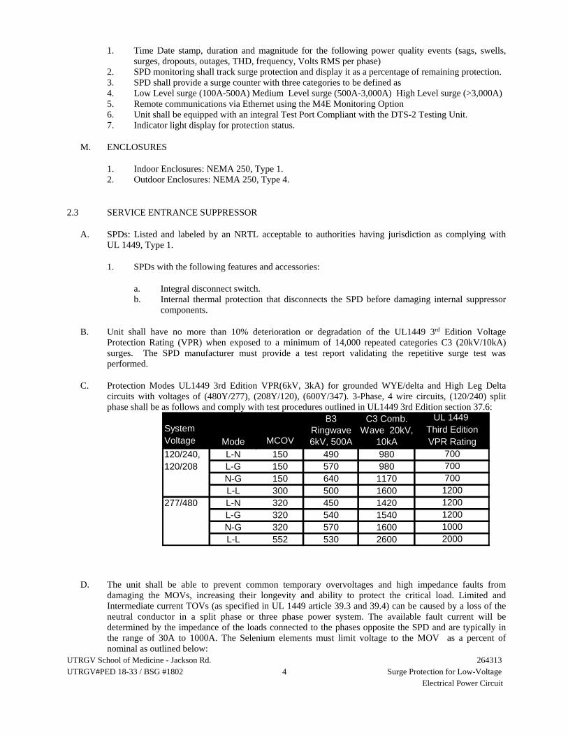
UTRGV School of Medicine - Jackson Rd. 264313 UTRGV#PED 18-33 / BSG #1802 4 Surge Protection for Low-Voltage Electrical Power Circuit
1. Time Date stamp, duration and magnitude for the following power quality events (sags, swells, surges, dropouts, outages, THD, frequency, Volts RMS per phase)
2. SPD monitoring shall track surge protection and display it as a percentage of remaining protection. 3. SPD shall provide a surge counter with three categories to be defined as 4. Low Level surge (100A-500A) Medium Level surge (500A-3,000A) High Level surge (>3,000A) 5. Remote communications via Ethernet using the M4E Monitoring Option 6. Unit shall be equipped with an integral Test Port Compliant with the DTS-2 Testing Unit. 7. Indicator light display for protection status.
M. ENCLOSURES
1. Indoor Enclosures: NEMA 250, Type 1. 2. Outdoor Enclosures: NEMA 250, Type 4.
2.3 SERVICE ENTRANCE SUPPRESSOR
A. SPDs: Listed and labeled by an NRTL acceptable to authorities having jurisdiction as complying with UL 1449, Type 1.
1. SPDs with the following features and accessories:
a. Integral disconnect switch. b. Internal thermal protection that disconnects the SPD before damaging internal suppressor
components.
B. Unit shall have no more than 10% deterioration or degradation of the UL1449 3rd Edition Voltage Protection Rating (VPR) when exposed to a minimum of 14,000 repeated categories C3 (20kV/10kA) surges. The SPD manufacturer must provide a test report validating the repetitive surge test was performed.
C. Protection Modes UL1449 3rd Edition VPR(6kV, 3kA) for grounded WYE/delta and High Leg Delta circuits with voltages of (480Y/277), (208Y/120), (600Y/347). 3-Phase, 4 wire circuits, (120/240) split phase shall be as follows and comply with test procedures outlined in UL1449 3rd Edition section 37.6:
UL 1449 System Third EditionVoltage MCOV VPR Rating120/240, L-N 150 490 980 700120/208 L-G 150 570 980 700
N-G 150 640 1170 700L-L 300 500 1600 1200
277/480 L-N 320 450 1420 1200L-G 320 540 1540 1200N-G 320 570 1600 1000L-L 552 530 2600 2000
Mode
B3 Ringwave 6kV, 500A
C3 Comb. Wave 20kV,
10kA
D. The unit shall be able to prevent common temporary overvoltages and high impedance faults from damaging the MOVs, increasing their longevity and ability to protect the critical load. Limited and Intermediate current TOVs (as specified in UL 1449 article 39.3 and 39.4) can be caused by a loss of the neutral conductor in a split phase or three phase power system. The available fault current will be determined by the impedance of the loads connected to the phases opposite the SPD and are typically in the range of 30A to 1000A. The Selenium elements must limit voltage to the MOV as a percent of nominal as outlined below:

UTRGV School of Medicine - Jackson Rd. 264313 UTRGV#PED 18-33 / BSG #1802 5 Surge Protection for Low-Voltage Electrical Power Circuit
time 30A 100A 500A 1000A1 cycle 120% 130% 150% 160%10 cycles 130% 150% 160% 160%30 cycles 140% 150% 160% 160%
Overvoltage seen by MOVs as % of Nominalavailable current
*To verify damage to the MOVs has been mitigated, the percent overvoltage seen at the MOV must be less than 200% for split-phase applications or 173% for three-phase applications (100% is nominal).
E. The unit shall be able to withstand multiple TOVs without damage to the MOVs by shunting current away from the MOVs during the overvoltage. SPD must have the ability to withstand >100 TOVs with a source current of 30A, duration of 30 cycles, with10s between TOV events.
F. The service entrance protector shall incorporate a combination of TPMOV and Selenium technology allowing for transient surge and temporary over voltage protection.
G. Integral Disconnect Switch (REQUIRED)
1. The device shall have an optional NEMA compliant safety interlocked integral disconnect switch with an externally mounted metal manual operator.
2. The switch shall disconnect all ungrounded circuit conductors from the distribution system to enable testing and maintenance without interruption to the facility’s distribution system.
3. The switch shall be rated for 600Vac. 4. The SPD device shall be tested to UL1449 3rd Edition listed with the integral disconnect switch
and the UL1449 VPR ratings shall be provided. 5. The integral disconnect switch shall be capable of withstanding, without failure, the published
maximum surge current magnitude without failure or damage to the switch. 6. The line side of the integral disconnect shall be blocked off so that when the SPD is opened there is
no direct access to the voltage present on the line side of the disconnect.
2.4 PANEL SUPPRESSORS
A. SPDs: Comply with UL 1449, Type 2.
1. Internal thermal protection that disconnects the SPD before damaging internal suppressor components.
B. Unit shall have no more than 10% deterioration or degradation of the UL1449 3rd Edition Voltage Protection Rating (VPR) when exposed to a minimum of 5,000 repeated categories C3 (20kV/10kA) surges. The SPD manufacturer must provide a test report validating the repetitive surge test was performed.
C. Protection Modes UL1449 3rd Edition VPR(6kV, 3kA) for grounded WYE/delta and High Leg Delta circuits with voltages of (480Y/277), (208Y/120), (600Y/347). 3-Phase, 4 wire circuits, (120/240) split phase shall be as follows and comply with test procedures outlined in UL1449 3rd Edition section 37.6:

UTRGV School of Medicine - Jackson Rd. 264313 UTRGV#PED 18-33 / BSG #1802 6 Surge Protection for Low-Voltage Electrical Power Circuit
UL 1449
System Third EditionVoltage MCOV VPR Rating120/240, L-N 150 760 2020 900120/208 L-G 150 800 1890 900
N-G 150 930 2330 1200L-L 300 790 250 900
277/480 L-N 320 740 2460 1200L-G 320 790 2460 1500N-G 320 900 2640 1200L-L 552 870 3390 2000
Mode
B3 Ringwave 6kV, 500A
C3 Comb. Wave 20kV,
10kA
2.5 CONDUCTORS AND CABLES
A. Power Wiring: Same size as SPD leads, complying with Section 260519 "Low-Voltage Electrical Power Conductors and Cables."
B. If installed lead length exceeds 5’ installer shall use a low impedance (HPI) cable to reduce the lead lengths effect on the installed performance of the SPD.
C. Class 2 Control Cables: Multiconductor cable with copper conductors not smaller than No. 18 AWG, complying with Section 260519 "Low-Voltage Electrical Power Conductors and Cables."
PART 3 - EXECUTION
3.1 INSTALLATION
A. Comply with NECA 1.
B. Install an OCPD or disconnect as required to comply with the UL listing of the SPD.
C. Install SPDs with conductors between suppressor and points of attachment as short and straight as possible, and adjust circuit-breaker positions to achieve shortest and straightest leads. Do not splice and extend SPD leads unless specifically permitted by manufacturer. Do not exceed manufacturer's recommended lead length. Do not bond neutral and ground.
D. Use crimped connectors and splices only. Wire nuts are unacceptable.
E. Wiring:
1. Power Wiring: Comply with wiring methods in Section 260519 "Low-Voltage Electrical Power Conductors and Cables."
2. Controls: Comply with wiring methods in Section 260519 "Low-Voltage Electrical Power Conductors and Cables."

UTRGV School of Medicine - Jackson Rd. 264313 UTRGV#PED 18-33 / BSG #1802 7 Surge Protection for Low-Voltage Electrical Power Circuit
3.2 FIELD QUALITY CONTROL
A. Perform the following tests and inspections with the assistance of a factory-authorized service representative.
1. Compare equipment nameplate data for compliance with Drawings and Specifications. 2. Inspect anchorage, alignment, grounding, and clearances. 3. Verify that electrical wiring installation complies with manufacturer's written installation
requirements.
B. An SPD will be considered defective if it does not pass tests and inspections.
C. Prepare test and inspection reports.
3.3 STARTUP SERVICE
A. Complete startup checks according to manufacturer's written instructions.
B. Do not perform insulation-resistance tests of the distribution wiring equipment with SPDs installed. Disconnect SPDs before conducting insulation-resistance tests, and reconnect them immediately after the testing is over.
C. Energize SPDs after power system has been energized, stabilized, and tested.
3.4 DEMONSTRATION
A. Engage a factory-authorized service representative to train Owner's maintenance personnel to operate and maintain SPDs.
END OF SECTION 264313

UTRGV School of Medicine - Jackson Rd. 265116 UTRGV#PED 18-33 / BSG #1802 1 Interior Lighting
SECTION 265116 - INTERIOR LIGHTING
PART 1 - GENERAL
1.1 RELATED DOCUMENTS
A. Drawings and general provisions of the Contract, including General and Supplementary Conditions and Division 01 Specification Sections, apply to this Section.
1.2 SUMMARY
A. Section Includes:
1. Interior LED luminaires and drivers. 2. Luminaire supports.
B. Related Requirements:
1. Section 260923 "Lighting Control Devices" for automatic control of lighting, including time switches, photoelectric relays, occupancy sensors, and multipole lighting relays and contactors.
1.3 DEFINITIONS
A. BIM: Building information model.
B. CAD: Computer-aided design.
C. CCT: Correlated color temperature.
D. CRI: Color Rendering Index.
E. LED: Light-emitting diode.
F. Fixture: See "Luminaire."
G. IP: International Protection or Ingress Protection Rating
H. Lumen: Measured output of lamp and luminaire, or both.
I. Luminaire: Complete lighting unit, including lamp, reflector, and housing.
1.4 ACTION SUBMITTALS
A. Product Data: For each type of product.
1. Arrange in order of luminaire designation. 2. Include data on features, accessories, and finishes. 3. Include physical description and dimensions of luminaires. 4. Include life, output (lumens, CCT, and CRI), and energy efficiency data. 5. Include photometric data and adjustment factors based on laboratory tests, complying with IESNA
Lighting Measurements Testing and Calculation Guides, of each luminaire type. The adjustment

UTRGV School of Medicine - Jackson Rd. 265116 UTRGV#PED 18-33 / BSG #1802 2 Interior Lighting
factors shall be for lamps, ballasts, and accessories identical to those indicated for the luminaire as applied in this Project. For LED light fixtures the adjustment factors shall be for lamps and accessories identical to those indicated for the lighting fixture as applied in this Project IES LM-79 and IES LM-80
a. Retain or "Manufacturers' Certified Data" or "Testing Agency Certified Data" Subparagraph below. Retain first subparagraph if photometric data, based on testing by accredited manufacturers' laboratories, is considered adequate for luminaires in this Project. Retain second subparagraph if photometric data for one or more luminaires are based on independent laboratory tests; coordinate with the Interior Lighting Fixture Schedule on Drawings to indicate which units shall meet this requirement. See the Evaluations. Manufacturers' Certified Data: Photometric data certified by manufacturer's laboratory with a current accreditation under the National Voluntary Laboratory Accreditation Program (NVLAP) for Energy Efficient Lighting Products.
b. Testing Agency Certified Data: For indicated luminaires, photometric data certified by a qualified independent testing agency. Photometric data for remaining luminaires shall be certified by manufacturer.
B. Shop Drawings: For nonstandard or custom luminaires.
1. Include plans, elevations, sections, and mounting and attachment details. 2. Include details of luminaire assemblies. Indicate dimensions, weights, loads, and required
clearances, method of field assembly, components, and location and size of each field connection. 3. Include diagrams for power, signal, and control wiring.
C. Product Schedule: For luminaires and lamps. Use same designations indicated on Drawings.
D. Qualification Data: For testing laboratory providing photometric data for luminaires.
E. Product Certificates: For each type of ballast for bi-level and dimmer-controlled luminaires, from manufacturer.
F. Product Test Reports: For each luminaire, for tests performed by manufacturer and witnessed by a qualified testing agency.
G. Sample warranty.
1.5 PRIOR APPROVAL SUBMITTAL REQUESTS
A. Full submittal data , by type, clearly highlighted and arrowed to identify the specific proposed manufacturer’s nomenclature
B. Full submittal data of lamp and proposed manufacturer.
C. Full submittal data of ballast/driver (LED) data of proposed manufacturer
D. LED lumen data will include 1. Lumen output 2. L70 and L90 testing 3. Confirmation of independent test lab data ITL 4. Color temperature and CRI with quantity of McAdam Ellipse steps
a. Data shall include sphere and goniometer results for total lumen, total power, luminaire efficacy, CRI and junction temperature for the specified color temperature
5. Make and brand of LED diode should be clearly identified on submittal data

UTRGV School of Medicine - Jackson Rd. 265116 UTRGV#PED 18-33 / BSG #1802 3 Interior Lighting
E. LED dimming shall be equal in range and quality to the specified drivers, Quality of dimming to be defined by dimming range, freedom from perceived flicker or visible stroboscopic flicker, smooth and continuous change in level (no visible steps in transitions), natural square law response to control input, and stable when input voltage conditions fluctuate over what is typically experience in a commercial environment.
F. All substitutions must meet specified fixtures certifications (UL,ETL,CE,CSA, RoHS, DLC, Energy Star)
G. Provide lighting calculations with the prior approval request based on reflectance values and light loss factors provided by the engineer and displayed on lighting calculation drawings. (may be unique by area) Calculations shall be shown on one sheet with dimensions as shown on construction set. Data will be submitted electronically in dxf format on a flash drive and with printed calculations on Architectural E size sheets to scale with construction set sheets.
1. Discrepancies between prior approval data calculations and the original design calculations will result in immediate disqualification of review due to time based constraints on the bid process
H. Prior approval request may require a sample of both the proposed and specified fixtures provided by the alternate manufacturer at NO additional cost to the project. Samples of both specified and proposed must be provided within 10 working days of request.
I. All data will be submitted electronically and in a bound format
J. Bound data will be secured in hard binder with 3” rings for ease of review or PDF file.
1. Types will be marked with a tab by type and indexed for ease of reference
K. LED warranty information MUST be included by type and marked in RED to clearly identify the manufacturer’s warranty terms. Warranty data MUST meet or exceed the specified manufacturers terms
L. Prior approvals MUST be received and acknowledged to the specifier’s office no less than 10 days prior to bid.
M. ALL prior approval data must be submitted in one package with complete information. Information that is incomplete will be rejected without review.
N. The prior approval will be returned marked approved or rejected by type with no explanation. If any specification is deemed not equal the review will be stopped, the type rejected with no explanation.
O. Lumen output for the proposed fixture must be highlighted in yellow for clear identification.
P. All inverter systems supply power to LED fixtures must have pure PWM sine wave function and work with any type of lighting load.
Q. LED warranty information must be included by type and marked in red to clearly identify the manufacturer’s warranty terms. Warranty data must meet or exceed the specified manufacturer’s terms.
1.6 CLOSEOUT SUBMITTALS
A. Operation and Maintenance Data: For luminaires and lighting systems to include in maintenance manuals.
1. Provide a list of all lamp types used on Project; use ANSI and manufacturers' codes.

UTRGV School of Medicine - Jackson Rd. 265116 UTRGV#PED 18-33 / BSG #1802 4 Interior Lighting
1.7 MAINTENANCE MATERIAL SUBMITTALS
A. Furnish extra materials that match products installed and that are packaged with protective covering for storage and identified with labels describing contents.
1. Lamps: Ten for every 100 of each type and rating installed. Furnish at least one of each type. 2. Diffusers and Lenses: One for every 100 of each type and rating installed. Furnish at least one of
each type. 3. Fluorescent-luminaire-mounted emergency battery pack: One for every 40 emergency lighting
unit. 4. Globes and Guards: One for every 20 of each type and rating installed. Furnish at least one of each
type.
1.8 QUALITY ASSURANCE
A. Luminaire Photometric Data Testing Laboratory Qualifications: Luminaire manufacturer's laboratory is accredited under the NVLAP for Energy Efficient Lighting Products.
B. Luminaire Photometric Data Testing Laboratory Qualifications: Provided by an independent agency, with the experience and capability to conduct the testing indicated, that is an NRTL as defined by OSHA in 29 CFR 1910.7, accredited under the NVLAP for Energy Efficient Lighting Products, and complying with the applicable IES testing standards.
A. LED luminaires 1. Provide from a single manufacturer for each luminaire type. 2. Each luminaire type shall be binned within a three-step MacAdam Ellipse to ensure color
consistency among luminaires
1.9 DELIVERY, STORAGE, AND HANDLING
A. Protect finishes of exposed surfaces by applying a strippable, temporary protective covering before shipping.
1.10 WARRANTY
A. Warranty: Manufacturer and Installer agree to repair or replace (materials and labor) components of luminaires that fail in materials or workmanship within specified warranty period.
1. Warranty Period: Five year(s) from date of Substantial Completion
PART 2 - PRODUCTS
2.1 LUMINAIRE REQUIREMENTS
A. Electrical Components, Devices, and Accessories: Listed and labeled as defined in NFPA 70, by a qualified testing agency, and marked for intended location and application.
B. NRTL Compliance: Luminaires for hazardous locations shall be listed and labeled for indicated class and division of hazard by an NRTL.
C. FM Global Compliance: Luminaires for hazardous locations shall be listed and labeled for indicated class and division of hazard by FM Global.

UTRGV School of Medicine - Jackson Rd. 265116 UTRGV#PED 18-33 / BSG #1802 5 Interior Lighting
D. UL Compliance: Comply with UL 1598.
E. Lamp base complying with ANSI C81.61 or IEC 60061-1.
F. Recessed Luminaires: Comply with NEMA LE 4.
G. EMI Filters: Factory installed to suppress conducted EMI according to MIL-STD-461E. Fabricate luminaires with one filter on each ballast indicated to require a filter.
2.2 EMERGENCY POWER UNIT
A. Internal Type: Self-contained, modular, battery-inverter unit, factory mounted within luminaire body and compatible with ballast. Comply with UL 924.
1. Emergency Connection: Operate LED’s continuously. Connect unswitched circuit to battery-inverter unit and switched circuit to luminaire driver.
2. Test Push Button and Indicator Light: Visible and accessible without opening luminaire or entering ceiling space.
a. Push Button: Push-to-test type, in unit housing, simulates loss of normal power and demonstrates unit operability.
b. Indicator Light: LED indicates normal power on. Normal glow indicates trickle charge; bright glow indicates charging at end of discharge cycle.
3. Battery: Sealed, maintenance-free, nickel-cadmium type. 4. Charger: Fully automatic, solid-state, constant-current type with sealed power transfer relay. 5. Remote Test: Switch in hand-held remote device aimed in direction of tested unit initiates coded
infrared signal. Signal reception by factory-installed infrared receiver in tested unit triggers simulation of loss of its normal power supply, providing visual confirmation of either proper or failed emergency response.
6. Integral Self-Test: Factory-installed electronic device automatically initiates code-required test of unit emergency operation at required intervals. Test failure is annunciated by an integral audible alarm and a flashing red LED.
B. External Type: Self-contained, modular, battery-inverter unit, suitable for powering one or more fluorescent lamps, remote mounted from luminaire. Comply with UL 924.
1. Emergency Connection: Operate one fluorescent lamp continuously. Connect unswitched circuit to battery-inverter unit and switched circuit to luminaire ballast.
2. Battery: Sealed, maintenance-free, nickel-cadmium type. 3. Charger: Fully automatic, solid-state, constant-current type. 4. Housing: NEMA 250, Type 1 enclosure. 5. Test Push Button: Push-to-test type, in unit housing, simulates loss of normal power and
demonstrates unit operability. 6. LED Indicator Light: Indicates normal power on. Normal glow indicates trickle charge; bright
glow indicates charging at end of discharge cycle. 7. Remote Test: Switch in hand-held remote device aimed in direction of tested unit initiates coded
infrared signal. Signal reception by factory-installed infrared receiver in tested unit triggers simulation of loss of its normal power supply, providing visual confirmation of either proper or failed emergency response.
8. Integral Self-Test: Factory-installed electronic device automatically initiates code-required test of unit emergency operation at required intervals. Test failure is annunciated by an integral audible alarm and a flashing red LED.

UTRGV School of Medicine - Jackson Rd. 265116 UTRGV#PED 18-33 / BSG #1802 6 Interior Lighting
2.3 LED LIGHTING FIXTURES AND LED LAMPS
A. All LED products must be UL, ETL and/or CSA listed
B. All LED products must have LM-79 and LM-80 testing noted on specification sheet by an independent test lab
C. All LED products should be identified as L70 and/or L90 ratings based on independent test lab data
D. All outdoor and wet location listed products must clearly state the IP rating carried on the fixture based on independent test lab data
E. Bulb shape complying with ANSI C79.1.
F. CRI of Minimum 80. CCT of 4100 K.
G. Rated lamp life of 50,000 hours.
H. Lamps dimmable from 100 percent to 0 percent of maximum light output.
I. Nominal Operating Voltage: as noted on light fixture schedule.
J. All LED products must be serviceable for accessible for field repair needs
K. All indoor lighting color rendering should be within a 3 step McAdams ellipse. All indoor lighting should be 4000-4100 kelvin unless specifically noted
L. All control systems that interface with an LED product will be supported by a project “integrator” until project completion. This includes contact with the installer prior to installation, availability during installation, and final checkout and startup after installation. The quantity of days required for startup will be based on the manufacturer/agents discretion and need.
1. The project integrator must be capable of performing low voltage and dmx terminations. High voltage terminations are performed solely by the electrical subcontractor.
2. Reporting of final startup completion of the controls system back to the engineer is mandatory. 3. Invitation to attend the training with the owners representative should be made to the engineer no
less than 5 days prior to training 4. Signature confirmation of training and startup is required within 5 business days after completion
back to the engineer’s office.
M. All LED drivers should be capable of 0-10 volt controls and DMX control and shall dim to 1% of total lumen output. Where specifically specified the dimming driver may be required to dim to .1% of lumen output , otherwise known as “dim to dark”
N. Driver manufacturers must have a 5 year history producing dimmable electronic LED drivers for the North American market.
O. Ambient driver temperatures must be within -20 degrees to 50 degrees C (-4 degrees to 122 degrees F)
P. Driver (internal) must limit inrush current.
1. Base specification: meet or exceed NEMA 410 driver inrush standard of 430 amp per 10 amps load with a maximum of 370 amps/2 seconds
2. Preferred specification : Meet or exceed 30ma’s at 277 VAC for up to 50 watts of load and 75A at 240us att 277 VAC for 100 watts of load
3. Withstand up to a 1,000 volt surge without impairment of performance as defined by ANSI C62.41 Category A

UTRGV School of Medicine - Jackson Rd. 265116 UTRGV#PED 18-33 / BSG #1802 7 Interior Lighting
4. No visible change in light output with a variation of plus/minus 10percent line voltage input. 5. Total harmonic distortion less than 20%, and meet ANSI C82.11 maximum allowable THD
requirements at full output. THD shall at no point in the dimming curve allow imbalance current to exceed full output THD
2.4 CYLINDER
A. With integral mounting provisions.
2.5 DOWNLIGHT
A. Universal mounting bracket.
B. Integral junction box with conduit fittings.
2.6 LINEAR INDUSTRIAL
A. Luminaire and housing certified to the following standard[s].
1. Class 1, Division 2, Group(s) [A] [B] [C] [and] [D]. 2. NEMA 4X. 3. IP 66. 4. Wet locations. 5. CSA C22.2 No 137.
2.7 PARKING GARAGE
A. Low-profile housing and heat sink.
B. Fully gasketed and sealed.
C. Stainless-steel latches.
D. Integral pressure equalizer.
2.8 RECESSED LINEAR
A. Integral junction box with conduit fittings.
2.9 STRIP LIGHT
A. Integral junction box with conduit fittings.
2.10 SURFACE MOUNT, LINEAR
A. Universal mounting bracket.
B. Integral junction box with conduit fittings.

UTRGV School of Medicine - Jackson Rd. 265116 UTRGV#PED 18-33 / BSG #1802 8 Interior Lighting
2.11 SURFACE MOUNT, NONLINEAR
A. Universal mounting bracket.
B. Integral junction box with conduit fittings.
2.12 SUSPENDED, LINEAR
A. Ceiling mounted with two 5/32-inch diameter aircraft cable supports adjustable to 120 inches in length.
2.13 SUSPENDED, NONLINEAR
A. Universal mounting bracket.
B. Integral junction box with conduit fittings.
2.14 MATERIALS
A. Metal Parts:
1. Free of burrs and sharp corners and edges. 2. Sheet metal components shall be steel unless otherwise indicated. 3. Form and support to prevent warping and sagging.
B. Doors, Frames, and Other Internal Access: Smooth operating, free of light leakage under operating conditions, and designed to permit relamping without use of tools. Designed to prevent doors, frames, lenses, diffusers, and other components from falling accidentally during relamping and when secured in operating position.
C. Diffusers and Globes:
1. Tempered Fresnel glass, prismatic glass or prismatic acrylic, refer to light fixture schedule. 2. Glass: Annealed crystal glass unless otherwise indicated. 3. Acrylic Diffusers: One hundred percent virgin acrylic plastic, with high resistance to yellowing
and other changes due to aging, exposure to heat, and UV radiation. 4. Lens Thickness: At least 0.125 inch minimum unless otherwise indicated.
D. Housings:
1. Extruded-aluminum housing and heat sink or as noted on light fixture schedule. 2. Powder-coat finish.
E. Factory-Applied Labels: Comply with UL 1598. Include recommended lamps. Locate labels where they will be readily visible to service personnel, but not seen from normal viewing angles when lamps are in place.
1. Label shall include the following lamp characteristics:
a. "USE ONLY" and include specific lamp type. b. Lamp diameter, shape, size, wattage, and coating. c. CCT and CRI for all luminaires.

UTRGV School of Medicine - Jackson Rd. 265116 UTRGV#PED 18-33 / BSG #1802 9 Interior Lighting
2.15 METAL FINISHES
A. Variations in finishes are unacceptable in the same piece. Variations in finishes of adjoining components are acceptable if they are within the range of approved Samples and if they can be and are assembled or installed to minimize contrast.
2.16 LUMINAIRE SUPPORT COMPONENTS
A. Comply with requirements in Section 260529 "Hangers and Supports for Electrical Systems" for channel and angle iron supports and nonmetallic channel and angle supports.
B. Single-Stem Hangers: 1/2-inch steel tubing with swivel ball fittings and ceiling canopy. Finish shall match luminaire.
C. Wires: ASTM A 641/A 641M, Class 3, soft temper, zinc-coated steel, 12 gage.
D. Rod Hangers: 3/16-inch minimum diameter, cadmium-plated, threaded steel rod.
E. Hook Hangers: Integrated assembly matched to luminaire, line voltage, and equipment with threaded attachment, cord, and locking-type plug.
PART 3 - EXECUTION
3.1 EXAMINATION
A. Examine substrates, areas, and conditions, with Installer present, for compliance with requirements for installation tolerances and other conditions affecting performance of the Work.
B. Examine roughing-in for luminaire to verify actual locations of luminaire and electrical connections before fixture installation.
C. Examine walls, floors, roofs, and ceilings for suitable conditions where luminaires will be installed.
D. Proceed with installation only after unsatisfactory conditions have been corrected.
3.2 TEMPORARY LIGHTING
A. If approved by the Architect, use selected permanent luminaires for temporary lighting. When construction is sufficiently complete, clean luminaires used for temporary lighting and install new lamps.
3.3 INSTALLATION
A. Comply with NECA 1.
B. Remote Mounting of Ballasts: Distance between the ballast and luminaire shall not exceed that recommended by ballast manufacturer. Verify, with ballast manufacturers, maximum distance between ballast and luminaire.
C. Install luminaires level, plumb, and square with ceilings and walls unless otherwise indicated.
D. Install lamps in each luminaire.

UTRGV School of Medicine - Jackson Rd. 265116 UTRGV#PED 18-33 / BSG #1802 10 Interior Lighting
E. Coordinate layout and installation of luminaires and suspension system with other construction that penetrates ceilings or is supported by them.
F. Supports:
1. Sized and rated for luminaire weight. 2. Able to maintain luminaire position after cleaning and relamping. 3. Provide support for luminaire without causing deflection of ceiling or wall. 4. Luminaire mounting devices shall be capable of supporting a horizontal force of 100 percent of
luminaire weight and vertical force of 400 percent of luminaire weight.
G. Ceiling-Grid-Mounted Luminaire Supports: Use grid as a support element.
1. Install ceiling support system rods or wires, independent of the ceiling suspension devices, for each luminaire. Locate not more than 6 inches from luminaire corners.
2. Support Clips: Fasten to luminaires and to ceiling grid members at or near each luminaire corner with clips that are UL listed for the application.
3. Luminaires of Sizes Less Than Ceiling Grid: Install as indicated on reflected ceiling plans or center in acoustical panel, and support luminaires independently with at least two 3/4-inch metal channels spanning and secured to ceiling tees.
4. Install at least one independent support rod or wire from structure to a tab on luminaire. Wire or rod shall have breaking strength of the luminaire weight at a safety factor of 3.
H. Flush-Mounted Luminaire Support:
1. Secured to outlet box. 2. Attached to ceiling structural members at four points equally spaced around circumference of
luminaire. 3. Trim ring flush with finished surface.
I. Wall-Mounted Luminaire Support:
1. Attached to structural members in walls, or a minimum 20 gauge backing plate attached to wall structural members, or using through bolts and backing plates on either side of wall.
2. Do not attach luminaires directly to gypsum board.
J. Suspended Luminaire Support:
1. Pendants and Rods: Where longer than 48 inches, brace to limit swinging. 2. Stem-Mounted, Single-Unit Luminaires: Suspend with twin-stem hangers. Support with approved
outlet box and accessories that hold stem and provide damping of luminaire oscillations. Support outlet box vertically to building structure using approved devices.
3. Continuous Rows of Luminaires: Use tubing or stem for wiring at one point and [tubing or rod for suspension for each unit length of luminaire chassis, including one at each end.
4. Do not use ceiling grid as support for pendant luminaires. Connect support wires or rods to building structure.
K. Comply with requirements in Section 260519 "Low-Voltage Electrical Power Conductors and Cables" and Section 260533 "Raceways and Boxes for Electrical Systems" for wiring connections and wiring methods.
3.4 IDENTIFICATION
A. Identify system components, wiring, cabling, and terminals. Comply with requirements for identification specified in Section 260553 "Identification for Electrical Systems."

UTRGV School of Medicine - Jackson Rd. 265116 UTRGV#PED 18-33 / BSG #1802 11 Interior Lighting
3.5 FIELD QUALITY CONTROL
A. Perform the following tests and inspections:
B. Operational Test: After installing luminaires, switches, and accessories, and after electrical circuitry has been energized, test units to confirm proper operation.
1. Test for Emergency Lighting: Interrupt power supply to demonstrate proper operation. Verify transfer from normal power to battery power and retransfer to normal.
C. Luminaire will be considered defective if it does not pass operation tests and inspections.
D. Prepare test and inspection reports.
3.6 ADJUSTING
A. Occupancy Adjustments: When requested within 12 months of date of Substantial Completion, provide on-site assistance in adjusting the direction of aim of luminaires to suit occupied conditions. Make up to two visits to Project during other-than-normal hours for this purpose. Some of this work may be required during hours of darkness.
1. During adjustment visits, inspect all luminaires. Replace lamps or luminaires that are defective. 2. Parts and supplies shall be manufacturer's authorized replacement parts and supplies. 3. Adjust the aim of luminaires in the presence of the Architect.
END OF SECTION 265116

UTRGV School of Medicine - Jackson Rd. UTRGV#PED 18-33 / BSG #1802 1
265219
Emergency and Exit Lighting
SECTION 265219 - EMERGENCY AND EXIT LIGHTING
PART 1 - GENERAL
1.1 RELATED DOCUMENTS
A. Drawings and general provisions of the Contract, including General and Supplementary Conditions and Division 01 Specification Sections, apply to this Section.
1.2 SUMMARY
A. Section Includes:
1. Emergency lighting units. 2. Exit signs. 3. Luminaire supports.
1.3 DEFINITIONS
A. CCT: Correlated color temperature.
B. CRI: Color Rendering Index.
C. Emergency Lighting Unit: A lighting unit with internal or external emergency battery powered supply and the means for controlling and charging the battery and unit operation.
D. Fixture: See "Luminaire" Paragraph.
E. Lumen: Measured output of lamp and luminaire, or both.
F. Luminaire: Complete lighting unit, including lamp, reflector, and housing.
1.4 ACTION SUBMITTALS
A. Product Data: For each type of emergency lighting unit, exit sign, and emergency lighting support.
1. Include data on features, accessories, and finishes. 2. Include physical description of the unit and dimensions. 3. Battery and charger for light units. 4. Include life, output of luminaire (lumens, CCT, and CRI), and energy-efficiency data. 5. Include photometric data and adjustment factors based on laboratory tests, complying with IES
LM-45, for each luminaire type.
a. Testing Agency Certified Data: For indicated luminaires and signs, photometric data certified by a qualified independent testing agency. Photometric data for remaining luminaires and signs shall be certified by manufacturer.
b. Manufacturers' Certified Data: Photometric data certified by manufacturer's laboratory with a current accreditation under the National Voluntary Laboratory Accreditation Program for Energy Efficient Lighting Products.
B. Shop Drawings: For nonstandard or custom luminaires.

UTRGV School of Medicine - Jackson Rd. UTRGV#PED 18-33 / BSG #1802 2
265219
Emergency and Exit Lighting
1. Include plans, elevations, sections, and mounting and attachment details. 2. Include details of equipment assemblies. Indicate dimensions, weights, loads, and required
clearances, method of field assembly, components, and location and size of each field connection. 3. Include diagrams for power, signal, and control wiring.
C. Product Schedule:
1. For emergency lighting units. Use same designations indicated on Drawings. 2. For exit signs. Use same designations indicated on Drawings.
D. Qualification Data: For testing laboratory providing photometric data for luminaires.
E. Product Certificates: For each type of luminaire.
F. Product Test Reports: For each luminaire for tests performed by manufacturer and witnessed by a qualified testing agency.
G. Sample Warranty: For manufacturer’s special warranty.
1.5 CLOSEOUT SUBMITTALS
A. Operation and Maintenance Data: For luminaires and lighting systems to include in emergency, operation, and maintenance manuals.
1. Provide a list of all lamp types used on Project; use ANSI and manufacturers' codes.
1.6 MAINTENANCE MATERIAL SUBMITTALS
A. Furnish extra materials that match products installed and that are packaged with protective covering for storage and identified with labels describing contents.
1. Lamps: 10 for every 100 of each type and rating installed. Furnish at least one of each type. 2. Luminaire-mounted, emergency battery pack: One for every 20 emergency lighting units. Furnish
at least one of each type. 3. Diffusers and Lenses: two for every 100 of each type and rating installed. Furnish at least one of
each type. 4. Globes and Guards: One for every 20 of each type and rating installed. Furnish at least one of each
type.
1.7 QUALITY ASSURANCE
A. Luminaire Photometric Data Testing Laboratory Qualifications: Luminaire manufacturer's laboratory that is accredited under the National Volunteer Laboratory Accreditation Program for Energy Efficient Lighting Products.
B. Luminaire Photometric Data Testing Laboratory Qualifications: Provided by an independent agency, with the experience and capability to conduct the testing indicated, that is an NRTL as defined by OSHA in 29 CFR 1910.7, accredited under the National Volunteer Laboratory Accreditation Program for Energy Efficient Lighting Products, and complying with the applicable IES testing standards.
C. FM Global Compliance: Luminaires for hazardous locations shall be listed and labeled for indicated class and division of hazard by FM Global.

UTRGV School of Medicine - Jackson Rd. UTRGV#PED 18-33 / BSG #1802 3
265219
Emergency and Exit Lighting
1.8 DELIVERY, STORAGE, AND HANDLING
A. Protect finishes of exposed surfaces by applying a strippable, temporary protective covering before shipping.
1.9 WARRANTY
A. Warranty: Manufacturer and Installer agree to repair or replace (materials and labor) components of luminaires that fail in materials or workmanship within specified warranty period.
1. Warranty Period: Two year(s) from date of Substantial Completion.
B. Special Warranty for Emergency Lighting Batteries: Manufacturer's standard form in which manufacturer of battery-powered emergency lighting unit agrees to repair or replace components of rechargeable batteries that fail in materials or workmanship within specified warranty period.
1. Warranty Period for Emergency Power Unit Batteries: 5 years from date of Substantial Completion. Full warranty shall apply for first year and prorated warranty for the remaining four years.
2. Warranty Period for Emergency Fluorescent Ballast and Self-Powered Exit Sign Batteries: Seven years from date of Substantial Completion. Full warranty shall apply for first year and prorated warranty for the remaining six years.
PART 2 - PRODUCTS
2.1 GENERAL REQUIREMENTS FOR EMERGENCY LIGHTING
A. Electrical Components, Devices, and Accessories: Listed and labeled as defined in NFPA 70, by a qualified testing agency, and marked for intended location and application.
B. NRTL Compliance: Fabricate and label emergency lighting units, exit signs, and batteries to comply with UL 924.
C. Comply with NFPA 70 and NFPA 101.
D. Comply with NEMA LE 4 for recessed luminaires.
E. Comply with UL 1598 for fluorescent luminaires.
F. Lamp Base: Comply with ANSI C81.61 or IEC 60061-1.
G. Bulb Shape: Complying with ANSI C79.1.
H. Internal Type Emergency Power Unit: Self-contained, modular, battery-inverter unit, factory mounted within luminaire body and compatible with ballast.
1. Emergency Connection: Operate two lamp(s) continuously at an output of 1100 lumens each upon loss of normal power. Connect unswitched circuit to battery-inverter unit and switched circuit to luminaire ballast.
2. Operation: Relay automatically turns lamp on when power-supply circuit voltage drops to 80 percent of nominal voltage or below. Lamp automatically disconnects from battery when voltage approaches deep-discharge level. When normal voltage is restored, relay disconnects lamps from battery, and battery is automatically recharged and floated on charger.

UTRGV School of Medicine - Jackson Rd. UTRGV#PED 18-33 / BSG #1802 4
265219
Emergency and Exit Lighting
3. Environmental Limitations: Rate equipment for continuous operation under the following conditions unless otherwise indicated:
a. Ambient Temperature: Less than 0 deg F or exceeding 104 deg F, with an average value exceeding 95 deg F over a 24-hour period.
b. Ambient Storage Temperature: Not less than minus 4 deg F and not exceeding 140 deg F. c. Humidity: More than 95 percent (condensing). d. Altitude: Exceeding 3300 feet.
4. Nightlight Connection: Operate lamp continuously at 40 percent of rated light output. 5. Test Push-Button and Indicator Light: Visible and accessible without opening luminaire or
entering ceiling space.
a. Push Button: Push-to-test type, in unit housing, simulates loss of normal power and demonstrates unit operability.
b. Indicator Light: LED indicates normal power on. Normal glow indicates trickle charge; bright glow indicates charging at end of discharge cycle.
6. Battery: Sealed, maintenance-free, nickel-cadmium type. 7. Charger: Fully automatic, solid-state, constant-current type with sealed power transfer relay. 8. Integral Self-Test: Factory-installed electronic device automatically initiates code-required test of
unit emergency operation at required intervals. Test failure is annunciated by an integral audible alarm and a flashing red LED.
I. External Type: Self-contained, modular, battery-inverter unit, suitable for powering one or more lamps, remote mounted from luminaire.
1. Emergency Connection: Operate fluorescent or LED lamp continuously. Connect unswitched circuit to battery-inverter unit and switched circuit to luminaire ballast.
2. Operation: Relay automatically turns lamp on when power-supply circuit voltage drops to 80 percent of nominal voltage or below. Lamp automatically disconnects from battery when voltage approaches deep-discharge level. When normal voltage is restored, relay disconnects lamps from battery, and battery is automatically recharged and floated on charger.
3. Nightlight Connection: Operate lamp in a remote luminaire continuously. 4. Battery: Sealed, maintenance-free, nickel-cadmium type. 5. Charger: Fully automatic, solid-state, constant-current type. 6. Housing: NEMA 250, Type 1 enclosure listed for installation inside, on top of, or remote from
luminaire. Remote assembly shall be located no less than half the distance recommended by the ballast/emergency power unit manufacturer, whichever is less.
7. Test Push Button: Push-to-test type, in unit housing, simulates loss of normal power and demonstrates unit operability.
8. LED Indicator Light: Indicates normal power on. Normal glow indicates trickle charge; bright glow indicates charging at end of discharge cycle.
9. Integral Self-Test: Factory-installed electronic device automatically initiates code-required test of unit emergency operation at required intervals. Test failure is annunciated by an integral audible alarm and a flashing red LED.
2.2 EMERGENCY LIGHTING
A. General Requirements for Emergency Lighting Units: Self-contained units.
B. Emergency Luminaires:
1. Emergency Luminaires: as indicated on Drawings, with the following additional features: a. Rated for installation in damp locations, and for sealed and gasketed luminaires in wet
locations.
UTRGV School of Medicine - Jackson Rd. UTRGV#PED 18-33 / BSG #1802 5
265219
Emergency and Exit Lighting
C. Emergency Lighting Unit:
1. Emergency Lighting Unit: as indicated on Drawings. 2. Wall with universal junction box adaptor. 3. UV stable thermoplastic housing, rated for damp locations.
D. Remote Emergency Lighting Units:
1. Emergency Lighting Unit: as indicated on Drawings. 2. Wall with universal junction box adaptor. 3. UV stable thermoplastic housing, rated for damp locations. 4. External emergency power unit.
2.3 EXIT SIGNS
A. General Requirements for Exit Signs: Comply with UL 924; for sign colors, visibility, luminance, and lettering size, comply with authorities having jurisdiction.
B. Internally Lighted Signs: 1. Lamps for AC Operation: Fluorescent, two for each luminaire; 20,000 hours of rated lamp life. 2. Lamps for AC Operation: LEDs; 50,000 hours minimum rated lamp life. 3. Self-Powered Exit Signs (Battery Type): Internal emergency power unit.
C. Self-Luminous Signs:
1. Powered by tritium gas, with universal bracket for flush-ceiling, wall, or end mounting. Signs shall be guaranteed by manufacturer to maintain the minimum brightness requirements in UL 924 for 20 years.
2. Use strontium oxide aluminate compound to store ambient light and release the stored energy when the light is removed. Include universal bracket for flush-ceiling, wall, or end mounting.
2.4 MATERIALS
A. Metal Parts:
1. Free of burrs and sharp corners and edges. 2. Sheet metal components shall be steel unless otherwise indicated. 3. Form and support to prevent warping and sagging.
B. Doors, Frames, and Other Internal Access:
1. Smooth operating, free of light leakage under operating conditions. 2. Designed to permit relamping without use of tools. 3. Designed to prevent doors, frames, lenses, diffusers, and other components from falling
accidentally during relamping and when secured in operating position.
C. Diffusers and Globes: 1. Glass: Annealed crystal glass unless otherwise indicated. 2. Acrylic: 100 percent virgin acrylic plastic, with high resistance to yellowing and other changes
due to aging, exposure to heat, and UV radiation. 3. Lens Thickness: At least 0.125 inch minimum unless otherwise indicated.
D. Housings: 1. Powder coat finish.

UTRGV School of Medicine - Jackson Rd. UTRGV#PED 18-33 / BSG #1802 6
265219
Emergency and Exit Lighting
2.5 METAL FINISHES
A. Appearance of Finished Work: Noticeable variations in same piece are not acceptable. Variations in appearance of adjoining components are acceptable if they are within the range of approved Samples and are assembled or installed to minimize contrast.
2.6 LUMINAIRE SUPPORT COMPONENTS
A. Comply with requirements in Section 260529 "Hangers and Supports for Electrical Systems" for channel and angle iron supports and nonmetallic channel and angle supports.
B. Support Wires: ASTM A 641/A 641M, Class 3, soft temper, zinc-coated steel, and 12 gage.
PART 3 - EXECUTION
3.1 EXAMINATION
A. Examine substrates, areas, and conditions, with Installer present, for compliance with requirements for conditions affecting performance of luminaires.
B. Examine roughing-in for luminaire to verify actual locations of luminaire and electrical connections before luminaire installation.
C. Examine walls, floors, roofs, and ceilings for suitable conditions where emergency lighting luminaires will be installed.
D. Proceed with installation only after unsatisfactory conditions have been corrected.
3.2 INSTALLATION
A. Comply with NECA 1.
B. Install luminaires level, plumb, and square with ceilings and walls unless otherwise indicated.
C. Install lamps in each luminaire.
D. Supports:
1. Sized and rated for luminaire and emergency power unit weight. 2. Able to maintain luminaire position when testing emergency power unit. 3. Provide support for luminaire and emergency power unit without causing deflection of ceiling or
wall. 4. Luminaire-mounting devices shall be capable of supporting a horizontal force of 100 percent of
luminaire and emergency power unit weight and vertical force of 400 percent of luminaire weight.
E. Wall-Mounted Luminaire Support:
1. Attached to structural members in walls, or a minimum 20 gauge backing plate attached to wall structural members, or using through bolts and backing plates on either side of wall.
2. Do not attach luminaires directly to gypsum board.
F. Suspended Luminaire Support:

UTRGV School of Medicine - Jackson Rd. UTRGV#PED 18-33 / BSG #1802 7
265219
Emergency and Exit Lighting
1. Pendants and Rods: Where longer than 48 inches, brace to limit swinging. 2. Stem-Mounted, Single-Unit Luminaires: Suspend with twin-stem hangers. Support with approved
outlet box and accessories that hold stem and provide damping of luminaire oscillations. Support outlet box vertically to building structure using approved devices.
3. Continuous Rows of Luminaires: Use tubing or stem for wiring at one point and tubing or rod for suspension for each unit length of luminaire chassis, including one at each end.
4. Do not use ceiling grid as support for pendant luminaires. Connect support wires or rods to building structure.
G. Ceiling Grid Mounted Luminaires:
1. Secure to any required outlet box. 2. Secure emergency power unit using approved fasteners in a minimum of four locations, spaced
near corners of emergency power unit. 3. Use approved devices and support components to connect luminaire to ceiling grid and building
structure in a minimum of four locations, spaced near corners of luminaire.
3.3 IDENTIFICATION
A. Identify system components, wiring, cabling, and terminals. Comply with requirements for identification specified in Section 260553 "Identification for Electrical Systems."
3.4 FIELD QUALITY CONTROL
A. Perform the following tests and inspections:
1. Test for Emergency Lighting: Interrupt power supply to demonstrate proper operation. Verify transfer from normal power to battery power and retransfer to normal.
B. Luminaire will be considered defective if it does not pass operation tests and inspections.
C. Prepare test and inspection reports.
3.5 STARTUP SERVICE
A. Perform startup service: 1. Charge emergency power units and batteries minimum of 24 hours and conduct one-hour
discharge test.
3.6 ADJUSTING
A. Adjustments: Within 12 months of date of Substantial Completion, provide on-site visit to do the following:
1. Inspect all luminaires. Replace lamps, emergency power units, batteries, signs, or luminaires that are defective.
a. Parts and supplies shall be manufacturer's authorized replacement parts and supplies.
2. Conduct short-duration tests on all emergency lighting.
END OF SECTION 265219

UTRGV School of Medicine - Jackson Rd. 265613 UTRGV#PED 18-33 / BSG #1802 1 Lighting Poles and Standards
SECTION 265613 - LIGHTING POLES AND STANDARDS
PART 1 - GENERAL
1.1 RELATED DOCUMENTS
A. Drawings and general provisions of the Contract, including General and Supplementary Conditions and Division 01 Specification Sections, apply to this Section.
1.2 SUMMARY
A. Section Includes:
1. Poles and accessories for support of luminaires. 2. Luminaire-lowering devices.
1.3 DEFINITIONS
A. EPA: Equivalent projected area.
B. Luminaire: Complete lighting fixture.
C. Pole: Luminaire-supporting structure, including tower used for large-area illumination.
D. Standard: See "Pole."
1.4 ACTION SUBMITTALS
A. Product Data: For each pole, accessory, and luminaire-supporting and -lowering device, arranged as indicated.
1. Include data on construction details, profiles, EPA, cable entrances, materials, dimensions, weight, rated design load, and ultimate strength of individual components.
2. Include finishes for lighting poles and luminaire-supporting devices. 3. Anchor bolts. 4. Manufactured pole foundations.
B. Shop Drawings:
1. Include plans, elevations, sections, and mounting and attachment details. 2. Include details of equipment assemblies. Indicate dimensions, weights, loads, and required
clearances, method of field assembly, components, and location and size of each field connection. 3. Detail fabrication and assembly of poles and pole accessories. 4. Foundation construction details, including material descriptions, dimensions, anchor bolts, support
devices, and calculations, signed and sealed by a professional engineer licensed in the state of installation.
5. Anchor bolt templates keyed to specific poles and certified by manufacturer. 6. Method and procedure of pole installation. Include manufacturer's written installations.

UTRGV School of Medicine - Jackson Rd. 265613 UTRGV#PED 18-33 / BSG #1802 2 Lighting Poles and Standards
C. Samples: For each exposed lighting pole, standard, and luminaire-supporting device and for each color and texture specified.
1.5 INFORMATIONAL SUBMITTALS
A. Pole and Support Component Certificates: Signed by manufacturers of poles, certifying that products are designed for indicated load requirements according to AASHTO LTS-6-M and that load imposed by luminaire and attachments has been included in design. The certification shall be based on design calculations signed and sealed by a professional engineer.
B. Qualification Data: For testing agency.
C. Material Test Reports:
1. For each foundation component, by a qualified testing agency. 2. For each pole, by a qualified testing agency.
D. Source quality-control reports.
E. Field quality-control reports.
F. Sample Warranty: Manufacturer's standard warranty.
G. Soil test reports
1.6 CLOSEOUT SUBMITTALS
A. Operation and Maintenance Data: For poles to include in emergency, operation, and maintenance manuals.
1. In addition to items specified in Section 017823 "Operation and Maintenance Data," include pole inspection and repair procedures.
1.7 MAINTENANCE MATERIAL SUBMITTALS
A. Pole repair materials.
1.8 QUALITY ASSURANCE
A. Testing Agency Qualifications: Qualified according to ASTM C 1093 for foundation testing.
1.9 DELIVERY, STORAGE, AND HANDLING
A. Package aluminum poles for shipping according to ASTM B 660.
B. Store poles on decay-resistant skids at least 12 inches above grade and vegetation. Support poles to prevent distortion and arrange to provide free air circulation.
C. Retain factory-applied pole wrappings on fiberglass and laminated wood poles until right before pole installation. Handle poles with web fabric straps.

UTRGV School of Medicine - Jackson Rd. 265613 UTRGV#PED 18-33 / BSG #1802 3 Lighting Poles and Standards
D. Retain factory-applied pole wrappings on metal poles until right before pole installation. Handle poles with web fabric straps.
1.10 WARRANTY
A. Special Warranty: Manufacturer agrees to repair or replace components of pole(s) that fail in materials or workmanship; that corrode; or that fade, stain, perforate, erode, or chalk due to effects of weather or solar radiation within a specified warranty period. Manufacturer may exclude lightning damage, hail damage, vandalism, abuse, or unauthorized repairs from special warranty period.
1. Warranty Period: Five years from date of Substantial Completion. 2. Warranty Period for Corrosion Resistance: Five years from date of Substantial Completion. 3. Warranty Period for Color Retention: Five years from date of Substantial Completion.
PART 2 - PRODUCTS
2.1 MANUFACTURERS
A. Manufacturers: Subject to compliance with requirements, provide products as listed on light fixture schedule and plans.
2.2 PERFORMANCE REQUIREMENTS
A. Delegated Design: Engage a qualified professional engineer, as defined in Section 014000 "Quality Requirements," to design pole foundation and pole power system.
B. Structural Characteristics: Comply with AASHTO LTS-6-M.
C. Dead Load: Weight of luminaire and its horizontal and vertical supports, lowering devices, and supporting structure, applied according to AASHTO LTS-6-M.
D. Live Load: Single load of 500 lbf distributed according to AASHTO LTS-6-M.
E. Ice Load: Load of 3 lbf/sq. ft., applied according to AASHTO LTS-6-M for applicable areas on the Ice Load Map.
F. Wind Load: Pressure of wind on pole and luminaire, calculated and applied according to AASHTO LTS-6-M.
G. Strength Analysis: For each pole, multiply the actual EPA of luminaires and brackets by a factor of 1.1 to obtain the EPA to be used in pole selection strength analysis.
H. Luminaire Attachment Provisions: Comply with luminaire manufacturers' mounting requirements. Use stainless-steel fasteners and mounting bolts unless otherwise indicated.
2.3 STEEL POLES
A. Source Limitations: Obtain poles from single manufacturer or producer.
B. Source Limitations: For poles, obtain each color, grade, finish, type, and variety of pole from single source with resources to provide products of consistent quality in appearance and physical properties.

UTRGV School of Medicine - Jackson Rd. 265613 UTRGV#PED 18-33 / BSG #1802 4 Lighting Poles and Standards
C. Poles: Comply with ASTM A 500/A 500M, Grade B carbon steel with a minimum yield of 46,000 psig; one-piece construction up to 40 feet in height with access handhole in pole wall.
1. Shape: round tapered, round, straight, square, straight (as noted on drawings). 2. Mounting Provisions: Butt flange for bolted mounting on foundation or breakaway support.
D. Steel Mast Arms: Single-arm type, continuously welded to pole attachment plate. Material and finish same as plate.
E. Brackets for Luminaires: Detachable, cantilever, without underbrace.
1. Adaptor fitting welded to pole, allowing the bracket to be bolted to the pole-mounted adapter, then bolted together with stainless -steel bolts.
2. Cross Section: Tapered oval, with straight tubular end section to accommodate luminaire. Match pole material and finish.
F. Pole-Top Tenons: Fabricated to support luminaire or luminaires and brackets indicated, and securely fastened to pole top.
G. Fasteners: Stainless steel, size and type as determined by manufacturer. Corrosion-resistant items compatible with support components.
1. Materials: Compatible with poles and standards as well as the substrates to which poles and standards are fastened and shall not cause galvanic action at contact points.
2. Anchor Bolts, Leveling Nuts, Bolt Caps, and Washers: Hot-dip galvanized after fabrication unless otherwise indicated.
H. Grounding and Bonding Lugs: Welded 1/2-inch threaded lug, complying with requirements in Section 260526 "Grounding and Bonding for Electrical Systems," listed for attaching grounding and bonding conductors of type and size indicated, and accessible through handhole.
I. Handhole: Oval shaped, with minimum clear opening of 2-1/2 by 5 inches, with cover secured by stainless-steel captive screws.
J. Prime-Coat Finish: Manufacturer's standard prime-coat finish ready for field painting.
K. Galvanized Finish: After fabrication, hot-dip galvanize according to ASTM A 123/A 123M.
L. Powder-Coat Finish: Comply with NAAMM's "Metal Finishes Manual for Architectural and Metal Products" recommendations for applying and designating finishes.
1. Surface Preparation: Clean surfaces according to SSPC-SP 1 to remove dirt, oil, grease, and other contaminants that could impair powder coat bond. Grind welds and polish surfaces to a smooth, even finish. Remove mill scale and rust, if present, from uncoated steel, according to SSPC-SP 5/NACE No. 1 or SSPC-SP 8.
2. Powder Coat: Comply with AAMA 2604.
a. Electrostatic-applied powder coating; single application and cured to a minimum 2.5- to 3.5-mils dry film thickness. Coat interior and exterior of pole for equal corrosion protection.
b. Color: As selected by Architect from manufacturer's full range.
2.4 ALUMINUM POLES
A. Poles: Seamless, extruded structural tube complying with ASTM B 221, Alloy 6061-T6, with access handhole in in pole wall.
UTRGV School of Medicine - Jackson Rd. 265613 UTRGV#PED 18-33 / BSG #1802 5 Lighting Poles and Standards
1. Shape: round tapered, round, straight, square, straight (as noted on drawings) 2. Mounting Provisions: Butt flange for bolted mounting on foundation or breakaway support.
B. Mast Arms: Aluminum Single-arm type, continuously welded to pole attachment plate. Material and finish same as plate.
C. Brackets for Luminaires: Detachable, cantilever, without underbrace.
1. Adaptor fitting welded to pole, allowing the bracket to be bolted to the pole-mounted adapter, then bolted together with stainless steel bolts.
2. Cross Section: Tapered oval, with straight tubular end section to accommodate luminaire. Match pole material and finish.
D. Pole-Top Tenons: Fabricated to support luminaire or luminaires and brackets indicated, and securely fastened to pole top.
E. Grounding and Bonding Lugs: Bolted 1/2-inch threaded lug, complying with requirements in Section 260526 "Grounding and Bonding for Electrical Systems," listed for attaching grounding and bonding conductors of type and size listed in that Section, and accessible through handhole.
F. Fasteners: Stainless steel, size and type as determined by manufacturer. Corrosion-resistant items compatible with support components.
1. Materials: Compatible with poles and standards as well as to substrates to which poles and standards are fastened and shall not cause galvanic action at contact points.
2. Anchor Bolts, Leveling Nuts, Bolt Caps, and Washers: Hot-dip galvanized after fabrication unless otherwise indicated.
G. Handhole: Oval shaped, with minimum clear opening of 2-1/2 by 5 inches, with cover secured by stainless-steel captive screws.
H. Prime-Coat Finish: Manufacturer's standard prime-coat finish ready for field painting.
I. Aluminum Finish: Comply with NAAMM's "Metal Finishes Manual for Architectural and Metal Products" recommendations for applying and designating finishes.
1. Finish designations prefixed by AA comply with the system established by the Aluminum Association for designating aluminum finishes.
2. Natural Satin Finish: Provide fine, directional, medium satin polish (AA-M32); buff complying with AA-M20 requirements; and seal aluminum surfaces with clear, hard-coat wax.
3. Class I, Clear-Anodic Finish: AA-M32C22A41 (Mechanical Finish: Medium satin; Chemical Finish: Etched, medium matte; Anodic Coating: Architectural Class I clear coating of 0.018 mm or thicker), complying with AAMA 611.
4. Class I, Color-Anodic Finish: AA-M32C22A42/A44 (Mechanical Finish: Medium; Chemical Finish: Etched, medium matte; Anodic Coating: Architectural Class I integrally colored or electrolytically deposited color coating 0.018 mm or thicker), complying with AAMA 611.
J. Powder-Coat Finish: Comply with NAAMM's "Metal Finishes Manual for Architectural and Metal Products" recommendations for applying and designating finishes.
1. Surface Preparation: Clean surfaces to comply with SSPC-SP 1 to remove dirt, oil, grease, and other contaminants that could impair powder coat bond. Grind welds and polish surfaces to a smooth, even finish. Remove mill scale and rust, if present, from uncoated steel, according to SSPC-SP 5/NACE No. 1 or SSPC-SP 8.
2. Powder coat shall comply with AAMA 2604.

UTRGV School of Medicine - Jackson Rd. 265613 UTRGV#PED 18-33 / BSG #1802 6 Lighting Poles and Standards
a. Electrostatic applied powder coating; single application with a minimum 2.5- to 3.5-mils dry film thickness; cured according to manufacturer's instructions. Coat interior and exterior of pole for equal corrosion protection.
b. Color: As selected by Architect from manufacturer's full range.
2.5 POLE ACCESSORIES
A. Duplex Receptacle: Ground-fault circuit interrupter type, 120 V ac, 20 A in a weatherproof assembly. Comply with requirements in Section 262726 "Wiring Devices."
1. Recessed 12 inches above finished grade.
a. NEMA 250, Type 3R, nonmetallic polycarbonate plastic or reinforced fiberglass, enclosure with cover; color to match pole.
b. Lockable hasp and latch complying with OSHA lockout and tag-out requirements.
B. Minimum 1800-W transformer, protected by replaceable fuses, mounted behind access cover.
C. Base Covers: Manufacturers' standard metal units, finished same as pole, and arranged to cover pole's mounting bolts and nuts.
2.6 MOUNTING HARDWARE
A. Anchor Bolts: Manufactured to ASTM F 1554, Grade 55, with a minimum yield strength of 55,000 psi.
1. Galvanizing: Hot dip galvanized according to ASTM A 153, Class C. 2. Bent or Headed rods, diameter and length as required by manufacturer. 3. Threading: Uniform National Coarse or Uniform National 8, Class 2A.
B. Nuts: ASTM A 563, Grade A, Heavy-Hex
1. Galvanizing: Hot dip galvanized according to ASTM A 153, Class C. 2. Four nuts provided per anchor bolt, shipped with nuts pre-assembled to the anchor bolts.
C. Washers: ASTM F 436, Type 1.
1. Galvanizing: Hot dip galvanized according to ASTM A 153, Class C. 2. Two washers provided per anchor bolt.
2.7 GENERAL FINISH REQUIREMENTS
A. Protect mechanical finishes on exposed surfaces from damage by applying a strippable, temporary protective covering before shipping.
B. Appearance of Finished Work: Noticeable variations in same piece are unacceptable. Variations in appearance of adjoining components are acceptable if they are within the range of approved Samples and are assembled or installed to minimize contrast.
UTRGV School of Medicine - Jackson Rd. 265613 UTRGV#PED 18-33 / BSG #1802 7 Lighting Poles and Standards
PART 3 - EXECUTION
3.1 EXAMINATION
A. Examine areas and conditions, with Installer present, for compliance with requirements for installation tolerances and other conditions affecting performance of the Work.
B. Examine poles, luminaire-mounting devices, lowering devices, and pole accessories before installation. Components that are scratched, dented, marred, wet, moisture damaged, or visibly damaged are considered defective.
C. Examine roughing-in for foundation and conduit to verify actual locations of installation.
D. Proceed with installation only after unsatisfactory conditions have been corrected.
3.2 POLE FOUNDATION
A. Concrete Pole Foundations: Cast in place, with anchor bolts to match pole-base flange. Structural steel complying with ASTM A 36/A 36M and hot-dip galvanized according to ASTM A 123/A 123 M; and with top-plate and mounting bolts to match pole-base flange and strength required to support pole, luminaire, and accessories. Concrete, reinforcement, and formwork are specified in Section 033000 "Cast-in-Place Concrete."
B. Anchor Bolts: Install plumb using manufacturer-supplied plywood template, uniformly spaced.
3.3 POLE INSTALLATION
A. Alignment: Align pole foundations and poles for optimum directional alignment of luminaires and their mounting provisions on pole.
B. Clearances: Maintain the following minimum horizontal distances of poles from surface and underground features unless otherwise indicated on drawing.
1. Fire Hydrants and Water Piping: 60 inches. 2. Water, Gas, Electric, Communications, and Sewer Lines: 10 feet. 3. Trees: 15 feet from tree trunk. 4. Overhead Utility lines: 15 feet from nearest conductor (confirm with utility company prior to
rough in).
C. Concrete Pole Foundations: Set anchor bolts according to anchor-bolt templates furnished by pole manufacturer. Concrete materials, installation, and finishing requirements are specified in Section 033000 "Cast-in-Place Concrete."
D. Foundation-Mounted Poles: Mount pole with leveling nuts and tighten top nuts to torque level according to pole manufacturer's written instructions. 1. Grout void between pole base and foundation. Use nonshrink or expanding concrete grout firmly
packed to fill space. 2. Install base covers unless otherwise indicated. 3. Use a short piece of 1/2 -inch diameter pipe to make a drain hole through grout. Arrange to drain
condensation from interior of pole.
E. Poles and Pole Foundations Set in Concrete-Paved Areas: Install poles with a minimum 6-inch- wide, unpaved gap between the pole or pole foundation and the edge of the adjacent concrete slab. Fill unpaved ring with pea gravel. Insert material to a level 1 inch below top of concrete slab.

UTRGV School of Medicine - Jackson Rd. 265613 UTRGV#PED 18-33 / BSG #1802 8 Lighting Poles and Standards
F. Raise and set pole using web fabric slings (not chain or cable) at locations indicated by manufacturer.
3.4 CORROSION PREVENTION
A. Aluminum: Do not use in contact with earth or concrete. When in direct contact with a dissimilar metal, protect aluminum using insulating fittings or treatment.
B. Steel Conduits: Comply with requirements in Section 260533 "Raceways and Boxes for Electrical Systems." In concrete foundations, wrap conduit with 0.010-inch- thick, pipe-wrapping plastic tape applied with a 50-percent overlap.
3.5 GROUNDING
A. Ground Metal Poles and Support Structures: Comply with requirements in Section 260526 "Grounding and Bonding for Electrical Systems."
1. Install grounding electrode for each pole unless otherwise indicated. 2. Install grounding conductor pigtail in the base for connecting luminaire to grounding system.
3.6 IDENTIFICATION
A. Identify system components, wiring, cabling, and terminals. Comply with requirements for identification specified in Section 260553 "Identification for Electrical Systems."
3.7 FIELD QUALITY CONTROL
A. Special Inspections: Engage a qualified special inspector to perform the following special inspections:
1. Inspect poles for nicks, mars, dents, scratches, and other damage. 2. System function tests.
END OF SECTION 265613

UTRGV School of Medicine - Jackson Rd. 265621 UTRGV#PED 18-33 / BSG #1802 1 Exterior Lighting
SECTION 265621 - EXTERIOR LIGHTING
PART 1 - GENERAL
1.1 RELATED DOCUMENTS
A. Drawings and general provisions of the Contract, including General and Supplementary Conditions and Division 01 Specification Sections, apply to this Section.
1.2 SUMMARY
A. Section Includes: 1. Exterior solid-state luminaires that are designed for and exclusively use LED lamp technology. 2. Luminaire-mounted photoelectric relays.
B. Related Requirements:
1. Section 260923 "Lighting Control Devices" for automatic control of lighting, including time switches, photoelectric relays, occupancy sensors, and multipole lighting relays and contactors.
2. Section 265613 "Lighting Poles and Standards" for poles and standards used to support exterior lighting equipment.
1.3 DEFINITIONS
A. CCT: Correlated color temperature.
B. CRI: Color rendering index.
C. Fixture: See "Luminaire."
D. Lumen: Measured output of lamp and luminaire, or both.
E. Luminaire: Complete lighting unit, including lamp, reflector, and housing.
F. Pole: Luminaire support structure, including tower used for large-area illumination.
G. Standard: See "Pole."
1.4 ACTION SUBMITTALS
A. Product Data: For each type of luminaire.
1. Arrange in order of luminaire designation. 2. Include data on features, accessories, and finishes. 3. Include physical description and dimensions of the luminaires. 4. Lamps, including life, output (lumens, CCT, and CRI), and energy-efficiency data. 5. Photometric data and adjustment factors based on laboratory tests, complying with IES "Lighting
Measurements Testing and Calculation Guides," of each luminaire type. The adjustment factors

UTRGV School of Medicine - Jackson Rd. 265621 UTRGV#PED 18-33 / BSG #1802 2 Exterior Lighting
shall be for lamps, ballasts, and accessories identical to those indicated for the luminaire as applied in this Project. For LED luminaires the adjustment factors shall be for lamps and accessories identical to those indicated for the luminaire as applied in this Project IES LM-79 and IES LM-80.
a. Manufacturers' Certified Data: Photometric data certified by manufacturer's laboratory with a current accreditation under the NVLAP for Energy Efficient Lighting Products.
b. Testing Agency Certified Data: For indicated luminaires, photometric data certified by a qualified independent testing agency. Photometric data for remaining luminaires shall be certified by manufacturer.
6. Photoelectric relays. 7. Means of attaching luminaires to supports, and indication that attachment is suitable for
components involved.
B. Shop Drawings: For nonstandard or custom luminaires.
1. Include plans, elevations, sections, and mounting and attachment details. 2. Include details of luminaire assemblies. Indicate dimensions, weights, loads, and required
clearances, method of field assembly, components, and location and size of each field connection. 3. Include diagrams for power, signal, and control wiring.
C. Include diagrams for power, signal, and control wiring.
D. Samples: For products designated for sample submission in the Exterior Lighting Fixture Schedule.
E. Samples for Initial Selection: For each type of luminaire with custom, factory-applied finish.
1. Include Samples of luminaires and accessories involving color and finish selection.
F. Samples for Verification: For each type of luminaire.
1. Include Samples of luminaires and accessories to verify finish selection. 2. Lamps and ballasts, installed. 3. Cords and plugs. 4. Support system.
G. Product Schedule: For luminaires and lamps. Use same designations indicated on Drawings.
1.5 INFORMATIONAL SUBMITTALS
A. Coordination Drawings: Plans, drawn to scale, on which the following items are shown and coordinated with each other, using input from installers of the items involved:
1. Luminaires. 2. Structural members to which equipment and luminaires will be attached. 3. Underground utilities and structures. 4. Existing underground utilities and structures. 5. Above-grade utilities and structures. 6. Existing above grade utilities and structures. 7. Building features. 8. Vertical and horizontal information.

UTRGV School of Medicine - Jackson Rd. 265621 UTRGV#PED 18-33 / BSG #1802 3 Exterior Lighting
B. Qualification Data: For testing laboratory providing photometric data for luminaires.
C. Detailed description of equipment anchorage devices on which the certification is based and their installation requirements.
D. Product Certificates: For each type of the following:
1. Drivers. 2. Lamp. 3. Photoelectric relay.
E. Product Test Reports: For each luminaire, for tests performed by manufacturer and witnessed by a qualified testing agency.
F. Sample warranty.
1.6 PRIOR APPROVAL SUBMITTAL REQUESTS
A. Full submittal data , by type, clearly highlighted and arrowed to identify the specific proposed manufacturer’s nomenclature
B. Full submittal data of driver (LED) data of proposed manufacturer
C. LED lumen data will include 1. Lumen output 2. L70 and L90 testing 3. Confirmation of independent test lab data ITL 4. Color temperature and CRI with quantity of McAdam Ellipse steps
a. Data shall include sphere and goniometer results for total lumen, total power, luminaire efficacy, CRI and junction temperature for the specified color temperature
5. Make and brand of LED diode should be clearly identified on submittal data
D. LED dimming shall be equal in range and quality to the specified drivers, Quality of dimming to be defined by dimming range, freedom from perceived flicker or visible stroboscopic flicker, smooth and continuous change in level (no visible steps in transitions), natural square law response to control input, and stable when input voltage conditions fluctuate over what is typically experience in a commercial environment.
E. All substitutions must meet specified fixtures certifications (UL,ETL,CE,CSA, RoHS, DLC, Energy Star)
F. Provide lighting calculations with the prior approval request based on reflectance values and light loss factors provided by the engineer and displayed on lighting calculation drawings. (may be unique by area) Calculations shall be shown on one sheet with dimensions as shown on construction set. Data will be submitted electronically in dxf format on a flash drive and with printed calculations on Architectural E size sheets to scale with construction set sheets.
1. Discrepancies between prior approval data calculations and the original design calculations will result in immediate disqualification of review due to time based constraints on the bid process
G. Prior approval request may require a sample of both the proposed and specified fixtures provided by the alternate manufacturer at NO additional cost to the project. Samples of both specified and proposed must be provided within 10 working days of request.

UTRGV School of Medicine - Jackson Rd. 265621 UTRGV#PED 18-33 / BSG #1802 4 Exterior Lighting
H. All data will be submitted electronically and in a bound format
I. Bound data will be secured in hard binder with 3” rings for ease of review or PDF file.
1. Types will be marked with a tab by type and indexed for ease of reference
J. LED warranty information MUST be included by type and marked in RED to clearly identify the manufacturer’s warranty terms. Warranty data MUST meet or exceed the specified manufacturers terms
K. Prior approvals MUST be received and acknowledged to the specifiers office no less than 10 days prior to bid.
L. ALL prior approval data must be submitted in one package with complete information. Information that is incomplete will be rejected without review.
M. The prior approval will be returned marked approved or rejected by type with no explanation. If any specification is deemed not equal the review will be stopped, the type rejected with no explanation.
N. Lumen output for the proposed fixture must be highlighted in yellow for clear identification.
O. All inverter systems supply power to LED fixtures must have pure PWM sine wave function and work with any type of lighting load.
P. LED warranty information must be included by type and marked in red to clearly identify the manufacturer’s warranty terms. Warranty data must meet or exceed the specified manufacturer’s terms.
1.7 CLOSEOUT SUBMITTALS
A. Operation and Maintenance Data: For luminaires to include in operation and maintenance manuals.
1. Provide a list of all lamp types used on Project; use ANSI and manufacturers' codes.
1.8 MAINTENANCE MATERIAL SUBMITTALS
A. Furnish extra materials that match products installed and that are packaged with protective covering for storage and identified with labels describing contents. 1. Glass, Acrylic, and Plastic Lenses, Covers and Other Optical Parts: One for every 100 of each type
and rating installed. Furnish at least one of each type. 2. Diffusers and Lenses: One for every 100 of each type and rating installed. Furnish at least one of
each type. 3. Globes and Guards: One for every 20 of each type and rating installed. Furnish at least one of each
type.
1.9 QUALITY ASSURANCE
A. Luminaire Photometric Data Testing Laboratory Qualifications: Luminaire manufacturers' laboratory accredited under the NVLAP for Energy Efficient Lighting Products.
B. Luminaire Photometric Data Testing Laboratory Qualifications: Provided by an independent agency, with the experience and capability to conduct the testing indicated, that is an NRTL as defined by OSHA in

UTRGV School of Medicine - Jackson Rd. 265621 UTRGV#PED 18-33 / BSG #1802 5 Exterior Lighting
29 CFR 1910.7, accredited under the NVLAP for Energy Efficient Lighting Products and complying with applicable IES testing standards.
1.10 DELIVERY, STORAGE, AND HANDLING
A. Protect finishes of exposed surfaces by applying a strippable, temporary protective covering before shipping.
1.11 FIELD CONDITIONS
A. Verify existing and proposed utility structures prior to the start of work associated with luminaire installation.
B. Mark locations of exterior luminaires for approval by Architect prior to the start of luminaire installation.
1.12 WARRANTY
A. Warranty: Manufacturer and Installer agree to repair or replace (labor and material) components of luminaires that fail in materials or workmanship within specified warranty period.
1. Failures include, but are not limited to, the following:
a. Structural failures including luminaire support components. b. Faulty operation of luminaires, ballasts, and accessories. c. Deterioration of metals, metal finishes, and other materials beyond normal weathering.
B. Warranty Period: Five year(s) from date of Substantial Completion.
PART 2 - PRODUCTS
2.1 LUMINAIRE REQUIREMENTS
A. Electrical Components, Devices, and Accessories: Listed and labeled as defined in NFPA 70, by a qualified testing agency, and marked for intended location and application.
B. NRTL Compliance: Luminaires shall comply with UL 1598 and be listed and labeled for indicated class and division of hazard by an NRTL.
C. FM Global Compliance: Luminaires for hazardous locations shall be listed and labeled for indicated class and division of hazard by FM Global.
D. Lateral Light Distribution Patterns: Comply with IES RP-8 for parameters of lateral light distribution patterns indicated for luminaires.
E. UL Compliance: Listed for wet location (UL 1598).
F. EMI Filters: Factory installed to suppress conducted EMI as required by MIL-STD-461E. Fabricate luminaires with one filter on each ballast indicated to require a filter.

UTRGV School of Medicine - Jackson Rd. 265621 UTRGV#PED 18-33 / BSG #1802 6 Exterior Lighting
G. In-line Fusing: Install on the ballast primary for each luminaire.
H. Lamp Rating: Lamp marked for outdoor use and in enclosed locations.
I. Source Limitations: Obtain luminaires from single source from a single manufacturer.
J. Source Limitations: For luminaires, obtain each color, grade, finish, type, and variety of luminaire from single source with resources to provide products of consistent quality in appearance and physical properties.
2.2 LED LIGHTING FIXTURES AND LED LAMPS
A. All LED products must be UL, ETL and/or CSA listed
B. All LED products must have LM-79 and LM-80 testing noted on specification sheet by an independent test lab
C. All LED products should be identified as L70 and/or L90 ratings based on independent test lab data
D. All outdoor and wet location listed products must clearly state the IP rating carried on the fixture based on independent test lab data
E. Bulb shape complying with ANSI C79.1.
F. CRI of Minimum 80. CCT of 4100 K.
G. Rated lamp life of 50,000 hours.
H. Lamps dimmable from 100 percent to 0 percent of maximum light output.
I. Nominal Operating Voltage: as noted on light fixture schedule.
J. All LED products must be serviceable for accessible for field repair needs.
K. All outdoor pole mounted products must have surge suppression within each fixture.
L. All outdoor lighting color rendering should be within a 7 step McAdams Ellipse. All outdoor lighting should be 4000 kelvin unless specifically noted
M. All control systems that interface with an LED product will be supported by a project “integrator” until project completion. This includes contact with the installer prior to installation, availability during installation, and final checkout and startup after installation. The quantity of days required for startup will be based on the manufacturer/agents discretion and need.
1. The project integrator must be capable of performing low voltage and dmx terminations. High voltage terminations are performed solely by the electrical subcontractor.
2. Reporting of final startup completion of the controls system back to the engineer is mandatory. 3. Invitation to attend the training with the owners representative should be made to the engineer no
less than 5 days prior to training 4. Signature confirmation of training and startup is required within 5 business days after completion
back to the engineer’s office.

UTRGV School of Medicine - Jackson Rd. 265621 UTRGV#PED 18-33 / BSG #1802 7 Exterior Lighting
N. All LED drivers should be capable of 0-10 volt controls and DMX control and shall dim to 1% of total lumen output. Where specifically specified the dimming driver may be required to dim to .1% of lumen output , otherwise known as “dim to dark”
O. Driver manufacturers must have a 5 year history producing dimmable electronic LED drivers for the North American market.
P. Ambient driver temperatures must be within -20 degrees to 50 degrees C (-4 degrees to 122 degrees F)
Q. Driver (internal) must limit inrush current.
1. Base specification: meet or exceed NEMA 410 driver inrush standard of 430 amp per 10 amps load with a maximum of 370 amps/2 seconds
2. Preferred specification : Meet or exceed 30ma’s at 277 VAC for up to 50 watts of load and 75A at 240us att 277 VAC for 100 watts of load
3. Withstand up to a 1,000 volt surge without impairment of performance as defined by ANSI C62.41 Category A
4. No visible change in light output with a variation of plus/minus 10percent line voltage input. 5. Total harmonic distortion less than 20%, and meet ANSI C82.11 maximum allowable THD
requirements at full output. THD shall at no point in the dimming curve allow imbalance current to exceed full output THD
2.3 LUMINAIRE-MOUNTED PHOTOELECTRIC RELAYS
A. Comply with UL 773 or UL 773A.
B. Contact Relays: Factory mounted, single throw, designed to fail in the on position, and factory set to turn light unit on at 1.5 to 3 fc and off at 4.5 to 10 fc with 15-second minimum time delay. Relay shall have directional lens in front of photocell to prevent artificial light sources from causing false turnoff.
1. Relay with locking-type receptacle shall comply with ANSI C136.10. 2. Adjustable window slide for adjusting on-off set points.
2.4 LUMINAIRE TYPES - see light fixture schedule on plans
2.5 MATERIALS
A. Metal Parts: Free of burrs and sharp corners and edges.
B. Sheet Metal Components: Corrosion-resistant aluminum or Stainless steel unless otherwise indicated. Form and support to prevent warping and sagging.
C. Plastic Parts: High resistance to yellowing and other changes due to aging, exposure to heat, and UV radiation.
D. Doors, Frames, and Other Internal Access: Smooth operating, free of light leakage under operating conditions, and designed to permit relamping without use of tools. Designed to prevent doors, frames, lenses, diffusers, and other components from falling accidentally during relamping and when secured in operating position. Doors shall be removable for cleaning or replacing lenses. Ballast shall automatically disconnect ballast when door opens.

UTRGV School of Medicine - Jackson Rd. 265621 UTRGV#PED 18-33 / BSG #1802 8 Exterior Lighting
E. Exposed Hardware Material: Stainless steel.
F. Diffusers and Globes:
1. Acrylic Diffusers: 100 percent virgin acrylic plastic, with high resistance to yellowing and other changes due to aging, exposure to heat, and UV radiation.
2. Glass: Annealed crystal glass unless otherwise indicated. 3. Lens Thickness: At least 0.125-inch minimum unless otherwise indicated.
G. Lens and Refractor Gaskets: Use heat- and aging-resistant resilient gaskets to seal and cushion lenses and refractors in luminaire doors.
H. Reflecting surfaces shall have minimum reflectance as follows unless otherwise indicated:
1. White Surfaces: 85 percent. 2. Specular Surfaces: 83 percent. 3. Diffusing Specular Surfaces: 75 percent.
I. Housings:
1. Rigidly formed, weather- and light-tight enclosure that will not warp, sag, or deform in use. 2. Provide filter/breather for enclosed luminaires.
J. Factory-Applied Labels: Comply with UL 1598. Include recommended lamps. Labels shall be located where they will be readily visible to service personnel, but not seen from normal viewing angles when lamps are in place.
1. Label shall include the following lamp characteristics:
a. "USE ONLY," including specific lamp type. b. Lamp type, wattage, bulb type, and coating (clear or coated) for HID luminaires. c. ANSI ballast type (M98, M57, etc.) for HID luminaires. d. CCT and CRI for all luminaires.
2.6 METAL FINISHES
A. Variations in Finishes: Noticeable variations in same piece are unacceptable. Variations in appearance of adjoining components are acceptable if they are within the range of approved Samples and are assembled or installed to minimize contrast.
B. Luminaire Finish: Manufacturer's standard paint applied to factory-assembled and -tested luminaire before shipping. Where indicated, match finish process and color of pole or support materials.
C. Factory-Applied Finish for Aluminum Luminaires: Comply with NAAMM's "Metal Finishes Manual for Architectural and Metal Products" for recommendations for applying and designating finishes.
1. Finish designations prefixed by AA comply with the system established by the Aluminum Association for designating aluminum finishes.
2. Natural Satin Finish: Provide fine, directional, medium satin polish (AA-M32); buff complying with AA-M20 requirements; and seal aluminum surfaces with clear, hard-coat wax.
3. Class I, Clear-Anodic Finish: AA-M32C22A41 (Mechanical Finish: Medium satin; Chemical Finish: Etched, medium matte; Anodic Coating: Architectural Class I, clear coating 0.018 mm or thicker), complying with AAMA 611.

UTRGV School of Medicine - Jackson Rd. 265621 UTRGV#PED 18-33 / BSG #1802 9 Exterior Lighting
4. Class I, Color-Anodic Finish: AA-M32C22A42/A44 (Mechanical Finish: Medium satin; Chemical Finish: Etched, medium matte; Anodic Coating: Architectural Class I, integrally colored or electrolytically deposited color coating 0.018 mm or thicker), complying with AAMA 611.
PART 3 - EXECUTION
3.1 EXAMINATION
A. Examine substrates, areas, and conditions, with Installer present, for compliance with requirements for installation tolerances and other conditions affecting performance of the Work.
B. Examine roughing-in for luminaire electrical conduit to verify actual locations of conduit connections before luminaire installation.
C. Examine walls, roofs, and canopy ceilings and overhang ceilings for suitable conditions where luminaires will be installed.
D. Proceed with installation only after unsatisfactory conditions have been corrected.
3.2 TEMPORARY LIGHTING
A. If approved by the Architect, use selected permanent luminaires for temporary lighting. When construction is sufficiently complete, clean luminaires used for temporary lighting and install new lamps.
3.3 GENERAL INSTALLATION REQUIREMENTS
A. Comply with NECA 1.
B. Use fastening methods and materials selected to resist seismic forces defined for the application and approved by manufacturer.
C. Install lamps in each luminaire.
D. Remote Mounting of Ballasts: Distance between the ballast and luminaire shall not exceed that recommended by ballast manufacturer. Verify the following with ballast manufacturer:
1. Maximum distance between ballast and luminaire. 2. Wire size between ballast and luminaire.
E. Wiring Method: Install cables in raceways. Conceal raceway and cables.
F. Fasten luminaire to indicated structural supports.
G. Supports:
1. Sized and rated for luminaire weight. 2. Able to maintain luminaire position after cleaning and relamping. 3. Support luminaires without causing deflection of finished surface. 4. Luminaire-mounting devices shall be capable of supporting a horizontal force of 100 percent of
luminaire weight and a vertical force of 400 percent of luminaire weight.

UTRGV School of Medicine - Jackson Rd. 265621 UTRGV#PED 18-33 / BSG #1802 10 Exterior Lighting
H. Wall-Mounted Luminaire Support:
1. Attached to structural members in walls, or a minimum 1/8-inch backing plate attached to wall structural members or using through bolts and backing plates on either side of wall.
I. Install luminaires level, plumb, and square with finished grade unless otherwise indicated. Install luminaires at height indicated on Drawings.
J. Coordinate layout and installation of luminaires with other construction. Refer to architectural elevations prior to rough-ins.
K. Adjust luminaires that require field adjustment or aiming. Include adjustment of photoelectric device to prevent false operation of relay by artificial light sources, favoring a north orientation.
L. Comply with requirements in Section 260519 "Low-Voltage Electrical Power Conductors and Cables" and Section 260533 "Raceways and Boxes for Electrical Systems;" for wiring connections and wiring methods.
3.4 BOLLARD LUMINAIRE INSTALLATION
A. Align units for optimum directional alignment of light distribution.
1. Install on concrete base with top 4 inches above finished grade or surface at location. Cast conduit into base, and shape base to match shape of bollard base. Finish by troweling and rubbing smooth. Concrete materials, installation, and finishing are specified in Section 033000 "Cast-in-Place Concrete."
3.5 INSTALLATION OF INDIVIDUAL GROUND-MOUNTING LUMINAIRES
A. Install on concrete base with top 4 inches above finished grade or surface at luminaire location. Cast conduit into base, and finish by troweling and rubbing smooth. Concrete materials, installation, and finishing are specified in Section 033000 "Cast-in-Place Concrete."
3.6 CORROSION PREVENTION
A. Aluminum: Do not use in contact with earth or concrete. When in direct contact with a dissimilar metal, protect aluminum by insulating fittings or treatment.
B. Steel Conduits: Comply with Section 260533 "Raceways and Boxes for Electrical Systems." In concrete foundations, wrap conduit with 0.010-inch- thick, pipe-wrapping plastic tape applied with a 50 percent overlap.
3.7 IDENTIFICATION
A. Identify system components, wiring, cabling, and terminals. Comply with requirements for identification specified in Section 260553 "Identification for Electrical Systems."

UTRGV School of Medicine - Jackson Rd. 265621 UTRGV#PED 18-33 / BSG #1802 11 Exterior Lighting
3.8 FIELD QUALITY CONTROL
A. Inspect each installed luminaire for damage. Replace damaged luminaires and components.
B. Perform the following tests and inspections with the assistance of a factory-authorized service representative:
1. Operational Test: After installing luminaires, switches, and accessories, and after electrical circuitry has been energized, test units to confirm proper operation.
2. Photoelectric Control Operation: Verify operation of photoelectric controls.
C. Illumination Tests:
1. Measure light intensities at night. Use photometers with calibration referenced to NIST standards. Comply with the following IES testing guide(s):
a. IES LM-5. b. IES LM-50. c. IES LM-52. d. IES LM-64. e. IES LM-72.
D. Prepare a written report of tests, inspections, observations, and verifications indicating and interpreting results. If adjustments are made to lighting system, retest to demonstrate compliance with standards.
3.9 DEMONSTRATION
A. Engage a factory-authorized service representative to train Owner's maintenance personnel to adjust, operate, and maintain luminaires and photocell relays.
3.10 ADJUSTING
A. Occupancy Adjustments: When requested within 12 months of date of Substantial Completion, provide on-site assistance in adjusting the direction of aim of luminaires to suit occupied conditions. Make up to two visits to Project during other-than-normal hours for this purpose. Some of this work may be required during hours of darkness.
1. During adjustment visits, inspect all luminaires. Replace lamps or luminaires that are defective. 2. Parts and supplies shall be manufacturer's authorized replacement parts and supplies. 3. Adjust the aim of luminaires in the presence of the Architect.
END OF SECTION 265621

UTRGV School of Medicine - Jackson Rd. 267210 UTRGV#PED 18-33 / BSG #1802 1 Fire Alarm
SECTION 267210 - FIRE ALARM SYSTEM
PART 1 - GENERAL
1.1 SUMMARY
A. Provide an addressable control panel with voice evacuation, manual and automatic initiation devices plus 50% expansion in the future and associated raceways and power connection for power supplies for a complete installation. Indicating devices shall also be provided to comply with TDLR. Including with all hardware/components necessary for an IP and cellular alarm communications. This contractor to provide the necessary equipment and hardware for remote monitoring with the existing college system.
B. Fully coordinate with Access Control Contractor for the Fire Alarm interfacing.
C. Fully coordinate with the Fire Sprinkler System Tamper and Flow Switches for the Fire Alarm interfacing.
D. Fully coordinate with the HVAC contractor for the Fire Alarm HVAC equipment (over 2,000 cfm’s) duct smoke detectors interfacing.
E. Related Sections: The following Sections contain requirements that relate to this Section:
1. HVAC Controls - "Electric Control Systems for duct smoke detectors. HVAC down relay. (AHU shut down relay furnished by Fire Alarm Contractor).
F. Definitions:
1. FACP: Fire alarm control panel. 2. LED: Light-emitting diode. 3. Definitions in NFPA 72 apply to fire alarm terms used in this Section.
G. System Description:
1. Noncoded, addressable system; multiplexed signal transmission dedicated to fire alarm service only.
H. Performance Requirements:
1. Comply with NFPA 72. 2. Fire alarm signal initiation shall be by one or more of the following devices:
a. Manual stations. b. Heat detectors. c. Smoke detectors. d. Verified automatic alarm operation of smoke detectors. e. Automatic sprinkler system water flow. f. Fire extinguishing system operation.
3. Fire alarm signal shall initiate the following actions:
a. Visual notification appliances shall operate continuously. b. Identify alarm at the FACP and remote annunciators. c. Audible notification appliances shall operate continuously until silenced. d. Visual notification appliances shall continue to operate until reset.

UTRGV School of Medicine - Jackson Rd. 267210 UTRGV#PED 18-33 / BSG #1802 2 Fire Alarm
e. Switch heating, ventilating, and air-conditioning equipment controls to fire alarm mode. f. Release fire and smoke doors held open by magnetic door holders. g. Transmit an alarm signal to the remote alarm receiving station h. Record events in the system memory.
4. Supervisory signal initiation shall be by one or more of the following devices or actions:
a. Operation of a fire-protection system valve tamper. b. Operation of a fire-protection system valve flow.
5. System trouble signal initiation shall be (per building) by one or more of the following devices or actions:
a. Open circuits, shorts and grounds of wiring for initiating device, signaling line, and notification-appliance circuits.
b. Opening, tampering, or removal of alarm-initiating and supervisory signal-initiating devices.
c. Loss of primary power at the FACP. d. Ground or a single break in FACP internal circuits. e. Abnormal ac voltage at the FACP. f. A break in standby battery circuitry. g. Failure of battery charging. h. Abnormal position of any switch at the FACP or annunciator. i. Fire-pump power failure, including a dead-phase or phase-reversal condition.
6. System Trouble and Supervisory Signal Actions: Ring trouble bell and annunciate at the FACP and remote annunciators. Record event.
I. AHU SHUT DOWN
1. When a fire alarm condition is detected by AHU duct smoke detector and reported, the following functions shall immediately occur:
a. The system alarm LED on the FACP shall flash. b. A local piezo electric signal in the control panel shall sound. c. A backlit 80-character LCD display on the FACP shall indicate all information
associated with the fire alarm condition, including the type of alarm point and its location within the protected premises.
d. This particular AHU shall be shut down only; the remaining AHU’s shall remain operational.
1.2 SUBMITTALS
A. Product Data: For each type of product indicated.
B. Shop Drawings:
1. System Operation Description: Detailed description for this Project, including method of operation and supervision of each type of circuit and sequence of operations for manually and automatically initiated system inputs and outputs. Manufacturer's standard descriptions for generic systems are not acceptable.
2. Device Address List: Coordinate with final system programming. 3. System riser diagram with device addresses, conduit sizes, and cable and wire types and sizes.
UTRGV School of Medicine - Jackson Rd. 267210 UTRGV#PED 18-33 / BSG #1802 3 Fire Alarm
4. Wiring Diagrams: Power, signal, and control wiring. Include diagrams for equipment and for system with all terminals and interconnections identified. Show wiring color code.
5. Batteries: Size calculations.
C. Field quality-control test reports.
D. Operation and maintenance data.
E. Submittals to Authorities Having Jurisdiction: In addition to distribution requirements for submittals specified in Division 1 Section "Submittals," make an identical submittal to authorities having jurisdiction. To facilitate review, include copies of annotated Contract Drawings as needed to depict component locations. Resubmit if required to make clarifications or revisions to obtain approval. On receipt of comments from authorities having jurisdiction, submit them to Architect for review.
F. Documentation:
1. Approval and Acceptance: Provide the "Record of Completion" form according to NFPA 72 to Owner, Architect, and authorities having jurisdiction.
2. Record of Completion Documents: Provide the "Permanent Records" according to NFPA 72 to Owner, Architect, and authorities having jurisdiction. Format of the written sequence of operation shall be the optional input/output matrix.
a. Hard copies on paper to Owner, Architect, and authorities having jurisdiction. b. Electronic media may be provided to Architect and authorities having jurisdiction.
1.3 QUALITY ASSURANCE
A. Installer Qualifications: 1. Installer shall provide proof of their qualifications as Factory Authorized and Factory Trained for
the product(s) specified herein. These documents shall be included in the submittal package. A letter from the manufacturer stating that the Contractor is the Factory Authorized Distributor for the submitted equipment shall be included in the submittal package.
2. The installing Contractor (Company) shall have completed a minimum of five projects of similar size and scope within the past five years. Provide a list of completed projects to include names and phone numbers of the Owner's representative and the General Contractor for the project.
3. Contractor Personnel Requirements: a. One full time employee with a current Texas Fire Alarm Planning Superintendents License. b. One full time employee with NICET Level III certification. c. A minimum of two technicians with Factory Training for the submitted product(s).
Copies of License, NICET Certification, and Factory Training shall be included in the submittals.
d. The installation shall be performed by licensed full time employees of the Factory Authorized Distributor.
B. Electrical Components, Devices, and Accessories: Listed and labeled as defined in NFPA 70, Article 100, by a testing agency acceptable to authorities having jurisdiction, and marked for intended use.
C. A factory-authorized Installer is to perform the Work of this Section. Installer is to be licensed by Texas Commission on Fire Protection as Fire Alarm Technician or Fire Alarm Planning Superintendent. Texas Commission on Fire Protection shall license installing company. Provide copies of licensing with submittal.
D. Compliance with Local Requirements: Comply with the applicable building code, local ordinances, and regulations, and the requirements of the authority having jurisdiction.

UTRGV School of Medicine - Jackson Rd. 267210 UTRGV#PED 18-33 / BSG #1802 4 Fire Alarm
E. Comply with Article 5.43-2 Insurance code and fire alarm rules as required by Texas Commission on Fire Protection.
F. Comply with Article 5.43-2 Insurance code and fire alarm rules as required by Texas Commission on Fire Protection.
G. NFPA Compliance: Provide fire alarm and detection systems conforming to the requirements of the following publications:
1. NFPA 72, "Installation, Maintenance, and Use of Protective Signaling Systems." 2. NFPA 72E, "Automatic Fire Detectors." 3. NFPA 72G, "Guide for the Installation, Maintenance and Use of Notification Appliances for
Protective Signaling Systems."
H. NRTL Listing: Provide systems and equipment that are listed and labeled. 1. Terms "Listed" and "Labeled": As defined in the "National Electrical Code," Article 100. 2. Listing and Labeling Agency Qualifications: A "Nationally Recognized Testing Laboratory"
(NRTL) as defined in OSHA Regulation 1910.7.
I. UL Compliance: All devices are to be UL listed for Fire, Security, and Access Control.
J. Single-Source Responsibility: Obtain fire alarm components from a single source who assumes responsibility for compatibility for system components.
1.4 WARRANTY
A. Guarantee all labor and equipment furnished under this bid package for a period of five (5) years commencing from the date of final system acceptance, including annual inspections of the system.
B. During the warranty period report to the site and repair or replace any defective materials or workmanship without cost to the Owner. Warranty service shall be rendered within 24 hours after request by Owner. Equivalent replacement equipment shall be temporarily provided when immediate on-site repairs cannot be made.
PART 2 - PRODUCTS
2.1 MANUFACTURERS
A. Manufacturers: Subject to compliance with requirements, provide products by one of the following:
1. FACP with voice evacuation and Equipment:
a. Silent Knight b. EST c. Notifier
2. Wire and Cable:
a. Comtran Corporation. b. Helix/HiTemp Cables, Inc.; a Draka USA Company. c. Rockbestos-Suprenant Cable Corporation; a Marmon Group Company. d. West Penn Wire/CDT; a division of Cable Design Technologies.

UTRGV School of Medicine - Jackson Rd. 267210 UTRGV#PED 18-33 / BSG #1802 5 Fire Alarm
3. Audible and Visual Signals:
a. Edwards Systems Technology Inc. b. Commercial Products Group. c. Gentex Corporation. d. System Sensor; a GE-Honeywell Company.
2.2 FACP
A. General Description:
1. Modular, power-limited design with electronic modules, UL 864 listed. 2. Addressable control circuits for operation of mechanical equipment.
B. Alphanumeric Display and System Controls: Arranged for interface between human operator at the FACP and addressable system components including annunciation and supervision. Display alarm, supervisory, and component status messages and the programming and control menu.
1. Annunciator and Display: Liquid-crystal type, three line(s) of 80 characters, minimum. 2. Keypad: Arranged to permit entry and execution of programming, display, and control
commands.
C. Circuits:
1. Signaling Line Circuits: NFPA 72, Class B, Style 4.
a. System Layout: Install no more than 100 addressable devices on each signaling line circuit.
2. Notification-Appliance Circuits: NFPA 72, Class A, Style Z. 3. Notification-Appliance Circuits: NFPA 72, Class B, Style Y. 4. Actuation of alarm notification appliances, emergency voice communications, annunciation,
elevator recall, and actuation of suppression systems shall occur within 10 seconds after the activation of an initiating device.
5. Electrical monitoring for the integrity of wiring external to the FACP for mechanical equipment shutdown and magnetic door-holding circuits is not required, provided a break in the circuit will cause doors to close and mechanical equipment to shut down.
D. Smoke-Alarm Verification:
1. Initiate audible and visible indication of an "alarm verification" signal at the FACP. 2. Activate a listed and approved "alarm verification" sequence at the FACP and the detector. 3. Record events. 4. Sound general alarm if the alarm is verified. 5. Cancel FACP indication and system reset if the alarm is not verified.
E. Notification-Appliance Circuit: Operation shall sound in a temporal pattern, complying with ANSI S3.41 [120 beats per minute, march-time pattern].
F. Power Supply for Supervision Equipment: Supply for audible and visual equipment for supervision of the ac power shall be from a dedicated dc power supply, and power for the dc component shall be from the ac supply.
G. Alarm Silencing, Trouble, and Supervisory Alarm Reset: Manual reset at the FACP and remote annunciators, after initiating devices are restored to normal.

UTRGV School of Medicine - Jackson Rd. 267210 UTRGV#PED 18-33 / BSG #1802 6 Fire Alarm
1. Silencing-switch operation halts alarm operation of notification appliances and activates an "alarm silence" light. Display of identity of the alarm zone or device is retained.
2. Subsequent alarm signals from other devices or zones reactivate notification appliances until silencing switch is operated again.
3. When alarm-initiating devices return to normal and system reset switch is operated, notification appliances operate again until alarm silence switch is reset.
H. Walk Test: A test mode to allow one person to test alarm and supervisory features of initiating devices. Enabling of this mode shall require the entry of a password. The FACP and annunciators shall display a test indication while the test is underway. If testing ceases while in walk-test mode, after a preset delay, the system shall automatically return to normal.
I. Transmission to Remote Alarm Receiving Station: Provide and install IPGSM cellular communicator by Honeywell and provide monitoring for 1 year. Automatically transmit alarm, trouble, and supervisory signals to a remote alarm station through this cellular communicator.
J. Primary Power: 24-V dc obtained from 120-V ac service and a power-supply module. Initiating devices, notification appliances, signaling lines, trouble signal, supervisory signal supervisory and digital alarm communicator transmitter shall be powered by the 24-V dc source.
1. The alarm current draw of the entire fire alarm system shall not exceed 80 percent of the power-supply module rating.
2. Power supply shall have a dedicated fused safety switch for this connection at the service entrance equipment. Paint the switch box red and identify it with "FIRE ALARM SYSTEM POWER."
K. Secondary Power: 24-V dc supply system with batteries and automatic battery charger and an automatic transfer switch.
1. Batteries: Sealed Lead-Acid, or Absorbed Glass Mat. 2. Battery and Charger Capacity: Comply with NFPA 72.
L. Surge Protection:
1. Install surge protection on normal ac power for the FACP and its accessories. Comply with Division 16 Section "Transient Voltage Suppression" for auxiliary panel suppressors.
2. Install surge protectors recommended by FACP manufacturer. Install on all system wiring external to the building housing the FACP.
M. Instructions: Computer printout or typewritten instruction card mounted behind a plastic or glass cover in a stainless-steel or aluminum frame. Include interpretation and describe appropriate response for displays and signals. Briefly describe the functional operation of the system under normal, alarm, and trouble conditions.
N. The fire alarm control panel shall have the capability to support remote monitoring and control via LAN, WAN or Internet connection to a remote graphics workstation in real time.
2.3 MANUAL FIRE ALARM BOXES
A. Description: UL 38 listed; finished in red with molded, raised-letter operating instructions in contrasting color. Station shall show visible indication of operation. Mounted on recessed outlet box; if indicated as surface mounted, provide manufacturer's surface back box. 1. Double-action mechanism requiring two actions to initiate an alarm, pull-lever type. With integral
addressable module, arranged to communicate manual-station status (normal, alarm, or trouble) to the FACP.
2. Station Reset: Key- or wrench-operated switch.

UTRGV School of Medicine - Jackson Rd. 267210 UTRGV#PED 18-33 / BSG #1802 7 Fire Alarm
3. Provide all manual stations with STI 1100 protective cover.
2.4 SYSTEM SMOKE DETECTORS
A. General Description:
1. UL 268 listed, operating at 24-V dc, nominal. 2. Integral Addressable Module: Arranged to communicate detector status (normal, alarm, or
trouble) to the FACP. 3. Multipurpose type, containing the following:
a. Integral Addressable Module: Arranged to communicate detector status (normal, alarm, or trouble) to the FACP.
b. Heat sensor, combination rate-of-rise and fixed temperature.
4. Plug-in Arrangement: Detector and associated electronic components shall be mounted in a plug-in module that connects to a fixed base. Provide terminals in the fixed base for connection of building wiring.
5. Self-Restoring: Detectors do not require resetting or readjustment after actuation to restore them to normal operation.
6. Integral Visual-Indicating Light: LED type. Indicating detector has operated and power-on status.
B. Photoelectric Smoke Detectors:
1. Sensor: LED or infrared light source with matching silicon-cell receiver. 2. Detector Sensitivity: Between 2.5 and 3.5 percent/foot smoke obscuration when tested according
to UL 268A.
C. Duct Smoke Detectors:
1. Photoelectric Smoke Detectors:
a. Sensor: LED or infrared light source with matching silicon-cell receiver. b. Detector Sensitivity: Between 2.5 and 3.5 percent/foot smoke obscuration when tested
according to UL 268A.
2. UL 268A listed, operating at 24-V dc, nominal. 3. Integral Addressable Module: Arranged to communicate detector status (normal, alarm, or
trouble) to the FACP. 4. Plug-in Arrangement: Detector and associated electronic components shall be mounted in a plug-
in module that connects to a fixed base. The fixed base shall be designed for mounting directly to the air duct. Provide terminals in the fixed base for connection to building wiring.
5. Self-Restoring: Detectors shall not require resetting or readjustment after actuation to restore them to normal operation.
6. Integral Visual-Indicating Light: LED type. Indicating detector has operated status. Provide remote status and alarm indicator and test station where indicated.
7. Sampling Tubes: Design and dimensions as recommended by manufacturer for the specific duct size, air velocity, and installation conditions where applied.
8. Relay Fan Shutdown: Rated to interrupt fan motor-control circuit.
D. Single-Station Duct Detectors:
1. UL 268A listed, operating at 120-V ac. 2. Sensor: LED or infrared light source with matching silicon-cell receiver.
UTRGV School of Medicine - Jackson Rd. 267210 UTRGV#PED 18-33 / BSG #1802 8 Fire Alarm
a. Detector Sensitivity: Between 2.5 and 3.5 percent/foot smoke obscuration when tested according to UL 268A.
3. Plug-in Arrangement: Detector and associated electronic components shall be mounted in a plug-in module that connects to a fixed base. The fixed base shall be designed for mounting directly to the air duct. Provide terminals in the fixed base for connection to building wiring.
4. Self-Restoring: Detectors shall not require resetting or readjustment after actuation to restore them to normal operation.
5. Integral Visual-Indicating Light: LED type. Indicating detector has operated status. Provide remote status and alarm indicator and test station where indicated.
6. Sampling Tubes: Design and dimensions as recommended by manufacturer for the specific duct size, air velocity, and installation conditions where applied.
7. Relay Fan Shutdown: Rated to interrupt fan motor-control circuit.
2.5 HEAT DETECTORS
A. General: UL 521 listed.
B. Heat Detector, Combination Type: Actuated by either a fixed temperature of 135 deg F or rate-of-rise of temperature that exceeds 15 deg F per minute, unless otherwise indicated.
1. Mounting: Plug-in base, interchangeable with smoke-detector bases. 2. Integral Addressable Module: Arranged to communicate detector status (normal, alarm, or
trouble) to the FACP.
C. Heat Detector, Fixed-Temperature Type: Actuated by temperature that exceeds a fixed temperature of 190 deg F.
1. Mounting: Plug-in base, interchangeable with smoke-detector bases. 2. Integral Addressable Module: Arranged to communicate detector status (normal, alarm, or
trouble) to the FACP.
2.6 NOTIFICATION APPLIANCES
A. Description: Equipped for mounting as indicated and with screw terminals for system connections.
1. Combination Devices: Factory-integrated audible and visible devices in a single-mounting assembly.
2. All appliances that are supplied for the requirements of this specification shall be UL Listed for Fire Protective Service, and shall be capable of providing the "equivalent facilitation" which is allowed under the Americans with Disabilities Act Accessibilities Guidelines (ADAAG)), and shall be UL 1971 Listed.
3. All appliances shall be of the same manufacturer as the fire alarm control panel specified to insure absolute compatibility between the appliances and the control panels, and to ensure that the application of the appliances are done in accordance with the single manufacturer's instructions.
4. Any appliances that do not meet the above requirements and are submitted for use must show written proof of their compatibility for the purpose intended. Such proof shall be in the form of documentation from all manufacturers that clearly states that their equipment (as submitted) is 100% compatible with each other for the purpose intended. All strobes shall be provided with lens markings oriented for wall mounting.

UTRGV School of Medicine - Jackson Rd. 267210 UTRGV#PED 18-33 / BSG #1802 9 Fire Alarm
5. Notification appliances shall be synchronized in hallways and in any area where two more appliances are visible.
6. All notification appliances shall be white unless noted otherwise on the drawings.
B. Speaker-Strobes: Provide 4" white speakers/strobes at the locations shown on the drawings. Speakers shall have a 4" mylar cone, paper cones are not acceptable. The rear of the speakers shall be completely sealed protecting the cone during and after installation. In and out screw terminals shall be provided for wiring. Speakers shall provide 1/4w, 1/2w, 1w, and 2w power taps for use with 25V or 70V systems. At the 2-watt setting, the speaker shall provide an 87-dBA sound output over a frequency range of 400-4000 Hz. when measured in reverberation room per UL-1480. Strobes shall provide synchronized flash. Strobe output shall be determined as required by its specific location and application from a family of 15/75cd, 30cd, & 110cd devices.
C. Low Profile Horns: Provide low profile wall mount horns at the locations shown on the drawings. The horn shall provide an 84-dBA sound output at 10 ft. when measured in reverberation room per UL-464. The horn shall have a selectable steady or synchronized temporal output. In and out screw terminals shall be provided for wiring. The horn shall mount in a North American 1-gang box.
D. Low Profile Strobes Horns: Provide low profile wall mount horn/strobes at the locations shown on the drawings. The horn/strobe shall provide an audible output of 84 dBA at 10 ft. when measured in reverberation room per UL-464. Strobes shall provide synchronized flash outputs. The strobe output shall be determined as required by its specific location and application from a family of 15cd, 30cd, 60cd, 75cd & 110cd devices. The horn shall have a selectable steady or synchronized temporal output. In and out screw terminals shall be provided for wiring. Low profile horn/strobes shall mount in a North American 1-gang box.
E. Low profile strobes: Xenon strobe lights listed under UL 1971, with clear or nominal white polycarbonate lens mounted on an aluminum faceplate. The word "FIRE" is engraved in minimum 1-inch- high letters on the lens.
1. Rated Light Output: 75 110 candela or as noted on plans. 2. Strobe Leads: Factory connected to screw terminals.
2.7 MAGNETIC DOOR HOLDERS
A. Description: Units are equipped for wall or floor mounting as indicated and are complete with matching door plate.
1. Electromagnet: Requires no more than 3 W to develop 25-lbf (111-N) holding force. 2. Wall-Mounted Units: Flush mounted, unless otherwise indicated. 3. Rating: 120-V ac.
B. Material and Finish: Match door hardware.
2.8 REMOTE ANNUNCIATOR
A. Description: Duplicate annunciator functions of the FACP for alarm, supervisory, and trouble indications. Also duplicate manual switching functions of the FACP, including acknowledging, silencing, resetting, and testing.
1. Mounting: Flush cabinet, NEMA 250, Class 1.

UTRGV School of Medicine - Jackson Rd. 267210 UTRGV#PED 18-33 / BSG #1802 10 Fire Alarm
B. Display Type and Functional Performance: Alphanumeric display same as the FACP. Controls with associated LEDs permit acknowledging, silencing, resetting, and testing functions for alarm, supervisory, and trouble signals identical to those in the FACP.
2.9 ADDRESSABLE INTERFACE DEVICE
A. Description: Microelectronic monitor module listed for use in providing a system address for listed alarm-initiating devices for wired applications with normally open contacts.
B. Integral Relay: Capable of providing a direct signal [to the elevator controller to initiate elevator recall] [to a circuit-breaker shunt trip for power shutdown] <Insert other functions>.
2.10 IP FIRE ALARM COMMUNICATOR TRANSMITTER
A. UL 864 listed for signaling under Other Transmission Technologies and comply with NFPA 72 requirements
B. Metal enclosure to mount next to a UL listed fire alarm control panel.
C. Two supervised inputs and two additional outputs.
D. Functional Performance: Unit receives an alarm, supervisory, or trouble signal from the FACP, and automatically captures the cellular alarm communicator (Telguard TG-7) dials a preset number for a remote central station.
E. Supports both dynamic (DHCP) or Public and Private Static IP address.
F. Supports dual-destination IP receiver address for high redundancy configurations.
G. RJ45X Ethernet Termination
H. Silent Knight SK-IP
2.11 CELLULAR ALARM COMMUNICATOR FOR 3G/4G NETWORKS
A. UL Listings 864
B. Full data reporting
C. Automatic self-test
D. Locking metal enclosure
E. Telguard TG-7
2.12 DIGITAL ALARM COMMUNICATOR TRANSMITTER
A. Listed and labeled according to UL 632.
B. Functional Performance: Unit receives an alarm, supervisory, or trouble signal from the FACP, and automatically captures one or two telephone lines and dials a preset number for a remote central station. When contact is made with the central station(s), the signal is transmitted. The unit supervises up to two

UTRGV School of Medicine - Jackson Rd. 267210 UTRGV#PED 18-33 / BSG #1802 11 Fire Alarm
telephone lines. Where supervising 2 lines, if service on either line is interrupted for longer than 45 seconds, the unit initiates a local trouble signal and transmits a signal indicating loss of telephone line to the remote alarm receiving station over the remaining line. When telephone service is restored, unit automatically reports that event to the central station. If service is lost on both telephone lines, the local trouble signal is initiated.
C. Secondary Power: Integral rechargeable battery and automatic charger. Battery capacity is adequate to comply with NFPA 72 requirements.
D. Self-Test: Conducted automatically every 24 hours with report transmitted to central station.
2.13 AUDIO AMPLIFIERS
A. Each audio power amplifier shall have integral audio signal de-multiplexers, allowing the amplifier to select any one of eight digitized audio channels. The channel selection shall be directed by the system software. Up to 8 multiple and different audio signals must be able to be broadcast simultaneously from the same system network node.
B. Each amplifier output shall include a dedicated, supervised 25/70 Vrms speaker circuit that is suitable for connection of emergency speaker appliances. Each amplifier shall also include a notification appliance circuit rated at 24Vdc @ 3.5A for connection of visible (strobe) appliances. This circuit shall be fully programmable, and it shall be possible to define the circuit for the support of audible, visible, or ancillary devices.
C. In the event of a total loss of audio data communications, all amplifiers will default to the local “EVAC” tone generator channel. If the local panel has an alarm condition, then all amplifiers will sound the EVAC signal on their connected speaker circuits.
2.14 WIRE AND CABLE
A. Wire and cable for fire alarm systems shall be UL listed and labeled as complying with NFPA 70, Article 760.
B. Signaling Line Circuits: Twisted, shielded pair, not less than No. 18 AWG size as recommended by system manufacturer.
1. Circuit Integrity Cable: Twisted shielded pair, NFPA 70 Article 760, Classification CI, for power-limited fire alarm signal service. UL listed as Type FPL and complying with requirements in UL 1424 and in UL 2196 for a 2-hour rating.
C. Non-Power-Limited Circuits: Solid-copper conductors with 600-V rated, 75 deg C, color-coded insulation.
1. Low-Voltage Circuits: No. 16 AWG, minimum. 2. Line-Voltage Circuits: No. 12 AWG, minimum.
D. Underground cabling: Please provide water resistant/water blocking type, equal to West Penn “Aquaseal”.

UTRGV School of Medicine - Jackson Rd. 267210 UTRGV#PED 18-33 / BSG #1802 12 Fire Alarm
PART 3 - EXECUTION
3.1 EQUIPMENT INSTALLATION
A. Connecting to Existing Equipment: Verify that existing fire alarm system is operational before making changes or connections.
1. Connect new equipment to the existing control panel in the existing part of the building. 2. Expand, modify, and supplement the existing control equipment as necessary to extend the
existing control functions to the new points. New components shall be capable of merging with the existing configuration without degrading the performance of either system.
B. Smoke or Heat Detector Spacing:
1. Smooth ceiling spacing shall not exceed the rating of the detector. 2. Spacing of heat detectors for irregular areas, for irregular ceiling construction, and for high ceiling
areas, shall be determined according to Appendix A in NFPA 72. 3. Spacing of heat detectors shall be determined based on guidelines and recommendations in
NFPA 72.
C. HVAC: Locate detectors not closer than 3 feet from air-supply diffuser or return-air opening.
D. Duct Smoke Detectors: Comply with NFPA 72 and NFPA 90A. Install sampling tubes so they extend the full width of the duct.
E. Single-Station Smoke Detectors: Where more than one smoke alarm is installed within a dwelling or suite, they shall be connected so that the operation of any smoke alarm causes the alarm in all smoke alarms to sound.
F. Remote Status and Alarm Indicators: Install near each smoke detector and each sprinkler water-flow switch and valve-tamper switch that is not readily visible from normal viewing position.
G. Audible Alarm-Indicating Devices: Install not less than 80 inches above the finished floor nor less than 6 inches below the ceiling whichever is lower.
H. Visual Alarm-Indicating Devices: Install as shown and not less than 80 inches above the finished floor or 6 inches below the ceiling whichever is lower.
I. Device Location-Indicating Lights: Locate in public space near the device they monitor.
J. FACP: Flush mount with tops of cabinets not more than 72 inches above the finished floor.
K. Annunciator: Install with top of panel not more than 72 inches above the finished floor.
L. Manual Pull Stations: Mount semi-flush in recessed back boxes with operating handles 48 inches above finished floor or as indicated.
3.2 WIRING INSTALLATION
A. Wiring Method: Install wiring in metal raceway according to Division 26 Section "Raceways and Boxes for Electrical Systems."
1. NECA 1. 2. TIA/EIA 568-A.
UTRGV School of Medicine - Jackson Rd. 267210 UTRGV#PED 18-33 / BSG #1802 13 Fire Alarm
3. Public areas with exposed structure, all wiring shall be concealed in raceway. 4. Stub up raceways into accessible ceiling space. 5. Install wiring in raceways except in accessible indoor ceiling spaces. Secure wiring from building
structure steel (no walls) by means of J-hooks. Where available lay out cables in cable tray. 6. Conceal raceways and wiring except in unfinished spaces and as indicated. 7. Minimum conduit size shall be 1/2 inch. Control and data transmission wiring shall not share
conduit with other building wiring systems. 8. Fire alarm circuits and equipment control wiring associated with the fire alarm system shall be
installed in a dedicated raceway system. This system shall not be used for any other wire or cable.
B. Wiring Method: Install wiring in metal raceway according to Division 26 Section "Raceways and Boxes for Electrical Systems."
1. Fire alarm circuits and equipment control wiring associated with the fire alarm system shall be installed in a dedicated raceway system. This system shall not be used for any other wire or cable.
C. Wiring Method:
1. Cables and raceways used for fire alarm circuits, and equipment control wiring associated with the fire alarm system, may not contain any other wire or cable.
2. Fire-Rated Cables: Use of 2-hour fire-rated fire alarm cables, NFPA 70 Types MI and CI, is not permitted.
3. Signaling Line Circuits: Power-limited fire alarm cables may be installed in the same cable or raceway as signaling line circuits.
D. Wiring within Enclosures: Separate power-limited and non-power-limited conductors as recommended by manufacturer. Install conductors parallel with or at right angles to sides and back of the enclosure. Bundle, lace, and train conductors to terminal points with no excess. Connect conductors that are terminated, spliced, or interrupted in any enclosure associated with the fire alarm system to terminal blocks. Mark each terminal according to the system's wiring diagrams. Make all connections with approved crimp-on terminal spade lugs, pressure-type terminal blocks, or plug connectors.
E. Cable Taps: Use numbered terminal strips in junction, pull, and outlet boxes, cabinets, or equipment enclosures where circuit connections are made.
F. Color-Coding: Color-code fire alarm conductors differently from the normal building power wiring. Use one color-code for alarm circuit wiring and a different color-code for supervisory circuits. Color-code audible alarm-indicating circuits differently from alarm-initiating circuits. Use different colors for visible alarm-indicating devices. Paint fire alarm system junction boxes and covers red.
G. Wiring to Remote Alarm Transmitting Device: 1-inch conduit between the FACP and the transmitter. Install number of conductors and electrical supervision for connecting wiring as needed to suit monitoring function.
3.3 IDENTIFICATION
A. Identify system components, wiring, cabling, and terminals according to Division 16 Section “Electrical Identification."
B. Install instructions frame in a location visible from the FACP.
C. Paint power-supply disconnect switch red and label "FIRE ALARM."

UTRGV School of Medicine - Jackson Rd. 267210 UTRGV#PED 18-33 / BSG #1802 14 Fire Alarm
3.4 GROUNDING
A. Ground the FACP and associated circuits; comply with IEEE 1100. Install a ground wire from main service ground to the FACP.
3.5 FIELD QUALITY CONTROL
A. Perform the following field tests and inspections and prepare test reports:
1. Before requesting final approval of the installation, submit a written statement using the form for Record of Completion shown in NFPA 72.
2. Perform each electrical test and visual and mechanical inspection listed in NFPA 72. Certify compliance with test parameters.
3. Visual Inspection: Conduct a visual inspection before any testing. Use as-built drawings and system documentation for the inspection. Identify improperly located, damaged, or nonfunctional equipment, and correct before beginning tests.
4. Testing: Follow procedure and record results complying with requirements in NFPA 72.
a. Detectors that are outside their marked sensitivity range shall be replaced.
5. Test and Inspection Records: Prepare according to NFPA 72, including demonstration of sequences of operation by using the matrix-style form in Appendix A in NFPA 70.
3.6 MONITORING
A. Include in bid proposal the cost for 1 year remote monitoring. Monitoring station shall UL listed and 24 hour 365 days operation.
3.7 ADJUSTING
A. Occupancy Adjustments: When requested within 12 months of date of Substantial Completion, provide on-site assistance in adjusting system to suit actual occupied conditions. Provide up to two visits to Project outside normal occupancy hours for this purpose.
B. Semiannual Test and Inspection: Six months after date of Substantial Completion and for the following three years, test the fire alarm system complying with the testing and visual inspection requirements in NFPA 72. Perform tests and inspections listed for monthly, quarterly, and semiannual periods. Use forms developed for initial tests and inspections.
3.8 DEMONSTRATION
A. Engage a factory-authorized service representative to train Owner's maintenance personnel to adjust, operate, and maintain the fire alarm system, appliances, and devices. Refer to Division 1 Section "Closeout Procedures."
END OF SECTION 267210

UTRGV School of Medicine - Jackson Rd. 267240 UTRGV#PED 18-33 / BSG #1802 1 Summary of Work
SECTION 267240 - INTRUSION DETECTION
PART 1 - GENERAL
1.1 RELATED DOCUMENTS
A. Drawings and general provisions of the Contract, including General and Supplementary Conditions and Division 1 Specification Sections, apply to this Section.
1.2 SUMMARY
A. This Section includes the following:
1. This document is intended to specify the requirements for the provision of all equipment, materials, labor, documentation and services necessary to furnish and install a complete and operational integrated security access control and alarm monitoring (ACAM) system. The system shall consist of a fully automated and integrated computer-based security system, including, but not limited to the following functions and capabilities:
a. Security alarm monitoring and reporting of alarm and trouble conditions detected by sensors and/or devices in local and remote locations
b. Control panel shall be expandable or networked to connect the future buildings.
1.3 DEFINITIONS
A. LCD: Liquid-crystal display.
B. LED: Light-emitting diode.
C. PIR: Passive infrared.
D. RFI: Radio-frequency interference.
E. UPS: Uninterruptible power supply.
F. Protected or Protection Zone: A space or area for which an intrusion must be detected and uniquely identified, the sensor or group of sensors assigned to perform the detection, and any interface equipment between sensors and communication link to central-station control unit.
1.4 SUBMITTALS
A. Product Data: Components for sensing, detecting, and control, including dimensions and data on features, performance, electrical characteristics, ratings, and finishes.
B. Shop Drawings: Detail assemblies of standard components that are custom assembled for specific application on this Project.
1. Functional Block Diagram: Show single-line interconnections between components including interconnections between components specified in this Section and those furnished under other Sections. Indicate control, signal, and data communication paths. \

UTRGV School of Medicine - Jackson Rd. 267240 UTRGV#PED 18-33 / BSG #1802 2 Summary of Work
2. Raceway Riser Diagrams: Detail raceway runs required for intrusion detection and for systems integration. Include designation of devices connected by raceway, raceway type, and size, and type and size of wire and cable fill for each raceway run.
3. Device Address List: Coordinate with final system programming. 4. System Wiring Diagrams: Include system diagrams unique to Project. Show connections for all
devices, components, and auxiliary equipment. Include diagrams for equipment and for system with all terminals and interconnections identified.
5. Details of surge-protection devices and their installation. 6. Sensor detection patterns and adjustment ranges.
C. Field quality-control test reports.
D. Operation and Maintenance Data: For intrusion detection system to include in emergency, operation, and maintenance manuals. In addition to items specified in Division 1 Section "Operation and Maintenance Data," include the following:
1. Data for each type of product, including features and operating sequences, both automatic and manual.
E. Warranty: Special warranty specified in this Section.
F. Other Information Submittals:
1. Test Plan and Schedule: Test plan defining all tests required to ensure that system meets technical, operational, and performance specifications.
1.5 QUALITY ASSURANCE
A. Installer Qualifications:
1. Manufacturer's authorized representative who is trained and approved for installation of units required for this Project.
B. Intrusion Detection Systems Integrator Qualifications: An experienced intrusion detection equipment supplier who has completed systems integration work for installations similar in material, design, and extent to that indicated for this Project, whose work has resulted in construction with a record of successful in-service performance.
C. FMG Compliance: FMG-approved and -labeled intrusion detection devices and equipment.
D. Comply with NFPA 70.
1.6 WARRANTY
A. Special Warranty: Manufacturer's standard form in which manufacturer and Installer agree to repair or replace (labor and materials) components of intrusion detection devices and equipment that fails in materials or workmanship within specified warranty period.
1. Warranty Period: Two years from date of Substantial Completion.
1.7 EXTRA MATERIALS
A. Furnish extra materials described below that match products installed and that are packaged with protective covering for storage and identified with labels describing contents.

UTRGV School of Medicine - Jackson Rd. 267240 UTRGV#PED 18-33 / BSG #1802 3 Summary of Work
1. Intrusion Detection Devices: Furnish quantity equal to two percent of the number of units of each type installed, but no less than one of each type.
PART 2 - PRODUCTS
2.1 MANUFACTURERS
1. Manufacturers: Subject to compliance with requirements, provide products by one of the manufacturers specified.
2.2 FUNCTIONAL DESCRIPTION OF SYSTEM
A. Supervision: System components shall be continuously monitored for normal, alarm, supervisory, and trouble conditions. Indicate deviations from normal conditions at any location in system. Indication includes identification of device or circuit in which deviation has occurred and whether deviation is an alarm or malfunction.
1. Alarm Signal: Display at central-station control unit and actuate audible and visual alarm devices. 2. Trouble Condition Signal: Distinct from other signals, indicating that system is not fully
functional. Trouble signal shall indicate system problems such as battery failure, open or shorted transmission line conductors, or controller failure.
3. Supervisory Condition Signal: Distinct from other signals, indicating an abnormal condition as specified for the particular device or controller.
B. System Control: Central-station control unit shall directly monitor intrusion detection units and connecting wiring.
C. System shall automatically reboot program without error or loss of status or alarm data after any system disturbance.
D. Operator Commands: 1. Acknowledge Alarm: To indicate that alarm message has been observed by operator. 2. Place Protected Zone in Access: Disable all intrusion-alarm circuits of a specific protected zone.
Tamper circuits may not be disabled by operator. 3. Place Protected Zone in Secure: Activate all intrusion-alarm circuits of a protected zone. 4. Protected Zone Test: Initiate operational test of a specific protected zone. 5. System Test: Initiate system-wide operational test.
E. Circuit Supervision: Supervise all signal and data transmission lines, links with other systems, and sensors from central-station control unit. Indicate circuit and detection device faults with both protected zone and trouble signals, sound a distinctive audible tone, and illuminate an LED. Maximum permissible elapsed time between occurrence of a trouble condition and indication at central-station control unit is 20 seconds. Initiate an alarm in response to opening, closing, shorting, or grounding of a signal or data transmission line.
F. Programmed Secure-Access Control: System shall be programmable to automatically change status of various combinations of protected zones between secure and access conditions at scheduled times. Status changes may be preset for repetitive, daily, and weekly; specially scheduled operations may be preset up to a year in advance. Manual secure-access control stations shall override programmed settings.
2.3 SYSTEM COMPONENT REQUIREMENTS
A. Surge Protection: Protect components from voltage surges originating external to equipment housing and entering through power, communication, signal, control, or sensing leads. Include surge protection for external wiring of each conductor entry connection to components.
UTRGV School of Medicine - Jackson Rd. 267240 UTRGV#PED 18-33 / BSG #1802 4 Summary of Work
1. Minimum Protection for Power Lines 120 V and More: Auxiliary panel suppressors complying with requirements in Division 16 Section "Transient Voltage Suppression."
2. Minimum Protection for Communication, Signal, Control, and Low-Voltage Power Lines: Comply with requirements in Division 16 Section "Transient Voltage Suppression" as recommended by manufacturer for type of line being protected.
B. Interference Protection: Components shall be unaffected by radiated RFI and electrical induction of 15 V/m over a frequency range of 10 to 10,000 MHz and conducted interference signals up to 0.25-V RMS injected into power supply lines at 10 to 10,000 MHz.
C. Tamper Protection: Tamper switches on detection devices, controllers, annunciators, pull boxes, junction boxes, cabinets, and other system components shall initiate a tamper-alarm signal when unit is opened or partially disassembled and when entering conductors are cut or disconnected.
D. Manufacturers:
1. Bosch 2. Napco
E. Keypad and Display Module: 1. Arranged for entering and executing commands for system-status changes and for displaying
system-status and command-related data. 2. 13 Character Alpha Numeric display. 3. Furnish with STI6560 protective cover with keyed lock.
F. Cellular Communicator: 1. Provide and install Napco Starlink NAP-SLEGSM34GFREE cellular communicator and provide
monitoring for 1 year. Automatically transmit alarm, trouble, and supervisory signals to a remote alarm station through this cellular communicator.
2.4 DOOR AND WINDOW SWITCHES
A. Description: Balanced-magnetic switch, complying with UL 634, installed on frame with integral overcurrent device to limit current to 80 percent of switch capacity. Bias magnet and minimum of two encapsulated reed switches shall resist compromise from introduction of foreign magnetic fields.
B. Flush-Mounted Switches: Unobtrusive and flush with surface of door and window frame.
C. Overhead Door Switch: Balanced-magnetic type, listed for outdoor locations, and having door-mounting magnet and floor-mounting switch unit.
2.5 MICROWAVE-PIR DUAL-TECHNOLOGY MOTION SENSORS
A. Description: Single unit combining a sensor that detects changes in microwave signals and a PIR sensor that detects changes in ambient level of infrared emissions caused by standard-intruder movement within detection pattern.
B. Device Performance: An alarm is transmitted when either sensor detects a standard intruder within a period of three to eight seconds from when the other sensor detects a standard intruder.
1. Minimum Detection Pattern: A room 20 by 30 feet. 2. PIR Sensor Sensitivity: Adjustable pattern coverage to detect a change in temperature of 2 deg F
or less, and standard-intruder movement within sensor's detection patterns at any speed between 0.3 to 7.5 fps across 2 adjacent segments of detector's field of view.

UTRGV School of Medicine - Jackson Rd. 267240 UTRGV#PED 18-33 / BSG #1802 5 Summary of Work
3. Microwave Sensor Sensitivity: Adjustable, able to detect standard-intruder movement within sensor's detection pattern at any speed between 0.3 to 7.5 fps. Sensor sensitivity adjustments shall be accessible only when sensor housing is removed, and sensors shall comply with 47 CFR 15.
4. Activation Indicator: LED indicator shall not be visible during normal operation. Indicator shall light when sensor detects a standard intruder. Locate test enabling switch under sensor housing cover.
2.6 ACOUSTIC-TYPE, GLASS-BREAK SENSORS:
A. Detect unique, airborne acoustic energy spectrum caused by breaking glass.
1. Sensor Element: Microprocessor-based, digital device to detect breakage of plate, laminate, tempered, and wired glass while rejecting common causes of false alarms. Detection pattern shall be at least a 20-foot range.
2. Hookup Cable: Factory installed, not less than 72 inches. 3. Activation Indicator: LED on sensor housing that lights when responding to vibrations, remaining
on until manually reset at sensor controller or at central-station control unit. 4. Controller: Integral with sensor housing or in a separate assembly, locally adjustable by control
under housing cover.
2.7 AUDIBLE AND VISUAL ALARM DEVICES
A. Siren: 30-W speaker with siren driver, rated to produce a minimum sound output of 103 dB at 10 feet from central-station control unit – provide one.
1. Enclosure: Weather-resistant steel box with tamper switches on cover and on back of box.
B. Strobe: Xenon light complying with UL 1638, with a clear polycarbonate lens.
1. Light Output: 115 cd, minimum. 2. Flash Rate: 60 per minute.
PART 3 - EXECUTION
3.1 SYSTEM INSTALLATION
A. Comply with UL 681.
3.2 WIRING INSTALLATION
A. Installation: UL 681.
B. Wiring Method: Install wiring in raceways except in accessible indoor ceiling spaces. Secure from building structure steel (no from walls) by means of J-hooks. Conceal raceways and wiring except in unfinished spaces and as indicated. Minimum conduit size shall be 1/2 inch. Control and data transmission wiring shall not share conduit with other building wiring systems.
C. Where available lay out cables in cable tray.
D. Wiring shall not be exposed below ceiling.
E. Raceway system shall comply with Section 16130.

UTRGV School of Medicine - Jackson Rd. 267240 UTRGV#PED 18-33 / BSG #1802 6 Summary of Work
F. Each security device is to have an individual cable from the device to the Control Panel.
G. Wiring within Enclosures: Bundle, lace, and train conductors to terminal points. Separate power-limited and non-power-limited conductors as recommended in writing by manufacturer. Install conductors parallel with or at right angles to sides and back of enclosure. Connect conductors that are terminated, spliced, or interrupted in any enclosure associated with intrusion system to terminal blocks. Mark each terminal according to system's wiring diagrams. Make all connections with approved crimp-on terminal spade lugs, pressure-type terminal blocks, or plug connectors.
H. Wires and Cables:
1. Conductors: Size as recommended in writing by system manufacturer, unless otherwise indicated. 2. 120-V Power Wiring: Install according to Division 16 Section "Conductors and Cables," unless
otherwise indicated. 3. Control and Signal Transmission Conductors: Install unshielded, twisted-pair cable, unless
otherwise indicated or if manufacturer recommends shielded cable. 4. Provide rated for return open plenum. 5. Underground cabling: Please provide water resistant/water blocking type, equal to West Penn
“Aquaseal”.
I. Splices, Taps, and Terminations: Make connections only on numbered terminal strips in junction, pull, and outlet boxes; terminal cabinets; and equipment enclosures.
J. Install power supplies and other auxiliary components for detection devices at controllers, unless otherwise indicated or required by manufacturer. Do not install such items near devices they serve.
K. Identify components with engraved, laminated-plastic or metal nameplate for central-station control unit and each terminal cabinet, mounted with corrosion-resistant screws. Nameplates and label products are specified in Division 16 Section "Electrical Identification."
3.3 ZONES
A. Each building area shall be zoned by occupancy areas (office area, kitchen, science lab, computer lab, first floor classrooms, second floor classrooms) and interior and exterior zones
3.4 GROUNDING
A. Ground system components and conductor and cable shields to eliminate shock hazard and to minimize ground loops, common-mode returns, noise pickup, cross talk, and other impairments.
B. Signal Ground Terminal: Locate at main equipment rack or cabinet. Isolate from power system and equipment grounding. Provide 5-ohm ground. Measure, record, and report ground resistance.
C. Install grounding electrodes of type, size, location, and quantity indicated. Comply with installation requirements in Division 16 Section "Grounding and Bonding."
3.5 FIELD QUALITY CONTROL
A. Pretesting: After installation, align, adjust, and balance system and perform complete pretesting to determine compliance of system with requirements in the Contract Documents. Correct deficiencies observed in pretesting.
1. Report of Pretesting: After pretesting is complete, provide a letter certifying that installation is complete and fully operable; include names and titles of witnesses to preliminary tests.

UTRGV School of Medicine - Jackson Rd. 267240 UTRGV#PED 18-33 / BSG #1802 7 Summary of Work
B. Perform the following field tests and inspections and prepare reports:
1. Inspection: Verify that units and controls are properly labeled and interconnecting wires and terminals are identified.
2. Operational Tests: Schedule tests after pretesting has been successfully completed. Test all modes of system operation and intrusion detection at each detection device. Test for detection of intrusion and for false alarms in each protected zone. Test for false alarms by simulating activities outside indicated detection patterns.
C. Report of Tests and Inspections: Prepare a written record of tests, inspections, and detailed test results in the form of a test log.
D. Tag all equipment, stations, and other components for which tests have been satisfactorily completed.
3.6 MONITORING
A. Include in bid proposal the cost for 1 year remote monitoring. Monitoring station shall UL listed and 24 hour 365 days operation.
3.7 DEMONSTRATION
A. Engage a factory-authorized service representative to train Owner's maintenance personnel to adjust, operate, and maintain intrusion detection. Refer to Division 1 Section "Demonstration and Training."
B. Train Owners maintenance personnel on programming equipment for starting up and shutting down, troubleshooting, servicing, and maintaining equipment. Provide a minimum of two 2 hours training.
3.8 ADJUSTING
A. Occupancy Adjustments: When requested within 12 months of Substantial Completion, provide on-site assistance in adjusting system to suit actual occupied conditions. Provide up to three visits to Project during other than normal occupancy hours for this purpose.
END OF SECTION 267240

UTRGV School of Medicine - Jackson Rd. 269750 UTRGV#PED 18-33 / BSG #1802 1 Voice and Data Communication Cable Equipment
SECTION 269750 – VOICE AND DATA COMMUNICATION CABLING EQUIPMENT
PART 1 - GENERAL
1.1 RELATED DOCUMENTS
A. Drawings and general provisions of the Contract, including General and Supplementary Conditions and Division 1 Specification Sections, apply to this Section.
1.2 SUMMARY
A. Active network equipment (switches, UPS, network cameras, etc.) to be procured by University’s Net-work Services department. Active network equipment (switches, UPS, network camera) to be configured and installed by University’s Network Services Department. Infrastructure components including but not limited to patch cables, patch panels, wire managers, racks, cabling, ladder, cable tray, fiber distribution panels, pig tails etc. to be provided and installed by contractor.
B. This section establishes a communications infrastructure to be used as signal pathways for voice and high-speed data transmission. Provide a structured cabling system as described hereafter including but not limited to: communications outlets, fiber and voice riser/backbone cable, data and voice copper horizontal cabling, cable connectors, cable protection and terminations, and equipment racks/cabinets for network-ing hardware and cable termination patch panels.
C. Furnish all labor, materials, tools, equipment and services for the installation described herein. All re-quirements and specifications will be enforced. Cable pathways and runs to individual outlets are not shown in their entirety but shall be provided as if shown in their entirety. The contractor shall determine exact routing.
D. Also, this Section includes wire, cable, connecting devices, installation, and testing for an independent lo-cal area network for the sole purpose of distributing video surveillance.
1.3 DEFINITIONS
A. EMI: Electromagnetic interference.
B. LAN: Local area network.
C. PVC: Polyvinyl chloride.
D. UTP: Unshielded twisted pair.
1.4 SUBMITTALS
A. Product Data: Include data on features, ratings, and performance for each component specified.
B. Shop Drawings: Include dimensioned plan and elevation views of components. Show access and work-space requirements.
1. System labeling schedules, including electronic copy of labeling schedules, as specified in Part 3, in software and format selected by Owner.
C. Samples: For workstation outlet connectors, jacks, jack assemblies, and faceplates for color selection and evaluation of technical features.

UTRGV School of Medicine - Jackson Rd. 269750 UTRGV#PED 18-33 / BSG #1802 2 Voice and Data Communication Cable Equipment
D. Product Certificates: Signed by manufacturers of cables, connectors, and terminal equipment certifying that products furnished comply with requirements.
E. Qualification Data: For firms and persons specified in "Quality Assurance" Article. Provide evidence of Current COMMSCOPE SYSTIMAX or LEVITON-BERKTEK certification. Contractor shall be certified under manufacture before bid date.
F. Field Test Reports: Indicate and interpret test results for compliance with performance requirements.
G. Maintenance Data: For products to include in maintenance manuals specified in Division 1.
1.5 QUALITY ASSURANCE
A. Installer Qualifications:
1. Contractor shall have installed similar systems in at least (5) other projects in the last five years prior to this bid and be regularly engaged in the business of installation of the types of systems specified in this document. Contractor shall provide information on prior projects including, but no limited to: items such as name and location of project contacts and numbers, total square foot-age, total number of cables/drops, types of media, etc
2. An experienced installer who is a registered communication distribution designer certified by the Building Industry Consulting Service International.
3. The Contractror (Company) shall have a minimum of two full time employees’ who have com-pleted the Manufacturers Certification for the submitted product(s). Copies of Certification shall be included in the submittals.
4. The head installer should be a Registered Communication Distribution Designer (RCDD) and should follow all BICSI recommendations for Telecommunication Infrastructure Copper and Fiber installations.
5. The Contractor (company) shall provide current Commscope Systimax or Leviton-BerkTek certi-fication before bid date.
6. The Contractor (Company) main headquarters office shall be 50 miles from job site.
B. Codes: Comply with applicable sections of the following for interior and exterior installations. Ensure you are using the latest and most current standards and regulations applicable.
1. International Building Code (IBC) 2. National Electrical Code (NEC/NFPA 70, 2002) 3. National Electrical Safety Code (NES IEEE C2-1997) 4. IEEE Std. 1100-1999 Recommended Practice for Powering and Grounding Sensitive Electronic. 5. Local Codes, amendments, and ordinances.
C. Comply with NFPA 70.
D. Electrical Components, Devices, and Accessories: Listed and labeled as defined in NFPA 70, Article 100, by a testing agency acceptable to authorities having jurisdiction, and marked for intended use.
1.6 WARRANTY
A. The guarantee shall be such, that during the 20-year period, if Owner determines that any cable no longer certifies at 100mb, the contractor shall correct it within 5 working days.
1.7 COORDINATION

UTRGV School of Medicine - Jackson Rd. 269750 UTRGV#PED 18-33 / BSG #1802 3 Voice and Data Communication Cable Equipment
A. Adjust arrangements and locations of distribution frames, patch panels, and cross connects in equipment rooms and wiring closets to accommodate and optimize arrangement and space requirements of telephone switch and LAN equipment.
B. Coordinate work of this section with Owner’s IT dept., for their system specifications, telephone instru-ments, workstations, equipment suppliers, etc.
1.8 EXTRA MATERIALS
A. UTP Patch Cords: For each data connector, provide four-pair cables in 48-inch lengths, terminated with RJ-45 plug at each end. Use keyed plugs for data service.
a. IT closet-quantity: sufficient to fill all Data/Phone ports on patch panels + 15% additional. b. Work area - quantity: sufficient to fill all Phone/Data/VoIP phone jacks in offices. c. PoE Cameras - quantity: sufficient to fill all Poe Camera locations
PART 2 - PRODUCTS
2.1 MANUFACTURERS
A. Manufacturers: Subject to compliance with requirements, provide products by one of the following:
1. Cable: Category 6
a. Mohawk #56093 b. Berk-tek #10136226
2. Cable Jacket Color coding:
a. Coordinate colors of the cables with owner for different applications.
3. Patch Panels: Category 6 48 port patch panel Panduit CPPL48WBL w/CJ5E88TGBL or Leviton #69586-C48. Provide/use stress relief bar for cabling punch downs.
a. Data and PoE applications (VoIP Phones, Cameras and Wireless AP’s racks should be ter-minated on separate patch panels in racks.
b. Ports in Patch panel: As needed + 15% future growth c. 48 Ports panels (only) for Data and VoIP Phones/PoE Cameras. d. 24 Ports panels for wireless and other powered applications. e. Cat 6, 110 f. Terminated on T568A.
4. Category 6 Connector and Face Plates:
a. Commscope Category 6 Jack (blue) - MGS400-0318 b. Panduit faceplate – CFPE6IW finish to match electrical outlets. c. Leviton Category 6 Jacks (blue) – 61110-RL6 d. Leviton faceplate – QuickPort finish to match electrical outlets.
5. Floor Distribution Racks:
a. 4 post, 19” free standing b. Height: 45U (84”). c. Construction Aluminum d. Anchored to floor and electrical ground

UTRGV School of Medicine - Jackson Rd. 269750 UTRGV#PED 18-33 / BSG #1802 4 Voice and Data Communication Cable Equipment
e. Chatsworth #48353-703 or Panduit #CMR19XX48
6. Enclosure cabinet
a. 4 post, 19” free standing, 42” depth. b. Height: 48U (88.9”) c. Security: include front door, rear door and side panel locks keyed the same d. Two Metered Rack PDUs (APC AP8858NA3 or equal) e. Eight Power Cord Kits (APC AP9890 or equal) f. APC, AR3300 or equal.
7. Battery Backup: APC
a. Coordinate with owner for current part numbers. One UPS per equipment rack. b. All accessories required for rack mount
8. Punch down block
a. For Analog phone cable termination – White. b. Use 110 punch blocks. c. Terminated on walls.
9. Vertical wire manager on both sides of the rack
a. Front and rear loading b. 45U, 4.9” Width. c. Black d. Suggested vendors: Chatsworth #30095-x03 or Panduit #WMPVHC45E.
10. Horizontal wire manager
a. Front loading only b. 2U c. Black d. Suggested vendors: Chatsworth #30130-179.
11. Rack Grounding
a. Chatsworth Ground Bus bar 12” – 13622-012 b. Chatsworth terminal block c. Chatsworth Sheath bonding clamp d. Essex # 6 AWG solid Green insulation ground wire
12. Vertical rack mounted power strip rack
a. 2U, with 12 or more outlets NEMA 5-20R b. APC #AP7820 or APC #AP9566. One PDU unit per equipment rack; input plug NEMA
L6-20P.
13. Above ceiling support hardware
a. Caddy b. Chatsworth c. PW Industries d. B-line
14. Inner duct

UTRGV School of Medicine - Jackson Rd. 269750 UTRGV#PED 18-33 / BSG #1802 5 Voice and Data Communication Cable Equipment
a. Carlon b. ARNCO c. Endot
15. Labeling:
a. Indelible labels b. Self-adhesive vinyl or vinyl-cloth wraparound tape markers, machine printed with alpha-
numeric cable designations
2.2 SYSTEM REQUIREMENTS
A. General: Provide all required outlets, cable, connectors, fiber, and copper / fiber translators to provide a complete integrated cable plant. Cable plan shall provide complete connectivity. Coordinate the features of materials and equipment so they form an integrated system
B. Expansion Capability: Unless otherwise indicated, provide spare fibers and conductor pairs in cables, po-sitions in patch panels, cross connects, and terminal strips, and space in backbone cable trays and wire ways to accommodate 20 percent future increase in active workstations.
2.3 MOUNTING ELEMENTS
A. Raceways and Boxes: Comply with Division 16 Section "Raceways and Boxes."
B. Backboards: 3/4-inch interior-grade, fire-resistive-treated plywood.
C. Distribution Racks: Freestanding modular-steel units designed for telecommunications terminal support and coordinated with dimensions of units to be supported.
1. Approximate Module Dimensions: 84 inches high by 22 inches wide.
2.4 TWISTED-PAIR CABLES, CONNECTORS, AND TERMINAL EQUIPMENT
A. Listed as complying with Category 6 of EIA/TIA-568-A. Mohawk part number M57193.
B. Conductors: Solid copper.
C. UTP Plenum Cable: Listed for use in air-handling spaces. Features are as specified above, except mate-rials are modified as required for listing.
D. UTP Cable Connecting Hardware: Comply with EIA/TIA-568-A. IDC type, using modules designed for punch-down caps or tools.
1. IDC Terminal Block Modules: Integral with connector bodies, including plug and jacks where in-dicated.
E. Patch Panel: Modular panels housing multiple, numbered jack units with IDC-type connectors at each jack for permanent termination of pair groups of installed cables.
1. Number of Jacks per Field: One for each four-pair UTP cable. 2. Mounting: Rack.
F. Jacks and Jack Assemblies for UTP Cable: Modular, color-coded, RJ-45 receptacle units with integral IDC-type terminals and which direct the patch cords down at a 45-degree angle. Use keyed jacks for data service.

UTRGV School of Medicine - Jackson Rd. 269750 UTRGV#PED 18-33 / BSG #1802 6 Voice and Data Communication Cable Equipment
G. Workstation Outlets (Data and Telephone): Dual jack-connector assemblies mounted in single faceplate.
1. Faceplate: High-impact plastic. 2. Mounting: Flush, unless otherwise indicated.
2.5 FIBER-OPTIC CABLES, CONNECTORS, AND TERMINAL EQUIPMENT
A. Cables: Factory fabricated, jacketed, low loss, glass type, fiber optic, multimode, graded index, operating at 850 and 1300 nm.
1. Backbone, Strands per Cable: 12, unless otherwise indicated. 2. Dimensions: 62.5-micrometer core diameter, 125-micrometer cladding diameter. 3. Maximum Attenuation: Minus 3.75 dB/km at 850 nm; minus 1.5 dB/km at 1300 nm. 4. Minimum Modal Bandwidth: 160 MHz/km at 850 nm; 500 MHz/km at 1300 nm.
B. Plenum Cable: Listed for use in plenums.
C. Cable Connectors: Quick-connect, simplex- and duplex-type ST couplers with self-centering, axial alignment mechanisms. Insertion loss not more than 0.7 dB.
D. Patch Panel: Modular panels housing multiple-numbered duplex cable connectors.
1. Permanent Connection: Permanently connect one end of each connector module to installed cable fiber.
2. Number of Connectors per Field: One for each fiber of cable or cables assigned to field, plus spares and blank positions adequate to satisfy specified expansion criteria.
3. Mounting: Rack.
E. Patch Cords: Dual fiber cables in 36-inch lengths.
1. Terminations: Two duplex connectors arranged to mate with patch-panel connectors, one at each end of each fiber in cord.
2.6 IDENTIFICATION PRODUCTS
A. Comply with Division 16 Section "Basic Electrical Materials and Methods" and the following:
1. Cable Labels: Self-adhesive vinyl or vinyl-cloth wraparound tape markers, machine printed with alphanumeric cable designations.
PART 3 - EXECUTION
3.1 EXAMINATION
A. Examine pathway elements intended for cable. Check raceways, cable trays, and other elements for compliance with space allocations, installation tolerances, hazards to cable installation, and other condi-tions affecting installation. Proceed with installation only after unsatisfactory conditions have been cor-rected.
3.2 APPLICATION OF MEDIA
A. Backbone Cable for Data Service: Use UTP cable complying with Category 6 of EIA/TIA-568-A, fiber-optic cable for runs between equipment rooms and wiring closets and for runs between wiring closets.

UTRGV School of Medicine - Jackson Rd. 269750 UTRGV#PED 18-33 / BSG #1802 7 Voice and Data Communication Cable Equipment
B. Backbone Cables for Voice Service: Use UTP cable complying with Category 6 of EIA/TIA-568-A for runs between equipment rooms and wiring closets and for runs between wiring closets.
C. Horizontal Cables for Data Service: Use UTP cable complying with Category 6 of EIA/TIA-568-A for runs between wiring closets and workstation outlets.
D. Horizontal Cables for Voice Service: Use UTP cable complying with Category 6 of EIA/TIA-568-A for runs between wiring closets and workstation outlets.
3.3 INSTALLATION
A. Wiring Method: Install wiring in raceway (inside walls and above inaccesible ceilings) and cable tray except within consoles, cabinets, desks, and counters and except in accessible ceiling spaces and in gyp-sum board partitions where cable wiring method may be used. Use UL-listed plenum cable in environ-mental air spaces, including plenum ceilings.
B. Install cable using techniques, practices, and methods that are consistent with Category 6 rating of com-ponents and that ensure Category 6 performance of completed and linked signal paths, end to end. Install cable without damaging conductors, shield, or jacket.
C. Do not bend cable in handling or in installing to smaller radius than minimums recommended by manu-facturer.
D. Pull cables without exceeding cable manufacturer's recommended pulling tensions.
1. Pull cables simultaneously if more than one is being installed in the same raceway. 2. Use pulling compound or lubricant if necessary. Use compounds that will not damage conductor
or insulation. 3. Use pulling means, including fish tape, cable, rope, and basket-weave wire/cable grips that will
not damage media or raceway.
E. Install cable above accessible ceiling parallel and perpendicular to surfaces or exposed structural mem-bers, and follow surface contours where possible when cable tray is not nearby. It is the intent for all wir-ing to be installed on the cable tray.
F. Secure and support cable at intervals not exceeding 30 inches and not more than 6 inches from cabinets, boxes, fittings, outlets, racks, frames, and terminals.
G. Wiring within Wiring Closets and Enclosures: Provide adequate length of conductors. Train conductors to terminal points with no excess. Use lacing bars to restrain cables, to prevent straining connections, and to prevent bending cables to smaller radii than minimums recommended by manufacturer.
H. Separation of Wires: Comply with EIA/TIA-569 rules for separating unshielded copper communication and data-processing equipment cables from potential EMI sources, including electrical power lines and equipment.
I. Make splices, taps, and terminations only at indicated outlets, terminals, and cross-connect and patch panels.
J. Punch downs: Shall be very tight, in the excess of ½” requirements.
K. Provide and install Innerduct rated appropriately for the installation location, verify with architect for ple-num and riser rated areas.
L. Install, terminate, test, and document all fiber and copper backbone.
M. Install, terminate, test, and document all fiber and copper voice and data horizontal cable.

UTRGV School of Medicine - Jackson Rd. 269750 UTRGV#PED 18-33 / BSG #1802 8 Voice and Data Communication Cable Equipment
N. Provide and place all termination devices such as but not limited to: Modular patch panels, termination blocks, information outlets, phone jacks, fiber distribution panels and fiber splice modules.
O. Provide and place horizontal and vertical cable support devices such as but not limited to: Cable tray, flex tray, D-rings, J-hooks, Cable saddles, and all required mounting hardware, unless other wise noted.
P. Provide and install approved fire-stopping systems in all communication pass-through spaces, conduit and cable tray wall and floor penetrations. Fire stop systems will be coordinated with General Contrac-tor/Architect.
Q. Patch Panels (specifications apply for Data and Phone Racks)
a. Data and PoE applications (VoIP Phones, Cameras and Wireless AP’s racks should be ter-minated on separate patch panels in racks.
b. Ports in Patch panel: As needed + 15% future growth c. 48 Ports panels (only) for Data and VoIP Phones/PoE Cameras. d. 24 Ports panels for wireless and other powered applications. e. Cat 6, 110 f. Terminated on T568A.
R. Office Data/Phone terminations.
a. Cat 6 (voice) grade termination blocks b. Faceplate color to match electrical wiring faceplates c. Faceplate to have space for labeling d. Data jacks: Cat 6. e. Terminated to T568A specifications. f. Phone Jack(s) should be located on the lower windows of the faceplate and data jacks on
top.
3.4 GROUNDING
A. Comply with Division 16 Section "Grounding."
B. Ground cable shields, drain conductors, and equipment to eliminate shock hazard and to minimize ground loops, common-mode returns, noise pickup, cross talk, and other impairments.
C. Bond shields and drain conductors to ground at only one point in each circuit.
D. Signal Ground Terminal: Locate in each equipment room and wiring closet. Isolate from power system and equipment grounding.
3.5 INSTALLATION IN EQUIPMENT ROOMS AND WIRING CLOSETS
A. Mount patch panels, terminal strips, and other connecting hardware on backboards and freestanding racks.
B. Group connecting hardware for cables into separate logical fields.
C. Use patch panels to terminate cables entering the space, unless otherwise indicated.
3.6 IDENTIFICATION
A. Identify system components complying with applicable requirements in Division 16 Section "Basic Elec-trical Materials and Methods" and the following Specifications.
UTRGV School of Medicine - Jackson Rd. 269750 UTRGV#PED 18-33 / BSG #1802 9 Voice and Data Communication Cable Equipment
B. System: Use a unique, three-syllable alphanumeric designation for each cable, and label cable and jacks, connectors, and terminals to which it connects with the same designation. Use logical and systematic designations for facility's architectural arrangement.
1. First syllable identifies and locates wiring closet or equipment room where cable originates. 2. Second syllable identifies and locates cross-connect or patch-panel field in which cable terminates. 3. Third syllable designates type of media (copper or fiber) and position occupied by cable pairs or
fibers in the field.
C. Workstation: Label cables within outlet boxes.
D. Distribution Racks and Frames: Label each unit and field within that unit.
E. Within Connector Fields, in Wiring Closets and Equipment Rooms: Label each connector and each dis-crete unit of cable-terminating and connecting hardware. Where similar jacks and plugs are used for both communication and data-processing equipment, use a different color for jacks and plugs of each service.
F. Cables, General: Label each cable within 4 inches of each termination and tap, where it is accessible in a cabinet or junction or outlet box, and elsewhere as indicated.
G. Exposed Cables and Cables in Cable Trays and Wire Troughs: Label each cable at intervals not exceed-ing 15 feet.
H. Cable Schedule: Post in prominent location in each wiring closet and equipment room. List incoming and outgoing cables and their designations, origins, and destinations. Protect with rigid frame and clear plastic cover. Provide electronic copy of final comprehensive schedules for Project, in software and for-mat selected by Owner.
3.7 FIELD QUALITY CONTROL
A. Testing: On installation of cable and connectors, demonstrate product capability and compliance with re-quirements. Test each signal path for end-to-end performance from each end of all pairs installed. Re-move temporary connections when tests have been satisfactorily completed.
1. Copper Cable Procedures: Inspect for physical damage and test each conductor signal path for continuity and shorts. Use Pentascanner bi-directional Category 6 tester. Test for faulty connect-ors, splices, and terminations. Test according to EIA/TIA-TSB 67, "Transmission Performance Specifications for Field Testing of Unshielded Twisted-Pair Cabling Systems." Link performance for UTP cables must meet minimum criteria of EIA/TIA-568-A.
2. Fiber-Optic Cable Procedures: Perform each visual and mechanical inspection and electrical test, including optional procedures, stated in NETA ATS, Section 7.25. Certify compliance with test parameters and manufacturer's written recommendations. Test optical performance with optical power meter capable of generating light at all appropriate wavelengths.
B. Correct malfunctioning units at Project site, where possible, and retest to demonstrate compliance; other-wise, remove and replace with new units and retest.
3.8 DEMONSTRATION
A. Engage a factory-authorized service representative to train Owner's maintenance personnel to adjust, op-erate, and maintain systems.
1. Train Owner's maintenance personnel on procedures and schedules for starting and stopping, trou-bleshooting, servicing, and maintaining equipment and schedules.
UTRGV School of Medicine - Jackson Rd. 269750 UTRGV#PED 18-33 / BSG #1802 10 Voice and Data Communication Cable Equipment
2. Train designated personnel in cable-plant management operations, including changing signal pathways for different workstations, rerouting signals in failed cables, and extending wiring to es-tablish new workstation outlets.
3. Review data in maintenance manuals. Refer to Division 1 Section "Operation and Maintenance Data."
4. Schedule training with Owner, through Architect, with at least seven days' advance notice.
END OF SECTION 260750

UTRGV School of Medicine - Jackson Rd. 269751 UTRGV#PED 18-33 / BSG #1802 1 Access Control
SECTION 269751 ACCESS CONTROL
PART 1 - GENERAL
1.1 RELATED DOCUMENTS
A. Drawings and general provisions of the Contract, including General and Supplementary Conditions and Division 01 Specification Sections, apply to this Section.
1.2 SUMMARY
A. The intent for this system to match other implemented already at other buildings on the UTRGV Edinburg Campus.
B. Section Includes:
1. Security access central-control station. 2. One or more security access networked workstations. 3. Security access operating system and application software. 4. Security access controllers connected to high-speed electronic-data transmission network.
1.3 DEFINITIONS
A. CCTV: Closed-circuit television.
B. CPU: Central processing unit.
C. Credential: Data assigned to an entity and used to identify that entity.
D. dpi: Dots per inch.
E. DTS: Digital Termination Service. A microwave-based, line-of-sight communication provided directly to the end user.
F. GFI: Ground fault interrupter.
G. Identifier: A credential card; keypad personal identification number; or code, biometric characteristic, or other unique identification entered as data into the entry-control database for the purpose of identifying an individual. Where this term is presented with an initial capital letter, this definition applies.
H. I/O: Input/Output.
I. LAN: Local area network.
J. Location: A Location on the network having a PC-to-controller communications link, with additional controllers at the Location connected to the PC-to-controller link with a TIA 485-A communications loop. Where this term is presented with an initial capital letter, this definition applies.

UTRGV School of Medicine - Jackson Rd. 269751 UTRGV#PED 18-33 / BSG #1802 2 Access Control
K. PC: Personal computer. Applies to the central station, workstations, and file servers.
L. PCI Bus: Peripheral Component Interconnect. A peripheral bus providing a high-speed data path between the CPU and the peripheral devices such as a monitor, disk drive, or network.
M. PDF: Portable Document Format. The file format used by the Acrobat document-exchange-system software from Adobe.
N. RAS: Remote access services.
O. RF: Radio frequency.
P. ROM: Read-only memory. ROM data are maintained through losses of power.
Q. TCP/IP: Transport control protocol/Internet protocol incorporated into Microsoft Windows.
R. TWAIN: Technology without an Interesting Name. A programming interface that lets a graphics application, such as an image editing program or desktop publishing program, activate a scanner, frame grabber, or other image-capturing device.
S. UPS: Uninterruptible power supply.
T. USB: Universal serial bus.
U. WAN: Wide area network.
V. WAV: The digital audio format used in Microsoft Windows.
W. WMP: Windows media player.
X. Wiegand: Patented magnetic principle that uses specially treated wires embedded in the credential card.
Y. Windows: Operating system by Microsoft Corporation.
Z. Workstation: A PC with software that is configured for specific, limited security-system functions.
AA. WYSIWYG: What You See Is What You Get. Text and graphics appear on the screen the same as they will in print.
1.4 ACTION SUBMITTALS
A. Product Data: For each type of product indicated. Include rated capacities, operating characteristics, and furnished specialties and accessories. Reference each product to a location on Drawings. Test and evaluation data presented in Product Data shall comply with SIA BIO-01.
B. Shop Drawings: Include plans, elevations, sections, details, and attachments to other work.
1. Diagrams for cable management system. 2. System labeling schedules, including electronic copy of labeling schedules that are part of the
cable and asset identification system of the software specified in Parts 2 and 3. 3. Wiring Diagrams. For power, signal, and control wiring. Show typical wiring schematics
including the following:

UTRGV School of Medicine - Jackson Rd. 269751 UTRGV#PED 18-33 / BSG #1802 3 Access Control
a. Workstation outlets, jacks, and jack assemblies. b. Patch cords. c. Patch panels.
4. Cable Administration Drawings: As specified in "Identification" Article.
1.5 CLOSEOUT SUBMITTALS
A. Operation and Maintenance Data: For security system to include in emergency, operation, and maintenance manuals. In addition to items specified in Section 017823 "Operation and Maintenance Data," include the following:
1. Microsoft Windows software documentation. 2. PC installation and operating documentation, manuals, and software for the PC and all installed
peripherals. Software shall include system restore, emergency boot diskettes, and drivers for all installed hardware. Provide separately for each PC.
3. Hard copies of manufacturer's specification sheets, operating specifications, design guides, user's guides for software and hardware, and PDF files on CD-ROM of the hard-copy submittal.
4. System installation and setup guides with data forms to plan and record options and setup decisions.
1.6 QULITY ASSURANCE
A. Installer Qualifications: An employer of workers trained and approved by manufacturer.
1. All technicians must be cleared and Texas State Licensed for alarm installation.
B. Source Limitations: Obtain central station, workstations, controllers, Identifier readers, and all software through one source from single manufacturer.
C. Electrical Components, Devices, and Accessories: Listed and labeled as defined in NFPA 70, by a qualified testing agency, and marked for intended location and application.
Comply with NFPA 70, "National Electrical Code."
1.7 DELIVERY, STORAGE, AND HANDLING
A. Central Station, Workstations, and Controllers:
1. Store in temperature- and humidity-controlled environment in original manufacturer's sealed containers. Maintain ambient temperature between 50 and 85 deg F, and not more than 80 percent relative humidity, noncondensing.
2. Open each container; verify contents against packing list; and file copy of packing list, complete with container identification, for inclusion in operation and maintenance data.
3. Mark packing list with the same designations assigned to materials and equipment for recording in the system labeling schedules that are generated by software specified in "Cable and Asset Management Software" Article.
4. Save original manufacturer's containers and packing materials and deliver as directed under provisions covering extra materials.

UTRGV School of Medicine - Jackson Rd. 269751 UTRGV#PED 18-33 / BSG #1802 4 Access Control
1.8 PROJECT CONDITIONS
A. Environmental Conditions: System shall be capable of withstanding the following environmental conditions without mechanical or electrical damage or degradation of operating capability:
1. Control Station: Rated for continuous operation in ambient conditions of 60 to 85 deg F and a relative humidity of 20 to 80 percent, noncondensing.
2. Indoor, Controlled Environment: NEMA 250, Type 1 enclosure. System components, except the central-station control unit, installed in air-conditioned indoor environments shall be rated for continuous operation in ambient conditions of 36 to 122 deg F dry bulb and 20 to 90 percent relative humidity, noncondensing.
PART 2 - PRODUCTS
2.1 MANUFACTURERS
A. Vanderbilt (match UTRGV standards) using the following:
1. Controller: VRCNX 2. Reader Interface: Either VRI-1 or VRI-2 3. Power Supply: Compatible and sufficient voltage for door hardware 4. Reader: MTMS15 dual reader 5. Other hardware: Von Duprin or Schlage only
2.2 DESCRIPTION
A. Security Access System: PC-based central station, one or more networked PC-based workstations, and field-installed controllers, connected by a high-speed electronic-data transmission network.
B. System Software: Based on Central-station, workstation operating system, server operating system, and application software. Software shall have the following capabilities:
1. Multiuser and multitasking to allow for independent activities and monitoring to occur simultaneously at different workstations.
2. Graphical user interface to show pull-down menus and a menu-tree format that complies with interface guidelines of Microsoft Windows.
3. System license for the entire system including capability for future additions that are within the indicated system size limits specified in this Section.
4. Open-architecture system that allows importing and exporting of data and interfacing with other systems that are compatible with Microsoft Windows.
5. Password-protected operator login and access. 6. Open-database-connectivity compliant.
C. Network connecting the workstations shall be a LAN/WAN using Microsoft Windows-based TCP/IP with a capacity of connecting up to 5 workstations. System shall be portable across multiple communication platforms without changing system software.
D. Network(s) connecting PCs and controllers shall consist of one or more of the following:
1. Local area, IEEE 802.3 Fast Ethernet [Gigabit-Ethernet] or [100 BASE-TX], star topology network based on TCP/IP.

UTRGV School of Medicine - Jackson Rd. 269751 UTRGV#PED 18-33 / BSG #1802 5 Access Control
2. Direct-connected, RS-232 cable from the COM port of the central station to the first controller, then RS-485 cable to interconnect the remaining controllers at that Location.
3. Dial-up and cable modem connection using a standard cable or dial-up telephone line.
2.3 OPERATION
A. Security access system shall use a single database for access-control and credential-creation functions.
B. Distributed Processing: A fully distributed processing system.
1. Access-control information, including time, date, valid codes, access levels, and similar data, shall be downloaded to controllers so each controller can make access-control decisions.
2. Intermediate controllers for access control are prohibited. 3. In the event that communications with the central controller are lost, controllers shall
automatically buffer event transactions until communications are restored, at which time buffered events shall be uploaded to the central station.
C. Number of Locations:
1. Support separate locations using a single PC with combinations of direct-connect, dial-up, or TCP/IP LAN connections to each Location.
2. Each Location shall have its own database and history in the central station. 3. Locations may be combined to share a common database.
D. Data Capacity:
1. PIV, CAC, Prox and Wiegand different card-reader formats. 2. Twelve Thousand (12.000) Credential database.
E. Location Capacity:
1. Unlimited reader-controlled doors on system. Panels are 8,16 or 32 reader ports. 2. Twelve Thousand (12,000) total-access credentials. 3. Eight (8) hardwired supervised alarm inputs. 4. One Thousand (1000) online programmable outputs.
F. System Network Requirements:
1. System components shall be interconnected and shall provide automatic communication of status changes, commands, field-initiated interrupts, and other communications required for proper system operation.
2. Communication shall not require operator initiation or response and shall return to normal after partial- or total-network interruption such as power loss or transient upset.
3. System shall automatically annunciate communication failures to the operator and shall identify the communications link that has experienced a partial or total failure.
4. Communications controller may be used as an interface between the central-station display systems and the field device network. Communications controller shall provide functions required to attain the specified network communications performance.
G. Client shall provide all monitoring of systems to include access, alarms, and video.
H. Field equipment shall include controllers, sensors, and controls.

UTRGV School of Medicine - Jackson Rd. 269751 UTRGV#PED 18-33 / BSG #1802 6 Access Control
1. Controllers shall serve as an interface between the central station and sensors and controls. 2. Data exchange between the central station and the controllers shall include down-line transmission
of commands, software, and databases to controllers. 3. The up-line data exchange from the controller to the central station shall include status data such
as intrusion alarms, status reports, and entry-control records. 4. Controllers are classified as alarm-annunciation or entry-control type.
I. Door Hardware Interface:
1. Comply with requirements in Section 087100 "Door Hardware" and "Door Hardware (Descriptive Specification)" for door hardware required to be monitored or controlled by the security access system.
2. Electrical characteristics of controllers shall match the signal and power requirements of door hardware.
2.4 APPLICATION SOFTWARE
A. System Software: Based on Windows 7 central-station and workstation operating system and application software.
1. Multiuser multitasking shall allow independent activities and monitoring to occur simultaneously at different workstations.
2. Graphical user interface shall show pull-down menus and a menu-tree format. 3. Capability for future additions within the indicated system size limits. 4. Open architecture that allows importing and exporting of data and interfacing with other systems
that are compatible with operating system. 5. Password-protected operator login and access.
B. Peer Computer Control Software: Detect a failure of a central computer and cause the other central computer to assume control of all system functions without interruption of operation. Both central computers shall have drivers to support this mode of operation.
C. Application Software: Interface between the alarm annunciation and entry-control controllers to monitor sensors, operate displays, report alarms, generate reports, and help train system operators.
1. Reside at the central station, workstations, and controllers as required to perform specified functions.
2. Operate and manage peripheral devices. 3. Manage files for disk I/O, including creating, deleting, and copying files; and automatically
maintain a directory of all files, including size and location of each sequential and random-ordered record.
4. Import custom icons into graphics to represent alarms and I/O devices. 5. Globally link I/O so that any I/O can link to any other I/O within the same Location without
requiring interaction with the host PC. This operation shall be at the controller. 6. Globally code I/O links so that any access-granted event can link to any I/O with the same
Location without requiring interaction with the host PC. This operation shall be at the controller. 7. Messages from PC to controllers and controllers to controllers shall be on a polled network that
utilizes check summing and acknowledgment of each message. Communication shall be automatically verified, buffered, and retransmitted if message is not acknowledged.
8. Selectable poll frequency and message time-out settings shall handle bandwidth and latency issues for TCP/IP, RF, and other PC-to-controller communications methods by changing the polling frequency and the amount of time the system waits for a response.

UTRGV School of Medicine - Jackson Rd. 269751 UTRGV#PED 18-33 / BSG #1802 7 Access Control
9. Automatic and encrypted backups for database and history backups shall be automatically backed up.
10. Operator audit trail for recording and reporting all changes made to database and system software. 11. Support network protocol and topology, TCP/IP, Novel Netware, Digital Pathworks, Banyan
Vines, LAN/WAN, and RAS.
D. Workstation Software:
1. Password levels shall be individually customized at each workstation to allow or disallow operator access to program functions for each Location.
2. Workstation event filtering shall allow user to define events and alarms that will be displayed at each workstation. If an alarm is unacknowledged (not handled by another workstation) for a preset amount of time, the alarm will automatically appear on the filtered workstation.
E. Controller Software:
1. Controllers shall operate as autonomous, intelligent processing units.
a. Controllers shall make decisions about access control, alarm monitoring, linking functions, and door-locking schedules for their operation, independent of other system components.
b. Controllers shall be part of a fully distributed processing-control network. c. The portion of the database associated with a controller, and consisting of parameters,
constraints, and the latest value or status of points connected to that controller, shall be maintained in the controller.
2. The following functions shall be fully implemented and operational within each controller:
a. Monitoring inputs. b. Controlling outputs. c. Automatically reporting alarms to the central station. d. Reporting of sensor and output status to the central station on request. e. Maintaining real time, automatically updated by the central station at least once a day. f. Communicating with the central station. g. Executing controller resident programs. h. Diagnosing. i. Downloading and uploading data to and from the central station.
3. Controller Operations at a Location:
a. Up to 32 controllers connected to TIA 485-A communications loop. Globally operating I/O linking and anti-passback functions between controllers within the same Location without central-station or workstation intervention. Linking and anti-passback shall remain fully functional within the same Location even when the central station or workstations are off-line.
b. In the event of communication failure between the central station and a Location, there shall be no degradation in operations at the controllers at that Location. Controllers at each Location shall be connected to a memory buffer with a capacity to store up to 10,000 events; there shall be no loss of transactions in system history files until the buffer overflows.
c. Buffered events shall be handled in a first-in-first-out mode of operation.
4. Individual Controller Operation:

UTRGV School of Medicine - Jackson Rd. 269751 UTRGV#PED 18-33 / BSG #1802 8 Access Control
a. Controllers shall transmit alarms, status changes, and other data to the central station when communications circuits are operable. If communications are not available, controllers shall function in a stand-alone mode; operational data, including the status and alarm data normally transmitted to the central station, shall be stored for later transmission to the central station. Storage capacity for the latest 1024 events shall be provided at each controller.
b. Card-reader ports of a controller shall be custom configurable for at least 5 different card-reader or keypad formats. Multiple reader or keypad formats may be used simultaneously at different controllers or within the same controller.
c. Controllers that are reset, or powered up from a nonpowered state, shall automatically
request a parameter download and reboot to their proper working state. This shall happen without any operator intervention.
d. Initial Startup: When controllers are brought on-line, database parameters shall be automatically downloaded to them. After initial download is completed, only database changes shall be downloaded to each controller.
e. On failure for any reason, controllers shall perform an orderly shutdown and force controller outputs to a predetermined failure-mode state, consistent with the failure modes shown and the associated control device.
f. After power is restored, following a power failure, startup software shall initiate self-test diagnostic routines, after which controllers shall resume normal operation.
g. After controller failure, if the database and application software are no longer resident, controllers shall not restart but shall remain in the failure mode until repaired. If database and application programs are resident, controllers shall immediately resume operation. If not, software shall be restored automatically from the central station.
5. Communications Monitoring:
a. System shall monitor and report status of TIA 485-A communications loop of each Location.
b. Communication status window shall display which controllers are currently communicating, a total count of missed polls since midnight, and which controller last missed a poll.
c. Communication status window shall show the type of CPU, the type of I/O board, and the amount of RAM for each controller.
6. Operating systems shall include a real-time clock function that maintains seconds, minutes, hours, day, date, and month. The real-time clock shall be automatically synchronized with the central station at least once a day to plus or minus 10 seconds. The time synchronization shall be automatic, without operator action and without requiring system shutdown.
F. PC-to-Controller Communications:
1. Central-station or workstation communications shall use the following:
a. Direct connection using serial ports of the PC. b. TCP/IP LAN interface cards. c. Dial-up or cable modems for connections to Locations.
2. Each serial port used for communications shall be individually configurable for "direct communications," "modem communications incoming and outgoing," or "modem communications incoming only," or as an ASCII output port. Serial ports shall have adjustable data transmission rates and shall be selectable under program control.
3. Use multiport communications board if more than two serial ports are needed.

UTRGV School of Medicine - Jackson Rd. 269751 UTRGV#PED 18-33 / BSG #1802 9 Access Control
a. Use a 4-, 8-, or 16-serial port configuration that is expandable to 32- or 64-serial ports. b. Connect the first board to an internal PCI bus adapter card.
4. Direct serial, TCP/IP, and dial-up, cable, or satellite communications shall be alike in the monitoring or control of the system except for the connection that must first be made to a dial-up or voice-over IP Location.
5. TCP/IP network interface card (NIV) shall have an option to set the poll-frequency and message-response time-out settings.
6. PC-to-controller and controller-to-controller communications (direct, dial-up, or TCP/IP) shall use a polled-communication protocol that checks sum and acknowledges each message. All communications in this subparagraph shall be verified and buffered, and retransmitted if not acknowledged.
G. Direct Serial or TCP/IP PC-to-Controller Communications:
1. Communication software on the PC shall supervise the PC-to-controller communications link. 2. Loss of communications to any controller shall result in an alarm at all PCs running the
communication software. 3. When communications are restored, all buffered events shall automatically upload to the PC, and
any database changes shall be automatically sent to the controller.
H. Dial-up Modem or Cable Modem PC-to-Controller Communications:
1. Communication software on the PC shall supervise the PC-to-controller communications link during dial-up modem connect times.
2. Communication software shall be programmable to routinely poll each of the remote dial-up or cable modem Locations, collecting event logs and verifying phone lines at operator-selectable time intervals for each Location.
3. Dial-up or cable modems shall be provided by manufacturer of the system. Modems used at the controller shall be powered by the controller. Power to the modem shall include battery backup if the controller is so equipped.
I. Anti-Passback:
1. System shall have global and local anti-passback features, selectable by Location. System shall support hard and soft anti-passback.
2. Hard Anti-Passback: Once a credential holder is granted access through a reader with one type of designation (IN or OUT), the credential holder may not pass through that type of reader designation until the credential holder passes through a reader of opposite designation.
3. Soft Anti-Passback: Should a violation of the proper IN or OUT sequence occur, access shall be granted, but a unique alarm shall be transmitted to the control station, reporting the credential holder and the door involved in the violation. A separate report may be run on this event.
4. Timed Anti-Passback: A controller capability that prevents an access code from being used twice at the same device (door) within a user-defined amount of time.
5. Provide four separate zones per Location that can operate without requiring interaction with the host PC (done at controller). Each reader shall be assignable to one or all four anti-passback zones. In addition, each anti-passback reader can be further designated as "Hard," "Soft," or "Timed" in each of the four anti-passback zones. The four anti-passback zones shall operate independently.
6. The anti-passback schemes shall be definable for each individual door. 7. The Master Access Level shall override anti-passback. 8. System shall have the ability to forgive (or reset) an individual credential holder or the entire
credential-holder population anti-passback status to a neutral status.

UTRGV School of Medicine - Jackson Rd. 269751 UTRGV#PED 18-33 / BSG #1802 10 Access Control
J. Visitor Assignment:
1. Provide for and allow an operator to be restricted to only working with visitors. The visitor badging subsystem shall assign credentials and enroll visitors. Allow only those access levels that have been designated as approved for visitors.
2. Provide an automated log of visitor name, time and doors accessed, and name of person contacted. 3. Allow a visitor designation to be assigned to a credential holder. 4. Security access system shall be able to restrict the access levels that may be assigned to credentials
issued to visitors. 5. Allow operator to recall visitors' credential-holder file once a visitor is enrolled in the system. 6. The operator may designate any reader as one that deactivates the credential after use at that
reader. The history log shall show the return of the credential. 7. System shall have the ability to use the visitor designation in searches and reports. Reports shall be
able to print all or any visitor activity.
K. Training Software: Enables operators to practice system operation, including alarm acknowledgment, alarm assessment, response force deployment, and response force communications. System shall continue normal operation during training exercises and shall terminate exercises when an alarm signal is received at the console.
L. Entry-Control Enrollment Software: Database management functions that allow operators to add, delete, and modify access data as needed.
1. The enrollment station shall not have alarm response or acknowledgment functions. 2. Provide multiple, password-protected access levels. Database management and modification
functions shall require a higher operator access level than personnel enrollment functions. 3. The program shall provide means to disable the enrollment station when it is unattended, to
prevent unauthorized use. 4. The program shall provide a method to enter personnel identifying information
2.5 SYSTEM DATABASE
A. Database and database management software shall define and modify each point in database using operator commands. Definition shall include parameters and constraints associated with each system device.
2.6 ENROLLMENT CENTER
A. Equipment for enrolling personnel into, and removing personnel from, system database, using a dedicated enrollment station.
B. Enrollment equipment shall support encoding of credential cards including cryptographic and other internal security checks as required for system.
1. Allow only authorized entry-control enrollment personnel to access the enrollment equipment using passwords.
2. Include enrollment-subsystem configuration controls and electronic diagnostic aids for subsystem setup and troubleshooting with the central station.
3. Enrollment-station records printer shall meet requirements of the report printer.
C. Entry-Control Enrollment Software:

UTRGV School of Medicine - Jackson Rd. 269751 UTRGV#PED 18-33 / BSG #1802 11 Access Control
1. Shall include database management functions for the system, and shall allow an operator to change and modify the data entered in the system as needed.
2. Software shall not have alarm response or acknowledgment functions as a programmable function. 3. Multiple, password-protected access levels shall be provided at the enrollment station. 4. Database management and modification functions shall require a higher operator-access level than
personnel enrollment functions. 5. Software shall provide a means for disabling the enrollment station when it is unattended, to
prevent unauthorized use. 6. Software shall provide a method to enter personnel identifying information into the entry-control
database files through enrollment stations to include a credential unit in use at the installation. 7. In the case of personnel identity-verification subsystems, this data shall include biometric data. 8. Software shall allow entry of this data into the system database files through the use of simple
menu selections and data fields. The data field names shall be customized to suit user and site needs.
9. Personnel identity-verification subsystems selected for use with the system shall fully support the enrollment function and shall be compatible with the entry-control database files.
D. Accessories:
E. System Capacity: Number of badges shall be limited only by hard disk space. Badge templates and images shall be in color, supporting the maximum color capability of Microsoft Windows
F. Badges and Credential Cards:
G. Shall be government approved PIV cards.
PUSH-BUTTON SWITCHES
H. Push-Button Switches: Momentary-contact back-lighted push buttons with stainless-steel switch enclosures.
I. Enclosures: Flush or surface mounting. Push buttons shall be suitable for flush mounting in the switch enclosures.
2.7 DOOR AND GATE HARDWARE INTERFACE
A. Exit Alarm: Operation of a monitored door shall generate an alarm. Exit devices and alarm contacts shall meet all specifications.
B. Electric Door Strikes: Use end-of-line resistors to provide power-line supervision. Signal switches shall transmit data to controller to indicate when the bolt is not engaged and the strike mechanism is unlocked, and they shall report a forced entry. Power and signal shall be from the controller.
C. Electromagnetic Locks: End-of-line resistors shall provide power-line supervision. Lock status sensing signal shall positively indicate door is secure. Power and signal shall be from the controller. Electromagnetic locks shall be fail-secure.
D. Vehicle Gate Operator: Interface electrical operation of gate with controls in this Section. Vehicle gate operators shall be connected, monitored, and controlled by the security access controllers.
E. FIELD-PROCESSING SOFTWARE

UTRGV School of Medicine - Jackson Rd. 269751 UTRGV#PED 18-33 / BSG #1802 12 Access Control
F. Operating System:
1. Local processors shall contain an operating system that controls and schedules that local processor's activities in real time.
2. Local processor shall maintain a point database in its memory that includes parameters, constraints, and the latest value or status of all points connected to that local processor.
3. Execution of local processor application programs shall utilize the data in memory resident files. 4. Operating system shall include a real-time clock function that maintains the seconds, minutes,
hours, date, and month, including day of the week. 5. Local processor real-time clock shall be automatically synchronized with the central station at
least once per day to plus or minus 10 seconds (the time synchronization shall be accomplished automatically, without operator action and without requiring system shutdown).
G. Startup Software:
1. Causes automatic commencement of operation without human intervention, including startup of all connected I/O functions.
2. Local processor restart program based on detection of power failure at the local processor shall be included in the local processor software.
3. Initiates operation of self-test diagnostic routines. 4. Upon failure of the local processor, if the database and application software are no longer resident,
the local processor shall not restart and systems shall remain in the failure mode indicated until the necessary repairs are made.
5. If the database and application programs are resident, the local processor shall immediately resume operation.
H. Operating Mode:
1. Local processors shall control and monitor inputs and outputs as specified, independent of communications with the central station or designated workstations.
2. Alarms, status changes, and other data shall be transmitted to the central station or designated workstations when communications circuits are operable.
3. If communications are not available, each local processor shall function in a stand-alone mode and operational data, including the status and alarm data normally transmitted to the central station or designated workstations, shall be stored for later transmission to the central station or designated workstations.
4. Storage for the latest 4000 events shall be provided at local processors, as a minimum. 5. Local processors shall accept software downloaded from the central station. 6. Panel shall support flash ROM technology to accomplish firmware downloads from a central
location.
I. Failure Mode: Upon failure for any reason, each local processor shall perform an orderly shutdown and force all local processor outputs to a predetermined (failure-mode) state, consistent with the failure modes shown and the associated control device.
J. Functions:
1. Monitoring of inputs. 2. Control of outputs. 3. Reporting of alarms automatically to the central station. 4. Reporting of sensor and output status to central station upon request. 5. Maintenance of real time, automatically updated by the central station at least once a day. 6. Communication with the central station. 7. Execution of local processor resident programs.

UTRGV School of Medicine - Jackson Rd. 269751 UTRGV#PED 18-33 / BSG #1802 13 Access Control
8. Diagnostics. 9. Download and upload data to and from the central station.
2.8 FIELD-PROCESSING HARDWARE
A. Alarm Annunciation Local Processor:
1. Respond to interrogations from the field device network, recognize and store alarm status inputs until they are transmitted to the central station, and change outputs based on commands received from the central station.
2. Local processor shall also automatically restore communication within 10 seconds after an interruption with the field device network and provide dc line supervision on each of its alarm inputs.
3. Local processor inputs shall monitor dry contacts for changes of state that reflect alarm conditions. 4. Local processor shall have at least eight alarm inputs which allow wiring contacts as normally
open or normally closed for alarm conditions; and shall provide line supervision for each input by monitoring each input for abnormal open, grounded, or shorted conditions using dc current change measurements.
5. Local processor shall report line supervision alarms to the central station. 6. Alarms shall be reported for any condition that remains abnormal at an input for longer than 500
milliseconds. 7. Alarm condition shall be transmitted to the central computer during the next interrogation cycle. 8. Local processor outputs shall reflect the state of commands issued by the central station. 9. Outputs shall be a form C contact and shall include normally open and normally closed contacts. 10. Local processor shall have at least four command outputs. 11. Local processor shall be able to communicate with the central station via RS-485 or TCP/IP as a
minimum.
B. Processor Power Supply:
1. Local processor and sensors shall be powered from an uninterruptible power source. 2. Uninterruptible power source shall provide eight hours of battery back-up power in the event of
primary power failure and shall automatically fully recharge the batteries within 12 hours after primary power is restored.
3. If the facility is without an emergency generator, the uninterruptible power source shall provide 24 hours of battery backup power.
4. There shall be no equipment malfunctions or perturbations or loss of data during the switch from primary to battery power and vice versa.
5. Batteries shall be sealed, non-outgassing type. 6. Power supply shall be equipped with an indicator for ac input power and an indicator for dc output
power. 7. Loss of primary power shall be reported to the central station as an alarm.
C. Auxiliary Equipment Power: A GFI service outlet shall be furnished inside the local processor's enclosure.
D. Entry-Control Local Processor:
1. Entry-control local processor shall respond to interrogations from the field device network, recognize and store alarm status inputs until they are transmitted to the central station, and change outputs based on commands received from the central station.

UTRGV School of Medicine - Jackson Rd. 269751 UTRGV#PED 18-33 / BSG #1802 14 Access Control
2. Local processor shall also automatically restore communication within 10 seconds after an interruption with the field device network and provide dc line supervision on each of its alarm inputs.
3. Entry-control local processor shall provide local entry-control functions including communicating with field devices such as card readers, keypads, biometric personnel identity-verification devices, door strikes, magnetic latches, gate and door operators, and exit push buttons.
4. Processor shall also accept data from entry-control field devices as well as database downloads and updates from the central station that include enrollment and privilege information.
5. Processor shall send indications of successful or failed attempts to use entry-control field devices and shall make comparisons of presented information with stored identification information.
6. Processor shall grant or deny entry by sending control signals to portal-control devices and mask intrusion-alarm annunciation from sensors stimulated by authorized entries.
7. Entry-control local processor shall use inputs from entry-control devices to change modes between access and secure.
8. Local processor shall maintain a date-time- and location-stamped record of each transaction and transmit transaction records to the central station.
9. Processor shall operate as a stand-alone portal controller using the downloaded database during periods of communication loss between the local processor and the central station.
10. Processor shall store a minimum of 4000 transactions during periods of communication loss between the local processor and the central station for subsequent upload to the central station upon restoration of communication.
11. Local processor inputs shall monitor dry contacts for changes of state that reflect alarm conditions. 12. Local processor shall have at least eight alarm inputs which allow wiring contacts as normally
open or normally closed for alarm conditions; and shall also provide line supervision for each input by monitoring each input for abnormal open, grounded, or shorted conditions using dc current change measurements.
13. Local processor shall report line supervision alarms to the access control system. 14. Alarm condition shall be transmitted to the central station during the next interrogation cycle. 15. Entry-control local processor shall include the necessary software drivers to communicate with
entry-control field devices. Information generated by the entry-control field devices shall be accepted by the local processor and automatically processed to determine valid identification of the individual present at the portal.
16. Upon authentication of the credentials or information presented, the local processor shall automatically check privileges of the identified individual, allowing only those actions granted as privileges.
17. Privileges shall include, but are not limited to, time of day control, day of week control, group control, and visitor escort control. The local processor shall maintain a date-time- and location-stamped record of each transaction.
18. Transaction is defined as any successful or unsuccessful attempt to gain access through a controlled portal by the presentation of credentials or other identifying information.
19. Local processor outputs shall reflect the state of commands issued by the central station. 20. Outputs shall be a form C contact and shall include normally open and normally closed contacts. 21. Local processor shall have at least four addressable outputs. 22. The entry-control local processor shall also provide control outputs to portal-control devices.
2.9 VIDEO AND CAMERA CONTROL
A. Control station or designated workstation displays live video from a CCTV source.
1. Control Buttons: On the display window, with separate control buttons to represent Left, Right, Up, Down, Zoom In, Zoom Out, Scan, and a minimum of two custom-command auxiliary controls.

UTRGV School of Medicine - Jackson Rd. 269751 UTRGV#PED 18-33 / BSG #1802 15 Access Control
2. Provide at least seven icons to represent different types of cameras, with ability to import custom icons. Provide option for display of icons on graphic maps to represent their physical location.
3. Provide the alarm-handling window with a command button that will display the camera associated with the alarm point.
B. Display mouse-selectable icons representing each camera source, to select source to be displayed. For CCTV sources that are connected to a video switcher, control station shall automatically send control commands through a COM port to display the requested camera when the camera icon is selected.
C. Allow cameras with preset positioning to be defined by displaying a different icon for each of the presets. Provide control with Next and Previous buttons to allow operator to cycle quickly through the preset positions.
2.10 CABLING
A. Comply with NECA 1, "Good Workmanship in Electrical Construction."
B. Install cables and wiring according to requirements in Section 260519 "Low-Voltage Electrical Power Conductors and Cables."
C. Wiring Method: Install wiring in raceway and cable tray except within consoles, cabinets, desks, and counters. Conceal raceway and wiring except in unfinished spaces.
D. Wiring Method: Install wiring in raceway and cable tray except within consoles, cabinets, desks, and counters and except in accessible ceiling spaces and in gypsum board partitions where unenclosed wiring method may be used. Use NRTL-listed plenum cable in environmental airspaces, including plenum ceilings. Conceal raceway and cables except in unfinished spaces.
E. Install LAN cables using techniques, practices, and methods that are consistent with Category 5E rating of components and fiber-optic rating of components, and that ensure Category 6 and fiber-optic performance of completed and linked signal paths, end to end.
F. Boxes and enclosures containing security-system components or cabling, and which are easily accessible to employees or to the public, shall be provided with a lock. Boxes above ceiling level in occupied areas of the building shall not be considered accessible. Junction boxes and small device enclosures below ceiling level and easily accessible to employees or the public shall be covered with a suitable cover plate and secured with tamperproof screws.
G. Install end-of-line resistors at the field device location and not at the controller or panel location.
2.11 CABLE APPLICATION
A. Comply with TIA 569-B, "Commercial Building Standard for Telecommunications Pathways and Spaces."
B. Cable application requirements are minimum requirements and shall be exceeded if recommended or required by manufacturer of system hardware.
C. TIA 232-F Cabling: Install at a maximum distance of 50 ft. (15 m).
D. TIA 485-A Cabling: Install at a maximum distance of 4000 ft. (1220 m).

UTRGV School of Medicine - Jackson Rd. 269751 UTRGV#PED 18-33 / BSG #1802 16 Access Control
E. Card Readers and Keypads:
1. Install number of conductor pairs recommended by manufacturer for the functions specified. 2. Unless manufacturer recommends larger conductors, install No. 22 AWG wire if maximum
distance from controller to the reader is 500’.
F. Install minimum No. 18 AWG cable from controller to electrically powered locks. Do not exceed [250 ft. (75 m).
2.12 GROUNDING
A. Comply with Section 260526 "Grounding and Bonding for Electrical Systems."
B. Comply with IEEE 1100, "Recommended Practice for Power and Grounding Electronic Equipment."
C. Ground cable shields, drain conductors, and equipment to eliminate shock hazard and to minimize ground loops, common-mode returns, noise pickup, cross talk, and other impairments.
D. Bond shields and drain conductors to ground at only one point in each circuit.
E. Signal Ground:
1. Terminal: Locate in each equipment room and wiring closet; isolate from power system and equipment grounding.
2. Bus: Mount on wall of main equipment room with standoff insulators. 3. Backbone Cable: Extend from signal ground bus to signal ground terminal in each equipment
room and wiring closet.
2.13 SYSTEM SOFTWARE AND HARDWARE
A. Develop, install, and test software and hardware, and perform database tests for the complete and proper operation of systems involved. Assign software license to Owner.
2.14 FIELD QUALITY CONTROL
A. Perform tests and inspections.
1. Manufacturer's Field Service: Engage a factory-authorized service representative to inspect components, assemblies, and equipment installations, including connections, and to assist in testing.
B. Tests and Inspections:
1. LAN Cable Procedures: Inspect for physical damage and test each conductor signal path for continuity and shorts. Use Class 2, bidirectional, Category 5 tester. Test for faulty connectors, splices, and terminations. Test according to TIA/EIA 568-B.1, "Commercial Building Telecommunications Cabling Standards - Part 1: General Requirements." Link performance for UTP cables must comply with minimum criteria in TIA/EIA 568-B.1.
2. Test each circuit and component of each system. Tests shall include, but are not limited to, measurements of power-supply output under maximum load, signal loop resistance, and leakage to

UTRGV School of Medicine - Jackson Rd. 269751 UTRGV#PED 18-33 / BSG #1802 17 Access Control
ground where applicable. System components with battery backup shall be operated on battery power for a period of not less than 10 percent of the calculated battery operating time. Provide special equipment and software if testing requires special or dedicated equipment.
3. Operational Test: After installation of cables and connectors, demonstrate product capability and compliance with requirements. Test each signal path for end-to-end performance from each end of all pairs installed. Remove temporary connections when tests have been satisfactorily completed.
C. Devices and circuits will be considered defective if they do not pass tests and inspections.
D. Prepare test and inspection reports.
2.15 STARTUP SERVICE
A. Engage a factory-authorized service representative to supervise and assist with startup service.
1. Complete installation and startup checks according to approved procedures that were developed in "Preparation" Article and with manufacturer's written instructions.
2. Enroll and prepare badges and access cards for Owner's operators, management, and security personnel.
2.16 PROTECTION
A. Maintain strict security during the installation of equipment and software. Rooms housing the control station, and workstations that have been powered up shall be locked and secured with an activated burglar alarm and access-control system reporting to a central station complying with UL 1610, "Central-Station Burglar-Alarm Units," during periods when a qualified operator in the employ of Contractor is not present.
2.17 DEMONSTRATION
A. Engage a factory-authorized service representative to train Owner's maintenance personnel to adjust, operate, and maintain security access system.
B. Develop separate training modules for the following:
1. Computer system administration personnel to manage and repair the LAN and databases and to update and maintain software.
2. Operators who prepare and input credentials to man the control station and workstations and to enroll personnel.
3. Security personnel. 4. Hardware maintenance personnel. 5. Corporate management.
END OF SPECIFICATION 269751