Commissioning Manual - RealPars
480
© Siemens AG 2018. All rights reserved 6FC5397-4EP10-1BA0, 12/2018 1 SINUMERIK SINUMERIK 808D ADVANCED Commissioning Manual Legal information Warning notice system This manual contains notices you have to observe in order to ensure your personal safety, as well as to prevent damage to property. The notices referring to your personal safety are highlighted in the manual by a safety alert symbol, notices referring only to property damage have no safety alert symbol. These notices shown below are graded according to the degree of danger. DANGER indicates that death or severe personal injury will result if proper precautions are not taken. WARNING indicates that death or severe personal injury may result if proper precautions are not taken. CAUTION indicates that minor personal injury can result if proper precautions are not taken. NOTICE indicates that property damage can result if proper precautions are not taken. If more than one degree of danger is present, the warning notice representing the highest degree of danger will be used. A notice warning of injury to persons with a safety alert symbol may also include a warning relating to property damage. Qualified Personnel The product/system described in this documentation may be operated only by personnel qualified for the specific task in accordance with the relevant documentation, in particular its warning notices and safety instructions. Qualified personnel are those who, based on their training and experience, are capable of identifying risks and avoiding potential hazards when working with these products/systems. Proper use of Siemens products Note the following: WARNING Siemens products may only be used for the applications described in the catalog and in the relevant technical documentation. If products and components from other manufacturers are used, these must be recommended or approved by Siemens. Proper transport, storage, installation, assembly, commissioning, operation and maintenance are required to ensure that the products operate safely and without any problems. The permissible ambient conditions must be complied with. The information in the relevant documentation must be observed.
-
Upload
khangminh22 -
Category
Documents
-
view
0 -
download
0
Transcript of Commissioning Manual - RealPars

© Siemens AG 2018. All rights reserved 6FC5397-4EP10-1BA0, 12/2018 1
SINUMERIK SINUMERIK 808D ADVANCED Commissioning Manual
Legal information Warning notice system This manual contains notices you have to observe in order to ensure your personal safety, as well as to prevent damage to property. The notices referring to your personal safety are highlighted in the manual by a safety alert symbol, notices referring only to property damage have no safety alert symbol. These notices shown below are graded according to the degree of danger.
DANGER indicates that death or severe personal injury will result if proper precautions are not taken.
WARNING indicates that death or severe personal injury may result if proper precautions are not taken.
CAUTION indicates that minor personal injury can result if proper precautions are not taken.
NOTICE indicates that property damage can result if proper precautions are not taken.
If more than one degree of danger is present, the warning notice representing the highest degree of danger will be used. A notice warning of injury to persons with a safety alert symbol may also include a warning relating to property damage.
Qualified Personnel The product/system described in this documentation may be operated only by personnel qualified for the specific task in accordance with the relevant documentation, in particular its warning notices and safety instructions. Qualified personnel are those who, based on their training and experience, are capable of identifying risks and avoiding potential hazards when working with these products/systems.
Proper use of Siemens products Note the following:
WARNING Siemens products may only be used for the applications described in the catalog and in the relevant technical documentation. If products and components from other manufacturers are used, these must be recommended or approved by Siemens. Proper transport, storage, installation, assembly, commissioning, operation and maintenance are required to ensure that the products operate safely and without any problems. The permissible ambient conditions must be complied with. The information in the relevant documentation must be observed.
Commissioning Manual 2 6FC5397-4EP10-1BA0, 12/2018
Preface Applicable products
This manual is valid for the following control systems:
Control system Software version SINUMERIK 808D ADVANCED T (Turning) SINUMERIK 808D ADVANCED M (Milling)
V4.91: PPU16x.3/PPU15x.3 with spindle/feed servo system
Documentation components and target audience
End-user documentation Target audience Programming and Operating Manual (Turning) Programmers and operators of turning machines Programming and Operating Manual (Milling) Programmers and operators of milling machines Programming and Operating Manual (ISO Turning/Milling) Programmers and operators of turning/milling machines Programming and Operating Manual (Manual Machine Plus (MM+), Turning)
Programmers and operators of turning machines
Diagnostics Manual Mechanical and electrical designers, commissioning engi-neers, machine operators, and service and maintenance personnel
Manufacturer/service documentation Target audience Commissioning Manual Installation personnel, commissioning engineers, and ser-
vice and maintenance personnel Function Manual Mechanical and electrical designers, technical professionals Parameter Manual Mechanical and electrical designers, technical professionals Service Manual Mechanical and electrical designers, technical profession-
als, commissioning engineers, and service and maintenance personnel
Readme file Third-party software - Licensing terms and copyright information
My Documentation Manager (MDM)
Under the following link you will find information to individually compile your documentation based on the Siemens content:
www.siemens.com/mdm
Standard scope
This manual only describes the functionality of the standard version. Extensions or changes made by the machine tool manufacturer are documented by the machine tool manufacturer.
Technical support
Country Hotline 1) Further service contact information: • Worldwide Web site:
https://support.industry.siemens.com/cs/ww/en/ • Chinese Web site:
http://www.siemens.com.cn/808D
Germany +49 911 895 7222 China +86 400 810 4288
1) You can find more hotline information at the worldwide Web site given above.

Commissioning Manual 6FC5397-4EP10-1BA0, 12/2018 3
EC Declaration of Conformity
The EC Declaration of Conformity for the EMC Directive can be found on the Internet at https://support.industry.siemens.com/cs/ww/en/.
Here, enter the number "59843164" as the search term or contact your local Siemens office.
Product maintenance
The components are subject to continuous further development within the scope of product maintenance (improvements to robustness, discontinuations of components, etc).
These further developments are "spare parts-compatible" and do not change the article number.
In the scope of such spare parts-compatible further developments, connector positions are sometimes changed slightly. This does not cause any problems with proper use of the components. Please take this fact into consideration in special installation situations (e.g. allow sufficient clearance for the cable length).
Use of third-party products
This document contains recommendations relating to third-party products. Siemens accepts the fundamental suitability of these third-party products.
You can use equivalent products from other manufacturers.
Siemens does not accept any warranty for the properties of third-party products.
Recycling and disposal
For environmentally-friendly recycling and disposal of your old device, please contact a company certified for the disposal of waste electrical and electronic equipment, and dispose of the old device as prescribed in the respective country of use.

Commissioning Manual 4 6FC5397-4EP10-1BA0, 12/2018
Table of contents Preface .................................................................................................................................................................. 2
1 Safety instructions .................................................................................................................................................11
1.1 Fundamental safety instructions ........................................................................................................... 11 1.1.1 General safety instructions .................................................................................................................... 11 1.1.2 Equipment damage due to electric fields or electrostatic discharge ...................................................... 15 1.1.3 Warranty and liability for application examples ..................................................................................... 15 1.1.4 Industrial security .................................................................................................................................. 15 1.1.5 Residual risks of power drive systems .................................................................................................. 16
1.2 Carrying out of repairs ........................................................................................................................... 17
2 Preparation before commissioning .........................................................................................................................17
2.1 Scope of delivery................................................................................................................................... 17 2.1.1 System overview ................................................................................................................................... 17 2.1.2 PPU and MCP ....................................................................................................................................... 18 2.1.3 Drives and motors ................................................................................................................................. 20 2.1.3.1 SINAMICS V70 feed servo system ....................................................................................................... 20 2.1.3.2 SINAMICS V70 spindle servo system ................................................................................................... 24 2.1.4 Cables and connectors ......................................................................................................................... 28 2.1.5 Options .................................................................................................................................................. 31 2.1.5.1 External 24 VDC power supply ............................................................................................................. 31 2.1.5.2 Fuse/Type E combination motor controllers and circuit breakers .......................................................... 31 2.1.5.3 Braking resistors ................................................................................................................................... 32 2.1.5.4 Shielding plate ...................................................................................................................................... 32 2.1.5.5 Line filters .............................................................................................................................................. 33 2.1.5.6 SD card ................................................................................................................................................. 36 2.1.5.7 Toolbox DVD ......................................................................................................................................... 36 2.1.6 Spare parts ........................................................................................................................................... 37
2.2 Commissioning software tools .............................................................................................................. 38 2.2.1 Installing the software tools ................................................................................................................... 38 2.2.2 Establishing a connection with the software tools ................................................................................. 41 2.2.2.1 Configuring the firewall .......................................................................................................................... 41 2.2.2.2 Connecting with PLC Programming Tool .............................................................................................. 42 2.2.2.3 Connecting with AMM ........................................................................................................................... 46
2.3 Personal computer ................................................................................................................................ 49
3 Mounting ...............................................................................................................................................................49
3.1 Mounting the PPU and MCP ................................................................................................................. 50 3.1.1 Outline dimensions (unit: mm) .............................................................................................................. 50 3.1.2 Cut-out dimensions and mounting clearance ........................................................................................ 52 3.1.3 Mounting the PPU and MCP with the companion clamps ..................................................................... 53
3.2 Mounting the drive................................................................................................................................. 55 3.2.1 Mounting orientation and clearance ...................................................................................................... 55 3.2.2 Drill patterns and outline dimensions .................................................................................................... 56 3.2.3 Mounting the drive................................................................................................................................. 58
3.3 Mounting the motor ............................................................................................................................... 59 3.3.1 Mounting the SIMOTICS S-1FL6 motor ................................................................................................ 59 3.3.1.1 Mounting orientation and outline dimensions ........................................................................................ 59 3.3.1.2 Mounting the motor ............................................................................................................................... 66 3.3.2 Mounting the SIMOTICS M-1PH1 main motor ...................................................................................... 67 3.3.2.1 Mounting orientation and outline dimensions ........................................................................................ 67 3.3.2.2 Mounting the motor ............................................................................................................................... 69 3.3.3 Motor heating conditions ....................................................................................................................... 71
3.4 Electrical cabinet design ....................................................................................................................... 71 3.4.1 Correct installation of fans ..................................................................................................................... 71 3.4.2 Correct installation of cooling units........................................................................................................ 72
3.5 Notes on the laying of cables in drag chains ......................................................................................... 72
Commissioning Manual 6FC5397-4EP10-1BA0, 12/2018 5
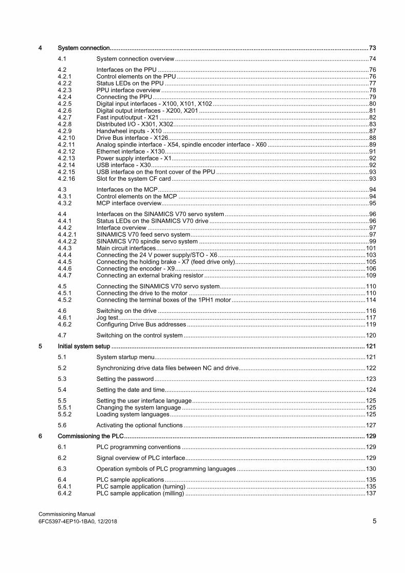
4 System connection................................................................................................................................................ 73
4.1 System connection overview ................................................................................................................. 74
4.2 Interfaces on the PPU ........................................................................................................................... 76 4.2.1 Control elements on the PPU ................................................................................................................ 76 4.2.2 Status LEDs on the PPU ....................................................................................................................... 77 4.2.3 PPU interface overview ......................................................................................................................... 78 4.2.4 Connecting the PPU .............................................................................................................................. 79 4.2.5 Digital input interfaces - X100, X101, X102 ........................................................................................... 80 4.2.6 Digital output interfaces - X200, X201 ................................................................................................... 81 4.2.7 Fast input/output - X21 .......................................................................................................................... 82 4.2.8 Distributed I/O - X301, X302 .................................................................................................................. 83 4.2.9 Handwheel inputs - X10 ........................................................................................................................ 87 4.2.10 Drive Bus interface - X126 ..................................................................................................................... 88 4.2.11 Analog spindle interface - X54, spindle encoder interface - X60 ........................................................... 89 4.2.12 Ethernet interface - X130 ....................................................................................................................... 91 4.2.13 Power supply interface - X1 ................................................................................................................... 92 4.2.14 USB interface - X30 ............................................................................................................................... 92 4.2.15 USB interface on the front cover of the PPU ......................................................................................... 93 4.2.16 Slot for the system CF card ................................................................................................................... 93
4.3 Interfaces on the MCP ........................................................................................................................... 94 4.3.1 Control elements on the MCP ............................................................................................................... 94 4.3.2 MCP interface overview ......................................................................................................................... 95
4.4 Interfaces on the SINAMICS V70 servo system .................................................................................... 96 4.4.1 Status LEDs on the SINAMICS V70 drive ............................................................................................. 96 4.4.2 Interface overview ................................................................................................................................. 97 4.4.2.1 SINAMICS V70 feed servo system ........................................................................................................ 97 4.4.2.2 SINAMICS V70 spindle servo system ................................................................................................... 99 4.4.3 Main circuit interfaces .......................................................................................................................... 101 4.4.4 Connecting the 24 V power supply/STO - X6 ...................................................................................... 103 4.4.5 Connecting the holding brake - X7 (feed drive only) ............................................................................ 105 4.4.6 Connecting the encoder - X9 ............................................................................................................... 106 4.4.7 Connecting an external braking resistor .............................................................................................. 109
4.5 Connecting the SINAMICS V70 servo system ..................................................................................... 110 4.5.1 Connecting the drive to the motor ....................................................................................................... 110 4.5.2 Connecting the terminal boxes of the 1PH1 motor .............................................................................. 114
4.6 Switching on the drive ......................................................................................................................... 116 4.6.1 Jog test ................................................................................................................................................ 117 4.6.2 Configuring Drive Bus addresses ........................................................................................................ 119
4.7 Switching on the control system .......................................................................................................... 120
5 Initial system setup ............................................................................................................................................. 121
5.1 System startup menu........................................................................................................................... 121
5.2 Synchronizing drive data files between NC and drive.......................................................................... 122
5.3 Setting the password ........................................................................................................................... 123
5.4 Setting the date and time ..................................................................................................................... 124
5.5 Setting the user interface language ..................................................................................................... 125 5.5.1 Changing the system language ........................................................................................................... 125 5.5.2 Loading system languages .................................................................................................................. 125
5.6 Activating the optional functions .......................................................................................................... 127
6 Commissioning the PLC ...................................................................................................................................... 129
6.1 PLC programming conventions ........................................................................................................... 129
6.2 Signal overview of PLC interface ......................................................................................................... 129
6.3 Operation symbols of PLC programming languages ........................................................................... 130
6.4 PLC sample applications ..................................................................................................................... 135 6.4.1 PLC sample application (turning) ........................................................................................................ 135 6.4.2 PLC sample application (milling) ......................................................................................................... 137

Commissioning Manual 6 6FC5397-4EP10-1BA0, 12/2018
6.5 PLC machine data............................................................................................................................... 139
6.6 PLC subroutine library ......................................................................................................................... 141 6.6.1 Overview ............................................................................................................................................. 141 6.6.2 Conventions for the symbols used in the subroutines ......................................................................... 144 6.6.3 Subroutine 20 - AUX_MCP (machine auxiliary functions) ................................................................... 144 6.6.4 Subroutine 21 - AUX_LAMP (working lamp) ....................................................................................... 145 6.6.5 Subroutine 22 - AUX_SAFE_DOOR (safety door) .............................................................................. 145 6.6.6 Subroutine 23 - AUX_CHIP (chip conveyor) ....................................................................................... 146 6.6.7 Subroutine 24 - AUX_3Color_LAMP ................................................................................................... 147 6.6.8 Subroutine 31 - PLC_ini_USR_ini (user initialization) .......................................................................... 147 6.6.9 Subroutine 32 - PLC_INI (PLC initialization) ....................................................................................... 148 6.6.10 Subroutine 33 - EMG_STOP ............................................................................................................... 148 6.6.11 Subroutine 37 - MCP_NCK (MCP and HMI signal processing) ........................................................... 149 6.6.12 Subroutine 38 - MCP_Tool_Nr (display tool number on the MCP) ...................................................... 151 6.6.13 Subroutine 39 - HANDWHL (selecting a handwheel according to HMI interface signals) ................... 151 6.6.14 Subroutine 40 - AXIS_CTL (controlling the spindle and axes) ............................................................ 152 6.6.15 Subroutine 41 - MINI_HHU (handwheel on hand-held unit) ................................................................ 154 6.6.16 Subroutine 42 - SPINDLE (spindle control) ......................................................................................... 155 6.6.17 Subroutine 43 - MEAS_JOG (measurement in JOG mode) ................................................................ 156 6.6.18 Subroutine 44 - COOLING (cooling control) ........................................................................................ 157 6.6.19 Subroutine 45 - LUBRICAT (control of lubricate) ................................................................................ 158 6.6.20 Subroutine 46 - PI_SERVICE .............................................................................................................. 159 6.6.21 Subroutine 47 - PLC_Select_PP (PLC selects a subroutine) .............................................................. 161 6.6.22 Subroutine 48 - ServPlan (service planner) ........................................................................................ 161 6.6.23 Subroutine 49 - GearChg1_Auto (automatic spindle gear change) ..................................................... 162 6.6.24 Subroutine 50 - GearChg2_Virtual (virtual spindle gear change) ........................................................ 163 6.6.25 Subroutine 51 - Turret1_HED_T (turret with Hall effect device position sensor) ................................. 164 6.6.26 Subroutine 52 - Turret2_BIN_T (turret with binary coding function) .................................................... 166 6.6.27 Subroutine 53 - Turret3_CODE_T (tool change control for turret with coding function) ...................... 168 6.6.28 Subroutine 54 - Turret2_3_ToolDir (tool change direction) .................................................................. 169 6.6.29 Subroutine 55 - Tail_stock_T (Tailstock control program for turning machines) .................................. 170 6.6.30 Subroutine 56 - Lock_unlock_T (clamping control for turning machine) .............................................. 171 6.6.31 Subroutine 58 (MM_MAIN) .................................................................................................................. 172 6.6.32 Subroutine 59 (MM_MCP_808D) ........................................................................................................ 174 6.6.33 Subroutine 60 - Disk_MGZ_M (disk-style tool magazine used for milling)........................................... 175 6.6.34 Subroutine 62 - Trg_key_OR ............................................................................................................... 177 6.6.35 Subroutine 63 - TOGGLES ................................................................................................................. 181 6.6.36 Subroutines 0 to 19, 34 to 36, 57, and 61 ........................................................................................... 181
6.7 PLC Programming Tool ....................................................................................................................... 182 6.7.1 Overview of PLC Programming Tool ................................................................................................... 182 6.7.2 Renaming the default program ............................................................................................................ 183 6.7.3 Changing the display language ........................................................................................................... 183 6.7.4 Selecting a target system .................................................................................................................... 185 6.7.5 Downloading/uploading/comparing PLC applications ......................................................................... 186 6.7.6 Compiling and monitoring programs ................................................................................................... 194
6.8 PLC alarms ......................................................................................................................................... 195 6.8.1 Alarm cancel/reset and reaction .......................................................................................................... 197 6.8.2 Editing PLC alarm texts ....................................................................................................................... 197
6.9 PLC diagnostics .................................................................................................................................. 200
6.10 Handwheel assignment ....................................................................................................................... 204
7 Commissioning the prototype machine ................................................................................................................. 205
7.1 Overview on commissioning and operation wizards............................................................................ 205
7.2 Commissioning the PLC ...................................................................................................................... 207 7.2.1 Setting PLC related parameters .......................................................................................................... 207 7.2.2 Downloading and commissioning PLC programs ................................................................................ 207 7.2.3 Checking I/O address assignment ...................................................................................................... 208 7.2.4 Editing PLC alarm texts ....................................................................................................................... 209
7.3 Configuring the drives ......................................................................................................................... 210
7.4 Setting basic parameters .................................................................................................................... 213 7.4.1 Setting feed axis parameters .............................................................................................................. 213 7.4.2 Commissioning the referencing function ............................................................................................. 214
Commissioning Manual 6FC5397-4EP10-1BA0, 12/2018 7
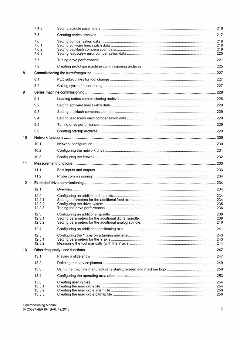
7.4.3 Setting spindle parameters .................................................................................................................. 216
7.5 Creating series archives ...................................................................................................................... 217
7.6 Setting compensation data .................................................................................................................. 218 7.6.1 Setting software limit switch data ........................................................................................................ 218 7.6.2 Setting backlash compensation data ................................................................................................... 219 7.6.3 Setting leadscrew error compensation data ........................................................................................ 220
7.7 Tuning drive performance .................................................................................................................... 221
7.8 Creating prototype machine commissioning archives.......................................................................... 225
8 Commissioning the turret/magazine ..................................................................................................................... 227
8.1 PLC subroutines for tool change ......................................................................................................... 227
8.2 Calling cycles for tool change .............................................................................................................. 227
9 Series machine commissioning ........................................................................................................................... 228
9.1 Loading series commissioning archives .............................................................................................. 228
9.2 Setting software limit switch data ........................................................................................................ 229
9.3 Setting backlash compensation data ................................................................................................... 229
9.4 Setting leadscrew error compensation data ........................................................................................ 229
9.5 Tuning drive performance .................................................................................................................... 229
9.6 Creating startup archives ..................................................................................................................... 229
10 Network functions ............................................................................................................................................... 230
10.1 Network configuration .......................................................................................................................... 230
10.2 Configuring the network drive .............................................................................................................. 231
10.3 Configuring the firewall ........................................................................................................................ 232
11 Measurement functions ....................................................................................................................................... 233
11.1 Fast inputs and outputs ....................................................................................................................... 233
11.2 Probe commissioning .......................................................................................................................... 234
12 Extended drive commissioning ............................................................................................................................ 234
12.1 Overview ............................................................................................................................................. 234
12.2 Configuring an additional feed axis...................................................................................................... 234 12.2.1 Setting parameters for the additional feed axis ................................................................................... 234 12.2.2 Configuring the drive system ............................................................................................................... 235 12.2.3 Tuning the drive performance .............................................................................................................. 236
12.3 Configuring an additional spindle ........................................................................................................ 238 12.3.1 Setting parameters for the additional digital spindle ............................................................................ 238 12.3.2 Setting parameters for the additional analog spindle ........................................................................... 240
12.4 Configuring an additional positioning axis ........................................................................................... 241
12.5 Configuring the Y axis on a turning machine ....................................................................................... 243 12.5.1 Setting parameters for the Y axis ........................................................................................................ 243 12.5.2 Measuring the tool manually (with the Y axis) ..................................................................................... 244
13 Other frequently used functions ........................................................................................................................... 247
13.1 Playing a slide show ............................................................................................................................ 247
13.2 Defining the service planner ................................................................................................................ 249
13.3 Using the machine manufacturer's startup screen and machine logo ................................................. 250
13.4 Configuring the operating area after startup ........................................................................................ 253
13.5 Creating user cycles ............................................................................................................................ 254 13.5.1 Creating the user cycle file .................................................................................................................. 254 13.5.2 Creating the user cycle alarm file ........................................................................................................ 256 13.5.3 Creating the user cycle bitmap file ...................................................................................................... 256
Commissioning Manual 8 6FC5397-4EP10-1BA0, 12/2018
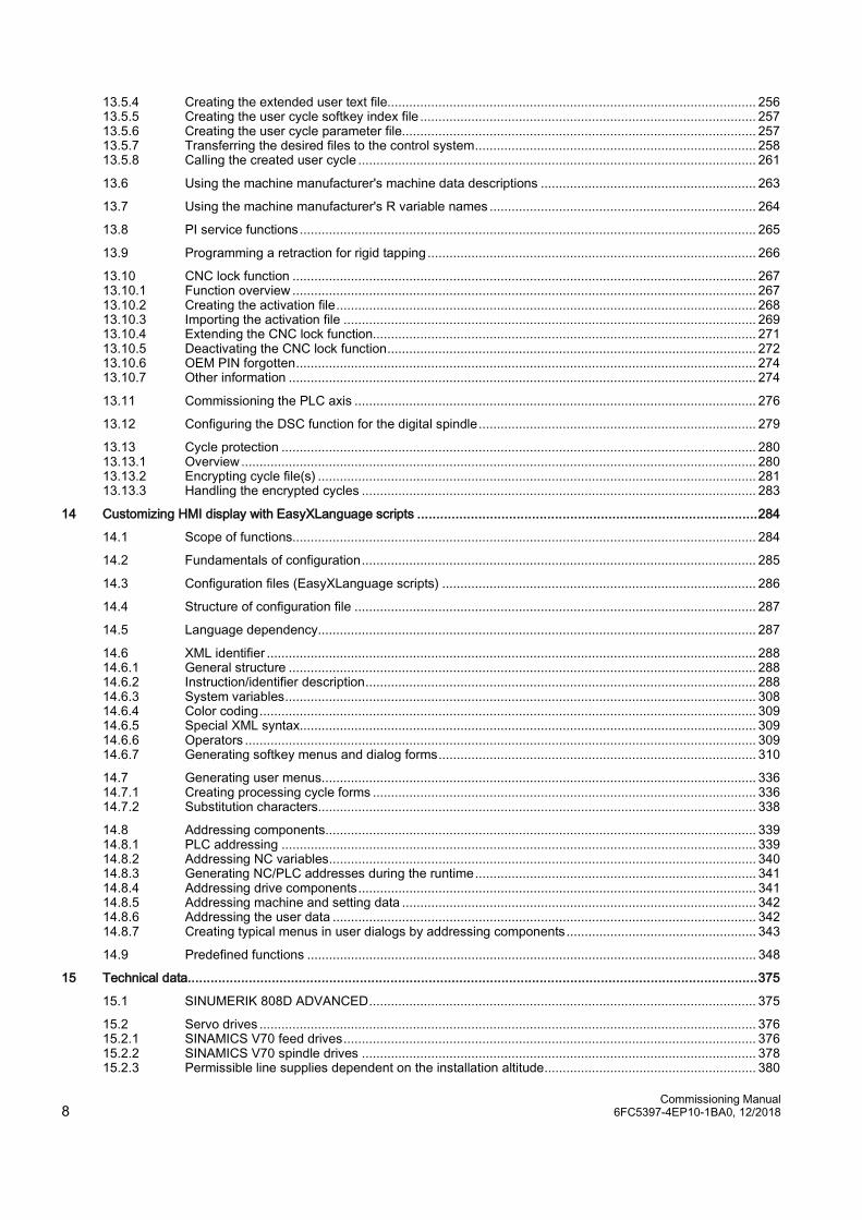
13.5.4 Creating the extended user text file..................................................................................................... 256 13.5.5 Creating the user cycle softkey index file ............................................................................................ 257 13.5.6 Creating the user cycle parameter file................................................................................................. 257 13.5.7 Transferring the desired files to the control system ............................................................................. 258 13.5.8 Calling the created user cycle ............................................................................................................. 261
13.6 Using the machine manufacturer's machine data descriptions ........................................................... 263
13.7 Using the machine manufacturer's R variable names ......................................................................... 264
13.8 PI service functions ............................................................................................................................. 265
13.9 Programming a retraction for rigid tapping .......................................................................................... 266
13.10 CNC lock function ............................................................................................................................... 267 13.10.1 Function overview ............................................................................................................................... 267 13.10.2 Creating the activation file ................................................................................................................... 268 13.10.3 Importing the activation file ................................................................................................................. 269 13.10.4 Extending the CNC lock function......................................................................................................... 271 13.10.5 Deactivating the CNC lock function ..................................................................................................... 272 13.10.6 OEM PIN forgotten .............................................................................................................................. 274 13.10.7 Other information ................................................................................................................................ 274
13.11 Commissioning the PLC axis .............................................................................................................. 276
13.12 Configuring the DSC function for the digital spindle ............................................................................ 279
13.13 Cycle protection .................................................................................................................................. 280 13.13.1 Overview ............................................................................................................................................. 280 13.13.2 Encrypting cycle file(s) ........................................................................................................................ 281 13.13.3 Handling the encrypted cycles ............................................................................................................ 283
14 Customizing HMI display with EasyXLanguage scripts ......................................................................................... 284
14.1 Scope of functions............................................................................................................................... 284
14.2 Fundamentals of configuration ............................................................................................................ 285
14.3 Configuration files (EasyXLanguage scripts) ...................................................................................... 286
14.4 Structure of configuration file .............................................................................................................. 287
14.5 Language dependency ........................................................................................................................ 287
14.6 XML identifier ...................................................................................................................................... 288 14.6.1 General structure ................................................................................................................................ 288 14.6.2 Instruction/identifier description ........................................................................................................... 288 14.6.3 System variables ................................................................................................................................. 308 14.6.4 Color coding ........................................................................................................................................ 309 14.6.5 Special XML syntax............................................................................................................................. 309 14.6.6 Operators ............................................................................................................................................ 309 14.6.7 Generating softkey menus and dialog forms ....................................................................................... 310
14.7 Generating user menus ....................................................................................................................... 336 14.7.1 Creating processing cycle forms ......................................................................................................... 336 14.7.2 Substitution characters ........................................................................................................................ 338
14.8 Addressing components ...................................................................................................................... 339 14.8.1 PLC addressing .................................................................................................................................. 339 14.8.2 Addressing NC variables ..................................................................................................................... 340 14.8.3 Generating NC/PLC addresses during the runtime ............................................................................. 341 14.8.4 Addressing drive components ............................................................................................................. 341 14.8.5 Addressing machine and setting data ................................................................................................. 342 14.8.6 Addressing the user data .................................................................................................................... 342 14.8.7 Creating typical menus in user dialogs by addressing components .................................................... 343
14.9 Predefined functions ........................................................................................................................... 348
15 Technical data..................................................................................................................................................... 375
15.1 SINUMERIK 808D ADVANCED .......................................................................................................... 375
15.2 Servo drives ........................................................................................................................................ 376 15.2.1 SINAMICS V70 feed drives ................................................................................................................. 376 15.2.2 SINAMICS V70 spindle drives ............................................................................................................ 378 15.2.3 Permissible line supplies dependent on the installation altitude .......................................................... 380
Commissioning Manual 6FC5397-4EP10-1BA0, 12/2018 9
15.3 Servo motors ....................................................................................................................................... 380 15.3.1 SIMOTICS S-1FL6 feed motors .......................................................................................................... 380 15.3.2 SIMOTICS M-1PH1 main motors ........................................................................................................ 384
15.4 Cables ................................................................................................................................................. 396 15.4.1 Drive Bus cable for the SINUMERIK 808D ADVANCED ..................................................................... 396 15.4.2 Cables for the SINAMICS V70 servo system ...................................................................................... 396
15.5 Address of CE-authorized manufacturer ............................................................................................. 397
16 Parameter list ..................................................................................................................................................... 398
16.1 Basic machine data ............................................................................................................................. 398
16.2 SINAMICS V70 parameters ................................................................................................................. 403 16.2.1 V70 parameters on BOP ..................................................................................................................... 404 16.2.2 Drive basic list on HMI ......................................................................................................................... 411
17 PLC user interface .............................................................................................................................................. 413
17.1 Signals from/to the MCP ...................................................................................................................... 413
17.2 Reading/Writing NC data ..................................................................................................................... 415 17.2.1 Reading/writing NC data: Job .............................................................................................................. 415 17.2.2 Reading/writing NC data: Result ......................................................................................................... 415
17.3 PI Service ............................................................................................................................................ 416 17.3.1 PI service: Job ..................................................................................................................................... 416 17.3.2 PI service: Result ................................................................................................................................ 416
17.4 Retentive data area ............................................................................................................................. 416
17.5 User Alarms ......................................................................................................................................... 417 17.5.1 User alarms: Activating ........................................................................................................................ 417 17.5.2 Variables for user alarms ..................................................................................................................... 417 17.5.3 Active alarm response ......................................................................................................................... 417 17.5.4 Alarm acknowledgement ..................................................................................................................... 418
17.6 Signals from/to HMI ............................................................................................................................. 418 17.6.1 Program control signals from the HMI (retentive area) ........................................................................ 418 17.6.2 Program selection from PLC (retentive area) ...................................................................................... 418 17.6.3 Checkback signal: Program selection from HMI (retentive area) ......................................................... 419 17.6.4 Signals from HMI ................................................................................................................................. 419 17.6.5 Signals from PLC ................................................................................................................................ 419 17.6.6 Signals to maintenance planners ........................................................................................................ 420 17.6.7 Signals from maintenance planners .................................................................................................... 420 17.6.8 Signals from operator panel (retentive area) ....................................................................................... 421 17.6.9 General selection/status signals from HMI (retentive area) ................................................................. 421 17.6.10 General selection/status signals to HMI (retentive area) ..................................................................... 421
17.7 Auxiliary functions transfer from NC channel ....................................................................................... 422 17.7.1 Overview ............................................................................................................................................. 422 17.7.2 Decoded M signals (M0 to M99) .......................................................................................................... 422 17.7.3 Transferred T functions ....................................................................................................................... 423 17.7.4 Transferred M functions ....................................................................................................................... 423 17.7.5 Transferred S functions ....................................................................................................................... 423 17.7.6 Transferred D functions ....................................................................................................................... 424 17.7.7 Transferred H functions ....................................................................................................................... 424
17.8 NCK signals ......................................................................................................................................... 424 17.8.1 General signals to NCK ....................................................................................................................... 424 17.8.2 General signals from NCK ................................................................................................................... 424 17.8.3 Signals at fast inputs and outputs ........................................................................................................ 425 17.8.4 Signals from fast inputs and outputs.................................................................................................... 425
17.9 Channel signals ................................................................................................................................... 426 17.9.1 Signals to NC channel ......................................................................................................................... 426 17.9.2 Signals from NC channel ..................................................................................................................... 429
17.10 Axis/spindle signals ............................................................................................................................. 432 17.10.1 Transferred M and S functions, axis specific ....................................................................................... 432 17.10.2 Signals to axis/spindle ......................................................................................................................... 432 17.10.3 Signals from axis/spindle ..................................................................................................................... 435
Commissioning Manual 10 6FC5397-4EP10-1BA0, 12/2018
17.11 PLC machine data............................................................................................................................... 437 17.11.1 INT values (MD 14510 USER_DATA_INT) ......................................................................................... 437 17.11.2 HEX values (MD 14512 USER_DATA_HEX) ...................................................................................... 438 17.11.3 FLOAT values (MD 14514 USER_DATA_FLOAT) .............................................................................. 438 17.11.4 User alarm: Configuring (MD 14516 USER_DATA_PLC_ALARM) ..................................................... 438
17.12 Signals, synchronized actions ............................................................................................................. 439 17.12.1 Signals, synchronized actions to channel ........................................................................................... 439 17.12.2 Signals, synchronized actions from channel ....................................................................................... 439 17.12.3 Reading and writing PLC variables ..................................................................................................... 439
17.13 Axis actual values and distance-to-go ................................................................................................. 440
17.14 Maintenance scheduler: User interface ............................................................................................... 440 17.14.1 Initial (start) data ................................................................................................................................. 440 17.14.2 Actual data .......................................................................................................................................... 440
17.15 User interface for ctrl energy ............................................................................................................... 441
A Appendix ............................................................................................................................................................ 442
A.1 Operating the SINAMICS V70 Basic Operator Panel (BOP) ............................................................... 442 A.1.1 BOP overview ..................................................................................................................................... 442 A.1.2 Parameter structure ............................................................................................................................ 446 A.1.3 Actual status display ........................................................................................................................... 447 A.1.4 Basic operations ................................................................................................................................. 447 A.1.4.1 Editing parameters .............................................................................................................................. 447 A.1.4.2 Viewing parameters ............................................................................................................................ 449 A.1.5 Auxiliary functions ............................................................................................................................... 449 A.1.5.1 Setting Drive Bus address ................................................................................................................... 450 A.1.5.2 Jog ...................................................................................................................................................... 450 A.1.5.3 Saving parameter set in drive (RAM to ROM) ..................................................................................... 451 A.1.5.4 Setting parameter set to default .......................................................................................................... 451 A.1.5.5 Transferring data (drive to SD card) .................................................................................................... 452 A.1.5.6 Transferring data (SD card to drive) .................................................................................................... 452 A.1.5.7 Updating firmware ............................................................................................................................... 453
A.2 Replacing the fan for the V70 drive ..................................................................................................... 454
A.3 Replacing the fan for the 1PH1 motor ................................................................................................. 457
A.4 Assembling the power cable for the 1PH1 motor ................................................................................ 457
A.5 Assembling the line supply terminal for the drive ................................................................................ 459
A.6 Cutting reserved holes in the MCP ..................................................................................................... 459
A.7 Customizing pre-defined labeling strips for keys of the MCP .............................................................. 460
A.8 Diagnostics ......................................................................................................................................... 461 A.8.1 SINUMERIK 808D ADVANCED alarms .............................................................................................. 461 A.8.2 SINAMICS V70 faults and alarms ....................................................................................................... 462 A.8.2.1 General information about faults and alarms ...................................................................................... 462 A.8.2.2 List of faults and alarms ...................................................................................................................... 463
A.9 AMM communication tool .................................................................................................................... 475 A.9.1 File management and transfer ............................................................................................................ 475 A.9.2 Remote control .................................................................................................................................... 477 A.9.2.1 Configuring the remote control ............................................................................................................ 477 A.9.2.2 Operating the HMI via remote control ................................................................................................. 479 A.9.2.3 Saving the remote control screen as a picture .................................................................................... 479

Commissioning Manual 6FC5397-4EP10-1BA0, 12/2018 11
1 Safety instructions 1.1 Fundamental safety instructions
1.1.1 General safety instructions
WARNING Electric shock and danger to life due to other energy sources Touching live components can result in death or severe injury. • Only work on electrical devices when you are qualified for this job. • Always observe the country-specific safety rules. Generally, the following six steps apply when establishing safety: 1. Prepare for disconnection. Notify all those who will be affected by the procedure. 2. Isolate the drive system from the power supply and take measures to prevent it being switched back on
again. 3. Wait until the discharge time specified on the warning labels has elapsed. 4. Check that there is no voltage between any of the power connections, and between any of the power
connections and the protective conductor connection. 5. Check whether the existing auxiliary supply circuits are de-energized. 6. Ensure that the motors cannot move. 7. Identify all other dangerous energy sources, e.g. compressed air, hydraulic systems, or water. Switch the
energy sources to a safe state. 8. Check that the correct drive system is completely locked. After you have completed the work, restore the operational readiness in the inverse sequence.
WARNING Risk of electric shock and fire from supply networks with an excessively high impedance Excessively low short-circuit currents can lead to the protective devices not tripping or tripping too late, and thus causing electric shock or a fire. • In the case of a conductor-conductor or conductor-ground short-circuit, ensure that the short-circuit current
at the point where the inverter is connected to the line supply at least meets the minimum requirements for the response of the protective device used.
• You must use an additional residual-current device (RCD) if a conductor-ground short circuit does not reach the short-circuit current required for the protective device to respond. The required short-circuit current can be too low, especially for TT supply systems.
WARNING Risk of electric shock and fire from supply networks with an excessively low impedance Excessively high short-circuit currents can lead to the protective devices not being able to interrupt these short-circuit currents and being destroyed, and thus causing electric shock or a fire. • Ensure that the prospective short-circuit current at the line terminal of the inverter does not exceed the
breaking capacity (SCCR or Icc) of the protective device used.
WARNING Electric shock if there is no ground connection For missing or incorrectly implemented protective conductor connection for devices with protection class I, high voltages can be present at open, exposed parts, which when touched, can result in death or severe injury. • Ground the device in compliance with the applicable regulations.
Commissioning Manual 12 6FC5397-4EP10-1BA0, 12/2018
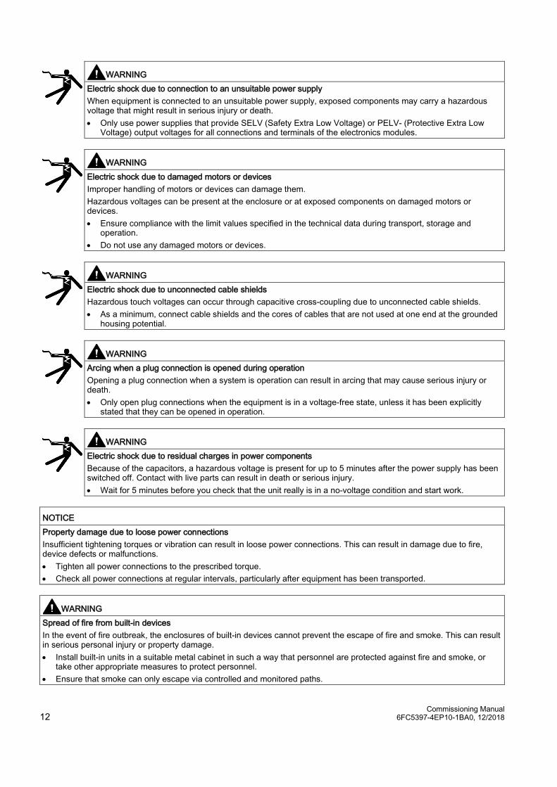
WARNING Electric shock due to connection to an unsuitable power supply When equipment is connected to an unsuitable power supply, exposed components may carry a hazardous voltage that might result in serious injury or death. • Only use power supplies that provide SELV (Safety Extra Low Voltage) or PELV- (Protective Extra Low
Voltage) output voltages for all connections and terminals of the electronics modules.
WARNING Electric shock due to damaged motors or devices Improper handling of motors or devices can damage them. Hazardous voltages can be present at the enclosure or at exposed components on damaged motors or devices. • Ensure compliance with the limit values specified in the technical data during transport, storage and
operation. • Do not use any damaged motors or devices.
WARNING Electric shock due to unconnected cable shields Hazardous touch voltages can occur through capacitive cross-coupling due to unconnected cable shields. • As a minimum, connect cable shields and the cores of cables that are not used at one end at the grounded
housing potential.
WARNING Arcing when a plug connection is opened during operation Opening a plug connection when a system is operation can result in arcing that may cause serious injury or death. • Only open plug connections when the equipment is in a voltage-free state, unless it has been explicitly
stated that they can be opened in operation.
WARNING Electric shock due to residual charges in power components Because of the capacitors, a hazardous voltage is present for up to 5 minutes after the power supply has been switched off. Contact with live parts can result in death or serious injury. • Wait for 5 minutes before you check that the unit really is in a no-voltage condition and start work.
NOTICE Property damage due to loose power connections Insufficient tightening torques or vibration can result in loose power connections. This can result in damage due to fire, device defects or malfunctions. • Tighten all power connections to the prescribed torque. • Check all power connections at regular intervals, particularly after equipment has been transported.
WARNING Spread of fire from built-in devices In the event of fire outbreak, the enclosures of built-in devices cannot prevent the escape of fire and smoke. This can result in serious personal injury or property damage. • Install built-in units in a suitable metal cabinet in such a way that personnel are protected against fire and smoke, or
take other appropriate measures to protect personnel. • Ensure that smoke can only escape via controlled and monitored paths.
Commissioning Manual 6FC5397-4EP10-1BA0, 12/2018 13
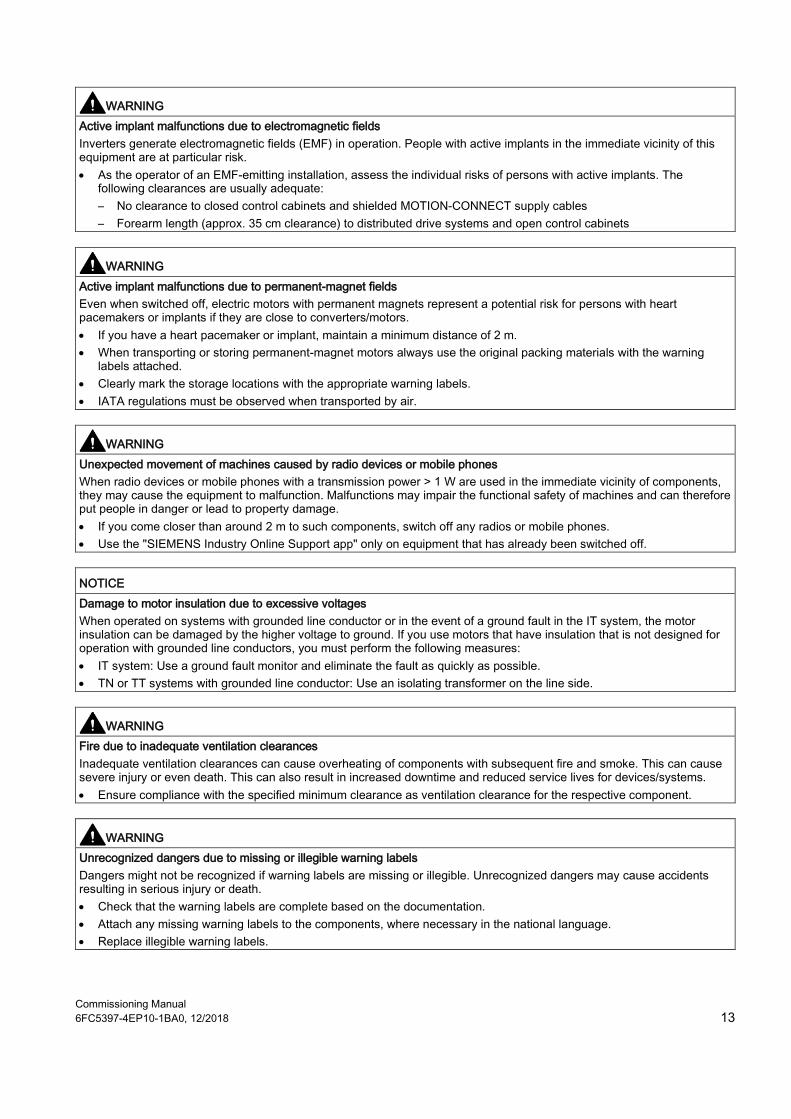
WARNING Active implant malfunctions due to electromagnetic fields Inverters generate electromagnetic fields (EMF) in operation. People with active implants in the immediate vicinity of this equipment are at particular risk. • As the operator of an EMF-emitting installation, assess the individual risks of persons with active implants. The
following clearances are usually adequate: – No clearance to closed control cabinets and shielded MOTION-CONNECT supply cables – Forearm length (approx. 35 cm clearance) to distributed drive systems and open control cabinets
WARNING Active implant malfunctions due to permanent-magnet fields Even when switched off, electric motors with permanent magnets represent a potential risk for persons with heart pacemakers or implants if they are close to converters/motors. • If you have a heart pacemaker or implant, maintain a minimum distance of 2 m. • When transporting or storing permanent-magnet motors always use the original packing materials with the warning
labels attached. • Clearly mark the storage locations with the appropriate warning labels. • IATA regulations must be observed when transported by air.
WARNING Unexpected movement of machines caused by radio devices or mobile phones When radio devices or mobile phones with a transmission power > 1 W are used in the immediate vicinity of components, they may cause the equipment to malfunction. Malfunctions may impair the functional safety of machines and can therefore put people in danger or lead to property damage. • If you come closer than around 2 m to such components, switch off any radios or mobile phones. • Use the "SIEMENS Industry Online Support app" only on equipment that has already been switched off.
NOTICE Damage to motor insulation due to excessive voltages When operated on systems with grounded line conductor or in the event of a ground fault in the IT system, the motor insulation can be damaged by the higher voltage to ground. If you use motors that have insulation that is not designed for operation with grounded line conductors, you must perform the following measures: • IT system: Use a ground fault monitor and eliminate the fault as quickly as possible. • TN or TT systems with grounded line conductor: Use an isolating transformer on the line side.
WARNING Fire due to inadequate ventilation clearances Inadequate ventilation clearances can cause overheating of components with subsequent fire and smoke. This can cause severe injury or even death. This can also result in increased downtime and reduced service lives for devices/systems. • Ensure compliance with the specified minimum clearance as ventilation clearance for the respective component.
WARNING Unrecognized dangers due to missing or illegible warning labels Dangers might not be recognized if warning labels are missing or illegible. Unrecognized dangers may cause accidents resulting in serious injury or death. • Check that the warning labels are complete based on the documentation. • Attach any missing warning labels to the components, where necessary in the national language. • Replace illegible warning labels.

Commissioning Manual 14 6FC5397-4EP10-1BA0, 12/2018
NOTICE Device damage caused by incorrect voltage/insulation tests Incorrect voltage/insulation tests can damage the device. • Before carrying out a voltage/insulation check of the system/machine, disconnect the devices as all converters and
motors have been subject to a high voltage test by the manufacturer, and therefore it is not necessary to perform an additional test within the system/machine.
WARNING Unexpected movement of machines caused by inactive safety functions Inactive or non-adapted safety functions can trigger unexpected machine movements that may result in serious injury or death. • Observe the information in the appropriate product documentation before commissioning. • Carry out a safety inspection for functions relevant to safety on the entire system, including all safety-related
components. • Ensure that the safety functions used in your drives and automation tasks are adjusted and activated through
appropriate parameterizing. • Perform a function test. • Only put your plant into live operation once you have guaranteed that the functions relevant to safety are running
correctly.
Note Important safety notices for Safety Integrated functions If you want to use Safety Integrated functions, you must observe the safety notices in the Safety Integrated manuals.
WARNING Malfunctions of the machine as a result of incorrect or changed parameter settings As a result of incorrect or changed parameterization, machines can malfunction, which in turn can lead to injuries or death. • Protect the parameterization (parameter assignments) against unauthorized access. • Handle possible malfunctions by taking suitable measures, e.g. emergency stop or emergency off.
WARNING Injury caused by moving or ejected parts Contact with moving motor parts or drive output elements and the ejection of loose motor parts (e.g. feather keys) out of the motor enclosure can result in severe injury or death. • Remove any loose parts or secure them so that they cannot be flung out. • Do not touch any moving parts. • Safeguard all moving parts using the appropriate safety guards.
WARNING Fire due to inadequate cooling Inadequate cooling can cause the motor to overheat, resulting in death or severe injury as a result of smoke and fire. This can also result in increased failures and reduced service lives of motors. • Comply with the specified cooling requirements for the motor.
WARNING Fire due to incorrect operation of the motor When incorrectly operated and in the case of a fault, the motor can overheat resulting in fire and smoke. This can result in severe injury or death. Further, excessively high temperatures destroy motor components and result in increased failures as well as shorter service lives of motors. • Operate the motor according to the relevant specifications. • Only operate the motors in conjunction with effective temperature monitoring. • Immediately switch off the motor if excessively high temperatures occur.
Commissioning Manual 6FC5397-4EP10-1BA0, 12/2018 15
CAUTION Burn injuries caused by hot surfaces In operation, the motor can reach high temperatures, which can cause burns if touched. • Mount the motor so that it is not accessible in operation. Measures when maintenance is required: • Allow the motor to cool down before starting any work. • Use the appropriate personnel protection equipment, e.g. gloves.
1.1.2 Equipment damage due to electric fields or electrostatic discharge Electrostatic sensitive devices (ESD) are individual components, integrated circuits, modules or devices that may be damaged by either electric fields or electrostatic discharge.
NOTICE Equipment damage due to electric fields or electrostatic discharge Electric fields or electrostatic discharge can cause malfunctions through damaged individual components, integrated circuits, modules or devices. • Only pack, store, transport and send electronic components, modules or devices in their original packaging
or in other suitable materials, e.g conductive foam rubber of aluminum foil. • Only touch components, modules and devices when you are grounded by one of the following methods:
– Wearing an ESD wrist strap – Wearing ESD shoes or ESD grounding straps in ESD areas with conductive flooring
• Only place electronic components, modules or devices on conductive surfaces (table with ESD surface, conductive ESD foam, ESD packaging, ESD transport container).
1.1.3 Warranty and liability for application examples Application examples are not binding and do not claim to be complete regarding configuration, equipment or any eventuality which may arise. Application examples do not represent specific customer solutions, but are only intended to provide support for typical tasks.
As the user you yourself are responsible for ensuring that the products described are operated correctly. Application examples do not relieve you of your responsibility for safe handling when using, installing, operating and maintaining the equipment.
1.1.4 Industrial security
Note Industrial security Siemens provides products and solutions with industrial security functions that support the secure operation of plants, systems, machines and networks. In order to protect plants, systems, machines and networks against cyber threats, it is necessary to implement – and continuously maintain – a holistic, state-of-the-art industrial security concept. Siemens’ products and solutions constitute one element of such a concept. Customers are responsible for preventing unauthorized access to their plants, systems, machines and networks. Such systems, machines and components should only be connected to an enterprise network or the Internet if and to the extent such a connection is necessary and only when appropriate security measures (e.g. firewalls and/or network segmentation) are in place. For additional information on industrial security measures that may be implemented, please visit: Industrial security (http://www.siemens.com/industrialsecurity) Siemens’ products and solutions undergo continuous development to make them more secure. Siemens strongly recommends that product updates are applied as soon as they are available and that the latest product versions are used. Use of product versions that are no longer supported, and failure to apply the latest updates may increase customer’s exposure to cyber threats. To stay informed about product updates, subscribe to the Siemens Industrial Security RSS Feed at: Industrial security (http://www.siemens.com/industrialsecurity)

Commissioning Manual 16 6FC5397-4EP10-1BA0, 12/2018
Further information is provided on the Internet: Industrial Security Configuration Manual (https://support.industry.siemens.com/cs/ww/en/view/108862708)
WARNING Unsafe operating states resulting from software manipulation Software manipulations (e.g. viruses, trojans, malware or worms) can cause unsafe operating states in your system that may lead to death, serious injury, and property damage. • Keep the software up to date. • Incorporate the automation and drive components into a holistic, state-of-the-art industrial security concept for the
installation or machine. • Make sure that you include all installed products into the holistic industrial security concept. • Protect files stored on exchangeable storage media from malicious software by with suitable protection measures, e.g.
virus scanners. • Protect the drive against unauthorized changes by activating the "know-how protection" drive function.
1.1.5 Residual risks of power drive systems When assessing the machine- or system-related risk in accordance with the respective local regulations (e.g., EC Machinery Directive), the machine manufacturer or system installer must take into account the following residual risks emanating from the control and drive components of a drive system:
1. Unintentional movements of driven machine or system components during commissioning, operation, maintenance, and repairs caused by, for example, – Hardware and/or software errors in the sensors, control system, actuators, and cables and connections – Response times of the control system and of the drive – Operation and/or environmental conditions outside the specification – Condensation/conductive contamination – Parameterization, programming, cabling, and installation errors – Use of wireless devices/mobile phones in the immediate vicinity of electronic components – External influences/damage – X-ray, ionizing radiation and cosmic radiation
2. Unusually high temperatures, including open flames, as well as emissions of light, noise, particles, gases, etc., can occur inside and outside the components under fault conditions caused by, for example: – Component failure – Software errors – Operation and/or environmental conditions outside the specification – External influences/damage
3. Hazardous shock voltages caused by, for example: – Component failure – Influence during electrostatic charging – Induction of voltages in moving motors – Operation and/or environmental conditions outside the specification – Condensation/conductive contamination – External influences/damage
4. Electrical, magnetic and electromagnetic fields generated in operation that can pose a risk to people with a pacemaker, implants or metal replacement joints, etc., if they are too close
5. Release of environmental pollutants or emissions as a result of improper operation of the system and/or failure to dispose of components safely and correctly
6. Influence of network-connected communication systems, e.g. ripple-control transmitters or data communication via the network
For more information about the residual risks of the drive system components, see the relevant sections in the technical user documentation.
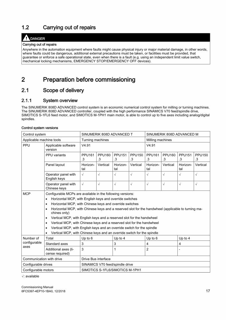
Commissioning Manual 6FC5397-4EP10-1BA0, 12/2018 17
1.2 Carrying out of repairs
DANGER Carrying out of repairs Anywhere in the automation equipment where faults might cause physical injury or major material damage, in other words, where faults could be dangerous, additional external precautions must be taken, or facilities must be provided, that guarantee or enforce a safe operational state, even when there is a fault (e.g. using an independent limit value switch, mechanical locking mechanisms, EMERGENCY STOP/EMERGENCY OFF devices).
2 Preparation before commissioning 2.1 Scope of delivery
2.1.1 System overview The SINUMERIK 808D ADVANCED control system is an economic numerical control system for milling or turning machines. The SINUMERIK 808D ADVANCED controller, coupled with the high performance SINAMICS V70 feed/spindle drive, SIMOTICS S-1FL6 feed motor, and SIMOTICS M-1PH1 main motor, is able to control up to five axes including analog/digital spindles.
Control system versions
Control system SINUMERIK 808D ADVANCED T SINUMERIK 808D ADVANCED M Applicable machine tools Turning machines Milling machines PPU Applicable software
version V4.91 V4.91
PPU variants PPU161.3
PPU160.3
PPU151.3
PPU150.3
PPU161.3
PPU160.3
PPU151.3
PPU150.3
Panel layout Horizon-tal
Vertical Horizon-tal
Vertical Horizon-tal
Vertical Horizon-tal
Vertical
Operator panel with English keys
√ √ √ √ √ √ √ √
Operator panel with Chinese keys
√ √ √ √ √ √ √ √
MCP Configurable MCPs are available in the following versions: • Horizontal MCP, with English keys and override switches • Horizontal MCP, with Chinese keys and override switches • Horizontal MCP, with Chinese keys and a reserved slot for the handwheel (applicable to turning ma-
chines only) • Vertical MCP, with English keys and a reserved slot for the handwheel • Vertical MCP, with Chinese keys and a reserved slot for the handwheel • Vertical MCP, with English keys and an override switch for the spindle • Vertical MCP, with Chinese keys and an override switch for the spindle
Number of configurable axes
Total Up to 6 Up to 4 Up to 6 Up to 4 Standard axes 3 3 4 4 Additional axes (li-cense required)
3 1 2 -
Communication with drive Drive Bus interface Configurable drives SINAMICS V70 feed/spindle drive Configurable motors SIMOTICS S-1FL6/SIMOTICS M-1PH1 √: available
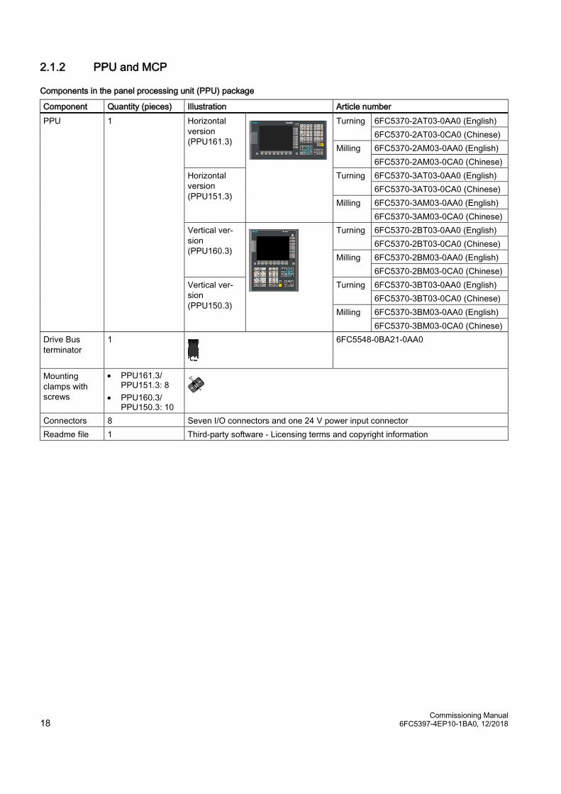
Commissioning Manual 18 6FC5397-4EP10-1BA0, 12/2018
2.1.2 PPU and MCP
Components in the panel processing unit (PPU) package
Component Quantity (pieces) Illustration Article number PPU 1 Horizontal
version (PPU161.3)
Turning 6FC5370-2AT03-0AA0 (English) 6FC5370-2AT03-0CA0 (Chinese)
Milling 6FC5370-2AM03-0AA0 (English) 6FC5370-2AM03-0CA0 (Chinese)
Horizontal version (PPU151.3)
Turning 6FC5370-3AT03-0AA0 (English) 6FC5370-3AT03-0CA0 (Chinese)
Milling 6FC5370-3AM03-0AA0 (English) 6FC5370-3AM03-0CA0 (Chinese)
Vertical ver-sion (PPU160.3)
Turning 6FC5370-2BT03-0AA0 (English) 6FC5370-2BT03-0CA0 (Chinese)
Milling 6FC5370-2BM03-0AA0 (English) 6FC5370-2BM03-0CA0 (Chinese)
Vertical ver-sion (PPU150.3)
Turning 6FC5370-3BT03-0AA0 (English) 6FC5370-3BT03-0CA0 (Chinese)
Milling 6FC5370-3BM03-0AA0 (English) 6FC5370-3BM03-0CA0 (Chinese)
Drive Bus terminator
1
6FC5548-0BA21-0AA0
Mounting clamps with screws
• PPU161.3/ PPU151.3: 8
• PPU160.3/ PPU150.3: 10
Connectors 8 Seven I/O connectors and one 24 V power input connector Readme file 1 Third-party software - Licensing terms and copyright information
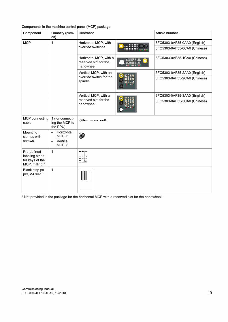
Commissioning Manual 6FC5397-4EP10-1BA0, 12/2018 19
Components in the machine control panel (MCP) package
Component Quantity (piec-es)
Illustration Article number
MCP 1 Horizontal MCP, with override switches
6FC5303-0AF35-0AA0 (English) 6FC5303-0AF35-0CA0 (Chinese)
Horizontal MCP, with a reserved slot for the handwheel
6FC5303-0AF35-1CA0 (Chinese)
Vertical MCP, with an override switch for the spindle
6FC5303-0AF35-2AA0 (English) 6FC5303-0AF35-2CA0 (Chinese)
Vertical MCP, with a reserved slot for the handwheel
6FC5303-0AF35-3AA0 (English) 6FC5303-0AF35-3CA0 (Chinese)
MCP connecting cable
1 (for connect-ing the MCP to the PPU)
Mounting clamps with screws
• Horizontal MCP: 6
• Vertical MCP: 8
Pre-defined labeling strips for keys of the MCP, milling *
1
Blank strip pa-per, A4 size *
1
* Not provided in the package for the horizontal MCP with a reserved slot for the handwheel.
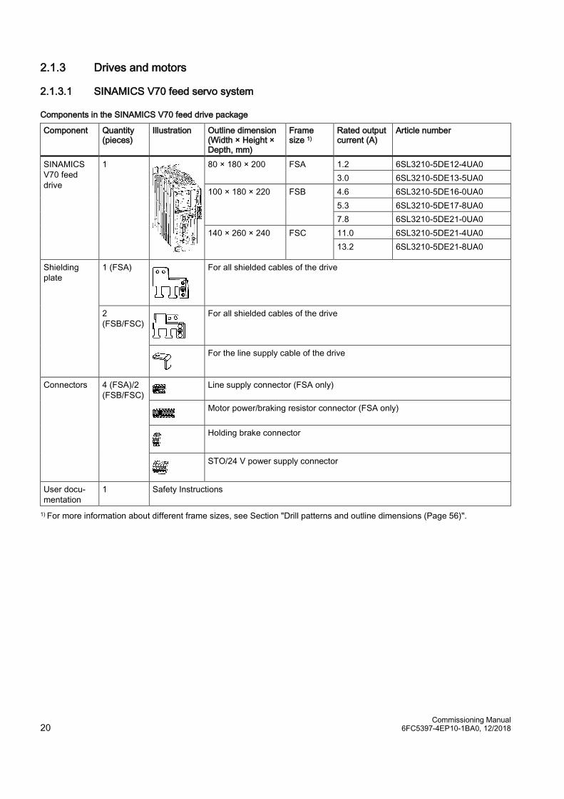
Commissioning Manual 20 6FC5397-4EP10-1BA0, 12/2018
2.1.3 Drives and motors
2.1.3.1 SINAMICS V70 feed servo system
Components in the SINAMICS V70 feed drive package
Component Quantity (pieces)
Illustration Outline dimension (Width × Height × Depth, mm)
Frame size 1)
Rated output current (A)
Article number
SINAMICS V70 feed drive
1
80 × 180 × 200 FSA 1.2 6SL3210-5DE12-4UA0 3.0 6SL3210-5DE13-5UA0
100 × 180 × 220 FSB 4.6 6SL3210-5DE16-0UA0 5.3 6SL3210-5DE17-8UA0 7.8 6SL3210-5DE21-0UA0
140 × 260 × 240 FSC 11.0 6SL3210-5DE21-4UA0 13.2 6SL3210-5DE21-8UA0
Shielding plate
1 (FSA)
For all shielded cables of the drive
2 (FSB/FSC)
For all shielded cables of the drive
For the line supply cable of the drive
Connectors 4 (FSA)/2 (FSB/FSC)
Line supply connector (FSA only)
Motor power/braking resistor connector (FSA only)
Holding brake connector
STO/24 V power supply connector
User docu-mentation
1 Safety Instructions
1) For more information about different frame sizes, see Section "Drill patterns and outline dimensions (Page 56)".
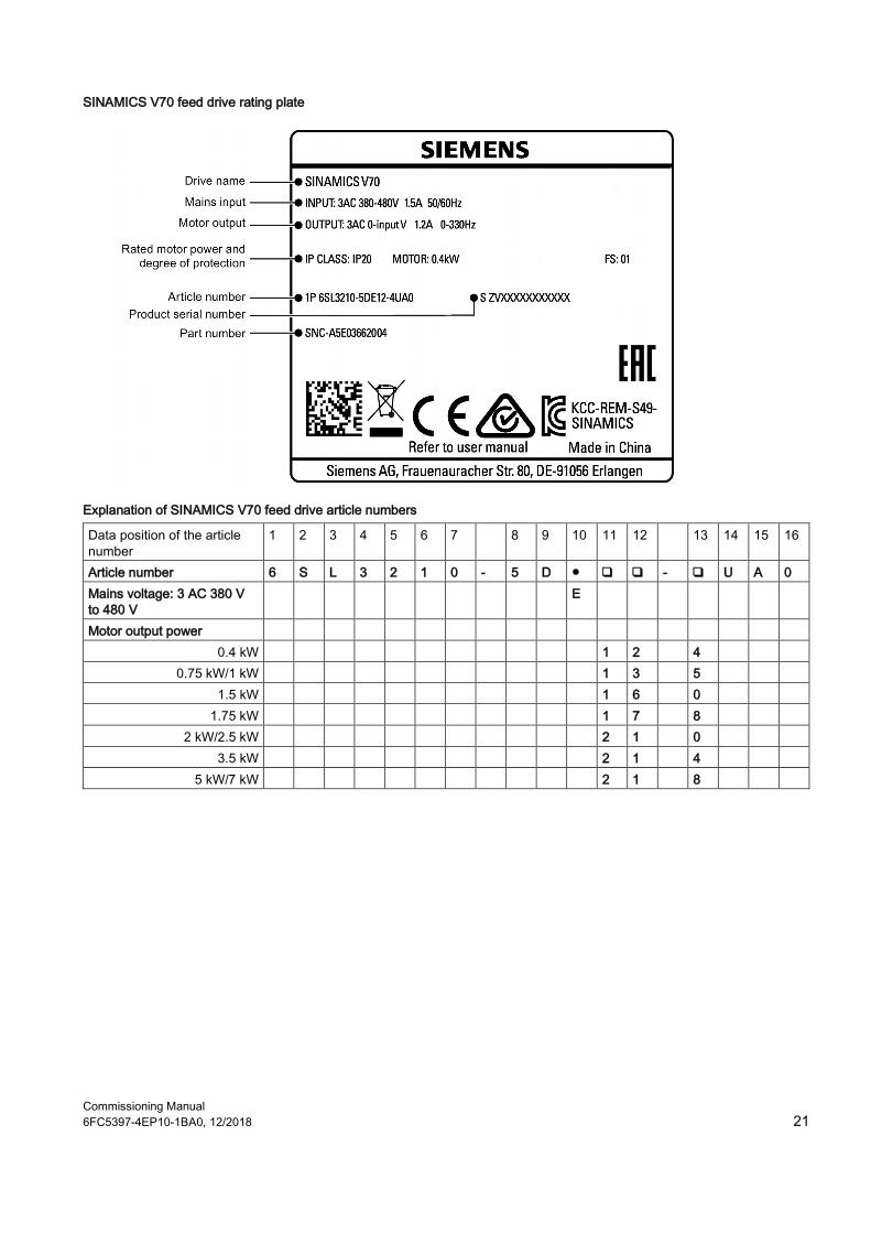
Commissioning Manual 6FC5397-4EP10-1BA0, 12/2018 21
SINAMICS V70 feed drive rating plate
Explanation of SINAMICS V70 feed drive article numbers
Data position of the article number
1 2 3 4 5 6 7 8 9 10 11 12 13 14 15 16
Article number 6 S L 3 2 1 0 - 5 D ● ❑ ❑ - ❑ U A 0 Mains voltage: 3 AC 380 V to 480 V
E
Motor output power 0.4 kW 1 2 4
0.75 kW/1 kW 1 3 5 1.5 kW 1 6 0
1.75 kW 1 7 8 2 kW/2.5 kW 2 1 0
3.5 kW 2 1 4 5 kW/7 kW 2 1 8

Commissioning Manual 22 6FC5397-4EP10-1BA0, 12/2018
Components in the SIMOTICS S-1FL6 motor package
Component Illustration Shaft height (mm) Stall torque (Nm) Article number 1) SIMOTICS S-1FL6 motor
45 1.9 1FL6042-1AF61-❑❑❑1 3.5 1FL6044-1AF61-❑❑❑1
65 4 1FL6061-1AC61-❑❑❑1 1FL6061-1AC64-2L❑1 2)
6 1FL6062-1AC61-❑❑❑1 1FL6062-1AC64-2L❑1 2)
8 1FL6064-1AC61-❑❑❑1 1FL6064-1AC64-2L❑1 2)
11 1FL6066-1AC61-❑❑❑1 1FL6066-1AC64-2L❑1 2)
15 1FL6067-1AC61-❑❑❑1 1FL6067-1AC64-2L❑1 2)
90 15 1FL6090-1AC61-❑❑❑1 22 1FL6092-1AC61-❑❑❑1 30 1FL6094-1AC61-❑❑❑1 40 1FL6096-1AC61-❑❑❑1
User documentation SIMOTICS S-1FL6 Servo Motors Installation Guide 1) For more information about article numbers, see motor article number explanation described later in this section.
2) ❑ = G or H only.
SIMOTICS S-1FL6 motor rating plate
① Motor type ⑩ Degree of protection
② Article number ⑪ Motor operating mode
③ Serial number ⑫ Stall current
④ Rated torque ⑬ Rated current
⑤ Stall torque ⑭ Holding brake
⑥ Rated voltage ⑮ Motor ID
⑦ Rated power ⑯ Weight
⑧ Encoder type and resolution ⑰ Maximum speed
⑨ Thermal class ⑱ Rated speed
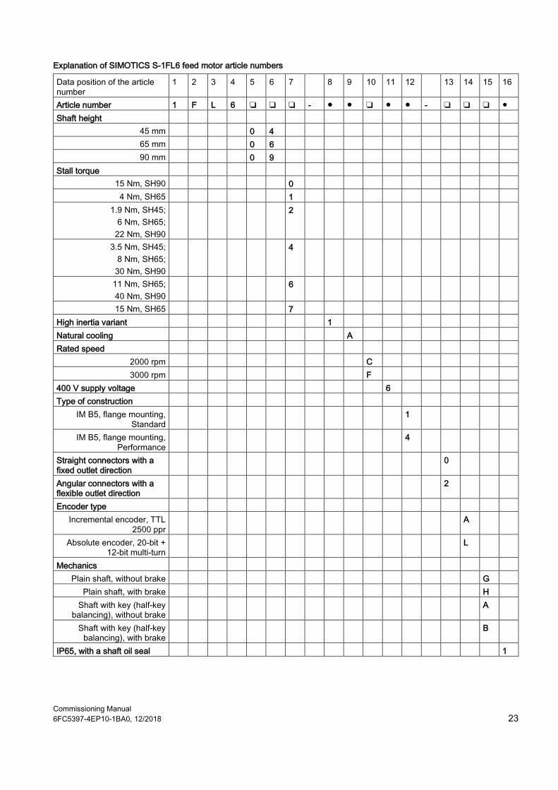
Commissioning Manual 6FC5397-4EP10-1BA0, 12/2018 23
Explanation of SIMOTICS S-1FL6 feed motor article numbers
Data position of the article number
1 2 3 4 5 6 7 8 9 10 11 12 13 14 15 16
Article number 1 F L 6 ❑ ❑ ❑ - ● ● ❑ ● ● - ❑ ❑ ❑ ● Shaft height
45 mm 0 4 65 mm 0 6 90 mm 0 9
Stall torque 15 Nm, SH90 0 4 Nm, SH65 1
1.9 Nm, SH45; 6 Nm, SH65;
22 Nm, SH90
2
3.5 Nm, SH45; 8 Nm, SH65;
30 Nm, SH90
4
11 Nm, SH65; 40 Nm, SH90
6
15 Nm, SH65 7 High inertia variant 1 Natural cooling A Rated speed
2000 rpm C 3000 rpm F
400 V supply voltage 6 Type of construction
IM B5, flange mounting, Standard
1
IM B5, flange mounting, Performance
4
Straight connectors with a fixed outlet direction
0
Angular connectors with a flexible outlet direction
2
Encoder type Incremental encoder, TTL
2500 ppr A
Absolute encoder, 20-bit + 12-bit multi-turn
L
Mechanics Plain shaft, without brake G
Plain shaft, with brake H Shaft with key (half-key
balancing), without brake A
Shaft with key (half-key balancing), with brake
B
IP65, with a shaft oil seal 1
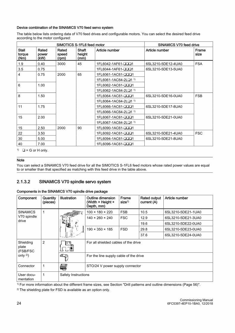
Commissioning Manual 24 6FC5397-4EP10-1BA0, 12/2018
Device combination of the SINAMICS V70 feed servo system
The table below lists ordering data of V70 feed drives and configurable motors. You can select the desired feed drive according to the motor configured:
SIMOTICS S-1FL6 feed motor SINAMICS V70 feed drive Stall torque (Nm)
Rated power (kW)
Rated speed (rpm)
Shaft height (mm)
Article number Article number Frame size
1.9 0.40 3000 45 1FL6042-1AF61-❑❑❑1 6SL3210-5DE12-4UA0 FSA 3.5 0.75 1FL6044-1AF61-❑❑❑1 6SL3210-5DE13-5UA0 4 0.75 2000 65 1FL6061-1AC61-❑❑❑1
1FL6061-1AC64-2L❑1 1) 6 1.00 1FL6062-1AC61-❑❑❑1
1FL6062-1AC64-2L❑1 1) 8 1.50 1FL6064-1AC61-❑❑❑1 6SL3210-5DE16-0UA0 FSB
1FL6064-1AC64-2L❑1 1) 11 1.75 1FL6066-1AC61-❑❑❑1 6SL3210-5DE17-8UA0
1FL6066-1AC64-2L❑1 1) 15 2.00 1FL6067-1AC61-❑❑❑1 6SL3210-5DE21-0UA0
1FL6067-1AC64-2L❑1 1) 15 2.50 2000 90 1FL6090-1AC61-❑❑❑1 22 3.50 1FL6092-1AC61-❑❑❑1 6SL3210-5DE21-4UA0 FSC 30 5.00 1FL6094-1AC61-❑❑❑1 6SL3210-5DE21-8UA0 40 7.00 1FL6096-1AC61-❑❑❑1 1) ❑ = G or H only.
Note You can select a SINAMICS V70 feed drive for all the SIMOTICS S-1FL6 feed motors whose rated power values are equal to or smaller than that specified as matching with this feed drive in the table above.
2.1.3.2 SINAMICS V70 spindle servo system
Components in the SINAMICS V70 spindle drive package
Component Quantity (pieces)
Illustration Outline dimension (Width × Height × Depth, mm)
Frame size1)
Rated output current (A)
Article number
SINAMICS V70 spindle drive
1
100 × 180 × 220 FSB 10.5 6SL3210-5DE21-1UA0 140 × 260 × 240 FSC 12.9 6SL3210-5DE21-3UA0
19.6 6SL3210-5DE22-0UA0 190 × 350 × 185 FSD 29.8 6SL3210-5DE23-0UA0
37.6 6SL3210-5DE24-0UA0
Shielding plate (FSB/FSC only 2))
2
For all shielded cables of the drive
For the line supply cable of the drive
Connector 1
STO/24 V power supply connector
User docu-mentation
1 Safety Instructions
1) For more information about the different frame sizes, see Section "Drill patterns and outline dimensions (Page 56)". 2) The shielding plate for FSD is available as an option only.
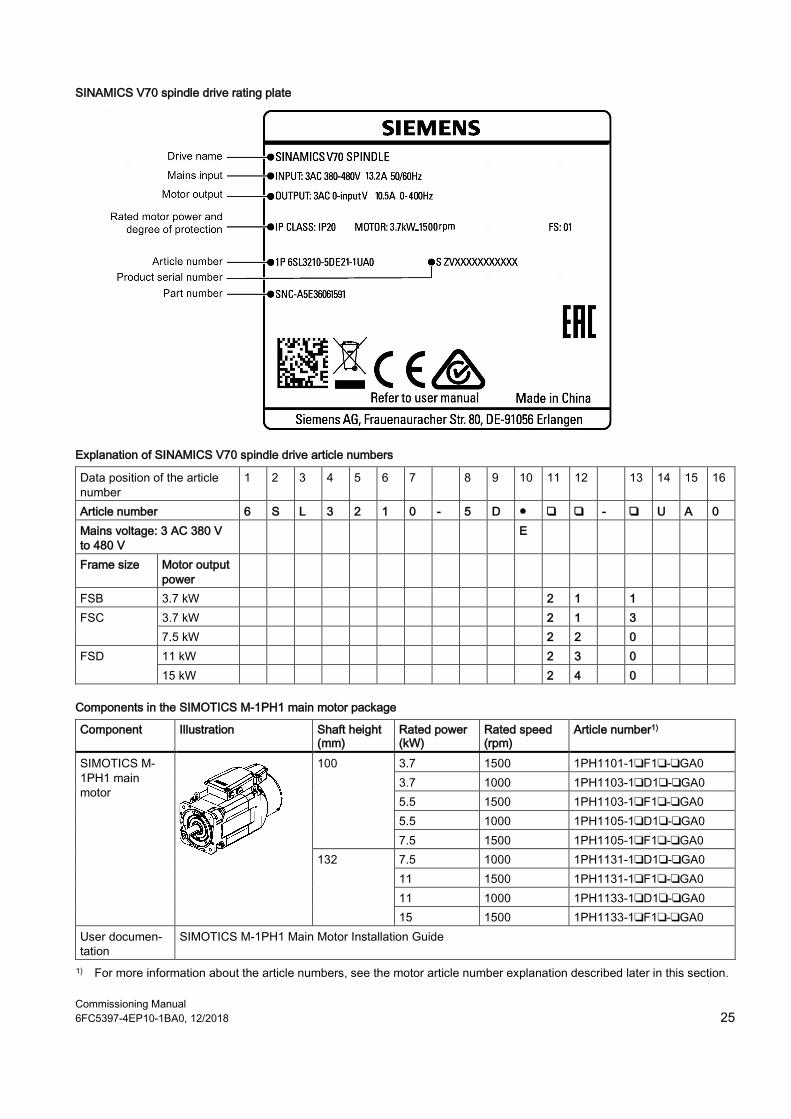
Commissioning Manual 6FC5397-4EP10-1BA0, 12/2018 25
SINAMICS V70 spindle drive rating plate
Explanation of SINAMICS V70 spindle drive article numbers
Data position of the article number
1 2 3 4 5 6 7 8 9 10 11 12 13 14 15 16
Article number 6 S L 3 2 1 0 - 5 D ● ❑ ❑ - ❑ U A 0 Mains voltage: 3 AC 380 V to 480 V
E
Frame size Motor output power
FSB 3.7 kW 2 1 1 FSC 3.7 kW 2 1 3
7.5 kW 2 2 0 FSD 11 kW 2 3 0
15 kW 2 4 0
Components in the SIMOTICS M-1PH1 main motor package
Component Illustration Shaft height (mm)
Rated power (kW)
Rated speed (rpm)
Article number1)
SIMOTICS M-1PH1 main motor
100 3.7 1500 1PH1101-1❑F1❑-❑GA0 3.7 1000 1PH1103-1❑D1❑-❑GA0 5.5 1500 1PH1103-1❑F1❑-❑GA0 5.5 1000 1PH1105-1❑D1❑-❑GA0 7.5 1500 1PH1105-1❑F1❑-❑GA0
132 7.5 1000 1PH1131-1❑D1❑-❑GA0 11 1500 1PH1131-1❑F1❑-❑GA0 11 1000 1PH1133-1❑D1❑-❑GA0 15 1500 1PH1133-1❑F1❑-❑GA0
User documen-tation
SIMOTICS M-1PH1 Main Motor Installation Guide
1) For more information about the article numbers, see the motor article number explanation described later in this section.
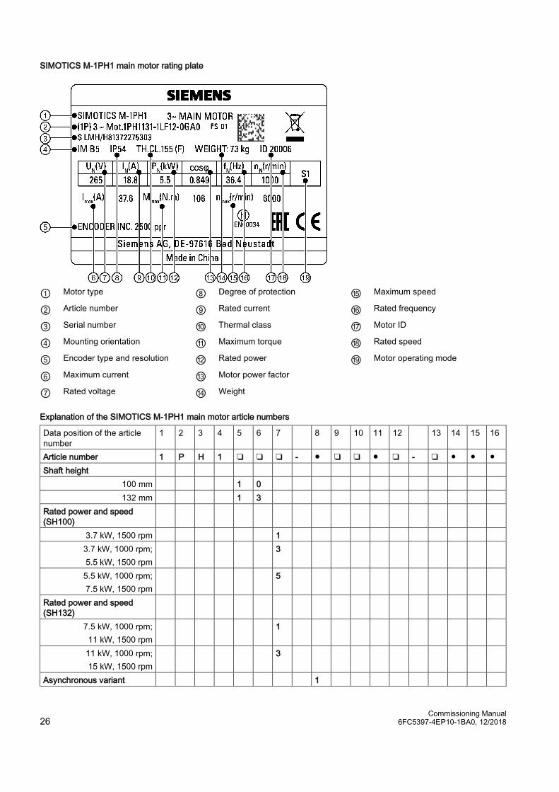
Commissioning Manual 26 6FC5397-4EP10-1BA0, 12/2018
SIMOTICS M-1PH1 main motor rating plate
① Motor type ⑧ Degree of protection ⑮ Maximum speed
② Article number ⑨ Rated current ⑯ Rated frequency
③ Serial number ⑩ Thermal class ⑰ Motor ID
④ Mounting orientation ⑪ Maximum torque ⑱ Rated speed
⑤ Encoder type and resolution ⑫ Rated power ⑲ Motor operating mode
⑥ Maximum current ⑬ Motor power factor
⑦ Rated voltage ⑭ Weight
Explanation of the SIMOTICS M-1PH1 main motor article numbers
Data position of the article number
1 2 3 4 5 6 7 8 9 10 11 12 13 14 15 16
Article number 1 P H 1 ❑ ❑ ❑ - ● ❑ ❑ ● ❑ - ❑ ● ● ● Shaft height
100 mm 1 0 132 mm 1 3
Rated power and speed (SH100)
3.7 kW, 1500 rpm 1 3.7 kW, 1000 rpm; 5.5 kW, 1500 rpm
3
5.5 kW, 1000 rpm; 7.5 kW, 1500 rpm
5
Rated power and speed (SH132)
7.5 kW, 1000 rpm; 11 kW, 1500 rpm
1
11 kW, 1000 rpm; 15 kW, 1500 rpm
3
Asynchronous variant 1
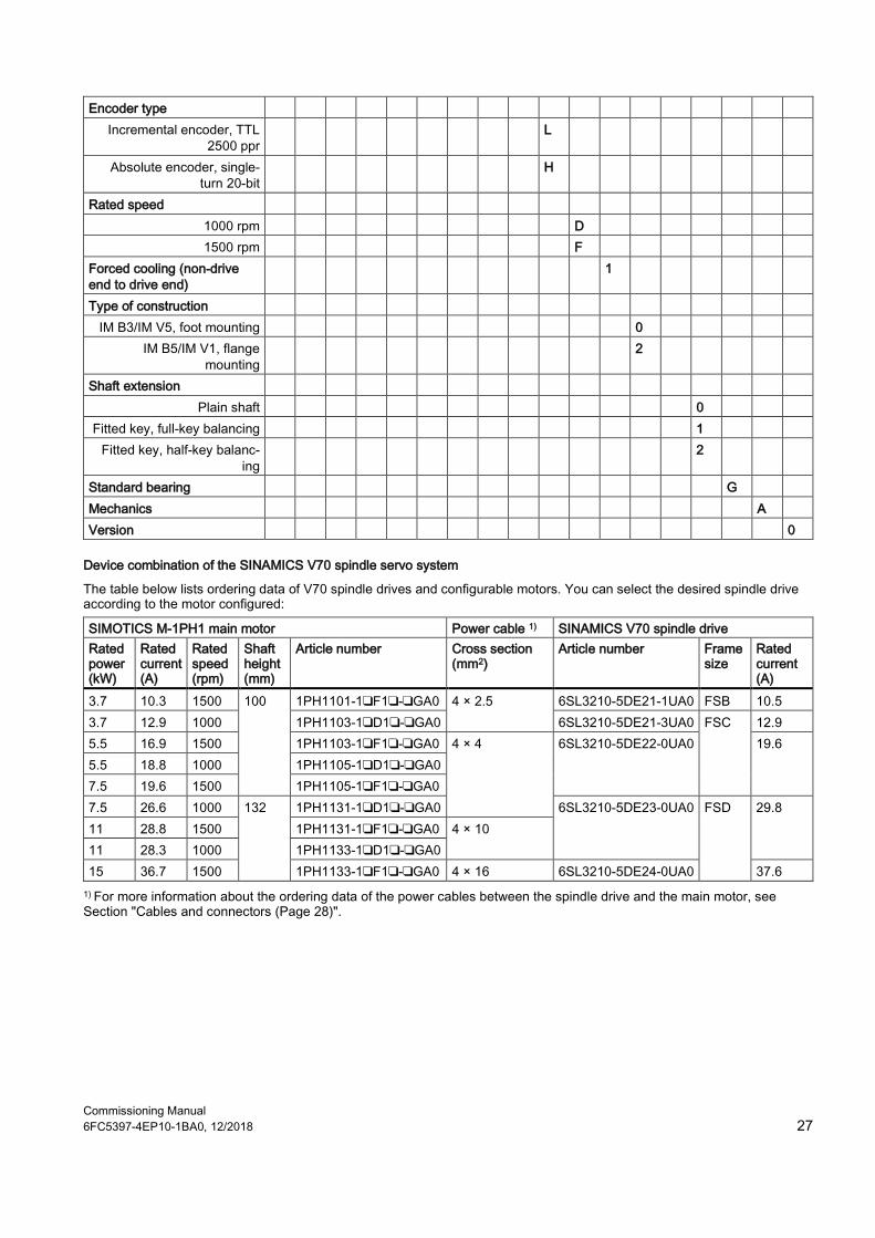
Commissioning Manual 6FC5397-4EP10-1BA0, 12/2018 27
Encoder type Incremental encoder, TTL
2500 ppr L
Absolute encoder, single-turn 20-bit
H
Rated speed 1000 rpm D 1500 rpm F
Forced cooling (non-drive end to drive end)
1
Type of construction IM B3/IM V5, foot mounting 0
IM B5/IM V1, flange mounting
2
Shaft extension Plain shaft 0
Fitted key, full-key balancing 1 Fitted key, half-key balanc-
ing 2
Standard bearing G Mechanics A Version 0
Device combination of the SINAMICS V70 spindle servo system
The table below lists ordering data of V70 spindle drives and configurable motors. You can select the desired spindle drive according to the motor configured:
SIMOTICS M-1PH1 main motor Power cable 1) SINAMICS V70 spindle drive Rated power (kW)
Rated current (A)
Rated speed (rpm)
Shaft height (mm)
Article number Cross section (mm2)
Article number Frame size
Rated current (A)
3.7 10.3 1500 100 1PH1101-1❑F1❑-❑GA0 4 × 2.5 6SL3210-5DE21-1UA0 FSB 10.5 3.7 12.9 1000 1PH1103-1❑D1❑-❑GA0 6SL3210-5DE21-3UA0 FSC 12.9 5.5 16.9 1500 1PH1103-1❑F1❑-❑GA0 4 × 4 6SL3210-5DE22-0UA0 19.6 5.5 18.8 1000 1PH1105-1❑D1❑-❑GA0 7.5 19.6 1500 1PH1105-1❑F1❑-❑GA0 7.5 26.6 1000 132 1PH1131-1❑D1❑-❑GA0 6SL3210-5DE23-0UA0 FSD 29.8 11 28.8 1500 1PH1131-1❑F1❑-❑GA0 4 × 10 11 28.3 1000 1PH1133-1❑D1❑-❑GA0 15 36.7 1500 1PH1133-1❑F1❑-❑GA0 4 × 16 6SL3210-5DE24-0UA0 37.6
1) For more information about the ordering data of the power cables between the spindle drive and the main motor, see Section "Cables and connectors (Page 28)".
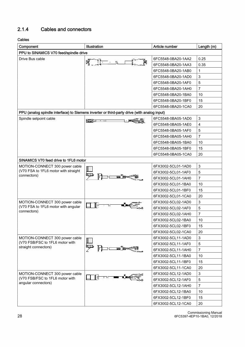
Commissioning Manual 28 6FC5397-4EP10-1BA0, 12/2018
2.1.4 Cables and connectors
Cables
Component Illustration Article number Length (m) PPU to SINAMICS V70 feed/spindle drive Drive Bus cable
6FC5548-0BA20-1AA2 0.25 6FC5548-0BA20-1AA3 0.35 6FC5548-0BA20-1AB0 1 6FC5548-0BA20-1AD0 3 6FC5548-0BA20-1AF0 5 6FC5548-0BA20-1AH0 7 6FC5548-0BA20-1BA0 10 6FC5548-0BA20-1BF0 15 6FC5548-0BA20-1CA0 20
PPU (analog spindle interface) to Siemens inverter or third-party drive (with analog input) Spindle setpoint cable
6FC5548-0BA05-1AD0 3 6FC5548-0BA05-1AE0 4 6FC5548-0BA05-1AF0 5 6FC5548-0BA05-1AH0 7 6FC5548-0BA05-1BA0 10 6FC5548-0BA05-1BF0 15 6FC5548-0BA05-1CA0 20
SINAMICS V70 feed drive to 1FL6 motor MOTION-CONNECT 300 power cable (V70 FSA to 1FL6 motor with straight connectors)
6FX3002-5CL01-1AD0 3 6FX3002-5CL01-1AF0 5 6FX3002-5CL01-1AH0 7 6FX3002-5CL01-1BA0 10 6FX3002-5CL01-1BF0 15 6FX3002-5CL01-1CA0 20
MOTION-CONNECT 300 power cable (V70 FSA to 1FL6 motor with angular connectors)
6FX3002-5CL02-1AD0 3 6FX3002-5CL02-1AF0 5 6FX3002-5CL02-1AH0 7 6FX3002-5CL02-1BA0 10 6FX3002-5CL02-1BF0 15 6FX3002-5CL02-1CA0 20
MOTION-CONNECT 300 power cable (V70 FSB/FSC to 1FL6 motor with straight connectors)
6FX3002-5CL11-1AD0 3 6FX3002-5CL11-1AF0 5 6FX3002-5CL11-1AH0 7 6FX3002-5CL11-1BA0 10 6FX3002-5CL11-1BF0 15 6FX3002-5CL11-1CA0 20
MOTION-CONNECT 300 power cable (V70 FSB/FSC to 1FL6 motor with angular connectors)
6FX3002-5CL12-1AD0 3 6FX3002-5CL12-1AF0 5 6FX3002-5CL12-1AH0 7 6FX3002-5CL12-1BA0 10 6FX3002-5CL12-1BF0 15 6FX3002-5CL12-1CA0 20

Commissioning Manual 6FC5397-4EP10-1BA0, 12/2018 29
Component Illustration Article number Length (m) MOTION-CONNECT 300 brake cable (V70 to 1FL6 motor with straight con-nectors)
6FX3002-5BL02-1AD0 3 6FX3002-5BL02-1AF0 5 6FX3002-5BL02-1AH0 7 6FX3002-5BL02-1BA0 10 6FX3002-5BL02-1BF0 15 6FX3002-5BL02-1CA0 20
MOTION-CONNECT 300 brake cable (V70 to 1FL6 motor with angular con-nectors)
6FX3002-5BL03-1AD0 3 6FX3002-5BL03-1AF0 5 6FX3002-5BL03-1AH0 7 6FX3002-5BL03-1BA0 10 6FX3002-5BL03-1BF0 15 6FX3002-5BL03-1CA0 20
MOTION-CONNECT 300 incremental encoder cable (V70 to 1FL6 motor with straight connectors)
6FX3002-2CT10-1AD0 3 6FX3002-2CT10-1AF0 5 6FX3002-2CT10-1AH0 7 6FX3002-2CT10-1BA0 10 6FX3002-2CT10-1BF0 15 6FX3002-2CT10-1CA0 20
MOTION-CONNECT 300 absolute encoder cable (V70 to 1FL6 motor with straight/angular connectors)
6FX3002-2DB10-1AD0 3 6FX3002-2DB10-1AF0 5 6FX3002-2DB10-1AH0 7 6FX3002-2DB10-1BA0 10 6FX3002-2DB10-1BF0 15 6FX3002-2DB10-1CA0 20
MOTION-CONNECT 300 incremental encoder cable (V70 to 1FL6 motor with angular connectors)
6FX3002-2CT12-1AD0 3 6FX3002-2CT12-1AF0 5 6FX3002-2CT12-1AH0 7 6FX3002-2CT12-1BA0 10 6FX3002-2CT12-1BF0 15 6FX3002-2CT12-1CA0 20
SINAMICS V70 spindle drive to 1PH1 motor MOTION-CONNECT 500 power cable (4 × 2.5 mm2, raw cable), for 1PH1 3.7 kW motor
6FX5008-1BB21-1DA0 30
MOTION-CONNECT 500 power cable (4 × 4 mm2, raw cable), for 1PH1 5.5 kW to 7.5 kW motor
6FX5008-1BB31-1DA0
MOTION-CONNECT 500 power cable (4 × 10 mm2, raw cable), for 1PH1 11 kW motor
6FX5008-1BB51-1DA0
MOTION-CONNECT 500 power cable (4 × 16 mm2, raw cable), for 1PH1 15 kW motor
6FX5008-1BB61-1DA0
MOTION-CONNECT 300 incremental encoder cable
6FX3002-2CT30-1AD0 3 6FX3002-2CT30-1AF0 5 6FX3002-2CT30-1AH0 7 6FX3002-2CT30-1BA0 10 6FX3002-2CT30-1BF0 15 6FX3002-2CT30-1CA0 20
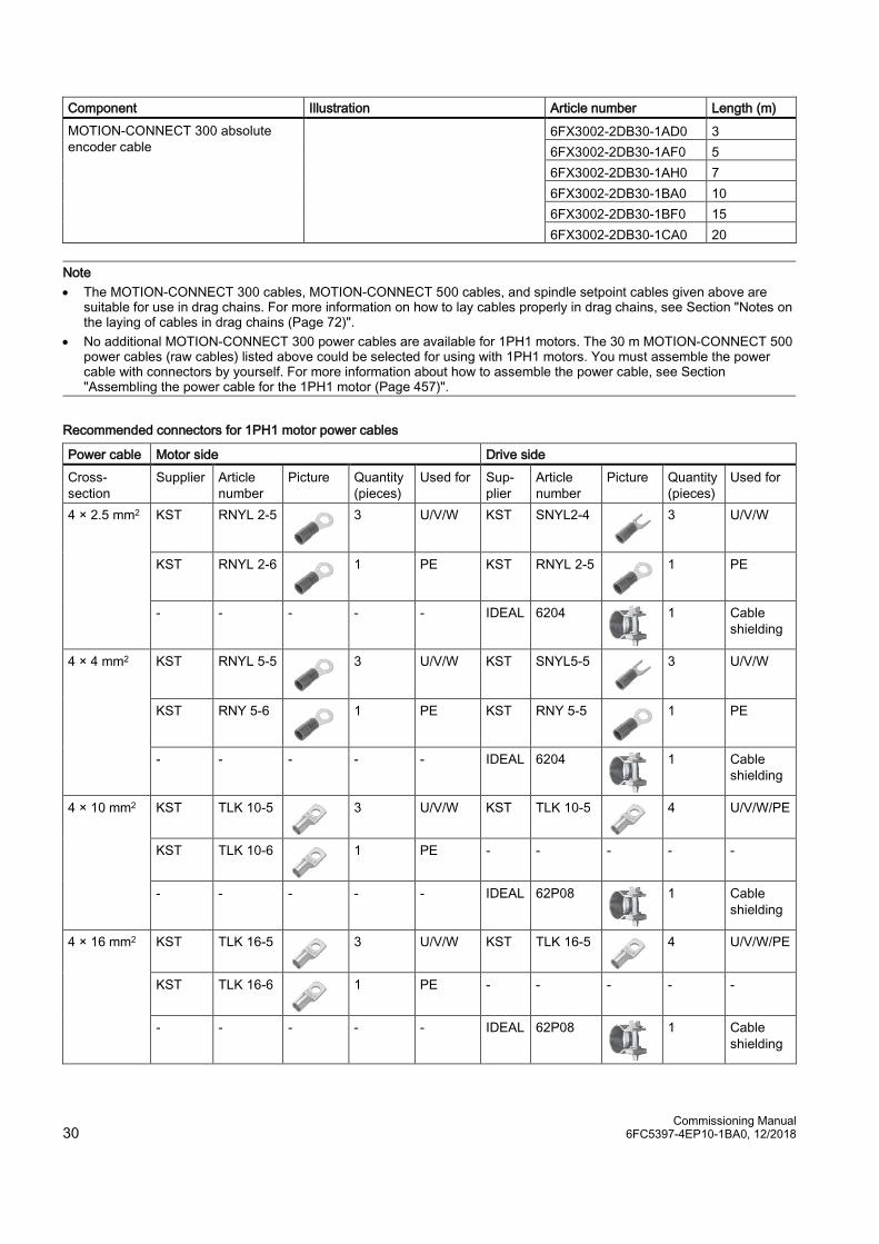
Commissioning Manual 30 6FC5397-4EP10-1BA0, 12/2018
Component Illustration Article number Length (m) MOTION-CONNECT 300 absolute encoder cable
6FX3002-2DB30-1AD0 3 6FX3002-2DB30-1AF0 5 6FX3002-2DB30-1AH0 7 6FX3002-2DB30-1BA0 10 6FX3002-2DB30-1BF0 15 6FX3002-2DB30-1CA0 20
Note • The MOTION-CONNECT 300 cables, MOTION-CONNECT 500 cables, and spindle setpoint cables given above are
suitable for use in drag chains. For more information on how to lay cables properly in drag chains, see Section "Notes on the laying of cables in drag chains (Page 72)".
• No additional MOTION-CONNECT 300 power cables are available for 1PH1 motors. The 30 m MOTION-CONNECT 500 power cables (raw cables) listed above could be selected for using with 1PH1 motors. You must assemble the power cable with connectors by yourself. For more information about how to assemble the power cable, see Section "Assembling the power cable for the 1PH1 motor (Page 457)".
Recommended connectors for 1PH1 motor power cables
Power cable Motor side Drive side Cross-section
Supplier Article number
Picture Quantity (pieces)
Used for Sup-plier
Article number
Picture Quantity (pieces)
Used for
4 × 2.5 mm2 KST RNYL 2-5
3 U/V/W KST SNYL2-4
3 U/V/W
KST RNYL 2-6
1 PE KST RNYL 2-5
1 PE
- - - - - IDEAL 6204
1 Cable shielding
4 × 4 mm2 KST RNYL 5-5
3 U/V/W KST SNYL5-5
3 U/V/W
KST RNY 5-6
1 PE KST RNY 5-5
1 PE
- - - - - IDEAL 6204
1 Cable shielding
4 × 10 mm2 KST TLK 10-5
3 U/V/W KST TLK 10-5
4 U/V/W/PE
KST TLK 10-6
1 PE - - - - -
- - - - - IDEAL 62P08
1 Cable shielding
4 × 16 mm2 KST TLK 16-5
3 U/V/W KST TLK 16-5
4 U/V/W/PE
KST TLK 16-6
1 PE - - - - -
- - - - - IDEAL 62P08
1 Cable shielding
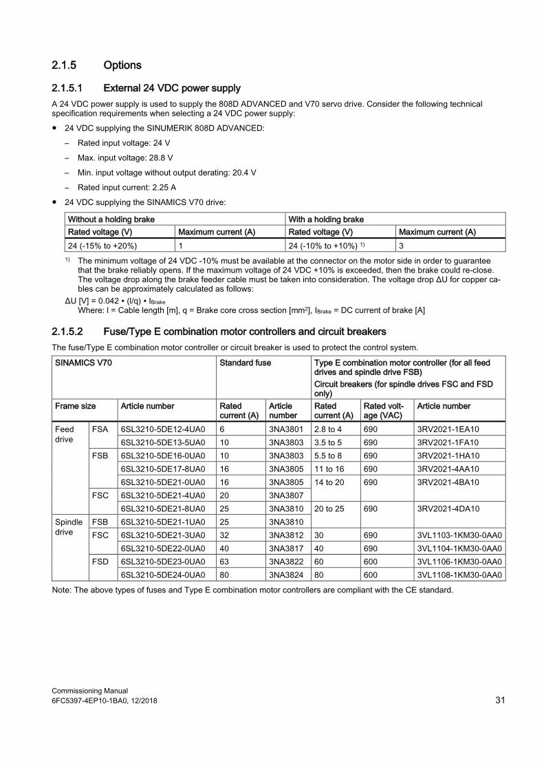
Commissioning Manual 6FC5397-4EP10-1BA0, 12/2018 31
2.1.5 Options
2.1.5.1 External 24 VDC power supply A 24 VDC power supply is used to supply the 808D ADVANCED and V70 servo drive. Consider the following technical specification requirements when selecting a 24 VDC power supply:
● 24 VDC supplying the SINUMERIK 808D ADVANCED:
– Rated input voltage: 24 V
– Max. input voltage: 28.8 V
– Min. input voltage without output derating: 20.4 V
– Rated input current: 2.25 A
● 24 VDC supplying the SINAMICS V70 drive:
Without a holding brake With a holding brake Rated voltage (V) Maximum current (A) Rated voltage (V) Maximum current (A) 24 (-15% to +20%) 1 24 (-10% to +10%) 1) 3 1) The minimum voltage of 24 VDC -10% must be available at the connector on the motor side in order to guarantee
that the brake reliably opens. If the maximum voltage of 24 VDC +10% is exceeded, then the brake could re-close. The voltage drop along the brake feeder cable must be taken into consideration. The voltage drop ΔU for copper ca-bles can be approximately calculated as follows:
ΔU [V] = 0.042 ∙ (l/q) ∙ IBrake Where: l = Cable length [m], q = Brake core cross section [mm2], IBrake = DC current of brake [A]
2.1.5.2 Fuse/Type E combination motor controllers and circuit breakers The fuse/Type E combination motor controller or circuit breaker is used to protect the control system.
SINAMICS V70 Standard fuse Type E combination motor controller (for all feed drives and spindle drive FSB) Circuit breakers (for spindle drives FSC and FSD only)
Frame size Article number Rated current (A)
Article number
Rated current (A)
Rated volt-age (VAC)
Article number
Feed drive
FSA 6SL3210-5DE12-4UA0 6 3NA3801 2.8 to 4 690 3RV2021-1EA10 6SL3210-5DE13-5UA0 10 3NA3803 3.5 to 5 690 3RV2021-1FA10
FSB 6SL3210-5DE16-0UA0 10 3NA3803 5.5 to 8 690 3RV2021-1HA10 6SL3210-5DE17-8UA0 16 3NA3805 11 to 16 690 3RV2021-4AA10 6SL3210-5DE21-0UA0 16 3NA3805 14 to 20 690 3RV2021-4BA10
FSC 6SL3210-5DE21-4UA0 20 3NA3807 6SL3210-5DE21-8UA0 25 3NA3810 20 to 25 690 3RV2021-4DA10
Spindle drive
FSB 6SL3210-5DE21-1UA0 25 3NA3810 FSC 6SL3210-5DE21-3UA0 32 3NA3812 30 690 3VL1103-1KM30-0AA0
6SL3210-5DE22-0UA0 40 3NA3817 40 690 3VL1104-1KM30-0AA0 FSD 6SL3210-5DE23-0UA0 63 3NA3822 60 600 3VL1106-1KM30-0AA0
6SL3210-5DE24-0UA0 80 3NA3824 80 600 3VL1108-1KM30-0AA0 Note: The above types of fuses and Type E combination motor controllers are compliant with the CE standard.

Commissioning Manual 32 6FC5397-4EP10-1BA0, 12/2018
2.1.5.3 Braking resistors A braking resistor is used for the SINAMICS V70 drive. For the feed drive, when the internal braking resistor cannot meet the braking requirements, an external braking resistor can be used to "dump" the regenerative energy produced by the motor, thus giving greatly improved braking and deceleration capabilities. For the spindle drive, an external braking resistor must be configured. Select a standard braking resistor according to the table below:
Drive frame size
Braking resistor Illustration Minimum re-
sistance (Ω) Max. power (kW) Rated power (W) Max. energy (kJ)
FSA
160 4 100 8 FSB 70 9.1 229 18.3 FSC 27 23.7 1185 189.6 FSD 18 37.4 1870 299.2 Note: When selecting a braking resistor, you must take into account the factors such as braking inertia, deceleration time,
speed variation, and braking period according to your specific application and technology. The resistance of the selected braking resistor must not be lower than the minimum resistance listed above.
2.1.5.4 Shielding plate To achieve EMC-compliant installation of the drive, use shielding plates to connect the cable shields. The shielding plate for V70 spindle drive FSD is provided as an option. While for V70 drives of other frame sizes, the shielding plates are provided at delivery.
Drive variant Article number Component Quantity V70 FSD 6SL3266-1ED00-0VA0 Shielding plate 2
M6 screws 4
Mounting dimensions (mm)

Commissioning Manual 6FC5397-4EP10-1BA0, 12/2018 33
Connecting
2.1.5.5 Line filters Siemens recommends you to use a filter to protect the system from high frequency noise.
The table below lists all filters recommended by Siemens:
SINAMICS V70 Recommended filter Drive vari-ant
Frame size
Rated input current (A)
Rated current (A)
Wire gauge (AWG)
Degree of protection
Article number
Feed drive FSA 1.5 5 15 to 13
IP20 6SL3203-0BE15-0VA0 FSA 3.8 5 IP20 FSB 5.8 12 15 to 14 IP20 6SL3203-0BE21-2VA0 FSB 6.6 12 IP20 FSB 9.8 12 IP20 FSC 13.8 20 11 to 10 IP20 6SL3203-0BE22-0VA0 FSC 16.5 20 IP20
Spindle drive
FSB 13.2 12 15 to 14 IP20 6SL3203-0BE21-2VA0 FSC 16.2 24 11 to 10 IP20 6SL3000-0HE21-0AA0 FSC 24.5 24 10 to 9 IP20 FSD 37.3 36 7 to 6 IP20 6SL3000-0BE21-6DA0 FSD 47 74 5 to 4 IP20 6SL3000-0BE23-6DA1

Commissioning Manual 34 6FC5397-4EP10-1BA0, 12/2018
Basic technical data
Rated current 5 A 12 A 20 A 24 A 36 A 74 A Rated voltage 3-phase 200 VAC to 480
VAC (-15% to +15%) 3-phase 380 VAC to 480 VAC (-15% to +15%)
3-phase 380 VAC to 480 VAC (-15% to +10%)
Line frequency 50/60 Hz (-10% to +10%) Product standard IEC 61800-5-1 Power loss < 2 W < 3 W < 7 W - Weight 0.68 kg 1.01 kg 1.33 kg - Package size (H × W × D)
140 mm × 200 mm × 260 mm
140 mm × 200 mm × 330 mm
-
Outline dimensions (unit: mm)
● Filter used for SINAMICS V70 feed drives and SINAMICS V70 spindle drives FSB:
Rated current (A)
W D W2 H H2 H1 H3 W1 Ø1
5 55 130 38 176.7 158 170 145 8.5 5 12 75 140 58 176.7 158 170 145 8.5 5 20 60 130 40 251.7 240 250 220 10 5.5
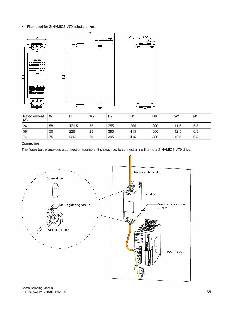
Commissioning Manual 6FC5397-4EP10-1BA0, 12/2018 35
● Filter used for SINAMICS V70 spindle drives:
Rated current (A)
W D W2 H2 H1 H3 W1 Ø1
24 58 121.5 35 255 265 200 11.5 5.5 36 50 226 25 395 415 380 12.5 6.5 74 75 226 50 395 415 380 12.5 6.5
Connecting
The figure below provides a connection example. It shows how to connect a line filter to a SINAMICS V70 drive.

Commissioning Manual 36 6FC5397-4EP10-1BA0, 12/2018
Filter rated current (A) Screw driver Max. tightening torque (Nm) Stripping length (mm) 5 Slot head (M3 screw) 0.8 8 12 20 24 Slot head (M4 screw) 1.5 10 36 2.4 11 74 Inside hexagon (M6 screw) 3.7 18
2.1.5.6 SD card An SD card can be used to copy drive parameters or perform a firmware update. Siemens recommends you to use the Siemens SD card (article number: 6SL3054-4AG00-2AA0).
You can also select other high quality SD cards with a maximum capacity of 2 GB from manufacturers such as KINGMAX, Kingston or SanDisk.
2.1.5.7 Toolbox DVD The Toolbox DVD (article number: 6FC5811-0CY00-0YA8) provides necessary software tools to integrate the control system into a machine tool. Under the Toolbox DVD root directory, it contains a file "setup.exe". After starting this file the program guides you through installing the following software on the computer:
● Access MyMachine
– Access MyMachine (AMM) is a tool that allows the commissioning engineer to exchange files between the computer and the control very easily through the Ethernet interface. For data transmission, the control can be connected to the computer directly or via the local network.
● PLC Programming Tool
– PLC Programming Tool makes a connection between the programming tool and the control system. The commissioning engineer can program and debug the PLC inside the control system.
● Config DATA
– Config_DATA contains the configuration data setup. The setup will install the configuration data for the control system to your computer. The configuration data consist of the Siemens examples, and the user documents.
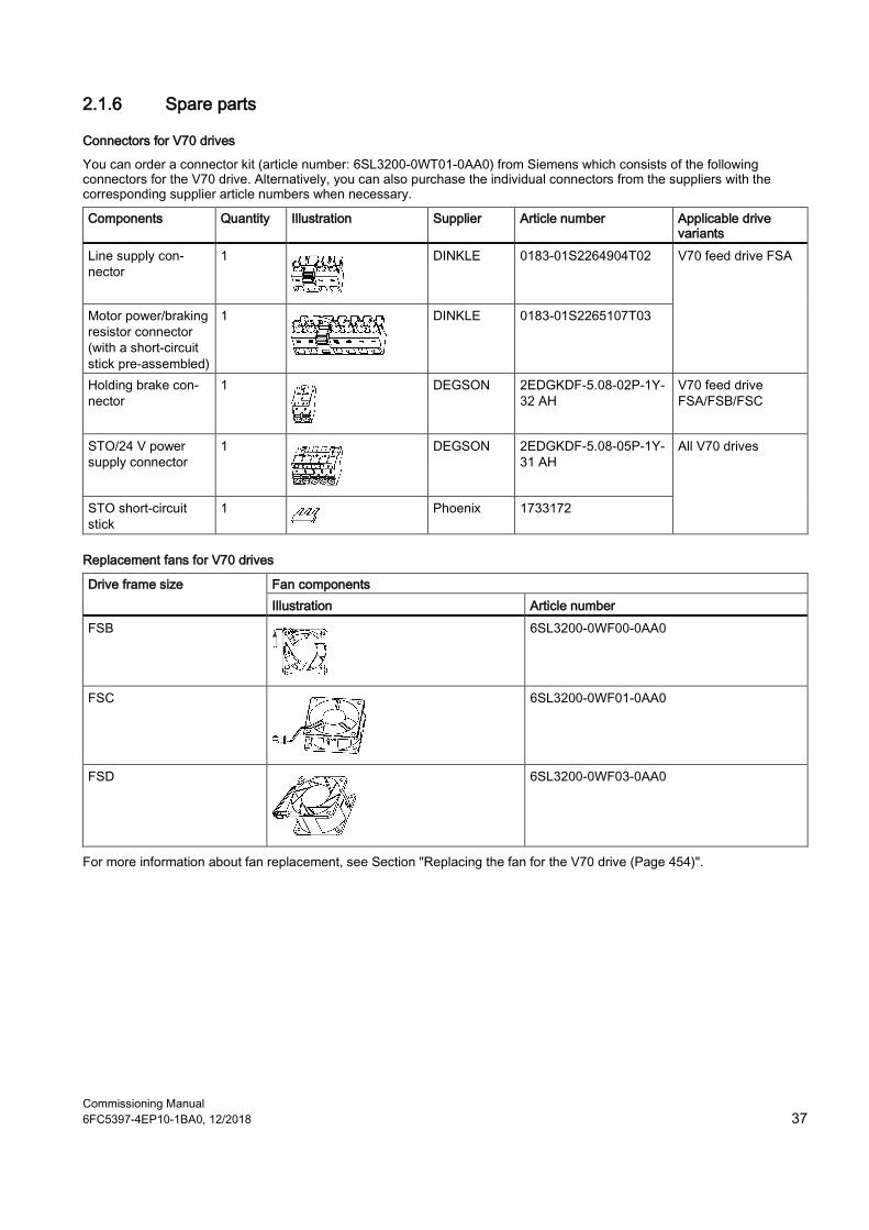
Commissioning Manual 6FC5397-4EP10-1BA0, 12/2018 37
2.1.6 Spare parts
Connectors for V70 drives
You can order a connector kit (article number: 6SL3200-0WT01-0AA0) from Siemens which consists of the following connectors for the V70 drive. Alternatively, you can also purchase the individual connectors from the suppliers with the corresponding supplier article numbers when necessary.
Components Quantity Illustration Supplier Article number Applicable drive variants
Line supply con-nector
1
DINKLE 0183-01S2264904T02 V70 feed drive FSA
Motor power/braking resistor connector (with a short-circuit stick pre-assembled)
1
DINKLE 0183-01S2265107T03
Holding brake con-nector
1
DEGSON 2EDGKDF-5.08-02P-1Y-32 AH
V70 feed drive FSA/FSB/FSC
STO/24 V power supply connector
1
DEGSON 2EDGKDF-5.08-05P-1Y-31 AH
All V70 drives
STO short-circuit stick
1
Phoenix 1733172
Replacement fans for V70 drives
Drive frame size Fan components Illustration Article number
FSB
6SL3200-0WF00-0AA0
FSC
6SL3200-0WF01-0AA0
FSD
6SL3200-0WF03-0AA0
For more information about fan replacement, see Section "Replacing the fan for the V70 drive (Page 454)".
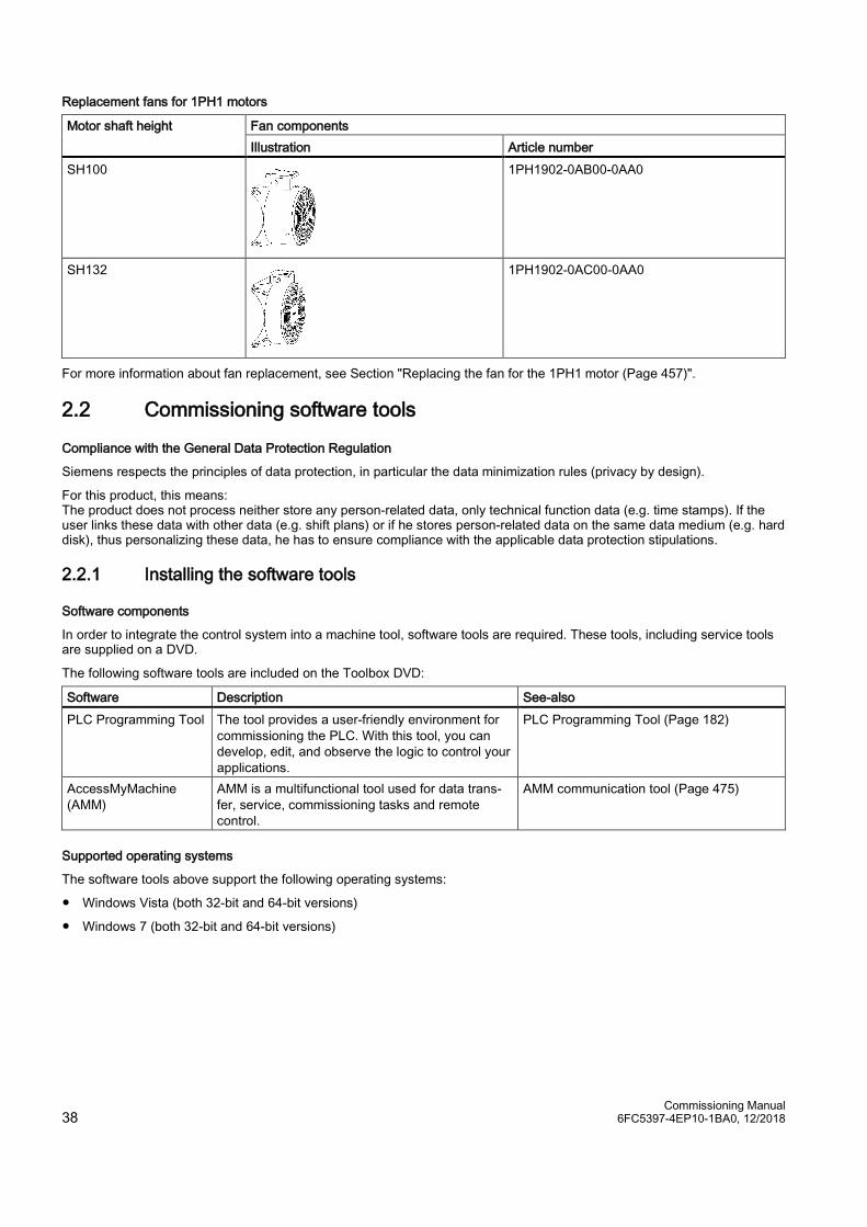
Commissioning Manual 38 6FC5397-4EP10-1BA0, 12/2018
Replacement fans for 1PH1 motors
Motor shaft height Fan components Illustration Article number
SH100
1PH1902-0AB00-0AA0
SH132
1PH1902-0AC00-0AA0
For more information about fan replacement, see Section "Replacing the fan for the 1PH1 motor (Page 457)".
2.2 Commissioning software tools
Compliance with the General Data Protection Regulation
Siemens respects the principles of data protection, in particular the data minimization rules (privacy by design).
For this product, this means: The product does not process neither store any person-related data, only technical function data (e.g. time stamps). If the user links these data with other data (e.g. shift plans) or if he stores person-related data on the same data medium (e.g. hard disk), thus personalizing these data, he has to ensure compliance with the applicable data protection stipulations.
2.2.1 Installing the software tools
Software components
In order to integrate the control system into a machine tool, software tools are required. These tools, including service tools are supplied on a DVD.
The following software tools are included on the Toolbox DVD:
Software Description See-also PLC Programming Tool The tool provides a user-friendly environment for
commissioning the PLC. With this tool, you can develop, edit, and observe the logic to control your applications.
PLC Programming Tool (Page 182)
AccessMyMachine (AMM)
AMM is a multifunctional tool used for data trans-fer, service, commissioning tasks and remote control.
AMM communication tool (Page 475)
Supported operating systems
The software tools above support the following operating systems:
● Windows Vista (both 32-bit and 64-bit versions)
● Windows 7 (both 32-bit and 64-bit versions)

Commissioning Manual 6FC5397-4EP10-1BA0, 12/2018 39
Installing the software
To install the software on your PC, proceed through the following steps:
1. Double-click the "Setup.exe" in the folder.
2. Read the welcome information and continue with "Next".
3. You can click the "Readme" button to read the indication information then close it and continue with "Next" or you can
skip the reading and click "Next" directly.
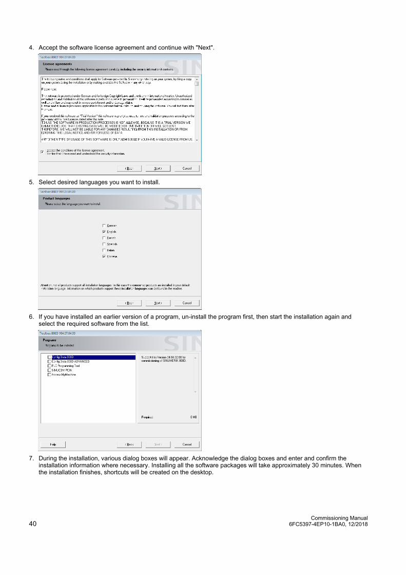
Commissioning Manual 40 6FC5397-4EP10-1BA0, 12/2018
4. Accept the software license agreement and continue with "Next".
5. Select desired languages you want to install.
6. If you have installed an earlier version of a program, un-install the program first, then start the installation again and
select the required software from the list.
7. During the installation, various dialog boxes will appear. Acknowledge the dialog boxes and enter and confirm the
installation information where necessary. Installing all the software packages will take approximately 30 minutes. When the installation finishes, shortcuts will be created on the desktop.
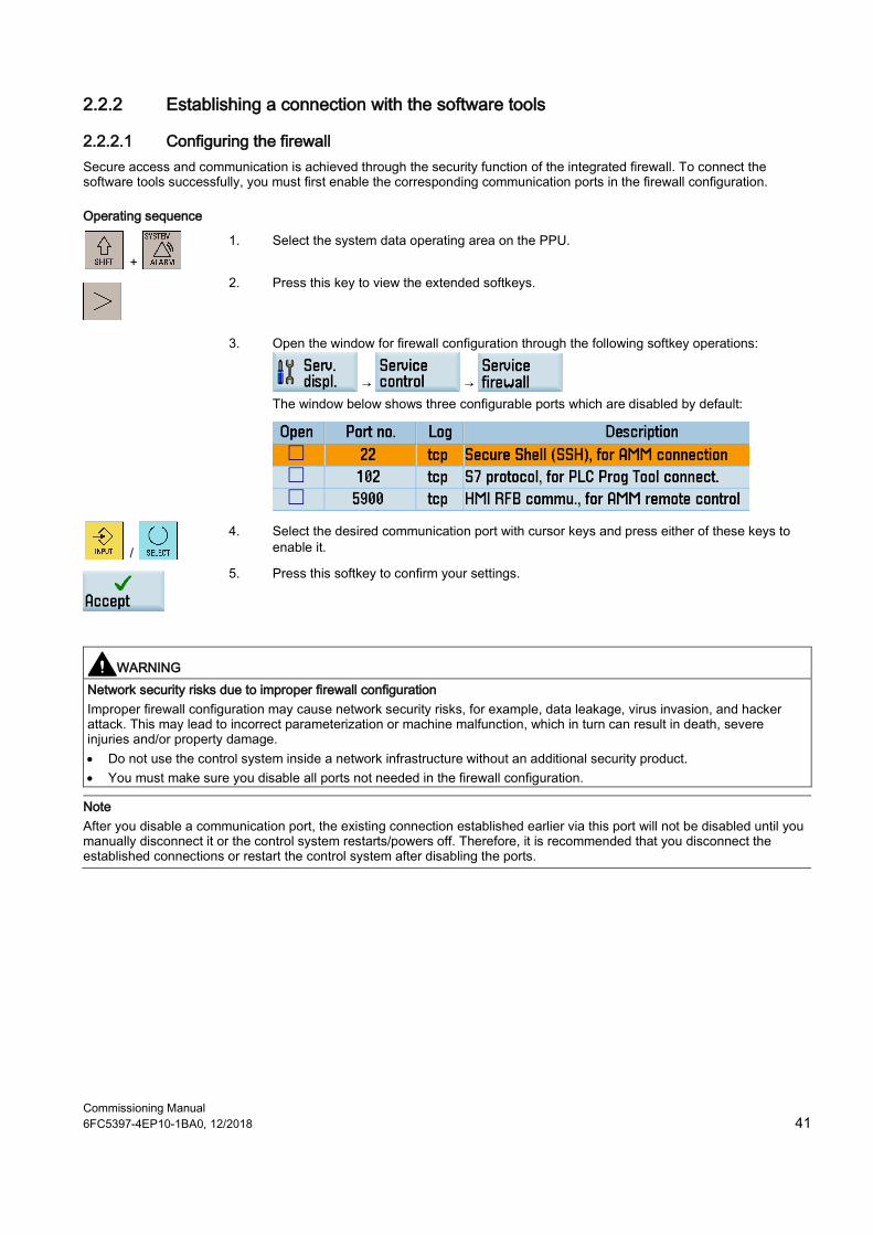
Commissioning Manual 6FC5397-4EP10-1BA0, 12/2018 41
2.2.2 Establishing a connection with the software tools
2.2.2.1 Configuring the firewall Secure access and communication is achieved through the security function of the integrated firewall. To connect the software tools successfully, you must first enable the corresponding communication ports in the firewall configuration.
Operating sequence
+ 1. Select the system data operating area on the PPU.
2. Press this key to view the extended softkeys.
3. Open the window for firewall configuration through the following softkey operations:
→ → The window below shows three configurable ports which are disabled by default:
/ 4. Select the desired communication port with cursor keys and press either of these keys to
enable it.
5. Press this softkey to confirm your settings.
WARNING Network security risks due to improper firewall configuration Improper firewall configuration may cause network security risks, for example, data leakage, virus invasion, and hacker attack. This may lead to incorrect parameterization or machine malfunction, which in turn can result in death, severe injuries and/or property damage. • Do not use the control system inside a network infrastructure without an additional security product. • You must make sure you disable all ports not needed in the firewall configuration.
Note After you disable a communication port, the existing connection established earlier via this port will not be disabled until you manually disconnect it or the control system restarts/powers off. Therefore, it is recommended that you disconnect the established connections or restart the control system after disabling the ports.
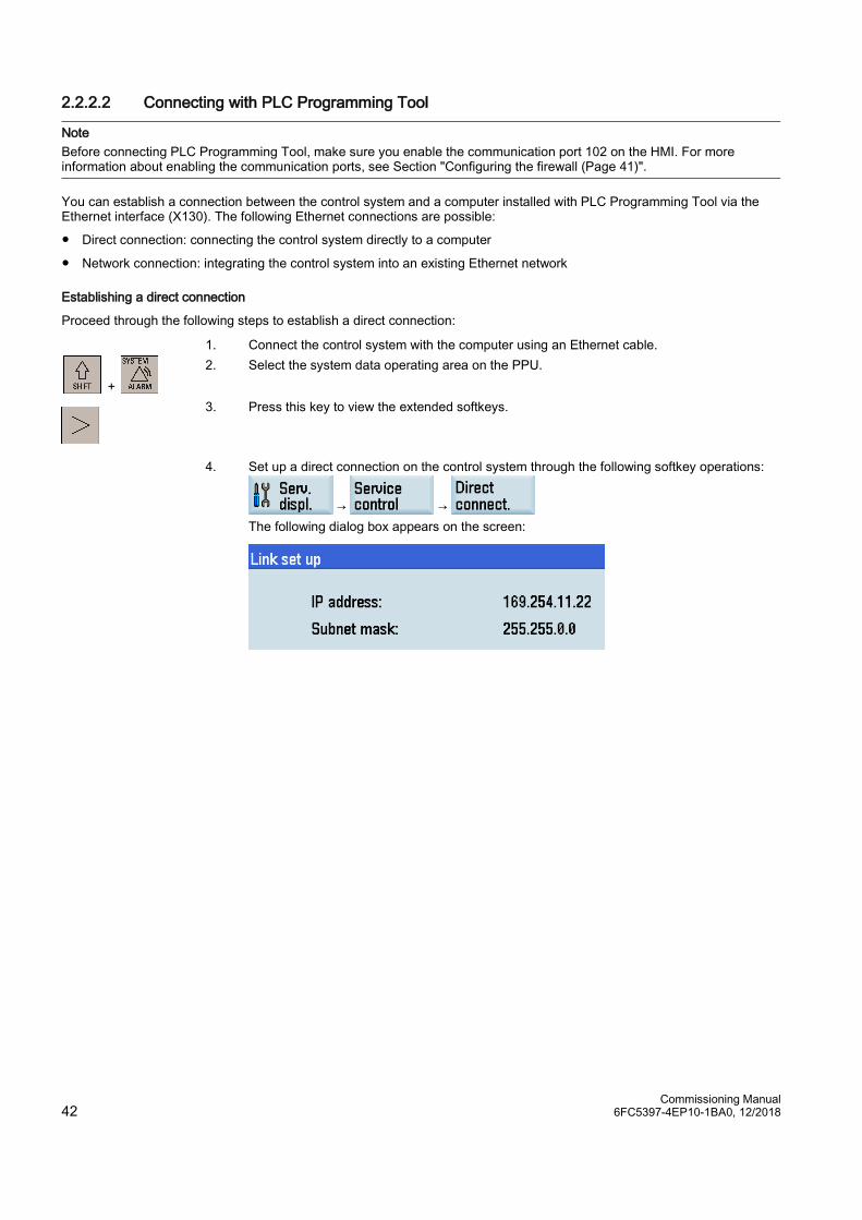
Commissioning Manual 42 6FC5397-4EP10-1BA0, 12/2018
2.2.2.2 Connecting with PLC Programming Tool
Note Before connecting PLC Programming Tool, make sure you enable the communication port 102 on the HMI. For more information about enabling the communication ports, see Section "Configuring the firewall (Page 41)".
You can establish a connection between the control system and a computer installed with PLC Programming Tool via the Ethernet interface (X130). The following Ethernet connections are possible:
● Direct connection: connecting the control system directly to a computer
● Network connection: integrating the control system into an existing Ethernet network
Establishing a direct connection
Proceed through the following steps to establish a direct connection:
1. Connect the control system with the computer using an Ethernet cable.
+ 2. Select the system data operating area on the PPU.
3. Press this key to view the extended softkeys.
4. Set up a direct connection on the control system through the following softkey operations:
→ → The following dialog box appears on the screen:

Commissioning Manual 6FC5397-4EP10-1BA0, 12/2018 43
5. Start PLC Programming Tool on your computer, and click the button in the toolbar to open the following dialog box:
6. Double-click the access point symbol, and the following "Set PG/PC Interface" dialog box is
displayed.
Select "TCP/IP" with the Ethernet card name of your computer and click the "OK" button. Note: You can find the name of your Ethernet card in the local area connection status under Control Panel on your computer.
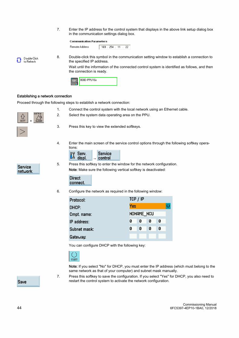
Commissioning Manual 44 6FC5397-4EP10-1BA0, 12/2018
7. Enter the IP address for the control system that displays in the above link setup dialog box in the communication settings dialog box.
8. Double-click this symbol in the communication setting window to establish a connection to
the specified IP address. Wait until the information of the connected control system is identified as follows, and then the connection is ready.
Establishing a network connection
Proceed through the following steps to establish a network connection:
1. Connect the control system with the local network using an Ethernet cable.
+ 2. Select the system data operating area on the PPU.
3. Press this key to view the extended softkeys.
4. Enter the main screen of the service control options through the following softkey opera-tions:
→
5. Press this softkey to enter the window for the network configuration. Note: Make sure the following vertical softkey is deactivated:
6. Configure the network as required in the following window:
You can configure DHCP with the following key:
Note: If you select "No" for DHCP, you must enter the IP address (which must belong to the same network as that of your computer) and subnet mask manually.
7. Press this softkey to save the configuration. If you select "Yes" for DHCP, you also need to restart the control system to activate the network configuration.
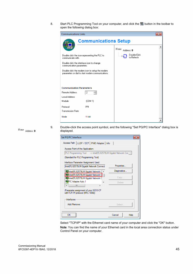
Commissioning Manual 6FC5397-4EP10-1BA0, 12/2018 45
8. Start PLC Programming Tool on your computer, and click the button in the toolbar to open the following dialog box:
9. Double-click the access point symbol, and the following "Set PG/PC Interface" dialog box is
displayed.
Select "TCP/IP" with the Ethernet card name of your computer and click the "OK" button. Note: You can find the name of your Ethernet card in the local area connection status under Control Panel on your computer.
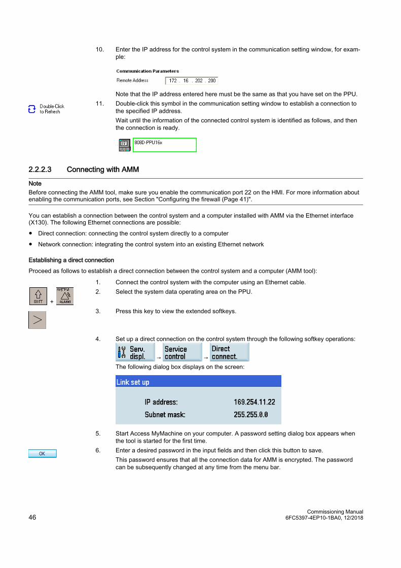
Commissioning Manual 46 6FC5397-4EP10-1BA0, 12/2018
10. Enter the IP address for the control system in the communication setting window, for exam-ple:
Note that the IP address entered here must be the same as that you have set on the PPU.
11. Double-click this symbol in the communication setting window to establish a connection to
the specified IP address. Wait until the information of the connected control system is identified as follows, and then the connection is ready.
2.2.2.3 Connecting with AMM
Note Before connecting the AMM tool, make sure you enable the communication port 22 on the HMI. For more information about enabling the communication ports, see Section "Configuring the firewall (Page 41)".
You can establish a connection between the control system and a computer installed with AMM via the Ethernet interface (X130). The following Ethernet connections are possible:
● Direct connection: connecting the control system directly to a computer
● Network connection: integrating the control system into an existing Ethernet network
Establishing a direct connection
Proceed as follows to establish a direct connection between the control system and a computer (AMM tool):
1. Connect the control system with the computer using an Ethernet cable.
+ 2. Select the system data operating area on the PPU.
3. Press this key to view the extended softkeys.
4. Set up a direct connection on the control system through the following softkey operations:
→ → The following dialog box displays on the screen:
5. Start Access MyMachine on your computer. A password setting dialog box appears when the tool is started for the first time.
6. Enter a desired password in the input fields and then click this button to save.
This password ensures that all the connection data for AMM is encrypted. The password can be subsequently changed at any time from the menu bar.
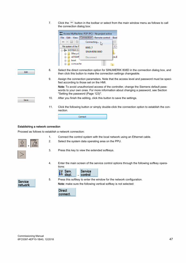
Commissioning Manual 6FC5397-4EP10-1BA0, 12/2018 47
7. Click the button in the toolbar or select from the main window menu as follows to call the connection dialog box:
8. Select the direct connection option for SINUMERIK 808D in the connection dialog box, and
then click this button to make the connection settings changeable.
9. Assign the connection parameters. Note that the access level and password must be speci-fied according to those set on the HMI. Note: To avoid unauthorized access of the controller, change the Siemens default pass-words to your own ones. For more information about changing a password, see Section "Setting the password (Page 123)".
10. After you finish the editing, click this button to save the settings.
11. Click the following button or simply double-click the connection option to establish the con-nection.
Establishing a network connection
Proceed as follows to establish a network connection:
1. Connect the control system with the local network using an Ethernet cable.
+ 2. Select the system data operating area on the PPU.
3. Press this key to view the extended softkeys.
4. Enter the main screen of the service control options through the following softkey opera-tions:
→
5. Press this softkey to enter the window for the network configuration. Note: make sure the following vertical softkey is not selected:
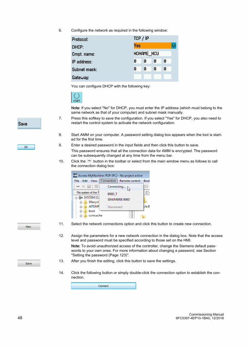
Commissioning Manual 48 6FC5397-4EP10-1BA0, 12/2018
6. Configure the network as required in the following window:
You can configure DHCP with the following key:
Note: If you select "No" for DHCP, you must enter the IP address (which must belong to the same network as that of your computer) and subnet mask manually.
7. Press this softkey to save the configuration. If you select "Yes" for DHCP, you also need to restart the control system to activate the network configuration.
8. Start AMM on your computer. A password setting dialog box appears when the tool is start-ed for the first time.
9. Enter a desired password in the input fields and then click this button to save.
This password ensures that all the connection data for AMM is encrypted. The password can be subsequently changed at any time from the menu bar.
10. Click the button in the toolbar or select from the main window menu as follows to call the connection dialog box:
11. Select the network connections option and click this button to create new connection.
12. Assign the parameters for a new network connection in the dialog box. Note that the access level and password must be specified according to those set on the HMI. Note: To avoid unauthorized access of the controller, change the Siemens default pass-words to your own ones. For more information about changing a password, see Section "Setting the password (Page 123)".
13. After you finish the editing, click this button to save the settings.
14. Click the following button or simply double-click the connection option to establish the con-nection.
Commissioning Manual 6FC5397-4EP10-1BA0, 12/2018 49
2.3 Personal computer A personal computer with the following basic configuration is necessary for commissioning:
● Operating system: Windows Vista (both 32-bit and 64-bit versions)/Windows 7 (both 32-bit and 64-bit versions)
● Hard drive capacity: > 40 GB
● Memory capacity: > 1 GB
● Ethernet interface: for NC, PLC, and drive commissioning
● RJ45 Ethernet cable
3 Mounting
WARNING Electric shock and danger to life when live parts are touched Death or serious injury can result when live parts are touched. • Only work on electrical devices when you are qualified for this job. • Always observe the country-specific safety rules. Before installing or removing the components of the control system, make sure that the system is disconnected from the mains.
WARNING Fire or electric shock due to inadequate protection class If the equipment operates in an area subject to inflammables or combustibles, water or corrosion hazards, it contains high risk of fire or electric shock. The fire or electric shock may lead to death or serious injury. Make sure that the control system is installed in a control cabinet with an adequate protection class.
Note When dimensioning the control cabinet, make sure that the installed components do not exceed the permissible surrounding air temperature, even if the outside temperature is high.
Note Fault of the wireless services caused by high-frequency faults in residential environments This product can cause high-frequency interferences in a residential environment that can require radio interference suppression measures. • Have the installation and commissioning with appropriate radio interference suppression measures performed by
qualified personnel.
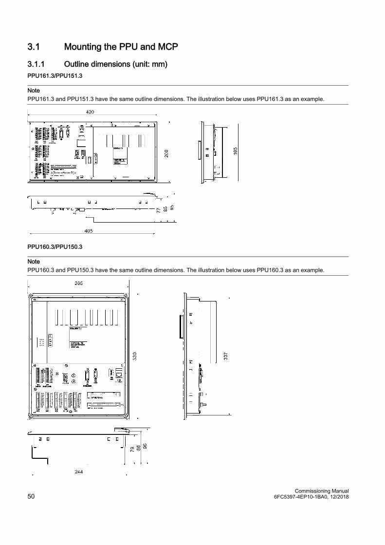
Commissioning Manual 50 6FC5397-4EP10-1BA0, 12/2018
3.1 Mounting the PPU and MCP
3.1.1 Outline dimensions (unit: mm) PPU161.3/PPU151.3
Note PPU161.3 and PPU151.3 have the same outline dimensions. The illustration below uses PPU161.3 as an example.
PPU160.3/PPU150.3
Note PPU160.3 and PPU150.3 have the same outline dimensions. The illustration below uses PPU160.3 as an example.

Commissioning Manual 6FC5397-4EP10-1BA0, 12/2018 51
Horizontal MCP
Note All horizontal MCP versions have the same outline dimensions. The illustration below uses the variant with override switches as an example.
* Not available on the horizontal MCP with a reserved slot for the handwheel
Vertical MCP
Note All vertical MCP versions have the same outline dimensions. The illustration below uses the variant with an override switch for the spindle as an example.

Commissioning Manual 52 6FC5397-4EP10-1BA0, 12/2018
3.1.2 Cut-out dimensions and mounting clearance
Note Make sure there is enough space around the PPU and the MCP for tightening the screws in the control cabinet.
Horizontal PPU and MCP (unit: mm)
Note The illustration below uses PPU161.3 and the horizontal MCP with a reserved slot for the handwheel as an example. All horizontal PPU/MCP versions share the same requirements for cut-out dimensions and mounting clearance.
To make maintenance easy, keep sufficient clearance (≥ 80 mm) between the system CF card slot and the cabinet wall. The recommended depth of the cabinet is greater than 155 mm.

Commissioning Manual 6FC5397-4EP10-1BA0, 12/2018 53
Vertical PPU and MCP (unit: mm)
Note All vertical MCP versions share the same requirements for cut-out dimensions and mounting clearance. The illustration below uses the vertical MCP with a reserved slot for the handwheel as an example.
Note When mounting a horizontal PPU together with a vertical MCP or vice versa, follow the requirement for the clearance between a vertical PPU and a vertical MCP shown above.
3.1.3 Mounting the PPU and MCP with the companion clamps Use the companion clamps (8 for PPU161.3/PPU151.3, 10 for PPU160.3/PPU150.3, 6 for the horizontal MCP, and 8 for the vertical MCP) to fix the PPU and MCP to the cabinet panel. You can find the mounting positions (circled) on the PPU and MCP. The distance between two mounting holes of each mounting position is 21 mm.
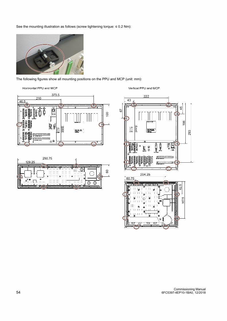
Commissioning Manual 54 6FC5397-4EP10-1BA0, 12/2018
See the mounting illustration as follows (screw tightening torque: ≤ 0.2 Nm):
The following figures show all mounting positions on the PPU and MCP (unit: mm):
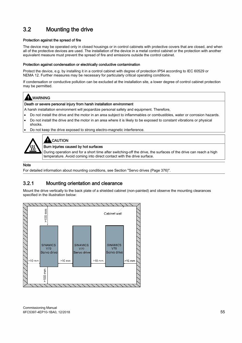
Commissioning Manual 6FC5397-4EP10-1BA0, 12/2018 55
3.2 Mounting the drive
Protection against the spread of fire
The device may be operated only in closed housings or in control cabinets with protective covers that are closed, and when all of the protective devices are used. The installation of the device in a metal control cabinet or the protection with another equivalent measure must prevent the spread of fire and emissions outside the control cabinet.
Protection against condensation or electrically conductive contamination
Protect the device, e.g. by installing it in a control cabinet with degree of protection IP54 according to IEC 60529 or NEMA 12. Further measures may be necessary for particularly critical operating conditions.
If condensation or conductive pollution can be excluded at the installation site, a lower degree of control cabinet protection may be permitted.
WARNING Death or severe personal injury from harsh installation environment A harsh installation environment will jeopardize personal safety and equipment. Therefore, • Do not install the drive and the motor in an area subject to inflammables or combustibles, water or corrosion hazards. • Do not install the drive and the motor in an area where it is likely to be exposed to constant vibrations or physical
shocks. • Do not keep the drive exposed to strong electro-magnetic interference.
CAUTION Burn injuries caused by hot surfaces During operation and for a short time after switching-off the drive, the surfaces of the drive can reach a high temperature. Avoid coming into direct contact with the drive surface.
Note For detailed information about mounting conditions, see Section "Servo drives (Page 376)".
3.2.1 Mounting orientation and clearance Mount the drive vertically to the back plate of a shielded cabinet (non-painted) and observe the mounting clearances specified in the illustration below:
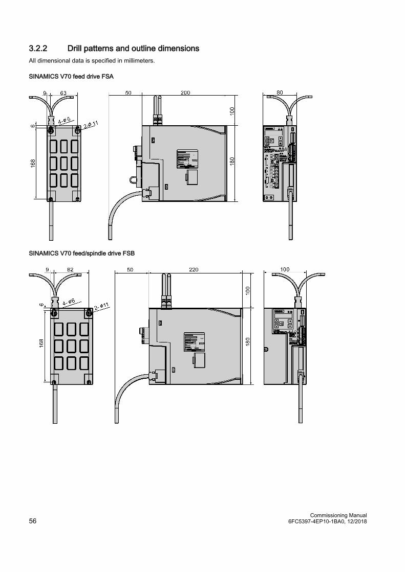
Commissioning Manual 56 6FC5397-4EP10-1BA0, 12/2018
3.2.2 Drill patterns and outline dimensions All dimensional data is specified in millimeters.
SINAMICS V70 feed drive FSA
SINAMICS V70 feed/spindle drive FSB

Commissioning Manual 6FC5397-4EP10-1BA0, 12/2018 57
SINAMICS V70 feed/spindle drive FSC
SINAMICS V70 spindle drive FSD

Commissioning Manual 58 6FC5397-4EP10-1BA0, 12/2018
3.2.3 Mounting the drive
Note EMC instructions • The SINAMICS V70 drives have been tested in accordance with the emission requirements of the category of C2
(residential) environment for FSA/FSB/FSC, and C3 (industrial) environment for FSD. The conducted emissions and radiated emissions are in compliance with the standard of EN 55011 and reached Class A for FSA/FSB/FSC and Class A2 for FSD.
• In a residential environment, this product can cause high-frequency interferences that may necessitate suppression measures.
• For a radiated emission test, an external AC filter (between the 380 VAC power supply and the drive) will be used to meet the EMC requirement and the drive will be installed inside the shielded metallic chamber, other parts of the motion control system (including the PLC, DC power supply, spindle drive, motor) will be put inside the shielded chamber.
• For a conductive emission test, an external AC filter (between the 380 VAC power supply and the drive) will be used to meet the EMC requirement.
• For the radiated emission and conductive emission test, the length of the line supply cable between the line filter and the drive must be shorter than 1 m.
Note Screw tightening After the drive installation is complete, make sure that you tighten the screw on the terminal door of the drive.
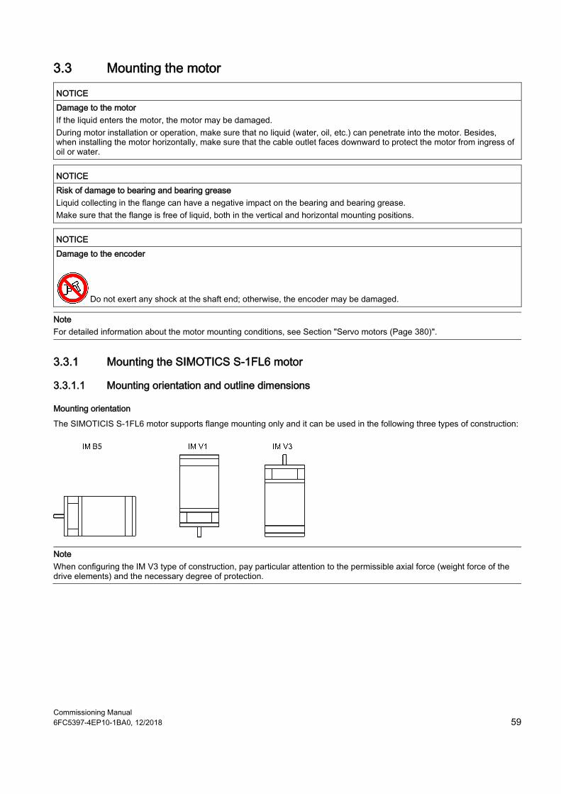
Commissioning Manual 6FC5397-4EP10-1BA0, 12/2018 59
3.3 Mounting the motor
NOTICE Damage to the motor If the liquid enters the motor, the motor may be damaged. During motor installation or operation, make sure that no liquid (water, oil, etc.) can penetrate into the motor. Besides, when installing the motor horizontally, make sure that the cable outlet faces downward to protect the motor from ingress of oil or water.
NOTICE Risk of damage to bearing and bearing grease Liquid collecting in the flange can have a negative impact on the bearing and bearing grease. Make sure that the flange is free of liquid, both in the vertical and horizontal mounting positions.
NOTICE Damage to the encoder
Do not exert any shock at the shaft end; otherwise, the encoder may be damaged.
Note For detailed information about the motor mounting conditions, see Section "Servo motors (Page 380)".
3.3.1 Mounting the SIMOTICS S-1FL6 motor
3.3.1.1 Mounting orientation and outline dimensions
Mounting orientation
The SIMOTICIS S-1FL6 motor supports flange mounting only and it can be used in the following three types of construction:
Note When configuring the IM V3 type of construction, pay particular attention to the permissible axial force (weight force of the drive elements) and the necessary degree of protection.
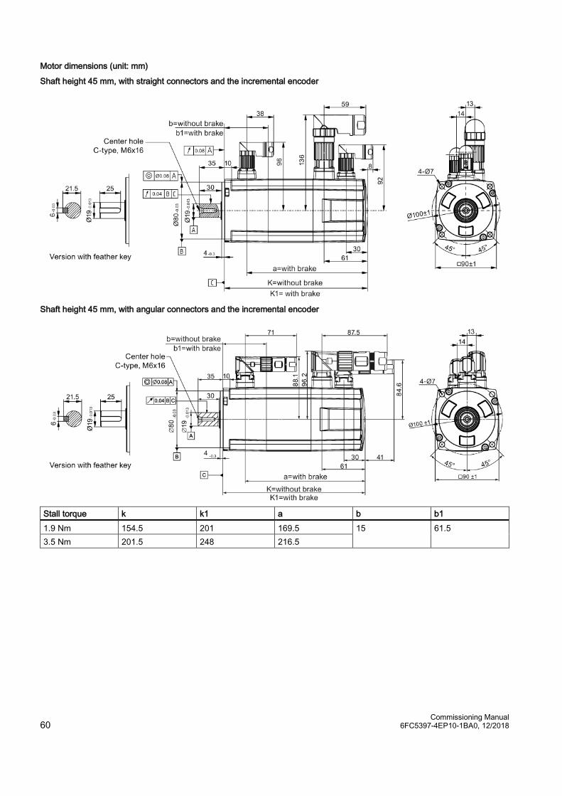
Commissioning Manual 60 6FC5397-4EP10-1BA0, 12/2018
Motor dimensions (unit: mm)
Shaft height 45 mm, with straight connectors and the incremental encoder
Shaft height 45 mm, with angular connectors and the incremental encoder
Stall torque k k1 a b b1 1.9 Nm 154.5 201 169.5 15 61.5 3.5 Nm 201.5 248 216.5

Commissioning Manual 6FC5397-4EP10-1BA0, 12/2018 61
Shaft height 45 mm, with straight connectors and the absolute encoder
Shaft height 45 mm, with angular connectors and the absolute encoder
Stall torque k k1 a b b1 1.9 Nm 157 203.5 172 15 61.5 3.5 Nm 204 250.5 219

Commissioning Manual 62 6FC5397-4EP10-1BA0, 12/2018
Shaft height 65 mm, with straight connectors and the incremental encoder
Shaft height 65 mm, with angular connectors and the incremental encoder
Stall torque k k1 a b b1 4 Nm 148 202.5 163 15 69.5 6 Nm 181 1)/164.5 2) 235.5 1)/219 2) 196 1)/179.5 2) 8 Nm 181 235.5 196 11 Nm 214 268.5 229 15 Nm 247 301.5 262 1) For the motor variants with straight connectors;
2) For the motor variants with angular connectors.
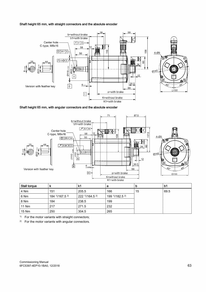
Commissioning Manual 6FC5397-4EP10-1BA0, 12/2018 63
Shaft height 65 mm, with straight connectors and the absolute encoder
Shaft height 65 mm, with angular connectors and the absolute encoder
Stall torque k k1 a b b1 4 Nm 151 205.5 166 15 69.5 6 Nm 184 1)/167.5 2) 222 1)/164.5 2) 199 1)/182.5 2) 8 Nm 184 238.5 199 11 Nm 217 271.5 232 15 Nm 250 304.5 265 1) For the motor variants with straight connectors;
2) For the motor variants with angular connectors.
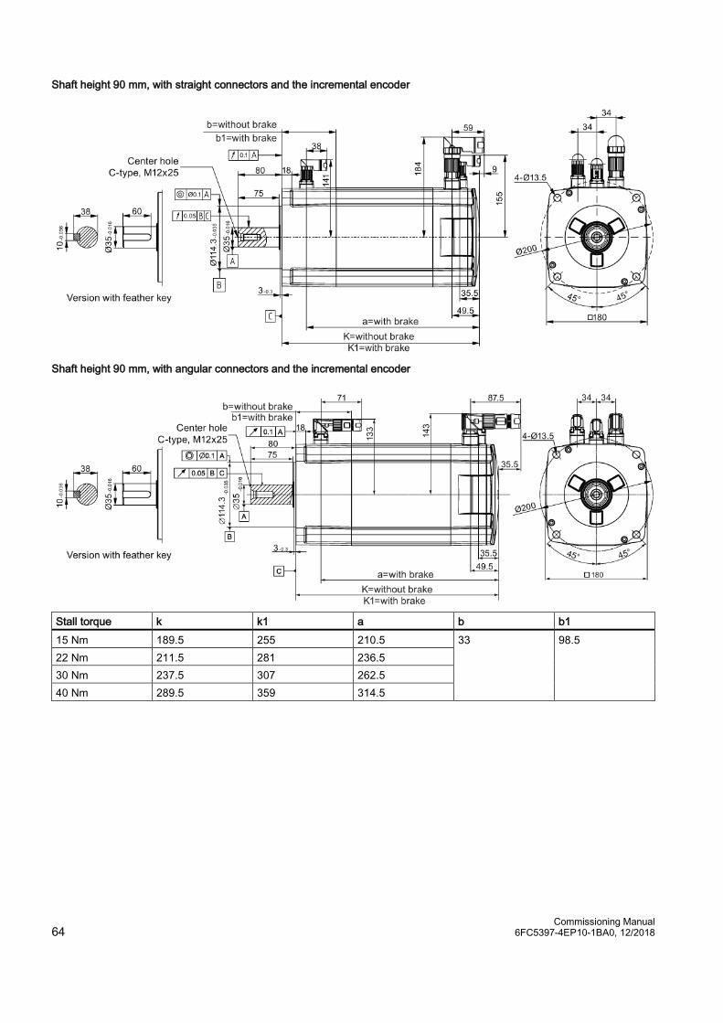
Commissioning Manual 64 6FC5397-4EP10-1BA0, 12/2018
Shaft height 90 mm, with straight connectors and the incremental encoder
Shaft height 90 mm, with angular connectors and the incremental encoder
Stall torque k k1 a b b1 15 Nm 189.5 255 210.5 33 98.5 22 Nm 211.5 281 236.5 30 Nm 237.5 307 262.5 40 Nm 289.5 359 314.5

Commissioning Manual 6FC5397-4EP10-1BA0, 12/2018 65
Shaft height 90 mm, with straight connectors and the absolute encoder
Shaft height 90 mm, with angular connectors and the absolute encoder
Stall torque k k1 a b b1 15 Nm 197 263 218 33 98.5 22 Nm 223 289 244 30 Nm 249 315 270 40 Nm 301 367 322
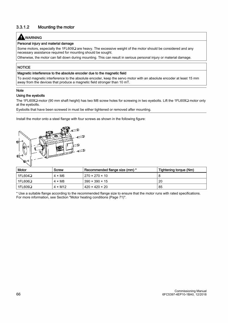
Commissioning Manual 66 6FC5397-4EP10-1BA0, 12/2018
3.3.1.2 Mounting the motor
WARNING Personal injury and material damage Some motors, especially the 1FL609❑ are heavy. The excessive weight of the motor should be considered and any necessary assistance required for mounting should be sought. Otherwise, the motor can fall down during mounting. This can result in serious personal injury or material damage.
NOTICE Magnetic interference to the absolute encoder due to the magnetic field To avoid magnetic interference to the absolute encoder, keep the servo motor with an absolute encoder at least 15 mm away from the devices that produce a magnetic field stronger than 10 mT.
Note Using the eyebolts The 1FL609❑ motor (90 mm shaft height) has two M8 screw holes for screwing in two eyebolts. Lift the 1FL609❑ motor only at the eyebolts. Eyebolts that have been screwed in must be either tightened or removed after mounting.
Install the motor onto a steel flange with four screws as shown in the following figure:
Motor Screw Recommended flange size (mm) * Tightening torque (Nm) 1FL604❑ 4 × M6 270 × 270 × 10 8 1FL606❑ 4 × M8 390 × 390 × 15 20 1FL609❑ 4 × M12 420 × 420 × 20 85
* Use a suitable flange according to the recommended flange size to ensure that the motor runs with rated specifications. For more information, see Section "Motor heating conditions (Page 71)".
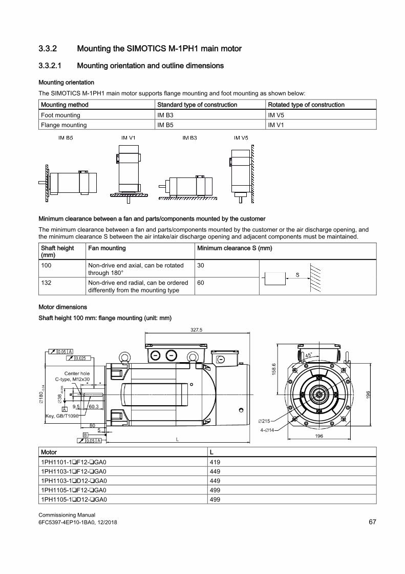
Commissioning Manual 6FC5397-4EP10-1BA0, 12/2018 67
3.3.2 Mounting the SIMOTICS M-1PH1 main motor
3.3.2.1 Mounting orientation and outline dimensions
Mounting orientation
The SIMOTICS M-1PH1 main motor supports flange mounting and foot mounting as shown below:
Mounting method Standard type of construction Rotated type of construction Foot mounting IM B3 IM V5 Flange mounting IM B5 IM V1
Minimum clearance between a fan and parts/components mounted by the customer
The minimum clearance between a fan and parts/components mounted by the customer or the air discharge opening, and the minimum clearance S between the air intake/air discharge opening and adjacent components must be maintained.
Shaft height (mm)
Fan mounting Minimum clearance S (mm)
100 Non-drive end axial, can be rotated through 180°
30
132 Non-drive end radial, can be ordered
differently from the mounting type 60
Motor dimensions
Shaft height 100 mm: flange mounting (unit: mm)
Motor L 1PH1101-1❑F12-❑GA0 419 1PH1103-1❑F12-❑GA0 449 1PH1103-1❑D12-❑GA0 449 1PH1105-1❑F12-❑GA0 499 1PH1105-1❑D12-❑GA0 499
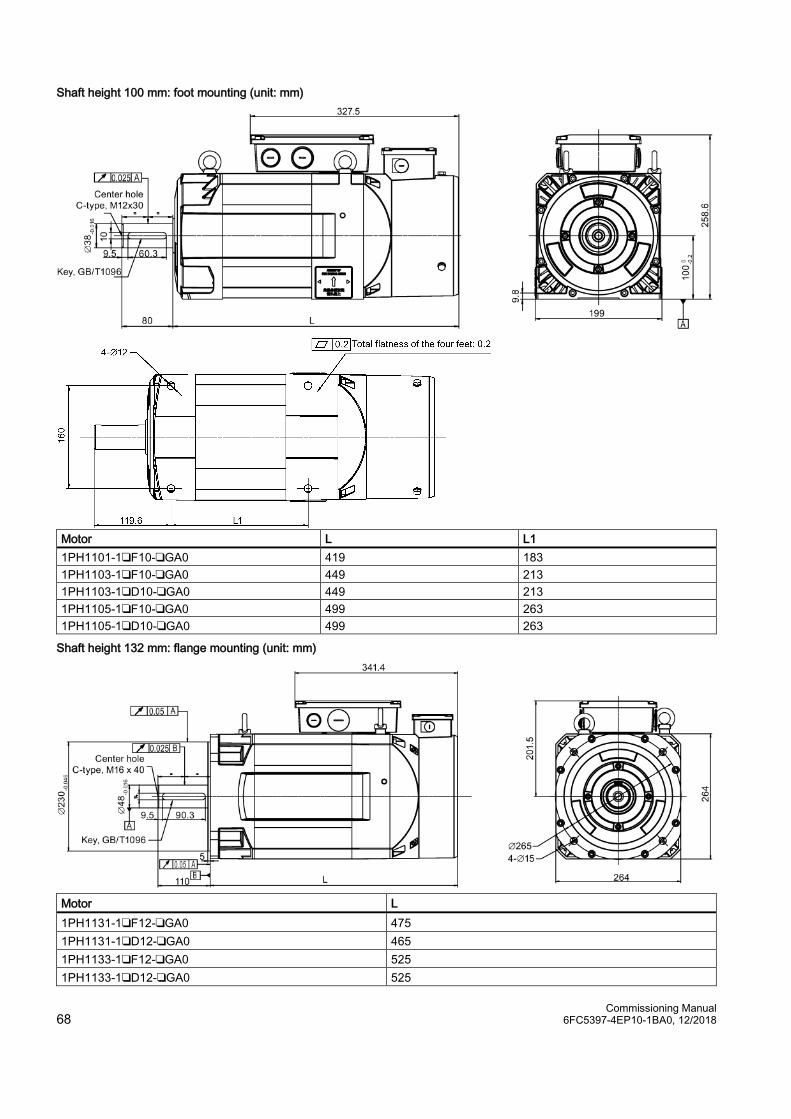
Commissioning Manual 68 6FC5397-4EP10-1BA0, 12/2018
Shaft height 100 mm: foot mounting (unit: mm)
Motor L L1 1PH1101-1❑F10-❑GA0 419 183 1PH1103-1❑F10-❑GA0 449 213 1PH1103-1❑D10-❑GA0 449 213 1PH1105-1❑F10-❑GA0 499 263 1PH1105-1❑D10-❑GA0 499 263
Shaft height 132 mm: flange mounting (unit: mm)
Motor L 1PH1131-1❑F12-❑GA0 475 1PH1131-1❑D12-❑GA0 465 1PH1133-1❑F12-❑GA0 525 1PH1133-1❑D12-❑GA0 525
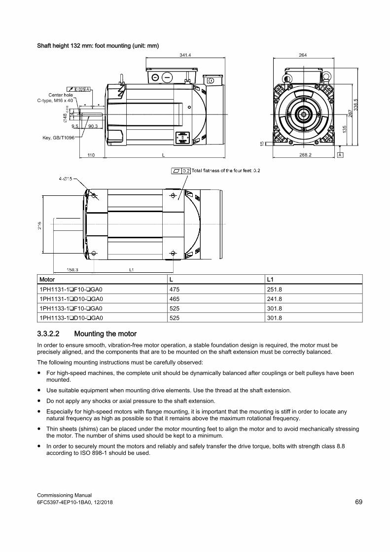
Commissioning Manual 6FC5397-4EP10-1BA0, 12/2018 69
Shaft height 132 mm: foot mounting (unit: mm)
Motor L L1 1PH1131-1❑F10-❑GA0 475 251.8 1PH1131-1❑D10-❑GA0 465 241.8 1PH1133-1❑F10-❑GA0 525 301.8 1PH1133-1❑D10-❑GA0 525 301.8
3.3.2.2 Mounting the motor In order to ensure smooth, vibration-free motor operation, a stable foundation design is required, the motor must be precisely aligned, and the components that are to be mounted on the shaft extension must be correctly balanced.
The following mounting instructions must be carefully observed:
● For high-speed machines, the complete unit should be dynamically balanced after couplings or belt pulleys have been mounted.
● Use suitable equipment when mounting drive elements. Use the thread at the shaft extension.
● Do not apply any shocks or axial pressure to the shaft extension.
● Especially for high-speed motors with flange mounting, it is important that the mounting is stiff in order to locate any natural frequency as high as possible so that it remains above the maximum rotational frequency.
● Thin sheets (shims) can be placed under the motor mounting feet to align the motor and to avoid mechanically stressing the motor. The number of shims used should be kept to a minimum.
● In order to securely mount the motors and reliably and safely transfer the drive torque, bolts with strength class 8.8 according to ISO 898-1 should be used.
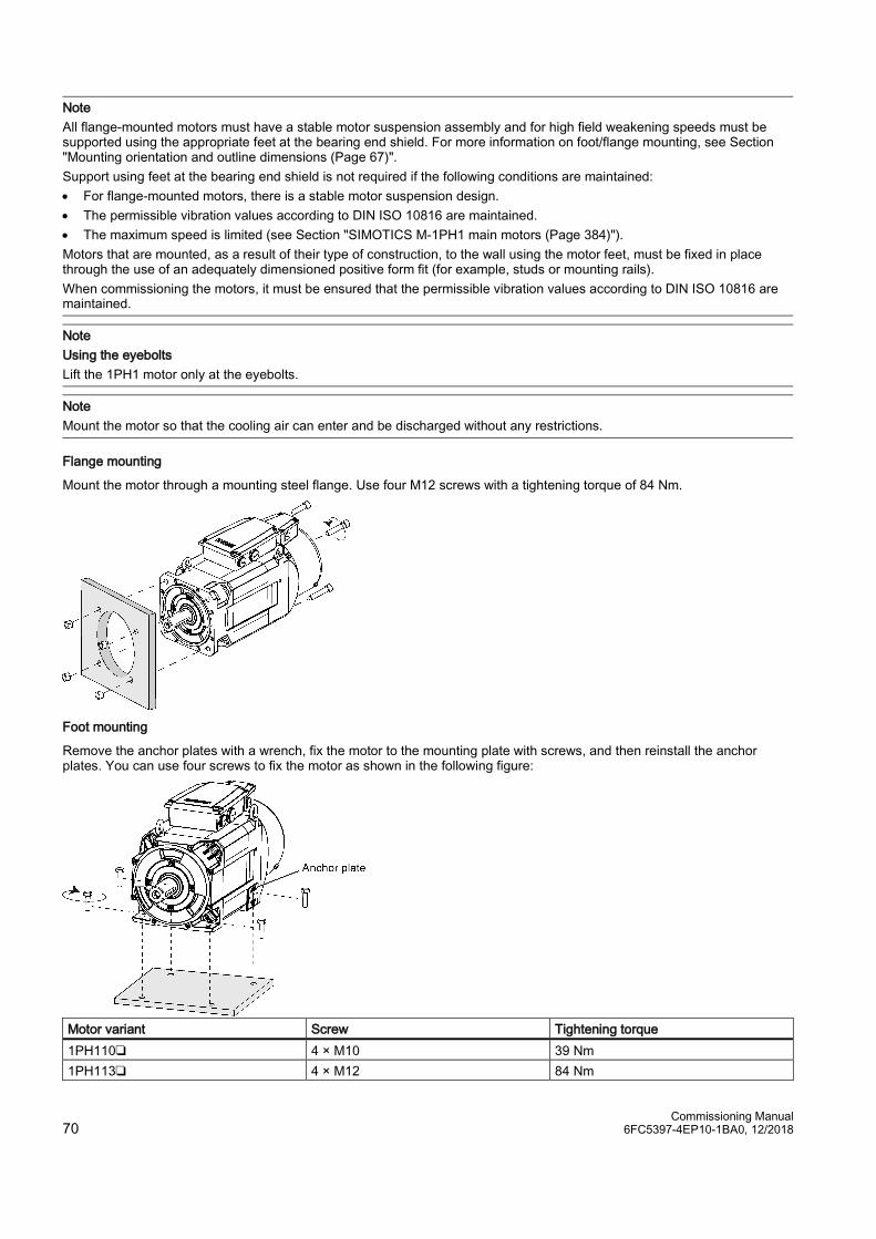
Commissioning Manual 70 6FC5397-4EP10-1BA0, 12/2018
Note All flange-mounted motors must have a stable motor suspension assembly and for high field weakening speeds must be supported using the appropriate feet at the bearing end shield. For more information on foot/flange mounting, see Section "Mounting orientation and outline dimensions (Page 67)". Support using feet at the bearing end shield is not required if the following conditions are maintained: • For flange-mounted motors, there is a stable motor suspension design. • The permissible vibration values according to DIN ISO 10816 are maintained. • The maximum speed is limited (see Section "SIMOTICS M-1PH1 main motors (Page 384)"). Motors that are mounted, as a result of their type of construction, to the wall using the motor feet, must be fixed in place through the use of an adequately dimensioned positive form fit (for example, studs or mounting rails). When commissioning the motors, it must be ensured that the permissible vibration values according to DIN ISO 10816 are maintained.
Note Using the eyebolts Lift the 1PH1 motor only at the eyebolts.
Note Mount the motor so that the cooling air can enter and be discharged without any restrictions.
Flange mounting
Mount the motor through a mounting steel flange. Use four M12 screws with a tightening torque of 84 Nm.
Foot mounting
Remove the anchor plates with a wrench, fix the motor to the mounting plate with screws, and then reinstall the anchor plates. You can use four screws to fix the motor as shown in the following figure:
Motor variant Screw Tightening torque 1PH110❑ 4 × M10 39 Nm 1PH113❑ 4 × M12 84 Nm
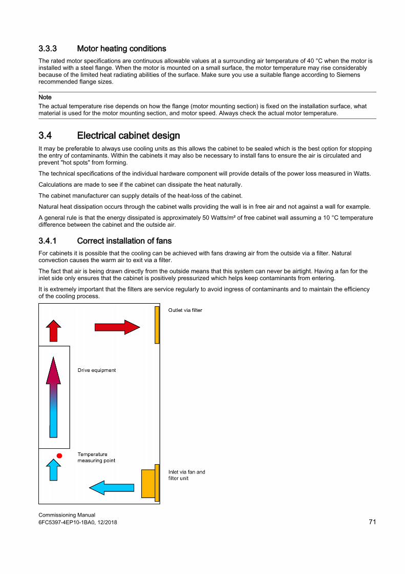
Commissioning Manual 6FC5397-4EP10-1BA0, 12/2018 71
3.3.3 Motor heating conditions The rated motor specifications are continuous allowable values at a surrounding air temperature of 40 °C when the motor is installed with a steel flange. When the motor is mounted on a small surface, the motor temperature may rise considerably because of the limited heat radiating abilities of the surface. Make sure you use a suitable flange according to Siemens recommended flange sizes.
Note The actual temperature rise depends on how the flange (motor mounting section) is fixed on the installation surface, what material is used for the motor mounting section, and motor speed. Always check the actual motor temperature.
3.4 Electrical cabinet design It may be preferable to always use cooling units as this allows the cabinet to be sealed which is the best option for stopping the entry of contaminants. Within the cabinets it may also be necessary to install fans to ensure the air is circulated and prevent "hot spots" from forming.
The technical specifications of the individual hardware component will provide details of the power loss measured in Watts.
Calculations are made to see if the cabinet can dissipate the heat naturally.
The cabinet manufacturer can supply details of the heat-loss of the cabinet.
Natural heat dissipation occurs through the cabinet walls providing the wall is in free air and not against a wall for example.
A general rule is that the energy dissipated is approximately 50 Watts/m² of free cabinet wall assuming a 10 °C temperature difference between the cabinet and the outside air.
3.4.1 Correct installation of fans For cabinets it is possible that the cooling can be achieved with fans drawing air from the outside via a filter. Natural convection causes the warm air to exit via a filter.
The fact that air is being drawn directly from the outside means that this system can never be airtight. Having a fan for the inlet side only ensures that the cabinet is positively pressurized which helps keep contaminants from entering.
It is extremely important that the filters are service regularly to avoid ingress of contaminants and to maintain the efficiency of the cooling process.

Commissioning Manual 72 6FC5397-4EP10-1BA0, 12/2018
3.4.2 Correct installation of cooling units The cool air should be directed to the bottom of the drive. The natural convection will draw the air through the drives.
The cool air from the cooling unit should not be directed straight onto/into the drives. It should be allowed to mix with the warmer air already in the cabinet, which can minimize the risk of condensation forming.
Cabinet top mounted cooling units require a method of directing the cool air from the cooling unit to the bottom of the drives.
In the case of a door mounted unit it may be necessary to direct the cool air with the use of a baffle.
3.5 Notes on the laying of cables in drag chains The MOTION-CONNECT cables between the drive and the motor, and setpoint cables between the drive and the controller satisfy requirements for use in drag chains.
Observe the following notes when laying these cables in drag chains:
Laying cables separately in the drag chain
• To ensure a long service life of the drag chain and cable, lay cables made of different materials separately with separating webs in the drag chain.
• Fill the webs evenly to ensure that the position of cables does not change during operation. • Distribute cables as symmetrically as possible according to their weights and dimensions. • Use webs to separate cables with different outer diameters. • Keep cables untwisted in the drag chain.
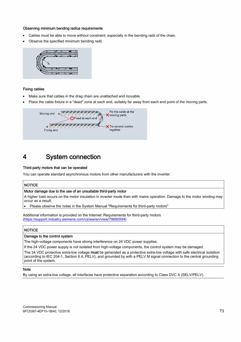
Commissioning Manual 6FC5397-4EP10-1BA0, 12/2018 73
Observing minimum bending radius requirements
• Cables must be able to move without constraint, especially in the bending radii of the chain. • Observe the specified minimum bending radii.
Fixing cables
• Make sure that cables in the drag chain are unattached and movable. • Place the cable fixture in a "dead" zone at each end, suitably far away from each end point of the moving parts.
4 System connection Third-party motors that can be operated
You can operate standard asynchronous motors from other manufacturers with the inverter:
NOTICE Motor damage due to the use of an unsuitable third-party motor A higher load occurs on the motor insulation in inverter mode than with mains operation. Damage to the motor winding may occur as a result. • Please observe the notes in the System Manual "Requirements for third-party motors"
Additional information is provided on the Internet: Requirements for third-party motors (https://support.industry.siemens.com/cs/ww/en/view/79690594)
NOTICE Damage to the control system The high-voltage components have strong interference on 24 VDC power supplies. If the 24 VDC power supply is not isolated from high-voltage components, the control system may be damaged. The 24 VDC protective extra-low voltage must be generated as a protective extra-low voltage with safe electrical isolation (according to IEC 204-1, Section 6.4, PELV), and grounded by with a PELV M signal connection to the central grounding point of the system.
Note By using an extra-low voltage, all interfaces have protective separation according to Class DVC A (SELV/PELV).
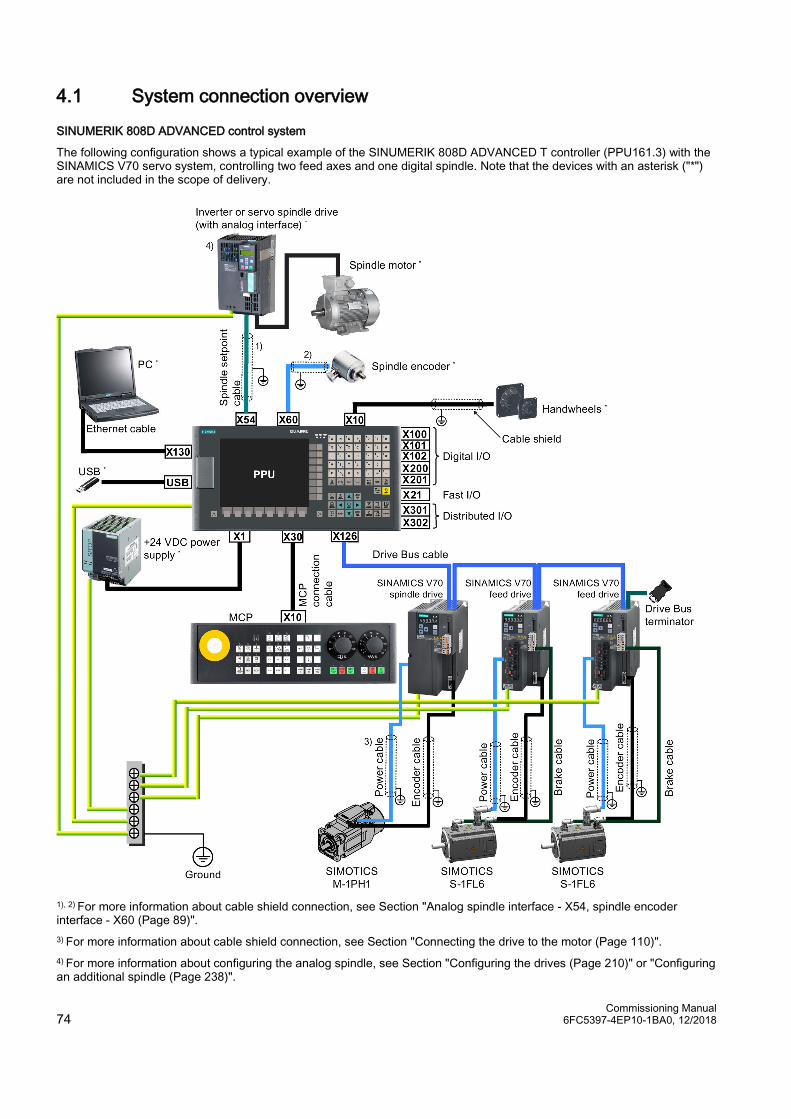
Commissioning Manual 74 6FC5397-4EP10-1BA0, 12/2018
4.1 System connection overview
SINUMERIK 808D ADVANCED control system
The following configuration shows a typical example of the SINUMERIK 808D ADVANCED T controller (PPU161.3) with the SINAMICS V70 servo system, controlling two feed axes and one digital spindle. Note that the devices with an asterisk ("*") are not included in the scope of delivery.
1), 2) For more information about cable shield connection, see Section "Analog spindle interface - X54, spindle encoder interface - X60 (Page 89)". 3) For more information about cable shield connection, see Section "Connecting the drive to the motor (Page 110)". 4) For more information about configuring the analog spindle, see Section "Configuring the drives (Page 210)" or "Configuring an additional spindle (Page 238)".
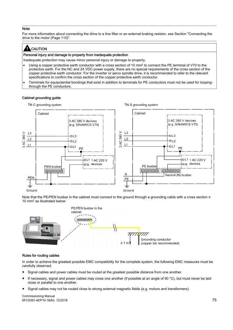
Commissioning Manual 6FC5397-4EP10-1BA0, 12/2018 75
Note For more information about connecting the drive to a line filter or an external braking resistor, see Section "Connecting the drive to the motor (Page 110)".
CAUTION Personal injury and damage to property from inadequate protection Inadequate protection may cause minor personal injury or damage to property. • Using a copper protective earth conductor with a cross section of 10 mm2 to connect the PE terminal of V70 to the
protective earth. For the NC and 24 VDC power supply, there are no special requirements of the cross section of the copper protective earth conductor. For the inverter or servo spindle drive, it is recommended to refer to the relevant specifications to confirm the cross section of the copper protective earth conductor.
• Terminals for equipotential bondings that exist in addition to terminals for PE conductors must not be used for looping-through the PE conductors.
Cabinet grounding guide
Note that the PE/PEN busbar in the cabinet must connect to the ground through a grounding cable with a cross section ≥ 10 mm2 as illustrated below:
Rules for routing cables
In order to achieve the greatest possible EMC compatibility for the complete system, the following EMC measures must be carefully observed:
● Signal cables and power cables must be routed at the greatest possible distance from one another.
● If necessary, signal and power cables may cross one another (if possible at an angle of 90 °C), but must never be laid close or parallel to one another.
● Signal cables may not be routed close to strong external magnetic fields (e.g. motors and transformers).

Commissioning Manual 76 6FC5397-4EP10-1BA0, 12/2018
● Pulse-loaded HC/HV lines must always be laid completely separately from all other lines.
● If signal lines cannot be routed a sufficient distance away from other cables, they must be installed in grounded cable ducts (metal).
● The clearance (interference injection area) between the following lines must be kept to a minimum:
– Signal line and electrical circuit signal line (twisted)
– Signal line and associated equipotential bonding conductor
– Equipotential bonding conductor and protective conductor (routed together)
4.2 Interfaces on the PPU
4.2.1 Control elements on the PPU
① Status indicators ⑧ Alarm cancellation key Cancels alarms and messages that are marked with the symbol on this key
② Protective cover for USB interface ⑨ Wizard key Guides you through performing basic commissioning and operation tasks
③ USB interface ⑩ Help key Calls help information
④ Horizontal and vertical keys Call the corresponding vertical/horizontal softkeys on the screen
⑪ Cursor keys
⑤ Return key Returns to the next higher-level menu
⑫ Modifier keys for use in key combinations
⑥ Menu extension key Calls the extended menu items
⑬ Edit control keys
⑦ Alphabetic and numeric keys ⑭ Operating area keys

Commissioning Manual 6FC5397-4EP10-1BA0, 12/2018 77
4.2.2 Status LEDs on the PPU
The individual LEDs and their functions are described in the table below:
LED Color Status Description POK Green Continuously lit The power supply for the CNC is switched on. RDY Green Continuously lit The CNC is ready and the PLC is in run mode.
Orange Continuously lit The PLC is in stop mode. Flashing The PLC is in power-up mode.
Red Continuously lit The CNC is in stop mode. TEMP Orange Continuously lit The CNC temperature is out of range.
- Off The CNC temperature is within the specified range.
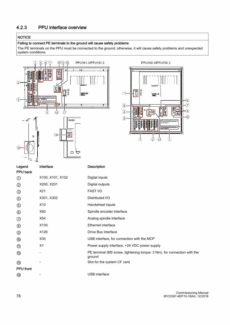
Commissioning Manual 78 6FC5397-4EP10-1BA0, 12/2018
4.2.3 PPU interface overview
NOTICE Failing to connect PE terminals to the ground will cause safety problems The PE terminals on the PPU must be connected to the ground; otherwise, it will cause safety problems and unexpected system conditions.
Legend Interface Description PPU back
① X100, X101, X102 Digital inputs
② X200, X201 Digital outputs
③ X21 FAST I/O
④ X301, X302 Distributed I/O
⑤ X10 Handwheel inputs
⑥ X60 Spindle encoder interface
⑦ X54 Analog spindle interface
⑧ X130 Ethernet interface
⑨ X126 Drive Bus interface
⑩ X30 USB interface, for connection with the MCP
⑪ X1 Power supply interface, +24 VDC power supply
⑫ - PE terminal (M5 screw, tightening torque: 3 Nm), for connection with the ground
⑬ - Slot for the system CF card
PPU front
⑭ - USB interface
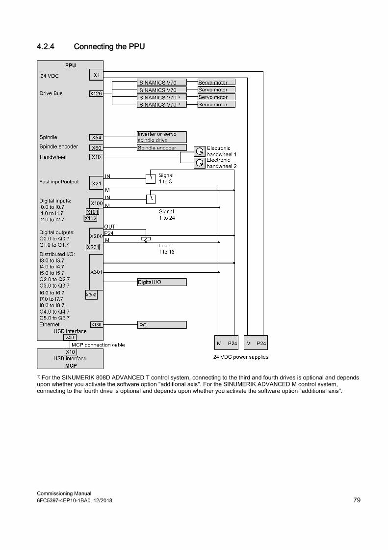
Commissioning Manual 6FC5397-4EP10-1BA0, 12/2018 79
4.2.4 Connecting the PPU
1) For the SINUMERIK 808D ADVANCED T control system, connecting to the third and fourth drives is optional and depends upon whether you activate the software option "additional axis". For the SINUMERIK ADVANCED M control system, connecting to the fourth drive is optional and depends upon whether you activate the software option "additional axis".
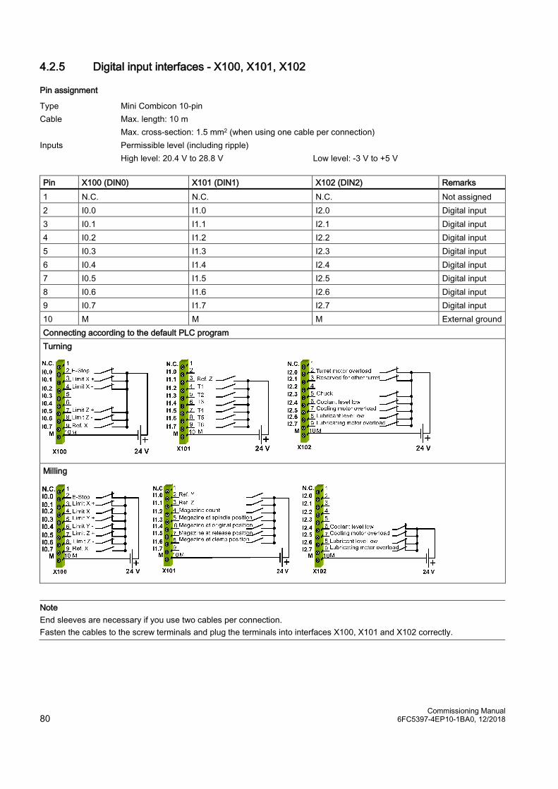
Commissioning Manual 80 6FC5397-4EP10-1BA0, 12/2018
4.2.5 Digital input interfaces - X100, X101, X102
Pin assignment
Type Mini Combicon 10-pin Cable Max. length: 10 m
Max. cross-section: 1.5 mm2 (when using one cable per connection) Inputs Permissible level (including ripple)
High level: 20.4 V to 28.8 V Low level: -3 V to +5 V
Pin X100 (DIN0) X101 (DIN1) X102 (DIN2) Remarks 1 N.C. N.C. N.C. Not assigned 2 I0.0 I1.0 I2.0 Digital input 3 I0.1 I1.1 I2.1 Digital input 4 I0.2 I1.2 I2.2 Digital input 5 I0.3 I1.3 I2.3 Digital input 6 I0.4 I1.4 I2.4 Digital input 7 I0.5 I1.5 I2.5 Digital input 8 I0.6 I1.6 I2.6 Digital input 9 I0.7 I1.7 I2.7 Digital input 10 M M M External ground Connecting according to the default PLC program Turning
Milling
Note End sleeves are necessary if you use two cables per connection. Fasten the cables to the screw terminals and plug the terminals into interfaces X100, X101 and X102 correctly.
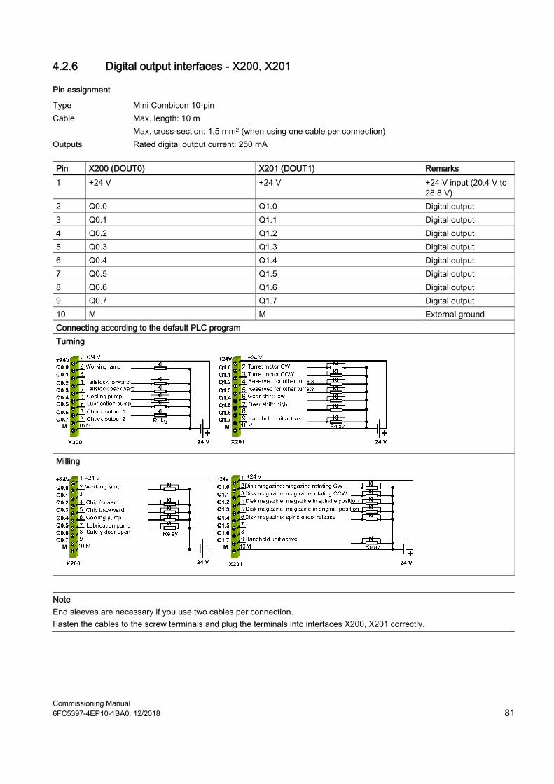
Commissioning Manual 6FC5397-4EP10-1BA0, 12/2018 81
4.2.6 Digital output interfaces - X200, X201
Pin assignment
Type Mini Combicon 10-pin Cable Max. length: 10 m
Max. cross-section: 1.5 mm2 (when using one cable per connection) Outputs Rated digital output current: 250 mA
Pin X200 (DOUT0) X201 (DOUT1) Remarks 1 +24 V +24 V +24 V input (20.4 V to
28.8 V) 2 Q0.0 Q1.0 Digital output 3 Q0.1 Q1.1 Digital output 4 Q0.2 Q1.2 Digital output 5 Q0.3 Q1.3 Digital output 6 Q0.4 Q1.4 Digital output 7 Q0.5 Q1.5 Digital output 8 Q0.6 Q1.6 Digital output 9 Q0.7 Q1.7 Digital output 10 M M External ground Connecting according to the default PLC program Turning
Milling
Note End sleeves are necessary if you use two cables per connection. Fasten the cables to the screw terminals and plug the terminals into interfaces X200, X201 correctly.
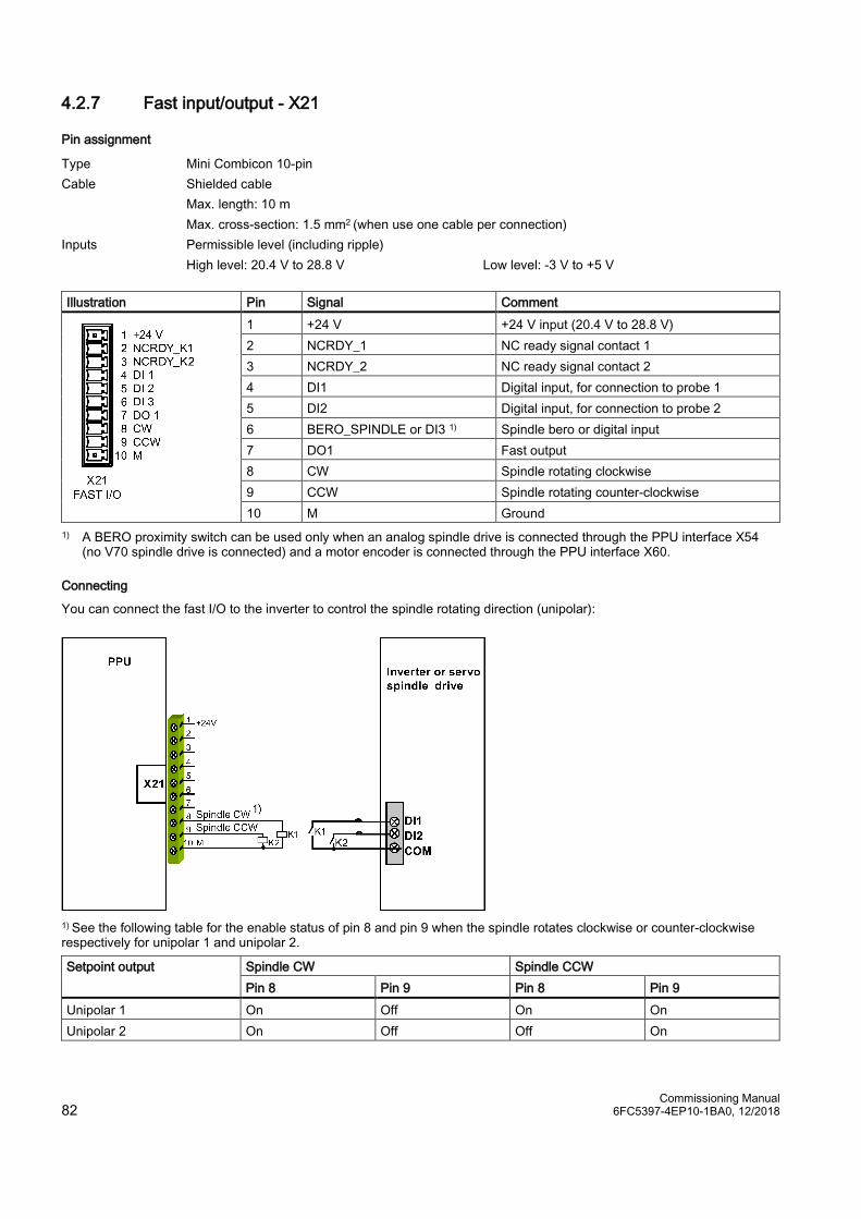
Commissioning Manual 82 6FC5397-4EP10-1BA0, 12/2018
4.2.7 Fast input/output - X21
Pin assignment
Type Mini Combicon 10-pin Cable Shielded cable
Max. length: 10 m Max. cross-section: 1.5 mm2 (when use one cable per connection)
Inputs Permissible level (including ripple) High level: 20.4 V to 28.8 V Low level: -3 V to +5 V
Illustration Pin Signal Comment
1 +24 V +24 V input (20.4 V to 28.8 V) 2 NCRDY_1 NC ready signal contact 1 3 NCRDY_2 NC ready signal contact 2 4 DI1 Digital input, for connection to probe 1 5 DI2 Digital input, for connection to probe 2 6 BERO_SPINDLE or DI3 1) Spindle bero or digital input 7 DO1 Fast output 8 CW Spindle rotating clockwise 9 CCW Spindle rotating counter-clockwise 10 M Ground
1) A BERO proximity switch can be used only when an analog spindle drive is connected through the PPU interface X54 (no V70 spindle drive is connected) and a motor encoder is connected through the PPU interface X60.
Connecting
You can connect the fast I/O to the inverter to control the spindle rotating direction (unipolar):
1) See the following table for the enable status of pin 8 and pin 9 when the spindle rotates clockwise or counter-clockwise respectively for unipolar 1 and unipolar 2.
Setpoint output Spindle CW Spindle CCW Pin 8 Pin 9 Pin 8 Pin 9
Unipolar 1 On Off On On Unipolar 2 On Off Off On
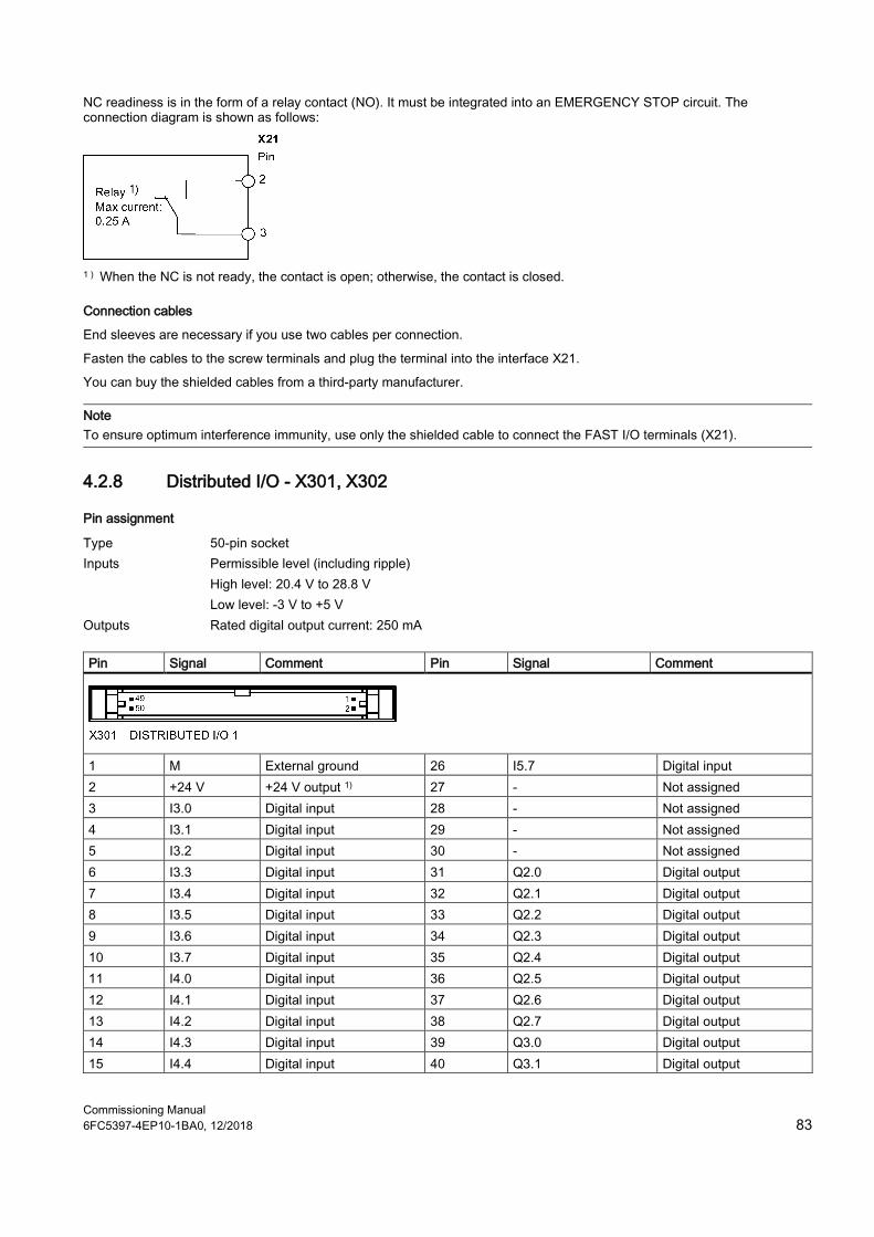
Commissioning Manual 6FC5397-4EP10-1BA0, 12/2018 83
NC readiness is in the form of a relay contact (NO). It must be integrated into an EMERGENCY STOP circuit. The connection diagram is shown as follows:
1 ) When the NC is not ready, the contact is open; otherwise, the contact is closed.
Connection cables
End sleeves are necessary if you use two cables per connection.
Fasten the cables to the screw terminals and plug the terminal into the interface X21.
You can buy the shielded cables from a third-party manufacturer.
Note To ensure optimum interference immunity, use only the shielded cable to connect the FAST I/O terminals (X21).
4.2.8 Distributed I/O - X301, X302
Pin assignment
Type 50-pin socket Inputs Permissible level (including ripple)
High level: 20.4 V to 28.8 V Low level: -3 V to +5 V
Outputs Rated digital output current: 250 mA
Pin Signal Comment Pin Signal Comment
1 M External ground 26 I5.7 Digital input 2 +24 V +24 V output 1) 27 - Not assigned 3 I3.0 Digital input 28 - Not assigned 4 I3.1 Digital input 29 - Not assigned 5 I3.2 Digital input 30 - Not assigned 6 I3.3 Digital input 31 Q2.0 Digital output 7 I3.4 Digital input 32 Q2.1 Digital output 8 I3.5 Digital input 33 Q2.2 Digital output 9 I3.6 Digital input 34 Q2.3 Digital output 10 I3.7 Digital input 35 Q2.4 Digital output 11 I4.0 Digital input 36 Q2.5 Digital output 12 I4.1 Digital input 37 Q2.6 Digital output 13 I4.2 Digital input 38 Q2.7 Digital output 14 I4.3 Digital input 39 Q3.0 Digital output 15 I4.4 Digital input 40 Q3.1 Digital output
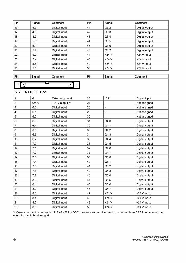
Commissioning Manual 84 6FC5397-4EP10-1BA0, 12/2018
Pin Signal Comment Pin Signal Comment 16 I4.5 Digital input 41 Q3.2 Digital output 17 I4.6 Digital input 42 Q3.3 Digital output 18 I4.7 Digital input 43 Q3.4 Digital output 19 I5.0 Digital input 44 Q3.5 Digital output 20 I5.1 Digital input 45 Q3.6 Digital output 21 I5.2 Digital input 46 Q3.7 Digital output 22 I5.3 Digital input 47 +24 V +24 V input 23 I5.4 Digital input 48 +24 V +24 V input 24 I5.5 Digital input 49 +24 V +24 V input 25 I5.6 Digital input 50 +24 V +24 V input
Pin Signal Comment Pin Signal Comment
1 M External ground 26 I8.7 Digital input 2 +24 V +24 V output 1) 27 - Not assigned 3 I6.0 Digital input 28 - Not assigned 4 I6.1 Digital input 29 - Not assigned 5 I6.2 Digital input 30 - Not assigned 6 I6.3 Digital input 31 Q4.0 Digital output 7 I6.4 Digital input 32 Q4.1 Digital output 8 I6.5 Digital input 33 Q4.2 Digital output 9 I6.6 Digital input 34 Q4.3 Digital output 10 I6.7 Digital input 35 Q4.4 Digital output 11 I7.0 Digital input 36 Q4.5 Digital output 12 I7.1 Digital input 37 Q4.6 Digital output 13 I7.2 Digital input 38 Q4.7 Digital output 14 I7.3 Digital input 39 Q5.0 Digital output 15 I7.4 Digital input 40 Q5.1 Digital output 16 I7.5 Digital input 41 Q5.2 Digital output 17 I7.6 Digital input 42 Q5.3 Digital output 18 I7.7 Digital input 43 Q5.4 Digital output 19 I8.0 Digital input 44 Q5.5 Digital output 20 I8.1 Digital input 45 Q5.6 Digital output 21 I8.2 Digital input 46 Q5.7 Digital output 22 I8.3 Digital input 47 +24 V +24 V input 23 I8.4 Digital input 48 +24 V +24 V input 24 I8.5 Digital input 49 +24 V +24 V input 25 I8.6 Digital input 50 +24 V +24 V input
1) Make sure that the current at pin 2 of X301 or X302 does not exceed the maximum current Iout = 0.25 A; otherwise, the controller could be damaged.
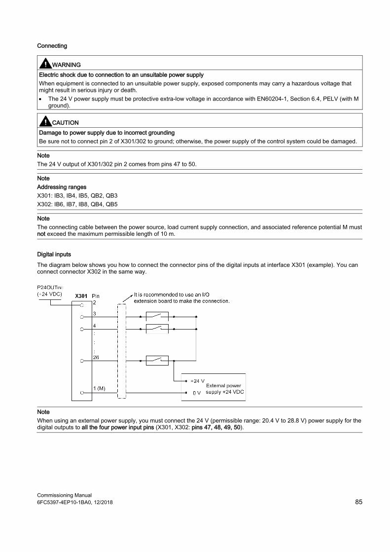
Commissioning Manual 6FC5397-4EP10-1BA0, 12/2018 85
Connecting
WARNING Electric shock due to connection to an unsuitable power supply When equipment is connected to an unsuitable power supply, exposed components may carry a hazardous voltage that might result in serious injury or death. • The 24 V power supply must be protective extra-low voltage in accordance with EN60204-1, Section 6.4, PELV (with M
ground).
CAUTION Damage to power supply due to incorrect grounding Be sure not to connect pin 2 of X301/302 to ground; otherwise, the power supply of the control system could be damaged.
Note The 24 V output of X301/302 pin 2 comes from pins 47 to 50.
Note Addressing ranges X301: IB3, IB4, IB5, QB2, QB3 X302: IB6, IB7, IB8, QB4, QB5
Note The connecting cable between the power source, load current supply connection, and associated reference potential M must not exceed the maximum permissible length of 10 m.
Digital inputs
The diagram below shows you how to connect the connector pins of the digital inputs at interface X301 (example). You can connect connector X302 in the same way.
Note When using an external power supply, you must connect the 24 V (permissible range: 20.4 V to 28.8 V) power supply for the digital outputs to all the four power input pins (X301, X302: pins 47, 48, 49, 50).

Commissioning Manual 86 6FC5397-4EP10-1BA0, 12/2018
Digital outputs
The diagram below shows you how to connect the connector pins of the digital outputs at interface X301 (example). You can connect connector X302 in the same way.
To supply the digital outputs, you must connect an external 24 VDC power supply (X301, X302: pins 47, 48, 49, 50).
You must also connect the reference ground of the external power supply to X301, X302: Pin 1 (M).
Note You must ensure that the maximum current consumption at pin 47, pin 48, pin 49 or pin 50 does not exceed 1 A.
Note You must connect the 24 V power supply for the digital outputs to all the four power input pins (X301, X302: pins 47, 48, 49, 50).
External power supply
When using an external power supply for the digital inputs, you must connect the reference ground to X301, X302: Pin 1 (M).
Connecting according to the default PLC program
The control system has integrated with a default PLC application. If you perform the commissioning work with the default PLC application, arrange wiring as follows.
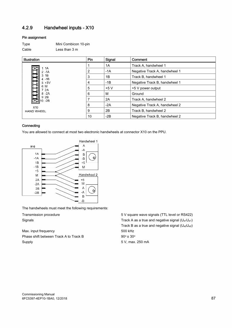
Commissioning Manual 6FC5397-4EP10-1BA0, 12/2018 87
4.2.9 Handwheel inputs - X10
Pin assignment
Type Mini Combicon 10-pin Cable Less than 3 m
Illustration Pin Signal Comment
1 1A Track A, handwheel 1 2 -1A Negative Track A, handwheel 1 3 1B Track B, handwheel 1 4 -1B Negative Track B, handwheel 1 5 +5 V +5 V power output 6 M Ground 7 2A Track A, handwheel 2 8 -2A Negative Track A, handwheel 2 9 2B Track B, handwheel 2 10 -2B Negative Track B, handwheel 2
Connecting
You are allowed to connect at most two electronic handwheels at connector X10 on the PPU.
The handwheels must meet the following requirements:
Transmission procedure 5 V square wave signals (TTL level or RS422) Signals Track A as a true and negative signal (Ua1Ua1)
Track B as a true and negative signal (Ua2Ua2) Max. input frequency 500 kHz Phase shift between Track A to Track B 90o ± 30o Supply 5 V, max. 250 mA
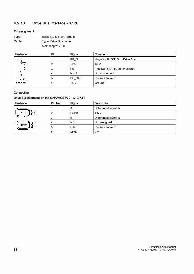
Commissioning Manual 88 6FC5397-4EP10-1BA0, 12/2018
4.2.10 Drive Bus interface - X126
Pin assignment
Type IEEE 1394, 6-pin, female Cable Type: Drive Bus cable
Max. length: 20 m
Illustration Pin Signal Comment
1 PB_N Negative RxD/TxD of Drive Bus 2 1P5 +5 V 3 PB Positive RxD/TxD of Drive Bus 4 NULL Not connected 5 PB_RTS Request to send 6 1M5 Ground
Connecting
Drive Bus interfaces on the SINAMICS V70 - X10, X11
Illustration Pin No. Signal Description
1 A Differential signal A 2 P5PB + 5 V 3 B Differential signal B 4 NC Not assigned 5 RTS Request to send 6 MPB 0 V

Commissioning Manual 6FC5397-4EP10-1BA0, 12/2018 89
Connecting example
Note You must install the Drive Bus terminator (that ships with the PPU) on X11 of the last servo drive; otherwise, the servo system cannot work normally.
4.2.11 Analog spindle interface - X54, spindle encoder interface - X60 Interface X54 is for connecting the PPU to the inverter or servo spindle drive. Interface X60 is for connecting the PPU to the spindle encoder.
Pin assignment - X54
Type Sub-D, 9-pin, female Cable Max. length: 10 m
Illustration Pin Signal Comment
1 AO Analog voltage 2 - not assigned 3 - not assigned 4 - not assigned 5 SE1 Analog drive enable (contact: electrically isolated n.o. contact) 6 SE2 Analog drive enable (contact: electrically isolated n.o. contact) 7 - not assigned 8 - not assigned 9 AGND Ground

Commissioning Manual 90 6FC5397-4EP10-1BA0, 12/2018
Pin assignment - X60
Type Sub-D, 15-pin, female Cable Type: encoder cable
Max. length: 10 m Max. frequency 2 MHz
Illustration Pin Signal Comment
1 - Not assigned 2 - Not assigned 3 - Not assigned 4 +5 V +5 V power supply 5 - Not assigned 6 +5 V +5 V power supply 7 M Ground 8 - Not assigned 9 M Ground 10 Z Zero mark 11 Z_N Zero mark, negative 12 B_N Track B, negative 13 B Track B 14 A_N Track A, negative 15 A Track A
Connecting
Connecting the inverter or servo spindle drive (unipolar)
1) 10 V analog voltage 2) 0 V signal
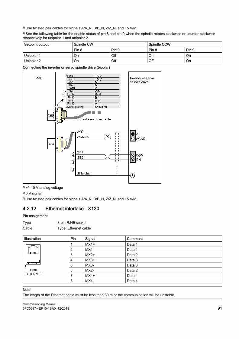
Commissioning Manual 6FC5397-4EP10-1BA0, 12/2018 91
3) Use twisted pair cables for signals A/A_N, B/B_N, Z/Z_N, and +5 V/M. 4) See the following table for the enable status of pin 8 and pin 9 when the spindle rotates clockwise or counter-clockwise respectively for unipolar 1 and unipolar 2.
Setpoint output Spindle CW Spindle CCW Pin 8 Pin 9 Pin 8 Pin 9
Unipolar 1 On Off On On Unipolar 2 On Off Off On
Connecting the inverter or servo spindle drive (bipolar)
1) +/- 10 V analog voltage 2) 0 V signal 3) Use twisted pair cables for signals A/A_N, B/B_N, Z/Z_N, and +5 V/M.
4.2.12 Ethernet interface - X130 Pin assignment
Type 8-pin RJ45 socket Cable Type: Ethernet cable
Illustration Pin Signal Comment
1 MX1+ Data 1 2 MX1- Data 1 3 MX2+ Data 2 4 MX3+ Data 3 5 MX3- Data 3 6 MX2- Data 2 7 MX4+ Data 4 8 MX4- Data 4
Note The length of the Ethernet cable must be less than 30 m or the communication will be unstable.
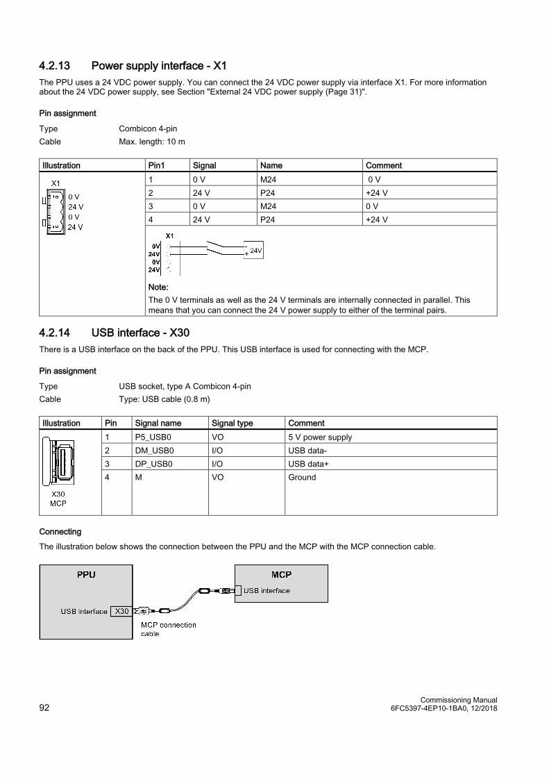
Commissioning Manual 92 6FC5397-4EP10-1BA0, 12/2018
4.2.13 Power supply interface - X1 The PPU uses a 24 VDC power supply. You can connect the 24 VDC power supply via interface X1. For more information about the 24 VDC power supply, see Section "External 24 VDC power supply (Page 31)".
Pin assignment
Type Combicon 4-pin Cable Max. length: 10 m
Illustration Pin1 Signal Name Comment
1 0 V M24 0 V 2 24 V P24 +24 V 3 0 V M24 0 V 4 24 V P24 +24 V
Note: The 0 V terminals as well as the 24 V terminals are internally connected in parallel. This means that you can connect the 24 V power supply to either of the terminal pairs.
4.2.14 USB interface - X30 There is a USB interface on the back of the PPU. This USB interface is used for connecting with the MCP.
Pin assignment
Type USB socket, type A Combicon 4-pin Cable Type: USB cable (0.8 m)
Illustration Pin Signal name Signal type Comment
1 P5_USB0 VO 5 V power supply 2 DM_USB0 I/O USB data- 3 DP_USB0 I/O USB data+ 4 M VO Ground
Connecting
The illustration below shows the connection between the PPU and the MCP with the MCP connection cable.

Commissioning Manual 6FC5397-4EP10-1BA0, 12/2018 93
4.2.15 USB interface on the front cover of the PPU
Pin assignment
Type USB socket, type A Cable Type: USB 1.1 cable
Length: less than 3 m ESD protect Contact discharge: ± 4 kV
Air discharge: ± 8 kV
Illustration Pin Signal name Signal type Comment
1 P5_USB0 VO 5 V power supply 2 DM_USB0 I/O USB data- 3 DP_USB0 I/O USB data+ 4 M VO Ground
4.2.16 Slot for the system CF card The system CF card is installed on the PPU at the factory.
① Slot for the CF card
② System CF card
Note The system CF card is accessible only by the Siemens service personnel. Do not touch or remove the system CF card under any conditions.
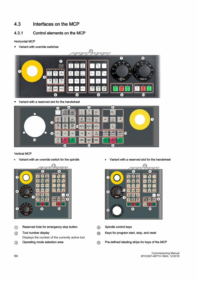
Commissioning Manual 94 6FC5397-4EP10-1BA0, 12/2018
4.3 Interfaces on the MCP
4.3.1 Control elements on the MCP
Horizontal MCP
● Variant with override switches
● Variant with a reserved slot for the handwheel
Vertical MCP
• Variant with an override switch for the spindle • Variant with a reserved slot for the handwheel
① Reserved hole for emergency stop button ⑨ Spindle control keys
② Tool number display Displays the number of the currently active tool
⑩ Keys for program start, stop, and reset
③ Operating mode selection area ⑪ Pre-defined labeling strips for keys of the MCP

Commissioning Manual 6FC5397-4EP10-1BA0, 12/2018 95
④ Program control keys ⑫ Reserved slot for the handwheel
⑤ User-defined keys ⑬ Spindle override control keys
⑥ Axis traversing keys ⑭ Feedrate override control keys
⑦ Spindle override switch ⑮ Keys for increment override/rapid traverse override *
⑧ Feedrate override switch
* The increment override can be activated in "JOG" mode, "Handwheel" mode, or "AUTO"/"MDA" mode with the contour handwheel activated. The rapid traverse override is effective only in "AUTO"/"MDA" mode with no contour handwheel ac-tivated. The "F0 G00" key can activate a rapid traverse override of 1% by default, which can be changed in the general machine data 12050[1], for example, 12050[1] = 0.15 as 15%.
4.3.2 MCP interface overview
Legend Description
① USB interface, for connection with the PPU
② Reserved hole for fixing the USB cable that connects the PPU and the MCP
Note The two variants of the vertical MCP, with a reserved hole for the handwheel and with an override switch for the spindle, have the same mechanical interface design for the USB cable and reserved hole for fixing the USB cable on the back. The illustration above takes the vertical MCP with a spindle override switch for example.
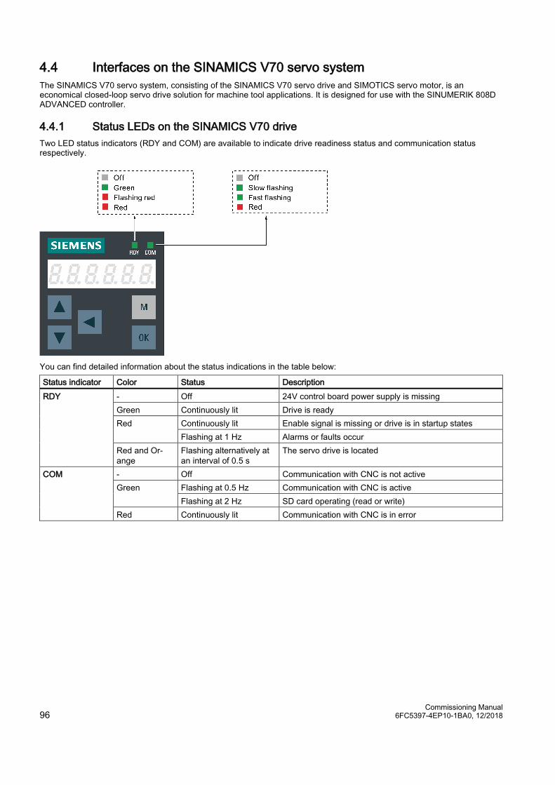
Commissioning Manual 96 6FC5397-4EP10-1BA0, 12/2018
4.4 Interfaces on the SINAMICS V70 servo system The SINAMICS V70 servo system, consisting of the SINAMICS V70 servo drive and SIMOTICS servo motor, is an economical closed-loop servo drive solution for machine tool applications. It is designed for use with the SINUMERIK 808D ADVANCED controller.
4.4.1 Status LEDs on the SINAMICS V70 drive Two LED status indicators (RDY and COM) are available to indicate drive readiness status and communication status respectively.
You can find detailed information about the status indications in the table below:
Status indicator Color Status Description RDY - Off 24V control board power supply is missing
Green Continuously lit Drive is ready Red Continuously lit Enable signal is missing or drive is in startup states
Flashing at 1 Hz Alarms or faults occur Red and Or-ange
Flashing alternatively at an interval of 0.5 s
The servo drive is located
COM - Off Communication with CNC is not active Green Flashing at 0.5 Hz Communication with CNC is active
Flashing at 2 Hz SD card operating (read or write) Red Continuously lit Communication with CNC is in error
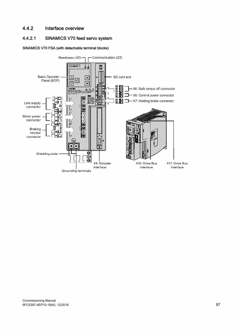
Commissioning Manual 6FC5397-4EP10-1BA0, 12/2018 97
4.4.2 Interface overview
4.4.2.1 SINAMICS V70 feed servo system
SINAMICS V70 FSA (with detachable terminal blocks)

Commissioning Manual 98 6FC5397-4EP10-1BA0, 12/2018
SINAMICS V70 FSB/FSC (with screw terminals)
Note For more information about the connection of the X10 and X11, see Section "Drive Bus interface - X126 (Page 88)".
SIMOTICS S-1FL6 motor
● Motor with straight connectors:
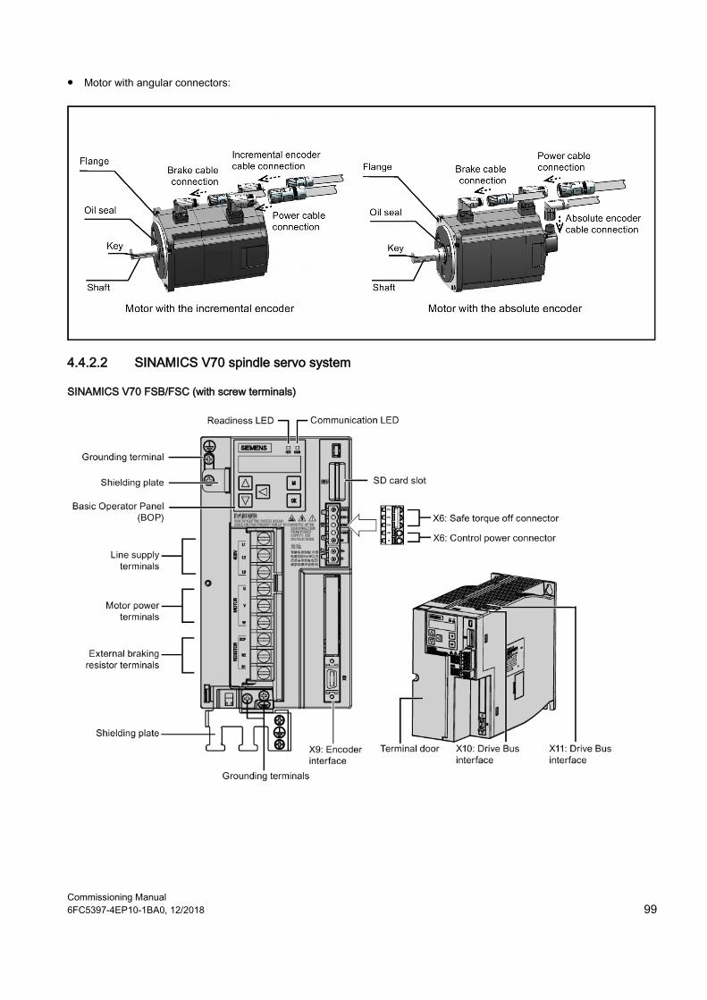
Commissioning Manual 6FC5397-4EP10-1BA0, 12/2018 99
● Motor with angular connectors:
4.4.2.2 SINAMICS V70 spindle servo system
SINAMICS V70 FSB/FSC (with screw terminals)
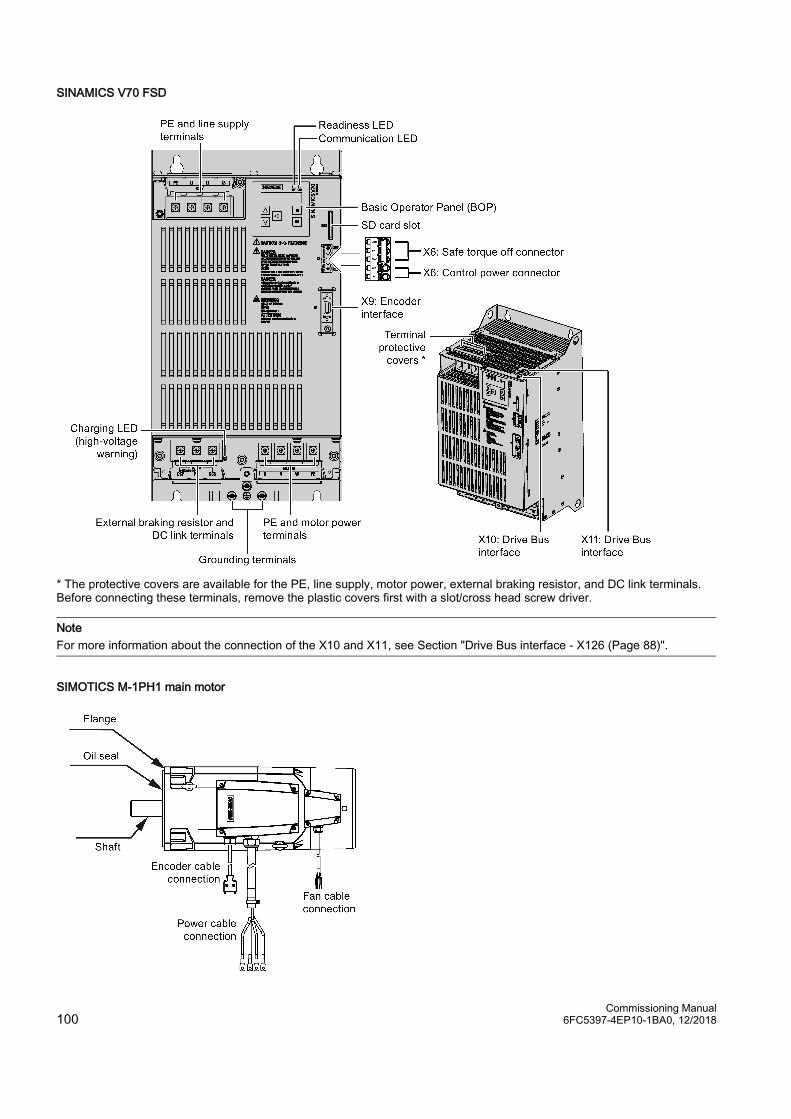
Commissioning Manual 100 6FC5397-4EP10-1BA0, 12/2018
SINAMICS V70 FSD
* The protective covers are available for the PE, line supply, motor power, external braking resistor, and DC link terminals. Before connecting these terminals, remove the plastic covers first with a slot/cross head screw driver.
Note For more information about the connection of the X10 and X11, see Section "Drive Bus interface - X126 (Page 88)".
SIMOTICS M-1PH1 main motor
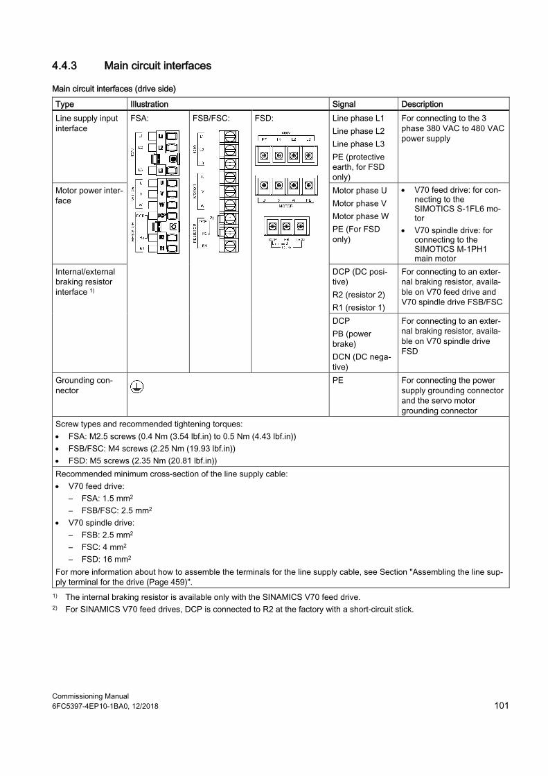
Commissioning Manual 6FC5397-4EP10-1BA0, 12/2018 101
4.4.3 Main circuit interfaces
Main circuit interfaces (drive side)
Type Illustration Signal Description Line supply input interface
FSA:
FSB/FSC:
FSD:
Line phase L1 Line phase L2 Line phase L3 PE (protective earth, for FSD only)
For connecting to the 3 phase 380 VAC to 480 VAC power supply
Motor power inter-face
Motor phase U Motor phase V Motor phase W PE (For FSD only)
• V70 feed drive: for con-necting to the SIMOTICS S-1FL6 mo-tor
• V70 spindle drive: for connecting to the SIMOTICS M-1PH1 main motor
Internal/external braking resistor interface 1)
DCP (DC posi-tive) R2 (resistor 2) R1 (resistor 1)
For connecting to an exter-nal braking resistor, availa-ble on V70 feed drive and V70 spindle drive FSB/FSC
DCP PB (power brake) DCN (DC nega-tive)
For connecting to an exter-nal braking resistor, availa-ble on V70 spindle drive FSD
Grounding con-nector
PE For connecting the power supply grounding connector and the servo motor grounding connector
Screw types and recommended tightening torques: • FSA: M2.5 screws (0.4 Nm (3.54 lbf.in) to 0.5 Nm (4.43 lbf.in)) • FSB/FSC: M4 screws (2.25 Nm (19.93 lbf.in)) • FSD: M5 screws (2.35 Nm (20.81 lbf.in)) Recommended minimum cross-section of the line supply cable: • V70 feed drive:
– FSA: 1.5 mm2 – FSB/FSC: 2.5 mm2
• V70 spindle drive: – FSB: 2.5 mm2 – FSC: 4 mm2 – FSD: 16 mm2
For more information about how to assemble the terminals for the line supply cable, see Section "Assembling the line sup-ply terminal for the drive (Page 459)". 1) The internal braking resistor is available only with the SINAMICS V70 feed drive.
2) For SINAMICS V70 feed drives, DCP is connected to R2 at the factory with a short-circuit stick.
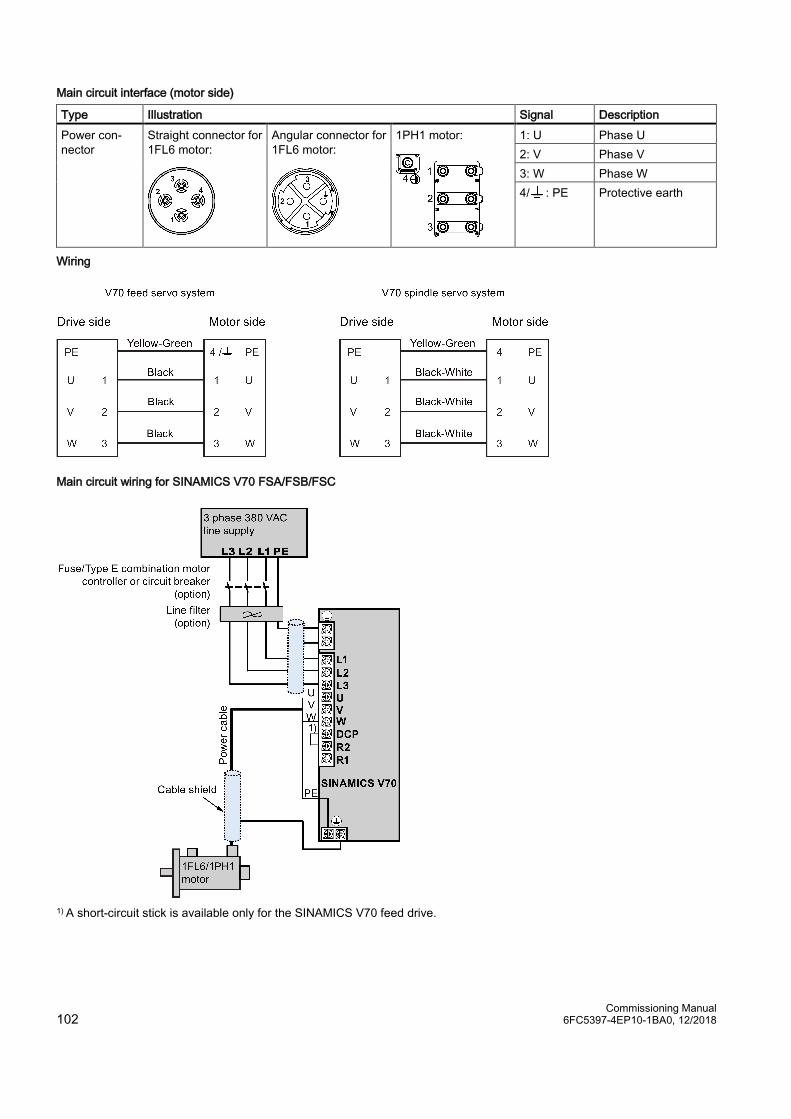
Commissioning Manual 102 6FC5397-4EP10-1BA0, 12/2018
Main circuit interface (motor side)
Type Illustration Signal Description Power con-nector
Straight connector for 1FL6 motor:
Angular connector for 1FL6 motor:
1PH1 motor:
1: U Phase U 2: V Phase V 3: W Phase W 4/ : PE Protective earth
Wiring
Main circuit wiring for SINAMICS V70 FSA/FSB/FSC
1) A short-circuit stick is available only for the SINAMICS V70 feed drive.
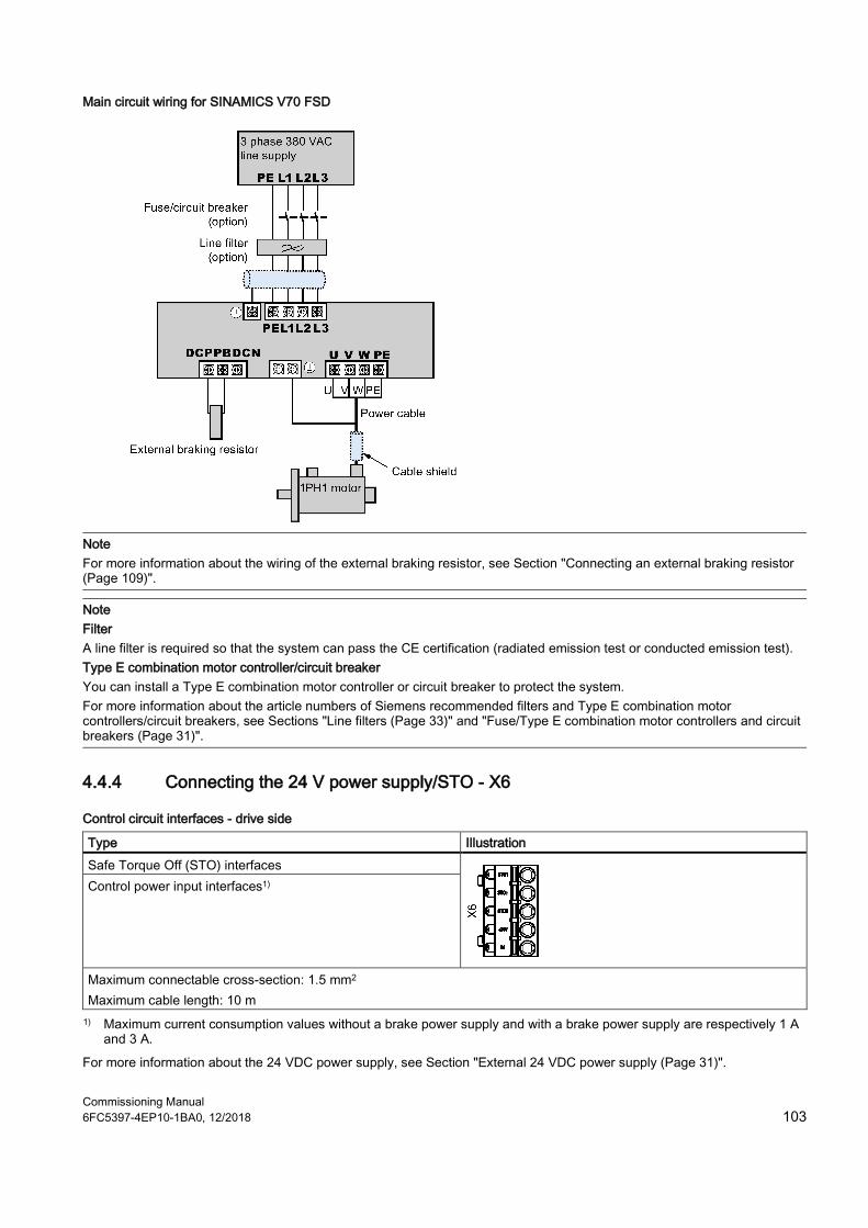
Commissioning Manual 6FC5397-4EP10-1BA0, 12/2018 103
Main circuit wiring for SINAMICS V70 FSD
Note For more information about the wiring of the external braking resistor, see Section "Connecting an external braking resistor (Page 109)".
Note Filter A line filter is required so that the system can pass the CE certification (radiated emission test or conducted emission test). Type E combination motor controller/circuit breaker You can install a Type E combination motor controller or circuit breaker to protect the system. For more information about the article numbers of Siemens recommended filters and Type E combination motor controllers/circuit breakers, see Sections "Line filters (Page 33)" and "Fuse/Type E combination motor controllers and circuit breakers (Page 31)".
4.4.4 Connecting the 24 V power supply/STO - X6
Control circuit interfaces - drive side
Type Illustration Safe Torque Off (STO) interfaces
Control power input interfaces1)
Maximum connectable cross-section: 1.5 mm2 Maximum cable length: 10 m 1) Maximum current consumption values without a brake power supply and with a brake power supply are respectively 1 A
and 3 A.
For more information about the 24 VDC power supply, see Section "External 24 VDC power supply (Page 31)".
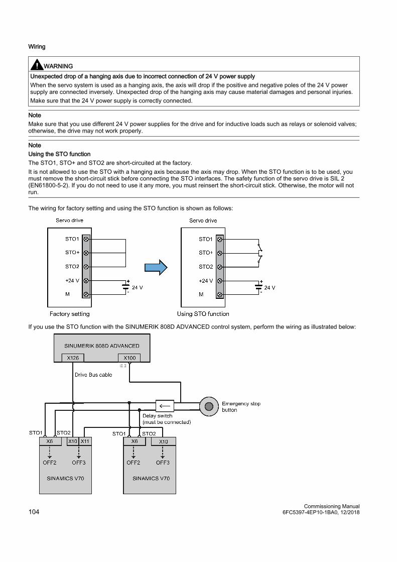
Commissioning Manual 104 6FC5397-4EP10-1BA0, 12/2018
Wiring
WARNING Unexpected drop of a hanging axis due to incorrect connection of 24 V power supply When the servo system is used as a hanging axis, the axis will drop if the positive and negative poles of the 24 V power supply are connected inversely. Unexpected drop of the hanging axis may cause material damages and personal injuries. Make sure that the 24 V power supply is correctly connected.
Note Make sure that you use different 24 V power supplies for the drive and for inductive loads such as relays or solenoid valves; otherwise, the drive may not work properly.
Note Using the STO function The STO1, STO+ and STO2 are short-circuited at the factory. It is not allowed to use the STO with a hanging axis because the axis may drop. When the STO function is to be used, you must remove the short-circuit stick before connecting the STO interfaces. The safety function of the servo drive is SIL 2 (EN61800-5-2). If you do not need to use it any more, you must reinsert the short-circuit stick. Otherwise, the motor will not run.
The wiring for factory setting and using the STO function is shown as follows:
If you use the STO function with the SINUMERIK 808D ADVANCED control system, perform the wiring as illustrated below:
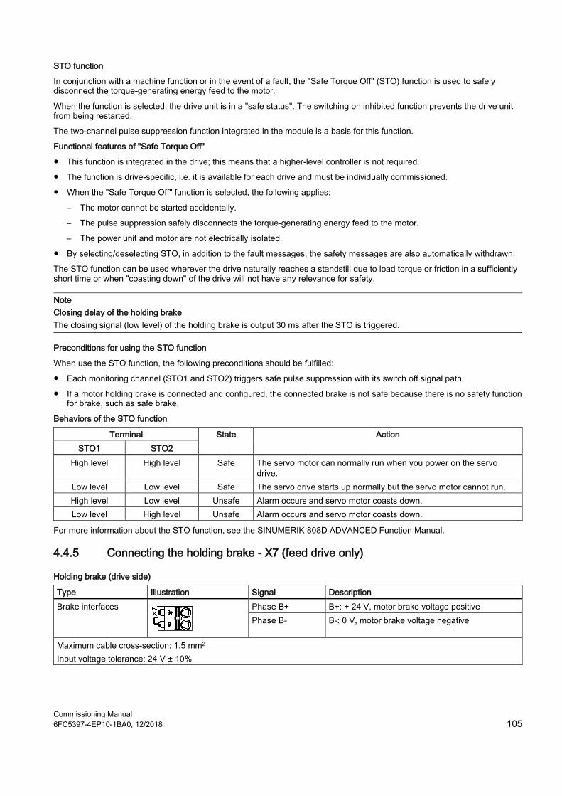
Commissioning Manual 6FC5397-4EP10-1BA0, 12/2018 105
STO function
In conjunction with a machine function or in the event of a fault, the "Safe Torque Off" (STO) function is used to safely disconnect the torque-generating energy feed to the motor.
When the function is selected, the drive unit is in a "safe status". The switching on inhibited function prevents the drive unit from being restarted.
The two-channel pulse suppression function integrated in the module is a basis for this function.
Functional features of "Safe Torque Off"
● This function is integrated in the drive; this means that a higher-level controller is not required.
● The function is drive-specific, i.e. it is available for each drive and must be individually commissioned.
● When the "Safe Torque Off" function is selected, the following applies:
– The motor cannot be started accidentally.
– The pulse suppression safely disconnects the torque-generating energy feed to the motor.
– The power unit and motor are not electrically isolated.
● By selecting/deselecting STO, in addition to the fault messages, the safety messages are also automatically withdrawn.
The STO function can be used wherever the drive naturally reaches a standstill due to load torque or friction in a sufficiently short time or when "coasting down" of the drive will not have any relevance for safety.
Note Closing delay of the holding brake The closing signal (low level) of the holding brake is output 30 ms after the STO is triggered.
Preconditions for using the STO function
When use the STO function, the following preconditions should be fulfilled:
● Each monitoring channel (STO1 and STO2) triggers safe pulse suppression with its switch off signal path.
● If a motor holding brake is connected and configured, the connected brake is not safe because there is no safety function for brake, such as safe brake.
Behaviors of the STO function
Terminal State Action STO1 STO2
High level High level Safe The servo motor can normally run when you power on the servo drive.
Low level Low level Safe The servo drive starts up normally but the servo motor cannot run. High level Low level Unsafe Alarm occurs and servo motor coasts down. Low level High level Unsafe Alarm occurs and servo motor coasts down.
For more information about the STO function, see the SINUMERIK 808D ADVANCED Function Manual.
4.4.5 Connecting the holding brake - X7 (feed drive only)
Holding brake (drive side)
Type Illustration Signal Description Brake interfaces
Phase B+ B+: + 24 V, motor brake voltage positive Phase B- B-: 0 V, motor brake voltage negative
Maximum cable cross-section: 1.5 mm2 Input voltage tolerance: 24 V ± 10%

Commissioning Manual 106 6FC5397-4EP10-1BA0, 12/2018
Holding brake (motor side)
Type Illustration Signal Description Brake connector Straight connector:
Angular connector:
1: B+ Phase Brake + 2: B- Phase Brake -
Wiring
4.4.6 Connecting the encoder - X9 The SINAMICS V70 drive supports the following types of encoders:
V70 feed drive Incremental encoder, TTL 2500 ppr Absolute encoder, 20-bit + 12-bit multi-turn
V70 spindle drive Incremental encoder, TTL 2500 ppr Absolute encoder, single-turn 20-bit
NOTICE Cable shielding The encoder cable must be shielded to meet the EMC requirements.
Encoder connector - drive side
14-pin socket connector for the incremental/absolute encoder interface X9
Illustration Pin No. Signal Description
1 Biss_DataP Absolute encoder data signal, positive 2 Biss_DataN Absolute encoder data signal, negative 3 Biss_ClockN Absolute encoder clock signal, negative 4 Biss_ClockP Absolute encoder clock signal, positive 5 P5V Encoder power supply, +5V 6 P5V Encoder power supply, +5V 7 M Encoder power supply, grounding 8 M Encoder power supply, grounding 9 Rp Encoder R phase positive signal 10 Rn Encoder R phase negative signal 11 Bn Encoder B phase negative signal 12 Bp Encoder B phase positive signal 13 An Encoder A phase negative signal 14 Ap Encoder A phase positive signal
Note The screw type is UNC 4-40 (plug-in terminal block) and the recommended tightening torque is 0.4 Nm.
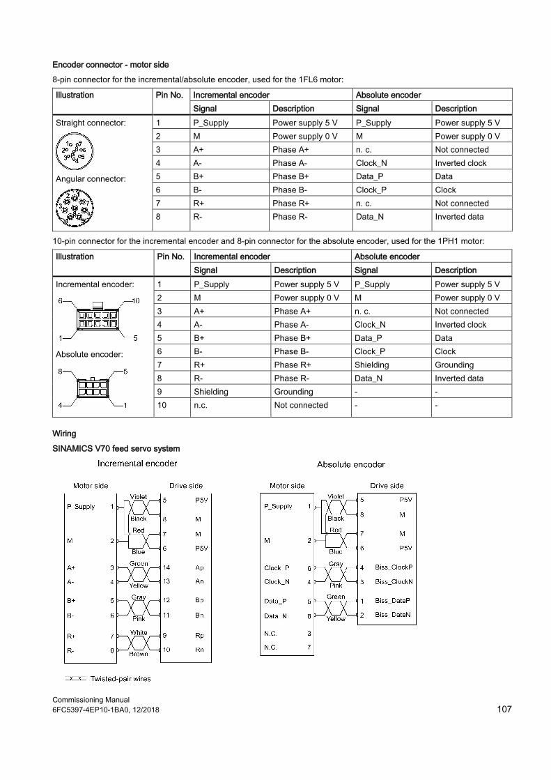
Commissioning Manual 6FC5397-4EP10-1BA0, 12/2018 107
Encoder connector - motor side
8-pin connector for the incremental/absolute encoder, used for the 1FL6 motor:
Illustration Pin No. Incremental encoder Absolute encoder Signal Description Signal Description
Straight connector:
Angular connector:
1 P_Supply Power supply 5 V P_Supply Power supply 5 V 2 M Power supply 0 V M Power supply 0 V 3 A+ Phase A+ n. c. Not connected 4 A- Phase A- Clock_N Inverted clock 5 B+ Phase B+ Data_P Data 6 B- Phase B- Clock_P Clock 7 R+ Phase R+ n. c. Not connected 8 R- Phase R- Data_N Inverted data
10-pin connector for the incremental encoder and 8-pin connector for the absolute encoder, used for the 1PH1 motor:
Illustration Pin No. Incremental encoder Absolute encoder Signal Description Signal Description
Incremental encoder:
Absolute encoder:
1 P_Supply Power supply 5 V P_Supply Power supply 5 V 2 M Power supply 0 V M Power supply 0 V 3 A+ Phase A+ n. c. Not connected 4 A- Phase A- Clock_N Inverted clock 5 B+ Phase B+ Data_P Data 6 B- Phase B- Clock_P Clock 7 R+ Phase R+ Shielding Grounding 8 R- Phase R- Data_N Inverted data 9 Shielding Grounding - - 10 n.c. Not connected - -
Wiring
SINAMICS V70 feed servo system
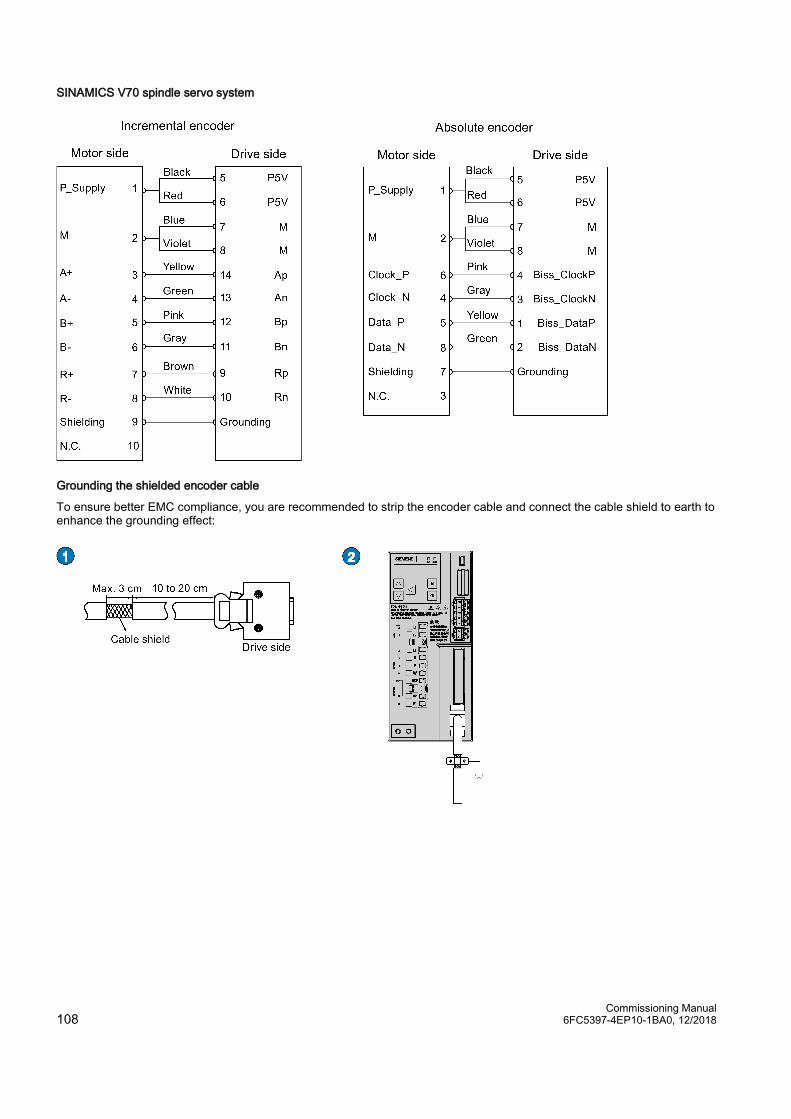
Commissioning Manual 108 6FC5397-4EP10-1BA0, 12/2018
SINAMICS V70 spindle servo system
Grounding the shielded encoder cable
To ensure better EMC compliance, you are recommended to strip the encoder cable and connect the cable shield to earth to enhance the grounding effect:
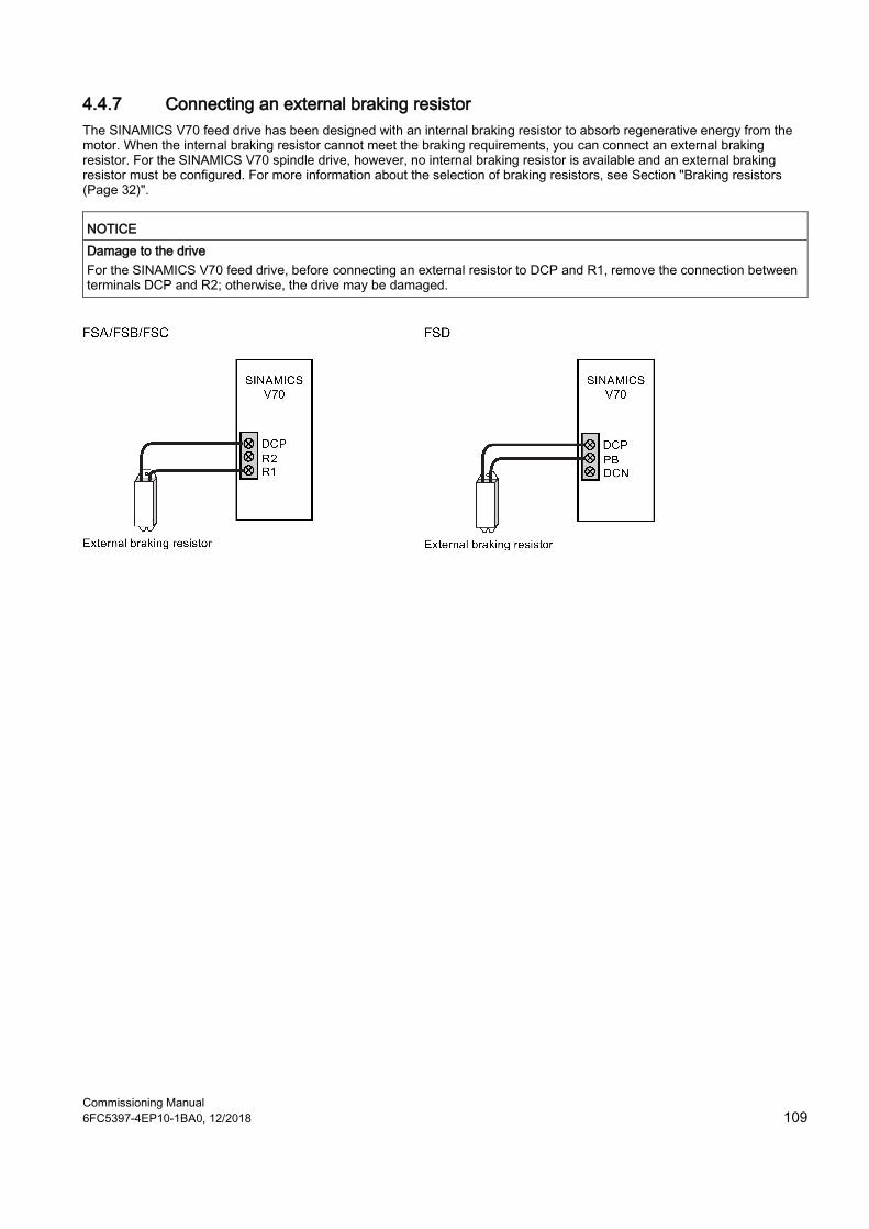
Commissioning Manual 6FC5397-4EP10-1BA0, 12/2018 109
4.4.7 Connecting an external braking resistor The SINAMICS V70 feed drive has been designed with an internal braking resistor to absorb regenerative energy from the motor. When the internal braking resistor cannot meet the braking requirements, you can connect an external braking resistor. For the SINAMICS V70 spindle drive, however, no internal braking resistor is available and an external braking resistor must be configured. For more information about the selection of braking resistors, see Section "Braking resistors (Page 32)".
NOTICE Damage to the drive For the SINAMICS V70 feed drive, before connecting an external resistor to DCP and R1, remove the connection between terminals DCP and R2; otherwise, the drive may be damaged.

Commissioning Manual 110 6FC5397-4EP10-1BA0, 12/2018
4.5 Connecting the SINAMICS V70 servo system
4.5.1 Connecting the drive to the motor
CAUTION Finger injuries caused by improper cable connection When connecting cables to the drive interfaces with detachable connectors, fixing the cables directly to the connectors which have not been fitted onto the drive may result in finger injuries. • First fit the connectors onto the drive, and then fix the cables to the connectors.
Connecting the SINAMICS V70 FSA/FSB/FSC servo system
Note The connection illustration below uses V70 FSA as an example, which is also applicable to V70 feed/spindle drives FSB and FSC.
1) The holding brake function is available only with the feed drive. 2) The short-circuit stick is available only with the feed drive for the use of an internal braking resistor. 3) For the V70 spindle drive, the SIMOTICS M-1PH1 main motor is connected. 4) An external braking resistor can be used to absorb excess regenerative energy in the DC link when the capacity of the internal braking resistor is insufficient. Note that no internal braking resistor is available in the V70 spindle drive, and you must select an external braking resistor as specified in Section "Braking resistors (Page 32)".
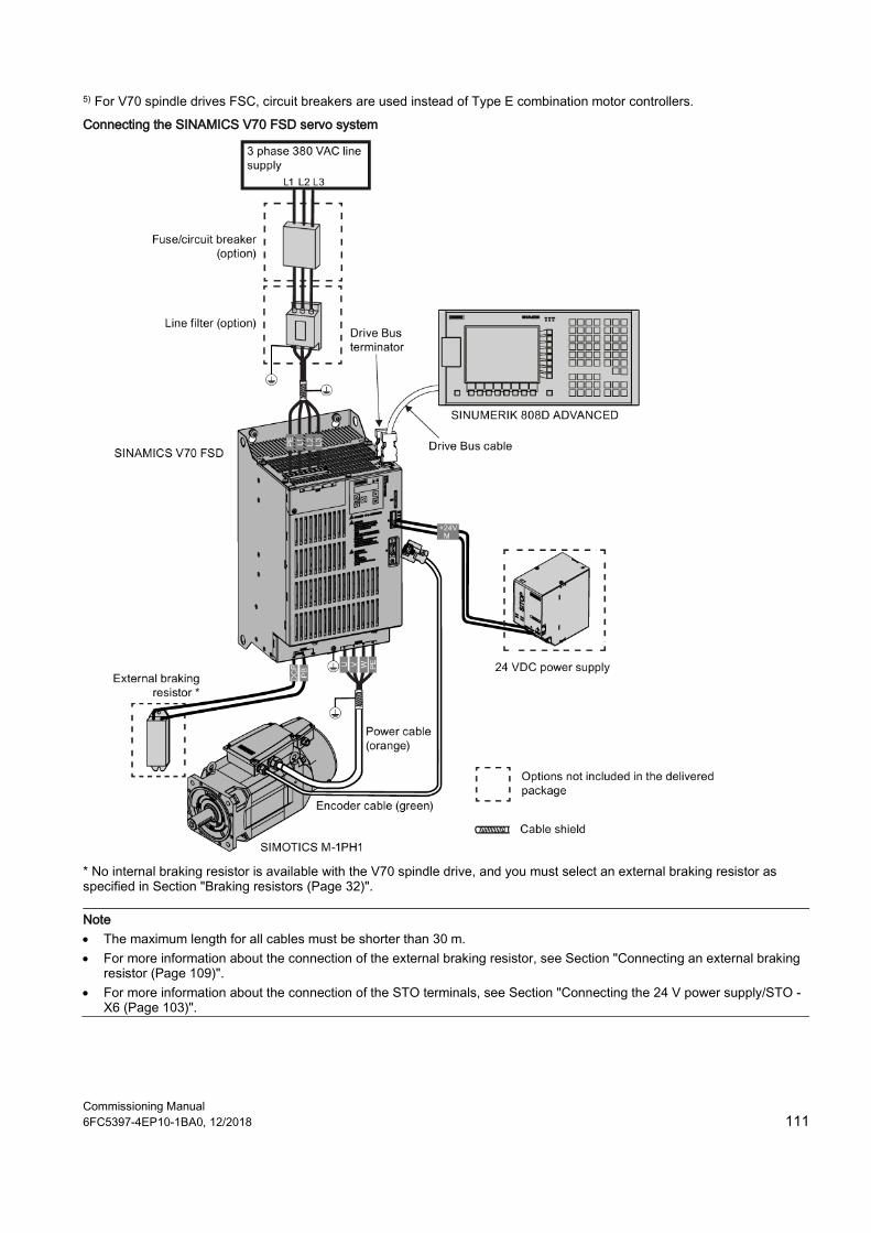
Commissioning Manual 6FC5397-4EP10-1BA0, 12/2018 111
5) For V70 spindle drives FSC, circuit breakers are used instead of Type E combination motor controllers. Connecting the SINAMICS V70 FSD servo system
* No internal braking resistor is available with the V70 spindle drive, and you must select an external braking resistor as specified in Section "Braking resistors (Page 32)".
Note • The maximum length for all cables must be shorter than 30 m. • For more information about the connection of the external braking resistor, see Section "Connecting an external braking
resistor (Page 109)". • For more information about the connection of the STO terminals, see Section "Connecting the 24 V power supply/STO -
X6 (Page 103)".
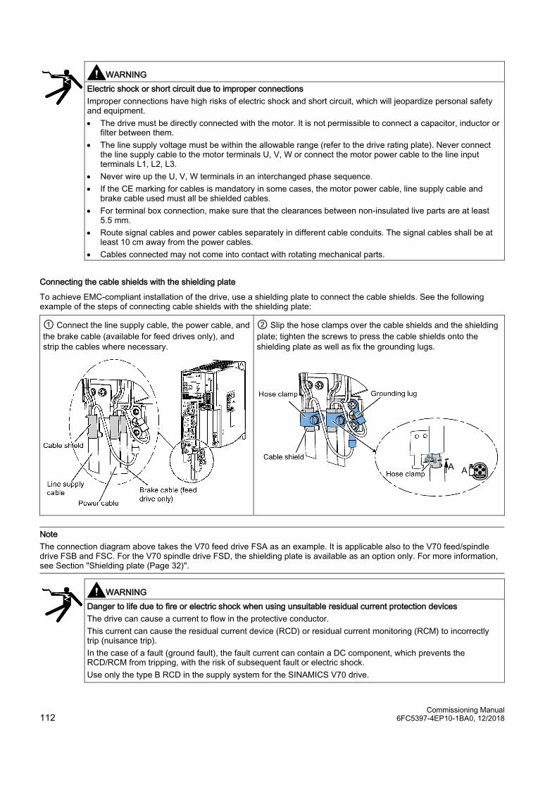
Commissioning Manual 112 6FC5397-4EP10-1BA0, 12/2018
WARNING Electric shock or short circuit due to improper connections Improper connections have high risks of electric shock and short circuit, which will jeopardize personal safety and equipment. • The drive must be directly connected with the motor. It is not permissible to connect a capacitor, inductor or
filter between them. • The line supply voltage must be within the allowable range (refer to the drive rating plate). Never connect
the line supply cable to the motor terminals U, V, W or connect the motor power cable to the line input terminals L1, L2, L3.
• Never wire up the U, V, W terminals in an interchanged phase sequence. • If the CE marking for cables is mandatory in some cases, the motor power cable, line supply cable and
brake cable used must all be shielded cables. • For terminal box connection, make sure that the clearances between non-insulated live parts are at least
5.5 mm. • Route signal cables and power cables separately in different cable conduits. The signal cables shall be at
least 10 cm away from the power cables. • Cables connected may not come into contact with rotating mechanical parts.
Connecting the cable shields with the shielding plate
To achieve EMC-compliant installation of the drive, use a shielding plate to connect the cable shields. See the following example of the steps of connecting cable shields with the shielding plate:
① Connect the line supply cable, the power cable, and the brake cable (available for feed drives only), and strip the cables where necessary.
② Slip the hose clamps over the cable shields and the shielding plate; tighten the screws to press the cable shields onto the shielding plate as well as fix the grounding lugs.
Note The connection diagram above takes the V70 feed drive FSA as an example. It is applicable also to the V70 feed/spindle drive FSB and FSC. For the V70 spindle drive FSD, the shielding plate is available as an option only. For more information, see Section "Shielding plate (Page 32)".
WARNING Danger to life due to fire or electric shock when using unsuitable residual current protection devices The drive can cause a current to flow in the protective conductor. This current can cause the residual current device (RCD) or residual current monitoring (RCM) to incorrectly trip (nuisance trip). In the case of a fault (ground fault), the fault current can contain a DC component, which prevents the RCD/RCM from tripping, with the risk of subsequent fault or electric shock. Use only the type B RCD in the supply system for the SINAMICS V70 drive.
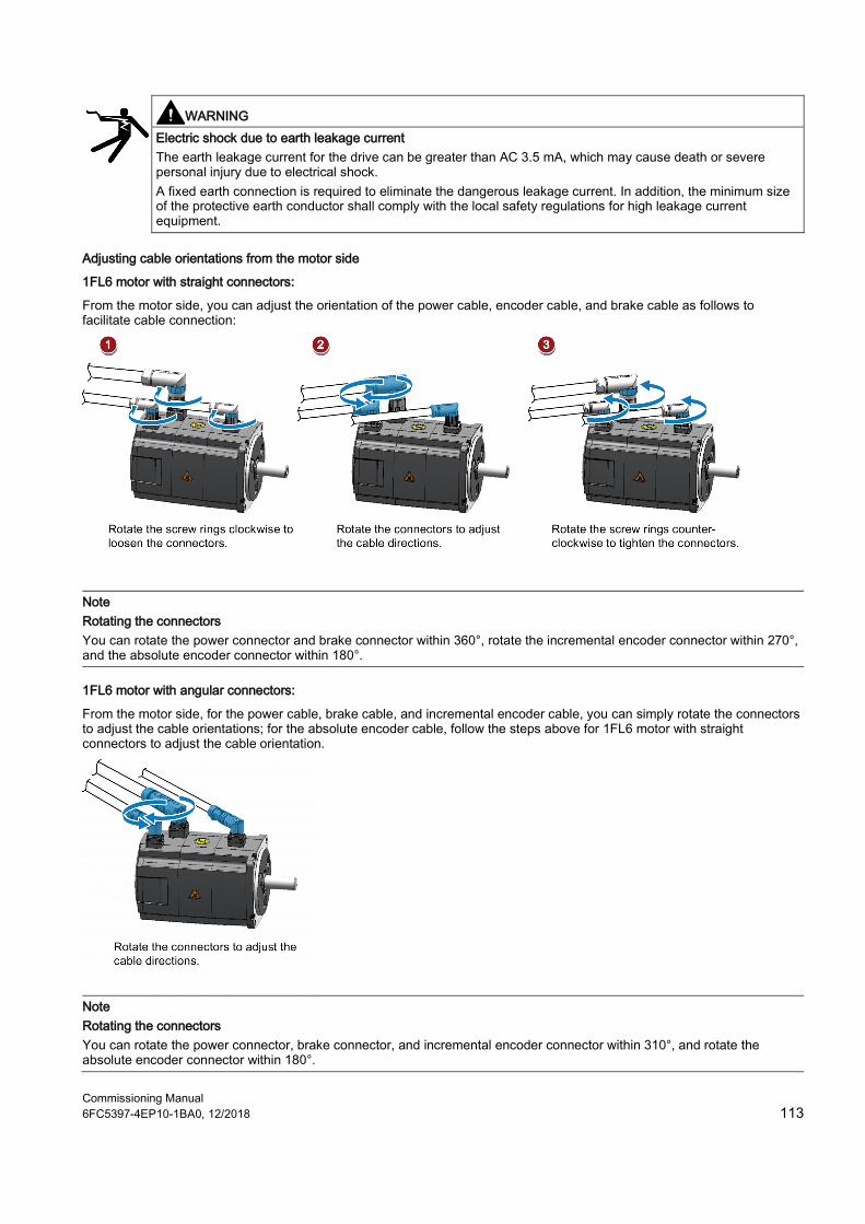
Commissioning Manual 6FC5397-4EP10-1BA0, 12/2018 113
WARNING Electric shock due to earth leakage current The earth leakage current for the drive can be greater than AC 3.5 mA, which may cause death or severe personal injury due to electrical shock. A fixed earth connection is required to eliminate the dangerous leakage current. In addition, the minimum size of the protective earth conductor shall comply with the local safety regulations for high leakage current equipment.
Adjusting cable orientations from the motor side
1FL6 motor with straight connectors:
From the motor side, you can adjust the orientation of the power cable, encoder cable, and brake cable as follows to facilitate cable connection:
Note Rotating the connectors You can rotate the power connector and brake connector within 360°, rotate the incremental encoder connector within 270°, and the absolute encoder connector within 180°.
1FL6 motor with angular connectors:
From the motor side, for the power cable, brake cable, and incremental encoder cable, you can simply rotate the connectors to adjust the cable orientations; for the absolute encoder cable, follow the steps above for 1FL6 motor with straight connectors to adjust the cable orientation.
Note Rotating the connectors You can rotate the power connector, brake connector, and incremental encoder connector within 310°, and rotate the absolute encoder connector within 180°.
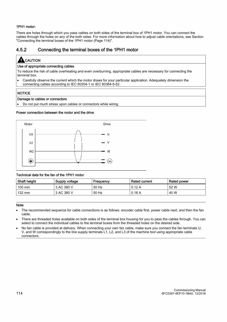
Commissioning Manual 114 6FC5397-4EP10-1BA0, 12/2018
1PH1 motor:
There are holes through which you pass cables on both sides of the terminal box of 1PH1 motor. You can connect the cables through the holes on any of the both sides. For more information about how to adjust cable orientations, see Section "Connecting the terminal boxes of the 1PH1 motor (Page 114)".
4.5.2 Connecting the terminal boxes of the 1PH1 motor
CAUTION Use of appropriate connecting cables To reduce the risk of cable overheating and even overburning, appropriate cables are necessary for connecting the terminal box. • Carefully observe the current which the motor draws for your particular application. Adequately dimension the
connecting cables according to IEC 60204-1 or IEC 60364-5-52.
NOTICE Damage to cables or connectors • Do not put much stress upon cables or connectors while wiring.
Power connection between the motor and the drive
Technical data for the fan of the 1PH1 motor
Shaft height Supply voltage Frequency Rated current Rated power 100 mm 3 AC 380 V 50 Hz 0.12 A 52 W 132 mm 3 AC 380 V 50 Hz 0.18 A 40 W
Note • The recommended sequence for cable connections is as follows: encoder cable first, power cable next, and then the fan
cable. • There are threaded holes available on both sides of the terminal box housing for you to pass the cables through. You can
select to connect the individual cables to the terminal boxes from the threaded holes on the desired side. • No fan cable is provided at delivery. When connecting your own fan cable, make sure you connect the fan terminals U,
V, and W correspondingly to the line supply terminals L1, L2, and L3 of the machine tool using appropriate cable connectors.

Commissioning Manual 6FC5397-4EP10-1BA0, 12/2018 115
1. Loosen the screws on the top of both the motor terminal box and the fan terminal box to remove the terminal box
covers. 2. Remove the three screw plugs on one side of the two terminal boxes. 3. Loosen the cable gland pre-assembled on the encoder cable. Pass the encoder cable through the first threaded hole
in the motor terminal box housing. Follow the steps below to connect the encoder cable to the motor terminal box: • For the absolute encoder cable:
3a1. Insert the male connector of the absolute encoder cable into the female connector in the motor terminal box. 3a2. Remove from the terminal box the grounding screws as well as the hose clamp. Lay the absolute encoder cable ap-
propriately. Place the hose clamp onto the cable shield, and then tighten the screws. You can select to fix the cable in the desired direction by screwing the hose clamp at any two of the three screw holes.
• For the incremental encoder cable:
3a1. Insert the male connector of the incremental encoder cable into the female connector in the motor terminal box. 3a2. (Optional) You can select to fix the cable in the desired direction by screwing the hose clamp at any two of the three
screw holes. For detailed information about how to fix the cable, see step 3a2 for connecting the absolute encoder cable mentioned above.
3b. Tighten the cable gland of the encoder cable onto the threaded hole.
Commissioning Manual 116 6FC5397-4EP10-1BA0, 12/2018
4. Pass the power cable through the cable gland, and then through the second threaded hole in the motor terminal box housing. Follow the steps below to connect the power cable to the motor terminal box:
4a. Remove from the terminal box the three binding post nuts that correspond to the power cable terminals U, V, and W. Place the three terminal lugs at the end of the power cable conductors onto the corresponding binding posts. Fasten the cable conductors with the nuts (3 x M5, max. 4.7 Nm). Remove the grounding screw for power terminal PE. Place the terminal lug of the PE conductor on the grounding screw, and then tighten the screw for the PE terminal (1PH110❑: 1 x M5, max. 4.7 Nm; 1PH113❑: 1 x M6, max. 4.7 Nm).
4b. Tighten the cable gland of the power cable onto the threaded hole. 5. Pass your own fan cable (recommended cable outer diameter: 4 mm to 8 mm) through the cable gland, and then
through the threaded hole in the fan terminal box housing. Follow the steps below to connect the fan cable to the fan terminal box:
5a. Loosen the four screws that correspond to the fan cable terminals U, V, W and PE. Insert the terminal lugs at the end of fan cable conductors into the corresponding sockets under the binding posts, and then fasten the cable conductors with the screws.
5b. Tighten the cable gland of the fan cable onto the threaded hole. 6. Replace the covers of the terminal boxes, and then tighten the screws respectively for the motor terminal box (4 x M5:
max. 4.7 Nm) and the fan terminal box (4 x M4: max. 2.4 Nm).
NOTICE Damage to the motor • After you finish connecting the terminal boxes and start the motor, make sure the fan rotates in the correct direction as
indicated by the arrow marked on the fan rating plate; otherwise, the motor may be damaged due to overheat.
4.6 Switching on the drive
NOTICE Plugging or unplugging the SD card will cause startup failure. Do not plug or unplug the SD card during startup; otherwise, the drive will fail to start up.
NOTICE Firmware damage due to drive power-off during data transfer Switching off the 24 VDC power supply for the drive during data transfer from the SD card to the drive can cause damage to the drive firmware. • Do not switch off the drive power supply when the data transfer from the SD card to the drive is in process.
NOTICE Existing setting data may be overwritten by the setting data on the SD card during startup. • When a drive is switched on with an SD card containing user setting data, the existing setting data on the drive will be
overwritten. • When a drive is switched on with an SD card containing no user setting data, the drive will automatically save the
existing user setting data onto the SD card. Before starting up the drive with an SD card, check whether the SD card contains user setting data. Otherwise, the existing data on the drive may be overwritten.
Note • Make sure that all cables are correctly connected and the connected servo system is in good condition with no faults
before switching on. • Prior to commissioning or operation, read carefully "Safety instructions (Page 11)" and "Operating the SINAMICS V70
Basic Operator Panel (BOP) (Page 442)". • See Chapters "Diagnostics (Page 461)" and "Parameter list (Page 398)" for detailed information about any possible
alarms and parameters used during commissioning.
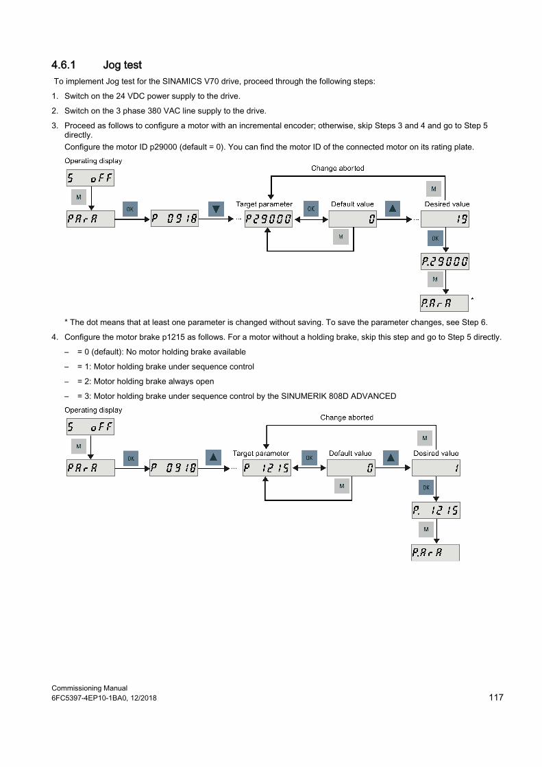
Commissioning Manual 6FC5397-4EP10-1BA0, 12/2018 117
4.6.1 Jog test To implement Jog test for the SINAMICS V70 drive, proceed through the following steps:
1. Switch on the 24 VDC power supply to the drive.
2. Switch on the 3 phase 380 VAC line supply to the drive.
3. Proceed as follows to configure a motor with an incremental encoder; otherwise, skip Steps 3 and 4 and go to Step 5 directly. Configure the motor ID p29000 (default = 0). You can find the motor ID of the connected motor on its rating plate.
* The dot means that at least one parameter is changed without saving. To save the parameter changes, see Step 6.
4. Configure the motor brake p1215 as follows. For a motor without a holding brake, skip this step and go to Step 5 directly.
– = 0 (default): No motor holding brake available
– = 1: Motor holding brake under sequence control
– = 2: Motor holding brake always open
– = 3: Motor holding brake under sequence control by the SINUMERIK 808D ADVANCED
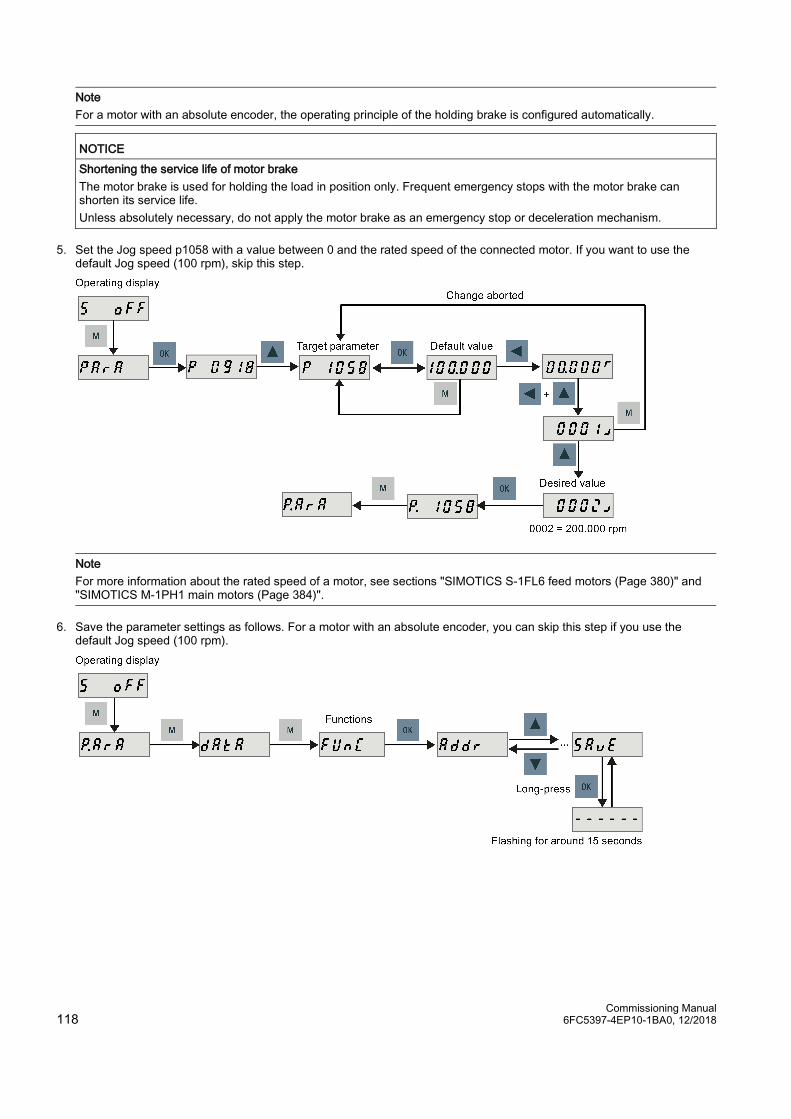
Commissioning Manual 118 6FC5397-4EP10-1BA0, 12/2018
Note For a motor with an absolute encoder, the operating principle of the holding brake is configured automatically.
NOTICE Shortening the service life of motor brake The motor brake is used for holding the load in position only. Frequent emergency stops with the motor brake can shorten its service life. Unless absolutely necessary, do not apply the motor brake as an emergency stop or deceleration mechanism.
5. Set the Jog speed p1058 with a value between 0 and the rated speed of the connected motor. If you want to use the default Jog speed (100 rpm), skip this step.
Note
For more information about the rated speed of a motor, see sections "SIMOTICS S-1FL6 feed motors (Page 380)" and "SIMOTICS M-1PH1 main motors (Page 384)".
6. Save the parameter settings as follows. For a motor with an absolute encoder, you can skip this step if you use the default Jog speed (100 rpm).
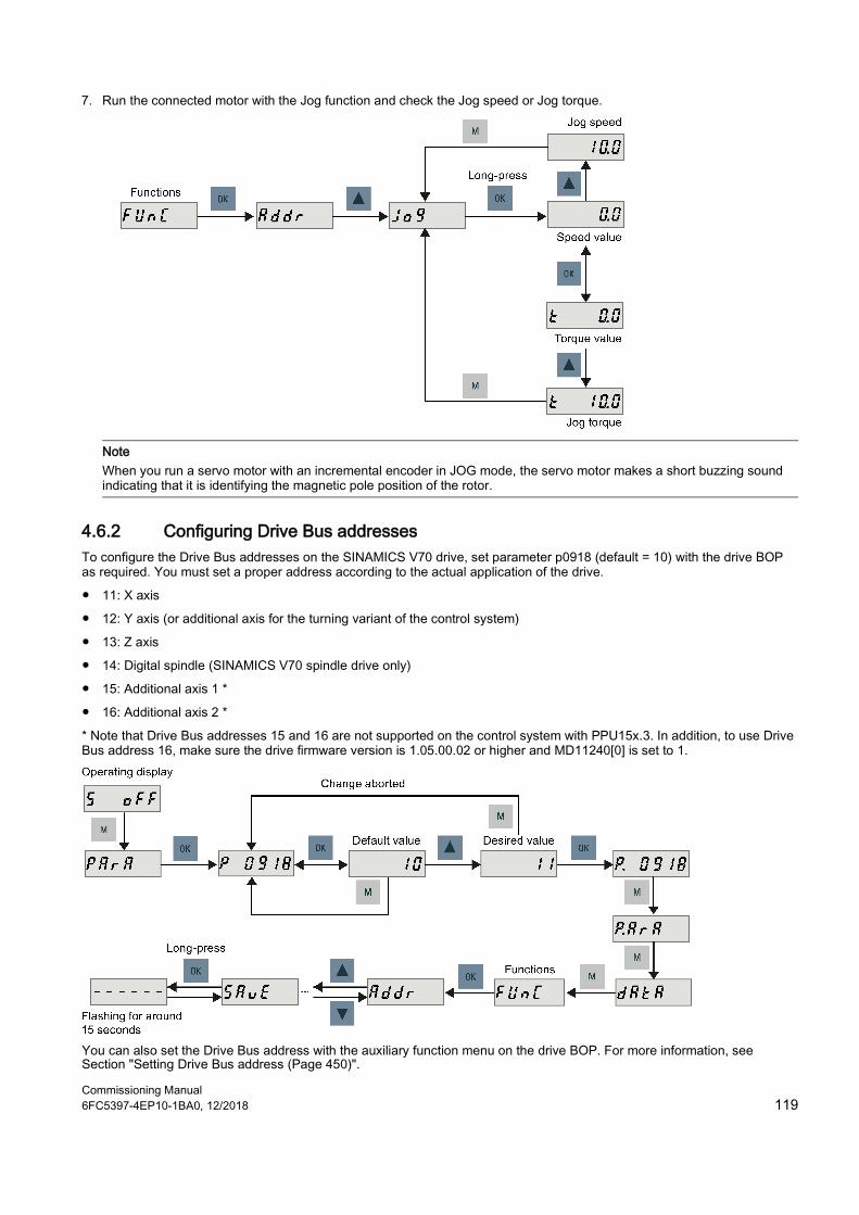
Commissioning Manual 6FC5397-4EP10-1BA0, 12/2018 119
7. Run the connected motor with the Jog function and check the Jog speed or Jog torque.
Note
When you run a servo motor with an incremental encoder in JOG mode, the servo motor makes a short buzzing sound indicating that it is identifying the magnetic pole position of the rotor.
4.6.2 Configuring Drive Bus addresses To configure the Drive Bus addresses on the SINAMICS V70 drive, set parameter p0918 (default = 10) with the drive BOP as required. You must set a proper address according to the actual application of the drive.
● 11: X axis
● 12: Y axis (or additional axis for the turning variant of the control system)
● 13: Z axis
● 14: Digital spindle (SINAMICS V70 spindle drive only)
● 15: Additional axis 1 *
● 16: Additional axis 2 *
* Note that Drive Bus addresses 15 and 16 are not supported on the control system with PPU15x.3. In addition, to use Drive Bus address 16, make sure the drive firmware version is 1.05.00.02 or higher and MD11240[0] is set to 1.
You can also set the Drive Bus address with the auxiliary function menu on the drive BOP. For more information, see Section "Setting Drive Bus address (Page 450)".
Commissioning Manual 120 6FC5397-4EP10-1BA0, 12/2018
Note Do not switch on the 24 VDC power supply for the SINUMERIK 808D ADVANCED before you finish setting the Drive Bus addresses for all connected drives. After setting a proper address, you must save the parameter and then restart the drive to apply your setting.
Note After the Drive Bus communication is established for the first time, the internal communication parameters are automatically changed and hence a dot appears on the display as follows:
You must perform a save operation to remove the dot.
Note After the Drive Bus communication is established, the BOP is protected from any operation except clearing alarms and acknowledging faults.
4.7 Switching on the control system
Preparation before switch-on
Make sure the following before switching on the control system:
● You have finished the mechanical installation of the whole system based on the information included in Chapter "Mounting (Page 49)".
● You have completed the wiring of the whole system according to the information included in Chapter "System connection (Page 73)" (if you use the default PLC program).
Operating sequence
1. Switch on the 24 VDC power supply to the control system. When the control system starts up for the first time, the following two alarms appear.
→
2. Press this key or the key combination to clear the alarms. For more information about the alarms and system responses, refer to the SINUMERIK 808D ADVANCED Diagnostics Manual.
3. When the control system enters the main screen, check the status LEDs on the PPU: • POK: green • RDY: green • TEMP: off
4. Check the status LEDs on the drive: • RDY: green • COM: slow flashing green every two seconds
Note The control system constantly creates restoring points during operation. In case of data loss due to power failure or other problems, the control system automatically restores the last autosaved system data upon startup with an alarm appearing on the screen.
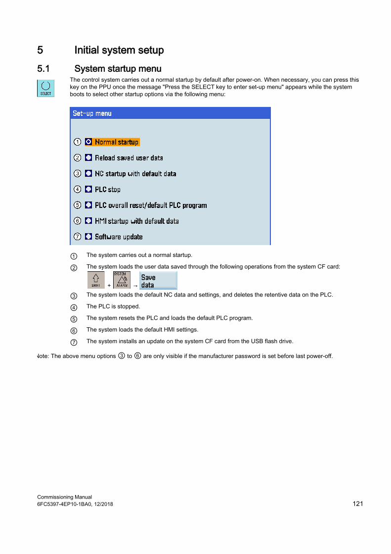
Commissioning Manual 6FC5397-4EP10-1BA0, 12/2018 121
5 Initial system setup 5.1 System startup menu
The control system carries out a normal startup by default after power-on. When necessary, you can press this key on the PPU once the message "Press the SELECT key to enter set-up menu" appears while the system boots to select other startup options via the following menu:
① The system carries out a normal startup.
② The system loads the user data saved through the following operations from the system CF card:
+ → ③ The system loads the default NC data and settings, and deletes the retentive data on the PLC.
④ The PLC is stopped.
⑤ The system resets the PLC and loads the default PLC program.
⑥ The system loads the default HMI settings.
⑦ The system installs an update on the system CF card from the USB flash drive.
Note: The above menu options ③ to ⑥ are only visible if the manufacturer password is set before last power-off.
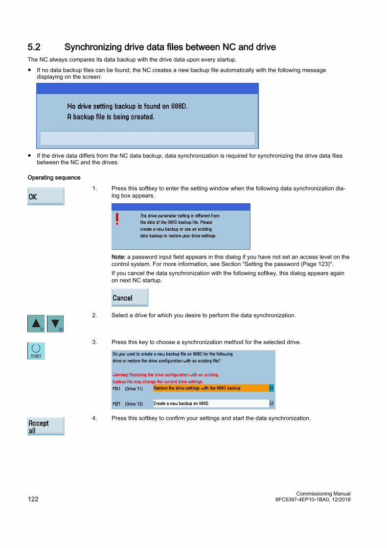
Commissioning Manual 122 6FC5397-4EP10-1BA0, 12/2018
5.2 Synchronizing drive data files between NC and drive The NC always compares its data backup with the drive data upon every startup.
● If no data backup files can be found, the NC creates a new backup file automatically with the following message displaying on the screen:
● If the drive data differs from the NC data backup, data synchronization is required for synchronizing the drive data files
between the NC and the drives.
Operating sequence
1. Press this softkey to enter the setting window when the following data synchronization dia-log box appears.
Note: a password input field appears in this dialog if you have not set an access level on the control system. For more information, see Section "Setting the password (Page 123)". If you cancel the data synchronization with the following softkey, this dialog appears again on next NC startup.
2. Select a drive for which you desire to perform the data synchronization.
3. Press this key to choose a synchronization method for the selected drive.
4. Press this softkey to confirm your settings and start the data synchronization.
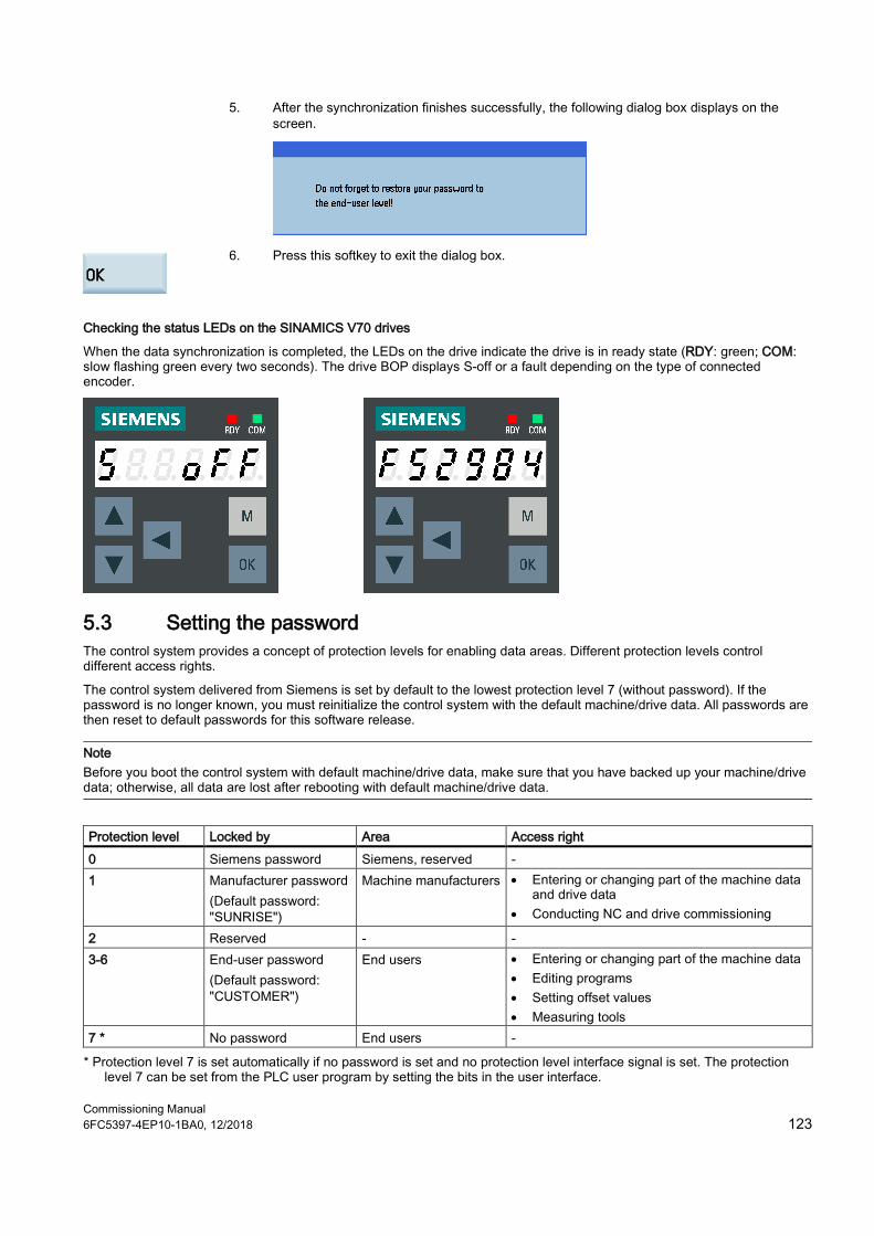
Commissioning Manual 6FC5397-4EP10-1BA0, 12/2018 123
5. After the synchronization finishes successfully, the following dialog box displays on the screen.
6. Press this softkey to exit the dialog box.
Checking the status LEDs on the SINAMICS V70 drives
When the data synchronization is completed, the LEDs on the drive indicate the drive is in ready state (RDY: green; COM: slow flashing green every two seconds). The drive BOP displays S-off or a fault depending on the type of connected encoder.
5.3 Setting the password The control system provides a concept of protection levels for enabling data areas. Different protection levels control different access rights.
The control system delivered from Siemens is set by default to the lowest protection level 7 (without password). If the password is no longer known, you must reinitialize the control system with the default machine/drive data. All passwords are then reset to default passwords for this software release.
Note Before you boot the control system with default machine/drive data, make sure that you have backed up your machine/drive data; otherwise, all data are lost after rebooting with default machine/drive data.
Protection level Locked by Area Access right 0 Siemens password Siemens, reserved - 1 Manufacturer password
(Default password: "SUNRISE")
Machine manufacturers • Entering or changing part of the machine data and drive data
• Conducting NC and drive commissioning
2 Reserved - - 3-6 End-user password
(Default password: "CUSTOMER")
End users • Entering or changing part of the machine data • Editing programs • Setting offset values • Measuring tools
7 * No password End users - * Protection level 7 is set automatically if no password is set and no protection level interface signal is set. The protection
level 7 can be set from the PLC user program by setting the bits in the user interface.

Commissioning Manual 124 6FC5397-4EP10-1BA0, 12/2018
The number of machine data and drive data which can be read or modified depends on the protection level. You can set the protection level for these function areas with the display machine data (USER_CLASS...).
The control system is delivered with no password. You must set the factory default manufacturer password "SUNRISE" to perform the commissioning work. Perform the following steps to enter the password:
+ 1. Select the system data operating area.
2. Press this vertical softkey to open the following dialog box.
3. Enter "SUNRISE" with the PPU keyboard and press this softkey. A message now shows at the bottom of the screen, which indicates that you have successfully set the password.
The following password operations are also available in this operating area:
Changes the default password of the control system
Note To avoid unauthorized access to the controller, you must change the Siemens default passwords to your own ones.
Deletes the current password
Note Clear the password before the machine is delivered; otherwise, end users can start the controller with the standard data, which can initialize the control system. As a consequence, the machine will not run.
5.4 Setting the date and time By default, the system date and time remain the factory settings. You can proceed through the following operating sequence to change the date and time as required.
Operating sequence
+ 1. Select the system data operating area.
2. Open the date and time setting window through the following softkey operations:
→ 3. Enter the date and time in the specified format.
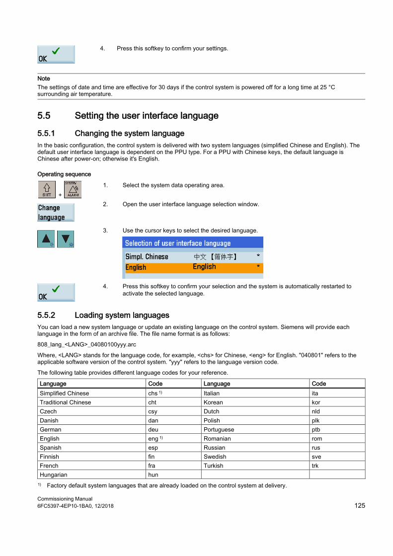
Commissioning Manual 6FC5397-4EP10-1BA0, 12/2018 125
4. Press this softkey to confirm your settings.
Note The settings of date and time are effective for 30 days if the control system is powered off for a long time at 25 °C surrounding air temperature.
5.5 Setting the user interface language
5.5.1 Changing the system language In the basic configuration, the control system is delivered with two system languages (simplified Chinese and English). The default user interface language is dependent on the PPU type. For a PPU with Chinese keys, the default language is Chinese after power-on; otherwise it's English.
Operating sequence
+ 1. Select the system data operating area.
2. Open the user interface language selection window.
3. Use the cursor keys to select the desired language.
4. Press this softkey to confirm your selection and the system is automatically restarted to activate the selected language.
5.5.2 Loading system languages You can load a new system language or update an existing language on the control system. Siemens will provide each language in the form of an archive file. The file name format is as follows:
808_lang_<LANG>_04080100yyy.arc
Where, <LANG> stands for the language code, for example, <chs> for Chinese, <eng> for English. "040801" refers to the applicable software version of the control system. "yyy" refers to the language version code.
The following table provides different language codes for your reference.
Language Code Language Code Simplified Chinese chs 1) Italian ita Traditional Chinese cht Korean kor Czech csy Dutch nld Danish dan Polish plk German deu Portuguese ptb English eng 1) Romanian rom Spanish esp Russian rus Finnish fin Swedish sve French fra Turkish trk Hungarian hun 1) Factory default system languages that are already loaded on the control system at delivery.
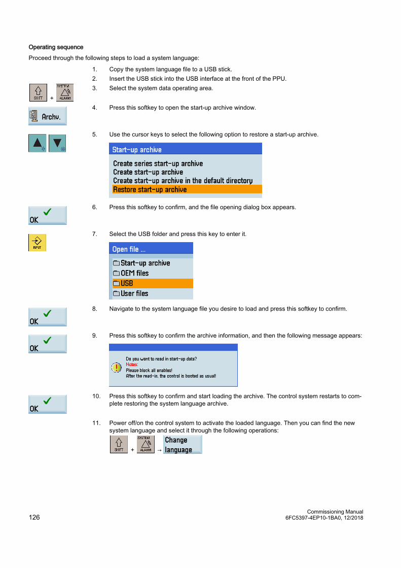
Commissioning Manual 126 6FC5397-4EP10-1BA0, 12/2018
Operating sequence
Proceed through the following steps to load a system language:
1. Copy the system language file to a USB stick. 2. Insert the USB stick into the USB interface at the front of the PPU.
+ 3. Select the system data operating area.
4. Press this softkey to open the start-up archive window.
5. Use the cursor keys to select the following option to restore a start-up archive.
6. Press this softkey to confirm, and the file opening dialog box appears.
7. Select the USB folder and press this key to enter it.
8. Navigate to the system language file you desire to load and press this softkey to confirm.
9. Press this softkey to confirm the archive information, and then the following message appears:
10. Press this softkey to confirm and start loading the archive. The control system restarts to com-plete restoring the system language archive.
11. Power off/on the control system to activate the loaded language. Then you can find the new system language and select it through the following operations:
+ →
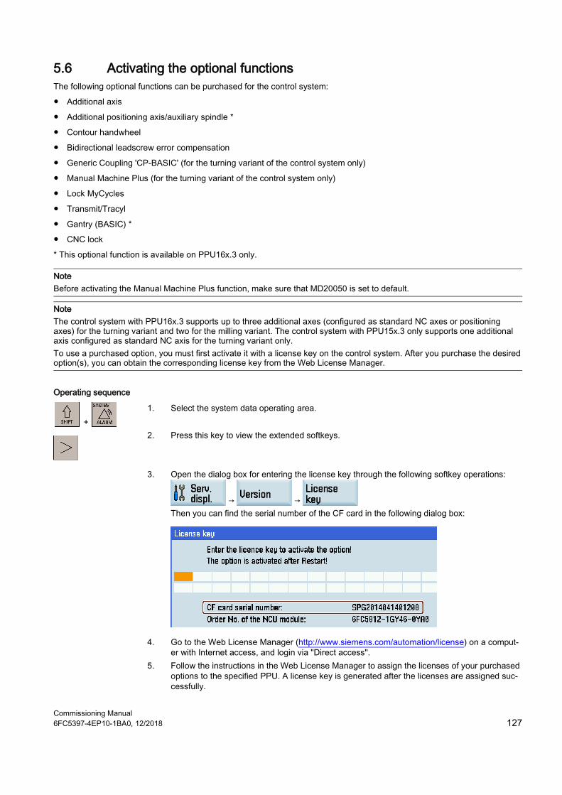
Commissioning Manual 6FC5397-4EP10-1BA0, 12/2018 127
5.6 Activating the optional functions The following optional functions can be purchased for the control system:
● Additional axis
● Additional positioning axis/auxiliary spindle *
● Contour handwheel
● Bidirectional leadscrew error compensation
● Generic Coupling 'CP-BASIC' (for the turning variant of the control system only)
● Manual Machine Plus (for the turning variant of the control system only)
● Lock MyCycles
● Transmit/Tracyl
● Gantry (BASIC) *
● CNC lock
* This optional function is available on PPU16x.3 only.
Note Before activating the Manual Machine Plus function, make sure that MD20050 is set to default.
Note The control system with PPU16x.3 supports up to three additional axes (configured as standard NC axes or positioning axes) for the turning variant and two for the milling variant. The control system with PPU15x.3 only supports one additional axis configured as standard NC axis for the turning variant only. To use a purchased option, you must first activate it with a license key on the control system. After you purchase the desired option(s), you can obtain the corresponding license key from the Web License Manager.
Operating sequence
+ 1. Select the system data operating area.
2. Press this key to view the extended softkeys.
3. Open the dialog box for entering the license key through the following softkey operations:
→ → Then you can find the serial number of the CF card in the following dialog box:
4. Go to the Web License Manager (http://www.siemens.com/automation/license) on a comput-er with Internet access, and login via "Direct access".
5. Follow the instructions in the Web License Manager to assign the licenses of your purchased options to the specified PPU. A license key is generated after the licenses are assigned suc-cessfully.

Commissioning Manual 128 6FC5397-4EP10-1BA0, 12/2018
6. Enter the license key generated by the Web License Manager in the following dialog box:
7. Press this softkey to confirm your entry.
8. Press this softkey to open the window of available options. You can find the licensing status in this window, for example:
If you have licensed one or more additional axes, you can find the number of the licensed
axes in the column of licensing status. For other licensed options, a "☑" symbol displays in this column.
Note: The last option (see below) in this window indicates the variant information and the licensing status of your control system, for example:
In case of any problems with the licensing status of your control system, contact Siemens service personnel.
9. Set the licensed options. • For the additional axes, enter a number as required in the setting column and press the
following key:
• For the other options, press the following key to select:
10. Press this softkey to restart the NCK, so that the licensed options are activated.
Note To use the CNC lock function, further activation operations are required after the CNC lock option is activated. For more information, see Section "CNC lock function (Page 267)".

Commissioning Manual 6FC5397-4EP10-1BA0, 12/2018 129
6 Commissioning the PLC 6.1 PLC programming conventions
Program organization
During the PLC programming, you must structure your program into finished program parts (subroutines). The programming language for the S7-200 offers you the capability to set up your user program in a structured manner.
There are the following two types of programs:
● Main program
● Subroutine
Eight levels of programming are possible.
6.2 Signal overview of PLC interface The PLC program exchanges information among the NCK, HMI, MCP, and I/O through the signals of the PLC interface and signals of the input and output cards.

Commissioning Manual 130 6FC5397-4EP10-1BA0, 12/2018
6.3 Operation symbols of PLC programming languages
Operand identifier
Address identifier Description Range DB Data DB1000 to DB7999
DB9900 to DB9906 T Timers T0 to T15 (100 ms)
T16 to T63 (10 ms) C Counters C0 to C63 I Image of digital inputs I0.0 to I8.7 Q Image of digital outputs Q0.0 to Q5.7 M Bit memory M0.0 to M255.7 SM Special bit memory SM0.0 to SM0.6 () AC Accumulators AC0 to AC3
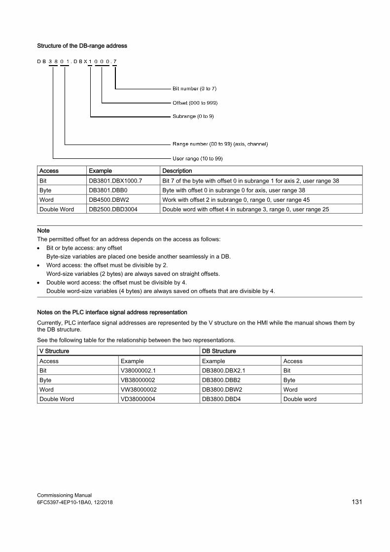
Commissioning Manual 6FC5397-4EP10-1BA0, 12/2018 131
Structure of the DB-range address
Access Example Description Bit DB3801.DBX1000.7 Bit 7 of the byte with offset 0 in subrange 1 for axis 2, user range 38 Byte DB3801.DBB0 Byte with offset 0 in subrange 0 for axis, user range 38 Word DB4500.DBW2 Work with offset 2 in subrange 0, range 0, user range 45 Double Word DB2500.DBD3004 Double word with offset 4 in subrange 3, range 0, user range 25
Note The permitted offset for an address depends on the access as follows: • Bit or byte access: any offset
Byte-size variables are placed one beside another seamlessly in a DB. • Word access: the offset must be divisible by 2.
Word-size variables (2 bytes) are always saved on straight offsets. • Double word access: the offset must be divisible by 4.
Double word-size variables (4 bytes) are always saved on offsets that are divisible by 4.
Notes on the PLC interface signal address representation
Currently, PLC interface signal addresses are represented by the V structure on the HMI while the manual shows them by the DB structure.
See the following table for the relationship between the two representations.
V Structure DB Structure Access Example Example Access Bit V38000002.1 DB3800.DBX2.1 Bit Byte VB38000002 DB3800.DBB2 Byte Word VW38000002 DB3800.DBW2 Word Double Word VD38000004 DB3800.DBD4 Double word
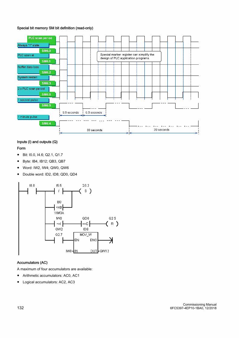
Commissioning Manual 132 6FC5397-4EP10-1BA0, 12/2018
Special bit memory SM bit definition (read-only)
Inputs (I) and outputs (Q)
Form
● Bit: I0.0, I4.6; Q2.1, Q1.7
● Byte: IB4, IB12; QB3, QB7
● Word: IW2, IW4; QW0, QW6
● Double word: ID2, ID8; QD0, QD4
Accumulators (AC)
A maximum of four accumulators are available:
● Arithmetic accumulators: AC0, AC1
● Logical accumulators: AC2, AC3
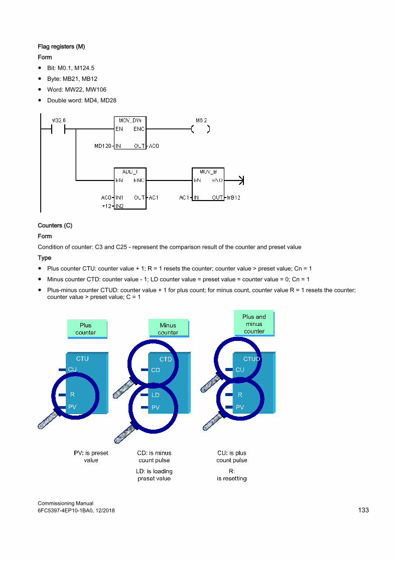
Commissioning Manual 6FC5397-4EP10-1BA0, 12/2018 133
Flag registers (M)
Form
● Bit: M0.1, M124.5
● Byte: MB21, MB12
● Word: MW22, MW106
● Double word: MD4, MD28
Counters (C)
Form
Condition of counter: C3 and C25 - represent the comparison result of the counter and preset value
Type
● Plus counter CTU: counter value + 1; R = 1 resets the counter; counter value > preset value; Cn = 1
● Minus counter CTD: counter value - 1; LD counter value = preset value = counter value = 0; Cn = 1
● Plus-minus counter CTUD: counter value + 1 for plus count; for minus count, counter value R = 1 resets the counter; counter value > preset value; C = 1

Commissioning Manual 134 6FC5397-4EP10-1BA0, 12/2018
Timers (T)
Form
Condition of timer: T3 and T25 - represent the comparison result of timer value and preset value
Type
● On-delay timer TON: IN = 1 starts timing; IN = 0 resets timer; timer value > preset value; Tn = 1
● Off-delay timer TOF: IN = 1 resets timer; IN = 0 starts timing; timer value > preset value; Tn = 0
● Retentive delay timer CTUD: IN = 1 starts timing; IN = 0 stops timing; timer value > preset value; Tn = 1
Assigning value "0" to T resets the timer.
Variable access rights
[r] You can "read only" the designated area. [r/w] You can "read and write" the designated area.
Data format information
1 BIT 8 BYTE 16 INT/WORD 32 DINT/DWORD/REAL
Note All of the empty fields in the user interface are reserved for Siemens and may neither be written to nor be evaluated. Fields designated with "0" always have the value "logical 0". If there is no data format information, you can read or write to all the specified data formats.
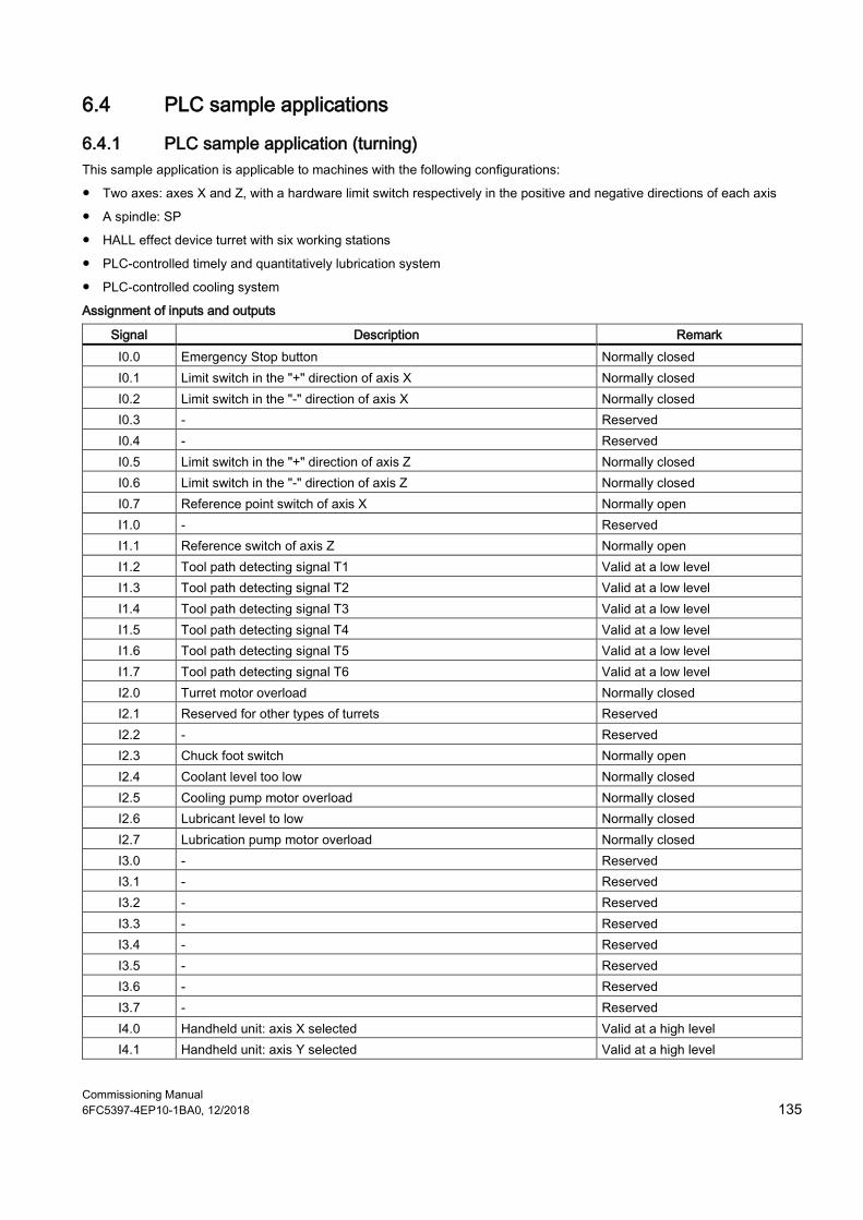
Commissioning Manual 6FC5397-4EP10-1BA0, 12/2018 135
6.4 PLC sample applications
6.4.1 PLC sample application (turning) This sample application is applicable to machines with the following configurations:
● Two axes: axes X and Z, with a hardware limit switch respectively in the positive and negative directions of each axis
● A spindle: SP
● HALL effect device turret with six working stations
● PLC-controlled timely and quantitatively lubrication system
● PLC-controlled cooling system
Assignment of inputs and outputs
Signal Description Remark I0.0 Emergency Stop button Normally closed I0.1 Limit switch in the "+" direction of axis X Normally closed I0.2 Limit switch in the "-" direction of axis X Normally closed I0.3 - Reserved I0.4 - Reserved I0.5 Limit switch in the "+" direction of axis Z Normally closed I0.6 Limit switch in the "-" direction of axis Z Normally closed I0.7 Reference point switch of axis X Normally open I1.0 - Reserved I1.1 Reference switch of axis Z Normally open I1.2 Tool path detecting signal T1 Valid at a low level I1.3 Tool path detecting signal T2 Valid at a low level I1.4 Tool path detecting signal T3 Valid at a low level I1.5 Tool path detecting signal T4 Valid at a low level I1.6 Tool path detecting signal T5 Valid at a low level I1.7 Tool path detecting signal T6 Valid at a low level I2.0 Turret motor overload Normally closed I2.1 Reserved for other types of turrets Reserved I2.2 - Reserved I2.3 Chuck foot switch Normally open I2.4 Coolant level too low Normally closed I2.5 Cooling pump motor overload Normally closed I2.6 Lubricant level to low Normally closed I2.7 Lubrication pump motor overload Normally closed I3.0 - Reserved I3.1 - Reserved I3.2 - Reserved I3.3 - Reserved I3.4 - Reserved I3.5 - Reserved I3.6 - Reserved I3.7 - Reserved I4.0 Handheld unit: axis X selected Valid at a high level I4.1 Handheld unit: axis Y selected Valid at a high level
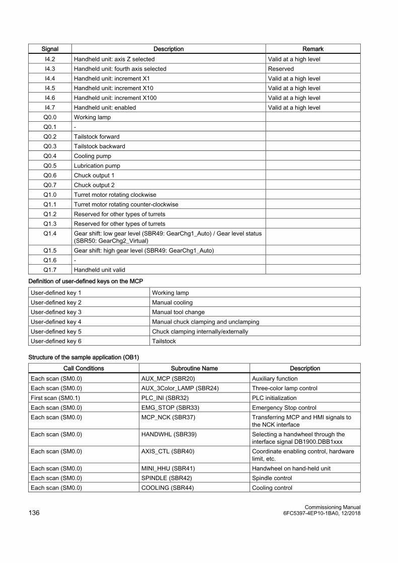
Commissioning Manual 136 6FC5397-4EP10-1BA0, 12/2018
Signal Description Remark I4.2 Handheld unit: axis Z selected Valid at a high level I4.3 Handheld unit: fourth axis selected Reserved I4.4 Handheld unit: increment X1 Valid at a high level I4.5 Handheld unit: increment X10 Valid at a high level I4.6 Handheld unit: increment X100 Valid at a high level I4.7 Handheld unit: enabled Valid at a high level Q0.0 Working lamp Q0.1 - Q0.2 Tailstock forward Q0.3 Tailstock backward Q0.4 Cooling pump Q0.5 Lubrication pump Q0.6 Chuck output 1 Q0.7 Chuck output 2 Q1.0 Turret motor rotating clockwise Q1.1 Turret motor rotating counter-clockwise Q1.2 Reserved for other types of turrets Q1.3 Reserved for other types of turrets Q1.4 Gear shift: low gear level (SBR49: GearChg1_Auto) / Gear level status
(SBR50: GearChg2_Virtual)
Q1.5 Gear shift: high gear level (SBR49: GearChg1_Auto) Q1.6 - Q1.7 Handheld unit valid
Definition of user-defined keys on the MCP
User-defined key 1 Working lamp User-defined key 2 Manual cooling User-defined key 3 Manual tool change User-defined key 4 Manual chuck clamping and unclamping User-defined key 5 Chuck clamping internally/externally User-defined key 6 Tailstock
Structure of the sample application (OB1)
Call Conditions Subroutine Name Description Each scan (SM0.0) AUX_MCP (SBR20) Auxiliary function Each scan (SM0.0) AUX_3Color_LAMP (SBR24) Three-color lamp control First scan (SM0.1) PLC_INI (SBR32) PLC initialization Each scan (SM0.0) EMG_STOP (SBR33) Emergency Stop control Each scan (SM0.0) MCP_NCK (SBR37) Transferring MCP and HMI signals to
the NCK interface Each scan (SM0.0) HANDWHL (SBR39) Selecting a handwheel through the
interface signal DB1900.DBB1xxx Each scan (SM0.0) AXIS_CTL (SBR40) Coordinate enabling control, hardware
limit, etc. Each scan (SM0.0) MINI_HHU (SBR41) Handwheel on hand-held unit Each scan (SM0.0) SPINDLE (SBR42) Spindle control Each scan (SM0.0) COOLING (SBR44) Cooling control
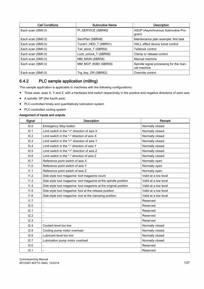
Commissioning Manual 6FC5397-4EP10-1BA0, 12/2018 137
Call Conditions Subroutine Name Description Each scan (SM0.0) PI_SERVICE (SBR46) ASUP (Asynchronous Subroutine Pro-
gram) Each scan (SM0.0) ServPlan (SBR48) Maintenance plan example: first task Each scan (SM0.0) Turret1_HED_T (SBR51) HALL effect device turret control Each scan (SM0.0) Tail_stock_T (SBR55) Tailstock control Each scan (SM0.0) Lock_unlock_T (SBR56) Clamp or release control Each scan (SM0.0) MM_MAIN (SBR58) Manual machine Each scan (SM0.0) MM_MCP_808D (SBR59) Spindle signal processing for the man-
ual machine Each scan (SM0.0) Trg_key_OR (SBR62) Override control
6.4.2 PLC sample application (milling) This sample application is applicable to machines with the following configurations:
● Three axes: axes X, Y and Z, with a hardware limit switch respectively in the positive and negative directions of each axis
● A spindle: SP (the fourth axis)
● PLC-controlled timely and quantitatively lubrication system
● PLC-controlled cooling system
Assignment of inputs and outputs
Signal Description Remark I0.0 Emergency Stop button Normally closed I0.1 Limit switch in the "+" direction of axis X Normally closed I0.2 Limit switch in the "-" direction of axis X Normally closed I0.3 Limit switch in the "+" direction of axis Y Normally closed I0.4 Limit switch in the "-" direction of axis Y Normally closed I0.5 Limit switch in the "+" direction of axis Z Normally closed I0.6 Limit switch in the "-" direction of axis Z Normally closed I0.7 Reference point switch of axis X Normally open I1.0 Reference point switch of axis Y Normally open I1.1 Reference point switch of axis Z Normally open I1.2 Disk-style tool magazine: tool magazine count Valid at a low level I1.3 Disk-style tool magazine: tool magazine at the spindle position Valid at a low level I1.4 Disk-style tool magazine: tool magazine at the original position Valid at a low level I1.5 Disk-style tool magazine: tool at the release position Valid at a low level I1.6 Disk-style tool magazine: tool at the clamping position Valid at a low level I1.7 - Reserved I2.0 - Reserved I2.1 - Reserved I2.2 - Reserved I2.3 - Reserved I2.4 Coolant level too low Normally closed I2.5 Cooling pump motor overload Normally closed I2.6 Lubricant level too low Normally closed I2.7 Lubrication pump motor overload Normally closed I3.0 - Reserved I3.1 - Reserved

Commissioning Manual 138 6FC5397-4EP10-1BA0, 12/2018
Signal Description Remark I3.2 - Reserved I3.3 - Reserved I3.4 - Reserved I3.5 - Reserved I3.6 - Reserved I3.7 - Reserved I4.0 Handheld unit: axis X selected Valid at a high level I4.1 Handheld unit: axis Y selected Valid at a high level I4.2 Handheld unit: axis Z selected Valid at a high level I4.3 Handheld unit: fourth axis selected Valid at a high level I4.4 Handheld unit: increment X1 Valid at a high level I4.5 Handheld unit: increment X10 Valid at a high level I4.6 Handheld unit: increment X100 Valid at a high level I4.7 Handheld unit: enabled Valid at a high level Q0.0 Working lamp Q0.1 - Q0.2 Chip forward Q0.3 Chip backward Q0.4 Cooling pump Q0.5 Lubrication pump Q0.6 Safety door open Q0.7 - Q1.0 Magazine rotating clockwise Q1.1 Magazine rotating counter-clockwise Q1.2 Magazine approaching spindle position Q1.3 Magazine approaching original position Q1.4 Tool release from the spindle Q1.5 - Q1.6 - Q1.7 Handheld unit valid
Definition of user-defined keys on the MCP
User-defined key 1 Working lamp User-defined key 2 Manual cooling User-defined key 3 Safety door User-defined key 4 Manual clockwise rotation of the tool magazine User-defined key 5 Manual reset of the tool magazine User-defined key 6 Manual counter-clockwise rotation of the tool magazine User-defined key 7 Removing chip forward User-defined key 8 Removing chip backward
Structure of the sample application (OB1)
Call Conditions Subroutine Name Description Each scan (SM0.0) AUX_MCP (SBR20) Auxiliary function First scan (SM0.1) PLC_INI (SBR32) PLC initialization Each scan (SM0.0) EMG_STOP (SBR33) Emergency Stop control
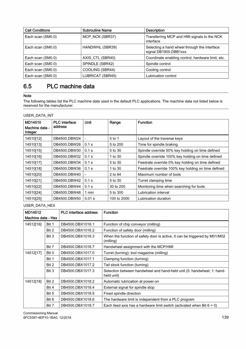
Commissioning Manual 6FC5397-4EP10-1BA0, 12/2018 139
Call Conditions Subroutine Name Description Each scan (SM0.0) MCP_NCK (SBR37) Transferring MCP and HMI signals to the NCK
interface Each scan (SM0.0) HANDWHL (SBR39) Selecting a hand wheel through the interface
signal DB1900.DBB1xxx Each scan (SM0.0) AXIS_CTL (SBR40) Coordinate enabling control, hardware limit, etc. Each scan (SM0.0) SPINDLE (SBR42) Spindle control Each scan (SM0.0) COOLING (SBR44) Cooling control Each scan (SM0.0) LUBRICAT (SBR45) Lubrication control
6.5 PLC machine data
Note The following tables list the PLC machine data used in the default PLC applications. The machine data not listed below is reserved for the manufacturer.
USER_DATA_INT
MD14510 Machine data - Integer
PLC interface address
Unit Range Function
14510[12] DB4500.DBW24 - 0 to 1 Layout of the traverse keys 14510[13] DB4500.DBW26 0.1 s 5 to 200 Time for spindle braking 14510[15] DB4500.DBW30 0.1 s 5 to 30 Spindle override 50% key holding on time defined 14510[16] DB4500.DBW32 0.1 s 1 to 30 Spindle override 100% key holding on time defined 14510[17] DB4500.DBW34 0.1 s 5 to 30 Feedrate override 0% key holding on time defined 14510[18] DB4500.DBW36 0.1 s 1 to 30 Feedrate override 100% key holding on time defined 14510[20] DB4500.DBW40 - 2 to 64 Maximum number of tools 14510[21] DB4500.DBW42 0.1 s 5 to 30 Turret clamping time 14510[22] DB4500.DBW44 0.1 s 30 to 200 Monitoring time when searching for tools 14510[24] DB4500.DBW48 1 min 5 to 300 Lubrication interval 14510[25] DB4500.DBW50 0.01 s 100 to 2000 Lubrication duration
USER_DATA_HEX
MD14512 Machine data - Hex
PLC interface address Function
14512[16] Bit 1 DB4500.DBX1016.1 Function of chip conveyor (milling) Bit 2 DB4500.DBX1016.2 Function of safety door (milling) Bit 3 DB4500.DBX1016.3 When the function of safety door is active, it can be triggered by M01/M02
(milling) Bit 7 DB4500.DBX1016.7 Handwheel assignment with the MCP/HMI
14512[17] Bit 0 DB4500.DBX1017.0 Turret (turning); tool magazine (milling) Bit 1 DB4500.DBX1017.1 Clamping function (turning) Bit 2 DB4500.DBX1017.2 Tail stock function (turning) Bit 3 DB4500.DBX1017.3 Selection between handwheel and hand-held unit (0: handwheel; 1: hand-
held unit) 14512[18] Bit 2 DB4500.DBX1018.2 Automatic lubrication at power-on
Bit 4 DB4500.DBX1018.4 External signal for spindle stop Bit 5 DB4500.DBX1018.5 Fixed spindle direction Bit 6 DB4500.DBX1018.6 The hardware limit is independent from a PLC program Bit 7 DB4500.DBX1018.7 Each feed axis has a hardware limit switch (activated when Bit 6 = 0)
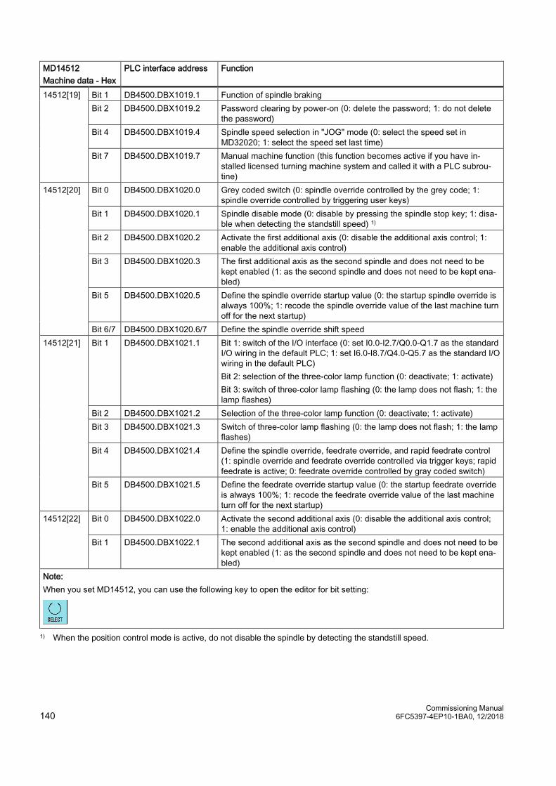
Commissioning Manual 140 6FC5397-4EP10-1BA0, 12/2018
MD14512 Machine data - Hex
PLC interface address Function
14512[19] Bit 1 DB4500.DBX1019.1 Function of spindle braking Bit 2 DB4500.DBX1019.2 Password clearing by power-on (0: delete the password; 1: do not delete
the password) Bit 4 DB4500.DBX1019.4 Spindle speed selection in "JOG" mode (0: select the speed set in
MD32020; 1: select the speed set last time) Bit 7 DB4500.DBX1019.7 Manual machine function (this function becomes active if you have in-
stalled licensed turning machine system and called it with a PLC subrou-tine)
14512[20] Bit 0 DB4500.DBX1020.0 Grey coded switch (0: spindle override controlled by the grey code; 1: spindle override controlled by triggering user keys)
Bit 1 DB4500.DBX1020.1 Spindle disable mode (0: disable by pressing the spindle stop key; 1: disa-ble when detecting the standstill speed) 1)
Bit 2 DB4500.DBX1020.2 Activate the first additional axis (0: disable the additional axis control; 1: enable the additional axis control)
Bit 3 DB4500.DBX1020.3 The first additional axis as the second spindle and does not need to be kept enabled (1: as the second spindle and does not need to be kept ena-bled)
Bit 5 DB4500.DBX1020.5 Define the spindle override startup value (0: the startup spindle override is always 100%; 1: recode the spindle override value of the last machine turn off for the next startup)
Bit 6/7 DB4500.DBX1020.6/7 Define the spindle override shift speed 14512[21] Bit 1 DB4500.DBX1021.1 Bit 1: switch of the I/O interface (0: set I0.0-I2.7/Q0.0-Q1.7 as the standard
I/O wiring in the default PLC; 1: set I6.0-I8.7/Q4.0-Q5.7 as the standard I/O wiring in the default PLC) Bit 2: selection of the three-color lamp function (0: deactivate; 1: activate) Bit 3: switch of three-color lamp flashing (0: the lamp does not flash; 1: the lamp flashes)
Bit 2 DB4500.DBX1021.2 Selection of the three-color lamp function (0: deactivate; 1: activate) Bit 3 DB4500.DBX1021.3 Switch of three-color lamp flashing (0: the lamp does not flash; 1: the lamp
flashes) Bit 4 DB4500.DBX1021.4 Define the spindle override, feedrate override, and rapid feedrate control
(1: spindle override and feedrate override controlled via trigger keys; rapid feedrate is active; 0: feedrate override controlled by gray coded switch)
Bit 5 DB4500.DBX1021.5 Define the feedrate override startup value (0: the startup feedrate override is always 100%; 1: recode the feedrate override value of the last machine turn off for the next startup)
14512[22] Bit 0 DB4500.DBX1022.0 Activate the second additional axis (0: disable the additional axis control; 1: enable the additional axis control)
Bit 1 DB4500.DBX1022.1 The second additional axis as the second spindle and does not need to be kept enabled (1: as the second spindle and does not need to be kept ena-bled)
Note: When you set MD14512, you can use the following key to open the editor for bit setting:
1) When the position control mode is active, do not disable the spindle by detecting the standstill speed.

Commissioning Manual 6FC5397-4EP10-1BA0, 12/2018 141
USER_DATA_FLOAT
MD14514 Machine data - Float
PLC interface address
Unit Range Function
14514[0] DB4500.DBD2000 - -3.40e38 to 3.40e38 Tool magazine: spindle poisoning angle 14514[1] DB4500.DBD2004 - -3.40e38 to 3.40e38 Tool magazine: preparation position of Z axis for tool
change 14514[2] DB4500.DBD2008 - -3.40e38 to 3.40e38 Tool magazine: tool change position of Z axis 14514[3] DB4500.DBD2012 - -3.40e38 to 3.40e38 Tool magazine: velocity of Z axis, go to tool change
position 14514[4] DB4500.DBD2016 - -3.40e38 to 3.40e38 Tool magazine: velocity of Z axis, back to tool
change preparation position
6.6 PLC subroutine library
6.6.1 Overview In order to simplify the PLC design, we provide refined PLC functions which have generality, such as initialization, machine panel signal processing, emergency stop processing, axis enable control, hard limit, and reference point etc. By adding the desired subroutine module to the main procedure, plus other supplementary procedures, you can complete the PLC procedure design easily.
The PLC subroutine library consists of the following files:
● PLC project file: SAMPLE_TURN.PTP (application program as examples for a turning machine)
● PLC project file: SAMPLE_MILL.PTP (application program as examples for a milling machine)
Note Through these examples, you can clearly realize how to create or invoke PLC subroutines. You can reorganize PLC subroutines or modify networks to realize most machine functions, test and debug subroutines of the library.
System resource
Resource
PLC system resource
Input I0.0 to I2.7 (24 inputs on X100, X101, and X102) I6.0 to I8.7 (48 distributed inputs on X301 and X302)
Output Q0.0 to Q1.7 (16 outputs on X200 and X201) Q4.0 to Q5.7 (32 distributed outputs on X301 and X302)
RAM M0.0 to M255.7 (256 bytes) Non-volatile memory DB1400.DBX0.0 to DB14000.DBX127.7 (128 bytes) PLC user alarm DB1600.DBX0.0 to DB16000.DBX15.7 (128 user alarms) Timer T0 to T15 (100 ms timer) T16 to T32 (10 ms timer) Counter C0 to C63 (64 counters)
NC resource
Parameter MD14510(32)
Statistic INT: DB4500.DBW0 to DB4500.DBW62 (32 double words)
Parameter MD14514(32)
Statistic HEX: DB4500.DBB1000 to DB4500.DBB1031 (32 bytes)
Parameter MD14514(8)
Statistic REAL: DB4500.DBD2000 to DB4500.DBD2028 (8 double words)
Programming tool resource
Subroutine (64) SBR0 to SBR63 (64 subroutines) Symbol table (32) SYM1 to SYM32 (32 symbol tables)
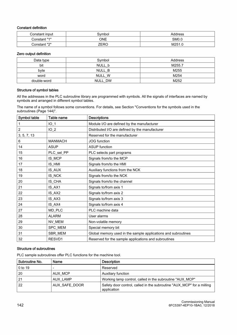
Commissioning Manual 142 6FC5397-4EP10-1BA0, 12/2018
Constant definition
Constant input Symbol Address Constant "1" ONE SM0.0 Constant "2" ZERO M251.0
Zero output definition
Data type Symbol Address bit NULL_b M255.7
byte NULL_B M255 word NULL_W M254
double-word NULL_DW M252
Structure of symbol tables
All the addresses in the PLC subroutine library are programmed with symbols. All the signals of interfaces are named by symbols and arranged in different symbol tables.
The name of a symbol follows some conventions. For details, see Section "Conventions for the symbols used in the subroutines (Page 144)".
Symbol table Table name Descriptions 1 IO_1 Module I/O are defined by the manufacturer 2 IO_2 Distributed I/O are defined by the manufacturer 3, 5, 7, 13 Reserved for the manufacturer 6 MANMACH JOG function 14 ASUP ASUP function 15 PLC_sel_PP PLC selects part programs 16 IS_MCP Signals from/to the MCP 17 IS_HMI Signals from/to the HMI 18 IS_AUX Auxiliary functions from the NCK 19 IS_NCK Signals from/to the NCK 20 IS_CHA Signals from/to the channel 21 IS_AX1 Signals to/from axis 1 22 IS_AX2 Signals to/from axis 2 23 IS_AX3 Signals to/from axis 3 24 IS_AX4 Signals to/from axis 4 27 MD_PLC PLC machine data 28 ALARM User alarms 29 NV_MEM Non-volatile memory 30 SPC_MEM Special memory bit 31 SBR_MEM Global memory used in the sample applications and subroutines 32 RESVD1 Reserved for the sample applications and subroutines
Structure of subroutines
PLC sample subroutines offer PLC functions for the machine tool.
Subroutine No. Name Description 0 to 19 - Reserved 20 AUX_MCP Auxiliary function 21 AUX_LAMP Working lamp control, called in the subroutine "AUX_MCP" 22 AUX_SAFE_DOOR Safety door control, called in the subroutine "AUX_MCP" for a milling
application
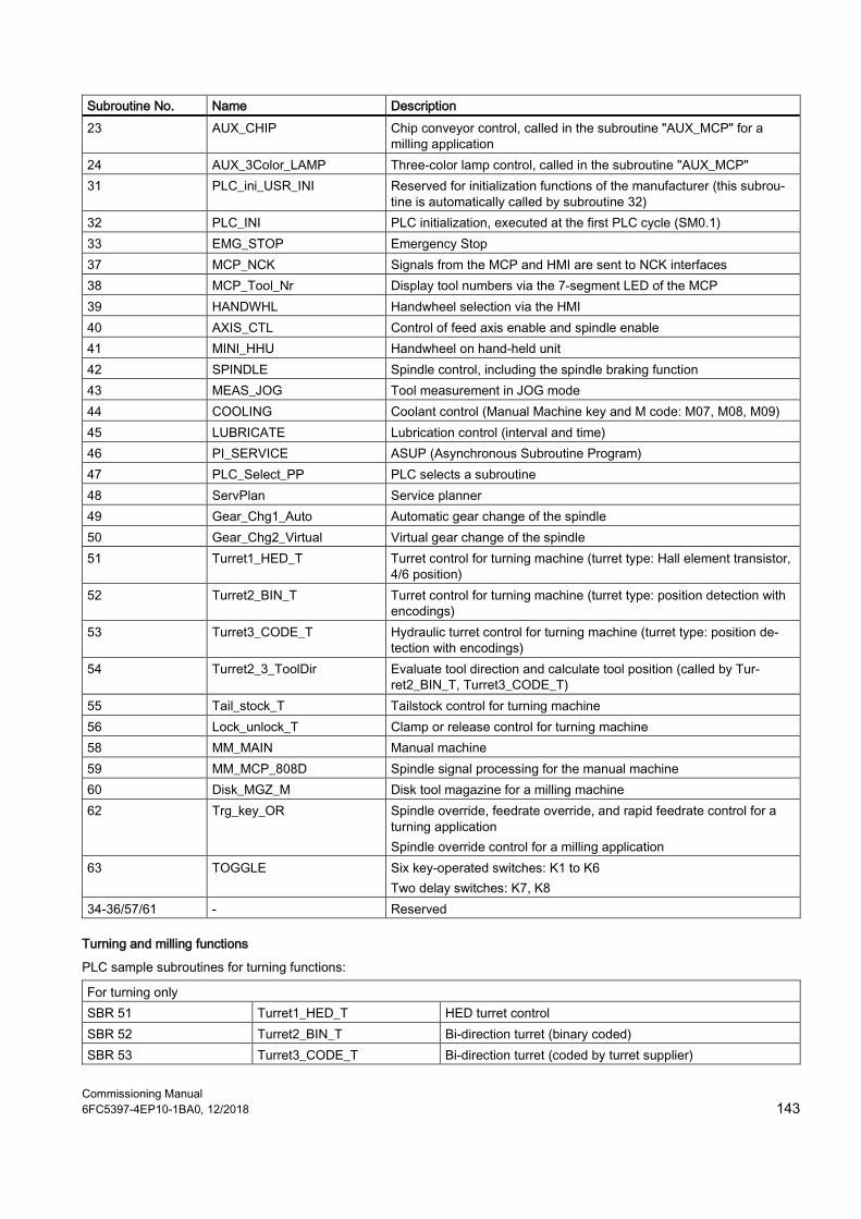
Commissioning Manual 6FC5397-4EP10-1BA0, 12/2018 143
Subroutine No. Name Description 23 AUX_CHIP Chip conveyor control, called in the subroutine "AUX_MCP" for a
milling application 24 AUX_3Color_LAMP Three-color lamp control, called in the subroutine "AUX_MCP" 31 PLC_ini_USR_INI Reserved for initialization functions of the manufacturer (this subrou-
tine is automatically called by subroutine 32) 32 PLC_INI PLC initialization, executed at the first PLC cycle (SM0.1) 33 EMG_STOP Emergency Stop 37 MCP_NCK Signals from the MCP and HMI are sent to NCK interfaces 38 MCP_Tool_Nr Display tool numbers via the 7-segment LED of the MCP 39 HANDWHL Handwheel selection via the HMI 40 AXIS_CTL Control of feed axis enable and spindle enable 41 MINI_HHU Handwheel on hand-held unit 42 SPINDLE Spindle control, including the spindle braking function 43 MEAS_JOG Tool measurement in JOG mode 44 COOLING Coolant control (Manual Machine key and M code: M07, M08, M09) 45 LUBRICATE Lubrication control (interval and time) 46 PI_SERVICE ASUP (Asynchronous Subroutine Program) 47 PLC_Select_PP PLC selects a subroutine 48 ServPlan Service planner 49 Gear_Chg1_Auto Automatic gear change of the spindle 50 Gear_Chg2_Virtual Virtual gear change of the spindle 51 Turret1_HED_T Turret control for turning machine (turret type: Hall element transistor,
4/6 position) 52 Turret2_BIN_T Turret control for turning machine (turret type: position detection with
encodings) 53 Turret3_CODE_T Hydraulic turret control for turning machine (turret type: position de-
tection with encodings) 54 Turret2_3_ToolDir Evaluate tool direction and calculate tool position (called by Tur-
ret2_BIN_T, Turret3_CODE_T) 55 Tail_stock_T Tailstock control for turning machine 56 Lock_unlock_T Clamp or release control for turning machine 58 MM_MAIN Manual machine 59 MM_MCP_808D Spindle signal processing for the manual machine 60 Disk_MGZ_M Disk tool magazine for a milling machine 62 Trg_key_OR Spindle override, feedrate override, and rapid feedrate control for a
turning application Spindle override control for a milling application
63 TOGGLE Six key-operated switches: K1 to K6 Two delay switches: K7, K8
34-36/57/61 - Reserved
Turning and milling functions
PLC sample subroutines for turning functions:
For turning only SBR 51 Turret1_HED_T HED turret control SBR 52 Turret2_BIN_T Bi-direction turret (binary coded) SBR 53 Turret3_CODE_T Bi-direction turret (coded by turret supplier)
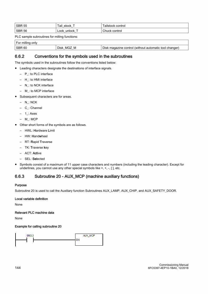
Commissioning Manual 144 6FC5397-4EP10-1BA0, 12/2018
SBR 55 Tail_stock_T Tailstock control SBR 56 Lock_unlock_T Chuck control
PLC sample subroutines for milling functions:
For milling only SBR 60 Disk_MGZ_M Disk magazine control (without automatic tool changer)
6.6.2 Conventions for the symbols used in the subroutines The symbols used in the subroutines follow the conventions listed below:
● Leading characters designate the destinations of interface signals.
– P_: to PLC interface
– H_: to HMI interface
– N_: to NCK interface
– M_: to MCP interface
● Subsequent characters are for areas.
– N_: NCK
– C_: Channel
– 1_: Axes
– M_: MCP
● Other short forms of the symbols are as follows.
– HWL: Hardware Limit
– HW: Handwheel
– RT: Rapid Traverse
– TK: Traverse key
– ACT: Active
– SEL: Selected
● Symbols consist of a maximum of 11 upper case characters and numbers (including the leading character). Except for underlines, you cannot use any other special symbols like =, +, -, [ ], etc.
6.6.3 Subroutine 20 - AUX_MCP (machine auxiliary functions)
Purpose
Subroutine 20 is used to call the Auxiliary function Subroutines AUX_LAMP, AUX_CHIP, and AUX_SAFETY_DOOR.
Local variable definition
None
Relevant PLC machine data
None
Example for calling subroutine 20

Commissioning Manual 6FC5397-4EP10-1BA0, 12/2018 145
6.6.4 Subroutine 21 - AUX_LAMP (working lamp)
Purpose
Subroutine 21 is used to control working lamp and can be called in AUX_MCP. One-time pressing of the "LAMP" key activates the working lamp while double pressing de-activates the working lamp.
Local variable definition
Inputs
Variable Type Description nodef BYTE Reserved LampK BOOL Lamp on/off key
Outputs
Variable Type Description LampLED BOOL Lamp status LampOut BOOL Lamp output
Relevant PLC machine data
No. Description 14512 [21].1 Switch of the I/O interface (0: set I0.0 to I2.7/Q0.0 to Q1.7 as the standard I/O wiring in
the default PLC; 1: set I6.0 to I8.7/Q4.0 to Q5.7 as the standard I/O wiring in the default PLC)
Example for calling subroutine 21
6.6.5 Subroutine 22 - AUX_SAFE_DOOR (safety door)
Purpose
Subroutine 22 is used to control the safety door and can be called in AUX_MCP.
If you open the safety door, that means you activate the spindle speed limiting function, with the speed limit being specified in MD35160.
Local variable definition
Inputs
Variable Type Description nodef BYTE Reserved DoorK BOOL Door control key IsDoorCls BOOL Signal: door is closed M1_2_OpDoor BOOL Open door when M01/M02 is active
Outputs
Variable Type Description DoorOp BOOL Door open output DoorLED BOOL Door status MsgDoorNotCls BOOL Message for door open
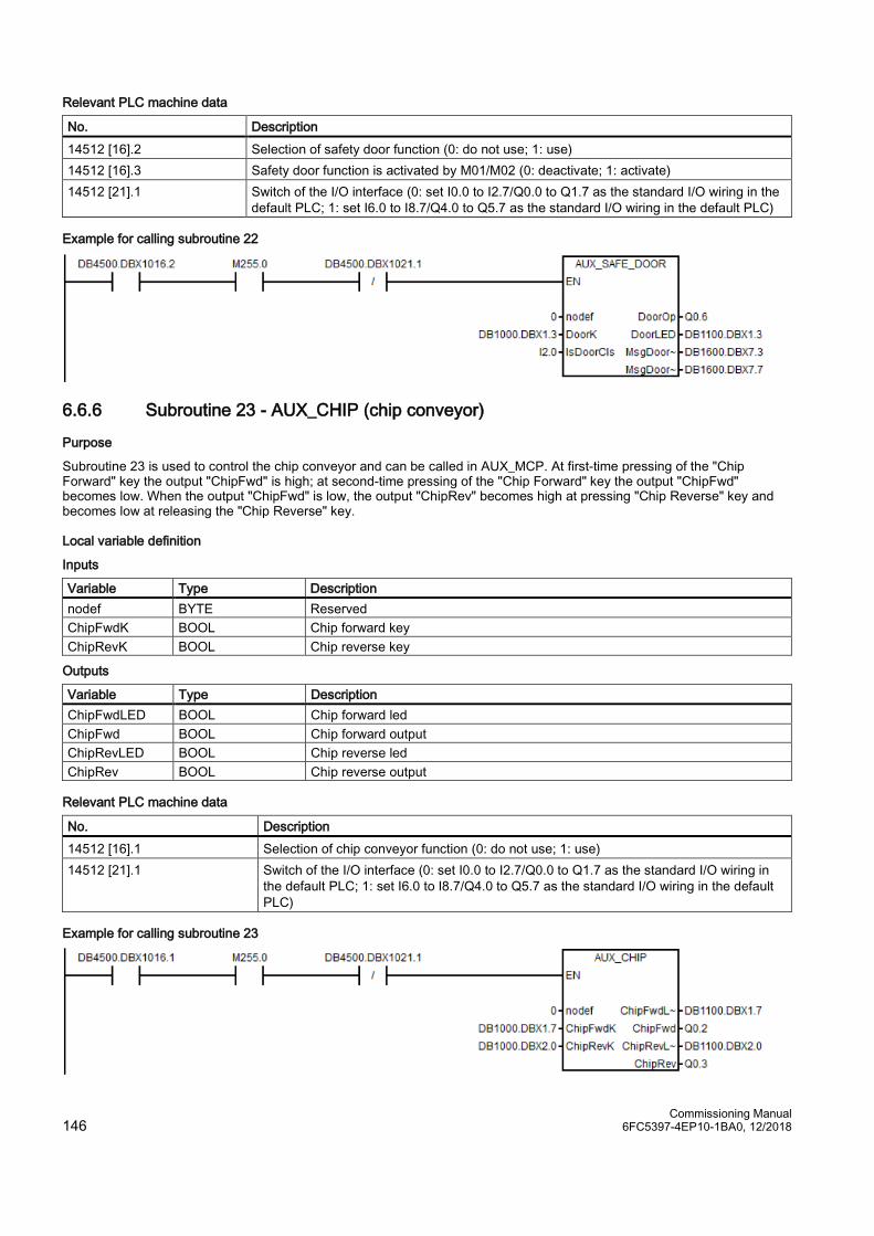
Commissioning Manual 146 6FC5397-4EP10-1BA0, 12/2018
Relevant PLC machine data
No. Description 14512 [16].2 Selection of safety door function (0: do not use; 1: use) 14512 [16].3 Safety door function is activated by M01/M02 (0: deactivate; 1: activate) 14512 [21].1 Switch of the I/O interface (0: set I0.0 to I2.7/Q0.0 to Q1.7 as the standard I/O wiring in the
default PLC; 1: set I6.0 to I8.7/Q4.0 to Q5.7 as the standard I/O wiring in the default PLC)
Example for calling subroutine 22
6.6.6 Subroutine 23 - AUX_CHIP (chip conveyor) Purpose
Subroutine 23 is used to control the chip conveyor and can be called in AUX_MCP. At first-time pressing of the "Chip Forward" key the output "ChipFwd" is high; at second-time pressing of the "Chip Forward" key the output "ChipFwd" becomes low. When the output "ChipFwd" is low, the output "ChipRev" becomes high at pressing "Chip Reverse" key and becomes low at releasing the "Chip Reverse" key.
Local variable definition
Inputs
Variable Type Description nodef BYTE Reserved ChipFwdK BOOL Chip forward key ChipRevK BOOL Chip reverse key
Outputs
Variable Type Description ChipFwdLED BOOL Chip forward led ChipFwd BOOL Chip forward output ChipRevLED BOOL Chip reverse led ChipRev BOOL Chip reverse output
Relevant PLC machine data
No. Description 14512 [16].1 Selection of chip conveyor function (0: do not use; 1: use) 14512 [21].1 Switch of the I/O interface (0: set I0.0 to I2.7/Q0.0 to Q1.7 as the standard I/O wiring in
the default PLC; 1: set I6.0 to I8.7/Q4.0 to Q5.7 as the standard I/O wiring in the default PLC)
Example for calling subroutine 23
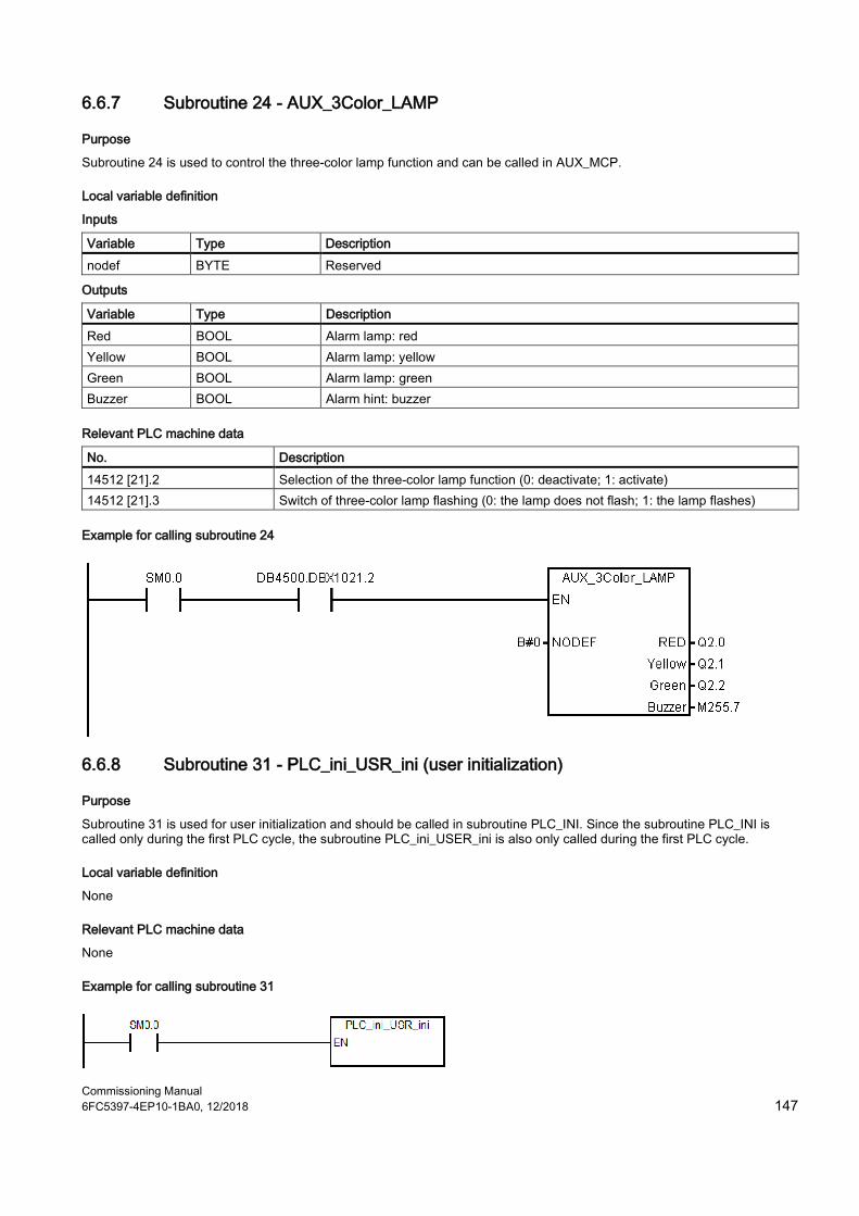
Commissioning Manual 6FC5397-4EP10-1BA0, 12/2018 147
6.6.7 Subroutine 24 - AUX_3Color_LAMP
Purpose
Subroutine 24 is used to control the three-color lamp function and can be called in AUX_MCP.
Local variable definition
Inputs
Variable Type Description nodef BYTE Reserved
Outputs
Variable Type Description Red BOOL Alarm lamp: red Yellow BOOL Alarm lamp: yellow Green BOOL Alarm lamp: green Buzzer BOOL Alarm hint: buzzer
Relevant PLC machine data
No. Description 14512 [21].2 Selection of the three-color lamp function (0: deactivate; 1: activate) 14512 [21].3 Switch of three-color lamp flashing (0: the lamp does not flash; 1: the lamp flashes)
Example for calling subroutine 24
6.6.8 Subroutine 31 - PLC_ini_USR_ini (user initialization)
Purpose
Subroutine 31 is used for user initialization and should be called in subroutine PLC_INI. Since the subroutine PLC_INI is called only during the first PLC cycle, the subroutine PLC_ini_USER_ini is also only called during the first PLC cycle.
Local variable definition
None
Relevant PLC machine data
None
Example for calling subroutine 31

Commissioning Manual 148 6FC5397-4EP10-1BA0, 12/2018
6.6.9 Subroutine 32 - PLC_INI (PLC initialization) Purpose
Subroutine 32 is executed at the first PLC cycle (SM0.1). This subroutine sets NCK interface signals according to the machine settings defined by PLC machine data. In this subroutine, the following interface signals are set:
● DB3200.DBX6.7: feed override of the NCK channel becomes active
● DB380x.DBX1.5: measurement system 1 of the axes is active
● DB380x.DBX1.7: feed override of the axes is active
● DB1700.DBX1.3: active ROV
The following signals are reset:
● DB1700.DBX0.6:reset DRY
At the end of this subroutine, subroutine 31 (PLC_ini_USR_ini) is called. You can program the initialization of customer PLC project in the subroutine 31.
Local variable definition
None
Relevant PLC machine data
None
Example for calling subroutine 32
6.6.10 Subroutine 33 - EMG_STOP
NOTICE Program safety Check whether this subroutine complies with the relevant safety requirements or not.
Purpose
Subroutine 33 handles emergency stop. Pressing down the Emergency Stop button produces an emergency stop alarm and disables the drive enable signal (DB380x.DBX2.1). If you want to clear the emergency stop alarm, you must first release the Emergency Stop button and then press the RESET key on the MCP.
This subroutine activates the alarm below:
Alarm 700016: DRIVE NOT READY
Timing diagram
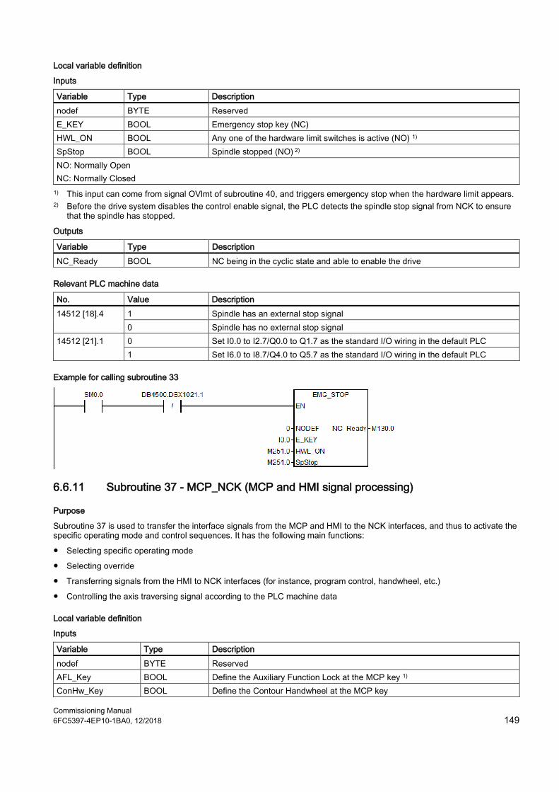
Commissioning Manual 6FC5397-4EP10-1BA0, 12/2018 149
Local variable definition
Inputs
Variable Type Description nodef BYTE Reserved E_KEY BOOL Emergency stop key (NC) HWL_ON BOOL Any one of the hardware limit switches is active (NO) 1) SpStop BOOL Spindle stopped (NO) 2) NO: Normally Open NC: Normally Closed 1) This input can come from signal OVlmt of subroutine 40, and triggers emergency stop when the hardware limit appears.
2) Before the drive system disables the control enable signal, the PLC detects the spindle stop signal from NCK to ensure that the spindle has stopped.
Outputs
Variable Type Description NC_Ready BOOL NC being in the cyclic state and able to enable the drive
Relevant PLC machine data
No. Value Description 14512 [18].4 1 Spindle has an external stop signal
0 Spindle has no external stop signal 14512 [21].1 0 Set I0.0 to I2.7/Q0.0 to Q1.7 as the standard I/O wiring in the default PLC
1 Set I6.0 to I8.7/Q4.0 to Q5.7 as the standard I/O wiring in the default PLC
Example for calling subroutine 33
6.6.11 Subroutine 37 - MCP_NCK (MCP and HMI signal processing)
Purpose
Subroutine 37 is used to transfer the interface signals from the MCP and HMI to the NCK interfaces, and thus to activate the specific operating mode and control sequences. It has the following main functions:
● Selecting specific operating mode
● Selecting override
● Transferring signals from the HMI to NCK interfaces (for instance, program control, handwheel, etc.)
● Controlling the axis traversing signal according to the PLC machine data
Local variable definition
Inputs
Variable Type Description nodef BYTE Reserved AFL_Key BOOL Define the Auxiliary Function Lock at the MCP key 1) ConHw_Key BOOL Define the Contour Handwheel at the MCP key
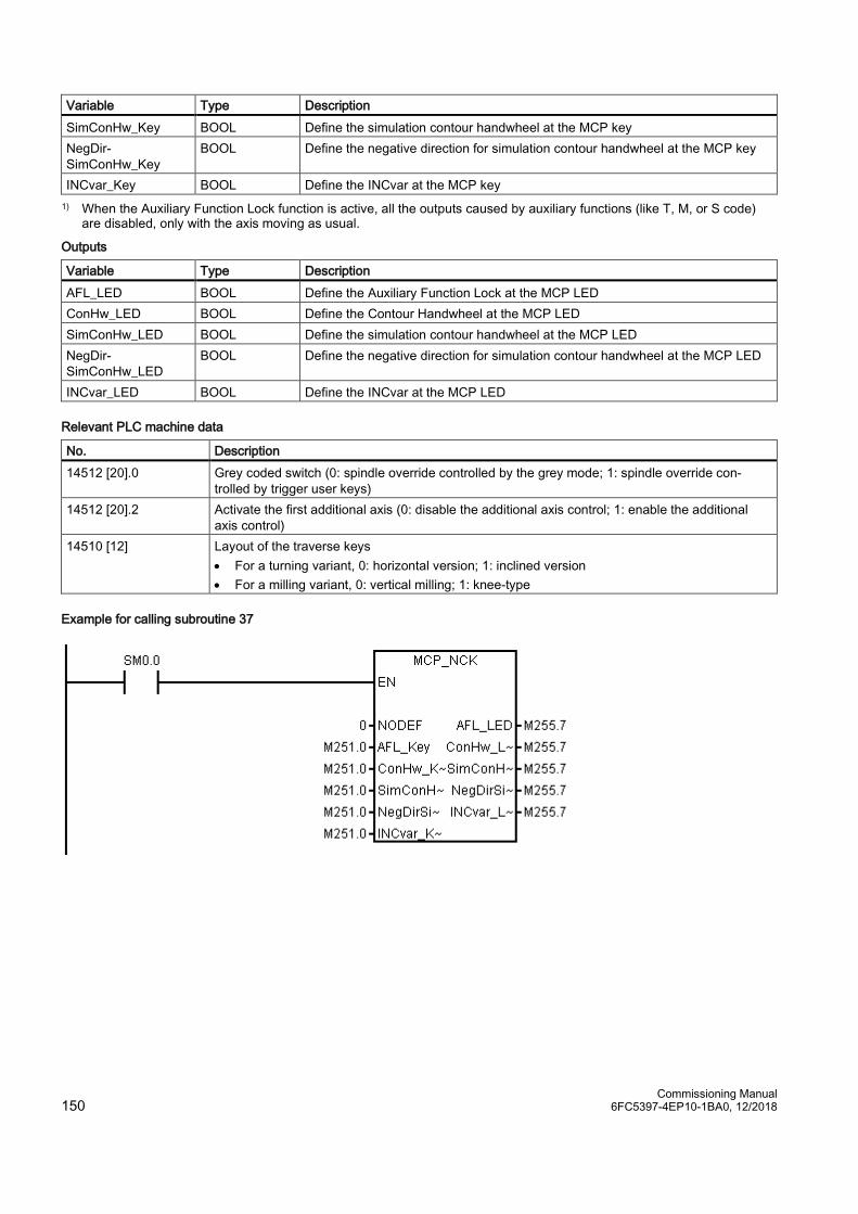
Commissioning Manual 150 6FC5397-4EP10-1BA0, 12/2018
Variable Type Description SimConHw_Key BOOL Define the simulation contour handwheel at the MCP key NegDir-SimConHw_Key
BOOL Define the negative direction for simulation contour handwheel at the MCP key
INCvar_Key BOOL Define the INCvar at the MCP key 1) When the Auxiliary Function Lock function is active, all the outputs caused by auxiliary functions (like T, M, or S code)
are disabled, only with the axis moving as usual.
Outputs
Variable Type Description AFL_LED BOOL Define the Auxiliary Function Lock at the MCP LED ConHw_LED BOOL Define the Contour Handwheel at the MCP LED SimConHw_LED BOOL Define the simulation contour handwheel at the MCP LED NegDir-SimConHw_LED
BOOL Define the negative direction for simulation contour handwheel at the MCP LED
INCvar_LED BOOL Define the INCvar at the MCP LED
Relevant PLC machine data
No. Description 14512 [20].0 Grey coded switch (0: spindle override controlled by the grey mode; 1: spindle override con-
trolled by trigger user keys) 14512 [20].2 Activate the first additional axis (0: disable the additional axis control; 1: enable the additional
axis control) 14510 [12] Layout of the traverse keys
• For a turning variant, 0: horizontal version; 1: inclined version • For a milling variant, 0: vertical milling; 1: knee-type
Example for calling subroutine 37
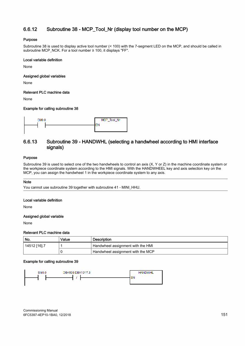
Commissioning Manual 6FC5397-4EP10-1BA0, 12/2018 151
6.6.12 Subroutine 38 - MCP_Tool_Nr (display tool number on the MCP)
Purpose
Subroutine 38 is used to display active tool number (< 100) with the 7-segment LED on the MCP, and should be called in subroutine MCP_NCK. For a tool number ≥ 100, it displays "FF".
Local variable definition
None
Assigned global variables
None
Relevant PLC machine data
None
Example for calling subroutine 38
6.6.13 Subroutine 39 - HANDWHL (selecting a handwheel according to HMI interface signals)
Purpose
Subroutine 39 is used to select one of the two handwheels to control an axis (X, Y or Z) in the machine coordinate system or the workpiece coordinate system according to the HMI signals. With the HANDWHEEL key and axis selection key on the MCP, you can assign the handwheel 1 in the workpiece coordinate system to any axis.
Note You cannot use subroutine 39 together with subroutine 41 - MINI_HHU.
Local variable definition
None
Assigned global variable
None
Relevant PLC machine data
No. Value Description 14512 [16].7 1 Handwheel assignment with the HMI
0 Handwheel assignment with the MCP
Example for calling subroutine 39

Commissioning Manual 152 6FC5397-4EP10-1BA0, 12/2018
6.6.14 Subroutine 40 - AXIS_CTL (controlling the spindle and axes)
Purpose
Subroutine 40 is used to control the drive pulse enable (DB380x.DBX4001.7) and controller enable (DB380x.DBX2.1), monitoring the hardware limits and the reference cam signals, and controlling the enable signal for the spindle according to a spindle command (for example, SPINDLE CW, SPINDLE CCW, M03, M04, SPOS, etc.). The motor brake is automatically controlled by the SINAMICS V70 drives.
This subroutine provides two ways to realize the hardware limit control:
● PLC solution (MD14512 [18] bit 6 = 0) Each feed axis has one (MD14512 [18] bit 7 = 1) or two (MD14512 [18] bit 7 = 0) hardware limit switches. This subroutine activates the NCK hardware limit function via the NCK interface DB380x.DBX1000.0 or DB380x.DBX1000.1 according to the configurations of the hardware limit switches, and thus makes the NCK produce a feed stop signal to an over-distance axis. Furthermore, you can also connect the output OVlmt of this subroutine with the input HWL_ON of subroutine 33 to activate the Emergency Stop automatically once the hardware limit of any axis has been reached.
● Hardware solution (MD14512 [18] bit 6 = 1) This solution is independent of the PLC and thus is much safer:
Encoding the hardware limit switches Result E_Key _1LMTp _2LMTp _3LMTp Direction 0 1 1 1 - EMERGENCY STOP
active 0 0 1 1 DB3900.DBX4.7 1st + over limit 0 0 1 1 DB3900.DBX4.6 1st - over limit 0 0 0 1 DB3901.DBX4.7 2nd + over limit 0 0 0 1 DB3901.DBX4.6 2nd - over limit 0 0 0 0 DB3902.DBX4.7 3rd + over limit 0 0 0 0 DB3902.DBX4.6 3rd - over limit
In the hardware solution above, the feed stop signals for all axes can be activated via the hardware limit switches when any of the hardware limits is reached or an EMERGENCY STOP happens. You can check the information of the PLC diagnostics from the encoding of the hardware limit switches shown in the table above, and identify the cause (Emergency Stop button or a hardware limit switch of an axis) of the EMERGENCY STOP signal.
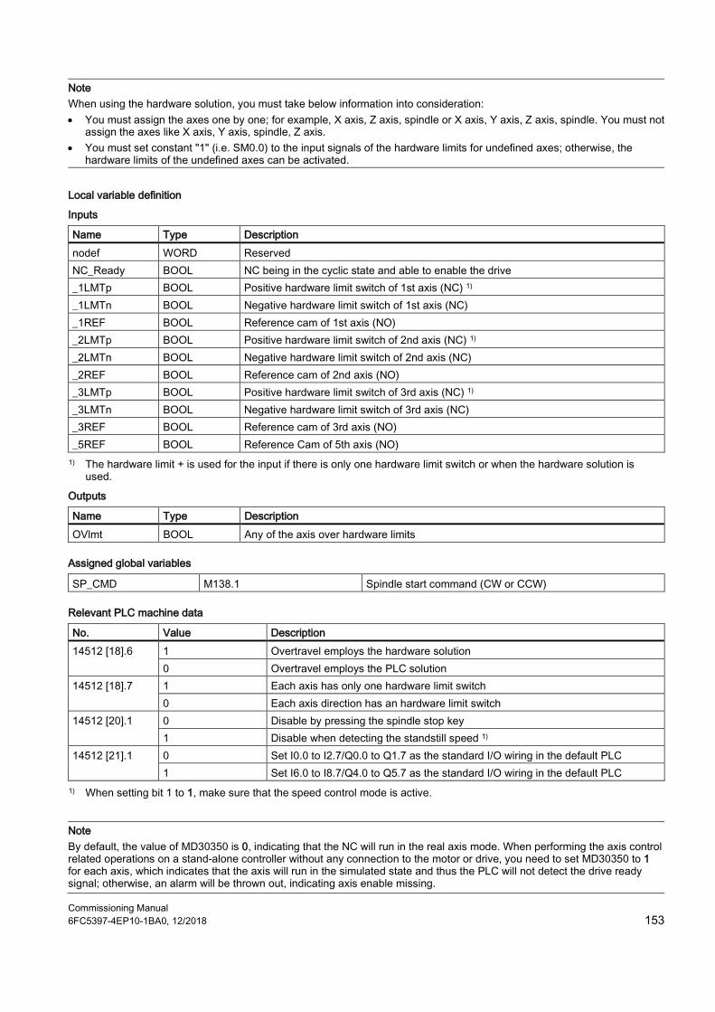
Commissioning Manual 6FC5397-4EP10-1BA0, 12/2018 153
Note When using the hardware solution, you must take below information into consideration: • You must assign the axes one by one; for example, X axis, Z axis, spindle or X axis, Y axis, Z axis, spindle. You must not
assign the axes like X axis, Y axis, spindle, Z axis. • You must set constant "1" (i.e. SM0.0) to the input signals of the hardware limits for undefined axes; otherwise, the
hardware limits of the undefined axes can be activated.
Local variable definition
Inputs
Name Type Description nodef WORD Reserved NC_Ready BOOL NC being in the cyclic state and able to enable the drive _1LMTp BOOL Positive hardware limit switch of 1st axis (NC) 1) _1LMTn BOOL Negative hardware limit switch of 1st axis (NC) _1REF BOOL Reference cam of 1st axis (NO) _2LMTp BOOL Positive hardware limit switch of 2nd axis (NC) 1) _2LMTn BOOL Negative hardware limit switch of 2nd axis (NC) _2REF BOOL Reference cam of 2nd axis (NO) _3LMTp BOOL Positive hardware limit switch of 3rd axis (NC) 1) _3LMTn BOOL Negative hardware limit switch of 3rd axis (NC) _3REF BOOL Reference cam of 3rd axis (NO) _5REF BOOL Reference Cam of 5th axis (NO) 1) The hardware limit + is used for the input if there is only one hardware limit switch or when the hardware solution is
used.
Outputs
Name Type Description OVlmt BOOL Any of the axis over hardware limits
Assigned global variables
SP_CMD M138.1 Spindle start command (CW or CCW)
Relevant PLC machine data
No. Value Description 14512 [18].6 1 Overtravel employs the hardware solution
0 Overtravel employs the PLC solution 14512 [18].7 1 Each axis has only one hardware limit switch
0 Each axis direction has an hardware limit switch 14512 [20].1 0 Disable by pressing the spindle stop key
1 Disable when detecting the standstill speed 1) 14512 [21].1 0 Set I0.0 to I2.7/Q0.0 to Q1.7 as the standard I/O wiring in the default PLC
1 Set I6.0 to I8.7/Q4.0 to Q5.7 as the standard I/O wiring in the default PLC 1) When setting bit 1 to 1, make sure that the speed control mode is active.
Note By default, the value of MD30350 is 0, indicating that the NC will run in the real axis mode. When performing the axis control related operations on a stand-alone controller without any connection to the motor or drive, you need to set MD30350 to 1 for each axis, which indicates that the axis will run in the simulated state and thus the PLC will not detect the drive ready signal; otherwise, an alarm will be thrown out, indicating axis enable missing.
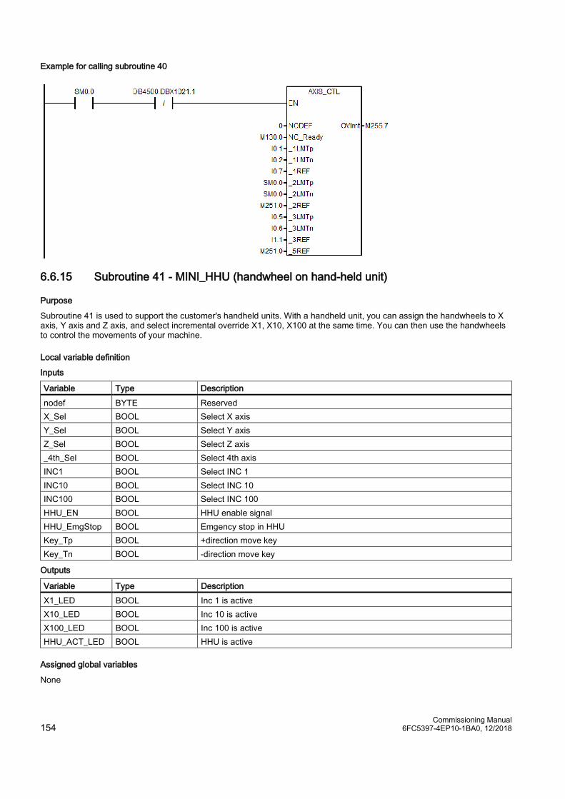
Commissioning Manual 154 6FC5397-4EP10-1BA0, 12/2018
Example for calling subroutine 40
6.6.15 Subroutine 41 - MINI_HHU (handwheel on hand-held unit)
Purpose
Subroutine 41 is used to support the customer's handheld units. With a handheld unit, you can assign the handwheels to X axis, Y axis and Z axis, and select incremental override X1, X10, X100 at the same time. You can then use the handwheels to control the movements of your machine.
Local variable definition
Inputs
Variable Type Description nodef BYTE Reserved X_Sel BOOL Select X axis Y_Sel BOOL Select Y axis Z_Sel BOOL Select Z axis _4th_Sel BOOL Select 4th axis INC1 BOOL Select INC 1 INC10 BOOL Select INC 10 INC100 BOOL Select INC 100 HHU_EN BOOL HHU enable signal HHU_EmgStop BOOL Emgency stop in HHU Key_Tp BOOL +direction move key Key_Tn BOOL -direction move key
Outputs
Variable Type Description X1_LED BOOL Inc 1 is active X10_LED BOOL Inc 10 is active X100_LED BOOL Inc 100 is active HHU_ACT_LED BOOL HHU is active
Assigned global variables
None
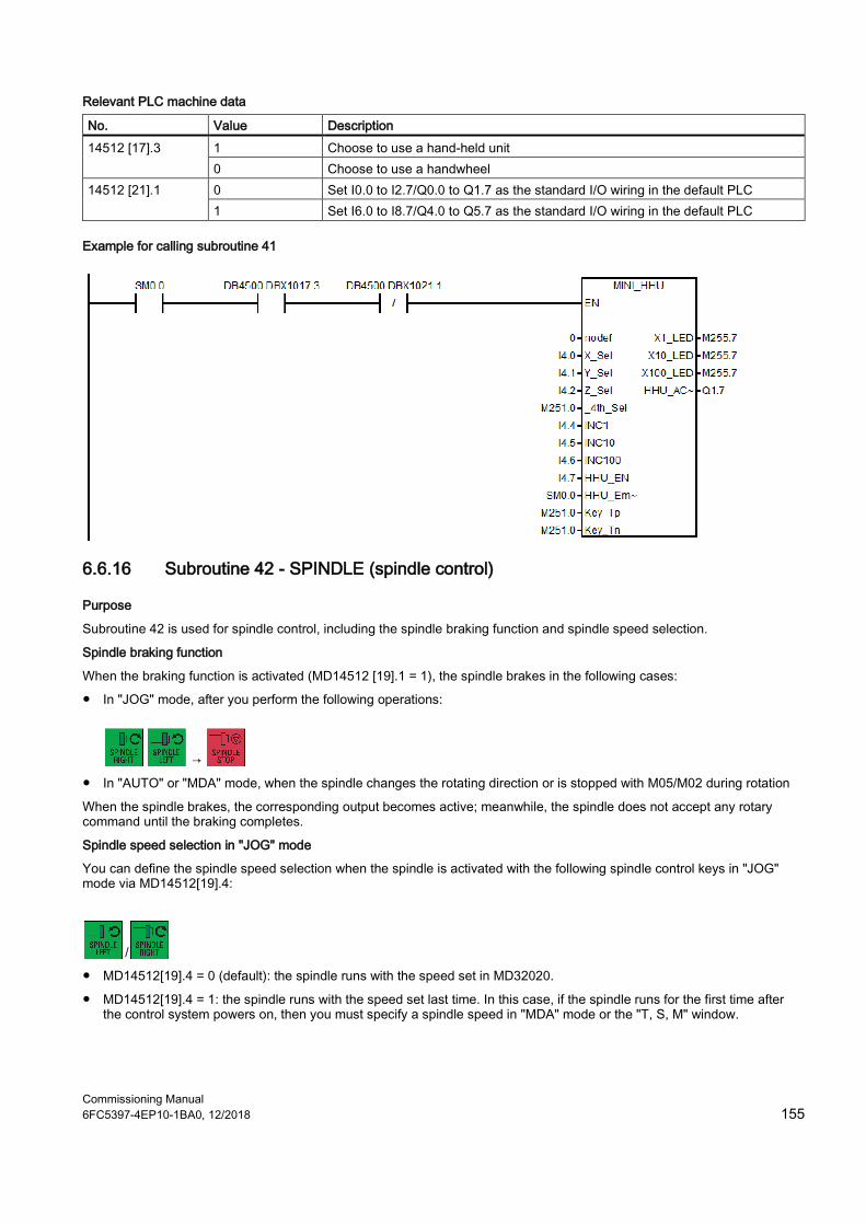
Commissioning Manual 6FC5397-4EP10-1BA0, 12/2018 155
Relevant PLC machine data
No. Value Description 14512 [17].3 1 Choose to use a hand-held unit
0 Choose to use a handwheel 14512 [21].1 0 Set I0.0 to I2.7/Q0.0 to Q1.7 as the standard I/O wiring in the default PLC
1 Set I6.0 to I8.7/Q4.0 to Q5.7 as the standard I/O wiring in the default PLC
Example for calling subroutine 41
6.6.16 Subroutine 42 - SPINDLE (spindle control)
Purpose
Subroutine 42 is used for spindle control, including the spindle braking function and spindle speed selection.
Spindle braking function
When the braking function is activated (MD14512 [19].1 = 1), the spindle brakes in the following cases:
● In "JOG" mode, after you perform the following operations:
→
● In "AUTO" or "MDA" mode, when the spindle changes the rotating direction or is stopped with M05/M02 during rotation
When the spindle brakes, the corresponding output becomes active; meanwhile, the spindle does not accept any rotary command until the braking completes.
Spindle speed selection in "JOG" mode
You can define the spindle speed selection when the spindle is activated with the following spindle control keys in "JOG" mode via MD14512[19].4:
/
● MD14512[19].4 = 0 (default): the spindle runs with the speed set in MD32020.
● MD14512[19].4 = 1: the spindle runs with the speed set last time. In this case, if the spindle runs for the first time after the control system powers on, then you must specify a spindle speed in "MDA" mode or the "T, S, M" window.
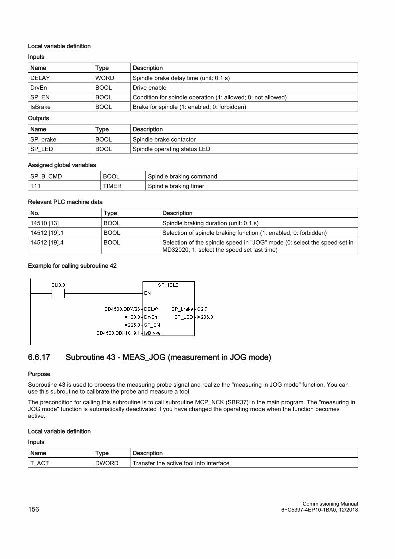
Commissioning Manual 156 6FC5397-4EP10-1BA0, 12/2018
Local variable definition
Inputs
Name Type Description DELAY WORD Spindle brake delay time (unit: 0.1 s) DrvEn BOOL Drive enable SP_EN BOOL Condition for spindle operation (1: allowed; 0: not allowed) IsBrake BOOL Brake for spindle (1: enabled; 0: forbidden)
Outputs
Name Type Description SP_brake BOOL Spindle brake contactor SP_LED BOOL Spindle operating status LED
Assigned global variables
SP_B_CMD BOOL Spindle braking command T11 TIMER Spindle braking timer
Relevant PLC machine data
No. Type Description 14510 [13] BOOL Spindle braking duration (unit: 0.1 s) 14512 [19].1 BOOL Selection of spindle braking function (1: enabled; 0: forbidden) 14512 [19].4 BOOL Selection of the spindle speed in "JOG" mode (0: select the speed set in
MD32020; 1: select the speed set last time)
Example for calling subroutine 42
6.6.17 Subroutine 43 - MEAS_JOG (measurement in JOG mode)
Purpose
Subroutine 43 is used to process the measuring probe signal and realize the "measuring in JOG mode" function. You can use this subroutine to calibrate the probe and measure a tool.
The precondition for calling this subroutine is to call subroutine MCP_NCK (SBR37) in the main program. The "measuring in JOG mode" function is automatically deactivated if you have changed the operating mode when the function becomes active.
Local variable definition
Inputs
Name Type Description T_ACT DWORD Transfer the active tool into interface
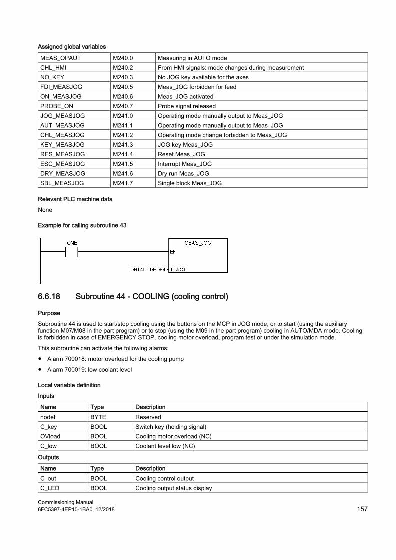
Commissioning Manual 6FC5397-4EP10-1BA0, 12/2018 157
Assigned global variables
MEAS_OPAUT M240.0 Measuring in AUTO mode CHL_HMI M240.2 From HMI signals: mode changes during measurement NO_KEY M240.3 No JOG key available for the axes FDI_MEASJOG M240.5 Meas_JOG forbidden for feed ON_MEASJOG M240.6 Meas_JOG activated PROBE_ON M240.7 Probe signal released JOG_MEASJOG M241.0 Operating mode manually output to Meas_JOG AUT_MEASJOG M241.1 Operating mode manually output to Meas_JOG CHL_MEASJOG M241.2 Operating mode change forbidden to Meas_JOG KEY_MEASJOG M241.3 JOG key Meas_JOG RES_MEASJOG M241.4 Reset Meas_JOG ESC_MEASJOG M241.5 Interrupt Meas_JOG DRY_MEASJOG M241.6 Dry run Meas_JOG SBL_MEASJOG M241.7 Single block Meas_JOG
Relevant PLC machine data
None
Example for calling subroutine 43
6.6.18 Subroutine 44 - COOLING (cooling control)
Purpose
Subroutine 44 is used to start/stop cooling using the buttons on the MCP in JOG mode, or to start (using the auxiliary function M07/M08 in the part program) or to stop (using the M09 in the part program) cooling in AUTO/MDA mode. Cooling is forbidden in case of EMERGENCY STOP, cooling motor overload, program test or under the simulation mode.
This subroutine can activate the following alarms:
● Alarm 700018: motor overload for the cooling pump
● Alarm 700019: low coolant level
Local variable definition
Inputs
Name Type Description nodef BYTE Reserved C_key BOOL Switch key (holding signal) OVload BOOL Cooling motor overload (NC) C_low BOOL Coolant level low (NC)
Outputs
Name Type Description C_out BOOL Cooling control output C_LED BOOL Cooling output status display

Commissioning Manual 158 6FC5397-4EP10-1BA0, 12/2018
Assigned global variables
COOLon MB150.0 Coolant on/off status
Relevant PLC machine data
No. Description 14512 [21].1 Switch of the I/O interface (0: set I0.0 to I2.7/Q0.0 to Q1.7 as the standard I/O wiring in
the default PLC; 1: set I6.0 to I8.7/Q4.0 to Q5.7 as the standard I/O wiring in the default PLC)
Example for calling subroutine 44
6.6.19 Subroutine 45 - LUBRICAT (control of lubricate)
Purpose
Subroutine 45 is used to control the lubrication according to specific time interval and duration (independent of the distance that the axis has travelled). Meanwhile, a manual button is available to start the lubrication, and you can configure that the lubrication starts automatically each time that the machine is powered up. Normally, lubricating starts automatically and cyclically according to specified time interval Lintv, and operates for a specific time Ltime at each cycle. Lubrication stops in case of an Emergency Stop, lubrication motor overload, low lubricant level.
This subroutine can activate following alarms:
● Alarm 700020: lubrication motor overload
● Alarm 700021: low lubricant level
Local variable definition
Inputs
Name Type Description Lintv WORD Lubricating time interval Ltime WORD Lubricating output time L_key BOOL Manual lubricating key L1st BOOL Lubricating by 1 PLC cycle (Power on) Ovload BOOL Lubricating motor overload (NC) L_low BOOL Lubricant level low (NC)
Outputs
Name Type Description L_out BOOL Lubricating output L_LED BOOL For lubricating status display
Assigned global variables
L_interval C24 Timer for the lubricating time intervals (unit: min) L_time T27 Timer for very lubricating time duration (unit: 0.01s, max.
327.67 s)
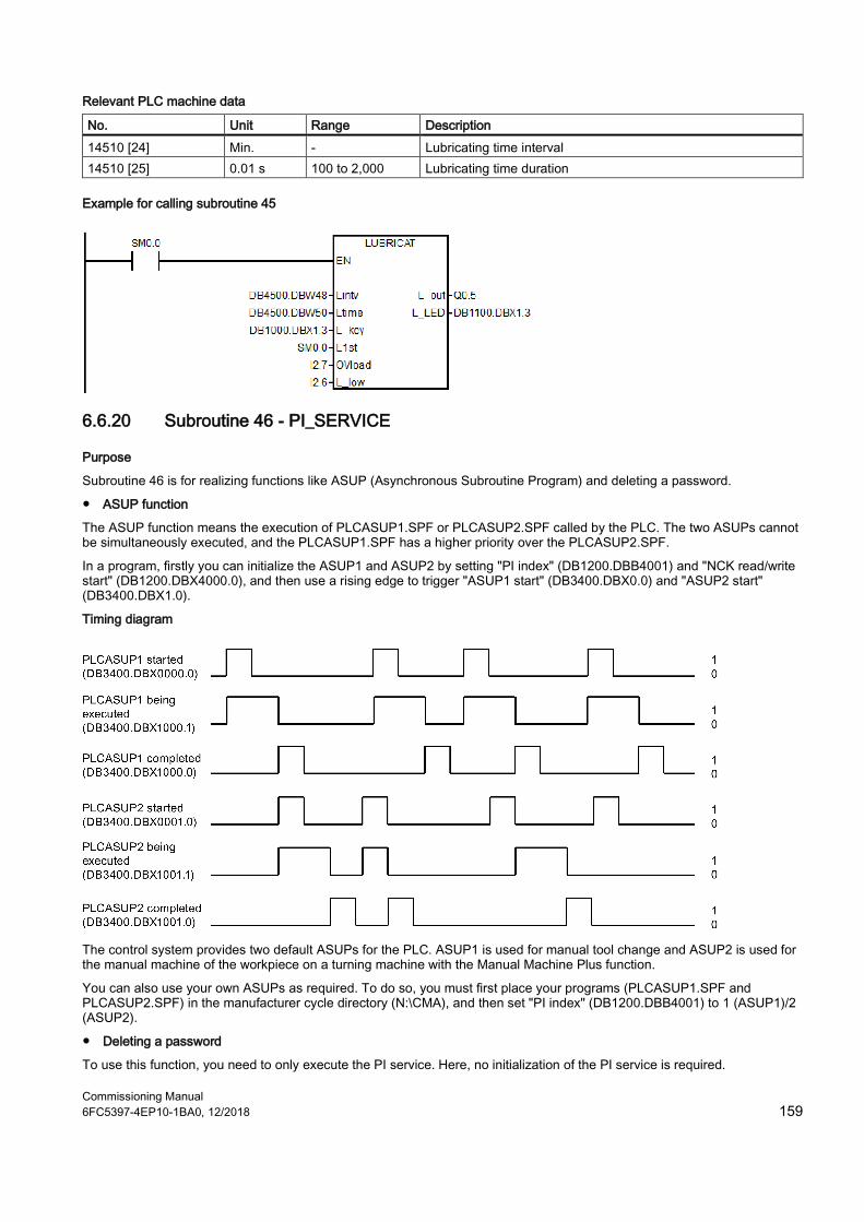
Commissioning Manual 6FC5397-4EP10-1BA0, 12/2018 159
Relevant PLC machine data
No. Unit Range Description 14510 [24] Min. - Lubricating time interval 14510 [25] 0.01 s 100 to 2,000 Lubricating time duration
Example for calling subroutine 45
6.6.20 Subroutine 46 - PI_SERVICE
Purpose
Subroutine 46 is for realizing functions like ASUP (Asynchronous Subroutine Program) and deleting a password.
● ASUP function
The ASUP function means the execution of PLCASUP1.SPF or PLCASUP2.SPF called by the PLC. The two ASUPs cannot be simultaneously executed, and the PLCASUP1.SPF has a higher priority over the PLCASUP2.SPF.
In a program, firstly you can initialize the ASUP1 and ASUP2 by setting "PI index" (DB1200.DBB4001) and "NCK read/write start" (DB1200.DBX4000.0), and then use a rising edge to trigger "ASUP1 start" (DB3400.DBX0.0) and "ASUP2 start" (DB3400.DBX1.0).
Timing diagram
The control system provides two default ASUPs for the PLC. ASUP1 is used for manual tool change and ASUP2 is used for the manual machine of the workpiece on a turning machine with the Manual Machine Plus function.
You can also use your own ASUPs as required. To do so, you must first place your programs (PLCASUP1.SPF and PLCASUP2.SPF) in the manufacturer cycle directory (N:\CMA), and then set "PI index" (DB1200.DBB4001) to 1 (ASUP1)/2 (ASUP2).
● Deleting a password
To use this function, you need to only execute the PI service. Here, no initialization of the PI service is required.
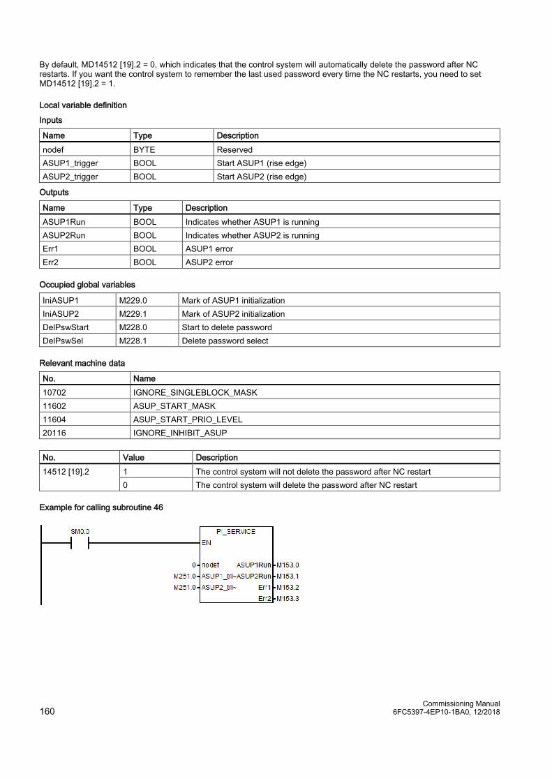
Commissioning Manual 160 6FC5397-4EP10-1BA0, 12/2018
By default, MD14512 [19].2 = 0, which indicates that the control system will automatically delete the password after NC restarts. If you want the control system to remember the last used password every time the NC restarts, you need to set MD14512 [19].2 = 1.
Local variable definition
Inputs
Name Type Description nodef BYTE Reserved ASUP1_trigger BOOL Start ASUP1 (rise edge) ASUP2_trigger BOOL Start ASUP2 (rise edge)
Outputs
Name Type Description ASUP1Run BOOL Indicates whether ASUP1 is running ASUP2Run BOOL Indicates whether ASUP2 is running Err1 BOOL ASUP1 error Err2 BOOL ASUP2 error
Occupied global variables
IniASUP1 M229.0 Mark of ASUP1 initialization IniASUP2 M229.1 Mark of ASUP2 initialization DelPswStart M228.0 Start to delete password DelPswSel M228.1 Delete password select
Relevant machine data
No. Name 10702 IGNORE_SINGLEBLOCK_MASK 11602 ASUP_START_MASK 11604 ASUP_START_PRIO_LEVEL 20116 IGNORE_INHIBIT_ASUP
No. Value Description 14512 [19].2 1 The control system will not delete the password after NC restart
0 The control system will delete the password after NC restart
Example for calling subroutine 46
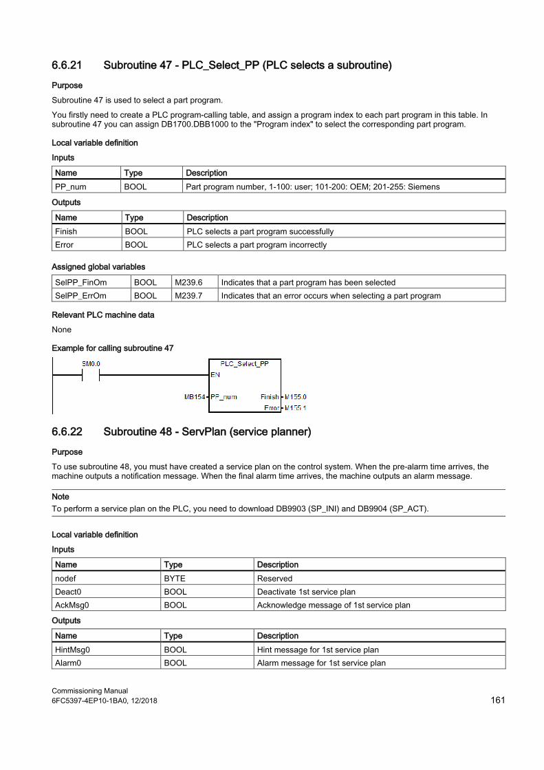
Commissioning Manual 6FC5397-4EP10-1BA0, 12/2018 161
6.6.21 Subroutine 47 - PLC_Select_PP (PLC selects a subroutine) Purpose
Subroutine 47 is used to select a part program.
You firstly need to create a PLC program-calling table, and assign a program index to each part program in this table. In subroutine 47 you can assign DB1700.DBB1000 to the "Program index" to select the corresponding part program.
Local variable definition
Inputs
Name Type Description PP_num BOOL Part program number, 1-100: user; 101-200: OEM; 201-255: Siemens
Outputs
Name Type Description Finish BOOL PLC selects a part program successfully Error BOOL PLC selects a part program incorrectly
Assigned global variables
SelPP_FinOm BOOL M239.6 Indicates that a part program has been selected SelPP_ErrOm BOOL M239.7 Indicates that an error occurs when selecting a part program
Relevant PLC machine data
None
Example for calling subroutine 47
6.6.22 Subroutine 48 - ServPlan (service planner)
Purpose
To use subroutine 48, you must have created a service plan on the control system. When the pre-alarm time arrives, the machine outputs a notification message. When the final alarm time arrives, the machine outputs an alarm message.
Note To perform a service plan on the PLC, you need to download DB9903 (SP_INI) and DB9904 (SP_ACT).
Local variable definition
Inputs
Name Type Description nodef BYTE Reserved Deact0 BOOL Deactivate 1st service plan AckMsg0 BOOL Acknowledge message of 1st service plan
Outputs
Name Type Description HintMsg0 BOOL Hint message for 1st service plan Alarm0 BOOL Alarm message for 1st service plan
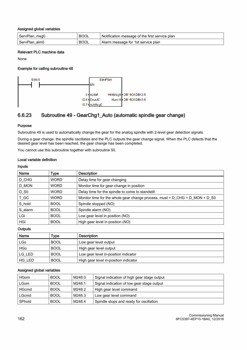
Commissioning Manual 162 6FC5397-4EP10-1BA0, 12/2018
Assigned global variables
ServPlan_msg0 BOOL Notification message of the first service plan ServPlan_alm0 BOOL Alarm message for 1st service plan
Relevant PLC machine data
None
Example for calling subroutine 48
6.6.23 Subroutine 49 - GearChg1_Auto (automatic spindle gear change)
Purpose
Subroutine 49 is used to automatically change the gear for the analog spindle with 2-level gear detection signals.
During a gear change, the spindle oscillates and the PLC outputs the gear change signal. When the PLC detects that the desired gear level has been reached, the gear change has been completed.
You cannot use this subroutine together with subroutine 50.
Local variable definition
Inputs
Name Type Description D_CHG WORD Delay time for gear changing D_MON WORD Monitor time for gear-change in position D_S0 WORD Delay time for the spindle to come to standstill T_GC WORD Monitor time for the whole gear change process, must > D_CHG + D_MON + D_S0 S_hold BOOL Spindle stopped (NO) S_alarm BOOL Spindle alarm (NO) LGi BOOL Low gear level in position (NO) HGi BOOL High gear level in position (NO)
Outputs
Name Type Description LGo BOOL Low gear level output HGo BOOL High gear level output LG_LED BOOL Low gear level in-position indicator HG_LED BOOL High gear level in-position indicator
Assigned global variables
HGom BOOL M248.0 Signal indication of high gear stage output LGom BOOL M248.1 Signal indication of low gear stage output HGcmd BOOL M248.2 High gear level command LGcmd BOOL M248.3 Low gear level command SPhold BOOL M248.4 Spindle stops and ready for oscillation

Commissioning Manual 6FC5397-4EP10-1BA0, 12/2018 163
Dstill BOOL M248.5 Signal for spindle stop Dchg BOOL M248.6 Spindle gear change delay Dmon BOOL M248.7 Monitoring for the gear change Req_SP_G_CHG
BOOL M244.0 Request for spindle gear change
Req_Low_G BOOL M244.1 Request to change to the low gear stage Req_Hign_G BOOL M244.2 Request to change to the high gear stage D_S0 TIMER T13 Spindle stop delay Td_GearChg TIMER T24 Gear change delay Tm_GearChg TIMER T25 Delay for monitoring the gear change
Relevant PLC machine data
None
Example for calling subroutine 49
6.6.24 Subroutine 50 - GearChg2_Virtual (virtual spindle gear change)
Purpose
Using subroutine 50, you can requests the system to switch to the corresponding gear after changing the gear manually. The corresponding gear is set when M41-M45 are executed.
This subroutine must not be used together with GearChg1_Auto (SBR 49).
Local variable definition
Outputs
Name Type Description HL_gear BOOL :=0, low gear level; :=1, high gear level
Assigned global variables
None
Relevant PLC machine data
None
Example for calling subroutine 50
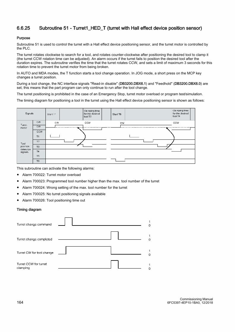
Commissioning Manual 164 6FC5397-4EP10-1BA0, 12/2018
6.6.25 Subroutine 51 - Turret1_HED_T (turret with Hall effect device position sensor)
Purpose
Subroutine 51 is used to control the turret with a Hall effect device positioning sensor, and the turret motor is controlled by the PLC.
The turret rotates clockwise to search for a tool, and rotates counter-clockwise after positioning the desired tool to clamp it (the turret CCW rotation time can be adjusted). An alarm occurs if the turret fails to position the desired tool after the duration expires. The subroutine verifies the time that the turret rotates CCW, and sets a limit of maximum 3 seconds for this rotation time to prevent the turret motor from being broken.
In AUTO and MDA modes, the T function starts a tool change operation. In JOG mode, a short press on the MCP key changes a turret position.
During a tool change, the NC interface signals "Read-in disable" (DB3200.DBX6.1) and "Feedhold" (DB3200.DBX6.0) are set; this means that the part program can only continue to run after the tool change.
The turret positioning is prohibited in the case of an Emergency Stop, turret motor overload or program test/simulation.
The timing diagram for positioning a tool in the turret using the Hall effect device positioning sensor is shown as follows:
This subroutine can activate the following alarms:
● Alarm 700022: Turret motor overload
● Alarm 700023: Programmed tool number higher than the max. tool number of the turret
● Alarm 700024: Wrong setting of the max. tool number for the turret
● Alarm 700025: No turret positioning signals available
● Alarm 700026: Tool positioning time out
Timing diagram

Commissioning Manual 6FC5397-4EP10-1BA0, 12/2018 165
Local variable definition
Inputs
Name Type Description Tmax WORD Number of tool on the turret, only 4, 6 are permitted C_time WORD Turret clamping delay time (unit: 0.1 s) M_time WORD Monitor time for searching for a tool (unit: 0.1s) T_polar BOOL Tool position signal: NC/NO T_key BOOL Manual tool change key T_01 to T_06 BOOL Tool position sensor (low active) OVload BOOL Turret motor overload (NC)
Outputs
Name Type Description T_cw BOOL Turret CW for tool change T_ccw BOOL Turret CCW for turret clamping T_LED BOOL Turret change status display ERR1 BOOL Error1: no turret position signal available ERR2 BOOL Error2: programmed tool exceeds turret range ERR3 BOOL Error3: tool searching time monitor time out ERR4 BOOL Error4: turret overload ERR5 BOOL Error5: max tool number setting error ERR6 BOOL Reserved
Assigned global variables
T_cw_m M156.0 Position marking for turret CW rotation T_ccw_m M156.1 Position marking for turret CCW rotation CcwDelay M156.2 Turret CCW rotation delay K_active M156.3 Manual key active Tpos_C M156.4 Turret position changed Tp_eq_Tc M156.5 Programmed tool number equal to the current tool number Tp_eq_0 M156.6 Programmed tool number equal to zero T_P_INDX MD160 Monitoring the tool change buffer zone in JOG mode T_CHL M168.4 Operating mode locked Tm1_FindT T15 Monitoring timer for tool searching T_CLAMP T13 Clamping timer for turret 1
Relevant PLC machine data
No. Unit Description 14510 [20] - Max. tool number (4 or 6) 14510 [21] 0.1 s Turret clamping time 14510 [22] 0.1 s Monitoring time for tool searching 14512 [17].0 - Activating the turret function of a turning machine 14512 [21].1 - Switch of the I/O interface (0: set I0.0 to I2.7/Q0.0 to Q1.7 as the standard
I/O wiring in the default PLC; 1: set I6.0 to I8.7/Q4.0 to Q5.7 as the standard I/O wiring in the default PLC)

Commissioning Manual 166 6FC5397-4EP10-1BA0, 12/2018
Example for calling subroutine 51
6.6.26 Subroutine 52 - Turret2_BIN_T (turret with binary coding function)
Purpose
Subroutine 52 is used to control the turret with encoder positioning signals and function of dual-direction adjacent tool change. Contact the turret vendor for the working theory and the timing diagram of a tool change.
During a tool change, the NC interface signals "Read-in disable" (DB3200.DBX6.1) and "Feedhold" (DB3200.DBX6.0) are set, so the part program can continue running only after the tool change action.
The turret position action is forbidden in case of an emergency stop, turret motor overload or program test/simulation.
This subroutine can activate the following alarms:
● Alarm 700022: Turret motor overload
● Alarm 700023: Programmed tool number higher than the max. tool number of the turret
● Alarm 700024: Wrong setting of the max. tool number for the turret
● Alarm 700026: Not able to find expected tool in monitor time
● Alarm 700011: Not able to lock tool in expected time
Local variable definition
Inputs
Name Type Description Tmax WORD Total tools on the turret Tm_Lck WORD Tool lock monitor time (unit: 0.01s) Tm_Chg WORD Tool change monitor time (unit: 0.1s) T_1 BOOL T code A T_2 BOOL T code B T_3 BOOL T code C T_4 BOOL T code D Parity BOOL Parity bit Strobe BOOL Tool on position signal OVload BOOL Turret motor overload (NC) P_Indx BOOL Turret pre-indexing sensor T_key BOOL Manual key for tool change
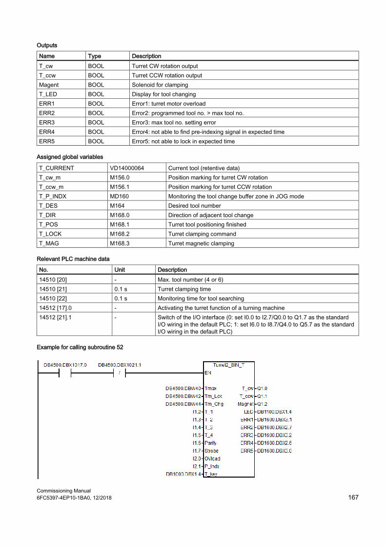
Commissioning Manual 6FC5397-4EP10-1BA0, 12/2018 167
Outputs
Name Type Description T_cw BOOL Turret CW rotation output T_ccw BOOL Turret CCW rotation output Magent BOOL Solenoid for clamping T_LED BOOL Display for tool changing ERR1 BOOL Error1: turret motor overload ERR2 BOOL Error2: programmed tool no. > max tool no. ERR3 BOOL Error3: max tool no. setting error ERR4 BOOL Error4: not able to find pre-indexing signal in expected time ERR5 BOOL Error5: not able to lock in expected time
Assigned global variables
T_CURRENT VD14000064 Current tool (retentive data) T_cw_m M156.0 Position marking for turret CW rotation T_ccw_m M156.1 Position marking for turret CCW rotation T_P_INDX MD160 Monitoring the tool change buffer zone in JOG mode T_DES M164 Desired tool number T_DIR M168.0 Direction of adjacent tool change T_POS M168.1 Turret tool positioning finished T_LOCK M168.2 Turret clamping command T_MAG M168.3 Turret magnetic clamping
Relevant PLC machine data
No. Unit Description 14510 [20] - Max. tool number (4 or 6) 14510 [21] 0.1 s Turret clamping time 14510 [22] 0.1 s Monitoring time for tool searching 14512 [17].0 - Activating the turret function of a turning machine 14512 [21].1 - Switch of the I/O interface (0: set I0.0 to I2.7/Q0.0 to Q1.7 as the standard
I/O wiring in the default PLC; 1: set I6.0 to I8.7/Q4.0 to Q5.7 as the standard I/O wiring in the default PLC)
Example for calling subroutine 52

Commissioning Manual 168 6FC5397-4EP10-1BA0, 12/2018
6.6.27 Subroutine 53 - Turret3_CODE_T (tool change control for turret with coding function)
Purpose
Subroutine 53 is used to control the turret with coded tool positions and function of adjacent tool change. The difference between the subroutine 52 and the subroutine 53 is that the subroutine 52 uses binary tool position codes while the subroutine 53 uses tool position codes made according to a specific common turret.
During a tool change, the NC interface signal "Feedhold" (DB3200.DBX6.0) is set; this means that the part program can only continue to run only after the tool change.
The turret positioning is prohibited in the case of an Emergency Stop, turret motor overload or program test/simulation.
Local variable definition
Inputs
Name Type Description M_time WORD Monitor time for searching for a tool T_key BOOL Tool change key A BOOL Tool position code 1 B BOOL Tool position code 2 C BOOL Tool position code 3 D BOOL Tool position code 4 Strobe BOOL Tool on position signal Lock_i BOOL Lock tool signal OVload BOOL Turret overload
Tool position Tool position code A Tool position code B Tool position code C Tool position code D 1 0 1 0 0 2 0 0 0 1 3 1 0 0 0 4 0 0 1 0 5 1 1 1 0 6 1 0 1 1 7 1 1 0 1 8 0 1 1 1
Outputs
Name Type Description T_UNCLAMP BOOL Turret release T_CLAMP BOOL Turret clamping T_CW BOOL Turret CW rotation T_CCW BOOL Turret CCW rotation T_LED BOOL Status display during the tool change
Assigned global variables
Tpos_C BOOL M156.4 Tool searching finished T_cwm BOOL M235.6 Mark for turret CW rotation T_ccwm BOOL M235.7 Mark for turret CCW rotation TK_act BOOL M236.4 Mark for manual tool change Tc_ne_0 BOOL M237.0 Current tool number is not 0

Commissioning Manual 6FC5397-4EP10-1BA0, 12/2018 169
T_dir BOOL M237.1 Direction for searching for an adjacent tool
Relevant PLC machine data
No. Unit Description 14510 [22] 0.1 s Monitoring time for searching for a tool 14512 [21].1 - Switch of the I/O interface (0: set I0.0 to I2.7/Q0.0 to Q1.7 as the standard
I/O wiring in the default PLC; 1: set I6.0 to I8.7/Q4.0 to Q5.7 as the standard I/O wiring in the default PLC)
Example for calling subroutine 53
6.6.28 Subroutine 54 - Turret2_3_ToolDir (tool change direction)
Purpose
Subroutine 54 is used to find out the direction of searching for an adjacent tool and the pre-indexing position (that is, the previous position of the desired tool in the direction of an adjacent tool). To find out the direction, you need to know the maximum tool number of the turret and the programmed tool number.
You can use this subroutine to control the turret to search for an adjacent tool on a turning machine or a machine center. The turret tool position ranges from 2 to 64.
For example:
Tool position number Current position Programmed tool
number Pre-indexing position Direction
1 7 2 1 CCW 2 7 5 6 CW 3 3 8 1 CW 4 1 4 3 CCW 5 6 8 7 CCW
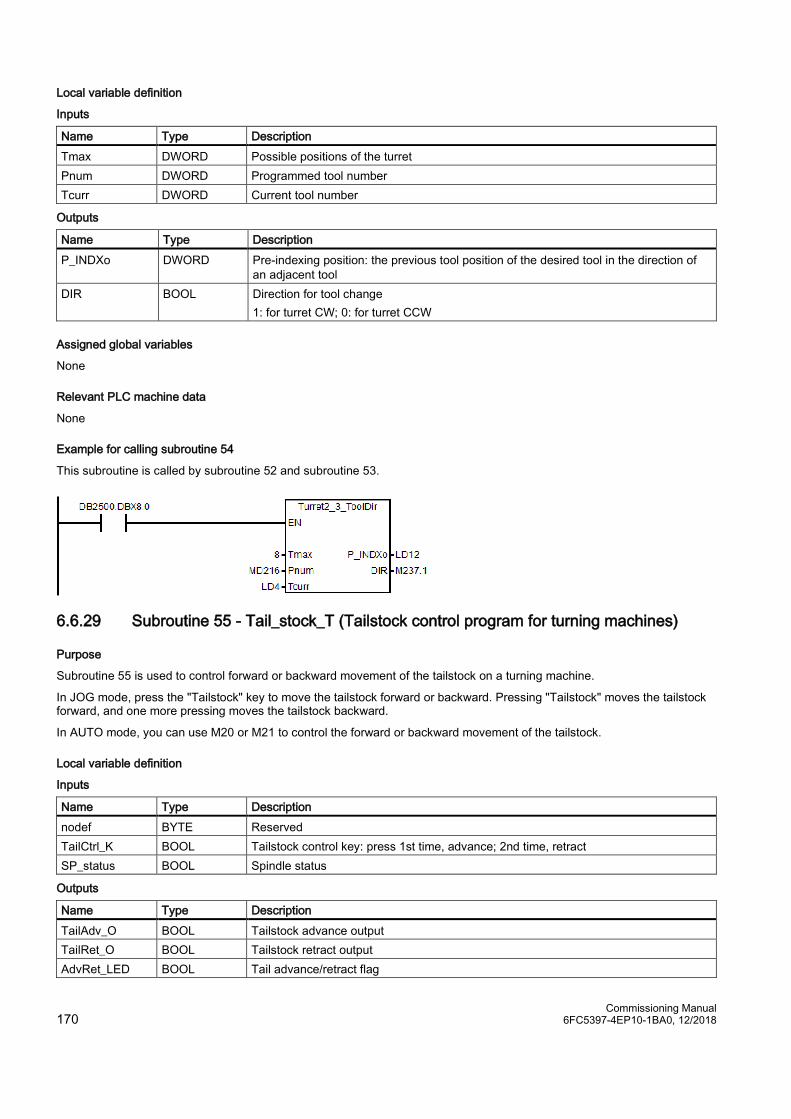
Commissioning Manual 170 6FC5397-4EP10-1BA0, 12/2018
Local variable definition
Inputs
Name Type Description Tmax DWORD Possible positions of the turret Pnum DWORD Programmed tool number Tcurr DWORD Current tool number
Outputs
Name Type Description P_INDXo DWORD Pre-indexing position: the previous tool position of the desired tool in the direction of
an adjacent tool DIR BOOL Direction for tool change
1: for turret CW; 0: for turret CCW
Assigned global variables
None
Relevant PLC machine data
None
Example for calling subroutine 54
This subroutine is called by subroutine 52 and subroutine 53.
6.6.29 Subroutine 55 - Tail_stock_T (Tailstock control program for turning machines)
Purpose
Subroutine 55 is used to control forward or backward movement of the tailstock on a turning machine.
In JOG mode, press the "Tailstock" key to move the tailstock forward or backward. Pressing "Tailstock" moves the tailstock forward, and one more pressing moves the tailstock backward.
In AUTO mode, you can use M20 or M21 to control the forward or backward movement of the tailstock.
Local variable definition
Inputs
Name Type Description nodef BYTE Reserved TailCtrl_K BOOL Tailstock control key: press 1st time, advance; 2nd time, retract SP_status BOOL Spindle status
Outputs
Name Type Description TailAdv_O BOOL Tailstock advance output TailRet_O BOOL Tailstock retract output AdvRet_LED BOOL Tail advance/retract flag
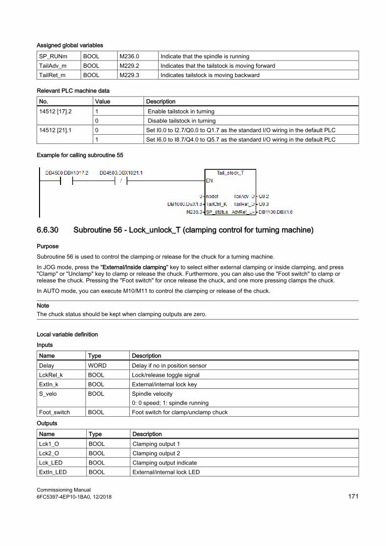
Commissioning Manual 6FC5397-4EP10-1BA0, 12/2018 171
Assigned global variables
SP_RUNm BOOL M236.0 Indicate that the spindle is running TailAdv_m BOOL M229.2 Indicates that the tailstock is moving forward TailRet_m BOOL M229.3 Indicates tailstock is moving backward
Relevant PLC machine data
No. Value Description 14512 [17].2 1 Enable tailstock in turning
0 Disable tailstock in turning 14512 [21].1 0 Set I0.0 to I2.7/Q0.0 to Q1.7 as the standard I/O wiring in the default PLC
1 Set I6.0 to I8.7/Q4.0 to Q5.7 as the standard I/O wiring in the default PLC
Example for calling subroutine 55
6.6.30 Subroutine 56 - Lock_unlock_T (clamping control for turning machine)
Purpose
Subroutine 56 is used to control the clamping or release for the chuck for a turning machine.
In JOG mode, press the "External/Inside clamping" key to select either external clamping or inside clamping, and press "Clamp" or "Unclamp" key to clamp or release the chuck. Furthermore, you can also use the "Foot switch" to clamp or release the chuck. Pressing the "Foot switch" for once release the chuck, and one more pressing clamps the chuck.
In AUTO mode, you can execute M10/M11 to control the clamping or release of the chuck.
Note The chuck status should be kept when clamping outputs are zero.
Local variable definition
Inputs
Name Type Description Delay WORD Delay if no in position sensor LckRel_k BOOL Lock/release toggle signal ExtIn_k BOOL External/internal lock key S_velo BOOL Spindle velocity
0: 0 speed; 1: spindle running Foot_switch BOOL Foot switch for clamp/unclamp chuck
Outputs
Name Type Description Lck1_O BOOL Clamping output 1 Lck2_O BOOL Clamping output 2 Lck_LED BOOL Clamping output indicate ExtIn_LED BOOL External/internal lock LED
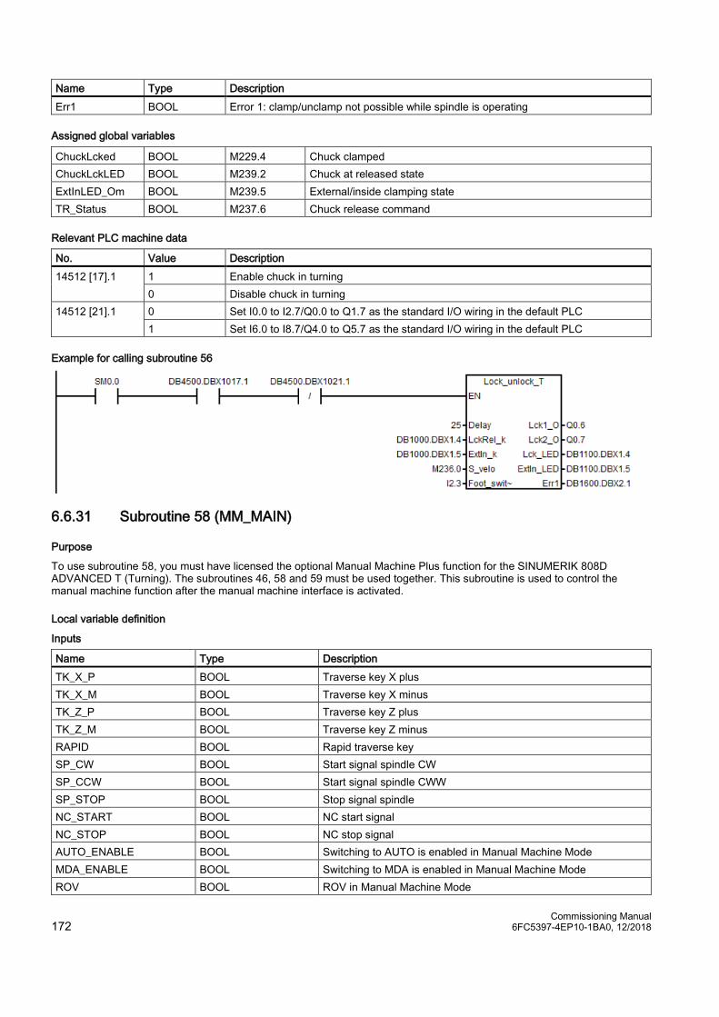
Commissioning Manual 172 6FC5397-4EP10-1BA0, 12/2018
Name Type Description Err1 BOOL Error 1: clamp/unclamp not possible while spindle is operating
Assigned global variables
ChuckLcked BOOL M229.4 Chuck clamped ChuckLckLED BOOL M239.2 Chuck at released state ExtInLED_Om BOOL M239.5 External/inside clamping state TR_Status BOOL M237.6 Chuck release command
Relevant PLC machine data
No. Value Description 14512 [17].1 1 Enable chuck in turning
0 Disable chuck in turning 14512 [21].1 0 Set I0.0 to I2.7/Q0.0 to Q1.7 as the standard I/O wiring in the default PLC
1 Set I6.0 to I8.7/Q4.0 to Q5.7 as the standard I/O wiring in the default PLC
Example for calling subroutine 56
6.6.31 Subroutine 58 (MM_MAIN)
Purpose
To use subroutine 58, you must have licensed the optional Manual Machine Plus function for the SINUMERIK 808D ADVANCED T (Turning). The subroutines 46, 58 and 59 must be used together. This subroutine is used to control the manual machine function after the manual machine interface is activated.
Local variable definition
Inputs
Name Type Description TK_X_P BOOL Traverse key X plus TK_X_M BOOL Traverse key X minus TK_Z_P BOOL Traverse key Z plus TK_Z_M BOOL Traverse key Z minus RAPID BOOL Rapid traverse key SP_CW BOOL Start signal spindle CW SP_CCW BOOL Start signal spindle CWW SP_STOP BOOL Stop signal spindle NC_START BOOL NC start signal NC_STOP BOOL NC stop signal AUTO_ENABLE BOOL Switching to AUTO is enabled in Manual Machine Mode MDA_ENABLE BOOL Switching to MDA is enabled in Manual Machine Mode ROV BOOL ROV in Manual Machine Mode

Commissioning Manual 6FC5397-4EP10-1BA0, 12/2018 173
Outputs
Name Type Description AL_03 BOOL Not approaching the reference point on axis X (user alarm 03) AL_04 BOOL Not approaching the reference point on axis Z (user alarm 04) AL_09 BOOL Incorrect start in the spindle direction (user alarm 09) AL_11 BOOL JOG program timeout (user alarm 11) AL_12 BOOL Spindle rate not 100% (user alarm 12) AL_13 BOOL Spindle not being started (user alarm 13) AL_14 BOOL Feed rate 0% (user alarm 14) AL_16 BOOL Spindle direction change in a thread not allowed (user alarm 16)
Assigned global variables
Byte Signal Byte 7 Byte 6 Byte 5 Byte 4 Byte 3 Byte 2 Byte 1 Byte 0 MB170 HMI<->MM Request
for MM HMI startup
MM HMI enabled
MM HMI started
MB171 HMI<->MM MB172 HMI<->MM MB173 HMI<->MM MB174 HMI<->MM Cone
angle 270°-360°
Cone angle 270°
Cone angle 180°-270°
Cone angle 180°
Cone angle 90°-180°
Cone angle 90°
Cone angle 0°-90°
Cone angle 0°
MB175 HMI<->MM Direction key ena-bled
Spindle rotated
MB176 HMI<->MM Working step ena-bled
Groove enabled
Thread chaining enabled
Drilling enabled
Arc ena-bled
Cutting enabled
Thread enabled
MB177 HMI<->MM MB178 MB179 MB180 Recutting
canceled Recutting performed
Recut the thread or not?
Relevant PLC machine data
No. Unit Range Description MD14512[19].7 - - 1: to enable the manual machine function
0: to disable the manual machine function
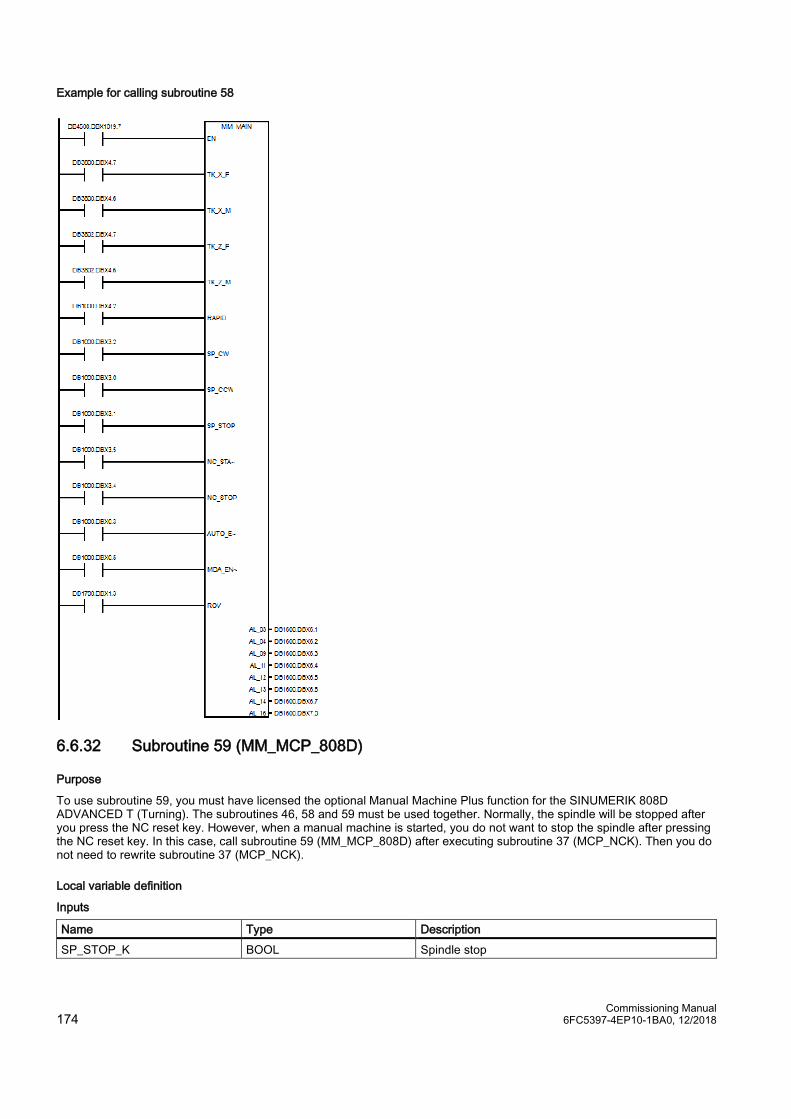
Commissioning Manual 174 6FC5397-4EP10-1BA0, 12/2018
Example for calling subroutine 58
6.6.32 Subroutine 59 (MM_MCP_808D)
Purpose
To use subroutine 59, you must have licensed the optional Manual Machine Plus function for the SINUMERIK 808D ADVANCED T (Turning). The subroutines 46, 58 and 59 must be used together. Normally, the spindle will be stopped after you press the NC reset key. However, when a manual machine is started, you do not want to stop the spindle after pressing the NC reset key. In this case, call subroutine 59 (MM_MCP_808D) after executing subroutine 37 (MCP_NCK). Then you do not need to rewrite subroutine 37 (MCP_NCK).
Local variable definition
Inputs
Name Type Description SP_STOP_K BOOL Spindle stop
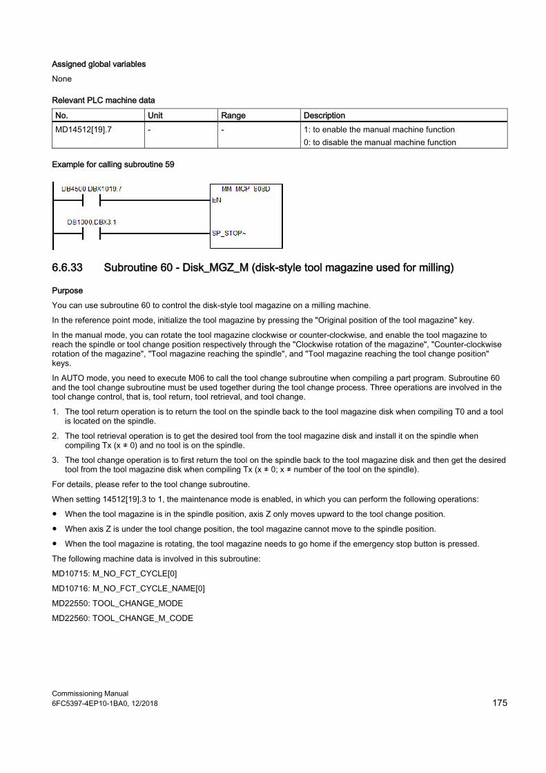
Commissioning Manual 6FC5397-4EP10-1BA0, 12/2018 175
Assigned global variables
None
Relevant PLC machine data
No. Unit Range Description MD14512[19].7 - - 1: to enable the manual machine function
0: to disable the manual machine function
Example for calling subroutine 59
6.6.33 Subroutine 60 - Disk_MGZ_M (disk-style tool magazine used for milling)
Purpose
You can use subroutine 60 to control the disk-style tool magazine on a milling machine.
In the reference point mode, initialize the tool magazine by pressing the "Original position of the tool magazine" key.
In the manual mode, you can rotate the tool magazine clockwise or counter-clockwise, and enable the tool magazine to reach the spindle or tool change position respectively through the "Clockwise rotation of the magazine", "Counter-clockwise rotation of the magazine", "Tool magazine reaching the spindle", and "Tool magazine reaching the tool change position" keys.
In AUTO mode, you need to execute M06 to call the tool change subroutine when compiling a part program. Subroutine 60 and the tool change subroutine must be used together during the tool change process. Three operations are involved in the tool change control, that is, tool return, tool retrieval, and tool change.
1. The tool return operation is to return the tool on the spindle back to the tool magazine disk when compiling T0 and a tool is located on the spindle.
2. The tool retrieval operation is to get the desired tool from the tool magazine disk and install it on the spindle when compiling Tx (x ≠ 0) and no tool is on the spindle.
3. The tool change operation is to first return the tool on the spindle back to the tool magazine disk and then get the desired tool from the tool magazine disk when compiling Tx (x ≠ 0; x ≠ number of the tool on the spindle).
For details, please refer to the tool change subroutine.
When setting 14512[19].3 to 1, the maintenance mode is enabled, in which you can perform the following operations:
● When the tool magazine is in the spindle position, axis Z only moves upward to the tool change position.
● When axis Z is under the tool change position, the tool magazine cannot move to the spindle position.
● When the tool magazine is rotating, the tool magazine needs to go home if the emergency stop button is pressed.
The following machine data is involved in this subroutine:
MD10715: M_NO_FCT_CYCLE[0]
MD10716: M_NO_FCT_CYCLE_NAME[0]
MD22550: TOOL_CHANGE_MODE
MD22560: TOOL_CHANGE_M_CODE
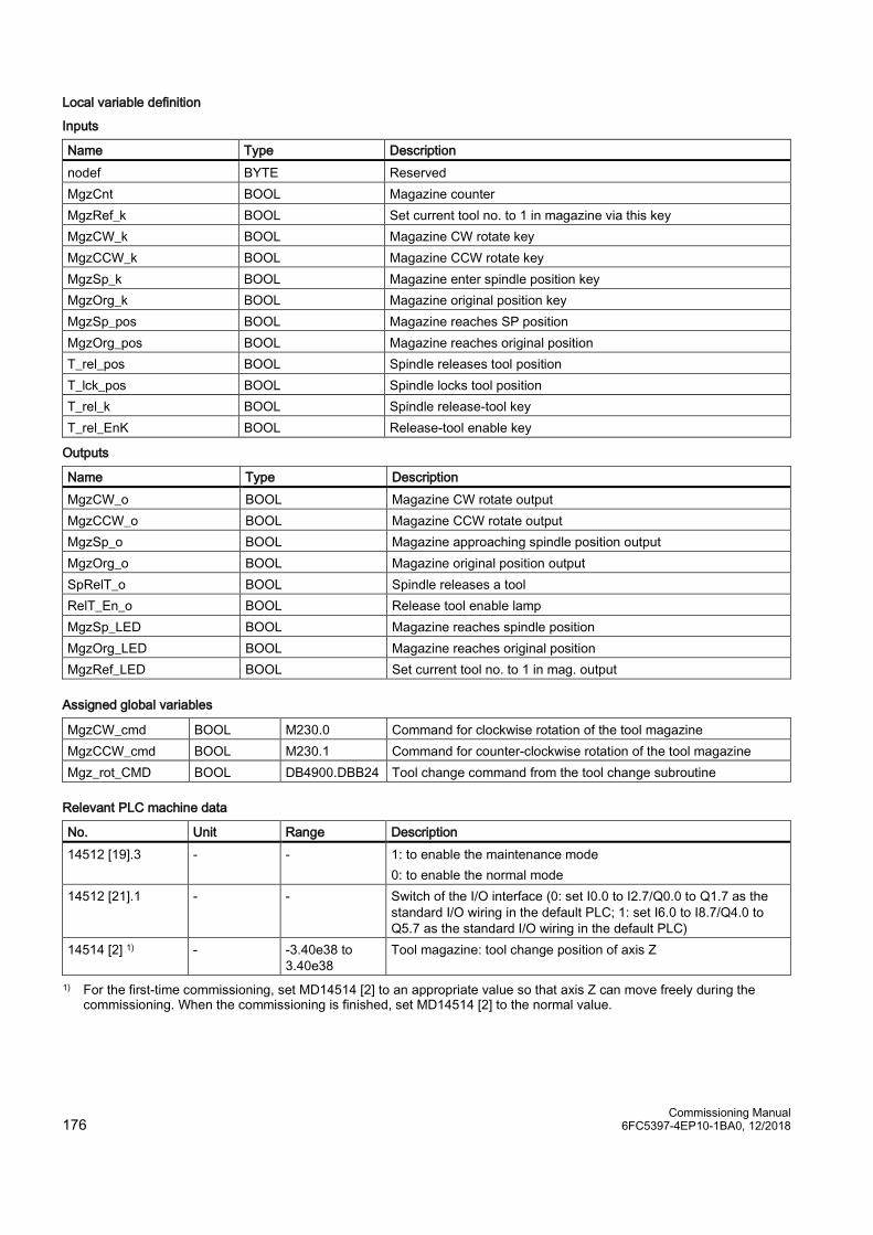
Commissioning Manual 176 6FC5397-4EP10-1BA0, 12/2018
Local variable definition
Inputs
Name Type Description nodef BYTE Reserved MgzCnt BOOL Magazine counter MgzRef_k BOOL Set current tool no. to 1 in magazine via this key MgzCW_k BOOL Magazine CW rotate key MgzCCW_k BOOL Magazine CCW rotate key MgzSp_k BOOL Magazine enter spindle position key MgzOrg_k BOOL Magazine original position key MgzSp_pos BOOL Magazine reaches SP position MgzOrg_pos BOOL Magazine reaches original position T_rel_pos BOOL Spindle releases tool position T_lck_pos BOOL Spindle locks tool position T_rel_k BOOL Spindle release-tool key T_rel_EnK BOOL Release-tool enable key
Outputs
Name Type Description MgzCW_o BOOL Magazine CW rotate output MgzCCW_o BOOL Magazine CCW rotate output MgzSp_o BOOL Magazine approaching spindle position output MgzOrg_o BOOL Magazine original position output SpRelT_o BOOL Spindle releases a tool RelT_En_o BOOL Release tool enable lamp MgzSp_LED BOOL Magazine reaches spindle position MgzOrg_LED BOOL Magazine reaches original position MgzRef_LED BOOL Set current tool no. to 1 in mag. output
Assigned global variables
MgzCW_cmd BOOL M230.0 Command for clockwise rotation of the tool magazine MgzCCW_cmd BOOL M230.1 Command for counter-clockwise rotation of the tool magazine Mgz_rot_CMD BOOL DB4900.DBB24 Tool change command from the tool change subroutine
Relevant PLC machine data
No. Unit Range Description 14512 [19].3 - - 1: to enable the maintenance mode
0: to enable the normal mode 14512 [21].1 - - Switch of the I/O interface (0: set I0.0 to I2.7/Q0.0 to Q1.7 as the
standard I/O wiring in the default PLC; 1: set I6.0 to I8.7/Q4.0 to Q5.7 as the standard I/O wiring in the default PLC)
14514 [2] 1) - -3.40e38 to 3.40e38
Tool magazine: tool change position of axis Z
1) For the first-time commissioning, set MD14514 [2] to an appropriate value so that axis Z can move freely during the commissioning. When the commissioning is finished, set MD14514 [2] to the normal value.
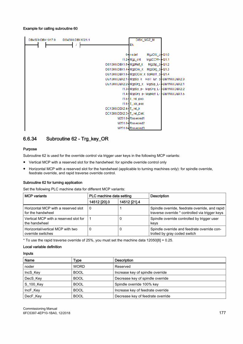
Commissioning Manual 6FC5397-4EP10-1BA0, 12/2018 177
Example for calling subroutine 60
6.6.34 Subroutine 62 - Trg_key_OR
Purpose
Subroutine 62 is used for the override control via trigger user keys in the following MCP variants:
● Vertical MCP with a reserved slot for the handwheel: for spindle override control only
● Horizontal MCP with a reserved slot for the handwheel (applicable to turning machines only): for spindle override, feedrate override, and rapid traverse override control.
Subroutine 62 for turning application
Set the following PLC machine data for different MCP variants:
MCP variants PLC machine data setting Description 14512 [20].0 14512 [21].4
Horizontal MCP with a reserved slot for the handwheel
0 1 Spindle override, feedrate override, and rapid traverse override * controlled via trigger keys
Vertical MCP with a reserved slot for the handwheel
1 0 Spindle override controlled by trigger user keys
Horizontal/vertical MCP with two override switches
0 0 Spindle override and feedrate override con-trolled by gray coded switch
* To use the rapid traverse override of 25%, you must set the machine data 12050[8] = 0.25.
Local variable definition
Inputs
Name Type Description noder WORD Reserved IncS_Key BOOL Increase key of spindle override DecS_Key BOOL Decrease key of spindle override S_100_Key BOOL Spindle override 100% key IncF_Key BOOL Increase key of feedrate override DecF_Key BOOL Decrease key of feedrate override

Commissioning Manual 178 6FC5397-4EP10-1BA0, 12/2018
Name Type Description F_100_Key BOOL Feedrate override 100% key RapidOvr_1 BOOL Rapid override 1% RapidOvr_25 BOOL Rapid override 25% RapidOvr_50 BOOL Rapid override 50% RapidOvr_100 BOOL Rapid override 100% Noder1 BYTE Reserved
Outputs
Name Type Description LED1_S BOOL Lights, spindle override < 100%; flashing, 50% LED2_S BOOL Lights, spindle override 100% LED3_S BOOL Lights, spindle override 105-115%; flashing, 120% LED1_F BOOL Lights, feedrate override < 100%; flashing, 0% LED2_F BOOL Lights, feedrate override 100% LED3_F BOOL Lights, feedrate override 105-115%; flashing, 120%
Assigned global variables
SP_OV_Switch BYTE MB202 Spindle override switch buffer USB_MCP_SP_OV BYTE MB209 USB MCP signal: spindle override FD_OV_Switch BYTE MB201 Feedrate override switch gray code USB_MCP_FD_OV BYTE MB208 USB MCP signal: feedrate override USB_MCP_Ra_OV BYTE MB220 USB MCP signal: rapid feedrate
Relevant PLC machine data
No. Unit Range Description 14510 [15] 0.1 s 0.5 s to 3 s Spindle override 50% key holding on time defined 14510 [16] 0.1 s 0.1 s to 3 s Spindle override 100% key holding on time defined 14510 [17] 0.1 s 0.5 s to 3 s Feedrate override 0% key holding on time defined 14510 [18] 0.1 s 0.1 s to 3 s Feedrate override 100% key holding on time defined 14512 [20] - - Bit 5: define the spindle override startup value (0: the startup spindle
override is always 100%; 1: recode the spindle override value of the last machine turn off for the next startup) Bit 6/7: define the spindle override shift speed • bit 6 = 0, bit 7 = 0
Standard speed. The steps are 50%, 55%, 60%, 65%, 70%, 75%, 80%, 85%, 90%, 95%, 100%, 105%, 110%, 115%, 120%
• bit 6 = 1, bit 7 = 0
Two times the standard speed. The steps are 50%, 60%, 70%, 80%, 90%, 100%, 110%, 120%
• bit 6 = 0, bit 7 = 1
About three times the standard speed. The steps are 50%, 60%, 70%, 85%, 100%, 110%, 120%
• bit 6 = 1, bit 7 = 1
About four times the standard speed. The steps are 50%, 60%, 80%, 100%, 120%
14512 [21] - - Bit 5: define the feedrate override startup value (0: the startup feedrate override is always 100%; 1: recode the feedrate override value of the last machine turn off for the next startup)
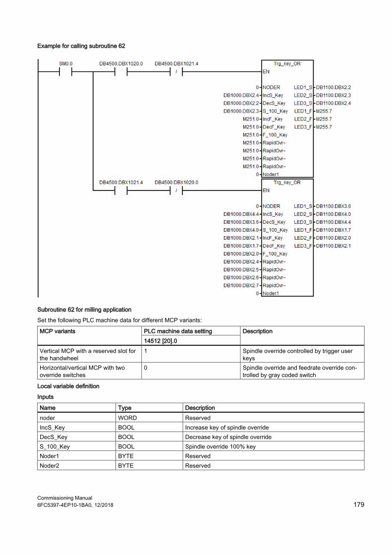
Commissioning Manual 6FC5397-4EP10-1BA0, 12/2018 179
Example for calling subroutine 62
Subroutine 62 for milling application
Set the following PLC machine data for different MCP variants:
MCP variants PLC machine data setting Description 14512 [20].0
Vertical MCP with a reserved slot for the handwheel
1 Spindle override controlled by trigger user keys
Horizontal/vertical MCP with two override switches
0 Spindle override and feedrate override con-trolled by gray coded switch
Local variable definition
Inputs
Name Type Description noder WORD Reserved IncS_Key BOOL Increase key of spindle override DecS_Key BOOL Decrease key of spindle override S_100_Key BOOL Spindle override 100% key Noder1 BYTE Reserved Noder2 BYTE Reserved

Commissioning Manual 180 6FC5397-4EP10-1BA0, 12/2018
Outputs
Name Type Description LED1_S BOOL Lights, spindle override < 100%; flashing, 50% LED2_S BOOL Lights, spindle override 100% LED3_S BOOL Lights, spindle override 105-115%; flashing, 120%
Assigned global variables
SP_OV_Switch BYTE MB202 Spindle override switch buffer USB_MCP_SP_OV BYTE MB209 USB MCP signal: spindle override
Relevant PLC machine data
No. Unit Range Description 14510 [15] 0.1s 0.5 s to 3 s Spindle override 50% key holding on time defined 14510 [16] 0.1s 0.1 s to 3 s Spindle override 100% key holding on time defined 14512 [20] - - Bit 5: define the spindle override startup value (0: the startup spindle
override is always 100%; 1: recode the spindle override value of the last machine turn off for the next startup) Bit 6/7: define the spindle override shift speed • bit 6 = 0, bit 7 = 0
Standard speed. The steps are 50%, 55%, 60%, 65%, 70%, 75%, 80%, 85%, 90%, 95%, 100%, 105%, 110%, 115%, 120%
• bit 6 = 1, bit 7 = 0
Two times the standard speed. The steps are 50%, 60%, 70%, 80%, 90%, 100%, 110%, 120%
• bit 6 = 0, bit 7 = 1
About three times the standard speed. The steps are 50%, 60%, 70%, 85%, 100%, 110%, 120%
• bit 6 = 1, bit 7 = 1
About four times the standard speed. The steps are 50%, 60%, 80%, 100%, 120%
Example for calling subroutine 62
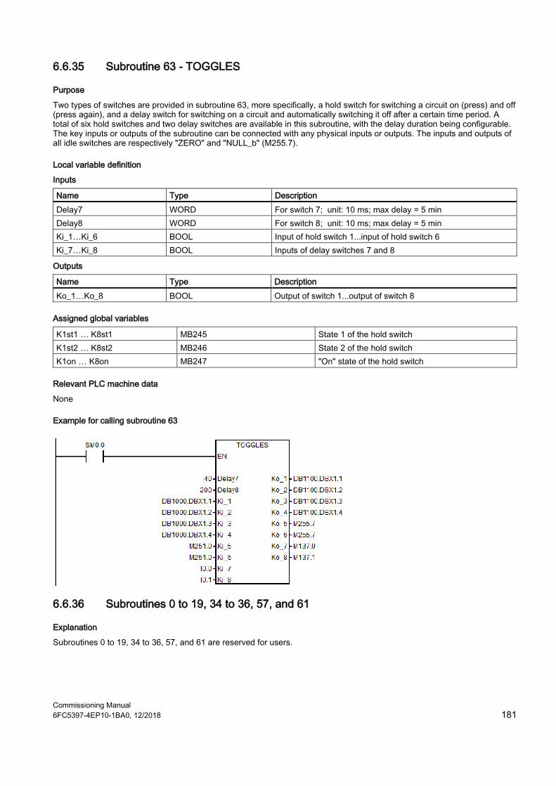
Commissioning Manual 6FC5397-4EP10-1BA0, 12/2018 181
6.6.35 Subroutine 63 - TOGGLES
Purpose
Two types of switches are provided in subroutine 63, more specifically, a hold switch for switching a circuit on (press) and off (press again), and a delay switch for switching on a circuit and automatically switching it off after a certain time period. A total of six hold switches and two delay switches are available in this subroutine, with the delay duration being configurable. The key inputs or outputs of the subroutine can be connected with any physical inputs or outputs. The inputs and outputs of all idle switches are respectively "ZERO" and "NULL_b" (M255.7).
Local variable definition
Inputs
Name Type Description Delay7 WORD For switch 7; unit: 10 ms; max delay = 5 min Delay8 WORD For switch 8; unit: 10 ms; max delay = 5 min Ki_1…Ki_6 BOOL Input of hold switch 1...input of hold switch 6 Ki_7…Ki_8 BOOL Inputs of delay switches 7 and 8
Outputs
Name Type Description Ko_1…Ko_8 BOOL Output of switch 1...output of switch 8
Assigned global variables
K1st1 … K8st1 MB245 State 1 of the hold switch K1st2 … K8st2 MB246 State 2 of the hold switch K1on … K8on MB247 "On" state of the hold switch
Relevant PLC machine data
None
Example for calling subroutine 63
6.6.36 Subroutines 0 to 19, 34 to 36, 57, and 61
Explanation
Subroutines 0 to 19, 34 to 36, 57, and 61 are reserved for users.
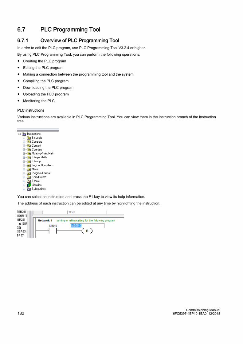
Commissioning Manual 182 6FC5397-4EP10-1BA0, 12/2018
6.7 PLC Programming Tool
6.7.1 Overview of PLC Programming Tool In order to edit the PLC program, use PLC Programming Tool V3.2.4 or higher.
By using PLC Programming Tool, you can perform the following operations:
● Creating the PLC program
● Editing the PLC program
● Making a connection between the programming tool and the system
● Compiling the PLC program
● Downloading the PLC program
● Uploading the PLC program
● Monitoring the PLC
PLC instructions
Various instructions are available in PLC Programming Tool. You can view them in the instruction branch of the instruction tree.
You can select an instruction and press the F1 key to view its help information.
The address of each instruction can be edited at any time by highlighting the instruction.
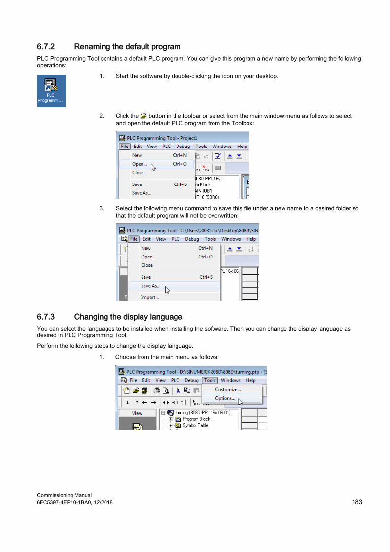
Commissioning Manual 6FC5397-4EP10-1BA0, 12/2018 183
6.7.2 Renaming the default program PLC Programming Tool contains a default PLC program. You can give this program a new name by performing the following operations:
1. Start the software by double-clicking the icon on your desktop.
2. Click the button in the toolbar or select from the main window menu as follows to select and open the default PLC program from the Toolbox:
3. Select the following menu command to save this file under a new name to a desired folder so that the default program will not be overwritten:
6.7.3 Changing the display language You can select the languages to be installed when installing the software. Then you can change the display language as desired in PLC Programming Tool.
Perform the following steps to change the display language.
1. Choose from the main menu as follows:
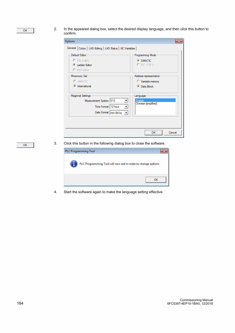
Commissioning Manual 184 6FC5397-4EP10-1BA0, 12/2018
2. In the appeared dialog box, select the desired display language, and then click this button to
confirm.
3. Click this button in the following dialog box to close the software.
4. Start the software again to make the language setting effective.
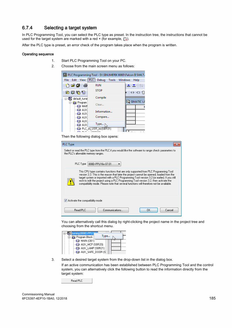
Commissioning Manual 6FC5397-4EP10-1BA0, 12/2018 185
6.7.4 Selecting a target system In PLC Programming Tool, you can select the PLC type as preset. In the instruction tree, the instructions that cannot be used for the target system are marked with a red × (for example, ).
After the PLC type is preset, an error check of the program takes place when the program is written.
Operating sequence
1. Start PLC Programming Tool on your PC. 2. Choose from the main screen menu as follows:
Then the following dialog box opens:
You can alternatively call this dialog by right-clicking the project name in the project tree and choosing from the shortcut menu.
3. Select a desired target system from the drop-down list in the dialog box. If an active communication has been established between PLC Programming Tool and the control system, you can alternatively click the following button to read the information directly from the target system:
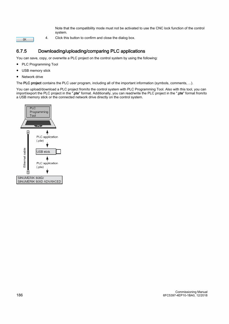
Commissioning Manual 186 6FC5397-4EP10-1BA0, 12/2018
Note that the compatibility mode must not be activated to use the CNC lock function of the control system.
4. Click this button to confirm and close the dialog box.
6.7.5 Downloading/uploading/comparing PLC applications You can save, copy, or overwrite a PLC project on the control system by using the following:
● PLC Programming Tool
● USB memory stick
● Network drive
The PLC project contains the PLC user program, including all of the important information (symbols, comments, ...).
You can upload/download a PLC project from/to the control system with PLC Programming Tool. Also with this tool, you can import/export the PLC project in the ".pte" format. Additionally, you can read/write the PLC project in the ".pte" format from/to a USB memory stick or the connected network drive directly on the control system.

Commissioning Manual 6FC5397-4EP10-1BA0, 12/2018 187
Downloading a PLC project to the control system
You can write the transferred data into the permanent memory (load memory) of the control system with PLC Programming Tool, a USB memory stick, or the network drive.
To download a PLC project with PLC Programming Tool, proceed as follows:
1. Establish the communication between the control system and PLC Programming Tool. For more information, see Section "Connecting with PLC Programming Tool (Page 42)".
2. Open the desired PLC project in PLC Programming Tool. 3. Select from the main screen menu as follows or click the toolbar button to start the
download:
4. Click this button on the download dialog box to proceed directly. You can also select the
following checkbox for data blocks to include the actual values of the data blocks, and then click this button.
5. Choose to download the PLC project when the PLC is in the run mode or in the stop mode.
Caution: You are recommended to download the PLC project when the PLC is in the stop mode. Downloading in the run mode can cause machine damages or even human injuries.
6. Start the download which will take several seconds.
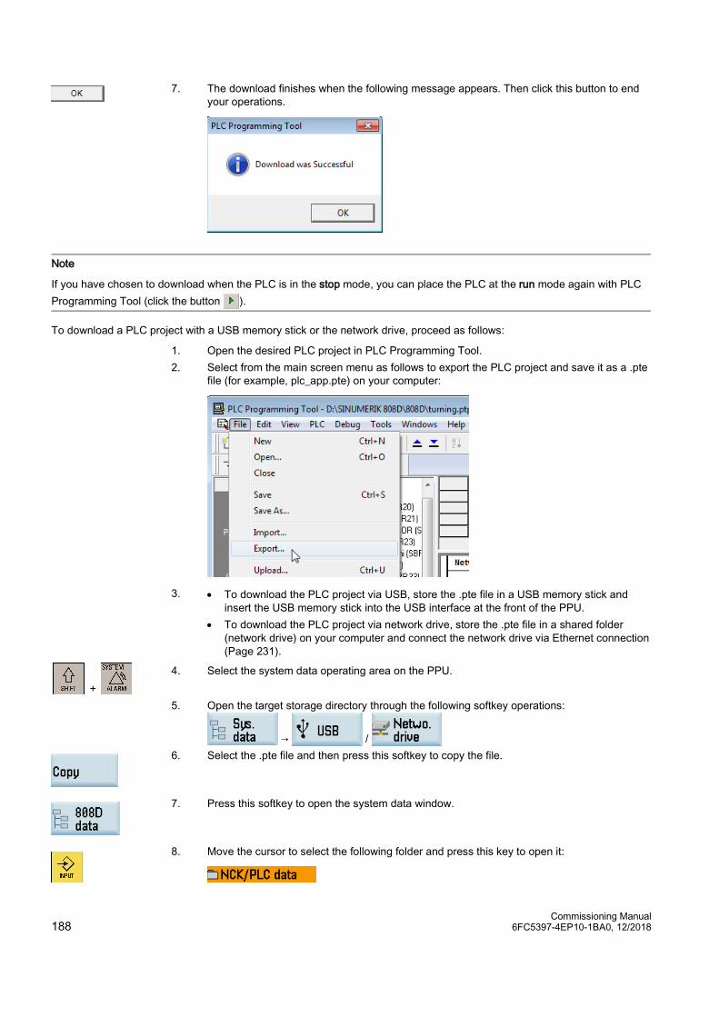
Commissioning Manual 188 6FC5397-4EP10-1BA0, 12/2018
7. The download finishes when the following message appears. Then click this button to end
your operations.
Note
If you have chosen to download when the PLC is in the stop mode, you can place the PLC at the run mode again with PLC Programming Tool (click the button ).
To download a PLC project with a USB memory stick or the network drive, proceed as follows:
1. Open the desired PLC project in PLC Programming Tool. 2. Select from the main screen menu as follows to export the PLC project and save it as a .pte
file (for example, plc_app.pte) on your computer:
3. • To download the PLC project via USB, store the .pte file in a USB memory stick and insert the USB memory stick into the USB interface at the front of the PPU.
• To download the PLC project via network drive, store the .pte file in a shared folder (network drive) on your computer and connect the network drive via Ethernet connection (Page 231).
+ 4. Select the system data operating area on the PPU.
5. Open the target storage directory through the following softkey operations:
→ /
6. Select the .pte file and then press this softkey to copy the file.
7. Press this softkey to open the system data window.
8. Move the cursor to select the following folder and press this key to open it:
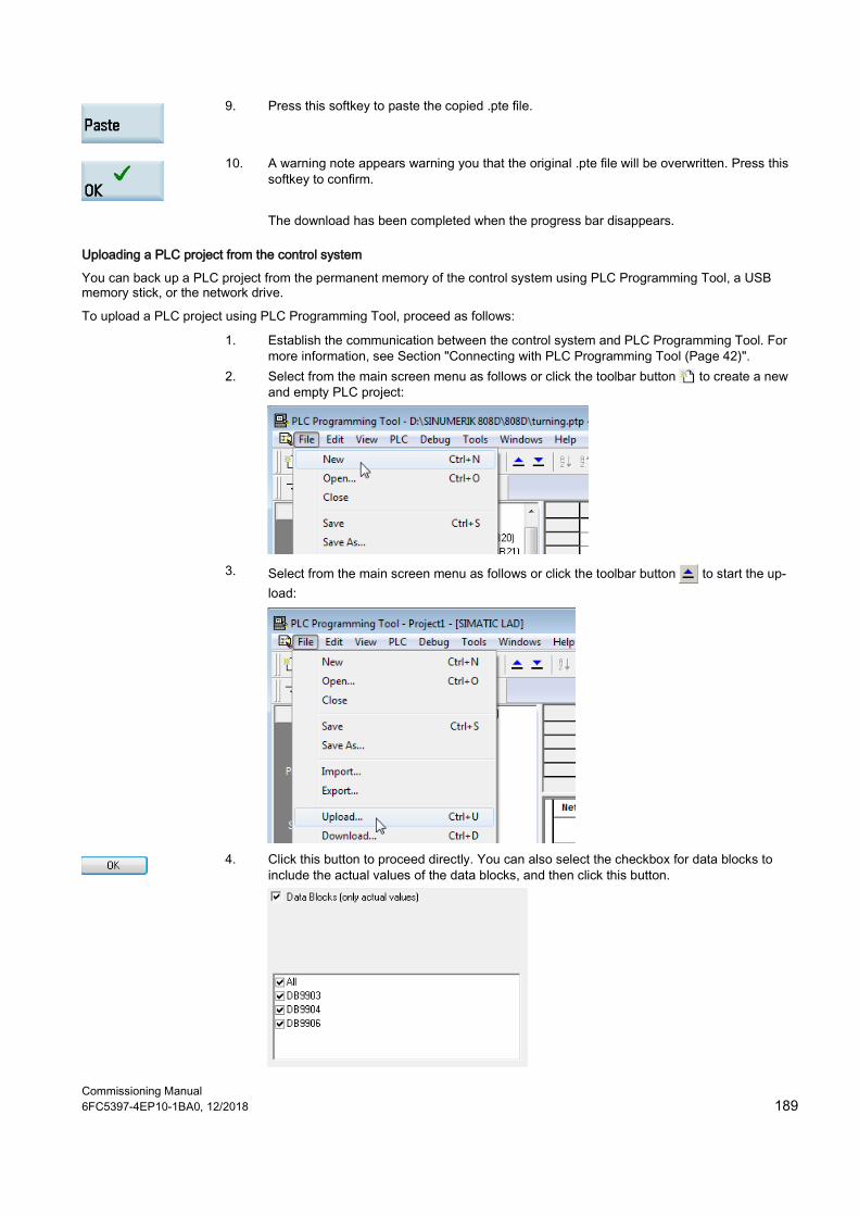
Commissioning Manual 6FC5397-4EP10-1BA0, 12/2018 189
9. Press this softkey to paste the copied .pte file.
10. A warning note appears warning you that the original .pte file will be overwritten. Press this softkey to confirm.
The download has been completed when the progress bar disappears.
Uploading a PLC project from the control system
You can back up a PLC project from the permanent memory of the control system using PLC Programming Tool, a USB memory stick, or the network drive.
To upload a PLC project using PLC Programming Tool, proceed as follows:
1. Establish the communication between the control system and PLC Programming Tool. For more information, see Section "Connecting with PLC Programming Tool (Page 42)".
2. Select from the main screen menu as follows or click the toolbar button to create a new and empty PLC project:
3. Select from the main screen menu as follows or click the toolbar button to start the up-
load:
4. Click this button to proceed directly. You can also select the checkbox for data blocks to
include the actual values of the data blocks, and then click this button.
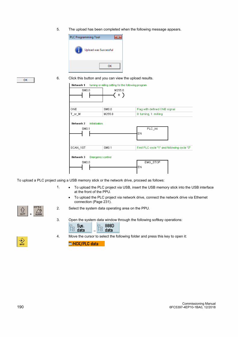
Commissioning Manual 190 6FC5397-4EP10-1BA0, 12/2018
5. The upload has been completed when the following message appears.
6. Click this button and you can view the upload results.
To upload a PLC project using a USB memory stick or the network drive, proceed as follows:
1. • To upload the PLC project via USB, insert the USB memory stick into the USB interface at the front of the PPU.
• To upload the PLC project via network drive, connect the network drive via Ethernet connection (Page 231).
+ 2. Select the system data operating area on the PPU.
3. Open the system data window through the following softkey operations:
→
4. Move the cursor to select the following folder and press this key to open it:
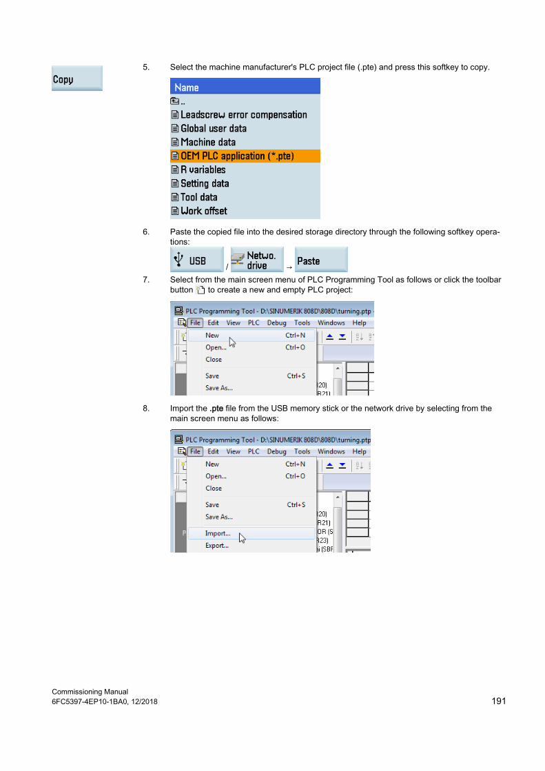
Commissioning Manual 6FC5397-4EP10-1BA0, 12/2018 191
5. Select the machine manufacturer's PLC project file (.pte) and press this softkey to copy.
6. Paste the copied file into the desired storage directory through the following softkey opera-tions:
/ → 7. Select from the main screen menu of PLC Programming Tool as follows or click the toolbar
button to create a new and empty PLC project:
8. Import the .pte file from the USB memory stick or the network drive by selecting from the main screen menu as follows:

Commissioning Manual 192 6FC5397-4EP10-1BA0, 12/2018
9. Click this button or double-click the .pte file in the following dialog box. It will take several
seconds to import the .pte file.
10. After successfully importing the PLC project, you can view the import results.
Comparing the PLC projects
You can compare the project opened in PLC Programming Tool with that stored on the control system by proceeding through the following steps:
1. Select from the main screen menu as follows:

Commissioning Manual 6FC5397-4EP10-1BA0, 12/2018 193
You can also select the checkbox for data blocks to include the actual values of the data blocks.
2. Click this button and the comparing begins. Wait for a few seconds, and then you can view
the compare results.
Version display
The transferred PLC application will be active in the working memory of the control after the system is started up. Then you can view the detailed information about the currently active PLC application in the version display through the following softkey operations:
+ → → →
In PLC Programming Tool, right-click the OB1 block and choose "Properties". In the comment text box of the opened OB1 property dialog, you can add your own additional information for the PLC application.
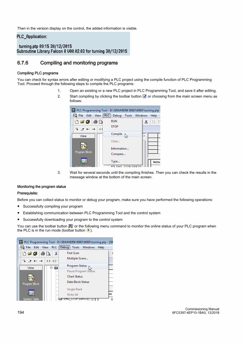
Commissioning Manual 194 6FC5397-4EP10-1BA0, 12/2018
Then in the version display on the control, the added information is visible.
6.7.6 Compiling and monitoring programs
Compiling PLC programs
You can check for syntax errors after editing or modifying a PLC project using the compile function of PLC Programming Tool. Proceed through the following steps to compile the PLC programs:
1. Open an existing or a new PLC project in PLC Programming Tool, and save it after editing. 2. Start compiling by clicking the toolbar button or choosing from the main screen menu as
follows:
3. Wait for several seconds until the compiling finishes. Then you can check the results in the message window at the bottom of the main screen.
Monitoring the program status
Prerequisite:
Before you can collect status to monitor or debug your program, make sure you have performed the following operations:
● Successfully compiling your program
● Establishing communication between PLC Programming Tool and the control system
● Successfully downloading your program to the control system
You can use the toolbar button or the following menu command to monitor the online status of your PLC program when the PLC is in the run mode (toolbar button ).
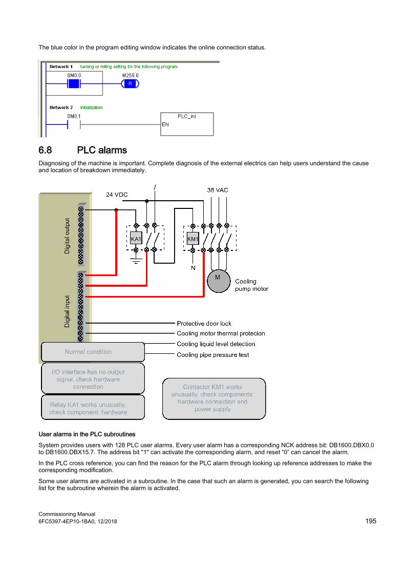
Commissioning Manual 6FC5397-4EP10-1BA0, 12/2018 195
The blue color in the program editing window indicates the online connection status.
6.8 PLC alarms Diagnosing of the machine is important. Complete diagnosis of the external electrics can help users understand the cause and location of breakdown immediately.
User alarms in the PLC subroutines
System provides users with 128 PLC user alarms. Every user alarm has a corresponding NCK address bit: DB1600.DBX0.0 to DB1600.DBX15.7. The address bit "1" can activate the corresponding alarm, and reset “0” can cancel the alarm.
In the PLC cross reference, you can find the reason for the PLC alarm through looking up reference addresses to make the corresponding modification.
Some user alarms are activated in a subroutine. In the case that such an alarm is generated, you can search the following list for the subroutine wherein the alarm is activated.
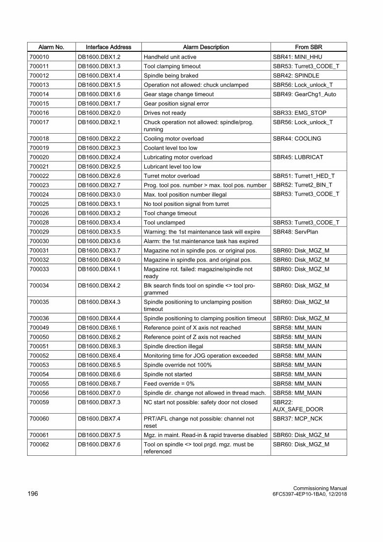
Commissioning Manual 196 6FC5397-4EP10-1BA0, 12/2018
Alarm No. Interface Address Alarm Description From SBR 700010 DB1600.DBX1.2 Handheld unit active SBR41: MINI_HHU 700011 DB1600.DBX1.3 Tool clamping timeout SBR53: Turret3_CODE_T 700012 DB1600.DBX1.4 Spindle being braked SBR42: SPINDLE 700013 DB1600.DBX1.5 Operation not allowed: chuck unclamped SBR56: Lock_unlock_T 700014 DB1600.DBX1.6 Gear stage change timeout SBR49: GearChg1_Auto 700015 DB1600.DBX1.7 Gear position signal error 700016 DB1600.DBX2.0 Drives not ready SBR33: EMG_STOP 700017 DB1600.DBX2.1 Chuck operation not allowed: spindle/prog.
running SBR56: Lock_unlock_T
700018 DB1600.DBX2.2 Cooling motor overload SBR44: COOLING 700019 DB1600.DBX2.3 Coolant level too low 700020 DB1600.DBX2.4 Lubricating motor overload SBR45: LUBRICAT 700021 DB1600.DBX2.5 Lubricant level too low 700022 DB1600.DBX2.6 Turret motor overload SBR51: Turret1_HED_T
SBR52: Turret2_BIN_T SBR53: Turret3_CODE_T
700023 DB1600.DBX2.7 Prog. tool pos. number > max. tool pos. number 700024 DB1600.DBX3.0 Max. tool position number illegal 700025 DB1600.DBX3.1 No tool position signal from turret 700026 DB1600.DBX3.2 Tool change timeout 700028 DB1600.DBX3.4 Tool unclamped SBR53: Turret3_CODE_T 700029 DB1600.DBX3.5 Warning: the 1st maintenance task will expire SBR48: ServPlan 700030 DB1600.DBX3.6 Alarm: the 1st maintenance task has expired 700031 DB1600.DBX3.7 Magazine not in spindle pos. or original pos. SBR60: Disk_MGZ_M 700032 DB1600.DBX4.0 Magazine in spindle pos. and original pos. SBR60: Disk_MGZ_M 700033 DB1600.DBX4.1 Magazine rot. failed: magazine/spindle not
ready SBR60: Disk_MGZ_M
700034 DB1600.DBX4.2 Blk search finds tool on spindle <> tool pro-grammed
SBR60: Disk_MGZ_M
700035 DB1600.DBX4.3 Spindle positioning to unclamping position timeout
SBR60: Disk_MGZ_M
700036 DB1600.DBX4.4 Spindle positioning to clamping position timeout SBR60: Disk_MGZ_M 700049 DB1600.DBX6.1 Reference point of X axis not reached SBR58: MM_MAIN 700050 DB1600.DBX6.2 Reference point of Z axis not reached SBR58: MM_MAIN 700051 DB1600.DBX6.3 Spindle direction illegal SBR58: MM_MAIN 700052 DB1600.DBX6.4 Monitoring time for JOG operation exceeded SBR58: MM_MAIN 700053 DB1600.DBX6.5 Spindle override not 100% SBR58: MM_MAIN 700054 DB1600.DBX6.6 Spindle not started SBR58: MM_MAIN 700055 DB1600.DBX6.7 Feed override = 0% SBR58: MM_MAIN 700056 DB1600.DBX7.0 Spindle dir. change not allowed in thread mach. SBR58: MM_MAIN 700059 DB1600.DBX7.3 NC start not possible: safety door not closed SBR22:
AUX_SAFE_DOOR 700060 DB1600.DBX7.4 PRT/AFL change not possible: channel not
reset SBR37: MCP_NCK
700061 DB1600.DBX7.5 Mgz. in maint. Read-in & rapid traverse disabled SBR60: Disk_MGZ_M 700062 DB1600.DBX7.6 Tool on spindle <> tool prgd. mgz. must be
referenced SBR60: Disk_MGZ_M

Commissioning Manual 6FC5397-4EP10-1BA0, 12/2018 197
6.8.1 Alarm cancel/reset and reaction
Conditions of alarm cancel/reset
After the cancel of an alarm, you need to press one of the following two keys to clear the alarm finally.
Then the alarm displayed will disappear by itself.
or
Alarm reaction
There are the following two ways for alarm reaction.
PLC reaction: the PLC program detects the reaction through the corresponding PLC interface, such as canceling the axis enable when giving an alarm.
NC reaction: every alarm has an eight-bit configuration MD14516[0] to [127]. You can set the cancelation condition and alarm reaction for every alarm according to the actual condition. The system then makes the corresponding reaction when the alarm begins.
6.8.2 Editing PLC alarm texts
Creating or editing alarm texts correctly and reasonably can make users clearly realize and understand the reason of a PLC alarm and then locate and resolve breakdown.
You can edit a PLC user alarm by using the following two methods:
● Editing via a USB memory stick
● Editing directly on the HMI
Editing a PLC user alarm via a USB memory stick
1. Insert the USB stick into the USB interface on the front panel of the PPU.
+ 2. Select the system data operating area.
3. Press this softkey to open the system data window.
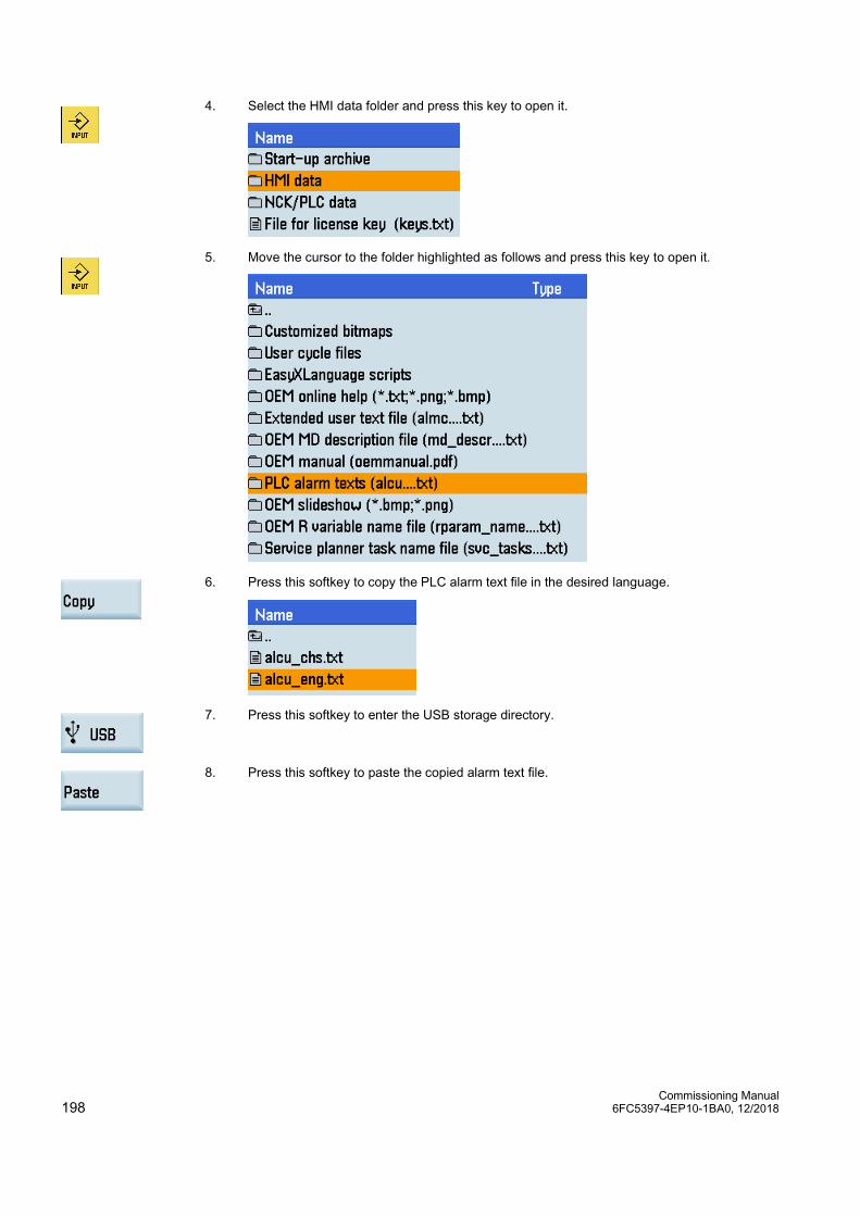
Commissioning Manual 198 6FC5397-4EP10-1BA0, 12/2018
4. Select the HMI data folder and press this key to open it.
5. Move the cursor to the folder highlighted as follows and press this key to open it.
6. Press this softkey to copy the PLC alarm text file in the desired language.
7. Press this softkey to enter the USB storage directory.
8. Press this softkey to paste the copied alarm text file.

Commissioning Manual 6FC5397-4EP10-1BA0, 12/2018 199
9. Connect the USB stick with your computer, find the PLC alarm text file copied from the NC, and open it with the WordPad.
10. Edit the alarm text as desired and then save and close the file. 11. Insert the USB stick into the USB interface on the front panel of the PPU. 12. Enter the USB storage directory through the following operations:
+ → →
13. Locate the edited alarm text file and press this softkey to copy it.
14. Open the PLC alarm text folder as shown in Step 6 above.
15. Press this softkey to paste the edited alarm text file and overwrite the original one.
16. Then you can check the editing result through the following softkey operations:
→
Editing a PLC user alarm on the HMI
+ 1. Select the system data operating area.
2. Open the window for editing the PLC user alarm texts through the following softkey opera-tions:
→ 3. Use the cursor keys to select the alarm text you desire to edit.
4. Press this softkey to activate the input field at the bottom of the screen and enter the de-sired text, for example:
Note that the text of each PLC user alarm must be limited to 50 characters; otherwise, the alarm cannot display properly.

Commissioning Manual 200 6FC5397-4EP10-1BA0, 12/2018
5. Confirm your entry with this softkey or the following key:
6.9 PLC diagnostics A PLC user program consists to a large degree of logical operations to realize safety functions and to support process sequences. These logical operations include the linking of various contacts and relays. As a rule, the failure of a single contact or relay results in a failure of the whole system/installation.
To locate causes of faults/failures or of a program error, various diagnostic functions are offered in the system data operating area.
You can open the PLC program stored in the permanent memory of the control system through the following operations:
+ → →
① Application area
② Supported PLC program language
③ Name of the active program block Representation: Symbolic name (absolute name)
④ • Program status – : Program is running – : Program is stopped
• Status of the application area – : Symbolic representation – : Absolute representation
⑤ Display of the active keys, e.g.
⑥ Focus Performs the tasks of the cursor
⑦ Tip line Contains notes for searching
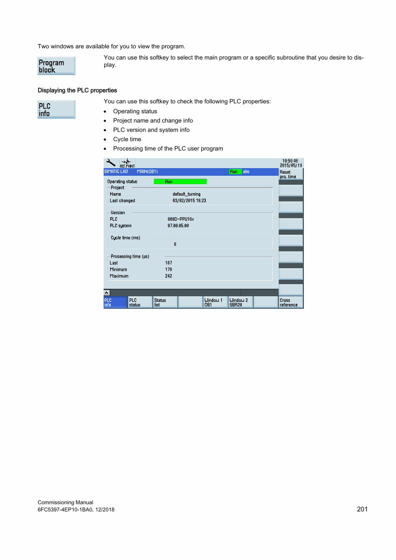
Commissioning Manual 6FC5397-4EP10-1BA0, 12/2018 201
Two windows are available for you to view the program.
You can use this softkey to select the main program or a specific subroutine that you desire to dis-play.
Displaying the PLC properties
You can use this softkey to check the following PLC properties: • Operating status • Project name and change info • PLC version and system info • Cycle time • Processing time of the PLC user program
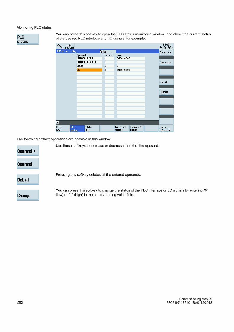
Commissioning Manual 202 6FC5397-4EP10-1BA0, 12/2018
Monitoring PLC status
You can press this softkey to open the PLC status monitoring window, and check the current status of the desired PLC interface and I/O signals, for example:
The following softkey operations are possible in this window:
Use these softkeys to increase or decrease the bit of the operand.
Pressing this softkey deletes all the entered operands.
You can press this softkey to change the status of the PLC interface or I/O signals by entering "0" (low) or "1" (high) in the corresponding value field.
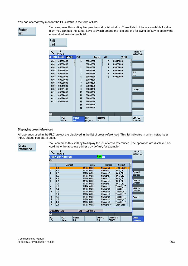
Commissioning Manual 6FC5397-4EP10-1BA0, 12/2018 203
You can alternatively monitor the PLC status in the form of lists.
You can press this softkey to open the status list window. Three lists in total are available for dis-play. You can use the cursor keys to switch among the lists and the following softkey to specify the operand address for each list:
Displaying cross references
All operands used in the PLC project are displayed in the list of cross references. This list indicates in which networks an input, output, flag etc. is used.
You can press this softkey to display the list of cross references. The operands are displayed ac-cording to the absolute address by default, for example:

Commissioning Manual 204 6FC5397-4EP10-1BA0, 12/2018
The following softkey operations are possible in this window:
Press this softkey to switch between the absolute and symbolic representation of the components.
You can open the selected program segment directly in the window using these softkeys.
Use this softkey to search for an operand in the cross reference list.
6.10 Handwheel assignment Up to 2 handwheels can be connected. This means that up to 2 axes can be traversed by handwheel simultaneously and independently. A handwheel is assigned to the geometry or machine axes (WCS or MCS) via interface signals.
The axis to be moved as a result of rotating handwheel 1 to 2 can be set via the PLC user interface with IS "Activate handwheel 1 to 2":
● For machine axis (traverse in MCS): DB380x.DBX4.0/.1
● For geometry axis (traverse in WCS): DB3200.DBX1000.0/.1, DB3200.DBX1004.0/.1, and DB3200.DBX1008.0/.1.
The assignment is linked to the PLC interface through the PLC user program. Only here can several machine axes be assigned to one handwheel simultaneously.
You must also set the increment INC1, INC10, etc., which applies to handwheel travel, via axis signals DB380x.DBX5.x or channel signals (DB3200.DBX1001.x, DB3200.DBX1005.x, and DB3200.DBX1009.x). Note that the mode signals DB2600.DBX1.0 and DB3000.DBX2.x must not be active in this case.
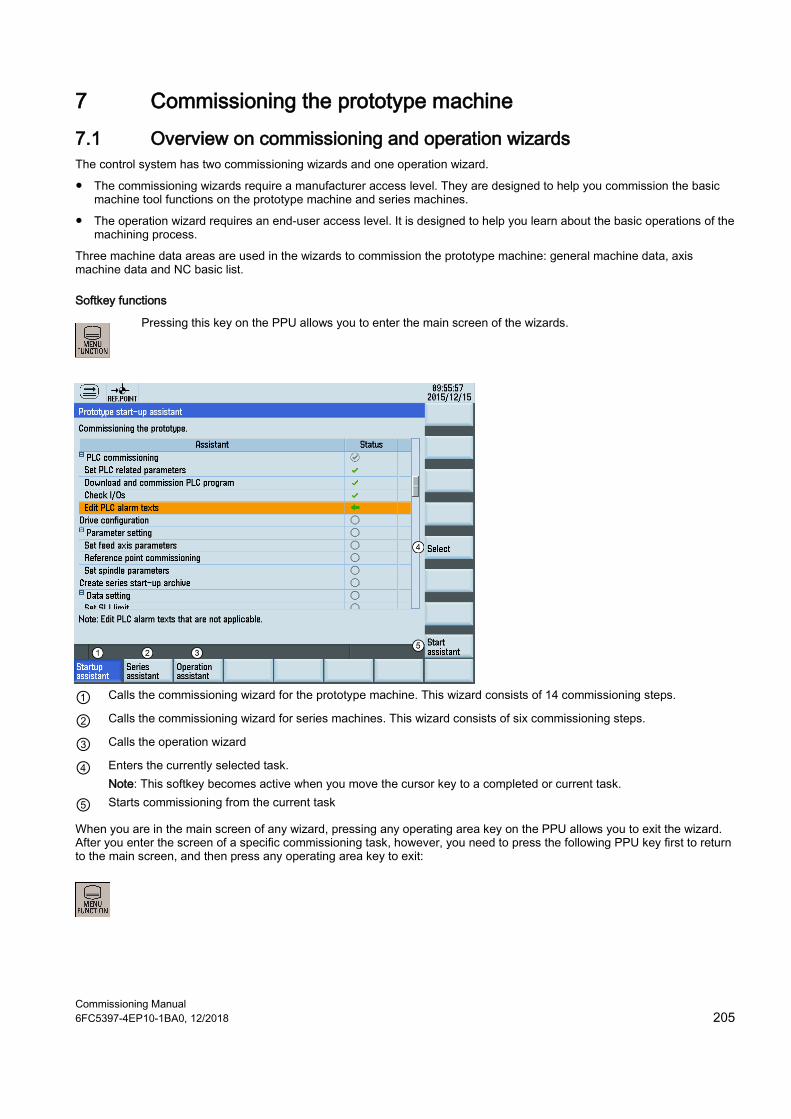
Commissioning Manual 6FC5397-4EP10-1BA0, 12/2018 205
7 Commissioning the prototype machine 7.1 Overview on commissioning and operation wizards The control system has two commissioning wizards and one operation wizard.
● The commissioning wizards require a manufacturer access level. They are designed to help you commission the basic machine tool functions on the prototype machine and series machines.
● The operation wizard requires an end-user access level. It is designed to help you learn about the basic operations of the machining process.
Three machine data areas are used in the wizards to commission the prototype machine: general machine data, axis machine data and NC basic list.
Softkey functions
Pressing this key on the PPU allows you to enter the main screen of the wizards.
① Calls the commissioning wizard for the prototype machine. This wizard consists of 14 commissioning steps.
② Calls the commissioning wizard for series machines. This wizard consists of six commissioning steps.
③ Calls the operation wizard
④ Enters the currently selected task. Note: This softkey becomes active when you move the cursor key to a completed or current task.
⑤ Starts commissioning from the current task
When you are in the main screen of any wizard, pressing any operating area key on the PPU allows you to exit the wizard. After you enter the screen of a specific commissioning task, however, you need to press the following PPU key first to return to the main screen, and then press any operating area key to exit:

Commissioning Manual 206 6FC5397-4EP10-1BA0, 12/2018
Commissioning status
You can check the commissioning status via the status symbols from the main screens of the commissioning wizards.
Status symbol Meaning
Completed task
Current task
Partially completed task group
Uncompleted task
Commissioning diagram
The diagram below shows the general commissioning procedure for the NC.
① Commissioning the prototype machine ② Series production
Note The control system constantly creates restoring points during operation. In case of data loss due to power failure or other problems, the control system automatically restores the last autosaved system data upon startup with an alarm appearing on the screen.
Note Before starting the machine commissioning with the commissioning wizard, make sure MD20050, MD20070, and MD35000 are set to defaults.

Commissioning Manual 6FC5397-4EP10-1BA0, 12/2018 207
7.2 Commissioning the PLC
7.2.1 Setting PLC related parameters Use either of the following softkeys on the main screen of prototype commissioning wizard to enter the window for setting the PLC related parameters:
/
Softkey functions
① Activates the parameter changes. Note that the con-
trol system restarts to accept the new values. ③ Cancels the last change to the parameter
② Resets the value of the selected parameter to default ④ Proceeds to the next step
For more information about setting the PLC related parameters, see Section "PLC machine data (Page 139)".
7.2.2 Downloading and commissioning PLC programs
Note If you use the default PLC programs, you can skip this step and move to the next step.
To realize your own PLC functions, you can upload the default PLC program to your computer and edit it. With PLC Programming Tool installed on your computer, you can download customized PLC programs into the permanent memory of the control system. PLC Programming Tool is available in the Toolbox.
Operating sequence
1. Connect the controller to your computer with an Ethernet cable.
2. Press this softkey on the main screen of this commissioning step, and the following connec-tion information displays:
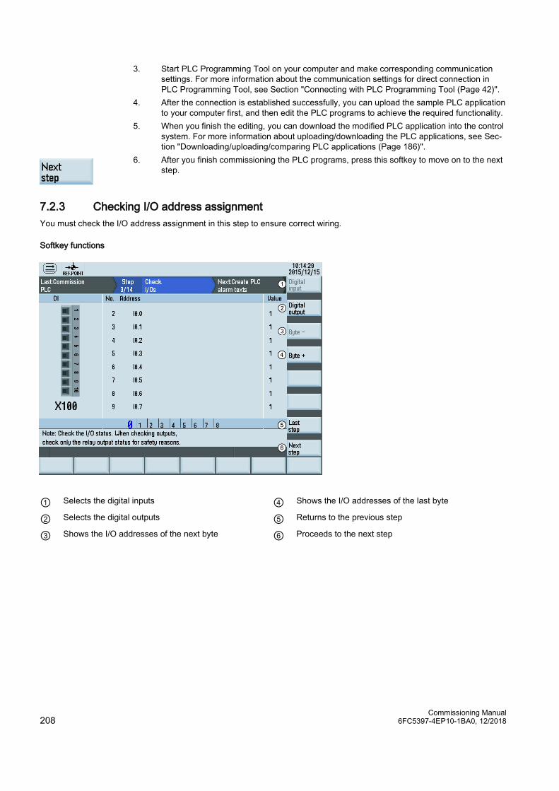
Commissioning Manual 208 6FC5397-4EP10-1BA0, 12/2018
3. Start PLC Programming Tool on your computer and make corresponding communication settings. For more information about the communication settings for direct connection in PLC Programming Tool, see Section "Connecting with PLC Programming Tool (Page 42)".
4. After the connection is established successfully, you can upload the sample PLC application to your computer first, and then edit the PLC programs to achieve the required functionality.
5. When you finish the editing, you can download the modified PLC application into the control system. For more information about uploading/downloading the PLC applications, see Sec-tion "Downloading/uploading/comparing PLC applications (Page 186)".
6. After you finish commissioning the PLC programs, press this softkey to move on to the next step.
7.2.3 Checking I/O address assignment You must check the I/O address assignment in this step to ensure correct wiring.
Softkey functions
① Selects the digital inputs ④ Shows the I/O addresses of the last byte
② Selects the digital outputs ⑤ Returns to the previous step
③ Shows the I/O addresses of the next byte ⑥ Proceeds to the next step
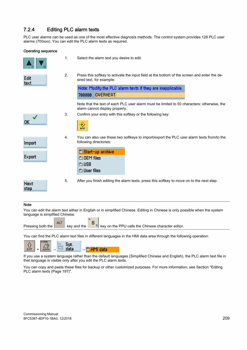
Commissioning Manual 6FC5397-4EP10-1BA0, 12/2018 209
7.2.4 Editing PLC alarm texts PLC user alarms can be used as one of the most effective diagnosis methods. The control system provides 128 PLC user alarms (700xxx). You can edit the PLC alarm texts as required.
Operating sequence
1. Select the alarm text you desire to edit.
2. Press this softkey to activate the input field at the bottom of the screen and enter the de-sired text, for example:
Note that the text of each PLC user alarm must be limited to 50 characters; otherwise, the alarm cannot display properly.
3. Confirm your entry with this softkey or the following key:
4. You can also use these two softkeys to import/export the PLC user alarm texts from/to the following directories:
5. After you finish editing the alarm texts, press this softkey to move on to the next step.
Note You can edit the alarm text either in English or in simplified Chinese. Editing in Chinese is only possible when the system language is simplified Chinese.
Pressing both the key and the key on the PPU calls the Chinese character editor.
You can find the PLC alarm text files in different languages in the HMI data area through the following operation:
+ → →
If you use a system language rather than the default languages (Simplified Chinese and English), the PLC alarm text file in that language is visible only after you edit the PLC alarm texts.
You can copy and paste these files for backup or other customized purposes. For more information, see Section "Editing PLC alarm texts (Page 197)".

Commissioning Manual 210 6FC5397-4EP10-1BA0, 12/2018
7.3 Configuring the drives
Note This commissioning step is applicable to the standard axes only. For the drive configuration of additional axes, see Section "Configuring an additional feed axis (Page 234)".
Before starting the drive configuration, you must ensure the Drive Bus addresses are properly set (p0918) via the drive BOPs. For more information about setting the Drive Bus address, refer to Section "Configuring Drive Bus addresses (Page 119)".
Press this softkey on the main screen of drive configuration, and the control system starts to identify the drives and motors connected. After the identification finishes, a drive list with motor information displays on the screen.
● If a V70 spindle drive is connected properly with the Drive Bus address set to 14, the control system identifies digital spindle and displays as follows:
● If an analog spindle drive is connected through the PPU interface X54 and no V70 spindle drive is connected, the control
system identifies the analog spindle and displays as follows:
Configuring the feed axes
Note This procedure is required only for a feed axis driven by a motor with an incremental encoder. If the selected axis is configured with a motor with an absolute encoder, the motor ID is identified automatically.
1. Select a feed axis using the cursor keys in the drive list window.
2. Press this softkey to open the motor configuration window.
3. Select the right motor ID with the cursor keys according to the motor rating plate.
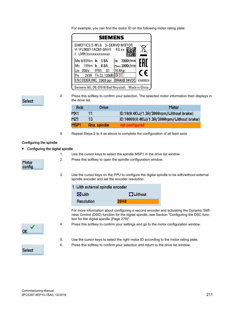
Commissioning Manual 6FC5397-4EP10-1BA0, 12/2018 211
For example, you can find the motor ID on the following motor rating plate:
4. Press this softkey to confirm your selection. The selected motor information then displays in the drive list.
5. Repeat Steps 2 to 4 as above to complete the configuration of all feed axes.
Configuring the spindle
● Configuring the digital spindle 1. Use the cursor keys to select the spindle MSP1 in the drive list window.
2. Press this softkey to open the spindle configuration window.
3. Use the cursor keys on the PPU to configure the digital spindle to be with/without external spindle encoder and set the encoder resolution.
For more information about configuring a second encoder and activating the Dynamic Stiff-ness Control (DSC) function for the digital spindle, see Section "Configuring the DSC func-tion for the digital spindle (Page 279)".
4. Press this softkey to confirm your settings and go to the motor configuration window.
5. Use the cursor keys to select the right motor ID according to the motor rating plate.
6. Press this softkey to confirm your selection and return to the drive list window.
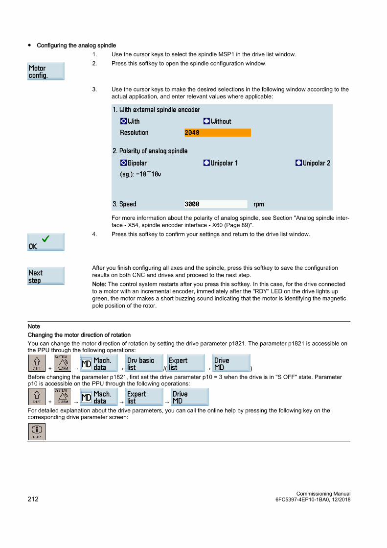
Commissioning Manual 212 6FC5397-4EP10-1BA0, 12/2018
● Configuring the analog spindle 1. Use the cursor keys to select the spindle MSP1 in the drive list window.
2. Press this softkey to open the spindle configuration window.
3. Use the cursor keys to make the desired selections in the following window according to the actual application, and enter relevant values where applicable:
For more information about the polarity of analog spindle, see Section "Analog spindle inter-face - X54, spindle encoder interface - X60 (Page 89)".
4. Press this softkey to confirm your settings and return to the drive list window.
After you finish configuring all axes and the spindle, press this softkey to save the configuration results on both CNC and drives and proceed to the next step. Note: The control system restarts after you press this softkey. In this case, for the drive connected to a motor with an incremental encoder, immediately after the "RDY" LED on the drive lights up green, the motor makes a short buzzing sound indicating that the motor is identifying the magnetic pole position of the rotor.
Note Changing the motor direction of rotation You can change the motor direction of rotation by setting the drive parameter p1821. The parameter p1821 is accessible on the PPU through the following operations:
+ → → /( → ) Before changing the parameter p1821, first set the drive parameter p10 = 3 when the drive is in "S OFF" state. Parameter p10 is accessible on the PPU through the following operations:
+ → → → For detailed explanation about the drive parameters, you can call the online help by pressing the following key on the corresponding drive parameter screen:
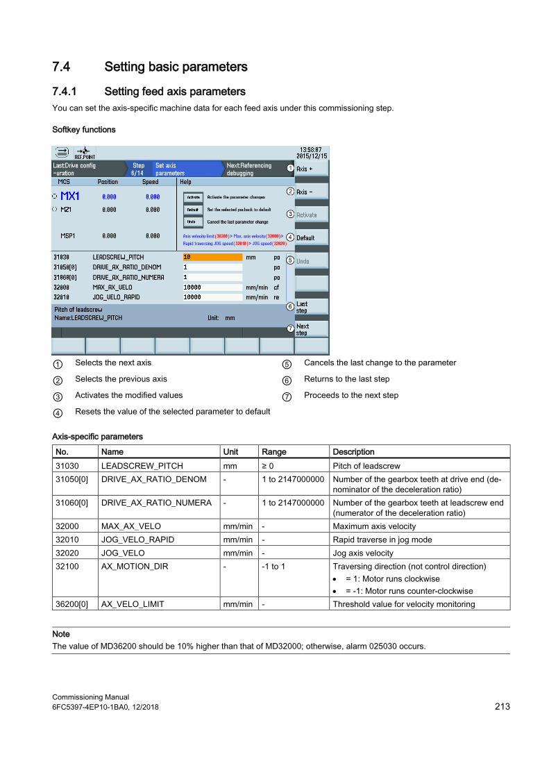
Commissioning Manual 6FC5397-4EP10-1BA0, 12/2018 213
7.4 Setting basic parameters
7.4.1 Setting feed axis parameters You can set the axis-specific machine data for each feed axis under this commissioning step.
Softkey functions
① Selects the next axis ⑤ Cancels the last change to the parameter
② Selects the previous axis ⑥ Returns to the last step
③ Activates the modified values ⑦ Proceeds to the next step
④ Resets the value of the selected parameter to default
Axis-specific parameters
No. Name Unit Range Description 31030 LEADSCREW_PITCH mm ≥ 0 Pitch of leadscrew 31050[0] DRIVE_AX_RATIO_DENOM - 1 to 2147000000 Number of the gearbox teeth at drive end (de-
nominator of the deceleration ratio) 31060[0] DRIVE_AX_RATIO_NUMERA - 1 to 2147000000 Number of the gearbox teeth at leadscrew end
(numerator of the deceleration ratio) 32000 MAX_AX_VELO mm/min - Maximum axis velocity 32010 JOG_VELO_RAPID mm/min - Rapid traverse in jog mode 32020 JOG_VELO mm/min - Jog axis velocity 32100 AX_MOTION_DIR - -1 to 1 Traversing direction (not control direction)
• = 1: Motor runs clockwise • = -1: Motor runs counter-clockwise
36200[0] AX_VELO_LIMIT mm/min - Threshold value for velocity monitoring
Note The value of MD36200 should be 10% higher than that of MD32000; otherwise, alarm 025030 occurs.

Commissioning Manual 214 6FC5397-4EP10-1BA0, 12/2018
7.4.2 Commissioning the referencing function
Principles for referencing
● Zero mark is away from the reference cam (MD34050: REFP_SEARCH_MARKER_REVERS = 0)
● Zero mark is above the reference point (MD34050: REFP_SEARCH_MARKER_REVERS = 1)
Vc Velocity for searching for the reference cam (MD34020: REFP_VELO_SEARCH_CAM) VM Velocity for searching for the zero mark (MD34040: REFP_VELO_SEARCH_MARKER) Vp Position velocity (MD34070: REFP_VELO_POS) Rv Shift of the reference point (MD34080: REFP_MOVE_DIST + MD34090: REFP_MOVE_DIST_CORR) Rk Set position of the reference point (MD34100: REFP_SET_POS [0])
Softkey functions
You can commission the axis referencing function and approach the reference point by setting relevant machine data in the following window:
① Selects the next axis ⑤ Cancels the last change to the parameter
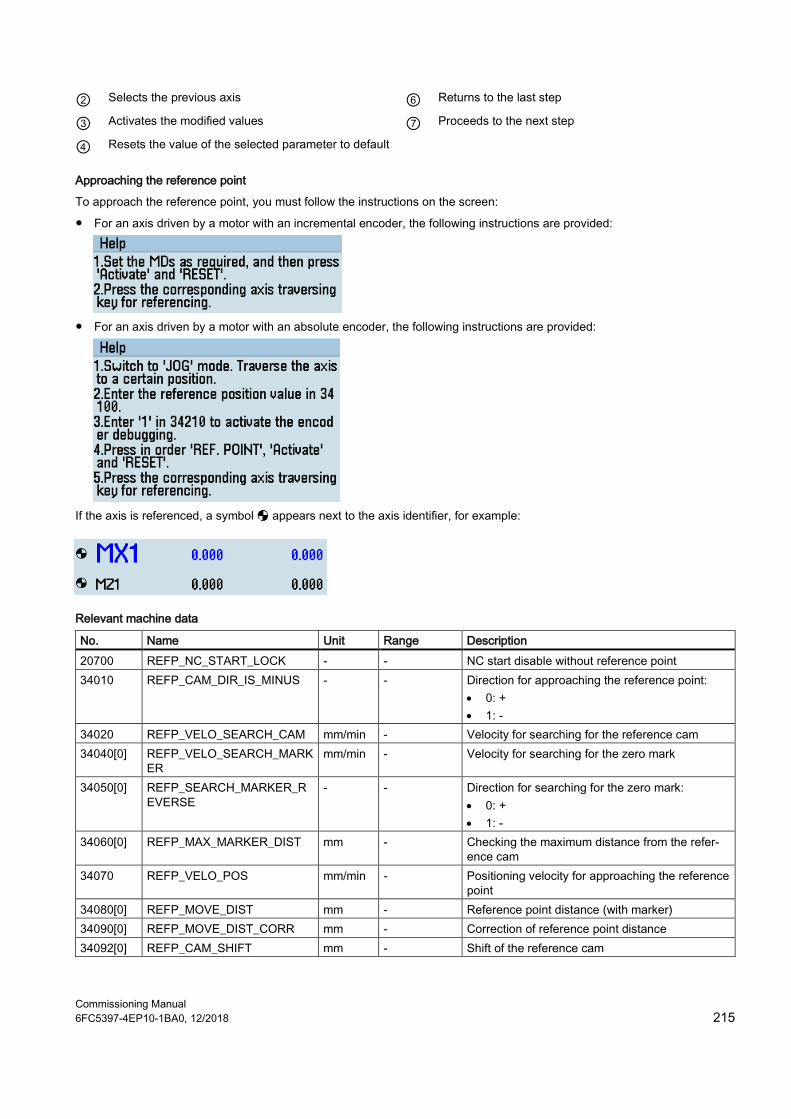
Commissioning Manual 6FC5397-4EP10-1BA0, 12/2018 215
② Selects the previous axis ⑥ Returns to the last step
③ Activates the modified values ⑦ Proceeds to the next step
④ Resets the value of the selected parameter to default
Approaching the reference point
To approach the reference point, you must follow the instructions on the screen:
● For an axis driven by a motor with an incremental encoder, the following instructions are provided:
● For an axis driven by a motor with an absolute encoder, the following instructions are provided:
If the axis is referenced, a symbol appears next to the axis identifier, for example:
Relevant machine data
No. Name Unit Range Description 20700 REFP_NC_START_LOCK - - NC start disable without reference point 34010 REFP_CAM_DIR_IS_MINUS - - Direction for approaching the reference point:
• 0: + • 1: -
34020 REFP_VELO_SEARCH_CAM mm/min - Velocity for searching for the reference cam 34040[0] REFP_VELO_SEARCH_MARK
ER mm/min - Velocity for searching for the zero mark
34050[0] REFP_SEARCH_MARKER_REVERSE
- - Direction for searching for the zero mark: • 0: + • 1: -
34060[0] REFP_MAX_MARKER_DIST mm - Checking the maximum distance from the refer-ence cam
34070 REFP_VELO_POS mm/min - Positioning velocity for approaching the reference point
34080[0] REFP_MOVE_DIST mm - Reference point distance (with marker) 34090[0] REFP_MOVE_DIST_CORR mm - Correction of reference point distance 34092[0] REFP_CAM_SHIFT mm - Shift of the reference cam
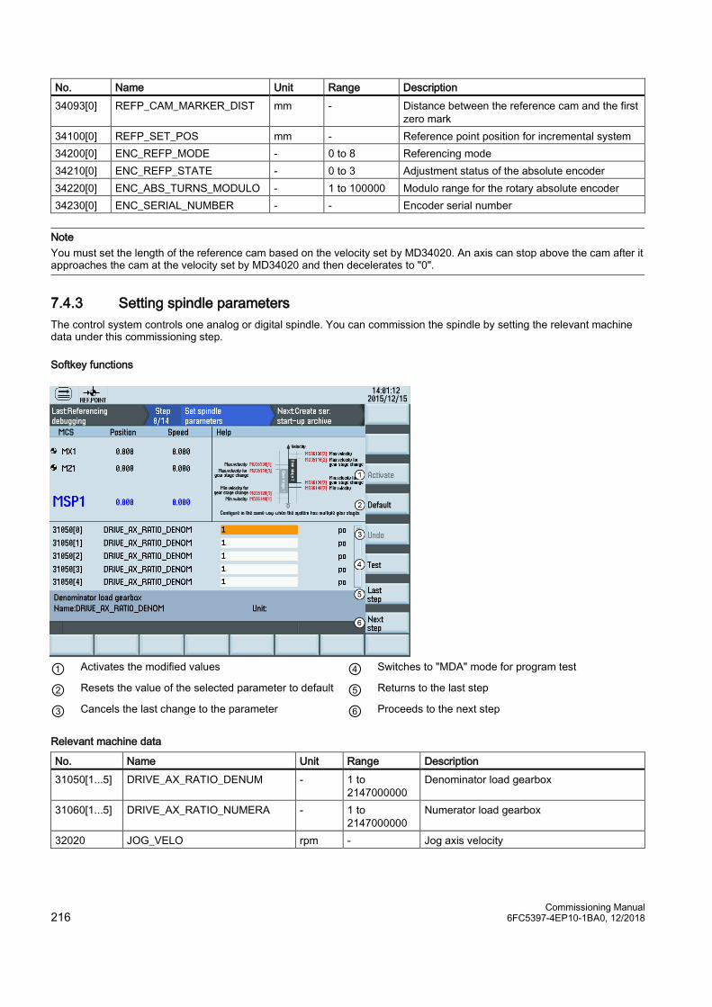
Commissioning Manual 216 6FC5397-4EP10-1BA0, 12/2018
No. Name Unit Range Description 34093[0] REFP_CAM_MARKER_DIST mm - Distance between the reference cam and the first
zero mark 34100[0] REFP_SET_POS mm - Reference point position for incremental system 34200[0] ENC_REFP_MODE - 0 to 8 Referencing mode 34210[0] ENC_REFP_STATE - 0 to 3 Adjustment status of the absolute encoder 34220[0] ENC_ABS_TURNS_MODULO - 1 to 100000 Modulo range for the rotary absolute encoder 34230[0] ENC_SERIAL_NUMBER - - Encoder serial number
Note You must set the length of the reference cam based on the velocity set by MD34020. An axis can stop above the cam after it approaches the cam at the velocity set by MD34020 and then decelerates to "0".
7.4.3 Setting spindle parameters The control system controls one analog or digital spindle. You can commission the spindle by setting the relevant machine data under this commissioning step.
Softkey functions
① Activates the modified values ④ Switches to "MDA" mode for program test
② Resets the value of the selected parameter to default ⑤ Returns to the last step
③ Cancels the last change to the parameter ⑥ Proceeds to the next step
Relevant machine data
No. Name Unit Range Description 31050[1...5] DRIVE_AX_RATIO_DENUM - 1 to
2147000000 Denominator load gearbox
31060[1...5] DRIVE_AX_RATIO_NUMERA - 1 to 2147000000
Numerator load gearbox
32020 JOG_VELO rpm - Jog axis velocity

Commissioning Manual 6FC5397-4EP10-1BA0, 12/2018 217
No. Name Unit Range Description 32100 AX_MOTION_DIR - -1 to 1 Traversing direction (not control direction)
• -1: Direction reversal • 0, 1: No direction reversal
32110[0] ENC_FEEDBACK_POL - -1 to 1 Sign actual value (control direction) 35010 GEAR_STEP_CHANGE_ENABLE - - Parameterize gear stage change 35100 SPIND_VELO_LIMIT rpm - Maximum spindle speed 35110[1...5] GEAR_STEP_MAX_VELO rpm - Maximum speed for gear stage change 35120[1...5] GEAR_STEP_MIN_VELO rpm - Minimum speed for gear stage change 35130[1...5] GEAR_STEP_MAX_VELO_LIMIT rpm - Maximum speed of gear stage 35140[1...5] GEAR_STEP_MIN_VELO_LIMIT rpm - Minimum speed of gear stage 36200[1...5] AX_VELO_LIMIT rpm - Threshold value for velocity monitoring
7.5 Creating series archives Creating series startup archives is a prerequisite for series machine commissioning. The series startup archives contain data from the prototype machine commissioning which bring the series machine to the same state.
Operating sequence
1. Specify the properties of the archive as required:
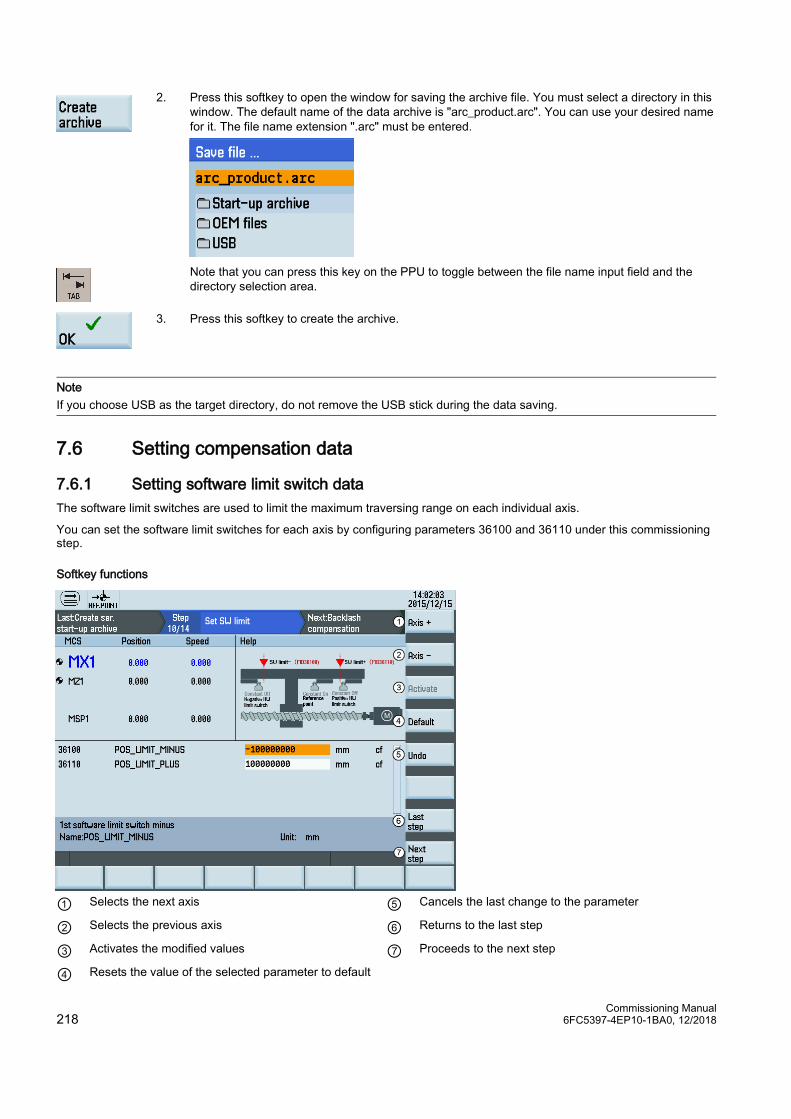
Commissioning Manual 218 6FC5397-4EP10-1BA0, 12/2018
2. Press this softkey to open the window for saving the archive file. You must select a directory in this window. The default name of the data archive is "arc_product.arc". You can use your desired name for it. The file name extension ".arc" must be entered.
Note that you can press this key on the PPU to toggle between the file name input field and the directory selection area.
3. Press this softkey to create the archive.
Note If you choose USB as the target directory, do not remove the USB stick during the data saving.
7.6 Setting compensation data
7.6.1 Setting software limit switch data The software limit switches are used to limit the maximum traversing range on each individual axis.
You can set the software limit switches for each axis by configuring parameters 36100 and 36110 under this commissioning step.
Softkey functions
① Selects the next axis ⑤ Cancels the last change to the parameter
② Selects the previous axis ⑥ Returns to the last step
③ Activates the modified values ⑦ Proceeds to the next step
④ Resets the value of the selected parameter to default
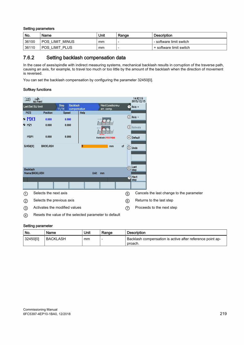
Commissioning Manual 6FC5397-4EP10-1BA0, 12/2018 219
Setting parameters
No. Name Unit Range Description 36100 POS_LIMIT_MINUS mm - - software limit switch 36110 POS_LIMIT_PLUS mm - + software limit switch
7.6.2 Setting backlash compensation data In the case of axes/spindle with indirect measuring systems, mechanical backlash results in corruption of the traverse path, causing an axis, for example, to travel too much or too little by the amount of the backlash when the direction of movement is reversed.
You can set the backlash compensation by configuring the parameter 32450[0].
Softkey functions
① Selects the next axis ⑤ Cancels the last change to the parameter
② Selects the previous axis ⑥ Returns to the last step
③ Activates the modified values ⑦ Proceeds to the next step
④ Resets the value of the selected parameter to default
Setting parameter
No. Name Unit Range Description 32450[0] BACKLASH mm - Backlash compensation is active after reference point ap-
proach.
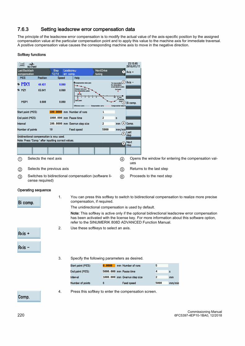
Commissioning Manual 220 6FC5397-4EP10-1BA0, 12/2018
7.6.3 Setting leadscrew error compensation data The principle of the leadscrew error compensation is to modify the actual value of the axis-specific position by the assigned compensation value at the particular compensation point and to apply this value to the machine axis for immediate traversal. A positive compensation value causes the corresponding machine axis to move in the negative direction.
Softkey functions
① Selects the next axis ④ Opens the window for entering the compensation val-
ues
② Selects the previous axis ⑤ Returns to the last step
③ Switches to bidirectional compensation (software li-cense required)
⑥ Proceeds to the next step
Operating sequence
1. You can press this softkey to switch to bidirectional compensation to realize more precise compensation, if required. The unidirectional compensation is used by default.
Note: This softkey is active only if the optional bidirectional leadscrew error compensation has been activated with the license key. For more information about this software option, refer to the SINUMERIK 808D ADVANCED Function Manual.
2. Use these softkeys to select an axis.
3. Specify the following parameters as desired.
4. Press this softkey to enter the compensation screen.

Commissioning Manual 6FC5397-4EP10-1BA0, 12/2018 221
5. Follow the instructions in the help window to perform the compensation for the selected axis.
You can input the compensation values manually on the screen. Alternatively, you can also use this softkey to import a compensation file in rtl format (produced with RENISHAW measuring software) to input the compensation values automatically.
6. Press this softkey and repeat the above operations for the rest axis/axes until all axes are compensated.
7.7 Tuning drive performance
Note This commissioning step is applicable to the standard axes only. For the drive tuning of additional axes, see Section "Configuring an additional feed axis (Page 234)".
The drive performance must be tuned to adapt the electric and mechanical characteristics of the machine, so as to achieve the best machining results. The tuning process is sophisticated and generally performed by experienced engineers. The SINUMERIK 808D ADVANCED control system is integrated with the advanced function of auto drive tuning, which provides facilities to tune the drive performance for the feed axes or the digital spindle by automatically modifying the control loop parameters. The tuning is performed based on frequency response measurements of the dynamic response of the machine.
NOTICE Machine damage due to tool collision The axes to be tuned traverse during the tuning process, which may cause damage to the machine in case of tool collision. Before starting the tuning, make sure there is no mechanical interference among the axes, and the limit protection is active on the machine, to avoid the collision of the machine tools.
Note Before performing the drive tuning for a digital spindle configured with two measuring systems (see Section "Configuring the DSC function for the digital spindle (Page 279)"), make sure you set MD32110[0] = 1 and MD32110[1] = 1. Otherwise, the drive tuning process cannot be completed successfully.
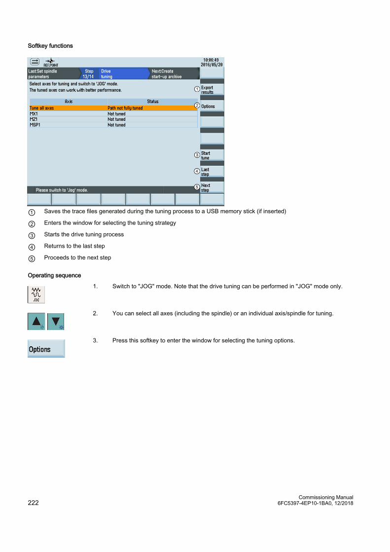
Commissioning Manual 222 6FC5397-4EP10-1BA0, 12/2018
Softkey functions
① Saves the trace files generated during the tuning process to a USB memory stick (if inserted)
② Enters the window for selecting the tuning strategy
③ Starts the drive tuning process
④ Returns to the last step
⑤ Proceeds to the next step
Operating sequence
1. Switch to "JOG" mode. Note that the drive tuning can be performed in "JOG" mode only.
2. You can select all axes (including the spindle) or an individual axis/spindle for tuning.
3. Press this softkey to enter the window for selecting the tuning options.

Commissioning Manual 6FC5397-4EP10-1BA0, 12/2018 223
4. Use this key to select a desired tuning objective. There are three objectives available for selection. You can select a suitable one according to your actual application by following the guidance on the PPU screen. • (default setting)
The speed and position controller gain (servo gain factor) is tuned with maximum values and minimum ruggedness. This setting is recommended for high-speed machining with maximum suppression of all disturbing forces. The machine must have a rigid design; the dynamic masses do not change significantly.
• This controller dynamic response is sufficient for the majority of machines and applications. The setting is more rugged than the default setting and is suitable for numerous applications.
• Only weak control gains are selected in order to ensure as high a level of ruggedness as possible. The speed controller is tuned so that it achieves maximum damping to prevent oscillations and to achieve good position controller gain. This setting is suitable for axes that react with oscillations, e.g. main spindles on turning machines or large axes with high load mass.
5. Move the cursor and select the desired measurement and interpolation options for each axis.
For the first tuning, only the following measurement option is available, which enables a new measurement with all preliminary measurement steps.
The following additional measurement options are available only if you have performed drive tuning for this axis: • Performs a new measurement without carrying out the preliminary steps:
• Uses the existing measurement results:
Besides, you can also specify the axis/axes for interpolation path tuning by selecting the corresponding interpolation option.
6. Press this softkey to confirm the selections and return to the main screen of drive tuning.
7. Press this softkey to enter the preparation screen before the tuning.
8. Use the axis traversing keys to move the axis/axes to be tuned to safe positions.
9. Press this softkey to initiate the drive tuning process.

Commissioning Manual 224 6FC5397-4EP10-1BA0, 12/2018
10. Press this softkey to confirm and proceed to one-key auto tuning.
11. Press this key on the MCP and the drive tuning starts automatically. Since the axes traverse during the tuning process, make sure you take proper precautions to avoid personal injury or machine damage.
12. After the drive tuning finishes successfully, the tuning results appear on the screen in the
form of a parameter list, for example:
Note: It may be the case that some parameters after tuning display the same values as those before tuning, since up to six decimal places can be displayed in the parameter list as above.
You can check the tuning results of other tuned axis/axes (if any) with these softkeys.
13. Press this softkey to save the tuning results and write the modified parameters into the drives.
Pressing this softkey aborts the tuning and deletes the results.
14. After it returns automatically to the main screen of drive tuning, press this softkey to proceed to the next step.
The following softkey operation is also available on this screen:
Saves the trace files during the tuning process to a USB flash disk (if inserted)
Note For the machine data that are changeable only with a manufacturer password, the settings made during drive tuning cannot be restored after an NC restart in case of power failure or unexpected abortion of the tuning process.
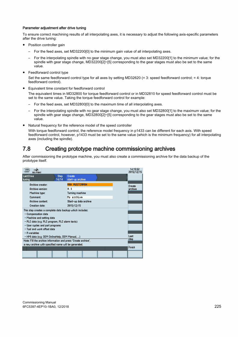
Commissioning Manual 6FC5397-4EP10-1BA0, 12/2018 225
Parameter adjustment after drive tuning
To ensure correct machining results of all interpolating axes, it is necessary to adjust the following axis-specific parameters after the drive tuning:
● Position controller gain
– For the feed axes, set MD32200[0] to the minimum gain value of all interpolating axes.
– For the interpolating spindle with no gear stage change, you must also set MD32200[1] to the minimum value; for the spindle with gear stage change, MD32200[2]~[5] corresponding to the gear stages must also be set to the same value.
● Feedforward control type Set the same feedforward control type for all axes by setting MD32620 (= 3: speed feedforward control; = 4: torque feedforward control).
● Equivalent time constant for feedforward control The equivalent times in MD32800 for torque feedforward control or in MD32810 for speed feedforward control must be set to the same value. Taking the torque feedforward control for example:
– For the feed axes, set MD32800[0] to the maximum time of all interpolating axes.
– For the interpolating spindle with no gear stage change, you must also set MD32800[1] to the maximum value; for the spindle with gear stage change, MD32800[2]~[5] corresponding to the gear stages must also be set to the same value.
● Natural frequency for the reference model of the speed controller With torque feedforward control, the reference model frequency in p1433 can be different for each axis. With speed feedforward control, however, p1433 must be set to the same value (which is the minimum frequency) for all interpolating axes (including the spindle).
7.8 Creating prototype machine commissioning archives After commissioning the prototype machine, you must also create a commissioning archive for the data backup of the prototype itself.
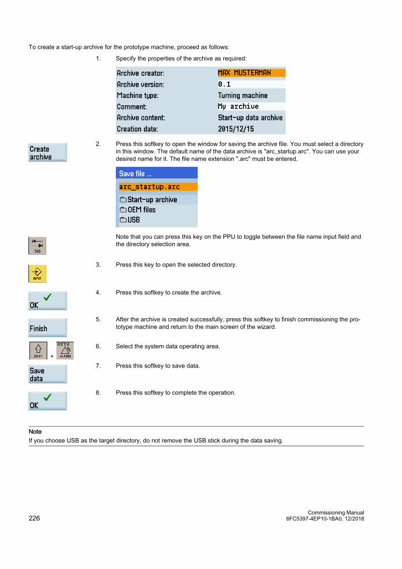
Commissioning Manual 226 6FC5397-4EP10-1BA0, 12/2018
To create a start-up archive for the prototype machine, proceed as follows:
1. Specify the properties of the archive as required:
2. Press this softkey to open the window for saving the archive file. You must select a directory in this window. The default name of the data archive is "arc_startup.arc". You can use your desired name for it. The file name extension ".arc" must be entered.
Note that you can press this key on the PPU to toggle between the file name input field and the directory selection area.
3. Press this key to open the selected directory.
4. Press this softkey to create the archive.
5. After the archive is created successfully, press this softkey to finish commissioning the pro-totype machine and return to the main screen of the wizard.
+ 6. Select the system data operating area.
7. Press this softkey to save data.
8. Press this softkey to complete the operation.
Note If you choose USB as the target directory, do not remove the USB stick during the data saving.
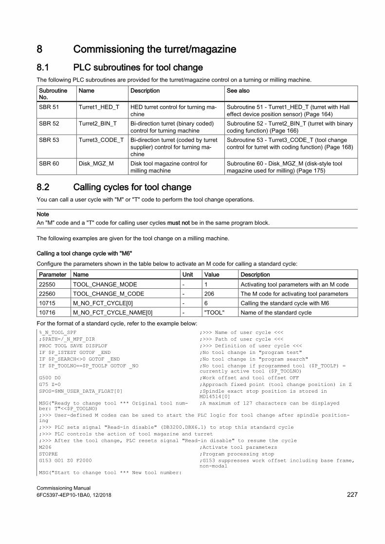
Commissioning Manual 6FC5397-4EP10-1BA0, 12/2018 227
8 Commissioning the turret/magazine 8.1 PLC subroutines for tool change The following PLC subroutines are provided for the turret/magazine control on a turning or milling machine.
Subroutine No.
Name Description See also
SBR 51 Turret1_HED_T HED turret control for turning ma-chine
Subroutine 51 - Turret1_HED_T (turret with Hall effect device position sensor) (Page 164)
SBR 52 Turret2_BIN_T Bi-direction turret (binary coded) control for turning machine
Subroutine 52 - Turret2_BIN_T (turret with binary coding function) (Page 166)
SBR 53 Turret3_CODE_T Bi-direction turret (coded by turret supplier) control for turning ma-chine
Subroutine 53 - Turret3_CODE_T (tool change control for turret with coding function) (Page 168)
SBR 60 Disk_MGZ_M Disk tool magazine control for milling machine
Subroutine 60 - Disk_MGZ_M (disk-style tool magazine used for milling) (Page 175)
8.2 Calling cycles for tool change You can call a user cycle with "M" or "T" code to perform the tool change operations.
Note An "M" code and a "T" code for calling user cycles must not be in the same program block.
The following examples are given for the tool change on a milling machine.
Calling a tool change cycle with "M6"
Configure the parameters shown in the table below to activate an M code for calling a standard cycle:
Parameter Name Unit Value Description 22550 TOOL_CHANGE_MODE - 1 Activating tool parameters with an M code 22560 TOOL_CHANGE_M_CODE - 206 The M code for activating tool parameters 10715 M_NO_FCT_CYCLE[0] - 6 Calling the standard cycle with M6 10716 M_NO_FCT_CYCLE_NAME[0] - "TOOL" Name of the standard cycle
For the format of a standard cycle, refer to the example below: %_N_TOOL_SPF ;>>> Name of user cycle <<< ;$PATH=/_N_MPF_DIR ;>>> Path of user cycle <<< PROC TOOL SAVE DISPLOF ;>>> Definition of user cycle <<< IF $P_ISTEST GOTOF _END ;No tool change in "program test" IF $P_SEARCH<>0 GOTOF _END ;No tool change in "program search" IF $P_TOOLNO==$P_TOOLP GOTOF _NO ;No tool change if programmed tool ($P_TOOLP) =
currently active tool ($P_TOOLNO) G500 D0 ;Work offset and tool offset OFF G75 Z=0 ;Approach fixed point (tool change position) in Z SPOS=$MN_USER_DATA_FLOAT[0] ;Spindle exact stop position is stored in
MD14514[0] MSG("Ready to change tool *** Original tool num-ber: T"<<$P_TOOLNO)
;A maximum of 127 characters can be displayed
;>>> User-defined M codes can be used to start the PLC logic for tool change after spindle position-ing ;>>> PLC sets signal "Read-in disable" (DB3200.DBX6.1) to stop this standard cycle ;>>> PLC controls the action of tool magazine and turret ;>>> After the tool change, PLC resets signal "Read-in disable" to resume the cycle M206 ;Activate tool parameters STOPRE ;Program processing stop G153 G01 Z0 F2000 ;G153 suppresses work offset including base frame,
non-modal MSG("Start to change tool *** New tool number:

Commissioning Manual 228 6FC5397-4EP10-1BA0, 12/2018
T"<<$P_TOOLP) GOTOF _END _NO: MSG("No action *** Reason: programmed tool num-ber=spindle tool number")
_END: M17 ;>>> End of the standard cycle <<<
Calling a tool change cycle with "T"
Configure the parameters shown in below table to activate a T code for calling a standard cycle:
Parameter Name Unit Value Description 22550 TOOL_CHANGE_MODE - 0 Activating tool parameters with a T code 10717 T_NO_FCT_CYCLE[0] - "TOOL" Calling the standard cycle with T code
The format of the standard cycle is the same with that of M codes. The programmed tool numbers will be saved into system variable $C_T.
9 Series machine commissioning
Note The control system constantly creates restoring points during operation. In case of data loss due to power failure or other problems, the control system automatically restores the last autosaved system data upon startup with an alarm appearing on the screen.
9.1 Loading series commissioning archives You can use the series commissioning archive to commission the machines for series production. The series archive is created during the commissioning of the prototype machine. For more information about creating a series archive, refer to Section "Creating series archives (Page 217)".
Note Before starting the series commissioning with the commissioning wizard, make sure MD20050, MD20070, and MD35000 are set to defaults.
Operating sequence
1. Press this horizontal softkey on the main screen of wizards to call the commissioning wizard for series machines.
2. Use either softkey to enter the window for loading the series commissioning archive.
3. Press this softkey to open the dialog for loading the series archive.
4. Enter the backup directory and select the desired archive file.

Commissioning Manual 6FC5397-4EP10-1BA0, 12/2018 229
5. Press this softkey to confirm your selection, and the archive information displays on the screen.
6. Check the archive information and press this softkey to start loading the series commission-ing archive.
Note Successful loading of the data archive can delete the password. You must set the password again before proceeding. For more information about setting a password, refer to Section "Setting the password (Page 123)".
9.2 Setting software limit switch data Refer to Section "Setting software limit switch data (Page 218)".
9.3 Setting backlash compensation data Refer to Section "Setting backlash compensation data (Page 219)".
9.4 Setting leadscrew error compensation data Refer to Section "Setting leadscrew error compensation data (Page 220)".
9.5 Tuning drive performance Refer to Section "Tuning drive performance (Page 221)".
9.6 Creating startup archives Refer to Section "Creating prototype machine commissioning archives (Page 225)".

Commissioning Manual 230 6FC5397-4EP10-1BA0, 12/2018
10 Network functions 10.1 Network configuration
Ethernet connections
You can establish a network connection between the control system and a computer via the Ethernet interface X130. The following Ethernet connections are possible:
● Direct connection: connecting the control system directly to a computer
● Network connection: integrating the control system into an existing Ethernet network
Establishing a direct connection
Proceed as follows to establish a direct connection between the control system and a computer:
1. Connect the control system with the computer using an Ethernet cable.
+ 2. Select the desired operating area on the PPU.
3. Press this key to view the extended softkeys.
4. Set up a direct connection on the control system through the following softkey operations:
→ → The following dialog pops up on the screen:
Establishing a network connection
Proceed as follows to establish a network connection:
1. Connect the control system with the local network using an Ethernet cable.
+ 2. Select the desired operating area on the PPU.
3. Press this key to view the extended softkeys.
4. Enter the main screen of the service control options through the following softkey opera-tions:
→
5. Press this softkey to enter the window for the network configuration.
Note: make sure this vertical softkey is not selected.
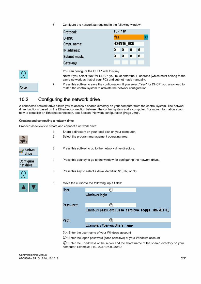
Commissioning Manual 6FC5397-4EP10-1BA0, 12/2018 231
6. Configure the network as required in the following window:
You can configure the DHCP with this key. Note: if you select "No" for DHCP, you must enter the IP address (which must belong to the same network as that of your PC) and subnet mask manually.
7. Press this softkey to save the configuration. If you select "Yes" for DHCP, you also need to restart the control system to activate the network configuration.
10.2 Configuring the network drive A connected network drive allows you to access a shared directory on your computer from the control system. The network drive functions based on the Ethernet connection between the control system and a computer. For more information about how to establish an Ethernet connection, see Section "Network configuration (Page 230)".
Creating and connecting a network drive
Proceed as follows to create and connect a network drive:
1. Share a directory on your local disk on your computer.
2. Select the program management operating area.
3. Press this softkey to go to the network drive directory.
4. Press this softkey to go to the window for configuring the network drives.
5. Press this key to select a drive identifier: N1, N2, or N3.
6. Move the cursor to the following input fields:
①: Enter the user name of your Windows account
②: Enter the logon password (case sensitive) of your Windows account ③: Enter the IP address of the server and the share name of the shared directory on your computer. Example: //140.231.196.90/808D

Commissioning Manual 232 6FC5397-4EP10-1BA0, 12/2018
7. Press this softkey to confirm and the configured network drive appears on the screen as follows. The drive icon is yellow if the network drive is connected successfully; otherwise, the icon is gray.
You can delete a selected network drive using this softkey.
Note After you properly configure all the settings for the direct connection between the control system and the network drive, if the network drive connection is still invalid, contact your Windows system administrator for possible problems with your operating system configuration.
10.3 Configuring the firewall
Configuring the firewall
Secure access and communication is achieved through the security function of the integrated firewall. You can open the window for firewall configuration through the following operations:
+ → → → →
Configurable ports are listed in the following window:
The ports are disabled by default and can be enabled when necessary. To change the port status, select the relevant port using the cursor keys and press either of the following keys to enable or disable the port:
/
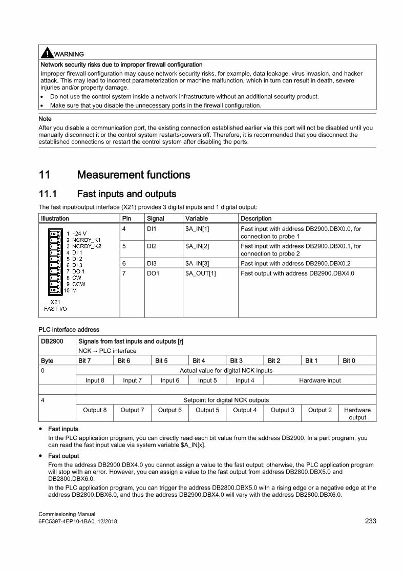
Commissioning Manual 6FC5397-4EP10-1BA0, 12/2018 233
WARNING Network security risks due to improper firewall configuration Improper firewall configuration may cause network security risks, for example, data leakage, virus invasion, and hacker attack. This may lead to incorrect parameterization or machine malfunction, which in turn can result in death, severe injuries and/or property damage. • Do not use the control system inside a network infrastructure without an additional security product. • Make sure that you disable the unnecessary ports in the firewall configuration.
Note After you disable a communication port, the existing connection established earlier via this port will not be disabled until you manually disconnect it or the control system restarts/powers off. Therefore, it is recommended that you disconnect the established connections or restart the control system after disabling the ports.
11 Measurement functions 11.1 Fast inputs and outputs The fast input/output interface (X21) provides 3 digital inputs and 1 digital output:
Illustration Pin Signal Variable Description
4 DI1 $A_IN[1] Fast input with address DB2900.DBX0.0, for connection to probe 1
5 DI2 $A_IN[2] Fast input with address DB2900.DBX0.1, for connection to probe 2
6 DI3 $A_IN[3] Fast input with address DB2900.DBX0.2 7 DO1 $A_OUT[1] Fast output with address DB2900.DBX4.0
PLC interface address
DB2900 Signals from fast inputs and outputs [r] NCK → PLC interface
Byte Bit 7 Bit 6 Bit 5 Bit 4 Bit 3 Bit 2 Bit 1 Bit 0 0 Actual value for digital NCK inputs
Input 8 Input 7 Input 6 Input 5 Input 4 Hardware input 4 Setpoint for digital NCK outputs
Output 8 Output 7 Output 6 Output 5 Output 4 Output 3 Output 2 Hardware output
● Fast inputs In the PLC application program, you can directly read each bit value from the address DB2900. In a part program, you can read the fast input value via system variable $A_IN[x].
● Fast output From the address DB2900.DBX4.0 you cannot assign a value to the fast output; otherwise, the PLC application program will stop with an error. However, you can assign a value to the fast output from address DB2800.DBX5.0 and DB2800.DBX6.0. In the PLC application program, you can trigger the address DB2800.DBX5.0 with a rising edge or a negative edge at the address DB2800.DBX6.0, and thus the address DB2900.DBX4.0 will vary with the address DB2800.DBX6.0.

Commissioning Manual 234 6FC5397-4EP10-1BA0, 12/2018
11.2 Probe commissioning The first probe is connected to pin 4 (DI1) and the second probe to pin 5 (DI2) of interface X21. For the probe, use an external voltage (24 V) whose reference potential should be connected to X21 pin 10
Setting machine data
The following machine data should be checked and adjusted if necessary:
● MD13200[0] $MN_MEAS_PROBE_LOW_ACTIVE = 0 or 1
● MD13200[1] $MN_MEAS_PROBE_LOW_ACTIVE = 0 or 1
– Value 0 = deflected state 24 V (default)
– Value 1 = deflected state 0 V
You can access this machine data through the following operations:
+ → → →
Testing signal
You can test the measuring signal by checking the PLC interface status through the following operations:
+ → →
Enter the interface address DB2700.DBB1 in the operand input field, and trigger the probe manually. In this case, the corresponding PLC status bit changes, which indicates the probe is properly connected.
12 Extended drive commissioning 12.1 Overview The SINUMERIK 808D ADVANCED control system with PPU16x.3 supports up to three additional axes for the turning variant and two for the milling variant. You can configure an additional axis as either a standard NC axis (feed axis or spindle) or a positioning axis. The control system with PPU15x.3, however, supports one additional axis for the turning variant, which can be configured as a standard NC axis only. Before the configuration, you must first activate the option for additional axis (Page 127). However, you need to configure the additional axis manually as you cannot proceed with the wizards.
12.2 Configuring an additional feed axis
12.2.1 Setting parameters for the additional feed axis You can configure an additional feed axis driven by SINAMICS V70 feed drive.
Prerequisites:
● The Drive Bus address (p0918) of the corresponding drive is properly set via the drive BOP. For more information, see Section "Configuring Drive Bus addresses (Page 119)".
● At least one additional axis is activated. For more information, see Section "Activating the optional functions (Page 127)".
Proceed as follows to set the parameters for an additional feed axis:
+ 1. Select the system data operating area.
2. Open the channel machine data window through the following softkey operations:
→ →

Commissioning Manual 6FC5397-4EP10-1BA0, 12/2018 235
3. Set the machine data 20070 as follows: • For the turning variant: set 20070[3]/[4]/[5] = 5 or 6 • For the milling variant: set 20070[4]/[5] = 5 or 6.
4. Press this key to return to the higher-level menu.
5. Open the basic machine data list.
6. Use this softkey or the cursor keys to search for "14512 USER_DATA_HEX[20]".
7. Select "Bit2" by using this key and the cursor keys.
8. Press this softkey to confirm your input.
9. Press this softkey to activate the value changes. Note that the control system restarts to ac-cept the new values and the additional axis can be displayed in the system.
Note The factory default PLC program only supports one additional axis.
12.2.2 Configuring the drive system
Note Before starting the drive configuration, make sure MD20050, MD20070, and MD35000 are set to defaults.
The following steps are also applicable to configuring the standard axes/spindle, if necessary.
+ 1. Select the system data operating area.
2. Press this horizontal softkey to open the window for drive configuration.
3. Press this softkey and the control system starts to identify the drives and motors connected.
After the identification finishes, a drive list with motor information displays on the screen, for example:
Note: For a motor with an absolute encoder, the motor ID is identified automatically. For a motor with an incremental encoder, however, you must configure the motor ID manually.
4. Select the additional axis using the cursor keys.
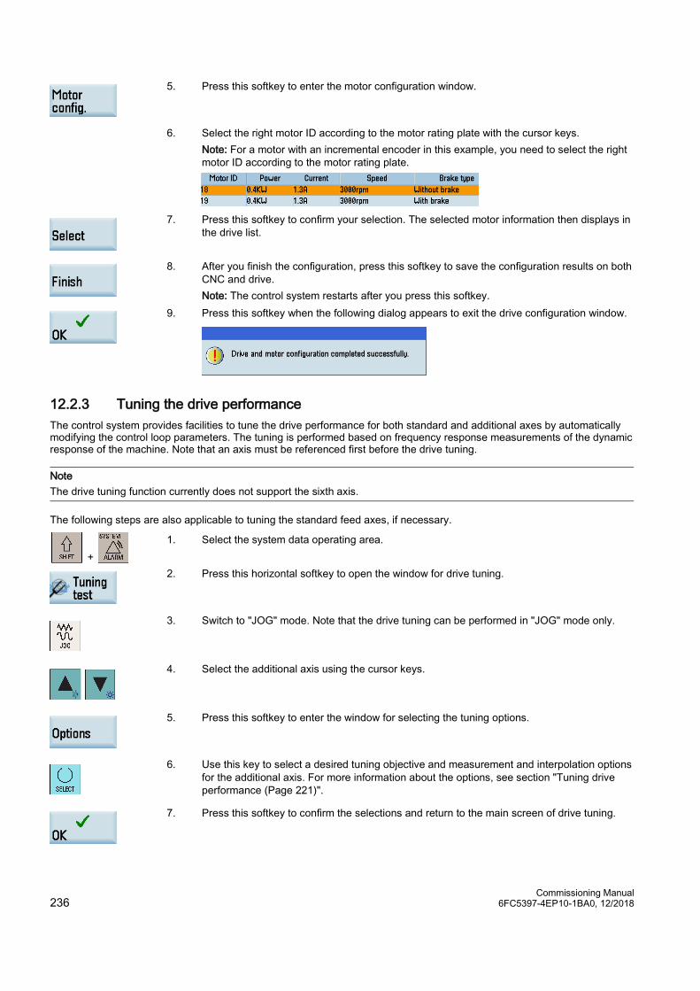
Commissioning Manual 236 6FC5397-4EP10-1BA0, 12/2018
5. Press this softkey to enter the motor configuration window.
6. Select the right motor ID according to the motor rating plate with the cursor keys. Note: For a motor with an incremental encoder in this example, you need to select the right motor ID according to the motor rating plate.
7. Press this softkey to confirm your selection. The selected motor information then displays in the drive list.
8. After you finish the configuration, press this softkey to save the configuration results on both CNC and drive. Note: The control system restarts after you press this softkey.
9. Press this softkey when the following dialog appears to exit the drive configuration window.
12.2.3 Tuning the drive performance The control system provides facilities to tune the drive performance for both standard and additional axes by automatically modifying the control loop parameters. The tuning is performed based on frequency response measurements of the dynamic response of the machine. Note that an axis must be referenced first before the drive tuning.
Note The drive tuning function currently does not support the sixth axis.
The following steps are also applicable to tuning the standard feed axes, if necessary.
+ 1. Select the system data operating area.
2. Press this horizontal softkey to open the window for drive tuning.
3. Switch to "JOG" mode. Note that the drive tuning can be performed in "JOG" mode only.
4. Select the additional axis using the cursor keys.
5. Press this softkey to enter the window for selecting the tuning options.
6. Use this key to select a desired tuning objective and measurement and interpolation options for the additional axis. For more information about the options, see section "Tuning drive performance (Page 221)".
7. Press this softkey to confirm the selections and return to the main screen of drive tuning.
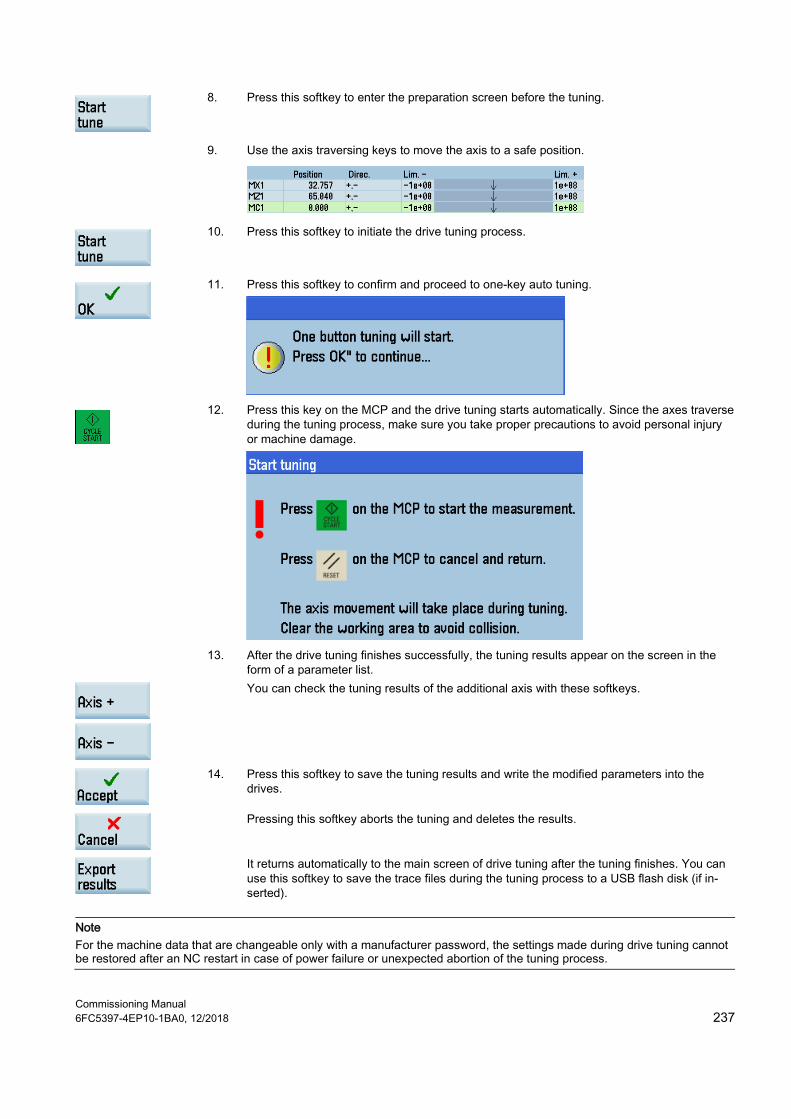
Commissioning Manual 6FC5397-4EP10-1BA0, 12/2018 237
8. Press this softkey to enter the preparation screen before the tuning.
9. Use the axis traversing keys to move the axis to a safe position.
10. Press this softkey to initiate the drive tuning process.
11. Press this softkey to confirm and proceed to one-key auto tuning.
12. Press this key on the MCP and the drive tuning starts automatically. Since the axes traverse during the tuning process, make sure you take proper precautions to avoid personal injury or machine damage.
13. After the drive tuning finishes successfully, the tuning results appear on the screen in the
form of a parameter list.
You can check the tuning results of the additional axis with these softkeys.
14. Press this softkey to save the tuning results and write the modified parameters into the drives.
Pressing this softkey aborts the tuning and deletes the results.
It returns automatically to the main screen of drive tuning after the tuning finishes. You can use this softkey to save the trace files during the tuning process to a USB flash disk (if in-serted).
Note For the machine data that are changeable only with a manufacturer password, the settings made during drive tuning cannot be restored after an NC restart in case of power failure or unexpected abortion of the tuning process.
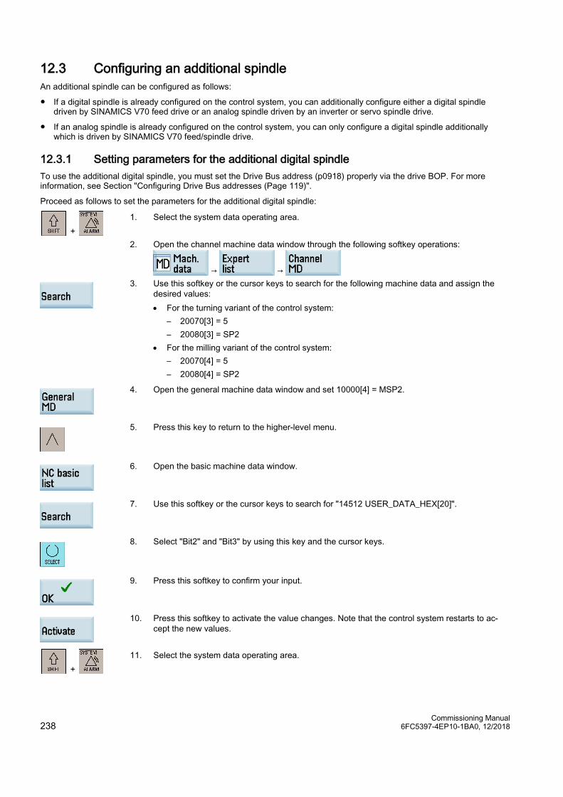
Commissioning Manual 238 6FC5397-4EP10-1BA0, 12/2018
12.3 Configuring an additional spindle An additional spindle can be configured as follows:
● If a digital spindle is already configured on the control system, you can additionally configure either a digital spindle driven by SINAMICS V70 feed drive or an analog spindle driven by an inverter or servo spindle drive.
● If an analog spindle is already configured on the control system, you can only configure a digital spindle additionally which is driven by SINAMICS V70 feed/spindle drive.
12.3.1 Setting parameters for the additional digital spindle To use the additional digital spindle, you must set the Drive Bus address (p0918) properly via the drive BOP. For more information, see Section "Configuring Drive Bus addresses (Page 119)".
Proceed as follows to set the parameters for the additional digital spindle:
+ 1. Select the system data operating area.
2. Open the channel machine data window through the following softkey operations:
→ →
3. Use this softkey or the cursor keys to search for the following machine data and assign the desired values: • For the turning variant of the control system:
– 20070[3] = 5 – 20080[3] = SP2
• For the milling variant of the control system: – 20070[4] = 5 – 20080[4] = SP2
4. Open the general machine data window and set 10000[4] = MSP2.
5. Press this key to return to the higher-level menu.
6. Open the basic machine data window.
7. Use this softkey or the cursor keys to search for "14512 USER_DATA_HEX[20]".
8. Select "Bit2" and "Bit3" by using this key and the cursor keys.
9. Press this softkey to confirm your input.
10. Press this softkey to activate the value changes. Note that the control system restarts to ac-cept the new values.
+ 11. Select the system data operating area.
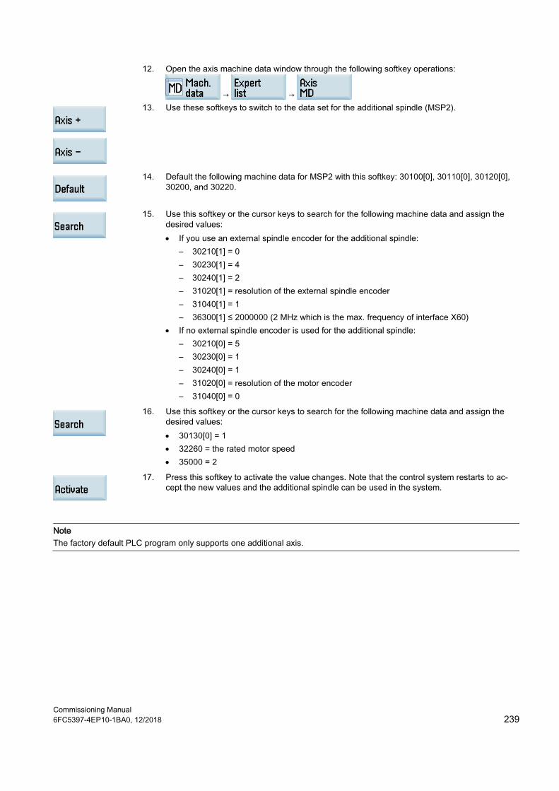
Commissioning Manual 6FC5397-4EP10-1BA0, 12/2018 239
12. Open the axis machine data window through the following softkey operations:
→ →
13. Use these softkeys to switch to the data set for the additional spindle (MSP2).
14. Default the following machine data for MSP2 with this softkey: 30100[0], 30110[0], 30120[0], 30200, and 30220.
15. Use this softkey or the cursor keys to search for the following machine data and assign the desired values: • If you use an external spindle encoder for the additional spindle:
– 30210[1] = 0 – 30230[1] = 4 – 30240[1] = 2 – 31020[1] = resolution of the external spindle encoder – 31040[1] = 1 – 36300[1] ≤ 2000000 (2 MHz which is the max. frequency of interface X60)
• If no external spindle encoder is used for the additional spindle: – 30210[0] = 5 – 30230[0] = 1 – 30240[0] = 1 – 31020[0] = resolution of the motor encoder – 31040[0] = 0
16. Use this softkey or the cursor keys to search for the following machine data and assign the desired values: • 30130[0] = 1 • 32260 = the rated motor speed • 35000 = 2
17. Press this softkey to activate the value changes. Note that the control system restarts to ac-cept the new values and the additional spindle can be used in the system.
Note The factory default PLC program only supports one additional axis.
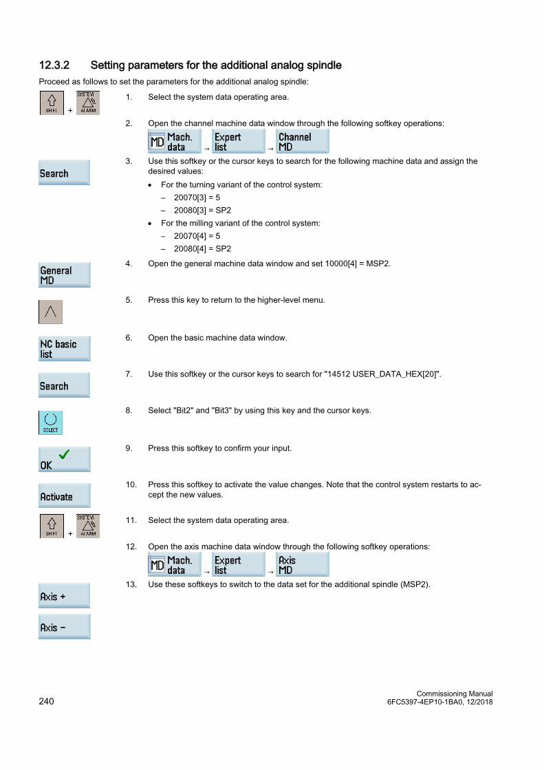
Commissioning Manual 240 6FC5397-4EP10-1BA0, 12/2018
12.3.2 Setting parameters for the additional analog spindle Proceed as follows to set the parameters for the additional analog spindle:
+ 1. Select the system data operating area.
2. Open the channel machine data window through the following softkey operations:
→ →
3. Use this softkey or the cursor keys to search for the following machine data and assign the desired values: • For the turning variant of the control system:
– 20070[3] = 5 – 20080[3] = SP2
• For the milling variant of the control system: – 20070[4] = 5 – 20080[4] = SP2
4. Open the general machine data window and set 10000[4] = MSP2.
5. Press this key to return to the higher-level menu.
6. Open the basic machine data window.
7. Use this softkey or the cursor keys to search for "14512 USER_DATA_HEX[20]".
8. Select "Bit2" and "Bit3" by using this key and the cursor keys.
9. Press this softkey to confirm your input.
10. Press this softkey to activate the value changes. Note that the control system restarts to ac-cept the new values.
+ 11. Select the system data operating area.
12. Open the axis machine data window through the following softkey operations:
→ →
13. Use these softkeys to switch to the data set for the additional spindle (MSP2).
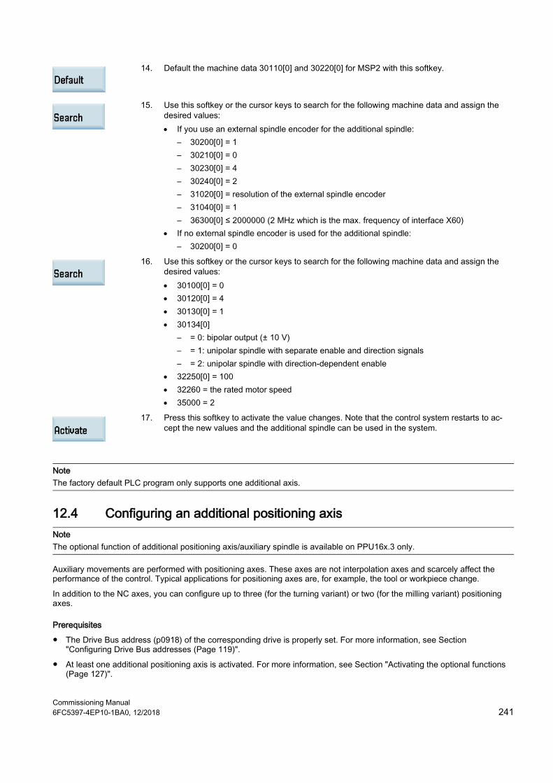
Commissioning Manual 6FC5397-4EP10-1BA0, 12/2018 241
14. Default the machine data 30110[0] and 30220[0] for MSP2 with this softkey.
15. Use this softkey or the cursor keys to search for the following machine data and assign the desired values: • If you use an external spindle encoder for the additional spindle:
– 30200[0] = 1 – 30210[0] = 0 – 30230[0] = 4 – 30240[0] = 2 – 31020[0] = resolution of the external spindle encoder – 31040[0] = 1 – 36300[0] ≤ 2000000 (2 MHz which is the max. frequency of interface X60)
• If no external spindle encoder is used for the additional spindle: – 30200[0] = 0
16. Use this softkey or the cursor keys to search for the following machine data and assign the desired values: • 30100[0] = 0 • 30120[0] = 4 • 30130[0] = 1 • 30134[0]
– = 0: bipolar output (± 10 V) – = 1: unipolar spindle with separate enable and direction signals – = 2: unipolar spindle with direction-dependent enable
• 32250[0] = 100 • 32260 = the rated motor speed • 35000 = 2
17. Press this softkey to activate the value changes. Note that the control system restarts to ac-cept the new values and the additional spindle can be used in the system.
Note The factory default PLC program only supports one additional axis.
12.4 Configuring an additional positioning axis
Note The optional function of additional positioning axis/auxiliary spindle is available on PPU16x.3 only.
Auxiliary movements are performed with positioning axes. These axes are not interpolation axes and scarcely affect the performance of the control. Typical applications for positioning axes are, for example, the tool or workpiece change.
In addition to the NC axes, you can configure up to three (for the turning variant) or two (for the milling variant) positioning axes.
Prerequisites
● The Drive Bus address (p0918) of the corresponding drive is properly set. For more information, see Section "Configuring Drive Bus addresses (Page 119)".
● At least one additional positioning axis is activated. For more information, see Section "Activating the optional functions (Page 127)".
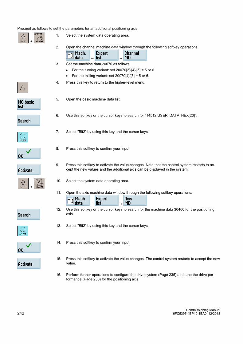
Commissioning Manual 242 6FC5397-4EP10-1BA0, 12/2018
Proceed as follows to set the parameters for an additional positioning axis:
+ 1. Select the system data operating area.
2. Open the channel machine data window through the following softkey operations:
→ → 3. Set the machine data 20070 as follows:
• For the turning variant: set 20070[3]/[4]/[5] = 5 or 6 • For the milling variant: set 20070[4]/[5] = 5 or 6.
4. Press this key to return to the higher-level menu.
5. Open the basic machine data list.
6. Use this softkey or the cursor keys to search for "14512 USER_DATA_HEX[20]".
7. Select "Bit2" by using this key and the cursor keys.
8. Press this softkey to confirm your input.
9. Press this softkey to activate the value changes. Note that the control system restarts to ac-cept the new values and the additional axis can be displayed in the system.
+ 10. Select the system data operating area.
11. Open the axis machine data window through the following softkey operations:
→ →
12. Use this softkey or the cursor keys to search for the machine data 30460 for the positioning axis.
13. Select "Bit2" by using this key and the cursor keys.
14. Press this softkey to confirm your input.
15. Press this softkey to activate the value changes. The control system restarts to accept the new value.
16. Perform further operations to configure the drive system (Page 235) and tune the drive per-formance (Page 236) for the positioning axis.
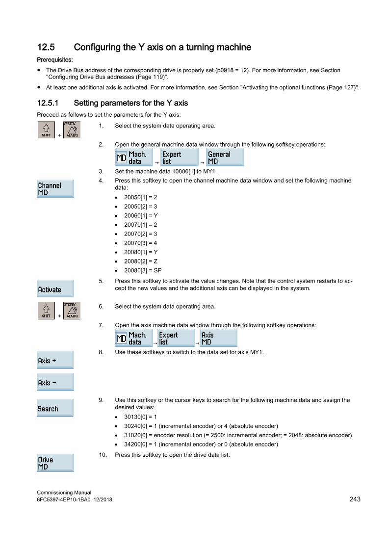
Commissioning Manual 6FC5397-4EP10-1BA0, 12/2018 243
12.5 Configuring the Y axis on a turning machine Prerequisites:
● The Drive Bus address of the corresponding drive is properly set (p0918 = 12). For more information, see Section "Configuring Drive Bus addresses (Page 119)".
● At least one additional axis is activated. For more information, see Section "Activating the optional functions (Page 127)".
12.5.1 Setting parameters for the Y axis Proceed as follows to set the parameters for the Y axis:
+ 1. Select the system data operating area.
2. Open the general machine data window through the following softkey operations:
→ → 3. Set the machine data 10000[1] to MY1.
4. Press this softkey to open the channel machine data window and set the following machine data: • 20050[1] = 2 • 20050[2] = 3 • 20060[1] = Y • 20070[1] = 2 • 20070[2] = 3 • 20070[3] = 4 • 20080[1] = Y • 20080[2] = Z • 20080[3] = SP
5. Press this softkey to activate the value changes. Note that the control system restarts to ac-cept the new values and the additional axis can be displayed in the system.
+ 6. Select the system data operating area.
7. Open the axis machine data window through the following softkey operations:
→ →
8. Use these softkeys to switch to the data set for axis MY1.
9. Use this softkey or the cursor keys to search for the following machine data and assign the desired values: • 30130[0] = 1 • 30240[0] = 1 (incremental encoder) or 4 (absolute encoder) • 31020[0] = encoder resolution (= 2500: incremental encoder; = 2048: absolute encoder) • 34200[0] = 1 (incremental encoder) or 0 (absolute encoder)
10. Press this softkey to open the drive data list.
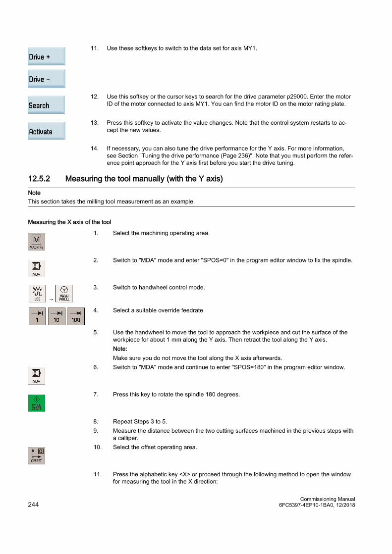
Commissioning Manual 244 6FC5397-4EP10-1BA0, 12/2018
11. Use these softkeys to switch to the data set for axis MY1.
12. Use this softkey or the cursor keys to search for the drive parameter p29000. Enter the motor ID of the motor connected to axis MY1. You can find the motor ID on the motor rating plate.
13. Press this softkey to activate the value changes. Note that the control system restarts to ac-cept the new values.
14. If necessary, you can also tune the drive performance for the Y axis. For more information, see Section "Tuning the drive performance (Page 236)". Note that you must perform the refer-ence point approach for the Y axis first before you start the drive tuning.
12.5.2 Measuring the tool manually (with the Y axis)
Note This section takes the milling tool measurement as an example.
Measuring the X axis of the tool
1. Select the machining operating area.
2. Switch to "MDA" mode and enter "SPOS=0" in the program editor window to fix the spindle.
→
3. Switch to handwheel control mode.
4. Select a suitable override feedrate.
5. Use the handwheel to move the tool to approach the workpiece and cut the surface of the workpiece for about 1 mm along the Y axis. Then retract the tool along the Y axis. Note: Make sure you do not move the tool along the X axis afterwards.
6. Switch to "MDA" mode and continue to enter "SPOS=180" in the program editor window.
7. Press this key to rotate the spindle 180 degrees.
8. Repeat Steps 3 to 5. 9. Measure the distance between the two cutting surfaces machined in the previous steps with
a calliper.
10. Select the offset operating area.
11. Press the alphabetic key <X> or proceed through the following method to open the window for measuring the tool in the X direction:
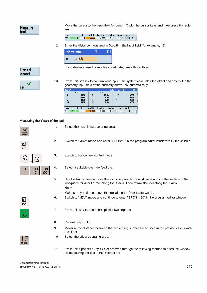
Commissioning Manual 6FC5397-4EP10-1BA0, 12/2018 245
Move the cursor to the input field for Length X with the cursor keys and then press this soft-key.
12. Enter the distance measured in Step 9 in the input field (for example, 48).
If you desire to use the relative coordinate, press this softkey.
13. Press this softkey to confirm your input. The system calculates the offset and enters it in the geometry input field of the currently active tool automatically.
Measuring the Y axis of the tool
1. Select the machining operating area.
2. Switch to "MDA" mode and enter "SPOS=0" in the program editor window to fix the spindle.
→
3. Switch to handwheel control mode.
4. Select a suitable override feedrate.
5. Use the handwheel to move the tool to approach the workpiece and cut the surface of the workpiece for about 1 mm along the X axis. Then retract the tool along the X axis. Note: Make sure you do not move the tool along the Y axis afterwards.
6. Switch to "MDA" mode and continue to enter "SPOS=180" in the program editor window.
7. Press this key to rotate the spindle 180 degrees.
8. Repeat Steps 3 to 5.
9. Measure the distance between the two cutting surfaces machined in the previous steps with a calliper.
10. Select the offset operating area.
11. Press the alphabetic key <Y> or proceed through the following method to open the window for measuring the tool in the Y direction:

Commissioning Manual 246 6FC5397-4EP10-1BA0, 12/2018
Move the cursor to the input field for Length Y with the cursor keys and then press this soft-key.
12. Enter the distance measured in Step 9 in the input field, for example, "48".
If you desire to use the relative coordinate, press this softkey.
13. Press this softkey to confirm your input. The system calculates the offset and enters it in the geometry input field of the currently active tool automatically.
Measuring the Z axis of the tool
1. Select the machining operating area.
2. Select a suitable override feedrate and use the handwheel to move the tool to scratch the
required workpiece edge (or the edge of the setting block, if it is used).
3. Select the offset operating area.
4. Press the alphabetic key <Z> or proceed through the following method to open the window for measuring the tool in the Z direction:
Move the cursor to the input field for Length Z with the cursor keys and then press this soft-key.
5. Enter the distance between the tool tip and the workpiece edge in the input field, for exam-ple, "0". (This value is the thickness of a setting block if it is used.)
If you desire to use the relative coordinate, press this softkey.
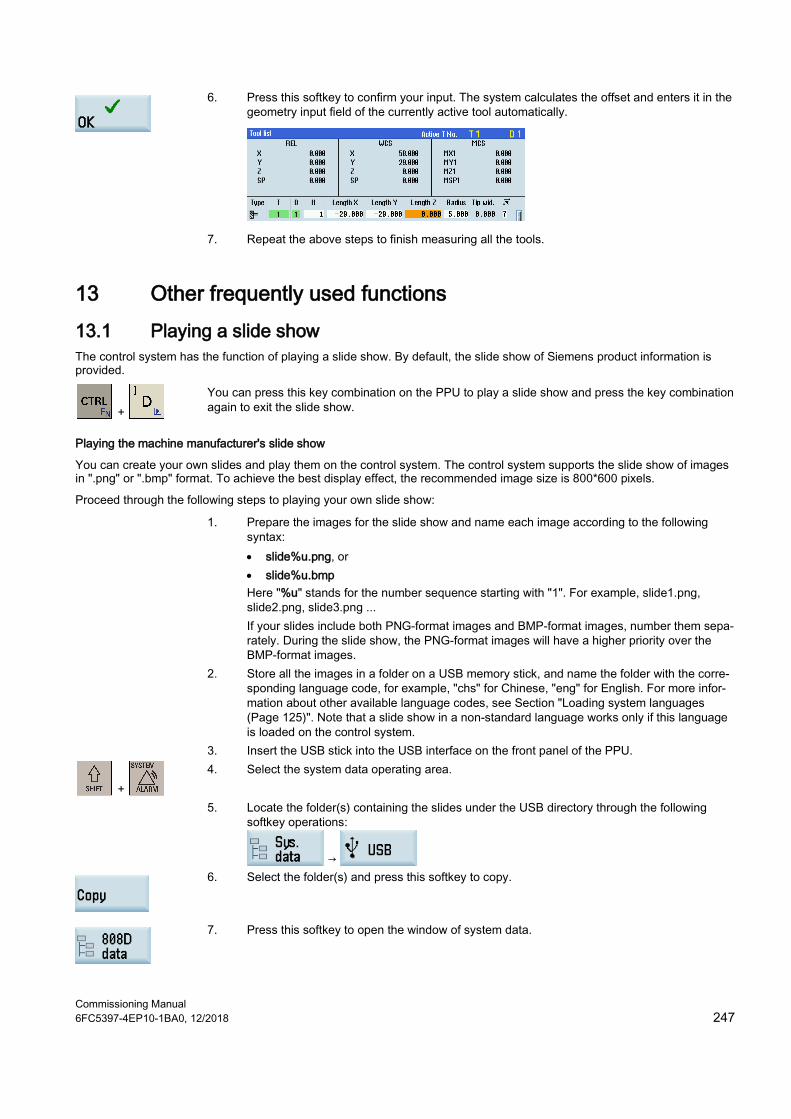
Commissioning Manual 6FC5397-4EP10-1BA0, 12/2018 247
6. Press this softkey to confirm your input. The system calculates the offset and enters it in the geometry input field of the currently active tool automatically.
7. Repeat the above steps to finish measuring all the tools.
13 Other frequently used functions 13.1 Playing a slide show The control system has the function of playing a slide show. By default, the slide show of Siemens product information is provided.
+ You can press this key combination on the PPU to play a slide show and press the key combination again to exit the slide show.
Playing the machine manufacturer's slide show
You can create your own slides and play them on the control system. The control system supports the slide show of images in ".png" or ".bmp" format. To achieve the best display effect, the recommended image size is 800*600 pixels.
Proceed through the following steps to playing your own slide show:
1. Prepare the images for the slide show and name each image according to the following syntax: • slide%u.png, or • slide%u.bmp Here "%u" stands for the number sequence starting with "1". For example, slide1.png, slide2.png, slide3.png ...
If your slides include both PNG-format images and BMP-format images, number them sepa-rately. During the slide show, the PNG-format images will have a higher priority over the BMP-format images.
2. Store all the images in a folder on a USB memory stick, and name the folder with the corre-sponding language code, for example, "chs" for Chinese, "eng" for English. For more infor-mation about other available language codes, see Section "Loading system languages (Page 125)". Note that a slide show in a non-standard language works only if this language is loaded on the control system.
3. Insert the USB stick into the USB interface on the front panel of the PPU.
+ 4. Select the system data operating area.
5. Locate the folder(s) containing the slides under the USB directory through the following softkey operations:
→
6. Select the folder(s) and press this softkey to copy.
7. Press this softkey to open the window of system data.
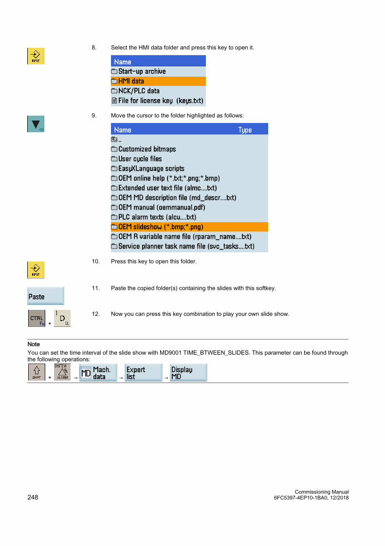
Commissioning Manual 248 6FC5397-4EP10-1BA0, 12/2018
8. Select the HMI data folder and press this key to open it.
9. Move the cursor to the folder highlighted as follows:
10. Press this key to open this folder.
11. Paste the copied folder(s) containing the slides with this softkey.
+ 12. Now you can press this key combination to play your own slide show.
Note You can set the time interval of the slide show with MD9001 TIME_BTWEEN_SLIDES. This parameter can be found through the following operations:
+ → → →
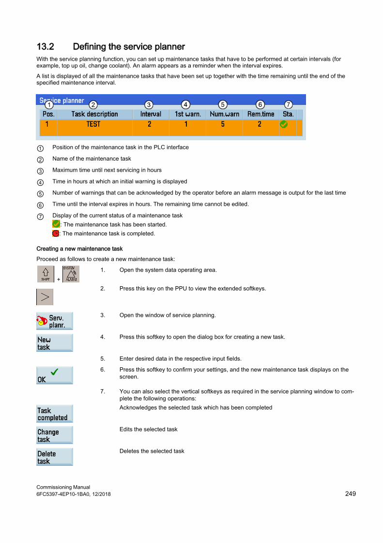
Commissioning Manual 6FC5397-4EP10-1BA0, 12/2018 249
13.2 Defining the service planner With the service planning function, you can set up maintenance tasks that have to be performed at certain intervals (for example, top up oil, change coolant). An alarm appears as a reminder when the interval expires.
A list is displayed of all the maintenance tasks that have been set up together with the time remaining until the end of the specified maintenance interval.
① Position of the maintenance task in the PLC interface
② Name of the maintenance task
③ Maximum time until next servicing in hours
④ Time in hours at which an initial warning is displayed
⑤ Number of warnings that can be acknowledged by the operator before an alarm message is output for the last time
⑥ Time until the interval expires in hours. The remaining time cannot be edited.
⑦ Display of the current status of a maintenance task : The maintenance task has been started. : The maintenance task is completed.
Creating a new maintenance task
Proceed as follows to create a new maintenance task:
+ 1. Open the system data operating area.
2. Press this key on the PPU to view the extended softkeys.
3. Open the window of service planning.
4. Press this softkey to open the dialog box for creating a new task.
5. Enter desired data in the respective input fields.
6. Press this softkey to confirm your settings, and the new maintenance task displays on the screen.
7. You can also select the vertical softkeys as required in the service planning window to com-plete the following operations:
Acknowledges the selected task which has been completed
Edits the selected task
Deletes the selected task
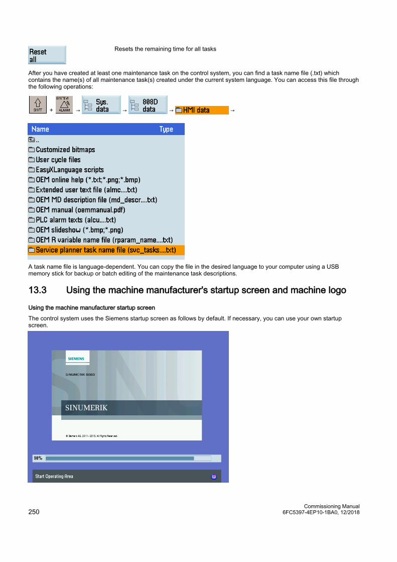
Commissioning Manual 250 6FC5397-4EP10-1BA0, 12/2018
Resets the remaining time for all tasks
After you have created at least one maintenance task on the control system, you can find a task name file (.txt) which contains the name(s) of all maintenance task(s) created under the current system language. You can access this file through the following operations:
+ → → → →
A task name file is language-dependent. You can copy the file in the desired language to your computer using a USB memory stick for backup or batch editing of the maintenance task descriptions.
13.3 Using the machine manufacturer's startup screen and machine logo
Using the machine manufacturer startup screen
The control system uses the Siemens startup screen as follows by default. If necessary, you can use your own startup screen.
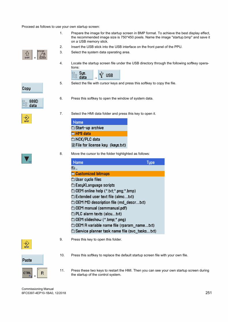
Commissioning Manual 6FC5397-4EP10-1BA0, 12/2018 251
Proceed as follows to use your own startup screen:
1. Prepare the image for the startup screen in BMP format. To achieve the best display effect, the recommended image size is 750*450 pixels. Name the image "startup.bmp" and save it on a USB memory stick.
2. Insert the USB stick into the USB interface on the front panel of the PPU.
+ 3. Select the system data operating area.
4. Locate the startup screen file under the USB directory through the following softkey opera-tions:
→
5. Select the file with cursor keys and press this softkey to copy the file.
6. Press this softkey to open the window of system data.
7. Select the HMI data folder and press this key to open it.
8. Move the cursor to the folder highlighted as follows:
9. Press this key to open this folder.
10. Press this softkey to replace the default startup screen file with your own file.
+ 11. Press these two keys to restart the HMI. Then you can see your own startup screen during
the startup of the control system.

Commissioning Manual 252 6FC5397-4EP10-1BA0, 12/2018
Note To restore the default startup screen, delete the customized bitmap file (startup.bmp) from the control system.
Using the machine manufacturer machine logo
The default machine logo is displayed in the machining operating area as follows. If necessary, you can use your own machine logo.
Proceed as follows to use your own machine logo:
1. Prepare the image of your own machine logo in BMP format. To achieve the best display effect, the recommended image size is 153*24 pixels. Name the image "mtbico.bmp" and save it on a USB memory stick.
2. Insert the USB stick into the USB interface on the front panel of the PPU.
+ 3. Select the system data operating area.
4. Locate the machine logo file under the USB directory through the following softkey opera-tions:
→
5. Select the file with cursor keys and press this softkey to copy the file.
6. Press this softkey to open the window of system data.
7. Select the HMI data folder and press this key to open it.
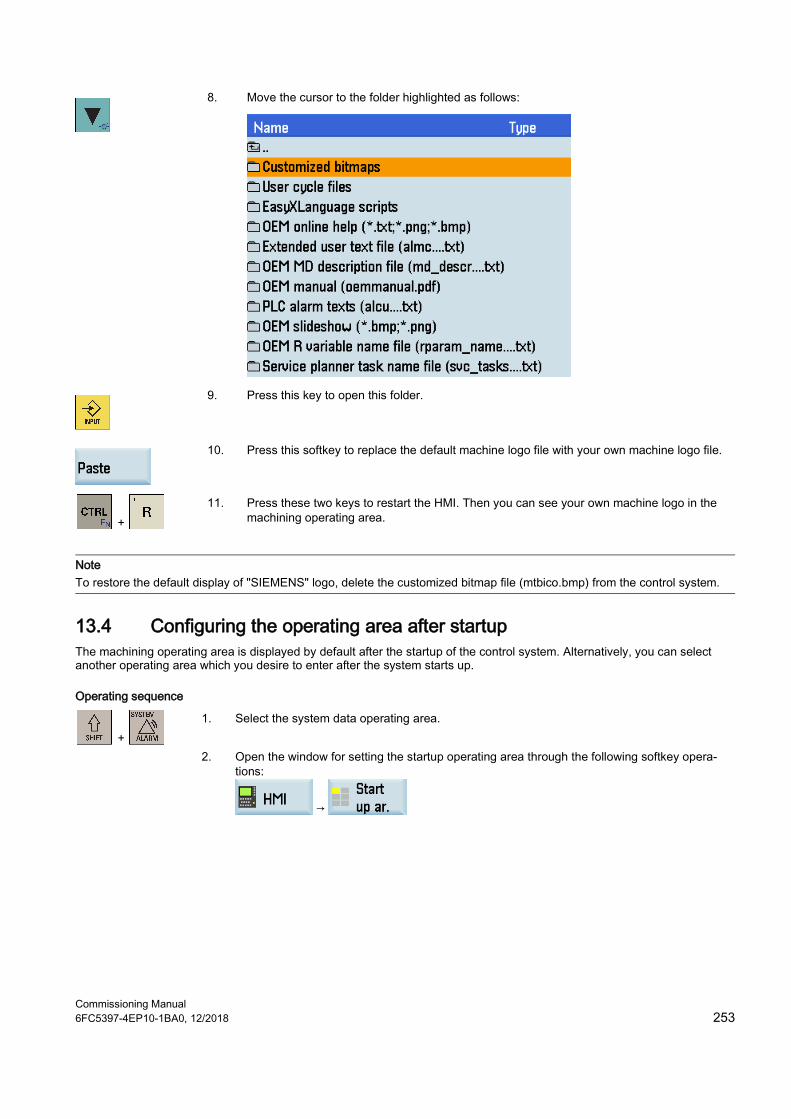
Commissioning Manual 6FC5397-4EP10-1BA0, 12/2018 253
8. Move the cursor to the folder highlighted as follows:
9. Press this key to open this folder.
10. Press this softkey to replace the default machine logo file with your own machine logo file.
+ 11. Press these two keys to restart the HMI. Then you can see your own machine logo in the
machining operating area.
Note To restore the default display of "SIEMENS" logo, delete the customized bitmap file (mtbico.bmp) from the control system.
13.4 Configuring the operating area after startup The machining operating area is displayed by default after the startup of the control system. Alternatively, you can select another operating area which you desire to enter after the system starts up.
Operating sequence
+ 1. Select the system data operating area.
2. Open the window for setting the startup operating area through the following softkey opera-tions:
→
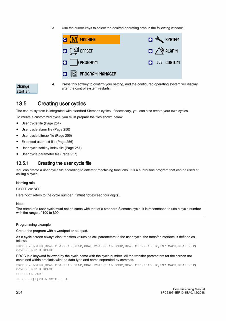
Commissioning Manual 254 6FC5397-4EP10-1BA0, 12/2018
3. Use the cursor keys to select the desired operating area in the following window:
4. Press this softkey to confirm your setting, and the configured operating system will display after the control system restarts.
13.5 Creating user cycles The control system is integrated with standard Siemens cycles. If necessary, you can also create your own cycles.
To create a customized cycle, you must prepare the files shown below:
● User cycle file (Page 254)
● User cycle alarm file (Page 256)
● User cycle bitmap file (Page 256)
● Extended user text file (Page 256)
● User cycle softkey index file (Page 257)
● User cycle parameter file (Page 257)
13.5.1 Creating the user cycle file You can create a user cycle file according to different machining functions. It is a subroutine program that can be used at calling a cycle.
Naming rule
CYCLExxx.SPF
Here "xxx" refers to the cycle number. It must not exceed four digits..
Note The name of a user cycle must not be same with that of a standard Siemens cycle. It is recommend to use a cycle number with the range of 100 to 800.
Programming example
Create the program with a wordpad or notepad.
As a cycle screen always also transfers values as call parameters to the user cycle, the transfer interface is defined as follows. PROC CYCLE100(REAL DIA,REAL DIAF,REAL STAP,REAL ENDP,REAL MID,REAL UX,INT MACH,REAL VRT) SAVE SBLOF DISPLOF
PROC is a keyword followed by the cycle name with the cycle number. All the transfer parameters for the screen are contained within brackets with the data type and name separated by commas. PROC CYCLE100(REAL DIA,REAL DIAF,REAL STAP,REAL ENDP,REAL MID,REAL UX,INT MACH,REAL VRT) SAVE SBLOF DISPLOF
DEF REAL VAR1
IF $P_EP[X]<DIA GOTOF LL1
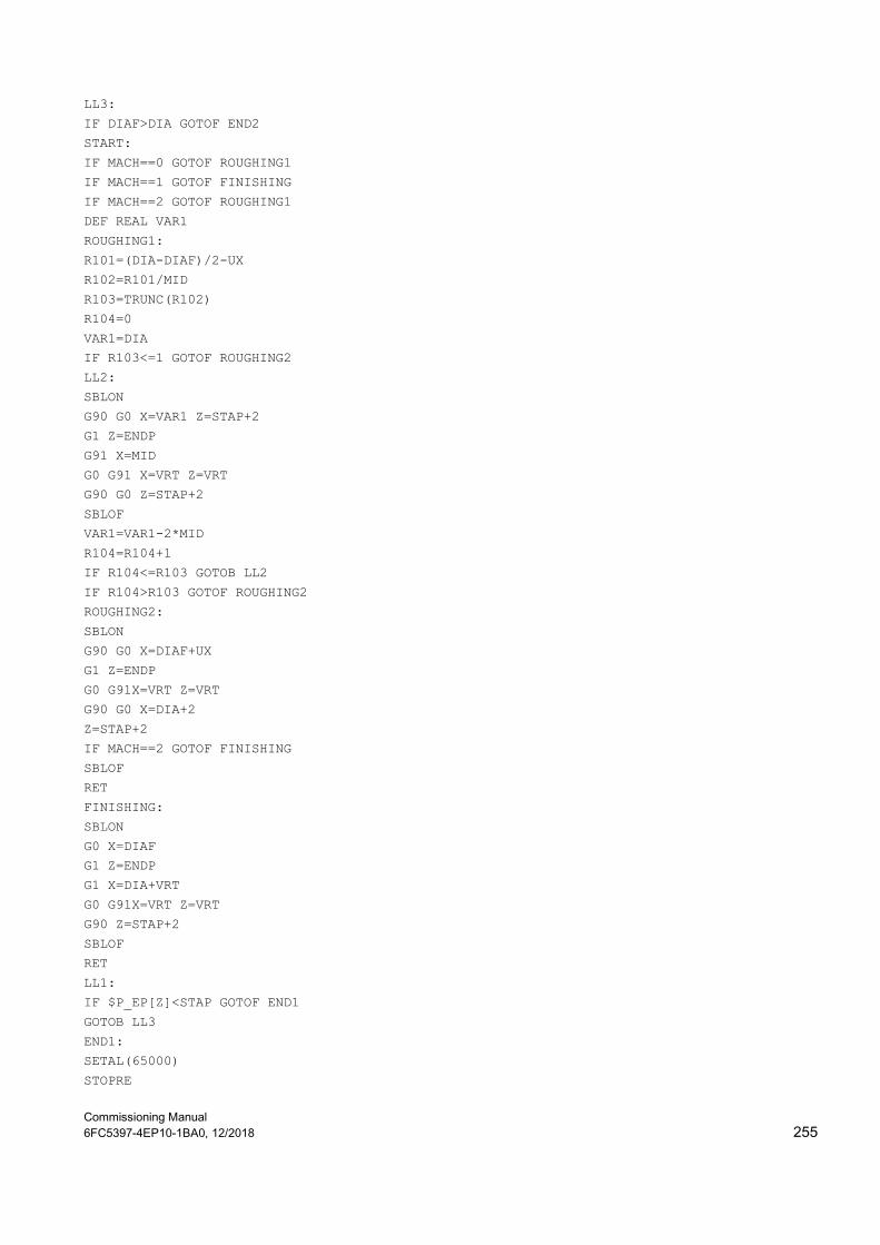
Commissioning Manual 6FC5397-4EP10-1BA0, 12/2018 255
LL3:
IF DIAF>DIA GOTOF END2
START:
IF MACH==0 GOTOF ROUGHING1
IF MACH==1 GOTOF FINISHING
IF MACH==2 GOTOF ROUGHING1
DEF REAL VAR1
ROUGHING1:
R101=(DIA-DIAF)/2-UX
R102=R101/MID
R103=TRUNC(R102)
R104=0
VAR1=DIA
IF R103<=1 GOTOF ROUGHING2
LL2:
SBLON
G90 G0 X=VAR1 Z=STAP+2
G1 Z=ENDP
G91 X=MID
G0 G91 X=VRT Z=VRT
G90 G0 Z=STAP+2
SBLOF
VAR1=VAR1-2*MID
R104=R104+1
IF R104<=R103 GOTOB LL2
IF R104>R103 GOTOF ROUGHING2
ROUGHING2:
SBLON
G90 G0 X=DIAF+UX
G1 Z=ENDP
G0 G91X=VRT Z=VRT
G90 G0 X=DIA+2
Z=STAP+2
IF MACH==2 GOTOF FINISHING
SBLOF
RET
FINISHING:
SBLON
G0 X=DIAF
G1 Z=ENDP
G1 X=DIA+VRT
G0 G91X=VRT Z=VRT
G90 Z=STAP+2
SBLOF
RET
LL1:
IF $P_EP[Z]<STAP GOTOF END1
GOTOB LL3
END1:
SETAL(65000)
STOPRE
Commissioning Manual 256 6FC5397-4EP10-1BA0, 12/2018
M0
RET
END2:
SETAL(65001)
STOPRE
M0
RET
13.5.2 Creating the user cycle alarm file The user cycle alarm file is required to display alarm numbers and alarm messages for user cycles.
Naming rule
alc_<LANG>.txt
Here "<LANG>" refers to the language denotation, for example, eng.
For more information, see Section "Loading system languages (Page 125)".
Text definition rules
When defining the texts, you must follow the rule below:
<AlarmNumber> "<Text>" // <lines*chars>
● <AlarmNumber>: here you define the alarm number. The number ranges from 65000 to 69999.
● <Text>: here you define the actual alarm text.
● <lines*chars>: here you specify the available space for the text in the GUI in number of characters and lines. You can start a new line by inserting the character of "%n".
Example
65000 "Current tool position is incorrect" // 34 ⇒ one line with 34-character space
65001 "DIAF is bigger than DIA" // 23 ⇒ one line with 23-character space
13.5.3 Creating the user cycle bitmap file The cycle icons must be stored as bitmap files (*.bmp) with a maximum size of 224 * 224 pixels in 16 colors.
The icon name must begin with an uppercase/lowercase "C" and its length must not exceed 32 characters including the file extension (for example, CN1.bmp).
Note If 16 colors are not sufficient for the display, you can also use 24-bit color depth bitmaps.
13.5.4 Creating the extended user text file The extended user text file is required for the display of respective screen texts, cycle messages and softkey texts.
Naming rule
almc_<LANG>.txt
Here "<LANG>" refers to the language denotation, for example, eng.
For more information, see Section "Loading system languages (Page 125)".
Text definition rules
When defining the texts, you must follow the rule below:
<Identifier> "<Text>" // <lines*chars>
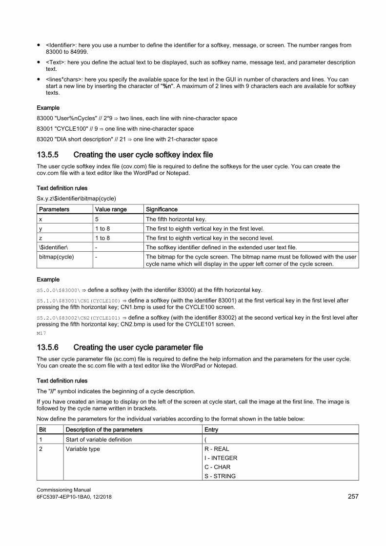
Commissioning Manual 6FC5397-4EP10-1BA0, 12/2018 257
● <Identifier>: here you use a number to define the identifier for a softkey, message, or screen. The number ranges from 83000 to 84999.
● <Text>: here you define the actual text to be displayed, such as softkey name, message text, and parameter description text.
● <lines*chars>: here you specify the available space for the text in the GUI in number of characters and lines. You can start a new line by inserting the character of "%n". A maximum of 2 lines with 9 characters each are available for softkey texts.
Example
83000 "User%nCycles" // 2*9 ⇒ two lines, each line with nine-character space
83001 "CYCLE100" // 9 ⇒ one line with nine-character space
83020 "DIA short description" // 21 ⇒ one line with 21-character space
13.5.5 Creating the user cycle softkey index file The user cycle softkey index file (cov.com) file is required to define the softkeys for the user cycle. You can create the cov.com file with a text editor like the WordPad or Notepad.
Text definition rules
Sx.y.z\$identifier\bitmap(cycle)
Parameters Value range Significance x 5 The fifth horizontal key. y 1 to 8 The first to eighth vertical key in the first level. z 1 to 8 The first to eighth vertical key in the second level. \$identifier\ - The softkey identifier defined in the extended user text file. bitmap(cycle) - The bitmap for the cycle screen. The bitmap name must be followed with the user
cycle name which will display in the upper left corner of the cycle screen.
Example
S5.0.0\$83000\ ⇒ define a softkey (with the identifier 83000) at the fifth horizontal key.
S5.1.0\$83001\CN1(CYCLE100) ⇒ define a softkey (with the identifier 83001) at the first vertical key in the first level after pressing the fifth horizontal key; CN1.bmp is used for the CYCLE100 screen.
S5.2.0\$83002\CN2(CYCLE101) ⇒ define a softkey (with the identifier 83002) at the second vertical key in the first level after pressing the fifth horizontal key; CN2.bmp is used for the CYCLE101 screen. M17
13.5.6 Creating the user cycle parameter file The user cycle parameter file (sc.com) file is required to define the help information and the parameters for the user cycle. You can create the sc.com file with a text editor like the WordPad or Notepad.
Text definition rules
The "//" symbol indicates the beginning of a cycle description.
If you have created an image to display on the left of the screen at cycle start, call the image at the first line. The image is followed by the cycle name written in brackets.
Now define the parameters for the individual variables according to the format shown in the table below:
Bit Description of the parameters Entry 1 Start of variable definition ( 2 Variable type R - REAL
I - INTEGER C - CHAR S - STRING
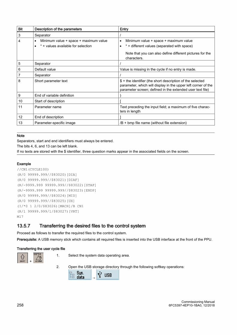
Commissioning Manual 258 6FC5397-4EP10-1BA0, 12/2018
Bit Description of the parameters Entry 3 Separator / 4 • Minimum value + space + maximum value
• * + values available for selection • Minimum value + space + maximum value • * + different values (separated with space)
Note that you can also define different pictures for the characters.
5 Separator / 6 Default value Value is missing in the cycle if no entry is made. 7 Separator / 8 Short parameter text $ + the identifier (the short description of the selected
parameter, which will display in the upper left corner of the parameter screen; defined in the extended user text file)
9 End of variable definition ) 10 Start of description [ 11 Parameter name Text preceding the input field; a maximum of five charac-
ters in length 12 End of description ] 13 Parameter-specific image /B + bmp file name (without file extension)
Note Separators, start and end identifiers must always be entered. The bits 4, 6, and 13 can be left blank. If no texts are stored with the $ identifier, three question marks appear in the associated fields on the screen.
Example //CN1(CYCLE100)
(R/0 99999.999//$83020)[DIA]
(R/0 99999.999//$83021)[DIAF]
(R/-9999.999 99999.999//$83022)[STAP]
(R/-9999.999 99999.999//$83023)[ENDP]
(R/0 99999.999//$83024)[MID]
(R/0 99999.999//$83025)[UX]
(I/*0 1 2/0/$83026)[MACH]/B CN1
(R/1 99999.999/1/$83027)[VRT]
M17
13.5.7 Transferring the desired files to the control system Proceed as follows to transfer the required files to the control system.
Prerequisite: A USB memory stick which contains all required files is inserted into the USB interface at the front of the PPU.
Transferring the user cycle file
+ 1. Select the system data operating area.
2. Open the USB storage directory through the following softkey operations:
→
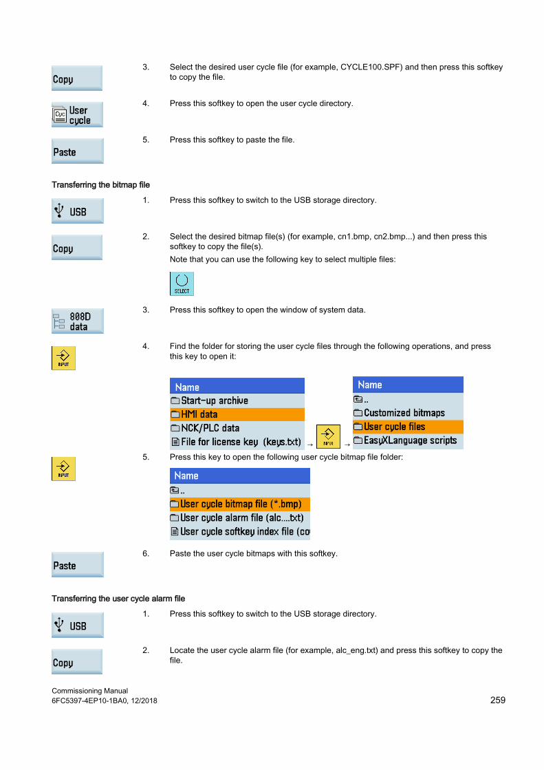
Commissioning Manual 6FC5397-4EP10-1BA0, 12/2018 259
3. Select the desired user cycle file (for example, CYCLE100.SPF) and then press this softkey to copy the file.
4. Press this softkey to open the user cycle directory.
5. Press this softkey to paste the file.
Transferring the bitmap file
1. Press this softkey to switch to the USB storage directory.
2. Select the desired bitmap file(s) (for example, cn1.bmp, cn2.bmp...) and then press this softkey to copy the file(s). Note that you can use the following key to select multiple files:
3. Press this softkey to open the window of system data.
4. Find the folder for storing the user cycle files through the following operations, and press this key to open it:
→ →
5. Press this key to open the following user cycle bitmap file folder:
6. Paste the user cycle bitmaps with this softkey.
Transferring the user cycle alarm file
1. Press this softkey to switch to the USB storage directory.
2. Locate the user cycle alarm file (for example, alc_eng.txt) and press this softkey to copy the file.

Commissioning Manual 260 6FC5397-4EP10-1BA0, 12/2018
3. Press this softkey to open the window of system data.
4. Find the following user cycle alarm file folder and press this key to open it:
5. Paste the user cycle alarm file with this softkey.
6. Press this softkey when a message appears prompting you to restart the HMI. The new data will be active after the HMI restarts successfully.
Transferring the cov.com file and sc.com file
+ 1. Select the system data operating area.
2. Open the USB storage directory through the following softkey operations:
→
3. Select the cov.com and sc.com files and then press this softkey to copy the files. Note that you can use the following key to select multiple files:
4. Press this softkey to open the window of system data.
5. Find the folder for storing the user cycle files through the following operations, and press this key to open it:
→ →
6. Press this softkey to replace the following empty files:

Commissioning Manual 6FC5397-4EP10-1BA0, 12/2018 261
7. Press this softkey when a message appears prompting you to restart the HMI. The new data will be active after the HMI restarts successfully.
Transferring the extended user text file
+ 1. Select the system data operating area.
2. Open the USB storage directory through the following softkey operations:
→
3. Locate the extended user text file (for example, almc_eng.txt) and press this softkey to copy the file.
4. Find the folder for storing the extended user text file through the following operations, and press this key to open it:
→ →
5. Press this softkey to paste the extended user text file.
6. Press this softkey when a message appears prompting you to restart the HMI. The new data will be active after the HMI restarts successfully.
13.5.8 Calling the created user cycle After you transfer all the files necessary for your own cycle to the control system, the cycle is created successfully. Then you can call the cycle in the program editing operating area.
Proceed as follows to call the created cycle, for example, CYCLE100.
1. Select the program management operating area.
2. Select the desired part program and press this key to open it in the program editor.

Commissioning Manual 262 6FC5397-4EP10-1BA0, 12/2018
Then you can see the softkey you define at the fifth horizontal softkey, for example:
3. Press this softkey to open the lower-level menu for calling user cycles, for example:

Commissioning Manual 6FC5397-4EP10-1BA0, 12/2018 263
4. Press this softkey to open the window for CYCLE100, for example:
5. Set the parameters as desired, and press this softkey to confirm and return to the program editing screen. Then you can find CYCLE100 inserted in your program.
13.6 Using the machine manufacturer's machine data descriptions If necessary, you can use your own descriptions for the PLC machine data 14510, 14512, 14514, 14516, and 17400.
Proceed as follows to edit the machine data description:
+ 1. Select the system data operating area.
2. Press this softkey, and the window of basic NC data opens by default.
3. Press this softkey and all machine data available for editing is listed.
4. Use the cursor keys to select a desired MD.
5. Press this softkey to activate the input field at the bottom of the screen and enter the de-sired description text, for example:
6. Confirm your entry with this softkey or the following key:
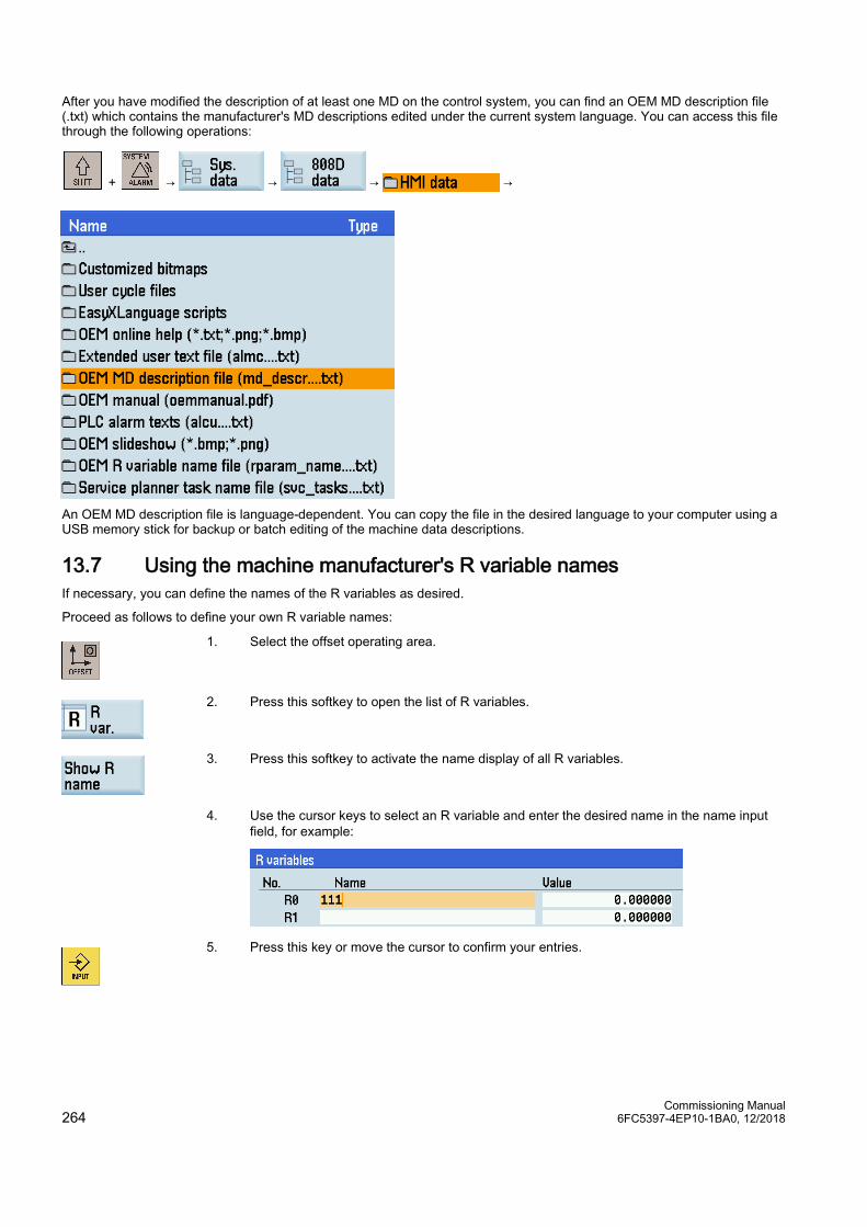
Commissioning Manual 264 6FC5397-4EP10-1BA0, 12/2018
After you have modified the description of at least one MD on the control system, you can find an OEM MD description file (.txt) which contains the manufacturer's MD descriptions edited under the current system language. You can access this file through the following operations:
+ → → → →
An OEM MD description file is language-dependent. You can copy the file in the desired language to your computer using a USB memory stick for backup or batch editing of the machine data descriptions.
13.7 Using the machine manufacturer's R variable names If necessary, you can define the names of the R variables as desired.
Proceed as follows to define your own R variable names:
1. Select the offset operating area.
2. Press this softkey to open the list of R variables.
3. Press this softkey to activate the name display of all R variables.
4. Use the cursor keys to select an R variable and enter the desired name in the name input field, for example:
5. Press this key or move the cursor to confirm your entries.
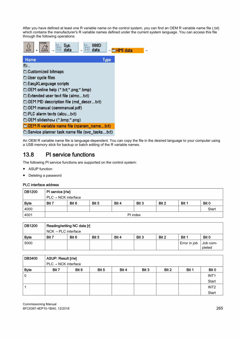
Commissioning Manual 6FC5397-4EP10-1BA0, 12/2018 265
After you have defined at least one R variable name on the control system, you can find an OEM R variable name file (.txt) which contains the manufacturer's R variable names defined under the current system language. You can access this file through the following operations:
+ → → → →
An OEM R variable name file is language-dependent. You can copy the file in the desired language to your computer using a USB memory stick for backup or batch editing of the R variable names.
13.8 PI service functions The following PI service functions are supported on the control system:
● ASUP function
● Deleting a password
PLC interface address
DB1200 PI service [r/w] PLC → NCK interface
Byte Bit 7 Bit 6 Bit 5 Bit 4 Bit 3 Bit 2 Bit 1 Bit 0 4000 Start 4001 PI index
DB1200 Reading/writing NC data [r] NCK → PLC interface
Byte Bit 7 Bit 6 Bit 5 Bit 4 Bit 3 Bit 2 Bit 1 Bit 0 5000 Error in job Job com-
pleted
DB3400 ASUP: Result [r/w] PLC → NCK interface
Byte Bit 7 Bit 6 Bit 5 Bit 4 Bit 3 Bit 2 Bit 1 Bit 0 0 INT1
Start 1 INT2
Start
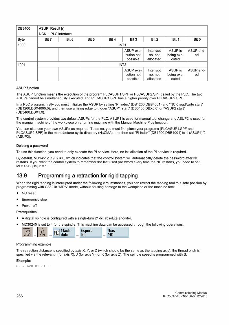
Commissioning Manual 266 6FC5397-4EP10-1BA0, 12/2018
DB3400 ASUP: Result [r] NCK → PLC interface
Byte Bit 7 Bit 6 Bit 5 Bit 4 Bit 3 Bit 2 Bit 1 Bit 0 1000 INT1
ASUP exe-cution not possible
Interrupt no. not
allocated
ASUP is being exe-
cuted
ASUP end-ed
1001 INT2 ASUP exe-
cution not possible
Interrupt no. not
allocated
ASUP is being exe-
cuted
ASUP end-ed
ASUP function
The ASUP function means the execution of the program PLCASUP1.SPF or PLCASUP2.SPF called by the PLC. The two ASUPs cannot be simultaneously executed, and PLCASUP1.SPF has a higher priority over PLCASUP2.SPF.
In a PLC program, firstly you must initialize the ASUP by setting "PI index" (DB1200.DBB4001) and "NCK read/write start" (DB1200.DBX4000.0), and then use a rising edge to trigger "ASUP1 start" (DB3400.DBX0.0) or "ASUP2 start" (DB3400.DBX1.0).
The control system provides two default ASUPs for the PLC. ASUP1 is used for manual tool change and ASUP2 is used for the manual machine of the workpiece on a turning machine with the Manual Machine Plus function.
You can also use your own ASUPs as required. To do so, you must first place your programs (PLCASUP1.SPF and PLCASUP2.SPF) in the manufacturer cycle directory (N:\CMA), and then set "PI index" (DB1200.DBB4001) to 1 (ASUP1)/2 (ASUP2).
Deleting a password
To use this function, you need to only execute the PI service. Here, no initialization of the PI service is required.
By default, MD14512 [19].2 = 0, which indicates that the control system will automatically delete the password after NC restarts. If you want the control system to remember the last used password every time the NC restarts, you need to set MD14512 [19].2 = 1.
13.9 Programming a retraction for rigid tapping When the rigid tapping is interrupted under the following circumstances, you can retract the tapping tool to a safe position by programming with G332 in "MDA" mode, without causing damage to the workpiece or the machine tool:
● NC reset
● Emergency stop
● Power-off
Prerequisites:
● A digital spindle is configured with a single-turn 21-bit absolute encoder.
● MD30240 is set to 4 for the spindle. This machine data can be accessed through the following operations:
+ → → →
Programming example
The retraction distance is specified by axis X, Y, or Z (which should be the same as the tapping axis); the thread pitch is specified via the relevant I (for axis X), J (for axis Y), or K (for axis Z). The spindle speed is programmed with S.
Example: G332 Z20 K1 S100
Commissioning Manual 6FC5397-4EP10-1BA0, 12/2018 267
Note • For the tapping retraction after an emergency stop, you must first press the following key to reset the NC before
executing the retraction program in "MDA" mode.
• For the tapping retraction after system power-off, you must enable the spindle first via program block "SPOS=IC(0)" after
power-on, and then execute the retraction program in "MDA" mode; otherwise, an alarm 014092 appears.
13.10 CNC lock function
13.10.1 Function overview
Note The "CNC lock function" is a licensed option (article number: 6FC5800-0AS71-0YB0).
Note It's machine manufacturer's responsibility to ensure that the CNC lock function works properly and reliably.
NOTICE License certificate The company that created the CNC lock function (machine manufacturer or dealer) must retain the license certificate for this option. This certificate can be used as legitimation for Siemens should the PIN be forgotten. The owner of the certificate (CoL) can have the machine unlocked.
The machine manufacturer can use the CNC lock function and the encrypted file created with Access MyMachine (AMM) application to activate a lock date in the control system. This allows the use of the machine to be limited to the time until the lock date is reached. The NC start function of the control system is locked when the lock date is exceeded. An NC program being processed in "AUTO" mode at this time is not interrupted.
The CNC lock function can be lengthened or deactivated with an additional encrypted file. The machine manufacturer sends this file to the end user if the user has fulfilled the agreed obligations.
Requirements
The following preconditions must be met for using the CNC lock function:
● The option of the CNC lock function must be activated with a license key. For more information about how to activate the optional functions, see Section "Activating the optional functions (Page 127)".
● A PLC project (of type 808D PPU15x/PPU16x) especially adapted to your machine tool must be downloaded into the control system with PLC Programming Tool. The compatibility mode must be deactivated. The default PLC project should never be used together with the CNC lock function. For more information about the operations with PLC Programming Tool, see Section "PLC Programming Tool (Page 182)".
● The AMM tool must be installed on your computer. For more information about AMM installation, see Section "Installing the software tools (Page 38)".
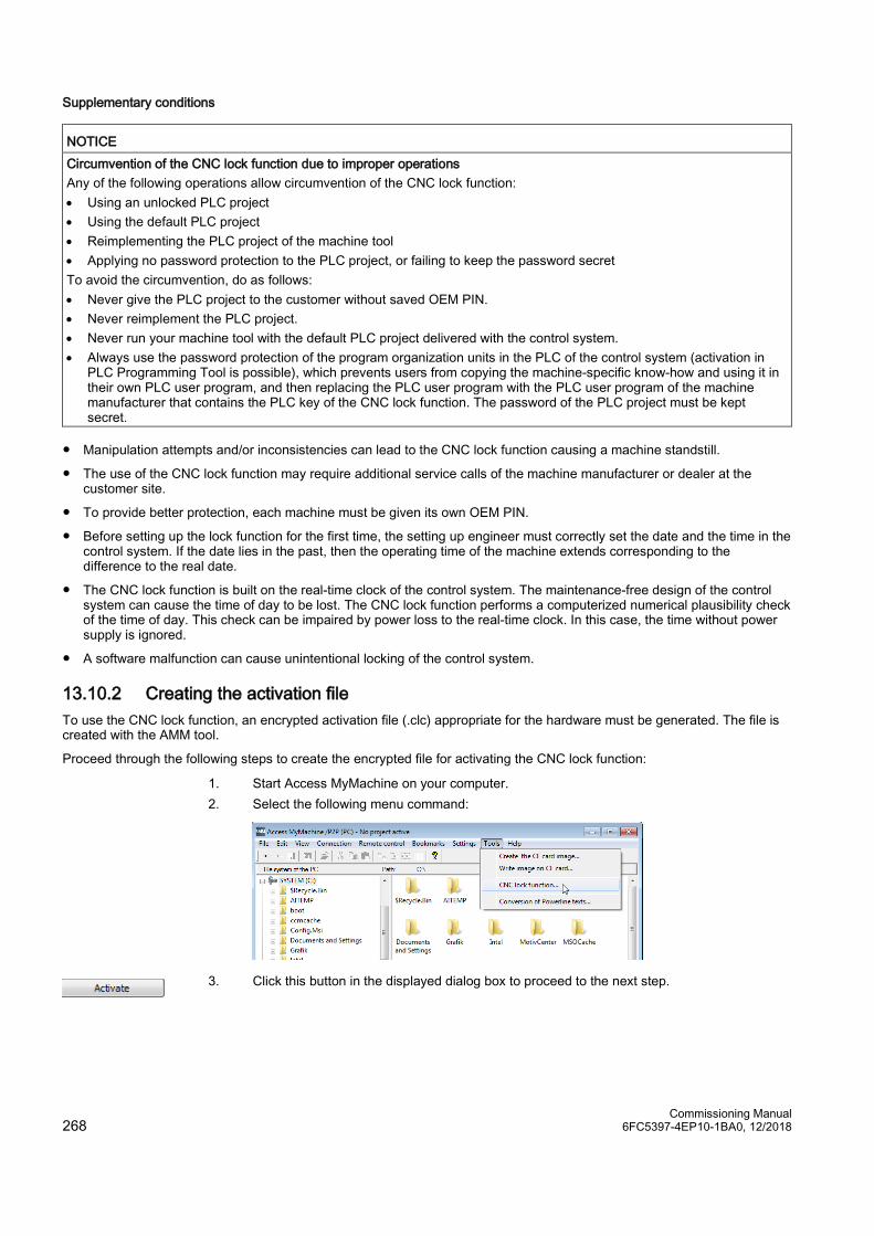
Commissioning Manual 268 6FC5397-4EP10-1BA0, 12/2018
Supplementary conditions
NOTICE Circumvention of the CNC lock function due to improper operations Any of the following operations allow circumvention of the CNC lock function: • Using an unlocked PLC project • Using the default PLC project • Reimplementing the PLC project of the machine tool • Applying no password protection to the PLC project, or failing to keep the password secret To avoid the circumvention, do as follows: • Never give the PLC project to the customer without saved OEM PIN. • Never reimplement the PLC project. • Never run your machine tool with the default PLC project delivered with the control system. • Always use the password protection of the program organization units in the PLC of the control system (activation in
PLC Programming Tool is possible), which prevents users from copying the machine-specific know-how and using it in their own PLC user program, and then replacing the PLC user program with the PLC user program of the machine manufacturer that contains the PLC key of the CNC lock function. The password of the PLC project must be kept secret.
● Manipulation attempts and/or inconsistencies can lead to the CNC lock function causing a machine standstill.
● The use of the CNC lock function may require additional service calls of the machine manufacturer or dealer at the customer site.
● To provide better protection, each machine must be given its own OEM PIN.
● Before setting up the lock function for the first time, the setting up engineer must correctly set the date and the time in the control system. If the date lies in the past, then the operating time of the machine extends corresponding to the difference to the real date.
● The CNC lock function is built on the real-time clock of the control system. The maintenance-free design of the control system can cause the time of day to be lost. The CNC lock function performs a computerized numerical plausibility check of the time of day. This check can be impaired by power loss to the real-time clock. In this case, the time without power supply is ignored.
● A software malfunction can cause unintentional locking of the control system.
13.10.2 Creating the activation file To use the CNC lock function, an encrypted activation file (.clc) appropriate for the hardware must be generated. The file is created with the AMM tool.
Proceed through the following steps to create the encrypted file for activating the CNC lock function:
1. Start Access MyMachine on your computer. 2. Select the following menu command:
3. Click this button in the displayed dialog box to proceed to the next step.
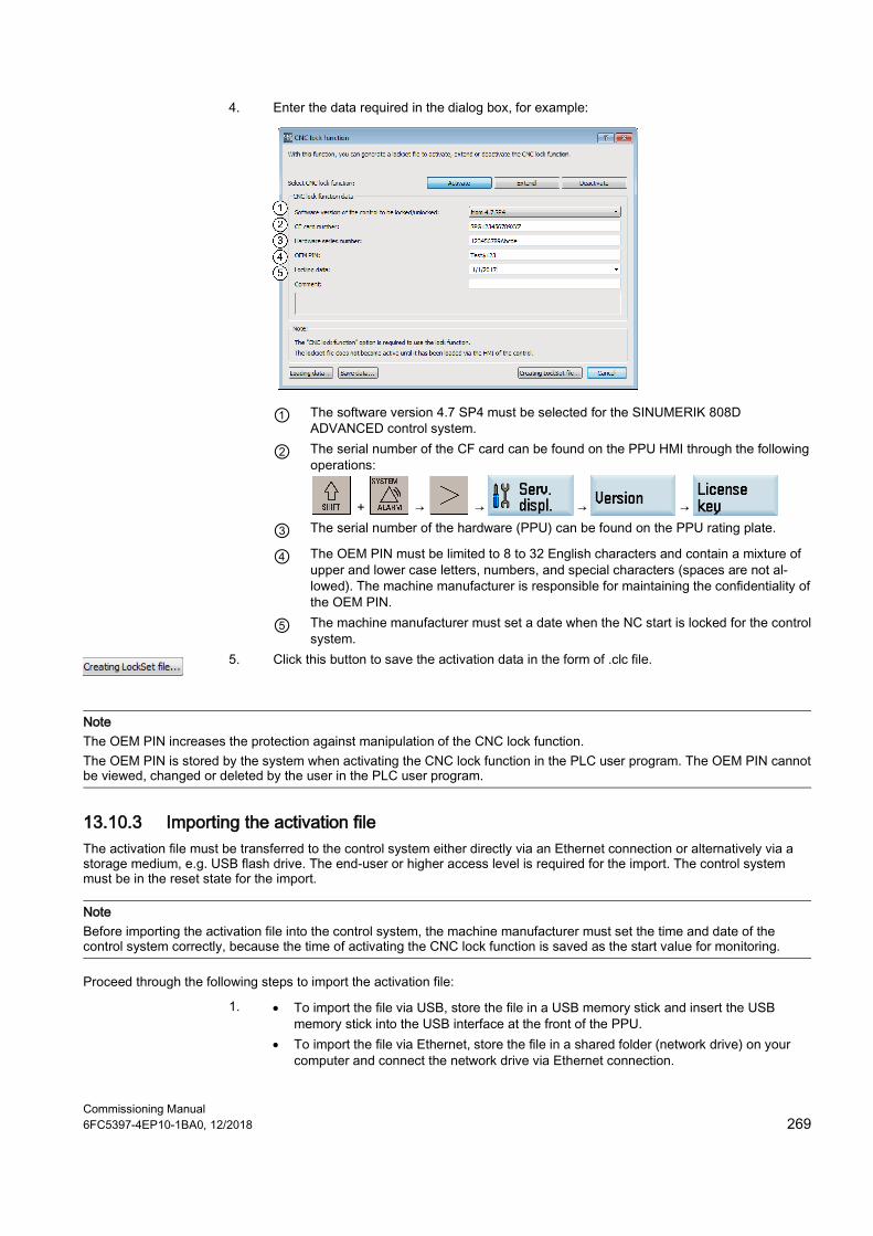
Commissioning Manual 6FC5397-4EP10-1BA0, 12/2018 269
4. Enter the data required in the dialog box, for example:
① The software version 4.7 SP4 must be selected for the SINUMERIK 808D ADVANCED control system.
② The serial number of the CF card can be found on the PPU HMI through the following operations:
+ → → → →
③ The serial number of the hardware (PPU) can be found on the PPU rating plate.
④ The OEM PIN must be limited to 8 to 32 English characters and contain a mixture of upper and lower case letters, numbers, and special characters (spaces are not al-lowed). The machine manufacturer is responsible for maintaining the confidentiality of the OEM PIN.
⑤ The machine manufacturer must set a date when the NC start is locked for the control system.
5. Click this button to save the activation data in the form of .clc file.
Note The OEM PIN increases the protection against manipulation of the CNC lock function. The OEM PIN is stored by the system when activating the CNC lock function in the PLC user program. The OEM PIN cannot be viewed, changed or deleted by the user in the PLC user program.
13.10.3 Importing the activation file The activation file must be transferred to the control system either directly via an Ethernet connection or alternatively via a storage medium, e.g. USB flash drive. The end-user or higher access level is required for the import. The control system must be in the reset state for the import.
Note Before importing the activation file into the control system, the machine manufacturer must set the time and date of the control system correctly, because the time of activating the CNC lock function is saved as the start value for monitoring.
Proceed through the following steps to import the activation file:
1. • To import the file via USB, store the file in a USB memory stick and insert the USB memory stick into the USB interface at the front of the PPU.
• To import the file via Ethernet, store the file in a shared folder (network drive) on your computer and connect the network drive via Ethernet connection.
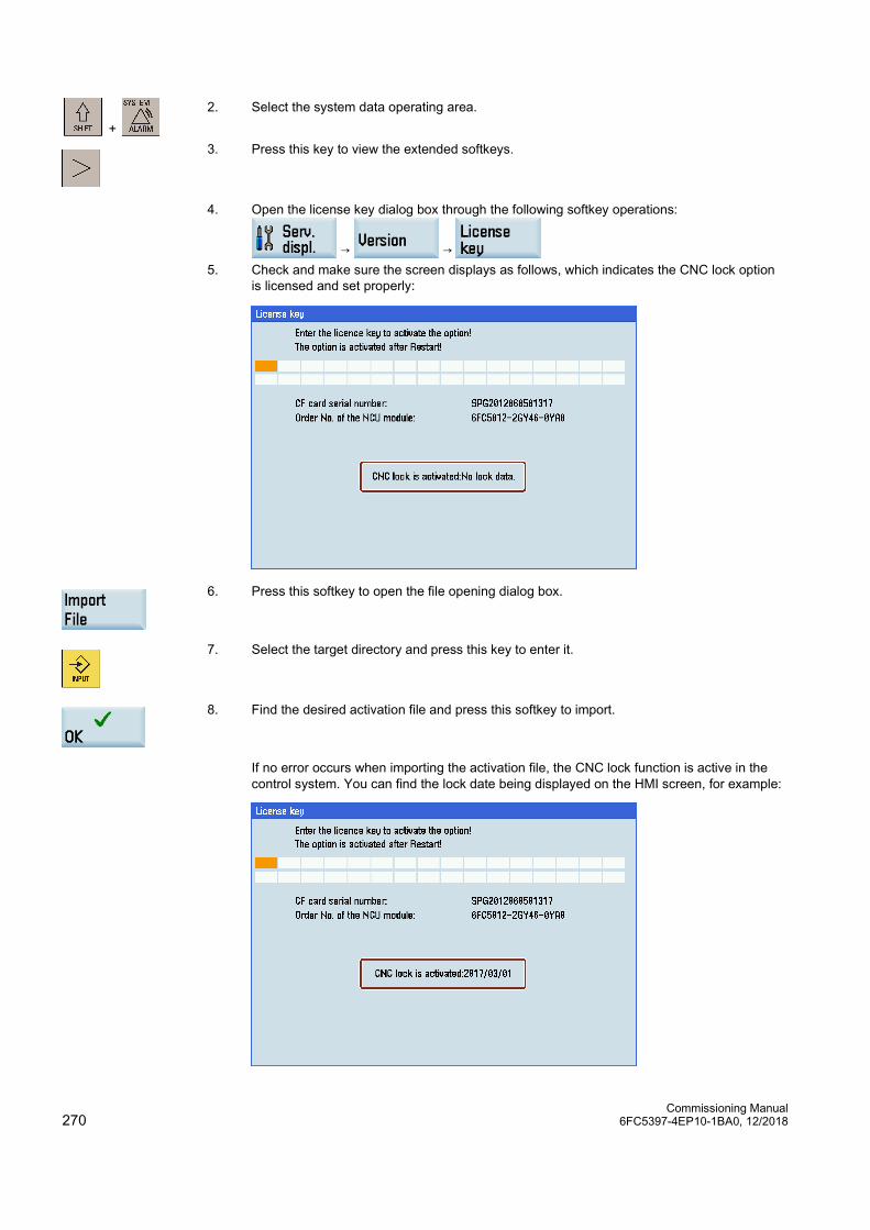
Commissioning Manual 270 6FC5397-4EP10-1BA0, 12/2018
+ 2. Select the system data operating area.
3. Press this key to view the extended softkeys.
4. Open the license key dialog box through the following softkey operations:
→ → 5. Check and make sure the screen displays as follows, which indicates the CNC lock option
is licensed and set properly:
6. Press this softkey to open the file opening dialog box.
7. Select the target directory and press this key to enter it.
8. Find the desired activation file and press this softkey to import.
If no error occurs when importing the activation file, the CNC lock function is active in the control system. You can find the lock date being displayed on the HMI screen, for example:
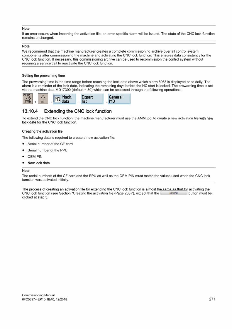
Commissioning Manual 6FC5397-4EP10-1BA0, 12/2018 271
Note If an error occurs when importing the activation file, an error-specific alarm will be issued. The state of the CNC lock function remains unchanged.
Note We recommend that the machine manufacturer creates a complete commissioning archive over all control system components after commissioning the machine and activating the CNC lock function. This ensures data consistency for the CNC lock function. If necessary, this commissioning archive can be used to recommission the control system without requiring a service call to reactivate the CNC lock function.
Setting the prewarning time
The prewarning time is the time range before reaching the lock date above which alarm 8063 is displayed once daily. The alarm is a reminder of the lock date, indicating the remaining days before the NC start is locked. The prewarning time is set via the machine data MD17300 (default = 30) which can be accessed through the following operations:
+ → → →
13.10.4 Extending the CNC lock function To extend the CNC lock function, the machine manufacturer must use the AMM tool to create a new activation file with new lock date for the CNC lock function.
Creating the activation file
The following data is required to create a new activation file:
● Serial number of the CF card
● Serial number of the PPU
● OEM PIN
● New lock date
Note The serial numbers of the CF card and the PPU as well as the OEM PIN must match the values used when the CNC lock function was activated initially.
The process of creating an activation file for extending the CNC lock function is almost the same as that for activating the CNC lock function (see Section "Creating the activation file (Page 268)"), except that the button must be clicked at step 3.
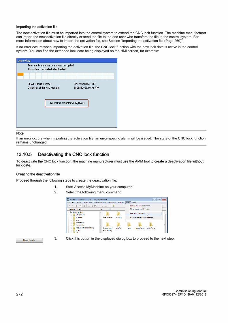
Commissioning Manual 272 6FC5397-4EP10-1BA0, 12/2018
Importing the activation file
The new activation file must be imported into the control system to extend the CNC lock function. The machine manufacturer can import the new activation file directly or send the file to the end user who transfers the file to the control system. For more information about how to import the activation file, see Section "Importing the activation file (Page 269)".
If no error occurs when importing the activation file, the CNC lock function with the new lock date is active in the control system. You can find the extended lock date being displayed on the HMI screen, for example:
Note If an error occurs when importing the activation file, an error-specific alarm will be issued. The state of the CNC lock function remains unchanged.
13.10.5 Deactivating the CNC lock function To deactivate the CNC lock function, the machine manufacturer must use the AMM tool to create a deactivation file without lock date.
Creating the deactivation file
Proceed through the following steps to create the deactivation file:
1. Start Access MyMachine on your computer. 2. Select the following menu command:
3. Click this button in the displayed dialog box to proceed to the next step.
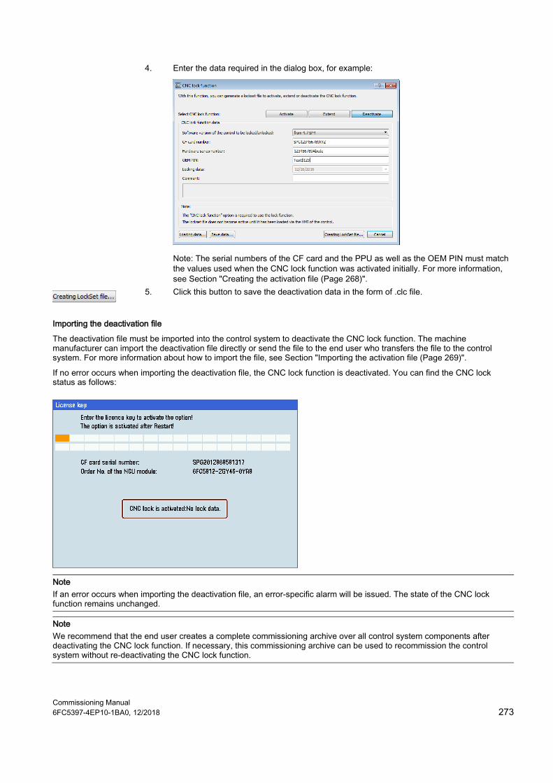
Commissioning Manual 6FC5397-4EP10-1BA0, 12/2018 273
4. Enter the data required in the dialog box, for example:
Note: The serial numbers of the CF card and the PPU as well as the OEM PIN must match the values used when the CNC lock function was activated initially. For more information, see Section "Creating the activation file (Page 268)".
5. Click this button to save the deactivation data in the form of .clc file.
Importing the deactivation file
The deactivation file must be imported into the control system to deactivate the CNC lock function. The machine manufacturer can import the deactivation file directly or send the file to the end user who transfers the file to the control system. For more information about how to import the file, see Section "Importing the activation file (Page 269)".
If no error occurs when importing the deactivation file, the CNC lock function is deactivated. You can find the CNC lock status as follows:
Note If an error occurs when importing the deactivation file, an error-specific alarm will be issued. The state of the CNC lock function remains unchanged.
Note We recommend that the end user creates a complete commissioning archive over all control system components after deactivating the CNC lock function. If necessary, this commissioning archive can be used to recommission the control system without re-deactivating the CNC lock function.

Commissioning Manual 274 6FC5397-4EP10-1BA0, 12/2018
13.10.6 OEM PIN forgotten The machine manufacturer or dealer has forgotten the OEM PIN that was assigned during the initial creation and so can no longer create a valid activation file for the associated control system.
Unlocking the machine
To allow the machine manufacturer or dealer to operate the machine, the technician must contact the Siemens Hotline and provide the following information:
● License certificate (CoL) for the option of the CNC lock function
● Serial number of the CF card
● Serial number of the control system (PPU)
● Software version of the CNC software
Note For more information about how to obtain the serial numbers of the CF card and of the control system (PPU), see Section "Creating the activation file (Page 268)". The software version of the CNC software can be found on the PPU HMI through the following operations:
+ → → →
The machine manufacturer or dealer receives from the Hotline the activation file to unlock the machine. The unlocking acts, however, only on the hardware of the control system (PPU). The PLC project is not unlocked. For this reason, the original PLC project appropriate for the machine must be available.
Further information concerning the procedure can be obtained from the Siemens Hotline.
13.10.7 Other information
Project file
The AMM tool can be used to create an unencrypted project file (.ucls) that contains the following data:
● Serial number of the CF card
● Serial number of the hardware (PPU)
● OEM PIN
● Creation date
● Lock date
Proceed through the following steps to create the unencrypted project file:
1. Start Access MyMachine on your computer. 2. Select the following menu command:
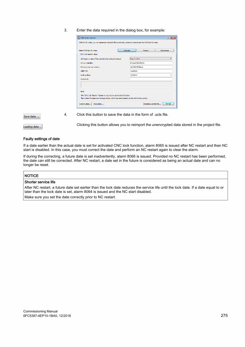
Commissioning Manual 6FC5397-4EP10-1BA0, 12/2018 275
3. Enter the data required in the dialog box, for example:
4. Click this button to save the data in the form of .ucls file.
Clicking this button allows you to reimport the unencrypted data stored in the project file.
Faulty settings of date
If a date earlier than the actual date is set for activated CNC lock function, alarm 8065 is issued after NC restart and then NC start is disabled. In this case, you must correct the date and perform an NC restart again to clear the alarm.
If during the correcting, a future date is set inadvertently, alarm 8066 is issued. Provided no NC restart has been performed, the date can still be corrected. After NC restart, a date set in the future is considered as being an actual date and can no longer be reset.
NOTICE Shorter service life After NC restart, a future date set earlier than the lock date reduces the service life until the lock date. If a date equal to or later than the lock date is set, alarm 8064 is issued and the NC start disabled. Make sure you set the date correctly prior to NC restart.

Commissioning Manual 276 6FC5397-4EP10-1BA0, 12/2018
13.11 Commissioning the PLC axis The PLC can control axes/spindles via data blocks of the PLC user interface. The PLC axis can be used for turret/magazine control or workpiece transfer on a turning or milling machine.
There are three positioning modes for the PLC axis:
● Positioning via the PLC user interface
● Positioning with the indexing position table predefined in the general machine data
● Positioning according to the distance value defined in the axis machine data
PLC user interface
Signals to PLC axis (excerpt)
DB380x PLC -> NCK interface [r/w] Byte Bit 7 Bit 6 Bit 5 Bit 4 Bit 3 Bit 2 Bit 1 Bit 0 8 Request
PLC ax-is/spindle
NC/PLC axis activa-tion signal
Request NC ax-is/spindle
3000 Start axis positioning
3002 Traversing dimension, inches (not
metric)
Distance condition, shortest distance
(DC)
Distance condition,
incremental (IC)
3003 Indexing position
Distance condition, absolute positive direction (ACP)
Distance condition, absolute negative direction (ACN)
3004 Position (REAL, with indexing axis: DINT) 3008 Feedrate velocity (REAL), if < 0, the value is taken from machine data POS_AX_VELO
Signals from PLC axis (excerpt)
DB390x Signals from PLC axis [r] NCK -> PLC interface
Byte Bit 7 Bit 6 Bit 5 Bit 4 Bit 3 Bit 2 Bit 1 Bit 0 8 PLC axis/
spindle Neutral
axis/ spin-dle
Axis inter-change possible
New type requested from PLC
NC ax-is/spindle
3000 Positioning axis active
Position reached
Error while traversing
Axis cannot be started
3003 Error number
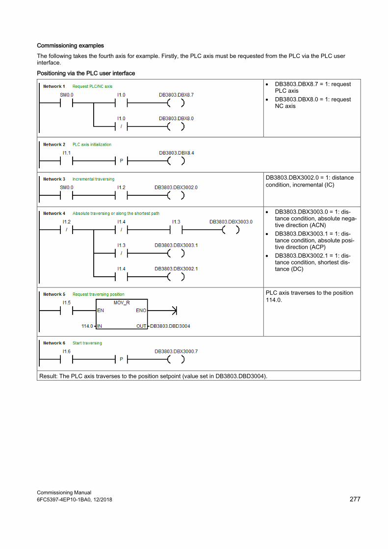
Commissioning Manual 6FC5397-4EP10-1BA0, 12/2018 277
Commissioning examples
The following takes the fourth axis for example. Firstly, the PLC axis must be requested from the PLC via the PLC user interface.
Positioning via the PLC user interface
• DB3803.DBX8.7 = 1: request PLC axis
• DB3803.DBX8.0 = 1: request NC axis
DB3803.DBX3002.0 = 1: distance condition, incremental (IC)
• DB3803.DBX3003.0 = 1: dis-tance condition, absolute nega-tive direction (ACN)
• DB3803.DBX3003.1 = 1: dis-tance condition, absolute posi-tive direction (ACP)
• DB3803.DBX3002.1 = 1: dis-tance condition, shortest dis-tance (DC)
PLC axis traverses to the position 114.0.
Result: The PLC axis traverses to the position setpoint (value set in DB3803.DBD3004).
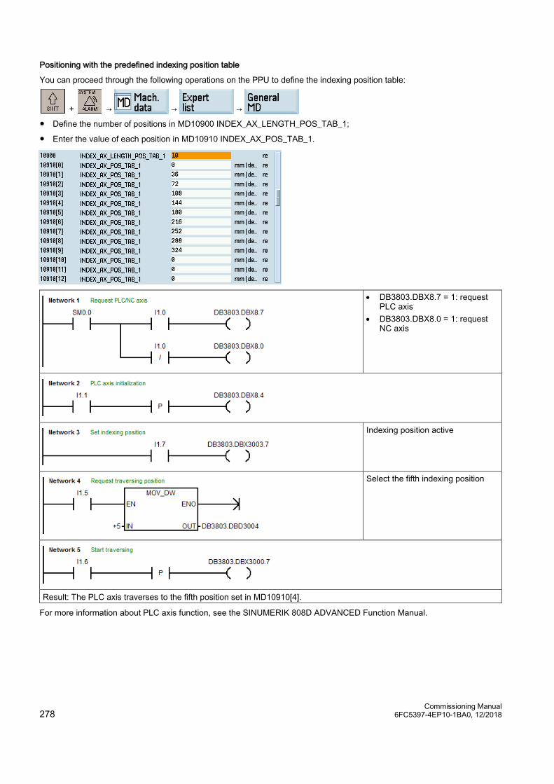
Commissioning Manual 278 6FC5397-4EP10-1BA0, 12/2018
Positioning with the predefined indexing position table
You can proceed through the following operations on the PPU to define the indexing position table:
+ → → →
● Define the number of positions in MD10900 INDEX_AX_LENGTH_POS_TAB_1;
● Enter the value of each position in MD10910 INDEX_AX_POS_TAB_1.
• DB3803.DBX8.7 = 1: request PLC axis
• DB3803.DBX8.0 = 1: request NC axis
Indexing position active
Select the fifth indexing position
Result: The PLC axis traverses to the fifth position set in MD10910[4].
For more information about PLC axis function, see the SINUMERIK 808D ADVANCED Function Manual.

Commissioning Manual 6FC5397-4EP10-1BA0, 12/2018 279
13.12 Configuring the DSC function for the digital spindle
Function overview
The Dynamic Stiffness Control (DSC) function eliminates the deadtime that necessarily exists at the speed-setpoint interface normally used between the NCK and drive due to relocation of the position controller into the drive.
To use the DSC function for the digital spindle, you must additionally connect an external spindle encoder via interface X60 in addition to the motor encoder and configure two measuring systems. For more information about interface X60, see Section "Analog spindle interface - X54, spindle encoder interface - X60 (Page 89)".
Setting parameters for two measuring systems
+ 1. Select the system data operating area.
2. Open the axis machine data window through the following softkey operations:
→ →
3. Use these softkeys to switch to the data set for the spindle (MSP1).
4. Use this softkey or the cursor keys to search for the following machine data and assign the desired values: • 30200 = 2 • For the first measuring system (motor encoder):
– 30210[0] = 5 – 30220[0] = 4 – 30230[0] = 1 – 30240[0] = 1 – 31020[0] = resolution of the motor encoder – 31040[0] = 0 – 31050[0] = load gearbox denominator – 31060[0] = load gearbox numerator
• For the second measuring system (external encoder): – 30210[1] = 0 – 30220[1] = 4 – 30230[1] = 4 – 30240[1] = 2 – 31020[1] = resolution of the external spindle encoder – 31040[1] = 1 – 31050[1] = load gearbox denominator – 31060[1] = load gearbox numerator – 36300[1] ≤ 2000000 (2 MHz which is the max. frequency of interface X60)
5. Press this softkey to activate the value changes. Note that the control system restarts to ac-cept the new values.
After finishing the parameter setting, you can activate the second measuring system by setting the following PLC user interfaces (where the fourth axis is configured as spindle):
● DB3803.DBX1.5 = 0
● DB3803.DBX1.6 = 1
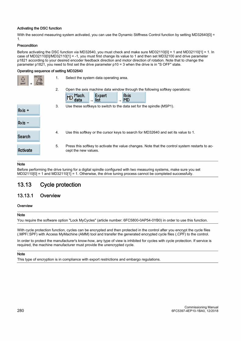
Commissioning Manual 280 6FC5397-4EP10-1BA0, 12/2018
Activating the DSC function
With the second measuring system activated, you can use the Dynamic Stiffness Control function by setting MD32640[0] = 1.
Precondition
Before activating the DSC function via MD32640, you must check and make sure MD32110[0] = 1 and MD32110[1] = 1. In case of MD32110[0]/MD32110[1] = -1, you must first change its value to 1 and then set MD32100 and drive parameter p1821 according to your desired encoder feedback direction and motor direction of rotation. Note that to change the parameter p1821, you need to first set the drive parameter p10 = 3 when the drive is in "S OFF" state.
Operating sequence of setting MD32640
+ 1. Select the system data operating area.
2. Open the axis machine data window through the following softkey operations:
→ →
3. Use these softkeys to switch to the data set for the spindle (MSP1).
4. Use this softkey or the cursor keys to search for MD32640 and set its value to 1.
5. Press this softkey to activate the value changes. Note that the control system restarts to ac-cept the new values.
Note Before performing the drive tuning for a digital spindle configured with two measuring systems, make sure you set MD32110[0] = 1 and MD32110[1] = 1. Otherwise, the drive tuning process cannot be completed successfully.
13.13 Cycle protection
13.13.1 Overview
Overview
Note You require the software option "Lock MyCycles" (article number: 6FC5800-0AP54-0YB0) in order to use this function.
With cycle protection function, cycles can be encrypted and then protected in the control after you encrypt the cycle files (.MPF/.SPF) with Access MyMachine (AMM) tool and transfer the generated encrypted cycle files (.CPF) to the control.
In order to protect the manufacturer's know-how, any type of view is inhibited for cycles with cycle protection. If service is required, the machine manufacturer must provide the unencrypted cycle.
Note This type of encryption is in compliance with export restrictions and embargo regulations.
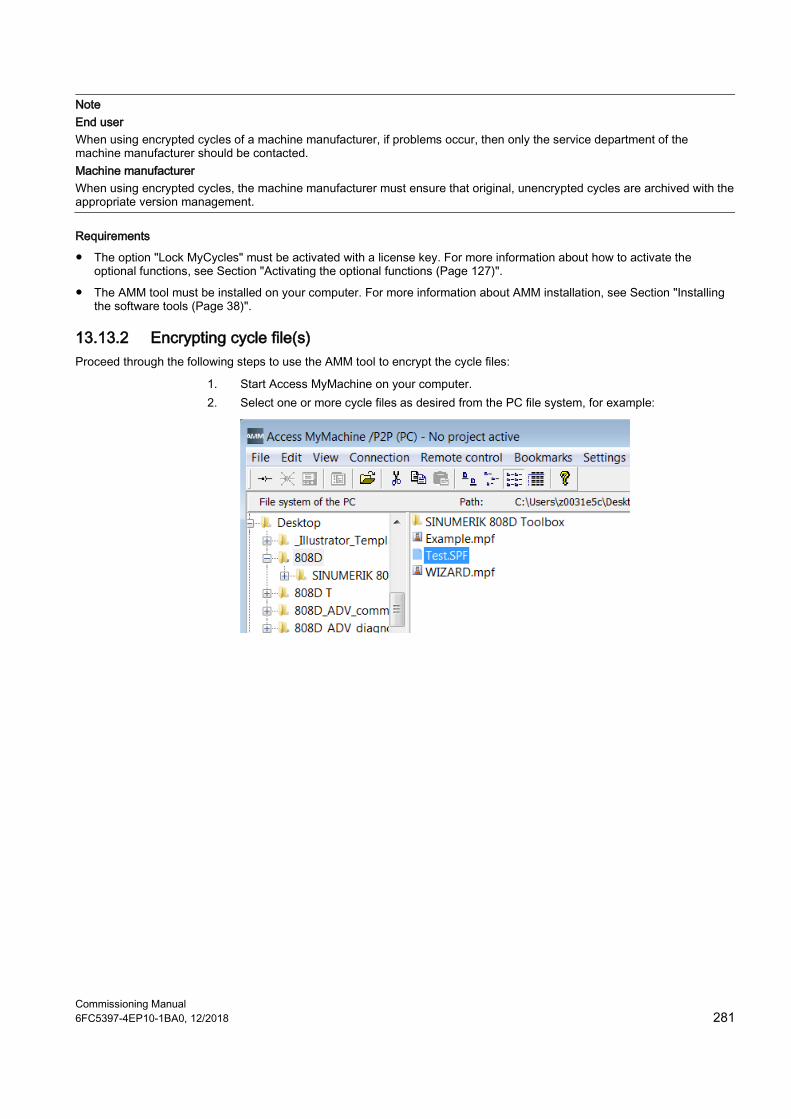
Commissioning Manual 6FC5397-4EP10-1BA0, 12/2018 281
Note End user When using encrypted cycles of a machine manufacturer, if problems occur, then only the service department of the machine manufacturer should be contacted. Machine manufacturer When using encrypted cycles, the machine manufacturer must ensure that original, unencrypted cycles are archived with the appropriate version management.
Requirements
● The option "Lock MyCycles" must be activated with a license key. For more information about how to activate the optional functions, see Section "Activating the optional functions (Page 127)".
● The AMM tool must be installed on your computer. For more information about AMM installation, see Section "Installing the software tools (Page 38)".
13.13.2 Encrypting cycle file(s) Proceed through the following steps to use the AMM tool to encrypt the cycle files:
1. Start Access MyMachine on your computer. 2. Select one or more cycle files as desired from the PC file system, for example:

Commissioning Manual 282 6FC5397-4EP10-1BA0, 12/2018
3. Right-click the file to open the context menu and select the cycle encrypting function as fol-lows:
Alternatively, you can select this function via the main menu:

Commissioning Manual 6FC5397-4EP10-1BA0, 12/2018 283
4. Select the desired encryption option from the following dialog box:
5. Click this button and the encryption process starts.
After the encryption process completes successfully, the following message appears and an encrypted cycle file is generated in the same directory as the original file. The name of the new created file is "Original file name.CPF".
13.13.3 Handling the encrypted cycles The machine manufacturer must transfer the encrypted cycles (.CPF files) to the control and perform a power-on reset before executing the encrytped cycles. If no power-on reset is performed, the processing of a .CPF file causes the NC alarm 15176.
An encrypted cycle can be deleted or unloaded just like an .SPF or .MPF file. All the encrypted .CPF files are also backed up when an archive is generated.
Executing an encrypted cycle
● An encrypted cycle cannot be directly selected for execution. It can only be called from a part program - or directly in MDI.
● An encrypted cycle cannot be executed with the external execution function.
Using encrypted cycles at one or more machines
● Using encrypted cycles at only one machine If a cycle must not be used at another machine, then it can be permanently linked to a particular machine. The machine data MD18030 $MN_HW_SERIAL_NUMBER can be used for this purpose. When the control powers on, the unique hardware serial number of the CF card is saved in this machine data. If a cycle is to be permanently linked to a machine, then the serial number of the CF card (MD18030) must be queried in the call of the cycle. If the cycle identifies a serial number that does not match, then an alarm can be output in the cycle and so prevents further processing. As the code of the cycle is encrypted, there is always a fixed link to a defined hardware.
● Using encrypted cycles at several machines If a cycle is to be permanently linked to several defined machines, then each of the hardware serial numbers must be entered in the cycle. The cycle must be re-encrypted with these hardware serial numbers.

Commissioning Manual 284 6FC5397-4EP10-1BA0, 12/2018
14 Customizing HMI display with EasyXLanguage scripts 14.1 Scope of functions The "Generate user dialogs" function offers an open structure and enables the user to develop customer-specific and application-specific user interfaces in the SINUMERIK 808D ADVANCED.
The control system offers an XML-based script language for generating user dialogs.
This script language makes it possible to display machine-specific menus and dialog forms in the user-defined operating area on the HMI.
All dialog forms can be designed on a language-neutral basis. In such cases, the system reads out the texts to be displayed from the accompanying language database.
Use
The defined XML instructions offer the following properties: ● Display dialogs containing the following elements:
– Softkeys – Variables – Texts and Help texts – Graphics and Help displays
● Call dialogs by performing the following operation: – Pressing the (start) softkeys
● Restructure dialogs dynamically by performing the following operations: – Editing and deleting softkeys – Defining and designing variable fields – Inserting, exchanging, and deleting display texts (language-dependent or language-neutral) – Inserting, exchanging, and deleting graphics
● Initiate operations in response to the following actions: – Displaying dialogs – Inputting values (variables) – Selecting a softkey – Exiting dialogs
● Exchange data between dialogs ● Operate variables as follows:
– Read (NC, PLC, and user variables) – Write (NC, PLC, and user variables) – Combine with mathematical, comparison, or logic operators
● Execute the following functions: – Subprograms – File functions – PI services
● Apply protection levels according to user classes
The valid elements (tags) for the script language are described in Section "XML identifier (Page 288)".
Note The following section is not intended as a comprehensive description of XML (Extensible Markup Language). Please refer to the relevant specialist literature for additional information.
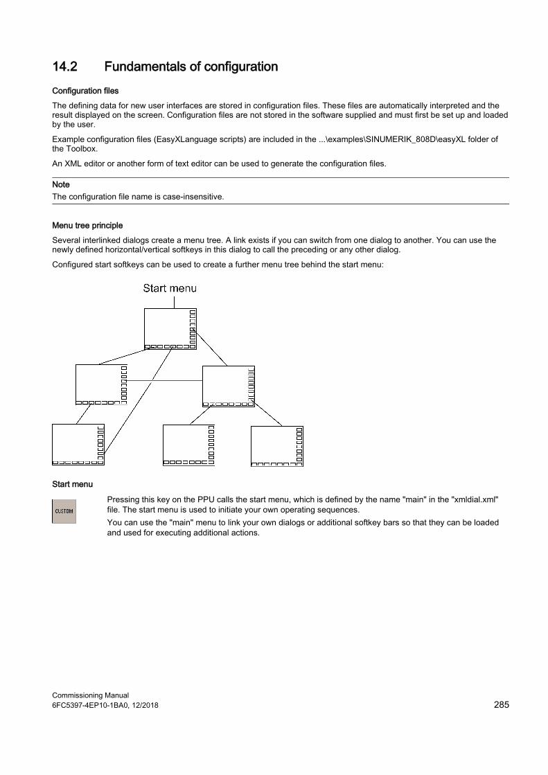
Commissioning Manual 6FC5397-4EP10-1BA0, 12/2018 285
14.2 Fundamentals of configuration
Configuration files
The defining data for new user interfaces are stored in configuration files. These files are automatically interpreted and the result displayed on the screen. Configuration files are not stored in the software supplied and must first be set up and loaded by the user.
Example configuration files (EasyXLanguage scripts) are included in the ...\examples\SINUMERIK_808D\easyXL folder of the Toolbox.
An XML editor or another form of text editor can be used to generate the configuration files.
Note The configuration file name is case-insensitive.
Menu tree principle
Several interlinked dialogs create a menu tree. A link exists if you can switch from one dialog to another. You can use the newly defined horizontal/vertical softkeys in this dialog to call the preceding or any other dialog.
Configured start softkeys can be used to create a further menu tree behind the start menu:
Start menu
Pressing this key on the PPU calls the start menu, which is defined by the name "main" in the "xmldial.xml" file. The start menu is used to initiate your own operating sequences. You can use the "main" menu to link your own dialogs or additional softkey bars so that they can be loaded and used for executing additional actions.
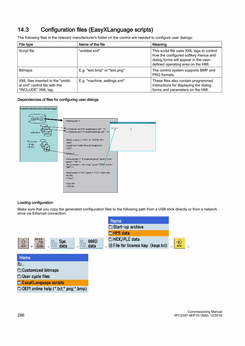
Commissioning Manual 286 6FC5397-4EP10-1BA0, 12/2018
14.3 Configuration files (EasyXLanguage scripts) The following files in the relevant manufacturer's folder on the control are needed to configure user dialogs:
File type Name of the file Meaning Script file "xmldial.xml" This script file uses XML tags to control
how the configured softkey menus and dialog forms will appear in the user-defined operating area on the HMI.
Bitmaps E.g. "text.bmp" or "text.png" The control system supports BMP and PNG formats.
XML files inserted in the "xmldi-al.xml" control file with the "INCLUDE" XML tag.
E.g. "machine_settings.xml" These files also contain programmed instructions for displaying the dialog forms and parameters on the HMI.
Dependencies of files for configuring user dialogs
Loading configuration
Make sure that you copy the generated configuration files to the following path from a USB stick directly or from a network drive via Ethernet connection:
+ → → → → →
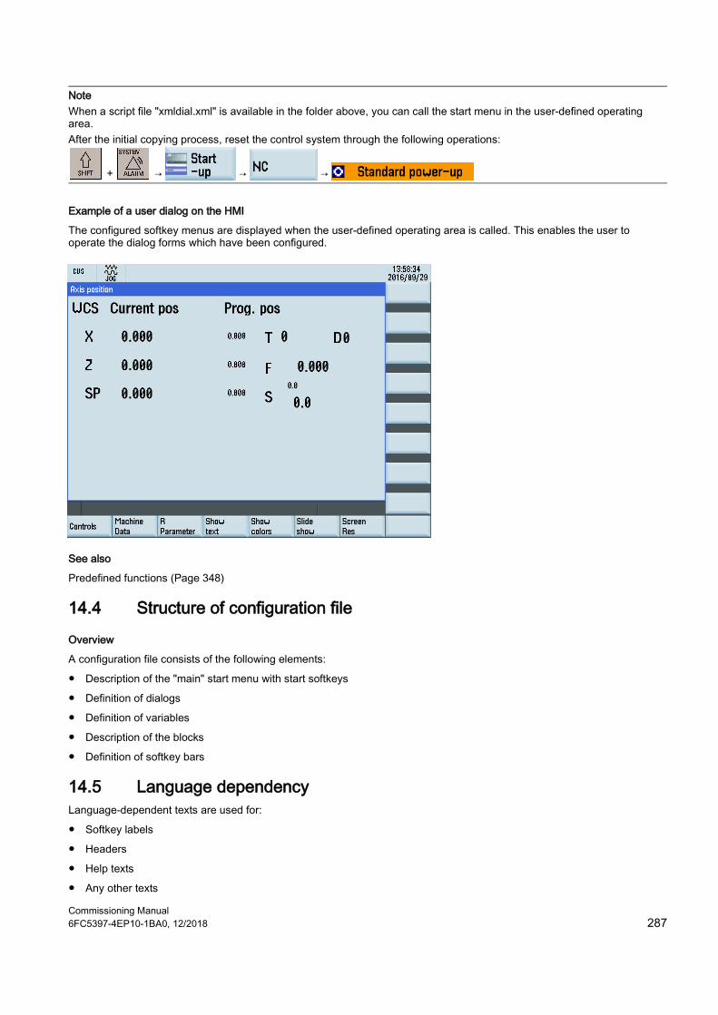
Commissioning Manual 6FC5397-4EP10-1BA0, 12/2018 287
Note When a script file "xmldial.xml" is available in the folder above, you can call the start menu in the user-defined operating area. After the initial copying process, reset the control system through the following operations:
+ → → →
Example of a user dialog on the HMI
The configured softkey menus are displayed when the user-defined operating area is called. This enables the user to operate the dialog forms which have been configured.
See also
Predefined functions (Page 348)
14.4 Structure of configuration file
Overview
A configuration file consists of the following elements:
● Description of the "main" start menu with start softkeys
● Definition of dialogs
● Definition of variables
● Description of the blocks
● Definition of softkey bars
14.5 Language dependency Language-dependent texts are used for:
● Softkey labels
● Headers
● Help texts
● Any other texts
Commissioning Manual 288 6FC5397-4EP10-1BA0, 12/2018
14.6 XML identifier
14.6.1 General structure
Structure and instructions of the script file for dialog configuration
All dialog configurations should be stored in the DialogGui tag. <DialogGui>
…
</DialogGui>
Example: <?xml version="1.0" encoding="utf-8"?>
<DialogGui>
…
<FORM name ="Hello_World">
<INIT>
<CAPTION>Hello World</CAPTION>
</INIT>
...
</FORM>
</DialogGui>
Instructions
The language offers the following instructions for executing conditional instructions and loop controls:
● For loop
● While loop
● Do while loop
● Conditional processing
● Switch and case instructions
● Operator controls in a dialog form
● Softkey descriptions
● Define variables
For a detailed description of instructions, see Instruction/identifier description (Page 288).
14.6.2 Instruction/identifier description The following XML tags are defined for generating dialogs and menus, and for executing program sequences:
Note Attribute values that are in quotation marks "<...>" should be replaced by the currently used expressions. Example: <DATA_LIST action="read/write/append" id="<list name>"> is programmed as follows: <DATA_LIST action="read/write/append" id="my datalist">
Tag identifier Meaning BREAK Conditional cancellation of a loop. CONTROL The tag is used to generate control elements.
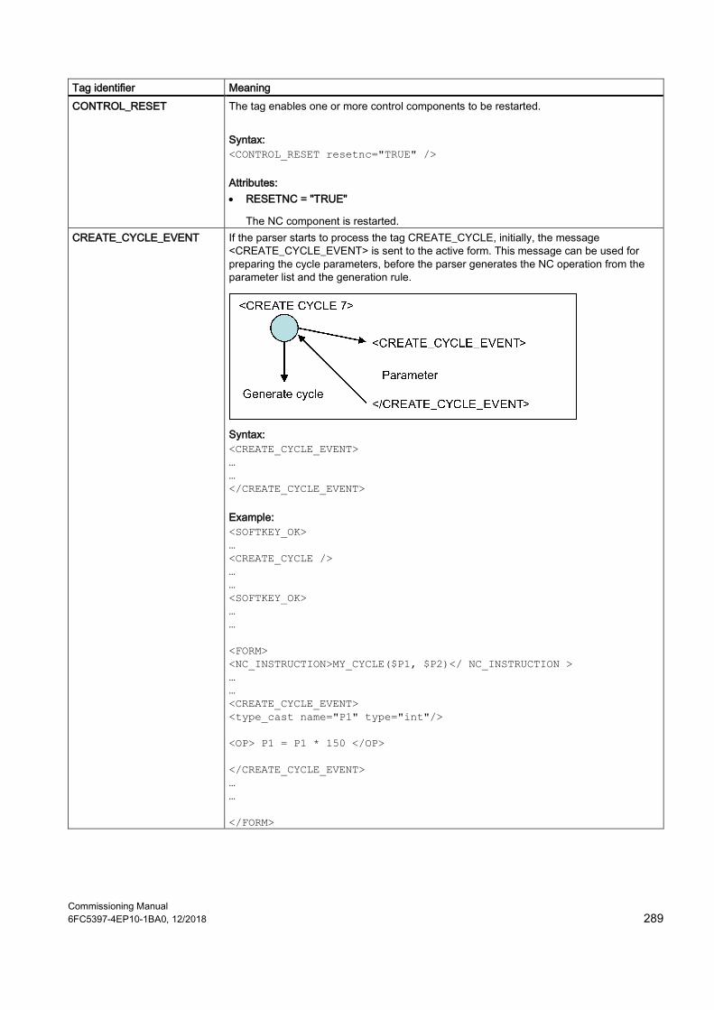
Commissioning Manual 6FC5397-4EP10-1BA0, 12/2018 289
Tag identifier Meaning CONTROL_RESET The tag enables one or more control components to be restarted.
Syntax: <CONTROL_RESET resetnc="TRUE" />
Attributes: • RESETNC = "TRUE"
The NC component is restarted. CREATE_CYCLE_EVENT If the parser starts to process the tag CREATE_CYCLE, initially, the message
<CREATE_CYCLE_EVENT> is sent to the active form. This message can be used for preparing the cycle parameters, before the parser generates the NC operation from the parameter list and the generation rule.
Syntax: <CREATE_CYCLE_EVENT> … … </CREATE_CYCLE_EVENT>
Example: <SOFTKEY_OK> … <CREATE_CYCLE /> … … <SOFTKEY_OK> … … <FORM> <NC_INSTRUCTION>MY_CYCLE($P1, $P2)</ NC_INSTRUCTION > … … <CREATE_CYCLE_EVENT> <type_cast name="P1" type="int"/> <OP> P1 = P1 * 150 </OP> </CREATE_CYCLE_EVENT> … … </FORM>
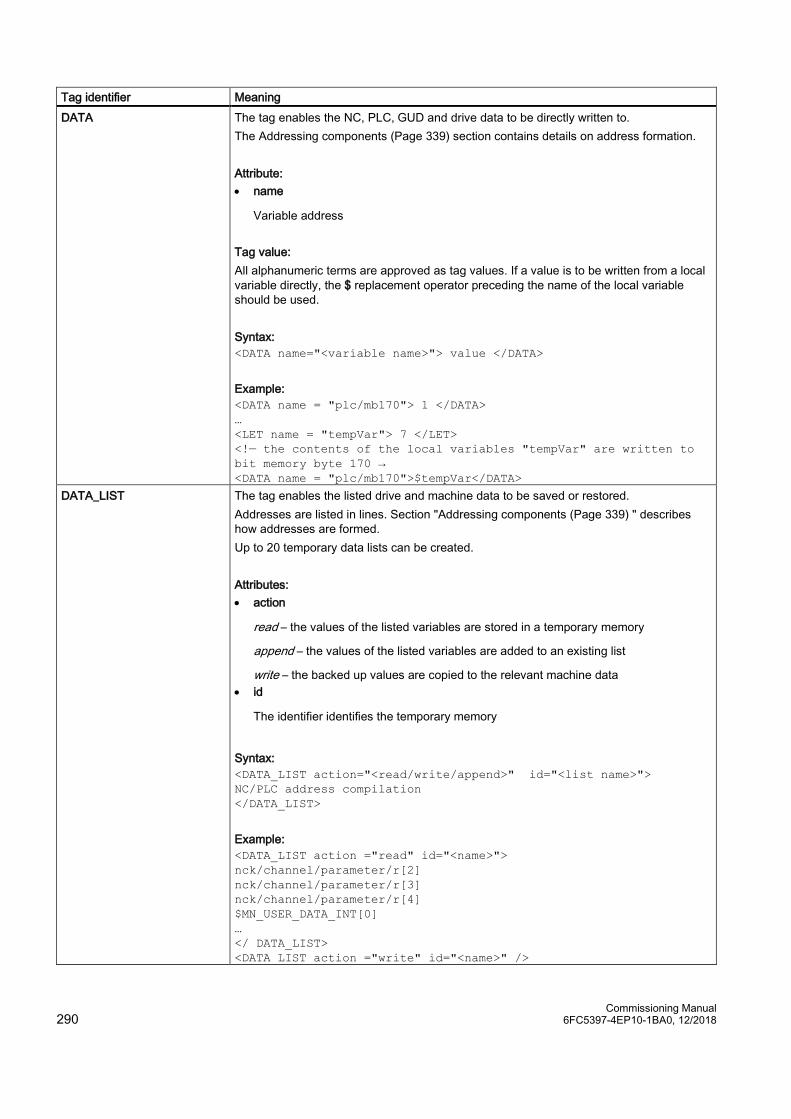
Commissioning Manual 290 6FC5397-4EP10-1BA0, 12/2018
Tag identifier Meaning DATA The tag enables the NC, PLC, GUD and drive data to be directly written to.
The Addressing components (Page 339) section contains details on address formation. Attribute: • name
Variable address Tag value: All alphanumeric terms are approved as tag values. If a value is to be written from a local variable directly, the $ replacement operator preceding the name of the local variable should be used. Syntax: <DATA name="<variable name>"> value </DATA>
Example: <DATA name = "plc/mb170"> 1 </DATA> … <LET name = "tempVar"> 7 </LET> <!— the contents of the local variables "tempVar" are written to bit memory byte 170 → <DATA name = "plc/mb170">$tempVar</DATA>
DATA_LIST The tag enables the listed drive and machine data to be saved or restored. Addresses are listed in lines. Section "Addressing components (Page 339) " describes how addresses are formed. Up to 20 temporary data lists can be created. Attributes: • action
read – the values of the listed variables are stored in a temporary memory
append – the values of the listed variables are added to an existing list
write – the backed up values are copied to the relevant machine data • id
The identifier identifies the temporary memory
Syntax: <DATA_LIST action="<read/write/append>" id="<list name>"> NC/PLC address compilation </DATA_LIST>
Example: <DATA_LIST action ="read" id="<name>"> nck/channel/parameter/r[2] nck/channel/parameter/r[3] nck/channel/parameter/r[4] $MN_USER_DATA_INT[0] … </ DATA_LIST> <DATA_LIST action ="write" id="<name>" />

Commissioning Manual 6FC5397-4EP10-1BA0, 12/2018 291
Tag identifier Meaning DO_WHILE Do while loop
DO Instructions WHILE (Test)
Syntax: <DO_WHILE> Instructions … <CONDITION>…</CONDITION> </DO_WHILE>
The Do while loop comprises a block of instructions and a condition. The code in the instruction block is executed first, then the condition is applied. If the condition is true, the function executes the code section again. This is continually repeated until the condition is false. Example: <DO_WHILE> <DATA name = "PLC/qb11"> 15 </DATA> <CONDITIION> "plc/ib9" == 0 </CONDITION> </DO_WHILE>
DYNAMIC_INCLUDE The tag includes an XML script file. Contrary to the INCLUDE tag, read-in is first only realized when executing the corre-sponding operation. For large projects, the use of the tag reduces the load time of the customer area and/or the cycle support. Further, the average level of resources is reduced, as not all of the dialogs are always called during a session. Syntax: <DYNAMIC_INCLUDE src="path name"/> Example: <SOFTKEY POSITION="3"> <CAPTION>MY_MENU</CAPTION> <DYNAMIC_INCLUDE src/> <NAVIGATION>MY_MENU</NAVIGATION>
</SOFTKEY> ELSE Instruction for situations where the condition has not been met (IF, THEN, ELSE)
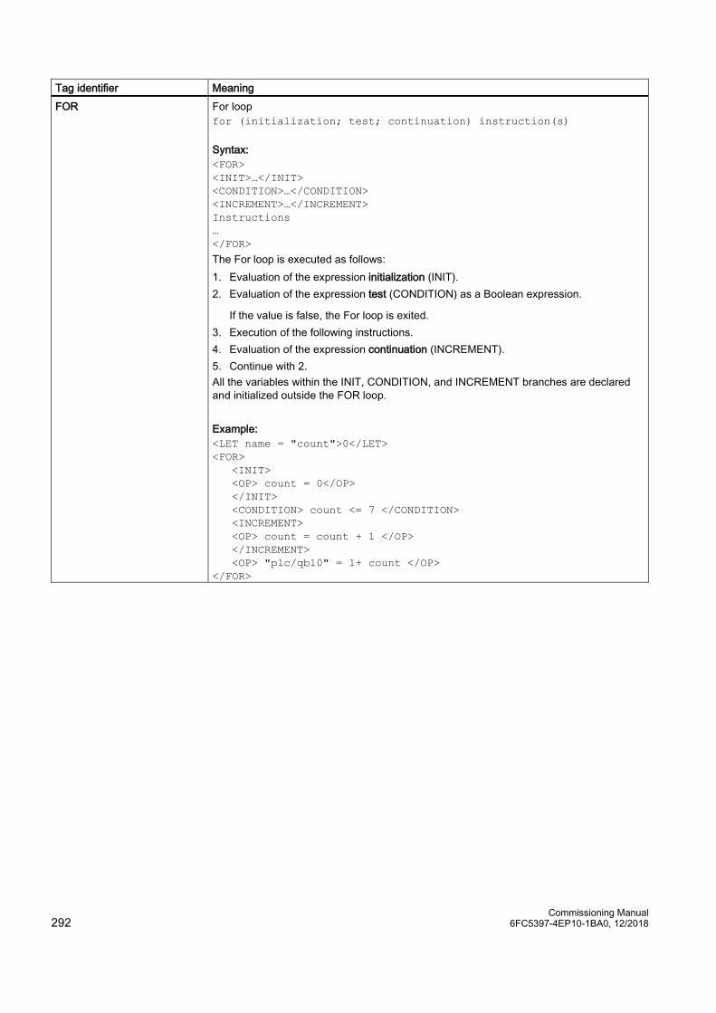
Commissioning Manual 292 6FC5397-4EP10-1BA0, 12/2018
Tag identifier Meaning FOR For loop
for (initialization; test; continuation) instruction(s)
Syntax: <FOR> <INIT>…</INIT> <CONDITION>…</CONDITION> <INCREMENT>…</INCREMENT> Instructions … </FOR>
The For loop is executed as follows: 1. Evaluation of the expression initialization (INIT). 2. Evaluation of the expression test (CONDITION) as a Boolean expression.
If the value is false, the For loop is exited. 3. Execution of the following instructions. 4. Evaluation of the expression continuation (INCREMENT). 5. Continue with 2. All the variables within the INIT, CONDITION, and INCREMENT branches are declared and initialized outside the FOR loop. Example: <LET name = "count">0</LET> <FOR> <INIT> <OP> count = 0</OP> </INIT> <CONDITION> count <= 7 </CONDITION> <INCREMENT> <OP> count = count + 1 </OP> </INCREMENT> <OP> "plc/qb10" = 1+ count </OP> </FOR>

Commissioning Manual 6FC5397-4EP10-1BA0, 12/2018 293
Tag identifier Meaning FORM The tag contains the description of a user dialog. The relevant tags are described in the
section on generating menus and dialog forms. Syntax: <FORM name="<dialog name>" color="#ff0000">
Attributes: • color
Background color of the dialog form (color coding, see Section "Color coding (Page 309)") – Default white
• name
Identifier of the form • type
Permissible value is cycle , which identifies a user cycle screen form • xpos
X-position of the top left corner of the dialog box (optional) • ypos
Y position of the top left corner (optional) • width
Extension in the X direction (in pixels) (optional) • height
Extension in the Y direction (in pixels) (optional) FORM Continued Attributes:
• truetypefont
Whether the font of the dialog form is of the true type (optional) Values: • true
The font of the dialog form is of the true type regardless of the value of machine data MD1113
• false
The font of the dialog form is set via bit 0 of MD1113 (default) – Bit 0 = 0: the fixed type font is used for text display (default) – Bit 0 = 1: the true type font is used for text display
Example: <FORM name="dialog name" truetypefont="true"> … … … </form>

Commissioning Manual 294 6FC5397-4EP10-1BA0, 12/2018
Tag identifier Meaning FORM Continued You can define how the images in a form will be displayed on the screen with a resolution
of 800x600 pixels, that is, adapt the image size to the screen, by setting bit 1 of MD1113. Precondition: This function is applicable only when the script file is copied to the control system with a screen resolution of 800x600 pixels. Values: • Bit 1 = 0: the image is automatically scaled up by a factor of 1.25 (default) • Bit 1 = 1: the original image size is kept without automatic scaling
IF Conditional instruction (IF, THEN, ELSE) The THEN and ELSE tags are enclosed in the IF tag. The condition that is executed in the CONDITION tag follows the IF tag. The further pro-cessing of the instructions depends upon the result of the operation. If the function result is true, then the THEN branch is executed and the ELSE branch is skipped. If the result of the function is false, the parser executes the ELSE branch. Syntax: <IF> <CONDITION> Condition != 7 </CONDITION> <THEN> Instruction for the case: Condition fulfilled </THEN> <ELSE> Instruction for the case: Condition not fulfilled </ELSE> </IF>
Or simplified as follows (cannot be used for addresses that require quotation marks): <IF CONDITION>="Condition != 7"> <THEN> Instruction for the case: Condition fulfilled </THEN> <ELSE> Instruction for the case: Condition not fulfilled </ELSE> </IF>
Example: <IF> <CONDITION> "plc/mb170" != 7 </CONDITION> <THEN> <OP> "plc/mb170" = 7 </OP> … </THEN> <ELSE> <OP> "plc/mb170" = 2 </OP> … </ELSE> </IF>
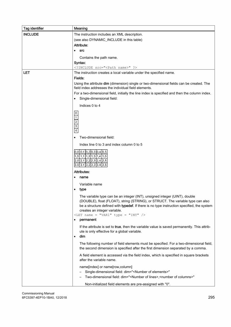
Commissioning Manual 6FC5397-4EP10-1BA0, 12/2018 295
Tag identifier Meaning INCLUDE The instruction includes an XML description.
(see also DYNAMIC_INCLUDE in this table) Attribute: • src
Contains the path name. Syntax: <?INCLUDE src="<Path name>" ?>
LET The instruction creates a local variable under the specified name. Fields: Using the attribute dim (dimension) single or two-dimensional fields can be created. The field index addresses the individual field elements. For a two-dimensional field, initially the line index is specified and then the column index. • Single-dimensional field:
Indices 0 to 4
• Two-dimensional field:
Index line 0 to 3 and index column 0 to 5
Attributes: • name
Variable name • type
The variable type can be an integer (INT), unsigned integer (UINT), double (DOUBLE), float (FLOAT), string (STRING), or STRUCT. The variable type can also be a structure defined with typedef. If there is no type instruction specified, the system creates an integer variable.
<LET name = "VAR1" type = "INT" /> • permanent
If the attribute is set to true, then the variable value is saved permanently. This attrib-ute is only effective for a global variable.
• dim
The following number of field elements must be specified. For a two-dimensional field, the second dimension is specified after the first dimension separated by a comma.
A field element is accessed via the field index, which is specified in square brackets after the variable name.
name[index] or name[row,column] – Single-dimensional field: dim="<Number of elements>" – Two-dimensional field: dim="<Number of lines>,<number of columns>"
Non-initialized field elements are pre-assigned with "0".
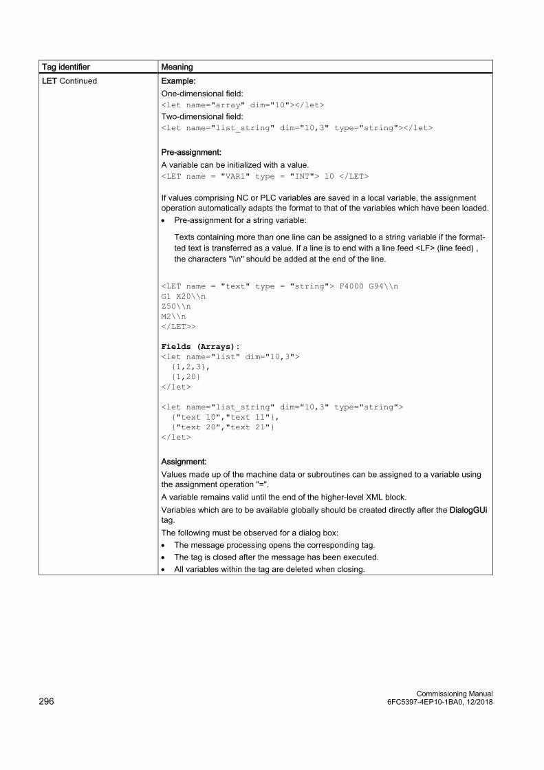
Commissioning Manual 296 6FC5397-4EP10-1BA0, 12/2018
Tag identifier Meaning LET Continued Example:
One-dimensional field: <let name="array" dim="10"></let>
Two-dimensional field: <let name="list_string" dim="10,3" type="string"></let>
Pre-assignment: A variable can be initialized with a value. <LET name = "VAR1" type = "INT"> 10 </LET>
If values comprising NC or PLC variables are saved in a local variable, the assignment operation automatically adapts the format to that of the variables which have been loaded. • Pre-assignment for a string variable:
Texts containing more than one line can be assigned to a string variable if the format-ted text is transferred as a value. If a line is to end with a line feed <LF> (line feed) , the characters "\\n" should be added at the end of the line.
<LET name = "text" type = "string"> F4000 G94\\n G1 X20\\n Z50\\n M2\\n </LET>> Fields (Arrays): <let name="list" dim="10,3"> {1,2,3}, {1,20} </let> <let name="list_string" dim="10,3" type="string"> {"text 10","text 11"}, {"text 20","text 21"} </let>
Assignment: Values made up of the machine data or subroutines can be assigned to a variable using the assignment operation "=". A variable remains valid until the end of the higher-level XML block. Variables which are to be available globally should be created directly after the DialogGUi tag. The following must be observed for a dialog box: • The message processing opens the corresponding tag. • The tag is closed after the message has been executed. • All variables within the tag are deleted when closing.

Commissioning Manual 6FC5397-4EP10-1BA0, 12/2018 297
Tag identifier Meaning LET Continued Variable type struct:
This variable type contains a composition of variables that can be addressed using the structure name. A structure can contain all variable types and structures. Within the structure, a variable is declared with the "element" tag. The attributes of the tags and the initialization correspond to the attributes and initialization of the let instruc-tion. <let name="name" type="struct"> <element name="<Name>" type="<Variable type>" /> … … … </let>
LET Continued Access to a variable of the structure is via the structure name and variable name. Both names are separated by a point operator. <op> Structure_name.variable_name = value; </op> Example: <let name="info" type="struct"> <element name="id" type="int" /> <element name="name" type="string" /> <element name="phone" type="string" /> </let> <op> info.id = 1; info.name = _T"my name"; info.phone = _T"0034 45634"; </op> Initialization of structures: Structures can be initialized when the variables are created by specifying an initial value for each structure element. In an array of structures, each structure must be separated from the others by braces.
MSG The operator component shows the message which is indicated in the tag. Example: <MSG text ="my message" />

Commissioning Manual 298 6FC5397-4EP10-1BA0, 12/2018
Tag identifier Meaning MSGBOX The instruction opens a message box whose return value can be used for branching.
Syntax: <MSGBOX text="<Message>" caption="<caption>" retvalue="<variable name>" type="<button type>" />
Attributes: • text
Text • retvalue
Name of the variables to which the return value is copied:
1 – OK
0 – CANCEL • type
Acknowledgment options:
"BTN_OK"
"BTN_CANCEL"
"BTN_OKCANCEL" Example: <MSGBOX text="Test message" retvalue="result" type="BTN_OK" />
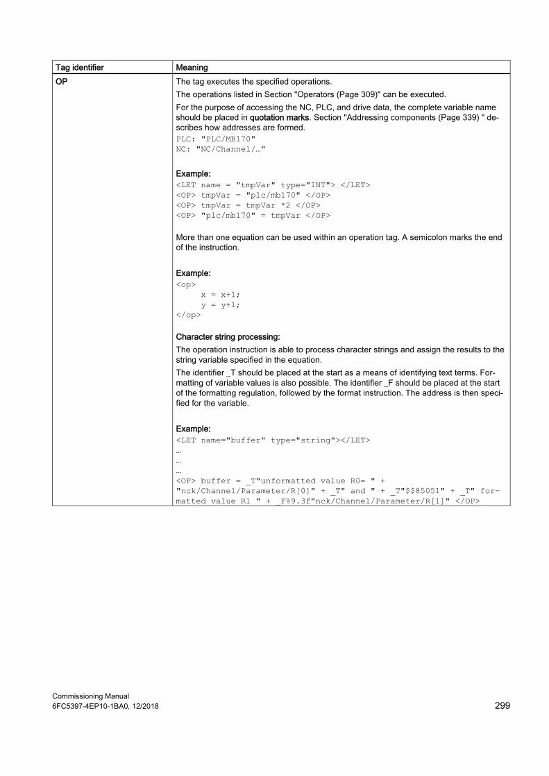
Commissioning Manual 6FC5397-4EP10-1BA0, 12/2018 299
Tag identifier Meaning OP The tag executes the specified operations.
The operations listed in Section "Operators (Page 309)" can be executed. For the purpose of accessing the NC, PLC, and drive data, the complete variable name should be placed in quotation marks. Section "Addressing components (Page 339) " de-scribes how addresses are formed. PLC: "PLC/MB170" NC: "NC/Channel/…"
Example: <LET name = "tmpVar" type="INT"> </LET> <OP> tmpVar = "plc/mb170" </OP> <OP> tmpVar = tmpVar *2 </OP> <OP> "plc/mb170" = tmpVar </OP>
More than one equation can be used within an operation tag. A semicolon marks the end of the instruction. Example: <op> x = x+1; y = y+1; </op>
Character string processing: The operation instruction is able to process character strings and assign the results to the string variable specified in the equation. The identifier _T should be placed at the start as a means of identifying text terms. For-matting of variable values is also possible. The identifier _F should be placed at the start of the formatting regulation, followed by the format instruction. The address is then speci-fied for the variable. Example: <LET name="buffer" type="string"></LET> … … … <OP> buffer = _T"unformatted value R0= " + "nck/Channel/Parameter/R[0]" + _T" and " + _T"$$85051" + _T" for-matted value R1 " + _F%9.3f"nck/Channel/Parameter/R[1]" </OP>
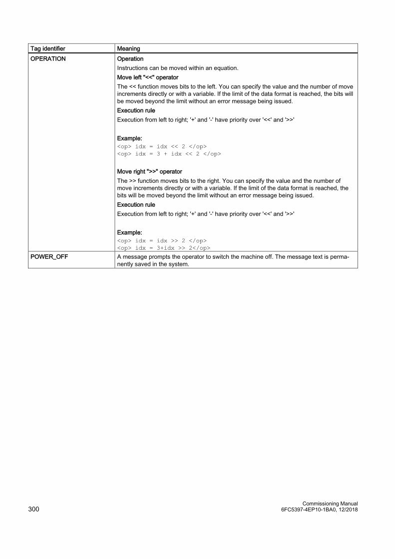
Commissioning Manual 300 6FC5397-4EP10-1BA0, 12/2018
Tag identifier Meaning OPERATION Operation
Instructions can be moved within an equation. Move left "<<" operator The << function moves bits to the left. You can specify the value and the number of move increments directly or with a variable. If the limit of the data format is reached, the bits will be moved beyond the limit without an error message being issued. Execution rule Execution from left to right; '+' and '-' have priority over '<<' and '>>' Example: <op> idx = idx << 2 </op> <op> idx = 3 + idx << 2 </op>
Move right ">>" operator The >> function moves bits to the right. You can specify the value and the number of move increments directly or with a variable. If the limit of the data format is reached, the bits will be moved beyond the limit without an error message being issued. Execution rule Execution from left to right; '+' and '-' have priority over '<<' and '>>' Example: <op> idx = idx >> 2 </op> <op> idx = 3+idx >> 2</op>
POWER_OFF A message prompts the operator to switch the machine off. The message text is perma-nently saved in the system.

Commissioning Manual 6FC5397-4EP10-1BA0, 12/2018 301
Tag identifier Meaning PRINT The tag outputs a text in the dialog line or copies the text to the variable specified.
If the text contains formatting identifiers, the variable values are inserted at the appropri-ate places. Syntax: <PRINT name="Variable name " text="text %Formatting "> Variable, … </PRINT> <PRINT text="text %Formatting"> Variable, … </PRINT>
Attributes: • name
Name of the variable where the text is to be stored (optional) • text
Text Formatting: The character "%" causes the variable specified as the value to be formatted. %[Flags] [Width] [.decimal places] type • Flags:
Optional character for defining output formatting: – Right-justified or left-justified ("-") for left-justified – Add leading zeros ("0") – Fill with blanks
• Width: The argument defines the minimum output width for a non-negative number. If the value to be output has fewer places than the argument defined, the missing spaces are filled with blanks.
• Decimal places: With floating-point numbers, the optional parameter defines the number of decimal places.
• Type: The type character defines which data formats are transferred for the print instruction. These characters need to be specified. – d: Integer value – f: Floating-point number – s: String
PRINT Continued Values: Number of variables whose values are to be inserted into the text. The variable types must match the corresponding type identifier for the formatting instruc-tion and must be separated from one another with a comma. Example: Output of a text in the information line <PRINT text="Infotext" />
Output of a text with variable formatting <LET name="trun_dir"></LET> <PRINT text="M%d">trun_dir</PRINT>
Output of a text in a string variable with variable formatting <LET name="trun_dir"></LET> <LET name="str" type="string" ></LET> <print name="str" text="M%d ">trun_dir</print>

Commissioning Manual 302 6FC5397-4EP10-1BA0, 12/2018
Tag identifier Meaning PROGRESS_BAR The tag opens or closes a progress bar. The bar is displayed below the application win-
dow. Syntax: <PROGRESS_BAR type="<true/false>"> value </ PROGRESS_BAR>
Attributes: • type = "TRUE" - opens the progress bar • type = "FALSE" - closes the progress bar • min
(optional) – minimum value • max
(optional) – maximum value Value: • Value
Percentage position of the bar
Example: <PROGRESS_BAR type="true" min="0" max="101" >20< /PROGRESS_BAR>......<PROGRESS_BAR >50< /PROGRESS_BAR>......<PROGRESS_BAR type="false" >100< /PROGRESS_BAR>
SEND_MESSAGE The tag sends a message with two parameters to the active form, which is processed in the tag message. Syntax: <SEND_MESSAGE>p1, p2</SEND_MESSAGE>
Example: <SOFTKEY POSITION="3"> <caption>Set%nParameter</caption> <send_message>1, 0</send_message> </SOFTKEY> <FORM> … … <MESSAGE> <SWITCH> <CONDITION>$message_par1</CONDITION> <CASE value="1"> … … </CASE> </SWITCH> </MESSAGE> … … </FORM>
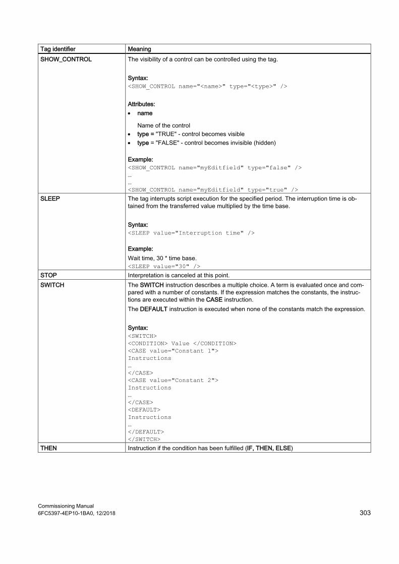
Commissioning Manual 6FC5397-4EP10-1BA0, 12/2018 303
Tag identifier Meaning SHOW_CONTROL The visibility of a control can be controlled using the tag.
Syntax: <SHOW_CONTROL name="<name>" type="<type>" />
Attributes: • name
Name of the control • type = "TRUE" - control becomes visible • type = "FALSE" - control becomes invisible (hidden) Example: <SHOW_CONTROL name="myEditfield" type="false" /> … … <SHOW_CONTROL name="myEditfield" type="true" />
SLEEP The tag interrupts script execution for the specified period. The interruption time is ob-tained from the transferred value multiplied by the time base. Syntax: <SLEEP value="Interruption time" />
Example: Wait time, 30 * time base. <SLEEP value="30" />
STOP Interpretation is canceled at this point. SWITCH The SWITCH instruction describes a multiple choice. A term is evaluated once and com-
pared with a number of constants. If the expression matches the constants, the instruc-tions are executed within the CASE instruction. The DEFAULT instruction is executed when none of the constants match the expression. Syntax: <SWITCH> <CONDITION> Value </CONDITION> <CASE value="Constant 1"> Instructions … </CASE> <CASE value="Constant 2"> Instructions … </CASE> <DEFAULT> Instructions … </DEFAULT> </SWITCH>
THEN Instruction if the condition has been fulfilled (IF, THEN, ELSE)
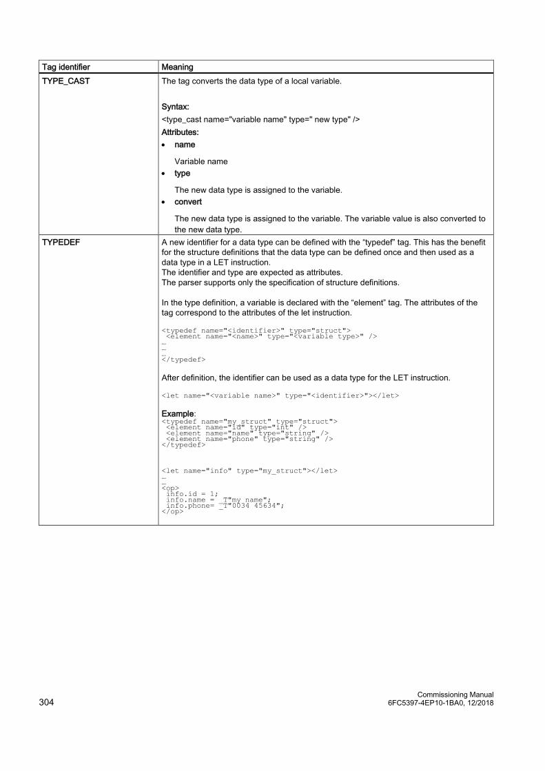
Commissioning Manual 304 6FC5397-4EP10-1BA0, 12/2018
Tag identifier Meaning TYPE_CAST The tag converts the data type of a local variable.
Syntax: <type_cast name="variable name" type=" new type" /> Attributes: • name
Variable name • type
The new data type is assigned to the variable. • convert
The new data type is assigned to the variable. The variable value is also converted to the new data type.
TYPEDEF A new identifier for a data type can be defined with the “typedef” tag. This has the benefit for the structure definitions that the data type can be defined once and then used as a data type in a LET instruction. The identifier and type are expected as attributes. The parser supports only the specification of structure definitions. In the type definition, a variable is declared with the “element” tag. The attributes of the tag correspond to the attributes of the let instruction. <typedef name="<identifier>" type="struct"> <element name="<name>" type="<variable type>" /> … … … </typedef> After definition, the identifier can be used as a data type for the LET instruction. <let name="<variable name>" type="<identifier>"></let> Example: <typedef name="my_struct" type="struct"> <element name="id" type="int" /> <element name="name" type="string" /> <element name="phone" type="string" /> </typedef> <let name="info" type="my_struct"></let> … … <op> info.id = 1; info.name = _T"my name"; info.phone= _T"0034 45634"; </op>

Commissioning Manual 6FC5397-4EP10-1BA0, 12/2018 305
Tag identifier Meaning TYPEDEF Continued Some predefined functions expect variables of structure type RECT, POINT, or SIZE as
the call parameter. These structures are defined in the file struct_def.xml. RECT: <typedef name="StructRect" type="struct" > <element name="left" type="int">0</element> <element name="top" type="int">0</element> <element name="right" type="int">0</element> <element name="bottom" type="int">0</element> </typedef>
POINT: <typedef name="StructPoint" type="struct" > <element name="x" type="int">0</element> <element name="y" type="int">0</element> </typedef>
SIZE: <typedef name="StructSize" type="struct" > <element name="width" type="int">0</element> <element name="height" type="int">0</element> </typedef>
WAITING The tag waits for the component to undergo a hot restart after an NC or drive reset. Attributes: • WAITINGFORNC = "TRUE" - the system waits for the NC to restart Syntax: <WAITING WAITINGFORNC = "TRUE"/>
Example: ... <CONTROL_RESET resetnc = "true"/> <WAITING waitingfornc = "true"/>
... WHILE WHILE loop
WHILE (Test) Instruction
Syntax: <WHILE> <CONDITION>…</CONDITION> Instructions … </WHILE>
The While loop executes a sequence of instructions repeatedly while a condition is met. This condition is tested before the sequence of instructions is executed. Example: <WHILE> <CONDITION> "plc/ib9" == 0 </CONDITION> <DATA name = "PLC/qb11"> 15 </DATA> </WHILE>

Commissioning Manual 306 6FC5397-4EP10-1BA0, 12/2018
Tag identifier Meaning XML_PARSER The “XML_PARSER” tag can be used to parse XML files.
The parser interprets an XML file and calls defined call-back functions. Each call-back function belongs to a predefined event. The programmer can process the XML data within this function. Predefined events: • start document
The parser opens the document and starts parsing. • end document
The parser closes the document. • start element
The parser has found an element and creates a list with all attributes and attribute val-ues.
These lists are forwarded to the call-back function. • end element
The end of the element has been found. • characters
The parser forwards all characters of an element. • error
The parser has detected a syntax error. When an event occurs, the parser calls the call-back function and checks the function return value. If the function returns "true," the parser continues the process. Interfaces The value of the name attribute contains the path to the XML file. To assign events to the call-back functions, the following properties must be specified: Standard startElementHandler endElementHandler charactersHandler Optional errorHandler documentHandler The value of an attribute defines the name of the call-back function. Example: <XML_PARSER name="f:\appl\xml_test.xml"> <!-- standard handler --> <property startElementHandler="startElementHandler" /> <property endElementHandler="endElementHandler" /> <property charactersHandler="charactersHandler" /> <!-- optional handler --> <property errorHandler="errorHandler" /> <property documentHandler="documentHandler" /> </XML_PARSER>

Commissioning Manual 6FC5397-4EP10-1BA0, 12/2018 307
Tag identifier Meaning XML_PARSER Continued The parser also supplies variables so that the call-back functions can access the event
data. startElementHandler: Function parameters tag_name - tag name num - number of attributes found System variables $xmlAttribute String array that contains the 0-num attribute name range. $xmlValue String array that contains the 0-num attribute value range. Example: <function_body name="startElementHandler" return="true" parameter="tag_name, num"> <print text="attribute name %s"> $xmlAttribute[0]</print> <print text="attribute value %s"> $xmlValue [0]</print> </function_body>
endElementHandler: Function parameters tag_name - tag name Example: <function_body name="endElementHandler" parameter="tag_name"> <print text="name %s"> tag_name </print> </function_body>

Commissioning Manual 308 6FC5397-4EP10-1BA0, 12/2018
Tag identifier Meaning XML_PARSER Continued charactersHandler:
System variables $xmlCharacters String with data $xmlCharactersStart Always 0 $xmlCharactersLength Number of bytes Example: <function_body name="charactersHandler" return="true" > <print text="chars %s"> $xmlCharacters </print> </function_body>
documentHandler: Function parameters state 1 start document, 2 end document errorHandler: System variables $xmlErrorString Contains the invalid line (system variable) Example: <function_body name="errorHandler" > <print text="error %s">$xmlErrorString</print> </function_body>
Call-back result: $return If 1 (true), the parser continues parsing the file
14.6.3 System variables The system variables can be used in the EasyXLanguage scripts for the data exchange between a script parser and a program flow.
The table below provides the automatically created system variables that can be used in the relevant tags.
System variable Description Tags where valid $actionresult Notifies a script parser of whether the event can be execut-
ed KEY_EVENT
$focus_name $focus_item_data
Contains the name of the control that has the input focus Contains the numeric value of item_data, which was as-signed to the control
FOCUS_IN INDEX_CHANGED EDIT_CHANGED
$return Transfers the return values of a subfunction FUNCTION_BODY $message_par1 $message_par2
Contains the parameters for calling the SEND_MESSAGE function
MESSAGE
$keycode $actionresult
Contains the key codes with executable scripts
KEY_EVENT
$xmlAttribute $xmlValue $xmlCharacters $xmlCharactersStart $xmlCharactersLength
Contains the attribute list of the obtained variables Contains the value list of the obtained variables Contains the data stream Contains the start index Contains the number of characters saved in a data stream
XML_PARSER - startEl-ementHandler XML_PARSER - character-sHandler
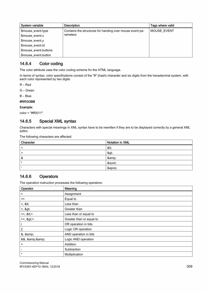
Commissioning Manual 6FC5397-4EP10-1BA0, 12/2018 309
System variable Description Tags where valid $mouse_event.type $mouse_event.x $mouse_event.y $mouse_event.id $mouse_event.buttons $mouse_event.button
Contains the structures for handing over mouse event pa-rameters
MOUSE_EVENT
14.6.4 Color coding The color attribute uses the color coding scheme for the HTML language.
In terms of syntax, color specifications consist of the "#" (hash) character and six digits from the hexadecimal system, with each color represented by two digits.
R – Red
G – Green
B – Blue
#RRGGBB
Example:
color = "#ff0011"
14.6.5 Special XML syntax Characters with special meanings in XML syntax have to be rewritten if they are to be displayed correctly by a general XML editor.
The following characters are affected:
Character Notation in XML < < > > & & " " ' '
14.6.6 Operators The operation instruction processes the following operators:
Operator Meaning = Assignment == Equal to <, < Less than >, > Greater than <=, <= Less than or equal to >=, >= Greater than or equal to | OR operation in bits || Logic OR operation &, & AND operation in bits &&, && Logic AND operation + Addition - Subtraction * Multiplication
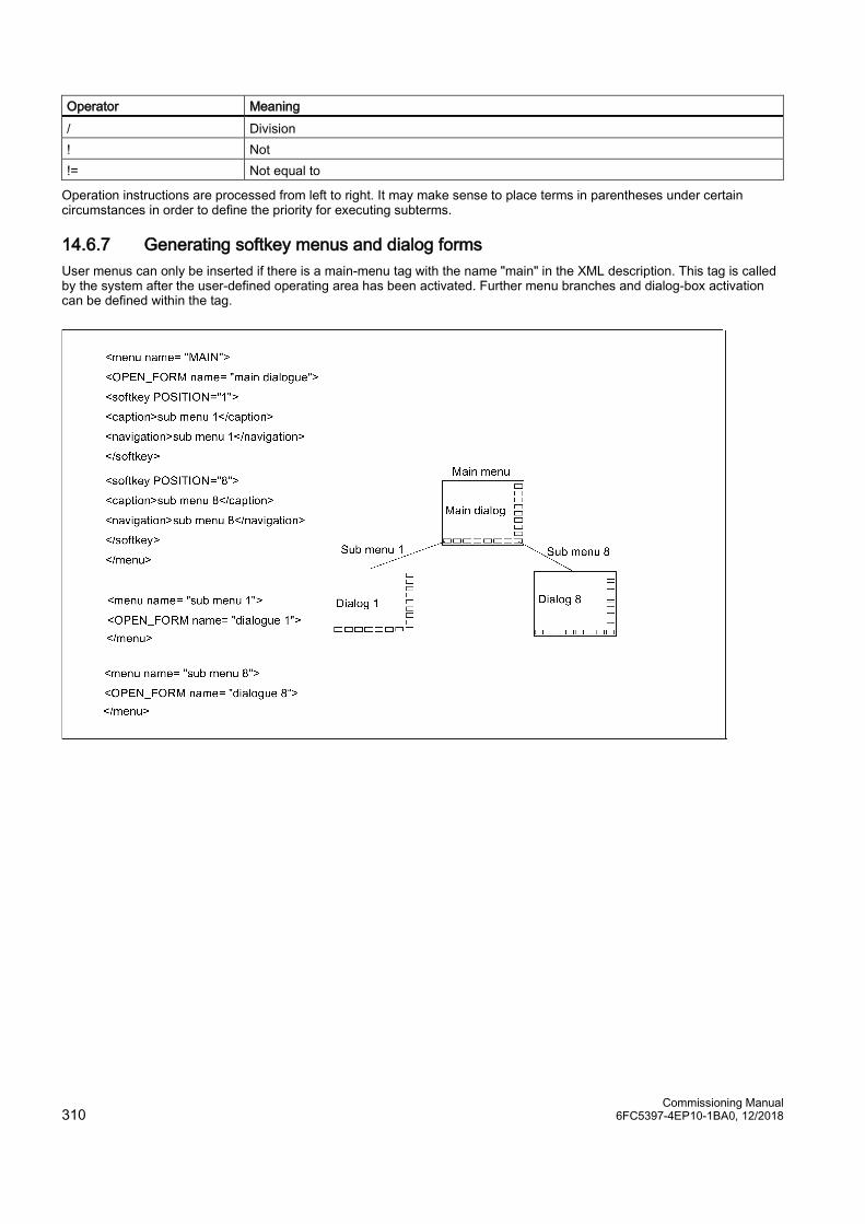
Commissioning Manual 310 6FC5397-4EP10-1BA0, 12/2018
Operator Meaning / Division ! Not != Not equal to
Operation instructions are processed from left to right. It may make sense to place terms in parentheses under certain circumstances in order to define the priority for executing subterms.
14.6.7 Generating softkey menus and dialog forms User menus can only be inserted if there is a main-menu tag with the name "main" in the XML description. This tag is called by the system after the user-defined operating area has been activated. Further menu branches and dialog-box activation can be defined within the tag.
Commissioning Manual 6FC5397-4EP10-1BA0, 12/2018 311
Tag identifier Meaning FORM This tag contains the description of a user dialog.
Attributes: • color
Background color of the dialog box (for color coding, see Section "Color coding (Page 309)")
• name
Identifier of the form • type
cycle -attribute specifies a cycle form • xpos
X-position of the top left corner of the dialog box (optional) • ypos
Y position of the top left corner (optional) • width
Extension in the X direction (in pixels) (optional) • height
Extension in the Y direction (in pixels) (optional) • truetypefont
Whether the font of the dialog form is of the true type (optional) FORM continued Dialog messages:
• INIT • PAINT • TIMER • CLOSE • FOCUS_IN • INDEX_CHANGED • EDIT_CHANGED • KEY_EVENT • MESSAGE
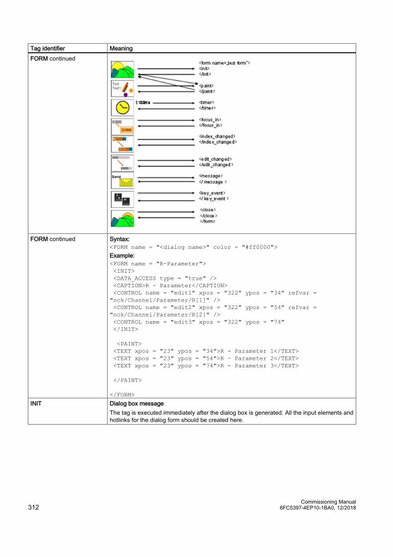
Commissioning Manual 312 6FC5397-4EP10-1BA0, 12/2018
Tag identifier Meaning FORM continued
FORM continued Syntax: <FORM name = "<dialog name>" color = "#ff0000">
Example: <FORM name = "R-Parameter"> <INIT> <DATA_ACCESS type = "true" /> <CAPTION>R - Parameter</CAPTION> <CONTROL name = "edit1" xpos = "322" ypos = "34" refvar = "nck/Channel/Parameter/R[1]" /> <CONTROL name = "edit2" xpos = "322" ypos = "54" refvar = "nck/Channel/Parameter/R[2]" /> <CONTROL name = "edit3" xpos = "322" ypos = "74" </INIT> <PAINT> <TEXT xpos = "23" ypos = "34">R - Parameter 1</TEXT> <TEXT xpos = "23" ypos = "54">R - Parameter 2</TEXT> <TEXT xpos = "23" ypos = "74">R - Parameter 3</TEXT> </PAINT> </FORM>
INIT Dialog box message The tag is executed immediately after the dialog box is generated. All the input elements and hotlinks for the dialog form should be created here.
Commissioning Manual 6FC5397-4EP10-1BA0, 12/2018 313
Tag identifier Meaning KEY_EVENT
Dialog message The tag KEY_EVENT can be integrated in the form to evaluate keyboard events. The sys-tem sends the MF2 keyboard code to the active form if the tag is available in a form. If the variable $actionresult is not set to zero, the system then subsequently processes the key-board event. The keyboard code is provided in the variable $keycode as an integer value. Example: The character entered into the variable exclude_key should be filtered-out of the input stream. <LET name="stream" type="string"/> <LET name="exclude_key" type="string"/> <FORM name = "keytest_form"> <INIT> <CONTROL name = "p1" xpos = "120" ypos = "84" width ="200" refvar="stream" hotlink="true" /> <CONTROL name = "p2" xpos = "160" ypos = "104" width ="8" refvar="exclude_key" hotlink="true" /> </INIT> <PAINT> <text xpos = "8" ypos = "84">data stream</text> <text xpos = "8" ypos = "104">exclude key</text> </PAINT> <KEY_EVENT> <LET name="excl_keycode" type="string"/> <OP>excl_keycode = exclude_key</OP> <type_cast name="excl_keycode" convert="int" /> <PRINT text="%d %d">$keycode, excl_keycode</PRINT> <IF> <CONDITION>$keycode == excl_keycode</CONDITION> <THEN> <op> $actionresult = 0</op> </THEN> </IF> </KEY_IVENT> </FORM>
Commissioning Manual 314 6FC5397-4EP10-1BA0, 12/2018
Tag identifier Meaning MESSAGE
Dialog message If the Send_message operation is executed in the script, then the parser processes the tag message. Values P1 and P2 are provided in the variables $message_par1 and $mes-sage_par2 (see the "SEND_MESSAGE" tag). Syntax: <MESSAGE> </MESSAGE>
Example: <LET name="user_selection" /> <SOFTKEY POSITION="3"> <CAPTION>Set%nParameter</CAPTION> <SEND_MESSAGE>1, 10</SEND_MESSAGE> </SOFTKEY> … … <FORM> … … <MESSAGE> <SWITCH> <CONDITION>$message_par1</CONDITION> <CASE value="1"> <OP> user_selection = $message_par2 </OP> … … </CASE> </SWITCH> </MESSAGE> … … </FORM>

Commissioning Manual 6FC5397-4EP10-1BA0, 12/2018 315
Tag identifier Meaning SEND_MESSAGE The tag sends a message with two parameters to the active form, which is processed in the
tag message (see also MESSAGE). Syntax: <SEND_MESSAGE>p1, p2</SEND_MESSAGE>
Example: <LET name="user_selection" /> <SOFTKEY POSITION="3"> <CAPTION>Set%nParameter</CAPTION> <SEND_MESSAGE>1, 10</SEND_MESSAGE> </SOFTKEY> … … <FORM> … … <MESSAGE> <SWITCH> <CONDITION>$message_par1</CONDITION> <CASE value="1"> <OP> user_selection = $message_par2 </OP> … </CASE> </SWITCH> </MESSAGE> … … </FORM>
FOCUS_IN Dialog box message The tag is called if the system places the focus on a control. To identify the control, the sys-tem copies the name of the control into variable $focus_name and the value of the attribute item_data into variable $focus_item_data. This message can be used, for example, to output images depending on the focus position. Example: <focus_in> <PRINT text="focus on filed:%s, %d">$focus_name, $focus_item_data </PRINT> </focus_in>
PAINT Dialog box message The tag is executed when the dialog box is displayed. All the texts and images which are to be displayed in the dialog box should be specified here. Further, the tag is executed if the system identifies that parts of the dialog box are to be redisplayed. For example, this can be initiated by closing high-level windows.
TIMER Dialog box message The tag is executed cyclically. Each form is assigned a timer. The tag is executed within a period less than 100 ms.

Commissioning Manual 316 6FC5397-4EP10-1BA0, 12/2018
Tag identifier Meaning CAPTION The tag contains the title of the dialog box.
This tag should be used within the INIT tag. Syntax: <CAPTION>Titel</CAPTION>
Example: <CAPTION>my first dialogue</CAPTION>
CLOSE Dialog box message This tag is executed before the dialog box is closed.
CLOSE_FORM The tag closes the active dialog. This instruction is only necessary if the dialog is opened by the MMC command and the user is offered a softkey function to close the dialog. Generally, dialogs are automatically man-aged and do not have to be explicitly closed. Syntax: <CLOSE_FORM/>
Example: <softkey_ok> <caption>OK</caption> <CLOSE_FORM /> <navigation>main_menu</navigation> </softkey_ok>
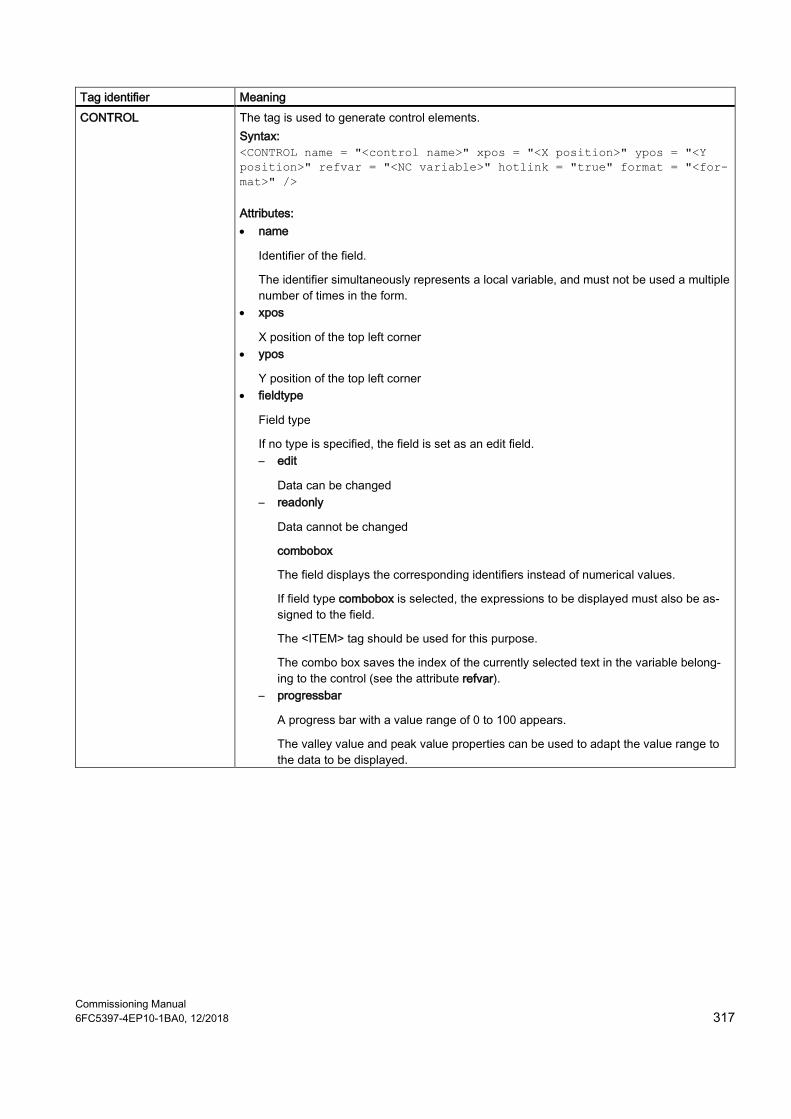
Commissioning Manual 6FC5397-4EP10-1BA0, 12/2018 317
Tag identifier Meaning CONTROL The tag is used to generate control elements.
Syntax: <CONTROL name = "<control name>" xpos = "<X position>" ypos = "<Y position>" refvar = "<NC variable>" hotlink = "true" format = "<for-mat>" />
Attributes: • name
Identifier of the field.
The identifier simultaneously represents a local variable, and must not be used a multiple number of times in the form.
• xpos
X position of the top left corner • ypos
Y position of the top left corner • fieldtype
Field type
If no type is specified, the field is set as an edit field. – edit
Data can be changed – readonly
Data cannot be changed
combobox
The field displays the corresponding identifiers instead of numerical values.
If field type combobox is selected, the expressions to be displayed must also be as-signed to the field.
The <ITEM> tag should be used for this purpose.
The combo box saves the index of the currently selected text in the variable belong-ing to the control (see the attribute refvar).
– progressbar
A progress bar with a value range of 0 to 100 appears.
The valley value and peak value properties can be used to adapt the value range to the data to be displayed.
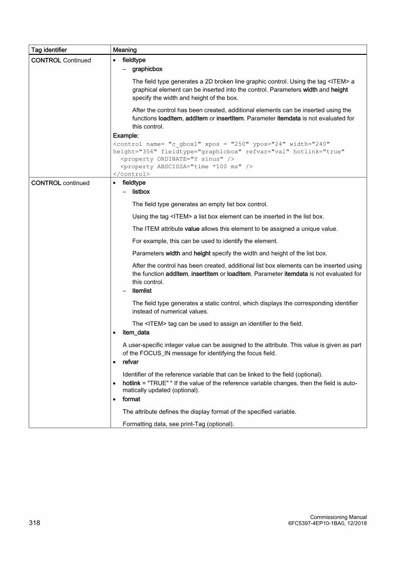
Commissioning Manual 318 6FC5397-4EP10-1BA0, 12/2018
Tag identifier Meaning CONTROL Continued • fieldtype
– graphicbox
The field type generates a 2D broken line graphic control. Using the tag <ITEM> a graphical element can be inserted into the control. Parameters width and height specify the width and height of the box.
After the control has been created, additional elements can be inserted using the functions loadItem, addItem or insertItem. Parameter itemdata is not evaluated for this control.
Example: <control name= "c_gbox1" xpos = "250" ypos="24" width="240" height="356" fieldtype="graphicbox" refvar="val" hotlink="true" <property ORDINATE="Y sinus" /> <property ABSCISSA="time *100 ms" /> </control>
CONTROL continued • fieldtype – listbox
The field type generates an empty list box control.
Using the tag <ITEM> a list box element can be inserted in the list box.
The ITEM attribute value allows this element to be assigned a unique value.
For example, this can be used to identify the element.
Parameters width and height specify the width and height of the list box.
After the control has been created, additional list box elements can be inserted using the function addItem, insertItem or loadItem. Parameter itemdata is not evaluated for this control.
– itemlist
The field type generates a static control, which displays the corresponding identifier instead of numerical values.
The <ITEM> tag can be used to assign an identifier to the field. • item_data
A user-specific integer value can be assigned to the attribute. This value is given as part of the FOCUS_IN message for identifying the focus field.
• refvar
Identifier of the reference variable that can be linked to the field (optional). • hotlink = "TRUE" " If the value of the reference variable changes, then the field is auto-
matically updated (optional). • format
The attribute defines the display format of the specified variable.
Formatting data, see print-Tag (optional).

Commissioning Manual 6FC5397-4EP10-1BA0, 12/2018 319
Tag identifier Meaning CONTROL continued Attributes:
• font
The attribute defines the font size used. – 0 – 1 – 2 – 3 – 4 – 5
• color_bk
The attribute sets the background color of the control. • color_fg
The attribute sets the foreground color of the control.
Color coding (see Section "Color coding (Page 309)") • display_format
The attribute defines the processing format of the specified variable. This attribute must be used when accessing a PLC float variable, as the access is realized by reading a double word.
The following data formats are permitted: – FLOAT – INT – DOUBLE – STRING
Assigning expressions (e.g. text or graphic element to be displayed) to a list box, graphics box or combo box: Syntax: <ITEM>Expression</ITEM> <ITEM value ="<Value>">Expression</ITEM>

Commissioning Manual 320 6FC5397-4EP10-1BA0, 12/2018
Tag identifier Meaning CONTROL continued Example:
<CONTROL name = "button1" xpos = "10" ypos = "10" fieldtype = " com-bobox "> <ITEM>text1</ITEM> <ITEM>text2</ITEM> <ITEM>text3</ITEM> <ITEM>text4</ITEM> </CONTROL>
If any integer value is to be assigned to an expression, the attribute value = "value" should be added to the tag. Rather than consecutive numbers, the control variable now contains the item's assigned value. Example: <CONTROL name = "button1" xpos = "10" ypos = "10" fieldtype = " com-bobox "> <ITEM value = "10">text1</ITEM> <ITEM value = "20">text2</ITEM> <ITEM value = "12">text3</ITEM> <ITEM value = "1">text4</ITEM>
</CONTROL> Example of a progress bar: <CONTROL name = "progress1" xpos = "10" ypos = "10" width = "100" fieldtype = "progressbar" hotlink = "true" refvar = "nck/Channel/GeometricAxis/actProgPos[1]"> <PROPERTY min = "0" /> <PROPERTY max = "1000" /> </CONTROL>
Example, list box: <let name="item_string" type="string"></let> <let name="item_data" ></let> <CONTROL name="listbox1" xpos = "360" ypos="150" width="200" height="200" fieldtype="listbox" /> • Adding elements:
Elements are added using the function insertitem, additem or loaditem. • Deleting the content:
The content is deleted using the function empty. <op> item_string = _T"text1\\n" </op> <function name="control.additem">_T"listbox1", item_string, item_data </function> <op> item_string = _T"text2\\n" </op> <function name="control.additem">_T"listbox1", item_string, item_data </function>
CONTROL continued Example itemlist: <CONTROL name = "itemlist1" xpos = "10" ypos = "10" fieldtype = " itemlist"> <ITEM value = "10">text1</ITEM> <ITEM value = "20">text2</ITEM> <ITEM value = "12">text3</ITEM> <ITEM value = "1">text4</ITEM> </CONTROL>
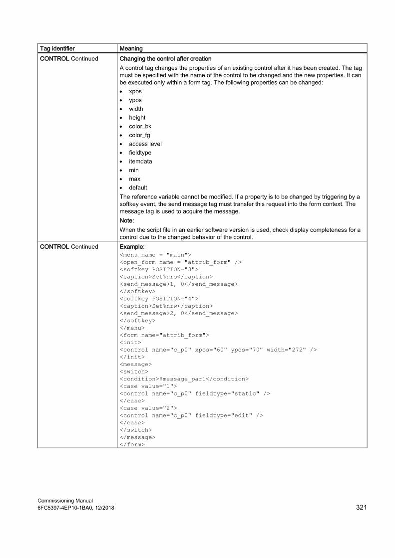
Commissioning Manual 6FC5397-4EP10-1BA0, 12/2018 321
Tag identifier Meaning CONTROL Continued Changing the control after creation
A control tag changes the properties of an existing control after it has been created. The tag must be specified with the name of the control to be changed and the new properties. It can be executed only within a form tag. The following properties can be changed: • xpos • ypos • width • height • color_bk • color_fg • access level • fieldtype • itemdata • min • max • default The reference variable cannot be modified. If a property is to be changed by triggering by a softkey event, the send message tag must transfer this request into the form context. The message tag is used to acquire the message. Note: When the script file in an earlier software version is used, check display completeness for a control due to the changed behavior of the control.
CONTROL Continued Example: <menu name = "main"> <open_form name = "attrib_form" /> <softkey POSITION="3"> <caption>Set%nro</caption> <send_message>1, 0</send_message> </softkey> <softkey POSITION="4"> <caption>Set%nrw</caption> <send_message>2, 0</send_message> </softkey> </menu> <form name="attrib_form"> <init> <control name="c_p0" xpos="60" ypos="70" width="272" /> </init> <message> <switch> <condition>$message_par1</condition> <case value="1"> <control name="c_p0" fieldtype="static" /> </case> <case value="2"> <control name="c_p0" fieldtype="edit" /> </case> </switch> </message> </form>
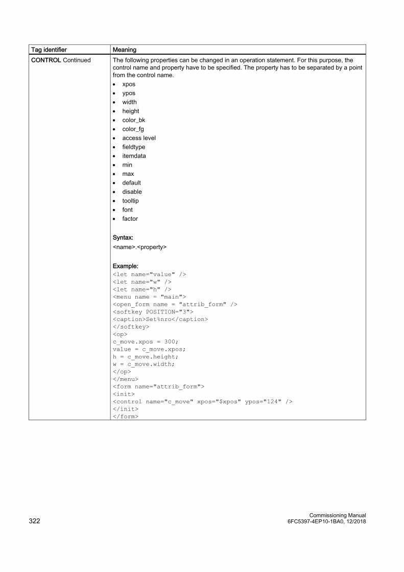
Commissioning Manual 322 6FC5397-4EP10-1BA0, 12/2018
Tag identifier Meaning CONTROL Continued The following properties can be changed in an operation statement. For this purpose, the
control name and property have to be specified. The property has to be separated by a point from the control name. • xpos • ypos • width • height • color_bk • color_fg • access level • fieldtype • itemdata • min • max • default • disable • tooltip • font • factor Syntax: <name>.<property> Example: <let name="value" /> <let name="w" /> <let name="h" /> <menu name = "main"> <open_form name = "attrib_form" /> <softkey POSITION="3"> <caption>Set%nro</caption> </softkey> <op> c_move.xpos = 300; value = c_move.xpos; h = c_move.height; w = c_move.width; </op> </menu> <form name="attrib_form"> <init> <control name="c_move" xpos="$xpos" ypos="124" /> </init> </form>
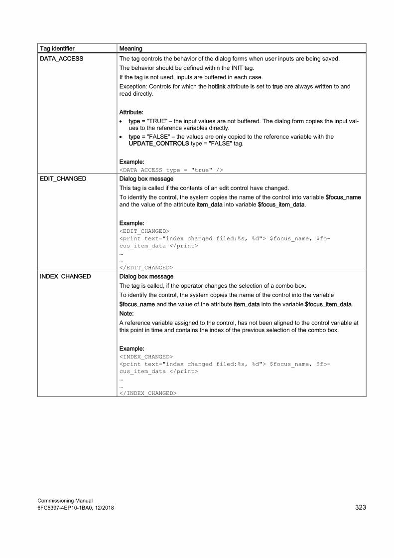
Commissioning Manual 6FC5397-4EP10-1BA0, 12/2018 323
Tag identifier Meaning DATA_ACCESS The tag controls the behavior of the dialog forms when user inputs are being saved.
The behavior should be defined within the INIT tag. If the tag is not used, inputs are buffered in each case. Exception: Controls for which the hotlink attribute is set to true are always written to and read directly. Attribute: • type = "TRUE" – the input values are not buffered. The dialog form copies the input val-
ues to the reference variables directly. • type = "FALSE" – the values are only copied to the reference variable with the
UPDATE_CONTROLS type = "FALSE" tag. Example: <DATA_ACCESS type = "true" />
EDIT_CHANGED Dialog box message This tag is called if the contents of an edit control have changed. To identify the control, the system copies the name of the control into variable $focus_name and the value of the attribute item_data into variable $focus_item_data. Example: <EDIT_CHANGED> <print text="index changed filed:%s, %d"> $focus_name, $fo-cus_item_data </print> … … </EDIT_CHANGED>
INDEX_CHANGED Dialog box message The tag is called, if the operator changes the selection of a combo box. To identify the control, the system copies the name of the control into the variable $focus_name and the value of the attribute item_data into the variable $focus_item_data. Note: A reference variable assigned to the control, has not been aligned to the control variable at this point in time and contains the index of the previous selection of the combo box. Example: <INDEX_CHANGED> <print text="index changed filed:%s, %d"> $focus_name, $fo-cus_item_data </print> … … </INDEX_CHANGED>
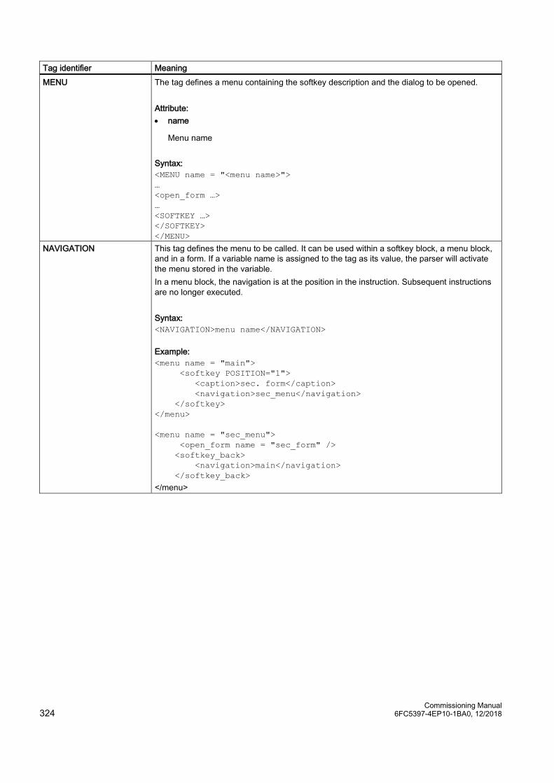
Commissioning Manual 324 6FC5397-4EP10-1BA0, 12/2018
Tag identifier Meaning MENU The tag defines a menu containing the softkey description and the dialog to be opened.
Attribute: • name
Menu name Syntax: <MENU name = "<menu name>"> … <open_form …> … <SOFTKEY …> </SOFTKEY> </MENU>
NAVIGATION This tag defines the menu to be called. It can be used within a softkey block, a menu block, and in a form. If a variable name is assigned to the tag as its value, the parser will activate the menu stored in the variable. In a menu block, the navigation is at the position in the instruction. Subsequent instructions are no longer executed. Syntax: <NAVIGATION>menu name</NAVIGATION>
Example: <menu name = "main"> <softkey POSITION="1"> <caption>sec. form</caption> <navigation>sec_menu</navigation> </softkey> </menu> <menu name = "sec_menu"> <open_form name = "sec_form" /> <softkey_back> <navigation>main</navigation> </softkey_back>
</menu>

Commissioning Manual 6FC5397-4EP10-1BA0, 12/2018 325
Tag identifier Meaning OPEN_FORM The tag opens the dialog form given under the name.
Attribute: • name
Name of the dialog form Syntax: <OPEN_FORM name = "<form name>" />
Example: <menu name = "main"> <open_form name = "main_form" /> <softkey POSITION="1"> <caption>main form</caption> <navigation>main</navigation> </softkey> </menu> <form name="main_form"> <init> </init> <paint> </paint> </form>
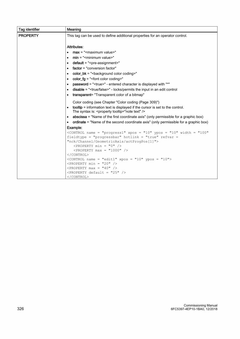
Commissioning Manual 326 6FC5397-4EP10-1BA0, 12/2018
Tag identifier Meaning PROPERTY This tag can be used to define additional properties for an operator control.
Attributes: • max = "<maximum value>" • min = "<minimum value>" • default = "<pre-assignment>" • factor = "conversion factor" • color_bk = "<background color coding>" • color_fg = "<font color coding>" • password = "<true>" - entered character is displayed with "*" • disable = "<true/false>" - locks/permits the input in an edit control • transparent= "Transparent color of a bitmap"
Color coding (see Chapter "Color coding (Page 309)") • tooltip = information text is displayed if the cursor is set to the control.
The syntax is: <property tooltip="note text" /> • abscissa = "Name of the first coordinate axis" (only permissible for a graphic box) • ordinate = "Name of the second coordinate axis" (only permissible for a graphic box) Example: <CONTROL name = "progress1" xpos = "10" ypos = "10" width = "100" fieldtype = "progressbar" hotlink = "true" refvar = "nck/Channel/GeometricAxis/actProgPos[1]"> <PROPERTY min = "0" /> <PROPERTY max = "1000" /> </CONTROL> <CONTROL name = "edit1" xpos = "10" ypos = "10"> <PROPERTY min = "20" /> <PROPERTY max = "40" /> <PROPERTY default = "25" /> </CONTROL>

Commissioning Manual 6FC5397-4EP10-1BA0, 12/2018 327
Tag identifier Meaning SOFTKEY The tag defines the properties and responses of a softkey.
Attributes: • position
Number of the softkey. 1-8 horizontal softkeys, 9-16 vertical softkeys
The following attributes become effective from: • type
Defines the property of the softkey.
user_controled - The script defines how the softkey is displayed
toggle_softkey - The softkey is displayed alternating between pressed and not pressed • refvar
Should only be used in conjunction with toggle_softkey .
Reference variable, into which the actual softkey property is copied.
A variable, type "String" should be specified, which includes the properties pressed, not pressed or locked (see tag state).
• picture
Using the attribute, a bitmap can be output left justified on the softkey. The complete path name should be specified.
The number of text characters that can be displayed is reduced to the width of the bit-map.
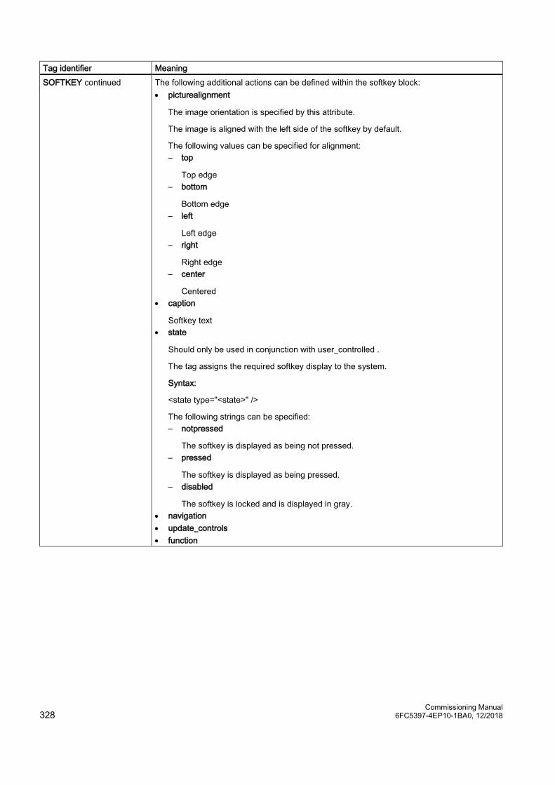
Commissioning Manual 328 6FC5397-4EP10-1BA0, 12/2018
Tag identifier Meaning SOFTKEY continued The following additional actions can be defined within the softkey block:
• picturealignment
The image orientation is specified by this attribute.
The image is aligned with the left side of the softkey by default.
The following values can be specified for alignment: – top
Top edge – bottom
Bottom edge – left
Left edge – right
Right edge – center
Centered • caption
Softkey text • state
Should only be used in conjunction with user_controlled .
The tag assigns the required softkey display to the system.
Syntax:
<state type="<state>" />
The following strings can be specified: – notpressed
The softkey is displayed as being not pressed. – pressed
The softkey is displayed as being pressed. – disabled
The softkey is locked and is displayed in gray. • navigation • update_controls • function
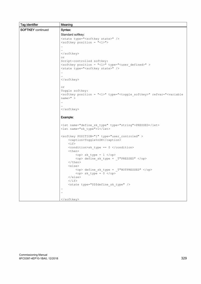
Commissioning Manual 6FC5397-4EP10-1BA0, 12/2018 329
Tag identifier Meaning SOFTKEY continued Syntax:
Standard softkey: <state type="<softkey state>" /> <softkey position = "<1>"> … … </softkey> or Script-controlled softkey: <softkey position = "<1>" type="<user_defined>" > <state type="<softkey state>" /> … … </softkey> or Toggle softkey: <softkey position = "<1>" type="<toggle_softkey>" refvar="<variable name>" > … … </softkey>
Example: <let name="define_sk_type" type="string">PRESSED</let> <let name="sk_type">1</let> <softkey POSITION="1" type="user_controled" > <caption>Toggle%nSK</caption> <if> <condition>sk_type == 0 </condition> <then> <op> sk_type = 1 </op> <op> define_sk_type = _T"PRESSED" </op> </then> <else> <op> define_sk_type = _T"NOTPRESSED" </op> <op> sk_type = 0 </op> </else> </if> <state type="$$$define_sk_type" /> … … </softkey>

Commissioning Manual 330 6FC5397-4EP10-1BA0, 12/2018
Tag identifier Meaning SOFTKEY continued Example:
or <let name="curr_softkey_state" type="string">PRESSED</let> </softkey> <softkey POSITION="3" type="toggle_softkey" refvar="curr_softkey_state"> <caption>Toggle%nSK</caption> …
</softkey>
SOFTKEY_OK
The tag defines the response of the softkey "OK".
The following additional actions can be defined within the softkey block: • navigation • update_controls • function Syntax: <SOFTKEY_OK> … … </SOFTKEY_OK>
SOFTKEY_CANCEL
The tag defines the response of the softkey "Cancel".
The following additional actions can be defined within the softkey block: • navigation • update_controls • function Syntax: <SOFTKEY_CANCEL> … … </SOFTKEY_CANCEL>
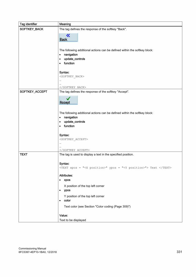
Commissioning Manual 6FC5397-4EP10-1BA0, 12/2018 331
Tag identifier Meaning SOFTKEY_BACK
The tag defines the response of the softkey "Back".
The following additional actions can be defined within the softkey block: • navigation • update_controls • function Syntax: <SOFTKEY_BACK> … … </SOFTKEY_BACK>
SOFTKEY_ACCEPT
The tag defines the response of the softkey "Accept".
The following additional actions can be defined within the softkey block: • navigation • update_controls • function Syntax: <SOFTKEY_ACCEPT> … … </SOFTKEY_ACCEPT>
TEXT The tag is used to display a text in the specified position. Syntax: <TEXT xpos = "<X position>" ypos = "<Y position>"> Text </TEXT>
Attributes: • xpos
X position of the top left corner • ypos
Y position of the top left corner • color
Text color (see Section "Color coding (Page 309)") Value: Text to be displayed
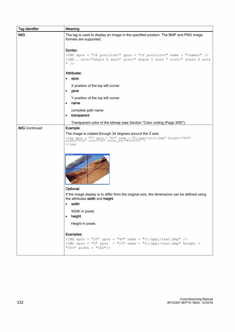
Commissioning Manual 332 6FC5397-4EP10-1BA0, 12/2018
Tag identifier Meaning IMG The tag is used to display an image in the specified position. The BMP and PNG image
formats are supported. Syntax: <IMG xpos = "<X position>" ypos = "<Y position>" name = "<name>" /> <IMG … xrot="angle X axis" yrot=" angle Y axis " zrot=" angle Z axis " />
Attributes: • xpos
X position of the top left corner • ypos
Y position of the top left corner • name
complete path name • transparent
Transparent color of the bitmap (see Section "Color coding (Page 309)"): IMG Continued Example:
The image is rotated through 34 degrees around the Z axis: <img xpos = "5" ypos = "23" name = "f:/appl/pic3.bmp" height="355" width="550" zrot="34" color_bk="#ffffff" > </img>
Optional: If the image display is to differ from the original size, the dimensions can be defined using the attributes width and height. • width
Width in pixels • height
Height in pixels Examples: <IMG xpos = "20" ypos = "40" name = "f:/appl/test.bmp" /> <IMG xpos = "5" ypos = "23" name = "f:/appl/test.bmp" height = "355" width = "550"/>
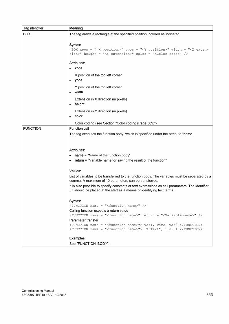
Commissioning Manual 6FC5397-4EP10-1BA0, 12/2018 333
Tag identifier Meaning BOX The tag draws a rectangle at the specified position, colored as indicated.
Syntax: <BOX xpos = "<X position>" ypos = "<Y position>" width = "<X exten-sion>" height = "<Y extension>" color = "<Color code>" />
Attributes: • xpos
X position of the top left corner • ypos
Y position of the top left corner • width
Extension in X direction (in pixels) • height
Extension in Y direction (in pixels) • color
Color coding (see Section "Color coding (Page 309)") FUNCTION Function call
The tag executes the function body, which is specified under the attribute "name. Attributes: • name = "Name of the function body" • return = "Variable name for saving the result of the function" Values: List of variables to be transferred to the function body. The variables must be separated by a comma. A maximum of 10 parameters can be transferred. It is also possible to specify constants or text expressions as call parameters. The identifier _T should be placed at the start as a means of identifying text terms. Syntax: <FUNCTION name = "<function name>" />
Calling function expects a return value <FUNCTION name = "<function name>" return = "<Variablenname>" />
Parameter transfer <FUNCTION name = "<function name>"> var1, var2, var3 </FUNCTION> <FUNCTION name = "<function name>"> _T"Text", 1.0, 1 </FUNCTION>
Examples: See "FUNCTION_BODY".
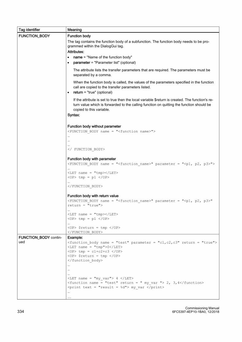
Commissioning Manual 334 6FC5397-4EP10-1BA0, 12/2018
Tag identifier Meaning FUNCTION_BODY Function body
The tag contains the function body of a subfunction. The function body needs to be pro-grammed within the DialogGui tag. Attributes: • name = "Name of the function body" • parameter = "Parameter list" (optional)
The attribute lists the transfer parameters that are required. The parameters must be separated by a comma.
When the function body is called, the values of the parameters specified in the function call are copied to the transfer parameters listed.
• return = "true" (optional)
If the attribute is set to true then the local variable $return is created. The function's re-turn value which is forwarded to the calling function on quitting the function should be copied to this variable.
Syntax: Function body without parameter <FUNCTION_BODY name = "<function name>"> … … … </ FUNCTION_BODY>
Function body with parameter <FUNCTION_BODY name = "<function_name>" parameter = "<p1, p2, p3>"> … <LET name = "tmp></LET> <OP> tmp = p1 </OP> … </FUNCTION_BODY>
Function body with return value <FUNCTION_BODY name = "<function_name>" parameter = "<p1, p2, p3>" return = "true"> … <LET name = "tmp></LET> <OP> tmp = p1 </OP> … <OP> $return = tmp </OP> </FUNCTION_BODY>
FUNCTION_BODY contin-ued
Example: <function_body name = "test" parameter = "c1,c2,c3" return = "true"> <LET name = "tmp">0</LET> <OP> tmp = c1+c2+c3 </OP> <OP> $return = tmp </OP> </function_body> … … … <LET name = "my_var"> 4 </LET> <function name = "test" return = " my_var "> 2, 3,4</function> <print text = "result = %d"> my_var </print> …
…
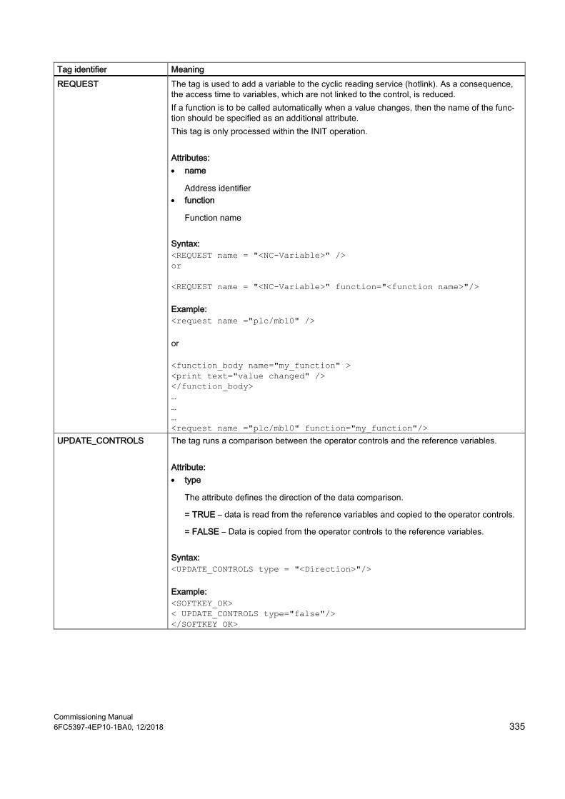
Commissioning Manual 6FC5397-4EP10-1BA0, 12/2018 335
Tag identifier Meaning REQUEST The tag is used to add a variable to the cyclic reading service (hotlink). As a consequence,
the access time to variables, which are not linked to the control, is reduced. If a function is to be called automatically when a value changes, then the name of the func-tion should be specified as an additional attribute. This tag is only processed within the INIT operation. Attributes: • name
Address identifier • function
Function name Syntax: <REQUEST name = "<NC-Variable>" /> or <REQUEST name = "<NC-Variable>" function="<function name>"/>
Example: <request name ="plc/mb10" />
or <function_body name="my_function" > <print text="value changed" /> </function_body> … … … <request name ="plc/mb10" function="my_function"/>
UPDATE_CONTROLS The tag runs a comparison between the operator controls and the reference variables. Attribute: • type
The attribute defines the direction of the data comparison.
= TRUE – data is read from the reference variables and copied to the operator controls.
= FALSE – Data is copied from the operator controls to the reference variables. Syntax: <UPDATE_CONTROLS type = "<Direction>"/>
Example: <SOFTKEY_OK> < UPDATE_CONTROLS type="false"/> </SOFTKEY_OK>
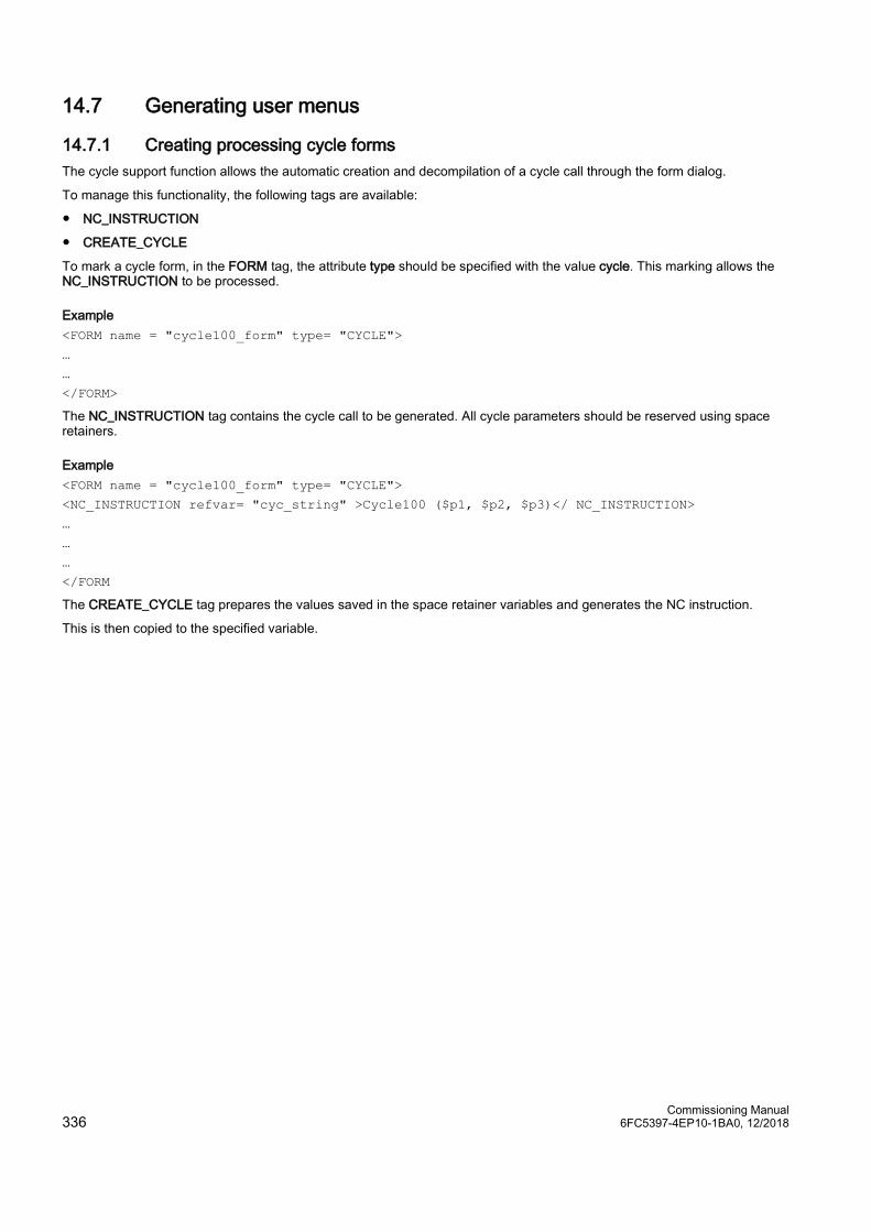
Commissioning Manual 336 6FC5397-4EP10-1BA0, 12/2018
14.7 Generating user menus
14.7.1 Creating processing cycle forms The cycle support function allows the automatic creation and decompilation of a cycle call through the form dialog.
To manage this functionality, the following tags are available:
● NC_INSTRUCTION
● CREATE_CYCLE
To mark a cycle form, in the FORM tag, the attribute type should be specified with the value cycle. This marking allows the NC_INSTRUCTION to be processed.
Example <FORM name = "cycle100_form" type= "CYCLE">
…
…
</FORM>
The NC_INSTRUCTION tag contains the cycle call to be generated. All cycle parameters should be reserved using space retainers.
Example <FORM name = "cycle100_form" type= "CYCLE">
<NC_INSTRUCTION refvar= "cyc_string" >Cycle100 ($p1, $p2, $p3)</ NC_INSTRUCTION>
…
…
…
</FORM
The CREATE_CYCLE tag prepares the values saved in the space retainer variables and generates the NC instruction.
This is then copied to the specified variable.

Commissioning Manual 6FC5397-4EP10-1BA0, 12/2018 337
Tag identifier Description NC_INSTRUCTION This tag is used to define the NC instruction to be generated.
All listed cycle parameters are automatically created as string variables of the FORM and are available to the FORM. Precondition: The FORMattribute type is set to the value CYCLE. Attribute: • refvar
If the tag is assigned a reference variable, all parameters are pre-assigned with the values from the NC block saved in the reference variables.
Syntax: <NC_INSTRUCTION> NC instruction with placeholders </ NC_INSTRUCTION>
Example: <let name="cyc_string" type="string"> Cycle100(0, 1000, 5)</let>
...
...
... <FORM name = "cycle100_form" type= "CYCLE"> <NC_INSTRUCTION refvar= "cyc_string" >Cycle100($p1, $p2, $p3)</ NC_INSTRUCTION> .. … … </FORM>
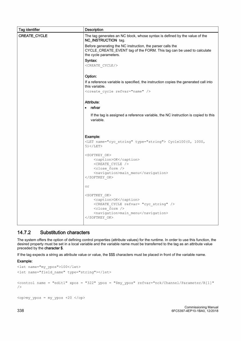
Commissioning Manual 338 6FC5397-4EP10-1BA0, 12/2018
Tag identifier Description CREATE_CYCLE The tag generates an NC block, whose syntax is defined by the value of the
NC_INSTRUCTION tag. Before generating the NC instruction, the parser calls the CYCLE_CREATE_EVENT tag of the FORM. This tag can be used to calculate the cycle parameters. Syntax: <CREATE_CYCLE/>
Option: If a reference variable is specified, the instruction copies the generated call into this variable. <create_cycle refvar="name" />
Attribute: • refvar
If the tag is assigned a reference variable, the NC instruction is copied to this variable.
Example: <LET name="cyc_string" type="string"> Cycle100(0, 1000, 5)</LET> <SOFTKEY_OK> <caption>OK</caption> <CREATE_CYCLE /> <close_form /> <navigation>main_menu</navigation> </SOFTKEY_OK> or <SOFTKEY_OK> <caption>OK</caption> <CREATE_CYCLE refvar= "cyc_string" /> <close_form /> <navigation>main_menu</navigation> </SOFTKEY_OK>
14.7.2 Substitution characters The system offers the option of defining control properties (attribute values) for the runtime. In order to use this function, the desired property must be set in a local variable and the variable name must be transferred to the tag as an attribute value preceded by the character $.
If the tag expects a string as attribute value or value, the $$$ characters must be placed in front of the variable name.
Example: <let name="my_ypos">100</let>
<let name="field_name" type="string"></let>
<control name = "edit1" xpos = "322" ypos = "$my_ypos" refvar="nck/Channel/Parameter/R[1]" />
<op>my_ypos = my_ypos +20 </op>
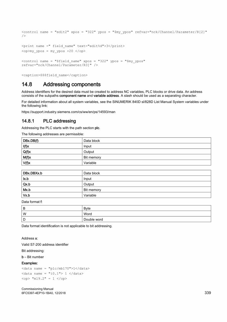
Commissioning Manual 6FC5397-4EP10-1BA0, 12/2018 339
<control name = "edit2" xpos = "322" ypos = "$my_ypos" refvar="nck/Channel/Parameter/R[2]" />
<print name =" field_name" text="edit%d">3</print>
<op>my_ypos = my_ypos +20 </op>
<control name = "$field_name" xpos = "322" ypos = "$my_ypos" refvar="nck/Channel/Parameter/R3]" />
<caption>$$$field_name</caption>
14.8 Addressing components Address identifiers for the desired data must be created to address NC variables, PLC blocks or drive data. An address consists of the subpaths component name and variable address. A slash should be used as a separating character.
For detailed information about all system variables, see the SINUMERIK 840D sl/828D List Manual System variables under the following link:
https://support.industry.siemens.com/cs/ww/en/ps/14593/man
14.8.1 PLC addressing Addressing the PLC starts with the path section plc.
The following addresses are permissible:
DBx.DB(f) Data block I(f)x Input Q(f)x Output M(f)x Bit memory V(f)x Variable
DBx.DBXx.b Data block Ix.b Input Qx.b Output Mx.b Bit memory Vx.b Variable
Data format f:
B Byte W Word D Double word
Data format identification is not applicable to bit addressing.
Address x:
Valid S7-200 address identifier
Bit addressing:
b – Bit number
Examples: <data name = "plc/mb170">1</data>
<data name = "i0.1"> 1 </data>
<op> "m19.2" = 1 </op>
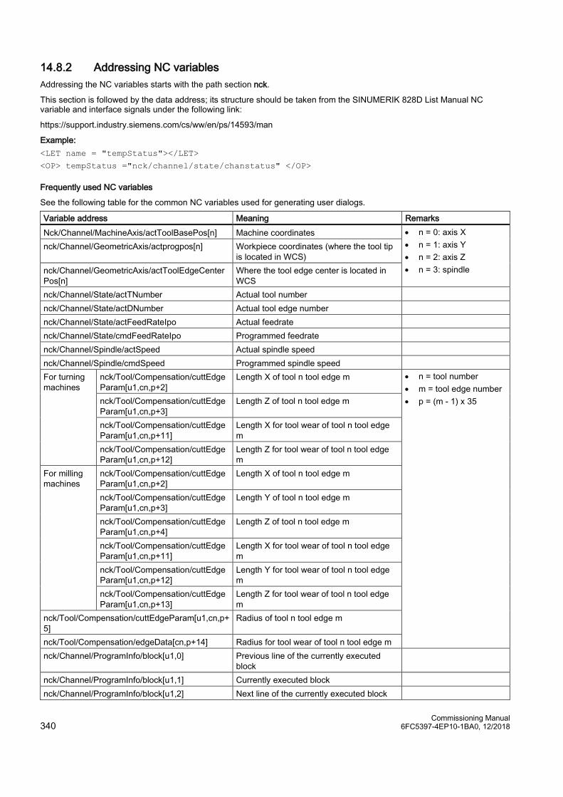
Commissioning Manual 340 6FC5397-4EP10-1BA0, 12/2018
14.8.2 Addressing NC variables Addressing the NC variables starts with the path section nck.
This section is followed by the data address; its structure should be taken from the SINUMERIK 828D List Manual NC variable and interface signals under the following link:
https://support.industry.siemens.com/cs/ww/en/ps/14593/man
Example: <LET name = "tempStatus"></LET>
<OP> tempStatus ="nck/channel/state/chanstatus" </OP>
Frequently used NC variables
See the following table for the common NC variables used for generating user dialogs.
Variable address Meaning Remarks Nck/Channel/MachineAxis/actToolBasePos[n] Machine coordinates • n = 0: axis X
• n = 1: axis Y • n = 2: axis Z • n = 3: spindle
nck/Channel/GeometricAxis/actprogpos[n] Workpiece coordinates (where the tool tip is located in WCS)
nck/Channel/GeometricAxis/actToolEdgeCenterPos[n]
Where the tool edge center is located in WCS
nck/Channel/State/actTNumber Actual tool number nck/Channel/State/actDNumber Actual tool edge number nck/Channel/State/actFeedRateIpo Actual feedrate nck/Channel/State/cmdFeedRateIpo Programmed feedrate nck/Channel/Spindle/actSpeed Actual spindle speed nck/Channel/Spindle/cmdSpeed Programmed spindle speed For turning machines
nck/Tool/Compensation/cuttEdgeParam[u1,cn,p+2]
Length X of tool n tool edge m • n = tool number • m = tool edge number • p = (m - 1) x 35 nck/Tool/Compensation/cuttEdge
Param[u1,cn,p+3] Length Z of tool n tool edge m
nck/Tool/Compensation/cuttEdgeParam[u1,cn,p+11]
Length X for tool wear of tool n tool edge m
nck/Tool/Compensation/cuttEdgeParam[u1,cn,p+12]
Length Z for tool wear of tool n tool edge m
For milling machines
nck/Tool/Compensation/cuttEdgeParam[u1,cn,p+2]
Length X of tool n tool edge m
nck/Tool/Compensation/cuttEdgeParam[u1,cn,p+3]
Length Y of tool n tool edge m
nck/Tool/Compensation/cuttEdgeParam[u1,cn,p+4]
Length Z of tool n tool edge m
nck/Tool/Compensation/cuttEdgeParam[u1,cn,p+11]
Length X for tool wear of tool n tool edge m
nck/Tool/Compensation/cuttEdgeParam[u1,cn,p+12]
Length Y for tool wear of tool n tool edge m
nck/Tool/Compensation/cuttEdgeParam[u1,cn,p+13]
Length Z for tool wear of tool n tool edge m
nck/Tool/Compensation/cuttEdgeParam[u1,cn,p+5]
Radius of tool n tool edge m
nck/Tool/Compensation/edgeData[cn,p+14] Radius for tool wear of tool n tool edge m nck/Channel/ProgramInfo/block[u1,0] Previous line of the currently executed
block
nck/Channel/ProgramInfo/block[u1,1] Currently executed block nck/Channel/ProgramInfo/block[u1,2] Next line of the currently executed block

Commissioning Manual 6FC5397-4EP10-1BA0, 12/2018 341
Variable address Meaning Remarks nck/Nck/ChannelDiagnose/poweronTime[u1] Time elapsed since the last normal power-
on (unit: min)
nck/Channel/State/actProgNetTime[u1] Run time of a selected program (unit: s) nck/Channel/State/reqParts[u1] Required parts to be counted nck/Channel/State/actParts[u1] Parts actually counted Nck/Channel/Parameter/R[n] R parameters
14.8.3 Generating NC/PLC addresses during the runtime It is possible to generate an address identifier during runtime.
In this case, the content of a string variable is used as address in an operation statement as well as in the nc.cap.read and nc.cap.write functions.
Observe the following for this type of addressing mode:
● Write the variable names in quotation marks.
● Use three ‚$’ characters as prefix for variable names.
Syntax: "$$$variable name"
Example: <PRINT name="var_adr" text="plc/DB9000.DBW%d"> 2000</PRINT>
<OP> "$$$var_adr" = 1 </OP>
14.8.4 Addressing drive components Addressing the drive components starts with the path section drive.
Then the drive device is specified:
CU - Control Unit
DC - Drive Control
The parameter to be set is added to this section.
Drive component addresses are defined as follows:
● do1: drive with address 11
● do2: drive with address 12
● do3: drive with address 13
● do4: drive with address 14
● do5: drive with address 15
Example: <LET name="r0002_content"></LET> <LET name="p1460_content"></LET>
<!— Reading of value r0002 on the CU of drive with address 11 ->
<op> r0002_content = "drive/cu/r2[do1]" </op>
<!— Reading of value r0002 on the CU of drive with address 15 ->
<op> r0002_content = "drive/cu/r0002[do5]" </op>
<!— Reading of value p1460 on dc of drive with address 12 ->
<op> p1460_content = "drive/dc/p1460[do2]" </op>
Commissioning Manual 342 6FC5397-4EP10-1BA0, 12/2018
Example:
Alternatively, the drive index can be read from a local variable using $<variable name> "substitution characters". for instance DO$local variable
Example: <DATA name = "drive/dc/p1460[do1]">1</DATA>
Indirect addressing: <LET name = "driveIndex">1</LET>
<DATA name = "drive/dc/p1460[do$driveIndex]">1</DATA>
14.8.5 Addressing machine and setting data Drive and setting data is identified by the character $ followed by the name of the data.
Machine data:
$Mx_<name[index, AX<axis_number>]>
Setting data:
$Sx_<name[index, AX<axis_number>]>
x:
N – General machine or setting data
C – Channel-specific machine or setting data
A – Axis-specific machine or setting data
Index:
For a field, the parameter indicates the index of the data.
AX<axis_number>:
The required axis (<axis_number>) has to be specified for axis-specific data.
Alternatively, the axis index can be read from a local variable using $<variable name> "substitution characters".
e.g. AX$localvariable
Example: <DATA name ="$MN_AXCONF_MACHAX_NAME_TAB[0] ">X1</DATA>
Direct addressing of the axis: <DATA name ="$MA_CTRLOUT_MODULE_NR[0, AX1] ">1</DATA>
…
…
Indirect addressing of the axis: <LET name ="axisIndex"> 1 </LET>
<DATA name ="$MA_CTRLOUT_MODULE_NR[0, AX$axisIndex] ">1</DATA>
14.8.6 Addressing the user data Addressing user data starts with the path section gud, followed by the GUD name.
For a field, after the name, the required field index should be specified in square brackets.
Example: <DATA name ="gud/syg_rm[0]"
<OP>"gud/syg_rm[0]" 0 10 </op>
Addressing the global user data
Addressing starts with the path section gud, followed by the specification of the area CHANNEL. This address section is followed by the specification of the GUD areas:

Commissioning Manual 6FC5397-4EP10-1BA0, 12/2018 343
GUD areas Assignment sgud Siemens GUD mgud Machine manufacturer GUD ugud User GUD
Then enter the GUD name. If an array is to be addressed, the name is followed by the array subscript in square brackets.
Example: <data name ="gud/channel/mgud/syg_rm[0]">1</data>
<op>"gud/channel/mgud/syg_rm[0]" = 5*2 </op>
14.8.7 Creating typical menus in user dialogs by addressing components This section describes how to create typical menus in user dialogs by generating the script file (xmldial.xml) and XML files (for example, machine_settings.xml) inserted in the "xmldial. xml" file that are required for addressing the desired components.
Generating the script file
The "xmldial.xml" control file integrates, with the "INCLUDE" XML tag, XML files containing programmed instructions for displaying the dialog forms and parameters on the HMI.
HMI Syntax Used identifiers and their meanings <?xml version="1.0" encoding="gb2312"?> <DialogGui type="1"> DialogGui: defines all dialog configurations. <?include src="f:\appl\Main.xml"?> INCLUDE: includes the desired XML description.
<?include src="f:\appl\Setting.xml"?> <?include src="f:\appl\Parameter.xml"?>
</DialogGui> DialogGui: defines all dialog configurations.
Generating the XML file for creating the start menu
General information
● Type of addressed components: NC variables
● Menu function on the HMI: displaying the system data
User dialog and XML file examples

Commissioning Manual 344 6FC5397-4EP10-1BA0, 12/2018
HMI Syntax Used identifiers and their meanings <menu name="Main"> MENU: defines the start menu containing the softkey
description and the dialog to be opened. <OPEN_FORM name="Main" /> OPEN_FORM: opens the desired dialog form given
under the desired name.
① <softkey position="1" type="user_controlled">
SOFTKEY: defines the properties and responses of the desired softkeys.
<state type="notpressed" /> <caption>Machine%nOperation</caption> <navigation>Setting</navigation> </softkey> <softkey position="2" type="user_controlled"> <state type="notpressed" /> <caption>Parameter%nSetting</caption> <navigation>Parameter</navigation> </softkey>
</menu> MENU: defines the start menu containing the softkey description and the dialog to be opened.
<form name="Main"> FORM: defines the description of the desired user dialog.
② </paint> PAINT: defines the desired texts and images which are to be displayed in the dialog box. <text xpos="369" color="#000000"
ypos="28">T, F, S</text> ... </paint>
<init> INIT: defines the desired input elements and hotlinks for the dialog form
③ <caption>User Mask</caption> CAPTION: defines the title of the desired dialog box.
④ <let name="time_array" dim="7" /> LET: defines the desired local variable under the specified name. <function name
="control.localtime">_T"time_array"</function>
⑤ <control name="InputField1" xpos="489" ypos="54" height="16" width="40" refvar="nck/Channel/State/actDNumber" hot-link="true" format="%2d" />
CONTROL: defines the desired control elements.
...
</init> INIT: defines the desired input elements and hotlinks for the dialog form
</form> FORM: defines the description of the desired user dialog.
Generating the XML file for creating the machine operating menu
General information
● Type of addressed components: PLC data
● Menu function on the HMI: making machine settings by addressing the PLC data to operate the machine.
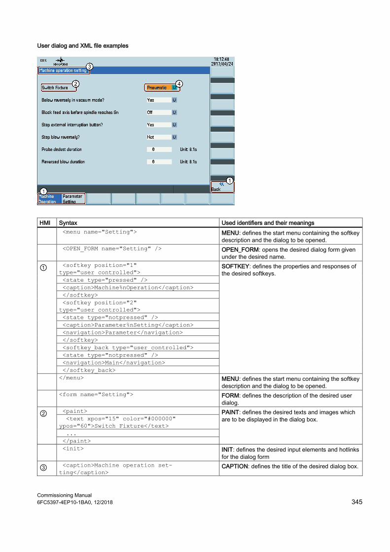
Commissioning Manual 6FC5397-4EP10-1BA0, 12/2018 345
User dialog and XML file examples
HMI Syntax Used identifiers and their meanings <menu name="Setting"> MENU: defines the start menu containing the softkey
description and the dialog to be opened. <OPEN_FORM name="Setting" /> OPEN_FORM: opens the desired dialog form given
under the desired name.
①
<softkey position="1" type="user_controlled">
SOFTKEY: defines the properties and responses of the desired softkeys.
<state type="pressed" /> <caption>Machine%nOperation</caption> </softkey> <softkey position="2" type="user_controlled"> <state type="notpressed" /> <caption>Parameter%nSetting</caption> <navigation>Parameter</navigation> </softkey> <softkey_back type="user_controlled"> <state type="notpressed" /> <navigation>Main</navigation> </softkey_back>
</menu> MENU: defines the start menu containing the softkey description and the dialog to be opened.
<form name="Setting"> FORM: defines the description of the desired user dialog.
② <paint> PAINT: defines the desired texts and images which are to be displayed in the dialog box. <text xpos="15" color="#000000"
ypos="60">Switch Fixture</text> ... </paint>
<init> INIT: defines the desired input elements and hotlinks for the dialog form
③ <caption>Machine operation set-ting</caption>
CAPTION: defines the title of the desired dialog box.
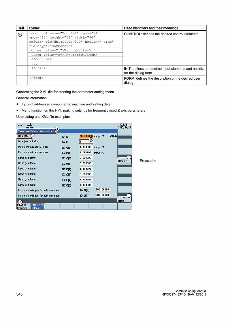
Commissioning Manual 346 6FC5397-4EP10-1BA0, 12/2018
HMI Syntax Used identifiers and their meanings
④ <control name="Toggle1" xpos="346" ypos="60" height="16" width="80" refvar="plc/db1400.dbx9.0" hotlink="true" fieldtype="combobox">
CONTROL: defines the desired control elements.
<item value="1">Vacuum</item> <item value="0">Pneumatic</item> </control> ...
</init> INIT: defines the desired input elements and hotlinks for the dialog form
</form> FORM: defines the description of the desired user dialog.
Generating the XML file for creating the parameter setting menu
General information
● Type of addressed components: machine and setting data
● Menu function on the HMI: making settings for frequently used Z axis parameters
User dialog and XML file examples
Pressed ⇒
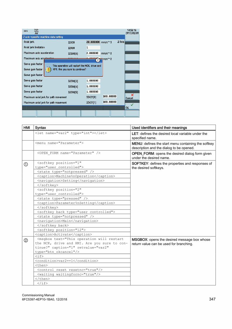
Commissioning Manual 6FC5397-4EP10-1BA0, 12/2018 347
HMI Syntax Used identifiers and their meanings <let name="var2" type="int"></let> LET: defines the desired local variable under the
specified name. <menu name="Parameter"> MENU: defines the start menu containing the softkey
description and the dialog to be opened. <OPEN_FORM name="Parameter" /> OPEN_FORM: opens the desired dialog form given
under the desired name.
①
<softkey position="1" type="user_controlled">
SOFTKEY: defines the properties and responses of the desired softkeys.
<state type="notpressed" /> <caption>Machine%nOperation</caption> <navigation>Setting</navigation> </softkey> <softkey position="2" type="user_controlled"> <state type="pressed" /> <caption>Parameter%nSetting</caption> </softkey> <softkey_back type="user_controlled"> <state type="notpressed" /> <navigation>Main</navigation> </softkey_back> <softkey position="12"> <caption>Activate</caption>
② <msgbox text="This operation will restart the NCK, drive and HMI. Are you sure to con-tinue?" caption="1" retvalue="var2" type="btn_okcancel"/>
MSGBOX: opens the desired message box whose return value can be used for branching.
<if> <condition>var2==1</condition> <then> <control_reset resetnc="true"/> <waiting waitingfornc="true"/> </then> </if>

Commissioning Manual 348 6FC5397-4EP10-1BA0, 12/2018
HMI Syntax Used identifiers and their meanings </softkey> SOFTKEY: defines the properties and responses of
the desired softkeys. </menu> MENU: defines the start menu containing the softkey
description and the dialog to be opened. <form name="Parameter"> FORM: defines the description of the desired user
dialog.
③ <paint> PAINT: defines the desired texts and images which are to be displayed in the dialog box. <TEXT xpos="10" ypos="30" co-
lor="#000000">Axial jerk</TEXT> ... </paint>
<init> INIT: defines the desired input elements and hotlinks for the dialog form
④ <caption>Z axis-specific machine data set-ting</caption>
CAPTION: defines the title of the desired dialog box.
⑤ <DATA_ACCESS type="true"/> CONTROL: defines the desired control elements. <CONTROL name="III" xpos="350" ypos="30" height="20" width="75" fieldtype="edit" refvar="$MA_JOG_AND_POS_MAX_JERK[AX3]" hot-link="true"/> ...
</init> INIT: defines the desired input elements and hotlinks for the dialog form
</form> FORM: defines the description of the desired user dialog.
14.9 Predefined functions The script language offers various string processing and standard mathematical functions. The function names listed below are reserved and cannot be overloaded.
Function name Description ncfunc.cap.read The function copies a value from the specified address into a local
variable. If the read operation was error-free, then the return variable contains the value zero. Contrary to the operation instruction, in the event of a fault, this func-tion does not interrupt the processing of the script operations. Syntax: <function name="ncfunc.cap.read" return="error"> lokale variable, "address"</function>
Example: <let name="error"></let> <function name="ncfunc.cap.read" return="error"> 3, "drive/cu/p0009"</function> <if> <condition>error != 0</condition> <then> <break /> </then> </if>
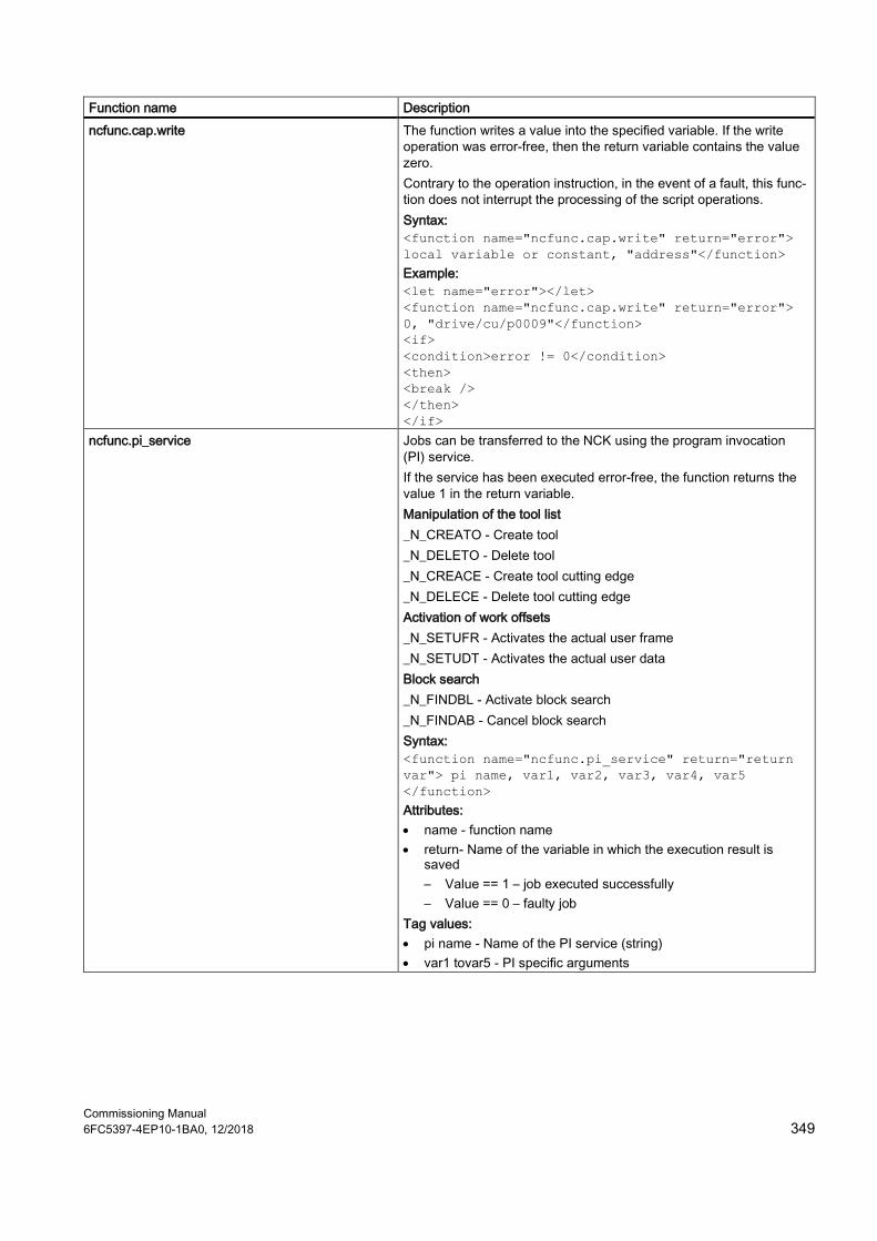
Commissioning Manual 6FC5397-4EP10-1BA0, 12/2018 349
Function name Description ncfunc.cap.write The function writes a value into the specified variable. If the write
operation was error-free, then the return variable contains the value zero. Contrary to the operation instruction, in the event of a fault, this func-tion does not interrupt the processing of the script operations. Syntax: <function name="ncfunc.cap.write" return="error"> local variable or constant, "address"</function>
Example: <let name="error"></let> <function name="ncfunc.cap.write" return="error"> 0, "drive/cu/p0009"</function> <if> <condition>error != 0</condition> <then> <break /> </then> </if>
ncfunc.pi_service Jobs can be transferred to the NCK using the program invocation (PI) service. If the service has been executed error-free, the function returns the value 1 in the return variable. Manipulation of the tool list _N_CREATO - Create tool _N_DELETO - Delete tool _N_CREACE - Create tool cutting edge _N_DELECE - Delete tool cutting edge Activation of work offsets _N_SETUFR - Activates the actual user frame _N_SETUDT - Activates the actual user data Block search _N_FINDBL - Activate block search _N_FINDAB - Cancel block search Syntax: <function name="ncfunc.pi_service" return="return var"> pi name, var1, var2, var3, var4, var5 </function>
Attributes: • name - function name • return- Name of the variable in which the execution result is
saved – Value == 1 – job executed successfully – Value == 0 – faulty job
Tag values: • pi name - Name of the PI service (string) • var1 tovar5 - PI specific arguments

Commissioning Manual 350 6FC5397-4EP10-1BA0, 12/2018
Function name Description ncfunc.pi_service Continued Arguments:
• _N_CREATO
var1 - Tool number • _N_DELETO
var1 - Tool number • _N_CREACE
var1 - Tool number
var2 - Cutting edge number • _N_DELECE
var1 - Tool number
var2 - Cutting edge number • _N_SETUFR
No arguments • _N_SETUDT
var1- User data area to be activated – 1 - Tool offset data – 2 - Active basic frame – 3 - Active adjustable frame
• _N_FINDBL
var1 - Search mode – 2 - Search with contour calculation – 4 - Search for the block end point – 1 - Block search without calculation.
• _N_FINDAB
No arguments Example: • Creating a tool – tool number 3 <function name="ncfunc.pi_service">_T"_N_CREATO", 3</function>
• Delete cutting edge 1 of tool 5 <function name="ncfunc.pi_service">_T"_N_DELECE", 5, 1</function>
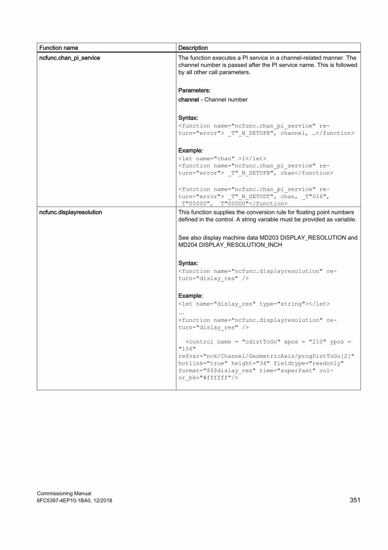
Commissioning Manual 6FC5397-4EP10-1BA0, 12/2018 351
Function name Description ncfunc.chan_pi_service The function executes a PI service in a channel-related manner. The
channel number is passed after the PI service name. This is followed by all other call parameters. Parameters: channel - Channel number Syntax: <function name="ncfunc.chan_pi_service" re-turn="error"> _T"_N_SETUFR", channel, …</function>
Example: <let name="chan" >1</let> <function name="ncfunc.chan_pi_service" re-turn="error"> _T"_N_SETUFR", chan</function>
<function name="ncfunc.chan_pi_service" re-turn="error"> _T"_N_SETUDT", chan, _T"016", _T"00000", _T"00000"</function>
ncfunc.displayresolution This function supplies the conversion rule for floating point numbers defined in the control. A string variable must be provided as variable. See also display machine data MD203 DISPLAY_RESOLUTION and MD204 DISPLAY_RESOLUTION_INCH Syntax: <function name="ncfunc.displayresolution" re-turn="dislay_res" />
Example: <let name="dislay_res" type="string"></let>
… <function name="ncfunc.displayresolution" re-turn="dislay_res" /> <control name = "cdistToGo" xpos = "210" ypos = "156" refvar="nck/Channel/GeometricAxis/progDistToGo[2]" hotlink="true" height="34" fieldtype="readonly" format="$$$dislay_res" time="superfast" col-or_bk="#ffffff"/>

Commissioning Manual 352 6FC5397-4EP10-1BA0, 12/2018
Function name Description ncfunc.password This function sets or deletes a password level.
• Set password:
The password should be specified for the required password lev-el as parameter.
• Delete password:
A blank string deletes the password level. Syntax: <function name="ncfunc.password">password </function>
Example: <let name="password"type="string"></let> <function name="ncfunc.password" > pass-word</function> <function name="ncfunc.password" > _T"CUSTOMER" </function>
Delete password: <function name="ncfunc.password" > _T"" </function>
control.formcolor This function provides the text or background color of the dialog box as string. Color coding (see Section "Color coding (Page 309)") Range: • BACKGROUND – request color value of the background • TEXT – request color value of the text (foreground) Syntax: <function name="control.formcolor" re-turn="variable">_T"range"</function> Example: <let name="bk_color" type="string"></let> <function name="control.formcolor" re-turn="bk_color">_T"BACKGROUND"</function>
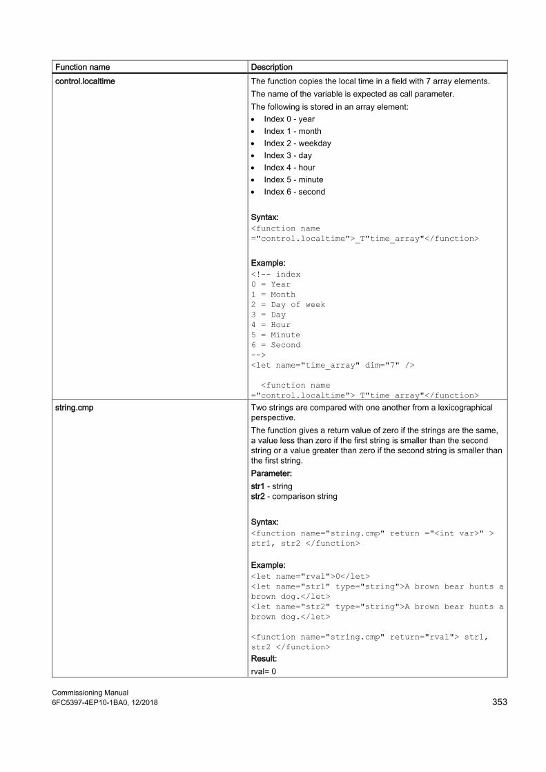
Commissioning Manual 6FC5397-4EP10-1BA0, 12/2018 353
Function name Description control.localtime The function copies the local time in a field with 7 array elements.
The name of the variable is expected as call parameter. The following is stored in an array element: • Index 0 - year • Index 1 - month • Index 2 - weekday • Index 3 - day • Index 4 - hour • Index 5 - minute • Index 6 - second Syntax: <function name ="control.localtime">_T"time_array"</function>
Example: <!-- index 0 = Year 1 = Month 2 = Day of week 3 = Day 4 = Hour 5 = Minute 6 = Second --> <let name="time_array" dim="7" /> <function name ="control.localtime">_T"time_array"</function>
string.cmp Two strings are compared with one another from a lexicographical perspective. The function gives a return value of zero if the strings are the same, a value less than zero if the first string is smaller than the second string or a value greater than zero if the second string is smaller than the first string. Parameter: str1 - string str2 - comparison string Syntax: <function name="string.cmp" return ="<int var>" > str1, str2 </function>
Example: <let name="rval">0</let> <let name="str1" type="string">A brown bear hunts a brown dog.</let> <let name="str2" type="string">A brown bear hunts a brown dog.</let> <function name="string.cmp" return="rval"> str1, str2 </function>
Result: rval= 0
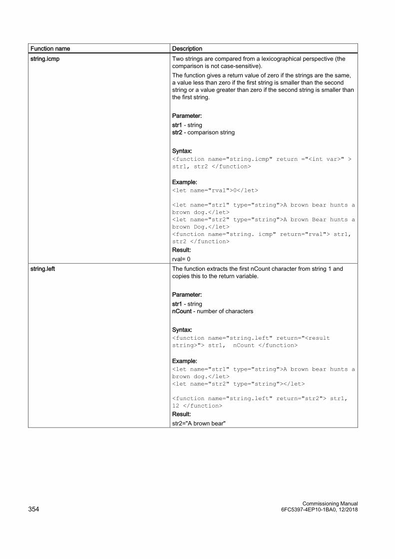
Commissioning Manual 354 6FC5397-4EP10-1BA0, 12/2018
Function name Description string.icmp Two strings are compared from a lexicographical perspective (the
comparison is not case-sensitive). The function gives a return value of zero if the strings are the same, a value less than zero if the first string is smaller than the second string or a value greater than zero if the second string is smaller than the first string. Parameter: str1 - string str2 - comparison string Syntax: <function name="string.icmp" return ="<int var>" > str1, str2 </function>
Example: <let name="rval">0</let> <let name="str1" type="string">A brown bear hunts a brown dog.</let> <let name="str2" type="string">A brown Bear hunts a brown Dog.</let> <function name="string. icmp" return="rval"> str1, str2 </function>
Result: rval= 0
string.left The function extracts the first nCount character from string 1 and copies this to the return variable. Parameter: str1 - string nCount - number of characters Syntax: <function name="string.left" return="<result string>"> str1, nCount </function>
Example: <let name="str1" type="string">A brown bear hunts a brown dog.</let> <let name="str2" type="string"></let> <function name="string.left" return="str2"> str1, 12 </function>
Result: str2="A brown bear"
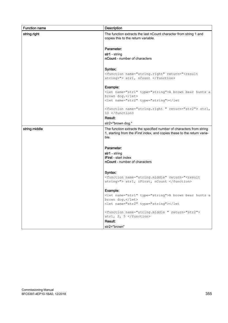
Commissioning Manual 6FC5397-4EP10-1BA0, 12/2018 355
Function name Description string.right The function extracts the last nCount character from string 1 and
copies this to the return variable. Parameter: str1 - string nCount - number of characters Syntax: <function name="string.right" return="<result string>"> str1, nCount </function>
Example: <let name="str1" type="string">A brown bear hunts a brown dog.</let> <let name="str2" type="string"></let <function name="string.right " return="str2"> str1, 10 </function>
Result: str2="brown dog."
string.middle The function extracts the specified number of characters from string 1, starting from the iFirst index, and copies these to the return varia-ble. Parameter: str1 - string iFirst - start index nCount - number of characters Syntax: <function name="string.middle" return="<result string>"> str1, iFirst, nCount </function>
Example: <let name="str1" type="string">A brown bear hunts a brown dog.</let> <let name="str2" type="string"></let <function name="string.middle " return="str2"> str1, 2, 5 </function>
Result: str2="brown"
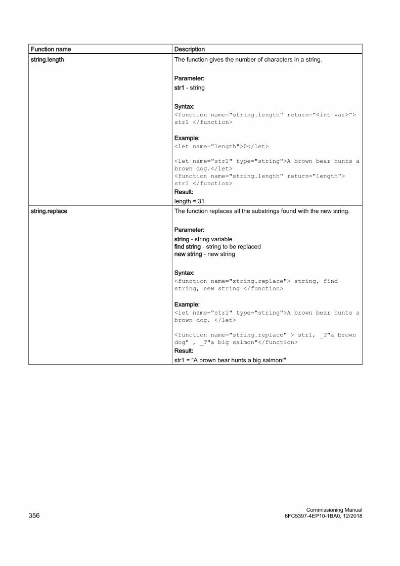
Commissioning Manual 356 6FC5397-4EP10-1BA0, 12/2018
Function name Description string.length The function gives the number of characters in a string.
Parameter: str1 - string Syntax: <function name="string.length" return="<int var>"> str1 </function>
Example: <let name="length">0</let> <let name="str1" type="string">A brown bear hunts a brown dog.</let> <function name="string.length" return="length"> str1 </function>
Result: length = 31
string.replace The function replaces all the substrings found with the new string. Parameter: string - string variable find string - string to be replaced new string - new string Syntax: <function name="string.replace"> string, find string, new string </function>
Example: <let name="str1" type="string">A brown bear hunts a brown dog. </let> <function name="string.replace" > str1, _T"a brown dog" , _T"a big salmon"</function>
Result: str1 = "A brown bear hunts a big salmon!"
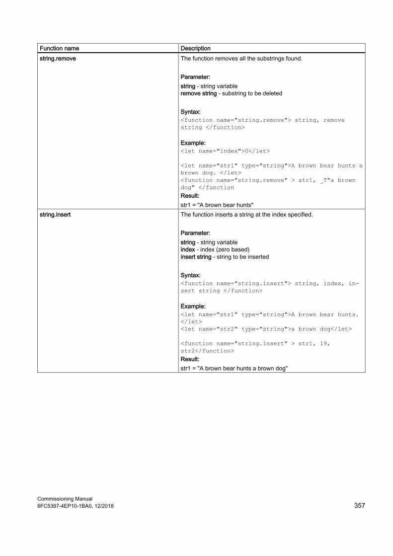
Commissioning Manual 6FC5397-4EP10-1BA0, 12/2018 357
Function name Description string.remove The function removes all the substrings found.
Parameter: string - string variable remove string - substring to be deleted Syntax: <function name="string.remove"> string, remove string </function>
Example: <let name="index">0</let> <let name="str1" type="string">A brown bear hunts a brown dog. </let> <function name="string.remove" > str1, _T"a brown dog" </function
Result: str1 = "A brown bear hunts"
string.insert The function inserts a string at the index specified. Parameter: string - string variable index - index (zero based) insert string - string to be inserted Syntax: <function name="string.insert"> string, index, in-sert string </function>
Example: <let name="str1" type="string">A brown bear hunts. </let> <let name="str2" type="string">a brown dog</let> <function name="string.insert" > str1, 19, str2</function>
Result: str1 = "A brown bear hunts a brown dog"

Commissioning Manual 358 6FC5397-4EP10-1BA0, 12/2018
Function name Description string.delete The function deletes the defined number of characters starting from
the start position specified. Parameter: string - string variable start index - start index (zero based) nCount - number of characters to be deleted Syntax: <function name="string.delete"> string, start index , nCount </function>
Example: <let name="str1" type="string">A brown bear hunts. </let> <function name="string.delete" > str1, 2, 5</function>
Result: str1 = "A bear hunts"
string.find The function searches the transferred string for the first match with the substring. If the substring is found, the function provides the index to the first character (starting with zero) or, failing this, -1. Parameter: string - string variable find string - string to be found startindex – start index (optional) Syntax: <function name="string.find" return="<int val>"> str1, find string </function>
Example: <let name="index">0</let> <let name="str1" type="string">A brown bear hunts a brown dog. </let> <function name="string.find" return="index"> str1, _T"brown" </function>
Result: Index = 2 or <function name="string.find" return="index"> str1, _T"brown", 1 </function>

Commissioning Manual 6FC5397-4EP10-1BA0, 12/2018 359
Function name Description string.reversefind The function searches the transferred string for the last match with
the substring. If the substring is found, the function provides the index to the first character (starting with zero) or, failing this, -1. Parameter: string - string variable find string - string to be found startindex – start index (optional) Syntax: <function name="string.reversefind" return="<int val>"> str1, find string </function>
Example: <let name="index">0</let> <let name="str1" type="string">A brown bear hunts a brown dog. </let> <function name="string.reversefind" return="index"> str1, _T"brown" </function>
Result: Index = 21 or <function name="string.reversefind" return="index"> str1, _T"brown", 10 </function>
Result: Index = 2
string.trimleft The function trims the starting characters from a string. Parameter: str1 - string variable Syntax: <function name="string.trimleft" > str1 </function>
Example: <let name="str1" type="string"> test trim left</let> <function name="string.trimleft" > str1 </function>
Result: str1 = "test trim left"

Commissioning Manual 360 6FC5397-4EP10-1BA0, 12/2018
Function name Description string.trimright The function trims the closing characters from a string.
Parameter: str1 - string variable Syntax: <function name="string.trimright" > str1 </function>
Example: <let name="str1" type="string"> test trim right </let> <function name="string.trimright" > str1 </function>
Result: str1 = "test trim right"
sin The function calculates the sine of the value transferred in degrees. Parameter: double - angle Syntax: <function name="sin" return="<double val>"> double </function>
Example: <let name= "sin_val" type="double"></let> <function name="sin" return="sin_val"> 20.0 </function>
cos The function calculates the cosine of the value transferred in de-grees. Parameter: double - angle Syntax: <function name="cos" return="<double val>"> double </function>
Example: <let name= "cos_val" type="double"></let> <function name="cos" return="cos_val"> 20.0 </function>

Commissioning Manual 6FC5397-4EP10-1BA0, 12/2018 361
Function name Description tan The function calculates the tangent of the value transferred in de-
grees. Parameter: double - angle Syntax: <function name="tan" return="<double val>"> double </function>
Example: <let name= "tan_val" type="double"></let> <function name="tan" return="tan_val"> 20.0 </function>
arcsin The function calculates the arcsine of the value transferred in de-grees. Parameter: double - x in the range from -PI/2 to +PI/2 Syntax: <function name="arcsin" return="<double val>"> dou-ble </function>
Example: <let name= "arcsin_val" type="double"></let> <function name="arcsin" return="arcsin_val"> 20.0 </function>
arcos The function calculates the arccosine of the value transferred in degrees. Parameter: double - x in the range from -PI/2 to +PI/2 Syntax: <function name="arcos" return="<double val>"> dou-ble </function>
Example: <let name= "arccos_val" type="double"></let> <function name="arccos" return="arccos_val"> 20.0 </function>
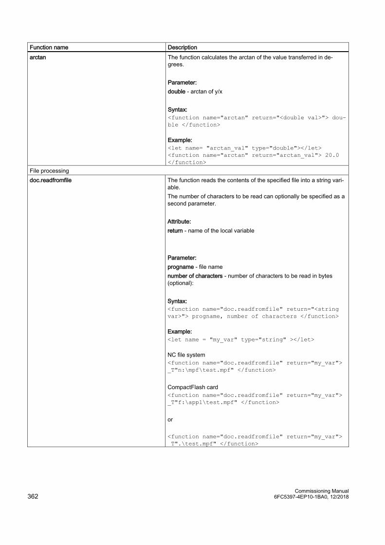
Commissioning Manual 362 6FC5397-4EP10-1BA0, 12/2018
Function name Description arctan The function calculates the arctan of the value transferred in de-
grees. Parameter: double - arctan of y/x Syntax: <function name="arctan" return="<double val>"> dou-ble </function>
Example: <let name= "arctan_val" type="double"></let> <function name="arctan" return="arctan_val"> 20.0 </function>
File processing doc.readfromfile The function reads the contents of the specified file into a string vari-
able. The number of characters to be read can optionally be specified as a second parameter. Attribute: return - name of the local variable Parameter: progname - file name number of characters - number of characters to be read in bytes (optional): Syntax: <function name="doc.readfromfile" return="<string var>"> progname, number of characters </function>
Example: <let name = "my_var" type="string" ></let>
NC file system <function name="doc.readfromfile" return="my_var"> _T"n:\mpf\test.mpf" </function>
CompactFlash card <function name="doc.readfromfile" return="my_var"> _T"f:\appl\test.mpf" </function>
or <function name="doc.readfromfile" return="my_var"> _T".\test.mpf" </function>
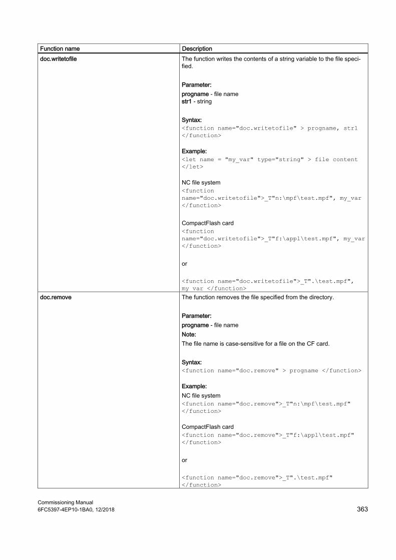
Commissioning Manual 6FC5397-4EP10-1BA0, 12/2018 363
Function name Description doc.writetofile The function writes the contents of a string variable to the file speci-
fied. Parameter: progname - file name str1 - string Syntax: <function name="doc.writetofile" > progname, str1 </function>
Example: <let name = "my_var" type="string" > file content </let>
NC file system <function name="doc.writetofile">_T"n:\mpf\test.mpf", my_var </function>
CompactFlash card <function name="doc.writetofile">_T"f:\appl\test.mpf", my_var </function>
or <function name="doc.writetofile">_T".\test.mpf", my_var </function>
doc.remove The function removes the file specified from the directory. Parameter: progname - file name Note: The file name is case-sensitive for a file on the CF card. Syntax: <function name="doc.remove" > progname </function>
Example: NC file system <function name="doc.remove">_T"n:\mpf\test.mpf" </function>
CompactFlash card <function name="doc.remove">_T"f:\appl\test.mpf" </function>
or <function name="doc.remove">_T".\test.mpf" </function>
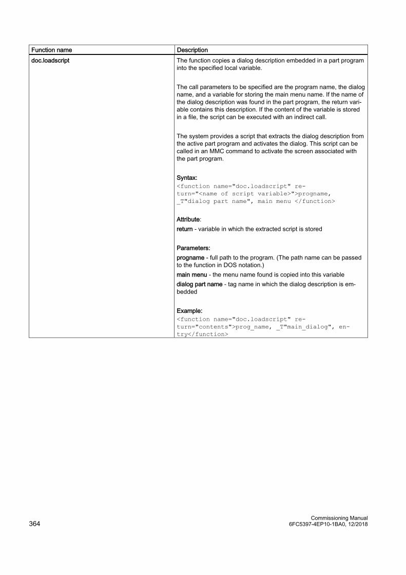
Commissioning Manual 364 6FC5397-4EP10-1BA0, 12/2018
Function name Description doc.loadscript The function copies a dialog description embedded in a part program
into the specified local variable. The call parameters to be specified are the program name, the dialog name, and a variable for storing the main menu name. If the name of the dialog description was found in the part program, the return vari-able contains this description. If the content of the variable is stored in a file, the script can be executed with an indirect call. The system provides a script that extracts the dialog description from the active part program and activates the dialog. This script can be called in an MMC command to activate the screen associated with the part program. Syntax: <function name="doc.loadscript" re-turn="<name of script variable>">progname, _T"dialog part name", main menu </function>
Attribute: return - variable in which the extracted script is stored Parameters: progname - full path to the program. (The path name can be passed to the function in DOS notation.) main menu - the menu name found is copied into this variable dialog part name - tag name in which the dialog description is em-bedded Example: <function name="doc.loadscript" re-turn="contents">prog_name, _T"main_dialog", en-try</function>
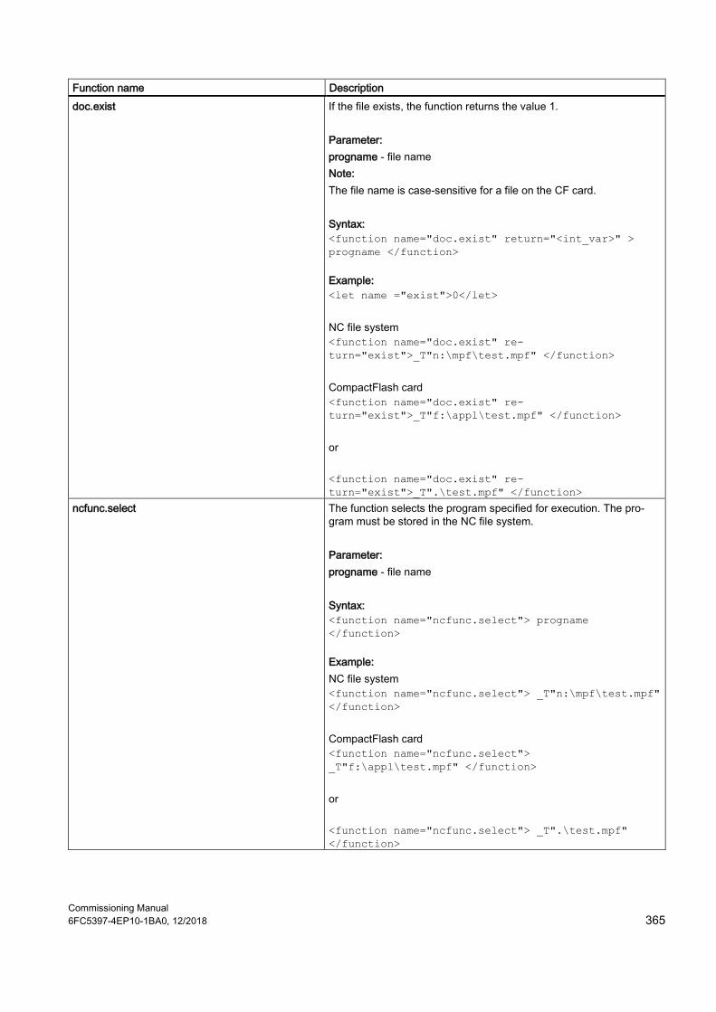
Commissioning Manual 6FC5397-4EP10-1BA0, 12/2018 365
Function name Description doc.exist If the file exists, the function returns the value 1.
Parameter: progname - file name Note: The file name is case-sensitive for a file on the CF card. Syntax: <function name="doc.exist" return="<int_var>" > progname </function>
Example: <let name ="exist">0</let>
NC file system <function name="doc.exist" re-turn="exist">_T"n:\mpf\test.mpf" </function>
CompactFlash card <function name="doc.exist" re-turn="exist">_T"f:\appl\test.mpf" </function>
or <function name="doc.exist" re-turn="exist">_T".\test.mpf" </function>
ncfunc.select The function selects the program specified for execution. The pro-gram must be stored in the NC file system. Parameter: progname - file name Syntax: <function name="ncfunc.select"> progname </function>
Example: NC file system <function name="ncfunc.select"> _T"n:\mpf\test.mpf" </function>
CompactFlash card <function name="ncfunc.select"> _T"f:\appl\test.mpf" </function>
or <function name="ncfunc.select"> _T".\test.mpf" </function>

Commissioning Manual 366 6FC5397-4EP10-1BA0, 12/2018
Function name Description ncfunc.bitset The function is used to manipulate individual bits of the specified
variables. The bits can either be set or reset. Syntax: <function name="ncfunc.bitset" refvar="address" value="set/reset" > bit0, bit1, … bit9 </function>
Attributes: refvar - specifies the name of the variable, in which the bit combina-tion should be written value – bit value, value range 0 and 1 Values: The bit numbers starting with zero should be transferred as function values. A maximum of 10 bits per call can be modified. Example: <function name="ncfunc.bitset" refvar="nck/Channel/Parameter/R[1]" value="1" > 0, 2, 3, 7 </function> <function name="ncfunc.bitset" refvar="nck/Channel/Parameter/R[1]" value="0" > 1, 4 </function>
control.delete The function deletes the specified control. Syntax: <function name="control.delete"> control name </function>
Attribute: name – function name Value: control name – name of the control Example: <function name="<control.delete>"> _T"my_editfield" </function>
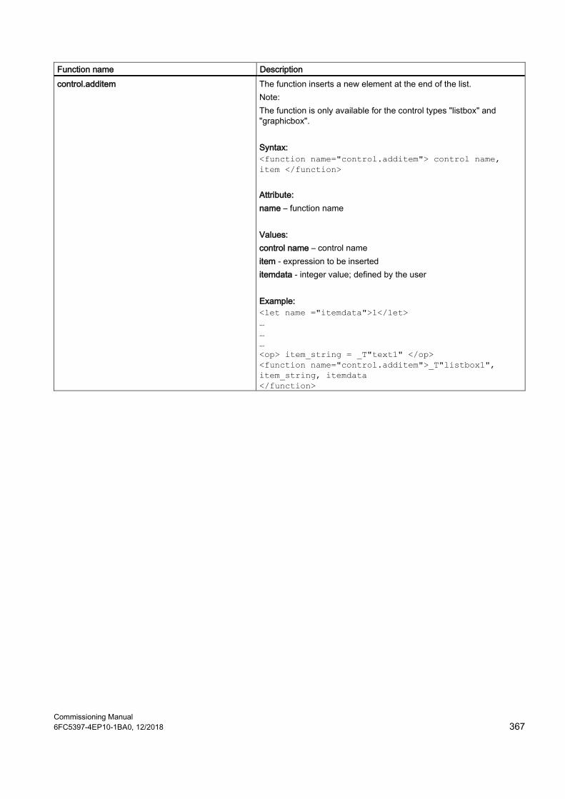
Commissioning Manual 6FC5397-4EP10-1BA0, 12/2018 367
Function name Description control.additem The function inserts a new element at the end of the list.
Note: The function is only available for the control types "listbox" and "graphicbox". Syntax: <function name="control.additem"> control name, item </function>
Attribute: name – function name Values: control name – control name item - expression to be inserted itemdata - integer value; defined by the user Example: <let name ="itemdata">1</let> … … … <op> item_string = _T"text1" </op> <function name="control.additem">_T"listbox1", item_string, itemdata </function>
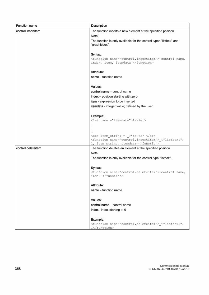
Commissioning Manual 368 6FC5397-4EP10-1BA0, 12/2018
Function name Description control.insertitem The function inserts a new element at the specified position.
Note: The function is only available for the control types "listbox" and "graphicbox". Syntax: <function name="control.insertitem"> control name, index, item, itemdata </function>
Attribute: name – function name Values: control name – control name index – position starting with zero item - expression to be inserted itemdata - integer value; defined by the user Example: <let name ="itemdata">1</let> … … … <op> item_string = _T"text2" </op> <function name="control.insertitem">_T"listbox1", 1, item_string, itemdata </function>
control.deleteitem The function deletes an element at the specified position. Note: The function is only available for the control type "listbox". Syntax: <function name="control.deleteitem"> control name, index </function>
Attribute: name – function name Values: control name – control name index– index starting at 0 Example: <function name="control.deleteitem">_T"listbox1", 1</function>
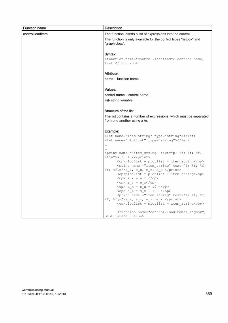
Commissioning Manual 6FC5397-4EP10-1BA0, 12/2018 369
Function name Description control.loaditem The function inserts a list of expressions into the control.
The function is only available for the control types "listbox" and "graphicbox". Syntax: <function name="control.loaditem"> control name, list </function>
Attribute: name – function name Values: control name – control name list- string variable Structure of the list: The list contains a number of expressions, which must be separated from one another using a \n. Example: <let name="item_string" type="string"></let> <let name="plotlist" type="string"></let> … … <print name ="item_string" text="p; %f; %f; %f; %f\n">s_z, s_x</print> <op>plotlist = plotlist + item_string</op> <print name ="item_string" text="l; %f; %f; %f; %f\n">s_z, s_x, e_z, e_x </print> <op>plotlist = plotlist + item_string</op> <op> s_x = e_x </op> <op> s_z = e_z</op> <op> e_x = s_x + 10 </op> <op> e_z = s_z - 100 </op> <print name ="item_string" text="l; %f; %f; %f; %f\n">s_z, s_x, e_z, e_x </print> <op>plotlist = plotlist + item_string</op> <function name="control.loaditem">_T"gbox", plotlist</function>
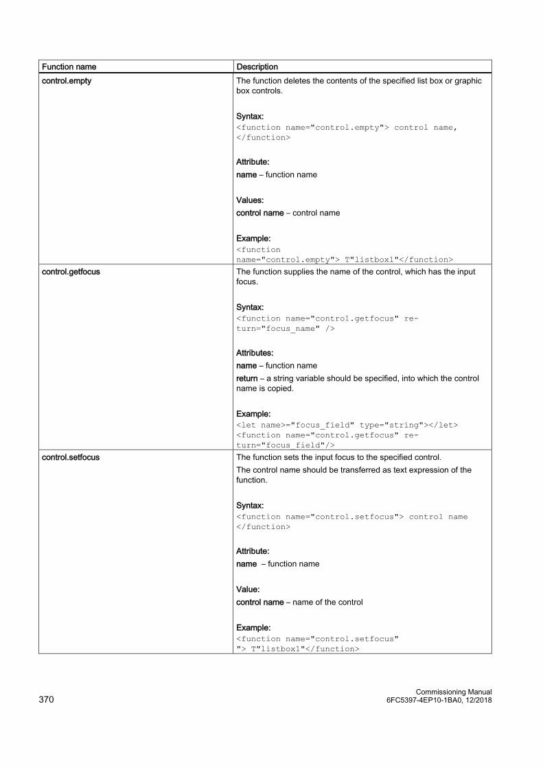
Commissioning Manual 370 6FC5397-4EP10-1BA0, 12/2018
Function name Description control.empty The function deletes the contents of the specified list box or graphic
box controls. Syntax: <function name="control.empty"> control name, </function>
Attribute: name – function name Values: control name – control name Example: <function name="control.empty">_T"listbox1"</function>
control.getfocus The function supplies the name of the control, which has the input focus. Syntax: <function name="control.getfocus" re-turn="focus_name" />
Attributes: name – function name return – a string variable should be specified, into which the control name is copied. Example: <let name>="focus_field" type="string"></let> <function name="control.getfocus" re-turn="focus_field"/>
control.setfocus The function sets the input focus to the specified control. The control name should be transferred as text expression of the function. Syntax: <function name="control.setfocus"> control name </function>
Attribute: name – function name Value: control name – name of the control Example: <function name="control.setfocus" ">_T"listbox1"</function>

Commissioning Manual 6FC5397-4EP10-1BA0, 12/2018 371
Function name Description control.getcurssel For a list box, the function supplies the cursor index.
The control name should be transferred as text expression of the function. Syntax: <function name="control.getcurssel" retvar="var"> control name </function>
Example: <let name>="index"></let> <function name="control.getcurssel" ">_T"listbox1"</function>
control.setcurssel For a list box, the function sets the cursor to the appropriate line. The control name should be transferred as text expression of the function. Syntax: <function name="control.setcurssel" > control name, index</function>
Example: <let name>="index">2</let> <function name="control.setcurssel" ">_T"listbox1",index</function>
control.getitem For a list box, the function copies the contents of the selected line to the specified variable. A string variable should be specified as reference variable. The control name should be transferred as text expression of the function. Syntax: <function name="control.getitem" return="var"> con-trol name, index </function>
Example: <let name>="index">2</let> <let name>="item" type="string"></let> <function name="control.getitem" return="item" ">_T"listbox1",index</function>
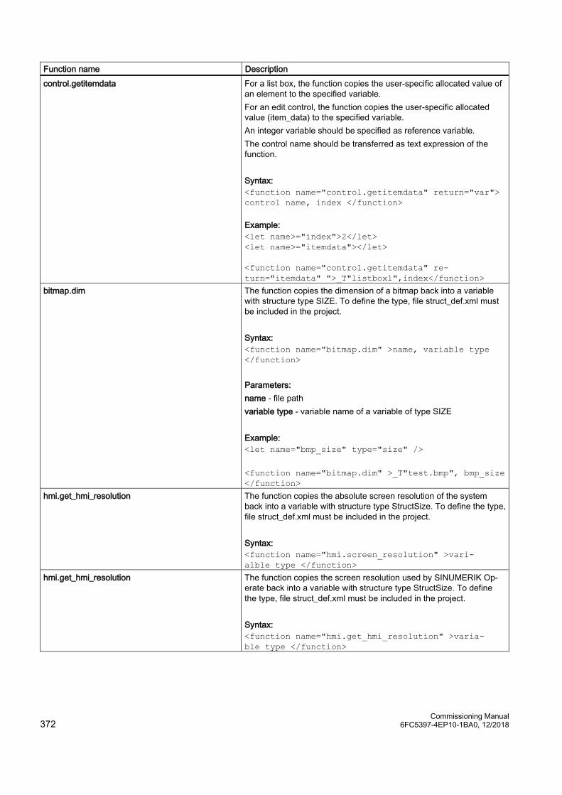
Commissioning Manual 372 6FC5397-4EP10-1BA0, 12/2018
Function name Description control.getitemdata For a list box, the function copies the user-specific allocated value of
an element to the specified variable. For an edit control, the function copies the user-specific allocated value (item_data) to the specified variable. An integer variable should be specified as reference variable. The control name should be transferred as text expression of the function. Syntax: <function name="control.getitemdata" return="var"> control name, index </function>
Example: <let name>="index">2</let> <let name>="itemdata"></let> <function name="control.getitemdata" re-turn="itemdata" ">_T"listbox1",index</function>
bitmap.dim The function copies the dimension of a bitmap back into a variable with structure type SIZE. To define the type, file struct_def.xml must be included in the project. Syntax: <function name="bitmap.dim" >name, variable type </function>
Parameters: name - file path variable type - variable name of a variable of type SIZE Example: <let name="bmp_size" type="size" />
<function name="bitmap.dim" >_T"test.bmp", bmp_size </function>
hmi.get_hmi_resolution The function copies the absolute screen resolution of the system back into a variable with structure type StructSize. To define the type, file struct_def.xml must be included in the project. Syntax: <function name="hmi.screen_resolution" >vari-alble type </function>
hmi.get_hmi_resolution The function copies the screen resolution used by SINUMERIK Op-erate back into a variable with structure type StructSize. To define the type, file struct_def.xml must be included in the project. Syntax: <function name="hmi.get_hmi_resolution" >varia-ble type </function>
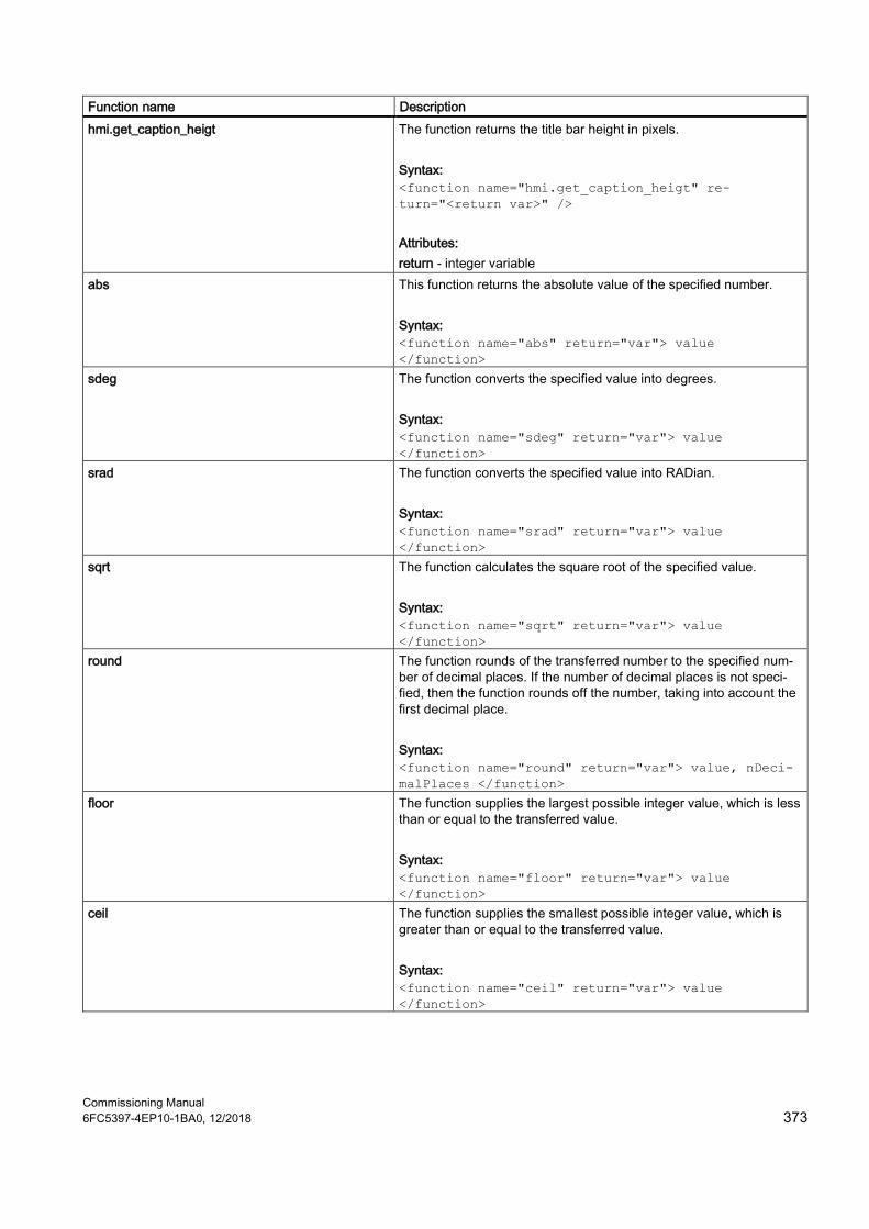
Commissioning Manual 6FC5397-4EP10-1BA0, 12/2018 373
Function name Description hmi.get_caption_heigt The function returns the title bar height in pixels.
Syntax: <function name="hmi.get_caption_heigt" re-turn="<return var>" />
Attributes: return - integer variable
abs This function returns the absolute value of the specified number. Syntax: <function name="abs" return="var"> value </function>
sdeg The function converts the specified value into degrees. Syntax: <function name="sdeg" return="var"> value </function>
srad The function converts the specified value into RADian. Syntax: <function name="srad" return="var"> value </function>
sqrt The function calculates the square root of the specified value. Syntax: <function name="sqrt" return="var"> value </function>
round The function rounds of the transferred number to the specified num-ber of decimal places. If the number of decimal places is not speci-fied, then the function rounds off the number, taking into account the first decimal place. Syntax: <function name="round" return="var"> value, nDeci-malPlaces </function>
floor The function supplies the largest possible integer value, which is less than or equal to the transferred value. Syntax: <function name="floor" return="var"> value </function>
ceil The function supplies the smallest possible integer value, which is greater than or equal to the transferred value. Syntax: <function name="ceil" return="var"> value </function>
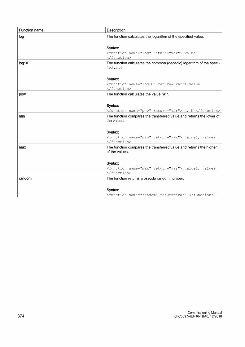
Commissioning Manual 374 6FC5397-4EP10-1BA0, 12/2018
Function name Description log The function calculates the logarithm of the specified value.
Syntax: <function name="log" return="var"> value </function>
log10 The function calculates the common (decadic) logarithm of the speci-fied value. Syntax: <function name="log10" return="var"> value </function>
pow The function calculates the value "ab". Syntax: <function name="pow" return="var"> a, b </function>
min The function compares the transferred value and returns the lower of the values. Syntax: <function name="min" return="var"> value1, value2 </function>
max The function compares the transferred value and returns the higher of the values. Syntax: <function name="max" return="var"> value1, value2 </function>
random The function returns a pseudo random number. Syntax: <function name="random" return="var" </function>
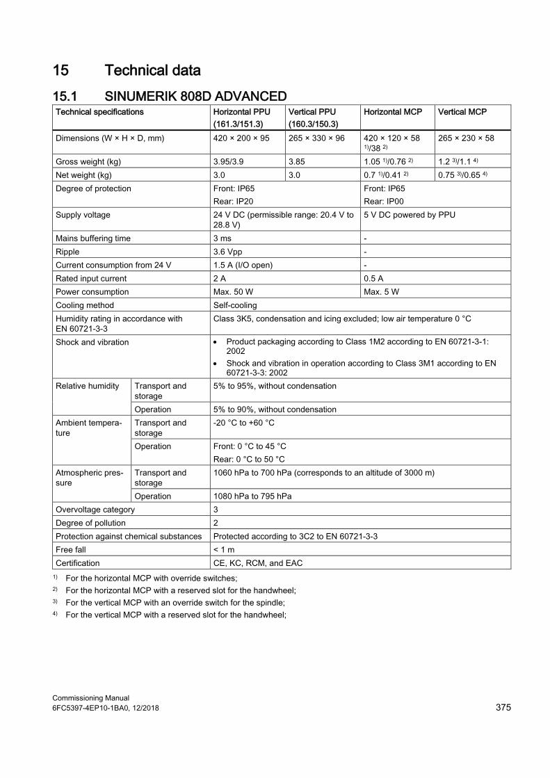
Commissioning Manual 6FC5397-4EP10-1BA0, 12/2018 375
15 Technical data 15.1 SINUMERIK 808D ADVANCED Technical specifications Horizontal PPU
(161.3/151.3) Vertical PPU (160.3/150.3)
Horizontal MCP Vertical MCP
Dimensions (W × H × D, mm) 420 × 200 × 95 265 × 330 × 96 420 × 120 × 58 1)/38 2)
265 × 230 × 58
Gross weight (kg) 3.95/3.9 3.85 1.05 1)/0.76 2) 1.2 3)/1.1 4) Net weight (kg) 3.0 3.0 0.7 1)/0.41 2) 0.75 3)/0.65 4) Degree of protection Front: IP65
Rear: IP20 Front: IP65 Rear: IP00
Supply voltage 24 V DC (permissible range: 20.4 V to 28.8 V)
5 V DC powered by PPU
Mains buffering time 3 ms - Ripple 3.6 Vpp - Current consumption from 24 V 1.5 A (I/O open) - Rated input current 2 A 0.5 A Power consumption Max. 50 W Max. 5 W Cooling method Self-cooling Humidity rating in accordance with EN 60721-3-3
Class 3K5, condensation and icing excluded; low air temperature 0 °C
Shock and vibration • Product packaging according to Class 1M2 according to EN 60721-3-1: 2002
• Shock and vibration in operation according to Class 3M1 according to EN 60721-3-3: 2002
Relative humidity Transport and storage
5% to 95%, without condensation
Operation 5% to 90%, without condensation Ambient tempera-ture
Transport and storage
-20 °C to +60 °C
Operation Front: 0 °C to 45 °C Rear: 0 °C to 50 °C
Atmospheric pres-sure
Transport and storage
1060 hPa to 700 hPa (corresponds to an altitude of 3000 m)
Operation 1080 hPa to 795 hPa Overvoltage category 3 Degree of pollution 2 Protection against chemical substances Protected according to 3C2 to EN 60721-3-3 Free fall < 1 m Certification CE, KC, RCM, and EAC 1) For the horizontal MCP with override switches;
2) For the horizontal MCP with a reserved slot for the handwheel; 3) For the vertical MCP with an override switch for the spindle; 4) For the vertical MCP with a reserved slot for the handwheel;
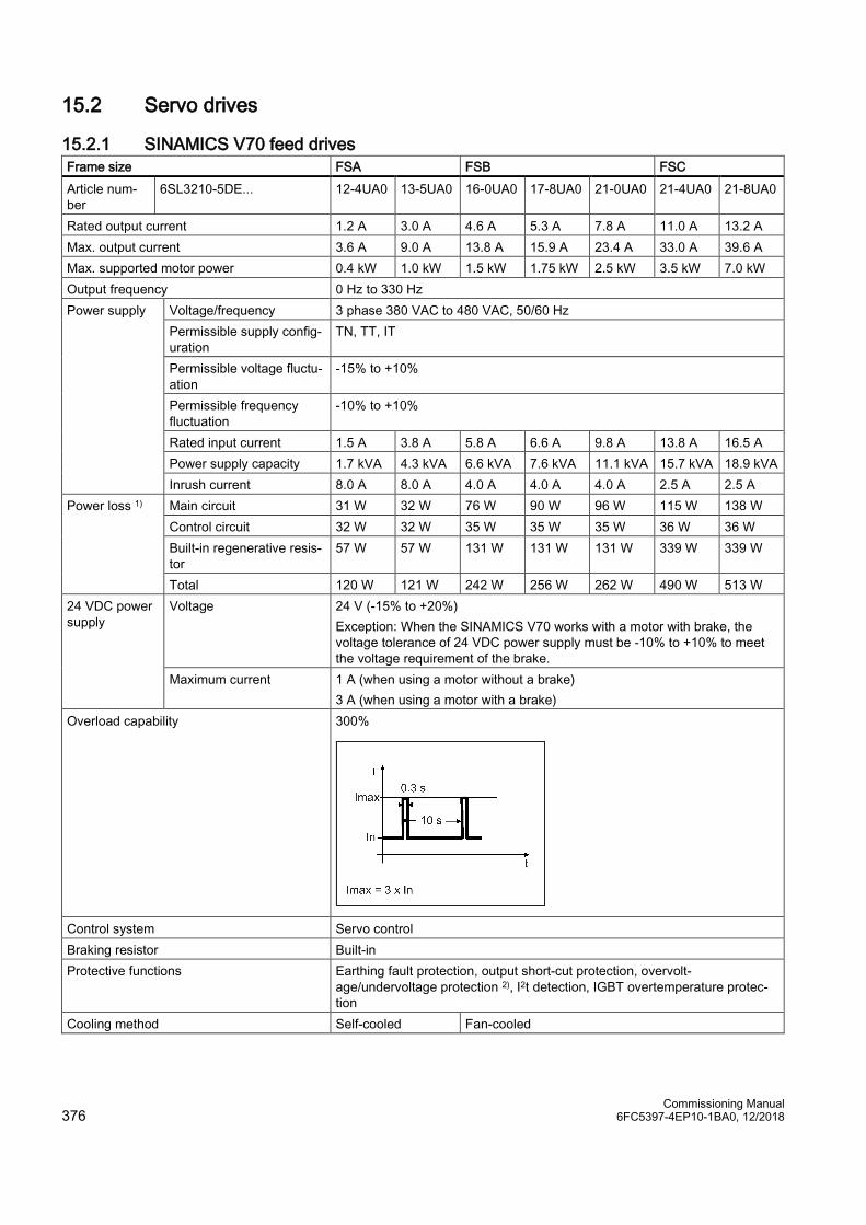
Commissioning Manual 376 6FC5397-4EP10-1BA0, 12/2018
15.2 Servo drives
15.2.1 SINAMICS V70 feed drives Frame size FSA FSB FSC Article num-ber
6SL3210-5DE... 12-4UA0 13-5UA0 16-0UA0 17-8UA0 21-0UA0 21-4UA0 21-8UA0
Rated output current 1.2 A 3.0 A 4.6 A 5.3 A 7.8 A 11.0 A 13.2 A Max. output current 3.6 A 9.0 A 13.8 A 15.9 A 23.4 A 33.0 A 39.6 A Max. supported motor power 0.4 kW 1.0 kW 1.5 kW 1.75 kW 2.5 kW 3.5 kW 7.0 kW Output frequency 0 Hz to 330 Hz Power supply Voltage/frequency 3 phase 380 VAC to 480 VAC, 50/60 Hz
Permissible supply config-uration
TN, TT, IT
Permissible voltage fluctu-ation
-15% to +10%
Permissible frequency fluctuation
-10% to +10%
Rated input current 1.5 A 3.8 A 5.8 A 6.6 A 9.8 A 13.8 A 16.5 A Power supply capacity 1.7 kVA 4.3 kVA 6.6 kVA 7.6 kVA 11.1 kVA 15.7 kVA 18.9 kVA Inrush current 8.0 A 8.0 A 4.0 A 4.0 A 4.0 A 2.5 A 2.5 A
Power loss 1) Main circuit 31 W 32 W 76 W 90 W 96 W 115 W 138 W Control circuit 32 W 32 W 35 W 35 W 35 W 36 W 36 W Built-in regenerative resis-tor
57 W 57 W 131 W 131 W 131 W 339 W 339 W
Total 120 W 121 W 242 W 256 W 262 W 490 W 513 W 24 VDC power supply
Voltage 24 V (-15% to +20%) Exception: When the SINAMICS V70 works with a motor with brake, the voltage tolerance of 24 VDC power supply must be -10% to +10% to meet the voltage requirement of the brake.
Maximum current 1 A (when using a motor without a brake) 3 A (when using a motor with a brake)
Overload capability 300%
Control system Servo control Braking resistor Built-in Protective functions Earthing fault protection, output short-cut protection, overvolt-
age/undervoltage protection 2), I2t detection, IGBT overtemperature protec-tion
Cooling method Self-cooled Fan-cooled
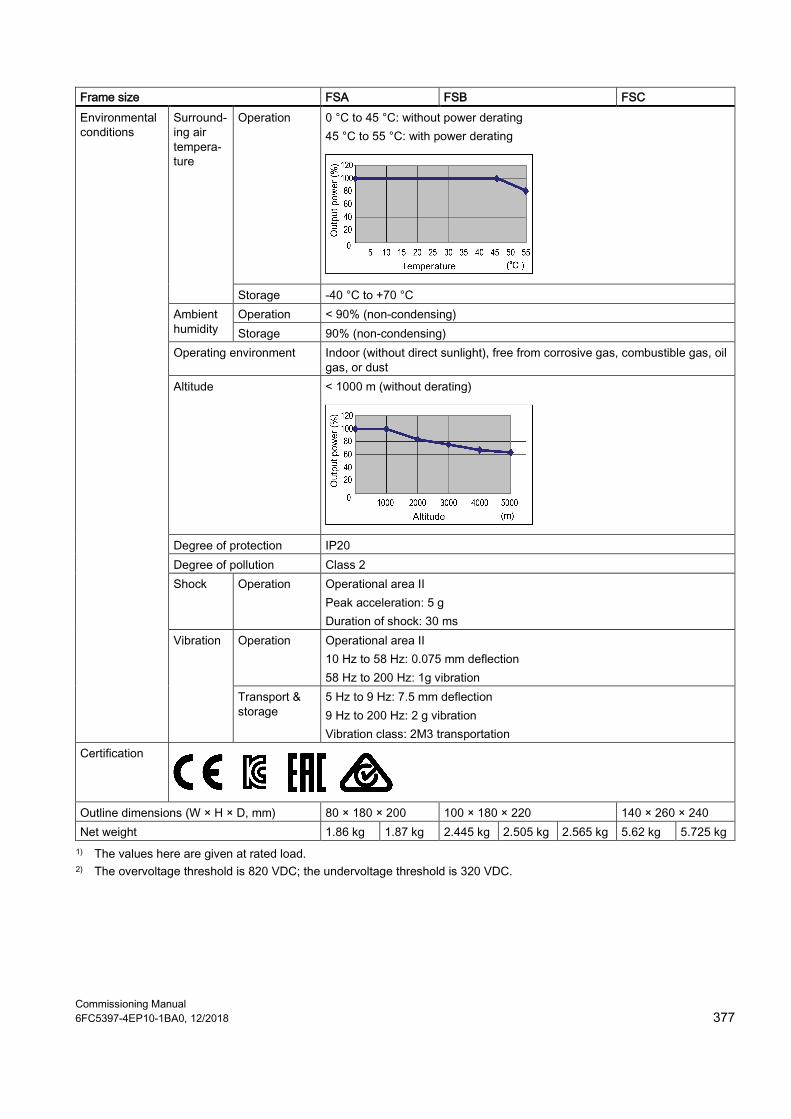
Commissioning Manual 6FC5397-4EP10-1BA0, 12/2018 377
Frame size FSA FSB FSC Environmental conditions
Surround-ing air tempera-ture
Operation 0 °C to 45 °C: without power derating 45 °C to 55 °C: with power derating
Storage -40 °C to +70 °C Ambient humidity
Operation < 90% (non-condensing) Storage 90% (non-condensing)
Operating environment Indoor (without direct sunlight), free from corrosive gas, combustible gas, oil gas, or dust
Altitude < 1000 m (without derating)
Degree of protection IP20 Degree of pollution Class 2 Shock Operation Operational area II
Peak acceleration: 5 g Duration of shock: 30 ms
Vibration Operation Operational area II 10 Hz to 58 Hz: 0.075 mm deflection 58 Hz to 200 Hz: 1g vibration
Transport & storage
5 Hz to 9 Hz: 7.5 mm deflection 9 Hz to 200 Hz: 2 g vibration Vibration class: 2M3 transportation
Certification
Outline dimensions (W × H × D, mm) 80 × 180 × 200 100 × 180 × 220 140 × 260 × 240 Net weight 1.86 kg 1.87 kg 2.445 kg 2.505 kg 2.565 kg 5.62 kg 5.725 kg 1) The values here are given at rated load.
2) The overvoltage threshold is 820 VDC; the undervoltage threshold is 320 VDC.
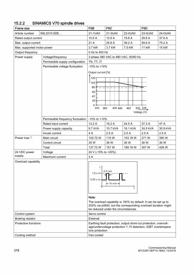
Commissioning Manual 378 6FC5397-4EP10-1BA0, 12/2018
15.2.2 SINAMICS V70 spindle drives Frame size FSB FSC FSD Article number 6SL3210-5DE... 21-1UA0 21-3UA0 22-0UA0 23-0UA0 24-0UA0 Rated output current 10.5 A 12.9 A 19.6 A 29.8 A 37.6 A Max. output current 21 A 25.8 A 39.2 A 59.6 A 75.2 A Max. supported motor power 3.7 kW 3.7 kW 7.5 kW 11 kW 15 kW Output frequency 0 Hz to 400 Hz Power supply Voltage/frequency 3 phase 380 VAC to 480 VAC, 50/60 Hz
Permissible supply configuration TN, TT, IT Permissible voltage fluctuation -15% to +10%
Permissible frequency fluctuation -10% to +10% Rated input current 13.2 A 16.2 A 24.5 A 37.3 A 47 A Power supply capacity 8.7 kVA 10.7 kVA 16.1 kVA 24.5 kVA 30.9 kVA Inrush current 4 A 2.5 A 2.5 A 2.5 A 2.5 A
Power loss 1) Main circuit 102.72 W 115 W 153.18 W 271 W 390 W Control circuit 35 W 36 W 36 W 36 W 36 W Total 137.72 W 151 W 189.18 W 307 W 426 W
24 VDC power supply
Voltage 24 V (-15% to +20%) Maximum current 3 A
Overload capability
Note: The overload capability is 150% by default. It can be set up to 200% via p0640, but the corresponding overload duration might be reduced under the circumstances.
Control system Servo control Braking resistor External Protective functions Earthing fault protection, output short-cut protection, overvolt-
age/undervoltage protection 2), I2t detection, IGBT overtempera-ture protection
Cooling method Fan-cooled
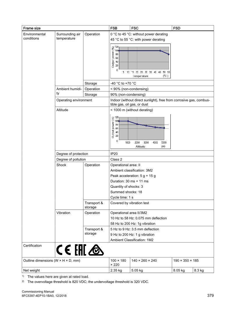
Commissioning Manual 6FC5397-4EP10-1BA0, 12/2018 379
Frame size FSB FSC FSD Environmental conditions
Surrounding air temperature
Operation 0 °C to 45 °C: without power derating 45 °C to 55 °C: with power derating
Storage -40 °C to +70 °C
Ambient humidi-ty
Operation < 90% (non-condensing) Storage 90% (non-condensing)
Operating environment Indoor (without direct sunlight), free from corrosive gas, combus-tible gas, oil gas, or dust
Altitude < 1000 m (without derating)
Degree of protection IP20 Degree of pollution Class 2 Shock Operation Operational area: II
Ambient classification: 3M2 Peak acceleration: 5 g + 15 g Duration: 30 ms + 11 ms Quantity of shocks: 3 Summed shocks: 18 Cycle time: 1 s
Transport & storage
Covered by vibration test
Vibration Operation Operational area II/3M2 10 Hz to 58 Hz: 0.075 mm deflection 58 Hz to 200 Hz: 1g vibration
Transport & storage
5 Hz to 9 Hz: 3.5 mm deflection 9 Hz to 200 Hz: 1 g vibration Ambient Classification: 1M2
Certification
Outline dimensions (W × H × D, mm) 100 × 180
× 220 140 × 260 × 240 190 × 350 × 185
Net weight 2.35 kg 5.05 kg 8.05 kg 8.3 kg 1) The values here are given at rated load.
2) The overvoltage threshold is 820 VDC; the undervoltage threshold is 320 VDC.

Commissioning Manual 380 6FC5397-4EP10-1BA0, 12/2018
15.2.3 Permissible line supplies dependent on the installation altitude ● For installation altitudes ≤ 2000 m above sea level, it is permissible to connect the V70 drive to any of the line supplies
that are specified for it.
● For installation altitudes 2000 m to 5000 m above sea level, you must connect a V70 drive to any of the specified line supplies either via an isolating transformer or with a grounded neutral point.
15.3 Servo motors
15.3.1 SIMOTICS S-1FL6 feed motors
General technical data
Parameter Description Type of motor Permanent-magnet synchronous motor Cooling Self-cooled Operating temperature 0 °C to 40 °C (without power derating) Storage temperature -20 °C to +65 °C Relative humidity ≤ 90% (non-condensing at 30 °C) Installation altitude ≤ 1000 m (without power derating) Maximum noise level 1FL604❑: 65 dB; 1FL606❑: 70 dB; 1FL609❑: 70 dB Thermal class B Vibration resistance ≤ 49 m/s2 Shock resistance ≤ 25 m/s2 (continuous in axial direction); ≤ 50 m/s2 (continuous in
radial direction); ≤ 250 m/s2 (in a short time of 6 ms) Holding brake
Rated voltage 24 V ± 10% Rated current 1FL604❑: 0.88 A 1FL606❑ : 1.44 A 1FL609❑: 1.88 A Holding brake torque 1FL604❑: 3.5 Nm 1FL606❑ : 12 Nm 1FL609❑: 30 Nm Maximum brake opening time 1FL604❑: 60 ms 1FL606❑ : 180 ms 1FL609❑: 220 ms Maximum brake closing time 1FL604❑: 45 ms 1FL606❑ : 60 ms 1FL609❑: 115 ms Maximum number of emergency stops 2000 1)
Bearing lifetime > 20000 h 2) Oil seal lifetime 5000 h Encoder lifetime > 20000 h 3) Paint finish Black Degree of protection IP65, with shaft oil seal Type of construction IM B5, IM V1 and IM V3 Positive rotation
Clockwise (default setting in SINAMICS V70 feed drives)
Certification
1) Restricted emergency stop operation is permissible. Up to 2000 braking operations can be executed with 300% rotor
moment of inertia as external moment of inertia from a speed of 3000 RPM without the brake being subject to an inad-missible amount of wear.
2) This lifetime is only for reference. When a motor keeps running at rated speed under rated load, replace its bearing after 20,000 hours to 30,000 hours of service time. Even if the time is not reached, the bearing must be replaced when unu-sual noise, vibration, or faults are found.
3) This lifetime is only for reference. When a motor keeps running at 80% rated value and the surrounding air temperature is 30 °C, the encoder lifetime can be ensured.
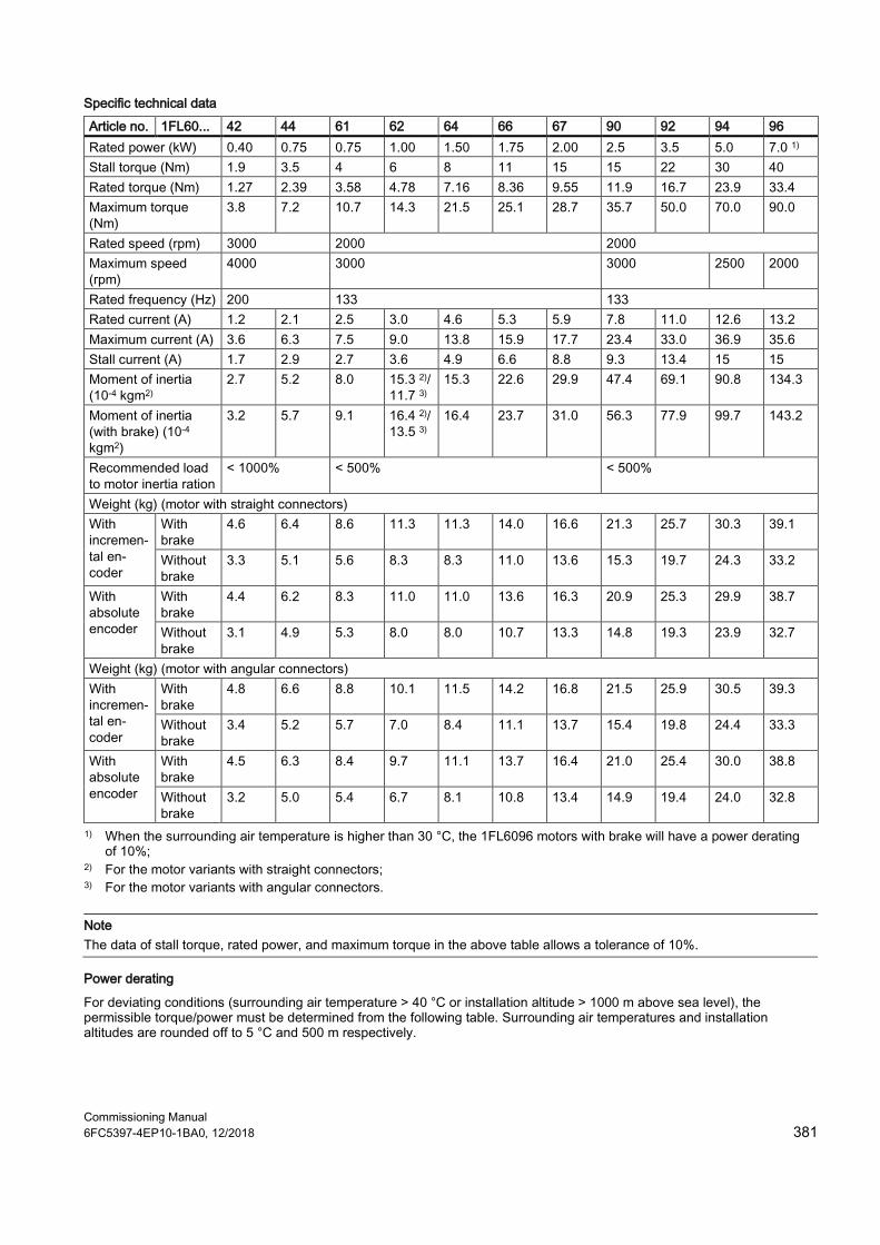
Commissioning Manual 6FC5397-4EP10-1BA0, 12/2018 381
Specific technical data Article no. 1FL60... 42 44 61 62 64 66 67 90 92 94 96 Rated power (kW) 0.40 0.75 0.75 1.00 1.50 1.75 2.00 2.5 3.5 5.0 7.0 1) Stall torque (Nm) 1.9 3.5 4 6 8 11 15 15 22 30 40 Rated torque (Nm) 1.27 2.39 3.58 4.78 7.16 8.36 9.55 11.9 16.7 23.9 33.4 Maximum torque (Nm)
3.8 7.2 10.7 14.3 21.5 25.1 28.7 35.7 50.0 70.0 90.0
Rated speed (rpm) 3000 2000 2000 Maximum speed (rpm)
4000 3000 3000 2500 2000
Rated frequency (Hz) 200 133 133 Rated current (A) 1.2 2.1 2.5 3.0 4.6 5.3 5.9 7.8 11.0 12.6 13.2 Maximum current (A) 3.6 6.3 7.5 9.0 13.8 15.9 17.7 23.4 33.0 36.9 35.6 Stall current (A) 1.7 2.9 2.7 3.6 4.9 6.6 8.8 9.3 13.4 15 15 Moment of inertia (10-4 kgm2)
2.7 5.2 8.0 15.3 2)/ 11.7 3)
15.3 22.6 29.9 47.4 69.1 90.8 134.3
Moment of inertia (with brake) (10-4 kgm2)
3.2 5.7 9.1 16.4 2)/ 13.5 3)
16.4 23.7 31.0 56.3 77.9 99.7 143.2
Recommended load to motor inertia ration
< 1000% < 500% < 500%
Weight (kg) (motor with straight connectors) With incremen-tal en-coder
With brake
4.6 6.4 8.6 11.3 11.3 14.0 16.6 21.3 25.7 30.3 39.1
Without brake
3.3 5.1 5.6 8.3 8.3 11.0 13.6 15.3 19.7 24.3 33.2
With absolute encoder
With brake
4.4 6.2 8.3 11.0 11.0 13.6 16.3 20.9 25.3 29.9 38.7
Without brake
3.1 4.9 5.3 8.0 8.0 10.7 13.3 14.8 19.3 23.9 32.7
Weight (kg) (motor with angular connectors) With incremen-tal en-coder
With brake
4.8 6.6 8.8 10.1 11.5 14.2 16.8 21.5 25.9 30.5 39.3
Without brake
3.4 5.2 5.7 7.0 8.4 11.1 13.7 15.4 19.8 24.4 33.3
With absolute encoder
With brake
4.5 6.3 8.4 9.7 11.1 13.7 16.4 21.0 25.4 30.0 38.8
Without brake
3.2 5.0 5.4 6.7 8.1 10.8 13.4 14.9 19.4 24.0 32.8
1) When the surrounding air temperature is higher than 30 °C, the 1FL6096 motors with brake will have a power derating of 10%;
2) For the motor variants with straight connectors; 3) For the motor variants with angular connectors.
Note The data of stall torque, rated power, and maximum torque in the above table allows a tolerance of 10%.
Power derating
For deviating conditions (surrounding air temperature > 40 °C or installation altitude > 1000 m above sea level), the permissible torque/power must be determined from the following table. Surrounding air temperatures and installation altitudes are rounded off to 5 °C and 500 m respectively.

Commissioning Manual 382 6FC5397-4EP10-1BA0, 12/2018
Power derating as a function of the installation altitude and surrounding air temperature Installation altitude above sea level (m)
Power deratings (kW) < 30 °C 30 °C to 40 °C 45 °C 50 °C 55 °C
1000 1.07 1.00 0.96 0.92 0.87 1500 1.04 0.97 0.93 0.89 0.84 2000 1.00 0.94 0.90 0.86 0.82 2500 0.96 0.90 0.86 0.83 0.78 3000 0.92 0.86 0.82 0.79 0.75 3500 0.88 0.82 0.79 0.75 0.71 4000 0.82 0.77 0.74 0.71 0.67
Torque-speed characteristics

Commissioning Manual 6FC5397-4EP10-1BA0, 12/2018 383
Note • Continuous operating area is a series of states when a motor can operate continuously and safely. The effective torque
must be located in this area. • Short-term operating area is a series of states when a motor can operate in a short duration if its effective torque is
smaller than the rated torque. • For the motors with different rated and maximum speeds, the output torque will decline at a faster rate after the speed
exceeds the rated speed. • The feature in short-term operating area varies with power supply voltages. • The continuous operating area becomes smaller and the voltage drop grows larger when the cables in the major loop
exceed 20 meters. • For 1FL6096 motors, the maximum speed can be ensured when the line supply voltage is higher than 380 V.
Permissible radial and axial forces
Note 1FL604❑ and 1FL609❑ have a 5 mm of shaft sheltered in sleeves, and 1FL606❑ has an 8 mm of shaft in sleeves. Therefore, the distances to flange in the above three figures begin respectively from 5 mm, 8 mm, and 5 mm.
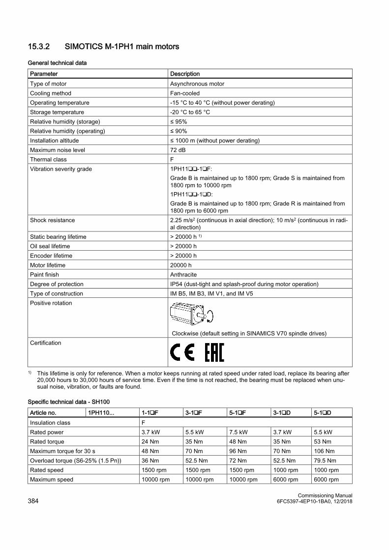
Commissioning Manual 384 6FC5397-4EP10-1BA0, 12/2018
15.3.2 SIMOTICS M-1PH1 main motors
General technical data
Parameter Description Type of motor Asynchronous motor Cooling method Fan-cooled Operating temperature -15 °C to 40 °C (without power derating) Storage temperature -20 °C to 65 °C Relative humidity (storage) ≤ 95% Relative humidity (operating) ≤ 90% Installation altitude ≤ 1000 m (without power derating) Maximum noise level 72 dB Thermal class F Vibration severity grade 1PH11❑❑-1❑F:
Grade B is maintained up to 1800 rpm; Grade S is maintained from 1800 rpm to 10000 rpm 1PH11❑❑-1❑D: Grade B is maintained up to 1800 rpm; Grade R is maintained from 1800 rpm to 6000 rpm
Shock resistance 2.25 m/s2 (continuous in axial direction); 10 m/s2 (continuous in radi-al direction)
Static bearing lifetime > 20000 h 1) Oil seal lifetime > 20000 h Encoder lifetime > 20000 h Motor lifetime 20000 h Paint finish Anthracite Degree of protection IP54 (dust-tight and splash-proof during motor operation) Type of construction IM B5, IM B3, IM V1, and IM V5 Positive rotation
Clockwise (default setting in SINAMICS V70 spindle drives)
Certification
1) This lifetime is only for reference. When a motor keeps running at rated speed under rated load, replace its bearing after 20,000 hours to 30,000 hours of service time. Even if the time is not reached, the bearing must be replaced when unu-sual noise, vibration, or faults are found.
Specific technical data - SH100
Article no. 1PH110... 1-1❑F 3-1❑F 5-1❑F 3-1❑D 5-1❑D Insulation class F Rated power 3.7 kW 5.5 kW 7.5 kW 3.7 kW 5.5 kW Rated torque 24 Nm 35 Nm 48 Nm 35 Nm 53 Nm Maximum torque for 30 s 48 Nm 70 Nm 96 Nm 70 Nm 106 Nm Overload torque (S6-25% (1.5 Pn)) 36 Nm 52.5 Nm 72 Nm 52.5 Nm 79.5 Nm Rated speed 1500 rpm 1500 rpm 1500 rpm 1000 rpm 1000 rpm Maximum speed 10000 rpm 10000 rpm 10000 rpm 6000 rpm 6000 rpm

Commissioning Manual 6FC5397-4EP10-1BA0, 12/2018 385
Article no. 1PH110... 1-1❑F 3-1❑F 5-1❑F 3-1❑D 5-1❑D Rated frequency 53.3 Hz 53 Hz 52.6 Hz 36.9 Hz 36.4 Hz Rated voltage (phase/phase) 326 V 290 V 327 V 269 V 265 V Motor maximum voltage 355 V Rated current 10.3 A 16.9 A 19.6 A 12.9 A 18.8 A Maximum current (for maximum torque) 20.6 A 33.8 A 39.2 A 25.8 A 37.6 A Winding resistance/stator phase re-sistance (20°C)
0.9682 Ω 0.4595 Ω 0.3597 Ω 0.8227 Ω 0.4557 Ω
Winding inductance/motor magnetizing inductance
97 mH 56 mH 54.5 mH 91 mH 69.5 mH
Moment of inertia 0.009 kgm2 0.0112 kgm2 0.015 kgm2 0.0112 kgm2 0.015 kgm2 Motor weight 29 kg 36 kg 45 kg 36 kg 45 kg
Specific technical data - SH132
Article no. 1PH113... 1-1❑F 3-1❑F 1-1❑D 3-1❑D Insulation class F Rated power 11 kW 15 kW 7.5 kW 11 kW Rated torque 70 Nm 95.5 Nm 71.6 Nm 105 Nm Maximum torque for 30 s 140 Nm 191 Nm 143 Nm 210 Nm Overload torque (S6-25% (1.5 Pn)) 105 Nm 143 Nm 107 Nm 158 Nm Rated speed 1500 rpm 1500 rpm 1000 rpm 1000 rpm Maximum speed 8000 rpm 8000 rpm 6000 rpm 6000 rpm Rated frequency 51.5 Hz 50.8 Hz 35.2 Hz 35 Hz Rated voltage (phase/phase) 295 V 317 V 220 V 301 V Motor maximum voltage 355 V Rated current 28.8 A 36.7 A 26.6 A 28.3 A Maximum current (for maximum torque) 57.6 A 73.4 A 53.2 A 56.6 A Winding resistance/stator phase resistance (20°C)
0.1977 Ω 0.1354 Ω 0.2645 Ω 0.2705 Ω
Winding inductance/motor magnetizing induct-ance
45.55 mH 34.7 mH 52.5 mH 69 mH
Moment of inertia 0.0547 kgm2 0.074 kgm2 0.0504 kgm2 0.074 kgm2 Motor weight 73 kg 90 kg 70 kg 90 kg
Power deratings at different installation altitudes and surrounding air temperatures
Operation: T = -15 °C to +40 °C (without restriction)
Under conditions other than those specified above (surrounding air temperature > 40 °C or installation altitude > 1000 m above sea level), the permissible torque/power must be determined from the following table. Surrounding air temperatures and installation altitudes are rounded off to 5 °C or 500 m respectively.
Operation: T = -15 °C to +40 °C (without derating) Under conditions other than those specified above (ambient temperature > 40° C or installation altitude > 1000 m above sea level), the permissible torque/power reduction must be determined from the following table. Ambient temperatures and installation altitudes are rounded off to 5 °C and 500 m respectively.
Installation altitude above sea level
Factors for reducing the torque/power according to EN 60034-6 40 °C 45 °C 50 °C
1000 1.00 0.96 0.92 1500 0.97 0.93 0.89 2000 0.94 0.90 0.86 2500 0.90 0.86 0.83
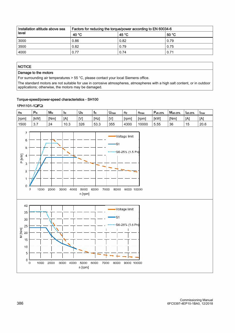
Commissioning Manual 386 6FC5397-4EP10-1BA0, 12/2018
Installation altitude above sea level
Factors for reducing the torque/power according to EN 60034-6 40 °C 45 °C 50 °C
3000 0.86 0.82 0.79 3500 0.82 0.79 0.75 4000 0.77 0.74 0.71
NOTICE Damage to the motors For surrounding air temperatures > 55 °C, please contact your local Siemens office. The standard motors are not suitable for use in corrosive atmospheres, atmospheres with a high salt content, or in outdoor applications; otherwise, the motors may be damaged.
Torque-speed/power-speed characteristics - SH100
1PH1101-1❑F❑:
nN PN MN IN UN fN Umax n2 nmax Ps6-25% Ms6-25% Is6-25% Imax [rpm] [kW] [Nm] [A] [V] [Hz] [V] [rpm] [rpm] [kW] [Nm] [A] [A] 1500 3.7 24 10.3 326 53.3 355 4300 10000 5.55 36 15 20.6

Commissioning Manual 6FC5397-4EP10-1BA0, 12/2018 387
1PH1103-1❑F❑:
nN PN MN IN UN fN Umax n2 nmax Ps6-25% Ms6-25% Is6-25% Imax [rpm] [kW] [Nm] [A] [V] [Hz] [V] [rpm] [rpm] [kW] [Nm] [A] [A] 1500 5.5 35 16.9 290 53 355 5500 10000 8.25 52.5 24 33.8
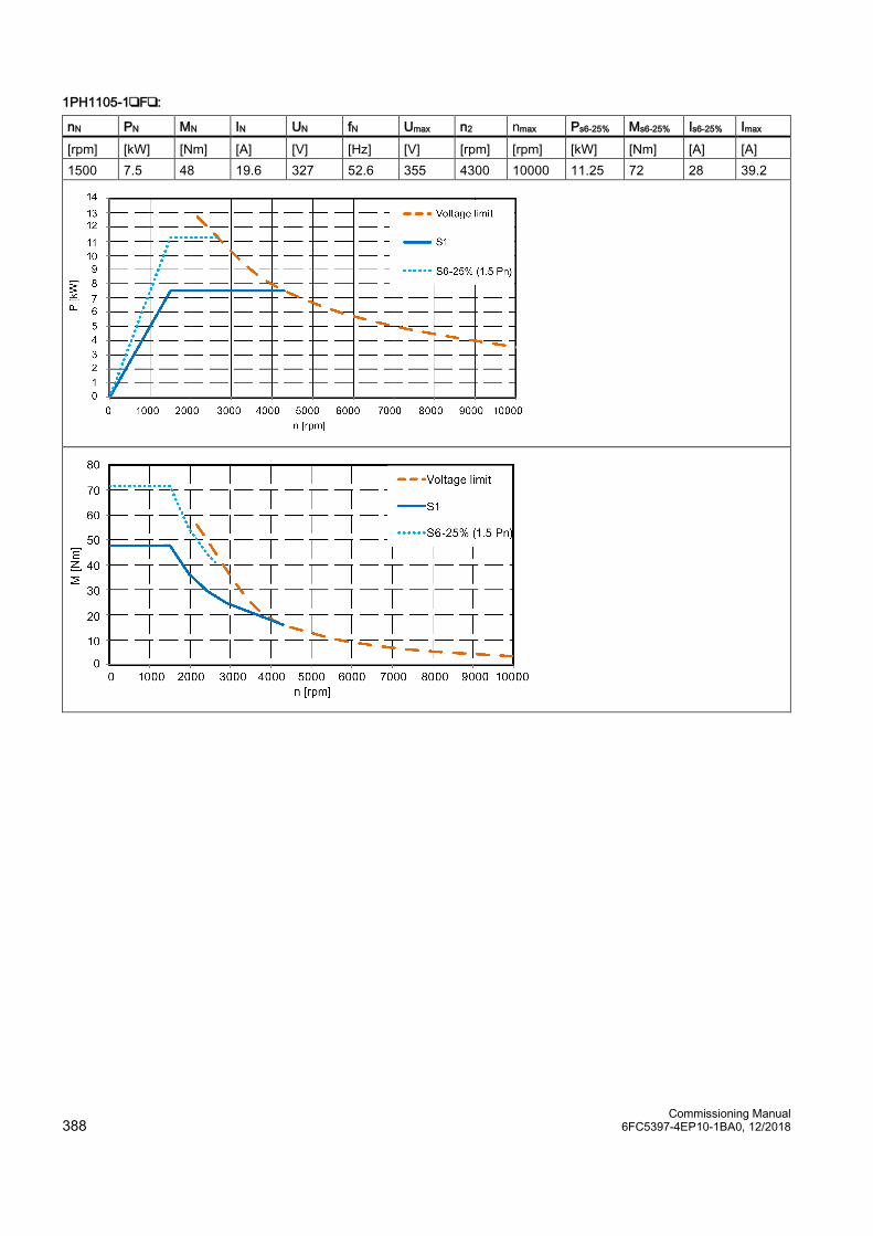
Commissioning Manual 388 6FC5397-4EP10-1BA0, 12/2018
1PH1105-1❑F❑:
nN PN MN IN UN fN Umax n2 nmax Ps6-25% Ms6-25% Is6-25% Imax [rpm] [kW] [Nm] [A] [V] [Hz] [V] [rpm] [rpm] [kW] [Nm] [A] [A] 1500 7.5 48 19.6 327 52.6 355 4300 10000 11.25 72 28 39.2
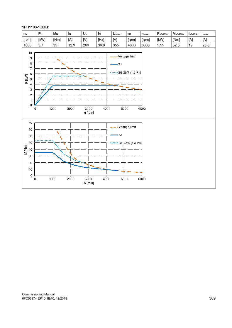
Commissioning Manual 6FC5397-4EP10-1BA0, 12/2018 389
1PH1103-1❑D❑:
nN PN MN IN UN fN Umax n2 nmax Ps6-25% Ms6-25% Is6-25% Imax [rpm] [kW] [Nm] [A] [V] [Hz] [V] [rpm] [rpm] [kW] [Nm] [A] [A] 1000 3.7 35 12.9 269 36.9 355 4600 6000 5.55 52.5 19 25.8
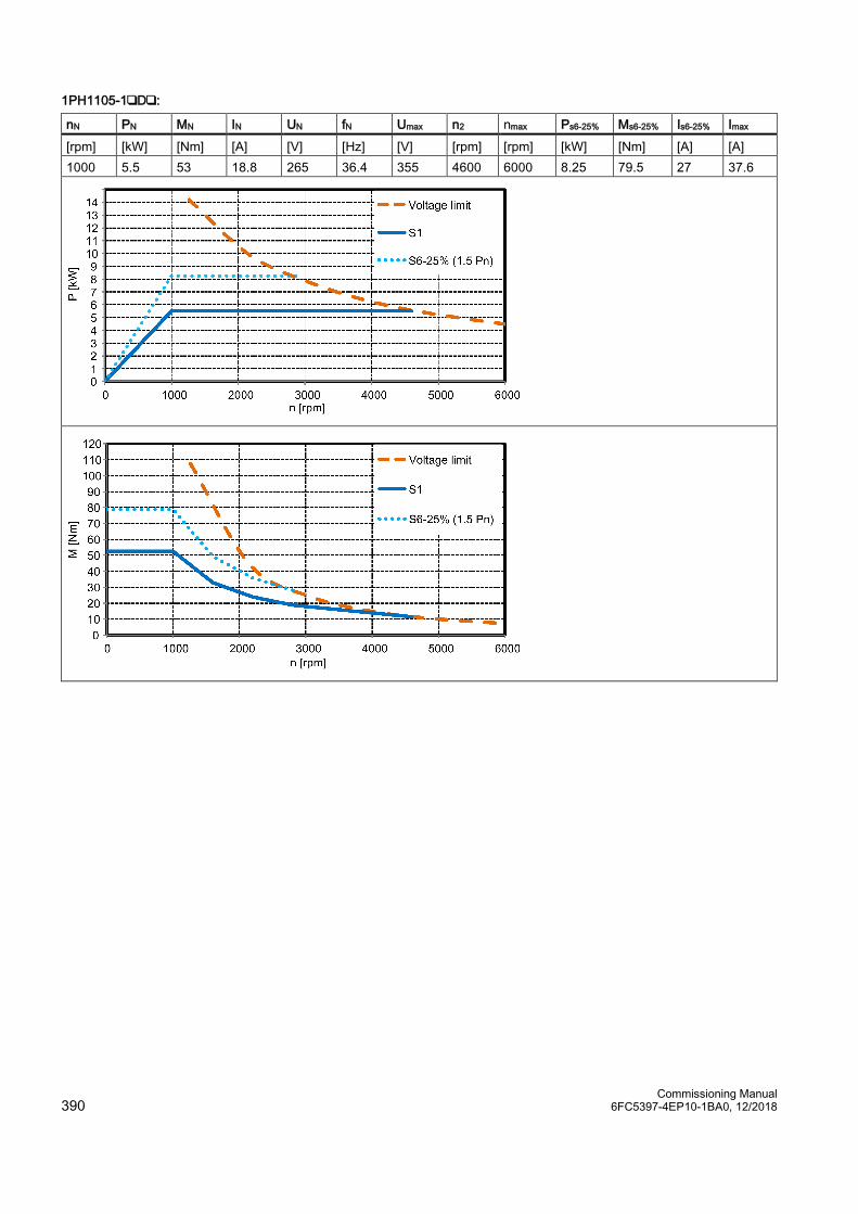
Commissioning Manual 390 6FC5397-4EP10-1BA0, 12/2018
1PH1105-1❑D❑:
nN PN MN IN UN fN Umax n2 nmax Ps6-25% Ms6-25% Is6-25% Imax [rpm] [kW] [Nm] [A] [V] [Hz] [V] [rpm] [rpm] [kW] [Nm] [A] [A] 1000 5.5 53 18.8 265 36.4 355 4600 6000 8.25 79.5 27 37.6
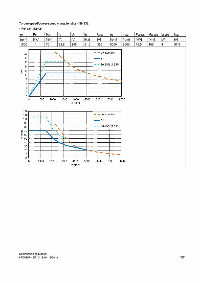
Commissioning Manual 6FC5397-4EP10-1BA0, 12/2018 391
Torque-speed/power-speed characteristics - SH132
1PH1131-1❑F❑:
nN PN MN IN UN fN Umax n2 nmax Ps6-25% Ms6-25% Is6-25% Imax [rpm] [kW] [Nm] [A] [V] [Hz] [V] [rpm] [rpm] [kW] [Nm] [A] [A] 1500 11 70 28.8 295 51.5 355 5000 8000 16.5 105 41 57.6
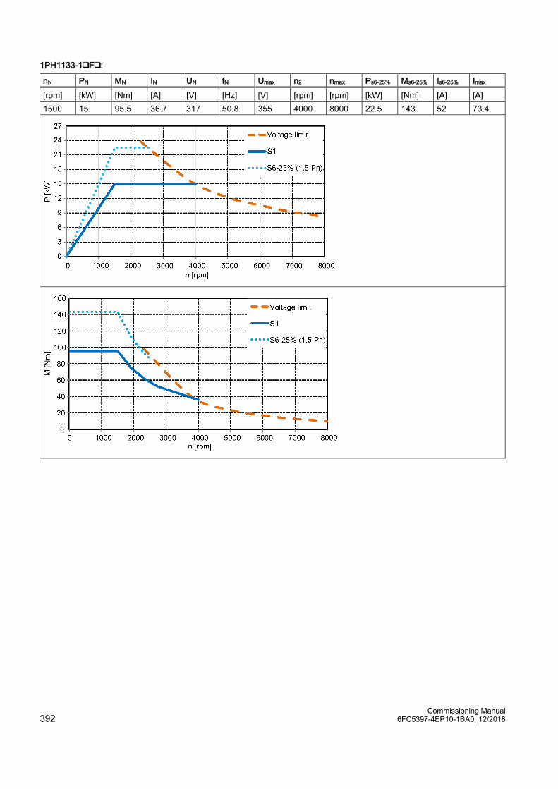
Commissioning Manual 392 6FC5397-4EP10-1BA0, 12/2018
1PH1133-1❑F❑:
nN PN MN IN UN fN Umax n2 nmax Ps6-25% Ms6-25% Is6-25% Imax [rpm] [kW] [Nm] [A] [V] [Hz] [V] [rpm] [rpm] [kW] [Nm] [A] [A] 1500 15 95.5 36.7 317 50.8 355 4000 8000 22.5 143 52 73.4

Commissioning Manual 6FC5397-4EP10-1BA0, 12/2018 393
1PH1131-1❑D❑:
nN PN MN IN UN fN Umax n2 nmax Ps6-25% Ms6-25% Is6-25% Imax [rpm] [kW] [Nm] [A] [V] [Hz] [V] [rpm] [rpm] [kW] [Nm] [A] [A] 1000 7.5 71.6 26.6 220 35.2 355 5000 6000 11.25 107 38 53.2

Commissioning Manual 394 6FC5397-4EP10-1BA0, 12/2018
1PH1133-1❑D❑:
nN PN MN IN UN fN Umax n2 nmax Ps6-25% Ms6-25% Is6-25% Imax [rpm] [kW] [Nm] [A] [V] [Hz] [V] [rpm] [rpm] [kW] [Nm] [A] [A] 1000 11 105 28.3 301 35 355 3000 6000 16.5 158 40 56.6
Permissible radial and axial forces - SH100

Commissioning Manual 6FC5397-4EP10-1BA0, 12/2018 395
Permissible radial and axial forces - SH132
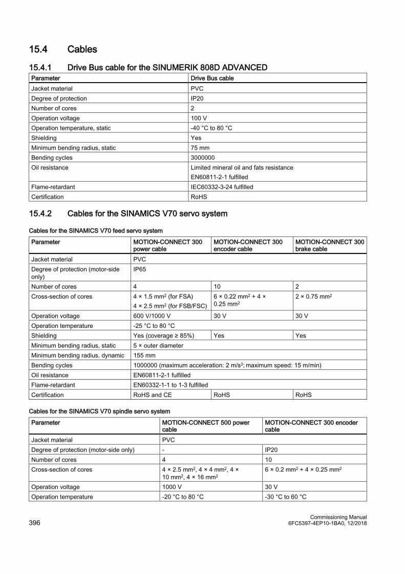
Commissioning Manual 396 6FC5397-4EP10-1BA0, 12/2018
15.4 Cables
15.4.1 Drive Bus cable for the SINUMERIK 808D ADVANCED Parameter Drive Bus cable Jacket material PVC Degree of protection IP20 Number of cores 2 Operation voltage 100 V Operation temperature, static -40 °C to 80 °C Shielding Yes Minimum bending radius, static 75 mm Bending cycles 3000000 Oil resistance Limited mineral oil and fats resistance
EN60811-2-1 fulfilled Flame-retardant IEC60332-3-24 fulfilled Certification RoHS
15.4.2 Cables for the SINAMICS V70 servo system
Cables for the SINAMICS V70 feed servo system
Parameter MOTION-CONNECT 300 power cable
MOTION-CONNECT 300 encoder cable
MOTION-CONNECT 300 brake cable
Jacket material PVC Degree of protection (motor-side only)
IP65
Number of cores 4 10 2 Cross-section of cores 4 × 1.5 mm2 (for FSA)
4 × 2.5 mm2 (for FSB/FSC) 6 × 0.22 mm2 + 4 × 0.25 mm2
2 × 0.75 mm2
Operation voltage 600 V/1000 V 30 V 30 V Operation temperature -25 °C to 80 °C Shielding Yes (coverage ≥ 85%) Yes Yes Minimum bending radius, static 5 × outer diameter Minimum bending radius, dynamic 155 mm Bending cycles 1000000 (maximum acceleration: 2 m/s2; maximum speed: 15 m/min) Oil resistance EN60811-2-1 fulfilled Flame-retardant EN60332-1-1 to 1-3 fulfilled Certification RoHS and CE RoHS RoHS
Cables for the SINAMICS V70 spindle servo system
Parameter MOTION-CONNECT 500 power cable
MOTION-CONNECT 300 encoder cable
Jacket material PVC Degree of protection (motor-side only) - IP20 Number of cores 4 10 Cross-section of cores 4 × 2.5 mm2, 4 × 4 mm2, 4 ×
10 mm2, 4 × 16 mm2 6 × 0.2 mm2 + 4 × 0.25 mm2
Operation voltage 1000 V 30 V Operation temperature -20 °C to 80 °C -30 °C to 60 °C

Commissioning Manual 6FC5397-4EP10-1BA0, 12/2018 397
Parameter MOTION-CONNECT 500 power cable
MOTION-CONNECT 300 encoder cable
Shielding Yes (coverage ≥ 80%) Yes Minimum bending radius, static 5 × outer diameter Minimum bending radius, dynamic 180 mm, 210 mm, 360 mm,
440 mm 20 × outer diameter
Bending cycles 100000 Oil resistance DIN VDE 472-803 Part B EN60811-2-1 fulfilled Flame-retardant IEC 332.1 EN60332-1-1 to 1-3 fulfilled Certification RoHS and CE RoHS
15.5 Address of CE-authorized manufacturer The CE Declaration of Conformity is held on file available to the competent authorities at the following address:
SINUMERIK 808D ADVANCED controller and SINAMICS V70 drive
Siemens AG
Digital Factory
Motion Control
Frauenauracher Straße 80
DE-91056 Erlangen
Germany
SIMOTICS S-1FL6 motor and M-1PH1 main motor
Siemens AG
Digital Factory
Motion Control
Industriestraße 1
DE-97615 Bad Neustadt a. d. Saale
Germany
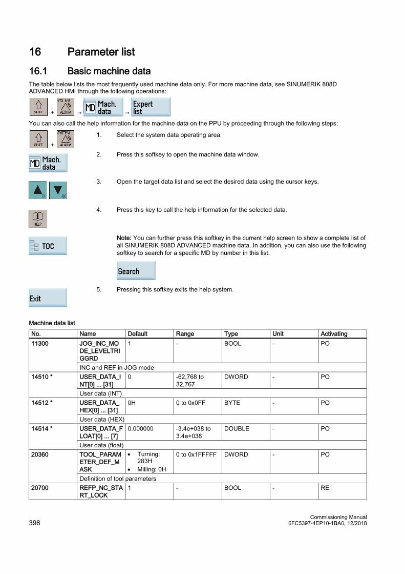
Commissioning Manual 398 6FC5397-4EP10-1BA0, 12/2018
16 Parameter list 16.1 Basic machine data The table below lists the most frequently used machine data only. For more machine data, see SINUMERIK 808D ADVANCED HMI through the following operations:
+ → →
You can also call the help information for the machine data on the PPU by proceeding through the following steps:
+ 1. Select the system data operating area.
2. Press this softkey to open the machine data window.
3. Open the target data list and select the desired data using the cursor keys.
4. Press this key to call the help information for the selected data.
Note: You can further press this softkey in the current help screen to show a complete list of all SINUMERIK 808D ADVANCED machine data. In addition, you can also use the following softkey to search for a specific MD by number in this list:
5. Pressing this softkey exits the help system.
Machine data list No. Name Default Range Type Unit Activating 11300 JOG_INC_MO
DE_LEVELTRIGGRD
1 - BOOL - PO
INC and REF in JOG mode 14510 * USER_DATA_I
NT[0] ... [31] 0 -62,768 to
32,767 DWORD - PO
User data (INT) 14512 * USER_DATA_
HEX[0] ... [31] 0H 0 to 0x0FF BYTE - PO
User data (HEX) 14514 * USER_DATA_F
LOAT[0] ... [7] 0.000000 -3.4e+038 to
3.4e+038 DOUBLE - PO
User data (float) 20360 TOOL_PARAM
ETER_DEF_MASK
• Turning: 283H
• Milling: 0H
0 to 0x1FFFFF DWORD - PO
Definition of tool parameters 20700 REFP_NC_STA
RT_LOCK 1 - BOOL - RE
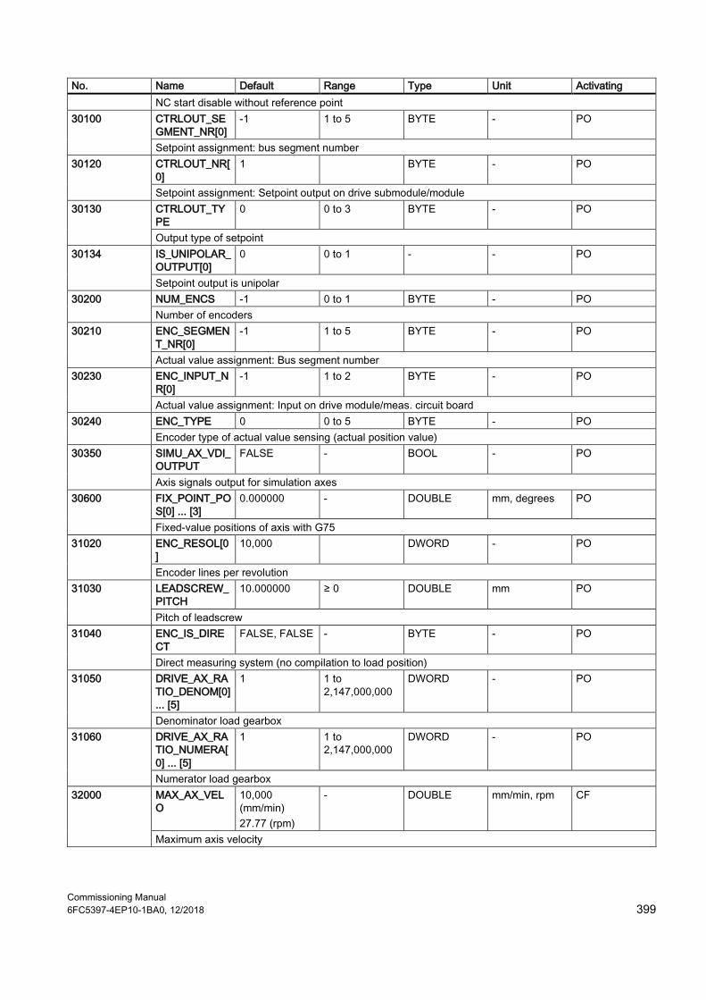
Commissioning Manual 6FC5397-4EP10-1BA0, 12/2018 399
No. Name Default Range Type Unit Activating NC start disable without reference point
30100 CTRLOUT_SEGMENT_NR[0]
-1 1 to 5 BYTE - PO
Setpoint assignment: bus segment number 30120 CTRLOUT_NR[
0] 1 BYTE - PO
Setpoint assignment: Setpoint output on drive submodule/module 30130 CTRLOUT_TY
PE 0 0 to 3 BYTE - PO
Output type of setpoint 30134 IS_UNIPOLAR_
OUTPUT[0] 0 0 to 1 - - PO
Setpoint output is unipolar 30200 NUM_ENCS -1 0 to 1 BYTE - PO
Number of encoders 30210 ENC_SEGMEN
T_NR[0] -1 1 to 5 BYTE - PO
Actual value assignment: Bus segment number 30230 ENC_INPUT_N
R[0] -1 1 to 2 BYTE - PO
Actual value assignment: Input on drive module/meas. circuit board 30240 ENC_TYPE 0 0 to 5 BYTE - PO
Encoder type of actual value sensing (actual position value) 30350 SIMU_AX_VDI_
OUTPUT FALSE - BOOL - PO
Axis signals output for simulation axes 30600 FIX_POINT_PO
S[0] ... [3] 0.000000 - DOUBLE mm, degrees PO
Fixed-value positions of axis with G75 31020 ENC_RESOL[0
] 10,000 DWORD - PO
Encoder lines per revolution 31030 LEADSCREW_
PITCH 10.000000 ≥ 0 DOUBLE mm PO
Pitch of leadscrew 31040 ENC_IS_DIRE
CT FALSE, FALSE - BYTE - PO
Direct measuring system (no compilation to load position) 31050 DRIVE_AX_RA
TIO_DENOM[0] ... [5]
1 1 to 2,147,000,000
DWORD - PO
Denominator load gearbox 31060 DRIVE_AX_RA
TIO_NUMERA[0] ... [5]
1 1 to 2,147,000,000
DWORD - PO
Numerator load gearbox 32000 MAX_AX_VEL
O 10,000 (mm/min) 27.77 (rpm)
- DOUBLE mm/min, rpm CF
Maximum axis velocity
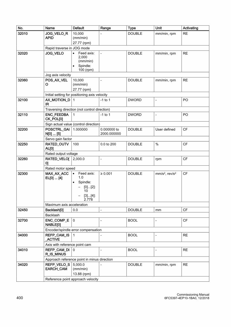
Commissioning Manual 400 6FC5397-4EP10-1BA0, 12/2018
No. Name Default Range Type Unit Activating 32010 JOG_VELO_R
APID 10,000 (mm/min) 27.77 (rpm)
- DOUBLE mm/min, rpm RE
Rapid traverse in JOG mode 32020 JOG_VELO • Feed axis:
2,000 (mm/min)
• Spindle: 100 (rpm)
- DOUBLE mm/min, rpm RE
Jog axis velocity 32060 POS_AX_VEL
O 10,000 (mm/min) 27.77 (rpm)
- DOUBLE mm/min, rpm RE
Initial setting for positioning axis velocity 32100 AX_MOTION_D
IR 1 -1 to 1 DWORD - PO
Traversing direction (not control direction) 32110 ENC_FEEDBA
CK_POL[0] 1 -1 to 1 DWORD - PO
Sign actual value (control direction) 32200 POSCTRL_GAI
N[0] ... [5] 1.000000 0.000000 to
2000.000000 DOUBLE User defined CF
Servo gain factor 32250 RATED_OUTV
AL[0] 100 0.0 to 200 DOUBLE % CF
Rated output voltage 32260 RATED_VELO[
0] 2,000.0 - DOUBLE rpm CF
Rated motor speed 32300 MAX_AX_ACC
EL[0] ... [4] • Feed axis:
1.0 • Spindle:
– [0]...[2]: 10
– [3]...[4]: 2.778
≥ 0.001 DOUBLE mm/s2, rev/s2 CF
Maximum axis acceleration 32450 Backlash[0] 0.0 - DOUBLE mm CF
Backlash 32700 ENC_COMP_E
NABLE[0] 0 - BOOL - CF
Encoder/spindle error compensation 34000 REFP_CAM_IS
_ACTIVE 1 - BOOL - RE
Axis with reference point cam 34010 REFP_CAM_DI
R_IS_MINUS 0 - BOOL - RE
Approach reference point in minus direction 34020 REFP_VELO_S
EARCH_CAM 5,000.0 (mm/min) 13.88 (rpm)
- DOUBLE mm/min, rpm RE
Reference point approach velocity
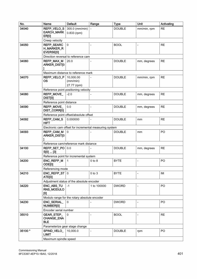
Commissioning Manual 6FC5397-4EP10-1BA0, 12/2018 401
No. Name Default Range Type Unit Activating 34040 REFP_VELO_S
EARCH_MARKER[0]
300.0 (mm/min) 0.833 (rpm)
- DOUBLE mm/min, rpm RE
Creep velocity 34050 REFP_SEARC
H_MARKER_REVERSE[0]
0 - BOOL - RE
Direction reversal to reference cam 34060 REFP_MAX_M
ARKER_DIST[0]
20.0 - DOUBLE mm, degrees RE
Maximum distance to reference mark 34070 REFP_VELO_P
OS 10,000.00 (mm/min) 27.77 (rpm)
- DOUBLE mm/min, rpm RE
Reference point positioning velocity 34080 REFP_MOVE_
DIST[0] -2.0 - DOUBLE mm, degrees RE
Reference point distance 34090 REFP_MOVE_
DIST_CORR[0] 0.0 - DOUBLE mm, degrees RE
Reference point offset/absolute offset 34092 REFP_CAM_S
HIFT 0.000000 - DOUBLE mm RE
Electronic cam offset for incremental measuring system 34093 REFP_CAM_M
ARKER_DIST[0]
0 - DOUBLE mm PO
Reference cam/reference mark distance 34100 REFP_SET_PO
S[0] ... [3] 0.0 - DOUBLE mm, degrees RE
Reference point for incremental system 34200 ENC_REFP_M
ODE[0] 1 0 to 8 BYTE - PO
Referencing mode 34210 ENC_REFP_ST
ATE[0] 0 0 to 3 BYTE - IM
Adjustment status of the absolute encoder 34220 ENC_ABS_TU
RNS_MODULO[0]
-1 1 to 100000 DWORD - PO
Modulo range for the rotary absolute encoder 34230 ENC_SERIAL_
NUMBER[0] 0 - DWORD - PO
Encoder serial number 35010 GEAR_STEP_
CHANGE_ENABLE
0 - BOOL - RE
Parameterize gear stage change 35100 * SPIND_VELO_
LIMIT 10,000.0 - DOUBLE rpm PO
Maximum spindle speed

Commissioning Manual 402 6FC5397-4EP10-1BA0, 12/2018
No. Name Default Range Type Unit Activating 35110 GEAR_STEP_
MAX_VELO[0] ... [5]
[0]...[1]: 500 [2]: 1,000 [3]: 2,000 [4]: 4,000 [5]: 8,000
- DOUBLE rpm CF
Maximum speed for gear stage change 35120 GEAR_STEP_
MIN_VELO[0] ... [5]
[0]...[1]: 50 [2]: 400 [3]: 800 [4]: 1,500 [5]: 3,000
- DOUBLE rpm CF
Minimum speed for gear stage change 35130 GEAR_STEP_
MAX_VELO_LIMIT[0] ... [5]
[0]...[1]: 500 [2]: 1,000 [3]: 2,000 [4]: 4,000 [5]: 8,000
- DOUBLE rpm CF
Maximum speed for gear stage 35140 GEAR_STEP_
MIN_VELO_LIMIT[0] ... [5]
[0]...[1]: 5 [2]: 10 [3]: 20 [4]: 40 [5]: 80
- DOUBLE rpm CF
Minimum speed for gear stage 36100 POS_LIMIT_MI
NUS -100,000,000 - DOUBLE mm, degrees RE
1st software limit switch minus Access level: Manufacturer
36110 POS_LIMIT_PLUS
100,000,000 - DOUBLE mm, degrees RE
1st software limit switch plus 36200 AX_VELO_LIMI
T[0] ... [5] 11,500 (mm/min) 31,944 (rpm)
- DOUBLE mm/min, rpm CF
Threshold value for velocity monitoring 36300 ENC_FREQ_LI
MIT[0] 3.33e5 - DOUBLE - PO
Encoder limit frequency 38000 MM_ENC_CO
MP_MAX_POINTS
• Turning: 125
• Milling: 200
- DWORD - PO
Number of intermediate for interpolar compensation (SRAM)
The machine data followed by an asterisk (*) have the access level of "Customer", while those without an asterisk have the access level of "Manufacturer".

Commissioning Manual 6FC5397-4EP10-1BA0, 12/2018 403
16.2 SINAMICS V70 parameters This section lists only the parameters displayed on the drive BOP and those frequently used for drive commissioning. For more parameters of the servo drive, see SINUMERIK 808D ADVANCED HMI through the following operations:
+ → → →
All parameters beginning with "p" are editable parameters, for example, p29000.
All parameters beginning with "r" are read-only parameters, for example, r0018.
Effective
Indicates the conditions for making parameterization effective. Two conditions are possible:
● IM (Immediately): Parameter value becomes effective immediately after changing.
● RE (Reset): Parameter value becomes effective after repower-on.
Can be changed
Indicates the state in which a parameter is changeable. Two states are possible:
● U (Run): Can be changed in the "Running" state when the enable signal is available. The "RDY" LED indicator lights up green.
● T (Ready to run): Can be changed in the "Ready" state when the enable signal is missing. The "RDY" LED indicator lights up red.
Note When judging the state of the drive according to the "RDY" LED indicator, ensure that no faults or alarms exist.
Data type
Type Description I16 16-bit integer I32 32-bit integer U16 16 bits without sign U32 32 bits without sign Uint16 16-bit unsigned integer Uint32 32-bit unsigned integer Float 32-bit floating point number
Calling help information for V70 parameters
You can call the help information for the V70 drive parameters on the PPU by proceeding through the following steps:
+ 1. Select the system data operating area.
2. Press this softkey to open the machine data window.
3. Open the drive data list through the following softkey operations:
→
4. Select the desired parameter using the cursor keys.
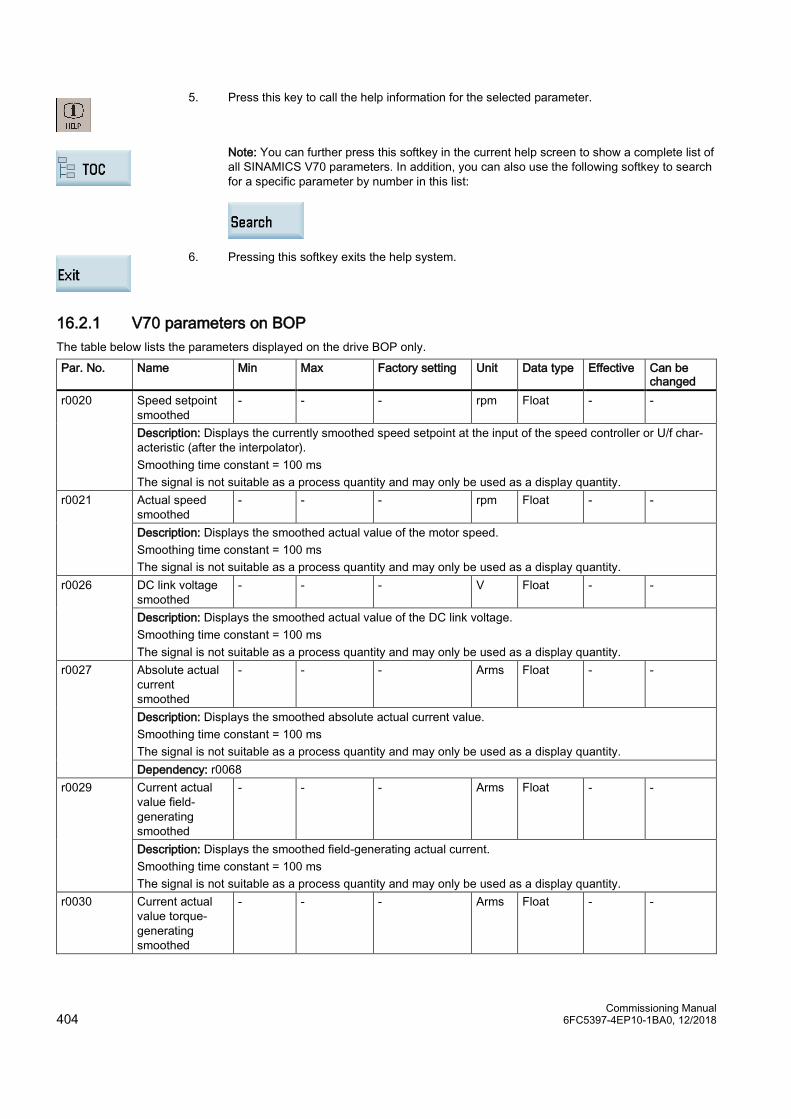
Commissioning Manual 404 6FC5397-4EP10-1BA0, 12/2018
5. Press this key to call the help information for the selected parameter.
Note: You can further press this softkey in the current help screen to show a complete list of all SINAMICS V70 parameters. In addition, you can also use the following softkey to search for a specific parameter by number in this list:
6. Pressing this softkey exits the help system.
16.2.1 V70 parameters on BOP The table below lists the parameters displayed on the drive BOP only. Par. No. Name Min Max Factory setting Unit Data type Effective Can be
changed r0020 Speed setpoint
smoothed - - - rpm Float - -
Description: Displays the currently smoothed speed setpoint at the input of the speed controller or U/f char-acteristic (after the interpolator). Smoothing time constant = 100 ms The signal is not suitable as a process quantity and may only be used as a display quantity.
r0021 Actual speed smoothed
- - - rpm Float - -
Description: Displays the smoothed actual value of the motor speed. Smoothing time constant = 100 ms The signal is not suitable as a process quantity and may only be used as a display quantity.
r0026 DC link voltage smoothed
- - - V Float - -
Description: Displays the smoothed actual value of the DC link voltage. Smoothing time constant = 100 ms The signal is not suitable as a process quantity and may only be used as a display quantity.
r0027 Absolute actual current smoothed
- - - Arms Float - -
Description: Displays the smoothed absolute actual current value. Smoothing time constant = 100 ms The signal is not suitable as a process quantity and may only be used as a display quantity. Dependency: r0068
r0029 Current actual value field-generating smoothed
- - - Arms Float - -
Description: Displays the smoothed field-generating actual current. Smoothing time constant = 100 ms The signal is not suitable as a process quantity and may only be used as a display quantity.
r0030 Current actual value torque-generating smoothed
- - - Arms Float - -
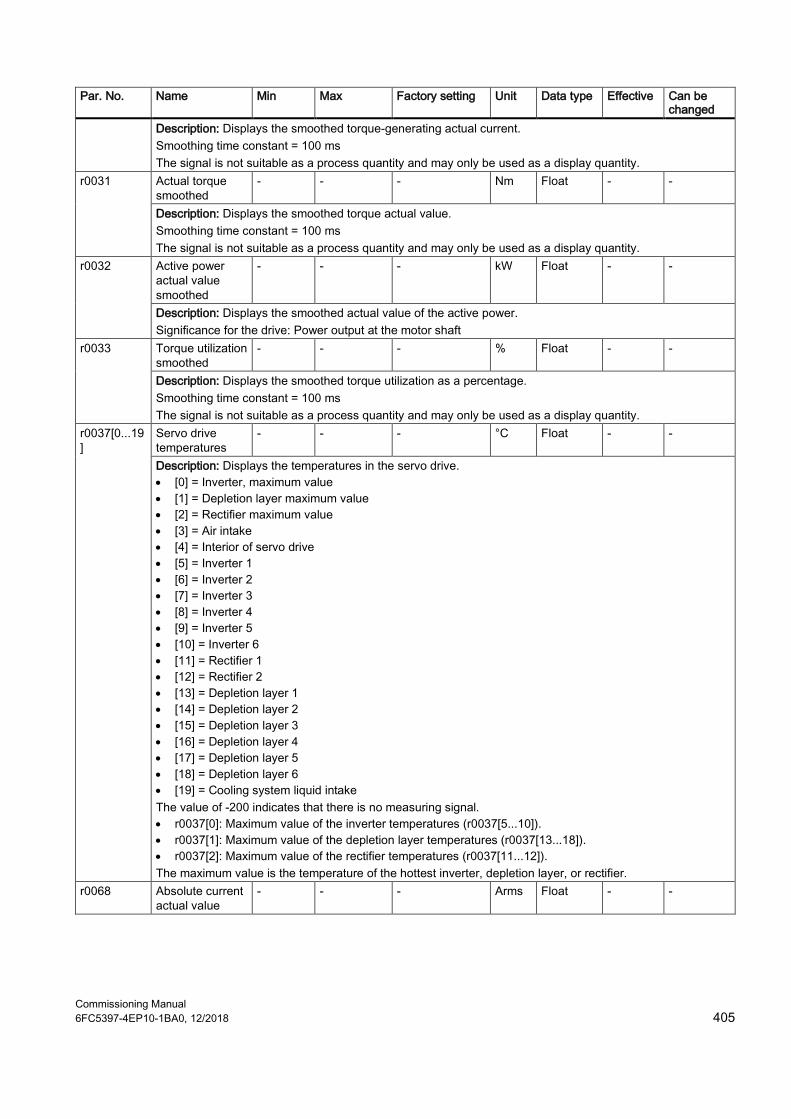
Commissioning Manual 6FC5397-4EP10-1BA0, 12/2018 405
Par. No. Name Min Max Factory setting Unit Data type Effective Can be changed
Description: Displays the smoothed torque-generating actual current. Smoothing time constant = 100 ms The signal is not suitable as a process quantity and may only be used as a display quantity.
r0031 Actual torque smoothed
- - - Nm Float - -
Description: Displays the smoothed torque actual value. Smoothing time constant = 100 ms The signal is not suitable as a process quantity and may only be used as a display quantity.
r0032 Active power actual value smoothed
- - - kW Float - -
Description: Displays the smoothed actual value of the active power. Significance for the drive: Power output at the motor shaft
r0033 Torque utilization smoothed
- - - % Float - -
Description: Displays the smoothed torque utilization as a percentage. Smoothing time constant = 100 ms The signal is not suitable as a process quantity and may only be used as a display quantity.
r0037[0...19]
Servo drive temperatures
- - - °C Float - -
Description: Displays the temperatures in the servo drive. • [0] = Inverter, maximum value • [1] = Depletion layer maximum value • [2] = Rectifier maximum value • [3] = Air intake • [4] = Interior of servo drive • [5] = Inverter 1 • [6] = Inverter 2 • [7] = Inverter 3 • [8] = Inverter 4 • [9] = Inverter 5 • [10] = Inverter 6 • [11] = Rectifier 1 • [12] = Rectifier 2 • [13] = Depletion layer 1 • [14] = Depletion layer 2 • [15] = Depletion layer 3 • [16] = Depletion layer 4 • [17] = Depletion layer 5 • [18] = Depletion layer 6 • [19] = Cooling system liquid intake The value of -200 indicates that there is no measuring signal. • r0037[0]: Maximum value of the inverter temperatures (r0037[5...10]). • r0037[1]: Maximum value of the depletion layer temperatures (r0037[13...18]). • r0037[2]: Maximum value of the rectifier temperatures (r0037[11...12]). The maximum value is the temperature of the hottest inverter, depletion layer, or rectifier.
r0068 Absolute current actual value
- - - Arms Float - -
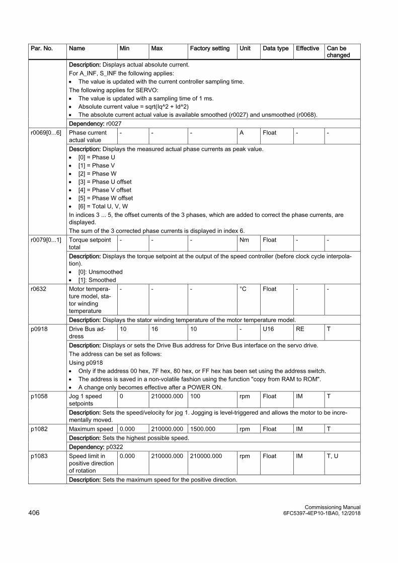
Commissioning Manual 406 6FC5397-4EP10-1BA0, 12/2018
Par. No. Name Min Max Factory setting Unit Data type Effective Can be changed
Description: Displays actual absolute current. For A_INF, S_INF the following applies: • The value is updated with the current controller sampling time. The following applies for SERVO: • The value is updated with a sampling time of 1 ms. • Absolute current value = sqrt(Iq^2 + Id^2) • The absolute current actual value is available smoothed (r0027) and unsmoothed (r0068). Dependency: r0027
r0069[0...6] Phase current actual value
- - - A Float - -
Description: Displays the measured actual phase currents as peak value. • [0] = Phase U • [1] = Phase V • [2] = Phase W • [3] = Phase U offset • [4] = Phase V offset • [5] = Phase W offset • [6] = Total U, V, W In indices 3 ... 5, the offset currents of the 3 phases, which are added to correct the phase currents, are displayed. The sum of the 3 corrected phase currents is displayed in index 6.
r0079[0...1] Torque setpoint total
- - - Nm Float - -
Description: Displays the torque setpoint at the output of the speed controller (before clock cycle interpola-tion). • [0]: Unsmoothed • [1]: Smoothed
r0632 Motor tempera-ture model, sta-tor winding temperature
- - - °C Float - -
Description: Displays the stator winding temperature of the motor temperature model. p0918 Drive Bus ad-
dress 10 16 10 - U16 RE T
Description: Displays or sets the Drive Bus address for Drive Bus interface on the servo drive. The address can be set as follows: Using p0918 • Only if the address 00 hex, 7F hex, 80 hex, or FF hex has been set using the address switch. • The address is saved in a non-volatile fashion using the function "copy from RAM to ROM". • A change only becomes effective after a POWER ON.
p1058 Jog 1 speed setpoints
0 210000.000 100 rpm Float IM T
Description: Sets the speed/velocity for jog 1. Jogging is level-triggered and allows the motor to be incre-mentally moved.
p1082 Maximum speed 0.000 210000.000 1500.000 rpm Float IM T Description: Sets the highest possible speed. Dependency: p0322
p1083 Speed limit in positive direction of rotation
0.000 210000.000 210000.000 rpm Float IM T, U
Description: Sets the maximum speed for the positive direction.
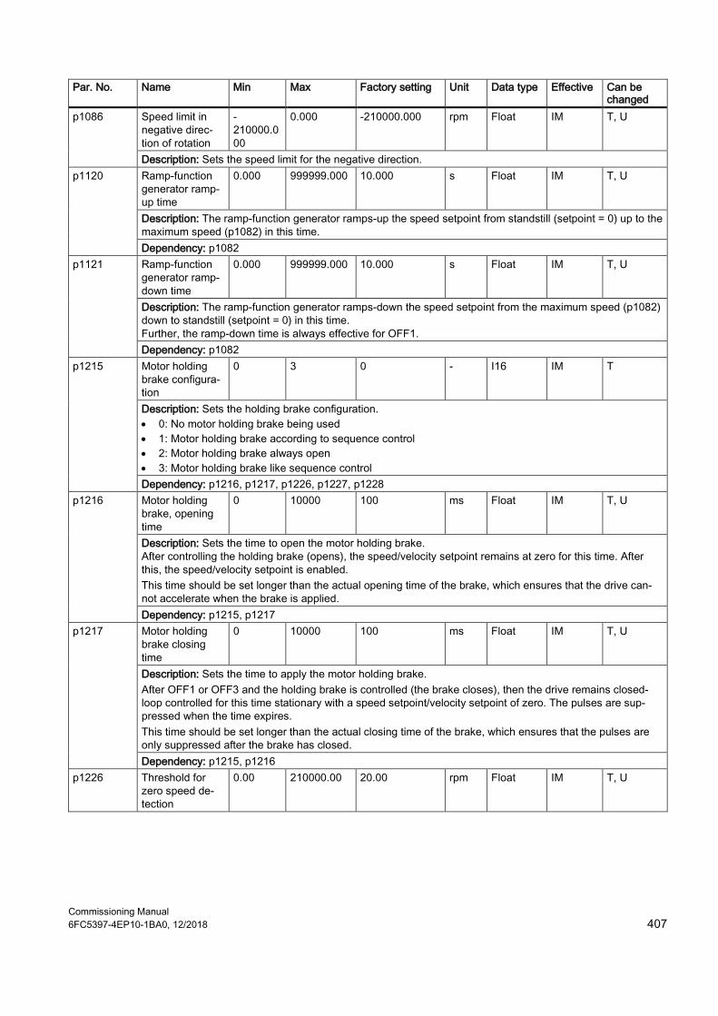
Commissioning Manual 6FC5397-4EP10-1BA0, 12/2018 407
Par. No. Name Min Max Factory setting Unit Data type Effective Can be changed
p1086 Speed limit in negative direc-tion of rotation
-210000.000
0.000 -210000.000 rpm Float IM T, U
Description: Sets the speed limit for the negative direction. p1120 Ramp-function
generator ramp-up time
0.000 999999.000 10.000 s Float IM T, U
Description: The ramp-function generator ramps-up the speed setpoint from standstill (setpoint = 0) up to the maximum speed (p1082) in this time. Dependency: p1082
p1121 Ramp-function generator ramp-down time
0.000 999999.000 10.000 s Float IM T, U
Description: The ramp-function generator ramps-down the speed setpoint from the maximum speed (p1082) down to standstill (setpoint = 0) in this time. Further, the ramp-down time is always effective for OFF1. Dependency: p1082
p1215 Motor holding brake configura-tion
0 3 0 - I16 IM T
Description: Sets the holding brake configuration. • 0: No motor holding brake being used • 1: Motor holding brake according to sequence control • 2: Motor holding brake always open • 3: Motor holding brake like sequence control Dependency: p1216, p1217, p1226, p1227, p1228
p1216 Motor holding brake, opening time
0 10000 100 ms Float IM T, U
Description: Sets the time to open the motor holding brake. After controlling the holding brake (opens), the speed/velocity setpoint remains at zero for this time. After this, the speed/velocity setpoint is enabled. This time should be set longer than the actual opening time of the brake, which ensures that the drive can-not accelerate when the brake is applied. Dependency: p1215, p1217
p1217 Motor holding brake closing time
0 10000 100 ms Float IM T, U
Description: Sets the time to apply the motor holding brake. After OFF1 or OFF3 and the holding brake is controlled (the brake closes), then the drive remains closed-loop controlled for this time stationary with a speed setpoint/velocity setpoint of zero. The pulses are sup-pressed when the time expires. This time should be set longer than the actual closing time of the brake, which ensures that the pulses are only suppressed after the brake has closed. Dependency: p1215, p1216
p1226 Threshold for zero speed de-tection
0.00 210000.00 20.00 rpm Float IM T, U

Commissioning Manual 408 6FC5397-4EP10-1BA0, 12/2018
Par. No. Name Min Max Factory setting Unit Data type Effective Can be changed
Description: Sets the speed threshold for the standstill identification. Acts on the actual value and setpoint monitoring. • When braking with OFF1 or OFF3, when the threshold is undershot, standstill is identified. The following applies when the brake control is activated: • When the threshold is undershot, the brake control is started and the system waits for the brake closing
time in p1217. The pulses are then suppressed. If the brake control is not activated, the following applies: • When the threshold is undershot, the pulses are suppressed and the drive coasts down. Dependency: p1215, p1216, p1217, p1227
p1227 Zero speed detection moni-toring time
0.000 300.000 300.000 s Float IM T, U
Description: Sets the monitoring time for the standstill identification. When braking with OFF1 or OFF3, standstill is identified after this time has expired, after the setpoint speed has fallen below p1226. After this, the brake control is started, the system waits for the closing time in p1217 and then the pulses are suppressed. Dependency: p1215, p1216, p1217, p1226
p1228 Pulse suppres-sion delay time
0.000 299.000 0.000 s Float IM T, U
Description: Sets the delay time for pulse suppression. After OFF1 or OFF3 and zero speed detection, the system waits for this time to expire and the pulses are then suppressed. Standstill is identified in the following cases: • The speed actual value falls below the speed threshold in p1226 and the time started after this in p1228
has expired. • The speed setpoint falls below the speed threshold in p1226 and the time started after this in p1227 has
expired. Dependency: p1226, p1227
p1414 Speed setpoint filter activation
- - 0000 bin - U16 IM T, U
Description: Setting for activating/de-activating the speed setpoint filter. If only one filter is required, filter 1 should be activated and filter 2 de-activated, to avoid excessive pro-cessing time. Dependency: The individual speed setpoint filters are parameterized as of p1415.
p1415 Speed setpoint filter 1 type
0 2 0 - I16 IM T, U
Description: Sets the type for speed setpoint filter 1. • 0: Low pass: PT1 • 1: Low pass: PT2 • 2: General 2nd-order filter Dependency: • PT1 low pass: p1416 • PT2 low pass: p1417, p1418 • General filter: p1417 ... p1420
p1416 Speed setpoint filter 1 time con-stant
0.00 5000.00 0.00 ms Float IM T, U
Description: Sets the time constant for the speed setpoint filter 1 (PT1). This parameter is only effective if the filter is set as a PT1 low pass. Dependency: p1414, p1415

Commissioning Manual 6FC5397-4EP10-1BA0, 12/2018 409
Par. No. Name Min Max Factory setting Unit Data type Effective Can be changed
p1417 Speed setpoint filter 1 denomi-nator natural frequency
0.5 16000.0 1999.0 Hz Float IM T, U
Description: Sets the denominator natural frequency for speed setpoint filter 1 (PT2, general filter). This parameter is only effective if the speed filter is parameterized as a PT2 low pass or as general filter. The filter is only effective if the natural frequency is less than half of the sampling frequency. Dependency: p1414, p1415
p1418 Speed setpoint filter 1 denomi-nator damping
0.001 10.000 0.700 - Float IM T, U
Description: Sets the denominator damping for velocity setpoint filter 1 (PT2, general filter). This parameter is only effective if the speed filter is parameterized as a PT2 low pass or as general filter. Dependency: p1414, p1415
p1419 Speed setpoint filter 1 numerator natural frequen-cy
0.5 16000.0 1999.0 Hz Float IM T, U
Description: Sets the numerator natural frequency for speed setpoint filter 1 (general filter). This parameter is only effective if the speed filter is set as a general filter. The filter is only effective if the natural frequency is less than half of the sampling frequency. Dependency: p1414, p1415
p1420 Speed setpoint filter 1 numerator damping
0.000 10.000 0.700 - Float IM T, U
Description: Sets the numerator damping for speed setpoint filter 1 (general filter). This parameter is only effective if the speed filter is set as a general filter. Dependency: p1414, p1415
p1460 Speed controller P gain adapta-tion speed, lower
0.000 999999.000 0.300 Nms/rad
Float IM T, U
Description: Sets the P gain of the speed controller before the adaptation speed range. This value corresponds to the basic setting of the P gain of the speed controller without adaptation.
p1462 Speed controller integral time adaptation speed lower
0.00 100000.00 20.00 ms Float IM T, U
Description: Sets the integration time of the speed controller before the adaptation speed range. This value corresponds to the basic setting of the integral time of the speed controller without adaptation.
p1520 Torque limit upper/motoring
-1000000.00
20000000.00
0.00 Nm Float IM T, U
Description: Sets the fixed upper torque limit or the torque limit when motoring. Note: Negative values when setting the upper torque limit (p1520 < 0) can result in the motor accelerating in an uncontrollable fashion. The maximum value depends on the maximum torque of the connected motor. Dependency: p1521
p1521 Torque limit low-er/regenerative
-20000000.00
1000000.00 0.00 Nm Float IM T, U
Description: Sets the fixed lower torque limit or the torque limit when regenerating.

Commissioning Manual 410 6FC5397-4EP10-1BA0, 12/2018
Par. No. Name Min Max Factory setting Unit Data type Effective Can be changed
Note: Positive values when setting the lower torque limit (p1521 > 0) can result in the motor accelerating in an uncontrollable fashion. The maximum value depends on the maximum torque of the connected motor. Dependency: p1520
p1656 Activates current setpoint filter
- - 0001 bin - U16 IM T, U
Description: Setting for activating/de-activating the current setpoint filter. If not all of the filters are required, then the filters should be used consecutively starting from filter 1. Dependency: The individual current setpoint filters are parameterized as of p1657.
p1657 Current setpoint filter 1 type
1 2 1 - I16 IM T, U
Description: Sets the current setpoint filter 1 as low pass (PT2) or as extended general 2nd-order filter. • 1: Low pass: PT2 • 2: General 2nd-order filter Dependency: Current setpoint filter 1 is activated via p1656.0 and parameterized via p1657 ... p1661.
p1658 Current setpoint filter 1 denomi-nator natural frequency
0.5 16000.0 1999.0 Hz Float IM T, U
Description: Sets the denominator natural frequency for current setpoint filter 1 (PT2, general filter). Dependency: Current setpoint filter 1 is activated via p1656.0 and parameterized via p1657 ... p1661.
p1659 Current setpoint filter 1 denomi-nator damping
0.001 10.000 0.700 - Float IM T, U
Description: Sets the denominator damping for current setpoint filter 1. Dependency: Current setpoint filter 1 is activated via p1656.0 and parameterized via p1657 ... p1661.
p1660 Current setpoint filter 1 numerator natural frequen-cy
0.5 16000.0 1999.0 Hz Float IM T, U
Description: Sets the numerator natural frequency for current setpoint filter 1 (general filter) Dependency: Current setpoint filter 1 is activated via p1656.0 and parameterized via p1657 ... p1661.
p1661 Current setpoint filter 1 numerator damping
0.000 10.000 0.700 - Float IM T, U
Description: Sets the numerator damping for current setpoint filter 1. Dependency: Current setpoint filter 1 is activated via p1656.0 and parameterized via p1657 ... p1661.
r2114[0...1] System runtime total
- - - - U32 - -
Description: Displays the total system runtime for the drive unit. The time comprises r2114[0] (milliseconds) and r2114[1] (days). After r2114[0] has reached a value of 86.400.000 ms (24 hours) this value is reset and r2114[1] is incre-mented. • [0] = Milliseconds • [1] = Days
p2153 Speed actual value filter time constant
0 1000000 0 ms Float IM T, U
Description: Sets the time constant of the PT1 element to smooth the speed/velocity actual value. The smoothed actual speed/velocity is compared with the threshold values and is only used for messages and signals.
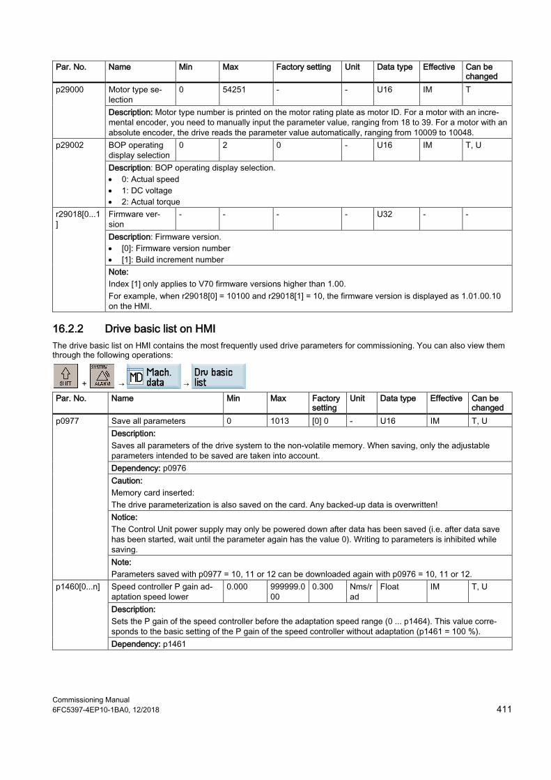
Commissioning Manual 6FC5397-4EP10-1BA0, 12/2018 411
Par. No. Name Min Max Factory setting Unit Data type Effective Can be changed
p29000 Motor type se-lection
0 54251 - - U16 IM T
Description: Motor type number is printed on the motor rating plate as motor ID. For a motor with an incre-mental encoder, you need to manually input the parameter value, ranging from 18 to 39. For a motor with an absolute encoder, the drive reads the parameter value automatically, ranging from 10009 to 10048.
p29002 BOP operating display selection
0 2 0 - U16 IM T, U
Description: BOP operating display selection. • 0: Actual speed • 1: DC voltage • 2: Actual torque
r29018[0...1]
Firmware ver-sion
- - - - U32 - -
Description: Firmware version. • [0]: Firmware version number • [1]: Build increment number Note: Index [1] only applies to V70 firmware versions higher than 1.00. For example, when r29018[0] = 10100 and r29018[1] = 10, the firmware version is displayed as 1.01.00.10 on the HMI.
16.2.2 Drive basic list on HMI The drive basic list on HMI contains the most frequently used drive parameters for commissioning. You can also view them through the following operations:
+ → → Par. No. Name Min Max Factory
setting Unit Data type Effective Can be
changed p0977 Save all parameters 0 1013 [0] 0 - U16 IM T, U
Description: Saves all parameters of the drive system to the non-volatile memory. When saving, only the adjustable parameters intended to be saved are taken into account. Dependency: p0976 Caution: Memory card inserted: The drive parameterization is also saved on the card. Any backed-up data is overwritten! Notice: The Control Unit power supply may only be powered down after data has been saved (i.e. after data save has been started, wait until the parameter again has the value 0). Writing to parameters is inhibited while saving. Note: Parameters saved with p0977 = 10, 11 or 12 can be downloaded again with p0976 = 10, 11 or 12.
p1460[0...n] Speed controller P gain ad-aptation speed lower
0.000 999999.000
0.300 Nms/rad
Float IM T, U
Description: Sets the P gain of the speed controller before the adaptation speed range (0 ... p1464). This value corre-sponds to the basic setting of the P gain of the speed controller without adaptation (p1461 = 100 %). Dependency: p1461
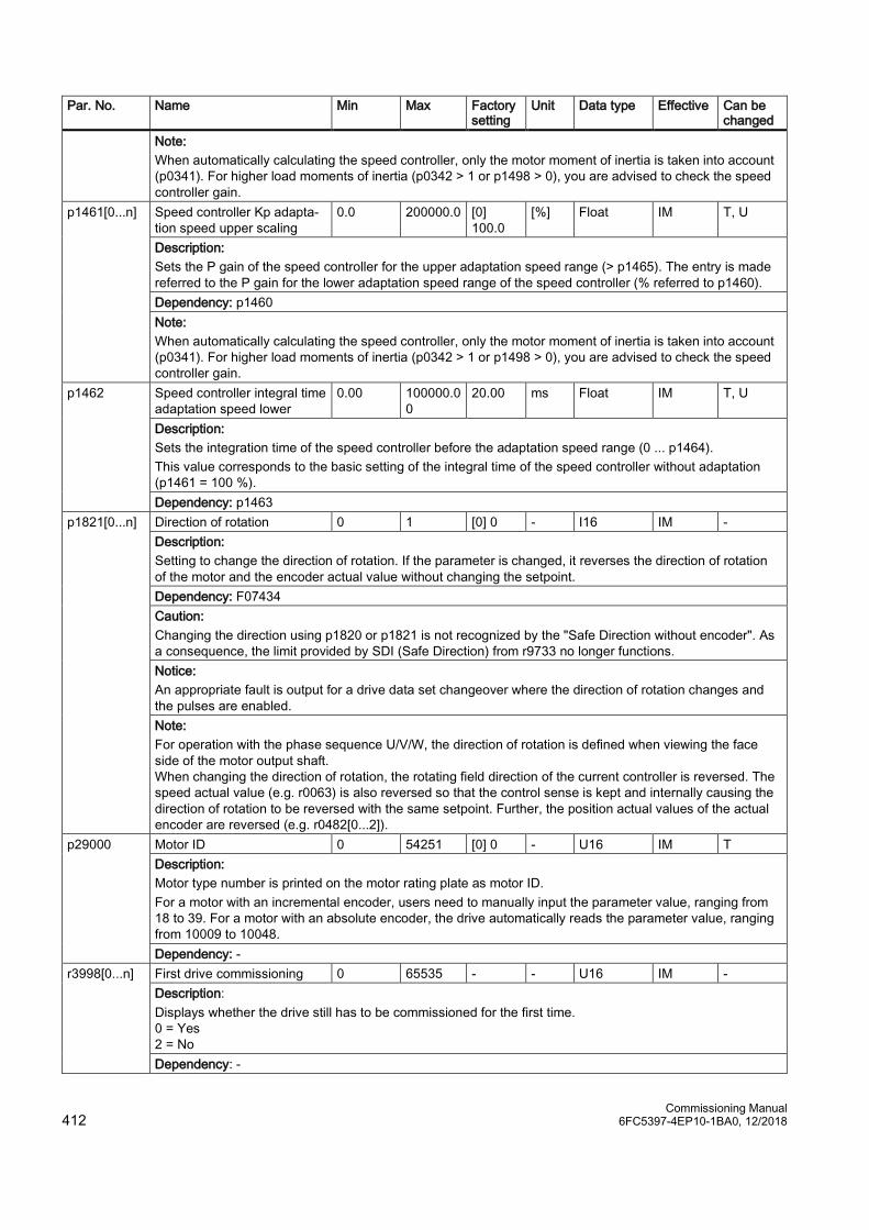
Commissioning Manual 412 6FC5397-4EP10-1BA0, 12/2018
Par. No. Name Min Max Factory setting
Unit Data type Effective Can be changed
Note: When automatically calculating the speed controller, only the motor moment of inertia is taken into account (p0341). For higher load moments of inertia (p0342 > 1 or p1498 > 0), you are advised to check the speed controller gain.
p1461[0...n] Speed controller Kp adapta-tion speed upper scaling
0.0 200000.0 [0] 100.0
[%] Float IM T, U
Description: Sets the P gain of the speed controller for the upper adaptation speed range (> p1465). The entry is made referred to the P gain for the lower adaptation speed range of the speed controller (% referred to p1460). Dependency: p1460 Note: When automatically calculating the speed controller, only the motor moment of inertia is taken into account (p0341). For higher load moments of inertia (p0342 > 1 or p1498 > 0), you are advised to check the speed controller gain.
p1462 Speed controller integral time adaptation speed lower
0.00 100000.00
20.00 ms Float IM T, U
Description: Sets the integration time of the speed controller before the adaptation speed range (0 ... p1464). This value corresponds to the basic setting of the integral time of the speed controller without adaptation (p1461 = 100 %). Dependency: p1463
p1821[0...n] Direction of rotation 0 1 [0] 0 - I16 IM - Description: Setting to change the direction of rotation. If the parameter is changed, it reverses the direction of rotation of the motor and the encoder actual value without changing the setpoint. Dependency: F07434 Caution: Changing the direction using p1820 or p1821 is not recognized by the "Safe Direction without encoder". As a consequence, the limit provided by SDI (Safe Direction) from r9733 no longer functions. Notice: An appropriate fault is output for a drive data set changeover where the direction of rotation changes and the pulses are enabled. Note: For operation with the phase sequence U/V/W, the direction of rotation is defined when viewing the face side of the motor output shaft. When changing the direction of rotation, the rotating field direction of the current controller is reversed. The speed actual value (e.g. r0063) is also reversed so that the control sense is kept and internally causing the direction of rotation to be reversed with the same setpoint. Further, the position actual values of the actual encoder are reversed (e.g. r0482[0...2]).
p29000 Motor ID 0 54251 [0] 0 - U16 IM T Description: Motor type number is printed on the motor rating plate as motor ID. For a motor with an incremental encoder, users need to manually input the parameter value, ranging from 18 to 39. For a motor with an absolute encoder, the drive automatically reads the parameter value, ranging from 10009 to 10048. Dependency: -
r3998[0...n] First drive commissioning 0 65535 - - U16 IM - Description: Displays whether the drive still has to be commissioned for the first time. 0 = Yes 2 = No Dependency: -
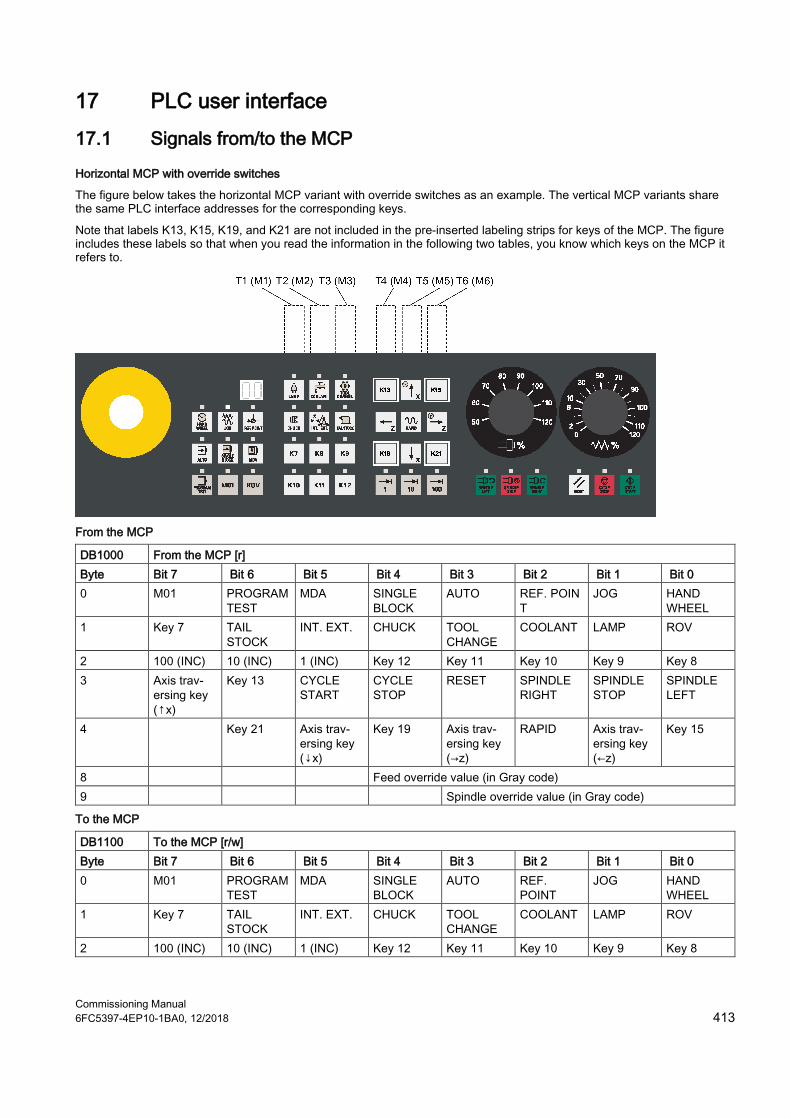
Commissioning Manual 6FC5397-4EP10-1BA0, 12/2018 413
17 PLC user interface 17.1 Signals from/to the MCP
Horizontal MCP with override switches
The figure below takes the horizontal MCP variant with override switches as an example. The vertical MCP variants share the same PLC interface addresses for the corresponding keys.
Note that labels K13, K15, K19, and K21 are not included in the pre-inserted labeling strips for keys of the MCP. The figure includes these labels so that when you read the information in the following two tables, you know which keys on the MCP it refers to.
From the MCP
DB1000 From the MCP [r] Byte Bit 7 Bit 6 Bit 5 Bit 4 Bit 3 Bit 2 Bit 1 Bit 0 0 M01 PROGRAM
TEST MDA SINGLE
BLOCK AUTO REF. POIN
T JOG HAND
WHEEL 1 Key 7 TAIL
STOCK INT. EXT. CHUCK TOOL
CHANGE COOLANT LAMP ROV
2 100 (INC) 10 (INC) 1 (INC) Key 12 Key 11 Key 10 Key 9 Key 8 3 Axis trav-
ersing key (↑x)
Key 13 CYCLE START
CYCLE STOP
RESET SPINDLE RIGHT
SPINDLE STOP
SPINDLE LEFT
4 Key 21 Axis trav-ersing key (↓x)
Key 19 Axis trav-ersing key (→z)
RAPID Axis trav-ersing key (←z)
Key 15
8 Feed override value (in Gray code) 9 Spindle override value (in Gray code)
To the MCP
DB1100 To the MCP [r/w] Byte Bit 7 Bit 6 Bit 5 Bit 4 Bit 3 Bit 2 Bit 1 Bit 0 0 M01 PROGRAM
TEST MDA SINGLE
BLOCK AUTO REF.
POINT JOG HAND
WHEEL 1 Key 7 TAIL
STOCK INT. EXT. CHUCK TOOL
CHANGE COOLANT LAMP ROV
2 100 (INC) 10 (INC) 1 (INC) Key 12 Key 11 Key 10 Key 9 Key 8
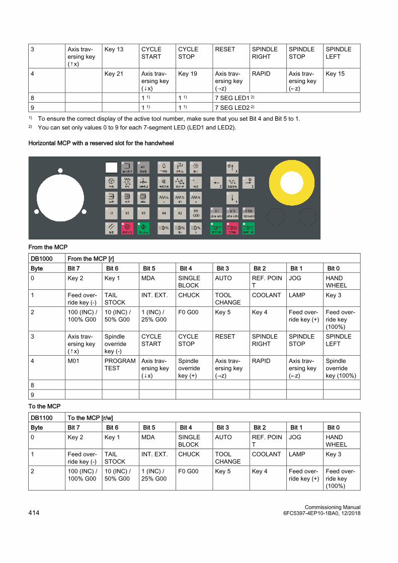
Commissioning Manual 414 6FC5397-4EP10-1BA0, 12/2018
3 Axis trav-ersing key (↑x)
Key 13 CYCLE START
CYCLE STOP
RESET SPINDLE RIGHT
SPINDLE STOP
SPINDLE LEFT
4 Key 21 Axis trav-ersing key (↓x)
Key 19 Axis trav-ersing key (→z)
RAPID Axis trav-ersing key (←z)
Key 15
8 1 1) 1 1) 7 SEG LED1 2) 9 1 1) 1 1) 7 SEG LED2 2) 1) To ensure the correct display of the active tool number, make sure that you set Bit 4 and Bit 5 to 1.
2) You can set only values 0 to 9 for each 7-segment LED (LED1 and LED2).
Horizontal MCP with a reserved slot for the handwheel
From the MCP
DB1000 From the MCP [r] Byte Bit 7 Bit 6 Bit 5 Bit 4 Bit 3 Bit 2 Bit 1 Bit 0 0 Key 2 Key 1 MDA SINGLE
BLOCK AUTO REF. POIN
T JOG HAND
WHEEL 1 Feed over-
ride key (-) TAIL STOCK
INT. EXT. CHUCK TOOL CHANGE
COOLANT LAMP Key 3
2 100 (INC) / 100% G00
10 (INC) / 50% G00
1 (INC) / 25% G00
F0 G00 Key 5 Key 4 Feed over-ride key (+)
Feed over-ride key (100%)
3 Axis trav-ersing key (↑x)
Spindle override key (-)
CYCLE START
CYCLE STOP
RESET SPINDLE RIGHT
SPINDLE STOP
SPINDLE LEFT
4 M01 PROGRAM TEST
Axis trav-ersing key (↓x)
Spindle override key (+)
Axis trav-ersing key (→z)
RAPID Axis trav-ersing key (←z)
Spindle override key (100%)
8 9
To the MCP
DB1100 To the MCP [r/w] Byte Bit 7 Bit 6 Bit 5 Bit 4 Bit 3 Bit 2 Bit 1 Bit 0 0 Key 2 Key 1 MDA SINGLE
BLOCK AUTO REF. POIN
T JOG HAND
WHEEL 1 Feed over-
ride key (-) TAIL STOCK
INT. EXT. CHUCK TOOL CHANGE
COOLANT LAMP Key 3
2 100 (INC) / 100% G00
10 (INC) / 50% G00
1 (INC) / 25% G00
F0 G00 Key 5 Key 4 Feed over-ride key (+)
Feed over-ride key (100%)
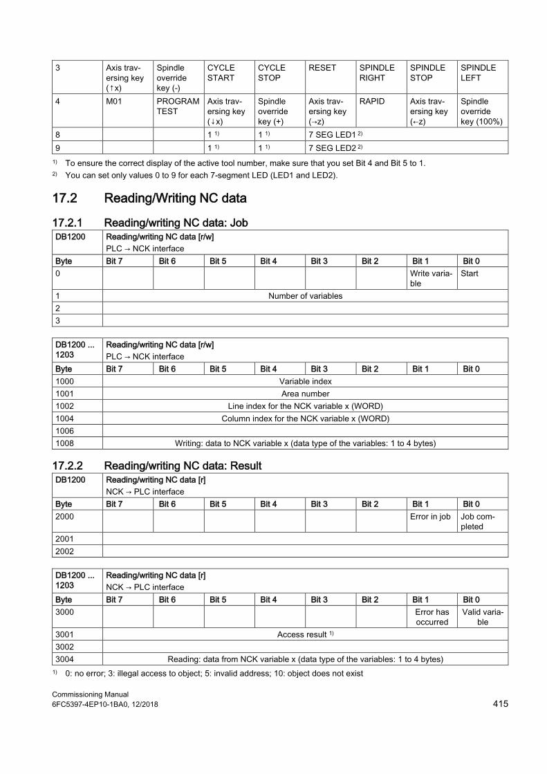
Commissioning Manual 6FC5397-4EP10-1BA0, 12/2018 415
3 Axis trav-ersing key (↑x)
Spindle override key (-)
CYCLE START
CYCLE STOP
RESET SPINDLE RIGHT
SPINDLE STOP
SPINDLE LEFT
4 M01 PROGRAM TEST
Axis trav-ersing key (↓x)
Spindle override key (+)
Axis trav-ersing key (→z)
RAPID Axis trav-ersing key (←z)
Spindle override key (100%)
8 1 1) 1 1) 7 SEG LED1 2) 9 1 1) 1 1) 7 SEG LED2 2) 1) To ensure the correct display of the active tool number, make sure that you set Bit 4 and Bit 5 to 1.
2) You can set only values 0 to 9 for each 7-segment LED (LED1 and LED2).
17.2 Reading/Writing NC data
17.2.1 Reading/writing NC data: Job DB1200
Reading/writing NC data [r/w] PLC → NCK interface
Byte Bit 7 Bit 6 Bit 5 Bit 4 Bit 3 Bit 2 Bit 1 Bit 0 0 Write varia-
ble Start
1 Number of variables 2 3
DB1200 ... 1203
Reading/writing NC data [r/w] PLC → NCK interface
Byte Bit 7 Bit 6 Bit 5 Bit 4 Bit 3 Bit 2 Bit 1 Bit 0 1000 Variable index 1001 Area number 1002 Line index for the NCK variable x (WORD) 1004 Column index for the NCK variable x (WORD) 1006 1008 Writing: data to NCK variable x (data type of the variables: 1 to 4 bytes)
17.2.2 Reading/writing NC data: Result DB1200 Reading/writing NC data [r]
NCK → PLC interface Byte Bit 7 Bit 6 Bit 5 Bit 4 Bit 3 Bit 2 Bit 1 Bit 0 2000 Error in job Job com-
pleted 2001 2002
DB1200 ... 1203
Reading/writing NC data [r] NCK → PLC interface
Byte Bit 7 Bit 6 Bit 5 Bit 4 Bit 3 Bit 2 Bit 1 Bit 0 3000 Error has
occurred Valid varia-
ble 3001 Access result 1) 3002 3004 Reading: data from NCK variable x (data type of the variables: 1 to 4 bytes)
1) 0: no error; 3: illegal access to object; 5: invalid address; 10: object does not exist

Commissioning Manual 416 6FC5397-4EP10-1BA0, 12/2018
17.3 PI Service
17.3.1 PI service: Job DB1200 PI service [r/w]
PLC → NCK interface Byte Bit 7 Bit 6 Bit 5 Bit 4 Bit 3 Bit 2 Bit 1 Bit 0 4000 Start 4001 PI index 4002 4003 4004 PI parameter 1 4006 PI parameter 2 4008 PI parameter 3 4010 PI parameter 4 4012 PI parameter 5 4014 PI parameter 6 4016 PI parameter 7 4018 PI parameter 8 4020 PI parameter 9 4022 PI parameter 10
17.3.2 PI service: Result DB1200 Reading / writing NC data [r]
NCK → PLC interface Byte Bit 7 Bit 6 Bit 5 Bit 4 Bit 3 Bit 2 Bit 1 Bit 0 5000 Error in job Job com-
pleted 5001 5002
17.4 Retentive data area DB1400 Retentive data [r/w] Byte Bit 7 Bit 6 Bit 5 Bit 4 Bit 3 Bit 2 Bit 1 Bit 0 User data 0 User data 1 User data 2 ... ... 32 ... ... User data 126 User data 127
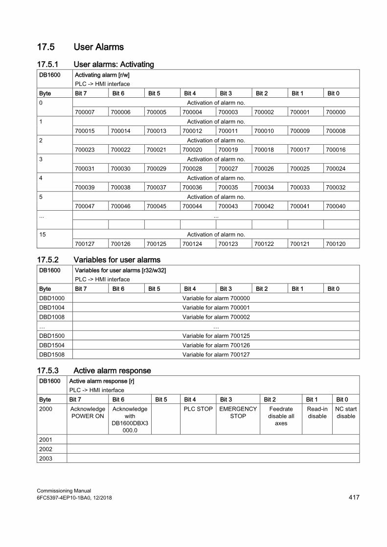
Commissioning Manual 6FC5397-4EP10-1BA0, 12/2018 417
17.5 User Alarms
17.5.1 User alarms: Activating DB1600 Activating alarm [r/w]
PLC -> HMI interface Byte Bit 7 Bit 6 Bit 5 Bit 4 Bit 3 Bit 2 Bit 1 Bit 0 0 Activation of alarm no.
700007 700006 700005 700004 700003 700002 700001 700000 1 Activation of alarm no.
700015 700014 700013 700012 700011 700010 700009 700008 2 Activation of alarm no.
700023 700022 700021 700020 700019 700018 700017 700016 3 Activation of alarm no.
700031 700030 700029 700028 700027 700026 700025 700024 4 Activation of alarm no.
700039 700038 700037 700036 700035 700034 700033 700032 5 Activation of alarm no.
700047 700046 700045 700044 700043 700042 700041 700040 ... ...
15 Activation of alarm no.
700127 700126 700125 700124 700123 700122 700121 700120
17.5.2 Variables for user alarms DB1600 Variables for user alarms [r32/w32]
PLC -> HMI interface Byte Bit 7 Bit 6 Bit 5 Bit 4 Bit 3 Bit 2 Bit 1 Bit 0 DBD1000 Variable for alarm 700000 DBD1004 Variable for alarm 700001 DBD1008 Variable for alarm 700002 … … DBD1500 Variable for alarm 700125 DBD1504 Variable for alarm 700126 DBD1508 Variable for alarm 700127
17.5.3 Active alarm response DB1600 Active alarm response [r]
PLC -> HMI interface Byte Bit 7 Bit 6 Bit 5 Bit 4 Bit 3 Bit 2 Bit 1 Bit 0 2000 Acknowledge
POWER ON Acknowledge
with DB1600DBX3
000.0
PLC STOP EMERGENCY STOP
Feedrate disable all
axes
Read-in disable
NC start disable
2001 2002 2003

Commissioning Manual 418 6FC5397-4EP10-1BA0, 12/2018
17.5.4 Alarm acknowledgement DB1600 Alarm acknowledgement [r/w]
PLC -> HMI interface Byte Bit 7 Bit 6 Bit 5 Bit 4 Bit 3 Bit 2 Bit 1 Bit 0 3000 Ack 3001 3002 3003
17.6 Signals from/to HMI
17.6.1 Program control signals from the HMI (retentive area) DB1700 Signals, HMI [r/w]
HMI -> PLC interface Byte Bit 7 Bit 6 Bit 5 Bit 4 Bit 3 Bit 2 Bit 1 Bit 0 0 Dry run
feedrate selected
M01 se-lected
DRF se-lected
1 Program test selected
Feedrate override selected for rapid trav-erse
2 Skip block 7 selected
Skip block 6 selected
Skip block 5 selected
Skip block 4 selected
Skip block 3 selected
Skip block 2 selected
Skip block 1 selected
Skip block 0 selected
3 Measure-ment in JOG active
Calculation of meas-urement value not finished
Skip block 9 selected
Skip block 8 selected
4 5 6 7 Reset NC stop NC start
17.6.2 Program selection from PLC (retentive area) DB1700 Program selection [r/w]
PLC -> HMI interface Byte Bit 7 Bit 6 Bit 5 Bit 4 Bit 3 Bit 2 Bit 1 Bit 0 1000 Program selection from the PLC: Program number 1001 Command job from the PLC: Command 1002 1003
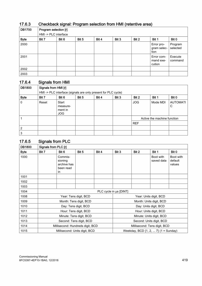
Commissioning Manual 6FC5397-4EP10-1BA0, 12/2018 419
17.6.3 Checkback signal: Program selection from HMI (retentive area) DB1700 Program selection [r]
HMI -> PLC interface Byte Bit 7 Bit 6 Bit 5 Bit 4 Bit 3 Bit 2 Bit 1 Bit 0 2000 Error pro-
gram selec-tion
Program selected
2001 Error com-mand exe-cution
Execute command
2002 2003
17.6.4 Signals from HMI DB1800 Signals from HMI [r]
HMI -> PLC interface (signals are only present for PLC cycle) Byte Bit 7 Bit 6 Bit 5 Bit 4 Bit 3 Bit 2 Bit 1 Bit 0 0 Reset Start
measure-ment in JOG
JOG Mode MDI AUTOMATIC
1 Active the machine function REF
2 3
17.6.5 Signals from PLC DB1800 Signals from PLC [r] Byte Bit 7 Bit 6 Bit 5 Bit 4 Bit 3 Bit 2 Bit 1 Bit 0 1000 Commis-
sioning archive has been read in
Boot with saved data
Boot with default values
1001 1002 1003 1004 PLC cycle in μs [DINT] 1008 Year: Tens digit, BCD Year: Units digit, BCD 1009 Month: Tens digit, BCD Month: Units digit, BCD 1010 Day: Tens digit, BCD Day: Units digit, BCD 1011 Hour: Tens digit, BCD Hour: Units digit, BCD 1012 Minute: Tens digit, BCD Minute: Units digit, BCD 1013 Second: Tens digit, BCD Second: Units digit, BCD 1014 Millisecond: Hundreds digit, BCD Millisecond: Tens digit, BCD 1015 Millisecond: Units digit, BCD Weekday, BCD {1, 2, ... 7} (1 = Sunday)
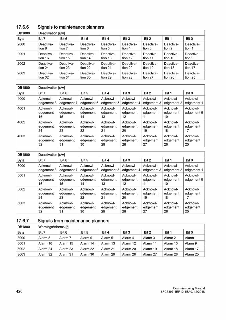
Commissioning Manual 420 6FC5397-4EP10-1BA0, 12/2018
17.6.6 Signals to maintenance planners DB1800 Deactivation [r/w] Byte Bit 7 Bit 6 Bit 5 Bit 4 Bit 3 Bit 2 Bit 1 Bit 0 2000 Deactiva-
tion 8 Deactiva-tion 7
Deactiva-tion 6
Deactiva-tion 5
Deactiva-tion 4
Deactiva-tion 3
Deactiva-tion 2
Deactiva-tion 1
2001 Deactiva-tion 16
Deactiva-tion 15
Deactiva-tion 14
Deactiva-tion 13
Deactiva-tion 12
Deactiva-tion 11
Deactiva-tion 10
Deactiva-tion 9
2002 Deactiva-tion 24
Deactiva-tion 23
Deactiva-tion 22
Deactiva-tion 21
Deactiva-tion 20
Deactiva-tion 19
Deactiva-tion 18
Deactiva-tion 17
2003 Deactiva-tion 32
Deactiva-tion 31
Deactiva-tion 30
Deactiva-tion 29
Deactiva-tion 28
Deactiva-tion 27
Deactiva-tion 26
Deactiva-tion 25
DB1800 Deactivation [r/w] Byte Bit 7 Bit 6 Bit 5 Bit 4 Bit 3 Bit 2 Bit 1 Bit 0 4000 Acknowl-
edgement 8 Acknowl-edgement 7
Acknowl-edgement 6
Acknowl-edgement 5
Acknowl-edgement 4
Acknowl-edgement 3
Acknowl-edgement 2
Acknowl-edgement 1
4001 Acknowl-edgement 16
Acknowl-edgement 15
Acknowl-edgement 14
Acknowl-edgement 13
Acknowl-edgement 12
Acknowl-edgement 11
Acknowl-edgement 10
Acknowl-edgement 9
4002 Acknowl-edgement 24
Acknowl-edgement 23
Acknowl-edgement 22
Acknowl-edgement 21
Acknowl-edgement 20
Acknowl-edgement 19
Acknowl-edgement 18
Acknowl-edgement 17
4003 Acknowl-edgement 32
Acknowl-edgement 31
Acknowl-edgement 30
Acknowl-edgement 29
Acknowl-edgement 28
Acknowl-edgement 27
Acknowl-edgement 26
Acknowl-edgement 25
DB1800 Deactivation [r/w] Byte Bit 7 Bit 6 Bit 5 Bit 4 Bit 3 Bit 2 Bit 1 Bit 0 5000 Acknowl-
edgement 8 Acknowl-edgement 7
Acknowl-edgement 6
Acknowl-edgement 5
Acknowl-edgement 4
Acknowl-edgement 3
Acknowl-edgement 2
Acknowl-edgement 1
5001 Acknowl-edgement 16
Acknowl-edgement 15
Acknowl-edgement 14
Acknowl-edgement 13
Acknowl-edgement 12
Acknowl-edgement 11
Acknowl-edgement 10
Acknowl-edgement 9
5002 Acknowl-edgement 24
Acknowl-edgement 23
Acknowl-edgement 22
Acknowl-edgement 21
Acknowl-edgement 20
Acknowl-edgement 19
Acknowl-edgement 18
Acknowl-edgement 17
5003 Acknowl-edgement 32
Acknowl-edgement 31
Acknowl-edgement 30
Acknowl-edgement 29
Acknowl-edgement 28
Acknowl-edgement 27
Acknowl-edgement 26
Acknowl-edgement 25
17.6.7 Signals from maintenance planners DB1800 Warnings/Alarms [r] Byte Bit 7 Bit 6 Bit 5 Bit 4 Bit 3 Bit 2 Bit 1 Bit 0 3000 Alarm 8 Alarm 7 Alarm 6 Alarm 5 Alarm 4 Alarm 3 Alarm 2 Alarm 1 3001 Alarm 16 Alarm 15 Alarm 14 Alarm 13 Alarm 12 Alarm 11 Alarm 10 Alarm 9 3002 Alarm 24 Alarm 23 Alarm 22 Alarm 21 Alarm 20 Alarm 19 Alarm 18 Alarm 17 3003 Alarm 32 Alarm 31 Alarm 30 Alarm 29 Alarm 28 Alarm 27 Alarm 26 Alarm 25
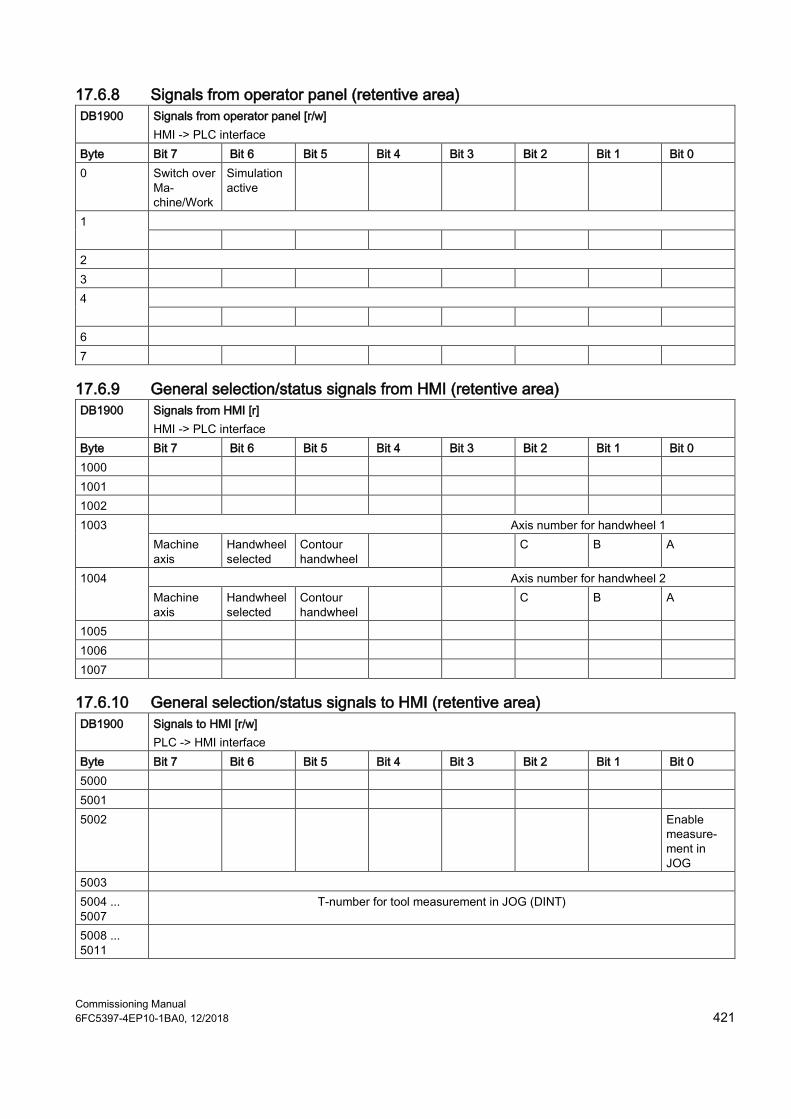
Commissioning Manual 6FC5397-4EP10-1BA0, 12/2018 421
17.6.8 Signals from operator panel (retentive area) DB1900 Signals from operator panel [r/w]
HMI -> PLC interface Byte Bit 7 Bit 6 Bit 5 Bit 4 Bit 3 Bit 2 Bit 1 Bit 0 0 Switch over
Ma-chine/Work
Simulation active
1
2 3 4
6 7
17.6.9 General selection/status signals from HMI (retentive area) DB1900 Signals from HMI [r]
HMI -> PLC interface Byte Bit 7 Bit 6 Bit 5 Bit 4 Bit 3 Bit 2 Bit 1 Bit 0 1000 1001 1002 1003 Axis number for handwheel 1
Machine axis
Handwheel selected
Contour handwheel
C B A
1004 Axis number for handwheel 2 Machine axis
Handwheel selected
Contour handwheel
C B A
1005 1006 1007
17.6.10 General selection/status signals to HMI (retentive area) DB1900 Signals to HMI [r/w]
PLC -> HMI interface Byte Bit 7 Bit 6 Bit 5 Bit 4 Bit 3 Bit 2 Bit 1 Bit 0 5000 5001 5002 Enable
measure-ment in JOG
5003 5004 ... 5007
T-number for tool measurement in JOG (DINT)
5008 ... 5011

Commissioning Manual 422 6FC5397-4EP10-1BA0, 12/2018
5012 ... 5015
5016 ... 5019
17.7 Auxiliary functions transfer from NC channel
17.7.1 Overview DB2500 Auxiliary functions from NCK channel [r]
NCK -> PLC interface Byte Bit 7 Bit 6 Bit 5 Bit 4 Bit 3 Bit 2 Bit 1 Bit 0 0 1 2 3 4 M fct. 5
change M fct. 4 change
M fct. 3 change
M fct. 2 change
M fct. 1 change
5 6 S fct. 1
change 7 8 T fct. 1
change 9 10 D fct.
Change 11 12 H fct. 3
change H fct. 2 change
H fct. change
13 14 15 16 17 18 19
17.7.2 Decoded M signals (M0 to M99)
Note The signals are output for the duration of a PLC cycle.
DB2500 M functions from NCK channel [r] 1) 2) NCK -> PLC interface
Byte Bit 7 Bit 6 Bit 5 Bit 4 Bit 3 Bit 2 Bit 1 Bit 0 1000 Dynamic M functions
M7 M6 M5 M4 M3 M2 M1 M0 1001 Dynamic M functions
M15 M14 M13 M12 M11 M10 M9 M8
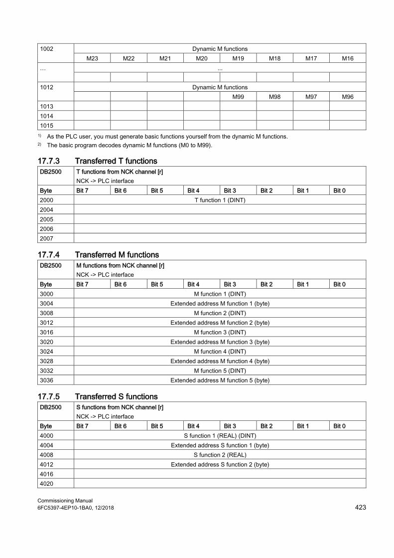
Commissioning Manual 6FC5397-4EP10-1BA0, 12/2018 423
1002 Dynamic M functions M23 M22 M21 M20 M19 M18 M17 M16
… ...
1012 Dynamic M functions M99 M98 M97 M96
1013 1014 1015 1) As the PLC user, you must generate basic functions yourself from the dynamic M functions.
2) The basic program decodes dynamic M functions (M0 to M99).
17.7.3 Transferred T functions DB2500 T functions from NCK channel [r]
NCK -> PLC interface Byte Bit 7 Bit 6 Bit 5 Bit 4 Bit 3 Bit 2 Bit 1 Bit 0 2000 T function 1 (DINT) 2004 2005 2006 2007
17.7.4 Transferred M functions DB2500 M functions from NCK channel [r]
NCK -> PLC interface Byte Bit 7 Bit 6 Bit 5 Bit 4 Bit 3 Bit 2 Bit 1 Bit 0 3000 M function 1 (DINT) 3004 Extended address M function 1 (byte) 3008 M function 2 (DINT) 3012 Extended address M function 2 (byte) 3016 M function 3 (DINT) 3020 Extended address M function 3 (byte) 3024 M function 4 (DINT) 3028 Extended address M function 4 (byte) 3032 M function 5 (DINT) 3036 Extended address M function 5 (byte)
17.7.5 Transferred S functions DB2500 S functions from NCK channel [r]
NCK -> PLC interface Byte Bit 7 Bit 6 Bit 5 Bit 4 Bit 3 Bit 2 Bit 1 Bit 0 4000 S function 1 (REAL) (DINT) 4004 Extended address S function 1 (byte) 4008 S function 2 (REAL) 4012 Extended address S function 2 (byte) 4016 4020

Commissioning Manual 424 6FC5397-4EP10-1BA0, 12/2018
17.7.6 Transferred D functions DB2500 D functions from NCK channel [r]
NCK -> PLC interface Byte Bit 7 Bit 6 Bit 5 Bit 4 Bit 3 Bit 2 Bit 1 Bit 0 5000 D function 1 (DINT) 5004
17.7.7 Transferred H functions DB2500 H functions from NCK channel [r]
NCK -> PLC interface Byte Bit 7 Bit 6 Bit 5 Bit 4 Bit 3 Bit 2 Bit 1 Bit 0 6000 H function 1 (REAL) (DINT) 6004 Extended address H function 1 (byte) 6008 H function 2 (REAL) 6012 Extended address H function 2 (byte) 6016 H function 3 (REAL) 6020 Extended address H function 3 (byte)
17.8 NCK signals
17.8.1 General signals to NCK DB2600 General signals to NCK [r/w]
PLC → NCK interface Byte Bit 7 Bit 6 Bit 5 Bit 4 Bit 3 Bit 2 Bit 1 Bit 0 0 Protection level
Keyswitch position 0 to 3 Acknowled
ge EMERGENCY STOP
EMERGENCY STOP
Braking along the contour in
case of EMERGENCY STOP
4 5 6 7
1 Request axis dis-tances to
go
Request axis actual
values
INC inputs in mode signal
range ac-tive 1)
2 3 1) Refer to mode signals
17.8.2 General signals from NCK DB2700 General signals from NCK [r/w]
NCK -> PLC interface Byte Bit 7 Bit 6 Bit 5 Bit 4 Bit 3 Bit 2 Bit 1 Bit 0 0 EMERGEN
CY OFF active
1 Inch meas-uring sys-tem
Probe actuated Probe 2 Probe 1
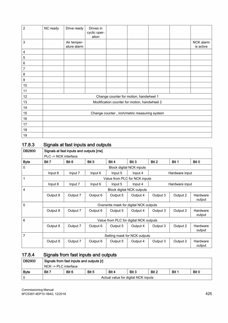
Commissioning Manual 6FC5397-4EP10-1BA0, 12/2018 425
2 NC ready Drive ready Drives in cyclic oper-
ation
3 Air temper-ature alarm
NCK alarm is active
4 5 6 7 8 9 10 11 12 Change counter for motion, handwheel 1 13 Modification counter for motion, handwheel 2 14 15 Change counter , inch/metric measuring system 16 17 18 19
17.8.3 Signals at fast inputs and outputs DB2800 Signals at fast inputs and outputs [r/w]
PLC -> NCK interface Byte Bit 7 Bit 6 Bit 5 Bit 4 Bit 3 Bit 2 Bit 1 Bit 0 0 Block digital NCK inputs
Input 8 Input 7 Input 6 Input 5 Input 4 Hardware input 1 Value from PLC for NCK inputs
Input 8 Input 7 Input 6 Input 5 Input 4 Hardware input 4 Block digital NCK outputs
Output 8 Output 7 Output 6 Output 5 Output 4 Output 3 Output 2 Hardware output
5 Overwrite mask for digital NCK outputs Output 8 Output 7 Output 6 Output 5 Output 4 Output 3 Output 2 Hardware
output 6 Value from PLC for digital NCK outputs
Output 8 Output 7 Output 6 Output 5 Output 4 Output 3 Output 2 Hardware output
7 Setting mask for NCK outputs Output 8 Output 7 Output 6 Output 5 Output 4 Output 3 Output 2 Hardware
output
17.8.4 Signals from fast inputs and outputs DB2900 Signals from fast inputs and outputs [r]
NCK -> PLC interface Byte Bit 7 Bit 6 Bit 5 Bit 4 Bit 3 Bit 2 Bit 1 Bit 0 0 Actual value for digital NCK inputs
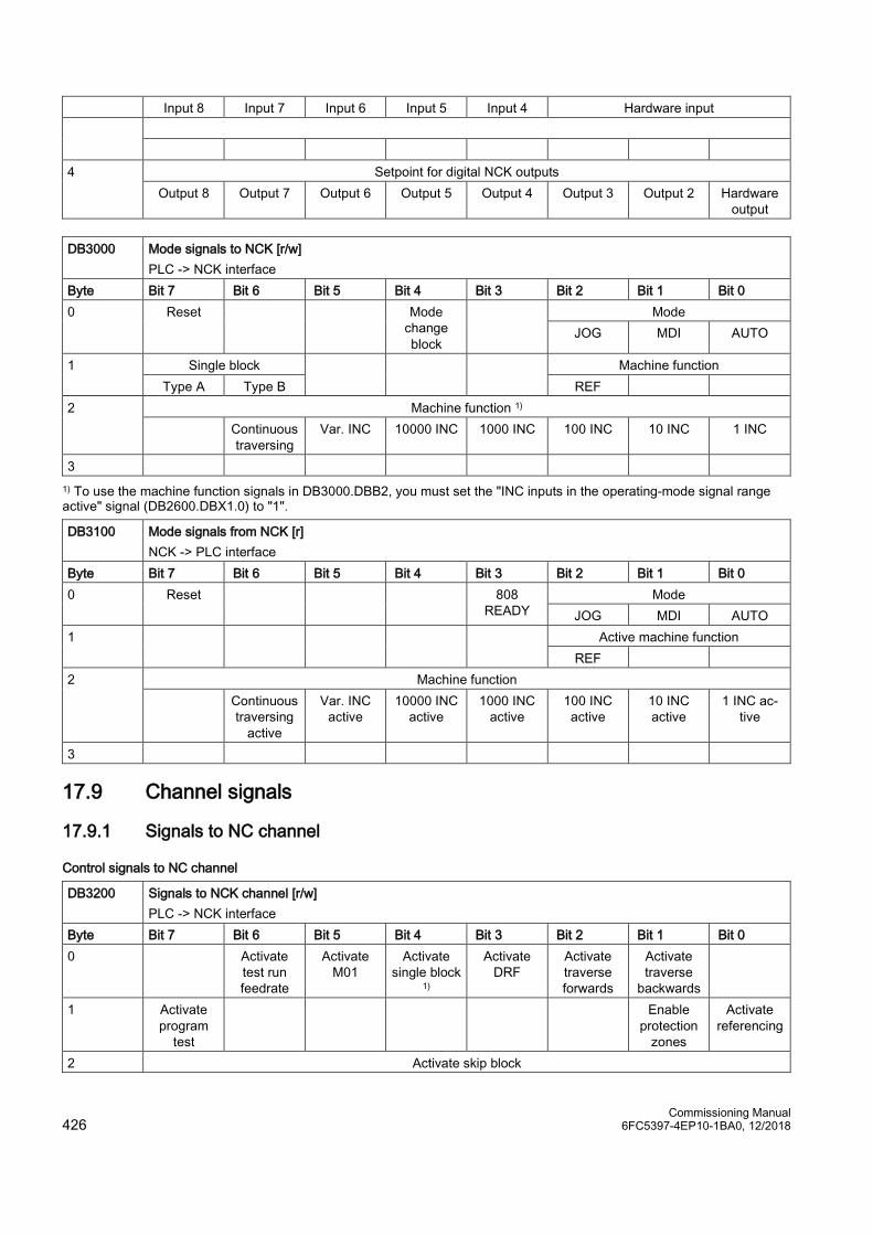
Commissioning Manual 426 6FC5397-4EP10-1BA0, 12/2018
Input 8 Input 7 Input 6 Input 5 Input 4 Hardware input
4 Setpoint for digital NCK outputs
Output 8 Output 7 Output 6 Output 5 Output 4 Output 3 Output 2 Hardware output
DB3000 Mode signals to NCK [r/w] PLC -> NCK interface
Byte Bit 7 Bit 6 Bit 5 Bit 4 Bit 3 Bit 2 Bit 1 Bit 0 0 Reset Mode
change block
Mode JOG MDI AUTO
1 Single block Machine function Type A Type B REF
2 Machine function 1) Continuous
traversing Var. INC 10000 INC 1000 INC 100 INC 10 INC 1 INC
3 1) To use the machine function signals in DB3000.DBB2, you must set the "INC inputs in the operating-mode signal range active" signal (DB2600.DBX1.0) to "1".
DB3100 Mode signals from NCK [r] NCK -> PLC interface
Byte Bit 7 Bit 6 Bit 5 Bit 4 Bit 3 Bit 2 Bit 1 Bit 0 0 Reset 808
READY Mode
JOG MDI AUTO 1 Active machine function
REF 2 Machine function
Continuous traversing
active
Var. INC active
10000 INC active
1000 INC active
100 INC active
10 INC active
1 INC ac-tive
3
17.9 Channel signals
17.9.1 Signals to NC channel
Control signals to NC channel
DB3200 Signals to NCK channel [r/w] PLC -> NCK interface
Byte Bit 7 Bit 6 Bit 5 Bit 4 Bit 3 Bit 2 Bit 1 Bit 0 0 Activate
test run feedrate
Activate M01
Activate single block
1)
Activate DRF
Activate traverse forwards
Activate traverse
backwards
1 Activate program
test
Enable protection
zones
Activate referencing
2 Activate skip block
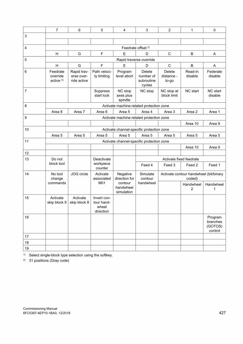
Commissioning Manual 6FC5397-4EP10-1BA0, 12/2018 427
7 6 5 4 3 2 1 0 3
4 Feedrate offset 2)
H G F E D C B A 5 Rapid traverse override
H G F E D C B A 6 Feedrate
override active 3)
Rapid trav-erse over-ride active
Path veloci-ty limiting
Program level abort
Delete number of subroutine
cycles
Delete distance -
to-go
Read-in disable
Federate disable
7 Suppress start lock
NC stop axes plus spindle
NC stop NC stop at block limit
NC start NC start disable
8 Activate machine-related protection zone Area 8 Area 7 Area 6 Area 5 Area 4 Area 3 Area 2 Area 1
9 Activate machine-related protection zone Area 10 Area 9
10 Activate channel-specific protection zone Area 5 Area 5 Area 5 Area 5 Area 5 Area 5 Area 5 Area 5
11 Activate channel-specific protection zone Area 10 Area 9
12 13 Do not
block tool Deactivate
workpiece counter
Activate fixed feedrate Feed 4 Feed 3 Feed 2 Feed 1
14 No tool change
commands
JOG circle Activate associated
M01
Negative direction for
contour handwheel simulation
Simulate contour
handwheel
Activate contour handwheel (bit/binary coded)
Handwheel 2
Handwheel 1
15 Activate skip block 9
Activate skip block 8
Invert con-tour hand-
wheel direction
16 Program branches (GOTOS)
control 17 18 19 1) Select single-block type selection using the softkey.
2) 31 positions (Gray code)

Commissioning Manual 428 6FC5397-4EP10-1BA0, 12/2018
Controls signals to axes in Work
DB3200 Signals to NCK channel [r/w] PLC -> NCK interface
Byte Bit 7 Bit 6 Bit 5 Bit 4 Bit 3 Bit 2 Bit 1 Bit 0 1000 Axis 1 in Work
Traversing keys Rapid trav-erse over-
ride
Traversing key dis-
tance disa-ble
Feedrate stop
Activate handwheel (bit/binary coded) 1) Plus Minus 2 1
1001 Axis 1 in Work Machine function 2)
Continuous traversing
Var. INC 10000 INC 1000 INC 100 INC 10 INC 1 INC
1002 1003
Handwheel direction of
rotation inverted
1004 Axis 2 in Work Traversing keys Rapid trav-
ers override Traversing key disable
Feedrate stop
Activate handwheel (bit/binary coded) Plus Minus 2 1
1005 Axis 2 in Work Machine function 2)
Continuous traversing
Var. INC 10000 INC 1000 INC 100 INC 10 INC 1 INC
1006 1007
Invert handwheel direction
1008 Axis 3 in Work Traversing keys Rapid trav-
erse over-ride
Traversing key disable
Feedrate stop
Activate handwheel (bit/binary coded) Plus Minus 2 1
1009 Axis 3 in Work Machine function 2)
Continuous traversing
Var. INC 10000 INC 1000 INC 100 INC 10 INC 1 INC
1010 1011 Invert
handwheel direction
1) The handwheel number is represented according to the $MD_HANDWH_VDI_REPRESENTATION machine data in a bit-coded (=0) or binary-coded (=1) manner.
2) Machine function: the machine function is only entered if the "INC inputs in the operating-mode signal range active" signal (DB2600.DBX1.0) is not set.
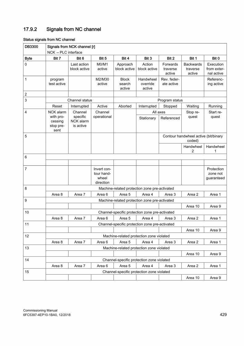
Commissioning Manual 6FC5397-4EP10-1BA0, 12/2018 429
17.9.2 Signals from NC channel
Status signals from NC channel
DB3300 Signals from NCK channel [r] NCK → PLC interface
Byte Bit 7 Bit 6 Bit 5 Bit 4 Bit 3 Bit 2 Bit 1 Bit 0 0 Last action
block active M0/M1 active
Approach block active
Action block active
Forwards traverse active
Backwards traverse active
Execution from exter-nal active
1 program test active
M2/M30 active
Block search active
Handwheel override active
Rev. feder-ate active
Referenc-ing active
2 3 Channel status Program status
Reset Interrupted Active Aborted Interrupted Stopped Waiting Running 4 NCK alarm
with pro-cessing
stop pre-sent
Channel specific
NCK alarm is active
Channel operational
All axes Stop re-quest
Start re-quest Stationary Referenced
5 Contour handwheel active (bit/binary coded)
Handwheel 2
Handwheel 1
6
7 Invert con-tour hand-
wheel direction
Protection zone not
guaranteed
8 Machine-related protection zone pre-activated Area 8 Area 7 Area 6 Area 5 Area 4 Area 3 Area 2 Area 1
9 Machine-related protection zone pre-activated Area 10 Area 9
10 Channel-specific protection zone pre-activated Area 8 Area 7 Area 6 Area 5 Area 4 Area 3 Area 2 Area 1
11 Channel-specific protection zone pre-activated Area 10 Area 9
12 Machine-related protection zone violated Area 8 Area 7 Area 6 Area 5 Area 4 Area 3 Area 2 Area 1
13 Machine-related protection zone violated Area 10 Area 9
14 Channel-specific protection zone violated Area 8 Area 7 Area 6 Area 5 Area 4 Area 3 Area 2 Area 1
15 Channel-specific protection zone violated Area 10 Area 9
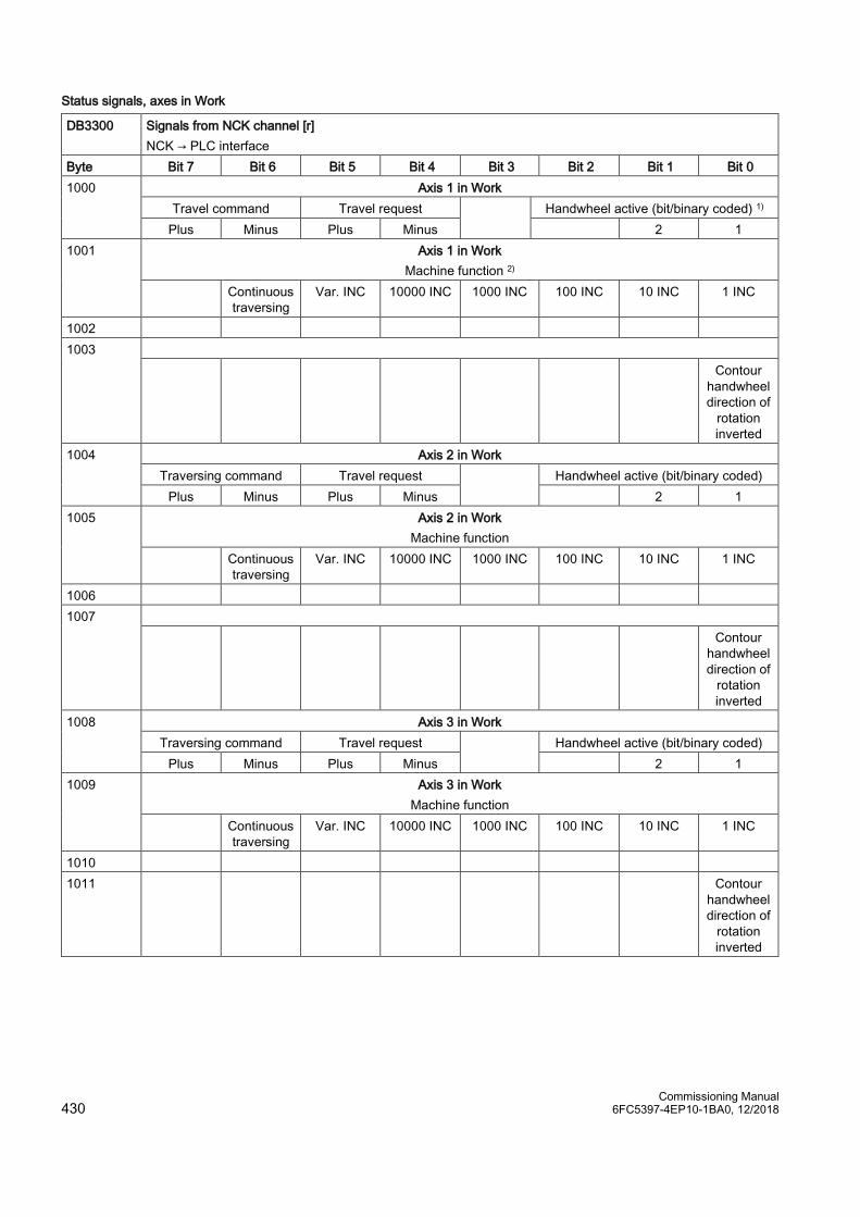
Commissioning Manual 430 6FC5397-4EP10-1BA0, 12/2018
Status signals, axes in Work
DB3300 Signals from NCK channel [r] NCK → PLC interface
Byte Bit 7 Bit 6 Bit 5 Bit 4 Bit 3 Bit 2 Bit 1 Bit 0 1000 Axis 1 in Work
Travel command Travel request Handwheel active (bit/binary coded) 1) Plus Minus Plus Minus 2 1
1001 Axis 1 in Work Machine function 2)
Continuous traversing
Var. INC 10000 INC 1000 INC 100 INC 10 INC 1 INC
1002 1003
Contour handwheel direction of
rotation inverted
1004 Axis 2 in Work Traversing command Travel request Handwheel active (bit/binary coded)
Plus Minus Plus Minus 2 1 1005 Axis 2 in Work
Machine function Continuous
traversing Var. INC 10000 INC 1000 INC 100 INC 10 INC 1 INC
1006 1007
Contour handwheel direction of
rotation inverted
1008 Axis 3 in Work Traversing command Travel request Handwheel active (bit/binary coded)
Plus Minus Plus Minus 2 1 1009 Axis 3 in Work
Machine function Continuous
traversing Var. INC 10000 INC 1000 INC 100 INC 10 INC 1 INC
1010 1011 Contour
handwheel direction of
rotation inverted

Commissioning Manual 6FC5397-4EP10-1BA0, 12/2018 431
Additional status signals from NC channel
DB3300 Signals from NCK channel [r] NCK → PLC interface
Byte Bit 7 Bit 6 Bit 5 Bit 4 Bit 3 Bit 2 Bit 1 Bit 0 4000 G00 active 4001 Travel
request, drive test present
Workpiece setpoint reached
External language mode ac-
tive 4002 Dry run
feedrate Active
Associated M01/M00
Active
STOP_DELAYED
ASUP is stopped
4003 No tool change
command active
DELAY FST
SUPPRESS
DELAY FST
4004 ProgEvent display Start after
block search
Boot Operator panel Reset
Part pro-gram End
Part pro-gram
Start from RESET
4005 Jog circle Active
Stop condi-tion
StopByColl Danger
4006 Dormant ASUP Active
ASUP ac-tive
4007 4008 Active transformation number
4009 Reserved
4010 Reserved
4011 Reserved
Asynchronous subroutines (ASUPs): Job
DB3400 ASUP: Result [r/w] PLC → NCK interface
Byte Bit 7 Bit 6 Bit 5 Bit 4 Bit 3 Bit 2 Bit 1 Bit 0 0 INT1
Start 1 INT2
Start 2 3
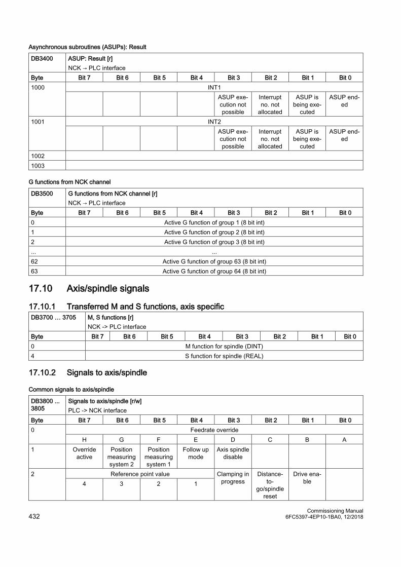
Commissioning Manual 432 6FC5397-4EP10-1BA0, 12/2018
Asynchronous subroutines (ASUPs): Result
DB3400 ASUP: Result [r] NCK → PLC interface
Byte Bit 7 Bit 6 Bit 5 Bit 4 Bit 3 Bit 2 Bit 1 Bit 0 1000 INT1
ASUP exe-cution not possible
Interrupt no. not
allocated
ASUP is being exe-
cuted
ASUP end-ed
1001 INT2 ASUP exe-
cution not possible
Interrupt no. not
allocated
ASUP is being exe-
cuted
ASUP end-ed
1002 1003
G functions from NCK channel
DB3500 G functions from NCK channel [r] NCK → PLC interface
Byte Bit 7 Bit 6 Bit 5 Bit 4 Bit 3 Bit 2 Bit 1 Bit 0 0 Active G function of group 1 (8 bit int) 1 Active G function of group 2 (8 bit int) 2 Active G function of group 3 (8 bit int) ... ... 62 Active G function of group 63 (8 bit int) 63 Active G function of group 64 (8 bit int)
17.10 Axis/spindle signals
17.10.1 Transferred M and S functions, axis specific DB3700 … 3705 M, S functions [r]
NCK -> PLC interface Byte Bit 7 Bit 6 Bit 5 Bit 4 Bit 3 Bit 2 Bit 1 Bit 0 0 M function for spindle (DINT) 4 S function for spindle (REAL)
17.10.2 Signals to axis/spindle
Common signals to axis/spindle
DB3800 ... 3805
Signals to axis/spindle [r/w] PLC -> NCK interface
Byte Bit 7 Bit 6 Bit 5 Bit 4 Bit 3 Bit 2 Bit 1 Bit 0 0 Feedrate override
H G F E D C B A 1 Override
active Position
measuring system 2
Position measuring system 1
Follow up mode
Axis spindle disable
2 Reference point value Clamping in progress
Distance-to-
go/spindle reset
Drive ena-ble
4 3 2 1

Commissioning Manual 6FC5397-4EP10-1BA0, 12/2018 433
3 Axis/spindle enable
program test
Veloci-ty/spindle
speed limit-ing
Activate fixed feedrate Enable approach to fixed stop
Feed 4 Feed 3 Feed 2 Feed 1
4 Traversing keys Rapid trav-erse over-
ride
Traverse key disable
Feedrate stop/spindle
stop
Activate handwheel Plus Minus 2 1
5 Machine function 1) Continuous
traversing Var. INC 10000 INC 1000 INC 100 INC 10 INC 1 INC
6 7 Contour-
handwheel direction of
rotation inverted
8 Request PLC ax-
is/spindle
Activation signal when this byte is changed
Request NC ax-
is/spindle
9 10 11 1) The machine function is only entered if the signal "INC inputs in the operating-mode signal range active"
(DB2600.DBX1.0) is not set.
Signals to axis
DB3800 ... 3805
Signals to axis [r/w] PLC -> NCK interface
Byte Bit 7 Bit 6 Bit 5 Bit 4 Bit 3 Bit 2 Bit 1 Bit 0 1000 Delay Ref.
pt. ap-proach
Module limit enabled
Software limit switch Hardware limit switch Plus Minus Plus Minus
1001 1002 Activate
program test
Suppress program
test 1003
Signals to spindle
DB3800 ... 3805
Signals to axis [r/w] PLC -> NCK interface
Byte Bit 7 Bit 6 Bit 5 Bit 4 Bit 3 Bit 2 Bit 1 Bit 0 2000 Delete S
value No speed monitoring
for gear change
Resynchronize spindle Gear changed
Actual gear stage 2 1 C B A
2001 Invert M3/M4
Resynchro-nize during positioning
Feedrate override for
spindle valid
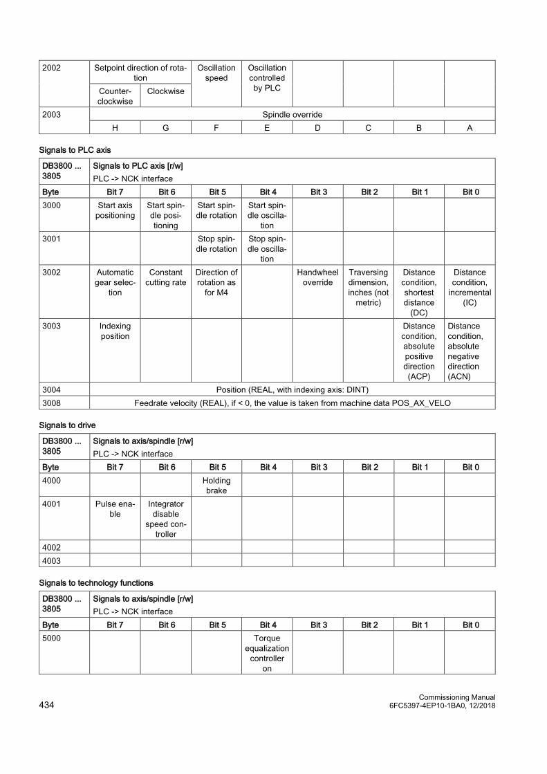
Commissioning Manual 434 6FC5397-4EP10-1BA0, 12/2018
2002 Setpoint direction of rota-tion
Oscillation speed
Oscillation controlled by PLC
Counter-clockwise
Clockwise
2003 Spindle override H G F E D C B A
Signals to PLC axis
DB3800 ... 3805
Signals to PLC axis [r/w] PLC -> NCK interface
Byte Bit 7 Bit 6 Bit 5 Bit 4 Bit 3 Bit 2 Bit 1 Bit 0 3000 Start axis
positioning Start spin-dle posi-tioning
Start spin-dle rotation
Start spin-dle oscilla-
tion
3001 Stop spin-dle rotation
Stop spin-dle oscilla-
tion
3002 Automatic gear selec-
tion
Constant cutting rate
Direction of rotation as
for M4
Handwheel override
Traversing dimension, inches (not
metric)
Distance condition, shortest distance
(DC)
Distance condition,
incremental (IC)
3003 Indexing position
Distance condition, absolute positive direction (ACP)
Distance condition, absolute negative direction (ACN)
3004 Position (REAL, with indexing axis: DINT) 3008 Feedrate velocity (REAL), if < 0, the value is taken from machine data POS_AX_VELO
Signals to drive
DB3800 ... 3805
Signals to axis/spindle [r/w] PLC -> NCK interface
Byte Bit 7 Bit 6 Bit 5 Bit 4 Bit 3 Bit 2 Bit 1 Bit 0 4000 Holding
brake
4001 Pulse ena-ble
Integrator disable
speed con-troller
4002 4003
Signals to technology functions
DB3800 ... 3805
Signals to axis/spindle [r/w] PLC -> NCK interface
Byte Bit 7 Bit 6 Bit 5 Bit 4 Bit 3 Bit 2 Bit 1 Bit 0 5000 Torque
equalization controller
on
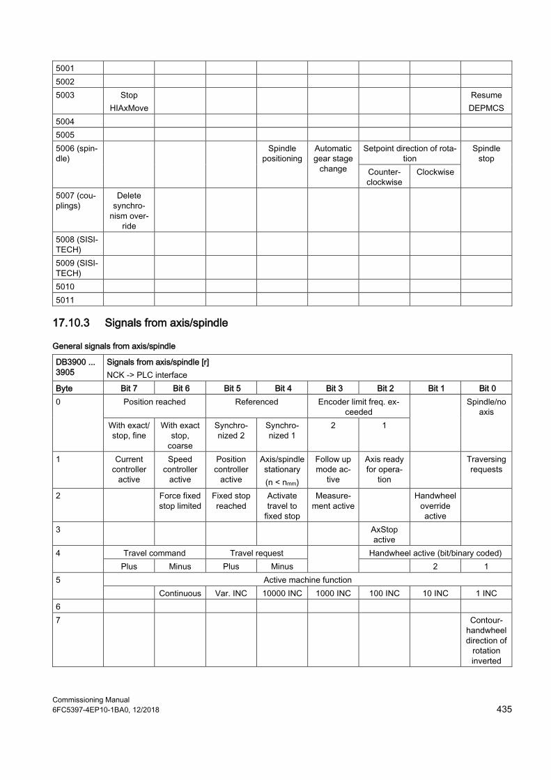
Commissioning Manual 6FC5397-4EP10-1BA0, 12/2018 435
5001 5002 5003 Stop
HIAxMove Resume
DEPMCS 5004 5005 5006 (spin-dle)
Spindle positioning
Automatic gear stage
change
Setpoint direction of rota-tion
Spindle stop
Counter-clockwise
Clockwise
5007 (cou-plings)
Delete synchro-
nism over-ride
5008 (SISI-TECH)
5009 (SISI-TECH)
5010 5011
17.10.3 Signals from axis/spindle
General signals from axis/spindle
DB3900 ... 3905
Signals from axis/spindle [r] NCK -> PLC interface
Byte Bit 7 Bit 6 Bit 5 Bit 4 Bit 3 Bit 2 Bit 1 Bit 0 0 Position reached Referenced Encoder limit freq. ex-
ceeded Spindle/no
axis With exact/ stop, fine
With exact stop,
coarse
Synchro-nized 2
Synchro-nized 1
2 1
1 Current controller
active
Speed controller
active
Position controller
active
Axis/spindle stationary (n < nmm)
Follow up mode ac-
tive
Axis ready for opera-
tion
Traversing requests
2 Force fixed stop limited
Fixed stop reached
Activate travel to
fixed stop
Measure-ment active
Handwheel override active
3 AxStop active
4 Travel command Travel request Handwheel active (bit/binary coded) Plus Minus Plus Minus 2 1
5 Active machine function Continuous Var. INC 10000 INC 1000 INC 100 INC 10 INC 1 INC
6 7 Contour-
handwheel direction of
rotation inverted
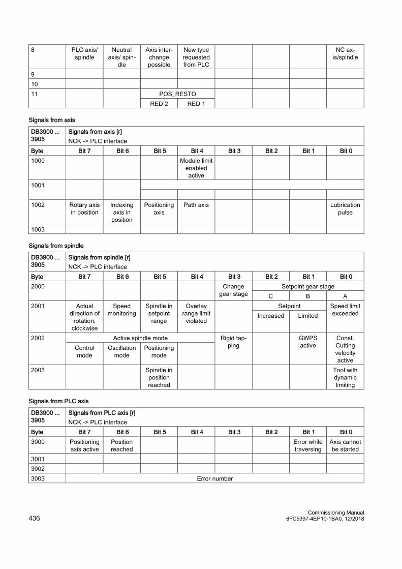
Commissioning Manual 436 6FC5397-4EP10-1BA0, 12/2018
8 PLC axis/ spindle
Neutral axis/ spin-
dle
Axis inter-change possible
New type requested from PLC
NC ax-is/spindle
9 10 11 POS_RESTO
RED 2 RED 1
Signals from axis
DB3900 ... 3905
Signals from axis [r] NCK -> PLC interface
Byte Bit 7 Bit 6 Bit 5 Bit 4 Bit 3 Bit 2 Bit 1 Bit 0 1000 Module limit
enabled active
1001
1002 Rotary axis in position
Indexing axis in
position
Positioning axis
Path axis Lubrication pulse
1003
Signals from spindle
DB3900 ... 3905
Signals from spindle [r] NCK -> PLC interface
Byte Bit 7 Bit 6 Bit 5 Bit 4 Bit 3 Bit 2 Bit 1 Bit 0 2000 Change
gear stage Setpoint gear stage
C B A 2001 Actual
direction of rotation,
clockwise
Speed monitoring
Spindle in setpoint range
Overlay range limit
violated
Setpoint Speed limit exceeded Increased Limited
2002 Active spindle mode Rigid tap-ping
GWPS active
Const. Cutting velocity active
Control mode
Oscillation mode
Positioning mode
2003 Spindle in position reached
Tool with dynamic limiting
Signals from PLC axis
DB3900 ... 3905
Signals from PLC axis [r] NCK -> PLC interface
Byte Bit 7 Bit 6 Bit 5 Bit 4 Bit 3 Bit 2 Bit 1 Bit 0 3000 Positioning
axis active Position reached
Error while traversing
Axis cannot be started
3001 3002 3003 Error number

Commissioning Manual 6FC5397-4EP10-1BA0, 12/2018 437
Signals from drive
DB3900 ... 3905
Signals from axis/spindle [r] NCK -> PLC interface
Byte Bit 7 Bit 6 Bit 5 Bit 4 Bit 3 Bit 2 Bit 1 Bit 0 4000 Holding
brake opened
RLI active
4001 Pulse ena-bled
Speed controller integrator disabled
Drive ready
4002 nact = nset nact < nx nact < nmin Md < Mdx Ramp-up completed
4003 Generator operation, minimum
speed falled below
VDClink < alarm
threshold
Signals from technology functions
DB3900 ... 3905
Signals from axis/spindle [r] NCK -> PLC interface
Byte Bit 7 Bit 6 Bit 5 Bit 4 Bit 3 Bit 2 Bit 1 Bit 0 5000 5001 5002 Accelera-
tion warn-ing
threshold reached
Velocity warning
threshold reached
Superim-posed mo-
tion
Actual value cou-
pling
Synchronous operation Coarse Fine
5003 Max. accel-eration reached
Max. veloci-ty reached
Synchroni-zation in progress
Axis is accelerat-
ing
Synchro-nism over-ride travel
5004 5005 5006 5007 Synchro-
nism over-ride is
factored in 5008 (grinding)
Active special axis Axis 6 Axis 5 Axis 4 Axis 3 Axis 2 Axis 1
17.11 PLC machine data
17.11.1 INT values (MD 14510 USER_DATA_INT) DB4500 Signals from NCK [r16]
NCK -> PLC interface Byte Bit 7 Bit 6 Bit 5 Bit 4 Bit 3 Bit 2 Bit 1 Bit 0 0 Int value (WORD/2 byte) 2 Int value (WORD/2 byte) 4 Int value (WORD/2 byte)
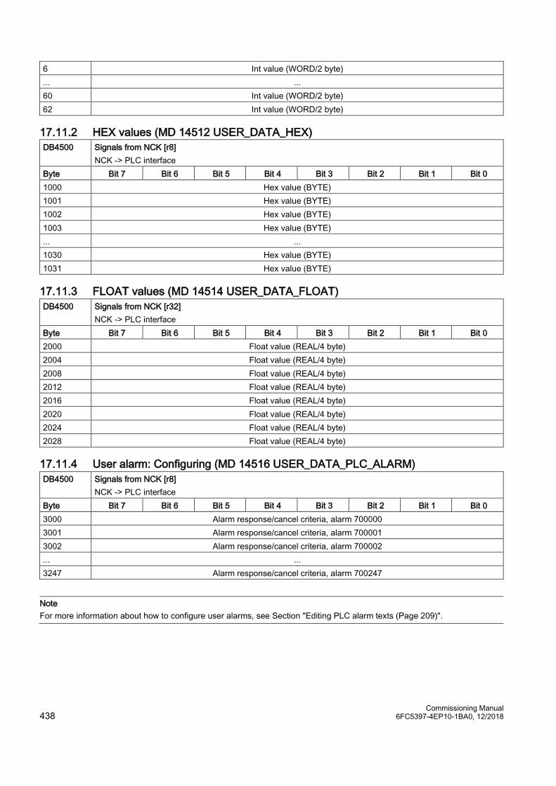
Commissioning Manual 438 6FC5397-4EP10-1BA0, 12/2018
6 Int value (WORD/2 byte) ... ... 60 Int value (WORD/2 byte) 62 Int value (WORD/2 byte)
17.11.2 HEX values (MD 14512 USER_DATA_HEX) DB4500 Signals from NCK [r8]
NCK -> PLC interface Byte Bit 7 Bit 6 Bit 5 Bit 4 Bit 3 Bit 2 Bit 1 Bit 0 1000 Hex value (BYTE) 1001 Hex value (BYTE) 1002 Hex value (BYTE) 1003 Hex value (BYTE) ... ... 1030 Hex value (BYTE) 1031 Hex value (BYTE)
17.11.3 FLOAT values (MD 14514 USER_DATA_FLOAT) DB4500 Signals from NCK [r32]
NCK -> PLC interface Byte Bit 7 Bit 6 Bit 5 Bit 4 Bit 3 Bit 2 Bit 1 Bit 0 2000 Float value (REAL/4 byte) 2004 Float value (REAL/4 byte) 2008 Float value (REAL/4 byte) 2012 Float value (REAL/4 byte) 2016 Float value (REAL/4 byte) 2020 Float value (REAL/4 byte) 2024 Float value (REAL/4 byte) 2028 Float value (REAL/4 byte)
17.11.4 User alarm: Configuring (MD 14516 USER_DATA_PLC_ALARM) DB4500 Signals from NCK [r8]
NCK -> PLC interface Byte Bit 7 Bit 6 Bit 5 Bit 4 Bit 3 Bit 2 Bit 1 Bit 0 3000 Alarm response/cancel criteria, alarm 700000 3001 Alarm response/cancel criteria, alarm 700001 3002 Alarm response/cancel criteria, alarm 700002 ... ... 3247 Alarm response/cancel criteria, alarm 700247
Note For more information about how to configure user alarms, see Section "Editing PLC alarm texts (Page 209)".
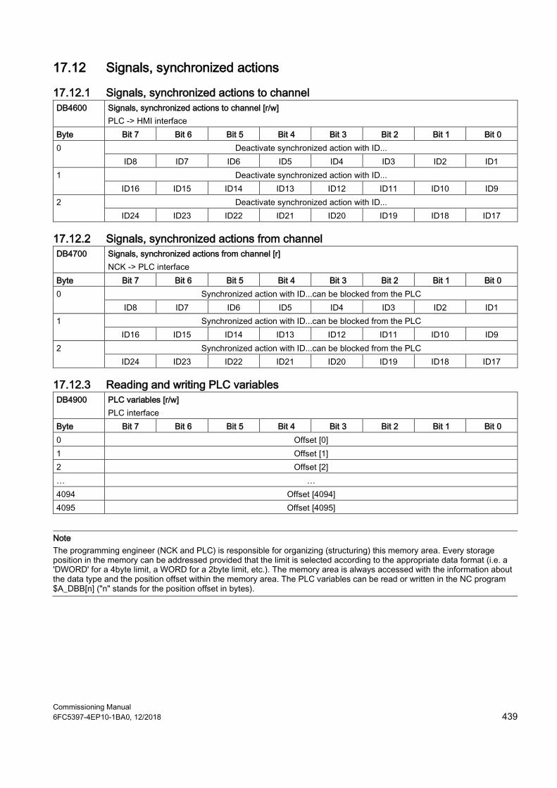
Commissioning Manual 6FC5397-4EP10-1BA0, 12/2018 439
17.12 Signals, synchronized actions
17.12.1 Signals, synchronized actions to channel DB4600 Signals, synchronized actions to channel [r/w]
PLC -> HMI interface Byte Bit 7 Bit 6 Bit 5 Bit 4 Bit 3 Bit 2 Bit 1 Bit 0 0 Deactivate synchronized action with ID...
ID8 ID7 ID6 ID5 ID4 ID3 ID2 ID1 1 Deactivate synchronized action with ID...
ID16 ID15 ID14 ID13 ID12 ID11 ID10 ID9 2 Deactivate synchronized action with ID...
ID24 ID23 ID22 ID21 ID20 ID19 ID18 ID17
17.12.2 Signals, synchronized actions from channel DB4700 Signals, synchronized actions from channel [r]
NCK -> PLC interface Byte Bit 7 Bit 6 Bit 5 Bit 4 Bit 3 Bit 2 Bit 1 Bit 0 0 Synchronized action with ID...can be blocked from the PLC
ID8 ID7 ID6 ID5 ID4 ID3 ID2 ID1 1 Synchronized action with ID...can be blocked from the PLC
ID16 ID15 ID14 ID13 ID12 ID11 ID10 ID9 2 Synchronized action with ID...can be blocked from the PLC
ID24 ID23 ID22 ID21 ID20 ID19 ID18 ID17
17.12.3 Reading and writing PLC variables DB4900 PLC variables [r/w]
PLC interface Byte Bit 7 Bit 6 Bit 5 Bit 4 Bit 3 Bit 2 Bit 1 Bit 0 0 Offset [0] 1 Offset [1] 2 Offset [2] … … 4094 Offset [4094] 4095 Offset [4095]
Note The programming engineer (NCK and PLC) is responsible for organizing (structuring) this memory area. Every storage position in the memory can be addressed provided that the limit is selected according to the appropriate data format (i.e. a 'DWORD' for a 4byte limit, a WORD for a 2byte limit, etc.). The memory area is always accessed with the information about the data type and the position offset within the memory area. The PLC variables can be read or written in the NC program $A_DBB[n] ("n" stands for the position offset in bytes).
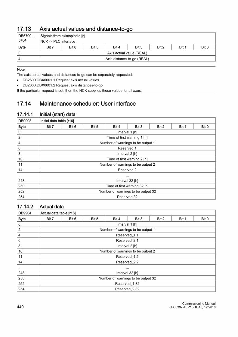
Commissioning Manual 440 6FC5397-4EP10-1BA0, 12/2018
17.13 Axis actual values and distance-to-go DB5700 ... 5704
Signals from axis/spindle [r] NCK -> PLC interface
Byte Bit 7 Bit 6 Bit 5 Bit 4 Bit 3 Bit 2 Bit 1 Bit 0 0 Axis actual value (REAL) 4 Axis distance-to-go (REAL)
Note The axis actual values and distances-to-go can be separately requested: • DB2600.DBX0001.1 Request axis actual values • DB2600.DBX0001.2 Request axis distances-to-go If the particular request is set, then the NCK supplies these values for all axes.
17.14 Maintenance scheduler: User interface
17.14.1 Initial (start) data DB9903 Initial data table [r16] Byte Bit 7 Bit 6 Bit 5 Bit 4 Bit 3 Bit 2 Bit 1 Bit 0 0 Interval 1 [h] 2 Time of first warning 1 [h] 4 Number of warnings to be output 1 6 Reserved 1 8 Interval 2 [h] 10 Time of first warning 2 [h] 11 Number of warnings to be output 2 14 Reserved 2 ... ... 248 Interval 32 [h] 250 Time of first warning 32 [h] 252 Number of warnings to be output 32 254 Reserved 32
17.14.2 Actual data DB9904 Actual data table [r16] Byte Bit 7 Bit 6 Bit 5 Bit 4 Bit 3 Bit 2 Bit 1 Bit 0 0 Interval 1 [h] 2 Number of warnings to be output 1 4 Reserved_1 1 6 Reserved_2 1 8 Interval 2 [h] 10 Number of warnings to be output 2 11 Reserved_1 2 14 Reserved_2 2 ... ... 248 Interval 32 [h] 250 Number of warnings to be output 32 252 Reserved_1 32 254 Reserved_2 32
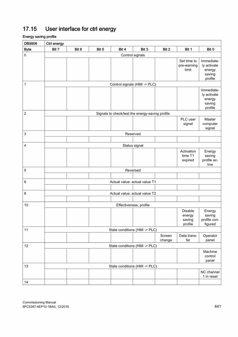
Commissioning Manual 6FC5397-4EP10-1BA0, 12/2018 441
17.15 User interface for ctrl energy Energy saving profile
DB9906 Ctrl energy Byte Bit 7 Bit 6 Bit 5 Bit 4 Bit 3 Bit 2 Bit 1 Bit 0 0 Control signals
Set time to pre-warning
limit
Immediate-ly activate
energy saving profile
1 Control signals (HMI -> PLC) Immediate-
ly activate energy saving profile
2 Signals to check/test the energy-saving profile PLC user
signal Master
computer signal
3 Reserved
4 Status signal Activation
time T1 expired
Energy saving
profile ac-tive
5 Reversed
6 Actual value: actual value T1
8 Actual value: actual value T2
10 Effectiveness, profile Disable
energy saving profile
Energy saving
profile con-figured
11 State conditions (HMI -> PLC) Screen
change Data trans-
fer Operator
panel 12 State conditions (HMI -> PLC)
Machine control panel
13 State conditions (HMI -> PLC) NC channel
1 in reset 14
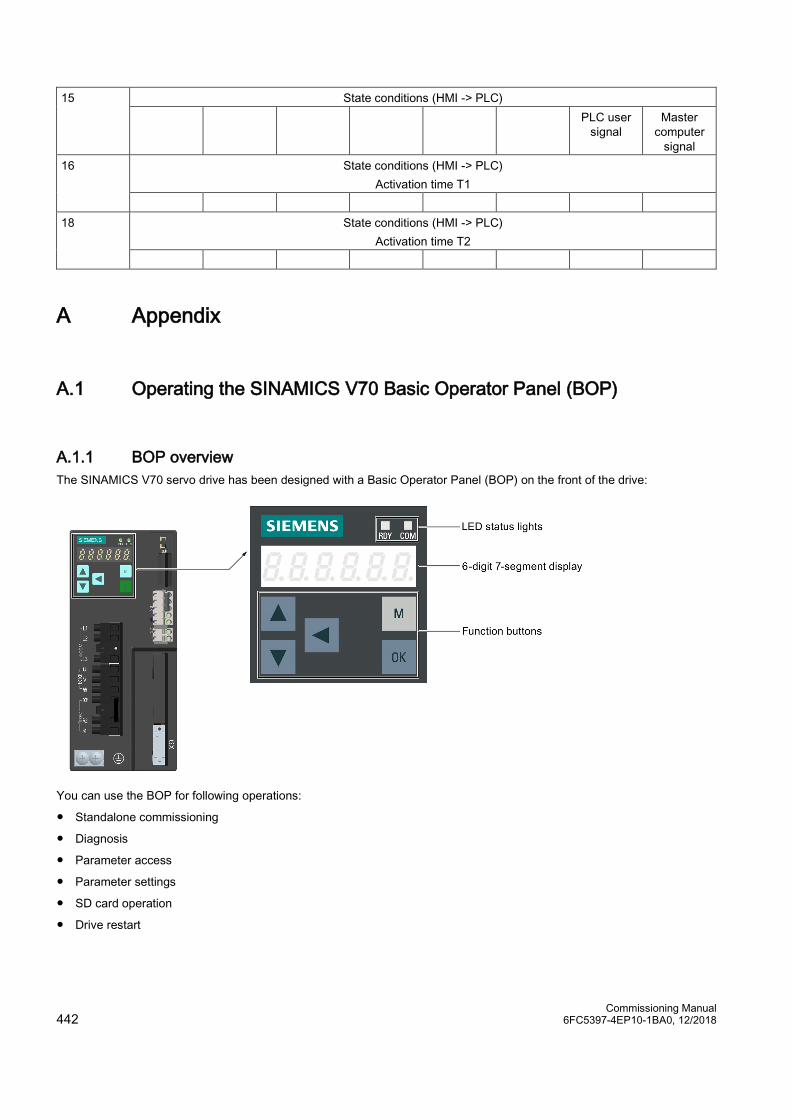
Commissioning Manual 442 6FC5397-4EP10-1BA0, 12/2018
15 State conditions (HMI -> PLC) PLC user
signal Master
computer signal
16 State conditions (HMI -> PLC) Activation time T1
18 State conditions (HMI -> PLC)
Activation time T2
A Appendix
A.1 Operating the SINAMICS V70 Basic Operator Panel (BOP)
A.1.1 BOP overview The SINAMICS V70 servo drive has been designed with a Basic Operator Panel (BOP) on the front of the drive:
You can use the BOP for following operations:
● Standalone commissioning
● Diagnosis
● Parameter access
● Parameter settings
● SD card operation
● Drive restart

Commissioning Manual 6FC5397-4EP10-1BA0, 12/2018 443
Button functions
Button Description Remarks
M button • Exits from current menu • Switches between operating modes in the top level menu
OK button Short-pressing: • Confirms selection or input • Enters sub menu • Acknowledges faults Long-pressing: Activates auxiliary functions • Sets Drive Bus address • Jog • Saves parameter set in drive (RAM to ROM) • Sets parameter set to default • Transfers data (drive to SD card) • Transfers data (SD card to drive) • Updates firmware
UP button • Navigates to next item • Increases a value • JOG in CW (clockwise)
DOWN button • Navigates to previous item • Decreases a value • JOG in CCW (counter-clockwise)
SHIFT button Moves the cursor from digit to digit for single digit editing, including the digit of positive/negative signs
Button combinations
Press this button combination for four seconds to restart the drive.
Moves the current display to the left page when is displayed at the upper right corner, for example .
Moves the current display to the right page when is displayed at the lower right corner, for exam-ple .
BOP display
Display Example Description Remarks 8.8.8.8.8.8.
Drive is in startup state Takes 20 s to 30 s
------
Drive is busy In the case of a task being executed
Fxxxxx
Fault code In the case of a single fault
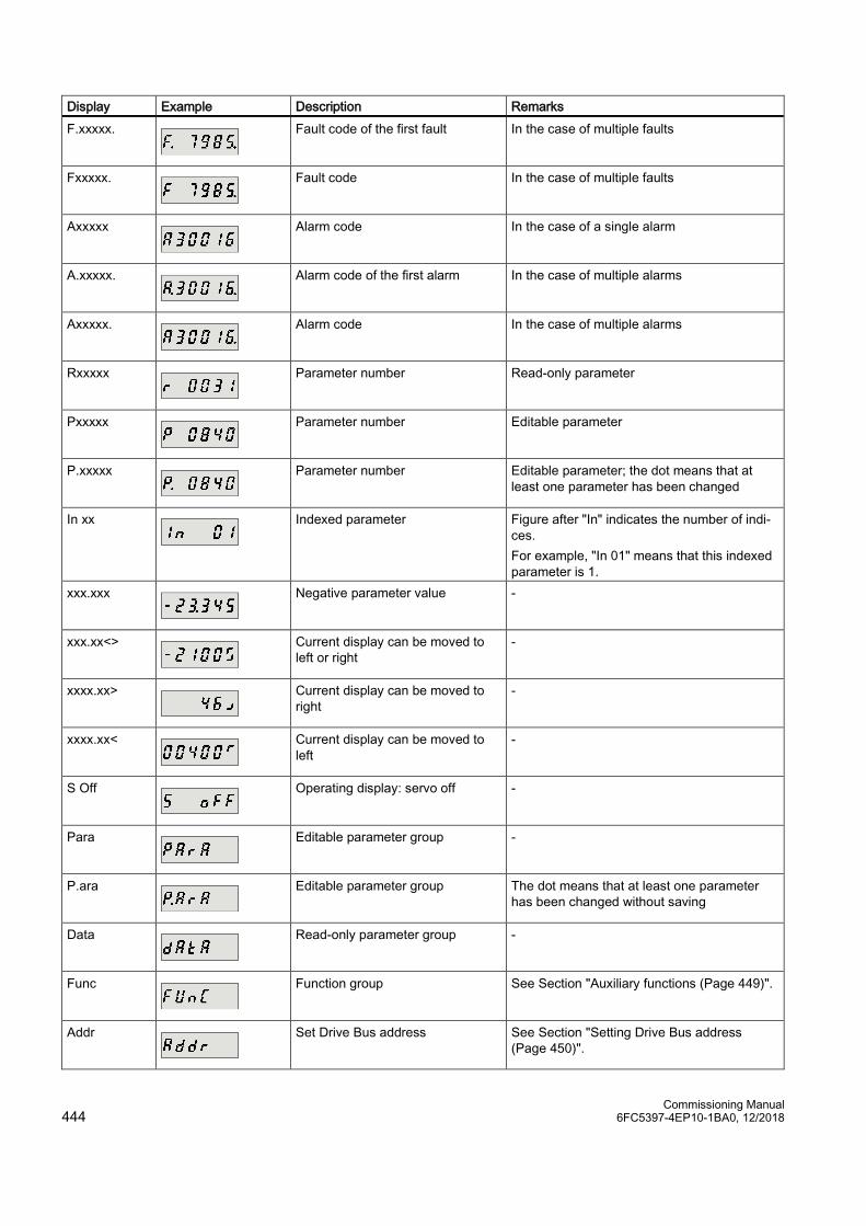
Commissioning Manual 444 6FC5397-4EP10-1BA0, 12/2018
Display Example Description Remarks F.xxxxx.
Fault code of the first fault In the case of multiple faults
Fxxxxx.
Fault code In the case of multiple faults
Axxxxx
Alarm code In the case of a single alarm
A.xxxxx.
Alarm code of the first alarm In the case of multiple alarms
Axxxxx.
Alarm code In the case of multiple alarms
Rxxxxx
Parameter number Read-only parameter
Pxxxxx
Parameter number Editable parameter
P.xxxxx
Parameter number Editable parameter; the dot means that at least one parameter has been changed
In xx
Indexed parameter Figure after "In" indicates the number of indi-ces. For example, "In 01" means that this indexed parameter is 1.
xxx.xxx
Negative parameter value -
xxx.xx<>
Current display can be moved to left or right
-
xxxx.xx>
Current display can be moved to right
-
xxxx.xx<
Current display can be moved to left
-
S Off
Operating display: servo off -
Para
Editable parameter group -
P.ara
Editable parameter group The dot means that at least one parameter has been changed without saving
Data
Read-only parameter group -
Func
Function group See Section "Auxiliary functions (Page 449)".
Addr
Set Drive Bus address See Section "Setting Drive Bus address (Page 450)".
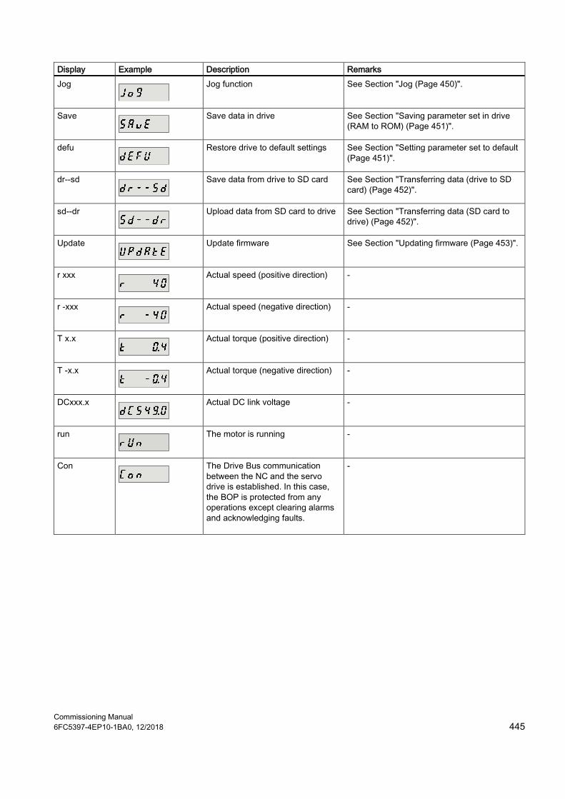
Commissioning Manual 6FC5397-4EP10-1BA0, 12/2018 445
Display Example Description Remarks Jog
Jog function See Section "Jog (Page 450)".
Save
Save data in drive See Section "Saving parameter set in drive (RAM to ROM) (Page 451)".
defu
Restore drive to default settings See Section "Setting parameter set to default (Page 451)".
dr--sd
Save data from drive to SD card See Section "Transferring data (drive to SD card) (Page 452)".
sd--dr
Upload data from SD card to drive See Section "Transferring data (SD card to drive) (Page 452)".
Update
Update firmware See Section "Updating firmware (Page 453)".
r xxx
Actual speed (positive direction) -
r -xxx
Actual speed (negative direction) -
T x.x
Actual torque (positive direction) -
T -x.x
Actual torque (negative direction) -
DCxxx.x
Actual DC link voltage -
run
The motor is running -
Con
The Drive Bus communication between the NC and the servo drive is established. In this case, the BOP is protected from any operations except clearing alarms and acknowledging faults.
-
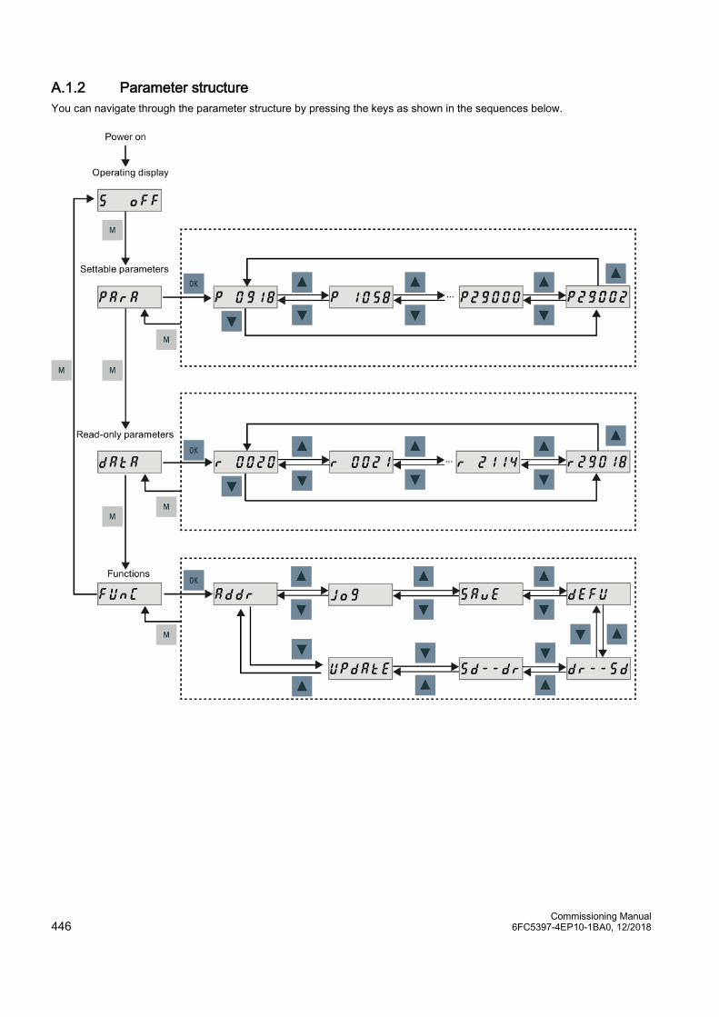
Commissioning Manual 446 6FC5397-4EP10-1BA0, 12/2018
A.1.2 Parameter structure You can navigate through the parameter structure by pressing the keys as shown in the sequences below.
Commissioning Manual 6FC5397-4EP10-1BA0, 12/2018 447
A.1.3 Actual status display You can monitor the following drive states by using the operating panel after power-on:
● Servo off
● Actual speed
● Torque
● Voltage
If the servo enable signal is available, actual drive speed is displayed by default; otherwise, "S OFF" (servo off) is displayed.
With p29002, you define which of the following drive operating status data is to be displayed on the BOP.
Value Meaning 0 (default) Actual speed 1 DC voltage 2 Actual torque
Note Make sure you save p29002 after modification.
A.1.4 Basic operations
Editable parameters
All P parameters under the "Para" menu are editable parameters.
Read-only parameters
All r parameters under the "Data" menu are read-only parameters.
Parameters with index
Some parameters have several indices. Each index has its own meaning and corresponding value.
Parameters without index
All parameters that do not have indices are parameters without index.
A.1.4.1 Editing parameters You can edit a parameter value in two methods:
● Method 1: change the value directly with the UP or DOWN button
● Method 2: move the cursor to a digit with the SHIFT button, then change the digit value with the UP or DOWN button

Commissioning Manual 448 6FC5397-4EP10-1BA0, 12/2018
If you change a parameter value with method 1, proceed as follows:
To change a parameter value digit by digit, proceed as follows:
Note You cannot change parameters p1414 and p1656 with the SHIFT button.
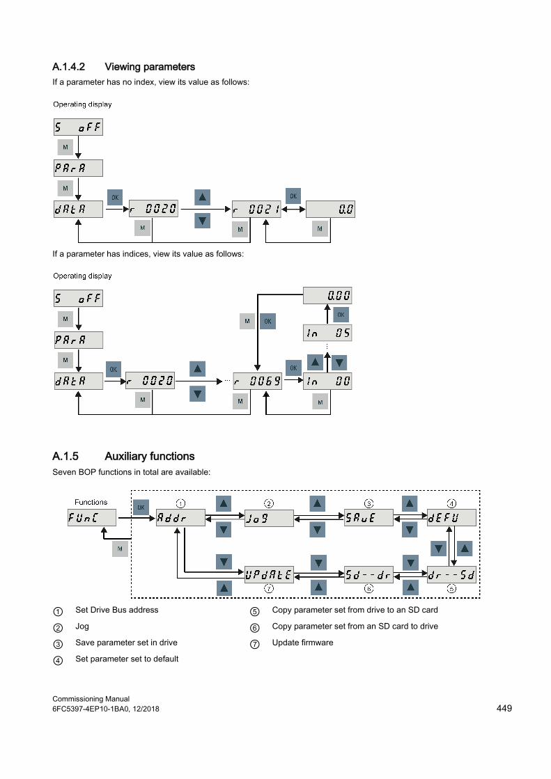
Commissioning Manual 6FC5397-4EP10-1BA0, 12/2018 449
A.1.4.2 Viewing parameters If a parameter has no index, view its value as follows:
If a parameter has indices, view its value as follows:
A.1.5 Auxiliary functions Seven BOP functions in total are available:
① Set Drive Bus address ⑤ Copy parameter set from drive to an SD card
② Jog ⑥ Copy parameter set from an SD card to drive
③ Save parameter set in drive ⑦ Update firmware
④ Set parameter set to default
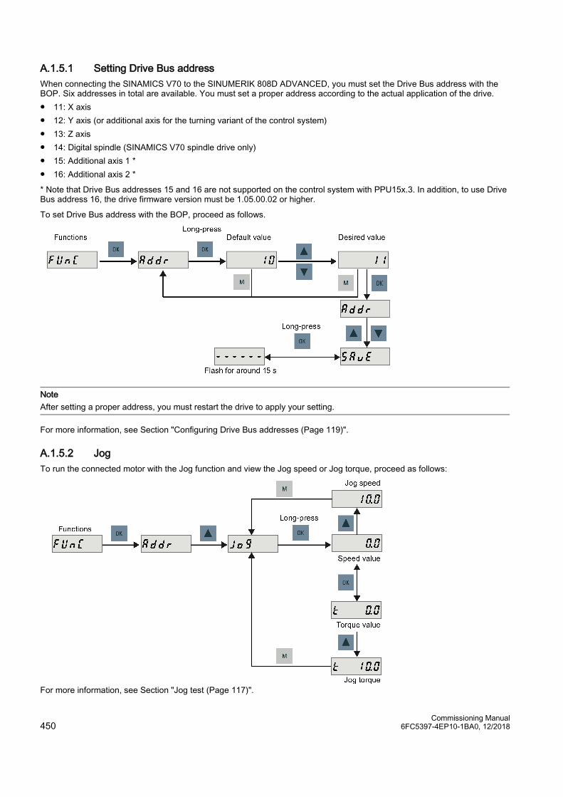
Commissioning Manual 450 6FC5397-4EP10-1BA0, 12/2018
A.1.5.1 Setting Drive Bus address When connecting the SINAMICS V70 to the SINUMERIK 808D ADVANCED, you must set the Drive Bus address with the BOP. Six addresses in total are available. You must set a proper address according to the actual application of the drive. ● 11: X axis ● 12: Y axis (or additional axis for the turning variant of the control system) ● 13: Z axis ● 14: Digital spindle (SINAMICS V70 spindle drive only) ● 15: Additional axis 1 * ● 16: Additional axis 2 *
* Note that Drive Bus addresses 15 and 16 are not supported on the control system with PPU15x.3. In addition, to use Drive Bus address 16, the drive firmware version must be 1.05.00.02 or higher.
To set Drive Bus address with the BOP, proceed as follows.
Note After setting a proper address, you must restart the drive to apply your setting.
For more information, see Section "Configuring Drive Bus addresses (Page 119)".
A.1.5.2 Jog To run the connected motor with the Jog function and view the Jog speed or Jog torque, proceed as follows:
For more information, see Section "Jog test (Page 117)".
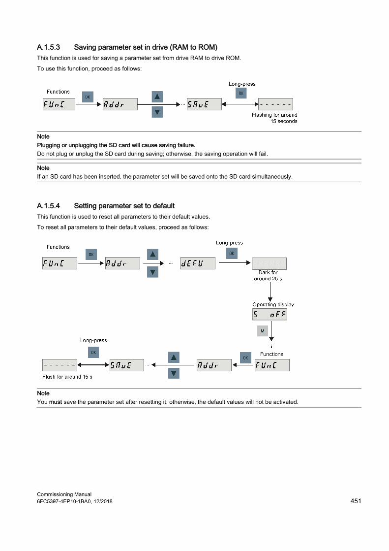
Commissioning Manual 6FC5397-4EP10-1BA0, 12/2018 451
A.1.5.3 Saving parameter set in drive (RAM to ROM) This function is used for saving a parameter set from drive RAM to drive ROM.
To use this function, proceed as follows:
Note Plugging or unplugging the SD card will cause saving failure. Do not plug or unplug the SD card during saving; otherwise, the saving operation will fail.
Note If an SD card has been inserted, the parameter set will be saved onto the SD card simultaneously.
A.1.5.4 Setting parameter set to default This function is used to reset all parameters to their default values.
To reset all parameters to their default values, proceed as follows:
Note You must save the parameter set after resetting it; otherwise, the default values will not be activated.

Commissioning Manual 452 6FC5397-4EP10-1BA0, 12/2018
A.1.5.5 Transferring data (drive to SD card) You can transfer the parameter set from the drive to an SD card with the BOP. To do this, proceed as follows:
Note Data transfer between the drive and the SD card is possible only when the drive is in "S OFF" state.
Note Plugging or unplugging the SD card will cause transferring failure. Do not plug or unplug the SD card during transferring; otherwise, the transferring operation will fail.
Note Write protection function is not supported by the SINAMICS V70. Data in the SD card will be overwritten even if the write protection function of the SD card is enabled.
A.1.5.6 Transferring data (SD card to drive) You can also transfer the parameter set from an SD card to the drive. To do this, proceed as follows:
Note Data transfer between the drive and the SD card is possible only when the drive is in "S OFF" state.
Note Plugging or unplugging the SD card will cause transferring failure. Do not plug or unplug the SD card during transferring; otherwise, the transferring operation will fail.
Note Parameter inconsistency If the parameters on the SD card are inconsistent with existing parameters in the drive memory, you must save and restart the servo drive to apply the changes.
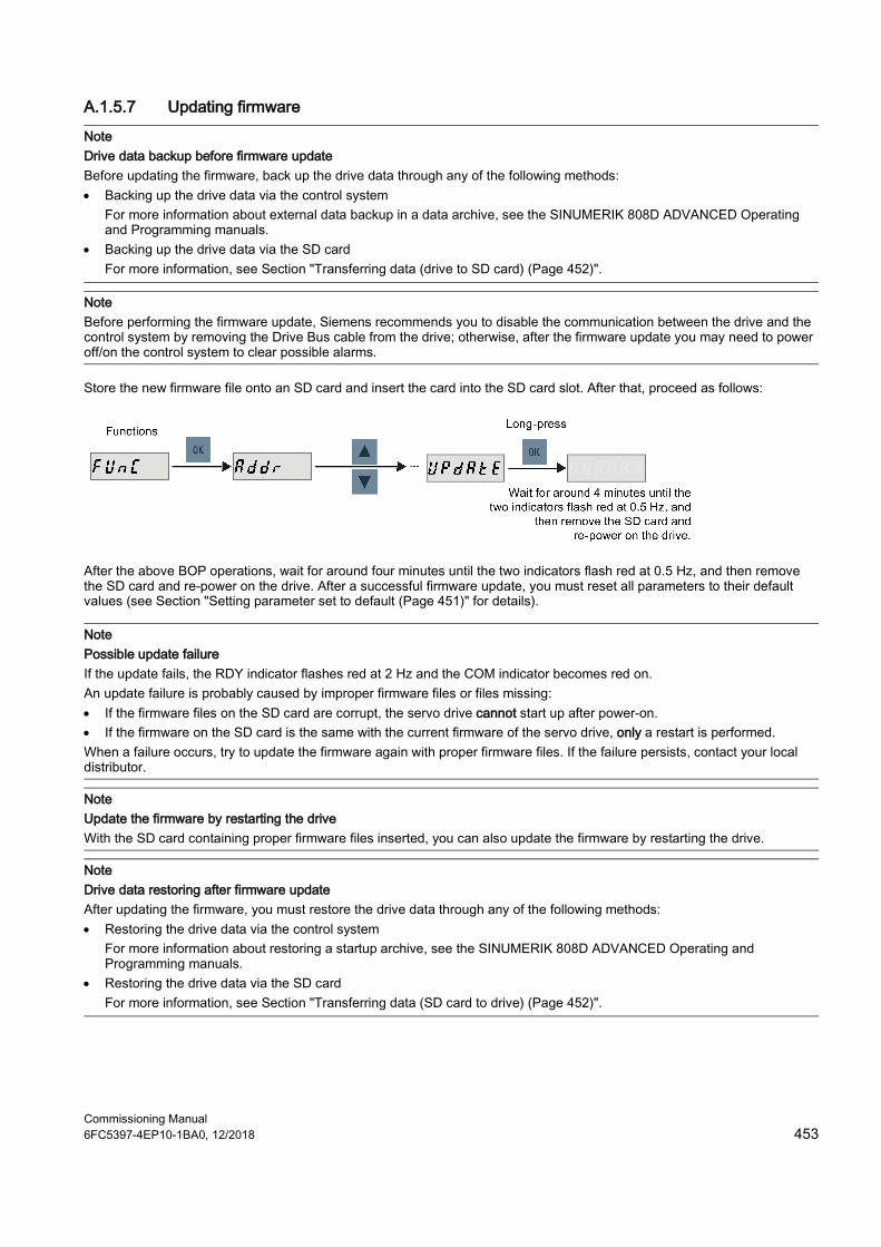
Commissioning Manual 6FC5397-4EP10-1BA0, 12/2018 453
A.1.5.7 Updating firmware
Note Drive data backup before firmware update Before updating the firmware, back up the drive data through any of the following methods: • Backing up the drive data via the control system
For more information about external data backup in a data archive, see the SINUMERIK 808D ADVANCED Operating and Programming manuals.
• Backing up the drive data via the SD card For more information, see Section "Transferring data (drive to SD card) (Page 452)".
Note Before performing the firmware update, Siemens recommends you to disable the communication between the drive and the control system by removing the Drive Bus cable from the drive; otherwise, after the firmware update you may need to power off/on the control system to clear possible alarms.
Store the new firmware file onto an SD card and insert the card into the SD card slot. After that, proceed as follows:
After the above BOP operations, wait for around four minutes until the two indicators flash red at 0.5 Hz, and then remove the SD card and re-power on the drive. After a successful firmware update, you must reset all parameters to their default values (see Section "Setting parameter set to default (Page 451)" for details).
Note Possible update failure If the update fails, the RDY indicator flashes red at 2 Hz and the COM indicator becomes red on. An update failure is probably caused by improper firmware files or files missing: • If the firmware files on the SD card are corrupt, the servo drive cannot start up after power-on. • If the firmware on the SD card is the same with the current firmware of the servo drive, only a restart is performed. When a failure occurs, try to update the firmware again with proper firmware files. If the failure persists, contact your local distributor.
Note Update the firmware by restarting the drive With the SD card containing proper firmware files inserted, you can also update the firmware by restarting the drive.
Note Drive data restoring after firmware update After updating the firmware, you must restore the drive data through any of the following methods: • Restoring the drive data via the control system
For more information about restoring a startup archive, see the SINUMERIK 808D ADVANCED Operating and Programming manuals.
• Restoring the drive data via the SD card For more information, see Section "Transferring data (SD card to drive) (Page 452)".

Commissioning Manual 454 6FC5397-4EP10-1BA0, 12/2018
A.2 Replacing the fan for the V70 drive Proceed as illustrated below to remove the fan from the drive. To re-assemble the fan, proceed in reverse order. When re-assembling the fan, make sure that the arrow symbol ("A" in the illustration) on the fan points to the drive rather than the fan housing.
Replacing the fan for V70 FSB
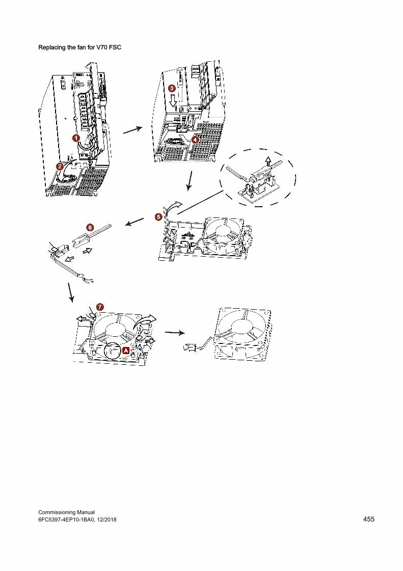
Commissioning Manual 6FC5397-4EP10-1BA0, 12/2018 455
Replacing the fan for V70 FSC
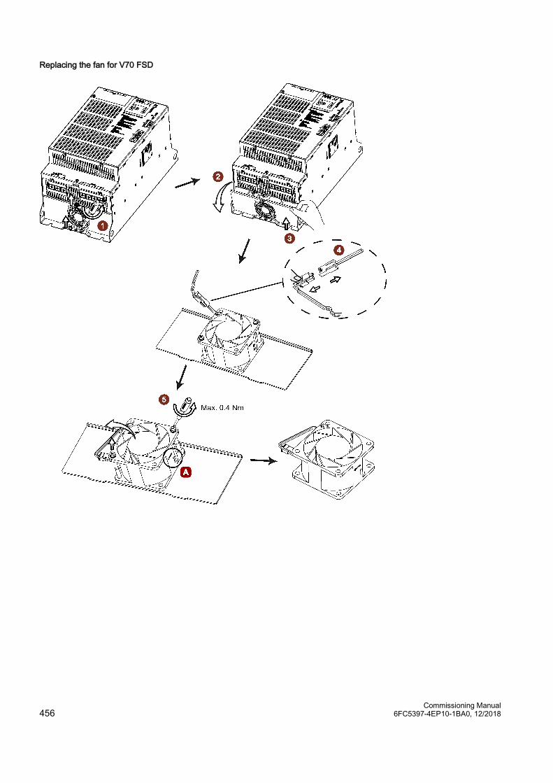
Commissioning Manual 456 6FC5397-4EP10-1BA0, 12/2018
Replacing the fan for V70 FSD
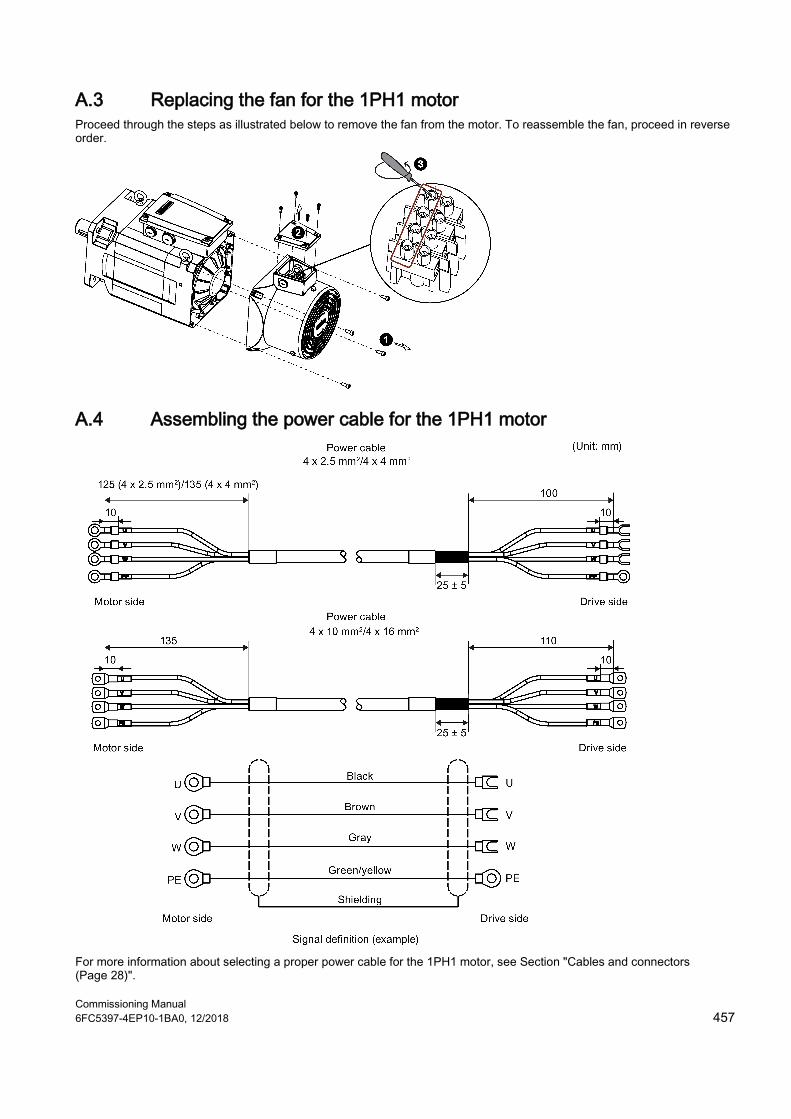
Commissioning Manual 6FC5397-4EP10-1BA0, 12/2018 457
A.3 Replacing the fan for the 1PH1 motor Proceed through the steps as illustrated below to remove the fan from the motor. To reassemble the fan, proceed in reverse order.
A.4 Assembling the power cable for the 1PH1 motor
For more information about selecting a proper power cable for the 1PH1 motor, see Section "Cables and connectors (Page 28)".

Commissioning Manual 458 6FC5397-4EP10-1BA0, 12/2018
Assembling procedure
Motor side
1. Strip the specified length (see below) of the outer sheath at the end of the cable.
4 x 2.5 mm2 power cable: 125 mm
all other power cables: 135 mm 2. Cut off the exposed braided shield in its entirety. 3. Strip the inner sheath without damage to the insulation of each cable conductor. 4. Pass white cable marker tubes through corresponding cable conductors. 5. Strip 10 mm of the insulation at the end of each cable conductor. 6. Insert cable wires into individual conductor terminals. Use a crimping tool to crimp the terminals (minimum
tensile strength: 350 N). 7. (This step is necessary only for 4 x 10 mm2/4 x 16 mm2 power cables. Skip this step if you assemble 4 x 2.5
mm2/4 x 4 mm2 power cables.) Pass each conductor terminal through a heat-shrinkable tube, which must com-pletely cover the bending area of the terminal. Heat the tube until it shrinks to wrap tightly around the terminal.
8. Pass all cable conductors through a heat-shrinkable tube. Heat the tube until it shrinks to wrap tightly around the cable.
Drive side
1. Strip the specified length (see below) of the outer sheath at the end of the cable.
4 x 2.5 mm2/4 x 4 mm2 power cable: 100 mm
4 x 10 mm2/4 x 16 mm2 power cable: 110 mm 2. Keep the exposed braided shield as long as 25 mm (± 5 mm) and cut off the rest of the shield. Fold the braided
shield backwards. 3. Pass the cable through a heat-shrinkable tube. Heat the tube until it shrinks to wrap tightly around the cable. 4. Strip the inner sheath without damage to the insulation of each cable conductor. 5. Pass white cable marker tubes through corresponding cable conductors. 6. Strip 10 mm of the insulation at the end of each cable conductor. 7. Insert cable wires into individual conductor terminals. Use a crimping tool to crimp the terminals (minimum
tensile strength: 350 N). 8. (This step is necessary only for 4 x 10 mm2/4 x 16 mm2 power cables. Skip this step if you assemble 4 x 2.5
mm2/4 x 4 mm2 power cables.) Pass each conductor terminal through a heat-shrinkable tube, which must com-pletely cover the bending area of the terminal. Heat the tube until it shrinks to wrap tightly around the terminal.
9. Use a hose clamp to secure the power cable to the drive.
For more information about the connectors and hose clamps, such as recommended suppliers and article numbers, see Section "Cables and connectors (Page 28)".
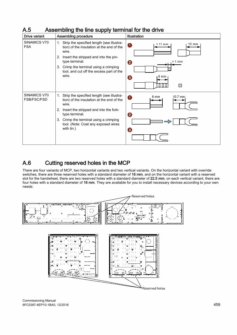
Commissioning Manual 6FC5397-4EP10-1BA0, 12/2018 459
A.5 Assembling the line supply terminal for the drive Drive variant Assembling procedure Illustration SINAMICS V70 FSA
1. Strip the specified length (see illustra-tion) of the insulation at the end of the wire.
2. Insert the stripped end into the pin-type terminal.
3. Crimp the terminal using a crimping tool, and cut off the excess part of the wire.
SINAMICS V70 FSB/FSC/FSD
1. Strip the specified length (see illustra-tion) of the insulation at the end of the wire.
2. Insert the stripped end into the fork-type terminal.
3. Crimp the terminal using a crimping tool. (Note: Coat any exposed wires with tin.)
A.6 Cutting reserved holes in the MCP There are four variants of MCP, two horizontal variants and two vertical variants. On the horizontal variant with override switches, there are three reserved holes with a standard diameter of 16 mm, and on the horizontal variant with a reserved slot for the handwheel, there are two reserved holes with a standard diameter of 22.5 mm; on each vertical variant, there are four holes with a standard diameter of 16 mm. They are available for you to install necessary devices according to your own needs:
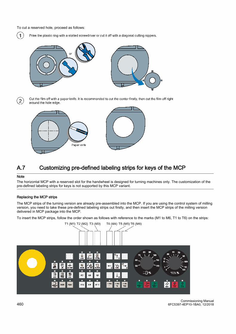
Commissioning Manual 460 6FC5397-4EP10-1BA0, 12/2018
To cut a reserved hole, proceed as follows:
A.7 Customizing pre-defined labeling strips for keys of the MCP
Note The horizontal MCP with a reserved slot for the handwheel is designed for turning machines only. The customization of the pre-defined labeling strips for keys is not supported by this MCP variant.
Replacing the MCP strips
The MCP strips of the turning version are already pre-assembled into the MCP. If you are using the control system of milling version, you need to take these pre-defined labeling strips out firstly, and then insert the MCP strips of the milling version delivered in MCP package into the MCP.
To insert the MCP strips, follow the order shown as follows with reference to the marks (M1 to M6, T1 to T6) on the strips:
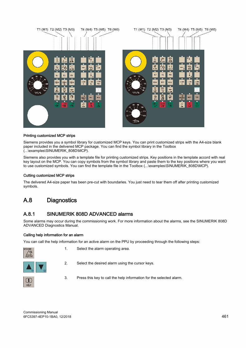
Commissioning Manual 6FC5397-4EP10-1BA0, 12/2018 461
Printing customized MCP strips
Siemens provides you a symbol library for customized MCP keys. You can print customized strips with the A4-size blank paper included in the delivered MCP package. You can find the symbol library in the Toolbox (...\examples\SINUMERIK_808D\MCP).
Siemens also provides you with a template file for printing customized strips. Key positions in the template accord with real key layout on the MCP. You can copy symbols from the symbol library and paste them to the key positions where you want to use customized symbols. You can find the template file in the Toolbox (...\examples\SINUMERIK_808D\MCP).
Cutting customized MCP strips
The delivered A4-size paper has been pre-cut with boundaries. You just need to tear them off after printing customized symbols.
A.8 Diagnostics
A.8.1 SINUMERIK 808D ADVANCED alarms Some alarms may occur during the commissioning work. For more information about the alarms, see the SINUMERIK 808D ADVANCED Diagnostics Manual.
Calling help information for an alarm
You can call the help information for an active alarm on the PPU by proceeding through the following steps:
1. Select the alarm operating area.
2. Select the desired alarm using the cursor keys.
3. Press this key to call the help information for the selected alarm.
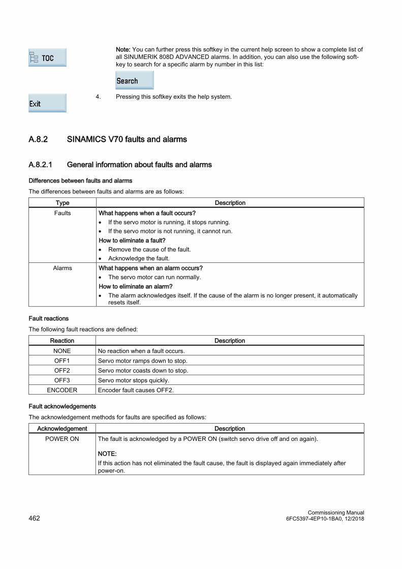
Commissioning Manual 462 6FC5397-4EP10-1BA0, 12/2018
Note: You can further press this softkey in the current help screen to show a complete list of all SINUMERIK 808D ADVANCED alarms. In addition, you can also use the following soft-key to search for a specific alarm by number in this list:
4. Pressing this softkey exits the help system.
A.8.2 SINAMICS V70 faults and alarms
A.8.2.1 General information about faults and alarms
Differences between faults and alarms
The differences between faults and alarms are as follows:
Type Description Faults What happens when a fault occurs?
• If the servo motor is running, it stops running. • If the servo motor is not running, it cannot run. How to eliminate a fault? • Remove the cause of the fault. • Acknowledge the fault.
Alarms What happens when an alarm occurs? • The servo motor can run normally. How to eliminate an alarm? • The alarm acknowledges itself. If the cause of the alarm is no longer present, it automatically
resets itself.
Fault reactions
The following fault reactions are defined:
Reaction Description NONE No reaction when a fault occurs. OFF1 Servo motor ramps down to stop. OFF2 Servo motor coasts down to stop. OFF3 Servo motor stops quickly.
ENCODER Encoder fault causes OFF2.
Fault acknowledgements
The acknowledgement methods for faults are specified as follows:
Acknowledgement Description POWER ON The fault is acknowledged by a POWER ON (switch servo drive off and on again).
NOTE: If this action has not eliminated the fault cause, the fault is displayed again immediately after power-on.
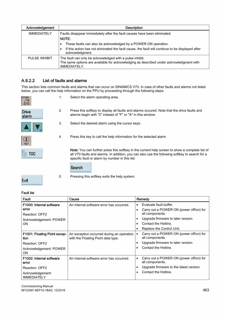
Commissioning Manual 6FC5397-4EP10-1BA0, 12/2018 463
Acknowledgement Description IMMEDIATELY Faults disappear immediately after the fault causes have been eliminated.
NOTE: • These faults can also be acknowledged by a POWER ON operation. • If this action has not eliminated the fault cause, the fault will continue to be displayed after
acknowledgment. PULSE INHIBIT The fault can only be acknowledged with a pulse inhibit.
The same options are available for acknowledging as described under acknowledgment with IMMEDIATELY.
A.8.2.2 List of faults and alarms This section lists common faults and alarms that can occur on SINAMICS V70. In case of other faults and alarms not listed below, you can call the help information on the PPU by proceeding through the following steps:
1. Select the alarm operating area.
2. Press this softkey to display all faults and alarms occured. Note that the drive faults and alarms begin with "2" instead of "F" or "A" in this window.
3. Select the desired alarm using the cursor keys.
4. Press this key to call the help information for the selected alarm.
Note: You can further press this softkey in the current help screen to show a complete list of all V70 faults and alarms. In addition, you can also use the following softkey to search for a specific fault or alarm by number in this list:
5. Pressing this softkey exits the help system.
Fault list
Fault Cause Remedy F1000: Internal software error Reaction: OFF2 Acknowledgement: POWER ON
An internal software error has occurred. • Evaluate fault buffer. • Carry out a POWER ON (power off/on) for
all components. • Upgrade firmware to later version. • Contact the Hotline. • Replace the Control Unit.
F1001: Floating Point excep-tion Reaction: OFF2 Acknowledgement: POWER ON
An exception occurred during an operation with the Floating Point data type.
• Carry out a POWER ON (power off/on) for all components.
• Upgrade firmware to later version. • Contact the Hotline.
F1002: Internal software error Reaction: OFF2 Acknowledgement: IMMEDIATELY
An internal software error has occurred. • Carry out a POWER ON (power off/on) for all components.
• Upgrade firmware to the latest version. • Contact the Hotline.

Commissioning Manual 464 6FC5397-4EP10-1BA0, 12/2018
Fault Cause Remedy F1003: Acknowledgement delay when accessing the memory Reaction: OFF2 Acknowledgement: IMMEDIATELY
A memory area was accessed that does not return a "READY".
• Carry out a POWER ON (power off/on) for all components.
• Contact the Hotline.
F1015: Internal software error Reaction: OFF2 Acknowledgement: POWER ON
An internal software error has occurred. • Carry out a POWER ON (power off/on) for all components.
• Upgrade firmware to the latest version. • Contact the Hotline.
F1018: Booting has been interrupted several times Reaction: NONE Acknowledgement: POWER ON
Module booting was interrupted several times. As a consequence, the module boots with the factory setting. Possible reasons for booting being inter-rupted: • Power supply interrupted. • CPU crashed. • Parameterization invalid. After this fault is output, then the module is booted with the factory settings.
• Carry out a POWER ON (power off/on). After switching on, the module reboots from the valid parameterization (if available).
• Restore the valid parameterization. Examples: • Carry out a first commissioning, save, carry
out a POWER ON (switch-off/switch-on). • Load another valid parameter backup (e.g.
from the memory card), save, carry out a POWER ON (switch-off/switch-on).
Note: If the fault situation is repeated, then this fault is again output after several interrupted boots.
F1030: Sign-of-life failure for master control Reaction: OFF3 Acknowledgement: IMMEDIATELY
For active PC master control, no sign-of-life was received within the monitoring time.
Contact the Hotline.
F1611: SI CU: Defect de-tected Reaction: OFF2 Acknowledgement: IMMEDIATELY
The drive-integrated "Safety Integrated" (SI) function on the Control Unit (CU) has detected an error and initiated an STO
• Make sure that the high level duration of the inut pulse is larger than 500 ms.
• Carry out a POWER ON (power off/on) for all components.
• Upgrade software. • Replace the Control Unit.
F1910: Drive Bus: Setpoint timeout Reaction: OFF3 Acknowledgement: IMMEDIATELY
The reception of setpoints from the Drive Bus interface has been interrupted. • Bus connection interrupted. • Controller switched off. • Controller set into the STOP state.
Restore the bus connection and set the con-troller to RUN.
F1911: Drive Bus clock cycle synchronous operation clock cycle failure Reaction: OFF1 Acknowledgement: IMMEDIATELY
The global control telegram to synchronize the clock cycles has failed - in cyclic oper-ation - for several Drive Bus clock cycles or has violated the time grid specified in the parameterizing telegram over several consecutive Drive Bus clock cycles.
• Check the physical bus configuration (ca-ble, connector, Drive Bus terminator, shielding, etc.).
• Check whether communication was briefly or permanently interrupted.
• Check the bus and controller for utilization level (e.g. bus cycle time was set too short).

Commissioning Manual 6FC5397-4EP10-1BA0, 12/2018 465
Fault Cause Remedy F1912: Clock cycle synchro-nous operation sign-of-life failure Reaction: OFF1 Acknowledgement: IMMEDIATELY
The maximum permissible number of errors in the controller sign-of-life (clock synchronous operation) has been exceed-ed in cyclic operation.
• Physically check the bus (cables, connect-ors, terminating resistor, shielding, etc.).
• Correct the interconnection of the controller sign-of-life.
• Check whether the controller correctly sends the sign-of-life.
• Check the permissible telegram failure rate. • Check the bus and controller for utilization
level (e.g. bus cycle time was set too short).
F7011: Motor overtempera-ture Reaction: OFF2 Acknowledgement: IMMEDIATELY
• Motor overloaded • Motor surrounding air temperature too
high • Wire breakage or sensor not connect-
ed • Motor temperature model incorrectly
parameterized
• Reduce the motor load. • Check the surrounding air temperature and
the motor ventilation. • Check the wiring and the connection. • Check the motor temperature model pa-
rameters.
F7085: Open-loop/closed-loop control parameters changed Reaction: NONE Acknowledgement: IMMEDIATELY
Open-loop/closed-loop control parameters have had to be changed for the following reasons: • As a result of other parameters, they
have exceeded the dynamic limits. • They cannot be used due to the fact
that the hardware detected not having certain features.
It is not necessary to change the parameters as they have already been correctly limited.
F7403: Lower DC link volt-age threshold reached Reaction: OFF1 Acknowledgement: IMMEDIATELY
The DC link voltage monitoring is active and the lower DC link voltage threshold was reached in the "Operation" state.
• Check the line supply voltage. • Check the infeed. • Reduce the lower DC link threshold. • Switch out (disable) the DC link voltage
monitoring. F7404: Upper DC link volt-age threshold reached Reaction: OFF2 Acknowledgement: IMMEDIATELY
The DC link voltage monitoring is active and the upper DC link voltage threshold was reached in the "Operation" state.
• Check the line supply voltage. • Check the infeed module or the brake
module. • Increase the upper DC link voltage thresh-
old. • Switch out (disable) the DC link voltage
monitoring. F7410: Current controller output limited Reaction: OFF2 Acknowledgement: IMMEDIATELY
The condition "I_act = 0 and Uq_set_1 longer than 16 ms at its limit" is present and can be caused by the following: • Motor not connected or motor contac-
tor open. • No DC link voltage present. • Motor Module defective.
• Connect the motor or check the motor contactor.
• Check the DC link voltage. • Check the Motor Module.
F7411: Drive: Flux controller output limited Reaction: OFF2 Acknowledgement: IMMEDIATELY
The specified flux setpoint cannot be reached although 90% of the maximum current has been specified. • Incorrect motor data. • Motor data and motor configuration do
not match. • The current limit has been set too low
for the motor. • Induction motor (encoderless, open-
loop controlled) in I2t limiting.
• Correct the motor data. • Check the motor configuration. • Reduce the induction motor load.

Commissioning Manual 466 6FC5397-4EP10-1BA0, 12/2018
Fault Cause Remedy F7412: Commutation angle incorrect (motor model) Reaction: ENCODER Acknowledgement: IMMEDIATELY
An incorrect commutation angle was de-tected that can result in a positive coupling in the speed controller. Possible causes: • The motor encoder is incorrectly ad-
justed with respect to the magnet posi-tion.
• The motor encoder is damaged. • Data to calculate the motor model has
been incorrectly set. • Pole position identification might have
calculated an incorrect value when ac-tivated.
• The motor encoder speed signal is faulted.
• The control loop is instable due to incorrect parameterization.
• If the encoder mounting was changed, re-adjust the encoder.
• Replace the defective motor encoder. • Correctly set the motor stator resistance,
cable resistance and motor-stator leakage inductance. Calculate the cable resistance from the cross-section and length, check the induct-ance and stator resistance using the motor data sheet, measure the stator resistance, e.g. using a multimeter - and if required, again identify the values using the station-ary motor data identification.
• With pole position identification activated, check the procedure for pole position iden-tification and force a new pole position identification procedure by means of de-selection followed by selection.
F7414: Encoder serial num-ber changed Reaction: ENCODER Acknowledgement: IMMEDIATELY
• The encoder was replaced. • A third-party, build-in or linear motor
was re-commissioned. • The motor with integrated and adjusted
encoder was replaced. • The firmware was updated to a version
that checks the encoder serial number.
For the first two causes: Carry out an automatic adjustment using the pole position identification routine. Acknowledge the fault. Initiate the pole position identification routine. Then check that the pole position identification routine is correctly exe-cuted. SERVO: If a pole position identification technique is selected, and if p0301 does not contain a mo-tor type with an encoder adjusted in the facto-ry, then p1990 is automatically activated. Mechanically adjust the encoder. Accept the new serial number. For the last two causes: Accept the new serial number with p0440 = 1.
F7420: Drive: Current set-point filter natural frequency > Shannon frequency Reaction: NONE Acknowledgement: IMMEDIATELY
One of the filter natural frequencies is greater than the Shannon frequency (2KHz). Filter 1 (p1658, p1660) Filter 2 (p1663, p1665) Filter 3 (p1668, p1670) Filter 4 (p1673, p1675)
• Reduce the numerator or denominator natural frequency of the current setpoint fil-ter involved at the control system side.
• Switch out the filter involved (p1656).
F7450: Standstill monitoring has responded Reaction: OFF1 Acknowledgement: IMMEDIATELY
After the standstill monitoring time expired, the drive left the standstill window. • Position loop gain too low. • Position loop gain too high (instabil-
ity/oscillation). • Mechanical overload. • Connecting cable, motor/drive convert-
er incorrect (phase missing, inter-change).
Check the causes and resolve.
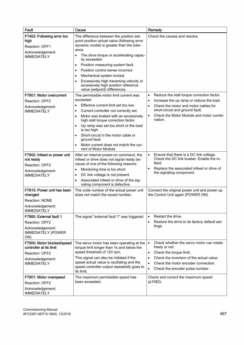
Commissioning Manual 6FC5397-4EP10-1BA0, 12/2018 467
Fault Cause Remedy F7452: Following error too high Reaction: OFF1 Acknowledgement: IMMEDIATELY
The difference between the position set-point position actual value (following error dynamic model) is greater than the toler-ance. • The drive torque or accelerating capac-
ity exceeded. • Position measuring system fault. • Position control sense incorrect. • Mechanical system locked. • Excessively high traversing velocity or
excessively high position reference value (setpoint) differences.
Check the causes and resolve.
F7801: Motor overcurrent Reaction: OFF2 Acknowledgement: IMMEDIATELY
The permissible motor limit current was exceeded. • Effective current limit set too low. • Current controller not correctly set. • Motor was braked with an excessively
high stall torque correction factor. • Up ramp was set too short or the load
is too high. • Short-circuit in the motor cable or
ground fault. • Motor current does not match the cur-
rent of Motor Module.
• Reduce the stall torque correction factor. • Increase the up ramp or reduce the load. • Check the motor and motor cables for
short-circuit and ground fault. • Check the Motor Module and motor combi-
nation.
F7802: Infeed or power unit not ready Reaction: OFF2 Acknowledgement: IMMEDIATELY
After an internal power-on command, the infeed or drive does not signal ready be-cause of one of the following reasons: • Monitoring time is too short. • DC link voltage is not present. • Associated infeed or drive of the sig-
naling component is defective.
• Ensure that there is a DC link voltage. Check the DC link busbar. Enable the in-feed.
• Replace the associated infeed or drive of the signaling component.
F7815: Power unit has been changed Reaction: NONE Acknowledgement: IMMEDIATELY
The code number of the actual power unit does not match the saved number.
Connect the original power unit and power up the Control Unit again (POWER ON).
F7860: External fault 1 Reaction: OFF2 Acknowledgement: IMMEDIATELY (POWER ON)
The signal "external fault 1" was triggered. • Restart the drive. • Restore the drive to its factory default set-
tings.
F7900: Motor blocked/speed controller at its limit Reaction: OFF2 Acknowledgement: IMMEDIATELY
The servo motor has been operating at the torque limit longer than 1s and below the speed threshold of 120 rpm. This signal can also be initiated if the speed actual value is oscillating and the speed controller output repeatedly goes to its limit.
• Check whether the servo motor can rotate freely or not.
• Check the torque limit. • Check the inversion of the actual value. • Check the motor encoder connection. • Check the encoder pulse number.
F7901: Motor overspeed Reaction: OFF2 Acknowledgement: IMMEDIATELY
The maximum permissible speed has been exceeded.
Check and correct the maximum speed (p1082).

Commissioning Manual 468 6FC5397-4EP10-1BA0, 12/2018
Fault Cause Remedy F7995: Pole position identifi-cation not successful Reaction: OFF2 Acknowledgement: IMMEDIATELY
The pole position identification routine was unsuccessful.
Contact the Hotline.
F30001: Power unit: Over-current Reaction: OFF2 Acknowledgement: IMMEDIATELY
The power unit has detected an overcur-rent condition. • Closed-loop control is incorrectly pa-
rameterized. • Motor has a short-circuit or fault to
ground (frame). • Power cables are not correctly con-
nected. • Power cables exceed the maximum
permissible length. • Power unit defective. • Line phase interrupted.
• Check the motor data - if required, carry out commissioning.
• Check the motor circuit configuration (star-delta)
• Check the power cable connections. • Check the power cables for short-circuit or
ground fault. • Check the length of the power cables. • Replace power unit. • Check the line supply phases. • Check the external braking resistor connec-
tion. F30002: DC link voltage, overvoltage Reaction: OFF2 Acknowledgement: IMMEDIATELY
The power unit has detected overvoltage in the DC link. • Motor regenerates too much energy. • Device connection voltage too high. • Line phase interrupted.
• Increase the ramp-down time. • Activate the DC link voltage controller. • Use a braking resistor. • Increase the current limit of the infeed or
use a larger module. • Check the device supply voltage. • Check the line supply phases.
F30003: DC link voltage, undervoltage Reaction: OFF2 Acknowledgement: IMMEDIATELY
The power unit has detected an undervolt-age condition in the DC link. • Line supply failure • Line supply voltage below the permis-
sible value. • Line supply infeed failed or interrupted. • Line phase interrupted.
• Check the line supply voltage. • Check the line supply infeed and observe
the fault messages relating to it (if there are any).
• Check the line supply phases. • Check the line supply voltage setting.
F30004: Drive heat sink overtemperature Reaction: OFF2 Acknowledgement: IMMEDIATELY
The temperature of the power unit heat sink has exceeded the permissible limit value. • Insufficient cooling, fan failure. • Overload. • Surrounding air temperature too high. • Pulse frequency too high.
• Check whether the fan is running. • Check the fan elements. • Check whether the surrounding air temper-
ature is in the permissible range. • Check the motor load. • Reduce the pulse frequency if this is higher
than the rated pulse frequency.
F30005: Power unit: Over-load I2t Reaction: OFF2 Acknowledgement: IMMEDIATELY
The power unit was overloaded. • The permissible rated power unit cur-
rent was exceeded for an inadmissibly long time.
• The permissible load duty cycle was not maintained.
• Reduce the continuous load. • Adapt the load duty cycle. • Check the motor and power unit rated cur-
rents.
F30011: Line phase failure in main circuit Reaction: OFF2 Acknowledgement: IMMEDIATELY
At the power unit, the DC link voltage ripple has exceeded the permissible limit value. Possible causes: • A line phase has failed. • The 3 line phases are inadmissibly
unsymmetrical. • The fuse of a phase of a main circuit
has ruptured. • A motor phase has failed.
• Check the main circuit fuses. • Check whether a single-phase load is dis-
torting the line voltages. • Check the motor feeder cables.

Commissioning Manual 6FC5397-4EP10-1BA0, 12/2018 469
Fault Cause Remedy F30015: Phase failure motor cable Reaction: OFF2 Acknowledgement: IMMEDIATELY
A phase failure in the motor feeder cable was detected. The signal can also be output in the follow-ing case: The motor is correctly connected, however the closed-speed control is instable and therefore an oscillating torque is generat-ed.
• Check the motor feeder cables. • Check the speed controller settings.
F30021: Ground fault Reaction: OFF2 Acknowledgement: IMMEDIATELY
Power unit has detected a ground fault. • Ground fault in the power cables. • Winding fault or ground fault at the
motor.
• Check the power cable connections. • Check the motor.
F30027: Precharging DC link time monitoring Reaction: OFF2 Acknowledgement: IMMEDIATELY
• The power unit DC link was not able to be pre-charged within the expected time. There is no line supply voltage con-nected.
• The line contactor/line side switch has not been closed.
• The line supply voltage is too low. • The pre-charging resistors are over-
heated as there were too many pre-charging operations per time unit
• The pre-charging resistors are over-heated as the DC link capacitance is too high.
• The pre-charging resistors are over-heated.
• The pre-charging resistors are over-heated as the line contactor was closed during the DC link fast dis-charge through the Braking Module.
• The DC link has either a ground fault or a short-circuit.
• The pre-charging circuit is possibly defective.
Check the line supply voltage at the input ter-minals.
F30036: Internal over-temperature Reaction: OFF2 Acknowledgement: IMMEDIATELY
The temperature inside the drive has ex-ceeded the permissible temperature limit. • Insufficient cooling, fan failure. • Overload. • Surrounding air temperature too high.
• Check whether the fan is running. • Check the fan elements. • Check whether the surrounding air temper-
ature is in the permissible range. Notice: This fault can only be acknowledged once the permissible temperature limit minus 5 K has been fallen below.
F30050: 24 V supply over-voltage Reaction: OFF2 Acknowledgement: POWER ON
The voltage monitor signals an overvolt-age fault on the module.
• Check the 24 V power supply. • Replace the module if necessary.
F30071: No new actual values received from the power unit module Reaction: OFF2 Acknowledgement: IMMEDIATELY
The number of actual value telegrams from the power unit module that have failed has exceeded the permissible num-ber.
Replace the module if necessary.
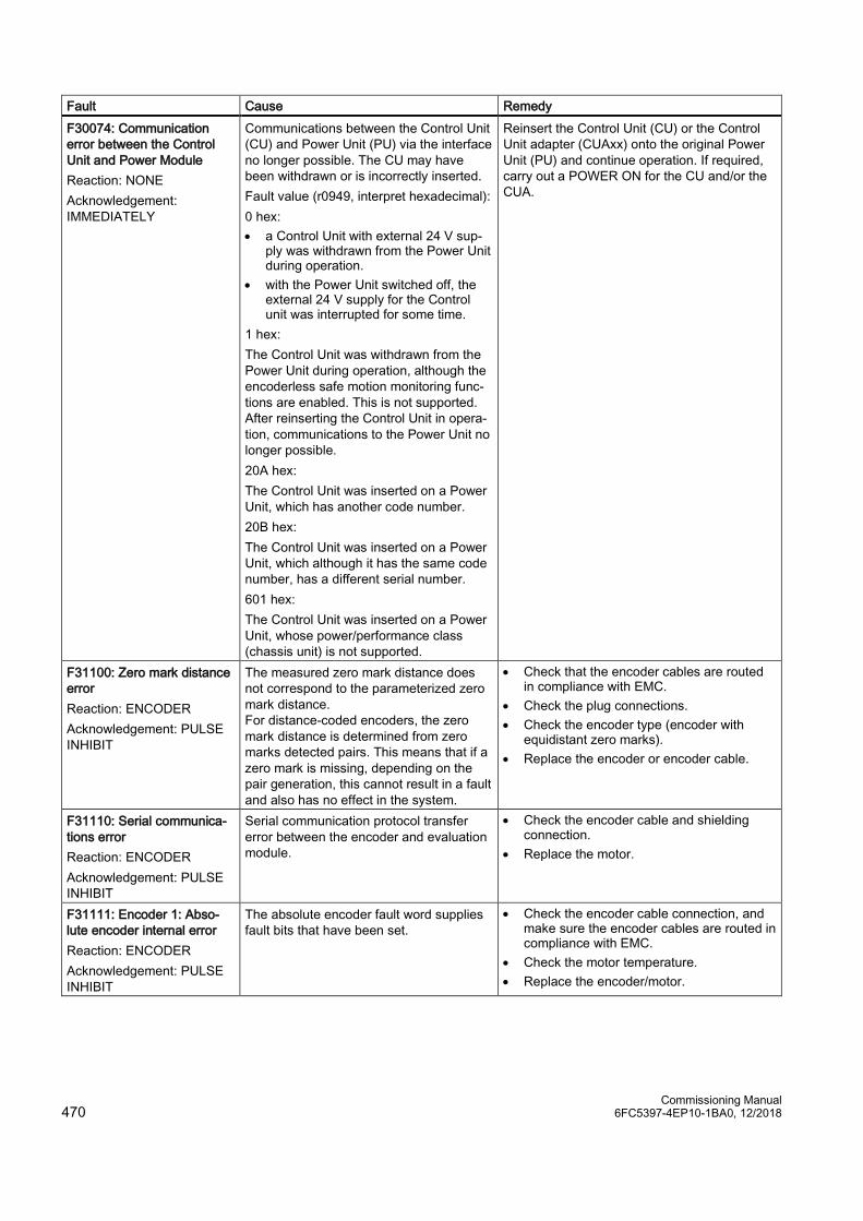
Commissioning Manual 470 6FC5397-4EP10-1BA0, 12/2018
Fault Cause Remedy F30074: Communication error between the Control Unit and Power Module Reaction: NONE Acknowledgement: IMMEDIATELY
Communications between the Control Unit (CU) and Power Unit (PU) via the interface no longer possible. The CU may have been withdrawn or is incorrectly inserted. Fault value (r0949, interpret hexadecimal): 0 hex: • a Control Unit with external 24 V sup-
ply was withdrawn from the Power Unit during operation.
• with the Power Unit switched off, the external 24 V supply for the Control unit was interrupted for some time.
1 hex: The Control Unit was withdrawn from the Power Unit during operation, although the encoderless safe motion monitoring func-tions are enabled. This is not supported. After reinserting the Control Unit in opera-tion, communications to the Power Unit no longer possible. 20A hex: The Control Unit was inserted on a Power Unit, which has another code number. 20B hex: The Control Unit was inserted on a Power Unit, which although it has the same code number, has a different serial number. 601 hex: The Control Unit was inserted on a Power Unit, whose power/performance class (chassis unit) is not supported.
Reinsert the Control Unit (CU) or the Control Unit adapter (CUAxx) onto the original Power Unit (PU) and continue operation. If required, carry out a POWER ON for the CU and/or the CUA.
F31100: Zero mark distance error Reaction: ENCODER Acknowledgement: PULSE INHIBIT
The measured zero mark distance does not correspond to the parameterized zero mark distance. For distance-coded encoders, the zero mark distance is determined from zero marks detected pairs. This means that if a zero mark is missing, depending on the pair generation, this cannot result in a fault and also has no effect in the system.
• Check that the encoder cables are routed in compliance with EMC.
• Check the plug connections. • Check the encoder type (encoder with
equidistant zero marks). • Replace the encoder or encoder cable.
F31110: Serial communica-tions error Reaction: ENCODER Acknowledgement: PULSE INHIBIT
Serial communication protocol transfer error between the encoder and evaluation module.
• Check the encoder cable and shielding connection.
• Replace the motor.
F31111: Encoder 1: Abso-lute encoder internal error Reaction: ENCODER Acknowledgement: PULSE INHIBIT
The absolute encoder fault word supplies fault bits that have been set.
• Check the encoder cable connection, and make sure the encoder cables are routed in compliance with EMC.
• Check the motor temperature. • Replace the encoder/motor.
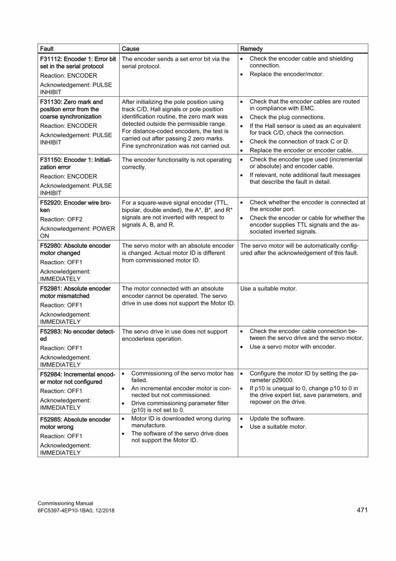
Commissioning Manual 6FC5397-4EP10-1BA0, 12/2018 471
Fault Cause Remedy F31112: Encoder 1: Error bit set in the serial protocol Reaction: ENCODER Acknowledgement: PULSE INHIBIT
The encoder sends a set error bit via the serial protocol.
• Check the encoder cable and shielding connection.
• Replace the encoder/motor.
F31130: Zero mark and position error from the coarse synchronization Reaction: ENCODER Acknowledgement: PULSE INHIBIT
After initializing the pole position using track C/D, Hall signals or pole position identification routine, the zero mark was detected outside the permissible range. For distance-coded encoders, the test is carried out after passing 2 zero marks. Fine synchronization was not carried out.
• Check that the encoder cables are routed in compliance with EMC.
• Check the plug connections. • If the Hall sensor is used as an equivalent
for track C/D, check the connection. • Check the connection of track C or D. • Replace the encoder or encoder cable.
F31150: Encoder 1: Initiali-zation error Reaction: ENCODER Acknowledgement: PULSE INHIBIT
The encoder functionality is not operating correctly.
• Check the encoder type used (incremental or absolute) and encoder cable.
• If relevant, note additional fault messages that describe the fault in detail.
F52920: Encoder wire bro-ken Reaction: OFF2 Acknowledgement: POWER ON
For a square-wave signal encoder (TTL, bipolar, double ended), the A*, B*, and R* signals are not inverted with respect to signals A, B, and R.
• Check whether the encoder is connected at the encoder port.
• Check the encoder or cable for whether the encoder supplies TTL signals and the as-sociated inverted signals.
F52980: Absolute encoder motor changed Reaction: OFF1 Acknowledgement: IMMEDIATELY
The servo motor with an absolute encoder is changed. Actual motor ID is different from commissioned motor ID.
The servo motor will be automatically config-ured after the acknowledgement of this fault.
F52981: Absolute encoder motor mismatched Reaction: OFF1 Acknowledgement: IMMEDIATELY
The motor connected with an absolute encoder cannot be operated. The servo drive in use does not support the Motor ID.
Use a suitable motor.
F52983: No encoder detect-ed Reaction: OFF1 Acknowledgement: IMMEDIATELY
The servo drive in use does not support encoderless operation.
• Check the encoder cable connection be-tween the servo drive and the servo motor.
• Use a servo motor with encoder.
F52984: Incremental encod-er motor not configured Reaction: OFF1 Acknowledgement: IMMEDIATELY
• Commissioning of the servo motor has failed.
• An incremental encoder motor is con-nected but not commissioned.
• Drive commissioning parameter filter (p10) is not set to 0.
• Configure the motor ID by setting the pa-rameter p29000.
• If p10 is unequal to 0, change p10 to 0 in the drive expert list, save parameters, and repower on the drive.
F52985: Absolute encoder motor wrong Reaction: OFF1 Acknowledgement: IMMEDIATELY
• Motor ID is downloaded wrong during manufacture.
• The software of the servo drive does not support the Motor ID.
• Update the software. • Use a suitable motor.
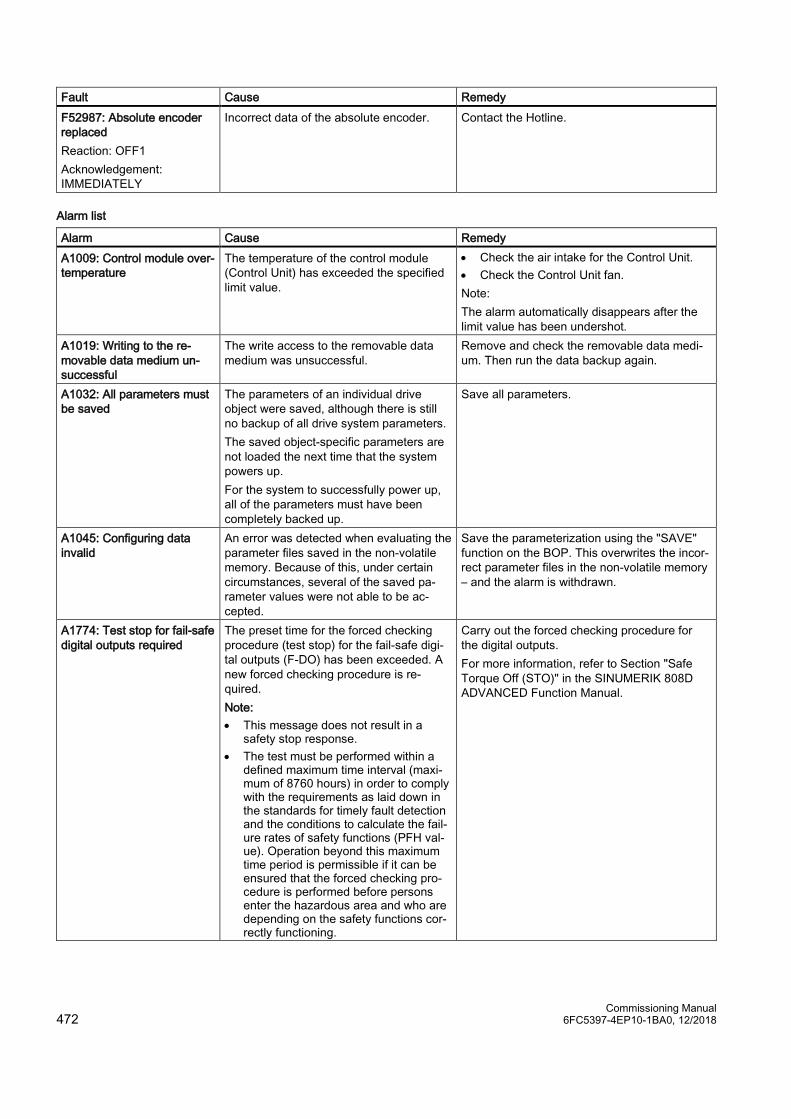
Commissioning Manual 472 6FC5397-4EP10-1BA0, 12/2018
Fault Cause Remedy F52987: Absolute encoder replaced Reaction: OFF1 Acknowledgement: IMMEDIATELY
Incorrect data of the absolute encoder. Contact the Hotline.
Alarm list
Alarm Cause Remedy A1009: Control module over-temperature
The temperature of the control module (Control Unit) has exceeded the specified limit value.
• Check the air intake for the Control Unit. • Check the Control Unit fan. Note: The alarm automatically disappears after the limit value has been undershot.
A1019: Writing to the re-movable data medium un-successful
The write access to the removable data medium was unsuccessful.
Remove and check the removable data medi-um. Then run the data backup again.
A1032: All parameters must be saved
The parameters of an individual drive object were saved, although there is still no backup of all drive system parameters. The saved object-specific parameters are not loaded the next time that the system powers up. For the system to successfully power up, all of the parameters must have been completely backed up.
Save all parameters.
A1045: Configuring data invalid
An error was detected when evaluating the parameter files saved in the non-volatile memory. Because of this, under certain circumstances, several of the saved pa-rameter values were not able to be ac-cepted.
Save the parameterization using the "SAVE" function on the BOP. This overwrites the incor-rect parameter files in the non-volatile memory – and the alarm is withdrawn.
A1774: Test stop for fail-safe digital outputs required
The preset time for the forced checking procedure (test stop) for the fail-safe digi-tal outputs (F-DO) has been exceeded. A new forced checking procedure is re-quired. Note: • This message does not result in a
safety stop response. • The test must be performed within a
defined maximum time interval (maxi-mum of 8760 hours) in order to comply with the requirements as laid down in the standards for timely fault detection and the conditions to calculate the fail-ure rates of safety functions (PFH val-ue). Operation beyond this maximum time period is permissible if it can be ensured that the forced checking pro-cedure is performed before persons enter the hazardous area and who are depending on the safety functions cor-rectly functioning.
Carry out the forced checking procedure for the digital outputs. For more information, refer to Section "Safe Torque Off (STO)" in the SINUMERIK 808D ADVANCED Function Manual.

Commissioning Manual 6FC5397-4EP10-1BA0, 12/2018 473
Alarm Cause Remedy A1920: Drive Bus: Receive setpoints after To
Output data of Drive Bus master (set-points) received at the incorrect instant in time within the Drive Bus clock cycle.
• Check bus configuration. • Check parameters for clock cycle synchro-
nization (ensure To > Tdx). Note: • To: Time of setpoint acceptance • Tdx: Data exchange time
A1932: Drive Bus clock cycle synchronization miss-ing for DSC
There is no clock synchronization or clock synchronous sign of life and DSC is se-lected. Note: DSC: Dynamic Servo Control
Set clock synchronization across the bus con-figuration and transfer clock synchronous sign-of-life.
A5000: Drive heat sink over-temperature
The alarm threshold for overtemperature at the inverter heat sink has been reached. If the temperature of the heat sink in-creases by an additional 5 K, then fault F30004 is initiated.
Check the following: • Is the surrounding air temperature within
the defined limit values? • Have the load conditions and the load duty
cycle been appropriately dimensioned? • Has the cooling failed?
A6310: DC link voltage ex-ceeding the tolerance range
For AC/AC drive units, the measured DC voltage lies outside the tolerance range after pre-charging has been completed. The following applies for the tolerance range: 1.16 * 400 V < actual DC link volt-age < 1.6 * 400 V. The alarm can only be eliminated when the drive is powered down.
Check the line supply voltage.
A7012: Motor temperature model 1/3 overtemperature
The motor temperature model 1/3 identi-fied that the alarm threshold was exceed-ed.
• Check the motor load and reduce it if re-quired.
• Check the motor surrounding air tempera-ture.
A7565: Encoder error in encoder interface
An encoder error was signaled for encoder via the encoder interface (G1_ZSW.15).
Acknowledge the encoder error using the en-coder control word (G1_STW.15 = 1).
A7576: Encoderless opera-tion due to a fault active
Encoderless operation is active due to a fault.
• Remove the cause of a possible encoder fault.
• Carry out a POWER ON (power off/on) for all components.
A7965: Save required The angular commutation offset was re-defined and has still not been saved. In order to permanently accept the new value, it must be saved in a non-volatile fashion.
This alarm automatically disappears after the data has been saved.
A7971: Angular commuta-tion offset determination activated
The automatic determination of the angu-lar commutation offset (encoder adjust-ment) is activated. The automatic determination is carried out at the next power-on command.
The alarm automatically disappears after de-termination.
A7991: Motor data identifica-tion activated
The motor data identification routine is activated. The motor data identification routine is carried out at the next power-on com-mand.
The alarm automatically disappears after the motor data identification routine has been successfully completed. If a POWER ON or a warm restart is performed with motor data identification selected, the motor data identification request will be lost. If motor data identification is required, it will need to be selected again manually following ramp-up.

Commissioning Manual 474 6FC5397-4EP10-1BA0, 12/2018
Alarm Cause Remedy A30016: Load supply switched off
The DC link voltage is too low. • Switch on the load supply. • Check the line supply if necessary.
A30031: Hardware current limiting in phase U
Hardware current limit for phase U re-sponded. The pulsing in this phase is inhibited for one pulse period. • Closed-loop control is incorrectly pa-
rameterized. • Fault in the motor or in the power ca-
bles. • The power cables exceed the maxi-
mum permissible length. • Motor load too high. • Power unit defective. Note: Alarm A30031 is always output if, for a Power Module, the hardware current limit-ing of phase U, V or W responds.
Check the motor data. As an alternative, run a motor data identification. • Check the motor circuit configuration (star-
delta). • Check the motor load. • Check the power cable connections. • Check the power cables for short-circuit or
ground fault. • Check the length of the power cables.
A31117: Inversion error signals A/B/R Reaction: ENCODER Acknowledgement: PULSE INHIBIT
For a square-wave encoder (bipolar, dou-ble ended) signals A*, B* and R* are not inverted with respect to signals A, B and R.
• Check the encoder/cable. • Does the encoder supply signals and the
associated inverted signals?
A31411: Encoder 1: Abso-lute encoder signals internal alarms
The absolute encoder fault word includes alarm bits that have been set.
• Check the encoder cable connection, and make sure the encoder cables are routed in compliance with EMC.
• Check the motor temperature. • Replace the encoder/motor.
A31412: Encoder 1: Error bit set in the serial protocol
The encoder sends a set error bit via the serial protocol.
• Carry out a POWER ON (power off/on) for all components.
• Check that the encoder cables are routed in compliance with EMC.
• Check the plug connections. • Replace the encoder.
A52900: Failure during data copying
• Copying is halted. • The SD card was plugged out. • The drive is not in the stop state.
• Re-plug in the SD card. • Make sure the drive is in the stop state.

Commissioning Manual 6FC5397-4EP10-1BA0, 12/2018 475
A.9 AMM communication tool With the communication tool Access MyMachine (AMM), you can establish an Ethernet connection and realize data transfer between the control system and a computer. This tool is available in the Toolbox and is supported by Windows Vista/Win 7.
Ethernet connections
The following Ethernet connections are possible between the control system and the AMM tool on the computer:
● Direct connection: connecting the control system directly to a computer
● Network connection: integrating the control system into an existing Ethernet network
For more information about connecting the AMM tool, see Section "Connecting with AMM (Page 46)".
After an active Ethernet connection is established, the AMM tool provides the possibility of data exchange between the control system and a computer, as well as remote control of the HMI from the computer. For more information about the tool functionality, see the Online Help of the tool.
A.9.1 File management and transfer After an active Ethernet connection is established, you can have a remote access to the control system's NC file system from your computer. In this case, you can easily manage the NC files with the AMM tool and transfer files between the control system and your computer.
You can edit, rename, copy, or delete part programs, workpiece programs, cycles, and so on directly in the NC file system of the AMM tool.
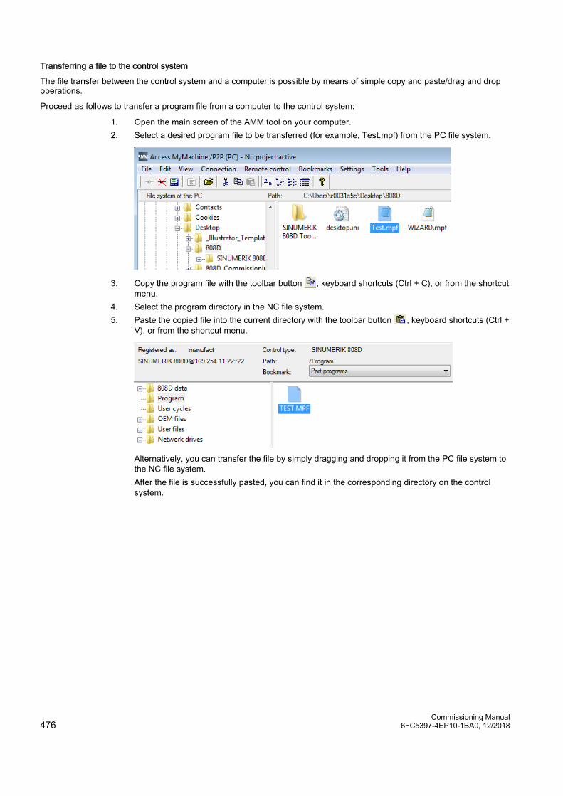
Commissioning Manual 476 6FC5397-4EP10-1BA0, 12/2018
Transferring a file to the control system
The file transfer between the control system and a computer is possible by means of simple copy and paste/drag and drop operations.
Proceed as follows to transfer a program file from a computer to the control system:
1. Open the main screen of the AMM tool on your computer. 2. Select a desired program file to be transferred (for example, Test.mpf) from the PC file system.
3. Copy the program file with the toolbar button , keyboard shortcuts (Ctrl + C), or from the shortcut menu.
4. Select the program directory in the NC file system. 5. Paste the copied file into the current directory with the toolbar button , keyboard shortcuts (Ctrl +
V), or from the shortcut menu.
Alternatively, you can transfer the file by simply dragging and dropping it from the PC file system to the NC file system.
After the file is successfully pasted, you can find it in the corresponding directory on the control system.
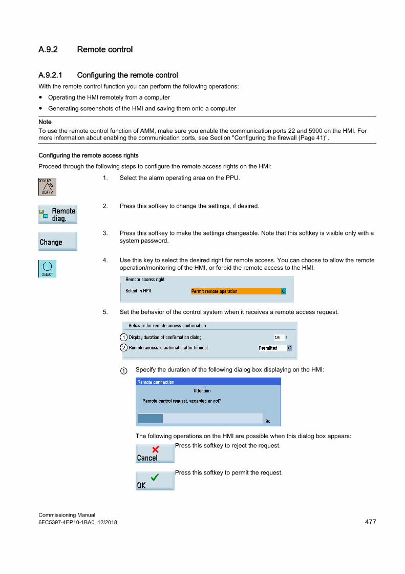
Commissioning Manual 6FC5397-4EP10-1BA0, 12/2018 477
A.9.2 Remote control
A.9.2.1 Configuring the remote control With the remote control function you can perform the following operations:
● Operating the HMI remotely from a computer
● Generating screenshots of the HMI and saving them onto a computer
Note To use the remote control function of AMM, make sure you enable the communication ports 22 and 5900 on the HMI. For more information about enabling the communication ports, see Section "Configuring the firewall (Page 41)".
Configuring the remote access rights
Proceed through the following steps to configure the remote access rights on the HMI:
1. Select the alarm operating area on the PPU.
2. Press this softkey to change the settings, if desired.
3. Press this softkey to make the settings changeable. Note that this softkey is visible only with a system password.
4. Use this key to select the desired right for remote access. You can choose to allow the remote operation/monitoring of the HMI, or forbid the remote access to the HMI.
5. Set the behavior of the control system when it receives a remote access request.
① Specify the duration of the following dialog box displaying on the HMI:
The following operations on the HMI are possible when this dialog box appears:
Press this softkey to reject the request.
Press this softkey to permit the request.
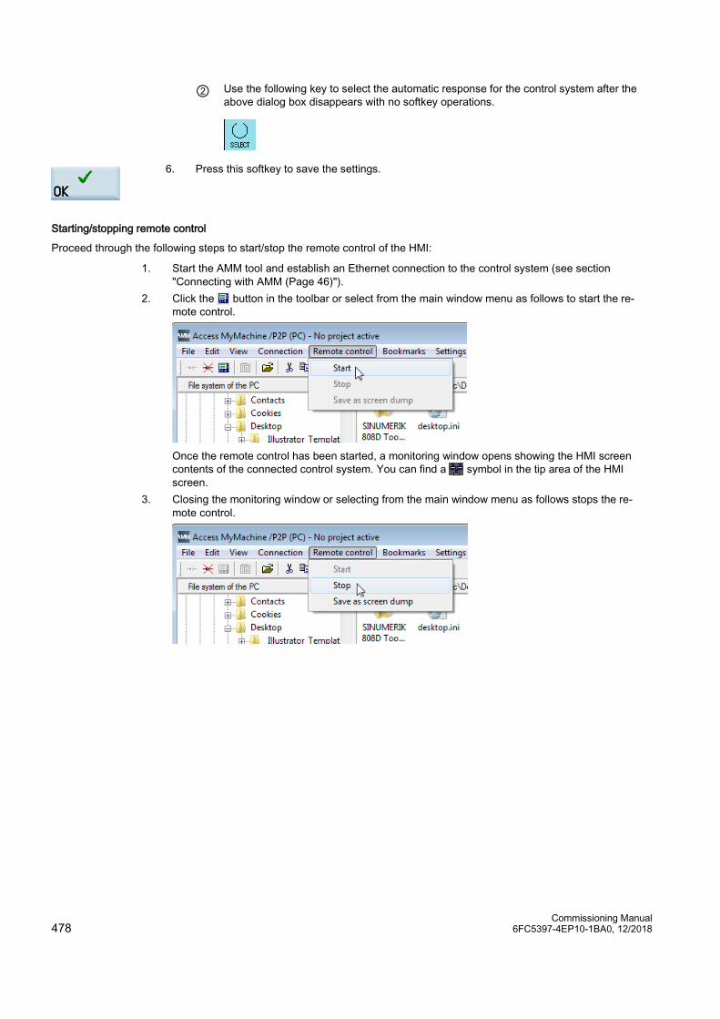
Commissioning Manual 478 6FC5397-4EP10-1BA0, 12/2018
② Use the following key to select the automatic response for the control system after the above dialog box disappears with no softkey operations.
6. Press this softkey to save the settings.
Starting/stopping remote control
Proceed through the following steps to start/stop the remote control of the HMI:
1. Start the AMM tool and establish an Ethernet connection to the control system (see section "Connecting with AMM (Page 46)").
2. Click the button in the toolbar or select from the main window menu as follows to start the re-mote control.
Once the remote control has been started, a monitoring window opens showing the HMI screen
contents of the connected control system. You can find a symbol in the tip area of the HMI screen.
3. Closing the monitoring window or selecting from the main window menu as follows stops the re-mote control.
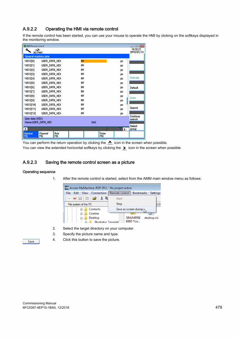
Commissioning Manual 6FC5397-4EP10-1BA0, 12/2018 479
A.9.2.2 Operating the HMI via remote control If the remote control has been started, you can use your mouse to operate the HMI by clicking on the softkeys displayed in the monitoring window.
You can perform the return operation by clicking the icon in the screen when possible. You can view the extended horizontal softkeys by clicking the icon in the screen when possible.
A.9.2.3 Saving the remote control screen as a picture
Operating sequence
1. After the remote control is started, select from the AMM main window menu as follows:
2. Select the target directory on your computer. 3. Specify the picture name and type.
4. Click this button to save the picture.

Commissioning Manual 6FC5397-4EP10-1BA0, 12/2018
Trademarks All names identified by ® are registered trademarks of Siemens AG. The remaining trademarks in this publication may be trademarks whose use by third parties for their own purposes could violate the rights of the owner.
Disclaimer of Liability We have reviewed the contents of this publication to ensure consistency with the hardware and software described. Since variance cannot be precluded entirely, we cannot guarantee full consistency. However, the information in this publication is reviewed regularly and any necessary corrections are included in subsequent editions.
Siemens AG Division Digital Factory Postfach 48 48 90026 NÜRNBERG GERMANY