DEPLOYMENT AND COMMISSIONING OF ENodeB's
54
مقراطية الشعبيةية الجزائرية الدي الجمهورRépublique algérienne démocratique et populaire تعلي وزارة ال ــلعال م ا ــ ي و البح ــعلم ث ال ــ يMinistère de l’enseignement supérieur et de la recherche scientifique لجامع المركز ا ـموشنت لعين ت يCentre Universitaire Belhadj Bouchaib d’Ain-Temouchent Institut des Sciences et de la Technologie Département de Génie Electrique Projet de fin d’études Pour l’obtention du diplôme de Master en : Domaine : SCIENCE ET TECHNOLOGIE Filière :ELETRONIQUE Spécialité : Génie Télécommunications Thème DEPLOYMENT AND COMMISSIONING OF E-NodeB’S Présenté Par : 1. Mlle.Haddou Souad 2. Mlle.Belromari Fatiha Devant les jurys composés de : Mr. Debal MCB C.U.B.B (Ain Temouchent) Président Mme. Slimane MCB C.U.B.B (Ain Temouchent) Encadreur Mr. Benmoussat MCB C.U.B.B (Ain Temouchent) Examinateur 2015/2016
-
Upload
khangminh22 -
Category
Documents
-
view
2 -
download
0
Transcript of DEPLOYMENT AND COMMISSIONING OF ENodeB's
الجمهورية الجزائرية الديمقراطية الشعبية
République algérienne démocratique et populaire
يــث العلمــي و البحــم العالــوزارة التعلي
Ministère de l’enseignement supérieur et de la recherche
scientifique ي لعين تموشنتـالمركز الجامع
Centre Universitaire Belhadj Bouchaib d’Ain-Temouchent
Institut des Sciences et de la Technologie
Département de Génie Electrique
Projet de fin d’études
Pour l’obtention du diplôme de Master en :
Domaine : SCIENCE ET TECHNOLOGIE
Filière :ELETRONIQUE
Spécialité : Génie Télécommunications
Thème
DEPLOYMENT AND COMMISSIONING OF E-NodeB’S
Présenté Par :
1. Mlle.Haddou Souad
2. Mlle.Belromari Fatiha
Devant les jurys composés de :
Mr. Debal MCB C.U.B.B (Ain Temouchent) Président
Mme. Slimane MCB C.U.B.B (Ain Temouchent) Encadreur
Mr. Benmoussat MCB C.U.B.B (Ain Temouchent) Examinateur
2015/2016

Acknowledgement
In the course of this project We got an insight into ZTE Corporation ,came to
know a lot about wireless communication ,Deployment of 4G network .First and
foremost We are very proud to be a students of University Center Belhadj Bouchaib -
Ain Temouchent. We avail this opportunity to convey our sincere thanks to Mr.Mouass ,the
manager of AT ZTE LTE Project.
We are thankful to Dr Abdelmalek (Slimane), our project guide for
recommending us the necessary information for the report. For her exemplary
guidance, valuable feedback and constant encouragement throughout the duration of
the project. Her valuable suggestions were of immense help through our project work.
Her perceptive criticism kept us working to make this project in a much better way.
Working under her was an extremely knowledgeable experience for us. We must
acknowledge as well the members of our dissertation committee, Dr.Debal and
Dr.Benmoussat, have generously given their time and expertise to better our work. For
their encouragement, insightful comments and questions. We thank them for their
contribution and their good-natured support.
Our acknowledgement would be incomplete if we didn’t thank our team mates.
During the research period we have developed a camaraderie which was very healthy and
enjoyable. We are grateful for everyone’s support and help when needed also to Dr. Kaid Omar
Omar and Mr.Abderahman Boualaoui. Without them this training would not have been the
same.
We are also thankful to our family members and friends who had given us their
constructive advice, educative suggestions, encouragement and co-operation to
prepare this report.

DEPLOYMENT AND COMMISSIONING OF ENodeB’s
GT M2 Page 3
We dedicate our dissertation work to our families and many friends. A special feeling of
gratitude to our loving parents, whose words of encouragement and push for tenacity ring in our
ears, our parents, have been a strong and steadfast support in our journey. They taught us the
value of life and faithful love. Especially the newborn Mouhamed Amir, Our sisters and
brothers, have never left our side and are very special.
We also dedicate this dissertation to our many friends and church family who have
supported us throughout the process. We will always appreciate all they have done.
We dedicate this work and give special thanks to our for being there for me throughout
the entire engineer program.
DEPLOYMENT AND COMMISSIONING OF ENodeB’s
GT M2 Page 4
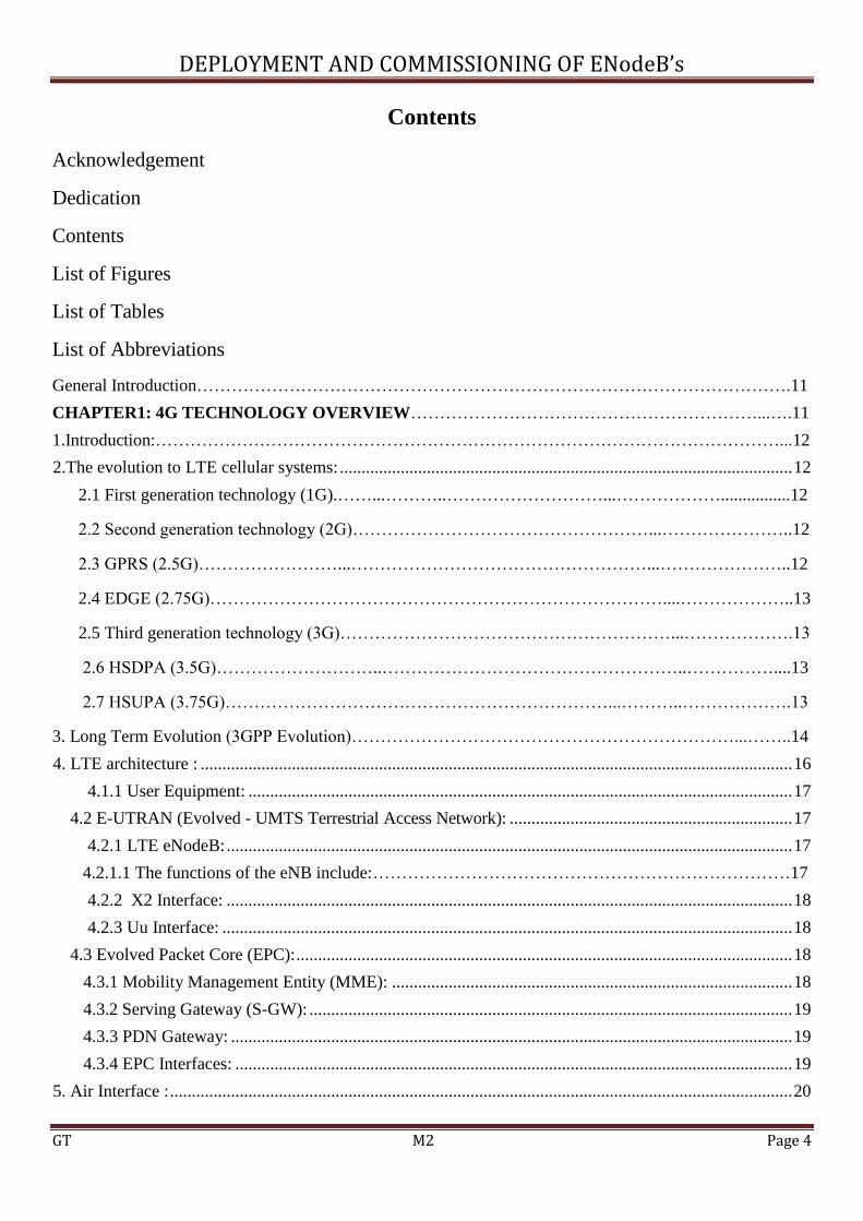
Contents
Acknowledgement
Dedication
Contents
List of Figures
List of Tables
List of Abbreviations
General Introduction………………………………………………………………………………………….11
CHAPTER1: 4G TECHNOLOGY OVERVIEW……………………………………………………...….11
1.Introduction:………………………………………………………………………………………………...12
2.The evolution to LTE cellular systems: ........................................................................................................ 12
2.1 First generation technology (1G).……...………..………………………...………………................12
2.2 Second generation technology (2G)……………………………………………...…………………..12
2.3 GPRS (2.5G)……………………...……………………………………………...…………………..12
2.4 EDGE (2.75G)……………………………………………………………………....………………..13
2.5 Third generation technology (3G)…………………………………………………...……………….13
2.6 HSDPA (3.5G)………………………..……………………………………………..……………....13
2.7 HSUPA (3.75G)…………………………………………………………...………..……………….13
3. Long Term Evolution (3GPP Evolution)…………………………………………………………...……..14
4. LTE architecture : ........................................................................................................................................ 16
4.1.1 User Equipment: ............................................................................................................................. 17
4.2 E-UTRAN (Evolved - UMTS Terrestrial Access Network): ................................................................. 17
4.2.1 LTE eNodeB: .................................................................................................................................. 17
4.2.1.1 The functions of the eNB include:………………………………………………………………17
4.2.2 X2 Interface: .................................................................................................................................. 18
4.2.3 Uu Interface: ................................................................................................................................... 18
4.3 Evolved Packet Core (EPC): .................................................................................................................. 18
4.3.1 Mobility Management Entity (MME): ............................................................................................ 18
4.3.2 Serving Gateway (S-GW): ............................................................................................................... 19
4.3.3 PDN Gateway: ................................................................................................................................. 19
4.3.4 EPC Interfaces: ................................................................................................................................ 19
5. Air Interface : ............................................................................................................................................... 20

DEPLOYMENT AND COMMISSIONING OF ENodeB’s
GT M2 Page 5
5.1 LTE Spectrum : .................................................................................................................................... 20
5.2 OFDMA/SC-FDMA Multiplexing technologies: ................................................................................. 20
5.3 FDD/TDD Duplexing technology: ....................................................................................................... 21
5.4 LTE Frame structure: ............................................................................................................................ 21
5.4.1 FDD Frame structure: ..................................................................................................................... 21
5.4.2 TDD frame structure: ...................................................................................................................... 22
5.4.3 Cyclic prefix………………………………………………………………………………………22
5.5 LTE Resource blocks: .................................................................................................................. 22
5.6 Radio channels……………………………………………………………………………………...23
5.6.1 Logical channels: .......................................................................................................................... 25
5.6.2 Transport channels: ......................................................................................................................... 26
5.6.3 Physical channels ............................................................................................................................ 26
5.7 Multiple-Input Multiple Output antenna technology(MIMO): ............................................................. 27
6. Requirements of LTE : ............................................................................................................................... 28
7.Conclusion: ................................................................................................................................................... 28
CHAPTER 2: DEPLOYMENT AND COMMISSIONING OF ENODEB‘s….…………………………28
1.Introduction:.................................................................................................................................................. 29
2. Site Survey: .................................................................................................................................................. 29
2.1 LTE RF survey: .................................................................................................................................... 29
2.2 Need of LTE survey:............................................................................................................................. 29
2.3 Before the survey: ........................................................................................................................... 29
2.4Tool Kit for LTE RF survey: ................................................................................................................. 29
2.5 Procedure of RF survey: ....................................................................................................................... 30
3.eNodeB Installation: ..................................................................................................................................... 30
3.1 Outdoor installation : .............................................................................................................................. 30
3.1.1 Remote Radio Unit RRU installation : ............................................................................................ 30
3.1.2 Antenna: ............................................................................................................................................ 31
3.1.2.1 Antenna Tilt : ............................................................................................................................. 31
3.2 Indoor installation: ................................................................................................................................. 31
3.2.1 BBU processing boards: .................................................................................................................... 32
3.2.2 Benefits of BBU+RRU Structure: ..................................................................................................... 33
4. Commissioning of the eNodeBs : ................................................................................................................ 33
4.1 Commissioning preparation: ................................................................................................................... 33
4.1.1 Planning Data Preparation : .............................................................................................................. 33
4.2 Commissioning Execution: ..................................................................................................................... 34
4.3 Troubleshooting : .................................................................................................................................... 34
4.3.1 e-NodeB Troubleshooting: ............................................................................................................... 34
DEPLOYMENT AND COMMISSIONING OF ENodeB’s
GT M2 Page 6
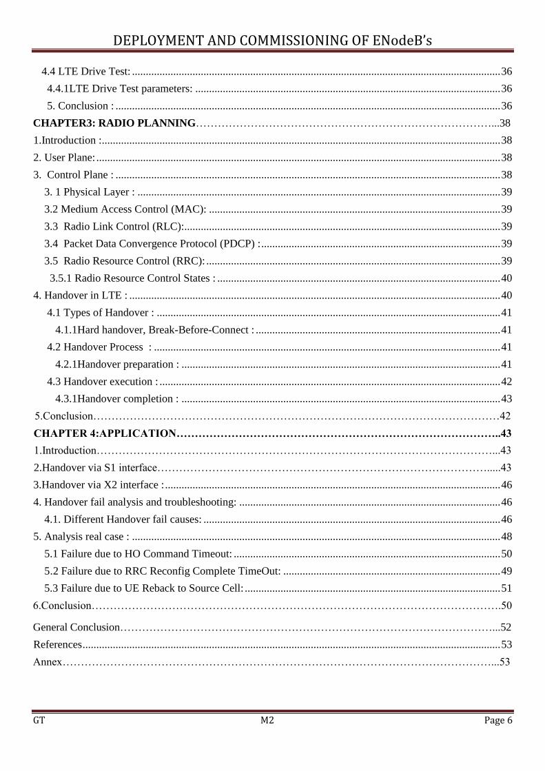
4.4 LTE Drive Test: ...................................................................................................................................... 36
4.4.1LTE Drive Test parameters: ............................................................................................................... 36
5. Conclusion : ............................................................................................................................................ 36
CHAPTER3: RADIO PLANNING………………………………………………………………………...38
1.Introduction :................................................................................................................................................. 38
2. User Plane: ................................................................................................................................................... 38
3. Control Plane : ............................................................................................................................................ 38
3. 1 Physical Layer : .................................................................................................................................... 39
3.2 Medium Access Control (MAC): .......................................................................................................... 39
3.3 Radio Link Control (RLC):................................................................................................................... 39
3.4 Packet Data Convergence Protocol (PDCP) : ....................................................................................... 39
3.5 Radio Resource Control (RRC): ........................................................................................................... 39
3.5.1 Radio Resource Control States : ....................................................................................................... 40
4. Handover in LTE : ....................................................................................................................................... 40
4.1 Types of Handover : ............................................................................................................................. 41
4.1.1Hard handover, Break-Before-Connect : ......................................................................................... 41
4.2 Handover Process : .............................................................................................................................. 41
4.2.1Handover preparation : .................................................................................................................... 41
4.3 Handover execution : ............................................................................................................................ 42
4.3.1Handover completion : .................................................................................................................... 43
5.Conclusion…………………………………………………………………………………………………42
CHAPTER 4:APPLICATION……………………………………………………………………………..43
1.Introduction………………………………………………………………………………………………...43
2.Handover via S1 interface……………………………………………………………………………….....43
3.Handover via X2 interface : .......................................................................................................................... 46
4. Handover fail analysis and troubleshooting: ............................................................................................... 46
4.1. Different Handover fail causes: ............................................................................................................ 46
5. Analysis real case : ...................................................................................................................................... 48
5.1 Failure due to HO Command Timeout: ................................................................................................. 50
5.2 Failure due to RRC Reconfig Complete TimeOut: ............................................................................... 49
5.3 Failure due to UE Reback to Source Cell: ............................................................................................. 51
6.Conclusion………………………………………………………………………………………………….50
General Conclusion…………………………………………………………………………………………...52
References ........................................................................................................................................................ 53
Annex………………………………………………………………………………………………………...53
DEPLOYMENT AND COMMISSIONING OF ENodeB’s
GT M2 Page 7
List of Figures
Figure1-1: wireless technology evolution ……………………. ……………………………….11
Figure1-2 :3GPP Roadmap ..……………………………………………………………............14
Figure1-3 :LTE Architecture……………………………………………………………………15
Figure 1-4: eNodeB………………………………………………………………………...........16
Figure1-5: eNB functions…………………………………………………………….….…........17
Figure1-6:OFDMA vs. SC-FDMA ………………………………………………….……….....20
Figure1-7: Type1 4G frame structure for FDD ……………………………………………........21
Figure1-8: Type2 4G frame structure for TDD …………………………………………….......22
Figure 1-9: Use of cyclic prefix as a guard interval (normal CP) ……………………………...22
Figure 1-10: Resource Elements and Resource Blocks ………………………………………..23
Figure1-11: Model of a MIMO system two TX / RX ………………………………..................25
Figure 2-1: BBU (ZXSDR B8200 L200) Physical Structure…………………………………..30
Figure 2-2 : Control & Clock board………………………………………………………….....32
Figure 3-1: LTE Architecture protocol………………………………………………..………..39
Figure 3-2: Handover preparation ………………………………………………..……………..40
Figure 3-3:Handover execution ……………………………………………..………………….41
Figure 3-4: Handover completion …………………………………….………………………...42
Figure 4-1:Handover via S1 interface…………………………………..………………….........43
Figure 4-2:Handover via X2 interface………………………………………………………......46
Figure 4-3: X2 interface implementation…………………………………………………….....47
Figure 4-4: Failure due to RRC reconfig complete timeout………………………………..…..47
Figure 4-5: Failure due to UE Reback to Source Cell……………………………………..…...48
Figure 5-1: BBU Location……………………………………………………………………...51
Figure 5-2: RRU Location……………………………………………………………………...51
Figure 5-3: Antenna………………………………………………………………………….....51
Figure 5-4: Electrical Tilt…………………………………………………………………….....51

DEPLOYMENT AND COMMISSIONING OF ENodeB’s
GT M2 Page 8
List of Tables
Table 1-1:4G/ LTE Spectrum ……………………………………………......... ..17
Table 1-2 :4G Bandwidth configurations ………………………………………………..22
Table 2-1: e-NodeB equipment specification ……………………………………………28
Table 2-2: Board List of BBU (B8200) ………………….………………………………30
Table 2-3: eNodeB Configuration Templates…………………………………………….31
Table 1-4 :e-NodeB Troubleshooting ………………………………………………….…33
Table 2-5: LTE Drive Test parameters…………………………………………………...37
Table 4-1: Handover KPI……………………………………………………………….…44
Table 4-2: Handover fail causes…………………………………………………………..45
DEPLOYMENT AND COMMISSIONING OF ENodeB’s
GT M2 Page 9
List of Abbreviations
A ACK : Acknowledgement
AMR: Adaptive Multi-Rate
AMC: Adaptive Modulation and Coding
B BW : Bandwidth
BER : Bit Error Rate
BCH : Broadcast Channel
BCCH: Broadcast Control Channel
C CCCH: Common Control Channel
CDMA : Code division Multiple Access
CP: Cyclic Prefix
CQI: Channel Quality Indicator
D DTCH: Dedicated Traffic Channel
DL-SCH : Downlink Shared
DFT : Discrete Fourier Transform I
DCCH: Dedicated Control Channel DL
Downlink
E EIRP: Effective Isotropic Radiation
Power
EPS :Evolved Packet System
EPC :Evolved Packet Core
eNB: Evolved Node B
E-UTRAN: Evolved UMTS Terrestrial
epa5 :Extended Pedestrian
eva70: Extended Vehicle A
etu300: Extended Typical Urban
F
FDD: Frequency Division Duplexing
FFT :Fast Fourier Transform
G GAN :Generic Access Network
GSM :Global system for Mobile
GPRS: General Packet Radio Service
GGSN: Gateway GPRS Support Node
GTP: GPRS Tunneling Protocol
H HARQ :Hybrid Automatic Repetition
Request
HSDPA :High Speed Downlink Packet
Access
HSUPA: High-Speed Uplink Packet
Access Channel
HSS:Home Subscriber Server
I IFFT: Inverse Fast Fourier Transform
IDFT: Inverse Discrete Fourier
Transform
IMS :IP Multimedia Subsystem
ISI: Inter-Symbol-Interference
L LTE: Long Term Evolution
M MBMS: Multimedia Broadcast Multicast
Service
MCCH :Multicast Control Channel
MME: Mobility Management Entity
MIMO: Multiple Input Multiple Output
MTCH :Multicast Traffic Channel
MCH :Multicast Channel
MAC: Medium Access Control
MISO: Multiple Input Single Output

DEPLOYMENT AND COMMISSIONING OF ENodeB’s
GT M2 Page 10
M MAPL: Maximum Allowed Path Loss
N NRB: Number of Resource Blocks
O OFDM :Orthogonal Frequency Division
Multiplexing
OLSM: Open Loop Spatial Multiplexing
P PAPR :Peak to Average Power Ratio
P-GW: Packet Gateway
P-SCH :Primary Synchronization Channel
PCCH :Paging Control Channel
PCH :Paging Channel
PMCH :Physical Multicast Channel U
PBCH: Physical Broadcast Channel
PDSCH:Physical Downlink Shared
Channel
PCFICH: Physical Control Format
Indicator Channel
PDCCH :Physical Downlink Control
Channel
PHICH: Physical Hybrid Indicator
Channel
PN :Pseudo random Noise code
PUSCH: Physical Uplink Shared Channel
PUCCH:Physical Uplink Control Channel
PRACH:Physical Random Access Channel
Q QAM :Quadrature Amplitude Modulation
QPSK :Quadrature Phase Shift Keying
QoS: Quality of Service
QUL : Loading In The Uplink
QDL: Loading In The Downlink
R RB :Resource Blocks
S
SAE: System Architecture Evolution
SC :Single Carrier
SINR:Signal Interferance-plus-noise Ratio
S-GW: Serving Gateway
SAE System Architecture Evolution
SIMO: Single Input Multiple Output
SISO: Single Input Single Output
SNR: Signal to Noise Ratio
S-SCH:Secondary Synchronization
Channel
T
TDMA: Time division Multiple Access
TDD: Time Division Duplexing
TMA :Tower Mounted Amplifier
TTI :Transmission Time Interval
U
UMTS:Universal Mobile
Telecommunications System
UE: User Equipment
UL: Uplink
UML: Unified Modeling Language
UL-SCH :Uplink Shared channel
V
VOIP: Voice over IP
WLAN :Wireless Local Area Network

DEPLOYMENT AND COMMISSIONING OF ENodeB’s
GT M2 Page 11
General Introduction
Third-generation (3G) mobile networks face a new rival: so-called 4G. And astonishingly
the new networks may even be profitable. Alvin Toffler, an eminent futurologist, once said, “THE
FUTURE ALWAYS COMES TOO FAST, BUT IN THE WRONG ORDER”. The state of Wireless
telecoms is a classic example. Even as 3G mobile networks are being switched on around the world,
a couple of years later than planned, attention is shifting to what comes next: a group of newer
technologies that are, inevitably, being called Fourth Generation Mobile Networks (4G). 4G is all
about an integrated, global network that based on an open systems approach. The goal of 4G is to
replace the current proliferation of core cellular networks with as single worldwide cellular core
network standard based on IP for control, video, packet data, and VoIP. This integrated 4G mobile
system provides wireless users an affordable broadband mobile access solutions for the applications
of secured wireless mobile Internet services with value-added QoS. This paper gives the reasons for
the evolution of 4G, though 3G has not deployed completely. And then gives the information on the
structure of the transceiver for 4G followed by the modulation techniques needed for the 4G. Later
this gives the information about the 4G processing .Finally concludes with futuristic views for the
quick .

DEPLOYMENT AND COMMISSIONING OF ENodeB’s
GT M2 Page 12
CHAPTER1: 4G/LTE TECHNOLOGY OVERVIEW
1.Introduction:
Based on the study, LTE technology is in a deployment stage. Although LTE wireless technology
offers higher data rates and the ability to roam across multiple heterogeneous wireless networks,
several issues require further research and development. Since LTE is still in the cloud of the
sensible standards creation, ITU and IEEE form several task forces to work on the possible
completion for the 4G mobile standards as well. 3GPP LTE is an evolution standard form UMTS,
and WiMAX is another candidate from IEEE. These technologies have different characteristics and
try to meet 4G characteristics to become a leading technology in the future market. Under these
circumstances, this chapter will present about the current trends and its underlying technologies to
implement the LTE technology. This chapter also shows some of the possible scenarios that will
benefit the LTE technology.
2.The evolution to 4G cellular systems:
Mobile networks have evolved through more than three generations, starting with the analogue or
first-generation (1G) networks deployed in the early 1980s, and moving on to the digital second-
generation (2G) networks deployed in the early 1990s. Operators started to deploy 3G networks in
2001-03, and 3.5G networks from around 2005. Networks still in the design phase include 3.9G and
4G systems, which are expected to be deployed in the 2008-2010 and 2010-2020 time frames,
respectively.
Figure 1-1: wireless technology evolution

DEPLOYMENT AND COMMISSIONING OF ENodeB’s
GT M2 Page 13
2.1 The First Generation technology (Analog 1G):
In 1980 the mobile cellular time had started. The First-generation mobile systems worn analog
transmission for talking services. In 1979, the first cellular system in the world became outfitted by
Nippon Telephone and Telegraph (NTT) in Tokyo and Japan. These systems offered handover and
roaming capabilities but the cellular networks were unable to interoperate between countries. This
was one of the inevitable disadvantages of first-generation mobile networks. In the United States, the
Superior Mobile Phone System (SMPS) was launched in 1982. The system was allocated a 40-MHz
bandwidth within the 800 to 900 MHz frequency range. The first deployed in Chicago, with a service
area of 2100 square miles. SMPS offered 832 channels, with a data rate of 10 kbps. Although Omni
directional antennas we are used in the earlier SMPS implementation, it was realized that using
directional antennas would yield better cell reuse. In fact, the smallest reuse factor that would fulfill
the 18db signal-to-interference ratio (SIR) using 120-degree directional antennas was found to be 7.
Hence, a 7-cell reuse pattern was adopted for SMPS. Transmissions from the base stations to mobiles
occur over the forward channel using frequencies between 869-894 MHz. The reverse channel is
used for transmissions from mobiles to base station, using frequencies between 824-849MHz.The
Traffics multiplexed onto an FDMA (frequency division multiple access) system.[1]
2.2 Second Generation Technology (2G):
In 1991, Second generation 2G cellular telecom networks were commercially launched the GSM
standard in Finland. The primary benefits of 2G networks over 1G predecessor were that phone
conversations were digitally encrypted. 2G systems were significantly more efficient on the spectrum
allowing for far greater mobile phone penetration levels; and 2G introduced data services for mobile,
starting with SMS text messages. 2G technologies enabled the various mobile phone networks to
provide the services such as text messages, picture messages and MMS (Multi Media Messages).
After 2G was launched, the previous mobile telephone systems were retrospectively dubbed 1G.
While radio signals on 1G networks are analog, radio signals on 2G networks are digital. Both
systems use digital signaling to connect the radio towers (which listen to the handsets) to the rest of
the telephone system.[2]
2.3 GPRS (General Packet Radio Service) 2.5G:
2.5G, which stands for "second and a half generation," is a cellular wireless technology
developed in between its predecessor, 2G, and its successor, 3G. The term "second and a half
generation" is used to describe 2G-systems that have implemented a packet switched domain in
addition to the circuit switched domain. "2.5G" is an informal term, invented solely for marketing
purposes, unlike "2G" or"3G" which are officially defined standards based on those defined by the
International Telecommunication (ITU). GPRS could provide data rates from 56 kbit/s up to 115
kbit/s. It can bused for services such as Wireless Application Protocol (WAP) access, Multimedia
Messaging Service (MMS), and for Internet communication services such as email and World Wide
Web access. GPRS data transfer is typically charged per megabyte of traffic transferred, while data
communication via traditional circuit switching is billed per minute of connection time, independent
of whether the user actually is utilizing the capacity or is in an idle state.2.5G networks may support
services such as WAP, MMS, SMS mobile games, and search and directory.[3]

DEPLOYMENT AND COMMISSIONING OF ENodeB’s
GT M2 Page 14
2.4 EDGE (Enhanced Data rates for GSM Evolution or Enhanced GPRS) 2.75:
EDGE (EGPRS) is an abbreviation for Enhanced Data rates for GSM Evolution, is a digital
mobile phone technology which acts as a bolt-on enhancement to 2G and 2.5G General Packet Radio
Service (GPRS) networks. This technology works in GSM networks. EDGE is a superset to GPRS
and can function on any network with GPRS deployed on it, provided the carrier implements then
necessary upgrades. EDGE technology is an extended version of GSM. It allows the clear and fast
transmission of data and information. It is also termed as IMT-SC or single carrier. EDGE
technology was invented and introduced by Cingular, which is now known as AT& T. EDGE is
radio technology and is a part of third generation technologies. EDGE technology is preferred over
GSM due to its flexibility to carry packet switch data and circuit switch data.[4]
2.5 Third Generation Technology (3G – 3.75G):
The third generation, as the name suggest, follows two previous generations. The Early SMPS
networks used Frequency Division Multiplexing Access (FDMA) to carry analog voice over
channels in the 800 MHz frequency band. 3G technologies enable network operators to offer users a
wider range of more advanced services while achieving greater network capacity through improved
spectral efficiency. Services contain wide area wireless voice telephony, video calls, and broadband
wireless data, all in a mobile environment. The High-Speed Packet Access (HSPA) is a collection of
mobile telephony protocols that extend and advance the performance of existing UMTS protocols.
The basic feature of 3G Technology is fast data transfer rates. 3G technology is much flexible,
because it is able to support the five major radio technologies. These radio technologies operate
under CDMA, TDMA and FDMA.[5]
2.6 HSDPA (High-Speed Downlink Packet Access) 3.5G:
High-Speed Downlink Packet Access (HSDPA) is a mobile telephony protocol, also called 3.5G
(or"3½G"), which provides a smooth evolutionary path for UMTS-based 3G networks allowing for
higher data transfer speeds. HSDPA is a packet-based data service in W-CDMA downlink with data
transmission up to 8-10 Mbit/s (and 20 Mbit/s for MIMO systems) over a 5MHz bandwidth in
WCDMA downlink. HSDPA implementations includes Adaptive Modulation and Coding (AMC),
Multiple-Input Multiple-Output (MIMO), Hybrid Automatic Request (HARQ), fast cell search, and
advanced receiver design.
2.7 HSUPA (High-Speed Uplink Packet Access) 3.75G:
The 3.75G refer to the technologies beyond the well defined 3G wireless/mobile technologies.
High-speed Uplink Packet Access (HSUPA) is a UMTS / WCDMA uplink evolution technology.
The HSUPA mobile telecommunications technology is directly related to HSDPA and the two are
gracious to one another. HSUPA will enhance advanced person-to-person data applications with
higher and symmetric data rates, like mobile e-mail and real-time person-to person gaming.
Traditional useful applications along with many consumer applications will benefit from enhanced
uplink speed. HSUPA will initially boost the UMTS / WCDMA uplink up to 1.4Mbps and in later
releases up to5.8Mbps.[6]

DEPLOYMENT AND COMMISSIONING OF ENodeB’s
GT M2 Page 15
3. Long Term Evolution (3GPP evolution):
3GPP, the body which defined the LTE specifications, has a well established evolutionary scheme
that is likely to continue for some time.
Release 99 (R99) defined the original dual-domain UMTS system that supports both circuit-
switched voice services and packet switched access.
Release 4 (R4) saw the earliest phase of network IP adoption with the deployment of a
bearer-independent circuit-switched architecture that disassociated the telephone switches
into media gateways and controllers (soft switches).
Releases 5 through 7 are dominated by techniques to increase the spectral efficiency, and
thereby extend the viability of the limited underlying W-CDMA technology. The resulting
HSPA+ (High Speed Packet Access, with enhancements) can theoretically achieve peak data
rates of 42 Mbps under ideal conditions. In addition to improving spectral efficiency, R5
specifies the initial design of IP Multimedia Subsystem (IMS) – an IP services environment.
Release 8 (R8) defines the Long Term Evolution (LTE) system as a break with the past. It
marks the start the transition to 4G technologies and networks.
Release 9 (R9) offers enhancements to LTE, including definition of Home eNodeBs for
improved residential and in-building coverage.
Figure 1-2: 3GPP Roadmap
LTE is the trademarked project name of a high performance air interface for cellular mobile
telephony. It is a project of the 3rd Generation Partnership Project (3GPP), operating under a named
trademarked by one of the associations within the partnership, the European Telecommunications
Standards Institute.We can consider LTE is the first step toward the 4th generation (4G) of radio
technologies designed to increase the capacity and speed of mobile telephone networks. Where the
current generation of mobile telecommunication networks are collectively known as 3G, LTE is
marketed as 4G. Ideally, LTE is a 3.9G technology since it does not fully comply with the IMT
Advanced 4G requirements.[7]

DEPLOYMENT AND COMMISSIONING OF ENodeB’s
GT M2 Page 16
Due to LTE promises features Global Major Telecommunications companies like Verizon
Wireless and AT&T Mobility in the United States and several worldwide carriers announced plans,
beginning in end of 2009, to convert their networks to LTE. The world's first publicly available
LTEservice was opened in the two Scandinavian capitals Stockholm and Oslo only five months ago
on the 14th of December 2009.
The latest standard in the mobile network technology tree is Long Term Evolution stander also is a
set of enhancements to the Universal Mobile Telecommunications System (UMTS) which was
introduced in 3rd
Generation Partnership Project (3GPP) Release 8. Much of 3GPP Release 8 focuses
on adopting 4G mobile communications technology, including an all-IP flat networking architecture.
The main goal of LTE is to provide a high data rate, low latency and packet optimized radioaccess
technology supporting flexible bandwidth deployments. Same time its network architecture has been
designed with the goal to support packet-switched traffic with seamless mobility and great quality of
service.[8]
4. LTE/4G architecture :
The LTE network is based on a “flat” IP architecture. This means that minimal functionality is
incorporated into the network and all User and Control Plane traffic is transported in IP datagram. In
this section the principle functions and interfaces required to support LTE operation and services are
discussed. This includes the role of the UE, the E-UTRAN and the Evolved Packet Core. The
function of eNB in terms of admission, resource management and mobility are explored as well as
the role of the MME to support security, Idle Mode and bearer management within the EPC Likewise
the role of the Serving and PDN Gateway is explained. Along with the functions it describes the
architecture of the Uu, X2 and S1 interfaces and the protocols supported on these are outlined.
Figure1-3 :LTE Architecture

DEPLOYMENT AND COMMISSIONING OF ENodeB’s
GT M2 Page 17
4.1Evolved - UMTS Terrestrial Access (E-UTRA):
4.1.1 User Equipment:
The mobile device, like UMTS is termed the UE (User Equipment) and this provides the LTE
modem service to the applications and features residing on the device that access and interact across
the bearer networks User Plane.
4.2 E-UTRAN (Evolved - UMTS Terrestrial Access Network):
Within the E-UTRAN the functionality of the NodeB and the RNC (Radio Network Controller)
has been combined into a common node termed the eNB (Evolved NodeB).
4.2.1 4G eNodeB:
Compared with UTRAN, the E-UTRAN OFDM-based structure is quite simple. It is only
composed of one network element: the eNodeB (for evolved Node B.). The 3G RNC (Radio
Network Controller) inherited from the 2G BSC (Base Station Controller) has disappeared from E-
UTRAN and the eNodeB is directly connected to the Core Network using the S1 interface. As a
consequence, the features supported by the RNC have been distributed between the eNodeB or the
Core Network MME or Serving Gateway entities.
Figure 1-4: eNodeB
4.2.1.1 The functions of the eNB include:
Radio Resource Management - this process involves the allocation of physical radio
resources to the mobile for uplink and downlink transmission. In terms of allocation this also
includes admission and commitment of the requested radio resource or the downgrade of this
resource due to availability.
Data Compression - IP compression is performed using PDCP (Packet Data Convergence
Protocol). This process involves the compression of the IP header.
User Data Encryption - encryption of the radio link is performed by the eNB. It should be
noted that this only protects the data across the air.

DEPLOYMENT AND COMMISSIONING OF ENodeB’s
GT M2 Page 18
Figure1-5: eNB functions
Routing - this process involves the forwarding of control plane signalling across the S1 interface
towards the MME (Mobility Management Entity). Likewise User Plane traffic is routed to the S-
GW (Serving Gateway).[9]
4.2.2 X2 Interface:
The X2 Interface connects eNB together. This interface should be an open interface enabling
eNB from different manufacturers to work together. The X2 supports signaling and the transport of
user data between eNB as well as extending the S1 interface when two or more eNB are involved
in the path between the mobile and the MME/S-GW.
4.2.3 Uu Interface:
The Uu Interface, like the S1 and X2 interface contains a Control Plane and a User Plane. In the
Control Plane the principle control protocol is RRC (Radio Resource Control). User Plane traffic
is transported using PDCP.
4.3 Evolved Packet Core (EPC):
The EPC comprises of the MME and a Gateway. The MME supports the Control Plane
functionality within the EPC. Gateway functionality, that supports switching of the User Plane, may
be divided into the S-GW and PDN (Packet Data Network) Gateway.
4.3.1 Mobility Management Entity (MME):
The MME is responsible for the following functions:
NAS (Non Access Stratum) Signaling - NAS signaling includes MM (Mobility
Management) and SM (Session Management) information. This includes procedures such
as Location Updating and Service Data Flow establishment etc. The MME is also
responsible for signaling security between itself and the UE.

DEPLOYMENT AND COMMISSIONING OF ENodeB’s
GT M2 Page 19
Idle Mode - while the UE is in the Idle Mode its position is tracked by the MME to the
granularity of a Tracking Area. As well as tracking the mobile the MME will issue paging
messages to the eNB associated with the relevant tracking area if data arrives for the UE.
Inter MME Mobility - if a handover involves changing the point of attachment within the
EPC, this may involve an Inter MME handover. If this is the case, the serving MME will
select the most appropriate target MME with which to conduct this process.
Authentication - the MME interacts with functions such as the HSS (Home Subscriber
Server) to obtain AAA (Access Authentication and Accounting) information with
which to authenticate the subscriber.
4.3.2 Serving Gateway (S-GW):
The S-GW is responsible for the following functions:
Mobility - the S-GW acts as the mobility anchor point for the User Plane during handovers
between eNB. Likewise it must also anchor mobility for inter 3GPP handovers.
Data Buffering - when traffic arrives for a UE in the Idle state, the S-GW must buffer this
traffic prior to the UE entering the Active state. Transition to the active state will be
through interaction with the MME and subsequent paging of the UE.
Routing - traffic must be routed to the correct eNB or towards the PDN.
4.3.3 PDN Gateway:
The PDN Gateway terminates the S-GW interface and is responsible for the following
functions:
Policy Enforcement - as part of the LTE security procedures policy information from the
AAA server in the subscriber’s home network will be downloaded to the EPC. The PDN
Gateway is responsible for monitoring traffic characteristics on a subscriber by subscriber
basis to ensure that the agreed traffic policy is being adhered.
Packet Filtering and Screening
Accounting - charging support is located at the PDN Gateway to monitor volumes and
traffic types.
IP Address Allocation - IP addressing information for the UE is allocated by the PDN
Gateway. This is included as part of the initial bearer establishment.
4.3.4 EPC Interfaces:
The EPC interfaces are denoted by the letter “S”. In terms of the User Plane, transport of traffic
is based on GTP (GPRS Tunneling Protocol). The Control Plane uses various protocols which may be
specific to the 3GPP or IETF (Internet Engineering Task Force) The principle interfaces that relate to
the EPC are the:
S1-MME - this supports the S1 Application Protocol between the E-UTRAN and the MME.
S1-U - this supports GTPu Protocol between the E-UTRAN and the S-GW for the transport
of User Plane traffic.[10]

DEPLOYMENT AND COMMISSIONING OF ENodeB’s
GT M2 Page 20
5. Air Interface:
3GPP have developed an air interface for LTE that is able to support enhanced services, voice and
other real time services. This section discusses the possible frequency allocation for LTE operation,
as well as the evolved radio access and the concepts of OFDMA and SC-FDMA that define the
structure of the physical layer. The format of the uplink and downlink frames are explained,
including the concepts of slots, sub frames and resources blocks.
5.1 LTE Spectrum:
There are a growing number of LTE frequency bands that are being designated as possibilities for
use with LTE. Many of the LTE frequency bands are already in use for other cellular systems,
whereas other LTE bands are new and being introduced as other users are re-allocated spectrum else
where.
Table1-1: 4G/ LTE Spectrum
Although these bands could potentially be used for 4G systems however they come
with their own sets of issues. These include available bandwidth, competition with
existing technologies within the band and the radio propagation characteristics of the
frequencies within these bands.
5.2 OFDMA/SC-FDMA Multiplexing technologies:
One of the key elements in LTE is the use of OFDM, Orthogonal Frequency Division
Multiplex, as the signal bearer and the associated access schemes, OFDMA (Orthogonal
Frequency Division Multiplex) and SC-FDMA (Single Frequency Division Multiple Access).

DEPLOYMENT AND COMMISSIONING OF ENodeB’s
GT M2 Page 21
OFDMA:
Can be define as a cellular air interface based on OFDM for multiple, simultaneous users. The
multiuser capability is achieved by assigning each user a subset of OFDM subcarriers Used in
communications networks such as WiMAX and LTE, OFDMA is expected to provide air interfaces
that are superior to CDMA and TDMA. OFDMA allows multiple users to access subcarriers
simultaneously, OFDMA was adopted for downlink connections
SC-FDMA:
The single-carrier FDMA is radio technology which adopted for uplink connections for the radio
part (E-UTRAN) mobile networks’ LTE because this encoding reduces the electrical consumption of
the terminal and therefore increases the autonomy of its battery. For downlink LTE networks of radio
links, for which there is less energy constraints is the OFDMA is used because it allows for an even
spectral width, a higher bit flow.
Figure1-6:OFDMA vs. SC-FDMA
5.3 FDD/TDD Duplexing technology:
FDD:Frequency Division Duplexing is a method in duplexing field of wireless
telecommunications. The Emission Estimation and data reception are at different frequencies;
that is, the frequency of the carrier signal is different according to the direction of the link is up or
down.This technique allows to transmit and receive simultaneously, its main advantage over the
other major technical duplexing, Time Division Duplexing (TDD).

DEPLOYMENT AND COMMISSIONING OF ENodeB’s
GT M2 Page 22
TDD: The Time Division Duplex TDD (Time-Division Duplex) is a technique allowing a
communication channel using the same transmission resource (radio channel) to separate in time
the transmission and reception. This technique has an advantage in the case where the flow rates
of transmission and reception are variable and asymmetrical. When the sending rate increases or
decreases, more or less bandwidth can be allocated. Another advantage of this technique for
mobile terminals moving at very low speed or fixed.
5.4 LTE Frame structure:
In the time domain LTE transmissions are organized into radio frames 10 ms in length. The LTE
standard defines two frame structures: type 1 for FDD and type 2 for TDD. A type 1 frame is
divided into ten subframes, each 1 ms in length, A subframe is further divided into two slots, each
0.5 ms in length. Each slot consists of seven symbols if normal cyclic prefix (CP) is in use or six
symbols in the case of extended CP.
5.4.1 FDD Frame structure:
Type 1 FDD frame has a length of 10 ms. It is divided into 10 subframes of 1ms length. Each sub-
frame is divided into 2 slots of 0.5 ms. A slot corresponds to a set of modulation symbols, 7 for the
case of a normal cyclic prefix size and 6 for the case of an extended cyclic prefix.
Figure1-7: Type2 LTE frame structure for FDD
5.4.2 TDD frame structure:
Type 2 TDD frames are made up of two half-frames of 5 ms each, which are further subdivided into
five subframes of 1 ms each. Each subframe consists of two 0.5 ms slots, except for special subframes
which carry three fields of switch information: downlink pilot timeslot (DwPTS), guard period (GP)
and uplink pilot timeslot (UpPTS). Subframes 0 and 5 and DwPTS are reserved for downlink
transmission only, with subframes 2 and 7 and UpPTS reserved for uplink transmission. The other
subframes can be used for either up- or downlink.

DEPLOYMENT AND COMMISSIONING OF ENodeB’s
GT M2 Page 23
Figure1-8: Type2 LTE frame structure for TDD
5.4.3 Cyclic Prefix:
The cyclic prefix acts as a guard interval to protect against inter symbol interference. It is
appended to each symbol and consists of a copy of a portion of the symbol end. In normal CP the
cyclic prefix is usually 4.7 µs in length compared to 16.7 µs for extended CP. When the basic symbol
length of 66.7 µs is lengthened by the cyclic prefix, the full symbol length becomes 71.4 µs for
normal CP and 83.3 for extended CP.
Figure 1-9: Use of cyclic prefix as a guard interval (normal CP)
DEPLOYMENT AND COMMISSIONING OF ENodeB’s
GT M2 Page 24
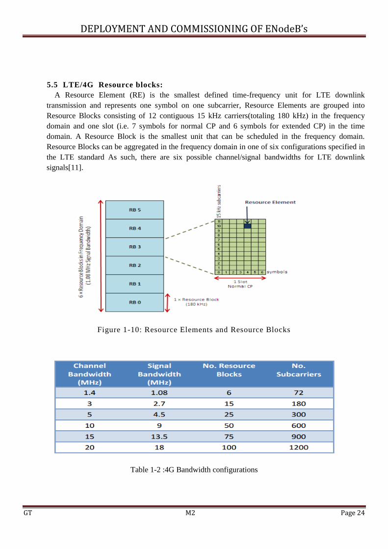
5.5 LTE/4G Resource blocks:
A Resource Element (RE) is the smallest defined time-frequency unit for LTE downlink
transmission and represents one symbol on one subcarrier, Resource Elements are grouped into
Resource Blocks consisting of 12 contiguous 15 kHz carriers(totaling 180 kHz) in the frequency
domain and one slot (i.e. 7 symbols for normal CP and 6 symbols for extended CP) in the time
domain. A Resource Block is the smallest unit that can be scheduled in the frequency domain.
Resource Blocks can be aggregated in the frequency domain in one of six configurations specified in
the LTE standard As such, there are six possible channel/signal bandwidths for LTE downlink
signals[11].
Figure 1-10: Resource Elements and Resource Blocks
Table 1-2 :4G Bandwidth configurations

DEPLOYMENT AND COMMISSIONING OF ENodeB’s
GT M2 Page 25
5.6 Radio channels:
The E-UTRAN radio interface must be able to transmit information in time and high throughput
latency Low. E-UTRAN signaling messages must be sent as soon as possible using the best
protection against system errors, as they are essential in the case of a mobile radio. On the other
hand, voice and data can be tolerated in a loss of frame reasonable because of the radio transmission.
To be flexible and allow different regime for data transmission, the specifications of the E-UTRAN
introduced several types of channels:
Logical channels.
Transport channels.
Physical channels.
5.6.1 Logical channels:
Logical channels correspond to data transfer services offered by the protocols the upper layers of
the interface radio. There are only two types of logical channels: control channels for the transfer of
control plane information and traffic channels for user plane for transfers of user data. Each of the
channels of the two categories corresponds to a certain type of information flows.
Logical channels controls in E-UTRAN are:
BCCH (Broadcast Control Channel) is a downlink common channel used by the network
broadcaster to the information system of the E-UTRAN to all the terminals present within a
radio cell. This information is used by the terminal, for example to know the operator for
information on configuring common channels of the cell and how to access the network, etc.
PCCH (Paging Control Channel) is a downlink common channel that transfers paging
informations of the present terminal in a cell.
CCCH (Common Control Channel) is used for communication between the terminal and
the EUTRAN when the RRC connection. This channel is typically used in the early stages
of establishing communication.
MCCH (Multicast Control Channel) is used for transmission of MBMS data (Multimedia
Broadcast and Multicast Service) of the network with several terminals.
DCCH (Dedicated Control Channel) is a bidirectional point-to-point channel that supports
the control information between a given terminal and the network. It supports only the RRC
and NAS signaling.
Logical traffic channels are:
DCTH (Dedicated Traffic Channel) is a bidirectional point-to-point channel used between a
given terminal and the network. It can support data transmission users that includes the data
itself and the application level signaling associated with this stream.
MTCH (Multicast Traffic Channel) is a data channel of point-to-multipoint transmission
network for the data traffic to one or more terminals. As for the MCCH, this channel is
associated with the MBMS.

DEPLOYMENT AND COMMISSIONING OF ENodeB’s
GT M2 Page 26
5.6.2 Transport channels:
The transport channels describe why and with what characteristic data are transferred through the
radio interface. For example, the transport channels describe how the data is protected against
transmission errors, channel coding type, the CRC protection is used, the size of packets sent over
the air interface, etc. This data set is known as the 'Transport Format'. As described in the
specification, transport channels are classified into two categories:
Transport channels and downlink transport channels uplink.
The transport channels in E-UTRAN downlink are:
BCH (Broadcast Channel) is assigned to the logical channel BCCH. Is there a 'Transport
Format' fixed and predefined and must cover the entire cell.
PCH (Paging Channel) associated with the BCCH.
DL-SCH (Downlink Shared Channel) that is used to transport the user to control or
data traffic.
MCH (Multicast Channel) that is associated with MBMS to control transport information.
The transport channels in E-UTRAN uplink are :
UL-SCH (Uplink Shared Channel) which is the equivalent of the DL-SCH in uplink.
RACH (Random Access Channel) which is a specific transport channel supporting a limited
control information. It is used in the early stages of establishment of communication or in the
case of change of state of RRC.
5.6.3 Physical channels
The physical channels are the implementation transport channels over the radio interface. Their
structure closely depends on the characteristics of the OFDM physical interface.
The downlink physical channels are:
PDSCH (Physical Downlink Shared Channel) that carries user data and signaling higher
layers
PDCCH (Physical Downlink Control Channel) transportation scheduling assignments for the
uplink.
PMCH (Physical Multicast Channel) carries information Multicast / Broadcast.
PBCH (Physical Broadcast Channel) that carries the system information.
PCFICH (Physical Control Format Indicator Channel) that informs the EU on the number of
symbols OFDM used for the PDCCH.
Physical Hybrid ARQ Indicator Channel which carries the ACK and NACK responses the
eNodeB to uplink transmissions.

DEPLOYMENT AND COMMISSIONING OF ENodeB’s
GT M2 Page 27
The physical channels in the uplink are:
PUSCH (Physical Uplink Shared Channel) that carries user data and signaling higher layers.
PUCCH (Physical Uplink Control Channel) carries control information.
PRACH (Physical Random Access Channel) that carries the random access preamble sent by
the terminal to the access network.
5.7 Multiple-Input Multiple Output antenna technology (MIMO):
MIMO, Multiple Input Multiple Output is another of the LTE major technology innovations used
to improve the performance of the system, MIMO technology enables the system to set up multiple
data streams on the same channel, thereby increasing the data capacity of a channel. Essentially
MIMO employs multiple antennas on the receiver and transmitter to use the multi-path effects that
always exist to transmit additional data, rather than causing interference.[12]
There are several ways in which MIMO is implemented in LTE. These vary according to the
equipment used, the channel function and the equipment involved in the link.
Transmission diversity: This form of LTE MIMO scheme uses the transmission of the same
information stream from multiple antennas. The purpose of the spatial diversity is to make more
robust transmission. There is no increase in the data rate.
Spatial multiplexing: This form of MIMO used within the LTE system involves sending two
information streams which can be transmitted over two or more antennas. The spatial multiplexing is
not intended to make the transmission more robust, but rather to increase the data rate.
Figure 1-11: Model of a MIMO system two TX / RX

DEPLOYMENT AND COMMISSIONING OF ENodeB’s
GT M2 Page 28
6. Requirements of LTE :
There are several reasons which are sufficient to answer a simple question- why do we need to
adopt 4G technology? Below are some requirements of LTE which make it an above all
technology.[13]
Data Rate:
Instantaneous downlink peak data rate of 150Mbit/s downlink spectrum
Instantaneous uplink peak data rate of 50 Mbit/s in uplink spectrum
Cell range:
5Km optima size
Cell capacity:
Up to200 active users per cell
Mobility:
Optimized for low mobility 15km/ h but supports high speed
Latency:
User plane<5ms
Control plane<50ms
Scalable bandwidth of 20,15,10,5,3 and1.4MHz
Co‐ existence with legacy standards
7.Conclusion:
In this first chapter, we presented the main technical standard of LTE. This chapter is structured in
a way where it will be useful for his successor, in which we describe the design process and planning
LTE network Indeed, a good knowledge of architectures allows planners to better manage resources,
to facilitate the evolution of the network by integrating more efficient technologies, which allow them
to simultaneously provide good quality services. The next chapter is a study on deployment and
commissioning of eNodeB’s of LTE network.
DEPLOYMENT AND COMMISSIONING OF ENodeB’s
GT M2 Page 29
CHAPTER 2: DEPLOYMENT AND COMMISSIONING OF ENODEB
1.Introduction:
The demand for IP based broadband services and the need to optimize the architecture of
telecommunication networks has forced vendors, operators and carriers into the network evolution
process. This section explores the deployment and commissioning of 4G network procedure starting
from the site survey, equipement installation, commissioning including eNB configuration,
troubleshooting and drive Test.
2. Site Survey:
2.1 LTE RF survey:
RF Survey is Collection of data from the site or in Field for installing a new site. Just checking the
Practically of Cell Site, for making determination for Coverage Region of Cell Site & for Deciding
the Link/Connectivity with the another Cell Site. This task results in physical changes in the network,
by modifying or adding new sites and/or equipment.
2.2 Need of LTE survey:
RF Survey is used to find the Problems in the Site. Because in wireless network many issues arise
day by day, which can prevent the signals from reaching all parts. Examples; by multipath
Distortion, “Near-far” Problem. In order to avoid the problem, we are doing RF Survey. RF Survey
helps us to find the place where multipath distortion can occur, any interference, By doing Survey,
we can eliminate the problem.
2.3 Before the survey:
As in any task to be performed, the Site Survey should be first of all well-placed, so that its
execution, as best as possible. Therefore, it is advisable to follow some basic procedures, or some
tasks that are common and necessary: a pre-analysis before any Site Survey. Before heading to the
Site Survey region, it is extremely important to make a complete analysis of that region. For this, all
available resources should be used: Aerial Photos, Google Earth, Maps, etc...Important: Always take
the printed data with you: the areas of interest highlighted, with a longer zoom and a smaller one,
especially in the focus area.
2.4 Tool Kit for LTE RF survey:
GPS
Laser Distance Meter
Digital Camera
Magnetic Compass

DEPLOYMENT AND COMMISSIONING OF ENodeB’s
GT M2 Page 30
2.5 Procedure of RF survey:
We need to see some criteria in cell site
Site Location
Orientation or Azimuth .
Height of Antenna.
Tilt of the Antenna.
GPS coordinates.
3. eNodeB Installation:
This part provides a high level description of ZTE LTE products eNodeB including ZXSDR
B8200 L200 (hereafter B8200) LTE Distributed BaseBand processing Unit (BBU) and Remote
Radio Unit RRU used in ZTE LTE total Solution. Also provides an overview of the characteristics of
BBU (B8200) and RRU(R8882), its key benefits, the outdoor/indoor installation, functionality and
services. BBU (B8200) and Remote Radio Units (RRU) comprise distributed eNodeB BS8700.
Item Specifications Bandwidth 1,4 5, 10, 15, 20 MHz
Access scheme Downlink: OFDMA
Uplink: SC-FDMA
Antenne technology Downlink: 2 x 2 MIMO Uplink: 1 x 2 SIMO
No. of sectors 6 sectors max
Maximum transmission power 60W(30w+30w)
Maximum transmission rate (per sector) Downlink: 150 Mb/s Uplink: 50 Mb/s
Mobile environment Up to 350 KM/h
Equipment size BBU :(120,300,400)mm. RRU: (233 × 1 19 × 55)mm
Table 2-1: e-NodeB equipement specification
3.1 Outdoor installation :
3.1.1 Remote Radio Unit RRU installation :
RRU is a remote radio unit. One or more RRU constitute the radio frequency (RF) part of a
distributed base station. RRU can be installed on a pole, wall, or stand. It can also be installed close
to antennas to shorten the feeder length, reduce feeder loss, and improve system coverage. The RRU
can be configured to communicate with a base band unit (BBU) via an optical interface compliant
with the common public radio interface (CPRI) and can communicate with a wireless mobile device
via an air interface.[14]

DEPLOYMENT AND COMMISSIONING OF ENodeB’s
GT M2 Page 31
3.1.2 Antenna:
Since LTE data channels are entirely separate from the voice channels, their base stations also
have their own unique identifier, TAC,CI and PCI, where TAC is the Tracking Area Code, CI is the
Cell Identity and PCI is the physical cell ID.[15]
3.1.2.1 Antenna Tilt:
Antenna tilt is one of the most important performance tuning parameters of a cellular network,
since it has a strong impact on the inter-site interference level and signal quality of the system, we
can have two tilts mechanic and electric.
Mechanical tilt :
It consist to tilting the antenna, through specific accessories on its bracket, without changing the
phase of the input signal, the diagram and consequently the signal propagation directions is modified.
Electrical tilt :
For the electrical tilt the modification of the diagram is obtained by changing the characteristics of
signal phase of each element of the antenna.
3.2 Indoor installation:
BBU a baseband unit is a unit that processes baseband in telecom systems. The baseband unit is
placed in the equipment room and connected with RRU via optical fiber, the BBU is responsible for
communication through the physical interface, a BBU has the following characteristics:
modular design,
small size
low power consumption
can be easily deployed.[16]

DEPLOYMENT AND COMMISSIONING OF ENodeB’s
GT M2 Page 32
3.2.1 BBU processing boards:
Figure 2-1: BBU (ZXSDR B8200 L200) Physical Structure
Table 2-2: Board List of BBU (B8200)

DEPLOYMENT AND COMMISSIONING OF ENodeB’s
GT M2 Page 33
3.2.2 Benefits of BBU+RRU Structure:
Saving costs on equipment rooms with a small size, the BBU can be installed in residential
and business buildings. It can also be located in the integrated power cabinets, in a basement,
or in a 2G cabinet, solving the problem of insufficient equipment rooms.
Reducing the feeder line losses by 2 to 3dB traditionally, the macro base station is connected
to the antenna via feeder cable. The BTS output power lost in feeder lines is 2 to 3dB at an
average. In the BBU+RRU structure, the remote RF module is connected to the antenna via
the flexible jumper, avoiding feeder line losses.
Shortening the construction time the BBU+RRU solution has no special needs for equipment
rooms and requires only the installation of the auxiliary antenna feeder systems, enabling
operators to speed up network construction to gain a first-mover advantage.
4. Commissioning of the eNodeBs :
The purpose of the commissioning process is to add a new eNodeB into the LTE network, the final
outcome of this process is a eNodeB that is ready for commercial service, network commissioning is
divided into Commissioning Preparation and Commissioning Execution.[17]
4.1 Commissioning preparation:
Commissioning preparation loads each eNodeB configuration on EMS and create a
commissioning before to eNodeB connectivity. Configuration data includes golden parameters, RF
and IP design data from Clearvision, hardware design data from SAP (Site Action Plan).
4.1.1 Planning Data Preparation :
In preparation for LTE eNodeB commissioning, a LTE summary data file and a common
configuration template are used to generate eNodeB configuration data, The LTE summary data file
that contains hardware, network, and RF configuration must be created for each eNodeB, these files
are used to configure the eNodeB from EMS. The common configuration template contains default
parameters and is preloaded in the EMS.
File Name Description
LTE Summary Data File Specify each eNodeB configuration
Common Configuration
Tempate
Specifies default common (Golden) configuration for each eNodeB
Table 2-3: eNodeB Configuration Templates
DEPLOYMENT AND COMMISSIONING OF ENodeB’s
GT M2 Page 34
LTE Summary Data File :
The LTE summary data file is a Microsoft Excel file that is imported into the Configuration
Management Express (CME) component of the EMS as part commissioning preparation. The
summary data file defines which parameters need to provided, parameter values for multiple
eNodeB can be filled out in one summary data file to facilitate bulk commissioning.
Common Configuration Template :
Parameters such as device parameters, radio parameters, and algorithm parameters that are
common for eNodeBs are defined in the common configuration template. This template is preloaded
in the EMS and is referenced by the LTE Summary Data File.
4.2 Commissioning Execution:
The eNodeB commissioning execution with the LMT is to use the LMT on the eNodeB side to
upgrade the eNodeB version to the target one so as to commission an eNodeB, and the
commissioning process often involves operations such as configuration file importing, alarm
query, and fault handling.
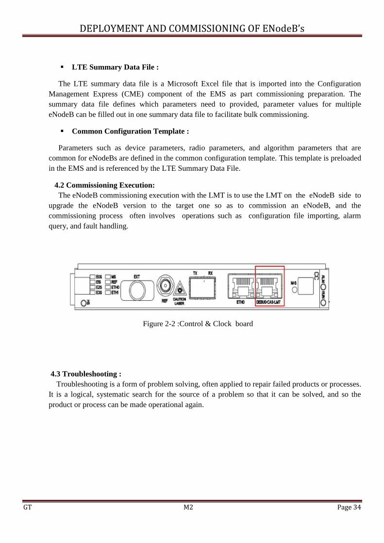
Figure 2-2 :Control & Clock board
4.3 Troubleshooting :
Troubleshooting is a form of problem solving, often applied to repair failed products or processes.
It is a logical, systematic search for the source of a problem so that it can be solved, and so the
product or process can be made operational again.
DEPLOYMENT AND COMMISSIONING OF ENodeB’s
GT M2 Page 35
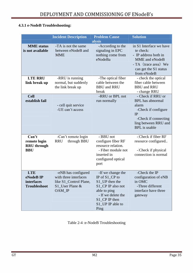
4.3.1 e-NodeB Troubleshooting:
Table 2-4 :e-NodeB Troubleshooting
Incident Description Problem Cause
Analysis
Solution
MME status
is not available
-TA is not the same
between eNodeB and
MME
-According to the
signaling in EPC
nothing come from
eNodeBa
in S1 Interface we have
te check:
- IP address both in
MME and eNodeB
- TA(trace area)We
can get the S1 status
from eNodeB
LTE RRU
link break up
-RRU is running
normal, but suddenly
the link break up
-The optical fiber
cable between the
BBU and RRU
break
- check the optical
fiber cable between
BBU and RRU
- change RRU
Cell
establish fail
- cell quit service
-UE can’t access
-RRU or BPL not
run normally
- Check if RRU or
BPL has abnormal
alarm
-Check if configure
IP
-Check if connecting
ling between RRU and
BPL is usable
Can’t
remote login
RRU through
BBU
-Can’t remote login
RRU through BBU
- BBU not
configure fiber RF
resource relation.
- Fiber module not
inserted in
configured optical
port
- Check if fiber RF
resource configured..
- Check if physical
connection is normal
LTE
eNodeB IP
interfaces
Troubleshoot
-eNB has configured
with three interfaces
like S1_Control Plane,
S1_User Plane &
OAM_IP
-If we change the
IP of S1_CP to
S1_UP then the
S1_CP IP also not
able to ping
- If we delete the
S1_CP IP then
S1_UP IP able to
Ping
-Check the IP
configuration of eNB
in OMC
-Three different
interface have three
gateway
DEPLOYMENT AND COMMISSIONING OF ENodeB’s
GT M2 Page 36
4.4 LTE Drive Test:
In Long Term Evolution (LTE), as with other cellular technologies, drive testing is a part of the
network deployment and management life cycle from the early onset. Drive testing provides an accurate
real-world capture of the RF environment under a particular set of network and environmental
conditions. The main benefit of drive testing is that it measures the actual network coverage and
performance that a user on the actual drive route would experience. It is argued that in today’s networks
with modern simulations, network engineers can mathematically model how a network will perform.
While this is true to a certain extent, it is also essential to conduct drive testing as network parameter
settings alter how the user equipment (UE) interacts and deals with the network environment. Such
interactions cannot be wholly predicted through mathematical modeling.
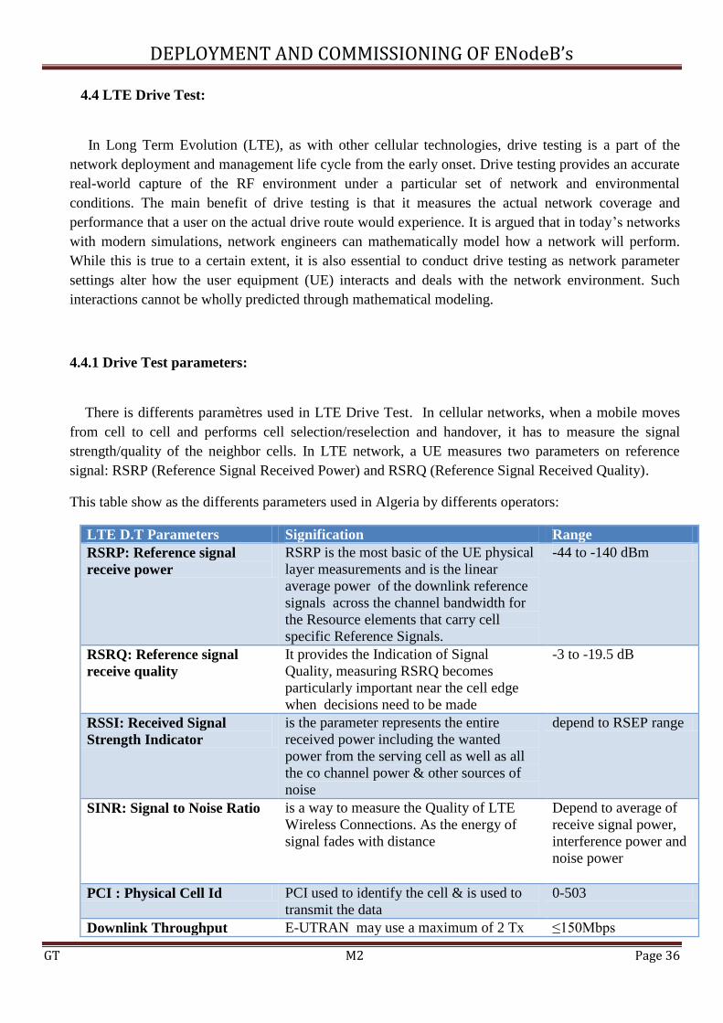
4.4.1 Drive Test parameters:
There is differents paramètres used in LTE Drive Test. In cellular networks, when a mobile moves
from cell to cell and performs cell selection/reselection and handover, it has to measure the signal
strength/quality of the neighbor cells. In LTE network, a UE measures two parameters on reference
signal: RSRP (Reference Signal Received Power) and RSRQ (Reference Signal Received Quality).
This table show as the differents parameters used in Algeria by differents operators:
LTE D.T Parameters Signification Range
RSRP: Reference signal
receive power
RSRP is the most basic of the UE physical
layer measurements and is the linear
average power of the downlink reference
signals across the channel bandwidth for
the Resource elements that carry cell
specific Reference Signals.
-44 to -140 dBm
RSRQ: Reference signal
receive quality
It provides the Indication of Signal
Quality, measuring RSRQ becomes
particularly important near the cell edge
when decisions need to be made
-3 to -19.5 dB
RSSI: Received Signal
Strength Indicator
is the parameter represents the entire
received power including the wanted
power from the serving cell as well as all
the co channel power & other sources of
noise
depend to RSEP range
SINR: Signal to Noise Ratio is a way to measure the Quality of LTE
Wireless Connections. As the energy of
signal fades with distance
Depend to average of
receive signal power,
interference power and
noise power
PCI : Physical Cell Id PCI used to identify the cell & is used to
transmit the data
0-503
Downlink Throughput E-UTRAN may use a maximum of 2 Tx ≤150Mbps

DEPLOYMENT AND COMMISSIONING OF ENodeB’s
GT M2 Page 37
antennas at the ENodeB and 2 Rx
antennas at the UE ( MIMO)
Uplink Throughput E-UTRAN uses a maximum of a single Tx
antenna at the UE and 2 Rx antennas at the
E Node B.
≤50Mbps
CQI :Channel Quality
Indicator
CQI is a measurement of the
communication quality of wireless
channels i.e. it indicates the downlink
mobile radio channel quality as
experienced by the UE
- 1 to 15
BLER :Block Error Rate A simple method by which a UE can
choose an appropriate CQI value could be
based on a set of BLER thresholds
BLER ≤ 10%
Table 2-5:LTE Drive Test Parameters
5. Conclusion :
LTE infrastructure is designed to be as simple as possible to deploy and operate, through flexible
technology that can be deployed in a wide variety of frequency bands. LTE offers scalable bandwidths,
from less than 5MHz up to 20MHz, together with support for both FDD paired and TDD unpaired
spectrum. The LTE–SAE architecture reduces the number of nodes, supports flexible network
configurations and provides a high level of service availability. Furthermore, LTE–SAE will
interoperate with GSM, WCDMA/HSPA, TD-SCDMA and CDMA.

DEPLOYMENT AND COMMISSIONING OF ENodeB’s
GT M2 Page 38
CHAPTER3: RADIO PLANNING
1.Introduction :
The overall radio interface protocol architecture for LTE can be divided into User Plane Protocols
and Control Plane Protocols.
Figure 3-1: LTE Architecture protocol
2. User Plane:
An IP packet is tunneled between the P-GW and the eNodeB to be transmitted towards the UE.
Different tunneling protocols can be used. The tunneling protocol used by 3GPP is called the GPRS
tunneling protocol (GTP)
3. Control Plane :
Control plane and User plane have common protocols which perform the same functions except
that for the control plane protocols there is no header compression. In the access stratum protocol
stack and above the PDCP, there is the Radio Resource Control (RRC) protocol which is considered
as a Layer 3 protocol. RRC sends signaling messages between the eNodeB and UE for establishing
and configuring the radio bearers of all lower layers in the access stratum.

DEPLOYMENT AND COMMISSIONING OF ENodeB’s
GT M2 Page 39
3. 1 Physical Layer :
Physical Layer carries all information from the MAC transport channels over thz air interface.
Takes care of the link adaptation ,power control,cell serch and other measurements for the RRC layer
3.2 Medium Access Control (MAC):
The MAC layer is the lowest sub layer of Layer 2 architecture of the LTE radio protocol stack and
it is located between the RLC layer and the physical layer. Logical channels connect MAC to the
RLC and Transport channels connect MAC to the physical layer; therefore the main responsibility of
the MAC layer is mapping the logical channels to the transport channels.
3.3 Radio Link Control (RLC):
Radio Link Control (RLC) is another sub layer of the data link layer. It is located between the
PDCP and MAC. The main purpose of this E-UTRAN protocol layer is to receive/deliver a data
packet from/to its peer RLC entity.
The communication between the RLC layer and the PDCP layer is done through the Service
Access Point (SAP) and the communication of the RLC layer with the MAC layer is done through
logical channels.
3.4 Packet Data Convergence Protocol (PDCP) :
Packet Data Convergence Protocol (PDCP) is one of the sub layers in the Data Link layer. The
PDCP protocol terminates in the eNB from one side and in the UE from the other side, and it also
acts both in the user plane and control plane. This layer processes Radio Resource Control (RRC)
messages in the control plane and Internet Protocol (IP) packets in the user plane.
3.5 Radio Resource Control (RRC):
The RRC (Radio Resource Control) layer is a key signaling protocol which supports many
functions between the terminal and the eNodeB The RRC (Radio Resource Control) layer is a key
signaling protocol which supports many functions between the terminal and the eNodeB. The RRC
protocol enables the transfer of common NAS information which is applicable to all UEs as well as
dedicated NAS information which is applicable only to a specific UE. In addition, for UEs in
RRC_IDLE, RRC supports notification of incoming calls.
Broadcast of System Information: Handles the broadcasting of system information, which
includes NAS common information. Some of the system information is applicable only for
UE’s in RRC-IDLE while other system information is also applicable for UEs in RRC-
CONNECTED.
RRC Connection Management: Covers all procedures related to the establishment,
modification and release of an RRC connection, including paging, initial security activation,
handover within LTE (including transfer of UE RRC context information), configuration of
the lower protocol layers.
Establishment and release of radio resources:This relates to the allocation of resources for
the transport of signaling messages or user data between the terminal and eNodeB.
Paging : This is performed through the PCCH logical control channel. The prominent usage
of paging is to page the UE’s that are in RRC-IDLE. Paging can also be used to notify UE’s
both in RRC-IDLE and RRC-CONNECTED modes.

DEPLOYMENT AND COMMISSIONING OF ENodeB’s
GT M2 Page 40
Handover: The handover is triggered by the eNodeB, based on the received measurement
reports from the UE. Handover is classified in different types based on the origination and
destination of the handover. The handover can start and end in the E-UTRAN, it can start in
the E-UTRAN and end in another Radio Access Technology (RAT), or it can start from
another RAT and end in E-UTRAN.
3.5.1 Radio Resource Control States :
The main function of the RRC protocol is to manage the connection between the terminal and the
EUTRAN access network,. in E-UTRAN, the RRC state machine is very simple and limited to two
states only RRC-IDLE, and RRC-CONNECTED
RRC-IDLE: In the RRC-IDLE state, there is no connection between the terminal and the
eNodeB, meaning that the terminal is actually not known by the E-UTRAN Access
Network. The terminal user is inactive from an application level perspective, which does
not mean at all that nothing happens at the radio interface level. Nevertheless, the terminal
behavior is specified in order to save as much battery power as possible.
RRC-CONNECTED: There is an active connection between the terminal and the eNodeB,
which implies a communication context being stored within the eNodeB for this terminal.
Unlike the RRC-IDLE state, the terminal location is known at the cell level. Terminal
mobility is under the control of the network using the handover procedure, which decision is
based on many possible criteria including measurement reported by the terminal of by the
physical layer of the eNodeB itself.[18]
4. Handover in LTE :
One of the main goals of the LTE radio network is to provide fast and seamless handover from one
cell to another while simultaneously keeping network management simple. LTE technology is
designed to support mobility for various mobile speeds up to 350km/h or even up to 500km/h. With
the moving speed even higher, the handover will be more frequent and fast. Handover is one of the
key procedures for ensuring that the users move freely through the network while still being
connected and being offered quality services. Since its success rate is a key indicator of user
satisfaction.

DEPLOYMENT AND COMMISSIONING OF ENodeB’s
GT M2 Page 41
4.1 Types of Handover :
4.1.1 Hard handover, Break-Before-Connect :
Hard handover is a category of handover procedures where all the old radio links in the UE are
abandoned before the new radio links are established. The hard handover is commonly used when
dealing with handovers in the legacy wireless systems. The hard handover requires a user to break
the existing connection with the current cell (source cell) and make a new connection to the target
cell.
Intra-LTE Handover: In this case source and target cells are part of the same LTE network.
Inter-LTE Handover: Handover happens towards other LTE nodes. (Inter-MME and Inter-
SGW).
Inter-RAT Handover: Handover between different radio technologies. For example
handover from LTE to WCDMA.[19]
4.2 Handover Process :
Handover procedure in LTE can be divided into three phases handover preparation, handover
execution and handover completion, the procedure starts with the measurement reporting of a
handover event by the User Equipment (UE) to the serving evolved Node B (eNB). The Evolved
Packet Core (EPC) is not involved in handover procedure for the control plane handlin.
4.2.1 Handover preparation :
During the handover preparation, data flows between UE and the core network as usual. This
phase includes messaging such as measurement control, which defines the UE measurement
parameters and then the measurement report sent accordingly as the triggering criteria is satisfied.
Handover decision is then made at the serving eNodeB, which requests a handover to the target cell
and performs admission control. Handover request is then acknowledged by the target eNodeB.

DEPLOYMENT AND COMMISSIONING OF ENodeB’s
GT M2 Page 42
Figure 3-2: Handover preparation.
4.2.2 Handover execution :
Handover execution phase is started when the source eNodeB sends a handover command to UE.
During this phase, data is forwarded from the source to the target eNodeB, which buffers the packets.
UE then needs to synchronize to the target cell and perform a random access to the target cell to
obtain UL allocation and timing advance as well as other necessary parameters. Finally, the UE
sends a handover confirm message to the target eNodeB after which the target eNodeB can start
sending the forwarded data to the UE.
UE Source eNB Target eNB MME S-GW
0. Area Restriction Provided
1. Measurement Control
Packet data Packet data
UL allocation
2. Measurement Reports Legend
L3 signaling
L1/L2
signaling
User Data
3. HO Decision
4. Handover
Request
5. Admission Control
6. Ho Request Ack
DL allocation

DEPLOYMENT AND COMMISSIONING OF ENodeB’s
GT M2 Page 43
Figure 3-3:Handover execution
4.2.3 Handover completion :
In the final phase, the target eNodeB informs the MME that the user plane path has
changed. S-GW is then notified to update the user plane path. At this point, the data starts
flowing on the new path to the target eNodeB. Finally all radio and control plane resources
are released in the source eNodeB.
7. Handover Commmand
Detach from old cell
synchronised to new
cell
Deliver buffered and
intransit packets to target
eNB
8. SN Status Transfer
Data Forwarding
Buffer Packets from Souce eNB
9. Synchronisation
10. UL allocation + TA for UE
11. Handover Confirm

DEPLOYMENT AND COMMISSIONING OF ENodeB’s
GT M2 Page 44
Figure 3-4: Handover completion.
4. Conclusion
Main goals of LTE, or any wireless system for that matter, is to provide fast and seamless
handover from one cell (a source cell) to another (a target cell). This is especially true for LTE
system because of the distributed nature of the LTE radio access network architecture which consists
of just one type of node, the base station, known in LTE as the eNodeB.
13. User
Plane Update
request 12. Path SwitchRequest
End Marker
14. Switch DL path
15. User
Plane Update
response 16. Path Switch
request Ack 17. Release Resource
Flush DL buffer
delivering in-transit
continue packets
Data Forwarding
End Marker
16. Release Ressources
Packet data Packet data

DEPLOYMENT AND COMMISSIONING OF ENodeB’s
GT M2 Page 45
CHAPTER 4: APPLICATION
1.Introduction
As we said in last chapter the handover in LTE can be done through X2 or S1 interfaces, both
interfaces can be used in handover procedures, but with different purposes.
Our simulation had place in Algers OMC ZTE Corporation using Business Object Tool which is a
professional tool that fully supports O&M of multi-system network taking network configuration
and radio equipment data. The main goal of our simulation is to shows the evolution of the success
rate of handover with the X2 interface dealing the handover results of of Constantine Koudia sites
2. Handover via S1 interface :
The S1-based handover procedure is used when the X2-based handover cannot be used.
Figure 4-1:Handover via S1 interface
UE Source eNB Target eNB
MME
1. Measurement Reports 2. Handover Required
7. eNB Status Transfer
11. UE Context Release Command
12. UE Context Release Completed
3. Handover Request
4. Handover Request Ack
5. Handover Command 6. RRC connection
reconfiguration
8. MME Status Transfer 9. RRC connection reconfiguration complete
10. Handover Notify

DEPLOYMENT AND COMMISSIONING OF ENodeB’s
GT M2 Page 46
3.Handover via X2 interface :
The X2 handovers have the benefit of reduced preparation times and lower core processing load.
Figure 4-2: Handover via X2 interface
Before we deal with the handover results via the interfaces, we will start be defining a couple of
causes that we might face when there is a failure in the handover process, that are closely supervised
using predefined counters set by the network operator.
4. Handover fail analysis and troubleshooting:
In LTE like other technologies we can supervised the handover fail with some key performance
indicator “KPI”, which we detail the problems that we can have during the handover process.
4.1. Different Handover fail causes:
This table shows us the different causes with their description, and in which phase on handover we
can find this fail cause.
UE Source eNB Target eNB
MME S-GW
1. Measurement Reports
2. Handover Request
6. RRC connection reconfiguration complete
3. Handover Request Ack 4. RRC connection
reconfiguration
5. SN Status Transfer
7. Path Switch
Request
Transfer
8. User Plane
update Request
9. User Plane
update Response 10. Path Switch
Request Ack
11. UE Context Release

DEPLOYMENT AND COMMISSIONING OF ENodeB’s
GT M2 Page 47
Counters Number Counter Name Or Causes
C373620600 Number of Successful Outgoing Inter - eNB(via X2) Intra - freq Handover
Preparation
C373610301 Number of Outgoing Inter - eNB(via X2) Intra - freq Handover Preparation
Failure due to HO Request ACK TimeOut
C373610380 Number of Successful Outgoing Inter - eNB(via X2) Intra - freq Handover
Execution
C373610381 Number of Outgoing Inter - eNB(via X2) Intra - freq Handover Execution
Failure due to UE Reback to Source Cell
C373610340 Number of Successful Incoming Inter - eNB(via X2) Intra - freq Handover
Preparation
C373610341 Number of Incoming Inter - eNB(via X2) Intra - freq Handover Preparation
Failure due to Resource Allocation Fail
C373610384 Number of Successful Incoming Inter - eNB(via X2) Intra - freq Handover
Execution
C373610385 Number of Incoming Inter - eNB(via X2) Intra - freq Handover Execution
Failure due to RRC Reconfig Complete TimeOut
C373610386 Number of Incoming Inter - eNB(via X2) Intra - freq Handover Execution
Failure due to Path Switch Failure
C373620600 Number of Successful Outgoing Inter - eNB(via S1) Intra - freq Handover
Preparation
C373620601 Number of Outgoing Inter - eNB(via S1) Intra - freq Handover Preparation
Failure due to HO Command Timeout (MME-eNB.T)
C373620680 Number of Successful Outgoing Inter - eNB(via S1) Intra - freq Handover
Execution
C373620681 Number of Outgoing Inter - eNB(via S1) Intra - freq Handover Execution
Failure due to UE Reback to Source Cell
C373620640 Number of Successful Incoming Inter - eNB(via S1) Intra - freq Handover
Preparation
C373620641 Number of Incoming Inter - eNB(via S1) Intra - freq Handover Preparation
Failure due to Resource Allocation Fail
C373620684 Number of Successful Incoming Inter - eNB(via S1) Intra - freq Handover
Execution
C373620685 Number of Incoming Inter - eNB(via S1) Intra - freq Handover Execution
Fai fa lure due to RRC Reconfig Complete T imeout
Table 4-1: Handover fail causes

DEPLOYMENT AND COMMISSIONING OF ENodeB’s
GT M2 Page 48
Each KPI is calculated through the integration to counters specific for each one , the general ZTE
formula for all KPI is only “Preparation Handover *Execution Handover” ,so there are to sub
formula for each KPI, one for preparation and one for execution both are composed by the counters
already integrated ,we can also named this counters the causes fail .
Success Rate of Inter-eNB Intra-freq EUtranRelation Outgoing Handover Via X2
( C373610300 / (C373610300 + C373610301 )) * (C373610380 / (C373610380 + C373610381))
Success Rate of Inter-eNB Intra-freq EUtranRelation Incoming Handover Via X2
( C373610340 / (C373610340 + C373610341 )) * (C373610384 / (C373610384 + C373610385 +
C373610386))
Success Rate of Inter-eNB Intra-freqE UtranRelation Outgoing Handover Via S1
( C373620600 / (C373620600 + C373620601)) * (C373620680 / (C373620680 + C373620681))
Success Rate of Inter-eNB Intra-freq EUtranRelation Incoming Handover Via S1
(C373620640 / (C373620640 + C373620641)) * (C373620684 / (C373620684 + C373620685))
Table 4-2: Handover KPI
5. Analysis real case :
Now we will compare the success rate of handover via X2-interface and via S1 interface, with
different parameters, in order to demonstrate the importance of the integration of the interface X2.
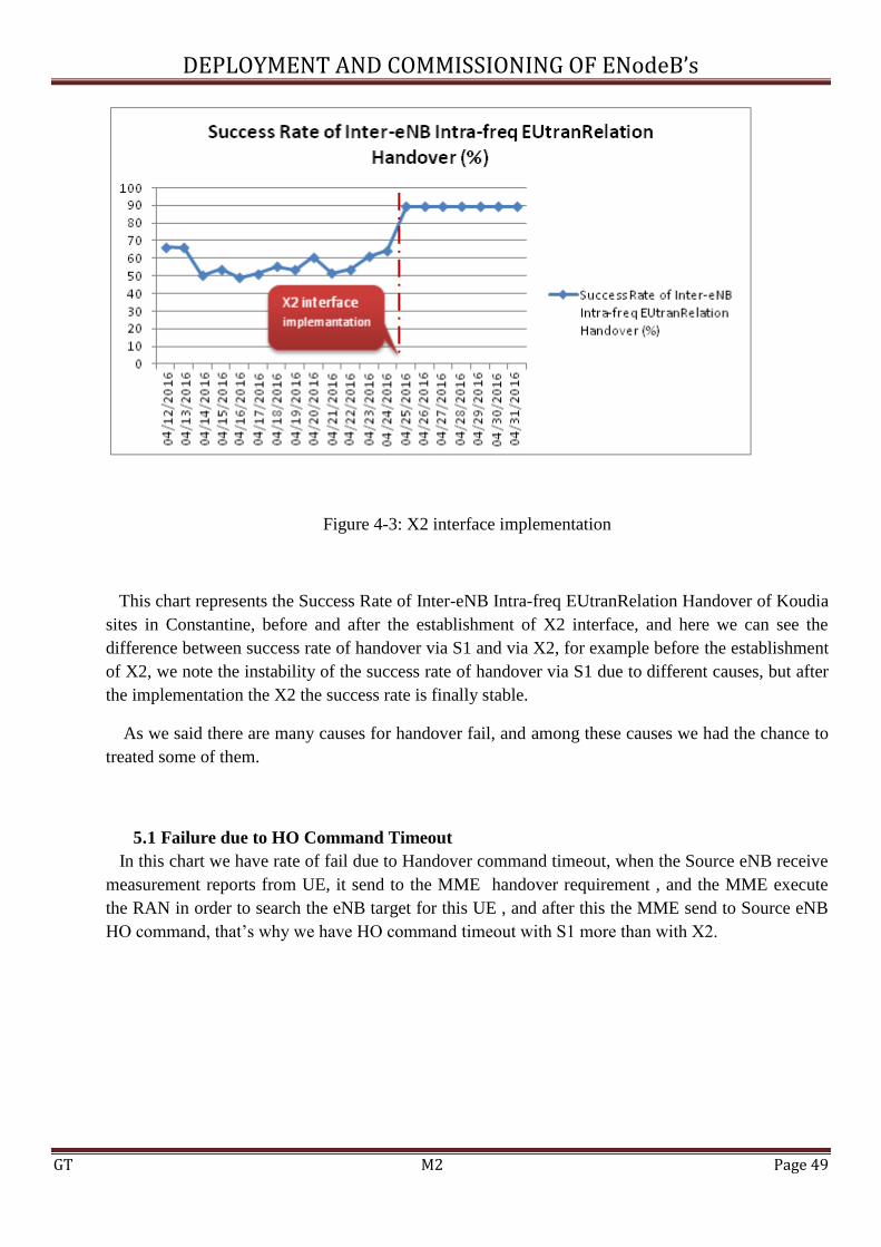
DEPLOYMENT AND COMMISSIONING OF ENodeB’s
GT M2 Page 49
Figure 4-3: X2 interface implementation
This chart represents the Success Rate of Inter-eNB Intra-freq EUtranRelation Handover of Koudia
sites in Constantine, before and after the establishment of X2 interface, and here we can see the
difference between success rate of handover via S1 and via X2, for example before the establishment
of X2, we note the instability of the success rate of handover via S1 due to different causes, but after
the implementation the X2 the success rate is finally stable.
As we said there are many causes for handover fail, and among these causes we had the chance to
treated some of them.
5.1 Failure due to HO Command Timeout
In this chart we have rate of fail due to Handover command timeout, when the Source eNB receive
measurement reports from UE, it send to the MME handover requirement , and the MME execute
the RAN in order to search the eNB target for this UE , and after this the MME send to Source eNB
HO command, that’s why we have HO command timeout with S1 more than with X2.

DEPLOYMENT AND COMMISSIONING OF ENodeB’s
GT M2 Page 50
FIGURE 4-4: Failure due to HO Command Timeout
5.2 Failure due to RRC Reconfig Complete TimeOut:
This chart shows us the rate of failure due to RRC Reconfig Complete Timeout via S1 interface
and X2 interface, in handover via S1 there is signaling transmission between eNodeB and MME,
that’s why we have higher rate failure, but with X2 there is not signaling transmission between
eNodeB and MME, only source eNB and Target eNB, so there will be less time on hand-over and
higher successful rate of handover.
FIGURE 4-5: Failure due to RRC reconfig complete timeout

DEPLOYMENT AND COMMISSIONING OF ENodeB’s
GT M2 Page 51
5.3 Failure due to UE Reback to Source Cell:
This cause means when the UE go from source eNB to target eNB sometimes the target eNB is
saturated, so here we can have problems because the target eNB will not accept the UE, and we note
that we have this failure due to UE reback to the source cell with S1 more than X2, because with X2
we have load balancing protocol ,when the target eNB is saturated it make a redirection for UE to
another cell unsaturated.
Figure 4-6: Failure due to UE Reback to Source Cell
6. Conclusion:
There are other causes for sure but the fact remains, the LTE network is still being deployed in
Algeria, and is still new for that we can face more causes, there is also the mobility coefficient,
which basically means the higher the mobility factor increases the more causes we get, which in term
suggests the increase in the failure rate.

DEPLOYMENT AND COMMISSIONING OF ENodeB’s
GT M2 Page 52
General Conclusion
LTE is well positioned today, and is already meeting the requirements of next-generation mobile
networks – both for existing 3GPP/3GPP2 operators. It enables operators to offer high-performance,
mass-market mobile broadband services, through a combination of high bit-rates and system
throughput – in both the uplink and downlink – with low latency. LTE infrastructure is designed to
be as simple as possible to deploy and operate, through flexible technology that can be deployed in a
wide variety of frequency bands. LTE offers scalable bandwidths, from 1.4MHz up to 20MHz,
together with support for both FDD paired and TDD unpaired spectrum. The LTE-SAE architecture
reduces the number of nodes, supports flxible network confiurations and provides a high level of
service availability. Furthermore, LTE-SAE interoperates with GSM, WCDMA/HSPA, TD-
SCDMA, MiFi and CDMA. Today LTE is already available in USB dongles, laptop/netbooks,
smartphones, routers and tablets, and will soon be available through other devices that benefit from
mobile broadband.
.

DEPLOYMENT AND COMMISSIONING OF ENodeB’s
GT M2 Page 53
References
[1],[6] GENERATIONS OF MOBILE WIRELESS TECHNOLOGY:A SURVEY MUDIT RATANA BHALLA
DEPT. OF COMPUTER SCIENCE & APPLICATIONS DR.H.S.GOUR CENTRAL UNIVERSITY, SAGAR(M.P.)
ANAND VARDHAN BHALLA B.T.I.R.T. COLLEGE OF ENGINEERING AND TECHNOLOGY, SAGAR(M.P.) LTE:
THE UMTS LONG TERM EVOLUTION S SESIA, I TOUFIK, M BAKER - 2009 - WILEY ONLINE LIBRARY
[7],[8] WHITE PAPER I WWW.TEKTRONIXCOMMUNICATIONS.COM/LTE
[9] ZTE LTE_SYSTEM ENGINEERING
[10],[11],[12] LTE TECHNOLOGY OVERVIEW, MOCHAMAD MIRZA, 11 AUGUST 2012
[13] ITU-R REPORT M.2134, “REQUIREMENTSRELATED TO TECHNICAL PERFORMANCE
[14],[15] ZTE LTE ZXSDR R8882 PRODUCT DESCRIPTION
[16] ZTE LTE ZXSDR B8200 L200 PRODUCT DESCRIPTION
[17] ZTE LTE_SYSTEM ENGINEERING
[18],[19] RHODE & SCHWARZ, “1MA232: LTE-ADVANCED (3GPP REL. 11) TECHNOLOGY

DEPLOYMENT AND COMMISSIONING OF ENodeB’s
GT M2 Page 54
Annex
Figure 5-1: BBU Location
Figure 5-2: RRU Location
Figure 5-3: Antenna
Figure 5-4: Electrical tilt