DEVELOPING AND COMMISSIONING BABAR ELECTRONICS
13
DEVELOPING AND COMMISSIONING BABAR ELECTRONICS A.J. Lankford, Department of Physics and Astronomy, University of California, Irvine, CA 92697-4575 (email: [email protected]) for the BABAR Collaboration Abstract Many aspects of the architecture and performance requirements of the electronics system for the BABAR Experiment are similar to those for the much larger LHC experiments. We briefly describe the requirements and architecture of BABAR Electronics, focusing on aspects that are similar to the LHC. We then discuss the experience of developing the system from design to operation, including such topics as prototype and system tests, manufacturing, grounding and shielding, integration, and initial performance. We focus primarily on front-end electronics, including IC development; however, we also discuss data acquisition. 1. INTRODUCTION This rather informal paper is a recollection of the experience of developing and commissioning the BABAR Electronics System. Hopefully, this account can serve as a reminder to LHC electronics developers of some of the issues, concerns, and pitfalls to remember during the development process. This paper is not intended as a description of the BABAR Electronics System. A brief introduction will point out how the BABAR Electronics System resembles electronics systems under construction for the LHC experiments, despite the fact that it differs in scale. However, neither the common aspects of the system nor the detector-specific electronics will be described. Summary descriptions of these aspects can be found in the paper that I presented at the 1998 LHC Electronics Board Workshop [1] and in the papers to which it refers, and in references [2-5]. Furthermore, this paper is by no means a complete guide to the "Do's" and "Don'ts" of electronics development. It is anecdotal, relating personal impressions and the comments of people involved in the BABAR project. It recounts some of the problems and setbacks encountered during development of BABAR Electronics; however, it does not recount all. It also includes lessons learned by the individuals during prior projects that were felt to have been successfully applied to BABAR. Several of the other leaders of the BABAR electronics development contributed to the preparation of this paper. I have frequently included their comments verbatim in the text. In these cases, I have chosen to include their comments as quotations without identifying the specific contributor since these comments were often informal. The contributors of the quotations are identified in the Acknowledgements. 2. THE BABAR EXPERIMENT The BABAR Experiment will study CP violation at the SLAC B-Factory. Its detector consists of five major systems: a silicon vertex tracker [6], a cylindrical drift chamber with dE/dx capability [7], a particle identification system (DIRC) based on imaging of Cerenkov rings [8,9], a cesium-iodide crystal calorimeter [10], and a muon identification system (IFR) based on resistive plate chambers [11]. The specialised requirements of each detector system are addressed by front-end electronics customised to the detector technology but integrated into a uniform data acquisition architecture. 3. BABAR ELECTRONICS OVERVIEW In order to address the requirements of its detector and operating environment, BABAR has designed an electronics, trigger, and data acquisition architecture that is quite similar to architectures being designed for the LHC. For instance, the BABAR architecture is multilevel, pipelined, and nearly deadtime free. It employs detector- specific custom ICs to realise the full performance of detector systems. Front-end electronics is detector- mounted. It simultaneously digitises analogue signals, writes data to buffers, and is read out to the data acquisition system. Although analogue front-ends and
-
Upload
khangminh22 -
Category
Documents
-
view
4 -
download
0
Transcript of DEVELOPING AND COMMISSIONING BABAR ELECTRONICS
DEVELOPING AND COMMISSIONING BABAR ELECTRONICS
A.J. Lankford, Department of Physics and Astronomy, University of California,Irvine, CA 92697-4575 (email: [email protected])
for the BABAR Collaboration
Abstract
Many aspects of the architecture and performancerequirements of the electronics system for the BABAR
Experiment are similar to those for the much larger LHCexperiments. We briefly describe the requirements andarchitecture of BABAR Electronics, focusing on aspectsthat are similar to the LHC. We then discuss theexperience of developing the system from design tooperation, including such topics as prototype and systemtests, manufacturing, grounding and shielding,integration, and initial performance. We focus primarilyon front-end electronics, including IC development;however, we also discuss data acquisition.
1. INTRODUCTIONThis rather informal paper is a recollection of the
experience of developing and commissioning the BABAR
Electronics System. Hopefully, this account can serve asa reminder to LHC electronics developers of some of theissues, concerns, and pitfalls to remember during thedevelopment process. This paper is not intended as adescription of the BABAR Electronics System. A briefintroduction will point out how the BABAR ElectronicsSystem resembles electronics systems under constructionfor the LHC experiments, despite the fact that it differs inscale. However, neither the common aspects of thesystem nor the detector-specific electronics will bedescribed. Summary descriptions of these aspects can befound in the paper that I presented at the 1998 LHCElectronics Board Workshop [1] and in the papers towhich it refers, and in references [2-5].
Furthermore, this paper is by no means a completeguide to the "Do's" and "Don'ts" of electronicsdevelopment. It is anecdotal, relating personalimpressions and the comments of people involved in theBABAR project. It recounts some of the problems andsetbacks encountered during development of BABAR
Electronics; however, it does not recount all. It alsoincludes lessons learned by the individuals during priorprojects that were felt to have been successfully appliedto BABAR.
Several of the other leaders of the BABAR electronicsdevelopment contributed to the preparation of this paper.I have frequently included their comments verbatim inthe text. In these cases, I have chosen to include their
comments as quotations without identifying the specificcontributor since these comments were often informal.The contributors of the quotations are identified in theAcknowledgements.
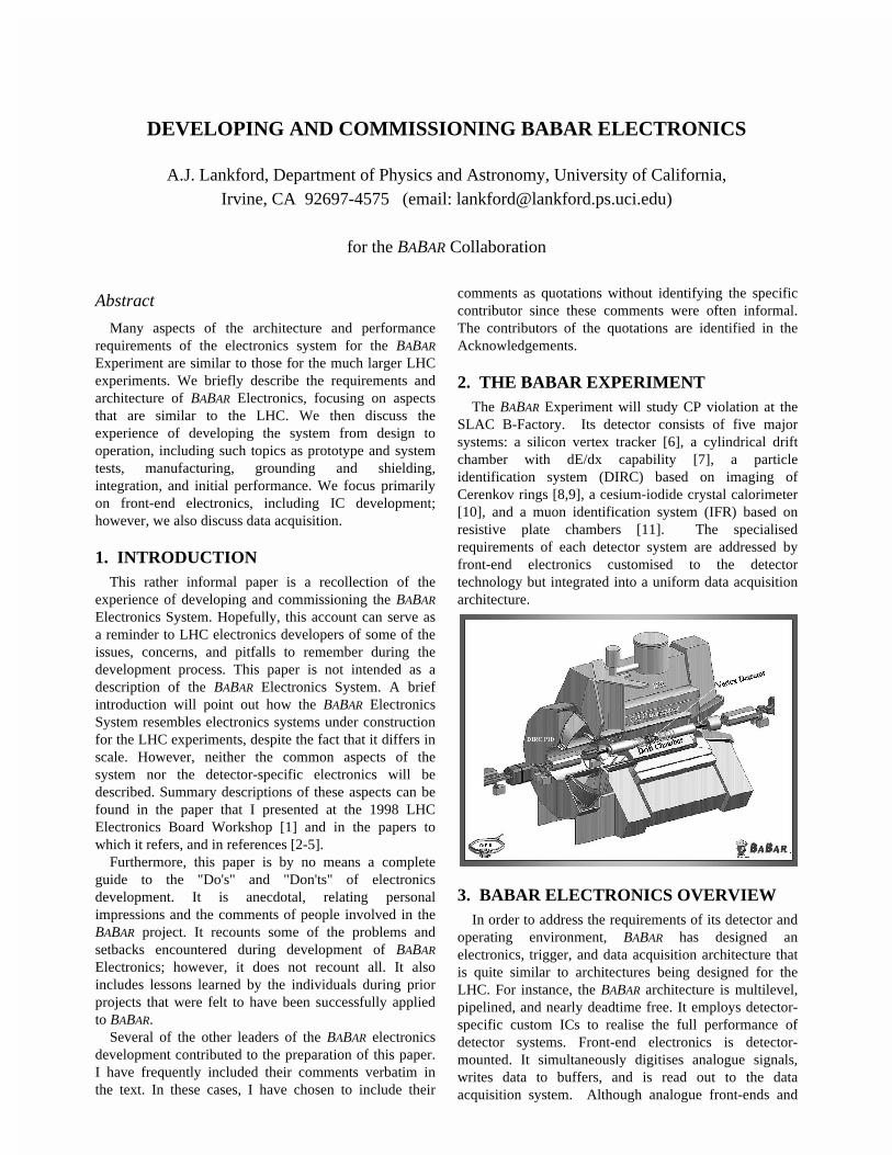
2. THE BABAR EXPERIMENTThe BABAR Experiment will study CP violation at the
SLAC B-Factory. Its detector consists of five majorsystems: a silicon vertex tracker [6], a cylindrical driftchamber with dE/dx capability [7], a particleidentification system (DIRC) based on imaging ofCerenkov rings [8,9], a cesium-iodide crystal calorimeter[10], and a muon identification system (IFR) based onresistive plate chambers [11]. The specialisedrequirements of each detector system are addressed byfront-end electronics customised to the detectortechnology but integrated into a uniform data acquisitionarchitecture.
3. BABAR ELECTRONICS OVERVIEWIn order to address the requirements of its detector and
operating environment, BABAR has designed anelectronics, trigger, and data acquisition architecture thatis quite similar to architectures being designed for theLHC. For instance, the BABAR architecture is multilevel,pipelined, and nearly deadtime free. It employs detector-specific custom ICs to realise the full performance ofdetector systems. Front-end electronics is detector-mounted. It simultaneously digitises analogue signals,writes data to buffers, and is read out to the dataacquisition system. Although analogue front-ends and

digital readout circuits are located in close proximity, fullanalogue performance has been realised without digitalnoise. The trigger system has two levels, with the optionfor an additional intermediate level. The first leveltrigger is based on pipelined hardware processors andutilises tracking and calorimeter data. The higher leveltrigger is based on an online event-processing farm ofcommercial processors and is integrated with a network-based event builder into the data acquisition system. Theonline system also includes a prompt reconstructionphase that performs full “offline” processing of the data.
The BABAR design incorporates an unusual level ofstandardisation across detector-specific subsystems.Front-end electronics is customised to detector-specificneeds; however, front-end buffer architecture and front-end links and protocols, for both readout and control, arestandard. All off-detector electronics is standardised. TheBABAR Readout Module provides standard interfaces totiming, data acquisition, and detector controls systems. Italso provides a standard platform and code framework fordetector-specific pre-processing and calibration code.Data acquisition crates, fast control and timing modules,and much detector controls hardware are also standardacross BABAR systems.
All front-end electronics subsystems of BABAR share acommon architecture. Each front-end chain consists ofan amplifier, digitisation (discriminator or flash ADC), acircular buffer (to store data during level 1 latency), and aderandomizing buffer (to store data between the level 1accept and transfer to a Readout Module). Analoguesignal processing, digitisation, and data readout occursimultaneously. All front-end subsystems except the IFRprovide data sparsification. All level 1 latency buffers aredigital; hence, it is possible to store data longer thananalogue buffers would allow. The buffers of all front-end systems are managed by a common protocol. Alllevel 1 latency buffers function as pipelines of fixedlength, and all derandomizing buffers function as FIFOswhich are capable of storing a fixed number of events,regardless of the actual implementation of the buffers.For instance, in the readout IC of the vertex detector [7,8], the derandomizing buffer holds four events in a seriesof a registers, two buffers, and the sparsification logic;whereas, in the drift chamber digitizer IC [9, 10], thederandomizing buffer is an SRAM that stores waveformsfor four events.
Each front-end subsystem also shares standard BABAR
interfaces to the detector-spanning, or common,electronics subsystems. In all cases, the front-endelectronics is mounted directly on the detector forperformance reasons. This solution also substantiallyreduces required cable plant. The design of eachdetector-specific subsystem balances its individual andcommon requirements in order to achieve a cost-effective, robust, and easy to maintain implementation.Custom integrated circuit solutions have been adopted for
four of the five detector subsystems. Seven customintegrated circuits were developed.
3.1 Catalogue of BABAR custom ICs
For the silicon vertex detector, a 128-channelamplifier/shaper/discriminator IC (ATOM) [2,12-15] wasdeveloped by Pavia, LBNL, and Santa Cruz. It features aprogrammable shaping time and a 4-bit, time-over-threshold pulse height measurement. It contains a level 1latency buffer, sparsification, derandomizing buffer,readout control logic, and a 60Mbps serial output. It wasfabricated in Honeywell rad-hard 0.8µm CMOS.
For the drift chamber electronics [3], a four-channelamplifier/shaper IC (DCAC) with analogue anddiscriminated outputs was developed by Santa Cruz inMaxim CPi semi-custom bipolar. In addition, an 8-channel drift chamber digitizer chip (ELEFANT) [16-18]was developed by LBNL. It features a TDC with 1ns binsand a 15MHz, bilinear, 6-bit flash ADC for each channel.It also includes a level 1 latency buffer, sparsification,and derandomizing buffer. It was fabricated in HewlettPackard triple-metal 0.8µm CMOS.
For the DIRC electronics [4], an eight-channel, low-noise, amplifier for phototube signals with zero-crossingdiscriminator and a multiplexed analogue output [19] wasdeveloped by Orsay in AMS 1.2µm CMOS. A 16-channelDIRC Digital Chip [20] containing TDCs with better than250ps linearity was developed by LPNHE Paris 6-7. Italso contains a programmable level 1 latency buffer,sparsification, and derandomizing buffer. It wasfabricated in Atmel-ES2 double-metal 0.8µm CMOS.
For the calorimeter, a single-channel low-noiseamplifier chip was developed by SLAC. It contains onlyone channel for reliability/redundancy reasons. It alsoprovides a split-range output and a cable driver. A 4-channel Calorimeter Auto-Ranging & Encoding chip(CARE) [5] was also developed by SLAC. It provides asample & hold on four amplitude scales and encodes theindex of the scale of interest. Both calorimeter chips werefabricated in AMS 1.2µm CMOS.
4. ORGANIZATION
4.1 Organisation of the Electronics System
The BABAR Electronics System incorporated allelectronics related activities into a single comprehensiveelectronics working group. The Electronics Systemincluded front-end electronics, data acquisition, trigger,including the level 3 trigger, electronics for detectorcontrols, and electronics infrastructure. The onlyelectronics components that were not provided by thisoverall working group were the detector-mountedcomponents (readout IC and hybrid) of the vertexdetector, although the overall electronics organisationwas involved in reviews of these components. In general,

the same working group also provided all softwaredirectly associated with electronics. For instance, thesoftware of the data acquisition system, of the level 3triggers, and for electronics initialisation, diagnostics, andmaintenance was provided by the electronics workinggroup. Of course, the overall working group includedsubgroups working on subprojects, such as drift chamberelectronics, and these subgroups further split into smallersubgroups as appropriate.
The purpose of organising all the electronics in a singledetector system working group was to facilitate co-ordination and to foster common solutions. Ascommented by a leader of one of the electronicssubsystems, "The grouping at the design and realisationphase of all electronics in one electronics group provedvery effective to assure commonality and uniformity. Thecaveat here is to maintain enough relationship with thesubdetector group, but this is not very hard to achieve."We found that the bond between individual electronicssubsystems and their respective detector systems wassufficiently strong that it was not necessary to explicitlyplace the electronics subsystem group within the detectorsystem organisation. We found that our organisationbound together, in a closer way than would otherwisehave been possible, all the electronics subsystems,including the trigger and data acquisition systems. Thisorganisation worked quite well throughout theconstruction project. It contributed to a coherent overallsystem design, including shared design solutions amongelectronics subsystems. It contributed to the constructiveattitude of design reviews performed by peers. It resultedin subsystems helping each other during design andduring implementation. It also afforded the projectleaders flexibility to redirect resources and effort whennecessary.
4.2 Working with multiple institutions
When a working group consists of a large number ofinstitutions, there is need for good communications andfrequent contact. The BABAR Electronics working groupincluded about 28 institutions from five nations. One ofthe electronics subsystem leaders commented,"Developing electronics with the involvement of severallabs on two continents requires very good communicationbetween teams. Thanks to the Web and videoconferences,it is now easy to exchange quickly any kind ofdocuments. However, at the very beginning and at theend obviously, nothing can replace meetings and work in-situ."
Even with the Web and video conferencing, significanttravel is needed as part of the communications.Participants must travel to meetings regularly, althoughnot all participants from each institution need to travel toeach meeting. During the design phase, BABAR heldmeetings of the overall working group about six times per
year, at four collaboration meetings and at two additionalelectronics workshops. These meetings were held both inthe U.S. and in Europe, with at least two per year inEurope.
The electronics co-ordinators, particularly at the levelof the "system manager" and "system engineer", mustalso perform site visits to demonstrate their interest, tofoster close co-operation, and to meet the participants atinstitutions that they might not meet through meetings.Site visits of course also offer the opportunity to see firsthand the facilities at participating institutions and to seethe work being performed.
In multi-institutional projects, design reviews are evenmore important than they otherwise would be. Thisimportance is because they help compensate for difficultcommunications. For instance, they provide a criticalopportunity to carefully examine interface definitions andimplementations of interfaces.
By paying attention to the need to communicate, that isby arranging frequent meetings and providingmechanisms for communications between meetings, it ispossible to draw upon the strengths of many institutionswithout compromising the integrity of the electronicsdesign. It is important to have at least one very qualifiedperson at each institution in order to make certain thatwork is on track and compatible with the overall systemdesign. The importance of communicating betweenmeetings should be stressed. The timely completion ofthe project requires that questions and open issues not beleft unanswered or unresolved until the next meeting.Email, telephone, or special meetings should be used toresolve issues promptly as they are identified and asresolution is needed.
5. REQUIREMENTSDefining requirements at the outset of the project is
essential. Requirements provide the yardstick againstwhich performance of prototype and production systemsis measured. Without this metric, the collaboration risksthat the system under development will not meet theperformance requirements of the experiment. There arealso the risks that the design effort will not converge asthe design team strives for unnecessary performance orthat the design solution will be unnecessarily complex,causing undue technical risk.
Requirements should be realistic. Overly stringentrequirements can cause the same risks relating tounnecessary performance and complexity mentionedabove. Proper discourse between physicists and engineersduring the definition of requirements, and ultimatelythroughout the design and prototyping phase, can helptremendously in achieving a set of requirements that areboth adequate and practical.
Achieving appropriate design solutions requires a goodknowledge of the problem being addressed, including anunderstanding of the context of the problem. This
knowledge and understanding can be more difficult toachieve in the multi-institutional efforts of largeexperiments. As observed by one of our electronicssubsystem leaders, "With the growing size of theexperiments, it is more and more important that peoplework with a sufficient knowledge of the context in theexperiment, where a piece of circuitry is sitting, how it isintended to be used, which issues can be expected if somerequirements are not met." An appropriate set ofrequirements properly defines the problem to beaddressed. Documentation explaining the requirementscan provide an understanding of the context.
When defining requirements, one should keep in mindthat "Simple is beautiful!" Again, collaborative projectsexacerbate the tendency to define requirements or designsolutions that are unnecessarily complex. As observed byone of our electronics subsystem leaders, "Everyone canadd features that delay and sometimes compromise themain goals. Unnecessary complexity is often the result oftoo many people interacting. This is a drawback of easycommunication." The tendency towards complexityshould be properly checked. Why take undue technicalrisk? That risk leads ultimately to cost risk, schedule risk,or both.
Requirements should be documented. Documentationis necessary in order that the requirements are notforgotten during the design process. It also makes therequirements available to newcomers on the project. Inaddition, the motivation or justification for eachrequirement should be documented. Documenting thejustification enables designers to understand and recallthe origin of any requirement, frequently enabling adesigner to question a requirement that is provingdifficult to satisfy. Documenting the justification forrequirements also provides a method of checking thatrequirements are still valid as time passes and a projectevolves, in case the underlying assumptions of some keyrequirement change.
6. SYSTEM DESIGNA coherent system design is the central component of
an adequate technical solution. The system design shouldbe developed first, before developing detailed solutions toaspects of the overall problem. The system design shouldbe developed from the "top down" from the requirementsthat should be addressed and from a clear vision of asolution that addresses the entire scope of the task."Bottoms up" designs, which derive from a solution toonly a part of the task or that originate in a desire toemploy a particular technical solution, should be avoided.Although it seems obvious to say that the first step indesign should be a top-down system design, in practice,design often does not happen that way.
For BABAR, we felt that it was important to develop asystem design with unified solutions for the mechanismsthat control the front-end electronics, for data acquisition
for all front-end electronics subsystems, for monitoring ofelectronics, and for slow control and monitoring ofdetector systems. Such common solutions simplify theoverall design and greatly ease integration.
When establishing common solutions, it is important togain acceptance of all electronics subsystems and to givesubsystems flexibility in the detailed implementation ofthe solution. Acceptance is of course important to thecompleteness and success in the implementation ofcommon solutions. In BABAR we gained acceptance byinvolving the entire community, through the overallelectronics working group, in the development of BABAR
protocols and standards. Flexibility in the detailedimplementation of common solutions allows subsystemsto tailor protocols and standards to the details of theirsystem. Allowing subsystem-specific details in theimplementation also helps subsystem designers to take"ownership" of the design of their subsystems.
Each design team should understand its requirements,and it should depart from convention when a departuresimplifies system design or allows an importantoptimisation. For instance, although BABAR adopted a"standard" deadtimeless, multilevel architecture, certaincharacteristics of BABAR allow its architecture toincorporate some unusual features. For instance, all level1 latency buffers in BABAR are digital, i.e. there is noanalogue storage during the level 1 latency. Thischaracteristic allowed BABAR to adopt an unusually longlevel 1 latency (12.5µs) without impacting the cost offront-end electronics. The benefit of this long latency wasa level 1 decision time significantly longer than usualvalues of two to five microseconds. The longer decisiontime simplifies trigger requirements and reduced the costof level 1 trigger. Similarly, modest hit occupancies inBABAR detector systems result in bandwidth requirementsthat fit comfortably within the capabilities of existingoptical link technologies. The resulting headroom inbandwidth facilitated adoption of a "data-pull"architecture between the buffers in the front-endelectronics and the data acquisition system, as opposed toa "data-driven" or "push" architecture, without aconsequent increase in deadtime. This architecture avoidsdata loss, and it greatly simplifies buffer management andevent synchronisation.
In order to result in a high performance system that iseasy to bring into operation, the system design mustinclude attention to power supplies and powerdistribution, grounding and shielding, cabling, andcooling. These are demanding areas that require attentionduring the design phase in order to avoid awkwardremedies to problems discovered during commissioning.In BABAR, we were fairly successful in achievingattention to detail; however, problems arose in some areaswhere we were not sufficiently attentive. For instance,one of our front-end subsystems required several retrofits
to the location and mounting of electronics on thedetector.
Because system design demands insight intorequirements, a broad view of possible technicalsolutions, and attention to detail, an experiencedelectronics engineer can contribute invaluably to thesuccess of the system design.
6.1 Connectors and connections
With respect to reliability and signal integrity,connectors and connections are often the weakest link ofthe electronics chain. Furthermore, connection problemscan be very difficult to diagnose. For instance, in BABAR,we had a problem with some of the backplanes in ourdata acquisition crates. These were custom backplanesthat we fabricated separately from the crates. They weresomewhat thicker than a standard backplane, and the pinsdid not always contact the pathways in the backplane.Contact would sometimes be lost when cards wereplugged into the crate, resulting in unpredictablebehaviour of the backplane that could not be diagnosedby interchanging modules and spares.
Because problems with connections can be difficult todiagnose, they should be avoided in advance by carefulconsideration during the design phase. Testing, bothduring the design phase and during production, can helpavoid problems. As commented by the leader of one ofour electronics subsystems, "Pay special attention tocables and connectors. Get the best quality you canafford. Cheap connectors in particular can lead to lots ofheadaches. Make sure the vendor does a thorough test ofeach cable (not just a random sampling of connections).Specify what resistance constitutes an open or a short.Get an early sample and give it a workout to see if anyshorts or opens develop. We thought we had done this,but when we actually started working with the cables wewished we had spent even more on connectors."
Problems with connections often arise when theelectrical connection also provides mechanical support.To avoid such problems, always provide mechanicalsupport that is independent of the electrical connection. Asimple example is to strain relieve cables where theyconnect to printed circuit boards. Electrical connectionscan also be broken due to mechanical stress in theconnections between motherboards and daughterboards ifadequate mechanical support is not provided. Forinstance, in BABAR we experienced problems betweentwo detector-mounted boards on the calorimeter. Ourcalorimeter Input/Output Boards (IOBs) directly pluggedinto right-angle connectors on ADC Boards (ADBs). Theelectrical connection between the connector and the boardon the ADBs was frequently broken during mounting orremounting of the IOBs. This type of problem isparticularly insidious because a new problem (a brokenconnection on an ADB) can easily be created when tryingto remedy an existing problem (a failure on an IOB).
6.2 Grounding and shielding
Details of grounding and shielding are critical to theperformance of analogue front-end electronics. Eachelectronics subsystem needs to invest careful design in itsgrounding and shielding plan. In fact, one subsystem withpoorly designed grounding or shielding can adverselyaffect other subsystems.
In BABAR, we had a fairly successful experience withgrounding and shielding in our final installation. Detailedgrounding and shielding plans were part of design andwere included in design reviews. In summary, detectorsubsystems in BABAR are isolated from one another. Eachhas a single point ground. Extensive work was done ongrounding and shielding during prototype and systemtests. Consequently, relatively little further work wasneeded during final installation. The in situ performanceexceeds requirements, and is as good as on the bench.The one exception is the calorimeter power supplyproblem discussed in Section 12, the whose remedy ispresently being implemented.
7. PLANNINGPlanning a project such that enough time is allocated to
each stage of the project, for instance to design andprototyping, procurement and fabrication, and installationand commissioning, can be important to the timelysuccess of the project. It is particularly important tobudget adequate time for design. Adequate time ondesign can avoid later problems, as pointed out by one ofthe leaders of our electronics project, "Spendingsufficient time to make sure the design (overall anddetail) is right and that it communicates properly withother parts is very important, since making it later workby testing and debugging the hardware is much more timeconsuming and expensive."
In order to maximise the amount of time available fordesign of BABAR electronics, while budgeting adequatetime for subsequent project phases, we drew up ourproject schedule by planning backwards from the earliestdate that electronics could be used by each detectorsystem. In reverse order, we conservatively scheduledtime for commissioning, installation, testing, production,and prototyping. Then we added some schedulecontingency to our estimates for those phases. Finally, weallocated all the remaining time for design. Fortunately,we performed this planning exercise sufficiently earlythat this approach led to ample allocations of design time.
7.1 Design iterations
For all board-level components, we scheduled threeiterations: one full-functionality prototype, one prepro-duction model, and one production run. In some cases,the full-functionality prototype was preceded by partialprototypes. The preproduction model was intended to beidentical to the production version and was intended to
validate the final design, although in some cases weallowed further small design changes between thepreproduction model and the production version. In suchcases, we generally assembled and tested first articles ofthe production design before assembling the entireproduction run. Likewise, for high volume items, we alsogenerally assembled and tested first articles beforecompleting the full system.
For custom integrated circuits, we planned for moreprototyping rounds than were budgeted for board-levelcomponents. Our experience was that our custom ICsrequired between four and eight iterations in total fromprototype through production. Our Drift ChamberAmplifier Chip (DCAC), of which we neededapproximately two thousand chips manufactured in aMaxim CPi semi-custom bipolar process, required aboutfive iterations (1 prototype run, 2 preproduction runs, and2 production runs). This number of preproduction andproduction runs included mistakes made by themanufacturer which, although not really design iterations,nevertheless cost time in our schedule. Our DriftChamber Digitizer Chip (ELEFANT) [16-18], of whichwe needed about one thousand chips in a Hewlett Packardtriple-metal 0.8µm CMOS process, required about fouriterations (preprototypes of key functional blocks, 1 full-functionality prototype run, 1 preproduction run, and 1production run). Our DIRC Analogue Chip [19], of whichwe needed about 1500 chips in an AMS 1.2µm CMOSprocess, required about six iterations (3 prototype runs, 2preproduction runs, and 1 production run). Our DIRCDigital Chip [20], of which we needed approximately 750chips in an Atmel-ES2 double-metal 0.8µm CMOSprocess, required approximately five iterations (3prototype runs, 1 preproduction run, and 1 productionrun). Our Calorimeter Amplifier Chip, of which weneeded approximately thirteen thousand chips in an AMS1.2µm BiCMOS process, required approximately eightiterations (1 semicustom preprototype run, 3 prototyperuns, 1 preproduction run, and 3 production runs). In thiscase, the number of production runs included issuesbeyond our control at the manufacturer. Our CalorimeterAuto-Ranging & Encoding Chip (CARE) [5], of whichwe needed approximately two thousand chips in an AMS1.2µm BiCMOS process, required approximately seveniterations (1 semicustom preprototype run, 3 prototyperuns, 1 preproduction run, and 2 production runs). Againin this case, the number of production runs was increasedby incidents beyond our control. Note that the abovestatistics are not exact, and do not count multipleprototyping and production runs in the same way fromchip to chip.
7.2 Manpower
In BABAR, one of our biggest problems was the loss ofengineers during the project. This problem wasparticularly significant at U.S. and U.K. laboratories. We
suffered many delays from this problem. For example, onthe vertex detector readout IC, as described by one of theproject leaders, "We basically had 100% turnover of theU.S. engineers, which was a real nightmare. Luckily, thePavia group stayed on the project and provided somecontinuity …". Loss of engineers during the project wasprimarily caused by job opportunities in industry.
Engineers are still needed after the design andprototyping phase. They are needed through thedebugging and commissioning phase as well. Asobserved by the leader of one of the BABAR electronicssubsystems, "With the long time frame [of the project],we couldn't keep any engineer on board, and had noengineer available for debugging. This really hurt."Engineering work is not complete until the readoutsystem is fully commissioned and operational.
The possibility of losing an engineer during a project,means that having a single engineer working on acomplex, critical project is dangerous. As stated by theleader of one of BABAR's electronics subsystems, "I thinkthe main lesson is to have few or no one-engineer sub-projects, since they become zero or minus one engineerprojects with Poisson statistics." For instance, at onepoint, we lost the one engineer working on our ReadoutModule that serves all detector systems. Although werecovered in time to complete Readout Moduleproduction on schedule, this debacle delayed our dataacquisition software development by many months,making it much more difficult to prepare detector-specificsoftware for commissioning. The loss of this engineerwas such a significant setback for BABAR that it is perhapsworthwhile to describe how we recovered, and, in thisaccount, to sketch the design of the Readout Module as itwas completed.
7.3 The BABAR Readout Module
When the lead engineer for the Readout Module(ROM) design left the project unexpectedly in latesummer 1996, a prototype ROM had already been built,and the design of the preproduction model of the ROMwas largely complete. Nevertheless, in order to completethe ROM project as rapidly as possible, we decided tostart a new design that was quite different from theoriginal. The new ROM conceptual design addressed thesame requirements as the original; however, it had theadded goal of not requiring the same high level ofengineering, i.e. to require a level of engineering lesssophisticated than the original design. The new design didbenefit from some of the experience gained during theinitial design. Being modular, it facilitated multipleengineers to participate in the design, and it alsosomewhat decreased the coupling between ROMhardware design and data acquisition software design.The production cost of the new solution was more costlythan would have been the case with the original design,because the new design uses embedded commercial CPU

boards. Nonetheless, the additional production cost wasoffset by reductions in the number of ROMs required andby reduced engineering costs. The new design and firstprototype of this complex module was completed in justover one year.
The implementation of the BABAR ROM consists offour printed circuit cards that assemble into a single-width 9U VME module. A commercial single boardVME computer (Motorola MVME2306) running a real-time operating system (Wind River VxWorks) buffers andprocesses data and interfaces to VME. A customcontroller board provides the interface to the fast controland timing system and manages front-end buffers and thetransfer of data. A custom personality module interfacesto the controller card via a private bus and interfaces tothe front-end electronics through BABAR-standard controland data links. There are two types of personality module.The first type is used by all detector systems for controland by all systems except the calorimeter for datatransfer. The second type is used only by the calorimeterfor data transfer. Finally, a custom PCI mezzanine card(PMC) interfaces between the CPU and controller boardsand provides the DMA engine (Intel i960) for datatransfer from event data buffers on the personality card toCPU memory via a PCI/i960-bus bridge.
8. REVIEWSReviews played an important role in the development
of BABAR Electronics. We instituted a series of threedesign reviews for each component or subsystem. Thegeneral scheme of our reviews followed a plan proposedby R. Jared of LBNL for the SDC Experiment. Oursystem of reviews was fairly similar to those of thequality assurance plan of the Rutherford Laboratory.Each electronics subsystem and each electronicscomponent, either IC or board, underwent a series ofthree reviews. The three reviews were:
PDRR+CDR: This review was the Preliminary DesignRequirements Review and Conceptual Design Review. Itwas held when requirements definition and conceptualdesign were complete and before detailed design began. Itreviewed the appropriateness of the requirements that hadbeen defined, and it reviewed whether the proposedconceptual design addressed requirements.
PDR: This review was the Preliminary DesignReview. It was held following completion of detaileddesign and before fabricating the first full-functionalityprototype. It was a detailed review of interfacespecifications and schematics. It also reviewed results ofpartial prototypes.
FDR: This review was the Final Design Review. Itwas held following completion of prototyping and ofsystem tests and before production fabrication wasstarted. It focused on completeness of the detailed designand on results of prototype and systems tests, where testresults were measured against the requirements that had
been defined at the first review. The Final Design Reviewalso reviewed plans for acceptance testing of productionunits.
For integrated circuits, there were often additionaldesign reviews before each submission.
Note that BABAR electronics reviews were tied tomilestones in each subproject. Consequently, each reviewwas held when there was a definite purpose to the review.BABAR did not perform periodic reviews of theelectronics. We felt that reviews tied to milestones weremore effective than periodic reviews. Because thedevelopment of BABAR Electronics was rather rapid, theperiod between reviews for any subsystem or componentwas never longer than about nine months. Note that inaddition to these reviews, each subsystem reportedprogress at collaboration meetings and electronicsworkshops.
In BABAR, most reviews were tied to the submission offabrication runs. This timing avoids the unnecessaryexpense of fabricating something that will not workbecause it is designed to the wrong functional or interfacespecification. A leader of one of BABAR's subsystemssuggests, "Have a sign-off procedure so that nocomponent can be submitted for production (prototype orfinal) until the people responsible for the componentsconnected to it in any way (mechanical or electrical) havereviewed and signed off on the design. System managershould also sign. … [This procedure] caught manyproblems before it was too late."
Our review procedure was well accepted within theelectronics leadership and community. As commented byone of the subsystem leaders, "The concept of regularreviews at fixed intervals in the project was a very goodthing. Our own experience … was the first [PDRR+CDR]and final [FDR] one were very useful." Another commentwas "Do reviews early on."
A qualified and appropriate review committee isessential to an effective review. In BABAR, each reviewcommittee included a physicist from the appropriatedetector system who was familiar with its requirementsand performance. The largest part of the reviewcommittee consisted of engineers and physicists fromother electronics subsystems. These members werefamiliar with the architecture of BABAR Electronics andwith the issues of concern in developing electronics. Eachcommittee also included engineers and physicists fromsystems that interface to the system under review andwho were familiar with interface requirements. Finally,each committee included one or two outside reviewers,who provided their experience and wisdom to the review.
Each BABAR electronics review required formaldocumentation. Electronics management provided the listof required documentation. Most of the requireddocumentation was documentation that should bedeveloped during the normal course of design;consequently, very little additional documentation was

required. For instance, the following documentation wasrequired for the Final Design Review:
Updated materials from the PDR:• Requirements Document• Hierarchical set of block diagrams• System Description (at level of block diagrams)• Interface Specifications Document• Grounding and Shielding Plan• List of deliverables• Cost estimate• Production schedule
New materials for the FDR:• Summary of design changes since PDR• Detailed schematics of production components• Mechanical drawings of production components• Reliability analysis of components and of system• Results of tests of individual preproduction units• Results of system tests of preproduction units• Quality Assurance Plan, including:
Production plansBurn-in plansAcceptance test planMaintenance plan
• Cooling and Access Plan• Cable specifications (including safety ratings)
Documentation was circulated, usually by posting onthe Web, approximately one week in advance of eachreview. We found that the review was generally noteffective when documentation was not available well inadvance.
For each review, the committee provided a writtenreport. Before finalisation, draft committee reports weresent to the group being reviewed in order that factualerrors in the report could be corrected. These reportsserved as recommendations to the Electronics Systemleaders. Written responses to committee reports were notrequested. After consultation between the leaders of theElectronics System and the group under review, it wasagreed which recommendations would be implemented.Generally all recommendations were implemented;however, there were cases when it was agreed that someparticular committee recommendation should not beimplemented, either because the recommendation was notpractical or not in the experiment's best overall interests.
In order to allow the fullest participation of the groupwhose work was under review, and to foster thecollaborative aspects of the review process, designreviews were usually held at the home institution of oneof collaborating design teams.
In order to perform an adequate review, a designreview must be sufficiently long to allow the committeeto understand the design and to allow ample time forquestions and discussion. In BABAR, we felt that it wasparticularly important that the review committee be leftwith no outstanding questions or misunderstandingsduring their deliberations. Consequently, we also
scheduled discussion following committee deliberations.Our electronics reviews were generally two to three daysin length, although reviews of individual componentswere frequently performed in a single day.
Peer reviews can have a positive impact on thecollaborative spirit and effectiveness of electronicsdevelopment. As commented by one of the participants,"Reviews offer opportunities to exchange ideas, stay on(or leave a bad) track, get out of your computer screen."
9. MANAGEMENTOne purpose of project management is to help avoid
setbacks and mistakes. The following comments arerelated to this purpose.
• Everyone involved in electronics development andmanagement should appreciate that "If it can gowrong, it will go wrong." Fortunately, thisstatement is not completely true, but plan forsetbacks.
• Problems don't go away on their own. If leftunattended, problems only grow worse. Beproactive, focus on priorities, keep everythingmoving forward.
• There is no problem that cannot be solved, in asystem that is well-designed and well-planned.Nonetheless, solutions often require time and/ormoney.
• Good system engineering helps avoid manymistakes and setbacks.
10. COST CONSIDERATIONSClearly, cost must be a consideration during design.
Nevertheless, one must avoid undue technical risk whentrying to reduce costs. In particular, systems should bedesigned to meet requirements in their first productioniteration, even if more expensive. The cost and scheduleimpact of failing usually overshadows any small costsavings. As pointed out by one of the leaders of BABAR
Electronics, "Cutting cost in order to save money willcost a lot more later to fix the problem."
Cost considerations during parts selection can oftenlead to costly retrofits or long term problems. Forexample, BABAR experienced a significant problem withreliability of the optoelectronics used to transmit datafrom the calorimeter to its Readout Modules. Thissubsystem used approximately 300 G-links and wasexperiencing about one failure of the optotransmitters perweek until all transmitters were replaced. Failures causedloss of data, and required frequent resynchronisation ofthe troubled links. The problematic transmitters were notthe same unit used during prototyping. Prototypes andother BABAR subsystems used a transmitter from Finisar.The problematic transmitters were purchased because oflower cost. The units purchased were manufactured byMethode under license from Finisar. At the time of

purchase, we were not aware of the fact that the Methodeparts we purchased used CD lasers; whereas, the Finisarunits available at that time used VCSELs. Short lifetimeof the CD lasers caused the problematic failure rate. Infact, Methode no longer fabricates the model that BABAR
used, and Methode Gigabit Ethernet transmitters useVCSELs. Until replacement, these transmitters were ourlargest reliability problem.
11. SYSTEM TESTSSystem tests can avoid integration problems and
problems of scale. A system test is a test of the completereadout chain, from front-end to data acquisition. Itincludes an actual or prototype detector, enough channelsto detect large scale system problems, and actual powersupplies, grounding, shielding, etc. The purpose of asystem test is to validate that system performance isconsistent with requirements. In BABAR, we required asystem test for each subsystem before full scaleproduction. Although our tests did not reveal any seriousproblems, they did help us refine grounding and shieldingplans in some of our subsystems. They also gave us theconfidence to enter production without worry ofsignificant setbacks that would be costly in terms ofmoney or valuable schedule time. In the case of oneBABAR electronics subsystem, if the system test hadinvolved a larger number of channels, two problemsfound later might have been avoided. As that subsystemleader commented regarding the "Importance of pre-testing a reasonably large sample of pre-production partsbefore going into production. We had two failures, whichreally were components. One was in manufacturing(solder-on surface-mount connectors), and the other wasthe bad transmitter problem [described above]. If we hadmade a larger preproduction and had a longer time tobreak it in, we might have spotted it."
12. VENDOR QUALITYInexperienced vendors will often take longer to
complete projects within specifications than experiencedvendors. Moreover, there is some risk that aninexperienced vendor will never be able to manufactureproduction units that consistently meet specifications.BABAR experienced two important problems withmanufacturers of electronics components, one in thecalorimeter subsystem and one in the vertex detectorsubsystem.
The problem in the calorimeter electronics subsystemwas with power supplies for the front-end electronics. Asdescribed by one of the subsystem leaders, "In openEuropean bidding, we got much lower bids fromcompanies with no experience in building the sort ofproduct we wanted. Our power supplies would no doubthave been well made by" experienced companies "but thecompany that made ours learned on the job." The
consequence was that the supplies were delivered at thelast moment and were out of specification. Theycontributed common-mode coherent noise at about twotimes design value until additional external filters wereinstalled on all supplies.
The problem in the vertex detector subsystem involvedhybrids for the detector-mounted electronics, andultimately led to changing vendors. The experience ledone of the subsystem leaders to comment, "The key wasto identify a good vendor, and not to waste a lot of timeworking with vendors who could not quite meetspecifications. Once we found the right vendor it turnedout very well." The original vendor, who produced toysand consumer electronics, was not familiar with hybridsof the quality needed for the vertex detector. Theconsequence was a huge delay in our ability to test thevertex detector readout chip in large numbers withdetectors. Such key components "should be on a fast-track with a very experienced and responsible group incharge." It is often a delicate issue to change vendors;however, a timely change can often save time or evenrescue a project.
13. CUSTOM INTEGRATED CIRCUITSCustom integrated circuits have profoundly changed
the way front-end electronics systems are designed.Indeed, there is no other way to build most present highenergy physics experiments. However, the use of customintegrated circuits implies years of development, and thedevelopment period is almost always underestimated. Aspointed out by one of the BABAR designers of integratedcircuits, one of the reasons for underestimatingdevelopment time, among others, is that there isessentially no room for even the smallest error during themulti-step development process. "If simulated, a chipmay work; if not, it never works." The same is true for ICevaluation testing. Furthermore, throughout thedevelopment process, "One relies strongly on industry,academic design centres, and students. One single failureis able to compromise months of efforts, and due to thesize of projects, it is impossible to cross-checkeverything." The demanding task of developing a full-performance IC can be further complicated byunnecessary complexity. Consequently, as pointed out byone of the subsystem leaders, "You can never startcustom IC design too early in the project, it is usually thepacing item. Always budget time and money foradditional prototype runs to fix the mistakes you didn'tknow you would make." And as remarked by an ICdesigner, "This is the price to pay for getting bothquantity and quality."
13.1 Unexpected IC setbacks
Development of custom integrated circuits can also bedelayed by unforeseen circumstances beyond the controlof the design team. BABAR experienced several such
delays. Because an engineering change order twice wasnot transmitted properly between foundry and packaginghouse, two consecutive fabrication runs of our DriftChamber Amplifier Chip (DCAC) were incorrectlybonded and were useless. In another incident, thecomplete order of our Calorimeter Auto-Ranging &Encoding (CARE) chip disappeared in U.S. Customs. Inthe case of our Calorimeter Amplifier Chip, we ended upwith three slightly different shaping times that requiredamplifiers to be sorted and grouped for trigger reasons.The second shaping time arose because the foundry fullyprocessed only a portion of the production run untilreceiving our evaluation of its performance, and thenprocessed the remainder of the run. The third shapingtime arose because the manufacturer overestimated theyield, and did not produce enough working chips in thefirst production run. One can draw separate lessons fromeach incident; however, the general conclusion is that oneshould plan for setbacks and delays. In BABAR, weexperienced delays beyond our control on three of ourseven custom ICs.
13.2 Radiation-hard ICs
Radiation-hard integrated circuits pose additionalchallenges to IC development. In the case of the BABAR
vertex detector readout chip (ATOM), one of thesubsystem leaders drew the following conclusions, someof which are general and some of which are particularlyrelevant to development of a radiation-hard IC. In fact,the ATOM development followed most of thesesuggestions.
• "If the project is distributed across more than oneinstitution, try to use a common set of design andlayout tools (seems obvious, but we had twodifferent sets.)"
• "If you are prototyping in a rad-soft process for arad-hard design, adopt a set of layout rulescombining the most conservative rules of bothprocesses so that the layout does not need to bemodified in going from prototype in the rad-softprocess to pre-production in the rad-hard process.We prototyped in HP 0.8µm CMOS and fabricatedin Honeywell 0.8µm CMOS (both processes had 3metal layers)."
• "Submit any analogue circuit elements to the rad-hard process as early as possible in the designprocess."
• "If the rad-hard process is not well-characterisedby the vendor, plan to invest in the tools and theeffort to characterise it yourself and to understandwhat process variations you can expect."
• "Develop your own test structures to be inserted inthe reticule along with the one used by the vendorto qualify the run so you can figure out why a runfailed when the vendor says it passed QA andwants payment. We did this after problems with
the first production run. The test structure wesubmitted was a full channel with a lot of probepoints, and it was very useful for debugging theprototype. (Unfortunately we didn't include it inthe pre-production!)"
13.3 Vendor IC testing
Production testing of several of the custom integratedcircuits developed for BABAR was performed by themanufacturers. We were definitely pleased with theresults of doing the testing this way. It was fast, effectiveat eliminating bad chips, and cost-effective. Thecalorimeter amplifier IC was tested at AMS. BABAR
supplied the test jig. After some initial difficulties ofgetting the test jig to work properly, testing proceededvery quickly. We did not retest the chips until after theywere mounted in pairs on the amplifier boards. TheCalorimeter Auto-Ranging & Encoding (CARE) IC wasalso tested at AMS. For this chip, we supplied the testsequence and the limits of acceptance. The test vectorsand the circuitry were developed at the test house. We didnot retest the chips prior to assembly on the ADC boards.Less than about 0.5% of the chips failed upon retest afterassembly. The vertex readout IC (ATOM) was tested asdie at Honeywell. In this case, we supplied the probe cardand test vectors. Honeywell supplied the tester. The testset-up was difficult to debug at the foundry, but it gave avery rapid turn-around once the wafers were out offabrication. The DIRC Digital IC was tested by Atmel-ES2. The test vectors used at the factory covered about60% of the chip. The delivered yield was very good.
14. PRODUCTION TESTINGAcceptance testing of production units before
installation in the experiment is an important step in thedevelopment process. Adequate production testing can bea very time consuming process. Developing a test standsuitable for production testing can also be very timeconsuming. Acceptance testing should be planned inadvance of receiving the production run. In order toensure that acceptance test procedures were adequate inBABAR, we reviewed Acceptance Test Plans for eachcomponent before production as part of the Final DesignReview. One of the BABAR subsystem leaders suggests,"Agree on a set of testing specifications and proceduresfor every component, to be followed by the responsibleinstitution(s) and documented (on the Web if possible). Inthis way the history of every part is available on the Weband problems later on can be tracked down. Also you canbe sure that each part really meets the specs."
Easy-to-operate test fixtures are often needed foracceptance testing components in large numbers. Suchfixtures often require extensive software suites for tests.BABAR found that multiple test set-ups and stations weresometimes needed. More set-ups can be needed thanexpected or planned. A detector system leader suggests,

"Don't forget to build enough prototypes to provide acomplete electronics readout chain to every institutionthat will be building detector modules or testing front-endcomponents. … Budget enough spares to provide asimilar final test set-up wherever it will be needed tocarry out any maintenance or repairs."
14.1 Industrial board production and testing
Our French colleagues working on the BABAR DIRCsubsystem had a very satisfactory experience manu-facturing and testing their principal component, the DIRCFront-end Board (DFB), in industry. As described by thesubsystem leader, "We have been lucky enough tointerest a big company [Thomson CSF] for which costwas not so much an issue but that wanted to learn ourtechniques. Besides the (usual I guess) very highrequirements on quality and control for the fabricationprocess, the key action was to implement OUR test benchin the factory to fully validate the fabrication and to trainTHEM to use it." The tests at the factory includedcomplete point-to-point coverage of the card, burn-in,and testing with a test bench provided by BABAR. Fiftypercent of the DFBs passed the tests the first time at thefactory. When the cards were received in Orsay, furthertests were made. One hundred percent of the cards passedthe same tests in Orsay as they did in the factory. Fivepercent did not pass a set of more stringent final testsused in Orsay. The screening provided by these tests wasquite successful. Since installation, we have had only oneor two minor problems on 168 cards. As an additionalbenefit of manufacture in industry, the manufacturer aspart of the bid process computed the MTBF of the DFBs(for free). Note that BABAR required MTBF calculationsbefore production of all major components as part of theFinal Design Review.
15. INSTALLATION AND CHECKOUTBABAR generally installed and checked out each front-
end electronics subsystem on its respective detectorsystem before the detector system was installed in theexperiment. Installation and checkout in this way greatlyfacilitates and accelerates final commissioning in situ. Italso provides a better, more peaceful environment forcommissioning. For instance, for the particleidentification system (DIRC), front-end electronics wasassembled and tested on DIRC sectors in France beforeshipment to SLAC. They were then remounted andretested on the DIRC sectors in a staging area at SLACbefore installation of the DIRC. Meanwhile, off-detectorelectronics was installed in the counting house prior toDIRC installation. Only final cabling and checkoutoccurred after installation
We also found that system tests are a useful prelude toinstallation and checkout. Initial checkout is also greatlyfacilitated by existence of a subsystem of the final dataacquisition system or, in the absence of final data
acquisition components, by suitable test modules thatcould perform the essential data acquisition functionality.We were not as successful in BABAR at having fullsubsystems of the final data acquisition system availablefor early checkout as we would have liked, primarily dueto our problem with turnover of engineers. This situationmade the leader of one of the electronics subsystemsremark that "The lack of a readout platform beforeproduction was complete really made debugging systemproblems extremely difficult." We did however have testmodules and prototype data acquisition modules availablefor early checkout, and partial subsystems of dataacquisition for final installation. The full data acquisitionframework was only available at the last moment. Finally,we found that cosmic ray tests can provide an excellentopportunity to perform final checkout with the detector.
Installation and checkout are a manpower intensiveeffort, and teams of ample strength should be assembled.We did not have enough effort available during this phasein some of our subsystems. These were larger subsystemsthat had less capability of being checked out outside theexperiment prior to installation. The consequence was aprotracted commissioning period for these subsystems,and lower quality initial performance.
Installation and checkout require a team of physiciststhat is larger than needed during design and productionphases. However, it is often difficult to identify teams tocommission a subsystem that did not have a role in designand production of some component of the system.Consequently, the teams that will eventually do thecommissioning should be included in the project near thebeginning of the development process.
Commissioning requires appropriate software suites ofdiagnostics. These can be the basis of final in situdiagnostic programs, if they are based upon (orcompatible with) the APIs of the data acquisition system.In situ diagnostics should be capable of validating properoperation of the entire electronics chain, includingconnections to the detector and of localising failures tothe replaceable component (board, cable, etc.). Morerefined diagnostics for board repair can be reserved forthe test bench. Developing the needed diagnostic suites isanother major software effort associated with electronicsdevelopment.
16. DATA ACQUISITION
16.1 Partitioning
Partitioning refers to the simultaneous and autonomousoperation of portions of the data acquisition system withfull functionality. For example, the drift chamber andparticle ID system can use the cosmic trigger, while thevertex detector does threshold scans, while the level 1electromagnetic energy trigger uses the calorimeter forcheckout, while the calorimeter diagnoses failures in onecrate, etc. Partitioning is important for efficient
integration of detectors into the central data acquisitionsystem, for efficient checkout and commissioning ofdetector subsystems, and for efficient calibration andmaintenance of detector subsystems. Partitioning ispervasive. It must be implemented in all systems thatcontrol and initialise electronics subsystems, thatdistribute fast timing and trigger signals, that acquire datafrom electronics subsystems, and that control the detector(e.g. high voltage).
BABAR implemented a system that allows partitionswith any combination of crates, utilising any combinationof triggers. It also allows trigger crates to participate inpartitions with detector-specific crates. This architecturewas facilitated by our compact data acquisition system(~25 crates), which allows fully flexible interconnectionsbetween "partition masters" and data acquisition crates.
16.2 Synchronisation
Because the flow of data is largely asynchronous fromeach front-end element in pipelined readout architectures,synchronisation of the flow of data into the dataacquisition system is of central importance. This issue isoften further complicated when flow control does notextend all the way to the source of data. That is, there isoften no mechanism to throttle triggers when front-endbuffers fill. Data flow synchronisation is a central designissue. The system should be robust against lack or loss ofsynchronisation; i.e. the system should not crash.Otherwise, it can be very difficult to commission thesystem or to debug synchronisation problems.
BABAR has approximately one thousand independentfront-end sections. Although its readout architecture ispipelined, BABAR implemented a "data-pull" operationbetween the front-end electronics and the ReadoutModules in order to simplify the synchronisationproblem. In BABAR, the difference in deadtime for a data-pull connection vs. a data-driven connection betweenfront ends and Readout Modules was very small, even ata 10KHz level 1 trigger rate vs. the nominal 2KHz rate.Deadtime is minimised by the multiple event buffer in thefront-end preceding the readout link (D-link), and by theample bandwidth of the D-links. Data-pull simplifiessynchronisation by eliminating potential data lossbetween the front-end electronics and the ReadoutModules. This is accomplished by allowing backpressureat the level of the Readout Module to throttle the level 1trigger, and by creating added event coherency in theReadout Module.
In BABAR, despite our best intentions, thoroughdocumentation, and design meetings, some subsystemsimplemented slightly different interpretations of ourstandard protocol, thus causing synchronisation problems.Fortunately, all of the differences were capable of remedyby reprogramming logic.
Once running in synchronisation, the BABAR systemremains synchronised in the absence of link problems that
"damage" data. The system was more difficult to getrunning in the first place, than to keep running.Integrating each front-end subsystem into the dataacquisition system required a very big investment ofeffort by the data acquisition group. Standard buffers,protocol, and readout module facilitated integration.
The most complex synchronisation issues duringBABAR commissioning were in subsystems that requiresynchronisation between their front-end electronics andthe trigger as well as between their front-end electronicsand data acquisition. We experienced some sequencingproblems in these systems.
16.3. Software
During the planning phase, software effort isfrequently, or even usually, underestimated. Software isneeded throughout the development cycle. It is needed totest and evaluate prototypes, to perform system tests, andto perform production acceptance testing. It is needed tocheck out and commission the system. It is needed todiagnose and monitor the system during operation and tomaintain and repair failed components. As pointed out bythe system engineer of one of electronics subsystems,"Last but not least, hardware and software have neverbeen so closely mixed in electronics design. The time ittakes to get a chip working, optimise the implementationof an algorithm, is 90% writing code: C, VHDL/Verilog,assembly, tests vectors. Even pure analogue designrequires programming for the hardware test set-up."
17. CONCLUSIONA long and tortuous path, with many potential
obstacles, winds between conceptual design andoperation. Nevertheless, it is a path that can be navigatedsuccessfully. The development of the BABAR ElectronicsSystem was completed in about four years. The BABAR
Experiment was approved in spring 1995. At that time,the conceptual design of the Electronics System was notyet complete. Electronics installation on detector systemsstarted in Early 1998. Detector assembly, without thevertex detector, was completed in October 1998. Acosmic ray run was performed from November 1998 toJanuary 1999. The detector, with the vertex detector, wasrolled on beam line in spring 1999. Physics runningstarted in May 1999. BABAR was able to record physicsquality data within weeks, without an engineering run.Although some wrinkles in the Electronics System arestill being ironed out, with few exceptions, the electronicshas performed as designed since the start of data taking.
18. ACKNOWLEDGEMENTSBABAR Electronics is the product of a large group of
talented scientists and engineers, from laboratories anduniversities in Canada (Montreal), France (LAL Orsay,LPNHE Paris 6-7, X-PNHE Palaiseau), Italy (Frascati,

Genova, Milano, Napoli, Padova, Pavia, Pisa, Torino),the United Kingdom (Bristol, Edinburgh, ImperialCollege, Royal Holloway, RAL), and the United States(UC Irvine, UC Santa Cruz, Caltech, Colorado, ColoradoState, Iowa, Iowa State, LBNL, Maryland, Pennsylvania,Princeton, SLAC, Stanford). This group deserves creditfor the outstanding work described here. Dr. G. Haller ofSLAC led the technical development.
The author would especially like to acknowledge thefollowing individuals who contributed to the content ofthis paper: D. Freytag, J.F. Genat, G. Haller, M. Huffer,J.F. Kral, N. Roe, and G. Wormser.
The author's work is supported in part by U.S.Department of Energy Grant DE FG03 91ER40679.
19. REFERENCES1. A.J. Lankford, Architecture of the BABAR Electronics
System, Proceedings of the Fourth Workshop onElectronics for LHC Experiments, Rome, Italy(1998) 383.
2. V. Re, The Radhard Readout System of BABARSilicon Vertex Tracker, Nucl. Instr. and Meth. A 409(1998) 354.
3. J. Albert, et al., Electronics for the BABAR CentralDrift Chamber, Presented at the 1998 NuclearScience Symposium, Toronto, to be published inIEEE Trans. Nucl. Sci.
4. P. Bailly, et al., BABAR DIRC Electronics Front EndChain, Proceedings of the Third Workshop onElectronics for LHC Experiments, London, England,(1997) 227.
5. G. Haller and D. Freytag, Analog Floating PointBiCMOS Sampling Chip and Architecture of theBABAR CsI Calorimeter Front-end Electronics Systemat the SLAC B-Factory, IEEE Trans. Nucl. Sci. NS-43 (1996) 1610.
6. C. Bozzi, et al., The BABAR Silicon Vertex Tracker,Nucl. Instr. and Meth. A 435 (1999) 25.
7. F. Ferroni, et al., The BABAR Drift Chamber Project,Nucl. Instr. and Meth. A 409 (1998) 46.
8. I. Adam, et al., DIRC, The Internally Reflecting RingImaging Cerenkov Detector for BABAR, IEEE Trans.Nucl. Sci. 45 (1998) 657.
9. L. Del Buono, Test DIRC: Beam Test Results andPerformances, Nucl. Instr. and Meth. A 409 (1998)382.
10. A. Stahl, et al., The BABAR ElectromagneticCalorimeter, Nucl. Instr. and Meth. A 409 (1998)615.
11. F. Anulli, et al., The Muon and Neutral HadronDetector for BABAR, Nucl. Instr. and Meth. A 409(1998) 542.
12. I. Kipnis, et al., A Time-over-Threshold Machine:the Readout Integrated Circuit for the BABAR SiliconVertex Tracker, IEEE Trans. Nucl. Sci. 44 (1997)289.
13. P.F. Manfredi, et al., The Analog Front-end Sectionof the BABAR Silicon Vertex Tracker Readout IC,Nucl. Phys. B 61B (1998) 532.
14. R. Becker, et al., Signal Processing in the Front-endElectronics of BABAR Vertex Detector, Nucl. Instr.Meth. A 377 (1996) 459.
15. P.F. Manfredi, et al., Functional Characteristics andRadiation Tolerance of ATOM, the front-end chip ofBABAR vertex detector, Presented at the 1998 NuclearScience Symposium, Toronto, to be published inIEEE Trans. Nucl. Sci.
16. S.F. Dow, et al., Design and Performance of theELEFANT Digitizer IC for the BABAR DriftChamber, IEEE Trans. Nucl. Sci., 46 (1999) 785.
17. A. Chan, et al., A Multi-Channel Time-to-DigitalConverter Chip for Drift Chamber Readout, IEEETrans. Nucl. Sci. 43 (1996).
18. D. Santos, et al., A CMOS Delay Locked Loop andSub-Nanosecond Time-to-Digital Converter Chip,IEEE Trans. Nucl. Sci. 43 (1996).
19. J. Ardelean, et al., A Discriminator and ShaperCircuit Realised in CMOS Technology for BABAR,Nucl. Instr. and Meth. A 409 (1998) 322.
20. P. Bailly, et al., A 16-Channel Digital TDC Chipwith Internal Buffering and Selective Readout for theDIRC Cerenkov Counter of the BABAR Experiment,Nucl. Instr. and Meth. A 432 (1999) 157.