Commissioning and Maintenance of Electrical Protection ...
89
Code of Practice 341 Issue 1 March 2010 Commissioning and Maintenance of Electrical Protection Systems Contents 1 Introduction 2 Scope 3 Definitions 4 Records 5 Defects 6 Maintenance Intervals 7 Work Requirements 8 Generic Procedures 9 Documents Referenced 10 Keywords Appendices A and B Approved for issue by the Technical Policy Panel © 2010 Electricity North West Limited. All Rights Reserved The copyright of this document, which contains information of a proprietary nature, is vested in Electricity North West Limited. The contents of this document may not be used for purposes other than that for which it has been supplied and may not be reproduced, either wholly or in part, in any way whatsoever. It may not be used by, or its contents divulged to, any other person whatsoever without the prior written permission of Electricity North West Limited. Electricity North West Limited. Registered in England & Wales. Registered No. 2366949. Registered Office: 304 Bridgewater Place, Birchwood Park, Birchwood, Warrington, WA3 6XG
-
Upload
khangminh22 -
Category
Documents
-
view
3 -
download
0
Transcript of Commissioning and Maintenance of Electrical Protection ...

Code of Practice 341 Issue 1 March 2010
Commissioning and Maintenance of Electrical Protection Systems
Contents
1 Introduction
2 Scope
3 Definitions
4 Records
5 Defects
6 Maintenance Intervals
7 Work Requirements
8 Generic Procedures
9 Documents Referenced
10 Keywords
Appendices A and B
Electricity North West Limited. Registered in England & Wales. Registered No. 23669
Approved for issue by the Technical Policy Panel © 2010 Electricity North West Limited. All Rights Reserved The copyright of this document, which contains information of a proprietary nature, is vested in Electricity North West Limited. The contents of this document may not be used for purposes other than that for which it has been supplied and may not be reproduced, either wholly or in part, in any way whatsoever. It may not be used by, or its contents divulged to, any other person whatsoever without the prior written permission of Electricity North West Limited.
49. Registered Office: 304 Bridgewater Place, Birchwood Park, Birchwood, Warrington, WA3 6XG


CP341.doc Issue 1 31/03/10 GB CP341 Page i of i © 2010 Electricity North West Limited.
Issue and Amendment Summary
Amendment No. Date
Brief Description and Amending Action
0
31/03/10
Issue 1 Replaces CP41. Prepared by: G Bryson Approved by the Technical Policy Panel and signed on its behalf by:
1
09/09/10
Issue 1 Addition of VPIS testing to procedures PT13 and PT14. Prepared by: G Bryson Approved by the Technical Policy Panel and signed on its behalf by:

CP341.doc Issue 1 31/03/10 GB CP341 Page 1 of 11 © 2010 Electricity North West Limited.
COMMISSIONING AND MAINTENANCE OF ELECTRICAL PROTECTION SYSTEMS
1. INTRODUCTION
This Code of Practice (CP) 341 defines the requirements for the commissioning and maintenance of electrical protection systems on the high voltage networks owned by Electricity North West Limited (Electricity North West).
This document is not intended to be an absolute step by step guide detailing every possible procedure to be followed but rather a guide to the minimum tests required and procedures to be followed in order to ensure the reliable operation of the equipment and systems concerned.
The order and method of carrying out protection testing is left to the discretion of the test engineer since this will often be dictated by the switchgear installation and maintenance programmes.
2. SCOPE
This CP covers all electrical protection systems on the Electricity North West high voltage electricity network operating at voltages of 6.6kV and above.
3. DEFINITIONS
ac Alternating Current
BT British Telecommunications plc
BSP Bulk Supply Point
CT Current Transformer
dc Direct Current
FSK Frequency Shift Keyed
GSP Grid Supply Point
IDMT Inverse Definite Minimum Time
IR Insulation Resistance
PCB Printed Circuit Board
TLF Time Limit Fuses
VF Voice Frequency
VT Voltage Transformer
4. RECORDS
4.1 Settings
All relay types, serial numbers, settings and CT ratios shall be recorded on the substation setting sheet.
Reference shall be made to CP606 Section S48 regarding the procedures for the application of protection settings and the administration of the Electricity North West protection setting database.
CP341.doc Issue 1 31/03/10 GB CP341 Page 2 of 11 © 2010 Electricity North West Limited.
4.2 Test Results
Records, either hand written or computer generated shall be kept of all tests and checks performed. Completed test result sheets shall be retained in the substation for future reference.
Records shall be initialled, signed and dated by the engineer(s) who have carried out the testing.
Use shall be made of the standard test result sheets. Where necessary, alternative sheets may be used, provided that all test results and checks as set out in this document are clearly recorded.
Where use is made of approved computer based protection testing equipment capable of producing electronic test result reports, these reports may be used either as a replacement or an addition to the standard test result sheets. Printed copies of such test reports shall be retained in the substation.
4.3 Review of Protection Settings Records
Electricity North West is in the process of carrying out validation of the settings recorded in the protection settings database and as such has instigated the following procedure:
4.3.1 Categorisation of Sites
All sites have been split into three categories: GSP, BSP and Primary. GSPs are sites where there are National Grid supergrid feeds. BSPs are sites where the highest voltage is 132kV and primaries are sites where the highest voltage is 33kV. Where there are multiple voltages at a site it shall be categorised by the highest voltage.
4.3.2 Circuit Setting Sheets
Existing setting sheets may have multiple circuits and/or voltages on the same sheet. All new sheets shall only have one voltage and one circuit eg a primary transformer (T11) would have one sheet for the 33kV protection and another separate sheet for the 11/6.6kV protection.
Sheets currently in the database with the latest saved date shall be used to produce the new, per circuit, unvalidated sheet.
A log file shall be stored alongside the settings sheet which shall contain the name of the engineer to update the settings sheet and the date it was updated.
4.3.3 Site Procedure
1. The new per circuit unvalidated sheet shall be taken to site.
2. The sheet shall be placed in a plastic wallet and attached to the panel to which it relates.
3. The plastic wallet may be attached to the panel using either a cable tie or string hung on a relay or control switch. If there is no suitable fixing point a self adhesive hook may be used.
4. All other setting sheets shall be removed from site and sent to the Major Projects Design Manager, Electricity North West.

CP341.doc Issue 1 31/03/10 GB CP341 Page 3 of 11 © 2010 Electricity North West Limited.
5. At the next maintenance the unvalidated sheet shall be checked against the settings in the relay, any corrections made and the unvalidated marker removed.
6. The log file shall be updated and saved in the current location.
7. The read only protection file shall be saved as “xx validated by (test engineer’s initials) on the test engineer’s computer.
8. The validated protection settings file shall be e-mailed to Data Management.
9. The validated sheet shall be printed and left on site in the plastic wallet on the panel to which it relates. The corresponding unvalidated sheet shall be destroyed.
5. DEFECTS
All defects on protection equipment shall be notified in accordance with the established procedure as set out in Electricity Policy Document (EPD) 305.
6. MAINTENANCE INTERVALS
Protection maintenance shall be undertaken at intervals as set out in EPD301.
It is recognised that in certain instances it may be necessary to adopt more frequent maintenance intervals for particular installations dependent on age, condition, location or importance of associated plant. Any such shorter maintenance intervals shall be approved by the Maintenance Strategy Manager, Electricity North West.
7. WORK REQUIREMENTS
7.1 General
Commissioning and maintenance of protection and control systems shall generally consist of the following activities:
(a) Insulation resistance tests in order to confirm the integrity of the secondary wiring insulation.
(b) Primary injection testing.
(c) CT magnetisation curves.
(d) CT and VT ratio and polarity tests
(e) VT winding resistance tests.
(f) Relay secondary injection of all ac current operated relays, in order to confirm flagging, indication, relay logic, start and operate characteristics.
(g) Secondary injection of all ammeters and current transducers.
(h) dc functional checks in order to prove each contact chain and the overall functionality of the protective scheme. This shall include the individual verification of all dc auxiliary relays, timers, fuses, alarms, flags and indication lamps.
(i) Trip testing of the associated switchgear/isolators from each initiating relay contact.

CP341.doc Issue 1 31/03/10 GB CP341 Page 4 of 11 © 2010 Electricity North West Limited.
Note: Primary injection and magnetisation curves of CTs are not normally required as a function of routine maintenance testing. However, in instances where a CT will only produce an output under fault conditions i.e. standby earth fault CTs, or where under normal circumstances it will not become apparent that the secondary output of a current transformer is defective, then checks shall be performed by a non-invasive means to ensure that the CT becomes magnetised during secondary injection. This can be performed by means of placing a small clip on ammeter capable of 0.1mA sensitivity, around the CT side of the CT secondary circuitry.
Before commencing testing the earthing of any protective device shall be confirmed.
Where practicable, trip testing shall be carried out with the circuit breaker in the service position to ensure that all auxiliary contacts are in circuit.
7.2 Indication of Equipment not under Test
In order to prevent inadvertent interference with “in service” equipment when undertaking protection commissioning or maintenance, the work zone shall be demarcated in accordance with the requirements of CP660.
7.3 Work on Pilot Cables and Associated Protection or Control Equipment
High voltages may appear on pilot cables due to induction or rise in earth potential effects. When working in such circumstances the additional precautions detailed in this subsection shall be observed.
7.3.1 To avoid hazards from high voltages caused by rise in earth potential or induction, the engineer shall remain at station earth potential and isolate himself from any pilots subject to high voltages. This may necessitate the use of approved insulated gloves, test leads and tools.
7.3.2 Where practicable, use shall be made of any barrier equipment provided, ie the work shall be carried out on the substation side of the barrier transformers or open isolating links.
7.3.3 Electricity North West owned Pilots
Before handling, the pilot cores shall be earthed locally during the time that test equipment is being connected to or disconnected from them. The test equipment and pilots shall be treated as live when not earthed. Pilots shall not be earthed for longer than is necessary to ensure safety.
7.3.4 Rented Pilots
It is not permitted to earth rented pilots in substations. The pilots and any connected equipment shall be treated as live at all times.
7.3.5 Pilots associated with Railway Stations
It is undesirable to earth such pilots in substations, because of the frequent incidence of rise in earth potential due to both faults and loads on the railway system. The pilots and any connected equipment shall be treated as live at all times.

CP341.doc Issue 1 31/03/10 GB CP341 Page 5 of 11 © 2010 Electricity North West Limited.
8. GENERIC PROCEDURES
This section details the generic procedures for protection maintenance and commissioning. These generic procedures shall be carried out in conjunction with the relevant manufacturer’s instructions. For some equipment specific procedures have been developed and these are detailed in Appendix A.
8.1 Disconnection and Reconnection of CT Secondary Wiring with the Primary Circuit Live
1. Before disconnection, shorting connections shall be applied to the CT secondary wiring using secure connections of cross sectional area at least equivalent to that of the CT secondary wiring.
2. The connections shall be applied prominently and in such a manner that permanent wiring in the vicinity is not disturbed.
3. The position of the CT wiring shall be carefully noted.
4. Disconnection of any secondary CT wiring shall not result in the operation or unbalance of any associated protective relays.
5. Prior to the removal of the shorting connections, all secondary wiring shall be replaced correctly and securely.
6. All shorting connections shall be removed.
8.2 Secondary Wiring Insulation Resistance Tests
IR tests, where applicable, shall be performed by means of an approved Insulation Tester. For commissioning purposes it shall be a 1000V tester, for maintenance a 500V tester and for pilot cables a 250V tester.
Caution shall be exercised when testing circuitry containing numerical relays with opto-inputs in order to avoid damage.
Whilst undertaking any IR testing on a protection scheme, caution shall be exercised in order to exclude tests on any secondary wiring that could inadvertently result in the operation of an associated protection scheme, eg bus zone wiring.
Insulation tests shall be performed on all secondary CT circuitry.
When measuring the IR to earth on an individual CT circuit, all other circuits shall be in their normal states, ie earth links closed, in order to ensure that the insulation level is satisfactory both to earth and other circuits.
Whilst undertaking IR tests on CT circuits that are normally earthed, the test shall be performed with the earth removed in order to establish that the circuit is earthed at one point only.
The integrity of the dc circuitry insulation shall be verified by the application of a suitably rated 10kΩ resistor in turn to the positive and negative legs of each applicable dc circuit, whilst observing the operation of the dc earth fault monitor.
Where it is necessary to perform IR testing on dc circuitry, eg for fault investigation purposes, precautions shall be taken in order to avoid damage to any electronic or numerical relays.
CP341.doc Issue 1 31/03/10 GB CP341 Page 6 of 11 © 2010 Electricity North West Limited.
8.3 Secondary Injection of ac Current Operated Relays
8.3.1 All ac current operated relays shall be tested by the injection of alternating current into the CT secondary circuits. Injection tests performed on IDMT relays and others with “dependent” time delay characteristics shall be sufficiently comprehensive to prove correct operation and timing in accordance with BS EN 60255. Actual times shall be within 5% of the expected values.
8.3.2 The preferred method for secondary injection shall be via CT test windings where available. Where no test windings exist, secondary injection shall always be carried out as near to the actual CT secondary windings as possible. Injection points shall be selected so that as far as is reasonably practicable, the test current flows in all protection circuitry that would be included during normal service. This shall include ammeters, switches, transducers, etc. Where practicable, secondary currents shall be measured by non invasive means ie by means of a clip on ammeter capable of 1mA sensitivity.
8.3.3 In order to avoid the energisation or re-energisation of apparatus with incorrect protection settings, it is desirable that wherever possible secondary injection is undertaken with the relay at service setting.
8.3.4 Where CT test windings are used in order to inject secondary currents, care shall be exercised in order that the maximum test winding current of the CT is not exceeded. In instances where the relay operating current required will exceed the rating of the test windings, the integrity of the CTs shall first be verified by injection of the test windings at a suitable current value. Secondary injection of the relays shall then be undertaken separately as per 8.3.2 where no test windings exist.
8.3.5 Relay operating times at two and five times the relay current setting shall be tested and recorded.
8.4 Electromechanical Relays
All electromechanical relays shall be checked to ensure that:
a. Where applicable, the relay creep is correct.
b. Relay movement is free.
c. Magnet gap and induction disc is clean.
d. Gear teeth are clean.
e. Contacts are clean and have adequate wipe and are not excessively pitted.
f. All contacts make or break simultaneously where applicable.
g. Flag mechanisms operate in the correct sequence with respect to relay contacts.
h. Flag and relay reset mechanisms operate with the relay cover on.
i. Relay cover glass and gasket provide an adequate seal.
j. Labelling and phase identification is correct.
k. Relay reset times are within tolerance as stated by the manufacturer.

CP341.doc Issue 1 31/03/10 GB CP341 Page 7 of 11 © 2010 Electricity North West Limited.
Note: It is recommended that moving coil type relays (in particular those with a Stabilay element) are not interfered with manually unless a defect is revealed by secondary injection.
8.5 ac Current Actuated Armature Relays
Secondary injection shall be performed in order to check the operate and reset levels of the relay.
8.6 Directional Overcurrent and Earth Fault
Tests on directional overcurrent elements shall be conducted by means of secondary injection in order to check the specific operation and restraint characteristics of the relay. This may be carried out by injecting current, whilst varying the voltage phase angle.
Relay operating times shall be checked as per subsection 8.3.5.
In order to test directional earth fault elements it is necessary to simulate the presence of zero sequence voltage.
8.7 High Set Overcurrent and Earth Fault
The pick up and drop off levels of the elements shall be confirmed, by means of secondary injection. Operating times shall be recorded where practicable, ie if the operation is delayed.
8.8 Voltage Dependent Overcurrent Relays
By means of secondary injection, the operating characteristic of the relay shall be tested, in order to ensure that:
a. Where the relay is set to the voltage controlled overcurrent mode, the operating time characteristic changes from the load characteristic to the fault characteristic when the voltage falls below the preset level.
b. Where the relay is set to the voltage restrained overcurrent mode, the operating time of the overcurrent characteristic is continuously reduced with declining voltage, when the voltage falls below the preset level.
8.9 Feeder Unit Type Protection (Translay, Solkor, etc)
Reference to the manufacturer’s commissioning and maintenance literature shall be made when performing protection tests on this type of relay.
a. The loop and insulation resistance of the pilots shall be checked.
b. Where applicable, the relay sensitivity and operation, including the bias characteristic, shall be confirmed by secondary injection.
c. Where fitted, the operation of the guard (starter) relays shall be checked.
d. Where applicable, the operation of the pilot supervision scheme shall be confirmed.

CP341.doc Issue 1 31/03/10 GB CP341 Page 8 of 11 © 2010 Electricity North West Limited.
8.10 Balanced or Restricted Earth Fault
Relay operation shall be checked by means of secondary injection so as to include, wherever possible, setting resistors. The operating voltage and the operating current through the relay / setting resistor combination shall be measured irrespective of the type of relay. This voltage measurement shall be taken over the Metrosil / shunt resistors or relay terminals and not at the point of injection.
8.11 Distance Protection
Reference to the manufacturer’s commissioning and maintenance literature shall be made when performing protection tests on this type of relay.
Use shall be made of an Electricity North West approved automatic injection test set.
The following generic testing shall be carried out:
a. By secondary injection, test the voltage starters (level detectors) and low and high set current starters (level detectors).
b. Test the phase and earth fault reaches of all zones in use at the characteristic angle.
c. Test the loss of load feature if fitted.
d. If in use, test the switch onto fault functionality.
e. Test the power swing blocking functionality, if used.
f. Test the VT supervision functionality, if used.
g. Test the distance to fault locator, if fitted.
h. Carry out all timing tests.
Where distance protection employs the use of acceleration, permissive or blocking schemes, it may be necessary to perform simultaneous injection at both ends of the circuit in order to confirm the correct functionality of such logic. The sequence of injection will be dependent on the type of scheme in use. The signalling channel shall be tested from relay to relay.
8.12 Transformer Biased Differential Protection
By means of secondary injection the following shall be confirmed:
a. The operation of the relay from each of the phase elements.
b. The operation of the high set overcurrent.
c. The bias or restrain characteristic of the relay.
8.13 Underfrequency Relay
The operate frequency and timings of each stage shall be confirmed by means of secondary injection.

CP341.doc Issue 1 31/03/10 GB CP341 Page 9 of 11 © 2010 Electricity North West Limited.
8.14 Neutral Voltage Displacement and Under/Over Voltage Relays
The relay sensitivity, operate and reset voltages shall be confirmed by means of secondary injection.
8.15 Circuit Breaker Fail
Where fitted, the operation and timing of the circuit breaker fail functionality shall be confirmed by means of secondary injection.
8.16 Delayed Auto Reclose and Synchronism Check
The following scheme functionality shall be confirmed by means of secondary injection and the simulation or actual operation of protection contacts:
a. Correct auto reclose operation following operation of the main and where applicable back up protection.
b. Lock out occurs following the prescribed number of trips.
c. Failure to reclose and lock out, following the issue of a protection trip whilst the reclaim timer is running.
d. All scheme timers, trip and reset relays etc are functioning correctly according to the scheme design logic and are within limits.
e. Correct operation and timing of the check synch and dead line charge functionality.
8.17 Auto Close Scheme
The functionality of the scheme shall be proven by simulating the necessary conditions for which the scheme would normally operate.
8.18 Remote Intertripping (dc Direct Wire)
a. The loop and insulation resistance of the pilots shall be checked.
b. The operation of the scheme shall be checked by means of an appropriate tripping test.
c. The pick up and drop off values shall be checked.
d. Where applicable, the functionality of the pilot supervision scheme and any related alarms shall be tested.
8.19 Remote Intertripping (Voice Frequency – VF)
a. Where applicable, the loop and insulation resistance of the pilots shall be checked.
b. The operation levels of the transmitted and received tones and/or data in accordance with Electricity North West testing procedures or the manufacturer’s instructions shall be checked.
c. The operation of the scheme shall be checked by means of an appropriate tripping test.
CP341.doc Issue 1 31/03/10 GB CP341 Page 10 of 11 © 2010 Electricity North West Limited.
d. The correct operation of any channel fail, or other associated intertripping fail alarms shall be confirmed.
e. A loop back timing test shall be performed.
8.20 33kV and 132kV High Impedance Busbar Schemes
Testing of 33kV and 132kV high impedance busbar protection schemes shall be carried out according to Procedure PT11 in Appendix A.
8.21 dc Trip and Auxiliary Relays
In order to ensure correct operation of protective systems it is essential that all dc relays which perform or control a tripping function shall operate correctly at all times.
The following checks shall be performed:
a. Check all fuse bases, carriers and links for correct fuse-link rating and for correct identification labels.
b. Check for loose or inadequate connections and for corrosion or deterioration of all external and internal wiring.
c. Examine all relay contacts for serious surface pitting, corrosive deposits, dirt ingress between contact surfaces etc.
d. Check that all relay contacts are suitably rated for their task.
e. With the relay in both “trip” and “reset” positions, hand check all contacts for good contact pressure.
f. Check barrel/relay movement for undue friction, surface tracking, general deterioration etc.
g. Ensure all “cut-throat” contacts are operating correctly.
h. Check mag blow out contacts where fitted.
i. Check flag indication and reset where fitted.
j. With the relay cover in position and all cover retaining screws tightened, as in service, check that the relay mechanism is completely free for both “operation” and “reset”. Check also that the flag mechanism does not interfere in any way with the relay movement.
k. Prove and reset all local and remote alarms.
l. Repair and/or change any faulty or suspect relays on an urgent basis.
m. Finally prove all tripping and resets at normal (panel) voltage.
8.22 Transformer and Tap Changer dc Protection Devices
Where applicable the operation of the following, including all associated flags and tripping relays and alarms shall be confirmed:
a. Buchholz alarm and tripping operation.
b. Pressure relief device

CP341.doc Issue 1 31/03/10 GB CP341 Page 11 of 11 © 2010 Electricity North West Limited.
c. Oil and winding temperature meters.
d. Pumps and fans.
e. Oil level indicators.
8.23 Neutral Earthing Resistors
The resistance shall be measured and confirmed, the manufacturers guidelines shall be consulted to ensure that the correct test is used.
Where applicable, the operation of the heater and any associated alarms shall be confirmed.
9. DOCUMENTS REFERENCED
BS EN 60255 Electrical Relays
EPD301 Inspection and Maintenance of Electrical Plant and Substation Security
EPD305 Reporting and Investigation of Network Equipment Defects
CP331 Protection of LV Underground and Overhead Distributors and HV Protection of Distribution Transformers
CP606 Operations Manual
CP660 Demarcation of Work Zones in Substations
10. KEYWORDS
Commissioning; Maintenance; Protection; Relays; Testing
CP341.doc Issue 1 31/03/10 GB CP341 Page A1 of 73 © 2010 Electricity North West Limited.
APPENDIX A – PROTECTION TEST PROCEDURES
A1. INTRODUCTION
This Appendix consists of a series of test procedures. Test circulars are covered in Appendix B.
When carrying out commissioning and maintenance tests to the procedures contained herein, the principles detailed in the main body of the CP shall apply. The test procedures detail commissioning and maintenance tests for certain types of protection equipment.
Additions and amendments to the test procedures will be issued for inclusion in this document as is necessary.
A2. INDEX OF PROTECTION TEST PROCEDURES
Protection Test Procedure Number
Handling of Electrostatic Devices PT1
Trip Testing from Protection Equipment PT2
Balanced or Restricted Earth Fault Protection PT3
Auto-Switching Equipment PT4
GEC “Teleprotection” VF Intertripping PT5
VF Intertripping Channels Routine “Push Button” Tests by means of Norweb Interface
PT6
Setting up Telecontrol Reflex Test Facility within Norweb Interface PT7
Norweb VF Intertripping Test Interface PT8
GEC MCGG Relays PT9
GEC Quadramho Distance Protection PT10
33kV / 132kV High Impedance Buszone Schemes PT11
Commissioning of Lucy Sabre VRN2a with TLF Protection PT12
Commissioning of Schneider RN2c with TLF Protection PT13
Commissioning of Schneider CN2 / CE2 with TLF Protection PT14
Maintenance of TLF Protection PT15
Commissioning Procedure for Schneider VIP300 Relay PT16

CP341.doc Issue 1 31/03/10 GB CP341/PT1 Page A2 of 73 © 2010 Electricity North West Limited.
TEST PROCEDURE PT1
HANDLING OF ELECTROSTATIC SENSITIVE DEVICES
1. GENERAL
Micro-electronic circuits can be damaged during handling by discharges of static electricity unless suitable precautions are taken. This test procedure offers practical advice to personnel who may need to handle such circuits.
The warning label to indicate electrostatic sensitive devices has been defined as a yellow hand on a black triangular background and will be found on packaging material, on the case of the device itself or on individual component boards. Manufacturer’s literature supplied with the devices shall also indicate that the device is sensitive to static.
2. SPECIAL HANDLING PROCEDURE
If it becomes necessary to withdraw a module containing electrostatic sensitive devices from the equipment case the following precautions will reduce the possibility of damage.
2.1 Before removing a module (printed circuit board) ensure that you are at the same electrostatic potential as the module by touching the equipment case. Care shall be taken if the equipment is energised and the use of wrist straps as outlined in 2.6 is recommended.
2.2 Handle the module by its front plate, frame or edges of the printed circuit board. Avoid touching the electronic components, printed circuit tracks and connectors.
2.3 Do not pass the module to any person without first ensuring that you are both at the same electrostatic potential. Shaking hands achieves equipotential.
2.4 Place the module on an anti-static surface or on a conducting surface which is at the same potential as yourself.
2.5 Store or transport the module in a conductive bag.
2.6 If you are making measurements on the internal electronic circuitry whilst in service, it is recommended that you are earthed to the equipment case with a conductive wrist strap. Wrist straps shall have a resistance to ground between 500kΩ and 10MΩ. If a wrist strap is not available regular contact shall be maintained with the equipment case to prevent the build up of static.
2.7 Voltages for continuity testing greater than 1.5V shall not be used. Any tests shall be made with a low voltage open circuit transient free tester with a short circuit current of less than 10mA. Care shall be taken with the use of multi-range test meters. Simple audible (buzzer or bell) types of continuity test shall not be used when electrostatic sensitive devices are present.

CP341.doc Issue 1 31/03/10 GB CP341/PT2 Page A3 of 73 © 2010 Electricity North West Limited.
TEST PROCEDURE PT2
TRIP TESTING FROM PROTECTION EQUIPMENT
1. GENERAL
Routine trip testing shall always include a visual inspection of the protection equipment under test. Any defects found shall be dealt with as per section 5 of this CP.
Routine trip tests shall be carried out by means of a simple “go / no go” method of secondary injection in order to fully check the tripping sequence.
2. TEST PROCEDURES
The table below provides a summary of the tests required for different protection schemes which shall be carried out as follows:
1. Check and record all relay settings prior to test.
2. Initiate tripping from as far back in the protection system as is practicable.
3. Tripping shall be checked from all phases or elements. Multiple operations of switchgear is not desirable, the preferred method shall be to prove the tripping to the trip relay(s) followed by an initial and final trip to the switchgear.
4. Special arrangements will be necessary where remote intertripping schemes exist, these shall include a final overall check; where twin channel equipment is installed correct operation of both channels shall be proved. Local tripping shall be carried out followed by remote tripping to the associated substations.
5. Auto reclose, delayed auto reclose and auto isolation shall be checked for the correct operating sequence.
6. Associated alarm operations, both local and remote, shall be proved. Ensure all alarms are reset when all tests are completed.
7. All relay settings shall be checked against those under item 1 and then recorded on the test sheet.

CP341.doc Issue 1 31/03/10 GB CP341/PT2 Page A4 of 73 © 2010 Electricity North West Limited.
Table A1 - Summary of Tests required for different Protection Schemes
Relay / Protection Scheme Test
IDMT. Overcurrent and/or Earth Fault. Electromechanical.
Trip from all elements. Check disc reset. Check for dust ingress etc. Check flag operations and reset.
Instantaneous Overcurrent and/or Earth Fault. Electromechanical.
Trip from all elements. Check element drop-off. Check for dust ingress etc. Check flag operations and reset.
Directional Overcurrent and/or Earth Fault. Electromechanical
Check relay restraint before tripping. Trip from all elements. Check disc reset. Check for dust ingress etc. Check flag operations and reset.
Feeder Unit Protection. (Translay, Solkor, etc). Electromechanical
Trip test, including guard (starter) relay(s) where appropriate. Check element reset. Test pilot insulation resistance and pilot loop resistance / continuity. Check for dust ingress etc. Check flag operation and reset.
Post Office Pilot Protection (DSC schemes).
Check relay restraint before tripping. Prove tripping via each starter relay (L1, L3 & E/F). Check element reset. Check for dust ingress etc. Check flag operations and reset.
Distance Protection. (DZ, YTC, H, etc). Check relay restraint before tripping. Trip from all phase and earth fault elements. Check element reset. Check for dust ingress etc. Check flag operations and reset.
Transformer Protection Overall. (DT2, Duobias, DMH, etc).
Check relay restraint before tripping. Prove from all phases. Check high set overcurrent. Check element reset. Check for dust ingress etc. Check flag operations and reset. Check harmonic bias when switching in.
Transformer HV and LV. Restricted Earth Fault. (FV2, CAC, B etc).
Trip test from relays. Check element drop-off. Check for dust ingress etc. Check flag operations and reset.
Transformer Stand-by Earth Fault (PG2, PC3, etc).
Prove tripping by winding disc. Check disc for complete resetting. Check for dust ingress etc. Check flag operations and reset.
Transformer 2-stage High Voltage Overcurrent
Trip test from all elements. Check guard contact where fitted. Rough check time delay. Check for dust ingress etc. Check flag operations and reset.
Neutral Voltage Displacement. Trip test from relay. Check element reset. Check for dust ingress etc. Check flag operation and reset.
Solid State relays fitted with manual trip facility.
Trip via manual trip facility. Carry out visual checks. Check flag operation and reset.

CP341.doc Issue 1 31/03/10 GB CP341/PT2 Page A5 of 73 © 2010 Electricity North West Limited.
Relay / Protection Scheme Test
Solid State relays with no manual trip facility.
Trip relay by means of a simple “go / no go” secondary injection test. Carry out visual checks. Check flag operation and reset.
Transformer Winding Temperature Check instrument indication prior to tripping. Check cooler on/off operations. Prove tripping / alarms. Inspect for moisture / dust ingress. Check flag operations and reset.
Transformer Buchholz Check for gas accumulation. Check conservator for low oil level indication. Prove tripping / alarms by shorting connections on Buchholz relay. Check flag operations and reset.

CP341.doc Issue 1 31/03/10 GB CP341/PT3 Page A6 of 73 © 2010 Electricity North West Limited.
TEST PROCEDURE PT3
BALANCED OR RESTRICTED EARTH FAULT PROTECTION
1. COMMISSIONING TESTS
The following tests shall be carried out before termination of the main cables:
1. CT magnetisation tests.
2. dc resistance tests on CT secondaries and wiring.
3. Insulation Resistance tests of ac and dc wiring.
4. Measurement and adjustment of relay shunt or series resistance if required.
Note: This test shall also be carried out following a setting change.
5. Ratio and polarity checks on all CTs.
6. Primary injection checks for minimum operation from line and neutral CTs. Through phase and earth fault stability tests.
7. Secondary injection tests.
The following tests shall be carried out after termination of the main cables
8. Carry out a visual inspection of the cable at the transformer and neutral earthing resistor. Verify that the primary cable sheath is clear of the neutral CT core and where fitted, that there is no short circuit across the island gland insulation. Test all island layers for insulation resistance with a 500V Megger.
9. Check the protection for minimum operation and through fault stability by primary injection. Suggested methods of checking the protection are as follows:
a. If the transformer links can be made available, isolate the transformer from its connecting cables, short the line and neutral cable links at the transformer end and use the primary cables as a means of injection.
b. If the links are not available, apply a Variac controlled 240V supply between one phase and earth of the system transformer star winding with a three phase short to earth on the 33kV side.
10. Check and record the tripping sequence.
The test results obtained from test 9 shall be compared with those obtained in test 6 and any discrepancies fully investigated.
2. MAINTENANCE TESTS
The following tests shall be carried out during maintenance:
1. dc resistance tests on CT secondaries and wiring.
2. Insulation Resistance tests of ac and dc wiring.
3. Secondary injection tests.
4. Check and record the tripping sequence.

CP341.doc Issue 1 31/03/10 GB CP341/PT4 Page A7 of 73 © 2010 Electricity North West Limited.
TEST PROCEDURE PT4
AUTO SWITCHING EQUIPMENT
1. GENERAL
Automatic switching as applied to the Electricity North West Network is normally split into three categories:
(i) Delayed auto reclose: This system is normally applied at 132kV. Time delay to full restoration is normally between 15 - 60 seconds. Re-closing sequences may include auto isolation and / or auto check features eg transformer auto isolation, check synchronism.
(ii) Auto reclose: These schemes are normally used on 11 and 6.6kV overhead lines but can also be considered at 33kV. Auto reclose is applied to both ground mounted and pole mounted circuit breakers. Time delay to full restoration is usually in the order of 1 - 15 seconds.
(iii) Auto changeover / Auto close: Such schemes may be used where high fault levels require that certain circuits are run open. Loss of normal feeding arrangement initiates auto changeover to the alternative supply. These schemes are usually timed between 2 -10 seconds.
It is essential that all automatic re-closing schemes are maintained in correct working order.
2. TEST PROCEDURE
2.1 Engineers shall familiarise themselves with the scheme before commencing any tests.
2.2 Working to the circuit diagram close as many series contacts as possible. Test the wiring insulation resistance using a 500V Megger or similar instrument.
Note: It is important to check whether any semi-conductor circuits are used and if so to take appropriate precautions.
2.3 Test by stop-watch, the “in service” setting of all timing relays. The measured time shall not vary from the setting time by more than 10%.
2.4 With the primary circuit dead, simulate the live system conditions by holding in relays, auxiliary switches, etc; operate the appropriate trip relay(s) and confirm that correct sequencing takes place.
2.5 Prior to final return to service carry out one “live shot” which in the case of delayed auto reclose schemes shall be such that as many aspects of the sequencing are functioned as is practicable.
2.6 Check all alarms, local and / or remote, for correct operation and reset.

CP341.doc Issue 1 31/03/10 GB CP341/PT5 Page A8 of 73 © 2010 Electricity North West Limited.
TEST PROCEDURE PT5
GEC “TELEPROTECTION” VF INTERTRIPPING
1. INTRODUCTION
This equipment is a high security, high speed, full duplex equipment capable of providing an address code and two trip signals. These signals are represented by digital code patterns which are used to modulate frequency shift keyed (FSK) signalling equipment. A carrier of 1500Hz (nominal) or 2500Hz (nominal) is used. The equipment will normally be fitted with 600 baud modems and is designated Classification T100 ie it has a nominal operating time of 100ms.
A test interlock code facility is also provided and this together with the two trip codes and telecontrol facilities, is utilised by the Norweb test interface in order to minimise the call-outs and circuit outages which may result from equipment or pilot failures. The commissioning and maintenance of the Norweb test interface is described in test procedure PT8.
2. TEST EQUIPMENT
Multi range meter Avometer or similar (20kΩ/V)
Frequency Counter 4 decade to 10kHz ± 1Hz
Timer 1ms to 1s (positive and negative trigger and start / stop facility from volt free contacts)
Millivoltmeter with dB scale 0 to -60 dBm (eg STC level measuring set type GTA20B)
Oscilloscope dc to 30MHz 10mV sensitivity
Integrated circuit test clip RS Components type 424-721 or similar
Maintenance card extender units: Recevier Transmitter
Type T80-34-01 Type T80-24-01
Teleprotection system maintenance handbook IB1311
Note: The logic circuit elements used in this equipment are of the CMOS type (B series with protected inputs) which can be damaged by the high voltages of the static electricity charges built up on unearthed equipment etc. It is therefore important that all test equipment is adequately earthed and that test probes are not connected to any part of the circuit before an earth connection has been made between the test equipment and the zero volt supply rail of the equipment under test. There is no dc connection between the zero volt supply rail and the 50V battery input or frame.
During the commissioning procedure the parameters given shall be measured and adjusted where applicable if outside the specified limits. Allow 15 minutes warm up time before attempting to make adjustments.

CP341.doc Issue 1 31/03/10 GB CP341/PT5 Page A9 of 73 © 2010 Electricity North West Limited.
3. SETTING ADDRESS AND TRIP CODES
The transmit codes are set by the DIL switches on the Input Interface units.
The receive codes are set by the DIL switches on the Output Interface units.
Address Code -Bug A (refer to Table A2) Trip 1 Code -Bug B (refer to Table A3) Trip 2 Code -Bug C (refer to Table A3)
Suitable codes will be issued by Grid and Primary Design.
Table A2
Settings for Address Codes on Teleprotection I/P and O/P Interface Units DIL Switch (Bug A)
DIL Switch Number Channel Code
1 2 3 4 5 6 7 8
01T OUT OUT IN OUT OUT IN OUT OUT
02T OUT IN OUT OUT OUT IN OUT OUT
03T OUT IN IN OUT OUT IN OUT OUT
04T IN OUT OUT OUT OUT IN OUT OUT
05T IN OUT IN OUT OUT IN OUT OUT
06T IN IN OUT OUT OUT IN OUT OUT
07T IN IN IN OUT OUT IN OUT OUT
CP341.doc Issue 1 31/03/10 GB CP341/PT5 Page A10 of 73 © 2010 Electricity North West Limited.
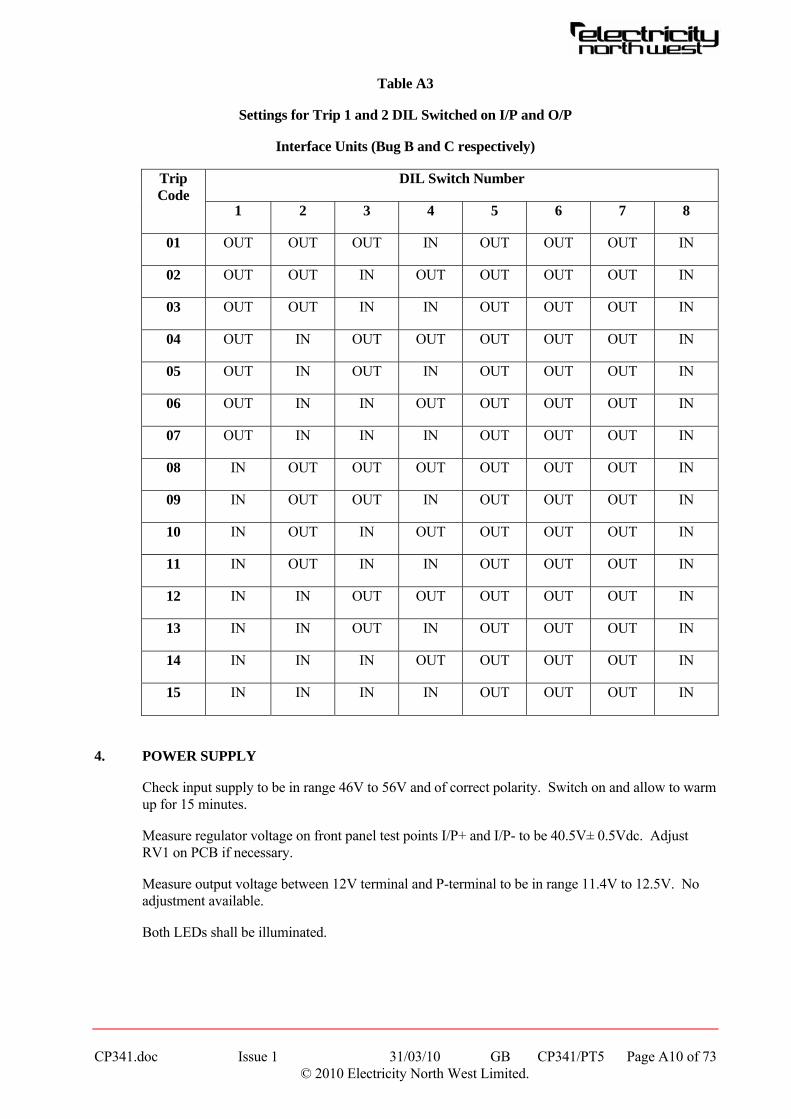
Table A3
Settings for Trip 1 and 2 DIL Switched on I/P and O/P
Interface Units (Bug B and C respectively)
DIL Switch Number Trip Code
1 2 3 4 5 6 7 8
01 OUT OUT OUT IN OUT OUT OUT IN
02 OUT OUT IN OUT OUT OUT OUT IN
03 OUT OUT IN IN OUT OUT OUT IN
04 OUT IN OUT OUT OUT OUT OUT IN
05 OUT IN OUT IN OUT OUT OUT IN
06 OUT IN IN OUT OUT OUT OUT IN
07 OUT IN IN IN OUT OUT OUT IN
08 IN OUT OUT OUT OUT OUT OUT IN
09 IN OUT OUT IN OUT OUT OUT IN
10 IN OUT IN OUT OUT OUT OUT IN
11 IN OUT IN IN OUT OUT OUT IN
12 IN IN OUT OUT OUT OUT OUT IN
13 IN IN OUT IN OUT OUT OUT IN
14 IN IN IN OUT OUT OUT OUT IN
15 IN IN IN IN OUT OUT OUT IN
4. POWER SUPPLY
Check input supply to be in range 46V to 56V and of correct polarity. Switch on and allow to warm up for 15 minutes.
Measure regulator voltage on front panel test points I/P+ and I/P- to be 40.5V± 0.5Vdc. Adjust RV1 on PCB if necessary.
Measure output voltage between 12V terminal and P-terminal to be in range 11.4V to 12.5V. No adjustment available.
Both LEDs shall be illuminated.

CP341.doc Issue 1 31/03/10 GB CP341/PT5 Page A11 of 73 © 2010 Electricity North West Limited.
5. TRANSMITTER
Before checking transmitter switch off, mount transmitter on extender unit and switch back on.
Check that Start, Parity and Clear LEDs are flashing in a regular rhythm at approximately 10 cycles per second.
Connect a frequency counter between TP6 and TP8 (zero volt). Frequency shall be 2400Hz +50Hz -25Hz. No variable adjustment is provided but frequency is raised approximately 50Hz with Link 4 in, or lowered 50Hz with Link 4 out.
5.1 Modem Transmitter Module Characteristic Frequency
Due to Manchester encoding all data patterns have the same average channel frequency, irrespective of code selected, when transmitting continuously. Check frequency using a frequency counter connected between zero volt and TP4 on the modem module to be:
Channel 1 1492Hz ± 1Hz
Channel 2 2492Hz ± 1Hz
Frequencies are derived from a crystal oscillator and no adjustment is available.
5.2 Output Level to Line
The maximum output from the modem is -5dBm and the attenuator pads of 2, 4, 8 and 16dB may be selected by DIL switch LA on the modem module.
The maximum permitted level to line is -13dBm (measured at the equipment side of the isolating transformer) for a single channel frequency (which will be the usual case) or -16dBm for two channels. The minimum recommended level is -20dBm to maintain good signal to noise ratio. A level between these limits shall be selected for the particular system and links LA set as follows:
2dB attenuator IN LA/1 open LA/2 closed OUT LA/1 closed LA/2 open
4dB attenuator IN LA/3 open LA/4 closed OUT LA/3 closed LA/4 open
8dB attenuator IN LA/5 open LA/6 closed OUT LA/5 closed LA/6 open
16dB attenuator IN LA/7 open LA/8 closed OUT LA/7 closed LA/8 open
6. RECEIVER
Switch OFF system. Plug transmitter into sub-rack and mount receiver unit on extender unit. Switch ON.
Before proceeding with the receiver checks the remote transmitter will have to be set up and left transmitting in the idling state.
6.1 Modem Receive Level
Measure the amplitude of the input signal received at the equipment side of the isolating transformer. This shall be similar to the transmitted level measured at the remote end.

CP341.doc Issue 1 31/03/10 GB CP341/PT5 Page A12 of 73 © 2010 Electricity North West Limited.
Press push-button on modem receive module and turn RV1 anti-clockwise until Red carrier detect LED is extinguished. Turn RV1 clockwise until LED turns on again leave set at this level. Release push-button.
6.2 Mark / Space Ratio (Distortion)
Using an oscilloscope set for 2V/cm sensitivity and 0.5ms/cm timebase, observe the Received Data output at interconnect point ML6. Adjust RV2 on the modem board if necessary to ensure good square-wave data with equal Mark/Space ratio of 1.67ms per bit. Trigger the oscilloscope from IC 8B pin 10.
6.3 Data Mask Monostable
Observe waveform on IC 8B pin 6 and check to be 2.5ms ± 0.1ms pulse at data rate (3.33ms) repetition frequency. Adjust RV1 on the receiver board if necessary. Trigger the oscilloscope from IC 8B pin 10.
6.4 Violation Detector Monostable
This is set for 4.167ms period but is normally re-triggered with each data pulse and only times out once per message. The violation pulse waveform therefore appears as a negative going pulse 2 x 3.333 – 4.167 = 2.5ms long. Adjust RV2 on the receiver board, if necessary, to give 2.5 ± 0.1ms negative going pulse at IC 8B pin 10.
7. SYSTEM PERFORMANCE
7.1 Initiate each trip input in turn and check all output contacts at remote end to ensure that only the correct has operated. In particular, confirm that the trip output contacts remain closed for as long as the trip input signal is maintained at the remote end.
Also check that when a “fleeting” (ie between 100 - 150ms) initiating signal is applied to each trip input in turn the corresponding trip output contacts remain closed for at least 95ms.
7.2 Initiate TRIP1 and TRIP2 simultaneously, then turn off each in turn to ensure correct operation and no interaction.
7.3 Initiate TEST input and check operation of TEST output at remote end.
7.4 Whilst the equipment is switched on, unplug the line connector plug and confirm that, on the appropriate unit at the remote end, the green HEALTHY lamp is extinguished, red DATA/LINE FAIL lamp is illuminated, and an alarm has been given.
Re-connect the line connector and repeat the above test from the remote end.
7.5 Where two (or more) available units are mounted in a common cubicle, or in adjacent cubicles, temporarily re-arrange the wiring on the substation side of the isolating transformers so that one local unit receives the incoming VF signal intended for another unit.
Check that, at this local receiver, the HEALTHY lamp is extinguished, the red ADDRESS FAIL lamp is illuminated, and an alarm has been given. Also check that initiating a trip input at the remote end does not cause a trip output contact operation at the local end.
Repeat this test at local and remote ends for all possible combinations and then reinstate wiring for normal operation.
CP341.doc Issue 1 31/03/10 GB CP341/PT5 Page A13 of 73 © 2010 Electricity North West Limited.
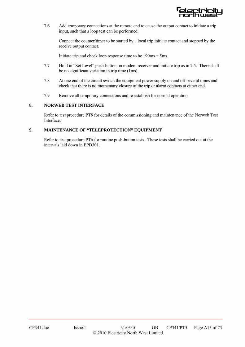
7.6 Add temporary connections at the remote end to cause the output contact to initiate a trip input, such that a loop test can be performed.
Connect the counter/timer to be started by a local trip initiate contact and stopped by the receive output contact.
Initiate trip and check loop response time to be 190ms ± 5ms.
7.7 Hold in “Set Level” push-button on modem receiver and initiate trip as in 7.5. There shall be no significant variation in trip time (1ms).
7.8 At one end of the circuit switch the equipment power supply on and off several times and check that there is no momentary closure of the trip or alarm contacts at either end.
7.9 Remove all temporary connections and re-establish for normal operation.
8. NORWEB TEST INTERFACE
Refer to test procedure PT8 for details of the commissioning and maintenance of the Norweb Test Interface.
9. MAINTENANCE OF “TELEPROTECTION” EQUIPMENT
Refer to test procedure PT6 for routine push-button tests. These tests shall be carried out at the intervals laid down in EPD301.
CP341.doc Issue 1 31/03/10 GB CP341/PT6 Page A14 of 73 © 2010 Electricity North West Limited.
TEST PROCEDURE PT6
VF INTERTRIPPING CHANNELS ROUTINE “PUSH BUTTON” TESTS BY MEANS OF NORWEB INTERFACE
1. GENERAL
1.1 Electricity North West’s VF intertripping equipment is designed for two way, digitally coded, twin channel intertripping using a FSK carrier of 1500 or 2000Hz and suitable for use over company owned pilots or BT private rented circuits. The equipment is fitted with 600 baud modems and is designated T100, ie it has an operating time of 100ms. An additional facility provided by the equipment is a test interlock code, which permits additional data to be transmitted between circuit ends.
1.2 Each VF intertripping equipment is physically and electrically associated with a Norweb Test Interface incorporating hardware, which when driven by Telecontrol enables remote isolation and testing to be carried out. The interface can also be manually selected into the “Test” mode.
1.3 Normally the interface marshals the 110Vdc intertrip send and receive cores for one end of two primary circuits and presents these cores via test isolating facilities to the VF equipment. Primary circuit intertripping between both ends of the two primary circuits is maintained via the second and/or third VF equipment(s) and interface(s) whilst the first equipment is in the test mode. Clearly this facility of maintaining primary circuit intertripping on one channel whilst its associated channel is out of service, for say test or pilot failure has considerable operational advantages.
1.4 In the case of single circuit primary systems the arrangement of the equipment is such that no standby facility is available.
1.5 Except where modified below the methods and principles set out in Test Circular 28(B) shall apply.
NOTE: PUSH-BUTTON TESTS ARE NOT INTERLOCKED AND CORRECT EQUIPMENT IDENTIFICATION IS ESSENTIAL.
1.6 For maintenance of equipment other than GEC Teleprotection, the appropriate manufacturer’s handbook shall be used.
2. TEST PROCEDURE
2.1 The following procedure shall be adopted for push-button testing of all VF intertripping equipment fitted with a Norweb Test Interface. The test procedure replaces Part 4 Steps (i) – (ix) given in Test Circular 28(B).
2.2 Agree the “Risk of Trip” situation with the control engineer. Each step of the 6 steps in the following sequence shall be carried out at both ends in strict order before proceeding to the next step. The engineer in charge will instruct the engineer at the remote end to carry out and to confirm each step. The engineer in charge will carry out the same step locally before proceeding to the next step.
Step 1 Obtain key and open door of Equipment A. Check that all push button switches are in the reset position, check that the interface test lamp is unlit, set the Test/Normal switch into the Test position and confirm that the interface test lamp is now lit, log the operation of the Test/Normal switch.
CP341.doc Issue 1 31/03/10 GB CP341/PT6 Page A15 of 73 © 2010 Electricity North West Limited.
Step 2 Operate the “Test LEDs” switch and confirm that all LEDs illuminate, release the switch and check that all LEDs are now unlit.
Step 3 (a) Operate the left hand side “Push to Test Equipment A” button for 10s.
(b) At the remote end observe the left hand set of LEDs and check that all four light for 10s approximately. Observe that all the LEDs extinguish when the test signal is removed. Confirm for both ends that no switch has tripped.
Step 4 (a) Operate the right hand side “Push to Test Equipment A” button for 10s.
(b) At the remote end observe the right hand set of LEDs and check that all four light for 10s approximately. Observe that all the LEDs extinguish when the test signal is removed. Confirm for both ends that no switch has tripped.
Step 5 Operate the “Test LEDs” push button switch, confirm that all left hand and right hand LEDs light. Release push button switch and confirm that all left hand and right hand LEDs are unlit.
Step 6 Confirm that the tests are now complete, set the Test/Normal switch into the Normal position, check that the interface test lamp is now unlit, close and lock the equipment A door and return the key to its storage position. Log the restoration of the Test/Normal switch to the Normal position.
The tests are now complete on equipment A. The same procedure shall be completed on equipment B. Following completion of the tests the “Risk of Trip” situation shall be cancelled with the control engineer.

CP341.doc Issue 1 31/03/10 GB CP341/PT7 Page A16 of 73 © 2010 Electricity North West Limited.
TEST PROCEDURE PT7
SETTING UP THE TELECONTROL REFLEX TEST FACILITY WITHIN THE NORWEB INTERFACE
1. PROCEDURE
GEC Teleprotection is a two trip circuit equipment. In order to ensure maximum security during remote testing the reflex tests can only be initiated on one trip circuit at one end of the equipment. Therefore the reflex test on the trip circuits are carried out, one from each end of the intertripping equipment.
As a general rule it was intended that the reflex test on trip circuit 1 shall be initiated from the double busbar substation end of the circuit or the end of the circuit nearest the double busbar substation. However this was not possible, so testing shall be carried out in accordance with the attached diagrammatic schedule. Tests are therefore initiated on the trip circuit going away from the double busbar substation as given by the number at the substation, on the schedule. Tests on the other trip circuit will be initiated on that circuit from the other end of the circuit.
Trip circuit 1 is carried through the left hand side of the test interface and Trip 1 of the Teleprotection with trip circuit 2 carried through the right hand side and Trip 2. In order to select the appropriate trip circuit test facility, the following procedure shall be followed:
(a) Remove the top covers of the interface. In order to set up the test facility on trip circuit 1, insert the Test Send relay into the Test Send relay base on the left-hand side (as viewed from the front), then ensure that the links at the rear of the interface on the lower terminal rail are removed in positions 1, 3 and 5 and inserted in positions 2, 4, and 6. Replace the top cover securely.
(b) To set up the test facility on trip circuit 2, insert the Test Send relay into the Test Send relay base on the right-hand side (as viewed from the front). Then ensure that the links at the rear of the interface on the lower terminal rail are removed in positions 2, 4 and 6 and inserted in positions 1, 3 and 5. Replace the top covers securely.

CP341.doc Issue 1 31/03/10 GB CP341/PT8 Page A17 of 73 © 2010 Electricity North West Limited.
TEST PROCEDURE PT8
NORWEB VF INTERTRIPPING TEST INTERFACE
1. INTRODUCTION
The Norweb test interface was designed to avoid the heavy expense arising from modifying existing relay panels to accommodate modern intertripping test facilities. More importantly, it is intended to eliminate as far as possible the chance of human element faults when working on two circuit equipment which carries intertripping messages for two primary circuits. The test interface incorporates hardware which when driven by telecontrol, will enable remote testing and isolation of intertripping to be carried out.
This test procedure is intended to be used following the installation of the interface and VF intertripping equipment and commissioning tests to establish the integrity of the VF equipment.
The test interface was designed as maintenance free equipment. It is not envisaged that any maintenance, other than the routine push button tests (as detailed in procedure PT6) shall be necessary. However, if any modification work is carried out than this procedure shall be followed either in part of in full in order to establish the integrity of the interface following such work.
2. TEST EQUIPMENT AND GENERAL PROCEDURE
Note: Commissioning and maintenance of GEC Teleprotection shall be carried out to test procedure PT5. Routine push button testing of the VF intertripping using the Norweb test interface shall be carried out to test procedure PT6.
2.1 Test Equipment
2 custom built test interface test boxes
50V and 125V stabilised power supplies.
The test interface test box is used to prove the correct operation of the test interface either in isolation from all other equipment, or when it is connected to the VF equipment but isolated from the relay panel and its tripping and indication supplies. The box allows the testing of both the manual push button test facility and the telecontrol reflex test facility. It also monitors the indication and alarm outputs, which are sent both to the telecontrol outstation and to the relay panels of the circuits with which the intertripping is associated.
The test box is constructed so that it produces a 125V tripping supply which would normally originate from the relay panel via the RTR and RTS links. It also produces a 50V supply which drives the mimic telecontrol facilities. The front panel of the test box is divided into three sections.
The left hand section has the 50V and 125V supply on / off switches and their indication lamps.
The centre section mimics the relay panel(s); it has a “TESTING” lamp which indicates that the intertripping equipment is switched into the test position. It has a mimic intertrip receive relay and lamp and a switch which mimics the intertrip send relay.
The right hand section represents the telecontrol facilities. There are switches to switch the interface into “TEST” and back into “NORMAL” and also to operate the “TEST SEND” relay. There are also indication and alarm lamps to give the following indications: Test interface in “NORMAL”, test interface switched into “TEST”, reflex “TEST CORRECT” and reflex “TEST FAILED”.
CP341.doc Issue 1 31/03/10 GB CP341/PT8 Page A18 of 73 © 2010 Electricity North West Limited.
3. SPECIFIC PROCEDURES
3.1 Pre-test Inspection
The following inspection can be carried out either before cabling of the intertripping cubicle or following the commissioning of the VF equipment.
Whilst the interface is still unconnected or isolated from the relay panels, it shall be drawn out from the intertripping panel rack on its telescopic slides. Remove the top covers and visually inspect the internal wiring paying particular attention for loose terminations. The base pins of the miniature relays are easily bent and it is important to check them at this stage. Also, with the covers removed check the operation of the TEST/NORMAL switch, watching the movement of the mechanical linkage whilst operating the switch. Check that the linkage movement is unobstructed and that the mechanism is securely assembled and that the switch body is securely fastened. Check that the “TEST” indication lamp can be easily removed from its holder. Operate each of the push button switches to check that the button moves in and out freely.
Position the Test Send relay as per test procedure PT7. Incorrect positioning of these relays and links will cause failure of the telecontrol reflex test procedure carried out later in the testing routine.
Replace the covers.
3.2 Connection of Interface Test Box
Before the following tests can be undertaken, the checks as detailed above shall be carried out at both ends of the circuit and the VF circuit shall be in service. A risk of trip shall not normally be required for these tests since the connection to the intertrip receive trip relays will not have been made.
At both ends of the VF circuit connect the interface test box to the interface, number to number, removing any multicore wiring to the relay panels. On the interface switch the TEST / NORMAL switch to the NORMAL position and the Teleprotection at both ends of the circuit shall be switched on and showing healthy.
Switch on the interface test box 50V and 125V supplies. On the test boxes at both ends of the circuit the following indications shall be seen: the 50V and 125V supply indicators shall be illuminated and the mimic telecontrol command / indications shall have only the NORMAL lamp illuminated.
The following sequence shall be carried out at both ends in strict order. The engineer in charge, stationed at the local end, shall instruct the engineer at the remote end to carry out and confirm each step.
3.3 Check Operation in NORMAL Mode
This test is designed to check correct operation in the NORMAL mode and to prove the TEST / NORMAL switch in the interface as a point of isolation in the intertripping circuit.
3.3.1 Set the TEST / NORMAL switch into the NORMAL position at both ends and confirm that the mimic telecontrol commands / indications have only the NORMAL lamp illuminated.
3.3.2 The following indications shall be observed when an intertrip signal is sent from the local end on trip circuit 1:
At the local end Trip 1 LED on the teleprotection input board shall light.
CP341.doc Issue 1 31/03/10 GB CP341/PT8 Page A19 of 73 © 2010 Electricity North West Limited.
At the remote end Trip 1 LED on the teleprotection output board shall light.
Trip Circuit 1 Intertrip Receive Lamp shall light and I/T receive relay shall operate.
3.3.3 At the local end:
(i) Operate I/T No 1 send switch on the test box (confirm local and remote indications).
(ii) Set the TEST / NORMAL switch to the NORMAL position (confirm cancellation of indications).
(iii) Restore the TEST / NORMAL switch to the NORMAL position (confirm restoration of indications).
(iv) Cancel I/T No 1 send switch on the test box (confirm cancellation of indications).
3.3.4 Repeat operation 3.3.3 for Trip Circuit 2.
3.3.5 Repeat operation 3.3.3 for Trip Circuits 1 and 2 operated simultaneously.
3.3.6 Repeat operations 3.3.3, 3.3.4 and 3.3.5 from remote end.
3.4 Check on Push Button Tests
To establish the correct operation of the “TEST / NORMAL” switch and the “Push to Test” push buttons, a simplified routine “Push Button” test procedure is carried out. The TEST / NORMAL switch on the interface unit is again proves as a point of isolation in the intertripping circuit.
3.4.1 Set the TEST / NORMAL switch into the TEST position at both ends and confirm that the interface test lamp is now lit. On the test box the TEST lamp on the mimic relay panel and the NORMAL and TESTING lamps on the mimic telecontrol panel shall all be illuminated.
3.4.2 At both ends operate Test LEDs switch and confirm that all LEDs illuminate. Release the switch and check that all LEDs are now unlit.
3.4.3 Left hand trip circuit check (from local end).
(i) Operate the left-hand side “Push to test Equipment A” button for 10s.
(ii) At the remote end observe the left hand set of LEDs and check that all four light for 10s approximately. Observe that all the LEDs extinguish when the test signal is removed. Confirm for both ends that no receive relay or lamp operates.
3.4.4 Repeat 3.4.3 for right-hand trip circuit.
3.4.5 Repeat 3.4.3 and 3.4.4 from remote end.
3.4.6 Operate the TEST LEDs push button switch, confirm that all left hand and right hand LEDs light. Release the push button switch and confirm that all the left-hand and right hand LEDs are unlit.
CP341.doc Issue 1 31/03/10 GB CP341/PT8 Page A20 of 73 © 2010 Electricity North West Limited.
3.4.7 At the local end set the TEST / NORMAL switch to the NORMAL position, check that the interface lamp is now extinguished, as have the TEST and TESTING indication lamps on the test box.
3.4.8 Repeat steps 3.4.2 to 3.4.6 and observe that the signals are not initiated and that the indicating lamps on the VF equipment do not light.
3.4.9 Restore the local end TEST / NORMAL switch to the TEST position and set the TEST / NORMAL switch at the remote end into the NORMAL position. Check that the interface lamp is now extinguished and likewise the TEST and TESTING indication lamps on the test box.
3.4.10 Repeat steps 3.4.2 to 3.4.6 and observe that the signals are not initiated and that the indicating lamps on the VF equipment do not light.
3.4.11 Reset the TEST / NORMAL switch at the local end to the NORMAL position.
3.5 Check on Telecontrol Facilities
The telecontrol test facility as provided is able to simulate the push button test facility. The tests carried out differ in that they are reflex tests and are carried out on one trip circuit only from each end. The following sequence shall be carried out in strict order.
3.5.1 On the test box at both ends of the circuit, operate the TEST MODE switch for 2s only. Observe that the NORMAL light has extinguished; the TESTING light, the TEST light and the TEST light on the interface are illuminated.
3.5.2 The engineer in charge shall then operate the TEST SEND switch, which initiates a reflex test on one trip circuit only. The switch shall be operated for 2s only. He shall observe the TEST CORRECT and TEST FAIL lamps; only the TEST CORRECT lamp shall light. Any fleeting illumination of the TEST FAIL lamp either with a TEST CORRECT indication or on its own is a failure and shall be investigated. The engineer at the remote end shall observe that no illumination either fleeting or permanent occurs.
3.5.3 Repeat operation 3.5.2 from the remote end.
3.5.4 This test is similar in principle to operation 3.3.3, the sending of an intertrip signal and its interruption by operating a TEST mode switch. The indications to be observed shall be the operation of a Trip LED on the Teleprotection Input Board at the local end and the Trip LED on the Output Board at the remote end. During the test one of the circuits (either Trip 1 or Trip 2) will reflex and cause the operation of the corresponding Output and Input Trip LEDs at the local and remote ends respectively. In neither case is the trip signal output to the interface test box, indication being restricted to Teleprotection LEDs.
Set the local interface to Telecontrol NORMAL; operate the trip circuit 1 I/T Send switch at the local end. The intertrip signal shall now be interrupted by operating the telecontrol TEST mode switch (operating the TEST / NORMAL relay into that TEST position). The intertrip signal shall be restored by operating the NORMAL mode switch. Restore to TEST mode.
3.5.5 Repeat operation 3.5.4 for Trip Circuit 2, noting which circuit is set to reflex.
3.5.6 Repeat operations 3.5.4 and 3.5.5 from the remote end.
CP341.doc Issue 1 31/03/10 GB CP341/PT8 Page A21 of 73 © 2010 Electricity North West Limited.
3.5.7 To prove the integrity of the digital Test interlock: At the local end disconnect the wire to terminal 1 of TEST MODE output TT, to render the interlock inoperative. Now repeat the reflex test 3.5.2 at the local end. Confirm that no intertrip signal is initiated from that end and that only the TEST FAIL indication is received. Replace the wire to terminal 1 and repeat the test 3.5.2 to ensure that the interlock has been reconnected correctly.
3.5.8 Repeat operation 3.5.7 from the remote end.
3.5.9 Another interlock is included which prevents restoration via Telecontrol to Normal mode if a trip output is present. This test checks this feature. Connect temporary shorts across Trip output 1 on the Teleprotection unit at the local end. Confirm that it is not possible to return to Telecontrol Normal.
Repeat this test for Trip output 2.
Repeat this test at the remote end for Trip outputs 1 and 2. Remove the temporary shorts and set both ends into Telecontrol Normal.
Note: Application of shorts to one of the Trip outputs will prevent return to Telecontrol Normal at both ends. In each case, this will be the Trip circuit which the end remote from the point of test uses for its reflex channel, eg remote end reflexes on Trip Circuit 2; application of shorts to Trip output 2 at the local end will prevent restoration to Telecontrol Normal at both the local and remote ends.
3.5.10 Repeat the push button test, 3.4.1 to 3.4.6, ie
Set the TEST / NORMAL interface switch to TEST at both ends.
Test LEDs.
Test left and right hand trip circuits from both ends.
Test LEDs.
3.5.11 Reset interfaces at both ends to NORMAL.
CP341.doc Issue 1 31/03/10 GB CP341/PT9 Page A22 of 73 © 2010 Electricity North West Limited.
TEST PROCEDURE PT9
GEC MCGG RELAYS
1. GENERAL
This procedure for the testing of MCGG relays is divided into two parts. Section 2 covers commissioning, when it is required to prove as far as practicable that the relay will operate correctly for all settings to be applied. Section 3 covers routine maintenance for which it is only necessary to test at the setting in use.
It is accepted that on occasions, it will be necessary to apply temporary settings to MCGG relays. This could follow the loss of unit protection on 132kV feeders when it is required to keep the feeder in service. The alteration of settings shall not, however, be undertaken lightly because it is easier to make a mistake with the selector switches than with changing settings on conventional electromechanical relays.
It is important to use test equipment capable of providing an undistorted sinusoidal current waveform.
2. COMMISSIONING
2.1 Inspection
Carefully examine the module and case to see that no damage has occurred during installation, and visually check that the current transformer shorting switches are wired correctly and are closed with the module withdrawn. Check that the relay serial number on the module case and cover are identical and that the model number and rating is correct.
2.2 Wiring
Check that the external wiring is correct to the relevant relay diagram and scheme. WITH THE RELAY REMOVED FROM ITS CASE connect the dc supply and check terminal 13 is positive and terminal 14 is negative. Ensure the dc supply is within the range for the relay.
2.3 Insulation Tests
It is necessary to use an insulation tester whose output does not exceed 1000V dc. Check the IR of CT circuits. Check the IR of the dc circuitry but, with fuses and links removed, temporarily short circuit terminals 13 and 14 of the relay. This will ensure that the power supply will not be damaged in the event of a wiring fault.
Check the IR across the normally open contacts used for tripping and alarms.
Note: Do not IR test the directional control terminals (eg 45, 46, 47, 48, 49 and 50 for an MCGG62) because these are internally connected to the case. If the relay has not been pre-wired to a directional relay, these terminals will be covered with a yellow plastic cover.
2.4 Electrostatic Discharges
When handling the module, care shall be taken to avoid contact with components and electrical connections. When removed from the case for storage, the module shall be placed in a conductive antistatic bag.

2.5 Earthing
Ensure that the case earthing terminal above the rear terminal block is used to connect the relay to the local earthing bar.
2.6 Relay CT Shorting Switches
With the relay removed from its case, check that each ct shorting switch is closed by injecting rated current into each phase circuit.
2.7 Energise Relay
With the trip circuits isolated and the relay module inserted in the case, connect the dc supply to the relay. Press the reset button on the front panel and check that all LEDs illuminate.
2.8 Current Sensitivity (Is = E x IN)
The upper seven blue switches are used to set the required current sensitivity. Each switch may be positioned to the left or right. The overall setting is obtained by adding the indicated values of the individual switch settings, and may be in steps of 5% over the range 0.05 to 2.4 x IN.
In this case: Is = (0.1 + 0.1 + 0.2 + 0.8) x IN = 1.2 x IN.
It is required to check on each pole that all the switches operate correctly. Current is injected into each pole and the green relay start LED is used to indicate that the setting has been reached.
The following table gives eight settings to be checked. The reason why 0.45 appears three times is because there are three possible ways of setting the value.
CP341.doc Issue 1 31/03/10 GB CP341/PT9 Page A23 of 73 © 2010 Electricity North West Limited.

Table A4 - Settings to be Checked on MCGG Relays
ac Current Operate Level (A) Is ( x IN) IN = 1A IN = 5A
0.05 0.05 – 0.055 0.25 – 0.275
0.10 0.10 – 0.110 0.50 – 0.550
0.15 0.15 – 0.165 0.75 – 0.825
0.25 0.25 – 0.275 1.25 – 1.375
0.45 0.45 – 0.495 2.25 – 2.475
0.45 0.45 – 0.495 2.25 – 2.475
0.45 0.45 – 0.495 2.25 – 2.475
0.85 0.85 – 0.935 4.25 – 4.675
The above current levels assume no instrument error, and actual site values will depend on the instruments used.
2.9 Curve Selection Switch
The three black switches positioned in the upper group of switches are used to select the required time curve from a choice of four inverse time and three definite time curves. The eighth switch combination sets the relay into the “trip test” mode.
In this case: 0 0 0
Standard Inverse is selected (SI)
Other combinations are:
Very Inverse (VI) 1 0 0
Extremely Inverse (EI) 0 1 0
Long Time Inverse (LTI) 1 1 0
CP341.doc Issue 1 31/03/10 GB CP341/PT9 Page A24 of 73 © 2010 Electricity North West Limited.
Definite Time 2 Seconds (D2) 0 0 1
Definite Time 4 Seconds (D4) 1 0 1
Definite Time 8 Seconds (D8) 0 1 1
Trip Test 1 1 1
In the majority of applications, standard inverse will be the only curve used. If it is known that another characteristic is to be applied, then that characteristic shall be checked in a similar manner to that described below for standard inverse.
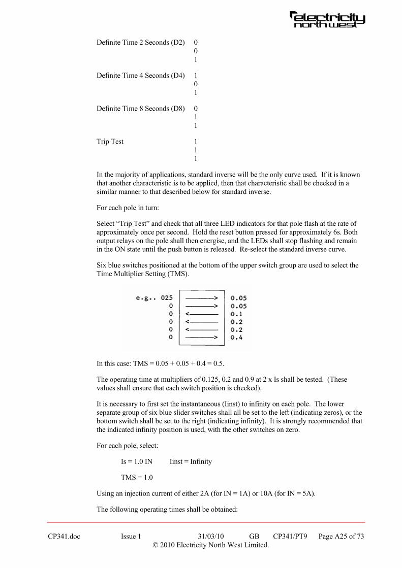
For each pole in turn:
Select “Trip Test” and check that all three LED indicators for that pole flash at the rate of approximately once per second. Hold the reset button pressed for approximately 6s. Both output relays on the pole shall then energise, and the LEDs shall stop flashing and remain in the ON state until the push button is released. Re-select the standard inverse curve.
Six blue switches positioned at the bottom of the upper switch group are used to select the Time Multiplier Setting (TMS).
In this case: TMS = 0.05 + 0.05 + 0.4 = 0.5.
The operating time at multipliers of 0.125, 0.2 and 0.9 at 2 x Is shall be tested. (These values shall ensure that each switch position is checked).
It is necessary to first set the instantaneous (Iinst) to infinity on each pole. The lower separate group of six blue slider switches shall all be set to the left (indicating zeros), or the bottom switch shall be set to the right (indicating infinity). It is strongly recommended that the indicated infinity position is used, with the other switches on zero.
For each pole, select:
Is = 1.0 IN Iinst = Infinity
TMS = 1.0
Using an injection current of either 2A (for IN = 1A) or 10A (for IN = 5A).
The following operating times shall be obtained:
CP341.doc Issue 1 31/03/10 GB CP341/PT9 Page A25 of 73 © 2010 Electricity North West Limited.

CP341.doc Issue 1 31/03/10 GB CP341/PT9 Page A26 of 73 © 2010 Electricity North West Limited.
Table A5 - Operating Times
TMS
0.125 0.2 0.9
TIME 1.25s 2s 9s
2.10 Instantaneous Selection Switch
It is considered that only one test per pole is sufficient to give confidence that the instantaneous circuitry is performing correctly. If an instantaneous setting is to be applied, then the setting shall be checked when the relay is tested at setting.
The reasons for not testing at all settings are:
1. Because of the risk of damaging the relay at high currents.
2. Because the majority of applications will have Iinst at infinity.
3. It will be tested at setting if it is not infinity.
For each pole select:
Is = 1.0IN Iinst = 1.0Is TMS = 1.0
The instantaneous output contact shall be checked for operation. It shall operate at 1.1 times the setting and not operate at the setting:
Table A6 - Instantaneous Response
Current Level
IN = 1A IN = 5A
Iinst
Response
1.1 5.5 TRIP
1.0 5.0 NO TRIP
2.11 Final Selected Setting Check
The relay switches shall be set to the specified setting and a check made on each pole of the relay that they are correct.
If possible a timing test at 2 x Is shall be made as detailed in 2.9 above. However, the actual time obtained will be 10 x actual TMS in use (assuming a standard curve relay) eg if TMS = 0.4, time will be 4s. If it is not possible to obtain 2 x setting current, then a minimum of 1.5 x shall be used. (17.2 sec at TMS = 1.0 for a standard inverse curve selection).
A final check shall be made that all LED indicators operate and then reset when the reset button is operated and reset with the front cover replaced.

CP341.doc Issue 1 31/03/10 GB CP341/PT9 Page A27 of 73 © 2010 Electricity North West Limited.
3. MAINTENANCE
Maintenance will consist of:
1. Performing IR checks and secondary injection tests at the setting in use (as 2.3 and 2.11 above).
2. Performing a trip test on each pole as 2.9 above.
3. Checking all LED indicators as 2.1 above.
Tests 2 and 3 shall also be carried out whenever trip tests are performed.
It is essential to ensure that the curve selection switches are reset correctly following a trip test and special care shall be taken to ensure that the switches are correctly set and not left “floating” between the “0” and “1” positions.
CP341.doc Issue 1 31/03/10 GB CP341/PT10 Page A28 of 73 © 2010 Electricity North West Limited.
TEST PROCEDURE PT10
GEC QUADRIMHO DISTANCE PROTECTION
1. GENERAL
This test procedure is concerned with proving the Quadramho relay for the most usual scheme in Electricity North West for which no signalling channel is used. The selected option is 01 for this case. If a signalling channel is used (eg a blocking or permissive under-reach scheme) then this test procedure shall be followed, but after test 16 the “Scheme Tests” found in GEC’s servicing instructions, section 5, part 5, shall be followed for the particular scheme in use.
Although this test procedure is complete and will prove that a relay is performing satisfactorily, it is recommended that the GEC Quadramho Servicing Instructions are available in case problems are encountered.
The current and voltage connections shall be made to include the maximum amount of panel wiring as possible, ie connect the test leads to the incoming ct terminals and to the relay side of the VT fuses.
A buzzer may be connected to the trip output contacts of the relay. These will normally be B17 and B18.
The GEC test plugs will be needed for the directional checks.
2. SECONDARY INJECTION TESTS
2.1 Settings
All settings on the Quadramho are by means of switches located on the front of the relay. The settings shall be applied before starting testing.
Any examples of current quoted assume a 1A relay.
When in a test mode (eg XY = 43) other LEDs may light up as well as those referred to. These shall be ignored.
2.2 Level Detector Checks
Test 1 Voltage Level Detectors
Each phase to neutral input voltage is monitored and pick-up of the level detector is fixed at 44.45V (± 10%), ie between 40V and 49V. The drop-off shall be within 10% of the actual pick-up.
(a) Select test option 43 (x = 4, y = 3). Note: All LEDs will have a different function to that on the nameplate. Relay available light will go out.
(b) With the current box switched off and full voltage applied, LEDs A, B & C will light.
(c) Select L1 – N fault and decrease voltage until LED A goes out. Record voltage.
(d) Increase voltage again until LED A re-lights. Record voltage.
(e) Select L2 – N fault and repeat test using LED B.

CP341.doc Issue 1 31/03/10 GB CP341/PT10 Page A29 of 73 © 2010 Electricity North West Limited.
(f) Select L3 – N fault and repeat test using LED C.
Test 2(i) Low Set Current Level Detectors (Phase)
The scheme logic uses these for switch onto fault (SOTF) detection (amongst other uses).
Each phase current is monitored and the setting is changed by the value of K1 and K2. The most sensitive setting is 5%In, where In = relay rated current.
Current setting = ((5 x 4.8) / ((100(K1 + K2))) x In A (±10%)
The drop-off shall be within 10% of the actual pick-up.
(a) Select test option 43 (x = 4, y = 3).
(b) With the voltage box switched off, inject single phase L1 – N. With the current above setting LED Z3 shall be lit. Reduce current until LED Z3 goes out. Record value. (If K1 + K2 = 4.8, then setting current = 50mA).
(c) Increase current until LED Z3 re-lights. Record value.
(d) Select L2 – N and repeat test, but using the LED “AIDED TRIP” for indication.
(e) Select L3 – N and repeat test, but using the LED “SOTF” for indication.
Test 2(ii) High Set Current Level Detectors (Phase)
These are only used in the Blocking or Weak Infeed scheme, however that shall be checked even if these schemes are not in use.
Current setting = ((12.1 x 4.8) / ((100(K1 + K2))) x In A (±10%)
(a) Select test option 53 (x = 5, y = 3).
(b) Inject L1 – N. With the current above setting “Z3” LED shall be lit. Reduce current until “Z3” LED goes out. Record value. (If K1 + K3 = 4.8 then setting current = 121mA).
(c) Increase current until “Z3” LED re-lights. Record value.
(d) Select L2- N and repeat test, but using the “AIDED TRIP” LED for indication.
(e) Select L3 – N and repeat test, but using the “SOTF” LED for indication.
Test 2(iii) Low Set Residual Current Level Detector
This is used in the Voltage Transformer Supervision scheme. The scheme detects a VT or fuse failure by detecting a residual voltage output WITHOUT the presence of residual current above this low set detector setting. During genuine earth faults there will be residual current above this low set value, and therefore a fuse failure is not assumed, and no alarm is generated.
Min op = ((2 x 4.8)/((100(K1 + K2))) x In A (±20%)
(a) Select test option 43 (x = 4, y = 3)
CP341.doc Issue 1 31/03/10 GB CP341/PT10 Page A30 of 73 © 2010 Electricity North West Limited.
(b) With L1 – N current injected above the minimum operate level, the “V˜ FAIL” LED shall be lit. Reduce value until “V˜ FAIL” LED goes out. Record value. (If K1 + K2 = 4.8, minimum operate value = 20mA).
(c) Increase current until “V˜ FAIL” LED re-lights. Record value.
(d) Select L2 – N and repeat test.
(e) Select L3 – N and repeat test.
Test 2(iv) High Set Residual Current Level Detector
This is used to block phase fault comparators during heavy close-up single phase to earth faults.
The minimum operate level = 8 x the low set
= ((16 x 4.8)/((100(K1 + K2))) x IN A (±20%)
(a) Select test option 53 (x = 5, y = 3)
(b) With L1 – N current injected above the minimum operate level, the “V˜ FAIL” LED shall be lit. Reduce value until “V˜ FAIL” LED goes out. Record value. (If K1 + K2 = 4.8, min operating value = 160mA).
(c) Increase current until “V˜ FAIL” LED re-lights. Record value.
(d) Select L2 – N and repeat test.
(e) Select L3 – N and repeat test.
2.3 Reach Tests
For most applications the line angle for both phase (θPH) and earth return (θN) will be equal and within the range 60° - 70°. A typical setting for these line angles is 65°.
A 60° angle setting for the test set shall be chosen.
The secondary impedances quoted on the setting sheets are “phase” values. When testing phase fault distance elements a phase to phase test is performed and the loop impedance of twice Z phase is presented to the relay.
When testing the earth fault elements, the loop impedance to be presented to the relay is Z phase plus the earth return impedance. For most overhead line circuits the earth return impedance is 0.47 times the phase impedance. The loop impedance to be presented to the relay when testing will therefore normally be about 1.47 Z phase.
Before commencing the reach tests below, all settings shall be applied and the “phase” secondary ohm settings shall be verified using the formulae quoted. It is advisable to do this even if the values are quoted on the settings sheet.
Note: The tests detailed below are for the general case when Zone 3 setting exceeds Zone 2 which exceeds Zone 1. This means that, for example, if Zone 2 is being checked, there will be no operation of Zone 1 at the Zone 2 balance point. On occasion, the settings will be similar or even identical. It will then have to be accepted that the phase indications (LEDs A, B & C) will light before either the Zone 2 and / or Zone 3 time delays. The operation of the Zone 2 and / or Zone 3 time delayed outputs will be evident from the Z2 & Z3 LEDs.

CP341.doc Issue 1 31/03/10 GB CP341/PT10 Page A31 of 73 © 2010 Electricity North West Limited.
Test 3 Zone 1 Reach Tests Reach Faults
The loop impedance of the relay for Zone 1 earth faults
= (K14(K1 + K2 + K4 + K5 + K6)(K11 + K12 + K13))/In ohm
If 2A is injected then the relay shall operate at a voltage of 2 x loop impedance.
(a) Select the scheme option (normally 01 (x = 0, y = 1)).
(b) Set test set to 60°, earth fault, current normal, L1 – N and fault on.
(c) In order to establish confidence that the relay will operate, reduce the fault voltage to minimum (ignore the indications for the moment). Switch to “fault off” (to restore voltage), reset relay and then switch to “fault on”. The A LED shall light instantly, followed by Z2 after Zone 2 time (typically 0.4s) and Z3 after Zone 3 time (typically 0.8s). It is not necessary to check the timer accuracies at this stage.
(d) Repeat test (c) but with the current set to “reverse”. The only indication this time shall be for a Zone 3 fault (A & Z3 LEDs both after Zone 3 time delay). The reason for this is because Zones 1 & 2 are completely directional, whereas Zone 3 is an “offset” characteristic which always has some reverse reach. Restore current switch to “normal”.
(e) With the test set as a (b), inject 2A and full volts. With the relay reset, only the relay available LED shall be lit.
(f) Reduce this voltage to a value about 15% above that calculated for the Zone 1 reach. Note that during this adjustment a Zone 2 and Zone 3 operation may occur.
(g) Switch to “fault off”, reset relay, switch fault on again and note sequencing of LEDs. It is required to eventually obtain an instantaneous illumination of the A LED (which will be followed by Z2 & Z3 if the fault is left on longer than Zone 3 time). At 15% above setting voltage the instantaneous operation shall not occur, and it is necessary to make adjustment of the voltage (say in 5% steps of the setting value) until an instantaneous trip is obtained when the “fault on” switch is operated. The actual voltage measured shall be within 10% of the calculated value, but due regard shall be given to instrument errors.
During this test the operation of the output tripping contacts shall be proved.
(h) Select L2 – N and repeat tests (c) to (g) but noting that B LED will illuminate in place of A
(i) Select L3 – N and repeat tests (c) to (g) but noting that C LED will illuminate in place of A.
Note: The indications are automatically reset when a new trip output is obtained but it may be easier to understand what is happening during commissioning by using the manual reset button.
Test 4 Zone 1 Reach Tests Phase Faults
The loop impedance to be presented to the relay is now:
CP341.doc Issue 1 31/03/10 GB CP341/PT10 Page A32 of 73 © 2010 Electricity North West Limited.
= (2 x K14(K1 + K2)(K11 + K12 + K13))/In ohm
If 2A is injected then the relay shall operate at 2 times the loop impedance.
Note: When injecting phase to phase, the test set reduces two phase to neutral voltages. This results in there being a residual voltage output, but because the injection is phase to phase there is no residual current. The VTS scheme will operate and V˜ fail alarm LED will indicate. It is necessary to put the switch SW3 to the LEFT during these tests to prevent the VTS scheme blocking the relay. The V˜ fail LED will still indicate.
(a) Select the scheme option (normally 01 (x = 0, y = 1))
(b) Set test set to 60°, phase fault, current normal, L1 – L2 and fault on.
(c) In order to establish confidence that the relay will operate, reduce the fault voltage to minimum (ignore the indications for the moment). Switch to “fault off” (to restore voltage), reset relay and then switch to “fault on”. The A & B LEDs shall light instantly, followed by Z2 after Zone 2 time (typically 0.4s) and Z3 after Zone 3 time (typically 0.8s). It is not necessary to check the timer accuracies at this stage.
(d) Repeat the test (c) above, but with the current set to “reverse”. The only indication this time shall be for a Zone 3 fault (A, B & Z3 LEDs all after Zone 3 time delay). The reason for this is because Zones 1 & 2 are completely directional, whereas Zone 3 is an “offset” characteristic which always has some reverse reach. Restore current switch to “normal”.
(e) With the test set as (b), inject 2A and full volts. With the relay reset, only the relay available LED shall be lit.
(f) Reduce the voltage to a value about 15% above that calculated for the Zone 1 reach. Note that during this adjustment a Zone 2 and Zone 3 operation may occur.
(g) Switch to “fault off”, reset relay, switch fault on again and note sequencing of LEDs. It is required to eventually obtain an instantaneous illumination of the A & B LEDs (which will be followed by Z2 & Z3 if the fault is left on longer than Zone 3 time). At 15% above setting voltage the instantaneous operation shall not occur, and it is necessary to make adjustment of the voltage (say in 5% steps of the setting value) until an instantaneous trip is obtained when the “fault on” is operated. The actual voltage measured shall be within 10% of the calculated value, but due regard shall be given to instrument errors.
During this test the operation of the output tripping contacts shall be proved.
(h) Select L2 – L3 and repeat tests (c) to (g) above, but noting that B & C LEDs will illuminate.
(i) Select L3 – L1 and repeat tests (c) to (g) above, but noting that C & A LEDs will illuminate.
Note: The indications are automatically reset when a new trip output is obtained but it may be easier to understand what is happening during commissioning by using the manual reset button.

CP341.doc Issue 1 31/03/10 GB CP341/PT10 Page A33 of 73 © 2010 Electricity North West Limited.
Test 5 – Zone 2 Reach Tests Earth Faults
When checking Zone 2 reaches, the effect of the expansion of the reach when any trip occurs may be apparent. If a fault is applied less than 5% outside the Zone 2 boundary and within the Zone 3 boundary, then if Zone 3 times out giving a trip output, Zone 2 indication will also be seen if the fault is maintained for Zone 2 time after the Zone 3 trip occurs.
The loop impedance of the relay for Zone 2 earth faults:
= (K14(K1 + K2 + K4 + K5 + K6)(K21 + K22))/In ohm
If 2A is injected then the relay shall operate at a voltage of 2 x loop impedance.
(a) Select the scheme option (normally 01 (x = 0, y = 1)).
(b) Set test set to 60°, earth fault, current normal, L1 – N, and fault on.
(c) Inject 2A and full volts. With the relay reset, only the relay available LED shall be lit.
(d) Reduce the voltage to a value about 15% above that calculated for the Zone 2 reach. Note that during this adjustment a Zone 3 operation may occur.
(e) Switch to “fault off”, reset relay, switch fault on again and note sequencing of LEDs. It is required to eventually obtain an illumination of the A LED after Zone 2 time (which will be followed by Z3 if the fault is left on longer than Zone 3 time). At 15% above setting voltage the Zone 2 operation shall not occur, and it is necessary to make adjustment of the voltage (say in 5% steps of the setting value) until a Zone 2 trip is obtained when the “fault on” switch is operated. The actual voltage measured shall be within 10% of the calculated value, but due regard shall be given to instrument errors.
During this test the operation of the output tripping contact shall be proved.
It is not required to accurately time the Zone 2 timer at this stage of the tests because the measuring elements are on the boundary of their characteristic and may be relatively slow. The time delay for Zone 2 shall, however, be obvious.
(f) Select L2 – N and repeat tests (c) to (e) above, but noting that B LED will illuminate in place of A.
(g) Select L3 – N and repeat tests (c) to (e) above, but noting that C LED will illuminate in place of A.
Note: The indications are automatically reset when a new trip output is obtained but it may be easier to understand what is happening during commissioning by using the manual reset button.
Test 6 Zone 2 Reach Tests Phase Faults
When checking Zone 2 reaches, the effect of the expansion of the reach when any trip occurs may be apparent. If a fault is applied less than 5% outside the Zone 2 boundary and within the Zone 3 boundary, then if Zone 3 times out giving a trip output, Zone 2 indication will also be seen if the fault is maintained for Zone 2 time after the Zone 3 trip occurs.
The loop impedance of the relay for Zone 2 phase faults:
CP341.doc Issue 1 31/03/10 GB CP341/PT10 Page A34 of 73 © 2010 Electricity North West Limited.
= (2 x K14(K1 + K2)(K21 + K22))/In ohm
If 2A is injected then the relay shall operate at a voltage of 2 x loop impedance.
(a) Select the scheme option (normally 01 (x = 0, y = 1)).
(b) Set test set to 60°, phase fault, current normal, L1 – L2, and fault on.
(c) Inject 2A and full volts. With the relay reset, only the relay available LED shall be lit.
(d) Reduce the voltage to a value about 15% above that calculated for the Zone 2 reach. Note that during this adjustment a Zone 3 operation may occur.
(e) Switch to “fault off”, reset relay, switch fault on again and note sequencing of LEDs. It is required to eventually obtain an illumination of the A & B LEDs after Zone 2 time (which will be followed by Z3 if the fault is left on longer than Zone 3 time). At 15% above setting voltage the Zone 2 operation shall not occur, and it is necessary to make adjustment of the voltage (say in 5% steps of the setting value) until a Zone 2 trip is obtained when the “fault on” switch is operated. The actual voltage measured shall be within 10% of the calculated value, but due regard shall be given to instrument errors.
During this test the operation of the output tripping contacts shall be proved.
It is not required to accurately time the Zone 2 timer at this stage of the tests because the measuring elements are on the boundary of their characteristic and may be relatively slow. The time delay for Zone 2 shall, however, be obvious.
(f) Select L2 – L3 and repeat tests (c) to (e) above, but noting that B & C LEDs will illuminate in place of A & B.
(g) Select L3 – L1 and repeat tests (c) to (e) above, but noting that C & A LEDs will illuminate in place of A & B.
Note: The indications are automatically reset when a new trip output is obtained but it may be easier to understand what is happening during commissioning by using the manual reset button.
Test 7 Zone 3 Reach Tests Earth Faults
There is an infinity position for Zone 3 time delay tz3, which, if required in the settings, shall be temporarily moved to the left to enable the reach checks to be done.
Zone 3 can be set with both forward and reverse reach along the line angle up to the same impedance.
The loop impedance of the relay for Zone 3 forward earth faults:
= (K33(K1 + K2 + K4 + K5 + K6)(K31 + K32))/In ohm
The loop impedance of the relay for Zone 3 reverse earth faults:
= (K33 (K1 + K2 + K4 + K5 + K6)(K35 + K36)K37)/In ohm
If 2A is injected then the relay shall operate at a voltage of 2 x loop impedance.
CP341.doc Issue 1 31/03/10 GB CP341/PT10 Page A35 of 73 © 2010 Electricity North West Limited.
(a) Select the scheme option (normally 01 (x = 0, y = 1)).
(b) Set test set to 60°, earth fault, current normal, L1 – N, and fault on.
(c) Inject 2A and full volts. With the relay reset, only the relay available LED shall be lit.
(d) Reduce the voltage to a value about 15% above that calculated for the Zone 3 forward reach.
(e) Switch to “fault off”, reset relay, switch fault on again and note LEDs. It is required to eventually obtain an illumination if the A LED after Zone 3 time. At 15% above setting the Zone 3 operation shall not occur, and it is necessary to make adjustments of the voltage (say in 5% steps of the setting value) until a Zone 3 trip is obtained when the “fault on” switch is operated. The actual voltage measured shall be within 10% of the calculated value, but due regard shall be given to instrument errors.
During this test the operation of the output tripping contacts shall be proved.
It is not required to accurately time the Zone 3 timer at this stage of the tests because the measuring elements are on the boundary of their characteristic and may be relatively slow. The time delay for Zone 3 shall, however, be obvious.
(f) Select L2 – N and repeat tests (c) to (e) above, but noting that B LED will illuminate in place of A.
(g) Select L3 – N and repeat tests (c) to (e) above, but noting that C LED will illuminate in place of A.
(h) Repeat the tests (c) to (g) above, but with the test set on current reverse, and using the value of voltage calculated from the formula for reverse Zone 3 reach given above.
Note: The indications are automatically reset when a new trip output is obtained but it may be easier to understand what is happening during commissioning by using the manual reset button.
Test 8 Zone 3 Reach Tests Phase Faults
There is an infinity position for Zone 3 time delay, tz3, which, if required in the settings, shall be temporarily moved to the left to enable the reach checks to be done.
Zone 3 can be set with both forward and reverse reach along the line angle up to the same impedance.
The loop impedance of the relay for Zone 3 forward phase faults:
= (2 x K33(K1 + K2)(K31 + K32))/In ohm
The loop impedance of the relay for Zone 3 reverse phase faults:
= (2 x K33(K1 + K2)(K35 + K36)K37) / In ohm
If 2A is injected then the relay shall operate at a voltage of 2 x loop impedance.
(a) Select the scheme option (normally 01 (x = 0, y = 1)).
CP341.doc Issue 1 31/03/10 GB CP341/PT10 Page A36 of 73 © 2010 Electricity North West Limited.
(b) Set test set to 60°, phase fault, current normal, L1 - L2 and fault on.
(c) Inject 2A and full volts. With the relay reset, only the relay available LED shall be lit.
(d) Reduce the voltage to a value about 15% above that calculated for the Zone 3 forward reach.
(e) Switch to “fault off”, reset relay, switch fault on again and note LEDs. It is required to eventually obtain an illumination of the A & B LEDs after Zone 3 time. At 15% above setting voltage the Zone 3 operation shall not occur, and it is necessary to make adjustment of the voltage (say in 5% steps of the setting value) until a Zone 3 trip is obtained when the “fault on” switch is operated. The actual voltage measured shall be within 10% of the calculated value, but due regard shall be given to instrument errors. During this test the operation of the output tripping contacts shall be proved.
It is not required to accurately time the Zone 3 timer at this stage of the tests because the measuring elements are on the boundary of their characteristic and may be relatively slow. The time delay for Zone 3 shall, however, be obvious.
(f) Select L2 – L3 and repeat tests (c) to (e) above, but noting that B & C LEDs will illuminate in place of A & B.
(g) Select L3 – L1 and repeat tests (c) to (e) above, but noting that C & A LEDs will illuminate in place of A & B.
(h) Repeat the tests (c) to (g) above, but with the test set on current reverse, and using the value of voltage calculated from the formula for reverse Zone 3 reach given above.
Note: The indications are automatically reset when a trip output is obtained but it may be easier to understand what is happening during commissioning by using the manual reset button.
Test 9 Resistive Reach Check
The standard relay used within Electricity North West has a quadrilateral characteristic for earth faults. The relay will have a setting K3 on module 1.
This test proves the quadrilateral characteristic.
In the forward direction all zones shall operate at the same loop impedance, which
= K3 / In ohm
If 2A is injected then the relay shall operate at 2 x loop impedance. Only Zone 3 will operate in the reverse direction.
(a) Set test set to 0°, earth fault, L1 – N, current normal and fault on.
(b) Inject 2A and full volts, reduce voltage until LEDs, A, Z2 & Z3 light. Switch to fault off, reset relay and switch fault on. Check that there is an instantaneous operation of LED A followed by Z2 and Z3. Record voltage and sequence.
(c) Repeat for L2 – N and L3 – N. Reset relay and select L1 – N on test set.

CP341.doc Issue 1 31/03/10 GB CP341/PT10 Page A37 of 73 © 2010 Electricity North West Limited.
(d) Switch current to reverse and repeat the tests. Note that only Zone 3 lights.
The voltage setting for Zone 3 in reverse shall be approximately the same as for the forward direction.
2.4 Operation Times
Test 10 Zone 1 Operation Times
Zone 1 operation times shall be checked by applying a fault using 2A and 50% of the setting voltages previously calculated. A value shall be obtained for L1 – N, L2 – N, L3 – N, L1 – L2, L2 – L3 & L3 – L1. Refer to test 3 for earth fault and test 4 for phase fault.
An interval timer shall be started when the fault is applied and stopped from the trip output terminals. Normally B17 and B18 will be the trip output contacts used in the scheme.
Typical times will be 20 – 35ms, but may vary depending upon point on wave of fault application, and whether or not the timer start contact closes at the exact moment of fault application. It is suggested that two or three timings are performed for each fault condition.
Test 11 Zone 2 Operation Times
Only one fault condition need be selected for this test because the comparators have already been proven for reach accuracy, and their operation time is negligible compared to the single software timer which is now being proved for timing accuracy. It is suggested that a L1 – N earth fault is selected.
Using 2A injection, set up a voltage slightly above the Zone 1 balance voltage previously obtained in test 3. Check that this value is below the Zone 2 setting voltage for 2A injection. (See note below if this is not the case).
Apply the fault and time the trip output as for the Zone 1 timing test. The time measured shall be within 40ms of the set time. (Normally 0.4s).
It is convenient to also check that the block auto-reclose contacts B25 – B26 close for the Zone 2 trip. (even if they are not used).
Note: Occasionally, the Zone 1 and Zone 2 settings may be very similar, or even identical, and it is not possible to prevent Zone 1 from operating. In these cases the timer stop shall be taken from terminals C9 & C10 (Zone 2 trip alarm output).
Test 12 Zone 3 Operation Times
Only one fault condition need be selected for this test because the comparators have already been proved for reach accuracy, and their operation time is negligible compared to the single software timer which is now being proved for timing accuracy.
It is suggested that a L1 – N earth fault is selected.
Using 2A injection, set up a voltage slightly above the Zone 2 balance voltage previously obtained in Test 5. Check that this value is below the Zone 3 setting voltage for 2A injection. (See note below if this is not the case).

CP341.doc Issue 1 31/03/10 GB CP341/PT10 Page A38 of 73 © 2010 Electricity North West Limited.
Apply the fault and time the trip output as for the Zone 1 timing test. The time measured shall be within 40ms of the set time. (Normally 0.8s).
It is convenient to also check that the block auto-reclose contacts B25 – B26 close for the Zone 3 trip. (even if they are not used).
Note: Occasionally, the Zone 2 and Zone 3 settings may be very similar, or even identical, and it is not possible to prevent Zone 2 from operating. In these cases the timer stop shall be taken from terminals C11 & C12 (Zone 3 trip alarm output).
2.5 Other Checks
Test 13 Voltage Transformer Supervision
The VTS scheme is designed around the fact that should a VT fuse blow, there will be an imbalance of the secondary voltages, and the vector sum of the secondary phase to neutral voltages will not be zero (ie a zero sequence voltage appears). During normal load conditions there will not be a significant amount of zero sequence current, and so an alarm is generated (see 2.2, Test 2(iii) for further detail).
The alarm can be set to alarm only, or to alarm and block the relay. Normally the settings will require the blocking scheme feature to be in, because with a faulty VT supply the relay is unstable and may operate for load or remote faults. This accords with the principle of applying guard relays and switching out pilot wire protection when pilots fail.
If set for indication only (SW3 – LEFT) then a time delayed (5.5s) alarm is given if the VTS operates alone. However, if there is a simultaneous Zone 1, 2 or 3 comparator operation, an instantaneous alarm is given (but the relay is not blocked from operating).
If set for indication and block (SW3 – RIGHT) the performance of the scheme is similar to that described above, but on operation of a comparator the relay is blocked.
13(i) Operation on Zero Sequence Voltage
(a) Set test set to 60°, L1 – N, earth fault, current normal.
(b) Set SW3 to LEFT.
(c) Apply balanced 3 phase – neutral volts (switch the current off, fault on with the variac voltage control at maximum) and reduce the voltage until V˜ fail indication is obtained. The operation time is 5.5s, and the phase to neutral voltage (fault voltage of the test set) shall be between 30 – 40 volts. It is necessary to take account of this time lag whilst determining the operate voltage level.
(d) Switch fault off, reset relay, switch fault on again and check it is approximately 5s until V˜ fail LED lights. Check that the alarm contacts C17 – C18 close.
(e) Set SW3 to RIGHT and repeat (d) above. The alarm shall be as (d) above.

CP341.doc Issue 1 31/03/10 GB CP341/PT10 Page A39 of 73 © 2010 Electricity North West Limited.
13(ii) Operation on Zero Sequence Current
Repeat (a), (b) and (c) of 13(i) above to obtain V˜ fail alarm with SW3 to LEFT, and no current. Check V˜ fail will not reset in this condition. In 2.2, Test 2(iii) the low set residual current detector was checked. It is now necessary to inject current above this setting. A value of 1.25 times the operation value shall be used.
Inject current and check that it is now possible to reset V˜ fail alarm.
Switch off the current to obtain the V˜ fail alarm again. Move SW3 to the RIGHT and check that the relay available LED goes out.
13(iii) Instantaneous Indication or Blocking
This test is to prove that operation of the VTS (due to zero sequence volts) will block the relay when there is a Zone 1 comparator operation without a zero sequence current being present.
(a) Set test set to L1 – N, 60°, earth fault, current normal.
(b) Set K11 to infinity. This gives Zone 1 an extremely long reach.
(c) Set SW3 to the left (None Block).
(d) Leave voltage connections normal.
(e) For current, connect the test set output L1 – N to relay L1 – L2. (The current output from the test set (L1 – N) is injected as a L1 – L2 fault and produces no zero sequence current in the relay).
(f) Inject 2A and 25V L1 – N. (This voltage will cause VTS to operate).
(g) Switch fault off and current off, reset relay. (May need to set K11 back to its setting to do this).
Reset K11 to infinity. Switch fault and current on together. Note that LEDs A, B & V˜ fail come on instantaneously.
(h) Put SW3 to the right (Blocking) and repeat test. Note that LEDs A & B do not come on and V˜ fail comes on after 5s. This proves the blocking feature.
(i) Restore K11 to normal setting.
Restore current leads to normal.
To prove K11 is back to normal, repeat a Zone 1 L1 – N injection at 2A, as Test 3 part (f) and (g).
Test 14 Switch on to Fault Check
This feature is needed for the main purpose of ensuring a fast trip if the circuit is closed onto a set of earths at the relay location. In this case there would be no voltage available from the VTs and no memory voltage to enable the Zone 1 (and Zone 2) comparators to operate. Zone 3 would operate but a time delayed trip would occur.

CP341.doc Issue 1 31/03/10 GB CP341/PT10 Page A40 of 73 © 2010 Electricity North West Limited.
Following detection by the relay of “poles dead” (no voltage or current level detectors picked up) the SOTF feature is enabled either 200ms or 110s later. If 200ms is chosen, the SOTF is available for the reclose attempt when DAR is employed, this having a dead time of 10s or more. If 110s is chosen, then SOTF will not be available for the reclose attempt, and if the fault was say Zone 2, there would be two time delayed trips. The time of 110s is of course too short for it to be possible to apply a set of earths, so SOTF will always be available for that condition whether 200ms or 110s is chosen.
When the relay detects current or voltage following poles dead, the SOTF feature is kept available for a further 240ms so that it can provide the fast trip if needed. After this time the feature is inoperative so that any faults will be cleared by the normal action of Zones 1, 2 and 3 with their time delays.
SW1 controls the method of detecting a switch onto fault.
With switch 1 to the right a trip is caused by a current being detected above the low-set phase current level detector threshold (see Test 2(i)) and volts being below the voltage level detector setting (see Test 1) on the same phase for more than 20ms.
With SW1 to the left a trip is caused by the operation of any Zone 1, Zone 2 or Zone 3 comparator (Zone 2 can operate on current alone).
It is possible when energising transformer feeders from a low fault level source to have the inrush current create an unwanted SOTF if SW1 is to the right. Consequently, SW1 will normally be set to the left.
Note: No phase indication is given, only the LED SOTF will light, but previous indications are not automatically reset. This means that although a reclose onto a persistent fault generates SOTF indication only, the indications for the first trip are retained.
(a) Set test set to L1 – N, 60°, earth fault, current normal.
(b) Place SW1 to the right (SOTF from current and voltage detectors).
(c) Place SW2 to the right (selects a 200ms enable time).
(d) Inject current slightly above the low set phase current detector level of Test 2(i) and set the fault voltage at 35V L1 – N (ie below the drop off value of the voltage detector). Switch off the test set main power switch without altering the test set control settings. Reset relay and switch power back on. Check that the SOTF LED lights and the trip output contact closes. Switch power off again.
(e) Place SW1 to the left (SOTF from comparators) and repeat test (d). No LED shall light. (because on Zone 1, 2 or 3 comparator shall operate for this impedance).
(f) Set up a Zone 1 L1 – N fault and check that the relay trips. Switch power off, reset relay and switch power on. SOTF LED only shall light.
(g) Reverse current and adjust voltage to cause a Zone 3 operation. Switch power off, reset relay and switch power on. SOTF LED only shall light. Switch power off (retain the test set control settings) and reset relay.

CP341.doc Issue 1 31/03/10 GB CP341/PT10 Page A41 of 73 © 2010 Electricity North West Limited.
(h) Place SW2 to the left (selects a 110s enable time). With the test set control settings as (g) above, leave power off for at least 110s and then switch on and confirm that a SOTF trip occurs. Switch power off again and wait 120s (during this time reset the relay), then switch on again and confirm a SOTF trip occurs again. Switch power off and wait 100s (during this time reset the relay), then switch on and confirm that a SOTF does not occur. Switch power off.
(i) If required by the settings, set SW2 to the right. With the test set unaltered from (g) and (h) above, switch on and confirm a SOTF trip occurs. Switch off and within a few seconds reset the relay and switch on again. Confirm a SOTF trip occurs.
Test 15 Memory Feature Check
In the event of a close up 3 phase fault, the voltage could collapse to zero. This would produce a condition which would only be “seen” by Zone 3 with consequent delay. To overcome this, a memory feature is included in the relay, such that the tripping will take place in Zone 1 time. The memory voltage is derived from L3 – N volt. In order to test the feature it is necessary to connect the relay L1, L2 & L3 voltage terminals together and supply this connection from the L3 output voltage terminal of the test set. The test set’s L1 and L2 voltage outputs shall be disconnected. The connection between test set voltage neutral and relay voltage neutral is kept as normal. All current connections are as normal.
(a) Set test set to L3 – N, 60°, earth fault, current normal and fault off.
Connect relay voltage leads L1, L2, L3 to L3 on test set and N on relay to N on test box. (As described above).
(b) Inject 2A and full volt. Reset relay.
(c) Switch off volt. Relay trip output contacts shall close instantly and remain closed for 180 – 220ms. They will then open until Zone 3 operates whereupon they will close again and remain closed until the test set current is switched off
Test 16 Trip Test Function Check
Set the option number to 88 (x = 8, y = 8) and press the reset button to cause trip outputs as controlled by SW1 – 5:
SW1 to the right gives TRIP C (Terminals B13 – B14 and B15 – B16)
SW2 to the right gives TRIP B (Terminals B9 – B10 and B11 – B12)
SW3 to the right gives TRIP A (Terminals B5 – B6 and B7 – B8)
SW4 to the right gives TRIP 3 phase (Terminals B17 – B18 and B19 – B20)
SW5 to the right gives ANY TRIP (Terminals B21 – B22 and B23 – B24)
These outputs shall be checked.
Reset the required scheme option (eg 01)

CP341.doc Issue 1 31/03/10 GB CP341/PT10 Page A42 of 73 © 2010 Electricity North West Limited.
Note: If a signalling channel is being used, the appropriate scheme test as detailed in the GEC Servicing Instructions shall be performed (see the reference to this in the first paragraph of this test procedure).
Test 17 Final Checks (if commissioning, on-load checks will follow these)
Restore all connections to normal, and check all settings and switches on the relay
It is considered possible that a switch may appear to be in the correct position and yet not make a proper contact. To check, first select option 54. the LEDs (A, B, C, Z2, Z3, Aided trip, SOTF and V˜ fail) will light to indicate that the corresponding switch is to the right for t2 time, repeat for options 55, 56, and 57 which indicate t3, tp and td, SW1 – 8 respectively.
NOW RESET THE REQUIRED SCHEME OPTION (eg 01)
Reconfirm the reach settings for a L1 – N injection as below: (It is not necessary to check other phases, or to test ph – ph).
Set test set to 60°, earth fault, current normal, L1 – N and fault on.
Zone 1 Reach Test Earth Fault
The value obtained from Test 3 shall be re-checked:
The loop impedance of the relay for Zone 1 earth faults
= (K14(K1 + K2 + K4 + K5 + K6)(K11 + K12 + K13))/In ohm
If 2A is injected then the relay shall operate at a voltage of 2 x loop impedance.
Zone 2 Reach Test Earth Fault
The value obtained from Test 5 shall be re-checked.
The loop impedance of the relay for Zone 2 earth faults
= (K14(K1 + K2 + K4 + K5 + K6)(K21 + K22))/In ohm
If 2A is injected then the relay shall operate at a voltage of 2 x loop impedance.
The Zone 2 time delay shall be re-checked.
Zone 3 Reach Test Earth Fault
The values obtained from Test 7 for both forward and reverse reach shall be re-checked.
The loop impedance of the relay for Zone 3 forward earth faults
= (K33(K1 + K2 + K4 + K5 + K6)(K31 + K32))/In ohm
The loop impedance of the relay for Zone 3 reverse faults
= K33(K1 + K2 + K4 + K5 + K6)(K35 + K36)K37/In ohm
If 2A is injected then the relay shall operate at a voltage of 2 x loop impedance.
CP341.doc Issue 1 31/03/10 GB CP341/PT10 Page A43 of 73 © 2010 Electricity North West Limited.
The Zone 3 time delay shall be re-checked.
2.6 On-load Check (Commissioning Tests)
It is necessary to prove the direction of the relay at commissioning. To do this it is essential to know the direction of the real (MW) and reactive (MVAR) power flow at the time the tests are made.
It is advisable to remove tripping before interfering with any CT or VT connections whilst taking measurements.
Whether or not MW & MVAR information is available from local or remote instruments, a check on the load power factor shall be made by measuring VA with IA, VB with IB and VC with IC. A phase angle meter or wattmeter, voltmeter and ammeter shall be needed. The tests shall be made using the GEC test blocks. If possible, confirm the results with DSMC.
2.6.1 Test Method
Remove trip links before changing K11.
Change the setting of K11 to infinity. This removes the restraint from the Zone 1 comparators. Whether or not operation occurs with normal CT and VT connections will depend on the load, and it may be necessary to reverse current or “roll” voltage connections to obtain operation.
Operation of the relay will be indicated by the lighting of LEDs A, B & C.
After obtaining operation, reverse the current connections and observe restraint.
Ensure K11 is restored to normal. Ensure relay angle is restored to normal. Replace all the test blocks with the normal connectors. Ensure relay available LED is lit. Replace tripping links.

CP341.doc Issue 1 31/03/10 GB CP341/PT11 Page A44 of 73 © 2010 Electricity North West Limited.
TEST PROCEDURE PT11
MAINTENANCE TESTING OF 33/132kV HIGH IMPEDANCE BUSZONE SCHEMES
1. INTRODUCTION
Due to outage considerations, it is generally impractical to carry out maintenance testing of high voltage busbar protection schemes with all associated primary plant removed from service. For this reason, maintenance testing of 33kV and 132kV high impedance buszone protection schemes shall be conducted with all associated primary apparatus live, the buszone protection scheme in service and all associated tripping links removed.
2. TEST METHOD
The following procedure shall be observed:
1. Identify and note the location of all trip links on associated relay control panels. Should no buszone trip links exist or any doubt exists as to the security of supply the test shall not be conducted live and an alternative method shall be agreed with the Protection Policy Manager, Electricity North West and Distribution System Management Centre (DSMC), Electricity North West.
2. Where interlocked overcurrent protection exists the interlocked overcurrent links on each associated circuit shall be removed. If links are not fitted the interlocked overcurrent function in each associated relay shall be disabled.
3. Switch the buszone protection to “Out of Service”.
4. All buszone tripping links identified in item 1 shall be removed.
5. All buszone trip and alarm fuses and links on the buszone panel shall be removed.
6. Close all buszone CT shorting links.
7. Open all buszone CT “in commission” links.
8. Replace all buszone trip and alarm fuses and links on the buszone panel.
9. Switch the buszone protection to “In Service”.
10. By means of secondary injection, check the minimum operating levels of the discriminating relay for each zone. Ensure that as each discriminating relay is operated that others do not operate.
11. By means of secondary injection check the operating level of the busbar supervision relay.
12. Prove the operation of the buszone interposing trip relays on each associated relay / control panel by operating the buszone protection. This shall include checking that no interposing relay operation occurs without the operation of the check zone.
13. Prove the buszone trip supply fail alarm, by removing the supply fuse or link on the buszone panel, thereafter replacing the fuse link.
14. Confirm that all associated alarms have been received by DSMC.
15. Ensure that all buszone and interposing trip relays are reset and that all alarms are cleared.
16. Switch the buszone protection to “Out of Service”.
CP341.doc Issue 1 31/03/10 GB CP341/PT11 Page A45 of 73 © 2010 Electricity North West Limited.
17. Close all buszone CT “in commission” links.
18. Open all buszone CT shorting links.
19. Switch the buszone protection to “In Service”.
20. Measure the voltage of each of the discriminating zones buswires ensuring that each zone is stable and no notable voltage is present.
21. Measure the voltage of each of the discriminating zones buswires whilst applying a temporary shorting connection to an associated circuit’s buszone CT secondary wiring that is sufficiently loaded. Where applicable this can be performed by temporarily shorting out CT test windings. Note the voltage that appears on the winding.
22. Ensure that all temporary shorts are removed and that no notable voltage is present on the buszone wiring of any discriminating zone.
23. If applicable replace any interlocked overcurrent links or enable the interlocked overcurrent in each associated relay.
24. Ensure that all buszone and interposing trip relays are reset, and that the protection settings are as found.
25. Replace the buszone tripping links on all associated relay panels.
26. Confirm that all flags and alarms are reset.

CP341.doc Issue 1 31/03/10 GB CP341/PT12 Page A46 of 73 © 2010 Electricity North West Limited.
TEST PROCEDURE PT12
COMMISSIONING OF LUCY SABRE VRN2a WITH TLF PROTECTION
1. PRE-PLANT ASSEMBLY TESTS
1.1 Preparation
1.1.1 Open the protection wiring compartment on the left hand side of the unit.
1.1.2 Remove the TLF cubicle cover on the front of the unit.
1.1.3 Ensure no TLFs are fitted.
1.2 IR & Resistance Tests
1.2.1 Disconnect the earth from the CTs by opening the knife blade on terminal 52.
1.2.2 Ensure that the circuit breaker disconnector is in the service position, in order that the selector auxiliary switches are not shorting out the CT secondary wiring to earth.
1.2.3 Connect a 1kV Megger across the open earth link and measure the insulation resistance of the secondary wiring.
1.2.4 Close the knife blade on terminal 52 in order to replace the earth, and ensure continuity across the link.
1.2.5 Remove the shorting bar from the CT terminals on the front of the unit.
Note: Access to C11, C31 & C51 is provided via test terminals in the protection wiring compartment on the left hand side of the unit.
1.2.6 Connect unfused test leads to a digital multimeter. Select resistance range and short leads together. Note the resistance of the measuring circuit.
1.2.7 Connect the test leads to C11 and C110 and measure the resistance of the CT secondary winding and wiring.
1.2.8 Repeat the tests for the lower ratio by connecting to C11 and C210.
1.2.9 Repeat the tests on both ratios for L2 and L3 phases by connecting to C31 – C130, C31 – C230, C51 – C150 and C51 – C250.
1.3 Magnetisation Characteristics
1.3.1 Connect the test set and filter to C110 – C11 for the higher ratio on the L1 phase.
1.3.2 Select 100V 10A tapping on the test set and 1A range on the filter.
1.3.3 Connect an AVO in the circuit to measure current.
1.3.4 Connect a second AVO across the CT connections to measure voltage.
1.3.5 Slowly increase current to about 1A to saturate the CT, then slowly reduce the current to 50mA without switching the test set off.
1.3.6 With 50mA of current flowing, note voltage. Increase current slowly to further values of current and note voltage.
CP341.doc Issue 1 31/03/10 GB CP341/PT12 Page A47 of 73 © 2010 Electricity North West Limited.
1.3.7 Do not switch off test set during test or increase current above test points and then reduce to test value or the results will be affected by hysteresis.
1.3.8 When all test points have been taken reduce current to zero and switch off the test set.
1.3.9 Connect the test set and filter C31 – C130 and repeat the tests and then C51 – C150.
1.3.10 Repeat the tests for the lower CT ratio by connecting the test set and filter to C11 – C210, C31 – C230 and C51 – C250.
1.3.11 When testing the lower CT ratio it is necessary to apply 2A to fully saturate the CT and the test points shall be extended to 2A.
1.4 CT Ratio and Polarity
1.4.1 Close tee-off disconnector and circuit breaker to on.
1.4.2 Remove cable box cover from one ring switch and close associated ring switch.
1.4.3 Apply a 100A short to L1 and L2 connections to the tee- off bushings.
1.4.4 Connect a test set (and filter) on 100A range to L1 and L2 connections to the ring switch bushings.
1.4.5 Connect the positive terminal of an AVO to C11.
1.4.6 Connect the positive terminal of a second AVO to C31.
1.4.7 Connect the two AVO negative terminals together and to a Fluke.
1.4.8 Connect the common terminal of the Fluke to C110 and C130.
1.4.9 Slowly increase the current to 100A and note the current flowing in the L1 and L2 CT secondary (displayed on AVOs) and the spill current (displayed on the Fluke).
1.4.10 Expect about 5A on each AVO and a spill of less than 100mA.
1.4.11 Switch off current and connect test set to L1 and L3 connections to the ring switch bushings.
1.4.12 Connect the 100A short to L1 and L3 connections on the tee-off bushings.
1.4.13 Move the second AVO positive terminal from C31 to C51.
1.4.14 Connect the Fluke common terminal to C110 and C150.
1.4.15 Slowly increase the current to 100A and note the current flowing in the L3 CT secondary (displayed on AVO) and the spill current (displayed on the Fluke).
1.4.16 Switch off current and repeat tests for 50/5 ratio by connecting fluke common terminal to C210 and C230 for L1 – L2 and C210 and C250 for L3 – L1 test. Use only 50A of primary current for the test on the 50/5 ratio.
1.4.17 Replace the shorting bar on the CT terminals on the front of the unit in the 100/5 position.
CP341.doc Issue 1 31/03/10 GB CP341/PT12 Page A48 of 73 © 2010 Electricity North West Limited.
1.5 Tests on Service CT ratio
1.5.1 Phase Fault Operation / Earth Fault Stability
1.5.1.1 Connect 100A test set to L1 and L2 connections to the ring switch bushings.
1.5.1.2 Apply a 100A short to L1 and L2 connections to the tee-off bushings.
1.5.1.3 Open the disconnector on terminal 53 in the left hand protection wiring compartment, by pushing and turning the peg in the middle of the terminal anti-clockwise. Connect a Fluke across terminal 53 by means of the banana test plug receptacles.
1.5.1.4 Slowly increase the current on the test set, and note the value at which the circuit breaker trips. Expect approximately 27 – 45A.
1.5.1.5 Connect a short across the L1 TLF terminals and a second short across the L3 TLF terminals.
1.5.1.6 Apply 100A and note earth fault spill (displayed on Fluke). Expect less than 100mA.
1.5.1.7 Remove the short from the red and blue TLF terminals, connect the test set and 100A short to L2 and L3 and repeat tests.
1.5.1.8 Remove the Fluke and close the disconnector on terminal 53 by pressing and running the centre peg clockwise.
1.5.2 Earth Fault Operation
1.5.2.1 Connect the test set between the L1 connection on the ring switch bushing and the L1 connections on the tee-off bushing. (A 100A short in not required for the earth fault test).
1.5.2.2 Connect a short across the L1 TLF terminals and a second short across the L3 TLF terminals.
1.5.2.3 Slowly increase the current and note the value at which the circuit breaker trips. Expect approximately 31 – 39A.
1.5.2.4 Repeat the test with the test set connected between the L2 connections of the ring switch bushings and the tee-off bushings and then the L3 connections.
1.5.2.5 Remove the shorts across the L1 and L3 TLF terminals
1.6 Tests on Voltage Presence Indication System (VPIS)
Caution shall be exercised to avoid inadvertent contact with any of the VRN2a HV bushings for the duration of this test. It is advised that approved insulating gloves are worn.
1.6.1 Ensure that both ring switches are in the open position, with the earths removed.
1.6.2 By means of a variac apply 250V ac between the right hand ring switch L1 HV bushing and earth.
1.6.3 Measure the secondary output of the VPIS phasing out sockets as below:
CP341.doc Issue 1 31/03/10 GB CP341/PT12 Page A49 of 73 © 2010 Electricity North West Limited.
Left hand VPIS
o Left hand L1 – earth,
o Left hand L2 – earth,
o Left hand L3 – earth,
Right hand VPIS
o Right hand L1 – earth,
o Right hand L2 – earth,
o Right hand L3 – earth.
1.6.4 Ensure that approximately 4.5V ac is present on the right hand L1 VPIS secondary socket and very little voltage (up to approximately 600mV) on all other test sockets.
1.6.5 Record the voltages on the test sheet
1.6.6 Repeat the tests with the variac voltage applied between L2 – earth, and then L3 – earth on the HV bushings of the right hand ring switch.
1.6.7 Repeat the above tests on the left hand ring switch HV bushings.
1.7 Test Results
All tests results shall be recorded. The completed results sheet shall be left in a plastic wallet inside the door of the unit. The site commissioning engineer can then check these results against the site test results.
2. PRE-COMMISSIONING TESTS
2.1 Introduction
2.1.1 The CTs have been fully tested and the protection system proved by primary injection prior to plant assembly. Site tests are only required to ensure that the equipment has not been damaged in transit to site.
2.1.2 The tests will consist of secondary wiring insulation resistance, CT secondary continuity test and secondary injection to trip for L1 and L3 phase overcurrent and earth fault.
2.1.3 The site commissioning engineer will also ensure that the correct CT ratio and time limit fuse rating is selected for the circuit being protected.
2.1.4 Transformer protection settings are given in CP331. If the circuit breaker is protecting any other plant such as cables or overhead lines, the planning engineer shall provide suitable settings.
2.1.5 Copies of the pre-plant assembly test record shall be attached to the unit. The site commissioning engineer will complete the site tests and record the value on the commissioning test record.
2.2 Insulation Resistance and Continuity Tests
2.2.1 Open protection wiring compartment on the left hand side of the unit.
CP341.doc Issue 1 31/03/10 GB CP341/PT12 Page A50 of 73 © 2010 Electricity North West Limited.
2.2.2 Remove the TLF and CT terminal cubicle cover on the front of the unit.
2.2.3 Ensure no TLFs are fitted.
2.2.4 Ensure that the circuit breaker disconnector is in the service position, in order that the selector auxiliary switches are not shorting out the CT secondary wiring to earth.
2.2.5 Disconnect earth from the CTs by opening the knife blade on terminal 52.
2.2.6 Connect a 1kV Megger across the open earth link and measure the insulation resistance of the secondary wiring. Expect a high value, usually greater than 10MΩ.
2.2.7 Check continuity of the CTs and wiring using a digital multimeter. Connect to C11 in the TLF terminals and check continuity to C110, C130, C150, C210, C230 and C250. Expect a resistance value of less than 1Ω.
2.2.8 Repeat the continuity test for C31 to C110, C130, C150, C210, C230 and C250 and C51 to C110, C130, C150, C230 and C250.
2.2.9 Reconnect the earth to the CTs by closing the knife blade on terminal 52 and ensure continuity across the terminal. Note this resistance value on the commissioning record. Expect a value of less than 1Ω.
2.2.10 Select the appropriate CT ratio by moving the shorting bar to the appropriate position.
2.2.11 Reverse the label (if required) above the TLF compartment to reflect the selected CT ratio.
2.3 Secondary Injection
2.3.1 Phase Fault Operation
2.3.1.1 Close the circuit breaker in the service position.
2.3.1.2 Connect a secondary injection test set to C11 and C31, in the left hand side terminal compartment.
2.3.1.3 Slowly increase the current and note the value at which the circuit breaker trips. Expect approximately 1.35 – 2.25A if 100/5 ratio selected and 1.9 – 2.6A if 50/5 ratio selected.
2.3.1.4 Close the circuit breaker in the service position.
2.3.1.5 Repeat the tests with the secondary injection test set connected to C31 and C51.
2.3.2 Earth Fault Operation
2.3.2.1 Close the circuit breaker in the service position.
2.3.2.2 Connect a short across the L1 TLF terminals and a second short across the L3 TLF terminals.
2.3.2.3 Connect a secondary injection test set to C11 and the true earth of the switchgear.
CP341.doc Issue 1 31/03/10 GB CP341/PT12 Page A51 of 73 © 2010 Electricity North West Limited.
2.3.2.4 Slowly increase the current and note the value at which the circuit breaker trips. Expect approximately 1.55 – 2.0A if 100/5 ratio selected and 2.5 – 3.0A if 50/5 ratio selected.
2.3.2.5 Repeat the tests from C31 and C51 to the true earth of the switchgear.
2.3.2.6 Remove shorts from the TLF terminals.
2.4 Final Checks
2.4.1 Ensure all wires are connected securely in the protection wiring compartment.
2.4.2 Ensure the ratio changeover link is in the correct position and all screws are tight.
2.4.3 Ensure that the correct size TLFs are securely fitted to the L1 and L3 elements.
2.4.4 Ensure no TLF is fitted in the central element.
2.4.5 Ensure that the CT ratio label above the TLF compartment correctly indicated the selected CT ratio.
2.4.6 Sign and date the commissioning record.
CP341.doc Issue 1 31/03/10 GB CP341/PT13 Page A52 of 73 © 2010 Electricity North West Limited.
TEST PROCEDURE PT13
COMMISSIONING OF SCHNEIDER RN2c WITH TLF PROTECTION
WARNING: If the switchgear is fitted with VTs terminal 12 (E70) shall be used for VT testing only and shall not be connected to earth. This terminal is connected to the VT star point and if it is connected to earth it will short circuit the yellow phase VT which will cause it to fail when the switchgear is energised.
1. PRE-PLANT ASSEMBLY TESTS
1.1 Preparation
1.1.1 Open test access compartment by depressing lever on lower edge of the compartment.
1.1.2 Remove the top cover of the LV wiring chamber by undoing the three screws along the front edge.
1.1.3 Remove the clear plastic cover from the TLF connections.
1.1.4 Ensure that no TLFs are fitted.
1.1.5 Remove cable box covers from one ring switch and tee – off circuit breaker.
1.2 Insulation Resistance Tests
1.2.1 Disconnect the earth from the CTs by loosening the screw and removing the link on the terminal block where C70 is connected to C90.
1.2.2 Connect a 1kV Megger across the open earth link and measure the insulation resistance of the secondary wiring.
1.2.3 Disconnect all the CT connections from the trip coils using the links on the terminal block (ie C11, C31, C51, C110, C130, C150, C210, C230 and C250). Loosen test terminal on C11/1, C31/5 and C51/9. Remove shorting bars, loosen screws and slide links to rear position.
1.2.4 Using good quality unfused leads, connect test leads to a digital multimeter (Fluke). Select resistance range (Ohm) and short test leads together. Note the resistance of the measuring circuit.
1.2.5 Connect the test leads to C11/1 and C110/3 and measure the resistance of the CT secondary winding and wiring.
1.2.6 The expected resistance value Rs is given on the CT rating plate. The value for the 100/5 ratio is expected to be 0.08Ω and the 50/5 ratio is expected to be 0.04Ω. These values are very low and quite difficult to measure.
1.2.7 Repeat the tests for the lower ratio by connecting to C11/1 and C210/2.
1.2.8 Repeat the tests on both ratios for L2 and L3 phases by connecting to C31/5 – C130/7, C31/5 – C230/6, C51/9 – C150/11 and C51/9 – C250/10.
1.3 Magnetisation Characteristics
1.3.1 Select the ratio to test by connecting the test set and filter C11/1 – C110/3 for the higher ratio on the red phase.

CP341.doc Issue 1 31/03/10 GB CP341/PT13 Page A53 of 73 © 2010 Electricity North West Limited.
1.3.2 Select 100V 10A tapping on test set and 1A range on filter.
1.3.3 Connect an AVO in the circuit to measure current.
1.3.4 Connect a second AVO across the CT connections to measure voltage.
1.3.5 Slowly increase current to about 1A to saturate the CT, then slowly reduce the current to 50mA without switching the test set off.
1.3.6 With 50mA of current flowing, note voltage. Increase the current slowly to further values of current and note voltage.
1.3.7 Do not switch test set off or increase the current above the test points and then reduce to test value or the results will be affected by hysteresis.
1.3.8 When all the measurements have been taken reduce the current to zero and switch off the test set.
1.3.9 Connect the test set and filter across C31/5 – C130/7 and repeat the tests and then C51/9 – C150/11.
1.3.10 Repeat the tests for the lower CT ratio by connecting the test set and filter to C11/1 – C210/2, C31/5 – C230/6 and C51/9 – C250/10.
1.4 CT Ratio and Polarity
1.4.1 Close tee-off circuit breaker and ring switch with the cable box removed to ON.
1.4.2 Apply a 100A short to L1 and L2 connections in tee-off cable box.
1.4.3 Connect a test set (& filter) on 100A range to L1 and L2 connections in ring switch cable box.
1.4.4 Connect the positive terminal of an AVO to C11/1 on the terminal block.
1.4.5 Connect the positive terminal of a second AVO to C31/5 on the terminal block.
1.4.6 Connect the two AVO negative terminals together and to a Fluke.
1.4.7 Connect the common terminal of the Fluke C110/3 and C130/7.
1.4.8 Slowly increase the current to 100A and note the current flowing in the L1 and L2 CT secondaries (displayed on AVOs) and the spill current (displayed on the Fluke).
1.4.9 Switch off current and connect test set to L1 and L3 connections on the ring switch cable box.
1.4.10 Connect the 100A short to L1 and L3 connections on the circuit breaker cable box.
1.4.11 Move the second AVO positive terminal from C31/5 to C51/9.
1.4.12 Connect the Fluke common terminal to C110/3 and C150/11.
1.4.13 Slowly increase the current to 100A and note the current flowing in the L3 CT secondary (displayed on AVO) and the spill current (displayed on the Fluke).
CP341.doc Issue 1 31/03/10 GB CP341/PT13 Page A54 of 73 © 2010 Electricity North West Limited.
1.4.14 Switch of current and repeat tests for 50/5 ratio be connecting fluke common terminal to C210/2 and C230/6 for L1 – L2 test and C210/2 and C250/10 for L3 – L1 test. Use only 50A of primary current for the test on the 50/5 ratio.
1.4.15 Connect the CTs to the protection wiring by sliding the links to their forward position and tightening screws and replace the CT shorting links in their unshorted position.
1.4.16 Insert earth link and check resistance across earth link is negligible and note the value.
1.4.17 Ensure 100/5 ratio is selected on the changeover link.
1.5 Tests on Service CT Ratio
1.5.1 Phase Fault Operation / Earth Fault Stability / TLF Volt Drop
1.5.1.1 Connect 100A test set to L1 and L2 connections in ring switch cable box.
1.5.1.2 Apply a 100A short to L1 and L2 connections in the circuit breaker cable box.
1.5.1.3 Remove the test link adjacent to the ratio changeover link and connect a Fluke across the test link terminals.
1.5.1.4 Slowly increase the current to 25A and note the voltage across the TLF terminals. Expect approximately 3.7V across L1 TLF terminals.
1.5.1.5 Slowly increase the current and note the value at which the circuit breaker trips. Expect approximately 32A (manufacturer’s figures suggest 24 – 32A using a pulse of current).
1.5.1.6 Connect a short across the L1 TLF terminals.
1.5.1.7 Apply 100A and note Earth Fault spill (displayed on Fluke).
1.5.1.8 Remove the short from the L1 TLF terminals, connect the test set and 100A short to L1 and L3 and repeat tests. Note that a voltage shall be present across both L1 and L3 TLF terminals when injecting L1 – L3. A short will be required across both L1 and L3 TLF terminals when testing earth fault spill.
1.5.1.9 Remove short from L1 and L3 TLF terminals, connect test set and 100A short to L2 and L3 and repeat tests. Note that a voltage shall be present across the L3 TLF terminals when injecting L2 – L3. A short will be required across the L3 TLF terminals when testing earth fault spill.
1.5.1.10 Replace the test link adjacent to the ratio changeover link.
1.5.2 Earth Fault Operation / TLF Volt Drop
1.5.2.1 Connect the test set between the L1 connection of the ring switch cable box and the L1 connection of the transformer cable box. (A 100A short is not required for the earth fault test).
1.5.2.2 Connect a short across the L1 TLF terminals and a second short across the L3 TLF terminals.
CP341.doc Issue 1 31/03/10 GB CP341/PT13 Page A55 of 73 © 2010 Electricity North West Limited.
1.5.2.3 Slowly increase current to 25A and note the voltage across earth fault TLF terminals. Expect approximately 3.7V across the earth fault TLF terminals.
1.5.2.4 Slowly increase the current and note the value at which the circuit breaker trips. Expect approximately 32A (manufacturer’s figures suggest 24 – 32A using a pulse of current).
1.5.2.5 Repeat the test with the test set connected between the L2 connections of the ring switch and circuit breaker cable box and then the L3 connections.
1.5.2.6 The test sheet will be left in a plastic wallet inside the LV wiring chamber so the site commissioning engineer can check the results against the site test results.
1.5.2.7 Refit the cable box covers, LV wiring chamber cover and the TLF terminal cover.
1.6 Tests on Voltage Presence Indication System (VPIS)
Caution shall be exercised to avoid inadvertent contact with any of the RN2c HV bushings for the duration of this test. It is advised that approved insulating gloves are worn.
1.6.1 Ensure that both ring switches are in the open position, with the earths removed.
1.6.2 By means of a variac apply 250V ac between the right hand ring switch L1 HV bushing and earth.
1.6.3 Measure the secondary output of the VPIS phasing out sockets as below:
Left hand VPIS
o Left hand L1 – earth,
o Left hand L2 – earth,
o Left hand L3 – earth,
Right hand VPIS
o Right hand L1 – earth,
o Right hand L2 – earth,
o Right hand L3 – earth.
1.6.4 Ensure that approximately 4.5V ac is present on the right hand L1 VPIS secondary socket and very little voltage (up to approximately 600mV) on all other test sockets.
1.6.5 Record the voltages on the test sheet
1.6.6 Repeat the tests with the variac voltage applied between L2 – earth, and then L3 – earth on the HV bushings of the right hand ring switch.
1.6.7 Repeat the above tests on the left hand ring switch HV bushings.
CP341.doc Issue 1 31/03/10 GB CP341/PT13 Page A56 of 73 © 2010 Electricity North West Limited.
1.7 Test Results
All tests results shall be recorded. The completed results sheet shall be left in a plastic wallet inside the door of the unit. The site commissioning engineer can then check these results against the site test results.
2. PRE-COMMISSIONING TESTS
2.1 Introduction
2.1.1 The CTs have been fully tested and the protection proved by primary injection prior to plant assembly. Site tests are only required to ensure that the equipment has not been damaged in transit to site.
2.1.2 The tests will consist of insulation resistance, continuity tests, secondary injections and volt drop.
2.1.3 The commissioning engineer will also ensure that the correct CT ratio and time limit fuse rating is selected for the circuit being protected.
2.1.4 Transformer protection settings are given in CP331. If the circuit breaker is protecting any other plant such as cables or overhead lines, the planning engineer shall provide suitable settings.
2.1.5 Copies of the pre-plant assembly test record will be attached to the unit. The site commissioning engineer will complete the site tests and record the values on the commissioning test record. This shall be left on site within the switchgear wiring compartment.
2.2 Insulation Resistance and Continuity Tests
2.2.1 Open the test access compartment of the ring main unit and remove the top cover to access the CT terminal block.
2.2.2 Disconnect the earth from the CTs by loosening the screw and opening the link on the terminal block by pushing the link towards the rear of the unit where C70 is connected to C90.
2.2.3 Connect a 1kV Megger across the open earth link and measure the insulation resistance of the secondary wiring. Expect a high value, usually greater than 10MΩ.
2.2.4 Remove the ratio changeover link (using a 2BA nut spinner) in the TLF compartment.
2.2.5 Check continuity of the CTs and wiring using a digital multimeter. Connect to C11 on the rear of the terminal block and check continuity to C110 and C210 on the rear connection of the terminal block. Expect a resistance value of less then 1Ω.
2.2.6 Repeat the continuity test for C31 to C130 and C230 and then for C51 to C150 and C250.
2.2.7 Replace the earth link by sliding the isolation link forward and tightening the screw. Check continuity across the link with a digital multimeter on Ohm range. Note this resistance value on the commissioning record. Expect less than 1Ω.

CP341.doc Issue 1 31/03/10 GB CP341/PT13 Page A57 of 73 © 2010 Electricity North West Limited.
2.2.8 Select the appropriate CT ratio by inserting the shorting bar in the appropriate position.
2.3 Secondary Injection
2.3.1 Phase Fault Operation
2.3.1.1 Close the circuit breaker in the service position.
2.3.1.2 Connect a secondary injection test set to C11/1 and C31/5 at the front of the terminal block.
2.3.1.3 Slowly increase the current and note the value at which the circuit breaker trips. Expect approximately 1.6 – 1.9A if 100/5 ratio selected and 1.9 – 2.2A if 50/5 ratio selected. (Note: manufacturer’s test only requires trip at 5A for overcurrent test).
2.3.1.4 Close the circuit breaker in the service position.
2.3.1.5 Repeat the test with the secondary injection test set connected to C31/5 and C51/9.
2.3.2 Earth Fault Operation
2.3.2.1 Close the circuit breaker in the service position.
2.3.2.2 Connect a short across the L1 TLF terminals and a second short across the L3 TLF terminals.
2.3.2.3 Connect a secondary injection test set to C31/5 and C90.
2.3.2.4 Slowly increase the current and note the value at which the circuit breaker trips. Expect approximately 1.1 – 1.65A. if 100/5 ratio selected and 1.7 – 2.8A if 50/5 ratio selected (manufacturer’s figures).
2.3.2.5 Remove shorts from L1 TLF terminals and L3 TLF terminals.
2.4 Time Limit Fuse Volt Drop
2.4.1 Connect a secondary injection test set to C11/1 and C51/9 (L1 – L3).
2.4.2 Inject 80% of the current required to trip the circuit breaker during the overcurrent test. For example, if 1.0A was required to trip the breaker, inject 0.8A.
2.4.3 Using a digital multimeter measure the voltage across the L1 and L3 TLF terminals. Expect between 1 and 5V depending on injected current.
2.4.4 Switch off current and insert the correct size of TLFs in the L1 and L3 locations.
2.4.5 Slowly increase the current from zero to the same value as in 2.4.2 and note the voltage across the TLFs. Expect a very low reading typically less than 0.1V.
2.5 Final Checks
2.5.1 Ensure all wires are connected securely to the CT wiring terminal block and all isolating links are in the service position with the screws tight.
CP341.doc Issue 1 31/03/10 GB CP341/PT13 Page A58 of 73 © 2010 Electricity North West Limited.
2.5.2 Ensure the CT shorting links are in the free position and secured by the test terminals.
2.5.3 Ensure the ratio changeover link is in the correct position and all nuts are tight.
2.5.4 Ensure the test link is securely fitted and the nuts are tight.
2.5.5 Ensure that the correct size TLFs are securely fitted to the L1 and L3 elements.
2.5.6 Ensure no TLF is fitted in the earth fault element.
2.5.7 Sign and date the commissioning record and place it in a plastic wallet in the LV wiring chamber.
2.5.8 Refit the covers to the LV wiring chamber and the TLF connections.

CP341.doc Issue 1 31/03/10 GB CP341/PT14 Page A59 of 73 © 2010 Electricity North West Limited.
TEST PROCEDURE PT14
COMMISSIONING OF SCHNEIDER CE2 / CN2 WITH TLF PROTECTION
WARNING: If the switchgear is fitted with VTs terminal 12 (E70) shall be used for VT testing only and shall not be connected to earth. This terminal is connected to the VT star point and if it is connected to earth it will short circuit the yellow phase VT which will cause it to fail when the switchgear is energised.
1. PRE-PLANT ASSEMBLY TESTS
1.1 Preparation
1.1.1 Open the protection wiring compartment.
1.1.2 Remove TLFs if fitted.
1.1.3 Remove cable box covers from circuit cable box.
1.2 Insulation Resistance Tests
1.2.1 Disconnect the earth from the CTs by loosening the screw and removing the link on the terminal block where C70 is connected to C90.
1.2.2 Connect a 1kV Megger across the open earth link and measure the insulation resistance of the secondary wiring.
1.2.3 Remove the CT ratio selection link to give access to C110, C130, C150, C210, C230 and C250.
1.2.4 Using good quality unfused leads, connect the test leads to a digital multimeter (Fluke). Select resistance range and short test leads together. Note the resistance of the measuring circuit.
1.2.5 Connect the test lead to C11 and C110 and measure the resistance of the CT secondary winding and wiring.
1.2.6 The expected resistance Rs is given on the CT rating plate. The value for the 100/5 ratio is expected to be 0.08Ω and the 50/5 ratio is 0.04Ω.
1.2.7 Repeat the tests for the lower ratio by connecting to C11 and C210.
1.2.8 Repeat the tests on both ratios for L2 and L3 phases by connecting to C31 – C130, C31 – C230, C51 – C150 and C51 – C250.
1.3 Magnetisation Characteristics
1.3.1 Select the ratio to test by connecting the test set and filter to C11 – C110 for the higher ratio on the red phase.
1.3.2 Select 100V 10A tapping on the test set and 1A range on the filter.
1.3.3 Connect an AVO in the circuit to measure current.
1.3.4 Connect a second AVO across the CT connections to measure voltage.
1.3.5 Slowly increase the current to about 1A to saturate the CT, then slowly reduce the current to 50mA without switching the test set off.
CP341.doc Issue 1 31/03/10 GB CP341/PT14 Page A60 of 73 © 2010 Electricity North West Limited.
1.3.6 With 50mA of current flowing, note the voltage. Increase the current slowly to further values of current and note voltage.
1.3.7 Do not switch off test set during the test or increase the current above test points and then reduce to test value or the results will be affected by hysteresis.
1.3.8 When all test points have been taken reduce the current to zero and switch off the test set.
1.3.9 Connect the test set and filter across C31 – C130 and repeat the tests and then C51 – C150.
1.3.10 Repeat the tests for the lower CT ratio by connecting the test set and filter to C11 – C210, C31 – C230 and C51 – C250.
1.4 CT Ratio and Polarity
1.4.1 Close the circuit breaker into circuit earth.
1.4.2 Connect a test set (and filter) on 100A range to L1 and L2 connections in the circuit cable box.
1.4.3 Connect the positive terminal of an AVO to C11 on the terminal block.
1.4.4 Connect the positive terminal of a second AVO to C31 on the terminal block.
1.4.5 Connect the two AVO negative terminals together and to a Fluke.
1.4.6 Connect the common terminal of the Fluke to C110 and C130.
1.4.7 Slowly increase the current to 100A and note the current flowing in the L1 and L2 CT secondaries (displayed on AVOs) and the spill current (displayed on the Fluke).
1.4.8 Switch off the current and connect the test set to L1 and L3 connections in the circuit cable box.
1.4.9 Move the second AVO positive terminal from C31 to C51.
1.4.10 Connect the Fluke common terminal to C110 and C150.
1.4.11 Slowly increase the current to 100A and note the current flowing in the L3 CT secondary (displayed on AVO) and the spill current (Displayed on the Fluke).
1.4.12 Switch off current and repeat tests for 50/5 ratio by connecting the Fluke common terminal to C210 and C230 for the L1 – L2 test and C210 and C250 for the L3 – L1 test. Use only 50A of primary current for the test on the 50/5 ratio.
1.4.13 Insert the earth link and check that the resistance across the link is negligible.
1.4.14 As most of the applications of this procedure will be used for transformer mounted CN2 units as part of a compact substation, the following tests will be carried out on the 50/5 ratio.
1.4.15 Insert the ratio selection link in the 50/5 position.
CP341.doc Issue 1 31/03/10 GB CP341/PT14 Page A61 of 73 © 2010 Electricity North West Limited.
1.5 Tests on Service CT Ratio
1.5.1 Phase Fault Operation / Earth Fault Stability / TLF Volt Drop
1.5.1.1 Connect a 100A test set to L1 and L2 connections in the circuit cable box.
1.5.1.2 Remove the test link adjacent to the ratio changeover link and connect a Fluke across the test link terminals.
1.5.1.3 Slowly increase the current to 12.5A and note the voltage across the L1 TLF and L3 TLF terminals. Expect approximately 3V across L1 TLF terminals and negligible voltage across the L3 TLF terminals.
1.5.1.4 Slowly increase the current and note the value at which the trip coil plunger is heard to hit the trip bar. The circuit breaker will not trip as it is in circuit earth to facilitate primary injection through the earth switch. Expect approximately 20 – 26.5A.
1.5.1.5 Connect a short across the L1 TLF terminals.
1.5.1.6 Apply 50A and note the earth fault spill (displayed on the Fluke).
1.5.1.7 Remove the short from the L1 TLF terminals, connect the test set to L1 and L3 and repeat tests. Note that a voltage shall be present across both L1 and L3 LTF terminals with injecting L1 – L3. A short will be required across both L1 and L3 TLF terminals when testing the earth fault spill.
1.5.1.8 Remove the short from the L1 and L3 TLF terminals, connect the test set to L2 and L3 and repeat tests. Note that a voltage shall be present across the L3 TLF terminals when injecting L2 – L3. A short will be required across the L3 TLF terminals when testing the earth spill.
1.5.1.9 Replace the test link adjacent to the ratio changeover link.
1.5.2 Earth Fault Operation / TLF Volt Drop
1.5.2.1 Connect the test set between the L1 connection of the circuit cable box and the main earth of the switchgear.
1.5.2.2 Connect a short across the L1 overcurrent TLF terminals and a second short across the L3 overcurrent TLF terminals.
1.5.2.3 Slowly increase the current to 12.5A and note the voltage across the earth fault TLF terminals. Expect approximately 1.9V across the earth fault TLF terminals.
1.5.2.4 Slowly increase the current and note the value at which the trip coil plunger is heard to hit the trip bar. Expect approximately 20 – 26.5A.
1.5.2.5 Repeat the test with the test set connected between the L2 connection of the circuit cable box and the main earth of the circuit breaker cable box. Then repeat the test with the test set connected between the L3 connection of the circuit cable box and the main earth of the circuit breaker cable box.

CP341.doc Issue 1 31/03/10 GB CP341/PT14 Page A62 of 73 © 2010 Electricity North West Limited.
1.6 Trip Tests
1.6.1 As it is not possible to carry out primary injection with the circuit breaker closed in service to prove tripping, secondary injection is carried out to prove the unit trips.
1.6.2 Close the circuit breaker in the service position.
1.6.3 Connect a secondary injection test set to C11 and C31 on the terminal block.
1.6.4 Slowly increase the current and note the value at which the circuit breaker trips. Expect approximately 2A. (Note: manufacturers test only requires trip at 5A for overcurrent test).
1.6.5 Close the circuit breaker in the service position.
1.6.6 Repeat the test with the secondary injection test set connected to C31 and C51.
1.6.7 Close the circuit breaker in the service position.
1.6.8 Connect a short across the L1 TLF terminals and a second short across the L3 TLF terminals.
1.6.9 Connect a secondary injection test set to C31 and C90.
1.6.10 Slowly increase the current and note the value at which the circuit breaker trips. Expect approximately 2.0 – 2.65A
1.6.11 Remove the shorts from the L1 and L3 TLF terminals
1.7 Tests on Voltage Presence Indication System (VPIS)
Caution shall be exercised to avoid inadvertent contact with any of the CE2 /CN2 HV bushings for the duration of this test. It is advised that approved insulating gloves are worn.
1.7.1 Ensure that both ring switches are in the open position, with the earths removed.
1.7.2 By means of a variac apply 250V ac between the right hand ring switch L1 HV bushing and earth.
1.7.3 Measure the secondary output of the VPIS phasing out sockets as below:
Left hand VPIS
o Left hand L1 – earth,
o Left hand L2 – earth,
o Left hand L3 – earth,
Right hand VPIS
o Right hand L1 – earth,
o Right hand L2 – earth,
o Right hand L3 – earth.
CP341.doc Issue 1 31/03/10 GB CP341/PT14 Page A63 of 73 © 2010 Electricity North West Limited.
1.7.4 Ensure that approximately 4.5V ac is present on the right hand L1 VPIS secondary socket and very little voltage (up to approximately 600mV) on all other test sockets.
1.7.5 Record the voltages on the test sheet
1.7.6 Repeat the tests with the variac voltage applied between L2 – earth, and then L3 – earth on the HV bushings of the right hand ring switch.
1.7.7 Repeat the above tests on the left hand ring switch HV bushings.
1.8 Test Results
All tests results shall be recorded. The completed results sheet shall be left in a plastic wallet inside the door of the unit. The site commissioning engineer can then check these results against the site test results.
2. PRE-COMMISSIONING TESTS
2.1 Introduction
2.1.1 The CTs have been fully tested and the protection system proved by primary injection prior to plant assembly. Site tests are only required to ensure that the equipment has not been damaged in transit to site.
2.1.2 The tests will consist of insulation resistance, continuity tests, secondary injection and volt drop.
2.1.3 The commissioning engineer will also ensure that the correct CT ratio and time limit fuse rating is selected for the circuit being protected.
2.1.4 Transformer protection settings are given in CP331. If the circuit breaker is protecting any other plant such as cables or overhead lines, the planning engineer shall provide suitable settings.
2.1.5 Copies of the pre-plant assembly tests record will be attached to the unit. The site commissioning engineer will complete the site tests and record the values on the commissioning test record. This shall be left on site within the switchgear wiring compartment.
2.2 Insulation Resistance and Continuity Tests
2.2.1 Open the protection wiring compartment.
2.2.2 Disconnect the earth from the CTs by loosening the screw and opening the link where C70 is connected to C90.
2.2.3 Connect a 1kV Megger across the open earth link and measure the insulation resistance of the secondary wiring. Expect a high value, usually greater than 10MΩ.
2.2.4 Remove the ratio changeover link (using a 2BA nut spinner) in the TLF compartment.
2.2.5 Check the continuity of the CTs and wiring using a digital multimeter. Connect to C11 on the terminal block and check continuity to C110 and C210 on ratio selection link studs. Expect a resistance value of less than 1Ω.

CP341.doc Issue 1 31/03/10 GB CP341/PT14 Page A64 of 73 © 2010 Electricity North West Limited.
2.2.6 Repeat the continuity test for C31 to C130 and C230 and then for C51 to C150 and C250.
2.2.7 Replace the earth link by sliding the isolating link forward and tightening the screw. Check the continuity across the link with a digital multimeter. Note this resistance value on the commissioning record. Expect less than 1Ω.
2.2.8 Select the appropriate CT ratio by inserting the shorting bar in the appropriate position.
2.3 Secondary Injection
2.3.1 Phase Fault Operation
2.3.1.1 Close the circuit breaker in the service position.
2.3.1.2 Connect a secondary injection test set to C11 and C31 on the terminal block.
2.3.1.3 Slowly increase the current and note the value at which the circuit breaker trips. Expect approximately 1.6 – 1.9A if 100/5 ratio is selected and 1.9 – 2.2A if 50/5 ratio is selected.
2.3.1.4 Close the circuit breaker in the service position.
2.3.1.5 Repeat the test with the secondary injection test set connected to C31 and C51.
2.3.2 Earth Fault Operation
2.3.2.1 Close the circuit breaker in the service position.
2.3.2.2 Connect a short across the L1 TLF terminals and a second short across the L3 TLF terminals.
2.3.2.3 Connect a secondary injection test set to C31 and C90.
2.3.2.4 Slowly increase the current and note the value at which the circuit breaker trips. Expect approximately 1.1 – 1.65A if 100/5 ratio is selected and 1.7 – 2.8A if 50/5 ratio is selected.
2.3.2.5 Remove the shorts from the L1 and L3 TLF terminals.
2.3.3 Time Limit Fuse Volt Drop
2.3.3.1 Connect a secondary injection test set to C11 and C51 (L1 – L3).
2.3.3.2 Inject 80% of the current required to trip the circuit breaker during the overcurrent test. For example, if 1.0A was required to trip the breaker, inject 0.8A.
2.3.3.3 Using a digital multimeter measure the voltage across the L1 and L3 TLF terminals. Expect 1 – 5V depending on injected current.
2.3.3.4 Switch off current and insert the correct size of TLFs in the L1 and L3 locations.

CP341.doc Issue 1 31/03/10 GB CP341/PT14 Page A65 of 73 © 2010 Electricity North West Limited.
2.3.3.5 Slowly increase the current from zero to the same value as in 2.3.3.2 and note the voltage across the TLFs. Expect a very low reading typically less than 0.1V.
2.4 Final Checks
2.4.1 Ensure all wires are connected securely to the CT wiring terminal block and all isolating links are in the service position with the screws tight.
2.4.2 Ensure the CT shorting links are in the free position and secured by the test terminals.
2.4.3 Ensure the ratio changeover link is in the correct position and all nuts are tight.
2.4.4 Ensure the test link is securely fitted and the nuts are tight.
2.4.5 Ensure that the correct size TLFs are securely fitted to the L1 and L3 elements.
2.4.6 Ensure no TLF is fitted in the earth fault element.
2.4.7 Sign and date the commissioning record and place it in a plastic wallet in the LV wiring chamber.
2.4.8 Refit the covers to the LV wiring chamber and the TLF connections.
CP341.doc Issue 1 31/03/10 GB CP341/PT15 Page A66 of 73 © 2010 Electricity North West Limited.
TEST PROCEDURE PT15
MAINTENANCE OF TLF PROTECTION
1. INTRODUCTION
The following notes are a guide to those engineers who are required to carry out maintenance tests on the above type of protection.
2. APPLICATION
This type of protection is normally associated with distribution transformers within the range of 200 to 1000kVA. The system utilises three line CTs and three ac release coils connected in the conventional 2-pole overcurrent and 1-pole earth fault arrangement.
The arrangement is instantaneous in operation and any time delay required for discrimination is achieved by shunting the release coil with a time fuse. Modern time fuses of the non-deteriorating type with improved contacts and a time/current characteristic are more suitable for discriminating purposes. Regular replacement of this type of fuse is not necessary. Any of the old tin or lead/tin alloy fuses shall be replaced at the earliest opportunity.
3. TESTING INSTRUCTIONS AND ORDER OF TEST
3.1 Insulation Resistance
3.1.1 Disconnect the wire earthing the CT secondary star point at the terminal block.
3.1.2 Check the secondary wiring insulation resistance using a 5000V or 1000V Megger.
3.1.3 Replace the star point earth. Check with the Megger that the earth connection is bonded into the substation earthing system.
3.2 Secondary Injection
3.2.1 Current to Trip L1 and L3 Release Coils
Note: The current required to operate the L1 and L3 release coils will depend on the protective CT secondary current rating and the release coil setting. Normally the protective CT has a 5A secondary current rating and the matched release coil is set to 100%. The current required for operation is therefore 5A. Any deviation from 100% will result in a proportionate change in the current required for operation.
Example 1
CT ratio = 80/5A and Coil setting =100%
Secondary current required for operation = 5A.
Example 2
CT ratio = 100/5A and Coil setting = 80%
Secondary current required for operation = 80% of 5A = 4A.
Operating current tolerances in the order of ±10% may be expected.
CP341.doc Issue 1 31/03/10 GB CP341/PT15 Page A67 of 73 © 2010 Electricity North West Limited.
Test Procedure:
1. Remove all time fuses.
2. Simulate a phase / phase fault by injecting across the L1 and L3 CT secondaries at the terminal block.
3. Slowly increase the injection current until the release coil shows signs of operating. Switch off the current. From this point increase the current in small steps switching off and then on after each step until the release coil operates and the breaker trips.
4. Repeat the procedure outlined in 2 and 3 above for L3 – L2 and L3 – L1 phase / phase faults noting that for L3 – L2 faults the L3 release coil shall operate whereas on L3 – L1 both the L3 and L1 release coils shall operate.
3.2.2 Time Limit Fuse Volt Drop
3.2.2.1 Inject 80% of rated CT secondary current across L1 and L3 CT secondaries.
3.2.2.2 Measure the volt drop across the L1 release coil with the time fuse out.
3.2.2.3 Reduce the test current to zero.
3.2.2.4 Insert the correct time fuse. Inject 80% CT rated current as in 1 above.
3.2.2.5 Measure the volt drop across the L1 release coil with the time fuse in circuit.
3.2.2.6 Reduce the test current to zero.
3.2.2.7 Repeat the procedure outlined above for L3 – L2 injection in conjunction with the L2 release coil.
3.2.3 Earth Fault Operation. Current to Trip
Note: The secondary current required to operate the earth fault release is dependent on the release coil rating and its setting. Normally this coil is rated at 5A and set at either 20% (1A) or 40% (2A). However due to the residual connection of the earth fault release in the secondary circuit any current supplied to one phase CT will include a component sufficient to magnetise the associated CTs in the “idle” phases. The result of this is that the secondary current required to operate under single phase fault conditions will exceed that of the release coil alone. Operating current in the order of 2 x setting value may be expected.
Example 1
CT ratio 80/5A. Coil setting = 20% or 1A.
Secondary current to operate 1 – 2A.
Test Procedure
1. Simulate an earth fault by injecting across the L1 CT, ie L1 – Star point.

CP341.doc Issue 1 31/03/10 GB CP341/PT15 Page A68 of 73 © 2010 Electricity North West Limited.
2. Slowly increase the injection current until the release coil shows signs of operating. Switch off the current. From this point, increase the current in small steps, switching off and then on after step until the release coil operates and the breaker trips.
3. Repeat the procedure outlined in 1 and 2 above for L2 and L3 earth faults.
3.3 On Load Tests
3.3.1 Install the correct rating of time fuses before the circuit is re-energised.
3.3.2 Where practicable, carry out the sequence of on load tests indicated on the test sheet.
4. TIME FUSES CHANGED
Record on the test sheet any change of time fuses.
5. FINAL CHECKS
Record the time fuse type and rating as left on site.

CP341.doc Issue 1 31/03/10 GB CP341/PT16 Page A69 of 73 © 2010 Electricity North West Limited.
TEST PROCEDURE PT16
COMMISSIONING PROCEDURE FOR SCHNEIDER VIP300 RELAY
WARNING: If the switchgear is fitted with VTs terminal 12 (E70) shall be used for VT testing only and shall not be connected to earth. This terminal is connected to the VT star point and if it is connected to earth it will short circuit the yellow phase VT which will cause it to fail when the switchgear is energised.
1. PREPARATION FOR TESTING
1.1 Ensure switchgear is bolted down, connected to the substation earth and cable box covers are removed.
1.2 Unclip ammeter from DIN rail, loosen hexagonal screw on the top of the rear of the relay and remove two small screws on the top of the front of the relay. Remove steel cover to expose connections to the relay.
1.3 Close circuit breaker in service position.
1.4 Close ring switch to ON if this will be the point of connection for testing.
1.5 Record substation and circuit details together with CT and relay details on the test sheet.
2. CT TESTS
2.1 Preparation
2.1.1 Disconnect C11, C31, C51 and C70 spade connections from relay.
2.1.2 Remove earth link on protection CTs.
2.2 Insulation Resistance Tests
2.2.1 Connect a 1kV Megger across the open earth link and measure the insulation resistance of the secondary wiring.
2.2.2 Using good quality unfused leads, connect test leads to a digital multimeter (Fluke). Select resistance range and short the test leads together. Note the resistance of the measuring circuit.
2.2.3 Connect the test leads across C11 and C70 spade connections and measure the resistance of the CT secondary winding and wiring.
2.2.4 Repeat for L2 phase and L3 phase CTs by connecting to C31 – C70 and C51 – C70.
2.2.5 Deduct the value of the resistance of the measuring circuit from the resistance of the CT secondary circuits.
2.3 CT Polarity Test (Flick Test)
2.3.1 This test is to establish that the CTs have been installed the same way round and the wiring is correctly labelled.
2.3.2 Using suitable connecting leads connect C11 to the positive of an AVO meter and C70 to the negative.
CP341.doc Issue 1 31/03/10 GB CP341/PT16 Page A70 of 73 © 2010 Electricity North West Limited.
2.3.3 Connect the negative of the 6V lantern battery to the L1 phase bushing in the cable box of the circuit that the relay under test is protecting.
2.3.4 Connect a further test lead to the L1 phase busbar side of the circuit under test. This could be on the busbar cable box or on a ring circuit cable box on RMU (with switch closed).
2.3.5 Touch this test lead on the positive terminal of the 6V lantern battery and observe the deflection on the AVO. The deflection shall be positive. If the deflection is negative reverse the connections on the battery.
2.3.6 Repeat this test connecting the battery to L2 phases in both cable boxes and the AVO connected to C31 and C70 observing the same polarity as in the L1 phase test.
2.3.7 Repeat the test again connecting the battery to the L3 phases in both cable boxes and the AVO connected to C51 and C70 observing the same polarity as in the previous tests.
2.3.8 The deflection shall be the same direction for all three phases.
2.4 CT Ratio Test (Primary Injection)
2.4.1 This test is to verify the stated ratio and to confirm that the CTs are matched. It also checks the ammeter and its separate CT (in L2 phase).
2.4.2 Connect C11 to the positive on one AVO and C31 to the positive terminal of a second AVO.
2.4.3 Connect the negative terminal of both AVOs through a digital multimeter (Fluke) to C70.
2.4.4 Connect a heavy duty short (400A) across L1 and L2 phase bushings of the cable box of circuit under test.
2.4.5 Connect the output leads of the primary injection test set across L1 and L2 busbars. This connection could be made to a ring switch or busbar cable box.
2.4.6 Use a clip on ammeter to measure the current in the primary injection test leads.
2.4.7 Slowly increase the current on the primary injection test set up to 400A and note the current in the secondary circuits. The first AVO measures L1 phase CT secondary current and the second AVO measures L2 phase CT secondary current and the Fluke measures the spill or the difference in output of the two CTs under test.
2.4.8 Note the indication current on the circuit breaker ammeter.
2.4.9 Switch off the current and connect the second AVO to C51 leaving all other secondary connections as in the previous test.
2.4.10 Connect a heavy duty short across L1 and L3 phase bushings of the cable box of the circuit under test.
2.4.11 Connect the output leads of the primary injection test set across L1 and L3 busbars.
CP341.doc Issue 1 31/03/10 GB CP341/PT16 Page A71 of 73 © 2010 Electricity North West Limited.
2.4.12 Inject 400A and note the secondary currents in L1 and L3 CTs and the spill current.
2.4.13 Switch off current and disconnect the primary injection test set and heavy duty short.
2.5 Magnetisation Curves
2.5.1 These tests are to check the magnetisation characteristics of the CTs and to establish the knee point.
2.5.2 Connect a secondary injection test set and filter to the CT secondary connections C11 – C70 for L1 phase.
2.5.3 Select 240V 3A tapping on test set and 0.25A range on filter.
2.5.4 Connect an AVO in the circuit to measure current.
2.5.5 Connect a second AVO across the CT connections to measure voltage.
2.5.6 Slowly increase the current to about 100mA to saturate the CT, then slowly reduce the current to 1mA without switching the test set off.
2.5.7 With 1mA of current flowing, note the voltage. Increase the current slowly to further values of current and note voltage.
2.5.8 Do not switch off test set during test or increase current above test points and then reduce to test value or the results will be affected by hysteresis.
2.5.9 When all the test points have been taken reduce the current to zero and switch off the test set.
2.5.10 Connect the test set across C31 – C70 and repeat the tests and then C51 – C70.
2.5.11 Disconnect the test set, insert the earth link and check the resistance across the earth link is negligible with Fluke. Note this value on the test sheet.
3. APPLICATION OF SETTINGS
3.1 Set the range required (X2 or X4). This is selected by the connection of the CT wiring spade terminals to the relay.
3.2 Connect C11, C31, C51, C71 and C70 spade terminals to the appropriate connections on the relay. Take great care to ensure this connection is correct. The labelling on the relay has been known to be out of line so check the location of the relay terminals by feel as well as labelling.
3.3 Remove hinged plastic cover from the front of the relay.
3.4 There are two double sided inserts supplied with the relay in a small plastic bag. Choose the correct insert for the CT ratio and X2 or X4 and insert into the relay front panel.
3.5 Set the overcurrent value Is to the setting required using a small screwdriver. It is a direct reading of minimum operating current.
3.6 Set the earth fault current Ios to the setting required as above.
3.7 Select the curve required for overcurrent I> and earth fault Io> (normally standard inverse SI).

CP341.doc Issue 1 31/03/10 GB CP341/PT16 Page A72 of 73 © 2010 Electricity North West Limited.
3.8 Select the time multiplier for the overcurrent t> and earth fault to> elements. Be aware that this is not a direct reading and is dependent on the X1/X10 switch and the curve selected. Use the table on the right of the relay to translate the setting required into the value on the dial and the position of the X1/X10 switch for a given curve.
3.9 The high set controls I>> and t>> can be used to protect small section cables or HV windings of transformers. I>> selects the multiple of the current setting and t>> selects the time to operate. If appropriate, apply the settings indicated on the setting sheet or set I>> to off.
3.10 The “DT only” control is not used unless the DT curve is selected.
3.11 Close the plastic cover on the relay, replace the steel cover, replace the crews and refit the ammeter.
4. SECONDARY INJECTION TESTS
4.1 General Principles
4.1.1 The VIP300 relay is an electronic 3 pole overcurrent and earth fault relay.
4.1.2 The tests are all carried out at required setting. The tests are minimum operation current, operating time for 2x setting current and 4x setting current for each element. Tripping is also to be proven for each test.
4.1.3 For the examples used in this guide, 800/1 CTs have been assumed.
4.1.4 To determine injection current read setting primary current and divide by CT ratio. (ie 400A overcurrent setting: min op 400/800 = 0.5A, 2x = 1A, 4x = 2A).
4.1.5 Minimum operation (creep) is indicated by a flashing LED on the relevant element.
4.1.6 Operation (trip) is indicated by a green fluorescent flag on the relay which can be difficult to see if light is not shining directly on the relay. Additionally an indicator on the circuit breaker indicates a protection initiated trip.
4.1.7 The MITOP trip coil is matched to the relay and no connections or measurements shall be made in the trip circuit.
4.2 Test Procedure
4.2.1 Connect the secondary injection test set and filter across C11 and C31 4mm sockets on the DIN rail connectors. Select 240V 3A range on the test set and 0.25A range on the filter.
4.2.2 Connect a test lead from terminals L7 and L5 (13 and 14 of the DIN rail connectors) to the timer contact set 1 on the test set to detect the breaker opening for the timing test. These contacts are open when the circuit breaker is closed and closed when the circuit breaker is open. The time value recorded therefore includes the circuit breaker timing value – nominally 0.1s.
4.2.3 Slowly increase the current to the set value and then increase very slowly until the LED flashes on the overcurrent element of the relay. Note this current value. Ensure the relay flag operates and trips the circuit breaker.

CP341.doc Issue 1 31/03/10 GB CP341/PT16 Page A73 of 73 © 2010 Electricity North West Limited.
4.2.4 Set up 2x operating current of the relay on the test set, switch off the current, select the internal start on the timer, ensure the circuit breaker is closed and switch on the current. Note the time shown on the timer.
4.2.5 Set up 4x operating current of the relay and repeat test and note time.
4.2.6 If high set settings are applied inject the current value of the high set multiplier, repeat the test and note the time.
4.2.7 Repeat the tests with the test set connected C11 – C51 and C31 – C51.
4.2.8 Connect the test set to C11 – C90 and inject minimum operating current and increase slowly until the LED flashes on the earth fault element and note the value. Ensure relay flag operates and trips the circuit breaker.
4.2.9 Switch off the current and repeat the set with the test set connected to C31 – C90 and C51 – C90.
4.2.10 Connect the test set to C11 – C90 and set up 2x operating current of the relay on the test set, switch off the current, select the internal start on the timer, ensure the circuit breaker is closed and switch on the current. Note the time shown on the timer.
4.2.11 Set up 4x operating current of the relay and repeat the test and note time.
4.2.12 The operating times can then be compared to the times given on the curves in the Schneider VIP300 guide.
4.2.13 Leave a signed, encapsulated setting sheet on site, send a copy of the setting sheet to the planning departments and file a further copy of the setting sheet and commissioning sheet in the maintenance department.
4.2.14 Leave the circuit breaker closed in circuit earth ready for jointing.
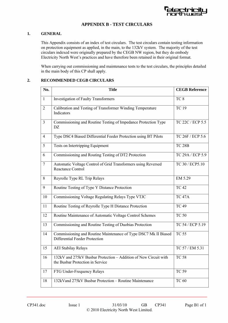
CP341.doc Issue 1 31/03/10 GB CP341 Page B1 of 1 © 2010 Electricity North West Limited.
APPENDIX B - TEST CIRCULARS
1. GENERAL
This Appendix consists of an index of test circulars. The test circulars contain testing information on protection equipment as applied, in the main, to the 132kV system. The majority of the test circulars indexed were originally prepared by the CEGB NW region, but they do embody Electricity North West’s practices and have therefore been retained in their original format.
When carrying out commissioning and maintenance tests to the test circulars, the principles detailed in the main body of this CP shall apply.
2. RECOMMENDED CEGB CIRCULARS
No. Title CEGB Reference
1 Investigation of Faulty Transformers TC 8
2 Calibration and Testing of Transformer Winding Temperature Indicators
TC 19
3 Commissioning and Routine Testing of Impedance Protection Type DZ
TC 22C / ECP 5.5
4 Type DSC4 Biased Differential Feeder Protection using BT Pilots TC 26F / ECP 5.6
5 Tests on Intertripping Equipment TC 28B
6 Commissioning and Routing Testing of DT2 Protection TC 29A / ECP 5.9
7 Automatic Voltage Control of Grid Transformers using Reversed Reactance Control
TC 30 / ECP5.10
8 Reyrolle Type RL Trip Relays EM 5.29
9 Routine Testing of Type Y Distance Protection TC 42
10 Commissioning Voltage Regulating Relays Type VTJC TC 47A
11 Routine Testing of Reyrolle Type H Distance Protection TC 49
12 Routine Maintenance of Automatic Voltage Control Schemes TC 50
13 Commissioning and Routine Testing of Duobias Protection TC 54 / ECP 5.19
14 Commissioning and Routine Maintenance of Type DSC7 Mk II Biased Differential Feeder Protection
TC 55
15 AEI Stabilay Relays TC 57 / EM 5.31
16 132kV and 275kV Busbar Protection – Addition of New Circuit with the Busbar Protection in Service
TC 58
17 FTG Under-Frequency Relays TC 59
18 132kVand 275kV Busbar Protection – Routine Maintenance TC 60