Commissioning 2007-01 - System eric - Swegon
50
Commissioning 2007-01 System e.r.i.c.
-
Upload
khangminh22 -
Category
Documents
-
view
2 -
download
0
Transcript of Commissioning 2007-01 - System eric - Swegon

www.swegon.se 2005-01-28
Rätt till konstruktionsändringar förbehålls1 (10)
Injusteringsanvisning
Commissioning 2007-01System e.r.i.c.
Co
mm
ission
ing
2007-01
Commissioning 2007-01 -------------
1Swegon Commissioning System e.r.i.c. 1-2007
www.swegon.com
Commissioning 2007-01
Revision History:Nov. 1, 2005: The first issue was based on commissioning and functional control. The RTC and KOP documents was added. TheKCW additional text for thermo actuator and blocked CO2 -function.Feb. 2006: Transferred documents to web base. The RTC text was adjusted. New commissioning charts for the ACK, ACL, AFK andAKY was added.2006-07: New text inserted in Variable 8 in the table entitled: ”All SNVT Variables for the KRF”.2006-09: Rev. in Variable 10 in the table entitled: ”All SNVT Variables for the KRF”.2006-09: Rev. in Variable 8 in the table entitled: ”All SNVT Variables for the KCD”.2006-11: RTCa upgraded to RTCb.2007-02: New product: ASDa - Active terminal. K-factor table availible for the following products: ACK, AKY, ACL, ARP, AFK andASD.
Figure 1. Connection of the hand terminal KOP to duct theproducts KZP, KZM, KSA and KRF.
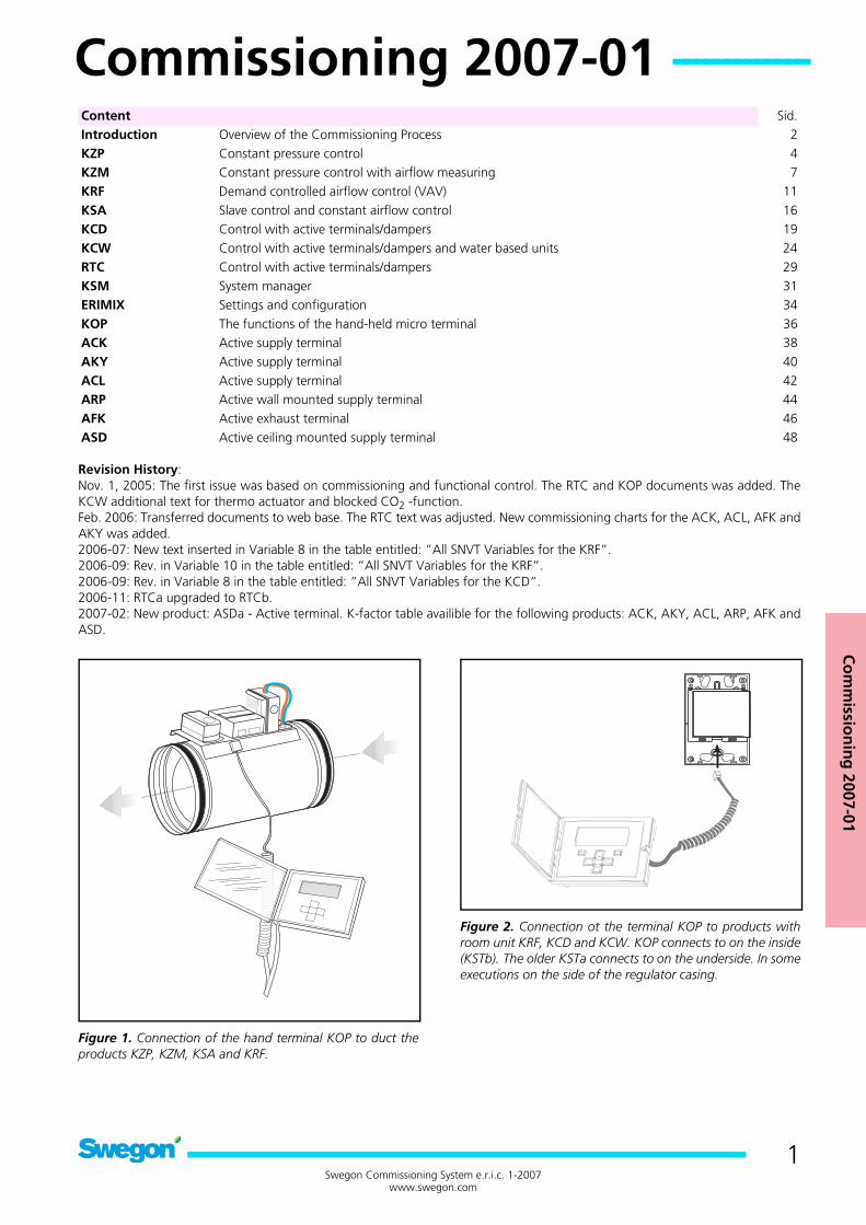
Figure 2. Connection ot the terminal KOP to products withroom unit KRF, KCD and KCW. KOP connects to on the inside(KSTb). The older KSTa connects to on the underside. In someexecutions on the side of the regulator casing.
Content Sid.Introduction Overview of the Commissioning Process 2KZP Constant pressure control 4KZM Constant pressure control with airflow measuring 7KRF Demand controlled airflow control (VAV) 11KSA Slave control and constant airflow control 16KCD Control with active terminals/dampers 19KCW Control with active terminals/dampers and water based units 24RTC Control with active terminals/dampers 29KSM System manager 31ERIMIX Settings and configuration 34KOP The functions of the hand-held micro terminal 36ACK Active supply terminal 38AKY Active supply terminal 40ACL Active supply terminal 42ARP Active wall mounted supply terminal 44AFK Active exhaust terminal 46ASD Active ceiling mounted supply terminal 48
Commissioning 2007-01 -----------------------------------------------
2Swegon Commissioning System e.r.i.c. 1-2007
www.swegon.com
INTRODUCTIONThis publication describes the actual work involved in commis-sioning an e.r.i.c. System. Besides this publication there areadditional documents which contain further informationabout different components and functions of the e.r.i.c. Sys-tem.
• The Regulator Manual, Edition 3• The Electric Wiring Planning Instructions• Assembly Instructions• Instructions for Use• Bindings for the e.r.i.c. System• Functional Control Forms
PreparationsIt is always advantageous to calculate theoretical settings forthe active regulators of the air terminals. In certain cases thismay already be pre-programmed from factory. The sales of-fice in question can inform you if this has been done.All factory settings are documented in the "SNVT" configura-tion document, which is supplied with the product and mayalso be ordered as a PDF document from the sales office.
UnitTo prevent fluctuations and changes in pressure from disturb-ing the commissioning work, it is important to lock the pres-sure regulation settings of the supply and extract air fans to apreliminary project-design value. If your system includes theKSM system manager, you can lock the fan pressures manu-ally via the KOP hand-held micro terminal.
Continuous operation after the commissioningIn systems without the KSM system manager, select the pres-sure set point of the unit in such a way that the pre-definedtarget specified in the commissioning documents (usually be-tween 70-100%) will, for the sake of simultaneity, provide theproject-design max airflow. In systems with the KSM systemmanager, the max. and min. pressure set points can be set inthe KOP hand-held micro terminal.
Zone dampersIn e.r.i.c. Systems with KZP/KZM for keeping the pressure con-stant in the branch ducts, these controls should be set to asuitable duct pressure, the default value is 50 Pa. It is very timeconsuming to calculate the optimal pressure if you do nothave access to a CAD system that quickly and easily computespressure settings for the whole system. As guidance, it is ad-visable to select a duct pressure that is as low as possible, butnot lower than a value that provides a pressure of 20 Pa meas-ured at the supply terminal connection. If the duct system issized with little margin for change, the pressure must insteadbe selected with the max. airflow rate as reference. Select80% as the max. permissible position in the supply terminalsto seek out which pressure is needed in the duct system. Thenincrease or decrease the setting in the KZP/KZM until the cor-rect airflow is obtained.
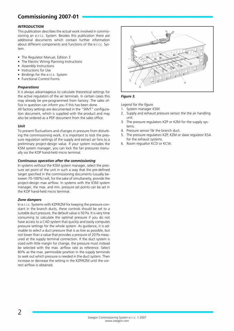
Figure 3.
Legend for the figure.1. System manager KSM.2. Supply and exhaust pressure sensor the the air handling
unit.3. The pressure regulators KZP or KZM for the supply sys-
tems.4. Pressure sensor får the branch duct.5. The pressure regulators KZP, KZM or slave regulator KSA
for the exhaust systems.6. Room regualtor KCD or KCW.
Co
mm
ission
ing
2007-01
3Swegon Commissioning System e.r.i.c. 1-2007
www.swegon.com
COMMISSIONING SEQUENCE
1. The unitCheck and set the operation of the unit to a constant pres-sure. A suitable approximate value will be between 150-300Pa depending on the size and character of the ventilation sys-tem.The pressure should be high enough to enable the unit man-age operation at the max. airflow according to project designspecifications. If the KSM system manager is included in thesystem, the unit pressures can be locked by means of the KOPhand-held micro terminal. This can be connected anywhere inthe network and then makes it possible to simply increase thepressure if the zone dampers are fully open. Manual operationis described on page 33.
2. The zone dampersSet the pressure set point of the zone damper to a value be-tween 30-50 Pa. Force at least 70% of all air terminals on thesame branch duct to their max. positions (80% is the default).Check that the zone damper is controlled to the preset setpoint, read the airflow through the damper and compare thetotal flow with the current forcing airflow of the supply termi-nals. If the airflow deviates increase or decrease the pressureset point. Do not forget to change the dead zone for pressureregulation when the pressure set point is changed. Thisshould be 10% of the pressure set point.In smaller systems, it is not common to use zone dampers. Theair handling unit’s pressure regulation mode is instead usedfor keeping the pressure constant in the branch ducts. It is im-portant that the pressure transducer of the unit be placed farout in the duct system at a representative place; see theProject Design Instructions for the e.r.i.c. System.
3. The air terminalsUse the Coefficient of Performance (K-factor) Graph in theseinstructions for commissioning the supply terminals. Begincommissioning as soon as the zone damper (KZP or KZM) hasreached its pressure set point, not sooner. Commissioning isdone by setting the min/max positions of the motor-driven“damper”. No airflow measurement is carried out in the con-trol process; instead it is assumed that the pressure in the ductsystem is regulated. This provides very stable control that doesnot have to compensate for pressure variations in the ductsystem. All the active supply terminals are equipped withmeasurement tappings and have a ”floating” coefficient ofperformance (K-factor). Set the min./max. positions in eachtype KCD, KCW or RTC room regulator.
4. KRF Room regulatorThis room regulator normally has totally pre-set values anddoes not have to be adjusted!
5. The slave airflow of the zone dampersThe slave airflow values can be checked when you’ve finishedadjusting the supply air. Normally, no adjustment should bemade; the airflow setting is transferred from the master to theslave. If there are any offset airflow values, they can be set inthe master if it has digital communication to the slave; and inthe slave if it has an analogue connection from the master. Asimple way to check whether transmission is digital or ana-logue is to see if a cord is connected to terminal 8 (Z1) on theKSA slave regulator, if this is the case, it has an analogue con-nection.
6. DocumentationRecord all the regulator setting changes on the ”Configura-tion data” form supplied with the product. If these forms aremissing, you can order them from your nearest sales repre-sentative in the form of a PDF document.
7. Finishing OffDo not forget to reset all the temporary settings in each reg-ulator. Settings of a temporary nature made in so-called “nvi”variables can be automatically set to 0 by briefly disconnectingthe power supply. This could be a good alternative instead ofgoing around having to adjust the regulator in every room.
FUNCTIONAL CONTROLSeparate functional control forms can be downloaded fromour homepage on the Internet. The performance of eachproduct should be tested individually and the findings shouldbe recorded on the relevant page of the functional controldocument.
KZPb
KZPb ----------------------------------------------------------
4Swegon Commissioning System e.r.i.c. 1-2007
www.swegon.com
Registered design. The company reserves the right to make design changes without prior notice.
KZPb
SYSTEM VARIANTSKZP is intended for pressure regulation of branch ducts. For adetailed description of the regulators function see the regula-tor KCP in the handbook that describes all the e.r.i.c. regula-tors and their functions, which is available to download aspdf-file from our website.
PUT INTO OPERATIONKZP is always factory set with data for its functions. As soonas the 24 VAC is connected the KZP is in operation, and noadditional work is called for.
COMMISSIONINGSetting of the pressure set point is done with the variable no23 nciSetptPress. Set the value which you require between10-300 Pa. The value for the dead zone 30 nciPressDzoneshould be set to 10% of the pressure setting, a lower valuemight make the control instable. If the regulator is acting hys-teric and does not stabilise the pressure, the actuator is mov-ing back and fourth, you could try with halving the gain factorin 28 nciPressGain.
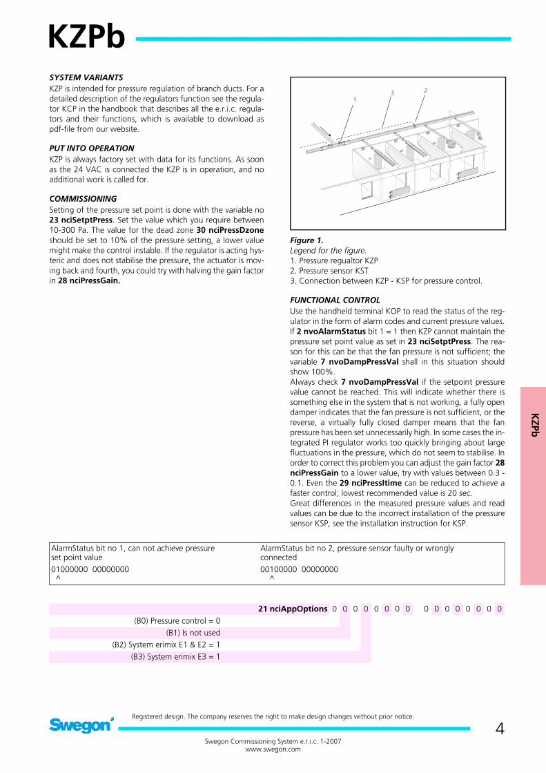
Figure 1.Legend for the figure.1. Pressure regualtor KZP2. Pressure sensor KST3. Connection between KZP - KSP for pressure control.
FUNCTIONAL CONTROLUse the handheld terminal KOP to read the status of the reg-ulator in the form of alarm codes and current pressure values.If 2 nvoAlarmStatus bit 1 = 1 then KZP cannot maintain thepressure set point value as set in 23 nciSetptPress. The rea-son for this can be that the fan pressure is not sufficient; thevariable 7 nvoDampPressVal shall in this situation shouldshow 100%.Always check 7 nvoDampPressVal if the setpoint pressurevalue cannot be reached. This will indicate whether there issomething else in the system that is not working, a fully opendamper indicates that the fan pressure is not sufficient, or thereverse, a virtually fully closed damper means that the fanpressure has been set unnecessarily high. In some cases the in-tegrated PI regulator works too quickly bringing about largefluctuations in the pressure, which do not seem to stabilise. Inorder to correct this problem you can adjust the gain factor 28nciPressGain to a lower value, try with values between 0.3 -0.1. Even the 29 nciPressItime can be reduced to achieve afaster control; lowest recommended value is 20 sec.Great differences in the measured pressure values and readvalues can be due to the incorrect installation of the pressuresensor KSP, see the installation instruction for KSP.
AlarmStatus bit no 1, can not achieve pressureset point value
AlarmStatus bit no 2, pressure sensor faulty or wronglyconnected
01000000 00000000 ^
00100000 00000000 ^
21 nciAppOptions 0 0 0 0 0 0 0 0 0 0 0 0 0 0 0 0(B0) Pressure control = 0
(B1) Is not used(B2) System erimix E1 & E2 = 1
(B3) System erimix E3 = 1

KZPb
5Swegon Commissioning System e.r.i.c. 1-2007
www.swegon.com
All SNVT-variables for KZP, also see Appendix A in the handbook.Highlighted variables are the signification for KZP with the regulator KCP.
No Description Normal value Explanation with reference to KCP-KCF-KCD-KCW Handbook0 nciLocation Any marking max 32 characters entered on the regulator usin e.g. LoneMaker
for Windows.1 nvoUnitStatus Auto.......... Current operating mode for the regulator, has no significance for KZP2 nvoAlarmStatus 00000000
000000003 nvoSpaceTemp -10.00 °C Does not apply to KZP4 nvoPressValue X.xxxx pasc Measured pressure value in the branch duct5 nvoSetpFlowSlave Invalid Does not apply to KZP6 nvoBoxFlow Invalid Does not apply to KZP7 nvoDampPressVal XX.XX % Output data KZPa damper position 100%=Open 0%=Closed8 nvoDampFlowVal XX.XX % Output data to mixing damper in system erimix, 0%=Heat 100%=Cooling9 nviApplicMode Auto Possibility to positively drive the damper, has no significance on KZP
10 nviSpaceTemp Invalid Input data from exhaust temperature in system erimix E2.11 nviSetpoint Invalid Does not apply to KZP12 nviPressValue Invalid Input data if measured pressure value via the Lon Network13 nviPressOffset 0 pasc Input data if the pressures deviation value via the Lon Network14 nviFlowOffset 0.0000 l/s Does not apply to KZP15 nviSptFlowSlave 0 l/s Does not apply to KZP16 nviEmergCmd Normal Positively driven operation of the regulator from a master
system17 nviManOverride Off 0.00 % Possibility of manual positively drive of the damper/diffuser position 0-100%,
only the function position has an effecton this regulator
18 nviOfstSlaveState Off Does not apply to KZP19 nviOfstSlavePerc 0.00 % Does not apply to KZP20 nviOfstSlaveFlow 0.00 l/s Does not apply to KZP21 nciAppOptions 00000000
00000000Setting the regualtor´s function. For KZPa the normal value applies
22 nciSetpoints no significance Does not apply to KZP23 nciSetptPress 50.0000 pasc The set point value for the branch duct pressure24 nciPressMin 10.0000 pasc Minimum setting for the set point value on the regulator25 nciPressMax 300.0000 pasc Maximum setting for the set point value on the regulator26 nciMinFlow 0 l/s Does not apply to KZP27 nciMaxFlow 0 l/s Does not apply to KZP28 nciPressGain 0.5000 Gain factor in the PI-regulator for pressure regulation29 nciPresstime 60 Integration time in the PI-regulator for pressure regulation30 nciPressDzone 4 pasc The dead zone for the PI-regulator (ought to be 10% of nciSetptPress)31 nciFlowGain 0.5000 Does not apply to KZP32 nciFlowtime 60.0 Does not apply to KZP33 nciFlowDzone 5.0 % Does not apply to KZP34 nciFlowConst 104.0 Does not apply to KZP35 nciInstallType Used by software36 nciSndHrtBt 0.0 May not be changed! Must be 0 sec.37 nciRcvHrtBt 0.0 Can be set to 60 sec if KZM is bound in a network38 nviRequest Used by software39 nvoStatus Used by software40 nviFileReq Used by software
KZPb -----------------------------------------------------------------
6Swegon Commissioning System e.r.i.c. 1-2007
www.swegon.com
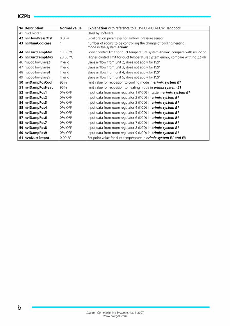
No Description Normal value Explanation with reference to KCP-KCF-KCD-KCW Handbook41 nvoFileStat Used by software42 nciFlowPressOfst 0.0 Pa 0-calibration parameter for airflow pressure sensor43 nciNumCoolcase 1 number of rooms to be controlling the change of cooling/heating
mode in the system erimix44 nciDuctTempMin 13.00 °C Lower control limit for duct temperature system erimix, compare with no 22 oc45 nciDuctTempMax 28.00 °C Higher control limit for duct temperature system erimix, compare with no 22 oh46 nviSptFlowSlave2 Invalid Slave airflow from unit 2, does not apply for KZP47 nviSptFlowSlavee Invalid Slave airflow from unit 3, does not apply for KZP48 nviSptFlowSlave4 Invalid Slave airflow from unit 4, does not apply for KZP49 nviSptFlowSlave5 Invalid Slave airflow from unit 5, does not apply for KZP50 nviDampPosCool 95% limit value for reposition to cooling mode in erimix system E151 nviDampPosHeat 95% limit value for reposition to heating mode in erimix system E152 nviDampPos1 0% OFF Input data from room regulator 1 (KCD) in system erimix system E153 nviDampPos2 0% OFF Input data from room regulator 2 (KCD) in erimix system E154 nviDampPos3 0% OFF Input data from room regulator 3 (KCD) in erimix system E155 nviDampPos4 0% OFF Input data from room regulator 4 (KCD) in erimix system E156 nviDampPos5 0% OFF Input data from room regulator 5 (KCD) in erimix system E157 nviDampPos6 0% OFF Input data from room regulator 6 (KCD) in erimix system E158 nviDampPos7 0% OFF Input data from room regulator 7 (KCD) in erimix system E159 nviDampPos8 0% OFF Input data from room regulator 8 (KCD) in erimix system E160 nviDampPos9 0% OFF Input data from room regulator 9 (KCD) in erimix system E161 nvoDuctSetpnt 0.00 °C Set point value for duct temperature in erimix system E1 and E3
KZM
b
KZMb --------------------------------------------------------
7Swegon Commissioning System e.r.i.c. 1-2007
www.swegon.com
Registered design. The company reserves the right to make design changes without prior notice.
KZMb
SYSTEM VARIANTSKZM is intended for pressure regulation of branch ducts andequipped with flow measuring to slave control the KSA in theexhaust duct. For a detailed description of the regulatrs func-tion see the regulator KCP in the handbook that describes allthe e.r.i.c. regulators and their functions, which is available todownload as pdf-file from our website.
PUT INTO OPERATIONKZM is always factory set with data for its functions. As soonas the 24 VAC is connected the KZM is in operation, and noadditional work is called for. For the slave control to be work-ing the products must be “bound” to each other if theLonNetwork is used for communication (if this is done in thefactory it will be stated on the product label), or be connectedanalogue to the slave regulator KSA. The analogue connec-tion is detected by two wires are connected to the plinth 6(Z2).
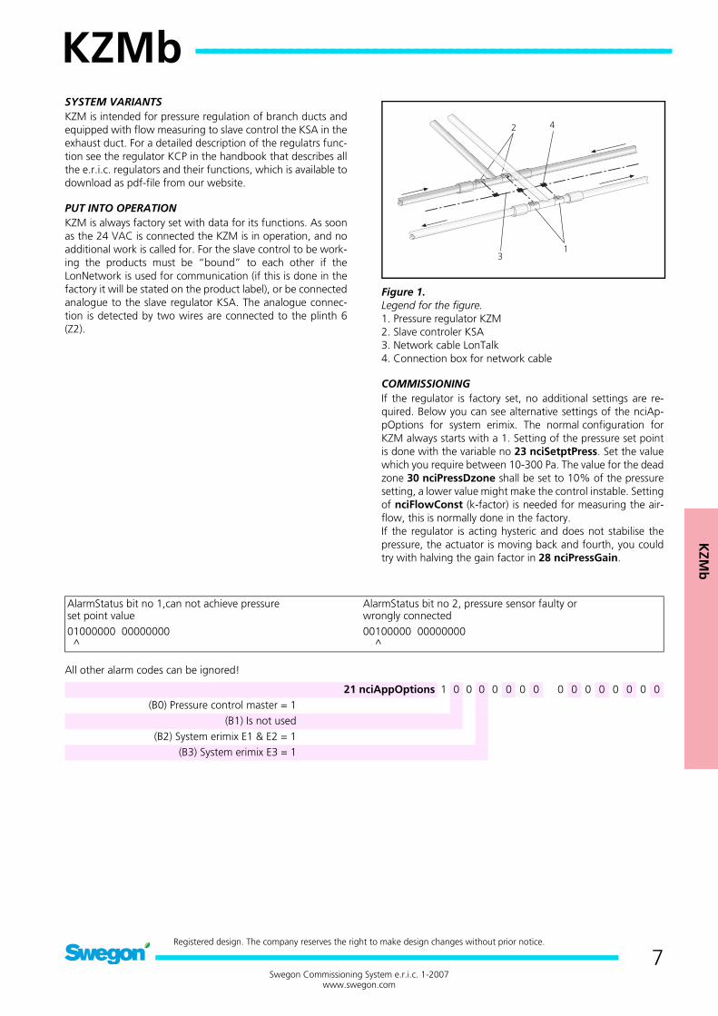
Figure 1.Legend for the figure.1. Pressure regulator KZM2. Slave controler KSA3. Network cable LonTalk4. Connection box for network cable
COMMISSIONINGIf the regulator is factory set, no additional settings are re-quired. Below you can see alternative settings of the nciAp-pOptions for system erimix. The normal configuration forKZM always starts with a 1. Setting of the pressure set pointis done with the variable no 23 nciSetptPress. Set the valuewhich you require between 10-300 Pa. The value for the deadzone 30 nciPressDzone shall be set to 10% of the pressuresetting, a lower value might make the control instable. Settingof nciFlowConst (k-factor) is needed for measuring the air-flow, this is normally done in the factory.If the regulator is acting hysteric and does not stabilise thepressure, the actuator is moving back and fourth, you couldtry with halving the gain factor in 28 nciPressGain.
All other alarm codes can be ignored!
AlarmStatus bit no 1,can not achieve pressureset point value
AlarmStatus bit no 2, pressure sensor faulty orwrongly connected
01000000 00000000 ^
00100000 00000000 ^
21 nciAppOptions 1 0 0 0 0 0 0 0 0 0 0 0 0 0 0 0(B0) Pressure control master = 1
(B1) Is not used(B2) System erimix E1 & E2 = 1
(B3) System erimix E3 = 1
KZMb ----------------------------------------------------------------
8Swegon Commissioning System e.r.i.c. 1-2007
www.swegon.com
SLAVE CONTROLThere are two methodes to slave control, analogue and digit-al. Setting the values for digital slave control of the KZMa isdone with the variables, 18 nviOfsSlaveState which describ-se how the slave control shall be preformed, 19 nviOfst-SlavePerc or 20 nviOfstSlaveFlow, were you can choosebetween an offset value from the supply/exhaust in l/s or %.
Data setting for, 18 nviOfsSlaveStateHigh = offset in l/sLow = offset in %
For digital transfer one of these values has to be set even if theoffset should not be calculated. Setting of the set point pres-sure value is done with the variable no 23 nciSetptPress. Setthe value which you require between 10-300 Pa. The value forthe dead zone 30 nciPressDzone shall be set to 10% of thepressure setting, a lower value might make the control insta-ble. If the regulator is acting hysteric and does not stabilise thepressure, the actuator is moving back and fourth, you couldtry with halving the gain factor in 28 nciPressGain.
FUNCTIONAL CONTROLUse the handheld terminal KOP to read the status of the reg-ulator in the form of alarm codes and current pressure values.If 2 nvoAlarmStatus bit 1 = 1 then KZM cannot maintain thepressure set point value as set in 23 nciSetptPress. The reasonfor this can be that the fan pressure is not sufficient; the vari-able 7 nvoDampPressVal shall in this situation should show100%.Always check 7 nvoDampPressVal if the setpoint pressurevalue cannot be reached. This will indicate whether there issomething else in the system that is not working, a fully opendamper indicates that the fan pressure is not sufficient, or thereverse, a virtually fully closed damper means that the fanpressure has been set unnecessarily high.In some cases the integrated PI regulator works too quicklybringing about large fluctuations in the pressure, which donot seem to stabilise. In order to correct this problem you canadjust the gain factor 28 nciPressGain to a lower value, trywith values between 0.3 - 0.1. Even the 29 nciPressItime canbe reduced to achieve a faster control; lowest recommendedvalue is 20 sec.Great differences in the measured pressure values and readvalues can be due to the incorrect installation of the pressuresensor KSP, see the installation instruction for KSP.Other variables that has significance and which can bechecked on the KZM is:6 nvoBoxFlow (Measured airflow value in l/s) and 5 nvo-SetptFlowSlave the setpoint value with the offset which issent to the slave regulator KSA when the digital LonTalk com-munication is used. With analogue connection, all the settingsare made in the slave regulator KSA. The variables in the KSAare 15 nviSetptFlowSlave (l/s). Make sure 33 nciFlowD-zone is not less then 5% of the set point value.
KZM
b
9Swegon Commissioning System e.r.i.c. 1-2007
www.swegon.com
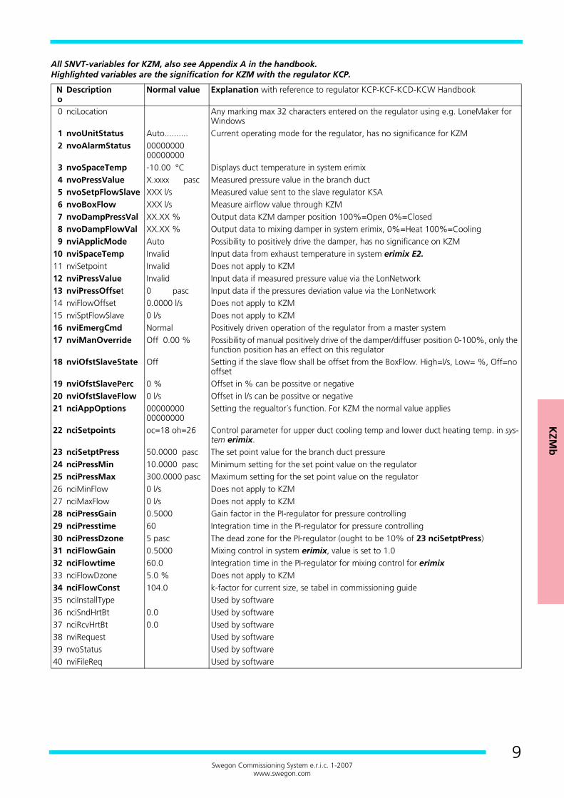
All SNVT-variables for KZM, also see Appendix A in the handbook.Highlighted variables are the signification for KZM with the regulator KCP.
No
Description Normal value Explanation with reference to regulator KCP-KCF-KCD-KCW Handbook
0 nciLocation Any marking max 32 characters entered on the regulator using e.g. LoneMaker for Windows
1 nvoUnitStatus Auto.......... Current operating mode for the regulator, has no significance for KZM2 nvoAlarmStatus 00000000
000000003 nvoSpaceTemp -10.00 °C Displays duct temperature in system erimix4 nvoPressValue X.xxxx pasc Measured pressure value in the branch duct5 nvoSetpFlowSlave XXX l/s Measured value sent to the slave regulator KSA6 nvoBoxFlow XXX l/s Measure airflow value through KZM7 nvoDampPressVal XX.XX % Output data KZM damper position 100%=Open 0%=Closed8 nvoDampFlowVal XX.XX % Output data to mixing damper in system erimix, 0%=Heat 100%=Cooling9 nviApplicMode Auto Possibility to positively drive the damper, has no significance on KZM
10 nviSpaceTemp Invalid Input data from exhaust temperature in system erimix E2.11 nviSetpoint Invalid Does not apply to KZM12 nviPressValue Invalid Input data if measured pressure value via the LonNetwork13 nviPressOffset 0 pasc Input data if the pressures deviation value via the LonNetwork14 nviFlowOffset 0.0000 l/s Does not apply to KZM15 nviSptFlowSlave 0 l/s Does not apply to KZM16 nviEmergCmd Normal Positively driven operation of the regulator from a master system17 nviManOverride Off 0.00 % Possibility of manual positively drive of the damper/diffuser position 0-100%, only the
function position has an effect on this regulator18 nviOfstSlaveState Off Setting if the slave flow shall be offset from the BoxFlow. High=l/s, Low= %, Off=no
offset19 nviOfstSlavePerc 0 % Offset in % can be possitve or negative20 nviOfstSlaveFlow 0 l/s Offset in l/s can be possitve or negative21 nciAppOptions 00000000
00000000Setting the regualtor´s function. For KZM the normal value applies
22 nciSetpoints oc=18 oh=26 Control parameter for upper duct cooling temp and lower duct heating temp. in sys-tem erimix.
23 nciSetptPress 50.0000 pasc The set point value for the branch duct pressure24 nciPressMin 10.0000 pasc Minimum setting for the set point value on the regulator25 nciPressMax 300.0000 pasc Maximum setting for the set point value on the regulator26 nciMinFlow 0 l/s Does not apply to KZM27 nciMaxFlow 0 l/s Does not apply to KZM28 nciPressGain 0.5000 Gain factor in the PI-regulator for pressure controlling29 nciPresstime 60 Integration time in the PI-regulator for pressure controlling30 nciPressDzone 5 pasc The dead zone for the PI-regulator (ought to be 10% of 23 nciSetptPress)31 nciFlowGain 0.5000 Mixing control in system erimix, value is set to 1.032 nciFlowtime 60.0 Integration time in the PI-regulator for mixing control for erimix33 nciFlowDzone 5.0 % Does not apply to KZM34 nciFlowConst 104.0 k-factor for current size, se tabel in commissioning guide35 nciInstallType Used by software36 nciSndHrtBt 0.0 Used by software37 nciRcvHrtBt 0.0 Used by software38 nviRequest Used by software39 nvoStatus Used by software40 nviFileReq Used by software
KZMb ----------------------------------------------------------------
10Swegon Commissioning System e.r.i.c. 1-2007
www.swegon.com
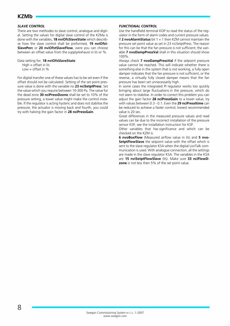
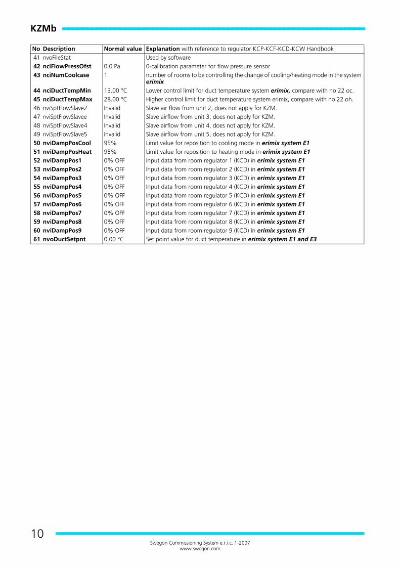
No Description Normal value Explanation with reference to regulator KCP-KCF-KCD-KCW Handbook41 nvoFileStat Used by software42 nciFlowPressOfst 0.0 Pa 0-calibration parameter for flow pressure sensor43 nciNumCoolcase 1 number of rooms to be controlling the change of cooling/heating mode in the system
erimix44 nciDuctTempMin 13.00 °C Lower control limit for duct temperature system erimix, compare with no 22 oc.45 nciDuctTempMax 28.00 °C Higher control limit for duct temperature system erimix, compare with no 22 oh.46 nviSptFlowSlave2 Invalid Slave air flow from unit 2, does not apply for KZM.47 nviSptFlowSlavee Invalid Slave airflow from unit 3, does not apply for KZM.48 nviSptFlowSlave4 Invalid Slave airflow from unit 4, does not apply for KZM.49 nviSptFlowSlave5 Invalid Slave airflow from unit 5, does not apply for KZM.50 nviDampPosCool 95% Limit value for reposition to cooling mode in erimix system E151 nviDampPosHeat 95% Limit value for reposition to heating mode in erimix system E152 nviDampPos1 0% OFF Input data from room regulator 1 (KCD) in erimix system E153 nviDampPos2 0% OFF Input data from room regulator 2 (KCD) in erimix system E154 nviDampPos3 0% OFF Input data from room regulator 3 (KCD) in erimix system E155 nviDampPos4 0% OFF Input data from room regulator 4 (KCD) in erimix system E156 nviDampPos5 0% OFF Input data from room regulator 5 (KCD) in erimix system E157 nviDampPos6 0% OFF Input data from room regulator 6 (KCD) in erimix system E158 nviDampPos7 0% OFF Input data from room regulator 7 (KCD) in erimix system E159 nviDampPos8 0% OFF Input data from room regulator 8 (KCD) in erimix system E160 nviDampPos9 0% OFF Input data from room regulator 9 (KCD) in erimix system E161 nvoDuctSetpnt 0.00 °C Set point value for duct temperature in erimix system E1 and E3

KR
Fc
KRFc -----------------------------------------------------------
11Swegon Commissioning System e.r.i.c. 1-2007
www.swegon.com
Registered design. The company reserves the right to make design changes without prior notice.
KRFc
SYSTEM VARIANTSKRF is intended for airflow control (VAV) with temperature -presence - CO2 level etc as control parameters. KRF can alsocontrol reheat battery in the duct or radiator in the room. Fora detailed description of the regulators function see the regu-lator KCF in the handbook that describes all the e.r.i.c. regu-lators and their functions, which is available to download aspdf-file from our website.
PUT INTO OPERATIONKRF is always factory set with data for its functions, as airƒPowconstants and min/max air volumes. As soon as the 24 VAC isconnected the KRF is in operation, and no additional work iscalled for. In most cases even the 27 nciAppOptions set inthe factory. The regulators operation is determined by the set-ting in the variable 27 nciAppOptions (0000000000000000) 16 bit, se below. Variables that needs to be set isas follows:
39 nciMinFlow (min airflow l/s in normal mode)40 nciMaxFlow (max airflow l/s in normal mode)41 nciMinFlowHeat (only when heat control)42 nciMinFlowStand (only when presence control)
Figure 1. Legend for the figure.1. Airflow regulator KRF2. Room unit KST 2 (0, 2 or 4)3. Presence sensor KSO4. C02 -sensor KSC
ControllingIf the regulator controls the damper actuator in to big stepswith the result of unstable airflow, the following adjustmentsis required:33 nciFlowGain reduced in steps, this will slow down thecontrols and the steps, try by halving the current factor. Inter-val 0.1 - 0.5 is recommended, where low values are for bigduct sizes. The new KRFc regulator calculates the mean air-flow signal value, thus FlowGain normally has a higher valuethan the older KRFa and KRFc models (0.005 – 0.1).34 nciFlowItime is factory preset and should not be altered;the value should be 30 sec.
27 nciAppOptions 0 0 0 0 0 0 0 0 0 0 0 0 0 0 0 0(B0) Presence sensor connected = 1
(B1) Window switch with power limitation = 1(B2) Cooling & heating control = 0
(B2) Only cooling control with air = 1(B3) Airflow control without slave control = 0
(B3) Airflow control with slave control of KSA = 1(B4) Reheat bettery type Coils in the duct = 0
B4) Heating with radiator in the room = 1(B5) CO2 control = 1
(B6) Thermo actuator power less closed = 1(B7) Control of BLB mixing box = 1
(B8) Presence sensor with closed switch when presence = 0
(B10) Extra cooling regulation step = 1
(B12) Save some nvi’er = 1
NOTE! B4, B7 and B10 cannot be selected at the same time; only one should have the value 1.

KRFc -----------------------------------------------------------------
12Swegon Commissioning System e.r.i.c. 1-2007
www.swegon.com
PUT INTO OPERATION CONTINUEDFor the slave control of KSA must work the products must beeither digital "bound" or analogue connectedto each other. The analogue connection is detected by twowires are connected to the plinth 6 (Z2) and the offset slaveairflow (Ofst) is then set in the KSA.23 nciSetptPress, low=% offset of the exhaust airflow,high= offset of the exhaust airflow in l/s.24 nviOfstSlavePerc give offset +/- in %25 nviOfstSlaveFlow give offset in +/- in l/s.When CO2 controlling it might be necessary to change thevalues for the P-band regulation that handles the airflow con-trol. See diagram below for the relation between CO2 -Current - Airflow.47 nciSpaceCO2Low shall normally represent the outdoorlevel, this value is normally between 340-500 ppm dependingon location.48 nciSpaceCO2High is the value where the regulator willput out max airflow.
CHECKING THE CO2 -SENSORIs simplest done by breathing on the sensor and read of theresult in 9 nvoSpaceCO2. The regulator should at the sametime increase the airflow. Normal values for fresh outdoor airis dependent on the location of the building, in the countryside it can be as low as 340 ppm and in cities 500 ppm. Alsocheck 46 nciCO2PerVolt, which normally shall be 200 whenconnected with Swegons sensor KSC.If the combined output OUT1(temperature + CO2-value) isused, 46 nciCo2PerVolt should be set on 100, 47nciSpaceCO2Low=0 and 48 nciSpaceCO2High=1000.
FUNCTIONAL CONTROLUse the hand terminal KOP to read the status of the regulatorin the form of alarm codes and current values.
You can read more about alarm codes and their values in thehandbook page 33. Note that alarm code automatically resetsto the value 0 as soon as the reason for the alarm has beencorrected, there is no possibility to through the operation pan-el see a activity log over previous problems.If the regulator controls the damper actuator in to big stepswith the result of unstable airflow, the following adjustmentsis requiered:33 nciFlowGain reduced in steps by halving, this will slowdown the control with smaller steps, interval 0,01 - 0.5 is rec-ommended.34 nciFlowItime can be reduced to get a quicker control,lowest recommended is 20 sec.
Bit Value Problem0 0
1NonDeviating room temperature
1 01
NonLow room temperature
2 01
NonWindow switch alarm
3 01
NonToo high CO2 level
4 01
NonAirflow deviation from set point
5 01
NonFaulty airflow sensor

KR
Fc
13Swegon Commissioning System e.r.i.c. 1-2007
www.swegon.com
CHECKING THE AIRFLOWFirst check the airflow data to ensure that these are withinreasonable limits, remember that the hand terminal only up-dates the values every 16th second.To positively drive the regulator towards max or min airflow iseasiest done with the variable 16 nviSpace Temp, this valuecan be set to -327.19 to check min airflow and +327.17 tocheck the max airflow. Do not forget to reset the value toINVALID.7 nvoBoxFlow (Measure airflow l/s) and 5 nvoSetpt-FlowSlave is the set point value with the offset that is sent tothe slave regulator KSA when the digital LonTalk communica-tion is used. With analogue connection is used all settings aremade in the KSA. Equivalent settings in the KSA are 15 nvi-SetptFlowSlave (l/s).If the airflow data is outside the min or max airflow settings,check the damper positions. 11 nvoDampFlowVal, if thisvalue is 30 - 80% this is indicating that the duct pressure is toolow or too high. Corrected by reducing/increasing the ductpressure in the KZP or air handling unit.
CHECKING THE CONTROL OF RADIATOR VALVECheck that 27 nciAppOptions is set for heating control.There is only one method of checking the valve control. Firstby setting 16 nviSpaceTemp to -327.19 to make sure thevalve is opening and then +327.17 to check that the valve isclosing. Do not forget to reset to INVALID.To check that the regulator has changed the outputs can bedisplayed in 2 nvoUnitStatus where hp shall show 100.00 atthe same time as 56 nvoHeatOutput shall show 100%.The output Y1-M shall put out 10V DC, output V1-M shall putout 24 VAC.
CHECK MIXING AIR REGULATION OR EXTRA COOLING STEPCheck that 27 nciAppOptions is set for every function.Check in the same way as you do the radiator valve as de-scribed above. Use the same output.
CHECKING THE PRESENCE CONTROLConnected analogue presence sensor is checked by readingthe variable 13 nvoOccSensor which shall show Occupiedwhen it is activated. If the function is not correct, check 27nciAppOptions bit 0 (=1) and 8 (=0). If the function still is in-correct you can check the regulator by connection the inputX2 and M. If 13 nvoOccSensor still shows Unoccupied theKCF regulator is faulty. The variable 1 nvoEffectOccup has adelayed disconnection of 20 min, this is adjustable with 58nciBypassTime. The variable 13 nvoOccSensor changes themode between Occupied and Unoccupied, while 1 nvoEffec-tOccup changes between Occupied and StandBye. In standbymode the regulator is operating with other set points for tem-perature, see more in the manual for the KOP.
CHECKING THE WINDOW SWITCHConnected window switch blocks the function by closingheating and the airflow is set to 0 l/s. Check is done with thevariable 2 nvoUnitStatus, which shows off when window isopen or open switch. When controlling radiator there is afrost protection that will open the radiator valve when roomtemp go below 10 °C.
KRFc -----------------------------------------------------------------
14Swegon Commissioning System e.r.i.c. 1-2007
www.swegon.com
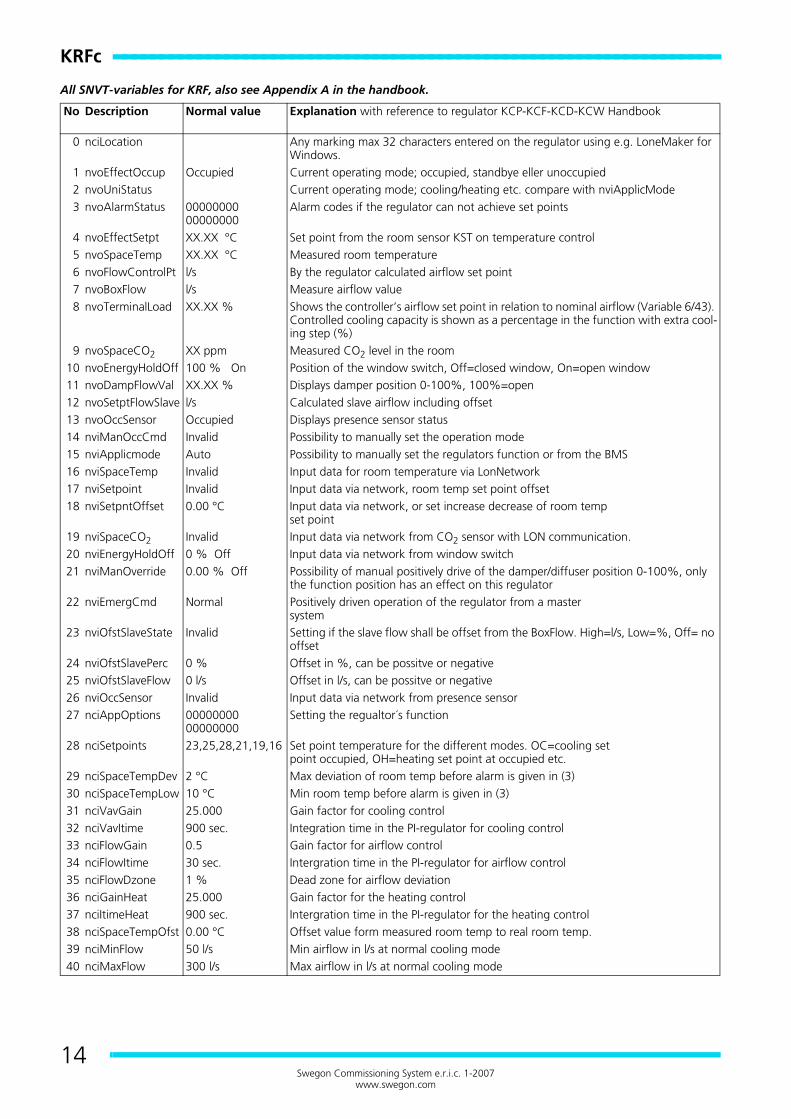
All SNVT-variables for KRF, also see Appendix A in the handbook.
No Description Normal value Explanation with reference to regulator KCP-KCF-KCD-KCW Handbook
0 nciLocation Any marking max 32 characters entered on the regulator using e.g. LoneMaker for Windows.
1 nvoEffectOccup Occupied Current operating mode; occupied, standbye eller unoccupied2 nvoUniStatus Current operating mode; cooling/heating etc. compare with nviApplicMode3 nvoAlarmStatus 00000000
00000000Alarm codes if the regulator can not achieve set points
4 nvoEffectSetpt XX.XX °C Set point from the room sensor KST on temperature control5 nvoSpaceTemp XX.XX °C Measured room temperature6 nvoFlowControlPt l/s By the regulator calculated airflow set point7 nvoBoxFlow l/s Measure airflow value8 nvoTerminalLoad XX.XX % Shows the controller’s airflow set point in relation to nominal airflow (Variable 6/43).
Controlled cooling capacity is shown as a percentage in the function with extra cool-ing step (%)
9 nvoSpaceCO2 XX ppm Measured CO2 level in the room10 nvoEnergyHoldOff 100 % On Position of the window switch, Off=closed window, On=open window11 nvoDampFlowVal XX.XX % Displays damper position 0-100%, 100%=open12 nvoSetptFlowSlave l/s Calculated slave airflow including offset13 nvoOccSensor Occupied Displays presence sensor status14 nviManOccCmd Invalid Possibility to manually set the operation mode15 nviApplicmode Auto Possibility to manually set the regulators function or from the BMS16 nviSpaceTemp Invalid Input data for room temperature via LonNetwork17 nviSetpoint Invalid Input data via network, room temp set point offset18 nviSetpntOffset 0.00 °C Input data via network, or set increase decrease of room temp
set point19 nviSpaceCO2 Invalid Input data via network from CO2 sensor with LON communication.20 nviEnergyHoldOff 0 % Off Input data via network from window switch21 nviManOverride 0.00 % Off Possibility of manual positively drive of the damper/diffuser position 0-100%, only
the function position has an effect on this regulator22 nviEmergCmd Normal Positively driven operation of the regulator from a master
system23 nviOfstSlaveState Invalid Setting if the slave flow shall be offset from the BoxFlow. High=l/s, Low=%, Off= no
offset24 nviOfstSlavePerc 0 % Offset in %, can be possitve or negative25 nviOfstSlaveFlow 0 l/s Offset in l/s, can be possitve or negative26 nviOccSensor Invalid Input data via network from presence sensor27 nciAppOptions 00000000
00000000Setting the regualtor´s function
28 nciSetpoints 23,25,28,21,19,16 Set point temperature for the different modes. OC=cooling setpoint occupied, OH=heating set point at occupied etc.
29 nciSpaceTempDev 2 °C Max deviation of room temp before alarm is given in (3)30 nciSpaceTempLow 10 °C Min room temp before alarm is given in (3)31 nciVavGain 25.000 Gain factor for cooling control32 nciVavItime 900 sec. Integration time in the PI-regulator for cooling control33 nciFlowGain 0.5 Gain factor for airflow control34 nciFlowItime 30 sec. Intergration time in the PI-regulator for airflow control35 nciFlowDzone 1 % Dead zone for airflow deviation36 nciGainHeat 25.000 Gain factor for the heating control37 nciItimeHeat 900 sec. Intergration time in the PI-regulator for the heating control38 nciSpaceTempOfst 0.00 °C Offset value form measured room temp to real room temp.39 nciMinFlow 50 l/s Min airflow in l/s at normal cooling mode40 nciMaxFlow 300 l/s Max airflow in l/s at normal cooling mode
KR
Fc
15Swegon Commissioning System e.r.i.c. 1-2007
www.swegon.com
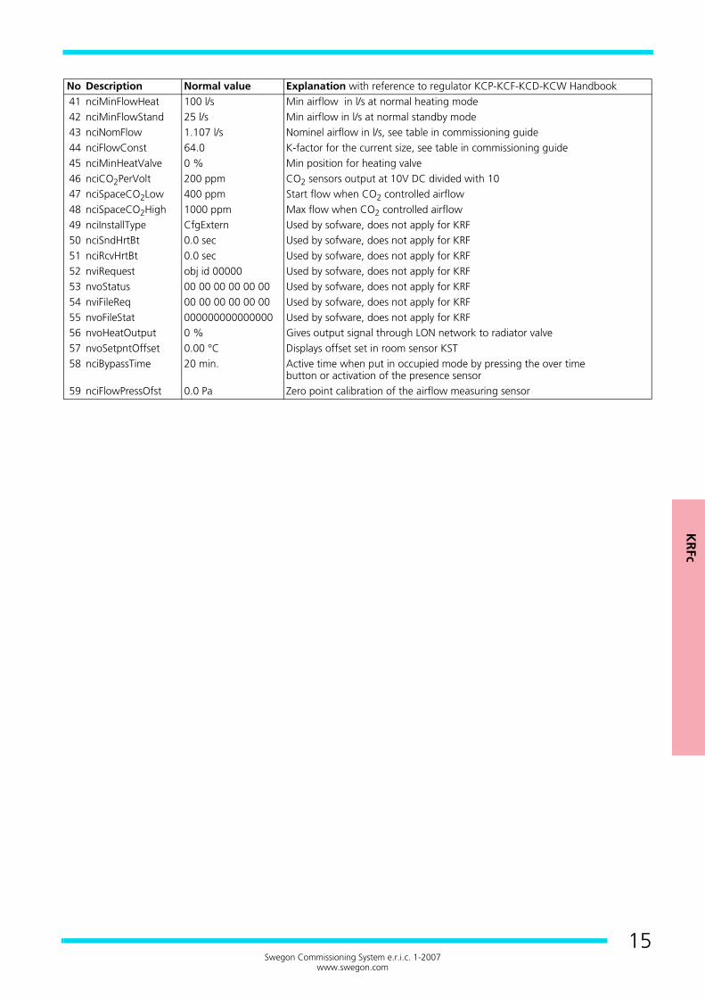
No Description Normal value Explanation with reference to regulator KCP-KCF-KCD-KCW Handbook41 nciMinFlowHeat 100 l/s Min airflow in l/s at normal heating mode42 nciMinFlowStand 25 l/s Min airflow in l/s at normal standby mode43 nciNomFlow 1.107 l/s Nominel airflow in l/s, see table in commissioning guide44 nciFlowConst 64.0 K-factor for the current size, see table in commissioning guide45 nciMinHeatValve 0 % Min position for heating valve46 nciCO2PerVolt 200 ppm CO2 sensors output at 10V DC divided with 1047 nciSpaceCO2Low 400 ppm Start flow when CO2 controlled airflow48 nciSpaceCO2High 1000 ppm Max flow when CO2 controlled airflow49 nciInstallType CfgExtern Used by sofware, does not apply for KRF50 nciSndHrtBt 0.0 sec Used by sofware, does not apply for KRF51 nciRcvHrtBt 0.0 sec Used by sofware, does not apply for KRF52 nviRequest obj id 00000 Used by sofware, does not apply for KRF53 nvoStatus 00 00 00 00 00 00 Used by sofware, does not apply for KRF54 nviFileReq 00 00 00 00 00 00 Used by sofware, does not apply for KRF55 nvoFileStat 000000000000000 Used by sofware, does not apply for KRF56 nvoHeatOutput 0 % Gives output signal through LON network to radiator valve57 nvoSetpntOffset 0.00 °C Displays offset set in room sensor KST58 nciBypassTime 20 min. Active time when put in occupied mode by pressing the over time
button or activation of the presence sensor59 nciFlowPressOfst 0.0 Pa Zero point calibration of the airflow measuring sensor
KSA
b
KSAb ---------------------------------------------------------
16Swegon Commissioning System e.r.i.c. 1-2007
www.swegon.com
Registered design. The company reserves the right to make design changes without prior notice.
KSAb
SYSTEM VARIANTSKSA is used for airflow control in branch ducts, as slave regu-lator to KZM or KRF and also as independent constant airflowregulator. For detailed description of the regulators functions,see regulator KCP in the handbook which describes all e.r.i.c.regulators and their functions, available as downloadable pdf-file on our website.
PUT INTO OPERATIONKSA is always configured from factory with the data for itsfunction. As soon as 24 VAC has been connected the KSA isin operation, some bindings may have to be made if using dig-ital data transfer.21 nciAppOptions shall always be 01000000 000001000.For slave control of the KSA to work, it has to be either bounddigitally to the KZM/KRF (if this is done in the factory it will bestated on the product label), or analogue connected to themaster KZM/KRF. The analogue connection is noted by wiresconnected to plinth 8 (Z1).
COMMISSIONINGChanging or checking the variable settings (SNVT) on site iseasiest with the operations panel KOP. KOP is connected toKSA, see figure 1.The operation of the regulator is determined by the settingsin the variable nciAppOptins (00000000 00000000) 16 bit,according to the table. KSA only has one setting though, butwith different functionalities.1. Digital transmitted of the slave airflow setting or
constant airflow functionWhen operating as constant flow regulator the variable 15 nviSetptFlowSlave shall be given the airflow set point in l/s.NB! The 13th character in nciAppOptions has to be entered after the set point has been entered.21 nciAppOptions = 01000000 00001000.When the slave airflow set point is digital transmitted via the LON-network, the set point in the variable 15 nvi-SetptFlowSlave is automatically set and changes as the master airflow changes.
2. Analogue transmitting the slave airflow set point from the KZM/KRF.15 nviSetptFlowSlave shall always be set INVALID.21 nciAppOptions = 01000000 00001000.When transmitted analogue and having different size on slave and master, nviOfstSlavePerc must be set as fol-lows:Master k-factor / Slave k-factor calculated to %Example: Master size 250 slave size 200 gives k-factors 40,0 / 26,5 = 1,51 set the offset to +51%.The regulators nviOfstSLaveState must in this case be set to Low.
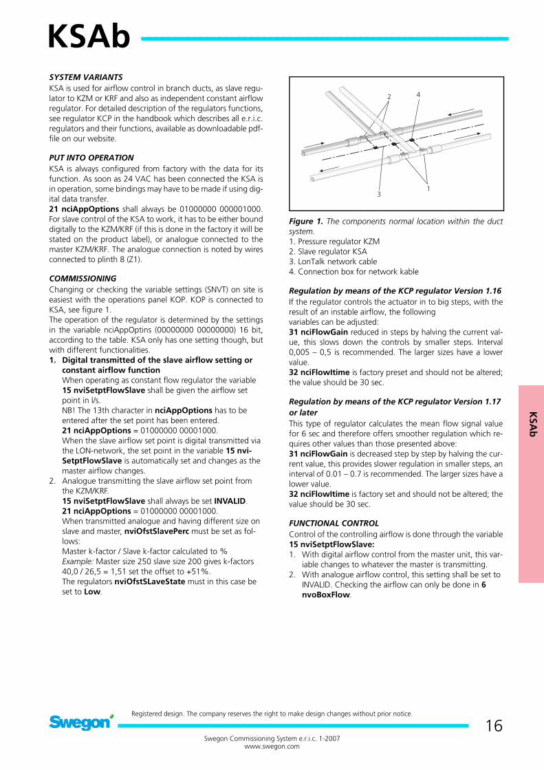
Figure 1. The components normal location within the ductsystem.1. Pressure regulator KZM2. Slave regulator KSA3. LonTalk network cable4. Connection box for network kable
Regulation by means of the KCP regulator Version 1.16If the regulator controls the actuator in to big steps, with theresult of an instable airflow, the followingvariables can be adjusted:31 nciFlowGain reduced in steps by halving the current val-ue, this slows down the controls by smaller steps. Interval0,005 – 0,5 is recommended. The larger sizes have a lowervalue.32 nciFlowItime is factory preset and should not be altered;the value should be 30 sec.
Regulation by means of the KCP regulator Version 1.17 or laterThis type of regulator calculates the mean flow signal valuefor 6 sec and therefore offers smoother regulation which re-quires other values than those presented above:31 nciFlowGain is decreased step by step by halving the cur-rent value, this provides slower regulation in smaller steps, aninterval of 0.01 – 0.7 is recommended. The larger sizes have alower value.32 nciFlowItime is factory set and should not be altered; thevalue should be 30 sec.
FUNCTIONAL CONTROLControl of the controlling airflow is done through the variable15 nviSetptFlowSlave:1. With digital airflow control from the master unit, this var-
iable changes to whatever the master is transmitting.2. With analogue airflow control, this setting shall be set to
INVALID. Checking the airflow can only be done in 6 nvoBoxFlow.

KSA
b
17Swegon Commissioning System e.r.i.c. 1-2007
www.swegon.com
All SNVT-variables for KSA, also see the Appendix A in the handbookHighlighted variables are the active once for KSA with the regulator KCP.
No Description Normal value Explanation with reference to regulator KCP-KCF-KCD-KCW Handbook0 nciLocation Any marking max 32 characters entered on the regulator using e.g. LoneMaker
for Windows.1 nvoUnitStatus Auto.......... Current operating mode, does not apply for KSA2 nvoAlarmStatus 00000000
000000003 nvoSpaceTemp -10.00 °C Output data exhaust temperature in erimix system E2-E3.4 nvoPressValue X.xxxx pasc Does not apply for KSA5 nvoSetpFlowSlave Invalid Does not apply for KSA6 nvoBoxFlow XXX l/s The present value for current flow through the KSA7 nvoDampPressVal Invalid Does not apply for KSA8 nvoDampFlowVal XX.XX % Output KSA damper position 100%=Open 0%=Closed9 nviApplicMode Auto Possible force control, Does not apply for KSA
10 nviSpaceTemp Invalid Does not apply for KSA11 nviSetpoint Invalid Does not apply for KSA12 nviPressValue Invalid Does not apply for KSA13 nviPressOffset 0 pasc Does not apply for KSA14 nviFlowOffset 0.0000 l/s Does not apply for KSA15 nviSptFlowSlave 0 l/s Input data measure airflow, fixed or from master via LON network16 nviEmergCmd Normal Possible forced control from BMS system17 nviManOverride Off 0.00 % Possible forced controlav of damper/diffuser position 0-100%,only the position
function apply in this regulator.18 nviOfstSlaveState Off Used only for analogue signal transmission from the master.19 nviOfstSlavePerc 0 % Used only for analogue signal transmission from the master.20 nviOfstSlaveFlow 0 l/s Used only for analogue signal transmission from the master.21 nciAppOptions 00000000
00000000Setting of the regulator function
22 nciSetpoints 18, 26 Applicable to the erimix System only.23 nciSetptPress 50.0000 pasc Does not apply for KSA24 nciPressMin 10.0000 pasc Does not apply for KSA25 nciPressMax 300.0000 pasc Does not apply for KSA26 nciMinFlow 0 l/s Does not apply for KSA27 nciMaxFlow 0 l/s Does not apply for KSA28 nciPressGain 0.5 Does not apply for KSA29 nciPresstime 60 Does not apply for KSA30 nciPressDzone 5 Does not apply for KSA31 nciFlowGain 0.5000 Gain factor for airflow control32 nciFlowtime 60.0 Integration factor for airflow control33 nciFlowDzone 5.0 % Dead zone for airflow control34 nciFlowConst 16.0 K-factor for the current size, see tabel in the commissioning guide35 nciInstallType Used by sofware36 nciSndHrtBt Used by sofware37 nciRcvHrtBt Used by sofware38 nviRequest Used by sofware39 nvoStatus Used by sofware40 nviFileReq Used by sofware
KSAb ----------------------------------------------------------------
18Swegon Commissioning System e.r.i.c. 1-2007
www.swegon.com
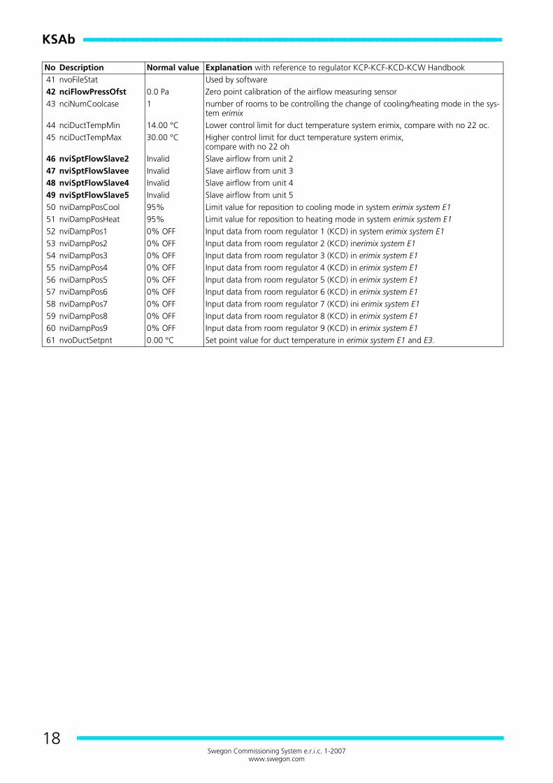
No Description Normal value Explanation with reference to regulator KCP-KCF-KCD-KCW Handbook41 nvoFileStat Used by software42 nciFlowPressOfst 0.0 Pa Zero point calibration of the airflow measuring sensor43 nciNumCoolcase 1 number of rooms to be controlling the change of cooling/heating mode in the sys-
tem erimix44 nciDuctTempMin 14.00 °C Lower control limit for duct temperature system erimix, compare with no 22 oc.45 nciDuctTempMax 30.00 °C Higher control limit for duct temperature system erimix,
compare with no 22 oh46 nviSptFlowSlave2 Invalid Slave airflow from unit 247 nviSptFlowSlavee Invalid Slave airflow from unit 348 nviSptFlowSlave4 Invalid Slave airflow from unit 449 nviSptFlowSlave5 Invalid Slave airflow from unit 550 nviDampPosCool 95% Limit value for reposition to cooling mode in system erimix system E151 nviDampPosHeat 95% Limit value for reposition to heating mode in system erimix system E152 nviDampPos1 0% OFF Input data from room regulator 1 (KCD) in system erimix system E153 nviDampPos2 0% OFF Input data from room regulator 2 (KCD) inerimix system E154 nviDampPos3 0% OFF Input data from room regulator 3 (KCD) in erimix system E155 nviDampPos4 0% OFF Input data from room regulator 4 (KCD) in erimix system E156 nviDampPos5 0% OFF Input data from room regulator 5 (KCD) in erimix system E157 nviDampPos6 0% OFF Input data from room regulator 6 (KCD) in erimix system E158 nviDampPos7 0% OFF Input data from room regulator 7 (KCD) ini erimix system E159 nviDampPos8 0% OFF Input data from room regulator 8 (KCD) in erimix system E160 nviDampPos9 0% OFF Input data from room regulator 9 (KCD) in erimix system E161 nvoDuctSetpnt 0.00 °C Set point value for duct temperature in erimix system E1 and E3.
KC
Db
KCDb ---------------------------------------------------------
19Swegon Commissioning System e.r.i.c. 1-2007
www.swegon.com
Registered design. The company reserves the right to make design changes without prior notice.
KCDb
SYSTEM VARIANTSKCD regulator can control active diffusers, traditional motor-ised dampers and radiator valves or reheat coils. For detaileddescription of the regulators functions, see regulator KCD inthe handbook which describes all e.r.i.c. regulators and theirfunctions, available as downloadable pdf file on our website.
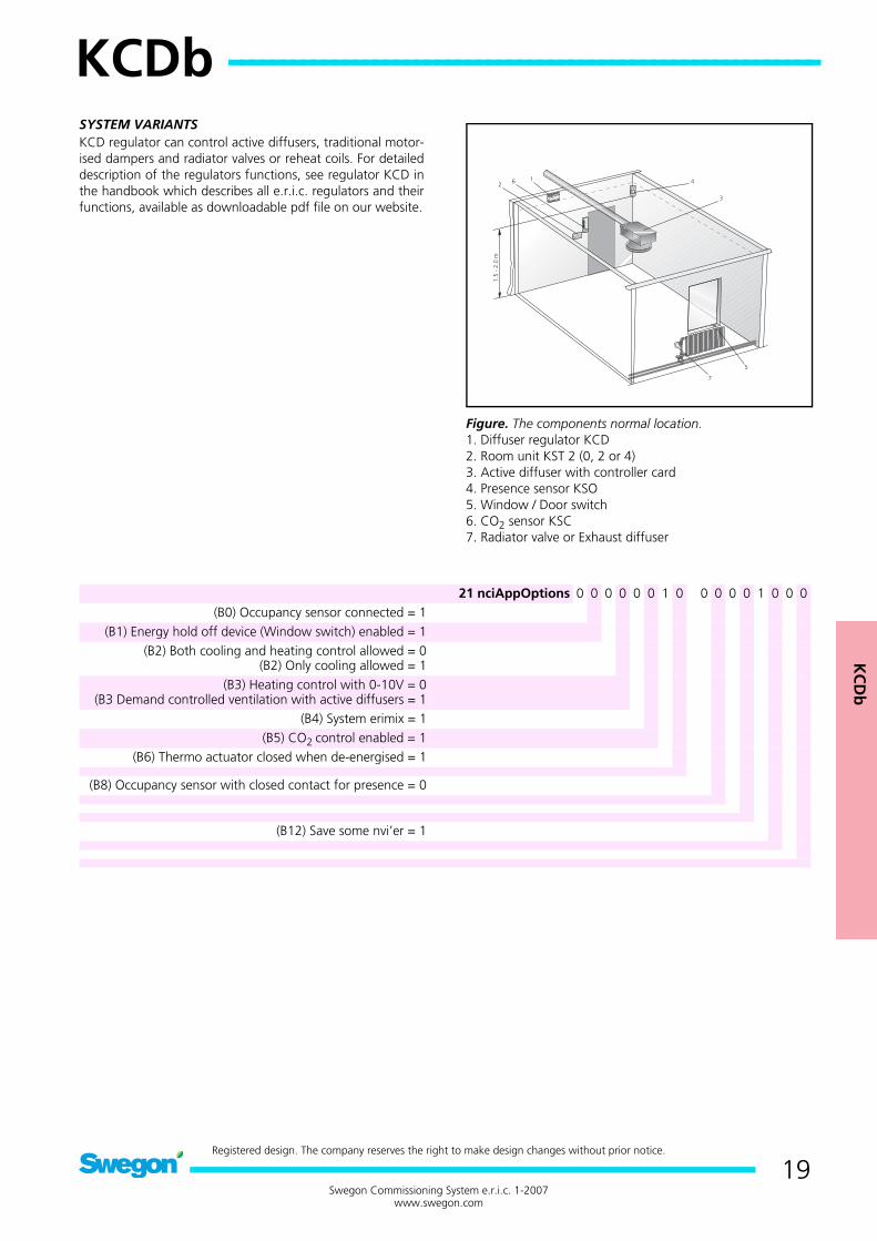
Figure. The components normal location.1. Diffuser regulator KCD2. Room unit KST 2 (0, 2 or 4)3. Active diffuser with controller card4. Presence sensor KSO5. Window / Door switch6. CO2 sensor KSC7. Radiator valve or Exhaust diffuser
21 nciAppOptions 0 0 0 0 0 0 1 0 0 0 0 0 1 0 0 0(B0) Occupancy sensor connected = 1
(B1) Energy hold off device (Window switch) enabled = 1(B2) Both cooling and heating control allowed = 0
(B2) Only cooling allowed = 1(B3) Heating control with 0-10V = 0
(B3 Demand controlled ventilation with active diffusers = 1(B4) System erimix = 1
(B5) CO2 control enabled = 1(B6) Thermo actuator closed when de-energised = 1
(B8) Occupancy sensor with closed contact for presence = 0
(B12) Save some nvi’er = 1
KCDb ----------------------------------------------------------------
20Swegon Commissioning System e.r.i.c. 1-2007
www.swegon.com
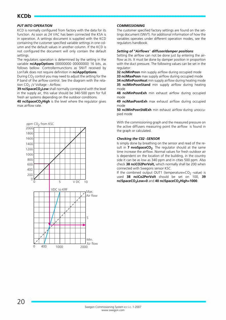
PUT INTO OPERATIONKCD is normally configured from factory with the data for itsfunction. As soon as 24 VAC has been connected the KSA isin operation. A settings document is supplied with the KCDcontaining the customer specified variable settings in one col-umn and the default values in another column. If the KCD isnot configured the document will only contain the defaultsettings.The regulators operation is determined by the setting in thevariable nciAppOptions (00000000 00000000) 16 bits, asfollows bellow. Controllermunctions as SNVT received byLonTalk does not require definition in nciAppOptions.During CO2 control you may need to adjust the setting for theP band of the airflow control. See the diagram with the rela-tion CO2 ¡V Voltage - Airflow.39 nciSpaceCO2Low shall normally correspond with the levelin the supply air, this value should be 340-500 ppm for fullfresh air systems depending on the outdoor conditions.40 nciSpaceCO2High is the level where the regulator givesmax airflow rate.
COMMISSIONINGThe customer specified factory settings are found on the set-tings document (SNVT). For additional information of how thevariables operates under different operation modes, see theregulators handbook.
Setting of "Airflows" diffuser/damper positionsSetting the airflow can not be done just by entering the air-flow as l/s. It must be done by damper position in proportionwith the duct pressure. The following values can be set in theregulator:32 nciMinPosn min supply airflow during occupied mode33 nciMaxPosn max supply airflow during occupied mode34 nciMinPosnHeat min supply airflow during heating mode35 nciMinPosnStand min supply airflow during heatingmode48 nciMinPosnExh min exhaust airflow during occupiedmode49 nciMaxPosnExh max exhaust airflow during occupiedmode50 nciMinPosnStdExh min exhaust airflow during unoccu-pied mode
With the commissioning graph and the measured pressure onthe active diffusers measuring point the airflow is found inthe graph or calculated.
Checking the C02 -SENSORIs simply done by breathing on the sensor and read of the re-sult in 7 nvoSpaceCO2. The regulator should at the sametime increase the airflow. Normal values for fresh outdoor airis dependent on the location of the building, in the countryside it can be as low as 340 ppm and in cities 500 ppm. Alsocheck 38 nciCO2PerVolt, which normally shall be 200 whenconnected with Swegons sensor KSC.If the combined output OUT1 (temperature+CO2 -value) isused 38 nciCo2PerVolt should be set on 100, 39nciSpaceCO2Low=0 and 40 nciSpaceCO2High=1000.

KC
Db
21Swegon Commissioning System e.r.i.c. 1-2007
www.swegon.com
FUNCTIONAL CONTROLUse the hand terminal KOP to read the status of the regulatorin the form of alarm codes and current values.
Table
Whether or not the value is 1 in other positions (4-11) is of noimportance for the regulation function of the regulator. Thereis more to read about the alarm codes and their limit values inthe handbook. Take into consideration that the alarm codesare automatically reset to the 0 value as soon as the cause ofthe alarm has been remedied. It is therefore not possible to di-rectly see any log of events disclosing earlier problems via theoperator panel.
CHECKING THE AIRFLOWChecks can only be carried out by forcing the regulator to themax. and min. positions respectively and in these positionscheck the pressure in the supply air terminal. See the Commis-sioning Instructions for each type of supply air terminal.Forced control of the regulator towards max. or min. airflowis best done with the variable 13 nviSpaceTemp, this valuecan be set to -327.19 to check min. airflow and +327.17 tocheck the max. airflow. Do not forget to reset the value toINVALID.
CHECKING THE RADIATOR VALVE CONTROLCheck that 21 nciAppOptions is set for heating control, bit2 and 3. There are two outputs for radiator valves, one is 0-10V for actuator control (Y1) which only can be used whenthe regulator is configured with bit 3=0 and one for thermoactuator (V1) which is used when bit 3=1.There is only one method of checking the valve control. Firstby setting 13 nviSpaceTemp to -327.19 to make sure thevalve is opening and then +327.17 to check that the valve isclosing. Do not forget to reset to INVALID.To check that the regulator has changed the outputs can bedisplayed in 2 nvoUnitStatus where hp shall show 100.00 atthe same time as 51 nvoHeatOutput shall show 100%.The output Y1-M shall put out 10V DC and output V1-M shallput out 24 VAC. If and how different makes of actuators re-spond differs. For Siemens I=closed and 0=open valve.
CHECKING THE WINDOW SWITCHConnected window switch blocks the function by closingheating and the airflow is set to 0 l/s. Check is done with thevariable 2 nvoUnitStatus, which shows off when window isopen or the switch is open. When controlling radiator there isa frost protection function that will open the radiator valvewhen the room temperature goes below 10 °C.
CHECKING THE PRESENCE CONTROLConnected analogue presence sensor is checked by readingthe variable 10 nvoOccSensor which shall show Occupiedwhen it is activated. If the function is not correct, check 21nciAppOptions bit 0 (=1) and 8 (=0). If the function still is in-correct you can check the regulator by connection the inputX2 and M. If 10 nvoOccSensor still shows Unoccupied theKCF regulator is faulty. The variable 1 nvoEffectOccup has adelayed disconnection of 20 min, this is adjustable with 36nciBypassTime. The variable 10 nvoOccSensor changes themode between Occupied and Unoccupied, while 1 nvoEffec-tOccup changes between Occupied and StandBye. In standbymode the regulator is operating with other set points for thetemperature control, see more in the manual for the KOP.
Bit Value Problem0 0
1NonDeviating room temperature
1 01
NonLow room temperature
2 01
NonWindow switch alarm
3 01
NonToo high C02 -level

KCDb ----------------------------------------------------------------
22Swegon Commissioning System e.r.i.c. 1-2007
www.swegon.com
All SNVT-variables for KCD, also see the Appendix A in the handbook.
No Description Normal value Explanation with reference to regulator KCP-KCF-KCD-KCW Handbook0 nciLocation Any marking max 32 characters entered on the regulator using e.g. LoneMaker for
Windows.1 nvoEffectOccup Occupied Current operating mode; occupied, standby or unoccupied2 nvoUniStatus Current operating mode; cooling/heating etc, compare with nviApplicMode3 nvoAlarmStatus 00000000
00000000Alarm codes if the regulator can not achieve set points
4 nvoEffectSetpt XX.XX °C Set point from the room sensor KST on temperature control5 nvoSpaceTemp XX.XX °C Measured room temperature6 nvoTerminalLoad XX.XX % Displays the regulators control mode cooling/heating in -100 to +100%. Positive val-
ue for cooling, negative value for heating.7 nvoSpaceCO2 XX ppm Measured CO2 level in the room8 nvoEnergyHold-
Off0 % Position of the window switch, Off=closed, On=open
9 nvoDampFlowVal XX.XX % Displays the set damper position (Y2) 0-100%, 100%=open10 nvoOccSensor Invalid Displays presence sensor status11 nviManOccCmd Invalid Possibility to manually set the operation mode12 nviApplicmode Auto Possibility to manually set the regulators function or from the BMS13 nviSpaceTemp Invalid Input data for room temperature via LonNetwork14 nviSetpoint Invalid Input data via network, room temp set point offset15 nviSetpntOffset 0.00 °C Input data via network, or set increase decrease of room temp set point16 nviSpaceCO2 Invalid Input data via network from CO2 sensor with LON communication17 nviEnergyHoldOff 0 % Input data via network from window switch18 nviManOverride Off Possibility of manual positively drive of the damper/diffuser position 0-100%, only
the function position has an effect on this regulator19 nviEmergCmd Normal Positively driven operation of the regulator from a master system20 nviOccSensor Invalid Input data via network from presence sensor21 nciAppOptions 00000000
00000000Setting the regulators function
22 nciSetpoints 23,25,28,21,19,16 Set point temperature for the different modes. OC=cooling set point occupied, OH=heating set point at occupied etc.
23 nciSpaceTempDev 2 °C Max deviation of room temp before alarm is given in (3)24 nciSpaceTem-
pLow10 °C Min room temp before alarm is given in (3)
25 nciVavGain 25.000 Gain factor for cooling control26 nciVavItime 900 sec. Integration time in the PI-regulator for cooling control27 nciGainHeat 25.000 Gain factor for the heating control28 nciItimeHeat 900 sec. Intergration time in the PI-regulator for the heating control29 nciSpaceTem-
pOfst0.00 °C Offset value form measured room temp to real room temp.
30 nciMinFlow Invalid Does not apply for KCD31 nciMaxFlow Invalid Does not apply for KCD32 nciMinPosn 20 % Damper/diffuser position (Y2) at min flow during cooling 0-100% .(see graph in
commissioning guide)33 nciMaxPosn 80 % Damper/diffuser position (Y2) at max flow during cooling 0-100% . (see graph in
commissioning guide)34 nciMinPosnHeat 20 % Damper/diffuser position at min flow during heating 0-100%. (see graph in commis-
sioning guide)35 nciMinPosnStand 20 % Damper/diffuser position (Y2) at min flow during standby. (see graph in commission-
ing guide)36 nciBypassTime 20 min Activation time for occupied mode by pressing the over time button or activation of
the presence sensor37 nciMinHeatValve 0 % Min position for heating valve38 nciCO2PerVolt 200 ppm CO2 sensors output at 10V DC divided with 1039 nciSpaceCO2Low 400 ppm Start flow when CO2 controlled airflow40 nciSpaceCO2High 1000 ppm Max flow when CO2 controlled airflow
KC
Db
23Swegon Commissioning System e.r.i.c. 1-2007
www.swegon.com
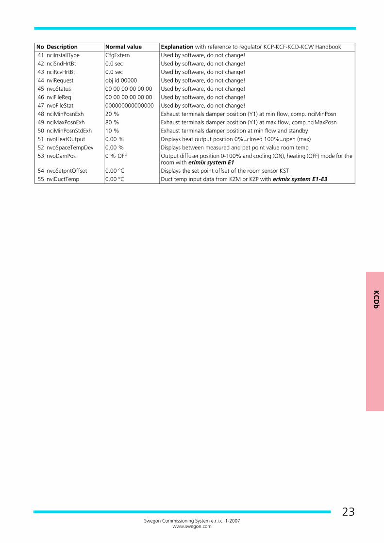
No Description Normal value Explanation with reference to regulator KCP-KCF-KCD-KCW Handbook41 nciInstallType CfgExtern Used by software, do not change!42 nciSndHrtBt 0.0 sec Used by software, do not change!43 nciRcvHrtBt 0.0 sec Used by software, do not change!44 nviRequest obj id 00000 Used by software, do not change!45 nvoStatus 00 00 00 00 00 00 Used by software, do not change!46 nviFileReq 00 00 00 00 00 00 Used by software, do not change!47 nvoFileStat 000000000000000 Used by software, do not change!48 nciMinPosnExh 20 % Exhaust terminals damper position (Y1) at min flow, comp. nciMinPosn49 nciMaxPosnExh 80 % Exhaust terminals damper position (Y1) at max flow, comp.nciMaxPosn50 nciMinPosnStdExh 10 % Exhaust terminals damper position at min flow and standby51 nvoHeatOutput 0.00 % Displays heat output position 0%=closed 100%=open (max)52 nvoSpaceTempDev 0.00 % Displays between measured and pet point value room temp53 nvoDamPos 0 % OFF Output diffuser position 0-100% and cooling (ON), heating (OFF) mode for the
room with erimix system E154 nvoSetpntOffset 0.00 °C Displays the set point offset of the room sensor KST55 nviDuctTemp 0.00 °C Duct temp input data from KZM or KZP with erimix system E1-E3

KC
Wa
KCWa --------------------------------------------------------
24Swegon Commissioning System e.r.i.c. 1-2007
www.swegon.com
Registered design. The company reserves the right to make design changes without prior notice.
KCWa
SYSTEM VARIANTSThe KCW regulator can control perimeter units, chilled beamsand active diffusers or duct dampers type ARE. For detaileddescription of the regulators functions, see regulator KCW inthe handbook, which describes all e.r.i.c. regulators and theirfunctions, available as downloadable pdf-file on our website.
PUT INTO OPERATIONThe regulators are normally factory preset. An Adjustmentsdocument, in which all factory set variables are specified, isthen supplied with the product. If the regulator has not beenpreset at the factory, no values will be specified in the Adjust-ments document, other than in the column for Default values.
Figure 1.Legend to the figure.1. Room regulator KCW2. Room unit KST 2 (0, 2 eller 4)3. Occupancy sensor KSO4. C02 -sensor KSC5. Window / Door switch6. Actuator for radiator valve RWB ST7. Actuator for radiator valve RWB ST
Figure 2.Legend to the figure.1. Room regulator KCW2. Room unit KST 2 (0, 2 or 4)3. Occupancy sensor KSO4. C02 -sensor KSC5. Window / Door switch6. Ceiling unit with actuator for radiator valve RWB ST7. Actuator for forcing the airflow
25 nciAppOptions 0 0 0 0 0 0 0 0 0 0 0 0 0 0 0 0(B0) Occupancy sensor = 1
(B1) Window switch = 1(B2) Heating control enabled = 1(B3) Cooling control enabled = 1
((B4) Air flow control = 1(B5) Cooling with water before air = 1(B5) Cooling with air before water = 0
(B6) C02 -control = 1(B7) Heating coil in supply air duct = 0
(B7) Radiators/Perimeter unit = 1(B8) Occupancy sensor closed contact when presence = 0
B10) Night cooling with air=0, with water = 1(B11) Valve actuators increase/decrese = 0, thermo actuators
= 1(B12) Save some nvi’er = 1
NOTE! (B7) and (B11) should be set to 1 when configuring for thermo actuators.
KC
Wa
25Swegon Commissioning System e.r.i.c. 1-2007
www.swegon.com
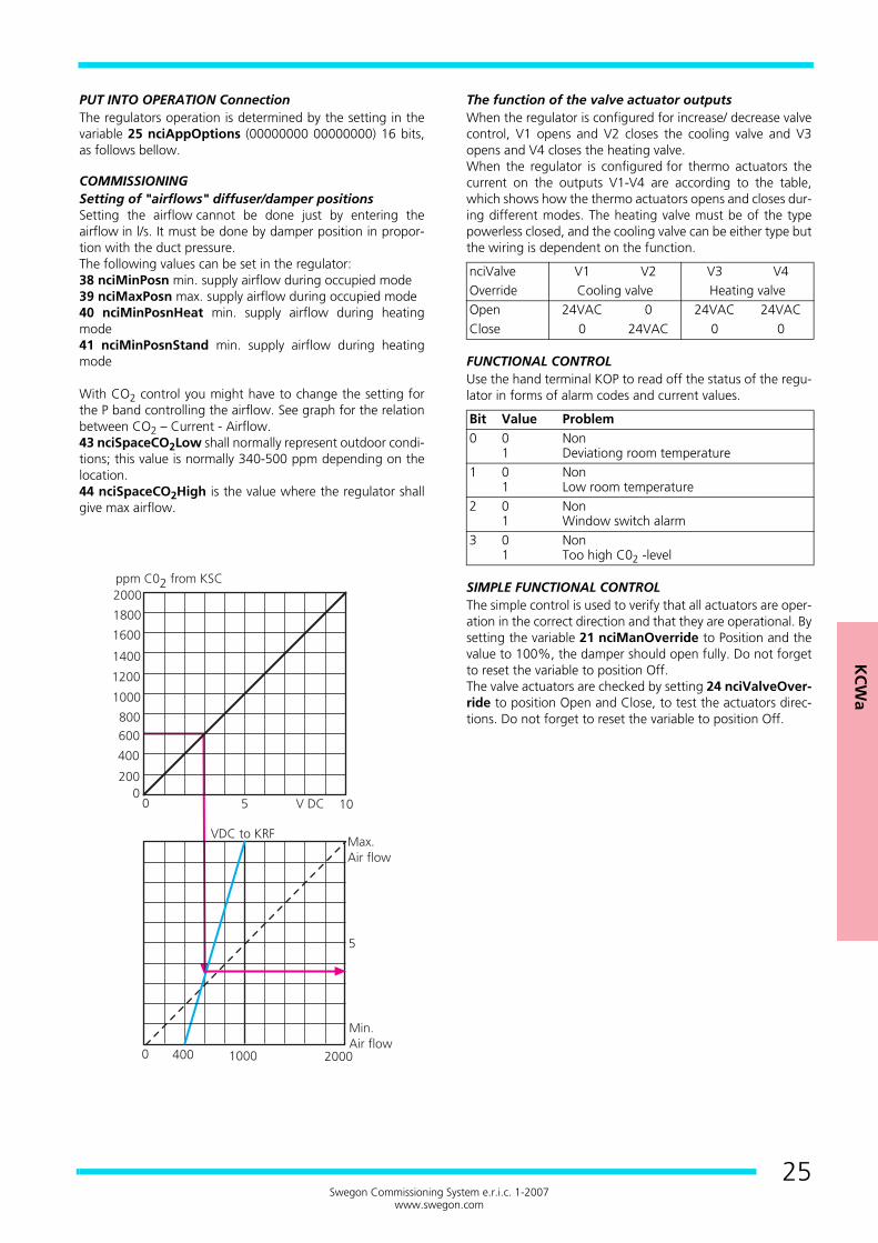
PUT INTO OPERATION ConnectionThe regulators operation is determined by the setting in thevariable 25 nciAppOptions (00000000 00000000) 16 bits,as follows bellow.
COMMISSIONINGSetting of "airflows" diffuser/damper positionsSetting the airflow cannot be done just by entering theairflow in l/s. It must be done by damper position in propor-tion with the duct pressure.The following values can be set in the regulator:38 nciMinPosn min. supply airflow during occupied mode39 nciMaxPosn max. supply airflow during occupied mode40 nciMinPosnHeat min. supply airflow during heatingmode41 nciMinPosnStand min. supply airflow during heatingmode
With CO2 control you might have to change the setting forthe P band controlling the airflow. See graph for the relationbetween CO2 – Current - Airflow.43 nciSpaceCO2Low shall normally represent outdoor condi-tions; this value is normally 340-500 ppm depending on thelocation.44 nciSpaceCO2High is the value where the regulator shallgive max airflow.
The function of the valve actuator outputsWhen the regulator is configured for increase/ decrease valvecontrol, V1 opens and V2 closes the cooling valve and V3opens and V4 closes the heating valve.When the regulator is configured for thermo actuators thecurrent on the outputs V1-V4 are according to the table,which shows how the thermo actuators opens and closes dur-ing different modes. The heating valve must be of the typepowerless closed, and the cooling valve can be either type butthe wiring is dependent on the function.
FUNCTIONAL CONTROLUse the hand terminal KOP to read off the status of the regu-lator in forms of alarm codes and current values.
SIMPLE FUNCTIONAL CONTROLThe simple control is used to verify that all actuators are oper-ation in the correct direction and that they are operational. Bysetting the variable 21 nciManOverride to Position and thevalue to 100%, the damper should open fully. Do not forgetto reset the variable to position Off.The valve actuators are checked by setting 24 nciValveOver-ride to position Open and Close, to test the actuators direc-tions. Do not forget to reset the variable to position Off.
nciValve V1 V2 V3 V4Override Cooling valve Heating valveOpen 24VAC 0 24VAC 24VACClose 0 24VAC 0 0
Bit Value Problem0 0
1NonDeviationg room temperature
1 01
NonLow room temperature
2 01
NonWindow switch alarm
3 01
NonToo high C02 -level
KCWa ----------------------------------------------------------------
26Swegon Commissioning System e.r.i.c. 1-2007
www.swegon.com
CHECKING THE COOLING SEQUENCETo force control the regulator towards max or min airflow isdone with the variable 16 nviSpaceTemp, it is set to +327,17to check the max airflow for cooling. Do not forget to resetthe variable to INVALID.The cooling valve should open first, can be checked by moni-toring the variable 9 nvoCoolOutput which shall display100%, then, if active diffusers are used, shall the damperopen to the value set in the variable 39 nviMaxPosn, whichis checked through 11 nvoDampFlowVal. If the actuatordoes not move it could be faulty wiring, cut wires or defect ac-tuator/valve.The cooling sequence could be reversed so that the diffuseropens first and then the cooling valve.Reset 13 nviSpaceTemp to INVALID after check.
CHECKING THE HEATING SEQUENCEForce the regulator by changing 13 nviSpaceTemp to -327,19 to check the min airflow and heating mode. First theheating valve shall open, which can be check through variable8 nvoHeatOutput, which shall display 100%. If the actuatordoes not move it could be faulty wiring, cut wires or defect ac-tuator/valve.Reset 13 nviSpaceTemp to INVALID after check.
CHECKING THE C02 -SENSORThe CO2 function is only active when the regulator is in thecooling mode. Check the function simply by exhaling air to-wards the sensor and reading the result in the 7nvoSpaceCO2. variable. The regulator should now increasethe airflow at the same time. The normal value for fresh out-door air depends on where the plant is geographically situat-ed. A value for fresh air in the countryside is 340 ppm,whereas a city air can contain 500 ppm. Also check 42nciCo2PerVolt, which normally should be 200 connected toSwegon’s KSC sensor.If the combined output, OUT1 (temperature + CO2 value) isused, the 42 nciCo2PerVolt should be set to 100, 43nciSpaceCO2Low=0 and 44 nciSpaceCO2High=1000.
CHECKING THE OCCUPANCY SENSORThe occupancy sensor KSO has a red diode that is light behindthe front when activated. On the room unitKST, the red diode shall be lit when the occupancy sensor ac-tivates operation mode Occupied. The system disconnect after20 minutes, which is a fixed setting in the KCW regulator. Inthe KSO there is possibilities to set the disconnection time forboth on and off.
KC
Wa
27Swegon Commissioning System e.r.i.c. 1-2007
www.swegon.com
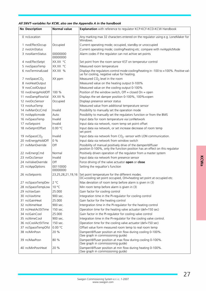
All SNVT-variables for KCW, also see the Appendix A in the handbook
No Description Normal value Explanation with reference to regulator KCP-KCF-KCD-KCW Handbook
0 nciLocation Any marking max 32 characters entered on the regulator using e.g. LoneMaker for Windows.
1 nvoEffectOccup Occupied Current operating mode; occupied, standby or unoccupied2 nvoUniStatus Current operating mode; cooling/heating etc. compare with nviApplicMode3 nvoAlarmStatus 00000000
00000000Alarm codes if the regulator can not achive set points
4 nvoEffectSetpt XX.XX °C Set point from the room sensor KST on temperatur control5 nvoSpaceTemp XX.XX °C Measured room temperature6 nvoTerminalLoad XX.XX % Displays the regulators control mode cooling/heating in -100 to +100%. Positive val-
ue for cooling, negative value for heating.7 nvoSpaceCO2 XX ppm Measured CO2 level in the room8 nvoHeatOutput Measured value on the heating output 0-100%9 nvoCoolOutput Measured value on the cooling output 0-100%
10 nvoEnergyHoldOff 100 % Position of the window switch, Off = closed On = open11 nvoDampFlowVal XX.XX % Displays the set damper position 0-100%, 100%=open12 nvoOccSensor Occupied Displays presence sensor status13 nvoAuxTemp Measured value from additional temperature sensor14 nviManOccCmd Invalid Possibility to manually set the operation mode15 nviApplicmode Auto Possibility to manually set the regulators function or from the BMS16 nviSpaceTemp Invalid Input data for room temperature via LonNetwork17 nviSetpoint Invalid Input data via network, room temp set point offset18 nviSetpntOffset 0.00 °C Input data via network, or set increase decrease of room temp
set point19 nviSpaceCO2 Invalid Input data via network from CO2 -sensor with LON communication.20 nviEnergyHoldOff 0 % Input data via network from window switch21 nviManOverride Off Possibility of manual positively drive of the damper/diffuser
position 0-100%, only the function position has an effect on this regulator22 nviEmergCmd Normal Positively driven operation of the regulator from a master system23 nviOccSensor Invalid Input data via network from presence sensor24 nviValveOverride Off Force driving of the valve actuator open or close25 nciAppOptions 00110000
00000000Setting the regualtor´s function
26 nciSetpoints 23,25,28,21,19,16 Set point temperature for the different modes.OC=cooling set point occupied, OH=heating set point at occupied etc.
27 nciSpaceTempDev 2 °C Max deviation of room temp before alarm is given in (3)28 nciSpaceTempLow 10 °C Min room temp before alarm is given in (3)29 nciVavGain 25.000 Gain factor for cooling control30 nciVavItime 900 sec. Integration time in the PI-regulator for cooling control31 nciGainHeat 25.000 Gain factor for the heating control32 nciItimeHeat 900 sec. Intergration time in the PI-regulator for the heating control33 nciHeatActStTime 150 sec. Operation time for the heating valve actuator (def=150 sec)34 nciGainCool 25.000 Gain factor in the PI-regulator for cooling valve control35 nciItimeCool 900 sec. Integration time in the PI-regulator for the cooling valve control.36 nciCoolActStTime 150 sec. Operation time for the cooling valve actuator (def=150 sec)37 nciSpaceTempOfst 0.00 °C Offset value form measured room temp to real room temp38 nciMinPosn 20 % Damper/diffuser position at min flow during cooling 0-100%.
(See graph in commissioning guide)39 nciMaxPosn 80 % Damper/diffuser position at max flow during cooling 0-100%.
(See graph in commissioning guide)40 nciMinPosnHeat 20 % Damper/diffuser position at min flow during heating 0-100%.
(See graph in commissioning guide)

KCWa ----------------------------------------------------------------
28Swegon Commissioning System e.r.i.c. 1-2007
www.swegon.com
No Description Normal value Explanation with reference to regulator KCP-KCF-KCD-KCW Handbook41 nciMinPosnStand 20 % Damper/diffuser position at min flow during standby.
(See graph in commissioning guide)42 nciCO2PerVolt 200 ppm CO2 sensors output at 10V DC divided with 1043 nciSpaceCO2Low 400 ppm Start flow when CO2 controlled airflow.44 nciSpaceCO2High 1000 ppm Max flow when CO2 controlled airflow.45 nciInstallType CfgExtern Used by software, do not change!46 nciSndHrtBt 0.0 sec Used by software47 nciRcvHrtBt 0.0 sec Used by software48 nviRequest obj id 00000 Used by software49 nvoStatus 00 00 00 00 00 0 Used by software50 nviFileReq 00 00 00 00 00 0 Used by software51 nvoFileStat 000000000000000 Used by software52 nciCalcFlow 0 l/s Input data to calculate damper position (l/s)53 nciCalcPress 0.0 pasc Input data to calculate damper position (Pa)54 nvoCalcResult 0.0000 Calculation constant, does not apply for KCW55 nciCalcConstC1 0.0000 Calculation constant, does not apply for KCW56 nciCalcConstC2 0.0000 Calculation constant, does not apply for KCW57 nciCalcConstC3 0.0000 Calculation constant, does not apply for KCW58 nciCalcConstC4 0.0000 Calculation constant, does not apply for KCW59 nciCalcConstC5 0.0000 Calculation constant, does not apply for KCW60 nciCalcConstC6 0.0000 Calculation constant, does not apply for KCW
RTC
b
RTCb ----------------------------------------------------------
29Swegon Commissioning System e.r.i.c. 1-2207
www.swegon.com
Registered design. The company reserves the right to make design changes without prior notice.
RTCb
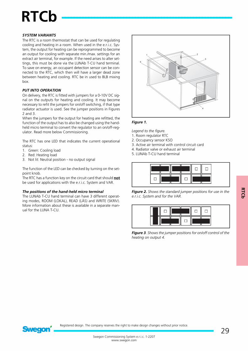
SYSTEM VARIANTSThe RTC is a room thermostat that can be used for regulatingcooling and heating in a room. When used in the e.r.i.c. Sys-tem, the output for heating can be reprogrammed to becomean output for cooling with separate min./max. settings for anextract air terminal, for example. If the need arises to alter set-tings, this must be done via the LUNAb T-CU hand terminal.To save on energy, an occupant detection sensor can be con-nected to the RTC, which then will have a larger dead zonebetween heating and cooling. RTC be in used to BLB mixingbox.
PUT INTO OPERATIONOn delivery, the RTC is fitted with jumpers for a 0-10V DC sig-nal on the outputs for heating and cooling. It may becomenecessary to refit the jumpers for on/off switching, if that typeradiator actuator is used. See the jumper positions in Figures2 and 3.When the jumpers for the output for heating are refitted, thefunction of the output has to also be changed using the hand-held micro terminal to convert the regulator to an on/off-reg-ulator. Read more below Commissioning.
The RTC has one LED that indicates the current operationalstatus:1. Green: Cooling load2. Red: Heating load3. Not lit: Neutral position - no output signal
The function of the LED can be checked by turning on the set-point knob.The RTC has a function key on the circuit card that should notbe used for applications with the e.r.i.c. System and VAR.
The positions of the hand-held micro terminalThe LUNAb T-CU hand terminal can have 3 different operat-ing modes, ROOM (LOKAL), READ (LÄS) and WRITE (SKRIV).More information about these is available in a separate man-ual for the LUNA T-CU.
Figure 1.
Legend to the figure.1. Room regulator RTC2. Occupancy sensor KSO3. Active air terminal with control circuit card4. Radiator valve or exhaust air terminal5. LUNAb T-CU hand terminal
Figure 2. Shows the standard jumper positions for use in thee.r.i.c. System and for the VAR.
Figure 3. Shows the jumper positions for on/off control of theheating on output 4.
RTCb -----------------------------------------------------------------
30Swegon Commissioning System e.r.i.c. 1-2207
www.swegon.com
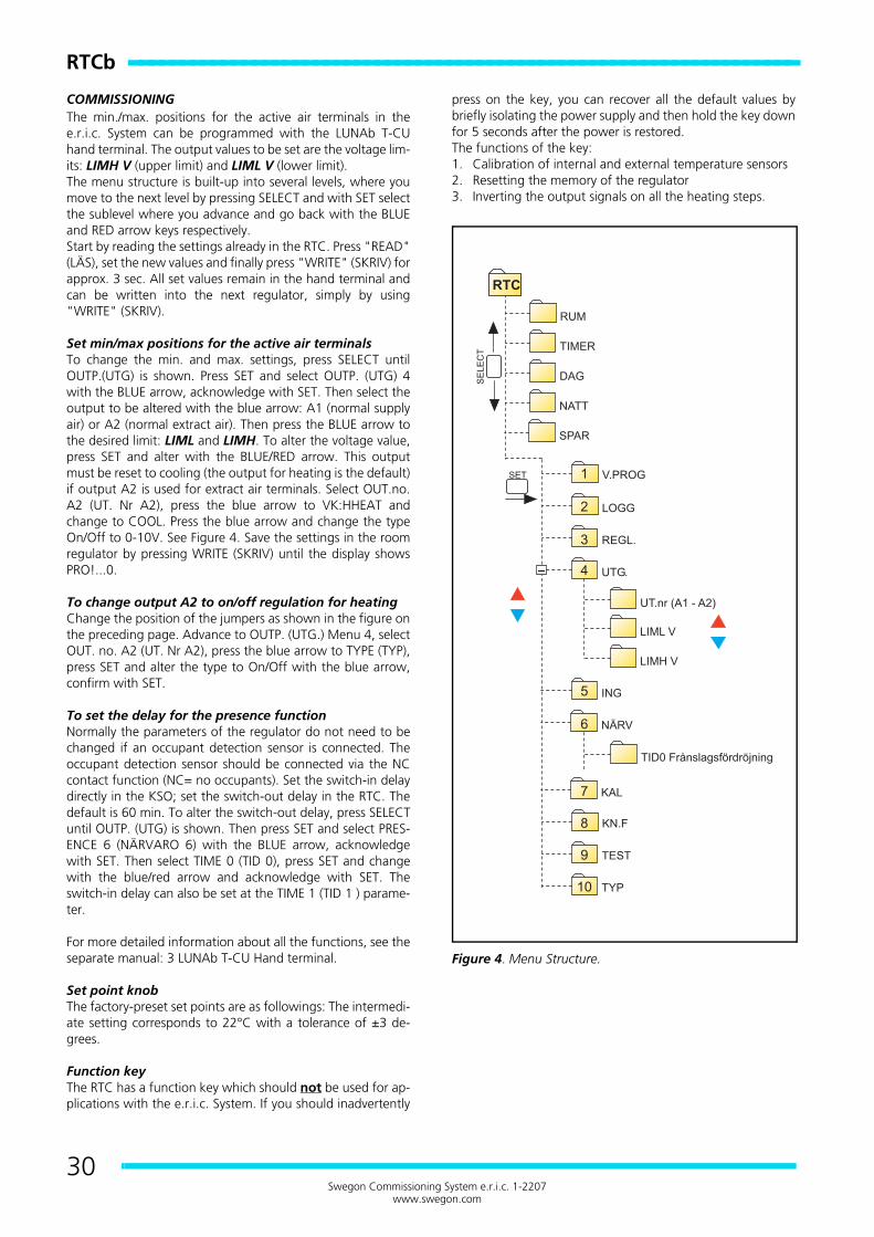
COMMISSIONINGThe min./max. positions for the active air terminals in thee.r.i.c. System can be programmed with the LUNAb T-CUhand terminal. The output values to be set are the voltage lim-its: LIMH V (upper limit) and LIML V (lower limit).The menu structure is built-up into several levels, where youmove to the next level by pressing SELECT and with SET selectthe sublevel where you advance and go back with the BLUEand RED arrow keys respectively.Start by reading the settings already in the RTC. Press "READ"(LÄS), set the new values and finally press "WRITE" (SKRIV) forapprox. 3 sec. All set values remain in the hand terminal andcan be written into the next regulator, simply by using"WRITE" (SKRIV).
Set min/max positions for the active air terminalsTo change the min. and max. settings, press SELECT untilOUTP.(UTG) is shown. Press SET and select OUTP. (UTG) 4with the BLUE arrow, acknowledge with SET. Then select theoutput to be altered with the blue arrow: A1 (normal supplyair) or A2 (normal extract air). Then press the BLUE arrow tothe desired limit: LIML and LIMH. To alter the voltage value,press SET and alter with the BLUE/RED arrow. This outputmust be reset to cooling (the output for heating is the default)if output A2 is used for extract air terminals. Select OUT.no.A2 (UT. Nr A2), press the blue arrow to VK:HHEAT andchange to COOL. Press the blue arrow and change the typeOn/Off to 0-10V. See Figure 4. Save the settings in the roomregulator by pressing WRITE (SKRIV) until the display showsPRO!...0.
To change output A2 to on/off regulation for heatingChange the position of the jumpers as shown in the figure onthe preceding page. Advance to OUTP. (UTG.) Menu 4, selectOUT. no. A2 (UT. Nr A2), press the blue arrow to TYPE (TYP),press SET and alter the type to On/Off with the blue arrow,confirm with SET.
To set the delay for the presence functionNormally the parameters of the regulator do not need to bechanged if an occupant detection sensor is connected. Theoccupant detection sensor should be connected via the NCcontact function (NC= no occupants). Set the switch-in delaydirectly in the KSO; set the switch-out delay in the RTC. Thedefault is 60 min. To alter the switch-out delay, press SELECTuntil OUTP. (UTG) is shown. Then press SET and select PRES-ENCE 6 (NÄRVARO 6) with the BLUE arrow, acknowledgewith SET. Then select TIME 0 (TID 0), press SET and changewith the blue/red arrow and acknowledge with SET. Theswitch-in delay can also be set at the TIME 1 (TID 1 ) parame-ter.
For more detailed information about all the functions, see theseparate manual: 3 LUNAb T-CU Hand terminal.
Set point knobThe factory-preset set points are as followings: The intermedi-ate setting corresponds to 22°C with a tolerance of ±3 de-grees.
Function keyThe RTC has a function key which should not be used for ap-plications with the e.r.i.c. System. If you should inadvertently
press on the key, you can recover all the default values bybriefly isolating the power supply and then hold the key downfor 5 seconds after the power is restored.The functions of the key:1. Calibration of internal and external temperature sensors2. Resetting the memory of the regulator3. Inverting the output signals on all the heating steps.
Figure 4. Menu Structure.
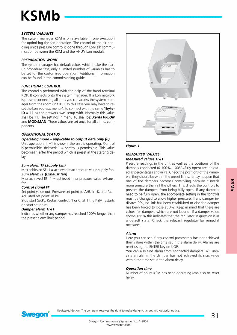
KSM
b
KSMb --------------------------------------------------------
31Swegon Commissioning System e.r.i.c. 1-2007
www.swegon.com
Registered design. The company reserves the right to make design changes without prior notice.
KSMb
SYSTEM VARIANTSThe system manager KSM is only available in one executionfor optimising the fan operation. The control of the air han-dling unit’s pressure control is done through LonTalk commu-nication between the KSM and the AHU’s Lon module.
PREPARATION WORKThe system manager has default values which make the startup procedure fast, only a limited number of variables has tobe set for the customised operation. Additional informationcan be found in the commissioning guide.
FUNCTIONAL CONTROLThe control s preformed with the help of the hand terminalKOP. It connects onto the system manager. If a Lon networkis present connecting all units you can access the system man-ager from the room unit KST. In this case you may have to re-set the Lon address, menu 4, to connect with the same 1byte-ID = 11 as the network was setup with. Normally this valueshall be 11. The settings in menu 10 shall be: Xenta100:ONand MOD:MAN. These values are set once for all e.r.i.c. com-ponents.
OPERATIONAL STATUSOperating mode – applicable to output data only (u)Unit operation: If =1 is shown, the unit is operating. Controlis permissible, delayed: 1 = control is permissible. This valuebecomes 1 after the period which is preset in the starting de-lay.
Sum alarm TF (Supply fan)Max achieved SF: 1 = achieved max pressure value supply fan.Sum alarm FF (Exhaust fan)Max achieved EF: 1 = achieved max pressure value exhaustfan.Control signal FFSet point value out: Pressure set point to AHU in % and Pa.Adjusted set point: in Pa.Stop start SetPt: Restart control. 1 or 0, at 1 the KSM restartson start set point.Damper alarm TF/FFIndicates whether any damper has reached 100% longer thanthe preset alarm limit period.
Figure 1.
MEASURED VALUESMeasured values TF/FFPressure readings in the unit as well as the positions of thedampers connected (0-100%, 100%=fully open) are indicat-ed as percentages and in Pa. Check the positions of the damp-ers; they should be within the preset limits. It may happen thatone of the dampers becomes controlling because it needsmore pressure than all the others. This directs the controls toprevent the dampers from being fully open. If any dampersneed to be fully open, the appropriate setting in the controlsmust be changed to allow higher pressure. If any damper in-dicates 0%, no link has been established or else the damperhas been forced to close at 0%. Keep in mind that there arevalues for dampers which are not bound! If a damper valueshows 166% this indicates that the regulator in question is ina default state. Check the relevant regulator for remedialmeasures.
AlarmHere you can see if any control parameters has not achievedtheir values within the time set in the alarm delay. Alarms arereset using the ENTER key on KOP.You can also find alarm from connected dampers. A 1 indi-cate an alarm, the damper has not achieved its max valuewithin the time set in the alarm delay.
Operation timeNumber of hours KSM has been operating (can also be resethere).
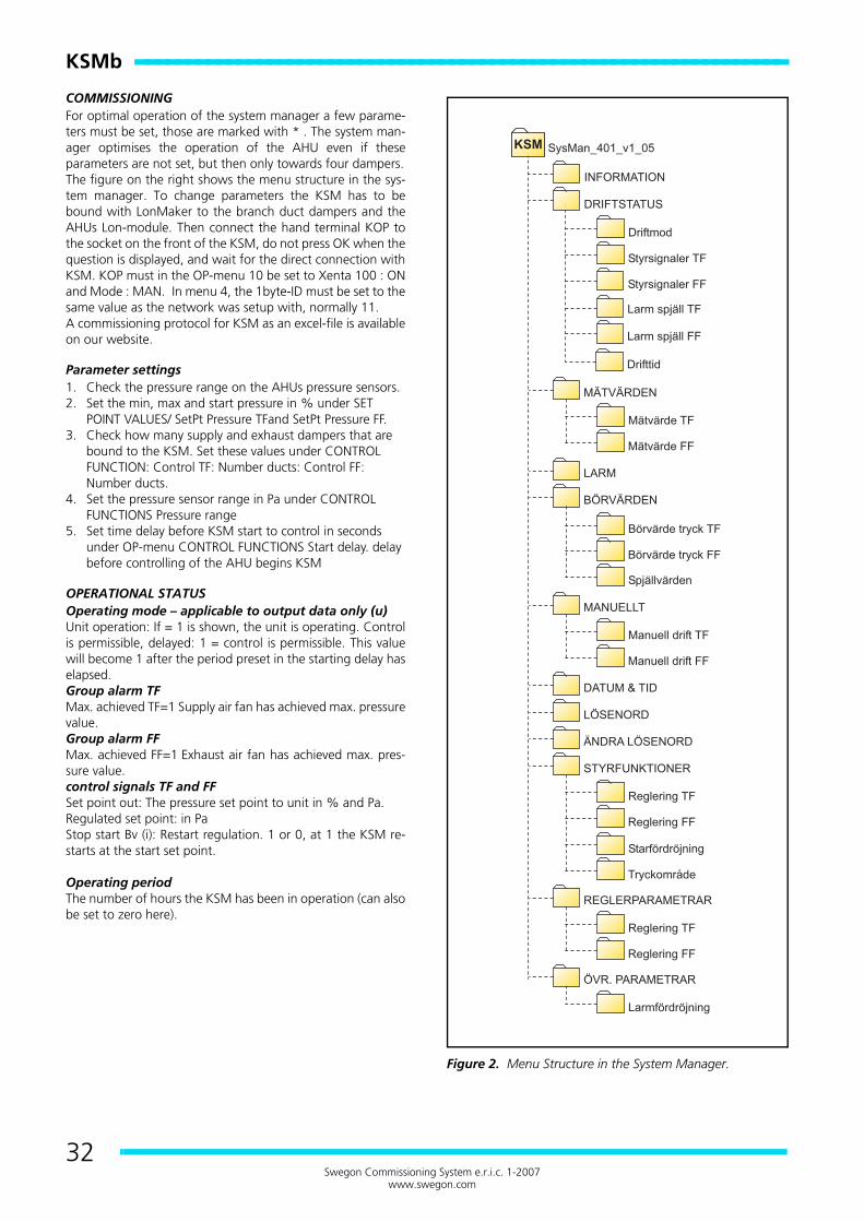
KSMb ----------------------------------------------------------------
32Swegon Commissioning System e.r.i.c. 1-2007
www.swegon.com
COMMISSIONINGFor optimal operation of the system manager a few parame-ters must be set, those are marked with * . The system man-ager optimises the operation of the AHU even if theseparameters are not set, but then only towards four dampers.The figure on the right shows the menu structure in the sys-tem manager. To change parameters the KSM has to bebound with LonMaker to the branch duct dampers and theAHUs Lon-module. Then connect the hand terminal KOP tothe socket on the front of the KSM, do not press OK when thequestion is displayed, and wait for the direct connection withKSM. KOP must in the OP-menu 10 be set to Xenta 100 : ONand Mode : MAN. In menu 4, the 1byte-ID must be set to thesame value as the network was setup with, normally 11.A commissioning protocol for KSM as an excel-file is availableon our website.
Parameter settings1. Check the pressure range on the AHUs pressure sensors.2. Set the min, max and start pressure in % under SET
POINT VALUES/ SetPt Pressure TFand SetPt Pressure FF.3. Check how many supply and exhaust dampers that are
bound to the KSM. Set these values under CONTROL FUNCTION: Control TF: Number ducts: Control FF: Number ducts.
4. Set the pressure sensor range in Pa under CONTROL FUNCTIONS Pressure range
5. Set time delay before KSM start to control in seconds under OP-menu CONTROL FUNCTIONS Start delay. delay before controlling of the AHU begins KSM
OPERATIONAL STATUSOperating mode – applicable to output data only (u) Unit operation: If = 1 is shown, the unit is operating. Controlis permissible, delayed: 1 = control is permissible. This valuewill become 1 after the period preset in the starting delay haselapsed.Group alarm TFMax. achieved TF=1 Supply air fan has achieved max. pressurevalue.Group alarm FFMax. achieved FF=1 Exhaust air fan has achieved max. pres-sure value.control signals TF and FFSet point out: The pressure set point to unit in % and Pa.Regulated set point: in PaStop start Bv (i): Restart regulation. 1 or 0, at 1 the KSM re-starts at the start set point.
Operating periodThe number of hours the KSM has been in operation (can alsobe set to zero here).
Figure 2. Menu Structure in the System Manager.

KSM
b
33Swegon Commissioning System e.r.i.c. 1-2007
www.swegon.com
MEASURED VALUESMeasured values TF/FFThe pressure after the AHU in % and Pa is presented and allconnected dampers positions (0-100%, 100%=fully open).
ALARMHere you can see if any control parameters has not achievedtheir values within the time set in the alarm delay. Alarms arereset using the ENTER key on KOP.
SET POINT VALUESThese values do normally not require changes.
SetPt Pressure TF/FF• SetPt Pressure Start: Satart set point in % (default 30%)• SetPt Pressure Min.: Lowest allowed pressure in % (defalut
10%)• SetPt Pressure Max.: Highest allowed pressure in %
(default 90%) Damper values• Increase SetPt TF/FF: At this damper position (85%) KSM
increases the pressure set point on the AHUs supply fan.• Increase SetPt TF/FF: At this damper position (70%) KSM
decreases the pressure set point on the AHUs supply fan.
MANUALManual operation TF/FF. This function is only used during thecommissioning phase if you wish to fix the duct pressure.Manual 1=%. 2=Pa: Setting if input data shall be in Pa or %.SetPt TF %: If previous value is set to 1 this is the manual valuein %.SetPt TF Pa: If first value is 2 this is the manual value in Pa.
DATE AND TIMESet or change the built in clock. The time is only used for reg-ister when an alarm occured.
PASSWORDState a password to be able to procced (1919).
CONTROL FUNCTIONSControlling TF/FF• Delay next package: KSM controls the pressure by sending
out “pressure packages”. The time between these pack-ages is set here (default is 1200 sec). High values gives slow control. Lowest recommended value is 300 sec.
• Package size: Setting of the package size in %. The size is dependent of the interval of the pressure sensor (0-100%) that KSM shall work within. Example: If the pressure sen-sor range is 0-3000 Pa, then maybe the KSM shall work within the interval 0-20% that means the package size should be smal (0.5%). Default value is 10%.
• Number ducts: Number of ducts/dampers which are bound to the KSM on supply and exhaust side, default value is 4.
• Pressure response from AHU: KSM always wait to send out the next pressure set point until the AHU has achieved the current set point. % allowed offset from set point value, before a new set point value may be sent from the KSM, default value is 2%.
Start delay• Control delay on start: Setting of the time (sec) before
KSM start to control after sending the start pressure set points. Default is 1800 sec, can be reduced but not less then 600 sec.
Pressure range• Pressure range Pa: Setting of what max output signal from
the pressure sensor (10V or 100%) represents in Pa. This value is only used to be able to present real values in the KOP, default value is 500.
CONTROL PARAMETERSThese values are adapted to the unit control parameters.Control 1time: Default=120 sec.This value should be set equal to the I-time set in the AHUpressure control.Velocity constant: Default=1.0This value is a gain factor depending on the numer of branchduct dampers connected. Value can be adjusted between 0.1-2.RampVelocity: Default=2%/min.This value effects the speed of how fast the KSM reduces thepressure set point value so that the dampers opens more. Val-ue 1-20 %/minute. If the reduction is slow, dubble the currentvalue, if it is too quick the system can start to hunt.
OTHER PARAMETERSAlarm delay TF / FFMaxAchieved TF (FF): Time in seconds until an alarm shall besent that KSM has achieved its highest allowed pressure setpoint for the supply fan.Pressure response TF(FF): Time in seconds until an alarmshall be sent that KSM has achieved its highest allowed pres-sure set point for the exhaust fan.
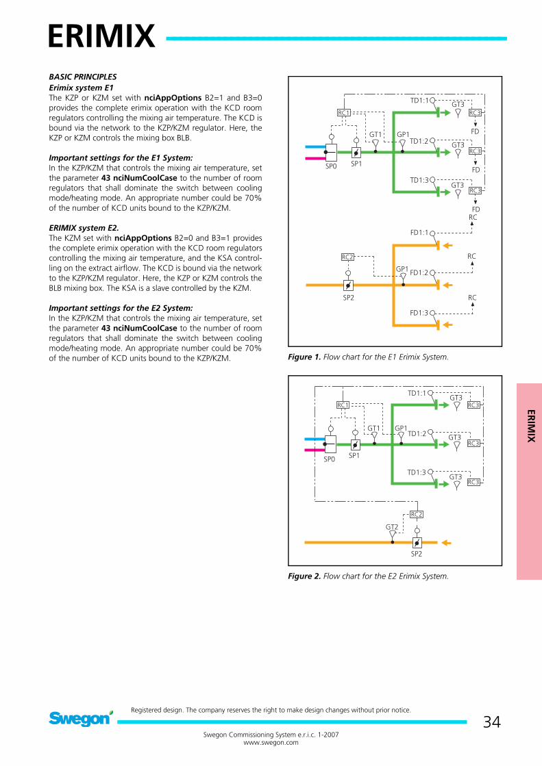
ERIM
IX
ERIMIX -----------------------------------------------------
34Swegon Commissioning System e.r.i.c. 1-2007
www.swegon.com
Registered design. The company reserves the right to make design changes without prior notice.
ERIMIX
BASIC PRINCIPLESErimix system E1The KZP or KZM set with nciAppOptions B2=1 and B3=0provides the complete erimix operation with the KCD roomregulators controlling the mixing air temperature. The KCD isbound via the network to the KZP/KZM regulator. Here, theKZP or KZM controls the mixing box BLB.
Important settings for the E1 System:In the KZP/KZM that controls the mixing air temperature, setthe parameter 43 nciNumCoolCase to the number of roomregulators that shall dominate the switch between coolingmode/heating mode. An appropriate number could be 70%of the number of KCD units bound to the KZP/KZM.
ERIMIX system E2.The KZM set with nciAppOptions B2=0 and B3=1 providesthe complete erimix operation with the KCD room regulatorscontrolling the mixing air temperature, and the KSA control-ling on the extract airflow. The KCD is bound via the networkto the KZP/KZM regulator. Here, the KZP or KZM controls theBLB mixing box. The KSA is a slave controlled by the KZM.
Important settings for the E2 System:In the KZP/KZM that controls the mixing air temperature, setthe parameter 43 nciNumCoolCase to the number of roomregulators that shall dominate the switch between coolingmode/heating mode. An appropriate number could be 70%of the number of KCD units bound to the KZP/KZM. Figure 1. Flow chart for the E1 Erimix System.
Figure 2. Flow chart for the E2 Erimix System.
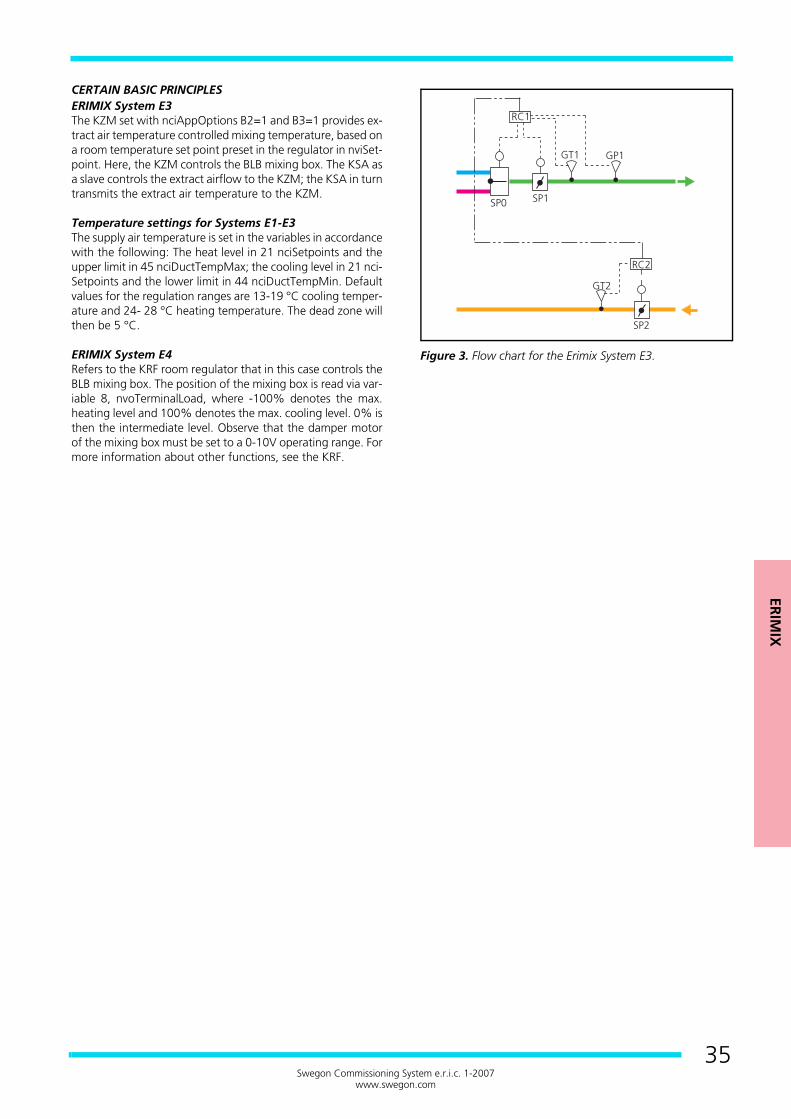
ERIM
IX
35Swegon Commissioning System e.r.i.c. 1-2007
www.swegon.com
CERTAIN BASIC PRINCIPLESERIMIX System E3The KZM set with nciAppOptions B2=1 and B3=1 provides ex-tract air temperature controlled mixing temperature, based ona room temperature set point preset in the regulator in nviSet-point. Here, the KZM controls the BLB mixing box. The KSA asa slave controls the extract airflow to the KZM; the KSA in turntransmits the extract air temperature to the KZM.
Temperature settings for Systems E1-E3The supply air temperature is set in the variables in accordancewith the following: The heat level in 21 nciSetpoints and theupper limit in 45 nciDuctTempMax; the cooling level in 21 nci-Setpoints and the lower limit in 44 nciDuctTempMin. Defaultvalues for the regulation ranges are 13-19 °C cooling temper-ature and 24- 28 °C heating temperature. The dead zone willthen be 5 °C.
ERIMIX System E4Refers to the KRF room regulator that in this case controls theBLB mixing box. The position of the mixing box is read via var-iable 8, nvoTerminalLoad, where -100% denotes the max.heating level and 100% denotes the max. cooling level. 0% isthen the intermediate level. Observe that the damper motorof the mixing box must be set to a 0-10V operating range. Formore information about other functions, see the KRF.
Figure 3. Flow chart for the Erimix System E3.
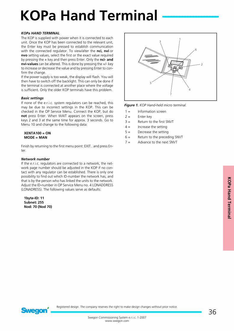
KO
Pa Han
d Term
inal
KOPa Hand Terminal --------------------
36Swegon Commissioning System e.r.i.c. 1-2007
www.swegon.com
Registered design. The company reserves the right to make design changes without prior notice.
KOPa Hand Terminal
KOPa HAND TERMINALThe KOP is supplied with power when it is connected to eachunit. Once the KOP has been connected to the relevant unit,the Enter key must be pressed to establish communicationwith the connected regulator. To view/alter the nci, nvi ornvo setting values, select the first or the exact value requiredby pressing the + key and then press Enter. Only the nci- andnvi-values can be altered. This is done by pressing the +/- keyto increase or decrease the value and by pressing Enter to con-firm the change.If the power supply is too weak, the display will flash. You willthen have to switch off the backlight. This can only be done ifthe terminal is connected at another place where the voltageis sufficient. Only the older KOP terminals have this problem.
Basic settingsIf none of the e.r.i.c. system regulators can be reached, thismay be due to incorrect settings in the KOP. This can bechecked in the OP Service Menu. Connect the KOP, but donot press Enter. When WAIT appears on the screen, presskeys 2 and 3 at the same time for approx. 3 seconds. Go toMenu 10 and change to the following data:
XENTA100 = ON MODE = MAN
Finish by returning to the first menu point: EXIT.. and press En-ter.
Network numberIf the e.r.i.c. regulators are connected to a network, the net-work page number should be adjusted in the KOP if no con-tact with any regulator can be established. There is only onepossibility to find out which ID-number the network has, andthat is by the person who has linked the units to the network.Adjust the ID-number in OP Service Menu no. 4 LONADDRESS(LONADRESS). The following values serve as defaults:
1byte-ID: 11 Subnet: 255 Nod: 70 (Nod 70)
Figure 1. KOP Hand-held micro terminal.
1 = Information screen2 = Enter key3 = Return to the first SNVT4 = Increase the setting5 = Decrease the setting6 = Return to the preceding SNVT7 = Advance to the next SNVT

KO
Pa Han
d Term
inal
37Swegon Commissioning System e.r.i.c. 1-2007
www.swegon.com
The first display information when the KOP is connected. Af-ter a few seconds, press ENTER to continue.
The second display information after contact is establishedwith the regulator. If the unit is presented as Unconfigured,change the setting to Configured. Do this by pressing + or -to change the setting.
The third display information indicates which regulator isconnected and its version data. Here you can directly selectthe desired variable.
Example of how to change a value in the list line-by-line. Usethe Enter key to move the cursor to the position to be altered.Alter the value by pressing + or -. Confirm by pressing Enteragain.
Example of how to change a value in the multi-line list. Usethe Enter key to move the cursor to the position to be altered.The rectangular blip is in front of the line to be altered. Alterthe value by pressing + or -. Confirm by pressing Enter again.
Background lightingTo switch on / switch off the backlight. Connect the KOP, butdo not press on Enter. Press keys 2 and 3 at the same time forapprox. 3 seconds when the display shows Wait (Avvakta). Goto Menu 8 and alter the setting by pressing the +/- key. Returnto the first menu point: EXIT.. and press Enter.
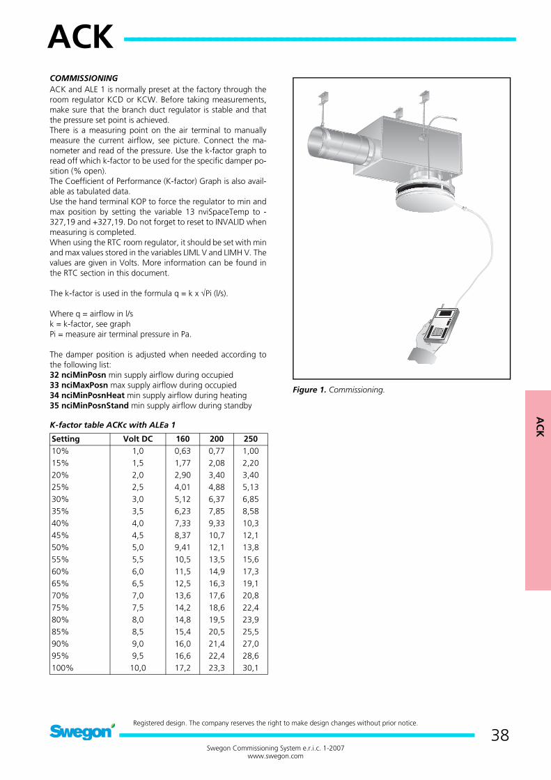
AC
K
ACK ------------------------------------------------------------
38Swegon Commissioning System e.r.i.c. 1-2007
www.swegon.com
Registered design. The company reserves the right to make design changes without prior notice.
ACK
COMMISSIONINGACK and ALE 1 is normally preset at the factory through theroom regulator KCD or KCW. Before taking measurements,make sure that the branch duct regulator is stable and thatthe pressure set point is achieved.There is a measuring point on the air terminal to manuallymeasure the current airflow, see picture. Connect the ma-nometer and read of the pressure. Use the k-factor graph toread off which k-factor to be used for the specific damper po-sition (% open).The Coefficient of Performance (K-factor) Graph is also avail-able as tabulated data.Use the hand terminal KOP to force the regulator to min andmax position by setting the variable 13 nviSpaceTemp to -327,19 and +327,19. Do not forget to reset to INVALID whenmeasuring is completed.When using the RTC room regulator, it should be set with minand max values stored in the variables LIML V and LIMH V. Thevalues are given in Volts. More information can be found inthe RTC section in this document.
The k-factor is used in the formula q = k x √Pi (l/s).
Where q = airflow in l/sk = k-factor, see graphPi = measure air terminal pressure in Pa.
The damper position is adjusted when needed according tothe following list:32 nciMinPosn min supply airflow during occupied33 nciMaxPosn max supply airflow during occupied34 nciMinPosnHeat min supply airflow during heating35 nciMinPosnStand min supply airflow during standby
K-factor table ACKc with ALEa 1
Figure 1. Commissioning.
Setting Volt DC 160 200 25010% 1,0 0,63 0,77 1,0015% 1,5 1,77 2,08 2,2020% 2,0 2,90 3,40 3,4025% 2,5 4,01 4,88 5,1330% 3,0 5,12 6,37 6,8535% 3,5 6,23 7,85 8,5840% 4,0 7,33 9,33 10,345% 4,5 8,37 10,7 12,150% 5,0 9,41 12,1 13,855% 5,5 10,5 13,5 15,660% 6,0 11,5 14,9 17,365% 6,5 12,5 16,3 19,170% 7,0 13,6 17,6 20,875% 7,5 14,2 18,6 22,480% 8,0 14,8 19,5 23,985% 8,5 15,4 20,5 25,590% 9,0 16,0 21,4 27,095% 9,5 16,6 22,4 28,6100% 10,0 17,2 23,3 30,1

AC
K
39Swegon Commissioning System e.r.i.c. 1-2007
www.swegon.com
ACKb + ALEa 1
Graph 1. k-factor graph ACKb (before 31 Dec. 2005). k-factor for the diffekent sizes of terminals and damper position in %.
ACKc + ALEa 1
Graph 2. k-factor graph ACKc (as from 1 January, 2006). k-factor for the diffekent sizes of terminals and damper position in %.
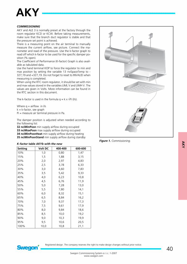
AK
Y
AKY ------------------------------------------------------------
40Swegon Commissioning System e.r.i.c. 1-2007
www.swegon.com
Registered design. The company reserves the right to make design changes without prior notice.
AKY
COMMISSIONINGAKY and ALE 3 is normally preset at the factory through theroom regulator KCD or KCW. Before taking measurements,make sure that the branch duct regulator is stable and thatthe pressure set point is achieved.There is a measuring point on the air terminal to manuallymeasure the current airflow, see picture. Connect the ma-nometer and read of the pressure. Use the k-factor graph toread off which k-factor to be used for the specific damper po-sition (% open).The Coefficient of Performance (K-factor) Graph is also avail-able as tabulated data.Use the hand terminal KOP to force the regulator to min andmax position by setting the variable 13 nviSpaceTemp to -327,19 and +327,19. Do not forget to reset to INVALID whenmeasuring is completed.When using the RTC room regulator, it should be set with minand max values stored in the variables LIML V and LIMH V. Thevalues are given in Volts. More information can be found inthe RTC section in this document.
The k-factor is used in the formula q = k x √Pi (l/s).
Where q = airflow in l/sk = k-factor, see graphPi = measure air terminal pressure in Pa.
The damper position is adjusted when needed according tothe following list:32 nciMinPosn min supply airflow during occupied33 nciMaxPosn max supply airflow during occupied34 nciMinPosnHeat min supply airflow during heating35 nciMinPosnStand min supply airflow during standby
K-factor table AKYb with the new Figure 1. Commissioning.
Setting Volt DC 400-400 600-60010% 1,0 0,80 1,4715% 1,5 1,88 3,1520% 2,0 2,97 4,8325% 2,5 3,78 6,3330% 3,0 4,60 7,8335% 3,5 5,42 9,3340% 4,0 6,23 10,845% 4,5 6,76 11,950% 5,0 7,28 13,055% 5,5 7,80 14,160% 6,0 8,32 15,165% 6,5 8,84 16,270% 7,0 9,37 17,375% 7,5 9,61 17,980% 8,0 9,84 18,685% 8,5 10,0 19,290% 9,0 10,3 19,995% 9,5 10,6 20,5100% 10,0 10,8 21,1
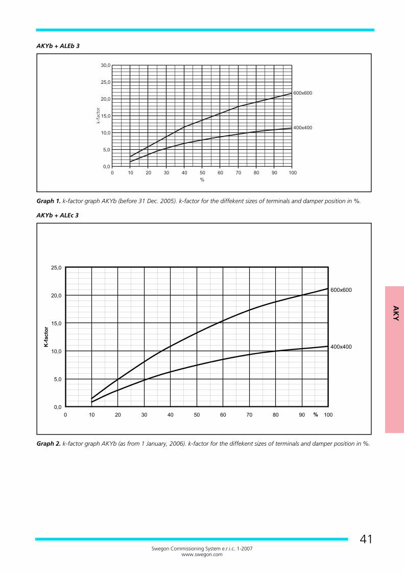
AK
Y
41Swegon Commissioning System e.r.i.c. 1-2007
www.swegon.com
AKYb + ALEb 3
Graph 1. k-factor graph AKYb (before 31 Dec. 2005). k-factor for the diffekent sizes of terminals and damper position in %.
AKYb + ALEc 3
Graph 2. k-factor graph AKYb (as from 1 January, 2006). k-factor for the diffekent sizes of terminals and damper position in %.
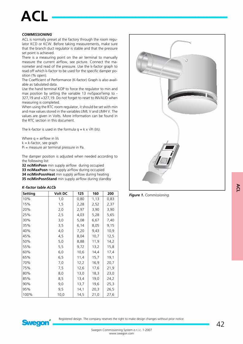
AC
L
ACL -------------------------------------------------------------
42Swegon Commissioning System e.r.i.c. 1-2007
www.swegon.com
Registered design. The company reserves the right to make design changes without prior notice.
ACL
COMMISSIONINGACL is normally preset at the factory through the room regu-lator KCD or KCW. Before taking measurements, make surethat the branch duct regulator is stable and that the pressureset point is achieved.There is a measuring point on the air terminal to manuallymeasure the current airflow, see picture. Connect the ma-nometer and read of the pressure. Use the k-factor graph toread off which k-factor to be used for the specific damper po-sition (% open).The Coefficient of Performance (K-factor) Graph is also avail-able as tabulated data.Use the hand terminal KOP to force the regulator to min andmax position by setting the variable 13 nviSpaceTemp to -327,19 and +327,19. Do not forget to reset to INVALID whenmeasuring is completed.When using the RTC room regulator, it should be set with minand max values stored in the variables LIML V and LIMH V. Thevalues are given in Volts. More information can be found inthe RTC section in this document.
The k-factor is used in the formula q = k x √Pi (l/s).
Where q = airflow in l/sk = k-factor, see graphPi = measure air terminal pressure in Pa.
The damper position is adjusted when needed according tothe following list:32 nciMinPosn min supply airflow during occupied33 nciMaxPosn max supply airflow during occupied34 nciMinPosnHeat min supplý airflow during heating35 nciMinPosnStand min supply airflow during standby
K-factor table ALCb
Figure 1. Commissioning.Setting Volt DC 125 160 20010% 1,0 0,80 1,13 0,8315% 1,5 2,28 2,52 2,3720% 2,0 2,97 3,90 3,9025% 2,5 4,03 5,28 5,6530% 3,0 5,08 6,67 7,4035% 3,5 6,14 8,05 9,1540% 4,0 7,20 9,43 10,945% 4,5 8,04 10,7 12,550% 5,0 8,88 11,9 14,255% 5,5 9,72 13,2 15,860% 6,0 10,6 14,4 17,465% 6,5 11,4 15,7 19,170% 7,0 12,2 16,9 20,775% 7,5 12,6 17,6 21,980% 8,0 13,0 18,3 23,085% 8,5 13,4 19,0 24,290% 9,0 13,7 19,6 25,395% 9,5 14,1 20,3 26,5100% 10,0 14,5 21,0 27,6
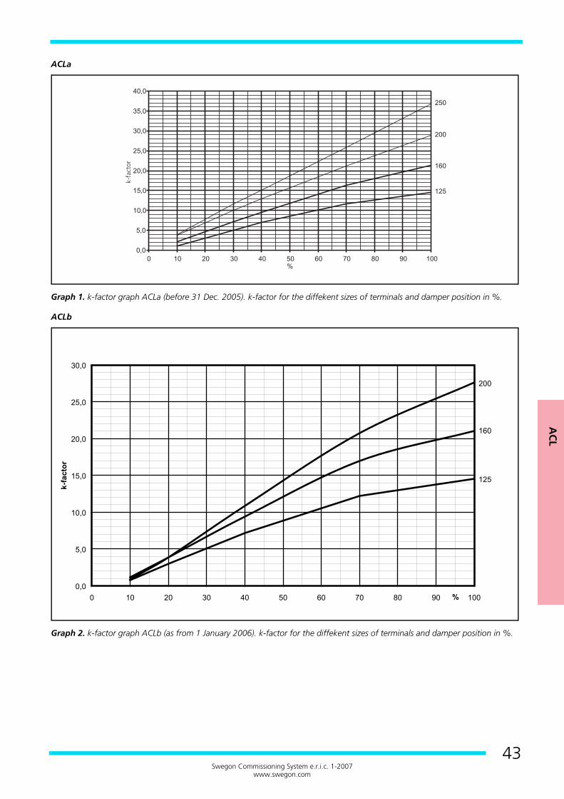
AC
L
43Swegon Commissioning System e.r.i.c. 1-2007
www.swegon.com
ACLa
Graph 1. k-factor graph ACLa (before 31 Dec. 2005). k-factor for the diffekent sizes of terminals and damper position in %.
ACLb
Graph 2. k-factor graph ACLb (as from 1 January 2006). k-factor for the diffekent sizes of terminals and damper position in %.
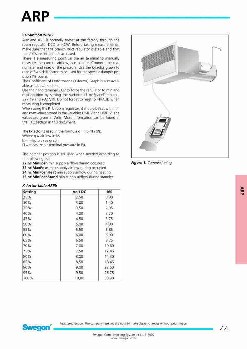
AR
P
ARP ------------------------------------------------------------
44Swegon Commissioning System e.r.i.c. 1-2007
www.swegon.com
Registered design. The company reserves the right to make design changes without prior notice.
ARP
COMMISSIONINGARP and AVE is normally preset at the factory through theroom regulator KCD or KCW. Before taking measurements,make sure that the branch duct regulator is stable and thatthe pressure set point is achieved.There is a measuring point on the air terminal to manuallymeasure the current airflow, see picture. Connect the ma-nometer and read of the pressure. Use the k-factor graph toread off which k-factor to be used for the specific damper po-sition (% open).The Coefficient of Performance (K-factor) Graph is also avail-able as tabulated data.Use the hand terminal KOP to force the regulator to min andmax position by setting the variable 13 nviSpaceTemp to -327,19 and +327,19. Do not forget to reset to INVALID whenmeasuring is completed.When using the RTC room regulator, it should be set with minand max values stored in the variables LIML V and LIMH V. Thevalues are given in Volts. More information can be found inthe RTC section in this document.
The k-factor is used in the formula q = k x √Pi (l/s).Where q = airflow in l/sk = k-factor, see graphPi = measure air terminal pressure in Pa.
The damper position is adjusted when needed according tothe following list:32 nciMinPosn min supply airflow during occupied33 nciMaxPosn max supply airflow during occupied34 nciMinPosnHeat min supply airflow during heating35 nciMinPosnStand min supply airflow during standby
K-factor table ARPb
Figure 1. Commissioning.
Setting Volt DC 16025% 2,50 0,9030% 3,00 1,4035% 3,50 2,0540% 4,00 2,7045% 4,50 3,7550% 5,00 4,8055% 5,50 5,8560% 6,00 6,9065% 6,50 8,7570% 7,00 10,6075% 7,50 12,4580% 8,00 14,3085% 8,50 18,4590% 9,00 22,6095% 9,50 26,75100% 10,00 30,90
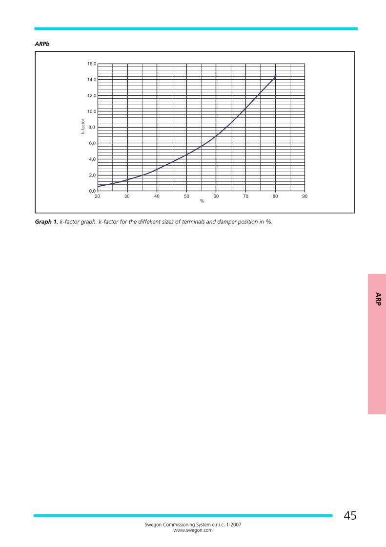
AR
P
45Swegon Commissioning System e.r.i.c. 1-2007
www.swegon.com
ARPb
Graph 1. k-factor graph. k-factor for the diffekent sizes of terminals and damper position in %.
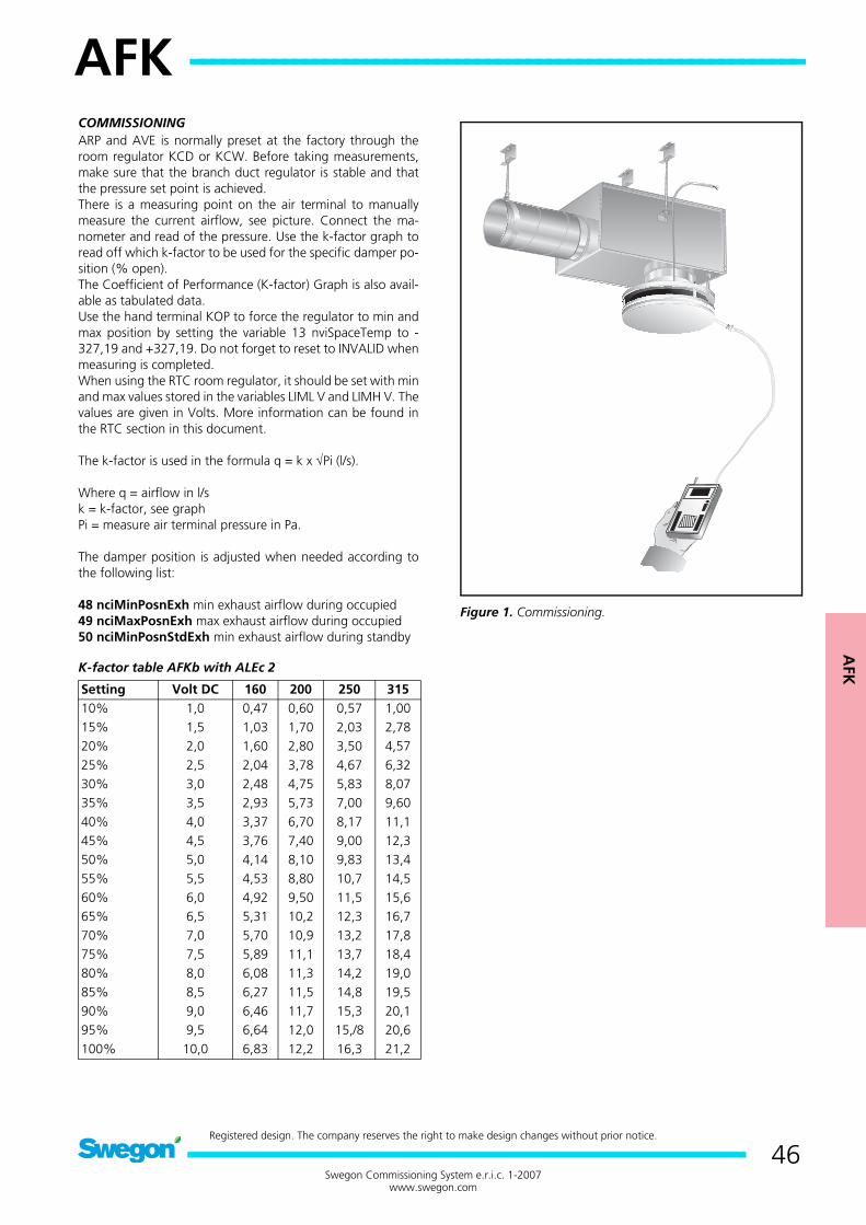
AFK
AFK ------------------------------------------------------------
46Swegon Commissioning System e.r.i.c. 1-2007
www.swegon.com
Registered design. The company reserves the right to make design changes without prior notice.
AFK
COMMISSIONINGARP and AVE is normally preset at the factory through theroom regulator KCD or KCW. Before taking measurements,make sure that the branch duct regulator is stable and thatthe pressure set point is achieved.There is a measuring point on the air terminal to manuallymeasure the current airflow, see picture. Connect the ma-nometer and read of the pressure. Use the k-factor graph toread off which k-factor to be used for the specific damper po-sition (% open).The Coefficient of Performance (K-factor) Graph is also avail-able as tabulated data.Use the hand terminal KOP to force the regulator to min andmax position by setting the variable 13 nviSpaceTemp to -327,19 and +327,19. Do not forget to reset to INVALID whenmeasuring is completed.When using the RTC room regulator, it should be set with minand max values stored in the variables LIML V and LIMH V. Thevalues are given in Volts. More information can be found inthe RTC section in this document.
The k-factor is used in the formula q = k x √Pi (l/s).
Where q = airflow in l/sk = k-factor, see graphPi = measure air terminal pressure in Pa.
The damper position is adjusted when needed according tothe following list:
48 nciMinPosnExh min exhaust airflow during occupied49 nciMaxPosnExh max exhaust airflow during occupied50 nciMinPosnStdExh min exhaust airflow during standby
K-factor table AFKb with ALEc 2
Figure 1. Commissioning.
Setting Volt DC 160 200 250 31510% 1,0 0,47 0,60 0,57 1,0015% 1,5 1,03 1,70 2,03 2,7820% 2,0 1,60 2,80 3,50 4,5725% 2,5 2,04 3,78 4,67 6,3230% 3,0 2,48 4,75 5,83 8,0735% 3,5 2,93 5,73 7,00 9,6040% 4,0 3,37 6,70 8,17 11,145% 4,5 3,76 7,40 9,00 12,350% 5,0 4,14 8,10 9,83 13,455% 5,5 4,53 8,80 10,7 14,560% 6,0 4,92 9,50 11,5 15,665% 6,5 5,31 10,2 12,3 16,770% 7,0 5,70 10,9 13,2 17,875% 7,5 5,89 11,1 13,7 18,480% 8,0 6,08 11,3 14,2 19,085% 8,5 6,27 11,5 14,8 19,590% 9,0 6,46 11,7 15,3 20,195% 9,5 6,64 12,0 15,/8 20,6100% 10,0 6,83 12,2 16,3 21,2

AFK
47Swegon Commissioning System e.r.i.c. 1-2007
www.swegon.com
AFKb + ALEb 2
Graph 1. k-factor graph AFKb (before 31 Dec. 2005). k-factor for the diffekent sizes of terminals and damper position in %.
AFKb + ALEc 2
Graph 2. k-factor graph AFKb (as from 1 January 2006). k-factor for the diffekent sizes of terminals and damper position in %.
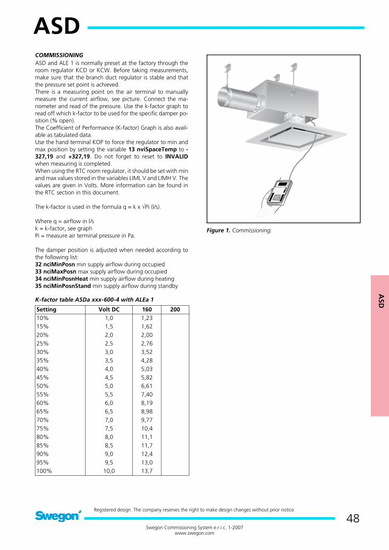
ASD
ASD ------------------------------------------------------------
48Swegon Commissioning System e.r.i.c. 1-2007
www.swegon.com
Registered design. The company reserves the right to make design changes without prior notice.
ASD
COMMISSIONINGASD and ALE 1 is normally preset at the factory through theroom regulator KCD or KCW. Before taking measurements,make sure that the branch duct regulator is stable and thatthe pressure set point is achieved.There is a measuring point on the air terminal to manuallymeasure the current airflow, see picture. Connect the ma-nometer and read of the pressure. Use the k-factor graph toread off which k-factor to be used for the specific damper po-sition (% open).The Coefficient of Performance (K-factor) Graph is also avail-able as tabulated data.Use the hand terminal KOP to force the regulator to min andmax position by setting the variable 13 nviSpaceTemp to -327,19 and +327,19. Do not forget to reset to INVALIDwhen measuring is completed.When using the RTC room regulator, it should be set with minand max values stored in the variables LIML V and LIMH V. Thevalues are given in Volts. More information can be found inthe RTC section in this document.
The k-factor is used in the formula q = k x √Pi (l/s).
Where q = airflow in l/sk = k-factor, see graphPi = measure air terminal pressure in Pa.
The damper position is adjusted when needed according tothe following list:32 nciMinPosn min supply airflow during occupied33 nciMaxPosn max supply airflow during occupied34 nciMinPosnHeat min supply airflow during heating35 nciMinPosnStand min supply airflow during standby
K-factor table ASDa xxx-600-4 with ALEa 1
Figure 1. Commissioning.
Setting Volt DC 160 20010% 1,0 1,2315% 1,5 1,6220% 2,0 2,0025% 2,5 2,7630% 3,0 3,5235% 3,5 4,2840% 4,0 5,0345% 4,5 5,8250% 5,0 6,6155% 5,5 7,4060% 6,0 8,1965% 6,5 8,9870% 7,0 9,7775% 7,5 10,480% 8,0 11,185% 8,5 11,790% 9,0 12,495% 9,5 13,0100% 10,0 13,7

ASD
49Swegon Commissioning System e.r.i.c. 1-2007
www.swegon.com
ASDa + ALEa 1
Graph 1. k-factor graph ASDa. k-factor for the diffekent sizes of terminals and damper position in %.