technical specifications – hvac works - IUCAA
73
1 TECHNICAL SPECIFICATIONS – HVAC WORKS 1. GUIDE LINES : 1.0 SCOPE : The scope of this section covers guidelines for the contractor on the specification and schedule of material and the general requirements. 2.0 SCOPE OF CONTRACT : 2.1 The scope of work under this contract covers supply of equipment, material & accessories and labour required for the specified works and to carry out the erection testing & commissioning as specified and shown on the drawing and schedule of material. 2.2 Safety, good workmanship, quality and timeliness are the prime requisites of the work covered under this contract. All the equipment, material and the works carried out shall meet the relevant codes, the intent of specifications and the proper functioning of the systems and installation and shall be as per industry standards meeting all statutory requirements and shall be in correct lives levels, aligned etc. 2.3 The scope of contract shall also cover all taxes and duties, loading and unloading, packing and forwarding, watch and ward, insurance, installations etc. up to commissioning & hand over. 3.0 DIVISION OF WORK : The division of work by the contractor and other agencies shall be as specified under 2 of section: 6 division of work. 4.0 MATERIAL : 4.1 The equipments and material shall meet the specifications and requirements indicated in the technical specifications covered under specific section and the relevant equipment data. 4.2 The makes of material shall be one of the recommended makes covered under Section: 4 makes of material. 5.0 SPECIFICATION : The technical specification given below gives general guidelines and minimum standards for equipments, material and workmanship. However, it is the responsibility of the contractor to meet the statutory provision and local codes. 6.0 SCHEDULE OF WORK : The schedule of work indicates the scope and quantity of the work estimated at the time of preparation of this tender. The quantities indicated are based on rough estimate on the basis of the drawings and subject to variation due to site condition. Also, additional requirements, deletion or replacement of items may arise during the installation. Hence there shall be variation in quantities indicated. However, the unit rates quoted shall remain firm during the contract period. 7.0 STANDARDS & REGULATIONS : Each section indicates the Indian Standard Specification to be followed. It is the responsibility of the contractor to meet the statutory regulation local codes and other relevant standards and specifications connected to the work being carried out. 8.0 INSPECTIONS & TESTING : 8.1 The Consultants/Clients have the right to inspect the plants, equipments and materials at manufacturer's work or at site at any stage and reject the materials that are substandard or do not meet the requirements of the specification makes and codes. 8.2 The contractor shall provide at his cost at site and elsewhere instruments and appliances for testing the equipments and installation at various stages of manufacturing/installation. These instruments shall be got tested and calibrated for their accuracy and performance from the approved institutions.
-
Upload
khangminh22 -
Category
Documents
-
view
2 -
download
0
Transcript of technical specifications – hvac works - IUCAA

1
TECHNICAL SPECIFICATIONS – HVAC WORKS 1. GUIDE LINES : 1.0 SCOPE : The scope of this section covers guidelines for the contractor on the specification and schedule of material and the general requirements. 2.0 SCOPE OF CONTRACT : 2.1 The scope of work under this contract covers supply of equipment, material & accessories and labour required for the specified works and to carry out the erection testing & commissioning as specified and shown on the drawing and schedule of material. 2.2 Safety, good workmanship, quality and timeliness are the prime requisites of the work covered under this contract. All the equipment, material and the works carried out shall meet the relevant codes, the intent of specifications and the proper functioning of the systems and installation and shall be as per industry standards meeting all statutory requirements and shall be in correct lives levels, aligned etc. 2.3 The scope of contract shall also cover all taxes and duties, loading and unloading, packing and forwarding, watch and ward, insurance, installations etc. up to commissioning & hand over. 3.0 DIVISION OF WORK : The division of work by the contractor and other agencies shall be as specified under 2 of section: 6 division of work. 4.0 MATERIAL : 4.1 The equipments and material shall meet the specifications and requirements indicated in the technical specifications covered under specific section and the relevant equipment data. 4.2 The makes of material shall be one of the recommended makes covered under Section: 4 makes of material. 5.0 SPECIFICATION : The technical specification given below gives general guidelines and minimum standards for equipments, material and workmanship. However, it is the responsibility of the contractor to meet the statutory provision and local codes. 6.0 SCHEDULE OF WORK : The schedule of work indicates the scope and quantity of the work estimated at the time of preparation of this tender. The quantities indicated are based on rough estimate on the basis of the drawings and subject to variation due to site condition. Also, additional requirements, deletion or replacement of items may arise during the installation. Hence there shall be variation in quantities indicated. However, the unit rates quoted shall remain firm during the contract period. 7.0 STANDARDS & REGULATIONS : Each section indicates the Indian Standard Specification to be followed. It is the responsibility of the contractor to meet the statutory regulation local codes and other relevant standards and specifications connected to the work being carried out. 8.0 INSPECTIONS & TESTING : 8.1 The Consultants/Clients have the right to inspect the plants, equipments and materials at manufacturer's work or at site at any stage and reject the materials that are substandard or do not meet the requirements of the specification makes and codes. 8.2 The contractor shall provide at his cost at site and elsewhere instruments and appliances for testing the equipments and installation at various stages of manufacturing/installation. These instruments shall be got tested and calibrated for their accuracy and performance from the approved institutions.

2
8.3 The inspection and testing carried out by the Consultants/Clients/Third party does not relieve the contractor of his responsibility of carrying out routine inspection during each stage of procurement, manufacture and installation and also meeting the intents and requirements of the specification and statutory requirements. 8.4 All equipments and the installation to be retested in the presence of the Consultants/Clients after carrying out necessary rectification, adjustments and balancing. Four sets of test readings should conform to the specification, equipment data, standards and codes. 9.0 TRAINING : The operating staff of the Client shall be trained free of cost for the operation, maintenance overhauling etc. of the equipments and installation. 10.0 STATUTORY INSPECTION : The contractor shall be fully responsible for meeting all the statutory obligations and local inspectorates pertaining to the works carried out by him. The contractor should prepare all working drawings and obtain approval of competent authorities and also have the equipment and installation inspected and got approved. All official fees will be paid by the Clients directly against demand in writing from the appropriate authorities and all other expenses for submission and approval of the various relevant statutory bodies shall be embodied in the tender prices. Contractor shall also carry out the necessary liaisoning work with the statutory bodies / institutions / company on Client's behalf. 11.0 DEVIATIONS : 11.1 Should the tenderer wish to deviate from the provision of specification and drawings; the same shall be indicated separately along with supporting drawing and specifications to decide the merits of such deviation. In the absence of any deviation it is deemed that the tenderer is fully satisfied with the intents of specification and drawings and their compliance with the statutory provisions and codes. 11.2 However, the offer shall be strictly on the basis of tender specification and schedule of material. The offer for the deviated items shall be furnished separately. 12.0 REFERENCE DRAWINGS : The drawings issued with the tender as mentioned in section: 3 and shown in Exhibit: D are basic schematic drawings and are part of the tender documents. These represent a feasible scheme for the optimum capital and operational costs. Should the Contractor find any modifications are required, the same shall be brought with proper supporting computations and approval of the same shall be obtained, in writing, from the HVAC Consultant, before execution. Contractor shall preserve one set of this drawing in good condition incorporating all modifications carried out from time to time during the erection period at the site and shall return them to the Consultant/Architect/Clients after completion of the work. Separate ‘As Executed’ drawings to be submitted. 13.0 WORKING DRAWINGS : 13.1 Contractor shall prepare execution drawings and get them approved by the Consultant before carrying out the execution, modify the drawings, if required, to suit the site conditions and get the approval. The execution drawings shall contain all details of finishes, levels and sections. The approval of the drawings does not relieve the contractor of their responsibility of meeting the intents and requirements of the specification and statutory requirements. 13.2 The contractor shall submit the followings details within 10 days of award of the contract. (a) List of equipments and the power requirements.

3
(b) Foundation drawings and structural support details for Foundations & supports for equipments to be provided by the civil contractor. (c) Any other civil, structural, electrical or plumbing requirement. (d) Bar chart for proper execution of the work along with cash flow statement. (e) List of working drawings that the Contractor proposes to submit. 13.3 On completion of the installation, the contractor shall prepare and submit AS EXECUTED drawing incorporating all modification carried out during the execution. 14.0 MEASUREMENTS AND PAYMENTS : The mode of measurement and payment shall be strictly as indicated under Section: 5 measurements and payments. This indicates the mode of measurement, items to be included and items excluded etc. in a board basis. However, it is the responsibility of the contractor to meet the intents of the specification and total installation on the works contract/turnkey basis. 15.0 HANDING OVER : 15.1 The installation shall be handed over after satisfactory testing along with the following documentation. a) Four sets of prints of the As Installed “AS BUILT” drawings along with 2 sets on CDs. b) Two sets of test readings duly certified by the HVAC Consultant. c) Four sets of detailed equipment data and operation and Maintenance manuals. d) List of recommended spares for 2 years of trouble free operation. e) Performance guarantee in the prescribed form. 15.2 The final acceptance shall be effective only after the submission of the above documents as also Performance Test. Final payment will be released only after the handing over and submission of documentation. 16.0 PERFORMANCE GUARANTEE : All equipment and the entire installation shall be guaranteed to yield the specified ratings and design conditions with a plus/minus 3% tolerance. Any equipment found short of the specified ratings by readings shall be rejected. Contractor has to replace these at his own cost after providing for stand-in equipment. 17.0 POWER SUPPLY : Power will be made available at 415/240V, 3 phase 4 wire 50 Hz earthed neutral system and all equipments shall be suitable for the above power supply with a variation of plus/minus 10%. Incoming Copper cable of suitable capacity shall be provided to each chiller mounted panel. Any equipment/component operating at other than the above power supply shall be provided with necessary transformer at the cost of the HVAC Contractor. 2. SYSTEM DESIGN & DIVISION OF WORK : 1.0 SCOPE : 1.1 The scope under this section shall cover the system design & the scope of the Work mentioned in the BOQ & tender. 1.2 The scope of work shall cover the following: a) S.I.T.C of Air-cooled Chillers b) S.I.T.C of Chilled Water Double Skin Air Handling Units c) S.I.T.C of Associated Chilled Water Piping work d) S.I.T.C of Associated Connecting Duct work e) S.I.T.C of Associated Insulation works f) S.I.T.C of Associated Electrical works

4
2.0 BUILDING : The Auditorium building is an existing building having old water-cooled chiller system connected with pumps and single skin AHU, which needs to be replaced with new Air-cooled Chiller system and Double Skin AHU. 3.0 DESIGN CONDITION : 3.1 The outdoor design conditions are based on the weather data from ISHRAE (as reproduced below) and design condition are as shown below: Site: Pune, Latitude: 18.32 deg North, Altitude: 559 m above M.S.L Design Weather data: (Based on ISHRAE Published Design Data) SEASON DB (°C) WB (°C) RH (%) a) Summer 42.0 24.4 28 b) Monsoon 28.3 26.1 85 c) Winter 10.3 6.1 50 *Air-cooled Chiller Capacity Selection and Sizing shall be provided at 42 Deg.C ambient. Winter conditions are not being considered for design purpose. 3.2 The indoor design condition proposed are as shown below: Areas Temperature(DBT-°C) Humidity (RH %) Chiller Water Coil Auditorium & Projector Room 22 + 2°C* 50% + 5% (no RH control) # 6R Green Room 23 + 2°C* 55% + 5% (no RH control) # 2R (DX coil) Visitor Room 23 + 2°C* 55% + 5% (no RH control) # 2R (DX coil) * Inside dry bulb shall be maintained within + 2°C by using suitable controls. # RH may exceed 65% in peak monsoon wherever no RH control is mentioned. Monsoon Reheat is not considered hence humidity may increase up to 65~70% during peak monsoon. Chilled water coil is to be selected accordingly. 4.0 PEAK COOLING LOAD AND PLANT SELECTION : 4.1 Based on the existing set-up and capacity of chillers, the new chiller configuration shall be 17.55 TR x 3 working + 1 standby and connected with new chilled water pumps and new chilled water AHU of 53 TR / 22000 CFM. 4.2 The chillers shall be located on the Terrace above and chilled water piping shall be routed down below to the existing AHU location, where existing AHU will be replaced with new AHU of above said capacity. 4.3 The required Chilled Water Primary Pumps, Ducting connectivity, Ch.W. Piping, Insulation and Electrical works shall form part of the low side works. 5.0 CONTROLS : The Chillers shall be microcontroller / microprocessor based with open type protocol and compatible with all type of BMS. The feature requirements of the microprocessor are broadly specified in the Technical Specifications of the Chiller. Chilled water AHU shall be controlled via 3-way modulating mixing valve and with return air temperature sensor / thermostat. Since the AHU is proposed with a VFD, the VFD will control the conditioned air based on achievement of temperature sensed for return air temperature sensor. The working and standby chillers and pumps shall operate on basis of lead / lag system with one chiller operating as master and other chillers as slave. The control system shall automatically start and stop a lag or lead chiller system. If one of the chillers on line goes into a fault mode, the other chiller shall be automatically started. The chiller lead/lag system shall allow manual rotation of the lead chiller, include load balancing, and a staggered restart of the chillers after a power failure. The chiller microprocessor shall be capable of interfacing with a PC operator workstation
5
supplied with chiller manufacturer software. The PC interface software shall include the ability to annunciate alarms, display dynamic graphics of the chiller plant, and display chiller plant reports. The chiller microprocessor shall be capable of communicating with other vendor supplied control devices as required for data logging, demand limiting, air side interface, and other control functions. 6.0 DIVISION OF WORK : The division of work between the air-conditioning contractor and others shall be as mentioned below: 6.1 BY HVAC Contractor : 1. Air-cooled Chillers (Working and Standby) 2. Air-cooled Split ACs and associated piping works 3. Chilled Water Pumping System 4. Insulated Chilled Water piping and Ancillary works 5. Double Skin Air Handling Unit with VFD and bypass starter and control panel. 6. Electrical Panels & cabling (for Chillers, Pumps, AHU etc.) 7. Insulated Drain Piping. 8. Connecting GI ducting, Dampers, supports & hangers. 9. Duct Silencers 10. Thermal & Acoustic Insulation of Ducts. 11. Acoustic lining of AHU Rooms. (if required) 12. Minor civil works including wall openings for pipes, ducting, cabling etc. as required & making good / sealing of those. Final finish shall be under civil / interior scope. 13. Hook-up of fire and smoke dampers in ducts and AHU motors to zonal + main fire panels. 6.2 By Other agencies (in coordination with and under direct supervision of HVAC Agency): a. Electrical Works: 1. Provision & Termination of main power supply and earthing to all Panels / Equipments. 2. Switch and socket outlet within one-meter distance of split AC units. (Power for 3 phase units shall be provided at ODU side) b. Plumbing Works: 1. Drain connection for AHU after floor drain points with ‘P’ traps. (Floor drains with traps shall be provided in each AHU room by the Plumbing agency) c. Civil Works, False Ceiling & Carpentry: 1. Boxing and false ceiling works. 2. Any slab, structural changes / major openings in masonry and breaking up in the existing structure & making good. 3. Final finish & painting of openings done for HVAC purpose. 4. False ceiling works, cut-outs in false ceiling for grills and diffusers. 5. Foundations 6. Insulated boxing 3. REFERENCE DRAWING : 1.0 SCOPE : 1.1 The scope under this section covers the basic drawings and details to understand the following: _ Scope of work _ Location of equipments _ General idea on the entire installation

6
_ Material requirements and specification requirements for the completion of work in the stipulated time schedule. 1.2 The reference drawings are schematic to provide a general understanding of the requirement and are prepared on the basis of preliminary requirements and data available. They are subject to undergo changes and modifications subject to the finalisation of details and requirements of the clients. 1.3 The detailed working drawings and the drawings required for the submission to statutory authorities shall be the responsibility of the contractor. Contractor shall submit minimum three copies of the following drawings to the Consultants for their scrutiny / approval before issuing to the statutory authorities and site for execution. List of Shop Drawings required to be submitted by the HVAC Vendor: 1 Chiller GA Drawing showing overall dimensions and connection sizes. 2 Chiller Point loading diagram and weight details for mounting on Terrace over a fabricated structure. 3 Electrical Power and Control wiring diagram for chillers 4 Pump GAD, Selection Curves, Technical data sheet 5 AHU GAD, Fan curves, Noise data and Technical data sheet 6 AHU VFD, bypass starter and control panel GAD, SLD, BOM, Control wiring diagram any additional Shop Drawings required for the proper execution of the project shall be properly numbered. 4. MAKES OF MATERIAL : 1.0 SCOPE : 1.1 The scope of this section covers the recommended makes of equipments & material components. The final choice of makes shall be indicated at the time of making the initial offer. 1.2 The makes of material offered by the contractor shall be indicated at the space provided for proper evaluation of the offer and shall be one of the recommended makes. In the absence of such indication, the decision rests with the Consultants / Clients. 1.3 When makes of material are mentioned in the BOQ, these shall supersede the list. 1.4 Items for which makes are not recommended, contractor shall obtain approval from Engineer In-Charge, IUCAA prior to procurement. 2.0 MAKES RECOMMENDED : The makes of material recommended are as shown below. The offers shall be strictly on the basis of the makes underlined. The scope of this section covers the recommended makes of equipments and material components. The tenderer shall quote his rates on the basis of the price of the brand /make stipulated in the item of works as described in BOQ, specifications and furnished in summary sheets/technical data. The owner reserves the right to select any of the brands indicated in the "List of Approved Makes". Incase of delay in delivery of ordered `make of item'. The contractor cannot claim anything extra if the owner changes the make within the list of approved makes. Items for which makes are not recommended, contractor shall obtain approval from Engineer In-Charge prior to procurement. ITEM APPROVED MAKES : Refrigeration Machines: Air-cooled Chillers (R410A) – Daikin, Carrier, Trane, York Pumps & Pumping System - Xylem, Grundfos, Wilo, Armstrong AHUs - Stulz, Daikin, Euroclima, VTS Clima Evaporating Cooling – HMX / DRI / Nutech / Toro Variable Frequency Drives - Danfoss-HVAC, Fuji Electric-HVAC GS sheets - LFQ as per IS 277 – Class VIII-180 GSM - Jindal, SAIL-Bhilai, TATA, POSCO
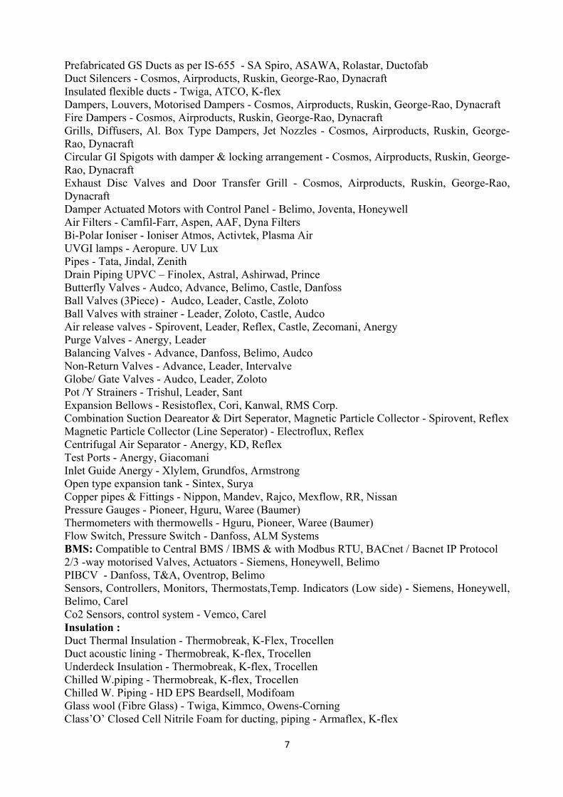
7
Prefabricated GS Ducts as per IS-655 - SA Spiro, ASAWA, Rolastar, Ductofab Duct Silencers - Cosmos, Airproducts, Ruskin, George-Rao, Dynacraft Insulated flexible ducts - Twiga, ATCO, K-flex Dampers, Louvers, Motorised Dampers - Cosmos, Airproducts, Ruskin, George-Rao, Dynacraft Fire Dampers - Cosmos, Airproducts, Ruskin, George-Rao, Dynacraft Grills, Diffusers, Al. Box Type Dampers, Jet Nozzles - Cosmos, Airproducts, Ruskin, George-Rao, Dynacraft Circular GI Spigots with damper & locking arrangement - Cosmos, Airproducts, Ruskin, George-Rao, Dynacraft Exhaust Disc Valves and Door Transfer Grill - Cosmos, Airproducts, Ruskin, George-Rao, Dynacraft Damper Actuated Motors with Control Panel - Belimo, Joventa, Honeywell Air Filters - Camfil-Farr, Aspen, AAF, Dyna Filters Bi-Polar Ioniser - Ioniser Atmos, Activtek, Plasma Air UVGI lamps - Aeropure. UV Lux Pipes - Tata, Jindal, Zenith Drain Piping UPVC – Finolex, Astral, Ashirwad, Prince Butterfly Valves - Audco, Advance, Belimo, Castle, Danfoss Ball Valves (3Piece) - Audco, Leader, Castle, Zoloto Ball Valves with strainer - Leader, Zoloto, Castle, Audco Air release valves - Spirovent, Leader, Reflex, Castle, Zecomani, Anergy Purge Valves - Anergy, Leader Balancing Valves - Advance, Danfoss, Belimo, Audco Non-Return Valves - Advance, Leader, Intervalve Globe/ Gate Valves - Audco, Leader, Zoloto Pot /Y Strainers - Trishul, Leader, Sant Expansion Bellows - Resistoflex, Cori, Kanwal, RMS Corp. Combination Suction Deareator & Dirt Seperator, Magnetic Particle Collector - Spirovent, Reflex Magnetic Particle Collector (Line Seperator) - Electroflux, Reflex Centrifugal Air Separator - Anergy, KD, Reflex Test Ports - Anergy, Giacomani Inlet Guide Anergy - Xlylem, Grundfos, Armstrong Open type expansion tank - Sintex, Surya Copper pipes & Fittings - Nippon, Mandev, Rajco, Mexflow, RR, Nissan Pressure Gauges - Pioneer, Hguru, Waree (Baumer) Thermometers with thermowells - Hguru, Pioneer, Waree (Baumer) Flow Switch, Pressure Switch - Danfoss, ALM Systems BMS: Compatible to Central BMS / IBMS & with Modbus RTU, BACnet / Bacnet IP Protocol 2/3 -way motorised Valves, Actuators - Siemens, Honeywell, Belimo PIBCV - Danfoss, T&A, Oventrop, Belimo Sensors, Controllers, Monitors, Thermostats,Temp. Indicators (Low side) - Siemens, Honeywell, Belimo, Carel Co2 Sensors, control system - Vemco, Carel Insulation : Duct Thermal Insulation - Thermobreak, K-Flex, Trocellen Duct acoustic lining - Thermobreak, K-flex, Trocellen Underdeck Insulation - Thermobreak, K-flex, Trocellen Chilled W.piping - Thermobreak, K-flex, Trocellen Chilled W. Piping - HD EPS Beardsell, Modifoam Glass wool (Fibre Glass) - Twiga, Kimmco, Owens-Corning Class’O’ Closed Cell Nitrile Foam for ducting, piping - Armaflex, K-flex

8
Cold Compound / CPRX Compound Shalimar, Shalicoat, Proprietary as per Insulation Mfg. Spec’s Lagging Pidilite Adhesive for Closed Cell / EPDM Pidilite / Proprietary as per Insulation Mfg. Spec’s Vibration Isolators/Cushy Foot Mounts - Dunlop, Resistoflex, Kanwal V-Belts - Dunlop, Fenner Hardware - Sundaram, GKW, Fittight Anchor Fasteners - Shakti, Hilti Water Storage Tanks, Expansion Tank - Sintex, Surya. Paint - Nerolac, Asian, Berger Welding Rods - ESAB,Advani-Orlecon MCCB - Siemens, Legrand MCB/DB/RCCB - Siemens, Legrand SFU, HRC & Control Fuses - Siemens, Legrand, L&T Starters and Contactors - Siemens, L&T Relays - Siemens, L&T, Legrand Timer - L&T, Legrand, Siemens Indicating Meters - L&T, AE, Legrand, Enercon LED Indicating Lamps - Teknic, Legrand, Siemens Push Buttons - Siemens, Teknic Terminals, Connectors in Panels - Elmex, Connectwell Cables & Wires - Finolex, Gloster, RR Glands - Commet, Braco Lugs - Jainson, Dowel 5.0 MEASUREMENTS & PAYMENTS : The scope under this section covers the mode of measurements and payments for the HVAC System. The general requirements, break-up and mode of payment etc. shall be as specified under measurements & payments. 1.0 EQUIPMENTS 1.1 REFRIGERATION UNITS Chillers: Each equipment shall be measured as one unit and classified based on the type and capacity of equipment. Complete unit with all components and accessories required for the specific duty 1.2 AHU’s - Each equipment shall be measured as one unit and classified based on the type and capacity of equipment. Complete unit with all components and accessories required for the specific duty 1.3 Split ACs: Each ODU + IDU shall be measured as one unit and classified based on the capacity. Fan, filter, cooling coil, drain pan, motor & drive assembly, thermal insulation, base frame, outlet flexible connection, vibration isolators, access doors etc. 2.0 REF. PIPES & WATER PIPING - The pipes shall be measured on the basis of unit length (meter) and shall be classified based on the material and diameter. Pipes with all fittings and accessories like coup-lings, tees, bends, reducers, nipples, flanges, plugs, bushes etc. supports and hangers. 3.0 AIR DISTRIBUTION - 3.1 DUCTS - The ducts shall be measured on the basis of sq. m of surface area of the fabricated duct and shall be classified on the basis of the thickness of GI sheet. GI sheet, fabrication stiffeners, flange connection, guide vane, splitters, opening for mounting collars, grills and diffusers, painted supports and hangers. 3.2 GRILLES & DIFFUSERS - The grilles and diffusers shall be measured on the basis of face area in sq.m. Grilles and diffusers with flange, collar, damper for supply grilles & damper of neck size for diffusers. Wooden / Al. frames to be included.

9
4.0 INSULATION : 4.1 FOR DUCTS - The ducts insulation shall be measured on the basis of unit surface area (sq. m) of the bare duct and classified based on thickness of insulation. Insulation, bonding cladding and fixing material 4.2 WALL, FLOORS & CEILING - The wall, floors & ceiling acoustic insulation shall be measured on the basis of the surface area in sq.m of the surface insulated and shall be classified on the basis of thickness of insulation. Insulation, bonding cladding and fixing materials and wooden frame work. 5.0 ELECTRICAL WORK : 5.1 POWER PANELS - Each power panel shall be measured as one unit. Incoming & outgoing feeders, busbars indicating lamps and control instruments, internal wiring etc. with suitable switchgear as indicated in drawings. 5.2 CONTROL PANELS - The control panels along with the cabling shall form part of the equipment & hence no extra payment shall be made. Control panel with instruments and indicators, piping and cabling Remote start stop push button and connected cabling 5.3 POWER CABLING - The power cabling shall be measured on the basis of unit length of cable between the lugs at each end termination Terminations. 5.4 CABLE END TERMINATION - Cable end terminations of both ends shall be measured as one unit Glands, lugs. 6.0 MISCELLANEOUS - The structural supports, hangers etc. shall form part of the item supported and hence no additional payments is applicable Structural supports, grouting, red oxide, primer, final painting, finishing etc. 3.0 MEASUREMENT FOR PAYMENT: 3.1 For insulated piping and drain piping, the measurements shall be based on per running meter basis and shall include insulation for various fittings such as flanges, elbows etc. No extra quantities shall be allowed for such fittings etc. However, each valve shall be counted as 1 meter of insulated pipe of the same diameter for the purpose of measurement. 3.2 For insulation of ducting the measurements shall be based on bare ducting surfaces and this shall be inclusive of insulation on flanges, elbows, supporting angles etc. For acoustic lining the insulation measurements shall also be based on bare duct areas. 3.4 For insulation on walls and exposed ceiling etc the measurements shall be taken on bare wall / ceiling floor surfaces. For beams and columns measurement shall be taken on finished surfaces, after insulation. 3.5 For grilles/diffusers etc. the measurements shall be based on the neck area of the unit. 3.6 Ducting shall be measured for the actual finished surface as per the surface developed. No allowance for cut outs, openings less than 1.0 sq. m. shall be considered. However, reduction in Insulation & ducting measurements for cut outs larger than 1.0 sq. m. shall be applied. 6. REFRIGERATION UNITS: A] Air-cooled Chillers: i) SCOPE: The scope of this section comprises the supply, erection, testing, adjusting and commissioning of complete Air-Cooled Chiller Package comprising of rotary screw compressor(s) suitable for outdoor installation and controlled by full function microcomputer controller. Chillers shall be selected for use with water. ii) BRIEF SPECIFICATIONS – Air-cooled Screw Chillers: a) Required Capacity of each Chillers - 17.55 TR (Actual capacity) b) No. of compressors per Chiller : Min. 2 Nos. per chiller.

10
c) Type of Chiller : Brazed Plate Heat Exchanger d) Type of Condenser : Air-Cooled e) Air entering Condenser : max 42 deg.C (Design Ambient for Chiller Selection) f) Chilled Water Inlet / Outlet : 12 deg C / 7 deg C g) Refrigerant: R410A h) Fouling Factor (Evaporator): 0.0001 hr•ft2°F/BTU (0.018 M 2•°C/kW) i) Minimum acceptable COP @ 100 % 35 Deg C ambient - 3.35 j) Minimum chilled water flow - 11.1 m3/hr k) Noise Level: shall not exceed 66 dBA at 1 mtr. l) Qty of Packaged Screw Chillers : 4 Nos. (3 Nos. Working + 1 No. Stand By) Location of Air-Cooled Chillers : On Building Terrace. iii) STANDARDS AND QUALITY ASSURANCE: The following standards shall be applicable: a) IS: 659 Safety codes for air conditioning b) IS: 660 Safety codes for mechanical refrigeration c) IS: 5111 COP and measurement procedure for testing refrigeration valves d) IS: 10594 Thermostat expansion valves e) IS: 11327 Requirements for refrigerant condensing units. f) IS: 11330 Refrigeration oil separators. g) IS: 2825 Code for unfired pressure vessels h) IS: 10123 Data sheets for shell and tube heat exchangers i) IS: 4503 Shell and tube heat exchangers. j) Unit shall be rated in accordance with ARI 550-90 latest version. k) Unit efficiency shall meet or exceed ASHRAE Standard 90.1-1989. l) Units shall be manufactured in a facility registered to ISO 9002/BS5750, Part-2 Manufacturing Quality Standard. m) Each Unit shall be full load tested at the factory with all options mounted and wired. n) ASME Boiler and Pressure Vessel Code, Section VIII, Division 1. o) ANSI/ASHRAE Standard 15 – Safety Code for Mechanical Refrigeration. p) ANSI/NFPA Standard 70 – National Electrical Code (N.E.C). q) Rating of chillers: EN 12055. r) Electrical Codes: IEC 204-1 CEI 44-5 Elect. & Safety Codes. s) Codes: CEI-EN 60204-1 Code. iv) DESIGN BASE: The tender drawings indicate a system based on a selected manufacturer of equipment and the design data available to the consultant during the document preparation. Electrical services, size, configuration and space allocations are consistent with that of the manufacturer’s recommendations and requirements. Other listed or approved manufacturers are encouraged to provide equipment on this project; however, it shall be the contractor and/or supplier’s responsibility to assure that the equipment is consistent with the design base. No compensation will be approved for revisions required to the design base because of any other manufacturer/s for any different services, space, clearances, etc. Units with multiple compressors with combination of fixed & inverter or All inverter compressor technologies will be preferred. v) SUBMITTALS: a. Submit shop drawings on each piece of equipment specified in accordance with the technical specifications. b. Submit General Arrangement Drawing (GAD), Technical Data Sheets, Chiller Point load diagram. c. Submit three (3) sets of Installation, Operations and Maintenance Data Manual. d. Electrical Power and Control wiring diagram.

11
vi) GENERAL REQUIREMENTS: The air cooled rotary scroll compressor(s) water chillers with infinite capacity control shall be fully factory assembled and wired in a single package complete with fixed / digital / inverter / all inverter compressor(s) with motor drive assembly, evaporator, condenser, starting controls, safety controls, operating controls and with full feature microcomputer-based controller with real time clock and programming / diagnosis facility. The unit is to be given a complete factory operating and control sequence test under load conditions with fluid hooked up and is to be shipped with full operating charge of refrigerant and oil. Air-cooled condenser, refrigeration piping controls, first charge of refrigerant etc. vii) AIR COOLED SCREW CHILLER TECHNICAL SPECIFICATIONS: Construction: The units shall be designed for maximum corrosion protection being of heavy gauge, G90 approved galvanized steel construction. The base shall be manufactured of formed, 8-gauge, galvanized steel channel. Frame members and legs are constructed of 12-gauge, galvanized steel. The unit control center, end enclosure panels and fan decking shall be constructed of 16- gauge galvanized steel and finished with baked power high grade outdoor quality coating system which exceeds 500-hour salt spray requirements when tested in accordance with the ASTM-B-117 specifications. Standard Light Grey Colour (RAL 7035) with textured finish to be provided unless specified otherwise. The unit should be equipped with low speed fans and a compressor sound attenuating enclosure / sound blanket / Shrouding. All Sound emitting parts, like refrigerant lines and panels subject to Vibration should be acoustically treated with sound absorbent material. Evaporator (Brazed Plate Heat Exchanger): Brazed heat exchanger plate made of AISI 316 stainless steel, externally coated with a anti condensation mat in a closed cell neoprene / closed cell foam (CFC and HCFC-free) thermal insulation, weather proof and UV resistant. Safeties to be included - Electric resistance thermostat & Differential pressure switch to protect against ice formation inside the unit, Low pressure drops and optimized energy exchange. The water side connections shall be Victaulic type and shall have factory supplied connections. Compressor: The Compressor(s) shall be hermetic scroll fixed / inverter type with capacity control and suitable for operating on R-410A Refrigerant. The capacity control shall be automatic with an unloaded starting device, safety valves, high and low-pressure cut-outs, oil pressure gauges. The unloading should be actuated through microprocessor by sensing chilled water outlet temperature with electronic temperature sensor. The Compressors shall be direct driven integral hermetic motor. The motors shall be suitable for operation on 415 Volts + 10% Voltage variation, 3-phase, 50 Hz A.C. supply and suitable for continuous application. Compressor(s) set shall be mounted on Galvanized base with anti vibration mounts. Each compressor shall have a suction check valve, suction filter and discharge check valve. (In addition, each compressor shall be furnished with suction and discharge service valve permitting isolation of the complete refrigerant charge in the condenser. Each compressor shall include an integral oil separation system, oil sump, oil sight glass and oil filter. The oil temperature shall be controlled during operation to maintain proper oil temperature. Each compressor shall be fitted with a crankcase heater to maintain oil temperature during shutdown period. Each compressor shall have a sound attenuating enclosure / sound blanket / shrouding. The compressor shall have a factory backed one year warranty. Air-Cooled Condenser : The condenser coil shall be air-cooled type made out of copper tube and die formed aluminium (polycoat) fins having self spacing collars. The condenser coils shall include sub-cooling circuit. Coils should be advanced crosshatch tubes with lanced fins. Coils should be leak tested and pressure tested at 450 psig. The precoated aluminium fin coils shall have a durable epoxy

12
phenolic coating to provide protection in mildly corrosive coastal and industrial environments. Coating shall be applied to the aluminium fin stock prior to fin stamping process to create an inert barrier between fin and tube. Post coated aluminium fin coils shall have durable organic coating uniformly applied over all coil surfaces. Coating shall be applied by a dip and bake process to ensure complete encapsulation of all coil surfaces. Coated coil shall withstand 1000 hours salt spray test in accordance with ASTM B117. Chillers with Al micro channel condenser coils can be considered subject to review and approval from Engineer In-Charge. Condenser Fans: The fans shall be with aerofoil of low noise, heavy duty, aluminium blade, direct drive propeller type dynamically balanced with inherent corrosion protection and driven by IP 55 /Class F insulation / 3 phase motors with overload protection and with permanently lubricated ball bearings should be provided. The fans shall be controlled by microprocessor on discharge head pressure. Air shall be discharged vertically upward. Fans shall be protected by coated steel wire safety guards. (The tenderer shall furnish in their offer details of requirements of water quantity, condensing temperature, power consumption, condenser heat exchange area, number of tubes, sub-cooling provided for in deg C). Capacity Control: An infinitely variable capacity control system that is capable of matching the demand requirement of the system should be provided. A microcomputer-based controller shall modulate a compressor(s), in response to supply water temperature and maintain water temperature within 1/2oF of set point. This system is to provide precise and stable control of supply water temperature over a complete range of operating conditions. It shall be capable of a capacity control range of 100% down to 20% at specified conditions. (Provide hot gas bypass to provide capacity control to approximately 50% of minimum unit slide valve unloading capability.) Refrigeration Circuits: Refrigeration piping and fittings interconnecting compressor, condenser and chiller shall be all copper and valves shall be brass / gunmetal construction. Each refrigerant circuit shall include two-stage hot gas muffler, liquid line shut-off valves, high pressure relief valves, charging and gauge connections, liquid sight glass with moisture indicator, charging port, refrigerant filter dryer (with replaceable core filters), sight glass, moisture indicator, refrigerant pilot solenoid valve and electronic expansion valve. Electronic Expansion Valve: Each refrigerant circuit shall be equipped with an electronic expansion valve that allows a simple control system that quickly interacts at load variations. The valve shall be capable to perform two functions a) liquid solenoid and b) electronic expansion valve. It is managed directly by the microprocessor. Multiple compressor units shall be provided with a multi-circuited direct expansion evaporator and air-cooled condenser. Suction line shall be insulated with minimum 50 mm thick Closed Cell Foam (Nitrile Rubber) / EPDM Insulation Class’O’ / 60 kg/ m3 density with aluminium cladding as approved by Engineer In-Charge. Control Centre : The control centre shall be fully enclosed in baked powder coated steel, control panel with hinged access doors. Dual compartments, separating the safety and operating controls from the power controls should be provided. The display should be 7” touch colour screen display utilizing an easy to understand menu driven software. It shall be proactive in control and accommodate system anomalies such as high condensing pressure, low suction pressure and high compressor amperage draw by controlling loading to keep the unit running but at reduced capacity until the fault is fixed. Battery backed-up real-time clock and memory with over 10 years life and automatic recharge of lithium ion battery that requires no service to be provided. Each package-chilling unit shall be provided with a centralized control centre panel with microprocessor with Auto, Manual and Semi-Auto Modes with programmable facilities for Auto

13
start/stop year-round programming, auto restart on power restoration, manual single start and stop and test mode start. The controls shall include: 1. Separate terminal blocks for main power, 115/230 VAC control power and 115/230 VAC chillers heater power. 2. Solid-state motor protection module providing phase loss, current imbalance, phase reversal, current sensing and thermal overload protection. 3. Complete labelling of all control components. 4. Numbering of wires and terminal strips for easier wire tracing. 5. Terminals for customer digital input to enable/ disable unit. 6. Dry contacts for chiller water pump control. 7. Dry contacts for unit alarm. 8. Condenser fan control contactors. 9. Fuses/ circuit breakers in the fan circuit. 10. Condenser pressure sensing fan cycling control for start-up and operation. 11. Control Transformer. 12. GFI Convenience outlet. (Convenience outlet 115/ 230 V AC powered dual 3-prong ground fault receptacle powered by dedicated transformer and fumed for 15 Amps.) 13. Chiller heater transformer. 14. Over/Under Voltage relay. 15. Operation and Safety lights visible from unit exterior including: power on, alarm and compressor overload. 16. Control panel door latch solenoid to prevent door opening before turning off power to the unit. 17. Energy meter displaying, current, voltage and power consumed. 18. Compressor elapsed time meter and Compressor cycle counter. 19. Entering chilled water temperature sensor. 20. Management of the compressor capacity slide and the EEX valve according to the distributed multiprocessor logic system Control centre’s individual microcomputer shall provide compressor staging based on leaving water temperature and maintaining equal loading of multiple compressors throughout the full range of operation. Microcomputer: Individual chiller controller shall provide for: 1. Unit Control : a. Compressor staging. b. Unloading and loading of compressors based on leaving water temperature. c. Activating condenser fan relays for fan cycling head pressure control. d. Seven-day time clock with schedules for machine control. e. Proactive control to unload the compressors based on high pressure, low pressure, and high amp. draw too reduce nuisance trips. f. Controls of hot gas bypass circuit. g. Dry contacts for chilled water pump control. h. Terminals for customer enable/ disable of unit. i. Dry contacts for unit alarm. 2. Unit Protection: a. Low-pressure protection. b. High-pressure protection. c. Automatic restart from power outage. d. Anti freeze protection. e. Compressor current limiting. f. Anti-recycling protection. g. Sensor error.

14
h. Motor high temperature protection. i. Low oil. j. Dry contacts for chilled water pump control. k. Over current protection. l. Phase loss, phase reversal and phase imbalance. m. Ramp control for timed unit loading when the return water temp. is 5oF above leaving water set point. 3. Microcomputer readouts shall provide the following: a. Compressor run time and cycles. b. Leaving water temperature. c. Entering water temperature. d. Compressor ampere draw. e. Suction pressure at each compressor. f. Discharge pressure at each compressor. g. Unit control contacts. h. Water flow switch. i. Chilled water reset. j. Digital outputs. k. Compressor control status. l. Unloader controller status. m. Liquid line solenoid status. n. Condenser fan control status. o. Alarm control status. p. Control power status. q. Ambient temp. r. Chilled water pump control. s. Utility demand limit. 4. Microcomputer – set points shall provide the following: a. High discharge pressure. b. Low suction pressure. c. Freeze protection temperature. d. Leaving water temperature. e. Condenser fan control. f. Low suction unload. g. High discharge unload. h. High and low compressor amperes. i. Chilled water reset. j. Demand limit reset. k. Low ambient lock-out. 5. Microcomputer –Alarm History shall provide the following: a. The 8 most recent alarms can be displayed. b. Low suction pressure of all circuits. c. High discharge pressure of all circuits. d. Freeze protection cutout. e. No run, No stop. f. Loss of water flow. g. Power failure. h. Temperature sensor error. i. Hi/ Low pressure error. j. Low oil. The chiller microprocessor shall be capable of communicating with other vendor supplied control

15
devices as required for data logging, demand limiting, air side interface, and other control functions. DELIVERY AND HANDLING: The unit shall be delivered to the job site completely assembled and charged with refrigerant and oil by the manufacturer. Delivery and Handling shall comply with the manufacturer’s instruction for rigging and handling. The unit controls shall be capable of withstanding 150oF (66oC) storage temperature in the control panel for an indefinite period of time. INSTALLATION: 1. The refrigeration unit shall be mounted on a structural framework with a common base frame having adequate strength. The structural base frame shall be mounted into a suitable concrete sub-base or pad separated from the main floor by means of necessary vibration isolation springs/ pads. The concrete / structural sub-base will be provided by the Vendor on the basis of foundation details submitted by the equipment manufacturer. It shall be the responsibility of the Chiller vendor to inspect and check the adequacy and certification of the sub-base. For Installation of Air-cooled Chiller on Terrace, the vendor shall provide column stubs in concrete and those shall extend on Terrace at approx 750mm~1000mm above FFL of terrace. The Chiller vendor shall submit the chiller loading diagram for the structural supporting work required within these column stubs to uniformly distribute the load on the stub columns. 2. The chiller vendor / contractor shall supply the required charge of refrigerant and lubricants for the commissioning and testing of the plant and till handing over. The refrigerant systems shall be pressure tested at 21 kg/sq.cm-g on high side and 7 kg/sq. cm-g on the low side before vacuumising. The system shall then be vacuumised to 7 mm of hg. Absolute and maintained for 24 hours before charging. 3. Water drain connections on chiller and condenser shall be piped to a 50 mm drain header through a funnel type open sight drain. 4. Pressure switches, preferably differential pressure type or flow switches shall be provided in chiller lines and interlocked with the compressor starting without condenser fans and chilled water flow established. 5. Crank case heaters shall be ON when the compressor stops. START UP: The contractor shall provide the labour to accomplish the check, test and start-up procedure as recommended by the unit manufacturer. The start up serviceman shall provide and complete the manufacturers check, test and start forms. One copy shall be sent to the engineer and one copy to the manufacturer’s factory. The unit manufacturer shall provide a factory trained service personnel to supervise the original start up of the units for final operation. TESTING: Unit shall be tested for establishing the capacity and power consumption. Refrigeration capacity of the unit shall be computed from measurement of water flow and entering and leaving water temperature. Flow measurements shall be through flow meters. Tests shall be carried in accordance with IS: 5111 for reciprocating water-chilling units. Computed results shall tally with the specified capacities and power consumption figures furnished with the tender offer. Tests shall be carried out on: a) The Compressor and drive motor side b) Chiller side c) Condenser side All meters, gauges thermometers, wattmeter’s etc. shall be furnished by the contractor and be duly calibrated. All necessary distance pieces etc. required in the piping shall be provided at the time the piping is installed. All test readings shall be correlated with each other and with the design parameters before submission for approval. At least 4 test readings lasting over a period of 3 hours shall be recorded. Minimum 3 days continuous running and testing should be done without any break

16
down. The chiller commissioning shall be in accordance with manufacturer’s requirements of commissioning and chiller vendor shall submit all readings and reports during the handover. WARRANTY: The equipment supplier shall provide a warranty on the entire refrigeration system exclusive of the refrigerant for a period of one year from the date of start up or 18 months from date of shipment, whichever is earlier. Compressors shall have factory backed 1 year warranty from date of handover duly certified by the Engineer In-Charge. B] Air-cooled Split AC Units: OUTDOOR UNITS (CONDENSING UNITS): The outdoor unit shall comprise of following facilities: _ Condenser fan(s) _ Constant speed scroll compressor _ Air cooled Condenser coil _ Resin based grille The outdoor unit shall be suitable for a power supply of 240V/ 1 phase/ 50Hz OR 415V / 3 phase/ 50Hz as per the size selected. The outdoor unit shall have a start current and run current as per detailed electrical characteristics recommended by the manufacturer. The outdoor unit shall be complete with expansion valves, oil separators, crankcase heaters, suction and liquid shut off valves, strainers, liquid receivers and accumulators as per requirements. The compressor pack shall be mounted on a sliding tray with springs and shock absorbing rubbers to facilitate service and maintenance. The Compressor shall be high EER, high efficiency compliant SCROLL design. (For outdoor units upto 3TR (Hi-wall Split Units) the machines shall be with reciprocating/ rotary compressors). Each compressor shall have rotolock valve for service purpose and with in-built overloads, HP and LP Controllers. The compressor shall be mounted on vibration isolators/rubber grommets. Pressure gauge ports shall be provided in each compressor. The casing of the compressor shall be hermetically sealed scroll and of a standard make, suitable for operation on R 410A / R32 refrigerant. The compressors shall be suitably protected by dual pressure stat, motor winding thermostat and special electronic device to safeguard against single and overloading. A system to reduce energy consumption, by way of Condenser recycling, Compressor hunting etc. during part load periods shall be preferred. The outdoor unit shall be complete with all safety devices including high pressure switch, fuse, thermal protectors for compressor and fan motors, over current protectors for compressor motors, sequential start and recycling timers & a common fault indication. The compressors, refrigerant circuits and electrical box should be placed in and enclosed compressor compartment separated from the air passages. The unit shall be sturdy, elegant in appearance and shall be quiet and vibration free in operation. The sheet metal shall be min. 16 G in construction. The outdoor unit shall be completely weatherproofed and be factory assembled, prewired and complete with all necessary electronic and refrigerant controls for easy installation. The unit shall be selected to enable it to run at low noise level of 60dB (A). The outdoor unit shall be factory charged with the CFC free refrigerant-R410 A/ R32. Additional refrigerant charge shall be added, as per the site conditions and as per recommended by the manufacturer, during the commissioning procedure. The outdoor unit heat exchanger shall be ‘rectangular’ shaped and shall be formed of seamless copper tube with internal grooving, & mechanically bonded to aluminium fins. The outdoor unit dimensions shall be optimized to assist with the movement of the equipment to the agreed outdoor unit location as well as ensuring that the area of steel decking is kept to a minimum. The outdoor unit heat exchanger shall be full height at the rear of the unit and shall be formed of seamless copper tube with internal grooving, and mechanically bonded to aluminium fins. The outdoor unit fan motor(s) shall be totally enclosed and incorporate a thermal fuse. The packaged air conditioner shall have a control panel for automatic / manual sequential operation of

17
the components and safety control. The Unit shall have its’ own Isolator for electrically isolating the Machine during emergency or maintenance. The outdoor fan(s) shall be of the direct drive sickle shape and of plastic construction. Air discharge shall be angled to ensure that the fan will not stall if overcome by the weight of dust / other debris. The air outlets shall have plastic coated wire fan guards. The outdoor fans shall accommodate a short amount of ductwork, where required, in order to expel discharge air when units are sited internally. Where a discharge air duct is used, removable ducting is recommended to ensure access to the fan section. The fan static should be able to take care of the losses due to duct cowl. The unit casing shall be manufactured from polyester powder coated galvanised sheet steel. The colour finish shall be to the manufacturers’ recommendations. Access to the units for routine service and maintenance shall be through the front panel only. For installation purposes only, access to the units shall be via removable panels. Units shall be installed making provision for the minimum space requirements between adjacent units or obstructions, as specified and as offered in the manufacturers data interconnecting pipe work from indoor units shall be made onto the outdoor unit terminations using brazed connections, in accordance with manufacturer’s stated requirements. Necessary MS stands duly powder coated shall be used to mount the Condensing Units. Electrical System: A main isolator (MCB) should be provided on the unit sized to meet the system total power requirement. Within the panel individual power loads should be distributed equally across the phases through a bus bar. Low voltage and high voltage protection for microprocessor control. All individual wires should be of copper and colour-coded or should be numbered at their point of termination to facilitate servicing. Low voltage control wiring and power wiring should be segregated from each other. The Electrical power system should confirm to relevant I.S. / I.E. standard. The following should be incorporated: Motor Protection circuit breakers (MPCB) of suitable rating should be provided for each sub-circuit, Contactors for automatic Micro Processor Control. Single-phase preventer in the main incoming and Auto-Off-Manual switch is to be provided. INDOOR UNITS: The following models of indoor units shall only be acceptable: _ Hi-Wall Mounted type The indoor unit shall be constructed from galvanised sheet metal panels. All surfaces shall be thermally and acoustically insulated. The indoor unit shall include fan impeller with direct drive fan motor. The motor shall be sealed and lubricated for life, the whole assembly being statically and dynamically balanced. The motor shall be of the totally enclosed, permanent split capacitor type with thermal safety cut out. The Indoor Unit has been designed to suit low noise application. i.e. the selected fan should not have an outlet velocity exceeding 9 m/s and a noise level of less than 60 dBA at 1 m from the IDU. The evaporator coil shall be of 15 mm O.D. copper tube with 5 aluminium fins per cm and shall be complete with thermostatic expansion valve and a distributor. Preferably a 4-rows deep coil should be provided. The indoor unit heat exchanger shall be manufactured from seamless copper tubes with internal grooving, and mechanically bonded to aluminium fins. All tubes shall be brazed into copper headers and return bends and fully tested at works. The refrigerant pipe terminations shall be fitted with flared connections, complete with flare nuts. The indoor unit shall incorporate a one-piece insulated drain tray. The drain connection shall be of a suitable size and be connected to either the gravity condensate system or a suitable condensate pump, supplied by the specialist installer. The indoor unit shall be complete with all necessary controls including thermostatic expansion valves etc. The indoor unit shall be provided with its own integral temperature sensor fixed onto or adjacent to the return air grill, measuring the return air temperature. The indoor unit shall be suitable for a power supply of 240V/ 1 phase/ 50Hz OR 415V /3 phase /50Hz OR 415V/ 3 phase/ 50Hz as per the size selected. The indoor unit

18
shall incorporate a return air filter. Filters shall be removable via the front, or underside of the unit, without removing any screwed panels. Filters shall be of the washable type unless otherwise specified. HIWALL INDOOR UNIT: The split A.C. unit shall be of hi-wall type and shall consist of: (i) Indoor unit with cooling coil, drain tray / connection and the blower (ii) Outdoor unit with the compressor and air-cooled condenser. (iii) Interconnecting piping with suction line insulation and controls. (iv) Cordless remote (v) MS Stand The unit shall have hermetically sealed reciprocating compressor with suction cooled motor/ rotary compressor and complete with overload protection. The condenser shall be liberally designed with sub-cooling of liquid refrigerant to reduce possibility of motor burn out. The cooling coil shall consist of staggered rows of expanded copper tubes with aluminium fins to ensure efficient heat transfer. The blower shall be statically and dynamically balanced for quiet and efficient operation and shall have 2/3-speed motor. The air throw shall not be less than 6.0 m and shall have uniform and not confined to just one direction. The indoor shall be exposed type either floor; wall / ceiling mounted type as specified. The desirable features of the room air conditioners both window & split type shall be: (i) High-energy efficiency. (ii) Good performance at high ambient temperature and high RH conditions. (iii) Good quality filtration with an easily accessible air filter. (iv) Suitable for operation from 180V to 260V A.C. supply for single phase and 350V to 460 V for 3 phase applications (v) Weather proof construction (vi) Convenient control system and quiet operation (vii) Efficient after sales service. (viii) Swing type airflow. (ix) Cordless Remote for control and display. 7.0 AIR HANDLING UNITS: The scope of this section comprises the supply, erection, testing, adjusting and commissioning of double skin air handling unit. The AHU’s shall conform to these specifications and in accordance with Basis of Design, Requirement of drawings and Schedule of Quantities (BOQ). Each AHU shall comprise of following: a) Extruded Al. Framework for all sections and Double Skin Panels. b) Fan section with fan, motor and drive assembly. c) Coil section with Chilled water-cooling coil. d) Filters section with filters as specified e) Damper at AHU Outlet (not required in case of direct drive plug fans) f) Double Skin Coil Tray in SS on inside and Pre-plasticised / Pre-coated GI on outside. The air handling units shall be double skin modular construction with filter section, filters of approved make, chilled water coil, with insulated joint less condensate drain pan and direct drive backward curved Radial EC fan (Electronically commutated) with permanent magnet brushless DC motor OR Aerofoil Backward Curve Centrifugal Fan. Units shall be of the arrangement shown on the Drawings and mentioned in the Schedule of Quantities (BOQ). The air moving capacities and maximum motor horsepower shall be as shown on Drawings as per AHU Summary Sheet and Schedule of Quantities. The AHU’s shall be Vertical/Horizontal Construction as specified in Schedule of Quantities (BOQ). The AHU’s shall be Loft mounted / Floor mounted / Ceiling Suspended and air outlet shall be topside / front discharge as per

19
requirement and as specified. The housing/casing of the air-handling unit shall be sectionalised /unitary of double skin construction. The housing shall be so made that it can be delivered at site in total/semi knocked down conditions depending upon the locations. The Framework shall be of Extruded Aluminium hollow sections filled with preformed insulation section duly powder coated /anodized. Frame shall be assembled using mechanical joints to make a sturdy & strong framework for various sections. All the AHU sections shall be with Thermal Break profile. 45mm +/- 2mm thick Double skin sandwich panels (each not exceeding 2750 mm width) shall be made of 24 G pre-plasticised GSS sheet on outside and 22 G galvanized sheet inside having PU Foam insulation (40 kg/m3 density) OR Rockwool insulation of density 60 kg/cum insulation. These panels shall be bolted from inside on to the framework with soft neoprene gasket to make the joints airtight. Suitable doors with aluminium die cast hinges and latches shall be provided for access to various panels for maintenance. Access panel shall be provided with safety screen. The entire housing shall be mounted on steel channel framework. Units for treated fresh air & ducted return air shall be provided with thermal break & motor operated modulating dampers. One-piece drain pan shall be constructed of stainless steel with necessary slope to facilitate fast removal of condensate water. Necessary supports will be provided to slide the coil in the drain pan. Outlet shall be provided on both the sides of drain pan. The drain pan shall be sized larger than coil to collect condensate water from coil bends & other control units. AHU’s requiring mixing box shall be complete with fresh, return air and exhaust air dampers. Dampers shall be opposed blade type. Blades shall be made of aerofoil extruded aluminium alloy frame. Manual dampers shall be provided with a bakelite knob for locking the damper blades in position. Linkages shall be extended wherever specified for motorized operation. Damper frames shall be sectional to minimize blade warping. Air leakage through dampers when in the closed position shall not exceed 1.5% of the maximum design air volume flow rate at the maximum design air total pressure. Fan motors shall be 415 V + 10%, DC drive electronically commutated with permanent magnet brushless specially designed for quiet operation; motor speed shall not exceed 1450 RPM. Fan motors shall be factory fitted to fan. Fan wheel and housing shall be fabricated from heavy gauge steel. Fan wheels shall be of the Aerofoil Backward Curve radial / backward curved Radial EC fan (Electronically commutated). All rotating parts shall be statically and dynamically balanced. The fan assembly shall be statically and dynamically balanced. The fan should be selected in such a way, which is required to deliver constant airflow rate at varying static pressures ranging from 50 to 150 mm w.g. Fan speed shall not exceed 1000 RPM and maximum fan outlet velocity shall be 550 meters per minute (1800 FPM). However higher velocity at fan outlet shall be acceptable in case of installations requiring higher static pressures with minimum noise. The fans shall meet the specifications of section 10: fans. Chilled water coils shall be of 12.5/15 mm dia tubes min. 24 gauge thick with sine wave aluminium fins, firmly bonded to copper tubes assembled in zinc coated steel frame, cooling coil shall be integrally finned type. Face and surface areas shall be such as to ensure rated capacity from each unit and such that the air velocity across each coil shall not exceed 150 meters per minute. The coil shall be pitched in the unit casing for proper drainage. Each coil shall be factory tested at 21 Kg./Sq.cm. air pressure while submerged in water. Tube shall be expanded hydraulically or through passing of bullet for minimum thermal contact resistance with fins. Fin spacing shall be 12 to 13 fins per inch (4-5 fins/cm.). Copper bends shall be brazed by holding the coils vertically to achieve clean finish. The coils shall be 4/6/8 rows deep as required and as mentioned against each AHU in the AHU summary sheet and BOQ. Cooling coil shall be suitable for entering chilled water temperature at 7 deg C and leaving temperature of 12 deg C. Vibration isolators shall be provided in all floor & Loft mounted air handling units. AHU’s mounted within the ceiling space shall be hung through vibration isolation suspensions. Filters shall be minimum 50mm thick and shall also be fire retardant type, washable media with 90% Efficiency 10 micron (G4). All access doors, coil connections etc., shall be provided on one side of the unit. In other words,

20
access to the other side of the unit should not be necessary for any purpose what so ever. Min. width of the door shall be 450 mm. Special care shall be taken to ensure that doors, handles, hinges, etc. shall be robust enough to with stand heavy industrial usage. Silicone sealants shall be applied to all joints -both on the inside of the AHU. The vibration of the AHU fans (as measured on the bearing block after assembly) shall not exceed a peak-to-peak displacement of 100 microns. For all AHUs serrated rubber pads shall be provided for vibration isolation. Shop coats of paint that have become marred during shipment or erection shall be cleaned off with mineral spirits, wire brushed and spot primed over the affected areas, then coated with enamel paint to match the finish over the adjoining shop painted surfaces. Air handling units shall be selected for the lowest noise level of the equipment. Fan performance rating and power consumption data with operating points clearly indicated shall be submitted with the tender or during execution stage to the Consultants and get prior approval from them. This performance is to be verified at the time of testing and commissioning of the installation. Noise level at 1 meter from the AHU shall be less than 70 dBA at 1mtr from AHU. The noise level reduction being achieved for airborne noise to be confirmed in the sound attenuator selection. Sound spectrum data to be provided and pressure drop across the sound attenuator to be provided. PIPING AND ACCESSORIES: Each air-handling unit shall be provided with air vent at highest point in the cooling coil and drain plug at the bottom of coil. In addition, the following accessories shall be required at air handling units, as described in the schedule of quantities. TESTING: Cooling capacity of various air handling unit models shall be computed from the measurements of airflow and dry and wet bulb temperatures of air entering and leaving the coil. Flow measurements shall be accurately calibrated. Computed results shall conform to the specified capacities and quoted ratings. Power consumption shall be computed from measurements of incoming voltage and input current. Tests shall be conducted on all AHUs at the factory for measurement of delivery vs. static Pressure, total pressure, BKW, efficiency & noise level at 100%, 80% 60%, 50% & 40% speeds. Owners / Consultants will witness the testing of 1 or 2 AHUs of each specified type at the factory. The contractors shall intimate in advance the date of the tests, which they will witness at their option. Further, all AHUs shall be leak-tested at 150 mm static pressure using an external testing rig. The test shall be conducted to Class `D’ level applicable for ducting as per STD DW 141/142. The test rig shall include an external fan with arrangements for varying the airflow instruments for measuring static pressure, airflow, etc. The tenderer shall afford every facility for the accepting officer or his authorized representative to witness the tests if they so desire. The HVAC contractor shall replace the filter set for each AHU being used upto testing, commissioning and flush out before final handover to client. 8. VARIABLE FREQUENCY DRIVE FOR AHU: GENERAL: A HVAC dedicated variable frequency drive is preferred over standard drives. The manufacturer shall have its own sales and service support network throughout the country. They shall provide full technical support, spares holding and troubleshooting capability from their own facility. A training course shall be provided by the manufacturer to the operating and maintenance engineers/staff. The supplier shall provide complete technical details of the product with the offer including catalogues, operating manual, dimensional drawings, weights etc. VFDs shall conform to the
21
recognized international standards like IEC and manufactured according to ISO 9001, BS 5750 part 1 & 2 and shall be UL listed. It shall carry the CE mark on EMC compliance. Suppliers shall offer a single series of controller over the whole required power range to ensure a common user interface, common circuit requirements and common spare parts. VFDs shall be suitable for operation in a “Stand Alone” mode, complete with all necessary protection to the motor or as a part of the centrally controlled Building Management System (BMS). In case of AHUs with Plug fans, the VFDs shall be part of the AHU supply. VFD DESIGN REQUIREMENTS: The VFD shall be of the type suitable for operation on a 3 phase, 415 V, 50 Hz input power supply. The VFD shall be suitable for operation at full load at the following conditions: Input supply voltage variations: + 10 % Input supply frequency variations: + 2 % Ambient temperature: 0-50 deg.C Maximum relative humidity: 95% non-condensing Minimum efficiency at full load: 96% The VFD shall use the advanced digital Vector Control technology for converting fixed voltage and frequency to variable voltage and frequency. It should ensure that full motor power is utilised at the rated speed. The VFD shall automatically correct the output voltage during main’s variations of + 10% to prevent loss of torque and speed variations occurring during motor operation. The VFDs shall have a metallic enclosure with a protection of minimum IP20 and shall be suitable for installing inside a IP 54 control panel without any de-rating. The output waveform of the VFD shall be suitable to control the quadratic load torques produced by pumps and fans to ensure that maximum total efficiency is obtained from the motor and drive at all loads and speeds. The VFD shall be capable of automatically varying the V/f ratio based on the load variations. VFDs providing constant or selectable V/f ratio are not acceptable. The VFD shall be capable of providing minimum 160% torque for 0.5 sec and 110% torque for 1 min. at starting. The VFD shall work in conjunction with any IEC standard design motor and shall not require the motor to be derated or cause the motor temperature to rise above the normal class ‘B’ rise expected on normal mains operation. The motor shall not require an external blower even at slow speed running. The VFD shall protection against damage of motor bearings due to the high voltage spikes by providing soft switching of the IGBTs. Those VFDs without soft switching shall be provided with LC filters (motor chokes) of suitable ratings. The VFD shall incorporate an “Automatic Energy Optimiser” function which continually adjusts the output voltage to a reduced level to give maximum motor efficiency at any given partial load. The VFD shall automatically adjust the output frequency and voltage to maintain a stable motor speed of +/- 0.5% at the motor’s rated speed. This accuracy shall be maintained over a speed range of 1% to 100% without the use of a closed feedback loop. The VFD shall allow selection of motors one frame size larger and 4 sizes smaller than its nominal rating. The VFDs shall be immune to interference from other RFI producing equipment and shall comply to AS/NZS 4252.1 – 1994, EN 61000-4-2, EN 61000–4-3, EN 61000-4-4, EN 61000-4-5, ENV 50204, ENV 61000-4-6 and VDE 0160. The VFD shall contain as a standard built-in DC reactor with both inductive and capacitive elements to control the mains harmonics. The harmonic current distortion produced by the controllers shall comply with IEC 1000-3-2 and IEC 100-3-4 respectively according to the current ratings. VFDs that do not include built-in DC reactors for harmonic control shall be supplied with external 3- phase AC reactors on the mains side with a minimum impedance of 3%. These AC reactors shall be of the same make of the VFD and shall be supplied as an integral part of the

22
VFD by the manufacturer itself. The VFDs shall be capable of allowing for a minimum of 1 start/min. on mains operation. Start/stop operation using electronic operation shall be unlimited. The VFDs shall be suitably protected to allow for switching to take place on the output via a contactor or isolator without damage to the inverter transistors or the switching device. The controller shall include features which limit the rate of the output voltage rise over time (dV/dt), and prevent peak voltages from occurring. Those VFDs having a higher dV/dt than specified shall be supplied with integral LC filters by the manufacturer itself. The switching frequency of the VFD shall be adjustable to reduce the acoustic noise generated from the motor. While adjusting the switching frequency no derating shall be applicable to the VFD. The VFD shall be capable of allowing up to 150 meters of armoured cabling between the VFD and the motor. If the offered VFD cannot allow this cable length, the supplier shall include motor chokes (LC filters) of coil reactance value required to increase the cable length upto 150 meters and quote accordingly. The VFD shall incorporate automatic motor tuning function to adapt itself to the actual motor parameters. The tuning shall be based on measurements of the motors inductance and resistance. The VFD shall be capable of automatically reconnecting to a spinning fan, forward or reverse running without tripping following mains interruption or transfer from bypass running. The VFD shall have DC injection braking to ensure that a pre-rotating high inertia load motor, even in the reverse direction, can be switched onto, braked to zero and then accelerated to the preset speed in the correct direction. The VFD shall be provided with at least 4 by-pass frequencies with adjustable band width in order to eliminate resonance in duct work and pipe lines occurring within the motor’s operating frequency range. The VFD shall incorporate an in-built programmable PID controller to enable closed loop control of the process. It shall respect the minimum and maximum limits and shall include an anti-wind-up function. The PID controller shall be able to operate in the normal or inverse modes. Remote monitoring of the feedback signal via a 0/4 - 20mA signal from the VFD is required. The VFD should include an interlock function which allows control and interlocking of other mechanical equipment such as dampers. In case of a power failure, the VFD shall be capable of automatically restarting after a programmable time delay. CONTROL AND MONITORING FUNCTIONS: Full galvanic isolation between power and control components shall be incorporated to ensure compliance with VDE 0160 PELV (Protective Extra Low Voltage) to prevent damage to BMS interface and ensure operator safety. Short circuiting of the control terminals shall not damage the control card. VFDs without galvanic isolation shall be provided with upto isolators. At least 6 digital inputs shall be provided with freely programmable functions and shall have a scan time less than 3 ms. Upto 4 analog inputs accepting voltage (max 10V) and current (max 20mA) inputs shall be provided in the VFD. These inputs shall be freely programmable and scalable. Two programmable relays shall be provided for remote monitoring of the VFD. The programmable options shall include as a minimum ready, run, and alarm. The run relay function shall initiate a run signal only when the frequency output from the VFD is greater than 0.5 Hz. Two programmable analogue outputs (for providing current and speed feedback to BMS) of 0/4-20 mA shall be provided for monitoring. The programmable options shall include as a minimum speed, current and torque. The VFD shall be capable of accepting input from a thermistor. The VFD shall be able to accept a pulse train the frequency of which gives an analogue reference of feedback.

23
The VFD shall have an internal power supply to provide a sensor supply for the digital inputs and any loop powered analogue sensors. This internal power supply shall have a minimum capacity of 100 mA at 24V DC. The VFD shall be able to generate a pulse train output, the frequency of which is proportional to the signal being transmitted. The VFD shall have local control panel with multi-line selectable alpha-numeric display which shall display the following minimum information: _ Frequency in Hz _ Feedback signal in units _ Current in A _ Output Voltage in V _ Power in kW _ Energy in kWh _ Output voltage V _ Run time in hours Those VFDs with LED display as standard are not acceptable and shall be supplied with additional alphanumeric displays. The local control panel shall be used for setting parameters and tuning the VFD. The VFD shall display the following minimum faults in clear English text and not by codes. _Mains phase loss _Over voltage _Under voltage _Inverter Overload _Motor Thermal Overload _Over current _Earth fault _Switch mode power Supply fault _Output short circuit _RS485 communications timeout _Heat sink over temperature _Motor phase missing _Inverter fault The VFD shall provide for Hand /Off /Auto switch to allow for local control by hand or remote Auto control by the BMS. This function shall be selectable via the Local Control Panel or via digital I/O. The VFD shall log and display “Total kWh consumed” and Total Hours Run” by the motor without additional instrumentation and facility to reset. The VFD shall be fitted with a RS485 serial port with an open protocol for allowing serial communication with the BMS system. The following indicating lights shall be provided on the local display panel of the VFD: VFD ‘ON’ b) VFD ‘WARNING’ c) VFD ‘ALARM’ A parameter lock shall be available in the VFD local display panel to prevent unauthorized resetting of parameters. PROTECTION FEATURES: The VFD shall shut down safely under the following conditions and operate the alarm relay. The display shall indicate the nature of the fault in clear English text. _ Mains phase loss _ Over voltage _ Under voltage

24
_ Inverter Overload _ Motor Thermal Overload _ Over current _ Earth fault _ Switch mode power supply fault _ Output short circuit _ RS485 communications timeout _ Heat sink over temperature _ Motor phase missing _ Inverter fault The VFD shall provide for both automatic and manual reset operation. In automatic mode there shall be a programmable choice of up to 10 reset attempts per fault before the controller shuts down making manual reset necessary to restart the system. The restart time after a trip in automatic mode shall be adjustable. In manual reset mode the reset shall be accomplished from both the keypad on the controller and by remote signal. The VFD shall be equipped with a data log menu that will allow storage of at least 10 latest faults that have occurred. Last fault memory shall be required in the event of power failures. The VFD shall have a sufficiently fast current limit feature to survive a continuous short circuit on the output terminals without damage to any drive components. The VFD shall not require special type input protection devices such as high speed semi-conductor fuses. In case, these are necessary for protection of the VFD, the same shall be included in the scope of supply of the VFD supplier. The VFD shall maintain operation as long as possible under fault conditions. For example, the controller should automatically derate itself and reduce the speed to a safe level on high temperature or a phase loss to maintain some control of the process rather than shutting down due to a trip. The controller shall include electronic motor thermal overload protection where the trip time is based on the motor’s running frequency, actual motor current, operating time and the motors rated current. The device shall automatically modify the trip time to take into account operation at low speed. On trip the controller shall indicate that the fault is a motor thermal trip. No rear access shall be necessary during normal service function. TECHNICAL SPECIFICATIONS: 1.0 Product type Dedicated HVAC Engineered design. General purpose drives are not acceptable 2.0 Manufacturer Shall have minimum 30 years’ experience in design and manufacturing VFDs. Brand labelled drives not accepted. 3.0 Certification UL, CE, C tick 4.0 VFD Design requirements: 4.1 Voltage variations 380-480 V + 10% 4.2 Nominal supply frequency 50 Hz + 5% 4.3 True Power Factor (λ) > 0.9 at nominal rated load 4.4 Displacement P.F. (cos φ) > 0.98 4.5 Harmonic current control 5% non-saturating dual reactors on both rails of DC bus. Swinging chokes which do not provide full harmonic filtering throughout the entire load range are not acceptable. VFDs with saturating (nonlinear) DC reactors to provide additional 3% AC chokes. 4.6 EMC Compliance (for emission and immunity) a) For powers ≤90 kW: Shall comply with requirements of IEC 61800-3: 2004, Category C1 with 50m motor cable. SCHEDULE 0 - For powers >90 kW: Shall comply with requirements of IEC 61800-3:2004, Category C2 with 50m motor cable. 4.7 VFD rated continuous output current
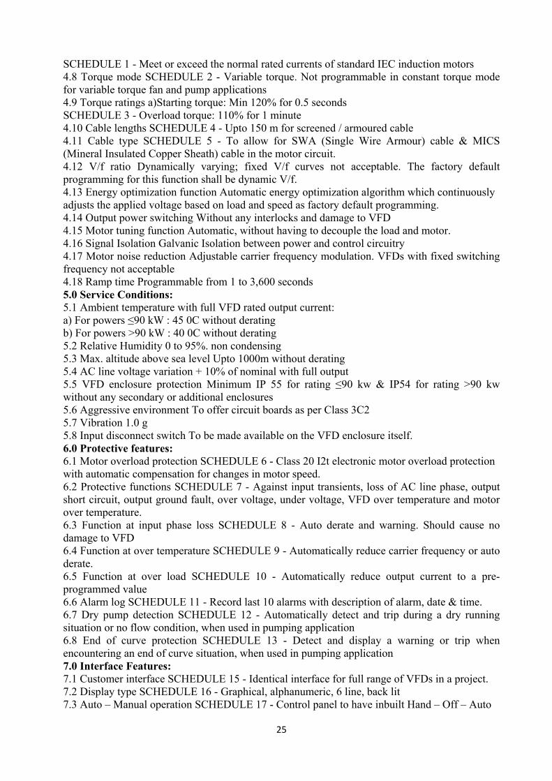
25
SCHEDULE 1 - Meet or exceed the normal rated currents of standard IEC induction motors 4.8 Torque mode SCHEDULE 2 - Variable torque. Not programmable in constant torque mode for variable torque fan and pump applications 4.9 Torque ratings a)Starting torque: Min 120% for 0.5 seconds SCHEDULE 3 - Overload torque: 110% for 1 minute 4.10 Cable lengths SCHEDULE 4 - Upto 150 m for screened / armoured cable 4.11 Cable type SCHEDULE 5 - To allow for SWA (Single Wire Armour) cable & MICS (Mineral Insulated Copper Sheath) cable in the motor circuit. 4.12 V/f ratio Dynamically varying; fixed V/f curves not acceptable. The factory default programming for this function shall be dynamic V/f. 4.13 Energy optimization function Automatic energy optimization algorithm which continuously adjusts the applied voltage based on load and speed as factory default programming. 4.14 Output power switching Without any interlocks and damage to VFD 4.15 Motor tuning function Automatic, without having to decouple the load and motor. 4.16 Signal Isolation Galvanic Isolation between power and control circuitry 4.17 Motor noise reduction Adjustable carrier frequency modulation. VFDs with fixed switching frequency not acceptable 4.18 Ramp time Programmable from 1 to 3,600 seconds 5.0 Service Conditions: 5.1 Ambient temperature with full VFD rated output current: a) For powers ≤90 kW : 45 0C without derating b) For powers >90 kW : 40 0C without derating 5.2 Relative Humidity 0 to 95%. non condensing 5.3 Max. altitude above sea level Upto 1000m without derating 5.4 AC line voltage variation + 10% of nominal with full output 5.5 VFD enclosure protection Minimum IP 55 for rating ≤90 kw & IP54 for rating >90 kw without any secondary or additional enclosures 5.6 Aggressive environment To offer circuit boards as per Class 3C2 5.7 Vibration 1.0 g 5.8 Input disconnect switch To be made available on the VFD enclosure itself. 6.0 Protective features: 6.1 Motor overload protection SCHEDULE 6 - Class 20 I2t electronic motor overload protection with automatic compensation for changes in motor speed. 6.2 Protective functions SCHEDULE 7 - Against input transients, loss of AC line phase, output short circuit, output ground fault, over voltage, under voltage, VFD over temperature and motor over temperature. 6.3 Function at input phase loss SCHEDULE 8 - Auto derate and warning. Should cause no damage to VFD 6.4 Function at over temperature SCHEDULE 9 - Automatically reduce carrier frequency or auto derate. 6.5 Function at over load SCHEDULE 10 - Automatically reduce output current to a pre-programmed value 6.6 Alarm log SCHEDULE 11 - Record last 10 alarms with description of alarm, date & time. 6.7 Dry pump detection SCHEDULE 12 - Automatically detect and trip during a dry running situation or no flow condition, when used in pumping application 6.8 End of curve protection SCHEDULE 13 - Detect and display a warning or trip when encountering an end of curve situation, when used in pumping application 7.0 Interface Features: 7.1 Customer interface SCHEDULE 15 - Identical interface for full range of VFDs in a project. 7.2 Display type SCHEDULE 16 - Graphical, alphanumeric, 6 line, back lit 7.3 Auto – Manual operation SCHEDULE 17 - Control panel to have inbuilt Hand – Off – Auto

26
Keys 7.4 Programming assistance key SCHEDULE 18 - Key for displaying on-line context sensitive assistance for programming and troubleshooting. 7.5 Protection against unauthorized access SCHEDULE 19 - 2 level password protection for read & write to prevent unauthorized access. 7.6 Parameter up load / down load SCHEDULE 20 - Control panel with program up load / down load function and also size / rating independent parameters. 7.9 Language required SCHEDULE 21 - English 7.10 Indicating lamps SCHEDULE 22 - Red FAULT light, yellow WARNING light and a green POWER-ON light. 8.0 HVAC Features: 8.1 Quick set up menu SCHEDULE 23 - Menu with factory preset typical HVAC parameters 8.2 HVAC application menus SCHEDULE 24 - Fan, Pump, and Compressor menus specifically designed to facilitate start-up of these applications. 8.3 Speed control using 3 feedback signals SCHEDULE 25 - A three-feedback PID controller to control the speed of the VFD. 8.4 3 – zone control SCHEDULE 26 - Sum, difference, average, compare to common set point or compare to individual set point and select min. or max. deviating signal 8.5 Square root function of feedback signal SCHEDULE 27 - Calculate the square root of any / all individual feedback signals so that a pressure sensor can be used to measure air flow 8.6 PI programming SCHEDULE 28 - Auto tuning PI controller to facilitate faster commissioning 8.7 Installation of pressure sensor near to output of pump. SCHEDULE 29 - Actively adjust its set point based on flow, to facilitate such installation 8.9 Independent PID controllers SCHEDULE 30 - Three nos. additional PID controllers to control damper and valve positioners in the system and to provide set point reset 8.10 Floating point control interface SCHEDULE 31 - To increase/decrease speed in response to contact closures. 8.11 Meter displays SCHEDULE 32 - 5 simultaneous meter displays on LCP 8.12 Display of feedback signals and set points SCHEDULE 33 - Display all connected feedback signals and its set points, in their own engg. units (e.g. : bar / 0C etc.) 8.13 Sleep mode SCHEDULE 34 - Programmable and be able to stop the VFD in the following situations: a) Output frequency drops below set “sleep” level for a specified time, b) External contact commands that the VFD go into Sleep Mode, or c) Detects a no flow situation. 8.14 Run permissive circuit SCHEDULE 35 - Receive a “system ready” signal before starting and also be capable of initiating an output “run request” signal to the external equipment. 8.15 Loss of load detection SCHEDULE 36 - Monitor a broken belt / loose coupling and indicate via key pad warning, relay output or serial communication. This function shall be based on torque and shall have a proof timer. 8.16 Real time clock SCHEDULE 37 - Integral feature and shall be capable of : a) Display current date & time on control panel b) Start / stop, change speed depending on time c) Time stamp all faults d) Program maintenance reminders based on time 8.17 Energy log SCHEDULE 38 - Function to monitor energy consumption pattern over programmable hours, days & weeks 8.18 Load profile SCHEDULE 39 - Store a load profile to assist in analyzing system demand and energy consumption

27
8.19 Sequential logic controller SCHEDULE 40 - To perform logic functions which has logic operators, comparators and timer functions. 8.20 Cascade controller for multiple motors SCHEDULE 41 - To control one variable speed motor and 2 fixed speed motors. Software to have full functionality and not just on / off. 8.21 Automatic restart SCHEDULE 42 - To automatically restart on receiving power after a power failure. 8.22 Adjustable ramp time SCHEDULE 43 - To avoid nuisance tripping, automatically adjust the ramp times. 8.23 Catching a spinning fan SCHEDULE 44 - To have a flying start function to effectively control an already spinning fan – in both forward and reverse direction 8.24 Programmable current limit SCHEDULE 45 - Programmable for site / application requirement. Shall be able to program for trip after an adjustable time. 8.25 Start Delay SCHEDULE 46 - A programmable start delay shall be provided. 8.26 Critical frequency lock out a) Semi-automatic setting of lock out range. b) 4 such lock out ranges to be provided 9 Inputs and Outputs 9.1 Minimum I/Os required SCHEDULE 47 - 4 DI SCHEDULE 48 - 2 DO SCHEDULE 49 - 2 relay outputs - of min 240V AC, 2 A; SCHEDULE 50 - 2 AI programmable for both 0-10V & 4-20 mA inputs; SCHEDULE 51 - 1 AO of 4-20 mA 9.2 Display of analog signal SCHEDULE 52 - The Local Control Panel to display each analog signal in its engg. units for trouble shooting & setup. 9.3 Serial com interface for AI/DI SCHEDULE 53 - Capable of reading the status of all analog and digital inputs of the VFD through serial bus communications 9.4 Serial com interface for AO/DO SCHEDULE 54 - Capable to command all digital and analog outputs (including options) through the serial communication bus 9.5 Fire over ride mode On receipt of a digital fire input, override all other local or remote commands, ignore most normal safety circuits including motor overload, display FIREMODE, select forward or reverse operation and speed source or preset speed. 10 AHU control through VFD 10.1 AHU control 3 additional PID Controllers shall be provided to control 3 external HVAC devices like chilled water valve, hot water valve and fresh air damper etc. 10.2 Additional inputs required 3 nos AI of 0-10V or Pt 1000 selectable 10.3 Additional outputs required 3 nos AO of 4-20 mA 10.4 Transmitter power supply 24 DC power supply to power transmitters and sensors 11 Serial Communications 11.1 Serial Com Port EIA-485 (RS 485) 11.2 Standard serial com protocols Modbus RTU, Johnson Controls Metasys N2 11.3 Protocol options required Bacnet MS/TP, Lonworks, Profibus, Devicenet 11.4 Connection to PC Using USB port 11.5 Communication in case of power failure to VFD Facility to provide optional 24 V DC back up power interface for keeping the controls section powered to keep communication to BMS 9. PUMPS: SCOPE:

28
The scope of this section covers supply, installation, testing, adjusting and commissioning of Primary and Secondary chilled water pumps. QUALIFICATION: The pump manufacturer shall be a company actively engaged and specialized in the manufacture of the type of specified pump(s) in this section. Pump manufacturer must be ISO 9001 Certified for the manufacture of Centrifugal Flow Pumps. ISO Certificate must be included with bid. STANDARDS: The following standards shall be applicable: a) IS: 1520 Horizontal centrifugal pumps for clear cold fresh water b) IS: 1710 Vertical turbine pumps for clear cold fresh water c) IS: 5659 Pumps for process water. d) IS: 9137 Code for acceptance test for centrifugal, mixed flow and axial pumps - Class C e) IS: 10981 Code for acceptance test for centrifugal, mixed flow and axial pumps - Class C f) IS: 9542 Horizontal centrifugal mono set pumps for clear, cold fresh water. g) IS:10596 COP for selection, installation, operation and maintenance of pumps for industrial application. BRIEF SPECIFICATIONS: As per mentioned in the Equipment Summary & Schedule of Quantities (BOQ) OPERATING CONDITIONS: Number of Pump(s) _____________ Design Capacity _____________GPM (M3/HR) Min. suction water elevation _____________ft. (GNVD) (m) Design suction water elevation _____________ft (m) Max. suction water elevation _____________ft (m) Min discharge water elevation ____________ft (m) Design discharge Water elevation ____________ft. (m) Max discharge water elevation ____________ft (m) Min TDH ______________ft. (m) Design TDH _____________ft. (m) Maximum TDH _____________ft. (m) Guaranteed Efficiency at design point ______% The pump(s) performance shall be non-overloading for the design H.P. of the furnished driver. Driver and related components shall have not less than a 1.25 S.F. SUBMITTALS: Following submittals are required for approval: Shop drawings on each piece of equipment specified in accordance with the technical specifications. ·Pump curves and selection. ·Data Sheet duly filled. ·Pump point load diagram. ·Foundation details ·Sets of Installation, Operations and Maintenance Data (IOM) Manual GENERAL REQUIREMENTS: The pumps assembly shall be direct driven suitable for clear fresh water of temperature 5 deg. C to 50 deg.C and shall be complete with pumps, motors, shafts, seals, coupling, glands, mounting frame fixing accessories etc. and shall conform to equipment data. The pumps shall be inline, single suction Monoblock or Double suction horizontal split case as indicated in the equipment data and bill of material. The pumps shall deliver the required quantity at the pressure head indicated. The capacity of motor, if indicated, is only a guideline and shall meet the duty specified. The pump selection shall be done to achieve lowest power consumption based on the Q-H chart of different models. The
29
pump efficiency shall be 75%+. The secondary chilled water pump sets shall be suitable for application with variable speed drives (VSD). INLINE/ MONOBLOCK PUMP: The single suction Monoblock pumps shall be with cast iron casing, bronze or gunmetal impeller. The opening for the shaft and bearing shall be precision bored. The shafts shall be heavy-duty solid steel with bronze sleeves. The impeller shall be hydraulically and dynamically balanced and shall be fitted with single row deep grove bail bearings to take radical and axial loads. The pumps shall be fitted with grease lubricators, air valve, drain plug and seal connections, suctions and discharge flange connections etc. DOUBLE / END SUCTION PUMPS: The double / end suction pumps shall be of split making it possible for servicing the rotating part without disturbing the pipe and motor connection. The casing shall be close-grained cast iron of heavy suction with volute suction passages for smooth flow and high efficiency. The impellers shall be double/ single suction bronze or gunmetal enclosed type with volute suction passages for smooth flow and high efficiency. The shaft shall be of high grade tensile protected by gunmetal sleeves extending through stuffing boxes. The stuffing boxes shall be supported on heavy-duty ball/roller bearings grease lubricated and contained in easily removable housing. The pumps shall be fitted with grease lubricators, air valve, drain plug and seal connections, suction and discharge flange connections. Pumps shall be connected to the motor directly through flexible couplings with motor coupling guard shall be factory aligned on common base frame. PERFORMANCE TEST: The pumps shall be given a certified performance test at the factory and approved before shipment. The tests shall be carried out with a “closed loop” system. Open discharge testing will not be acceptable. INSTALLATION & TESTING: The pumps shall be installed on concrete foundation with vibration isolation pads. Flexible pipe connection shall be provided at suction and discharge whenever indicated. The pumps shall be lubricated in accordance with the manufacturer’s instruction before running and testing the pumps. The pumps performance shall be computed from the performance curve supplied by the manufacturers and operating prints indicated on the curve. The actual power consumption to be measured and verified with the manufacturers date. WARRANTY: The pumps shall be warranted for one year. Warranty shall include both the pump and the motor. Warranty shall go into effect from the date of acceptance by the owner. Defects or failures shall be promptly replaced with new parts by the manufacturer / supplier at no additional cost to the owner within the warranty period. Exceptions shall include instances where it could be conclusively proven that failure was a result of improper operation of the equipment, either prior or after the acceptance by the owner. 10. AIR WASHER: The scope of this section comprises the supply, erection, testing, adjusting and commissioning of double stage Evaporative Cooling System (ECS). The ECS shall confirm to these specifications and in accordance with Basis of Design, Requirement of drawings and Schedule of Quantities (BOQ). Each ECS shall comprise of following: a) Extruded Al. Framework for all sections and Double Skin Panels. b) Fan section with fan, motor and drive assembly. c) Direct & Indirect Evaporative Cooling Sections shall comprise of Cooling media, Water tank & pumping system, d) Pre-filters section with Pre-filters as specified e) Dampers at ECS Outlet

30
f) Double Skin Tray in SS on inside and Pre-plasticised / Pre-coated GI on outside. g) Insulated water sump tank shall be of SS construction with float valve arrangement, drain provision from both sides. h) Pumping System shall comprise of 2 nos monoblock self priming pump assembly and water Distribution System along with necessary valves, accessories. i) The System consists of UV filters at the outlet of the re-circulating pumps. Accessories such as Water level sensors, Temp & RH Sensors & Mist eliminator-GI single bend shall be part of unit. The ECS shall be double skin modular construction with filter section. Units shall be of the arrangement shown on the Drawings and mentioned in the Schedule of Quantities (BOQ). The air moving capacities and maximum motor horsepower shall be as shown on Drawings as per AHU Summary Sheet and Schedule of Quantities. The housing/casing of the ECS shall be sectionalised /unitary of double skin construction. The housing shall be so made that it can be delivered at site in total/semi knocked down conditions depending upon the locations. The Framework shall be of Extruded Aluminium hollow sections filled with preformed insulation section duly powder coated /anodized. Frame shall be assembled using mechanical joints to make a sturdy & strong framework for various sections. Double skin panels (each not exceeding 2750 mm width) shall be made of 24 G pre-plasticised GSS sheet on outside and 24 G galvanized sheet inside injected with 25 mm thick (as specified) HFC polyurethane foam (PUF) 40Kg/cu.m + 2 Kg/cu.m density insulation sandwiched panels. These panels shall be bolted from inside on to the framework with soft neoprene gasket to make the joints airtight. Suitable doors with aluminium die cast hinges and latches shall be provided for access to various panels for maintenance. Access panel shall be provided with safety screen. The entire housing shall be mounted on steel channel framework. Units for treated fresh air & ducted return air shall be provided with thermal break & motor operated modulating dampers. One-piece drain pan shall be constructed of stainless steel with necessary slope to facilitate fast removal of water. Primary heat exchanger should be of engineering polymer with thermally fused Non- woven cartridges. Whereas, Secondary heat exchanger should be 200 mm thick with 7mm flute. Material used for adiabatic HE shall be Treated and impregnated special cellulose material with saturation up to 90%. Direct & Indirect Evaporative Cooling Sections shall comprise of Cooling media, Water tank & Pumping system, water distribution system, Air circulation System. Dampers shall be opposed blade type. Blades shall be made of aerofoil extruded aluminium alloy frame. Manual dampers shall be provided with a bakelite knob for locking the damper blades in position. Linkages shall be extended wherever specified for motorized operation. Damper frames shall be sectional to minimize blade warping. Air leakage through dampers when in the closed position shall not exceed 1.5% of the maximum design air volume flow rate at the maximum design air total pressure. Fan motors shall be 415 V + 10%, 50 cycles three phase AC supply squirrel cage, totally enclosed fan cooled. Motors shall be High Efficiency type (EFF-1 / IE-3 or better) specially designed for quiet operation; motor speed shall not exceed 1450 RPM. Fan motors shall be mounted inside the ECS casing on slide rails for easy belt tensioning. Drive to fan shall be provided through flat belt drive with bolt and adjustable motor sheave. Belts shall be of the oil resistant type. Base frame shall be fixed to casing through metal listik vibration isolators. The pulley system shall be toper lock suitable for flat belts. Fan wheel and housing shall be fabricated from heavy gauge steel. Fan wheels shall be of the Aerofoil Backward Curve OR Plug type multiple fans / ECS as specified curve multi-blade type, enclosed in housing and mounted on a common shaft. Fan housing shall be made of die-formed steel sheets with streamlined inlets and guide vanes to ensure smooth air flow into the fans. Bearings shall be mounted externally for servicing without dismantling of the unit. All rotating parts shall be statically and dynamically balanced. The fan

31
assembly shall be statically and dynamically balanced to ISO 1940 & AMCA 204/3 – G 4.0 std. The fan shall be suitable for operating with Variable Frequency Drive and the fan should be selected in such a way, which is required to deliver constant airflow rate at varying static pressures ranging from 50 to 150 mm w.g. Fan speed shall not exceed 1000 RPM and maximum fan outlet velocity shall be 550 meters per minute (1800 FPM). However higher velocity at fan outlet shall be acceptable in case of installations requiring higher static pressures with minimum noise. The fans shall meet the specifications of section: fans. Vibration isolators shall be provided with unit. Pre-filters shall be minimum 50mm thick and shall also be fire retardant type, washable media with 90% down to 10-micron efficiency filters. All access doors shall be provided on one side of the unit. In other words, access to the other side of the unit should not be necessary for any purpose what so ever. Min. width of the door shall be 450 mm. Special care shall be taken to ensure that doors, handles, hinges, etc. shall be robust enough to with stand heavy industrial usage. Silicone sealants shall be applied to all joints -both on the inside of the unit. The vibration of the fans (as measured on the bearing block after assembly) shall not exceed a peak-to-peak displacement of 100 microns. For all units serrated rubber pads shall be provided for vibration isolation. Shop coats of paint that have become marred during shipment or erection shall be cleaned off with mineral spirits, wire brushed and spot primed over the affected areas, then coated with enamel paint to match the finish over the adjoining shop painted surfaces. PERFORMANCE DATA: ECS units shall be selected for the lowest noise level of the equipment. Fan performance rating and power consumption data with operating points clearly indicated shall be submitted with the tender or during execution stage to the Consultants and get prior approval from them. This performance is to be verified at the time of testing and commissioning of the installation. Noise level at 1 meter from the ECSU shall be less than 66 dBA. TESTING: Cooling capacity of various ECS unit models shall be computed from the measurements of airflow and dry and wet bulb temperatures of air entering and leaving the double stage evaporative sections. Flow measurements shall be accurately calibrated. Computed results shall conform to the specified capacities and quoted ratings. Power consumption shall be computed from measurements of incoming voltage and input current. Tests shall be conducted on all ECSUs at the factory for measurement of delivery vs. static Pressure, total pressure, BKW, efficiency & noise level at 100%, 80% 60%, 50% & 40% speeds. Owners / Consultants will witness the testing of 1 or 2 ECSUs of each specified type at the factory. The contractors shall intimate in advance the date of the tests, which they will witness at their option. Further, all ECSUs shall be leak-tested at 150 mm static pressure using an external testing rig. The test shall be conducted to Class `D’ level applicable for ducting as per STD DW 141/142. The test rig shall include an external fan with arrangements for varying the airflow instruments for measuring static pressure, airflow, etc. The tenderer shall afford every facility for the accepting officer or his authorized representative to witness the tests if they so desire. 11. AIR DISTRIBUTION: 1.0 SCOPE 1.1 The scope under this section covers air distribution system consisting of: a) Ductwork materials, construction, fabrication, and supporting b) Turning Vanes, Manual Volume control dampers, Fire dampers c) Flexible duct connections

32
d) Duct access doors, Duct test holes e) Diffusers, grilles and registers, Louvers f) Terminal boxes / Plenums for Diffusers g) Air control devices h) Duct sealing, inspection and leak testing i) Duct cleaning j) Painting 2.0 STANDARDS 2.1 The following standards shall be applicable: a) IS: 655 Metal air ducts b) IS: CP352 Mechanical ventilation and air conditioning in buildings c) IS: 2629 Recommended practice for hot-dip galvanising of iron & steel. d) SMACNA Standard for low-pressure duct construction (as applicable, as noted & specified below) 3.0 SHOP DRAWINGS A] The Consultants Drawings show the general layout of ductwork and accessories but do not show all required fittings and offsets that may be necessary to connect ducts to equipment, boxes, diffusers, grilles, etc., and to coordinate with other trades. Fabricate ductwork based on field measurements. Indicate & provide all necessary fittings and offsets as required. Coordinate with other trades for space availability and relative location of ducting, HVAC equipment and accessories on ceiling grid. Duct sizes indicated on the drawings are finished inside dimensions which shall be altered by Contractor to other dimensions with the same air handling characteristics where necessary to avoid interferences and clearance difficulties. The contractor shall submit the CAD generated shop drawings in scaled layout drawings of metal ductwork and fittings including, but not limited to, duct sizes, locations, elevations and slopes of horizontal runs, wall and floor penetrations and connections. The interface and spatial relationship between ductwork and proximate equipment shall also be indicated. The shop drawings shall include following information / data (but not limited to) & any other project relevant details which the contractor feels necessary from execution point of view: 1. Fabrication, assembly, and installation, including plans, elevations, sections, components, and attachments to other work. 2. Factory fabricated ducts, fittings & joining systems. 3. Duct layout indicating sizes, materials and pressure classes. 4. Elevations of top and bottom of ducts. 5. Dimensions of main duct runs from building grid lines / adjacent walls / columns 6. Duct Fittings. 7. Plenums dimensions, joints, support details, access door 8. Reinforcement and spacing. 9. Seam and joint construction. 10. Penetrations / Openings / cut-outs through fire-rated and other partitions. 11. Equipment installation details based on equipment being used on Project. 12. Duct accessories, including access doors and panels. 13. Hangers and supports, including methods for duct and building attachment, vibration isolation & seismic restraints. 14. Submit control wiring diagrams for automatic dampers & other automated duct work accessories. B] Coordination Drawings: The HVAC contractor shall be responsible for coordination with other trades / agencies of various services & provide sufficient clearances / provisions to

33
accommodate them. Reflected ceiling plans, drawn to scale, on which the following items are shown and coordinated with each other, based on input from installers of the items involved: Ceiling suspension assembly members. Other systems installed in same space as ducts, including but not limited to power, lighting, building management system, data and telephone conduits and / or cable trays, piping and plumbing systems, fire protection piping, structural systems etc. Ceiling and wall-mounting access doors and panels required to provide access to dampers and other operating devices. Ceiling-mounting items, including lighting fixtures, diffusers, grilles, speakers, detectors, response indicators, sprinklers, access panels and special mouldings. C] Submittals: a. Product Data: Submit manufacturer's specifications on manufactured products and factory-fabricated ductwork, used for work of this section. b. Duct Samples: Duct samples indicating joining methodology, flanges, nut bolt arrangement, gasket & sealants used / application method. c. Ducting ancillary items samples. 4.0 MATERIAL 4.1 Sheets: The material for sheet metal ducting shall be cold rolled sheets continuous galvanised with zinc coating of total 180 GSM (g /Sq.M) for both sides put together conforming to Class VIII of IS: 277. All galvanised plain sheets shall be reasonably flat and free from twist. The zinc coating shall be clean, even and free of pits, blisters, slivers & ungalvanised spots. Sheets shall not crack or peel during bending or fabrication. All sheets shall be procured from approved manufactures such as Jindal / SAIL / TATA / POSCO. 4.2 Sealants: Entire Ducts of the Proposed Hospital Project will be sealed leak tight with Silicon sealant as specified. 1. Joint and Seam Sealants, General: The term "sealant" is not limited to materials of adhesive or mastic nature but includes tapes and combinations of open-weave fabric strips and mastics. 2. Joint and Seam Tape: Not allowed. 3. Water-Based Joint and Seam Sealant: Flexible, adhesive sealant, resistant to UV light when cured and complying for Class 1 ducts. 4. Solvent-Based Joint and Seam Sealant: One-part, no sag, solvent-release-curing, polymerized butyl sealant formulated with a minimum of 75 percent solids. 5. Flanged Joint Mastic: One-part, acid-curing, silicone, elastomeric joint sealant. 6. Fire Stopping: Seal duct work penetrations to halt the spread of fire, water & smoke thru’ fire walls & floors as indicated on the drawings with a fire-resistant sealant rated for 2 hrs of fire rating. 4.3 Flange Gaskets: The gasket for duct joints shall be 3 mm Butyl rubber or EPDM polymer with poly-isobutylene plasticizer. 4.4 Hangers & Supports: 1. The duct flanges and supporting material shall be with Galvanised steel angle / channel / structure section. Galvanized, all-thread rods or galvanized rods with adjustable nuts for levelling and a check nut for safety are recommended. The rod with threads painted with zinc-chromate primer after installation is also acceptable. 2. Building Attachments: Concrete inserts, powder-actuated fasteners or structural-steel fasteners appropriate for construction materials to which hangers are being attached. Use powder-actuated concrete fasteners for standard-weight aggregate concrete or for slabs more than 4 inches (100 mm) thick. Exception: Do not use powder-actuated concrete fasteners for lightweight-aggregate concretes or for slabs less than 4 inches (100 mm) thick. 3. Duct Attachments: Sheet metal screws, blind rivets, or self-tapping metal screws; compatible with duct materials. 5.0 DELIVERY, STORAGE & HANDLING:

34
Protect shop-fabricated and factory-fabricated ductwork, accessories and purchased products from damage during shipping, storage and handling. Prevent end damage and prevent dirt and moisture from entering ducts and fittings. Protection and Cleaning: Adequately protect equipment and materials against physical damage. Place equipment in first class operating condition or return to source of supply for repair or replacement, as determined by In-charge, Engineer. Protect equipment and ducts during construction against entry of foreign matter to the inside and clean both inside and outside before operation and painting. When new ducts are connected to existing ductwork, clean both new and existing ductwork by mopping and vacuum cleaning inside and outside before operation. 6.0 DUCT PRESSURE CLASSIFICATION: Unless otherwise noted or approved in writing by the Consultant: a) Supply ductwork should be sized to a maximum velocity of 7.6 mps and pressure drop of 8.5 mm of w.c. or less per 100 m of duct equivalent length. b) For ductwork downstream of VAV / CV terminal units and a maximum velocity of 11 mps and pressure drop of 17 mm of w.c. per 100 m for ductwork upstream of VAV/CV terminal units. c) Return air ductwork shall be fabricated at max velocity of 6 mps / 6.5 mps OR to meet 25 mm w.c. internal pressure. Incase of other applications such as multiplex, auditorium, clean room, laboratory etc. please consult prior with the HVAC consultant. d) Rest room exhaust & general exhaust ductwork shall be fabricated to meet the lower of either 50 mm 2” w.c. negative pressure or exhaust fan pressure at shut-off. e) For Ducting works for other applications, please refer separate instructions from Consultant. 7.0 GENERAL REQUIREMENTS: The Contractor is responsible for coordination between the ductwork agency and the other mechanical, electrical and architectural trades. The HVAC contractor’s representative at site shall also be responsible for onsite coordination with other trades / agencies of various services & the installation sequences as may be required for installation for HVAC equipment, ducting & other air distribution items. 1) Construct all ducts, casings and fittings of rigid, galvanized steel, unless otherwise mentioned in the specifications / bill of quantities. 2) The sheet metal ducting shall be done for the proper distribution of air in air-conditioned space. The ducting shall be designed on the basis of equal pressure drop and shall incorporate necessary accessories like reducers, bends, splitters, dampers and guide vanes for proper control and smooth airflow. 3) The selection of air diffusing attachments and their location shall be done to achieve uniform air distribution. The grilles and diffusers shall be painted M.S or Aluminium or shall be powder coated as specified and shown on the drawing. 4) The ducting shall be supported by means of hangers from the ceiling slab using anchor bolts and shall not rest on the false ceiling. 5) Duct crossing walls and slabs shall be encased in wooden framework and the openings shall be closed properly unless indicated on the drawing for the purpose of return air. 6) Electrical Equipment Spaces: Route ducts to avoid passing through transformer vaults and electrical equipment spaces and enclosures. 7) Volume control dampers of splitter or louvered type shall be provided as required or as shown on the drawings. Additional dampers if required shall be provided for proper balancing of the air distribution system. Provide balancing dampers at points on supply, return and exhaust systems where branches lead from larger ducts as required for air balancing. Install the damper at a distance of minimum of one duct width from branch takeoff. 8) Fire dampers shall be provided at the AHU outlet. Additional fire dampers shall be provided as per the codes of local fire authorities. 9) Access door shall be provided adjacent to the fire, splitter and louvered dampers.

35
10) Air outlets shall be selected based on the air quantity, throw and aerodynamic noise power not exceeding NC 30.The location size and shape of the air outlets shall be coordinated with interior and false ceiling scheme. 11) Ducts thru’ masonry openings and along edges of all plenums at floors and walls, shall be provided with a continuous 50mm x 50 mm x 3.2 mm galvanized angle iron which shall be bolted to the construction and made airtight to the same by applying silicone caulking compound. 12) Ducts thru’ sheet metal at these locations shall be bolted to the angle irons. Ducts passing thru’ drywall or plaster walls shall be finished with a 22 gauge galvanised sheet flange neatly installed. 13) The contractor shall ensure that filters, dampers, louvers, gauges, electrical components and other accessories referenced in this document are installed correctly and system is operating in compliance with requirements. 14) Provide guide vanes for all elbows in main duct & especially the for elbows near AHU / Fan outlet. 15) Provide test holes at fan inlets and outlets and elsewhere as indicated. 16) Examine areas where diffusers, registers, and grilles are to be installed for compliance with requirements for installation tolerances and other conditions affecting performance of equipment. 17) Install diffusers, registers, and grilles level and plumb. Install diffusers, registers, and grilles with airtight connections to ducts and to allow service and maintenance of dampers. Where diffusers, registers and grilles cannot be installed to avoid seeing inside the duct, paint the inside of the duct with flat black paint to reduce visibility. After installation, adjust diffusers, registers, and grilles to air patterns indicated, or as directed, before starting air balancing. 18) Provide necessary offsets, transitions and streamliners to avoid interference with the building construction, piping, or equipment. Locate ducts with sufficient space around equipment to allow normal operating and maintenance activities. 19) Repair damaged galvanized surfaces with zinc rich paint. 20) Enclose dampers located behind architectural intake or exhaust louvers in a sheet metal collar and seal to building construction. 21) Set duct plenum doors 6" to 12" above floor. Arrange door swings so that fan static pressure holds door in closed position. 22) Provide temporary closures on open ductwork to prevent construction dust from entering ductwork system. 23) Provide straight runs of ductwork at equipment, VAV boxes, fans, coils, air terminal units, and humidifiers per manufacturer's recommendations. 24) Provide flexible connector where ductwork connects to fans, air handling units and other rotating equipment and where indicated on drawings. 25) Do not hang ductwork from piping, other ducts or equipment. Provide at least two supports for each length of duct - for ducts longer than 4ft.. Install supports on both sides of duct turns, branch fittings and transitions. 26) Use angle iron "V" construction supports or similarly rigid construction for vertical ducting which needs lateral support. 27) Anchor duct and supports to prevent swaying. After system start-up replace or otherwise alleviate condition of any duct support element which vibrates. 28) Where ductwork system contains heavy equipment, hang equipment independently of the ductwork. 29) Provide duct test holes where indicated and required for testing and balancing purposes. 30) Provide duct transitions, offsets and connections to dampers, coils, and other equipment in accordance with the standards. Provide streamliner, when an obstruction cannot be avoided and must be taken in by a duct. Repair galvanized areas with galvanizing repair compound. 31) Seal openings around duct penetrations of floors and fire rated partitions with fire stop material as required by NFPA 90A.

36
32) Control Damper Installation: a. Provide necessary blank - off plates required to install dampers that are smaller than duct size. Provide necessary transitions required to install dampers larger than duct size. b. Assemble multiple sections dampers with required interconnecting linkage and extend required number of shafts through duct for external mounting of damper motors. c. Provide necessary sheet metal baffle plates to eliminate stratification and provide air volumes specified. Locate baffles by experimentation, and affix and seal permanently in place, only after stratification problem has been eliminated. d. Install all damper control/adjustment devices on stand-offs to allow complete coverage of insulation. 33) Air Flow Measuring Devices (AFMD): Install units with minimum straight run distances, upstream and downstream as recommended by the manufacturer. 8.0 DUCT FABRICATION: A) SITE FABRICATED DUCTS: Duct construction shall, generally, confirm to IS-655 “Specifications for Metal Air Ducts”. The ducts shall be rectangular or circular as indicated on the drawings. The minimum thickness of the sheets shall be as shown below: Dimensions of Ducts (mm) Gauge G.I. Type of Joints Type of Bracings Upto 600 24 G.I. Flange at 2.5 centre Cross bracing / beads for factory fabricated ducts. 601 to 750 24 25 x 25 x 3mm angle iron frame with 6mm dia nuts & bolts 25 x 25 x 3mm MS angle bracing at 1500mm from joints 750 to 1000 22 25 x 25 x 3mm angle iron frame with 6mm dia nuts & bolts 25 x 25 x 3mm MS angle bracing at 1500mm from joints 1001 to 1500 22 40 x 40 x 5mm angle iron frame with 8mm dia. nuts & bolts 40 x 40 x 3mm MS angle bracing at 1500mm from joints. 1501 to 2250 20 50 x 50 x 3mm angle iron to be cross braced diagonally with10mm dia nuts & bolts at 125 center 40 x 40 x 3mm MS angle bracing at 1200mm from joints OR 40 x 40 x 3mm MS angle diagonal bracing 2250 and above 18 - 50 x 50 x 6mm angle iron to be cross braced diagonally with 10mm dia nuts& bolts at 125 centre 50 x 50 x 3mm MS angle bracing at 1200mm from joints OR 50 x 50x3 mm MS angle diagonal bracing * All duct sizes mentioned above are finished inside sizes. Sheet metal ducts shall be fabricated out of galvanized steel sheets conforming to BIS 655, BIS 277, BIS 737. Sheets used shall be produced by Hot dip process and galvanizing shall be Class VIII- Minimum Average Coating 120 gm / Sq.M (GSM) as per BIS 277: 1992. 8.2 The thickness of all four sides shall be determined by the thickness required for the longest side of the duct from the above Table. Dimensions on drawings indicate free inside area. Actual duct dimensions may need to be altered for insulation allowance when required. Ducts shall be transitioned or divided as may be required; whenever this is necessary, the equivalent area shall be maintained. 8.3 The companion flanges and girth angles shall be metered and welded at corners and riveted to the duct at 75 mm centres. The longitudinal seams shall be inside groove or Pittsburgh type or double corner seams. The flanged joints shall be made air tight with 3 mm rubber or 6 mm felt gasket and secured with 10 mm GI bolts at 150mm centres. Ducts shall not be cross-broken, if insulated. The seams and joints shall be rendered air tight with mastic sealant. 8.4 The elbows shall have a minimum R / D ratio of 1:3. The elbows of R / D rate of less than 1:3 and square elbows wherever provided due to site condition, shall be with equally spaced guide vanes for smooth flow. Splitter dampers shall be provided for all branch splits. All branches, feeding more than two outlets, shall be provided with control dampers. 8.5 Radius Elbows - Radius elbows with a rectangular cross section shall have a centreline radius of not less than the width of the duct or shall be furnished with single thickness splitter vanes. A
37
single splitter vane shall be used for elbows with a ratio of inside radius to duct width of 0.5 to 0.2. Two splitter vanes shall be used for ratios less than 0.2. 8.6 Square Elbows: Shall be used for RA ducts turning into the AHU room or to suit site requirements. The square elbows shall be equipped with either a single or double turning vanes with a radius of 4.5” & with a separation of 3.25”, pre-assembled on runners as per standard industry practice. Vanes shall be securely attached to the runners. For ducts with higher velocities the vanes shall be welded on to the runners. 8.7 Capped airflow connections shall be provided, wherever shown, for testing and balancing of air distribution. 8.8 Cross-breaking: Ducts & fittings over 18 inches shall be cross-broken; or otherwise stiffened to eliminate vibration. Vertical & horizontal sheet metal barriers, duct offsets & elbows shall be cross-broken. Cross-breaking shall be applied to duct sheets between the standing seams or reinforcing angles; the centre of cross-break shall be of the required height to assure surfaces being rigid. 8.9 All nuts, bolts and washers shall be of Zinc plated steel and all rivets shall be galvanised. Self-tapping screws shall not be used. 8.10 The flanged joints shall be used at intervals not exceeding 2500 mm using angle iron of size 35 mm x 35mm x 5mm. In this case the angle iron bracing shall be provided from outside at half the distance. Flanges shall be welded at the corners first and then riveted to the duct. All flanged joints shall have at least 6mm thick felt lining between the flanges. 8.11 Suitable supply and volume control dampers shall be provided in the branch ducts for balancing air quantities. Every damper shall have indicating device clearly showing the damper position at all times. Volume control dampers shall also be provided on the supply air grilles / diffusers, as specified. 8.12 All joints shall be made airtight and all interior surfaces shall be smooth. Bends shall be made with radius not less than one half the width of the duct or with properly designed interior curved vanes. 8.13 All ducts shall be supported on angle iron supports for duct sizes as indicated. In case of ceiling suspended ducts anchor fasteners of adequate sizes shall be fixed to the ceiling and threaded rods and G.I. straps with spring washers and lock nuts shall be used for holding the ducts. Where ducts cannot be suspended from ceiling, wall brackets or other suitable arrangement shall be adopted. 8.14 A minimum of 6-mm neoprene or other vibration isolation packing shall be provided between the duct and the angle iron support/ bracket. Where metal ducts or sleeves terminate in woodwork, brick or masonry openings and tight joints shall be made by means of closely fitting heavy flanged collar. 8.15 Duct connection to the Air-handling units / Ductable Units shall be made by inserting a double canvas sleeve 100 mm long. The canvas connection shall be made from ‘VIPER‘ or an equivalent fire resistant material. The sleeve shall be securely bent and bolted to the duct and the unit casing. 8.16 The air handling (equipment) plenums shall be factory built as follows–18 gauge galvanized steel, minimum, double-wall construction (perforated inner walls) with 25 mm thick 48 kg /m3 density rigid board fibreglass insulation in between (at all sides), hinged access doors with 90° latching handles to all compartments (double-wall insulated doors with air tigh sealing gaskets). The plenums shall be provided with (end, bottom or top) supply and return duct openings, as shown on the drawings. Return air & outside air dampers shall be furnished where indicated. Interior partition walls shall be perforated 20-gauge steel acoustic panels sandwiching 1 inch minimum thickness, 48kg/m3 density rigid board fibreglass insulation, reinforced to be rigid under all operating conditions. The plenums together with acoustic lining shall be factory fabricated in pieces & assembled at site.
38
8.17 All other plenums shall be factory or site built of 18-gauge galvanized metal panels with acoustic lining as indicated. 9.0 DUCT WORK INSTALLATION 9.1 Construct and install ducts as per IS-655 and this specification. 9.2 The ducts shall be routed as shown on the drawing or as instructed. Working drawing shall be got approved before taking up the fabrication and erection. 9.3 Ductwork installation shall not proceed, until representatives from the other contracting trades have been consulted to ensure that there are no layout or installation conflicts. 9.4 Structural conditions of the building may indicate that modifications to the ductwork are necessary; hence contractor has to ascertain these changes before duct fabrication & carry out the modifications as per site requirement after the consultant’s approval. 9.5 HANGERS FOR DUCT: Duct Size Spacing Size of GI Angle Size of GI Rod (mm) (M) (mm x mm) (mm) Upto 750 2.5 40 x 3 8 /10 751 to 1500 2.0 40 x 3 10 /12 1501 to 2250 2.0 50 x 3 12 /15 2251 to above 2.0 50 x 5 12 /15 * For duct size above 2251 – use 16 /18 mm GI fully threaded rod. 9.6 Additional supports wherever considered necessary by the Consultant / Engineer - in-charge shall be provided. Supports shall be taken from steel members grouted in the RCC work and fixing of steel members shall involve minimum damage. The entire supporting system shall be met with the approval of the Engineer-in-charge. 9.7 All duct supports, flanges; hanger shall be given two coats of red-oxide before installation and one coat of aluminium paint after erection. 9.8 Where ducts are connected to the wall, such connections shall be made through mild steel frame fixed to the wall through suitable shear fasteners. 9.9 Exit passageways, stairs, ramps and other exits shall not be used as a part of the air return, supply or exhaust. 9.10 Installation and workmanship shall be such that the system is free from leakages, buckling, warping, and vibration. 9.11 Open ends of the ducts shall be covered and sealed with the duct tape during installation to prevent fine dust, debris from contaminating the system. Ducts connecting to air moving apparatus shall be through 15 oz. mildew resistant double canvas as directed by the Engineer. On all circular spigots the flexible material is to be screwed or clip band with adjustable screw or toggle fitting. For rectangular ducts the material is to be flanged and bolted with a backing flat or bolted to mating flange with backing flat. The flexible connection shall not be less than 75 mm and not more than 200 mm. B) FACTORY FABRICATED DUCTS & FITTINGS: Dimensions of Ducts (mm) Gauge G.I. Type of Joints Type of Bracings Upto 600 26 Four bolt Rolamate / TDC flange / rolled on TDF flange with groove for rubber gasket. Stiffening beads at every 300 mm. 601 to 750 24 Four bolt Rolamate / TDC flange / rolled on TDF flange with groove for rubber gasket. Stiffening beads at every 300 mm. 750 to 1000 22 Four bolt Rolamate / TDC flange / rolled on TDF flange with groove for rubber gasket Stiffening beads at every 300 mm. 1001 to 1500 22 Four bolt Rolamate / TDC flange / rolled on TDF flange with groove for rubber gasket Stiffening beads at every 300 mm.

39
1501 to 2250 20 50 x 50 x 3mm angle iron to be cross braced diagonally with10 mm dia nuts & bolts at 125 center 40 x 40 x 3mm MS angle bracing at 1200mm from joints OR 40 x 40 x 3 mm MS angle diagonal bracing 2250 and above 18 50 x 50 x 6mm angle iron to be cross braced diagonally with 10mm dia nuts & bolts at 125 centre 50 x 50 x 3mm MS angle bracing at 1200mm from joints OR 50 x 50x3 mm MS angle diagonal bracing 1.0 All ducts shall be made out of LFQ (lock forming quality) sheets of prime galvanised iron raw material (in roll form/ coil form) & furnished with mill test certificates. The material for sheet metal ducting shall be cold rolled sheets continuous galvanised with zinc coating of total 120 g /Sq.M. for both sides put together conforming to IS: 277, Class VIII. 2.0 Approved manufacturer for GSS coil are Jindal / SAIL / TATA. Use of raw material in coil form / rolled form is necessary in order to limit longitudinal joints at the edges, irrespective of the dimensions. 3.0 Incase of necessity, samples of sheet selected at random by Client representative shall be tested for thickness & zinc coating at supplier / contractor’s expense. 4.0 The duct work construction, erection, testing & performance shall be confirming to IS -655 / SMACNA / DW 144 as applicable – but with sheet thickness for various sizes shall be as described above. 26 G ducting is not allowed unless specifically mentioned. 5.0 The factory fabricated ducts can be in full wrap around / L shape duct in standard 4’ (1200 mm) length with stiffening beads (every 300 mm) duly sealed on seams & joints & with bracing angles omitted. Ducts larger than 600 mm shall be cross broken. In case of duct lengths increasing beyond 1200 mm, bracing may be required. 6.0 Pre-assemble work in shop to greatest extent possible, so as to minimize field assembly of systems. Disassemble systems only to extent necessary for shipping and handling and mark sections for re-assembly and coordinated installation. 7.0 Assemble and install ductwork in accordance with recognized industry practices which will achieve air tight (5% leakage) and noiseless (no objectionable noise) systems, capable of performing each indicated service. Install each run with minimum of joints. Align ductwork accurately at connections, within 1/8" misalignment tolerance and with internal surfaces smooth. Support ducts rigidly with suitable ties, braces, hangers and anchors of type, which will hold ducts true-to-shape, and to prevent buckling. 8.0 Transform duct sizes gradually, not exceeding 20 deg. divergence and 30 deg. convergence. 9.0 All the duct work including straight sections, tapers, elbows, branches, transition pieces, shoe-pieces, collars, droppers, terminal boxes, grill / slot diffuser plenums & transformation pieces shall be factory fabricated with state of art equipment such as de-coiler, Plasma / CNC profile cutters, lock-formers & rollers. Plenums shall be factory fabricated panel type & assembled at site. 10.0 Four bolt Rolamate / TDC flange / rolled on TDF flange are acceptable for flanged duct joints. Slips on flanges are not allowed. The flanges shall have a groove arrangement for fixing of gasket. All the transverse duct connectors (flanges / cleats), accessories & related hardware such as support system shall be zinc coated (i.e. galvanised) The Rolamate / TDC flange / rolled on TDF flange system is acceptable upto 1500 mm wide ducts beyond which it is required to have galvanised angle flanges (or tie rod arrangement at 1200 mm distance.) 11.0 Ductwork supporting arrangement shall be as per IS-655 as described above. Strap supporting system not allowed for rigid GS ducts. 12.0 The ductwork shall be fabricated as per approved drawings & all connecting sections shall be dimensionally matched to avoid any gaps. Dimensional tolerance is + 1.0mm of specified dimension. To obtain perpendicularity, the diagonal tolerance shall also be + 1.0 mm per metre. 13.0 Longitudinal seams shall be made airtight and the corners shall be Pittsburgh or snap button punch to ensure air tightness. 14.0 Each duct pieces shall be identified by coded label / sticker, which shall indicate specific part no., job name, drawing no, duct size & gauge.

40
15.0 The gauges, joints & bracing for the duct work shall confirm to the provisions as indicated on the approved drawings. 16.0 Shop fabricated ductwork shall be in 1200 mm / 1500 mm / 2400 mm lengths, unless otherwise indicated or required to complete runs. Pre-assemble the duct work in shop to a greatest extent, so as to minimize field assembly of systems. Disassemble systems only to the extent necessary for shipping and handling and mark sections for re-assembly and coordinated installation. 17.0 The duct work supplied & installed shall be free from visual imperfections including pitting, seam marks, roller marks, stains and discoloration and other imperfections, including those which would impair painting. 8.1 DUCTWORK ACCESSORIES: 1.0 DAMPERS & GUIDE VANES: 1.1 The GUIDE VANES shall be provided as shown below: a) At every non-split branch take off b) At every bend / elbow of less than 1.3 R/D ratio c) At first 4 collars after the fans and first two collar after every bends. The vanes shall be double walled and properly curved for smooth air flow and change in direction of flow and shall be fabricated out of 0.8 mm GI sheets. The vanes shall be fixed to the side runners at equidistant and reverted / bolted to the ducts. Turning vanes shall be installed perpendicular to the entering air and leaving air to minimize air flow turbulence. 1.2 Splitter Dampers shall be double walled aerofoil blade fabricated out 1.6mm (16 SWG) GI sheet. The damper shall be complete with flanged sheet metal enclosure to suit the upstream and downstream duct connections, hinge at the downstream and operating road at the upstream end. The GI enclosure shall be one size thicker than the upstream duct. 1.3 Fire Dampers shall be installed in SA duct and RA ducts crossing AHU room walls, Elec. Room walls, Compactor Room walls etc & at locations shown on the drawings and shall meet the requirements of Local Fire Authority / NFPA 90A. Dampers shall be constructed & tested in accordance with UL555 consistent with the fire rating of the partition in which they are installed. Dampers shall be classified for “Dynamic Closure” to shutoff against airflow for a minimum of 11.9 mps and 100 mm wc 2375 FPM and 4” w.g. for horizontal or vertical flow. Each damper shall bear a UL stamp be marked with the UL hour classification, flow direction, and maximum pressure and velocity and “for use in dynamic systems”. The dampers shall be curtain type and the fire damper's blades shall be retained in a recess such that the free area of connecting ductwork is not reduced. Fire dampers shall be rated for a minimum of 1 1/2 hours and have a fusible link rated 45 °F above the maximum temperature of the system, but not less than 160 °F. Provide a hook on the fusible link, so that link can be easily removed to check damper for operation. Each damper shall be shipped with the manufactures UL installation instructions and the dampers shall be installed in accordance with these instructions. The FIRE DAMPERS shall be housed in a GI sheet enclosure flanged at both ends and shall include the damper blades, fusible link, holding spring, manual adjustable handle etc. The material for fabrication of fire dampers shall be as shown below: a) Damper blades - 3mm (10 SWG) Galvanised sheet steel b) Casing- 2mm (13/14 SWG) c) Bearing- Sintered d) Spring - SS 304 e) Fusible link - Set for 70 deg C fusing temperature. Dampers shall meet the requirements of NFPA90A, 92A and 92B. Dampers shall have a fire rating of 11/2 hours in accordance with the latest edition of UL555 and shall be classified as Leakage Class I Smoke Dampers in accordance with the latest version of UL555S. Dampers shall be FM approved and labelled as Specification Tested Products and shall be warranted to be free

41
from defects in material and workmanship for a period of 5 years after date of shipment. Each fire smoke damper shall be AMCA licensed and shall bear the AMCA Certified Ratings Seal for Air Performance. AMCA certified testing shall verify pressure drop does not exceed .03" w.g. at a face velocity of 1,000 fpm on a 24" x 24" damper. In addition the dampers and their actuators shall have a UL555S elevated temperature rating of 250°F (121°C) or 350°F (177°C) depending upon the actuato r. Appropriate electric actuators shall be installed by the damper manufacturer at time of damper fabrication. The motorised actuator shall be of the spring return type and in case of power not available during smoke/fire condition the spring actuator shall ensure the closure of the damper. Rating of Electric Actuator – Spring Return type – Torque 7 NM upto Damper area of 1.0 m2 & 16 NM upto Damper area of 2.4 m2 Smoke and Fire Damper Panel - Smoke and fire damper panel should be designed to operate motorised Damper. It should close the damper in case the temperature in the duct increases more than 74°C or it gets smoke signal from the smoke sensor. The panel should also operate Damper by external signal from Fire panel etc. The panel has been provided with audio and visual alarm and has independent indicators to indicate Damper open, Damper close, Fault, Power ON and audio alarm. The panel should be provided with test/reset push button. One set of 5Amp. 230V AC change over contacts to be provided which can be used to trip off the AHU fan and operate external audio alarm in case of fire or smoke. Specification: Input voltage: 230V ± 10% 50 Hz AC Power consumption: 10W max. Fault Temperature: 74 ± 5°C Indications/Controls: Power: Indicate that the power / supply has been connected to the panel and ready for operation. Fault: Indicates when smoke is sensed by smoke sensor or the temperature inside the duct increases more than the fault temperature. Open: Indicates when damper is open. Close: Indicates when damper is close. Reset/Test: When the reset/test push button is pressed continuously the damper get closed and reopen when released. It also reset fault alarm when fault has been cleared. Electric actuators shall have been energized hold open tested for a period of at least 1 year with no spring return failures. Each fire smoke damper shall be equipped with a "controlled closure" quick detect heat-actuated release device to prevent duct and HVAC component damage. Instantaneous damper closure through the use of fusible links is unacceptable. Bearings shall be stainless steel turning in an extruded hole in the frame. Blade edge seals shall be silicone rubber and galvanized steel mechanically locked in to the blade edge (adhesive type seals are not acceptable). Each damper shall be supplied with a factory mounted sleeve of 17" (432) minimum length. Each sleeve shall include a factory mounted access door. Fire damper sleeve shall be provided wherever specified. The sleeve shall be of rectangular piece of galvanized sheet (one gauge heavier than the ductwork sheet) & shall be wrapped around the damper in order to meet the requirements of national codes. The damper and sleeve shall be sized slightly smaller than the opening in the barrier to ensure proper damper operation during the expansion that comes with changing temperatures. It should be noted that a damper sleeve might not be required if the side profile of the fire damper is wide enough to accommodate retaining angles on either side of the barrier. The fire dampers shall be installed in accordance with installation details as per drawing issued by HVAC consultant. 1.4 Outside Air Dampers: Dampers shall be low-leakage, aerofoil type with heavy gauge aluminium blades and frame work with extruded vinyl seals.

42
1.5 Manual Balancing Dampers: Dampers may be factory fabricated per SMACNA Duct Construction Standards Metal and Flexible section for Volume Dampers with the following exceptions: Dampers shall be prefabricated in a frame to attach to the duct. The frame for rectangular dampers shall be minimum 16-gauge galvanized steel structural hat channel with reinforced corners. Bearings shall be sleeve type synthetic or oil impregnated bronze, pressed into the frame. Dampers shall have an external locking manual quadrant. On duct systems with external insulation, the quadrant shall be installed with a standoff bracket to clear the insulation. The quadrant shall have a wing nut for locking the damper in place and a scale for indicating the position of the damper. (A handle attached directly to the damper shaft is not acceptable). The end of the shaft shall be permanently marked to indicate blade position: 1. Dampers shall be of the same material as the duct material. 2. Blades shall be positively locked to the shafts. 3. Round dampers up to 24” shall be single blade butterfly type. Frames shall include rolled stiffener beads to allow easy sealing of spiral ductwork joints. 4. Reinforce all blades to prevent vibration, flutter, or other noise. Construct dampers in multiple sections with mullions where width is over 48 inches. Use rivets or tack welds to secure individual components; sheet metal screws will not be accepted. Provide operators with locking devices and damper position indicators for each damper; use an elevated platform on insulated ducts. Provide end bearings or bushings for all volume damper rods penetrating ductwork constructed to a 3" w.g. pressure class or above. 1.6 Back draft Dampers: Multiple-blade, parallel action gravity balanced, with [centre-pivoted] blades of maximum 150-mm width, with sealed edges, assembled in rattle-free manner with 90-degree stop, steel ball bearings, and axles; adjustment device to permit setting for varying differential static pressure. · Frame: 1.6-mm- thick extruded aluminium, with welded corners and mounting flange. ·Blades: 1.2-mm- thick aluminium sheet. ·Blade Seals: Neoprene. ·Blade Axles: Galvanized steel. ·Tie Bars and Brackets: Galvanized steel. ·Return Spring: Adjustable tension. Back draft dampers shall be installed on following occasions unless specified otherwise: 1. Ahead of Toilet Extract Fans. 2. For any 2 AHUs / Ductable Units which are connected to a common duct / plenum & serving as working + standby basis. 3. All extract fans Back draft damper shall open with pressure in case of fan start-up & shall shut-off when the fan is in OFF mode. 1.7 Duct Access Door shall be factory fabricated, galvanized steel, double skin, and insulated. Door shall conform to SMACNA duct construction standards and shall be hinged with sash locks and gaskets. Access doors shall be provided adjacent to each fire damper, smoke damper, smoke detector, and control device and for any additional locations shown on the drawings. The opening size shall be large enough to permit maintenance and resetting of the device. 1.8 Plenum Access Door shall be double wall constructed per SMACNA duct construction standards metal & flexible for casing Access Doors – 3-10” W.G. Doors shall be 20 inches wide unless shown otherwise on the drawings and doors shall open against the air pressure. Flexible Connectors / Canvass Connectors: Provide flexible connections, not less than 100 mm 4 inches wide, constructed of approved fireproof, waterproof, non-asbestos, glass fabric, at the inlet and outlet connection of each fan unit, fans & AHU’s, securely fastened to the unit and to the ductwork by a galvanized iron band provided with tightening screws.

43
There shall be no metal-to-metal contact at flexible connections. There shall be no stretching of the flexible material at the flexible connections. 1. Indoor Supply / Return Air: Neoprene coated glass fabric, minimum 30 oz./sq. yd. 2. Outdoor Supply/Return Air: U.V. resistant coated glass fabric, minimum 24 oz/sq. yd. 3. Laboratory / Chemical Exhaust: Teflon coated glass fabric, minimum 16 oz./sq.yd. 4. Smoke Extract / Kitchen Extract: Fire Retardant. 1.9 Wire Mesh Screen: Wire mesh screen shall be manufactured from Galvanised Iron with open Area: upto 70%, Diameter of Rod or Wire: 6mm & Steel Weight kg/Sq.M: 1.23. 9.0 AIR OUTLETS / TERMINALS: All supply air Grilles / Diffusers = 400 FPM = 2 mps All return air Grilles / Diffusers = 500 FPM = 2.50 mps All exhaust air grilles = 750 FPM = 3.80 mps Velocity at return air boxing/inlets = 300 FPM = 1.52 mps 10.1 The air outlets shall be grille or diffuser type as indicated on the drawing. The grilles and diffusers shall be aluminium powder coated as shown on the drawing and schedule of material. The colour of all grills & diffusers shall be as per approved by Architect / Client / Consultant before / during ordering. 10.2 Supply air grilles shall be double deflection type with horizontal face bars and vertical rear bars placed in a rigid marginal frame. Bars shall be shaped and spaced at 18 mm centres with swaged pivot pins positively holding the defections setting under all conditions of velocity and pressure. All grilles shall be provided with integral opposed blade, grille face kept-operated dampers. 10.3 Return grilles shall have fixed face bars shaped and set at 18 mm centres. Bars shall be set at 30 / 45–degree deflection for vision proof installation. The grilles shall be complete with rigid marginal frames and shall be matching with the supply grilles. 10.4 Ceiling diffusers shall be round /square / rectangular face flush type horizontal air diffusion pattern. Diffusers shall have ample margins to minimise ceiling smudge. Half diffusers shall be provided with face operated volume control dampers. Half diffusers shall be similar to full diffusers. 10.5 All duct collars terminating on to a grille or diffuser shall be given two coats of black paint for a length of 300 mm. 10.6 Aluminium grilles and diffusers wherever specified shall be of extruded aluminium with margins & GSS butterfly dampers. Grilles shall have horizontal face bars only. 10.7 Linear diffusers / grilles shall be die formed, flush mounted type with single or double directional air flow. The diffuser / grille shall be in a frame with minimum 20 mm margin. All linear air diffusing equipment shall be fitted with a distribution sheet metal plenum as shown on the drawings. Linear bar grilles shall be with 0 / 15 / 30 / 45 deg. fixed deflection as approved by the consultant. 10.8 Slot Diffusers in single / 2 / 3 slots with 25mm wide - Form slots or use adjustable pattern controllers, to provide stable, horizontal air flow pattern over a wide range of operating conditions. 11.0 AIR INTAKES & EXHAUST OUTLETS: 11.1 The outside air intakes and exhaust air outlets shall consist of louvers, bird screen and enclosure, the total assembly fitted into wall with clear opening and the edges sealed with sealant. 11.3 The sheet metal enclosure shall be made out of 1.25 mm GI sheets flanged at both ends and with minimum 4 hold fast. The enclosure shall be minimum 250 mm long or 100 mm more than the width of the wall.

44
11.3 The bird screen shall be made out of 15 x 15 mm 1.0 mm GI wire mesh inset with 0.8mm GI frame and bolted to the enclosure flange at 150 mm centres using 12mm MS brass bolts and nuts. 13.0 LOUVERS (FOR FRESH AIR & EXHAUST): The Louvers shall be of extruded aluminium / formed aluminium sections and shall have the maximum free area (minimum 50% of nominal size) & with minimum pressure drop for each type. The frame shall be manufactured from heavy gauge / thickness aluminium & with powder coated weatherised finish. The slats shall be inclined at least 45 deg. From horizontal and overlap a minimum of 1”. Slats over 48” shall have intermediate supports. An integral rain channel shall be formed with the slats. Louvers shall include a ½” ~ ¾” mesh galvanised steel / aluminium bird screen. Louvers shall be compatible with the adjacent substrate. The louvers shall be custom ordered as per site requirements. 14.0 GRAVITY TYPE AIR-INTAKE / EXHAUST HOODS: Aluminium, louvered, spun, or fabricated using panel sections with roll-formed edges, 13 mm (1/2 inch) mesh aluminium or galvanized welded wire bird screen, with gravity or motorized dampers where shown, accessible interior, designed for wind velocity as specified & required. Area of hood perimeter opening shall be not less than the throat area. Dampers for Gravity Ventilators without Duct Connection - Construct damper of the same material as the ventilator and of the design to completely close opening or remain wide open. Hold damper in closed position by a brass chain and catch. Extend chains 300 mm (12 inches) below and engage catch when damper is closed. 15.0 INSULATED FLEXIBLE DUCTS: Flexible Duct - Supply & Return Air (Insulated, Low Pressure): Duct to be a factory fabricated assembly with a laminated inner liner of aluminium foil, fibreglass and polyester, a galvanized steel helix coil formed to the inner liner, a fibreglass insulation blanket, and a polyethylene outer jacket. The insulated flexible duct shall have inner core made of double lamination of metalized polyester film permanently bonded to a coated spring steel wire helix. Fibreglass insulation of a minimum 14 kg./ cu.m. density having a R-value 4.2o F-Ft2- hr/btu and 25 mm thick shall be wrapped over the inner core and covered with stronger outer jacket cum vapour barrier made of fibreglass reinforced metalized polyester film laminate. The insulated flexible duct should be fire retardant type. Limit Flexible Duct to not more than 1 ~ 1.5 m Length/ Diffuser Connection. Flexible duct shall be rated for upto 6.0” w.g. positive pressure, 4.0” w.g. negative pressure thru 16” diameter and have a maximum thermal conductance of 0.23 BTUH/Hr-Deg F. Flexible duct shall have a flame-resistant rating of 25 or less and a smoke developed rating of 50 or less. Flexible duct shall be tested in accordance with UL 181 and listed and labelled as Class 0 or Class 1. Installation of flex ducts: a) Provide flexible duct in fully extended condition, free from kinks. b) Use only the minimum length required to make the connection. c) Do not exceed 1.5 m in length, fully extended. d) Where horizontal support is required, hanger or saddle material shall be wide enough so that it does not reduce the internal diameter of the duct and shall be a minimum 25 mm wide banding material hangers at not more than 750 mm centers. Maximum allowable sag ½” per foot of support spacing. Flexible duct shall extend straight for several inches from a connection before bending. e) Make joints and connections with 12.5 mm wide positive locking steel, nylon or plenum rated straps. f) Use insulated flex where insulated duct is required. g) Flexible ducts shall not penetrate floors, or any chase or partition designated as a fire or smoke barrier, including corridor partitions fire rated one hour or two hour.

45
h) For Flexible Ductwork - Unless noted otherwise, install flexible ductwork at maximum lengths of 1.5 m. Provide sheet metal elbow fittings for 90 degree turns. 16.0 SOUND ATTENUATING UNITS IN SA DUCTS: The duct sound attenuators shall be factory fabricated with the sheet metal enclosure casing, not less than 1.0 mm (20 gauge) galvanized sheet steel, or 1.3 mm (18 gauge) aluminium fitted with suitable flanges to make clean airtight connections to ductwork. For insulation material, refer detail specifications under “Insulation Works”. Sound - absorbent material faced with Open cell Insulation – 25mm thick / min. 160-180 kg/m3 density. Entire unit shall be completely air tight and free of vibration and buckling at internal static pressures up to 2000 Pa (8 inches W.G.) at operating velocities. Pressure drop through each unit: Not to exceed indicated value at design air quantities indicated. Contractor to submit complete independent laboratory test data showing pressure drop and acoustical performance. Till the attenuators are installed in place, the open ends of attenuators shall be capped at factory with plastic, heavy duty paper, cardboard, or other appropriate material to prevent entrance of dirt, water, or any other foreign matter to inside of attenuator. Caps shall not be removed until attenuator is installed in duct system. 17.0 TERMINAL BOXES: Support boxes independently from adjacent ductwork. Ensure supports do not interfere with accessibility. Provide a minimum of 2 duct diameters rigid straight duct upstream of terminal box. Label reference number on bottom and side of box using permanent marker, legible from floor. Provide suitable openings for connecting to flex / rigid duct / connecting duct to the diffuser / grille from one side & to the duct on other side. 18.0 DUCT SEALING: Greater than 2" w.g. positive or ½” negative classification: All Joints, seams and penetrations shall be sealed as specified / approved by consultant. The shop procedure for sealing ducts shall be equivalent to the following: 1. Before fittings and joints are assembled, duct adhesive shall be applied; using pump-type oil can, to rivets, grooved seams, and tap-off collars on the internal side of the metal. 2. Pittsburgh lock pocket shall be flooded with adhesive, using pump-type oil can, and the duct assembled. 3. Duct sealer shall be brushed around reinforcing corners, rivets, notches and tap-off collars after duct is assembled. Where joints are not accessible for proper sealing, hand holes should be cut in the duct and joints sealed from the inside. 4. Fabricate hand hole covers and cover the holes with insulation. Special care shall be taken to seal all duct corners. 5. All supply air ductwork (round, oval or rectangular) from the air handling unit to terminal boxes (VAV) or diffuser (constant volume) should be sealed in accordance with Seal Class A requirements regardless of the operating pressure specified. 6. All supply air ductwork from the terminal box (VAV) to the air supply device should be sealed in accordance with Seal Class B requirements regardless of operating pressure specified. 7. All return and general exhaust duct from the room devices to the return and/or exhaust fan should be sealed in accordance with Seal Class A or B requirements. 8. All return, relief and outside air ductwork located upstream of the air handling unit or between the return fan and the AHU should be sealed in accordance with Seal Class A or B, depending on the operating pressure specified. 9. Ductwork should be laid out to allow for tight joints. Special attention should be paid to ductwork either routed through shafts or otherwise inaccessible after construction. 10. Note that Class C sealing methods are not allowed. 19.0 DUCT PAINTING: (As specified & as per site requirement)

46
Where interior of duct would be visible through air diffusion devices, paint the viewed portion interior flat black. Coordinate work with interior agency. For Plenum Returns: Where construction above ceiling would be visible through return air grilles, provide black sheet metal baffle with turned edges suspended from building construction. Size and position of baffle to not restrict air flow. Where space above ceiling precludes use of baffle, paint visible building surfaces flat black. 20.0 TESTING & BALANCING 20.1 The entire air distribution shall be adjusted and balanced for delivery of design air quantities or as required for achieving design space conditions. After all adjustments are made, the air readings shall be recorded on the drawings vis-à-vis the space conditions. All dampers after adjustment shall be set and locked in position. All air and static pressure measurements shall be done through probe type meters. Vane type meter readings are not considered reliable. 20.2 The entire duct work shall be leak pressure tested & leakages found shall be rectified & sealed properly with the specified sealant as above. 21. CO2 Sensor and Controls: Co2 Sensor with display for FA intake control: Approved Makes: Vemco, Carel, Provide a space / duct mounted CO2 (carbon dioxide) gas detection sensor as indicated within the field termination schedules and/or control diagrams. CO2 detection sensors shall meet, at minimum, the following requirements: 1. Set-up to be fully microprocessor based via plug and play LCD. 2. 4-20 mA, 0-10 or 0-5 Vdc output compatible with BMS proportional to 0 to 2000 ppm (adjustable to 10,000 ppm in 500 ppm increments) of carbon dioxide concentration 3. Power supply to be 20-30Vac/dc @ 80 mA max for 24 Vac and 36 mA avg @24 Vdc. 4. No maintenance or periodic sensor replacement needed. The sensor shall have a 5-year calibration interval, utilizing the Automatic Calibration Logic Program (ACLP). 5. Standard accuracy to be 3% of reading or 75 ppm, whichever is greater. 6. Operating temperature of 0°C to 50°C (32°F to 122°F). Room Type Co2 Sensor with LCD Display: Sr.No. Description Specification 1 Type Opticial Sensor (NDIR) 2 Accuracy ±1.5% 3 Measuring Range 0-2000 PPM 4 Ambient Temp 0-50 deg.C 5 Response Time < 60 sec for 90% step change 6 Input voltage 24 VAC, 20 to 36 VDC class 2 7 Output signal 4-20 mA (clipped & capped)/ 0-5 VDC/0-10 VDC (selectable) 8 Zero point adjustment Required 9 Electronic damping Required 10 Accessories Mounting Bracket, Wall mounting type 11 Approved Makes As stated above Co2 sensors shall be placed in RA path and shall sense and control the FA intake modulating damper in proportion to demand / to maintain the Co2 acceptable range in Auditorium. 12. WATER DISTRIBUTION 1.0 SCOPE 1.1 The scope under this section shall cover supply, fabrication, assembling, laying, testing and commissioning of piping work required for HVAC installation. 2.0 STANDARDS 2.1 The piping work shall conform to the relevant standard indicated under each section. 3.0 GENERAL REQUIREMENTS 3.1 The pipe and pipe fittings shall be one of the recommended makes and best quality without any defects. The pipes shall be truly cylindrical. The inside and outside surfaces shall be smooth
47
with uniform wall thickness. The pipes and pipe fittings shall bear manufacturer’s name and ISI marks and supplied along with manufacturer’s test certificates. 3.2 The size indicated shall be clear inside diameter unless otherwise indicated. The pipes should withstand the test pressure for the various type and class of pipes indicated in the relevant IS specifications. 3.3 The pipes shall be suitable for the fluid, the temperature and the pressure of the fluid; it carries the system as a whole. 3.4 The pipe assembly shall be suitable for the service and pressure of the system. The assembly shall be totally leak proof and easy for maintenance. The fabrication shall conform to ANSI B 31.3. 3.5 Necessary flanged joints and control valves shall be incorporated in pipe for easy maintenance, replacement and isolation of section of pipes. The flanged joints shall be with 3 mm neoprene gasket, or fibre reinforced PTFE suitable for the pressure and temperature of the fluid. 3.6 The pipes shall be laid in lines and levels indicated on the drawings. The vertical risers shall be properly secured to the building structure with necessary clamps. The horizontal runners shall be hung from the ceiling using pipe hangers or laid on structural steel racks. 3.7 Supports shall be provided at the assembly or valves and control accessories, change in direction of pipes etc. in addition to the supports specified. 3.8 Neat appearance and good workmanship with provision for easy maintenance shall be consideration. Pipes shall be cleaned thoroughly and cleared off all foreign matters before taking up the assembly. 3.9 Adequate slopes are to be provided for drainage lines, steam lines etc. 3.10 The inside and outside surface of the pipe, and fittings shall be thoroughly cleaned before and after the fabrication work. 3.11 All fabricated piping shall conform to the fabrication dimensional tolerance specified in the code for pressure piping, ANSI B 31.3 and shall in any case be not more than the following. a) Individual tolerance: + 1.5 mm b) Overall tolerance: + 3.0 mm 3.12 All piping work shall be provided with protective coating as specified separately in this section. 4.0 MATERIAL 4.1 The material for pipes and valves for various utilities shall be as shown systems and material and the schedule of material. 5.0 M.S. PIPES 5.1 The M. S. pipes and fittings shall conform to the following standard specifications. a) IS: 1239 Mild steel tubes, tubular and other wrought steel fittings (part 1 & 2) b) IS: 3589 Electrically welded steel pipes for water gas and sewage (150 mm to 2000 mm nominal size) c) IS: 1839 Malleable iron GI fittings 5.2 The M.S. pipes shall be of ERW medium or heavy class suitable for welded joints. 5.3 The fittings shall be heavy quality M.S. and shall be suitable for welded joints. 5.4 The fittings upto 50 mm dia may be fabricated out of pipes. 5.5 All fittings above 50 mm shall be forged steel or ERW heavy quality suitable for welded joints. The flanges shall be slip on type with plane faces conforming tot IS: 6392 and rated for 1.0 N/sq.m. 5.6 The steam and refrigeration suction piping shall be with M.S. seamless pipe minimum Schedule 40. 6.0. GI PIPES 6.1 The GI pipes and pipe fittings shall conform to the following standard specification. a) IS: 1239 Mild steel tubes, tubular and other wrought steel fittings (Part 1 & 2)

48
b) IS: 3589 Electrically welded steel pipes for water gas and sewage (150 mm to 2000 mm nominal size) c) IS: 1839 Malleable iron GI fittings d) IS: 2629 Recommended practice for Hot dip galvanising of iron & hot steel e) IS: 4736 Hot dip zinc coatings for steel tubes 6.2 The GI pipes shall be of ERW medium or heavy class with screwed ends as indicated in the schedule of work. 6.3 The fitting shall be heavy quality and shall include couplings, tees, bends, reducers, nipples and plugs. 6.4 The fittings shall be forged steel or ERW heavy quality hot dip galvanised and with screwed ends. The threading shall conform to IS: 554 unless otherwise specified. The flange shall be screwed type with full-faced gasket suitable for the pressure and the liquid. 7.0 NON-METALLIC PIPES 7.1 The non-metallic pipes and fittings shall be of PVC, UPVC or polythene conforming to the following standard specification. a) ASTM - D - 1785 For PVC pipes b) IS: 1239 (part I) For UPVC threaded pipes c) IS: 4984 For HDPE pipes d) IS: 4985 For PVC/UPVC pipes e) IS: 7384 For PVC fittings 7.2 The pipes shall be suitable for threaded joints/soldered joints. The wall thickness shall be suitable for the temperature and pressure of the fluid handled without any damage to the pipe and the chemical and physical properties and composition of the material. 8.0 VALVES 8.1 The shut off valves for water circuit shall be globe upto 40 mm and butterfly for 50 mm and above provision for locking facility and or identification of opening of the valves after balancing shall be incorporated. Valves shall be PN-16 Rated unless specified separately. 8.2 The valves shall conform to the following standard specification and shall have minimum pressure rating of 1.0 N/sq.m. a) IS: 778 Gate, globe and check valves, copper alloy for water supply works b) IS: 780 Sluice valve for water supply works (50 - 300 mm size). c) IS : 4828 Check valves quick closing for centrifugal pump outlets d) IS : 5752 Metal valves for use in flanged pipe system. e) IS : 5155 Cast iron & carbon steel butterfly valves for general purpose. 8.3 Valves for control of steam shall meet the requirement of IBR and shall be of cast steel body with stainless steel internals. 8.4 The valves for condenser and chilled water circuit shall be with a) Gunmetal body with bronze or stainless-steel internals b) Cast iron body with bronze or stainless steel internal 8.5 The polypropylene valves shall conform to IS: 4660. 8.6 All valves flanges shall conform to table E IS: 6392, IS: 6392, IS:1538. 8.7 Gate valves upto 50 mm NB shall be bronze/gun metal with solid wedge gate and flanged ends. conforming to IS: 778-1971. Larger sizes shall have gray cast iron body to Gr 20 IS: 210 with gun metal internals and high tensile brass spindle and gun metal nut. The valve shall have flanged ends and a non - rising spindle and gun metal nut. The valve shall have flanged ends and a non - rising spindle and gun metal nut. The valve shall have flanged ends and a non-rising spindle and conform to IS: 780-1980 upto 300 mm dia and IS: 2906 - 1969 for larger sizes. 8.8 Ball valves over 50 mm shall cast iron no lubrication full-bore valves with fine again cast iron (Gr 20) body with mirror finished AISI 410 stainless steel ball, glass filled PTEE seats and stem seals.

49
Valves shall be suitable for control and drop-tight shut off and shall have flanged ends drilled as required. Ball valves for less than 50 m NB shall be gunmetal with integral strainers with FPT inlet and MPT flared connection on the outlet. 8.9 Butterfly valves shall have a cast iron body with cast steel disc and spindle of stainless steel AISI 410. The valve shall be of wafer like and should be fitted with two slip on type pipe flanges. The valve shall have a moulded PTFE sleeve, which shall bring about 100% tight shut off at the design working pressure. 8.10 Non-return valves upto 50 mm NB shall be swing - type of gunmetal construction with flanged ends. Larger sizes shall be of cast iron construction with gunmetal internals. 8.11 Water strainers shall be either 'Y' or pot type with cast iron or fabricated steel bodies for specified test pressure. Strainers shall be complete with brass basket with 3 mm perforations, a dirt blow out plug and a permanent magnet. Strainers shall be designed for easy removal of strainer basket without dismantling the pipe shall have flanged end connections. 9.0 FABRICATION, ASSEMBLY & LAYING 9.1 The fabrication, assembly and laying of pipes shall be conforming to the following standards. a) IS: 5822 COP for laying of welded steel pipe b) IS: 634 COP for plastic pipe work for potable water supply 9.2 The method of fabrication and assembling of various piping work shall be as shown below: a) M.S. pipe Butt or socket welded b) GI pipes Screwed assembly c) UPVC Screwed assembly d) Polyethylene Fusion welded 9.3 Pipe supports shall be of steel with a prime coat of red oxide and two finish coats of matt black paint after installation. Supports shall be spaced as follows: -------------------------------------------------------------------------------------------------- SIZE HORIZONTAL VERTICAL -------------------------------------------------------------------------------------------------- Upto 15 mm 1.25 m 1.8 m 20 to 25 mm 2.00 m 2.5 m 32 to 125 mm 2.50 m 3.0 m 150 & over 3.00 m 3.0 m ------------------------------------------------------------------------------------------------ Additional supports shall be provided at the bends, at heavy fittings like valves, near equipment and as be from structural steel, steel inserts in concrete, adequate shear fasteners wall brackets or floor supports as decided by the Engineer-in-charge depending upon the location of the support. Hangers shall not be secured to light weight roof, wall, false ceilings or any other member, which is not structurally meant for such loading. Hangers from structural steel shall be from suitably designed clamps or attachments and in no case should drilling or punching of such steel members be allowed. All pipe supports shall be capable of being adjusted in height to the tune of 50 mm. 9.5 Pipe clamps shall be specially fabricated fittings for pipes. All clamps shall be of mild steel prime coated with red oxide and finish coated with matt black paint. Clamps shall take into account pipe movement owing to temperature variations & anchors, and in no case shall the clamping arrangement induce stresses beyond the safe load limits of the pipe under fully filled conditions. Where pipes are insulated, the clamping shall interpose a hard insulation material or shall be designed so that the insulation is not compressed for more than 60% of its compression strength. 9.6 Vertical pipe risers shall be supported at each floor and in addition, the riser shall have duck-foot support.

50
9.7 Manual air vents shall be provided at all high points in the piping systems for air purging. Vent sizes shall be as follows and suitable for specified test pressure. · Upto 152 mm (6"): 12 mm size globe type gunmetal valves with hose connections · Over 152 mm (6"): 20 mm size globe type gunmetal valves with hose connection. 9.8 Drains shall be provided at all low points and all drain valves shall be gunmetal globe type with hose connections. 9.9 Pipes passing through walls & floors shall be provided with sleeves as follows: 9.10 All piping shall be laid and tack welded in position with flanges, valves etc. After inspection and approval by the Engineer as to the alignment and height, the piping shall be full welded. Slip-on flanges shall be demounted for welding. Piping may be presented to the Engineer for such approval in sections. Random samples of valves shall be tested for leaks and seating. Necessary hand pump and blank flange facilities with pressure gauge, valves etc. should be provided at site. 10.0 WELDED PIPE ASSEMBLY-CARBON STEEL 10.1 The pipe assembly shall be carried out by electrical arc welding conforming to ASME section IX, IS: 817 and IS: 9595 10.2 The welding electrodes with suitable coating shall be of reputed make conforming to IS: 814 and shall be got approved by the owner/consultants 10.3 Machine cut levels to form the welding groove are preferred but smooth, clean, slag free flame cut and ground levels and acceptable. 10.4 The pipes to be aligned and tack welded leaving a gap of 1.5 mm for pipes upto 150 mm dia and 3.0 mm for pipes above 150 mm dia for fuse penetration of welds before carrying out the permanent weld point. Tack welding lacking full penetration of welds before carrying out the permanent weld point. Tack welding lacking full penetration is not acceptable. 10.5 In case of multiple pass welding the slag shall be cleaned from previous layer lacking up the neat layer, the weld shall be cleaned freed from scale, slag, flex etc. 10.6 The finished weld shall be uniform and shall project not less than 1.5 mm or more than 3 mm from the outer surface of the pipe. 10.7 Pipe bends fabricated out by hot bending of pipes are acceptable upto 50 mm dia. The minimum radius of the bend shall be not less than 3 times the diameter and the bends shall be free of bulges, cracks, wrinkles, buckles etc. 11.0 FUSION WELD ASSEMBLY - HDPE : The HDPE pipe assembly shall be done with butt-welding using 200 deg. C hot plate. After heating the ends to be welded they shall be done pressed against each other till uniform joint is obtained. 13. REFRIGERANT PIPING ; 14.1 Refrigerant piping shall be Type-L-Copper piping. 14.2 All copper piping shall be type 'L' ASTM B-38 or table 'Y' BS 287 Part I -1971 conforming to the following: ------------------------------------------------------------------------------------ Min. O.D. Thickness Working Pressure NB (mm) (mm) (Kg/sq. mm) ------------------------------------------------------------------------------------ 8 7 .965 0.8 13.6 12 11 .965 0.8 8.7 15 14 .965 1.0 8.7 22 21 .975 1.2 6.9 28 27 .975 1.2 5.5 35 34. 99 1.5 5.4 ------------------------------------------------------------------------------------ All fittings shall be cast bronze for flared connections. Copper piping shall be carried out only where final equipment connections are to be made as advised by the Engineer-in-charge. 14.3 Pipe size shall be as shown on the drawing or should follow the following criteria. · Suction line: Pressure drop not exceeding equivalent to 1.0 deg. C

51
· Liquid lines: Pressure drop not exceeding equivalent to 0.5 deg. C · Discharge lines: Pressure drop not exceeding equivalent to 0.5 deg .C 14.4 All suction and liquid lines shall be lapped and together insulated as specified under "THERMAL INSULATION". CLEANING : The pipe shall be thoroughly cleaned internally and externally during the fabrication, assembling and completion of the entire piping work using compressed air, clean water etc. Necessary detergents shall be used while cleaning and flushing the piping system. Strainer buckets shall be removed while cleaning the system and in-line instruments, traps etc. shall be isolated. 14. MOTIVE & TRANSMISSION EQUIPMENTS 1.0 SCOPE 1.1 The scope of this section covers motive equipments such as: a) Motors, b) Pulleys c) Drive belts 2.0 STANDARDS 2.1 The following standards shall be applicable: a) IS: 325 3 Ph. Induction Motors b) IS: 996 1 Ph. small AC and universal electric motors c) IS: 900 COP for installation & maintenance of induction motors d) IS:1231 Dimensions of foot mounted induction motors e) IS: 2223 Dimensions of flange mounted induction motors f) IS: 2253 Type of construction and mounting of motors g) IS: 4029 Guide for testing 3 Ph. induction motor h) IS: 4722 Rotating electrical machinery i) IS: 4691 Degree of protection provided by enclosure for rotating electrical machinery j) IS: 4728 Terminal marking for rotating electrical machines k) IS: 3003 Carbon brushes for electrical machines l) IS: 6362 Designation of the method of cooling of rotating electrical machines m) IS: 3142 V-grooved pulleys for V belts give sections A, B, C, D & E n) IS: 2949 V belts for industrial purpose o) IS: 2122 COP for selection, storage, installation and Maintenance of belts for power transmission p) ECBC standard for Motor Efficiency. 3.0 GENERAL REQUIREMENTS 3.1 The motors and transmission equipments shall be suitable for the motive power required and the speed of the equipment to be driven. 3.2 For air handling equipments desired to run for 24 hrs. Shall be provided with 2 nos. motive and transmission equipment. Motor shall be of high efficiency. 4.0 MOTORS 4.1 The motor shall conform to the details shown on the equipment data of the equipment driven and shall be designed for an average ambient of 45-degree C with a peak of 50 degree C. The motors shall be squirrel cage induction upto and including 200 hp unless otherwise indicated. The motors shall be suitable for continuous operation round the clock and statically and dynamically balanced to achieve smooth operation and low noise level. The enclosure shall be of cast iron having a minimum degree of protection as shown below for Refrigeration units & AHU’s, Fans. 4.2 The stator and rotor cores shall be made out of high quality magnetic steel stampings of high permeability and low loss. The stator winding shall be with synthetic enamelled copper wire with slot insulation of minimum class F insulation. The rotor winding shall be of caged construction with copper or copper alloy bars brazed to end ring of same material. The motors shall be with shaft mounted fans for cooling the windings.

52
4.3 The shaft shall be of high-grade tensile steel suitable for heavy duty. The bearing at the free end shall be ball type at free end and roller type at the load end. 5.0 PULLEYS 5.1 The pulleys shall be of heavy duty M.S or Cast Iron with flat groves. 5.2 The pulleys shall have taper lock hub with 2 grub screws for tightening and 1 grub screw for loosening. 6.0 DRIVE BELTS 6.1 The drive belts shall be flat-belts suitable for industrial purpose. The size and number of belts shall be according to the power to be transmitted. The belt safety factor shall be not less than 2.5. 7.0 INSTALLATION 7.1 The motors shall be directly coupled to the equipment. However, indirect driven equipments are acceptable provided it is essential for the proper performance of the equipment and owing to the space restrictions. 7.2 The motor and the equipment shall be mounted on a common base frame. The direct driven equipments shall be provided with flexible couplings. The couplings and the belt and pulley assembly shall be provided with suitable safety guards. 8.0 TESTING 8.1 The motors shall be meggered to record a IR value of not less than 1 mega ohm. The direction of rotation of the equipment to be checked before putting the equipment to operation. The no load and full load currents to be recorded. 15. NOISE AND VIBRATION CONTROL 1.0 SCOPE 1.1 The scope under this section covers control of noise and vibration for the equipments and installation. 2.0 STANDARDS 2.1 The following standards shall be applicable: a) IS: 1950 COP for sound insulation of non-industrial buildings b) IS: 3483 COP for noise reduction in industrial buildings c) IS: 4954 Recommendations for noise abetment in town planning. 2.2 In addition to the above standards any other standards prevailing and the general construction and installation practices shall be applicable for the control of noise and vibration. 3.0 GENERAL REQUIREMENTS 3.1 The equipments and the installation shall be selected, designed and erected such a way that the noise and vibration is minimum where the noise level is high necessary precaution to be taken in the selection of the equipments and necessary acoustic treatment to be provided. Similarly where the vibration is high necessary isolator shall be provided to minimise the transmission of the vibration to the structure or other areas. 4.0 NOISE CONTROL 4.1 The equipments shall be selected for low noise level especially on handling equipments. Fan and drive motors shall be statically and dynamically balanced and provided with proper bearings. The sound pressure level should not exceed NC 60. 4.2 The fan coil and air handling unit R.A plenum shall be acoustically insulated. The supply and return air ducts shall be acoustically insulated for a minimum length of 3m or as shown on the drawing with 25mm thick fibre glass crown 200 covered with 28 G perforated aluminium sheet. The sheet metal duct shall be increased accordingly to accommodate the insulation and get a clear ducts size indicated on the drawings. 4.3 The acoustic treatment of equipment rooms shall be by providing acoustic insulation of walls and ceiling as shown on the drawing. Resin bonded glass wool of 32-kg/cu.m density and 50 mm thickness shall be laid over bitumen bonding and wooden framework covered with 50% perforated 28 SWG GI sheets of 3 mm perforation.
53
4.4 ACOUSTIC LOUVERS: All openings in the wall and ceiling or those behind the return air grills in cabins, conference rooms, training halls shall be provided with 30/50 mm deep 3-bend (multiple louvers) GI sheet 22 SWG stuck with 25 mm thick resin bonded fibreglass covered with 22 SWG perforated aluminium. The space between adjacent louvers shall not exceed 70 mm. The excess of the area of the continuous return air grill shall be blanked-off with 22 SWG sheet and painted black. 4.5 The velocity of air inside the ducts shall be limited to 9 m/sec. for main ducts and 7.5 m/sec. for branch ducts. The grilles shall be selected such that the noise pressure level should not exceed NC 35 for conference, meeting and guest rooms, NC 55 for open areas. 5.0 AIR TIGHT DOORS 5.1 The air handling equipment room shall be provided with air tight doors. The doors shall be made of 14 SWG MS frame and 50 mm hollow door panels of 16 SWG MS filled with normal density resin bonded glass wool. There shall be double acoustic seal at the hinged side of the door and single seal at the other sides. The latche shall be positive pressure with adjustable strike and push rod release. The leakage shall not exceed 0.2 cmh/ sq.m. 6.0 VIBRATION CONTROL 6.1 The equipments shall be statically and dynamically balanced and shall be provided with necessary concrete foundation. The equipments shall be fixed to the foundation/floor through vibration isolators. 6.2 The pipe connection to the pumps and other vibrating equipments shall be through flexible connection and necessary flexible hangers shall be provided for the pipe support near the equipments. 6.3 The duct connection to the air handling equipments shall be through double canvas connection or other flexible connection. 6.4 The equipment foundation shall be provided by other agencies based on the foundation drawing furnished by the air conditioning contractor. Necessary supervision during the construction of foundation and grouting of anchor/foundation bolts etc. shall be the responsibility of the air conditioning contractor. 16. THERMAL INSULATION 1.0 SCOPE 1.1 The scope under this section covers thermal insulation of pipes, ducting, roof and walls. 2.0 STANDARDS 2.1 The following standards shall be applicable: a) IS:7240 COP for application and finishing of thermal insulation material at temp. between 80 deg.C to 40 deg.C. b) IS:7413 COP for application and finishing of thermal insulation material at temp. between 40 deg.C to 700 deg.C. c) IS: 10556 COP for storage and handling of insulation material d) IS: 3346 Method of determination of thermal conductivity of thermal insulation material e) IS: 3690 Specification for glass wool mats for thermal insulation f) IS: 4671 Specification for expanded polystyrene for thermal insulation purposes g) IS: 8183 Specification for bonded mineral wool h) IS: 702 Specification for industrial bitumen 3.0 MATERIALS FOR DUCT & PIPE INSULATION Electron Beam (physically) cross linked polyolefin foam insulation with factory laminated heavy duty and ultra-tough multi-layered composite aluminium foil facing. Thickness of the insulation material should be in conjunction with manufacturer’s recommendation/ as per BOQ. The density of the foam should be not less than 25kg/m3 and the maximum thermal conductivity K should be 0.032W/mK @ 23 Deg C. The permeability resistance factor u should be higher than 80000 (on 25mm basis).

54
The minimum fire rating property of the insulation material when tested to BS476 part6 & 7 should be Class 0. The material should have puncture resistance of more than 400N as per ASTM D4833. The material shall be UV resistance and weathering tested. Material shall comply to green building standards by using formaldehyde free compound or adhesives with low VOC content and also comply to ASTM G21 standard for mould growth. Thickness shall be 50mm for Supply Duct and 25mm for Return Duct. FOR VRF / SPLIT AC PIPING: Physically cross linked closed cell polyolefin foam with UV treated clear film surface having density of 25 kg/m3 and thermal conductivity 0.032 W/m K at 23 deg C as per ASTM C 518. Material shall have fire retardency complying to UL94 HF-1, and shall withstand temperature range up to 100deg C. Water absorption of the material shall be 0.10mg/cm3 as per JISK6767 and water vapour permeability of 8.3 x 10⁻¹⁴ Kg/m/s/Pa as per JIS Z0208. Thickness shall be 50mm thick for Chilled Water piping upto 80mm (3”) dia and 75mm thick for piping upto 150mm dia and 100mm thick for piping from 151mm to 250mm dia. ACOUSTIC INSULATION MATERIAL: Physically crosslinked Open cell polyolefin foam with factory applied reinforced aluminium foil having density of 25kg/m3 and meeting the Class 0 requirements of Fire safety as per BS 476 Part 6 & 7. The material shall be antifungal in nature and tested to ASTM G21 standard. The NRC of 15mm thick material would be 0.4 when tested as per ISO 354 standard and would have thermal conductivity of 0.036W/mK at 23 Deg C mean temperature. Acoustic lining of ducts shall be min. 25mm thk open cell insulation. Acoustic lining of AHU rooms / Plant rooms shall be with min. 50mm thk open cell insulation. Thickness of the material shall be as specified for the individual application. The insulation shall be installed as per manufacturer’s recommendation. UNDERDECK INSULATION: Physically cross linked polyolefin foam insulation or equivalent with factory laminated reinforced aluminium foil facing. Thickness of the insulation material should be in conjunction with manufacturers recommendation / as per BOQ, The density of foam should not be less than 25Kg/m3 and maximum thermal conductivity K should be 0.032WmK@ 23 Deg C. The permeability resistance factor u should be 80000 and above. The minimum fire rating property of the insulation material when tested to BS 476 part6 & 7 should be Class O. The insulation material should pass the smoke toxicity test as per BS 6853 and ISO 5659 standards & Euro class SBI corner test with minimum (B, s2, d0) for combustibility, smoke density & flaming droplets. Material should be ASTM E84 and NFPA 90A & 90B compliant. Material should comply to green building stds by using formaldehyde free compounds or adhesives with low VOC content & also comply to ASTM G 21 std for mould growth. Approved Makes: Thermobreak / Trocellen only INSTALLATION: Installation for Ducts: Foam Insulation must be installed in accordance with manufacturer’s instruction. All joints should be butted firmly against each other, seal all joints with 75mm wide reinforced aluminium tape. Insulate each duct separately, flanges should be insulated with a 120mm wide strip of insulation material, ensuring joints are sealed with 75mm reinforced aluminium foil tape. All supporting hangers should be lined with the same insulation material to avoid excess compression of insulation. (refer manufacturer’s instruction). Ensure no air pockets during the installation of the insulation to the duct. Any minor surface cuts should be covered with aluminium foil tape.

55
Installation procedure for Hot water and chilled water pipes: Foam Insulation must be installed in accordance with manufacturer’s instruction. All joints should be glued using any reputed make rubber based adhesive and butted firmly against each other, seal all joints with 75mm wide reinforced aluminium tape. Insulate each pipe separately, flanges, and valves should be insulated using the same material in the sheet form and ensure all joints are sealed with 75mm reinforced aluminium foil tape having UV resistance and weather resistance properties. High density PE foam should be used for supporting the pipes. Ensure no air pockets during the installation of the insulation on the pipes. Any minor surface cuts should be covered with aluminium foil tape. Acoustic Duct Lining: Ducts so identified and marked on Drawings and included in Schedule of Quantities shall be provided with acoustic lining of acoustic insulation material for a distance of minimum 5 meters (or 30% of the duct length whichever is more). Installation Procedure: The inside surface for the ducts shall be covered with adhesive recommended by the manufacturer. Cut Foamed sheets into required sizes apply adhesive on the foam and stick it to the duct surface ACOUSTIC LINING OF MECHANICAL ROOMS: The walls and ceiling of air conditioning plant room and air handling unit rooms may be provided with acoustic lining with specified thickness of Open cell polyolefin foam. Installation Procedure : The wall surface shall be cleaned and required surface preparation shall be done for applying adhesive. Rubber based contact adhesive recommended by the manufacturer shall be used. The foam sheets shall be cut to required size and a thin layer of adhesive shall be applied to both the surfaces; wall and insulation. When it is tack dry, it is applied / stuck with enough pressure to the walls/ceiling. Minimum 5 fasteners with washer (of G.I Sheet 2.5 inch x 2.5 inch) / square meter, 4 at corners & 1 at centre shall be put immediately after sticking with the help of adhesive. The length of the fastener shall be minimum 75 mm. PUMP INSULATION : Chilled water pump shall be insulated to the same thickness as the pipe to which they are connected and application shall be same as above. Care shall be taken to apply insulation in a manner as to allow the dismantling of pumps without damaging the insulation. SHELL INSULATION : The chiller shells shall be factory / site insulated in accordance with the manufacturer’s standards. COLD WATER AND EXPANSION TANK INSULATION Cold water tank, and chilled water expansion tank shall be insulated as per manufacturer’s standard. Pipe Supports : All pipe supports shall be factory made as per detailed specification attached INSTALLATION EXPOSED DIRECTLY TO SUNLIGHT: For installations exposed to sunlight, after giving 36 hours curing time for the adhesive apply manufacturer’s recommended UV/Mechanical Protection. Please refer the separate detailed guidelines on UV/Mechanical Protection and choose the right product, as needed for specific requirement. 17. ELECTRICAL INSTALLATION 1.0 SCOPE 1.1 The scope of this section covers electrical installation connected with the air conditioning work. 2.0 STANDARDS 2.1 The following standards shall be applicable in addition to the relevant standards indicated in the sub-section. a) IS : 732 COP for electrical wiring installation b) IS : 1646 COP for fire safety of buildings,(General) electrical installation

56
c) IS : 5216 Guide for safety procedure & practice in electrical work d) Indian Electricity Act and Rules 3.0 GENERAL REQUIREMENTS 3.1 The electrical work pertaining to the air-conditioning installation shall be the responsibility of HVAC contractor unless otherwise indicated. The electrical work shall conform to the relevant Indian Standards and the codes and regulation of local authorities. 4.0 ELECTRICAL PANELS 4.1 The panels shall be cubicle, flush front free standing with individual feeders housed in separate enclosure and shall conform to IS: 8623, IS: 3072, IS: 2147, IS: 4047, IS: 2516, IS: 2529, IS: 3914 and IS: 5124. The ratings of feeders and accessories shall be selected for the fill load current of the equipment or the feeder load. The indicating and measuring instruments shall be 144 x 144 square. All incoming and outgoing feeders shall be with phase indicating lamps and ammeters. The panel fabrication drawings shall be got approved before taking up the fabrication work. HVAC MAIN PANEL: The sheet steel (CRCA) used for fabrication shall be of 2.0 mm for non-load bearing members and 2.5 mm for load bearing members. The panels shall be supplied with required base channels. The insulators shall be made of high epoxy resin moulding. The bus bars and cable chambers shall be housed in separate chambers. The busbar and cable chambers should be fitted with bolted covers with gaskets and should be shrouded to avoid direct access to live parts immediately after opening respective covers. The bus bars and jumper connections shall be insulated to full maximum operating voltage. The cubicle shall be designed for IP4X protection. The vermin proofing shall be such that the vermin cannot enter from one compartment to another/ busbar chambers. Neoprene gaskets shall be used for all doors, covers and openings. The bus bars and connectors shall be made of high conductivity Aluminium. The busbars and their connections shall be capable of withstanding, without damage, the thermal and mechanical effects of through fault currents equivalent to the short time. Switchgear shall be designed for a bottom/top cable entry and the busbars preferably shall be located at top, unless otherwise specified. All switch drives other than rotary switches shall be lockable in “OFF” position. Shutters shall be provided at busbar chamber cutout for closing the same when the withdrawable chassis of the modules are drawn out. 1) Air Circuit Breaker (ACB’s) The circuit breaker shall be capable of making and breaking the specified fault currents without straining or damaging any part of the switchgear. The breakers shall be air break, motor/manual operated (as specified in specific requirement sheet), and horizontal non-draw out type. a) The circuit breaker shall be stored energy closing type, manual/electrically operated with tripping mechanism. The circuit breaker shall be provided with 4 NO + 4 NC (specifically for purchaser’s use) of auxiliary potential free contacts required for indication, control, interlocking and other purposes. All contacts shall be wired to a terminal block. b) Circuit breakers with stored energy closing mechanism shall be capable of making the rated short-circuit current, when the stored energy is suitably charged by a spring. c) The ACBs shall be provided with microprocessor based comprehensive releases for protection against overload, short circuit and earth faults. d) The circuit breakers shall be suitable for locking in fully isolated condition. e)Following interlocks and features shall be provided so that: a. Truck can be moved within panel only when CB is off. b. CB can be closed only when the test (or) service limit switches permit. c. Breaker compartment door cannot be opened when the CB is in Service/test position. d. Breaker cannot be put in to service position with compartment door open. e. Earth slide beyond the test position till trolley is drawn out.

57
f) Closing and tripping coil shall operate satisfactorily under the following conditions of supply voltage variation: ·Closing coils – 85% to 110% of rated voltage. ·Trip coils – 70% to 110% of rated voltage. 2) MCCB’s a) The MCCB’s shall confirm to the latest applicable standards. b) MCCB’s in AC circuits shall be of three/four pole construction arranged for simultaneous four pole manual closing and opening. Operating mechanism shall be quick-make, quick-break type. The ON, OFF and TRIP positions of the MCCB shall be clearly indicated and visible to the operator. Operating handle for operating MCCB’s from door of board shall be provided. c) The instantaneous short circuit release shall be so chosen by the SUPPLIER as to operate at a current in excess of the peak motor inrush current and a range of settings shall be provided for the Engineer-in-charge selection. d) MCCB terminals shall be shrouded and designed to receive cable lugs for cable sizes relevant to circuit ratings. e) MCCB’s shall incorporate time delay devices to ensure that it will tolerate harmless transient overload unless this is well in excess of 25% of its rated value for a sustained period. 3) MCBs Miniature circuit breakers for use on motor space heater control circuits shall comply with the requirements of applicable standards, unless otherwise mentioned 4) MOTOR STARTERS a) Contactors: · Motor starter contactor shall be of the electromagnetic type rated for uninterrupted duty as defined in applicable standard. · Main contacts of motor-starter contactor s shall be of silver plated copper. · Contactors shall be of the double break, non-gravity type. b) Direct-on-line starters · Direct-on-line starters shall be suitable for Class AC-3 utilisation category as specified in applicable standards. c) Thermal Overload Relays · Starter shall be complete with a three element, positive acting, ambient temperature compensated, time lagged thermal overload relay with adjustable settings. The setting range shall be properly selected in accordance with the rating of the motor. 5) SWITCHES, FUSE, CONTACTORS. a) The switches shall be with silver plated contacts and capable of breaking safely full load current of associated equipment. Switches shall be quick make and break type and capable of breaking the circuit even if the mechanism spring fails. barriers shall be provided to prevent inter phase arcing. Switches and contactors for motor feeder shall be adequately rated for motor duty (AC-3). Wherever called or, the same shall be sized for capacitor switching. Fuses shall be HRC line type fuses shall be provided with plungers and shall be visible without removal of fuse room service. Fuse pullers shall be provided. 6) CURRENT TRANSFORMERS a) The current transformers shall have synthetic cast resin insulation and be of the single phase type, with number of cores as per the specific requirements. b) The primary & secondary connections shall be clearly labelled. c) All current transformers shall have insulation level and short time rating as per main switchgear. All current transformers shall be dimensioned to carry continuously current of 120% of the rated current. The ratios shall be as per the specific requirements. 7) VOLTAGE / POTENTIAL TRANSFORMER (PT): a) The voltage transformers shall be insulated for full voltage rating.

58
b) The PT shall have synthetic resin insulation and be of single phase type. Rated secondary voltage shall be 110 V/Ö3 unless otherwise specified. PT shall be capable of withstanding thermal and mechanical stresses resulting from short circuit and momentary current rating of breaker/switches. 8) METERS, RELAYS AND OTHER ACCESSORIES: a) All relays shall be of switchboard pattern, back connected, drawout type suitable for flush mounting and fitted with dust tight cases and provided with flag indicators and hand reset devices. The relays shall conform to IS 3231 or BS 3950 and BS 142. A set of test block and test lead for necessary secondary injection tests shall be included. All relays in drawout cases shall have suitable spring-loaded contacts for inserting test block. b) Relays shall be provided with hand reset type contacts. The flag indication shall be suitable for external hand resetting and mechanically interlocked to prevent falling when relays are subjected to vibration. The rating of the auxiliary contacts shall not be less than 10 amp at 240 V AC and 5 amp for 30V DC. c) Each incomer / feeder shall be equipped with relays as detailed in the specific requirements. d) All relays shall have the following features: a) Shall be suitable for auxiliary supply, as indicated in the specific requirement. b) Shall be of drawout type suitable for flush mounting. c) All auxiliary relays shall be of semi-flush or surface mounting type. d) All protective relays shall be provided with adequate number of self-reset contacts and hand reset flag indicators. e) Wherever called for, APFC relays of adequate steps shall be provided in the PCC panels. Required CTs shall be provided in the incomer of the panels for feeding the APFC relay. The APFC relay shall be intelligent microprocessor-based type. f) The thyristorised capacitor panel shall form part of the PCC/MCC panel. The thyristorised capacitor panel shall consist of required no. of fuse switch, contactors, Aux. Contactors, timers and capacitors of specified rating. g) The scheme for capacitor feeders shall be suitable for Auto/ manual operation. In the auto mode, the capacitor feeders shall be controlled by APFC relay. In the manual mode the same shall be controlled by ON/OFF pushbuttons mounted on the front of respective feeders. h) Suitable timers shall be provided in the manual mode of operation to ensure that a capacitor is not switched ON immediately after switching OFF. i) Motor duty contactors shall be three pole air break electro-magnetic type suitable for making and breaking locked rotor current of the motor. The connection of the contactor shall be direct-on-line type. Reversible motor contactors shall be mechanically and electrically interlocked with each other. The contact material shall have anti-weld properties. 3 main contacts 2NO and 2NC auxiliary contacts shall be provided as a standard future. The aux. Contact shall be rated for min. 5A at 240V AC and 1.5A at 110V DC. Over-load relays for the contactors shall be three element, compensated time lag, hand reset, and bimetallic thermal type with adjustable setting range. The relay shall have at least 1NO + 1NC change over contacts. The thermal overload relay shall have reset facility without opening the door. Required no. of aux. Relays/contactors shall be considered to suit the specific schematic requirement. 9) AMMETERS, VOLTMETERS, KW METERS, KWH METERS: a)These ammeter, voltmeter and KW meter shall be of moving iron static type. Ammeters for motor feeders shall be of extended scale type. The KW Meter and KWH meter shall be suitable for measuring unbalanced loads on a 3-phase, 4 wire system. The KW Meter, KWH meter and voltmeter shall operate on 415V 3f, 4 wires supply. 10) INDICATING LAMPS / PUSH BUTTONS: a) These shall be switchboard type, low power consumption, LED type lamps complete with necessary resistors. Lamps shall be provided with screwed translucent covers to diffuse light. The

59
lamp covers shall preferably be unbreakable, moulded, heat resistant material and shall be provided with chromium plated bezels. b) Push Buttons shall be heavy duty, push to actuate type with coloured button and inscription marked with its function. Each push button shall have minimum 2 NO + 2 NC contacts or as required, rated 10 A at operating voltage. Push button shall be shrouded type except for emergency trip button (if provided) which shall be mushroom type for easy identification. Push button colour shall be as follows: a) Stop/off-Red b) Start/ON-Green c) Reset -Yellow d) Test -Black 11) CONTROL WIRING: a) Stud type terminals with identification ferrules shall be used. Local dependent marking as well as remote end dependent marking may be indicated in the ferruling at terminal blocks. Interlocking type ferrules shall be used. All wires carried within the switchgear enclosure shall be HRPVC insulated and neatly arranged so as to be readily accessible and to be easily replaceable. Wherever necessary the wires should be run in cable troughs and the wiring should be routed so that the same remains away from areas where electrical flame or flash over may occur. No conduit or cables shall be carried through the bus bar chamber. b) The voltage transformer wiring shall be done by HRPVC insulated, 1100V grade multi stranded flexible copper conductor of size 1.5 sq.mm and all the current transformer and DC control wiring shall be of the same type of cable as specified above with conductor size of 2.5 sq.mm. The colour coding shall be as per IS 375. c) AC and DC wiring are to be distinguishable function wise, AC and DC terminals are to be separated by shrouded terminal separators. d) All spare contacts of switches / relays shall be wired upto the terminal blocks. e) 20% extra spare terminals shall be provided. All terminals shall be suitable for terminating 2 wires from bottom and top side of the terminal block. However not more than one wire shall be terminated from either side on any terminal. f) All CT wiring shall be terminated on shorting and disconnecting type terminals. 12. NAME PLATE: a) Suitable anodised aluminium name plate of 1.2 mm thick shall be provided on all the switchboards and individual compartments. 13. EARTHING: a) An earth bus of requisite section not less than 40mmx10mm copper strip, shall be provided. It shall extend throughout and solidly connect all panels in a line with proper terminals, at the end to connect to the station earthing system. The terminal arrangement at the ends shall be suitable for connection by 50x6 mm GI flat and shall be complete in the bimetallic washers etc. 14.CABLE CHAMBER: a) The position of the cable chamber shall be such that the cables can be safely taken and carried through one-meter trench at the bottom of the switchgear line up and the jointing carried out in a convenient and satisfactory manner. The cable termination arrangement for multiple cables shall permit connection and disconnection of individual cables without disturbing the other cables. Each panel shall have a separate cable alley. Cable alleys shall consist of cable supporting arrangement so that the load of the cable does not act on the terminals. Special warning labels shall be provided on removable covers (or) doors giving access to cable terminals and busbars. 15. PAINTING: a) All metal surfaces shall be thoroughly cleaned and degreased to remove mill scale, rust, grease and dirt. Fabricated structure shall be pickled and then rinsed to remove any trace of acid. The under surface shall be prepared by applying a coat of phosphate paint and a coat of yellow zinc

60
chromate primer. The under surface shall be made free from all imperfections before undertaking finishing coat. b) After preparation of the under surface, the switchgear panel shall be spray painted with two coats of final paint. Colour shade of final paint shall be RAL 7032 (epoxy based). The finished panel shall be dried in staving oven in dust free atmosphere. Panel finish shall be free from imperfections like pin holes, orange peels, run off paint etc. The vendor shall furnish painting procedure details along with the drawings submission. c) All unpainted steel parts shall be cadmium plated or suitably treated to prevent rust corrosion. If these parts are on moving element, then these shall be greased. 16. LIST OF DRAWINGS The supplier shall furnish the following drawings for the switchgear. a) Overall outline dimensions and general arrangement including plan, front elevation, rear & side elevations, clearances recommended in front and back. b) Switchgear layout plan including floor openings, fixing arrangements and loading details. c) Schematic control diagrams to cover controls, protection, interlocks, instruments, space heaters, etc., for each type of module. d) Detailed internal wiring diagram of each type of module, including terminal block numbers, ferrule numbers and the external cable connection designations. e) Itemised bill of material for each module, listing all devices mounted and also otherwise furnished like cable glands, indicating the Manufacturer’s type, rating, quantity & special notes, if any. f) Inter panel interconnection wiring diagram including terminal numbers and ferrule numbers. g) Each type of protection relay and circuit breaker release characteristics. h) The supplier shall be entirely responsible for the correctness of the internal wiring diagrams. i) The supplier shall ensure that the characteristics of the CT’s, fuses, protection relays, PT’s and all other devices offered by him are such as to be suitable for the purpose for which they are intended. 17. TEST CERTIFICATES Type test certificates of all standard component parts, e.g. contactors, breakers, switches, fuses, relays, CT’s, PT’s, and for the standard factory-built assembly shall be submitted by the supplier. 18.INSTRUCTION MANUALS (After award of contract) The supplier shall furnish specified number of copies of the instruction manual which would contain detailed instructions for all operational & maintenance requirement. The manual shall be furnished at the time of dispatch of the equipment and shall include the following aspects: a) Outline dimension drawings showing relevant cross-sectional views, earthing details and constructional features. b) Rated voltages, current, duty-cycle and all other technical information which may be necessary for correct operation of the switchgear. c) Catalogue numbers of all components liable to be replaced during the life of the switchgear. d) Storage for prolonged duration. e) Unpacking. f) Handling at site. g) Erection. h) Pre-commissioning tests. i) Operating procedures j) Maintenance procedures. k) Precautions to be taken during operation and maintenance work The Contractor shall comply with the specification irrespective of the information included in the technical literature and catalogues. SPECIFIC REQUIREMENT FOR LV INDOOR SWITCHGEAR 1.0 System voltage : 415V

61
2.0 No. of phase : Three 3.0 System frequency : 50Hz 4.0 Voltage variation : + 10% 5.0 Frequency variation : + 5% 6.0 System Neutral Earthing : Effective earthed 6.1 Design ambient : 500C 7.0 Service : Indoor 8.1 Fault level (Sym.) : 50kA for 1 sec 8.2 Fault level (Dyn.) : 125kA (Peak) 9.0 Switchgear details 9.1 Type : Metal enclosed, Compartmentalized 9.2 Degree of protection : IP4X 9.3 Thickness of sheet steel a. Front : 2.5mm thick CRCA b. Sides : 2mm thick CRCA 9.4 Paint : Pebble Grey shade (RAL 7032) 9.5 Busbar material : Aluminium 9.6 Support insulators : Epoxy 9.6 Temperature rise : 40o C rise above 50o C ambient 9.7 1 min. power frequency withstand voltage : 2.5kV (rms) 9.8 Control voltage For trip circuit and indication : 30V DC For spring charging, space heater closing and space heaters : 220V 1 phase AC 10.0 ACB Feeder 10.1 Type : Electrically operated with manual draw-out facility / manually operated (refer related SLD) 10.2 Protection : Microprocessor based overload, short circuit and earth fault release and also refer respective SLD for other relays. 10.3 Metering : Refer respective SLD 10.4 Indication a. CB ON : 1 b. CB OFF : 1 c. CB AUTO TRIP : 1 d. CB Trip healthy : 1 e. DC supply fail : 1 f. CB “SERVICE” : 1 g. CB “TEST” : 1 10.5 Aux. Relays a. Lock out relay : 1 No. b. Trip circuit Supervision Relay : 1 No. 10.6 Aux. Components a. CB ON PB : 1 b. CB OFF PB : 1 11.0 Switch fuse Feeder 11.1 Type : Fixed type combination fuse switch. 11.2 Protection : Fuse. 11.3 Metering : Refer respective SLD 12.0 Current transformer : To be provided wherever metering and protections are indicated. 13.0 Ratio : Refer respective SLD 14.0 VA burden : Refer respective SLD 15.0 Class : Refer respective SLD 16.0 Metering details Refer respective SLD

62
5.0 CABLING 5.1 All cables shall be PVC insulated, sheathed and armoured cables with copper conductor upto 16 sq.mm and aluminium conductor of 25 sq.mm and above. The cables and the laying shall conform to IS: 4288/IS: 1255. 6.0 STARTERS 6.1 The starter selection shall be as indicated in the equipment data. The starters shall be totally enclosed air insulated metal clad conforming to IS: 5124, IS: 3914 and IS: 2959 and shall include adjustable thermal OL relays, single phase preventers, under voltage protection and additional contactors for inter-locking arrangement, indicators and remote controls. 7.0 EARTHING 7.1 All electrical equipments, panels, starters, cabling and conduiting shall be earthened conforming to IS: 732 and IS: 3043. The main earth grid shall be provided by others. The earthing conductors shall be as shown below: Load Earth conductor-GI Conduit & load upto 1 kw 2 nos. 10 SWG 2 to 10 kw 2 nos. 4 SWG 11 to 25 kw 2 nos. 12 x 2 mm 26 to 50 kw 2 nos. 20 x 3 mm 51 to 75 kw 2 nos. 25 x 3 mm 76 to 100 kw 2 nos. 20 x 6 mm 100 kw and above 2 nos. 25 x 6 mm 8.0 INSTALLATION & TESTING 8.1 The panels shall be provided with ISMC 75 base framework and grouted to the floor or the pedestal provided. Individual starters, control station etc. shall be provided with ISA 25 frame support and grouted properly. Cables and earthing shall be laid in rents indicated and shall be supported on cable trays and clamped. Cables and earthing laid on floor shall be through PVC pipe sleeves buried in the floor or in cable trench. 8.2 The electrical installation shall be tested as indicated is IS: 732 and IS: 3043. The IR valves of panels and cables and the earth resistance shall be measured and recorded. The test reports shall be signed and submitted by the licensed electrical supervisor. 18. TEST READINGS BRIEF SCOPE: 1. Testing, adjusting, and balancing of air cooled chiller 2. Testing, adjusting and balancing of ch.w.pumps 3. Testing, adjustment and balancing of AHU 4. Testing, adjustment and balancing of air side systems. 5. Testing, adjusting, and balancing of chilled water and ref. piping systems. 6. Measurement of final operating condition of HVAC systems. 7. Sound measurement of equipment operating conditions. 8. Vibration measurement of equipment operating conditions. The testing, adjustment, balancing and commissioning activities (T&C) shall be carried out by qualified personnel of the HVAC works contractor / Chiller Vendor. Necessary documents, drawings and data to be provided to this agency and cooperation & coordination with this agency is required to be provided. EXAMINATION: The HVAC Contractor shall verify that systems are complete and operable before commencing work. Verification shall include but not be limited to the following: 1.Systems are started and operating in safe and normal condition. 2.Temperature control systems are installed complete and operable. 3. Proper thermal overload protection is in place for electrical equipment.
63
4. AHU filters are clean and in place. If required, install temporary media in addition to final filters. 5. Duct systems are clean of debris. 6. AHU Fans are rotating correctly. 7. Fire and volume dampers are in place and open. 8. Air coil fins are cleaned and combed. 9. Access doors are closed and duct end caps are in place. 10. Air outlets are installed and connected. 11. Duct system leakage is minimized. 12. Piping systems are flushed, filled, and vented. 13. Proper strainer baskets are clean and in place or in normal position. 15. Service and balancing valves are open. 16. Drains are flushed and clean. PART 1 - GENERAL 1.1 RELATED DOCUMENTS A.Drawings and general provisions of the Contract, including General and Special Conditions to this Section. 1.2 PURPOSE A.The purpose of this Section is to define responsibilities in the Commissioning process. Additional system testing is required within individual Specification Sections. B.Ensure that all systems are operating in a manner consistent with the Contract Documents. General Commissioning requirements and coordination are detailed in Tender Specifications. Execute all Commissioning responsibilities assigned and include the cost of Commissioning in the Contract price. 1. Air-cooled Chiller 2. Pumps 3. Chilled Water Distribution Systems 4. Air Handling Unit 5. Ductwork Systems 6. Fire, Fire/Smoke and Volume Dampers 7. VFD for AHU, Bypass starter for AHU 1.3 REFERENCE STANDARDS A.The latest published edition of a reference shall be applicable to this Project unless identified by a specific edition date. B.All reference amendments adopted prior to the effective date of this Contract shall be applicable to this Project. C.All materials, installation and workmanship shall comply with all applicable requirements and standards. 1.4 DEFINITIONS: A. Commissioning: A systematic process confirming that building systems have been installed, properly started, and consistently operated in strict accordance with the Contract Documents, that all systems are complete and functioning in accordance with the Contract Documents at Substantial Completion, and that HVAC Contractor has provided Client adequate system documentation and training. Commissioning includes deferred and/or seasonal tests as approved by Engineer In-Charge. B. Commissioning Plan: Document prepared by HVAC Contractor and approved by HVAC Consultant / Client that provides the structure, schedule, and coordination plan for the Commissioning process from the construction phase through the warranty period. The Commissioning Plan must satisfy the Client’s test requirements. C. Commissioning Team: Working group made up of representative(s) from the Client, HVAC Consultant, HVAC Contractor, Chiller Commissioning Team, specialty manufacturers and

64
suppliers service personnel and any other specialised expert brought by HVAC contractor. HVAC Contractor will provide ad-hoc representation of HVAC Contractors on the Commissioning Team as required for implementation of the Commissioning Plan. D. Deferred Tests: Functional Performance or Integrated System Tests performed after Substantial Completion due to partial occupancy, partial equipment acceptance, seasonal requirements, design, or other Site conditions that prohibit the test from being performed prior to Substantial Completion. E. Deficiency: Condition of a component, piece of equipment or system that is not in compliance with Contract Documents. F. Factory Testing: Testing of equipment at the factory, by factory personnel with an Client’s representative present if deemed necessary by Client. (As specified & Applicable) G. Functional Performance Test Procedures: Commissioning protocols and detailed test procedures and instructions in tabular and script-type format that fully describe system configuration and steps required to determine if the system is performing and functioning properly. HVAC Contractor prepares these procedures to document Functional Performance Tests. H. Functional Performance Test (FPT): Test of dynamic function and operation of equipment and systems executed by HVAC Contractor. Systems are tested under various modes, such as during low cooling loads, high loads, component failures, unoccupied, varying outside air temperatures, life safety conditions, power failure, etc. Systems are run through all specified sequences of operation. Components are verified to be responding in accordance with Contract Documents. Functional Performance Tests are executed after Start-ups and Pre-functional Checklists are complete. I. Pre-functional Checklist: A list of static inspections and material or component tests that verify proper installation of equipment (e.g., belt tension, oil levels, labels affixed, gages in place, sensors calibrated, etc.). The word Pre-functional refers to before Functional tests. Pre-functional Checklists must include the manufacturer’s Start-up checklist(s). HVAC Contractor shall sign Pre-functional Checklists as complete and submit with the Request for Start-up/Functional Performance Test Form. J. Start-up: The activities where equipment is initially energized, tested, and operated. Start-up is completed prior to Functional Performance Tests. K. Test Requirements: Requirements specifying what systems, modes and functions, etc. must be tested. Test requirements are not detailed test procedures. Test requirements and acceptance criteria are specified in the Contract Documents. 1.5 SUBMITTALS A.HVAC Contractor shall prepare Pre-functional Checklists and Functional Performance Test (FPT) procedures and execute and document results. All Pre-functional Checklists and tests must be documented using specific, procedural forms in Microsoft Word or Excel software developed for that purpose. Prior to testing, HVAC Contractor shall submit those forms to the Client for review and approval. B.HVAC Contractor shall provide Client with documentation required for Commissioning Work. At minimum, documentation shall include: Detailed Start-up procedures, full sequences of operation, Operating and Maintenance data, performance data, Functional Performance Test Procedures, control drawings, and details of Client-contracted tests. C.HVAC Contractor shall submit to Client installation and checkout materials actually shipped inside equipment and actual field checkout sheet forms used by factory or field technicians. D.HVAC Contractor shall review and approve other relative documentation for impact on FPT’s of the systems: 1. Shop drawings and product submittal data related to systems or equipment to be commissioned. The HVAC Contractor responsible for the FPT shall review and incorporate comments from the Client and consultant via the HVAC Contractor.

65
2. Incorporate manufacturer’s Start-up procedures with Pre-functional checklists. 3. Draft Test, Adjust and Balance (TAB) Reports: HVAC Consultant to Review and provide comments to Client. 4. Factory Performance Test Reports: Review and compile all factory performance data to assure that the data is complete prior to executing the FPT’s. 5. Completed equipment Start-up certification forms along with the manufacturer’s field or factory performance and Start-up test documentation: HVAC Contractor performing the test will review the documentation prior to commencing with the scheduled FPT’s. Client may require that system one-line diagrams and applicable Specification Section(s) be attached to the FPT documentation. 6. Final TAB Reports: HVAC Contractor performing the test will review the documentation prior to commencing with the scheduled FPT’s. 7. Operating and Maintenance (O&M) information per requirements of the Technical Specifications and requirements: To validate adequacy and completeness of the FPT, the HVAC Contractor shall ensure that the O&M manual content, marked-up record. Drawings and Specifications, component submittal drawings, and other pertinent documents are available at the Project Site for review. PART 2 - PRODUCTS 2.1 GENERAL A. All materials shall meet or exceed all applicable referenced standards, federal, state and local requirements, and conform to codes and ordinances of authorities having jurisdiction. 2.2 TEST EQUIPMENT A. Provide all specialized tools, test equipment and instruments required to execute Start-up, checkout, and testing of equipment. B. All specialized tools, test equipment, and instruments required to execute Start-up, checkout, and testing of equipment shall be of sufficient quality and accuracy to test and/or measure system performance within specified tolerances. A testing laboratory must have calibrated test equipment within the previous twelve (12) months. Calibration shall be traceable. HVAC Contractor must calibrate test equipment and instruments according to manufacturer’s recommended intervals and whenever the test equipment is dropped or damaged. Calibration tags must be affixed to the test equipment or certificates readily available. PART 3 - EXECUTION 3.1 PREPARATION A. Construction Phase: 1. In each purchase order or subcontract that is written for changes in scope, include the following requirements for submittal data, Commissioning documentation, testing assistance, Operating and Maintenance (O&M) data, and training, as a minimum. 2. Attend Pre-Commissioning Meeting(s), Pre-Installation Meeting(s), and other Project meetings scheduled by the HVAC Contractor to facilitate the Commissioning process. 3. Provide manufacturer’s data sheets and shop drawing submittals of equipment. 4. Provide additional requested documentation to the HVAC Contractor, prior to O&M manual submittals, for development of Pre-functional Checklist and Functional Performance Tests procedures. a. Typically, this will include detailed manufacturer’s installation and Start-up, operating, troubleshooting and maintenance procedures, full details of any Client contracted tests, full factory testing reports, if any, and full warranty information, including all responsibilities of the Client to keep the warranty in force clearly identified. b. In addition, the installation, Start-up, and checkout materials that are actually shipped inside the equipment and the actual field checkout sheet forms to be used by the factory or field technicians shall be submitted to the HVAC Contractor. c. This information and data request may be made prior to normal submittals.

66
5. With input from the BAS Provider and PMC, ARCHITECT, HVAC CONSULTANT Clarify the operation and control of commissioned equipment in areas where the Specifications, BAS control drawings, or equipment documentation are not sufficient for writing detailed test procedures. 6. Prepare the specific Functional Performance Test procedures specified. Ensure that Functional Performance Test procedures address feasibility, safety, and equipment protection and provide necessary written alarm limits to be used during the tests. 7. Develop the Commissioning Plan using manufacturer’s Start-up procedures and the Prefunctional . Checklists. Submit manufacturer’s detailed Start-up procedures and the Commissioning Plan and procedures and other requested equipment documentation to Client for review. 8. During the Start-up and initial checkout process, execute and document related portions of the Pre-functional Checklists for all commissioned equipment. 9. Perform and clearly document all completed Pre-functional Checklists and Start-up procedures. Provide a copy to the Client prior to the Functional Performance Test. 10. Address current punch list items to the HVAC Consultant and Client before Functional Performance Tests. Air and water tests adjust and balance shall be completed with discrepancies and problems remedied before Functional Performance Tests of the respective air or water related systems are executed. 11. Provide skilled technicians to execute starting of equipment and to assist in execution of Functional Performance Tests. Ensure that they are available and present during the agreed-upon schedules and for a sufficient duration to complete the necessary tests, adjustments, and problem solving. 12. Correct deficiencies (differences between specified and observed performance) as interpreted by the Client’s Project Manager & HVAC Consultant and retest the system and equipment. 13. Compile all Commissioning records and documentation to be included in a Commissioning and Closeout Manual. 14. Prepare O&M manuals according to the Contract Documents, including clarifying and updating the original sequences of operation to as-built conditions. 15. During construction, maintain as-built marked-up Drawings and Specifications of all Contract Documents and HVAC Contractor-generated coordination Drawings. Update after completion of Commissioning activities (include deferred tests). The as-built drawings and specifications shall be delivered to the Client both in electronic format and hard copies as required by the Client. 16. Provide training of the Client’s operating personnel as specified. 17. Coordinate with equipment manufacturers to determine specific requirements to maintain the validity of the warranty. B. Warranty Phase: 1. Execute seasonal or deferred tests, witnessed by the Client, according to the Specifications. a. Complete deferred tests as part of this Contract during the Warranty Period. Schedule this activity with Client. Perform tests and document and correct deficiencies. Client may observe the tests and review and approve test documentation and deficiency corrections. b. If any check or test cannot be completed prior to Substantial Completion due to the building structure, required occupancy condition, or other condition, execution of such test may be delayed to later in the Warranty Period, upon approval of the Client. HVAC Contractor shall reschedule and conduct these unforeseen deferred tests in the same manner as deferred tests. 2. Correct deficiencies and make necessary adjustments to O&M manuals, Commissioning documentation, and as-built drawings for applicable issues identified in any seasonal testing. 3.2 INSTALLATION A. Installation shall meet or exceed all applicable / specified requirements, referenced standards and conform to codes and ordinances of authorities having jurisdiction. B. All installation shall be in accordance with manufacturer’s published recommendations.

67
3.3 Testing A. Pre-functional Checklists and Start-up: 1. Follow the Start-up and initial checkout procedures listed in this Section and in Specifications. Start-up and complete systems and sub-systems so they are fully functional, meeting the requirements of the Contract Documents. 2. Pre-functional Checklists shall be complete prior to commencement of a Functional Performance test. B. Functional Performance Tests: 1. Functional Performance Tests are conducted after system Start-up and checkout is satisfactorily completed. Air balancing and water balancing shall be completed before Functional Performance Tests. C. Coordination Between Testing Parties: 1. Factory Start-ups: Factory Start-ups are specified for certain equipment. Factory Start-ups generally are Start-up related activities that will be reviewed and checked prior to Functional Performance Tests. All costs associated with factory Start-ups shall be included with the contract price unless otherwise noted. Notify the Commissioning Team of the factory Start-up schedule and coordinate these factory Start-ups with witnessing parties. The Commissioning Team members may witness these Start-ups at their discretion. 2. Independent Testing Agencies: For systems that specify testing by an independent testing agency, the cost of the test shall be included in the Contract price unless otherwise noted. Testing performed by independent agencies may cover aspects required in the Pre-functional Checklists, Start-ups, and Functional Performance Tests. Coordinate with the independent testing agency so that Client and/or consultant, can witness the test to ensure that applicable aspects of the test meet requirements. 3.4 TRAINING A. Submit a written training plan to the Client and HVAC Consultant for review and approval. HVAC Contractor’s training plan shall cover the following elements: 1. Equipment included in training. 2. Intended audience. 3. Location of training. 4. Objectives. 5. Subjects covered. 6. Duration of training on each subject. 7. Instructor for each subject. 8. Methods (classroom lecture, video, Site walk-through, actual operational demonstrations, written handouts, etc.). 9. Instructors and qualifications. B.HVAC Contractor shall have the following training responsibilities: 1. Provide a training plan ten (10) calendar days prior to the scheduled training, in accordance with Specifications 2. Provide Client personnel with comprehensive training in the understanding of the systems and the operation and maintenance of each major piece of commissioned mechanical equipment or system. 3. Training shall start with classroom sessions, if necessary, followed by hands-on training on each piece of equipment, which shall illustrate the various modes of operation, including Start-up, shutdown, fire/smoke alarm, power failure, etc. 4. During any demonstration, should the system fail to perform in accordance with the requirements of the O&M manual or sequence of operations, the system will be repaired or adjusted as necessary and the demonstration repeated. 5. The appropriate trade or manufacturer's representative shall provide the instructions on each major piece of equipment. This representative may be the Start-up technician for the piece of

68
equipment, the installing HVAC Contractor, or manufacturer’s representative. Practical building operating expertise as well as in-depth knowledge of all modes of operation of the specific piece of equipment is required. More than one party may be required to execute the training. 6. The training sessions shall follow the outline in the Table of Contents of the O&M manual and illustrate whenever possible the use of the O&M manuals for reference. 7. Training shall include: a. Usage of the printed installation, operation and maintenance instruction material included in the O&M manuals. b. Review of the written O&M instructions emphasizing safe and proper operating requirements, preventative maintenance, special tools needed and spare parts inventory suggestions. The training shall include Start-up, operation in all modes possible, shutdown, seasonal changeover and any emergency procedures. c. Discussion of relevant health and safety issues and concerns. d. Discussion of warranties and guarantees. e. Common troubleshooting problems and solutions. f. Explanation of information included in the O&M manuals and the location of all plans and manuals in the facility. g. Discussion of any peculiarities of equipment installation or operation. 8. Hands-on training shall include Start-up, operation in all modes possible, including manual, shutdown, and any emergency procedures and maintenance of all pieces of equipment 9. Training shall occur after Functional Performance Tests are complete and shall be scheduled with the Engineer In-Charge. C.HVAC Contractor shall cooperate with Engineer In-Charge & Consultant for verification testing and final adjustments and balancing as may be indicated in the Contract Documents or as directed by Engineer In-Charge. D. Provide training on each system/piece of equipment according to the following schedule: Hours System _____Chillers and Pumps System _____Chilled W. Piping Systems _____Air Handler Units _____Variable Speed Drives BALANCING 1. ELECTRICAL (for HVAC Scope Only) a. Motors wired and energized. b. Proper starter and overload protection installed. c. Correct fuses installed. d. Motors properly secured on their frames. e. Motor bearings lubricated. 2. CONTROLS a. Controls complete and functional. b. Make initial tests on all fans and pump applicable to the system being balanced. c. Balance and adjust the distribution system. d. Adjust the fan or pump as needed. e. Take final reading. f. Complete reports. 3. AIR SYSTEM PROCEDURE A. Adjust air handling and distribution systems to obtain required or design supply, return, and exhaust air quantities. (Air Side Balancing) B. Make air quantity measurements in main ducts by Pitot tube traverse of entire cross-sectional area of duct. C. Measure air quantities at air inlets and outlets.

69
D. Adjust distribution system to obtain uniform space temperatures free from objectionable drafts. E. Use volume control devices to regulate air quantities only to extent adjustments do not create objectionable air motion or sound levels. Effect volume control by using volume dampers located in ducts. F. Vary total system air quantities by adjustment of fan speeds. Provide sheave drive changes if applicable to vary fan speed. Vary branch air quantities by damper regulation. G. Provide system schematic with required and actual air quantities recorded at each outlet or inlet. H. Measure static air pressure conditions on air supply units, including filter and coil pressure drops, and total pressure across fan. Make allowances for 50 percent loading of filters. I. Adjust outside air automatic dampers, outside air, return air, and exhaust dampers for design conditions. J. Measure temperature conditions across outside air, return air, and exhaust dampers to check leakage. K. At modulating damper locations, take measurements and balance at extreme conditions. Balance variable volume systems at maximum airflow rate, full cooling, and at minimum airflow rate, full heating. L. Measure building static pressure and adjust supply, return, and exhaust air systems to obtain required relationship between each to maintain approximately 0.05 inches positive static pressure near building entries. M. Check multi-zone units for motorized damper leakage. Adjust air quantities with mixing dampers set first for cooling, then heating, then modulating. N. For variable air volume system powered units set volume controller to airflow setting indicated. Confirm connections properly made and confirm proper operation for automatic variable-air-volume temperature control. D. WATER SYSTEM PROCEDURE a. Automatic and manual air vents properly installed and functional b. All air purged from the system. c. Strainers and piping free from debris, cleaned, and flushed d. Adjust water systems, after air balancing, to obtain design quantities. e. Use calibrated Venturi tubes, orifices, or other metered fittings and pressure gauges to determine flow rates for system balance. Where flow-metering devices are not installed, base flow balance on temperature difference across various heat transfer elements in system. f. Adjust systems to obtain prescribed pressure drops and flows through heat transfer elements prior to thermal testing. Perform balancing by measurement of temperature differential in conjunction with air balancing. g. Effect system balance with automatic control valves fully open or in normal position to heat transfer elements. h. Effect adjustment of water distribution systems by means of balancing cocks, valves, and fittings. Do not use service or shut-off valves for balancing unless indexed for balance point. i. Where available pump capacity is less than total flow requirements or individual system parts, simulate full flow in one part by temporary restriction of flow to other parts. REPORT FORMS: The test results shall be drafted in a proper format for necessary submissions and is summarised as below: 1. Title Page: a. Name of Testing, Adjusting, and Balancing Agency b. Address of Testing, Adjusting, and Balancing Agency c. Telephone and contact details (mobile numbers, email id’s of T & C Agency) d. Project name

70
e. Project location f. Project Architect g. Project Engineer h. Project Contractor i. Project altitude j. Report date 2. Summary Comments: a. Design versus final performance b. Notable characteristics of system c. Description of systems operation sequence d. Summary of outdoor and exhaust flows to indicate building pressurization e. Nomenclature used throughout report f. Test conditions 3. Instrument List: a. Instrument b. Manufacturer c. Model number d. Serial number e. Range f. Calibration date 4. Electric Motors: a. Manufacturer b. Model/Frame c. HP/BHP and kW d. Phase, voltage, amperage; nameplate, actual, no load e. RPM f. Service factor g. Starter size, rating, heater elements h. Sheave Make/Size/Bore 5. V-Belt Drive: a. Identification/location b. Required driven RPM c. Driven sheave, diameter and RPM d. Belt, size and quantity e. Motor sheave diameter and RPM f. Centre to centre distance, maximum, minimum and actual 6. Cooling Coil Data: a. Identification/number b. Location c. Service d. Manufacturer e. Air flow, design and actual f. Entering air DB temperature, design and actual g. Entering air WB temperature, design and actual h. Leaving air DB temperature, design and actual i. Leaving air WB temperature, design and actual j. Water flow, design and actual k. Water pressure drop, design and actual l. Entering water temperature, design and actual m. Leaving water temperature, design and actual n. Saturated suction temperature, design and actual

71
o. Air pressure drop, design and actual 7. Air Handling /Moving Equipment: a. Location b. Manufacturer c. Model number d. Serial number e. Arrangement/Class/Discharge f. Air flow, specified and actual g. Return air flow, specified and actual h. Outside air flow, specified and actual i. Total static pressure (total external), specified and actual j. Inlet pressure Discharge pressure l. Sheave Make/Size/Bore m. Number of Belts/Make/Size n. Fan RPM 8. Return Air/Outside Air Data: a. Identification/location b. Design air flow c. Actual air flow d. Design return air flow e. Actual return air flow f. Design outside air flow g. Actual outside air flow h. Return air temperature i. Outside air temperature j. Required mixed air temperature k. Actual mixed air temperature l. Design outside/return air ratio m. Actual outside/return air ratio 9. Duct Traverse: a. System zone/branch b. Duct size c. Area d. Design velocity e. Design air flow f. Test velocity g. Test air flow h. Duct static pressure i. Air temperature j. Air correction factor 10. Duct Leak Test: a. Description of ductwork under test b. Duct design operating pressure c. Duct design test static pressure d. Duct capacity, air flow e. Maximum allowable leakage duct capacity times leak factor f. Test apparatus 1) Blower 2) Orifice, tube size 3) Orifice size 4) Calibrated

72
g. Test static pressure h. Test orifice differential pressure i. Leakage % recorded 11. Air Distribution Test Sheet: a. Air terminal number (Diffuser / Grille No.) b. Room number/location c. Terminal type d. Terminal size e. Area factor f. Design velocity g. Design air flow h. Test (final) velocity i. Test (final) air flow j. Percent of design air flow 12. Sound Level Report: a. Location b. Octave bands - equipment off c. Octave bands - equipment on d. RC level - equipment on 13. Vibration Test: a. Location of points: 1) Fan bearing, drive end 2) Fan bearing, opposite end 3) Motor bearing, centre (when applicable) 4) Motor bearing, drive end 5) Motor bearing, opposite end 6) Casing (bottom or top) 7) Casing (side) 8) Duct after flexible connection (discharge) 9) Duct after flexible connection (suction) b. Test readings: 1) Horizontal, velocity and displacement 2) Vertical, velocity and displacement 3) Axial, velocity and displacement c. Normally acceptable readings, velocity and acceleration d. Unusual conditions at time of test e. Vibration source (when non-complying) Following instruments shall be used as minimum for testing, adjustment, balancing and commissioning: Sr. No. Description of Item Range Least Count 1 Differential Pressure Gauge /Indicator or Digital Manometer – Water 0- 5 kg/cm2 ≤0.1 kg/cm2 2 Sling Psychrometer 32oF–212oF ≤0.1 kg/cm2 3 Differential Pressure Gauge Digital / Analog – Air 0 – 8 inWG 0.01 inWG 4 Digital Multimeter / Clamp Meter 0-500 V, 0 – 100 A 0.1 V 0.1 A 5 Vane Type Anemometer / Hot Wire Anemometer 0 – 2500 FPM 0.1 FPM 7 Tachometer 0 – 5000 RPM 0.1 RPM 8 Insulation Tester 0 – 1000 V 1 V 9 Vibration Meter 0 – 20 mm/s RMS velocity 0.1 mm/s 10 Sound Level Meter 16.4 dB to 140dB A-weighted dynamic range 0.1 dB 11 Hi-Voltage Test Kit 0 – 70 kV -- 12 Secondary Injection Kit 0 – 10 A --

73
13 Insulation tester 1000 V/5000 V 14 Multimeter (AC/DC) 0 - 1000 V AC/ DC 15 Clamp Meter (AC/DC) 0 - 1000 A AC/ DC 16 Multimeter (AC/DC) 0 - 1000 V AC/ DC 17 Digital Time Interval Kit 0 s – 20 s 18 Contact Resistance kit 0 – 2000 Ω 19 Earth Tester 0 – 100 Ω -- 19.0 EQUIPMENT DATA 1.0 SCOPE 1.1 The scope under this section shall cover the basic data of equipments to be filled in by the tenderer for the equipment that he intends to supply from the approved makes. 1.2 The equipment data indicates the general and basic requirements. The equipment details especially the motor output etc. shall be as per the manufacturer. 2.0 STANDARDS & SPECIFICATIONS 2.1 The equipments shall conform to the relevant Indian Standard specification and shall be as specified under Technical specification. 3.0 GENERAL REQUIREMENTS 3.1 All equipments shall meet the details indicated in the equipment data and technical specification. The tenderer shall submit the detailed catalogues indicating technical details, physical dimensions, performance chart etc. 3.2 The equipments shall be new and free from defects and shall be supplied along with the manufacturer’s test certificate, operation and maintenance manuals etc. 4.0 EQUIPMENT DATA 4.1 The following are the equipment data sheet enclosed with the tender. The tenderer should fill-in all the data. 1) Chiller 2) AHU 3) Pumps