lg hvac solution - accessories air conditioning
44
LG Electronics AE Company, Commercial Air Conditioning Two IFC, 10 Gukjegeumyung-ro, Yeongdeungpo-gu, Seoul 150-945 www.lg.com www.lgeaircon.com Copyright © 2014 LG Electronics. All rights reserved. Distributed by LG HVAC SOLUTION ACCESSORIES AIR CONDITIONING
-
Upload
khangminh22 -
Category
Documents
-
view
0 -
download
0
Transcript of lg hvac solution - accessories air conditioning

LG ElectronicsAE Company, Commercial Air ConditioningTwo IFC, 10 Gukjegeumyung-ro, Yeongdeungpo-gu, Seoul 150-945
www.lg.com www.lgeaircon.com
Copyright © 2014 LG Electronics. All rights reserved.
Distributed by
LG HVAC SOLUTION
ACCESSORIESAIR CONDITIONING

GREENOVATIONGreenovation represents one of LG’s core values including reducing greenhouse gas emissions, promoting sustainable growth with suppliers and developing new green businesses.
Green VisionLG’s green vision is to provide values that enhance the quality of life for its consumers and create a healthier and cleaner environment.
Green Goals LG is committed to creating innovation values that contribute to environmental protection through Greenovation activities
Green StrategyLG is working towards minimising its environmental impact through the entire production process to deal with various environmental issues, including climate change. To achieve this, LG has established the following five green management strategies:
Green ManagementThe Green Technology Committee makes decisions concerning LG’s green management strategy. It consists of CTO(Chief Technical Officer) as the head and executive officers, including a research director. The Green TechnologyCommittee aims to create operational initiative for development of green technologies and products.
Green Business• Solar Business • Lighting Solution Business • HVAC Business • Water Treatment Business • Smart Grids Business
We’re in the business of creating comfort for every season in the year through Heating, Ventilation and Air-Conditioning solutions. LG provides a total HVAC system with optimised heating, ventilation and air conditioning solutions carefully adapted to the unique conditions of each site during the building’s construction or renovation. The company is also engaging in the development of green buildings through its line of products using renewable energy. For example, our MULTI V Wateruses geothermal energy, which is known as a constant source of heating and cooling that maintains a temperature of 15±5oC regardless of the surface temperature.
• Respond pro-actively to climate change• Strengthen ‘Green’ energy business• Enhance ‘Green’ product development• Promote green and sustainable growth• Facilitate resource recycling
20% 20% 20%Primary Energy Consumption
Greenhouse GasEmissions 2020
By the year
Sharing ofRenewable Energy

08 Remote Controller
14 Central Controller
22 Gateway
30 Electronic Accessories
52 Mechanical Accessories
AIR CONDITIONER CONTROL SYSTEM
MECHANICAL ACCESSORIES
66 Piping Accessories
PIPING ACCESSORIES
INDEXLG HVAC SOLUTION
In an affordable, eco-friendly way. Over the years, LG has strived to meetthe demand for high quality air conditioning solutions with greater energy efficiency,
that can reduce energy costs and also help protect the environment.Greater energy savings can be achieved over the lifetime of the product that can offer
cost savings to your home and business.
VITALIZINGEVERY ENVIRONMENT
LG IMPROVES QUALITY OF LIFE

76
ACCESSORIESAIR CONDITIONER CONTROL SYSTEM LINE UP
Remote Controller Central Controller Central Controller Gateway AHU Kit(Air Handling Unit)
Electronic Accessories
Wired Remote Controller
Wireless RemoteController
Simple CentralController
ACSmart Premium
ACP(Advanced Control Platform)
&AC Manager Plus
Building Network Unit
PI 485 &
DO Kit(Digital Output Kit)
• PDI (Power Distribution Indicator) Premium
• Dry Contact
• I/O Module (Input / Output Module)
• Variable Water Flow Control kit
• Independent Power Module
• Remote Temperature Sensor
• Cool/Heat Selector
• Group Control Wire
• Zone Controller
Simple standard Deluxe PremiumCommunication kit
PRCKA0PRDCA0
PQRCVCL0Q(Black/Simple)
PQRCVSL0 PQRCUDS0 (White)
PREMTA000 PQWRHQ0FDB(H/P) AC Ez
PQCSZ250S0AC Smart Premium
PQCSW421E0A ACP (Advanced Control Platform)
Standard
PQCPC22NO
ACP (Advanced Control Platform)
Premium
PQCPC22AO
AC Manager Plus
PQCSSA21EO
ACP LonWorks Gateway
PLNWKB000PI 485
PMNFP14A1 PHNFP14A0 PSNFP14A0
EEV kit(Electronic Expansion Valve kit)
PRLK048A0PRLK096A0
PQRCVCL0QW(White/Simple)
PQRCVSL0QW PQRCUDSOB (Blue)
ACP BACnet/Modbus Gateway
PQNFB17C0DO Kit (Digital Output Kit)
PQNFP00T0
Control kit
PRCKD21EPRCKD41E
Expnsion kit
PATX13A0EPATX20A0EPATX25A0EPATX35A0EPATX50A0E
PQRCHCA0Q(Black/Simple for Hotel)
PQRCUDSOS(Silver)
PQRCHCA0QW(White/Simple for Hotel)
KNX Gateway

98
AIR CON
DITIO
NER CO
NTRO
L SYSTEM
REMO
TE CON
TROLLER
Model name
PQRCVCL0QPQRCVCL0QW
PQRCHCA0QPQRCHCA0QW
PQRCVSL0PQRCVSL0QW
PQRCUDS0 (B,S) PREMTA000 PQWRHQ0FDB (H/P)
On/Off O O O O O O
Fan speed O O O O O O
Temperature setting O O O O O O
Mode change O - O O O O
Auto swing O O O O O O
Vane control (Louver direction) O - O O O O
E.S.P (External Static Pressure) function O O O O O -
Reservation - - O O O O
Time function - - O O O O
Electric failure compensation - - O - 50 hours -
Child lock O O O O O -
Remote Controller Line Up
REMOTE CONTROLLER
Standard WiredRemote Controller
> Page 10
Simple Wired Remote Controller
> Page 9
Deluxe Wired Remote Controller
> Page 11
WirelessRemote Controller
> Page 13
Premium WiredRemote Controller
> Page 12
SIMPLE WIRED REMOTE CONTROLLERA simple way to control office or hotel systems in a compact design
Simple
Simple for Hotel
PQRCVCL0QW (White)PQRCVCL0Q (Black)
PQRCHCA0QW (White)PQRCHCA0Q (Black)
* Refer to each model block for applicable models.
Model name PQRCVCL0Q / PQRCVCLOQW PQRCHCA0Q / PQRCHCA0QW
Operating mode On/Off / Fan speed / Mode / Temperature On/Off / Fan speed / Mode / Temperature
Room temperature O O
Child lock O O
Mode change Cooling / Heating / Fan / Dehumidify / Auto Only changeable by central controller
Backlight O O
Features

1110
AIR CON
DITIO
NER CO
NTRO
L SYSTEM
REMO
TE CON
TROLLER
PQRCUDS0B (Blue)
PQRCUDS0S (Silver)
PQRCUDS0 (White)
* Refer to each model block for applicable models.
Model name PQRCUDS0 / PQRCUDS0B / PQRCUDS0S
Operating mode On/Off / Fan speed / Mode / Temperature
Touch screen / LCD back_light O
Room temperature O
Fan / Plasma / Swirl / Heater O
Vane control (Louver direction) / Auto swing O
E.S.P (External Static Pressure) function O
Reservation Weekly / Simple
Time function O
Child lock O
Features
PQRCUDS0 PQRCUDS0BPQRCUDS0S
DELUXE WIRED REMOTE CONTROLLERTouch screen with a premium design for high end interior designs
STANDARD WIRED REMOTE CONTROLLERProviding easy control of one or a group of indoor units to various applications
PQRCVSL0PQRCVSL0QW
PQRCVSL0QW (White)
PQRCVSL0 (Black)
* Terminal Block included. (Applied to models produced since ’10 Nov.)* Refer to each model block for applicable models.
Model name PQRCVSL0 / PQRCVSL0QW
Operating mode On/Off / Fan speed / Mode / Temperature
Maximum number of indoor units 16
On/Off LED O
Room temperature O
Fan / Plasma / Swirl / Heater O
Vane control (Louver direction) / Auto swing / Fan auto O
E.S.P (External Static Pressure) function O
Reservation On/Off / Weekly / Simple / Sleep / Holiday
Time function O
Child lock O
Electric failure compensation Max 3 hours
Wireless remocon receiver O
Main/Sub setting of indoor units (For override function) Applicable for MULTI V II, III and IV series.
2 Controllers to 1 indoor unit Applicable for MULTI V II, III and IV series.
Group and central control at the same time Applicable for MULTI V II, III and IV series.
Ventilation mode setting Applicable for ERV II series.
Rapid ventilation Applicable for ERV II series.
Power saving ventilation Applicable for ERV II series.
Dimensions (W X H X D, mm) 120 x 121 x 16
Backlight Unit O
Features

1312
AIR CON
DITIO
NER CO
NTRO
L SYSTEM
REMO
TE CON
TROLLER
* Refer to each model block for applicable models.
Model name PQWRHQ0FDB (H/P)
Operating mode On/Off / Fan speed / Mode / Temperature
Room temperature checking O
Chaos swing / Jet cool O
On/Off timer O
Sleep mode auto O
Main / Sub setting of indoor units (For override function) Applicable for MULTI V II, III and IV series.
* Combination with other remote controllers for various indoor units.* All Duct products can be controlled through wireless remote controller when wired remote controller is installed.
Model name PQWRHQ0FDB (H/P)
CST, SRAC, CVT, Duct*, Floor Standing O
Features
Applicable Models
WIRELESSREMOTE CONTROLLERWireless control to operate air conditioners more conveniently
PQWRHQ0FDB (H/P)
5inch full touch screen with a premium design
PREMTA000
Features1) Self administration function for Energy saving
- Air-conditioning saving mode / Continuous operation time limit / Electricity consumption monitoring.- Weekly / Monthly / Yearly Trend / Target setting alarm.- Temperature scope locking (cooling / heating)
2) User friendly design- Full touch type / Intuitive UI&GUI design / Display Configuration.
3) Enhanced schedule function- Yearly schedule function / Schedule pattern
4) Various localized function mode- 2 Set point / Setback / Override / 8 Zone Control / Summer Time.
* Must check compatibility between indoor unit and remote controller before installation with2 controllers to 1 indoor unit function (see user&installer manual for this product).
* Available from July
Model name PREMTA000
Operating mode On/Off / Fan speed / Mode / Temperature
Maximum number of indoor units 16
On/Off LED O
Room temperature O
Fan / Plasma / Swirl / Heater O
Vane control (Louver direction) / Auto swing / Fan auto O
E.S.P (External Static Pressure) function O
Reservation Timer (simple/sleep) / Daily(On/Off) / Weekdays / Yearly / Holiday
Time function O
Child lock O
Electric failure compensation 50 hours
Wireless remocon receiver O
Main/Sub setting of indoor units (For override function) Applicable for MULTI V II, III and IV series.
2 Controllers to 1 indoor unit * Applicable for after MULTI V IV Series indoor unit.
Group and central control at the same time Applicable for MULTI V II, III and IV series.
Ventilation mode setting Applicable for ERV II series.
Rapid ventilation Applicable for ERV II series.
Power saving ventilation Applicable for ERV II series.
Dimensions (W X H X D, mm) 137 x 121 x 16.5
Display 5" TFT color LCD (480 x 272)
Touch type RESISTIVE Touch pannel
(Only for ceiling duct type indoor unit)
All / Individual (On/Off, Mode, Temperature)
PREMIUM WIRED REMOTE CONTROLLER

1514
AIR CON
DITIO
NER CO
NTRO
L SYSTEM
CENTRA
L CON
TROLLER
AC Manager Plus
> Page 20
ACP(Advanced Control Platform)Standard / Premium> Page 18
Name and description of the system
Individual Indoor On/Off control and LED Display
Lock control
Control mode select button
LCD Display
Total On/Off control
Detailed function control part
Model name PQCSZ50S0
Maximum number of indoor units 32
Individual control On/Off / Operation Mode / Fan Speed / Temperature
Lock function Central
Mode change Cooling / Heating / Fan / Dehumidification / Auto
Schedule 8 event schedule/day
Ventilation control On/Off / Ventilation Mode / Fan Speed
Display (All Indoor status indication) Operation, Set temp, Room Temp, Schedule
Dimensions (W X H X D, mm) 190x120x17
Power DC 12V
Features
Combination
AC EzIn addition to On/Off control, more functions such as operation mode, fan speed, and scheduling can be run and monitored
AC Ez
> Page 15
AC Smart Premium
> Page 16
Central Controller Line Up
CENTRAL CONTROLLER
Model name
PQCSZ250S0 PQCSW421E0A PQCPC22N0PQCPC22A0
PQCSSA21E0
On/Off O O O OMaximum number of indoor units 32 128 256 8,192
Mode change O O O OControl of each room O O O OTotal lock O O O OError check LED/LCD display Self- diagnosis Self- diagnosis Self- diagnosis
Fan speed / Temperature control O O O OSchedule Weeky Weeky / Yearly Weeky / Yearly Weeky / Yearly
Ventilation control O O O OPDI Monitoring - O O OWeb access - O O OSet temperature range restriction - O O OAuto changeover - O O OTemperature limit control - O O OHistory - O O OInterlocking function - O O OMulti languages - O O OVisual Navigation - O O O
PQCSZ250S0
PQCSZ250S0
PI 485
MULTI V IIMULTI V IIIMULTI V IV
MULTI,Single CAC
MULTI V SPACE IIMULTI V SPACE IIIMULTI V MINI 1)
1) ARUN40GS2A / ARUV40GS2A Only needs PI4852) Max 64 indoor units
2)
MULTI V WATER IIMULTI V WATER IV
PHNFP14A0 PMNF14A1
ERV

1716
AIR CON
DITIO
NER CO
NTRO
L SYSTEM
CENTRA
L CON
TROLLER
It is possible to control the unit (IDU, ERV, on/off, AWHP, Hydro Kit, ERV DX, AHU) and register the units.
Control / Monitoring controls and monitors the operation status of the air conditioner / ERV / Hydro kit / DO (Digital Output) Kit devices.
ScheduleOperates the air conditioners, ERV, AHU (Air Handling Unit), AWHP, Hydro Kit and DO (Digital Output) Kit connected to AC Smart Premium according to the schedule.
Automation control- Peak Control : user can set the peak operation rate, ACSmart
premium manages the air conditioners not to exceed their power consumption more than set rate.
- Interlocking : User can set input condition and output condition, so that , if input condition is true, output condition will be activated. (ex. Input condition : UNIT_00 is ON, output condition : UNIT_01 is ON. )
Time limit Control : AC Smart premium will allow the air conditioners only specified amount time.
AC SMART PREMIUM
New AC Smart Premium provides a user-friendly GUI with 10.2 inch screen
CombinationStatisticsDisplays power consumption or usage of the air conditioners.
ReportDisplays the history of any errors that have occurred in the airconditioners.
Device settingRegisters, modifies or Device setting air conditioners, ERV, AHU (Air Handling Unit), AWHP, Hydro Kit and DO (Digital Output) Kit connected to AC Smart Premium.
ConfigureGeneral contents, user accounts, network, E-mail account, set up TMS contents etc.
PI 485 PI 485
MULTI V IIMULTI V IIIMULTI V IV
MULTI V WATER IIMULTI V WATER IV
PHNFP14A0
ERV
AWHP AHUMULTI V SPACE IIMULTI V SPACE IIIMULTI V MINI
MULTI,Single CAC
* ARUN40GS2A/ARUV40GS2A Only needs PI485
*
PMNF14A1
• Visual navigation• User friendly GUI (Graphic User Interface) • Screen size up (10.2inch) and resolution (1024*600)• 2 D/I and 2 D/O ports for interlocking function• Energy bill calculation function • 2 Point setback • 2 Point auto changeover• E-mail of statistics
PQCSW421E0A Improved web functions / Intuitive GUI designWith its user-friendly Web GUI, AC Smart Premium showscurrent status of air conditioners and summary of schedule.
Energy reportAC Smart premium shows statistical data about indoor units (Operation hours / Power consumption)
Visual navigationFloor plan (jpg format) can be edited according to the air conditioners location and shows the status.
AHU (Air Handling Unit) controlAC Smart Premium provides various control functions to users.
Home Screen

1918
AIR CON
DITIO
NER CO
NTRO
L SYSTEM
CENTRA
L CON
TROLLER
(ADVANCED CONTROL PLATFORM)
PQCPC22N0 (ACP Standard)PQCPC22A0 (ACP Premium)
AC Smart Premium
AC Ez
Control /Monitor
Stand AloneOperation
Power Proportional
Peak PowerControl
Schedule
New FunctionUpgrade
RemoteAccess
Various ControllerCombination
Product Name ACP Standard ACP PremiumExternal I/O Port No. D/I 2, D/O 2 D/I 10, D/O 4
Interfaceable ProductsAir conditioner/ERV/ ERV DX /
AHWP / Hydro kit
Air conditioner/ERV/ ERV DX/
AWHP/ Hydro Kit / AHU
(Standard / Premium) With its Linux bases web server, users can control up to 256 unit including indoor unit, ERV, Hydro kit, AHU (only Premium model) Alsoit has schedule / peak / power consumption report function
Features
Model name PQCPC22N0 / PQCPC22A0
Maximum number of indoor units 256
Control / Monitoring OSchedule management OLock function Mode, Temperature, Fan
Temperature range restriction 18oC ~ 30oC
Temperature limit function OAuto changeover function OHistory function Error history
Peak control OPDI monitoring Need of PDI
Auto address searching function OStatistics function OPeak Priority funtion OERV, ERV DX Control O
Combination
Internet
PI 485
MULTI V IIMULTI V IIIMULTI V IV
MULTI V WATER IIMULTI V WATER IV
PHNFP14A0
ERV
AWHP AHU(Only PQCPC22A0)
MULTI V SPACE IIMULTI V SPACE IIIMULTI V MINI
or
PI 485
MULTI,Single CAC
PMNF14A1
1) ARUN40GS2A/ARUV40GS2A Only needs PI4852) ACP (Advanced Control Platform) Premium3) Max 64 indoor units
1)
2)
3)
Standard
Premium
PQCPC22N0
PQCPC22A0
(Advanced Control Platform)

2120
AIR CON
DITIO
NER CO
NTRO
L SYSTEM
CENTRA
L CON
TROLLER
Visual Navigation
Plus Application
Korean reference site.AC Manager Plus ACP
Max. 8,192 Indoor
Multi Area ManagementThe product specially designed for multi area management.-Central control & monitor Max. 8,192 indoor units & Max. 32 ACP
PLUS
PLUS&
Provides efficient control and monitoring system for up to 8,192 indoor units by connecting 32 ACPs
Features
Model name PQCSSA21E0
Maximum number of indoor units 8,192 (32 ACP)
Control / Monitoring OSchedule management OLock function Mode/Temperature/Fan speed/Total
Temperature range restriction OTemperature limit function OAuto changeover function OHistory function Monitoring & Error history
Peak control OPDI monitoring Need of PDI
Printing function OStatistics function OTime limit function OERV, ERV DX Control OPeak Priority function OInterlocking function OAHU Control function OHydro Kit, AWHP Control O
Combination
Control /Monitor
Fire Alarm Stand AloneOperation
Various ControllerCombination
Power Proportional
SchedulePeak PowerControl
2)
2)
Max. 32 ACP
AC Manager PlusPQCSSA21E0
HUB
Internet
PI 485
PI 485
MULTI V IIMULTI V IIIMULTI V IV
MULTI V IIMULTI V IIIMULTI V IV
MULTI V WATER IIMULTI V WATER IV
MULTI V WATER IIMULTI V WATER IV
PHNFP14A0
PHNFP14A0
ERV
ERV
MULTI V SPACE IIMULTI V SPACE IIIMULTI V MINI
MULTI V SPACE IIMULTI V SPACE IIIMULTI V MINI
1) ARUN40GS2A/ARUV40GS2A Only needs PI4852) Max 64 indoor units
1) ARUN40GS2A/ARUV40GS2A Only needs PI4852) Max 64 indoor units
PI 485
PI 485
MULTI,Single CAC
MULTI,Single CAC
PMNF14A1
PMNF14A1
1)
1)
PQCSSA21E0

2322
AIR CON
DITIO
NER CO
NTRO
L SYSTEM
GATEW
AY
GATEWAY
PI 485
> Page 26
KNX Gateway
> Page 28
ACP LonWorks Gateway
> Page 24
ACP BACnet/ModbusGateway
> Page 25
DO Kit(Digital Output Kit)
> Page 27
AIR CON
DITIO
NER CO
NTRO
L SYSTEM
GATEW
AY

2524
AIR CON
DITIO
NER CO
NTRO
L SYSTEM
GATEW
AY
or
or
AC Smart Premium
AC Smart Premium
AC Ez
AC Ez
PI 485
PI 485
MULTI V IIMULTI V IIIMULTI V IV
MULTI V IIMULTI V IIIMULTI V IV
MULTI V SPACE IIMULTI V SPACE IIIMULTI V MINI
MULTI V SPACE IIMULTI V SPACE IIIMULTI V MINI
MULTI V WATER IIMULTI V WATER IV
MULTI V WATER IIMULTI V WATER IV
PHNFP14A0
PHNFP14A0
ERV
ERV
AWHP
AWHP
AHU
AHU
PQNFB17C0
Network
Combination
Internet
LON comm. line
BACnet comm. line
BMS system Other LON devices
Other BACnet devices
Indoor unit : Max. 64 units (Air-conditioner & ventilation)Indoor address : 00 - FF
Indoor unit : Max. 256 units (Air-conditioner & ventilation)Indoor address : 00 ~ FF
Remote checking
Remote checking
Utility control
Utility control
PLNWKB000
Network
Lighting control
Lighting control
Combination
Internet
1) ARUN40GS2A/ARUV40GS2A Only needs PI4852) Max 64 indoor units
1) ARUN40GS2A/ARUV40GS2A Only needs PI4852) Max 64 indoor units
PI 485
PI 485
MULTI,Single CAC
MULTI,Single CAC
PMNF14A1
PMNF14A1
2)
2) 1)
1)
Interface between BMS (Building Management System) and LG air conditioner• BTL certified : Operation system based on BACnet Service.
ACP BACnet GATEWAY
PQNFB17C0Improved BMS (Building Management System) connection.- With its Linux bases web server, users can control up to 256 unit including indoor unit,
ERV, Hydro kit, AHU. Also it has schedule/peak/power consumption report function.
Interface between BMS (Building Management System) and LG air conditioner
• Connect to use protocol and LG air conditioner protocol.• Process ability
- EHP Type : 64 unit (indoors, ERV and AWHP) - AHU (Air Handling Unit) Type : 16 unit (AHU)
• Self installation verification function using internet (Web server included)- Setting gateway- Diagnosis of communication status on LG Air-conditioner network
• Connection to remote total management system (LG system)• It offers ACP (Advanced Control Platform) function (Central Controller)
which allows the customer to efficiently control various types ofequipment from the customer’s own PC.
Interface between BMS (Building Management System) and LG air conditioners.- LonMark certified : Operation system based on LNS ( Network Service)
Control various types of equipment from the customer’s own PC.- With its Linux based web server, users can control functions such as temperature setting, schedule, peak, power control, etc.
PLNWKB000
Features
ACP LonWorks GATEWAY
• Through embedded web control function in BACnet ,one can access the air conditioner and external devices through BMS (Building Management System)
• ACP (Advanced Control Platform) New platform & Smart base GUI driven.• Max 256 unit ( Indoor / ERV / ERV DX / Hydro kit / AWHP, AHU).
Max number of AHU is 16.• It is compatible with AC Ez and AC Smart Premium.• External devices such as fire alarm, motion detector can be
connected to gateway and their function can be interlinked with air conditioner operation using BACnet.
• Compatible with MULTI V, Multi, Single system & AWHP.• Supporting a 1°F control.• BTL certification (B-ASC)• It offers ACP (Advanced Control Platform) function (Central Controller)
which allows the customer to efficiently control various types of equipment from the customer’s own PC.
* For more information, see 18 page* For more information, see 18 page
Features
Controlling Monitoring itemsOn/Off command On/Off status report
Operation mode setting Operation mode status report
Fan speed setting Fan speed status report
Lock setting Lock status report
Air flow setting Air flow status report
Set temp. setting Set temperature status report- Current Space temperature status report- Error status report
User mode setting (for only ERV) User mode status report (for only ERV)
- Accumulator power distribution status report
Upper limit temp. setting Upper limit temperature status reportLow limit temp. setting Low limit temperature status report
Mode lock setting Mode lock status report
AC operation mode setting (ERV DX only) AC operation mode status report (ERV DX only)
AC On/Off command (ERV DX only) AC On/Off status report (ERV DX only)

2726
AIR CON
DITIO
NER CO
NTRO
L SYSTEM
GATEW
AY
1. Pull out the power or shut down the breaker.2. Connect the power line from the breaker to the additional relay cable.3. Connect the device power line to the additional relay cable.4. Finish the connected area with the insulating tape.
1. Pull out the power or shut down the breaker.2. Cut the communication line.3. Connect the cut communication line to the additional relay cable.4. Finish the connected area with the insulating tape.
1. Pull out the power or shut down the breaker.2. Connect the power line from the breaker to the additional relay cable.3. Connect the field-supply relay power line to the additional relay cable.4. Connect the device power line to the field-supply relay.5. Finish the connected area with the insulating tape.
• When the product input is less or equal to 25A (The device is controlled by turning On/Off the power supply line of the product.)
• When the product input is greater or equal to 25A (The device is controlled by turning On/Off the indoor/outdoor communication line.)
• When the product input is greater than or equal to 25A (The device is controlled by turning On/Off the power supply line of the product thrue a field-supplied relay)
* MULTI V II & III & IV series don’t need any other PI 485 because MULTI V II & III & IV series have PI 485 in its outdoor unit PCB.
• Model name : PHNFP14A0• Power : Connected with the indoor units• 1 for each unit
- ERV
• Model name : PSNFP14A0• Power : Connected with the indoor units• 1 for each indoor unit
- Non-inverter products
* Provided with a case to be installed on the exterior.
• Model name : PMNFP14A1• Power : Single phase AC 220V 50/60Hz• 1 for each outdoor unit (max 64 indoor units)
- MULTI V MINI (ARUN40GS2A/ARUV40GS2A Only needs PI485) - SCAC - MULTI - AWHP
PI 485 converts the air conditioner's protocol to the RS485 protocol for the central controller
Connected between AC Manager Plus (or ACP, AC Smart) and external devices, which can switch On/Off devices such as light, pump, motor, etc
Features Features
PI 485 DO KIT (DIGITAL OUTPUT KIT)
PMNFP14A1PHNFP14A0PSNFP14A0
PQNFP00T0

2928
AIR CON
DITIO
NER CO
NTRO
L SYSTEM
GATEW
AY
PI 485
MULTI V IIMULTI V IIIMULTI V IV
MULTI V SPACE IIMULTI V SPACE IIIMULTI V MINI
Other type of IDU
MULTI V WATER IIMULTI V WATER IV
PHNFP14A0
ERV
1) ARUN40GS2A/ARUV40GS2A Only needs PI4852) Max 64 indoor units
PI 485
MULTI,Single CAC
PMNF14A1 2)
1)
• Bidirectional: Monitoring and control. • Robust and reliable hardware.• Direct connection to KNX bus.
• Independent management of communications.• Power supply: 9 to 24Vdc or 24Vac.• Standard DIN-Rail 6 modules enclosure.
• Ref. LG-AC-KNX-4, with capacity of up to 4 indoor units.• Ref. LG-AC-KNX-8, with capacity of up to 8 indoor units.• Ref. LG-AC-KNX-16, with capacity of up to 16 indoor units.• Ref. LG-AC-KNX-64, with capacity of up to 64 indoor units.
LG-AC-KNX-4
LG-AC-KNX-8
LG-AC-KNX-16
LG-AC-KNX-64
Specifications
Models available
KNX GATEWAY
• Easy installation, direct connection to all outdoor units (communication interface PMNFP14A1, when needed) and Heat recovering units (communication interface PHNFP14A0, when needed) throungh the RS485 Bus.
• Great integration flexibility. Using the supplied software LinkBoxEIB, a complete set of communication objects can be accessed.
Easy to use tool for the configuration of intesisBox, in a fast and effective way.It offers the maximum integration possibilities with a minimal knowledge required on the system to be integrated.
Specially designed to allow monitoring and bidirectional control of all the parameters and functionality of LG air conditioners from KNX installations
* This product is provided by INTESIS. For more information, please contact INTESIS directly
• Only needed during configuration.• One single tool for the configuration of the whole range of IntesisBox
KNX series gateways.• Supplied with IntesisBox with no additional cost.• Configuration examples for all systems that can be integrated.• Mapping table editable using excel, allowing a simple and fast
association of KNX Group Addresses, exported from ETS, to IntesisBox’s datapoints.
• Includes powerful and useful features for configuration, setup and troubleshooting.
Main features
Link BoxEIB configuration software for IntesisBox® KNX serious
Combination
LinkBoxEIBConfiguration software
(Only needed forconfiguration)
ConfigurationSoftware
LinkBoxEIB
RS232 RS485125mm2x2C
(shield)
IntesisBoxLG-AC-KNX-4LG-AC-KNX-8LG-AC-KNX-16LG-AC-KNX-64

3130
AIR CON
DITIO
NER CO
NTRO
L SYSTEM
ELECTRON
IC ACCESSO
RIES
Zone Controller
> Page 46
IndependentPower Module
> Page 42
PDI Premium(Power Distribution Indicator)
> Page 32
Dry Contact
> Page 34
Variable Water Flow Control Kit
> Page 40
Remote TemperatureSensor
> Page 43
Group Control Wire
> Page 45
AHU Kit(Air Handling Unit)
> Page 48
Cool / Heat Selector
> Page 44
ACSELECTRONIC ACC.
I/O Module(Input / Output Module)
> Page 39
AIR CON
DITIO
NER CO
NTRO
L SYSTEM
ELECTRON
IC ACCESSO
RIES

3332
AIR CON
DITIO
NER CO
NTRO
L SYSTEM
ELECTRON
IC ACCESSO
RIES
If communication with the product is not smooth If no power detection signal is available
Instantaneous power screenShows the estimated value based on one minute power consumption.
Error displayShows accumulated power consumption of the system.
Wattmeter number
Each indoor unit number
Overall instantaneous powerof P(1) wattmeter
Instantaneous power of eachapplicable indoor unit
Total accumulated power consumption display Shows accumulated power consumption of the system.
Wattmeter number
Each indoor unit number
Overall accumulated powerof P(1) wattmeter
Accumulated power of eachapplicable indoor unit
• Connection to max 8 outdoors.• Accumulated total power consumption of outdoor and indoor unit.• Accumulated / Current Power Consumption of each indoor unit.• Max 128 indoor units.• RS-485 type wattmeter can be interlocked.• Data back up.
Features
PDI PREMIUM(POWER DISTRIBUTION INDICATOR)
Using Pulse Type Wattmeter : Independent operation of power indicator.
Combination
Pulse SignalPower insingle phase 50Hz 220V
Power in3 phase 4 win 50Hz 220V
RS485(LGAP)
Watt meter
Pulse Signal
Pulse Signal
Pow
er c
able
of i
ndoo
r uni
t
Watt meter
ACP AC Smart Premium
or
PQNUD1S40
For Multi Split, total power consumption is displayed

3534
AIR CON
DITIO
NER CO
NTRO
L SYSTEM
ELECTRON
IC ACCESSO
RIES
PQDSBNGCM1
- For no power contact point signal input - For power contact point signal input - Indoor unit monitoring
Control Module
* Refer to each model block for applicable models.* With case model : PQDSB , PQDSBC / Without case model : PQDSA
PQDSA , PQDSB PQDSBC
To apply power source through PCB
INPUTAC 220V(PQDSB)AC 24V(PQDSB1)
AC 220V(PQDSB)AC 24V(PQDSB1)
In case Non Voltage signalTo apply power source directly to external source
In case Voltage signal
System Structure
Dry contact(Contact point linked
with outer part)
Key Switch Lighting Sensor
Fire Alarm Timer MotionDetect Sensor
Door Check Sensor
Connection between an indoor unit and external devices to control various functions
Features Features
Combination Combination
DRY CONTACT
Model name PQDSA/ PQDSB PQDSBC
Contact point 1 Control point 2 Control points
Power input AC 220V from outside power source DC 5V&12V from indoor unit PCB
Voltage / Non voltage input - OOn/Off control O OLock / Unlock - OThermo off - OEnergy saving - OTemperature setting - OError monitoring O OOperation monitoring O O
Model name PQDSBNGCM1
Dimensions (W X H X D, mm) 105 x 78 x 35
Contact Point 8 contact point
Voltage / Non voltage input OOn/Off control OMode control O (Cool, Heat, Fan)
Fan Speed Setting O (Low, Middle, High)
Thermo off OError Monitoring OOperation monitoring ORotary switch 1 Operating set temperature selection
Rotary switch 2 Operating logic selection
PQDSAPQDSBPQDSBC
PQDSBNGCM1

3736
AIR CON
DITIO
NER CO
NTRO
L SYSTEM
ELECTRON
IC ACCESSO
RIESRS485 Communication function.* RCU : Room Control Unit.
<RS485 communication function>
Indoor unit Dry contact
Controller(RCU)RS485
CO
MM
Inpu
t AIn
put
B
BU
S B
BU
S A
LG does notRoom Control
Unitsupply this section(Field supply)
Error Display
(Depends on Operation display power type)
Power AC or DC
Field Supply
(Depends on Error display power type)
Power AC or DC
Operation Display
Connection between an indoor unit and external devices to control various functions
PQDSBCGCD0
Features Combination
DRY CONTACT
1) Model name : PQDSBCGCD02) Specification• Dimensions(mm) : 105x78x35• Applied Model : MULTI V II, MULTI V III, MULTI V IV • Function
- Contact Point : 2 contact point (operation depends on the Control Mode_SW setting) - Pl 485 Communication Mode Input : LGAP 485 Communication- Voltage/Non Voltage Input- Error Monitoring Output- Operation Monitoring Output
3) DescriptionThe product is especially designed for interface with other controllers using dry contact communication or RS485 communication.
<PQDSBC function>
Fire AlarmKey
2 Contact
Room Control master

3938
AIR CON
DITIO
NER CO
NTRO
L SYSTEM
ELECTRON
IC ACCESSO
RIES1) Model name : PQDSBCDVM02) Specification• Applied Model : MULTI V MINI, MULTI V SPACE II, MULTI V WATER II,
MULTI V WATER S• Function
- Demand control (3 contact signal)- Demand control (Co-work with DDC)- ODU fan low speed control (Night low noise operation)- All Off- Error Output (Display)
3) DescriptionThe product is especially designed for demand control.
RS485
Max. 16
Simple Contact
Analogue Input(0~10V)
Demand control (input)
By DDC0~10V
Low noise
orBy Drycontact
Errordisplay
Dry contact for demand control
PQDSBCDVM0
Features
Combination
OUT DOOR UNIT DRY CONTACT
PVDSMN000
1) Model name : PVDSMN0002) Specification• Applied Model : MULTI V IV, MULTI V WATER IV• Function
- Demand control - Low speed control (Night low noise operation)- Operation, error output- Comp off, system off
3) Description I/O (Input / Output Module) Module is communication interface module for connectionbetween Multi V IV and external I/O (Input / Output Module) devices.
Features
I/O MODULE (INPUT / OUTPUT MODULE)
UART to external device interface module for system air conditioner
Direct Digital Controller
Combination
C/Box
Contact Signal(0~10V input)

4140
AIR CON
DITIO
NER CO
NTRO
L SYSTEM
ELECTRON
IC ACCESSO
RIES
PWFCKN000
Features1) Model name : PWFCKN0002) Specification• Applied Model : MULTI V WATER IV• Function
- Water pump valve control (0~10V)- Minimum voltage setting available- Operation, error output (display)
• Advantage- Water flow consumption reduction- Pump electricity consumption reduction- Including I/O module (Dry contact input, Analog input/output, Digital output): Using Dry contact and variable water flow control function simultaneously
3) Description- Dry contact input and analog output for demand control- Analog output for controlling third party devices
such as valve actuator and damper actuator (Max. 3 actuator)- Digital output for connecting status display devices
Wiring Diagram
PRVCO
Features
From Water Source
• Flow control valve : Regulates the flow or pressure of a fluid, normally responding to signals generated by independent devices.• Flow Meter : Measures mass flow rate of a fluid traveling through a tube. (The mass flow rate is the mass of the fluid traveling past a fixed point per unit time.)• Pressure Sensor : Measures the pressure.
Flow control
valve
Flow control
valve Pressuresensor
Cooling T
ower
Inverter Pum
pV
ariable Water Flow
Control V
alve
Cooling T
ower
Inverter Pum
pV
ariable Water Flow
Control V
alve Inverter pump
Flow meter
Flow meter
Single Line
Water Flow Line
BL : Blue BK : Black
BR : Brown WH : White
RD : Red GR : Green
Pump/Cooling Tower Controller
Cooling Tower
Inverter Pump Variable Water Flow Control Valve
Combination
1) Model name : PRVC02) Specification• Applied Model : MULTI V WATER II• Function
- Water pump valve control (0~10V)- Minimum voltage setting available- Operation, error output (display)
• Advantage- Water flow consumption reduction- Pump electricity consumption reduction
3) DescriptionThe product is specially designed to control the water pump valve in MULTI V WATER system.
Accessory developed for controlling the water flow
VARIABLE WATER FLOW CONTROL KIT
Wiring for Damper Actuator
Transformer
I/O ModuleTerminalBlock
AC 220V
AC 220V BR
BL
RDRD
RD
BK
GR
WH
AC/DC 24V
Power Module
Main PCB
Variable Water Flow Control Kit Damper Actuator
Signal

4342
AIR CON
DITIO
NER CO
NTRO
L SYSTEM
ELECTRON
IC ACCESSO
RIES
Power Plug
Power Plug
Outdoor Unit
Main Switch
Main Switch
A/C Switch
A/C Switch
Switch BOX
Each room
Each room
Switch BOX
1st
1st
2nd
2nd
3rd
3rd
4th
3 phase400V
1 phase220V
Independent Power Module (Option)
Independent Power Module (Option)
EEV full close function in case of power cut
INDEPENDENT POWER MODULE
Features
Combination
1) Model name : PRIP02) Specification• Applied Model : MULTI V Indoor• Function
- Supply Voltage : DV12V 5% - Indoor EEV full close at power cut-off
3) DescriptionThe product is specially designed to close the Indoor EEV at power cut-off.
Indoor unit
Remote TemperatureSensor
Extension cable
Screw terminalconnection
Connector
Sensor for detecting the room temperature
REMOTE TEMPERATURE SENSOR
Features
Parts Included
Wiring Diagram
• It can help to detect the exact room temperature.• Applied to ceiling cassette, ceiling concealed duct, AWHP and Hydro Kit.
• Remote temperature sensor• Extension cable (15m)• Manual
1. Wire to the control box in the indoor unit by removing the existing thermistor and connect the extension cable its place.2. Cut the extension cable to the appropriate length and connect the screw terminal of the remote sensor.
PRIP0 PQRSTA0

4544
AIR CON
DITIO
NER CO
NTRO
L SYSTEM
ELECTRON
IC ACCESSO
RIES
* Communication line length can be maximum 300m, use Communication line as thick as 1.25mm
Note Cable assembly for indoor units. Cable assembly for connecting indoor to indoor. - Please connect cable assembly with already connected indoor unit.
1
1
2
Indoor 1
Indoor 1 MAIN PCB
Indoor 2 Indoor 3Indoor terminal block
RED (12V)YL (SIGNAL)BK (GND)
YL (SIGNAL)BK (GND)
YL (SIGNAL)BK (GND)
Indoor terminal block Indoor terminal block
Cables used to connect a wired remote controller up to 16 indoor units
PZCWRCG3
GROUP CONTROL WIRE
FeaturesFeatures
Wiring Diagram
Wiring Diagram
Models Applied
Model name PZCWRCG3
Y-type cable 25cm length
Long cable 9.6m length
Cooling, heating, or fan mode can be selected to prevent cooling and heating mixing errors during seasonal changes
COOL / HEAT SELECTOR
* Specific set up method is referred to outdoor installation manual or PDB
<Outdoor Main PCB>
Insert wire method
Push arrow direction
Insert wire to connector
<Outdoor Dry Contact Back Side>
Shows field wiringConnected wiring
* Communication line length can be maximum 300m,use communication line as thick as 1.25mm².
Push Button
• Connect terminals (1, 2, GND) on theback side of the outdoor dry contactto terminals (1, 2, GND) of outdooras show below.
Fan or OffCooling
Mode ChangeHeating
Cooling, heating, or fan mode can be selected to prevent cooling and heating mixing errors during seasonal changes.
PRDSBM
COOL / HEAT SELECTOR
Features
Models Applied
Wiring Diagram
• Indoor unit control without central controller• Select operation mode : Cooling, Heating, Fan mode• Mode lock for cooling & heating mixing error-proof during the change of season.
• MULTI V PLUS• MULTI V WATER III, IV• MULTI V MINI
• MULTI V III, IV • MULTI V SPACE II
PRDSBM
• Indoor unit control without central controller.• Select operation mode : Cooling, Heating, Fan mode.• Mode lock for cooling & heating mixing error-proof during the change of season.
• MULTI V PLUS• MULTI V WATER III, IV• MULTI V MINI
• Connect terminals (1, 2, GND) on the back side of the outdoor dry contact to terminals (1, 2, GND) of outdoor as show below.
• MULTI V III, IV• MULTI V SPACE II

4746
AIR CON
DITIO
NER CO
NTRO
L SYSTEM
ELECTRON
IC ACCESSO
RIES
Thermostat 1 Damper 1
Damper 2
Damper 3
Damper 4
Thermostat 2
* Refer to each model PDB for applicable models
• Factory supplied - Zone controller PCB (1EA)- Transformer (1EA)- Case (1EA)- Cover (1EA)- Main lead wires (1EA)- Screws (1EA)- Holder (4EA)- Installation manual (1EA)
• Purchased locally (reference siemens, honneywell)- Damper Motor- Thermostat- Damper
ROOM1
ROOM3
ROOM2
ROOM4
temperature sensor
temperature sensor temperature sensor
temperature sensor
Controls air conditioning in up to 4 zones
ZONE CONTROLLER
Features
Components
Models Applied
Parts Included
• Controls different zones (up to 4 zones)• Maintain proper temperature of each zone.• Auto variation of dampers.• Auto control of fan speed.
• Ceiling Concealed Duct (High Static Pressure)
Array of PCB & Controllers Local sourcing components
• Ceiling Concealed Duct (High Static Pressure)
Zone Controlsub PCB
1. Zone Controller PCB
2. Trans
5. Main lead wires3. Case
1
2
3
4
5
6
7
8
ABZCA Wiring Diagram
*CentralController
*CentralSub PCB
** Main PCB
** WiredRemoteController
** IRRemoteController
** Main PCB
** Main PCB
Replay
Replay
Replay
Replay** Main PCB
AC 24VTransformer
Indoor Unit
Outdoor Unit

4948
AIR CON
DITIO
NER CO
NTRO
L SYSTEM
ELECTRON
IC ACCESSO
RIES
PUCKA0PRCKA0
PRDCA0 PRLK048A0PRLK096A0
PRCKD21EPRCKD41E
PATX13A0E PATX20A0E
PATX25A0E PATX35A0E PATX50A0E
Type Model name Control CommentsDimensions(mm)
W H D
Communication kit
PUCKA0 For SINGLE CAC - Self sufficient No EEV or Expansion Kit need 280 135 280
PRCKA0 For MULTI V - Self sufficient EEV Kits or Expansion Kit 280 135 280
PRDCA0 For MULTI V - Controlled by DDC EEV Kits or Expansion Kit 330 180 430
Type Model name Control Max CapacityDimensions(mm)
W H D
Control.KitPRCKD21E For MULTI V - Total AHU control 1~4 ODU 600 750 285
PRCKD41E For MULTI V - Total AHU control 5~8 ODU 600 750 285
Type Model name Control Max CapacityDimensions(mm)
W H D
Expansion Kit
PATX13A0E For MULTI V - Stand alone(with 1xODU) ODU Capacity : 8~16HP(23~46kW)
238 169 491 PATX20A0E For MULTI V - Stand alone(with 1xODU) ODU Capacity : 18~26HP(52~75kW)
PATX25A0E For MULTI V - Stand alone(with 1xODU) ODU Capacity : 28~36HP(82~104kW)
PATX35A0E For MULTI V - Stand alone(with 1xODU) ODU Capacity : 38~46HP(110~133kW)
PATX50A0E For MULTI V - Stand alone(with 1xODU) ODU Capacity : 48~56HP(139~163kW) 291 192 561
Type Model name Control Max CapacityDimensions(mm)
W H D
EEV KitPRLK048A0
For MULTI V - In combination with ACsystem or stand alone(with 1xODU)
28.1kW 404 83 217
PRLK096A0For MULTI V - In combination with ACsystem or stand alone(with 1xODU)
56.2kW 404 83 217
When selecting evaporator, change ‘Option PCB’ in Control kitaccording to below table (Basic ‘Option PCB is for 24k Btu/h )
• When selecting evaporator, change ‘Option PCB’ in Control kit according to below table (Basic ‘Option PCB' is for 36k Btu/h)
• After checking the need capacity, remove the 192k Option PCB equipped in the main PCB, and set up the Option PCB fitted the need capacity in the main PCB.
For SCAC
For MULTI V
Model name Option PCBP/No
Capacity (Btu/h)
Maximum heat exchanger capacity(kW)
Air flow rate(CMM)
PRLK048A0
EBR52358907 28k 8.6 22~26
EBR52358908 36k 11.0 25~32
EBR52358909 42k 13.8 31~35
EBR52358910 48k 15.4 33~45
EBR52358911 76k 22.2 50~64
EBR52358912 96k 28.1 64~72
PRLK096A0
EBR52358914 115k 33.7 72~88
EBR52358915 134k 39.3 88~103
EBR52358916 155k 45.4 103~116
EBR52358917 172k 50.4 114~129
EBR52358913 192k 56.2 121~137
Capacity (Btu/h)
Allowed heat exchanger capacity (kW)
Air flow rate(CMM)
18K 5~6 18~21
24K 6~7 20~23
30K 7~9 22~26
36K 9~11 25~32
42K 11~13 31~35
48K 13~16 33~45
60K 20~24 42~55
* Evaporator saturated temperature = 6°C, SH (Superheat) = 5K, Air Temperature = 27°C DB / 19°C WB.
(Main PCB)
Detail
Capacity setting'Option PCB'
Detail
Detail
(Main PCB)Capacity setting'Option PCB'
* Saturated Suction Temperature (SST) = 6°C, SH (Superheat) = 5k, Air Temperature = 27°C DB / 19°C WB.
Specification
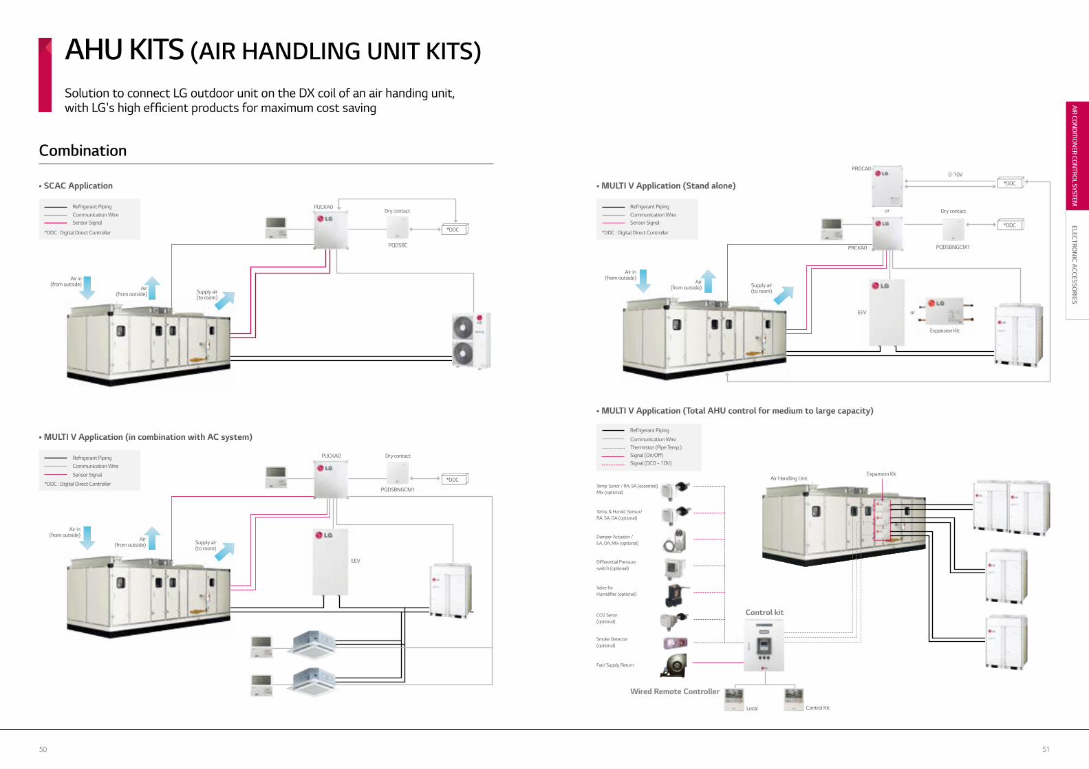
Solution to connect LG outdoor unit on the DX coil of an air handing unit,with LG's high efficient products for maximum cost saving
AHU KITS (AIR HANDLING UNIT KITS)
Selection of Evaporator
5150
AIR CON
DITIO
NER CO
NTRO
L SYSTEM
ELECTRON
IC ACCESSO
RIES
• SCAC Application • MULTI V Application (Stand alone)
• MULTI V Application (Total AHU control for medium to large capacity)
• MULTI V Application (in combination with AC system)
PQDSBNGCM1
EEV
Temp. Senor / RA, SA (essential), Mix (optional)
Temp. & Humid. Sensor/ RA, SA, OA (optional)
Damper Actuator / EA, OA, Mix (optional)
Differential Pressure switch (optional)
Valve for Humidifier (optional)
CO2 Senor (optional)
Smoke Detector (optional)
Fan/ Supply, Return
Wired Remote Controller
Local Control Kit
Air Handling UnitExpansion Kit
Air in(from outside)
Air in(from outside)
Air in(from outside)
Air (from outside)
Air (from outside)
Air (from outside)
Supply air(to room)
Supply air(to room)
Supply air(to room)
Dry contact Dry contact
Dry contact
PQDSBC
PUCKA0
PUCKA0
*DDC
*DDC
PRDCA0
PRCKA0
EEV
or
or
Expansion Kit
PQDSBNGCM1
0-10V
Refrigerant Piping
Sensor SignalCommunication Wire
*DDC : Digital Direct Controller
Refrigerant Piping
Sensor SignalCommunication Wire
*DDC : Digital Direct Controller
Refrigerant Piping
Sensor Signal
Communication Wire
*DDC : Digital Direct Controller
Refrigerant Piping
Thermistor (Pipe Temp.)Communication Wire
Signal (DC0 ~ 10V)Signal (On/Off)
*DDC
*DDC
Combination
Control kit
AHU KITS (AIR HANDLING UNIT KITS)Solution to connect LG outdoor unit on the DX coil of an air handing unit,with LG's high efficient products for maximum cost saving

5352
MECH
AN
ICAL A
CCESSORIES
Drain Pump Kit
> Page 54
Communication kit SCAC Type MULTI Type MULTI V Type Remark
ARTCOOL Panel O O O ARTCOOL indoor unitElectric Heater O - - Single package / Ducted splitDrain Pump Kit O O - Ceiling concealed ductSuction Grille / Canvas - - O Ceiling concealed duct (Built-in)Auto Elevation Grille O - O 4 Way CassettePlasma Kit O - O 4 Way CassetteCassette Cover O O O 4 Way CassetteAir guide - - O Outdoor unit
MECHANICAL ACCESSORIES
Mechanical Accessories Line up and Application
Suction Grille / Canvas
> Page 56
Auto Elevation Grille
> Page 58
Plasma Kit
> Page 59
Ventilation Kit (Fresh kit) for New Cassette
> Page 62
Cassette Cover
> Page 63
Panel ARTCOOL
> Page 53
A unique blend of art and colours
ARTCOOL PANEL
Models Applied
Model name
ARTCOL Mirror ARTCOL SF chassis
ChassisColour
SE S8 SF
Mirror PSAPECR10 PSAP8CR10 -Silver PSAPECV10 PSAP8CV10 PSAPFCV11
Red - - PSAPFCE11
Gold - - PSAPFCG11
White Silver - - PSAPFCH11
ARTCOOL SF Chassis
ARTCOOL Mirror
Silver Red Gold White Silver
Silver Mirror
* Panel colour• CG : Gold• CE : Red • CH : WhiteSilver • CR : Mirror • CV : Silver
PSAPE**10PSAP8**10PSAPF**11
Air Guide
> Page 64
AWHP
> Page 60

5554
MECH
AN
ICAL A
CCESSORIES
• For G/H/R/T Chassis Models :- Drain pump assembly (1EA)
(AC 220~240V,50/60Hz,400CMM)- Screw (4EA)- Cap (1EA)- Installation manual (1EA)
• For E Chassis Models :- Drain pump assembly (1EA)
(AC 220~240V,50/60Hz,400CMM)- Elbow (Ø32)(1EA) - Hose (1EA)- Tie wrap (2EA) - Screw (10EA)- Rubber (1EA) - Installationmanual (1EA)
Model nameE Chassis G/H/R Chassis T ChassisABDPE ABDPG ABDPT
MULTI V Type Default Default Default
MULTI Type O O OSCAC Type O O -
• In some places where natural drainage is not possible, a drain pump is very useful to pump out condensed water from indoor units.• Drain pump assembly (AC 220~240V, 50/60Hz)
• Ceiling concealed duct (refer PDB for applicable models)
• Ceiling concealed duct (refer PDB for applicable models)
Drains away condensed water
DRAIN PUMP KIT
Features
Parts Included
Models Applied
Accessory Model Name
ABDPE ABDPG ABDPT
ABDPEABDPGABDPT
High Head Drain Pump
Drain Pipe Slope (1/50~1/100)
Flexible Drain Hose
300mm
700mm
450mm
Fixture
Drain pipe
* Included in H-Inverter* Supplied as acacessory for Standard Inverter (ABDPG)
• High head drain pump automatically drains water up to 700mm of drain-head height. It provides perfect solution for water drainage.
Application

5756
MECH
AN
ICAL A
CCESSORIES
C
A
B AB
C
AB
C
(Unit : mm) (Unit : mm)
over
520
mm
over
270
mm
Category Model nameCapacity (Btu/h)
7K 9K 12K 15K 18K 24 K
Grillepbsgb30 O O O O - -
pbsgb40 - - - - O O
Canvaspbsc30 O O O O - -
pbsc40 - - - - O O
Model name A B C
PBSGB30 910 359 56
PBSGB40 1188 359 56
Model name A B C
PBSC30 821 274 42-250
PBSC40 1100 274 42-250
• High external static pressure facilitates unit use with flexible ducts of varying lengths.• When using suction panel, unit requires only 270mm of ceiling space.• Blends unobtrusively with any interior decoration.
• Ceiling concealed duct _ Built-in type (refer block for applicable model)
High flexibility for a wide variety of applications
SUCTION GRILLE / CANVAS
Features
Models Applied
Accessory Model Name
Dimensions
Application
• For the suction grille : - Suction panel with air filter (1EA) - Suction panel fix bolt M5x18 (4EA) - Installation manual (1EA)
• For the suction canvas : - Air suction canvas (1EA) - Screws for air suction canvas (4EA) - Adjusting chain (4EA) - Screws for adjusting chain (8EA) - Installation manual (1EA)
PBSGB30PBSGB40
PBSC30PBSC40
Parts Included

5958
MECH
AN
ICAL A
CCESSORIES
• Auto elevation grille kit • Install the kit inside indoor unit
• Install the front panel and the Inlet grille
• Operate the auto elevation grille by the wireless remote controller
• Easy maintenance
- Memory for user’s level - Max 4.5m length - Model : PTEGM0 (TM, TN, TP)
4-Point Support Structure Auto Horizontal Control Memory for user’s level
STOP
Auto bottom detection
* Operating with wired remote controller PQRCVSL0 (QW) and wireless remote controller included in PTEGM0.
Easy filter cleaning with the elevation grille Air purifying filter to repel dust and allergens
AUTO ELEVATION GRILLE PLASMA KIT
• Easy filter cleaning with elevation grill- Installation inside main body- Auto horizontal control- 4 points support structure
• It can remove microscopic contaminants such as dust and pollen to help reduce allergies.
• 4-way cassette : Single CAC, MULTI, MULTI V (refer block for applicable models)
• Inlet Grille (1EA)• Auto elevation grille kit (1EA)• Wireless Remote Controller (1EA)
• Plasma Kit (1EA)• Screws• Installation Manual (1EA)
• Screws (4EA)• Installation manual (1EA)
Features Features
Models Applied• 4-way cassette : Single CAC, MULTI, MULTI V (refer PDB for applicable models)
Models Applied
Parts Supplied Parts Supplied
Application
PTEGM0 PTPKM0PTPKQ0

6160
MECH
AN
ICAL A
CCESSORIES
CombinationCombination
SANITARY TANK KIT FORTHERMA V
SOLAR HEATING KIT
PHLTA (1Φ)PHLTC (3Φ)PHLTB
PHLLA
Features Features• Easy to install sanitary water tank for monobloc. There is a MCCB to protect the product. • Dimensions (HXWXD, mm) : 250x170x110• Weight (kg) : 2.1
To extend THERMA V functionality in generating domestic hot water.Only applied to split-type THERMA V.
• Interface for solar-thermal system with split-type THERMA V and double coil sanitary tank.• Installed at the water pipe, between sanitary tank and solar-thermal system.• Dimensions (HXWXD, mm) : 110x55x22
PHLTA / PHLTC PHLTB
*
• Components : THERMA V system, PHLTA, PHLTC, and field-supplied items.
Outdoor Indoor
Outdoor Unit
Hot Water Fan Coin Unit Floor Heating Loop Radator
SanitaryWaterTank
City Water
Indoor Unit
* The sensor (PHRSTA0) can be purchased separately in case of using other brand’s sanitary tank.
* To be installed inside THERMA V indoor unit.
• Components : THERMA V system, PHLTA, PHLTC, and field-supplied items.
Outdoor Unit
Hot Water Fan Coin Unit
Solar HeatSource
Floor Heating Loop Radator
SanitaryWaterTank
City WaterCity Water
Indoor Unit
Outdoor Indoor

6362
MECH
AN
ICAL A
CCESSORIES
Model name Front PanelWeight (kg) Dimensions (mm)
NET Gross W H D
PTDCMPT-UMC/PT-UMC1
TP/TN 5.9 8.8 1,157 1,157 268
TN 5.9 8.8 1,157 1,157 310
PTDCQ PT-UQC
TR 5.0 7.2 907 907 268
TQ 5.0 7.2 907 907 310
134
55mm
43
5
44
3
84
0
406
419
840
81
PTVK410+PTVK420
PTVK430
VENTILATION KIT CASSETTE COVER
Features Features
Parts Supplied
Accessory Model Name
Models AppliedModels Applied
Dimensions Assembly Diagram
• PTVK410 : 1 Ventilation Kit, 8 Bolts, 1 Insulation• PTVK420 : 1 Flange, 7 Screws• PTVK420 : 1 Flange, 4 Screws, 1 Insulation
• Specially designed for indoor unit.• Covers the side area of cassette.• Gives elegant looks.• Light weight.• Suitable when false ceiling is unavailable.
• Cover A (4EA), Cover B (4EA)• Cover C (4EA), Cover D (4EA)• Screws• Installation Manual (1EA)
• There are 2 solutions for Fresh air - PTVK410+PTVK420 (for chassis TP, TN, TM) - PTVK430 (for chassis TR, TQ, TP, TN, TM)
* Users can purchase and use PTVK430 in addition to PTVK410+PTVK420 in need to phase in larger outdoor air volume.
• 4-way cassette (TP, TN, TM, TQ, TR)
Fresh air can be supplied from outside through this ventilation kit Air purifying filter to prevent dust and allergens
PTVK410 PTVK430PTVK420
PTVK410PTVK420PTVK430
PTDCMPTDCQ

6564
MECH
AN
ICAL A
CCESSORIES
564
512
50
0
50
05
12 R600
R600
45
50
632
618
65
2
570
832
900
760
832
762
904
50
45
50
45
600
652
33
718
564
512
50
0
50
05
12 R600
R600
45
50
632
618
65
2
570
832
900
760
832
762
904
50
45
50
45
600
652
33
718
564
512
50
0
50
05
12 R600
R600
45
50
632
618
65
2
570
832
900
760
832
762
904
50
45
50
45
600
652
33
718
564
512
50
0
50
05
12 R600
R600
45
50
632
618
65
2
570
832
900
760
832
762
904
50
45
50
45
600
652
33
718
564
512
50
0
50
05
12 R600
R600
45
50
632
618
65
2
570
832
900
760
832
762
904
50
45
50
45
600
652
33
718
Model name Gross Weight Net Weight
PRAGX2S0 22.5kg 12.3kg
PRAGX3S0 17kg 9.4kg
AIR GUIDE
Air discharge in difficult to access areas
Features
Models Applied
Dimensions
• Converts vertical discharge into horizontal discharge.• Designed for outdoor discharge air.• Direction of air discharge can be changed by simple installation.• Installation flexibility.
• MULTI V IV (UX2, UX3)
* In case of UX3, must purchase 2 units of PRAGX3SO.
Application
MULTI V IV (UX3)MULTI V IV (UX2)
MULTI V IV (UX3)
MULTI V IV (UX2)
PRAGX*SO

6766
PIPING
ACCESSO
RIES
PIPINGACCESSORIES
Refrigerant Charging Kit
> Page 71
Stopper Valve
> Page 72
Y Branch & HeaderBranch (Synchro)
> Page 67
Branch Distributor
> Page 68
Drain Pan
> Page 77
Drain Hose
> Page 76
Y Branch & Branch Kit(MULTI F DX)
> Page 70
Heat Recovery Unit
> Page 74
Y Branch & HeaderBranch (MULTI V)
> Page 78
Model name SCAC Type MULTI Type MULTI V Type Remark
Y Branch and Header Branch (Synchro) O O - SynchroBranch Distributor (MULTI) - - - MULTI FdxHeat Recovery Unit - - O MULTI V Sync II / MULTI V III Heat RecoveryY Branch and Branch Kit (MULTI) - O - MULTI FdxY Branch and Header Branch (MULTI V) - - O MULTI V Heat Pump / Heat RecoveryMULTI V Space / MULTI V MINI
Mechanical Accessories Line up and Application
2 Units
PMUB11A3 Units
PMUB111A4 Units
PMUB1111A Gas Pipe Liquid Pipe
2 branch 3 branch 4 branch
Category Model name Gas pipe Liquid pipe
2 UNITS PMUB11A(1:1) (1:1)
3 UNITS PMUB111A(1:1:1) (1:1:1)
4 UNITS PMUB1111A(1:1:1:1) (1:1:1:1)
Accessory Model Name
• Various Y-branch pipes of different capacities make installation easier.• Y-branch and header branch for both gas and liquid are provided.• Insulation material is also provided for covering the branches.
• Synchro
Models Applied
Features
Dimensions
Refrigerant distribution channel
Y BRANCH AND HEADER BRANCH(SYNCHRO)

6968
PIPING
ACCESSO
RIES
PMBD3620PMBD3630PMBD3640
PMBD3640PMBD3630 PMBD3620
Features• Distribution of refrigerant to various indoor units.• 3 models (2, 3, 4 indoor units)• Consists of LEVs inside it.• Controlling PCB inside the unit.• Internally insulated (prevents any chances of drainage)• Flare joints for easy and clean installation.• Compact design (low height)• Flexible installation.
No brazing Just flaring
Effective way of distributing refrigerant
BRANCH DISTRIBUTOR(DISTRIBUTOR BOX)
• MULTI F DX systems (refer PDB for applicable models)
• Position of branch distributor in the system.• PDB (Select) - Installation PDB.
Installation
Models Applied
Model name PMBD3620 PMBD3630 PMBD3640Connectable Number of Indoor unit 1~2 1~3 1~4
Capacity (Btu/hr) 5k/7k/9k/12k/18k/24k 5k/7k/9k/12k/18k/24k 5k/7k/9k/12k/18k/24k
Casing colour Paintingless Paintingless Paintingless
Power source1ø, 50/60Hz, 1ø, 50/60Hz, 1ø, 50/60Hz,
220~240/220B 220~240/220B 220~240/220B
Power consumption (W) 10 10 10
Running current (A) 0.05 0.05 0.05
Dimensions (W x H x D) (mm) 302x143x252 302x143x252 302x143x252
Packing dimensions (W x H x D) (mm) 422x202x300 422x202x300 422x202x300
Net weight 4.8 4.9 5.0
Connecting cable Indoor unit No. x mm² 4x0.75 4x0.75 4x0.75
Outdoor unit No. x mm² 4x0.75 4x0.75 4x0.75
Piping connection(Outdoor unit)
liquid (mm) 9.52 9.52 9.52
Gas (mm) 19.05 19.05 19.05
Piping connection (Indoor unit)
Liquid (mm) 6.35x2 6.35x3 6.35x4
Gas (mm) 9.52x2 9.52x3 9.52x4
Parts Hanger (EA) 4 4 4
Screw (EA) 8 8 8
Manual (EA) 1 1 1
(R410A)
Specification
• BD (Banch Distributor) unit (1EA)• Brackets (4EA)• Screws (8EA)• Installation Manual (1EA)
Parts Supplied

7170
PIPING
ACCESSO
RIES
• “329” : Temperature Range Error (In case that indoor unit or outdoor unit is out of range)• “339” : Low Pressure Descent Error (In case the system runs at low pressure limit for over 10 minutes)• “349” : Rapid refrigerant inflow (In case the liquid refrigerant flows in because of not using designated capil-lary assembly)• “359” : Instability Error (In case the high/low pressure target doesn’t get satisfied for some time after the starting operation)
REFRIGERANT CHARGING KITRecharge refrigerant after a pump down or when refrigerant is either insufficient or excessive
Models Applied
Procedure
Error Contents about Auto Refrigerant Charging Function
PRAC12 Units
PMBL3620PMBL56202 Units
PMBL1203F0
Y BRANCH AND BRANCH KIT MULTI F DX
Application
Parts Supplied
Accessory Model Name
Features Models Applied• Y Branch and Branch kit make MULTI F DX installation easier.• Y-Branch and Branch kit for both gas and liquid are provided.• Insulation material is also provided for covering the branches.
• Y Branch for Gas side and Liquid side (1 set)• Installation manual (1EA)
• MULTI F DX, 1ø, 3ø
Refrigerant distribution channel
(Unit : mm)
Model name No. of BD units Applicable ModelSpecification
Gas Liquid
PMBL3620 2 units Only 3ø, 36k Btu/h
PMBL5620 2 units 1ø, 3ø
PMBL1203F0 3 units 1ø, 3ø
Ø15.88 Ø15.88
Ø15.88
Ø6.35 Ø6.35
Ø6.35
Ø19.05 Ø19.05
Ø19.05
Ø9.52 Ø9.52
Ø9.52
Ø15.88 Ø15.88
Ø15.88
Ø6.35 Ø6.35
Ø6.35
Ø19.05 Ø19.05
Ø19.05
Ø9.52 Ø9.52
Ø9.52
Ø9.52Ø19.05 Ø9.52
Ø15.88 Ø15.88
Ø15.88
Ø6.35 Ø6.35
Ø6.35
Ø19.05 Ø19.05
Ø19.05
Ø9.52 Ø9.52
Ø9.52
Ø15.88 Ø15.88
Ø15.88
Ø6.35 Ø6.35
Ø6.35
Ø19.05 Ø19.05
Ø19.05
Ø9.52 Ø9.52
Ø9.52
Ø9.52Ø19.05 Ø9.52
• Arrange manifold, capillary assembly, refrigerant vessel and scale.• Connect manifold to the gas pipe service valve of outdoor uint as shown in the figure.• Connect manifold and capillary tube. Use designated capillary assembly only. If designated capillary assembly isn’t used, the system may get damaged.• Connect capillary and refrigerant vessel.• Purge hose and manifold.• After “568” is displayed, open the valve and charge the refrigerant
* Fault Detect & Diagnosis
Mainfold
Capillary Assembly
Refrigerant
Models Applied• MULTI V III

7372
PIPING
ACCESSO
RIES
• In case of installation of additional indoor unit, refrigerant of used indoor unit must be discharged.(Room3 & Room4)• If stopper valve is already installed, you can install additional indoor unit without refrigerant loss from the entire system.• After installation of additional indoor unit, you just need refrigerant charging for “A” section.• Then, open the Stopper Valve.
• case1(Room 3 & 4 : in use / Room 1 & 2 : need to install indoor units)
* Stopper Valve is already installed
Room 4
Room 3
Room 2
Room 1
9.52 : 19.05
9.52 : 19.05
3.0m
3.0m
3.0m
10.0m
5.0m
9.52 : 15.88
9.52 : 15.88
6.35 : 12.7
"A"
Closed state
Stopper valves
Pin(Closed) Pin(Open)
In case of installation of stopper valve, flare part should be facing towards additional indoor unit.
In case of installation of additional indoor unit, SVC valve should be in closed state
In case of the installation of additional indoor unit, outlet side connector should be cut according to installation pipe.
-When welding, service valve shoud be wrapped by wet cloth.
Cut inlet side of the connector, and weldthe pipe
Room 1
Room 2
Room 3
Room 4
10.0m
3.0m
3.0m
3.0m
3.0m
9.52 : 15.88
6.35 : 12.7
9.52 : 15.88
9.52 : 19.05
9.52 : 19.05
Stopper ValvesOpen state
Open/close portCharge port
Model name Spec
PRVT120
PRVT780
PRVT980
STOPPER VALVES
Features
Usage
Installation
• This unit can be applied for the additional indoor unit’s installation.• This unit can be applied for each indoor unit’s service.
* When welding, service valve shoud be wrapped by wet cloth.
1. Cut the inlet side of the connector, and weld the pipe
2. If installing additional indoor units, the outlet side connector should be cut according to installation pipe.
3. When installing a stopper valve, the flare part should be facing towards additional indoor unit.
4. When installing anadditional indoor unit, the SVC valve should be in closed state.
Pin(Closed) Pin(Open)
In case of installation of stopper valve, flare part should be facing towards additional indoor unit.
In case of installation of additional indoor unit, SVC valve should be in closed state
In case of the installation of additional indoor unit, outlet side connector should be cut according to installation pipe.
-When welding, service valve shoud be wrapped by wet cloth.
Cut inlet side of the connector, and weldthe pipe
Details of Model NameUnder 1/2 (inch)
Under 7/8 (inch)
Under 9/8 (inch)
PRVT120
PRVT780
PRVT980

7574
PIPING
ACCESSO
RIES
HEAT RECOVERY UNIT
Features
Models Applied
• Max. 32 indoor units can be connected (Max 8 indoor units per branch)• Due to the automatic search algorithm for piping detection, easy installation.• Subcooling cycle in HR unit makes the system efficiency maximum.
• MULTI V SYNC• MULTI V SYNC II
PRHR021PRHR031PRHR041
Model name PRHR021 PRHR031 PRHR041Number of branch EA 2 3 4
Maximum connectable capacity of indoor units (Per branch/unit) kW 16/32 16/48 16/58
Maximum number of connectable indoor units per branch EA 8 8 8
Nominal InputCooling kW 0.026 0.040 0.040
Heating kW 0.026 0.040 0.040
Net. Weight kg 18 20 22
Dimensions (WxHxD) mm 801x218x617 801x218x617 801x218x617
Piping connections
Indoor UnitLiquid mm (inch) 9.52 (3/8) 9.52 (3/8) 9.52 (3/8)
Gas mm (inch) 15.88 (5/8) 15.88 (5/8) 15.88 (5/8)
Outdoor UnitLiquid mm (inch) 9.52 (3/8) 15.88 (5/8) 15.88 (5/8)
Low pressure mm (inch) 22.2 (7/8) 28.58 (11/8) 28.58 (11/8)
High Pressure mm (inch) 19.05 (3/4) 22.2 (7/8) 22.2 (7/8)
Power Supply ø /V/Hz 1 / 220~240 / 50 1 / 220~240 / 50 1 / 220~240 / 50
• MULTI V WATER II Heat Recovery• MULTI V III Heat Recovery
MULTI V III Heat recovery provides flexible control over individual zones for the user’s convenience.
• Individual Control- Perfect individual control over spaces ventilation needed
• Zone Control- Max. of 8 indoor units can be connected for one branch- Max. of 32 indoor units can be connected for one HR unit- Same opeational model can be operated by indoor units
with zone control function installed
• Combination of Individual and Zoning Installations- Flexible piping design
• Save Product and Installation Cost
PRHR031(3 branch Unit)
PRHR021(2 branch Unit)
PRHR041(4 branch Unit)
Specification
• Washers M10 (8EA)• Reducers
• HR unit (1EA)• Hanging bolts M10 or M8 (4EA)• Nut M8 or M10 (8EA)
Dimensions
Convenient Free Zoning
Reducers for Indoor Unit and HR Unit
Model name Liquid pipe High pressure Low pressure
Indoor unit reducer
HR unitreducer
PRHR021
PRHR031/PRHR041
ModelsHigh pressure
Gas pipe
Low pressureLiquid pipe
Indoor unit reducer
HR unitreducer
PRHR020OD22.2 Ø19.05 Ø15.88
OD15.88 Ø12.7Ø6.35OD9.52
Ø6.35OD9.52
OD19.05 Ø15.88 Ø12.7
OD22.2 Ø19.05 Ø15.88OD15.88 Ø12.7 Ø9.52PRHR030
/PRHR040
OD15.88 Ø12.7
OD28.58 Ø22.2 Ø19.05
OD12.7 Ø9.52 OD15.88 Ø12.7
OD19.05 Ø15.88
(Unit : mm)
[Zoning control]
HR unit
Zoning Control (Max Indoor unit 8EA)
Office
Room
Kitchen
IT Room

7776
PIPING
ACCESSO
RIES
• This unit does not cover water drops of the outside product. • Connect drain hose to drain pipe for drain condensate.
Drain Pipe
Service Valve
* In case of the installation of drain pan, drain pipe should be located below the SVC valve.
* Tuck drain pan below base pan
* Push drain pan in the direction of the arrow. Brackets can be fixed on the side panel.
Models applied to Ceiling Cassette, Ceiling Concealed Duct. (refer PDB for applicable model.)
Model name Length Quantity
PHDHA05T 500mm 30EA
PHDHA07T 700mm 30EA
PHDHA05B 500mm 5EA
PHDHA07B 700mm 5EA Model name L Remark
PRODX20 920mm UX2
PRODX30 1240mm UX3
Max. 450
250Flexible HoseMake a loop form
1 Way, 4 Way Ceiling Cassette,
Concealed Duct
(with drain pump)
(Unit : mm)
DRAIN HOSE DRAIN PAN
Easy drain installation Easy drain installation
Features Features
Installation
Standard
Accessory Model Name
Accessory Model Name
It reduces the installation time by over 40% with elbow-less drain hose.Midget drain pump covers maximum 800mm high, featuring easy piping installation.
This unit can be applied for outdoor unit’s drain.
PRODX20PRODX30
PHDHA05TPHDHA07T
PHDHA05BPHDHA07B

7978
PIPING
ACCESSO
RIES
Model name Gas pipe Liquid pipe
4 branch / ARBL054
7 branch / ARBL057
4 branch / ARBL104
7 branch / ARBL107
10 branch / ARBL1010
10 branch / ARBL2010
• R410A
Header Branch
Y BRANCH AND HEADER BRANCH ( )For refrigerant distribution of indoor units
Features
Piping Diagram
• Various Y-branch pipe of different capacities make MULTI V installation much easier.• Y-branch and header branch for both gas and liquid are provided.• Insulation material is also provided for covering the branches.
Models Applied• MULTI V PLUS• MULTI V PLUS II• MULTI V III
Accessory Model Name
(Unit : mm)
• MULTI V IV• MULTI V MINI• MULTI V SPACE II
• MULTI V SPACE III• MULTI V WATER II• MULTI V WATER IV• MULTI V Heat Recovery
Y Branch Header Branch
Header Branch
Outdoor unit
Y- branch

8180
PIPING
ACCESSO
RIES
PIPING ACCESSORIES
2 Outdoor Units
Model name Low Pressure Gas pipe Liquid pipe
ARCNN21
C
B
A B C
C
A
B
C
ARCNN31
ARCNN41
ARCNN21
130
408416
111
I.D.28.58
I.D.34.9I.D.31.8
I.D.28.58
I.D.28.58I.D.41.3 I.D.38.1 O.D.34.9
I.D.22.2
125
341
298
111
I.D.41.3 O.D.34.9
I.D.34.9I.D.41.3
I.D.28.58
415
375
I.D.41.3
I.D.28.58
I.D.44.48 I.D.53.98 134
70
83
314331
I.D.22.2 O.D.19.05
I.D.15.88
I.D.19.05
I.D.15.88I.D.12.7
I.D.12.7
I.D.15.88
I.D.9.52
334
281
83I.D.19.05
I.D.12.7 I.D.15.88
I.D.19.05I.D.22.2
334
281
83
80
I.D.25.4 O.D.22.2
I.D.19.05
I.D.12.7 I.D.15.88
I.D.19.05I.D.22.2
C
B
A B C
C
A
B
C
ARCNN31
ARCNN41
ARCNN21
130
408416
111
I.D.28.58
I.D.34.9I.D.31.8
I.D.28.58
I.D.28.58I.D.41.3 I.D.38.1 O.D.34.9
I.D.22.2
125
341
298
111
I.D.41.3 O.D.34.9
I.D.34.9I.D.41.3
I.D.28.58
415
375
I.D.41.3
I.D.28.58
I.D.44.48 I.D.53.98 134
70
83
314331
I.D.22.2 O.D.19.05
I.D.15.88
I.D.19.05
I.D.15.88I.D.12.7
I.D.12.7
I.D.15.88
I.D.9.52
334
281
83I.D.19.05
I.D.12.7 I.D.15.88
I.D.19.05I.D.22.2
334
281
83
80
I.D.25.4 O.D.22.2
I.D.19.05
I.D.12.7 I.D.15.88
I.D.19.05I.D.22.2
2 Outdoor Units
Model name Low Pressure Gas pipe Liquid pipe High Pressure Gas pipe
ARCNB21
3 Outdoor Units
Model name Low Pressure Gas pipe Liquid pipe High Pressure Gas pipe
ARCNB31
4 Outdoor Units
Model name Low Pressure Gas pipe Liquid pipe High Pressure Gas pipe
ARCNB41
3 Outdoor Units
Model name Low Pressure Gas pipe Liquid pipe
ARCNN31
C
B
A B C
C
A
B
C
ARCNN31
ARCNN41
ARCNN21
130
408416
111
I.D.28.58
I.D.34.9I.D.31.8
I.D.28.58
I.D.28.58I.D.41.3 I.D.38.1 O.D.34.9
I.D.22.2
125
341
298
111
I.D.41.3 O.D.34.9
I.D.34.9I.D.41.3
I.D.28.58
415
375
I.D.41.3
I.D.28.58
I.D.44.48 I.D.53.98 134
70
83
314331
I.D.22.2 O.D.19.05
I.D.15.88
I.D.19.05
I.D.15.88I.D.12.7
I.D.12.7
I.D.15.88
I.D.9.52
334
281
83I.D.19.05
I.D.12.7 I.D.15.88
I.D.19.05I.D.22.2
334
281
83
80
I.D.25.4 O.D.22.2
I.D.19.05
I.D.12.7 I.D.15.88
I.D.19.05I.D.22.2
C
B
A B C
C
A
B
C
ARCNN31
ARCNN41
ARCNN21
130
408416
111
I.D.28.58
I.D.34.9I.D.31.8
I.D.28.58
I.D.28.58I.D.41.3 I.D.38.1 O.D.34.9
I.D.22.2
125
341
298
111
I.D.41.3 O.D.34.9
I.D.34.9I.D.41.3
I.D.28.58
415
375
I.D.41.3
I.D.28.58
I.D.44.48 I.D.53.98 134
70
83
314331
I.D.22.2 O.D.19.05
I.D.15.88
I.D.19.05
I.D.15.88I.D.12.7
I.D.12.7
I.D.15.88
I.D.9.52
334
281
83I.D.19.05
I.D.12.7 I.D.15.88
I.D.19.05I.D.22.2
334
281
83
80
I.D.25.4 O.D.22.2
I.D.19.05
I.D.12.7 I.D.15.88
I.D.19.05I.D.22.2
4 Outdoor Units
Model name Low Pressure Gas pipe Liquid pipe
ARCNN41
C
B
A B C
C
A
B
C
ARCNN31
ARCNN41
ARCNN21
130
408416
111
I.D.28.58
I.D.34.9I.D.31.8
I.D.28.58
I.D.28.58I.D.41.3 I.D.38.1 O.D.34.9
I.D.22.2
125
341
298
111
I.D.41.3 O.D.34.9
I.D.34.9I.D.41.3
I.D.28.58
415
375
I.D.41.3
I.D.28.58
I.D.44.48 I.D.53.98 134
70
83
314331
I.D.22.2 O.D.19.05
I.D.15.88
I.D.19.05
I.D.15.88I.D.12.7
I.D.12.7
I.D.15.88
I.D.9.52
334
281
83I.D.19.05
I.D.12.7 I.D.15.88
I.D.19.05I.D.22.2
334
281
83
80
I.D.25.4 O.D.22.2
I.D.19.05
I.D.12.7 I.D.15.88
I.D.19.05I.D.22.2
C
B
A B C
C
A
B
C
ARCNN31
ARCNN41
ARCNN21
130
408416
111
I.D.28.58
I.D.34.9I.D.31.8
I.D.28.58
I.D.28.58I.D.41.3 I.D.38.1 O.D.34.9
I.D.22.2
125
341
298
111
I.D.41.3 O.D.34.9
I.D.34.9I.D.41.3
I.D.28.58
415
375
I.D.41.3
I.D.28.58
I.D.44.48 I.D.53.98 134
70
83
314331
I.D.22.2 O.D.19.05
I.D.15.88
I.D.19.05
I.D.15.88I.D.12.7
I.D.12.7
I.D.15.88
I.D.9.52
334
281
83I.D.19.05
I.D.12.7 I.D.15.88
I.D.19.05I.D.22.2
334
281
83
80
I.D.25.4 O.D.22.2
I.D.19.05
I.D.12.7 I.D.15.88
I.D.19.05I.D.22.2
134
415375
I.D.44.48 I.D.53.98 I.D.41.3
I.D.28.58
334281
I.D.15.88
I.D.19.05
O.D.22.2I.D.25.4
I.D.19.05
I.D.12.7
83
80
I.D.22.2
341
111
125
298
I.D.34.9I.D.41.3
I.D.41.3 O.D.34.9
I.D.28.58
111
130
416408
I.D.28.58 I.D.28.58
I.D.34.9
I.D.41.3I .D.38.1 O.D.34.9
I.D.31.8I.D.22.2
I.D.28.58
I.D.15.88 I.D.15.88
I.D.15.88
I.D.19.05 I.D.12.7
I.D.12.7
I.D.9.52
331
83
70
314
I.D.22.2 O.D.19.05
334281
I.D.15.88
I.D.19.05 I.D.19.05
I.D.12.7
83I.D.22.2
341
111
125
298
I.D.34.9I.D.41.3
I.D.41.3 O.D.34.9
I.D.28.58
334281
I.D.15.88
I.D.19.05 I.D.19.05
I.D.12.7
83I.D.22.2
111
130
416408
I.D.28.58 I.D.28.58
I.D.34.9
I.D.41.3I .D.38.1 O.D.34.9
I.D.31.8I.D.22.2
I.D.28.58
(Unit : mm) (Unit : mm)
• R410A / • R410A / MULTI V III, MULTI V IV, MULTI V MINI, MULTI V SPACE II MULTI V III Heat Recovery, MULTI V IV Heat Recovery

8382
PIPING
ACCESSO
RIES
Model name Low Pressure Gas pipe Liquid pipe High Pressure Gas pipe
ARBLB01621
ARBLB03321
ARBLB07121
ARBLB14521
I.D. 19.05
ARBLB01620
ARBLB03320
ARBLB07120
ARBLB14520
I.D. 15.88
I.D. 15.88
I.D. 12.7
I.D. 12.7
I.D. 9.52
I.D. 6.35
O.D. 28.58I.D. 25.4
O.D. 22.2
O.D. 19.05I.D. 15.88
I.D. 12.7
O.D. 19.05
I.D. 12.7
I.D. 9.52
O.D. 22.2 I.D. 15.88
I.D. 15.88
I.D. 19.05I.D. 34.9
I.D. 31.8O.D. 28.58
I.D. 28.58
I.D. 22.2I.D. 25.4
I.D. 19.05
I.D. 22.2I.D. 28.58
I.D. 25.4
I.D. 9.52 O.D. 12.7
I.D. 15.88
I.D. 12.7
I.D. 12.7
I.D. 9.52
I.D. 6.35
I.D. 9.52
I.D. 12.7I.D. 19.05
I.D. 15.88
I.D. 28.58
I.D. 25.4
I.D. 15.88
I.D. 19.05
I.D. 19.05I.D. 12.7
O.D. 19.05
I.D. 15.88
I.D. 12.7 O.D. 19.05
I.D. 12.7
I.D. 9.52
O.D. 34.9
X 2
X 2
I.D. 31.8
I.D. 19.05
I.D. 28.58
O.D. 25.4
O.D. 9.52I.D. 6.35
I.D. 19.05
I.D. 15.88
I.D. 12.7
I.D. 9.52
I.D. 12.7
O.D. 28.58I.D. 22.2
O.D. 19.05I.D. 12.7
I.D. 28.58
I.D. 19.05
I.D. 28.58
I.D. 34.9
I.D. 22.2
I.D. 19.05
I.D. 12.7
I.D. 22.2O.D. 19.05
I.D. 31.8
I.D. 28.58
I.D. 25.4
I.D. 34.9I.D. 41.3
I.D. 38.1
I.D. 15.88
I.D. 9.52
I.D. 15.88
I.D. 12.7
I.D. 19.05I.D. 9.52
I.D. 6.35
I.D. 12.7I.D. 15.88
I.D. 12.7I.D. 15.88
I.D. 12.7
I.D. 9.52
I.D. 9.52
I.D. 6.35I.D. 12.7
I.D. 22.2O.D. 28.58
I.D. 19.05
I.D. 15.88
I.D. 22.2
I.D. 19.05
I.D. 15.88
I.D. 22.2
I.D. 9.52I.D. 6.35
I.D. 9.52
I.D. 6.35
I.D. 9.52
I.D. 6.35
I.D. 12.7
I.D. 9.52I.D. 6.35
I.D. 19.05I.D. 15.88
I.D. 19.05
I.D. 15.88
I.D. 9.52
I.D. 12.7
I.D. 6.35I.D. 12.7
I.D. 15.88
I.D. 28.58
I.D. 22.2
I.D. 19.05I.D. 28.58
I.D. 22.2
I.D. 41.3I.D. 34.9
I.D. 28.58I.D. 25.4I.D. 19.05
ARBLB01620
ARBLB03320
ARBLB07120
ARBLB14520
I.D. 15.88
I.D. 15.88
I.D. 12.7
I.D. 12.7
I.D. 9.52
I.D. 6.35
O.D. 28.58I.D. 25.4
O.D. 22.2
O.D. 19.05I.D. 15.88
I.D. 12.7
O.D. 19.05
I.D. 12.7
I.D. 9.52
O.D. 22.2 I.D. 15.88
I.D. 15.88
I.D. 19.05I.D. 34.9
I.D. 31.8O.D. 28.58
I.D. 28.58
I.D. 22.2I.D. 25.4
I.D. 19.05
I.D. 22.2I.D. 28.58
I.D. 25.4
I.D. 9.52 O.D. 12.7
I.D. 15.88
I.D. 12.7
I.D. 12.7
I.D. 9.52
I.D. 6.35
I.D. 9.52
I.D. 12.7I.D. 19.05
I.D. 15.88
I.D. 28.58
I.D. 25.4
I.D. 15.88
I.D. 19.05
I.D. 19.05I.D. 12.7
O.D. 19.05
I.D. 15.88
I.D. 12.7 O.D. 19.05
I.D. 12.7
I.D. 9.52
O.D. 34.9
X 2
X 2
I.D. 31.8
I.D. 19.05
I.D. 28.58
O.D. 25.4
O.D. 9.52I.D. 6.35
I.D. 19.05
I.D. 15.88
I.D. 12.7
I.D. 9.52
I.D. 12.7
O.D. 28.58I.D. 22.2
O.D. 19.05I.D. 12.7
I.D. 28.58
I.D. 19.05
I.D. 28.58
I.D. 34.9
I.D. 22.2
I.D. 19.05
I.D. 12.7
I.D. 22.2O.D. 19.05
I.D. 31.8
I.D. 28.58
I.D. 25.4
I.D. 34.9I.D. 41.3
I.D. 38.1
I.D. 15.88
I.D. 9.52
I.D. 15.88
I.D. 12.7
I.D. 19.05I.D. 9.52
I.D. 6.35
I.D. 12.7I.D. 15.88
I.D. 12.7I.D. 15.88
I.D. 12.7
I.D. 9.52
I.D. 9.52
I.D. 6.35I.D. 12.7
I.D. 22.2O.D. 28.58
I.D. 19.05
I.D. 15.88
I.D. 22.2
I.D. 19.05
I.D. 15.88
I.D. 22.2
I.D. 9.52I.D. 6.35
I.D. 9.52
I.D. 6.35
I.D. 9.52
I.D. 6.35
I.D. 12.7
I.D. 9.52I.D. 6.35
I.D. 19.05I.D. 15.88
I.D. 19.05
I.D. 15.88
I.D. 9.52
I.D. 12.7
I.D. 6.35I.D. 12.7
I.D. 15.88
I.D. 28.58
I.D. 22.2
I.D. 19.05I.D. 28.58
I.D. 22.2
I.D. 41.3I.D. 34.9
I.D. 28.58I.D. 25.4
I.D. 19.05
ARBLB01620
ARBLB03320
ARBLB07120
ARBLB14520
I.D. 15.88
I.D. 15.88
I.D. 12.7
I.D. 12.7
I.D. 9.52
I.D. 6.35
O.D. 28.58I.D. 25.4
O.D. 22.2
O.D. 19.05I.D. 15.88
I.D. 12.7
O.D. 19.05
I.D. 12.7
I.D. 9.52
O.D. 22.2 I.D. 15.88
I.D. 15.88
I.D. 19.05I.D. 34.9
I.D. 31.8O.D. 28.58
I.D. 28.58
I.D. 22.2I.D. 25.4
I.D. 19.05
I.D. 22.2I.D. 28.58
I.D. 25.4
I.D. 9.52 O.D. 12.7
I.D. 15.88
I.D. 12.7
I.D. 12.7
I.D. 9.52
I.D. 6.35
I.D. 9.52
I.D. 12.7I.D. 19.05
I.D. 15.88
I.D. 28.58
I.D. 25.4
I.D. 15.88
I.D. 19.05
I.D. 19.05I.D. 12.7
O.D. 19.05
I.D. 15.88
I.D. 12.7 O.D. 19.05
I.D. 12.7
I.D. 9.52
O.D. 34.9
X 2
X 2
I.D. 31.8
I.D. 19.05
I.D. 28.58
O.D. 25.4
O.D. 9.52I.D. 6.35
I.D. 19.05
I.D. 15.88
I.D. 12.7
I.D. 9.52
I.D. 12.7
O.D. 28.58I.D. 22.2
O.D. 19.05I.D. 12.7
I.D. 28.58
I.D. 19.05
I.D. 28.58
I.D. 34.9
I.D. 22.2
I.D. 19.05
I.D. 12.7
I.D. 22.2O.D. 19.05
I.D. 31.8
I.D. 28.58
I.D. 25.4
I.D. 34.9I.D. 41.3
I.D. 38.1
I.D. 15.88
I.D. 9.52
I.D. 15.88
I.D. 12.7
I.D. 19.05I.D. 9.52
I.D. 6.35
I.D. 12.7I.D. 15.88
I.D. 12.7I.D. 15.88
I.D. 12.7
I.D. 9.52
I.D. 9.52
I.D. 6.35I.D. 12.7
I.D. 22.2O.D. 28.58
I.D. 19.05
I.D. 15.88
I.D. 22.2
I.D. 19.05
I.D. 15.88
I.D. 22.2
I.D. 9.52I.D. 6.35
I.D. 9.52
I.D. 6.35
I.D. 9.52
I.D. 6.35
I.D. 12.7
I.D. 9.52I.D. 6.35
I.D. 19.05I.D. 15.88
I.D. 19.05
I.D. 15.88
I.D. 9.52
I.D. 12.7
I.D. 6.35I.D. 12.7
I.D. 15.88
I.D. 28.58
I.D. 22.2
I.D. 19.05I.D. 28.58
I.D. 22.2
I.D. 41.3I.D. 34.9
I.D. 28.58I.D. 25.4
I.D12.7 I.D15.88
I.D12.7 I.D15.88I.D19.05
O.D15.88
I.D15.88
I.D12.7O.D9.52
I.D9.52
I.D6.35
I.D9.52 I.D6.35
I.D. 9.52 I.D6.35
I.D9.52
I.D12.7
I.D9.52 I.D6.35
I.D12.7
I.D9.52
I.D12.7
I.D6.35
O.D19.05
I.D 22.2 I.D 22.2
O.D19.05
I.D25.4
I.D28.58
I.D19.05I.D22.2 I.D15.88 I.D19.05
I.D12.7
I.D12.7I.D15.88
I.D19.05
I.D25.4
O.D19.05
I.D28.58
I.D31.8
I.D34.9
O.D31.8
I.D28.58
I.D31.8 O.D22.2
I.D22.2
O.D19.05 I.D28.58
I.D19.05 I.D15.88
I.D12.7
I.D15.88I.D22.2
I.D19.05
I.D12.7 I.D15.88
I.D19.05
I.D15.88
I.D19.05
I.D12.7
I.D12.7
I.D19.05I.D15.88
I.D9.52
O.D12.7 I.D6.35
I.D9.52
O.D12.7
I.D38.1
I.D41.3 O.D34.9I.D41.3
O.D38.1
I.D19.05
O.D22.2 I.D15.88 I.D12.7
O.D15.88 I.D22.2
O.D28.58 I.D19.05
I.D34.9 I.D41.3
I.D38.1
I.D38.1
I.D34.9
I.D28.58
I.D28.58
I.D22.2I.D34.9
PIPING ACCESSORIES
• R410A / MULTI V III Heat recovery, MULTI V IV Heat recovery, MULTI V WATER II Heat recoveryMULTI V WATER IV Heat recovery
Model name Gas pipe Liquid pipe
ARBLN01621
ARBLN03321
I.D9.52
I.D12.7
I.D9.52 I.D6.35
I.D12.7
I.D9.52
I.D12.7
I.D6.35
O.D19.05
I.D 22.2 I.D 22.2
O.D19.05
I.D25.4
I.D28.58
I.D19.05I.D22.2 I.D15.88 I.D19.05
I.D12.7
I.D12.7I.D15.88
I.D19.05
I.D25.4
O.D19.05
I.D12.7 I.D15.88
I.D12.7 I.D15.88I.D19.05
O.D15.88
I.D15.88
I.D15.88
I.D12.7O.D9.52
I.D9.52
I.D6.35
I.D9.52 I.D6.35
I.D. 9.52 I.D6.35
• R410A / MULTI V PLUS, MULTI V PLUS II, MULTI V III, MULTI V IV, MULTI V MINI, MULTI V SPACE II,MULTI V WATER II, MULTI V WATER IV (Unit : mm) (Unit : mm)
Model name Low Pressure Gas pipe Liquid pipe High Pressure Gas pipe
ARBLB23220O.D.28.58
I.D.22.2
115
X2
100
O.D15.88
I.D12.7
70O.D.22.2
I.D.15.88I.D.19.05
120
O.D.38.1
I.D.34.9
I.D.28.58 O.D.44.48
X2
175
I.D31.8I.D.53.98 I.D.25.4
I.D.44.48
I.D.44.48I.D38.1I.D41.3
I.D.44.48 I.D38.1I.D41.3
I.D.53.98
420
490
134
12
3
3
2
3
23
33
O.D.19.05 I.D.12.7I.D.15.88
O.D12.7 I.D6.35I.D9.52
X2
110 110
I.D25.4 I.D22.2
I.D.19.05
I.D.19.05I.D.22.2 I.D.25.4
I.D.25.4I.D.22.2
346379
96
2
3 32
3
471517
125
120 130
I.D19.05I.D15.88O.D22.2
I.D12.7
I.D19.05
I.D22.2
I.D41.3 I.D38.1
I.D41.3
O.D34.9
I.D34.9
I.D34.9
I.D22.2I.D28.58
I.D28.58I.D38.1I.D41.3I.D34.9
I.D38.1
O.D38.1
O.D15.88
O.D28.58
90
70 120
2
3
3
2
2
33
• R410A / MULTI V III Heat recovery, MULTI V IV Heat recovery, MULTI V WATER IV Heat recovery (Unit : mm)
Model name Gas pipe Liquid pipe
ARBLN07121
ARBLN14521
I.D28.58
I.D31.8
I.D34.9
O.D31.8
I.D28.58
I.D31.8 O.D22.2
I.D22.2
O.D19.05 I.D28.58
I.D19.05 I.D15.88
I.D12.7
I.D15.88I.D22.2
I.D19.05
I.D12.7 I.D15.88
I.D19.05
I.D15.88
I.D19.05
I.D12.7
I.D12.7
I.D19.05I.D15.88
I.D9.52
O.D12.7 I.D6.35
I.D9.52
O.D12.7
I.D38.1
I.D41.3 O.D34.9I.D41.3
O.D38.1
I.D19.05
O.D22.2 I.D15.88 I.D12.7
O.D15.88 I.D22.2
O.D28.58 I.D19.05
I.D34.9 I.D41.3
I.D38.1
I.D38.1
I.D34.9
I.D28.58
I.D28.58
I.D22.2I.D34.9
• R410A / MULTI V PLUS, MULTI V PLUS II, MULTI V III, MULTI V IV, MULTI V WATER II, MULTI V WATER IV, MULTI V MINI, MULTI V SPACE II (Unit : mm)
Model name Gas pipe Liquid pipe
ARBLN23220
• R410A / MULTI V PLUS, MULTI V PLUS II, MULTI V III, MULTI V IV, MULTI V WATER IV MULTI V MINI, MULTI V SPACE II (Unit : mm)

8584
MEMO

8786
The Total HVAC and Energy Solution ProviderEver since manufacturing Korea’s first air conditioner in 1968, LG has remained at the forefront of air conditioning innovation. For eight of the last 10 years, LG has been the world’s top selling manufacturer of residential air conditioning solutions. And in 2008, LG became the first company to sell a cumulative total of more than 100 million air conditioners.
Building on its success and technological leadership in the residential air conditioning sector, LG has moved into system air conditioning as well. The company’s range of
high-performance system air conditioning products provides effective temperature control to large-scale buildings and facilities. Over time, LG has evolved into the total HVAC and energy solution provider, investing in new technologies VRF systems, and building management systems (BMS) into its comprehensive product portfolio.
Along with a wide range of innovative solutions, LG delivers unrivalled customer service. The company produces top-notch air conditioning professionals at its SAC academies,of which there are more than 100 worldwide. These centers
of excellence provide detailed product workshops andtraining programs that offer invaluable hands-onexperience.LG also provides useful tools for HVAC system engineers and installers, including its timesaving LG Air Conditioner Technical Solution (LATS) software.
Additionally, LG operates several state-of-the-art R&Dfacilities all across the planet. One such facility is the Energy Lab, a purpose-built R&D and testing center in northern France. Helping to keep the company ahead of the competition, the scientists and engineers at theEnergy Lab
study the effects of different environmental conditions on LG’s products. This in-depth research and analysis enablesLG to tailor its solutions to the specific environmentaldemands of each individual market.
With 10 manufacturing plants throughout the world, LG produces in excess of 17 million reliable compressors and16 million first-class HVAC solutions per year. Combiningthe best technologies with the best ideas, LG’s high qualityproducts are now enjoyed by consumers in over 100 countries.