SECTION 25 55 00 - CONTROL OF HVAC - American University
34
American University Design Standards CONTROL OF HVAC 25 55 00-1 25 55 00 CONTROL OF HVAC PART 1. GENERAL 1.01 SECTION INCLUDES A. Related Documents B. Approved Control Systems C. Contractor Responsibilities D. Description of Work E. Procurement F. BAS Quality Assurance and Performance Parameters G. Definitions and Functional Intent H. Submittal and Record Document Requirements I. System Architecture J. Warranty, Storage and Material Handling K. Construction Coordination Requirements L. Field Workmanship and Quality Control M. Wiring and Electrical Requirements N. Control Panels/Quantity and Location O. Demolition and Reuse of Existing Materials and Equipment P. Sequence of Work for Existing Systems Conversions 1.02 RELATED DOCUMENTS A. The General Conditions of the Contract, Supplementary Conditions, and General Requirements are part of this specification and shall be used in conjunction with this section as part of the contract documents. See Division 01 for details. The Sections below should be coordinated with other Project Sections B. Section 01 91 00 – General Commissioning Requirements C. Section 01 91 10 – Functional Test Procedures D. Section 25 08 00 - Commissioning of Integrated Automation E. Section 25 11 13 – Integrated Automation Network Servers F. Section 25 111 6 - Integrated Automation Network Routers, Bridges, Switches, Hubs, and Modems G. Section 25 14 13 - Integrated Automation Remote Control Panels
-
Upload
khangminh22 -
Category
Documents
-
view
1 -
download
0
Transcript of SECTION 25 55 00 - CONTROL OF HVAC - American University

American University Design Standards
CONTROL OF HVAC 25 55 00-1
25 55 00 CONTROL OF HVAC
PART 1. GENERAL
1.01 SECTION INCLUDES
A. Related Documents
B. Approved Control Systems
C. Contractor Responsibilities
D. Description of Work
E. Procurement
F. BAS Quality Assurance and Performance Parameters
G. Definitions and Functional Intent
H. Submittal and Record Document Requirements
I. System Architecture
J. Warranty, Storage and Material Handling
K. Construction Coordination Requirements
L. Field Workmanship and Quality Control
M. Wiring and Electrical Requirements
N. Control Panels/Quantity and Location
O. Demolition and Reuse of Existing Materials and Equipment
P. Sequence of Work for Existing Systems Conversions
1.02 RELATED DOCUMENTS
A. The General Conditions of the Contract, Supplementary Conditions, and General Requirements are part of this specification and shall be used in conjunction with this section as part of the contract documents. See Division 01 for details.
The Sections below should be coordinated with other Project Sections
B. Section 01 91 00 – General Commissioning Requirements
C. Section 01 91 10 – Functional Test Procedures
D. Section 25 08 00 - Commissioning of Integrated Automation
E. Section 25 11 13 – Integrated Automation Network Servers
F. Section 25 111 6 - Integrated Automation Network Routers, Bridges, Switches, Hubs, and Modems
G. Section 25 14 13 - Integrated Automation Remote Control Panels
American University Design Standards
CONTROL OF HVAC 25 55 00-2
H. Section 25 15 16 - Integrated Automation Software for Control and Monitoring Networks
I. Section 25 35 00 – Integrated Automation Instrumentation Terminal Devices for HVAC
J. Section 25 35 13 – Integrated Automation Actuators and Operators
K. Section 25 35 16 – Integrated Automation Sensors and Transmitters
L. Section 25 35 19 – Integrated Automation Control Valves
M. Section 25 35 23 – Integrated Automation Control Dampers
N. (This Section) Section 25 55 00 – Integrated Automation Control of HVAC
O. Section 25 55 0.13 - Integrated Automation Control of HVAC -Object Naming
P. Section 25 95 00 – Integrated Automation Control Sequences for HVAC
1.03 PROCUREMENT
A. The BAS and digital control and communications components installed as work of this contract shall be an integrated distributed processing system of the following manufacturer(s).
B. The following are approved control system suppliers, manufacturers, and product lines:
SUPPLIER MANUFACTURER PRODUCT LINE
Siemens Building Technologies, Inc.
Siemens APOGEE (w/Desigo CC)
C. Substitutions (Authorization required from AU Facilities Management’s Director of Energy and Engineering on a per project basis): Automated Logic Corporation WebCTRL.
1.04 RESPONSIBILITIES
A. BAS Contractor shall coordinate, manage and comply with all specifications defined herein to furnish and install a direct digital control Building Automation System (BAS).
B. All BAS related interconnecting cabling, wiring, conduit, and associated support structures that would normally be installed to support the conduit, cabling, wire and BAS Field Enclosures shall be installed by the BAS Contractor.
C. All wiring terminations as required to complete the installation of the BAS shall be performed by the BAS Contractor.
D. The BAS Contractor shall be responsible for the installation of all devices that comprise the BAS system.

American University Design Standards
CONTROL OF HVAC 25 55 00-3
E. The BAS Contractor shall provide all drawings and details to properly wire and terminate the BAS.
F. The BAS Contractor shall be responsible for the coordination and guidance in all matters BAS related, including all electrical requirements that constitute the manufacturer’s recommended installation best practices for a complete and fully operational BAS.
G. The BAS contractor shall comply with all specifications detailed herein and agree to the management protocols dictated by the project contract documents.
H. Refer to Division 01 requirements defining commissioning requirements for substantial completion. At a minimum and in coordination with Division 01, provide a letter of substantial completion indicating that all performance verification tests (PVTs) have been completed and the BAS is ready for 3rd party commissioning.
I. The BAS Contractor shall assist the Owner and Engineer as needed with LEED credit qualification including utility metering trends, IAQ, and outside air delivery monitoring.
1.05 DESCRIPTION OF WORK
A. The new BAS shall utilize electronic sensing, microprocessor-based digital control, and electronic and pneumatic actuation of dampers and valves as referred to in the sequence of operations to perform control sequences and functions specified. Refer also to control drawings, sequences of operation, and point lists.
B. The distributed digital control (DDC) and building automation system (BAS) defined in this specification shall interface with an Ethernet network. Contractor shall provide all specified objects and services and have them configured/mapped as applicable.
C. All control work shall be installed by the BAS contractor, unless specified otherwise. Certain building systems including but not limited to, electrical equipment, plumbing equipment, security systems, mechanical equipment and special systems are equipped with manufacturer furnished controls that must be integrated into the BAS for monitoring and control. All labor, materials, equipment, software, and services necessary for the installation of a complete integrated system shall be provided with the exception as noted in this specification.
D. The proposed system must be entirely compatible with the existing building BAS. No system, even if supplied by the same manufacturer, may be installed as sole source if gateways or other means are required to interface with the existing system. In the exclusion of sole source, the project will be open bid to vendors with similar interface capabilities.

American University Design Standards
CONTROL OF HVAC 25 55 00-4
1.06 QUALITY ASSURANCE AND CONTROL
A. Product Line Demonstrated History: The product line to be installed must comply with the design standards. The product line being proposed for the project must be the most current model and version as defined in the design standard and have an installed history of demonstrated satisfactory operation for a length of [2] years since date of final completion in at least [20] installations of comparative size and complexity. Proposed product lines whose current model and version are more than [4] years old must be pre-approved by the Owner. Documentation of this requirement with references shall be available upon request.
B. Installer's Qualifications: The BAS contractor coordinating this project must demonstrate to the Owner the installing contractor’s experience in DDC installation projects with point counts equal to this project and systems of the same complexity as those of this project. Experience starts with awarded Final Completion of previous projects. Documentation of this requirement with references shall be available upon request.
C. Installer's Experience with Proposed Product Line: The BAS contractor coordinating this project must demonstrate specialization in and be experienced with the installation of the proposed product line for not less than [2] years from date of final completion on at least [5] projects of similar size and complexity. Submittals shall document this experience with references.
D. Installer’s Field Coordinator and Sequence Programmer Qualifications: Individual(s) shall specialize in and be experienced with control system installation for not less than [3] years. Proposed field coordinator shall have experience with the installation of the proposed product line for not less than 3 projects of similar size and complexity. Installer shall submit the names of the proposed individual and at least one alternate for each duty. Submittals shall document this experience with references. The proposed individuals must show proof of the following training:
1. Product Line Training: Individuals overseeing the installation and configuration of the proposed product line must provide evidence of the most advanced training offered by the Manufacturer on that product line for installation and configuration.
2. Programming Training: Individuals involved with programming the site-specific sequences shall provide evidence of the most advanced programming training offered by the vendor of the programming application offered by the Manufacturer.
E. Installer’s Service Qualifications: The installer must be experienced in control system operation, maintenance and service. Installer must document a minimum 5-year history of servicing installations of similar size and complexity. Installer must also document at least a one-year history of servicing the proposed product line.
F. Installer’s Response Time and Proximity
American University Design Standards
CONTROL OF HVAC 25 55 00-5
1. Installer must maintain a fully capable service facility within an 80-mile radius of the project site. Service facility shall manage the emergency service dispatches and maintain the inventory of spare parts.
2. Emergency response times are listed below in this section. Installer must demonstrate the ability to meet the response times.
G. Installer’s Quality Assurance Plan
1. Installer must provide a description of their quality assurance operations from contract award through final delivery. The description shall include organizational responsibilities for each department represented within the execution of this document from installers to engineers, service technicians and management.
H. Performance Parameters: The communication speed between the controllers, LAN interface devices, and operator interface devices shall be sufficient to ensure fast system response time under any loading condition. In no case shall delay times between an event, request, or command initiation and its completion be greater than those listed herein. Contractor shall reconfigure LAN and programming as necessary to accomplish these performance requirements (see Integrated Automation Software for Control and Monitoring Networks Section for alarm definitions):
1. 5 seconds between a Level 1 (critical) alarm occurrence and enunciation at operator workstation.
2. 10 seconds between a Level 2 alarm occurrence and enunciation at operator workstation.
3. 20 seconds between and a Level 3-5 alarm occurrence and enunciation at operator workstation.
4. 3 seconds between an operator command via an operator interface to change a setpoint and the subsequent change in the controller.
5. 3 seconds between an operator command via an operator interface to start/stop a device and the subsequent command to be received at the controller.
6. 10 seconds between a change of value or state of an input and it being updated on an operator interface.
7. 10 seconds between an operator selection of a graphic and it completely painting the screen and updating at least 10 points.
8. 2 seconds for any point being used across the LAN for control between 2 Field Panels at any level of the architecture.
9. Programmable Controllers: Programmable controllers shall be able to completely execute DDC PID control loops at a frequency adjustable down to once per second. Select execution times consistent with the mechanical process under control.
10. Multiple Alarm Annunciations: Each workstation on the network shall receive alarms within 5 sec of other workstations.
American University Design Standards
CONTROL OF HVAC 25 55 00-6
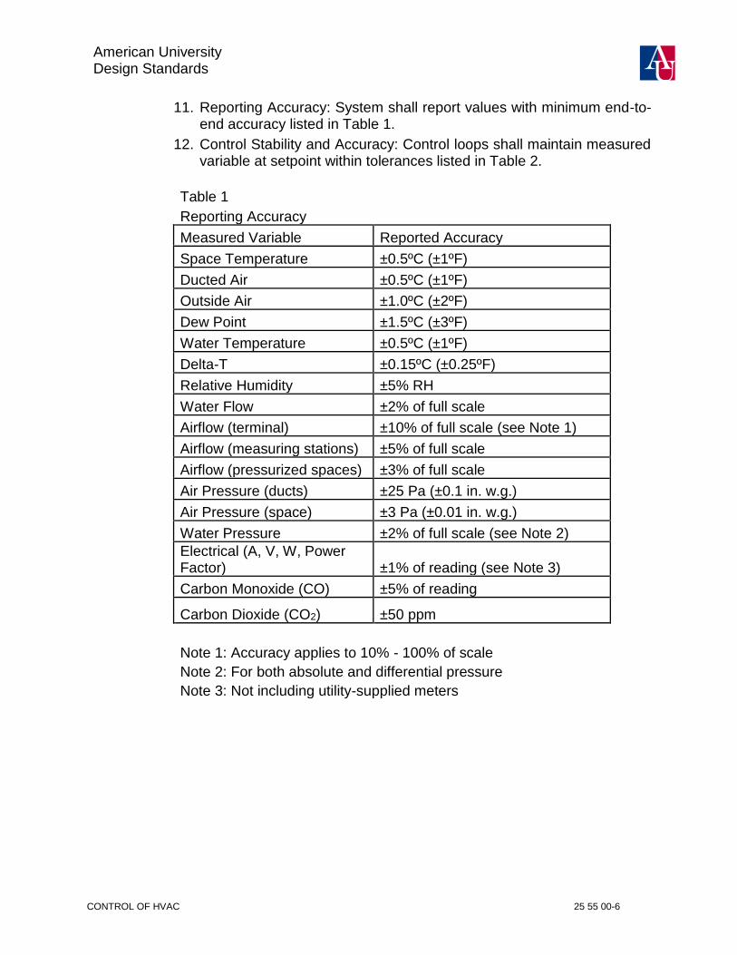
11. Reporting Accuracy: System shall report values with minimum end-to-end accuracy listed in Table 1.
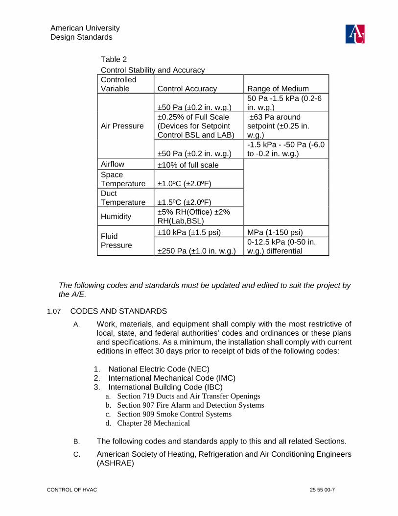
12. Control Stability and Accuracy: Control loops shall maintain measured variable at setpoint within tolerances listed in Table 2.
Table 1 Reporting Accuracy
Measured Variable Reported Accuracy
Space Temperature ±0.5ºC (±1ºF)
Ducted Air ±0.5ºC (±1ºF)
Outside Air ±1.0ºC (±2ºF)
Dew Point ±1.5ºC (±3ºF)
Water Temperature ±0.5ºC (±1ºF)
Delta-T ±0.15ºC (±0.25ºF)
Relative Humidity ±5% RH
Water Flow ±2% of full scale
Airflow (terminal) ±10% of full scale (see Note 1)
Airflow (measuring stations) ±5% of full scale
Airflow (pressurized spaces) ±3% of full scale
Air Pressure (ducts) ±25 Pa (±0.1 in. w.g.)
Air Pressure (space) ±3 Pa (±0.01 in. w.g.)
Water Pressure ±2% of full scale (see Note 2) Electrical (A, V, W, Power Factor) ±1% of reading (see Note 3)
Carbon Monoxide (CO) ±5% of reading
Carbon Dioxide (CO2) ±50 ppm
Note 1: Accuracy applies to 10% - 100% of scale
Note 2: For both absolute and differential pressure
Note 3: Not including utility-supplied meters
American University Design Standards
CONTROL OF HVAC 25 55 00-7
Table 2
Control Stability and Accuracy
Controlled Variable Control Accuracy Range of Medium
Air Pressure
±50 Pa (±0.2 in. w.g.) 50 Pa -1.5 kPa (0.2-6 in. w.g.)
±0.25% of Full Scale (Devices for Setpoint Control BSL and LAB)
±63 Pa around setpoint (±0.25 in. w.g.)
±50 Pa (±0.2 in. w.g.) -1.5 kPa - -50 Pa (-6.0 to -0.2 in. w.g.)
Airflow ±10% of full scale
Space Temperature ±1.0ºC (±2.0ºF)
Duct Temperature ±1.5ºC (±2.0ºF)
Humidity ±5% RH(Office) ±2% RH(Lab,BSL)
Fluid Pressure
±10 kPa (±1.5 psi) MPa (1-150 psi)
±250 Pa (±1.0 in. w.g.) 0-12.5 kPa (0-50 in. w.g.) differential
The following codes and standards must be updated and edited to suit the project by the A/E.
1.07 CODES AND STANDARDS
A. Work, materials, and equipment shall comply with the most restrictive of local, state, and federal authorities' codes and ordinances or these plans and specifications. As a minimum, the installation shall comply with current editions in effect 30 days prior to receipt of bids of the following codes:
1. National Electric Code (NEC) 2. International Mechanical Code (IMC) 3. International Building Code (IBC)
a. Section 719 Ducts and Air Transfer Openings
b. Section 907 Fire Alarm and Detection Systems
c. Section 909 Smoke Control Systems
d. Chapter 28 Mechanical
B. The following codes and standards apply to this and all related Sections.
C. American Society of Heating, Refrigeration and Air Conditioning Engineers (ASHRAE)

American University Design Standards
CONTROL OF HVAC 25 55 00-8
1. ANSI/ASHRAE Standard 135-2008 BACnet - A Data Communication Protocol for Building Automation and Control Networks
D. Electronics Industries Alliance
1. EIA-709.1-B-2002: Control Network Protocol Specification
2. EIA-709.3-99: Free-Topology Twisted-Pair Channel Specification
3. EIA-232: Interface Between Data Terminal Equipment and Data Circuit-Terminating Equipment Employing Serial Binary Data Interchange.
4. EIA-458: Standard Optical Fiber Material Classes and Preferred Sizes
5. EIA-485: Standard for Electrical Characteristics of Generator and Receivers for use in Balanced Digital Multipoint Systems.
6. EIA-472: General and Sectional Specifications for Fiber Optic Cable
7. EIA-475: Generic and Sectional Specifications for Fiber Optic Connectors and all Sectional Specifications
8. EIA-573: Generic and Sectional Specifications for Field Portable Polishing Device for Preparation Optical Fiber and all Sectional Specifications
9. EIA-590: Standard for Physical Location and Protection of Below-Ground Fiber Optic Cable Plant and all Sectional Specifications
E. Underwriters Laboratories
1. UL 916: Energy Management Systems.
2. UUKL 864: UL Supervised Smoke Control
F. NEMA Compliance
1. NEMA 250: Enclosure for Electrical Equipment
2. NEMA ICS 1: General Standards for Industrial Controls.
G. NFPA Compliance
1. NFPA 90A "Standard for the Installation of Air Conditioning and Ventilating Systems" where applicable to controls and control sequences.
2. NFPA 70 National Electrical Code (NEC)
3. NFPA 72 National Fire Alarm and Signaling Code
H. Institute of Electrical and Electronics Engineers (IEEE)
1. IEEE 142: Recommended Practice for Grounding of Industrial and Commercial Power Systems
2. IEEE 802.3: CSMA/CD (Ethernet – Based) LAN
3. IEEE 802.4: Token Bus Working Group (ARCNET – Based) LAN
1.08 DEFINITIONS
A. Accuracy: Accuracy shall include combined effects of nonlinearity, non-repeatability and hysteresis. See other Division 25 Sections for details specific to devices and applications.
American University Design Standards
CONTROL OF HVAC 25 55 00-9
B. Advanced Application Controller (AAC): A device with limited resources relative to the Building Controller (BC). It may support a level of programming and may also be intended for application specific applications.
C. American University (AU): Owner of all facilities and systems.
D. Application Protocol Data Unit (APDU): A unit of data specified in an application protocol and consisting of application protocol control information and possible application user data (ISO 9545).
E. Application Specific Controller (ASC): A device with limited resources relative to the Advanced Application Controller (AAC). It may support a level of programming and may also be intended for application-specific applications. .
F. BAS Contractor: Contractor responsible for the installation, programming, commissioning, training, and warranty service of the new building automation system.
G. Binding: In the general sense, binding refers to the associations or mappings of the sources network variable and their intended or required destinations.
H. Building Automation System (BAS): The entire integrated management and control system
I. Building Controller (BC): A fully programmable device capable of carrying out a number of tasks including control and monitoring via direct digital control (DDC) of specific systems, acting as a communications router between the LAN backbone and sub-LANs, and data storage for trend information, time schedules, and alarm data.
J. Change of Value (COV): An event that occurs when a measured or calculated analog value changes by a predefined amount (ASHRAE/ANSI 135-2010).
K. Client: A device that is the requestor of services from a server. A client device makes requests of and receives responses from a server device.
L. Continuous Monitoring: A sampling and recording of a variable based on time or change of state (e.g. trending an analog value, monitoring a binary change of state).
M. Contractor: Within this specification, all references to “Contractor” shall mean the contractor that holds the construction contract that incorporates the BAS. This contractor would normally be called the General Contractor, or Construction Management contractor, but ultimately, it is the contractor that is responsible for and owns the construction contract.
N. Controller or Control Unit (CU): Intelligent stand-alone control panel. Controller is a generic reference and shall include BCs, AACs, and ASCs as appropriate.
American University Design Standards
CONTROL OF HVAC 25 55 00-10
O. Control Systems Server (CSS): This shall be a computer (or computers) that maintain the systems configuration and programming database. This may double as an operator workstation.
P. Direct Digital Control (DDC): Microprocessor-based control including Analog/Digital conversion and program logic.
Q. Ethernet: Reference to the campus Information Technology network, used for normal business-related e-mail and Internet communication. IEEE 802.3 based network connecting multiple facilities with a central data warehouse and server, accessible via standard web-browser or client installed software.
R. Functional Profile: A collection of variables required to define the key parameters for a standard application. As this applies to the HVAC industry, this would include applications like VAV terminal, fan coil units, and the like.
S. Gateway (GTWY): A device, which contains two or more dissimilar networks/protocols, permitting information exchange between them (ASHRAE/ANSI 135-2008).
T. Hand Held Device (HHD): Manufacturer’s microprocessor based device for direct connection to a Controller.
U. LAN Interface Device (LANID): Device or function used to facilitate communication and sharing of data throughout the BAS
V. Local Area Network (LAN): General term for a network segment within the architecture. Various types and functions of LANs are defined herein.
W. Local Supervisory LAN: Ethernet-based LAN connecting Primary Controller LANs with each other and OWSs and CSSs. See System Architecture below. This LAN can function as the Primary Controlling LAN.
X. Master-Slave/Token Passing (MS/TP): Data link protocol as defined by the BACnet standard. (ASHRAE/ANSI 135-2010).
Y. Open Database Connectivity (ODBC): An open standard application-programming interface (API) for accessing a database developed. ODBC compliant systems make it possible to access any data from any application, regardless of which database management system (DBMS) is handling the data.
Z. Operator Interface (OI): A device used by the operator to manage the BAS including OWSs, POTs, and HHDs.
AA. Operator Workstation (OWS): The user’s interface with the BAS system. As the BAS network devices are stand-alone, the OWS is not required for communications to occur.
BB. Point-to-Point (PTP): Serial communication as defined in the BACnet standard.
American University Design Standards
CONTROL OF HVAC 25 55 00-11
CC. Portable Operators Terminal (POT): Laptop PC used both for direct connection to a controller and for remote dial up connection.
DD. Primary Controlling LAN: High speed, peer-to-peer controller LAN connecting BCs and optionally AACs and ASCs. Refer to System Architecture below.
EE. Router: A device that connects two or more networks at the network layer.
FF. Secondary Controlling LAN: Subordinate LAN connecting AACs and ASCs to the Primary Controlling LAN. Refer to System Architecture below.
GG. Server: A device that is a provider of services to a client. A client device makes requests of and receives responses from a server device.
HH. SQL: Standardized Query Language, a standardized means for requesting information from a database.
II. Smart Device (SD): A control I/O device such as a sensor or actuator that can directly communicate with the controller network to which it is connected. This differs from an ASC in that it typically deals only with one variable.
1.09 FUNCTIONAL INTENT
A. Throughout Division 25 detailed requirements are specified, some of which indicate a means, method or configuration acceptable to meet that requirement. Contractor may submit products that utilize alternate means, methods, and configurations that meet the functional intent in coordination with the BAS contractor. However, the Owner will only allow these with prior approval.
B. The BAS Contractor shall submit an Exception List with their bid to include any alternative products or product configurations and any items for which the BAS Contractor cannot explicitly confirm to a requirement of this specification. The listing shall be indexed to match the structure of these specifications. The list shall include the section, part, item, and subparagraph number, of the specification requirement to which the exception is taken. A description of the alternate method of meeting the functional intent shall be provided.
1.10 SUBMITTALS
A. Design engineer shall concurrently review all submittals along with the Owner’s Engineering/IT/Facilities Departments and incorporate all comments into a final review document. All submittals shall comply with all Cx requirements as detailed in Division 01 and each relevant Division’s commissioning section.
B. Electronic Submittals: Control submittals and O&M information shall be provided electronically in Adobe PDF format. Control drawings shall be electronically provided in Adobe PDF and AutoCAD (format to match current Owner standard) in a size no less than 11”x17”. Documents will be
American University Design Standards
CONTROL OF HVAC 25 55 00-12
developed in a preferred format or converted from their native electronic format directly to a preferred format. Any documents scanned as images must be converted to a searchable text format using OCR (Optical Character Recognition) and reduced in size prior to submission. O&M manual shall include electronic versions of the project Mechanical and Electrical design drawings.
C. Qualifications: Manufacturer, Installer, and Key personnel qualifications as indicated for the appropriate item above. Include QA/QC plan for all phases (design, install, commission, warranty) along with documentation of industry standard QA/QC practices followed.
D. Product Data: Submit manufacturer's technical product data for each control device, panel, and accessory furnished, indicating dimensions, capacities, performance and electrical characteristics including compliance with grounding and power conditioning requirements, and material finishes. Also include installation and start-up instructions.
E. Shop Drawings: Submit shop drawings for each control system, including a complete drawing for each air handling unit, system, pump, device, etc. with all point descriptors, addresses and point names indicated. Each shop drawing shall be provided in Adobe PDF and AutoCAD format and contain the following indexes:
1. System Architecture, System Layout, Risers:
a) One-line diagram indicating schematic locations of all control units, workstations, LAN interface devices, gateways, etc. Indicate network number, device ID, drawing reference number, and controller type for each control unit. All optical isolators, repeaters, end-of-line resistors, junctions, ground locations etc. shall be located on the diagram. Indicate relevant communication protocol on each network segment.
b) Indicate device instance and MAC address for each CU. Indicate media, protocol, baud rate, and type of each LAN.
c) Provide floor plans locating all control units, LAN interface devices, gateways, etc. Include all WAN and LAN communication wiring routing, power wiring, power originating sources, and low voltage power wiring. Wiring routing as-built conditions shall be maintained accurately throughout the construction period and the drawing shall be updated to accurately reflect accurate, actual installed conditions.
d) Indicate network number, device ID, address, MAC address, drawing reference number, and controller type for each control unit. Indicate media, protocol, baud rate, and type of each LAN. All optical isolators, repeaters, end-of-line resistors, junctions, ground locations etc. shall be located on the floor plans.
e) For renovation projects, the system diagram shall clearly show all new and modified connections to existing networks and controllers.

American University Design Standards
CONTROL OF HVAC 25 55 00-13
2. PI&D Schematic flow diagram of each air and water system showing fans, coils, dampers, valves, pumps, heat exchange equipment and control devices. Include narrative description of sequence of operation, as it will be applied by the proposed control system (providing verbatim copy of contract documents is not acceptable). Indicate which items will be installed by others. Where applicable, provide a diagram for factory-controlled equipment detailing the BAS interface.
3. All physical points on the schematic flow diagram shall be indicated with names, descriptors, and point addresses identified as listed in the point summary table.
4. With each schematic, provide a point summary table listing building number and abbreviation, system type, equipment type, full point name, point description, Ethernet backbone network number, network number, device ID, object ID (object type, instance number). See Section 25 55 00 - Part 3 for additional requirements.
5. Label each control device with set point and range of adjustable control.
6. Label each controller input and output with the appropriate range.
7. Label each control device with the relevant detail drawing number.
8. Provide a Bill of Materials with each schematic. Indicate device identification to match schematic and actual field labeling, quantity, actual product ordering number, manufacturer, description, size, voltage range, pressure range, temperature range, etc. as applicable.
9. Provide a Control Valve Schedule listing valve and actuator information including: size, Cv, design flow, design pressure drop, manufacturer, model number, close off rating, control signal, line size, line pressure, ANSI class rating, tag number, system service, valve type, material construction of body, stem, disc, etc. Indicate normal positions of automatic return valves.
10. Provide a Control Damper Schedule listing damper and actuator information including: size, material, blade arrangement, manufacturer, model number, control signal, close off rating, etc. Indicate normal positions of automatic return dampers.
11. Provide an Air Flow Monitoring Station Schedule listing the following information: size, material, manufacturer, model number, control signal, CFM, velocity, etc.
12. Provide a Metering Device Schedule listing the following information: Flow range, fluid type, mechanical input type (magnetic, wheel, ultrasonic), Manufacturer, Model, Purpose, Location.
13. Indicate all required electrical wiring. Electrical wiring diagrams shall include both ladder logic type diagram for motor starter, control, and safety circuits and detailed digital interface panel point termination diagrams with all wire numbers and terminal block numbers identified. Provide panel termination drawings on separate drawings. Clearly

American University Design Standards
CONTROL OF HVAC 25 55 00-14
differentiate between portions of wiring which are existing, factory-installed and portions to be field-installed.
14. Provide details of control panels, including controls, instruments, and labeling shown in plan or elevation indicating the installed locations and allocated service clearances. Provide panel layout drawing including power supply, control unit(s) and wiring terminals.
15. Sheets shall be consecutively numbered.
16. Each sheet shall have a title indicating the type of information included and the system controlled.
17. A Table of Contents shall list sheet titles and sheet numbers followed by a symbol legend and list of abbreviations.
18. BACnet Protocol Implementation Conformance Statement (PICS) for each submitted type of controller and operator interface.
F. Control Logic Documentation
1. Submit control logic program listings to document the control software of all control units.
2. Include written description of each control sequence.
3. Include a test plan for each unique control program. The test program must mirror the control program.
G. Operation and Maintenance Materials:
1. Submit documents under provisions of Division 01. Documents shall be provided electronically as described for electronic submittals.
2. Submit maintenance instructions and spare parts lists for each type of control device, control unit, and accessory.
3. Include all submittals (product data, shop drawings, control logic documentation, hardware manuals, software manuals, installation guides or manuals, maintenance instructions and spare parts lists) in maintenance manual; in accordance with requirements of Division 01. Only include sections for equipment and software used on this project. Do not provide entire catalog of product data with extraneous information, cross out or draw a single line thru non-related data.
4. Submit BAS User’s Guides (Operating Manuals) for each controller type and for all workstation hardware and software and workstation peripherals.
5. Submit BAS advanced Programming Manuals for each controller type and for all workstation software.
H. Training Materials
1. Provide course outline and materials for each class at least six weeks before first class. Training shall be furnished via instructor-led sessions, computer-based training, or web-based training. BAS Engineer will

American University Design Standards
CONTROL OF HVAC 25 55 00-15
modify course outlines to match installed project. Provide a minimum of 4 copies of training materials and one electronic copy.
I. Schedule
1. Schedule of work provided within one month of contract award, indicating;
a) Intended sequence of work items
b) Start date of each work item
c) Duration of each work item
d) Planned delivery dates for ordered material and equipment and expected lead times
e) Milestones indicating possible restraints on work by other trades or situations
2. Monthly written status reports indicating work completed and revisions to expected delivery dates. Include updated schedule of work.
J. Panel Control Drawings
Provide laminated control drawings within each control panel for the CUs and devices controlled from that panel. System control schematics shall be mounted adjacent to key pieces of equipment for that system. Panel termination drawings shall be mounted in or adjacent to respective panels.
K. System Conversion Planning
1. Submit schedule of work with respect to equipment outages and/or occupancy/work schedules.
2. Provide details of control panels, including controls and instruments impacted. Provide scale panel layout drawing including power supply, control unit(s) and wiring terminals impacted.
3. Provide details of additional power source connections required beyond those provided in existing system.
L. Controls contractor shall provide Owner with all product line technical manuals and technical bulletins, to include new and upgraded products, by the same distribution channel as to dealers or branches throughout the warranty period of the project.
M. Manufacturers Certificates: For all listed and/or labeled products, provide certificate of conformance.
N. Product Warranty Certificates: Coordinate and submit manufacturers product warranty certificates covering the hardware provided once approved by the Owner. Provide a written one-year guarantee showing the starting and ending dates as noted in Division 01. List the local offices and the representatives to perform routine and emergency maintenance on system components.

American University Design Standards
CONTROL OF HVAC 25 55 00-16
O. Re-Submittals: Include cover letter that specifically responds to all previous submittal comments and explains how they are addressed in the current re-submittal.
1.11 PROJECT RECORD DOCUMENTS
A. Submit documents under provisions of Division 01 Closeout Procedures. Documentation shall be provided electronically as defined for electronic submittals.
B. As-Built copies of product data and control shop drawings updated to reflect the final installed condition.
C. As-Built copies of approved control logic programming and database uploaded and stored on the project BAS server. Accurately record actual setpoints and settings of controls, final sequence of operation, including changes to programs made after submission and approval of shop drawings and including changes to programs made during specified testing.
D. As-Built copies of approved project specific graphic software stored on the Owner’s BAS server.
E. As-Built copies shall include individual floor plans with controller locations with all interconnecting wiring routing including space sensors, LAN wiring, power wiring, low voltage power wiring.
F. As-Built copies shall include the final riser diagram showing the location of all controllers.
G. As-Built copies shall include ALL control drawings revision history to reflect the As-Built date. No drawing, Document nor database shall be provided without the final As-Built revision date and comment attached.
H. All As-Built documents shall be provided electronically and copied to the BAS CSS. Links to this documentation shall be provided on each equipment graphic for access to the as-built shop drawings, point lists, and sequences of operation.
I. Confirm AU BAS Supervisor is able to access all record documentation once uploaded to CSS.
1.12 SYSTEM ARCHITECTURE
A. The system provided shall incorporate hardware resources sufficient to meet the functional requirements of this project. The Contractor shall include all items not specifically itemized in these Specifications that are necessary to implement, maintain, and operate the system in compliance with the functional intent of these contract documents.
B. The system shall be configured as a distributed processing network(s) capable of expansion.
American University Design Standards
CONTROL OF HVAC 25 55 00-17
C. The system architecture shall consist of an Ethernet-based, wide area network (WAN), a single Local Area Network (LAN) or multi-leveled LANs that support BCs, AACs, ASCs, Operator Workstations (OWS), Smart Devices (SD), and Remote Communication Devices (RCDs) as applicable. The BAS network shall be able to seamlessly communicate using the standard protocols, MODBUS and BACnet, at all network levels. The following is a functional description of the BAS structure.
1. WAN: Internet-based network connecting multiple facilities with a central data warehouse and server, accessible via standard web-browser. This is an existing infrastructure and contractor is not required to configure any components of this WAN. Refer to Section 25 11 16 for requirements.
2. Local Supervisory LAN: The Local Supervisory LAN is an extension of the WAN. Contractor will be provided specific ports dedicated for control module/interface device connectivity. The LAN is IEEE 802.3 compliant with switches and routers that support 100 Mbps minimum throughput. Contractor may not extend this network without prior approval from the Owner. Power-line carrier communication shall not be acceptable for communications.
a) The Contractor is responsible for the installation of a temporary Ethernet network that will serve the purpose of the Local Supervisory LAN until such time as the permanent Local Supervisory LAN is available. Should the temporary network be required, the BAS Contractor is responsible for the coordination and implementation of the Local Supervisory LAN to conform to the eventual permanent LAN’s settings and addresses for the BAS.
3. Primary Controller LAN (‘Primary LAN’): High-speed, peer-to-peer communicating LAN used to connect Building Controllers (BCs) and communicate control information. Acceptable technologies are:
a) Ethernet (IEEE802.3)
b) ARCNET (IEEE802.4)
4. Secondary Controller LAN (‘Secondary LAN’): Network used to connect AACs, ASCs or SDs. These can be BACnet MS/TP or MODBUS, in addition to those allowed for Primary Controller LANs. Network speed versus the number of controllers on the LAN shall be dictated by the response time and trending requirements (see the Integrated Automation Remote Control Panels Section).
D. Dynamic Data Access: Any data throughout any level of the network shall be available to and accessible by all other devices, Controllers and OWS, whether directly connected or connected remotely.
American University Design Standards
CONTROL OF HVAC 25 55 00-18
E. Remote BAS Access: Coordinate remote access connectivity with the Owner. The system shall support the following methods of remote access to the building data.
1. Browser-based access: A remote user using a standard browser shall be able to access all control system facilities and graphics with proper password. BAS contractor shall coordinate the required server side internet connection with the Owner. The following is acceptable for browser-based access:
a) Native browser-based user interfaces that do not require browser extension. The user interface must be compatible with the most current stable version of the supporting software without requiring the user to downgrade to a lesser version.
F. Communication Interruptions: Interruptions or fault at any point on any Primary Controller LAN shall not interrupt communications between other nodes on the network. If a LAN is severed, separate networks shall be formed and communications within each network shall continue uninterrupted.
G. Communication Devices: All line drivers, signal boosters, and signal conditioners etc. shall be provided as necessary for proper data communication (see also Network Bandwidth Management).
H. Control Systems Server (CSS): The CSS is a virtual machine that maintains the systems configuration, programming database, and historical trend data. The BAS software shall be platform independent and capable of residing on Owner’s specific operating system with virtualization software.
It shall hold backup files of information downloaded into the individual controllers and as such support uploading and downloading that information directly to/from the controllers. It shall also act as a control information server to non-control system based programs. It shall allow secure multiple-user access to the control information. Refer to Section 25 1113 – Integrated Automation Network Servers for its requirements.
Operator Interfaces shall provide for overall system supervision, graphical user interface, management report generation, alarm annunciation, and remote monitoring. Refer to Section 25 1113 – Integrated Automation Network Servers.
1. During construction and prior to acceptance by the Owner new BAS projects will reside on their respective QA (Quality Assurance) server. This server operates separately from the primary CSS to prevent construction phase work from impacting existing systems. The CSS QA will be configured to match the primary CSS capability and allow testing of all CSS functions including historical trending and alarm reporting.
I. Field Panel Independence: The BCs, AACs, ASCs, and SDs shall monitor, control, and provide the field interface for all points specified. Each BC,
American University Design Standards
CONTROL OF HVAC 25 55 00-19
AAC, or ASC shall be capable of performing all specified energy management functions, and all DDC functions, independent of other BCs, AACs, or ASCs and operator interface devices as more fully specified in Section 25 1413 - Integrated Automation Remote Control Panels.
J. Touch Screen Kiosk: A single touch screen interface (Eco-Screen Sustainability Kiosk; other) showing general building conditions and utility usage shall be installed as shown on the contract documents. This interface will provide all capabilities of an OWS excluding modification of any parameters, schedules, programming, graphics or access to the underlying operating system.
1.13 WARRANTY MAINTENANCE
A. All references in this Article 1.14, to the term ‘Contractor’ shall mean both the BAS Contractor and contractors providing installation services.
B. Contractor shall warrant all BAS products and labor for a period of two years after substantial completion as defined in Division 01.
C. The Owner reserves the right to make changes to the BAS during the warranty period. Such changes do not constitute a waiver of warranty. The Contractor shall warrant parts and installation work regardless of any such changes made by the owner, unless the Contractor provides clear and convincing evidence that a specific problem is the result of such changes to the BAS. Any disagreement between the Owner and the Contractor on such matters shall be subject to resolution through the contract ‘Disputes’ clause.
D. Maintenance Services: During the warranty period, the Contractor shall provide maintenance services for software and hardware components as specified below, at no additional cost. The AU BAS department will be the Owner’s authorized representative for all service requests:
1. Maintenance services shall be provided for all devices and hardware specified in Division 25 and supplied by the BAS Contractor. Service all equipment per the manufacturer’s recommendations. All devices shall be calibrated within the last month of the warranty period. An update to the points Information Block detail of the points definition in the CSS shall be added indicating the date of calibration and initials of the technician performing calibration.
2. Emergency Service: Any malfunction, failure, or defect in any hardware component or failure of any control programming that would result in patient impact, property damage or loss of comfort control shall be corrected and repaired following notification by the Owner to the Contractor.
a) Response by telephone to any request for service shall be provided within one hour of the Owner’s initial telephone request for service.

American University Design Standards
CONTROL OF HVAC 25 55 00-20
b) In the event that the malfunction, failure, or defect is not corrected through telephonic communication, at least one (1) hardware and software technician, trained in the system to be serviced, shall be dispatched to the Owner’s site within two hours of the initial telephone request for such services, as specified.
3. Normal Service: Any malfunction, failure, or defect in any hardware component or failure of any control programming that would not result in property damage or loss of comfort control shall be corrected and repaired following telephonic notification by the Owner to the Contractor.
a) Response by telephone to any request for service shall be provided within two working hours (contractor specified 40 hours per week normal working period) of the Owner's initial telephone request for service.
b) In the event that the malfunction, failure, or defect is not corrected through the telephonic communication, at least one (1) hardware and software technician, trained in the system to be serviced, shall be dispatched to the Owner's site within two working days of the initial telephone request for such services, as specified.
4. Telephonic Request for Service: Contractor shall specify a maximum of three telephone numbers to call in the event of a need for service. At least one of the lines shall be attended at any given time. Once contacted, a technician shall respond to calls within 15 minutes.
5. Technical Support: Contractor shall provide technical support by telephone throughout the warranty period.
6. Preventive Maintenance: Preventive maintenance shall be provided throughout the warranty period in accordance with the hardware component manufacturer's requirements.
7. Product Updates: Provide updates to operator workstation or web server software, project-specific software, graphic software, database software, and firmware that resolve Contractor-identified software deficiencies at no charge during warranty period. If available, Owner can purchase in-warranty service agreement to receive upgrades for functional enhancements associated with above-mentioned items. Do not install updates or upgrades without Owner's written authorization
1.14 DELIVERY, STORAGE, AND HANDLING
A. Provide factory-shipping cartons for each piece of equipment and control device. Maintain cartons during shipping, storage and handling as required to prevent equipment damage, and to eliminate dirt and moisture from equipment. Store equipment and materials indoors, within manufacturer’s specified environmental conditions and protect from construction work, weather and theft.

American University Design Standards
CONTROL OF HVAC 25 55 00-21
1.15 LISTING AND LABELING
A. The BAS and components shall be listed by Underwriters Laboratories (UL 916) as an Energy Management System.
B. Portions of the BAS utilized for fire/smoke management, stairwell pressurization controls and monitoring shall be listed by Underwriters Laboratories (UUKL 864).
1.16 OWNERSHIP OF PROPRIETARY MATERIAL
A. Project specific software and documentation shall become the Owner’s property. This includes, and is not limited to:
1. System database structure project files.
2. System custom code project files.
3. System graphic project files.
4. Record Drawings of all file types, including the Design File Format of all project drawings.
5. Documentation
PART 2. PRODUCTS
2.01 MATERIALS AND EQUIPMENT
A. Materials shall be new, the best of their respective kinds without imperfections or blemishes and shall not be damaged in any way. Used equipment shall not be used in any way for the permanent installation except where drawings or specifications specifically allow existing materials to remain in place or be reinstalled.
B. Do not use this installation as a product test site unless explicitly approved in writing by Owner. Spare parts shall be available for at least five years after completion of this contract.
2.02 UNIFORMITY
A. To the extent practical, all equipment of the same type serving the same function shall be identical and from the same OEM manufacturer.
2.03 PRODUCTS FURNISHED BUT NOT INSTALLED UNDER THIS SECTION
A. Section 25 35 16 - Integrated Automation Sensors and Transmitters
1. Airflow measuring stations
2. Flow meters
3. Flow switches
4. Pressure sensor wells and sockets
5. Temperature sensor wells and sockets
B. Section 25 3519 - Integrated Automation Control Valves
1. Control Valves

American University Design Standards
CONTROL OF HVAC 25 55 00-22
C. Section 25 3513 - Integrated Automation Control Dampers
1. BAS Automated Dampers
D. Division 23: HVAC Equipment
1. Air Terminal Units; VAV and CAV terminal Controls
2. AHU, Heating, Ventilation Unit Controls
3. Unitary, Convection, and Radiant Unit Equipment Controls and Humidifier Controls
2.04 PRODUCTS NOT FURNISHED NOR INSTALLED BUT INTEGRATED WITH WORK OF THIS SECTION
A. Coordination Meetings: The Contractor shall coordinate meetings between the BAS Contractor and the Installers(s) furnishing each of the following products to coordinate the details of the interface between these products and the DDC network. The Owner or his representative shall be present at every coordination meeting. Submittals for these products shall not be approved prior to the completion of this meeting. Any issues identified during these meetings must also be resolved satisfactorily and with agreement between the BAS Contractor and the Installer(s) prior to the submittal being approved. Each Installer shall provide the Owner and BAS Contractor and all other Installers with the details of the proposed interface including the following;
1. BACnet PICS
2. Point List
3. Wiring Requirements
4. Communication Specifications for speed, type etc.
5. Required Network Accessories
6. (3) Past Examples of Integration to the proposed BAS at the Field Panel (BC) communication Level of the Architecture.
7. Network Identifiers
B. Heating Boilers
1. Boiler Controls: The boiler vendor shall furnish boilers with an interface to the control and monitoring points specified in Section 25 95 00. These specified points shall be the minimum acceptable interface to the boiler. The connection to these points shall be of the following methods determined during the coordination meetings:
a) Hardwired connection such as relay, 0-10VDC, or 4-20mA
b) BACnet/IP network connection
c) MODBUS network connection.
d) BACnet MS/TP network connection
C. Central Cooling Equipment

American University Design Standards
CONTROL OF HVAC 25 55 00-23
1. Chiller Controls: The chiller vendor shall furnish chillers with an interface to the control and monitoring points specified in Section 25 95 00. These specified points shall be the minimum acceptable interface to the chiller. The connection to these points shall be of the following methods determined during the coordination meetings:
a) Hardwired connection such as relay, 0-10VDC, or 4-20mA
b) BACnet/IP network connection
c) BACnet MS/TP network connection
D. Central HVAC Equipment-Customized AHU
1. Packaged AHU or Evaporative Cooler Controls: Unit shall be furnished configured to accept control inputs from an external building automation system controller as specified in Section 25 95 00. Factory mounted safeties and other controls shall not interfere with this controller.
E. Decentralized HVAC Equipment
1. Unit Ventilators, Unit Heaters, Fan Coils, etc.: Unit ventilators, unit heaters, fan coils, cabinet heaters, convective or fin tube heaters, zone reheat, and similar terminal units. These units shall be furnished configured to accept control inputs from an external building automation system controller as specified in Section 25 95 00. Factory mounted safeties and other controls shall not interfere with this controller.
F. Variable Frequency Drives
1. Variable Frequency Drives: The variable frequency drive (VFD) vendor shall furnish all VFDs with an interface to the control and monitoring points specified in Section 25 95 00. These specified points shall be the minimum acceptable interface to the VFD. The connection to these points shall be of the following methods determined during the coordination meetings:
a) Hardwired connection such as relay, 0-10VDC, or 4-20mA
b) BACnet/IP network connection
c) BACnet MS/TP network connection
G. Communications with Third Party Equipment:
1. Any additional integral control systems included with the products integrated with the work of this section shall be furnished with a BACnet/IP interface for integration into the Direct Digital Control system described in this section.
PART 3. EXECUTION
3.01 INSPECTION
A. Examine areas and conditions under which control systems are to be installed. Do not proceed with work until unsatisfactory conditions have been corrected in manner acceptable to the Installer.
American University Design Standards
CONTROL OF HVAC 25 55 00-24
B. Inspect site to verify that equipment can be installed as shown. Report discrepancies, conflicts, or omissions to Engineer for resolution before starting rough-in work.
C. Examine drawings and specifications for work of others. Report inadequate headroom or space conditions or other discrepancies to Engineer and obtain written instructions for changes necessary to accommodate Section 25 55 00 work with work of others. Controls Contractor shall perform at his expense necessary changes in specified work caused by failure or neglect to report discrepancies.
3.02 PROTECTION
A. BAS Contractor shall protect against and be liable for damage to work and to material caused by the BAS Contractor's work or employees.
B. Contractor shall be responsible for work and equipment until inspected, tested, and accepted. Protect material not immediately installed. Close open ends of work with temporary covers or plugs during storage and construction to prevent entry of foreign objects. Prevent any item or equipment from theft while on the site for the duration of the project.
3.03 CONSTRUCTION COORDINATION
A. Site and Schedule Coordination:
1. Contractor shall assist in coordinating space conditions to accommodate the work of each trade where work will be installed near or will interfere with work of other trades. If installation without coordination causes interference with work of other trades, Contractor shall correct conditions without extra charge.
2. Contractor shall coordinate and schedule work with other work in the same area and with work dependent upon other work to facilitate mutual progress.
3. Contractor shall integrate all facets of the BAS installation into the project construction schedule.
4. Contractor shall coordinate schedule updates and changes with the BAS Contractor.
B. Test and Balance:
1. BAS Contractor Support:
a) The BAS Contractor shall provide the Test and Balance Contractor a single set of tools necessary to interface with the control system for testing and balancing.
b) The BAS Contractor shall train the Test and Balance Contractor to use control system interface tools.
c) The BAS Contractor shall provide a qualified technician to assist with testing and balancing the first 10 terminal units.
American University Design Standards
CONTROL OF HVAC 25 55 00-25
2. The Test and Balance Contractor shall return tools undamaged and in working condition at completion of testing and balancing.
C. Electrical Coordination:
1. The BAS Contractor shall coordinate all facets of the BAS installation.
2. The BAS Contractor shall validate the accuracy, fit and finish of all installed BAS Electrical work results in comparison to the BAS Design documents, during the course of the project.
D. Third Party Coordination:
1. The BAS Contractor shall be the systems integrator for all third party control systems that must interface with the BAS.
2. Each supplier shall comply with the communication media, software and equipment as specified in Section 25 5500.
3. Each supplier of a controls product shall configure, program, start up, and test that product to meet the sequences of operation regardless of where within the contract documents those products are described.
4. Coordinate and resolve incompatibility issues that arise between control products provided under this section and those provided under other sections or divisions of this specification.
5. BAS Contractor shall be responsible for integration of control products provided by multiple suppliers regardless of where integration is described within the contract documents.
3.04 GENERAL WORKMANSHIP
A. Install systems and materials in accordance with manufacturer's instructions, roughing-in drawings and details shown on drawings and within the Owner’s Design Standard.
B. Install equipment, piping, and wiring or raceway horizontally, vertically, and parallel to walls wherever possible.
C. Provide sufficient slack and flexible connections to allow for piping and equipment vibration isolation.
D. Verify wiring integrity to ensure continuity and freedom from shorts and ground faults.
E. Equipment, installation, and wiring shall comply with industry specifications and standards and local codes for performance, reliability, and compatibility
F. Refer to additional requirements in other sections of this specification.
3.05 FIELD QUALITY CONTROL
A. Work, materials, and equipment shall comply with rules and regulations of applicable local, state, and federal codes and ordinances as identified in the Section Codes and Standards.
American University Design Standards
CONTROL OF HVAC 25 55 00-26
B. Continually monitor field installation for code compliance and workmanship quality.
C. Contractor shall arrange for work inspection by local or state authorities having jurisdiction over the work as required.
3.06 WIRING
A. Control and interlock wiring and installation shall comply with national and local electrical codes, Division 26, and manufacturer's recommendations. Where the requirements of the BAS specification differ from Division 26, provide written notification to A/E of discrepancy and request direction.
B. NEC Class 1 (line voltage) wiring shall be UL listed in approved raceway as specified by NEC and Division 26.
C. Low-voltage wiring shall meet NEC Class 2 requirements. Sub-fuse low-voltage power circuits as required to meet Class 2 current limit.
D. Limit connected loads to 80% of rated capacity.
E. NEC Class 2 (current-limited) wires not in raceway but in concealed and accessible locations such as return air plenums shall be UL listed for the intended application.
F. Install wiring in raceway where subject to mechanical damage and at levels below 3 m (10ft) in mechanical, electrical, or service rooms.
G. Install Class 1 and Class 2 wiring in separate raceways. Boxes and panels containing high-voltage wiring and equipment shall not be used for low-voltage wiring except for the purpose of interfacing the two through relays and transformers.
H. Do not install wiring in raceway containing tubing.
I. Run exposed Class 2 wiring parallel to a surface or perpendicular to it and tie neatly at 3 m (10 ft) intervals.
J. Use structural members to support or anchor plenum cables without raceway. Do not use ductwork, electrical raceways, piping, or ceiling suspension systems to support or anchor cables.
K. Secure raceways with raceway clamps fastened to structure and spaced according to code requirements. Raceways and pull boxes shall not be hung on or attached to ductwork, electrical raceways, piping, or ceiling suspension systems.
L. Size raceway and select wire size and type in accordance with manufacturer's recommendations and NEC requirements.
M. Include one pull string in each raceway 1.8 cm (3/4 in.) or larger.
N. Locate control and status relays in designated enclosures only. Do not install control and status relays in packaged equipment control panel enclosures containing Class 1 starters.

American University Design Standards
CONTROL OF HVAC 25 55 00-27
O. Conceal raceways except within mechanical, electrical, or service rooms. Maintain minimum clearance of 15 cm (6 in.) between raceway and high-temperature equipment such as steam pipes or flues.
P. Adhere to requirements in Division 26 where raceway crosses building expansion joints.
Q. Install insulated bushings on raceway ends and enclosure openings. Seal top ends of vertical raceways.
R. Terminate control and interlock wiring related to the work of this section. Maintain at the job site updated (as-built) wiring diagrams that identify terminations.
S. Flexible metal raceways and liquid-tight flexible metal raceways shall not exceed 1 m (3 ft) in length and shall be supported at each end. Do not use flexible metal raceway less than ½ in. electrical trade size. Use liquid-tight flexible metal raceways in areas exposed to moisture including chiller and boiler rooms.
T. Install raceway rigidly, support adequately, ream at both ends, and leave clean and free of obstructions. Join raceway sections with couplings and according to code.
U. Make terminations in boxes with fittings. Do not make terminations in boxes with bushings.
V. Do not make splices unless absolutely necessary. All wiring is to as much as practical remaining uniform from termination to termination.
W. Do not make splices in plenum wire.
X. All splices made shall be placed within a box or enclosure and labeled as a BAS splice on the cover.
Y. All raceways will be labeled as BAS.
Z. Verify wire integrity by proving continuity; end to end and toward ground, of all wire prior to terminating.
3.07 COMMUNICATION WIRING
A. Communication wiring shall be low-voltage Class 2 wiring and shall comply with Article 3.7 (Wiring).
B. Install communication wiring in separate raceways and enclosures from other Class 2 wiring.
C. During installation do not exceed maximum cable pulling, tension, or bend radius specified by the cable manufacturer.
D. Verify entire network's integrity following cable installation using appropriate tests for each cable.
E. Install lightning arrestor according to manufacturer's recommendations between cable and ground where a cable enters or exits a building.

American University Design Standards
CONTROL OF HVAC 25 55 00-28
F. Each run of communication wiring shall be a continuous length without splices when that length is commercially available. Runs longer than commercially available lengths shall have as few splices as possible using commercially available lengths. Comply with Article 3.7 (Wiring) for labeling and splice management.
G. Label communication wiring to indicate origination and destination.
H. BACnet MS/TP communications wiring shall be installed in accordance with ASHRAE/ANSI Standard 135. This includes but is not limited to;
1. The network shall use shielded, twisted-pair cable with characteristic impedance between 100 and 120 ohms. Distributed capacitance between conductors shall be less than 100 pF per meter (30 pF per foot).
2. The maximum length of an MS/TP segment is 1200 meters (4000 ft) with AWG 18 cable. The use of greater distances and/or different wire gauges shall comply with the electrical specifications of EIA-485.
3. The maximum number of nodes per segment shall be 32, as specified in the EIA 485 standard. Additional nodes may be accommodated by the use of repeaters.
4. An MS/TP EIA-485 network shall have no T connections.
I. All IEEE 802.3 communication wiring used in the BAS shall be addressed and directed within the Division 27 specification.
J. All BC’s, and Third Party Integration Devices (e.g. All BACnet/IP devices) shall be provided an Ethernet connection point.
3.08 WARNING LABELS
A. Affix permanent warning labels to equipment that can be automatically started by the control system.
1. Labels shall use white lettering (12-point type or larger) on a red background.
2. Warning labels shall read as follows:
C A U T I O N This equipment is operating under automatic control and may start or
stop at any time without warning. Switch disconnect to "Off" position before servicing.
B. Affix permanent warning labels to motor starters and control panels that are connected to multiple power sources utilizing separate disconnects.
1. Labels shall use white lettering (12-point type or larger) on a red background.
2. Warning labels shall read as follows:
American University Design Standards
CONTROL OF HVAC 25 55 00-29
C A U T I O N This equipment is fed from more than one power source with separate
disconnects. Disconnect all power sources before servicing.
3.09 IDENTIFICATION OF HARWARE AND WIRING
A. Label wiring and cabling, with control system identification information, at each end within 5 cm (2 in.) of termination.
B. Permanently label or code each point of field terminal strips to show instrument or item served.
C. Label control panels with minimum 1 cm (½ in.) letters on laminated plastic nameplates.
D. Label each control component with a permanent label. Label plug-in components such that label remains stationary during component replacement.
E. Label room sensors related to terminal boxes or valves with nameplates. Ensure the nameplate is aesthetically pleasing and unobtrusive to the room sensors functionality or design.
F. Manufacturers' nameplates and UL or CSA labels shall be visible and legible after equipment is installed.
G. Label identifiers shall match record documents.
3.10 CONTROL PANELS, CONTROLLER QUANTITY AND LOCATION
A. Control panels shall consist of one or multiple controllers to meet requirements of this specification. Control panels shall be wall mounted within mechanical equipment rooms. Electrical equipment rooms may be used with prior Owner approval. In no case shall panels, other than terminal unit controllers, be located above ceilings.
B. Restrictions in applying controllers are specified in Section 25 14 13 - Integrated Automation Remote Control Panels. If the BAS contractor wishes to further distribute panels to other locations, the Contractor is responsible for extending power to that location also. Furthermore, the Contractor is responsible for ensuring adequate locations for the panels that do not interfere with other requirements of the project and maintain adequate clearance for maintenance access.
C. It is the BAS Contractor's responsibility to provide enough controllers to adequately accomplish the sequence of operations and the required point lists plus an added 20% of each of the available point types, AI, AO, BI, BO. No controller installed shall exceed 80% of point capacity of each of the 4 point types, AI, AO, BI, BO. This does not apply to those controllers on the Secondary Controller LAN.

American University Design Standards
CONTROL OF HVAC 25 55 00-30
D. Point expansion modules shall be considered an extension of the controller they are connected to and as such are integral to that controller. Point expansion modules shall comply with the same installation rules as the controller they are connected to regardless of the actual LAN they are communicating upon.
E. For rooftop AHUs and ERUs, controllers rated for use outside the building envelope shall be mounted inside the unit casings. If adequate space is not available for installation of the controllers per the manufacturer’s recommendations, they shall be installed in NEMA4X enclosures adjacent to the unit served. For all other controllers serving rooftop equipment, coordinate with the AE and Owner for control panel location.
F. Controllers for terminal equipment:
1. For equipment located in the conditioned space, controllers shall be mounted inside the unit enclosure. Where sufficient mounting space is not available inside the unit enclosure, a control panel shall be installed above the ceiling, inside the room, as close to the room space sensor as possible with the exception of spaces with impenetrable hard ceilings, in which case the controller shall be mounted above the ceiling in an adjacent hallway as close to the equipment served as possible. Coordinate with the AE and Owner to clarify acceptable mounting locations.
2. For equipment located above dropped ceilings, controllers shall be unit mounted within a plenum rated enclosure. Provide adhesive backed ceiling labels, affixed to ceiling grid below all ceiling concealed controllers, affix to ceiling panel access door for solid ceilings.
G. Control drawings, including system control schematics, sequences of operation and panel termination drawings, shall be provided in panels for major pieces of equipment. Terminal unit drawings shall be located in the central plant equipment panel or mechanical room panel.
3.11 CONTROL POWER SOURCE AND SUPPLY
A. Contractor shall extend all power source wiring required for operation of all equipment and devices included within the BAS.
B. General requirements for obtaining power include the following:
1. All control panels shall be served by dedicated power circuits. BC control panels served by stand-by power circuits shall additionally be provided with one of the following;
a) As Primary selection, a dedicated available UPS circuit from the buildings UPS system to meet the requirements for BC power failure operation in Section 25 1413 - Integrated Automation Remote Control Panels.
b) As Secondary selection, an external UPS power supply to meet the requirements for BC power failure operation in Section 25 14 13 - Integrated Automation Remote Control Panels.
American University Design Standards
CONTROL OF HVAC 25 55 00-31
Control panel shall be labeled with electrical panel name & circuit number.
2. Where a controller controls multiple systems with varying levels of power reliability (normal, stand-by, and/or interruptible), the controller shall be powered by the highest level of reliability taking into account the space restrictions mentioned above.
3. For all controlled equipment operating with an available stand-by generator the control panel must be powered from the same power source including the same automatic transfer switch for normal or stand-by power.
4. Standalone Functionality: Refer to Section 25 14 13 - Integrated Automation Remote Control Panels.
5. Obtain power from a source that feeds the equipment being controlled such that both the control component and the equipment are powered from the same MCC or panel. Where equipment is powered from a 460V source, obtain power from the electrically most proximate 120 VAC source fed from a common origin.
6. Where control equipment is located inside a new equipment enclosure, coordinate with the equipment manufacturer and feed the control with the same source as the equipment. If the equipment’s control transformer is large enough and of the correct voltage to supply the controls it may be used. If the equipment’s control transformer is not large enough or of the correct voltage to supply the controls provide separate transformer.
C. Power Supplies: Control transformers shall be UL listed. Furnish Class 2 current-limiting type or furnish over-current protection in primary and secondary circuits for Class 2 service in accordance with NEC requirements. Limit connected loads to 80% of rated capacity.
3.12 SURGE PROTECTION
A. The Contractor shall furnish and install any power supply surge protection, filters, etc. as necessary for proper operation and protection of all BCs, AAC/ASCS operator interfaces, routers, gateways and other hardware and interface devices. All equipment shall be capable of handling voltage variations 10% above or below measured nominal value, with no effect on hardware, software, communications, and data storage. CUs and panels shall have suppressors to protect against lighting damage, induced voltage from other equipment, and RF interference as applicable.
3.13 DEMOLITION AND REUSE OF EXISTING MATERIALS AND EQUIPMENT
A. Contractor shall assume that existing equipment that is specifically indicated to be reused is in good condition and is operable. Contractor during the course of work, shall inspect these devices and determine if any devices are in need of replacement or repair. Contractor shall prepare an itemized list of suggested repairs/replacement. This repair/replacement will
American University Design Standards
CONTROL OF HVAC 25 55 00-32
be at the discretion of the Owner and will be accomplished under separate contract.
B. Existing wire, conduit, and control panel cabinets may be reused at the contractor’s discretion, but only if such materials or equipment comply with the applicable specification for new materials and equipment. Such materials shall not be reused if visibly damaged or otherwise unsuitable for the intended service. Materials shall not be reused if visibly damaged or otherwise unsuitable for the intended service. The University does not guarantee the suitability of any such existing materials or equipment for reuse in accordance with the requirements for new materials and equipment.
C. Where such materials are reused, the contractor’s shop drawings shall reflect the existing wiring designation. If existing labeling is illegible or otherwise does not comply with the applicable specification for labeling, wiring runs shall be relabeled in accordance with the requirements specified elsewhere.
D. Existing control modules that will be replaced as part of this project are to be turned over to AU BAS department. All other existing control devices and panels that will not be reused are to be removed from the site.
E. Existing electrical service to control panels or devices that will not be reused must be properly terminated and secured per NEC requirements. Label wire with the panel and circuit breaker it is served by. Label wire as “HOT” if circuit cannot be deenergized.
F. Existing pneumatic tubing located between the existing BAS panels and the pneumatic operators shall not be reused; however, conduit for such tubing may be reused. All other pneumatic tubing may be reused, but only if such materials comply with the applicable specification for new materials. Materials shall not be reused if visibly damaged or otherwise unsuitable for the intended service.
G. The existing pneumatic main air supply system shall be modified as required and reused to serve existing pneumatic controls that are to remain, and shall be extended as necessary to serve new pneumatic controls. Where existing pneumatic controls are removed, main air piping shall be removed back to the point of connection to the main air supply which remains in use, and shall be capped or plugged.
H. Existing valves and dampers and their operators shall be reused, except where noted to be removed or provided as new. If an existing valve or damper actuator is not serviceable the actuator will be replaced with an equivalent electronic model. If an electronic model is not available the entire assembly, valve and actuator must be replaced. Contractor shall lubricate all damper linkages of dampers being controlled under this project.
I. Other materials and equipment not specifically mentioned herein may be reused only if specifically allowed by indications on the drawings.
J. For HVAC systems which are indicated to receive a new BAS, all existing materials and equipment associated with the existing pneumatic system

American University Design Standards
CONTROL OF HVAC 25 55 00-33
and BAS shall be removed unless otherwise specified or indicated to remain, or unless reused in accordance with the above requirements, except for the following: 1) conduit and electrical boxes (but not wiring within conduit) may remain in place if not reused; 2) inaccessible pneumatic tubing may remain in place if not reused. Existing materials and equipment to be removed shall be removed subject to the requirements in paragraph “Sequence of Work”. For systems that are not to receive new BAS, the existing system shall remain fully functional.
K. Where existing wall mounted devices are removed in finished spaces, comply with the requirements of Division 01.
L. Removed materials and equipment shall be subject to the requirements of Division 01.
M. For systems with existing workstation graphics, the existing graphic must be entirely removed from the system including all links and references and replaced with a new graphic meeting all requirements of these BAS Sections. If renovation is only partial, the entire system graphic must be replaced including devices and equipment that will be reused.
N. Existing system points shall be released. Partial system renovations shall not be split between old and new points. All points shall be created or recreated to meet the requirements of these BAS Sections.
3.14 SEQUENCE OF WORK
A. General: All work involving changeover of control functions from existing systems to the new BAS shall be performed in accordance with the following sequence in order to minimize the duration of equipment outages. The following descriptions are intended to indicate the sequence in which the work shall be performed, not to define fully the scope of the work.
B. Install construction server, operator’s terminal, peripherals, graphic software, and LAN prior to placing any equipment under the control of the new BAS.
C. Work which requires shutting down a pump motor, fan motor, or chiller shall be considered a utility shutdown and shall be subject to the restrictions specified in Division 01.
D. The following sequence applies to an individually controlled HVAC subsystem, such as an air handling unit. Only one such system shall be placed under manual control (as described below) at any given time.
1. Install CUs adjacent to (or within) existing control panel. Programming shall be complete (except for loading and debugging) prior to installation. Install all field devices which do not require interruption of the existing system.
2. Install all conduit, wiring, and pneumatic tubing which does not require interruption of the existing system.
3. Remove existing controls including wiring, conduit, and tubing (except materials to be reused in accordance with provisions specified

American University Design Standards
CONTROL OF HVAC 25 55 00-34
elsewhere) which must be removed to facilitate installation of new BAS materials and equipment.
4. Remove existing digital points. Install and calibrate remainder of new BAS materials and equipment for this subsystem. Load CU software. Connect CU(s) to LAN.
5. Perform all field testing and calibration that does not require connection of permanent pneumatic outputs.
6. Notify the contracting officer prior to this step. Place the system under the control of the new BAS equipment. Conclude field testing and submit field-testing report prior to placing the next subsystem under control. The owner shall be given a password with a priority level that allows monitoring (but not control until notification of substantial completion has been approved).
7. Remove remaining existing materials and equipment (except materials to be reused in accordance with provisions specified elsewhere). All existing equipment for those subsystems that have not yet been converted shall remain intact, on-line, and fully functional.
3.15 CLEANING
A. Each day clean up debris resulting from work. Remove packaging material as soon as its contents have been removed. Collect waste and place in designated location.
B. On completion of work in each area, clean work debris and equipment. Keep areas free from dust, dirt, and debris.
C. On completion of work, Contractor is to check equipment furnished under this section for paint damage. Repair damaged factory-finished paint to match adjacent areas. Replace deformed cabinets and enclosures with new material and repaint to match adjacent areas.
3.16 BAS START UP, COMMISSIONING AND TRAINING
A. Refer to Section 01 91 13 and 25 08 00 for Commissioning requirements.
3.17 SEQUENCE OF OPE RATION
A. Refer to 25 9500 and Drawings for specific requirements.
END OF SECTION