Application Bulletin - HVAC-Talk
21
Application Bulletin TS “Twin Single”™ Compressor Applications with Refrigerants R22 and R410A
-
Upload
khangminh22 -
Category
Documents
-
view
2 -
download
0
Transcript of Application Bulletin - HVAC-Talk

Application Bulletin
TS “Twin Single”™ Compressor Applicationswith Refrigerants R22 and R410A

Application Bulletin 137 - Page 2 of 21
Application Bulletin Number: 137 Release E/N: G25104 Date: 11/19/99 Revision E/N: P07304 Date: 11/3/06 Subject: TS “Twin-Single”™ Compressor Applications with
Refrigerants R22 and R410A
This Application Bulletin is for air-to-air heat pump and air conditioning applications only. For other applications
or deviations from this Bulletin, please call Bristol’s Applications Engineering Department at (276) 466-4121.
“TS Technology” is a trademark name given to a revolutionary new concept that allows a recipro-cating compressor to deactivate cylinders by reversing compressor rotation. TS Technology allows multiple capacities in a single compressor simpler than any scheme developed to date. Compressor longevity and reliability are significantly increased because the compressor will operate in “one cylinder” mode 80% of the time, resulting in a 75% reduction in compressor start/stops and also by reducing the operating pressure ratios. The motor is the same proven hermetic design that is currently being used and has been optimized for maximum efficiency in one-cylinder mode. Other compressor designs like two speeds (4-pole/2-pole) or unloader capacity control cannot match the efficiency of the TS “matched motor to the displacement” advantage and efficiency. TS Technology will allow simplification, standardization, reduced costs and other benefits for system design. When applying TS, considerations regarding indoor airflow, humidity, outdoor airflow, sound, vibration, discharge pulse, refrigerant-metering devices, and electrical control of components must be made in order to take full advantage of the compressor’s two capacities. Adding thermostats/humidistats that interface with the indoor and outdoor unit controls and using a properly matched indoor blower/control (i.e., a 2-step 60 Hz line/30 Hz inverter, variable speed, or 2-speed blower motor) will greatly increase creature comfort while decreasing operating costs and increasing overall system life.
The Bristol TS “Twin Single” compressors are offered for both R22 and R410A refrigerant applications. They are the most cost effective variable capacity reciprocating compressors in the industry today. Capacity splits of 40%, 50% and 60% are available. Bristol’s family of Twin Single R410A compressors are virtually the same machines as our proven R22 products, except for the following: 1. Thicker housing (shell) 2. Smaller displacement 3. Polyolester lubricant (Mobil 32BC) 4. Higher pressure relief valve setting 5. Larger bearing surfaces Twin Single products are designated by a “T” as the first character in the model number. The second character designates the refrigerant. R22 models are identified with a “2” (example: T27B284CBCA) and R410A with an “8” (example: T89B284CBCA). Twin Single R410A compressors inherently have lower efficiency than R22 compressors at high condenser temperatures such as 130°F (54.4°C). They have roughly the same efficiency at low condenser temperatures such as 100°F (37.7°C). For system performance, R410A has better heat transfer and pressure characteristics. The following guidelines were developed for single and three-phase compressors through system and laboratory testing. The information covers both refrigerant usages noting specifics for R410A where applicable.

Application Bulletin 137 - Page 3 of 21
1.0 R410A Refrigerant
R410A is a non-ozone depleting, hydrofluorocarbon (HFC) refrigerant. It is a near-azeotropic blend of two refrigerants with the following composition: R32 50% R125 50% 2.0 Safety Considerations
R410A systems operate at 50% - 60% higher pressures than R22. R22 service equipment should not be used with R410A refrigerant. Refer to the attached pressure temperature chart on page 24 for
comparison. The compressor housing thickness has been increased to compensate for the higher operating pressures.
3.0 Lubricant and Exposure to Moisture
R22 model compressors are factory-charged with mineral oil lubricant. R410A model compressors are factory-charged with Mobil 32BC polyolester (POE) oil, which is the only approved lubricant. Reference the individual compressor model specification sheet for viscosity and oil charge. In the event an R410A (TS) model compressor requires an oil recharge, only Mobil 32BC should be used. Substitutes can have an adverse effect on system performance and long-term reliability of the compressor. Improper oil charging of the compressor voids the Bristol Compressors’ warranty. POE lubricant is highly hygroscopic (i.e., it readily absorbs water). POE lubricants can absorb 15 times as much water as mineral oil or an alkylbenzene lubricant. When installing the
compressor, it is very important not to leave the compressor exposed to the atmosphere for more than 15 minutes. Tubing should be prepared and the system ready to accept the compressor before the compressor plugs are removed. If a system in the field has lost the refrigerant charge and has been exposed to moisture, the lubricant must be removed from the compressor and replaced. In order to properly replace the lubricant, the compressor must be removed from the system so the lubricant can be drained out via the compressor suction fitting. If the amount of lubricant removed from the compressor is not within 5% of the recommended recharge, the system must be flushed to remove the remaining lubricant and all filter driers replaced.
4.0 Internal Pressure Relief Valve
R410A TS models have a redesigned internal pressure relief valve that limits the maximum operating pressure of the compressor. The valve will open between 550 and 600 psig (39-42 kg/cm2) pressure differential. With a suction pressure of 142 psig (10 kg/cm2) the internal relief will open at 692 to 742 psig (49-52 kg/cm2). If the internal relief is used to protect the system, the following test must be successfully performed: (1) Operate the system
at the highest outdoor and indoor ambient that the system will experience; (2) Simulate a failed condenser fan motor by disconnecting the fan motor. Heat pumps will require simulating the outdoor unit motor failure in cooling mode and the indoor unit motor failure in the heating mode. It is recommended that all commercial installations incorporate low and high pressure manual reset safety switches.

Application Bulletin 137 - Page 4 of 21
5.0 Critical Pressure
The critical pressure for R410A is 677 psig (48 kg/cm2), and the critical temperature is 158°F (70.0°C). R410A compressors have a rapid decrease in performance as the condenser
temperature approaches 150°F (65.5°C) and above. The critical temperature of R410A is much lower than other R22 alternatives such as R407A, which has a critical temperature of 187°F (86.1°C).
6.0 Filters/Driers
The proper selection of a filter/drier is very important. Some filter driers may not be suitable for R410A and POE lubricant. For R410A, the
filter/drier must be rated for the higher working pressures. Use filters with no more than 25% activated alumina.
7.0 Power Terminal Cover
Only the Bristol Compressors approved power terminal cover/retainer should be used unless
written approval is provided by Bristol for an alternative.
8.0 Crankcase Heat
A crankcase heater is required on all systems, even if the total system charge is below the compressor charge limitation. The heater is necessary to prevent extended liquid slugging and vibration periods that can shorten the life of tubing, etc.
Preventing start-up slugging in the one-cylinder mode is especially critical. Note: Liquid refrigerant can also dilute the oil, causing excessive compressor bearing wear and possible premature compressor failure.
9.0 Accumulators
R410A will require an accumulator specifically designed for this refrigerant. Oil trapping can occur in standard accumulators. All heat pump systems require an accumulator. Other systems should be tested per Application Bulletin 101 to determine if an accumulator will be required. Cooling-only systems, with a total charge less than the compressor charge limitation normally will not require an accumulator. A double-sided see-
through sight glass, installed in the suction line of a test compressor will assist the system designer in making this decision. Large volumes of liquid refrigerant repeatedly flooding back to the compressor during the off-cycle, defrost cycle or excessive floodback during steady operation can dilute the oil to the point that the bearings may be inadequately lubricated, causing excessive bearing wear.
10.0 Excessive Continuous Liquid Floodback Tests
The following tests are for all systems including those designed with an accumulator. These tests are used to confirm appropriate system design and must be performed in both one and two-cylinder operation. Bristol testing has indicated that adding an accumulator as the only solution to excessive flooding, in most cases, is inadequate. Two excessive liquid floodback tests are required on heat pumps: one for the heating mode and one
for the cooling mode. Air conditioners require only the cooling test. The test set up is the same for heat pumps and air conditioners. Before starting the test, thermocouples (TC’s) should be attached to the suction and discharge lines approximately 6 to 8 inches (15.24cm to 20.32cm) from the compressor. A thermocouple should also be attached to the sump of the compressor (as close to bottom center as possible, all TC’s must be insulated). Package and split

Application Bulletin 137 - Page 5 of 21
system charge for this test should be 20% greater than design specifications. Split systems should include a 25-foot (7.62m) line set. The 20% overcharge simulates commonly found overcharge in the field. For split systems testing, the evaporator
should be elevated 5 feet (1.52m) above the condensing unit. Sight glasses should be added per Section 9.0. Should you have any questions, please call Bristol’s Applications Engineering Department.
Heating Mode Excessive Continuous Liquid Floodback Test (R22 Applications) The defrost control must be disconnected to prevent unit from defrosting. Outdoor ambient must be 17°F DB (-8.3°C), 15°F WB (-9.4°C) and indoor ambient 70°F DB (21.1°C), 60°F WB (15.5°C) maximum. Outdoor unit fan motor must be disconnected. Run unit in two-cylinder mode until pressures and temperatures are stabilized and then repeat test in one-cylinder mode. Test criteria should be as follows: • Discharge temperature should be 50°F (27.7°K)
warmer than the saturated temperature equivalent of the discharge pressure (i.e., discharge superheat)
• Sump temperature should be 50°F (27.7°K)
warmer than the saturated temperature equivalent of the suction pressure (i.e., Sump ΔT)
See examples below. Example: Discharge superheat should not be less than 50°F (27.7°K). For R22 at 168-psig (11.81 kg/cm2) discharge, the saturated condensing temperature is 90°F (32.2°C). Example No. 1: With discharge temperature of 140°F (60°C) Discharge superheat = 140°F (60°C) - 90°F (32.2°C) = 50°F (27.8°K) Therefore no system design change is required Example No. 2: With discharge temperature of 130°F (54.4°C) Discharge superheat = 130°F (54.4°C) - 90°F (32.2°C) = 40°F (22.2°K) Therefore system design change is required If discharge superheat is less than 50°F (27.7°K), system design must be changed.
Example: Sump ΔT should not be less than 50°F (27.7°K) For R22 at 15-psig (1.05 kg/cm2) suction, the saturated evaporator temperature is -12°F (-24.4°C) Example No. 1: With sump temperature of 48°F (8.9°C) Δ temperature = 48°F (8.9°C) - (-12°F) (-24.4°C) = 60°F (33.3°K) Therefore no system design change is required Example No. 2: With sump temperature of 35°F (1.6°C) Δ temperature = 35°F (1.6°C) - (-12°F) (-24.4°C) = 47°F (26°K) Therefore system design change is required If sump ΔT is less than 50°F (27.7°K), system design must be changed.
Cooling Mode Excessive Continuous Liquid Floodback Test (R22 Applications) Operate the system for one hour; outdoor unit must be in 95°F DB (35°C), 75°F WB (23.9°C) ambient and indoor unit at 67°F DB (19.4°C), 57°F WB (13.9°C) with evaporator air flow reduced to 50% of rated capacity at two and one-cylinder operation to
simulate dirty return air filters. Test criteria should be as follows: • Discharge temperature should be 50°F (27.7°K)
warmer than the saturated temperature equivalent

Application Bulletin 137 - Page 6 of 21
of the discharge pressure (i.e. discharge superheat)
• Sump temperature should be 50°F (27.7°K)
warmer than the saturated temperature equivalent of the suction pressure (i.e. sump ΔT)
See examples below. Example: Discharge superheat should not be less than 50°F (27.7°K) For R22 at 260-psig (18.28kg/cm2) discharge, the saturated condensing temperature is 120°F (48.9°C) Example: No. 1: With discharge temperature of 170°F (76.6°C) Discharge superheat = 170°F (76.6°C) - 120°F (48.9°C) = 50°F (27.7°K) Therefore no system design change is required Example No. 2: With discharge temperature of 150°F (65.6°C) Discharge superheat = 150°F (65.6°C) - 120°F (48.9°C) = 30°F (16.7°K)
Therefore system design change is required If discharge superheat is less than 50°F (27.7°K), system design must be changed. Example: Sump ΔT should not be less than 50°F (27.7°K) For R22 at 68-psig (4.78 kg/cm2) suction, the saturated evaporator temperature is 40°F (4.4°C) Example No. 1: With sump temperature of 90°F (32.2°C) Δ temperature = 90°F (32.2°C) - 40°F (4.4°C) = 50°F (27.7°K) Therefore no system design change is required Example No. 2: With sump temperature of 85°F (29.4°C) Δ temperature = 85°F (29.4°C) - 40°F (4.4°C) = 45°F (25°K) Therefore system design change is required If sump ΔT is less than 50°F (27.7°K), system design must be changed
11.0 Heating Mode Excessive Continuous Liquid Floodback Test (R410A Applications)
The defrost control must be disconnected to prevent unit from defrosting. Outdoor ambient must be 17°F DB (-8.3°C), 15°F WB (-9.4°C) and indoor ambient 70°F DB (21.1°C), 60°F WB (15.6°C) maximum. Outdoor unit fan motor must be disconnected. Run unit until in two-cylinder mode until pressures and temperatures are stabilized; repeat test in one-cylinder mode. Test criteria should be as follows: • Discharge temperature should be 35°F (19.4°K)
warmer than the saturated temperature equivalent of the discharge pressure (i.e. discharge superheat).
• Sump temperature should be 50°F (27.7°K)
warmer than the saturated temperature equivalent of the suction pressure (i.e. sump ΔT).
See examples below. Example: Discharge superheat should not be less than 35°F (19.4°K). For R410A at 274-psig (19.3 kg/cm2) discharge, the saturated condensing temperature is 90°F (32.2°C).
Example No. 1: Assume actual discharge temperature of 125°F (51.6°C) Discharge superheat = 125°F (51.6°C) – 90°F (32.2°C) = 35°F (19.4°K) Therefore no system design change is required. Example No. 2: Assume actual discharge temperature of 120°F (48.9°C) Discharge superheat = 120°F (48.9°C) – 90°F (32.2°C) = 30°F (16.7°K) Therefore system design change is required. If discharge superheat temperature is less than 35°F (19.4°K), the system design must be changed. Sump temperature should be 50°F (27.7°K) higher than the saturated temperature equivalent of the suction pressure. Example: For R410A at 34-psig (2.4 kg/cm2) suction, the saturated evaporator temperature is -12°F (-24.4°C).
Application Bulletin 137 - Page 7 of 21
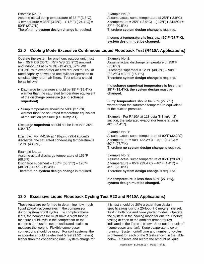
Example No. 1: Assume actual sump temperature of 38°F (3.3°C) Δ temperature = 38°F (3.3°C) – (-12°F) (-24.4°C) = 50°F (27.7°K) Therefore no system design change is required.
Example No. 2: Assume actual sump temperature of 25°F (-3.9°C) Δ temperature = 25°F (-3.9°C) – (-12°F) (-24.4°C) = 37°F (20.5°K) Therefore system design change is required. If sump Δ temperature is less than 50°F (27.7°K), system design must be changed.
12.0 Cooling Mode Excessive Continuous Liquid Floodback Test (R410A Applications)
Operate the system for one hour; outdoor unit must be in 95°F DB (35°C), 75°F WB (23.9°C) ambient and indoor unit at 67°F DB (19.4°C), 57°F WB (13.9°C) with evaporator air flow reduced to 50% of rated capacity at two and one-cylinder operation to simulate dirty return air filters. Test criteria should be as follows: • Discharge temperature should be 35°F (19.4°K)
warmer than the saturated temperature equivalent of the discharge pressure (i.e. discharge superheat).
• Sump temperature should be 50°F (27.7°K)
warmer than the saturated temperature equivalent of the suction pressure (i.e. sump ΔT).
Discharge superheat should not be less than 35°F (19.4°K). Example: For R410A at 418-psig (29.4 kg/cm2) discharge, the saturated condensing temperature is 120°F (48.9°C). Example No. 1: Assume actual discharge temperature of 155°F (68.3°C) Discharge superheat = 155°F (68.3°C) – 120°F (48.8°C) = 35°F (19.4°K) Therefore no system design change is required.
Example No. 2: Assume actual discharge temperature of 150°F (65.6°C) Discharge superheat = 120°F (48.9°C) – 90°F (32.2°C) = 30°F (16.7°K) Therefore system design change is required. If discharge superheat temperature is less than 35°F (19.4°K), the system design must be changed. Sump temperature should be 50°F (27.7°K) warmer than the saturated temperature equivalent of the suction pressure. Example: For R410A at 118-psig (8.3 kg/cm2) suction, the saturated evaporator temperature is 40°F (4.4°C). Example No. 1: Assume actual sump temperature of 90°F (32.2°C) Δ temperature = 90°F (32.2°C) – 40°F (4.4°C) = 50°F (27.7°K) Therefore no system design change is required. Example No. 2: Assume actual sump temperature of 85°F (29.4°C) Δ temperature = 85°F (29.4°C) – 40°F (4.4°C) = 45°F (25.0°K) Therefore system design change is required. If Δ temperature is less than 50°F (27.7°K), system design must be changed.
13.0 Excessive Liquid Floodback Cycling Test R22 and R410A Applications)
These tests are performed to determine how much liquid actually accumulates in the compressor during system on/off cycles. To complete these tests, the compressor must have a sight tube to measure liquid level in the compressor or the compressor must be set on calibrated scales to measure the weight. Flexible compressor connections should be used. For split systems, the evaporator should be elevated 5 feet (1.52 meters) higher than the condensing unit. System charge for
this test should be 20% greater than design specifications using a 25-foot (7.6 meters) line set. Test in both one and two-cylinder modes. Operate the system in the cooling mode for one hour before testing at each of the ambient temperatures indicated in the Table 1 below. Shut outdoor unit off (compressor and fan). Keep evaporator blower running. System on/off time and number of cycles is different for each of the 3 tests shown in the table below. Observe and record the amount of liquid

Application Bulletin 137 - Page 8 of 21
refrigerant (height or weight) at the start of each on cycle. If the compressor slugs, vibrates, or makes a
metallic sound on start-up, system design change is required.
Test No. 1 No. 2 No. 3
Indoor Ambient (°F) 70 (21.1°C) 70 (21.1°C) 70 (21.1°C) Outdoor Ambient (°F) 85 (29.4°C) 95 (35.0°C) 105 (40.6°C) System On-time (Minutes) 7 14 54 System Off-time (Minutes) 13 8 6 Number of On/Off Cycles 5 5 4
Table 1
14.0 Metering Devices
Only one balanced port thermostatic expansion is necessary to meter the refrigerant in a cooling-only system, in one or two-cylinder operation. Packaged heat pumps also require only one balanced port TXV (bi-flow). Split heat pumps normally require two balanced port TXVs (with check valves), one in the indoor section and one in the outdoor section. Bristol has worked with several suppliers to develop electrically activated dual orifice refrigerant flow control that can be used as a lower cost alternative to thermostatic expansion valves.
Dual Orifice Scheme: This scheme will employ a two-orifice valve which will be in the small orifice position for one-cylinder operation (de-energized solenoid) and in the large orifice position for two-cylinder operation (energized solenoid). Single Orifice Scheme: This scheme will employ a single orifice valve (optimized for one-cylinder operation) installed in series with the existing metering device, and when energized for two-cylinder operation will open and allow full flow to the existing full capacity metering device.
15.0 Start-up Sound, Vibration, and Discharge Pulsations
A normal characteristic of the “TS”, due to the engagement of the reversing mechanism, can be a metallic impact noise during start up. This noise is normally not noticeable but may be more detectable if starting components are employed (i.e., start capacitor/relay) and thus should be taken into consideration by the system designer. The two-cylinder vibration/pulsation characteristic is very similar to standard reciprocating products. The increased magnitude and lower frequency of the one-cylinder vibration/ pulsation characteristic require special consideration in cabinetry and tube designs. Capillary tubes feeding refrigerant from the metering device, tubes from switches (low and high-pressure, etc.), and low and high-side service
gauge connecting tubes must have special attention to minimize their movement. Close proximity tubing designs should have insulators to assure they cannot come in contact with other system components. In heat pump designs, an external discharge muffler is required to minimize indoor coil excitation in the one-cylinder heat mode. A muffler such as Spinco 162076-12 (approx. 9.5 in3 internal volume) is recommended for most applications, however, a larger muffler may be needed in some applications. Although Bristol testing indicates the best mounting location to be as close to the compressor discharge outlet as possible, system testing should be conducted to confirm the optimum location.
16.0 Compressor Oil Circulation and Return on Split Systems
Keeping oil circulation to a minimum and insuring its return to the compressor is very important and is dependent on the system design and application. On TS compressors, the tube sizing of the system is selected to meet the total capacity output of the compressor in the two-cylinder mode. Because of
this, oil circulation and return when the compressor is operating in one-cylinder mode is very critical due to the reduced refrigerant gas velocity. Oil return is most critical for upward flow (condensing unit/compressor above evaporator)

Application Bulletin 137 - Page 9 of 21
through the vapor suction line between the indoor coil and the compressor. The system designer needs to do the following: Step 1: Specify the highest ambient temperature and the lowest evaporator temperature at which the one-cylinder mode could operate with allowance made for control tolerance. Step 2: Determine the mass flow of one cylinder at the condition in Step 1 using the performance tables of the one-cylinder operation.
Step 3: Compare the mass flow from Step 2 with the minimum refrigeration capacity (in tons) for oil entrainment through the selected suction line size as from Table 13 of Chapter 2 of the 1998 ASHRAE Handbook on Refrigeration. Step 4: If the capacity of the one-cylinder mode, as calculated from Step 2, is equal or close to the minimum capacity derived from the ASHRAE Handbook, the designer should run actual oil return tests to insure the minimum compressor oil level is maintained when tested at the worst case conditions of suction and discharge pressures and temperature.
17.0 Operating Envelope
TS compressors must operate within the operating envelope as defined by published performance tables. Operation outside these limits could result in
increased noise and possible premature compressor failure. Pressure limiting switches are highly recommended.
“TS” Electrical See attached Schematics I through IV for suggested system controls including compressor, indoor blower, outdoor fan, start assist, and metering devices. 18.0 Power Wiring
All “TS” compressors have standard 3 pin terminal connections. The two-cylinder wiring is identical to our single capacity compressors. The basic one-cylinder scheme uses an additional single-pole contactor, which reverses the motor, refer to Schematic I. The main winding becomes the start
winding and the start winding becomes the main winding, simultaneously optimizing the motor strength for the reduced load. Another scheme would be to use only one single pole contactor (for power) along with a toggling relay (for motor direction control) as shown in Schematic IV.
19.0 Motor Protection
“TS” employs the same proven motor and internal line break motor protector that has been used for the last 30 years. The dual element protector is designed to protect both windings under the most common overload situations. As with any single-phase compressor, applying line power (L1 and L2) to the S (T2) and R (T3) terminals (i.e., a
miswire) can damage the protector and/or motor. One side of the line power (L1) must always go directly to the common terminal (T1) on the compressor so miswires will be avoided. Only L2 will be switched between S (T2) and R (T3) to reverse rotation of the compressor. See following schematic:
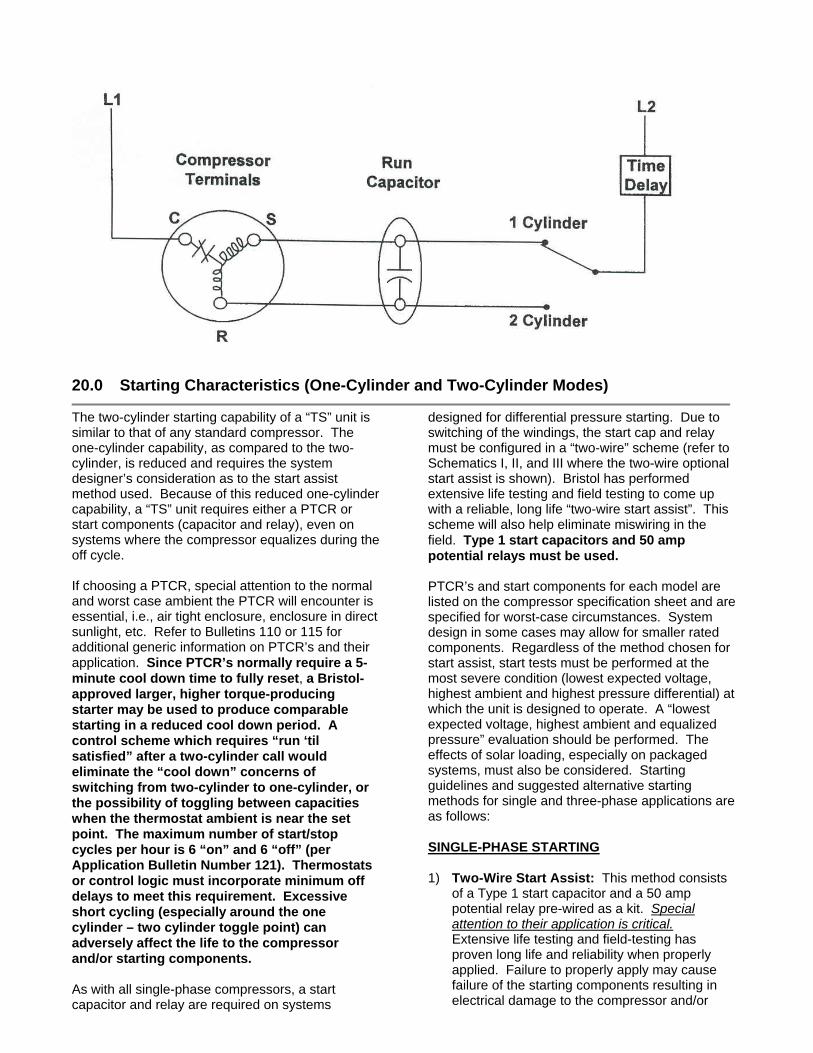
20.0 Starting Characteristics (One-Cylinder and Two-Cylinder Modes)
The two-cylinder starting capability of a “TS” unit is similar to that of any standard compressor. The one-cylinder capability, as compared to the two-cylinder, is reduced and requires the system designer’s consideration as to the start assist method used. Because of this reduced one-cylinder capability, a “TS” unit requires either a PTCR or start components (capacitor and relay), even on systems where the compressor equalizes during the off cycle. If choosing a PTCR, special attention to the normal and worst case ambient the PTCR will encounter is essential, i.e., air tight enclosure, enclosure in direct sunlight, etc. Refer to Bulletins 110 or 115 for additional generic information on PTCR’s and their application. Since PTCR’s normally require a 5-minute cool down time to fully reset, a Bristol-approved larger, higher torque-producing starter may be used to produce comparable starting in a reduced cool down period. A control scheme which requires “run ‘til satisfied” after a two-cylinder call would eliminate the “cool down” concerns of switching from two-cylinder to one-cylinder, or the possibility of toggling between capacities when the thermostat ambient is near the set point. The maximum number of start/stop cycles per hour is 6 “on” and 6 “off” (per Application Bulletin Number 121). Thermostats or control logic must incorporate minimum off delays to meet this requirement. Excessive short cycling (especially around the one cylinder – two cylinder toggle point) can adversely affect the life to the compressor and/or starting components. As with all single-phase compressors, a start capacitor and relay are required on systems
designed for differential pressure starting. Due to switching of the windings, the start cap and relay must be configured in a “two-wire” scheme (refer to Schematics I, II, and III where the two-wire optional start assist is shown). Bristol has performed extensive life testing and field testing to come up with a reliable, long life “two-wire start assist”. This scheme will also help eliminate miswiring in the field. Type 1 start capacitors and 50 amp potential relays must be used. PTCR’s and start components for each model are listed on the compressor specification sheet and are specified for worst-case circumstances. System design in some cases may allow for smaller rated components. Regardless of the method chosen for start assist, start tests must be performed at the most severe condition (lowest expected voltage, highest ambient and highest pressure differential) at which the unit is designed to operate. A “lowest expected voltage, highest ambient and equalized pressure” evaluation should be performed. The effects of solar loading, especially on packaged systems, must also be considered. Starting guidelines and suggested alternative starting methods for single and three-phase applications are as follows: SINGLE-PHASE STARTING 1) Two-Wire Start Assist: This method consists
of a Type 1 start capacitor and a 50 amp potential relay pre-wired as a kit. Special attention to their application is critical. Extensive life testing and field-testing has proven long life and reliability when properly applied. Failure to properly apply may cause failure of the starting components resulting in electrical damage to the compressor and/or

Application Bulletin 137 - Page 11 of 21
associated system wiring. The following guidelines are required:
• Part Number – Always use the exact
specified part number and never substitute alternate kits or individual components unless approved by Bristol. Reference the individual compressor specification sheet for the correct two-wire start assist part number. This can be found at www.bristolcompressors.com or obtained directly from Bristol Compressors.
• Relay Mounting – The relay must be
securely and directionally mounted per print or as indicated on the case as “This side up” or Top ↑ (with an arrow pointing direction). Improper mounting can affect the contact “pick-up” and “drop-out” characteristics. Note: If a kit is dropped during handling and assembly, do not use. Although visual damage may not be evident, the calibration could be affected.
• Capacitor Mounting – The start capacitor
must be mounted vertically in the electrical box (terminal end facing up). The area between the top of the capacitor and edge of electrical box should remain clear of any other electrical components, wire harnesses or flammable material. Improper mounting can result in electrical component damage in the event of electrolyte leakage or venting. It is highly recommended that the start capacitor be isolated, or otherwise shielded, to minimize the hazards during servicing with the electrical box open. Adequate warnings to service personnel, both on the unit and service manuals, must require the use of eye protection and procedures to check the capacitor current and proper relay operation.
• Wiring – Two-wire start assist kits are not
designed to be wired like typical hard start kits using a three-wire connection. To avoid the potential of a miswire or loose connection, they should not be separated and re-wired during installation. The only connections necessary by the installer are the two wires connected across the compressor run capacitor (start-run terminals of the compressor). They must be permanently wired to assure the capacitors discharge properly for every start-up sequence. It is important to make sure all connections are tight. If for any reason either component in the kit is determined defective, always remove and replace the complete assembly.
• Operation – The relay coil depends on the
potential developed across the compressor run capacitor for proper contact disconnect or “pick-up”. System operational voltage must be between 197 – 253 volts. Exceeding 253 volts could cause the relay contacts to “pick-up” too quickly stalling the compressor before it gets up to speed and tripping the internal overload protector. Dropping below 197 volts could cause the relay contacts to not “pick-up” properly or chatter, exposing the start capacitor to extended periods of high current. Continued exposure to this high current condition will quickly fail the start capacitor, damage the relay and overheat the device wiring.
• System Control Scheme – System control
schemes and thermostat applications must employ logic to protect against compressor short cycling and/or compressor contactor chatter. Maximum cycle rate should be 6 “on” and “off” cycles per hour (Application Bulletin 121). Operational schemes that can toggle between one and two-cylinder operation for less than 10 minute cycles should be avoided. A “run until satisfied” after two-cylinder operation is initiated is highly recommended. Compressor short-cycling or short run time toggling between two-cylinder and one-cylinder operation will cause excessive relay contact wear and excessive heat build-up in the start capacitor. Compressor contactor chatter can rapidly deteriorate the relay contacts resulting in premature failure.
2) Timer/Start Capacitor: This method is an
alternate to the “two-wire” starting scheme for non-equalizing systems. It requires the system designer to incorporate a precision “fixed” timer and a normally closed relay with the specified start capacitor. The timer/relay can be integrated into the TS system electronic control board or can be configured as a stand-alone device. The timer must be a “delay on make” initiated when power is applied to the compressor. It must employ sensing logic (i.e., line current or capacitor voltage) to reset itself in the event the compressor internal overload opens. This will prevent a restart attempt without the start capacitor in the circuit. The relay must have a 50 amp minimum contact rating. The start capacitor microfarad (μfd) value should be minimized to reduce the stress on the capacitor and relay since the compressor will almost always be up to speed at switch-out. Higher switch-out speed produces higher

Application Bulletin 137 - Page 12 of 21
voltage and current especially at high line voltage. The timer value must never exceed .5 seconds. If system starting requirements are met, a lower ampere rated relay, lower μfd start capacitor or lower cost Type II start capacitor
may be used. Although the relay will not be position sensitive, the same criteria for the 2-wire start capacitor mounting and system control scheme must be followed.
3) Equalized Pressure with PTCR: This low cost
approach requires the designer to incorporate a method of total system equalization prior to each compressor start attempt. Reduced compressor mechanical stress, lower cost/complexity, and higher reliability can be realized with this scheme. A smaller 2-wire start capacitor and relay may be substituted. However, this approach could affect the system ARI system performance rating (Cd) and should be designed to minimize the impact. Some techniques for consideration are:
• Cycle the reversing valve (Heat pumps). • High to low side by-pass loop activated with
a solenoid (AC systems). • Bleed type TXV, fixed orifice or capillary tube
refrigerant controls with additional switching time delay.

Application Bulletin 137 - Page 13 of 21
4) Equalized Pressure While Maintaining System Delta P: This technique will achieve internal compressor equalization but maintain the system delta P to address Cd issues that may arise with ARI performance testing. It requires a check valve, bleed tube, and solenoid to be installed at the compressor as illustrated:
Three Phase Starting Bristol TS (Twin Single) compressor crankshafts feature a special rotating eccentric lobe that repositions itself when the compressor reverses. The high torque of three phase starting requires the use of a “soft start” to reduce impact and prevent damage when the lobe contacts the stop block. In many regions of the world, electrical codes require the use of soft starters on most HVAC systems to limit in-rush current for single and three phase applications. TS compressor applications for systems already designed for operation in these areas will inherently have the soft start requirement satisfied. For applications without this mandate, there are many commercial soft starters of various types available. Listed below are some excellent sources that offer both “off the shelf” devices and are equipped to assist system designers with cost effective solutions for their specific requirements.
CARLO GAVAZZI 750 Hastings Lane Buffalo Grove, IL 60089-6904 Phone: (874) 465-7373 Fax: (847) 465-7373 Internet: http://www.carlogavazzi.com/us E-Mail: [email protected] ICM CONTROLS PO Box 2819 Syracuse, NY 13220 Phone: (315) 233-5266 Fax: (315) 233-5276 Application Assistance: 1-(800) 365-5525 Internet: http://www.icmcontrols.com WEIGEL ELEKTRONIK Kramenwiesstrasse 14 CH 9652 Neu St. Johann Switzerland Phone: (+041) 071/994 2111 Fax: (+041) 071/994 2813
LEASAM CONTROLS OEM Electronics Pty Ltd Unit 30 / 17-37 Lorraine Street Peakhurst NSW 2210 Australia Phone: +61 2 9533 2300 Fax: +61 2 9533 2252 A cost-effective alternative soft starting method for consideration by the system designer is using ceramic power resistors. This requires the construction of a device consisting of three ceramic power resistors (value specified by Bristol), one three-pole contactor (or three single-pole relays) and one delay on make timer. It can be configured as a “stand alone” device or integrated into the existing system controls. See Figure 1 for circuit arrangement. The operational characteristics of the device are as follows: at start up, power flows through the resistors limiting the current and voltage to the compressor motor causing the mechanical to turn slowly. After 100 mS the resistors are shunted by the M2 contactor allowing full line power to compressor. This limited voltage/current effect reduces the impact on the eccentric lobe against the stop block as the motor comes to full speed.

Application Bulletin 137 - Page 14 of 21
Figure 1
Note: M2 contact rating must be equivalent to M1 contact rating. A precision “delay on make” timer capable of shunting M2 contactor at 100 mS must be used. *CAUTION*: The resistors must be mounted in a metal enclosure and shielded from any flammable components.

Application Bulletin 137 - Page 15 of 21
21.0 Time Delays
Time delays are required anytime the motor is switched from one direction to the other (from one to two-cylinder or vice-versa) to assure the compressor has come to a complete stop. If the system has start components (capacitor and relay); the minimum time delay only needs to be two seconds. If the system uses only a PTCR start assist, the time must be set to
assure system pressures are equalized before starting (normally two minutes minimum). This does not preclude a start test to determine the time delay required for customer’s specific system/application.
22.0 Low Voltage Controls
Four suggested methods of control: 1) Conventional – Using off-the-shelf two-stage
thermostat, relay, and discrete time delays (See Schematic I).
2) Outdoor thermostat – Using off-the-shelf single-stage room thermostat, outdoor stat(s), relay, and discrete time delays (See Schematic II).
3) Semi-electronic – Using conventional two-stage room thermostat with microprocessor control of all functions and time delays. This scheme allows greatly improved capabilities and lower cost than discrete components. (See Schematic III).
4) Ultimate electronic – Integrates all system controls into a two-wire “communicating” scheme (only two wires connect the thermostat, air handler, and outdoor unit) (see Schematic IV). Includes a digital room thermostat, indoor two-step inverter blower control, and a “combined function” outdoor board. The outdoor board includes the compressor control relays (no additional contactors required), start relay, condenser fan relay, three-count logic safety input, and compressor over-current protection. Output relays are also provided to control electrically actuated dual orifice expansion valves (EXV). The heat pump version includes demand defrost with all sensor inputs and reversing valve control. This control system has been developed exclusively for TS Technology.
23.0 Indoor Blower Controls
Bristol has worked with suppliers to develop a two-step control to reduce the blower speed on one-cylinder operation. The new device optimizes the indoor air CFM using significantly lower power, which further increases system efficiency. The 60 Hz line/30 Hz inverter concept operates the motor at line voltage/frequency at the high CFM air requirements (two-cylinder) and at 30-38 Hz for the low air requirements while
significantly reducing motor power. The inverter power requirements are greatly reduced at the lower frequency, allowing a much lower cost alternative to conventional full variable speed. Tapped blowers can also be used effectively to control indoor airflow with some power savings as compared to full blower speed operation.

A
pplication Bulletin 137 - P
age 16 of 21

A
pplication Bulletin 137 - P
age 17 of 21

A
pplication Bulletin 137 - P
age 18 of 21

A
pplication Bulletin 137 - P
age 19 of 21

Application Bulletin 137 - Page 20 of 21
R22 and R410A Pressure / Temperature Tables

Application Bulletin 137 - Page 21 of 21
Release EN Number G25104 Release Date 11/19/99
REVISIONS J07109 3/30/01 P07304 11/3/06 K20001 8/9/02 L33602 1/16/04 M20404 11/05/04