ReliaTel™ Microprocessor Controls (RT-SVD03 - HVAC-Talk
116
RT-SVD03D-EN September 2005 ReliaTel ™ Microprocessor Controls
-
Upload
khangminh22 -
Category
Documents
-
view
2 -
download
0
Transcript of ReliaTel™ Microprocessor Controls (RT-SVD03 - HVAC-Talk

RT-SVD03D-ENSeptember 2005
ReliaTel™
Microprocessor Controls

© 2005 American Standard All rights reserved
3 to 10 ton Convertible and12½ to 50 ton DedicatedPackaged Rooftops3 to 10 ton cooling only and gas electricconvertible packaged units can be builtwith either electromechanical orReliaTel™ controls. 12½ to 50 ton unitsare built with ReliaTel controls only. AllHeat pumps are built exclusively withReliaTel controls. This publication coversboth electromechanical and ReliaTelcontrols. Due to the more complexapplication and service opportunities,greater emphasis is placed on units withReliaTel controls.This publication does not cover allaspects of service. It assumes that theservice person is an experiencedcommercial service technician with astrong background in electrical controlsand DC circuits. If you are notexperienced and fully qualified in HVACservice, do not attempt to use this manualto service equipment. Doing so couldcause personal injury to yourself orothers and could result in expensiveequipment or property damage.
ReliaTel IntroductionReliaTel is not the name of a circuit board,but rather an overall communicatingcontrol system consisting of up to fivecommunicating modules. The nextsection covers various aspects of ReliaTeland Electromechanical controls.ReliaTel is the name given to the secondgeneration microprocessor controlsdeveloped by Trane/American Standard.ReliaTel controls were first used in the 3-10 ton convertible packaged cooling withelectric heat, gas electric, and heatpumps. ReliaTel has now been added toother commercial products as well. InApril 2003, 12½-25 ton dedicated unitswere converted to ReliaTel controls. InApril 2004, ReliaTel controls were addedto 27½ to 50 ton dedicated units
Why change?The Micro has proven itself to ourcustomers in thousands of applicationsaround the world. A microprocessorbased unit provides superior comfort,unmatched reliability and much greaterflexibility than conventional systems.ReliaTel has even more flexibility, is morecompact, has additional system reliabilityenhancements and more.Much of what ReliaTel does will be veryfamiliar to service techniciansaccustomed to the previous generationMicro. Testing and troubleshooting issimilar, and in many cases the same.There are, however, some significantdifferences, so it is important that theservice person use the correct materialfor the unit being serviced.
Introduction

3
Contents
IntroductionConvertible and Dedicated Packaged Rooftops .......................... 2ReliaTel ............................................................................................ 2
General InformationReliaTel vs. Electromechanical ..................................................... 5ReliaTel - Module Descriptions ..................................................... 5
Refrigeration Module Flow Diagram (RTRM)TSC, THC Electric Heat/No Heat .................................................... 6YSC, YHC Gas Heating ................................................................... 7WSC Heat Pump ............................................................................. 8Options Module (RTOM) ................................................................ 9Economizer Module (ECA) ............................................................ 10COMM3/4 Module for ICS Communications .............................. 11
Low Voltage Terminal Strip ........................................................................12Typical Control Box Layout
3-5 Tons ..........................................................................................136-10 Tons ........................................................................................1412½-25 Tons ...................................................................................15
ReliaTel Refrigeration Module (RTRM)Layout .............................................................................................16Board Connections .......................................................................17Diagnostics ....................................................................................18Diagnostics (VAV) ..........................................................................23
ReliaTel Control (RTRM)Default Operation ..........................................................................24
ReliaTel Options Module (RTOM)Layout .............................................................................................26Inputs .............................................................................................27
LED Functions .............................................................................................28Protocol of Communications ....................................................................29Test Mode ...................................................................................................30Thermostat and Sensors
Layout .............................................................................................34Sensor Descriptions .....................................................................35Sensor Diagrams...........................................................................36
High Temperature Sensor ..........................................................................43Zone Sensor (ZSM) Testing-Zone Temperature Input ..............................44Zone Sensor Cooling/Heating Setpoints/Mode Inputs-Mechanical ZoneSensor Module ...........................................................................................45Zone Sensor Mode Inputs .........................................................................46RTRM/RTOM Temperature Inputs .............................................................48Zone Sensor Averaging..............................................................................51Operation with a Conventional Thermostat .............................................52COMM3/4 Interface Operation and Troubleshooting ...............................55Direct Spark Ignition Control - Texas Instruments ..................................56Direct Spark Ignition Control - Sequence of Operation ..........................57ReliaTel Hot Surface Ignition Control - Texas Instruments .....................58Hot Surface Ignition Control - Sequence of Operation ...........................59

4
Contents,continued
Gas Heat Specifications3-5 Tons Low Heat .......................................................................... 603-5 Tons Medium Heat .................................................................... 613-5 Tons High Heat .......................................................................... 626-10 Tons Low Heat .........................................................................636-10 Tons Medium Heat .................................................................. 646-10 Tons High Heat ........................................................................ 65
Heat Pump Demand Defrost ....................................................................... 66ReliaTel Economizer Module (ECA) Layout ............................................... 68ReliaTel Economizer Operation ................................................................. 69Economizer Damper Enthalpy Layout .......................................................71Economizer Operation Enthalpy Changeover ...........................................72ReliaTel Economizer Inputs ....................................................................... 75ReliaTel Economizer Control Actuator (ECA) LED Fault Code Information .............................................................. 76ReliaTel Humidity Sensors .........................................................................77Electromechanical Economizer Functions ................................................ 78Electromechanical Economizer Testing ..................................................... 79Electromechanical Economizer - 3 Position Damper ...............................80ReliaTel Control - Temporary Operation ....................................................81ReliaTel Supply Air Tempering Control ..................................................... 82Discharge Air Sensing with TCI COMM3/4 ................................................ 83C02 Sensor Connections for ReliaTel Units with Economizer ................. 84ReliaTel - Ventilation Override .................................................................... 85ReliaTel - Dehumidification ........................................................................ 86ReliaTel Heating/Cooling Changeover .......................................................87Electromechanical Time Delay Relay ......................................................... 88Electromechanical Time Delay Relay - Sequence of Operation .............. 89Snubber Circuits ......................................................................................... 90Transformer Troubleshooting ..................................................................... 91High and Low Pressure Lockout Circuits .................................................. 93Novar Controls ............................................................................................ 94Voyager Commercial 27½ to 50 ton VAV/CV ............................................. 97
Overview ......................................................................................... 97Module Definitions .........................................................................98Configuration Input ........................................................................ 99VAV Modes of Operation ............................................................. 100VAV Airflow ................................................................................... 101VAV RTAM ..................................................................................... 102CV/VAV Troubleshooting .............................................................. 103VAV Outdoor Airflow Condensation ........................................... 104BAYSENS021* .............................................................................. 105VAV Remote Setpoints ................................................................. 105VAV Setpoint Inputs ..................................................................... 106VAV RTAM Setpoints .................................................................... 107
Software Change History ...........................................................................110Index ........................................................................................................... 112Tables ......................................................................................................... 114

5
ReliaTel vs. ElectromechanicalThree to ten ton convertible packagedgas/electric (YSC, YHC) and cooling only(TSC, THC) are available withoutmicroprocessor controls.1 Withelectromechanical controls, zone sensorscannot control the units, nor can buildingautomation systems communicate withit. Electromechanical units require theuse of a thermostat or relay basedcontrol system to directly control relays,contactors, etc. The ignition control andeconomizer are different than the onesused with ReliaTel. Service informationfor these components are handledseparately in this book.1. ReliaTel Controls: 9th digit “R”Electromechanical Controls: 9th digit “E”
27.5-50 Ton: ReliaTel controls 10th digit“M” or greater.
ReliaTel – Module Descriptions
Each ReliaTel Module is a communicatingcontrol.
ReliaTel Refrigeration Module (RTRM)Every ReliaTel unit uses an RTRM. TheRTRM provides primary unit control forheating and cooling. In addition, it hasbuilt-in logic that controls heating andcooling staging, minimum run times,diagnostics, heat pump defrost control,short cycle timing and more. It can becontrolled directly by any of the following:
Zone Sensor Module(BAYSENS006-11B,AYSTAT661-664B)
Programmable Zone Sensor(BAYSENS019*, 20*,AYSTAT666*)
Conventional Thermostat(such as BAYSTAT036-038A,ASYSTAT701-703)
Note: Unlike the previous Micro, aconventional thermostat does notrequire any sort of interface. It can bewired directly to the RTRM.
GeneralInformation
In addition, the unit can be controlledusing Trane® ICS systems by applyingthe appropriate interface. The RTRM isconfigured through the unit wiringharness. The same module is used ongas/electric, cooling only with electricheat, and heat pumps. The followingadditional inputs are connected to theRTRM:Outdoor Air Sensor (OAS)Coil Temperature Sensor (CTS) heatpump onlySmoke detector (unless it is factoryinstalled) or other shutdown device.
(See (RTOM) outlines on thefollowing pages)
The RTOM gets power from andcommunicates with the RTRM.
Any of these optional ReliaTel devicesrequire the use of an RTOM:• Frostat (FOS)• Clogged Filter Switch (CFS)• Fan Failure Switch (FFS)• Discharge Air Sensor (DAS) used for
supply air tempering and ICS inputdata
• Smoke Detector, Factory Installed
Note: A factory installed SmokeDetector provides instant shutdown andICS alarm output.
(27.5-50 Ton) Note: RTOM is standard.
(See (ECA) outlines on the followingpages)
Economizer Actuator w/ Module (ECA)The economizer can be used with orwithout the Options module. The actuatorhas a detachable communicating module,which can be replaced separately. Theoutdoor air sensor, connected to theRTRM, provides outdoor temperatureinformation for the changeover decision.
The ECA accepts the following inputs:
Mixed Air Sensor (MAS)
Return Air Sensor (RAS) for comparativeenthalpy or ICS input data
Outdoor Humidity Sensor (OHS) forreference or comparative enthalpy
Return Air Humidity Sensor (RHS) forcomparative enthalpy
CO2 Sensor 0-10VDC input
Remote Minimum Potentiometer (RMP)
The Power Exhaust relay is connected tothe ECA module as well.
(See (COMM3/4) outlines on thefollowing pages)
COMM3/4 Communication InterfaceAllows ICS communication between aReliaTel unit and Trane ICS systems asfollows:Tracer™ 100 seriesTracer™ SummitTracker™ComforTrac™VariTrac™ 1 (Comfort Manager)VariTrac 2 (Central Control Panel)
LonTalk® Communication InterfaceAllows ICS communication between aReliaTel unit and LonTalk CommunicationInterface (LCI).

6
TSC/THC Refrigeration Module (RTRM) Electric Heat/No Heat
Refrigeration ModuleFlow Diagram (RTRM)

7
YSC/YHC Refrigeration Module (RTRM) Gas Heating
Refrigeration ModuleFlow Diagram (RTRM)

8
WSC Refrigeration Module (RTRM) Heat Pump
Refrigeration ModuleFlow Diagram (RTRM)

9
Options Module (RTOM)
Options ModuleFlow Diagram (RTOM)

10
Economizer Module (ECA)
Economizer ModuleFlow Diagram (ECA)

11
COMM3/4 Module for ICS Communication/LonTalk Communication Interface (LCI)
Communication ModuleFlow Diagram (TCI/LCI)

12
TEST terminalsBy jumpering from TEST1 to TEST2, theservice technician can test the unit orstart it with or without any controlsattached. See TEST MODE section fordetails.
Compressor 1 disableIf the factory installed jumper from 1 to 2is removed (Compressor 1 disable),compressor 1 will not run, even in theTEST MODE. This is where a loadshedding device could be connected.
Compressor 2 disableIf the factory installed jumper from 3 to 4is removed (Compressor 2 disable),compressor 2 will not run, even in theTEST MODE. This is where a loadshedding device could be connected.
Emergency StopIf the factory installed jumper from 5 to 6is removed (Emergency Stop), the unitwill not run. The RTRM system LED willbe on. The unit will have Heat + Cooldiagnostic. An external smoke detector orother interlock device can be added here.
Low VoltageTerminal Strip

13
Typical ControlBox Layout (3-5 ton)
Zone Sensor
Thermostat
(or)

14
Typical ControlBox Layout (6-10 Tons)
Zone Sensor Thermostat(or)

15
Typical ControlBox Layout (12½ - 25 Tons)
Zone Sensor Thermostat(or)

16
➀➀➀➀➀ To enable lead/lag on multiple compressor units, cut wire connected to J3-8.
ReliaTel RefrigerationModule (RTRM) (Layout)
➀➀➀➀➀

17
For production, several versions of the RTRM are used depending on unit functions. There is one replacement module for all units.
ReliaTel RefrigerationModule (RTRM)
(BoardConnections)

18
The RTRM provides certain diagnosticinformation to the end user or servicetechnician depending on the type ofcontrols used. Regardless of controlsused however, a service technician with aDC voltmeter can read the diagnostics atthe RTRM as shown below.
Note: when a voltmeter is first applied,allow 2-3 seconds for the reading tostabilize.
The actual readings obtained vary depending on the controls used. The following charts show what readings to expect, as well aswhat the readings mean.
Approximate voltage readings (depending on control used)See “What Thermostat or Programmable MechanicalThe mechanical ZSM ZSM with ZSM withReadings without indicators indicators indicatorsMean” on or with no controlsthe follow- attached at alling pages.
ON 32 VDC ± 10% 26 VDC ± 10% 2.0 VDC ± 10%OFF 0.75 VDC ± 10% 0.75 VDC ± 10% 0.75 VDC ± 10%PULSING 20 TO 30VDC 1.5 TO 2.5VDC 14 TO 30VDC
ReliaTel RefrigerationModule (RTRM) (Diagnostics)
RTRM System LED Diagnostic IndicatorOn RTRM version 4.0 or higher, the greensystem LED on the RTRM module canprovide a quick visual indication of thepresence of certain diagnostics. If thegreen LED on the RTRM is blinking withtwo ¼ second blinks every two seconds,one or more of the following diagnosticsis present:
3-50 ton unitsSupply fan failZone temperature sensor input failureProgrammable ZSM communicationfailureManual compressor lockout (one or bothcircuits)Invalid outdoor coil temp sensor failure(heat pumps only)Defrost fault condition (heat pumps only)Gas heat failure
27½ to 50 ton units:Zone temperature sensor failure duringunoccupied mode (VAV only)Static pressure transducer output failure(VAV only)High duct static pressure trip (VAV only)Discharge air sensor failure (VAV only)If the service technician sees the RTRMfault indication, the next step is to checkfor diagnostics as indicated on thefollowing pages to help determine whichof the above diagnostics is present.
Note: Since Constant Volume (CV) units3-50 ton may use a conventionalthermostat, the RTRM will not display adiagnostic if a zone sensor is notattached when power is applied to theunit. Also, the RTRM ignores a zonesensor if it is attached to a powered-upunit (after a brief time-out). Therefore,always reset power after installing amechanical ZSM such as a BAYSENS006– 010 to terminals RTRM J6-1 throughJ6-10.

19
ReliaTel RefrigerationModule (RTRM) (Diagnostics)
What the readings meanServiceON – Clogged filter switchhas been closed for at least2 minutes, indicating aclogged filter.This example illustrateswhat would be seen if theunit did not have a zonesensor with indicator LEDs,such as would be the casewith an ICS system. Page 17lists voltages seen if a zonesensor is attached. Voltmeter readings should bewithin 10%.
OFF –1) Clogged filterswitch is in openposition or no switchis installed.2) Fan Fail switch (ifinstalled) has openedwithin the first 40seconds, proving thatthe fan has started.
PULSING – Fan Proving switch (alsocalled Fan Fail Switch FFS) has failed toopen after 40 seconds.During this condition, the unit will run for40 seconds and thenstop. Only the fan willrun during the TESTmode, except duringthe first 40 seconds.Note that at thebottom of the meterdisplay, the “analogbar” will pulse backand forth. Somemeters do not havethis extra feature.

20
ReliaTel RefrigerationModule (RTRM) (Diagnostics)
What the readings meanSystemON – System is poweredup. This output should beon whenever the RTRMSystem LED (Lite Port) ison. Incidentally, the LitePort flickers as part of itsnormal function.
OFF – If 0VDC is seen, the RTRM does nothave power, the output wiring is shorted,or there is an internal failure. Removeany wires connected to thisterminal and check again.
PULSING – Unit is in theTEST mode.
Also during the TEST modethe System LED will pulseon and off.
This output does notprovide any diagnosticinformation, but is a goodplace to confirm thatvoltage readings taken areconsistent with what shouldbe seen on other outputs.
What the readings meanCoolingON – System is in thecooling mode andactively cooling. The unitcould be economizing orhave one or bothcompressors on. If theunit is a heat pump, thereversing valve isenergized as well.

21
ReliaTel RefrigerationModule (RTRM) (Diagnostics)
OFF – System is notactively cooling.It may or may not be in thecooling mode.
PULSING – Thisindicator can mean oneor more of the following:
Any controls1) CC1 or CC2 opens
during cooling, or isopen when a call forcompressor occurs.The unaffectedcircuit will still run.With RTRM version4.0 or greater, CC1 orCC2 circuit mustopen on 3consecutive cycles.On the 3rd trip, theunit will lockout.
2) CPR1 Disable or CPR2 Disable input has opened during acompressor cycle each time acompressor starts (within the first 3minutes) for 3 consecutive cycles. Itlocks out on the fourth cycle. Theunaffected circuit will still run.
Mechanical ZSM1) Zone temperature input failure after a
successful input.2) Both heating and cooling setpoint
inputs have failed or are not attached(such as when using a 2 - wire sensoron terminals 1 & 2).
Programmable ZSMThe ZSM has failed to communicate for15 consecutive minutes after successfulcommunication has occurred.

22
ReliaTel RefrigerationModule (RTRM) (Diagnostics)
What the readings meanHeatingON – System is activelyheating.
OFF – System is notactively heating.
PULSING –Gas HeatIf any failure occurs such asloss of flame, limit switch trip,flame rollout etc, thisindication is present. Furtherdiagnostics are available byexamining the IgnitionModule LED. See the gasheat section for details.
Electric heatThese units have safetylimit switches in theelectric heat controlcircuit. Should they triphowever, no indicationwill occur. The HEATindication will stay ON.
Heat Pump1) Unit is in the EMERGENCY HEAT mode.2) If the Compressor Disable circuit or CC1, CC2 circuits create a lockout during heatingmode, a COOL FAIL (pulsing) indication will occur, not a HEAT FAIL (pulsing) indication.See COOL indications for details.
HEAT FAIL and COOL FAIL at the same time:1) Coil temperature sensor is open or shorted.2) Unit has failed to defrost properly. See Heat Pump section for further details.3) Outdoor air sensor is open or shorted. (RTRM version 4.0 or greater.)

23
ReliaTel RefrigerationModule (RTRM)VAV Only (Diagnostics)
27½ to 50 ton unit Additional Diagnostics(VAV only)If only one diagnostic is present, refer tothat diagnostic. If more than onediagnostic is present, refer tocombination diagnostics such asCOOL + HEAT as appropriate. On aBAYSENS020*, the display will showHEAT FAIL or COOL FAIL or SERVICE (oran appropriate combination) if adiagnostic is present.
HEAT (YC only)1. TCO1, TCO2, or TCO3 has opened2. IGN Module lockout (see gas heat
section for troubleshooting)
COOL1. Discharge air sensor (DTS) is open,
shorted, or has failed.2. Zone temp input (RTRM J6-1) is open,
shorted, or failed during anunoccupied mode. If the unit has adefault mode input (jumper fromRTRM J6-2 to RTRM J6-4, a valid zonetemp input is needed for unoccupiedheating, MWU and DWU.
3. CC1 or CC2 24 VAC control circuit hasopened 3 times during a coolingmode. Check CC1, CC2 coils or anycontrol in series with the coils (windingthermostat, HPC, circuit breakerauxiliary contacts).
4. LPC 1 or LPC 2 has opened during the3 minute minimum “on” time during 4consecutive compressor starts. CheckLPC 1 circuit by measuring voltagefrom RTRM J1-8 to chassis ground.Check LPC 2 circuit by measuringvoltage from RTRM J3-2 to chassisground. If 24 VAC is not present, thecircuit is open. 24 VAC should presentat these terminals at all times.
SERVICE1. The supply fan proving switch (FFS)
has failed to open within 40 secondsafter the fan starts or has closedduring fan operation.
COOL + SERVICE1. Static Pressure Transducer output
voltage at RTAM J1-3 is less than0.25VDC. The transducer output isopen, shorted, or the transducer isreading a negative supply airpressure.
HEAT + COOL1. The Emergency Stop input (TB1-5 and
TB1-6) is open. Check this input at theRTRM by measuring voltage fromRTRM J1-12 to chassis ground. 24 VACshould be present whenever theEmergency Stop input is closed.
2. Outdoor air sensor (OAS) input isopen, shorted, or has failed.
HEAT + COOL + SERVICE1. Static Pressure High Duct Static Trip.
The static pressure has exceeded 3.5"W.C. three consecutive times.

24
ReliaTel RefrigerationModule (RTRM)
(DefaultOperation)
Default operation for Mechanical ZSM (CV Only):J6 Input / connection If no input / connection this happens:J6-1 - Zone temperature Unit stopsJ6-2 – Common terminal for 1-5 Unit stopsJ6-3 - Cooling Set Point (CSP) HSP + 4FJ6-5* - Heating Set Point (HSP) CSP – 4FJ6-3&5 - No CSP or HSP from unit 74F CSP, 71F HSPJ6-4 - Mode Input from ZSM Auto Changeover with continuous fanJ6-6* – Common terminal for 7-10 LED’s will not function any timeJ6-7* – Heat indication LED will not come on while heating
LED will not flash during heat failJ6-8* – Cool indication LED will not come on while cooling
LED will not flash during cool fail*J6-9* – System indication LED will not come on while unit has powerJ6-10* – Service indication LED will not come on when CFS or FFS trips
* these connections are only on certain model ZSM’s.
Default operation for Programmable ZSM:J6 Input / connection If no input / connection this happens:J6-7 – Heat indication “HEAT” will not be displayed while heating
“HEAT FAIL” will not be displayed during heat failJ6-8 – Cool indication “COOL” will not be displayed while cooling
“COOL FAIL” will not be displayed during cool fail*J6-9 – System indication Colon (:) will not blink during normal operation
“TEST” will not be displayed during TEST modeJ6-10 – Service indication “SERVICE” will not be displayed when clogged filter switch has
tripped“SERVICE” will not flash when the FFS has tripped
J6-11 – Common No display, no communicationJ6-12 - Communication No communication – “COOL FAIL” indicationJ6-14 – 24VAC power No display, no communication
The ReliaTel Refrigeration Module(RTRM) can accept input from any of thefollowing:Mechanical Zone Sensor Module (ZSM)BAYSENS006-11B, AYSTAT661-664BProgrammable Zone SensorBAYSENS019*, AYSTAT666*Conventional thermostat BAYSTAT036-038A (or similar)
*cool fail indication can occur for several reasons. See diagnostic section for more on this.
Note: Version 1.1 and 1.3 RTRM do not provide Heat, Cool, Service, Cool Fail, Heat Fail indications for Programmable ZSM. Laterversions (with a higher number) do.
ICS systems – Tracer, Tracker, VariTracWith each installed device, default modesof operation come into play, dependingon that device’s inputs. Following is asummary of functions and defaults:

25
ReliaTel RefrigerationModule (RTRM)
(DefaultOperation)
Default operation for ICS control:COMM3/4 and COMM5 Communication Interface Modules use MODBUS communication directly with the RTRM. Tracker and Tracerrequire inputs as shown:
J6 Input / connection If no input this happens:J6-1 - Zone temperature Unit stops (unless Tracer is providing this input)J6-2 – Common terminal for 1-3 Unit stopsJ6-3 - Cooling Set Point (CSP) Tracer / Tracker set points are used.
Note: VariTrac does not require any input to J6
Conventional thermostat – default operationSee section on Conventional Thermostat Operation for more on this.
Input / connection If no input, this happens:G (Indoor fan) A heat or cool call will also enable the fan.The purpose of G is to provide a way to run the fan continuously.
Input / connection (27½ to 50 ton VAV only) If no input, this happens:Default mode input jumper J6-2 to J6-4. Without a mode input, the unit will not run.Zone temperature input J6-2 to J6-1. Unoccupied mode (short J6-11 to J6-12).
Gives cool fail diagnostic.

26
3 to 10 tonThe RTOM is installed in the indoor fansection. When field installed, it comeswith a short harness which allows bothends of the unit control harness to beattached.
ReliaTel OptionsModule (RTOM) (Layout)
12½ to 50 tonThe RTOM is installed in the control panel.

27
J1, J2 Inputs:J1 provides 24VAC power and MODBUScommunication to and from the RTRM(via the COMM 3/4 if used). J2 sendspower and communication to the ECA (ifused).
J3 Inputs:J3-1 to J3-2 – Allows supply airtempering when using a mechanical ZSMsuch as BAYSENS006-11/AYSTAT664.Removed = supply air temperingenabled, installed = disabled. Supply airtempering can also be enabled ordisabled by using the BAYSENS019*/AYSTAT666* or a Trane ICS system. Theother inputs are not used on this unit.
J4 Inputs:Discharge air sensor (10K @ 77°F/25°C)allows supply air tempering, alsodischarge air information for BuildingAutomation systems (BAS) usingCOMM5 such as Tracer Summit™ V13and Tracker™ Version 10. Earlier versionsof Tracker (V6.5 and below) and anyTracer system using COMM3 or COMM4do not recognize this input.The input seen by Tracer (using COMM3or COMM4) and Tracker (prior to Version10) is “Supply Air Temperature”, which isactually the Mixed Air Temperature inputfrom the ECA to the RTRM. The otherinputs on J4 are not used.
J5 Input is not used on this unit.
ReliaTel OptionsModule (RTOM) (Inputs)
J6 Inputs:Ventilation override inputs J6-1, 2, 3 areexplained in the application section of thismanual.Remote Shutdown – when this input isopen, the unit runs normally. Whenclosed, the unit shuts down afterminimum run times are met, up to 4minutes. This is not the same as theemergency stop inputs on LTB 5&6.
J7 Inputs:Frostat closes at 10°F+-2°. When closed,compressors will shut off after minimumrun times are met. The Frostat opens at60°F+-2°. When the Frostat opens, thecompressors will re-start. There is nodiagnostic during Frostat trip.Clogged filter switch is factory set toclose at 0.45”, however is adjustable from0.05” to 12.0”. A 7/32” allen wrench isrequired for this adjustment. When theswitch is closed for 2 minutes, the serviceindicator on the ZSM will be on (seediagnostics section for details). When theswitch opens, the indicator is off (autoreset).Fan proving switch (3-25 tons) isfactory set to open at 0.07”, and isadjustable from 0.05” to 12.0”, thoughadjustment is not recommended. If theswitch does not open within 40 secondsafter the fan starts, the unit stops,requiring manual reset from the ZoneSensor or BAS system, or by resettingpower to the unit. The SERVICE indicatoron the ZSM will pulse during fan failmode.
Fan proving switch (27½-50 tons) isfactory set to close at 0.15”, and isadjustable from 0.05” to 12.0”, thoughadjustment is not recommended. If theswitch does not close within 40 secondsafter the fan starts, the unit stops,requiring manual reset from the ZoneSensor or BAS system, or by resettingpower to the unit. The SERVICE indicatoron the ZSM will pulse during fan failmode.Smoke detector contacts are openduring normal operation. When closed,the unit shuts down immediately. Whenthe contacts are re-opened, the unit willautomatically restart. Ventilation overrideoption will override smoke detector inputthrough the RTOM.Exhaust setpoint potentiometer setsthe point to which the exhaust fan willcome on. It can be set from 0%(whenever supply fan is on exhaust is on)to 100% (exhaust fan comes on wheneconomizer is 100% outside air). Turnclockwise to increase setpoint.
J8 Input:Relative humidity sensor providesinput for humidity sensor. When the inputis for humidity sensor. When the input isvalid, the reheat value is energized. Whenthe humidity sensor is satisfied, the inputis removed and the reheat value de-energizes.
J10 Input:Humidistat provides binary input toenergize the reheat valve fordehumidification. When the humidistat issatisfied, the reheat valve is de-energized.

28
ReliaTel Refrigeration Module (RTRM)Green System LED
On: Normal operation (slight pulsing isnormal) Blinking: Test mode
Off: No power, board failure
Blink 1/4 second on/off every 2seconds - a diagnostic is present(version 4.0 or greater) [see page 18for list of diagnostics]
Green Transmit LED
Very fast flash: Normal operation,information being sent to othermodules.
Off: System failure
Yellow Receive LED
Very fast flash .5 second, off 1.5second:
Normal communication
1/4 second wink every 2 seconds:
Not communicating with any othermodule
Off: Board failure
ReliaTel Options Module (RTOM)Green system LED
On: Normal communication withRTRM
1/4 second on, 2 seconds off: Nocommunication
Off: No power or board failure
ReliaTel (LED Functions)
COMM3/4 InterfaceYellow receive (RX) LED
Flashing intermittently: ICS lineactivity
Off: Communication down or nopower
Green transmit (TX) LED
Flashing intermittently: Unit iscommunicating OK with ICS system
Off yet RX light flashes – addresswrong, COMM3/4 board in wrongposition
LCILED1 Green MODBUS LED
Flashing intermittently: Unit iscommunicating to RTRM
LED4 Green LCI status LED
Flashing intermittently: Unit isconnected to a LonTalk link.
LED2 Red Service LED
OFF: Normal
Flashing 1 second on, 1 second off, LCIis in unconfigured state.
Economizer Actuator Module (ECA)Green system LED
On: OK to economize
Slow flash: Not OK to economize
Fast flash: Not communicating withRTRM
OFF: No power or system failure
Error codes — 1/2 second on, 1/4second off
1 flash – Actuator fault
2 flash – CO2 sensor
3 flash – RA humidity sensor
4 flash – RA temp sensor
6 flash – OA humidity sensor
7 flash – OA temperature sensor (Onpower up: No communication withRTRM)
8 flash – MA temp sensor
9-11 flash – Internal fault
Ignition Control (IGN)(See ignition control section for specificflash code schedule.)
Green
On: Normal no call for heat
Slow flash: Active call for heat
Fast flash: Not communicating withRTRM
Error codes
2 flash – system lockout – failure tosense flame
3 flash – pressure switch failure toclose when CBM stops or open whenCBM starts (not applicable to 12½ to50 tons)
4 flash – TCO circuit open
5 flash – Flame being sensed yet gasvalve not energized
6 flash - Flame Rollout (FR) circuitopen (Not applicable to 12½ to 50tons)

29
ICS (Tracker*, Tracer*, VariTrac, Summit*) ....................... (highest priority)*Using BAYSENS013, 014, 017 as needed
Programmable Zone Sensor .............................................. (next priority)(BAYSENS019*, AYSTAT666*, BAYSENS020*)
Mechanical ZSM ................................................................... (next priority)(BAYSENS006-11B, AYSTAT661-664)
Conventional Thermostat (R,G,Y,W,C) ............................... (least priority)
Although it’s possible to connect multiple devices, doing so increases the chance forerror in application and troubleshooting.
Note:27½ - 50 Tons VAV - conventional thermostat inputs do not work and are ignored bythe RTRM.
ReliaTelControl
(Protocol ofCommunications)
It is possible, though not recommended,to connect multiple control devices to aReliaTel system. The terminal strip isarranged such that simultaneousconnection of ICS communication(Tracker, Tracer, Summit, VariTrac),Mechanical Zone Sensor Module (ZSM),Programmable Zone Sensor, and aconventional thermostat is possible. Ofcourse, only one device can control theunit at a time. Following is a protocol ofcommunication; if communication fails,the RTRM seeks the next lower prioritylevel device. If no device is connected,the unit will not run except during theTEST MODE.
On power up, the RTRM looks for a zonetemperature input (J6-1, J6-2). If itdoesn’t see one, it then ignores zonesensor inputs and looks for thermostat(RGYW) inputs. However, if the unit doessee a valid zone temperature input onstartup then the thermostat (RGYW)inputs are ignored. A programmable zonesensor will take priority over either inputwhen connected, and an ICS systemtakes the highest priority.

30
ReliaTelControl (Test Mode)
Service Test mode allows the qualifiedservice technician or installer to activateall functions of the unit, regardless ofthermostat, sensor, or ICS input. TestMode is activated using either a fixedresistance or a jumper as explainedbelow. In Service Test mode, the unit canbe operated in any of several pre-definedoperating modes that exercise all unitfunctions. The operating modes includeSupply Fan On, Economizer open andclose, Cool 1, Cool 2, Reheat Valve, Heat1, Heat 2, Emergency Heat (heat pumpsonly), and Outdoor Coil Defrost (heatpump only). If a unit does not have acomponent, such as an economizer, thattest stage is skipped.There are 3 ways to use the Test Mode; ineach case, the unit can be running in anymode or not running at all. Service TestMode can be initiated any time the unit ispowered and an open condition has beendetected on the Service Test Terminal atsome time since power-up.
1) Auto-Cycle Test –Place a jumper fromTEST 1 to TEST 2. The unit will run ineach mode for 30 seconds, scrollingthrough all modes, then exiting theTest mode automatically. To gothrough Test Mode again, remove thenrestore the jumper. If the jumper isremoved at any time during the testmode, the unit will stay in the selectedmode for 1 hour (except for thedefrost mode on heat pumps), thenrevert to normal operation. Unusedstates, such as Heat 2 when no Heat 2is present, shall be skipped.
2) Resistance Test -Specific operatingstates can be selected by applying anappropriate resistance from TEST 1 toTEST 2. Operating modes can bechanged in any order by applying thecorrect resistance values. Operationin any one mode is limited to 60minutes as with the jumper method.
Resistance Test Table:1 Indoor fan on 2.2k ohms2* Economizer open 3.3k ohms3 Cool 1 4.7k ohms4* Cool 2 6.8k ohms5 Heat 1 10k ohms6* Heat 2 15k ohms7* Heat 3 22k ohms8** Defrost cycle/reheat 33k ohms9* Emergency heat 47k ohms*optional components.** defrost cycle in test mode runs for atleast 1 minute, up to 10 minutes,depending on outdoor ambient andoutdoor coil temperature. Reheat step isvalid only with dehumidification optionand will be step 5 of the test..
3) Step Test - By placing a jumper fromTEST 1 to TEST 2 for 2 continuousseconds nominal, allowing the unit toenergize the mode for at least 2seconds, then placing the jumperagain, the unit can be scrolled throughmodes as in method 1 but morequickly. Unused states, such as Heat 2when no Heat 2 is present, shall beskipped.

31
TEST MODE - Service Tips:To ensure appropriate unit restart afteroperating in Service TEST MODE, ServiceTEST MODE termination causes asystem reset resulting in execution of thestartup sequence identical to initialpower-on startup.To prevent undesired activation ofService TEST MODE at startup, ServiceTEST MODE can only be activated afteran open condition has been detected onthe Service Test terminals.The TEST MODE bypasses timingfunctions including minimum run times.TEST MODE does not bypass safetycontrols such as the high temperaturelimit switch, high pressure control orsmoke detector circuits.To help with troubleshooting, unplug J4from the RTRM. This removes all optionalcomponents such as the COMM3/4, ECAand RTOM.
Emergency Stop input, LTB 5&6(3J1-12 on RTRM) – if this input is open,the indoor fan, heat & cooling will not runin the TEST MODE. The diagnostic for thiscondition is HEAT FAIL + COOL FAIL.When this input is closed, the unit willrestart.
Fan Proving input, 5J2-6 on RTOM –The indoor fan will run in the TEST MODEfor 40 seconds and then stop if this inputfails to open (3-25 ton) or CLOSE (27.5-50ton) within 40 seconds. The diagnostic forthis failure is SERVICE (pulsing 1.5 –2.5VDC from J6-6 to J6-10).
ReliaTelControl (Test Mode)
Compressor disable inputs, 3J1-8,3J3-2 (2 compressor units) onRTRM – if this input is open, ie. 24VACnot present, that compressor circuit willnot run during TEST MODE. No diagnosticwill be seen.
Compressor proving circuits, 3J1-9,3J3-3 (2 compressor units) onRTRM – if this input is open when thecontactor is energized by the RTRM, thatcircuit will not run during TEST MODE. Thediagnostic for this failure is COOL FAIL(pulsing 1.5 – 2.5VDC from J6-6 to J6-8).
Gas heat failures, such as TCO, PS,FR (see wiring diagram) will not bebypassed during TEST MODE.Diagnostics can be picked up at theIgnition Control Module. Also, anadditional diagnostic for this failure isHEAT FAIL (pulsing 1.5 – 2.5VDC from J6-6 to J6-7).
Ventilation Override mode (VOM), J6on the RTOM – while in the test mode, ifa VOM is activated, test mode willtemporarily be halted. When the VOM isterminated, the test mode will continuefrom where it was halted.
C02 Option through DCV Input onECA – test mode will operate normallywith a CO2 signal. When the economizerstep is initiated, the CO2 signal isoverridden. When the test mode goes tothe next step, the CO2 signal is re-established. The economizer will drive tothe closed position and then proceed todrive open from the CO2 signal.
Frostat Input – J7-1, J7-2 on RTOM - ifthis input closes indicating a frostedsuction line, the compressors will not runduring the TEST MODE. No diagnostic willbe seen.

32
ReliaTelControl (3-25 Ton Test Mode)
Electric/Electric UnitsStep Mode IDM Econ CPR1 CPR2 HT1 HT2 ODM1 ODM21 Fan On On Min Off Off Off Off Off Off2* Econ. On Open Off Off Off Off Off Off3 Cool 1 On Min On Off Off Off On **4 Cool 2 On Min On On Off Off On **5* Reheat On MIn On On Off Off On **6* Heat 1 On Min Off Off On Off Off Off7* Heat 2 On Min Off Off On On Off Off
* With Optional Accessory** “Off” If temperature falls below 60° (±2° )F, “On” if temperature rises above 65° (±2°)F.
Note: Steps for optional accessories and modes not present in unit will be skipped.
Heat Pump UnitsStep Mode IDM Econ CPR1 CPR2 HT1 HT2 SOV ODM1 ODM21 Fan On On Min Off Off Off Off Off Off Off2* Econ. On Open Off Off Off Off Off Off Off3 Cool 1 On Min On Off Off Off On On **4 Cool 2 On Min On On Off Off On On **5 Heat 1 On Min On On Off Off Off On On6* Heat 2 On Min On On On Off Off On On7* Heat 3 On Min On On On On Off On On8*** Defrost On Min On On On On On Off Off9 Em Heat On Min Off Off On On Off Off Off
* With Optional Accessory** “Off” If temperature falls below 60° (±2° )F, “On” if temperature rises above 65° (±2°)F.*** defrost cycle in test mode runs for at least 1 minute, up to 10 minutes, depending on outdoor ambient and outdoor coil temperature
Note: Steps for optional accessories and modes not present in unit will be skipped.
Gas/Electric UnitsStep Mode IDM Econ CPR1 CPR2 HT1 HT2 ODM1 ODM21 Fan On On Min Off Off Off Off Off Off2* Econ. On Open Off Off Off Off Off Off3 Cool 1 On Min On Off Off Off On **4 Cool 2 On Min On On Off Off On **5* Reheat On MIn On On Off Off On **6 Heat 1 On Min Off Off On Off Off Off7 Heat 2 On Min Off Off On On Off Off
* With Optional Accessory** “Off” If temperature falls below 60° (±2° )F, “On” if temperature rises above 65° (±2°)F.
Note: Steps for optional accessories and modes not present in unit will be skipped.

33
(27½-50 Ton Test Mode)ReliaTelControl
Notes:1. The IGV/VFD will be controlled to the supply pressure setpoint unless test mode has been running for 6 minutes or longer. After 6 minutes, the IGV damper will drive to the full open
position/VFD will drive to 100%. (This note applies to RTRM version 4.0 only).2. The supply fan will not be allowed to go from an off state to an on state until the IGV are fully closed.3. The Heat outputs will not be allowed to come on until the IGV are at the full open position/VFD will drive to 100%.4. The condenser fans will operate any time a compressor is ON providing the outdoor air temperatures are within normal operating range.5. For 27.5 to 35 Ton units, cool stage 2 is not used and cool stage 3 becomes the active sequence.6. The exhaust fan will turn on anytime the economizer damper position is equal to or greater than the exhaust
fan setpoint.7. The VHR relay output will be energized at the start of the test mode to allow time for the VAV boxes to open. It takes 6 minutes for the boxes to drive from the full closed position to
the full open position. The timing cannot be changed in the field.
TEST MODE IGV/VFD FAN ECON COMP COMP HEAT HEAT VHR OHMSSTEP (Note 1) (Note 6) 1 2 1 2 RELAY
(Note 7)
1 IGV/VFD TEST OPEN/100% OFF CLOSED OFF OFF OFF OFF ON 2.2k2 IGV/VFD TEST CLOSED/OFF OFF CLOSED OFF OFF OFF OFF ON 3.3k3 MINIMUM (Note 2) IN ON MINIMUM
VENTILATION CONTROL ON POSITION OFF OFF OFF OFF ON 4.7k4 ECONOMIZER IN
CONTROL ON OPEN OFF OFF OFF OFF ON 6.8k5 COOL IN (Note 2) MINIMUM (Note 4)
STAGE 1 CONTROL ON POSITION ON OFF OFF OFF ON 10k6 COOL IN (Note 2) MINIMUM (Note 5) (Note 4,5)
STAGE 2 CONTROL ON POSITION OFF ON OFF OFF ON 15k7 COOL IN (Note 2) MINIMUM (Note 4) (Note 4)
STAGE 3 CONTROL ON POSITION ON ON OFF OFF ON 22k8 HEAT (Note 3) (Note 2) (Note 3)
STAGE 1 OPEN ON CLOSED OFF OFF ON OFF ON 33k9 HEAT (Note 3) (Note 2) (Note 3) (Note 3)
STAGE 2 OPEN ON CLOSED OFF OFF ON ON ON 47k10 RESET
CV Test Modes (Also VAV w/o IGV)
TEST MODE FAN ECON COMP COMP HEAT HEAT OHMSSTEP (Note 6) 1 2 1 2
1 MINIMUM MINIMUMVENTILATION ON POSITION OFF OFF OFF OFF 4.7k
2 ECONOMIZERTEST OPEN ON OPEN OFF OFF OFF OFF 6.8k
3 COOL MINIMUM (Note 4)STAGE 1 ON POSITION ON OFF OFF OFF 10k
4 COOL MINIMUM (Note 5) (Note 4,5)STAGE 2 ON POSITION OFF ON OFF OFF 15k
5 COOL MINIMUM (Note 4) (Note 4)STAGE 3 ON POSITION ON ON OFF OFF 22k
6 HEATSTAGE 1 ON CLOSED OFF OFF ON OFF 33k
7 HEATSTAGE 2 ON CLOSED OFF OFF ON ON 47k

34
Thermostat, Sensorand ICS Layout

35
Accessory Zone Sensor Required #Model # Module Description Conductors Terminal Connections at J6
Heat/CoolBAYSENS006B Single Set Point 4 1,2,3,4ASYSTAT661B Manual Change OverBAYSENS008B Dual Set Point 5 1,2,3,4,5ASYSTAT663B Manual / Auto
Change Over
BAYSENS010B Dual Set Point with 10 1,2,3,4,5,LEDs Manual / Auto 6,7,8,9,10Change Over
BAYSENS019* Programmable with 3-7 7,8,9,10,ASYSTAT666* Night Setback and 11,12,14,
LCD Indicators (7-10 are optional)
BAYSENS017B Remote sensor 2 1, 2
BAYSENS032 Averaging Remote sensor 2 1, 2(2 required)
BAYSENS035A Digital Dual Setpoint 10 1,2,3,4,5,ASYSTAT709A with Manual/Auto 6,7,8,9,10
Changeover
Heat PumpBAYSENS007B Single Set Point 6 1,2,3,4,5ASYSTAT662B Manual Change Over 6,7
BAYSENS009B Dual Set Point 7 1,2,3,4,5ASYSTAT664B Manual / Auto 6,7
Change Over
BAYSENS011B Dual Set Point with 10 1,2,3,4,5,LEDs Manual / Auto 6,7,8,9,10Change Over
BAYSENS019* Programmable with 3-7 7,8,9,10,ASYSTAT666* Night Setback and 11,12,14,
LCD Indicators (7-10 are optional)
BAYSENS017B Remote sensor 2 1, 2
BAYSENS032 Averaging Remote sensor 2 1, 2(2 required)
BAYSENS031A Digital Heat Pump Dual 10 1,2,3,4,5,Setpoint with Manual/Auto 6,7,8,9,10Changeover
VAV 27½ - 50 tonsBAYSENS020* Programmable with 3-7 7,8,9,10,11,12,14
Night Setback and LCD indicators (7-10 are optional)
BAYSENS021 VAV Setpoint Panel w/LED’s 9 1,2,3,4,6,7,8,9,10
Tracer / Tracker ICS
BAYSENS013C Override Sensor with 2 1,2Override / Cancel
BAYSENS014C Override Sensor with 3 1,2,3Setpoint and Override / Cancel
Thermostat andSensor Descriptions

36
4 3 2 1
TB1
MODECOOL SETPOINTCOMMONZONE TEMP.
67
TB2
COMMONHEAT STATUS
Component Description Part NumberBAYSENS007B [Sunne part# 62821] SEN-0411ASYSTAT662B [Sunne part# 62831] SEN-0418
Zone Sensor Diagrams
BAYSENS006B/ASYSTAT661BAccessory Heat / Cool Zone Sensor Module (ZSM), single set point, manual change over. Four conductors required. Manufactured bySunne, introduced 12/93.
Component Description Part NumberBAYSENS006B [Sunne part# 62822] SEN-0410ASYSTAT661B [Sunne part# 62830] SEN-0417
BAYSENS007B/ASYSTAT662BAccessory Heat Pump Zone Sensor Module (ZSM), single set point, manual change over. Six conductors required. Manufactured bySunne, introduced 12/93.

37
Component Description Part NumberBAYSENS008B [Sunne part# 62826] SEN-0408ASYSTAT663B [Sunne part# 62833] SEN-0419
BAYSENS009B/ASYSTAT664BAccessory Heat Pump Zone Sensor Module (ZSM), dual set point, manual / auto change over. Seven conductors required.Manufactured by Sunne, introduced 12/93.
Zone Sensor Diagrams
BAYSENS008B/ASYSTAT663BAccessory Heat / Cool Zone Sensor Module (ZSM), dual set point, manual / auto change over. Five conductors required.Manufactured by Sunne, introduced 12/93
Component Description Part NumberBAYSENS009B [Sunne part# 62825] SEN-0412ASYSTAT664B [Sunne part# 62832] SEN-0420
38
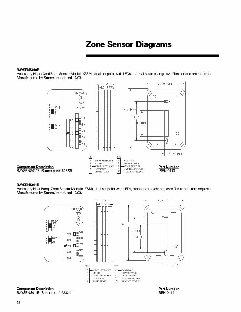
BAYSENS010BAccessory Heat / Cool Zone Sensor Module (ZSM), dual set point with LEDs, manual / auto change over. Ten conductors required.Manufactured by Sunne, introduced 12/93.
Component Description Part NumberBAYSENS010B [Sunne part# 62823] SEN-0413
BAYSENS011BAccessory Heat Pump Zone Sensor Module (ZSM), dual set point with LEDs, manual / auto change over. Ten conductors required.Manufactured by Sunne, introduced 12/93.
Zone Sensor Diagrams
Component Description Part NumberBAYSENS011B [Sunne part# 62824] SEN-0414

39
BAYSENS013CAccessory ICS (Tracer/Tracker/ComforTrac) Zone Sensor Module (ZSM), with override button, and override cancel button. Twoconductors required. Manufactured by Sunne, introduced 08/95.
Component Description Part NumberBAYSENS013C [Sunne part# 65464] SEN-0495
BAYSENS014CAccessory ICS (Tracer/Tracker/ComforTrac) Zone Sensor Module (ZSM), with override button, set point, and override cancel button.Three conductors required. Manufactured by Sunne, introduced 08/95.
Component Description Part NumberBAYSENS014C [Sunne part# 65465] SEN-0496
Zone Sensor Diagrams

40
BAYSENS017B/ASYSTAT669AAccessory Zone Sensor Remote, used with all current zone sensors. Two conductors required. Manufactured by Sunne, introduced12/93.
Component Description Part NumberBAYSENS017B [Sunne part# 62828] SEN-0435ASYSTAT669A [Sunne part# 65541] SEN-0493
BAYSENS016AThermistor Sensor (OAS, SAS, RAS, CTS)Outdoor Air Sensor: Located in the condenser section, lower left corner. The compressor access panel has a slotted opening toprovide airflow across the sensor. Standard with all ReliaTel controlled units.Return Air Sensor: Field or factory installed accessory. Located on the return air damper of the economizer, used with comparativeenthalpy control only.Coil Temperature Sensor: Located in a 3/8" copper tube well, which is brazed to the lowest circuit entering the outdoor coil (2-10 tonheat pumps only).Mixed Air Sensor: Field or factory installed in the supply fan section, protruding through the fan housing.Discharge Air Sensor: Field or factory installed in the supply fan section, using an averaging tube located downstream of the heatsection.
Component Description Part NumberThermistor Sensor (OAS, SAS, RAS, MAS, CTS) SEN-0339
Sensor Diagrams

41
BAYSENS019*/ASYSTAT666*(CV 3-50 Ton)Accessory Heat/Cool, programmable night set back Zone Sensor Module (ZSM), with LCD status / diagnostic indicators. Sevenconductors: terminals 11, 12 & 14 required, 7 through 10 optional. Manufactured by Caradon, introduced 06/98.
Component Description Part NumberBAYSENS019* [Caradon part# 91K91] SEN-0874ASYSTAT666* [Caradon part# 91K92] SEN-0907
Zone Sensor Diagrams
BAYSENS031A/ASYSTAT707AAccessory Digital Heat Pump Zone Sensor Module (ZSM), Dual Set Point, Manual/Auto Changeover. Ten Conductors required.Manufactured by Sunne, introduced 5/03.
Component Description Part NumberBAYSENS031A [Sunne part# SD155-002] SEN01078ASYSTAT707A [Sunne part# SD155-005] SEN01235

42
Zone Sensor Diagrams
Component Description Part NumberBAYSENS032A SENS01120
BAYSENS035A/AYSTAT709AAccessory Digital Heat/Cool Zone Sensor Module (ZSM), Dual SetPoint, Manual/Auto Changeover. Ten conductors required.
Component Description Part NumberBAYSENS035A [Sunne part# SD155-004] SEN001130ASYSTAT709A [Sunne part# SD155-006] SEN01237
BAYSENS0032A(CV 3-50 Ton)Accessory Averaging, Remote Zone Sensor, Dual Thermistors, Two conductors required.

43
High Temperature SensorThe high temperature sensor accessory(BAYFRST001A) provides high limitcutout with manual reset in ICS deviceTracer/ Tracker/ComforTrac/ VariTracsystems. The sensors are wired to theLTB5 and LTB6 in the control panel.Jumper must be removed.The sensors may be used to detectexcessive heat in air conditioning orventilation ducts and provide system shutdown. Immediately after sensor opens,the associated unit will completely shutdown. The sensors come with case andcover, and mount directly to theductwork. There are two sensors that areincluded in the accessory. Both sensorsare factory set; one opens at 135° F andshould be installed in the return air duct,the other opens at 240° F and should beinstalled in the supply duct.
Note: This accessory can also be appliedin Non-ICS applications. The wiring onthe unit is the same. The unit will shutdown immediately when the sensoropens.
Component Description Part NumberBAYFRST001A CNT-0637 & CNT-0638
High TemperatureSensor Diagrams
To reset a sensor which has opened, pushand release the button protrudingthrough the cover. See reset button. Thesensor temperature must drop 25° Fbelow the cut out point before it will reset.There are no field adjustments that canbe made to the sensor; if a problemexists, the sensor must be replaced.Part Number “CNT-0637” = 135° Fsensor. Part Number “CNT-0638” = 240°F sensor.
SENSING ELEMENT
MANUAL RESET BUTTON
TCI COMMUNICATION INTERFACE(TCI)
TBISWITCH INPUT
TB2SWITCH COMM
1 2 1 2
Compressor 1 disable
Compressor 2 disable
Immediate shutdown,Automatic reset
24 VAC
TEST 1 TEST 2
Supply Sensor240˚F
Return Sensor135˚F

44
BAYSENS006–11, 14, 17/AYSTAT661–664
Terminals to read voltage: RTRM J6-1, J6-2
Read DC voltage with the sensorattached. If voltage does notappear to be correct, read theresistance of the circuit, then thesensor itself, to see if a problemexists in the sensor or the wiring.With the sensor not attached thereshould be 5.00 VDC at the terminalsas shown.
Temperature°F Resistance (K ohms) DC Volts Temperature °F Resistance (K ohms) DC Volts
40 26.097 3.613 68 12.435 2.77041 25.383 3.585 69 12.126 2.73942 24.690 3.557 70 11.827 2.70843 24.018 3.528 71 11.535 2.67744 23.367 3.500 72 11.252 2.64645 22.736 3.471 73 10.977 2.61646 22.123 3.442 74 10.709 2.5847 21.530 3.412 75 10.448 2.55448 20.953 3.383 76 10.194 2.52349 20.396 3.353 77 9.949 2.49350 19.854 3.324 78 9.710 2.46251 19.330 3.294 79 9.477 2.43252 18.821 3.264 80 9.250 2.40253 18.327 3.233 81 9.030 2.37254 17.847 3.203 82 8.815 2.34255 17.382 3.173 83 8.607 2.31256 16.930 3.142 84 8.404 2.28357 16.491 3.111 85 8.206 2.25358 16.066 3.080 86 8.014 2.22459 15.654 3.050 87 7.827 2.19560 15.253 3.019 88 7.645 2.16661 14.864 2.988 89 7.468 2.13762 14.486 2.957 90 7.295 2.10963 14.119 2.926 91 7.127 2.08064 13.762 2.895 92 6.963 2.05265 13.416 2.864 93 6.803 2.02466 13.078 2.832 94 6.648 1.99667 12.752 2.801 95 6.497 1.969
Problems to look for:• Miswire/short/open• Excessive resistance in circuit (corroded or loose connection)• Sensor inaccurate (should be +- 2F of chart)• Moisture in sensor (becomes accurate when dry)• Induced voltage (high voltage wires in same conduit)
Service Tips:To check for induced voltage, read AC voltage to ground from each sensor wire. Should be less than 1 VAC.
ZSMTesting
(Zone TemperatureInput)

45
Symptom Probable cause and solution
Display does not come on. Check for 24 vac on terminals 11 and 12of the sensor.
No communication with unit. Verify a varying voltage per step 2 oftesting the sensor. If no voltage ispresent, check with wiring to unit.
Sensor is communicating, but unit Check option 18 in Option Menu setupwon’t run. for correct baud rate.Displayed zone temperature is different Follow Option Menu setup in literaturefrom actual temperature. to calibrate the display.Zone temperature is not displayed. Check option selection in Option Menu
setup.Displayed zone temperature reads Space temperature is above or below“99”. the measurable range of the sensor.Displayed zone temperature reads Verify that option 11 in Option Menu isSh and the COOL FAIL icon is set correctly. If correct, check the wiringilluminated. from the remote sensor at terminals S1
and S2 for a shorted condition.Displayed zone temperature reads Verify that option 11 in Option Menu isoP and the COOL FAIL icon is set correctly. If correct, check remoteilluminated. sensor wiring at terminals S1 and S2
for an open circuit condition.Programmable sensor will not respond Check lower left corner of display for ato keypad selections. padlock icon. If displayed, press and
hold the Time (+) and (-) key until theicon goes away.
Fan mode is set to on, but does not run Check option 6 in Option Menu setupduring unoccupied mode. for Auto selection during unoccupiedperiods.Buzzer indicates System Failure, Check Press erase key to reset filter lapseFilter or Service is required. timer. Buzzer will be reset until noon of
the next day if a System Failure has notbeen corrected.
Sensor will not hold override changes. Press the HOLD TEMP button within 20seconds after changes are made.
COOL FAIL flashes and unit doesn’t run. Sensor not communicating with unit.Check for varying voltage on terminals 11 and 12 at the unit. If voltage is steady
at approximately 30 vdc, check for opencircuit in wiring.
COOL FAIL + HEAT FAIL icons flash Check for defective outside air sensor.simultaneously. Emergency input is open. (RTRM
version 4.0 or greater.)HEAT FAIL flashing. A heat failure has occurred. If HP unit,
the unit may be in Emergency Heat, orthere is a defrost problem.
BAYSENS019B,C (ProgrammableZone Sensor)
The BAYSENS019B, C ProgrammableZone sensor is a digital display sensorthat communicates to micro controls. Thesensor is compatible with UCP Microcontrols used with Voyager products aswell as the new ReliaTel controls usedcertain packaged and split systemproducts. It is also now used with LargeCommercial Voyager III products.Operation of the sensor and electricalconnections are the same for both UCPand ReliaTel control systems, whichmakes programming, operation andtroubleshooting easier. For programminginformation, refer to literature ACC-SVN28A-EN.
Testing the Programmable Zone Sensor(PZS)
Step 1. Verify unit operation by runningunit through test mode.
Step 2. Verify that the PZS has a normaldisplay of time, temperature, fan andsystem status.
Step 3. For UCP Micro, disconnect wiresfrom LTB-11 (-) and LTB-12 (+); ForReliaTel controls, disconnect wiresfrom J6-11 and J6-12. Measure the dcvoltage between terminals 11 and 12.Voltage should read between 28 to 32vdc. If no voltage is present for UCPmicro, check wiring between UCP andLTB.
Step 4. Reconnect wires to terminals 11and 12. Measure the voltage between11 and 12 again. Voltage should flashat 0.5 second rate, with a voltagevalue randomly changing fromapproximately 24 to 32 vdc.
Step 5. On the PZS, press the FANbutton to turn the fan ON. If the fancomes on, the PZS is good; if the fandoes not come on, the PZS may bedefective and will need to be replaced.
Note: The sensor will not communicate ifthe wrong baud rate is selected. The PZSis shipped with the baud rate set to1200. See Option Menu setup in theliterature to verify proper baud rate. Thebaud rate may need to be changed to1024 for units built before 1/96.
Troubleshooting the Programmable Zone SensorBecause the PZS is a communicating sensor, troubleshooting is very limited. Steps 2through 5 of testing the sensor are the first steps to verify. The following table willprovide other troubleshooting tips for diagnosing the sensor and unit operations.
If all wiring and preliminary tests do not indicate any defects, disconnect the PZS fromthe wall and take to the unit, and with a short (approx. two feet) length of thermostatwire, connect the PZS and see if symptoms still exist. If not, check for thermostat wirerouting in close proximity of high voltage wires and fluorescent lights.
AYSTAT666B,C

46
BAYSENS006–11, 14, 17, 031A, 035A AYSTAT661–664
Setpoint Inputs Read voltage here or hereCooling setpoint RTRM J6-3 ZSM terminal 3Heating setpoint RTRM J6-5 ZSM terminal 5Common RTRM J6-2 ZSM terminal 2
Read DC voltage with Zone Sensor Module (ZSM) attached. If voltage readdoes not appear to be correct, read the resistance of the circuit, then the ZSMitself, to see if a problem exists in the ZSM or the wiring. With theZSM not attached there should be 5.00 VDC at the terminals asshown. To check for induced voltage, read AC voltage to groundfrom each sensor wire. Should be less than 2VAC.
Setpoint/ModeInputs
(Mechanical ZoneSensor Module)
Temperature °F Resistance (K ohms) DC Volts Temperature °F Resistance (K ohms) DC Volts
open 5.00 (open circuit) 67.0 .5584 1.79240.0 1.0841 2.601 68.0 .5390 1.75141.0 1.0656 2.579 69.0 .5195 1.70942.0 1.0472 2.557 70.0 .5000 1.66743.0 1.0287 2.535 71.0 .4805 1.62344.0 1.0102 2.513 72.0 .4610 1.57845.0 .9918 2.490 73.0 .441.6 1.53246.0 .9733 2.466 74.0 .4221 1.48447.0 .9548 2.442 75.0 .4026 1.43548.0 .9363 2.418 76.0 .3832 1.38549.0 .9179 2.393 77.0 .3637 1.33350.0 .8994 2.368 78.0 .3442 1.28051.0 .8787 2.338 79.0 .3247 1.22652.0 .8580 2.309 80.0 .3053 1.16953.0 .8373 2.278 81.0 .2858 1.11154.0 .8166 2.247 82.0 .2663 1.05155.0 .7958 2.216 83.0 .2468 0.99056.0 .7751 2.183 84.0 .2273 0.92657.0 .7544 2.150 85.0 .2079 0.86058.0 .7337 2.116 86.0 .1884 0.79359.0 .7142 2.083 87.0 .1689 0.72360.0 .6948 2.050 88.0 .1495 0.65061.0 .6753 2.015 89.0 .1301 0.57562.0 .6558 1.980 90.0 .1106 0.49863.0 .6363 1.944 (shorted/no power) 0.00064.0 .6169 1.90865.0 .5974 1.87066.0 .5779 1.831

47
Problems to look for:• Miswire/short/open• Excessive resistance in circuit (corroded or loose connection)• Setpoint lever inaccurate (should be +-2F of chart)• Induced voltage (high voltage wires in same conduit)
Mode Input:
Mode Input RTRM J6-4 ZSM terminal 4
Common RTRM J6-2 ZSM terminal 2
Read DC voltage with Zone Sensor Module (ZSM) attached. If voltage read does notappear to be correct, read the resistance of the circuit, then the ZSM itself, to see if aproblem exists in the ZSM or the wiring. With the ZSM not attached there should be5.00 VDC at the terminals listed above. To check for induced voltage, read AC voltage toground from each sensor wire. Should be less than 2VAC.
Problems to look for:• Miswire/short/open• Excessive resistance in circuit (corroded or loose connection)• Induced voltage (high voltage wires in same conduit)
System Fan OHms VoltsSwitch Switch Rx1K DC+-5%
Short to common 0 0.00OFF AUTO 2.32 0.94COOL AUTO 4.87 1.64AUTO AUTO 7.68 2.17OFF ON 10.77 2.59COOL ON 13.32 2.85AUTO ON 16.13 3.08HEAT AUTO 19.48 3.30HEAT ON 27.93 3.68EM HEAT AUTO 35.00 3.88EM HEAT ON 43.45 4.06Open circuit 5.00
Setpoint/ModeInputs
(Mechanical ZoneSensor Module)

48
Outdoor Air SensorDischarge Air SensorCoil Temperature Sensor
Terminals to read voltage:Outdoor Air Sensor – RTRM J8-2, J8-1Discharge Air Sensor – RTOM J4-5, J4-4Coil Temperature Sensor– RTRM J2-3, J2-4
Note: These are RTRM, RTOM inputs only. Economizer inputs (MAS, RAS, OHS, RHS,CO
2) are in the ReliaTel Economizer inputs section.
Read DC voltage with the sensor attached. If voltage does not appear to be correct,read the resistance of the circuit, then the sensor itself, to see if a problem exists in thesensor or the wiring. With the sensor not attached there should be 5.00 VDC at theterminals listed above.
Service Tips:The second sensor terminal listed above is common. All common terminals aregrounded, therefore one volt meter lead can be attached to ground for voltage tests.To check for induced voltage, read AC voltage to ground from each sensor wire. Shouldbe less than 1 VAC.
Problems to look for:• Miswire / short / open• Excessive resistance in circuit (corroded or loose connection)• Sensor inaccurate (should be +- 2F of chart)• Moisture in sensor (becomes accurate when dry)• Induced voltage (high voltage wires in same conduit)
RTRM / RTOM(TemperatureInputs)
Temperature °F Resistance DC Volts Temperature °F Resistance DC Volts(K ohms) (K ohms)open circuit 5.000
-40 345.684 4.856 -15 143.192 4.670-39 333.237 4.851 -14 138.435 4.660-38 321.274 4.845 -12 129.449 4.638-37 309.777 4.840 -11 125.199 4.627-36 298.724 4.834 -10 121.100 4.615-35 288.097 4.828 -9 117.146 4.603-34 277.879 4.823 -8 113.331 4.591-33 268.053 4.816 -7 109.652 4.579-32 258.603 4.810 -6 106.102 4.566-31 249.523 4.804 -5 102.676 4.553-30 240.810 4.797 -4 99.377 4.540-29 232.425 4.790 -3 96.197 4.526-28 224.355 4.783 -2 93.127 4.512-27 216.590 4.776 -1 90.163 4.498-26 209.114 4.768 0 87.301 4.483-25 201.918 4.760 1 84.537 4.468-24 194.991 4.752 2 81.868 4.453-23 188.320 4.744 3 79.291 4.437-22 181.904 4.736 4 76.802 4.421-21 175.738 4.727 5 74.403 4.404-20 169.798 4.718 6 72.087 4.388-19 164.076 4.709 7 69.849 4.371-18 158.562 4.700 8 67.687 4.353-17 153.248 4.690 9 65.597 4.336-16 148.127 4.680 10 63.577 4.317

49
Temperature °F Resistance DC Volts Temperature °F Resistance DC Volts(K ohms) (K ohms)
11 61.624 4.299 64 13.762 2.89512 59.737 4.280 65 13.416 2.86413 57.913 4.261 66 13.078 2.83214 56.153 4.241 67 12.752 2.80115 54.452 4.221 68 12.435 2.77016 52.807 4.201 69 12.126 2.73917 51.216 4.180 70 11.827 2.70818 49.677 4.159 71 11.535 2.67719 48.188 4.138 72 11.252 2.64620 46.748 4.116 73 10.977 2.61621 45.354 4.094 74 10.709 2.58522 44.007 4.072 75 10.448 2.55423 42.705 4.049 76 10.194 2.52324 41.446 1.026 77 9.949 2.49325 40.226 4.002 78 9.710 2.46226 39.046 3.978 79 9.477 2.43227 37.904 3.954 80 9.250 2.40228 36.797 3.929 81 9.030 2.37229 35.726 3.904 82 8.815 2.34230 34.689 3.879 83 8.607 2.31231 33.686 3.853 84 8.404 2.28332 32.720 3.827 85 8.206 2.25333 31.797 3.801 86 8.014 2.22434 30.903 3.775 87 7.827 2.19535 30.037 3.749 88 7.645 2.16636 29.198 3.722 89 7.468 2.13737 28.386 3.695 90 7.295 2.10938 27.599 3.668 91 7.127 2.08039 26.836 3.641 92 6.963 2.05240 26.097 3.613 93 6.803 2.02441 25.383 3.585 94 6.648 1.99642 24.690 3.557 95 6.497 1.96943 24.018 3.528 96 6.350 1.94244 23.367 3.500 97 6.207 1.91545 22.736 3.471 98 6.067 1.88846 22.123 3.442 99 5.931 1.86147 21.530 3.412 100 5.798 1.83548 20.953 3.383 101 5.668 1.80949 20.396 3.353 102 5.543 1.78350 19.854 3.324 103 5.420 1.75751 19.330 3.294 104 5.300 1.73252 18.821 3.264 105 5.184 1.70753 18.327 3.233 106 5.070 1.68254 17.847 3.203 107 4.959 1.65855 17.382 3.173 108 4.851 1.63356 16.930 3.142 109 4.745 1.60957 16.491 3.111 110 4.642 1.58558 16.066 3.080 111 4.542 1.56259 15.654 3.050 112 4.444 1.53960 15.253 3.019 113 4.349 1.51661 14.864 2.988 114 4.256 1.49362 14.486 2.957 115 4.165 1.47063 14.119 2.926
RTRM / RTOM(TemperatureInputs)

50
Temperature °F Resistance DC Temperature °F Resistance DC(K ohms) Volts (K ohms) Volts
116 4.076 1.448 168 1.458 0.637117 3.990 1.426 169 1.432 0.627118 3.906 1.405 170 1.406 0.617119 3.824 1.383 171 1.380 0.607120 3.743 1.362 172 1.356 0.598121 3.665 1.341 173 1.331 0.588122 3.589 1.321 174 1.308 0.579123 3.514 1.301 175 1.284 0.570124 3.442 1.281 176 1.261 0.561125 3.371 1.261 177 1.239 0.552126 3.302 1.241 178 1.217 0.543127 3.234 1.222 179 1.196 0.535128 3.169 1.204 180 1.174 0.526129 3.104 1.185 181 1.154 0.518130 3.041 1.166 182 1.133 0.510131 2.980 1.148 183 1.113 0.502132 2.919 1.130 184 1.094 0.494133 2.861 1.113 185 1.076 0.487134 2.804 1.095 186 1.057 0.479135 2.748 1.078 187 1.038 0.471136 2.693 1.061 188 1.020 0.464137 2.640 1.045 189 1.003 0.457138 2.587 1.028 190 .986 0.450139 2.536 1.012 191 .969 0.443140 2.486 0.996 192 .952 0.436141 2.438 0.981 193 .397 0.429142 2.390 0.965 194 .920 0.422143 2.343 0.950 195 .905 0.416144 2.298 0.935 196 .890 0.410145 2.253 0.920 197 .875 0.403146 2.210 0.906 198 .860 0.397147 2.167 0.891 199 .846 0.391148 2.125 0.877 200 .831 0.385149 2.085 0.863 Shorted or 0150 2.044 0.849 no power151 2.006 0.836152 1.967 0.823153 1.930 0.810154 1.894 0.797155 1.859 0.784156 1.823 0.772157 1.789 0.759158 1.756 0.747159 1.723 0.736160 1.691 0.724161 1.659 0.712162 1.629 0.701163 1.599 0.690164 1.570 0.679165 1.541 0.688166 1.512 0.658167 1.485 0.647
RTRM / RTOM(TemperatureInputs)

51
In some applications, 1 zone sensor doesnot give a good representation of zonetemperature. The internal thermistors,10K ohm resistance @ 25C/77F, can bewired as shown below in order to providean average input to the mechanical orprogrammable Zone Sensor Module
Zone SensorAveraging
(BAYSENS006-11/AYSTAT661-663,BAYSENS019*/AYSTAT666*). If using aProgrammable ZSM, the remote sensorwiring must be twisted/shielded. Connectthe shield to terminal J6-11.
BAYSENS017 BAYSENS017 BAYSENS017 BAYSENS017
1 2 1 2 1 2
1 2 1 2
BAYSENS017 BAYSENS017
BAYSENS032
To provide ZSM averaging with2 BAYSENS017B’s, connect 2thermistors inside each ZoneSensor as shown below, thenwire the two modified sensorsin series as shown on the left.Obtain the thermistors byremoving them from anotherzone sensor.

52
• 27½ to 50 VAV - Conventionalthermostat input terminals areinactive.
• Built in Night Set Back and UnoccupiedFunctions function differently with aconventional mechanical thermostat.
• A built-in algorithm which allows forautomatic reset of the discharge airtemperature while economizing is notavailable.
The terminal strip for attaching thethermostat wires is located onthe RTRM module in thecontrol compartment.The purpose of each terminalis discussed in the nextsection.
The ReliaTel module has conventionalthermostat connections as well as ZoneSensor Module connections. When aconventional thermostat is controlling theunit, operation differs as follows.• Supply Air Tempering feature is not
available. If outdoor air is beingintroduced through the equipment,discharge air temperature may becold when not actively heating.
• Proportional Integral (PI) control is notavailable.
• Zone Sensor Diagnostics are onlyavailable on the RTRM module on theJ6 terminals, instead of at the ZoneSensor in the space.
• Intelligent Fall-Back is not available. Ifa failure occurs in the devicecontrolling the equipment, operationwill cease.
• Heat Pump Smart Recovery andSmart Staging is not available. HeatPump operation becomes more costlyunless the generic control beingapplied can accomplish this.
• Remote Sensing Capabilities are notavailable on most mechanicalthermostats.
• Space Temperature Averagingcapabilities are not available on mostmechanical thermostats.
Operation with aConventional Thermostat

53
Customers occasionally require operation with a conventional thermostat rather than azone sensor. In some cases there is a preference for a specific thermostat model, andin others there is reluctance to adopt newer technology that may not be as wellunderstood as conventional thermostats. In addition, non-Trane Building Controllerstypically provide an interface to HVAC equipment based on a conventional thermostatinterface. Units applied with this type of controller need to accept conventionalthermostat inputs.Conventional thermostat signals represent direct calls for unit functions. In theirsimplest applications, thermostat contacts directly control contactors or other loadswitching devices. This function provides inputs for the thermostat signals andprocessing to enhance reliability and performance. Compressor protection andreliability enhancement functions (HPC, LPC, Minimum On/Off timers, etc.). All operatethe same whether applied with zone sensors or a conventional thermostat. Logic isalso provided to cause appropriate unit functions when inappropriate thermostatsignals are provided. Simultaneous calls for heating and cooling will be ignored, andthe fan will be turned on with a call for heating or cooling even if the fan request is notdetected.If the thermostat is immediately changed from a heating to a cooling call, or vice versa,there will be a five minute delay before the new call will initiate.
Thermostat signals are as follows:R 24VAC power to thermostatY1 Call for compressor 1 or first stage coolingY2 Call for compressor 2 or 2nd stage coolingG Call for supply fanW1 Call for heat 1W2 Call for heat 2Heat pump only:X2 Call for emergency heatO Switchover valve On = cooling, Off = heatingT Bias for heat anticipation for those mechanical thermostats that use this
function
Conventional thermostat – Gas/ Electric, Electric Heat:
Input/connection Function when energized:G (fan) Fan runs continuously except during
unoccupied mode (see next page)Y1 (compressor 1 or economizer) Compressor #1 runs or economizeroperatesY2 (compressor 2 or compressor 1 Compressor #2 also runs, or #1while economizing) compressor runs while economizingW1 (gas / electric heat first stage) 1st stage heatW2 (gas / electric heat 2nd stage) 2nd stage heat (if available)
Conventional thermostat – Heat Pump
Input/connection Function when energized
Cooling mode:G (fan) Fan runs continuously except duringunoccupied mode (see next page)O (reversing valve during cooling) Reversing valve in cool modeY1 + O (first stage cooling) Compressor #1 runs or economizer
operatesY1 + Y2 + O (2nd stage cool) Compressor #2 also runs, or #1compressor runs while economizing.
Operation with aConventional Thermostat

54
Operation with aConventional Thermostat
Heating mode:
G (fan) Fan runs continuously except duringunoccupied mode (see below)
Y1 (both compressors 1st stage heat) Both compressors runY2 (during heating – nothing happens) No changeW2 (electric heat 2nd stage) 2nd stage (electric) heatX2 (electric heat only) Electric heat only – no compressors
T (provides heat anticipation signal for those mechanical thermostats that use thisfeature. If the thermostat used does not have a “T” terminal, disregard this terminal.
Unoccupied mode: If the thermostat being used is programmable, it will have its ownstrategy for unoccupied mode and will control the unit directly. If a mechanicalthermostat is being used, a field applied time clock with relay contacts connected to J6-11 and J6-12 can initiate an unoccupied mode as follows:
Contacts open: Normal occupied operation.Contacts closed: Unoccupied operation as follows - Fan in auto mode
regardless of fan switch position.Economizer closes except while economizing regardless ofminimum position setting.
Cooling/Economizer Operation:If unit does not have an economizer, the Cool/Econ Stage 1 and Stage 2 will call directlyfor mechanical cooling (compressor) stages. If the unit has an economizer, the Cool/Econ stages will function as follows.
Cooling/Economizer Operation with Thermostat
Call for CompressorOK to Thermostat Thermostat Economizer StagingEconomize? Y1 Y2 Cooling RequestNo On Off Inactive Compressor
Output 1No Off On Inactive Compressor
Output 2No On On Inactive Compressor
Outputs 1 & 2Yes On Off Active OffYes Off On Active OffYes On On Active Compressor
Output 1Notes:40 to 50 ton CV onlyThis unit has 3 stages of cooling if using a zone sensor or binary inputs as shown above.If using a conventional thermostat it has 2 stages as follows:
Y1 = 1st stage
Y1 + Y2 = 3rd stage
VAVThermostat inputs are ignored on VAV units.

55
Wiring:The COMM3/4 board communicates withthe RTRM via the MODBUS link using theharness, labeled 4366-1151. Theconnections to the board are shownbelow.Communication wires must be twisted/shielded as specified by the BAS systembeing applied. Do not attach the shield tothe COMM3/4 board. It must be tapedback to prevent it from touching the unit.
LED’s:Amber receive (RX) LED: Blinkswhenever communication is occurringwith any device. This tells the servicetechnician that the BAS system iscommunicating or trying to communicatewith other devices as well as this one.Green transmit (TX) LED: Blinks onceevery several seconds, sometimes up to45 seconds between blinks, when the unitis sending data to the BAS system. Thistells the service technician that this unit iscommunicating information to the BASsystem. When the TX LED is blinking, theunit is communicating.
Communication problems:
Won’t communicate with Tracker
3-25 Ton only• Harness, labeled 4366-1151, must be
plugged into RTRM correctly – seeprevious page.
• Com Link board must be in“ISOLATED COM 3” position. If it is inthe wrong position or not installed, theunit will not communicate.
• Each unit must have a unique addressby setting the DIP switches accordingto the IOM. If 2 units have the sameaddress, neither will communicate. Ifthe unit has a DIP switch setting otherthan the ones specified in the IOM,Tracker will not recognize it.
• Once the unit communicates withTracker, the Tracker panel willautomatically recognize the unit.
• Resistor missing at last unit in daisychain (depending on length of line run).
COMM3/4 InterfaceOperation & Troubleshooting
Communicates but will not run, even inTEST mode:• Emergency stop input is open (RTRM
3J1-12).
Communicates but will not run; fan (butnot heating or cooling) runs in TEST modefor 40 seconds only.
3-25 Tons• Fan proving circuit (RTOM 5J7-6) is
closed; should open when fan is on. Ifnot, the fan will run in TEST mode for40 seconds and then stop.
27½-50 Tons• Fan proving circuit (RTOM 5J7-6) is
opened; should close when fan is on. Ifnot, the fan will run in TEST mode for40 seconds and then stop.
Communicates but will not runcompressor(s); fan and heating run inTEST mode:• Compressor disable circuit(s) (RTRM
3J1-8, 3J3-2) open due to loss ofcharge or LTB jumper removal.
Communicates but will not runcompressors, yet everything runs inTEST mode:• FROSTAT circuit (RTOM 5J7-2) is
closed; should open when indoor coilis frost free. There is no diagnosticoutput when this occurs.
• 27.5-50 Tons VariTrac CCP withconstant volume unit with bypass VAV:Unit must have a discharge air sensorinstalled at RTOM J4-4, J4-5.
Won’t communicate with TracerSUMMIT:• Harness, labeled 4366-1151, must be
plugged into RTRM correctly – seeabove.
• Com Link board must be in “NONISOLATED COMM3 or COMM4”position. If it is in the wrong position ornot installed, the unit will notcommunicate.
• Each unit must have a unique addressby setting the DIP switches accordingto the IOM. If 2 units have the sameaddress, neither will communicate. Ifthe unit has a DIP switch setting otherthan the ones specified in the IOM,Tracer will not recognize it.
• Once the unit communicates withTracer, the Tracer panel willautomatically recognize the unit.
Won’t communicate with VariTrac CCPzoning system:• Harness, labeled 4366-1151, must be
plugged into RTRM correctly – seeabove.
• Com Link board must be in “NONISOLATED COMM3 or COMM4”position. If it is in the wrong position ornot installed, the unit will notcommunicate.
VariTrac I Comfort Manager and VariTracII Center Control Panel:• The DIP switches must all be in the ON
position. If not, the VariTrac CCP willnot recognize it.
• The communication wires must be inthe same daisy chain link as thedampers.
• VariTrac III central control panel(optional touch screen) — All DIPswitches must be in the off position. Ifnot, the VariTrac CCP will not recognizeit.

56
Ignition Module DiagnosticsThe ignition module has a green LED for diagnostics:
—Steady light ................................................Module is powered up, but no active call for heat.—Blinking at continuous steady rate ..........Active call for heat.—One blink .................................................... Loss of communication.—Two blinks ..................................................System lockout (failure to ignite, no spark, low/no gas pressure, etc.—Three blinks ...............................................Pressure switch (no vent air flow, bad CBM, closed at initial call for heat).
Auto reset.—Four blinks .................................................High limit (excessive heat in combustion chamber, low airflow). Auto reset.—Five blinks .................................................. Flame sensed and gas valve not energized or flame sensed and
no call for heat.—Six blinks .................................................... Flame rollout (CBM failure, incorrect gas pressure, incorrect
primary air). Requires manual reset of the switch.—ReliaTel module will communicate a heat fail diagnostic back to the RTRM.
Direct SparkIgnition Control
(TexasInstruments)
This microprocessor based,communicating solid state deviceprovides gas valve control, proof ofignition, ignition retries, 1 hour reset,operation of the inducer and diagnosticsthrough an LED as well ascommunication to the refrigerationmodule. Inputs to the control include apressure switch, rollout switch and limitswitch as well as a flame proving circuit.This device takes control of the ignition,timings related to the ignition cycle, andsupervision of the gas components.
Ignition Module Specifications
Voltage range 18-32 VAC, 50/60HzPower consumption 350mA @ 24vacSpark Voltage 25,000 volts max @ 10-13 mJFlame sense voltage Nominal 90VrmsFlame sense signal Nominal 4.5 micro amps,
minimum 1.2 micro amps
Pre-purge 20 secondsPost-purge 5 SecondsInter-purge 60 secondsFlame establishment period 2 to 7 secondsFlame failure response time 0.8 secondsLoss of flame lockout 3 tries, locks out after 3rd tryLockout reset Interrupt power for 3 seconds
minimumAuto reset 1 hourLoss of communication lockout 10 seconds (with RTRM)
The RTRM controls all functions via aMODBUS communication link.The remote flame sensor is located onthe top burner which ensures that allburners are lit. Field measured flamesensor voltage can vary significantly dueto the construction of typical voltmetersused.The control has a 20 second pre-purgecycle as well as a 60 second inter-purgebetween cycles should a flame not beestablished on the first try.

57
1-stage unitsIgnition control (IGN) runs a self check(including verification that the gas valve isde-energized). IGN checks the high limitswitch (TCO 1) for closed contacts, thepressure switch (PS) for open contacts,flame rollout (FR) for closed contacts.IGN energizes inducer blower. When PScloses, 20 second pre-purge begins. After20 seconds, the IGN energizes the sparkand gas valve at the same time. Thespark will stay energized for at least 2seconds attempting to establish flame. Ifa flame is not established, the spark willcontinue up to 7 seconds. Once a flame isestablished, spark is de-energized andindoor blower motor (IBM) timing begins.45 seconds later, the RTRM energizes theIBM. When the zone sensor or thermostatis satisfied, the gas valve is de-energized,the inducer runs for 5 seconds then stops(post-purge), and the IBM runs for 60seconds then stops unless beingrequested to run continuously.
Direct SparkIgnition Control
(Sequence ofOperation)
2-stage unitsIgnition control (IGN) runs a self check(including verification that the gas valve isde-energized). IGN checks the high limitswitches (TCO 1 & TCO 2) for closedcontacts, the pressure switch (PS) foropen contacts, flame rollout (FR) forclosed contacts.IGN energizes inducer blower on highspeed. When PS closes, 20 second (15seconds on high, 5 seconds on low) pre-purge begins. After 20 seconds, the IGNenergizes the spark and gas valve at thesame time. The spark will stay energizedfor at least 2 seconds attempting toestablish flame. If a flame is notestablished, the spark will continue up to7 seconds. Once a flame is established,spark is de-energized and indoor blowermotor (IBM) timing begins. 45 secondslater, the RTRM energizes the IBM. Ifdeviation from setpoint is great enough,there is no minimum delay before 2nd
stage is energized. When the zone sensoror thermostat is satisfied, the gas valve isde-energized, the inducer runs for 5seconds then stops (post-purge), and theIBM runs for 60 seconds then stopsunless being requested to runcontinuously.
1st Stagecall for heat
Start trialfor ignition 1st stg on
2nd stg on
End call for heat
5 sec CBMpost-purge
CBM off
NoMinimum
Delay
7 sec trial for ignition
IDM offIDM on for 60or 90 secIDM on
Start 45 second delay for IDM
Additional 5 sec if needed
2 sec minimum
CBM 20 sec Pre-purge

58
ReliaTel HotSurface IgnitionControl
This microprocessor base, communicating solid state device provides gas valvecontrol, proof of ignition, ignition retries, one hour reset, operation of the inducer anddiagnostics through an LED, as well as communication to the refrigeration module via aMODBUS. Inputs to the control include high limits and flame sensor operation. Unlikethe 3 through 10 ton units that use direct spark ignition, there is no combustion fanproving switch or flame rollout. This device takes control of the ignition, timings relatedto the ignition cycle and supervision of the gas components.
Ignition Module SpecificationsVoltage range 18-32 vac, 50/60 HzIgnitor voltage 115vac, 50/60 HzFlame sense current 4.5 microamps (nominal), 1 microamp minimum
Pre-purge 45 secFlame establishment period 2 sec min, 7 sec maxFlame failure response time 0.8 sec or lessLoss of flame lockout 3 tries, locks out after 3rd tryLockout reset Interrupt power for 3 seconds minimumAuto reset 1 hourLoss of communication lockout 10 sec(with RTRM)
Ignition Control Module DiagnosticsThere is a green LED located on the ignition module. The table below lists thediagnostics and the status of the LED during the various operating states.
Any time the Ignition module is powered, the LED will be lit to provide status of theignition system. At initial power-up, the LED will flash for one second.
Steady OFF No power/ Internal failureSteady ON Normal power-up, with no heat call.Slow flash rate Normal call for heat, ¾ second on, ¼ second off.Fast flash rate Used for error indication only
Error Code Flashes-One flash Communication loss between RTRM and IGNTwo flashes System lockout; failed to detect or sustain flameThree flashes Not usedFour flashes High limit switch openFive flashes Flame sensed and gas valve not energized; or flame sensed and no
call for heat
The pause between groups of flashes is approximately two seconds.
(Sequence ofOperation)

59
ReliaTel HotSurface IgnitionControl
(Sequence ofOperation)
The 12½ through 25 ton packaged unitsuse a drum and tube heat exchanger witha negative pressure gas valve and hotsurface ignition. This design is the sameas was used with the UCP micro controls,but the control circuitry for ignitions haschanged to take advantage of ReliaTelMODBUS communications.When the system switch is set to the"Heat" position and the zone temperaturefalls below the heating setpoint, a heatcycle is initiated when the RTRMcommunicates ignition information to theignition module (IGN).The IGN runs a self-check (includingverification that the gas valve is de-energize). IGN checks the high-limitswitches (TC01 & TCO2) for normallyclosed contacts. With 115 vac supplied tothe ignition module (IGN), the hot surfaceignitor probe (IP) is preheated forapproximately 45 seconds. The gas valve(GV) is energized for approximately 7seconds for trial ignition to ignite theburner. Once the burner is ignited, the hotsurface ignition probe (IP) is de-energizedby the ignition module and then functionsas the flame sensor. The unit initially fireson high heat, but after approximately 60seconds, if no additional heating isrequired, the ignition module will dropback to low heat.
When the fan selection switch is set tothe "AUTO" position, the RTRM energizesthe indoor fan relay (F) approximately 30seconds after initiating the heating cycleto start the indoor fan motor (IDM).If the burner fails to ignite, the ignitionmodule will attempt two more ignitioncycles before locking out. The green LEDwill indicate a lockout by two fast flashes.An ignition lockout can be reset by:1. Opening for 3 seconds and closing the
main power disconnect switch,2. By switching the "Mode" switch on
the zone sensor to "OFF" and then tothe desired position, or
3. Allowing the ignition control moduleto reset automatically after one hour.
When the RTRM is communicating withthe ignition module (IGN), the MODBUSvoltage can be measured at the 3J5 plug,pins 3 (negative) and 4 (positive).The voltage will be flashing atapproximately 10.7 to -9.6 vdc at a rate ofonce every three seconds. If the 3J5plug is disconnected, the measuredvoltage at pins 3 and 4 on the RTRM willbe approximately 10.5 to 11.2 vdc and willbe flashing.Flame current measurements can alsobe made at two pins on the ignitionmodule labeled "FLAME CHECK" locatedat the bottom of the module. Flamecurrent can be measured with a DCvoltmeter. One volt dc equals onemicroamp of flame current (1vdc = 1mA)

60
Mo
del
Nu
mb
er D
igit
18 =
(B,C
)D
eno
tes
Th
rou
gh
th
e B
ase
Gas
Y#C
036A
#LY
#C04
8A#L
YS
C06
0A#L
YH
C06
0A#L
Un
it S
ize
(To
nn
age)
34
55
Cab
inet
Siz
eA
AA
BIn
pu
t (B
TU
h)
6000
060
000
6000
060
000
Ou
tpu
t (B
TU
h)
480
0048
000
480
0048
000
Min
imu
m I
np
ut
(BT
Uh
)60
000
6000
060
000
6000
0H
igh
Alt
itu
de
Max
imu
m In
pu
t (B
TU
h)
540
0054
000
540
0054
000
Hig
h A
ltit
ud
e M
inim
um
Inp
ut
(BT
Uh
)43
200
4320
043
200
4320
0Te
mp
erat
ure
Ris
e R
ang
e (
F)25
-55
15-4
5 1
0-40
10-
40M
axim
um
Ou
tlet
(F)
180
180
180
180
Max
imu
m E
xter
nal
Sta
tic
(in
. w.c
.)0.
20.
20.
20.
2N
G O
rifi
ce D
rill
(0-2
000
ft.)
3838
3838
Max
imu
m G
as S
up
ply
Pre
ssu
re (
in. w
.c.)
1414
1414
Min
imu
m G
as S
up
ply
Pre
ssu
re (
in. w
.c.)
4.5
4.5
4.5
4.5
Man
ifo
ld P
ress
ure
(in
. w.c
.)3.
33.
33.
33.
3M
axim
um
In
pu
t (B
TU
h)
6000
060
000
6000
060
000
LP O
rifi
ce D
rill
#52
5252
52B
urn
er In
sert
Insi
de
Dia
met
er (
in.)
0.6
0.6
0.6
0.6
Air
Ori
fice
Dia
met
er (
in.)
1.28
11.
281
1.28
11.
281
TC
O1
Hig
h L
imit
Val
ue
(F)
170
170
170
155
Rat
e Pe
r P
RI T
ub
e (B
TU
h)
3000
030
000
3000
030
000
Nu
mb
er o
f Pr
imar
y Tu
bes
22
22
Nu
mb
er o
f S
eco
nd
ary
Tub
es2
22
2Fi
nal
Res
tric
tor
Hei
gh
t (i
n.)
(If
Use
d)
Turb
ula
tor
Len
gth
(in
.) (
If U
sed
)12
12T
CO
2 H
igh
Lim
it V
alu
e (F
)12
012
012
012
0N
ote
s:T
he
pri
mar
y tu
bes
are
co
nst
ruct
ed o
f .04
9” m
inim
um
T1
40 A
lum
iniz
ed S
teel
, 2.2
5” O
D, 2
9.8”
lon
g.
All
Y*0
36-0
60 u
nit
s w
ill u
se a
FA
SC
O 7
021-
1105
4 co
mb
ust
ion
blo
wer
as
des
crib
ed in
the
rep
ort
.A
ll Y
*036
-060
un
its
will
use
a 2
40 F
Fla
me
Ro
llou
t dev
ice
as d
escr
ibed
in th
e re
po
rt.
All
Y*0
36-0
60 u
nit
s w
ill u
se a
120
F F
an L
imit
as
des
crib
ed in
the
rep
ort
.A
ll Y
*36-
060
un
its
will
be
fact
ory
set
for
hig
h s
pee
d in
do
or
fan
.
3-5
Tons
Gas
Hea
t Spe
cifi
cation
s —
Low
Hea
t
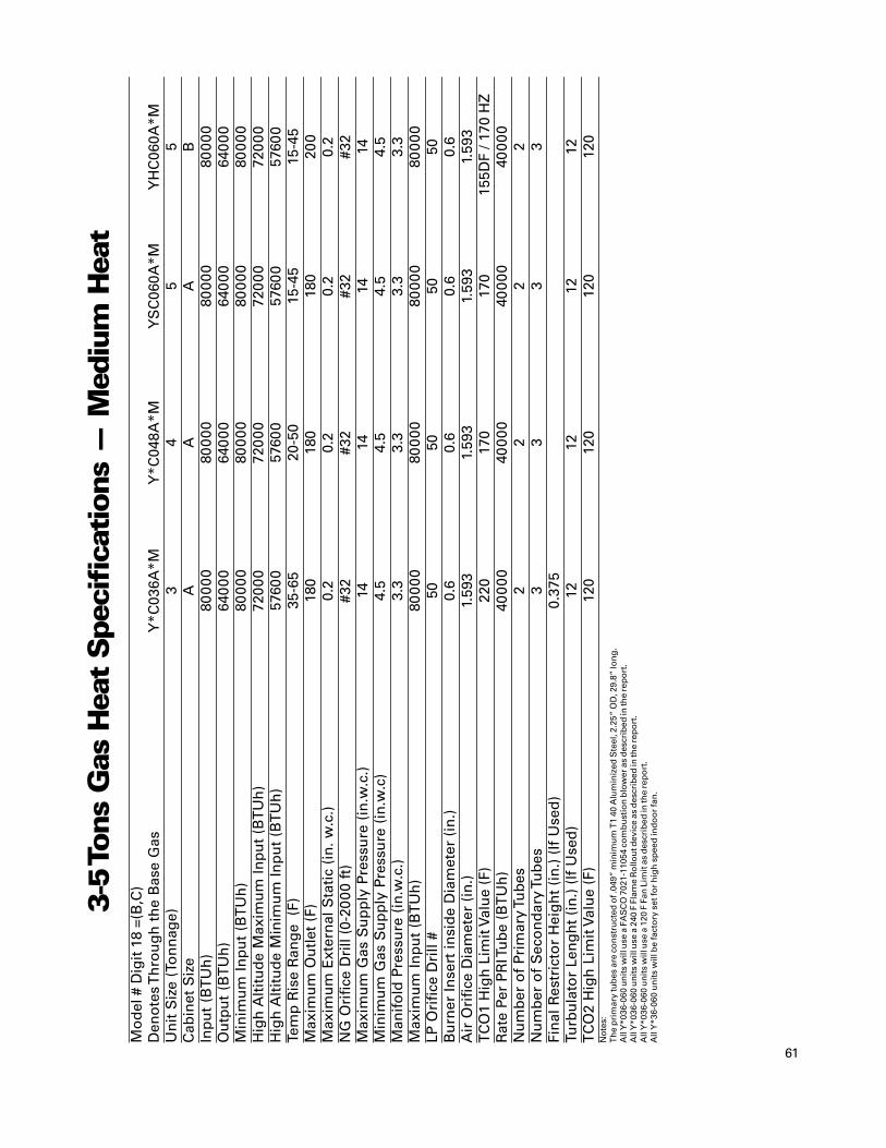
61
Mo
del
# D
igit
18
=(B
,C)
Den
ote
s T
hro
ug
h t
he
Bas
e G
asY
*C03
6A*M
Y*C
048A
*MY
SC
060A
*MY
HC
060A
*MU
nit
Siz
e (T
on
nag
e)3
45
5C
abin
et S
ize
AA
AB
Inp
ut
(BT
Uh
)80
000
8000
080
000
8000
0O
utp
ut
(BT
Uh
)64
000
640
0064
000
640
00M
inim
um
In
pu
t (B
TU
h)
8000
080
000
8000
080
000
Hig
h A
ltit
ud
e M
axim
um
Inp
ut
(BT
Uh
)72
000
720
0072
000
720
00H
igh
Alt
itu
de
Min
imu
m In
pu
t (B
TU
h)
5760
057
600
5760
057
600
Tem
p R
ise
Ran
ge
(F)
35-6
520
-50
15-4
515
-45
Max
imu
m O
utl
et (
F)18
018
018
020
0M
axim
um
Ext
ern
al S
tati
c (i
n. w
.c.)
0.2
0.2
0.2
0.2
NG
Ori
fice
Dri
ll (0
-20
00 f
t)#3
2#3
2#3
2#3
2M
axim
um
Gas
Su
pp
ly P
ress
ure
(in
.w.c
.)14
1414
14M
inim
um
Gas
Su
pp
ly P
ress
ure
(in
.w.c
)4.
54.
54.
54.
5M
anif
old
Pre
ssu
re (
in.w
.c.)
3.3
3.3
3.3
3.3
Max
imu
m I
np
ut
(BT
Uh
)80
000
8000
080
000
8000
0LP
Ori
fice
Dri
ll #
5050
5050
Bu
rner
Inse
rt in
sid
e D
iam
eter
(in
.)0.
60.
60.
60.
6A
ir O
rifi
ce D
iam
eter
(in
.)1.
593
1.59
31.
593
1.59
3T
CO
1 H
igh
Lim
it V
alu
e (F
)22
017
017
0 1
55D
F / 1
70 H
ZR
ate
Per
PR
I Tu
be
(BT
Uh
)40
000
4000
040
000
4000
0N
um
ber
of
Prim
ary
Tub
es2
22
2N
um
ber
of
Sec
on
dar
y Tu
bes
33
33
Fin
al R
estr
icto
r H
eig
ht
(in
.) (
If U
sed
)0.
375
Turb
ula
tor
Len
gh
t (i
n.)
(If
Use
d)
1212
1212
TC
O2
Hig
h L
imit
Val
ue
(F)
120
120
120
120
No
tes:
Th
e p
rim
ary
tub
es a
re c
on
stru
cted
of .
049”
min
imu
m T
1 40
Alu
min
ized
Ste
el, 2
.25”
OD
, 29.
8” lo
ng
.A
ll Y
*036
-060
un
its
will
use
a F
AS
CO
702
1-11
054
com
bu
stio
n b
low
er a
s d
escr
ibed
in th
e re
po
rt.
All
Y*0
36-0
60 u
nit
s w
ill u
se a
240
F F
lam
e R
ollo
ut d
evic
e as
des
crib
ed in
the
rep
ort
.A
ll Y
*036
-060
un
its
will
use
a 1
20 F
Fan
Lim
it a
s d
escr
ibed
in th
e re
po
rt.
All
Y*3
6-06
0 u
nit
s w
ill b
e fa
cto
ry s
et fo
r h
igh
sp
eed
ind
oo
r fa
n.
3-5
Tons
Gas
Hea
t Spe
cifi
cation
s —
Med
ium
Hea
t

62
Mo
del
Nu
mb
er D
igit
18
=(B
,C)
Den
ote
s T
hro
ug
h t
he
Bas
e G
asY
#C03
6A#H
Y#C
048A
#HY
#C06
0A#H
Un
it S
ize
(To
ns)
34
5C
abin
et S
ize
BB
BIn
pu
t (B
TU
h)
120
000
120
000
130
000
Ou
tpu
t (B
TU
h)
960
0096
000
1080
00M
inim
um
In
pu
t (B
TU
h)
120
000
120
000
130
000
Hig
h A
ltit
ud
e M
axim
um
Inp
ut
(BT
Uh
)10
8000
1080
0011
7000
Hig
h A
ltit
ud
e M
inim
um
Inp
ut
(BT
Uh
)86
400
8640
097
200
Tem
per
atu
re R
ise
Ran
ge
(F)
55-8
5 4
0-70
35-6
5M
axim
um
Ou
tlet
(F)
200
200
200
Max
imu
m E
xter
nal
Sta
tic
(in
. w.c
.)0.
20.
20.
2N
G O
rifi
ce D
rill
(0-2
000
FT)
#32
#32
31M
axim
um
Gas
Su
pp
ly P
ress
ure
(in
.w.c
.)14
1414
Min
imu
m G
as S
up
ply
Pre
ssu
re (
in. w
.c.)
4.5
4.5
4.5
Man
ifo
ld P
ress
ure
(in
. w.c
.)3.
33.
33.
3M
axim
um
In
pu
t (B
TU
h)
120
000
120
000
130
000
LP O
rifi
ce D
rill
#50
5049
Bu
rner
Inse
rt In
sid
e D
iam
eter
(in
.)0.
60.
60.
7A
ir O
rifi
ce D
iam
eter
(in
.)2.
252.
252.
75T
CO
1 H
igh
Lim
it V
alu
e (F
) (D
f/H
z) 1
90F/
210F
180
F/22
0F17
0F/2
00F
Rat
e Pe
r P
RI T
ub
e (B
TU
h)
4000
040
000
430
00N
um
ber
of
Prim
ary
Tub
es3
33
Nu
mb
er o
f S
eco
nd
ary
Tub
es4
44
Fin
al R
estr
icto
r H
eig
ht
(in
.) (
If U
sed
)0.
250.
25Tu
rbu
lato
r Le
ng
th (
in.)
(If
Use
d)
1212
12T
CO
2 H
igh
Lim
it V
alu
e (F
)12
012
012
0N
ote
s:T
he
pri
mar
y tu
bes
are
co
nst
ruct
ed o
f .04
9” m
inim
um
T1
40 A
lum
iniz
ed S
teel
, 2.2
5” O
D, 2
9.8”
lon
g.
All
Y*0
36-0
60 u
nit
s w
ill u
se a
FA
SC
O 7
021-
1105
4 co
mb
ust
ion
blo
wer
as
des
crib
ed in
the
rep
ort
.A
ll Y
*036
-060
un
its
will
use
a 2
40 F
Fla
me
Ro
llou
t dev
ice
as d
escr
ibed
in th
e re
po
rt.
All
Y*0
36-0
60 u
nit
s w
ill u
se a
120
F F
an L
imit
as
des
crib
ed in
the
rep
ort
.A
ll Y
*36-
060
un
its
will
be
fact
ory
set
for
hig
h s
pee
d in
do
or
fan
.
3-5
Tons
Gas
Hea
t Spe
cifi
cation
s —
Hig
h H
eat

63
Mo
del
Nu
mb
erY
*C07
2A-L
YS
C(0
90,0
92)A
-LY
HC
092A
-LY
*C10
2A-L
Y*C
120A
-LU
nit
Siz
e (T
on
s)6
7.5
7.5
8.5
10C
abin
et S
ize
CC
DD
DIn
pu
t (B
TU
h)
8000
012
0000
1200
0012
0000
1500
00O
utp
ut (
BT
Uh
)64
000
9600
096
000
9600
012
0000
Min
imu
m In
pu
t (B
TU
h)
6000
090
000
9000
090
000
1050
00Te
mp
erat
ure
Ris
e R
ang
e15
-45
20-5
020
-50
15-4
520
-50
Max
imu
m O
utle
t18
016
016
016
018
0M
axim
um
Ext
ern
al S
tati
c0.
20.
20.
20.
20.
2N
G O
rifi
ce D
rill
(0-2
000
ft)
#32
#32
#32
#32
3.3m
mM
axim
um
Gas
Su
pp
ly P
ress
ure
(in
. w.c
.)14
1414
1414
Min
imu
m G
as S
up
ply
Pre
ssu
re (
in. w
.c.)
4.5
4.5
4.5
4.5
4.5
Man
ifo
ld P
ress
ure
(Lo
w/ H
igh
) (i
n. w
.c.)
3.3
3.3
3.3
3.3
1.8/
3.5
Max
imu
m In
pu
t80
000
1200
0012
0000
1200
0015
0000
LP O
rifi
ce D
rill
4949
4949
46B
urn
er In
sert
Insi
de
Dia
met
er0.
60.
60.
60.
60.
7A
ir O
rifi
ce D
iam
eter
1.59
33.
253.
253.
251.
844
TC
O1
Hig
h L
imit
Tri
p Te
mp
erat
ure
200
200
225
225
200
FAS
CO
Par
t Nu
mb
er70
21-1
1054
7021
-110
5470
21-1
1054
7021
-110
5470
62-5
033
Co
mb
ust
ion
Blo
wer
Mo
tor
Nu
mb
er o
f Sp
eed
s1
11
12
Co
mb
ust
ion
Blo
wer
Mo
tor
HP
1/35
1/35
1/35
1/35
1/15
Co
mb
ust
ion
Blo
wer
Mo
tor
FLA
0.7
0.7
0.7
0.7
0.42
Co
mb
ust
ion
Blo
wer
Mo
tor
(vo
lts/
ph
/ hz)
208-
230/
1/60
208-
230/
1/60
208-
230/
1/60
208-
230/
1/60
208-
230/
1/60
Co
mb
ust
ion
Blo
wer
Mo
tor
RP
M30
0030
0030
0030
0032
50R
ate
per
Pri
mar
y Tu
be
4040
4040
50N
um
ber
Pri
mar
y Tu
bes
23
33
3N
um
ber
Sec
on
dar
y Tu
bes
23
33
4A
ir B
affl
e R
equ
ired
No
No
No
No
No
Turb
ula
tor
1212
1212
12In
let
Pip
e S
ize
(in
.) 1
/2 1
/2 1
/2 1
/2 3
/4T
CO
2 H
igh
Lim
it V
alu
e (F
)12
012
012
012
012
0N
ote
s:P
rim
ary
tub
es a
re 3
5.8”
lon
g, T
1 40
Alu
min
ized
Ste
el, 2
.25”
OD
.S
eco
nd
ary
tub
es a
re c
on
stru
cted
of .
042”
min
imu
m T
1 40
alu
min
ized
ste
el, 1
.75”
OD
. T
hey
are
32.
25”
lon
g.
All
un
its
will
use
a 2
40 fl
ame
rollo
ut d
evic
e as
des
crib
ed in
the
rep
ort
.A
ll u
nit
s w
ill u
se a
120
F fa
n li
mit
as
des
crib
ed in
the
rep
ort
.A
ll u
nit
s w
ill u
se 1
2” lo
ng
turb
ula
tors
in th
e p
rim
ary
tub
es.
6-10
Tons
Gas
Hea
t Spe
cifi
cation
s —
Low
Hea
t

64
Mo
del
Nu
mb
erY
*C07
2A-M
YS
C(0
90,0
92)A
-MY
HC
092A
-MY
*C10
2A-M
Y*C
120A
-MU
nit
Siz
e (T
on
s)6
7.5
7.5
8.5
10
Cab
inet
Siz
eC
CD
DD
Inp
ut (
BT
Uh
)12
0000
1500
0015
0000
1500
0020
0000
Ou
tpu
t (B
TU
h)
9600
012
0000
1200
0012
0000
1600
00M
inim
um
Inp
ut (
BT
Uh
)90
000
1050
0010
5000
1050
0014
0000
Tem
per
atu
re R
ise
Ran
ge
20-5
025
-55
25-5
520
-50
25-5
5M
axim
um
Ou
tlet
160
200
200
180
200
Max
imu
m E
xter
nal
Sta
tic
0.2
0.2
0.2
0.2
0.2
NG
Ori
fice
Dri
ll (0
-20
00 ft
)#3
23.
3mm
3.3m
m3.
3mm
3.3m
mM
axim
um
Gas
Su
pp
ly P
ress
ure
(in
. w.c
.)14
1414
1414
Min
imu
m G
as S
up
ply
Pre
ssu
re (
in. w
.c.)
4.5
4.5
4.5
4.5
4.5
Man
ifo
ld P
ress
ure
(Lo
w/ H
igh
) (i
n. w
.c.)
3.3
1.8/
3.5
1.8/
3.5
1.8/
3.5
1.8/
3.5
Max
imu
m In
pu
t12
0000
1500
0015
0000
1500
0020
0000
LP O
rifi
ce D
rill
4946
4646
46B
urn
er In
sert
Insi
de
Dia
met
er0.
60.
70.
70.
70.
7A
ir O
rifi
ce D
iam
eter
3.25
1.84
41.
844
1.84
42.
25T
CO
1 H
igh
Lim
it Tr
ip Te
mp
erat
ure
(Df/
Hz)
200/
200
180/
220
180/
220
180/
220
190/
260
FAS
CO
Par
t Nu
mb
er70
21-1
1054
7062
-503
370
62-5
033
7062
-503
370
62-5
033
Co
mb
ust
ion
Blo
wer
Mo
tor
Nu
mb
er o
f Sp
eed
s1
22
22
Co
mb
ust
ion
Blo
wer
Mo
tor
HP
1/35
1/15
1/15
1/15
1/15
Co
mb
ust
ion
Blo
wer
Mo
tor
FLA
0.7
0.42
0.42
0.42
0.42
Co
mb
ust
ion
Blo
wer
Mo
tor
(vo
lts/
ph
/ hz)
208-
230/
1/60
208-
230/
1/60
208-
230/
1/60
208-
230/
1/60
208-
230/
1/60
Co
mb
ust
ion
Blo
wer
Mo
tor
RP
M30
0032
5032
5032
5032
50R
ate
per
Pri
mar
y Tu
be
4050
5050
50N
um
ber
Pri
mar
y Tu
bes
33
33
4N
um
ber
Sec
on
dar
y Tu
bes
34
44
5A
ir B
affl
e R
equ
ired
No
No
No
No
No
Turb
ula
tor
1212
1212
12In
let
Pip
e S
ize
(in
.) 1
/2 3
/4 3
/4 3
/4 3
/4T
CO
2 H
igh
Lim
it V
alu
e (F
)12
012
012
012
012
0N
ote
s:P
rim
ary
tub
es a
re 3
5.8”
lon
g, T
1 40
Alu
min
ized
Ste
el, 2
.25”
OD
.S
eco
nd
ary
tub
es a
re c
on
stru
cted
of .
042”
min
imu
m T
1 40
alu
min
ized
ste
el, 1
.75”
OD
. T
hey
are
32.
25”
lon
g.
All
un
its
will
use
a 2
40 fl
ame
rollo
ut d
evic
e as
des
crib
ed in
the
rep
ort
.A
ll u
nit
s w
ill u
se a
120
F fa
n li
mit
as
des
crib
ed in
the
rep
ort
.A
ll u
nit
s w
ill u
se 1
2” lo
ng
turb
ula
tors
in th
e p
rim
ary
tub
es.
6-10
Ton
s G
as H
eat
Spe
cifi
cation
s —
Med
ium
Hea
t
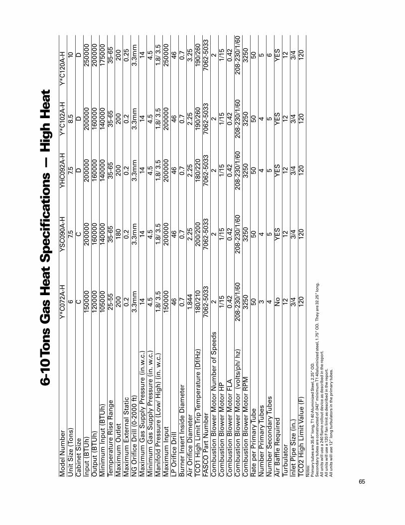
65
Mo
del
Nu
mb
erY
*C07
2A-H
YS
C09
0A-H
YH
C09
2A-H
Y*C
102A
-HY
*C12
0A-H
Un
it S
ize
(To
ns)
67.
57.
58.
510
Cab
inet
Siz
eC
CD
DD
Inp
ut
(BT
Uh
)15
000
020
0000
2000
0020
0000
250
000
Ou
tpu
t (B
TU
h)
120
000
160
000
160
000
160
000
2000
00M
inim
um
In
pu
t (B
TU
h)
1050
0014
000
014
000
014
000
017
5000
Tem
per
atu
re R
ise
Ran
ge
25-5
535
-65
35-6
535
-65
35-6
5M
axim
um
Ou
tlet
200
180
200
200
200
Max
imu
m E
xter
nal
Sta
tic
0.2
0.2
0.2
0.2
0.25
NG
Ori
fice
Dri
ll (0
-20
00 f
t)3.
3mm
3.3m
m3.
3mm
3.3m
m3.
3mm
Max
imu
m G
as S
up
ply
Pre
ssu
re (
in.w
.c.)
1414
1414
14M
inim
um
Gas
Su
pp
ly P
ress
ure
(in
. w.c
.)4.
54.
54.
54.
54.
5M
anif
old
Pre
ssu
re (
Low
/ Hig
h)
(in
. w.c
.)1.
8/ 3
.51.
8/ 3
.51.
8/ 3
.51.
8/ 3
.51.
8/ 3
.5M
axim
um
In
pu
t15
000
020
0000
2000
0020
0000
250
000
LP O
rifi
ce D
rill
4646
4646
46B
urn
er In
sert
Insi
de
Dia
met
er0.
70.
70.
70.
70.
7A
ir O
rifi
ce D
iam
eter
1.84
42.
252.
252.
253.
25T
CO
1 H
igh
Lim
it T
rip
Tem
per
atu
re (
Df/
Hz)
180/
210
200/
200
180/
220
190/
260
190/
260
FAS
CO
Par
t N
um
ber
7062
-503
370
62-5
033
7062
-503
370
62-5
033
7062
-503
3C
om
bu
stio
n B
low
er M
oto
r N
um
ber
of
Sp
eed
s2
22
22
Co
mb
ust
ion
Blo
wer
Mo
tor
HP
1/15
1/15
1/15
1/15
1/15
Co
mb
ust
ion
Blo
wer
Mo
tor
FLA
0.42
0.42
0.42
0.42
0.42
Co
mb
ust
ion
Blo
wer
Mo
tor
(vo
lts/
ph
/ hz)
208-
230/
1/60
208-
230/
1/60
208-
230/
1/60
208-
230/
1/60
208-
230/
1/60
Co
mb
ust
ion
Blo
wer
Mo
tor
RP
M32
5032
5032
5032
5032
50R
ate
per
Pri
mar
y Tu
be
5050
5050
50N
um
ber
Pri
mar
y Tu
bes
34
44
5N
um
ber
Sec
on
dar
y Tu
bes
45
55
6A
ir B
affl
e R
equ
ired
No
YE
SY
ES
YE
SY
ES
Turb
ula
tor
1212
1212
12In
let
Pip
e S
ize
(in
.)3/
43/
43/
43/
43/
4T
CO
2 H
igh
Lim
it V
alu
e (F
)12
012
012
012
012
0N
ote
s:P
rim
ary
tub
es a
re 3
5.8”
lon
g, T
1 40
Alu
min
ized
Ste
el, 2
.25”
OD
.S
eco
nd
ary
tub
es a
re c
on
stru
cted
of .
042”
min
imu
m T
1 40
alu
min
ized
ste
el, 1
.75”
OD
. T
hey
are
32.
25”
lon
g.
All
un
its
will
use
a 2
40 fl
ame
rollo
ut d
evic
e as
des
crib
ed in
the
rep
ort
.A
ll u
nit
s w
ill u
se a
120
F fa
n li
mit
as
des
crib
ed in
the
rep
ort
.A
ll u
nit
s w
ill u
se 1
2” lo
ng
turb
ula
tors
in th
e p
rim
ary
tub
es.
6-10
Tons
Gas
Hea
t Spe
cifi
cation
s —
Hig
h H
eat

66
Termination of the defrost cycle includesa “soft start” delay. At the end of eachdefrost cycle, the outdoor fan comes on 5seconds before the reversing valve is de-energized. This reduces stress on thecompressor and makes for a quieterdefrost.
Demand defrost operationHeating modeOutdoor ambient <52°FOutdoor coil <35
Defrost Service TestWhen a Service Test Defrost Request isreceived, defrost mode is initiatedimmediately. The defrost cycle willremain active for a minimum of 1 minute,after which the normal termination willoccur when the coil temperature exceedsthe defrost termination temperature asdefined below.
Defrost Mode OperationDefrost Mode shall remain active until theOutdoor Coil Temperature (OCT) exceedsthe Defrost Termination Temperature(DTT) or until ten (10) minutes havepassed, whichever occurs first. If allCompressor Outputs turn Off during thedefrost cycle, such as during a HighPressure Cutout or Low-Pressure Cutoutevent, Defrost Mode will terminate.When Defrost Mode has terminated, thefunction will track twelve (12) minutes toassure that a dry coil condition has beenachieved. At the twelve-minute point, DTwill be calculated using the current valuesof OAT and OCT (OAT is expected to behigher than OCT). This value is doubled tobecome the new Initiate Value. Figure 1presents a graphical representation of atypical demand defrost cycle.
There are two schemes in commonusage for heat pump outdoor coildefrosting: demand defrost and time-temperature defrost. Demand Defrost ismore efficient because defrost cycles areinitiated only when necessary, comparedwith initiation based on operating timebelow the threshold temperature. All 3-10 ton convertible packaged heat pumpsuse Demand Defrost.Outdoor coil defrosting occurs only whenoperating in heating mode with outdoorambient temperature below 52°F and theoutdoor coil temperature below 35°F. Thefirst defrost cycle after power-up isinitiated based on operating time at therequired conditions. Shortly aftercompletion of the defrost cycle, thetemperature difference between theoutdoor coil and outdoor air is calculatedand is used as an indicator of unitperformance at dry coil conditions. Overtime, as moisture and frost accumulateon the coil, the coil temperature will drop,increasing the temperature difference.When the temperature differencereaches double the dry coil temperaturedifferential (delta T), a defrost cycle isinitiated. While defrosting, the reversingvalve is in the cooling position, outdoorfans are off, and the compressorscontinue to operate. The defrost cycle isterminated when the coil temperaturerises high enough to indicate that the frosthas been eliminated.
Heat PumpDemand Defrost
Figure 1—Typical Demand Defrost Cycle

67
Diagnostic InformationDemand Defrost also tracks failures and operating problems as follows.When any Defrost Fault is active, or if any sensor has failed, a 5-minute defrost cyclewill be initiated after each 30 minutes of compressor heating operation.
Heat PumpDemand Defrost
Table1 — Demand Defrost Fault Designation
Symptom Diagnostic Response
∆T is below Minimum Low ∆T If> 2 hours, activate Defrost FaultValue 12 minutes after defrost is terminated Reset timer if ∆T returns within bounds.
Defrost Terminated Time If defrost is terminated on timeon time requirement Termination requirement (vs. differential
temperature).After 10 consecutive TimeTerminations, activate Defrost Fault.
∆T is above Maximum Value 12 minutes High ∆T Initiate Defrostafter defrost is terminated After 16 consecutive High ∆T Initiations
activate Defrost Fault.
∆T does not change by 2 degrees in an Unchanging ∆T Initiate Defrost and activatehour’s time starting 12 minutes after Defrost Activate Defrost Fault.
defrost is terminated and ∆T is less thanor equal to 4 degrees 12 minutes after
defrost is terminatedNotes:Defrost Termination Temperature (DTT) = Outdoor Air Temperature (OAT) + 47ºF57ºF <= DDT <= 72ºFDT = Outdoor Air Temperature (OAT) – Outdoor Coil Temperature (OCT)
Defrost Initiate Temperature 1.8 * (DT| 12 Minutes After Defrost Mode is terminated)~=
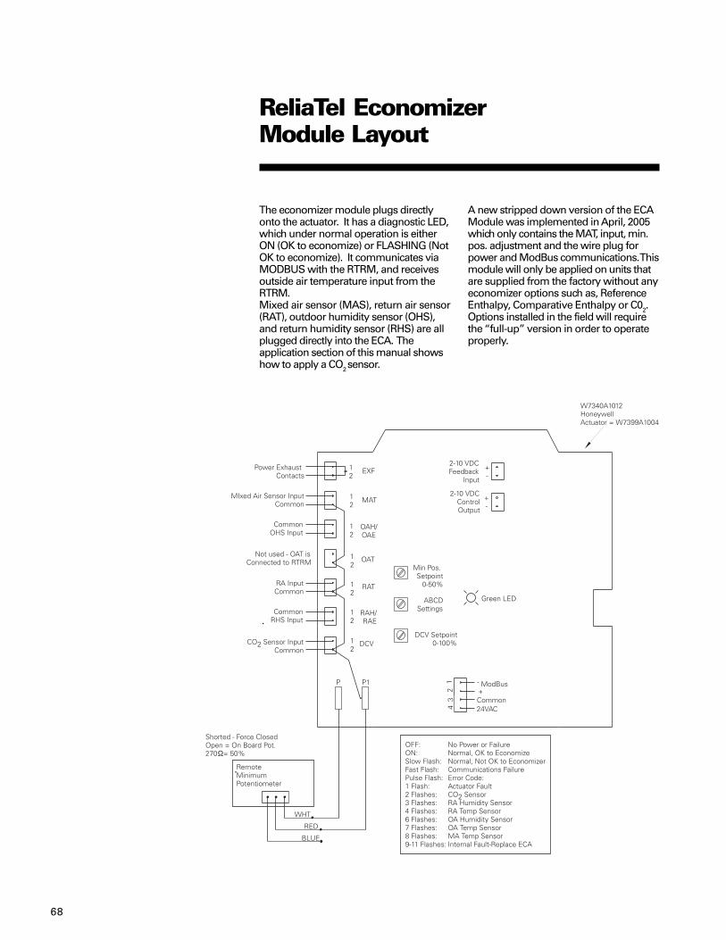
68
The economizer module plugs directlyonto the actuator. It has a diagnostic LED,which under normal operation is eitherON (OK to economize) or FLASHING (NotOK to economize). It communicates viaMODBUS with the RTRM, and receivesoutside air temperature input from theRTRM.Mixed air sensor (MAS), return air sensor(RAT), outdoor humidity sensor (OHS),and return humidity sensor (RHS) are allplugged directly into the ECA. Theapplication section of this manual showshow to apply a CO2 sensor.
ReliaTel EconomizerModule Layout
A new stripped down version of the ECAModule was implemented in April, 2005which only contains the MAT, input, min.pos. adjustment and the wire plug forpower and ModBus communications. Thismodule will only be applied on units thatare supplied from the factory without anyeconomizer options such as, ReferenceEnthalpy, Comparative Enthalpy or C02.Options installed in the field will requirethe “full-up” version in order to operateproperly.
69
Customer BenefitAn economizer consists of a fresh airdamper, a return air damper, linkage tomaintain an inverse relationship betweenthe two, and an actuator to control thedamper position. An economizer is usedto provide two unit functions: ventilationand economizer cooling. In either case,the inverse relationship between thereturn and outdoor air dampers allowsthe unit to maintain the sameapproximate total airflow regardless ofeconomizer position. A linkageadjustment is typically required in thefield to adjust for differences in pressuredrops due to different duct designs.Economizer cooling is provided to takeadvantage of cooler outdoor air to satisfya cooling load in a conditioned spaceminimizing the need for mechanicalcooling (with compressors). Whileeconomizer cooling, it is necessary to limitthe damper position so that the mixed airtemperature does not fall below 53°F (±3°F) and cause excessively cool air frombeing discharged from the unit. Whenused with a zone sensor, an economizersetpoint that is below the cooling setpointis used to allow sub-cooling essentially forfree, further reducing the need for moreexpensive mechanical cooling. Tomaximize the use of an economizer,mechanical cooling is delayed fromrunning until it has been determined thatthe economizer alone cannot satisfy theload.Any time the supply fan is On and thebuilding (unit) is occupied, the economizerdamper will be maintained at or aboveminimum position. The economizerdamper is held Closed when the supplyfan is Off to prevent water from gettinginto the economizer section of the unit.Compressors will be delayed fromoperating until the economizer hasopened to 100% for 5 minutes on all unittypes other than Voyager III which willhave a 3-minute delay.
ReliaTel EconomizerOperation
VAV Economizer Cooling Operation:A similar method of determining andadjusting the economizer setpoint asdescribed in CV operation will be used inVAV Cooling operation with the additionalVAV requirements below.
• Economizer Setpoint = SA Temp ControlPoint - 2°F.
• Economizer Cooling is only allowedwhen economizing is enabled and SAtemp is greater than Economizer Setpoint- 1.5°F.
• If conditions allow enabling ofeconomizer cooling after a compressor isactive, the economizer damper is forcedto 100% open until all compressors aredeactivated or conditions change todisable economizing.
• If economizer cooling is active prior tomechanical cooing, compressoroperation will be inhibited until theeconomizer damper reaches 100%. Oncethe economizer reaches 100%,mechanical cooling will be enabledwithout delay.
• During VAV Unoccupied operationeconomizer cooling will operate as it doesin CV Unoccupied.
Economizer Operation with zone sensor,programmable zone sensor or ICSWhen economizing is enabled and theunit is operation in the cooling mode witha zone sensor, the economizer damper ismodulated between its minimum positionand 100% to maintain the zonetemperature at the economizer setpoint.When the unit is applied with a zonesensor, programmable sensor or ICS, theeconomizer setpoint is (ESP) is derivedfrom the Cooling and Heating setpoints(CSP and HSP) so that ESP is the higher of1) CSP – 1.5°F or 2) HSP + 1.5°F. Whenenabled, the economizer will modulatebetween minimum position and 100% tomaintain a mixed air temperature of53±3°F. If the mixed air temperaturestarts to fall below 53°F, the economizerstarts closing; and at 50°F, the damper willbe at minimum position.
If the economizer is not able to satisfy thecooling setpoint, 1st stage cooling will beenergized. Should the cooling setpointnot be satisfied with 1st stage cooling, 2nd
stage cooling will be energized. Mostoften, the economizer and 1st stagecooling will be adequate to satisfy theload. 1st stage cooling will not start untilthe economizer has been full open for fiveminutes and the zone temperature errorhas not being reduced quickly enough.
Economizer Operation withConventional ThermostatWhen the unit is operating from aconventional thermostat or other binaryinput, the economizer setpoint feature,relative to the cooling and heatingsetpoints, is lost. The economizer controlis based strictly on a signal from thethermostat, but still maintains mixed airtemperature control of 53°±3°F when inthe economizer mode. The economizerenable and disable function is stilldetermined by the outside air sensorthrough the RTRM.If a single-stage thermostat is used, onlythe economizer (if enabled) or thecompressor (if economizer is disabled)will operate on a call for cooling. A two-stage thermostat is required to achieveeconomizer operation and compressoroperation at the same time.With economizer enabled, a Y1 call for 1st
stage cooling will be the economizer. Thedamper will modulate between minimumposition and 100% to maintain mixed airtemperature at 53°±3°. At 50°F thedamper will be at minimum position. Ifthe economizer is enabled, a Y2 call for2nd stage cooling will start the firstcompressor if required.If the economizer is disabled, 1st stage(Y1) will be the first compressor. If theunit has two compressors, a call for 2nd
stage cooling (Y2) will start the secondcompressor.When using a conventional thermostat,or other binary input, the ReliaTel controlswill only allow two stages of cooling.

70
Barometric reliefUnits with economizers bring in outsideair for ventilation and/or economizercooling. Because the economizercontains a return air damper thatoperates inversely to the outdoor airdamper, the outdoor air will tend topressurize the conditioned space. Thiscan cause exterior doors to open oraudible noise from air escaping throughvarious building openings.Units without exhaust fans rely onbarometric dampers to vent the pressurethat builds up in the space due to outdoorairflow.
Power exhaustExhaust fans offer improvedperformance since they can be sized toovercome the pressure drops associatedwith the return duct that would otherwiseadd to the space pressure. This functionallows the exhaust fan to operate whenappropriate to maintain space pressure.Units without RTOM: The power exhaustis on whenever the economizer damperis at 25% outside air or greater. This is notadjustable.
Units with RTOM: The power exhaust setpoint (point at which the power exhaust isturned on) is adjustable from 0% to 100%at the RTOM “exhaust setpoint”potentiometer.
Three different methods can be used todetermine if outdoor air contains morecooling capacity than the return air andare described below. The differentmethods are suited for differentapplications and environments.• Comparative Enthalpy — Outdoor Air
Enthalpy is compared with Return AirEnthalpy. This method is best suited forhigh humidity climates and applicationsin which humidity can affect the coolingcapacity of the outdoor air or return air.
• Reference Enthalpy — Outdoor AirEnthalpy is compared with a referenceenthalpy point. This method is bestsuited for high humidity climates inwhich humidity can affect the coolingcapacity of the outdoor air, but notnecessarily the return air.
• Reference Dry Bulb— Outdoor AirTemperature is compared with a userset reference temperature. Thismethod is best suited for low humidityclimates and applications in whichhumidity does not strongly affectcooling capacity of the outdoor air orreturn air.
Dry bulb temperature and relativehumidity data are used to determineenthalpy.Economizer-based cooling is enabled onlywhen outdoor air is determined to havemore cooling capacity than the return air.The method used is according to theavailable data. When temperature andhumidity data are available for theoutdoor air and return air, theComparative Enthalpy method is used.One of the other methods are used if datais invalid or unavailable. Ultimately, whenthere is insufficient data to use any of thethree methods, economizer-basedcooling is disabled.When the Active Unit Mode is Cool, oneof the enthalpy or temperature methodsare used to determine if economizer-based cooling should be enabled ordisabled.
Thermostat noteIf the unit is applied with a thermostat, thealgorithms use a fixed mixed airtemperature setpoint of 55°F when the Y1input is closed. If the unit is applied with azone sensor, the algorithms use adynamically calculated mixed airtemperature setpoint, which is calculatedby other algorithms, when cooling isrequested.
The damper can be in three differentstates.
Closed. The damper is held at 0%.Minimum Position. The damper is heldat the Minimum Position as determinedby the Minimum Position Potentiometeron the ECA or by an edited input fromICS. This position is between 0% and50%. Note: When making minimumposition adjustments, allow 30-45seconds for actuator to respond.Modulating. Algorithms control thedamper to meet cooling demand.When modulating, the damper’s rangeof motion is between Active MinimumPosition and 100%.
The following inputs are used:Mixed Air Sensor (MAS) measures thedry bulb temperature of the air leavingthe evaporator coil while economizing.Return air, outdoor air and cooling causedby any compressor cooling make up theMixed Air input. The MAS is plugged intothe Economizer Actuator Module (ECA).
Outdoor Air Sensor (OAS) measures theambient air surrounding the unit. It islocated in the compressor section on theleft side. Ventilation holes in the accesspanel of the unit allow air movementacross the sensor. The OAS is pluggedinto the RTRM module.Outdoor Humidity Sensor (OHS)measures the relative humidity of theoutside air. It is located inside theeconomizer hood. The OHS is pluggedinto the ECA.Return Air Temperature Sensor (RAT)measures the return air temperature. Itis located on the return air damper of theeconomizer.The RAT is plugged into the ECA.Return Humidity Sensor (RHS) measuresthe relative humidity of the return air. It islocated on the return air damper of theeconomizer. The RHS is plugged into theECA.
ReliaTel EconomizerOperation

71
Figure 1—Economizer
Table 1 — Choice of Enthalpy Method
Method used to Required Datadetermine economizereffectivenessComparative Enthalpy MAS, OAT, OAH, RAT, RAHReference Enthalpy MAS, OAT, OAHReference Dry Bulb MAS, OATUnit will not economize MAS or OAT data is invalid
or unavailable
Economizer DamperEnthalpy Layout

72
Dry bulb/Reference Point SelectionsThe Dry Bulb or Reference Enthalpy Pointis user-selectable, according to thechoices below. This selection is made onthe ECA and is only functional on unitswith a reference or comparative enthalpyoption.
Comparative Enthalpy MethodOA Enthalpy is compared with RAEnthalpy.• The Economizer is enabled when OA
Enthalpy < [RA Enthalpy - 3.0 BTU/lb.].• The Economizer is disabled when OA
Enthalpy > RA Enthalpy.
Economizer OperationEnthalpy Changeover
Table 2 — Dry Bulb/Reference Enthalpy
Point Choices
Potentiometer Dry bulb ReferenceSetting changeover EnthalpyPoint PointA* 73°F** 27 BTU/lb.B 70°F 25 BTU/lb.C 67°F 23 BTU/lb.D 63°F 22 BTU/lb.
Figure 2— Comparative Enthalpy Enable
Economizer Enabled
Economizer Disabled
OA Enthalpy - RA Enthalpy
Comparative Enthalpy Hysteresis
• While [RA Enthalpy - 3.0 BTU/lb.] < OAEnthalpy < RA Enthalpy, the Economizerenable/disable status is not changed.
*factory setting**dry bulb is fixed @73°F and is notadjustable

73
Reference Enthalpy MethodOA Enthalpy is compared with areference enthalpy point.• The Economizer is enabled when OA
Enthalpy < [reference enthalpy point -0.5 BTU/lb.].
• The Economizer is disabled when OAEnthalpy > [reference enthalpy point +0.5 BTU/lb.].
Reference Dry Bulb MethodOA Temperature is compared with areference dry bulb point.• The Economizer is enabled when OA
Temp < reference dry bulb point.• The Economizer is disabled when OA
Temp > (reference dry bulb point +5.0)°F.
Figure 3 — Reference Enthalpy Enable
Figure 4 — Dry Bulb Enthalpy Enable
Economizer Enabled
Reference Enthalpy Hysteresis
OA Enthalpy - Ref Enthalpy (BTU/lb.)
Economizer Disabled
Dry Bulb Hysteresis
Economizer Enabled
OAT - reference point (˚F)
Economizer Disabled
• While reference dry bulb point < OATemp < (reference dry bulb point +5.0°F), the Economizer enable/disablestatus is not changed.
• While [reference enthalpy point - 0.5BTU/lb.] < OA Enthalpy < [referenceenthalpy point + 0.5 BTU/lb.], theEconomizer enable/disable status is notchanged.
Economizer OperationEnthalpy Changeover

74
ReliaTel Economizer Inputs
Terminals to read voltage:Mixed Air Sensor ECA MASReturn Air Sensor ECA RAT
Note: These are Economizer inputs only. RTRM, RTOM inputs (Zone temp, Setpoints, OAS, DAS) are in the ReliaTel Temperatureinputs section.
Read DC voltage with the sensor attached. If voltage does not appear to be correct, read the resistance of the circuit, then the sensoritself, to see if a problem exists in the sensor or the wiring. With the sensor not attached there should be approximately 2.50 VDC atthe terminals listed above.
Service Tips:Terminal 1 in each of these circuits is common. All common terminals are grounded, therefore one volt meter lead can be attached toground for voltage measurements.
Internal CalculationsAir enthalpy is a value calculated from the air temperature and relative humidity usingthe relationship:Enthalpy= 0.24 x O.A.Temp(deg. F) + h(R.H.,OAT)Air enthalpy is calculated (Btu/Lb. dry air) using:H = 0.24 * T + W * HvWhere T= dry bulb temperature, deg. F
W= humidity ration, lb. water/lb. dry airW = 0.622 * P/ (14.696 - P)Hv= enthalpy of water at T, Btu/lb.Hv= 1062.1 + 0.43 * T
Also,P= partial pressure of water at T, psiaP= (0.421 - 0.01503 * T + 0.000202 * T**2) * RH
ReliaTel EconomizerOperation & Inputs
Temperature °F Resistance DCV Temperature °F Resistance DCV(K ohms) Volts (K ohms) Volts\
40 26.105 1.853 61 14.899 1.55141 25.393 1.839 62 14.521 1.53642 24.703 1.826 63 14.154 1.52043 24.033 1.812 64 13.797 1.50544 23.385 1.799 65 13.451 1.49045 22.756 1.785 66 13.114 1.47546 22.146 1.771 67 12.787 1.46047 21.554 1.757 68 12.469 1.44448 20.980 1.743 69 12.160 1.42949 20.424 1.728 70 11.860 1.41350 19.884 1.714 71 11.568 1.39851 19.360 1.699 72 11.284 1.38352 18.852 1.685 73 11.008 1.36753 18.359 1.670 74 10.740 1.35254 17.880 1.656 75 10.479 1.33755 17.415 1.641 76 10.225 1.32156 16.964 1.626 77 9.978 1.30657 16.527 1.611 78 9.738 1.29158 16.102 1.596 79 9.505 1.27659 15.689 1.581 80 9.278 1.26160 15.288 1.566

75
To Test Humidity SensorsReturn Air Humidity Sensor ECA RAH/RAEOutdoor Humidity Sensor ECA OAH/OAE
To test this circuit, place a DC milliamp meter in series with either of the leads to the humidity sensor. If the reading is 0ma, polaritymay be reversed. Reverse + & - and retest. If the reading does not correspond to the table below, check the output voltage from theECA with the sensor disconnected. It should be approximately 20VDC. If so, and all connections are intact, replace the sensor. If20VDC is not present, yet the ECA green LED is on, the ECA module has failed.
RH% DCma RH%D Cma RH% DCma100% 20.000 52.6 12.414 31.2 9.00097.7 19.636 51.7 12.273 30.8 8.92695.5 19.286 50.8 12.135 30.3 8.85293.4 18.947 50.0 12.000 29.9 8.78091.4 18.621 49.2 11.868 29.4 8.71089.4 18.305 48.4 11.739 29.0 8.64087.5 18.000 47.6 11.613 28.6 8.57185.7 17.705 46.8 11.489 28.1 8.50483.9 17.419 46.1 11.368 27.7 8.43882.1 17.143 45.3 11.250 27.3 8.37280.5 16.875 44.6 11.134 26.9 8.30878.8 16.615 43.9 11.020 26.5 8.24477.3 16.364 43.2 10.909 26.1 8.18275.7 16.119 42.5 10.800 25.8 8.12074.3 15.882 41.8 10.693 25.4 8.06072.8 15.652 41.2 10.588 25.0 8.00071.4 15.429 40.5 10.485 24.6 7.94170.1 15.211 39.9 10.385 24.3 7.83368.8 15.000 39.3 10.286 23.9 7.82667.5 14.795 38.7 10.189 23.6 7.77066.2 14.595 38.1 10.093 23.2 7.71465.0 14.400 37.5 10.000 22.9 7.66063.8 14.211 36.9 9.908 22.5 7.60662.7 14.026 36.4 9.818 22.2 7.55261.5 13.846 35.8 9.730 21.9 7.50060.4 13.671 35.3 9.463 21.6 7.44859.4 13.500 34.7 9.558 21.2 7.39758.3 13.333 34.2 9.474 20.9 7.34757.3 13.171 33.7 9.391 20.6 7.29756.3 13.012 33.2 9.310 20.3 7.24855.4 12.857 32.7 9.231 20.0 7.20054.4 12.706 32.2 9.15353.5 12.558 31.7 9.076
ReliaTel EconomizerInputs

76
Actuator fault: An actuator fault will occurwhen the economizer position signal tothe actuator is 25% different than thefeedback signal from the actuator.Example: if the economizer is notattached to the motor, you would get anactuator fault only after the economizerwould tell the motor to drive to at least25% open.Sensor faults: Sensor faults will occur ifthe sensors are disconnected duringnormal operation. However, during the 3minute boot-up period, the ECA willdefault to the sensors that are connected.During the 3 minute period, theeconomizer will look to see which sensorsare hooked up and determine which stateit will be in. Example: if only the OAS andMAS is hooked up, it will be in Dry Bulb. Ifthe OAS, OHS and MAS is hooked up, itwill be in Reference.If after the 3 minute “configuration” timehas passed, if one of those sensors aredisconnected, the economizer shouldfault. If you attach and disconnectsensors during the original 3 minutes, theeconomizer should not fault.
Service Note:The actuator has an internalpotentiometer that reports the actualdamper position. Should the linkagebecome bound, the actuator may reportan unexpected output to a BAS output(Tracer, Tracker, CCP).
ReliaTel EconomizerControl Actuator
(LED FaultCode Info.)
The mixed air sensor (MAS) and outdoorair sensor input from the RTRM areminimum required sensors.If the CO2 sensor is not hooked up, theeconomizer will not look for it and will notfault.
The flash codes are prioritized. The higherthe flash count, the more priority the faulthas. If there is more than one fault, onlythe higher priority fault will flash.
The green system LED is locatednear the center of the ECA Module.
On: OK to economizeSlow flash: Not OK to economizeFast flash: Not communicating withRTRMOFF: No power or system failureError codes — ½ second on, ¼second off1 flash — Actuator fault2 flash — CO2 sensor3 flash — RA humidity sensor4 flash — RA temp sensor6 flash — OA humidity sensor7 flash — OA temperature sensor(On power up: No communicationwith RTRM)8 flash — MA temp sensor9-11 flash — Internal fault
77
ReliaTelHumidity Sensors
Outdoor Humidity SensorField installed accessory, located belowand to the left of economizer actuatormotor. Used in reference(BAYENTH005A) and comparative(BAYENTH006A) enthalpy control.Operates from 10-90% RH, 32°F – 90°F.
Component Description Part NumberHumidity Sensor (OHS, RHS) SEN-01036
Return Humidity SensorField installed accessory, located insideeconomizer barometric relief hood. Usedin comparative (BAYENTH006A)enthalpy control only. (Honeywell#C7600C).

78
ElectromechanicalEconomizer Functions
Economizer Actuator (ECA)
connected to the unit
Economizer Actuator (ECA)
connected to the unit

79
When the outdoor air thermostat is in thecold position (closed), the unit will attemptto economize if a fan (G) and cooling (Y1)call exists at the ECA module. This isreadily apparent at the ECA, as the “OK toeconomize” LED will be on. During thistime, the ECA is measuring the Mixed Airtemperature via the Mixed Air Sensor(MAS).
ElectromechanicalEconomizer Testing
Service TipsThe MAS sensor is not energized unlessthe LED is on (G signal present, OK toeconomize), and the Y1 signal is present.If the MAS is open, approximately 4.3VDC will be seen.Outdoor Air Thermostat opens at 70°Fand closes at 60°F.Read the voltage with the sensorconnected, read the resistance with thesensor disconnected.
Temp F Temp C R(K OHMS) DC Volts33.8 1 9.576 3.91035.6 2 9.092 3.88237.4 3 8.636 3.89439.2 4 8.204 3.86341.0 5 7.796 3.82942.8 6 7.412 3.79044.6 7 7.048 3.74946.4 8 6.705 3.71348.2 9 6.380 3.67450.0 10 6.073 3.63451.8 11 5.782 3.59053.6 12 5.507 3.55055.4 13 5.247 3.50757.2 14 5.000 3.42059.0 15 4.767 3.37360.8 16 4.545 3.32862.6 17 4.335 3.28364.4 18 4.136 3.23966.2 19 3.948 3.18068.0 20 3.769 3.15769.8 21 3.599 3.11871.6 22 3.437 3.08073.4 23 3.284 3.03475.2 24 3.138 3.00777.0 25 3.000 2.97178.8 26 2.869 2.93280.6 27 2.744 2.89682.4 28 2.625 2.86084.2 29 2.512 2.82486.0 30 2.404 2.78787.8 31 2.301 2.75089.6 32 2.204 2.71491.4 33 2.111 2.67693.2 34 2.023 2.63995.0 35 1.938 2.60096.8 36 1.858 2.56198.6 37 1.781 2.526100.4 38 1.708 2.484

80
Full open (50%) economizer minimumposition is accomplished by setting theECA minimum position potentiometer to100% and installing a set of contacts inseries with the existing 130 ohm resistorto terminals P and P1 on the ECA.Any intermediate (0 - 50%) economizerposition is accomplished by installing a 0 -270 ohm potentiometer in series with anadditional set of contacts and the existing130 ohm resistor to terminals P and P1 onthe ECA. 0 ohms = 50% outside air and270 ohms = 0% outside air.Fully closed position is accomplishedwhen the indoor fan is disabled.
Note: Actual outside airflow is alsodependent on return air static pressure
ElectromechanicalEconomizer
(3 PositionDamper)
Set pot at 100%
130 ohm resistor shippedwith the economizer and connected from P to PI
from the factory.
0-270 ohm

81
Temporary comfort can be providedwithout a Zone Sensor Module orthermostat in place by using the OutdoorAir Sensor or a spare Supply Air / ReturnAir Sensor. How to do it: remove thesensor from the unit, add enoughthermostat wire to it so that it can beplaced in the return air stream, thenconnect the sensor to J6-1 & J6-2.After the permanent Zone Sensor orthermostat is in place, the sensor must beremoved from J6-1 & J6-2.
ReliaTelControl
(Temporary Operation3-25 tons)
If the RTRM does not have a spacetemperature input (J6-1, J6-2), or have aconventional thermostat input (G, Y, W),the unit will not run (except in the testmode).Temporary Sensor (thermistor)attached to J6-1 and J6-2 only:Continuous fanAuto changeover74°F cooling, 71°F heating
ReliaTel Refrigeration Module
place sensor in returnair stream
connect sensor toterminals 1&2
Note:27½-50 ton units - the outdoor air sensorshould not be used for this purpose.

82
Supply air tempering maintains thesupply air temperature above a lowerlimit during minimum ventilation periodswhen in heat mode. Supply air temperingis available when using a BAYSENS019*/AYSTAT666* Programmable ZoneSensor, BAYSENS006-11/AYSTAT661-664 Mechanical Zone Sensor, or Trane ICSsystem. It is only active in the Heatingmode.The unit requires an RTOM (optionsmodule) and BAYTUBE discharge airsensing kit. Supply air tempering will notwork with a conventional thermostat.
How to enable Supply Air Tempering(CV only):Mechanical Zone Sensor BAYSENS006-11/AYSTAT661-664: remove the jumperfrom RTOM J3-1 and J3-2.Programmable Zone SensorBAYSENS019*/AYSTAT666*: changeOption 4 in the options menu to1=enabled. Or, remove the jumper fromRTOM J3-1 and J3-2.Trane ICS system: Enable throughappropriate menu
Note:Supply air tempering is not available on27½ to 50 ton VAV units.
ReliaTel Supply AirTempering Control
Sequence of operation:When Supply Air Tempering is enabled,the supply fan is on, active mode is Heator Emergency Heat, and with the unit notactively heating, stage 1 of heat is turnedON when the supply air temperature is10°F below the Active Heating Setpoint.Stage 1 of heat is turned OFF when thesupply air temperature is 10°F above theActive Heating Setpoint or the Mode is nolonger Heat or Emergency Heat. Shouldthe zone temperature exceed the ActiveHeating Setpoint by 1-2F, Supply AirTempering will cease until anothernormal heating cycle resumes.For heat pump units, the auxiliary heat isused for tempering.
83
Discharge Air Sensingwith TCI Comm3/4
Units connected to ICS systems have theability to look at discharge airtemperature. Units operating onCOMM3/4 systems only have the abilityto see one point for discharge air and thatis through the Mixed Air sensor. This isreported back to the ICS display graphicsas SAS (Supply Air Sensor). Thedischarge air sensor is often used tomonitor true discharge air temperatureout of the unit. It is also used to do supplyair tempering with an ICS system or aBAYSENS019* programmable zonesensor.Systems using LonTalk, and an LCI cardhave the ability to see both Mixed Air andDischarge Air temperature.The following discussion is focused onlywith units utilizing COMM3/4communications.If an economizer is not installed, thedischarge air sensor option is required tomonitor discharge air temperature. Thesensor must be used in conjunction withthe RTOM options module. The dischargesensor will be located in the dischargeopening of the unit and provides truedischarge temperature out of the unit.
If a unit has an economizer, in order tomonitor true discharge air temperature,the unit can use the Mixed Air sensor, butit will have to be relocated to thedischarge of the unit. If the Mix Air sensoris relocated to the discharge of the unit,no further action is required. The sensorwill report back true dischargetemperature through the economizermodule, and also still function as theMixed Air sensor for the economizeroperation. The Discharge Air sensoroption is the recommended methodbecause it uses an averaging tube tosense the air across the dischargeopening. This sensor will have to be wiredback to the Mixed Air Sensor (MAS) inputon the economizer module and replacesthe MAS sensor.
Service Note:If there should be a sensor failure ofeither the Mixed Air sensor or theDischarge Air sensor, the diagnostic willbe reported back as a Supply Air Sensorfailure. It will require a visit to the jobsiteto determine which sensor has failed.
Note for 3-25 Ton Units:If the unit has an economizer and theDischarge Air sensor option is installed,then a 5.6K (1/4 watt) resistor must beinstalled on the OAT terminals of theeconomizer actuator module (ECA). Thisresistor will allow the economizer tocontinue operation from the Mixed Airsensor. The discharge air sensor willreport true discharge temperature to theRTOM, and in turn, to the ICS panel viathe TCI COMM3/4 communications.KIT08318 can be ordered for the 5.6Kresistor.

84
CO2 Sensor Connections For ReliaTel
Units With EconomizerCO2 setpoint adjustment
DCV setpoint potentiometer oneconomizer module can be adjusted asfollows:0% = 500ppm50% = 1000ppm100% - 1500ppm
CO2 SensorConnections
C02sensor
4190-4100
24 VAC
ECA
24VOUTGND
DCVSetpoint
DCV0% 100%
Analog input0 to 10 VDC
X13790422010
The CO2 sensor can be configured for 0-10vdc, 0-20mA or 4-20mA analogoutputs. For use with the ReliaTeleconomizer, the sensor must be set for 0-10vdc. As the CO2 level increases, thevoltage output increases accordingly. TheDCV potentiometer on the ReliaTeleconomizer module can be set to thedesired point at which the economizer willstart modulating. The adjustment range isto 100%; 0% = 500ppm, 50% = 1000ppmand 100% = 1500ppm.When the DCV threshold is reached theeconomizer will start to modulate open tobring in more fresh air to reduce the CO2level. The damper will modulate open insmall increments until the CO2 level issatisfied or the damper reaches the fullopen position. Once the threshold issatisfied, the damper will return tonormal economizer operation.
If the mixed air temperature drops to40° F, the CO2 sensor input is overridenand closes the damper to minimumposition to prevent, hot water coils fromfreezing, or if gas heating, to preventcondensation in the heat exchanger.When the mixed air temperature rises to43°F, CO2 or economizer operation is onceagain restored. Since the damper candrive wide open, it is also recommendedto install an evaporative defrost control toprevent the evaporator coil from freezing.
(ReliaTel unitswith Economizer)

85
ReliaTel VentilationOverride
Three Ventilation modes are availablewith ReliaTel through use of an OptionsModule (RTOM) and economizer (ECA)with Power Exhaust. Following is a list ofeach mode and what happens duringeach.
Compressors OK to heat Economizer PowerSupply Fan forced: may run? (gas/elect.)? position? Exhaust?
Pressurization ON No No 100% OffPurge ON No No 100% OnExhaust OFF No No 0% On
Connections to the unit to accomplishVentilation Modes are shown below. Allthree inputs are shown for illustration;only one is typically used.
Note: Although not associated withventilation override, humidistatconnections for dehumidification are alsoprovided on this terminal block.
Emergency shutdown from the RTRMwill override any ventilation overridemode.Ventilation override inputs overridesmoke detector inputs through theRTOM. (3-25 tons only)

86
Dehumidification withHot Gas Reheat (3-25 Tons)
Verification of the RH setpoint can be determined by measuring the dc voltage at TB1and TB2 on the RTOM.
Setpoint Voltage Setpoint Voltage Setpoint Voltage Setpoint Voltage(%) (vdc) (%) (vdc) (%) (vdc) (%) (vdc)
40 0.0 45 1.00 50 1.67 55 2.1441 .238 46 1.15 51 1.77 56 2.2242 .455 47 1.30 52 1.88 57 2.3043 .652 48 1.43 53 1.97 58 2.3744 .833 49 1.55 54 2.06 59 2.44
60 2.50
Calculation to convert mA to RH = (mA reading - 4) * 6.254mA = 0%20mA = 100%Example: (12mA - 4) * 6.25 = 50% RHTo measure the mA input current from the humidity sensor, disconnect sensor wirethat is connected to terminal 18 of LTB. Connect amp meter in series with the wire andterminal 18 of the LTB.
Factory installed hot gas reheat allowsapplication of dehumidification. Initiationof reheat is performed by an input to theRTOM module from either a relativehumidity sensor or a humidistat typedevice. These connections are madethrough the low voltage terminal striplocated in the unit control panel. Actuationof the reheat is accomplished byenergizing a valve that allows refrigeranthot gas to flow through the hot gas reheatcoil.Dehumidification is allowed only whenthe outside air temperature is above 40°Fand below 100°F. Dehumidification is alsonot allowed if there is an active call forheating or cooling. If, during adehumidification cycle, there is a call forheating or cooling, the dehumidificationcycle is terminated. The economizeroutside air damper is also driven tominimum position duringdehumidification.A humidity sensor that is capable ofproviding a 4 - 20 ma output can be used.The RH setpoint is established byadjusting the R41 potentiometer (labeledDehumid SP) on the RTOM module. Therange can be set from 40 to 60%. In theabsence of a zone humidity sensor input,an on/off input from a zone humidistat isused to initiate or terminate thedehumidification cycle.A relative humidity sensor takes priorityover a humidistat. Dehumidification takespriority over a call for one stage cooling.Heating or 2 stage cooling takes priorityover dehumidification.
Sequence of Events
Single compressor unitsOn a call for dehumidification, the reheatvalve is energized and the compressor isturned on. When the humidity controlsetpoint is satisfied, the valve is de-energized and the compressor is turnedoff. If there is a call for cooling from thespace temperature controller, i.e. zonesensor or thermostat, while in reheat, thereheat valve is de-energized and thecompressor continues to run. The three-minute compressor on and off times arestill active during compressor operation.
Dual Compressor unitsOn a call for dehumidification, the reheatvalve is energized and both compressorsare turned on. When the humidity controlsetpoint is satisfied, the valve is de-energized and both compressors areturned off. If there is a call for 1st stagecooling while in the dehumidificationmode, no action takes place. If there is acall for 2nd stage cooling, the reheatvalve is de-energized, and the unitreverts to the cooling mode. If 2nd stagecooling is satisfied and there is still a callfor dehumidification, the reheat valve willonce again be energized. The three-minute compressor on and off times arestill active during compressor operation.
Refer to appropriate unit wiring diagramsfor control connections.

87
The change over from heating to coolingis accomplished in two different ways.The first drawing below illustrates changeover in a system without an economizer,and the second drawing illustrateschange over in a system with aneconomizer. Change over from cooling toheating is accomplished in the samemanner for both economizer and non-economizer systems.
Heating/CoolingChangeover
If the unit is in the cooling mode and thezone temperature is falling, the unit willchange to the heating mode when thezone temperature is equal to or less thanthe heating set point. For systemswithout economizers, if the unit is in theheating mode, and the zone temperatureis rising, the unit will change to the coolingmode when the zone temperature isequal to or greater than the cooling setpoint. For systems with economizers, ifthe unit is in the heating mode, and thezone temperature is rising, the unit willchange to the cooling mode when thezone temperature is equal to or greaterthan the economizer set point.
ZTEMPfalling
CSP
HSP
Changeto cooling
with economizer
ESP
CSP
HSP
ZTEMPfalling
ZTEMPrising
ZTEMPrising
without economizer
Changeto heating
Changeto heating Change
to cooling

88
Time Delay RelayThis time delay circuit board attaches tothe side of the relay. When energized, thefan starts immediately and when de-energized shuts off 80 seconds later. Thisdelay is not adjustable.
ElectromechanicalTime Delay Relay

89
Fan “Off” Delay Solid State TimerWhen “G” is energized, the N.O. contactsbetween 1 and 2 close immediately,energizing the fan relay (F), which in turnstarts the indoor fan.When “G” is de-energized, the contactsbetween 1 and 2 remain closed for 80seconds, then open. This in turn de-energizes the F relay, which stops theindoor fan.
ElectromechanicalTime Delay Relay
(Sequence ofOperation)
"G"
"R"
"C"
F
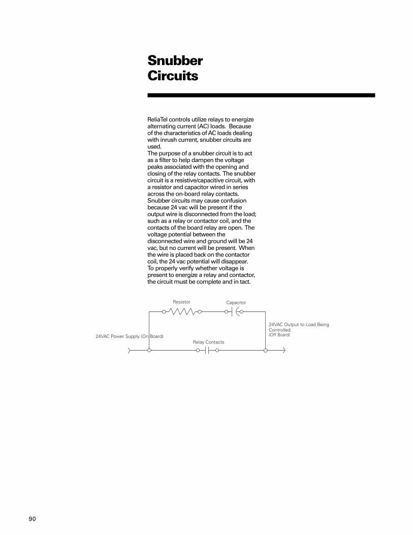
90
ReliaTel controls utilize relays to energizealternating current (AC) loads. Becauseof the characteristics of AC loads dealingwith inrush current, snubber circuits areused.The purpose of a snubber circuit is to actas a filter to help dampen the voltagepeaks associated with the opening andclosing of the relay contacts. The snubbercircuit is a resistive/capacitive circuit, witha resistor and capacitor wired in seriesacross the on-board relay contacts.Snubber circuits may cause confusionbecause 24 vac will be present if theoutput wire is disconnected from the load;such as a relay or contactor coil, and thecontacts of the board relay are open. Thevoltage potential between thedisconnected wire and ground will be 24vac, but no current will be present. Whenthe wire is placed back on the contactorcoil, the 24 vac potential will disappear.To properly verify whether voltage ispresent to energize a relay and contactor,the circuit must be complete and in tact.
SnubberCircuits

91
TransformerTroubleshooting
A transformer usually burns out due to ashort circuit. When this occurs, thetechnician can usually find the source ofthe short. Sometime though, the cause oftransformer failure is not so obvious. Itcan also fail when excessive voltagedrops occur because of poor connections,thermostat wires too long, bad contactson the smoke detector, etc. The excessivevoltage drop results in low voltage to theload (contactor, relay) and then thetransformer blows.
The graph below shows how as current caused by loadson the transformer increases, voltage decreases. Once thevoltage drops below the level that the contractor can pullin, usually about 16-18 volts, the current raises up to thepoint where the transformer burns out. The chart below isfor illustration only.

92
TransformerTroubleshooting
Here’s what to look for:Transformer on the wrong voltage tap,i.e. 208 volts at the unit, transformer onthe 230 volt tap.
Voltage drop across contacts (measurewith a load on the circuit):
Voltage drop across contacts when loadis applied should be less than ½ volt.

93
High Pressure and LowPressure Lockout Circuits
High Pressure Cutout (HPC) and LowPressure Cutout (LPC) circuits aredesigned to shut compressor operationdown when pressures are too low, suchas loss of charge; or too high, such aswould result from dirty condenser coils.The operational logic of these circuits issomewhat unique and requiresexplanation to fully understand how theyoperate.
LPC LogicLPC logic was changed with version 3.1 ofthe RTRM. Timing was changed from twominutes to 10 seconds to enhancecompressor reliability due to no-flowissues for the TXV option duringcompressor starts.
Sequence of operationOn a call for cooling, there is a ten secondperiod where the LPC switch is ignored. Ifthere is a low charge condition or lowpressure condition due to extreme coldambient conditions, the unit is allowed torun for ten seconds to build up pressure.
If the switch is closed after ten seconds,the compressor will continue to run. If theswitch is open, the compressor will shutdown immediately. After three minutes, ifthere is still an active call for cooling, theunit will once again start. If the switch isstill open after the initial 10 seconds, thecompressor will again shut down. Theunit will try to start four times. If theswitch is still open after the fourth try, theunit will shut down and be locked out, andwill require a manual reset to start theunit again.If the switch is closed and the compressorcontinues to run for three minutes, thecounter is reset and the logic sequencestarts over.If the call for cooling goes away at anytime during the routine, the counter isreset and the logic sequence starts over.
HPC LogicHigh Pressure Cutout (HPC) is similar tothe LPC in that the unit may be given upto four tries to operate. Like the LPC, theHPC provides reliability protection forcompressors, but it is also used for safetyprotection due to the high operatingpressures that the unit may see.At no time should the HPC be removed ordisabled in order to maintain unitoperation.
Sequence of operationOn a call for cooling, if the HPC switch isclosed, the compressor will be allowed tostart. If at any time the HPC opens, theunit will shut down immediately. After afifteen minute period, if there is still a callfor cooling, the control logic will check tosee if the switch has closed. If not, the unitis locked out and requires a manual resetto restart the unit.After fifteen minutes, if the HPC is closed,and there is still a call for cooling, the unitwill be allowed to restart. Once again, ifthe HPC opens, the unit will shut downand wait fifteen minutes to validate arestart. If the switch is closed, the unit willbe allowed to restart.If the HPC opens and closes four timesduring an active call for cooling, the unitwill be shut down and locked out, and willrequire a manual reset.If any time during the counter routine, thecall for cooling goes away, the counterwill reset and the logic sequence starts allover again.

94
NovarControls
(Sequence ofOperation)
Novar is a control system that is ofteninterfaced with ReliaTel controls whichallows others to take control of ourequipment. The Novar system includes,but is not limited to, a control moduleEMT2024 or EMT3051, a relay panel andvarious sensors such as discharge andreturn. The Novar system connects to ourunit in the same manner as aconventional thermostat. Othermodifications are also made that allowsthe Novar system to take control of theeconomizer.
Novar Controls Sequence ofOperation
GeneralNovar Control units use a hybrid Reliatel-Novar control scheme. The Reliatelsystem is controlled using the RTRMthermostat inputs connected to a NovarElectronic Thermostat Controller thatserves as a master unit controller andBAS network communication device. Inaddition to basic thermostat operationcontrol, a Novar unit includes someadditional relay connections that providemaster control of economizer operation.
Cooling with an EconomizerOn a Novar-controlled system the mastercontroller initiates control requests to theRTRM through its Indoor Fan, Cool, andHeat command outputs and the RTRMthermostat inputs. The economizercontrol actuator (ECA) is wired to aDamper relay and a NightmodeDamper relay as described in theEconomizer Set-up section. To enter aneconomizer-cooling only mode themaster controller will energize its Fan (G)output activating the supply fan and closethe contacts on the Damper relayallowing a valid signal from the mixed airsensor. The unit will then modulate theoutdoor air damper open if the mixed airsensor reading is high compared to themixed air setpoint of 53° F. If the Damperrelay is not energized when the supplyfan is on the ECA will maintain theoutdoor air damper at default minimumposition. When the Novar controllersenses conditions that require additionalcooling greater than that provided fromeconomizing-only it will energize its Cool1 (Y1) output calling for compressoroperation. If additional cooling is requiredabove that provided by the first stage of
– Manual Enthalpy OverrideThe economizer control actuator (ECA) isconfigured for Novar operation byplacing a 100K resistor across thenormally unused outdoor air temp inputon the ECA. This signals the economizer toenter Manual Enthalpy Override whichenables economizer cooling operation atall times regardless of outdoor or indoorconditions.
– Damper RelayA relay output on the Novar controller isthat signals a relay placed in-line with themixed air temperature sensor. It is usedto interrupt the mixed air sensor signal tothe ECA indicating when to modulate foreconomizing or to go to minimumposition. If an open is detected on themixed air temperature input the ECA willhold the damper at minimum position.
– Nightmode Damper RelayA relay on the Novar controller isconnected across the remote minimumposition potentiometer inputs (P and P1)on the ECA. When the relay contacts areclosed for Nightmode operation the ECAuses a default damper minimum positionof 0%. When they are not closed it usesthe standard minimum positionadjustment on the ECA as default.
[Gas/Electric] HeatingThe Novar controller uses its zonetemperature input and setpoint input todetermine when to initiate requests forcompressors or heat. Calls for heatingare interpreted by the Reliatel controlleras thermostat requests. When the zonetemperature is sufficiently lower than thesetpoint the Novar will energize its Heat1 (W1) output to turn the first stage ofheat on. It will also close the contacts onits Fan (G) output to call for the SupplyFan to turn on. The first stage of [Gas/Electric] heat will energize. If additionalheating capacity is required above thatprovided by the first stage the secondstage of [Gas/Electric] will be activated byenergizing the Heat 2 (W2) output. Oncethe zone temperature rises above thesetpoint sufficiently the heat and fanoutputs on the Novar controller will bedeactivated and the RTRM will respondappropriately and deactivate itsrespective outputs. On Gas Heat units theSupply Fan will remain on for a period of90 seconds after heat is deactivated forfree heating and heat exchanger cooldown.
compressors the second stage will beactivated by energizing the Cool 2 (Y2)output. Compressors will respond tothese calls independent of the position orstatus of the economizer, but they willcontinue to adhere to minimum on, off,and inter-stage timing.
Note: When compressors are activatedand the indoor coil begins to cool downthe temperature of the mixed air sensormay drop below the mixed air setpointcausing the ECA to close the outdoor airdamper to minimum position.
Cooling without an EconomizerThe Novar controller uses its zonetemperature input and setpoint input todetermine when to initiate requests forcompressors or heat. Calls for cooling areinterpreted by the Reliatel controller asthermostat requests. When the zonetemperature is sufficiently greater thanthe setpoint, the Novar will energize itsCool 1 (Y1) output to turn compressorson. It will also close the contacts on itsFan (G) output to call for the Supply Fanto turn on. The first compressor willenergize after its minimum 3-minute offtime has expired. If additional coolingcapacity is required above that providedby the first stage the second stage ofcompressors will be activated byenergizing the Cool 2 (Y2) output. Oncethe zone temperature falls below thesetpoint sufficiently the compressor andfan outputs on the Novar controller willbe deactivated and the RTRM willrespond appropriately and deactivate itsrespective outputs. As with normalthermostat control the Supply Fan willremain on for a period of 60 secondsafter the compressor output is de-energized for free cooling.
Economizer Set-upThe economizer function on a Novar-controlled unit is controlled more directlythan in normal operation. The economizeris wired with additional inputs from theNovar controller to provide this control:
ΩΩΩΩΩ

95
Novar Controls Checkout/Troubleshooting Procedure
GeneralThe Novar Electronic Thermostat Module(ETM) includes an installation manual thatdescribes the basic connections andcheckout of the Novar controller. Thismanual should be consulted duringinstallation, checkout, or troubleshooting.If problems are encountered with unitoperation after consulting the Novar ETMinstallation manual, the followingcheckout procedures may help todetermine and isolate the cause of theproblem.
Checkout Procedure:1. If the Novar controller is connected to
the BAS network check for any failuremessages related to the controller inquestion. Take appropriate actions ifmessages exist.
2. Verify proper power connection andthat it is connected to a 24VAC sourcewith at least a 10VA consumptionrating.
3. Apply Power to the unit.4. Verify all installed boards are
energized by checking the statusLED's on each. On the Novar boardthe Status LED will either be OFF if inScheduled On mode and blink ONwhen network communications areexchanged, or be ON steady andblink OFF during communications if inScheduled ON mode. The status lightson the main ReliaTel control moduleswill be on steady if the boards arepowered up and properlycommunicating on the inter-modulebus.
5. Check the 1-amp fuse on the NovarETM (located next to the NightModeoutput relay) for integrity.
6. Verify all inputs are connectedaccording to the ETM installationinstructions.
7. Other than economizer connectionverification all jumper locations andshort connections refer to the ETM.
8. Apply a short across the jumper tabson the Fan output relay on the ETM.Verify the supply fan energizes withina few seconds. Remove the short. Thesupply fan should turn off within afew seconds. If the supply fan doesnot energize verify proper connection
of the Fan output relay to the RTRMThermostat-G input and verify theSupply Fan Relay on the RTRM isproperly connected.
9. To completely check economizer (ifinstalled) operation the conditions atthe Mixed Air Temperature Sensormust be at least 55° F or warmer. TheMixed Air Temp Sensor is locateddownstream of the indoor coil so thistest should be performed in theabsence of active compressoroperation which would produce sub-cooled air across the Mixed AirSensor preventing economizeropening. Mixed air sensor resistanceshould be less than 20K.
10. To verify proper economizeroperation place a short across thejumper tabs on the Fan output relayand the NightMode output relay.Ensure that the 100K resistor is inplace on the Outdoor Air Temp inputon the economizer module. Verify thesupply fan energizes and the outdoorair damper opens to the minimumposition set by the on-boardEconomizer Module potentiometer.Once the damper reaches minimumposition apply a short across theNightMode output relay. The dampershould close completely. Disconnectthe short and verify the damperopens back to minimum position.
11. If the outdoor air damper does notactuate as described above verifyproper operation and connection ofthe economizer actuator as describedin the Reliatel Controls installationguide. Also verify proper connectionbetween the NightMode Damperrelay and the P and P1 connections.
12. To continue the economizer operationcheck, place a short across the jumpertabs on the Damper output relay. Ifconditions are warm enough at theMixed Air Sensor the economizeractuator should begin opening thedamper toward fully open. The traveltime is dependent on thetemperature of the air flowing acrossthe sensor. If the Mixed Air Sensortemperature falls below the 53° Feconomizer setpoint the damper willstop opening and begin to close backto minimum position.
NovarControls
(Sequence ofOperation)

96
13. If incoming air conditions are warmerthan the setpoint and the damper isnot opening check the damper relayconnection in the Mixed Air Sensorcircuit and verify the proper sensorand sensor wiring. Also measure the100K resistor and verifycorrectness and that it is connected tothe proper input.
14. To check out compressor operationfrom the Novar ETM connect a shortacross the jumper tabs on the Cool 1output relay. Verify that the 1st stageof compressors activates within 3minutes. Each stage of compressorswill be forced off for a minimum of 3minutes at power up and after aperiod of operation. Be aware thatthe compressor will remain on for aminimum of 3 minutes even if theshort is removed. To immediatelydiscontinue compressor operationdisconnect unit power. Verify that theunit is producing cool, conditioned air.Keep in mind that the outdoor airdamper will close to minimumposition when the discharge air coolsbelow the economizer setpoint.
15. If compressors do not activate within3 minutes of placing the short verifythe Cool 1 relay output is properlyconnected to the Thermostat-Y1 inputon the RTRM and that compressorcircuit 1 is properly connectedaccording to the Reliatel Installationguide. Verify the compressor(s) hasproperly connected line power andthat all in-line safety limits andcontactors are functioning correctly.
16. Follow the same procedure as aboveto check proper operation of the 2ndstage of compressors by placing ashort across the Cool 2 output relay.Keep in mind that the Cool 1 and Cool2 thermostat controls operateindependently of each other and mustadhere to a 3-minute delay betweenstage additions. If problems areencountered complete the checksabove except verify properconnection between the Cool 2 outputrelay and the RTRM Thermostat-Y2input.
NovarControls
(Sequence ofOperation)
ΩΩΩΩΩ
17. After verifying proper operation ofboth refrigeration circuits remove allshorts. Compressors shoulddeactivate immediately if they havebeen running for at least 3 minutes.The supply fan will remain on for 60seconds, and the outdoor damper willclose after the supply fan shuts off.
18. For heating checks (if installed) placea short across the jumper tabs on theHeat 1 output relay. If the unit is a gasheat unit the gas modules will beginthe approximately 30 second cycleinitiation. The supply fan will remainoff until the gas heat has successfullyinitiated and operated forapproximately 60 seconds. If the unitis an electric heat unit the 1st stage ofelectric heat will be energized and thesupply fan will come on immediately.The unit should be discharging warmair.
19. If heat does not activate after placingthe short, verify proper connection ofthe Heat 1 output relay to the RTRMThermostat-W1 input. Verify properReliatel Module heater connectionsand function using the ReliatelInstallation Guide.
20. To activate the second stage of heat(if applicable) place a short across thejumper tabs on the Heat 2 outputrelay. A similar process as describedwith the 1st stage of heat will takeplace. Verify, if possible, the 2nd stageof heat activates. If the 2nd stage ofheat does not activate verify properconnection of the Heat 2 output relayto the RTRM Thermostat-W2 andverify proper Reliatel heat module/output connections. Also verify linepower connections to the heatingunits.
21. If heat operation is correct, disconnectall shorts from the jumper tabs on therelays. All heat will deactivate withina few seconds, supply fan willdeactivate when electric heatdeactivates or 90 seconds after gasheat deactivates.

97
27½ to 50 TonCV and VAV (Overview)
OverviewAs of April 19, 2004, all 27½ to 50 toncommercial rooftop units YCD, YCH, TED,TEH, TCD, TCH 330-600 are built usingReliaTel controls. The 10th digit of themodel number is "M" and beyond.ReliaTel controls replace the nowobsolete UCP controls.
Constant Volume (CV)CV units operate much like 3-25 ton unitswith a few exceptions. These units mayuse a conventional thermostat or zonesensor. The units can be controlled usinga LonTalk Communications Interface (LCI)or Tracer™ Summit. Every unit comeswith an RTRM and RTOM. All other circuitboards are optional depending upon unitconfiguration. Troubleshooting thecontrols is comparable to 3-25 ton units.
Variable Air Volume (VAV)VAV units use the same circuit boards asCV models, but operation and in somecases troubleshooting, are significantlydifferent. The following section containsoperating and troubleshootinginformation on VAV units. Every unitcomes with an RTRM, RTOM, and RTAM.Additional information can be found in theInstallation Operation and Maintenance(IOM) guide.
VAV with ReliaTel versus VAV with UCPReliaTel units do everything UCP units didand more. Here are some differencesbetween UCP and ReliaTel units:VAV Setpoint panel: ReliaTel has thesame setpoints as UCP but they aremounted on (and integral to) the RTAMmodule. Also, every setpoint can beprovided remotely by clipping theappropriate jumper and using theterminal strip on the RTAMExhaust Fan Setpoint panel: ReliaTelexhaust fan setpoint potentiometer islocated on the RTOM module in the maincontrol box.Zone sensor and NSB inputs: WithReliaTel, these inputs are located on theRTRM module instead of LTB1 (UCP).
VAV Note: The thermostat inputs on theRTRM are ignored. These inputs are forCV units only.
Emergency stop: This input, called ESTOP,is located on LTB1-5 and LTB1-6 insteadof LTB1-16 and LTB1-17 (UCP).

98
The following modules are used in 27.5-50 ton Voyager units as of 4/19/04. Digit 10of the model number is M or higher.ReliaTel modules communicate with eachother on a ModBus link. Each module hasa status LED indicating that the module iscommunicating with the link.
RTRM - ReliaTel Refrigeration Module -(standard)This is the primary control module. It hasbuilt-in terminal strips for Zone Sensor,thermostat, and Night Setbackconnections as well as diagnostic outputsfor service. In addition, the RTRM has thefollowing inputs and outputs:Compressor outputsOutdoor fan relay outputsLow Pressure (LPC) inputsOutdoor Air Sensor (OAS) inputSupply Fan outputElectric Heat outputs (TE* only)TEST mode inputEmergency Stop input
Note: There is only one module used for27.5 - 50 ton units regardless ofconfiguration (VAV, CV). The unit isconfigured by wire harness inputs. Seethe wiring diagram for details.
RTOM - ReliaTel Options Module -(standard)This module has inputs for the following:Ventilation Override (LTB4)Frost Stat inputClogged Filter Switch (optional)Discharge Air Sensor (optional on CV**,standard on VAV)
RTAM - ReliaTel Air Handler Module -(standard on VAV, optional on CV)This module contains the VAV setpointpotentiometers as well as the followinginputs and outputs:DIP switch inputs for Supply Air Reset,Daytime Warmup enable, and IGV/VFDconfiguration.Supply pressure transducer inputInlet Guide Vane (IGV) or VariableFrequency Drive (VFD) output.Ventilation Heat Relay (VHR) output
ECA - Economizer Actuator - (optional).If the unit has an economizer this moduleis present. It is screwed to the top of theeconomizer actuator motor in theeconomizer section of the unit. The ECAhas the following inputs and outputs:Mixed Air Sensor - this sensor is locatedin the supply air section of the unit.
Return Air Sensor (optional) - This sensoris used when the unit has ComparativeEnthalpy.
Return Humidity Sensor (optional) - thissensor is used when the unit hasComparative Enthalpy.
Outdoor Humidity Sensor (optional) - thissensor is used when the unit hasReference Enthalpy or ComparativeEnthalpy.
Exhaust Fan Relay output
CO2 Sensor input (optional)
Remote minimum position potentiometer(optional)
TCI - Trane Communication Interface -(optional)Input and output for communication toTracer Summit (COMM4) or CCP(COMM4). Note: ReliaTel TCI does supportcommunication from earlier versions ofTracker, Tracer 100 or ComforTrac.
LCI - LonTalk Communication Interface(optional)Input and output for LON communicationwith Tracer Summit, Tracker Version 10+,or 3rd party LonTalk buildingmanagement systems.
IGN - Ignition Control Module (YC* only)This module has the following inputs andoutputs: TCO 1, TCO 2, TCO 3 input (limitswitches)Hot Surface Ignitor output / flame sensorinputCombustion blower motor outputGas valve output
(ModuleDefinitions)
27½ to 50 TonCV and VAV
Note: **Required with COMM3/4 ICS

99
(ConfigurationInput)27½ to 50 Ton
The unit is hard wired with specific inputsas indicated below. These inputs causethe unit to respond with the appropriateoutputs. Configuration inputs are onlyrecognized at unit power-up.
Unit RTOM RTRMType J3-5 J1-3,J1-5V3 GNDV2, Precedent OpenNon Heat Pump Jumper
Cond Fan Cycling RTOM J3-427.5-30 Ton GND 35 Ton Open 40 Ton GND 50 Ton Open
Electric Heat RTRM J2-1,J2-2Heat OpenNo Heat Jumper
3 Compressor RTRM J3-727.5-35 Ton Open40-50 Ton GND
Lead/Lag RTRM J3-8Disabled GNDEnabled OpenSA Tempering RTOM
(CV Units Only) J3-1,J3-2Enabled OpenDisabled Jumper
Where “GND” is indicated below, theinput is connected to chassis ground.Where “JUMPER” is indicated below,both connection points are shown.

100
(Modesof Operation)
27½ to 50 TonVAV
Unit functions are determined by theinputs on RTRM J6 as follows. Thepossible inputs are shown in the top(horizontal) row. The functions availableare shown in the vertical columns beloweach input.
No Inputs on Jumper RTRM BAYSENS017B w/RTRM BAYSENS021B or BAYSENS020BRTRM J6 RTRM J6-2&4 J6-2&4 Jumper BAYSENS017B or ICS™ system
w/7.68k (Tracer Summit)resistor betweenRTRM J6-2&4
Occupied Cooling No Yes Yes Yes YesDaytime Warmup(DWU) No No Yes Yes YesMorning Warmup No No Yes Yes Yes(MWU)Indoor Blower Off On On On On(occupied mode)Indoor Blower N/A Off Auto Auto Auto(unoccupied mode)Unoccupied Cooling N/A No No No YesUnoccupied Heating N/A No Yes Yes YesShort Across RTRM No No Yes Yes N/AJ6-11&12 createsan unoccupiedmode (Night setback)

101
Supply Duct Static Pressure ControlThe supply duct static pressure ismeasured by using a 0 to 5VDCtransducer. The transducer is mountedon the supply fan bulkhead on the motorside of the supply fan section. Thetransducer is comparing the supply ductpressure (actually the pressure of theheat section of the unit) to outdoor airpressure. The high port of the transduceris connected to the static pressuresensing cover plate located on the supplyfan bulkhead. The low port of thetransducer is connected to a tubingconnector on a vertical support of the unitand is field-connected to the Outside AirPressure Sensor as pictured below. Thetransducer is wired to the RTAM and thedecision to modulate the IGV or VFD ismade at the RTRM.
27½ to 50 TonVAV
Figure VC-1
(Airflow)
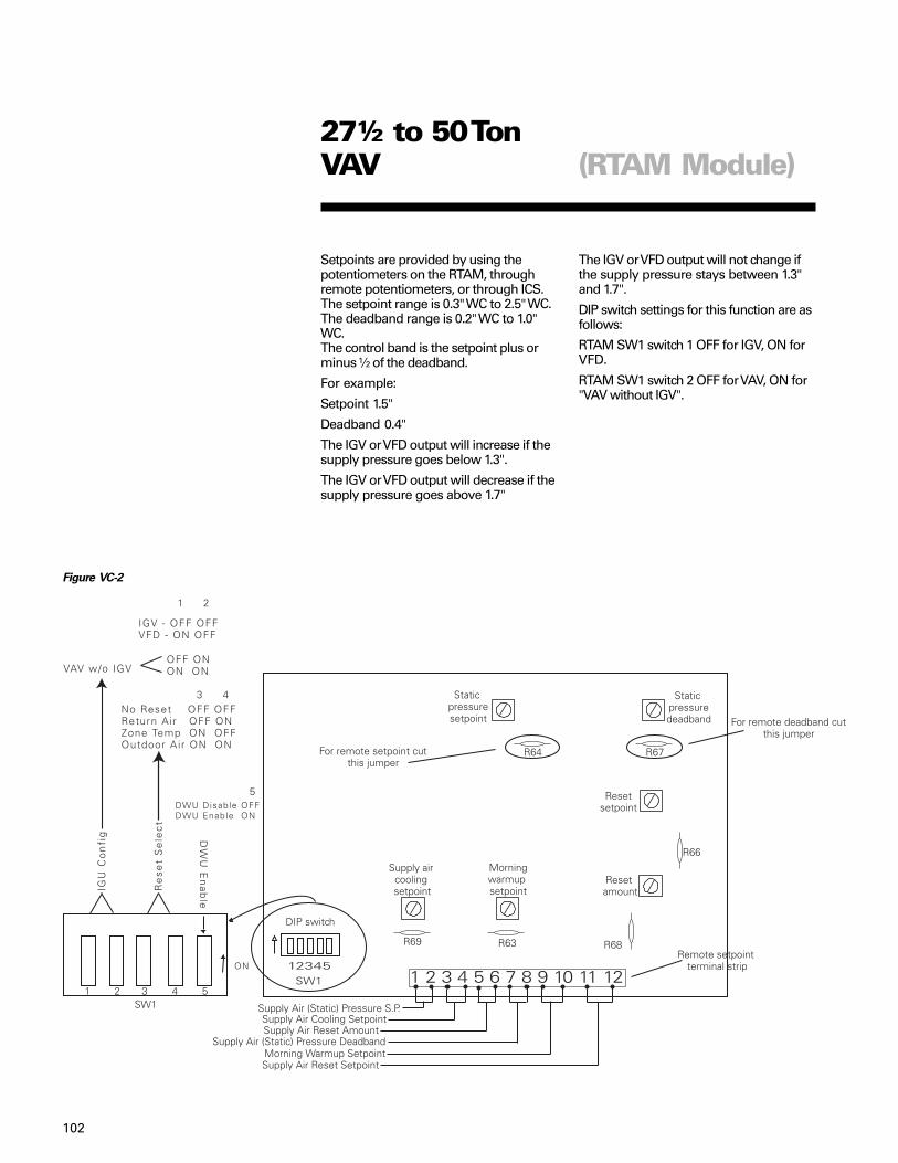
102
Setpoints are provided by using thepotentiometers on the RTAM, throughremote potentiometers, or through ICS.The setpoint range is 0.3" WC to 2.5" WC.The deadband range is 0.2" WC to 1.0"WC.The control band is the setpoint plus orminus ½ of the deadband.
For example:
Setpoint 1.5"
Deadband 0.4"
The IGV or VFD output will increase if thesupply pressure goes below 1.3".
The IGV or VFD output will decrease if thesupply pressure goes above 1.7"
The IGV or VFD output will not change ifthe supply pressure stays between 1.3"and 1.7".
DIP switch settings for this function are asfollows:
RTAM SW1 switch 1 OFF for IGV, ON forVFD.
RTAM SW1 switch 2 OFF for VAV, ON for"VAV without IGV".
Figure VC-2
27½ to 50 TonVAV (RTAM Module)

103
Figure VC-3 Transducer Voltage
Output vs. Pressure
The transducer has a 0 to 5VDC rangewith a 0.25 to 2.125 VDC valid outputrange. The output is proportional. Thechart illustrates the measured outputvoltage at typical supply duct pressures.Airflow during unoccupied mode andheating:When the unit transitions from occupiedmode to unoccupied mode the VHR relayis energized. The VHR relay has a set ofcontacts on TB3 for the purpose ofcommanding the VAV boxes to driveopen. The unit will only bring the fan on at100% during the unoccupied mode.During Morning Warm-up and DaytimeWarm-up modes the relay is energizedand the fan runs at 100% airflow as well.If the unit has heat, the VAV boxes mustbe driven open. If the boxes are allowedto stay in control, the boxes may try toclose instead of open when the warm airenters the room.
Additional notes:1. When DIP SW1-1 is on, the output
voltage range is approximately 0 to10.5VDC.
2. When DIP SW1-1 is off, the outputvoltage range is approximately 2.5 to8.5VDC.
3. IGV: When the supply fan is on andthe output is 0%, the IGV are closed.
4. VFD: When the supply fan is on andthe output is 0%, the VFD runs at35hz.
5. If the supply static pressure goesbelow -0.2" (0.2VDC) the IGV / VFDoutput will stay at 0% and thediagnostic COOL FAIL + SERVICEFAIL will be present.
6. If the static pressure exceeds 3.8" WCthe supply fan will stop and thediagnostic HEAT FAIL + COOL FAIL +SERVICE FAIL will be present.
7. During all heating modes; DaytimeWarm-up, Morning Warm-up, andUnoccupied, the IGV or VFD output isalways 100%.
Troubleshooting tipsIf the transducer output voltages do notseem right, connect a 0-5" manometer inparallel with the transducer. This way youcan see the same pressure thetransducer is seeing. Many transducersget replaced in error when the real culpritis a loose tube or clogged fitting.The polyethylene tubing in the transducercircuit does not readily go back to itsoriginal shape after use. Therefore, if atube is removed from a fitting it should becut back to a fresh end prior toreattaching.
Measure the transducer output voltage atRTAM terminal J1-3 to chassis ground.When the supply fan is off, the transduceroutput voltage should be approximately0.25VDC. If the voltage output is high orlow, unplug the transducer tubing to see ifthe voltage increases or decreases. If itdoes, a tube is probably clogged.The input voltage to the transducer ismeasured between RTAM J1-4 andchassis ground. It should be 5VDC. If it islow, unplug the transducer and measurethe voltage again. If OK now, thetransducer or transducer wiring isshorted to common or ground.The outdoor air pressure sensor must bemounted as shown in Fig. VC-1. If thesensor is mounted upside down thetubing can fill with water during heavyrains.The static pressure sensing cover plate inthe fan section of the unit is bolted to thefan bulkhead. The bulkhead has a verysmall (0.07") hole in the center area. Thepurpose of using such a small hole is toensure that the transducer only sees theaverage supply air pressure. If the hole isenlarged, the transducer could responderratically. If the hole is plugged, thetransducer will not respond. If the gasketbetween the cover plate and bulkhead isleaking, the supply pressure will appearto be abnormally low since the coverplate is in the fan section.
Application NotesSome applications call for relocating thesupply air tube to 2/3 of the way down theduct. If this is done, be certain that thereis no potential obstruction between theunit and the pickup point (such as firedampers). A separate high duct staticswitch may need to be added.The Outside Air Pressure Sensor shouldbe located on top of the unit as shown inFigure VC-1. Some applications withextreme winds could require mountingthe sensor in an area less affected bywind.
27½ to 50 TonCV and VAV (Troubleshooting)

104
27½ to 50 TonVAV
(OutdoorAirflowCompensation)
Outdoor Airflow Compensation (27½ - 50Ton VAV only)When a VAV unit is modulating supplyairflow, the pressure drop across theoutdoor air damper changes. This usuallymeans that the quantity of outside air willdrop as the IGV closes or the VFD slowsdown. VAV units have a feature calledOutside Air (OA) Flow Compensation tohelp maintain consistent OA flowregardless of supply airflow.
Note: OA Flow Compensation mode isdisabled if the unit has a CO2 sensor, minposition input from ICS, or remote minposition input at LTB3-1 and LTB3-2. It isalso overridden during all VentilationOverride modes. Also, the minimumposition can only be adjusted from 0 to50% damper position regardless of OAFlow setpoints.
Set upOnce set up, the OA damper position willincrease as the IGV closes or VFD slowsdown. The 27K resistor with plug inKIT#PLU00970 provides a signal to theunit to enable this function. The resistormust be plugged to the "OAT" input (this isan otherwise unused input) on theeconomizer module (ECA) and powerreset to the unit.
OperationThe potentiometers MIN POS and DCVSETPOINT must now each be set in orderto control the OA damper position.The MIN POS setpoint determines the OAdamper position (from 0 to 50%) whenthe IGV / VFD is at 100% regardless ofDCV SETPOINT.The DCV SETPOINT determines thepercentage increase of the OA damperposition when the IGV / VFD is at 0%. Thepercentage of OA damper increasebetween 0 and 100% IGV / VFD is linear.To have no effect on the OA damperposition when the IGV/VFD output is 0%,set the DCV SETPOINT to 0%.To have the maximum effect on the OAdamper position when the IGV/VFDoutput is 0%, set the DCV SETPOINT to100%.This chart shows the effect of DCV inputvs. MIN POS when the IGV/VFD is at 0%.
MIN POS 0% (CCW) MIN POS 25% MIN POS 50% (CW)DCVSP 0% 0 (closed) 25% 50%DCVSP 50% 25% 37.5% 50%DCVSP 100% 50% 50% 50%
OA damper minimum position when IGV/VFD is closed / 0%
Figure VC-4

105
27½ to 50 TonVAV
(BAYSENS021*VAV RemoteSetpoints)
This chart lists setpoint /voltage/resistance for the VAV Supply Air Coolingsetpoint on the RTRM module. The chartcan be used for troubleshooting units thathave a remote setpoint at this input.The typical remote setpoint input deviceis a BAYSENS021 zone sensor.The connection points are RTRM J6-2and RTRM J6-3.If a remote setpoint is used, clip jumperR69 on the RTAM module. If the jumper isnot clipped, the unit will ignore the RTRMsetpoint.
Note: A remote setpoint can also beapplied to the RTAM Supply Air CoolingSetpoint input. However, the RTAMinputs use different temperature/resistance inputs. See VAV SetpointInputs for input values.
Supply AirCoolingSetpoint Resistance DC Volts(deg F) (ohms)40 1084 2.641 1065 2.5842 1045 2.5643 1026 2.5344 1006 2.5145 987 2.4846 967 2.4647 948 2.4348 928 2.4149 909 23850 889 2.3551 870 2.3352 850 2.353 831 2.2754 812 2.2455 792 2.2156 773 2.1857 753 2.1558 734 2.1259 714 2.0860 695 2.0561 675 2.0262 656 1.9863 636 1.9464 617 1.9165 597 1.8766 578 1.8367 558 1.7968 539 1.7569 519 1.7170 500 1.6771 481 1.6272 461 1.5873 442 1.5374 422 1.4875 403 1.4476 383 1.3977 364 1.3378 344 1.2879 325 1.2380 305 1.17

106
This chart lists setpoint/voltage/resistancefor VAV setpoints on the RTAM module inthe control compartment. The chart canbe used for troubleshooting the RTAMmodule or for applying a remote setpointto the unit.
Each setpoint can be provided remotelyby applying the appropriate resistance asshown in the table after cutting theresistor next to the setpoint knob. Seedrawing below.
Remote Setpoint inputs on RTAM J7:
J7-1, 2 Supply Air Pressure Setpoint
J7-3, 4 Supply Air Cooling Setpoint
J7-5, 6 Supply Air Reset Amount
J7-7, 8 Supply Air Pressure Deadband
J7-9, 10 Morning Warmup Setpoint
J7-11, 12 Supply Air Reset Setpoint
For remote setpoint cut this jumper:
Supply Air Pressure Setpoint R64
Supply Air Cooling Setpoint R69
Supply Air Reset Amount R68
Supply Air Pressure Deadband R67
Morning Warmup Setpoint R63
Supply Air Reset Setpoint R66
Note: Remote SA Cooling Setpoint can beinstalled on RTAM J7-2, 3 (as shown) oron RTRM J6-2, 3. If the SA CoolingSetpoint is installed on RTRM J6-2, 3 or aBAYSENS021* is being used,
See VAV Supply Air Cooling remotesetpoint - BAYSENS021*
27½ to 50 TonVAV
(VAV SetpointInputs)
Figure VC-5

107
(VAV RTAMSetpoints)
27½ to 50 TonVAV
Supply Air➀ Supply Air Supply Air Supply Air➁ Morning Supply Air Supply AirPressure Cooling Reset Pressure Warmup Reset ResetSetpoint Setpoint Amount Deadband Setpoint Setpoint Setpoint(see note) Outdoor Zone or
Return Air
J7-1,2 J7-3,4 J7-5,6 J7-7,8 J7-9,10 J7-11,12 J7-11,12Resistance(Ohms) DC Volts “WC Deg F Deg F “WC Deg F Deg F Deg F0 0.00 0.00 40.00 0.00 0.00 50.00 0.00 50.0010 0.05 0.02 40.27 0.13 0.01 50.27 0.67 50.2720 0.10 0.05 40.81 0.40 0.02 50.81 20.02 50.8130 0.15 0.08 41.29 0.65 0.03 51.29 3.23 51.2940 0.19 0.11 41.23 0.91 0.05 51.23 4.57 51.8350 0.24 0.14 42.31 1.16 0.06 52.31 5.78 52.3160 0.28 0.17 42.79 1.40 0.07 52.79 6.99 52.7970 0.33 0.20 43.28 1.64 0.08 53.28 8.19 53.2880 0.37 0.24 43.76 1.88 0.09 53.76 9.40 53.7690 0.41 0.27 44.24 2.12 0.11 54.24 10.61 54.24100 0.45 0.30 44.73 2.36 0.12 54.73 11.82 54.73110 0.50 0.32 45.16 2.58 0.13 55.16 12.89 55.16120 0.54 0.35 45.59 2.79 0.14 55.59 13.97 55.59130 0.58 0.38 46.02 3.01 0.15 56.02 15.04 56.02140 0.61 0.40 46.45 3.22 0.16 56.45 16.12 56.45150 0.65 0.43 46.88 3.44 0.17 56.88 17.19 56.88160 0.69 0.46 47.31 3.65 0.18 57.31 18.26 57.31170 0.73 0.48 47.68 3.84 0.19 57.68 19.20 57.68180 0.76 0.51 48.11 4.06 0.20 58.11 20.28 58.11190 0.80 0.53 48.49 4.24 0.21 58.49 21.22 58.49200 0.83 0.55 48.86 4.43 0.22 58.86 22.16 58.86210 0.87 0.58 49.24 4.62 0.23 59.24 23.10 59.24220 0.90 0.60 49.62 4.81 0.24 59.62 24.04 59.62230 0.93 0.62 49.99 5.00 0.25 59.99 24.98 59.99240 0.97 0.65 50.37 5.18 0.26 60.37 25.92 60.37250 1.00 0.67 50.69 5.34 0.27 60.69 26.72 60.69260 1.03 0.70 51.26 5.63 0.28 61.26 28.14 61.26270 1.06 0.73 51.74 5.87 0.29 61.74 29.35 61.74280 1.09 0.77 52.30 6.15 0.31 62.30 30.76 62.30290 1.12 0.80 52.79 6.39 0.32 62.79 31.97 62.79300 1.15 0.83 53.27 6.63 0.33 63.27 33.17 63.27310 1.18 0.86 53.75 6.88 0.34 63.75 34.38 63.75320 1.21 0.89 54.24 7.12 0.36 64.24 35.59 64.24330 1.24 0.92 54.72 7.36 0.37 64.72 36.80 64.72340 1.27 0.95 55.12 7.56 0.38 65.12 37.81 65.12350 1.30 0.98 55.61 7.80 0.39 65.61 39.01 65.61360 1.32 1.01 56.09 8.04 0.40 66.09 40.22 66.09370 1.35 1.03 56.49 8.25 0.41 66.49 41.23 66.49380 1.38 1.06 56.89 8.45 0.42 66.89 42.24 66.89390 1.40 1.09 57.38 8.69 0.43 67.38 43.45 67.38400 1.43 1.11 57.78 8.89 0.44 67.78 44.45 67.78410 1.45 1.14 58.18 9.09 0.45 68.18 45.46 68.18420 1.48 1.16 58.59 9.29 0.46 68.59 46.47 68.59430 1.50 1.19 58.99 9.49 0.47 68.99 47.47 68.99440 1.53 1.21 59.39 9.70 0.48 69.39 48.48 69.39450 1.55 1.24 59.80 9.90 0.49 69.80 49.49 69.80
➀ Supply Air Pressure Setpoint valid range is .3”-2.5”.➁ Supply Air Pressure Deadband valid range is .2”-1”.

108
(VAV RTAMSetpoints)
27½ to 50 TonVAV
Supply Air➀ Supply Air Supply Air Supply Air➁ Morning Supply Air Supply AirPressure Cooling Reset Pressure Warmup Reset ResetSetpoint Setpoint Amount Deadband Setpoint Setpoint Setpoint(see note) Outdoor Zone or
Return Air
J7-1,2 J7-3,4 J7-5,6 J7-7,8 J7-9,10 J7-11,12 J7-11,12Resistance(Ohms) DC Volts “WC Deg F Deg F “WC Deg F Deg F Deg F460 1.58 1.26 60.20 10.10 0.50 70.20 50.50 70.20470 1.60 1.29 60.60 10.30 0.52 70.60 51.50 70.60480 1.62 1.31 61.00 10.50 0.53 71.00 52.51 71.00490 1.64 1.33 61.33 10.66 0.53 71.33 53.32 71.33500 1.67 1.36 61.73 10.86 0.54 71.73 54.32 71.73510 1.69 1.39 62.25 11.12 0.56 72.25 55.62 72.25520 1.71 1.43 62.81 11.41 0.57 72.81 57.03 72.81530 1.73 1.45 63.26 11.63 0.58 73.26 58.16 73.26540 1.75 1.49 63.83 11.91 0.60 73.83 59.57 73.83550 1.77 1.52 64.28 12.14 0.61 74.28 60.70 74.28560 1.79 1.55 64.73 12.36 0.62 74.73 61.82 74.73570 1.82 1.57 65.18 12.59 0.63 75.18 62.95 75.18580 1.84 1.60 65.63 12.82 0.64 75.63 64.08 75.63590 1.86 1.63 66.08 13.04 0.65 76.08 65.21 76.08600 1.88 1.67 66.65 13.32 0.67 76.65 66.62 76.65610 1.89 1.69 66.99 13.49 0.67 76.99 67.46 76.99620 1.91 1.71 67.44 13.72 0.69 77.44 68.59 77.44630 1.93 1.74 67.89 13.94 0.70 77.89 69.72 77.89640 1.95 1.77 68.34 14.17 0.71 78.34 70.85 78.34650 1.97 1.80 68.79 14.40 0.72 78.79 71.98 78.79660 1.99 1.83 69.24 14.62 0.73 79.24 73.10 79.24670 2.01 1.85 69.58 14.79 0.74 79.58 73.95 79.58680 2.02 1.88 70.03 15.02 0.75 80.03 75.08 80.03690 2.04 1.91 70.48 15.24 0.76 80.48 76.21 80.48700 2.06 1.93 70.82 15.41 0.77 80.82 77.05 80.82710 2.08 1.95 71.27 15.64 0.78 81.27 78.18 81.27720 2.09 1.98 71.61 15.81 0.79 81.61 79.03 81.61730 2.11 2.00 72.06 16.03 0.80 82.06 80.15 82.06740 2.13 2.02 72.40 16.20 0.81 82.40 81.00 82.40750 2.14 2.05 72.74 16.37 0.82 82.74 81.85 82.74760 2.16 2.08 73.29 16.65 0.83 83.29 83.23 83.29770 2.18 2.11 73.75 16.87 0.84 83.75 84.36 83.75780 2.19 2.14 74.20 17.10 0.85 84.20 85.49 84.20790 2.21 2.17 74.65 17.32 0.87 84.65 86.62 84.65800 2.22 2.20 75.25 17.62 0.88 85.25 88.12 85.25810 2.24 2.23 75.70 17.85 0.89 85.70 89.25 85.70820 2.25 2.26 76.15 18.08 0.90 86.15 90.38 86.15830 2.27 2.29 76.60 18.30 0.92 86.60 91.51 86.60840 2.28 2.32 77.05 18.53 0.93 87.05 92.63 87.05850 2.30 2.34 77.50 18.75 0.94 87.50 93.76 87.50860 2.31 2.37 77.96 18.98 0.95 87.96 94.89 87.96870 2.33 2.40 78.41 19.20 0.96 88.41 96.02 88.41880 2.34 2.43 78.86 19.43 0.97 88.86 97.15 88.86890 2.35 2.46 79.31 19.65 0.98 89.31 98.27 89.31
➀ Supply Air Pressure Setpoint valid range is .3”-2.5”.➁ Supply Air Pressure Deadband valid range is .2”-1”.
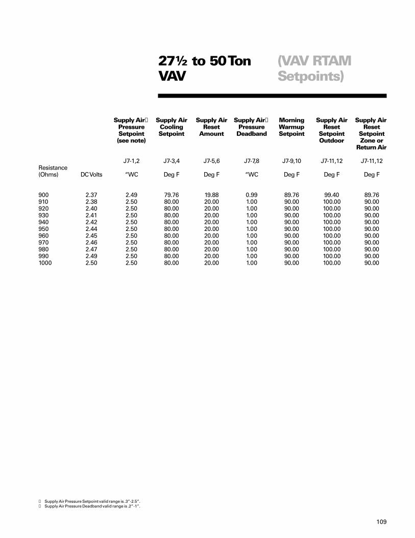
109
(VAV RTAMSetpoints)
27½ to 50 TonVAV
Supply Air➀ Supply Air Supply Air Supply Air➁ Morning Supply Air Supply AirPressure Cooling Reset Pressure Warmup Reset ResetSetpoint Setpoint Amount Deadband Setpoint Setpoint Setpoint(see note) Outdoor Zone or
Return Air
J7-1,2 J7-3,4 J7-5,6 J7-7,8 J7-9,10 J7-11,12 J7-11,12Resistance(Ohms) DC Volts “WC Deg F Deg F “WC Deg F Deg F Deg F
900 2.37 2.49 79.76 19.88 0.99 89.76 99.40 89.76910 2.38 2.50 80.00 20.00 1.00 90.00 100.00 90.00920 2.40 2.50 80.00 20.00 1.00 90.00 100.00 90.00930 2.41 2.50 80.00 20.00 1.00 90.00 100.00 90.00940 2.42 2.50 80.00 20.00 1.00 90.00 100.00 90.00950 2.44 2.50 80.00 20.00 1.00 90.00 100.00 90.00960 2.45 2.50 80.00 20.00 1.00 90.00 100.00 90.00970 2.46 2.50 80.00 20.00 1.00 90.00 100.00 90.00980 2.47 2.50 80.00 20.00 1.00 90.00 100.00 90.00990 2.49 2.50 80.00 20.00 1.00 90.00 100.00 90.001000 2.50 2.50 80.00 20.00 1.00 90.00 100.00 90.00
➀ Supply Air Pressure Setpoint valid range is .3”-2.5”.➁ Supply Air Pressure Deadband valid range is .2”-1”.

Software ChangeHistory
RTRMV1.1 4/12/01 X13650864010 -Initial ReleaseV1.3 6/11/01 X13650867010 -Correct thermostat versus zone sensor detection.V2.4 11/28/04 X13650866010 -Hardware change for power robbing thermostats and NSB status
LCD’s.-Revise test mode logic for heating and cooling.-Revise fan cycling when changing from economizer to mechanicalcooling.-Correct LPC2 diagnostic not to show on single circuit unit.-Correct defrost not to run less than one minute if coil was thought tobe clean.
V2.6 11/28/01 X13650867020 -Local ventilation fixed to work in remote.-Fix all outdoor fans to run if outdoor sensor fails.-Fix indoor fan on gas heat to run only if heat fires.-Change Timed Override (TOV) bit for Tracer from two hours twominutes.-If outdoor sensor fails, fix so that unit will still do default defrost.-Set unit mode to auto with no sensor if unit transitions from remoteto local.
V2.7 11/28/05 X13650867020 -Fix outdoor fan control in service test.-Add ICS communication failure if comm. stops for 2 minutes.-Fix stages of heat & cool to report correctly on ICS.-Fix ICS Lead/Lag hardware to work if in remote control-Correct algorithm Heat proportional gain to stop heat cycling.-Fixed ICS cool and heat stage reporting.-Fixed supply fan lockout to reset with ICS.-Fixed supply fan lockout so zone sensor mode setting to off willreset.-Fixed default defrost without call for heat.
V2.9 4/1/02 X13650867020 -Fix unit mode with remote.-Fix defrost function to halt defrost if call for heat is removed orswitched to cooling.-Added stage 1 electric heat to defrost service test.-Added 15 second delay before RTRM talks to TCI to preventeconomizer false diagnostic.-Fix software to ignore fault for MAS below 40 degrees withcompressors on.
V2.10 8/13/02 X13650867020 -Fixed thermostat Y call on heat pump to keep SOV energized untilthree minute time has elapsed.-Fixed false diagnostic reports on COMM5 without RTOM.-Correct invalid economizer MAS from 65.4 to 53 F.-Change hardware initialization to stop false diagnostics on Tracker10.
V3.0 3/15/03 X13650867030 -Feature Enhancement: Add Dehumidification/Reheat Control.-Bug fixes:
-Fix unit mode when going from off to auto.-Fix supply fan to not wait 20 seconds at power-up if testmode is activated.-Fix RTRM to ignore ICS compressor disable duringservice test mode.-Fix ICS zone temp to work without local zone sensor.

Software ChangeHistory
V3.1 8/25/03 X13650867040 -Fixed Cool 1 and Cool 2 in slave mode to allow economizing.-Changed LPC startup bypass time from two minutes to tenseconds.-Turn off electric heat if defrost terminates on HPC.-Fix reheat with zone sensor, override reheat with cooling call.-Ignore-40F MAT if compressor is running.
V4.0 1/13/04 X13650867040 -Feature Enhancement:- Add Voyager III control functions.-Added two flash diagnostic code and steady light.
-Bug fixes:-Fix service test to lock out after power reset withresistance.-Fix outdoor fan operation on one compressor unitduring Service Test with dehumidfication/reset.-Fix to disable Dehumidification if either compressorcircuit becomes disabled.-Fix Defrost Default A timing issues.-Add 30 second delay before looking at Mixed Air andReturn Air temperature.
V5.0 4/21/04 X13650867050 -Added dehumidification purge cycle.-Fixed Fan Fail input to normally open input for Voyager III.
V5.1 1/1/05 X13650867050 -Fix compressor staging in test mode.
RTOMV1.0 4/6/01 X13650868010 -Initial production release.V1.1 5/28/01 X13650868010 -Fix Supply Air Tempering enable input by inverting jumper
configuration.V1.4 11/12/01 X13650868010 -Fixed false diagnostics with COMM5.V2.0 4/1/04 X13650868020 -Add Dehumidification support
ECAV1.05 4/12/01 X13650878020 -First production release.V2.05 7/15/02 X13650878020 -Fixed 60 seconds communication loss.V2.07 10/21/03 X13650878060 -Changed to Masked chip.
-Fixed comparative enthalpy.V2.08 8/25/04 X13650878080 -Went back to OTP chip to resolve Masked chip problems.V1.0 4/1/05 X13651082010 -First production of upgraded ECA/Actuator Assy.V1.0 4/1/05 X13651082020 -First production ECA manual with ALL sensor inputs.V1.0 4/1/05 X13651081010 -First production release of ECA module with dry bulb only input.
TCIV1.3 4/16/01 X13650869010 -First production release.V1.23 12/31/01 X13650869010 -Fix a variety of false diagnostics.V1.24 1/25/01 X13650869010 -Revised to allow true discharge air sensor to be reported through
RTOM if unit doesn’t have economizer option.V3.1 3/10/04 X13650869030 -Add status LED support and VAV enhancements.
-Added code to fix VAV lockup.LCIV1.02 4/16/01 X13650870010 -First production release.V2.06 X13650870020 -Fixed to allow stand-alone operation without communication link.

Index
Accessories High temperature thermostats ..........................43 Zone sensor modules ...................................36-42 Power exhaust ....................................................68Airflow (27½-50 ton VAV) .......................................97Averaging ................................................................50ASYSTAT661B.........................................................36ASYSTAT662B.........................................................36ASYSTAT663B.........................................................37ASYSTAT664B.........................................................37ASYSTAT666B.........................................................41ASYSTAT669A.........................................................40
BAYSENS006B .......................................................36BAYSENS007B .......................................................36BAYSENS008B .......................................................37BAYSENS009B .......................................................37BAYSENS010B ........................................................38BAYSENS011B.........................................................38BAYSENS013C ........................................................39BAYSENS017B ........................................................40BAYSENS019* .........................................................41 Testing and Troubleshooting ............................45BAYSENS020* ........................................................35BAYSENS021 ....................................................35, 99Barometric Relief ....................................................70
Clogged Filter switch ............................................27CO2 input ..............................................................5,31CO2 wiring ...............................................................85Coil Temperature ..................................................... 5COMM 3 / 4 Communication Interface .................. 5COMM 3 / 4 description .......................................... 5COMM 3 / 4 flow diagram ..................................... 11COMM 3/ 4 Troubleshooting ..............................5,55COMM 5 (see LonTalk®)Communication protocol .......................................29Comparative Enthalpy .............................. 5,40,69,73Component Relationships COMM 3 / 4 ICS module (RTCI) ....................... 11 economizer module (ECA) ............................... 10 options module (RTOM) .................................... 9 heat pump (RTRM) ............................................. 8 gas heat (RTRM)................................................. 7 electric/no heat (RTRM)..................................... 6Compressor 1 disable ............................................12Compressor 2 disable ............................................12
Configuration Input ..............................................100Control Box Layout 2-5 ton ....................................13Control Box Layout 6-10 ton ..................................14Control Box Layout 12½-25 ton .............................15Control inputs .........................................................28Conventional thermostat ......................... 5,18,24,25Conventional thermostat connections .................52Conventional thermostat economizer ..................54Conventional thermostat heating .........................53Conventional thermostat operation ......................52Conventional thermostat heatpump .....................53Cooling setpoint (resistance/voltage) ...................46
Dehumidification ...................................................87DIP switches ................................................55,56,98Default operation ..............................................24,25Defrost .................................................... 18,22,30,32Demand Defrost .................................................... 68Diagnostics .......................................................18-23Direct spark ignition ............................................ 57Discharge air ........................................ 5,18,23,27,40Dry bulb/reference point selection ..................... 73
Economizer - ReliaTel barometric ........................................................ 69 ECA ...................................................... 71,73,74,76 economizer LED fault code .........................69,77 economizer Module layout ............................. 69 economizer operation w/ t’stat. ...................... 54 economizer voltage inputs ............................. 75 flow diagram ..................................................... 10 operation .......................................................... 73Electromechanical economizer layout ................................................................ 79 3-position damper ............................................ 81 economizer testing .......................................... 80 mixed air sensor .......................................... 77,75Emergency stop .............................................. 12, 31Enthalpy calculations ........................................... 75Exhaust fan setpoint ............................................ 27
Fan time-delay relay ............................................ 89 Sequence of operation .................................... 90Frostat ................................................................. 5,27

Index
Gas Heat diagnostic flash codes - Direct Spark ........... 57 ignition module specifications ...................... 57 flame sensor - Direct Spark ........................... 57 flame sensor - Hot Surface ............................ 59 diagnostic flash codes - Hot Surface ............ 59Gas Heat continued sequence of operation - Hot Surface ............ 60 sequence of operation - Direct Spark ........... 58 specifications (High 3-5 ton) .......................... 63 specifications (High 6-10 ton) ........................ 66 specifications (Low 3-5 ton) ........................... 61 specifications (Low 6-10 ton) ......................... 64 specifications (Med 3-5 ton) .......................... 62 specifications (Med 6-10 ton) ......................... 65
Heating setpoint (resistance/voltage) ................ 46Heating/Cooling changeover ............................... 86Heatpump coil temperature sensor .................................. 48 outside air sensor ............................................ 48 demand defrost ................................................ 67 demand defrost fault ........................................ 68High Pressure Lockout Circuit ............................ 93High temperature sensor used with non-ICS ........................................... 43 used with TCI .................................................... 43Hot Surface Ignition ............................................. 59
Lead/Lag................................................................ 16LED functions ....................................................... 28LonTalk (LCI) .................................................. 5,11,28Low Voltage Terminal Strip .................................. 12Low Pressure Lockout Circuit ............................. 93
Mixed air sensor .........................................40,69,75MODBUS ................................... 17,25,27,55,57,59,60Mode inputs (2-50 tons CV) ................................. 47Mode inputs (27½ - 50 tons VAV) ........................ 99Modules RTAM (27½-50 ton VAV setpoints) ................. 101 RTRM board layout .......................................... 16 RTRM flow diagram ........................................... 6 RTRM connections .......................................... 17 RTOM Board Layout ...........................................26
RTOM description .............................................. 5 ECA (also see Economizer) ECA description ................................................. 5 ECA flow diagram ............................................. 10 ECA layout ........................................................ 69 ECA CO2 inputs ............................................69,85 Module Definitions (27½ - 50 tons) ................ 98 Morning Warmup ............................................. 98Novar Controls ............................................. 104,107
Outdoor air sensor .....................................40,48,71Outdoor humidity sensor ............................. 5,76,69Outside air ................................................... 67,69,70Overview 27½-50 ton CV and VAV ...................... 97
Power Exhaust ..............................................5,69,86
Reference enthalpy ............................... 69,71,72,95ReliaTel temporary control .................................. 82Relay- time delay (electromechanical) ................ 89Relay – fan delay .................................................. 90Remote zone sensor ............................................ 40Return air humidity sensor ............................. 69,76Return air sensor ...........................................5,40,69RTRM diagnostics ............................................18-22RTRM diagnostics (27½ - 50 tons VAV) .............. 23
Sensor locations remote/auxiliary description ........................... 35 high temperature .............................................. 43 mixed air ........................................................... 69 return air .......................................................40,69 humidity .......................................................69,71 supply air pressure .........................................100Service tips ........................................................... 31Setpoints OA CFM compensation ...................... 103Setpoints remote VAV ......................................... 104Setpoints RTAM airflow ............................... 105-109Smoke detector ................................................26,27Snubber Circuits .................................................. 91Supply air tempering ....................................... 27,83Supply duct static pressure ...............................100

Index
Temporary operation (see ReliaTel temporarycontrol)Test Mode ....................................................12,28,30 auto ................................................................... 30 step .................................................................... 30 resistance ......................................................... 30Thermostats connections ..................................................16,17 with ReliaTel operation: .................................. 52 operation ......................................................53-54Tracer/Tracker ....................... 5,24,25,27,29,35,39,43Transducer supply air .................................18,23,98Troubleshooting Cool Fail/ Heat Fail ........................... 22-24,31,102 clogged filter ................................................ 19,24 ECA ...................................................... 31,73,74,76 transformer ................................................... 91-92 COMM 3 / 4 ....................................................... 55 Coil temperature ..................................... 22,67-68 diagnostics ...................................................18-23 service tips ....................................................... 31 sensors ..........................................................44-50 test mode ......................................................30-33 test terminals ................................................12,30 zone sensor- mechanical .............................44-50
Variable Air Volume (VAV) 27½-50 ton ......... 99,102VAV diagnostics ................................................... 23VariTrac ...........................................5,24,25,29,43,56Ventilation override ..................................... 27,31,86
Zone Sensors ASYSTAT661B .................................................. 36 ASYSTAT662B .................................................. 36 ASYSTAT663B .................................................. 37 ASYSTAT664B .................................................. 37 ASYSTAT666B .................................................. 41 ASYSTAT669A .................................................. 40 BAYSENS006B ................................................. 36 BAYSENS007B ................................................. 36 BAYSENS008B ................................................. 37 BAYSENS009B ................................................. 37 BAYSENS010B .................................................. 38 BAYSENS011B .................................................. 38 BAYSENS013C .................................................. 39 BAYSENS017B .................................................. 40 BAYSENS019* .................................................. 41 BAYSENS020* .................................................. 35
Temporary operation (see ReliaTel temporarycontrol)Test Mode ....................................................12,28,30 auto ................................................................... 30 step .................................................................... 30 resistance ......................................................... 30Thermostats connections ..................................................16,17 with ReliaTel operation: .................................. 52 operation ......................................................53-54Tracer/Tracker ....................... 5,24,25,27,29,35,39,43Transducer supply air .................................18,23,98
TablesCoil Temperature Sensor ..................................... 48Cooling/Economizer with thermostat ................. 53Cooling/Heating Setpoints .................................. 46Discharge Air Sensor ........................................... 48Mixed Air Sensor - Electromechanical ......................................... 80 - ReliaTel ........................................................... 75Mode Input ........................................................... 47Outdoor Air Sensor .............................................. 48Outdoor Humidity Sensor .................................... 76Return Air Sensor ................................................. 75Return Air Humidity Sensor ................................. 76Test Mode- Resistance Test ................................................... 30- Step Mode ......................................................32-33Zone Temperature ................................................. 4427½-50 Ton VAV RTAM Setpoints ..................................... 106 VAV Mode of Operation .................................. 99 VAV Diagnostics .............................................. 23


Literature Order Number
File Number
Supersedes
Stocking Location
American Standard has a policy of continuous product and product data improvement and reserves the right tochange design and specifications without notice.
RT-SVD03D-EN
PL-UN-RT-SVD03D-EN-09-05
RT-SVD03C-EN 02-05
PI Louisville