Présentation PowerPoint - OPAL-RT
49
eFPGASIM The new era of fast simulation
-
Upload
khangminh22 -
Category
Documents
-
view
1 -
download
0
Transcript of Présentation PowerPoint - OPAL-RT
eFPGASIMThe new era of fast simulation

AGENDA 2
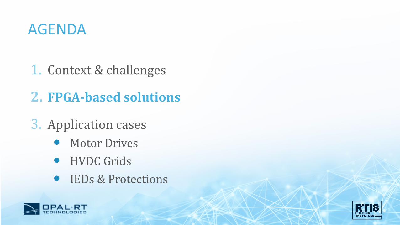
1. Context & challenges
2. FPGA-based solutions
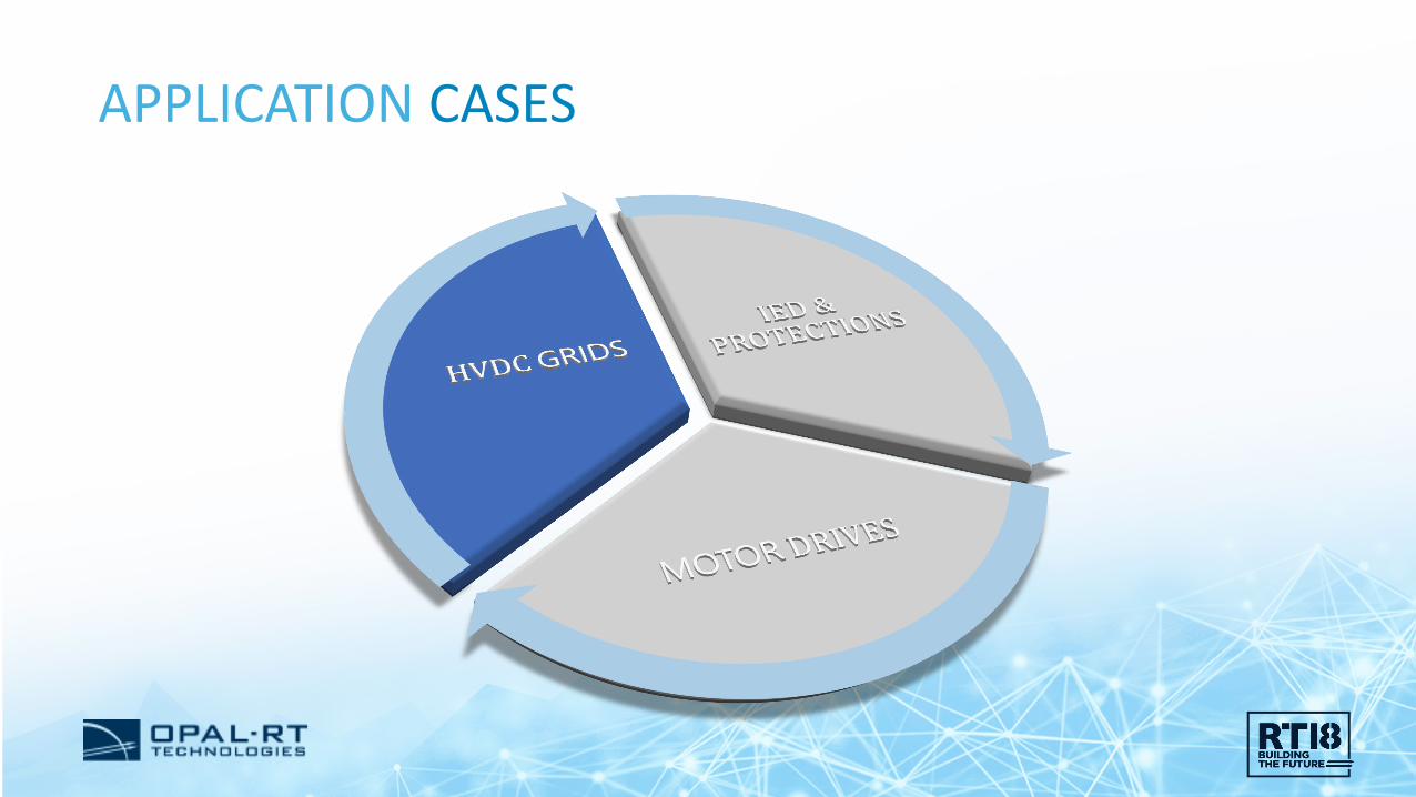
3. Application cases Motor Drives HVDC Grids IEDs & Protections

WHERE ARE WE GOING ? 3
Credit: Knowledge@Wharton – University of Pennsylvania

SOME CHALLENGES 4
Low-carboneconomy
Efficiency
Sustainability

SOME APPLICATION FIELDS 5
POWER GRIDS
Smart Grids HVDC Transmission
Offshore generation
DRIVES
ElectricalVehicle
More ElectricalAircraft
Credit: 3M, Oran Viriyincy, Wikipedia, Renault, Airbus

REAL-TIME SIMULATION APPROACH 6
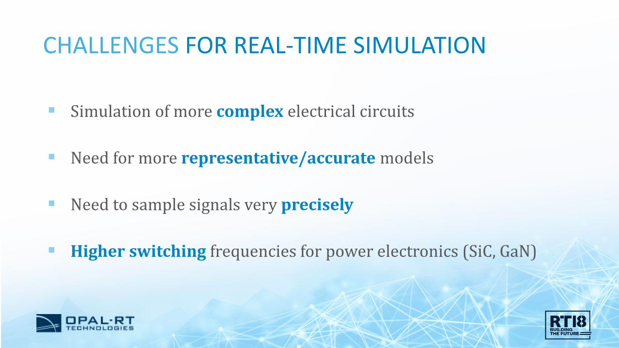
CHALLENGES FOR REAL-TIME SIMULATION 7
Simulation of more complex electrical circuits
Need for more representative/accurate models
Need to sample signals very precisely
Higher switching frequencies for power electronics (SiC, GaN)

FOCUS ON ACCURACY 8
Higher switching frequencies (>100 kHz) Higher power density, lower THD Requires higher sampling rates (< 1 µs)
0 5 10 15 20-0.5
0
0.5
1
1.51 kHz PWM (UA)
Logi
c le
vel
Time (ms)
0 5 10 15 20
-20
0
20
Load currents
Cur
rent
(A)
Time (ms)
0 5 10 15 20-0.5
0
0.5
1
1.520 kHz PWM (UA)
Logi
c le
vel
Time (ms)
0 5 10 15 20
-20
0
20
Load currents
Cur
rent
(A)
Time (ms)

FOCUS ON CIRCUIT COMPLEXITY 9
Modular Multilevel Converters for HVDC N submodules (SM) per arm (N -> 500) Up to 5 switches per SM
Up to 15 000 switches per converter
Credit: ABB, Siemens, MDPI
AGENDA 10
1. Context & challenges
2. FPGA-based solutions
3. Application cases Motor Drives HVDC Grids IEDs & Protections

CPU & FPGA CO-SIMULATION 11
All OPAL-RT systems takeadvantage of both CPU and FPGA resources. CPU: massive computation power
Ts > 10 µs
FPGA: great accuracy and low latencyTs < 1 µs

ONE SOLUTION: FPGA SIMULATION 12
ACCURATE: Low sampling time and therefore excellent resolution for high frequency switching (up to 50-100 kHz)
FAST: Excellent execution latency (typ. 1 µs)
PARALLEL: Massively parallel processing unit
Credit: Technolution

FPGA DRAWBACKS 13
COMPLEX DESIGN: Higher coding complexity (‘for’ loop, product, …)
TIME CONSUMING: Very long compilation time (~hours)
DIFFICULT DEBUGGING: Increased debugging difficulty

CHALLENGES & OPPORTUNITIES 14
Complex electrical circuits Accurate models Precise signal sampling High switching frequencies Project constraints (quality, cost,
delay, risk)
Accurate Fast Parallel computing
Complex design Time consuming Difficult debugging

SOFTWARE SUITES 15
Set of models and solversdesigned to facilitate the fast and accurate simulation of electrical circuits on FPGA, as well as associated services (gating signals, sensor emulation, communications)

AGENDA 16
1. Context & challenges
2. FPGA-based solutions
3. Application cases Motor Drives HVDC Grids IEDs & Protections

APPLICATION CASES 17

MOTOR DRIVES – CHALLENGES 18
Grid and motor drive controllers are getting more complex
They require higher bandwidth and more accuratemodels to be validated properly
Simulated PlantPhysical Controller
Analog V/I Hall Effect
Gate pulses
0 5 10 15 20-0.5
0
0.5
1
1.51 kHz PWM (UA)
Logi
c le
vel
Time (ms)
0 5 10 15 20
-20
0
20
Load currents
Cur
rent
(A)
Time (ms)
0 5 10 15 20-0.5
0
0.5
1
1.520 kHz PWM (UA)
Logi
c le
vel
Time (ms)
0 5 10 15 20
-20
0
20
Load currents
Cur
rent
(A)
Time (ms)

MOTOR DRIVES – eHS CONCEPT 19
HIL : a real controller is connected to the simulated plant (electrical circuit). Simulation has to be as fast as possible.
Simulated PlantPhysical Controller
Analog V/I Hall Effect

MOTOR DRIVES – CHALLENGES 20
Validation in steady state ?
Validation of transient/dynamic states ?
Validation in faulty conditions ?
What effort to deploy the solution ?
MOTOR DRIVES – eHS CONCEPT 21
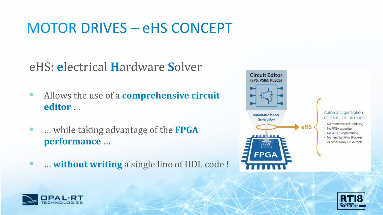
eHS: electrical Hardware Solver
Allows the use of a comprehensive circuit editor …
… while taking advantage of the FPGA performance …
… without writing a single line of HDL code !

RT Simulator
MOTOR DRIVES – eHS CONCEPT 22
CPU
Slower model - mechanical, grid, control (~50 µs)
FPGA
Fast model – power electronics, motors (< 1 µs)
PCIe
Real controller
Host Computer

RT Simulator
MOTOR DRIVES – eHS CONCEPT 23
FPGA
Fast model – power electronics, motors (< 1 µs)

MOTOR DRIVES – eHS CAPABILITIES 24
Characteristic eHSx64Xilinx Kintex-7
eHSx128Xilinx Virtex-7
Max. number of inputs (sources) 32 128Max. number of outputs (measurements) 32 128Max. number of switches 72 144Max. number of LC 150 300Max. number of R UnlimitedCircuit editors SimPowerSystems, PSIM, PLECS, MultisimSimultaneous Machine models 2 4
We are not stopping here !
…

MOTOR DRIVES – MOTOR LIBRARY 25

MOTOR DRIVES – EXAMPLE MODELS 26
Inverter 2-level 3-phases
Model Time Step = 200ns50 kHz PWM @1% resolution
States 5
Switches 6
Inputs 4
Outputs 8

MOTOR DRIVES – EXAMPLE MODELS 27
States 7
Switches 22
Inputs 3
Outputs 8 Matrix converter drive
Model Time Step = 350 ns
MOTOR DRIVES – EXAMPLE MODELS 28
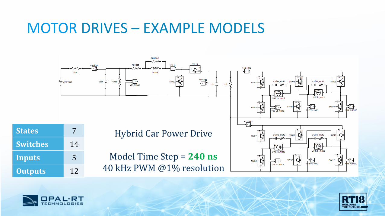
States 7
Switches 14
Inputs 5
Outputs 12
Hybrid Car Power Drive
Model Time Step = 240 ns40 kHz PWM @1% resolution

MOTOR DRIVES – EXAMPLE MODELS 29
2 x NPC 3-level 3-phase converters
Model Time Step = 580 ns17kHz PWM @1% resolution
States 22
Switches 36
Inputs 8
Outputs 28

MOTOR DRIVES – EXAMPLE MODELS 30
6 x 2-level 3-phase converters with filters and loads
Model Time Step = 880 ns
States 58
Switches 36
Inputs 20
Outputs 68
APPLICATION CASES 31
HVDC GRIDS 32
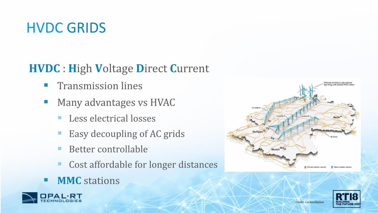
HVDC : High Voltage Direct Current Transmission lines Many advantages vs HVAC Less electrical losses Easy decoupling of AC grids Better controllable Cost affordable for longer distances
MMC stations
Credit: CarbonNation

HVDC GRIDS 33
MMC: Types of submodules Half-Bridge Full-Bridge Clamp-Double T-Type
HVDC GRIDS 34
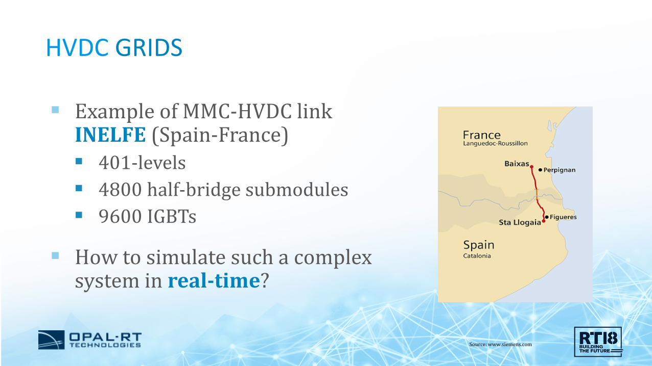
Example of MMC-HVDC linkINELFE (Spain-France) 401-levels 4800 half-bridge submodules 9600 IGBTs
How to simulate such a complexsystem in real-time?
Source: www.siemens.com

HVDC GRIDS 35
Challenges Complexity of converter Complexity of control Complexity of signal management Communication between control and converters/station

HVDC GRIDS 36
Pole Control and Protection (PCP) Valve Base Controller (VBC)
MMC Station MMC Valves

HVDC GRIDS: SOLUTION FOR RT SIMULATION 37
Solution FPGA Simulation of MMC Up to 6000 submodules per FPGA 250 ns time step Connection with controller : Aurora or Gigabit Ethernet Co-simulation with CPU which runs the station and grid
models

HVDC GRIDS: SOLUTION FOR RT SIMULATION 38

HVDC GRIDS: SOLUTION FOR RT SIMULATION 39

APPLICATION CASES 40

TRAVELLING WAVE 41
Travelling wave is a temporary wave that creates a disturbance and moves along the transmission lineat a constant speed. It’s mainly due to switching, faults and lightning.
https://circuitglobe.com/travelling-wave.html
L R

TRAVELLING WAVE 42
At buses and characteristic impedance discontinuities, TWs are reflected
Single-ended TW fault locating algorithm
TWIA at left terminal (A)-500 0 500 1000
Tim
e (u
s)
0
100
200
300
400
500
600
700
800
900
1000
Distance from left terminal (pu)0 0.2 0.4 0.6 0.8 1
Tim
e (u
s)
0
100
200
300
400
500
600
700
800
900
1000
L R

TRAVELLING WAVE 43
At buses and characteristic impedance discontinuities, TWs are reflected
Double-ended TW fault locating algorithm
TWIA at left terminal (A)-500 0 500 1000
Tim
e (u
s)
0
100
200
300
400
500
600
700
800
900
1000
Distance from left terminal (pu)0 0.2 0.4 0.6 0.8 1
Tim
e (u
s)
0
100
200
300
400
500
600
700
800
900
1000
TWIA at right terminal (A)-50005001000
Tim
e (u
s)
0
100
200
300
400
500
600
700
800
900
1000
L R

TRAVELLING WAVE 44
Objective
To test Travelling Wave Fault Detectors such as SEL-T400L using the HIL approach.
https://selinc.com/products/T400L/
Damaged insulators

TRAVELLING WAVE 45
Challenges
An EM wave propagates at almost the speed of light (300 m/µs)
Simulate transmission lines precisely and with very low latencies, in order to represent properly the transmission line
Simulate power systems at low time steps (100s of ns)
Digital to analog converter with high sampling rate (> 1MHz)
Precise line models

TRAVELLING WAVE 46
Point-to-point fiber-optic differential protection channel
Low level analog signals at 1MHz
3-ph distributed parameter line model running at 500 ns on FPGA
VL_abc, IL_abc
VR_abc, IR_abc
L R

TRAVELLING WAVE 47
Form Factors Min Time-Stepx64 615 ns
x128 410 ns

CONCLUSION 48

49