Solicitation For - Amazon AWS
527
Solicitation For Construction of the New VA Medical Center (VAMC) Project in Louisville, KY P2: 453413 Design-Bid-Build RFP Specifications Phase B Volume 4 Div. 22 Certified Final Design 03 December 2020 W912QR21R0008 ARIMS: 200A Disposition: Maintain for 15yrs after construction W912QR21R0008_Specs_PhaseB_Vol4-0000
-
Upload
khangminh22 -
Category
Documents
-
view
4 -
download
0
Transcript of Solicitation For - Amazon AWS

Solicitation For Construction of the New VA Medical Center (VAMC) Project in Louisville, KY
P2: 453413
Design-Bid-Build RFP
Specifications Phase B Volume 4 Div. 22
Certified Final Design
03 December 2020 W912QR21R0008
ARIMS: 200A Disposition: Maintain for 15yrs after construction
W912QR21R0008_Specs_PhaseB_Vol4-0000

Replacement VA Medical CenterLouisville, Kentucky
Project Managers
Cynthia K. Pozolo, FAIAURS/SmithGroup Joint Venture Project ManagerSmithGroup500 Griswold Street, Suite 1700 Detroit, Michigan 48226t 313.983.3600
Randy L. Kirschner, AIA, NCARB URS/SmithGroup Joint Venture Project ManagerAECOM277 Nationwide Blvd. Columbus, Ohio 43215t 614.464.4500
CERTIFIED FINALVA101CFM-P-0157/603-320 USACE P2 No. 453413
Phase B New Hospital BuildingsSpecifications 22-05-11 — 22-70-00 (Vol. 4)
03 December 2020
W912QR21R0008_Specs_PhaseB_Vol4-0000

W912QR21R0008_Specs_PhaseB_Vol4-0000

VA 603-320, P2 453413 Louisville VAMC Replacement Phase B
00 01 10-1
DEPARTMENT OF VETERANS AFFAIRS
TABLE OF CONTENTS Section 00 01 10
VOLUME 1
DIVISION 00 - SPECIAL SECTIONS
00 01 07 Seals Page 00 01 10 Table of Contents 00 31 32 Geotechnical Data 00 31 32a 9-12-14 Report of Geotechnical Exploration Rev 1
00 31 32b Supplemental Recommendations Summary Report of Geotechnical
Exploration (REV 1) 01 November 2018
00 31 32c Louisville VA Hospital Geophysical Report 2 29 16
00 80 00.00 06
Special Provisions
00 80 00.01 06
Construction Project Sign Details
00 80 00.02 06
Communication Systems Matrix
00 80 00.03 06
LOD Matrix
00 80 00.04 06
Initial Facility Maintenance Data (COBie) Workbooks (FMDW) – Provided under separate cover as .XLS spreadsheets (a-e)
00 80 00.04a 06
Hospital Building Medical Center – Provided under separate cover as .XLS spreadsheets (a-e)
00 80 00.04b 06
Central Utility Plan (CUP) – Laundry – Provided under separate cover as .XLS spreadsheets (a-e)
00 80 00.04c 06
North Parking Structure (Garage) – Provided under separate cover as .XLS spreadsheets (a-e)
00 80 00.04d 06
Miscellaneous – Provided under separate cover as .XLS spreadsheets (a-e)
00 80 00.04e 06
South Parking Structure (Garage) – Provided under separate cover as .XLS spreadsheets (a-e)
00 80 00.05 06
Project Submittal Register – Phase A
00 80 00.06 06
Project Submittal Register – Phase B
00 80 00.07 06
Delegated Design List – Phase A
00 80 00.08 06
Delegated Design List – Phase B
DIVISION 01 - GENERAL REQUIREMENTS 01 32 01.00 06
Project Schedule
01 33 00.00 06
Submittal Procedures
01 35 26.00 06
Government Safety Requirements
W912QR21R0008_Specs_PhaseB_Vol4-0000

VA 603-320, P2 453413 Louisville VAMC Replacement Phase B
00 01 10-2
01 35 26.01 06
FORM 16-1 Certificate of Compliance for LHE and Rigging
01 35 26.02 06
CELRL FORM 1259 Activity Hazards Analysis
01 43 39 Exterior Wall Mockups 01 45 00.15 10
Resident Management System Contractor Mode (RMS CM)
01 45 04.10 06
Contractor Quality Control
01 45 29 Testing Laboratory Services 01 45 35 Special Inspections 01 50 00 Temporary Construction Facilities and Controls 01 50 00.01 Federal Airport Authority (FAA) and/or Kentucky Airport Zoning
Commission (KAZC) Determination and Permit – Antenna Tower and Building
01 50 00.02 Federal Airport Authority (FAA) and/or Kentucky Airport Zoning Commission (KAZC) Determination and Permit – Elevated Water Tank
01 50 00.03 Property Transfers with KYTC 01 57 19.00 06
Temporary Environmental Controls and Permits
01 57 19.01 06
Permit Matrix
01 74 19 Construction and Demolition Waste Management 01 78 23 Operations and Maintenance Manuals 01 78 24.00 10
Facility Maintenance (FM)Data Requirements
01 79 00 Operations and Maintenance Training 01 81 11 Exterior Shell Air-Blast Performance Requirements 01 81 13 Sustainable Construction Requirements 01 91 00 General Commissioning Requirements 01 91 00a Appendix A Commissioning Status Tracking 01 91 00b Appendix B Commissioning Schedule Activities 01 91 18 Commissioning of Building Envelope Systems DIVISION 02 – EXISTING CONDITIONS NOT USED DIVISION 03 – CONCRETE 03 30 00 Cast-in-Place Concrete 03 30 01 Cast-in-Place Concrete for Garage Structures 03 30 02 Cast-in-Place Concrete for Site Structures 03 41 33 Precast Structural Pretension Concrete 03 45 00 Precast Architectural Concrete 03 45 00.02 Precast Architectural Concrete (Parking Structure) DIVISION 04 – MASONRY 04 05 13 Masonry Mortaring 04 05 16 Masonry Grouting 04 20 00 Unit Masonry DIVISION 05 – METALS 05 12 00 Structural Steel Framing 05 12 13 Architecturally Exposed Structural Steel Framing 05 21 00 Steel Joist Framing
W912QR21R0008_Specs_PhaseB_Vol4-0000

VA 603-320, P2 453413 Louisville VAMC Replacement Phase B
00 01 10-3
05 31 00 Steel Decking 05 36 00 Composite Metal Decking 05 40 00 Cold-Formed Metal Framing 05 43 13 Medical Equipment Support Systems 05 50 00 Metal Fabrications 05 50 00.02 Metal Fabrications (Parking Structure) 05 50 11 Metal Fabrications for Fall Protection Systems 05 51 00 Metal Stairs 05 52 20 Barrier Cable Systems 05 58 13 Column and Beam Covers 05 70 10 Decorative Metal Grilles 05 73 13 Glazed Decorative Railing Systems DIVISION 06 – WOOD, PLASTICS AND COMPOSITES 06 10 00 Rough Carpentry 06 16 63 Sheathing 06 20 00 Finish Carpentry 06 61 16 Solid Surface Fabrications VOLUME 2 DIVISION 07 - THERMAL AND MOISTURE PROTECTION 07 05 23 Pressure Testing an Air Barrier System for Air Tightness 07 05 23a Appendix A Air Leakage Test Form Example 07 05 23b Appendix B Air Leakage Test Results Form 07 05 23c Appendix C Test Agency Qualifications Sheet 07 11 13 Bituminous Damproofing O7 13 00 Sheet Waterproofing 07 13 26 Self-Adhering Sheet Waterproofing 07 13 54 Thermoplastic Sheet Waterproofing O7 14 13 Hot Fluid-Applied Rubberized Asphalt Waterproofing 07 16 19 Metal Oxide Waterproofing 07 18 00.02 Traffic Coatings (Parking Structure) 07 18 13 Pedestrian Traffic Coatings 07 21 13 Thermal Insulation 07 22 00 Roof and Deck Insulation 07 27 27 Fluid-Applied Membrane Air Barriers, Vapor Retarding 07 40 00.02 Roofing and Siding Panels (Parking Structure) 07 42 00 Metal Wall Panels 07 42 13 16.02
Metal Plate Wall Panels (Parking Structure)
07 42 29 Terra Cotta Panel Rain Screen Systems 07 42 53 Glass Exterior Rain and Wind Screen Systems 07 42 53.02 Glass Exterior Rain and Wind Screen Systems (Parking Structure) 07 54 19 Polyvinyl-Chloride (PVC) Roofing 07 54 19a Appendix A Example RRO Report 07 60 00 Flashing and Sheet Metal 07 72 00 Roof Accessories 07 76 16 Roof Decking Pavers 07 81 00 Applied Fireproofing 07 81 23 Intumescent Fireproofing 07 84 00 Firestopping 07 92 00 Joint Sealants 07 95 13 Expansion Joint Cover Assemblies
W912QR21R0008_Specs_PhaseB_Vol4-0000

VA 603-320, P2 453413 Louisville VAMC Replacement Phase B
00 01 10-4
07 95 13 19.02
Parking Deck Expansion Joint Cover Assemblies (Parking Structure)
DIVISION 08 - OPENINGS 08 11 13 Hollow Metal Doors and Frames 08 14 00 Interior Wood Doors 08 17 10 Integrated Door Assemblies 08 31 13 Access Doors and Frames 08 33 00 Coiling Doors and Grilles 08 33 00.02 Coiling Grilles (Parking Structure) 08 33 13 Coiling Counter Doors 08 34 53 Security Doors and Frames 08 34 59 Vault Doors and Day Gates 08 35 13.23 Accordion Folding Fire Doors 08 41 13 Aluminum-Framed Entrances and Storefronts 08 41 13.02 Aluminum-Framed Entrances and Storefronts (Parking Structure) 08 41 26.01 Custom All-Glass Wall and Door System 08 42 29.23 Sliding and Bi-Folding Automatic Entrances 08 42 33 Revolving Door Entrances 08 42 43 Intensive Care Unit (ICU) Entrances 08 44 13 Glazed Aluminum Curtain Walls 08 44 13.02 Glazed Aluminum Curtain Walls (Parking Structure) 08 51 13 Aluminum Windows 08 56 19 Pass Windows 08 56 53 Blast and Ballistic Resistant Windows 08 56 59 Service and Teller Window Units 08 56 66 Security Window Screens 08 62 00 Unit Skylights 08 63 00 Metal-Framed Skylights 08 71 00 Door Hardware 08 71 13 Automatic Door Operators 08 71 13.11 Low Energy Power Assist Door Operators 08 80 00 Glazing 08 88 16 Vision Control Glass 08 90 00 Louvers and Vents DIVISION 09 – FINISHES 09 05 16 Subsurface Preparation for Floor Finishes 09 22 16 Non-Structural Metal Framing 09 23 00 Gypsum Plastering 09 24 00 Portland Cement Plastering 09 26 00 Veneer Plastering 09 29 00 Gypsum Board 09 30 13 Ceramic / Porcelain Tiling 09 51 00 Acoustical Ceilings 09 54 26 Linear Wood Wall and Ceiling Systems 09 54 81 Custom Interior Aluminum Beams and Fins 09 65 13 Resilient Base and Accessories 09 65 16 Resilient Sheet Flooring 09 65 16.33 Rubber Sheet Flooring 09 65 19 Resilient Tile Flooring 09 65 66 Resilient Athletic Flooring 09 66 16 Terrazzo Floor Tile 09 67 23.20 Resinous (Epoxy Based) With Vinyl Chip Broadcast (RES-2)
W912QR21R0008_Specs_PhaseB_Vol4-0000

VA 603-320, P2 453413 Louisville VAMC Replacement Phase B
00 01 10-5
09 67 23.30 Resinous (Epoxy Based) High Performance Mortar Flooring (RES-3) 09 67 23.40 Resinous Poured in Place Resilient Flooring (RES-4) 09 67 23.50 Resinous Terrazzo Flooring (RES-5) 09 67 23.60 Resinous Urethane and Epoxy Mortar Flooring (RES-6A and RES-6B) 09 67 23.70 Epoxy Floor Coating (EPY-01, EPY-02) 09 68 13 Tile Carpeting 09 69 00 Access Flooring 09 77 01 Interior Glass Wall Panel System 09 77 14 Wood Veneer Acoustic Wall Panels 09 84 33 Sound-Absorbing Wall Units 09 91 00 Painting 09 96 59 Resinous Specialty Glazed Coating Systems for Walls, Ceilings,
Wallboard, and Block CMU (RES-W1, RES-W2) 09 96 59.10 High Build Glazed Specialty Coating (SC-01) VOLUME 3 DIVISION 10 – SPECIALTIES 10 11 13 Chalkboards and Markerboards 10 11 23 Tackboards 10 13 00 Directories 10 14 00 Signage 10 21 13 Toilet Compartments 10 21 16 Shower and Dressing Compartments 10 21 23 Cubicle Curtain Tracks 10 22 13 Interior Wire Mesh Partitions 10 22 13.02 Exterior Wire Mesh Partitions (Parking Structure) 10 22 39 Folding Panel Partitions 10 22 39.01 Automatic Operable Vertically Retractable Acoustic Wall 10 25 13 Patient Bed Service Walls (PBSW) 10 26 00 Wall and Door Protections 10 26 41 Bullet Resistant Panels 10 28 00 Toilet Bath and Laundry Accessories 10 44 13 Fire Extinguisher Cabinets 10 44 13.02 Fire Extinguisher Cabinets (Parking Structure) 10 55 00.16 Private-Delivery Postal Specialties 10 56 26 Manual Mobile and Fixed Shelving 10 75 00 Flagpoles 10 82 19 Exterior Acoustical Barrier Screen Walls DIVISION 11 – EQUIPMENT 11 05 12 General Motor Requirements for Equipment 11 06 00 Medical Equipment Schedule 11 06 01 Project Room Contents Report 11 08 00 Commissioning of Equipment 11 11 00 Laundry Equipment 11 12 00 Parking Control Equipment - Parking/Barrier Gate Operators 11 12 00.02 Parking Control Equipment (Parking Structure) 11 13 00 Loading Dock Equipment 11 17 36 Package Transfer Units 11 24 11 Horizontal Lifeline Fall Protection Systems 11 24 14 Suspended Façade Access Equipment 11 40 11 Custom Fabricated Foodservice Equipment 11 40 21 Foodservice Equipment - Utility Distribution System 11 41 00 Food Storage Equipment
W912QR21R0008_Specs_PhaseB_Vol4-0000

VA 603-320, P2 453413 Louisville VAMC Replacement Phase B
00 01 10-6
11 41 21 Walk-In Coolers and Freezers 11 44 00 Food Cooking Equipment 11 45 00 Miscellaneous Food Service Equipment 11 48 00 Cleaning and Disposal Equipment 11 53 00 Laboratory Equipment 11 53 13 Laboratory Fume Hoods 11 53 53 Biological Safety Cabinets and Laminar Airflow Workstations 11 53 61 Custom Fabricated Laboratory Equipment 11 71 00 Healthcare Equipment 11 71 01 Medical Washing and Sterilizing Equipment 11 71 02 Laboratory Washing and Sterilizing Equipment 11 73 00 Ceiling Mounted Patient Lift System 11 73 11 Patient ICU Service Boom Systems 11 74 00 Dental Equipment 11 78 00 Mortuary Equipment 11 78 13 Mortuary Refrigerators 11 82 00 Waste Handling Equipment DIVISION 12 – FURNISHINGS 12 24 00 Window Shades 12 24 00.01 Motorized Window Shades 12 31 00 Manufactured Metal Casework 12 32 00 Manufactured Wood Casework 12 35 53 Adaptable Laboratory Casework Systems 12 36 00 Laboratory Countertops and Accessories 12 36 61.16 Solid Surfacing Countertops 12 48 13 Entrance Floor Mats DIVISION 13 - SPECIAL CONSTRUCTION 13 01 00 Radiofrequency (RF) MRI Shielding System 13 01 01 DC MRI Magnetic Shielding System 13 05 41 Seismic Restraint Requirements for Non-Structural Components 13 21 13.34 Automatic Clean Room Swinging Doors and Fixed Windows 13 21 13.38 Clean Room Pass-Through Chambers 13 21 29 Constant Temperature Rooms 13 49 00 Radiation Protection 13 49 00 A Radiation Shielding Plan Review Report (Level 1) 13 49 00 B Radiation Shielding Plan Review Report (Level 2) 13 49 00 C Radiation Shielding Plan Review Report (Level 3) 13 49 00 D Radiation Shielding Plan Review Report (Level 4) 13 49 23 AC ELF Magnetic Shielding Systems 13 49 25 Main Computer Room Shielding DIVISION 14– CONVEYING EQUIPEMENT 14 08 00 Commissioning of Conveying Equipment 14 21 00 Electric Traction Elevators 14 24 00 Hydraulic Elevators 14 91 33 Laundry and Linen Chutes 14 91 82 Trash Chutes 14 92 00 Pneumatic Tube System DIVISION 21- FIRE SUPPRESSION 21 08 00 Commissioning of Fire Suppression System
W912QR21R0008_Specs_PhaseB_Vol4-0000
VA 603-320, P2 453413 Louisville VAMC Replacement Phase B
00 01 10-7
21 12 00 Manual Dry Standpipe Systems 21 13 13 Wet-Pipe Sprinkler Systems 21 13 16 Dry-Pipe Sprinkler Systems 21 22 00 Clean Agent Fire Suppression Systems 21 30 13 Electric-Driven, Fire Pumps VOLUME 4 DIVISION 22 – PLUMBING 22 05 11 Common Work Results for Plumbing 22 05 12 General Motor Requirements for Plumbing Equipment 22 05 19 Meters and Gages for Plumbing Piping 22 05 23 General-Duty Valves for Plumbing Piping 22 05 33 Heat Tracing for Plumbing Piping 22 07 11 Plumbing Insulation 22 08 00 Commissioning of Plumbing Systems 22 08 00a Division 22 Sample PFC 22 08 00b Division 22 Sample FPT 22 11 00 Facility Water Distribution 22 11 23 Domestic Water Pumps 22 13 00 Facility Sanitary and Vent Piping 22 13 23 Sanitary Waste Interceptors 22 13 29 Sanitary Sewerage Pumps 22 14 00 Facility Storm Drainage 22 14 29 Sump Pumps 22 15 00 General Service Compressed-Air Systems 22 20 00 Facility Natural-Gas Piping 22 31 11 Water Softeners 22 33 00 Electric Domestic Water Heaters 22 35 00 Domestic Water Heat Exchangers 22 40 00 Plumbing Fixtures 22 61 13.74 Dental Compressed-Air Piping 22 61 19.74 Dental Compressed-Air Equipment 22 62 00 Vacuum Systems for Laboratory and Healthcare Facilities 22 62 19.74 Dental Vacuum and Evacuation Equipment 22 63 00 Gas Systems for Laboratory and Healthcare Facilities 22 66 00 Chemical-Waste Systems for Laboratory and Healthcare Facilities 22 67 19.16 Reverse-Osmosis Water Equipment 22 70 00 Facility Fuel Oil Systems VOLUME 5 DIVISION 23 – HEATING, VENTILATING, AND AIR CONDITIONING (HVAC) 23 05 10 Common Work Results for Boiler Plant and Steam Generation 23 05 11 Common Work Results for HVAC 23 05 12 General Motor Requirements for HVAC and Steam Generation
Equipment 23 05 14 Variable Frequency Drives 23 05 41 Noise and Vibration Control for HVAC Piping and Equipment 23 05 51 Noise and Vibration Control for Boiler Plant 23 05 93 Testing, Adjusting, and Balancing for HVAC 23 07 11 HVAC and Boiler Plant Insulation 23 08 00 Commissioning of HVAC Systems 23 08 00a Division 23 Sample PFC 23 08 00b Division 23 Sample FPT 23 08 11 Demonstrations and Tests for Boiler Plant
W912QR21R0008_Specs_PhaseB_Vol4-0000

VA 603-320, P2 453413 Louisville VAMC Replacement Phase B
00 01 10-8
23 08 11a Attachment A VHA Boiler and Associated Plant Safety Device Testing Manual Fifth Edition
23 08 11b Attachment B Appendix B of VHA Directive 1810 23 09 11 Instrumentation and Control for Boiler Plant 23 09 23 Direct-Digital Control System for HVAC 23 21 11 Boiler Plant Piping Systems 23 21 13 Hydronic Piping 23 21 23 Hydronic Pumps 23 22 13 Steam and Condensate Heating Piping 23 22 23 Steam Condensate Pumps 23 23 00 Refrigerant Piping 23 25 00 HVAC Water Treatment 23 31 00 HVAC Ducts and Casings 23 34 00 HVAC Fans 23 35 03 Dryer Vent Exhaust System 23 36 00 Air Terminal Units 23 37 00 Air Outlets and Inlets 23 40 00 HVAC Air Cleaning Devices 23 50 11 Boiler Plant Mechanical Equipment 23 51 00 Breechings, Chimneys, and Stacks 23 52 39 Fire-Tube Boilers 23 64 00 Packaged Water Chillers 23 64 20 Heat Recovery Chillers 23 65 00 Cooling Towers 23 73 00 Indoor Central-Station Air-Handling Units 23 81 00 Decentralized Unitary HVAC Equipment 23 81 23 Computer-Room Air-Conditioners 23 81 43 Air-Source Unitary Heat Pumps 23 82 00 Convection Heating and Cooling Units 23 82 16 Air Coils DIVISION 25 – INTEGRATED AUTOMATION 25 10 10 Advanced Utility Metering System 25 08 00 Commissioning of Advanced Utility Metering Systems VOLUME 6 DIVISION 26 – ELECTRICAL 26 05 11 Requirements for Electrical Installations 26 05 13 Medium-Voltage Cables 26 05 19 Low-Voltage Electrical Power Conductors and Cables 26 05 26 Grounding and Bonding for Electrical Systems 26 05 33 Raceway and Boxes for Electrical Systems 26 05 36.26 Wireways for Radiology Equipment 26 05 41 Underground Electrical Construction 26 05 73 Overcurrent Protective Device Study 26 08 00 Commissioning of Electrical Systems 26 08 00a Division 26 Sample PFC 26 08 00b Division 26 FPT 26 09 23 Lighting Controls 26 11 16 Secondary Unit Substations 26 13 13 Medium-Voltage Circuit Breaker Switchgear 26 13 16 Medium-Voltage Fusible Interrupter Switches 26 20 11 Isolated Power Systems 26 22 00 Low-Voltage Transformers
W912QR21R0008_Specs_PhaseB_Vol4-0000

VA 603-320, P2 453413 Louisville VAMC Replacement Phase B
00 01 10-9
26 23 00 Low-Voltage Switchgear 26 23 13 Generator Paralleling Controls 26 24 13 Distribution Switchboards 26 24 16 Panelboards 26 24 19 Motor Control Centers 26 25 11 Busways 26 26 10 Emergency Power Off System 26 27 26 Wiring Devices 26 29 11 Motor Controllers 26 29 21 Enclosed Switches and Circuit Breakers 26 32 13 Engine Generators 26 33 53 Static Uninterruptible Power Supply 26 36 23 Automatic Transfer Switches 26 41 00 Facility Lightning Protection 26 43 13 Surge Protective Devices 26 51 00 Interior Lighting 26 56 00 Exterior Lighting DIVISION 27 – COMMUNICATIONS 27 05 11 Requirements for Communications Installations 27 05 26 Grounding and Bonding for Communications Systems 27 05 33 Raceways and Boxes for Communications Systems 27 08 00 Commissioning of Communications Systems 27 10 00 Control, Communication and Signal Wiring 27 11 00 Telecommunications Room Fittings 27 15 00 Communications Structured Cabling 27 41 31 Cable Television Distribution System 27 51 16 Public Address (Overhead Paging) System 27 51 23 Clinical Intercom 27 51 25 Limited Area Networked Sound Masking System 27 52 23 Nurse Call and Code Blue System 27 53 13 Clock Systems 27 53 19 Distributed Antenna System DIVISION 28 – ELECTRONIC SAFETY AND SECURITY 28 05 00 Common Work Results for Electronic Safety and Security 28 05 13 Conductors and Cables for Electronic Safety and Security 28 05 26 Grounding and Bonding for Electronic Safety and Security 28 05 28.33 Conduits and Backboxes for Electronic Safety and Security 28 08 00 Commissioning of Electronic Safety and Security Systems 28 13 00 Physical Access Control and Security Management System 28 13 53 Security Access Detection 28 16 00 Intrusion Detection System 28 23 00 Video Surveillance 28 26 00 Electronic Personal Protection System 28 31 00 Fire Detection and Alarm 28 52 31 Emergency Communications Systems VOLUME 7 DIVISION 31 – EARTHWORK 31 20 00 Earthwork 31 23 19 Dewatering 31 23 23.33 Flowable Fill
W912QR21R0008_Specs_PhaseB_Vol4-0000

VA 603-320, P2 453413 Louisville VAMC Replacement Phase B
00 01 10-10
31 31 16 Termite Control 31 63 26 Drilled Pier 31 68 14 Soil and Rock Anchors for VA Medical Center (Building B)
Structure DIVISION 32 – EXTERIOR IMPROVEMENTS 32 05 23 Cement and Concrete for Exterior Improvements 32 12 16 Asphalt Paving 32 14 13 Precast Concrete Unit Paving 32 17 13 Parking Bumpers 32 17 23 Pavement Markings 32 17 26 Tactile Warning Surfacing 32 31 13.02 Chain Link Fences and Gates (Parking Structure) 32 31 53 Perimeter Security Fences and Gates 32 33 13 Exterior Site Furnishings 32 84 00 Planting Irrigation 32 90 00 Planting 32 97 00 Vegetated Roof Assemblies DIVISION 33 – UTILITIES 33 08 00 Commissioning of Site Utility Systems 33 10 00 Water Utilities 33 16 19 Elevated Water Storage Tank Structure 33 16 23 Ground Water Storage Tank Structure 33 30 00 Sanitary Sewer Utilities 33 40 00 Storm Sewer Utilities 33 40 13 Stormwater Pump Station 33 46 13 Foundation Drainage 33 51 00 Natural-Gas Distribution DIVISION 34 – TRANSPORTATION 34 08 00 Commissioning of Active Vehicle Barriers 34 71 13 Vehicle Barriers 34 75 13.13 Active Vehicle Barriers DIVISION 48 – ELECTRICAL POWER GENERATION 48 08 00 Commissioning of Solar Energy Electrical Power Generation Systems 48 14 00 Solar Energy Electrical Power Generation Systems
W912QR21R0008_Specs_PhaseB_Vol4-0000

VA 603-320, P2 453413 Louisville VAMC Replacement Phase B
22 05 11 - 1
SECTION 22 05 11 COMMON WORK RESULTS FOR PLUMBING
PART 1 - GENERAL
1.1 DESCRIPTION
A. The requirements of this Section shall apply to all sections of
Division 22.
B. Definitions:
1. Exposed: Piping and equipment exposed to view in finished rooms.
C. Abbreviations/Acronyms:
1. ABS: Acrylonitrile Butadiene Styrene
2. AC: Alternating Current
3. ACR: Air Conditioning and Refrigeration
4. AI: Analog Input
5. AISI: American Iron and Steel Institute
6. AO: Analog Output
7. AWG: American Wire Gauge
8. BACnet: Building Automation and Control Network
9. BAg: Silver-Copper-Zinc Brazing Alloy
10. BAS: Building Automation System
11. BCuP: Silver-Copper-Phosphorus Brazing Alloy
12. BSG: Borosilicate Glass Pipe
13. CDA: Copper Development Association
14. C: Celsius
15. CLR: Color
16. CO: Carbon Monoxide
17. COR: Contracting Officer’s Representative
18. CPVC: Chlorinated Polyvinyl Chloride
19. CR: Chloroprene
20. CRS: Corrosion Resistant Steel
21. CWP: Cold Working Pressure
22. CxA: Commissioning Agent
23. db(A): Decibels (A weighted)
24. DDC: Direct Digital Control
25. DI: Digital Input
26. DISS: Diameter Index Safety System
27. DO: Digital Output
28. DVD: Digital Video Disc
29. DN: Diameter Nominal
W912QR21R0008_Specs_PhaseB_Vol4-0000
VA 603-320, P2 453413 Louisville VAMC Replacement Phase B
22 05 11 - 2
30. DWV: Drainage, Waste and Vent
31. ECC: Engineering Control Center
32. EPDM: Ethylene Propylene Diene Monomer
33. EPT: Ethylene Propylene Terpolymer
34. ETO: Ethylene Oxide
35. F: Fahrenheit
36. FAR: Federal Acquisition Regulations
37. FD: Floor Drain
38. FED: Federal
39. FG: Fiberglass
40. FNPT: Female National Pipe Thread
41. FPM: Fluoroelastomer Polymer
42. GPM: Gallons Per Minute
43. HDPE: High Density Polyethylene
44. Hg: Mercury
45. HOA: Hands-Off-Automatic
46. HP: Horsepower
47. HVE: High Volume Evacuation
48. ID: Inside Diameter
49. IPS: Iron Pipe Size
50. Kg: Kilogram
51. kPa: Kilopascal
52. lb: Pound
53. L/s: Liters Per Second
54. L/min: Liters Per Minute
55. MAWP: Maximum Allowable Working Pressure
56. MAX: Maximum
57. MED: Medical
58. m: Meter
59. MFG: Manufacturer
60. mg: Milligram
61. mg/L: Milligrams per Liter
62. ml: Milliliter
63. mm: Millimeter
64. MIN: Minimum
65. NF: Oil Free Dry (Nitrogen)
66. NPTF: National Pipe Thread Female
67. NPS: Nominal Pipe Size
W912QR21R0008_Specs_PhaseB_Vol4-0000

VA 603-320, P2 453413 Louisville VAMC Replacement Phase B
22 05 11 - 3
68. NPT: Nominal Pipe Thread
69. OD: Outside Diameter
70. OSD: Open Sight Drain
71. OS&Y: Outside Stem and Yoke
72. OXY: Oxygen
73. PBPU: Prefabricated Bedside Patient Units
74. PH: Power of Hydrogen
75. PLC: Programmable Logic Controllers
76. PP: Polypropylene
77. PPM: Parts per Million
78. PSIG: Pounds per Square Inch
79. PTFE: Polytetrafluoroethylene
80. PVC: Polyvinyl Chloride
81. PVDF: Polyvinylidene Fluoride
82. RAD: Radians
83. RO: Reverse Osmosis
84. RPM: Revolutions Per Minute
85. RTRP: Reinforced Thermosetting Resin Pipe
86. SCFM: Standard Cubic Feet Per Minute
87. SDI: Silt Density Index
88. SPEC: Specification
89. SPS: Sterile Processing Services
90. STD: Standard
91. SUS: Saybolt Universal Second
92. SWP: Steam Working Pressure
93. TEFC: Totally Enclosed Fan-Cooled
94. TFE: Tetrafluoroethylene
95. THHN: Thermoplastic High-Heat Resistant Nylon Coated Wire
96. THWN: Thermoplastic Heat & Water Resistant Nylon Coated Wire
97. T/P: Temperature and Pressure
98. USDA: U.S. Department of Agriculture
99. V: Volt
100. VAC: Vacuum
101. VA: Veterans Administration
102. VAMC: Veterans Administration Medical Center
103. VAC: Voltage in Alternating Current
104. WAGD: Waste Anesthesia Gas Disposal
105. WOG: Water, Oil, Gas
W912QR21R0008_Specs_PhaseB_Vol4-0000

VA 603-320, P2 453413 Louisville VAMC Replacement Phase B
22 05 11 - 4
1.2 RELATED WORK
A. Section 01 3300, SUBMITTAL PROCEDURES..
B. Section 01 74 19, CONSTRUCTION WASTE MANAGEMENT.
C. Section 01 79 00, OPERATIONS AND MAINTENANCE TRAINING.
D. Section 01 81 13, SUSTAINABLE CONSTRUCTION REQUIREMENTS.
E. Section 01 91 00, GENERAL COMMISSIONING REQUIREMENTS.
F. Section 03 30 00, CAST-IN-PLACE CONCRETE: Concrete and Grout.
G. Section 05 31 00, STEEL DECKING: Building Components for Attachment of
Hangers.
H. Section 05 36 00, COMPOSITE METAL DECKING: Building Components for
Attachment of Hangers.
I. Section 05 50 00, METAL FABRICATIONS.
J. Section 07 60 00, FLASHING AND SHEET METAL: Flashing for Wall and Roof
Penetrations.
K. Section 07 84 00, FIRESTOPPING.
L. Section 07 92 00, JOINT SEALANTS.
M. Section 09 91 00, PAINTING.
N. Section 13 05 41, SEISMIC RESTRAINT REQUIREMENTS FOR NON-STRUCTURAL
COMPONENTS.//
O. Section 22 05 12, GENERAL MOTOR REQUIREMENTS FOR PLUMBING EQUIPMENT.
P. Section 22 07 11, PLUMBING INSULATION.
Q. Section 22 08 00, COMMISSIONING OF PLUMBING SYSTEMS.
R. Section 23 09 23, DIRECT-DIGITAL CONTROL SYSTEM FOR HVAC.
S. Section 26 05 11, REQUIREMENTS FOR ELECTRICAL INSTALLATIONS.
T. Section 26 05 19, LOW-VOLTAGE ELECTRICAL POWER CONDUCTORS AND CABLES.
U. Section 26 29 11, MOTOR CONTROLLERS.
V. Section 31 20 00, EARTH MOVING: Excavation and Backfill.
1.3 APPLICABLE PUBLICATIONS
A. The publications listed below shall form a part of this specification
to the extent referenced. The publications are referenced in the text
by the basic designation only.
B. American Society of Mechanical Engineers (ASME):
ASME Boiler and Pressure Vessel Code -
BPVC Section IX-2013....Welding, Brazing, and Fusing Qualifications
B31.1-2012..............Power Piping
C. American Society for Testing and Materials (ASTM):
A36/A36M-2012...........Standard Specification for Carbon Structural
Steel
W912QR21R0008_Specs_PhaseB_Vol4-0000

VA 603-320, P2 453413 Louisville VAMC Replacement Phase B
22 05 11 - 5
A575-96(R2013)e1........Standard Specification for Steel Bars, Carbon,
Merchant Quality, M-Grades
E84-2013a...............Standard Test Method for Surface Burning
Characteristics of Building Materials
E119-2012a..............Standard Test Methods for Fire Tests of
Building Construction and Materials
F1760-01(R2011).........Standard Specification for Coextruded
Poly(Vinyl Chloride) (PVC) Non-Pressure Plastic
Pipe Having Reprocessed-Recycled Content
D. International Code Council, (ICC):
IBC-2015................International Building Code
IPC-2015................International Plumbing Code
E. Manufacturers Standardization Society (MSS) of the Valve and Fittings
Industry, Inc:
SP-58-2009..............Pipe Hangers and Supports - Materials, Design,
Manufacture, Selection, Application and
Installation
SP-69-2003..............Pipe Hangers and Supports - Selection and
Application
F. Military Specifications (MIL):
P-21035B................Paint High Zinc Dust Content, Galvanizing
Repair (Metric)
G. National Electrical Manufacturers Association (NEMA):
MG 1-2011...............Motors and Generators
H. National Fire Protection Association (NFPA):
51B-2014................Standard for Fire Prevention During Welding,
Cutting and Other Hot Work
54-2012.................National Fuel Gas Code
70-2014.................National Electrical Code (NEC)
I. NSF International (NSF):
5-2012..................Water Heaters, Hot Water Supply Boilers, and
Heat Recovery Equipment
14-2012.................Plastic Piping System Components and Related
Materials
61-2012.................Drinking Water System Components – Health
Effects
372-2011................Drinking Water System Components – Lead Content
W912QR21R0008_Specs_PhaseB_Vol4-0000
VA 603-320, P2 453413 Louisville VAMC Replacement Phase B
22 05 11 - 6
J. Department of Veterans Affairs (VA):
PG-18-10................Plumbing Design Manual
PG-18-13-2011...........Barrier Free Design Guide
1.4 SUBMITTALS
A. Submittals, including number of required copies, shall be submitted in
accordance with Section 01 33 00, SUBMITTAL PROCEDURES.
B. Information and material submitted under this section shall be marked
"SUBMITTED UNDER SECTION 22 05 11, COMMON WORK RESULTS FOR PLUMBING",
with applicable paragraph identification.
C. Contractor shall make all necessary field measurements and
investigations to assure that the equipment and assemblies will meet
contract requirements and will fit the space available.
D. If equipment is submitted which differs in arrangement from that shown,
provide drawings that show the rearrangement of all associated systems.
Approval will be given only if all features of the equipment and
associated systems, including accessibility, are equivalent to that
required by the contract.
E. Prior to submitting shop drawings for approval, contractor shall
certify in writing that manufacturers of all major items of equipment
have each reviewed drawings and specifications, and have jointly
coordinated and properly integrated their equipment and controls to
provide a complete and efficient installation.
F. Installing Contractor shall provide lists of previous installations for
selected items of equipment. Contact persons who will serve as
references, with telephone numbers and e-mail addresses shall be
submitted with the references.
G. Manufacturer's Literature and Data: Manufacturer’s literature shall be
submitted under the pertinent section rather than under this section.
1. Electric motor data and variable speed drive data shall be submitted
with the driven equipment.
2. Equipment and materials identification.
3. Firestopping materials.
4. Hangers, inserts, supports and bracing. Provide load calculations
for variable spring and constant support hangers.
5. Wall, floor, and ceiling plates.
H. Submittals and shop drawings for interdependent items, containing
applicable descriptive information, shall be furnished together and
complete in a group. Coordinate and properly integrate materials and
W912QR21R0008_Specs_PhaseB_Vol4-0000

VA 603-320, P2 453413 Louisville VAMC Replacement Phase B
22 05 11 - 7
equipment in each group to provide a completely compatible and
efficient installation. Final review and approvals will be made only by
groups.
I. Coordination Drawings: Complete consolidated and coordinated layout
drawings shall be submitted for all new systems, and for existing
systems that are in the same areas. The drawings shall include plan
views, elevations and sections of all systems and shall be on a scale
of not less than 1:32 (3/8 inch equal to one foot). Clearly identify
and dimension the proposed locations of the principal items of
equipment. The drawings shall clearly show the proposed location and
adequate clearance for all equipment, controls, piping, pumps, valves
and other items. All valves, trap primer valves, water hammer
arrestors, strainers, and equipment requiring service shall be provided
with an access door sized for the complete removal of plumbing device,
component, or equipment. Equipment foundations shall not be installed
until equipment or piping layout drawings have been approved. Detailed
layout drawings shall be provided for all piping systems. In addition,
details of the following shall be provided.
1. Mechanical equipment rooms.
2. Interstitial space.
3. Hangers, inserts, supports, and bracing.
4. Pipe sleeves.
5. Equipment penetrations of floors, walls, ceilings, or roofs.
J. Maintenance Data and Operating Instructions:
1. Maintenance and operating manuals in accordance with Division 1,
Article, INSTRUCTIONS, for systems and equipment. Include complete
list indicating all components of the systems with diagrams of the
internal wiring for each item of equipment.
2. Include listing of recommended replacement parts for keeping in
stock supply, including sources of supply, for equipment shall be
provided. The listing shall include belts for equipment: Belt
manufacturer, model number, size and style, and distinguished
whether of multiple belt sets.
K. Completed System Readiness Checklist provided by the Commissioning
Agent and completed by the contractor, signed by a qualified technician
and dated on the date of completion, in accordance with the
requirements of Section 22 08 00 COMMISSIONING OF PLUMBING SYSTEMS.
W912QR21R0008_Specs_PhaseB_Vol4-0000

VA 603-320, P2 453413 Louisville VAMC Replacement Phase B
22 05 11 - 8
L. Submit training plans, trainer qualifications and instructor
qualifications in accordance with the requirements of Section 22 08 00
COMMISSIONING OF PLUMBING SYSTEMS.
1.5 QUALITY ASSURANCE
A. Products Criteria:
1. Standard Products: Material and equipment shall be the standard
products of a manufacturer regularly engaged in the manufacture,
supply and servicing of the specified products for at least 5 years.
However, digital electronics devices, software and systems such as
controls, instruments, computer work station, shall be the current
generation of technology and basic design that has a proven
satisfactory service record of at least 5 years.
2. Equipment Service: There shall be permanent service organizations,
authorized and trained by manufacturers of the equipment supplied,
located within 100 miles of the project. These organizations shall
come to the site and provide acceptable service to restore
operations within four hours of receipt of notification by phone, e-
mail or fax in event of an emergency, such as the shut-down of
equipment; or within 24 hours in a non-emergency. Names, mail and e-
mail addresses and phone numbers of service organizations providing
service under these conditions for (as applicable to the project):
pumps, compressors, water heaters, critical instrumentation,
computer workstation and programming shall be submitted for project
record and inserted into the operations and maintenance manual.
3. All items furnished shall be free from defects that would adversely
affect the performance, maintainability and appearance of individual
components and overall assembly.
4. The products and execution of work specified in Division 22 shall
conform to the referenced codes and standards as required by the
specifications. Local codes and amendments enforced by the local
code official shall be enforced, if required by local authorities
such as the natural gas supplier. If the local codes are more
stringent, then the local code shall apply. Any conflicts shall be
brought to the attention of the Contracting Officer.
5. Multiple Units: When two or more units of materials or equipment of
the same type or class are required, these units shall be products
of one manufacturer.
W912QR21R0008_Specs_PhaseB_Vol4-0000
VA 603-320, P2 453413 Louisville VAMC Replacement Phase B
22 05 11 - 9
6. Assembled Units: Manufacturers of equipment assemblies, which use
components made by others, assume complete responsibility for the
final assembled product.
7. Nameplates: Nameplate bearing manufacturer's name or identifiable
trademark shall be securely affixed in a conspicuous place on
equipment, or name or trademark cast integrally with equipment,
stamped or otherwise permanently marked on each item of equipment.
8. Asbestos products or equipment or materials containing asbestos
shall not be used.
9. Bio-Based Materials: For products designated by the USDA’s Bio-
Preferred Program, provide products that meet or exceed USDA
recommendations for bio-based content, so long as products meet all
performance requirements in this specifications section. For more
information regarding the product categories covered by the Bio-
Preferred Program, visit http://www.biopreferred.gov .
B. Welding: Before any welding is performed, contractor shall submit a
certificate certifying that welders comply with the following
requirements:
1. Qualify welding processes and operators for piping according to ASME
"Boiler and Pressure Vessel Code", Section IX, "Welding and Brazing
Qualifications".
2. Comply with provisions of ASME B31 series "Code for Pressure
Piping".
3. Certify that each welder and welding operator has passed American
Welding Society (AWS) qualification tests for the welding processes
involved, and that certification is current.
4. All welds shall be stamped according to the provisions of the
American Welding Society.
C. Manufacturer's Recommendations: Where installation procedures or any
part thereof are required to be in accordance with the recommendations
of the manufacturer of the material being installed, printed copies of
these recommendations shall be furnished to the Contracting Officer
prior to installation. Installation of the item will not be allowed to
proceed until the recommendations are received. Failure to furnish
these recommendations can be cause for rejection of the material.
D. Execution (Installation, Construction) Quality:
1. All items shall be applied and installed in accordance with
manufacturer's written instructions. Conflicts between the
W912QR21R0008_Specs_PhaseB_Vol4-0000

VA 603-320, P2 453413 Louisville VAMC Replacement Phase B
22 05 11 - 10
manufacturer's instructions and the contract documents shall be
referred to the Contracting Officer for resolution. Printed copies
or electronic files of manufacturer’s installation instructions
shall be provided to the Contracting Officer at least 10 working
days prior to commencing installation of any item.
2. All items that require access, such as for operating, cleaning,
servicing, maintenance, and calibration, shall be easily and safely
accessible by persons standing at floor level, or standing on
permanent platforms, without the use of portable ladders. Examples
of these items include, but are not limited to: all types of valves,
filters and strainers, transmitters, and control devices. Prior to
commencing installation work, refer conflicts between this
requirement and contract documents to Contracting Officer for
resolution.
3. Complete layout drawings shall be required by Paragraph, SUBMITTALS.
Construction work shall not start on any system until the layout
drawings have been approved by VA.
4. Installer Qualifications: Installer shall be licensed and shall
provide evidence of the successful completion of at least five
projects of equal or greater size and complexity. Provide tradesmen
skilled in the appropriate trade.
5. If an installation is unsatisfactory to the Contracting Officer, the
Contractor shall correct the installation at no additional cost or
additional time to the Government.
E. Guaranty: Warranty of Construction, FAR clause 52.246-21.
F. Plumbing Systems: IPC, International Plumbing Code. Unless otherwise
required herein, perform plumbing work in accordance with the latest
version of the IPC. For IPC codes referenced in the contract documents,
advisory provisions shall be considered mandatory, the word “should”
shall be interpreted as “shall”. Reference to the “code official” or
“owner” shall be interpreted to mean the Contracting Officer.
G. Cleanliness of Piping and Equipment Systems:
1. Care shall be exercised in the storage and handling of equipment and
piping material to be incorporated in the work. Debris arising from
cutting, threading and welding of piping shall be removed.
2. Piping systems shall be flushed, blown or pigged as necessary to
deliver clean systems.
W912QR21R0008_Specs_PhaseB_Vol4-0000

VA 603-320, P2 453413 Louisville VAMC Replacement Phase B
22 05 11 - 11
3. The interior of all tanks shall be cleaned prior to delivery and
beneficial use by the Government. All piping shall be tested in
accordance with the specifications and the International Plumbing
Code (IPC). All filters, strainers, fixture faucets shall be flushed
of debris prior to final acceptance.
4. Contractor shall be fully responsible for all costs, damage, and
delay arising from failure to provide clean systems.
1.6 DELIVERY, STORAGE AND HANDLING
A. Protection of Equipment:
1. Equipment and material placed on the job site shall remain in the
custody of the Contractor until phased acceptance, whether or not
the Government has reimbursed the Contractor for the equipment and
material. The Contractor is solely responsible for the protection of
such equipment and material against any damage.
2. Damaged equipment shall be replaced with an identical unit as
determined and directed by the Contracting Officer. Such replacement
shall be at no additional cost or additional time to the Government.
3. Interiors of new equipment and piping systems shall be protected
against entry of foreign matter. Both inside and outside shall be
cleaned before painting or placing equipment in operation.
4. Existing equipment and piping being worked on by the Contractor
shall be under the custody and responsibility of the Contractor and
shall be protected as required for new work.
1.7 AS-BUILT DOCUMENTATION
A. Submit manufacturer’s literature and data updated to include submittal
review comments and any equipment substitutions.
B. Submit operation and maintenance data updated to include submittal
review comments, substitutions and construction revisions shall be
inserted into a three ring binder. All aspects of system operation and
maintenance procedures, including piping isometrics, wiring diagrams of
all circuits, a written description of system design, control logic,
and sequence of operation shall be included in the operation and
maintenance manual. The operations and maintenance manual shall include
troubleshooting techniques and procedures for emergency situations.
Notes on all special systems or devices such as damper and door closure
interlocks shall be included. A List of recommended spare parts
(manufacturer, model number, and quantity) shall be furnished.
W912QR21R0008_Specs_PhaseB_Vol4-0000
VA 603-320, P2 453413 Louisville VAMC Replacement Phase B
22 05 11 - 12
Information explaining any special knowledge or tools the owner will be
required to employ shall be inserted into the As-Built documentation.
C. The installing contractor shall maintain as-built drawings of each
completed phase for verification; and, shall provide the complete set
at the time of final systems certification testing. As-built drawings
are to be provided, and a copy of them on Auto-Cad version 2014
provided on compact disk or DVD. Should the installing contractor
engage the testing company to provide as-built or any portion thereof,
it shall not be deemed a conflict of interest or breach of the ‘third
party testing company’ requirement.
D. Certification documentation shall be provided prior to submitting the
request for final inspection. The documentation shall include all test
results, the names of individuals performing work for the testing
agency on this project, detailed procedures followed for all tests, and
a certification that all results of tests were within limits specified.
PART 2 - PRODUCTS
2.1 MATERIALS FOR VARIOUS SERVICES
A. Steel pipe shall contain a minimum of 25 percent recycled content.
B. Plastic pipe, fittings and solvent cement shall meet NSF 14 and shall
bear the NSF seal “NSF-PW”. Polypropylene pipe and fittings shall
comply with NSF 14 and NSF 61. Solder or flux containing lead shall not
be used with copper pipe.
C. Material or equipment containing a weighted average of greater than
0.25 percent lead shall not be used in any potable water system
intended for human consumption, and shall be certified in accordance
with NSF 61 or NSF 372.
D. In-line devices such as water meters, building valves, check valves,
stops, valves, fittings, tanks and backflow preventers shall comply
with NSF 61 and NSF 372.
E. End point devices such as drinking fountains, lavatory faucets, kitchen
and bar faucets, ice makers supply stops, and end-point control valves
used to dispense drinking water must meet requirements of NSF 61 and
NSF 372.
2.2 FACTORY-ASSEMBLED PRODUCTS
A. Standardization of components shall be maximized to reduce spare part
requirements.
B. Manufacturers of equipment assemblies that include components made by
others shall assume complete responsibility for final assembled unit.
W912QR21R0008_Specs_PhaseB_Vol4-0000

VA 603-320, P2 453413 Louisville VAMC Replacement Phase B
22 05 11 - 13
1. All components of an assembled unit need not be products of same
manufacturer.
2. Constituent parts that are alike shall be products of a single
manufacturer.
3. Components shall be compatible with each other and with the total
assembly for intended service.
4. Contractor shall guarantee performance of assemblies of components,
and shall repair or replace elements of the assemblies as required
to deliver specified performance of the complete assembly at no
additional cost or time to the Government.
C. Components of equipment shall bear manufacturer's name and trademark,
model number, serial number and performance data on a name plate
securely affixed in a conspicuous place, or cast integral with, stamped
or otherwise permanently marked upon the components of the equipment.
D. Major items of equipment, which serve the same function, shall be the
same make and model.
2.3 COMPATIBILITY OF RELATED EQUIPMENT
A. Equipment and materials installed shall be compatible in all respects
with other items being furnished and with existing items so that the
result will be a complete and fully operational system that conforms to
contract requirements.
2.4 SAFETY GUARDS
A. Pump shafts and couplings shall be fully guarded by a sheet steel
guard, covering coupling and shaft but not bearings. Material shall be
minimum 16-gage sheet steel; ends shall be braked and drilled and
attached to pump base with minimum of four 1/4 inch bolts. Reinforce
guard as necessary to prevent side play forcing guard onto couplings.
B. All Equipment shall have moving parts protected from personal injury.
2.5 LIFTING ATTACHMENTS
A. Equipment shall be provided with suitable lifting attachments to enable
equipment to be lifted in its normal position. Lifting attachments
shall withstand any handling conditions that might be encountered,
without bending or distortion of shape, such as rapid lowering and
braking of load.
2.6 ELECTRIC MOTORS, MOTOR CONTROL, CONTROL WIRING
A. All material and equipment furnished and installation methods used
shall conform to the requirements of Section 22 05 12, GENERAL MOTOR
REQUIREMENTS FOR PLUMBING EQUIPMENT; Section 26 29 11, MOTOR
W912QR21R0008_Specs_PhaseB_Vol4-0000

VA 603-320, P2 453413 Louisville VAMC Replacement Phase B
22 05 11 - 14
CONTROLLERS; and, Section 26 05 19, LOW-VOLTAGE ELECTRICAL POWER
CONDUCTORS AND CABLES. All electrical wiring, conduit, and devices
necessary for the proper connection, protection and operation of the
systems shall be provided. Premium efficient motors shall be provided.
Unless otherwise specified for a particular application, electric
motors shall have the following requirements.
B. Special Requirements:
1. Where motor power requirements of equipment furnished deviate from
power shown on plans, provide electrical service designed under the
requirements of NFPA 70 without additional cost or time to the
Government.
2. Assemblies of motors, starters, and controls and interlocks on
factory assembled and wired devices shall be in accordance with the
requirements of this specification.
3. Wire and cable materials specified in the electrical division of the
specifications shall be modified as follows:
a. Wiring material located where temperatures can exceed 160° F
shall be stranded copper with Teflon FEP insulation with jacket.
This includes wiring on the boilers and water heaters.
b. Other wiring at boilers and water heaters, and to control panels,
shall be NFPA 70 designation THWN.
c. Shielded conductors or wiring in separate conduits for all
instrumentation and control systems shall be provided where
recommended by manufacturer of equipment.
4. Motor sizes shall be selected so that the motors do not operate into
the service factor at maximum required loads on the driven
equipment. Motors on pumps shall be sized for non-overloading at all
points on the pump performance curves.
5. Motors utilized with variable frequency drives shall be rated
“inverter-ready” per NEMA Standard, MG1.
C. Motor Efficiency and Power Factor: All motors, when specified as “high
efficiency or Premium Efficiency” by the project specifications on
driven equipment, shall conform to efficiency and power factor
requirements in Section 22 05 12, GENERAL MOTOR REQUIREMENTS FOR
PLUMBING EQUIPMENT, with no consideration of annual service hours.
Motor manufacturers generally define these efficiency requirements as
“NEMA premium efficient” and the requirements generally exceed those of
W912QR21R0008_Specs_PhaseB_Vol4-0000

VA 603-320, P2 453413 Louisville VAMC Replacement Phase B
22 05 11 - 15
the Energy Policy Act (EPACT), revised 2005. Motors not specified as
“high efficiency or premium efficient” shall comply with EPACT.
D. Single-phase Motors: Capacitor-start type for hard starting
applications. Motors for centrifugal pumps may be split phase or
permanent split capacitor (PSC).
E. Poly-phase Motors: NEMA Design B, Squirrel cage, induction type. Each
two-speed motor shall have two separate windings. A time delay (20
seconds minimum) relay shall be provided for switching from high to low
speed.
F. Rating: Rating shall be continuous duty at 100 percent capacity in an
ambient temperature of 104° F; minimum horsepower as shown on drawings;
maximum horsepower in normal operation shall not exceed nameplate
rating without service factor.
G. Insulation Resistance: Not less than one-half meg-ohm between stator
conductors and frame shall be measured at the time of final inspection.
2.7 VARIABLE SPEED MOTOR CONTROLLERS
A. Refer to Section 26 05 11, REQUIREMENTS FOR ELECTRICAL INSTALLATIONS
and Section 26 29 11, MOTOR CONTROLLERS for specifications.
B. The combination of controller and motor shall be provided by the
respective pump manufacturer, and shall be rated for 100 percent output
performance. Multiple units of the same class of equipment, i.e. pumps,
shall be product of a single manufacturer.
C. Motors shall be premium efficient type, “invertor duty”, and be
approved by the motor controller manufacturer. The controller-motor
combination shall be guaranteed to provide full motor nameplate
horsepower in variable frequency operation. Both driving and driven
motor sheaves shall be fixed pitch.
D. Controller shall not add any current or voltage transients to the input
AC power distribution system, DDC controls, sensitive medical
equipment, etc., nor shall be affected from other devices on the AC
power system.
2.8 EQUIPMENT AND MATERIALS IDENTIFICATION
A. Use symbols, nomenclature and equipment numbers specified, shown on the
drawings, or shown in the maintenance manuals. Coordinate equipment and
valve identification with local VAMC shops. In addition, provide bar
code identification nameplate for all equipment which will allow the
equipment identification code to be scanned into the system for
W912QR21R0008_Specs_PhaseB_Vol4-0000

VA 603-320, P2 453413 Louisville VAMC Replacement Phase B
22 05 11 - 16
maintenance and inventory tracking. Identification for piping is
specified in Section 09 91 00, PAINTING.
B. Interior (Indoor) Equipment: Engraved nameplates, with letters not less
than 3/16 inch high of brass with black-filled letters, or rigid black
plastic with white letters specified in Section 09 91 00, PAINTING
shall be permanently fastened to the equipment. Unit components such as
water heaters, tanks, coils, filters, etc. shall be identified.
C. Exterior (Outdoor) Equipment: Brass nameplates, with engraved black
filled letters, not less than 3/16 inch high riveted or bolted to the
equipment.
D. Control Items: All temperature, pressure, and controllers shall be
labeled and the component’s function identified. Identify and label
each item as they appear on the control diagrams.
E. Valve Tags and Lists:
1. Plumbing: All valves shall be provided with valve tags and listed on
a valve list (Fixture stops not included).
2. Valve tags: Engraved black filled numbers and letters not less than
1/2 inch high for number designation, and not less than 1/4 inch for
service designation on 19 gage, 1-1/2 inches round brass disc,
attached with brass "S" hook or brass chain.
3. Valve lists: Valve lists shall be created using a word processing
program and printed on plastic coated cards. The plastic coated
valve list card(s), sized 8-1/2 inches by 11 inches shall show valve
tag number, valve function and area of control for each service or
system. The valve list shall be in a punched 3-ring binder notebook.
An additional copy of the valve list shall be mounted in picture
frames for mounting to a wall. Contracting Officer shall instruct
contractor where frames shall be mounted.
4. A detailed plan for each floor of the building indicating the
location and valve number for each valve shall be provided in the
3-ring binder notebook. Each valve location shall be identified with
a color coded sticker or thumb tack in ceiling or access door.
2.9 FIRESTOPPING
A. Section 07 84 00, FIRESTOPPING specifies an effective barrier against
the spread of fire, smoke and gases where penetrations occur for
piping. Refer to Section 22 07 11, PLUMBING INSULATION, for pipe
insulation.
W912QR21R0008_Specs_PhaseB_Vol4-0000
VA 603-320, P2 453413 Louisville VAMC Replacement Phase B
22 05 11 - 17
2.10 GALVANIZED REPAIR COMPOUND
A. Mil. Spec. DOD-P-21035B, paint.
2.11 PIPE AND EQUIPMENT SUPPORTS AND RESTRAINTS
A. In lieu of the paragraph which follows, suspended equipment support and
restraints may be designed and installed in accordance with the
International Building Code (IBC) and Section 13 05 41, SEISMIC
RESTRAINT REQUIREMENTS FOR NON-STRUCTURAL COMPONENTS. Submittals based
on the International Building Code (IBC) and Section 13 05 41, SEISMIC
RESTRAINT REQUIREMENTS FOR NON-STRUCTURAL COMPONENTS requirements, or
the following paragraphs of this Section shall be stamped and signed by
a professional engineer registered in the state where the project is
located. The Support system of suspended equipment over 500 pounds
shall be submitted for approval of the Contracting Officer in all
cases. See the above specifications for lateral force design
requirements.
B. Type Numbers Specified: For materials, design, manufacture, selection,
application, and installation refer to MSS SP-58. For selection and
application refer to MSS SP-69. Refer to Section 05 50 00, METAL
FABRICATIONS, for miscellaneous metal support materials and prime coat
painting.
C. For Attachment to Concrete Construction:
1. Concrete insert: Type 18, MSS SP-58.
2. Self-drilling expansion shields and machine bolt expansion anchors:
Permitted in concrete not less than 4 inches thick when approved by
the Contracting Officer for each job condition.
3. Power-driven fasteners: Permitted in existing concrete or masonry
not less than 4 inches thick when approved by the Contracting
Officer for each job condition.
D. For Attachment to Steel Construction: MSS SP-58.
1. Welded attachment: Type 22.
2. Beam clamps: Types 20, 21, 28 or 29. Type 23 C-clamp may be used for
individual copper tubing up to 7/8 inch outside diameter.
E. Attachment to Metal Pan or Deck: As required for materials specified in
Section 05 31 00, STEEL DECKING. Section 05 36 00, COMPOSITE METAL
DECKING.
F. For Attachment to Wood Construction: Wood screws or lag bolts.
G. Hanger Rods: Hot-rolled steel, ASTM A36/A36M or ASTM A575 for allowable
load listed in MSS SP-58. For piping, provide adjustment means for
W912QR21R0008_Specs_PhaseB_Vol4-0000
VA 603-320, P2 453413 Louisville VAMC Replacement Phase B
22 05 11 - 18
controlling level or slope. Types 13 or 15 turn-buckles shall provide
1-1/2 inches minimum of adjustment and incorporate locknuts. All-thread
rods are acceptable.
H. Multiple (Trapeze) Hangers: Galvanized, cold formed, lipped steel
channel horizontal member, not less than 1-5/8 inches by 1-5/8 inches,
No. 12 gage, designed to accept special spring held, hardened steel
nuts.
1. Allowable hanger load: Manufacturers rating less 91kg (200 pounds).
2. Guide individual pipes on the horizontal member of every other
trapeze hanger with 1/4 inch U-bolt fabricated from steel rod.
Provide Type 40 insulation shield, secured by two 1/2 inch
galvanized steel bands, or insulated calcium silicate shield for
insulated piping at each hanger.
I. Pipe Hangers and Supports: (MSS SP-58), use hangers sized to encircle
insulation on insulated piping. Refer to Section 22 07 11, PLUMBING
INSULATION for insulation thickness. To protect insulation, provide
Type 39 saddles for roller type supports or insulated calcium silicate
shields. Provide Type 40 insulation shield or insulated calcium
silicate shield at all other types of supports and hangers including
those for insulated piping.
1. General Types (MSS SP-58):
a. Standard clevis hanger: Type 1; provide locknut.
b. Riser clamps: Type 8.
c. Wall brackets: Types 31, 32 or 33.
d. Roller supports: Type 41, 43, 44 and 46.
e. Saddle support: Type 36, 37 or 38.
f. Turnbuckle: Types 13 or 15.
g. U-bolt clamp: Type 24.
h. Copper Tube:
1) Hangers, clamps and other support material in contact with
tubing shall be painted with copper colored epoxy paint,
copper-coated, plastic coated or taped with isolation tape to
prevent electrolysis.
2) For vertical runs use epoxy painted, copper-coated or plastic
coated riser clamps.
3) For supporting tube to strut: Provide epoxy painted pipe
straps for copper tube or plastic inserted vibration isolation
clamps.
W912QR21R0008_Specs_PhaseB_Vol4-0000

VA 603-320, P2 453413 Louisville VAMC Replacement Phase B
22 05 11 - 19
4) Insulated Lines: Provide pre-insulated calcium silicate
shields sized for copper tube.
i. Supports for plastic or glass piping: As recommended by the pipe
manufacturer with black rubber tape extending one inch beyond
steel support or clamp. Spring Supports (Expansion and
contraction of vertical piping):
1) Movement up to 3/4 inch: Type 51 or 52 variable spring unit
with integral turn buckle and load indicator.
2) Movement more than 3/4 inch: Type 54 or 55 constant support
unit with integral adjusting nut, turn buckle and travel
position indicator.
j. Spring hangers are required on all plumbing system pumps one
horsepower and greater.
2. Plumbing Piping (Other Than General Types):
a. Horizontal piping: Type 1, 5, 7, 9, and 10.
b. Chrome plated piping: Chrome plated supports.
c. Hangers and supports in pipe chase: Prefabricated system ABS
self-extinguishing material, not subject to electrolytic action,
to hold piping, prevent vibration and compensate for all static
and operational conditions.
d. Blocking, stays and bracing: Angle iron or preformed metal
channel shapes, 18 gage minimum.
J. Pre-insulated Calcium Silicate Shields:
1. Provide 360 degree water resistant high density 140 psig compressive
strength calcium silicate shields encased in galvanized metal.
2. Pre-insulated calcium silicate shields to be installed at the point
of support during erection.
3. Shield thickness shall match the pipe insulation.
4. The type of shield is selected by the temperature of the pipe, the
load it must carry, and the type of support it will be used with.
a. Shields for supporting cold water shall have insulation that
extends a minimum of 1 inch past the sheet metal.
b. The insulated calcium silicate shield shall support the maximum
allowable water filled span as indicated in MSS SP-69. To support
the load, the shields shall have one or more of the following
features: structural inserts 600 psig compressive strength, an
extra bottom metal shield, or formed structural steel (ASTM
A36/A36M) wear plates welded to the bottom sheet metal jacket.
W912QR21R0008_Specs_PhaseB_Vol4-0000

VA 603-320, P2 453413 Louisville VAMC Replacement Phase B
22 05 11 - 20
5. Shields may be used on steel clevis hanger type supports, trapeze
hangers, roller supports or flat surfaces.
K. Seismic Restraint of Piping: Refer to Section 13 05 41, SEISMIC
RESTRAINT REQUIREMENTS FOR NON-STRUCTURAL COMPONENTS.
2.12 PIPE PENETRATIONS
A. Pipe penetration sleeves shall be installed for all pipe other than
rectangular blocked out floor openings for risers in mechanical bays.
B. Pipe penetration sleeve materials shall comply with all firestopping
requirements for each penetration.
C. To prevent accidental liquid spills from passing to a lower level,
provide the following:
1. For sleeves: Extend sleeve 1 inch above finished floor and provide
sealant for watertight joint.
2. For blocked out floor openings: Provide 1-1/2 inch angle set in
silicone adhesive around opening.
3. For drilled penetrations: Provide 1-1/2 inch angle ring or square
set in silicone adhesive around penetration.
D. Penetrations are not allowed through beams or ribs, but may be
installed in concrete beam flanges, with structural engineer prior
approval. Any deviation from these requirements must receive prior
approval of Contracting Officer.
E. Sheet metal, plastic, or moisture resistant fiber sleeves shall be
provided for pipe passing through floors, interior walls, and
partitions, unless brass or steel pipe sleeves are specifically called
for below.
F. Cast iron or zinc coated pipe sleeves shall be provided for pipe
passing through exterior walls below grade. The space between the
sleeve and pipe shall be made watertight with a modular or link rubber
seal. The link seal shall be applied at both ends of the sleeve.
G. Galvanized steel or an alternate black iron pipe with asphalt coating
sleeves shall be for pipe passing through concrete beam flanges, except
where brass pipe sleeves are called for. A galvanized steel sleeve
shall be provided for pipe passing through floor of mechanical rooms,
laundry work rooms, and animal rooms above basement. Except in
mechanical rooms, sleeves shall be connected with a floor plate.
H. Brass Pipe Sleeves shall be provided for pipe passing through quarry
tile, terrazzo or ceramic tile floors. The sleeve shall be connected
with a floor plate.
W912QR21R0008_Specs_PhaseB_Vol4-0000

VA 603-320, P2 453413 Louisville VAMC Replacement Phase B
22 05 11 - 21
I. Sleeve clearance through floors, walls, partitions, and beam flanges
shall be 1 inch greater in diameter than external diameter of pipe.
Sleeve for pipe with insulation shall be large enough to accommodate
the insulation plus 1 inch in diameter. Interior openings shall be
caulked tight with firestopping material and sealant to prevent the
spread of fire, smoke, water and gases.
J. Sealant and Adhesives: Shall be as specified in Section 07 92 00, JOINT
SEALANTS. Bio-based materials shall be utilized when possible.
K. Pipe passing through roof shall be installed through a 4.9 kg per
square meter copper flashing with an integral skirt or flange. Skirt or
flange shall extend not less than 8 inches from the pipe and set in a
solid coating of bituminous cement. Extend flashing a minimum of 10
inches up the pipe. Pipe passing through a waterproofing membrane shall
be provided with a clamping flange. The annular space between the
sleeve and pipe shall be sealed watertight.
2.13 TOOLS AND LUBRICANTS
A. Furnish, and turn over to the Contracting Officer, special tools not
readily available commercially, that are required for disassembly or
adjustment of equipment and machinery furnished.
B. Grease Guns with Attachments for Applicable Fittings: One for each type
of grease required for each motor or other equipment.
C. Tool Containers: metal, permanently identified for intended service and
mounted, or located, where directed by the Contracting Officer.
D. Lubricants: A minimum of 1 quart of oil, and 1 pound of grease, of
equipment manufacturer's recommended grade and type, in unopened
containers and properly identified as to use for each different
application. Bio-based materials shall be utilized when possible.
2.14 WALL, FLOOR AND CEILING PLATES
A. Material and Type: Chrome plated brass or chrome plated steel, one
piece or split type with concealed hinge, with set screw for fastening
to pipe, or sleeve. Use plates that fit tight around pipes, cover
openings around pipes and cover the entire pipe sleeve projection.
B. Thickness: Not less than 3/32 inch for floor plates. For wall and
ceiling plates, not less than 0.025 inch for up to 3 inch pipe, 0.035
inch for larger pipe.
C. Locations: Use where pipe penetrates floors, walls and ceilings in
exposed locations, in finished areas only. Wall plates shall be used
where insulation ends on exposed water supply pipe drop from overhead.
W912QR21R0008_Specs_PhaseB_Vol4-0000

VA 603-320, P2 453413 Louisville VAMC Replacement Phase B
22 05 11 - 22
A watertight joint shall be provided in spaces where brass or steel
pipe sleeves are specified.
2.15 ASBESTOS
A. Materials containing asbestos are not permitted.
PART 3 - EXECUTION
3.1 ARRANGEMENT AND INSTALLATION OF EQUIPMENT AND PIPING
A. Location of piping, sleeves, inserts, hangers, and equipment, access
provisions shall be coordinated with the work of all trades. Piping,
sleeves, inserts, hangers, and equipment shall be located clear of
windows, doors, openings, light outlets, and other services and
utilities. Equipment layout drawings shall be prepared to coordinate
proper location and personnel access of all facilities. The drawings
shall be submitted for review.
B. Manufacturer's published recommendations shall be followed for
installation methods not otherwise specified.
C. Operating Personnel Access and Observation Provisions: All equipment
and systems shall be arranged to provide clear view and easy access,
without use of portable ladders, for maintenance, testing and operation
of all devices including, but not limited to: all equipment items,
valves, backflow preventers, filters, strainers, transmitters, sensors,
meters and control devices. All gages and indicators shall be clearly
visible by personnel standing on the floor or on permanent platforms.
Maintenance and operating space and access provisions that are shown on
the drawings shall not be changed nor reduced.
D. Structural systems necessary for pipe and equipment support shall be
coordinated to permit proper installation.
E. Location of pipe sleeves, trenches and chases shall be accurately
coordinated with equipment and piping locations.
F. Cutting Holes:
1. Holes shall be located to avoid interference with structural members
such as beams or grade beams. Holes shall be laid out in advance and
drilling done only after approval by Contracting Officer. If the
Contractor considers it necessary to drill through structural
members, this matter shall be referred to Contracting Officer for
approval.
2. Waterproof membrane shall not be penetrated. Pipe floor penetration
block outs shall be provided outside the extents of the waterproof
membrane.
W912QR21R0008_Specs_PhaseB_Vol4-0000

VA 603-320, P2 453413 Louisville VAMC Replacement Phase B
22 05 11 - 23
3. Holes through concrete and masonry shall be cut by rotary core
drill. Pneumatic hammer, impact electric, and hand or manual hammer
type drill will not be allowed, except as permitted by Contracting
Officer where working area space is limited.
G. Minor Piping: Generally, small diameter pipe runs from drips and
drains, water cooling, and other services are not shown but must be
provided.
H. Minor Piping: Generally, small diameter pipe runs from drips and
drains, water cooling, and other service are not shown but must be
provided.
I. Protection and Cleaning:
1. Equipment and materials shall be carefully handled, properly stored,
and adequately protected to prevent damage before and during
installation, in accordance with the manufacturer's recommendations
and as approved by the Contracting Officer. Damaged or defective
items in the opinion of the Contracting Officer, shall be replaced
at no additional cost or time to the Government.
2. Protect all finished parts of equipment, such as shafts and bearings
where accessible, from rust prior to operation by means of
protective grease coating and wrapping. Close pipe openings with
caps or plugs during installation. Pipe openings, equipment, and
plumbing fixtures shall be tightly covered against dirt or
mechanical injury. At completion of all work thoroughly clean
fixtures, exposed materials and equipment.
J. Concrete and Grout: Concrete and shrink compensating grout 25 MPa (3000
psig) minimum, specified in Section 03 30 00, CAST-IN-PLACE CONCRETE,
shall be used for all pad or floor mounted equipment.
K. Gages, thermometers, valves and other devices shall be installed with
due regard for ease in reading or operating and maintaining said
devices. Thermometers and gages shall be located and positioned to be
easily read by operator or staff standing on floor or walkway provided.
Servicing shall not require dismantling adjacent equipment or pipe
work.
L. Interconnection of Controls and Instruments: Electrical interconnection
is generally not shown but shall be provided. This includes
interconnections of sensors, transmitters, transducers, control
devices, control and instrumentation panels, alarms, instruments and
computer workstations. Comply with NFPA 70.
W912QR21R0008_Specs_PhaseB_Vol4-0000

VA 603-320, P2 453413 Louisville VAMC Replacement Phase B
22 05 11 - 24
M. Many plumbing systems interface with the HVAC control system. See the
HVAC control points list and Section 23 09 23, DIRECT DIGITAL CONTROL
SYSTEM FOR HVAC.
N. Work in bathrooms, restrooms, housekeeping closets: All pipe
penetrations behind escutcheons shall be sealed with plumbers putty.
O. Switchgear Drip Protection: Every effort shall be made to eliminate the
installation of pipe above data equipment, and electrical and telephone
switchgear. If this is not possible, encase pipe in a second pipe with
a minimum of joints. Drain valve shall be provided in low point of
casement pipe.
P. Inaccessible Equipment:
1. Where the Government determines that the Contractor has installed
equipment not conveniently accessible for operation and maintenance,
equipment shall be removed and reinstalled or remedial action
performed as directed at no additional cost or additional time to
the Government.
2. The term "conveniently accessible" is defined as capable of being
reached without the use of ladders, or without climbing or crawling
under or over obstacles such as electrical conduit, motors, fans,
pumps, belt guards, transformers, high voltage lines, piping, and
ductwork.
3.2 TEMPORARY PIPING AND EQUIPMENT
A. The Contractor shall provide all required facilities in accordance with
the requirements of phased construction and maintenance of service. All
piping and equipment shall be properly supported, sloped to drain,
operate without excessive stress, and shall be insulated where injury
can occur to personnel by contact with operating facilities. The
requirements of paragraph 3.1 shall apply.
B. Temporary facilities and piping shall be completely removed back to the
nearest active distribution branch or main pipe line and any openings
in structures sealed. Dead legs are not allowed in potable water
systems. Necessary blind flanges and caps shall be provided to seal
open piping remaining in service.
3.3 RIGGING
A. Openings in building structures shall be planned to accommodate design
scheme.
W912QR21R0008_Specs_PhaseB_Vol4-0000

VA 603-320, P2 453413 Louisville VAMC Replacement Phase B
22 05 11 - 25
B. Alternative methods of equipment delivery may be offered and will be
considered by Government under specified restrictions of phasing and
service requirements as well as structural integrity of the building.
C. All openings in the building shall be closed when not required for
rigging operations to maintain proper environment in the facility for
Government operation and maintenance of service.
D. Contractor shall provide all facilities required to deliver specified
equipment and place on foundations. Attachments to structures for
rigging purposes and support of equipment on structures shall be
Contractor's full responsibility.
E. Contractor shall check all clearances, weight limitations and shall
provide a rigging plan designed by a Registered Professional Engineer.
All modifications to structures, including reinforcement thereof, shall
be at Contractor's cost, time and responsibility.
F. Rigging plan and methods shall be referred to Contracting Officer for
evaluation prior to actual work.
3.4 PIPE AND EQUIPMENT SUPPORTS
A. Where hanger spacing does not correspond with joist or rib spacing, use
structural steel channels secured directly to joist and rib structure
that will correspond to the required hanger spacing, and then suspend
the equipment and piping from the channels. Holes shall be drilled or
burned in structural steel ONLY with the prior written approval of the
Contracting Officer.
B. The use of chain pipe supports, wire or strap hangers; wood for
blocking, stays and bracing, or hangers suspended from piping above
shall not be permitted. Rusty products shall be replaced.
C. Hanger rods shall be used that are straight and vertical. Turnbuckles
for vertical adjustments may be omitted where limited space prevents
use. A minimum of 1/2 inch clearance between pipe or piping covering
and adjacent work shall be provided.
D. For horizontal and vertical plumbing pipe supports, refer to the
International Plumbing Code (IPC) and these specifications.
E. Overhead Supports:
1. The basic structural system of the building is designed to sustain
the loads imposed by equipment and piping to be supported overhead.
2. Provide steel structural members, in addition to those shown, of
adequate capability to support the imposed loads, located in
accordance with the final approved layout of equipment and piping.
W912QR21R0008_Specs_PhaseB_Vol4-0000

VA 603-320, P2 453413 Louisville VAMC Replacement Phase B
22 05 11 - 26
3. Tubing and capillary systems shall be supported in channel troughs.
F. Floor Supports:
1. Provide concrete bases, concrete anchor blocks and pedestals, and
structural steel systems for support of equipment and piping.
Concrete bases and structural systems shall be anchored and doweled
to resist forces under operating and seismic conditions (if
applicable) without excessive displacement or structural failure.
2. Bases and supports shall not be located and installed until
equipment mounted thereon has been approved. Bases shall be sized to
match equipment mounted thereon plus 2 inch excess on all edges.
Structural drawings shall be reviewed for additional requirements.
Bases shall be neatly finished and smoothed, shall have chamfered
edges at the top, and shall be suitable for painting.
3. All equipment shall be shimmed, leveled, firmly anchored, and
grouted with epoxy grout. Anchor bolts shall be placed in sleeves,
anchored to the bases. Fill the annular space between sleeves and
bolts with a grout material to permit alignment and realignment.
4. For seismic anchoring, refer to Section 13 05 41, SEISMIC RESTRAINT
REQUIREMENTS FOR NON-STRUCTURAL COMPONENTS.
3.5 LUBRICATION
A. All equipment and devices requiring lubrication shall be lubricated
prior to initial operation. All devices and equipment shall be field
checked for proper lubrication.
B. All devices and equipment shall be equipped with required lubrication
fittings. A minimum of one quart of oil and 1 pound of grease of
manufacturer's recommended grade and type for each different
application shall be provided. All materials shall be delivered to
Contracting Officer in unopened containers that are properly identified
as to application.
C. A separate grease gun with attachments for applicable fittings shall be
provided for each type of grease applied.
D. All lubrication points shall be accessible without disassembling
equipment, except to remove access plates.
E. All lubrication points shall be extended to one side of the equipment.
3.6 CLEANING AND PAINTING
A. Prior to final inspection and acceptance of the plant and facilities
for beneficial use by the Government, the plant facilities, equipment
W912QR21R0008_Specs_PhaseB_Vol4-0000

VA 603-320, P2 453413 Louisville VAMC Replacement Phase B
22 05 11 - 27
and systems shall be thoroughly cleaned and painted. Refer to Section
09 91 00, PAINTING.
B. In addition, the following special conditions apply:
1. Cleaning shall be thorough. Solvents, cleaning materials and methods
recommended by the manufacturers shall be used for the specific
tasks. All rust shall be removed prior to painting and from surfaces
to remain unpainted. Scratches, scuffs, and abrasions shall be
repaired prior to applying prime and finish coats.
2. The following Material and Equipment shall NOT be painted:
a. Motors, controllers, control switches, and safety switches.
b. Control and interlock devices.
c. Regulators.
d. Pressure reducing valves.
e. Control valves and thermostatic elements.
f. Lubrication devices and grease fittings.
g. Copper, brass, aluminum, stainless steel and bronze surfaces.
h. Valve stems and rotating shafts.
i. Pressure gages and thermometers.
j. Glass.
k. Name plates.
3. Control and instrument panels shall be cleaned and damaged surfaces
repaired. Touch-up painting shall be made with matching paint type
and color obtained from manufacturer or computer matched.
4. Pumps, motors, steel and cast iron bases, and coupling guards shall
be cleaned, and shall be touched-up with the same paint type and
color as utilized by the pump manufacturer.
5. Temporary Facilities: Apply paint to surfaces that do not have
existing finish coats per Section 09 91 00, Painting.
6. The final result shall be a smooth, even-colored, even-textured
factory finish on all items. The entire piece of equipment shall be
repainted, if necessary, to achieve this. Lead based paints shall
not be used.
3.7 IDENTIFICATION SIGNS
A. Laminated plastic signs, with engraved lettering not less than 3/16
inch high, shall be provided that designates equipment function, for
all equipment, switches, motor controllers, relays, meters, control
devices, including automatic control valves. Nomenclature and
identification symbols shall correspond to that used in maintenance
W912QR21R0008_Specs_PhaseB_Vol4-0000

VA 603-320, P2 453413 Louisville VAMC Replacement Phase B
22 05 11 - 28
manual, and in diagrams specified elsewhere. Attach by chain, adhesive,
or screws.
B. Factory Built Equipment: Metal plate, securely attached, with name and
address of manufacturer, serial number, model number, size, and
performance data shall be placed on factory built equipment.
C. Pipe Identification: Refer to Section 09 91 00, PAINTING.
3.8 STARTUP AND TEMPORARY OPERATION
A. Startup of equipment shall be performed as described in the equipment
specifications. Vibration within specified tolerance shall be verified
prior to extended operation. Temporary use of equipment is specified in
Division 1,Article, TEMPORARY USE OF MECHANICAL AND ELECTRICAL
EQUIPMENT.
B. The commissioning Agent will observe startup and contractor testing of
selected equipment. Coordinate the startup and contractor testing
schedules with the Contracting Officer’s Representative and
Commissioning Agent. Provide a minimum of two weeks prior notice.
3.9 OPERATING AND PERFORMANCE TESTS
A. Prior to the final inspection, all required tests shall be performed as
specified in Division 1, Article, TESTS and submit the test reports and
records to the Contracting Officer.
B. Should evidence of malfunction in any tested system, or piece of
equipment or component part thereof, occur during or as a result of
tests, make proper corrections, repairs or replacements, and repeat
tests at no additional cost to the Government.
C. When completion of certain work or systems occurs at a time when final
control settings and adjustments cannot be properly made to make
performance tests, then conduct such performance tests and finalize
control settings during the first actual seasonal use of the respective
systems following completion of work. Rescheduling of these tests shall
be requested in writing to Contracting Officer for approval.
D. Perform tests as required for commissioning provisions in accordance
with Section 22 08 00, COMMISSIONING OF PLUMBING SYSTEMS and Section 01
91 00, GENERAL COMMISSIONING REQUIREMENTS.
3.10 OPERATION AND MAINTENANCE MANUALS
A. All new and temporary equipment and all elements of each assembly shall
be included.
W912QR21R0008_Specs_PhaseB_Vol4-0000

VA 603-320, P2 453413 Louisville VAMC Replacement Phase B
22 05 11 - 29
B. Data sheet on each device listing model, size, capacity, pressure,
speed, horsepower, impeller size, and other information shall be
included.
C. Manufacturer’s installation, maintenance, repair, and operation
instructions for each device shall be included. Assembly drawings and
parts lists shall also be included. A summary of operating precautions
and reasons for precautions shall be included in the Operations and
Maintenance Manual.
D. Lubrication instructions, type and quantity of lubricant shall be
included.
E. Schematic diagrams and wiring diagrams of all control systems corrected
to include all field modifications shall be included.
F. Set points of all interlock devices shall be listed.
G. Trouble-shooting guide for the control system troubleshooting shall be
inserted into the Operations and Maintenance Manual.
H. The control system sequence of operation corrected with submittal
review comments shall be inserted into the Operations and Maintenance
Manual.
I. Emergency procedures for shutdown and startup of equipment and systems.
3.11 COMMISSIONING
A. Provide commissioning documentation in accordance with the requirements
of Section 22 08 00, COMMISSIONING OF PLUMBING SYSTEMS.
B. Components provided under this section of the specification will be
tested as part of a larger system.
3.12 DEMONSTRATION AND TRAINING
A. Provide services of manufacturer’s technical representative to
instruct VA Personnel in operation and maintenance of the various
plumbing systems. Time frame for instruction to be determined based on
the complexity of the plumbing system.
B. Submit training plans and instructor qualifications in accordance with
the requirements of Section 22 08 00, COMMISSIONING OF PLUMBING SYSTEMS
and Section 01 79 00 OPERATIONS AND MAINTENANCE TRAINING.
- - - E N D - - -
W912QR21R0008_Specs_PhaseB_Vol4-0000

W912QR21R0008_Specs_PhaseB_Vol4-0000

VA 603-320, P2 453413 Louisville VAMC Replacement Phase B
22 05 12 - 1
SECTION 22 05 12 GENERAL MOTOR REQUIREMENTS FOR PLUMBING EQUIPMENT
PART 1 - GENERAL
1.1 DESCRIPTION
A. This section describes the general motor requirements for plumbing
equipment and applies to all sections of Division 22.
B. A complete listing of all acronyms and abbreviations are included in
Section 22 05 11, COMMON WORK RESULTS FOR PLUMBING.
1.2 RELATED WORK
A. Section 01 33 00, SUBMITTAL PROCEDURES.
B. Section 01 81 13, SUSTAINABLE CONSTRUCTION REQUIREMENTS.
C. Section 01 91 00, GENERAL COMMISSIONING REQUIREMENTS.
D. Section 22 08 00, COMMISSIONING OF PLUMBING SYSTEMS.
E. Section 26 05 11, REQUIREMENTS FOR ELECTRICAL INSTALLATIONS.
F. Section 26 24 19, MOTOR-CONTROL CENTERS: Motor Control Centers.
G. Section 26 29 11, MOTOR CONTROLLERS: Starters, control and protection
of motors.
1.3 APPLICABLE PUBLICATIONS
A. The publications listed below form a part of this specification to the
extent referenced. The publications are referenced in the text by the
basic designation only.
B. American Bearing Manufacturers Association (ABMA):
ABMA 9–1990 (R2008).....Load Ratings and Fatigue Life for Ball Bearings
C. Institute of Electrical and Electronics Engineers, Inc. (IEEE):
841-2009................IEEE Standard for Petroleum and Chemical
Industry-Premium-Efficiency, Severe-Duty,
Totally Enclosed Fan-Cooled (TEFC) Squirrel
Cage Induction Motors--Up to and Including 370
kW (500 HP)
D. International Code Council (ICC):
IPC-2015................International Plumbing Code
E. National Electrical Manufacturers Association (NEMA):
MG 1-2011...............Motors and Generators
MG 2-2001 (R2007).......Safety Standard for Construction and Guide for
Selection, Installation and Use of Electric
Motors and Generators
250-2008................Enclosures for Electrical Equipment (1000 Volts
Maximum)
W912QR21R0008_Specs_PhaseB_Vol4-0000

VA 603-320, P2 453413 Louisville VAMC Replacement Phase B
22 05 12 - 2
F. National Fire Protection Association (NFPA):
70-2011.................National Electrical Code (NEC)
1.4 SUBMITTALS
A. Submittals, including number of required copies, shall be submitted in
accordance with Section 01 33 00, SUBMITTAL PROCEDURES.
B. Information and material submitted under this section shall be marked
“SUBMITTED UNDER SECTION 22 05 12, GENERAL MOTOR REQUIREMENTS FOR
PLUMBING EQUIPMENT”, with applicable paragraph identification.
C. Shop Drawings:
1. Sufficient information, clearly presented, shall be included to
determine compliance with drawings and specifications.
2. Motor nameplate information shall be submitted including electrical
ratings, dimensions, mounting details, materials, horsepower, power
factor, current as a function of speed, current efficiency, speed as
a function of load, RPM, enclosure, starting characteristics, torque
characteristics, code letter, full load and locked rotor current,
service factor, and lubrication method.
3. Motor parameters required for the determination of the Reed Critical
Frequency of vertical hollow shaft motors shall be submitted.
D. Operating and Maintenance Manuals: Companion copies of complete
maintenance and operating manuals, including technical data sheets and
application data shall be submitted simultaneously with the shop
drawings. Complete operating and maintenance manuals including wiring
diagrams, technical data sheets and information for ordering
replaceable parts:
1. Include complete list indicating all components of the systems.
2. Include complete diagrams of the internal wiring for each item of
equipment.
3. Diagrams shall have their terminals identified to facilitate
installation, operation and maintenance.
E. Certification: Two weeks prior to final inspection, unless otherwise
noted, the following certification shall be submitted to the
Contracting Officer.
1. Certification shall be submitted stating that the motors have been
properly applied, installed, adjusted, lubricated, and tested.
1.5 QUALITY ASSURANCE
A. Bio-Based Materials: For products designated by the USDA’s Bio-
Preferred Program, provide products that meet or exceed USDA
W912QR21R0008_Specs_PhaseB_Vol4-0000

VA 603-320, P2 453413 Louisville VAMC Replacement Phase B
22 05 12 - 3
recommendations for bio-based content, so long as products meet all
performance requirements in this specifications section. For more
information regarding the product categories covered by the Bio-
Preferred Program, visit http://www.biopreferred.gov .
PART 2 - PRODUCTS
2.1 MOTORS
A. For alternating current, fractional and integral horsepower motors,
NEMA MG 1 and NEMA MG 2 shall apply.
B. For severe duty totally enclosed motors, IEEE 841 shall apply.
C. Voltage ratings shall be as follows:
1. Single phase:
a. Motors connected to 120-volt systems: 115 volts.
b. Motors connected to 208-volt systems: 200 volts.
c. Motors connected to 240-volt or 480-volt systems: 230/460 volts,
dual connection.
2. Three phase:
a. Motors connected to 208-volt systems: 200 volts.
b. Motors, less than 100 HP, connected to 240-volt or 480-volt
systems: 230/460 volts, dual connection.
c. Motors, 100 HP or larger, connected to 240-volt systems: 230
volts.
d. Motors, 100 HP or larger, connected to 480-volt systems: 460
volts.
e. Motors connected to high voltage systems: Shall conform to NEMA
MG 1 Standards for connection to the nominal system voltage shown
on the drawings.
D. Number of phases shall be as follows:
1. Motors, less than 1/2 HP: Single phase.
2. Motors, 1/2 HP and larger: 3 phase.
3. Exceptions:
a. Hermetically sealed motors.
b. Motors for equipment assemblies, less than 746 W (1 HP), may be
single phase provided the manufacturer of the proposed assemblies
cannot supply the assemblies with three phase motors.
E. Horsepower ratings shall be adequate for operating the connected loads
continuously in the prevailing ambient temperatures in areas where the
motors are installed, without exceeding the NEMA standard temperature
rises for the motor insulation.
W912QR21R0008_Specs_PhaseB_Vol4-0000

VA 603-320, P2 453413 Louisville VAMC Replacement Phase B
22 05 12 - 4
F. Motor designs, as indicated by the NEMA code letters, shall be
coordinated with the connected loads to assure adequate starting,
acceleration and running torque without exceeding nameplate ratings or
considering service factor.
G. Motor Enclosures:
1. Shall be the NEMA types shown on the drawings for the motors.
2. Where the types of motor enclosures are not shown on the drawings,
they shall be the NEMA types per NEMA 250, which are most suitable
for the environmental conditions where the motors are being
installed.
3. Enclosures shall be primed and finish coated at the factory with
manufacturer's prime coat and standard finish.
4. All motors in hazardous locations shall be approved for the
application and meet the Class and Group as required by the area
classification.
H. Electrical Design Requirements:
1. Motors shall be continuous duty.
2. The insulation system shall be rated minimum of Class B, 266 degrees
3. The maximum temperature rise by resistance at rated power shall not
exceed Class B limits, 144 degrees F.
4. The speed/torque and speed/current characteristics shall comply with
NEMA Design A or B, as specified.
5. Motors shall be suitable for full voltage starting, unless otherwise
noted. Coordinate motor features with applicable motor controllers.
6. Motors for variable frequency drive applications shall adhere to
NEMA MG 1, Part 30, Application Considerations for Constant Speed
Motors Used on a Sinusoidal Bus with Harmonic Content and General
Purpose Motors Used with Adjustable Voltage or Adjustable Frequency
Controls, or both, or NEMA MG 1, Part 31, Definite Purpose Inverter
Fed Polyphase Motors.
I. Mechanical Design Requirements:
1. Bearings shall be rated for a minimum fatigue life of 26,280 hours
for belt-driven loads and 100,000 hours for direct-drive loads based
on L10 (Basic Rating Life) at full load direct coupled, except
vertical high thrust motors which require a 40,000 hour rating. A
minimum fatigue life of 40,000 hours is required for VFD drives.
2. Vertical motors shall be capable of withstanding a momentary up
thrust of at least 30 percent of normal down thrust.
W912QR21R0008_Specs_PhaseB_Vol4-0000
VA 603-320, P2 453413 Louisville VAMC Replacement Phase B
22 05 12 - 5
3. Grease lubricated bearings shall be designed for electric motor use.
Grease shall be capable of the temperatures associated with electric
motors and shall be compatible with Polyurea based greases.
4. Grease fittings, if provided, shall be Alemite type or equivalent.
5. Oil lubricated bearings, when specified, shall have an externally
visible sight glass to view oil level.
6. Vibration shall not exceed 0.15 inch per second, unfiltered peak.
7. Noise level shall meet the requirements of the application.
8. Motors on 180 frames and larger shall have provisions for lifting
eyes or lugs capable of a safety factor of 5.
9. All external fasteners shall be corrosion resistant.
10. Condensation heaters, when specified, shall keep motor windings at
least 9 degrees F above ambient temperature.
11. Winding thermostats, when specified shall be normally closed,
connected in series.
12. Grounding provisions shall be in the main terminal box.
J. Additional requirements for specific motors, as indicated in other
sections, shall also apply.
K. NEMA Premium Efficiency Electric Motors, Motor Efficiencies: All
permanently wired polyphase motors of 1 HP or more shall meet the
minimum full-load efficiencies as indicated in the following table, and
as specified in this specification. Motors of 1 HP or more with open,
drip-proof or totally enclosed fan-cooled enclosures shall be NEMA
premium efficiency type, unless otherwise indicated. Motors provided as
an integral part of motor driven equipment are excluded from this
requirement if a minimum seasonal or overall efficiency requirement is
indicated for that equipment by the provisions of another section.
W912QR21R0008_Specs_PhaseB_Vol4-0000

VA 603-320, P2 453413 Louisville VAMC Replacement Phase B
22 05 12 - 6
Minimum Efficiencies
Open Drip-Proof
Minimum Efficiencies
Totally Enclosed Fan-Cooled
Rating HP
1200 RPM
1800 RPM
3600 RPM
Rating HP
1200 RPM
1800 RPM
3600 RPM
1 82.5% 85.5% 77.0% 1 82.5% 85.5% 77.0%
1.5 86.5% 86.5% 84.0% 1.5 87.5% 86.5% 84.0%
2 87.5% 86.5% 85.5% 2 88.5% 86.5% 85.5%
3 88.5% 89.5% 85.5% 3 89.5% 89.5% 86.5%
5 89.5% 89.5% 86.5% 5 89.5% 89.5% 88.5%
7.5 90.2% 91.0% 88.5% 7.5 91.0% 91.7% 89.5%
10 91.7% 91.7% 89.5% 10 91.0% 91.7% 90.2%
15 91.7% 93.0% 90.2% 15 91.7% 92.4% 91.0%
20 92.4% 93.0% 91.0% 20 91.7% 93.0% 91.0%
25 93.0% 93.6% 91.7% 25 93.0% 93.6% 91.7%
30 93.6% 94.1% 91.7% 30 93.0% 93.6% 91.7%
40 94.1% 94.1% 92.4% 40 94.1% 94.1% 92.4%
50 94.1% 94.5% 93.0% 50 94.1% 94.5% 93.0%
60 94.5% 95.0% 93.6% 60 94.5% 95.0% 93.6%
75 94.5% 95.0% 93.6% 75 94.5% 95.4% 93.6%
100 95.0% 95.4% 93.6% 100 95.0% 95.4% 94.1%
125 95.0% 95.4% 94.1% 125 95.0% 95.4% 95.0%
150 95.4% 95.8% 94.1% 150 95.8% 95.8% 95.0%
200 95.4% 95.8% 95.0% 200 95.8% 96.2% 95.4%
L. Minimum Power Factor at Full Load and Rated Voltage: 90 percent at 1200
RPM, 1800 RPM and 3600 RPM. Power factor correction capacitors shall be
installed unless the motor is controlled by a variable frequency drive.
The power factor correction capacitors shall be able to withstand high
voltage transients and power line variations without breakdown.
PART 3 - EXECUTION
3.1 INSTALLATION
A. Install motors in accordance with manufacturer’s recommendations, the
NEC, NEMA, as shown on the drawings and/or as required by other
sections of these specifications.
B. If an installation is unsatisfactory to the Contracting Officer, the
Contractor shall correct the installation at no cost to the Government.
W912QR21R0008_Specs_PhaseB_Vol4-0000

VA 603-320, P2 453413 Louisville VAMC Replacement Phase B
22 05 12 - 7
3.2 FIELD TESTS
A. Megger all motors after installation, before start-up. All shall test
free from grounds.
3.3 COMMISSIONING
A. Provide commissioning documentation in accordance with the requirements
of Section 22 08 00, COMMISSIONING OF PLUMBING SYSTEMS.
B. Components provided under this section of the specification will be
tested as part of a larger system.
- - - E N D - - -
W912QR21R0008_Specs_PhaseB_Vol4-0000

W912QR21R0008_Specs_PhaseB_Vol4-0000

VA 603-320, P2 453413 Louisville VAMC Replacement Phase B
22 05 19 - 1
SECTION 22 05 19 METERS AND GAGES FOR PLUMBING PIPING
PART 1 - GENERAL
1.1 DESCRIPTION
A. This section describes the requirements for water meters and gages
primarily used for troubleshooting the system and to indicate system
performance.
B. A complete listing of all acronyms and abbreviations are included in
Section 22 05 11, COMMON WORK RESULTS FOR PLUMBING.
1.2 RELATED WORK
A. Section 01 33 00, SUBMITTAL PROCEDURE.
B. Section 01 81 13, SUSTAINABLE CONSTRUCTION REQUIREMENTS.
C. Section 22 05 11, COMMON WORK RESULTS FOR PLUMBING.
D. Section 25 10 10, ADVANCED UTILITY METERING SYSTEM.
1.3 APPLICABLE PUBLICATIONS
A. The publications listed below form a part of this specification to the
extent referenced. The publications are referenced in the text by the
basic designation only.
B. American Society of Mechanical Engineers (ASME):
B40.100-2013............Pressure Gauges and Gauge Attachments
B40.200-2008............Thermometers, Direct Reading and Remote Reading
C. American Water Works Association (AWWA):
C700-2009...............Standard for Cold Water Meters, Displacement
Type, Bronze Main Case
C701-2012...............Cold Water Meters-Turbine Type, for Customer
Service
C702-2010...............Cold Water Meters – Compound Type
C706-2010...............Direct-Reading, Remote-Registration Systems for
Cold-Water Meters
D. Institute of Electrical and Electronics Engineers (IEEE):
C2–2012.................National Electrical Safety Code (NESC)
E. International Code Council (ICC):
IPC-2015................International Plumbing Code
F. National Fire Protection Association (NFPA):
70–2011.................National Electrical Code (NEC)
G. NSF International (NSF):
61-2012.................Drinking Water System Components – Health
Effects
372-2011................Drinking Water System Components – Lead Content
W912QR21R0008_Specs_PhaseB_Vol4-0000

VA 603-320, P2 453413 Louisville VAMC Replacement Phase B
22 05 19 - 2
1.4 SUBMITTALS
A. Submittals, including number of required copies, shall be submitted in
accordance with Section 01 33 00, SUBMITTAL PROCEDURES..
B. Information and material submitted under this section shall be marked
“SUBMITTED UNDER SECTION 22 05 19, METERS AND GAGES FOR PLUMBING
PIPING”, with applicable paragraph identification.
C. Manufacturer's Literature and Data including: Full item description and
optional features and accessories. Include dimensions, weights,
materials, applications, standard compliance, model numbers, size, and
capacity.
1. Water Meter.
2. Pressure Gages.
3. Thermometers.
4. Product certificates for each type of meter and gage.
5. BACnet communication protocol.
D. Operations and Maintenance manual shall include:
1. System Description.
2. Major assembly block diagrams.
3. Troubleshooting and preventive maintenance guidelines.
4. Spare parts information.
E. Shop Drawings shall include the following: One line, wiring and
terminal diagrams including terminals identified, protocol or
communication modules, and Ethernet connections.
1.5 AS-BUILT DOCUMENTATION
A. Submit manufacturer’s literature and data updated to include submittal
review comments and any equipment substitutions.
B. Submit copies of complete operation and maintenance data updated to
include submittal review comments, substitutions and construction
revisions shall be inserted into a three ring binder per the
requirements of Section 01 33 00, SUMBITTAL PROCEDURES. All aspects of
system operation and maintenance procedures, including piping
isometrics, wiring diagrams of all circuits, a written description of
system design, control logic, and sequence of operation shall be
included in the operation and maintenance manual. The operations and
maintenance manual shall include troubleshooting techniques and
procedures for emergency situations. A list of recommended spare parts
(manufacturer, model number, and quantity) shall be furnished.
W912QR21R0008_Specs_PhaseB_Vol4-0000

VA 603-320, P2 453413 Louisville VAMC Replacement Phase B
22 05 19 - 3
Information explaining any special knowledge or tools the owner will be
required to employ shall be inserted into the As-Built documentation.
PART 2 – PRODUCTS
2.1 DISPLACEMENT WATER METER
A. For pipe sizes 2 inches and smaller, the water meter shall be
displacement type, full size nutating disc, magnetic drive, sealed
register, and fully conform to AWWA C700. Peak domestic flow shall be
34 gpm. The meter register shall indicate flow in U.S. gallons.
B. The water meter shall be rated for use at temperatures ranging from -40
degrees F and 158 degrees F and operate at a working pressure of 150
psig.
C. The meter case, bottom caps, and register box lids shall be constructed
from cast bronze.
D. The meter shall register plus or minus 3 percent of the water actually
passing through it at any rate of flow within the normal test flow
limits specified in AWWA 700.
E. The water meter shall conform to NSF 61and NSF 372.
2.2 COMPOUND WATER METER
A. The compound water meter shall be a combination of a main line meter of
the turbine type and a meter of appropriate size for measuring low
rates of flow. The compound meter shall have an automatic valve
mechanism for diverting low rates of flow through the bypass meter.
Both metering devices shall be provided with registers contained in the
same case. The operating characteristics shall fully conform to AWWA
C702. Peak domestic flow rate for meters shall be as scheduled on the
____L/s (____ gpm). Each Register shall indicate in U.S. gallons.
B. The water meter shall be rated for use at temperatures ranging from -40
degrees F and 158 degrees F and operate at a working pressure of 150
psig.
C. The main case shall be made of copper alloy containing no less than 75
percent copper.
D. The register box rings and lids shall be made of a cast copper alloy.
E. The measuring chambers shall be made of a copper alloy containing not
less than 84 percent copper.
F. The measuring turbines shall be made of a suitable synthetic polymer
with specific gravity approximately equal to that of water or stainless
steel. The measuring turbines shall have sufficient dimensional
stability to retain operating clearances at working temperatures.
W912QR21R0008_Specs_PhaseB_Vol4-0000

VA 603-320, P2 453413 Louisville VAMC Replacement Phase B
22 05 19 - 4
G. The turbine meter shall have flanged ends and supplied with companion
flanges, gaskets, and with bolts and nuts. The companion flanges shall
be made of cast iron.
H. The meter shall register plus or minus 3 percent of the water actually
passing through it at any rate of flow within the normal test flow
limits specified in AWWA C702 except in the registration of flows
within the changeover period from bypass meter to main meter.
I. The water meter shall conform to NSF 61 and NSF 372.
2.3 WATER METER STRAINER
A. All meters shall be fitted with a factory installed integral strainer
or bronze inlet strainer with top access. The strainer shall conform to
AWWA C702.
B. The water meter strainer shall conform to NSF 61 and NSF 372.
2.4 WATER METER PROGRAMMING
A. All meters 2 inches and above shall be programmable with software
supplied by the meter manufacturer.
B. The software shall have a Microsoft based interface and operate on the
latest Windows operating system. The software shall allow the user to
configure the meter, troubleshoot the meter, query and display meter
parameters, and configure data and stored values.
C. The meter firmware shall be upgradeable through one of the
communication ports without removing the unit from service.
D. The meter shall include output for analog 4-20 milliamp signals and
binary output.
E. The meter shall have two dry contact relays outputs for alarm or
control functions.
2.5 WATER METER COMMUNICATION PROTOCOL
A. The meter shall use a native BACnet Ethernet communication protocol
supporting Modbus. The communications shall be protected against surges
induced on its communications channels.
2.6 REMOTE READOUT REGISTER
A. All meters shall be equipped with a remote readout register in
accordance with AWWA C706.
2.7 PRESSURE GAGES FOR WATER AND SEWAGE USAGE
A. ASME B40.100 all metal case 4-1/2 inches diameter, bottom connected
throughout, graduated as required for service, and identity labeled.
Range shall be 0 to 200 psig gage.
W912QR21R0008_Specs_PhaseB_Vol4-0000

VA 603-320, P2 453413 Louisville VAMC Replacement Phase B
22 05 19 - 5
B. The pressure element assembly shall be bourdon tube. The mechanical
movement shall be lined to pressure element and connected to pointer.
C. The dial shall be non-reflective aluminum with permanently etched scale
markings graduated in psig.
D. The pointer shall be dark colored metal.
E. The window shall be glass.
F. The ring shall be brass or stainless steel.
G. The accuracy shall be grade A, plus or minus 1 percent of middle half
of scale range.
H. The pressure gage for water domestic use shall conform to NSF 61 and
NSF 372.
2.8 THERMOMETERS
A. Accuracy; Plus or minus 1% of range span, or plus or minus one scale
division to maximum of 1.5% of range span
1. Scale Range: Temperature ranges for services listed as follows:
a. Domestic, Non-potable and Soft Hot Water: 30 deg to 240 deg F
with 2 deg scale divisions.
b. Domestic, Non-potable and Soft Cold Water: 0 deg to 100 deg F
with 2 deg scale divisions.
B. Case: Die-cast, aluminum finished in baked epoxy enamel, glass front,
spring-secured, 9 inches long.
C. Adjustable Joint: Finished to match case, 180-degree adjustment in
vertical plane, 360-degree adjustment in horizontal plane, with locking
device.
D. Tube: Red reading, organic liquid-filled magnifying lens.
E. Scale: Satin-faced, non-reflective aluminum, with permanently etched
markings.
F. Stem: Copper-plated steel, aluminum or brass, for separable socket,
length to suit installation.
2.9 THERMOMETER WELLS
A. Brass or stainless steel, pressure-rated to match piping system design
pressure; with 2-inch extension for insulated piping and threaded cap
nut with chain permanently fastened to well and cap.
2.10 TEST PLUGS
A. Test plugs shall be nickel-plated brass body, with 1/2-inch NPS fitting
and 2 self-sealing valve-type core inserts suitable for inserting a
1/8-inch O.D. probe assembly from a dial-type thermometer or pressure
gauge. Test plug shall have gasketed and threaded cap with retention
W912QR21R0008_Specs_PhaseB_Vol4-0000
VA 603-320, P2 453413 Louisville VAMC Replacement Phase B
22 05 19 - 6
chain and body of length to extend beyond insulation. Pressure rating
shall be 500 psig.
B. Core Material: Conform to the following for fluid and temperature
range:
1. Air, Water, Oil, and Gas, 20 deg to 200 deg F: Neoprene.
2. Air and Water, minus 30 deg to 275 deg F: EPDM.
C. Ranges of pressure gauge and thermometers shall be approximately two
times systems operating conditions.
PART 3 - EXECUTION
3.1 INSTALLATION
A. Direct mounted pressure gages shall be installed in piping tees with
pressure gage located on pipe at the most readable position.
B. Valves and snubbers shall be installed in piping for each pressure
gage.
C. Test plugs shall be installed on the inlet and outlet pipes of all heat
exchangers or water heaters serving more than one plumbing fixture.
D. Pressure gages shall be installed where indicated on the drawings and
at the following locations:
1. Building water service entrance into building.
2. Inlet and outlet of each pressure reducing valve.
3. Suction and discharge of each domestic water pump or re-circulating
hot water return pump.
E. Water meter installation shall conform to AWWA C700, AWWA C701, and
AWWA C702. Electrical installations shall conform to IEEE C2, NFPA 70,
and to the requirements specified herein. New materials shall be
provided.
F. Remote readout register shall be mounted at the location indicated on
the drawings or as directed by the Contracting Officer.
G. Thermometers shall be installed on the water heater inlet and outlet
piping, thermostatic mixing valve outlet piping, and the hot water
circulation pump inlet piping.
H. If an installation is unsatisfactory to the Contracting Officer, the
Contractor shall correct the installation at no cost to the Government.
3.2 FIELD QUALITY CONTROL
A. The meter assembly shall be visually inspected and operationally
tested. The correct multiplier placement on the face of the meter shall
be verified.
W912QR21R0008_Specs_PhaseB_Vol4-0000

VA 603-320, P2 453413 Louisville VAMC Replacement Phase B
22 05 19 - 7
3.3 TRAINING
A. A training course shall be provided to the medical center on meter
configuration and maintenance. Training manuals shall be supplied for
all attendees with four additional copies supplied. The training course
shall cover meter configuration, troubleshooting, and diagnostic
procedures.
B Provide Training in accordance with requirements in Section 01 79 00,
OPERATIONS AND MAINTENANCE TRAINING.
- - - E N D - - -
W912QR21R0008_Specs_PhaseB_Vol4-0000

W912QR21R0008_Specs_PhaseB_Vol4-0000
VA 603-320, P2 453413 Louisville VAMC Replacement Phase B
22 05 23 - 1
SECTION 22 05 23 GENERAL-DUTY VALVES FOR PLUMBING PIPING
PART 1 - GENERAL
1.1 DESCRIPTION
A. This section describes the requirements for general-duty valves for
domestic water and sewer systems.
B. A complete listing of all acronyms and abbreviations are included in
Section 22 05 11, COMMON WORK RESULTS FOR PLUMBING.
1.2 RELATED WORK
A. Section 01 33 00, SUBMITTAL PROCEDURES.
B. Section 01 81 13, SUSTAINABLE CONSTRUCTION REQUIREMENTS.
C. Section 01 91 00, GENERAL COMMISSIONING REQUIREMENTS.
D. Section 22 05 11, COMMON WORK RESULTS FOR PLUMBING.
E. Section 22 08 00, COMMISSIONING OF PLUMBING SYSTEMS.
1.3 APPLICABLE PUBLICATIONS
A. The publications listed below form a part of this specification to the
extent referenced. The publications are referenced in the text by the
basic designation only.
B. American Society of Mechanical Engineers (ASME):
A112.14.1-2003..........Backwater Valves
C. American Society of Sanitary Engineering (ASSE):
1001-2008...............Performance Requirements for Atmospheric Type
Vacuum Breakers
1003-2009...............Performance Requirements for Water Pressure
Reducing Valves for Domestic Water Distribution
Systems
1011-2004...............Performance Requirements for Hose Connection
Vacuum Breakers
1013-2011...............Performance Requirements for Reduced Pressure
Principle Backflow Preventers and Reduced
Pressure Principle Fire Protection Backflow
Preventers
1015-2011...............Performance Requirements for Double Check
Backflow Prevention Assemblies and Double Check
Fire Protection Backflow Prevention Assemblies
1017-2009...............Performance Requirements for Temperature
Actuated Mixing Valves for Hot Water
Distribution Systems
W912QR21R0008_Specs_PhaseB_Vol4-0000

VA 603-320, P2 453413 Louisville VAMC Replacement Phase B
22 05 23 - 2
1020-2004...............Performance Requirements for Pressure Vacuum
Breaker Assembly
1035-2008...............Performance Requirements for Laboratory Faucet
Backflow Preventers
1069-2005...............Performance Requirements for Automatic
Temperature Control Mixing Valves
1070-2004...............Performance Requirements for Water Temperature
Limiting Devices
1071-2012...............Performance Requirements for Temperature
Actuated Mixing Valves for Plumbed Emergency
Equipment
D. American Society for Testing and Materials (ASTM):
A126-2004(R2009)........Standard Specification for Gray Iron Castings
for Valves, Flanges, and Pipe Fittings
A276-2013a..............Standard Specification for Stainless Steel Bars
and Shapes
A536-1984(R2009)........Standard Specification for Ductile Iron
Castings
B62-2009................Standard Specification for Composition Bronze
or Ounce Metal Castings
B584-2013...............Standard Specification for Copper Alloy Sand
Castings for General Applications
E. International Code Council (ICC):
IPC-2015................International Plumbing Code
F. Manufacturers Standardization Society of the Valve and Fittings
Industry, Inc. (MSS):
SP-25-2008..............Standard Marking Systems for Valves, Fittings,
Flanges and Unions
SP-67-2011..............Butterfly Valves
SP-70-2011..............Gray Iron Gate Valves, Flanged and Threaded
Ends
SP-71-2011..............Gray Iron Swing Check Valves, Flanged and
Threaded Ends
SP-80-2013..............Bronze Gate, Globe, Angle, and Check Valves
SP-85-2011..............Gray Iron Globe & Angle Valves, Flanged and
Threaded Ends
SP-110-2010.............Ball Valves Threaded, Socket-Welding, Solder
Joint, Grooved and Flared Ends
W912QR21R0008_Specs_PhaseB_Vol4-0000

VA 603-320, P2 453413 Louisville VAMC Replacement Phase B
22 05 23 - 3
G. National Environmental Balancing Bureau (NEBB):
7th Edition 2005 Procedural Standards for Testing, Adjusting,
Balancing of Environmental Systems
H. NSF International (NSF):
61-2012.................Drinking Water System Components – Health
Effects
372-2011................Drinking Water System Components – Lead Content
I. University of Southern California Foundation for Cross Connection
Control and Hydraulic Research (USC FCCCHR):
9th Edition.............Manual of Cross-Connection Control
1.4 SUBMITTALS
A. Submittals, including number of required copies, shall be submitted in
accordance with Section 01 33 00, SUBMITTAL PROCEDURES.
B. Information and material submitted under this section shall be marked
“SUBMITTED UNDER SECTION 22 05 23, GENERAL-DUTY VALVES FOR PLUMBING
PIPING”, with applicable paragraph identification.
C. Manufacturer's Literature and Data Including: Full item description and
optional features and accessories. Include dimensions, weights,
materials, applications, standard compliance, model numbers, size, and
capacity.
1. Ball Valves.
2. Gate Valves.
3. Butterfly Valves.
4. Balancing Valves.
5. Check Valves.
6. Globe Valves.
7. Water Pressure Reducing Valves and Connections.
8. Backwater Valves.
9. Backflow Preventers.
10. Chainwheels.
11. Thermostatic Mixing Valves.
D. Test and Balance reports for balancing valves.
E. Complete operating and maintenance manuals including wiring diagrams,
technical data sheets and information for ordering replaceable parts:
1. Include complete list indicating all components of the systems.
2. Include complete diagrams of the internal wiring for each item of
equipment.
W912QR21R0008_Specs_PhaseB_Vol4-0000

VA 603-320, P2 453413 Louisville VAMC Replacement Phase B
22 05 23 - 4
3. Diagrams shall have their terminals identified to facilitate
installation, operation and maintenance.
4. Piping diagrams of thermostatic mixing valves to be installed.
F. Completed System Readiness Checklist provided by the Commissioning
Agent and completed by the Contractor, signed by a qualified technician
and dated on the date of completion, in accordance with the
requirements of Section 22 08 00, COMMISSIONING OF PLUMBING SYSTEMS.
G. Submit training plans and instructor qualifications in accordance with
the requirements of Section 22 08 00, COMMISSIONING OF PLUMBING
SYSTEMS.
1.5 DELIVERY, STORAGE, AND HANDLING
A. Valves shall be prepared for shipping as follows:
1. Protect internal parts against rust and corrosion.
2. Protect threads, flange faces, grooves, and weld ends.
3. Set angle, gate, and globe valves closed to prevent rattling.
4. Set ball and plug valves open to minimize exposure of functional
surfaces.
5. Set butterfly valves closed or slightly open.
6. Block check valves in either closed or open position.
B. Valves shall be prepared for storage as follows:
1. Maintain valve end protection.
2. Store valves indoors and maintain at higher than ambient dew point
temperature.
C. A sling shall be used for large valves. The sling shall be rigged to
avoid damage to exposed parts. Hand wheels or stems shall not be used
as lifting or rigging points.
PART 2 - PRODUCTS
2.1 VALVES, GENERAL
A. Asbestos packing and gaskets are prohibited.
B. Bronze valves shall be made with dezincification resistant materials.
Bronze valves made with copper alloy (brass) containing more than 15
percent zinc shall not be permitted.
C. Valves in insulated piping shall have 2 inch stem extensions and
extended handles of non-thermal conductive material that allows
operating the valve without breaking the vapor seal or disturbing the
insulation. Memory stops shall be fully adjustable after insulation is
applied.
W912QR21R0008_Specs_PhaseB_Vol4-0000
VA 603-320, P2 453413 Louisville VAMC Replacement Phase B
22 05 23 - 5
D. Exposed Valves over 2-1/2 inches installed at an elevation over 12 feet
shall have a chain-wheel attachment to valve hand-wheel, stem, or other
actuator.
E. All valves used to supply potable water shall meet the requirements of
NSF 61 and NSF 372.
F. Bio-Based Materials: For products designated by the USDA’s Bio-
Preferred Program, provide products that meet or exceed USDA
recommendations for bio-based content, so long as products meet all
performance requirements in this specifications section. For more
information regarding the product categories covered by the Bio-
Preferred Program, visit http://www.biopreferred.gov .
2.2 SHUT-OFF VALVES
A. Cold, Hot and Re-circulating Hot Water:
1. DN50 2 inches and smaller: Ball, MSS SP-110, Ball valve shall be
full port three piece or two piece with a union design with
adjustable stem package. Threaded stem designs are not allowed. The
ball valve shall have a SWP rating of 150 psig and a CWP rating of
600 psig. The body material shall be Bronze ASTM B584, Alloy C844.
The ends shall be non-lead solder.
2. Less than 4 inches: Butterfly shall have an iron body with EPDM seal
and aluminum bronze disc. The butterfly valve shall meet MSS SP-67,
type I standard. The butterfly valve shall have a SWP rating of 200
psig. The valve design shall be lug type suitable for bidirectional
dead-end service at rated pressure. The body material shall meet
ASTM A536, ductile iron.
3. 4 inches and larger:
a. Class 125, OS&Y, Cast Iron Gate Valve. The gate valve shall meet
MSS SP-70 type I standard. The gate valve shall have a CWP rating
of 200 psig. The valve materials shall meet ASTM A126, grey iron
with bolted bonnet, flanged ends, bronze trim, and positive-seal
resilient solid wedge disc. The gate valve shall be gear operated
for sizes under 8 inches and crank operated for sizes 8 inches
and above.
b. Single flange, ductile iron butterfly valves: The single flanged
butterfly valve shall meet the MSS SP-67 standard. The butterfly
valve shall have a CWP rating of 200 psig. The butterfly valve
shall be lug type, suitable for bidirectional dead-end service at
rated pressure without use of downstream flange. The body
W912QR21R0008_Specs_PhaseB_Vol4-0000

VA 603-320, P2 453413 Louisville VAMC Replacement Phase B
22 05 23 - 6
material shall comply with ASTM A536 ductile iron. The seat shall
be EPDM with stainless steel disc and stem.
c. Grooved end, ductile iron butterfly valves. The grooved butterfly
valve shall meet the MSS SP-67 standard. The grooved butterfly
valve shall have a CWP rating of 200 psig. The valve materials
shall be epoxy coated ductile iron conforming to ASTM A536 with
two piece stainless steel stem, Buna-N encapsulated ductile iron
disc, and EPDM seal. The butterfly valve shall be gear operated.
B. Reagent Grade Water: Valves for reagent grade, reverse osmosis, or
deionized water service shall be ball type of same material as used for
pipe.
2.3 BALANCING VALVES
A. Hot Water Re-circulating, 3 inches and smaller manual balancing valve
shall be of bronze body, brass ball construction with glass and carbon
filled TFE seat rings and designed for positive shutoff. The manual
balancing valve shall have differential pressure read-out ports across
the valve seat area. The read out ports shall be fitting with internal
EPT inserts and check valves. The valve body shall have 1/4 inch NPT
tapped drain and purge port. The valves shall have memory stops that
allow the valve to close for service and then reopened to set point
without disturbing the balance position. All valves shall have
calibrated nameplates to assure specific valve settings.
B. Larger than 3 inches: Manual balancing valves shall be of heavy duty
cast iron flanged construction with 125 psig flange connections. The
flanged manual balancing valves shall have either a brass ball with
glass and carbon filled TFE seal rings or fitted with a bronze seat,
replaceable bronze disc with EPDM seal insert and stainless steel stem.
The design pressure shall be 175 psig at 250 degrees F.
2.4 CHECK VALVES
A. 75 mm or DN75 (3 inches) and smaller shall be Class 125, bronze swing
check valves with non-metallic disc suitable for type of service. The
check valve shall meet MSS SP-80 Type 4 standard. The check valve shall
have a CWP rating of 200 psig. The check valve shall have a Y pattern
horizontal body design with bronze body material conforming to ASTM
B62, solder joints, and PTFE or TFE disc.
B. 4 inches and larger:
1. Check valves shall be Class 125, iron swing check valve with lever
and weight closure control. The check valve shall meet MSS SP-71
W912QR21R0008_Specs_PhaseB_Vol4-0000
VA 603-320, P2 453413 Louisville VAMC Replacement Phase B
22 05 23 - 7
Type I standard. The check valve shall have a CWP rating of 200
psig. The check valve shall have a clear or full waterway body
design with gray iron body material conforming to ASTM A126, bolted
bonnet, flanged ends, bronze trim.
2. All check valves on the discharge side of submersible sump pumps
shall have factory installed exterior level and weight with
sufficient weight to prevent the check valve from hammering against
the seat when the sump pump stops.
2.5 GLOBE VALVES
A. 3 inches or smaller: Class 150, bronze globe valve with non-metallic
disc. The globe valve shall meet MSS SP-80, Type 2 standard. The globe
valve shall have a CWP rating of 300 psig. The valve material shall be
bronze with integral seal and union ring bonnet conforming to ASTM B62
with solder ends, copper-silicon bronze stem, PTFE or TFE disc, and
malleable iron hand wheel.
B. Larger than 3 inches: Similar to above, except with cast iron body and
bronze trim, Class 125, iron globe valve. The globe valve shall meet
MSS SP-85, Type 1 standard. The globe valve shall have a CWP rating of
200 psig. The valve material shall be gray iron with bolted bonnet
conforming to ASTM A126 with flanged ends, bronze trim, and malleable
iron handwheel.
2.6 WATER PRESSURE REDUCING VALVE AND CONNECTIONS
A. 3 inches or smaller: The pressure reducing valve shall consist of a
bronze body and bell housing, a separate access cover for the plunger,
and a bolt to adjust the downstream pressure. The pressure reducing
valve shall meet ASSE 1003. The bronze bell housing and access cap
shall be threaded to the body and shall not require the use of ferrous
screws. The assembly shall be of the balanced piston design and shall
reduce pressure in both flow and no flow conditions. The assembly shall
be accessible for maintenance without having to remove the body from
the line.
B. 4 inches and larger: The pressure reducing valve shall consist of a
flanged cast iron body and rated to 200 psig. The valve shall have a
large elastomer diaphragm for sensitive response. The pressure reducing
valve shall meet ASSE 1003.
C. The regulator shall have a tap for pressure gauge.
W912QR21R0008_Specs_PhaseB_Vol4-0000

VA 603-320, P2 453413 Louisville VAMC Replacement Phase B
22 05 23 - 8
D. The regulator shall have a temperature rating of 212 degrees F for hot
water or hot water return service. Pressure regulators shall have
accurate pressure regulation to +/- 1 psig.
E. Setting: Entering water pressure, discharge pressure, capacity, size,
and related measurements shall be as shown on the drawings.
F. Connections Valves and Strainers: Shut off valves shall be installed on
each side of reducing valve and a bypass line equal in size to the
regulator inlet pipe shall be installed with a normally closed globe
valve. A strainer shall be installed on inlet side of, and same size as
pressure reducing valve. A pressure gage shall be installed on the
inlet and outlet of the valve.
2.7 BACKWATER VALVE
A. The backwater valve shall have a cast iron body, automatic
thermoplastic type valve seat and flapper suited for water service. The
flapper shall be slightly open during periods of non-operation. The
pressure reducing valve shall meet ASME A112.14.1. The cleanout shall
be extended to the finish floor and fit with a threaded countersunk
plug. A clamping device shall be included when the cleanout extends
through the waterproofing membrane.
B. When the backwater valve is installed greater than 24 inches below the
finish floor elevation, a pit or manhole large enough for a repair
person can enter to service the backwater valve shall be installed.
2.8 BACKFLOW PREVENTERS
A. A backflow prevention assembly shall be installed at any point in the
plumbing system where the potable water supply comes in contact with a
potential source of contamination. The backflow prevention assembly
shall be approved by the University of Southern California Foundation
for Cross Connection Control and Hydraulic Research (USCFCCC).
B. The reduced pressure principle backflow prevention assembly shall be
ASSE listed 1013 with full port OS&Y positive-seal resilient gate
valves and an integral relief monitor switch. The main body and access
cover shall be epoxy coated ductile iron conforming to ASTM A536 grade
4. The seat ring and check valve shall be the thermoplastic type suited
for water service. The stem shall be stainless steel conforming to ASTM
A276. The seat disc shall be the elastomer type suited for water
service. The checks and the relief valve shall be accessible for
maintenance without removing the device from the line. An epoxy coated
wye type strainer with flanged connections shall be installed on the
W912QR21R0008_Specs_PhaseB_Vol4-0000

VA 603-320, P2 453413 Louisville VAMC Replacement Phase B
22 05 23 - 9
inlet. Reduced pressure backflow preventers shall be installed in the
following applications.
1. Sterilizers.
2. Dialysis, Deionized or Reverse Osmosis Water Systems.
3. Water make up to heating systems, cooling tower, chilled water
system, generators, and similar equipment consuming water.
4. Water service entrance from loop system.
5. Dental equipment.
6. Power washer.
7. Medical equipment.
8. Process equipment.
9. Autopsy, on each hot and cold water outlet at each table or sink.
10. Reclaimed water systems.
C. The pipe applied or integral atmospheric vacuum breaker shall be ASSE
listed 1001. The main body shall be cast bronze. The seat disc shall be
the elastomer type suited for water service. The device shall be
accessible for maintenance without removing the device from the service
line. The installation shall not be in a concealed or inaccessible
location or where the venting of water from the device during normal
operation is deemed objectionable. Atmospheric vacuum breakers shall be
installed in the following applications.
1. Hose bibs and sinks with threaded outlets.
2. Disposers.
3. Showers (telephone/handheld type).
4. All kitchen equipment, if not protected by air gap.
5. Ventilating hoods with wash down system.
6. Film processor.
7. Detergent system.
8. Fume hoods.
9. Glassware washers.
10. Service sinks (integral with faucet only).
11. Laundry tubs (integral with faucet only).
D. The hose connection vacuum breaker shall be ASSE listed 1011. The main
body shall be cast brass with stainless steel working parts. The
diaphragm and disc shall be the elastomer type suited for water
service. The device shall permit the attachment of portable hoses to
hose thread outlets. Hose connection vacuum breakers shall be installed
in the following locations requiring non-continuous pressure:
W912QR21R0008_Specs_PhaseB_Vol4-0000

VA 603-320, P2 453413 Louisville VAMC Replacement Phase B
22 05 23 - 10
1. Hose bibbs and wall hydrants.
E. The pressure vacuum breaker shall be ASSE listed 1020. The main body
shall be brass. The disc and O-ring seal shall be the elastomer type.
The valve seat and disc float shall be the thermoplastic type. Tee
handle or lever handle shut-off ball valves. Test cocks for testing and
draining where freezing conditions occur. All materials shall be
suitable for water service. The device shall be accessible for
maintenance without removing the device from the service line. The
installation shall not be in a concealed or inaccessible location or
where the venting of water from the device during normal operation is
deemed objectionable. Pressure vacuum breakers shall be installed in
the following locations requiring continuous pressure and no
backpressure including equipment with submerged inlet connections:
1. Lawn Irrigation.
F. The laboratory faucet vacuum breaker shall be ASSE listed 1035. The
main body shall be cast brass. Dual check valves with stainless steel
working parts. The diaphragm and disc shall be the elastomer type
suited for water service. The device shall permit the attachment of
portable hoses to laboratory faucets for non-continuous pressure
applications.
G. The double check backflow prevention assembly shall be ASSE listed 1015
and supply with full port, OS&Y, positive-seal, resilient gate valves.
The main body and access cover shall be epoxy coated ductile iron
conforming to ASTM A536 grade. The seat ring and check valve shall be
the thermoplastic type suited for water service. The stem shall be
stainless steel conforming to ASTM A276. The seat disc shall be the
elastomer type suited for water service. The first and second check
valve shall be accessible for maintenance without removing the device
from the line. Double check valves shall be installed in the following
location requiring continuous pressure subject to backpressure and back
sphonage conditions.
1. Lawn Irrigation.
2. Food Processing Equipment.
3. Laundry equipment.
2.9 CHAIN WHEELS
A. Valve chain wheel assembly with sprocket rim brackets and chain shall
be constructed according to the following:
W912QR21R0008_Specs_PhaseB_Vol4-0000

VA 603-320, P2 453413 Louisville VAMC Replacement Phase B
22 05 23 - 11
1. Brackets: Type, number, size, and fasteners required to mount
actuator on valve.
2. Attachment: For connection to butterfly valve stem.
3. Sprocket rim with chain guides: Ductile or cast iron //Aluminum//
//Bronze// of type and size required for valve with zinc coating.
4. Chain: Hot dipped galvanized steel or stainless steel of size
required to fit sprocket rim.
2.10 THERMOSTATIC MIXING VALVES
A. Thermostatic Mixing Valves shall comply with the following general
performance requirements:
1. Shall meet ASSE requirements for water temperature control.
2. The body shall be cast bronze or brass with corrosion resistant
internal parts preventing scale and biofilm build-up. Provide
chrome-plated finish in exposed areas.
3. No special tool shall be required for temperature adjustment,
maintenance, replacing parts and disinfecting operations.
4. Valve shall be able to be placed in various positions without making
temperature adjustment or reading difficult.
5. Valve finish shall be chrome plated in exposed areas.
6. Valve shall allow easy temperature adjustments to allow hot water
circulation. Internal parts shall be able to withstand disinfecting
operations of chemical and thermal treatment of water temperatures
up to 180°F for 30 minutes or 50 ppm chlorine residual concentration
for 24 hours.
7. Parts shall be easily removed or replaced without dismantling the
valves, for easy scale removal and disinfecting of parts.
8. Valve shall have a manual adjustable temperature control with
locking mechanism to prevent tampering by end user. Outlet
temperature shall be visible to ensure outlet temperature does not
exceed specified limits, particularly after thermal eradication
procedures.
9. Provide mixing valves with integral check valves with screens and
stop valves.
B. Master Thermostatic Water Mixing Valves:
1. Application: Tempered water distribution from hot water source.
2. Standard: ASSE 1017.
3. Pressure Rating: 125 psig.
W912QR21R0008_Specs_PhaseB_Vol4-0000

VA 603-320, P2 453413 Louisville VAMC Replacement Phase B
22 05 23 - 12
4. Type: Exposed-mounting or Cabinet-type, as indicated, digital
thermostatically controlled water mixing valve.
5. Connections: Flanged or threaded union inlets and outlet.
6. Cabinet: Factory-fabricated, stainless steel, for recessed or
surface mounting and with hinged, stainless-steel door.
7. Thermometers shall be provided to indicate mixed water temperature.
8. Provide a high temperature alarm device to detect mixing valve
failure and to automatically stop the flow of hot water upon cold
water inlet supply failure.
9. Programmable set point range of 81-151 deg. F, thermal disinfection
mode, high/low temperature alarm display and temperature error level
for safety shutdown. Mixing valve shall be powered by 120 volt, 1
phase, capable of BAS interface with Modbus or Bacnet and also have
an LCD display.
10. Packaged assembly shall be mounted on frame inclusive of digital
displays and interface module, strainers, shut-off and check valves,
balancing valves, thermometers, pressure gauges, etc. Entire
assembly in contact with water shall be lead free.
C. Hi-Lo Water-Mixing-Valve Assemblies:
1. Application: Tempered water distribution from hot water source
covering a wide range of flow.
2. Description: Factory-fabricated, cabinet-type or exposed-mounting,
thermostatically controlled, water-mixing-valve assembly in two-
valve parallel arrangement including pressure regulators, pressure
gages and thermometer.
3. Large-Flow Parallel: Master thermostatic water mixing valve and
downstream pressure regulator with pressure gages on inlet and
outlet.
4. Small-Flow Parallel: Master thermostatic water mixing valve.
5. Master Thermostatic Mixing Valves: Comply with ASSE 1017.
6. Water Regulator(s): Comply with ASSE 1003. Include pressure gage on
inlet and outlet.
7. Component Pressure Ratings: 125 psig minimum, unless otherwise
indicated.
8. Cabinet: Factory-fabricated, stainless steel, for recessed or
surface mounting and with hinged, stainless-steel door.
9. Connections: Soldered or threaded union inlets and outlet.
10. Thermometers shall be provided to indicate mixed water temperature.
W912QR21R0008_Specs_PhaseB_Vol4-0000
VA 603-320, P2 453413 Louisville VAMC Replacement Phase B
22 05 23 - 13
11. Provide a high temperature alarm device to detect mixing valve
failure.
D. Water Temperature Limiting Devices:
1. Application: Single plumbing fixture point-of-use such as sinks or
lavatories.
2. Standard: ASSE 1070.
3. Pressure Rating: 125 psig.
4. Type: Thermostatically controlled water mixing valve set at 110
degrees F.
5. Connections: Threaded union, compression or soldered inlets and
outlet.
6. Upon cold water supply failure the hot water flow shall
automatically be reduced to 0.2 gpm maximum.
7. Integral thermal disinfection mode built into valve.
E. Temperature Activated Mixing Valves:
1. Application: Emergency eye/face/drench shower equipment.
2. Standard: ASSE 1071.
3. Pressure Rating125 psig.
4. Type: Thermostatically controlled water mixing valve set at 75-85
degrees F.
5. Connections: Soldered or threaded union inlets and outlet.
6. Cabinet: Factory-fabricated, stainless steel, for recessed or
surface mounting and with hinged, stainless-steel door.
7. Thermometers shall be provided to indicate mixed water temperature.
8. Upon cold water supply failure the hot water flow shall
automatically be reduced to 0.5 gpm maximum.
PART 3 - EXECUTION
3.1 EXAMINATION
A. Valve interior shall be examined for cleanliness, freedom from foreign
matter, and corrosion. Special packing materials shall be removed, such
as blocks, used to prevent disc movement during shipping and handling.
B. Valves shall be operated in positions from fully open to fully closed.
Guides and seats shall be examined and made accessible by such
operations.
C. Threads on valve and mating pipe shall be examined for form and
cleanliness.
D. Mating flange faces shall be examined for conditions that might cause
leakage. Bolting shall be checked for proper size, length, and
W912QR21R0008_Specs_PhaseB_Vol4-0000

VA 603-320, P2 453413 Louisville VAMC Replacement Phase B
22 05 23 - 14
material. Gaskets shall be verified for proper size and that its
material composition is suitable for service and free from defects and
damage.
E. Do not attempt to repair defective valves; replace with new valves.
3.2 INSTALLATION
A. Install valves with unions or flanges at each piece of equipment
arranged to allow service, maintenance, and equipment removal without
system shutdown.
B. Valves shall be located for easy access and shall be provide with
separate support. Valves shall be accessible with access doors when
installed inside partitions or above hard ceilings.
C. Valves shall be installed in horizontal piping with stem at or above
center of pipe.
D. Valves shall be installed in a position to allow full stem movement.
E. Install chain wheels on operators for butterfly, gate and globe valves
4 inches and larger and more than 12 feet above floor. Chains shall be
extended to 60 inches above finished floor.
F. Check valves shall be installed for proper direction of flow and as
follows:
1. Swing Check Valves: In horizontal position with hinge pin level and
on top of valve.
G. Install backflow preventers in each water supply to mechanical
equipment and systems and to other equipment and water systems that may
be sources of contamination. Comply with authorities having
jurisdiction. Locate backflow preventers in same room as connected
equipment or system.
1. Install drain for backflow preventers with atmospheric-vent drain
connection with air-gap fitting, fixed air-gap fitting, or
equivalent positive pipe separation of at least two pipe diameters
in drain piping and pipe to floor drain or to exterior of building
as noted on drawings. Locate air-gap device attached to or under
backflow preventer. Simple air breaks are not acceptable for this
application.
H. Install pressure gages on outlet of backflow preventers.
I. Do not install bypass piping around backflow preventers.
J. Install temperature-actuated water mixing valves with check stops or
shutoff valves on inlets.
1. Install thermometers if specified.
W912QR21R0008_Specs_PhaseB_Vol4-0000
VA 603-320, P2 453413 Louisville VAMC Replacement Phase B
22 05 23 - 15
2. Install cabinet-type units recessed in or surface mounted on wall as
specified.
K. If an installation is unsatisfactory to the Contracting Officer, the
Contractor shall correct the installation at no cost to the Government.
3.3 LABELING AND IDENTIFYING
A. Equipment Nameplates and Signs: Install engraved plastic-laminate
equipment nameplate or sign on or near each of the following:
1. Calibrated balancing valves.
2. Master, thermostatic, water mixing valves.
3. Manifold, thermostatic, water-mixing-valve assemblies.
B. Distinguish among multiple units, inform operator of operational
requirements, indicate safety and emergency precautions, and warn of
hazards and improper operations, in addition to identifying unit.
3.4 ADJUSTING
A. Valve packing shall be adjusted or replaced after piping systems have
been tested and put into service but before final adjusting and
balancing. Valves shall be replaced if persistent leaking occurs.
B. Set field-adjustable flow set points of balancing valves and record
data. Ensure recorded data represents actual measured or observed
conditions. Permanently mark settings of valves and other adjustment
devices allowing settings to be restored. Set and lock memory stops.
After adjustment, take measurements to verify balance has not been
disrupted or that such disruption has been rectified.
C. Set field-adjustable temperature set points of temperature-actuated
water mixing valves.
D. Testing and adjusting of balancing valves shall be performed by an
independent NEBB Accredited Test and Balance Contractor. A final
settings and flow report shall be submitted to the Contracting Officer.
3.5 COMMISSIONING
A. Provide commissioning documentation in accordance with the requirements
of Section 22 08 00, COMMISSIONING OF PLUMBING SYSTEMS.
B. Components provided under this section of the specification will be
tested as part of a larger system.
3.6 DEMONSTRATION AND TRAINING
A. Provide services of manufacturer’s technical representative for two
hours to instruct VA Personnel in operation and maintenance of the
system.
W912QR21R0008_Specs_PhaseB_Vol4-0000

VA 603-320, P2 453413 Louisville VAMC Replacement Phase B
22 05 23 - 16
B. Submit training plans and instructor qualifications in accordance with
the requirements of Section 22 08 00, COMMISSIONING OF PLUMBING SYSTEMS
and Section 01 79 00, OPERATIONS AND MAINTENANCE TRAINING..
- - E N D - - -
W912QR21R0008_Specs_PhaseB_Vol4-0000

VA 603-320, P2 453413 Louisville VAMC Replacement Phase B
22 05 33 - 1
SECTION 22 05 33 HEAT TRACING FOR PLUMBING PIPING
PART 1 - GENERAL
1.1 DESCRIPTION
A. This section describes the requirement for supplying, installing, and
testing of the electric heat tracing system of the plumbing piping.
Freeze protection shall be utilized for domestic water piping in areas
subject to freezing temperatures. Ice and snow melting shall be
utilized for gutters, downspouts, roof drain bodies and roof drain
leaders exposed to snow and ice accumulation and located above areas
with ceilings.
B This section includes providing a hot water maintenance cable for hot
water systems that can’t be recirculated in order to maintain the hot
water temperature. These hot water systems serve Labs, SPS and HVAC
grease duct sumps.
C. A complete listing of all acronyms and abbreviations are included in
Section 22 05 11, COMMON WORK RESULTS FOR PLUMBING.
1.2 RELATED WORK
A. Section 01 33 00, SUBMITTAL PROCEDURES.
B. Section 01 81 13, SUSTAINABLE CONSTRUCTION REQUIREMENTS.
C. Section 01 91 00, GENERAL COMMISSIONING REQUIREMENTS.
D. Section 22 05 11, COMMON WORK RESULTS FOR PLUMBING.
E. Section 22 07 11, PLUMBING INSULATION.
F. Section 22 08 00, COMMISSIONING OF PLUMBING SYSTEMS.
G. Section 26 05 19, LOW VOLTAGE ELECTRICAL POWER CONDUCTORS AND CABLES.
1.3 APPLICABLE PUBLICATIONS
A. The publications listed below form a part of this specification to the
extent referenced. The publications are referenced in the text by the
basic designation only.
B. The Institute of Electrical and Electronic Engineers (IEEE):
515.1-2012..............Standard for the Testing, Design, Installation,
and Maintenance of Electrical Resistance Trace
Heating for Commercial Applications
C. International Code Council, (ICC):
IPC-2012015.............International Plumbing Code
D. National Fire Protection Association (NFPA):
70–2011.................National Electrical Code (NEC)
E. Underwriters' Laboratories, Inc. (UL):
508-99 (R2013)..........Standard For Industrial Control Equipment
W912QR21R0008_Specs_PhaseB_Vol4-0000

VA 603-320, P2 453413 Louisville VAMC Replacement Phase B
22 05 33 - 2
1.4 SUBMITTALS
A. Submittals, including number of required copies, shall be submitted in
accordance with Section 01 33 00, SUBMITTAL PROCEDURES.
B. Information and material submitted under this section shall be marked
“SUBMITTED UNDER SECTION 22 05 33, HEAT TRACING FOR PLUMBING PIPING”,
with applicable paragraph identification.
C. Manufacturer's Literature and Data including: Full item description and
optional features and accessories. Include dimensions, weights,
materials, applications, standard compliance, model numbers, size, and
capacity.
1. Rated capacity.
2. Length of cable.
3. Cable spacing.
4. Electrical power requirements.
5. Controls.
6. Enclosures.
7. Accessories.
D. The shop drawings shall include plans, sections, details, wiring
diagrams, and attachments to other work. The wiring diagrams shall
include power, signal, and control wiring.
E. Field quality control test reports shall be submitted.
F. Operation and Maintenance data in accordance with section 1.6.
1.5 QUALITY ASSURANCE
A. Manufacturer Qualifications: Ten years’ experience in design,
engineering, manufacture and support of specified system and
components.
B. Product Requirements:
1. Pipe or tank tracing cable assembly shall be factory assembled,
immersed in water for a minimum of 12 hours, and then tested for
insulation resistance, high potential breakdown and continuity
before leaving the factory.
2. Factory Mutual approved heating cable that has the same wattage per
lineal foot (power output), throughout its entire length.
3. UL Listed, thermostat and contactor panel.
4. UL Listed Control/Monitor Panel.
C. Electrical Components, Devices, and Accessories: Listed and labeled as
defined in NFPA 70, by a qualified testing agency, and marked for
intended location and application.
W912QR21R0008_Specs_PhaseB_Vol4-0000

VA 603-320, P2 453413 Louisville VAMC Replacement Phase B
22 05 33 - 3
D. Bio-Based Materials: For products designated by the USDA’s Bio-
Preferred Program, provide products that meet or exceed USDA
recommendations for bio-based content, so long as products meet all
performance requirements in this specifications section. For more
information regarding the product categories covered by the Bio-
Preferred Program, visit http://www.biopreferred.gov .
1.6 AS-BUILT DOCUMENTATION
A. Submit manufacturer’s literature and data updated to include submittal
review comments, construction revisions and any equipment
substitutions.
B. Submit operation and maintenance data updated to include submittal
review comments shall be inserted into a three ring binder. All aspects
of system operation and maintenance procedures, including piping
isometrics, wiring diagrams of all circuits, a written description of
system design, control logic, and sequence of operation shall be
included in the operation and maintenance manual. The operations and
maintenance manual shall include troubleshooting techniques and
procedures for emergency situations. Notes on all special systems or
devices such as damper and door closure interlocks shall be included. A
List of recommended spare parts (manufacturer, model number, and
quantity) shall be furnished. Information explaining any special
knowledge or tools the owner will be required to employ shall be
inserted into the As-Built documentation.
PART 2 - PRODUCTS
2.1 SELF-REGULATING PARALLEL RESISTANCE HEATING CABLES
A. Self-regulating parallel resistance heating cables shall comply with
IEEE 515.1.
B. The heating element shall be a pair of parallel No. 16 AWG nickel
coated stranded copper bus wires embedded in cross linked conductive
polymer core, which varies heat output in response to temperature along
its length. Cables shall be terminated with waterproof, factory
assembled non heating leads with connects at one and seal the opposite
end watertight. The cable shall be capable of crossing over itself
without overheating.
C. The electrical insulating jacket shall be flame-retardant polyolefin.
D. The cable cover shall be tinned copper braid ,and polyolefin outer
jacket with UV inhibitor.
W912QR21R0008_Specs_PhaseB_Vol4-0000

VA 603-320, P2 453413 Louisville VAMC Replacement Phase B
22 05 33 - 4
E. The maximum power on operating temperature shall be 65 degrees C (150
degrees F).
F. The maximum power off exposure temperature shall be 85 degrees C (185
degrees F).
G. The capacities and characteristics shall be:
1. Maximum heat output 5.0 W/foot.
2. Pipe Diameter: Varies.
3. Volts: 208.
4. Phase: Single.
5. Hertz: 60.
6. Full load amps: //INSERT VALUE//.
7. Minimum circuit ampacity: 20.
8. Maximum over current Protection: //INSERT VALUE//.
2.2 HOT WATER MAINTENANCE CABLE
A. The self-regulating cable shall consist of two 16 AWG nickel plated
copper bus wires embedded in a radiation-cross linked parallel
conductive polymer as the heating element, covered by a radiation-cross
linked, polyolefin, dielectric jacket, surrounded by a polymer-coated
aluminum vapor barrier wrap, enclosed in a tinned copper braid of 14
AWG wire. The braid shall be covered with a 40-mil polyolefin outer
jacket, color coded, and with a minimum cut-through resistance of 600
lb. per CSA 22.2 0.3 Cutting Test 4.14.
B. The heater shall vary its output all along its length to maintain
temperatures between 105 deg F and 140 deg F and operate on 208-240
volt power. Temperature shall be maintained by utilizing and
programmable electronic controller with straight runs of heating cable
on the pipe.
C. Single Circuit Local Digital Controller
1. Local digital controller.
2. Digital controller shall operate on 208 – 240 V.
3. Pre-programmed duty cycles based on ambient temperature ranging from
60-80 deg F.
4. The pre-programmed duty cycles shall be based on manufacturer’s
heating cables only. No other heating cables may be used with the
controller.
5. Flexible temperature control from 105-140 deg F.
6. Three programmable temperature set points for maximum energy
efficiency: Maintain, Economy and Off.
W912QR21R0008_Specs_PhaseB_Vol4-0000
VA 603-320, P2 453413 Louisville VAMC Replacement Phase B
22 05 33 - 5
7. Controller shall have heat cycle setting.
8. Heating cable manufacturer shall provide a local digital controller
with 24/7 pre-programmed time based profiles specific to the
selected heating cable application.
9. Controller shall have remote temperature setting through 0 – 10 Vdc
BAS interface.
10. Controller shall have a water heater sensor and water heater
temperature alarm:
11. To maximize the energy efficiency of the system by verifying that
the hot water supply is at the correct temperature (low temperature
alarm).
12. To monitor and alarm if the supply water temperature is hotter than
intended (high temperature alarm).
13. Multiple controllers can be networked together (master/slave
association):
14. Allows BAS to interface with a master controller to control cloned
circuits.
15. Minimizes the number of controllers that must be individually
programmed.
16. Controller shall have 24 A switching capacity rating.
17. Enclosure type shall be NEMA 12 (ABS).
18. Controller shall have NO/NC alarm contacts. Controller shall alarm
on: Loss of power.
19. Controller reinitialized.
20. Internal controller temperature too high.
21. Water heater temperature too high.
22. Water heater temperature too low.
23. Master/slave error.
D. Digital controller shall have c-UL-us approvals specifically for use
with manufacturers heating cable. Power retention of the heating
element shall be a minimum of 90% after 30 cycles between 50 deg F and
212 deg F, and shall not decrease in resistance when powered at 208
volts and exposed to 400 deg F for 30 minutes.
E. Power connection, end seal, splice and tee components shall be applied
in the field, shall be NEMA 4X rated, shall be UL listed, shall not
require the Contractor to cut the heater core to expose bus wires,
shall be re-enterable for servicing. All components that make an
electrical connection shall be installed under this insulation.
W912QR21R0008_Specs_PhaseB_Vol4-0000

VA 603-320, P2 453413 Louisville VAMC Replacement Phase B
22 05 33 - 6
2.3 CONTROLS
A. Pipe mounting thermostats for Freeze protection shall have be a remote
bulb unit with adjustable temperature range from minus 34 to 50 degrees
F. The thermostat shall be snap action, open-on-rise, single pole
switch with minimum current rating adequate for the connected cable.
The thermostat shall be remote bulb on capillary, resistance
temperature device, or thermistor for direct sensing of pipe wall
temperature. The control enclosure shall be corrosion resistant and
waterproof.
B. The precipitation and temperature sensor for snow melting on roofs and
in gutters shall be automatic based control with manual on, automatic,
and standby/reset switches. The precipitation and temperature sensors
shall sense the surface conditions of roof and/or gutters and shall be
programmed to energize the cable as follows:
1. Temperature span between 34 to 44 degrees F.
2. Adjustable delay off span between 30 and 90 minutes.
3. Following a two minute delay, the cables shall be energized if
ambient temperature is below set-point and precipitation is
detected.
4. The cables shall be de-energized upon detection of a dry surface
plus a time delay of 15 minutes.
C. The enclosure shall be the NEMA 4X type.
D. A minimum 30 amp contactor shall be provided to energize cable or close
other contactors. Provide relay with contacts to indicate operational
status, on/off, and for interface with central energy management and
control system.
2.4 ACCESSORIES
A. Cable Installation Accessories: Fiberglass tape, heat-conductive putty,
cable ties, silicone end seals and splice kits, and installation clips
all furnished by manufacturer, or as recommended in writing by
manufacturer.
B. Warning Labels: Shall comply with NFPA 70.
C. Warning Tape: Continuously printed "Electrical Tracing"; vinyl, at
least 0.08 mm (3 mils) thick, and with pressure-sensitive, permanent,
waterproof, self-adhesive back.
1. Width for Markers on Pipes with Outside Dimension, Including
Insulation, Less Than 6 inches: 3/4 inch minimum.
W912QR21R0008_Specs_PhaseB_Vol4-0000
VA 603-320, P2 453413 Louisville VAMC Replacement Phase B
22 05 33 - 7
2. Width for Markers on Pipes with Outside Dimension, Including
Insulation, 6 inches or Larger: 1-1/2 inches minimum.
PART 3 - EXECUTION
3.1 GENERAL
A. Inspect surfaces and substrates of electric heating cables for
compliance with requirements of this specification. Ensure surfaces and
pipes in contact with electric heating cables are free of burrs and
sharp protrusions.
B. Notify Resident Engineer if the existing substrate conditions are
unsuitable for application of heating cables in accordance with
manufacturer’s recommendations.
C. If the installation of the heat tracing is unsatisfactory, then the
Contractor shall correct the installation at no cost to the Government.
3.2 INSTALLATION
A. Electric heating cable shall be installed for the following
applications:
1. Snow and ice melting on designated roof drain bodies and roof drain
leaders as indicated on the drawings: Self-regulating parallel-
resistance heating cable.
2. Freeze protection of plumbing piping: Self-regulating parallel-
resistance heating cable.
3. Hot water maintenance cable serving the hot water systems in Labs,
Sterilization department and HVAC duct sumps.
B. Electric heating cable shall be installed across expansion,
construction, and control joints according to the manufacturer’s
recommendations using cable protection conduit and slack cable to allow
for movement without damage to cable.
C. The installation of electric heating cable for snow and ice melting on
roofs, and roof drain leaders shall be provided with clips furnished by
the manufacturer that are compatible with roof, and roof drain leaders.
D. Electric heating cable for pipe freeze protection shall be installed
according to the following:
1. Electric heating cables shall be installed after piping has been
tested and before insulation is installed.
2. Electric heat cables shall be installed according to IEEE 515.1
3. Insulation shall be installed or applied over piping with electric
cables. Refer to Section 22 07 11, PLUMBING INSULATION.
W912QR21R0008_Specs_PhaseB_Vol4-0000

VA 603-320, P2 453413 Louisville VAMC Replacement Phase B
22 05 33 - 8
4. Warning tape shall be installed on pipe insulation where piping is
equipped with electric heating cables.
E. Field adjustable switches and circuit breaker trip ranges shall be set.
F. Heating cables including leads shall be protected from damage.
G. Equipment shall be grounded according to Section 26 05 19, LOW VOLTAGE
ELECTRICAL POWER CONDUCTORS AND CABLES.
H. Wiring shall be connected according to Section 26 05 19, LOW VOLTAGE
ELECTRICAL POWER CONDUCTORS AND CABLES.
I. Testing of the hot water maintenance cable shall be performed by
measuring the heater circuit continuity and the insulation resistance
between the braid and bus wires with a 2500-Vdc megohmmeter (megger).
The heater shall be deemed acceptable if the circuit is continuous and
megger readings shall be at least 20 megohms regardless of heater
length. Circuits yielding unacceptable readings must be repaired or
replaced. Submit records of the test data to the Resident Engineer.
J. The tests should be performed after the pipe insulation has been
installed and prior to installation of wall or ceiling panels, and
shall be witnessed by the Construction Manager and the manufacturer or
the manufacturer’s representative.
3.3 TESTS
A. Manufacturer's Field Service: Engage a factory-authorized service
representative to test and inspect components, assemblies, and
equipment installations, including connections.
B. Perform the following tests and inspections with the assistance of a
factory-authorized service representative:
1. Perform tests after cable installation but before application of
coverings such as insulation, wall or ceiling construction, or
concrete.
2. Test cables for electrical continuity and insulation integrity
before energizing.
3. Test cables to verify rating and power input. Energize and measure
voltage and current simultaneously.
C. Repeat tests for continuity, insulation resistance, and input power
after applying thermal insulation on pipe-mounted cables.
D. If deficiency is found, Contractor shall correct all deficiencies at no
cost to the Government.
E. Prepare test and inspection reports.
- - - E N D - - -
W912QR21R0008_Specs_PhaseB_Vol4-0000

VA 603-320, P2 453413 Louisville VAMC Replacement Phase B
22 07 11 - 1
SECTION 22 07 11 PLUMBING INSULATION
PART 1 - GENERAL
1.1 DESCRIPTION
A. Field applied insulation for thermal efficiency and condensation
control for the following:
1. Plumbing piping and equipment.
B. Definitions:
1. ASJ: All Service Jacket, Kraft paper, white finish facing or jacket.
2. Air conditioned space: Space having air temperature and/or humidity
controlled by mechanical equipment.
3. All insulation systems installed within supply, return, exhaust,
relief and ventilation air plenums shall be limited to uninhabited
crawl spaces, areas above a ceiling or below the floor, attic
spaces, interiors of air conditioned or heating ducts, and
mechanical equipment rooms shall be noncombustible or shall be
listed and labeled as having a flame spread indexes of not more than
25 and a smoke-developed index of not more than 50 when tested in
accordance with ASTM E84 or UL 723. Note: ICC IMC, Section 602.2.1.
4. Cold: Equipment or piping handling media at design temperature of 60
degrees F or below.
5. Concealed: Piping above ceilings and in chases, interstitial space,
and pipe spaces.
6. Exposed: Piping and equipment exposed to view in finished areas
including mechanical equipment rooms or exposed to outdoor weather.
Shafts, chases, interstitial spaces, unfinished attics, crawl
spaces and pipe basements are not considered finished areas.
7. FSK: Foil-scrim-Kraft facing.
8. Hot: Plumbing equipment or piping handling media above 104 degrees
F.
9. Density: Pcf - pounds per cubic foot.
10. Thermal conductance: Heat flow rate through materials.
a. Flat surface: BTU per hour per square foot.
b. Pipe or Cylinder: BTU per hour per linear foot for a given
outside diameter.
11. Thermal Conductivity (kBTU - inch thickness, per hour, per square
foot, per degree F temperature difference.
W912QR21R0008_Specs_PhaseB_Vol4-0000

VA 603-320, P2 453413 Louisville VAMC Replacement Phase B
22 07 11 - 2
12. Vapor Retarder (Vapor Barrier): A material which retards the
transmission (migration) of water vapor. Performance of the vapor
retarder is rated in terms of permeance (perms). For the purpose of
this specification, vapor retarders/vapor barriers shall have a
maximum published permeance of .02 perms.
13. DHWR: Hot Water Recirculating.
14. DCWR Cold Water Recirculating.
15. DCW: Cold water.
16. SCW: Soft water.
17. DHW: Hot water.
18. NPW: Non-potable water
19. SNPW: Softened non-potable water
20. PVDC: Polyvinylidene chloride vapor retarder jacketing, white.
1.2 RELATED WORK
A. Section 01 33 00, SUBMITTAL PROCEDURES.
B. Section 01 81 13, SUSTAINABLE CONSTRUCTION REQUIREMENTS: Insulation
material and insulation production method.
C. Section 01 91 00, GENERAL COMMISSIONING REQUIREMENTS.
D. Section 07 84 00, FIRESTOPPING: Mineral fiber and bond breaker behind
sealant.
E. Section 11 41 21, WALK-IN COOLERS AND FREEZERS: Insulation used in
refrigerators and freezers//.
F. Section 22 05 11, COMMON WORK RESULTS FOR PLUMBING: General mechanical
requirements and items, which are common to more than one section of
Division 22.
G. Section 22 05 19, METERS AND GAGES FOR PLUMBING PIPING: Hot and cold
water piping.
H. Section 22 05 23, GENERAL-DUTY VALVES FOR PLUMBING PIPING: Hot and cold
water piping.
I. Section 22 05 33, HEAT TRACING FOR PLUMBING PIPING: Insulation over
heating cables.
J. Section 22 08 00, COMMISSIONING OF PLUMBING SYSTEMS.
K. Section 23 21 13, HYDRONIC PIPING: electrical heat tracing systems.
L. Section 26 32 13, ENGINE GENERATORS: Exhaust stacks and muffler.
1.3 APPLICABLE PUBLICATIONS
A. The publications listed below form a part of this specification to the
extent referenced. The publications are referenced in the text by basic
designation only.
W912QR21R0008_Specs_PhaseB_Vol4-0000
VA 603-320, P2 453413 Louisville VAMC Replacement Phase B
22 07 11 - 3
B. American Society for Testing and Materials (ASTM):
B209-2014...............Standard Specification for Aluminum and
Aluminum-Alloy Sheet and Plate
C411-2011...............Standard Test Method for Hot-Surface
Performance of High-Temperature Thermal
Insulation
C449-2007 (R2013).......Standard Specification for Mineral Fiber
Hydraulic-Setting Thermal Insulating and
Finishing Cement
C450-2008 (R2014).......Standard Practice for Fabrication of Thermal
Insulating Fitting Covers for NPS Piping, and
Vessel Lagging
Adjunct to C450.........Compilation of Tables that Provide Recommended
Dimensions for Prefab and Field Thermal
Insulating Covers, etc.
C533-2013...............Standard Specification for Calcium Silicate
Block and Pipe Thermal Insulation
C534/C534M-2014.........Standard Specification for Preformed Flexible
Elastomeric Cellular Thermal Insulation in
Sheet and Tubular Form
C547-2015...............Standard Specification for Mineral Fiber Pipe
Insulation
C552-2014...............Standard Specification for Cellular Glass
Thermal Insulation
C553-2013...............Standard Specification for Mineral Fiber
Blanket Thermal Insulation for Commercial and
Industrial Applications
C591-2013...............Standard Specification for Unfaced Preformed
Rigid Cellular Polyisocyanurate Thermal
Insulation
C680-2014...............Standard Practice for Estimate of the Heat Gain
or Loss and the Surface Temperatures of
Insulated Flat, Cylindrical, and Spherical
Systems by Use of Computer Programs
C612-2014...............Standard Specification for Mineral Fiber Block
and Board Thermal Insulation
C1126-2014..............Standard Specification for Faced or Unfaced
Rigid Cellular Phenolic Thermal Insulation
W912QR21R0008_Specs_PhaseB_Vol4-0000

VA 603-320, P2 453413 Louisville VAMC Replacement Phase B
22 07 11 - 4
C1136-2012..............Standard Specification for Flexible, Low
Permeance Vapor Retarders for Thermal
Insulation
C1710-2011..............Standard Guide for Installation of Flexible
Closed Cell Preformed Insulation in Tube and
Sheet Form
D1668/D1668M-1997a (2014)e1 Standard Specification for Glass
Fabrics (Woven and Treated) for Roofing and
Waterproofing
E84-2015a...............Standard Test Method for Surface Burning
Characteristics of Building Materials
E2231-2015..............Standard Practice for Specimen Preparation and
Mounting of Pipe and Duct Insulation to Assess
Surface Burning Characteristics
C. Federal Specifications (Fed. Spec.):
L-P-535E-1979...........Plastic Sheet (Sheeting): Plastic Strip; Poly
(Vinyl Chloride) and Poly (Vinyl Chloride -
Vinyl Acetate), Rigid.
D. International Code Council, (ICC):
IMC-2015................International Mechanical Code
IPC-2015----------------International Plumbing Code
E. Military Specifications (Mil. Spec.):
MIL-A-3316C (2)-1990....Adhesives, Fire-Resistant, Thermal Insulation
MIL-A-24179A (2)-1987...Adhesive, Flexible Unicellular-Plastic Thermal
Insulation
MIL-PRF-19565C (1)-1988.Coating Compounds, Thermal Insulation, Fire-and
Water-Resistant, Vapor-Barrier
MIL-C-20079H-1987.......Cloth, Glass; Tape, Textile Glass; and Thread,
Glass and Wire-Reinforced Glass
F. National Fire Protection Association (NFPA):
90A-2015................Standard for the Installation of Air-
Conditioning and Ventilating Systems
G. Underwriters Laboratories, Inc (UL):
723-2008 (R2013)........Standard for Test for Surface Burning
Characteristics of Building Materials
1887-2004 (R2013).......Standard for Fire Test of Plastic Sprinkler
Pipe for Visible Flame and Smoke
Characteristics
W912QR21R0008_Specs_PhaseB_Vol4-0000

VA 603-320, P2 453413 Louisville VAMC Replacement Phase B
22 07 11 - 5
H. 3E Plus® version 4.1 Insulation Thickness Computer Program: Available
from NAIMA with free download; http://.www.pipeinsulation.net
1.4 SUBMITTALS
A. Submittals, including number of required copies, shall be submitted in
accordance with Section 01 33 00, SUBMITTAL PROCEDURES.
B. Information and material submitted under this section shall be marked
“SUBMITTED UNDER SECTION 22 07 11, PLUMBING INSULATION”, with
applicable paragraph identification.
C. Manufacturer's Literature and Data including: Full item description and
optional features and accessories. Include dimensions, weights,
materials, applications, standard compliance, model numbers, size, and
capacity.
D. Shop Drawings:
1. All information, clearly presented, shall be included to determine
compliance with drawings and specifications and ASTM Designation,
Federal and Military specifications.
a. Insulation materials: Specify each type used and state surface
burning characteristics.
b. Insulation facings and jackets: Each type used and state surface
burning characteristics.
c. Insulation accessory materials: Each type used.
d. Manufacturer's installation and fitting fabrication instructions
for flexible unicellular insulation shall follow the guidelines
in accordance with ASTM C1710.
e. Make reference to applicable specification paragraph numbers for
coordination.
f. All insulation fittings (exception flexible unicellular
insulation) shall be fabricated in accordance with ASTM C450 and
the referenced Adjunct to ASTM C450.
E. Completed System Readiness Checklist provided by the CxA and completed
by the contractor, signed by a qualified technician and dated on the
date of completion, in accordance with the requirements of Section 22
08 00, COMMISSIONING OF PLUMBING SYSTEMS.
1.5 QUALITY ASSURANCE
A. Refer to article QUALITY ASSURANCE, in Section 22 05 11, COMMON WORK
RESULTS FOR PLUMBING.
W912QR21R0008_Specs_PhaseB_Vol4-0000

VA 603-320, P2 453413 Louisville VAMC Replacement Phase B
22 07 11 - 6
B. Criteria:
1. Comply with NFPA 90A, particularly paragraphs 4.3.3.1 through
4.3.3.6, 4.3.11.2.6, parts of which are quoted as follows:
4.3.3.1 Pipe and duct insulation and coverings, duct linings, vapor retarder facings, adhesives, fasteners, tapes, and supplementary materials added to air ducts, plenums, panels and duct silencers used in duct systems shall have, in the form in which they are used, a maximum flame spread index of 25 without evidence of continued progressive combustion and a maximum smoke developed index of 50 when tested in accordance with ASTM E84 and appropriate mounting practice, e.g. ASTM E2231.
4.3.3.3 Coverings and linings for air ducts, pipes, plenums and panels including all pipe and duct insulation materials shall not flame, glow, smolder, or smoke when tested in accordance with a similar test for pipe covering, ASTM C411, Standard Test Method for Hot-Surface Performance of High-Temperature Thermal Insulation, at the temperature to which they are exposed in service. In no case shall the test temperature be below 250 degrees F.
4.3.11.2.6.3 Nonferrous fire sprinkler piping shall be listed as having a maximum peak optical density of 0.5 or less, an average optical density of 0.15 or less, and a maximum flame spread distance of 5 ft or less when tested in accordance with UL 1887, Standard for Safety Fire Test of Plastic Sprinkler Pipe for Visible Flame and Smoke Characteristics.
4.3.11.2.6.8 Smoke detectors shall not be required to meet the provisions of Section 4.3.
2. Test methods: ASTM E84, UL 723, and ASTM E2231.
3. Specified k factors are at 75 degrees F mean temperature unless
stated otherwise. Where optional thermal insulation material is
used, select thickness to provide thermal conductance no greater
than that for the specified material. For pipe, use insulation
manufacturer's published heat flow tables. For domestic hot water
supply and return, run out insulation and condensation control
insulation, no thickness adjustment need be made.
4. All materials shall be compatible and suitable for service
temperature, and shall not contribute to corrosion or otherwise
attack surface to which applied in either the wet or dry state.
C. Every package or standard container of insulation or accessories
delivered to the job site for use shall have a manufacturer's stamp or
label giving the name of the manufacturer, description of the material,
and the production date or code.
D. Bio-Based Materials: For products designated by the USDA’s Bio-
Preferred Program, provide products that meet or exceed USDA
recommendations for bio-based content, so long as products meet all
W912QR21R0008_Specs_PhaseB_Vol4-0000

VA 603-320, P2 453413 Louisville VAMC Replacement Phase B
22 07 11 - 7
performance requirements in this specifications section. For more
information regarding the product categories covered by the Bio-
Preferred Program, visit http://www.biopreferred.gov.
1.6 AS-BUILT DOCUMENTATION
A. Submit manufacturer’s literature and data updated to include submittal
review comments and any equipment substitutions.
B. Submit operation and maintenance data updated to include submittal
review comments, substitutions and construction revisions shall be in
electronic version on compact disc or DVD inserted into a three ring
binder. All aspects of system operation and maintenance procedures,
including piping isometrics, wiring diagrams of all circuits, a written
description of system design, control logic, and sequence of operation
shall be included in the operation and maintenance manual. The
operations and maintenance manual shall include troubleshooting
techniques and procedures for emergency situations. Notes on all
special systems or devices such as damper and door closure interlocks
shall be included. A List of recommended spare parts (manufacturer,
model number, and quantity) shall be furnished. Information explaining
any special knowledge or tools the owner will be required to employ
shall be inserted into the As-Built documentation.
C. The installing contractor shall maintain as-built drawings of each
completed phase for verification; and, shall provide the complete set
at the time of final systems certification testing. As-built drawings
are to be provided, and a copy of them in Auto-CAD version //2014___//
provided on compact disk or DVD. Should the installing contractor
engage the testing company to provide as-built or any portion thereof,
it shall not be deemed a conflict of interest or breach of the ‘third
party testing company’ requirement.
D. Certification documentation shall be provided prior to submitting the
request for final inspection. The documentation shall include all test
results, the names of individuals performing work for the testing
agency on this project, detailed procedures followed for all tests, and
certification that all results of tests were within limits specified.
1.7 STORAGE AND HANDLING OF MATERIAL
A. Store materials in clean and dry environment, pipe insulation jackets
shall be clean and unmarred. Place adhesives in original containers.
Maintain ambient temperatures and conditions as required by printed
W912QR21R0008_Specs_PhaseB_Vol4-0000

VA 603-320, P2 453413 Louisville VAMC Replacement Phase B
22 07 11 - 8
instructions of manufacturers of adhesives, mastics and finishing
cements.
PART 2 - PRODUCTS
2.1 MINERAL FIBER OR FIBER GLASS
A. ASTM C612 (Board, Block), Class 1 or 2, density nominal 3 pcf, k = .26
at 75 degrees F, external insulation for temperatures up to 400 degrees
F.
B. ASTM C553 (Blanket, Flexible) Type I, Class B-3, Density nominal 1
pcf, k = 0.31 at 75 degrees F, for use at temperatures up to 400
degrees F.
C. ASTM C547 (Pipe Fitting Insulation and Preformed Pipe Insulation),
Class 1, k = 0.26 at 75 degrees F, for use at temperatures up to 446
degrees F with an all service vapor retarder jacket (ASJ) and with
polyvinyl chloride (PVC) premolded fitting covering.
2.2 MINERAL WOOL OR REFRACTORY FIBER
A. Comply with Standard ASTM C612, Class 3, 450 degrees C (842 degrees F).
2.3 RIGID CELLULAR PHENOLIC FOAM
A. Preformed (molded) pipe insulation, ASTM C1126, Type III, grade 1, k =
0.15 at 50 degrees F, for use at temperatures up to 250 degrees F with
vapor retarder and all service vapor retarder jacket (ASJ) and with PVC
premolded fitting covering.
B. Equipment Insulation, ASTM C1126, Type II, grade 1, k = 0.15 at 50
degrees F, for use at temperatures up to 250 degrees F with rigid
cellular phenolic insulation and covering, and all service vapor
retarder jacket (ASJ).
2.4 CELLULAR GLASS CLOSED-CELL
A. Comply with Standard ASTM C552, density 7.5 pcf nominal, k = 0.29at 75
degrees F.
B. Pipe insulation for use at process temperatures below ambient air to
900 degrees F with or without all service vapor retarder jacket (ASJ).
C. Pipe insulation for use at process temperatures for pipe and tube below
ambient air temperatures or where condensation control is necessary are
to be installed with a vapor retarder/barrier system of with or without
all service vapor retarder sealed jacket (ASJ) system. Without ASJ
shall require all longitudinal and circumferential joints to be vapor
sealed with vapor barrier mastic.
D. Cellular glass thermal insulation intended for use on surfaces
operating at temperatures between −450 and 900 degrees F. It is
W912QR21R0008_Specs_PhaseB_Vol4-0000

VA 603-320, P2 453413 Louisville VAMC Replacement Phase B
22 07 11 - 9
possible that special fabrication or techniques for pipe insulation, or
both, shall be required for application in the temperature range from
250 to 800 degrees F.
2.5 FLEXIBLE ELASTOMERIC CELLULAR THERMAL
A. ASTM C534/C534M, k = 0.27 at 75 degrees F, flame spread not over 25,
smoke developed not over 50, for temperatures from minus 40 degrees F
to 199 degrees F. Under high humidity exposures for condensation
control an external vapor retarder/barrier jacket is required. Consult
ASTM C1710.
2.6 CALCIUM SILICATE
A. Preformed pipe Insulation: ASTM C533, Type I and Type II with indicator
denoting asbestos-free material.
B. Premolded Pipe Fitting Insulation: ASTM C533, Type I and Type II with
indicator denoting asbestos-free material.
C. Equipment Insulation: ASTM C533, Type I and Type II.
D. Characteristics:
Insulation Characteristics
ITEMS TYPE I TYPE II
Surface Temperature, maximum degrees F
1200 1700
Density (dry), lb/ ft3 15 22
Thermal conductivity:
Min Btu in/h ft 2 degrees F@ mean temperature of 199 degrees F
0.45
0.540
Surface burning characteristics:
Flame spread Index, Maximum
0
0
Smoke Density index, Maximum 0 0
2.7 INSULATION FACINGS AND JACKETS
A. Vapor Retarder, higher strength with low water permeance = 0.02 or less
perm rating, Beach puncture 50 units for insulation facing on pipe
insulation jackets. Facings and jackets shall be ASJ or PVDC Vapor
Retarder jacketing.
B. ASJ shall be white finish (kraft paper) bonded to 1 mil thick aluminum
foil, fiberglass reinforced, with pressure sensitive adhesive closure.
Comply with ASTM C1136. Beach puncture is 50 units, suitable for
painting without sizing. Jackets shall have minimum 1-1/2 inch lap on
W912QR21R0008_Specs_PhaseB_Vol4-0000

VA 603-320, P2 453413 Louisville VAMC Replacement Phase B
22 07 11 - 10
longitudinal joints and minimum 3 inch butt strip on end joints. Butt
strip material shall be same as the jacket. Lap and butt strips shall
be self-sealing type with factory-applied pressure sensitive adhesive.
C. Vapor Retarder medium strength with low water vapor permeance of 0.02
or less perm rating), Beach puncture 25 units: FSK or PVDC type for
concealed ductwork and equipment.
D. Except for flexible elastomeric cellular thermal insulation (not for
high humidity exposures), field applied vapor barrier jackets shall be
provided, in addition to the specified facings and jackets, on all
exterior piping as well as on interior piping exposed to outdoor air
(i.e.; in ventilated attics, piping in ventilated (not air conditioned)
spaces, etc.)in high humidity locations . The vapor barrier jacket
shall consist of a multi-layer laminated cladding with a maximum water
vapor permeance of 0.001 perms. The minimum puncture resistance shall
be 30 inch-pounds for interior locations and 80 inch-pounds for
exterior or exposed locations or where the insulation is subject to
damage.
E. Except for cellular glass thermal insulation, when all longitudinal and
circumferential joints are vapor sealed with a vapor barrier mastic or
caulking, vapor barrier jackets may not be provided. For aesthetic and
physical abuse applications, exterior jacketing is recommended.
Otherwise field applied vapor barrier jackets shall be provided, in
addition to the applicable specified facings and jackets, on all
exterior piping as well as on interior piping exposed to outdoor air
(i.e.; in ventilated attics, piping in ventilated (not air conditioned)
spaces, etc.) in high humidity locations conveying fluids below ambient
temperature. The vapor barrier jacket shall consist of a multi-layer
laminated cladding with a maximum water vapor permeance of 0.001 perms.
The minimum puncture resistance shall be 30 inch-pounds for interior
locations and 80 inch-pounds for exterior or exposed locations or where
the insulation is subject to damage.
F. Glass Cloth Jackets: Presized, minimum 7.8 ounces per square yard, 300
psig bursting strength with integral vapor retarder where required or
specified. Weather proof if utilized for outside service.
G. Pipe fitting insulation covering (jackets): Fitting covering shall be
premolded to match shape of fitting and shall be PVC conforming to Fed
Spec L-P-535E, composition A, Type II Grade GU, and Type III, minimum
thickness 0.03 inches. Provide color matching vapor retarder pressure
W912QR21R0008_Specs_PhaseB_Vol4-0000

VA 603-320, P2 453413 Louisville VAMC Replacement Phase B
22 07 11 - 11
sensitive tape. Staples, tacks, or any other attachment that penetrates
the PVC covering is not allowed on any form of a vapor barrier system
in below ambient process temperature applications.
H. Aluminum Jacket-Piping systems and circular breeching and stacks: ASTM
B209, 3003 alloy, H-14 temper, 0.023 inch minimum thickness with
locking longitudinal joints. Jackets for elbows, tees and other
fittings shall be factory-fabricated or with cut aluminum gores to
match shape of fitting and of 0.024 inch minimum thickness aluminum.
Aluminum fittings shall be of same construction with an internal
moisture barrier as straight run jackets but need not be of the same
alloy. Factory-fabricated stainless steel bands with wing seals shall
be installed on all circumferential joints. Bands shall be 0.5 inch
wide on 18 inch centers. System shall be weatherproof if utilized for
outside service.
I. Aluminum jacket-Rectangular breeching: ASTM B209, 3003 alloy, H-14
temper, 0.020 inches thick with 1-1/4 inch corrugations or 0.032 inches
thick with no corrugations. System shall be weatherproof if used for
outside service.
2.8 PIPE COVERING PROTECTION SADDLES
A. Cold pipe support: Premolded pipe insulation 180 degrees (half-shells)
on bottom half of pipe at supports. Material shall be cellular glass
insulation of the same thickness as adjacent insulation.
Nominal Pipe Size and Accessories Material (Insert Blocks)
Nominal Pipe Size inches Insert Blocks inches
Up through 5 6 long
6 6 long
8, 10, 12 9 long
14, 16 12 long
450 through 600 (18 through 24) 14 long
B. Warm or hot pipe supports: Premolded pipe insulation (180 degree half-
shells) on bottom half of pipe at supports. Material shall be for
temperatures up to 300 degrees F, cellular glass or calcium silicate.
Insulation at supports shall have same thickness as adjacent
insulation.
W912QR21R0008_Specs_PhaseB_Vol4-0000

VA 603-320, P2 453413 Louisville VAMC Replacement Phase B
22 07 11 - 12
2.9 ADHESIVE, MASTIC, CEMENT
A. Mil. Spec. MIL-A-3316, Class 1: Jacket and lap adhesive and protective
finish coating for insulation.
B. Mil. Spec. MIL-A-3316, Class 2: Adhesive for laps and for adhering
insulation to metal surfaces.
C. Mil. Spec. MIL-A-24179A, Type II Class 1: Adhesive for installing
flexible unicellular insulation and for laps and general use.
D. Mil. Spec. MIL-PRF-19565C, Type I: Protective finish for outdoor use.
E. Mil. Spec. MIL-PRFC-19565C, Type I or Type II: Vapor barrier compound
for indoor use.
F. ASTM C449: Mineral fiber hydraulic-setting thermal insulating and
finishing cement.
G. Other: Insulation manufacturers' published recommendations.
2.10 MECHANICAL FASTENERS
A. Pins, anchors: Welded pins, or metal or nylon anchors with galvanized
steel or fiber washer, or clips. Pin diameter shall be as recommended
by the insulation manufacturer.
B. Staples: Outward clinching galvanized steel. Staples are not allowed
for below ambient vapor barrier applications.
C. Wire: 18 gage thick soft annealed galvanized or 14 gage copper clad
steel or nickel copper alloy or stainless steel.
D. Bands: 1/2 inch nominal width, brass, galvanized steel, aluminum or
stainless steel.
E. Tacks, rivets, screws or any other attachment device capable of
penetrating the vapor retarder shall NOT be used to attach/close the
any type of vapor retarder jacketing. Thumb tacks sometimes used on PVC
jacketing and preformed fitting covers closures are not allowed for
below ambient vapor barrier applications.
2.11 REINFORCEMENT AND FINISHES
A. Glass fabric, open weave: ASTM D1668/D1668M, Type III (resin treated)
and Type I (asphalt or white resin treated).
B. Glass fiber fitting tape: Mil. Spec MIL-C-20079H, Type II, Class 1.
C. Tape for Flexible Elastomeric Cellular Insulation: As recommended by
the insulation manufacturer.
D. Hexagonal wire netting: one inch) mesh, 22 gage thick galvanized steel.
E. Corner beads: 2 inch by 2 inch, 26 gag thick e) galvanized steel; or, 1
inch by 1 inch, 28 gage thick) aluminum angle adhered to 2 inch by 2
inch Kraft paper.
W912QR21R0008_Specs_PhaseB_Vol4-0000

VA 603-320, P2 453413 Louisville VAMC Replacement Phase B
22 07 11 - 13
F. PVC fitting cover: Fed. Spec L-P-535E, Composition A, 11-86 Type II,
Grade GU, with Form B Mineral Fiber insert, for media temperature 50 to
250 degrees F. Below 50 degrees F and above 250 degrees F provide
mitered pipe insulation of the same type as insulating straight pipe.
Provide double layer insert. Provide vapor barrier pressure sensitive
tape matching the color of the PVC jacket.
2.12 FIRESTOPPING MATERIAL
A. Other than pipe insulation, refer to Section 07 84 00, FIRESTOPPING.
2.13 FLAME AND SMOKE
A. Unless shown otherwise all assembled systems shall meet flame spread 25
and smoke developed 50 rating as developed under ASTM and UL standards
and specifications. See paragraph "Quality Assurance".
PART 3 - EXECUTION
3.1 GENERAL REQUIREMENTS
A. Required pressure tests of piping joints and connections shall be
completed and the work approved by the Contracting Officer’s
Representative (COR) for application of insulation. Surface shall be
clean and dry with all foreign materials, such as dirt, oil, loose
scale and rust removed.
B. Except for specific exceptions or as noted, insulate all specified
equipment, and piping (pipe, fittings, valves, accessories). Insulate
each pipe individually. Do not use scrap pieces of insulation where a
full length section will fit.
C. Insulation materials shall be installed with smooth and even surfaces,
with jackets and facings drawn tight and smoothly cemented down and
sealed at all laps. Insulation shall be continuous through all sleeves
and openings, except at fire dampers and duct heaters (NFPA 90A).
Maintain insulation thickness across all inline accessories (valves and
fittings).
D. Vapor retarders shall be continuous and uninterrupted throughout
systems with operating temperature 60 degrees F and below. Lap and seal
vapor barrier over ends and exposed edges of insulation. Anchors,
supports and other metal projections through insulation on cold
surfaces shall be insulated and vapor sealed for a minimum length of 6
inches.
E. Install vapor stops with operating temperature 60 degrees F and below
at all insulation terminations on either side of valves, pumps,
fittings, and equipment and particularly in straight lengths every
W912QR21R0008_Specs_PhaseB_Vol4-0000

VA 603-320, P2 453413 Louisville VAMC Replacement Phase B
22 07 11 - 14
approx. 15 to 20 feet of pipe insulation. The annular space between the
pipe and pipe insulation of approx. 1 inch in length at every vapor
stop shall be sealed with appropriate vapor barrier sealant. Bio-based
materials shall be utilized when possible.
F. Construct insulation on parts of equipment such as cold water pumps and
heat exchangers that must be opened periodically for maintenance or
repair, so insulation can be removed and replaced without damage.
Install insulation with bolted 20 gage thick galvanized steel or
aluminum covers as complete units, or in sections, with all necessary
supports, and split to coincide with flange/split of the equipment. Do
not insulate over equipment nameplate data.
G. Insulation on hot piping and equipment shall be terminated square at
items not to be insulated, access openings and nameplates. Cover all
exposed raw insulation with white sealer coating (caution about
coating’s maximum temperature limit) or jacket material.
H. Protect all insulations outside of buildings with aluminum jacket using
lock joint or other approved system for a continuous weather tight
system. Access doors and other items requiring maintenance or access
shall be removable and sealable.
I. Plumbing work not to be insulated unless otherwise noted:
1. Piping and valves of fire protection system.
2. Chromium plated brass piping.
3. Water piping in contact with earth.
4. Reverse osmosis water piping.
J. Apply insulation materials subject to the manufacturer's recommended
temperature limits. Apply adhesives, mastic and coatings at the
manufacturer's recommended minimum wet or dry film thickness. Bio-based
materials shall be utilized when possible.
K. Elbows, flanges and other fittings shall be insulated with the same
material as is used on the pipe straights. Use of polyurethane or
polyisocyanurate spray-foam to fill a PVC elbow jacket is prohibited on
cold applications.
L. Firestop Pipe insulation:
1. Provide firestopping insulation at fire and smoke barriers through
penetrations. Firestopping insulation shall be UL listed as defined
in Section 07 84 00, FIRESTOPPING.
2. Pipe penetrations requiring fire stop insulation including, but not
limited to the following:
W912QR21R0008_Specs_PhaseB_Vol4-0000

VA 603-320, P2 453413 Louisville VAMC Replacement Phase B
22 07 11 - 15
a. Pipe risers through floors
b. Pipe chase walls and floors
c. Smoke partitions
d. Fire partitions
e. Hourly rated walls
M. Freeze protection of above grade outdoor piping (over heat tracing
tape): 3/4 inch thick insulation, for all pipe sizes 3 inches and
smaller and 1 inch thick insulation for larger pipes. Provide metal
jackets for all pipe insulations. Provide freeze protection for cold
water make-up piping and equipment where indicated on the drawings as
described in Section 23 21 13, HYDRONIC PIPING (electrical heat tracing
systems).
N. Provide vapor barrier systems as follows:
1. All piping exposed to outdoor weather.
2. All interior piping conveying fluids exposed to outdoor air (i.e. in
attics, ventilated (not air conditioned) spaces, etc.).
O. Provide metal jackets over insulation as follows:
1. All plumbing piping exposed to outdoor weather.
2. Piping exposed in building, within 6 feet of the floor, that
connects to sterilizers, kitchen and laundry equipment. Jackets may
be applied with pop rivets except for cold pipe or tubing
applications. Provide aluminum angle ring escutcheons at wall,
ceiling or floor penetrations.
3. A 2 inch jacket overlap is required at longitudinal and
circumferential joints with the overlap at the bottom.
P. Provide PVC jackets over insulation as follows:
1. Piping exposed in building, within 6 feet of the floor, on piping
that is not precluded in previous sections.
2. A 2 inch jacket overlap is required at longitudinal and
circumferential joints with the overlap at the bottom.
3.2 INSULATION INSTALLATION
A. Mineral Fiber Board:
1. Vapor retarder faced board: Apply board on pins spaced not more than
12 inches on center each way, and not less than 3 inches from each
edge of board. In addition to pins, apply insulation bonding
adhesive to entire underside of horizontal metal surfaces. (Bio-
based materials shall be utilized when possible.) Butt insulation
edges tightly and seal all joints with laps and butt strips. After
W912QR21R0008_Specs_PhaseB_Vol4-0000

VA 603-320, P2 453413 Louisville VAMC Replacement Phase B
22 07 11 - 16
applying speed clips cut pins off flush and apply vapor seal patches
over clips.
2. Plain unfaced board:
a. Insulation shall be scored, beveled or mitered to provide tight
joints and be secured to equipment with bands spaced 9 inches on
center for irregular surfaces or with pins and clips on flat
surfaces. Use corner beads to protect edges of insulation.
b. For hot equipment: Stretch 1 inch mesh wire, with edges wire
laced together, over insulation and finish with insulating and
finishing cement applied in one coat, 1/4 inch thick, trowelled
to a smooth finish.
c. For cold equipment: Apply meshed glass fabric in a tack coat 60
to 70 square feet per gallon of vapor mastic and finish with
mastic at 12 to 15 square feet per gallon over the entire fabric
surface.
3. Cold equipment: 1-1/2inch thick insulation faced with vapor retarder
ASJ or FSK. Seal all facings, laps, and termination points and do
not use staples or other attachments that may puncture ASJ or FSK.
a. Water filter, chemical feeder pot or tank.
b. Pneumatic, cold storage water and surge tanks.
4. Hot equipment: 1-1/2 inch thick insulation faced with unsealed ASJ
or FSK.
a. Domestic water heaters and hot water storage tanks (not factory
insulated).
b. Booster water heaters for dietetics dish and pot washers and for
washdown grease-extracting hoods.
B. Molded Mineral Fiber Pipe and Tubing Covering:
1. Fit insulation to pipe, aligning all longitudinal joints. Seal
longitudinal joint laps and circumferential butt strips by rubbing
hard with a nylon sealing tool to assure a positive seal. Staples
may be used to assist in securing insulation except for cold piping.
Seal all vapor retarder penetrations on cold piping with a generous
application of vapor barrier mastic. Provide cellar glass inserts
and install with metal insulation shields at outside pipe supports.
Install freeze protection insulation over heating cable.
2. Contractor's options for fitting, flange and valve insulation:
a. Insulating and finishing cement for sizes less than 4 inches
operating at surface temperature of 60 degrees F or more.
W912QR21R0008_Specs_PhaseB_Vol4-0000

VA 603-320, P2 453413 Louisville VAMC Replacement Phase B
22 07 11 - 17
b. Factory premolded, one piece PVC covers with mineral fiber, (Form
B), inserts surface temperature of above 40 degrees F to 250
degrees F. Provide mitered preformed insulation of the same type
as the installed straight pipe insulation for pipe temperatures
below 40 degrees F. Secure first layer of mineral fiber
insulation with twine. Seal seam edges with vapor barrier mastic
and secure with fitting tape.
c. Factory preformed, ASTM C547 or fabricated mitered sections,
joined with adhesive or (hot only) wired in place. (Bio-based
materials shall be utilized when possible.) For hot piping finish
with a smoothing coat of finishing cement. For cold fittings, 60
degrees F or less, vapor seal with a layer of glass fitting tape
imbedded between two 1/16 inch coats of vapor barrier mastic.
d. Fitting tape shall extend over the adjacent pipe insulation and
overlap on itself at least 2 inches.
3. Nominal thickness in millimeters and inches specified in the
schedule at the end of this section.
C. Rigid Cellular Phenolic Foam:
1. Rigid closed cell phenolic insulation may be provided, exterior
only, for piping, ductwork and equipment for temperatures up to 250
degrees F.
2. Note the ASTM E84 or UL 723 surface burning characteristics
requirements of maximum 25/50 indexes in paragraph "Quality
Assurance".
3. Provide secure attachment facilities such as welding pins.
4. Apply insulation with joints tightly drawn together.
5. Apply adhesives, coverings, neatly finished at fittings, and valves.
6. Final installation shall be smooth, tight, neatly finished at all
edges.
7. Minimum thickness in inches specified in the schedule at the end of
this section.
8. Condensation control insulation: Minimum 1 inch thick for all pipe
sizes depending on high humidity exposures.
a. Body of roof and overflow drains horizontal runs and offsets
(including elbows) of interior downspout piping in all areas
above pipe basement.
b. Waste piping from electric water coolers and icemakers to
drainage system.
W912QR21R0008_Specs_PhaseB_Vol4-0000

VA 603-320, P2 453413 Louisville VAMC Replacement Phase B
22 07 11 - 18
c. Waste piping located above basement floor from ice making and
film developing equipment and air handling units, from equipment
(including trap) to main vertical waste pipe.
d. MRI quench vent piping.
e. Bedpan sanitizer atmospheric vent
f. Reagent grade water piping.
g. Cold water piping, exterior only.
D. Cellular Glass Insulation:
1. Pipe and tubing, covering nominal thickness in millimeters and
inches as specified in the schedule at the end of this section.
2. Underground piping other than or in lieu of that specified in
Section 22 11 00, FACILITY WATER DISTRIBUTION: Type II, factory
jacketed with a 3 mm laminate jacketing consisting of 10 ft x 10 ft
asphalt impreganted glass fabric, bituminous mastic and outside
protective plastic film.
a. 3 inches thick for hot water piping.
b. As scheduled at the end of this section for chilled water piping.
c. Underground piping: Apply insulation with joints tightly butted.
Seal longitudinal self-sealing lap. Use field fabricated or
factory made fittings. Seal butt joints and fitting with
jacketing as recommended by the insulation manufacturer. Use 4
inch wide strips to seal butt joints.
d. Provide expansion chambers for pipe loops, anchors and wall
penetrations as recommended by the insulation manufacturer.
e. Underground insulation shall be inspected and approved by the COR
as follows:
1) Insulation in place before coating.
2) After coating.
f. Sand bed and backfill: Minimum 3 inches all around insulated pipe
or tank, applied after coating has dried.
g. All piping up to 900 degrees F requiring protection from physical
heavy contact/abuse including in mechanical rooms and exposures
to the public.
3. Cold equipment: 2 inch thick insulation faced with ASJ.
E. Flexible Elastomeric Cellular Thermal Insulation:
1. Apply insulation and fabricate fittings in accordance with the
manufacturer's installation instructions and finish with two coats
of weather resistant finish as recommended by the insulation
W912QR21R0008_Specs_PhaseB_Vol4-0000

VA 603-320, P2 453413 Louisville VAMC Replacement Phase B
22 07 11 - 19
manufacturer. External vapor barrier jacketing may be required for
expected or anticipated high humidity exposures. See ASTM C1710.
2. Pipe and tubing insulation:
a. Use proper size material. Do not stretch or strain insulation.
b. To avoid undue compression of insulation, use supports as
recommended by the elastomeric insulation manufacturer.
Insulation shields are specified under Section 22 05 11, COMMON
WORK RESULTS FOR PLUMBING.
c. Where possible, slip insulation over the pipe or tubing prior to
connection, and seal the butt joints with adhesive. Where the
slip-on technique is not possible, slit the insulation and apply
it to the pipe sealing the seam and joints with contact adhesive.
Optional tape sealing, as recommended by the manufacturer, may be
employed. Bio-based materials shall be utilized when possible.
3. Apply sheet insulation to flat or large curved surfaces with 100
percent adhesive coverage. For fittings and large pipe, apply
adhesive to seams only.
4. Pipe insulation: nominal thickness in millimeters (inches as
specified in the schedule at the end of this section.
F. Calcium Silicate:
1. Minimum thickness in millimeter (inches) specified below for piping
other than in boiler plant.
W912QR21R0008_Specs_PhaseB_Vol4-0000
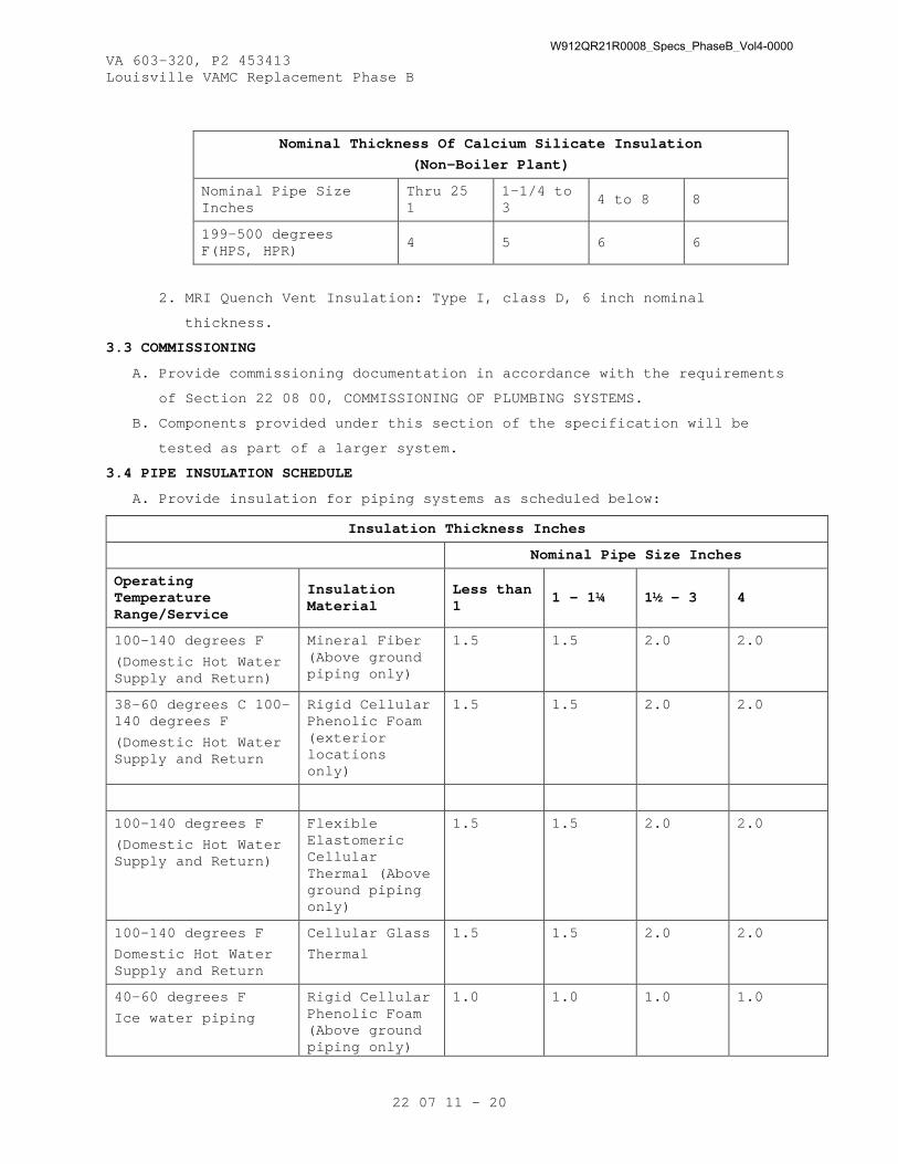
VA 603-320, P2 453413 Louisville VAMC Replacement Phase B
22 07 11 - 20
Nominal Thickness Of Calcium Silicate Insulation
(Non-Boiler Plant)
Nominal Pipe Size Inches
Thru 25 1
1-1/4 to 3
4 to 8 8
199-500 degrees F(HPS, HPR)
4 5 6 6
2. MRI Quench Vent Insulation: Type I, class D, 6 inch nominal
thickness.
3.3 COMMISSIONING
A. Provide commissioning documentation in accordance with the requirements
of Section 22 08 00, COMMISSIONING OF PLUMBING SYSTEMS.
B. Components provided under this section of the specification will be
tested as part of a larger system.
3.4 PIPE INSULATION SCHEDULE
A. Provide insulation for piping systems as scheduled below:
Insulation Thickness Inches
Nominal Pipe Size Inches
Operating Temperature Range/Service
Insulation Material
Less than 1
1 – 1¼ 1½ - 3 4
100-140 degrees F
(Domestic Hot Water Supply and Return)
Mineral Fiber (Above ground piping only)
1.5 1.5 2.0 2.0
38-60 degrees C 100-140 degrees F
(Domestic Hot Water Supply and Return
Rigid Cellular Phenolic Foam (exterior locations only)
1.5 1.5 2.0 2.0
100-140 degrees F
(Domestic Hot Water Supply and Return)
Flexible Elastomeric Cellular Thermal (Above ground piping only)
1.5 1.5 2.0 2.0
100-140 degrees F
Domestic Hot Water Supply and Return
Cellular Glass
Thermal
1.5 1.5 2.0 2.0
40-60 degrees F
Ice water piping
Rigid Cellular Phenolic Foam (Above ground piping only)
1.0 1.0 1.0 1.0
W912QR21R0008_Specs_PhaseB_Vol4-0000

VA 603-320, P2 453413 Louisville VAMC Replacement Phase B
22 07 11 - 21
(exterior locations only)
Horizontal Storm Mineral Fiber N/A N/A (1.0) (1.0)
40-60 degrees F
Ice water piping and Roof Drain bodies
Flexible Elastomeric Cellular Thermal (Above ground piping only)
1.0 1.0 1.0 1.0
40-60 degrees F
Cellular Glass
Thermal
1.5 1.5 1.5 1.5
40-90 degrees F Cold, Tepid, Non-Potable & Soft Cold Water
Mineral Fiber
(aboveground piping)
0.5 0.5 1.0 1.0
- - - E N D - - -
W912QR21R0008_Specs_PhaseB_Vol4-0000

W912QR21R0008_Specs_PhaseB_Vol4-0000

VA 603-320, P2 453413 Louisville VAMC Replacement Phase B
22 08 00 - 1
SECTION 22 08 00
COMMISSIONING OF PLUMBING SYSTEMS
PART 1 - GENERAL
1.1 DESCRIPTION
A. The requirements of this Section apply to all sections of Division 22.
B. This project will have selected building systems commissioned. The
complete list of equipment and systems to be commissioned is specified
in Section 01 91 00 GENERAL COMMISSIONING REQUIREMENTS. The
commissioning process, which the Contractor is responsible to execute,
is defined in Section 01 91 00 GENERAL COMMISSIONING REQUIRMENTS. A
Commissioning Agent (CxA) appointed by the U.S Army Corp of Engineers
(USACE) and Department of Veterans Affairs (VA) will manage the
commissioning process.
1.2 RELATED WORK
A. Section 01 00 00 GENERAL REQUIREMENTS.
B. Section 01 91 00 GENERAL COMMISSIONING REQUIREMENTS.
C. Section 01 33 23 SHOP DRAWINGS, PRODUCT DATA, AND SAMPLES D. Section 01 78 23 - OPERATIONS AND MAINTENANCE MANUALS E. Section 01 79 00 - OPERATIONS AND MAINTENANCE TRAINING F. ALL Division 22 Technical Specification Sections
1.3 SUMMARY
A. This Section includes requirements for commissioning the Plumbing
systems, subsystems and equipment. This Section supplements the
general requirements specified in Section 01 91 00
General Commissioning Requirements.
B. Refer to Section 01 91 00 GENERAL COMMISSIONING REQUIREMENTS for more
details regarding processes and procedures as well as roles and
responsibilities for all Commissioning Team members.
1.4 DEFINITIONS
A. Refer to Section 01 91 00 GENERAL COMMISSIONING REQUIREMENTS for
definitions.
1.5 COMMISSIONED SYSTEMS
A. Commissioning of a system or systems specified in Division 22 is part
of the construction process. Documentation and testing of these
systems, as well as training of the VA’s Operation and Maintenance
personnel in accordance with the requirements of Section 01 91 00 and
W912QR21R0008_Specs_PhaseB_Vol4-0000

VA 603-320, P2 453413 Louisville VAMC Replacement Phase B
22 08 00 - 2
01 78 23 and 01 79 00 and of Division 22, is required in cooperation
with USACE Field Representative, the VA SRE and the Commissioning
Agent.
B. The Plumbing systems commissioning will include the systems and
equipment listed in Section 01 91 00 General Commissioning
Requirement and in the 01 91 00 Appendix A Equipment and Systems
Tracking. 100% of the listed systems and equipment will be tested.
1.6 SUBMITTALS
A. The commissioning process requires review of selected Submittals. The
Commissioning Agent will provide a list of submittals that will be
reviewed by the Commissioning Agent. This list will be reviewed and
approved by the USACE Field Representative and the VA SRE prior to
forwarding to the Contractor. Refer to Section 01 33 23 SHOP DRAWINGS,
PRODUCT DATA, and SAMPLES for further details.
B. The commissioning process requires Submittal review simultaneously with
engineering review. Specific submittal requirements related to the
commissioning process are specified in Section 01 91 00 GENERAL
COMMISSIONING REQUIREMENTS.
PART 2 - PRODUCTS (NOT USED)
PART 3 - EXECUTION
3.1 CONSTRUCTION INSPECTIONS
A. Commissioning of the building plumbing systems will require inspection of individual elements of the plumbing construction throughout the
construction period. The Contractor and equipment vendors shall
coordinate with the USACE Field Representative, the VA SRE and
Commissioning Agent in accordance with Section 01 91 00 and the
Commissioning plan to schedule inspections as required to support the
Commissioning Process.
3.2 PRE-FUNCTIONAL CHECKLISTS
A. The Contractor shall complete Pre-Functional and Start-Up Checklists to verify systems, subsystems, and equipment installation is complete and
systems are ready for Systems Functional Performance Testing.
W912QR21R0008_Specs_PhaseB_Vol4-0000

22 08 00 - 3
The Commissioning Agent will prepare Pre-Functional and Start-Up
Checklists to be used to document equipment installation. The
Contractor and equipment vendors shall complete the checklists.
Completed checklists shall be submitted to the USACE Field
Representative , the VA SRE and to the Commissioning Agent for review.
The Commissioning Agent WILL spot check a sample of completed
checklists. If the Commissioning Agent determines that the information
provided on the checklists is not accurate, the Commissioning Agent
will return the marked-up checklist to the Contractor for correction
and resubmission. If the Commissioning Agent determines that a
significant number of completed checklists for similar equipment are
not accurate, the Commissioning Agent will select a broader sample of
checklists for review.
If the Commissioning Agent determines that a significant number of the
broader sample of checklists is also inaccurate, all the checklists
for the type of equipment will be returned to the Contractor for
correction and resubmission.
Refer to SECTION 01 91 00 GENERAL COMMISSIONING REQUIREMENTS for
submittal requirements for Pre-Functional Checklists, Equipment
Startup Reports, and other commissioning documents.
3.3 CONTRACTORS TESTS
A. Contractor tests as required by other sections of Division 22 shall be
scheduled and documented in accordance with Section 01 00 00 GENERAL
REQUIREMENTS. All testing shall be incorporated into the project
schedule. Contractor shall provide no less than 7 calendar days’
notice of testing to the USACE Field Representative , the VA SRE and
the Commissioning Agent.
The Commissioning Agent will witness selected Contractor tests at the
sole discretion of the Commissioning Agent. Contractor tests shall be
completed prior to scheduling Systems Functional Performance Testing.
3.4 SYSTEMS FUNCTIONAL PERFORMANCE TESTING
A. The Commissioning Process includes Systems Functional Performance
Testing that is intended to test systems functional performance under
steady state conditions, to test system reaction to changes in
operating conditions, and system performance under emergency
conditions. The Commissioning Agent will prepare detailed Systems
Functional Performance Test procedures for review and approval by the
W912QR21R0008_Specs_PhaseB_Vol4-0000

22 08 00 - 4
USACE Field Representative and the VA SRE. The Contractor shall review
and comment on the tests prior to approval.
The Contractor shall provide the required labor, materials, and
test equipment identified in the test procedure to perform the tests.
The Commissioning Agent will witness and document the Functional
testing. 100% of the equipment and systems indicated to be
commissioned in Section 01 91 00 will be functionally tested. The
Contractor shall sign the test reports to verify tests were performed.
See Section 01 91 00 GENERAL COMMISSIONING REQUIREMENTS, for
additional details.
3.5 OPERATIONS AND MAINTENANCE DOCUMENTATION A. The Commissioning Process includes the provision of Operations and
Maintenance Documentation as detailed in the individual Division 22
Specification Sections and in accordance with Section 01 78 23.
B. The Contractor shall provide the necessary labor and materials to provide this Operations and Maintenance Documentation and shall
submit to the USACE COR and VA SRE and Commissioning Authority as
detailed in Section 01 78 23.
3.6 TRAINING OF VA PERSONNEL
A. Training of the VA operation and maintenance personnel is required in
cooperation with the USACE Field Representative, the VA SRE, and
Commissioning Agent. Provide competent, factory authorized personnel
to provide instruction to operation and maintenance personnel
concerning the location, operation, and troubleshooting of the
installed systems. Contractor shall submit training agendas and
trainer resumes in accordance with the requirements of Section 01 79
00 - OPERATIONS AND MAINTENANCE TRAINING. The Training shall be
scheduled in coordination with the USACE Field Representative, the VA
SRE and the Commissioning Agent after submission and approval of
formal training plans by the USACE COR and the VA SRE and the
Commissioning Agent. Refer to Section 01 91 00 GENERAL COMMISSIONING
REQUIREMENTS, and Section 01 79 00 - OPERATIONS AND MAINTENANCE
TRAINING, and Division 22 Sections for additional Contractortraining
requirements.
B. Minimum Training Hours shall be the following:
1. GENERAL PLUMBING SYSTEMS TRAINING- Two 8 Hour Classroom and Field
Sessions
W912QR21R0008_Specs_PhaseB_Vol4-0000

22 08 00 - 5
2. PLUMBING METERS TRAINING- Two 4 Hour Classroom and Field Sessions
3. MIXING VALVE SYSTEMS TRAINING- Two 4 Hour Classroom and Field
Sessions
4. DOMESTIC WATER BOOSTER PUMP SYSTEMS TRAINING – Two- 4 Hour
Classroom and Field Sessions
5. SANITARY SEWER AND SUMP PUMP SYSTEMS TRAINING – Two- 4 Hour
Classroom and Field Sessions
6. INSTRUMENT COMPRESSED AIR SYSTEMS TRAINING – Two- 8 Hour Classroom and Field Sessions
7. WATER SOFTNER SYSTEMS TRAINING- Two- 4 Hour Classroom and Field Sessions
8. ELECTRIC DOMESTIC WATER HEATER TRAINING-Two- 2 Hour Classroom and
Field Sessions
9. DOMESTIC HOT WATER HEAT EXCHANGER TRAINING- Two- 4 Hour Classroom
and Field Sessions
10. DENTAL COMPRESSED AIR AND VACUUM SYSTEMS TRAINING- Two- 8 Hour
Classroom and Field Sessions
11. MEDICAL COMPRESSED AIR AND VACUUM SYSTEMS TRAINING- Two- 8 Hour Classroom and Field Sessions
12. MEDICAL GAS SYSTEMS TRAINING- Two- 8 Hour Classroom and Field Sessions
13. CHEMICAL WASTE SYSTEMS TRAINING Two- 2 Hour Classroom and Field
Sessions
14. REVERSE OSMOSIS SYSTEMS TRAINING -Two- 4 Hour Classroom and Field
Sessions
15. FACILITY FUEL SYSTEMS TRAINING -TWO- 8 Hour Classroom and Field
Sessions
16. PLUMBING FIXURES TRAINNG – TWO- 4 Hour Classroom and Field Sessions
3.7 SAMPLE PFCs and FPTs (Attached are representative PFCs and FPTs for Division 22)
----- END -----
W912QR21R0008_Specs_PhaseB_Vol4-0000

W912QR21R0008_Specs_PhaseB_Vol4-0000

Division 22 – Plumbing
System Type PFC Name
Booster (Domestic Water) Booster Pump Duplex
Sump Pumps Sump Pump Elevator Pit
Fuel Oil Pumps Fuel Oil Polisher Re-Circulation
Recirculation Pumps None
Steam / Domestic Water Heaters Heat Exchanger Shell and Tube Steam to Water
Water Softeners None
RO Systems None
Expansion Tank Expansion Tank Floor Mounted
Heat Exchanger Heat Exchanger Shell and Tube Steam to Water
Instrument Air Compressor Air Compressor Rotary Screw
Medical Air Compressor Air Compressor Rotary Screw
General Air Compressor Air Compressor Rotary Screw
Medical Air Vacuum Vacuum Skid
Lab Air Compressor Air Compressor Rotary Screw
Lab Air Vacuum Vacuum Skid
Dental Air Compressor Air Compressor Rotary Screw
Dental Air Vacuum Vacuum Skid
Waste Anesthesia Gas Vacuum Vacuum Skid
W912QR21R0008_Specs_PhaseB_Vol4-0000

Commissioning Pre-functional Checklist
JEG Project No: R2W63202 Page 1 of 4 PFC - ESP1-BVAMC Louisville KY
PROJECT: VAMC Louisville KY
PROJECT NUMBER: R2W63202
REPORT ID: PFC - ESP1-B
CHECKLIST DESCRIPTION: Sump Pump Elevator Pit
TAG NO: ESP1-B
SITE: VAMC Louisville BUILDING: VAMC Louisville ROOM: Elevator Shaft FLOOR: Various
This Pre-Functional Checklist is used during the Commissioning Process to ensure the correctmaterials are delivered, installed and properly started in preparation for Functional PerformanceTesting of related building systems. This Checklist does not take the place of the manufacturer'srecommended checkout and startup procedures.This Checklist is divided into 5 Sections and is to be completed by the Contractor in 5 separatephases.
SECTION 1: DELIVERY: The Contractor shall complete Section 1 upon delivery to the site. The purpose is to record the actualdesign parameters listed below along with the checklist items as indicated.
SECTION 2: INSTALLATION:The Contractor shall complete Section 2 when the installation is being performed. The purpose of thisSection is to verify all materials are installed to the Project Design and the Manufacturer'srecommendations. Immediately notify the Commissioning Authority should any item be checkedincomplete.
SECTION 3: START-UP:The Contractor shall complete Section 3 during the Start-up procedures for the equipment. Thepurpose of this Section is to document that proper start-up and check-out procedures were completedand documented.
SECTION 4: BAS CONTROL, POWER MONITORING & INTEGRATION: The Contractor shall complete Section 4 during the BAS controls and/or power monitoringconfiguration and integration process for the system. The purpose of this Section is to document thefull control and monitoring capabilities of the controls systems including alarms, trends and full rangeof the sequence of operations.
SECTION 5: COMPLETION & NOTIFICATION FOR TESTING: The Contractor shall complete Section 5 to confirm that this equipment or system is properly installed,is operational, and ready for functional performance testing.
W912QR21R0008_Specs_PhaseB_Vol4-0000

Commissioning Pre-functional Checklist
JEG Project No: R2W63202 Page 2 of 4 PFC - ESP1-BVAMC Louisville KY
DESIGN INFORMATION: ESP1-BPARAMETERS DESIGN ACTUALFlow Rate (GPM) 100.0 Head (ft) 38.0 Manufacturer Model Motor HP 0.5 RPM 3450.0 Serial Number Temperature (°F) 60.0 v/p 115/1
Tag ID: ESP1-BCHECKLIST ITEMS: Sect. ID Verified By Complete Description
Del
iver
y
1.001
All related submittals approved by A/E
1.002
Sump pump and pit thoroughly inspected for physical damage
1.003
System installation diagrams and details have been provided
1.004
All accessories received
1.005
Piping openings sealed and protected against debris
1.006
Equipment stored in a clean, dry location
W912QR21R0008_Specs_PhaseB_Vol4-0000

Commissioning Pre-functional Checklist
JEG Project No: R2W63202 Page 3 of 4 PFC - ESP1-BVAMC Louisville KY
Sect. ID Verified By Complete DescriptionIn
stal
latio
n
2.001
Proper maintenance access provided
2.002
Piping accessories installed per drawing details
2.003
Proper motor overload protection provided
2.004
All quality assurance testing complete and reports submitted
2.005
Piping system cleaned and flushed
2.006
Pumps mounted on specified vibration isolation
2.007
Piping supported to prevent strain on pump housing
2.008
Sump basin vented per drawing details
2.009
Correct number of level switches installed per contract document
2.010
Flexible pipe installed at pump connections.
2.011
Pipe union installed in pump discharge for maintenance access
2.012
Oil separator is installed where required
2.013
Check valve and isolation valve installed in discharge line
Sect. ID Verified By Complete Description
Star
t Up
3.001
Power supply is energized/identified
3.002
Pre-start inspection report submitted
3.003
Cx Authority has been notified of start-up
3.004
All manufacturer's startup checks have been performed and documented
3.005
All shipping blocks removed
3.006
All moving parts are properly lubricated
3.007
Overload relay is properly sized and set for motor
3.008
No unusual noise or vibration
Sect. ID Verified By Complete Description
BA
S C
ontr
ols
&
Inte
grat
ion
4.001
Level switches set to start and stop pump at specified liquid depth
4.002
All specified monitoring/alarm points available at building front end
4.003
Point-to-point verifications have been completed
4.004
The HOA switch properly activates and deactivates the unit under manual and automatic control
W912QR21R0008_Specs_PhaseB_Vol4-0000
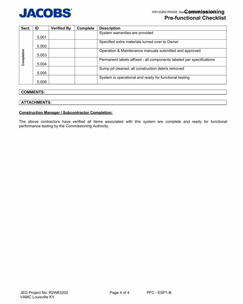
Commissioning Pre-functional Checklist
JEG Project No: R2W63202 Page 4 of 4 PFC - ESP1-BVAMC Louisville KY
Sect. ID Verified By Complete DescriptionC
ompl
etio
n
5.001
System warranties are provided
5.002
Specified extra materials turned over to Owner
5.003
Operation & Maintenance manuals submitted and approved
5.004
Permanent labels affixed - all components labeled per specifications
5.005
Sump pit cleaned, all construction debris removed
5.006
System is operational and ready for functional testing
COMMENTS:
ATTACHMENTS:
Construction Manager / Subcontractor Completion:
The above contractors have verified all items associated with this system are complete and ready for functionalperformance testing by the Commissioning Authority.
W912QR21R0008_Specs_PhaseB_Vol4-0000

Commissioning Pre-functional Checklist
JEG Project No: R2W63202 Page 1 of 4 PFC - LAC1-BVAMC Louisville KY
PROJECT: VAMC Louisville KY
PROJECT NUMBER: R2W63202
REPORT ID: PFC - LAC1-B
CHECKLIST DESCRIPTION: Air Compressor Rotary Screw
TAG NO: LAC1-B
SITE: VAMC Louisville BUILDING: VAMC Louisville ROOM: Area 5 FLOOR: Level 6
This Pre-Functional Checklist is used during the Commissioning Process to ensure the correctmaterials are delivered, installed and properly started in preparation for Functional PerformanceTesting of related building systems. This Checklist does not take the place of the manufacturer'srecommended checkout and startup procedures.This Checklist is divided into 5 Sections and is to be completed by the Contractor in 5 separatephases.
SECTION 1: DELIVERY: The Contractor shall complete Section 1 upon delivery to the site. The purpose is to record the actualdesign parameters listed below along with the checklist items as indicated.
SECTION 2: INSTALLATION:The Contractor shall complete Section 2 when the installation is being performed. The purpose of thisSection is to verify all materials are installed to the Project Design and the Manufacturer'srecommendations. Immediately notify the Commissioning Authority should any item be checkedincomplete.
SECTION 3: START-UP:The Contractor shall complete Section 3 during the Start-up procedures for the equipment. Thepurpose of this Section is to document that proper start-up and check-out procedures were completedand documented.
SECTION 4: BAS CONTROL, POWER MONITORING & INTEGRATION: The Contractor shall complete Section 4 during the BAS controls and/or power monitoringconfiguration and integration process for the system. The purpose of this Section is to document thefull control and monitoring capabilities of the controls systems including alarms, trends and full rangeof the sequence of operations.
SECTION 5: COMPLETION & NOTIFICATION FOR TESTING: The Contractor shall complete Section 5 to confirm that this equipment or system is properly installed,is operational, and ready for functional performance testing.
W912QR21R0008_Specs_PhaseB_Vol4-0000

Commissioning Pre-functional Checklist
JEG Project No: R2W63202 Page 2 of 4 PFC - LAC1-BVAMC Louisville KY
DESIGN INFORMATION: LAC1-BPARAMETERS DESIGN ACTUALDischarge Pressure (PSIG) 100.0 Manufacturer Model Reciever Capacity (gal) 200.0 Serial Number v/p 460/3
Tag ID: LAC1-BCHECKLIST ITEMS: Sect. ID Verified By Complete Description
Del
iver
y
1.001
All related submittals approved by A/E
1.002
All factory testing complete and reports submitted
1.003
Air compressor thoroughly inspected for physical damage
1.004
System installation diagrams and details have been provided
1.005
All accessories received
1.006
Pipe openings sealed and protected against debris
1.007
Equipment stored in a clean, dry location
1.008
Concrete housekeeping pad is properly sized
W912QR21R0008_Specs_PhaseB_Vol4-0000

Commissioning Pre-functional Checklist
JEG Project No: R2W63202 Page 3 of 4 PFC - LAC1-BVAMC Louisville KY
Sect. ID Verified By Complete DescriptionIn
stal
latio
n
2.001
Pressure and temperature gauges installed where shown on piping details
2.002
Isolation valves and balancing valves installed with handle extensions to clear insulation
2.003
Pneumatic piping system cleaned and flushed
2.004
All piping connections checked for leaks
2.005
Vibration isolators installed and properly tensioned
2.006
Storage tank drain piped to floor drain
2.007
Air drier condensate drain piped to floor drain
2.008
Pressure relief valve installed and piped to safe discharge location as indicated on drawings
2.009
Power supply energized and properly identified
2.010
Compressor oil levels checked
2.011
All moving parts properly lubricated
2.012
Proper maintenance access provided
2.013
Piping accessories installed per drawing details
Sect. ID Verified By Complete Description
Star
t Up
3.001
Testing, adjusting, and balancing complete, and report submitted
3.002
Motor rotation correct and belt tension checked
3.003
Cx Authority has been notified of start-up
3.004
All manufacturer's startup checks have been performed and documented
3.005
Compressed air system is operational
Sect. ID Verified By Complete Description
BA
S C
ontr
ols
&
Inte
grat
ion
4.001
All specified monitoring/control points available at building front end
4.002
Sequence of operations programmed per approved system submittal
4.003
System control set point confirmed with TAB contractor
4.004
System trending enabled
W912QR21R0008_Specs_PhaseB_Vol4-0000

Commissioning Pre-functional Checklist
JEG Project No: R2W63202 Page 4 of 4 PFC - LAC1-BVAMC Louisville KY
Sect. ID Verified By Complete DescriptionC
ompl
etio
n
5.001
System warranties are provided
5.002
Specified extra materials turned over to Owner
5.003
Operation & Maintenance manuals submitted and approved
5.004
System control and monitoring sensors labeled and location indicated on as-built documents
5.005
Filters changed after startup, clean filters installed
5.006
System is operational and ready for functional testing
COMMENTS:
ATTACHMENTS:
Construction Manager / Subcontractor Completion:
The above contractors have verified all items associated with this system are complete and ready for functionalperformance testing by the Commissioning Authority.
W912QR21R0008_Specs_PhaseB_Vol4-0000
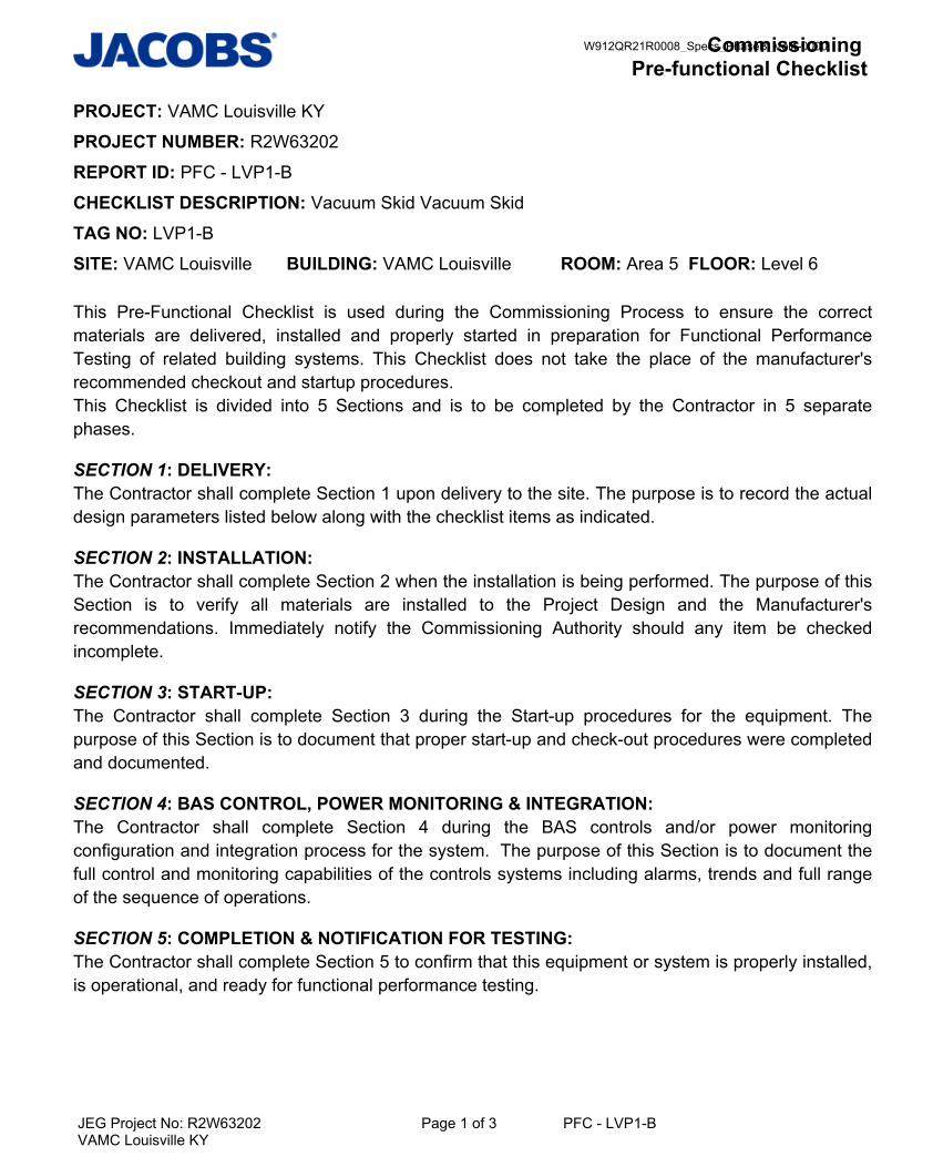
Commissioning Pre-functional Checklist
JEG Project No: R2W63202 Page 1 of 3 PFC - LVP1-BVAMC Louisville KY
PROJECT: VAMC Louisville KY
PROJECT NUMBER: R2W63202
REPORT ID: PFC - LVP1-B
CHECKLIST DESCRIPTION: Vacuum Skid Vacuum Skid
TAG NO: LVP1-B
SITE: VAMC Louisville BUILDING: VAMC Louisville ROOM: Area 5 FLOOR: Level 6
This Pre-Functional Checklist is used during the Commissioning Process to ensure the correctmaterials are delivered, installed and properly started in preparation for Functional PerformanceTesting of related building systems. This Checklist does not take the place of the manufacturer'srecommended checkout and startup procedures.This Checklist is divided into 5 Sections and is to be completed by the Contractor in 5 separatephases.
SECTION 1: DELIVERY: The Contractor shall complete Section 1 upon delivery to the site. The purpose is to record the actualdesign parameters listed below along with the checklist items as indicated.
SECTION 2: INSTALLATION:The Contractor shall complete Section 2 when the installation is being performed. The purpose of thisSection is to verify all materials are installed to the Project Design and the Manufacturer'srecommendations. Immediately notify the Commissioning Authority should any item be checkedincomplete.
SECTION 3: START-UP:The Contractor shall complete Section 3 during the Start-up procedures for the equipment. Thepurpose of this Section is to document that proper start-up and check-out procedures were completedand documented.
SECTION 4: BAS CONTROL, POWER MONITORING & INTEGRATION: The Contractor shall complete Section 4 during the BAS controls and/or power monitoringconfiguration and integration process for the system. The purpose of this Section is to document thefull control and monitoring capabilities of the controls systems including alarms, trends and full rangeof the sequence of operations.
SECTION 5: COMPLETION & NOTIFICATION FOR TESTING: The Contractor shall complete Section 5 to confirm that this equipment or system is properly installed,is operational, and ready for functional performance testing.
W912QR21R0008_Specs_PhaseB_Vol4-0000

Commissioning Pre-functional Checklist
JEG Project No: R2W63202 Page 2 of 3 PFC - LVP1-BVAMC Louisville KY
DESIGN INFORMATION: LVP1-BPARAMETERS DESIGN ACTUALManufacturer Model Reciever Capacity (gal) 120.0 Serial Number Vacuum Pressure (in HG) 19.0 v/p 460/3
Tag ID: LVP1-BCHECKLIST ITEMS: Sect. ID Verified By Complete Description
Del
iver
y
1.001
All related submittals approved by A/E
1.002
Equipment thoroughly inspected for physical damage
1.003
Equipment stored in clean and dry environment
1.004
Concrete housekeeping pad properly sized
1.005
All associated equipment and documentation including manufacturer's test reports included
1.006
Piping connections sealed and protected
1.007
Equipment/component wiring & installation diagrams have been provided
1.008
All accessories received
Sect. ID Verified By Complete Description
Inst
alla
tion
2.001
Proper clearance provided around all sides of pump skid and vacuum tanks
2.002
Vacuum skid placed on insulating pads furnished with the equipment
2.003
Proper motor overload protection provided.
2.004
Isolation valves installed to allow for service and maintenance work.
2.005
Zone valves provided in cabinets where indicated on plans and outside each Operating Room. A minimum one zone valve assembly for each 18 outlets.
2.006
Vacuum gage 40mm (1 1/2 inch) diameter line is installed downstream ofeach zone valve in cabinets.
2.007
Piping supported to prevent strain on equipment flanges.
2.008
Pump rotation is correct.
2.009
Sensors installed as indicated on drawings
2.010
Pump skid and vacuum tank installed per drawing details.
2.011
All quality assurance testing completed and reports submitted.
W912QR21R0008_Specs_PhaseB_Vol4-0000

Commissioning Pre-functional Checklist
JEG Project No: R2W63202 Page 3 of 3 PFC - LVP1-BVAMC Louisville KY
Sect. ID Verified By Complete DescriptionSt
art U
p
3.001
Manufacturers Rep on site for start-up.
3.002
Motor voltage balanced and within normal limit.
3.003
Motor amperage balanced and within normal limits.
3.004
Field leak testing has been completed. If repairs are made, re-testing hasbeen performed.
Sect. ID Verified By Complete Description
BA
S C
ontr
ols
&
Inte
grat
ion
4.001
Sequence of operations including all interlocks, safeties and alarms are functional per Basis of Design and Construction Documents.
4.002
Sensor sensitivity calibrated to maintain design vacuum levels
4.003
Vacuum system controls and demonstrate comply with requirements.
4.004
Vacuum skid properly networked to central control system
4.005
Specified points available at BAS front end for monitoring, scheduling, and control
4.006
Trend data of control variables show stable operation.
Sect. ID Verified By Complete Description
Com
plet
ion
5.001
Vacuum skid warranties are provided
5.002
Specified extra materials turned over to Owner
5.003
Operation & Maintenance manuals submitted and approved
5.004
Permanent labels affixed
5.005
Any scratches painted to match finish of surrounding materials per specification
5.006
All piping and tanks have been cleaned.
COMMENTS:
ATTACHMENTS:
Construction Manager / Subcontractor Completion:
The above contractors have verified all items associated with this system are complete and ready for functionalperformance testing by the Commissioning Authority.
W912QR21R0008_Specs_PhaseB_Vol4-0000

Commissioning Pre-functional Checklist
JEG Project No: R2W63202 Page 1 of 4 PFC - SWH1-BVAMC Louisville KY
PROJECT: VAMC Louisville KY
PROJECT NUMBER: R2W63202
REPORT ID: PFC - SWH1-B
CHECKLIST DESCRIPTION: Heat Exchanger Shell and Tube Steam to Water
TAG NO: SWH1-B
SITE: VAMC Louisville BUILDING: VAMC Louisville ROOM: Area 5 FLOOR: Level 6
This Pre-Functional Checklist is used during the Commissioning Process to ensure the correctmaterials are delivered, installed and properly started in preparation for Functional PerformanceTesting of related building systems. This Checklist does not take the place of the manufacturer'srecommended checkout and startup procedures.This Checklist is divided into 5 Sections and is to be completed by the Contractor in 5 separatephases.
SECTION 1: DELIVERY: The Contractor shall complete Section 1 upon delivery to the site. The purpose is to record the actualdesign parameters listed below along with the checklist items as indicated.
SECTION 2: INSTALLATION:The Contractor shall complete Section 2 when the installation is being performed. The purpose of thisSection is to verify all materials are installed to the Project Design and the Manufacturer'srecommendations. Immediately notify the Commissioning Authority should any item be checkedincomplete.
SECTION 3: START-UP:The Contractor shall complete Section 3 during the Start-up procedures for the equipment. Thepurpose of this Section is to document that proper start-up and check-out procedures were completedand documented.
SECTION 4: BAS CONTROL, POWER MONITORING & INTEGRATION: The Contractor shall complete Section 4 during the BAS controls and/or power monitoringconfiguration and integration process for the system. The purpose of this Section is to document thefull control and monitoring capabilities of the controls systems including alarms, trends and full rangeof the sequence of operations.
SECTION 5: COMPLETION & NOTIFICATION FOR TESTING: The Contractor shall complete Section 5 to confirm that this equipment or system is properly installed,is operational, and ready for functional performance testing.
W912QR21R0008_Specs_PhaseB_Vol4-0000
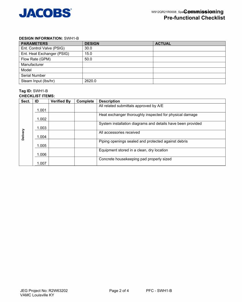
Commissioning Pre-functional Checklist
JEG Project No: R2W63202 Page 2 of 4 PFC - SWH1-BVAMC Louisville KY
DESIGN INFORMATION: SWH1-BPARAMETERS DESIGN ACTUALEnt. Control Valve (PSIG) 30.0 Ent. Heat Exchanger (PSIG) 15.0 Flow Rate (GPM) 50.0 Manufacturer Model Serial Number Steam Input (lbs/hr) 2620.0
Tag ID: SWH1-BCHECKLIST ITEMS: Sect. ID Verified By Complete Description
Del
iver
y
1.001
All related submittals approved by A/E
1.002
Heat exchanger thoroughly inspected for physical damage
1.003
System installation diagrams and details have been provided
1.004
All accessories received
1.005
Piping openings sealed and protected against debris
1.006
Equipment stored in a clean, dry location
1.007
Concrete housekeeping pad properly sized
W912QR21R0008_Specs_PhaseB_Vol4-0000
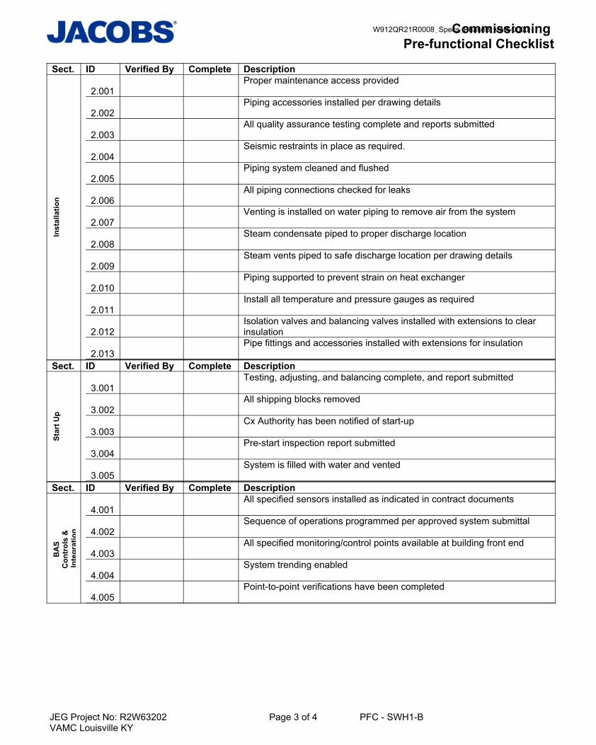
Commissioning Pre-functional Checklist
JEG Project No: R2W63202 Page 3 of 4 PFC - SWH1-BVAMC Louisville KY
Sect. ID Verified By Complete DescriptionIn
stal
latio
n
2.001
Proper maintenance access provided
2.002
Piping accessories installed per drawing details
2.003
All quality assurance testing complete and reports submitted
2.004
Seismic restraints in place as required.
2.005
Piping system cleaned and flushed
2.006
All piping connections checked for leaks
2.007
Venting is installed on water piping to remove air from the system
2.008
Steam condensate piped to proper discharge location
2.009
Steam vents piped to safe discharge location per drawing details
2.010
Piping supported to prevent strain on heat exchanger
2.011
Install all temperature and pressure gauges as required
2.012
Isolation valves and balancing valves installed with extensions to clear insulation
2.013
Pipe fittings and accessories installed with extensions for insulation
Sect. ID Verified By Complete Description
Star
t Up
3.001
Testing, adjusting, and balancing complete, and report submitted
3.002
All shipping blocks removed
3.003
Cx Authority has been notified of start-up
3.004
Pre-start inspection report submitted
3.005
System is filled with water and vented
Sect. ID Verified By Complete Description
BA
S C
ontr
ols
&
Inte
grat
ion
4.001
All specified sensors installed as indicated in contract documents
4.002
Sequence of operations programmed per approved system submittal
4.003
All specified monitoring/control points available at building front end
4.004
System trending enabled
4.005
Point-to-point verifications have been completed
W912QR21R0008_Specs_PhaseB_Vol4-0000
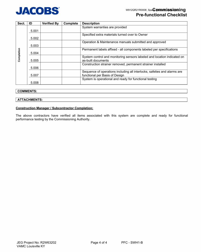
Commissioning Pre-functional Checklist
JEG Project No: R2W63202 Page 4 of 4 PFC - SWH1-BVAMC Louisville KY
Sect. ID Verified By Complete DescriptionC
ompl
etio
n
5.001
System warranties are provided
5.002
Specified extra materials turned over to Owner
5.003
Operation & Maintenance manuals submitted and approved
5.004
Permanent labels affixed - all components labeled per specifications
5.005
System control and monitoring sensors labeled and location indicated on as-built documents
5.006
Construction strainer removed, permanent strainer installed
5.007
Sequence of operations including all interlocks, safeties and alarms are functional per Basis of Design
5.008
System is operational and ready for functional testing
COMMENTS:
ATTACHMENTS:
Construction Manager / Subcontractor Completion:
The above contractors have verified all items associated with this system are complete and ready for functionalperformance testing by the Commissioning Authority.
W912QR21R0008_Specs_PhaseB_Vol4-0000

Commissioning PFC
JEG Project No: F3W80018 Page 1 of 3 PFC - DWP-1UTMB Health Education Center
PROJECT: UTMB Health Education Center
PROJECT NUMBER: F3W80018
REPORT ID: PFC - DWP-1
CHECKLIST DESCRIPTION: Booster Pump Duplex
TAG NO: DWP-1
SITE: UTMB HEC BUILDING: UTMB HEC ROOM: 2.222 FLOOR: Level-2Last Execution Date: This PFC is used during the Commissioning Process to ensure the correct materials are delivered,installed and properly started in preparation for Functional Performance Testing of related buildingsystems. This Checklist does not take the place of the manufacturer's recommended checkout andstartup procedures.This Checklist is divided into 5 Sections and is to be completed by the Contractor in 5 separatephases.
SECTION 1: DELIVERY: The Contractor shall complete Section 1 upon delivery to the site. The purpose is to record the actualdesign parameters listed below along with the checklist items as indicated.
SECTION 2: INSTALLATION:The Contractor shall complete Section 2 when the installation is being performed. The purpose of thisSection is to verify all materials are installed to the Project Design and the Manufacturer'srecommendations. Immediately notify the Commissioning Authority should any item be checkedincomplete.
SECTION 3: START-UP: The Contractor shall complete Section 3 during the Start-up procedures for the equipment. Thepurpose of this Section is to document that proper start-up and check-out procedures were completedand documented.
SECTION 4: BAS CONTROL, POWER MONITORING & INTEGRATION: The Contractor shall complete Section 4 during the BAS controls and/or power monitoringconfiguration and integration process for the system. The purpose of this Section is to document thefull control and monitoring capabilities of the controls systems including alarms, trends and full rangeof the sequence of operations.
SECTION 5: COMPLETION & NOTIFICATION FOR TESTING: The Contractor shall complete Section 5 to confirm that this equipment or system is properly installed,is operational, and ready for functional performance testing.
W912QR21R0008_Specs_PhaseB_Vol4-0000

Commissioning PFC
JEG Project No: F3W80018 Page 2 of 3 PFC - DWP-1UTMB Health Education Center
DESIGN INFORMATION:
PARAMETERS: Design ActualManufacturer
Model
Serial Number
Tag ID: DWP-1CHECKLIST ITEMS:
Sect. ID Verified By Complete Date Executed Description
Del
iver
y
1.001 All related submittals approved by A/E 1.002 Booster pump skid thoroughly inspected for physical damage 1.003 System installation diagrams and details have been provided 1.004 All accessories received 1.005 Piping openings sealed and protected 1.006 Equipment stored in a clean, dry location 1.007 Pump shafts periodically rotated by hand until started 1.008 Verify pump bearings are protected from sand, grit and
foreign matter 4.002 System set points entered to maintain correct pressure at
farthest fixtureSect. ID Verified By Complete Date Executed Description
Inst
alla
tion
2.001 Proper maintenance access provided 2.002 Piping accessories installed per drawing details 2.003 Proper motor overload protection provided 2.004 All quality assurance testing complete and reports submitted 2.005 Domestic water piping, including backflow preventers, is
installed, pressure testing completed, and reports submitted 2.006 Piping system cleaned and flushed 2.007 Vibration isolators are installed and properly compressed 2.008 Seismic restraints in place as required 2.009 Piping supported to prevent strain on pump skid 2.010 All pressure gauges installed as indicated in drawing details 2.011 Isolation valves and balancing valves installed with
extensions to clear insulation 2.012 Pipe fittings and accessories installed with extensions for
insulation 2.013 Air vents and bleeds at high points of systems functional 2.014 Pump seal drains piped to proper discharge point
W912QR21R0008_Specs_PhaseB_Vol4-0000

Commissioning PFC
JEG Project No: F3W80018 Page 3 of 3 PFC - DWP-1UTMB Health Education Center
Sect. ID Verified By Complete Date Executed Description
Star
t Up
3.001 Testing, adjusting, and balancing complete, and report submitted
3.002 Pump rotation correct 3.003 Power supply is energized/identified 3.004 All shipping blocks removed 3.005 Manufacturer start-up complete and reports submitted 3.006 Cx Authority has been notified of start-up 3.007 Motor voltages balanced and within normal limits 3.008 Motor amperages balanced and within normal limits 3.009 Overload relay is properly sized and set for skid 3.010 No unusual noise or vibration 3.011 All moving parts are properly lubricated
Sect. ID Verified By Complete Date Executed Description
BA
S C
ontr
ols
&
Inte
grat
ion
4.001 All specified sensors installed as indicated in contract documents
4.003 All specified monitoring/control points available at building front end
4.004 Point-to-point verifications have been completed 4.005 The HOA switch properly activates and deactivates each
pump under manual and automatic control 4.006 Lead pump alternates per specified sequence 4.007 VFDs synchronized to operate pumps together 4.008 System trending enabled
Sect. ID Verified By Complete Date Executed Description
Com
plet
ion
5.001 Specified extra materials turned over to Owner 5.002 Operation & Maintenance manuals submitted and approved 5.003 Permanent labels affixed - all components labeled per
specifications 5.004 System control and monitoring sensors labeled and location
indicated on as-built documents 5.005 System is operational and ready for functional testing 5.006 System warranties are provided
COMMENTS:
ATTACHMENTS:
Construction Manager / Subcontractor Completion:
The above contractors have verified all items associated with this system are complete and ready for functional performance testing by the Commissioning Authority.
W912QR21R0008_Specs_PhaseB_Vol4-0000

Commissioning PFC
JEG Project No: R6W67502 Page 1 of 3 PFC - FOP-1Hidalgo County Courthouse
PROJECT: Hidalgo County Courthouse
PROJECT NUMBER: R6W67502
REPORT ID: PFC - FOP-1
CHECKLIST DESCRIPTION: Fuel Oil Polisher Re-Circulation
TAG NO: FOP-1
SITE: Houston Project Site BUILDING: HIDALGO COUNTY COURTHOUSE ROOM: CUP FLOOR: CUPLast Execution Date: This PFC is used during the Commissioning Process to ensure the correct materials are delivered,installed and properly started in preparation for Functional Performance Testing of related buildingsystems. This Checklist does not take the place of the manufacturer's recommended checkout andstartup procedures.This Checklist is divided into 5 Sections and is to be completed by the Contractor in 5 separatephases.
SECTION 1: DELIVERY: The Contractor shall complete Section 1 upon delivery to the site. The purpose is to record the actualdesign parameters listed below along with the checklist items as indicated.
SECTION 2: INSTALLATION:The Contractor shall complete Section 2 when the installation is being performed. The purpose of thisSection is to verify all materials are installed to the Project Design and the Manufacturer'srecommendations. Immediately notify the Commissioning Authority should any item be checkedincomplete.
SECTION 3: START-UP: The Contractor shall complete Section 3 during the Start-up procedures for the equipment. Thepurpose of this Section is to document that proper start-up and check-out procedures were completedand documented.
SECTION 4: BAS CONTROL, POWER MONITORING & INTEGRATION: The Contractor shall complete Section 4 during the BAS controls and/or power monitoringconfiguration and integration process for the system. The purpose of this Section is to document thefull control and monitoring capabilities of the controls systems including alarms, trends and full rangeof the sequence of operations.
SECTION 5: COMPLETION & NOTIFICATION FOR TESTING: The Contractor shall complete Section 5 to confirm that this equipment or system is properly installed,is operational, and ready for functional performance testing.
W912QR21R0008_Specs_PhaseB_Vol4-0000

Commissioning PFC
JEG Project No: R6W67502 Page 2 of 3 PFC - FOP-1Hidalgo County Courthouse
DESIGN INFORMATION:
PARAMETERS: Design ActualManufacturer
Model
Serial Number
Tag ID: FOP-1CHECKLIST ITEMS:
Sect. ID Verified By Complete Date Executed Description
Del
iver
y
1.001 Concrete housekeeping pad properly sized 1.002 Equipment stored in a clean, dry location 1.003 Proper maintenance access provided 1.004 All related submittals approved by A/E 1.005 Fuel oil pump thoroughly inspected for physical damage 1.006 All accessories received 1.007 Piping openings sealed and protected against debris
Sect. ID Verified By Complete Date Executed Description
Inst
alla
tion
2.001 Piping accessories installed per drawing details 2.002 All quality assurance testing complete and reports submitted 2.003 Piping system cleaned and flushed 2.004 Vibration isolators installed and properly compressed 2.005 All piping connections checked for leaks 2.006 Piping supported to prevent strain on pump 2.007 All pressure and temperature gauges installed as required 2.008 Isolation valves installed in accessible location 2.009 Pipe fittings and accessories installed 2.010 Recirculating line with check valve installed per drawing
details 2.011 Strainer installed between oil storage tank and pump inlet 2.012 Fusible link emergency stop valve installed in oil supply line
Sect. ID Verified By Complete Date Executed Description
Star
t Up
3.001 Pump rotation correct 3.002 Power supply is energized/identified 3.003 All shipping blocks removed 3.004 Clean oil filter installed 3.005 Manufacturer start-up complete and reports submitted 3.006 Cx Authority has been notified of start-up 3.007 All moving parts are properly lubricated 3.008 No unusual noise or vibration
W912QR21R0008_Specs_PhaseB_Vol4-0000

Commissioning PFC
JEG Project No: R6W67502 Page 3 of 3 PFC - FOP-1Hidalgo County Courthouse
Sect. ID Verified By Complete Date Executed Description
BA
S C
ontr
ols
&
Inte
grat
ion
4.001 All specified sensors installed as indicated in contract documents
4.002 Sequence of operations programmed per approved system submittal
4.003 All specified monitoring/control points available at building front end
4.004 System trending enabled 4.005 Point-to-point verifications have been completed 4.006 Pump interlocks with mechanical float 4.007 The HOA switch properly activates and deactivates the unit
under manual and automatic controlSect. ID Verified By Complete Date Executed Description
Com
plet
ion
5.001 Specified extra materials turned over to Owner 5.002 Operation & Maintenance manuals submitted and approved 5.003 Permanent labels affixed - all components labeled per
specifications 5.004 System control and monitoring sensors labeled and location
indicated on as-built documents 5.005 Construction strainer removed and clean strainer and filters
installed 5.006 System is operational and ready for functional testing
COMMENTS:
ATTACHMENTS:
Construction Manager / Subcontractor Completion:
The above contractors have verified all items associated with this system are complete and ready for functional performance testing by the Commissioning Authority.
W912QR21R0008_Specs_PhaseB_Vol4-0000

Commissioning Pre-functional Checklist
JEG Project No: R2W63202 Page 1 of 3 PFC - ET1-BVAMC Louisville KY
PROJECT: VAMC Louisville KY
PROJECT NUMBER: R2W63202
REPORT ID: PFC - ET1-B
CHECKLIST DESCRIPTION: Expansion Tank Floor Mounted
TAG NO: ET1-B
SITE: VAMC Louisville BUILDING: VAMC Louisville ROOM: Various FLOOR: Various
This Pre-Functional Checklist is used during the Commissioning Process to ensure the correctmaterials are delivered, installed and properly started in preparation for Functional PerformanceTesting of related building systems. This Checklist does not take the place of the manufacturer'srecommended checkout and startup procedures.This Checklist is divided into 5 Sections and is to be completed by the Contractor in 5 separatephases.
SECTION 1: DELIVERY: The Contractor shall complete Section 1 upon delivery to the site. The purpose is to record the actualdesign parameters listed below along with the checklist items as indicated.
SECTION 2: INSTALLATION:The Contractor shall complete Section 2 when the installation is being performed. The purpose of thisSection is to verify all materials are installed to the Project Design and the Manufacturer'srecommendations. Immediately notify the Commissioning Authority should any item be checkedincomplete.
SECTION 3: START-UP:The Contractor shall complete Section 3 during the Start-up procedures for the equipment. Thepurpose of this Section is to document that proper start-up and check-out procedures were completedand documented.
SECTION 4: BAS CONTROL, POWER MONITORING & INTEGRATION: Not Applicable
SECTION 5: COMPLETION & NOTIFICATION FOR TESTING: The Contractor shall complete Section 5 to confirm that this equipment or system is properly installed,is operational, and ready for functional performance testing.
W912QR21R0008_Specs_PhaseB_Vol4-0000

Commissioning Pre-functional Checklist
JEG Project No: R2W63202 Page 2 of 3 PFC - ET1-BVAMC Louisville KY
DESIGN INFORMATION: ET1-BPARAMETERS DESIGN ACTUALInitial Pressure in Tank (PSIG) 55.0 Manufacturer Maximum Operating Pressure (PSIG)
150.0
Maximum Temperature (°F) 240.0 Minimum Acceptance Volume (gal) 35.0 Minimum Tank Volume (gal) 90.0 Minimum Temperature (°F) 32.0 Model Relief Valve (PSIG) 165.0 Serial Number
Tag ID: ET1-BCHECKLIST ITEMS: Sect. ID Verified By Complete Description
Del
iver
y
1.001
All related submittals approved by A/E
1.002
Expansion tank thoroughly inspected for physical damage
1.003
System installation diagrams and details have been provided
1.004
All accessories received
1.005
Piping openings sealed and protected against debris
1.006
Concrete housekeeping pad properly sized
Sect. ID Verified By Complete Description
Inst
alla
tion
2.001
Proper maintenance access provided
2.002
All quality assurance testing complete and reports submitted
2.003
Piping supported to prevent strain on tank connections
2.004
Seismic restraints in place as required.
2.005
Hydronic piping, including relief valves, are installed, pressure testing completed, and reports submitted
2.006
Piping system cleaned and flushed
2.007
Make up water piping installed and tested for leaks
2.008
Expansion tank is insulated per specifications
2.009
Isolation valves installed with extensions to clear insulation
2.010
ASME pressure vessel data sheet or certification tag posted and inspection complete for each expansion tank
2.011
Air vents and bleeds are functional
W912QR21R0008_Specs_PhaseB_Vol4-0000

Commissioning Pre-functional Checklist
JEG Project No: R2W63202 Page 3 of 3 PFC - ET1-BVAMC Louisville KY
Sect. ID Verified By Complete DescriptionSt
art U
p
3.001
Testing, adjusting, and balancing complete, and report submitted
3.002
Power supply is energized/identified
3.003
Expansion tank charged to proper system pressure
3.004
Pre-start inspection report submitted
3.005
Cx Authority has been notified of start-up
Sect. ID Verified By Complete Description
Com
plet
ion
5.001
System warranties are provided
5.002
Operation & Maintenance manuals submitted and approved
5.003
Permanent labels affixed - all components labeled per specifications
COMMENTS:
ATTACHMENTS:
Construction Manager / Subcontractor Completion:
The above contractors have verified all items associated with this system are complete and ready for functionalperformance testing by the Commissioning Authority.
W912QR21R0008_Specs_PhaseB_Vol4-0000

W912QR21R0008_Specs_PhaseB_Vol4-0000

Division 22 – Plumbing
System Type FPT Name
Booster (Domestic Water) FPT – Domestic Water Booster Pump
Sump Pumps FPT – Sump Pump
Fuel Oil Pumps Fuel Oil Pump FPT
Recirculation Pumps
FPT – Domestic Hot Water System (Integrated into
test)
Steam / Domestic Water Heaters FPT – Steam to Hot Water HX
Water Softeners None
RO Systems None
Expansion Tank
FPT – Domestic Water Booster Pump (Integrated
into test)
Heat Exchanger FPT – Steam to Hot Water HX
Instrument Air Compressor FPT – Medical Air System Air Compressor
Medical Air Compressor FPT – Medical Air System Air Compressor
General Air Compressor FPT – Medical Air System Air Compressor
Medical Air Vacuum FPT – Vacuum System
Lab Air Compressor FPT – Medical Air System Air Compressor
Lab Air Vacuum FPT – Vacuum System
Dental Air Compressor FPT – Medical Air System Air Compressor
Dental Air Vacuum FPT – Vacuum System
Waste Anesthesia Gas Vacuum FPT – Vacuum System
W912QR21R0008_Specs_PhaseB_Vol4-0000
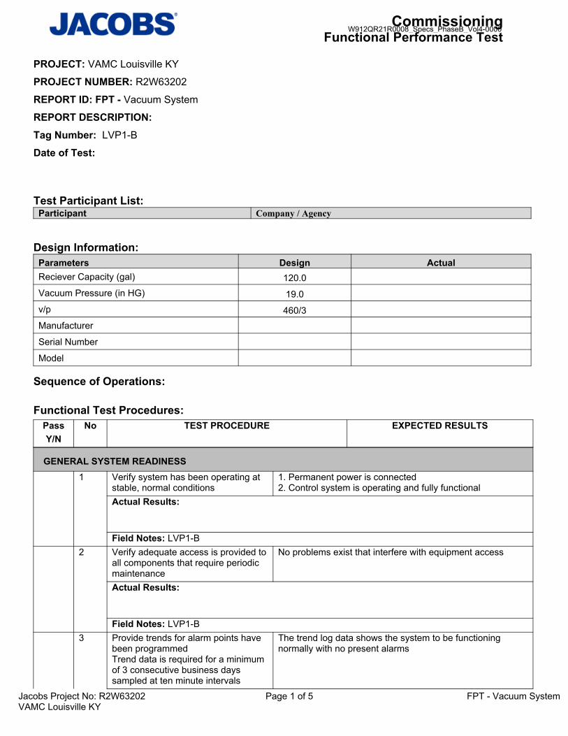
CommissioningFunctional Performance Test
Jacobs Project No: R2W63202 Page 1 of 5 FPT - Vacuum SystemVAMC Louisville KY
PROJECT: VAMC Louisville KY
PROJECT NUMBER: R2W63202
REPORT ID: FPT - Vacuum System
REPORT DESCRIPTION: Tag Number: LVP1-B
Date of Test:
Test Participant List:Participant Company / Agency
Design Information:Parameters Design ActualReciever Capacity (gal) 120.0Vacuum Pressure (in HG) 19.0v/p 460/3Manufacturer
Serial Number
Model
Sequence of Operations:
Functional Test Procedures:
PassY/N
No TEST PROCEDURE EXPECTED RESULTS
GENERAL SYSTEM READINESS1 Verify system has been operating at
stable, normal conditions1. Permanent power is connected2. Control system is operating and fully functional
Actual Results:
Field Notes: LVP1-B2 Verify adequate access is provided to
all components that require periodic maintenance
No problems exist that interfere with equipment access
Actual Results:
Field Notes: LVP1-B3 Provide trends for alarm points have
been programmedTrend data is required for a minimum of 3 consecutive business days sampled at ten minute intervals
The trend log data shows the system to be functioning normally with no present alarms
W912QR21R0008_Specs_PhaseB_Vol4-0000

CommissioningFunctional Performance Test
Jacobs Project No: R2W63202 Page 2 of 5 FPT - Vacuum SystemVAMC Louisville KY
Actual Results:
Field Notes: LVP1-B
VERIFICATION OF ALARMS4 For each pump and while the vacuum
system is enabled, test the vacuum system failure alarm by switching the lead pump HOA from the "Auto" position to the "Off" positionVerify that the lag pump enables oncethe lead pump is disabledNote: Alternation of pumps will need to be performed in order to test the lag pump fault and standby control
1. Lead vacuum pump is disabled2. Lag pump is enabled3. Failure alarm is generated at the ECC workstation
Actual Results:
Field Notes: LVP1-B5 After failure alarms and standby
control has been verified, return both HOA switches back to the "Auto" positions
1. Failure alarms are cleared at the ECC workstation2. Vacuum system resumes normal operation
Actual Results:
Field Notes: LVP1-B6 For each pump and while the vacuum
system is enabled, test the Lag In Use alarm by switching the lag pump HOA from the "Auto" position to the "On" positionNote: Alternation of pumps will need to be performed in order to test the lag pump fault and standby control
1. Lag vacuum pump is enabled2. Lag In Use alarm is generated at the ECC workstation
Actual Results:
Field Notes: LVP1-B7 After failure alarms have been
verified, return both HOA switches back to the "Auto" positions
1. Failure alarms are cleared at the ECC workstation2. Vacuum system resumes normal operation
Actual Results:
Field Notes: LVP1-B
W912QR21R0008_Specs_PhaseB_Vol4-0000

CommissioningFunctional Performance Test
Jacobs Project No: R2W63202 Page 3 of 5 FPT - Vacuum SystemVAMC Louisville KY
8 From the vacuum system local control panel, verify the high system pressure alarm by lowering the high pressure alarm setpoint below the actual system pressureVerify a fault condition is displayed at the local control panel
Fault alarm is displayed at the ECC workstation
Actual Results:
Field Notes: LVP1-B9 From the vacuum system local
control panel, return the high pressure alarm setpoint back to the origional value
Fault alarm is cleared at the ECC workstation
Actual Results:
Field Notes: LVP1-B10 From the vacuum system local
control panel, verify the low system pressure alarm by raising the low pressure alarm setpoint below the actual system pressureVerify a fault condition is displayed at the local control panel
Fault alarm is displayed at the ECC workstation
Actual Results:
Field Notes: LVP1-B11 From the vacuum system local
control panel, return the low pressure alarm setpoint back to the origional value
Fault alarm is cleared at the ECC workstation
Actual Results:
Field Notes: LVP1-B12 From the vacuum system local
control panel, verify the high system temperature alarm by lowering the high temperature alarm setpoint below the actual system temperatureVerify a fault condition is displayed at the local control panel
Fault alarm is displayed at the ECC workstation
Actual Results:
Field Notes: LVP1-B13 From the vacuum system local
control panel, return the high temperature alarm setpoint back to the origional value
Fault alarm is cleared at the ECC workstation
W912QR21R0008_Specs_PhaseB_Vol4-0000

CommissioningFunctional Performance Test
Jacobs Project No: R2W63202 Page 4 of 5 FPT - Vacuum SystemVAMC Louisville KY
Actual Results:
Field Notes: LVP1-B
NORMAL OPERATION14 From the vacuum system bleed valve
and with the system pressure setpointsatisfied, verify system pressure control by slowly opening the bleed valve allowing the system pressure todecreaseObserve and record the pressure thatthe lead pump is enabledVerify that the lead pump enables at the "lead cut-in" pressure setpoint and continues to run for at least 10min
After the system pressure decreases to the "lead cut-in" pressure setpoint, the lead vacuum pump is enabled and continues to run for at least 10min
Actual Results:
Field Notes: LVP1-B15 After verification of "lead cut-in" and
with the lead pump running, slowly close the bleed valve until the systempressure lowers below the "cut-out" setpointVerify that after a 10min delay, the lead pump is disabled
After the system pressure increases to the "lead cut-out" pressure setpoint, the lead vacuum pump is disabled
Actual Results:
Field Notes: LVP1-B16 From the vacuum system bleed valve
and with the system pressure setpointsatisfied, verify system lead/lag control by slowly opening the bleed valve allowing the system pressure toincrease until the lead compressor is enabledContinue to bleed air back into the system until the lag compressor is enabledVerify that the lag pump enables at the "lag cut-in" pressure setpoint and continues to run for at least 10min
1. Lead vacuum pump is enabled at the lead cut-in setpoint.2. After the system pressure decreases to the "lag cut-in" pressure setpoint, the lag vacuum pump is enabled and continues to run for at least 10min
Actual Results:
Field Notes: LVP1-B
W912QR21R0008_Specs_PhaseB_Vol4-0000

CommissioningFunctional Performance Test
Jacobs Project No: R2W63202 Page 5 of 5 FPT - Vacuum SystemVAMC Louisville KY
17 After verification of " lag cut-in" and with the lead and lag pumps running, slowly close the bleed valve until the system pressure lowers below the "lag cut-out" setpointVerify that after a 10min delay, the lead and lag pumps disable at their cut-out setpoints.
After the system pressure increases to their cut-out pressures, both vacuum pumps are disabled
Actual Results:
Field Notes: LVP1-B
RETURN TO NORMAL OPERATION18 From the vacuum system control
panel, return all manipulation and setpoints back to their original value vacuum system returns to normal operations.
Lab vacuum system resumes normal operation
Actual Results:
Field Notes: LVP1-B
Documents Attached:
END OF TEST
Comments:
ACCEPTANCE OF TEST:
Owner Representative:
General Contractor Representative:
Mechanical Contractor Representative:
Controls Contractor Representative:
Commissioning Authority:
W912QR21R0008_Specs_PhaseB_Vol4-0000
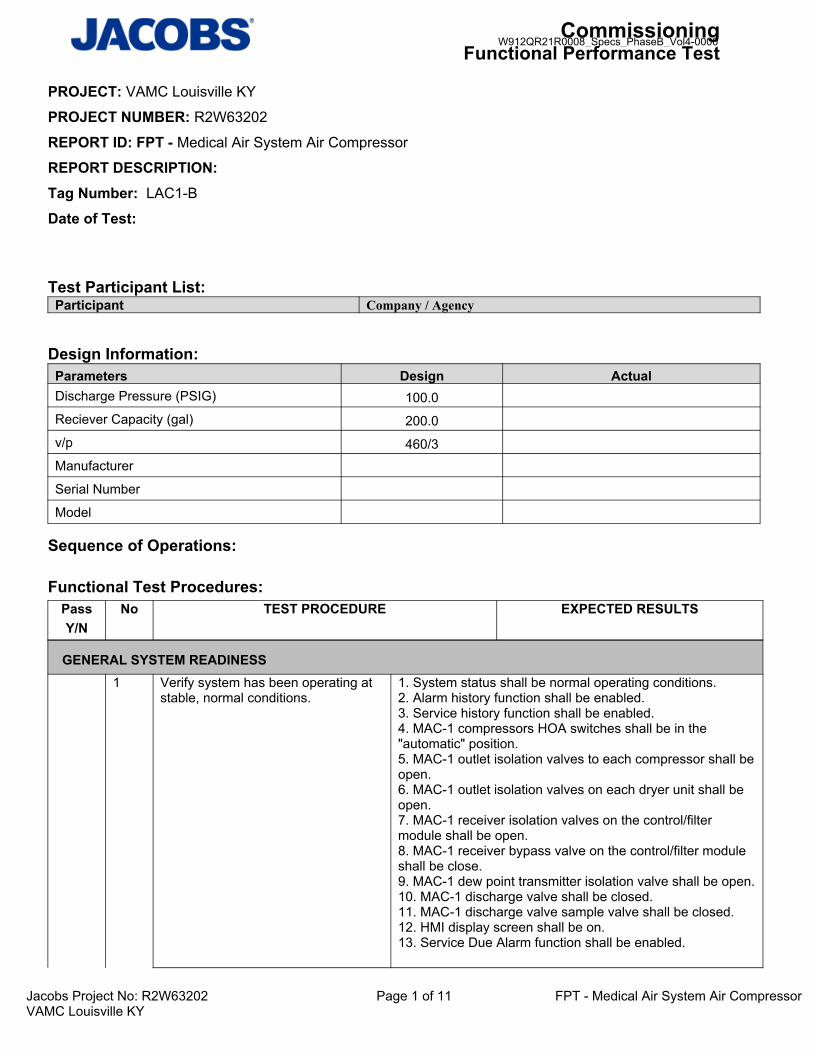
CommissioningFunctional Performance Test
Jacobs Project No: R2W63202 Page 1 of 11 FPT - Medical Air System Air CompressorVAMC Louisville KY
PROJECT: VAMC Louisville KY
PROJECT NUMBER: R2W63202
REPORT ID: FPT - Medical Air System Air Compressor
REPORT DESCRIPTION: Tag Number: LAC1-B
Date of Test:
Test Participant List:Participant Company / Agency
Design Information:Parameters Design ActualDischarge Pressure (PSIG) 100.0Reciever Capacity (gal) 200.0v/p 460/3Manufacturer
Serial Number
Model
Sequence of Operations:
Functional Test Procedures:
PassY/N
No TEST PROCEDURE EXPECTED RESULTS
GENERAL SYSTEM READINESS1 Verify system has been operating at
stable, normal conditions.1. System status shall be normal operating conditions.2. Alarm history function shall be enabled.3. Service history function shall be enabled.4. MAC-1 compressors HOA switches shall be in the "automatic" position.5. MAC-1 outlet isolation valves to each compressor shall beopen.6. MAC-1 outlet isolation valves on each dryer unit shall be open.7. MAC-1 receiver isolation valves on the control/filter module shall be open.8. MAC-1 receiver bypass valve on the control/filter module shall be close.9. MAC-1 dew point transmitter isolation valve shall be open.10. MAC-1 discharge valve shall be closed.11. MAC-1 discharge valve sample valve shall be closed.12. HMI display screen shall be on.13. Service Due Alarm function shall be enabled.
W912QR21R0008_Specs_PhaseB_Vol4-0000

CommissioningFunctional Performance Test
Jacobs Project No: R2W63202 Page 2 of 11 FPT - Medical Air System Air CompressorVAMC Louisville KY
Actual Results:
Field Notes: LAC1-B
NORMAL OPERATION2 Place MAC-1 into off mode via PLC
panel.1. MAC-1 shall de-energize.2. HOA indicating lights shall indicate MAC-1 compressors 1-3 are in the off position.
Actual Results:
Field Notes: LAC1-B3 While MAC-1 in off mode, turn HOA
switch momentarily into "hand" and "off" position to compressor 1 to verifycorrect rotation.
1. MAC-1 compressor 1 shall have correct rotation as listed in belt guard and compressor sheave.
Actual Results:
Field Notes: LAC1-B4 Turn HOA switch momentarily into
"hand" and "off" position to compressor 2 to verify correct rotation.
1. MAC-1 compressor 2 shall have correct rotation as listed in belt guard and compressor sheave.
Actual Results:
Field Notes: LAC1-B5 Turn HOA switch momentarily into
"hand" and "off" position to compressor 3 to verify correct rotation.
1. MAC-1 compressor 3 shall have correct rotation as listed in belt guard and compressor sheave.
Actual Results:
Field Notes: LAC1-B6 Return MAC-1 into automatic mode
via PLC panel.MAC-1 shall sequence compressors to maintain system pressure.
Actual Results:
Field Notes: LAC1-B7 While MAC-1 in auto mode, exhaust
system pressure such lead compressor (as recorded in step2) runs continuously for 17 minutes and allow system pressure not decrease less than __PSI.
1. After lead compressor runs continuously for 17 minutes, lag compressor 1 shall energize to maintain system pressure and lead compressor shall de-energize
W912QR21R0008_Specs_PhaseB_Vol4-0000

CommissioningFunctional Performance Test
Jacobs Project No: R2W63202 Page 3 of 11 FPT - Medical Air System Air CompressorVAMC Louisville KY
Actual Results:
Field Notes: LAC1-B8 Continue to exhaust system pressure
such lag compressor 1 (as recorded in step 9) runs continuously for 17 minutes and allow system pressure not decrease less than __PSI.
1. After lag compressor 1 runs continuously for 17 minutes, lag compressor 2 shall energize to maintain system pressure and operating lag compressor 1 shall deenergize.
Actual Results:
Field Notes: LAC1-B9 Continue to exhaust system pressure
such lag compressor 2 (as recorded in step 10) runs continuously for 17 minutes and allow system pressure not decrease less than __PSI.
1. After lag compressor 2 runs continuously for 17 minutes, lag compressor 3 shall energize to maintain system pressure and operating lag compressor 2 shall deenergize.
Actual Results:
Field Notes: LAC1-B11 Continue to exhaust system pressure
(as recorded in step 10) and allow system pressure to decline to __PSI.
1. Lag compressor shall energize in conjunction with operating compressors to maintain system pressure.2. MAC-1 Lag (visual) Alarm shall be generated at the PLC and HMI Panel.3. MAC-1 Lag (auditory) Alarm shall be generated at the PLC Panel.
Actual Results:
Field Notes: LAC1-B12 Continue to decrease system
pressure (as recorded in step 10) andallow system pressure to decline to __PSI.
1. Lag compressor shall energize in conjunction with operating compressors to maintain system pressure.2. MAC-1 Lag (visual) Alarm shall be generated at the PLC and HMI Panel.3. MAC-1 Lag (auditory) Alarm shall be generated at the PLC Panel.
Actual Results:
Field Notes: LAC1-B13 Continue to decrease system
pressure (as recorded in step 10) andallow system pressure to decline to __PSI.
1. Lag compressor shall energize in conjunction with operating compressors to maintain system pressure.2. MAC-1 Lag (visual) Alarm shall be generated at the PLC and HMI Panel.3. MAC-1 Lag (auditory) Alarm shall be generated at the PLC Panel.
Actual Results:
Field Notes: LAC1-B
W912QR21R0008_Specs_PhaseB_Vol4-0000

CommissioningFunctional Performance Test
Jacobs Project No: R2W63202 Page 4 of 11 FPT - Medical Air System Air CompressorVAMC Louisville KY
14 Suspend exhaust procedure and allow system pressure to achieve original system pressure set point.
1. MAC-1 compressors shall remain energized in conjunction with operating compressor until original system pressure set point been achieved.2. After system pressure set point has been achieved Audio and visual "MAC-1 Lag Alarm" shall be acknowledged and reset at the PLC and HMI Panel.
Actual Results:
Field Notes: LAC1-B15 Exhaust system pressure such MAC-
1 energizes lead compressor.MAC-1 lead compressor shall be energized
Actual Results:
Field Notes: LAC1-B16 While compressor energized, modify
High Air Temperature Shutdown alarm set point 50F below operating temperature to lead compressor via PLC Panel.
1. Lag compressor 1 shall energize to maintain original system pressure set point.2. Lead compressor (as recorded in step2) shall de-energize.3. MAC-1 High Air Temperature Shutdown (visual) Alarm shall be generated at the PLC and HMI Panel.4. MAC-1 High Air Temperature Shutdown (auditory)
Actual Results:
Field Notes: LAC1-B17 Return modified lead compressor
"High Temperature Alarm" set point back to original alarm set point.
Audio and visual "MAC-1 High Air Temperature Shutdown Alarm" shall beacknowledged and reset at the PLC and HMI Panel
Actual Results:
Field Notes: LAC1-B18 Continue to exhaust system pressure
such "energized" lag compressor 1 remains operating to maintain systempressure set point.
Lag compressor 1 shall be energized
Actual Results:
Field Notes: LAC1-B19 While lag compressor energized,
modify High Air Temperature Shutdown alarm set point 50F below operating temperature.
1. Lag compressor 2 shall energize to maintain original system pressure set point.2. Lag compressor1 shall de-energize.3. MAC-1 High Air Temperature Shutdown (visual) Alarm shall be generated at the PLC and HMI Panel.4. MAC-1 High Air Temperature Shutdown (auditory) Alarm shall be generated at the PLC Panel.
Actual Results:
Field Notes: LAC1-B
W912QR21R0008_Specs_PhaseB_Vol4-0000

CommissioningFunctional Performance Test
Jacobs Project No: R2W63202 Page 5 of 11 FPT - Medical Air System Air CompressorVAMC Louisville KY
20 Return modified lag compressor 2 "High Temperature Alarm" set point back to original alarm set point.
1. Audio and visual "MAC-1 High Air Temperature ShutdownAlarm" shall beacknowledged and reset at the PLC and HMI Panel.
Actual Results:
Field Notes: LAC1-B21 Continue to exhaust system pressure
such "energized" lag compressor 2 remains operating to maintain systempressure set point.
1. Lag compressor 2 shall be energized.
Actual Results:
Field Notes: LAC1-B22 While lag compressor 2 energized,
modify High Air Temperature Shutdown alarm set point 50F below operating temperature
1. Lag compressor 3 shall energize to maintain original system pressure set point.2. Lag compressor2 shall de-energize.3. MAC-1 High Air Temperature Shutdown (visual) Alarm shall be generated at the PLC and HMI Panel.4. MAC-1 High Air Temperature Shutdown (auditory) Alarm shall be generated at the PLC Panel.
Actual Results:
Field Notes: LAC1-B23 Return modified lag compressor
"High Temperature Alarm" set point back to original alarm set point.
1. Audio and visual "MAC-1 High Air Temperature ShutdownAlarm" shall beacknowledged and reset at the PLC and HMI Panel.
Actual Results:
Field Notes: LAC1-B24 Continue to exhaust system pressure
and allow system pressure to decline to __PSI.
1. MAC-1 compressors shall energize in conjunction with operating compressor to maintain system pressure.2. MAC-1 Lag (visual) Alarm shall be generated at the PLC and HMI Panel.3. MAC-1 Lag (auditory) Alarm shall be generated at the PLC Panel.
Actual Results:
Field Notes: LAC1-B
W912QR21R0008_Specs_PhaseB_Vol4-0000

CommissioningFunctional Performance Test
Jacobs Project No: R2W63202 Page 6 of 11 FPT - Medical Air System Air CompressorVAMC Louisville KY
25 While compressors 1-3 are energizedto maintain system pressure, simulateMotor Overload Shutdown alarm to compressor 1 via disconnecting starter feedback signal to the HMI Panel.
1. MAC-1 shall de-energize compressor 1.2. MAC-1 shall disable compressor 1 out of normal sequence of operation.3. MAC-1 Motor Overload Shutdown (visual) Alarm shall be generated at the PLC and HMI Panel.4. MAC-1 Motor Overload Shutdown (auditory) Alarm shall be generated at the PLC Panel.5. MAC-1 Failed Start (visual) Alarm shall be generated at the PLC and HMI Panel.6. MAC-1 Failed Start (auditory) Alarm shall be generated atthe PLC Panel.7. MAC-1 Lag (visual) Alarm shall remain active at the PLC and HMI Panel.8. MAC-1 Lag (auditory) Alarm shall remain active at the PLC Panel.
Actual Results:
Field Notes: LAC1-B26 While compressors 2 and 3 are
energized to maintain system pressure, simulate Motor Overload Shutdown alarm to compressor 2 via disconnecting starter feedback signal to the HMI Panel.
1. MAC-1 shall de-energize compressor 2.2. MAC-1 shall disable compressor 2 out of normal sequence of operation.3. MAC-1 Motor Overload Shutdown (visual) Alarm shall remain active at the PLC and HMI Panel.4. MAC-1 Motor Overload Shutdown (auditory) Alarm shall remain active at the PLC Panel.5. MAC-1 Lag (visual) Alarm shall remain active at the PLC and HMI Panel.6. MAC-1 Lag (auditory) Alarm shall remain active at the PLC Panel.7. MAC-1 Failed Start (visual) Alarm shall remain active at the PLC and HMI Panel.8. MAC-1 Failed Start (auditory) Alarm shall remain active atthe PLC Panel.
Actual Results:
Field Notes: LAC1-B27 While compressor 3 is energized to
maintain system pressure, simulate Motor Overload Shutdown alarm to compressor 3 via disconnecting starter feedback signal to the HMI Panel.
1. MAC-1 shall de-energize compressor 3.2. MAC-1 shall disable compressor 3 out of normal sequence of operation.3. MAC-1 Motor Overload Shutdown (visual) Alarm shall remain active at the PLC and HMI Panel.4. MAC-1 Motor Overload Shutdown (auditory) Alarm shall remain active at the PLC Panel.5. MAC-1 Lag (visual) Alarm shall remain active at the PLC and HMI Panel.6. MAC-1 Lag (auditory) Alarm shall remain active at the PLC Panel.7. MAC-1 Failed Start (visual) Alarm shall remain active at the PLC and HMI Panel.8. MAC-1 Failed Start (auditory) Alarm shall remain active atthe PLC Panel.
W912QR21R0008_Specs_PhaseB_Vol4-0000
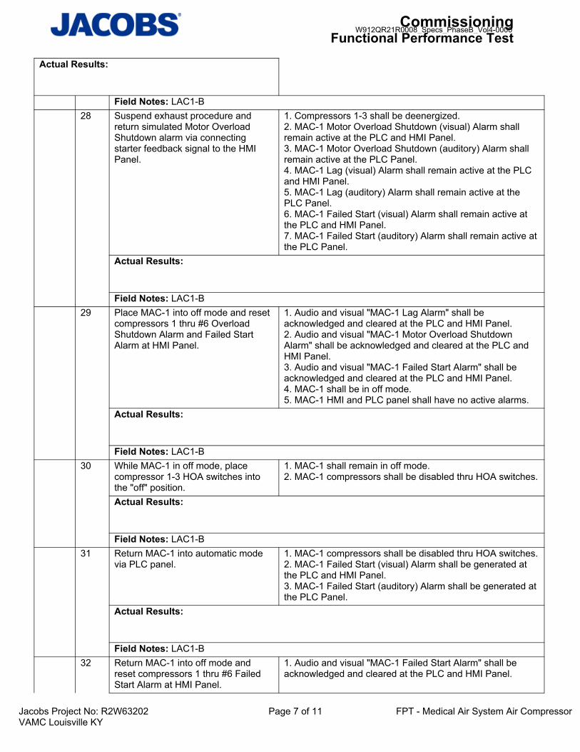
CommissioningFunctional Performance Test
Jacobs Project No: R2W63202 Page 7 of 11 FPT - Medical Air System Air CompressorVAMC Louisville KY
Actual Results:
Field Notes: LAC1-B28 Suspend exhaust procedure and
return simulated Motor Overload Shutdown alarm via connecting starter feedback signal to the HMI Panel.
1. Compressors 1-3 shall be deenergized.2. MAC-1 Motor Overload Shutdown (visual) Alarm shall remain active at the PLC and HMI Panel.3. MAC-1 Motor Overload Shutdown (auditory) Alarm shall remain active at the PLC Panel.4. MAC-1 Lag (visual) Alarm shall remain active at the PLC and HMI Panel.5. MAC-1 Lag (auditory) Alarm shall remain active at the PLC Panel.6. MAC-1 Failed Start (visual) Alarm shall remain active at the PLC and HMI Panel.7. MAC-1 Failed Start (auditory) Alarm shall remain active atthe PLC Panel.
Actual Results:
Field Notes: LAC1-B29 Place MAC-1 into off mode and reset
compressors 1 thru #6 Overload Shutdown Alarm and Failed Start Alarm at HMI Panel.
1. Audio and visual "MAC-1 Lag Alarm" shall be acknowledged and cleared at the PLC and HMI Panel.2. Audio and visual "MAC-1 Motor Overload Shutdown Alarm" shall be acknowledged and cleared at the PLC and HMI Panel.3. Audio and visual "MAC-1 Failed Start Alarm" shall be acknowledged and cleared at the PLC and HMI Panel.4. MAC-1 shall be in off mode.5. MAC-1 HMI and PLC panel shall have no active alarms.
Actual Results:
Field Notes: LAC1-B30 While MAC-1 in off mode, place
compressor 1-3 HOA switches into the "off" position.
1. MAC-1 shall remain in off mode.2. MAC-1 compressors shall be disabled thru HOA switches.
Actual Results:
Field Notes: LAC1-B31 Return MAC-1 into automatic mode
via PLC panel.1. MAC-1 compressors shall be disabled thru HOA switches.2. MAC-1 Failed Start (visual) Alarm shall be generated at the PLC and HMI Panel.3. MAC-1 Failed Start (auditory) Alarm shall be generated atthe PLC Panel.
Actual Results:
Field Notes: LAC1-B32 Return MAC-1 into off mode and
reset compressors 1 thru #6 Failed Start Alarm at HMI Panel.
1. Audio and visual "MAC-1 Failed Start Alarm" shall be acknowledged and cleared at the PLC and HMI Panel.
W912QR21R0008_Specs_PhaseB_Vol4-0000

CommissioningFunctional Performance Test
Jacobs Project No: R2W63202 Page 8 of 11 FPT - Medical Air System Air CompressorVAMC Louisville KY
Actual Results:
Field Notes: LAC1-B33 Place MAC-1 into automatic mode via
PLC panel.1. MAC-1 compressors shall sequence to maintain original system pressure.
Actual Results:
Field Notes: LAC1-B
ALARMS10 Continue to decrease system
pressure (as recorded in step 10) andallow system pressure to decline to __PSI.
1. Lag compressor shall energize in conjunction with operating compressor tomaintain system pressure.
Actual Results:
Field Notes: LAC1-B48 Simulate "PLC Failure" via
disconnecting communications to PLC Panel.
1. MAC-1 shall continue to operate under normal conditions thru Backup Pressure Switch.2. MAC-1 system pressure value at HMI Panel shall read "0PSIG"
Actual Results:
Field Notes: LAC1-B49 Exhaust system pressure to __PSI. 1. Compressors 1 and 3 shall energize after backup
pressure transducer detects __PSI differential pressure between system original pressure set point and actual system pressure value.2. MAC-1 compressor 3 shall remain disabled thru PLC Panel.
Actual Results:
Field Notes: LAC1-B50 Suspend exhaust procedure and
allow compressors 1 and 3 to achievesystem pressure set point.
1. Compressors 1 and 2 shall remain energized until system pressure set point has been achieved.
Actual Results:
Field Notes: LAC1-B51 Return simulated "PLC Failure" via
reconnecting communications back toPLC Panel.
1. Pressure transducer signal at PLC Panel shall return to normal operating pressure value
Actual Results:
Field Notes: LAC1-B
W912QR21R0008_Specs_PhaseB_Vol4-0000

CommissioningFunctional Performance Test
Jacobs Project No: R2W63202 Page 9 of 11 FPT - Medical Air System Air CompressorVAMC Louisville KY
MANUAL OPERATIONAL VERIFICATION34 Place MAC-1 into off mode via PLC
panel.1. MAC-1 shall de-energize.2. HOA indicating lights shall indicate MAC-1 compressors are in the off position.
Actual Results:
Field Notes: LAC1-B35 Place compressor 1 HOA switch into
the hand position.1. Compressor 1 shall energize to maintain system pressureset point
Actual Results:
Field Notes: LAC1-B36 Allow compressor 1 to achieve
system pressure set point.1. System pressure shall be normal.2. Compressor 1 shall de-energize after system pressure setpoint has been achieved.
Actual Results:
Field Notes: LAC1-B37 Exhaust system pressure to __PSI. 1. Compressor 1 shall energize after backup pressure
transducer detects __PSI differential pressure between system original pressure set point and actual system pressure value.
Actual Results:
Field Notes: LAC1-B38 Suspend exhaust procedure and
allow compressor 1 to achieve system pressure set point after system pressure set point been achieved return compressor 1 HOA into auto position.
1. System pressure shall be normal.2. Compressor 1 shall de-energize after system pressure setpoint has been achieved.
Actual Results:
Field Notes: LAC1-B39 Place compressor 2 HOA switch into
the hand position.1. Compressor 2 shall energize to maintain system pressureset point
Actual Results:
Field Notes: LAC1-B40 Allow compressor 2 to achieve
system pressure set point.1. System pressure shall be normal.2. Compressor 2 shall de-energize after system pressure setpoint has been achieved.
W912QR21R0008_Specs_PhaseB_Vol4-0000

CommissioningFunctional Performance Test
Jacobs Project No: R2W63202 Page 10 of 11 FPT - Medical Air System Air CompressorVAMC Louisville KY
Actual Results:
Field Notes: LAC1-B41 Exhaust system pressure to __PSI. 1. Compressor 2 shall energize after backup pressure
transducer detects __PSI differential pressure between system original pressure set point and actual system pressure value.
Actual Results:
Field Notes: LAC1-B42 Suspend exhaust procedure and
allow compressor 2 to achieve system pressure set point after system pressure set point been achieved return compressor 2 HOA into auto position.
1. System pressure shall be normal.2. Compressor 2 shall de-energize after system pressure setpoint has been achieved.
Actual Results:
Field Notes: LAC1-B43 Place compressor 3 HOA switch into
the hand position.1. Compressor 3 shall energize to maintain system pressureset point.
Actual Results:
Field Notes: LAC1-B44 Allow compressor 3 to achieve
system pressure set point.1. System pressure shall be normal.2. Compressor 3 shall de-energize after system pressure setpoint has been achieved.
Actual Results:
Field Notes: LAC1-B45 Exhaust system pressure to __PSI. 1. Compressor 3 shall energize after backup pressure
transducer detects __PSI differential pressure between system original pressure set point and actual system pressure value.
Actual Results:
Field Notes: LAC1-B46 Suspend exhaust procedure and
allow compressor 3 to achieve system pressure set point after system pressure set point been achieved return compressor 3 HOA into automatic position.
1. System pressure shall be normal.2. Compressor 3 shall de-energize after system pressure setpoint has been achieved.
W912QR21R0008_Specs_PhaseB_Vol4-0000

CommissioningFunctional Performance Test
Jacobs Project No: R2W63202 Page 11 of 11 FPT - Medical Air System Air CompressorVAMC Louisville KY
Actual Results:
Field Notes: LAC1-B47 Return MAC-1 into automatic mode
via PLC panel.1. MAC-1 compressors 1-3 HOA switches shall be in the automatic position.2. MAC-1 shall energize and sequence compressors to maintain system pressure.
Actual Results:
Field Notes: LAC1-B
RETURN TO NORMAL OPERATION52 Verify MAC-1 is operating under
stable normal conditions.1. MAC-1 shall be operating in normal stable conditions.
Actual Results:
Field Notes: LAC1-B
Documents Attached:
END OF TEST
Comments:
ACCEPTANCE OF TEST:
Owner Representative:
General Contractor Representative:
Mechanical Contractor Representative:
Controls Contractor Representative:
Commissioning Authority:
W912QR21R0008_Specs_PhaseB_Vol4-0000

CommissioningFunctional Performance Test
Jacobs Project No: R2W63202 Page 1 of 3 FPT - Sump PumpVAMC Louisville KY
PROJECT: VAMC Louisville KY
PROJECT NUMBER: R2W63202
REPORT ID: FPT - Sump Pump
REPORT DESCRIPTION: Tag Number: ESP1-B
Date of Test:
Test Participant List:Participant Company / Agency
Design Information:Parameters Design ActualRPM 3450.0Motor HP 0.5Flow Rate (GPM) 100.0Head (ft) 38.0Temperature (°F) 60.0v/p 115/1Manufacturer
Serial Number
Model
Sequence of Operations:
Functional Test Procedures:
PassY/N
No TEST PROCEDURE EXPECTED RESULTS
GENERAL SYSTEM READINESS1 Verify system has been operating at
stable, normal conditions1. Permanent power is connected2. Control system is operating and fully functional3. Record current water level
Actual Results:
Field Notes: ESP1-B2 Verify adequate access is provided to
all components that require periodic maintenance
No problems exist that interfere with equipment access
W912QR21R0008_Specs_PhaseB_Vol4-0000

CommissioningFunctional Performance Test
Jacobs Project No: R2W63202 Page 2 of 3 FPT - Sump PumpVAMC Louisville KY
Actual Results:
Field Notes: ESP1-B3 Verify alarm panel is accessible from
elevator doorsNo problems exist that interfere with visual access to alarm LEDs
Actual Results:
Field Notes: ESP1-B
VERIFICATION OF ALARMS4 Verify individual LED indicator lights
are active for each condition1. LED for oil in the sump2. LED for high liquid level in the sump3. LED for high amps or locked rotor motor condition4. LED for electric power to the panel5. LED for pump activation
Actual Results:
Field Notes: ESP1-B
NORMAL OPERATION5 Add water to the sump to simulate
rising liquid level for pump activation1. Liquid rise in sump raises float switch2. Float switch activates pump3. LED indicates pump operation
Actual Results:
Field Notes: ESP1-B6 Add water to the sump to reach high
water alarm float level1. High water alarm activates2. LED indicates high liquid level in the sump3. Alarm signal is received at BAS4. High water level warning horn buzzer is activated5. If pump is not already on, pump activates on high water level6. High water level warning horn buzzer is silenced with alarm silencing switch
Actual Results:
Field Notes: ESP1-B7 All pump to remove water from sump
to reduce liquid level to reduce liquid level below the high water alarm level
1. High water alarm deactivates2. LED for high liquid level in the sump is off3. Alarm signal to BAS is off4. Pump remains on
Actual Results:
Field Notes: ESP1-B8 Remove water from sump to reduce
liquid level below the float level1. Pump turns off2. LED for pump activation is off
W912QR21R0008_Specs_PhaseB_Vol4-0000

CommissioningFunctional Performance Test
Jacobs Project No: R2W63202 Page 3 of 3 FPT - Sump PumpVAMC Louisville KY
Actual Results:
Field Notes: ESP1-B
RETURN TO NORMAL OPERATION9 Verify the sump pump returns to
normal operationsReturn any changed parameters to their original value
1. Alarm LEDs are off2. Pump is off3. Liquid level is below float activation level
Actual Results:
Field Notes: ESP1-B
Documents Attached:
END OF TEST
Comments:
ACCEPTANCE OF TEST:
Owner Representative:
General Contractor Representative:
Mechanical Contractor Representative:
Controls Contractor Representative:
Commissioning Authority:
W912QR21R0008_Specs_PhaseB_Vol4-0000

CommissioningFPT
Jacobs Project No: F3W80021 Page 1 of 9 FPT- Domestic Water Booster PumpUTMB Webster
PROJECT: UTMB Webster
PROJECT NUMBER: F3W80021
REPORT ID: FPT- Domestic Water Booster Pump
REPORT DESCRIPTION:
Design Information:Parameters Design Actual
References:
Procedures:
PassY/N
No TEST PROCEDURE EXPECTED RESULTS
GENERAL SYSTEM READINESS1 Verify adequate access is provided to
all components that require periodic maintenance.
Unit and associated components are accessible for service
Actual Results:
Field Notes: 2 Verify system has been operating at
stable, normal conditions and all test pre-requisites have been satisfied
Trends provided.System has been operating at stable, normal conditions.
Actual Results:
Field Notes: 3 If the system is integrated to the BAS,
verify trend graphs for each point listed below. Trend data is required for a minimum of 3 consecutive business days sampled at 5 minute intervals.
DWP-4 Speed/StatusDWP-5 Speed/StatusDWP-6 Speed/StatusDischarge PressureDischarge Pressure Set pointGeneral Alarm
Actual Results:
Field Notes:
W912QR21R0008_Specs_PhaseB_Vol4-0000

CommissioningFPT
Jacobs Project No: F3W80021 Page 2 of 9 FPT- Domestic Water Booster PumpUTMB Webster
VERIFICATION OF ALARMS4 At the pump skid human machine
interface (HMI), enter the system setup screen and notate the current low water pressure setpoint in field notes. Once the current setpoint is noted, adjust the low pressure set point higher than the current operating pressure.Verify that pump(s) enable and a low suction pressure alarm is received at the HMI, BAS, and that a local panel buzzer/strobe alarm enables in the space. Once verified, return the low pressuresetpoint back to its original value and ensure the unit resumes normal operation.
1. Low water pressure setpoint is noted in field notes below:____ 2. Low water pressure setpoint is adjusted above the currentoperating pressure:_____ 3. Booster set indexes 'fill mode and pump(s) enable:_____4. Low suction pressure alarm is indicated at the HMI:_____5. Low suction pressure alarm is indicated at the BAS:_____6. Common alarm received at the BAS:____7. Local panel buzzer/strobe activate in the space:____8. All points are accurately displayed at the HMI and BAS:___ 9. Once pressure is established above the low pressure setpoint, alarm will clear and system will resume normal operation:_____
Actual Results:
Field Notes: 5 At the pump skid human machine
interface (HMI), enter the system setup screen and notate the current high water pressure setpoint in field notes. Once the current setpoint is noted, adjust the high pressure set point lower than the current operating pressure.Verify that pump(s) disable and a high discharge pressure alarm is received at the HMI, BAS, and that a local panel buzzer/strobe alarm enables in the space. Once verified, return the high pressure setpoint back to its original value and ensure the unit resumes normal operation.
1. High water pressure setpoint is noted in field notes below:____2. High water pressure setpoint is adjusted below the currentoperating pressure:_____3. Booster set disables operational pumps:_____4. High discharge pressure alarm is indicated at the HMI:_____5. High discharge pressure alarm is indicated at the BAS:_____6. Common alarm received at the BAS:_____7. Local panel buzzer/strobe activate in the space:_____8. All points are accurately displayed at the HMI and BAS:____9. Once pressure is established below the high pressure setpoint, alarm will clear and system will resume normal operation:____
Actual Results:
Field Notes:
W912QR21R0008_Specs_PhaseB_Vol4-0000

CommissioningFPT
Jacobs Project No: F3W80021 Page 3 of 9 FPT- Domestic Water Booster PumpUTMB Webster
6 At the pump skid human machine interface (HMI), disconnect the pressure transducer to simulate a loss of signal. Verify that the booster set disables, a transducer failure alarm is received atthe HMI, a general alarm is indicated at the BAS, and that a local panel buzzer/strobe alarm enables in the space. Once verified, reattach the pressure transducer and ensure the unit resumes normal operation.
1. Pressure transducer is disconnected and loss of signal occurs:_____2. Booster set disables any operational pump:_____ 3. Transducer failure alarm is indicated at the HMI:_____4. General alarm is indicated at the BAS:_____5. All points are accurately displayed at the HMI and BAS:____6. Once the pressure transducer signal is re- established, alarm will clear and system resumes normal operation:_____
Actual Results:
Field Notes: 7 At the pump skid, simulate a power
supply failure to the set. Verify that the system enables emergency mode, and verify if a general alarm is reported to the BAS, and that a local panel buzzer/strobe alarm enables in the space. Once verified, re-establish power to the unit and verify system is able to resume normal operation.
1. Power supply failure to the set is simulated:____2. Unit indexes emergency mode:____3. General alarm contact is activated:____4. General alarm is indicated at the BAS:_____5. All points are accurately displayed at the HMI and BAS6. Once power is re- established, alarm will clear and system resumes normal operation
Actual Results:
Field Notes: 8 At the pump skid, simulate a no flow
shutdown scenario by restricting flow at a discharge. Verify that pumps disable, a no flow alarm is reported at the HMI, a general alarm to the BAS, and that a local panel buzzer/strobe alarm enables in the space. Once verified, re-establish flow at the unit and verify system is able to resume normal operation.
1. Discharge flow is restricted:____2. All active pumps disable:____ 3. No flow alarm is activated:____4. General alarm is indicated at the BAS:____5. All points are accurately displayed at the HMI and BAS:____6. Once alarm is cleared, system resumes normal operation:_____
Actual Results:
Field Notes:
W912QR21R0008_Specs_PhaseB_Vol4-0000
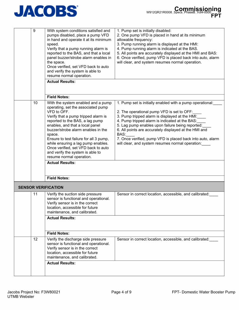
CommissioningFPT
Jacobs Project No: F3W80021 Page 4 of 9 FPT- Domestic Water Booster PumpUTMB Webster
9 With system conditions satisfied and pumps disabled, place a pump VFD in hand and operate it at its minimum speed. Verify that a pump running alarm is reported to the BAS, and that a local panel buzzer/strobe alarm enables in the space. Once verified, set VFD back to auto and verify the system is able to resume normal operation.
1. Pump set is initially disabled:2. One pump VFD is placed in hand at its minimum allowable frequency:3. Pump running alarm is displayed at the HMI:4. Pump running alarm is indicated at the BAS.5. All points are accurately displayed at the HMI and BAS:6. Once verified, pump VFD is placed back into auto, alarm will clear, and system resumes normal operation.
Actual Results:
Field Notes: 10 With the system enabled and a pump
operating, set the associated pump VFD to OFF. Verify that a pump tripped alarm is reported to the BAS, a lag pump enables, and that a local panel buzzer/strobe alarm enables in the space. Ensure to test failure for all 3 pump, while ensuring a lag pump enables.Once verified, set VFD back to auto and verify the system is able to resume normal operation.
1. Pump set is initially enabled with a pump operational:____
2. The operational pump VFD is set to OFF:____3. Pump tripped alarm is displayed at the HMI:____4. Pump tripped alarm is indicated at the BAS:____5. Lag pump enables upon failure being reported:____6. All points are accurately displayed at the HMI and BAS:____7. Once verified, pump VFD is placed back into auto, alarm will clear, and system resumes normal operation:____
Actual Results:
Field Notes:
SENSOR VERIFICATION11 Verify the suction side pressure
sensor is functional and operational.Verify sensor is in the correct location, accessible for future maintenance, and calibrated.
Sensor in correct location, accessible, and calibrated:____
Actual Results:
Field Notes: 12 Verify the discharge side pressure
sensor is functional and operational.Verify sensor is in the correct location, accessible for future maintenance, and calibrated.
Sensor in correct location, accessible, and calibrated:____
Actual Results:
W912QR21R0008_Specs_PhaseB_Vol4-0000

CommissioningFPT
Jacobs Project No: F3W80021 Page 5 of 9 FPT- Domestic Water Booster PumpUTMB Webster
Field Notes: 13 Verify the remote pressure sensor is
functional and operational.Verify sensor is in the correct location, accessible for future maintenance, and calibrated.
Sensor in correct location, accessible, and calibrated:____
Actual Results:
Field Notes:
MATERIAL START-UP14 With the system initially disabled,
verify that the booster set protection (remote stop and low water switch) features are not enabled, and that valves are open to ensure water circulation. Also, ensure the expansion tank valve is open and a part of the loop.
1. System is disabled:____2. Remote stop is not enabled:____3. Low water switch is not enabled:____4. Valves are open:____5. Expansion tank is integrated into the loop:____6. System is ready for operation:____
Actual Results:
Field Notes: 15 At the HMI system setup screen,
verify the current system operating values and note them below.
Pressure set point: _____ psiSoft Fill setpoint: ______ %Initial ramp time: _____ seconds
Actual Results:
Field Notes: 16 At the HMI pump arrangement
screen, verify the number of pumps associated with the system, and ensure the standby pump option is off. Also, record the frequency at which pumps operate when pressure transducer failure occurs.
Number of associated pumps: _____Standby Pump is set to OFF: ______ Y/NReference Loss Frequency: ___ % - Pumps disable during reference loss event.
Actual Results:
Field Notes: 17 At the HMI pump head and sleep
function screen, note the system values currently programmed.
Installed system controls differ from O&M, this does not lookto be applicable.
Actual Results:
Field Notes:
W912QR21R0008_Specs_PhaseB_Vol4-0000

CommissioningFPT
Jacobs Project No: F3W80021 Page 6 of 9 FPT- Domestic Water Booster PumpUTMB Webster
18 At the HMI stage off/on mode screen,verify that stage off/on modes are set to auto. Also, note the Pump stage on frequencies, pump stage off frequencies, and the system sleep frequency below. Also note if/which break tank selector option is being utilized.
Stage on mode: ____% pump speed with 10 second delayStage off mode: ____%pump speed for 30 secondsStage on setpoint: ______ %Stage off setpoint: ______ %Sleep frequency: _______ HzBreak Tank Selector mode: _______
Actual Results:
Field Notes: 19 At the human machine interface
(HMI), extract the current min/max frequencies, and also the current PID settings and note them below.
Min frequency: ________ HzMax frequency: ________ HzGain:____%Speed up limit:____%Speed down limit:____%
Actual Results:
Field Notes: 20 At the human machine interface
(HMI), record the current values usedfor the duty pump rotation function.
Boost period (helps force pump to sleep): ____ secDuty change: ____ hrsDelay start: ____ secDelay stop: ____ secHMI does not have similar setup as indicated on O&M – rotation will occur every 24 hrs.
Actual Results:
Field Notes:
NORMAL OPERATION21 At the skid, allow the system to
enable and record the current operating conditions of the pump skid.
Pressure set point: ______Current operating mode: ______Pump 1 status: ______Pump 2 status: ______ Pump 3 status: ______Common pump speed: ______
Actual Results:
Field Notes: 22 At the HMI, increase the pressure
setpoint and verify the operating VFD increases speed to achieve the desired setpoint.
1. Pressure setpoint is increased:____ Y/N2. Active pump increases speed to achieve pressure setpoint:_____Y/N3. All points are accurately displayed at the HMI and BAS:____ Y/N
Actual Results:
W912QR21R0008_Specs_PhaseB_Vol4-0000

CommissioningFPT
Jacobs Project No: F3W80021 Page 7 of 9 FPT- Domestic Water Booster PumpUTMB Webster
Field Notes: 23 At the HMI, decrease the pressure
setpoint and verify the operating VFD decreases speed to achieve the desired setpoint.
1. Pressure setpoint is decreased:____ Y/N2. Active pump decreases speed to achieve pressure setpoint:____Y/N3. All points are accurately displayed at the HMI and BAS:____ Y/N
Actual Results:
Field Notes: 24 With only one pump operating, adjust
the stage on frequency to a value above the current pump speed. Verify that a lag pump enables.
1. System is operating utilizing only one pump:____Y/N2. Stage on frequency is decreased to a value above the current pump frequency:____Y/N3. Lag pump enables after any start delay expires:____Y/N4. All points are accurately displayed at the HMI and BAS:____Y/N
Actual Results:
Field Notes: 25 With two pumps operating, adjust the
stage on frequency to a value above the current pump speed. Verify that the lag lag pump enables.
1. System is operating utilizing two pumps:____Y/N2. Stage on frequency is decreased to a value above the current pump frequency:____Y/N3. Lag lag pump enables after any start delay expires, with pump speeds operating in unison:____Y/N4. All points are accurately displayed at the HMI and BAS:____Y/N
Actual Results:
Field Notes: 26 With three pumps operating, adjust
the stage off frequency to a value below the current pump speed. Verify that the lag lag pump disables.
1. System is operating utilizing two pumps:____Y/N2. Stage on frequency is decreased to a value above the current pump frequency:____Y/N3. Lag lag pump enables after any start delay expires, with pump speeds operating in unison:____Y/N4. All points are accurately displayed at the HMI and BAS:____Y/N
Actual Results:
Field Notes: 27 With two pumps operating, adjust the
stage off frequency to a value below the current pump speed. Verify that the lag pump disables.
1. System is operating utilizing two pumps:____Y/N2. Stage off frequency is decreased to a value below the current pump frequency:____Y/N3. Lag pump disables after any stop delay expires, with pump speeds operating in unison:____Y/N4. All points are accurately displayed at the HMI and BAS:____Y/N
Actual Results:
W912QR21R0008_Specs_PhaseB_Vol4-0000
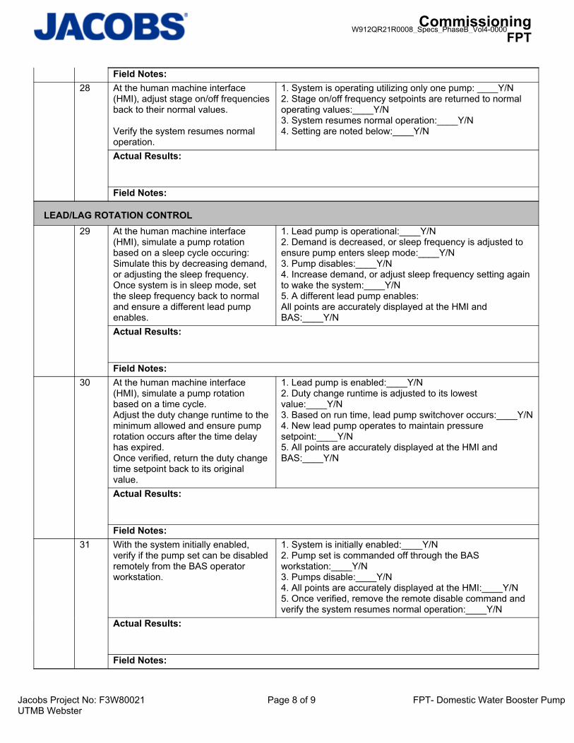
CommissioningFPT
Jacobs Project No: F3W80021 Page 8 of 9 FPT- Domestic Water Booster PumpUTMB Webster
Field Notes: 28 At the human machine interface
(HMI), adjust stage on/off frequenciesback to their normal values.
Verify the system resumes normal operation.
1. System is operating utilizing only one pump: ____Y/N2. Stage on/off frequency setpoints are returned to normal operating values:____Y/N3. System resumes normal operation:____Y/N4. Setting are noted below:____Y/N
Actual Results:
Field Notes:
LEAD/LAG ROTATION CONTROL29 At the human machine interface
(HMI), simulate a pump rotation based on a sleep cycle occuring:Simulate this by decreasing demand, or adjusting the sleep frequency. Once system is in sleep mode, set the sleep frequency back to normal and ensure a different lead pump enables.
1. Lead pump is operational:____Y/N2. Demand is decreased, or sleep frequency is adjusted to ensure pump enters sleep mode:____Y/N 3. Pump disables:____Y/N4. Increase demand, or adjust sleep frequency setting again to wake the system:____Y/N5. A different lead pump enables:All points are accurately displayed at the HMI and BAS:____Y/N
Actual Results:
Field Notes: 30 At the human machine interface
(HMI), simulate a pump rotation based on a time cycle.Adjust the duty change runtime to theminimum allowed and ensure pump rotation occurs after the time delay has expired. Once verified, return the duty change time setpoint back to its original value.
1. Lead pump is enabled:____Y/N2. Duty change runtime is adjusted to its lowest value:____Y/N3. Based on run time, lead pump switchover occurs:____Y/N4. New lead pump operates to maintain pressure setpoint:____Y/N5. All points are accurately displayed at the HMI and BAS:____Y/N
Actual Results:
Field Notes: 31 With the system initially enabled,
verify if the pump set can be disabled remotely from the BAS operator workstation.
1. System is initially enabled:____Y/N2. Pump set is commanded off through the BAS workstation:____Y/N3. Pumps disable:____Y/N4. All points are accurately displayed at the HMI:____Y/N 5. Once verified, remove the remote disable command and verify the system resumes normal operation:____Y/N
Actual Results:
Field Notes:
W912QR21R0008_Specs_PhaseB_Vol4-0000

CommissioningFPT
Jacobs Project No: F3W80021 Page 9 of 9 FPT- Domestic Water Booster PumpUTMB Webster
RETURN TO NORMAL32 Return all program logic, set points,
instrumentation, and control devices back to normal operation.
Unit resumes normal operation.
Actual Results:
Field Notes:
Documents Attached:
END OF TEST
Comments:
ACCEPTANCE OF TEST:
Owner Representative:
General Contractor Representative:
Mechanical Contractor Representative:
Controls Contractor Representative:
Commissioning Authority:
W912QR21R0008_Specs_PhaseB_Vol4-0000

Project No: R6W63300 Page 2 of 21 FPT_221113-01 BP Westlake 1 Central Utility Plant Phase 2 Duplex Fuel Oil Pump System
Functional Performance Test Prerequisites
Prerequisite Yes No Comments
1. Contractor QA/QC Testing Reports completed & submitted to CxA.
2. Factory Test Reports have been provided.
3. Pre Functional Checklist completed & signed off.
4. O&M Manuals submitted.
5. All circuits operated under load.
6. All 3rd Party NETA Testing has been completed.
7. Manufacturers startup has been completed
8. Coordination (Short Circuit) Study is completed, turned over to the Third party testing Agency and all breakers are set to correct settings.
Equipment Identification
Unit Identification Location (or Service)
DUPLEX FUEL OIL PUMP SYSTEM NORTH GARAGE RM-NG003
W912QR21R0008_Specs_PhaseB_Vol4-0000
MorellF
Typewritten Text
FUEL OIL PUMP FPT

Project No: R6W63300 Page 3 of 21 FPT_221113-01 BP Westlake 1 Central Utility Plant Phase 2 Duplex Fuel Oil Pump System
DIESEL FUEL PUMPING ASSEMBLY: Enclosed fuel transfer system shall consist of (2) supply pumps, (1) return pump, control panel, Enclosure and accessories for a complete operational package. Package shall include fully contained Free-standing weatherproof enclosure, UL508 listed controller with automatic operation, touch screen Graphical display, integral positive displacement fuel transfer pumps (3) each with inlet strainer and Gauges, integral differential pressure switch, flow proving controls, integral leak basin with leak switch, Sight flow indicator for quick operational assessment API 607 Fire safe isolation valves, schedule 40 Steel pipe and fittings. Pumps shall have a flow rate of 180 gallons per hour each at 50 psi, 1/2 HP, 115 volt single phase, 1” suction and 1” discharge connections, automatic alternator for (2) fuel supply Pumps complete with dry contacts for DDC connection for each pump status, enclosure shall be 48”Lx24”Wx48”H, manufactured by Cougar Sales, Inc. No. EFTS-180. Also, unit shall interface with Additional leak switch in drain pan for existing fuel pump box shown on the plumbing drawings. Provide dry contacts for leak detection to DDC system. Provide leak switch and all warring required for Complete operation system Sequence of operation: New fuel oil pumping system: Assembly shall interface with new emergency generator day tank. Assembly shall cut on (1) fuel Supply pump when generator cuts on. Fuel return pump shall cut on when generator day tank has Tank overflow level. The (2) fuel supply pumps shall alternate automatically with each run cycle. Supply Pumps shall cut off when generator cuts off. Return pump shall cut off when generator day tank Normal level is achieved (pumped down from overflow level). Leak detection interface with existing fuel oil pumping system: Panel shall cut off existing pumps if leak is detected in drain pan. The Existing pump controls shall be modified to incorporate the shutdown of pumps upon leak detection Indication.
W912QR21R0008_Specs_PhaseB_Vol4-0000

Project No: R6W63300 Page 4 of 21 FPT_221113-01 BP Westlake 1 Central Utility Plant Phase 2 Duplex Fuel Oil Pump System
Functional Test Procedures:
Pass Y/N
No TEST PROCEDURE EXPECTED RESULTS
GENERALSYSTEM READINESS
1 Verify Duplex pump controller with (2) supply pumps and (1) return pump has been installed fuel oil piping complete and electrical power provided and is ready for testing.
1. Duplex controller installed. Y N
2. (2) Supply pumps. Y N
3. (1) Return Pump. Y N
4. Fuel Oil Piping complete. Y N
5. Double wall piping. Y N
6. Piping connected to storage tank.
Y N
7. Piping connected to generator day tank.
Y N
8. Leak detection provided. Y N
9. Monitoring panel provided (Touch screen graphical display). Y N
10. 120vac circuit provided and connected to an emergency circuit. Y N
11. Ready for testing. Y N
Field Notes:
2 Verify all existing single wall piping has been replaced with new double wall piping.
Y N
Field Notes:
3 Verify (2) new 3” stainless steel drip pans with leak detection have been installed (1) at existing generator flexible fuel hoses and (1) at existing fuel oil pumping assembly.
1. Existing generator. Y N
2. Existing fuel oil pumping assembly.
Y N
Field Notes:
4 Verify (2) emergency vent fittings and (1) flash arrestor have been installed and mounted 12’ above ground level.
1. (2) Emergency vents fittings. Y N
2. (1) Flash arrestor. Y N
Field Notes:
W912QR21R0008_Specs_PhaseB_Vol4-0000

Project No: R6W63300 Page 5 of 21 FPT_221113-01 BP Westlake 1 Central Utility Plant Phase 2 Duplex Fuel Oil Pump System
Pass Y/N
No TEST PROCEDURE EXPECTED RESULTS
5 Verify the Fire Safety Valve with limit switch has been installed in the supply line near tap connection at the 2000gal storage tank.
Y N
Field Notes:
6 Verify new foot valve has been installed at existing 2000gal fuel oil storage tank.
Y N
Field Notes:
7 Verify (4) strainers have been installed. 1. Supply pumps FOS 2-1. Y N
2. Supply pumps FOS 2-2. Y N
3. Return pumps FOR 2-1. Y N
4. Bypass fuel oil piping header solenoid valve side.
Y N
Field Notes:
8 Verify (3) check valves have been installed.
1. Supply pumps FOS 2-1. Y N
2. Supply pumps FOS 2-2. Y N
3. Return pumps FOR 2-1. Y N
Field Notes:
9 Verify (5) manual isolation valves have been installed.
1. Supply pumps FOS 2-1. Y N
2. Supply pumps FOS 2-2. Y N
3. Return pumps FOR 2-1. Y N
4. Bypass fuel oil piping header (2).
Y N
Field Notes:
10 Verify continuous read level transmitter has been installed.
Y N
Field Notes:
W912QR21R0008_Specs_PhaseB_Vol4-0000

Project No: R6W63300 Page 6 of 21 FPT_221113-01 BP Westlake 1 Central Utility Plant Phase 2 Duplex Fuel Oil Pump System
Pass Y/N
No TEST PROCEDURE EXPECTED RESULTS
11 Verify solenoid valve has been installed in the bypass fuel oil header on the supply side.
Y N
Field Notes:
12 Verify pipe leak switch has been installed in double wall piping.
Y N
Field Notes:
13 Verify fuel detector switch has been installed.
Y N
Field Notes:
14 Verify sight glasses and flow gauges are installed.
Y N
Field Notes:
15 Verify fuel oil piping system has been hydrostatically tested at 100psi to check for leaks.
1. Tested for leaks at 100psi. Y N
2. System has no leaks. Y N
Field Notes:
16 1. Verify the fuel oil piping system has been thoroughly flushed with diesel fuel to remove all moisture and debris.
2. Fuel oil piping system after flushing has been filled with fuel with end valves closed.
1. Y N
2. Y N
Field Notes:
17 Verify generator installation is complete and the 2000gal fuel oil storage tank is full of fuel and ready for testing.
1. Generator installation complete.
Y N
2. Storage tank full of fuel. Y N
3. Ready for testing. Y N
Field Notes:
W912QR21R0008_Specs_PhaseB_Vol4-0000

Project No: R6W63300 Page 7 of 21 FPT_221113-01 BP Westlake 1 Central Utility Plant Phase 2 Duplex Fuel Oil Pump System
Pass Y/N
No TEST PROCEDURE EXPECTED RESULTS
18 Verify Wiring to DDC has been installed from fuel oil pump controller for status and alarms.
Y N
Field Notes:
TOUCH SCREEN GRAPHICAL DISPLAY
19 Verify operation of touch screen graphical display.
1. Main screen display matches installed fuel oil piping system. Y N
2. Fuel oil piping system can be controlled from touch screen.
Y N
3. Alarm status is displayed correctly. Y N
4. Pump running status is displayed correctly. Y N
5. Day tank status is displayed correctly. Y N
6. Alarm history has been recorded and stored. Y N
Field Notes:
MANUAL OPERATION OF CONTROLLER AND PUMPS
20 Note: May need to pump the fuel of the day tank down using the FOR 2-1 Pump or manually using 50gal drums to the low level (pump start) position to insure enough time is allowed for pumps to be called for and run.
1. Verify Generator ATS-9 2000AF/1800AT Main feeder breaker is open and Lock out Tag Out is in place for fuel oil pump testing.
2. Verify ATS-FP1A 800amp Feeder breaker is open and Lock out Tag Out is in place for fuel oil pump testing.
3. Verify ATS-FP2A 800amp Feeder breaker is open and Lock out Tag Out is in place for fuel oil pump testing.
4. Verify ATS-FP3A 800amp Feeder
1. Y N
2. Y N
3. Y N
4. Y N
W912QR21R0008_Specs_PhaseB_Vol4-0000

Project No: R6W63300 Page 8 of 21 FPT_221113-01 BP Westlake 1 Central Utility Plant Phase 2 Duplex Fuel Oil Pump System
Pass Y/N
No TEST PROCEDURE EXPECTED RESULTS
breaker is open and Lock out Tag Out is in place for fuel oil pump testing.
Field Notes:
21 1. With control panel in the manual mode does the DDC display a general alarm not in auto?
2. With the selector switch in the on position for FOS 2-1 does the pump run.
a. Is the run status light illuminated?
b. Did the solenoid valve open?
c. Is fuel flowing into the day tank?
i. Is pump pumping 300gph?
d. Is pump running status displayed at the DDC?
3. With the selector switch in the off position for FOS 2-1 does the pump turn off?
a. Is the run status light off?
b. Did the solenoid valve close?
c. Is the pump off?
d. Is pump off status displayed at the DDC?
4. With the selector switch in the on position for FOS 2-2 does the pump run.
a. Is the run status light illuminated?
b. Did the solenoid valve open?
c. Is fuel flowing into the day tank?
i. Is pump pumping 300gph?
1. Y N
2. Y N
a. Y N
b. Y N
c. Y N
i. Y N
d. Y N
3. Y N
a. Y N
b. Y N
c. Y N
d. Y N
4. Y N
a. Y N
b. Y N
c. Y N
i. Y N
W912QR21R0008_Specs_PhaseB_Vol4-0000

Project No: R6W63300 Page 9 of 21 FPT_221113-01 BP Westlake 1 Central Utility Plant Phase 2 Duplex Fuel Oil Pump System
Pass Y/N
No TEST PROCEDURE EXPECTED RESULTS
d. Is pump running status displayed at the DDC?
5. With the selector switch in the off position for FOS 2-2 does the pump turn off?
a. Is the run status light off?
b. Did the solenoid valve close?
c. Is the pump off?
d. Is pump off status displayed at the DDC?
6. With the selector switch in the on position for FOR 2-1 does the pump run.
a. Is the run status light illuminated?
b. Is fuel flowing out of the day tank into the storage tank?
c. Is pump running status displayed at the DDC?
7. With the selector switch in the off position for FOR 2-1 does the pump turn off?
a. Is the run status light off?
b. Is the pump off?
c. Is pump off status displayed at the DDC?
d. Y N
5. Y N
a. Y N
b. Y N
c. Y N
d. Y N
6. Y N
a. Y N
b. Y N
c. Y N
7. Y N
a. Y N
b. Y N
c. Y N
Field Notes:
AUTO OPERATION OF CONTROLLER AND PUMPS
22 Note: May need to pump the fuel of the day tank down using the FOR 2-1 Pump or manually using 50gal drums to the low level (pump start) position to insure enough time is allowed for pumps to be called for and run.
1. Place the duplex fuel oil pump controller in the AUTO mode.
2. From the ECM at the generator start
1. Y N
2. Y N
W912QR21R0008_Specs_PhaseB_Vol4-0000

Project No: R6W63300 Page 10 of 21 FPT_221113-01 BP Westlake 1 Central Utility Plant Phase 2 Duplex Fuel Oil Pump System
Pass Y/N
No TEST PROCEDURE EXPECTED RESULTS
the generator.
3. Verify (1) of the fuel oil supply pumps (FOS 2-1) is running.
a. Is the run status light illuminated?
b. Did the solenoid valve open?
c. Is fuel flowing into the day tank?
d. Is pump running status displayed at the DDC?
4. Once the fuel level has reached the cut-off level (approximately 7”) or verification from the controller that the day tank is full does the pump turn off?
a. Is the run status light off?
b. Did the solenoid valve close?
c. Is the pump off?
d. Is pump off status displayed at the DDC?
5. From the ECM at the generator stop the generator.
3. Y N
a. Y N
b. Y N
c. Y N
d. Y N
4. Y N
a. Y N
b. Y N
c. Y N
d. Y N
5. Y N
Field Notes:
23
Note: This step will verify the alternating circuit of the controller.
Note: May need to pump the fuel of the day tank down using the FOR 2-1 Pump or manually using 50gal drums to the low level (pump start) position to insure enough time is allowed for pumps to be called for and run.
1. From the ECM at the generator start the generator.
2. Verify (1) of the fuel oil supply pumps (FOS 2-2) is running.
a. Is the run status light illuminated?
1. Y N
2. Y N
a. Y N
W912QR21R0008_Specs_PhaseB_Vol4-0000

Project No: R6W63300 Page 11 of 21 FPT_221113-01 BP Westlake 1 Central Utility Plant Phase 2 Duplex Fuel Oil Pump System
Pass Y/N
No TEST PROCEDURE EXPECTED RESULTS
b. Did the solenoid valve open?
c. Is fuel flowing into the day tank?
d. Is pump running status displayed at the DDC?
3. Once the fuel level has reached the cut-off level (approximately 7”) or verification from the controller that the day tank is full does the pump turn off?
a. Is the run status light off?
b. Is the pump off?
c. Did the solenoid valve close?
d. Is pump off status displayed at the DDC?
4. From the ECM at the generator stop the generator.
b. Y N
c. Y N
d. Y N
3. Y N
a. Y N
b. Y N
c. Y N
d. Y N
4. Y N
Field Notes:
24
Note:
1) This step will verify the pump failure operation of the supply pump FOS 2-1 by disconnecting the power source or disabling the pump.
2) May need to pump the fuel of the day tank down using the FOR 2-1 Pump or manually using 50gal drums to the low level (pump start) position to insure enough time is allowed for pumps to be called for and run.
1. From the ECM at the generator start the generator.
2. Verify (1) of the fuel oil supply pumps (FOS 2-1) is running.
a. Is the run status light illuminated?
b. Did the solenoid valve open?
c. Is fuel flowing into the day tank?
1. Y N
2. Y N
a. Y N
b. Y N
c. Y N
W912QR21R0008_Specs_PhaseB_Vol4-0000

Project No: R6W63300 Page 12 of 21 FPT_221113-01 BP Westlake 1 Central Utility Plant Phase 2 Duplex Fuel Oil Pump System
Pass Y/N
No TEST PROCEDURE EXPECTED RESULTS
d. Is pump running status displayed at the DDC?
3. Simulate a pump failure by disconnecting the power source or disabling the pump FOS 2-1.
a. Is the run status light off?
b. Is the pump off?
c. Did the solenoid valve open or remain open?
d. Is the local controller displaying a pump failure?
e. Is pump off status displayed at the BAS?
f. Is pump fail status displayed at the BAS?
4. Verify the alternate fuel oil supply pump (FOS 2-2) is running.
a. Is the run status light illuminated?
b. Did the solenoid valve open or remain open?
c. Is fuel flowing into the day tank?
d. Is pump running status displayed at the BAS?
5. Once the fuel level has reached the cut-off level (approximately 7”) or verification from the controller that the day tank is full does the pump turn off?
a. Is the run status light off?
b. Is the pump off?
c. Did the solenoid valve close?
d. Is the local controller still displaying a pump failure for pump FOS 2-1?
e. Is pump off status displayed at the BAS?
f. Is pump fail status still displayed at the BAS for
d. Y N
3. Y N
a. Y N
b. Y N
c. Y N
d. Y N
e. Y N
f. Y N
4. Y N
a. Y N
b. Y N
c. Y N
d. Y N
5. Y N
a. Y N
b. Y N
c. Y N
d. Y N
e. Y N
f. Y N
W912QR21R0008_Specs_PhaseB_Vol4-0000

Project No: R6W63300 Page 13 of 21 FPT_221113-01 BP Westlake 1 Central Utility Plant Phase 2 Duplex Fuel Oil Pump System
Pass Y/N
No TEST PROCEDURE EXPECTED RESULTS
pump FOS 2-1?
6. From the ECM at the generator stop the generator.
7. Re-connect the power source or enable the pump FOS 2-1.
a. Reset the pump controller to clear the alarm.
b. Did the pump failure go away at the local controller?
c. Did the pump fail status go away at the BAS for pump FOS 2-1?
6. Y N
7. Y N
a. Y N
b. Y N
c. Y N
Field Notes:
25 Note:
1) This step will verify the pump failure operation of the supply pump FOS 2-2 by disconnecting the power source or disabling the pump.
2) May need to pump the fuel of the day tank down to the low level (pump start) position to insure enough time is allowed for pumps to be called for and run.
1. From the ECM at the generator start the generator.
2. Verify (1) of the fuel oil supply pumps (FOS 2-2) is running.
a. Is the run status light illuminated?
b. Did the solenoid valve open?
c. Is fuel flowing into the day tank?
d. Is pump running status displayed at the BAS?
3. Simulate a pump failure by disconnecting the power source or disabling the pump FOS 2-2.
a. Is the run status light off?
b. Is the pump off?
1. Y N
2. Y N
a. Y N
b. Y N
c. Y N
d. Y N
3. Y N
a. Y N
b. Y N
W912QR21R0008_Specs_PhaseB_Vol4-0000

Project No: R6W63300 Page 14 of 21 FPT_221113-01 BP Westlake 1 Central Utility Plant Phase 2 Duplex Fuel Oil Pump System
Pass Y/N
No TEST PROCEDURE EXPECTED RESULTS
c. Did the solenoid valve open or remain open?
d. Is the local controller displaying a pump failure?
e. Is pump off status displayed at the BAS?
f. Is pump fail status displayed at the BAS?
4. Verify the alternate fuel oil supply pump (FOS 2-1) is running.
a. Is the run status light illuminated?
b. Did the solenoid valve open or remain open?
c. Is fuel flowing into the day tank?
d. Is pump running status displayed at the BAS?
5. Once the fuel level has reached the cut-off level (approximately 7”) or verification from the controller that the day tank is full does the pump turn off?
a. Is the run status light off?
b. Is the pump off?
c. Did the solenoid valve close?
d. Is the local controller still displaying a pump failure for pump FOS 2-2?
e. Is pump off status displayed at the BAS?
f. Is pump fail status still displayed at the BAS for pump FOS 2-2?
6. From the ECM at the generator stop the generator.
7. Re-connect the power source or enable the pump FOS 2-2.
a. Reset the pump controller to clear the alarm.
b. Did the pump failure go
c. Y N
d. Y N
e. Y N
f. Y N
4. Y N
a. Y N
b. Y N
c. Y N
d. Y N
5. Y N
a. Y N
b. Y N
c. Y N
d. Y N
e. Y N
f. Y N
6. Y N
7. Y N
a. Y N
b. Y N
W912QR21R0008_Specs_PhaseB_Vol4-0000

Project No: R6W63300 Page 15 of 21 FPT_221113-01 BP Westlake 1 Central Utility Plant Phase 2 Duplex Fuel Oil Pump System
Pass Y/N
No TEST PROCEDURE EXPECTED RESULTS
away at the local controller?
c. Did the pump fail status go away at the BAS for pump FOS 2-2?
c. Y N
Field Notes:
26 Note:
1) This step will verify the pump failure operation of the supply pump FOS 2-1 by shutting off the fuel supply to the day tank with the local valve.
2) May need to pump the fuel of the day tank down to the low level (pump start) position to insure enough time is allowed for pumps to be called for and run.
1. From the ECM at the generator start the generator.
2. Verify (1) of the fuel oil supply pumps (FOS 2-1) is running.
a. Is the run status light illuminated?
b. Did the solenoid valve open?
c. Is fuel flowing into the day tank?
d. Is pump running status displayed at the BAS?
3. Simulate a pump fuel flow failure of the supply pump FOS 2-1 by shutting off the fuel supply to the day tank with the local valve.
a. Is the run status light on?
b. Is the pump on?
c. Is the solenoid valve open?
d. Is the local controller displaying a pump fuel flow failure?
e. Is pump on status displayed at the BAS?
f. Is pump fuel flow fail status
1. Y N
2. Y N
a. Y N
b. Y N
c. Y N
d. Y N
3. Y N
a. Y N
b. Y N
c. Y N
d. Y N
e. Y N
f. Y N
W912QR21R0008_Specs_PhaseB_Vol4-0000

Project No: R6W63300 Page 16 of 21 FPT_221113-01 BP Westlake 1 Central Utility Plant Phase 2 Duplex Fuel Oil Pump System
Pass Y/N
No TEST PROCEDURE EXPECTED RESULTS
displayed at the BAS?
4. Verify the alternate fuel oil supply pump (FOS 2-2) is running.
a. Is the run status light illuminated?
b. Did the solenoid valve open or remain open?
c. Is fuel flowing into the day tank?
d. Is pump running status displayed at the BAS?
5. Once the fuel level has reached the cut-off level (approximately 7”) or verification from the controller that the day tank is full does the pump turn off?
a. Is the run status light off?
b. Is the pump off?
c. Did the solenoid valve close?
d. Is the local controller still displaying a pump fuel flow failure for pump FOS 2-1?
e. Is pump off status displayed at the BAS?
f. Is pump fuel flow fail status still displayed at the BAS for pump FOS 2-1?
6. From the ECM at the generator stop the generator.
7. Restore pump fuel flow of the supply pump FOS 2-1 by opening the fuel supply to the day tank with the local valve.
a. Reset the pump controller to clear the alarm.
b. Did the pump failure go away at the local controller?
c. Did the pump fail status go away at the BAS for pump FOS 2-1?
4. Y N
a. Y N
b. Y N
c. Y N
d. Y N
5. Y N
a. Y N
b. Y N
c. Y N
d. Y N
e. Y N
f. Y N
6. Y N
7. Y N
a. Y N
b. Y N
c. Y N
Field Notes:
W912QR21R0008_Specs_PhaseB_Vol4-0000
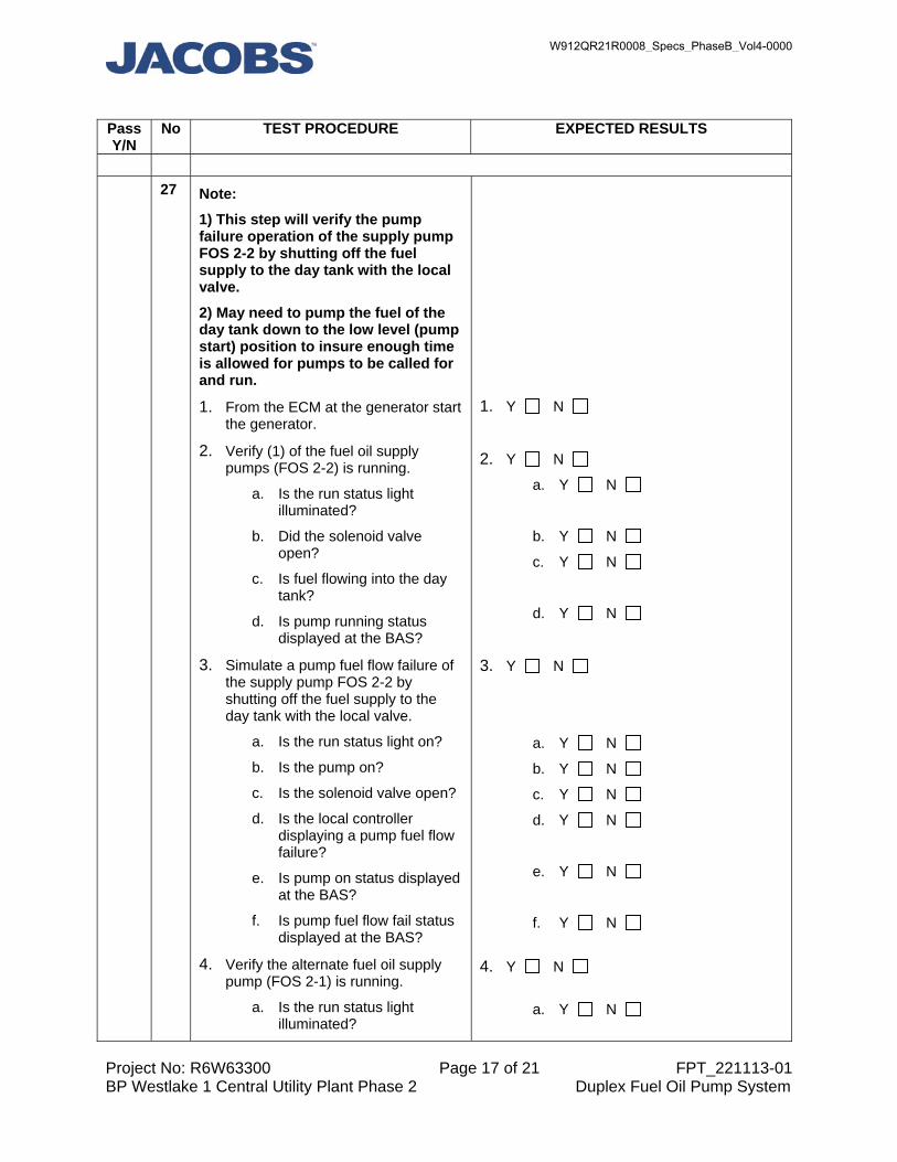
Project No: R6W63300 Page 17 of 21 FPT_221113-01 BP Westlake 1 Central Utility Plant Phase 2 Duplex Fuel Oil Pump System
Pass Y/N
No TEST PROCEDURE EXPECTED RESULTS
27 Note:
1) This step will verify the pump failure operation of the supply pump FOS 2-2 by shutting off the fuel supply to the day tank with the local valve.
2) May need to pump the fuel of the day tank down to the low level (pump start) position to insure enough time is allowed for pumps to be called for and run.
1. From the ECM at the generator start the generator.
2. Verify (1) of the fuel oil supply pumps (FOS 2-2) is running.
a. Is the run status light illuminated?
b. Did the solenoid valve open?
c. Is fuel flowing into the day tank?
d. Is pump running status displayed at the BAS?
3. Simulate a pump fuel flow failure of the supply pump FOS 2-2 by shutting off the fuel supply to the day tank with the local valve.
a. Is the run status light on?
b. Is the pump on?
c. Is the solenoid valve open?
d. Is the local controller displaying a pump fuel flow failure?
e. Is pump on status displayed at the BAS?
f. Is pump fuel flow fail status displayed at the BAS?
4. Verify the alternate fuel oil supply pump (FOS 2-1) is running.
a. Is the run status light illuminated?
1. Y N
2. Y N
a. Y N
b. Y N
c. Y N
d. Y N
3. Y N
a. Y N
b. Y N
c. Y N
d. Y N
e. Y N
f. Y N
4. Y N
a. Y N
W912QR21R0008_Specs_PhaseB_Vol4-0000

Project No: R6W63300 Page 18 of 21 FPT_221113-01 BP Westlake 1 Central Utility Plant Phase 2 Duplex Fuel Oil Pump System
Pass Y/N
No TEST PROCEDURE EXPECTED RESULTS
b. Did the solenoid valve open or remain open?
c. Is fuel flowing into the day tank?
d. Is pump running status displayed at the BAS?
5. Once the fuel level has reached the cut-off level (approximately 7”) or verification from the controller that the day tank is full does the pump turn off?
a. Is the run status light off?
b. Is the pump off?
c. Did the solenoid valve close?
d. Is the local controller still displaying a pump fuel flow failure for pump FOS 2-2?
e. Is pump off status displayed at the BAS?
f. Is pump fuel flow fail status still displayed at the BAS for pump FOS 2-2?
6. From the ECM at the generator stop the generator.
7. Restore pump fuel flow of the supply pump FOS 2-2 by opening the fuel supply to the day tank with the local valve.
a. Reset the pump controller to clear the alarm.
b. Did the pump failure go away at the local controller?
c. Did the pump fail status go away at the BAS for pump FOS 2-2?
b. Y N
c. Y N
d. Y N
5. Y N
a. Y N
b. Y N
c. Y N
d. Y N
e. Y N
f. Y N
6. Y N
7. Y N
a. Y N
b. Y N
c. Y N
Field Notes:
VERIFY THE LEAK DETECTION SYSTEM FOR THE NEW & EXISTING GENERATOR FUEL SYSTEMS
28 1. Verify the fuel leak switch for the new generator double wall piping
1. Switch was activated manually.
Y N
W912QR21R0008_Specs_PhaseB_Vol4-0000

Project No: R6W63300 Page 19 of 21 FPT_221113-01 BP Westlake 1 Central Utility Plant Phase 2 Duplex Fuel Oil Pump System
Pass Y/N
No TEST PROCEDURE EXPECTED RESULTS
system is functioning properly by manually activating the switch.
2. Reset the leak switch.
a. Did an alarm display at the touch screen controller?
Y N
b. Did an alarm display at the DDC. Y N
c. Did the new fuel oil pumping system shut down?
Y N
2. Did the switch reset? Y N
a. Did the alarm at the touch screen clear? Y N
b. Did the alarm at the DDC clear? Y N
c. Did the new fuel oil pumps resume normal operation?
Y N
Field Notes:
29 1. Verify the fuel leak detection installed in the new 3” high stainless steel drip pan under the flexible fuel hoses to the existing generator will shut down the existing fuel oil pumping system when activated. Manually activate the leak detection.
2. Reset the leak detection. Note: This is an added feature only to shut down the existing fuel oil pumping system when a leak has accrued in the new drip pans at the existing generator. It is not clear if this will be monitored from the touch screen or the DDC.
1. Leak detection was activated manually.
Y N
a. Did an alarm display at the touch screen controller? Y N
b. Did an alarm display at the DDC. Y N
c. Did the existing fuel oil pumping system shut down? Y N
2. Did the leak detection reset?
a. Did an alarm display at the touch screen controller? Y N
b. Did the alarm at the DDC clear? Y N
c. Did the existing fuel oil pumps resume normal operation?
Y N
Field Notes:
W912QR21R0008_Specs_PhaseB_Vol4-0000
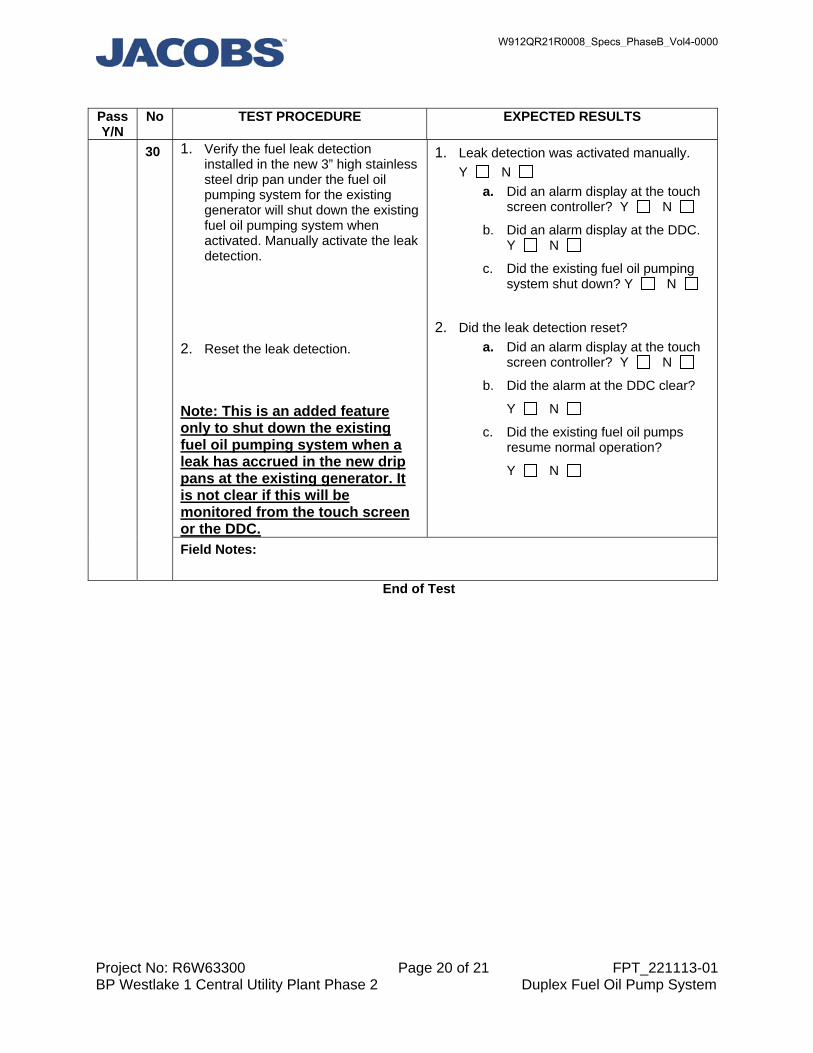
Project No: R6W63300 Page 20 of 21 FPT_221113-01 BP Westlake 1 Central Utility Plant Phase 2 Duplex Fuel Oil Pump System
Pass Y/N
No TEST PROCEDURE EXPECTED RESULTS
30 1. Verify the fuel leak detection installed in the new 3” high stainless steel drip pan under the fuel oil pumping system for the existing generator will shut down the existing fuel oil pumping system when activated. Manually activate the leak detection.
2. Reset the leak detection. Note: This is an added feature only to shut down the existing fuel oil pumping system when a leak has accrued in the new drip pans at the existing generator. It is not clear if this will be monitored from the touch screen or the DDC.
1. Leak detection was activated manually.
Y N
a. Did an alarm display at the touch screen controller? Y N
b. Did an alarm display at the DDC. Y N
c. Did the existing fuel oil pumping system shut down? Y N
2. Did the leak detection reset?
a. Did an alarm display at the touch screen controller? Y N
b. Did the alarm at the DDC clear?
Y N
c. Did the existing fuel oil pumps resume normal operation?
Y N
Field Notes:
End of Test
W912QR21R0008_Specs_PhaseB_Vol4-0000

Project No: R6W63300 Page 21 of 21 FPT_221113-01 BP Westlake 1 Central Utility Plant Phase 2 Duplex Fuel Oil Pump System
Date:_________________________
Summary of Results:
Lessons Learned:
Corrective Issues:
ACCEPTANCE OF TEST:
Owner Representative: ____________________________________________
General Contractor Representative: ____________________________________________
Electrical Contractor Representative: ____________________________________________
Controls Contractor Representative: ____________________________________________
Commissioning Authority: ____________________________________________
W912QR21R0008_Specs_PhaseB_Vol4-0000

CommissioningFPT
Jacobs Project No: R6W63800 HCC-6 Page 1 of 8 FPT- Domestic Hot Water SystemColeman
PROJECT: Coleman
PROJECT NUMBER: R6W63800 HCC-6
REPORT ID: FPT- Domestic Hot Water System
REPORT DESCRIPTION:
Design Information:Parameters Design Actual
References:
Procedures:
PassY/N
No TEST PROCEDURE EXPECTED RESULTS
GENERAL SYSTEM READINESS1 Verify system has been operating at
stable, normal conditions. Record current water temperature and current mode.
DWH Temp Set point: ______°FTMV Temp Set point: ______°F Current Mode: _____
Actual Results:
Field Notes: 2 Verify adequate access to the unit
and associated components that require periodic maintenance and service.
Unit and associated components are easily accessible for service.
Actual Results:
Field Notes:
ALARMS AND SAFETIES
W912QR21R0008_Specs_PhaseB_Vol4-0000

CommissioningFPT
Jacobs Project No: R6W63800 HCC-6 Page 2 of 8 FPT- Domestic Hot Water SystemColeman
3 At the blocked inlet switch, open the normally closed contacts to simulate a fall in pressure. This switch ensuresintake air to the water heater is not restricted.Verify that the control system disables heating operation when the contacts are opened during a heating cycle.
1. During a heating cycle, opening the blocked inlet contactsdisables the equipment:2. Alarm is displayed on the local HMI:3. Once verified, close the contacts and verify that the unit resumes normal operation:
Error Code: _______
Actual Results:
Field Notes: 4 At the blower prover switch, close the
normally open contacts to simulate a rise in pressure. This switch ensures the combustion blower is operating properly at blower start-up.Verify that the control system disables heating operation when contacts are closed during a heating cycle.
1. Heating operation disables if contacts are closed before the combustion blower is energized:2. Alarm is displayed on the local equipment interface:3. Once verified, close the contacts and verify that the unit resumes normal operation:
Error Code: _______
Actual Results:
Field Notes: 5 At the blocked outlet switch, open the
normally closed contacts to simulate a rise in pressure. This switch ensures exhaust piping connected to the water heater is not restricted.Verify that the control system disables heating operation when the contacts are opened during a heating cycle.
1. During a heating cycle, opening the blocked outlet switch contacts disables the equipment:2. Alarm is displayed on the local equipment interface:3. Once verified, close the contacts and verify that the unit resumes normal operation:
Error Code: ______
Actual Results:
Field Notes: 6 At the low gas pressure switch, close
the normally open contacts to simulate a low pressure condition. This switch ensures supply gas pressure is above minimum requirements.Verify that the control system disables heating operation when contacts are closed during a heating cycle.
1. During a heating cycle, closing the low gas pressure switch contacts disables the equipment:2. Alarm is displayed on the local equipment interface:3. Once verified, close the contacts and verify that the unit resumes normal operation:
Error Code: ________
Actual Results:
W912QR21R0008_Specs_PhaseB_Vol4-0000

CommissioningFPT
Jacobs Project No: R6W63800 HCC-6 Page 3 of 8 FPT- Domestic Hot Water SystemColeman
Field Notes: 7 Note: The below step may 'lock-out'
the system. To restart the unit, ensure that water temperature is below 160°F, and press the Set/Reset button on the display panel.At the upper temperature probe, openthe normally closed contacts to simulate a high temperature limit condition.Verify that the control system disables heating operation when contacts are opened during a heating cycle, and the system is locked out.
1. Heating operation disables when contacts are opened:2. Energy Cut Out Alarm is displayed on the local equipmentinterface:3. Unit is manually reset as described:4. Once verified, close the contacts and manually reset the unit as described:5. Unit resumes normal operation:
Error Code: ________
Actual Results:
Field Notes:
INSTALLATION VERIFICATION8 Measure the supply pressure with all
gas fired appliances connected to thecommon main firing at full capacity.Verify that supply pressure does not drop more than 1.5 in WC, and nominal gas supply pressure is approximately 7.0 in WC, and does not fall below this threshold during operation.
Note: Min gas supply pressure: 5.5 in W.CMax gas supply pressure: 12.0 in W.C.
1. Nominal gas supply pressure is approximately 7.0 in WC, and the equipment does not see a supply pressure drop exceeding 1.5 in WC during operation.
Actual Results:
Field Notes: 9 Measure the maximum supply
pressure while the gas is not flowing. Verify that the static pressure does not exceed the 12 in WC limit.
1. If unit exceeds the 12 in WC threshold, install a positive lock-up gas pressure regulator in the supply line, installed in accordance with manufacturer's instructions.
Actual Results:
Field Notes: 10 Measure the manifold pressure.
Verify that the manifold pressure reads 4.0±0.3 in W.C.
1. Manifold pressure is within operating range.
Actual Results:
W912QR21R0008_Specs_PhaseB_Vol4-0000

CommissioningFPT
Jacobs Project No: R6W63800 HCC-6 Page 4 of 8 FPT- Domestic Hot Water SystemColeman
Field Notes: 11 Verify that the condensate drain line
is not elevated above the condensatedrain connection on the condensate trap.Also, verify that the drain line is no more than 6 inches above the drain.
1. Condensate drain line is not elevated above the condensate drain connection on the condensate trap2. Drain line is not more than 6 inches above the drain
Actual Results:
Field Notes: 12 Verify that the factory installed
exhaust/condensate elbow is in place. The water trap inside of the exhaust/condensate elbow prevents flue gases from escaping into the installed space.
1. Factory exhaust/condensate elbow is installed.
Actual Results:
Field Notes: 13 Ensure the hose barb installed in the
tee fitting is not facing down towards the ground, and angled between 90° and 130°.If not correct, residual condensate may form in the intake air pipe and drain into the blocked air intake switch and damage it.Also, for a direct vent application, ensure that the intake air screen is removed.
1. Hose barb installed in correct orientation.2. Intake air screen is removed.
Actual Results:
Field Notes: 14 Shut off the supply gas line and
adjust the set point to be higher than the current temperature to enable the unit. Verify that the unit tries to enable 3 times, then locks out after the 3rd attempt, displaying Error Code 02 and Gas Valve LED flashes.
1. Unit enables sequence as described in step 16:2. After no flame being sensed, gas-valve de-energizes:3. 30 second blower purge occurs:4. Unit attempts igniting up to 3 times, with a blower purge between each try. 5. Heater locks out after 3rd try, displays error code 02, and gas valve LED flashes.
Actual Results:
Field Notes:
W912QR21R0008_Specs_PhaseB_Vol4-0000

CommissioningFPT
Jacobs Project No: R6W63800 HCC-6 Page 5 of 8 FPT- Domestic Hot Water SystemColeman
NORMAL OPERATION15 At the gas water heater local HMI,
record the current equipment settings.
Tank Temperature: _______°FUpper Tank Temperature: _______°FLower Tank Temperature: _______°FOperating set point: _______°FStatus: _______
Actual Results:
Field Notes: 16 Note: load shedding may need to be
performed in order to conduct the below step.With the unit disabled, raise the set point to be 5°F greater than the actualtemperature. Ensure set point is outside of dead band.Verify that the gas water heater enables.
1. Pre-diagnostic system check is performed and verifies pressure switch circuit as open2. Blower motor is energized and a 20 second pre-purge is performed:3. Blower prover switch contacts close and pressure switch circuit is verified closed:4. Ignitor is energized for warmup period (approximately 17 seconds)5. Gas valve is energized and gas flows to burner6. Flame is sensed during 7.5 second trial for ignition:7. Water is heated to set point:
Actual Results:
Field Notes: 17 Once unit achieves set point, verify
that firing disables, a 30 second blower purge occurs, and unit enters standby mode.
1. Set point is below actual temperature and outside of deadband:2. Gas valve is de-energized:3. A 30 second blower purge occurs:4. Heater goes into standby mode:
Actual Results:
Field Notes: 18 Restore set points to original values. 1. Unit resumes normal operation:
Actual Results:
Field Notes: 19 At the thermostatic mixing valve,
record the current temperature setting.
Verify if the hot water circulation pumps are enabled or disabled.
1. Current settings recorded below:
TMV set point: ______°FTMV supply temperature: ______FCP-1 status: _________CP-1 aqua-stat set point: ______°FCP-2 status: _________CP-2 aqua-stat set point: _______°FCP-3 status: _________CP-3 aqua-stat set point: ________°F
Actual Results:
W912QR21R0008_Specs_PhaseB_Vol4-0000

CommissioningFPT
Jacobs Project No: R6W63800 HCC-6 Page 6 of 8 FPT- Domestic Hot Water SystemColeman
Field Notes: 20 With the circulation pumps enabled,
verify aqua-stat functionality by lowering the set point for each DHW loop return temperature below its current return temperature.
CP-1 disables when loop return temperature is above aqua-stat set point.CP-2 disables when loop return temperature is above aqua-stat set point.CP-3 disables when loop return temperature is above aqua-stat set point.
Thermostatic mixing valve maintains supply set point: Y / N Actual Results:
Field Notes: 21 With the circulation pumps disabled,
verify aqua-stat functionality by increasing the set point for each DHW loop return temperature above its current return temperature.
CP-1 enables when loop return temperature is below aqua-stat set point.CP-2 enables when loop return temperature is below aqua-stat set point.CP-3 enables when loop return temperature is below aqua-stat set point.
Thermostatic mixing valve maintains supply set point: Y / N Actual Results:
Field Notes: 22 Restore HW set points to original
value.1. Unit resumes normal operation:
Actual Results:
Field Notes: 23 Verify that the circulation pumps are
on a timer for occupied/unoccupied operation.Adjust time settings to verify each circulation pump enables and disables.
1. DHW Circulating Pumps (CP-1, CP-2, CP-3) enable and disable correctly based on building occupied/unoccupied hours:
Actual Results:
Field Notes:
W912QR21R0008_Specs_PhaseB_Vol4-0000

CommissioningFPT
Jacobs Project No: R6W63800 HCC-6 Page 7 of 8 FPT- Domestic Hot Water SystemColeman
24 Test faucets in lavatory sinks throughout the facility for mixed watertemperature. Record the time it takes for fixtures to reach 105°F at different locations throughout the building.
Verify faucets do not exceed 110°F.
Record results in attached "DHW Fixture Temperature Log" document.
1. Faucets are able to reach temperature (~105°F) in an acceptable time frame prior to disabling.2. Faucets do not exceed 110°F discharge temperature.
Actual Results:
Field Notes: 25 Test faucets in janitor's closet and
other manual mixing locations to verify the time it takes to reach 110°F water temperature.
Record results in attached "DHW Fixture Temperature Log" document.
1. Hot water reaches 110°F within 10 seconds of turning on only the hot water at each faucet.
Actual Results:
Field Notes:
UNOCCUPIED MODE26 Set the schedule so the building is in
unoccupied mode.Verify that the Circulation Pumps are disabled.
1. Circulation Pumps de-energize based on the unoccupied schedule.
Actual Results:
Field Notes: 27 Return the building schedule to its
occupied mode and ensure there is a need for hot water to circulate.Verify that the Circulation Pumps enable.
1. Circulation Pumps energize to circulate HW in the loop.
Actual Results:
Field Notes:
RETURN TO NORMAL28 Return all program logic, set points,
instrumentation, and control devices back to normal operation.
1. Unit resumes normal operation:
Actual Results:
W912QR21R0008_Specs_PhaseB_Vol4-0000
CommissioningFPT
Jacobs Project No: R6W63800 HCC-6 Page 8 of 8 FPT- Domestic Hot Water SystemColeman
Field Notes:
Documents Attached:
END OF TEST
Comments:
ACCEPTANCE OF TEST:
Owner Representative:
General Contractor Representative:
Mechanical Contractor Representative:
Controls Contractor Representative:
Commissioning Authority:
W912QR21R0008_Specs_PhaseB_Vol4-0000

CommissioningFPT
Jacobs Project No: F9Y98701 Page 1 of 4 FPT- Steam to Hot Water HXPENN Hospital
PROJECT: PENN Hospital
PROJECT NUMBER: F9Y98701
REPORT ID: FPT- Steam to Hot Water HX
REPORT DESCRIPTION: Tag Number: PP-LD-HEX-1 (Snow Melt)
Date of Test: Execution Dates: Retest Dates: 11/04/2019
Test Participant List:Participant Company / Agency
Design Information:Parameters Design ActualManufacturer
Model
Serial Number
Water Flow Rate (GPM) 167.5Maximum Pressure Drop (ft WG) 7.09EWT/LWT (deg F) 130/150Operating Pressure (PSIG) 50#/HR 1645
References:
Procedures:
PassY/N
No TEST PROCEDURE EXPECTED RESULTS
GENERAL SYSTEM READINESS1 Observe typical loop ∆T Complete attached spreadsheet
Actual Results:
Field Notes: 2 Check for any unusual
noises/vibrationsThe system does not exhibit any unusual noises/vibrations
Actual Results:
Field Notes:
W912QR21R0008_Specs_PhaseB_Vol4-0000

CommissioningFPT
Jacobs Project No: F9Y98701 Page 2 of 4 FPT- Steam to Hot Water HXPENN Hospital
3 Verify system has been operating at stable, normal conditions. All test pre-requisites have been satisfied
The system is operating at stable and normal conditions
Actual Results:
Field Notes: 4 Verify heat exchanger has been
inspected and started up by personnel authorized by the equipment manufacturer
The system has been inspected and started by authorized personnel
Actual Results:
Field Notes: 5 Verify adequate access is provided to
all components that require periodic maintenance
The system has adequate access to all essential components
Actual Results:
Field Notes: 6 Verify that all gauges operate
properlyAll gauges associated with the system are operating as designed
Actual Results:
Field Notes: 7 Verify operation of the pressure relief
valveThe pressure relief valve associated with the system is operating as designed
Actual Results:
Field Notes: 8 Verify operation of the low water cut
out switchThe low water cut out switch is operating as designed
Actual Results:
Field Notes: 9 Verify operation of the high limit
temperature switchThe high temperature switch is operating as designed
Actual Results:
Field Notes: 10 Verify that system controls are fully
functionalThe system controls associated with the system are operating as designed
W912QR21R0008_Specs_PhaseB_Vol4-0000

CommissioningFPT
Jacobs Project No: F9Y98701 Page 3 of 4 FPT- Steam to Hot Water HXPENN Hospital
Actual Results:
Field Notes: 11 Verify that system controls have been
calibratedThe system controls have been calibrated correctly
Actual Results:
Field Notes:
NORMAL OPERATION12 Verify and document current state of
control instrumentation and set pointsComplete attached spreadsheet
Actual Results:
Field Notes: 13 Reset digital time clock so
unoccupied mode is enabled. Reset the thermostat set point 10 °F lower than the current hot water temperature
1. Digital time clock output is off2. Thermostat output is off3. Circulation pump is disabled
Actual Results:
Field Notes: 14 Reset digital time clock so occupied
mode is enabled1. Digital time clock output is on2. Thermostat output is off3. Circulation pump is disabled
Actual Results:
Field Notes: 15 Reset thermostat set point 10 °F
higher than the current hot water temperature
1. Digital time clock output is on2. Thermostat output is on3. Circulation pump is enabled
Actual Results:
Field Notes: 16 Reset digital time clock and
thermostat set points back to the original set points
Circulation pump returns to normal operation
Actual Results:
Field Notes:
W912QR21R0008_Specs_PhaseB_Vol4-0000

CommissioningFPT
Jacobs Project No: F9Y98701 Page 4 of 4 FPT- Steam to Hot Water HXPENN Hospital
Documents Attached:
END OF TEST
Comments:
ACCEPTANCE OF TEST:
Owner Representative:
General Contractor Representative:
Mechanical Contractor Representative:
Controls Contractor Representative:
Commissioning Authority:
W912QR21R0008_Specs_PhaseB_Vol4-0000

W912QR21R0008_Specs_PhaseB_Vol4-0000

VA 603-320, P2 453413 Louisville VAMC Replacement Phase B
22 11 00 - 1
SECTION 22 11 00 FACILITY WATER DISTRIBUTION
PART 1 - GENERAL
1.1 DESCRIPTION
A. Domestic and non-potable water systems, including piping, equipment and
all necessary accessories as designated in this section.
B. A complete listing of all acronyms and abbreviations are included in
Section 22 05 11, COMMON WORK RESULTS FOR PLUMBING.
1.2 RELATED WORK
A. Section 01 33 00, SUBMITTAL PROCEDURES.
B. Section 01 81 13, SUSTAINABLE CONSTRUCTION REQUIREMENTS.
C. Section 01 91 00, GENERAL COMMISSIONING REQUIREMENTS.
D. Section 07 84 00, FIRESTOPPING.
E. Section 07 92 00, JOINT SEALANTS.
F. Section 09 91 00, PAINTING.
H. Section 13 05 41, SEISMIC RESTRAINT REQUIREMENTS FOR NON-STRUCTURAL
COMPONENTS: Seismic Restraint.
H. Section 22 05 11, COMMON WORK RESULTS FOR PLUMBING.
I. Section 22 07 11, PLUMBING INSULATION.
J. SECTION 22 08 00, COMMISSIONING OF PLUMBING SYSTEMS.
1.3 APPLICABLE PUBLICATIONS
A. The publications listed below form a part of this specification to the
extent referenced. The publications are referenced in the text by the
basic designation only.
B. American Society of Mechanical Engineers (ASME):
A13.1-2007 (R2013)......Scheme for Identification of Piping Systems
B16.3-2011..............Malleable Iron Threaded Fittings: Classes 150
and 300
B16.9-2012..............Factory-Made Wrought Buttwelding Fittings
B16.11-2011.............Forged Fittings, Socket-Welding and Threaded
B16.12-2009 (R2014).....Cast Iron Threaded Drainage Fittings
B16.15-2013 ............Cast Copper Alloy Threaded Fittings: Classes
125 and 250
B16.18-2012.............Cast Copper Alloy Solder Joint Pressure
Fittings
B16.22-2013.............Wrought Copper and Copper Alloy Solder-Joint
Pressure Fittings
W912QR21R0008_Specs_PhaseB_Vol4-0000

VA 603-320, P2 453413 Louisville VAMC Replacement Phase B
22 11 00 - 2
B16.24-2011.............Cast Copper Alloy Pipe Flanges and Flanged
Fittings: Classes 150, 300, 600, 900, 1500, and
2500
B16.51-2013.............Copper and Copper Alloy Press-Connect Fittings
ASME Boiler and Pressure Vessel Code -
BPVC Section IX-2015....Welding, Brazing, and Fusing Qualifications
C. American Society of Sanitary Engineers (ASSE):
1010-2004...............Performance Requirements for Water Hammer
Arresters
D. American Society for Testing and Materials (ASTM):
A47/A47M-1999 (R2014)...Standard Specification for Ferritic Malleable
Iron Castings
A53/A53M-2012...........Standard Specification for Pipe, Steel, Black
and Hot-Dipped, Zinc-Coated, Welded and
Seamless
A183-2014...............Standard Specification for Carbon Steel Track
Bolts and Nuts
A269/A269M-2014e1.......Standard Specification for Seamless and Welded
Austenitic Stainless Steel Tubing for General
Service
A312/A312M-2015.........Standard Specification for Seamless, Welded,
and Heavily Cold Worked Austenitic Stainless
Steel Pipes
A403/A403M-2014.........Standard Specification for Wrought Austenitic
Stainless Steel Piping Fittings
A536-1984 (R2014).......Standard Specification for Ductile Iron
Castings
A733-2013...............Standard Specification for Welded and Seamless
Carbon Steel and Austenitic Stainless Steel
Pipe Nipples
B32-2008 (R2014)........Standard Specification for Solder Metal
B43-2014................Standard Specification for Seamless Red Brass
Pipe, Standard Sizes
B61-2008 (R2013)........Standard Specification for Steam or Valve
Bronze Castings
B62-2009................Standard Specification for Composition Bronze
or Ounce Metal Castings
B75/B75M-2011...........Standard Specification for Seamless Copper Tube
W912QR21R0008_Specs_PhaseB_Vol4-0000

VA 603-320, P2 453413 Louisville VAMC Replacement Phase B
22 11 00 - 3
B88-2014................Standard Specification for Seamless Copper
Water Tube
B584-2014...............Standard Specification for Copper Alloy Sand
Castings for General Applications
B687-1999 (R2011).......Standard Specification for Brass, Copper, and
Chromium-Plated Pipe Nipples
C919-2012...............Standard Practice for Use of Sealants in
Acoustical Applications
D1785-2012..............Standard Specification for Poly (Vinyl
Chloride) (PVC) Plastic Pipe, Schedules 40, 80,
and 120
D2000-2012..............Standard Classification System for Rubber
Products in Automotive Applications
D2564-2012..............Standard Specification for Solvent Cements for
Poly (Vinyl Chloride) (PVC) Plastic Piping
Systems
D2657-2007..............Standard Practice for Heat Fusion Joining of
Polyolefin Pipe and Fittings
D2855-1996 (R2010)......Standard Practice for Making Solvent-Cemented
Joints with Poly (Vinyl Chloride) (PVC) Pipe
and Fittings
D4101-2014..............Standard Specification for Polypropylene
Injection and Extrusion Materials
E1120-2008..............Standard Specification for Liquid Chlorine
E1229-2008..............Standard Specification for Calcium Hypochlorite
F2389-2010..............Standard Specification for Pressure-rated
Polypropylene (PP) Piping Systems
F2620-2013..............Standard Practice for Heat Fusion Joining of
Polyethylene Pipe and Fittings
F2769-2014..............Standard Specification for Polyethylene of
Raised Temperature (PE-RT) Plastic Hot and
Cold-Water Tubing and Distribution Systems
E. American Water Works Association (AWWA):
C110-2012...............Ductile-Iron and Gray-Iron Fittings
C151-2009...............Ductile Iron Pipe, Centrifugally Cast
C153-2011...............Ductile-Iron Compact Fittings
W912QR21R0008_Specs_PhaseB_Vol4-0000
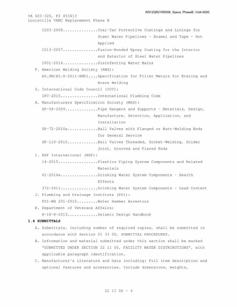
VA 603-320, P2 453413 Louisville VAMC Replacement Phase B
22 11 00 - 4
C203-2008...............Coal-Tar Protective Coatings and Linings for
Steel Water Pipelines - Enamel and Tape - Hot
Applied
C213-2007...............Fusion-Bonded Epoxy Coating for the Interior
and Exterior of Steel Water Pipelines
C651-2014...............Disinfecting Water Mains
F. American Welding Society (AWS):
A5.8M/A5.8-2011-AMD1....Specification for Filler Metals for Brazing and
Braze Welding
G. International Code Council (ICC):
IPC-2015................International Plumbing Code
H. Manufacturers Specification Society (MSS):
SP-58-2009..............Pipe Hangers and Supports - Materials, Design,
Manufacture, Selection, Application, and
Installation
SP-72-2010a.............Ball Valves with Flanged or Butt-Welding Ends
for General Service
SP-110-2010.............Ball Valves Threaded, Socket-Welding, Solder
Joint, Grooved and Flared Ends
I. NSF International (NSF):
14-2015.................Plastics Piping System Components and Related
Materials
61-2014a................Drinking Water System Components – Health
Effects
372-2011................Drinking Water System Components – Lead Content
J. Plumbing and Drainage Institute (PDI):
PDI-WH 201-2010.........Water Hammer Arrestors
K. Department of Veterans Affairs:
H-18-8-2013.............Seismic Design Handbook
1.4 SUBMITTALS
A. Submittals, including number of required copies, shall be submitted in
accordance with Section 01 33 00, SUBMITTAL PROCEDURES.
B. Information and material submitted under this section shall be marked
“SUBMITTED UNDER SECTION 22 11 00, FACILITY WATER DISTRIBUTIONS”, with
applicable paragraph identification.
C. Manufacturer's Literature and Data including: Full item description and
optional features and accessories. Include dimensions, weights,
W912QR21R0008_Specs_PhaseB_Vol4-0000

VA 603-320, P2 453413 Louisville VAMC Replacement Phase B
22 11 00 - 5
materials, applications, standard compliance, model numbers, size, and
capacity.
1. All items listed in Part 2 - Products.
D. Complete operating and maintenance manuals including wiring diagrams,
technical data sheets and information for ordering replacement parts:
1. Include complete list indicating all components of the systems.
2. Include complete diagrams of the internal wiring for each item of
equipment.
3. Diagrams shall have their terminals identified to facilitate
installation, operation and maintenance.
E. Completed System Readiness Checklist provided by the CxA and completed
by the Contractor, signed by a qualified technician and dated on the
date of completion, in accordance with the requirements of Section 22
08 00, COMMISSIONING OF PLUMBING SYSTEMS.
F. Submit training plans and instructor qualifications in accordance with
the requirements of Section 22 08 00, COMMISSIONING OF PLUMBING
SYSTEMS.
1.5 QUALITY ASSURANCE
A. A certificate shall be submitted prior to welding of steel piping
showing the Welder’s certification. The certificate shall be current
and no more than one year old. Welder’s qualifications shall be in
accordance with ASME BPVC Section IX.
B. All grooved joint couplings, fittings, valves, and specialties shall be
the products of a single manufacturer. Grooving tools shall be by the
same manufacturer as the groove components.
C. All pipe, couplings, fittings, and specialties shall bear the
identification of the manufacturer and any markings required by the
applicable referenced standards.
D. Bio-Based Materials: For products designated by the USDA’s Bio-
Preferred Program, provide products that meet or exceed USDA
recommendations for bio-based content, so long as products meet all
performance requirements in this specifications section. For more
information regarding the product categories covered by the Bio-
Preferred Program, visit http://www.biopreferred.gov .
E. The contractor shall be certified by the press fit manufacturer for
installation of the pipe and fittings using the manufacturer’s tools.
W912QR21R0008_Specs_PhaseB_Vol4-0000

VA 603-320, P2 453413 Louisville VAMC Replacement Phase B
22 11 00 - 6
1.6 SPARE PARTS
A. For mechanical press-connect fittings, provide tools required for each
pipe size used at the facility.
1.7 AS-BUILT DOCUMENTATION
A. Submit manufacturer’s literature and data updated to include submittal
review comments and any equipment substitutions.
B. Submit operation and maintenance data updated to include submittal
review comments, substitutions and construction revisions shall be in
electronic version on compact disc or DVD inserted into a three ring
binder. All aspects of system operation and maintenance procedures,
including piping isometrics, wiring diagrams of all circuits, a written
description of system design, control logic, and sequence of operation
shall be included in the operation and maintenance manual. The
operations and maintenance manual shall include troubleshooting
techniques and procedures for emergency situations. Notes on all
special systems or devices shall be included. A list of recommended
spare parts (manufacturer, model number, and quantity) shall be
furnished. Information explaining any special knowledge or tools the
owner will be required to employ shall be inserted into the As-Built
documentation.
C. The installing contractor shall maintain as-built drawings of each
completed phase for verification; and, shall provide the complete set
at the time of final systems certification testing. As-built drawings
are to be provided, and a copy of them in Auto-CAD version 2014
provided on compact disk or DVD. Should the installing contractor
engage the testing company to provide as-built or any portion thereof,
it shall not be deemed a conflict of interest or breach of the ‘third
party testing company’ requirement.
D. Certification documentation shall be provided to COR 10 working days
prior to submitting the request for final inspection. The documentation
shall include all test results, the names of individuals performing
work for the testing agency on this project, detailed procedures
followed for all tests, and certificate if applicable that all results
of tests were within limits specified. If a certificate is not
available, all documentation shall be on the Certifier’s letterhead.
W912QR21R0008_Specs_PhaseB_Vol4-0000

VA 603-320, P2 453413 Louisville VAMC Replacement Phase B
22 11 00 - 7
PART 2 - PRODUCTS
2.1 MATERIALS
A. Material or equipment containing a weighted average of greater than
0.25 percent lead are prohibited in any potable water system intended
for human consumption, and shall be certified in accordance with NSF 61
or NSF 372. Endpoint devices used to dispense water for drinking shall
meet the requirements of NSF 61, Section 9.
B. Plastic pipe, fittings, and solvent cement shall meet NSF 14 and shall
be NSF listed for the service intended.
2.2 UNDERGROUND WATER SERVICE CONNECTIONS TO BUILDINGS
A. From inside face of exterior wall to a distance of approximately 5 feet
outside of building and underground inside building, material to be the
same for the size specified inside the building.
B. 3 inch Diameter and Greater: Ductile iron, AWWA C151, 350 psig pressure
class, exterior bituminous coating, and cement lined. Bio-based
materials shall be utilized when possible. Provide flanged and anchored
connection to interior piping.
C. Under 3 inch Diameter: Copper tubing, ASTM B88, Type K, seamless,
annealed. Fittings are as specified in paragraph “Above Ground
(Interior) Water Piping”. Use brazing alloys, AWS A5.8M/A5.8,
Classification BCuP.
D. Flexible Expansion Joint: Ductile iron with ball joints rated for 250
psig working pressure conforming to AWWA C153, capable of deflecting a
minimum of 20 degrees in each direction. Flexible expansion joint size
shall match the pipe size it is connected to and shall have the
expansion capability designed as an integral part of the ductile iron
ball castings. Pressure containing parts shall be lined with a minimum
of 15 mils of fusion bonded epoxy conforming to the applicable
requirements of AWWA C213 and shall be factory tested with a 1500 volt
spark test. Flexible expansion joint shall have flanged connections
conforming to AWWA C110. Bolts and nuts shall be 316 stainless steel
and gaskets shall be neoprene. The flexible expansion fitting shall not
expand or exert an axial thrust under internal water pressure. Provide
piping joint restraints at each mechanical joint end connection and
piping restraints at the penetration of the building wall. The
restraints shall be provided to address the developed thrust at the
change of piping direction.
W912QR21R0008_Specs_PhaseB_Vol4-0000
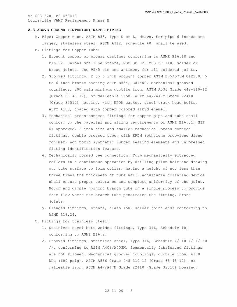
VA 603-320, P2 453413 Louisville VAMC Replacement Phase B
22 11 00 - 8
2.3 ABOVE GROUND (INTERIOR) WATER PIPING
A. Pipe: Copper tube, ASTM B88, Type K or L, drawn. For pipe 6 inches and
larger, stainless steel, ASTM A312, schedule 40 shall be used.
B. Fittings for Copper Tube:
1. Wrought copper or bronze castings conforming to ASME B16.18 and
B16.22. Unions shall be bronze, MSS SP-72, MSS SP-110, solder or
braze joints. Use 95/5 tin and antimony for all soldered joints.
2. Grooved fittings, 2 to 6 inch wrought copper ASTM B75/B75M C12200, 5
to 6 inch bronze casting ASTM B584, C84400. Mechanical grooved
couplings, 300 psig minimum ductile iron, ASTM A536 Grade 448-310-12
(Grade 65-45-12), or malleable iron, ASTM A47/A47M Grade 22410
(Grade 32510) housing, with EPDM gasket, steel track head bolts,
ASTM A183, coated with copper colored alkyd enamel.
3. Mechanical press-connect fittings for copper pipe and tube shall
conform to the material and sizing requirements of ASME B16.51, NSF
61 approved, 2 inch size and smaller mechanical press-connect
fittings, double pressed type, with EPDM (ethylene propylene diene
monomer) non-toxic synthetic rubber sealing elements and un-pressed
fitting identification feature.
4. Mechanically formed tee connection: Form mechanically extracted
collars in a continuous operation by drilling pilot hole and drawing
out tube surface to form collar, having a height of not less than
three times the thickness of tube wall. Adjustable collaring device
shall ensure proper tolerance and complete uniformity of the joint.
Notch and dimple joining branch tube in a single process to provide
free flow where the branch tube penetrates the fitting. Braze
joints.
5. Flanged fittings, bronze, class 150, solder-joint ends conforming to
ASME B16.24.
C. Fittings for Stainless Steel:
1. Stainless steel butt-welded fittings, Type 316, Schedule 10,
conforming to ASME B16.9.
2. Grooved fittings, stainless steel, Type 316, Schedule // 10 // // 40
//, conforming to ASTM A403/A403M. Segmentally fabricated fittings
are not allowed. Mechanical grooved couplings, ductile iron, 4138
kPa (600 psig), ASTM A536 Grade 448-310-12 (Grade 65-45-12), or
malleable iron, ASTM A47/A47M Grade 22410 (Grade 32510) housing,
W912QR21R0008_Specs_PhaseB_Vol4-0000

VA 603-320, P2 453413 Louisville VAMC Replacement Phase B
22 11 00 - 9
with EPDM gasket, steel track head bolts, ASTM A183, coated with
copper colored alkyd enamel.
D. Adapters: Provide adapters for joining pipe or tubing with dissimilar
end connections.
E. Solder: ASTM B32 alloy type Sb5, HA or HB. Provide non-corrosive flux.
F. Brazing alloy: AWS A5.8M/A5.8, brazing filler metals shall be BCuP
series for copper to copper joints and BAg series for copper to steel
joints.
G. Re-agent Grade Water Piping and Dialysis Water Piping:
1. Polypropylene, ASTM F2389, Schedule 80 pressure pipe without
additions of modifiers, plasticizers, colorants, stabilizers or
lubricants. Bio-based materials shall be utilized when possible.
This virgin un-plasticized pipe and fittings shall transport 10
megohm water with no loss of purity. Provide socket or butt end
fittings with ASTM D2657 heat fusion joints.
2. Polyethylene, ASTM F2769, Schedule 80, food and medical grade,
capable of transporting 10 megohm water with no loss of purity.
Processed by continuous compression molding without the addition of
fillers, polymer modifiers or processing aids. Uniform color with no
cracks, flaws, blisters or other imperfections in appearance.
Provide ASTM D2657 or ASTM F2620 heat fusion butt welded joints. In
accordance with manufacturer's recommendations, provide continuous
channel support under all horizontal piping.
3. Reverse Osmosis (RO) Water Piping:
a. Low Pressure Feed, Reject and Recycle Piping: Less than or equal
to 75 psig: ASTM D1785, Schedule 80 PVC, ASTM D2855 socket welded
and flanged.
b. RO Product Tubing From Each Membrane Housing: ASTM D1785,
Schedule 80 PVC, ASTM D2855 socket welded and flanged.
c. Low Pressure Control and Pressure Gage Tubing: Polyethylene.
d. High Pressure Reject and Recycle Piping: Greater than 75 psig:
ASTM A269/A269M, Type 304 schedule 10 stainless steel with butt
welded joints.
e. High Pressure Control and Pressure Gage Tubing: 1000 psig burst
nylon.
2.4 EXPOSED WATER PIPING
A. Finished Room: Use full iron pipe size chrome plated brass piping for
exposed water piping connecting fixtures, casework, cabinets, equipment
W912QR21R0008_Specs_PhaseB_Vol4-0000

VA 603-320, P2 453413 Louisville VAMC Replacement Phase B
22 11 00 - 10
and reagent racks when not concealed by apron including those furnished
by the Government or specified in other sections.
1. Pipe: ASTM B43, standard weight.
2. Fittings: ASME B16.15 cast bronze threaded fittings with chrome
finish.
3. Nipples: ASTM B687, Chromium-plated.
4. Unions: MSS SP-72, MSS SP-110, brass or bronze with chrome finish.
Unions 2-1/2 inches and larger shall be flange type with approved
gaskets.
B. Unfinished Rooms, Mechanical Rooms and Kitchens: Chrome-plated brass
piping is not required. Paint piping systems as specified in Section 09
91 00, PAINTING.
2.5 TRAP PRIMER WATER PIPING
A. Pipe: Copper tube, ASTM B88, type K, hard drawn.
B. Fittings: Bronze castings conforming to ASME B16.18 Solder joints.
C. Solder: ASTM B32 alloy type Sb5. Provide non-corrosive flux.
2.6 STRAINERS
A. Provide on high pressure side of pressure reducing valves, on suction
side of pumps, on inlet side of indicating and control instruments and
equipment subject to sediment damage and where shown on drawings.
Strainer element shall be removable without disconnection of piping.
B. Water: Basket or "Y" type with easily removable cover and brass
strainer basket.
C. Body: Less than 3 inches, brass or bronze; 3 inches and greater, cast
iron or semi-steel.
2.7 DIELECTRIC FITTINGS
A. Provide dielectric couplings or unions between pipe of dissimilar
metals.
2.8 STERILIZATION CHEMICALS
A. Hypochlorite: ASTM E1120.
B. Liquid Chlorine: ASTM E1229.
2.9 WATER HAMMER ARRESTER
A. Closed copper tube chamber with permanently sealed 60 psig air charge
above a Double O-ring piston. Two high heat Buna-N 0-rings pressure
packed and lubricated with FDA approved silicone compound. All units
shall be designed in accordance with ASSE 1010. Access shall be
provided where devices are concealed within partitions or above
W912QR21R0008_Specs_PhaseB_Vol4-0000

VA 603-320, P2 453413 Louisville VAMC Replacement Phase B
22 11 00 - 11
ceilings. Size and install in accordance with PDI-WH 201 requirements.
Provide water hammer arrestors at:
1. All solenoid valves.
2. All groups of two or more flush valves.
3. All quick opening or closing valves.
4. All medical washing equipment.
PART 3 - EXECUTION
3.1 INSTALLATION
A. General: Comply with the International Plumbing Code and the following:
1. Install branch piping for water from the piping system and connect
to all fixtures, valves, cocks, outlets, casework, cabinets and
equipment, including those furnished by the Government or specified
in other sections.
2. Pipe shall be round and straight. Cutting shall be done with proper
tools. Pipe, except for plastic and glass, shall be reamed to remove
burrs and a clean smooth finish restored to full pipe inside
diameter.
3. All pipe runs shall be laid out to avoid interference with other
work/trades.
4. Install union and shut-off valve on pressure piping at connections
to equipment.
5. Pipe Hangers, Supports and Accessories:
a. All piping shall be supported per the IPC, H-18-8 Seismic Design
Handbook, MSS SP-58, and SMACNA as required.
b. Shop Painting and Plating: Hangers, supports, rods, inserts and
accessories used for pipe supports shall be shop coated with zinc
chromate primer paint. Electroplated copper hanger rods, hangers
and accessories may be used with copper tubing.
c. Floor, Wall and Ceiling Plates, Supports, Hangers:
1) Solid or split un-plated cast iron.
2) All plates shall be provided with set screws.
3) Pipe Hangers: Height adjustable clevis type.
4) Adjustable Floor Rests and Base Flanges: Steel.
5) Concrete Inserts: "Universal" or continuous slotted type.
6) Hanger Rods: Mild, low carbon steel, fully threaded or
Threaded at each end with two removable nuts at each end for
positioning rod and hanger and locking each in place.
W912QR21R0008_Specs_PhaseB_Vol4-0000

VA 603-320, P2 453413 Louisville VAMC Replacement Phase B
22 11 00 - 12
7) Pipe Hangers and Riser Clamps: Malleable iron or carbon steel.
Pipe Hangers and riser clamps shall have a copper finish when
supporting bare copper pipe or tubing.
8) Rollers: Cast iron.
9) Self-drilling type expansion shields shall be "Phillips" type,
with case hardened steel expander plugs.
10) Hangers and supports utilized with insulated pipe and tubing
shall have 180 degree (minimum) metal protection shield
centered on and welded to the hanger and support. The shield
thickness and length shall be engineered and sized for
distribution of loads to preclude crushing of insulation
without breaking the vapor barrier. The shield shall be sized
for the insulation and have flared edges to protect
vapor-retardant jacket facing. To prevent the shield from
sliding out of the clevis hanger during pipe movement, center-
ribbed shields shall be used.
11) Miscellaneous Materials: As specified, required, directed or
as noted on the drawings for proper installation of hangers,
supports and accessories. If the vertical distance exceeds 20
feet for cast iron pipe additional support shall be provided
in the center of that span. Provide all necessary auxiliary
steel to provide that support.
12) With the installation of each flexible expansion joint,
provide piping restraints for the upstream and downstream
section of the piping at the flexible expansion joint. Provide
calculations supporting the restraint length design and type
of selected restraints. Restraint calculations shall be based
on the criteria from the manufacturer regarding their
restraint design.
6. Install chrome plated cast brass escutcheon with set screw at each
wall, floor and ceiling penetration in exposed finished locations
and within cabinets and millwork.
7. Penetrations:
a. Firestopping: Where pipes pass through fire partitions, fire
walls, smoke partitions, or floors, install a fire stop that
provides an effective barrier against the spread of fire, smoke,
and gases as specified in Section 07 84 00, FIRESTOPPING.
W912QR21R0008_Specs_PhaseB_Vol4-0000

VA 603-320, P2 453413 Louisville VAMC Replacement Phase B
22 11 00 - 13
Completely fill and seal clearances between raceways and openings
with the firestopping materials.
b. Waterproofing: At floor penetrations, completely seal clearances
around the pipe and make watertight with sealant as specified in
Section 07 92 00, JOINT SEALANTS. Bio-based materials shall be
utilized when possible.
8. Mechanical press-connect fitting connections shall be made in
accordance with the manufacturer’s installation instructions. The
tubing shall be fully inserted into the fitting and the tubing
marked at the shoulder of the fitting. The fitting alignment shall
be checked against the mark on the tubing to assure the tubing is
fully engaged (inserted) in the fitting. Ensure the tube is
completely inserted to the fitting stop (appropriate depth) and
squared with the fitting prior to applying the pressing jaws onto
the fitting. The joints shall be pressed using the tool(s) approved
by the manufacturer. Minimum distance between fittings shall be in
accordance with the manufacturer’s requirements. When the pressing
cycle is complete, visually inspect the joint to ensure the tube has
remained fully inserted, as evidenced by the visible insertion mark.
B. Domestic and Non-Potable Water piping shall conform to the following:
1. Grade all lines to facilitate drainage. Provide drain valves at
bottom of risers and all low points in system. Design domestic hot
water circulating lines with no traps.
2. Connect branch lines at bottom of main serving fixtures below and
pitch down so that main may be drained through fixture. Connect
branch lines to top of main serving only fixtures located on floor
above.
C. All water hammer arrestors shall be installed in locations where they
are readily accessible for service. Where required, provide suitable
access doors.
3.2 TESTS
A. General: Test system either in its entirety or in sections. Submit
testing plan to Contracting Officer 10 working days prior to test
date.
B. Potable Water System: Test after installation of piping and domestic
water heaters, but before piping is concealed, before covering is
applied, and before plumbing fixtures are connected. Fill systems with
water and maintain hydrostatic pressure of 150 psig gage for two hours.
W912QR21R0008_Specs_PhaseB_Vol4-0000

VA 603-320, P2 453413 Louisville VAMC Replacement Phase B
22 11 00 - 14
No decrease in pressure is allowed. Provide a pressure gage with a
shutoff and bleeder valve at the highest point of the piping being
tested. Pressure gauge shall have 1 psig increments.
C. Re-agent Grade Water Systems: Fill system with water and maintain
hydrostatic pressure of 200 psig gage during inspection and prove tight
or test as recommended by the manufacturer.
D. All Other Piping Tests: Test new installed piping under 1-1/2 times
actual operating conditions and prove tight.
E. The test pressure shall hold for the minimum time duration required by
the applicable plumbing code or authority having jurisdiction.
3.3 STERILIZATION
A. After tests have been successfully completed, thoroughly flush and
sterilize the interior domestic water distribution system in accordance
with AWWA C651.
B. Use liquid chlorine or hypochlorite for sterilization.
3.4 COMMISSIONING
A. Provide commissioning documentation in accordance with the requirements
of Section 22 08 00, COMMISSIONING OF PLUMBING SYSTEMS.
B. Components provided under this section of the specification will be
tested as part of a larger system.
3.5 DEMONSTRATION AND TRAINING
A. Provide services of manufacturer’s technical representative for four
hours to instruct VA Personnel in operation and maintenance of the
system.
B. Submit training plans and instructor qualifications in accordance with
the requirements of Section 22 08 00, COMMISSIONING OF PLUMBING SYSTEMS
and Section 01 79 00, OPERATIONS AND MAINTENANCE TRAINING.
- - - E N D - - -
W912QR21R0008_Specs_PhaseB_Vol4-0000

VA 603-320, P2 453413 Louisville VAMC Replacement Phase B
22 11 23 - 1
SECTION 22 11 23 DOMESTIC WATER PUMPS
PART 1 - GENERAL
1.1 DESCRIPTION
A. Hot water circulating pump, hot water recirculation pump and domestic
water pressure booster system.
B. A complete listing of all acronyms and abbreviations are included in
Section 22 05 11, COMMON WORK RESULTS FOR PLUMBING.
1.2 RELATED WORK
A. Section 01 33 00, SUBMITTAL PROCEDURES.
B. Section 01 81 13, SUSTAINABLE CONSTRUCTION REQUIREMENTS.
C. Section 01 91 00, GENERAL COMMISSIONING REQUIREMENTS.
D. Section 13 05 41, SEISMIC RESTRAINT REQUIREMENTS FOR NON-STRUCTURAL
COMPONENTS: Seismic Restraint.
E. Section 22 05 11, COMMON WORK RESULTS FOR PLUMBING.
F. Section 22 05 12, GENERAL MOTOR REQUIREMENTS FOR PLUMBING EQUIPMENT.
G. Section 22 08 00, COMMISSIONING OF PLUMBING SYSTEMS: Requirements for
commissioning, systems readiness checklist, and training.
H. Section 26 29 11, MOTOR CONTROLLERS.
1.3 APPLICABLE PUBLICATIONS
A. The publications listed below form a part of this specification to the
extent referenced. The publications are referenced in the text by the
basic designation only.
B. American Society of Mechanical Engineers (ASME):
ASME Boiler and Pressure Code -
BPVC Section VIII-1-2015 Rules for Construction of Pressure
Vessels, Division 1
BPVC Section VIII-2-2015 Rules for Construction of Pressure
Vessels, Division 2-Alternative Rules
C. American Society for Testing and Materials (ASTM):
A48/A48M-2003 (R2012)...Standard Specification for Gray Iron Castings
B584-2014...............Standard Specification for Copper Alloy Sand
Castings for General Applications
D. International Code Council (ICC)
IPC-2015................International Plumbing Code
E. National Electrical Manufacturers Association (NEMA):
ICS 6-1993 (R2001, R2006) Industrial Control and Systems:
Enclosures
W912QR21R0008_Specs_PhaseB_Vol4-0000

VA 603-320, P2 453413 Louisville VAMC Replacement Phase B
22 11 23 - 2
250-2014................Enclosures for Electrical Equipment (1000 Volts
Maximum)
F. NSF International (NSF)
61-2014a................Drinking Water System Components – Health
Effects
372-2011................Drinking Water System Components – Lead Content
G. Underwriters' Laboratories, Inc. (UL):
508-1999 (R2013)........Standards for Industrial Control Equipment
778-2010 (R2014)........Standard for Motor-Operated Water Pumps
1.4 SUBMITTALS
A. Submittals, including number of required copies, shall be submitted in
accordance with Section 01 33 00, SUBMITTAL PROCEDURES.
B. Information and material submitted under this section shall be marked
“SUBMITTED UNDER SECTION 22 11 23, DOMESTIC WATER PUMPS”, with
applicable paragraph identification.
C. Manufacturer's Literature and Data including: Full item description and
optional features and accessories. Include dimensions, weights,
materials, applications, standard compliance, model numbers, size, and
capacity.
1. Pump:
a. Manufacturer and model.
b. Operating speed.
c. Capacity.
d. Characteristic performance curves.
2. Motor:
a. Manufacturer, frame and type.
b. Speed.
c. Current Characteristics.
d. Efficiency.
3. Tank:
a. Manufacturer and model.
b. Capacity
4. Drive: Information in accordance with Section 26 29 11, MOTOR
CONTROLLERS.
D. Certificate of shop test for domestic water booster system. Provide
certified performance curves.
E. Certified copies of all the factory and construction site test data
sheets and reports.
W912QR21R0008_Specs_PhaseB_Vol4-0000

VA 603-320, P2 453413 Louisville VAMC Replacement Phase B
22 11 23 - 3
F. Complete operating and maintenance manuals including wiring diagrams,
technical data sheets, information for ordering replacement parts, and
troubleshooting guide:
1. Include complete list indicating all components of the systems.
2. Include complete diagrams of the internal wiring for each item of
equipment.
3. Diagrams shall have their terminals identified to facilitate
installation, operation and maintenance.
G. Completed System Readiness Checklist provided by the CxA and completed
by the contractor, signed by a qualified technician and dated on the
date of completion, in accordance with the requirements of Section 22
08 00, COMMISSIONING OF PLUMBING SYSTEMS.
H. Submit training plans and instructor qualifications in accordance with
the requirements of Section 22 08 00, COMMISSIONING OF PLUMBING
SYSTEMS.
1.5 QUALITY ASSURANCE
A. General:
1. UL Compliance: Comply with UL 778 for motor-operated water pumps.
2. Design Criteria:
a. Pump sizes, capacities, pressures, operating characteristics and
efficiency shall be as scheduled.
b. Head-capacity curves shall slope up to maximum head at shut-off.
Select pumps near the midrange of the curve, and near the point
of maximum efficiency, without approaching the pump curve end
point and possible cavitation and unstable operation. Select
pumps for open systems so that required net positive suction head
(NPSHR) does not exceed the net positive head available (NPSHA).
c. Pump Driver: Furnish with pump. Size shall be non-overloading at
any point on the head-capacity curve, including in a parallel or
series pumping installation with one pump in operation.
d. Provide all pumps with motors, impellers, drive assemblies,
bearings, coupling guard and other accessories specified.
Statically and dynamically balance all rotating parts.
e. Furnish each pump and motor with a nameplate giving the
manufacturers name, serial number of pump, capacity in GPM and
head in feet at design condition, horsepower, voltage, frequency,
speed and full load current and motor efficiency.
W912QR21R0008_Specs_PhaseB_Vol4-0000

VA 603-320, P2 453413 Louisville VAMC Replacement Phase B
22 11 23 - 4
f. Test all pumps before shipment. The manufacturer shall certify
all pump ratings.
g. After completion of balancing, provide replacement of impellers
or trim impellers to provide specified flow at actual pumping
head, as installed.
B. Hot Water Circulating and Recirculating Pumps: Components shall be
assembled by a single manufacturer and the pump motor assembly shall be
the standard cataloged product of the manufacturer.
C. Domestic Water Pressure Booster System:
1. Components shall be furnished by a single manufacturer and the
system shall be the standard cataloged product of the manufacturer.
2. Shop Test: Water booster unit and its component parts shall undergo
a thorough electric and hydraulic operating test prior to shipment.
Tests shall include a system operating flow test from zero to 100
percent of design flow rate under specified suction and system
pressure conditions. Certified performance curves shall be
furnished.
D. Bio-Based Materials: For products designated by the USDA’s Bio-
Preferred Program, provide products that meet or exceed USDA
recommendations for bio-based content, so long as products meet all
performance requirements in this specifications section. For more
information regarding the product categories covered by the Bio-
Preferred Program, visit http://www.biopreferred.gov .
1.6 AS-BUILT DOCUMENTATION
A. Submit manufacturer’s literature and data updated to include submittal
review comments and any equipment substitutions.
B. Submit operation and maintenance data updated to include submittal
review comments, substitutions and construction revisions shall be in
electronic version on compact disc or DVD inserted into a three ring
binder. All aspects of system operation and maintenance procedures,
including piping isometrics, wiring diagrams of all circuits, a written
description of system design, control logic, and sequence of operation
shall be included in the operation and maintenance manual. The
operations and maintenance manual shall include troubleshooting
techniques and procedures for emergency situations. Notes on all
special systems or devices such as damper and door closure interlocks
shall be included. A List of recommended spare parts (manufacturer,
model number, and quantity) shall be furnished. Information explaining
W912QR21R0008_Specs_PhaseB_Vol4-0000
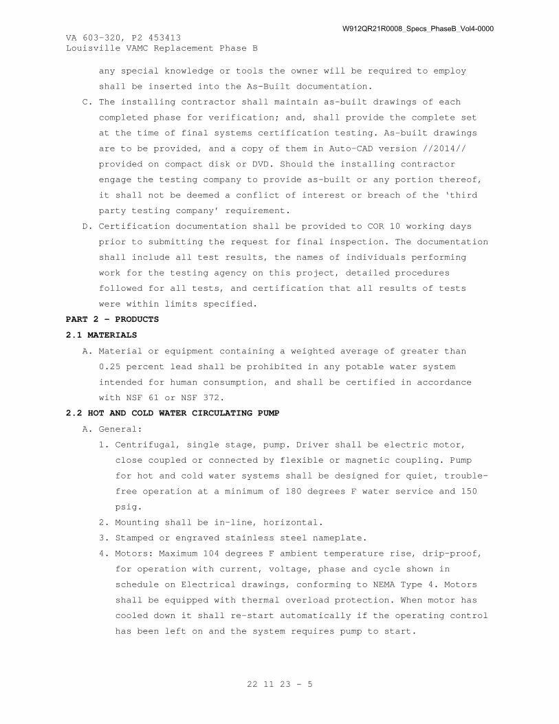
VA 603-320, P2 453413 Louisville VAMC Replacement Phase B
22 11 23 - 5
any special knowledge or tools the owner will be required to employ
shall be inserted into the As-Built documentation.
C. The installing contractor shall maintain as-built drawings of each
completed phase for verification; and, shall provide the complete set
at the time of final systems certification testing. As-built drawings
are to be provided, and a copy of them in Auto-CAD version //2014//
provided on compact disk or DVD. Should the installing contractor
engage the testing company to provide as-built or any portion thereof,
it shall not be deemed a conflict of interest or breach of the ‘third
party testing company’ requirement.
D. Certification documentation shall be provided to COR 10 working days
prior to submitting the request for final inspection. The documentation
shall include all test results, the names of individuals performing
work for the testing agency on this project, detailed procedures
followed for all tests, and certification that all results of tests
were within limits specified.
PART 2 - PRODUCTS
2.1 MATERIALS
A. Material or equipment containing a weighted average of greater than
0.25 percent lead shall be prohibited in any potable water system
intended for human consumption, and shall be certified in accordance
with NSF 61 or NSF 372.
2.2 HOT AND COLD WATER CIRCULATING PUMP
A. General:
1. Centrifugal, single stage, pump. Driver shall be electric motor,
close coupled or connected by flexible or magnetic coupling. Pump
for hot and cold water systems shall be designed for quiet, trouble-
free operation at a minimum of 180 degrees F water service and 150
psig.
2. Mounting shall be in-line, horizontal.
3. Stamped or engraved stainless steel nameplate.
4. Motors: Maximum 104 degrees F ambient temperature rise, drip-proof,
for operation with current, voltage, phase and cycle shown in
schedule on Electrical drawings, conforming to NEMA Type 4. Motors
shall be equipped with thermal overload protection. When motor has
cooled down it shall re-start automatically if the operating control
has been left on and the system requires pump to start.
W912QR21R0008_Specs_PhaseB_Vol4-0000
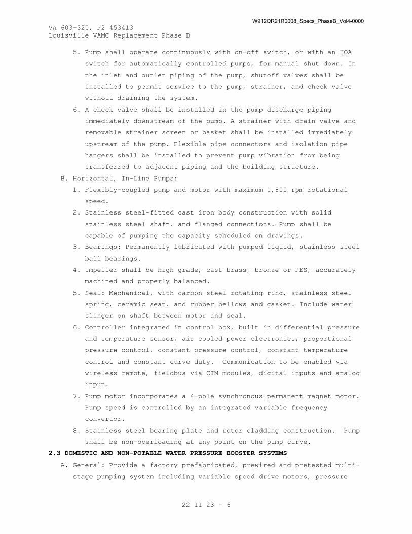
VA 603-320, P2 453413 Louisville VAMC Replacement Phase B
22 11 23 - 6
5. Pump shall operate continuously with on-off switch, or with an HOA
switch for automatically controlled pumps, for manual shut down. In
the inlet and outlet piping of the pump, shutoff valves shall be
installed to permit service to the pump, strainer, and check valve
without draining the system.
6. A check valve shall be installed in the pump discharge piping
immediately downstream of the pump. A strainer with drain valve and
removable strainer screen or basket shall be installed immediately
upstream of the pump. Flexible pipe connectors and isolation pipe
hangers shall be installed to prevent pump vibration from being
transferred to adjacent piping and the building structure.
B. Horizontal, In-Line Pumps:
1. Flexibly-coupled pump and motor with maximum 1,800 rpm rotational
speed.
2. Stainless steel-fitted cast iron body construction with solid
stainless steel shaft, and flanged connections. Pump shall be
capable of pumping the capacity scheduled on drawings.
3. Bearings: Permanently lubricated with pumped liquid, stainless steel
ball bearings.
4. Impeller shall be high grade, cast brass, bronze or PES, accurately
machined and properly balanced.
5. Seal: Mechanical, with carbon-steel rotating ring, stainless steel
spring, ceramic seat, and rubber bellows and gasket. Include water
slinger on shaft between motor and seal.
6. Controller integrated in control box, built in differential pressure
and temperature sensor, air cooled power electronics, proportional
pressure control, constant pressure control, constant temperature
control and constant curve duty. Communication to be enabled via
wireless remote, fieldbus via CIM modules, digital inputs and analog
input.
7. Pump motor incorporates a 4-pole synchronous permanent magnet motor.
Pump speed is controlled by an integrated variable frequency
convertor.
8. Stainless steel bearing plate and rotor cladding construction. Pump
shall be non-overloading at any point on the pump curve.
2.3 DOMESTIC AND NON-POTABLE WATER PRESSURE BOOSTER SYSTEMS
A. General: Provide a factory prefabricated, prewired and pretested multi-
stage pumping system including variable speed drive motors, pressure
W912QR21R0008_Specs_PhaseB_Vol4-0000

VA 603-320, P2 453413 Louisville VAMC Replacement Phase B
22 11 23 - 7
regulating valves with integral check valves, pressure transducers,
vibration pads, emergency switches, duplex flow switches, power and
control panels, suction and discharge manifolds, butterfly isolation
valves, ball drain valves, bypass loops with appropriate valves and
check valves, low pressure cut-off switches, hydropneumatic tanks and
accessories. All components shall be furnished by a single manufacturer
and the system shall be the standard cataloged product of the
manufacturer. All components shall be factory installed on a common
structural steel skid and shall be completely tested in the factory
before shipment. Manufacturer shall assume “unit responsibility” to
ensure that all components effectively interface to execute the
operation of the designed system.
B. System Operation and Configuration:
1. System shall automatically maintain constant system pressure as
scheduled on drawings at the outlet of the pressure control valve
and hydropneumatic tank check valve at all times. Suction pressure
for non-potable water pumps is 0 psig. Suction pressure for domestic
booster pumps varies from 25 psig) to (46 psig). The multi-stage
pumping system shall include the scheduled quantity of pumps.
2. Triplex pump systems shall include a lead pump sized for 50 percent
of the total capacity and lag and stand-by pumps sized for 50
percent of the total capacity.
C. Centrifugal Pump: Pumps shall be single stage, in-line pump with
variable speed drive motor, low pressure cut-off switches and bypass
loops with ball, gate, and check valves as indicated on the Contract
Drawings.
1. Impellers: ASTM B584 Cast bronze, radially or vertically split keyed
to shaft and secured by a locking cap-screw. Each impeller shall be
statically and dynamically balanced prior to assembly in pump
casing. Provide replaceable bronze casing wear rings.
2. Pump shaft: Steel, with replaceable bronze shaft sleeve completely
covering the wetted area of the shaft under the seal.
3. Lubrication: Water lubricated type pump.
4. Pump Casing: ASTM A48/A48M CL20 Cast iron suitable for 175 psig.
Pump volute shall be supplied with vent and drain tappings.
Connections shall be female NPT. The casing shall be O-ring sealed
to the seal housing.
W912QR21R0008_Specs_PhaseB_Vol4-0000

VA 603-320, P2 453413 Louisville VAMC Replacement Phase B
22 11 23 - 8
5. Seal: Mechanical general purpose type, with sleeve mounting. Seal
shall be rated at 175 psig maximum.
6. Adjustable Spacer Coupling: Removable type required so that pump
seal can be replaced without disturbing motor.
7. Motor: Solid shaft motors balanced to 0.0085 inch vibration
amplitude shall be operated at any point on the pump head curve
without overloading the motor. Conform to NEMA Type 2.
D. Vertical Multistage Pump: Pumps shall be vertical multistage short-
coupled pumps with variable speed drive motor, low pressure cut-off
switches and bypass loops with ball, butterfly, check valves as
indicated on the Contract Drawings.
1. Impellers: Cast bronze, mixed flow enclosed type.
2. Balancing of Impellers: Each impeller shall be statically and
dynamically balanced prior to assembly in pump casing.
3. Pump shaft: Stainless steel Type 416.
4. Lubrication: Water lubricated type pump.
5. Pump Bowls: Cast Iron, stainless steel or bronze flanged and bolted.
6. Pump Bearings: Bronze, radial type.
7. Pump Head: Fabricated steel with continuous bypass for low seal
pressure. Cast iron heads are prohibited. Pump head shall be lined
same as pump barrel.
8. Seal: Mechanical general purpose type, with sleeve mounting. Seal
shall be rated at 175 psig maximum.
9. Adjustable Spacer Coupling: Removable type required so that pump
seal can be replaced without disturbing motor.
10. Motor: Solid shaft motors balanced to 0.0085 inch vibration
amplitude shall be operated at any point on the pump head curve
without overloading the motor. Conform to NEMA Type 2.
11. Pump Barrel: Schedule 40 steel pipe with two-coat "baked" internal
lining to meet the potable water requirements of U.S. Food and Drug
Administration. Bio-based materials shall be utilized when possible.
Unlined pump barrels are prohibited. Provide drain tapping.
E. Pressure Regulating Valves: System pressure shall be maintained by
pilot-operated, diaphragm type pressure regulating valves, rated at 300
psig minimum, one for each pump. Valves shall be piloted to control
system pressure and to cause the valve to act as a non-slam check
valve. Pilot shall be rated at 175 psig minimum.
W912QR21R0008_Specs_PhaseB_Vol4-0000

VA 603-320, P2 453413 Louisville VAMC Replacement Phase B
22 11 23 - 9
F. Hydropneumatic Tank: Bladder type, hydropneumatic, designed and
constructed in accordance with requirements of the ASME Pressure Vessel
Code and stamped with appropriate symbol. Tank shall include pre-
pressurized, sealed-in air cushion which shall accommodate pressure
increases and expanded water volumes in the tank. Tank shall include
butyl rubber or poly-propylene liner in lower, or water side of
chamber. Minimum working pressure of tank shall be 175 psig. Unit shall
be designed and manufactured for domestic water applications. Insulate
tank as specified. Check valve at hydropneumatic tank shall include
small orifice for undue loading.
G. Power and Control Panel: Class "A" shadow box double NEMA 1 enclosure,
UL labeled, bonderized double prime coated with baked enamel finish:
1. Fused disconnect switches with external operating handles.
2. Magnetic contactor for each motor with HOA switch.
3. Door interlock.
4. Thermal overload protection relay for each motor, three leg type.
5. Running light for each motor.
6. Power light for each motor.
7. Control transformer, switch, circuit breaker, light.
8. Lead pump failure protection.
H. Motor and Starter: Maximum 104 degrees F ambient temperature rise,
drip-proof type motor, ball bearings, voltage and phase as shown in
schedule on Electrical drawings, conforming to NEMA Type 4. Motor shall
be of such capacity that brake horsepower required by driven equipment
at normal rated capacity will not exceed nameplate rating of the motor.
Refer to Section 22 05 12, GENERAL MOTOR REQUIREMENTS FOR PLUMBING
EQUIPMENT. Provide each motor with automatic, fully enclosed, magnetic
starter of type specified in Section 26 29 11, MOTOR CONTROLLERS.
I. Instrumentation: All instrumentation shall be factory installed and
shall include the following 4-1/2 inch dial gages with shut-off cock.
1. Pump pressure gage for each pump.
2. System pressure gage.
3. Suction pressure gage.
J. Operating and Emergency Controls:
1. The pump station shall receive a 4-20mA signal from each pressure
transducer, as provided by the pumping station manufacturer. A
pressure transducer signal shall be provided for each pump
controller. The differential pressure transducers shall monitor
W912QR21R0008_Specs_PhaseB_Vol4-0000

VA 603-320, P2 453413 Louisville VAMC Replacement Phase B
22 11 23 - 10
system discharge pressure versus suction line pressure and provide
an analog signal 4-20mA to the pump control software, and allow the
variable speed pump controller, to provide a variable Volts/Hz
output to the motor. Once the pressure drops below the set system
pressure, the pump shall start and provide system pressure (as
determined by the station operator or program), if this pressure
cannot be maintained by one pump, the next pump in sequence shall
operate in a lead/lag capacity to provide the extra flow and
pressure automatically without the use of additional panels or
alternators. The sequence of the pumps shall be field adjustable,
and completely automatic without additional panels or alternator
controls. The variable speed pump controller shall be completely
integrated with the VFD. Special type motors shall not be allowed.
Refer to Section 22 05 12, GENERAL MOTOR REQUIREMENTS FOR PLUMBING
EQUIPMENT. Pump assignments shall alternate as described below. All
program settings shall be based on centrifugal pump language and
centrifugal pumps. Program settings shall be field adjustable to
provide onsite adjustments. When the system experiences low demand,
the variable speed pump controllers shall reduce the speed of each
pump, until demand has stopped. Pump controllers shall stop each
pump at zero demand, without the use of external switches or
controls.
2. The pumping system includes multiple pumps as indicated above. In
three-pump systems, the lead pump, lag pump, and stand-by pump
normally satisfy demand in three stages. The first (lead) pump
operates initially, until the water demand exceeds the lead pump’s
capacity. The second (lag) pump starts and the lead pump stops,
allowing the lag pump to operate until the water demand exceeds the
lag pump’s capacity. At this point, the lead pump restarts, and
operates concurrently with the lag pump to add capacity when needed.
The third pump is a stand-by pump, ready for operation if the lead
or lag pump is taken out of service and the system demand requires
two pumps. The system is to be configured so that at least two pumps
can be in service if any one pump is taken out of service. Pump
assignments shall alternate to automatically equalize the run time
in similarly sized pumps, which excludes uniquely-sized lead pumps.
3. The pump logic controller shall provide the following standard user-
selectable features:
W912QR21R0008_Specs_PhaseB_Vol4-0000

VA 603-320, P2 453413 Louisville VAMC Replacement Phase B
22 11 23 - 11
a. Low Suction Pressure Alarm and Cut Out
b. High Suction Pressure Alarm and Cut Out
c. Low System Pressure Alarm
d. High System Pressure Alarm and Cut Out
e. High Temperature Alarm and Cut Out
f. Low Level Alarm and Cut Out
g. No-Flow Shut Down
h. Audible/Visible alarm with push to silence feature
i. Overload Failure Alarm
j. Pump Failure Alarm
k. Pump operating order assignments
l. Minimum run timers to prevent short cycle operation.
4. Provide auxiliary contacts for remote communication with the BAS,
including the following input/output points:
a. Domestic water supply pressure (analog input to BAS)
b. Alarm condition activated (binary input to BAS)
c. Run status of lead pump (binary input to BAS)
d. Run status of lag pump (binary input to BAS)
e. Run status of stand-by pump (binary input to BAS)
K. Factory Test: The booster system and its component parts shall undergo
a complete operation flow test from zero to 100 percent design flow
rate under the specified suction and net system pressure conditions.
The system certification shall include copies of the test and test data
as performed in the factory prior to shipment. Performance test
certifications should be placed inside the system control panel and two
extra copies shall be provided to the Contracting Officer with the
installation manual.
PART 3 - EXECUTION
3.1 STARTUP AND TESTING
A. Make tests as recommended by product manufacturer and listed standards
and under actual or simulated operating conditions and prove full
compliance with design and specified requirements. Tests of the various
items of equipment shall be performed simultaneously with the system of
which each item is an integral part.
B. System Test: After installation is completed provide an operational
test of the completed system including flow rates, pressure compliance,
alarms and all control functions.
W912QR21R0008_Specs_PhaseB_Vol4-0000

VA 603-320, P2 453413 Louisville VAMC Replacement Phase B
22 11 23 - 12
C. When any defects are detected, correct defects and repeat test at no
additional cost or time to the Government.
D. The CxA will observe startup and contractor testing of selected
equipment. Coordinate the startup and contractor testing schedules with
the COR and CxA. Contractor shall provide a minimum of 10 working days
prior to startup and testing.
3.2 COMMISSIONING
A. Provide commissioning documentation in accordance with the requirements
of Section 22 08 00, COMMISSIONING OF PLUMBING SYSTEMS.
B. Components provided under this section of the specification will be
tested as part of a larger system.
3.3 DEMONSTRATION AND TRAINING
A. Provide services of manufacturer’s technical representative for four
hours to instruct VA Personnel in operation and maintenance of the
system.
B. Submit training plans and instructor qualifications in accordance with
the requirements of Section 22 08 00, COMMISSIONING OF PLUMBING SYSTEMS
and Section 01 79 00, OPERATIONS AND MAINTENANCE TRAINING.
- - - E N D - - -
W912QR21R0008_Specs_PhaseB_Vol4-0000

VA 603-320, P2 453413 Louisville VAMC Replacement Phase B
22 13 00 - 1
SECTION 22 13 00 FACILITY SANITARY AND VENT PIPING
PART 1 - GENERAL
1.1 DESCRIPTION
A. This section pertains to sanitary sewer and vent systems, including
piping, equipment and all necessary accessories as designated in this
section.
B. A complete listing of all acronyms and abbreviations are included in
Section 22 05 11, COMMON WORK RESULTS FOR PLUMBING.
1.2 RELATED WORK
A. Section 01 33 00, SUBMITTAL PROCEDURES.
B. Section 01 81 13, SUSTAINABLE CONSTRUCTION REQUIREMENTS.
C. Section 01 91 00, GENERAL COMMISSIONING REQUIREMENTS.
D. Section 07 84 00, FIRESTOPPING: Penetrations in rated enclosures.
E. Section 07 92 00, JOINT SEALANTS: Sealant products.
F. Section 09 91 00, PAINTING: Preparation and finish painting and
identification of piping systems.
G. Section 22 05 11, COMMON WORK RESULTS FOR PLUMBING: Pipe Hangers and
Supports, Materials Identification.
H. Section 22 07 11, PLUMBING INSULATION.
I. Section 22 08 00, COMMISSIONING OF PLUMBING SYSTEMSJ. Section 26 05 26,
GROUNDING AND BONDING FOR ELECTRICAL SYSTEMS.
K. Section 26 05 33, RACEWAY AND BOXES FOR ELECTRICAL SYSTEMS.
1.3 APPLICABLE PUBLICATIONS
A. The publications listed below form a part of this specification to the
extent referenced. The publications are referenced in the text by the
basic designation only.
B. American Society of Mechanical Engineers (ASME):
A13.1-2007..............Scheme for the Identification of Piping Systems
A112.36.2M-1991(R 2012).Cleanouts
A112.6.3-2001 (R2007)...Standard for Floor and Trench Drains
B1.20.1-2013............Pipe Threads, General Purpose (Inch)
B16.1-2010..............Gray Iron Pipe Flanges and Flanged Fittings
B16.4-2011..............Standard for Grey Iron Threaded Fittings
Classes 125 and 250
B16.15-2013.............Cast Copper Alloy Threaded Fittings, Classes
125 and 250
W912QR21R0008_Specs_PhaseB_Vol4-0000
VA 603-320, P2 453413 Louisville VAMC Replacement Phase B
22 13 00 - 2
B16.18-2012.............Cast Copper Alloy Solder Joint Pressure
Fittings
B16.21-2011.............Nonmetallic Flat Gaskets for Pipe Flanges
B16.22-2013.............Wrought Copper and Copper Alloy Solder-Joint
Pressure Fittings
B16.23-2011.............Cast Copper Alloy Solder Joint Drainage
Fittings: DWV
B16.24-2001 (R2006).....Cast Copper Alloy Pipe Flanges and Flanged
Fittings
B16.29-2012.............Wrought Copper and Wrought Copper Alloy Solder-
Joint Drainage Fittings: DWV
B16.39-2009.............Malleable Iron Threaded Pipe Unions Classes
150, 250, and 300
B18.2.1-2012............Square, Hex, Heavy Hex, and Askew Head Bolts
and Hex, Heavy Hex, Hex Flange, Lobed Head, and
Lag Screws (Inch Series)
C. American Society of Sanitary Engineers (ASSE):
1001-2008...............Performance Requirements for Atmospheric Type
Vacuum Breakers
1018-2001...............Performance Requirements for Trap Seal Primer
Valves – Potable Water Supplied
1044-2001...............Performance Requirements for Trap Seal Primer
Devices – Drainage Types and Electronic Design
Types
1079-2012...............Performance Requirements for Dielectric Pipe
Unions
D. American Society for Testing and Materials (ASTM):
A53/A53M-2012...........Standard Specification for Pipe, Steel, Black
And Hot-Dipped, Zinc-coated, Welded and
Seamless
A74-2013a...............Standard Specification for Cast Iron Soil Pipe
and Fittings
A888-2013a..............Standard Specification for Hubless Cast Iron
Soil Pipe and Fittings for Sanitary and Storm
Drain, Waste, and Vent Piping Applications
B32-2008................Standard Specification for Solder Metal
B43-2009................Standard Specification for Seamless Red Brass
Pipe, Standard Sizes
W912QR21R0008_Specs_PhaseB_Vol4-0000
VA 603-320, P2 453413 Louisville VAMC Replacement Phase B
22 13 00 - 3
B75-2011................Standard Specification for Seamless Copper Tube
B88-2009................Standard Specification for Seamless Copper
Water Tube
B306-2013...............Standard Specification for Copper Drainage Tube
(DWV)
B584-2013...............Standard Specification for Copper Alloy Sand
Castings for General Applications
B687-1999 (R 2011)......Standard Specification for Brass, Copper, and
Chromium-Plated Pipe Nipples
B813-2010...............Standard Specification for Liquid and Paste
Fluxes for Soldering of Copper and Copper Alloy
Tube
B828-2002 (R 2010)......Standard Practice for Making Capillary Joints
by Soldering of Copper and Copper Alloy Tube
and Fittings
C564-2012...............Standard Specification for Rubber Gaskets for
Cast Iron Soil Pipe and Fittings
D1785-2012..............Standard Specification for Poly(Vinyl Chloride)
(PVC) Plastic Pipe, Schedules 40, 80, and 120
D2321-2011..............Standard Practice for Underground Installation
of Thermoplastic Pipe for Sewers and Other
Gravity-Flow Applications
D2564-2012..............Standard Specification for Solvent Cements for
Poly(Vinyl Chloride) (PVC) Plastic Piping
Systems
D2665-2012..............Standard Specification for Poly(Vinyl Chloride)
(PVC) Plastic Drain, Waste, and Vent Pipe and
Fittings
D2855-1996 (R 2010).....Standard Practice for Making Solvent-Cemented
Joints with Poly(Vinyl Chloride) (PVC) Pipe and
Fittings
D5926-2011..............Standard Specification for Poly(Vinyl Chloride)
(PVC) Gaskets for Drain, Waste, and Vent (DWV),
Sewer, Sanitary, and Storm Plumbing Systems
F402-2005 (R 2012)......Standard Practice for Safe Handling of Solvent
Cements, Primers, and Cleaners Used for Joining
Thermoplastic Pipe and Fittings
W912QR21R0008_Specs_PhaseB_Vol4-0000
VA 603-320, P2 453413 Louisville VAMC Replacement Phase B
22 13 00 - 4
F477-2010...............Standard Specification for Elastomeric Seals
(Gaskets) for Joining Plastic Pipe
F1545-1997 (R 2009).....Standard Specification for Plastic-Lined
Ferrous Metal Pipe, Fittings, and Flanges
E. Cast Iron Soil Pipe Institute (CISPI):
2006....................Cast Iron Soil Pipe and Fittings Handbook
301-2012................Standard Specification for Hubless Cast Iron
Soil Pipe and Fittings for Sanitary and Storm
Drain, Waste, and Vent Piping Applications
310-2012................Specification for Coupling for Use in
Connection with Hubless Cast Iron Soil Pipe and
Fittings for Sanitary and Storm Drain, Waste,
and Vent Piping Applications
F. Copper Development Association, Inc. (CDA):
A4015...................Copper Tube Handbook
G. International Code Council (ICC):
IPC-2015................International Plumbing Code
H. Manufacturers Standardization Society (MSS):
SP-123-2013.............Non-Ferrous Threaded and Solder-Joint Unions
for Use With Copper Water Tube
I. National Fire Protection Association (NFPA):
70-2014.................National Electrical Code (NEC)
J. Plumbing and Drainage Institute (PDI):
WH-201 (R 2010).........Water Hammer Arrestors Standard
K. Underwriters' Laboratories, Inc. (UL):
508-99 (R2013)..........Standard For Industrial Control Equipment
1.4 SUBMITTALS
A. Submittals, including number of required copies, shall be submitted in
accordance with Section 01 33 00, SUBMITTAL PROCEDURES..
B. Information and material submitted under this section shall be marked
“SUBMITTED UNDER SECTION 22 13 00, FACILITY SANITARY AND VENT PIPING”,
with applicable paragraph identification.
C. Manufacturer's Literature and Data including: Full item description and
optional features and accessories. Include dimensions, weights,
materials, applications, standard compliance, model numbers, size, and
capacity.
1. Piping.
2. Floor Drains.
W912QR21R0008_Specs_PhaseB_Vol4-0000

VA 603-320, P2 453413 Louisville VAMC Replacement Phase B
22 13 00 - 5
3. Grease Removal Unit.
4. Cleanouts.
5. Trap Seal Protection.
6. Penetration Sleeves.
7. Pipe Fittings.
8. Traps.
9. Exposed Piping and Fittings.
D. Detailed shop drawing of clamping device and extensions when required
in connection with the waterproofing membrane or the floor drain.
1.5 QUALITY ASSURANCE
A. Bio-Based Materials: For products designated by the USDA’s Bio-
Preferred Program, provide products that meet or exceed USDA
recommendations for bio-based content, so long as products meet all
performance requirements in this specifications section. For more
information regarding the product categories covered by the Bio-
Preferred Program, visit http://www.biopreferred.gov .
1.6 AS-BUILT DOCUMENTATION
A. The installing contractor shall maintain as-built drawings of each
completed phase for verification; and, shall provide the complete set
at the time of final systems certification testing. As-built drawings
are to be provided, and a copy of them on Auto-Cad version 2014
provided on compact disk or DVD. Should the installing contractor
engage the testing company to provide as-built or any portion thereof,
it shall not be deemed a conflict of interest or breach of the ‘third
party testing company’ requirement.
B. Certification documentation shall be provided prior to submitting the
request for final inspection. The documentation shall include all test
results, the names of individuals performing work for the testing
agency on this project, detailed procedures followed for all tests, and
a certification that all results of tests were within limits specified.
PART 2 - PRODUCTS
2.1 SANITARY WASTE, DRAIN, AND VENT PIPING
A. Cast iron waste, drain, and vent pipe and fittings.
1. Cast iron waste, drain, and vent pipe and fittings shall be used for
the following applications:
a. Pipe buried in or in contact with earth.
b. Sanitary pipe extensions to a distance of approximately 1500 mm
(5 feet) outside of the building.
W912QR21R0008_Specs_PhaseB_Vol4-0000

VA 603-320, P2 453413 Louisville VAMC Replacement Phase B
22 13 00 - 6
c. Interior waste and vent piping above grade.
2. Cast iron Pipe shall be bell and spigot or hubless (plain end or no-
hub or hubless).
3. The material for all pipe and fittings shall be cast iron soil pipe
and fittings and shall conform to the requirements of CISPI 301,
ASTM A888, or ASTM A74.
4. Cast iron pipe and fittings shall be made from a minimum of 95
percent post-consumer recycled material.
5. Joints for hubless pipe and fittings shall conform to the
manufacturer’s installation instructions. Couplings for hubless
joints shall conform to CISPI 310. Joints for hub and spigot pipe
shall be installed with compression gaskets conforming to the
requirements of ASTM C564.
B. Copper Tube, (DWV):
1. Copper DWV tube sanitary waste, drain and vent pipe may be used for
piping above ground, except for urinal drains.
2. The copper DWV tube shall be drainage type, drawn temper conforming
to ASTM B306.
3. The copper drainage fittings shall be cast copper or wrought copper
conforming to ASME B16.23 or ASME B16.29.
4. The joints shall be lead free, using a water flushable flux, and
conforming to ASTM B32.
2.2 PUMP DISCHARGE PIPING
A. Galvanized steel pump discharge pipe and fittings:
1. Galvanized steel pipe shall be Schedule 40 weight class conforming
to ASTM A53/A53M, with square cut grooved or threaded ends to match
joining method.
2. Fittings shall be Class 125, gray-iron threaded fittings conforming
to ASME B16.4.
3. Unions shall be Class 150 hexagonal-stock body with ball and socket,
metal to metal, bronze seating surface, malleable iron conforming to
ASME B16.39 with female threaded ends.
4. Flanges shall be Class 125 cast iron conforming to ASME B16.1.
a. Flange gaskets shall be full face, flat nonmetallic, asbestos
free conforming to ASME B16.21.
b. Flange nuts and bolts shall be carbon steel conforming to ASME
B18.2.1.
W912QR21R0008_Specs_PhaseB_Vol4-0000

VA 603-320, P2 453413 Louisville VAMC Replacement Phase B
22 13 00 - 7
B. Copper pump discharge pipe and fittings:
1. Copper tube shall be hard drawn Type L conforming to ASTM B88.
2. Fittings shall be cast copper alloy conforming to ASME B16.18 or
wrought copper conforming to ASME B16.22 with solder joint ends.
3. Unions shall be copper alloy, hexagonal stock body with ball and
socket, metal to metal seating surface conforming to MSS SP-123 with
female threaded ends.
4. Flanges shall be Class 150, cast copper conforming to ASME B16.24
with solder-joint end.
a. Flange gaskets shall be full face, flat nonmetallic, asbestos
free conforming to ASME B16.21.
b. Flange nuts and bolts shall be carbon steel conforming to ASME
B18.2.1.
5. Solder shall be lead free, water flushable flux conforming to ASTM
B32 and ASTM B813.
2.3 EXPOSED WASTE PIPING
A. Chrome plated brass piping of full iron pipe size shall be used in
finished rooms for exposed waste piping connecting fixtures, casework,
cabinets, equipment and reagent racks when not concealed by apron
including those furnished by the Government or specified in other
sections.
1. The Pipe shall meet ASTM B43, regular weight.
2. The Fittings shall conform to ASME B16.15.
3. Nipples shall conform to ASTM B687, Chromium-plated.
4. Unions shall be brass or bronze with chrome finish. Unions 2-1/2
inches and larger shall be flange type with approved gaskets.
B. In unfinished Rooms such as mechanical Rooms and Kitchens,
Chrome-plated brass piping is not required. The pipe materials
specified under the paragraph “Sanitary Waste, Drain, and Vent Piping”
can be used. The sanitary pipe in unfinished rooms shall be painted as
specified in Section 09 91 00, PAINTING.
2.4 SPECIALTY PIPE FITTINGS
A. Transition pipe couplings shall join piping with small differences in
outside diameters or different materials. End connections shall be of
the same size and compatible with the pipes being joined. The
transition coupling shall be elastomeric, sleeve type reducing or
transition pattern and include shear and corrosion resistant metal,
W912QR21R0008_Specs_PhaseB_Vol4-0000

VA 603-320, P2 453413 Louisville VAMC Replacement Phase B
22 13 00 - 8
tension band and tightening mechanism on each end. The transition
coupling sleeve coupling shall be of the following material:
1. For cast iron soil pipes, the sleeve material shall be rubber
conforming to ASTM C564.
2. For dissimilar pipes, the sleeve material shall be PVC conforming to
ASTM D5926, or other material compatible with the pipe materials
being joined.
B. The dielectric fittings shall conform to ASSE 1079 with a pressure
rating of 125 psig at a minimum temperature of 180 degrees F. The end
connection shall be solder joint copper alloy and threaded ferrous.
C. Dielectric flange insulating kits shall be of non-conducting materials
for field assembly of companion flanges with a pressure rating of 150
psig. The gasket shall be neoprene or phenolic. The bolt sleeves shall
be phenolic or polyethylene. The washers shall be phenolic with steel
backing washers.
D. The di-electric nipples shall be electroplated steel nipple complying
with ASTM F1545 with a pressure rating of 300 psig at 225 degrees F.
The end connection shall be male threaded. The lining shall be inert
and noncorrosive propylene.
2.5 CLEANOUTS
A. Cleanouts shall be the same size as the pipe, up to 4 inches; and not
less than 4 inches for larger pipe. Cleanouts shall be easily
accessible and shall be gastight and watertight. Minimum clearance of
24 inches shall be provided for clearing a clogged sanitary line.
B. Floor cleanouts shall be gray iron housing with clamping device and
round, secured, scoriated, gray iron cover conforming to ASME
A112.36.2M. A gray iron ferrule with hubless, socket, inside calk or
spigot connection and counter sunk, taper-thread, brass or bronze
closure plug shall be included. The frame and cover material and finish
shall be nickel-bronze copper alloy with a square shape. The cleanout
shall be vertically adjustable for a minimum of 2 inches. When a
waterproof membrane is used in the floor system, clamping collars shall
be provided on the cleanouts. Cleanouts shall consist of wye fittings
and eighth bends with brass or bronze screw plugs. Cleanouts in the
resilient tile floors, quarry tile and ceramic tile floors shall be
provided with square top covers recessed for tile insertion. In the
carpeted areas, carpet cleanout markers shall be provided. Two way
cleanouts shall be provided where indicated on drawings and at every
W912QR21R0008_Specs_PhaseB_Vol4-0000

VA 603-320, P2 453413 Louisville VAMC Replacement Phase B
22 13 00 - 9
building exit, unless a manhole is installed for piping larger than 8
inch as required by IPC. The loading classification for cleanouts in
sidewalk areas or subject to vehicular traffic shall be heavy duty
type.
C. Cleanouts shall be provided at or near the base of the vertical stacks
with the cleanout plug located approximately 24 inches above the floor.
If there are no fixtures installed on the lowest floor, the cleanout
shall be installed at the base of the stack. The cleanouts shall be
extended to the wall access cover. Cleanout shall consist of sanitary
tees. Nickel-bronze square frame and stainless steel cover with minimum
opening of 6 by 6 inches shall be furnished at each wall cleanout.
Where the piping is concealed, a fixture trap or a fixture with
integral trap, readily removable without disturbing concealed pipe,
shall be accepted as a cleanout equivalent providing the opening to be
used as a cleanout opening is the size required.
D. In horizontal runs above grade, cleanouts shall consist of cast brass
tapered screw plug in fitting or caulked/hubless cast iron ferrule.
Plain end (hubless) piping in interstitial space or above ceiling may
use plain end (hubless) blind plug and clamp.
2.6 FLOOR DRAINS
A. General Data: floor drain shall comply with ASME A112.6.3. A caulking
flange, inside gasket, or hubless connection shall be provided for
connection to cast iron pipe, screwed or no hub outlets for connection
to steel pipe. The drain connection shall be bottom outlet. A membrane
clamp and extensions shall be provided, if required, where installed in
connection with waterproof membrane. Puncturing membrane other than for
drain opening will not be permitted. Double drainage pattern floor
drains shall have integral seepage pan for embedding into floor
construction, and weep holes to provide adequate drainage from pan to
drain pipe. For drains not installed in connection with a waterproof
membrane, a 2.5 to 4 lbs. flashing membrane, 24 inches square or
another approved waterproof membrane shall be provided.
B. Type B (FDB) medium duty (non-traffic) floor drain shall comply with
ASME A112.6.3. The type B floor drain shall be constructed of
galvanized cast iron with medium duty nickel bronze grate, double
drainage pattern, clamping device, without sediment bucket but with
secondary strainer in bottom for large debris. The grate shall be 7
inches minimum.
W912QR21R0008_Specs_PhaseB_Vol4-0000

VA 603-320, P2 453413 Louisville VAMC Replacement Phase B
22 13 00 - 10
C. Type C (FDC) medium duty (non-traffic) floor drain shall comply with
ASME A112.6.3. The type C floor drain shall have a cast iron body,
double drainage pattern, clamping device, light duty nickel bronze
adjustable strainer with round or square grate of 6 inches width or
diameter minimum for toilet rooms, showers and kitchens.
D. Type D (FDD) medium duty (non-traffic) floor drain shall comply with
ASME A112.6.3. The type D floor drain shall have a cast iron body with
flange for membrane type flooring, integral reversible clamping device,
seepage openings and 7 inch diameter or square satin nickel bronze or
satin bronze strainer with 4 inch flange for toilet rooms, showers and
kitchens.
E. Type E (FDE) floor drain shall comply with ASME A112.6.3. The type E
floor drain shall have a heavy, cast iron body, double drainage
pattern, heavy non-tilting ductile iron grate not less than 12 inches
square, and removable sediment bucket. Clearance between body and
bucket shall be ample for free flow of waste water. For traffic use, an
extra heavy duty load classification ductile iron grate shall be
provided.
F. Type F (FDF) medium duty (non-traffic) floor drain shall comply with
ASME A112.6.3. The type F floor drain shall be have a cast iron body
with flange, integral reversible clamping device, seepage openings and
a 9 inch two-piece satin nickel-bronze or satin bronze strainer for use
with seamless vinyl floors in toilet rooms and showers.
G. Type G (FD-G) medium duty (non-traffic) floor drain shall comply with
ASME A112.6.3. The type G floor drain shall have a cast iron body,
shallow type with double drainage flange and removable, perforated
aluminum sediment bucket. The type G drain shall have all interior and
exposed exterior surfaces coated with acid resistant porcelain enamel
finish. The floor drain shall have a clamping device. The frame and
grate shall be nickel bronze. The grate shall be approximately 8 inches
in diameter. The space between body of drain and basket shall be
sufficient for free flow of waste water.
H. Type J (FDJ) floor drain shall comply with ASME A112.6.3. The type J
floor drain shall be a flushing rim drain with heavy duty cast iron
body, double drainage pattern with flushing rim and clamping device.
The nickel bronze grate shall be approximately 11 inches in diameter
and flush with floor. A deep-seal P-trap shall be attached to drain.
The body and trap shall have pipe taps for water supply connections.
W912QR21R0008_Specs_PhaseB_Vol4-0000

VA 603-320, P2 453413 Louisville VAMC Replacement Phase B
22 13 00 - 11
1. Drain Flange: Flange for synthetic flooring.
2. Flush Valve: Large diaphragm flushometer, exposed, side oscillating
handle. For the flush valve mounting and installation detail, see
the detail indicated on the drawings.
I. Type L (FDL) floor drain shall comply with ASME A112.6.3. The type L
floor drain shall be a flushing rim drain with heavy cast iron body,
double drainage pattern with flushing rim and clamping device. Solid
bronze gasketed grate shall be approximately 280 mm (11 inches) in
diameter, with 50 mm (2 inch) length of 20 mm (3/4 inch) brass pipe
brazed or threaded into the center of the solid grate. Pipe shall be
threaded and provided with a brass cap with inter gasket (neoprene) to
provide a gas tight installation. A deep-seal P-trap shall be attached
to drain. Body and trap shall have pipe taps for water supply
connections. Used in dialysis rooms.
1. Drain Flange: Flange for synthetic flooring.
2. Cystoscopy Rooms:
a. Flush Valve: The flush valves shall be large diaphragm type
flushometer, solenoid operated with a single-circuit timer. Mount
in valve cabinet.
b. Operation: Valve solenoid shall be cycled by a single-circuit
timer set to operate flush valve at five minute intervals. Timer
shall be electrically connected to an "on-off" toggle switch and
be provided with pilot light. Timer and flush valve shall operate
only when timer/valve switch is in the "on" position.
c. Valve Cabinets:
1) General: Sheet metal not lighter than 1.6 mm thick (16 gauge),
size as required, rigidly assembled with joints welded, and
punched or drilled for passage of required pipes and services.
Provide anchors for fastening cabinet in place. Front shall be
flush with wall finish and shall have flush fitting, hinged
doors, with latch. Door shall be arranged to not offer any
obstruction when open.
2) Doors and Trim: Flush with front of cabinet, constructed of
not lighter than number 2.7 mm thick (12 gauge) steel. Doors
shall open through 180 degrees and be provided with two butt
hinges or continuous hinge. Latch shall be provided by
manufacture of cabinet.
W912QR21R0008_Specs_PhaseB_Vol4-0000

VA 603-320, P2 453413 Louisville VAMC Replacement Phase B
22 13 00 - 12
3) Painting: Prime and finish painting is specified under Section
09 91 00, PAINTING.
J. Type M (FDM) medium duty (non-traffic) floor drain shall comply with
ASME A112.6.3. The type M floor drain shall have a cast iron body,
nickel bronze adjustable funnel strainer and clamping device. Funnel
strainer shall consist of a perforated floor-level square or round
grate and funnel extension for indirect waste. Cut-out grate below
funnel. Minimum dimensions as follows:
1. Area of strainer and collar – 23,000 square mm (36 square inches).
2. Height of funnel – 95 mm (3-3/4 inches).
3. Diameter of lower portion of funnel – 50 mm (2 inches).
4. Diameter of top portion of funnel – 100 mm (4 inches).
5. Provide paper collars for construction purposes.
K. Type R (FDR) floor drain shall comply with ASME A112.6.3. The type R
floor drain shall have a cast iron body, double drainage pattern and
clamping device, less grate and sediment basket but with dome type
secondary strainer. The drain shall be 8 inches in diameter or 200 mm
(8 inches) square and approximately 6 inches deep. The interior and
exposed exterior surfaces and rim shall have an acid resisting finish
for indirect waste in sanitary areas.
L. Type S (FDS) floor sink shall comply with ASME A112.6.3. The type S
floor sink shall be constructed from type 304 stainless steel and shall
be 300 mm (12 inches) square, and 200 mm (8 inches deep). The interior
surface shall be polished. The double drainage flange shall be provided
with weep holes, internal dome strainer, and heavy duty non-tilting
loose set grate. A clamping device shall be provided.
M. Type W (FDW) Open Sight Drains (OSDs) for clear water wastes only:
1. OSD’s shall be the cast iron open hub type.
2. A cast iron drain standpipe shall be utilized for equipment with a
high rate of discharge.
N. Type X (FDX) floor drain shall comply with ASME A112.6.3. The type X
floor drain shall be a chemical resistant floor drain and integral p-
trap. Double drainage pattern floor drain shall have integral seepage
pan for embedding in floor and weep holes to provide adequate drainage
from pan to drain pipe. Floor drain shall be polypropylene, flame
retardant, Schedule 40 or 80. An outlet of floor drain shall be
suitable for properly joining a perforated or slotted floor level
grate.
W912QR21R0008_Specs_PhaseB_Vol4-0000

VA 603-320, P2 453413 Louisville VAMC Replacement Phase B
22 13 00 - 13
2.7 TRENCH DRAINS
A. 6-inch wide modular interlocking system with 0.6% built-in sloped
channels. First sloped channel shall be 5-1/2-inch deep. Channels
shall all be the same width and length and be constructed of precast
polyester concrete with water absorption rate of less than 1%. Provide
a slotted ductile iron grating over the entire length of drain with a
Class F load rating. Grating shall be secured with a locking device
including all nuts and bolts. Provide trench drain complete with all
channel end caps and neutral (non-sloped) channels so that total length
is as noted on Drawings.
2.8 TRAPS
A. Traps shall be provided on all sanitary branch waste connections from
fixtures or equipment not provided with traps. Exposed brass shall be
polished brass chromium plated with nipple and set screw escutcheons.
Concealed traps may be rough cast brass or same material as the piping
they are connected to. Slip joints are not permitted on sewer side of
trap. Traps shall correspond to fittings on cast iron soil pipe or
steel pipe respectively, and size shall be as required by connected
service or fixture.
2.9 PRIMER VALVES AND TRAP SEAL PRIMER SYSTEMS
A. Trap Primer (TP-1): The trap seal primer system shall be electronic
type conforming to ASSE 1044.
1. The controller shall have a 24 hour programmable timer, solid state,
6 outlet zones, minimum adjustable run time of 1 minute for each
zone, 12 hour program battery backup, manual switch for 120VAC
power, 120VAC to 24VAC internal transformer, fuse protected
circuitry, UL listed, 120VAC input-24VAC output, constructed of
enameled steel or plastic.
2. The cabinet shall be recessed or surface mounted as shown on the
drawings. Cabinet shall have a stainless steel cover.
3. The solenoid valve shall have a brass body, suitable for potable
water service, normally closed, 125 psig rated, 24VAC.
4. The control wiring shall be copper in accordance with the National
Electric Code (NFPA 70), Article 725 and not less than 18 gauge. All
wiring shall be in conduit and in accordance with Division 26 of the
specifications.
5. The vacuum breaker shall conform to ASSE 1001.
W912QR21R0008_Specs_PhaseB_Vol4-0000

VA 603-320, P2 453413 Louisville VAMC Replacement Phase B
22 13 00 - 14
B. Trap Primer (TP-2): The trap seal primer valve shall be hydraulic,
supply type with a pressure rating of 125 psig and conforming to
standard ASSE 1018.
1. The inlet and outlet connections shall be NPS 1/2 inch
2. The trap seal primer valve shall be fully automatic with an all
brass or bronze body.
3. The trap seal primer valve shall be activated by a drop in building
water pressure, no adjustment required. Trap primer to require no
greater than 3 psi to activate.
4. The trap seal primer valve shall include a manifold when serving
two, three, or four traps.
5. The manifold shall be omitted when serving only one trap.
2.10 PENETRATION SLEEVES
A. A sleeve flashing device shall be provided at points where pipes pass
through membrane waterproofed floors or walls. The sleeve flashing
device shall be manufactured, cast iron fitting with clamping device
that forms a sleeve for the pipe floor penetration of the floor
membrane. A galvanized steel pipe extension shall be included in the
top of the fitting that will extend 2 inches above finished floor and
galvanized steel pipe extension in the bottom of the fitting that will
extend through the floor slab. A waterproof caulked joint shall be
provided at the top hub.
PART 3 - EXECUTION
3.1 PIPE INSTALLATION
A. The pipe installation shall comply with the requirements of the
International Plumbing Code (IPC) and these specifications.
B. Branch piping shall be installed for waste from the respective piping
systems and connect to all fixtures, valves, cocks, outlets, casework,
cabinets and equipment, including those furnished by the Government or
specified in other sections.
C. Pipe shall be round and straight. Cutting shall be done with proper
tools. Pipe shall be reamed to full size after cutting.
D. All pipe runs shall be laid out to avoid interference with other work.
E. The piping shall be installed above accessible ceilings where possible.
F. The piping shall be installed to permit valve servicing or operation.
G. The piping shall be installed free of sags and bends.
H. Seismic restraint shall be installed where required by code.
W912QR21R0008_Specs_PhaseB_Vol4-0000
VA 603-320, P2 453413 Louisville VAMC Replacement Phase B
22 13 00 - 15
I. Changes in direction for soil and waste drainage and vent piping shall
be made using appropriate branches, bends and long sweep bends.
Sanitary tees and short sweep quarter bends may be used on vertical
stacks if change in direction of flow is from horizontal to vertical.
Long turn double wye branch and eighth bend fittings shall be used if
two fixtures are installed back to back or side by side with common
drain pipe. Straight tees, elbows, and crosses may be used on vent
lines. Do not change direction of flow more than 90 degrees. Proper
size of standard increaser and reducers shall be used if pipes of
different sizes are connected. Reducing size of drainage piping in
direction of flow is prohibited.
J. Buried soil and waste drainage and vent piping shall be laid beginning
at the low point of each system. Piping shall be installed true to
grades and alignment indicated with unbroken continuity of invert. Hub
ends shall be placed upstream. Required gaskets shall be installed
according to manufacturer’s written instruction for use of lubricants,
cements, and other installation requirements.
K. Cast iron piping shall be installed according to CISPI’s “Cast Iron
Soil Pipe and Fittings Handbook,” Chapter IV, “Installation of Cast
Iron Soil Pipe and Fittings”
L. Aboveground copper tubing shall be installed according to Copper
Development Association’s (CDA) “Copper Tube Handbook”.
M. If an installation is unsatisfactory to the Contracting Officer, the
Contractor shall correct the installation at no cost to the Government.
3.2 JOINT CONSTRUCTION
A. Hub and spigot, cast iron piping with gasket joints shall be joined in
accordance with CISPI’s “Cast Iron Soil Pipe and Fittings Handbook” for
compression joints.
B. Hub and spigot, cast iron piping with calked joints shall be joined in
accordance with CISPI’s “Cast Iron Soil Pipe and Fittings Handbook” for
lead and oakum calked joints.
C. Hubless or No-hub, cast iron piping shall be joined in accordance with
CISPI’s “Cast Iron Soil Pipe and Fittings Handbook” for hubless piping
coupling joints.
D. For threaded joints, thread pipe with tapered pipe threads according to
ASME B1.20.1. The threads shall be cut full and clean using sharp disc
cutters. Threaded pipe ends shall be reamed to remove burrs and
W912QR21R0008_Specs_PhaseB_Vol4-0000

VA 603-320, P2 453413 Louisville VAMC Replacement Phase B
22 13 00 - 16
restored to full pipe inside diameter. Pipe fittings and valves shall
be joined as follows:
1. Apply appropriate tape or thread compound to external pipe threads
unless dry seal threading is required by the pipe service.
2. Pipe sections with damaged threads shall be replaced with new
sections of pipe.
E. Copper tube and fittings with soldered joints shall be joined according
to ASTM B828. A water flushable, lead free flux conforming to ASTM B813
and a lead free alloy solder conforming to ASTM B32 shall be used.
3.3 SPECIALTY PIPE FITTINGS
A. Transition coupling shall be installed at pipe joints with small
differences in pipe outside diameters.
B. Dielectric fittings shall be installed at connections of dissimilar
metal piping and tubing.
3.4 PIPE HANGERS, SUPPORTS AND ACCESSORIES
A. All piping shall be supported according to the International Plumbing
Code (IPC), Section 22 05 11, COMMON WORK RESULTS FOR PLUMBING, and
these specifications. Where conflicts arise between these the code and
Section 22 05 11, COMMON WORK RESULTS FOR PLUMBING the most restrictive
or the requirement that specifies supports with highest loading or
shortest spacing shall apply.
B. Hangers, supports, rods, inserts and accessories used for pipe supports
shall be painted according to Section 09 91 00, PAINTING. Electroplated
copper hanger rods, hangers and accessories may be used with copper
tubing.
C. Horizontal piping and tubing shall be supported within 300 mm (12
inches) of each fitting or coupling.
D. Horizontal cast iron piping shall be supported with the following
maximum horizontal spacing and minimum hanger rod diameters:
1. NPS 1-1/2 inch to NPS 2 inch: 60 inches with 3/8 inch rod.
2. NPS 3 inch: 60 inches with 1/2 inch rod.
3. NPS 4 inch to NPS 5 inch: 60 inches with 5/8 inch rod.
4. NPS 6 inch to NPS 8 inch: 60 inches with 3/4 inch rod.
5. NPS 10 inch to NPS 12 inch: 60 inch with 7/8 inch rod.
E. Vertical piping and tubing shall be supported at the base, at each
floor, and at intervals no greater than 15 feet.
W912QR21R0008_Specs_PhaseB_Vol4-0000

VA 603-320, P2 453413 Louisville VAMC Replacement Phase B
22 13 00 - 17
F. In addition to the requirements in Section 22 05 11, COMMON WORK
RESULTS FOR PLUMBING, Floor, Wall and Ceiling Plates, Supports, Hangers
shall have the following characteristics:
1. Solid or split unplated cast iron.
2. All plates shall be provided with set screws.
3. Height adjustable clevis type pipe hangers.
4. Adjustable floor rests and base flanges shall be steel.
5. Hanger rods shall be low carbon steel, fully threaded or threaded at
each end with two removable nuts at each end for positioning rod and
hanger and locking each in place.
6. Riser clamps shall be malleable iron or steel.
7. Rollers shall be cast iron.
8. See Section 22 05 11, COMMON WORK RESULTS FOR PLUMBING, for
requirements on insulated pipe protective shields at hanger
supports.
G. Miscellaneous materials shall be provided as specified, required,
directed or as noted on the drawings for proper installation of
hangers, supports and accessories. If the vertical distance exceeds 20
feet for cast iron pipe additional support shall be provided in the
center of that span. All necessary auxiliary steel shall be provided to
provide that support.
H. Cast escutcheon with set screw shall be provided at each wall, floor
and ceiling penetration in exposed finished locations and within
cabinets and millwork.
I. Penetrations:
1. Fire Stopping: Where pipes pass through fire partitions, fire walls,
smoke partitions, or floors, a fire stop shall be installed that
provides an effective barrier against the spread of fire, smoke and
gases as specified in Section 07 84 00, FIRESTOPPING. Clearances
between raceways and openings shall be completely filled and sealed
with the fire stopping materials.
2. Water proofing: At floor penetrations, clearances shall be
completely sealed around the pipe and make watertight with sealant
as specified in Section 07 92 00, JOINT SEALANTS.
J. Exhaust vents shall be extended separately through roof. Sanitary vents
shall not connect to exhaust vents.
W912QR21R0008_Specs_PhaseB_Vol4-0000

VA 603-320, P2 453413 Louisville VAMC Replacement Phase B
22 13 00 - 18
3.5 TESTS
A. Sanitary waste and drain systems shall be tested either in its entirety
or in sections.
B. Waste System tests shall be conducted before trenches are backfilled or
fixtures are connected. A water test or air test shall be conducted, as
directed.
1. If entire system is tested for a water test, tightly close all
openings in pipes except highest opening, and fill system with water
to point of overflow. If the waste system is tested in sections,
tightly plug each opening except highest opening of section under
test, fill each section with water and test with at least a 3 m (10
foot) head of water. In testing successive sections, test at least
upper 3 m (10 feet) of next preceding section so that each joint or
pipe except upper most 3 m (10 feet) of system has been submitted to
a test of at least a 3 m (10 foot) head of water. Water shall be
kept in the system, or in portion under test, for at least 15
minutes before inspection starts. System shall then be tight at all
joints.
2. For an air test, an air pressure of 34 kPa (5 psig) gage shall be
maintained for at least 15 minutes without leakage. A force pump and
mercury column gage shall be used for the air test.
3. After installing all fixtures and equipment, open water supply so
that all p-traps can be observed. For 15 minutes of operation, all
p-traps shall be inspected for leaks and any leaks found shall be
corrected.
4. Final Tests: Either one of the following tests may be used.
a. Smoke Test: After fixtures are permanently connected and traps
are filled with water, fill entire drainage and vent systems with
smoke under pressure of .25 kPa (1 inch of water) with a smoke
machine. Chemical smoke is prohibited.
b. Peppermint Test: Introduce 60 ml (2 ounces) of peppermint into
each line or stack.
3.6 COMMISSIONING
A. Provide commissioning documentation in accordance with the requirements
of Section 22 08 00, COMMISSIONING OF PLUMBING SYSTEMS.
B. Components provided under this section of the specification will be
tested as part of a larger system.
- - - E N D - - -
W912QR21R0008_Specs_PhaseB_Vol4-0000

VA 603-320, P2 453413 Louisville VAMC Replacement Phase B
22 13 23 - 1
SECTION 22 13 23 SANITARY WASTE INTERCEPTORS
PART 1 - GENERAL
1.1 DESCRIPTION
A. This section pertains to metal sanitary waste interceptors used for the
removal of hair, oil, grease and sediment from waste streams for
installations within the building envelop. Fiberglass interceptors,
located underground at the exterior of the building, are also contained
within this section.
B. A complete listing of all acronyms and abbreviations are included in
Section 22 05 11, COMMON WORK RESULTS FOR PLUMBING.
1.2 RELATED WORK
A. Section 01 33 00, SUBMITTAL PROCEDURES.
B. Section 01 81 13, SUSTAINABLE CONSTRUCTION REQUIREMENTS.
C. Section 01 91 00, GENERAL COMMISSIONING REQUIREMENTS.
D. Section 22 05 11, COMMON WORK RESULTS FOR PLUMBING.
E. Section 22 08 00, COMMISSIONING OF PLUMBING SYSTEMS.
F. Section 22 13 00, FACILITY SANITARY AND VENT PIPING.
G. Section 33 30 00, SANITARY SEWERAGE UTILITIES.
1.3 APPLICABLE PUBLICATIONS
A. The publications listed below form a part of this specification to the
extent referenced. The publications are referenced in the text by the
basic designation only.
B. American Society for Testing and Materials (ASTM):
C891-2011...............Standard Practice for Installation of
Underground Precast Concrete Utility Structures
C. International Code Council (ICC)
IPC-2015................International Plumbing Code
1.4 SUBMITTALS
A. Submittals, including number of required copies, shall be submitted in
accordance with Section 01 33 00, SUBMITTAL PROCEDURES.
B. Information and material submitted under this section shall be marked
"SUBMITTED UNDER SECTION 22 13 23, SANITARY WASTE INTERCEPTORS", with
applicable paragraph identification.
C. Manufacturer's Literature and Data: For each type of interceptor
indicated, the submittal shall include materials of fabrication,
dimensions, rated capacities, retention capacities, operating
characteristics, size and location of each pipe connection, furnished
specialties, and accessories.
W912QR21R0008_Specs_PhaseB_Vol4-0000
VA 603-320, P2 453413 Louisville VAMC Replacement Phase B
22 13 23 - 2
D. Complete operating and maintenance manuals including wiring diagrams,
technical data sheets and information for ordering replaceable parts:
1. Include complete list indicating all components of the systems.
2. Include complete diagrams of the internal wiring for each item of
equipment.
3. Diagrams shall have their terminals identified to facilitate
installation, operation and maintenance.
E. Completed System Readiness Checklist provided by the Commissioning
Agent and completed by the contractor, signed by a qualified technician
and dated on the date of completion, in accordance with the
requirements of Section 22 08 00, COMMISSIONING OF PLUMBING SYSTEMS.
F. Submit training plans and instructor qualifications in accordance with
the requirements of Section 22 08 00, COMMISSIONING OF PLUMBING
SYSTEMS.
1.5 AS-BUILT DOCUMENTATION
A. Submit manufacturer’s literature and data updated to include submittal
review comments, construction revisions and any equipment
substitutions.
B. Submit operation and maintenance data updated to include submittal
review comments, substitutions and construction revisions shall be
inserted into a three ring binder. All aspects of system operation and
maintenance procedures, including piping isometrics, wiring diagrams of
all circuits, a written description of system design, control logic,
and sequence of operation shall be included in the operation and
maintenance manual. The operations and maintenance manual shall include
troubleshooting techniques and procedures for emergency situations.
Notes on all special systems or devices such as damper and door closure
interlocks shall be included. A List of recommended spare parts
(manufacturer, model number, and quantity) shall be furnished.
Information explaining any special knowledge or tools the owner will be
required to employ shall be inserted into the As-Built documentation.
C. The installing contractor shall maintain as-built drawings of each
completed phase for verification; and, shall provide the complete set
at the time of final systems certification testing. As-built drawings
are to be provided, and a copy of them on Auto-Cad version 2014
provided on compact disk or DVD. Should the installing contractor
engage the testing company to provide as-built or any portion thereof,
W912QR21R0008_Specs_PhaseB_Vol4-0000

VA 603-320, P2 453413 Louisville VAMC Replacement Phase B
22 13 23 - 3
it shall not be deemed a conflict of interest or breach of the ‘third
party testing company’ requirement.
D. Certification documentation shall be provided prior to submitting the
request for final inspection. The documentation shall include all test
results, the names of individuals performing work for the testing
agency on this project, detailed procedures followed for all tests, and
a certification that all results of tests were within limits specified.
PART 2 - PRODUCTS
2.1 UNDERGROUND GREASE INTERCEPTORS
A. Basis-of-Design: Fiberglass (FRP) grease interceptor construction with
inlet piping and baffle penetration designed to introduce wastewater in
a tangential laminar flow pattern, to be appropriately sized based on
anticipated usage and flow rates to meet applicable sanitary sewer
discharge limits, incl. municipal by-laws.
1. Include accessways, tanks, and piping and baffle openings to retain
grease and solids and to permit tangential laminar wastewater flow.
2. Factory installed Schedule 40 PVC cement welded type socket ports,
or straight pipe, fitted into interceptor walls for each pipe
connection.
3. Accessway Extension Collar: Fiberglass risers, 24-inch.
4. Accessway Frames and Covers: Round cover with non-slip cover
finish, gasketed and non-vented top design.
a. Cast Iron: AASHTO M306 Traffic load rated. 24-inch-diameter
cover with 0.25-inch gasket. Two closed pickholes. Non-bolted
or bolted option. Weight 249 lbs. ASTM A48 CL35B.
5. Watertight Flexible Caulking: Sikaflex 255 or Sikaflex 221 or
approved alternate to provide watertight seal at extension collar
joints.
B. Capacities and Characteristics:
1. Number of Compartments: 2 cells.
2. Total Liquid Capacity: 2000 USG
3. Grease Retention Capacity: <1154 USG>
4. Solids Retention Capacity: <589 USG >
5. Inlet and Outlet Schedule 40 PVC Pipe Size: 4 inch.
6. Vent Pipe Size: 3 inch.
7. Installation Position: Underground with accessway collar riser to
grade.
8. OPTIONS as required:
W912QR21R0008_Specs_PhaseB_Vol4-0000

VA 603-320, P2 453413 Louisville VAMC Replacement Phase B
22 13 23 - 4
a. 4-inch side or top suction port for remote pump-out.
b. Alarm for high oil accumulation. Includes alarm probe to be
installed in top of tank accessway and alarm panel for indoor
wall mount.
9. Fiberglass accessway extensions: Fiberglass wound pipe.
a. Length: From top of underground tank to underside of access frame
at grade.
b. Extension Sections: 0.25-inch minimum thickness and 24-inch as a
single continuous piece, without joints unless approved by the
manufacturer.
c. Sealant: Watertight Flexible Caulking, Sikaflex 255 or Sikaflex
221 or approved alternate to provide watertight seal at extension
collar joining to tank on bottom and access frame at top.
2.2 GREASE/OIL REMOVAL UNIT
A. The grease/oil removal unit shall be welded stainless steel, automatic
self-cleaning interceptor with a rotating gear wheel assembly for
automatic grease/oil removal.
B. The grease/oil removal unit shall have a flow control device.
C. The grease/oil removal unit shall include the following electrical
components:
1. Self-regulating electric immersion heater.
2. A programmable 24 hour time control.
3. Capable of connection to building BAS system.
D. The grease/oil removal unit shall have quick release, stainless steel
lid clamps, a gasketed and fully removable stainless steel lid, a
separate grease/oil collection container and an internal stainless
steel strainer basket for collection of solids and sediment.
E. The grease/oil removal unit shall have a high level alarm probe and
light. The Alarm probe shall be constructed of corrosion-resistant
material and utilize 120 VAC radio frequency and shall be provided
fully calibrated and ready to use. The alarm light shall operate on 120
VAC and shall be actuated by the output relay on the alarm probe. The
alarm light shall be located as shown on drawing. The alarm shall be
tied to the building automation system (BAS) panel for monitoring.
F. Grease/Oil Collection Container shall be constructed of corrosive
resistant materials, with lid, and minimum 55 gallons. Provide
container with dolly that has swivel casters.
W912QR21R0008_Specs_PhaseB_Vol4-0000

VA 603-320, P2 453413 Louisville VAMC Replacement Phase B
22 13 23 - 5
G. Grease interceptor to sit on elevated stainless steel stand of
elevation required to discharges grease from interceptor into
collection container.
PART 3 - EXECUTION
3.1 INSTALLATION
A. Interceptors shall be set level and plumb.
B. Metal interceptors covers shall be set flush with finished surface in
pavements and the tops shall be traffic-rated. Set tops 3 inches above
finished surface elsewhere unless otherwise indicated.
C. If an installation is unsatisfactory to the Resident Engineer, the
Contractor shall correct the installation at no cost to the Government.
3.2 CONNECTIONS
A. Pipe installation requirements are specified in Section 22 13 00,
FACILITY SANITARY AND VENT PIPING.
B. Piping connections shall be made between interceptors and piping
systems in accordance with interceptor manufacturer’s written
guidelines.
3.3 WARNING TAPE
A. Warning tape shall be placed over ferrous piping.
B. Detectable warning tape shall be used over nonferrous pipe and over the
edges of underground structures.
3.4 STARTUP AND TESTING
A. As recommended by product manufacturer and listed standards and under
actual or simulated operating conditions, tests shall be conducted to
prove full compliance with design and specified requirements. Tests of
the various items of equipment shall be performed simultaneously with
each integrated system.
B. The tests shall include system capacity, control function, and alarm
functions.
C. When any defects are detected, correct defects and repeat test at no
additional costs to the Government.
D. The commissioning Agent will observe startup and contractor testing of
selected equipment. Coordinate the startup and contractor testing
schedules with the Contracting Officer’s Representative and
Commissioning Agent. Provide a minimum of 7 days prior notice.
3.5 COMMISSIONING
A. Provide commissioning documentation in accordance with the requirements
of Section 22 08 00, COMMISSIONING OF PLUMBING SYSTEMS.
W912QR21R0008_Specs_PhaseB_Vol4-0000

VA 603-320, P2 453413 Louisville VAMC Replacement Phase B
22 13 23 - 6
B. Components provided under this section of the specification will be
tested as part of a larger system.
3.6 DEMONSTRATION AND TRAINING
A. Provide services of manufacturer’s technical representative for two
hours to instruct VA Personnel in operation and maintenance of the
system.
B. Submit training plans and instructor qualifications in accordance with
the requirements of Section 22 08 00, COMMISSIONING OF PLUMBING SYSTEMS
and Section 01 79 00, OPERATIONS AND MAINTENANCE TRAINING.
- - - E N D - - -
W912QR21R0008_Specs_PhaseB_Vol4-0000
VA 603-320, P2 453413 Louisville VAMC Replacement Phase B
22 13 29 - 1
SECTION 22 13 29 SANITARY SEWERAGE PUMPS
PART 1 - GENERAL
1.1 DESCRIPTION
A. Sanitary centrifugal sewerage pumps capable of handling 2 inch solids.
See schedule on Drawings for pumps capacity and head.
B. A complete listing of all acronyms and abbreviations are included in
Section 22 05 11, COMMON WORK RESULTS FOR PLUMBING.
1.2 RELATED WORK
A. Section 01 33 00, SUBMITTAL PROCEDURES.
B. Section 01 81 13, SUSTAINABLE CONSTRUCTION REQUIREMENTS.
C. Section 01 91 00, GENERAL COMMISSIONING REQUIREMENTS.
D. Section 22 05 11, COMMON WORK RESULTS FOR PLUMBING.
E. Section 22 05 12, GENERAL MOTOR REQUIREMENTS FOR PLUMBING EQUIPMENT.
F. SECTION 22 08 00, COMMISSIONING OF PLUMBING SYSTEMS.
G. Section 26 29 11, MOTOR CONTROLLERS.
1.3 APPLICABLE PUBLICATIONS
A. The publications listed below form a part of this specification to the
extent referenced. The publications are referenced in the text by the
basic designation only.
B. International Code Council (ICC):
IPC-2015................International Plumbing Code
C. National Electrical Manufacturers Association (NEMA):
ICS 6-1993 (R2006)......Enclosures
250-2008................Enclosures for Electrical Equipment (1000 Volts
Maximum)
D. National Fire Protection Association (NFPA):
70-2011.................National Electrical Code (NEC)
E. Underwriters' Laboratories, Inc. (UL):
508-99 (R2013).......... Standard for Industrial Control Equipment
1.4 SUBMITTALS
A. Submittals, including number of required copies, shall be submitted in
accordance with Section 01 33 00, SUBMITTAL PROCEDURES.
B. Information and material submitted under this section shall be marked
“SUBMITTED UNDER SECTION 22 13 29, SANITARY SEWERAGE PUMPS”, with
applicable paragraph identification.
C. Manufacturer's Literature and Data including: Full item description and
optional features and accessories. Include dimensions, weights,
W912QR21R0008_Specs_PhaseB_Vol4-0000

VA 603-320, P2 453413 Louisville VAMC Replacement Phase B
22 13 29 - 2
materials, applications, standard compliance, model numbers, size, and
capacity.
1. Pump:
a. Manufacturer and model.
b. Operating speed.
c. Capacity.
d. Characteristic performance curves.
2. Motor:
a. Manufacturer, frame and type.
b. Speed.
c. Current Characteristics and W (HP).
d. Efficiency.
3. Controls and Disconnect Apparatus:
a. Starting switch.
b. Automatic control and level alarm.
c. Alternating relay.
d. Circuiting of control panel.
e. Sensors.
4. Removal/Disconnect System.
D. Certified copies of all the factory and construction site test data
sheets and reports.
E. Complete operating and maintenance manuals including wiring diagrams,
technical data sheets and information for ordering replaceable parts:
1. Include complete list indicating all components of the systems.
2. Include complete diagrams of the internal wiring for each item of
equipment.
3. Diagrams shall have their terminals identified to facilitate
installation, operation and maintenance.
F. Completed System Readiness Checklist provided by the Commissioning
Agent and completed by the Contractor, signed by a qualified technician
and dated on the date of completion, in accordance with the
requirements of Section 22 08 00, COMMISSIONING OF PLUMBING SYSTEMS.
G. Submit training plans and instructor qualifications in accordance with
the requirements of Section 22 08 00, COMMISSIONING OF PLUMBING
SYSTEMS.
1.5 QUALITY ASSURANCE
A. Bio-Based Materials: For products designated by the USDA’s Bio-
Preferred Program, provide products that meet or exceed USDA
W912QR21R0008_Specs_PhaseB_Vol4-0000
VA 603-320, P2 453413 Louisville VAMC Replacement Phase B
22 13 29 - 3
recommendations for bio-based content, so long as products meet all
performance requirements in this specifications section. For more
information regarding the product categories covered by the Bio-
Preferred Program, visit http://www.biopreferred.gov .
1.6 AS-BUILT DOCUMENTATION
A. The installing contractor shall maintain as-built drawings of each
completed phase for verification; and, shall provide the complete set
at the time of final systems certification testing. As-built drawings
are to be provided, and a copy of them on Auto-Cad version 2014
provided on compact disk or DVD. Should the installing contractor
engage the testing company to provide as-built or any portion thereof,
it shall not be deemed a conflict of interest or breach of the ‘third
party testing company’ requirement.
B. Certification documentation shall be provided prior to submitting the
request for final inspection. The documentation shall include all test
results, the names of individuals performing work for the testing
agency on this project, detailed procedures followed for all tests, and
a certification that all results of tests were within limits specified.
PART 2 - PRODUCTS
2.1 SANITARY SEWERAGE PUMP
A. Duplex or multiplex pumps centrifugal type designed for 140 degrees F
maximum water service. Driver shall be electric motor. Support shall be
rigid type. Systems to include two pumps as required by the Contract
Documents. Where hazardous environment condition exists, explosion
proof pumps shall be installed.
1. Pump housings shall be cast iron, or stainless steel . Cast iron
housings for submersible pumps shall be epoxy coated.
B. Impeller: Ductile iron, non-clog, to accommodate 2 inch solids .
C. Shaft: Stainless steel.
D. Bearings: As per manufacturer’s recommendations to hold shaft
alignment, anti-friction type for thrust and permanently lubricated.
E. Motor: Maximum 72 degrees F ambient temperature rise, drip-proof,
voltage and phase as shown in schedule on Electrical drawings
conforming to NEMA 250, Type 4. Size the motor capacity to operate
pump without overloading the motor at any point on the pump curve.
Refer to Section 22 05 12, GENERAL MOTOR REQUIREMENTS FOR PLUMBING
EQUIPMENT.
W912QR21R0008_Specs_PhaseB_Vol4-0000

VA 603-320, P2 453413 Louisville VAMC Replacement Phase B
22 13 29 - 4
F. Starting Switch: Manually-operated, tumbler type, as specified in
Section 26 29 11, MOTOR CONTROLLERS.
G. Automatic Control and Level Alarm: Provide control panel in a NEMA 1
enclosure for indoors .
1. The controls shall be suitable for operation with the electrical
characteristics listed on the electrical drawings.
2. The control panel shall have a level control system with switches to
start and stop pumps automatically, and to activate a high water
alarm.
3. The level control system will include sensors in the sump that
detect the level of the liquid.
4. The sensors shall be float type switches, ultrasonic level
sensors, or transducers.
5. The high water alarm shall have a red beacon light at the control
panel and a horn, or bell.
6. The alarm shall have a silencing switch.
H. For a duplex system, provide an alternating relay to automatically
alternate leadoff and standby duties of each pump of a duplex unit at
the end of each pumping cycle. Standby pump shall start when water
level in sump rises to a predetermined level that indicates excessive
inflow or failure of the lead pump.
I. The circuitry of the control panel shall include:
1. Power switch to turn on/off the automatic control mechanism.
2. HOA switches to manually override automatic control mechanism.
3. Run lights to indicate when pumps are powered up.
4. Level status lights to indicate when water in sump has reached the
predetermined on/off and alarm levels.
5. Magnetic motor contactors.
6. Disconnect/breaker for each pump.
7. Automatic motor overload protection.
8. Provide auxiliary contacts for remote alarming to the Engineering
Control Center and BACnet compatible open-protocol type interface to
DDC Controls System.
J. Sensors that detect the level of water in the sump shall be arranged as
to allow the accumulation of enough volume of liquid so that the pump
will run for a minimum cycle time of one minute. Sensors shall be
located to activate the alarm before the water level rises to the inlet
pipe.
W912QR21R0008_Specs_PhaseB_Vol4-0000

VA 603-320, P2 453413 Louisville VAMC Replacement Phase B
22 13 29 - 5
K. Provide two separate power supplies to the control panel, one for the
control/alarm circuitry and one for power to the pump motors. Each
power supply is to be fed from its own breaker. If a pump overload
trips a breaker, the alarm system must still function. Each power
supply will be wired in its own conduit. Wiring from the sump to the
control panel shall have separate conduits for the pump power and for
the sensor switches. All conduits are to be sealed at the sump basin
and at the control panel to prevent the intrusion of moisture and of
flammable and/or corrosive gases.
L. Provide a union, and check and shut-off valve in the discharge from
each pump. Locate outside the sump basin.
M. Where the sump depth is greater than 1.5 m (5 feet) or removal of the
pump is difficult or hazardous, the system shall include a rail guided
quick disconnect apparatus to allow the pump to be pulled up out of the
sump without workers entering the sump and without disconnecting the
piping. Removal/disconnect system to be compatible with and furnished
by the pump manufacturer.
PART 3 - EXECUTION
3.1 INSTALLATION
A. If an installation is unsatisfactory to the Contracting Officer, the
Contractor shall correct the installation at no cost to the Government.
3.2 STARTUP AND TESTING
A. As recommended by product manufacturer and listed standards and under
actual or simulated operating conditions, tests shall be conducted to
prove full compliance with design and specified requirements. Tests of
the various items of equipment shall be performed simultaneously with
each integrated system.
B. The tests shall include system capacity, control function, and alarm
functions.
C. When any defects are detected, correct defects and repeat test at no
additional costs to the Government.
D. The Commissioning Agent will observe startup and Contractor testing of
selected equipment. Coordinate the startup and Contractor testing
schedules with the Contracting Officer’s Representative and
Commissioning Agent. Provide a minimum of 7 days prior to notice.
3.3 COMMISSIONING
A. Provide commissioning documentation in accordance with the requirements
of Section 22 08 00, COMMISSIONING OF PLUMBING SYSTEMS.
W912QR21R0008_Specs_PhaseB_Vol4-0000

VA 603-320, P2 453413 Louisville VAMC Replacement Phase B
22 13 29 - 6
B. Components provided under this section of the specification will be
tested as part of a larger system.
3.4 DEMONSTRATION AND TRAINING
A. Provide services of manufacturer’s technical representative for two
hours to instruct VA Personnel in operation and maintenance of the
system.
B. Submit training plans and instructor qualifications in accordance with
the requirements of Section 22 08 00, COMMISSIONING OF PLUMBING SYSTEMS
and Section 01 79 00, OPERATIONS AND MAINTENANCE TRAINING.
- - - E N D - - -
W912QR21R0008_Specs_PhaseB_Vol4-0000

VA 603-320, P2 453413 Louisville VAMC Replacement Phase B
22 14 00 - 1
SECTION 22 14 00 FACILITY STORM DRAINAGE
PART 1 - GENERAL
1.1 DESCRIPTION
A. This section describes the requirements for storm drainage systems,
including piping and all necessary accessories as designated in this
section.
B. A complete listing of all acronyms and abbreviations are included in
Section 22 05 11, COMMON WORK RESULTS FOR PLUMBING.
1.2 RELATED WORK
A. Section 01 33 00, SUBMITTAL PROCEDURES.
B. Section 01 81 13, SUSTAINABLE CONSTRUCTION REQUIREMENTS.
C. Section 01 91 00, GENERAL COMMISSIONING REQUIREMENTS.
D. Section 07 84 00, FIRESTOPPING: Penetrations in rated enclosures.
E. Section 07 92 00, JOINT SEALANTS.
F. Section 09 91 00, PAINTING: Preparation and finish painting and
identification of piping systems.
G. Section 13 05 41, SEISMIC RESTRAINT REQUIREMENTS FOR NON-STRUCTURAL
COMPONENTS: Seismic Restraint.
H. Section 22 05 11, COMMON WORK RESULTS FOR PLUMBING: Pipe Hangers and
Supports, Materials Identification.
I. Section 22 05 33, HEAT TRACING FOR PLUMBING PIPING.
J. Section 22 07 11, PLUMBING INSULATION.
K. SECTION 22 08 00, COMMISSIONING OF PLUMBING SYSTEMS.
1.3 APPLICABLE PUBLICATIONS
A. The publications listed below form a part of this specification to the
extent referenced. The publications are referenced in the text by the
basic designation only.
B. American Society of Mechanical Engineers (ASME):
A112.6.4-2003 (R2012) ..Roof, Deck, and Balcony Drains
A13.1-2007 (R2013)......Scheme for Identification of Piping Systems
B1.20.1-2013............Pipe Threads, General Purpose, Inch
B16.3-2011 ..............Malleable Iron Threaded Fittings: Classes 150
and 300
B16.9-2012 ..............Factory-Made Wrought Buttwelding Fittings
B16.11-2011.............Forged Fittings, Socket-Welding and Threaded
B16.12-2009 (R2014).....Cast Iron Threaded Drainage Fittings
W912QR21R0008_Specs_PhaseB_Vol4-0000
VA 603-320, P2 453413 Louisville VAMC Replacement Phase B
22 14 00 - 2
B16.15-2013.............Cast Copper Alloy Threaded Fittings: Classes
125 and 250
B16.18-2012.............Cast Copper Alloy Solder-Joint Pressure
Fittings
B16.22-2013.............Wrought Copper and Copper Alloy Solder-Joint
Pressure Fittings
B16.23-2011.............Cast Copper Alloy Solder Joint Drainage
Fittings - DWV
B16.29-2012.............Wrought Copper and Wrought Copper Alloy Solder-
Joint Drainage Fittings – DWV
C. American Society of Sanitary Engineering (ASSE)
1079-2012...............Performance Requirements for Dielectric Pipe
Unions
D. American Society for Testing and Materials (ASTM):
A47/A47M-1999 (R2014)...Standard Specification for Ferritic Malleable
Iron Castings
A53/A53M-2012...........Standard Specification for Pipe, Steel, Black
And Hot-Dipped, Zinc-coated Welded and Seamless
A74-2013a...............Standard Specification for Cast Iron Soil Pipe
and Fittings
A183-2014...............Standard Specification for Carbon Steel Track
Bolts and Nuts
A312/A312M-2015.........Standard Specification for Seamless, Welded,
and Heavily Cold Worked Austenitic Stainless
Steel Pipes
A536-1984(R2014)........Standard Specification for Ductile Iron
Castings
A733-2013...............Standard Specification for Welded and Seamless
Carbon Steel and Austenitic Stainless Steel
Pipe Nipples
A888-2013a..............Standard Specification for Hubless Cast Iron
Soil Pipe and Fittings for Sanitary and Storm
Drain, Waste, and Vent Piping Applications
B32-2008 (R2014)........Standard Specification for Solder Metal
B61-2008 (R2013)........Standard Specification for Steam or Valve
Bronze Castings
B62-2009................Standard Specification for Composition Bronze
or Ounce Metal Castings
W912QR21R0008_Specs_PhaseB_Vol4-0000

VA 603-320, P2 453413 Louisville VAMC Replacement Phase B
22 14 00 - 3
B75/B75M-2011...........Standard Specification for Seamless Copper Tube
B88-2014................Standard Specification for Seamless Copper
Water Tube
B306-2013 ...............Standard Specification for Copper Drainage Tube
(DWV)
B584-2014...............Standard Specification for Copper Alloy Sand
Castings for General Applications
B687-1999 (R2011).......Standard Specification for Brass, Copper, and
Chromium-Plated Pipe Nipples
B828-2002 (R2010).......Standard Practice for Making Capillary Joints
by Soldering of Copper and Copper Alloy Tube
and Fittings
B813-2010...............Standard Specification for Liquid and Paste
Fluxes for Soldering of Copper and Copper Alloy
Tube
C564-2014...............Standard Specification for Rubber Gaskets for
Cast Iron Soil Pipe and Fittings
C1173-2010 (R2014)......Standard Specification for Flexible Transition
Couplings for Underground Piping Systems
D1785-2012..............Standard Specification for Poly(Vinyl Chloride)
(PVC) Plastic Pipe, Schedules 40, 80 and 120
D2000-2012..............Standard Classification System for Rubber
Products in Automotive Applications
D2321-2014e1............Standard Practice for Underground Installation
of Thermoplastic Pipe for Sewers and Other
Gravity-Flow Applications
D2564-2012..............Standard Specification for Solvent Cements for
Poly (Vinyl Chloride) (PVC) Plastic Piping
Systems
D2665-2014 ..............Standard Specification for Poly (Vinyl
Chloride) (PVC) Plastic Drain, Waste, and Vent
Pipe and Fittings
D2855-1996 (R2010)......Standard Practice for Making Solvent-Cemented
Joints with Poly (Vinyl Chloride) (PVC) Pipe
and Fittings
D4101-2014..............Standard Specification for Polypropylene
Injection and Extrusion Materials
W912QR21R0008_Specs_PhaseB_Vol4-0000

VA 603-320, P2 453413 Louisville VAMC Replacement Phase B
22 14 00 - 4
D5926-2011..............Standard for Poly (Vinyl Chloride) (PVC)
Gaskets for Drain, Waste, and Vent (DWV),
Sewer, Sanitary, and Storm Plumbing Systems
F477-2014...............Standard Specification for Elastomeric Seals
(Gaskets) for Joining Plastic Pipe
F656-2010...............Standard Specification for Primers for Use in
Solvent Cement Joints of Poly (Vinyl Chloride)
(PVC) Plastic Pipe and Fittings
F1545-2015..............Standard Specification for Plastic-Lined
Ferrous Metal Pipe, Fittings, and Flanges
E. American Welding Society (AWS):
A5.8M/A5.8 AMD1-2011....Specification for Filler Metals for Brazing and
Braze Welding
F. Copper Development Association (CDA):
A4015-2011..............Copper Tube Handbook
G. Cast Iron Soil Pipe Institute (CISPI):
301-2012................Standard Specification for Hubless Cast Iron
Soil Pipe and Fittings for Sanitary and Storm
Drain, Waste, and Vent Piping Applications
310-2012................Standard Specification for Coupling for Use in
Connection with Hubless Cast Iron Soil Pipe and
Fittings for Sanitary and Storm Drain, Waste,
and Vent Piping Applications
H. International Code Council (ICC):
IPC-2015................International Plumbing Code
I. Manufacturers Standardization Society of the Valve and Fittings
Industry, Inc. (MSS):
SP-72-2010a.............Ball Valves with Flanged or Butt-Welding Ends
for General Service
SP-110-2010.............Ball Valves Threaded, Socket-Welding, Solder
Joint, Grooved and Flared Ends
1.4 SUBMITTALS
A. Submittals, including number of required copies, shall be submitted in
accordance with Section 01 33 00, SUBMITTAL PROCEDURES.
B. Information and material submitted under this section shall be marked
“SUBMITTED UNDER SECTION 22 14 00, FACILITY STORM DRAINAGE”, with
applicable paragraph identification.
W912QR21R0008_Specs_PhaseB_Vol4-0000

VA 603-320, P2 453413 Louisville VAMC Replacement Phase B
22 14 00 - 5
C. Manufacturer's Literature and Data including: Full item description and
optional features and accessories. Include dimensions, weights,
materials, applications, standard compliance, model numbers, size, and
capacity.
1. Pipe and Fittings.
2. Specialty Pipe Fittings.
3. Cleanouts.
4. Roof Drains.
5. Expansion Joints.
6. Downspout Nozzles.
7. Sleeve Flashing Devices.
D. Detailed shop drawing of clamping device and extensions when required
in connection with the waterproofing membrane.
E. Completed System Readiness Checklist provided by the CxA and completed
by the contractor, signed by a qualified technician and dated on the
date of completion, in accordance with the requirements of Section 22
08 00, COMMISSIONING OF PLUMBING SYSTEMS.
F. Submit training plans and instructor qualifications in accordance with
the requirements of Section 22 08 00, COMMISSIONING OF PLUMBING
SYSTEMS.
1.5 QUALITY ASSURANCE
A. Bio-Based Materials: For products designated by the USDA’s Bio-
Preferred Program, provide products that meet or exceed USDA
recommendations for bio-based content, so long as products meet all
performance requirements in this specifications section. For more
information regarding the product categories covered by the Bio-
Preferred Program, visit http://www.biopreferred.gov .
1.6 AS-BUILT DOCUMENTATION
A. Submit manufacturer’s literature and data updated to include submittal
review comments and any equipment substitutions.
B. Submit operation and maintenance data updated to include submittal
review comments, substitutions and construction revisions shall be in
electronic version on compact disc or DVD inserted into a three ring
binder. All aspects of system operation and maintenance procedures,
including piping isometrics, wiring diagrams of all circuits, a written
description of system design, control logic, and sequence of operation
shall be included in the operation and maintenance manual. The
operations and maintenance manual shall include troubleshooting
W912QR21R0008_Specs_PhaseB_Vol4-0000

VA 603-320, P2 453413 Louisville VAMC Replacement Phase B
22 14 00 - 6
techniques and procedures for emergency situations. Notes on all
special systems or devices such as damper and door closure interlocks
shall be included. A List of recommended spare parts (manufacturer,
model number, and quantity) shall be furnished. Information explaining
any special knowledge or tools the owner will be required to employ
shall be inserted into the As-Built documentation.
C. The installing contractor shall maintain as-built drawings of each
completed phase for verification; and, shall provide the complete set
at the time of final systems certification testing. As-built drawings
are to be provided, and a copy of them in Auto-CAD version 2014
provided on compact disk or DVD. Should the installing contractor
engage the testing company to provide as-built or any portion thereof,
it shall not be deemed a conflict of interest or breach of the ‘third
party testing company’ requirement.
D. Certification documentation shall be provided to COR 10 working days
prior to submitting the request for final inspection. The documentation
shall include all test results, the names of individuals performing
work for the testing agency on this project, detailed procedures
followed for all tests, and certification that all results of tests
were within limits specified.
PART 2 - PRODUCTS
2.1 STORM WATER DRAIN PIPING
A. Cast Iron Storm Pipe and Fittings:
1. Cast iron storm pipe and fittings shall be used for the following
applications:
a. Pipe buried in or in contact with earth.
b. Extension of pipe to a distance of approximately 5 feet outside
of building walls.
c. Interior storm piping above grade.
d. All mechanical equipment rooms or other areas containing
mechanical air handling equipment.
2. The cast iron storm pipe shall be bell and spigot, or hubless (plain
end or no-hub) as required by selected jointing method.
3. The material for all pipe and fittings shall be cast iron soil pipe
and fittings and shall conform to the requirements of CISPI 301,
ASTM A888, or ASTM A74.
4. Joints for hubless pipe and fittings shall conform to the
manufacturer’s installation instructions. Couplings for hubless
W912QR21R0008_Specs_PhaseB_Vol4-0000
VA 603-320, P2 453413 Louisville VAMC Replacement Phase B
22 14 00 - 7
joints shall conform to CISPI 310. Joints for hub and spigot pipe
shall be installed with compression gaskets conforming to the
requirements of ASTM C564.
B. Copper Tube, (DWV): May be used for piping above ground.
1. The copper DWV tube shall be drainage type, drawn temper conforming
to ASTM B306.
2. The copper drainage fittings shall be cast copper or wrought copper
conforming to ASME B16.23 or ASME 16.29.
3. The joints shall be lead free, using a water flushable flux, and
conforming to ASTM B32.
C. Polyvinyl Chloride (PVC)for piping 16” and larger:1. PVC storm sewer
pipe and fittings are permitted for single story structures except for
mechanical equipment rooms and other areas containing air handling
equipment or hot water generation equipment.
1. PVC storm sewer pipe and fittings shall be schedule 40 solid core
piping conforming to ASTM D1785 and ASTM D2665, Sewer and Drain
Series, with ends for solvent cemented joints.
2. PVC joints shall be solvent welded socket type using solvent cement
conforming to ASTM D2564 and adhesive primer conforming to ASTM
F656. Bio-based materials shall be utilized when possible.
D. Roof drain piping and body of drain in locations where the outdoor
conditions are subject to freezing shall be insulated.
2.2 PUMPED DRAIN PIPING
A. Pumped drain piping 3 inches and less shall be copper tube conforming
to ASTM B88, type K or L. For pumped drain piping 4 inches and greater,
galvanized steel conforming to ASTM A53/A53M, seamless, schedule 40 may
be used.
B. Pumped drain pipe fittings shall comply with the following:
1. Wrought copper or bronze castings for use with copper tube
conforming to ASME B16.18 and B16.22.
2. Unions, for use with copper tube up to 2 inches shall be cast with
bronze, conforming to ASME B16.18 and ASTM B584 with solder or braze
joints.
3. Grooved fittings, for use with copper tube 2-1/2 to 4 inch shall be
wrought copper conforming to ASTM B75/B75M, alloy C12200, 5 to 6
inch bronze castings conforming to ASTM B584.
4. Mechanical grooved couplings shall have a ductile iron housing
conforming to ASTM A536 (Grade 65-45-12) elastomer gasket suitable
W912QR21R0008_Specs_PhaseB_Vol4-0000

VA 603-320, P2 453413 Louisville VAMC Replacement Phase B
22 14 00 - 8
for potable water service and process temperature and steel track
head bolts conforming to ASTM A183, housing shall be coated with
colored alkyd enamel paint.
C. Adapters shall be provided for joining pipe with different end
connections.
D. The solder shall be lead free using a water flushable, non-corrosive
flux conforming to ASTM B32.
E. Dielectric fittings and specialties shall be provided when joining pipe
of dissimilar metals.
2.3 SPECIALTY PIPE FITTINGS
A. Transition pipe couplings shall join piping with small differences in
outside diameters or be of different materials. End connections shall
be of the same size and compatible with the pipes being joined. The
transition coupling shall be unshielded, elastomeric, sleeve type
reducing or transition pattern conforming with ASTM C1173 and include
shear ring and corrosion resistant metal tension band and tightening
mechanism on each end. The transition coupling sleeve coupling shall be
of the following material:
1. For cast iron soil pipes, the sleeve material shall be rubber
conforming to ASTM C564.
2. For PVC soil pipes, the sleeve material shall be elastomeric seal
conforming to ASTM F477 or PVC conforming to ASTM D5926. dissimilar
pipes, the sleeve material shall be PVC conforming to ASTM D5926, or
other material compatible with the pipe materials being joined.
B. Dielectric fittings shall conform to ASSE 1079 with a pressure rating
of 150 psigat a minimum temperature of 180 degrees F. The end
connection shall be solder joint copper alloy and threaded ferrous.
C. Dielectric flanges shall conform to ASSE 1079 with a pressure rating of
175 psig. The flange shall be a factory fabricated, bolted, companion
flange assembly. The end connection shall be threaded or solder-joint
copper alloy and threaded ferrous.
D. Dielectric flange insulating kits shall be of non-conducting materials
for field assembly of companion flanges with a pressure rating of 150
psig. The gasket shall be neoprene or phenolic. The bolt sleeves shall
be phenolic or polyethylene. The washers shall be phenolic with steel
backing washers.
E. Dielectric nipples shall be electroplated steel and shall conform with
ASTM F1545 with a pressure ratings of 300 psig at 225 degrees F. The
W912QR21R0008_Specs_PhaseB_Vol4-0000

VA 603-320, P2 453413 Louisville VAMC Replacement Phase B
22 14 00 - 9
end connection shall be male threaded. The lining shall be inert and
noncorrosive propylene. Bio-based materials shall be utilized when
possible.
2.4 CLEANOUTS
A. Cleanouts shall be the same size as the pipe, up to 4 inches; not less
than 4 inches for larger pipe. Cleanouts shall be easily accessible and
shall be gastight and watertight. A minimum clearance of 24 inches
shall be provided for clearing a clogged storm sewer line.
B. Floor cleanouts shall be gray iron housing with clamping device and
round, secured, scoriated, gray iron cover conforming to ASME
A112.36.2M. A gray iron ferrule with hubless, socket, inside caulk or
spigot connection and counter sunk, taper-thread, brass or bronze
closure plug shall be included. The frame and cover material and finish
shall be nickel-bronze copper alloy with a square shape. The cleanout
shall be vertically adjustable for a minimum of 2 inches. When a
waterproof membrane is used in the floor system, clamping collars shall
be provided on the cleanouts. Cleanouts shall consist of wye fittings
and eighth bends with brass or bronze screw plugs. Cleanouts in the
resilient tile floors, quarry tile and ceramic tile floors shall be
provided with square top covers recessed for tile insertion. In the
carpeted areas, carpet cleanout markers shall be provided. Two way
cleanouts shall be provided where indicated on the drawings and at each
building exit unless a manhole is installed for piping larger than 8
inch as required by IPC. The loading classification for cleanouts in
sidewalk areas or subject to vehicular traffic shall be heavy duty.
C. Cleanouts shall be provided at or near the base of the vertical stacks
with the cleanout plug located approximately 24 inches above the floor.
The cleanouts shall be extended to the wall access cover. Cleanout
shall consist of sanitary tees. Nickel bronze square frame and
stainless steel cover with minimum opening of 6 inch by 6 inch shall be
provided at each wall cleanout.
D. In horizontal runs above grade, cleanouts shall consist of cast brass
tapered screw plug in fitting or caulked/no hub cast iron ferrule.
Plain end (no-hub) piping in interstitial space or above ceiling may
use plain end (no-hub) blind plug and clamp.
2.5 ROOF DRAINS AND CONNECTIONS
A. Roof Drains: Roof Drains (RD) shall be cast iron with clamping device
for making watertight connection and shall conform with ASME A112.6.4.
W912QR21R0008_Specs_PhaseB_Vol4-0000
VA 603-320, P2 453413 Louisville VAMC Replacement Phase B
22 14 00 - 10
Free openings through strainer shall be twice area of drain outlet. For
roof drains not installed in connection with a waterproof membrane, a
soft copper membrane shall be provided 12 inches in diameter greater
than outside diameter of drain collar. An integral gravel stop shall be
provided for drains installed on roofs having built up roofing covered
with gravel or slag. Integral no-hub, soil pipe gasket or threaded
outlet connection shall be provided.
1. Flat Roofs (RD1): The roof drain shall have a beehive or dome shaped
strainer with integral flange not less than 12 inches in diameter.
For an insulated roof, a roof drain with an adjustable drainage
collar shall be provided, which can be raised or lowered to meet
required insulation heights, sump receiver and deck clamp. The
bottom section shall serve as roof drain during construction before
insulation is installed.
2. Canopy Roofs: The roof drain shall have a beehive or dome shaped
strainer with the integral flange no greater than 8 inches in
diameter. For an insulated roof, the roof drain shall be provided
with an adjustable drainage collar, which can be raised or lowered
to meet the required insulation heights, sump receiver and deck
clamp. Bottom section shall serve as roof drain during construction
before insulation is installed. Where canopies are covered with
concrete pavers, provide Promenade type drain bodies.
3. Promenade Decks (RD3 & OFD3): the roof drain shall be the same as
for canopy roofs, except decks shall have flat, round, loose,
non-slip, bronze grate set in square, non-slip, bronze frame.
4. Portico Roofs and Gutters: Roof drains shall be horizontal angle
type drain with flat bottom and horizontal outlet at the same
elevation as the pipe to which it is connected. Strainer shall be
removable angle grate type.
5. Green Roof Planter Drains (RD2 & OFD2): Duco cast iron body,
flashing clamp and stainless steel perforated gravel stop with solid
stainless steel cover, PVC standpipe with orifice.
6. Parking Garage Drains (FDZ): floor drain shall comply with ASME
A112.6.3. The type Z floor drain shall be suitable for parking decks
and constructed of extra heavy duty, cast iron body with double
drainage pattern. The extra heavy duty ductile iron grate shall be
not less than 15 inches in diameter with flashing collar, heavy duty
support flange, under deck clamp and vandal proof grate. Provide
W912QR21R0008_Specs_PhaseB_Vol4-0000

VA 603-320, P2 453413 Louisville VAMC Replacement Phase B
22 14 00 - 11
with spigot adapter for threaded connection to be converted to non-
hub connection. Provide adaptor with length as required for concrete
floor slab thickness. Type Z shall be used for both primary and
overflow drains.
7. Protective Roof Membrane Insulation Assembly: The roof drain shall
have a perforated stainless steel extension filter, non-puncturing
clamp ring, large sump with extra wide roof flange and deck clamp.
a. Non pedestrian Roofs: The roof drain shall have large
polypropylene or aluminum locking dome.
b. Pedestrian Roof: The roof drain shall have a bronze promenade top
14 inches square, set in square secured frame support collar.
8 Roof Drains, Overflow or Secondary (Emergency): Roof Drains (OFD1)
identified as overflow or secondary (emergency) drains shall have a
2 inch water dam integral to the drain body. OFD1, OFD2 & OFD3 shall
be installed 2 inches higher on taper).
9. Roof drains in areas subject to freezing shall have heat tape and
shall be insulated.
B. Expansion Joints: Expansions joints shall be heavy cast iron with cast
brass or PVC expansion sleeve having smooth bearing surface working
freely against a packing ring held in place and under pressure of a
bolted gland ring, forming a water and air tight flexible joint.
Asbestos packing is prohibited.
C. Interior Downspouts: An expansion joint shall be provided, specified
above, at top of run on straight, vertical runs of downspout piping 40
feet long or greater.
D. Downspout Nozzle(DSN): The downspout nozzle fitting shall be of
stainless steel construction with hinged perforated cover on end and
vandal resistant protections with internal pipe connection to
downspout.
2.6 TRENCH DRAINS
A. 6-inch wide modular interlocking system with 0.6% built-in sloped
channels. First sloped channel shall be 5-1/2-inch deep. Channels
shall all be the same width and length and be constructed of precast
polyester concrete with water absorption rate of less than 1%. Provide
a slotted ductile iron grating over the entire length of drain with a
Class F load rating. Grating shall be secured with a locking device
including all nuts and bolts. Provide trench drain complete with all
W912QR21R0008_Specs_PhaseB_Vol4-0000

VA 603-320, P2 453413 Louisville VAMC Replacement Phase B
22 14 00 - 12
channel end caps and neutral (non-sloped) channels so that total length
is as noted on Drawings.
2.7 WATERPROOFING
A. A sleeve flashing device shall be provided at points where pipes pass
through membrane waterproofed floors or walls. The sleeve flashing
device shall be manufactured, cast iron fitting with clamping device
that forms a sleeve for the pipe floor penetration of the floor
membrane. A galvanized steel pipe extension shall be included in the
top of the fitting that will extend 2 inches above finished floor and
galvanized steel pipe extension in the bottom of the fitting that will
extend through the floor slab. A waterproofed caulked joint shall be
provided at the top hub.
PART 3 - EXECUTION
3.1 PIPE INSTALLATION
A. The pipe installation shall comply with the requirements of the IPC and
these specifications.
B. Branch piping shall be installed from the piping system and connect to
all drains and outlets.
C. Pipe shall be round and straight. Cutting shall be done with proper
tools. Pipe, except for glass, shall be reamed to remove burrs and a
clean smooth finish restored to full pipe inside diameter.
D. All pipe runs shall be laid out to avoid interference with other
work/trades.
E. The piping shall be installed above accessible ceilings to allow for
ceiling panel removal.
F. Unless otherwise stated on the documents, minimum horizontal slope
shall be one inch for every 8 feet (1 percent slope) of pipe length.
G. The piping shall be installed free of sags and bends.
H. Seismic restraint shall be installed where required by code.
I. Changes in direction for storm drainage piping shall be made using
appropriate branches, bends and long sweep bends. Sanitary tees and
short sweep 1/4 bends may be used on vertical stacks if change in
direction of flow is from horizontal to vertical. Long turn double wye
branch and 1/8 bend fittings shall be used if two drains are installed
back to back or side by side with common drain pipe. Do not change
direction of flow more than 90 degrees. Proper size of standard
increaser and reducers shall be used if pipes of different sizes are
W912QR21R0008_Specs_PhaseB_Vol4-0000

VA 603-320, P2 453413 Louisville VAMC Replacement Phase B
22 14 00 - 13
connected. Reducing size of drainage piping in direction of flow is
prohibited.
J. Buried storm drainage piping shall be laid beginning at the low point
of each system. Piping shall be installed true to grades and alignment
indicated with unbroken continuity of invert. Hub ends shall be placed
upstream. Required gaskets shall be installed according to
manufacturer’s written instruction for use of lubricants, cements, and
other installation requirements. Bio-based materials shall be utilized
when possible.
K. Cast iron piping shall be installed according to CISPI’s “Cast Iron
Soil Pipe and Fittings Handbook,” Chapter IV, “Installation of Cast
Iron Soil Pipe and Fittings”.
L. Aboveground copper tubing shall be installed according to CDA A4015.
M. Aboveground PVC piping shall be installed according to ASTM
D2665.Underground PVC piping shall be installed according to ASTM
D2321.
3.2 JOINT CONSTRUCTION
A. Hub and spigot, cast iron piping with gasket joints shall be joined in
accordance with CISPI’s “Cast Iron Soil Pipe and Fittings Handbook” for
compression joints.
B. Hub and spigot, cast iron piping with calked joints shall be joined in
accordance with CISPI’s “Cast Iron Soil Pipe and Fittings Handbook” for
lead and oakum calked joints.
C. Hubless, cast iron piping shall be joined in accordance with CISPI’s
“Cast Iron Soil Pipe and Fittings Handbook” for hubless piping coupling
joints.
D. For threaded joints, thread pipe with tapered pipe threads according to
ASME B1.20.1. The threads shall be cut full and clean using sharp disc
cutters. Threaded pipe ends shall be reamed to remove burrs and
restored to full pipe inside diameter. Pipe fittings and valves shall
be joined as follows:
1. Apply appropriate tape or thread compound to external pipe threads
unless dry seal threading is required by the pipe service
2. Pipe sections with damaged threads shall be replaced with new
undamaged sections of pipe at no additional time or cost to
Government.
W912QR21R0008_Specs_PhaseB_Vol4-0000

VA 603-320, P2 453413 Louisville VAMC Replacement Phase B
22 14 00 - 14
E. Copper tube and fittings with soldered joints shall be joined according
to ASTM B828. A water flushable, lead free flux conforming to ASTM B813
and a lead free alloy solder conforming to ASTM B32 shall be used.
F. For PVC piping, solvent cement joints shall be used for joints. All
surfaces shall be cleaned and dry prior to applying the primer and
solvent cement. Installation practices shall comply with ASTM F402. The
joint shall conform to ASTM D2855 and ASTM D2665 appendices.
3.3 SPECIALTY PIPE FITTINGS
A. Transition coupling shall be installed at pipe joints with small
differences in pipe outside diameters.
B. Dielectric fittings shall be installed at connections of dissimilar
metal piping and tubing.
3.4 PIPE HANGERS, SUPPORTS AND ACCESSORIES
A. All piping shall be supported according to the IPC, Section 22 05 11,
COMMON WORK RESULTS FOR PLUMBING, and these specifications.
B. Hangers, supports, rods, inserts and accessories used for Pipe supports
shall be shop coated with zinc Chromate primer paint. Electroplated
copper hanger rods, hangers and accessories may be used with copper
tubing.
C. Horizontal piping and tubing shall be supported within 12 inches of
each fitting or coupling.
D. Horizontal cast iron piping shall be supported with the following
maximum horizontal spacing and minimum hanger rod diameters:
1. NPS 1-1/2 to NPS 2: 60 inches with 13/8 inch rod.
2. NPS 3: 60 inches with 1/2 inch rod.
3. NPS 4 to NPS 5: 60 inches with 5/8 inch rod.
4. NPS 6 to NPS 8: 60 inches with 3/4 inch rod.
5. NPS 10 to NPS 15: 60 inches with 7/8 inch rod.
E. The maximum support spacing for horizontal plastic shall be 4 feet.
F. Vertical piping and tubing shall be supported at the base, at each
floor, and at intervals no greater than 15 feet.
G. In addition to the requirements in Section 22 05 11, COMMON WORK
RESULTS FOR PLUMBING, floor, wall and ceiling plates shall have the
following characteristics:
1. Solid or split unplated cast iron.
2. All plates shall be provided with set screws.
3. Height adjustable clevis type pipe hangers.
4. Adjustable Floor Rests and Base Flanges shall be steel.
W912QR21R0008_Specs_PhaseB_Vol4-0000

VA 603-320, P2 453413 Louisville VAMC Replacement Phase B
22 14 00 - 15
5. Hanger Rods shall be low carbon steel, fully threaded or threaded at
each end with two removable nuts at each end for positioning rod and
hanger and locking each in place.
6. Riser Clamps shall be malleable iron or steel.
7. Roller shall be cast iron.
8. Hangers and supports utilized with insulated pipe and tubing shall
have 180 degree (minimum) metal protection shield centered on and
welded to the hanger and support. The shield shall be 4 inches in
length and be 16 gage steel. The shield shall be sized for the
insulation.
H. Miscellaneous materials shall be provided as specified, required,
directed or as noted on the drawings for proper installation of
hangers, supports and accessories. If the vertical distance exceeds 20
feet for cast iron pipe additional support shall be provided in the
center of that span. All necessary auxiliary steel shall be provided to
provide that support.
I. Cast escutcheon with set screw shall be installed at each wall, floor
and ceiling penetration in exposed finished locations and within
cabinets and millwork.
J. Penetrations:
1. Fire Stopping: Where pipes pass through fire partitions, fire walls,
smoke partitions, or floors, a fire stop shall be installed that
provides an effective barrier against the spread of fire, smoke and
gases as specified in Section 07 84 00, FIRESTOPPING. Clearances
between raceways and openings shall be completely filled and sealed
with the fire stopping materials.
2. Water proofing: At floor penetrations, Clearances around the pipe
shall be completely sealed and made watertight with sealant as
specified in Section 07 92 00, JOINT SEALANTS. Bio-based materials
shall be utilized when possible.
3.5 INSULATION
A. Insulate horizontal sections and 2 feet past changes of direction to
vertical sections for interior section of roof drains. Install
insulation in accordance with the requirements of Section 22 07 11,
PLUMBING INSULATION.
3.6 TESTS
A. Storm sewer system shall be tested either in its entirety or in
sections.
W912QR21R0008_Specs_PhaseB_Vol4-0000

VA 603-320, P2 453413 Louisville VAMC Replacement Phase B
22 14 00 - 16
B. Storm Water Drain tests shall be conducted before trenches are
backfilled or fixtures are connected. A water test or air test shall be
conducted, as directed.
1. If entire system is tested with water, tightly close all openings in
pipes except the highest opening, and fill system with water to
point of overflow. If system is tested in sections, tightly plug
each opening except highest opening of section under test, fill each
section with water and test with at least a 10 foot head of water.
In testing successive sections, test at least upper 10 feet of next
preceding section so that each joint or pipe except upper most 10
feet of system has been submitted to a test of at least a 10 foot
head of water. Water shall be kept in the system, or in portion
under test, for at least 15 minutes before inspection starts. System
shall then be tight at all joints.
2. For an air test, an air pressure of 5 psig gage shall be maintained
for at least 15 minutes without leakage. A force pump and mercury
column gage shall be used for the test.
3. Final Tests: While either one of the following tests may be used,
Contractor shall check with VA as to which test will be performed.
a. Smoke Test: After fixtures are permanently connected and traps
are filled with water, fill entire drainage and vent systems with
smoke under pressure of 1 inch of water with a smoke machine.
Chemical smoke is prohibited.
b. Peppermint Test: Introduce 2 ounces of peppermint into each line
or stack.
C. Contracting Officer shall witness all tests. Contractor shall
coordinate schedules with the COR and CxA. Contractor shall provide a
minimum of 10 working days prior to flushing,
disinfection/sterilization, startup, and testing.
3.7 COMMISSIONING
A. Provide commissioning documentation in accordance with the requirements
of Section 22 08 00, COMMISSIONING OF PLUMBING SYSTEMS.
B. Components provided under this section of the specification will be
tested as part of a larger system.
3.8 DEMONSTRATION AND TRAINING
A. Provide services of manufacturer’s technical representative for four
hours to instruct VA Personnel in operation and maintenance of the
system.
W912QR21R0008_Specs_PhaseB_Vol4-0000

VA 603-320, P2 453413 Louisville VAMC Replacement Phase B
22 14 00 - 17
B. Submit training plans and instructor qualifications in accordance with
the requirements of Section 22 08 00, COMMISSIONING OF PLUMBING SYSTEMS
and Section 01 79 00, OPERATIONS AND MAINTENANCE TRAINING.
- - - E N D - - -
W912QR21R0008_Specs_PhaseB_Vol4-0000

W912QR21R0008_Specs_PhaseB_Vol4-0000

VA 603-320, P2 453413 Louisville VAMC Replacement Phase B
22 14 29 - 1
SECTION 22 14 29 SUMP PUMPS
PART 1 - GENERAL
1.1 DESCRIPTION
A. Sump pumps. See schedule on Drawings for pump capacity and head.
1.2 RELATED WORK
A. Section 22 05 11, COMMON WORK RESULTS FOR PLUMBING.
B. Section 22 05 12, GENERAL MOTOR REQUIREMENTS FOR PLUMBING EQUIPMENT.
C. SECTION 22 08 00, COMMISSIONING OF PLUMBING SYSTEMS.Requirements for
commissioning, systems readiness checklist, and training.
D. Section 26 29 11, LOW-VOLTAGE MOTOR STARTERS.
1.3 SUBMITTALS
A. Submit in accordance with Section 01 33 00, SUBMITTAL PROCEDURES.
B. Manufacturer's Literature and Data:
1. Pump:
a. Manufacturer and model.
b. Operating speed.
c. Capacity.
d. Characteristic performance curves.
2. Motor:
a. Manufacturer, frame and type.
b. Speed.
c. Current Characteristics and W (HP).
d. Efficiency.
C. Certified copies of all the factory and construction site test data
sheets and reports.
D. Complete operating and maintenance manuals including wiring diagrams,
technical data sheets and information for ordering replaceable parts:
1. Include complete list which indicates all components of the system.
2. Include complete diagrams of the internal wiring for each item of
equipment.
3. Diagrams shall have their terminals identified to facilitate
installation, operation and maintenance.
E. Completed System Readiness Checklist provided by the Commissioning
Agent and completed by the contractor, signed by a qualified technician
and dated on the date of completion, in accordance with the
requirements of Section 22 08 00, COMMISSIONING OF PLUMBING SYSTEMS.
W912QR21R0008_Specs_PhaseB_Vol4-0000

VA 603-320, P2 453413 Louisville VAMC Replacement Phase B
22 14 29 - 2
1.4 APPLICABLE PUBLICATIONS
A. The publications listed below form a part of this specification to the
extent referenced. The publications are referenced in the text by the
basic designation only.
B. National Electrical Manufacturers Association (NEMA):
ICS6-93 (2006)..........Industrial Control and Systems Enclosures
250 2008................Enclosures for Electrical Equipment (1000 Volts
Maximum)
C. Underwriters' Laboratories, Inc. (UL):
508-99 (R2008) ..........Standards For Industrial Control Equipment
PART 2 - PRODUCTS
2.1 SUMP PUMP
A. Centrifugal, vertical, submersible pump and motor, designed for 140
degrees F maximum water service. Driver shall be electric motor.
Support shall be rigid type. Provide perforated, suction strainer.
Systems may include one or two pumps with alternator as required by
Contract Documents. Pumps shall be capable of continuous duty cycle.
1. Pump housings may be cast iron, bronze, aluminum, plastic or
stainless steel. Cast iron and aluminum housings for submersible
pumps shall be epoxy coated.
B. Impeller: Brass, bronze or cast iron.
C. Shaft: Stainless steel or other approved corrosion-resisting metal.
D. Bearings: As required to hold shaft alignment, anti-friction type for
thrust permanently lubricated.
E. Motor: Maximum 104 degrees F ambient temperature rise above the
maximum fluid temperature being pumped , completely enclosed, voltage
and phase as shown in schedule on Electrical drawings conforming to
NEMA 250 -Type 4. Size the motor capacity to operate pump without
overloading the motor at any point on the pump curve. Refer to Section
22 05 12, GENERAL MOTOR REQUIREMENTS FOR PLUMBING EQUIPMENT.
F. Starting Switch: Manually-operated, tumbler type, as specified in
Section 26 29 11, LOW-VOLTAGE MOTOR STARTERS.
G. Automatic Control and Level Alarm: Furnish a control panel in a Nema 1
enclosure for indoors or in a Nema 4X enclosure for outdoors. The
controls shall be suitable for operation with the electrical
characteristics listed on the Electrical drawings. The control panel
shall have a level control system with switches to start and stop pumps
automatically, and to activate a high water alarm. The level control
W912QR21R0008_Specs_PhaseB_Vol4-0000

VA 603-320, P2 453413 Louisville VAMC Replacement Phase B
22 14 29 - 3
system will include sensors in the sump that detect the level of the
liquid. The sensors may be float type switches, ultrasonic level
sensors, or transducers. The high water alarm shall have a red beacon
light at the control panel and a buzzer, horn, or bell. The alarm shall
have a silencing switch. Provide auxiliary contacts for remote
alarming to the Energy Control Center and BAC net compatible open-
protocol type interface to DDC Controls System.
1. The circuitry of the control panel shall include:
a. power switch to turn on/off the automatic control mechanism
b. HOA switches to manually override automatic control mechanism
c. run lights to indicate when pumps are powered up
d. level status lights to indicate when water in sump has reached
the predetermined on/off and alarm levels
e. magnetic motor contactors
f. disconnect/breaker for each pump
g. automatic motor overload protection
2. Sensors that detect the level of water in the sump shall be so
arranged as to allow the accumulation of enough volume of liquid
below the normal on level that the pump will run for a minimum cycle
time as recommended by the pump manufacturer. Sensors shall be
located to activate the alarm adequately before the water level
rises to the inlet pipe.
3. Provide two separate power supplies to the control panel, one for
the control/alarm circuitry and one for power to the pump motors.
Each power supply is to be fed from its own breaker so that if a
pump overload trips a breaker, the alarm system will still function.
Each power supply is to be wired in its own conduit.
4. Wiring from the sump to the control panel shall have separate
conduits for the pump power and for the sensor switches. All
conduits are to be sealed at the basin and at the control panel to
prevent the intrusion of moisture and of flammable and/or corrosive
gases.
H. Sump:Concrete Construction refer to Structural Drawings. I. Provide a
check and ball valve in the discharge of each pump.
I. Removal/Disconnect System: In a system utilizing a submersible pump,
where sump depth, pump size, or other conditions make removal of the
pump unusually difficult or unsafe, a removal/disconnect system shall
be provided. The system will consist of a discharge fitting mounted on
W912QR21R0008_Specs_PhaseB_Vol4-0000

VA 603-320, P2 453413 Louisville VAMC Replacement Phase B
22 14 29 - 4
vertical guide rails attached to the sump. The pump shall be fitted
with an adapter fitting that easily connects to/disconnects from the
discharge fitting as the pump is raised from or lowered into the sump.
The discharge piping will connect to the discharge fitting so that it
is not necessary to disconnect any piping in order to remove the pump.
Where the sump depth is greater than five feet or other conditions
exist to make the removal of the pump difficult or hazardous, the
system shall include a rail guided quick disconnect apparatus to allow
the pump to be pulled up out of the sump without workers entering the
sump and without disconnecting the piping.
PART 3 - EXECUTION
3.1 STARTUP AND TESTING
A. Make tests as recommended by product manufacturer and listed standards
and under actual or simulated operating conditions and prove full
compliance with design and specified requirements. Tests of the various
items of equipment shall be performed simultaneously with the system of
which each item is an integral part.
B. The tests shall include system capacity and all control and alarm
functions.
C. When any defects are detected, correct defects and repeat test.
D. The commissioning Agent will observe startup and contractor testing of
selected equipment. Coordinate the startup and contractor testing
schedules with the Contracting Officer and Commissioning Agent.
Provide a minimum of 7 days prior to notice.
3.2 COMMISSIONING
A. Provide commissioning documentation accordance with the requirements of
Section 22 08 00, COMMISSIONING OF PLUMBING SYSTEMS for all inspection,
startup, and contractor testing required above and required by the
System Readiness Checklist provided by the Commissioning Agent.
B. Components provided under this section of the specification will be
tested as part of a larger system. Refer to Section 22 08 00,
COMMISSIONING OF PLUMBING SYSTEMS and related sections for contractor
responsibilities for system commissioning.
3.3 DEMONSTRATION AND TRAINING
A. Provide services of manufacturer’s technical representative for four
hours to instruct VA Personnel in operation and maintenance of units.
W912QR21R0008_Specs_PhaseB_Vol4-0000

VA 603-320, P2 453413 Louisville VAMC Replacement Phase B
22 14 29 - 5
B. Submit training plans and instructor qualifications in accordance with
the requirements of Section 22 08 00, COMMISSIONING OF PLUMBING SYSTEMS
and Section 01 79 00, OPERATIONS AND MAINTENANCE TRAINING.
- - - E N D - - -
W912QR21R0008_Specs_PhaseB_Vol4-0000

W912QR21R0008_Specs_PhaseB_Vol4-0000

VA 603-320, P2 453413 Louisville VAMC Replacement Phase B
22 15 00 - 1
CONTRACTING OFFICER 22 15 00 GENERAL SERVICE COMPRESSED-AIR SYSTEMS
PART 1 - GENERAL
1.1 DESCRIPTION
A. This section describes the requirements for NFPA 99 Category 4 shop
compressed air systems for non-medical air piping materials, including
compressors, electric motors and starters, receiver, all necessary
piping, fittings, valves, gages, switches and all necessary
accessories, connections and equipment. NFPA 99 Category 4 systems are
non-medical systems of 100 psi or less in which failure of equipment
would have no impact on patient care.
B. A complete listing of all acronyms and abbreviations are included in
Contracting Officer 05 11, COMMON WORK RESULTS FOR PLUMBING.
1.2 RELATED WORK
A. Contracting Officer 33 00, SUBMITTAL PROCEDURES.
B. Contracting Officer 81 13, SUSTAINABLE CONSTRUCTION REQUIREMENTS.
C. Contracting Officer 91 00, GENERAL COMMISSIONING REQUIREMENTS.
D. Contracting Officer 05 41, SEISMIC RESTRAINT REQUIREMENTS FOR NON-
STRUCTURAL COMPONENTS.
E. Contracting Officer 05 11, COMMON WORK RESULTS FOR PLUMBING.
F. Contracting Officer 05 12, GENERAL MOTOR REQUIREMENTS FOR PLUMBING
EQUIPMENT.
G. Contracting Officer 05 19, METERS AND GAGES FOR PLUMBING PIPING:
Exposed Piping and Gages.
H. CONTRACTING OFFICER 08 00, COMMISSIONING OF PLUMBING SYSTEMS.
I. Contracting Officer 05 41, NOISE AND VIBRATION CONTROL FOR HVAC PIPING
AND EQUIPMENT.
J. Contracting Officer 29 11, MOTOR CONTROLLERS.
1.3 APPLICABLE PUBLICATIONS
A. The publications listed below form a part of this specification to the
extent referenced. The publications are referenced in the text by the
basic designation only.
B. American Society of Mechanical Engineers (ASME):
A13.1-2007..............Scheme for the Identification of Piping Systems
B16.21-2011.............Nonmetallic Flat Gaskets for Pipe Flanges
Bl6.22-2013.............Wrought Copper and Copper Alloy Solder-Joint
Pressure Fittings
W912QR21R0008_Specs_PhaseB_Vol4-0000

VA 603-320, P2 453413 Louisville VAMC Replacement Phase B
22 15 00 - 2
B16.24-2011.............Cast Copper Alloy Pipe Flanges and Flanged
Fittings: Classes 150, 300, 600, 900, 1500, and
2500
B18.2.1-2012............Square, Hex, Heavy Hex, and Askew Head Bolts
and Hex, Heavy Hex, Hex Flange, Lobed Head, and
Lag Screws (Inch Series)
ASME Boiler and Pressure Vessel Code -
BPVC Section VIII-1-2013 Rules for Construction of Pressure
Vessels, Division 1
C. American Society for Testing and Materials (ASTM):
A126-2004 (R2009........Standard Specification for Gray Iron Castings
for Valves, Flanges, and Pipe Fittings
B32-2008................Standard Specification for Solder Metal
B61-2008 (R2013)........Standard Specification for Steam or Valve
Bronze Castings
B62-2009................Standard Specification for Composition Bronze
or Ounce Metal Castings
B88-2009................Standard Specification for Seamless Copper
Water Tube
B584-2013...............Standard Specification for Copper Alloy Sand
Castings for General Applications
B813-2010...............Standard Specification for Liquid and Paste
Fluxes for Soldering of Copper and Copper Alloy
Tube
B819-2000 (R2011).......Standard Specification for Seamless Copper Tube
for Medical Gas Systems
D. American Welding Society (AWS):
A5.8/A5.8M AMD1-2011....Specification for Filler Metals for Brazing and
Braze Welding
E. International Code Council (ICC):
IPC-2015................International Plumbing Code
F. Manufacturer Standardization of the Valve and Fittings Industry, Inc
(MSS):
SP-70-2011..............Gray Iron Gate Valves, Flanged and Threaded
Ends
SP-71-2011..............Gray Iron Swing Check Valves, Flanged and
Threaded Ends
W912QR21R0008_Specs_PhaseB_Vol4-0000

VA 603-320, P2 453413 Louisville VAMC Replacement Phase B
22 15 00 - 3
SP-72-2010a.............Ball Valves With Flanged or Butt-Welding Ends
For General Service
SP-80-2013..............Bronze Gate, Globe, Angle, and Check Valves
SP-110-2010.............Ball Valves Threaded, Socket-Welding, Solder
Joint, Grooved and Flared Ends
SP-123-2013.............Non-Ferrous Threaded and Solder-Joint Unions
for Use with Copper Water Tube
G. National Electrical Manufacturers Association (NEMA):
250-2008................Enclosures for Electrical Equipment (1000 Volts
Maximum)
H. National Fire Protection Association (NFPA):
70-2011.................National Electrical Code (NEC)
I. Underwriters' Laboratories, Inc. (UL):
508-1999 (R2013)........Standard for Industrial Control Equipment
1.4 SUBMITTALS
A. Submittals, including number of required copies, shall be submitted in
accordance with Contracting Officer 33 00, SUBMITTAL PROCEDURES.
B. Information and material submitted under this section shall be marked
“SUBMITTED UNDER CONTRACTING OFFICER 15 00, GENERAL SERVICE COMPRESSED-
AIR SYSTEMS”, with applicable paragraph identification.
C. Manufacturer's Literature and Data including: Full item description and
optional features and accessories. Include dimensions, weights,
materials, applications, standard compliance, model numbers, size, and
capacity.
l. Aboveground Piping
2. Underground Piping
3. Supporting elements
4. Valves
5. Pressure Gages
6. Air Pressure Reducing and Regulating Valves
7. Automatic drain valves
8. Filter capacity and operating characteristics
9. Vibration Isolation
10. Quick couplings
11. Hose Assemblies
12. Air Compressor System:
a. Characteristic performance curves
b. Efficiency
W912QR21R0008_Specs_PhaseB_Vol4-0000
VA 603-320, P2 453413 Louisville VAMC Replacement Phase B
22 15 00 - 4
c. Compressor; manufacturer and model
d. Compressor operating speed
e. Capacity; (free air delivered at indicated pressure)
f. Type of bearing in compressor
g. Type of lubrication
h. Capacity of receiver
i. Unloader; manufacturer, type, and model
j. Type and adjustment of drive
k. Electrical motor; manufacturer, frame and model
l. Speed of motor
m. Current characteristics and HP of motor
n. Air muffler filter; manufacture, type, and model
o. After cooler; manufacturer, type, and model
D. Pneumatic compressed air system and hydrostatic drainage piping test
reports shall be submitted.
E. Brazing and welding certificates shall be submitted.
F. For Seismic Restraint design the following shall be submitted:
1. Dimensioned drawings of equipment identifying center of gravity and
location and description of seismic mounting and anchorage systems.
G. Complete operating and maintenance manuals including wiring diagrams,
technical data sheets and information for ordering replaceable parts:
1. Include complete list indicating all components of the systems.
2. Include complete diagrams of the internal wiring for each item of
equipment.
3. Diagrams shall have their terminals identified to facilitate
installation, operation and maintenance.
H. Completed System Readiness Checklist provided by the Commissioning
Agent and completed by the contractor, signed by a qualified technician
and dated on the date of completion, in accordance with the
requirements of Contracting Officer 08 00, COMMISSIONING OF PLUMBING
SYSTEMS.
I. Submit training plans and instructor qualifications in accordance with
the requirements of Contracting Officer 08 00, COMMISSIONING OF
PLUMBING SYSTEMS.
1.5 QUALITY ASSURANCE
A. The Contractor shall obtain the services of a qualified engineer or
technician from the compressor manufacturer to review final
installation, and supervise start-up, and testing of the compressor.
W912QR21R0008_Specs_PhaseB_Vol4-0000

VA 603-320, P2 453413 Louisville VAMC Replacement Phase B
22 15 00 - 5
After satisfactory installation of the equipment, the engineer or
technician shall provide a signed certification that the equipment is
installed in accordance with the manufacturer's recommendations.
B. Bio-Based Materials: For products designated by the USDA’s Bio-
Preferred Program, provide products that meet or exceed USDA
recommendations for bio-based content, so long as products meet all
performance requirements in this specifications section. For more
information regarding the product categories covered by the Bio-
Preferred Program, visit http://www.biopreferred.gov .
1.6 AS-BUILT DOCUMENTATION
A. Operation and maintenance data updated to include submittal review
comments, substitutions and construction revisions shall be inserted
into a three ring binder. All aspects of system operation and
maintenance procedures, including piping isometrics, wiring diagrams of
all circuits, a written description of system design, control logic,
and sequence of operation shall be included in the operation and
maintenance manual. The operations and maintenance manual shall include
troubleshooting techniques and procedures for emergency situations.
Notes on all special systems or devices such as damper and door closure
interlocks shall be included. A List of recommended spare parts
(manufacturer, model number, and quantity) shall be furnished.
Information explaining any special knowledge or tools the owner will be
required to employ shall be inserted into the As-Built documentation.
B. The installing contractor shall maintain as-built drawings of each
completed phase for verification; and, shall provide the complete set
at the time of final systems certification testing. As-built drawings
are to be provided, and a copy of them on Auto-Cad version 2014
provided on compact disk or DVD. Should the installing contractor
engage the testing company to provide as-built or any portion thereof,
it shall not be deemed a conflict of interest or breach of the ‘third
party testing company’ requirement.
PART 2 - PRODUCTS
2.1 PIPES, TUBES AND FITTINGS
A. Pipe for general service compressed air system shall be drawn temper,
Type "K" or "L" seamless copper tube, conforming to ASTM B88, with
wrought copper solder joint fittings conforming to ASME B16.22.
B. Copper unions shall conform to ASME B16.22 or MSS SP-123.
W912QR21R0008_Specs_PhaseB_Vol4-0000
VA 603-320, P2 453413 Louisville VAMC Replacement Phase B
22 15 00 - 6
C. Cast copper alloy flanges shall be Class 300 conforming to ASME B16.24.
1. Pipe-Flange Gasket Materials: ASME B16.21, nonmetallic, flat,
asbestos free, 1/8 inch maximum thickness, full-face type.
2. Flange Bolts and Nuts: ASME B18.2.1, carbon steel.
D. Solder filler metal shall consist of lead free alloys conforming to
ASTM B32 with water flushable flux conforming to ASTM B813.
E. Silver Brazing Filler metals shall be BCuP series, copper phosphorus
alloys for general duty brazing conforming to AWS A5.8/A5.8M.
F. Pipe identification shall comply with ASME A13.1. Pipe identification
labels shall be located as follows:
1. At intervals of not more than 20 feet.
2. At least visible once in or above every room.
3. On both sides of walls or partitions penetrated by the piping.
4. At least once in every story height traversed by risers.
2.2 VALVES
A. Ball:
1. Ball valves 3 inches and smaller shall be full port, two or three
piece ball valve conforming to MSS SP-110. The ball valve shall have
a SWP rating of 50 psig and a CWP rating of 600 psig. The body
material shall be Bronze ASTM B584, Alloy C844. The ends shall be
soldered.
B. Check:
1. Check valves smaller than 4 inches shall be Class 125, bronze swing
check valves with non metallic Buna-N disc. The check valve shall
meet MSS SP-80 Type 4 standard. The check valve shall have a CWP
rating of 200 psig. The check valve shall have a Y pattern
horizontal body design with bronze body material conforming to ASTM
B62, solder joints, and PTFE or TFE disc.
2.3 DIELECTRIC FITTINGS
A. Fittings joining copper alloy and ferrous materials shall be isolated.
B. Dielectric unions shall be factory fabricated union assemblies, rated
at 250 psig minimum working pressure at 180 degrees F suitable for
compressed air service.
C. Dielectric flanges shall be factory fabricated companion flange
assemblies, rated at 300 psig minimum working pressure at 180 degrees
F suitable for compressed air service.
W912QR21R0008_Specs_PhaseB_Vol4-0000

VA 603-320, P2 453413 Louisville VAMC Replacement Phase B
22 15 00 - 7
2.4 FLEXIBLE PIPE CONNECTORS
A. Stainless steel hose flexible connectors shall be corrugated, stainless
steel tubing with stainless steel wire braid covering and ends welded
to inner tubing. The stainless steel hose connectors shall be rated at
200 psig)minimum. The end connections for NPS 2 inches and smaller
shall be threaded steel pipe nipple. The end connections for NPS 2-1/2
inches and larger shall be flanged steel nipple.
B. Corrugated-bronze tubing with bronze wire-braid covering and ends
brazed to inner tubing. The corrugated- bronze tubing shall be rated at
200 psig minimum.
2.5 SPECIALTIES
A. Pressure Gages: Pressure gages permanently installed in the system or
used for testing purposes shall be listed for compressed air service
and shall include a snubber or pulsation dampener and an isolation
valve for maintenance access.
1. For line pressure use adjacent to source equipment: ASME B40.1,
pressure gage, single, size 4-1/2 inches, for compressed air,
accurate to within two percent, with metal case. Range shall be two
times operating pressure. Dial graduations and figures shall be
black on a white background, or white on a black background. Gage
shall be labeled for appropriate service, and marked "USE NO OIL".
2. For all services downstream of main shutoff valve: Manufactured for
compressed air use and marked "USE NO OIL", 1-1/2 inch diameter gage
with dial range 1-100 psig for air service.
B. Air Pressure Regulating Valves:
1. Air pressure regulating valves under NPS 3 inches shall be pilot or
diaphragm operated, bronze body and trim, direct acting, spring
loaded manual pressure setting adjustment and rated for 200 psig
inlet pressure. Delivered pressure shall not vary more than 1.5 psig
variation in inlet pressure.
2. Air pressure regulators 3 inchesand larger shall be pilot operated,
bronze body, direct acting, spring loaded manual pressure setting
adjustment and rated for 250 psig inlet pressure. Delivered pressure
shall not vary more than 1.5 psig variation in inlet pressure.
C. Safety valves shall be constructed according to the ASME BPVC Section
VIII and be National Board Certified, labeled, and factory sealed. The
safety valve shall be constructed of bronze body with poppet type
safety valve for compressed air service.
W912QR21R0008_Specs_PhaseB_Vol4-0000
VA 603-320, P2 453413 Louisville VAMC Replacement Phase B
22 15 00 - 8
D. The automatic drain valves shall have stainless steel body and internal
parts rated for 200 psig minimum working pressure. The automatic drain
valve shall be capable of automatic discharge of collected condensate.
E. The coalescing filter shall be capable of removing water and oil
aerosols, efficiency of 99.9 percent retention of particles 0.3
micrometer and smaller, with color change dye to indicate when carbon
is saturated and warning light to indicate when selected maximum
pressure drop has been exceeded. The coalescing filter shall including
mounting brackets for wall mount application.
F. Air line lubricators shall come with a drip chamber and sight dome for
observing oil drop entering air stream. The air line lubricator shall
have oil feed adjustment screw and quick release collar for easy bowl
removal. The Air line lubricators shall include mounting brackets for
wall mount application. Lubricators shall be suitable for 200 psig at
160 degrees F.
2.6 QUICK CONNECT COUPLINGS
A. The quick connect coupling assemblies shall have a locking mechanism
constructed to permit one-handed feature for quick connection and
disconnection of compressed air hose and equipment. Furnish complete
keyed indexing noninterchangeable coupling to prevent connection to
medical compressed-air pressure outlets.
B. Automatic shutoff quick couplings shall be straight through brass body
with O-ring or gasket seal and stainless steel or nickel plated steel
operating parts. The automatic shutoff quick connect coupling shall
consist of socket or plug ends with one way valve and with barbed
outlet or threaded hose fittings for attaching hose.
C. Valve less quick couplings shall be straight through brass body with O-
ring or gasket seal and stainless steel or nickel plated steel
operating parts. The valve less quick connect coupling shall consist of
socket or plug ends and with barbed outlet or threaded hose fittings
for attaching hose.
2.7 HOSE ASSEMBLIES
A. Hose, clamps, couplings, splicers shall be suitable for compressed air
service of nominal diameter indicated and rated for 300 psig minimum
working pressure.
B. The hose shall be reinforced double wire braid, chloroprene reinforced
covered hose.
C. Hose clamps shall be stainless steel.
W912QR21R0008_Specs_PhaseB_Vol4-0000

VA 603-320, P2 453413 Louisville VAMC Replacement Phase B
22 15 00 - 9
D. Hose couplings shall be two-piece straight through, threaded brass or
stainless steel O-ring or gasket seal swivel coupling with barbed ends
for connecting two sections of hose.
E. Hose splicers shall be one piece, straight through brass or stainless
steel fitting with barbed ends.
2.8 Hose Reels
A. Containerized spring assembly with retractable hose reel.
B. Frame: Heavy gauge epoxy powder coated steel reel with rolled edges.
C. Dual ball bearing spool support. Sealed ball bearing swivel union
requiring minimum torque and smooth retraction capability.
D. Aluminum casting: Main shaft, catch rachet, spring arbor, gooseneck
outlet and swivel inlet.
E. Thirty five (35) feet of 1/2 inch wire braided hose.
2.9 AIR COMPRESSOR FOR SHOP AIR SYSTEMS
A. The packaged air compressor and receiver shall be a factory assembled,
wired, piped, and tested that deliver air of quality equal to intake
air. The packaged air compressor shall be air cooled, oil
less,/horizontal tank mounted duplex continuous duty. The packaged air
compressor shall be capable of operating against a pressure of 100
psig.
B. The automatic control panel shall house local control and protection
functions. The control panel shall comply with NEMA 250 Type 4 and UL
508. The motor controllers shall be full voltage, combination magnetic
type with under-voltage release feature and motor circuit protector
type disconnecting means and short circuit protective device. The
control voltage shall be 120 volts or less. The motor overload
protection shall consist of overload relays in each phase. Starting
devices shall consist of Hand-off-Auto selector switch in cover of
control panel plus pilot device for automatic control. Automatic
control switches shall alternate lead-lag compressor for duplex
arrangement. Compressor system to be capable of being monitored by the
BAS. Compressed air system shall include discharge air pressure gage,
air filter maintenance indicator, hour meter, compressor discharge air
and coolant temperature gages, and control transformer. For connection
to alarm system, an alarm signaling device shall annunciate when backup
air compressor is operating, low pressure air, and trip point.
C. The receiver shall be a steel tank constructed according to ASME BPVC
Section VIII. The receiver pressure rating shall be (200 psig and
W912QR21R0008_Specs_PhaseB_Vol4-0000

VA 603-320, P2 453413 Louisville VAMC Replacement Phase B
22 15 00 - 10
bearing appropriate code symbols and markings. The interior finish
shall be corrosion resistant. The tank shall include a safety valve,
pressure gage, drain, and pressure regulating valves.
D. The packaged air compressor unit shall be secured to a mounting frame
strong enough to resist movement due to a seismic event.
E. The compressor shall be scroll or rotary screw type., The Lubrication
system may be automatic flood system or forced feed. A belt guard shall
totally enclose all pulleys and shafts. The air compressor shall be
capable of operating against a pressure of 100 psig.
F. Motor and Starter: Refer to Contracting Officer 05 12, GENERAL MOTOR
REQUIREMENTS FOR PLUMBING EQUIPMENT. Where conflicts occur between this
paragraph and Contracting Officer 05 12, GENERAL MOTOR REQUIREMENTS FOR
PLUMBING EQUIPMENT this paragraph shall take precedence. The motor
shall be designed to operate in 120 degrees F ambient temperature, ball
bearing, voltage and phase as indicated in schedule and conforming to
NEMA standards. The maximum motor speed shall be 1800RPM. The motor
shall be of sufficient size to operate compressor without overloading.
Each motor with automatic, fully enclosed, magnetic starter as
specified in Contracting Officer 29 11, MOTOR CONTROLLERS, controlled
by a Hand-off-Auto (HOA) switch.
G. After Cooler Air Cooled: The after cooler shall be capable of cooling
the air stream within 7 degrees F of the ambient air temperature before
it enters the receiver. After cooler shall be built in accordance with
applicable requirements of ASME BPVC Section VIII and be provided with
an automatic condensate drain trap. Each compressor shall be provided
with an after cooler.
H. The in line filter shall have a 10 micron element with l/2 pint safety
green transparent bowl. The filter shall be rated at 150 psig at 125
degrees F.
I. The Sound level of the compressor package shall not exceed 65 dB(A)
when measured in the free field conditions at one meter.
PART 3 - EXECUTION
3.1 INSTALLATION
A. Piping shall be installed concealed from view and protected from
physical contact unless indicated to be exposed. Piping shall be
installed exposed in mechanical rooms and service areas.
B. All pipe shall be installed at right angles or parallel to building
walls. Diagonal runs are prohibited unless indicated.
W912QR21R0008_Specs_PhaseB_Vol4-0000

VA 603-320, P2 453413 Louisville VAMC Replacement Phase B
22 15 00 - 11
C. Piping shall be installed above accessible ceilings, allowing for
sufficient space for ceiling panel removal and to coordinate with other
services occupying that that space.
D. Piping installed adjacent to equipment shall be located to allow for
the required service clearances.
E. Air and drain piping shall be installed with a 1 percent slope downward
in direction of flow.
F. Nipples, flanges, unions, transitions, and special fittings, and valves
shall be installed with pressure ratings same as or higher than system
pressure rating.
G. Cast copper alloy companion flange with gasket and soldered joints
shall be used to connect equipment and specialties with flanged
connections.
H. Flanged joints may be used instead of specified joint for any piping or
tubing system.
I. Only eccentric reducers shall be installed where compressed air piping
is reduced in direction of flow, with bottoms of both pipes and
reducers fitting flush.
J. Branch connections shall be installed from the top of the main
compressed air line. Drain legs and drain trap shall be installed at
the end of each main and branch and at all low points in the system.
K. Thermometers and pressure gages shall be installed on discharge piping
from each air compressor and on each receiver.
L. Valves shall be installed to permit servicing to all equipment.
M. Pipes shall be installed free of all sags and bends.
N. Seismic restraint shall be installed for all piping and equipment as
required for location.
O. Piping shall be cut square and accurately with a tube cutter (sawing is
not permitted) to measurements determined at place of installation and
worked into place without springing or forcing the pipe. Tube must
bottom in each solder socket so there are no gaps between tube and
fitting where solder can enter the inside of line. The tube shall be
reamed to remove burrs, being careful not to expand tube and that no
chips of copper remain in the line. Care shall be exercised in handling
equipment and tools used in cutting or reaming of pipe to prevent oil
or grease being introduced into piping.
P. Particular care shall be exercised, when flux is applied to avoid
leaving any excess inside the completed joints. Thoroughly wash the
W912QR21R0008_Specs_PhaseB_Vol4-0000

VA 603-320, P2 453413 Louisville VAMC Replacement Phase B
22 15 00 - 12
outside of each joint with clean hot water after assembly to remove
oxide coating.
Q. The Filtered Muffler shall be mounted to the air compressor outdoor
intake line without the use of foundations or support frames. Silencer
tubes shall be located between the filter and the housing.
R. Rigidly support valves and other equipment to prevent strain on tube or
joints.
S. Compressor assembly shall have an equipment identification nameplate
and data in accordance with 22 05 11, COMMON WORK RESULTS FOR PLUMBING.
T. Suitably brace piping against sway and vibration. Bracing shall consist
of brackets, anchor chairs, rods, and structural steel for vibration
isolation.
U. If an installation is unsatisfactory to the Resident Engineer, the
Contractor shall correct the installation at no cost to the Government.
3.2 PRELIMINARY STAGE TESTS
A. Preliminary tests shall be performed by the contractor prior to testing
witnessed by the Resident Engineer. Tests shall be pneumatic and shall
use dry, oil-free compressed air, carbon dioxide or nitrogen in
metallic systems.
B. Testing of any system for any purpose shall include preliminary testing
by swabbing joints under test with standard soap solution and observing
for bubbles at internal pressures not in excess of 5 psi.
C. When testing reveals system leakage, isolate and repair the leaks,
replace defective materials where necessary, and retest the system
until there is no loss of pressure. Remake leaking gaskets with new
gaskets and new flange bolting, and discard used bolting and gaskets.
D. Drainage piping shall be hydrostatically tested to a pressure of 5 psi
to ensure the piping does not leak. Repair all observed leaks and
retest until all leaks have been corrected.
3.3 STARTUP AND TESTING
A. As recommended by product manufacturer and listed standards and under
actual or simulated operating conditions, pneumatic tests shall be
conducted to prove piping system integrity and full compliance with
design and specified requirements. Tests of the various items of
equipment shall be performed simultaneously with each integrated
system. Tests shall be pneumatic and shall use dry, oil-free compressed
air, carbon dioxide or nitrogen in metallic systems.
W912QR21R0008_Specs_PhaseB_Vol4-0000

VA 603-320, P2 453413 Louisville VAMC Replacement Phase B
22 15 00 - 13
B. The tests shall include initial piping purge test, initial pneumatic
test for positive–pressure gas systems, initial cross-connection test,
and initial standing positive-pressure gas piping tests, system
capacity, control function, and alarm functions.
C. Pneumatic tests shall be performed utilizing a test pressure of 50 psi
higher than the MAWP, minimum of 150 psi. Test pressure shall be
maintained for a minimum period of four hours to ensure the temperature
in the piping system stabilizes, then the pressure is refreshed and
held for two hours with no loss of pressure. Pneumatic testing
performance shall be in accordance with industry safety standards with
the pressure gradually increased in increments of 25% of the MAWP until
the required test pressure is reached. At each interval, the system
pressure shall be held long enough for piping strains to stabilize. If
leaks are observed, the leaks shall be identified, the system de-
pressurized and repairs made before proceeding.
D. Other than standard piping flanges, plugs, caps and valves, only use
commercially manufactured expandable elastomer plugs for sealing off
piping for test purposes. Published safe test pressure rating of any
plug used shall be not less than three times the actual test pressure
being applied. During pneumatic testing evacuate personnel from areas
where plugs are used.
E. Remove components that could be damaged by test pressure from piping
systems to be tested.
F. Perform valve-operating tests and drainage tests to insure valves do
not leak when operating under pressure and are correctly labeled.
G. Check piping system components, such as valves, for proper operation
under system test pressure.
H. No test media shall be added to a system during a test for a period
specified or determined by the Contracting Officer.
I. Duration of a test will be determined by the Contracting Officer and
will be for a minimum of 15 minutes with a maximum of 24 hours. Test
may be terminated by direction of the Contracting Officer at any point
after it has been determined that the pressure leak test has been
satisfied.
J. Prepare and maintain test records of all piping systems tests. Records
shall show Governmental and Contractor test personnel responsibilities,
dates, test gage identification numbers, ambient temperatures, pressure
ranges, rates of pressure drop, and leakage rates.
W912QR21R0008_Specs_PhaseB_Vol4-0000
VA 603-320, P2 453413 Louisville VAMC Replacement Phase B
22 15 00 - 14
K. System verification and final testing shall be conducted comprising of
a system verifier standing pressure test, verifier cross-connection
test, verifier piping purge test, verifier final tie-in test, verifier
operational pressure test, verifier piping particulate test, verifier
piping purity test, labeling, and source equipment verification test.
L. When any defects are detected, correct defects and repeat test at no
additional costs to the Government. When testing reveals system
leakage, isolate and repair the leaks, replace defective materials
where necessary, and retest the system until there is no loss of
pressure. Remake leaking gaskets with new gaskets and new flange
bolting, and discard used bolting and gaskets.
M. The Commissioning Agent will observe startup and contractor testing of
selected equipment. Coordinate the startup and contractor testing
schedules with the Contracting Officer’s Representative and
Commissioning Agent. Provide a minimum of 7 days prior to notice.
3.4 COMMISSIONING
A. Provide commissioning documentation in accordance with the requirements
of Contracting Officer 08 00, COMMISSIONING OF PLUMBING SYSTEMS.
B. Components provided under this section of the specification will be
tested as part of a larger system.
3.5 DEMONSTRATION AND TRAINING
A. Provide services of manufacturer’s technical representative for two
hours to instruct VA Personnel in operation and maintenance of the
system.
B. Submit training plans and instructor qualifications in accordance with
the requirements of Contracting Officer 08 00 COMMISSIONING OF PLUMBING
SYSTEMS and Contracting Officer 79 00, OPERATIONS AND MAINTENANCE
TRAINING.
- - - E N D - - -
W912QR21R0008_Specs_PhaseB_Vol4-0000

VA 603-320, P2 453413 Louisville VAMC Replacement Phase B
22 20 00 - 1
SECTION 22 20 00 FACILITY NATURAL-GAS PIPING
PART 1 - GENERAL
1.1 DESCRIPTION
A. Fuel gas systems, including piping, equipment and all necessary
accessories as designated in this section. Fuel gas piping for central
boiler plants is not included.
1.2 RELATED WORK
A. Section 01 33 00, SUBMITTAL PROCEDURES.
B. Section 01 91 00, GENERAL COMMISSIONING REQUIREMENTS
C. Section 07 84 00, FIRESTOPPING.
D. Section 07 92 00, JOINT SEALANTS.
E. Section 09 91 00, PAINTING.
F. Section 22 05 11, COMMON WORK RESULTS FOR PLUMBING.
G. Section 22 05 23, GENERAL DUTY VALVES FOR PLUMBING PIPING
H. Section 23 08 00, COMMISSIONING OF HVAC SYSTEMS
I. Section 23 21 11, BOILER PLANT PIPING SYSTEMS.
J. Section 25 10 10 – ADVANCED UTILITY METERING SYSTEM
1.3 SUBMITTALS
A. Submit in accordance with Section 01 33 00, SUBMITTAL PROCEDURES..
B. Manufacturer's Literature and Data:
1. Pipe & Fittings.
2. Valves.
3. Strainers.
4. All items listed in Part 2 - Products.
C. Detailed shop drawing of clamping device and extensions when required
in connection with the waterproofing membrane.
1.4 APPLICABLE PUBLICATIONS
A. The publications listed below form a part of this specification to the
extent referenced. The publications are referenced in the text by the
basic designation only.
B. Federal Specifications (Fed. Spec.):
A-A-59617...............Unions, Brass or Bronze Threaded, Pipe
Connections and Solder-Joint Tube Connections
C. American National Standards Institute (ANSI):
American Society of Mechanical Engineers (ASME): (Copyrighted Society)
A13.1-(2007) ...........Scheme for Identification of Piping Systems
W912QR21R0008_Specs_PhaseB_Vol4-0000

VA 603-320, P2 453413 Louisville VAMC Replacement Phase B
22 20 00 - 2
B16.3-(2006) ............Malleable Iron Threaded Fittings: Classes 150
and 300 ANSI/ASME
B16.9-2007 ..............Factory-Made Wrought Steel Buttwelding Fittings
ANSI/ASME
B16.11-2009.............Forged Steel Fittings, Socket-Welding and
Threaded ANSI/ASME
B16.15-2006.............Cast Copper Alloy Threaded Fittings: Classes
125 and 250 ANSI/ASME
B31.8-2010 .............Gas Transmission and Distribution Piping
Systems ANSI/ASME
D. American Society for Testing and Materials (ASTM):
A47-99(2009) ...........Standard Specification for Ferritic Malleable
Iron Castings
A53-10..................Standard Specification for Pipe, Steel, Black
And Hot-Dipped, Zinc-coated Welded and Seamless
A183-09.................Standard Specification for Carbon Steel Track
Bolts and Nuts
A536-09.................Standard Specification for Ductile Iron
Castings
A733-03(2009)e1.........Standard Specification for Welded and Seamless
Carbon Steel and Austenitic Stainless Steel
Pipe Nipples
B687-99(2005)e1.........Standard Specification for Brass, Copper, and
Chromium-Plated Pipe Nipples
E. National Fire Protection Association (NFPA):
54-2009 ................National Fuel Gas Code
F. International Code Council
IPC 2015 ...............International Plumbing Code
IFGC 2015...............International Fuel Gas Code
G. International Association of Plumbing and Mechanical Officials (IAPMO):
Uniform Plumbing Code – 2009
IS6-06..................Installation Standard
H. Manufacturers Standardization Society of the Valve and Fittings
Industry, Inc. (MSS):
SP-72-2010 .............Ball Valves with Flanged or Butt-Welding For
General Service
SP-110-2010.............Ball Valve Threaded, Socket-Welding, Solder
Joint, Grooved and Flared Ends
W912QR21R0008_Specs_PhaseB_Vol4-0000

VA 603-320, P2 453413 Louisville VAMC Replacement Phase B
22 20 00 - 3
1.5 SYSTEM PRESSURE
A. Natural gas systems unless otherwise noted are designed and materials
and equipment selected to prevent failure under gas pressure of 210 kPa
(15 psi) entering government property 35 kPa (5 psi) at downstream
side of pressure regulator.
PART 2 - PRODUCTS
2.1 FUEL GAS SERVICE CONNECTIONS TO BUILDING
A. From inside face of exterior wall to a distance of approximately 5 feet
outside of building, use coated piping.
B. Pipe: Black steel, ASTM A53, Schedule 40. Shop-applied pipe coating
shall be one of the following types:
1. Coal Tar Enamel Coating: Exterior of pipe and fittings shall be
cleaned, primed with Type B primer and coated with hot-applied coal
tar enamel with bonded layer of felt wrap in accordance with AWWA
C203. Asbestos felt shall not be used; felt material shall be
fibrous glass mat as specified in Appendix Section A2.1 of AWWA
C203.
2. Adhesive-thermoplastic Resin Coating: Fed. Spec. L-C-530, Type I
3. Thermosetting Epoxy Coating: Fed. Spec. L-C-530, Type II
4. Field-applied plastic tape material used on pipe joints and for
repairing damaged areas of shop-applied coatings, Fed. Spec. L-T-
1512, Type I, 10 mils nominal thickness for pipe joints, and Type
II, 20 mils nominal thickness for coating repairs.
C. Holiday Inspections: Procedure for holiday inspection: Holiday
Inspection shall be conducted on all coatings to determine the presence
and number of discontinuities in those coatings referenced in 2.6/B -
1, 2, 3, and 4 using a Tinker & Rasor model AP/W Holiday Detector.
Holiday inspection shall be performed in a manner spelled out in the
Tinker & Rasor operating instructions and at a voltage level
recommended by the coating manufacturer or applicable NACE
International Standard such as RPO 274-93 or RPO 490-90 in the case
thermosetting epoxy coating. Holiday Detectors shall be calibrated and
supplied with a certificate of calibration from the factory. A
calibration of the Holiday Detector shall be performed once every 6
months to verify output voltages are true and correct.
D. Fittings:
1. Butt weld fittings, wrought steel, ANSI B16.9.
2. Socket weld and threaded fittings forged steel, ANSI B16.11.
W912QR21R0008_Specs_PhaseB_Vol4-0000

VA 603-320, P2 453413 Louisville VAMC Replacement Phase B
22 20 00 - 4
3. Grooved End: Ductile iron (ASTM A536, Grade 65-45-12), malleable
iron (ASTM A47, Grade 32510), or steel (ASTM A53, Type F or Type E
or S, Grade B).
E. Joints: Welded, ANSI B31.8.
2.2 FUEL GAS PIPING
A. Pipe: Black steel, ASTM A53, Schedule 40.
B. Nipples: Steel, ASTM A733, Schedule 40.
C. Fittings:
1. Sizes 2 inch under ANSI B 16.3 threaded malleable iron.
2. Over 2 inch and up to 4 inch ANSI B16.11 socket welded.
3. Over 4 inch ANSI 16.9 butt welded.
D. Joints: Provide welded or threaded joints.
2.3 EXPOSED FUEL GAS PIPING
A. Finished Room: Use full iron pipe size chrome plated brass piping for
exposed fuel gas piping connecting fixtures, casework, cabinets,
equipment and reagent racks when not concealed by apron including those
furnished by the Government or specified in other sections.
1. Pipe: Fed. Spec. WW-P-351, standard weight
2. Fittings: ANSI B16.15 cast bronze threaded fittings with chrome
finish, (125 and 250).
3. Nipples: ASTM B 687, Chromium-plated.
4. Unions: 2 inches and smaller Mss SP-72, SP-110, Brass or Bronze
threaded with chrome finish. Unions 2-1/2 inches and larger shall be
flange type with approved gaskets.
5. Valves: Mss SP-72, SP-110, Brass or bronze with chrome finish.
B. Unfinished Rooms, Mechanical Rooms and Kitchens: Chrome-plated brass
piping is not required. Paint piping systems as specified in Section 09
91 00, PAINTING
2.4 VALVES
A. Ball Valve: Bronze body, rated for 150 psi at 365ºF, 250 psi at 250ºF,
reinforced TFE seat, stem seal and thrust washer; end entry, threaded
ends, UL-listed for natural or LP gas shut off service when used on
those services.
B. Gas Vent Cocks: Type 701: Bronze body, tee handle, rated for 30 psi at
100ºF, ground plug, rated for tight shut-off on fuel gas service.
C. Lubricated Plug Valve: Cast iron body complying with ASTM A126, Class
B, bronze plug, thermoplastic coated seat, stem seal compatible with
natural gas, threaded or flanged as required, 125 psi
W912QR21R0008_Specs_PhaseB_Vol4-0000

VA 603-320, P2 453413 Louisville VAMC Replacement Phase B
22 20 00 - 5
D. Service Pressure Regulators: Comply with ANSI Z21.80.
1. Body and Diaphragm Case: Cast iron or die-cast aluminum.
2. Springs: Zinc-plated steel; interchangeable.
3. Diaphragm Plate: Zinc-plated steel.
4. Seat Disc: Nitrile rubber resistant to gas impurities, abrasion, and
deformation at the valve port.
5. Orifice: Aluminum; interchangeable.
6. Seal Plug: Ultraviolet-stabilized, mineral-filled nylon.
7. Single-port, self-contained regulator with orifice no larger than
required at maximum pressure inlet, and no pressure sensing piping
external to the regulator.
8. Pressure regulator shall maintain discharge pressure setting
downstream, and not exceed 150 percent of design discharge pressure at
shutoff.
9. Overpressure protection device is optional feature. See Evaluations.
10. Overpressure Protection Device: Factory mounted on pressure
regulator.
11. Atmospheric Vent: Factory- or field-installed, stainless-steel screen
in opening if not connected to vent piping.
12. Maximum Inlet Pressure: 3 0 psig.
E. Line Pressure Regulators: Comply with ANSI Z21.80
1. Body and Diaphragm Case: Cast iron or die-cast aluminum.
2. Springs: Zinc-plated steel; interchangeable.
3. Diaphragm Plate: Zinc-plated steel.
4. Seat Disc: Nitrile rubber resistant to gas impurities, abrasion, and
deformation at the valve port.
5. Orifice: Aluminum; interchangeable.
6. Seal Plug: Ultraviolet-stabilized, mineral-filled nylon.
7. Single-port, self-contained regulator with orifice no larger than
required at maximum pressure inlet, and no pressure sensing piping
external to the regulator.
8. Pressure regulator shall maintain discharge pressure setting
downstream, and not exceed 150 percent of design discharge pressure at
shutoff.
9. Overpressure protection device is optional feature. See Evaluations.
10. Overpressure Protection Device: Factory mounted on pressure
regulator.
W912QR21R0008_Specs_PhaseB_Vol4-0000
VA 603-320, P2 453413 Louisville VAMC Replacement Phase B
22 20 00 - 6
11. Atmospheric Vent: Factory- or field-installed, stainless-steel screen
in opening if not connected to vent piping. Regulator may include vent
limiting device, instead of vent connection.
12. Maximum Inlet Pressure: 5 psig.
F. Appliance Pressure Regulators: Comply with ANSI Z21.18
1. Body and Diaphragm Case: Die-cast aluminum.
2. Springs: Zinc-plated steel; interchangeable.
3. Diaphragm Plate: Zinc-plated steel
4. Seat Disc: Nitrile rubber.
5. Seal Plug: Ultraviolet-stabilized, mineral-filled nylon.
6. Factory-Applied Finish: Minimum three-layer polyester and polyurethane
paint finish.
7. Regulator may include vent limiting device, instead of vent connection.
8. Maximum Inlet Pressure: 5 psig
2.5 WATERPROOFING
A. Provide at points where pipes pass through membrane waterproofed floors
or walls in contact with earth.
B. Floors: Provide cast iron stack sleeve with flashing device and a
underdeck clamp. After stack is passed through sleeve, provide a
waterproofed caulked joint at top hub.
C. Walls: See detail shown on drawings.
2.6 STRAINERS
A. Provide on high pressure side of pressure reducing valves, on inlet
side of indicating and control instruments and equipment subject to
sediment damage and where shown on drawings. Strainer element shall be
removable without disconnection of piping.
B. Gas Lines: "Y" type with removable mesh lined brass strainer sleeve.
C. Body: Smaller than 3 inches, brass or bronze; 3 inches and larger, cast
iron or semi-steel.
2.7 DIELECTRIC FITTINGS
A. Provide dielectric couplings or unions between ferrous and non-ferrous
pipe. ASSE 1079 compliant, 125 psi pressure rating, factory fabricated.
2.8 GAS EQUIPMENT CONNECTORS
A. Flexible connectors with teflon core, interlocked galvanized steel
protective casing, AGA certified design.
PART 3 - EXECUTION
3.1 INSTALLATION
A. General: Comply with the International Fuel Gas Code and the following:
W912QR21R0008_Specs_PhaseB_Vol4-0000

VA 603-320, P2 453413 Louisville VAMC Replacement Phase B
22 20 00 - 7
1. Install branch piping for fuel gas and connect to all fixtures,
valves, cocks, outlets, casework, cabinets and equipment, including
those furnished by the Government or specified in other sections.
2. Pipe shall be round and straight. Cutting shall be done with proper
tools. Pipe, shall be reamed to full size after cutting.
3. All pipe runs shall be laid out to avoid interference with other
work.
4. Install valves with stem in horizontal position whenever possible.
All valves shall be easily accessible.
5. Install union and shut-off valve on pressure piping at connections
to equipment.
6. Pipe Hangers, Supports and Accessories:
a. All piping shall be supported per the International Fuel Gas
Code, Chapter No. 4.
b. Shop Painting and Plating: Hangers, supports, rods, inserts and
accessories used for Pipe supports shall be shop coated with red
lead or zinc Chromate primer paint. Electroplated copper hanger
rods, hangers and accessories may be used with copper tubing.
c. Floor, Wall and Ceiling Plates, Supports, Hangers:
1) Solid or split unplated cast iron, chrome plated in finished
areas.
2) All plates shall be provided with set screws.
3) Pipe Hangers: Height adjustable clevis type.
4) Adjustable Floor Rests and Base Flanges: Steel.
5) Concrete Inserts: "Universal" or continuous slotted type.
6) Hanger Rods: Mild, low carbon steel, fully threaded or
Threaded at each end with two removable nuts at each end for
positioning rod and hanger and locking each in place.
7) Riser Clamps: Malleable iron or steel.
8) Rollers: Cast iron.
9) Self-drilling type expansion shields shall be "Phillips" type,
with case hardened steel expander plugs.
10) Miscellaneous Materials: As specified, required, directed or
as noted on the drawings for proper installation of hangers,
supports and accessories.
7. Install cast chrome plated escutcheon with set screw at each wall,
floor and ceiling penetration in exposed finished locations and
within cabinets and millwork.
W912QR21R0008_Specs_PhaseB_Vol4-0000

VA 603-320, P2 453413 Louisville VAMC Replacement Phase B
22 20 00 - 8
8. Extend relief vent connections for service regulators, line
regulators, and overpressure protection devices to outdoors and
terminate with weatherproof vent cap.
9. Install pressure gage upstream and downstream from each line and
service regulator.
10. Penetrations:
a. Fire Stopping: Where pipes pass through fire partitions, fire
walls, smoke partitions, or floors, install a fire stop that
provides an effective barrier against the spread of fire, smoke
and gases as specified in Section 07 84 00, FIRESTOPPING.
Completely fill and seal clearances between piping and openings
with the fire stopping materials.
b. Waterproofing: At floor penetrations, completely seal clearances
around the pipe and make watertight with sealant as specified in
Section 07 92 00, JOINT SEALANTS.
B. Piping shall conform to the following:
1. Fuel Gas:
a. Entire fuel gas piping installation shall be in accordance with
requirements of NFPA 54.
b. Provide fuel gas piping with plugged drip pockets at low points.
3.2 CLEANING OF SYSTEM AFTER INSTALLATION
A. Clean all piping systems to remove all dirt, coatings and debris.
3.3 TESTS
A. General: Test system either in its entirety or in sections after system
is installed or cleaned.
B. Test shall be made in accordance with Section 406 of the International
Fuel Gas Code. The system shall be tested at a minimum of 1.5 times
maximum working pressure, but not less than 10 psig gage) .
3.4 COMMISSIONING
A. Provide commissioning documentation in accordance with the requirements
of Section 23 08 00 – COMMISSIONING OF HVAC SYSTEMS for all inspection,
start up, and contractor testing required above and required by the
System Readiness Checklist provided by the Commissioning Agent.
- - - E N D - - -
W912QR21R0008_Specs_PhaseB_Vol4-0000

VA 603-320, P2 453413 Louisville VAMC Replacement Phase B
22 31 11 - 1
SECTION 22 31 11 WATER SOFTENERS
PART 1 – GENERAL
1.1 DESCRIPTION
A. Provide sodium cycle, cation exchange, pressure type, water softening
equipment complete with piping services, remote underground brine tank,
electrical services, controls, accessories and auxiliary equipment.
B. A complete listing of all acronyms and abbreviations are included in
Section 22 05 11, COMMON WORK RESULTS FOR PLUMBING.
1.2 RELATED WORK
A. Section 01 33 00, SUBMITTAL PROCEDURES.
B. Section 01 81 13, SUSTAINABLE CONSTRUCTION REQUIREMENTS.
C. Section 01 91 00, GENERAL COMMISSIONING REQUIREMENTS.
D. Section 22 05 11, COMMON WORK RESULTS FOR PLUMBING.
E. SECTION 22 08 00, COMMISSIONING OF PLUMBING SYSTEMS: Requirements for
commissioning, systems readiness checklist, and training.
1.3 APPLICABLE PUBLICATIONS
A. The publications listed below form a part of this specification to the
extent referenced. The publications are referenced in the text by the
basic designation only.
B. American Society of Mechanical Engineers (ASME):
B16.1-2010..............Gray Iron Pipe Flanges and Flanged Fittings:
Classes 25, 125, 250
B16.3-2011..............Malleable Iron Threaded Fittings: Classes 150
and 300
B40.100-2013............Pressure Gauges and Gauge Attachments
ASME Boiler and Pressure Vessel Code -
BPVC Section VIII-1-2015 Rules for Construction of Pressure
Vessels, Division 1
BPVC Section X-2015.....Fiber-Reinforced Plastic Pressure Vessels
C. American Society of Sanitary Engineering (ASSE):
1013-2011...............Performance Requirements for Reduced Pressure
Principle Backflow Preventers and Reduced
Pressure Principle Fire Protection Backflow
Preventers
W912QR21R0008_Specs_PhaseB_Vol4-0000

VA 603-320, P2 453413 Louisville VAMC Replacement Phase B
22 31 11 - 2
D. ASTM International (ASTM):
A6/A6M-2014.............Standard Specification for General Requirements
for Rolled Structural Steel Bars, Plates,
Shapes, and Sheet Piling
A53/A53M-2012...........Standard Specification for Pipe, Steel, Black
and Hot-Dipped, Zinc Coated, Welded and
Seamless
D1785-2012..............Standard Specification for Poly (Vinyl
Chloride) (PVC) Plastic Pipe, Schedules 40, 80
and 120
E. American Water Works Association (AWWA):
B300-2010...............Hypochlorites
B301-2010...............Liquid Chlorine
C511-2007...............Reduced-Pressure Principle Backflow Prevention
Assembly
C651-2014...............Disinfecting Water Mains
F. Federal Specifications (Fed. Spec.):
A-A-694D-2002...........Sodium Chloride, Technical
G. Department of Health and Human Services, Food and Drug Administration
(FDA):
CFR 21, Chapter 1, Part 173.25, Ion-Exchange Resins
CFR 21, Chapter 1, Part 175.300, Resinous and Polymeric Coatings (Bio-
based materials shall be utilized when
possible.)
H. International Code Council (ICC):
IPC-2015................International Plumbing Code
I. National Electrical Manufacturers Association (NEMA):
ICS 6-1993 (R2001, R2006) Industrial Control and Systems:
Enclosures
J. NSF International (NSF):
61-2014a................Drinking Water System Components – Health
Effects
372-2011................Drinking Water System Components – Lead Content
K. Underwriters' Laboratories, Inc. (UL):
979-2005 (R2014)........Standard for Water Treatment Appliances
W912QR21R0008_Specs_PhaseB_Vol4-0000

VA 603-320, P2 453413 Louisville VAMC Replacement Phase B
22 31 11 - 3
1.4 SUBMITTALS
A. Submittals, including number of required copies, shall be submitted in
accordance with Section 01 33 23, SHOP DRAWINGS, PRODUCT DATA, AND
SAMPLES.
B. Information and material submitted under this section shall be marked
“SUBMITTED UNDER SECTION 22 31 11, WATER SOFTENERS”, with applicable
paragraph identification.
C. Manufacturer's Literature and Data including: Full item description and
optional features and accessories. Include dimensions, weights,
materials, applications, standard compliance, model numbers, size, and
capacity.
1. Softener tank construction, coatings and linings. Bio-based
materials shall be utilized when possible.
2. Tank distribution system design.
3. Main operating valve.
4. Control system and flow meter.
5. Wiring diagram for controls.
6. Exchange resin.
7. Brine system.
8. Accessories including pressure gages and test kit.
9. Performance data including normal and maximum flow and pressure
drop. Certification that required performance shall be achieved.
10. Piping.
D. Complete detailed layout, setting, arrangement, and installation
drawings including electrical/pneumatic controls. Drawings shall also
show all parts of the apparatus including relative positions,
dimensions, and sizes and general arrangement of connecting piping.
E. Completed System Readiness Checklist provided by the CxA and completed
by the contractor, signed by a qualified technician and dated on the
date of completion, in accordance with the requirements of Section 22
08 00, COMMISSIONING OF PLUMBING SYSTEMS.
F. Submit training plans and instructor qualifications in accordance with
the requirements of Section 22 08 00, COMMISSIONING OF PLUMBING
SYSTEMS.
1.5 QUALITY ASSURANCE
A. Bio-Based Materials: For products designated by the USDA’s Bio-
Preferred Program, provide products that meet or exceed USDA
recommendations for bio-based content, so long as products meet all
W912QR21R0008_Specs_PhaseB_Vol4-0000

VA 603-320, P2 453413 Louisville VAMC Replacement Phase B
22 31 11 - 4
performance requirements in this specifications section. For more
information regarding the product categories covered by the Bio-
Preferred Program, visit http://www.biopreferred.gov .
1.6 PROJECT CONDITIONS
A. Water sample shall be tested by USEPA certified testing laboratory.
Sample shall be taken by water softener equipment contractor and
submitted for testing.
B. Influent Water Analysis:
Component Concentration (mg/L)
Alkalinity ____
Aluminum ____
Arsenic ____
Barium ____
Cadmium ____
Carbonate Hardness as Calcium Carbonate ____
Free Carbon Dioxide Calcium Carbonate ____
Methyl Orange as Calcium Carbonate ____
Noncarbonate Hardness as Calcium Carbonate ____
Phenolphthalein as Calcium Carbonate ____
Total Hardness as Calcium Carbonate ____
Chlorides ____
Residual Chlorine ____
Chromium ____
Copper ____
Fluoride ____
Dissolved Iron ____
Total Iron ____
Lead ____
Magnesium ____
Manganese ____
Mercury ____
Nickel ____
Nitrates ____
Odor ____
Dissolved Oxygen ____
Conductivity pH ____
Color by Platinum Standard Comparison ____
Silica ____
W912QR21R0008_Specs_PhaseB_Vol4-0000

VA 603-320, P2 453413 Louisville VAMC Replacement Phase B
22 31 11 - 5
Silver ____
Sodium ____
Sodium Potassium ____
Total Dissolved Solids ____
Sulphate ____
Turbidity in Nethlometric Turbidity units ____
Zinc ____
Confirm the analysis with current samples and tests.
C. Design Parameters:
Normal System Flow and Pressure Drop: ____ gpm @ 15 psig
Maximum System Flow and Pressure Drop: ____ gpm @ 25 psig
Backwash/Rinse Flow: ____ gpm
Backwash Volume: ____ gallons nominal
Daily Water Usage: ____ gallons per day
Volume of soft water between regenerations: ____ gallons min.
Daily Hours of Water Demand: 16____
Operating Temperature Range: 40 to 120 degrees F
Operating Pressure Range (System): 30___ - _100___ psig
Electrical Requirements: Dedicated 120 v, 60 Hz, 1 phase receptacle.
1.7 AS-BUILT DOCUMENTATION
A. Submit manufacturer’s literature and data updated to include submittal
review comments and any equipment substitutions.
B. Submit operation and maintenance data updated to include submittal
review comments, substitutions and construction revisions shall be in
electronic version on compact disc or DVD inserted into a three ring
binder. All aspects of system operation and maintenance procedures,
including piping isometrics, wiring diagrams of all circuits, a written
description of system design, control logic, and sequence of operation
shall be included in the operation and maintenance manual. The
operations and maintenance manual shall include troubleshooting
techniques and procedures for emergency situations. Notes on all
special systems or devices such as damper and door closure interlocks
shall be included. A List of recommended spare parts (manufacturer,
model number, and quantity) shall be furnished. Information explaining
any special knowledge or tools the owner will be required to employ
shall be inserted into the As-Built documentation.
C. The installing contractor shall maintain as-built drawings of each
completed phase for verification; and, shall provide the complete set
W912QR21R0008_Specs_PhaseB_Vol4-0000

VA 603-320, P2 453413 Louisville VAMC Replacement Phase B
22 31 11 - 6
at the time of final systems certification testing. As-built drawings
are to be provided, and a copy of them in Auto-CADD version 2014
provided on compact disk or DVD. Should the installing contractor
engage the testing company to provide as-built or any portion thereof,
it shall not be deemed a conflict of interest or breach of the ‘third
party testing company’ requirement.
D. Certification documentation shall be provided to COR 10 working days
prior to submitting the request for final inspection. The documentation
shall include all test results, the names of individuals performing
work for the testing agency on this project, detailed procedures
followed for all tests, and certification that all results of tests
were within limits specified.
PART 2 - PRODUCTS
2.1 MATERIALS
A. Material or equipment containing a weighted average of greater than
0.25 percent lead is prohibited in any potable water system intended
for human consumption, and shall be certified in accordance with NSF 61
or NSF 372.
2.2 SOFTENING SYSTEM
A. Vertical, down flow, pressure type with automatic controls to operate
on sodium cycle. Automatic-alternating duplex units. Designed for 100
psig working pressure. All materials exposed to water shall be
considered as generally safe by the Food and Drug Administration (FDA).
System shall comply with UL 979.
B. Performance Requirements:
1. Continuous flow of zero hardness soft water (use hardness test
strips) with influent water conditions and flows listed in Part 1,
with only one of the duplex units in service.
2. Exchanger material shall not wash out of apparatus during any
softening run regardless of rate of flow.
3. Turbidity and color of treated water shall not increase above that
of raw water.
4. Dirty or turbid water shall not occur during any softening run,
regardless of changes in demand rate.
5. Strainer system, gravel bed, and exchange material shall not become
fouled, either by turbidity in the raw water, or by dirt, rust or
scale from pipe to the extent to render backwash ineffective.
W912QR21R0008_Specs_PhaseB_Vol4-0000
VA 603-320, P2 453413 Louisville VAMC Replacement Phase B
22 31 11 - 7
6. Regeneration shall be accomplished within a period of 75 minutes and
occur not more than once per day. Regeneration period shall be that
part of cycle of operation from the time unit has delivered its
softening capacity until it is ready to be delivering soft water
again, including all backwashing, brining and brine washout,
complete. Amount of salt necessary to completely recondition unit
after a capacity run shall not exceed 15 pounds per cubic foot of
existing material.
C. Softener Tanks–Steel:
1. Butt-welded steel conforming to ASTM A6/A6M. Test hydrostatically at
1.5 times the design pressure and provide certification. Conform to
ASME Boiler and Pressure Vessel Code, Section VIII. Provide stamp on
tank and written certification. Sidewall height shall be adequate
to allow 50 percent of the mineral bed depth for expansion. Tanks
shall have openings for mineral filling and removal. Provide steel
supports welded to tank before testing and labeling to hold tanks in
operating position above floor. Exterior shall be degreased,
cleaned, and coated with manufacturer’s standard prime and finish
coatings. Interior shall have near-white sandblast and lined with
phenolic epoxy, 0.20 to 0.25 mm (8 to 10 mils) thick. Interior
coating shall be chemically inert, non-toxic, odorless and meet the
requirements of CFR 21, Chapter 1, Part 175.300. Bio-based materials
shall be utilized when possible.
2. Fiberglass Reinforced Plastic (FRP): Polyester reinforced by a
continuous roving glass filament overwrap. Hydrostatically test at
design pressure and provide certification to comply with ASME Boiler
and Pressure Vessel Code, Section X. Support on a molded structural
base. Tanks shall have flanged openings for mineral filling and
removal. Provide vacuum breaker.
D. Distribution System: Soft water collector and backwash water
distributor shall be non-clogging, single point and hub radial
laterals, designed to not cause channeling in the bed, PVC, Schedule
80. The distributor system shall be fully covered by one layer of
quartz under-bedding with no debris or fines mesh size from 16 to 40
and above.
E. Exchange Material: Solid virgin high capacity styrene base resinous
material. Material shall be stable over the entire pH range with
resistance to bead fracture from attrition or osmotic shock. Particle
W912QR21R0008_Specs_PhaseB_Vol4-0000

VA 603-320, P2 453413 Louisville VAMC Replacement Phase B
22 31 11 - 8
size 20 to 50 mesh and contain no agglomerates, shells, plates or other
shapes that might interfere with the functioning of the softener.
Exchange capacity as CaCO3 shall be considered to be 23.8 grains per
cubic foot at 15 pounds per cubic foot salt dosage. Resin shall not
require dosing or addition of any chemical, mixture, or solution to the
water requiring treatment, or the water used for backwashing, other
than NaCl for regeneration. Resin shall be FDA compliant under CFR 21,
Chapter 1, Part 173.25.
F. Brine Measuring Tank with Cover: Rotationally molded high density
polyethylene. Tank sized to provide a minimum of four regenerations per
load of salt at a full salting. Tank shall include elevated salt plate
and a chamber to house the brine valve assembly.
G. Brine System Controls: Automatic valve shall open to admit brine to
softener and close to prevent air admission to the softener. During
refill, the valve shall regulate flow of soft water to the brine tank.
Provide float-operated safety valve to prevent brine tank overfill.
1. System to include pressure gauges for hard water inlet and soft
water outlet.
2. System to include sampling cocks for hard water inlet and soft water
outlet.
3. Level control shall interact with underground brine solution tank.
H. System Controls:
1. The controller shall be completely automatic and shall sequence all
steps of regeneration and return the softener to a service or stand-
by mode and alternate the duplex units. Selectable time or flow
meter initiated regeneration. The initiating time or volume set
points shall automatically reset upon initiation of the regeneration
sequence. Controller shall permit manual initiation of regeneration.
2. Computer-based field-programmable controller with selectable flow
meter based and time clock based operating cycles. The controller
shall utilize alphanumeric, self-prompting programming for simple
startup. EEPROM memory shall store program data eliminating need for
battery back up on configuration input after power loss. Self-
diagnostic and capable of emitting an audible error signal and
displaying error-specific messages. Lockout function to prevent
unauthorized access to the program data. Sealed keypad with
capability of all programming functions. Fluorescent alphanumeric
W912QR21R0008_Specs_PhaseB_Vol4-0000

VA 603-320, P2 453413 Louisville VAMC Replacement Phase B
22 31 11 - 9
display on face of controller. Enclose controls in NEMA ICS 6; Type
4X enclosure mounted approximately 5 feet above the floor.
3. Operating conditions shall be continuously monitored and display
shall show time of day, volume remaining before next regeneration,
number of regenerations in last 14 days, number of days since last
regeneration, instantaneous flow rate, resettable totalized flow
since the last regeneration, time of next regeneration, and identify
the cycle that is in progress.
4. Flow shall be regulated to prevent resin loss, operate between 29
and 100 psig supply pressure, and prevent noise and hydraulic shock.
Control shall permit only one unit to regenerate at a time.
5. Flow meter shall have turndown range of 60/1, minimum accuracy of
+/-1 percent of maximum range, repeatability of +/-0.5 percent of
full range. Install with manufacturer’s recommended straight pipe
before and after the meter.
6. Main operating valve shall be a fully automatic multiport diaphragm
type or valve nest constructed of cast iron or corrosion resistant
alloy material with hard-coat anodization and final coat of
flouroplate polymer. Coating shall resist 1000 hour/5 percent salt
spray test without sign of corrosion. Bio-based materials shall be
utilized when possible. Valves shall be slow opening and closing,
free of water hammer; diaphragm assembly shall be fully guided. All
valve parts accessible for service. The main operating valve shall
include a valve mounted automatic self-adjusting brine injector to
draw brine and control rinse at a constant rate regardless of water
pressure in the range of 29 to 100 psig. Valve shall have soft water
sampling cock and indicator to show system status.
I. Sampling Cocks: Provide for hard and soft water.
J. Sodium Chloride: Fed. Spec. A-A-694D. Provide sufficient quantity for
ten regenerations.
2.3 EXTERNAL SOFTENER PIPING
A. Pipe: ASTM A53/A53M, galvanized, Schedule 40 .
B. Fittings: Malleable iron, ASME B16.3, or coated cast iron, ASME B16.1,
Class 125.
C. Flanges: ASME B16.1, Class 125.
D. Threaded Joints: Shall be made with ends reamed out. Apply bituminous
base lubricant or fluorocarbon resin tape to male threads only. Bio-
based materials shall be utilized when possible.
W912QR21R0008_Specs_PhaseB_Vol4-0000

VA 603-320, P2 453413 Louisville VAMC Replacement Phase B
22 31 11 - 10
2.4 BRINE PIPING
A. Polyvinyl chloride (PVC), ASTM D1785, Schedule 80 with solvent welded
joints.
2.5 VALVES
A. Ball: Carbon steel body, stainless steel trim, reinforced Teflon seat
and seal, full port, threaded ends.
2.6 PRESSURE GAGES
A. ASME B40.100, Grade A, 1 percent accuracy, 4-1/2 inches diameter, all
metal case, bottom connected. White dials, black hands, graduated from
0 to 100 psig and identity labeled. Provide gages with gage cocks at
softener hard water inlet and soft water outlet to show pressure drop
thru softener.
2.7 REMOTE UNDERGROUND BRINE TANKA.
A. The system will consist of an NSF rated fiberglass r einforced plastic
(FRP) tank measuring 26’-6” long x 8’ wide, which will hold 50,000 lbs.
of salt and store 1,160 gallons of salt brine. With a 55-degree water
temperature, this system will produce 658 gallons of saturated brine
every 15.5 minutes. One 1/2 HP. single phase, 208/230 V, salt suitable
submersible pump will be installed inside the tank. This pump will
produce 40 GPM with a head of 34 feet. Bury tank with 4’-0” of fine
stone cover.
B. Provide a 6 inch PVC conduit from the tank manway to where the piping
and electrical wiring enter the building. Install a 2 inch brine line
(pump discharge), 1 inch cold water line and 1 inch conduits for power
and control wiring. Penetration entries into manway shall be sealed
watertight. Inside manways a sediment deflector cover shall be
installed.
C. Provide two (2) 26 inch dia. lockable composite construction manhole
covers and plastic manways. Install manholes 1/2 inch to 1 inch above
surrounding concrete. One manway is for filling salt into and tank and
the other is for water, brine, electrical wiring services and access to
the submersible pump.
2.8 WATER TESTING EQUIPMENT
A. Furnish water testing hardness test strips which measure 0-25 grains of
hardness with minimum bottle of 50 strips with color code chart for
reading test strips.
W912QR21R0008_Specs_PhaseB_Vol4-0000
VA 603-320, P2 453413 Louisville VAMC Replacement Phase B
22 31 11 - 11
PART 3 – EXECUTION
3.1 REQUIRED TECHNICAL SERVICES
A. Provide services of a qualified manufacturer's representative to check
complete installation for conformance to manufacturer's recommendation,
put system into service, make all adjustments required for full
conformance to design and specified requirements, and perform all
demonstrations and tests.
3.2 FLUSHING AND DISINFECTING
A. Flush and disinfect new water lines and softener interiors in
accordance with AWWA C651.
B. Material:
1. Liquid chlorine: AWWA B301.
2. Hypochlorite: AWWA B300.
3.3 STARTUP AND TESTING
A. Operating: Tests shall be conducted in presence of Contracting Officer
(RE). It is prohibited, for testing purposes, to add to or subtract
from exchange material used in apparatus, neither will any regenerating
agent, other than the solution specified, be permitted.
B. Procedure:
1. Regenerate system to demonstrate operation of multiport valve.
2. Operate each softener at constant maximum required capacity for ten
minutes after soft water is produced. When necessary, waste softened
water to sewer to maintain above flow rate. Contractor shall submit
samples to a USEPA certified testing laboratory. A certified test
report shall be prepared indicating hardness levels are within the
specified range. Hardness shall be less than 50 mg/L or as
specified.
3. Demonstrate all features of the control system including diagnostics
and flow and cycle indications.
C. The CxA will observe startup and contractor testing of selected
equipment. Coordinate the startup and contractor testing schedules with
the COR and CxA. Contractor shall provide a minimum of 10 working days
prior to startup and testing.
3.4 BRINE TANK
A. The underground brine tank excavation will be made i n truck accessible
drive area as indicated on the plans. Excavation size shall be 30 feet
long x 10 feet wide x 13 feet deep. At least six inches of rice stone
shall be placed on the bottom of the excavation. The tank will be set
W912QR21R0008_Specs_PhaseB_Vol4-0000

VA 603-320, P2 453413 Louisville VAMC Replacement Phase B
22 31 11 - 12
on the stone. The remainder of the excavation will b e filled with fine
stone. The top of the tank will be capped with 12 inches of 5000 PSI
fiber reinforced concrete. The concrete top will be equal to a class H-
bridge load (20,000 lbs. per square foot). A filter fabric shall be
installed around the excavation to prevent soil from mixing with tank
embedment. The concrete on top of the tank will be brought to grade
level or subgrade if macadam is required. Provide a concrete hold down
slab for anchoring tank as indicated on drawings. The tank shall be
connected to the slab u sing guy wires/hold down straps and attach to
t he concrete slab eye bolts. The entire assembly shall be in compliance
with a local bulk salt supplier. The mechanical (plumbing) contractor
shall hire bulk salt supplier company as a consultant for installation.
B. Salt for bulk brine make-up: Furnish initial bulk sa lt load,
approximately 40,000 lbs. high-purity, sodium chloride crystal that is
mostly free of dirt and foreign material. Granulated forms of salt are
unacceptable.
3.5 COMMISSIONING
A. Provide commissioning documentation in accordance with the requirements
of Section 22 08 00, COMMISSIONING OF PLUMBING SYSTEMS.
B. Components provided under this section of the specification will be
tested as part of a larger system.
3.6 DEMONSTRATION AND TRAINING
A. Provide services of manufacturer’s technical representative for four
hours to instruct VA Personnel in operation and maintenance of units.
B. Submit training plans and instructor qualifications in accordance with
the requirements of Section 22 08 00, COMMISSIONING OF PLUMBING SYSTEMS
and Section 01 79 00, OPERATIONS AND MAINTENANCE TRAINING.
3.7 MAINTENANCE SERVICE
A. Provide full maintenance contract for 6 months by service technician of
water softener manufacturers, including preventative maintenance as
required for proper operation of water softener equipment. Servicing
company shall be within 2 hours drive and be capable of responding
within 6 to 8 hours.
- - - E N D - - -
W912QR21R0008_Specs_PhaseB_Vol4-0000

VA 603-320, P2 453413 Louisville VAMC Replacement Phase B
22 33 00 - 1
SECTION 22 33 00 ELECTRIC DOMESTIC WATER HEATERS
PART 1 - GENERAL
1.1 DESCRIPTION
A. This section describes the requirements for installing a complete
electric domestic water heater system ready for operation including the
water heaters, thermometers, and all necessary accessories,
connections, and equipment.
B. A complete listing of all acronyms and abbreviations are included in
Section 22 05 11, COMMON WORK RESULTS FOR PLUMBING.
1.2 RELATED WORK
A. Section 01 33 00, SUBMITTAL PRODECURES.
B. Section 01 81 13, SUSTAINABLE CONSTRUCTION REQUIREMENTS.
C. Section 01 91 00, GENERAL COMMISSIONING REQUIREMENTS.
D. Section 03 30 00, CAST-IN-PLACE CONCRETE: Concrete and Grout.
E. Section 09 91 00, PAINTING: Preparation and finish painting.
F. Section 22 05 11, COMMON WORK RESULTS FOR PLUMBING.
G. Section 22 05 19, METERS AND GAGES FOR PLUMBING PIPING,
H. Section 22 05 23, GENERAL-DUTY VALVES FOR PLUMBING PIPING
I. Section 22 07 11, PLUMBING INSULATION.
J. SECTION 22 08 00, COMMISSIONING OF PLUMBING SYSTEMS.
K. Section 22 11 00, FACILITY WATER DISTRIBUTION: Piping, Fittings, Valves
and Gages.
L. Section 22 11 23, DOMESTIC WATER PUMPS: Circulating Pumps.
M. Section 23 56 00, SOLAR ENERGY HEATING SYSTEM.
1.3 APPLICABLE PUBLICATIONS
A. The publications listed below form a part of this specification to the
extent referenced. The publications are referenced in the text by the
basic designation only.
B. American National Standard Institute (ANSI):
Z21.22B-2001 (R2008)....Relief Valves for Hot Water Supply Systems
C. American Society for Heating, Refrigerating and Air Conditioning
Engineers (ASHRAE):
90.1 (2013).............Energy Standard for Buildings Except Low-Rise
Residential Buildings
D. American Society of Mechanical Engineers (ASME):
ASME Boiler and Pressure Vessel Code
BPVC Section IV-2013....Rules for Construction of Heating Boilers
W912QR21R0008_Specs_PhaseB_Vol4-0000

VA 603-320, P2 453413 Louisville VAMC Replacement Phase B
22 33 00 - 2
BPVC Section VIII-1-2013 Rules for Construction of Pressure
Vessels, Division 1
Form U-1................Manufacturer’s Data Report for Pressure Vessels
B1.20.1-2013............Pipe Threads, General Purpose (Inch)
B16.5-2013..............Pipe Flanges and Flanged Fittings: NPS 1/2
through NPS 24 Metric/Inch Standard
B16.24-2011.............Cast Copper Alloy Pipe Flanges and Flanged
Fittings: Classes 150, 300, 600, 900, 1500, and
2500
CSD-1-2012..............Controls and Safety Devices for Automatically
Fired Boilers
E. American Society of Sanitary Engineering (ASSE):
1005-1999...............Performance Requirements for Water Heater Drain
Valves, 3/4 Inch Size
F. National Fire Protection Association (NFPA)
70-2011.................National Electrical Code (NEC)
G. NSF International (NSF):
5-2012..................Water Heaters, Hot Water Supply Boilers, and
Heat Recovery Equipment
61-2012.................Drinking Water System Components – Health
Effects
372-2011................Drinking Water System Components – Lead Content
H. Underwriters Laboratories, Inc. (UL):
174-04 (R2012)..........Standard for Household Electric Storage Tank
Water Heaters
499-05 (R2013)..........Standard for Electric Heating Appliances
1453-04 (R2011).........Standard for Electric Booster and Commercial
Storage Tank Water Heaters
1.4 SUBMITTALS
A. Submittals, including number of required copies, shall be submitted in
accordance with Section 01 33 00, SUBMITTAL PROCEDURES.
B. Information and material submitted under this section shall be marked
“SUBMITTED UNDER SECTION 22 33 00, ELECTRIC DOMESTIC WATER HEATERS”,
with applicable paragraph identification.
C. Manufacturer's Literature and Data including: Full item description and
optional features and accessories. Include dimensions, weights,
materials, applications, standard compliance, model numbers, size, and
capacity.
W912QR21R0008_Specs_PhaseB_Vol4-0000

VA 603-320, P2 453413 Louisville VAMC Replacement Phase B
22 33 00 - 3
1. Water Heaters.
2. Pressure and Temperature Relief Valves.
3. Thermometers.
4. Pressure Gages.
5. Vacuum Breakers.
6. Expansion Tanks.
D. For each electric domestic hot water heater type and size, the
following characteristics shall be submitted:
1. Rated Capacities.
2. Operating characteristics.
3. Electrical characteristics.
4. Furnished specialties and accessories.
5. A form U-1 or other documentation stating compliance with the ASME
Boiler and Pressure Vessel code.
E. Shop drawings shall include wiring diagrams for power, signal and
control functions.
F. Seismic qualification certificates shall be submitted that details
equipment anchorage components, identifies equipment center of gravity
with mounting and anchorage provisions, and whether the seismic
qualification certificate is based on an actual test or calculations.
G. Submit documentation indicating compliance with applicable requirements
with ASHRAE 90.1 for Service Water Heating.
H. Complete operating and maintenance manuals including wiring diagrams,
technical data sheets and information for ordering replaceable parts:
1. Include complete list indicating all components of the systems.
2. Include complete diagrams of the internal wiring for each item of
equipment.
3. Diagrams shall have their terminals identified to facilitate
installation, operation and maintenance.
I. Completed System Readiness Checklist provided by the Commissioning
Agent and completed by the contractor, signed by a qualified technician
and dated on the date of completion, in accordance with the
requirements of Section 22 08 00, COMMISSIONING OF PLUMBING SYSTEMS
J. Submit training plans and instructor qualifications in accordance with
the requirements of Section 22 08 00, COMMISSIONING OF PLUMBING
SYSTEMS.
W912QR21R0008_Specs_PhaseB_Vol4-0000

VA 603-320, P2 453413 Louisville VAMC Replacement Phase B
22 33 00 - 4
1.5 QUALITY ASSURANCE
A. For commercial applications, comply with American Society of Heating,
Refrigerating and Air - Conditioning Engineers (ASHRAE) for efficiency
performance. ASHRAE 90.1, “Energy Efficient Design of New Buildings
Except Low-Rise Residential Buildings, for commercial water heaters.”
B. Electrical components, devices and accessories shall be listed and
labeled as defined in NFPA 70 by a qualified testing agency, and marked
for intended location and application.
C. ASME code construction shall be a vessel fabricated in compliance with
the ASME BPVC Section VIII-1.
D. Fabricate and label equipment components that will be in contact with
potable water to comply with NSF 61 and NSF 372.
E. The domestic water heater shall be certified and labeled by an
independent testing agency.
F. Bio-Based Materials: For products designated by the USDA’s Bio-
Preferred Program, provide products that meet or exceed USDA
recommendations for bio-based content, so long as products meet all
performance requirements in this specifications section. For more
information regarding the product categories covered by the Bio-
Preferred Program, visit http://www.biopreferred.gov .
1.6 AS-BUILT DOCUMENTATION
A. Submit operation and maintenance data updated to include submittal
review comments, substitutions and construction revisions shall be
inserted into a three ring binder. All aspects of system operation and
maintenance procedures, including piping isometrics, wiring diagrams of
all circuits, a written description of system design, control logic,
and sequence of operation shall be included in the operation and
maintenance manual. The operations and maintenance manual shall include
troubleshooting techniques and procedures for emergency situations.
Notes on all special systems or devices such as damper and door closure
interlocks shall be included. A List of recommended spare parts
(manufacturer, model number, and quantity) shall be furnished.
Information explaining any special knowledge or tools the owner will be
required to employ shall be inserted into the As-Built documentation.
B. The installing contractor shall maintain as-built drawings of each
completed phase for verification; and, shall provide the complete set
at the time of final systems certification testing. As-built drawings
are to be provided, and a copy of them on Auto-Cad version 2014
W912QR21R0008_Specs_PhaseB_Vol4-0000

VA 603-320, P2 453413 Louisville VAMC Replacement Phase B
22 33 00 - 5
provided on compact disk or DVD. Should the installing contractor
engage the testing company to provide as-built or any portion thereof,
it shall not be deemed a conflict of interest or breach of the ‘third
party testing company’ requirement.
PART 2 - PRODUCTS
2.1 ELECTRIC DOMESTIC WATER HEATERS
A. The tank construction shall be steel shell, with an inner tank liner
complying with NSF 61 and NSF 372 for barrier materials for potable
water. The inner liner shall be extended into the openings. The vessel
shall be ASME BPVC Section VIII-1, fabricated with a pressure rating of
150 psig. Provide with access for cleaning and disinfection.
B. Tapping (openings) shall be Factory fabricated of materials compatible
with the tank and in accordance with appropriate ASME standards B1.20.1
for piping connections, pressure and temperature relief valve, pressure
gauge, thermometer, drain valve, anode rods and controls as required.
Tappings shall comply with the following ASME standards listed below:
1. 2 inch and smaller: Threaded ends according to ASME B1.20.1.
C. Tank insulation shall comply with ASHRAE 90.1andENERGY STAR
requirements.
D. For domestic water heater sizes greater than 9 KW, the heating element
shall be arranged in multiples of elements. For heaters less than 4.5
KW, the heater elements shall be arranged in single elements. Heater
capacities are scheduled on the drawings.
E. The domestic water heaters shall have screw in or bolt on immersion
type, thermostatically adjustable elements. Set thermostat for minimum
water storage temperature of 140 degrees F). The electrical
characteristics are scheduled on the drawings. Heaters shall be capable
of raising the discharge temperature to 170 to 180 degrees F for
thermal eradication.
F. The Combination Pressure and Temperature relief Valve shall be ANSI
Z21.22 and ASME rated.
G. The anode rod shall be replaceable magnesium.
H. The drain valve shall be corrosion resistant metal complying with ASSE
1005.
I. Comply with NSF 5 for water heaters.
W912QR21R0008_Specs_PhaseB_Vol4-0000

VA 603-320, P2 453413 Louisville VAMC Replacement Phase B
22 33 00 - 6
2.2 ELECTRIC, TANKLESS, DOMESTIC WATER HEATER
A. Electric, Tankless, domestic water heaters shall be constructed with
copper piping or tubing complying with NSF 61 and NSF 372 for barrier
materials for potable water heaters without storage capacity.
B. The pressure rating shall be 150 psig.
C. The heating element shall be resistance heating system type.
D. Temperature control shall be made with thermostat.
E. The safety control shall be a high temperature limit cutoff device or
system.
F. The heater shall have an enameled jacket with an aluminum or steel
floor stand or wall bracket for off-floor mounting.
G. Heater capacities and electrical characteristics are scheduled on the
drawings.
2.3 DOMESTIC HOT WATER EXPANSION TANKS
A. A steel pressure rated tank constructed with welded joints and factory
installed butyl rubber diaphragm shall be installed as scheduled. The
air precharge shall be set to minimum system operating pressure at
tank.
B. The tappings shall be factory fabricated steel, welded to the tank and
include ASME B1.20.1 pipe thread.
C. The interior finish shall comply with NSF 61 and NSF 372 for barrier
materials for potable water tank linings and the liner shall extend
into and through the tank fittings and outlets.
D. The air charging valve shall be factory installed.
2.4 ELECTRIC WATER HEATER DRAIN PAN
A. A stainless steel drain pan shall be provided that is large enough to
contain the volume of the heater. The drain pan shall include a drain
outlet not less than NPS 3/4 inch with ASME B1.20.7 garden hose
threads.
2.5 HEAT TRAPS
A. Heat traps shall be installed in accordance with ASHRAE 90.1 unless
provided integrally with the heater.
2.6 COMBINATION TEMPERATURE AND PRESSURE RELIEF VALVES
A. The combination pressure and temperature relief valve shall be ANSI
Z21.22 and ASME rated and constructed of all brass or bronze with a
self-closing reseating valve. The relief valves shall include a
relieving capacity greater than the heat input and include a pressure
W912QR21R0008_Specs_PhaseB_Vol4-0000

VA 603-320, P2 453413 Louisville VAMC Replacement Phase B
22 33 00 - 7
setting less than the water heater’s working pressure rating. Sensing
element shall extend into storage tank.
2.7 THERMOMETERS
A. Thermometers shall be rigid stem or remote sensing, scale or dial type
with an aluminum, black metal, stainless steel, or chromium plated
brass case. The thermometer shall be back connected, red liquid
(alcohol or organic-based) fill, vapor, bi-metal or gas actuated, with
9 inches high scale dial or circular dial 2 to 5 inches in diameter
graduated from 40 to 212 degrees F, with two-degree graduations
guaranteed accurate within one scale division. The socket shall be
separable, double-seat, micrometer-fittings, with extension neck not
less than 2-1/2 inches to clear tank or pipe covering. The thermometer
shall be suitable for 3/4 inch pipe threads. Thermometers may be
console-mounted with sensor installed in separate thermometer well.
2.8 SUPPORTS
A. Water heater stands shall be factory-fabricated steel for floor
mounting capable of supporting water heater and water a minimum of 18
inches above the floor.
B. Wall brackets for wall mounted heaters shall be factory-fabricated
steel capable of supporting water heater and water.
2.9 MANIFOLD KITS
A. For multiple water heater installation, provide factory-fabricated
copper manifold kits to include ball-type shutoff valves to isolate
each water heater and balancing valves to provide balanced flow through
each water heater.
PART 3 - EXECUTION
3.1 INSTALLATION
A. Water heaters shall be installed on concrete bases unless elevated
above the floor. Refer to Specification Section 03 30 00, CAST-IN-PLACE
CONCRETE and Section 22 05 11, COMMON WORK RESULTS FOR PLUMBING.
B. The water heaters shall be installed level and plumb and securely
anchored.
C. The water heaters shall be installed and connected in accordance with
manufacturer’s written instructions with manufacturer’s recommended
clearances.
D. All pressure and temperature relief valves discharge shall be piped to
nearby floor drains with air gap or break.
W912QR21R0008_Specs_PhaseB_Vol4-0000

VA 603-320, P2 453413 Louisville VAMC Replacement Phase B
22 33 00 - 8
E. Thermometers shall be installed on the water heater inlet and outlet
piping and shall be positioned such that they can be read by an
operator or staff standing on floor or walkway.
F. The thermostatic control shall be set for a minimum setting of 140
degrees F for storage heaters and regulated to a maximum discharge
temperature of 130 degrees F for distribution to personnel.
G. Dielectric unions shall be provided if there are dissimilar metals
between the water heater connections and the attached piping.
H. Provide vacuum breakers per ANSI Z21.22 on the inlet pipe if the water
heater is bottom fed. Refer to Specification Section 22 11 00, FACILITY
WATER DISTRIBUTION.
I. Shutoff valves shall be installed on the domestic water supply piping
to the water heater and on the domestic hot water outlet piping.
J. All manufacturer’s required clearances shall be maintained.
K. A combination temperature and pressure relief valve shall be installed
at the top portion of the storage tank in accordance with
manufacturer’s recommendations. The sensing element shall extend into
the tank. The relief valve outlet drain piping shall discharge by
positive air gap into a floor drain.
L. Piping type heat traps shall be installed on the inlet and outlet
piping of the electric domestic water heater storage tanks if not
provided integrally with the tanks.
M. Water heater drain piping shall be installed as indirect waste to spill
by positive air gap into open drains or over floor drains. Hose end
drain valves shall be installed at low points in water piping for
electric domestic water heaters without integral drains.
N. If an installation is unsatisfactory to the COR, the Contractor shall
correct the installation at no cost to the Government.
3.2 LEAKAGE TEST
A. Before piping connections are made, water heaters shall be tested with
hydrostatic pressure of 200 psig and 240 psig for a unit with a MAWP of
160 psig. Any domestic water heater leaking water shall be replaced
with a new unit at no additional cost to the VA.
3.3 PERFORMANCE TEST
A. All of the remote water outlets shall have a minimum of 110 degrees F
and a maximum of 120 degrees F water flow at all times.
W912QR21R0008_Specs_PhaseB_Vol4-0000

VA 603-320, P2 453413 Louisville VAMC Replacement Phase B
22 33 00 - 9
3.4 STARTUP AND TESTING
A. As recommended by product manufacturer and listed standards and under
actual or simulated operating conditions, tests shall be conducted to
prove full compliance with design and specified requirements. Tests of
the various items of equipment shall be performed simultaneously with
each integrated system.
B. The tests shall include system capacity, control function, and alarm
functions.
C. When any defects are detected, correct defects and repeat test at no
additional costs to the Government.
D. The Commissioning Agent will observe startup and contractor testing of
selected equipment. Coordinate the startup and contractor testing
schedules with the Contracting Officer’s Representative and
Commissioning Agent. Provide a minimum of 7 days prior to notice.
3.5 COMMISSIONING
A. Provide commissioning documentation in accordance with the requirements
of Section 22 08 00, COMMISSIONING OF PLUMBING SYSTEMS.
B. Components provided under this section of the specification will be
tested as part of a larger system.
3.6 DEMONSTRATION AND TRAINING
A. Provide services of manufacturer’s technical representative for four
hours to instruct VA Personnel in operation and maintenance of the
system.
B. Submit training plans and instructor qualifications in accordance with
the requirements of Section 22 08 00, COMMISSIONING OF PLUMBING SYSTEMS
and Section 01 79 00, OPERATIONS AND MAINTENANCE TRAINING.
- - - E N D - - -
W912QR21R0008_Specs_PhaseB_Vol4-0000

W912QR21R0008_Specs_PhaseB_Vol4-0000

VA 603-320, P2 453413 Louisville VAMC Replacement Phase B
22 35 00 - 1
SECTION 22 35 00 DOMESTIC WATER HEAT EXCHANGERS
PART 1 - GENERAL
1.1 DESCRIPTION
A. This section describes the requirements for domestic hot water heat
exchangers including thermometers and all necessary accessories,
connections and equipment.
B. Application is for indirect water heating utilizing steam or hot water
as a medium.
C. A complete listing of all acronyms and abbreviations are included in
Section 22 05 11, COMMON WORK RESULTS FOR PLUMBING.
1.2 RELATED WORK
A. Section 01 33 00, SUBMITTAL PROCEDURES.
B. Section 01 81 13, SUSTAINABLE CONSTRUCTION REQUIREMENTS.
C. Section 01 91 00, GENERAL COMMISSIONING REQUIREMENTS.
D. Section 03 30 00, CAST-IN-PLACE CONCRETE: Concrete and Grout.
E. Section 09 91 00, PAINTING: Preparation and finish painting.
F. Section 13 05 41, SEISMIC RESTRAINT REQUIREMENT FOR NON STRUCTURAL
COMPONENTS: Seismic Restraint for Equipment.
G. Section 22 05 11, COMMON WORK RESULTS FOR PLUMBING.
H. Section 22 05 19, METERS AND GAGES FOR PLUMBING PIPING.
I. Section 22 05 23, GENERAL-DUTY VALVES FOR PLUMBING PIPING.
J. Section 22 07 11, PLUMBING INSULATION.
K. Section 22 08 00, COMMISSIONING OF PLUMBING SYSTEMS.
L. Section 22 11 00, FACILITY WATER DISTRIBUTION: Piping, Fittings, Valves
and Gages.
M. Section 22 11 23, DOMESTIC WATER PUMPS: Circulating Pump.
1.3 APPLICABLE PUBLICATIONS
A. The publications listed below form a part of this specification to the
extent referenced. The publications are referenced in the text by the
basic designation only.
B. American Society for Heating, Refrigerating and Air Conditioning
Engineers (ASHRAE):
90.1 (2013).............Energy Standard for Buildings Except Low-Rise
Residential Buildings
C. American National Standard Institute (ANSI):
Z21.22B-2001 (R2008)....Relief Valves for Hot Water Supply Systems
D. American Society of Mechanical Engineers (ASME):
ASME Boiler and Pressure Vessel Code –
W912QR21R0008_Specs_PhaseB_Vol4-0000

VA 603-320, P2 453413 Louisville VAMC Replacement Phase B
22 35 00 - 2
BPVC Section IV-2013....Rules for Construction of Heating Boilers
BPVC Section VIII-1-2013 Rules for Construction of Pressure
Vessels, Division 1
Form U-1................Manufacturer’s Data Report for Pressure Vessels
B1.20.1-2013............Pipe Threads, General Purpose (Inch)
B16.5-2013..............Pipe Flanges and Flanged Fittings: NPS 1/2
through NPS 24 Metric/Inch Standard
B16.24-2011.............Cast Copper Alloy Pipe Flanges and Flanged
Fittings: Classes 150, 300, 600, 900, 1500, and
2500
PTC 25.3-02.............Pressure Relief Devices
E. National Fire Protection Association (NFPA):
70-2011.................National Electrical Code (NEC)
F. NSF International (NSF):
61-2012.................Drinking Water System Components – Health
Effects
372-2011................Drinking Water System Components – Lead Content
G. Underwriter Laboratories (UL):
207-2013................Standard for Refrigerant-Containing Components
and Accessories, Nonelectrical
778-2002................Standard for Motor-Operated Water Pumps
1.4 SUBMITTALS
A. Submittals, including number of required copies, shall be submitted in
accordance with Section 01 33 00, SUBMITTAL PROCEDURES.
B. Information and material submitted under this section shall be marked
“SUBMITTED UNDER SECTION 22 35 00, DOMESTIC WATER HEAT EXCHANGERS”,
with applicable paragraph identification.
C. Manufacturer's Literature and Data including: Full item description and
optional features and accessories. Include dimensions, weights,
materials, applications, standard compliance, model numbers, size, and
capacity.
1. Heat Exchangers.
2. Pressure and Temperature Relief Valves.
3. Steam Control Valves.
4. Heating Hot Water Control Valves.
5. Thermometers.
6. Pressure Gages.
7. Vacuum Breakers.
W912QR21R0008_Specs_PhaseB_Vol4-0000

VA 603-320, P2 453413 Louisville VAMC Replacement Phase B
22 35 00 - 3
8. Safety Valves.
9. Expansion Tanks.
10. Heat Traps.
D. A form U-1 or other documentation stating compliance with the ASME
Boiler and Pressure Vessel Code.
E. Shop drawings shall include wiring diagrams for power, signal and
control functions.
F. Seismic qualification certificates shall be submitted that details
equipment anchorage components identifies equipment center of gravity
with mounting and anchorage provisions, and whether the seismic
qualification certificate is based on an actual test or calculations.
G. Submit documentation indicating compliance with applicable requirements
of ASHRAE 90.1, Unfired Storage Tanks, for Service Water Heating.
H. Complete operating and maintenance manuals including wiring diagrams,
technical data sheets and information for ordering replaceable parts:
1. Include complete list indicating all components of the systems.
2. Include complete diagrams of the internal wiring for each item of
equipment.
3. Diagrams shall have their terminals identified to facilitate
installation, operation and maintenance.
I. Completed System Readiness Checklist provided by the Commissioning
Agent and completed by the contractor, signed by a qualified technician
and dated on the date of completion, in accordance with the
requirements of Section 22 08 00, COMMISSIONING OF PLUMBING SYSTEMS.
J. Submit training plans and instructor qualifications in accordance with
the requirements of Section 22 08 00, COMMISSIONING OF PLUMBING
SYSTEMS.
1.5 QUALITY ASSURANCE
A. Equipment components in contact with potable water shall meet
compliance requirements in documents NSF 61 and NSF 372.
B. Comply with American Society of Heating, Refrigerating and Air-
Conditioning Engineers (ASHRAE) 90.1 for efficiency performance.
C. The domestic water heat exchanger shall conform to Section 13 05 41,
SEISMIC RESTRAINT REQUIREMENT FOR NON STRUCTURAL COMPONENTS on seismic
restraint requirements, withstanding Seismic movement without
separation of any parts from the equipment when subjected to a seismic
event.
W912QR21R0008_Specs_PhaseB_Vol4-0000

VA 603-320, P2 453413 Louisville VAMC Replacement Phase B
22 35 00 - 4
D. The heat exchanger shall be certified and labeled by an independent
testing agency.
E. Circulating pump shall be installed per NFPA 70.
F. Bio-Based Materials: For products designated by the USDA’s Bio-
Preferred Program, provide products that meet or exceed USDA
recommendations for bio-based content, so long as products meet all
performance requirements in this specifications section. For more
information regarding the product categories covered by the Bio-
Preferred Program, visit http://www.biopreferred.gov .
1.6 AS-BUILT DOCUMENTATION
A. Submit operation and maintenance data updated to include submittal
review comments, substitutions and construction revisions shall be
inserted into a three ring binder. All aspects of system operation and
maintenance procedures, including piping isometrics, wiring diagrams of
all circuits, a written description of system design, control logic,
and sequence of operation shall be included in the operation and
maintenance manual. The operations and maintenance manual shall include
troubleshooting techniques and procedures for emergency situations.
Notes on all special systems or devices such as damper and door closure
interlocks shall be included. A List of recommended spare parts
(manufacturer, model number, and quantity) shall be furnished.
Information explaining any special knowledge or tools the owner will be
required to employ shall be inserted into the As-Built documentation.
B. The installing contractor shall maintain as-built drawings of each
completed phase for verification; and, shall provide the complete set
at the time of final systems certification testing. As-built drawings
are to be provided, and a copy of them on Auto-Cad version 2014
provided on compact disk or DVD. Should the installing contractor
engage the testing company to provide as-built or any portion thereof,
it shall not be deemed a conflict of interest or breach of the ‘third
party testing company’ requirement.
PART 2 - PRODUCTS
2.1 CIRCULATING DOMESTIC WATER HEAT EXCHANGERS
A. A packaged /double wall unit with minimal hot water storage shall be
provided with circulator, heat exchanger coil, controls, sacrificial
anode (if required), and specialties. The domestic water heat exchanger
with circulator shall be based upon a standard flow arrangement with
water from bottom of storage tank circulated across the heat exchanger
W912QR21R0008_Specs_PhaseB_Vol4-0000

VA 603-320, P2 453413 Louisville VAMC Replacement Phase B
22 35 00 - 5
coil and returned to tank. The vessel shall be ASME BPVC Section VIII-1
or ASME HLM Section IV, fabricated with a pressure rating of 150 psig.
Tank shall comply with NSF 61 and NSF 372 for barrier materials for
potable-water tank linings. Provide with access for cleaning and
disinfection.
B. A hot water outlet shall be included at the top of the tank.
C. A temperature sensor shall be located inside the storage tank.
D. A circulating pump complying with UL 778, all bronze construction,
overhung impeller, and separately coupled inline pump shall be
included. The pump shall have mechanical seals. The working pressure
shall be rated at 125 psig.
E. The stand shall be factory fabricated for floor mounting.
F. The tappings (openings) shall be factory fabricated of materials
compatible with the tank and in accordance with appropriate ASME
standards for piping connections, pressure and temperature relief
valve, pressure gauge, thermometer, drain valve, anode rods and
controls. The openings shall be in accordance with ASME standards
listed below:
1. 2 inch and smaller: Threaded ends according to ASME B1.20.1.
2. 2-1/2 inch and larger: Flanged ends according to ASME B16.5 for
steel and stainless steel flanges, and according to ASME B16.24.
G. Shell fiberglass insulation shall comply with ASHRAE 90.1 and suitable
for operating temperature, with jacket. The entire shell and nozzles
shall be completely surrounded except connections and controls.
H. The heat exchanger helix wound or U-tube coils shall be constructed
from copper and fabricated for steam heating medium. The pressure
rating shall be equal to or greater than the steam or water supply
pressure plus 50 percent, but not less than 150 psig.
I. The temperature controls shall be based upon an adjustable temperature
transmitter that operates a control valve and is capable of maintaining
outlet water temperature within 4 degrees F of setting of 140 degrees
F. Heaters shall be capable of raising the discharge temperature to
170-180 degrees F for thermal eradication.
J. Safety control shall be automatic, high temperature limit shutoff
device.
K. The relief valves shall be ASME rated and stamped for combination
temperature and pressure relief valves.
W912QR21R0008_Specs_PhaseB_Vol4-0000

VA 603-320, P2 453413 Louisville VAMC Replacement Phase B
22 35 00 - 6
2.2 THERMOMETERS
A. Thermometers shall be rigid stem or remote sensing, scale or dial type
with an aluminum, black metal, stainless steel, or chromium plated
brass case. The thermometer shall be back connected, red liquid
(alcohol or organic-based) fill, vapor, bi-metal or gas actuated, with
9 inches high scale dial or circular dial 2 to 5 inches in diameter
graduated from 40 to 210 degrees F, with two-degree graduations
guaranteed accurate within one scale division. The socket shall be
separable, double-seat, micrometer-fittings, with extension neck not
less than 2 1/2 inches to clear tank or pipe covering. The thermometer
shall be suitable for 3/4 inch pipe threads. Thermometers may be
console-mounted with sensor installed in separate thermometer well.
2.3 SAFETY VALVES FOR SHELL AND COIL HEATERS
A. Separate combination pressure/temperature relief valves shall be
provided on each water heater.
B. A double solenoid safety system shall be provided for each shell and
coil heater to function as a safety over temperature prevention system.
System shall consist of aquastat, pilot light, solenoid safety valve
and solenoid water safety valve located in the control circuit. The
aquastat shall be set at 140 degrees F.
2.4 DOMESTIC HOT WATER EXPANSION TANKS
A. A steel pressure rated tank constructed with welded joints and factory
installed butyl rubber diaphragm shall be installed as scheduled. The
air precharge shall be set to minimum system operating pressure at
tank.
B. The tappings shall be factory fabricated steel, welded to the tank and
include ASME B1.20.1 pipe thread.
C. The interior finish shall comply with NSF 61 and NSF 372 for barrier
materials for potable water tank linings and the liner shall extend
into and through the tank fittings and outlets.
D. The air charging valve shall be factory installed.
2.5 HEAT TRAPS
A. Heat traps shall be installed in accordance with ASHRAE 90.1 unless
provided integrally with the heaters.
2.6 COMBINATION TEMPERATURE AND PRESSURE RELIEF VALVES
A. The combination pressure and temperature relief Valve shall be ANSI
Z21.22 and ASME rated and constructed of all brass or bronze with a
self-closing reseating valve. The relief valves shall include a
W912QR21R0008_Specs_PhaseB_Vol4-0000

VA 603-320, P2 453413 Louisville VAMC Replacement Phase B
22 35 00 - 7
relieving capacity greater than the heat input and include a pressure
setting less than the water heater’s working pressure rating. Sensing
element shall extend into storage tank.
PART 3 - EXECUTION
3.1 INSTALLATION
A. The water heaters shall be installed on concrete bases. Refer to
Specification Section 03 30 00, CAST-IN-PLACE CONCRETE and Section 22
05 11, COMMON WORK RESULTS FOR PLUMBING.
B. The water heaters shall be installed level and plumb and securely
anchored.
C. Water heaters shall be installed and connected in accordance with
manufacturer’s written instructions with manufacturer’s recommended
clearances.
D. All pressure and temperature relief valves discharge shall be piped to
nearby floor drains with air gap or break.
E. Thermometers and isolation valves shall be installed on water heater
inlet and outlet piping and shall be positioned such that they can be
read by an operator or staff standing on floor or walkway.
F. The thermostatic control shall be set for a minimum setting of 140
degrees F for storage heaters and regulated to a maximum discharge
temperature of 130 degrees F for distribution to personnel.
G. Shutoff valves shall be installed on the domestic water supply piping
to the water heater and on the domestic hot water outlet piping.
H. All manufacturer’s required clearances shall be maintained.
I. The domestic water heaters shall be installed with seismic restraint
devices.
J. A combination temperature and pressure relief valve shall be installed
at the top portion of the storage tank. The sensing element shall
extend into the tank. The relief valve outlet drain piping shall
discharge by positive air gap into a floor drain.
K. Piping type heat traps shall be installed on the inlet and outlet
piping of the domestic water heater storage tanks, unless provided
integrally with the tanks.
L. Water heater drain piping shall be installed as indirect waste to spill
by positive air gap into open drains or over floor drains. Hose end
drain valves shall be installed at low points in water piping for gas
fueled domestic hot water heaters without integral drains.
W912QR21R0008_Specs_PhaseB_Vol4-0000

VA 603-320, P2 453413 Louisville VAMC Replacement Phase B
22 35 00 - 8
M. Dielectric unions shall be provided if there are dissimilar metals
between the water heater connections and the attached piping.
N. Provide vacuum breakers per ANSI Z21.22 on the inlet pipe if the water
heater is bottom fed.
O. If an installation is unsatisfactory to the Resident Engineer, the
Contractor shall correct the installation at no cost to the Government.
3.2 LEAKAGE TEST
A. Before piping connections are made, the water heaters shall be tested
at a hydrostatic pressure of 200 psig for water heaters rated at less
than 160 psig and 240 psig for units with an maximum working pressure
of 160 psig or over. Any failed test shall be corrected and the water
heater shall be replaced with a new unit at no additional cost to the
VA.
3.3 PERFORMANCE TEST
A. Ensure that all of the remote water outlets will have a minimum of 110
degrees F and a maximum of 120 degrees F water flow at all times. If
necessary, make all correction to balance the return water system or
reset the thermostat to make the system comply with design
requirements.
3.4 STARTUP AND TESTING
A. As recommended by product manufacturer and listed standards and under
actual or simulated operating conditions, tests shall be conducted to
prove full compliance with design and specified requirements. Tests of
the various items of equipment shall be performed simultaneously with
each integrated system.
B. The tests shall include system capacity, control function, and alarm
functions.
C. When any defects are detected, correct defects and repeat test at no
additional costs to the Government.
D. The Commissioning Agent will observe startup and contractor testing of
selected equipment. Coordinate the startup and contractor testing
schedules with the Contracting Officer’s Representative and
Commissioning Agent. Provide a minimum of 7 days prior to notice.
3.5 COMMISSIONING
A. Provide commissioning documentation in accordance with the requirements
of Section 22 08 00, COMMISSIONING OF PLUMBING SYSTEMS.
B. Components provided under this section of the specification will be
tested as part of a larger system.
W912QR21R0008_Specs_PhaseB_Vol4-0000

VA 603-320, P2 453413 Louisville VAMC Replacement Phase B
22 35 00 - 9
3.6 DEMONSTRATION AND TRAINING
A. Provide services of manufacturer’s technical representative for four
hours to instruct VA Personnel in operation and maintenance of the
system.
B. Submit training plans and instructor qualifications in accordance with
the requirements of Section 22 08 00, COMMISSIONING OF PLUMBING SYSTEMS
and Section 01 79 00, OPERATIONS AND MAINTENANCE TRAINING.
- - - E N D - - -
W912QR21R0008_Specs_PhaseB_Vol4-0000

W912QR21R0008_Specs_PhaseB_Vol4-0000

VA 603-320, P2 453413 Louisville VAMC Replacement Phase B
22 40 00 - 1
SECTION 22 40 00 PLUMBING FIXTURES
PART 1 - GENERAL
1.1 DESCRIPTION
A. Plumbing fixtures, associated trim and fittings necessary to make a
complete installation from wall or floor connections to rough piping,
and certain accessories.
B. A complete listing of all acronyms and abbreviations are included in
Section 22 05 11, COMMON WORK RESULTS FOR PLUMBING.
1.2 RELATED WORK
A. Section 01 33 00, SUBMITTAL PROCEDURES
B. Section 01 81 13, SUSTAINABLE CONSTRUCTION REQUIREMENTS.
C. Section 01 91 00, GENERAL COMMISSIONING REQUIREMENTS.
D. Section 07 92 00, JOINT SEALANTS: Sealing between fixtures and other
finish surfaces.
E. Section 08 31 13, ACCESS DOORS AND FRAMES: Flush panel access doors.
F. Section 10 21 13, TOILET COMPARTMENTS: Through bolts.
G. Section 22 05 11, COMMON WORK RESULTS FOR PLUMBING.
H. Section 22 08 00, COMMISSIONING OF PLUMBING SYSTEMS: Requirements for
commissioning, systems readiness checklist, and training.
I. 22 13 00, FACILITY SANITARY AND VENT PIPING.
1.3 APPLICABLE PUBLICATIONS
A. The publications listed below form a part of this specification to the
extent referenced. The publications are referenced in the text by the
basic designation only.
B. The American Society of Mechanical Engineers (ASME):
A112.6.1M-1997 (R2012)..Supports for Off-the-Floor Plumbing Fixtures
for Public Use
A112.19.1-2013..........Enameled Cast Iron and Enameled Steel Plumbing
Fixtures
A112.19.2-2013..........Ceramic Plumbing Fixtures
A112.19.3-2008..........Stainless Steel Plumbing Fixtures
C. American Society for Testing and Materials (ASTM):
A276-2013a..............Standard Specification for Stainless Steel Bars
and Shapes
B584-2008...............Standard Specification for Copper Alloy Sand
Castings for General Applications
D. CSA Group:
B45.4-2008 (R2013)......Stainless Steel Plumbing Fixtures
W912QR21R0008_Specs_PhaseB_Vol4-0000

VA 603-320, P2 453413 Louisville VAMC Replacement Phase B
22 40 00 - 2
E. National Association of Architectural Metal Manufacturers (NAAMM):
AMP 500-2006............Metal Finishes Manual
F. American Society of Sanitary Engineering (ASSE):
1016-2011...............Automatic Compensating Valves for Individual
Showers and Tub/Shower Combinations
G. NSF International (NSF):
14-2013.................Plastics Piping System Components and Related
Materials
61-2013.................Drinking Water System Components – Health
Effects
372-2011................Drinking Water System Components – Lead Content
H. American with Disabilities Act (A.D.A)
I. International Code Council (ICC):
IPC-2015................International Plumbing Code
1.4 SUBMITTALS
A. Submittals, including number of required copies, shall be submitted in
accordance with Section 01 33 00, SUBMITTAL PROCEDURES.
B. Information and material submitted under this section shall be marked
“SUBMITTED UNDER SECTION 22 40 00, PLUMBING FIXTURES”, with applicable
paragraph identification.
C. Manufacturer's Literature and Data including: Full item description and
optional features and accessories. Include dimensions, weights,
materials, applications, standard compliance, model numbers, size,
connections, and capacity.
D. Operating Instructions: Comply with requirements in DIVISION 1.
E. Completed System Readiness Checklist provided by the CxA and completed
by the Contractor, signed by a qualified technician and dated on the
date of completion, in accordance with the requirements of Section 22
08 00, COMMISSIONING OF PLUMBING SYSTEMS
F. Submit training plans and instructor qualifications in accordance with
the requirements of Section 22 08 00, COMMISSIONING OF PLUMBING
SYSTEMS.
1.5 QUALITY ASSURANCE
A. Bio-Based Materials: For products designated by the USDA’s Bio-
Preferred Program, provide products that meet or exceed USDA
recommendations for bio-based content, so long as products meet all
performance requirements in this specifications section. For more
W912QR21R0008_Specs_PhaseB_Vol4-0000

VA 603-320, P2 453413 Louisville VAMC Replacement Phase B
22 40 00 - 3
information regarding the product categories covered by the Bio-
Preferred Program, visit http://www.biopreferred.gov .
1.6 AS-BUILT DOCUMENTATION
A. Submit manufacturer’s literature and data updated to include submittal
review comments and any equipment substitutions.
B. Submit operation and maintenance data updated to include submittal
review comments, substitutions and construction revisions shall be in
electronic version on compact disc or DVD inserted into a three ring
binder. All aspects of system operation and maintenance procedures,
including piping isometrics, wiring diagrams of all circuits, a written
description of system design, control logic, and sequence of operation
shall be included in the operation and maintenance manual. The
operations and maintenance manual shall include troubleshooting
techniques and procedures for emergency situations. Notes on all
special systems or devices such as damper and door closure interlocks
shall be included. A List of recommended spare parts (manufacturer,
model number, and quantity) shall be furnished. Information explaining
any special knowledge or tools the owner will be required to employ
shall be inserted into the As-Built documentation.
C. The installing contractor shall maintain as-built drawings of each
completed phase for verification; and, shall provide the complete set
at the time of final systems certification testing. As-built drawings
are to be provided, and a copy of them in AutoCAD version 2014 provided
on compact disk or DVD. Should the installing contractor engage the
testing company to provide as-built or any portion thereof, it shall
not be deemed a conflict of interest or breach of the ‘third party
testing company’ requirement.
D. Certification documentation shall be provided to COR 10 working days
prior to submitting the request for final inspection. The documentation
shall include all test results, the names of individuals performing
work for the testing agency on this project, detailed procedures
followed for all tests, and certification that all results of tests
were within limits specified.
PART 2 - PRODUCTS
2.1 MATERIALS
A. Material or equipment containing a weighted average of greater than
0.25 percent lead is prohibited in any potable water system intended
for human consumption, and shall be certified in accordance with NSF 61
W912QR21R0008_Specs_PhaseB_Vol4-0000

VA 603-320, P2 453413 Louisville VAMC Replacement Phase B
22 40 00 - 4
or NSF 372. Endpoint devices used to dispense water for drinking shall
meet the requirements of NSF 61.
B. Plastic pipe, fittings, and solvent cement shall meet NSF 14 and shall
be NSF listed for the service intended.
2.2 STAINLESS STEEL
A. Corrosion-resistant Steel (CRS):
1. Plate, Sheet and Strip: CRS flat products shall conform to chemical
composition requirements of any 300 series steel specified in ASTM
A276.
2. Finish: Exposed surfaces shall have standard polish (ground and
polished) equal to NAAMM finish Number 4.
B. Die-cast zinc alloy products are prohibited.
2.3 STOPS
A. Provide lock-shield loose key or screw driver pattern angle stops,
straight stops or stops integral with faucet, with each compression
type faucet whether specifically called for or not, including sinks in
solid-surface, wood and metal casework, laboratory furniture and
pharmacy furniture. Locate stops centrally above or below fixture in
accessible location.
B. Furnish keys for lock shield stops to the COR.
C. Supply from stops not integral with faucet shall be chrome plated
copper flexible tubing or flexible stainless steel with inner core of
non-toxic polymer.
D. Supply pipe from wall to valve stop shall be rigid threaded IPS copper
alloy pipe, i.e. red brass pipe nipple, chrome plated where exposed.
E. Mental Health Area: Provide stainless steel drain guard for all
lavatories not installed in casework.
2.4 ESCUTCHEONS
A. Heavy type, 17 gauge chrome plated, with set screws. Provide for piping
serving plumbing fixtures and at each wall, ceiling and floor
penetrations in exposed finished locations and within cabinets and
millwork.
2.5 LAMINAR FLOW CONTROL DEVICE
A. Smooth, bright stainless steel or satin finish, chrome plated metal
laminar flow device shall provide non-aeration, clear, coherent laminar
flow that will not splash in basin. Device shall also have a flow
control restrictor and have vandal resistant housing. Aerators are
prohibited.
W912QR21R0008_Specs_PhaseB_Vol4-0000

VA 603-320, P2 453413 Louisville VAMC Replacement Phase B
22 40 00 - 5
B. Flow Control Restrictor:
1. Capable of restricting flow from 0.5 gpm to 1.5 gpm for lavatories;
1.5 gpm to 2.2 gpm for sinks P-505 through P-520, P-524 and P-528;
and 2.75 gpm to 3.0 gpm) for dietary food preparation and rinse
sinks or as specified.
2. Compensates for pressure fluctuation maintaining flow rate specified
above within 10 percent between 25 psig and 80 psig.
3. Operates by expansion and contraction, eliminates mineral/sediment
build-up with self-cleaning action, and is capable of easy manual
cleaning.
2.6 CARRIERS
A. ASME A112.6.1M, with adjustable gasket faceplate chair carriers for
wall hung closets with auxiliary anchor foot assembly, hanger rod
support feet, and rear anchor tie down.
B. ASME A112.6.1M, lavatory, chair carrier for thin wall construction
concealed arm support. All lavatory chair carriers shall be capable of
supporting the lavatory with a 250-pound vertical load applied at the
front of the fixture.
C. Where water closets, lavatories or sinks are installed back-to-back and
carriers are specified, provide one carrier to serve both fixtures in
lieu of individual carriers. The drainage fitting of the back to back
carrier shall be so constructed that it prevents the discharge from one
fixture from flowing into the opposite fixture.
2.7 WATER CLOSETS
A. (P-101) Water Closet (Floor Mounted, ASME A112.19.2, Figure 6)-office
and industrial, elongated bowl, siphon jet 1.28 gallons , floor
outlet. Top of seat shall be (16-1/8 inches to 16-1/4 inches) above
finished floor.
1. Seat: Institutional/Industrial, extra heavy duty, chemical
resistant, solid plastic, open front less cover for elongated bowls,
integrally molded bumpers, concealed check hinge with stainless
steel post. Seat shall be posture contoured body design. Color shall
be white.
2. Fittings and Accessories: Floor flange fittings-cast iron; Gasket-
wax; bolts with chromium plated cap nuts and washers.
3. Flush valve: Large chloramines resistant diaphragm, semi-red brass
valve body, exposed chrome plated, hard-wired electric electronic
infra-red sensor for automatic operation with mechanical override
W912QR21R0008_Specs_PhaseB_Vol4-0000

VA 603-320, P2 453413 Louisville VAMC Replacement Phase B
22 40 00 - 6
button for manual operation , 120/24V transformer, solenoid
operator, water saver design 1.28 gallons per flush with maximum 10
percent variance, top spud connection, adjustable tailpiece, one-
inch IPS screwdriver back check angle stop with vandal resistant
cap, high back pressure vacuum breaker, solid-ring pipe support, and
sweat solder adapter with cover tube and cast set screw wall flange.
Set centerline of inlet 11-1/2 inches above seat. Seat bumpers shall
be integral part of flush valve. Valve body, cover, tailpiece and
control stop shall be in conformance with ASTM B584 Alloy
classification for semi-red brass.
B. (P-103) Water Closet (Wall Hung, ASME A112.19.2) office and industrial,
elongated bowl, siphon jet 1.28 gallons per flush, wall outlet. Top of
seat shall be between 16 inches and 17 inches above finished floor. (P-
103A) Handicapped water closet shall have seat set 18 inches above
finished floor.
1. Seat: Institutional/Industrial, extra heavy duty, chemical
resistant, solid plastic, open front less cover for elongated bowls,
integrally molded bumpers, concealed check hinge with stainless
steel post. Seat shall be posture contoured body design. Color shall
be white.
2. Fittings and Accessories: Gaskets-neoprene; bolts with chromium
plated caps nuts and washers and carrier.
3. Flush valve: Large chloramines resistant diaphragm, semi-red brass
valve body, exposed chrome plated, manual flush water saver design
1.28 gallons per flush with maximum 10 percent variance 1 inch
screwdriver back check angle stop with vandal resistant cap,
adjustable tailpiece, a high back pressure vacuum breaker, spud
coupling for 1-1/2 inches top spud, wall and spud flanges, solid-
ring pipe support, and sweat solder adapter with cover tube and set
screw wall flange. Valve body, cover, tailpiece and control stop
shall be in conformance with ASTM alloy classification for semi-red
brass. Seat bumpers shall be integral part of flush valve. Set
centerline of inlet 11-1/2 inches above seat.
C. (P-104) Water Closet (Wall Hung with Bedpan Washer, ASME A112.19.2)
elongated bowl, siphon jet, wall outlet, with bedpan lugs-bedpan washer
with grab bar offset, flush valve operated 1.28 gallons) per flush. Top
of seat shall be 18 inches above finished floor. Provide standoff
W912QR21R0008_Specs_PhaseB_Vol4-0000

VA 603-320, P2 453413 Louisville VAMC Replacement Phase B
22 40 00 - 7
bracket support between studs for bedpan washer at height recommended
by the manufacturer.
1. Seat: Institutional/Industrial, extra heavy duty, chemical
resistant, solid plastic, open front less cover for elongated bowls,
integrally molded bumpers, concealed check hinge with stainless
steel post. Seat shall be posture contoured body design. Color shall
be white.
2. Fittings and Accessories: Gaskets-neoprene; bolts with chromium
plated cap nuts and washers and carrier.
3. Flush valve: Large chloramines resistant diaphragm, semi-red brass
valve body, exposed chrome plated, water saver design per flush with
maximum 10 percent variance, non-hold open ADA approved operating
side oscillating handle, 1 inch IPS screwdriver back check angle
stop with vandal resistant cap, adjustable tailpiece, high back
pressure vacuum breaker, solid-ring pipe support, offset spud
coupling for 1-1/2 inches top spud, cast screw wall and spud
flanges, sweat solder adapter with cover tube and wall support at
diverter valve body. Valve body, cover, tailpiece and control stop
shall be in conformance with ASTM alloy classification for semi-red
brass. Set centerline of inlet 26-1/2 inches above fixture rim.
D. (P-105) Water Closet (Wall Hung, ASME A112.19.2) office and industrial,
elongated bowl, siphon jet 1.28 gallons per flush, wall outlet. Top of
seat shall be between 16 inches and 17 inches above finished floor. (P-
105A) Handicapped water closet shall have seat set 18 inches above
finished floor.
1. Seat: Institutional/Industrial, extra heavy duty, chemical
resistant, solid plastic, open front less cover for elongated bowls,
integrally molded bumpers, concealed check hinge with stainless
steel post. Seat shall be posture contoured body design. Color shall
be white.
2. Fittings and Accessories: Gaskets-neoprene; bolts with chromium
plated caps nuts and washers and carrier.
3. Flush valve: Large chloramines resistant diaphragm, semi-red brass
valve body, exposed chrome plated, electronic sensor operated with
manual override water saver design 1.28 gallons per flush with
maximum 10 percent variance 1 inch screwdriver back check angle
stop with vandal resistant cap, adjustable tailpiece, a high back
pressure vacuum breaker, spud coupling for 1-1/2 inches top spud,
W912QR21R0008_Specs_PhaseB_Vol4-0000

VA 603-320, P2 453413 Louisville VAMC Replacement Phase B
22 40 00 - 8
wall and spud flanges, solid-ring pipe support, and sweat solder
adapter with cover tube and set screw wall flange. Valve body,
cover, tailpiece and control stop shall be in conformance with ASTM
alloy classification for semi-red brass. Seat bumpers shall be
integral part of flush valve. Set centerline of inlet 11-1/2 inches
above seat.
E. (P-106) Water Closet (Tank Type, pressure assisted, ASME A112.19.2)
domestic, elongated bowl with tank, closed coupled, flushometer tank,
floor outlet. Top of seat shall be a minimum of 17-1/2 inches above
finished floor.
1. Seat: Domestic with cover, solid molded plastic, elongated bowl,
slow close check hinge. Color shall be white.
2. Fittings: Tank fittings and accessories;
a. Flushing mechanism shall be: Pressure assisted, close coupled,
flushometer tank, 1.28 gallons per flush.
b. Stops, tank-angle.
F. (P-110) Water Closet (Wall Hung ASME A112.19.2) elongated bowl, siphon
jet 1.28 gallons per) flush, wall outlet with 10 percent maximum
variance, back inlet spud. Top of seat shall be 18 inches above
finished floor.
1. Seat: Institutional/Industrial, extra heavy duty, chemical
resistant, solid plastic, open front less cover for elongated bowls,
integrally molded bumpers, concealed check hinge with stainless
steel post. Seat shall be posture contoured body design. Color shall
be white.
2. Fittings and Accessories: Gaskets and bolts with chrome plated cap
nuts and washers and carrier.
3. Flush valve: Concealed, Large chloramines resistant diaphragm semi-
red brass valve body, hydraulic flush valve , solenoid operator,
non-hold open, push button minimum 1-1/2 inches diameter,1.28
gallons per flush 1 inch IPS wheel handle back check angle valve,
high pressure vacuum breaker, concealed back spud connection. Valve
body, tailpiece and control stop shall be in conformance with ASTM
alloy classification for semi-red brass. Provide 12 inches by 16
inches stainless steel access door with vandal resistant screws as
specified in Section 08 31 13, ACCESS DOORS AND FRAMES.
G. (P-114) Bariatric Floor Mounted Water Closet ASME A112.19.2, elongated
bowl, floor mounted, floor outlet , siphon jet, white-powder-coated,
W912QR21R0008_Specs_PhaseB_Vol4-0000
VA 603-320, P2 453413 Louisville VAMC Replacement Phase B
22 40 00 - 9
and hinged elongated open front bariatric seat , flush valve operated,
top of seat 17 inches above floor. Bio-based materials shall be
utilized when possible. Rated for bariatric use – 1000 pound minimum
capacity.
1. Fittings and Accessories: Gaskets-neoprene, bolts with chromium
plated cap nuts and washers, and extra heavy-duty carrier.
2. Flush Valve: exposed chrome plated diaphragm type with low force ADA
compliant 1.28 gallon manual flush bio-guard handle per flush, seat
bumper, integral screwdriver stop and vacuum breaker, solid-ring
pipe support, and escutcheon.
2.8 URINALS
A. (P-201) Urinal (Wall Hung, ASME A112.19.2) bowl with integral flush
distribution, wall to front of flare 13.5 inches minimum. Wall hung
with integral trap, siphon jet flushing action 00.125 gallons per
flush with 2 inches back outlet and 3/4 inch top inlet spud.
1. Support urinal with chair carrier and install with rim 24 inches
above finished floor.
2. Flushing Device: Large chloramines resistant diaphragm, semi-red
brass body, exposed flush valve electronic sensor operated
,override button, hardwired active infrared sensor for automatic
operation non-hold open, water saver design, solid-ring pipe
support, and 3/4 inch capped screwdriver angle stop valve. Set
centerline of inlet 11-1/2 inches above urinal. Valve body, cover,
tailpiece, and control stop shall be in conformance with ASTM alloy
classification for semi-red brass.
B. (P-202) Urinal (Wheelchair, Wall Hung, ASME A112.19.2) bowl with
integral flush distribution, wall to front of flare 13.5inches minimum.
Wall hung with integral trap, siphon jet flushing action 0.125 gallons
per flush with 2 inches back outlet and 3/4 inch top inlet spud.
1. Support urinal with chair carrier and install with rim 15 inches
maximum above finished floor.
2. Flushing Device: Large chloramines resistant diaphragm, semi-red
brass body, exposed flush valve, electronic sensor operated
,override button, hardwired active infrared sensor for automatic
operation non-hold open, water saver design, solid-ring pipe
support, and 3/4 inch capped screwdriver angle stop valve. Set
centerline of inlet 11-1/2 inches above urinal. Valve body, cover,
W912QR21R0008_Specs_PhaseB_Vol4-0000
VA 603-320, P2 453413 Louisville VAMC Replacement Phase B
22 40 00 - 10
tailpiece and control stop shall be in conformance with ASTM alloy
classification for semi-red brass.
2.9 BATHTUBS
A. P-302) Bathtub (Recessed, with Shower, Thermostatic Valve, ASME
A112.19.1) engineered composite enameled steel (or enameled cast iron),
slip resistant, approximately 1535 mm by 60 inches by 34 inches and 17-
1/2 inches high, recessed, wide rim.
1. Drain: Pop-up, 1-1/2 inches.
2. Shower Installation: Wall mounted fixed height showerhead,
detachable spray assembly with handspray and hose attached to a 33
inches chrome grab/slide bar with adjustable slide, elevated vacuum
breaker, supply wall connection and flange, 3-way diverter valve,
over the rim tub spout, thermostatic/pressure balanced mixing valve.
3. Shower Head: Metallic shower head with 60 inches length of rubber
lined CRS or chrome plated brass interlocked, metal flexible
reinforced hose connection to 1/2 inch supply, with automatic flow
control device to limit discharge to not more than 1.5 gpm . Design
showerhead to fit in palm of hand. Provide CRS or chrome plated
metal wall bar with an adjustable swivel hanger for showerhead.
Fasten wall bar securely to wall.
4. Valve: Type T/P combination thermostatic and pressure balancing,
wall mounted shower with chrome plated metal lever type operating
handle with adjustment for rough-in variation and chrome plated
brass or CRS face plate. Valve body shall be any suitable copper
alloy. Internal parts shall be copper, nickel alloy, CRS, or
thermoplastic material. Valve inlet and outlet shall be 1/2 inch
IPS. Provide external screwdriver check stops and temperature limit
stops. Set stops for a maximum temperature of 110 degrees F. All
exposed fasteners shall be vandal resistant. Valve shall provide a
minimum of 1.5 gpm at 45 psig pressure drop.
2.10 LAVATORIES
A. Dimensions for lavatories are specified, Length by width (distance from
wall) and depth.
B. Brass components in contact with water shall contain no more than 0.25
percent lead content by dry weight. Faucet flow rates shall be 1.5 gpm
for private lavatories and either 0.5 gpm or 0.25 gallons per cycle for
public lavatories. Hot water ASSE 1070 thermostatic mixing valve for
tempering.
W912QR21R0008_Specs_PhaseB_Vol4-0000

VA 603-320, P2 453413 Louisville VAMC Replacement Phase B
22 40 00 - 11
C. (P-408) Lavatory (ASME A112.19.2) straight back, approximately 18
inches by 15 inches and a 4 inches maximum apron, first quality
vitreous china. Punching for faucet on 4 inches centers. Support
lavatory with in wall concealed arm carrier. Set with rim 34 inches
above finished floor:
1. Faucet: Solid cast brass construction with washerless ceramic disc
mixing cartridge type and centrally exposed rigid gooseneck spout
with outlet 5-6 inches above rim. Provide laminar flow control
device. 4-inch wrist blade type handles on faucets shall be cast,
formed or drop forged copper alloy. Faucet, wall and floor
escutcheons shall be either copper alloy or CRS. Exposed metal
parts, including exposed part under valve handle when in open
position, shall be chrome plated with a smooth bright finish.
2. Drain: Cast or wrought brass with flat grid strainer and offset
tailpiece, chrome plated finish.
3. Stops: Angle type. See paragraph “Stops”.
4. Trap: Cast copper alloy, 1 1/2 inches by 1 1/4 inches P-trap.
Adjustable with connected elbow and 17 gauge thick tubing extension
to wall. Exposed metal trap surface, and connection hardware shall
be chrome plated with a smooth bright finish. Set trap parallel to
wall.
5. Provide cover for exposed piping, drain, stops and trap per A.D.A.
D. (P-413) Lavatory (Counter Mounted ASME A112.19.2) vitreous china, self-
rimming, approximately 483 mm (19 inches) in diameter with punching for
faucet on 8 inches centers. Mount unit in countertop. Support
countertop with ASME A112.6.1M, Type I, chair carrier with exposed
arms.
1. Faucet: Solid cast brass construction with washerless ceramic disc
mixing cartridge type, rigid gooseneck spout with outlet 4 inches to
5 inches above slab with 4 inches wrist blade handles. Provide
laminar flow control device. Faucet, wall and floor escutcheons
shall be either copper alloy or CRS. Exposed metal parts shall be
chrome plated with a smooth bright finish.
2. Drain: cast or wrought brass with flat grid strainer, offset
tailpiece, brass, chrome plated.
3. Stops: Angle type. See paragraph “Stops”.
4. Trap: Cast copper alloy, 1 1/2 inches by 1 1/4 inches P-trap,
adjustable with connected elbow and 17 gauge tubing extension to
W912QR21R0008_Specs_PhaseB_Vol4-0000

VA 603-320, P2 453413 Louisville VAMC Replacement Phase B
22 40 00 - 12
wall. Exposed metal trap surface and connection hardware shall be
chrome plated with a smooth bright finish. Set trap parallel to the
wall.
5. Provide cover for exposed piping, drain, stops and trap per A.D.A.E.
E. (P-417) Lavatory (Sensor Control, Counter Mounted ASME A12.19.2)
vitreous china, self-rimming, approximately 19 inches in diameter with
punching for faucet on 4 inches centers. Mount unit in countertop.
1. Faucet: Solid cast brass construction, chrome plated, gooseneck
spout with outlet 4 inches to 5 inches above rim. Electronic sensor
operated, 4 inches center set mounting, wiring box, 120/24 volt
solenoid, remote mounted transformer back check valves, ASSE 1070
solid brass hot-cold water thermostatic mixer . Provide laminar flow
control device. Breaking the light beam shall activate the water
flow. Flow shall stop when user moves away from light beam. All
connecting wiring between transformer, solenoid valve and sensor
shall be cut to length with no excess hanging or wrapped up wiring
allowed.
2. Drain: Cast or wrought brass with flat grid strainer, offset
tailpiece, chrome plated.
3. Stops: Angle type. See paragraph “Stops”.
4. Trap: Cast copper alloy, 1 1/2 inches by 1 1/4 inches P-trap,
adjustable with connected elbow and thick (17 gauge) tubing
extension to wall. Set trap parallel to the wall. Exposed metal trap
surface and connection hardware shall be chrome plated with a smooth
bright finish.
5. Provide cover for exposed piping, drain, stops and trap per A.D.A.
F. (P-418) Lavatory (Sensor Control, Gooseneck Spout, ASME A112.19.2)
straight back, approximately 20 inches by 18 inches and a 4 inches
minimum apron, first quality vitreos china with punching for gooseneck
spout. Set rim 34 inches) above finished floor.
1. Faucet: Solid cast brass construction, chrome plated, gooseneck
spout with outlet 4 inches to 5 inches above rim. Electronic sensor
operated, 4 inches center set mounting, wiring box, 120/24 volt
solenoid, remote mounted transformer back check valves, ASSE 1070
solid brass hot-cold water thermostatic mixer . Provide laminar flow
control device. Breaking the light beam shall activate the water
flow. Flow shall stop when user moves away from light beam. All
connecting wiring between transformer, solenoid valve and sensor
W912QR21R0008_Specs_PhaseB_Vol4-0000

VA 603-320, P2 453413 Louisville VAMC Replacement Phase B
22 40 00 - 13
shall be cut to length with no excess hanging or wrapped up wiring
allowed.
2. Drain: Cast or wrought brass with flat grid strainer with offset
tailpiece, brass, chrome plated.
3. Stops: Angle type. See paragraph “Stops”.
4. Trap: Cast copper alloy, 1 1/2 inches by 1 1/4 inches P-trap.
Adjustable with connected elbow and 17 gage tubing extension to
wall. Exposed metal trap surface and connection hardware shall be
chrome plated with a smooth bright finish. Set trap parallel to
wall.
5. Provide cover for exposed piping, drain, stops and trap per A.D.A.
G. (P-419) Lavatory (Wrist Control, ASME A112.19.2) wall hung corner,
approximately 16 inches by 16 inches and a 314 inches by 12 inches
minimum bowl size, first quality vitreous china. Punching for faucet
shall be on 4 inches centers. Set rim 34 inches above finished floor.
1. Faucet: Solid cast brass construction with washerless ceramic mixing
cartridge type and centrally exposed rigid gooseneck spout with
outlet 6 inches to 8 inches above rim. Provide laminar flow control
device. 4-inch wrist blade type, handles on faucets shall be cast,
formed or drop forged copper alloy (installed to clear wall abutment
when closed). Faucet, wall and floor escutcheons shall be either
copper alloy or CRS. Exposed metal parts, including exposed part
under valve handle when in open position, shall be chrome plated
with a smooth bright finish.
2. Drain: Cast or wrought brass with flat grid strainer, offset
tailpiece, chrome plated.
3. Stops: Angle type. See paragraph “Stops”.
4. Trap: Cast copper alloy, 1 1/2 inches by 1 1/4 inches P-trap.
Adjustable with connected elbow and 17 gauge thick tubing extension
to wall. Exposed metal trap surface, and connection hardware shall
be chrome plated with a smooth bright finish. Set trap parallel to
the wall.
H. (P-420) Lavatory (Sensor Control, Counter Mounted ASME A112.19.2)
vitreous china, self-rimming, approximately 19 inches in diameter with
punching for faucet on 4 inches centers. Mount unit in countertop.
Support countertop with ASME A112.19.1, Type 1, chair carrier with
exposed arms.
W912QR21R0008_Specs_PhaseB_Vol4-0000
VA 603-320, P2 453413 Louisville VAMC Replacement Phase B
22 40 00 - 14
1. Faucet: Brass, chrome plated, gooseneck spout with outlet 6 inches
to 8 inches above rim. Electronic sensor operated, 4 inches center
set mounting with deck plate, wiring box, ASSE 1070 solid brass
hot/cold waterthermostatic mixer and inline filter. Provide laminar
flow control device. Breaking the light beam shall activate the
water flow. Flow shall stop when user moves away from light beam.
All connecting wiring between transformer, solenoid valve and sensor
shall be cut to length with no excess hanging or wrapped up wiring
allowed.
2. Drain: Cast or wrought brass with flat grid strainer, offset
tailpiece, chrome plated. Set trap parallel to wall.
3. Stops: Angle type. See paragraph “Stops”.
4. Trap: Cast copper alloy, 1 1/2 inches by 1 1/4 inches P-trap,
adjustable with connected elbow and thick (17 gauge) tubing
extension to wall. Set trap parallel to the wall. Exposed metal trap
surface and connection hardware shall be chrome plated with a smooth
bright finish.
5. Provide cover for exposed piping, drain, stops and trap per A.D.A.
I. (P-421) Bariatric Floor Mounted Pedestal Lavatory (Sensor controlled
ASME A112.19.2), 14 gage type 304 stainless steel construction with
white powder coating of lavatory deck. Bio-based materials shall be
utilized when possible. Rated for bariatric use – 1000 pound minimum
capacity.
1. Faucet: Brass, chrome plated, gooseneck spout with outlet 14 inches
to 5 inches above rim. Electronic sensor operated, 4 inches center
set mounting, wiring box 120/24 volt solenoid remote mounted
transformer back check valves solid brass hot/cold water mixer
adjusted from top deck with barrier free design control handle and
inline filter. Provide laminar flow control device. Breaking the
light beam shall activate the water flow. Flow shall stop when user
moves away from light beam. All connecting wiring between
transformer, solenoid valve and sensor shall be cut to length with
no excess hanging or wrapped up wiring allowed.
2. (P-422) Lavatory (Sensor Control, Wall Mounted NSF 61) 304 stainless
steel, mounting bracket, approximately 17-1/4 inches by 15-1/4
inches with centered punching for faucet on backsplash. 14 by 10 by
5 inch bowl. Mount unit on wall with wall bracket supplied.
W912QR21R0008_Specs_PhaseB_Vol4-0000

VA 603-320, P2 453413 Louisville VAMC Replacement Phase B
22 40 00 - 15
3. Faucet: Brass, chrome plated, gooseneck spout with outlet 6 inches
to 8 inches above rim. Electronic sensor operated, center set
mounting in backsplash plate, wiring box, ASSE 1070 solid brass
hot/cold water, thermostatic mixer and inline filter. Provide
laminar flow control device at 0.5 gallons per minute. Breaking the
light beam shall activate the water flow. Flow shall stop when user
moves away from light beam. All connecting wiring between
transformer, solenoid valve and sensor shall be cut to length with
no excess hanging or wrapped up wiring allowed.
4. Drain: Cast or wrought brass with flat grid strainer, offset
tailpiece, chrome plated. Set trap parallel to wall.
5. Stops: Angle type. See paragraph “Stops”.
6. Trap: Cast copper alloy, 1 1/2 inches by 1 1/4 inches P-trap,
adjustable with connected elbow and thick (17 gauge) tubing
extension to wall. Set trap parallel to the wall. Exposed metal trap
surface and connection hardware shall be chrome plated with a smooth
bright finish.
7. Provide cover for exposed piping, drain, stops and trap per A.D.A.
J. (P-423) Wall Mounted Lavatory (Sensor controlled ASME A112.19.2), 16
gage type 304 stainless steel construction, approximately 22 inches by
30 inches. 18 1/2 by 26 by 6 1/2 inch bowl. Integral mounted emergency
eyewash with separate thermostatic mixing valve. Mount unit on wall
with wall bracket supplied.
1. Faucet: Brass, chrome plated, gooseneck spout with outlet 6
inches to 8 inches above rim. Electronic sensor operated, center set
mounting in backsplash plate, wiring box, ASSE 1070 solid brass
hot/cold water, thermostatic mixer and inline filter. Provide
laminar flow control device at 2.0 gallons per minute. Breaking the
light beam shall activate the water flow. Flow shall stop when user
moves away from light beam. All connecting wiring between
transformer, solenoid valve and sensor shall be cut to length with
no excess hanging or wrapped up wiring allowed.
2. Thermostatic Mixing Valve:
3. Drain: Type 304 stainless steel with flat grid strainer, offset
tailpiece, chrome plated. Set trap parallel to wall.
4. Stops: Angle type. See paragraph “Stops”.
5. Trap: Chrome plated cast brass, 1 1/2 inches by 1 1/2 inches P-trap,
adjustable with connected elbow and thick (17 gauge) tubing
W912QR21R0008_Specs_PhaseB_Vol4-0000
VA 603-320, P2 453413 Louisville VAMC Replacement Phase B
22 40 00 - 16
extension to wall. Set trap parallel to the wall. Exposed metal trap
surface and connection hardware shall be chrome plated with a smooth
bright finish.
6. Provide cover for exposed piping, drain, stops and trap per A.D.A.
7. Emergency Eyewash: swing down to operational position activating
water flow. Each head with "flip top" dust cover, internal flow
control. ANSI-compliant identification sign included. Tested and
comply with ANSI Z358.1-2014
8. Eyewash Mixing Valve: High Temp Limit set at 900 F (320 C). Outlet
dial thermometer color coded to view temperature. Min. hot water
supply temp 1400 F (600 C). Internal cold water bypass on failure of
hot water supply. Min. hot and cold supply 30 psi; max supply
pressure 125 PSI. 2.0-9.0 GPM. 1/2" inlets with check and stop
valves. Polished chrome plated brass construction with housing cover
of type 316 stainless steel. ASSE 1071-2012 tested. Prepiped
enclosure final connections to be completed at jobsite.
2.11 SINKS AND LAUNDRY TUBS
A. Dimensions for sinks and laundry tubs are specified, length by width
(distance from wall) and depth.
B. (P-502) Service Sink (Corner, Floor Mounted) stain resistant terrazzo,
28 inches by 28 inches by 12 inches with 152 mm (6 inches) drop front.
Terrazzo, composed of marble chips and white Portland cement, shall
develop compressive strength of 3000 psig seven days after casting.
Provide stainless steel cap on threshold.
1. Faucet: Solid brass construction, 2.5 gpm combination faucet with
replaceable Monel seat, removable replacement unit containing all
parts subject to wear, integral check/stops, mounted on wall above
sink. Spout shall have a pail hook, 19 mm (3/4 inch) hose coupling
threads, vacuum breaker, and top or bottom brace to wall. Four-arm
handles on faucets shall be cast, formed, or drop forged copper
alloy. Escutcheons shall be either forged copper alloy or CRS.
Exposed metal parts, including exposed part under valve handle when
in open position, shall have a smooth bright finish. Provide 36
inches hose with wall hook. Centerline of rough in is 48 inches
above finished floor.
2. Drain: 3 inches cast brass drain with nickel bronze strainer.
3. Trap: P-trap, drain through floor.
W912QR21R0008_Specs_PhaseB_Vol4-0000

VA 603-320, P2 453413 Louisville VAMC Replacement Phase B
22 40 00 - 17
4. Provide stainless steel wall guards, mop hanger bracket, hose and
other accessories.
C. (P-505) Clinic Service Sink (Flushing Rim, Wall Hung) approximately 20
inches by 25 inches by 8 inches deep. Support with ASME A112.6.1M chair
carrier and secure with 3/8 inch bracket studs and nuts. Set sink with
rim 30 inches above finished floor. Provide 30 inches CRS drainboard
where required, without corrugations and with heavy duty CRS brackets.
1. Faucet: Elbow control, wall hung, integral check/stops, single spout
with 19 mm (3/4 inch) hose threaded outlet and pail hook, vacuum
breaker and brace to wall. Outlet 14 inches to 15 inches from wall.
Exposed metal parts shall be chromium plated with a smooth bright
finish. Provide 2.5 gpm laminar flow control device.
2. Flush valve: Large diaphragm, semi-red brass body, Foot pedal
operated, exposed chromium plated flush valve with screwdriver back
check straight stop with cap, union outlet, street ells, elevated
high pressure vacuum breaker, casing cover, 1 1/4 inches elbow flush
connection from finished wall to 1 1/2 inches top spud. Spud
coupling, wall and spud flanges.
3. Bed Pan Washer: Mechanical pedal mixing valve, wall hung, with
double self-closing pedal valve with loose key stops, renewable
seats and supply from valve to nozzle with wall hook hose
connection; 48 inches of heavy duty rubber hose, with extended spray
outlet elevated vacuum breaker, indexed lift up pedals having
clearance of not more than 1/2 inch above the floor and not less
than 14 inches from wall when in operation. Supply pipe from wall to
valve stop shall be rigid, threaded, IPS copper alloy pipe. Exposed
metal parts shall be chromium plated with a smooth bright finish.
Provide valve plate for foot control. Provide inline laminar flow
control device.
D. (P-507) Plaster Sink, vitreous glazed earthenware, single compartment
with 6 inches to 8 inches integral back and approximately 30 inches by
22 inches with 9 inches apron. Support sink with cast aluminum or
enameled iron brackets on ASME A112.6.1M, Type I, chair carrier. Set
sink rim 36 inches above finished floor. Provide CRS drainboard without
corrugations and with heavy duty CRS brackets with leveling screws:
1. Faucet: Solid brass construction, 2.5 gpm combination faucet with
replaceable Monel seat, removable replacement unit containing all
parts subject to wear, mounted on wall above sink back, 1/2 inch
W912QR21R0008_Specs_PhaseB_Vol4-0000

VA 603-320, P2 453413 Louisville VAMC Replacement Phase B
22 40 00 - 18
female union inlets, integral screw-driven stops in shank, and rigid
gooseneck spout. Provide laminar control device. 152 mm (6 inches)
blade handles on faucets shall be cast, formed or drop forged copper
alloy. Escutcheons shall be either forged copper alloy or CRS.
Exposed metal parts, including exposed part under valve handle when
in open position, shall have a smooth bright finish.
2. Drain: Open waste strainer with 2 inches outside diameter waste
connection and clean out between strainer and plaster trap. Provide
2 inches outside diameter connection to wall with escutcheon.
3. Plaster Trap: Heavy cast iron or steel body with removable gasket
cover, porcelain enamel exterior and two female, threaded, side
inlet and outlet. Provide removable perforated stainless steel
sediment bucket. Minimum overall dimensions shall be 8 1/2 inches)
diameter by 12 1/2 inches high. Trap shall be non-siphoning and
easily accessible for cleaning.
4. Drainboard: Not less than 14 gage CRS. Secure to wall with two
substantial stainless steel brackets. Size shall be as follows:
a. Cast Room: 48 inches by 21 inches.
b. Other Locations: 30 inches by 21 inches.
5. Provide cover for exposed piping, drain, stops and trap per A.D.A.
E. (P-519) Sink (Surgeons Scrub-up, Sensor Control) single unit,
approximately 31 inches by 26 inches and 12 inches deep.
1. Construction: Provide a minimum of 16 gage, Type 302/304 stainless
steel, with exposed welds grounded and polished to blend with
adjacent surfaces. Sound deadened front and back, front access
panel, splash-retarding angle design. Exterior surfaces shall have a
uniformed NAAMM Number 4 finish. Mount sink with wall hanger and
stainless steel support brackets and ASME A112.6.1M, Type III, heavy
duty chair carriers and secure fixture with minimum 3/8-inch bracket
studs and nuts. Cove corners with 1/4 inch radius. Set sink rim 36
inches above finished floor as shown.
2. Equip each scrub bay with an infrared photocell sensor to control
water flow automatically, solenoid valve and thermostatic valve.
Breaking the light beam shall activate the water flow. Flow shall
stop when the user moves away from light beam. Sensor may be wall
mounted, deck mounted, or integral with faucet.
3. Valve: Type T/P combination thermostatic and pressure balancing with
chrome plated metal lever type operating handle and chrome plated
W912QR21R0008_Specs_PhaseB_Vol4-0000

VA 603-320, P2 453413 Louisville VAMC Replacement Phase B
22 40 00 - 19
metal or CRS face plate. Valve body shall be any suitable copper
alloy. Internal parts shall be copper, nickel alloy, CRS or
thermoplastic material. Valve inlet and outlet shall be IPS. Provide
external screwdriver check stops, and temperature limit stops. Set
stops for a maximum temperature of 110 degrees F. All exposed
fasteners shall be vandal resistant. Valve shall provide a minimum
of 2.2 gpm at 15 psig pressure drop.
4. Gooseneck Spout: For each scrub bay, provide gooseneck spout with
laminar flow device. Spout and trim shall be cast or wrought copper
alloy and be chrome plated with smooth bright finish. Hard wired
Infra-Red control sensor.
5. Grid Drain: Stainless steel stamped drain fitting, 4 1/2 inches top
with 3 inches grid and 1 1/2 inches tailpiece.
6. Trap: Cast copper alloy, 1 1/2 inches P-trap, adjustable with
connected elbow and nipple to the wall. Exposed metal trap surfaces
and connection hardware shall be chrome plated with smooth bright
finish.
7. Shelf: Surface mounted of Type 304 stainless steel with exposed
surface in satin finish and stainless steel support brackets. Shelf
shall be 8 inches wide and length as shown on the drawings.
F. (P-520) Sink (Surgeons Scrub-up, Sensor Control) Double units
approximately 63 inches by 22 inches and 12 inches deep.
1. Construction: Provide a minimum of 16 gage, Type 302/304 stainless
steel, with exposed welds grounded and polished to blend with
adjacent surfaces. Sound deadened front and back, front access
panel, splash-retarding angle design. Exterior surfaces shall have a
uniformed NAAMM Number 4 finish. Mount sink with wall hanger and
stainless steel support brackets and ASME A112.6.1M, Type III, heavy
duty chair carriers and secure fixture with minimum 3/8-inch bracket
studs and nuts. Cove corners with 1/4 inch radius. Set sink rim 36
inches above finished floor as shown.
2. Equip each scrub bay with an infrared photocell sensor to control
water flow automatically, solenoid valve and thermostatic valve.
Breaking the light beam shall activate the water flow. Flow shall
stop when the user moves away from light beam. Sensor may be wall
mounted, deck mounted, or integral with faucet.
3. Valve: Type T/P combination thermostatic and pressure balancing with
chrome plated metal lever type operating handle and chrome plated
W912QR21R0008_Specs_PhaseB_Vol4-0000

VA 603-320, P2 453413 Louisville VAMC Replacement Phase B
22 40 00 - 20
metal or CRS face plate. Valve body shall be any suitable copper
alloy. Internal parts shall be copper, nickel alloy, CRS or
thermoplastic material. Valve inlet and outlet shall be IPS. Provide
external screwdriver check stops, and temperature limit stops. Set
stops for a maximum temperature of 110 degrees F. All exposed
fasteners shall be vandal resistant. Valve shall provide a minimum
of 2.2 gpm at 15 psig pressure drop.
4. Gooseneck Spout: For each scrub bay, provide gooseneck spout with
laminar flow device. Spout and trim shall be cast or wrought copper
alloy and be chrome plated with smooth bright finish. Hard wired
Infra-Red control sensor.
5. Grid Drain: Stainless steel stamped drain fitting, 4 1/2 inches top
with 3 inches grid and 1 1/2 inches tailpiece.
6. Trap: Cast copper alloy, 1 1/2 inches P-trap, adjustable with
connected elbow and nipple to the wall. Exposed metal trap surfaces
and connection hardware shall be chrome plated with smooth bright
finish.
7. Shelf: Surface mounted of Type 304 stainless steel with exposed
surface in satin finish and stainless steel support brackets. Shelf
shall be 8 inches wide and length as shown on the drawings.
G. (P-521) Sink (CRS, Triple Compartment with Drainboards, floor mounted
on reinforced adjustable 1-1/2” pipe legs, Manual backsplash mounted
swing spout faucets; one of two provided with pre-rinse spray) 16 gauge
CRS approximately 20 inches by 28 inches by 12 inches deep with 3 inch
continuous rim front and both ends, 8 inches backsplash and drainboards
at right and left as shown on the drawings. Overall dimensions sink and
drainboards, approximately 139 inches long by 35 inches wide. Slope
drainboards to sinks, not less than 1/8 inch per foot of drainboard
length. Corners and edges shall be well rounded. Set rim of sink 36
inches above finished floor.
1. Drain: Drain plug with cup strainers.
2. Trap: Cast copper alloy, 1 1/2 inches P-trap. Adjustable with
connected elbow and nipple the wall and escutcheon.
H. (P-522) Sink (CRS, Double Compartment, floor mounted on reinforced
adjustable 1-1/2” pipe legs, Manual backsplash mounted swing spout
faucet) 16 gauge CRS bowls approximately 20 inches by 28 inches 12
inches deep with 3 inch continuous rim front and both ends, 8 inches
backsplash. Overall dimensions (sink), approximately (52 inches) long
W912QR21R0008_Specs_PhaseB_Vol4-0000

VA 603-320, P2 453413 Louisville VAMC Replacement Phase B
22 40 00 - 21
by 35 inches wide. Corners and edges shall be well rounded. Set rim of
sink at 36” above floor.
1. Drain: Drain plug with cup strainers.
2. Trap: Cast copper alloy, 1 1/2 inches P-trap. Adjustable with
connected elbow and nipple the wall and escutcheon.
I. (P-523) Sink (CRS, Single Compartment, floor mounted on reinforced
adjustable 1-1/2” pipe legs, Manual backsplash mounted swing spout
faucet 16 gauge CRS bowl approximately 20 inches by 28 inches 12 inches
deep with 3 inch continuous rim front and both ends, 8 inches
backsplash. Overall dimensions sink, approximately 29 inches long by 35
inches wide. Corners and edges shall be well rounded. Set rim of sink
at 36” above floor.
1. Drain: Drain plug with cup strainers.
2. Trap: Cast copper alloy, 1 1/2 inches P-trap. Adjustable with
connected elbow and nipple the wall and escutcheon
J. (P-524) Sink, (CRS, Double Compartment, Counter Top, ASME A112.19.3,
Kitchen Sinks) self-rimming, approximately (33 inches by 22 inches)
with two compartments inside dimensions approximately 13 1/2 inches by
16 inches by 7 1/2 inches, minimum 20 gage CRS. Corners and edges shall
be well rounded.
1. Faucet: Kitchen sink, solid brass construction, 1.5 gpm single lever
handle operation, swing spout, chrome plated copper alloy with spray
and hose.
2. Drain: Drain plug with cup strainer, stainless steel.
3. Trap: Cast copper alloy, 1 1/2 inches P-trap with cleanout plug,
continuous drain with wall connection and escutcheon.
4. Provide cover for exposed piping, laminar flow fitting, drain, stops
and trap per A.D.A.
K. (P-528) Sink (CRS, Single Compartment, Counter Top ASME A112.19.2,
Kitchen Sinks) self-rimming, back faucet ledge, approximately 17 inches
by 22 inches with single compartment inside dimensions approximately 16
inches by 19 inches by 5-1/2 inches deep. Shall be minimum of 18 gauge
CRS. Corners and edges shall be well rounded:
1. Faucet: Solid brass construction, 1.5 gpm deck mounted combination
faucet with Monel or ceramic seats, removable replacement unit
containing all parts subject to wear, swivel gooseneck spout with
laminar flow fitting approximately (9 inches) reach with spout
W912QR21R0008_Specs_PhaseB_Vol4-0000

VA 603-320, P2 453413 Louisville VAMC Replacement Phase B
22 40 00 - 22
outlet 6-1/2 inches above deck and 4 inches wrist blades with hose
spray. Faucet shall be polished chrome plated.
2. Drain: Drain plug with cup strainer, stainless steel.
3. Trap: Cast copper alloy 1 1/2 inches P-trap with cleanout plug.
Provide wall connection and escutcheon.
4. Provide cover for exposed piping, drain, stops and trap per A.D.A.
L. (P-530) Sink (CRS, Single Compartment with Drainboard, floor mounted on
reinforced adjustable 1-1/2” pipe legs, Manual backsplash mounted swing
spout faucet) 16 gauge CRS approximately 20 inches by 28 inches by 12
inches deep with (3 inch) continuous rim front and both ends, 8 inches
backsplash and drainboard at right or left as shown on the drawings.
Overall dimensions (sink and drainboard), approximately 62 inches long
by 35 inches wide. Slope drainboard to sink, not less than 1/8 inch per
foot of drainboard length. Corners and edges shall be well rounded. Set
rim of sink 36 inches above finished floor.
1. Drain: Drain plug with cup strainers.
2. Trap: Cast copper alloy, 1 1/2 inches P-trap. Adjustable with
connected elbow and nipple the wall and escutcheon.
3. 12 inch L type swing spout with lever handles: Adjustable arms spout
and trim shall be solid brass construction and be chromium plated
with smooth bright finish. Provide laminar flow device.
M. (P-531) Sink (CRS, Single Compartment, Counter Top ASME/ANSI
A112.19.2M, Kitchen Sinks, Figure 5) self-rimming, back faucet ledge,
approximately 21 inches by 22 inches with single compartment inside
dimensions approximately 19 inches by 19 inches by 7 1/2 inches deep.
Shall be minimum of 18 gauge CRS. Corners and edges shall be well
rounded:
1. Faucet: Solid brass construction, deck mounted combination faucet
with monel or ceramic seats, removable replacement unit containing
all parts subject to wear, swivel gooseneck spout with laminar flow
fitting, approximately 8 inches reach with spout outlet 8 inches
above deck and 4 inches wrist blades. Faucet shall be polished
chrome plated.
2. Drain: Drain plug with cup strainer, stainless steel.
3. Trap: Cast copper alloy 1 1/2 inches P-trap with cleanout plug.
Provide wall connection and escutcheon.
Provide cover for drain, stops and trap per A.D.A 4-19.4.
N. (P-532) Sink and Faucet provided with casework
W912QR21R0008_Specs_PhaseB_Vol4-0000

VA 603-320, P2 453413 Louisville VAMC Replacement Phase B
22 40 00 - 23
1. Faucet: Provide chrome plated copper alloy supply stops with
flexible chrome plated risers, ASSE 1070 thermostatic mixing valve.
2. Drain: Drain with grid strainer, stainless steel.
3. Trap: Cast copper alloy, 1 1/2 inches P-trap with cleanout plug,
continuous drain with wall connection and escutcheon.
4. Provide cover for exposed piping, laminar flow fitting, drain, stops
and trap per A.D.A.
O. (P-534) Sink (CRS, Single Compartment, Counter Top ASME A112.19.2,
Kitchen Sinks) self-rimming, back faucet ledge, approximately 22 inches
by 22 inches with single compartment inside dimensions approximately 16
inches by 19 inches by 5-1/2 inches deep. Shall be minimum of 18 gauge
CRS. Corners and edges shall be well rounded:
1. Faucet: Solid brass construction, 1.5 gpm deck mounted combination
faucet with Monel or ceramic seats, removable replacement unit
containing all parts subject to wear, swivel gooseneck spout with
laminar flow fitting approximately (9 inches) reach with spout
outlet 6-1/2 inches above deck and 4 inches wrist blades with hose
spray. Faucet shall be polished chrome plated.
2. Drain: Drain plug with cup strainer, stainless steel.
3. Trap: Cast copper alloy 1 1/2 inches P-trap with cleanout plug.
Provide wall connection and escutcheon.
4. Provide cover for exposed piping, drain, stops and trap per A.D.A.
P. (P-536) Laboratory Sink provided with casework.
1. Faucet: Solid brass construction, 1.5 gpm deck mounted combination
faucet with Monel or ceramic seats, removable replacement unit
containing all parts subject to wear, swivel gooseneck spout with
atmospheric vacuum breaker and serrated full flow laboratory nozzle
approximately (11-3/8 inches) reach with spout outlet 5-3/8 inches
above deck and 4 inches vandal proof wrist blades. Faucet shall be
polished chrome plated.
2. Drain: Drain body is part of casework. Provide acid waste piping.
3. Trap: Polypropylene 1 1/2 inches P-trap with cleanout plug. Provide
wall connection and escutcheon.
Q. (P-537) Sink (CRS, Single Compartment, Counter Top ASME A112.19.2,
Kitchen Sinks) self-rimming, back faucet ledge, approximately 17 inches
by 22 inches with single compartment inside dimensions approximately
13-1/2 inches by 16 inches by 10-1/8 inches deep. Shall be minimum of
18 gauge CRS. Corners and edges shall be well rounded:
W912QR21R0008_Specs_PhaseB_Vol4-0000

VA 603-320, P2 453413 Louisville VAMC Replacement Phase B
22 40 00 - 24
1. Faucet: Solid brass construction, 1.5 gpm deck mounted combination
faucet with Monel or ceramic seats, removable replacement unit
containing all parts subject to wear, swivel gooseneck spout with
laminar flow fitting approximately (9 inches) reach with spout
outlet 6-1/2 inches above deck and 4 inches wrist blades with hose
spray. Faucet shall be polished chrome plated.
2. Drain: Drain plug with cup strainer, stainless steel.
3. Trap: Cast copper alloy 1 1/2 inches P-trap with cleanout plug.
Provide wall connection and escutcheon.
R. (P-538) Sink (CRS, Single Compartment, Counter Top ASME A112.19.2,
Kitchen Sinks) self-rimming, back faucet ledge, approximately 17 inches
by 20 inches with single compartment inside dimensions approximately 14
inches by 14 inches by 7-5/8 inches deep. Shall be minimum of 18 gauge
CRS. Corners and edges shall be well rounded:
1. Faucet: Solid brass construction, 1.5 gpm deck mounted combination
faucet with Monel or ceramic seats, removable replacement unit
containing all parts subject to wear, swivel gooseneck spout with
laminar flow fitting approximately (9 inches) reach with spout
outlet 6-1/2 inches above deck and 4 inches wrist blades with hose
spray. Faucet shall be polished chrome plated.
2. Drain: Drain plug with cup strainer, stainless steel.
3. Trap: Cast copper alloy 1 1/2 inches P-trap with cleanout plug.
Provide wall connection and escutcheon.
2.12 DISPENSER, DRINKING WATER
A. Standard rating conditions: 50 degrees F water with 80 degrees F inlet
water temperature and 90 degrees F ambient air temperature.
B. (P-607) Electric Water Cooler (Mechanically Cooled, Wall Hung, Dual
height, with Bottle Filler, air cooled compressor, 8 gph minimum
capacity, lead free. Each top shall be one piece type 304 CRS anti-
splash design. Each cabinet, CRS satin finish, approximately 18 inches
by 36 inches by 25 inches high with mounting plate.
C. (P-608) Electric Water Cooler (Mechanically Cooled, Wall Hung,
Wheelchair, with Bottle Filler, air cooled compressor, 8 gph minimum
capacity, lead free. Top shall be one piece type 304 CRS anti-splash
design. Cabinet, CRS satin finish, approximately 18 inches by 18 inches
by 25 inches high with mounting plate. Provide with bottle filler
option.
W912QR21R0008_Specs_PhaseB_Vol4-0000

VA 603-320, P2 453413 Louisville VAMC Replacement Phase B
22 40 00 - 25
D. (P-609) Electric Water Cooler: Mechanically cooled, self contained,
wheel chair, bubbler style fully exposed dual height stainless steel
fountain bowls, recessed in wall refrigeration system, stainless steel
grille, stainless steel support arm, wall mounting box, energy
efficient cooling system consisting of a hermetically sealed
reciprocating type compressor, 115v, 60 Hz, single phase, fan cooled
condenser, permanently lubricated fan motor. Set highest bubbler 40
inches above finished floor.
2.13 SHOWER BATH FIXTURE
A. (P-701) Shower Bath Fixture (Detachable, Wall Mounted, Concealed
Supplies, Type T/P Combination Valve):
1. Shower Installation: Wall mounted detachable spray assembly, 24 inch
wall bar, elevated vacuum breaker, supply elbow and flange and
valve. All external trim, chrome plated metal.
2. Shower Head Assembly: Metallic shower head with flow control to
limit discharge to 1.5 gpm, 60 inches length of rubber lined CRS,
chrome plated metal flexible, or white vinyl reinforced hose and
supply wall elbow. Design showerhead to fit in palm of hand. Provide
CRS or chrome plated metal wall bar with an adjustable swivel hanger
for showerhead. Fasten wall bar securely to wall for hand support.
3. Valves: Type T/P combination thermostatic and pressure balancing,
with chrome plated metal lever type operating handle adjustable for
rough-in variations and chrome plated metal or CRS face plate. Valve
body shall be any suitable copper alloy. Internal parts shall be
copper, nickel alloy, CRS or thermoplastic material. Valve inlet and
outlet shall be 1/2 inch IPS. Provide external screwdriver check
stops, vacuum breaker and temperature limit stops. Set stops for a
maximum temperature of 110 degrees F. All exposed fasteners shall be
vandal resistant. Valve shall provide a minimum of 1.5 gpm15 psig
pressure drop.
B. (P-702) Shower Bath Fixture (Wall Mounted, Concealed Supplies, Type T/P
Combination Valve):
1. Shower Installation: One piece acrylic reinforced stall with shower
curtain, grab bars and base drain. Wall mounted, shower head
connected to shower arm. All external trim shall be chrome plated
metal.
2. Shower Heads: Chrome plated metal head, adjustable ball joint, self
cleaning with automatic flow control device to limit discharge to
W912QR21R0008_Specs_PhaseB_Vol4-0000

VA 603-320, P2 453413 Louisville VAMC Replacement Phase B
22 40 00 - 26
not more than 1.75 gpm. Body, internal parts of shower head and flow
control fittings shall be copper alloy or CRS. Install showerhead 72
inches above finished floor.
3. Valves: Type T/P combination thermostatic and pressure balancing,
with chrome plated metal lever with adjustment for rough-in
variations, type operating handle and chrome plated brass or CRS
face plate. Valve body shall be any suitable copper alloy. Internal
parts shall be copper, nickel alloy, CRS or thermoplastic material.
Valve inlet and outlet shall be 1/2 inch IPS. Provide external
screwdriver check stops, and temperature limit stops. Set stops for
a maximum temperature of 110 degrees F. Install valve 54 inches from
bottom of shower receptor. All exposed fasteners shall be vandal
resistant. Valve shall provide a minimum of 1.5 gpm 15 psig
pressure drop.
2.14 EMERGENCY FIXTURES
A. (P-706) Concealed-In Wall-Swing Down Emergency Eye/Face Wash with
shower control (Recessed Wall Mounted): Stainless steel cabinet and
door, swing down/pull down control. Mount bottom of cabinet at 20-5/8
inches above finished floor for barrier-free compliance. Receptor shall
be self contained in door complete with drain plug with perforated
strainer, P-trap and waste connection to wall with escutcheon. Provide
with thermostatic mixing valve in recessed access compartment to
provide tepid water from 85 to 95 degrees F. Flow rate shall be 5.1 gpm
for eye wash and 22 gpm for shower.
1. Shower Head: Stainless steel,8 inches) in diameter.
2. Installation: Head shall be 96 inches maximum above floor.
3. Provide with signage to easily locate fixture.
B. (P-707) Emergency Shower and Eye and Face Wash (Free Standing):
1. Shower Head: Polished stainless steel, 8 inches in diameter, install
head 84 inches above floor. Equip with stay-open ball valve, chrome
plated. Operate valve with 24 inches stainless steel pull-rod with
triangle handle. Pull-down opens valve; push-up closes valve. Flow
rate shall be 20 gpm.
2. Emergency Eye and Face Wash: CRS receptor. Equipment with a 1/2 inch
stay open ball valve operated by push flag handle. Mount eye and
face wash spray heads 42 inches above finished floor. Flow rate
shall be 3 gpm.
W912QR21R0008_Specs_PhaseB_Vol4-0000

VA 603-320, P2 453413 Louisville VAMC Replacement Phase B
22 40 00 - 27
3. Provide with thermostatic mixing valve to provide tepid water from
85 to 95 degrees F.
4. Shower head and emergency eye and face wash shall be mounted to
stanchion with floor flange through floor waste connection and P-
trap. Paint stanchion same color as room interior. Provide with
signage to easily locate fixture.
5. Provide with emergency alarm horn and light. Tie alarm to BAS.
C. (P-708) Emergency Eye and Face Wash (Wall Mounted): CRS, wall mounted,
foot pedal control. Mount eye and face wash spray heads 42 inches above
finished floor. Pedal shall be wall mounted, entirely clear of floor,
and be hinged to permit turning up. Receptor shall be complete with
drain plug with perforated strainer, P-trap and waste connection to
wall with escutcheon. Provide with thermostatic mixing valve to provide
tepid water from 85 to 95 degrees F. Flow rate shall be 3 gpm.
1. Shower Head: Polished chrome plated,8 inches
2. Installation: Head shall be 96 inches maximum above floor
D. (P-709) Concealed-In Wall- Swing Down Emergency Eye and Face Wash
(Recessed Wall Mounted): Stainless steel cabinet and door, swing down
control. Mount bottom of cabinet at 20-5/8 inches above finished floor
for barrier-free compliance. Receptor shall be self contained in door
complete with drain plug with perforated strainer, P-trap and waste
connection to wall with escutcheon. Provide with thermostatic mixing
valve in recessed access compartment to provide tepid water from 85 to
95 degrees F. Flow rate shall be 3 gpm.
E. (P-710) Emergency Eye and Face Wash (Counter Mounted): CRS, counter
mounted, Swing-Activated control. Mount eye and face wash spray heads
positioned as required to rotate to active position over sink bowl.
Provide with thermostatic mixing valve under sink counter to provide
tepid water from 85 to 95 degrees F. Flow rate shall be 3 gpm.
F. (P-713) Emergency Eye and Face Wash (Deck Mounted): Swing down
activation, polished chrome plated, dual spray heads with protective
covers, ceramic stay open valve, integral flow control, universal
identification sign.
G. (P-714) Emergency Eye Wash (Counter Mounted): CRS, counter mounted,
Pull Down-Activated control. Mount eye wash spray heads positioned as
required to pull down active to position over sink bowl without
interference of faucet assembly. Provide with thermostatic mixing valve
W912QR21R0008_Specs_PhaseB_Vol4-0000

VA 603-320, P2 453413 Louisville VAMC Replacement Phase B
22 40 00 - 28
under sink counter to provide tepid water from 85 to 95 degrees F. Flow
rate shall be 3 gpm.
H. (P-715) Emergency Eye and Face Wash (Counter Mounted): CRS, counter
mounted, Pull Down-Activated control. Mount eye and face wash spray
heads positioned as required to pull down to active position over sink
bowl without interference of faucet assembly. Provide with thermostatic
mixing valve under sink counter to provide tepid water from 85 to 95
degrees F. Flow rate shall be 3 gpm.
2.15 HYDRANT, HOSE BIBB AND MISCELLANEOUS DEVICES
A. (P-801 or WH1) Wall Hydrant: Cast bronze non-freeze hydrant with
detachable T-handle. Brass operating rod within casing of bronze pipe
of sufficient length to extend through wall and place valve inside
building. Brass valve with coupling and union elbow having metal-to-
metal seat. Valve rod and seat washer removable through face of
hydrant; 19 mm (3/4 inch) hose thread on spout; 19 mm (3/4 inch) pipe
thread on inlet. Finish may be rough; exposed surfaces shall be chrome
plated. Set not less than 457 mm (18 inches) nor more than 914 mm (36
inches) above grade. On porches and platforms, set approximately 762 mm
(30 inches) above finished floor. Provide integral vacuum breaker which
automatically drains when shut off.
B. (P-804 or HB1) Hose Bibb (Single Faucet, Wall Mounted to Exposed
Supply Pipe): Cast or wrought copper alloy, single faucet with
replaceable Monel seat, removable replacement unit containing all parts
subject to wear, mounted on wall 36 inches above floor to supply pipe.
Provide faucet with 3/4 inch hose coupling thread on spout and vacuum
breaker. Four-arm handle on faucet shall be cast, formed or drop forged
copper alloy. Escutcheons shall be either forged copper alloy or CRS.
Exposed metal parts, including exposed part under valve handle when in
open position, shall have a bright finish.
C. (P-807) Reagent Grade Water Faucet: Gooseneck, deck mounted for
recirculating reagent grade water, forged brass valve body and 1/2 inch
I.P.S. brass riser with polypropylene interior lining, polypropylene
serrated hose end. Polypropylene inlet and outlet tube, compression
control polypropylene diaphragm valve inside valve body. Provide inlet
and outlet adapters. Color code faucets with full view plastic index
buttons. Bio-based materials shall be utilized when possible.
D. (P-808) Washing Machine Supply and Drain Units: Fabricate of 20-gage
stainless steel with polished finish. Unit to have 2 inches drain
W912QR21R0008_Specs_PhaseB_Vol4-0000

VA 603-320, P2 453413 Louisville VAMC Replacement Phase B
22 40 00 - 29
connection, dual 1/2 inch combination MPT brass sweat connection, ball
type shut-off valves, 8-1/4 inches by 6-1/4 inches rough wall opening.
Centerline of box shall be 44 inches above finished floor.
E. (P-812) Water Supply Box Units: Fabricate of 16-gage steel with highly
corrosion resistant epoxy finish. Unit to have 1/2 inch combination MPT
brass sweat connection, ball type shut-off valve. Size 9 inches by 11
3/4 inches rough wall opening 8 inches by 10 inches by 3 5/8 inches.
Bottom of box shall be 18 inches above finished floor.
F. (P-809) Dialysis Box: Recessed wall box with continuously welded 18
gage CRS, Type 316, with satin finish. Wall flange and hinged door
shall be 16 gage CRS, Type 304, with satin finish. Provide
polypropylene ball valve, 3/4 inch male supply outlet and two discharge
hose brackets above 1 1/2 inches chemical resisting waste. Furnish each
valve with flushing nipple. Provide with indirect drain in box or with
separate funnel floor drain.
2.16 MENTAL HEALTH PLUMBING FIXTURES
A. All fixtures shall utilize an anti-ligature design specifically
intended for the safety of mental health patients and fitting for
patient rooms. All Stainless Steel fixtures shall be white powder-
coated.
B. There shall be no sharp edges/corners, exposed piping or conduit in
patient areas. The faucet should be a single unit with a round handle
that is designed with a taper or a round lever so a noose would slip
off with the weight of a person. A sensor type faucet is preferable
since this has no lever.
C. Tamper resistant screws/security fasteners shall be used. Tamper
resistant strainers and screws used for the covers should be of the
TORX or Allen head type (tools typically carried by IT personnel) for
maintenance access purposes. Coordinate with VA Maintenance Shops for
type of tamper resistant screws they are currently using.
D. Each patient toilet room shall have individual isolation valves on hot
and cold water lines accessible above ceilings.
E. Fixtures:
1. Water Closet
2. Urinal
3. Lavatory
4. Shower push button controls for the shower are also an acceptable
alternative.
W912QR21R0008_Specs_PhaseB_Vol4-0000

VA 603-320, P2 453413 Louisville VAMC Replacement Phase B
22 40 00 - 30
F. (P-909) Ligature Resistant Water Closet (Floor Mounted, ASME A112.19.3
and CSA B45.4) - Security fixture fabricated from white powder-coated
14 gauge or 16 gauge type 304 stainless steel. (Bio-based materials
shall be utilized when possible.) The standard toilet shall include:
elongated toilet bowl with integral contoured seat, integral crevice-
free self-draining flushing rim with positive after fill and fully
enclosed trap which shall maintain a minimum 2 inch seal and pass 2-1/8
inch ball. Skirt of toilet bowl shall be extended to floor as close to
front of toilet bowl to prevent tie off. 1.28 gallons per flush. Top of
seat shall be 18 inches above finished floor. Fixture shall withstand
loadings up to 2000 lbs. with no measureable deflection and loadings up
to 5,000 lbs. with no permanent damage.
1. Fittings and Accessories: Rear wall chase connections; 4 inch waste
outlet and 1-1/2 inch water back spud. Provide toilet waste
extension, gaskets, wall sleeve, and cleanout. Provide water
connections with individual shutoff valve for each fixture.
2. Seat: Seat shall be integral with the bowl #4 satin finish high
polish seat (as required).
3. Flush valve: Hard-wired electric infra-red sensor for automatic
operation with courtesy flush button for manual operation, water
saver design per flush with maximum 10 percent variance, // rear
spud connection, adjustable tailpiece, 1 inch IPS screwdriver back
check angle stop with vandal resistant cap, high back pressure
vacuum breaker. Valve body, cover, tailpiece and control stop shall
be in conformance with ASTM B584 alloy classification for semi-red
brass. Flush valves shall be concealed.
G. (P-910) Ligature Resistant Water Closet (ADA) Handicap (Floor Mounted,
ASME A112.19.3 and CSA B45.4) - Security fixture fabricated from 14
gauge or 16 gauge type 304 stainless steel. The standard toilet shall
include: elongated toilet bowl with contoured seat, integral crevice-
free self-draining flushing rim with positive after fill and fully
enclosed trap which shall maintain a minimum 2 inch seal and pass 2-1/8
inch ball. Skirt of toilet bowl shall be extended to floor as close to
front of toilet bowl to prevent tie off. 1.28 gallons per flush. Top of
seat shall be 17 to 19 inches above finished floor. Fixture shall
withstand loadings up to 2000 lbs. with no measureable deflection and
loadings up to 5,000 lbs. with no permanent damage.
W912QR21R0008_Specs_PhaseB_Vol4-0000

VA 603-320, P2 453413 Louisville VAMC Replacement Phase B
22 40 00 - 31
1. Fittings and Accessories: Rear wall chase connections; 4 inch waste
and 1-1/2 inch water back spud. Provide toilet waste extension,
gaskets, wall sleeve, and cleanout. Provide water connections with
individual shutoff valve for each fixture.
2. Seat: Seat shall be integral with the bowl #4 satin finish high
polish seat as required).
3. Flush valve: Hard-wired electric // infra-red sensor for automatic
operation with courtesy flush button for manual operation, water
saver design per flush with maximum 10 percent variance, rear spud
connection, adjustable tailpiece, 1 inch IPS screwdriver back check
angle stop with vandal resistant cap, high back pressure vacuum
breaker. Valve body, cover, tailpiece and control stop shall be in
conformance with ASTM B584 alloy classification for semi-red brass.
H. (P-935) Ligature Resistant ADA Handicap Lavatory.
1. Dimensions for lavatories are specified, length by width (distance
from wall) and depth.
2. Brass components in contact with water shall contain no more than
0.25 percent lead content by dry weight. Faucet flow rates shall be
1.5 gpm for private lavatories and either 0.5 gpm per cycle for
public lavatories.
3. Ligature Resistant Lavatory front access handicap lavatory
fabricated from 14 gauge, type 304 type stainless steel, the
construction shall be all welded, with exposed stainless steel
surfaces polished to a #4 satin finish, approximately 12-3/4 inches
by 8-1/4 inches and 5 inches depth. Stainless steel anti-suicide
penal filler/bubbler, slow drain with air vent, elbow waste 1-1/2
inch FIP, sloped backsplash and self-draining soap dish. Punching
for faucet on 4 inches centers.
4. Faucet: Solid cast brass construction, vandal resistant, heavy-duty,
hemispherical pushbuttons. Hot and cold air control valve assembly.
Provide laminar flow control device, adjustable hot water limit
stop, and vandal proof screws. Flow shall be limited to 1.9 L/m (0.5
gpm) with hemispherical penal bubbler.
5. Drain: Cast or wrought brass with flat, ligature resistant grid
strainer offset tailpiece, chrome plated. Pop-up drains are
prohibited. Provide cover per A.D.A 4-19.4.
6. Stops: Angle type. Provide cover per A.D.A 4-19.4.
W912QR21R0008_Specs_PhaseB_Vol4-0000

VA 603-320, P2 453413 Louisville VAMC Replacement Phase B
22 40 00 - 32
7. Trap: Cast copper alloy, 1 1/2 inches by 1 1/4 inches P-trap.
Adjustable with connected elbow and 1.4 mm thick (17 gauge) tubing
extensions to wall. Exposed stainless steel trap enclosure . Set
trap parallel to wall. Provide cover per A.D.A 4-19.4.
I. (P-940) Shower Bath Mixing Valve (Wall Mounted, Concealed Supplies,
Type T/P Combination Valve with ligature resistant Single Ligature
resistant handle:
1. Shower Head Assembly: Metallic institutional shower head with flow
control to limit discharge to 1.5 gpm Conical ligature resistant
showerhead, chrome plated brass.
2. Valves: Shower valve shall meet performance requirements of ASSE
1016 lead free Type T/P combination thermostatic and pressure
balancing individual showers, with chrome plated metal, ligature
resistant single type operating handle adjustable for rough-in
variations and chrome plated metal. Valve body shall be any suitable
copper alloy. Internal parts shall be copper, nickel alloy, CRS or
thermoplastic material. Valve inlet and outlet shall be 1/2 inch
IPS. Provide external screwdriver check stops, vacuum breaker and
temperature limit stops. Set stops for a maximum temperature of 110
degrees F. All exposed fasteners shall be vandal resistant. Valve
shall provide a maximum of 1.5 gpm15 psig pressure drop.
3. For handicap access fixtures, provide knurled diverter valve handle
with hand-held, ligature resistant shower head with hook. Hose and
hook shall be on quick disconnect so that when head is removed, hook
is also disconnected.
J. Shower floor or trench drains shall be vandal resistant and as
specified in Section 22 13 00, FACILITY SANITARY AND VENT PIPING.
PART 3 - EXECUTION
3.1 INSTALLATION
A. Fixture Setting: Opening between fixture and floor and wall finish
shall be sealed as specified under Section 07 92 00, JOINT SEALANTS.
Bio-based materials shall be utilized when possible.
B. Supports and Fastening: Secure all fixtures, equipment and trimmings to
partitions, walls and related finish surfaces. Exposed heads of bolts
and nuts in finished rooms shall be hexagonal, polished chrome plated
brass with rounded tops.
C. Through Bolts: For free standing marble and metal stud partitions refer
to Section 10 21 13, TOILET COMPARTMENTS.
W912QR21R0008_Specs_PhaseB_Vol4-0000

VA 603-320, P2 453413 Louisville VAMC Replacement Phase B
22 40 00 - 33
D. Toggle Bolts: For hollow masonry units, finished or unfinished.
E. Expansion Bolts: For brick or concrete or other solid masonry. Shall be
6 mm (1/4 inch) diameter bolts, and to extend at least 76 mm (3 inches)
into masonry and be fitted with loose tubing or sleeves extending into
masonry. Wood plugs, fiber plugs, lead or other soft metal shields are
prohibited.
F. Power Set Fasteners: May be used for concrete walls, shall be 6 mm (1/4
inch) threaded studs, and shall extend at least 32 mm (1 1/4 inches)
into wall.
G. Tightly cover and protect fixtures and equipment against dirt, water
and chemical or mechanical injury.
H. Where water closet waste pipe has to be offset due to beam
interference, provide correct and additional piping necessary to
eliminate relocation of water closet.
I. Aerators are prohibited on lavatories and sinks.
J. If an installation is unsatisfactory to the COR, the Contractor shall
correct the installation at no cost or additional time to the
Government.
3.2 CLEANING
A. At completion of all work, fixtures, exposed materials and equipment
shall be thoroughly cleaned.
3.3 COMMISSIONING
A. Provide commissioning documentation in accordance with the requirements
of Section 22 08 00, COMMISSIONING OF PLUMBING SYSTEMS.
B. Components provided under this section of the specification will be
tested as part of a larger system.
3.4 DEMONSTRATION AND TRAINING
A. Provide services of manufacturer’s technical representative for four
hours to instruct VA Personnel in operation and maintenance of the
system.
B. Submit training plans and instructor qualifications in accordance with
the requirements of Section 22 08 00, COMMISSIONING OF PLUMBING
SYSTEMS.
- - - E N D - - -
W912QR21R0008_Specs_PhaseB_Vol4-0000

W912QR21R0008_Specs_PhaseB_Vol4-0000

VA 603-320, P2 453413 Louisville VAMC Replacement Phase B
22 61 13.74 - 1
SECTION 22 61 13.74 DENTAL COMPRESSED-AIR PIPING
PART 1 - GENERAL
1.1 DESCRIPTION
A. This section describes the requirements for central dental compressed
air piping, including all necessary piping, fittings, valves, cabinets,
outlets, and gages. System and installation to meet 2015 version of
NFPA 99, Category 3 requirements.
B. A complete listing of all acronyms and abbreviations are included in
Section 22 05 11, COMMON WORK RESULTS FOR PLUMBING.
1.2 RELATED WORK
A. Section 01 33 00, SUBMITTAL PROCEDURES.
B. Section 01 81 13, SUSTAINABLE CONSTRUCTION REQUIREMENTS.
C. Section 01 91 00, GENERAL COMMISSIONING REQUIREMENTS.
D. Section 07 84 00, FIRESTOPPING: Sealing around pipe penetrations to
maintain the integrity of time rated construction.
E. Section 07 92 00, JOINT SEALANTS: Sealing around pipe penetrations
through the floor to prevent moisture migration.
F. Section 13 05 41, SEISMIC RESTRAINT REQUIREMENTS FOR NON-STRUCTURAL
COMPONENTS: Seismic Restraint.
G. Section 22 05 11, COMMON WORK RESULTS FOR PLUMBING.
H. Section 22 08 00, COMMISSIONING OF PLUMBING SYSTEMS.
I. Section 22 61 19.74, DENTAL COMPRESSED AIR EQUIPMENT: Air source
equipment.
J. Section 22 63 00, GAS SYSTEMS FOR LABORATORY AND HEALTHCARE FACILITIES:
Ceiling outlets, hose drops and valve cabinets.
1.3 APPLICABLE PUBLICATIONS
A. The publications listed below form a part of this specification to the
extent referenced. The publications are referenced in the text by the
basic designation only.
B. American Society of Mechanical Engineers (ASME):
ASME Boiler and Pressure Vessel Code -
BPVC Section IX-2013....Welding, Brazing, and Fusing Qualifications
A13.1-2007..............Scheme for the Identification of Piping Systems
B16.3-2011..............Malleable Iron Threaded Fittings: Classes 150
and 300
B16.22-2013.............Wrought Copper and Copper Alloy Solder-Joint
Pressure Fittings
W912QR21R0008_Specs_PhaseB_Vol4-0000

VA 603-320, P2 453413 Louisville VAMC Replacement Phase B
22 61 13.74 - 2
B40.100-2013............Pressure Gauges and Gauge Attachments
C. American Society of Sanitary Engineering (ASSE):
6000-2015...............Standard Series Medical Gas Professional
Qualifications Standard for Medical Gas Systems
Personnel
6010-2015...............Medical Gas Systems Installers
6020-2015...............Medical Gas Systems Inspectors
6030-2015...............Medical Gas Systems Verifiers
D. American Society for Testing and Materials (ASTM):
A47/A47M-1999 (R2009)...Standard Specification for Ferritic Malleable
Iron Castings
A53/A53M-2012...........Standard Specification for Pipe, Steel, Black
and Hot–Dipped, Zinc-Coated, Welded and
Seamless
A536-1984 (R2009).......Standard Specification for Ductile Iron
Castings
B819-2000 (R2011).......Standard Specification for Seamless Copper Tube
for Medical Gas Systems
F2063-2012..............Standard Specification for Wrought Nickel-
Titanium Shape Memory Alloys for Medical
Devices and Surgical Implants
E. American Welding Society (AWS):
A5.8/A5.8M AMD1-2011....Specification for Filler Metals for Brazing and
Braze Welding
B2.2/B2.2M-2010.........Standard for Brazing Procedure and Performance
Qualification
F. Compressed Gas Association (CGA):
C-9-2009................Standard Color Marking of Compressed Gas
Containers for Medical Use
G-4.1-2009..............Cleaning Equipment for Oxygen Service
G-10.1-2008.............Commodity Specification for Nitrogen
P-9-2008................The Inert Gases: Argon, Nitrogen and Helium
V-1-2013................Standard for Compressed Gas Cylinder Valve
Outlet and Inlet Connections
V-5-2008 (R2013) .......Diameter Index Safety System
(Noninterchangeable Low Pressure Connections
for Medical Gas Applications)
W912QR21R0008_Specs_PhaseB_Vol4-0000

VA 603-320, P2 453413 Louisville VAMC Replacement Phase B
22 61 13.74 - 3
G. International Code Council (ICC):
IPC-2015................International Plumbing Code
H. Manufacturing Standardization Society: (MSS)
SP-72-2010a.............Ball Valves with Flanged or Butt-Welding Ends
for General Service
SP-110-2010.............Ball Valves Threaded, Socket-Welding, Solder
Joint, Grooved and Flared Ends
I. National Association of Architectural Metal Manufacturers (NAAMM):
AMP 500-2006............Metal Finishes Manual
J. National Fire Protection Association (NFPA):
70-2011.................National Electrical Code (NEC)
99-2015.................Health Care Facilities Code
K. Department of Veterans Affairs (VA):
PG-18-10................Plumbing Design Manual
1.4 SUBMITTALS
A. Submittals, including number of required copies, shall be submitted in
accordance with Section 01 33 00, SUBMITTAL PROCEDURES.
B. Information and material submitted under this section shall be marked
“SUBMITTED UNDER SECTION 22 61 13.74, DENTAL COMPRESSED-AIR PIPING”,
with applicable paragraph identification.
C. Manufacturer's Literature and Data including: Full item description and
optional features and accessories. Include dimensions, weights,
materials, applications, standard compliance, model numbers, size, and
capacity.
1. Piping and fittings.
2. Valves.
3. Zone valve box.
4. Outlets.
5. Gages.
6. Switches (pressure).
7. Alarm components.
D. Station Outlets and Inlets: A letter shall be submitted from
manufacturer stating that outlets and inlets are designed,
manufactured, and shall comply with NFPA 99. Outlets and inlets shall
bear label of approval as assembly of Underwriters Laboratories, Inc.
or Associated Factory Mutual Research Corporation. In lieu of above
labels, certificate may be submitted by a nationally recognized
independent testing laboratory, satisfactory to the Contracting
W912QR21R0008_Specs_PhaseB_Vol4-0000

VA 603-320, P2 453413 Louisville VAMC Replacement Phase B
22 61 13.74 - 4
Officer, certifying that materials, appliances and assemblies conform
to published standards, including methods of tests, of above
organizations.
E. Certification: The completed systems shall be certified having been
installed, tested, purged and analyzed in accordance with the
requirements of this specification and NFPA 99.
F. Qualification of the Installer: Provide the name and copy of the ASSE
qualifications of each person completing the installation.
G. As-built drawings.
H. Certification that all results of tests are within limits specified.
I. Provide testing agency qualifications, including names and
qualifications of each person completing the testing, detailed testing
procedures, and references from three completed projects involving
similar scope.
1.5 QUALITY ASSURANCE
A. Installer qualifications shall meet those qualifications stated in ASSE
6010.
B. Medical Gas System Testing Organization:
1. The testing shall be conducted by a party technically competent and
experienced in the field of medical gas pipeline testing. Such
testing shall be performed by a party other than the installing
contractor.
2. The testing personnel shall be qualified according to ASSE 6020 for
inspectors and ASSE 6030 for verifiers.
3. Names of three projects where testing of medical gas systems has
been performed shall be submitted by the testing agency for review.
The list of three references shall include the name of the project,
names of such persons at that project who supervised the work for
the project owner, or who accepted the report for the project owner,
and a written statement that the projects listed required work of
similar scope to that set forth in this specification.
4. The testing agency's detailed procedure to be followed in the
testing of this project shall be submitted. These procedures shall
be in compliance with current NFPA standards and shall include
details of the testing sequence, procedures for cross connection
tests, outlet function tests, alarm tests, and purity tests, as
required by NFPA 99. Data on test methods, types of equipment to be
W912QR21R0008_Specs_PhaseB_Vol4-0000
VA 603-320, P2 453413 Louisville VAMC Replacement Phase B
22 61 13.74 - 5
used, and calibration sources and method references for purity tests
procedures shall be submitted.
C. Brazing process and operators shall be qualified according to ASME BPVC
Section IX or AWS B2.2/B2.2M.
D. The electrical devices and accessories shall be listed and labeled as
defined in NFPA 70 by a testing agency and marked for its intended use.
E. All work shall comply with NFPA 99.
F. Bio-Based Materials: For products designated by the USDA’s Bio-
Preferred Program, provide products that meet or exceed USDA
recommendations for bio-based content, so long as products meet all
performance requirements in this specifications section. For more
information regarding the product categories covered by the Bio-
Preferred Program, visit http://www.biopreferred.gov .
1.6 AS-BUILT DOCUMENTATION
A. Submit manufacturer’s literature and data updated to include submittal
review comments, construction revisions and any equipment
substitutions.
B. The installing contractor shall maintain as-built drawings of each
completed phase for verification; and, shall provide the complete set
at the time of final systems certification testing. As-built drawings
are to be provided, and a copy of them on Auto-Cad version 2014
provided on compact disk or DVD. Should the installing contractor
engage the testing company to provide as-built or any portion thereof,
it shall not be deemed a conflict of interest or breach of the ‘third
party testing company’ requirement.
C. Certification documentation shall be provided prior to submitting the
request for final inspection. The documentation shall include all test
results, the names of individuals performing work for the testing
agency on this project, detailed procedures followed for all tests, and
a certification that all results of tests were within limits specified.
PART 2 - PRODUCTS
2.1 PIPING
A. Copper medical gas tube shall be type K or L, seamless, drawn temper
meeting ASTM B819 that has been cleaned, purged, and sealed for medical
gas service by the pipe manufacturer. Standard color markings “ACR/MED”
shall be in green for Type K and in blue for type L tubing.
B. Wrought copper fittings shall conform to ASME B16.22 or brazed fittings
complying with ASME B16.50.
W912QR21R0008_Specs_PhaseB_Vol4-0000

VA 603-320, P2 453413 Louisville VAMC Replacement Phase B
22 61 13.74 - 6
C. Brazing filler Metals shall be BCuP series, copper-phosphorus allows
for general duty brazing conforming to AWS A5.8/A5.8M.
D. Screw Joints shall be made with degreased polytetrafluoroethylene
(teflon) tape.
E. Piping identification labels shall be applied in accordance with NFPA
99. Supplementary color identification shall be in accordance with ASME
A13.1.
F. Temperature and pressure ratings of Memory metal couplings shall be not
less than that of a brazed joint shall be permitted. The memory metal
couplings shall be made of ASTM F2063, nickel titanium, shape memory
alloy, cleaned, purged, and sealed for medical gas service.
2.2 VALVES
A. Valves shall be cleaned purged, and bagged according to CGA G-4.1 for
oxygen service.
B. Ball valves 4 inches and smaller shall be full port, double seal,
chrome plated brass with PTFE or TGFE seats, lever type handle with
locking device, blowout proof stem with PTFE or TFE seal and ends
manufactured according to ASTM B819 with copper tube extensions. The
ball valve shall have a pressure rating of 600 psig wog.
C. Check valves 3 inches and smaller shall be spring loaded with ends
manufactured according to ASTM B819 with copper tube extensions. Check
valves shall have directional arrow permanently cast into body. The
check valve shall have a pressure rating of 400 psig wog.
2.3 OUTLETS
A. The outlet shall be for specific medical/dental compressed air pressure
and service listed. Rough-in assemblies shall be included. Recessed
units shall be provided unless indicated. Outlets shall be UL listed,
CSA certified.
B. Finish assembly shall include primary check valve and secondary check
valve rated at maximum 200 psig, double seals to prevent air leakage
and cover plate with service label.
C. Quick coupler service connections shall include a pressure outlet with
non-interchangeable keyed indexing and constructed to permit one-handed
connection and removal of equipment using a positive locking ring that
retains the equipment stem in valve during use.
D. DISS service connection outlets shall comply with CGA V-5 with threaded
indexing constructed to permit one handed connection and removal of
equipment.
W912QR21R0008_Specs_PhaseB_Vol4-0000

VA 603-320, P2 453413 Louisville VAMC Replacement Phase B
22 61 13.74 - 7
2.4 GAGES, PRESSURE
A. Pressure gages used for testing purposes shall be listed for dental
compressed air and conform to ASME B40.100.
B. Pressure gages for line pressure use adjacent to source equipment shall
be 4-1/2 inch diameter, accuracy to within 2 percent. The pressure
range shall be twice the operating pressure. Dial graduations and
figures shall be black on white background. Gage shall be cleaned and
listed for oxygen use and marked “USE NO OIL”. The pressure gage shall
comply with ASME B40.100 and have a gage cock and marked "USE NO OIL".
Install with gage cock.
C. For all services downstream of main shutoff valve, the pressure gages
shall be manufactured expressly for oxygen use but labeled for dental
air service and marked "USE NO OIL", 1-1/2 inch diameter gage with dial
range 1-300 psig.
2.5 PRESSURE SWITCH
A. Pressure switches and sensors shall be UL listed and shall be NEMA Type
4 watertight housing field adjustable pressure settings. The switch may
be wired normally open, 1/4 inch FNPT connection and fitted with a
quick connect to facilitate field service. Electrical rating 10 amperes
at 120-volt AC.
PART 3 - EXECUTION
3.1 PREPARATION
A. All dental air tube and fittings, valves, gages, and other components
shall be free of oil, grease, and other readily oxidizable materials as
required according to CGA G-4.1.
B. All dental air tube and components shall be cleaned and capped for
oxygen service in a facility equipped to clean, rinse and purge the
material in accordance with Category 3 piping per NFPA 99.
3.2 INSTALLATION
A. Pipe, fitting, and component installation shall conform to NFPA 99.
B. New pipe to existing pipe connections shall be connected with memory
metal couplings.
C. Dental air piping shall use either type L or K, copper medical gas
tube, wrought copper fittings, and brazed joints.
D. Section 22 05 11, COMMON WORK RESULTS FOR PLUMBING, shall be used for
pipe penetrations and sleeves.
E. Pipe installation shall comply with ASSE 6010.
W912QR21R0008_Specs_PhaseB_Vol4-0000

VA 603-320, P2 453413 Louisville VAMC Replacement Phase B
22 61 13.74 - 8
F. All piping shall be installed parallel or at right angles to building
walls.
G. Piping above ceilings shall be installed to allow for the removal of
ceiling tiles.
H. Air and drain piping shall be installed at a one percent slope.
I. Nipples, unions, special fittings shall be installed with pressure
ratings same as or higher than system pressure rating.
J. Eccentric reduces shall be used when dental air piping is reduced in
the direction of flow with bottoms of both pipes and reduced fitting
flush with bottom of pipe.
K. Branch connections shall be installed from the top of the main.
L. Pressure gages shall be installed on discharge piping from each
compressor and on each receiver.
M. Open ends of tube shall be capped or plugged at all times or otherwise
sealed until final assembly.
N. Piping shall be cut square and accurately with a tube cutter (sawing
not permitted) to measurements determined at place of installation.
Pipe shall be reamed to remove burrs, being careful not to expand tube,
and so no chips of copper remain in the tube. Piping shall be worked
into place without springing or forcing. Tube shall be bottomed in
socket so there are no gaps between tube and fitting. Care shall be
exercised in handling equipment and tools used in cutting or reaming of
tube to prevent oil or grease being introduced into tubing. Where
contamination has occurred, material shall be no longer suitable for
dental air service.
O. Spacing of Hangers shall comply with NFPA 99.
P. Valves and other equipment shall be rigidly supported to prevent strain
on tube or joints.
Q. Install unions in compressed air piping adjacent to each valve and
connection to equipment and each specialty.
R. While being brazed, joints shall be continuously purged with oil-free
dry nitrogen complying with NFPA 99. The flow of purge gas shall be
maintained until joint is cool to the touch.
S. Pipe fittings shall be used for all changes in direction. Tube shall
not be bent or forced into place.
T. Support ceiling column assembly from heavy sub-mounting castings
furnished with the unit as part of roughing-in. The ceiling column
assembly shall be anchored with 1/2 inch diameter bolts attached to
W912QR21R0008_Specs_PhaseB_Vol4-0000

VA 603-320, P2 453413 Louisville VAMC Replacement Phase B
22 61 13.74 - 9
angle iron frame supported from structural ceiling, unless otherwise
indicated.
U. Pressures and vacuum switches, transmitters, and gages shall be
installed to be easily accessed, and provide access panel where
installed above plaster ceiling. Pressure switches and sensors shall be
installed for gas specified with gas specific demand check fittings.
V. Pipe labeling shall be applied during installation process and not
after installation is completed. The size of legend letters shall be in
accordance with ASME A13.1.
W. Compressor intake shall be piped to a source of clean ambient air as
indicated in NFPA 99.
X. After initial leakage testing is completed, allow piping to remain
pressurized with testing gas until testing agency performs final tests.
Y. Penetrations:
1. Where pipes pass through fire partitions, fire walls, smoke
partitions, or floors, install a firestop that provides an effective
barrier against the spread of fire, smoke and gases as specified in
Section 07 84 00, FIRESTOPPING. Completely fill and seal clearances
between raceways and openings with the firestopping material.
2. At floor penetrations, completely seal clearances around the pipe
and make watertight with sealant as specified in Section 07 92 00,
JOINT SEALANTS.
Z. Install flexible pipe connector is discharge piping from each
compressor.
AA. Install shut-off valve to each connection to and from air compressor
and specialties.
BB. If an installation is unsatisfactory to the Contracting Officer, the
Contractor shall correct the installation at no cost to the Government.
3.3 TESTS
A. Initial blow down, initial pressure test for positive–pressure gas
systems and copper Level 3 vacuum piping, initial cross-connection
test, initial piping purge test, and initial standing positive-pressure
gas piping tests shall be conducted for a Category 3 compressed air
system as required by NFPA 99. All test results shall be documented and
submitted to the Contracting Officer.
B. Verifier standing pressure test, verifier cross-connection test,
verifier Level 3 warning system test, verifier piping purge test,
verifier final tie-in test, verifier operational pressure test,
W912QR21R0008_Specs_PhaseB_Vol4-0000

VA 603-320, P2 453413 Louisville VAMC Replacement Phase B
22 61 13.74 - 10
verifier piping particulate test, verifier piping purity test,
labeling, use of source equipment for pipeline verification test, and
test of secondary equipment shall be conducted for a Category 3
compressed air system as required by NFPA 99. All test results shall
be documented and submitted to the Contracting Officer.
C. As recommended by product manufacturer and listed standards and under
actual or simulated operating conditions, tests shall be conducted to
prove full compliance with design and specified requirements. Tests of
the various items of equipment shall be performed simultaneously with
each integrated system.
D. The tests shall include system capacity, control function, and alarm
functions.
E. When any defects are detected, correct defects and repeat test at no
additional costs to the Government.
F. The Commissioning Agent will observe startup and contractor testing of
selected equipment. Coordinate the startup and contractor testing
schedules with the Contracting Officer and Commissioning Agent. Provide
a minimum of 7 days prior to notice.
3.4 COMMISSIONING
A. Provide commissioning documentation in accordance with the requirements
of Section 22 08 00, COMMISSIONING OF PLUMBING SYSTEMS.
B. Components provided under this section of the specification will be
tested as part of a larger system.
3.5 DEMONSTRATION AND TRAINING
A. Provide services of manufacturer’s technical representative for two
hours to instruct VA Personnel in operation and maintenance of the
system.
B. Submit training plans and instructor qualifications in accordance with
the requirements of Section 22 08 00, COMMISSIONING OF PLUMBING SYSTEMS
and Section 01 79 00, OPERATIONS AND MAINTENANCE TRAINING.
- - - E N D - - -
W912QR21R0008_Specs_PhaseB_Vol4-0000
VA 603-320, P2 453413 Louisville VAMC Replacement Phase B
22 61 19.74 - 1
SECTION 22 61 19.74 DENTAL COMPRESSED-AIR EQUIPMENT
PART 1 - GENERAL
1.1 DESCRIPTION
A. The section describes the requirements for central dental compressed
air equipment, including all control panels, air compressors, electric
motors and starters, receivers, air dryers, filters, pressure
regulators, and all necessary parts, accessories, connections and
equipment.
B. A complete listing of all acronyms and abbreviations are included in
Section 22 05 11, COMMON WORK RESULTS FOR PLUMBING.
1.2 RELATED WORK
A. Section 01 33 00, SUBMITTAL PROCEDURES.
B. Section 01 81 13, SUSTAINABLE CONSTRUCTION REQUIREMENTS.
C. Section 01 91 00, GENERAL COMMISSIONING REQUIREMENTS.
D. Section 22 05 11, COMMON WORK RESULTS FOR PLUMBING.
E. Section 22 05 12, GENERAL MOTOR REQUIREMENTS FOR PLUMBING EQUIPMENT:
Electric motors.
F. Section 22 08 00, COMMISSIONING OF PLUMBING SYSTEMS.
G. Section 22 61 13.74, DENTAL COMPRESSED AIR PIPING.
H. Section 23 05 41, NOISE AND VIBRATION CONTROL FOR HVAC PIPING AND
EQUIPMENT.
I. Section 23 09 23, DIRECT-DIGITAL CONTROL SYSTEM FOR HVAC.
J. Section 26 05 19, LOW-VOLTAGE ELECTRICAL POWER CONDUCTORS AND CABLES.
K. Section 26 05 33, RACEWAY AND BOXES FOR ELECTRICAL SYSTEMS.
L. Section 26 29 11, MOTOR CONTROLLERS: Motor starters.
1.3 APPLICABLE PUBLICATIONS
A. The publications listed below form a part of this specification to the
extent referenced. The publications are referenced in the text by the
basic designation only.
B. American Society of Mechanical Engineers (ASME):
ASME Boiler and Pressure Vessel Code
BPVC Section VIII-1-2013 Rules for Construction of Pressure
Vessels, Division 1
BPVC Section IX-2013....Welding, Brazing, and Fusing Qualifications
B16.3-2011..............Malleable Iron Threaded Fittings: Classes 150
and 300
W912QR21R0008_Specs_PhaseB_Vol4-0000

VA 603-320, P2 453413 Louisville VAMC Replacement Phase B
22 61 19.74 - 2
B16.22-2013.............Wrought Copper and Copper Alloy Solder-Joint
Pressure Fittings
B40.100-2013............Pressure Gauges and Gauge Attachments
C. American Society of Sanitary Engineering (ASSE):
6000-2012...............Standard Series Medical Gas Professional
Qualifications Standard for Medical Gas Systems
Personnel
6010-2012...............Medical Gas Systems Installers
6020-2012...............Medical Gas Systems Inspectors
6030-2012...............Medical Gas Systems Verifiers
D. American Society for Testing and Materials (ASTM):
A47/A47M-1999 (R2009)...Standard Specification for Ferritic Malleable
Iron Castings
A53/A53M-2012...........Standard Specification for Pipe, Steel, Black
and Hot-Dipped, Zinc-Coated, Welded and
Seamless
A536-1984 (R2009).......Standard Specification for Ductile Iron
Castings
B819-2000 (R2011).......Standard Specification for Seamless Copper Tube
for Medical Gas Systems
E. American Welding Society (AWS):
A5.8/A5.8M AMD1-2011....Specification for Filler Metals for Brazing and
Braze Welding
B2.2/B2.2M-2010.........Standard for Brazing Procedure and Performance
Qualification
F. Compressed Gas Association (CGA):
C-9-2013................Standard Color Marking of Compressed Gas
Containers for Medical Use
G-4.1-2009..............Cleaning Equipment for Oxygen Service
G-10.1-2008.............Commodity Specification for Nitrogen
P-9-2008................The Inert Gases: Argon, Nitrogen and Helium
V-1-2013................Standard for Compressed Gas Cylinder Valve
Outlet and Inlet Connections
V-5-2008 (R2013) .......Diameter Index Safety System
(Noninterchangeable Low Pressure Connections
for Medical Gas Applications)
G. International Code Council (ICC):
IPC-2015................International Plumbing Code
W912QR21R0008_Specs_PhaseB_Vol4-0000

VA 603-320, P2 453413 Louisville VAMC Replacement Phase B
22 61 19.74 - 3
H. Manufacturing Standardization Society: (MSS)
SP-72-2010a.............Ball Valves with Flanged or Butt-Welding Ends
for General Service
SP-110-2010.............Ball Valves Threaded, Socket-Welding, Solder
Joint, Grooved and Flared Ends
I. National Association of Architectural Metal Manufacturers (NAAMM):
AMP 500-2006............Metal Finishes Manual
J. National Electrical Manufacturers Association (NEMA):
ICS 6-1993 (R2006)......Enclosures
K. National Fire Protection Association (NFPA):
70-2011.................National Electrical Code (NEC)
99-2015.................Health Care Facilities Code
L. Underwriter Laboratories Inc (UL):
60601-1-2003 (R2006)....Medical Electrical Equipment, Part 1: General
Requirements for Safety
M. Department of Veterans Affairs (VA):
PG-18-10................Plumbing Design Manual
1.4 SUBMITTALS
A. Submittals, including number of required copies, shall be submitted in
accordance with Section 01 33 00, SUBMITTAL PROCEDURES.
B. Information and material submitted under this section shall be marked
“SUBMITTED UNDER SECTION 22 61 19.74, DENTAL COMPRESSED-AIR EQUIPMENT”,
with applicable paragraph identification.
C. Manufacturer's Literature and Data including: Full item description and
optional features and accessories. Include dimensions, weights,
materials, applications, standard compliance, model numbers, size, and
capacity.
1. Air control panels.
2. Air compressor systems (Provide certified compressor test data at
start-up):
a. Compressors: Manufacturer and model.
b. Characteristic performance curves.
c. Compressor operating speed (RPM).
d. Capacity: Free air delivered at indicated pressure (SCFM).
e. Type of bearing in compressor.
f. Type of lubrication.
g. Type and adjustment of drive.
W912QR21R0008_Specs_PhaseB_Vol4-0000

VA 603-320, P2 453413 Louisville VAMC Replacement Phase B
22 61 19.74 - 4
h. Electric motors: Manufacturer, frame and type, speed of motors
(RPS) (RPM).
i. Current characteristics and horsepower of motors.
j. Receiver capacity and pressure rating.
k. Air silencer: Manufacturer, type and model.
l. Air filters: Manufacturer, type, model and capacity.
m. Pressure regulators: Manufacturer and capacity.
n. Dew point monitor: Manufacturer, type and model.
o. Air dryers: Manufacturer, type, model and capacity (Standard
L/min) (SCFM).
p. Carbon monoxide monitor: Manufacturer, type, model.
q. Local Alarms and Master Alarms.
r. Air compressor noise generation, db.
3. Wiring diagrams.
D. For station Outlets and Inlets, a letter shall be submitted from the
manufacturer stating that outlets and inlets are designed,
manufactured, and complies with NFPA 99. Outlets and inlets shall bear
label of approval as assembly of Underwriters Laboratories, Inc. or
Associated Factory Mutual Research Corporation. In lieu of above
labels, certificate may be submitted by a nationally recognized
independent testing laboratory, satisfactory to the Contracting
Officer, certifying that materials, appliances and assemblies conform
to published standards, including methods of tests, of above
organizations.
E. Completed systems shall be certified that the installation, testing,
final purge and inspected in accordance with the requirements of this
specification and NFPA 99. Certification shall be provided on
letterhead of the testing agency.
F. Qualification of the installer: Provide the names and qualifications of
each person completing the installation. Include documented evidence of
equivalent product installed at three installations similar to this
project that has been in satisfactory and efficient operation for 3
years.
G. As-built drawings.
H. Provide testing agency qualifications, including names and
qualifications of each person performing the testing, detailed testing
procedures, and references from completed similar projects involving
similar scope.
W912QR21R0008_Specs_PhaseB_Vol4-0000

VA 603-320, P2 453413 Louisville VAMC Replacement Phase B
22 61 19.74 - 5
I. Complete operating and maintenance manuals including wiring diagrams,
technical data sheets and information for ordering replaceable parts:
1. Include complete list indicating all components of the systems.
2. Include complete diagrams of the internal wiring for each item of
equipment.
3. Diagrams shall have their terminals identified to facilitate
installation, operation and maintenance.
J. Completed System Readiness Checklist provided by the Commissioning
Agent and completed by the contractor, signed by a qualified technician
and dated on the date of completion, in accordance with the
requirements of Section 22 08 00, COMMISSIONING OF PLUMBING SYSTEMS.
K. Submit training plans and instructor qualifications in accordance with
the requirements of Section 22 08 00, COMMISSIONING OF PLUMBING
SYSTEMS.
1.5 QUALITY ASSURANCE
A. Installer qualifications shall meet those qualifications stated in ASSE
6010 and documented technical qualifications and previous experience in
installing medical gas equipment on three similar projects shall be
submitted for review. Names and addresses of referenced projects shall
be included in the documentation. Documented evidence of equivalent
product installed at three installations similar to this project shall
be submitted that has been in satisfactory and efficient operation for
three years. Names and addresses shall be included in the documentation
indicating where the product is installed.
B. Dental compressed air equipment shall be furnished by the equipment
manufacturer(s) or supplier(s) who shall be familiar with the proper
application of the equipment and shall supervise its installation.
Material and equipment shall be standard products of a manufacturer
regularly engaged in the manufacture, supply and servicing of the
specified products for at least 5 years.
C. Medical Gas System Testing Organization:
1. The testing shall be conducted by a party technically competent and
experienced in the field of medical gas pipeline and medical/dental
compressed air equipment testing. Such testing shall be performed by
a party other than the installing contractor.
2. The testing personnel shall be qualified according to ASSE 6020 for
inspectors and ASSE 6030 for verifiers.
W912QR21R0008_Specs_PhaseB_Vol4-0000

VA 603-320, P2 453413 Louisville VAMC Replacement Phase B
22 61 19.74 - 6
3. Names of three projects where testing of medical gas systems has
been performed by the testing agency shall be submitted for review.
The name of the project, names of such persons at that project who
supervised the work for the project owner, or who accepted the
report for the project owner, and a written statement that the
projects listed required work of similar scope to that set forth in
this specification shall be included in the documentation for
review.
4. The testing agency's detailed procedure to be followed in the
testing of this project by contractor shall be submitted. These
procedures shall be in compliance with NFPA 99 and shall include
details of the testing sequence, procedures for cross connection
tests, outlet function tests, alarm tests, purity tests, as
required. Data on test methods, types of equipment to be used, and
calibration sources and method references for purity tests
procedures shall be submitted.
D. Certification documentation shall be provided prior to submitting
request for final inspection. The documentation shall include all test
results, the names of individuals performing work for the testing
agency on this project, detailed procedures followed for all tests, and
a certification that all results of tests were within limits specified.
E. The electrical components, devices, and accessories shall be listed and
labeled as defined in NFPA 70 by a testing agency and marked for its
intended use.
F. All work and equipment shall comply with NFPA 99.
G. All work and equipment shall comply with UL 60601-1 for medical and
compressed air equipment.
H. Bio-Based Materials: For products designated by the USDA’s Bio-
Preferred Program, provide products that meet or exceed USDA
recommendations for bio-based content, so long as products meet all
performance requirements in this specifications section. For more
information regarding the product categories covered by the Bio-
Preferred Program, visit http://www.biopreferred.gov .
1.6 AS-BUILT DOCUMENTATION
A. Submit manufacturer’s literature and data updated to include submittal
review comments, construction revisions and any equipment
substitutions.
W912QR21R0008_Specs_PhaseB_Vol4-0000

VA 603-320, P2 453413 Louisville VAMC Replacement Phase B
22 61 19.74 - 7
B. Submit operation and maintenance data updated to include submittal
review comments shall be inserted into a three ring binder. All aspects
of system operation and maintenance procedures, including piping
isometrics, wiring diagrams of all circuits, a written description of
system design, control logic, and sequence of operation shall be
included in the operation and maintenance manual. The operations and
maintenance manual shall include troubleshooting techniques and
procedures for emergency situations. Notes on all special systems or
devices such as damper and door closure interlocks shall be included. A
List of recommended spare parts (manufacturer, model number, and
quantity) shall be furnished. Information explaining any special
knowledge or tools the owner will be required to employ shall be
inserted into the As-Built documentation.
C. The installing contractor shall maintain as-built drawings of each
completed phase for verification; and, shall provide the complete set
at the time of final systems certification testing. As-built drawings
are to be provided, and a copy of them on Auto-Cad version 2014
provided on compact disk or DVD. Should the installing contractor
engage the testing company to provide as-built or any portion thereof,
it shall not be deemed a conflict of interest or breach of the ‘third
party testing company’ requirement.
1.7 TRAINING
A. The services of a competent instructor shall be provided for not less
than one 2-hour period for instructing personnel in the operation and
maintenance of the dental air system and on the date requested by
Contracting Officer.
PART 2 - PRODUCTS
2.1 DENTAL AIR COMPRESSOR SYSTEMS (ORAL SURGERY 140 PSIG AIR)
A. The dental air compressors shall provide compressed medical air for
dental use only in compliance with NFPA 99. All components shall be
factory packaged and tested (prewired and pre-piped) on a steel base,
or tank mounted. Completed system installation shall be compatible with
pneumatically operated surgical hand pieces, and shall provide dental
air quality equal to or better than the quality specified under
paragraph TESTS AND VERIFICATION.
B. Dental Air Reciprocating Compressors: Dental air compressors shall be
oil free duplex type, such that design load is provided with one unit
out of service. The dental air compressor piping, pipe accessories and
W912QR21R0008_Specs_PhaseB_Vol4-0000

VA 603-320, P2 453413 Louisville VAMC Replacement Phase B
22 61 19.74 - 8
controls shall be designed to 175 psig maximum allowable working
pressure. Each compressor shall be provided with automatic check valves
as required for proper operation and the prevention of loss of pressure
through the compressor. Manual shut-off valve shall be provided
downstream of the check valve for service to check valve and compressor
without total system shut down. Noise levels of not more than 88 dB(A)
at one meter and no detectable vibration 6 inches from operating
position.
C. Motor and Starters shall comply with NEMA designation with temperature
rating, service factor, enclosure type, and efficiency requirements for
motors specified in Section 22 05 12, GENERAL MOTOR REQUIREMENTS FOR
PLUMBING EQUIPMENT. Each motor shall be provided with an automatic,
fully enclosed, magnetic starter of type specified in Section 26 29 11,
MOTOR CONTROLLERS.
D. Controls:
1. Controls shall automatically operate compressors to maintain an
adjustable receiver pressure set point. The control system shall
automatically alternate lead and lag compressors based upon a time
schedule.
2. An automatic unloading device shall unload compressor under all
startup conditions including following current failure while
operating, as well as protect against receiver back pressure.
3. High temperature shutdown sensor shall monitor compressor discharge
air temperature and shutdown affected compressor if a temperature
above 225 degrees F is detected. An audible alarm and compressor
circuit reset button shall be provided on the control panel.
4. The control panel shall be housed in a NEMA 250 ICS 6, Type 12,
listed, dustproof enclosure; prewired to include all specified
electrical, electronic and electro-pneumatic devices. Wiring
diagrams and operating descriptions in the cabinet. The following
shall be included:
a. Breaker disconnects for each compressor and one non-fused main
disconnect with external operators.
b. Hand-off-automatic selector switch for each compressor.
c. Redundant 120 volt control circuit transformers.
d. Magnetic motor starter for each compressor with integral overload
protection and short circuit protection.
e. Hour meter for each compressor.
W912QR21R0008_Specs_PhaseB_Vol4-0000

VA 603-320, P2 453413 Louisville VAMC Replacement Phase B
22 61 19.74 - 9
f. Lubricant temperature gage.
g. Air pressure gage.
h. External visual (lights, red for running, green for off) and
audible (horn/buzzer) signals. The signals provided include:
1) Compressor in operation (visual only).
2) High temperature shutdown (audible).
3) Low lubricant shutdown (audible) for lubricated compressor
only.
4) Cancel button, which will silence an audible alarm, reactivate
should a second alarm occur while the audible is silenced, and
reset automatically upon correction of the original condition.
5) Lag In Use where there are multiplexed compressors.
6) Auxiliary contacts for remote alarming of signals 1 thru 4.
E. The receiver tank shall be welded steel, galvanized, in compliance with
ASME BPVC Section VIII-1, 250 psig working pressure stamped and
certified. The receiver tank shall be equipped with a safety relief
valve set at 185 psig, motorized automatic drain system and manual
drain system for tank, sight glass and pressure gage. A receiver of
sufficient capacity to ensure practical on/off operation of compressors
shall be provided. The receiver shall have a full size three valve by
pass for servicing.
F. The air silencer shall be finned dry type inlet filter/muffler,
enclosed in a housing allowing easy removal of the element for
inspection or replacement, with a nominal retention of 40 microns or
less, and muffling by a series of silencer tubes. A filter of
sufficient size shall be provided to minimize backpressure. For noise
and vibration requirement, refer to Section 23 05 41, NOISE AND
VIBRATION CONTROL FOR HVAC PIPING AND EQUIPMENT.
G. Duplex final Air Filters shall be provided piped in parallel and
provided with three valve bypass. The filter set shall be provided for
no greater than 5 psig differential pressure at 175 psig inlet and the
stated capacity.
1. Pre filter: A pre filter shall be installed with a maximum 2.5
micron filter, with automatic drain located on the inlet side of the
desiccant dryer and receiver.
2. Final Filter Package: The final filter package shall consist:
a. 0.01 micron coalescing filter with automatic drain.
W912QR21R0008_Specs_PhaseB_Vol4-0000

VA 603-320, P2 453413 Louisville VAMC Replacement Phase B
22 61 19.74 - 10
b. Activated carbon filter at the 0.01 micron level with odor and
hydrocarbon absorption.
H. Duplexed pressure regulating valves shall be provided in parallel,
valued for maintenance shut-down without service interruption:
1. Brass or bronze body and trim, reduced pressure range 5 to 250 psig
adjustable, spring type, diaphragm operated, relieving. Delivered
pressure shall vary not more than 5 psig for each 50 psig variation
in inlet pressure.
I. Air Dryers:
1. The air dryer shall be sized for 100 percent of the design load. The
air dryer shall be self-contained, refrigerated type, with counter
current heat exchanger, automatic drain, and all internal wiring
included The air dryer shall have a non-cycling design with moisture
separator housed in a factory standard corrosion resistant cabinet
with access doors or panels as required for ease of service and
maintenance. The air dryer shall be properly sized to produce 35
degrees F or better dew point at design pressure under full load
conditions at site. At high temperature operation, the system cools
outgoing air to a temperature of 70 degrees F plus or minus 5
degrees.
2. The dryer shall be a heatless regenerative type, desiccant air
dryer. The dryer shall be an ASME code welded twin drying tower unit
using spherical-particle, non-corrosive activated alumina desiccant
as drying media. A continuous supply of dry air shall be provided by
an automatically cycled operation of the drying vessels, including
drying, pressure stabilization and reactivation. Automatic cycling
shall be controlled by a solid state timer. Purge air control system
shall include mufflers to reduce the noise level of the purge air
exhaust to within OSHA standards, and shall be designed to provide a
continuous, minimum flow of purge air should then purge air control
regulating valve fail. Dryer shall include / switch for power "on-
off", and indicating light signaling power "on". Dryer shall be
provided with local visual alarm contacts to signal failure of
tower cycling, and high dew point. An alarm circuit to compressed
air system disconnect switch panel shall be provided to indicate a
local alarm condition. All interconnecting power and alarm wiring
shall be provided between compressed air system disconnect panel and
W912QR21R0008_Specs_PhaseB_Vol4-0000
VA 603-320, P2 453413 Louisville VAMC Replacement Phase B
22 61 19.74 - 11
air dryer. Water vapor shall be eliminated to a pressure dew point
of minus 90 degrees F.
J. A combination dew point hydrometer/CO monitor shall be mounted, pre-
piped and wired. The dew point hydrometer/CO monitor shall be a ceramic
type with integral chemical type CO sensor and include remote alarm
contacts. System range accuracy shall be + 3.6 degrees F for dew point
and 2 PPM for carbon monoxide. Dew point alarm shall be factory set at
35 degrees F per NFPA 99, and the CO alarm shall be factory set at 10
PPM. Both set points shall be field adjustable. Aluminum oxide sensors
are not acceptable.
2.2 ALARMS
A. All low voltage wiring, except for wiring from alarm relay interface
control cabinet to Engineering Control Center (ECC) shall be provided
as required for complete proper functioning system, in conformance with
Section 26 05 19, LOW-VOLTAGE ELECTRICAL POWER CONDUCTORS AND CABLES.
Run wiring in conduit, in conformance with Section 26 05 33, RACEWAY
AND BOXES FOR ELECTRICAL SYSTEMS.
1. Dental Compressed Air Alarms shall include:
a. Dew point alarm shall activate when the operating dew point rises
above 35 degrees F at system delivery pressure and receives
signal from dew point monitor. The dew point alarm shall receive
data from a dew point monitor.
b. Filter set alarm shall operate when the pressure drop across the
filter set increases more than 2 psig over the pressure drop for
new filters. The filter set alarm shall operate by a differential
pressure switch.
c. Pressure alarms shall operate when system pressure downstream of
main shutoff valve drops below a threshold of 20 percent below
normal operating line pressure (plus/minus 2 psig) or increases
20 percent above normal operating line pressure. The pressure
alarms shall operate by pressure switches.
d. High temperature shutdown alarm shall operate when the discharge
air temperature exceeds 225 degrees F, the high temperature
shutdown alarm shall disable the affected compressor.
e. Low lubricant shutdown shall operate when the lubricant level
drops to a low alarm set low point.
f. High carbon monoxide level alarm shall operate when carbon
monoxide level rises above 10 parts per million.
W912QR21R0008_Specs_PhaseB_Vol4-0000

VA 603-320, P2 453413 Louisville VAMC Replacement Phase B
22 61 19.74 - 12
g. Lag compressor in use.
h. Motor overload.
i. Desiccant dryer malfunction.
B. Alarm Panels:
1. The alarm panel shall have a Modular design, and be easily
serviceable. Alarms shall operate on direct current (DC) low voltage
control circuit. The required number of transformers shall be
provided for efficient functioning of a complete system. Alarm
panels shall be integral units, reporting dental air services.
2. The alarm panel shall be flush mounted, sectional or one piece
constructed of corrosion resistant material. The alarm panel shall
be of a size to accommodate the required number of service functions
for each location, and for one audible signal in each panel. The
alarm panel shall be seismically anchored according to the project
location.
3. Cover plates shall be designed to accommodate the required number of
signals, visual and audible, for each location, and containing
adequate operating instructions within the operators view. Bezel
shall be extruded aluminum, chrome plated metal, or plastic. The
cover plate shall be secure to the alarm panel with chrome plated or
stainless steel countersunk screws.
4. Service indicator lights shall be red translucent plastic of LED
with proper service identification inscribed thereon. The number of
lights and service instructions shall be as required for each
location. The service indicator lights shall be provided with a
green test button of the same material, inscribed thereon with "PUSH
TO TESTS" or similar message.
5. An audible signaling device shall be provided with the alarm panel
and connected electrically with all service indicator light
functions.
6. Controls:
a. When an alarm condition occurs, each individual service indicator
light shall activate, which cannot be canceled until such
condition is corrected.
b. An audible alarm shall give an audible signal upon circuit
activation of any visual signal. The audible signal shall be
continuous until silenced by pushing a reset button. This action
shall cancel and reset the audible alarm only, and not affect the
W912QR21R0008_Specs_PhaseB_Vol4-0000

VA 603-320, P2 453413 Louisville VAMC Replacement Phase B
22 61 19.74 - 13
visual signal. After silencing, subsequent alarms shall
reactivate the audible alarm.
c. A test button or separate normal light shall be continuously
lighted to indicate electrical circuit serving each individual
alarm activated. Pushing the test button shall temporarily
activate all visual signals and sound audible signal, thereby
providing desired indications of status of system.
C. Alarm relay interface shall be designed to transfer the closed circuit
alarm signals through relays to a set of terminals for monitoring
signals at the ECC without interrupting the closed circuit system. The
alarm relay interface shall be constructed of 14 gage steel, conforming
with NEMA ICS 6, Type 1 enclosures. The alarm relay interface shall be
provided with both normally open and normally closed contacts for
output signals, with number of circuits required for a full alarm
capability at the ECC. Refer to Section 23 09 23, DIRECT-DIGITAL
CONTROL SYSTEM FOR HVAC for compatibility.
PART 3 - EXECUTION
3.1 INSTALLATION
A. Install in accordance with NFPA 99 and NFPA 70.
B. Coordinate with electrical drawings and the Electrical Engineer and all
wiring and conduit for motors shall meet requirements of NFPA 70.
C. Valves and other equipment shall be rigidly supported to prevent strain
on tube or joints.
D. Pressures and vacuum switches, transmitters and gages shall be
installed where the devices are easily accessed. An access panel shall
be installed where devices are installed above a plaster ceiling.
Pressure switches and sensors shall be installed for gas specific DISS
demand check valves.
E. The compressor intake shall be piped to a source of clean ambient air
as indicated in NFPA 99.
F. After initial leakage testing is completed, Piping shall be pressurized
with testing gas until testing agency performs final tests.
G. Install pressure regulators on compressed-air piping where reduced
pressure is required.
H. Provide spring isolators for mounting air compressor.
I. Engage factory authorized service representative to perform start-up
service.
W912QR21R0008_Specs_PhaseB_Vol4-0000

VA 603-320, P2 453413 Louisville VAMC Replacement Phase B
22 61 19.74 - 14
1. Complete installation and start-up checks according to
manufacturer’s written instructions.
2. Check belt drives for proper tension.
3. Verify inlet filter and piping are clear.
4. Check safety devices for correct setting.
5. Drain received tank.
6. Check lubricating levels.
7. Operational test: After circuitry has been energized, start units to
confirm proper unit operation.
8. Test and adjust controls.
J. Provide manufacturer’s nameplate data in accordance with Section 22 05
11, COMMON WORK RESULTS FOR PLUMBING.
K. If an installation is unsatisfactory to the Contracting Officer, the
Contractor shall correct the installation at no cost to the Government.
3.2 TESTS AND VERIFICATION
A. An initial test for the system shall consist of initial blow down,
initial piping purge test, initial pressure test for positive–pressure
gas systems and copper Level 3 vacuum piping, initial cross-connection
test, and initial standing positive-pressure gas piping tests. Tests
shall be conducted as required by NFPA 99 for a Category 3 compressed
air system with documentation.
B. System verification and final testing shall be conducted comprising of
a system verifier standing pressure test, verifier cross-connection
test, verifier Level 3 warning system test, verifier piping purge test,
verifier final tie-in test, verifier operational pressure test,
verifier piping particulate test, verifier piping purity test,
labeling, and source equipment verification test shall be performed for
a Category 3 compressed air system as required by current NFPA.
3.3 STARTUP AND TESTING
A. As recommended by product manufacturer and listed standards and under
actual or simulated operating conditions, tests shall be conducted to
prove full compliance with design and specified requirements. Tests of
the various items of equipment shall be performed simultaneously with
each integrated system.
B. The tests shall include system capacity, control function, and alarm
functions.
C. When any defects are detected, correct defects and repeat test at no
additional costs to the Government.
W912QR21R0008_Specs_PhaseB_Vol4-0000

VA 603-320, P2 453413 Louisville VAMC Replacement Phase B
22 61 19.74 - 15
D. The Commissioning Agent will observe startup and contractor testing of
selected equipment. Coordinate the startup and contractor testing
schedules with the Contracting Officer and Commissioning Agent. Provide
a minimum of 7 days prior to notice.
3.4 COMMISSIONING
A. Provide commissioning documentation in accordance with the requirements
of Section 22 08 00, COMMISSIONING OF PLUMBING SYSTEMS.
B. Components provided under this section of the specification will be
tested as part of a larger system.
3.5 DEMONSTRATION AND TRAINING
A. Provide services of manufacturer’s technical representative for two
hours to instruct VA Personnel in operation and maintenance of the
system.
B. Submit training plans and instructor qualifications in accordance with
the requirements of Section 22 08 00, COMMISSIONING OF PLUMBING SYSTEMS
and Section 01 79 00, OPERATIONS AND MAINTENANCE TRAINING.
- - - E N D - - -
W912QR21R0008_Specs_PhaseB_Vol4-0000

W912QR21R0008_Specs_PhaseB_Vol4-0000

VA 603-320, P2 453413 Louisville VAMC Replacement Phase B
22 62 00 - 1
SECTION 22 62 00 VACUUM SYSTEMS FOR LABORATORY AND HEALTHCARE FACILITIES
PART 1 - GENERAL
1.1 DESCRIPTION
A. Central Laboratory (NFPA 99, Category 4) and Healthcare Vacuum Systems
(NFPA 99, Category 1): This section describes the labor, equipment, and
services necessary for and incidental to the installation of piped
medical vacuum systems and medical vacuum and waste anesthesia gas
disposal systems (WAGD). Medical vacuum and WAGD systems shall be
installed started, tested, and ready for use. The scope of work shall
include all necessary piping, fittings, valves, cabinets, station
outlets and inlets, rough ins, ceiling services, gages, alarms
including low voltage wiring, vacuum pumps, electric motors and
starters, receivers, and all necessary parts, accessories, connections
and equipment for a complete and operational system.
B. The contractor shall provide all elements and accessories required for
a complete system according to 2015 version of NFPA 99, Gas and Vacuum
Systems.
C. All necessary connections to owner furnished equipment shall be made as
indicated on the contract documents. A separate construction isolation
valve shall be made at the point of connection to an existing vacuum
system.
D. Electrical power and control wiring for vacuum pump(s), WAGD
Producer(s), ceiling columns, alarms wiring from equipment to alarm
panels, and modular accessories associated with the system(s) shall be
included.
E. Pressure testing, cross connection testing and final testing per NFPA
99 shall be performed.
F. The contractor shall retain a qualified third party medical vacuum
verifier acceptable to the engineer of record and approved by USACE to
perform and attest to final verification of the systems. The contractor
shall make all corrections as determined by this third party verifier,
including additional testing if necessary to attain full and
unqualified certification at no additional time or cost to the
Government.
G. A complete listing of all acronyms and abbreviations are included in
Section 22 05 11, COMMON WORK RESULTS FOR PLUMBING.
W912QR21R0008_Specs_PhaseB_Vol4-0000

VA 603-320, P2 453413 Louisville VAMC Replacement Phase B
22 62 00 - 2
1.2 RELATED WORK
A. Section 01 33 00, SUBMITTAL PROCEDURES.
B. Section 01 81 13, SUSTAINABLE CONSTRUCTION REQUIREMENTS.
C. Section 01 91 00, GENERAL COMMISSIONING REQUIREMENTS.
D. Section 07 84 00, FIRESTOPPING: Sealing around pipe penetrations to
maintain the integrity of time rated construction.
E. Section 07 92 00, JOINT SEALANTS: Sealing around pipe penetrations
through the floor to prevent moisture migration.
F. Section 10 25 13, PATIENT BED SERVICE WALLS: Prefabricated bedside
patient units (PBPU).
G. Section 13 05 41, SEISMIC RESTRAINT REQUIREMENTS FOR NON-STRUCTURAL
COMPONENTS: Seismic Restraint.
H. Section 22 05 11, COMMON WORK RESULTS FOR PLUMBING: General
requirements and items common to more than one section of Division 22.
I. Section 22 05 12, GENERAL MOTOR REQUIREMENTS FOR PLUMBING EQUIPMENT:
Electric motors.
J. SECTION 22 08 00, COMMISSIONING OF PLUMBING SYSTEMS.
K. Section 22 63 00, GAS SYSTEMS FOR LABORATORY AND HEALTHCARE FACILITIES:
Laboratory and healthcare gases and vacuum alarms.
L. SECTION 22 63 00, GAS SYSTEMS FOR LABORATORY AND HEALTHCARE FACILITIES:
Laboratory and healthcare gas piping and equipment.
M. Section 23 09 23, DIRECT-DIGITAL CONTROL SYSTEM FOR HVAC: Alarm
interface with BAS.
N. Section 26 05 19, LOW-VOLTAGE ELECTRICAL POWER CONDUCTORS AND CABLES:
Control wiring.
O. Section 26 05 33, RACEWAY AND BOXES FOR ELECTRICAL SYSTEMS: Conduit.
P. Section 26 27 26, WIRING DEVICES: Electrical wiring and accessories.
Q. Section 26 29 11, MOTOR CONTROLLERS: Motor starters.
1.3 APPLICABLE PUBLICATIONS
A. The publications listed below form a part of this specification to the
extent referenced. The publications are referenced in the test by the
basic designation only.
B. American Society of Mechanical Engineers (ASME):
A13.1-2007 (R2013)......Scheme for the Identification of Piping Systems
B16.15-2013.............Cast Copper Alloy Threaded Fittings: Classes
125 and 250
B16.22-2013.............Wrought Copper and Copper Alloy Solder-Joint
Pressure Fittings
W912QR21R0008_Specs_PhaseB_Vol4-0000

VA 603-320, P2 453413 Louisville VAMC Replacement Phase B
22 62 00 - 3
B16.50-2013.............Wrought Copper and Copper Alloy Braze-Joint
Pressure Fittings
B40.100-2013............ Pressure Gauges and Gauge Attachments
ASME Boiler and Pressure Code -
BPVC Section IX-2015....Welding, Brazing, and Fusing Qualifications
C. American Society of Sanitary Engineers (ASSE):
6000 Series-2012........Professional Qualifications Standard for
Medical Gas Systems Personnel
D. American Society for Testing and Materials (ASTM):
B43-2014................Standard Specification for Seamless Red Brass
Pipe, Standard Sizes
B687-1999 (2011)........Standard Specification for Brass, Copper, and
Chromium-Plated Pipe Nipples
B819-2000 (R2011).......Standard Specification for Seamless Copper Tube
for Medical Gas Systems
D1785-2012..............Standard Specification for Poly (Vinyl
Chloride) (PVC) Plastic Pipe, Schedules 40, 80,
and 120
E. American Welding Society (AWS):
A5.8M/A5.8-2011-AMD1....Specification for Filler Metals for Brazing and
Braze Welding
B2.2/B2.2M-2010.........Specification for Brazing Procedure and
Performance Qualification
F. Compressed Gas Association (CGA):
P-9-2008................The Inert Gases: Argon, Nitrogen, and Helium
G. Manufacturing Standardization Society (MSS):
SP-72-2010a.............Ball Valves with Flanged or Butt-Welding Ends
For General Service
SP-110-2010.............Ball Valves Threaded, Socket-Welding, Solder
Joint, Grooved and Flared Ends
H. National Electrical Manufacturers Association (NEMA):
ICS 6-1993 (R2001, R2006) Industrial Control and Systems Enclosures
I. National Fire Protection Association (NFPA):
70-2014.................National Electrical Code
99-2015.................Health Care Facilities Code
1.4 SUBMITTALS
A. Submittals, including number of required copies, shall be submitted in
accordance with Section 01 33 00, SUBMITTAL PROCEDURES.
W912QR21R0008_Specs_PhaseB_Vol4-0000
VA 603-320, P2 453413 Louisville VAMC Replacement Phase B
22 62 00 - 4
B. Information and material submitted under this section shall be marked
“SUBMITTED UNDER SECTION 22 62 00, VACUUM SYSTEMS FOR LABORATORY AND
HEALTHCARE FACILITIES”, with applicable paragraph identification.
C. Manufacturer's Literature and Data including: Full item description and
optional features and accessories. Include dimensions, weights,
materials, applications, standard compliance, model numbers, size, and
capacity.
1. Complete specifications for the product intended to be installed,
dimensional drawings, and wiring schematics.
2. Package drawing indicating package style, dimensions when complete,
method of disassembly and sizes of subsections for rigging and
installation.
3. Piping.
4. Valves.
5. Inlet and outlet cocks
6. Valve cabinets.
7. Gages.
8. Station inlets, and rough in assemblies.
9. Ceiling services.
10. Alarm controls and panels.
11. Vacuum switches.
12. Vacuum bottle brackets.
13. Vacuum pump systems (Provide certified pump test data at startup):
a. Pumps: Manufacturer and model.
b. Pump performance curves.
c. Pump operating speed (RPM).
d. Capacity: Free air exhaust from 19 and 24 inches Hg gage vacuum
SCFM.
e. Capacity: Expanded air capacity at 19 and 24 inches Hg gage
vacuum SCFM.
f. Type of bearing in pump.
g. Type of lubrication.
h. Type and adjustment of drive.
i. Electric motors: Manufacturer, frame and type.
j. Speed of motors (RPM).
k. Current characteristics and horsepower of motors.
l. Receiver capacity and rating.
m. Silencers: Manufacturer, type and model.
W912QR21R0008_Specs_PhaseB_Vol4-0000

VA 603-320, P2 453413 Louisville VAMC Replacement Phase B
22 62 00 - 5
D. Station Inlets: A letter from manufacturer shall be submitted stating
that inlets are designed and manufactured to comply with NFPA 99. Inlet
shall bear label of approval as an assembly, of Underwriters
Laboratories, Inc., or Associated Factory Mutual Research Corporation.
E. Certification: The completed systems have been installed, tested,
purged and analyzed in accordance with the requirements of this
specification. Certification shall be submitted to COR.
F. A notarized affidavit from the verifier stating that the verifier
undertakes to verify this project and thus agrees to disqualify
themselves from supplying any equipment which shall be included in the
scope of their verification. No verifier who supplies equipment shall
be permitted to verify that equipment. Statement declaring that the
vacuum system manufacturer has no fiduciary interest in the verifier
and that the verifier is not an agent or representative of the vacuum
system manufacturer. Statement declaring that the contractor has no
fiduciary interest in the third party verifier and that the third party
verifier has no fiduciary interest in the contractor.
G. Completed System Readiness Checklist provided by the CxA and completed
by the contractor, signed by a qualified technician and dated on the
date of completion, in accordance with the requirements of Section 22
08 00, COMMISSIONING OF PLUMBING SYSTEMS.
H. Submit training plans and instructor qualifications in accordance with
the requirements of Section 22 08 00, COMMISSIONING OF PLUMBING
SYSTEMS.
1.5 QUALITY ASSURANCE
A. Contractor shall include with submittals an affidavit attesting to
compliance with all relevant paragraphs of NFPA 99, 2015 version.
Personnel assembling medical vacuum and WAGD system shall meet NFPA 99
5.1.10.11.10 “Qualification of Installers” and hold medical gas
endorsements as under ASSE Standard Series 6000. The Contractor shall,
on company letterhead, furnish documentation attesting that all
installed piping materials were purchased cleaned and complied with the
requirements of NFPA 99 5.1.10.1 and 5.1.10.2. Electrical Control
systems and Medical vacuum Alarms are to be UL listed as assemblies
with label affixed. Medical vacuum and WAGD controls are to be wired in
accordance with NEC.
B. Equipment Installer: The equipment installer shall provide
documentation proving that the personnel installing the equipment meet
W912QR21R0008_Specs_PhaseB_Vol4-0000

VA 603-320, P2 453413 Louisville VAMC Replacement Phase B
22 62 00 - 6
the standards set by ASSE Standard Series 6000. Show technical
qualifications and previous experience in installing medical gas
equipment on three similar projects. Submit names, phone numbers, and
addresses of referenced projects. The equipment installer shall perform
the following coordination functions:
1. Coordinate with other trades to ensure timely installations and
avoid conflicts and interferences.
2. Coordinate and field verify with the metal stud partition installer
and/or mason to ensure anchors, sleeves and similar items are
provided in sufficient time to avoid delays; chases and openings are
properly sized and prepared.
3. Coordinate with VA to ensure medical vacuum inlets, whether owner
supplied or contractor supplied, in walls, ceiling and all equipment
is provided by the same Medical Vacuum Equipment Manufacturer
satisfactory to the owner.
4. The contractor shall coordinate with the Medical Vacuum System.
Verifier to deliver a complete, operational, and tested medical gas
installation ready for owner’s use.
C. Equipment Supplier: The Equipment supplier shall demonstrate evidence
of installing equivalent product at three installations similar to this
project that has been in satisfactory and efficient operation for three
years. Names, phone numbers, and addresses where the product is
installed shall be submitted for verification.
D. Medical Gas System Testing Organization: The Medical vacuum verifier
shall show documentation proving that the medical gas verifier meets
the standards set by ASSE Standard Series 6000. The testing shall be
conducted by a party technically competent and experienced in the field
of medical gas pipeline testing. Such testing shall be performed by a
third party testing company independent of the installing and general
contractor.
E. Names of three projects where testing of vacuum systems has been
performed by the testing agency shall be provided. The name of the
project, names of such persons at that project who supervised the work
for the project owner, or who accepted the report for the project
owner, and a written statement that the projects listed required work
of similar scope to that set forth in this specification shall be
included in the documentation.
W912QR21R0008_Specs_PhaseB_Vol4-0000

VA 603-320, P2 453413 Louisville VAMC Replacement Phase B
22 62 00 - 7
F. The testing agency's detailed procedure shall be followed in the
testing of this project and submitted to Contracting Officer 10 working
days prior to testing. In the testing agency’s procedure documentation,
include details of the testing sequence, procedures for cross
connection tests, outlet function tests, alarm tests, purity tests,
etc., as required by this specification. For purity test procedures,
data on test methods, types of equipment to be used, calibration
sources and method references shall be submitted.
G. Installation and Startup: The manufacturer shall provide factory
authorized representatives to review the installation and perform the
initial startup of the system. The factory authorized representatives
shall submit a report to the Contracting Officer and to the
Contractor. The Contractor shall make all corrections identified by the
factory authorized representative at no additional cost or time to the
Government.
H. Certification: The Final inspection documentation shall include all
test results, the names of individuals performing work for the testing
agency on this project, detailed procedures followed for all tests, and
certification that all results of tests were within limits allowed by
this specification.
I. Bio-Based Materials: For products designated by the USDA’s Bio-
Preferred Program, provide products that meet or exceed USDA
recommendations for bio-based content, so long as products meet all
performance requirements in this specifications section. For more
information regarding the product categories covered by the Bio-
Preferred Program, visit http://www.biopreferred.gov .
1.6 MAINTENANCE SUPPORT
A. The medical vacuum equipment manufacturer shall demonstrate a national
factory direct service capability able to perform major overhauls. The
medical vacuum equipment manufacturer shall provide factory direct
preventative maintenance contract. The medical vacuum equipment
manufacturer shall provide formal maintenance training courses. See
paragraph “Demonstration and Training” for additional requirements for
training. Servicer shall be no more than 100 miles away, be capable of
responding within 4 hours, and provide certified personnel to perform
all work.
W912QR21R0008_Specs_PhaseB_Vol4-0000

VA 603-320, P2 453413 Louisville VAMC Replacement Phase B
22 62 00 - 8
1.7 AS-BUILT DOCUMENTATION
A. Submit manufacturer’s literature and data updated to include submittal
review comments and any equipment substitutions.
B. Submit operation and maintenance data updated to include submittal
review comments, substitutions and construction revisions shall be in
electronic version on compact disc or DVD inserted into a three ring
binder. All aspects of system operation and maintenance procedures,
including piping isometrics, wiring diagrams of all circuits, a written
description of system design, control logic, and sequence of operation
shall be included in the operation and maintenance manual. The
operations and maintenance manual shall include troubleshooting
techniques and procedures for emergency situations. Notes on all
special systems or devices such as damper and door closure interlocks
shall be included. A List of recommended spare parts (manufacturer,
model number, and quantity) shall be furnished. Information explaining
any special knowledge or tools the owner shall be required to employ
shall be inserted into the As-Built documentation.
C. The installing contractor shall maintain as-built drawings of each
completed phase for verification; and, shall provide the complete set
at the time of final systems certification testing. As-built drawings
are to be provided, and a copy of them in Auto-CAD version 2014
provided on compact disk or DVD. Should the installing contractor
engage the testing company to provide as-built or any portion thereof,
it shall not be deemed a conflict of interest or breach of the ‘third
party testing company’ requirement.
D. Certification documentation shall be provided to COR 10 working days
prior to submitting the request for final inspection. The documentation
shall include all test results, the names of individuals performing
work for the testing agency on this project, detailed procedures
followed for all tests, and certification that all results of tests
were within limits specified.
PART 2 - PRODUCTS
2.1 GENERAL PRODUCT REQUIREMENTS
A. A single Medical Vacuum Equipment Manufacturer shall supply the medical
vacuum system(s) and equipment to include outlets, valves and gauges,
valve boxes, alarm panels, manifolds, medical air, instrument air,
vacuum and WAGD sources.
W912QR21R0008_Specs_PhaseB_Vol4-0000

VA 603-320, P2 453413 Louisville VAMC Replacement Phase B
22 62 00 - 9
2.2 PIPING
A. Copper Tubing: Copper tubing shall be type "K" or "L", ASTM B819,
seamless copper tube, hard drawn temper, with wrought copper fittings
conforming to ASME B16.22 or brazing fittings complying with ASME
B16.50. The copper tubing size designated reflects nominal inside
diameter. All tubing and fittings shall be labeled "ACR/OXY", "OXY",
"OXY/MED", "ACR/MED", or "MED".
B. Brazing Alloy: The brazing alloy shall comply with AWS A5.8M/A5.8,
Classification BCuP, greater than 1000 degrees F melting temperature.
Flux shall be strictly prohibited for copper to copper connections.
C. Screw Joints: Screw joints shall use polytetrafluoroethylene (Teflon)
tape.
D. Use only copper or stainless steel pipes for discharge from vacuum
product (exhaust pipes).
E. Memory metal couplings shall have temperature and pressure ratings not
less than that of a brazed joint.
F. Piping identification labels shall be applied at time of installation
in accordance with NFPA 99. Supplementary color identification shall be
in accordance with CGA Pamphlet C-9.
G. Special Fittings: The following special fittings shall be permitted to
be used in lieu of brazed joints:
1. Memory-metal couplings having temperature and pressure ratings
joints not less than that of a brazed joint.
2. Listed or approved metallic gas tube fittings that, when made up,
provide a permanent joint having the mechanical, thermal, and
sealing integrity of a brazed joint.
3. Dielectric fittings where required by the manufacturer of special
medical equipment to electrically isolate the equipment from the
piping distribution system.
4. Axially swaged, elastic strain preload fittings providing metal to
metal seal having pressure and temperature ratings not less than
that of a brazed joint and when complete are permanent and non-
separable.
2.3 EXPOSED LABORATORY AND HEALTHCARE VACUUM PIPING
A. Finished Room: Use iron pipe size (IPS) chrome plated brass or
stainless steel piping for exposed laboratory and healthcare vacuum
piping connecting fixtures, casework, cabinets, equipment and reagent
W912QR21R0008_Specs_PhaseB_Vol4-0000

VA 603-320, P2 453413 Louisville VAMC Replacement Phase B
22 62 00 - 10
racks when not concealed by apron including those furnished by the
Government or specified in other sections.
1. Pipe: ASTM B43, standard weight.
2. Fittings: Fittings shall comply with ASME B16.15 cast bronze
threaded fittings with chrome finish (125 and 250 psig Classes).
3. Nipples: Nipples shall comply with ASTM B687, chromium-plated.
4. Unions: Unions shall comply with MSS SP-72, MSS SP-110, brass or
bronze with chrome finish. Unions 2-1/2 inches and greater shall be
flange type with approved gaskets.
5. Valves: Valves shall comply with MSS SP-72, MSS SP-110, brass or
bronze with chrome finish.
2.4 VALVES
A. Ball: Ball valves shall be in line, other than zone valves in cabinets.
1. 2-1/2 inches and less: Ball valves shall be bronze/ brass body, MSS
SP-72 and MSS SP-110, Type II, Class 150, Style 1, with tubing
extensions for brazed connections, full ported, three piece or
double union end connections, Teflon seat seals, full flow, 600 psig
WOG minimum working pressure, with locking type handle.
2. 3 to 6 inches: Ball valves shall be bronze/ brass body, MSS SP-72
and MSS SP-110, Type II, Class 150, Style 1 with tubing extensions
brazed to flanges, full ported, three piece, double seal, Teflon
seals, full flow, 600 psig WOG minimum working pressure, with
locking type handle.
B. Check:
1. 3 inches and less: Check valves shall be brass and bronze body,
straight through design for minimum pressure drop, spring loaded,
self-aligning with Teflon cone seat, vibration free, silent
operation, supplied NPT female threads at each end with flow
direction arrow permanently cast into body, 400 psig WOG minimum
working pressure.
2. 4 inches and greater: Check valves shall be iron body, bronze trim,
swing type, vertical or horizontal installation, flange connection,
150 psig WSP with flow direction arrow permanently cast into body.
C. Zone valve in cabinet shall be ball valve with bronze/ brass body,
double seal, three piece or double union end connections, replaceable
Teflon seat seals, Teflon stem seal, 600 psig WOG, cold, non-shock gas
working pressure or vacuum service to 29.5 inches Hg, blowout proof
stem, one quarter turn of handle to completely open or close. Tubing
W912QR21R0008_Specs_PhaseB_Vol4-0000
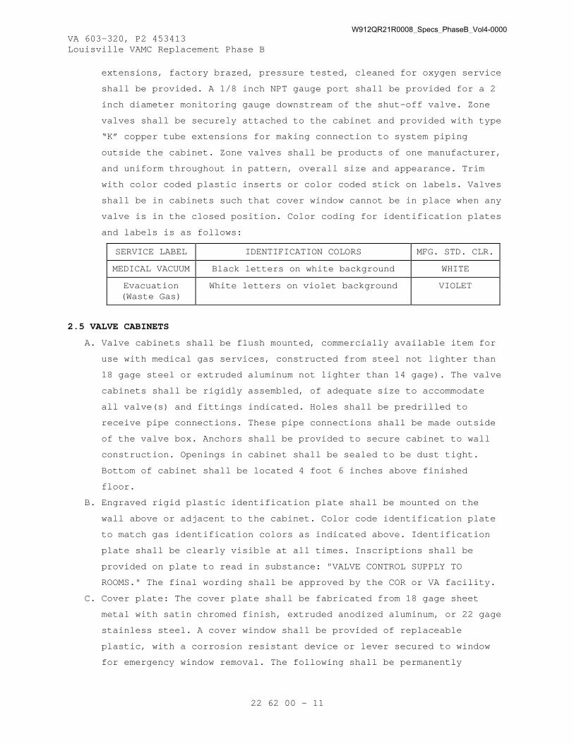
VA 603-320, P2 453413 Louisville VAMC Replacement Phase B
22 62 00 - 11
extensions, factory brazed, pressure tested, cleaned for oxygen service
shall be provided. A 1/8 inch NPT gauge port shall be provided for a 2
inch diameter monitoring gauge downstream of the shut-off valve. Zone
valves shall be securely attached to the cabinet and provided with type
“K” copper tube extensions for making connection to system piping
outside the cabinet. Zone valves shall be products of one manufacturer,
and uniform throughout in pattern, overall size and appearance. Trim
with color coded plastic inserts or color coded stick on labels. Valves
shall be in cabinets such that cover window cannot be in place when any
valve is in the closed position. Color coding for identification plates
and labels is as follows:
SERVICE LABEL IDENTIFICATION COLORS MFG. STD. CLR.
MEDICAL VACUUM Black letters on white background WHITE
Evacuation (Waste Gas)
White letters on violet background VIOLET
2.5 VALVE CABINETS
A. Valve cabinets shall be flush mounted, commercially available item for
use with medical gas services, constructed from steel not lighter than
18 gage steel or extruded aluminum not lighter than 14 gage). The valve
cabinets shall be rigidly assembled, of adequate size to accommodate
all valve(s) and fittings indicated. Holes shall be predrilled to
receive pipe connections. These pipe connections shall be made outside
of the valve box. Anchors shall be provided to secure cabinet to wall
construction. Openings in cabinet shall be sealed to be dust tight.
Bottom of cabinet shall be located 4 foot 6 inches above finished
floor.
B. Engraved rigid plastic identification plate shall be mounted on the
wall above or adjacent to the cabinet. Color code identification plate
to match gas identification colors as indicated above. Identification
plate shall be clearly visible at all times. Inscriptions shall be
provided on plate to read in substance: "VALVE CONTROL SUPPLY TO
ROOMS." The final wording shall be approved by the COR or VA facility.
C. Cover plate: The cover plate shall be fabricated from 18 gage sheet
metal with satin chromed finish, extruded anodized aluminum, or 22 gage
stainless steel. A cover window shall be provided of replaceable
plastic, with a corrosion resistant device or lever secured to window
for emergency window removal. The following shall be permanently
W912QR21R0008_Specs_PhaseB_Vol4-0000

VA 603-320, P2 453413 Louisville VAMC Replacement Phase B
22 62 00 - 12
painted or stenciled on window: "FOR EMERGENCY SHUT-OFF VALVES ONLY,
SHUT-OFF VALVES FOR PIPED GASES", or equivalent wording. The valve
cabinet shall be configured such that it is not possible to install
window with any valve in the closed position. Each valve shall have a
pressure gauge upstream of valve and this pressure gage shall be inside
valve box.
D. Cabinets and isolation valves shall be located and piped as shown on
the contract documents, and at a minimum, so as to allow the isolation
of each smoke compartment separately. Each cabinet shall serve no more
than one smoke compartment.
2.6 GAGES
A. Vacuum Gages:
1. For vacuum line adjacent to source equipment the vacuum gages shall
comply with ASME B40.100, vacuum gage type, size 4-1/2 inches, gage
listed for vacuum, accurate to within 2-1/2 percent, with metal
case. The vacuum gage range shall be 0 to 29.5 inches Hg. Dial
graduations and figures shall be black on a white background, or
white on a black background. Label shall be for vacuum service. A
gage cock shall be installed. Dual scale gages shall be installed
for vacuum system.
2. For vacuum service upstream of main shut-off valve: A 1-1/2 inches
diameter gage shall be provided with steel case, bourdon tube and
brass movement, dial range 0 to 29.5 inches Hg. Dual scale gages
shall be provided for vacuum system.
2.7 STATION INLETS
A. Vacuum Station inlets:
1. Station inlets shall be for designated service, consisting of a
quick coupler, quick disconnect type with inlet supply tube.
2. The outlet station shall be made, cleaned, and packaged to NFPA 99
standards and shall be UL listed and CSA certified.
3. A coupler shall be provided that is non-interchangeable with other
services, and leak proof under three times normal working pressure.
4. Each station inlet shall be equipped with an automatic valve to
conform with NFPA 99. Valves shall be placed in the assembly to
provide easy access after installation for servicing and
replacement, and to facilitate line blow-out, purging, and testing.
5. Each inlet shall be securely fastened to structure and provide each
with a capped stub length of 1/4 inches (3/8 inches outside
W912QR21R0008_Specs_PhaseB_Vol4-0000
VA 603-320, P2 453413 Louisville VAMC Replacement Phase B
22 62 00 - 13
diameter) tubing for connection to supply tubing. Stub tubing shall
be labeled for appropriate service. Rough in shall be indexed and
gas specified latch valve with non-interchangeable safety keying
with color coded gas service identification.
6. Rough-in kits and test plugs for PBPU shall be furnished under this
specification but installed by manufacturer of PBPU before initial
test specified herein.
7. Completion kits (valve body and face plate) shall be installed for
the remainder of required tests.
B. For Ceiling Hose Drops:
1. Brass, stainless steel or chromed metal non-interchangeable DISS
connections for appropriate service to conform with CGA V-5.
2. Hose assemblies shall be furnished for all ceiling stations for the
finished ceiling height as indicated on the contract drawings. Each
hose shall be provided with a heavy chain type dual retractor for
vacuum. Retractors made of stainless steel are prohibited. An extra
450 mm (18 inches) of hose length shall be provided for retractors.
3. Each station inlet shall be equipped with an automatic valve to
conform with NFPA 99. Valves shall be placed in the assembly to
provide easy access after installation, for servicing and
replacement, and to facilitate line blow-out, purging, and testing.
4. Each inlet shall be securely fastened to structure and provide each
with a capped stub length of 1/4 inches3/8 inches outside diameter
tubing for connection to supply tubing. Stub tubing shall be labeled
for appropriate service for the installation. The installation shall
be adjusted to compensate for variations in plaster or cover
thickness.
2.8 STATION INLET ROUGH-IN
A. Station inlet rough in shall be flush mounted, and protected against
corrosion. Rough in shall be anchored securely to unit or wall
construction.
B. The modular cover plate shall be constructed from die cast plate, two
piece 22 gage stainless steel or 16 gage chromium plated metal, secured
to rough in with stainless steel or chromium plated countersunk screws.
The latch mechanism shall be designed for one handed, single thrust
mounting and one handed fingertip release of secondary equipment.
C. Cover Plate for PBPU shall be one piece with construction and material
as indicated for modular cover plate.
W912QR21R0008_Specs_PhaseB_Vol4-0000

VA 603-320, P2 453413 Louisville VAMC Replacement Phase B
22 62 00 - 14
D. Permanent, metal or plastic, identification plates shall be provided
securely fastened at each inlet opening, with inscription for
appropriate service using color coded letters and background. Metal
plates shall have letters embossed on baked on enamel background. Color
coding for identification plates is as follows:
SERVICE LABEL IDENTIFICATION PLATE COLORS
MEDICAL VACUUM Black letters on white background
EVACUATION
(Waste Gas)
White letters on violet background
2.9 CEILING SERVICES
A. Column accessories: Each utility column shall be equipped with flush
type quick coupler vacuum service station inlets as specified under
paragraph “Station Inlets”. The following inlets, mounted on the
utility column shall be provided: three medical vacuum and one
anesthesia evacuation.
B. Ceiling Mounted Station Inlets shall be equipped as specified under
paragraph “Station Inlets”. The station inlets shall be flush mount on
ceiling and provide with hose tubing drops and retractors. Male thread
DISS connection shall be extended through ceiling plate.
1. Hoses: Conductive, neoprene tubing hoses, color coded for
appropriate service shall be capable of, dropping to within 4 feet 8
inches from floor, with upper end of hose having female DISS
connection with nut, easily finger tightened to ceiling inlet, and
lower end of hose having DISS connection quick. Color coding for
hoses is as follows:
SERVICE HOSE COLOR
VACUUM White
EVACUATION (Waste Gas) Violet
2. Rough-in shall be standard metal single gang, interchangeable,
sectional or one piece, securely anchored to ceiling runner channels
Ceiling plate shall be die cast plate, 22 gage stainless steel or 16
gage chromium plated metal. Identification plate shall be attached
as specified in paragraph “Station Inlet Rough-In” to ceiling plate
and attached adjacent to each inlet.
3. Hose retractor kit: The hose retractor kits shall be chrome plated,
spring loaded assembly. Hose clamps shall have stainless steel sash
W912QR21R0008_Specs_PhaseB_Vol4-0000

VA 603-320, P2 453413 Louisville VAMC Replacement Phase B
22 62 00 - 15
chain; to automatically withdraw hose assembly a minimum of 20
inches from fully extended position of 4 feet 8 inches) to 6 feet 4
inches above finished floor.
2.10 VACUUM SWITCHES
A. Vacuum switches shall be general purpose, contact or mercury type,
allowing both high and low set points, with contact type provided with
a protective dust cover. The vacuum switch shall have an adjustable
range set by inside or outside adjustment. Vacuum switches shall
activate when indicated by alarm requirements. One orifice nipple (or
DISS demand check valve) shall be used for each sensor switch.
2.11 VACUUM BOTTLE BRACKET
A. Vacuum bottle bracket shall be single plate of one piece, 22 gage)
stainless steel or 16 gage chromium plated metal or aluminum, finish
matching cover of adjoining vacuum inlet. All components shall be of
same material as plate and assembly and anchored securely to structure.
The bracket shall be provided and plastic vacuum bottle holder for each
vacuum wall inlet.
2.12 LABORATORY VACUUM SYSTEMS
A. Duplex vacuum system. Factory assembled, piped and wired components
shall include:”
1. The vacuum pumps shall be non-contacting claw style rotary design.
The internal construction shall be friction free and require no
sealants. Each pump shall be air-cooled and continuous duty rated.
Each vacuum pump shall be provided with a single lubricated gearbox
requiring an oil change not more often than 5,000 operating hours.
Each vacuum pump shall be equipped with an exhaust silencer. Each
pump shall be equipped with a high vacuum shutdown, a high
temperature shutdown, and remote and local alarms. The lubricant
supplied shall be inert with oxygen and the vacuum pump shall be
factor cleaned for oxygen service.
B. Each pump shall be directly connected to an induction motor,
open-drip-proof, factory wound for 3 phase, 60 Hz, AC voltage as
indicated on contract drawings. The motor shall be as specified in
Section, 22 05 12, GENERAL MOTOR REQUIREMENTS FOR PLUMBING EQUIPMENT.
C. A welded steel receiver tank shall be provided with gauge glass, relief
valve and vacuum gauge. The receiver tank shall carry ASME Code, Stamp,
and Certificate. The receiver tank shall be hot dip galvanized inside
and out. The receiver tank shall not be used as a catch tank where a
W912QR21R0008_Specs_PhaseB_Vol4-0000

VA 603-320, P2 453413 Louisville VAMC Replacement Phase B
22 62 00 - 16
bio-hazard could develop. Any carryover of foreign materials such as
liquids or tissue shall be intercepted at the inlet of the vacuum pump
with filtration and discharged to sanitary sewer drain.
D. The following accessories shall be factory piped in all brass piping
and pre-wired to ensure proper operation of each vacuum unit:
1. Solenoid valves with manual bypass.
2. Strainers.
3. Inlet check valves suitable for vacuum service.
4. Shut-off valves.
5. Vacuum relief valve.
6. Gage glass on reservoir tank and receiver tank.
E. Control: For control of the unit, the following shall be included in a
NEMA 12 pre-wired control panel factory mounted on the receiver. Panel
shall be equipped with HOA switches and indicating lights along with
the following:
1. Combination circuit breaker type magnetic across-the-line starters
to provide overload and under voltage protection.
2. 115 volt control transformers.
3. Minimum run timers.
4. Vacuum switches factory mounted and preset.
5. Electric time alternator circuit to automatically switch the
operation of each pump.
6. Audible and visual alarm circuit with silence and reset button to
activate when a pump starts out of sequence.
7. Vibration isolators and flexible connections are supplied loose for
field installation.
F. The vacuum pumps shall be individually tested and test results shall be
submitted to the COR.
2.13 MEDICAL VACUUM SYSTEMS
A. Provide a complete medical vacuum package, complying with NFPA 99 in
all respects, as specified and scheduled in the contract documents. All
components shall be factory packaged (pre-wired and pre-piped), on a
steel base, or tank mounted. All package piping shall be type “L” or
type “K” rigid copper. Provide discharge separator/silencer.
B. All components shall be multiplex and valved (or check valved as
permitted NFPA 99) to allow service to any component without
interrupting vacuum service to the facility during any maintenance
operation or any condition of single fault failure. The design load
W912QR21R0008_Specs_PhaseB_Vol4-0000

VA 603-320, P2 453413 Louisville VAMC Replacement Phase B
22 62 00 - 17
shall be met with the largest single unit out of service. Each pump
exhaust shall be isolated by a union fitting permitting capping for
service removal.
C. A complete and operational plant (source equipment) shall be furnished
consisting of pumps, receiver and controls capable of providing the
scheduled capacity with one pump out of service. All capacities shall
be indicated in SCFM at 19 inches Hg and 24 inches Hg.
D. System shall be completely factory assembled, requiring only
interconnection between modules on site. Systems requiring on site
assembly other than interconnection are prohibited (replacement of
components removed for shipping is permitted).
E. Motor and Starter: Maximum 104 degrees °F ambient temperature rise,
close coupled to a NEMA rated, High Efficiency, TEFC motor with a
service factor of 1.15, ball bearings, for operation with current,
voltage, phase and cycle specified in Section 22 05 12, GENERAL MOTOR
REQUIREMENTS FOR PLUMBING EQUIPMENT. Motor shall be of such capacity
that brake horsepower required by driver equipment at normal rated
capacity will not exceed nameplate rating of the motor. Provide each
motor with automatic, fully enclosed, magnetic starter of type
specified in Section 26 29 11, MOTOR CONTROLLERS.
F. Each pump shall include inlet and outlet flex connectors supplied by
the medical vacuum equipment manufacturer.
G. Programmable Logic Controllers (PLC) or Direct Digital Controls (DDC)
can be used to implement operating logic. Controls shall have integral
memory and EPROM backup. Controls shall control the automatic
alternation lead-lag of the vacuum pumps with provisions for
simultaneous operation if required, and automatic activation of reserve
or lag unit if required. A lag alarm on control cabinet and contacts
for the master alarm shall be provided.
H. The complete control system and all electrical components shall be NEMA
ICS 6, Type 12 and UL labeled. The control system shall provide:
1. Automatic lead/lag sequencing including self adjusting minimum run
timers which adaptively optimize the number of pump starts based on
demand.
2. Circuit breaker disconnects for each vacuum pump with external
operators. Units with fuses instead of circuit breakers in motor
circuit are prohibited. The control system shall include an
W912QR21R0008_Specs_PhaseB_Vol4-0000

VA 603-320, P2 453413 Louisville VAMC Replacement Phase B
22 62 00 - 18
automatic minimum run time adjustment to automatically adjust run
time based on demand.
3. Full voltage motor starters with overload protection.
4. Redundant 120 volt control circuit transformers.
5. Visual and audible reserve unit alarm with isolated contacts for
remote alarms and audio cancel.
6. Control cabinet shall have lighted HOA selector switches
7. Panel mounted vacuum gauge, external visual lights indicating on/off
status, audible and visual signals for thermal overload, oil
discharge filter differential pressure or back pressure alarm, and
alarm silence button.
8. Contacts for external oil discharge filter differential pressure or
back pressure alarm
9. If silence has been pressed, audible and visual signal would be
reactivated upon second alarm condition. Alarm shall be reset upon
correction of original signal.
10. Runtime hour-meter for each pump.
I. The medical vacuum pumps shall be non-contacting claw style rotary
design. The internal construction shall be friction free and require no
sealants. Each medical vacuum pump shall be air-cooled and continuous
duty rated. Each medical vacuum pump shall be provided with a single
lubricated gearbox requiring an oil change not more often than 5,000
operating hours. Each medical vacuum pump shall be equipped with an
exhaust silencer. Each medical vacuum pump shall be equipped with a
high vacuum shutdown, a high temperature shutdown, a remote alarm at
the BAS and local alarms. The lubricant supplied shall be inert with
oxygen and the medical vacuum pump shall be factory cleaned for oxygen
service.
J. The complete medical vacuum system and all electrical components shall
be factory tested prior to shipment by the medical vacuum equipment
manufacturer.
K. Waste Anesthetic Gas Disposal Pumps.
1. Provide a complete WAGD source, complying with NFPA 99 5.1.3.7 in
all respects, as specified and scheduled.
2. All components shall be at least duplex/and valved to permit service
to any component without interrupting WAGD supply to the facility
during any maintenance operation or any condition of single fault
failure.
W912QR21R0008_Specs_PhaseB_Vol4-0000

VA 603-320, P2 453413 Louisville VAMC Replacement Phase B
22 62 00 - 19
3. Furnish complete and operational plant consisting of producer and
controls capable of providing the scheduled capacity with one
producer out of service.
4. System shall be completely factory assembled. Systems requiring site
assembly are prohibited (removal of components for shipping is
permitted).
5. Each producer shall include inlet and outlet flex connectors
supplied by the medical vacuum equipment manufacturer.
6. A Programmable Logic Controller (PLC) or Direct Digital Controls
(DDC) can be used to implement the operating sequence of operation.
The controls shall have integral memory and EPROM memory backup.
Alternating between the lead and lag WAGD pumps shall be made
automatically by the programmable logic controller. The reserve unit
shall be automatically activated as required to maintain
uninterrupted service. A provision for simultaneous operation of two
or more WAGD pumps shall be made when one operating WAGD pump is not
meeting the demand. An alarm shall be activated whenever a reserve
WAGD producer or lag WAGD producer is activated.
7. The complete control system and all electrical components shall be
NEMA 12 and UL labeled. The control system shall provide:
a. Automatic lead/lag sequencing.
b. Circuit breaker disconnects for each producer with external
operators. Units with fuses instead of circuit breakers in motor
circuit are prohibited.
c. Full voltage motor starters with overload protection.
d. Redundant 120 volt control circuit transformers.
e. Visual and audible reserve unit alarm with isolated contacts for
remote alarms and audio cancel.
f. Control cabinet shall have lighted HOA selector switches
g. Runtime hour-meter for each producer.
8. Claw: A non-contacting claw style rotary pumps shall be provided.
Internal construction is friction free and rotors are non-
contacting. Air end is oil free and requires no sealants. Each pump
is air cooled and continuous duty rated. Pump is provided with a
single lubricated gearbox requiring lubricant change not more often
than 5,000 operating hours. Pump is provided with exhaust silencer.
Pumps shall be equipped with high vacuum shutdown, high temperature
shutdown, and visual and audible alarms per NFPA 99. Lubricant
W912QR21R0008_Specs_PhaseB_Vol4-0000

VA 603-320, P2 453413 Louisville VAMC Replacement Phase B
22 62 00 - 20
supplied shall be inert with oxygen. Pump shall be provided with
vacuum modulated variable speed drive to control vacuum level at 7
inches Hg.
9. The complete WAGD system and all electrical components shall be
factory pretested prior to shipment.
L. Controls:
1. Automatic: Adjustable, vacuum operated, automatic, electric switch
to start and stop motor at receiver vacuum indicated. Provide heavy
duty alternator, automatic, operating on a timed basis, to alternate
the pumps by time forced alternation.
2. Control panel: Housed in a NEMA ICS 6, Type 12, listed, dust proof
enclosure; prewired to include all specified electrical, electronic
and electro pneumatic devices. Include wiring diagrams and operating
descriptions in the cabinet. Include the following:
a. Circuit breakers for each control and motor circuit.
b. Hand off automatic selector switch for each pump.
c. Hour meter for each pump.
d. Control circuit transformers.
e. One magnetic motor starter for each pump.
f. Provide panel with external visual (lights, red for running,
green for off) and audible (horn/buzzer) signals. The signals
provided include:
1) Pump in operation (visual only).
2) Thermal overload shutdown (visual and audible).
3) Oil discharge filter differential pressure or back pressure
alarm (visual), with contacts for external signal. Wire to
master alarm panel.
4) Cancel button, which shall silence an audible alarm,
reactivate should a second alarm occur while the horn is
silenced, and reset automatically upon correction of the
original signal.
M. Receiver Tank: The receiver tank shall be welded galvanized steel, in
compliance with ASME Section VIII, 125 psig working pressure stamped
and certified. The receiver tank shall be equipped with vacuum gage and
gage glass. The receiver tank shall be of sufficient capacity to ensure
practical on/off operation of pumps.
N. Bio-Hazard Safety Statement: "BIOHAZARD CAUTION: Fluid and waste
material inside vacuum pipelines and vacuum equipment may be
W912QR21R0008_Specs_PhaseB_Vol4-0000

VA 603-320, P2 453413 Louisville VAMC Replacement Phase B
22 62 00 - 21
contaminated with blood and other potentially infectious material.
Construction and service personnel shall use proper PERSONAL PROTECTIVE
EQUIPMENT and practice UNIVERSAL PRECAUTIONS when opening or servicing
vacuum systems."
PART 3 - EXECUTION
3.1 INSTALLATION
A. All installation shall be performed in strict accordance with NFPA 99
5.1.10. Brazing procedures shall be as detailed in NFPA 99 5.1.10.4.
Brazing shall be performed only by brazers qualified under NFPA 99
5.1.10.11.10. Where piping runs underground, the installation shall be
made in accordance with NFPA 99 5.1.10.11.5.
B. Contractor shall furnish 4 inches high concrete housekeeping pads. The
contractor shall furnish inertia bases in lieu of housekeeping pads
where the equipment installed is not factory isolated by the
manufacturer. Anchor bolts shall be cast into bases
C. Cast escutcheon shall be installed with set screw at each wall, floor
and ceiling penetration in exposed finished locations and within
cabinets and millwork.
D. Open ends of tube shall be capped or plugged at all times or otherwise
sealed until final assembly to prevent infiltration of any foreign
matter.
E. Piping shall be cut square and accurately with a tube cutter ( sawing is
prohibited) to measurements determined at place of installation. The
tubing shall be reamed to remove burrs, being careful not to expand
tube, and so no chips of copper remain in the tube. The tubing shall be
worked into place without springing or forcing. The tubing shall be
bottomed in socket so there are no gaps between tube and fitting. Care
shall be exercised in handling equipment and tools used in cutting or
reaming of tube to prevent oil or grease from being introduced into the
tubing. Where contamination has occurred, material shall be no longer
suitable for vacuum service and new, sealed tube sections used.
F. Piping shall be supported with pipe trays or hangers at intervals as
shown on the contract drawings or as defined in NFPA 99. Piping shall
not be supported by other piping. Isolation of copper piping from
dissimilar metals shall be of a firm, positive nature. Duct tape is
prohibited as an isolation material.
G. Valves and other equipment shall be rigidly supported to prevent strain
on tube or joints.
W912QR21R0008_Specs_PhaseB_Vol4-0000
VA 603-320, P2 453413 Louisville VAMC Replacement Phase B
22 62 00 - 22
H. Piping exposed to physical damage shall be protected.
I. During any brazing operation, the interior of the pipe shall be purged
continuously with oil free, dry nitrogen NF, following the procedure in
NFPA 99 5.1.10.4.5. At the completion of any section, all open pipe
ends shall be capped using an EXTERNAL cap. The flow of purged gas
shall be maintained until joint is cool to touch. The use of flux is
prohibited when making of joints between copper to copper pipes and
fittings.
J. Threaded joints in piping systems shall be avoided whenever possible.
Where unavoidable, make up the male threads with
polytetrafluoroethylene (such as Teflon) tape. Liquid sealants are
prohibited.
K. Tubing shall not be bent. Fittings shall be used in all change of
direction or angle.
L. After installation of the piping, but before installation of the outlet
valves, blow lines clear using nitrogen NF per NFPA 99.
M. Ceiling column assembly shall be supported from heavy sub-mounting
castings and furnished with the unit as part of rough in. Ceiling
columns shall be anchored with 1/2 inch diameter bolts attached to
angle iron frame supported from structural ceiling.
N. Two 1 inch minimum conduits shall be provided from ceiling column
assembly to the adjacent corridor, one for mass spectrometer tubing and
wiring and one for monitor wiring, and for connection to signal cabling
network.
O. Pressure and vacuum switches, transmitter and gauges shall be installed
to be easily accessed, and provide access panel where installed above
plaster ceiling. Pressure switch and sensors shall be installed with
orifice nipple between the pipe line and switches/sensors.
P. Pipe labeling shall be applied during installation process and not
after installation is completed. Size of legend letters shall be in
accordance with ASME A13.1.
Q. After initial leakage testing is completed, the piping shall be allowed
to remain pressurized with testing gas until testing agency performs
final tests.
R. Penetrations:
1. Fire Stopping: Where pipes pass through fire partitions, fire walls,
smoked partitions, or floors, fire stopping shall be installed that
provides an effective barrier against the spread of fire, smoke and
W912QR21R0008_Specs_PhaseB_Vol4-0000
VA 603-320, P2 453413 Louisville VAMC Replacement Phase B
22 62 00 - 23
gases as specified in Section 07 84 00, FIRESTOPPING, Clearances
between raceways and openings with the fire stopping material shall
be completely filled and sealed.
2. Water proofing: At floor penetrations, clearances shall be
completely sealed around the pipe and made watertight with sealant
as specified in Section 07 92 00, JOINT SEALANTS.
S. A vacuum gage 1-1/2 inch diameter shall be installed in line downstream
of each valve located in a zone valve cabinet.
T. Zone valves shall be provided in cabinets where indicated and outside
each Operating Room and a minimum one zone valve assembly for each 18
outlets.
U. Piping shall be labeled with name of service, identification color and
direction of flow. Where non-standard pressures are piped, pressure
shall be labeled. Labels shall be placed at least once every 20 feet of
linear run or once in each story (whichever is more frequent). A label
shall additionally be placed immediately on each side of all wall or
floor penetrations. Pipe labels shall be self adhesive vinyl type or
other water resistant material with permanent adhesive colored in
accordance with NFPA 99 Table 5.1.11 and shall be visible on all sides
of the pipe. Each master alarm signal shall be labeled for function
after ring out. Each zone valve shall be labeled and each area alarm
labeled for the area of control or surveillance after test. Labels
shall be permanent and of a type approved by the VAMC.
V. Alarms and valves shall be labeled for service and areas monitored or
controlled. Coordinate with the VAMC for final room or area
designations. Valves shall be labeled with name and identification
color of the gas and direction of flow.
W. Provide an auxiliary source connection point of the same size as main
line which shall be located immediately on the patient side of the
source valve.
3.2 INSTALLER TESTING
A. Prior to declaring the lines ready for final verification, the
installing contractor shall strictly follow the procedures for
verification as described in NFPA 99 5.1.12.2 and attest in writing
over the notarized signature of an officer of the installing company
the following;
1. That all brazing was conducted by brazers qualified to ASSE Standard
Series 6000 and holding current medical gas endorsements.
W912QR21R0008_Specs_PhaseB_Vol4-0000

VA 603-320, P2 453413 Louisville VAMC Replacement Phase B
22 62 00 - 24
2. That all brazing was conducted with nitrogen purging. (Procedure per
NFPA 99 5.1.10.4.5).
3. That the lines have been blown clear of any construction debris
using oil free dry nitrogen or air are clean and ready for use.
(Procedure per NFPA 99 5.1.12.2.2).
4. That the assembled piping, prior to the installation of any devices,
maintained a test pressure 1 1/2 times the standard pressures listed
in NFPA 99 Table 5.1.11 without leaks. (Procedure per NFPA 99
5.1.12.2.3).
5. That after installation of all devices, the pipeline was proven leak
free for 24 hours at a pressure 20 percent above the standard
pressures listed in NFPA 99 Table 5.1.11. (Procedure per NFPA 99
5.1.12.2. 6)
6. That the systems have been checked for cross connections and none
were found. (Procedure per NFPA 99 5.1.12.2.4)
7. That the manufacturer has started up all medical air compressors,
medical vacuum pumps WAGD producers, liquid oxygen system(s) and
manifolds, and that they are in operating order.
B. Four originals of the affidavit, shall be distributed; (2) to the COR,
(1) to the general contractor, and (1) to the verifier (www.mgpho.org).
3.3 VERIFIER TESTING
A. Prior to handing over the systems to VAMC, the contractor shall retain
a verifier acceptable to the engineer of record and approved by USACE
who shall follow strictly the procedures for verification as described
in NFPA 99 5.1.12.3 and provide a written report and certificate
bearing the notarized signature of an officer of the verification
company on company letterhead which contains at least the following:
1. A current ACORD insurance certificate indicating professional
liability coverage in the minimum amount of $1 Million per
occurrence, and general aggregate liability in the minimum amount of
$1 Million, valid and in force when the project is to be verified.
General liability insurance alone is not acceptable.
2. An affidavit bearing the notarized signature of an officer of the
verification company stating that the verification company is not
the supplier of any equipment used on this project or tested in this
report and that the verification contractor has no relationship to,
or pecuniary interest in, the manufacturer, seller, or installer of
any equipment used on this project or tested in this report.
W912QR21R0008_Specs_PhaseB_Vol4-0000

VA 603-320, P2 453413 Louisville VAMC Replacement Phase B
22 62 00 - 25
3. A listing of all tests performed, listing each source, outlet, valve
and alarm included in the testing.
4. An assertion that all tests were performed by a Medical Vacuum
System Certified Medical Gas or vacuum Verifier or by individuals
qualified to perform the work and holding valid qualifications to
ASSE 6030 and under the immediate supervision a Verifier. Include
the names, credential numbers and expiration dates for all
individuals working on the project.
5. A statement that equipment used was calibrated at least within the
last six months by a method traceable to a National Bureau of
Standard Reference and enclosing certificates or other evidence of
such calibration(s). Where outside laboratories are used in lieu of
on site equipment, those laboratories shall be named and their
original reports enclosed.
6. A statement that where and when needed, equipment was re calibrated
during the verification process and describing the method(s) used.
7. A statement that the systems were tested and found to be free of
debris to a procedure per NFPA 99 5.1.12.3.7.
8. The flow from each outlet when tested to a procedure per NFPA 99
5.1.12.3.10.
9. A statement that the systems were tested and found to have no cross-
connections to a procedure per NFPA 99 5.1.12.3.3.
10. A statement that the systems were tested and found to be free of
contaminants to a procedure per NFPA 99 5.1.12.3.8 except that the
purity standard shall be 2 ppm difference for halogenated
hydrocarbons and 1 ppm total hydrocarbons (as methane).
11. Statement that all local signals function as required under NFPA 99
5.1.3.5.8 and as per the relevant NFPA 99 sections relating to the
sources.
12. A listing of local alarms, their function and activation per NFPA 99
5.1.12.3.14.
13. A listing of master alarms, their function and activation, including
pressures for high and low alarms per NFPA 99 5.1.12.3.5.2.
14. A listing of area alarms, their function and activation pressures
per NFPA 99 5.1.12.3.5.3.
15. A statement that the sources include all alarms required by NFPA 99
Table A.5.1.9.5.
W912QR21R0008_Specs_PhaseB_Vol4-0000

VA 603-320, P2 453413 Louisville VAMC Replacement Phase B
22 62 00 - 26
16. The concentration of each component of NFPA 99 Table 5.1.12.3.11 in
the medical air after 24 hours of operation of the medical air
source.
17. The concentration of each gas at each outlet as specified in NFPA 99
5.1.12.3.11.
18. A statement that all valves and alarms are accurately labeled as to
zone of control.
B. Perform and document all cross connection tests, labeling verification,
supply system operation, and valve and alarm operation tests as
required by, and in accordance with NFPA 99 and the procedures set
forth in pre-qualification documentation.
C. Verify that the systems, as installed, meet or exceed the requirements
of NFPA 99, this specification, and that the systems operate as
required.
D. Piping purge test: For each positive pressure gas system, verify
cleanliness of piping system. Filter a minimum of 35 cubic feet of gas
through a clean white 0.45 micron filter at a minimum velocity of 3.5
fpm. Filter shall show no discoloration, and shall accrue no more than
0.1 mg of matter. Test each zone at the outlet most remote from the
source. Perform test with the use of an inert gas as described in CGA
P-9. Retest until all tests pass at no additional time or cost to the
Government.
E. Inlet flow test:
1. Test all inlets for flow. Perform test with the use of an inert gas
as described in CGA P-9.
2. Needle valve vacuum inlets shall draw no less than 1.0 SCFM with
adjacent inlet flowing, at a dynamic inlet pressure of 12 inches Hg,
and a static vacuum of 3 inches Hg.
3. Vacuum inlets shall draw no less than 3.0 SCFM with adjacent inlet
flowing, at a dynamic inlet pressure of 12 inches Hg, and a static
vacuum of 15 inches Hg.
4. Anesthesia evacuation inlets shall draw no less than 1 L/mm (1.0
SCFM) at a dynamic inlet pressure of 12 inches Hg, and a static
vacuum of 15 inches Hg.
3.4 COMMISSIONING
A. Provide commissioning documentation in accordance with the requirements
of Section 22 08 00, COMMISSIONING OF PLUMBING SYSTEMS.
W912QR21R0008_Specs_PhaseB_Vol4-0000

VA 603-320, P2 453413 Louisville VAMC Replacement Phase B
22 62 00 - 27
B. Components provided under this section of the specification will be
tested as part of a larger system.
3.5 DEMONSTRATION AND TRAINING
A. Provide services of manufacturer’s technical representative for four
hours to instruct VA Personnel in operation and maintenance of the
system.
B. Submit training plans and instructor qualifications in accordance with
the requirements of Section 22 08 00, COMMISSIONING OF PLUMBING SYSTEMS
and Section 01 79 00, OPERATIONS AND MAINTENANCE TRAINING.
- - - E N D - - -
W912QR21R0008_Specs_PhaseB_Vol4-0000

W912QR21R0008_Specs_PhaseB_Vol4-0000

VA 603-320, P2 453413 Louisville VAMC Replacement Phase B
22 62 19.74 - 1
SECTION 22 62 19.74 DENTAL VACUUM AND EVACUATION EQUIPMENT
PART 1 - GENERAL
1.1 DESCRIPTION
A. This section specifies central piped high volume oral evacuation (HVE)
system for dental operatories, including piping, valving, vacuum
producers, separators, electric motors, starters, controls and
installation and startup. System to meet 2015 version of NFPA 99,
Category 3 requirements.
B. A complete listing of all acronyms and abbreviations are included in
Section 22 05 11, COMMON WORK RESULTS FOR PLUMBING.
1.2 RELATED WORK
A. Section 01 33 00, SUBMITTAL PROCEDURES.
B. Section 01 81 13, SUSTAINABLE CONSTRUCTION REQUIREMENTS.
C. Section 01 91 00, GENERAL COMMISSIONING REQUIREMENTS.
D. Section 07 84 00, FIRESTOPPING: Sealing around pipe penetrations to
maintain the integrity of time rated construction.
E. Section 07 92 00, JOINT SEALANTS: Sealing around pipe penetrations
through the floor to prevent moisture migration.
F. Section 09 91 00, PAINTING: Piping system identification.
G. Section 22 05 11, COMMON WORK RESULTS FOR PLUMBING: General
requirements and items common to more than one Section of Division 22.
H. Section 22 05 12, GENERAL MOTOR REQUIREMENTS FOR PLUMBING EQUIPMENT:
Electric Motors.
I. Section 22 05 23, GENERAL-DUTY VALVES FOR PLUMBING PIPING: Valves (as
required for water).
J. SECTION 22 08 00, COMMISSIONING OF PLUMBING SYSTEMS.
K. Section 22 11 00, FACILITY WATER DISTRIBUTION: Strainers (as required
for water).
L. Section 26 29 11, MOTOR CONTROLLERS: Motor Starters.
1.3 APPLICABLE PUBLICATIONS
A. The publications listed below form a part of this specification to the
extent referenced. The publications are in the text by the basic
designation only.
B. American Society of Mechanical Engineers (ASME):
A13.1-2007 (R2013)......Scheme for the Identification of Piping System
B1.20.1-2013............Pipe Threads, General Purpose, Inch
B16.3-2011..............Malleable Iron Threaded Fittings: Classes 150
and 300
W912QR21R0008_Specs_PhaseB_Vol4-0000

VA 603-320, P2 453413 Louisville VAMC Replacement Phase B
22 62 19.74 - 2
B16.22-2013.............Wrought Copper and Copper Alloy Solder-Joint
Pressure Fittings
B40.100-2013............Pressure Gauges and Gauge Attachments
C. American Society for Testing and Materials (ASTM):
A47/A47M-1999 (2014)....Standard Specification for Ferritic Malleable
Iron Castings
A53/A53M-2012...........Standard Specification for Pipe, Steel, Black
and Hot-Dipped, Zinc-Coated, Welded and
Seamless
A536-1984 (2014)........Standard Specification for Ductile Iron
Castings
B306-2013...............Standard Specification for Copper Drainage Tube
(DWV)
D1785-2012..............Standard Specification for Poly (Vinyl
Chloride) (PVC) Plastic Pipe, Schedule 40, 80,
and 120
D2564-2012..............Standard Specification for Solvent Cements for
Poly (Vinyl Chloride) (PVC) Plastic Piping
Systems
D2466-2013..............Standard Specification for Poly(Vinyl Chloride)
(PVC) Plastic Pipe Fittings, Schedule 40
D3311-2011..............Standard Specification for Drain, Waste, and
Vent (DWV) Plastic Fittings Patterns
D. National Fire Protection Association (NFPA):
NFPA 99-2015............Health Care Facilities Code
E. Underwriters’ Laboratories, Inc. (UL):
60601-1-2003 (R2006)....Medical Electrical Equipment, Part 1: General
Requirements for Safety
1.4 SUBMITTALS
A. Submittals, including number of required copies, shall be submitted in
accordance with Section 01 33 00, SUBMITTAL PROCEDURES.
B. Information and material submitted under this section shall be marked
“SUBMITTED UNDER SECTION 22 62 19.74, DENTAL VACUUM AND EVACUATION
EQUIPMENT”, with applicable paragraph identification.
C. Manufacturer's Literature and Data including: Full item description and
optional features and accessories. Include dimensions, weights,
materials, applications, standard compliance, model numbers, size, and
capacity.
W912QR21R0008_Specs_PhaseB_Vol4-0000

VA 603-320, P2 453413 Louisville VAMC Replacement Phase B
22 62 19.74 - 3
1. Piping.
2. Vacuum producer.
3. Vacuum cleaning inlet.
4. Vacuum gage.
5. Separator.
6. Vacuum relief valve.
7. Butterfly valve.
8. Directional flow valve.
9. Anti-surge valve.
10. Exhaust Silencer.
11. Separator Drainage Pump.
12. Control Panel.
D. Completed System Readiness Checklist provided by the CxA and completed
by the contractor, signed by a qualified technician and dated on the
date of completion, in accordance with the requirements of Section 22
08 00, COMMISSIONING OF PLUMBING SYSTEMS.
E. Submit training plans and instructor qualifications in accordance with
the requirements of Section 22 08 00, COMMISSIONING OF PLUMBING
SYSTEMS.
1.5 QUALITY ASSURANCE
A. System: The minimum system demand shall be based on 7 SCFM per dental
chair and at an operating pressure of 6 to 8 inches Hg. A minimum of
vacuum of 6 inches Hg shall be maintained at the most distant outlet.
System pressure drop shall be a maximum of 1 inches Hg at the
calculated demand flow.
B. Bio-Based Materials: For products designated by the USDA’s Bio-
Preferred Program, provide products that meet or exceed USDA
recommendations for bio-based content, so long as products meet all
performance requirements in this specifications section. For more
information regarding the product categories covered by the Bio-
Preferred Program, visit http://www.biopreferred.gov .
1.6 WARRANTY
A. System shall have a ten-year warranty against pump wear-out or failure.
This warranty is beyond the typical warranty as referenced in Section
22 05 11, COMMON WORK RESULTS FOR PLUMBING, Guaranty: Warranty of
Construction, FAR clause 52.246-21.
W912QR21R0008_Specs_PhaseB_Vol4-0000
VA 603-320, P2 453413 Louisville VAMC Replacement Phase B
22 62 19.74 - 4
1.7 AS-BUILT DOCUMENTATION
A. Submit manufacturer’s literature and data updated to include submittal
review comments and any equipment substitutions.
B. Submit operation and maintenance data updated to include submittal
review comments, substitutions and construction revisions shall be in
electronic version on compact disc or DVD inserted into a three ring
binder. All aspects of system operation and maintenance procedures,
including piping isometrics, wiring diagrams of all circuits, a written
description of system design, control logic, and sequence of operation
shall be included in the operation and maintenance manual. The
operations and maintenance manual shall include troubleshooting
techniques and procedures for emergency situations. Notes on all
special systems or devices such as damper and door closure interlocks
shall be included. A List of recommended spare parts (manufacturer,
model number, and quantity) shall be furnished. Information explaining
any special knowledge or tools the owner will be required to employ
shall be inserted into the As-Built documentation.
C. The installing contractor shall maintain as-built drawings of each
completed phase for verification; and, shall provide the complete set
at the time of final systems certification testing. As-built drawings
are to be provided, and a copy of them in Auto-CAD version 2014
provided on compact disk or DVD. Should the installing contractor
engage the testing company to provide as-built or any portion thereof,
it shall not be deemed a conflict of interest or breach of the ‘third
party testing company’ requirement.
D. Certification documentation shall be provided to COR 10 working days
prior to submitting the request for final inspection. The documentation
shall include all test results, the names of individuals performing
work for the testing agency on this project, detailed procedures
followed for all tests, and certification that all results of tests
were within limits specified.
PART 2 - PRODUCTS
2.1 PIPING
A. PVC: ASTM D1785, Type 1 (normal impact), Grade 1 (chemical resistance),
Schedule 40 pipe. Provide socket ASTM D2466 fittings and ASTM D2564 PVC
solvent cement with PVC primer recommended by manufacturer. Provide DWV
(drain-waste-vent) pipe fittings. Use long radius fittings for turns
and wye fittings for branching, as defined in Section 22 13 00,
W912QR21R0008_Specs_PhaseB_Vol4-0000

VA 603-320, P2 453413 Louisville VAMC Replacement Phase B
22 62 19.74 - 5
FACILITY SANITARY AND VENT PIPING. Minimum pipe size for distributing
piping in or below slab is 2 inches.
B. CPVC: Use only for discharge from vacuum producer, as per
manufacturer’s instructions.
1. Pipe and fittings: CPVC ASTM F 2618, standard weight.
C. Cleanouts: Same size and material as pipe. Provide accessible and
easily removable cleanouts as defined in Section 22 13 00, FACILITY
SANITARY AND VENT PIPING.
D. Apply piping identification per ASME A13.1.
2.2 DENTAL ORAL EVACUATION VACUUM PUMPS
A. Provide a completely packaged, continuous duty dental vacuum duplex
system as shown in the contract documents.
B. Each vacuum producer shall be sized to produce 8 inches Hg at an air
flow of 75 SCFM.
C. Duplex or multiplex systems shall consist of two or more separate high
efficiency positive displacement oil sealed, rotary vane pumps with
automatic continuous oil flow to all moving parts. Operation shall be
waterfree.
D. Duplex systems shall be powered by two separate standard NEMA frame
motors with V-belt drive enclosed in a UL approved guard.
E. Provide one (1) 50 gallon fiberglass wet separator tank with
interconnecting auto drain tank. Tanks shall be pressure tested and
certified for 18 inch Hg. Tanks shall be freestanding with legs.
Provide tank drain with check valve to drain to sanitary sewer.
F. Provide an electronic moisture alarm system capable of detecting liquid
or foam overflows. Moisture sensors shall be located outside the wet
tank. Connect moisture sensor(s) to BAS.
G. 3 Phase motor control center shall be complete with motor starters,
overload protection, single phasing protection and control
transformers.
H. Controls shall be DDC with LED status indicators for “power” and “motor
on”; and solid state moisture alarm circuitry, moisture detector,
wiring harness, manual start-stop switch, bypass for moisture alarm and
remote on-off circuitry, and indicator for required maintenance.
I. System shall be UL 60601-1 Dental Vacuum System listed and a FDA
Registered Medical Device.
W912QR21R0008_Specs_PhaseB_Vol4-0000
VA 603-320, P2 453413 Louisville VAMC Replacement Phase B
22 62 19.74 - 6
2.3 CENTRAL SEPARATOR (DUPLEX)
A. Freestanding, bottom pitched to drain at low end, hot-dipped galvanized
steel or fiberglass construction with smooth interior walls, and able
to withstand a constant negative pressure of 18 inch Hg. Provide
optional 360 degree solid state auto flush assembly, with positive
protection against flush operation with vacuum producer running, solid-
state high-low liquid sensor and corrosion resistant effluent pump to
drain the tank. Adjust one tank to sense 90 percent and the other tank
to sense 100 percent of its water capacity, to allow for non-
simultaneous discharge and, therefore, uninterrupted HVE function to
the clinical facility. Provide a sensor operated (120 VAC) solenoid
valve to control the outgoing airstream for adjustments between five
and 180 seconds. Cold water supply to the autoflush unit shall contain
an in-line filter equipped with 40-mesh stainless-steel screens 0.0165
inch opening size. Provide a vacuum switch to prevent the wash down
solenoid from operating when system is under a vacuum. Provide pressure
reducing valve to maintain water pressure not to exceed 50 psig.
2.4 VACUUM RELIEF VALVE (PROVIDE FOR BACKWARD CURVE IMPELLER DESIGN EXHAUSTERS)
A. Mechanically operated, placed at the end of each trunk-line, to
automatically sense negative pressure in the system to maintain
movement of liquids through the piping system to the separator when
inlet branches are closed. Valve connector shall be 1/2 inch NPT. Equip
with a silencer to reduce air noise to below 85 decibels.
2.5 PIPE ISOLATORS
A. Flexible rubber, couple band, sealed clamps to isolate the turbine from
the piping. Size coupling in accordance with the turbine's intake and
output connections and provide steel coupling guards.
2.6 BUTTERFLY VALVE
A. Inlet: Built-in or located near the first stage of the turbine to
prevent turbine overload through the operational range.
B. Exhaust: Flanged, wafer-style, installed at exhauster output flange for
equipment isolation.
2.7 DIRECTIONAL FLOW VALVE
A. Non-restrictive on turbine inlet to prevent back-flow of air.
2.8 ANTI-SURGE VALVE
A. Mechanically or electrically operated valve that shall operate
automatically throughout the turbine's designed range. Valve shall
W912QR21R0008_Specs_PhaseB_Vol4-0000
VA 603-320, P2 453413 Louisville VAMC Replacement Phase B
22 62 19.74 - 7
continually sense the negative pressure within the turbine and maintain
a predetermined, operational level of x inches Hg draw. Equip with a
silencer to reduce air noise to below 85 decibels.
2.9 EXHAUST SILENCER
A. Open-bore expansion type to reduce air noise to below 85 decibels with
interior baffling or shrouding.
2.10 REPLACEMENT PARTS
A. Furnish a turbine bearings and coupling kit to include one set of
turbine bearings and one complete motor/turbine flexible coupling, all
of the same size and design as those supplied with the turbine.
B. Provide complete installation instructions for repair kit items.
2.11 SEPARATOR DRAIN AND VENT
A. Construct in accordance with NFPA 99, 5.3.3.10.1.3 for Drainage from
Vacuum Equipment and 5.3.3.10.1.4 for Vacuum Exhaust.
2.12 VACUUM CLEANING INLET
A. Use only in oral surgery recovery rooms. Provide recessed wall inlet
valve with 1-1/2 inch NPS male hose repair coupling with 1/2 inch NPS
outside diameter aluminum tube stub 2 inches long.
2.13 VACUUM GAGE (DUAL SCALE)
A. In remote control panel: ASME B40.100, 1-1/2 inch dial with decorative
ring and a dial range of 0 to 29.5 inches Hg.
B. In piping near separator: ASME B40.100, with metal case, 4-1/2 inch
dial with a dial range of 0 to 29.5 inches Hg.
2.14 PVC BODY BALL VALVES
A. PVC Body double-seal ball valves with replaceable neoprene or TFE seat
seals. Provide valves suitable for at least 100 psig, cold water, non-
shock working pressure. Designed especially for vacuum service.
Operating parts of valve shall be removable without removing from line.
2.15 AMALGAM SEPARATOR
A. Provide amalgam separator consisting of a sedimentation collection
chamber that is removable. Separation process shall be sedimentation
which may be supplemented with filtration, and/or ion exchange. Unit
shall be compatible for use on wet and dry vacuum systems. Assembly
shall be wall or floor mounted. Provide minimum 1-1/2 inch inlet and
outlet connection. Unit shall be ISO 11143 Certified and have a minimum
of 99 percent removal efficiency.
W912QR21R0008_Specs_PhaseB_Vol4-0000

VA 603-320, P2 453413 Louisville VAMC Replacement Phase B
22 62 19.74 - 8
PART 3 - EXECUTION
3.1 INSTALLATION
A. Place vacuum producers on insulating pads furnished with the equipment.
Do not bolt or anchor equipment to the floor slab.
B. Cut pipe square, with burrs removed and install with minimum
obstructions to air flow. Use DWV (drain-waste-vent) long-radius
fittings for turns and wye type for branches.
C. Slope horizontal piping not less than 1/4 inch per 10 feet toward the
separator tanks.
D. All fittings shall be DWV (drain-waste-vent) long-radius bend types for
turns and wye types for branching. For small bore piping for which
long-radius bends are not available, two 45-degree bends shall be
substituted for 90-degree turning.
E. All risers to all HVE inlet locations shall be 1-1/2 inch NPS. Risers
shall connect to trunk-lines whose nominal pipe sizes shall be
determined by head loss calculations that yield a system designed for
no more than 0.5 inches Hg worse case head loss. Piping no smaller than
1-1/2 inch NPS shall be used.
F. The cross-sectional area of all trunk-lines shall be graduated,
increasing toward the vacuum source. The cross-sectional area at any
point along the trunk-line shall equate to the sum of the riser cross-
sectional areas connected prior to that point. Individual trunk-lines
shall terminate with connection to the manifold of the separators.
G. If backward curve impeller design turbine is installed, terminate the
most distant end from the separator of each trunk-line with a vacuum
relief valve.
H. Install separators level and anchored to the floor slab.
I. Startup shall be by factory representative and observed by COR.
J. Penetrations:
1. Fire Stopping: Where pipes pass through fire partitions, fire walls,
smoke partitions, or floors, install a fire stop that provides an
effective barrier against the spread of fire, smoke and gases as
specified in Section 07 84 00, FIRESTOPPING. Completely fill and
seal clearances between raceways and openings with the fire stopping
material.
2. Waterproofing: At floor penetrations, completely seal clearances
around the pipe and make watertight with sealant as specified in
W912QR21R0008_Specs_PhaseB_Vol4-0000
VA 603-320, P2 453413 Louisville VAMC Replacement Phase B
22 62 19.74 - 9
Section 07 92 00, JOINT SEALANTS. Bio-based materials shall be
utilized when possible.
3.2 STARTUP AND TESTING
A. Pipe Leakage Test: Test in accordance with NFPA 99, 5.3.12.2.5 Category
3 Plastic Vacuum Piping Systems. Exhaust complete piping system to a
vacuum of not less than 8 inch Hg after the pipe line is dried out
initially. Vacuum shall not decrease by more than 0.4 inch Hg in one
hour. If the vacuum does not hold, repair the leaks and retest.
B. Air Volume and Vacuum Tests:
1. Tests shall confirm that the system shall meet air volume and vacuum
requirements at aspirator tips and that vacuum producer(s) shall
produce the total capacity required as specified in paragraph
“Quality Assurance”. Perform tests after all oral evacuation
equipment is properly installed and piping is cleaned and proved
tight.
2. Install HVE tips into the designed number of the facility’s HVE
valves. Close all remaining HVE valves.
3. With all hoses fully closed, start the system. Fifteen minutes after
startup, measure the current draw of the motors with ammeter and
record the reading of the vacuum gage. Fully open HVE valves with
HVE tips in them and record the current and vacuum values again.
Amperage measurements shall not exceed the motor full load amperage
rating.
4. Check entire system and ensure the minimum flow stated in paragraph
“Quality Assurance” is achieved.
C. The CxA will observe startup and contractor testing of selected
equipment. Coordinate the startup and contractor testing schedules with
the COR and CxA. Contractor shall provide a minimum of 10 working days
prior to startup or testing.
D. Perform and document all cross connection tests, labeling verification,
supply system operation, and valve and alarm operation tests as
required by, and in accordance with NFPA 99 and the procedures set
forth in pre-qualification documentation.
3.3 COMMISSIONING
A. Provide commissioning documentation in accordance with the requirements
of Section 22 08 00, COMMISSIONING OF PLUMBING SYSTEMS.
B. Components provided under this section of the specification will be
tested as part of a larger system.
W912QR21R0008_Specs_PhaseB_Vol4-0000

VA 603-320, P2 453413 Louisville VAMC Replacement Phase B
22 62 19.74 - 10
3.4 DEMONSTRATION AND TRAINING
A. Provide services of manufacturer’s technical representative for four
hours to instruct VA Personnel in operation and maintenance of the
system.
B. Submit training plans and instructor qualifications in accordance with
the requirements of Section 22 08 00, COMMISSIONING OF PLUMBING SYSTEMS
and Section 01 79 00, OPERATIONS AND MAINTENANCE TRAINING.
- - - E N D - - -
W912QR21R0008_Specs_PhaseB_Vol4-0000

VA 603-320, P2 453413 Louisville VAMC Replacement Phase B
22 63 00 - 1
SECTION 22 63 00 GAS SYSTEMS FOR LABORATORY AND HEALTHCARE FACILITIES
PART 1 - GENERAL
1.1 DESCRIPTION
A. Central Laboratory (NFPA 99, Category 4) and Healthcare Gas Systems
(NFPA 99, Category 1): Consisting of oxygen, nitrous oxide, nitrogen,
carbon dioxide and compressed air services; complete, ready for
operation, including all necessary piping, fittings, valves, cabinets,
station outlets, rough-ins, ceiling services, gages, alarms including
low voltage wiring, nitrogen control panels, cylinder manifolds, air
compressors, electric motors and starters, air dryers, filters,
pressure regulators, dew point monitor, carbon monoxide monitor and all
necessary parts, accessories, connections and equipment.
B. Oxygen System: Provide 6000 gallon bulk oxygen system consisting of
primary liquid tank, 900 gallon reserve liquid tank, vaporizers, alarms
including all low voltage wiring, and automatic controls including all
interconnecting control and power wiring. Connect to bulk supply main
at outside bulk tank farm.
C. Nitrous Oxide, Carbon Dioxide and Nitrogen Systems Ready for connection
to cylinders, but not including cylinders.
D. Supply Lines Outside of Building (including PVC protective pipe): As
specified in this Section.
E. Laboratory and healthcare gas system alarm wiring from equipment to
alarm panels.
F. A complete listing of all acronyms and abbreviations are included in
Section 22 05 11, COMMON WORK RESULTS FOR PLUMBING.
1.2 RELATED WORK
A. Section 01 33 00, SUBMITTAL PROCEDURES.
B. Section 01 81 13, SUSTAINABLE CONSTRUCTION REQUIREMENTS.
C. Section 01 91 00, GENERAL COMMISSIONING REQUIREMENTS.
D. Section 07 84 00, FIRESTOPPING: Sealing around pipe penetrations to
maintain the integrity of time rated construction.
E. Section 07 92 00, JOINT SEALANTS: Sealing around pipe penetrations
through the floor to prevent moisture migration.
F. Section 10 25 13, PATIENT BED SERVICE WALLS: Prefabricated bedside
patient units (PBPU).
G. Section 13 05 41, SEISMIC RESTRAINT REQUIREMENTS FOR NON-STRUCTURAL
COMPONENTS: Seismic Restraint.
W912QR21R0008_Specs_PhaseB_Vol4-0000

VA 603-320, P2 453413 Louisville VAMC Replacement Phase B
22 63 00 - 2
H. Section 22 05 11, COMMON WORK RESULTS FOR PLUMBING: General
requirements and items common to more than one section of Division 22.
I. Section 22 05 12, GENERAL MOTOR REQUIREMENTS FOR PLUMBING EQUIPMENT:
Electric motors.
J. SECTION 22 08 00, COMMISSIONING OF PLUMBING SYSTEMS: Requirements for
commissioning, systems readiness checklist, and training.
K. SECTION 22 62 00, VACUUM SYSTEMS FOR LABORATORY AND HEALTHCARE
FACILITIES: Vacuum Piping and Equipment.
L. Section 23 09 23, DIRECT-DIGITAL CONTROL SYSTEM FOR HVAC: Alarm
interface with BAS.
M. Section 26 05 19, LOW-VOLTAGE ELECTRICAL POWER CONDUCTORS AND CABLES:
Control wiring.
O. Section 26 05 33, RACEWAY AND BOXES FOR ELECTRICAL SYSTEMS: Conduit.
P. Section 26 27 26, WIRING DEVICES: Electrical wiring and accessories.
Q. Section 26 29 11, MOTOR CONTROLLERS: Motor starters.
1.3 APPLICABLE PUBLICATIONS
A. The publications listed below form a part of this specification to the
extent referenced. The publications are referenced in the text by the
basic designation only.
B. American Society of Mechanical Engineers (ASME):
A13.1-2007 (R2013)......Scheme for the Identification of Piping Systems
B16.15-2013.............Cast Copper Alloy Threaded Fittings: Classes
125 and 250
B16.22-2013.............Wrought Copper and Copper Alloy Solder-Joint
Pressure Fittings
B16.50-2013.............Wrought Copper and Copper Alloy Braze-Joint
Pressure Fittings
B40.100-2013............Pressure Gauges and Gauge Attachments
ASME Boiler and Pressure Vessel Code -
BPVC Section VIII-2015..Rules for Construction of Pressure Vessels,
Division I
BPVC Section IX-2015....Welding, Brazing, and Fusing Qualifications
C. American Society of Sanitary Engineers (ASSE):
6000 Series-2012........Professional Qualifications Standard for
Medical Gas Systems Personnel
D. American Society for Testing and Materials (ASTM):
B43-2014................Standard Specification for Seamless Red Brass
Pipe, Standard Sizes
W912QR21R0008_Specs_PhaseB_Vol4-0000

VA 603-320, P2 453413 Louisville VAMC Replacement Phase B
22 63 00 - 3
B687-1999 (2011)........Standard Specification for Brass, Copper, and
Chromium-Plated Pipe Nipples
B819-2000 (R2011).......Standard Specification for Seamless Copper Tube
for Medical Gas Systems
D1785-2012..............Standard Specification for Poly (Vinyl
Chloride) (PVC) Plastic Pipe, Schedules 40, 80,
and 120
E. American Welding Society (AWS):
A5.8M/A5.8-2011.........Specification for Filler Metals for Brazing and
Braze Welding
B2.2/B2.2M-2010.........Specification for Brazing Procedure and
Performance Qualification
F. Compressed Gas Association (CGA):
C-9-2013................Standard Color Marking of Compressed Gas
Containers for Medical Use
G-4.1-2009..............Cleaning Equipment for Oxygen Service
G-10.1-2008.............Commodity Specification for Nitrogen
P-9-2008................The Inert Gases: Argon, Nitrogen, and Helium
V-1-2013................Standard for Compressed Gas Cylinder Valve
Outlet and Inlet Connections
G. Manufacturing Standardization Society (MSS):
SP-72-2010a.............Ball Valves With Flanged or Butt-Welding Ends
For General Service
SP-110-2010.............Ball Valves Threaded, Socket-Welding, Solder
Joint, Grooved and Flared Ends
H. National Electrical Manufacturers Association (NEMA):
ICS 6-1993 (R2001, R2006) Industrial Control and Systems Enclosures
I. National Fire Protection Association (NFPA):
99-2015.................Health Care Facilities Code
1.4 SUBMITTALS
A. Submittals, including number of required copies, shall be submitted in
accordance with Section 01 33 00, SUBMITTAL PROCEDURES.
B. Information and material submitted under this section shall be marked
“SUBMITTED UNDER SECTION 22 63 00, GAS SYSTEMS FOR LABORATORY AND
HEALTHCARE FACILITIES”, with applicable paragraph identification.
C. Manufacturer's Literature and Data including: Full item description and
optional features and accessories. Include dimensions, weights,
W912QR21R0008_Specs_PhaseB_Vol4-0000

VA 603-320, P2 453413 Louisville VAMC Replacement Phase B
22 63 00 - 4
materials, applications, standard compliance, model numbers, size, and
capacity.
1. Piping.
2. Valves.
3. Inlet and outlet cocks
4. Valve cabinets.
5. Gages.
6. Station outlets and rough-in assemblies.
7. Ceiling services.
8. Alarm controls and panels.
9. Pressure Switches.
10. Nitrogen control panels.
11. Manifolds.
12. Air compressor systems (Provide certified compressor test data at
startup.):
a. Compressors: Manufacturer and model.
b. Characteristic performance curves.
c. Compressor operating speed (RPM).
d. Capacity: Free air delivered at indicated pressure SCFM.
e. Type of bearing in compressor.
f. Type of lubrication.
g. Type and adjustment of drive.
h. Electric motors: Manufacturer, frame and type.
i. Speed of motors (RPM).
j. Current characteristics and horsepower of motors.
k. Receiver capacity and rating.
l. Air silencer: Manufacturer, type and model.
m. Air filters: Manufacturer, type, model and capacity.
n. Pressure regulators: Manufacturer and capacity.
o. Dew point monitor: Manufacturer, type and model.
p. Air dryers: Manufacturer, type, model and capacity SCFM.
q. Carbon monoxide monitor manufacturer, type and model.
r. Aftercoolers.
D. Station Outlets: Submit letter from manufacturer stating that outlets
are designed and manufactured to comply with NFPA 99. Outlet shall bear
label of approval as an assembly, of Underwriters Laboratories, Inc.,
or Associated Factory Mutual Research Corporation.
W912QR21R0008_Specs_PhaseB_Vol4-0000

VA 603-320, P2 453413 Louisville VAMC Replacement Phase B
22 63 00 - 5
E. Certification: The completed systems have been installed, tested,
purged, analyzed and verified in accordance with the requirements of
this specification. Certification shall be submitted to COR.
F. Completed System Readiness Checklist provided by the CxA and completed
by the contractor, signed by a qualified technician and dated on the
date of completion, in accordance with the requirements of Section 22
08 00, COMMISSIONING OF PLUMBING SYSTEMS.
G. Submit training plans and instructor qualifications in accordance with
the requirements of Section 22 08 00, COMMISSIONING OF PLUMBING
SYSTEMS.
1.5 QUALITY ASSURANCE
A. Materials and Installation: In accordance with NFPA 99 and as
specified.
B. Equipment Installer: Show technical qualifications and previous
experience in installing laboratory and healthcare equipment on three
similar projects. Submit names, phone numbers, and addresses of
referenced projects. Installers shall meet the qualifications of ASSE
Standard Series 6000.
C. Equipment Supplier: Provide evidence of equivalent product installed at
three installations similar to this project that has been in
satisfactory and efficient operation for three years. Submit names,
phone numbers, and addresses where the product is installed.
D. Laboratory and healthcare System Testing Organization: The testing
shall be conducted by a party technically competent and experienced in
the field of laboratory and healthcare pipeline testing. Testing and
systems verification shall be performed by personnel meeting the
qualifications of ASSE Standard Series 6000. Such testing shall be
performed by a party other than the installing contractor.
E. Provide the names of three projects where testing of medical or
laboratory gases systems has been performed by the testing agency.
Include the name of the project, names of such persons at that project
who supervised the work for the project owner, or who accepted the
report for the project owner, and a written statement that the projects
listed required work of similar scope to that set forth in this
specification.
F. Submit the testing agency's detailed procedure which shall be followed
in the testing of this project. Include details of the testing
sequence, procedures for cross connection tests, outlet function tests,
W912QR21R0008_Specs_PhaseB_Vol4-0000
VA 603-320, P2 453413 Louisville VAMC Replacement Phase B
22 63 00 - 6
alarm tests, purity tests, field quality control reports, etc., as
required by this specification. For purity test procedures, include
data on test methods, types of equipment to be used, calibration
sources and method references.
G. Certification: Provide COR documentation 10 working days prior to
submitting request for final inspection to include all test results,
brazing certificates, the names of individuals performing work for the
testing agency on this project, detailed procedures followed for all
tests, and certification that all results of tests were within limits
allowed by this specification.
H. Bio-Based Materials: For products designated by the USDA’s Bio-
Preferred Program, provide products that meet or exceed USDA
recommendations for bio-based content, so long as products meet all
performance requirements in this specifications section. For more
information regarding the product categories covered by the Bio-
Preferred Program, visit http://www.biopreferred.gov.
1.6 AS-BUILT DOCUMENTATION
A. Submit manufacturer’s literature and data updated to include submittal
review comments and any equipment substitutions.
B. Submit operation and maintenance data updated to include submittal
review comments, substitutions and construction revisions shall be in
electronic version on compact disc or DVD inserted into a three ring
binder. All aspects of system operation and maintenance procedures,
including piping isometrics, wiring diagrams of all circuits, a written
description of system design, control logic, and sequence of operation
shall be included in the operation and maintenance manual. The
operations and maintenance manual shall include troubleshooting
techniques and procedures for emergency situations. Notes on all
special systems or devices such as damper and door closure interlocks
shall be included. A List of recommended spare parts (manufacturer,
model number, and quantity) shall be furnished. Information explaining
any special knowledge or tools the owner will be required to employ
shall be inserted into the As-Built documentation.
C. The installing contractor shall maintain as-built drawings of each
completed phase for verification; and, shall provide the complete set
at the time of final systems certification testing. As-built drawings
are to be provided, and a copy of them in Auto-CAD version 2014
provided on compact disk or DVD. Should the installing contractor
W912QR21R0008_Specs_PhaseB_Vol4-0000

VA 603-320, P2 453413 Louisville VAMC Replacement Phase B
22 63 00 - 7
engage the testing company to provide as-built or any portion thereof,
it shall not be deemed a conflict of interest or breach of the ‘third
party testing company’ requirement.
D. Certification documentation shall be provided to COR 10 working days
prior to submitting the request for final inspection. The documentation
shall include all test results, the names of individuals performing
work for the testing agency on this project, detailed procedures
followed for all tests, and certification that all results of tests
were within limits specified.
1.7 TRAINING
A. Furnish the services of a competent instructor for not less than two
four-hour periods for instructing personnel in the operation and
maintenance of the laboratory and healthcare gas systems, on the dates
requested by Contracting Officer.
B. Coordinate with other requirements specified in Section 01 00 00,
GENERAL REQUIREMENTS.
PART 2 - PRODUCTS
2.1 PIPING AND FITTINGS
A. Copper Tubing: Type "K", ASTM B819, seamless copper tube, hard drawn
temper, with wrought copper fittings conforming to ASME B16.22 or
brazing fittings complying with ASME B16.50. Size designated reflecting
nominal inside diameter. All tubing and fittings shall be labeled
"ACR/OXY", "OXY", "OXY/MED", "ACR/MED", or "MED".
B. Brazing Alloy: AWS A5.8M/A5.8, Classification BCuP, greater than 538
degrees C (1000 degrees F) melting temperature. Flux is strictly
prohibited for copper-to-copper connections.
C. Threaded Joints: Polytetrafluoroethylene (Teflon) tape.
D. Underground Protective Pipe: Polyvinyl Chloride (PVC), ASTM D1785,
Schedule 80.
E. Memory metal couplings: Temperature and pressure rating shall not be
less than that of a brazed joint in accordance with NFPA 99, paragraph
5.1.10.6.1.
F. Apply piping identification labels at the time of installation in
accordance with NFPA 99. Apply supplementary color identification in
accordance with CGA Pamphlet C-9.
G. Special Fittings: The following special fittings shall be permitted to
be used in lieu of brazed joints:
W912QR21R0008_Specs_PhaseB_Vol4-0000

VA 603-320, P2 453413 Louisville VAMC Replacement Phase B
22 63 00 - 8
1. Memory-metal couplings having temperature and pressure ratings
joints not less than that of a brazed joint.
2. Listed or approved metallic gas tube fittings that, when made up,
provide a permanent joint having the mechanical, thermal, and
sealing integrity of a brazed joint.
3. Dielectric fittings where required by the manufacturer of special
medical equipment to electrically isolate the equipment from the
piping distribution system.
4. Axially swaged, elastic strain preload fittings providing metal to
metal seal having pressure and temperature ratings not less than
that of a brazed joint and when complete are permanent and non-
separable.
2.2 EXPOSED LABORATORY AND HEALTHCARE GASES PIPING
A. Finished Room: Use iron pipe size (IPS) chrome plated brass or
stainless steel piping for exposed laboratory and healthcare gas piping
connecting fixtures, casework, cabinets, equipment and reagent racks
when not concealed by apron including those furnished by the Government
or specified in other sections.
1. Pipe: ASTM B43, standard weight.
2. Fittings: Fittings shall comply with ASME B16.15 cast bronze
threaded fittings with chrome finish (125 and 250 psig Classes).
3. Nipples: Nipples shall comply with ASTM B687, chromium-plated.
4. Unions: Unions shall comply with MSS SP-72, MSS SP-110, brass or
bronze with chrome finish. Unions 2-1/2 inches and greater shall be
flange type with approved gaskets.
5. Valves: Valves shall comply with MSS SP-72, MSS SP-110, brass or
bronze with chrome finish.
2.3 VALVES
A. Ball: In-line, other than zone valves in cabinets:
1. 3 inches and smaller: Bronze/ brass body, MSS SP-72, MSS SP-110,
Type II, Class 150, Style 1, with tubing extensions for brazed
connections, full port, three-piece or double union end connections,
Teflon seat seals, full flow, 600 psig WOG minimum working pressure,
with locking type handle, cleaned for oxygen use and labeled for
intended service.
2. 3 to 4 inches: Bronze/ brass body, MSS SP-72 MSS SP-110, Type II,
Class 150, Style 1 with tubing extensions brazed to flanges, full
port, three piece, double seal, Teflon seals, full flow, 600 psig
W912QR21R0008_Specs_PhaseB_Vol4-0000
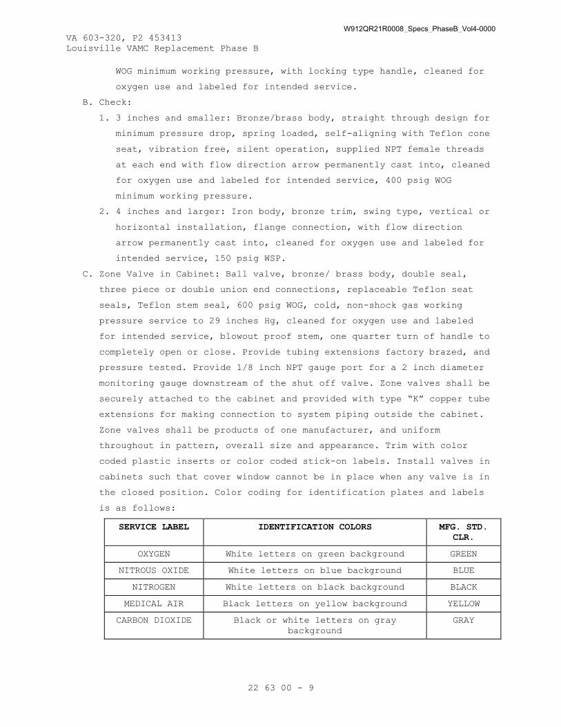
VA 603-320, P2 453413 Louisville VAMC Replacement Phase B
22 63 00 - 9
WOG minimum working pressure, with locking type handle, cleaned for
oxygen use and labeled for intended service.
B. Check:
1. 3 inches and smaller: Bronze/brass body, straight through design for
minimum pressure drop, spring loaded, self-aligning with Teflon cone
seat, vibration free, silent operation, supplied NPT female threads
at each end with flow direction arrow permanently cast into, cleaned
for oxygen use and labeled for intended service, 400 psig WOG
minimum working pressure.
2. 4 inches and larger: Iron body, bronze trim, swing type, vertical or
horizontal installation, flange connection, with flow direction
arrow permanently cast into, cleaned for oxygen use and labeled for
intended service, 150 psig WSP.
C. Zone Valve in Cabinet: Ball valve, bronze/ brass body, double seal,
three piece or double union end connections, replaceable Teflon seat
seals, Teflon stem seal, 600 psig WOG, cold, non-shock gas working
pressure service to 29 inches Hg, cleaned for oxygen use and labeled
for intended service, blowout proof stem, one quarter turn of handle to
completely open or close. Provide tubing extensions factory brazed, and
pressure tested. Provide 1/8 inch NPT gauge port for a 2 inch diameter
monitoring gauge downstream of the shut off valve. Zone valves shall be
securely attached to the cabinet and provided with type “K” copper tube
extensions for making connection to system piping outside the cabinet.
Zone valves shall be products of one manufacturer, and uniform
throughout in pattern, overall size and appearance. Trim with color
coded plastic inserts or color coded stick-on labels. Install valves in
cabinets such that cover window cannot be in place when any valve is in
the closed position. Color coding for identification plates and labels
is as follows:
SERVICE LABEL IDENTIFICATION COLORS MFG. STD. CLR.
OXYGEN White letters on green background GREEN
NITROUS OXIDE White letters on blue background BLUE
NITROGEN White letters on black background BLACK
MEDICAL AIR Black letters on yellow background YELLOW
CARBON DIOXIDE Black or white letters on gray background
GRAY
W912QR21R0008_Specs_PhaseB_Vol4-0000

VA 603-320, P2 453413 Louisville VAMC Replacement Phase B
22 63 00 - 10
2.4 VALVE CABINETS
A. Flush mounted commercially available item for use with laboratory and
healthcare services, not lighter than 18 gage steel or 14 gage extruded
aluminum, rigidly assembled, of adequate size to accommodate valve(s)
and fittings. Punch or drill sides to receive tubing. Provide anchors
to secure cabinet to wall construction. Seal openings in cabinet to be
dust tight. Locate bottom of cabinet 4 feet 6 inches above finished
floor.
B. Mount engraved rigid plastic identification plate on wall above or
adjacent to cabinet. Color code identification plate to match gas
identification colors as indicated above. Identification plate shall be
clearly visible at all times. Provide inscriptions on plate to read in
substance: "VALVE CONTROL SUPPLY TO ROOMS."
C. Cover plate: Fabricate from 18 gage sheet metal with satin chromed
finish, extruded anodized aluminum, or 22 gage stainless steel. Provide
cover window of replaceable plastic, with a corrosion resistant device
or lever secured to window for emergency window removal. Permanently
paint or stencil on window: CAUTION-CLOSE ONLY IN EMERGENCY, SHUT-OFF
VALVES FOR PIPED GASES", or equivalent wording. Configure such that it
is not possible to install window with any valve in the closed
position. Each valve shall have gauge upstream of valve inside valve
box.
D. Cabinets and isolation valves shall be located and piped as shown on
drawings, and at a minimum, so as to allow the isolation of each smoke
compartment separately. No cabinet shall serve more than one smoke
compartment.
2.5 GAGES
A. Pressure Gages: Includes gages temporarily supplied for testing
purposes.
1. For line pressure use adjacent to source equipment: ASME B40.1,
pressure gage, single, size 4-1/2 inches, for compressed air,
nitrogen and oxygen, accurate to within 2 percent, with metal case.
Range shall be two times operating pressure. Dial graduations and
figures shall be black on a white background, or white on a black
background. Gage shall be cleaned for oxygen use, labeled for
appropriate service, and marked "USE NO OIL". Install with gage
cock.
W912QR21R0008_Specs_PhaseB_Vol4-0000

VA 603-320, P2 453413 Louisville VAMC Replacement Phase B
22 63 00 - 11
2. For all services downstream of main shutoff valve: Manufactured for
oxygen use, labeled for the appropriate service and marked "USE NO
OIL", 1-1/2 inch diameter gage with dial range 1 to 100 psig for air
service and (1 to 297 psig) for nitrogen and instrument air
service.
2.6 STATION OUTLETS
A. For all services except ceiling hose drops and nitrogen system: For
designated service, consisting of a quick coupler and inlet supply
tube. Provide coupler that is non-interchangeable with other services,
and leak proof under three times the normal working pressure. Equip
each station outlet with an automatic valve and a secondary check valve
to conform with NFPA 99. Equip each station inlet with an automatic
valve to conform with NFPA 99. Place valves in the assembly to provide
easy access after installation for servicing and replacement, and to
facilitate line blow-out, purging, and testing. Fasten each outlet and
inlet securely to rough-in to prevent floating and provide each with a
capped stub length of 1/4-inch (3/8-inch outside diameter) tubing for
connection to supply. Identification of each gas service shall be
permanently cast into the back plate and shall be visible through a
transparent plastic guard. Label stub tubing for appropriate service.
Rough-in kits and test plugs for PBPU are furnished under this
specification but installed by manufacturer of PBPU before initial test
specified herein. Install completion kits (valve body and face plate)
for the remainder of required tests.
B. For Ceiling Hose Drops and Nitrogen Service: Brass, stainless steel or
chromed metal non-interchangeable DISS connections for appropriate
service to conform with CGA V-5. Equip each station outlet with an
automatic valve and a secondary check valve to conform with NFPA 99.
Equip each station inlet with an automatic valve to conform with NFPA
99. Place valves in the assembly to provide easy access after
installation, for servicing and replacement, and to facilitate line
blow-out, purging, and testing. Fasten each outlet and inlet securely
to rough-in to prevent floating, and provide each with a capped stub
length of 1/4-inch 3/8-inch outside diameter) tubing for connection to
supply. Label stub tubing for appropriate service. Adjust to compensate
for variations in plaster or cover thickness.
2.7 STATION OUTLET ROUGH-IN
A. Anchor flush mounted rough-in securely to unit or wall construction.
W912QR21R0008_Specs_PhaseB_Vol4-0000

VA 603-320, P2 453413 Louisville VAMC Replacement Phase B
22 63 00 - 12
B. Modular Cover Plate: Die cast back plate, two-piece 22 gage stainless
steel or 16 gage chromium plated metal, with mounting flanges on all
four sides, secured to rough-in with stainless steel or chromium plated
countersunk screws.
C. Cover Plate for PBPU: One-piece with construction and material as
indicated for modular cover plate.
D. Provide permanent, metal or plastic, identification plates securely
fastened at each outlet and inlet opening, with inscription for
appropriate service using color coded letters and background. Metal
plates shall have letters embossed on baked-on enamel background. Color
coding for identification plates is as follows:
SERVICE LABEL IDENTIFICATION PLATE COLORS
OXYGEN White letters on green background and vice versa
NITROUS OXIDE White letters on blue background
NITROGEN White letters on black background
MEDICAL AIR Black letters on yellow
CARBON DIOXIDE White letters on gray background
2.8 CEILING SERVICES
A. Column Accessories:
1. Equip each utility column with flush type quick coupler gas service
station outlets, except nitrogen outlets shall be DISS, as specified
under paragraph “Station Outlets”. Provide the following outlets,
mounted on the utility column: two oxygen, one nitrous oxide, one
nitrogen, one medical air, and one carbon dioxide, unless otherwise
noted.
2. Provide one 1-7/8 inches by 3 inches blank and face plate for future
installation of mass spectrometer inlet tubing and wiring.
3. Provide spacing to allow for future installation of up to three
monitoring receptacles.
4. Provide four single, NEMA 5-20R, hospital grade receptacles rated at
20 amps, 125 volts, 2 pole, 3 wire; two grounding receptacles.
Coordinate with Section 26 27 26, WIRING DEVICES.
5. Equip column with four I.V. hooks.
6. Provide one 1-7/8 inches x 3 inches blank face plate for computer
connection.
W912QR21R0008_Specs_PhaseB_Vol4-0000

VA 603-320, P2 453413 Louisville VAMC Replacement Phase B
22 63 00 - 13
B. Articulating Utility Column:
1. Pendent: Articulating arm and head constructed of lightweight
aluminum alloy castings enclosed in high impact, flame retardant (UL
94 V-O) dress shrouds. Arm shall have a minimum of 20 inch vertical
range of motion and a horizontal swing of 5.67 RAD (330 degrees),
adjustable in 15 degree increments. Head shall have a minimum
rotation of 330 degrees adjustable in 15 degree increments. Minimum
reach of the arm from ceiling pivot to head pivot is 37 inches. The
total reach of the pendant with head perpendicular to the arm axis
is 57 inches. Vertical motion shall be achieved by 1/8 hp induction
motor. Driven linear motion is by hand control contained in housing.
Pneumatic driven unit shall consist of a pneumatic cylinder, duplex
regulating valve, pressure gauge, filter, pressure relief valve,
master control valve and lubricator/muffler. The entire vertical
motor mechanism within unit shall be furnished and pre-installed.
The weight capacity of head shelf shall be 175 pounds of weight
mounted onto integral shelf or 125 pounds if the optional monitor
mount is used. Nitrogen control system shall be integral with the
unit with internal regulators mounted in the dispensing head.
Factory assembled and tested. Provide with complete protective cover
for the duration of construction.
2. Ceiling Support: Provide manufacturers standard anchoring device for
pendant. Provide all required hardware to support pendent from the
building structure.
C. Retractable Utility Column: Column: Upper section for rigid mounting at
drop-ceiling level, and counter-balanced telescoping lower section
capable of being extended and retracted minimum 18 inches. Provide
fail-proof stops to prevent the underside from extending lower than 5
feet 6 inches above finished floor. Equip with combination handle and
release lever to allow the lower telescoping section to be positively
locked in any position from fully extended to fully retracted.
Construct vertical sections with 20 gage stainless steel and bottom
plate with 14 gage stainless steel. Welded seams shall be ground smooth
for seamless appearance. Except for the escutcheon which may be
extruded aluminum, exposed surfaces shall be NAAMM Number 4 satin
finish stainless steel. Provide access panels to allow inspection of
interior column fittings. Nitrogen control system shall be integral
with the unit with internal regulators mounted in the dispensing head.
W912QR21R0008_Specs_PhaseB_Vol4-0000

VA 603-320, P2 453413 Louisville VAMC Replacement Phase B
22 63 00 - 14
Factory assembled and tested. Provide with complete protective cover
for the duration of construction.
D. Ceiling Mounted Station Outlets: As specified under paragraph “Station
Outlets”, flush mount on ceiling and provide with hose tubing drops and
retractors. Extend male thread DISS connection through ceiling plate.
1. Hoses: Conductive, neoprene tubing, color coded for appropriate
service, dropping to within 4 feet 6 inches from floor, with upper
end of hose having female DISS connection with nut, easily finger
tightened to ceiling outlet or inlet, and lower end of hose having
DISS connection only for nitrogen service, and having quick coupler
for all other services. Color coding for hoses is as follows:
SERVICE HOSE COLOR
OXYGEN Green
NITROUS OXIDE Blue
NITROGEN Black
AIR Yellow
CARBON DIOXIDE Gray
2. Rough-in: Standard metal single gang, interchangeable, sectional or
one piece, securely anchored to ceiling runner channels; ceiling
plates of die cast plate, 22 gage stainless steel or 16 gage
chromium plated metal. Attach identification plate, as specified in
paragraph “Station Outlet Rough-In”, to ceiling plate adjacent to
each outlet and inlet.
3. Hose retractor kit: Chrome-plated, spring loaded assembly and hose
clamps with stainless steel sash chain; to automatically withdraw
hose assembly a minimum of 508 mm (20 inches) from fully extended
position of 4 feet 8 inches to 6 feet 4 inches above finished floor.
2.9 ALARMS
A. Provide all low voltage control wiring, including wiring from alarm
relay interface control cabinet to BAS, required for complete, proper
functioning system, in conformance with Section 26 05 19, LOW-VOLTAGE
ELECTRICAL POWER CONDUCTORS AND CABLES. Run wiring in conduit, in
conformance with Section 26 05 33, RACEWAY AND BOXES FOR ELECTRICAL
SYSTEMS. Provide two master alarm panels at locations noted on drawings
as well as capability of connection to BAS.
B. Local Alarm Functions: Provide individual local air compressor
malfunction alarms at each compressor system main control panel.
W912QR21R0008_Specs_PhaseB_Vol4-0000
VA 603-320, P2 453413 Louisville VAMC Replacement Phase B
22 63 00 - 15
1. Compressor Malfunction Alarm: Each compressor system receiving any
of the following individual signals and sends a single combined
"compressor malfunction alarm" signal to master alarm panel.
a. Thermal Malfunction Alarm: Functions when discharge air
temperature exceeds 350 degrees F, shutting down affected
compressor.
b. Lead Compressor Fails to Start: Functions when lead compressor
fails to start when actuated, causing lag pump to start.
c. Lag Compressor In Use: Functions when the primary or lead
compressor is incapable of satisfying the demand. When three or
more compressors are part of the system, the lag compressor in
use alarm shall energize when the last compressor has been
signaled to start.
d. High Water Level in Receiver (liquid ring or water-cooled units).
e. High Water Level in Separator (if so required) (liquid ring
unit).
2. Desiccant Air Dryer Malfunction Alarm: Dryer receives the following
individual signals and sends a single consolidated dryer malfunction
alarm signal to master alarm panel.
a. Dew Point Alarm: Functions when line pressure dew point rises
above 40 degrees F at 55 psig.
3. Vacuum Pump Malfunction Alarm: Pump system receives the following
individual signals and sends a single consolidated pump malfunction
alarm signal to master alarm panel.
a. High Temperature Shut down Alarm: Functions when exhaust air
temperature exceeds 220 degrees F, shutting down affected pump.
b. Lead Pump Fails to Start Alarm: Functions when lead pump fails to
start when actuated causing lag pump to start.
c. Lag Pump In Use Alarm: Functions when the primary or lead vacuum
pump in incapable of satisfying the demand. When three or more
vacuum pumps are part of the system, the lag pump in use alarm
shall energize when the last vacuum pump has been signaled to
start.
4. Waste Anesthetic Gas Disposal (WAGD) Lag In Use Alarm: Provide when
a central WAGD system is used. The signal shall be manually reset.
5. Instrument Air Dew Point High: Functions when the line pressure dew
point is greater than -22 degrees F.
W912QR21R0008_Specs_PhaseB_Vol4-0000
VA 603-320, P2 453413 Louisville VAMC Replacement Phase B
22 63 00 - 16
C. Master Alarm Functions: Provide the following individual alarms at the
master alarm panel.
1. Oxygen Alarms:
a. Liquid oxygen low level alarm: Functions when stored liquid
oxygen reaches a predetermined minimum level.
b. Reserve switchover alarm: Functions when, or just before, reserve
oxygen supply goes in operation.
c. Reserve low supply alarm: Functions when contents of cylinder
reserve oxygen supply are reduced to one day's average supply;
switch and contacts at the bulk tank control panel.
d. Reserve low pressure alarm: Functions when the gas pressure
available in the liquid reserve oxygen supply is reduced below
the pressure required to function properly.
e. Low pressure alarm: Functions when system pressure downstream of
the main shutoff valve drops below 40 psig, ±2 psig; operated by
pressure switch or transmitters.
f. High pressure alarm: functions when system pressure downstream of
main shutoff valve increases above 60 psig, ±2 psig set points;
operated by pressure switches or transmitters.
g. Cylinder reserve pressure low: Functions when the content of a
cylinder reserve header is reduced below one day’s average
supply.
2. Nitrous Oxide Alarms:
a. Reserve switchover alarm: Functions when, or just before,
secondary or reserve nitrous oxide supply goes in operation.
b. Pressure alarms: Functions when system pressure downstream of
main shutoff valve drops below 40 psig, ±2 psig or increases
above 60 psig, ±2 psig set points; operated by pressure switches
or transmitters.
c. Cylinder reserve pressure low: Functions when the content of a
cylinder reserve header is reduced below one day’s average
supply.
3. Nitrogen Alarms:
a. Reserve switchover alarm: Functions when, or just before,
secondary or reserve nitrogen supply goes in operation.
b. Pressure alarms: Functions when system pressure downstream of
main shutoff valve drops below 190 psig, ±2 psig or increases
W912QR21R0008_Specs_PhaseB_Vol4-0000
VA 603-320, P2 453413 Louisville VAMC Replacement Phase B
22 63 00 - 17
above 220 psig, ±2 psig set points; operated by pressure switches
or transmitters.
c. Cylinder reserve pressure low: Functions when the content of a
cylinder reserve header is reduced below one day’s average
supply.
4. Carbon Dioxide Alarms:
a. Reserve Switchover Alarm: Functions when, or just before,
secondary or reserve carbon dioxide supply goes in operation.
b. Pressure Alarms: Functions when system pressure downstream of
main shutoff valve drops below 40 psig, ±2 psig or increases
above 60 psig, ±2 psig set points; operated by pressure switches
or transmitters.
c. Cylinder reserve pressure low: Functions when the content of a
cylinder reserve header is reduced below one day’s average
supply.
5. Compressed Air Alarms:
a. Medical air dew point high alarm: Functions when the line
pressure dew point rises above 35 degrees F at 55 psig.
b. Carbon Monoxide Alarm: Functions when the carbon monoxide levels
rise above 10 parts per million; receives signal from the carbon
monoxide monitor.
c. Main Bank Filter Set Alarm: Functions when the pressure drop
across filter set increases more than 2 psig over that when
filters are clean and new; operates by differential pressure
switch or transmitters.
d. Desiccant Prefilter Alarm: Functions when pressure across the
filter increases more than 3 psig over that when filters are
clean and new; operates by pressure differential switch.
e. Desiccant Post Filter Alarm: Functions when pressure drop across
filter increases more than 3 psig over that when filters are
clean and new; operates by pressure differential switch.
f. Desiccant Dryer Malfunction Alarm: Functions on any combination
of failure of tower cycling and/or pressure dew point rise above
140 degrees F at 100 psig.
g. Aftercooler High temperature Alarm: Functions when aftercooler
discharge air temperature exceeds 100 degrees F.
h. Pressure Abnormal Alarm: Functions when system pressure
downstream of main shutoff valve drops below 80 psig (± gage or
W912QR21R0008_Specs_PhaseB_Vol4-0000

VA 603-320, P2 453413 Louisville VAMC Replacement Phase B
22 63 00 - 18
increases above 120 psig ±2 psig set points; operated by pressure
switch.
i. Compressor Malfunction Alarm: Functions when compressor system
control panel signals compressor thermal malfunction alarm, lead
compressor fails to start alarm or high water level in receiver
or separator (if so required) receives signal from system control
panel.
j. Low Lubricant Shutdown: For rotary screw compressors. Functions
when lubricant level drops to a low point. Receives signal from
compressor control panel.
k. Instrument air dew point high alarm: Functions when the line
pressure dew point rises above -22 degrees F at 55 psig.
D. Alarm Functions:
1. Oxygen, nitrous oxide, carbon dioxide and compressed air alarms:
Pressure alarms: Functions when pressure in branch drops below 40
psig), ±2 psig or increases above 60 psig, ±2 psig set points;
operated by pressure switches or transmitters.
2. Nitrogen alarms: Pressure alarms: Functions when pressure in branch
drops below 190 psig, ±2 psig or increases above 220 psig, ±2 psig
set points; operated by pressure switches or transmitters.
3. Vacuum alarms: Low vacuum alarm: Functions when vacuum in branch
drops below 12 inches Hg; operated by vacuum switch.
4. Vacuum alarms:
a. Low vacuum alarm: Function when system vacuum upstream of main
shutoff valve drops below 12 inches Hg; operated by vacuum
switch.
b. Filter differential pressure/back pressure alarm: Functions when
discharge oil filter differential rises to set level, or when
back pressure is sensed; receives signal from pump control panel.
c. Laboratory vacuum pump malfunction.
5. Waste Anesthetic Gas Disposal (WAGD) low alarm: Functions when WAGD
vacuum level or flow is below effective operating limits.
E. Alarm Panels:
1. General: Modular design, easily serviced and maintained; alarms
operate on alternating current (AC) low voltage control circuit;
provide required number of transformers for efficient functioning of
complete system. Alarm panels shall be integral units, reporting
cylinder manifold compressed air and vacuum services, as required.
W912QR21R0008_Specs_PhaseB_Vol4-0000

VA 603-320, P2 453413 Louisville VAMC Replacement Phase B
22 63 00 - 19
2. Box: Flush mounted, sectional or one piece, corrosion resistant.
Size box to accommodate required number of service functions for
each location, and for one audible signal in each box. Anchor box
securely. Provide spare capacity to accommodate 50 percent of the
number of provided alarm points.
3. Cover plate: Designed to accommodate required number of signals,
visual and audible, for each location, and containing adequate
operating instructions within the operator's view. Bezel shall be
extruded aluminum, chromium plated metal, or plastic. Secure to the
box with chromium plated or stainless steel countersunk screws.
4. Service indicator lights: Red translucent plastic or LED with proper
service identification inscribed thereon. Number of lights and
service instruction shall be as required for each location. Provide
each panel with a green test button of the same material, inscribed
with "PUSH TO TEST" or similar message.
5. Audible signal: Provide one in each alarm panel and connect
electrically with all service indicator light functions.
6. Controls:
a. Visual signal: When the condition occurs which any individual
service indicator light is to report, button for particular
service shall give a lighted visual signal which cannot be
canceled until such condition is corrected.
b. Audible signal: Alarm shall give an audible signal upon circuit
energization of any visual signal. Audible signal shall be
continuous until silenced by pushing a button. This shall cancel
and reset audible only, and not affect the visual signal. After
silencing, subsequent alarms shall reactivate the audible alarm.
c. Signal tester: Test button or separate normal light shall be
continuously lighted to indicate electrical circuit serving each
individual alarm is energized. Pushing test button shall
temporarily activate all visual signals and sound audible signal,
thereby providing desired indications of status of system.
F. Alarm Relay Interface Control Cabinet: Design cabinet to transfer the
closed circuit alarm signals through relays to a set of terminals for
monitoring signals at the BAS without interrupting the closed circuit
system. Constructed of 14 gage steel, conforming with NEMA ICS 6, Type
1, enclosures. Provide both normally open and normally closed contacts
for output signals, with number of circuits required for full alarm
W912QR21R0008_Specs_PhaseB_Vol4-0000

VA 603-320, P2 453413 Louisville VAMC Replacement Phase B
22 63 00 - 20
capability at the BAS. Refer to Section 23 09 23, DIRECT-DIGITAL
CONTROL SYSTEM FOR HVAC for compatibility.
G. Alarm Network Communication: Network communications board shall be
installed in local alarm and connected to the contractor supplied
network. Local alarm modules shall send information to the master alarm
and the data can be downloaded thru the computer connected to the
contractor supplied network. Master alarm displays the message, sounds
its alarm and saves the information in an event log. This event log
shall be downloaded to a computer file for tracking data and
troubleshooting.
2.10 PRESSURE SWITCHES
A. General purpose, contact or mercury type, allowing both high and low
pressure set points, with contact type provided with a protective dust
cover; adjustable range; switches activate when indicated by alarm
requirements. Use one orifice nipple (or DISS demand check valve) for
each sensor or pressure switch.
2.11 NITROGEN CONTROL PANEL (NCP)
A. General: For nitrogen service, consisting of a line pressure control
regulator, outlet line pressure gage, DISS service outlet, and supply
valve, assembled and rigidly mounted in a roughing-in assembly, and
provided with a metal cover plate. Panel shall be designed to deliver
20 SCFM at 223 psig. Unit may be recessed wall mounted or integral with
the articulating arm or column with individual regulators for each
outlet.
B. Manifold Assembly: Mounted to a steel support bracket, factory
assembled and tested, ready for installation in the roughing-in
assembly.
1. Supply valve, bronze bodied, double seal, full flow, ball type,
designed for working pressure in excess of 300 psig, with chrome
plated brass ball which seals in both directions, requiring only a
quarter turn of the knob from open to closed position.
2. Line pressure control regulator, self-relieving, diaphragm type,
with high-flow precision adjustment and working pressure in excess
of 250 psig.
3. Line pressure gage, to monitor the gas outlet line pressure,
calibrated from 0 to 300 psig in increments of 10 psig.
W912QR21R0008_Specs_PhaseB_Vol4-0000

VA 603-320, P2 453413 Louisville VAMC Replacement Phase B
22 63 00 - 21
4. Nitrogen service outlet, DISS type as specified under paragraph
“Station Outlets”, with a self-sealing dust plug, having a working
pressure of 250 psig maximum.
5. Two 5-3/4 inch lengths of 3/8 inch outside diameter type "K" copper
tubing for connection to gas service supply line and to remote
outlet line.
C. Roughing-In Assembly: Designed for recessed installation, consisting of
a prime painted steel fabricated back box with mounting flanges on all
four sides, with provisions to securely anchor the back box to wall
construction. Equip with a crossover "U" tube to facilitate testing of
the nitrogen system prior to the manifold installation, and a plaster
shield to prevent dust or other foreign matter from contaminating
internal parts prior to final assembly.
D. Cover plate Assembly: Chromed cast metal or NAAMM Number 4 satin
finished stainless steel panel with provisions for line pressure
gage(s), nitrogen outlet, regulator and supply valve knobs, attaching
directly to the roughing-in assembly by means of four Number 6 - 32 by
1-1/2 inch long mounting screws, with plaster adjustments up to 3/4
inch.
2.12 CYLINDER GAS SUPPLY MANIFOLDS
A. Non-ferrous metal manifold and fittings, valves, parts and connections,
suitable for a regular working pressure of 3000 psig. Gas cylinders at
manifold shall be individually chained to wall or floor with adequate
support. Cylinders shall not be chained to portable or movable
apparatus such as beds.
B. Duplex arrangement, each bank having number of cylinder connections as
required, high pressure copper cylinder connection pigtails with brazed
fittings. Shutting of either bank shall not interrupt supply to system.
C. Provide manifold with two (one for each bank) two-stage pressure
regulators with gages and built-in safety valves, manifold header
valves and check valves, service line connection valves, relief valves,
tank connecting coils and handles, and all required equipment for a
complete assembly. Enclose manifold controls in sheet metal cabinet.
D. Supply pressure for nitrous oxide and carbon dioxide is 55 psi.
Supply pressure for nitrogen is 200 psi.
E. Switch-over to full reserve bank shall be automatic when one cylinder
bank becomes exhausted, with no fluctuation in pressure, and not
require resetting of regulators. After replacement of empty tank,
W912QR21R0008_Specs_PhaseB_Vol4-0000

VA 603-320, P2 453413 Louisville VAMC Replacement Phase B
22 63 00 - 22
resetting of controls shall be automatic or by single lever. Reserve
switch-over shall be actuated by pressure switch; alarm shall be part
of manifold control.
2.13 AIR COMPRESSOR SYSTEMS
A. System Design: The medical air, instrument air and laboratory air
systems shall be of a modular base mounted design consisting of
multiplex compressor, dryer/control, and an air receiver. Each unit
shall be fully compliant with the latest edition of NFPA 99.
B. Compressors: Continuous duty rated “oil-less” type with permanently
lubricated, sealed bearings. Single stage design, air cooled,
reciprocating type for instrument air and scroll type for medical and
laboratory air with corrosion resistant reed type valves with stainless
steel reeds. Both the compression rings and rider rings shall be made
from a long life, fluororesin material designed for continuous duty
operation. The crankshaft shall be constructed of a durable nodular
graphite cast iron and designed to be fully supported on both ends by
heavy duty ball bearings permanently lubricated and sealed. The
crankcase shall be constructed of gray cast iron. Maximum heat
dissipation shall be achieved through cast aluminum alloy cylinders
treated for optimum corrosion and wear resistance. Cylinder sleeves
shall not be required. Additionally, heat transmission from the piston
wall to the piston pin needle bearing shall be minimized by an
insulated “heat cut” piston pin. The connecting rod shall be of a one
piece design for maximum reliability. Bio-based materials shall be
utilized when possible.
C. Compressor Drive and Motor: V-belt driven through a combination
flywheel/sheave and steel motor sheave with tapered bushing and
protected by an OSHA approved, totally enclosed belt guard. Belt
tensioning shall be achieved by a pivoting motor mounting base that is
fully adjustable through twin adjusting screws. The motor shall be a
NEMA rated, open-drip-proof, 1800 RPM, with 1.15 service factor
suitable for 208/230/460V electrical service, a specified in Section 22
05 12, GENERAL MOTOR REQUIREMENTS FOR PLUMBING EQUIPMENT and Section 26
29 11, MOTOR CONTROLLERS.
D. Intake Piping: Provide a pre-piped intake manifold with one inlet air
filter with threaded opening for remote intake connection. Isolate
filter housing from the intake manifold with a braided 304 stainless
steel flex connector.
W912QR21R0008_Specs_PhaseB_Vol4-0000

VA 603-320, P2 453413 Louisville VAMC Replacement Phase B
22 63 00 - 23
E. Discharge Piping: Provide an integral air cooled aftercooler designed
for a maximum approach temperature of 12 degrees F complete with
moisture separator and timed automatic solenoid drain valve with a
manual drain value by-pass. Provide each cylinder head with a pre-wired
high discharge air temperature shutdown switch. Include a flex
connector, safety relief valve, and check valve. The compressor
discharge line the piping shall be of ASTM B819 copper tubing, brass,
and/or stainless steel. The discharge flex connector shall be braided
304 stainless steel, brass or bronze.
F. Isolation System: Isolate the compressor and monitor from the main
compressor module base by means of a four point, heavy duty, spring
isolation system for a minimum of 95 percent isolation efficiency.
G. Dryer/Control: The dryer/control shall include a NEMA 12, U.L. labeled
control system, duplexed desiccant drying system, duplexed final line
filters, duplexed final line regulators, and combination dew point/CO
monitor. All of the above shall be pre-wired and pre-piped in
accordance with NFPA 99 and include valving to allow complete air
receiver by-pass, as well as air sampling port.
H. Dryer: Size each desiccant dryer for the peak calculated demand and
capable of producing 10 degrees F for medical and laboratory air
compressors and -40 degrees F for instrument air compressor pressure
dew point. Dryer purge flow shall be minimized through an on-demand
purge saving control system. Include a mounted prefilter rated for 0.01
micron with automatic drain and element change indicator on the inlet
of each dryer.
I. Control System: Mounted and pre-wired control system shall be NEMA 12
and U.L. labeled. This control system shall provide automatic lead/lag
sequencing with circuit breaker disconnects for each compressor with
external operators, one non-fused main disconnect with external
operators, full voltage motor magnetic starters with overload
protection, redundant 120V control circuit transformers, visual and
audible reserve unit alarm with isolated contacts for remote alarm,
hand-off-auto (HOA) lighted selector switches, automatic alternation of
both compressors with provisions for simultaneous operation if
required, automatic activation of reserve unit if required, visual
alarm indication for high discharge air temperature shutdown with
isolated contacts for remote alarm, and duplexed run time hour meters.
W912QR21R0008_Specs_PhaseB_Vol4-0000

VA 603-320, P2 453413 Louisville VAMC Replacement Phase B
22 63 00 - 24
J. Final Line Filters and Regulators: Fully duplexed final line filters
rated for 0.01 micron with element change indicators shall be factory
mounted and pre-piped, along with duplexed factory mounted and pre-
piped final line regulators and duplex safety relief valves.
K. Dew Point Hygrometer/CO Monitor: Mounted, pre-piped and wired,
combination dew point hygrometer/CO monitor shall be of the ceramic
type with integral chemical type CO sensor. System accuracy shall be +
2 degrees F for dew point and 2 PPM (at 10 PPM) for carbon monoxide.
Dew point alarm shall be factory set at 40 degrees F per NFPA 99, and
the CO alarm shall be factory set at 10 PPM. Both set points shall be
field adjustable.
L. Air Receiver: Vertical air receiver, galvanized, ASME Coded, National
Board Certified, rated for minimum 150 psig design pressure and
includes a sight gauge glass as well as a timed automatic solenoid
drain valve. Provide three valve bypass on supply.
M. Example of an acceptable product and manufacturer: Beacon Medical
Products “Lifeline Medical Air Systems”.
2.14 PRESSURE REGULATORS
A. For 100 psig regulator, provide duplex in parallel, valve for
maintenance shut-down without service interruption. For additional
pressures, locate regulators remote from compressor near point of use,
and provide with isolation valves and valve bypass.
1. For systems 10 SCFM and below: Brass or bronze body and trim,
reduced pressure range 25 to 123 psig adjustable, spring type,
diaphragm operated, relieving. Delivered pressure shall vary not
more than 0.15 psig for each 1.5 psig variation in inlet pressure.
2.15 EMERGENCY LOW PRESSURE OXYGEN INLET
A. The Low Pressure Emergency Oxygen Inlet provides an inlet for
connecting a temporary auxiliary source of oxygen to the oxygen
pipeline system for emergency or maintenance situations per NFPA 99.
B. The inlet consist of a 1 inch ball valve, pressure gauge and a 1/2 inch
x 1 inch NPTF connection housed in a weather tight enclosure. The
enclosure is labeled "Emergency Low Pressure Gaseous Oxygen Inlet", and
includes a padlock staple to prevent tampering or unauthorized access.
The enclosure is suitable for recess mounting on the exterior of the
building being served. The enclosure is 14 gauge, cold rolled steel
with a primer coat of paint. The Emergency Oxygen Inlet is connected at
a point downstream of the main supply line shutoff valve.
W912QR21R0008_Specs_PhaseB_Vol4-0000

VA 603-320, P2 453413 Louisville VAMC Replacement Phase B
22 63 00 - 25
C. Check valves are provided for installation in the emergency supply line
and in the main supply line between the main line shutoff valve and the
emergency supply line connection per by NFPA 99. Check valves have a
cast bronze body and straight through design for minimum pressure drop.
D. The check valves for sizes under 3 inch are soft seated, bubble tight,
self-aligning, and spring loaded, and ball type check valves. 3 inch
check valves are hard seated, spring loaded, self-aligning ball type
checks with cone seats (3 inch valves may not be "bubble tight"). Check
valves shall be fast acting type.
E. A relief valve is provided for installation in the emergency supply
line per NFPA 99. The relief valve has a brass body, single seat
design, and is cleaned for oxygen use. It automatically reseats to
provide a "bubble tight" seal after discharging excess gas. Pre-set at
75 psig.
PART 3 - EXECUTION
3.1 INSTALLATION
A. In accordance with NFPA 99. Run buried oxygen piping in PVC protective
pipe for entire length including enclosure of fittings and changes of
direction.
B. Install cast escutcheon with set screw at each wall, floor and ceiling
penetration in exposed finished locations and within cabinets and
millwork.
C. Open ends of tube shall be capped or plugged at all times or otherwise
sealed until final assembly to prevent infiltration of any foreign
matter.
D. Cut piping square and accurately with a tube cutter (sawing is
prohibited) to measurements determined at place of installation. Ream
tube to remove burrs, being careful not to expand tube, and so no chips
of copper remain in the tube. Work into place without springing or
forcing. Bottom tube in socket so there are no gaps between tube and
fitting. Exercise care in handling equipment and tools used in cutting
or reaming of tube to prevent oil or grease being introduced into
tubing. Where contamination has occurred, material is no longer
suitable for oxygen service.
E. Spacing of hangers: NFPA 99.
F. Rigidly support valves and other equipment to prevent strain on tube or
joints.
W912QR21R0008_Specs_PhaseB_Vol4-0000

VA 603-320, P2 453413 Louisville VAMC Replacement Phase B
22 63 00 - 26
G. While being brazed, joints shall be continuously purged with oil free
nitrogen. The flow of purged gas shall be maintained until joint is
cool to touch. Government reserves the right to require non-destructive
joint fill testing if workmanship on joint is questionable.
H. Do not bend tubing. Use fittings.
I. Support ceiling column assembly from heavy sub-mounting castings
furnished with the unit as part of roughing-in. Anchor with 1/2-inch
diameter bolts attached to angle iron frame supported from structural
ceiling, unless otherwise indicated.
J. Provide two 1 inch minimum conduits from ceiling column assembly to
adjacent corridor, one for mass spectrometer tubing and wiring and one
for monitor wiring, for connection to signal cabling network.
K. Install pressure switches, transmitter and gauges to be easily
accessed, and provide access panel where installed above plaster
ceiling. Install pressure switch and sensors with orifice nipple
between the pipe line and switches/sensors.
L. Apply pipe labeling during installation process and not after
installation is completed. Size of legend letters shall be in
accordance with ASME A13.1.
M. Pipe compressor intake to a source of clean ambient air as indicated in
NFPA 99.
N. After initial leakage testing is completed, allow piping to remain
pressurized with testing gas until testing agency performs final tests.
O. Penetrations:
1. Fire Stopping: Where pipes pass through fire partitions, fire walls,
smoked partitions, or floors, install a fire stop that provides an
effective barrier against the spread of fire, smoke and gases as
specified in Section 07 84 00, FIRESTOPPING, with intumescent
materials only. Completely fill and seal clearances between raceways
and openings with the fire stopping material.
2. Waterproofing: At floor penetrations, completely seal clearances
around the pipe and make watertight with sealant as specified in
Section 07 92 00, JOINT SEALANTS. Bio-based materials shall be
utilized when possible.
P. Provide 1-1/2 inch diameter line pressure gage downstream of zone valve
in cabinets.
W912QR21R0008_Specs_PhaseB_Vol4-0000

VA 603-320, P2 453413 Louisville VAMC Replacement Phase B
22 63 00 - 27
Q. Provide zone valves in cabinets where indicated and outside each
Operating Room and a minimum one zone valve assembly for each 18 outlet
set.
R. All source systems shall be provided with an auxiliary source
connection point of the same size as main line which shall be located
immediately on the patient side of the source valve.
3.2 STARTUP AND TESTING
A. Initial Tests: Blow down and high and low pressure leakage tests as
required by NFPA 99 with documentation. Perform tests, inspections,
verifications, and certification of medical compressed-air piping
systems concurrently with tests, inspections, and certification of
[medical gas piping] [and] [medical vacuum piping] systems.
B. Preparation: Perform the following Installer tests according to
requirements in NFPA 99 and ASSE Standard #6010:
1. Initial blowdown.
2. Initial pressure test.
3. Cross-connection test.
4. Piping purge test.
5. Standing pressure test for positive-pressure medical and
instrument compressed-air piping.
6. Repair leaks and retest until no leaks exist.
C. System Verification: Perform the following tests and inspections
according to NFPA 99, ASSE Standard #6020, and ASSE Standard #6030:
1. Standing pressure test 2. Individual-pressurization or pressure-differential cross-connection
test
3. Valve test
4. Master and area alarm tests
5. Piping purge test
6. Piping particulate test
7. Piping purity test
8. Final tie-in test
9. Operational pressure test
10. Medical air purity test
11. Verify correct labeling of equipment and components
D. Testing Certification: Certify that specified tests, inspections, and
procedures have been performed and certify report results. Include the
following:
W912QR21R0008_Specs_PhaseB_Vol4-0000

VA 603-320, P2 453413 Louisville VAMC Replacement Phase B
22 63 00 - 28
1. Inspections performed
2. Procedures, materials and gases used.
3. Test methods used.
4. Results of tests.
E. Laboratory and/or healthcare testing agency shall perform the
following:
1. Perform and document all cross connection tests, labeling
verification, supply system operation, and valve and alarm operation
tests as required by, and in accordance with NFPA 99 and the
procedures set forth in pre-qualification documentation.
2. Verify that the systems, as installed, meet or exceed the
requirements of NFPA 99, this specification, and that the systems
operate as required.
3. Piping purge test: For each positive pressure gas system, verify
cleanliness of piping system. Filter a minimum of 35 cubic feet of
gas through a clean white 0.45 micron filter at a minimum velocity
of 3.5 SCFM. Filter shall show no discoloration, and shall accrue no
more than 0.0000035 ounces of matter. Test each zone at the outlet
most remote from the source. Perform test with the use of an inert
gas as described in CGA P-9.
4. Piping purity test: For each positive pressure system, verify purity
of piping system. Test each zone at the most remote outlet for dew
point, carbon monoxide, total hydrocarbons (as methane), and
halogenated hydrocarbons, and compare with source gas. The two tests
shall in no case exceed variation as specified in paragraph,
“Maximum Allowable Variation”. Perform test with the use of an inert
gas as described in CGA P-9. Piping purity tests are not required
for instrument air.
5. Outlet and inlet flow test:
a. Test all outlets for flow. Perform test with the use of an inert
gas as described in CGA P-9.
b. Oxygen, carbon dioxide, nitrous oxide and air (medical and
instrument) outlets shall deliver 3.5 SCFM with a pressure drop
of no more than 34 kPa (5 psig), and static pressure of 50 psig.
c. Nitrogen outlets shall deliver 20 SCFM with a pressure drop of no
more than 5 psig, and static pressure of 210 psig.
d. Needle valve air outlets shall deliver 1.5 SCFM with a pressure
drop of no more than five psig, and static pressure of 50 psig.
W912QR21R0008_Specs_PhaseB_Vol4-0000
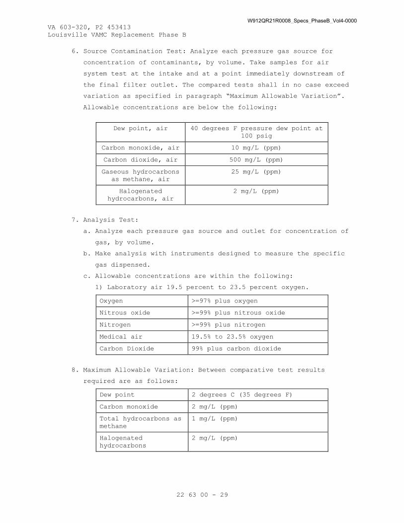
VA 603-320, P2 453413 Louisville VAMC Replacement Phase B
22 63 00 - 29
6. Source Contamination Test: Analyze each pressure gas source for
concentration of contaminants, by volume. Take samples for air
system test at the intake and at a point immediately downstream of
the final filter outlet. The compared tests shall in no case exceed
variation as specified in paragraph “Maximum Allowable Variation”.
Allowable concentrations are below the following:
Dew point, air 40 degrees F pressure dew point at 100 psig
Carbon monoxide, air 10 mg/L (ppm)
Carbon dioxide, air 500 mg/L (ppm)
Gaseous hydrocarbons as methane, air
25 mg/L (ppm)
Halogenated hydrocarbons, air
2 mg/L (ppm)
7. Analysis Test:
a. Analyze each pressure gas source and outlet for concentration of
gas, by volume.
b. Make analysis with instruments designed to measure the specific
gas dispensed.
c. Allowable concentrations are within the following:
1) Laboratory air 19.5 percent to 23.5 percent oxygen.
Oxygen >=97% plus oxygen
Nitrous oxide >=99% plus nitrous oxide
Nitrogen >=99% plus nitrogen
Medical air 19.5% to 23.5% oxygen
Carbon Dioxide 99% plus carbon dioxide
8. Maximum Allowable Variation: Between comparative test results
required are as follows:
Dew point 2 degrees C (35 degrees F)
Carbon monoxide 2 mg/L (ppm)
Total hydrocarbons as methane
1 mg/L (ppm)
Halogenated hydrocarbons
2 mg/L (ppm)
W912QR21R0008_Specs_PhaseB_Vol4-0000

VA 603-320, P2 453413 Louisville VAMC Replacement Phase B
22 63 00 - 30
F. The CxA will observe startup and contractor testing of selected
equipment. Coordinate the startup and contractor testing schedules with
the COR and CxA. Contractor shall provide a minimum of 10 working days
prior to startup and testing.
G. Joint Construction
1. Remove scale, slag, dirt, and debris from outside of cleaned tubing
and fittings before assembly.
2. Threaded Joints: Apply appropriate tape to external pipe threads.
3. Brazed Joints: Join copper tube and fittings according to CDA's
"Copper Tube Handbook," "Brazed Joints" chapter. Continuously purge
joint with oil-free dry nitrogen during brazing.
4. Flanged Joints: Install flange on copper tubes. Use pipe-flange
gasket between flanges. Join flanges with gasket and bolts according
to ASME B31.9 for bolting procedure.
3.3 COMMISSIONING
A. Provide commissioning documentation in accordance with the requirements
of Section 22 08 00, COMMISSIONING OF PLUMBING SYSTEMS.
B. Components provided under this section of the specification will be
tested as part of a larger system.
3.4 DEMONSTRATION AND TRAINING
A. Provide services of manufacturer’s technical representative for four
hours to instruct VA Personnel in operation and maintenance of units.
B. Submit training plans and instructor qualifications in accordance with
the requirements of Section 22 08 00, COMMISSIONING OF PLUMBING SYSTEMS
and Section 01 79 00, OPERATIONS AND MAINTENANCE TRAINING.
- - - E N D - - -
W912QR21R0008_Specs_PhaseB_Vol4-0000
VA 603-320, P2 453413 Louisville VAMC Replacement Phase B
22 66 00 - 1
SECTION 22 66 00 CHEMICAL-WASTE SYSTEMS FOR LABORATORY AND HEALTHCARE FACILITIES
PART 1 - GENERAL
1.1 DESCRIPTION
A. This section describes the requirements for chemical waste systems,
including piping, neutralization equipment and all necessary
accessories as designated in this section.
B. A complete listing of all acronyms and abbreviations are included in
Section 22 05 11, COMMON WORK RESULTS FOR PLUMBING.
1.2 RELATED WORK
A. Section 01 33 00, SUBMITTAL PROCEDURES.
B. Section 01 81 13, SUSTAINABLE CONSTRUCTION REQUIREMENTS.
C. Section 01 91 00, GENERAL COMMISSIONING REQUIREMENTS.
D. Section 07 84 00, FIRESTOPPING: Penetrations in rated enclosures.
E. Section 07 92 00, JOINT SEALANTS.
F. Section 09 91 00, PAINTING: Preparation and finish painting and
identification of piping systems.
G. Section 22 05 11, COMMON WORK RESULTS FOR PLUMBING.
H. Section 22 07 11, PLUMBING INSULATION.
I. SECTION 22 08 00, COMMISSIONING OF PLUMBING SYSTEMS.
1.3 APPLICABLE PUBLICATIONS
A. The publications listed below form a part of this specification to the
extent referenced. The publications are referenced in the text by the
basic designation only.
B. American Society of Mechanical Engineers (ASME):
A13.1-2007..............Scheme for Identification of Piping Systems
B1.20.1-2013............Pipe Threads, General Purpose, Inch
B16.11-2011.............Forged Fittings, Socket-Welding and Threaded
B16.12-2009.............Cast Iron Threaded Drainage Fittings
B16.15-2013.............Cast Copper Alloy Threaded Fittings: Classes
125 and 250
C. American Society for Testing and Materials (ASTM):
A74-2013a...............Standard Specification for Cast Iron Soil Pipe
and Fittings
A183-2003 (R2009).......Standard Specification for Carbon Steel Track
Bolts and Nuts
W912QR21R0008_Specs_PhaseB_Vol4-0000

VA 603-320, P2 453413 Louisville VAMC Replacement Phase B
22 66 00 - 2
D2447-03................Standard Specification for Polyethylene (PE)
Plastic Pipe, Schedule 40 and 80, Based on
Outside Diameter
D4101-2011..............Standard Specification for Polypropylene
Injection and Extrusion Materials
E84-2013a...............Standard Test Method for Surface Burning
Characteristics of Building Materials
F402-2005 (R2012).......Standard Practice for Safe Handling of Solvent
Cements, Primers, and Cleaners Used for Joining
Thermoplastic Pipe and Fittings
F1412-2009..............Standard Specification for Polyolefin Pipe and
Fittings for Corrosive Waste Drainage Systems
D. Cast Iron Soil Pipe Institute (CISPI):
2006....................Cast Iron Soil Pipe and Fittings Handbook, 12th
Printing
301-2012................Standard Specification for Hubless Cast Iron
Soil Pipe and Fittings for Sanitary and Storm
Drain, Waste, and Vent Piping Applications
310-2012................Specification for Coupling for Use in
Connection with Hubless Cast Iron Soil Pipe and
Fittings for Sanitary and Storm Drain, Waste,
and Vent Piping Applications
E. International Code Council (ICC):
IPC-2015................International Plumbing Code
F. National Electrical Manufacturers Association (NEMA):
250-2008................Enclosures for Electrical Equipment (1000 Volts
Maximum)
G. Underwriters' Laboratories, Inc. (UL):
723-2008................Test for Surface Burning Characteristics of
Building Materials
1.4 SUBMITTALS
A. Submittals, including number of required copies, shall be submitted in
accordance with Section 01 33 00, SUBMITTAL PROCEDURES.
B. Information and material submitted under this section shall be marked
“SUBMITTED UNDER SECTION 22 66 00, CHEMICAL-WASTE SYSTEMS FOR
LABORATORY AND HEALTHCARE FACILITIES”, with applicable paragraph
identification.
W912QR21R0008_Specs_PhaseB_Vol4-0000

VA 603-320, P2 453413 Louisville VAMC Replacement Phase B
22 66 00 - 3
C. Manufacturer's Literature and Data including: Full item description and
optional features and accessories. Include dimensions, weights,
materials, applications, standard compliance, model numbers, size, and
capacity.
1. Chemical resistant waste and vent piping
2. Piping specialties
3. Neutralization tanks
4. Continuous flow neutralization and monitoring system
5. Cleanouts
6. Floor drains
7. Waterproofing
D. Detailed shop drawing of clamping device and extensions when required
in connection with the waterproofing membrane or the floor drain.
E. Shop Drawings: For neutralization system and leak-detection system.
Include plans, elevations, sections, details, and in junction with
Electrical,/ work.
1. Detail neutralization-system assemblies and indicate dimensions,
weights, loads, required clearances, method of field assembly,
components, and location and size of each field connection.
2. Detail leak-detection-system assemblies and indicate required
clearances, method of field assembly, components, and location and
size of each field connection.
3. Wiring Diagrams: For power, signal, and control wiring.
F. Seismic-Design Submittal: For seismic restraints of aboveground piping,
including analysis data signed and sealed by the qualified professional
engineer responsible for their preparation.
G. Complete operating and maintenance manuals including wiring diagrams,
technical data sheets and information for ordering replaceable parts:
1. Include complete list indicating all components of the systems.
2. Include complete diagrams of the internal wiring for each item of
equipment.
3. Diagrams shall have their terminals identified to facilitate
installation, operation and maintenance.
H. Completed System Readiness Checklist provided by the Commissioning
Agent and completed by the contractor, signed by a qualified technician
and dated on the date of completion, in accordance with the
requirements of Section 22 08 00, COMMISSIONING OF PLUMBING SYSTEMS.
W912QR21R0008_Specs_PhaseB_Vol4-0000

VA 603-320, P2 453413 Louisville VAMC Replacement Phase B
22 66 00 - 4
I. Submit training plans and instructor qualifications in accordance with
the requirements of Section 22 08 00, COMMISSIONING OF PLUMBING
SYSTEMS.
1.5 QUALITY ASSURANCE
A. Bio-Based Materials: For products designated by the USDA’s Bio-
Preferred Program, provide products that meet or exceed USDA
recommendations for bio-based content, so long as products meet all
performance requirements in this specifications section. For more
information regarding the product categories covered by the Bio-
Preferred Program, visit http://www.biopreferred.gov .
1.6 AS-BUILT DOCUMENTATION
A. Submit manufacturer’s literature and data updated to include submittal
review comments, construction revisions and any equipment
substitutions.
B. The installing contractor shall maintain as-built drawings of each
completed phase for verification; and, shall provide the complete set
at the time of final systems certification testing. As-built drawings
are to be provided, and a copy of them on Auto-Cad version 2014
provided on compact disk or DVD. Should the installing contractor
engage the testing company to provide as-built or any portion thereof,
it shall not be deemed a conflict of interest or breach of the ‘third
party testing company’ requirement.
C. Certification documentation shall be provided prior to submitting the
request for final inspection. The documentation shall include all test
results, the names of individuals performing work for the testing
agency on this project, detailed procedures followed for all tests, and
a certification that all results of tests were within limits specified.
PART 2 - PRODUCTS
2.1 CHEMICAL RESISTANT WASTE AND VENT PIPING
A. The material shall include connecting fittings in stacks or mains.
The chemical resistant waste and vent pipe material shall be extruded
polypropylene plastic pipe and drainage pattern fittings conforming to
ASTM F1412 and tested in accordance with applicable provisions of ASTM
D2447. The polypropylene pipe and fittings shall be schedule 40 and
made from a PP black olefin resin with a fire retardant additive
complying with ASTM D4101 with mechanical joints for sizes under 3
inches and fusion and mechanical joints for sizes 3 inches and over.
W912QR21R0008_Specs_PhaseB_Vol4-0000

VA 603-320, P2 453413 Louisville VAMC Replacement Phase B
22 66 00 - 5
1. Exception: Pipe and fittings made from PP resin without fire-
retardant additive may be used for underground installation. Comply
with applicable provisions of ASME B16.12 for material dimensions
and configurations.
2.2 PIPING SPECIALTIES
A. Plastic dilution traps shall be corrosion resistant polypropylene with
removable base and mechanical joint connections. The dilution tanks
shall have a one gallon capacity with a clear base unless color base is
indicated. The dilution tank shall have two NPS 1-1/2 top inlets and
one NPS 1-1/2 side outlet.
B. Corrosion resistant P-trap or drum trap shall have NPS 1-1/2 or NPS 2
as required for fixture and waste and conform to ASTM A861 for high
silicon iron pipe with hubless joints, ASTM D4101 for polypropylene
pipe with mechanical joints, ASTM D3222 for PVDF pipe with mechanical
joints, and ASTM C1053 for glass pipe with coupling connections.
2.3 NEUTRALIZATION TANKS
A. Plastic neutralization tanks shall have a capacity as noted on the
drawings and be constructed from corrosion resistant plastic materials
HDPE or ASTM D4101, PP with removable, gastight cover, inlet, vent, and
discharge sidewall pipe connections. The tank shall be filled with
limestone 1 to 3 inch chips or lumps with a calcium carbonate content
exceeding 90 percent.
2.4 CONTINUOUS FLOW NEUTRALIZATION AND MONITORING SYSTEM
A. The plastic tank acid neutralization monitoring system shall use a 120-
volt factory wired and tested control system to continuously monitor
the pH level of effluent with wiring and electrical power terminals.
The monitoring system shall power the probes and the metering pumps.
B. The panel shall be NEMA 250 Type 4X enclosure with the following
features:
1. Control devices.
2. Indicators devices.
3. Power light and on/off switch.
4. pH Analyzer with meter and high and low pH indicators.
5. Low caustic and acid solution level indicators.
6. Alarm horn with silencer and reset switch.
7. Agitator running light with on/off switch.
8. Running lights with on/off switches for caustic and acid solution
pumps.
W912QR21R0008_Specs_PhaseB_Vol4-0000

VA 603-320, P2 453413 Louisville VAMC Replacement Phase B
22 66 00 - 6
C. The recorder shall have a 30 day record capacity.
D. The piping between the tanks shall be the same material as the chemical
waste and vent system.
E. The interceptor tank shall function as a sediment trap and effluent
equalization tank and shall be the same material as mixing and
neutralization tank with removable, gastight cover, sidewall inlet and
outlet connections and vent connection in the top. Internal piping
shall be fitted with inlet elbows turned down to prevent settlement
from flowing to mixing and neutralization tank.
F. The mixing and neutralization tank shall be constructed from //
polypropylene in conformance with ASTM D4101. The pH probe type and
length shall be suitable for the size of the mixing tank. The agitator
shall be electric with stainless steel shaft and propeller.
G. The caustic solution storage tank shall be constructed from
polypropylene in conformance with ASTM D4101. The caustic solution
storage tank shall be filled with a sodium hydroxide solution.
H. The acid solution storage tank shall be constructed from polypropylene
in conformance with ASTM D4101. The acid solution storage tank shall be
filled with a sulfuric acid solution.
I. The metering pump shall be suitable for neutralizing solutions.
J. The sampling tank shall be the same material as the mixing tank with
removable, gastight cover, sidewall inlet and outlet connections and an
opening in the top for a pH probe.
2.5 CLEANOUTS
A. Cleanouts shall be the same size as the pipe, up to 4 inches; not less
than 4 inches for larger pipe. Cleanouts for chemical waste drain pipe
shall be of same material as the pipe. Cleanouts shall be easily
accessible and shall be gastight and watertight. A minimum clearance of
24 inches shall be provided for clearing a clogged chemical waste
drain.
B. Floor cleanouts shall have cast iron body and frame with square
adjustable scoriated secured nickel bronze top. The cleanout shall be
vertically adjustable for a minimum of 2 inches. When a waterproof
membrane is used in the floor system, a clamping collar shall be
provided on the cleanouts. Cleanouts shall consist of wye fittings and
eighth bends with brass or bronze screw plugs. Cleanouts in the
resilient tile floors, quarry tile and ceramic tile floors shall be
provided with square top covers recessed for tile insertion. In the
W912QR21R0008_Specs_PhaseB_Vol4-0000

VA 603-320, P2 453413 Louisville VAMC Replacement Phase B
22 66 00 - 7
carpeted areas, carpet cleanout markers shall be provided. Two way
cleanouts shall be provided where indicated on drawings.
C. Cleanouts shall be provided at or near the base of the vertical stacks
with the cleanout plug located approximately 24 inches above the floor.
If there are no fixtures installed on the lowest floor, the cleanout
shall be installed at the base of the stack. The cleanouts shall be
extended to the wall access cover. The vertical cleanout shall consist
of sanitary tees. Nickel bronze square frame and stainless steel cover
shall be furnished with a minimum opening of 6 by 6 inches at each wall
cleanout. Where the piping is concealed, a fixture trap or a fixture
with integral trap, readily removable without disturbing concealed
roughing work, shall be accepted as a cleanout equivalent providing the
opening to be used as a cleanout opening is the size required.
D. In horizontal runs above grade, cleanouts shall consist of cast brass
tapered screw plug in fitting or caulked/no hub cast iron ferrule.
Plain end (no-hub) piping in interstitial space or above ceiling may
use plain end (no-hub) blind plug and clamp.
2.6 FLOOR DRAINS
A. Type L: Flushing Rim Drain. Heavy cast iron body, double drainage
pattern with flushing rim and clamping device. Solid bronze gasketed
grate approximately 11 inches in diameter, with 2 inch length of 3/4
inch brass pipe brazed or threaded into the center of the solid grate,
pipe shall be threaded and provide brass cap with inter gasket
(neoprene) to provide a gas tight installation. Attach deep seal P-trap
to drain. Body and trap shall have pipe taps for water supply
connections:
1. Drain Flange: Flange for synthetic flooring.
2. Cystoscopy Rooms:
a. Flush Valve: The flush valve shall be large diaphragm type
flushometer, solenoid operated with a single circuit timer. Mount
in valve cabinet.
b. Operation: Valve solenoid shall be cycled by a single circuit
timer set to operate flush valve at five minute intervals. Timer
shall be electrically connected to an "on - off" toggle switch
and be provided with pilot light. Timer and flush valve shall
operate only when timer/valve switch is in the "on" position.
W912QR21R0008_Specs_PhaseB_Vol4-0000

VA 603-320, P2 453413 Louisville VAMC Replacement Phase B
22 66 00 - 8
c. Valve Cabinets:
1) General: Sheet metal not lighter than 16 gauge thick, size as
required, rigidly assembled with joints welded, and punched or
drilled for passage of required pipes and services. Provide
anchors for fastening cabinet in place. Front shall be flush
with wall finish and shall have flush fitting, hinged doors,
with latch. Door shall be arranged to not offer any
obstruction when open.
2) Doors and Trim: Flush with front of cabinet, constructed of
not lighter than number 12 gauge thick steel. Doors shall open
through 180 degrees and be provided with two butt hinges or
continuous hinge. Latch shall be provided by manufacture of
cabinet.
3) Painting: Prime and finish painting is specified under Section
09 91 00, PAINTING.
B. Type T: Funnel Type Chemical Resistant Floor Drain and "P" Trap: Double
drainage pattern with integral seepage pan for embedding in floor and
weep holes to provide adequate drainage from pan to drain pipe. Floor
drain shall be polypropylene, flame retardant, Schedule 40 or 80.
Provide outlet of floor drain suitable for properly jointing perforated
or slotted floor level grate and funnel extension. Cut out grate below
funnel. Minimum dimensions as follows:
1. Height of funnel 3-3/4 inches.
2. Diameter of lower portion of funnel - 2 inches.
3. Diameter of top portion of funnel - 4 inches.
C. Type X: Chemical resistant floor drain and p-trap. Double drainage
pattern with integral seepage pan for embedding in floor and weep holes
to provide adequate drainage from pan to drain pipe. Floor drain shall
be polypropylene, flame retardant, Schedule 40 or 80. Provide outlet of
floor drain suitable for properly joining with chemical resistant pipe
material.
2.7 WATERPROOFING
A. A sleeve flashing device shall be provide at points where pipes pass
through membrane waterproofed floors or walls. The sleeve flashing
device shall be manufactured, cast iron fitting with clamping device
that forms a sleeve for the pipe floor penetration of the floor
membrane. A galvanized steel pipe extension shall be included in the
top of the fitting that will extend 2 inches above finished floor and
W912QR21R0008_Specs_PhaseB_Vol4-0000

VA 603-320, P2 453413 Louisville VAMC Replacement Phase B
22 66 00 - 9
galvanized steel pipe extension in the bottom of the fitting that will
extend through the floor slab. A waterproofed caulked joint shall be
provided at the top hub.
PART 3 - EXECUTION
3.1 PIPE INSTALLATION
A. The pipe installation shall comply with the requirements of the
International Plumbing Code and these specifications.
B. Branch piping for chemical waste piping system shall be installed and
connected to all fixtures, valves, cocks, outlets, casework, cabinets
and equipment, including those furnished by the Government or specified
in other sections.
C. Piping shall be installed for reagent racks. The piping shall be
arranged neatly and located as required by the equipment.
D. Pipe shall be round and straight. Cutting shall be done with proper
tools. Pipe, except for plastic and glass, shall be reamed to full size
after cutting.
E. All pipe runs shall be laid out to avoid interference with other work.
F. The piping shall be installed above accessible ceilings to allow for
ceiling panel removal.
G. The piping shall be installed to permit valve servicing or operation.
H. The piping shall be installed at the indicated slopes or according to
the International Plumbing Code.
I. The piping shall be installed free of sags and bends.
J. Seismic restraint shall be installed where required by code.
K. Changes in direction for chemical waste drainage and vent piping shall
be made using appropriate branches, bends and long sweep bends.
Sanitary tees and short sweep quarter bends may be used on vertical
stacks if change in direction of flow is from horizontal to vertical.
Long turn double wye branch and eighth bend fittings shall be used if
two fixtures are installed back to back or side by side with common
drain pipe. Straight tees, elbows, and crosses may be used on vent
lines. Do not change direction of flow more than 90 degrees. Proper
size of standard increaser and reducers shall be used if pipes of
different sizes are connected. Reducing size of drainage piping in
direction of flow is prohibited.
L. Buried soil and waste drainage and vent piping shall be laid beginning
at the low point of each system. Piping shall be installed true to
grades and alignment indicated with unbroken continuity of invert. Hub
W912QR21R0008_Specs_PhaseB_Vol4-0000

VA 603-320, P2 453413 Louisville VAMC Replacement Phase B
22 66 00 - 10
ends shall be placed upstream. Required gaskets shall be installed
according to manufacturer’s written instruction for use of lubricants,
cements, and other installation requirements.
M. Cast iron piping shall be installed according to CISPI’s “Cast Iron
Soil Pipe and Fittings Handbook,” Chapter IV, “Installation of Cast
Iron Soil Pipe and Fittings”.
N. If an installation is unsatisfactory to the COR, the Contractor shall
correct the installation at no cost to the Government.
O. Chemical-resistant vent pipe shall be independently vented through the
roof.
3.2 JOINT CONSTRUCTION
A. Hub and spigot, cast iron piping with gasket joints shall be joined in
accordance with CISPI’s “Cast Iron Soil Pipe and Fittings Handbook” for
compression joints.
B. Hub and spigot, cast iron piping with calked joints shall be joined in
accordance with CISPI’s “Cast Iron Soil Pipe and Fittings Handbook” for
lead and oakum calked joints.
C. Hubless, cast iron piping shall be joined in accordance with CISPI’s
“Cast Iron Soil Pipe and Fittings Handbook” for hubless piping coupling
joints.
D. For threaded joints, thread pipe with tapered pipe threads according to
ASME B1.20.1. The threads shall be cut full and clean using sharp disc
cutters. Threaded pipe ends shall be reamed to remove burrs and
restored to full pipe inside diameter. Pipe fittings and valves shall
be joined as follows:
1. Apply appropriate tape or thread compound to external pipe threads
unless dry seal threading is required by the pipe service.
2. Pipe sections with damaged threads shall be replaced with new
sections of pipe.
3.3 SPECIALTY PIPE FITTINGS
A. Transition coupling shall be installed at pipe joints with small
differences in pipe outside diameters.
B. Dielectric fittings shall be installed at connections of dissimilar
metal piping and tubing.
C. All chemical waste piping shall be joined with specialty fittings in
accordance with referenced standards and manufacturer’s recommendations
for the applications used.
W912QR21R0008_Specs_PhaseB_Vol4-0000

VA 603-320, P2 453413 Louisville VAMC Replacement Phase B
22 66 00 - 11
3.4 NEUTRALIZATION SYSTEM INSTALLATION
A. Install neutralization systems on smooth and level concrete base .
Include neutralizing solutions and full initial charge of limestone.
3.5 PIPE HANGERS, SUPPORTS, AND ACCESSORIES
A. All piping shall be supported according to the International Plumbing
Code, Section 22 05 11, COMMON WORK RESULTS FOR PLUMBING, and these
specifications.
B. Hangers, supports, rods, inserts and accessories used for Pipe supports
shall be shop coated with zinc Chromate primer paint. Refer to Section
09 91 00, PAINTING.
C. Horizontal piping and tubing shall be supported within 300 mm (12
inches) of each fitting or coupling.
D. Vinyl coated hangers shall be installed for glass piping. The maximum
horizontal spacing and minimum rod diameters shall be:
1. For NPS 1 and NPS 1-1/4, the maximum spacing shall be 48 inches with
3/8 inch rod.
2. For NPS 1-1/2 and NPS 2, the maximum spacing shall be 72 inches with
3/8 inch rod.
3. For NPS 3 inch, the maximum spacing shall be 72 inches with 1/2 inch
rod.
4. For NPS 4 inch, the maximum spacing shall be 72 inches with 5/8 inch
rod.
E. Vertical piping and tubing shall be supported at the base, at each
floor, and at intervals no greater than 15 feet.
F. In addition to the requirements in Section 22 05 11, COMMON WORK
RESULTS FOR PUMBING, floor, Wall and Ceiling Plates, Supports, and
Hangers shall have the following characteristics:
1. Solid or split unplated cast iron.
2. All plates shall be provided with set screws.
3. Height adjustable clevis type pipe hangers.
4. Adjustable Floor Rests and Base Flanges shall be steel.
5. Hanger Rods shall below carbon steel, fully threaded or Threaded at
each end with two removable nuts at each end for positioning rod and
hanger and locking each in place.
6. Riser Clamps shall be malleable iron or steel.
7. Rollers shall be Cast iron.
8. Hangers and supports utilized with insulated pipe and tubing shall
have 180 degree (min.) metal protection shield Centered on and
W912QR21R0008_Specs_PhaseB_Vol4-0000

VA 603-320, P2 453413 Louisville VAMC Replacement Phase B
22 66 00 - 12
welded to the hanger and support. The shield shall be 4 inches in
length and be 16 gauge steel. The shield shall be sized for the
insulation.
G. Miscellaneous Materials: As specified, required, directed or as noted
on the drawings for proper installation of hangers, supports and
accessories.
H. Cast escutcheon with set screw shall be installed at each wall, floor
and ceiling penetration in exposed finished locations and within
cabinets and millwork.
I. Penetrations:
1. Where pipes pass through fire partitions, fire walls, smoke
partitions, or floors, install a firestop system that provides an
effective barrier against the spread of fire, smoke and gases as
specified in Section 07 84 00, FIRESTOPPING. Clearances between
raceways and openings shall be completely filled and sealed with the
fire stopping materials.
2. At floor penetrations, Clearances around the pipe shall be
completely sealed and made watertight with sealant as specified in
Section 07 92 00, JOINT SEALANTS.
J. Chemical waste and vent piping shall conform to the following:
1. Where waste lines from fixtures are shown on plans to be chemical
resistant, vents from those fixtures shall also be chemical
resistant.
2. Mechanically Joined Polypropylene Pipe requires a pre-grooved pipe
or cutting of a groove in each pipe section using a rotation cutting
tool. Polypropylene chemical resistant pipe pitch shall be 1/4 inch
per foot minimum. Mechanically joined pipe shall not be installed
below grade.
3. Plastic chemical waste pipe shall not be installed within 75 feet of
hot water appliances (autoclaves, dishwashers, sterilizers) and
similar equipment.
4. High silicon content cast iron pipe with bell and spigot joints and
heat fusion plastic pipe may be used below grade under building.
5. Stainless steel, mechanical joints shall not be installed below
grade.
6. Stainless Steel Piping system shall be Joined and supported per
manufacturer's recommendations.
W912QR21R0008_Specs_PhaseB_Vol4-0000

VA 603-320, P2 453413 Louisville VAMC Replacement Phase B
22 66 00 - 13
3.6 TESTS
A. The chemical resistant pipe system shall be tested either in its
entirety or in sections.
B. Tests for Chemical Resistant Waste, and Vent, Systems shall be
conducted before fixtures are connected. A water test or air test
shall be conducted as directed.
1. Entire system is tested using a water test, tightly close all
openings in pipes except highest opening, and fill system with water
to point of overflow. If system is tested in sections, tightly plug
each opening except highest opening of section under test, fill each
section with water and test with at least a 10 foot head of water.
In testing successive sections, test at least upper 10 feet of next
preceding section so that each joint or pipe except upper most 10
feet of system has been submitted to a test of at least a 10 foot
head of water. Water shall be kept in system, or in portion under
test, for at least 15 minutes before inspection starts. System shall
then be tight at all joints.
2. Entire system is tested using an air pressure test of 5 psig gage
shall be maintained for at least 15 minutes without leakage. A force
pump and column gage shall be used for the test.
3. Final Tests: Either one of the following tests may be used.
a. Smoke Test: After fixtures are permanently connected and traps
are filled with water, fill entire drainage and vent systems with
smoke under pressure of 1 inch of water with a smoke machine.
Chemical smoke is prohibited.
b. Peppermint Test: Introduce two ounces of peppermint into each
line or stack.
3.7 STARTUP AND TESTING
A. As recommended by product manufacturer and listed standards and under
actual or simulated operating conditions, tests shall be conducted to
prove full compliance with design and specified requirements. Tests of
the various items of equipment shall be performed simultaneously with
each integrated system.
B. The tests shall include system capacity, control function, and alarm
functions.
C. When any defects are detected, correct defects and repeat test at no
additional costs to the Government.
W912QR21R0008_Specs_PhaseB_Vol4-0000

VA 603-320, P2 453413 Louisville VAMC Replacement Phase B
22 66 00 - 14
D. The Commissioning Agent will observe startup and contractor testing of
selected equipment. Coordinate the startup and contractor testing
schedules with the Contracting Officer’s Representative and
Commissioning Agent. Provide a minimum of 7 days prior to notice.
3.8 COMMISSIONING
A. Provide commissioning documentation in accordance with the requirements
of Section 22 08 00, COMMISSIONING OF PLUMBING SYSTEMS.
B. Components provided under this section of the specification will be
tested as part of a larger system.
3.9 DEMONSTRATION AND TESTING
A. Provide services of manufacturer’s technical representative for two
hours to instruct VA Personnel in operation and maintenance of the
system.
B. Submit training plans and instructor qualifications in accordance with
the requirements of Section 22 08 00, COMMISSIONING OF PLUMBING SYSTEMS
and Section 01 79 00, OPERATIONS AND MAINTENANCE TRAINING.
- - - E N D - - -
W912QR21R0008_Specs_PhaseB_Vol4-0000

VA 603-320, P2 453413 Louisville VAMC Replacement Phase B
22 67 19.16 - 1
SECTION 22 67 19.16 REVERSE-OSMOSIS WATER EQUIPMENT
PART 1 – GENERAL
1.1 DESCRIPTION
A. Provide a boiler make up water complete industrial-type packaged
reverse osmosis (RO) water treatment system producing high purity water
by removal of dissolved minerals, bacteria, particles and organic
impurities. Designed for continuous automatic operation. The system
shall include pre-filter, product storage tank and all devices
necessary for fully operational system. RO system operation will be
controlled by the water level in the product storage tank.
B. Provide separate Reverse Osmosis water treatment systems serving
Sterile Processing and Pathology Laboratories
1. GENERAL: The system is a standard Original Equipment Manufacturer
(OEM) product designed to fit through restricted access doorways,
elevators, and access panels with minimal onsite assembly. This
system produces and distributes ASTM Type II Quality RO water.
a. Unit shall be designed to fit within a 36” X 96” footprint and
shall not weigh more than 1300lbs (Dry).
b. Unit shall be a standard OEM product offering and is not a
prototype or first article design. Custom built systems are not
acceptable. Unit data sheets, General Arrangement Drawing,
testing, performance, and characterization data to be submitted
by Vendor with pricing proposal.
c. Unit shall produce 3.00 Gallons per minute (GPM) of reverse
osmosis permeate water.
d. Sterile Processing Unit shall store 300 Gallons and deliver 40
GPM of ASTM Type II water to customer use points.
e. Pathology Laboratory Unit shall store 300 Gallons and deliver 15
GPM of ASTM Type II water to customer use points.
2. Pretreatment: General: Suitable pretreatment including water
softening shall be provided by the Vendor to ensure feedwater
contaminants are within the following ranges:
a. Calcium Ca ppm (as CaCO3) less than 250, pretreatment softener
b. Total Chlorine CI ppm less than 0.1, pretreatment carbon filter
c. Silica SiO2 ppm less than 30, pretreatment sediment cartridge
filter
d. Fouling Index SDI less than 5, pretreatment sediment cartridge
filter.
W912QR21R0008_Specs_PhaseB_Vol4-0000
VA 603-320, P2 453413 Louisville VAMC Replacement Phase B
22 67 19.16 - 2
e. Iron/ Manganese Fe/Mn ppm less than 0.05, pretreatment sediment
cartridge filter.
f. Organics TOC ppm less than 2, pretreatment carbon filter.
C. Provide Reverse Osmosis water treatment systems serving Research
Laboratory.
1. GENERAL: The system utilizes multiple components including a
pretreatment filter, carbon filter, water softener, brine tank,
packaged reverse osmosis unit, deionization tanks, and booster pump.
This system produces and distributes ASTM Type II Quality RO water.
a. Packaged Reverse Osmosis Unit shall be designed to fit within a
48” X 60” footprint.
b. Packaged Reverse Osmosis Unit shall be a standard OEM product
offering and is not a prototype or first article design. Custom
built systems are not acceptable. Unit data sheets, General
Arrangement Drawing, testing, performance, and characterization
data to be submitted by Vendor with pricing proposal.
c. Packaged Reverse Osmosis Unit shall produce 0.90 Gallons per
minute (GPM) of reverse osmosis permeate water.
d. Research Laboratory Packaged Reverse Osmosis Unit shall store 79
Gallons and deliver 10 GPM of ASTM Type II water to customer use
points.
2. Pretreatment: General: Suitable pretreatment including water
softening shall be provided by the Vendor to ensure feedwater
contaminants are within the following ranges:
a. Calcium Ca ppm (as CaCO3) less than 250, pretreatment softener
b. Total Chlorine CI ppm less than 0.1, pretreatment carbon filter
c. Silica SiO2 ppm less than 30, pretreatment sediment cartridge
filter
d. Fouling Index SDI less than 5, pretreatment sediment cartridge
filter.
e. Iron/ Manganese Fe/Mn ppm less than 0.05, pretreatment sediment
cartridge filter.
f. Organics TOC ppm less than 2, pretreatment carbon filter.
1.2 RELATED WORK
A. Section 13 05 41, SEISMIC RESTRAINT REQUIREMENTS FOR NON-STRUCTURAL
COMPONENTS.
B. Systems for service other than boiler plant make-up water, Section
22 05 11, COMMON WORK RESULTS FOR PLUMBING.
W912QR21R0008_Specs_PhaseB_Vol4-0000
VA 603-320, P2 453413 Louisville VAMC Replacement Phase B
22 67 19.16 - 3
C. Section 22 31 11, WATER SOFTENERS.
D. Section 23 07 11, HVAC, PLUMBING & BOILER PLANT INSULATION
E. Section 26 05 11, REQUIREMENTS FOR ELECTRICAL INSTALLATION
F. SECTION 22 08 00, COMMISSIONING OF PLUMBING SYSTEMS. Requirements for
commissioning, systems readiness checklist, and training.
1.3 QUALITY ASSURANCE
A. Manufacturer shall have been engaged in the manufacture of reverse
osmosis systems as a primary product for at least ten years. The ten
year requirement supersedes any conflicting requirement in other parts
of the project specification.
1.4 SUBMITTALS
A. Submit in accordance with Section 01 33 00, SUBMITTAL PROCEDURES.
B. Manufacturer's Literature and Data:
1. Catalog cuts, complete description and specifications of all
equipment and accessories
2. Accessories including filters, product storage tank, pressure gages
and test kit.
3. Performance data including normal and maximum flow and pressure
drop. Certification that required performance will be achieved.
Piping.
C. Complete detailed layout, setting, arrangement, and installation
drawings including elevation, preventative maintenance schedule with
instructions, spare parts list, equipment shipping weight, and
equipment operating weights. Drawings shall also show all parts of the
apparatus including relative positions, dimensions, and sizes and
general arrangement of connecting piping. Vendor to provide a three
dimensional CAD model of the complete unit. The CAD model shall be
compatible with Computer-Aided Design (CAD) / Architectural Design
software. Examples include Revit, AutoCAD, AutoDesk Inventor,
NavisWorks, Microstation, and SolidWorks.
D. Completed System Readiness Checklist provided by the Commissioning
Agent and completed by the contractor, signed by a qualified technician
and dated on the date of completion, in accordance with the
requirements of Section 22 08 00, COMMISSIONING OF PLUMBING SYSTEMS.
E. Complete operating and maintenance manuals including wiring diagrams,
technical data sheets and information for ordering replaceable parts:
1. Include complete list indicating all components of the systems.
W912QR21R0008_Specs_PhaseB_Vol4-0000

VA 603-320, P2 453413 Louisville VAMC Replacement Phase B
22 67 19.16 - 4
2. Include complete diagrams of the internal wiring for each item of
equipment.
3. Diagrams shall have their terminals identified to facilitate
installation, operation and maintenance.
F. Submit training plans and instructor qualifications in accordance with
the requirements of Section 22 08 00, COMMISSIONING OF PLUMBING SYSTEMS
G. Calculations
1. Vendor shall execute a reverse osmosis performance projection. The
projection must meet the following criteria: Feedwater data is based
on end user site data. Projection must be executed using the reverse
osmosis membrane manufacturers’ proprietary software.
2. Pressure/ Temperature rating calculations.
3. System operation pressure and flow calculations. Pressures and
ranges for each pressure gauge and flow meter shall be provided.
H. Tagging: All valves, instrumentation, filters, membranes, tanks, and
process equipment shall be clearly tagged in accordance with the
following: tags must be traceable to the P&ID and General Arrangement,
tags shall be metallic (paper, adhesive, or handwritten tags are not
permitted, text shall be stamped, etched, or engraved. Font shall be a
minimum text size of 3/16” (18 Point), tags must be affixed to the
system using a means that will not be subject to corrosion or water
damage.
1.5 PROJECT CONDITIONS
A. Influent Water Analysis:
Maximum Silt Density Index (SDI) Rating 260mg/L
Turbidity, NTU <1.0
Maximum Free Chlorine and/or Chloramine 0.17mg/L
Color: ________
Maximum pH (continuous) 8.64SU
Minimum pH (continuous) ________
Maximum pH (cleaning-30 minutes) ________
Minimum pH (cleaning–30 minutes) ________
Confirm the analysis with current samples and tests.
B. Design Parameters for Boiler RO System:
Normal System Flow: (80 gpm)
Maximum System Flow: (100gpm)
Daily Water Usage: (115,200 gallons per day)
Daily Hours of Water Demand: 24
W912QR21R0008_Specs_PhaseB_Vol4-0000
VA 603-320, P2 453413 Louisville VAMC Replacement Phase B
22 67 19.16 - 5
Operating Temperature Range: 45-85 degrees F)
1.6 APPLICABLE PUBLICATIONS:
A. The publications listed below form a part of this specification to the
extent referenced. The publications are referenced in the text by the
basic designation only.
B. American Society of Mechanical Engineers (ASME):
B40.100-2005 ............ Pressure Gages and Gage Attachments
C. ASTM International (ASTM):
A269-07.................Seamless and Welded Austenitic Stainless Steel
Tubing for General Service.
D1785-06................Poly (Vinyl Chloride) (PVC) Plastic Pipe,
Schedules 40, 80, and 120.
D1998-06................Polyethylene Upright Storage Tanks.
D. American Water Works Association (AWWA):
B300-04.................Hypochlorites
B301-04.................Liquid Chlorine
C651-05.................Disinfecting Water Mains
E. National Electrical Manufacturers Association (NEMA):
ICS-6-1993(R2001, R2006)Industrial Control and Systems: Enclosures
F. National Fire Protection Association (NFPA):
70- 08 .................National Electrical Code.
G. Department of Health and Human Services, Food and Drug Administration
(FDA):
CFR 21, Chapter 1, Part 175.300, 02 Resinous and Polymeric Coatings
H. NSF/ANSI 61 ............Drinking Water System Components – Health
Effects.
PART 2 - PRODUCTS
2.1 REVERSE OSMOSIS SYSTEM (BOILER MAKE UP WATER)
A. Packaged automatic reverse osmosis system mounted on steel frame,
designed for project conditions. Equipment arranged on the frame to
allow easy access for operating, maintenance and repair. Unit shall
include reverse osmosis membrane, pressure vessels, pre-filtration
system, high pressure pump and all required piping, wiring and controls
for a fully operational system. Provide with Clean In Place (CIP)
factory assembly.
B. Performance Requirements:
1. Membrane reject ratio: 98% minimum. TDS of product is 2% maximum of
input TDS.
W912QR21R0008_Specs_PhaseB_Vol4-0000

VA 603-320, P2 453413 Louisville VAMC Replacement Phase B
22 67 19.16 - 6
2. Capture rate: 70% minimum. Maximum amount of water to drain 30% of
input.
C. RO Membrane Elements: Thin-film composite with FRP over-wrap, anti-
telescoping device, u-cup brine seal. The design salt rejection shall
be 98% based on 2000 ppm water at 225 psig at 77 degrees F.
D. RO Element Housings: Type 304 stainless steel with PVC end caps held in
place with stainless steel bands. Each housing assembly complete with
one set of O-rings and O-ring lubricant. Housings for systems over 9000
gallons per day shall be constructed of fiberglass reinforced polyester
(FRP). Provide cleaning connections.
E. High Pressure Pumps and Motors: Single vertical multistage high
efficiency centrifugal type with Type 304 stainless steel casing,
shaft, impellers. Tungsten carbide and ceramic shaft seals. Cast iron
frame with flanged piping connections. Premium efficiency TEFC motor
selected to be non-overloading on the entire performance curve. Provide
with variable frequency drive (VFD).
F. Manual Valves:
1. Pump Throttle Valve: Type 316 stainless steel ball valve, socket
welded.
2. Concentrate Throttle Valve, Recycle Throttle Valve: In-line needle
style, stainless steel, rated for 300 psi minimum.
3. Inlet Isolation Valve, Product and Concentrate Check Valves: PVC
with EPDM seats and seals.
4. Feedwater Sample Valve, Product Water Sample Valve: PVC plug valve
with EPDM seats and seals.
5. High Pressure Sample Valve: Type 316 stainless steel plug valve.
G. Automatic Valves:
1. Automatic Inlet Shut Off Valve: Solenoid type, diaphragm actuated,
normally closed, constructed of glass-filled Noryl thermoplastic.
2. Automatic Membrane Flush Valve: Provide for purging the membranes
with fresh water upon machine shut down.
H. Piping:
1. Low Pressure Feed, Reject and Recycle Piping (75 psi and under):
ASTM D1785, Schedule 80 PVC, socket welded and flanged.
2. RO Product Tubing From Each Membrane Housing: ASTM D1785, Schedule
80 PVC, socket welded and flanged.
3. Low Pressure Control and Pressure Gage Tubing: Polyethylene.
W912QR21R0008_Specs_PhaseB_Vol4-0000

VA 603-320, P2 453413 Louisville VAMC Replacement Phase B
22 67 19.16 - 7
4. High Pressure Reject and Recycle Piping (above 75 psi): ASTM A269,
Type 304 Schedule 10 stainless steel with butt welded joints.
5. High Pressure Control and Pressure Gage Tubing: 1000 psi burst
nylon.
I. Controls:
1. Electronic PLC or microprocessor controller providing automatic
control for all operating functions. Motor starter panel. All in FRP
enclosures rated NEMA 4. All wiring factory-installed and tested.
Comply with Section 26 05 21, LOW-VOLTAGE ELECTRICAL POWER
CONDUCTORS AND CABLES (600 VOLTS AND BELOW) and NFPA 70.
2. Autoflush indicator and control to flush RO concentrate at shut down
or at predetermined intervals.
3. Warning Alarms: Low quality product, low feed pressure, high feed
temperature.
4. Automatic Shutdowns and Alarms: Low feed pressure, low product
quality, pretreatment out of service, storage tank full.
5. Status Indicators: Low feed pressure, low quality, flow alarm, high
feed water temperature, product divert to drain valve open,
pretreatment lockout, storage tank full.
6. Low and High pressure safety switches.
7. Tank water level control switches.
8. Pump Motor Starter: Comply with Section 26 29 11, LOW-VOLTAGE MOTOR
STARTERS.
9. Miscellaneous Controls: Elapsed run time indicator, alarm horn,
chemical pump receptacles, convenience receptacles, auxiliary
contacts.
J. Instrumentation and Displays:
1. All instrumentation readouts panel-mounted in FRP enclosures rated
NEMA 4. All factory wiring. Comply with NFPA 70.
2. Digital flow indicators for, product, reject, recycle.
3. Pressure gages for inlet, cartridge filter outlet, RO feed, RO
concentrate, and RO product.
4. Conductivity indicator measuring product quality with digital
displays, alarm relays and automatic temperature compensation.
5. Conductivity probe mounted in the RO product.
K. Skid and Frame Assembly:
W912QR21R0008_Specs_PhaseB_Vol4-0000

VA 603-320, P2 453413 Louisville VAMC Replacement Phase B
22 67 19.16 - 8
1. RO machine shall be built on a skid and frame constructed of welded
structural carbon steel. The entire surface shall be sand-blasted
and coated with high solids epoxy coating.
L. Reassembly:
1. Unit shall be shipped to the site completely assembled and tested.
If units or sections are to be disassembled at the site to allow for
installation in a limited space, the unit shall be reassembled and
tested for intended operation.
M. Pre-filter
1. Single multi-media filter sized for the RO machine inlet flow rate.
Filter designed for suspended solids removal down to 10 microns and
automatic backwash cycle.
2. Media Tank: FRP designed for 150 psi. Pre-piped internal backwash
distributor and filtered water collector.
3. Filter Media: Top layer of anthracite, middle layer of silica sand,
bottom layer of multi-grade garnet. Install filter media at job
site.
4. Backwash Cycle: Top-mounted, piston-operated control valve with pre-
sized drain line flow control orifice. The cycle shall be initiated
by and adjustable seven day electronic time clock. Include RO
lockout switch.
5. Replacement Filter Media: Provide elements for one complete
replacement.
N. Activated Carbon Filter
1. Single filter sized for the RO machine inlet flow rate. Designed to
remove chlorine and prevent RO membrane damage.
2. Media Tank: FRP designed for 150 psi. Pre-piped internal backwash
distributor and filtered water collector.
3. Filter Media: 12 x 40 mesh bituminous coal-based activated carbon.
Install media at job site.
4. Backwash Cycle: Top-mounted, piston-operated control valve with pre-
sized drain line flow control orifice. The cycle shall be initiated
by and adjustable seven day electronic time clock. Include RO
lockout switch.
O. RO Water Storage Tank
1. Free-standing, closed-top, flat-bottom, (1)668 cubic feet total
volume. Top access manway, PVC bulkhead fittings for high- and low-
level alarm switches, RO permeate inlet, RO permeate discharge and
W912QR21R0008_Specs_PhaseB_Vol4-0000

VA 603-320, P2 453413 Louisville VAMC Replacement Phase B
22 67 19.16 - 9
drain. Install 0.2-micron tank vent filter at the top head. Vented
to atmosphere.
2. Provide skid mounted duplex close coupled end suction stainless
steel housing and impeller transfer pumps with variable frequency
drive (VFD) controller.
3. Materials of Construction: Linear polyethylene in one piece.
4. Tank Water Level Control: Adjustable float switch that signal
starting and stopping RO pump. High- and low-level alarm switches.
2.2 REVERSE OSMOSIS SYSTEM (PATHOLOGY LABORATORY AND STERILE PROCESSING)
A. DESIGN
1. The unit shall be complete with two reverse osmosis membranes, one
ultra-violet (UV) disinfection unit, one multi-cartridge filter
(MCF). All pumps shall be mounted to a structural frame.
2. Each unit shall be equipped with a polypropylene 4-1/2” x 20” 20µ
filter
a. Filter must be accessible from the front of the unit and
positioned for easy replacement and service.
b. Filter inlet and outlet must be equipped with a sampling valve
and pressure gauges for easy pressure drop (dP) and water quality
determination.
3. All piping assemblies and weldments shall be joined with ANSI B16.5
fittings. All piping assemblies and weldments shall be pre-
fabricated and available as replacements.
4. The Programmable Logic Controller (PLC) shall be an Allen Bradley
MicroLogix™ 1000.
a. The PLC inputs and outputs shall be 24V DC.
b. The PLC shall be mounted within a control panel enclosure rated
to NEMA 4X or greater.
c. The PLC shall have the following dry alarm contract outputs: (1)
N/O Dry and (1) N/C Dry.
5. All control panels shall be UL listed and must be enclosed within an
enclosure rated to NEMA 4X or greater.
6. All control panel enclosures must meet the following criteria:
a. Minimum NEMA rating of 4X.
b. One filter fan with a minimum NEMA rating of 4X.
c. Must be readily accessible for all maintenance and repair work.
d. Shall have at least one access panel.
e. All feedthrough connections shall be water tight.
W912QR21R0008_Specs_PhaseB_Vol4-0000

VA 603-320, P2 453413 Louisville VAMC Replacement Phase B
22 67 19.16 - 10
f. Shall feature a touchscreen HMI.
7. The unit shall be equipped with dry-run protection on all motors.
8. Each unit shall utilize pressure gauges, flow meters, and sample
valves for diagnostics and troubleshooting. A pressure gauge, sample
valve, and isolation valve shall be located adjacent to all filter
and membrane inlets and outlets.
9. All pipes and fittings shall be ANSI Schedule 80 minimum.
10. All connection points shall conform to ANSI B16.5/ASME
11. All wetted surfaces must be free from transition metals.
12. Tank shall be factory equipped with the following features: cone
bottom with 2” FNPT fitting, open top with 8” non-venting lid.
13. Tank shall be furnished with one Clean-in-place (CIP) tank wash
nozzle to prevent biofilm proliferation on interior tank surfaces.
Nozzle must be directed to cover the top and sides of the tank.
Spray coverage is to be equal to or greater than 240º.
14. Deionization tanks shall be unobstructed and easily accessible from
the front of the unit for maintenance and replacement.
15. Deionization media shall be monitored for quality. The unit shall
feature a deionized water quality meter to indicate when the
deionization media requires replacement. Each deionization tank
shall be equipped with one water quality indicator.
16. Deionization media tanks shall be provided with quick-disconnect
fittings to allow for easy replacement.
17. The unit shall include a pre-treatment carbon filter and water
softener. The unit must include the following control logic:
a. The unit must control all backflush and backwash operations by
means of relay outputs from the control valves,
b. The unit must feature controls to prevent a carbon filter, media
filter, or water softener to execute any backwash, backflush, or
regeneration operations during permeate water production.
B. PERFORMANCE
1. Main power: 230V/480V, 3 Phase, 60Hz
2. Incoming feedwater operating range: 40-60PSI at 5 GPM
3. The unit shall be factory programmed to provide real-time water
conductivity readings in microSiemens (µS/cm) for incoming
feedwater, permeate water, and distribution.
a. The unit shall be factory programmed to provide real-time system
reject rate on an integrated HMI screen.
W912QR21R0008_Specs_PhaseB_Vol4-0000
VA 603-320, P2 453413 Louisville VAMC Replacement Phase B
22 67 19.16 - 11
b. Multi-channel conductivity meter shall function integrally with
the system PLC
c. Multi-channel conductivity meter shall feature the following
derived measurements: Difference, Sum, Ratio, % Recovery, %
Rejection, % Passage.
d. Unit enclosure must be rated to meet or exceed NEMA 4X
e. All parameters must be protected with security passcodes to
prevent unauthorized or accidental modifications.
4. HMI screen pages shall be tabulated to display separate operating
screens. The unit shall at a minimum display the following
information:
a. System operating status
b. Pump status and runtimes
c. Inlet and process valve status and position(open/close).
d. System shutdown, startup, and delay timers.
e. System alarms, including: Low incoming feedwater pressure, High
feedwater conductivity, High feedwater temperature, High permeate
water conductivity, High distribution loop conductivity, Water
detection/ surface sensor leak alarm, two (2) locations, Pump
failure or trouble condition, Motor protection circuit breaker
faulty condition.
5. All system parameters and timers must be protected with security
passcodes.
6. The unit shall be equipped with two (2) leak detection devices to
provide a signal to close a solenoid valve and shut off the incoming
water supply.
7. The unit shall be equipped with tank overflow detection
instrumentation.
8. The unit shall be capable of monitoring the operating temperature of
the ultra-violet disinfection unit. The unit shall trigger an alarm
if the ultra-violet unit exceeds the maximum operating temperature.
C. MANUFACTURERS
1. Basis of Design System Manufacturer: Elga/Veolia.
2. Basis of Design System Model Number
a. Pathology Laboratory QL275-300-15
b. Sterile Processing QL275-300-40
D. MATERIALS OF CONSTRUCTION
W912QR21R0008_Specs_PhaseB_Vol4-0000

VA 603-320, P2 453413 Louisville VAMC Replacement Phase B
22 67 19.16 - 12
1. Piping and fittings upstream of reverse osmosis membranes: Grey
Schedule 80 PVC manufactured in the USA and must meet or exceed the
following specifications: ASTM D1784, ASTM D1785, ASTM D2464, ASTM
2467, ASTM F1498, ASTM D2672, ASTM F1970, ANSI B16.5, ANSI B1.20.1,
NSF/ ANSI 14, NSF/ ANSI 61.
2. Piping and fittings downstream of reverse osmosis membranes: Natural
or pigmented Schedule 80 100% virgin polypropylene rated to 150PSI.
All piping must be produced in a Class 100 clean room environment.
Piping must meet or exceed the following specifications: ASTM
D4101, ASTM D2837, ISO 15494, ANSI B16.5, ANSI B1.20.1, NSF/ ANSI
61-G.
3. Main Frame: Aluminum extrusion with protective anodized treatment to
resist corrosion. Frame shall be constructed and designed to be
movable with a standard sized pallet truck.
4. Tank Frame: Steel with black power coat.
5. Storage Tank: Medium or high-density polyethylene with a minimum
wall thickness of 0.22” (5.6mm). Only virgin grade material shall be
used. Tank must be translucent to allow for water level viewing.
Tank must bear markings and text in Gallons/Liters to allow for
level quantification. Tank must be suitable for storage of Deionized
water up to 100ºF (38ºC). Tank must meet or exceed the following
specifications: ASTM D1998-06, NSF/ ANSI 61, UL94HB.
6. Deionization Tank(s): Woven fiberglass and glass-filled epoxy resin
outer shell with a polypropylene inner shell. Maximum operating
pressure shall be no less than 150PSI (10 Bar) at 120ºF (50ºC). Tank
must be opaque to prevent growth of algae and micro-organisms. Tank
shall be equipped with a rubber base. Tank must meet or exceed the
following specifications: NSF/ ANSI 44.
7. Deionization Media: Shall be premium grade spherical bead component
resin rated for semiconductor applications. Only mixed bed
deionization is permitted. Deionization media must be replaced with
new media only. Bed must be capable of producing 18 megohm
resistivity. Resin must be factory tested to ensure less than 50ppb
of leachable TOC in less than 50 bed volumes from the start of
service. Resin must meet or exceed the following specifications:
CFR173.25.
W912QR21R0008_Specs_PhaseB_Vol4-0000

VA 603-320, P2 453413 Louisville VAMC Replacement Phase B
22 67 19.16 - 13
8. Reverse Osmosis pump: All wetted material must be rated for NSF
applications. The pump motor shall be NEMA and UR or UL rated. Pump
motor must utilize a TEFC design.
9. Delivery/ Distribution pump: All wetted surfaces must be 316
Stainless Steel. The pump motor shall be NEMA, UR, or UL rated. Pump
motor must utilize a TEFC design.
10. Pretreatment Softener:
a. Tank: Mineral volume capacity shall be 1.5ft³. Media shall be
high capacity ion exchange resin. Material of construction shall
be Woven fiberglass and glass-filled epoxy. All internal piping
shall be 1” NPS.
b. Brine Tank: Shall be included. Salt capacity shall be 240lbs or
greater
c. Control Valve: Shall be capable of automatic backwashing and
fully programmable.
11. Pretreatment Carbon Filter:
a. Tank: Mineral volume capacity shall be 1.5ft³. Media shall be
high performance coconut shell activated carbon. Material of
construction shall be Woven fiberglass and glass-filled epoxy.
All internal piping shall be 1” NPS.
b. Control Valve: Shall be capable of automatic backwashing and
fully programmable.
12. Pretreatment Cartridge Filter:
a. Filter: 4-1/2” x 20” 20µ polypropylene melt blown construction.
b. Filter inlet and outlet must be equipped with a sampling valve
and pressure gauges for easy pressure drop (dP) and water quality
determination.
2.3 REVERSE OSMOSIS SYSTEM (RESEARCH LABORATORY)
A. The system utilizes multiple components including a pretreatment
accessory, packaged reverse osmosis unit, deionization tanks, and
booster pump. This system produces and distributes ASTM Type II Quality
RO water.
1. Pretreatment accessories include the following: pretreatment kit,
20” diameter prefilter, 14” diameter service carbon filter, 12”
water softener, and 18” diameter brine tank.
2. Packaged Reverse Osmosis unit is a 53 gal/hr RO system with integral
79-gallon tank, in-line UV treatment, in-line filtration (0.2um),
distribution loop SDI connection, distribution pump & controls.
W912QR21R0008_Specs_PhaseB_Vol4-0000

VA 603-320, P2 453413 Louisville VAMC Replacement Phase B
22 67 19.16 - 14
Designed to deliver 53 gallons per hour of primary grade water to
the tank and supply purified water up to ultra-pure water quality
(dependent on SDI cylinders) through laboratory ring mains. The
system utilizes pre-filter, reverse osmosis module, 53-gallon
integral tank & distribution pump. It also includes UV treatment,
0.2um filtration & SDI treatment within the distribution loop to
maintain post RO water quality & guarantee water quality within the
laboratory distribution loop. It has user initiated automatic
sanitation and comprehensive status display with user definable
alarms monitoring essential functions. Multi-level ownership
protection for user level (view performance), maintenance level
(alarm set points) & service levels (calibration). System can also
be connected to Building Management System
3. Features include RS232 (D9 connector for printer and PC) and RS485
outputs for remote monitoring of the loop. Provide remote display
for monitoring system performance at separate locations to the unit.
System is supplied with a complete set of consumables. Main power
supply 220-240 volts, 50 Hz, power consumption 2200 VA.
4. Additional system components:
a. Loop booster module
b. High recovery kit
c. SDI treatment: two 14” diameter deionization vessels
d. TOC analyzer to provide real time Total Organic Carbon
measurement. The TOC analyzer is a Thornton Model 4000 used in
conjunction with an M300 TOC transmitter. The TOC analyzer will
continuously monitor the distribution loop water quality and
requires ~ 100 ml/minute sample drawn from the distribution loop.
5. Manufacturer
a. Basis of Design System Manufacturer: Elga/Veolia.
b. Basis of Design Packaged Reverse Osmosis Unit Model No. Centra
R200 Hi-Flow with loop boost module
2.4 PRODUCT WATER DISTRIBUTION PIPING
A. Boiler make up water distribution shall be Schedule 40 316L stainless
steel welded piping with flanged 150-pound WOG rated connections. All
valve types wetted parts shall be 316L stainless steel fitted.
B. All laboratories and sterile processing water distribution shall be
high purity virgin polypropylene schedule 40 or 80 piping meeting ASTM
D 4101 and socket fusion fittings and valves meeting ASTM D 2657.
W912QR21R0008_Specs_PhaseB_Vol4-0000
VA 603-320, P2 453413 Louisville VAMC Replacement Phase B
22 67 19.16 - 15
2.5 PRESSURE GAGES
A. ASME B40.100, Grade A, 1% accuracy, 4-1/2 inches diameter, all metal
case, bottom connected. White dials, black hands, graduated from 0 to 0
to 100 psi and identity labeled.
2.6 WATER TESTING EQUIPMENT:
A. Furnish water testing equipment in a portable cabinet specially made
for the installed equipment. Include sufficient materials for 6 months
of normal testing procedures.
B. Silt Density Index (SDI) apparatus to measure degree of suspended
solids feeding the RO membranes. Include pressure regulator, pressure
gage, filter holder, 600 mL beaker, sample valve, tubing and 0.45
micron filter papers.
C. Test kit to measure total water hardness, total iron, free chlorine,
pH.
PART 3 – EXECUTION
3.1 REQUIRED TECHNICAL SERVICES:
A. Provide services of a qualified manufacturer's representative to check
complete installation for conformance to manufacturer's
recommendations, put system into service, make all adjustments required
for full conformance to design and specified requirements, and perform
all demonstrations and tests.
3.2 FLUSHING AND DISINFECTING:
A. Flush and disinfect new water lines and RO system and tank interiors in
accordance with AWWA C651.
B. Material:
Liquid chlorine: AWWA B301.
Hypochlorite: AWWA B300.
3.3 STARTUP AND TESTING:
A. Operating: Tests shall be run in presence of Resident Engineer.
B. Procedure:
1. Operate RO system at constant maximum required capacity for one hour
after demineralized RO product water is produced. When necessary,
waste product water to sewer to maintain above flow rate. Product
water production shall begin when a sample shows that
demineralization complies with requirements.
2. Demonstrate all features of the control system including diagnostics
and flow and cycle indications.
W912QR21R0008_Specs_PhaseB_Vol4-0000

VA 603-320, P2 453413 Louisville VAMC Replacement Phase B
22 67 19.16 - 16
C. The Commissioning Agent will observe startup and contractor testing of
selected equipment. Coordinate the startup and contractor testing
schedules with the Resident Engineer and Commissioning Agent. Provide
a minimum of 7 days prior to notice.
3.4 COMMISSIONING:
A. Provide commissioning documentation accordance with the requirements of
Section 22 08 00 – COMMISSIONING OF PLUMBING SYSTEMS for all
inspection, startup, and contractor testing required above and required
by the System Readiness Checklist provided by the Commissioning Agent.
B. Components provided under this section of the specification will be
tested as part of a larger system. Refer to Section 22 08 00,
COMMISSIONING OF PLUMBING SYSTEMS and related sections for contractor
responsibilities for system commissioning.
3.5 DEMONSTRATION AND TRAINING:
A. Provide services of manufacturer’s technical representative for four
hours to instruct VA Personnel in operation and maintenance of units.
B. Submit training plans and instructor qualifications in accordance with
the requirements of Section 22 08 00, COMMISSIONING OF PLUMBING
SYSTEMS.
- - - E N D - - -
W912QR21R0008_Specs_PhaseB_Vol4-0000
VA 603-320, P2 453413 Louisville VAMC Replacement Phase B
22 70 00 - 1
SECTION 22 70 00 FACILITY FUEL OIL SYSTEMS
PART 1 - GENERAL
1.1 DESCRIPTION
A. Diesel fuel, fuel oil and gasoline tanks, piping, and accessories
located underground as shown on contract drawings. Refer to contract
drawings for type of fuel and application (Boilers, Generators or
Dispensing to fleet vehicles) and for tank capacities.
B. Emergency Generator day tanks with transfer pumps, overflow pumps,
piping and accessories.
C. Tank Level and Leak Sensor Management Systems.
D. Fuel transfer pumps and controls.
E. Tank fluid level monitoring and alarm systems.
F. Leak detection system for tanks and underground piping.
G. Fuel oil quality maintenance system (water and particulate removal).
H. Gasoline and fuel oil dispensing system with remote monitoring, controls
and alarms.
I. A complete listing of common acronyms and abbreviations are included in
Section 22 05 11, COMMON WORK RESULTS FOR PLUMBING.
1.2 RELATED WORK
A. Section 01 33 00, SUBMITTAL PROCEDURES.
B. Section 01 81 13, SUSTAINABLE CONSTRUCTION REQUIREMENTS.
C. Section 01 91 00, GENERAL COMMISSIONING REQUIREMENTS.
D. Section 03 30 00, CAST-IN-PLACE CONCRETE.
E. Section 05 50 00, METAL FABRICATIONS.
F. Section 09 91 00, PAINTING.
G. Section 13 05 41, SEISMIC RESTRAINT REQUIREMENTS FOR NON-STRUCTURAL
COMPONENTS.
H. Section 23 05 10, COMMON WORK RESULTS FOR BOILER PLANT AND STEAM
GENERATION.
I. Section 22 05 11, COMMON WORK RESULTS FOR PLUMBING.
J. Section 23 07 11, HVAC AND BOILER PLANT INSULATION.
K. Section 23 09 11, INSTRUMENTATION AND CONTROL FOR BOILER PLANT.
L. Section 23 21 11, BOILER PLANT PIPING SYSTEMS.
M. Section 23 50 11, BOILER PLANT MECHANICAL EQUIPMENT.
N. Section 26 05 41, UNDERGROUND ELECTRICAL CONSTRUCTION.
O. Section 26 32 13, ENGINE GENERATORS.
P. Section 31 20 00, EARTHWORK.
W912QR21R0008_Specs_PhaseB_Vol4-0000

VA 603-320, P2 453413 Louisville VAMC Replacement Phase B
22 70 00 - 2
1.3 APPLICABLE PUBLICATIONS
A. The publications listed below form a part of this specification to the
extent referenced. The publications are referenced in the text by the
basic designation only. Where conflicts occur, these specifications and
the VHA standard will govern.
B. American Petroleum Institute (API):
RP 1631-2001 Interior Lining and Periodic Inspection of
Underground Storage Tanks
C. American Society of Mechanical Engineers (ASME):
B16.5-2013 Pipe Flanges and Flanged Fittings: NPS 1/2 through
NPS 24 Metric/Inch Standard.
B16.9-2012 Factory Made Wrought Buttwelding Fittings
B16.11-2011 Forged Fittings, Socket-Welding and Threaded
B31.1-2014 Power Piping
D. American Society for Testing and Materials (ASTM):
A36/A36M-2014 Standard Specification for Carbon Structural Steel
A53/A53M-2012 Standard Specification for Pipe, Steel, Black and
Hot-Dipped, Zinc-Coated, Welded and Seamless
A105/A105M-2014 Standard Specification for Carbon Steel Forgings for
Piping Applications
A106/A106M-2015 Standard Specification for Seamless Carbon Steel Pipe
for High-Temperature Service
A126-04(R2014) Standard Specification for Gray Iron Castings for
Valves, Flanges, and Pipe Fittings
A234/A234M-2015 Standard Specification for Piping Fittings of Wrought
Carbon Steel and Alloy Steel for Moderate and High
Temperature Service
B62-2015 Standard Specification for Composition Bronze or
Ounce Metal Castings
D2996-2015 Standard Specification for Filament-Wound
“Fiberglass” (Glass-Fiber-Reinforced Thermosetting-
Resin) Pipe
E. Federal Specifications (Fed. Spec.):
A-A-60005-1998 Frames, Covers, Grating, Steps, Sump and Catch Basin,
Manhole
F. NACE International (NACE):
SP0169-2013 Control of External Corrosion on Underground or
Submerged Metallic Piping Systems
W912QR21R0008_Specs_PhaseB_Vol4-0000

VA 603-320, P2 453413 Louisville VAMC Replacement Phase B
22 70 00 - 3
3/SSPC–SP6 Commercial Blast Cleaning
4/SSPC-SP7 Brush-off Blast Cleaning
G. National Electrical Manufacturers Association (NEMA):
250-2014 Enclosures for Electrical Equipment (1000 Volts
Maximum)
H. National Fire Protection Association (NFPA):
30-2015 Flammable and Combustible Liquids Code
31-2016 Standard for the Installation of Oil-Burning
Equipment
70-2014 National Electrical Code (NEC)
99-15 Health Care Facilities
I. Steel Tank Institute (STI):
F001-2014 Flameshield® Standard for Fire Tested Tanks
F841-2006 Standard for Dual Wall Underground Steel Storage
Tanks
F894-2015 ACT-100® Specification for External Corrosion
Protection of FRP Composite Steel Underground Storage
Tanks
F941-2015 Fireguard: Specification for Fireguard Protected
Aboveground Storage Tanks
F961-2015 ACT-100U Specification for External Corrosion
Protection of Composite Steel Underground Storage
Tanks
P3-2015 Specification and Manual for External Corrosion
Protection of Underground Steel Storage Tanks
R891-2006 Recommended Practice for Hold Down Strap Isolation
J. Underwriters Laboratories Inc. (UL):
58-1996 (R1998) Standard for Steel Underground Tanks for Flammable
and Combustible Liquids
142-2006 (R2014) Standard for Steel Aboveground Tanks for Flammable
and Combustible Liquids
971-2008 Standard for Nonmetallic Underground Piping for
Flammable Liquids
1316-2008 Glass-Fiber-Reinforced Plastic Underground Storage
Tanks for Petroleum Products, Alcohols, and Alcohol-
Gasoline Mixtures
1746-2007 (R2014) Standard for External Corrosion Protection Systems
for Steel Underground Storage Tanks
W912QR21R0008_Specs_PhaseB_Vol4-0000

VA 603-320, P2 453413 Louisville VAMC Replacement Phase B
22 70 00 - 4
2085-2003 Standard for Protected Aboveground Tanks for
Flammable and Combustible Liquids.
1.4 SUBMITTALS
A. Submittals, including number of required copies, shall be submitted in
accordance with Section 01 33 00, SUBMITTAL PROCEDURES.
B. Information and material submitted under this section shall be marked
“SUBMITTED UNDER SECTION 22 70 00, FACILITY FUEL OIL SYSTEMS”, with
applicable paragraph identification.
C. Manufacturer's Literature and Data including: Full item description and
optional features and accessories. Include dimensions, weights,
materials, applications, standard compliance, model numbers, size, and
capacity.
D. Underground Tanks:
1. Drawings of tanks, anchoring devices, tank manholes, tank
manhole enclosures, access doors for the tank manhole
enclosures and all accessories. Include overall dimensions
and dimensional locations and sizes of all anchoring devices,
pipe connections, and access openings.
2. Manufacturer's installation instructions describing
recommended foundation, bedding and backfill material,
support and anchoring devices, and method of installation.
3. Weight of entire tank assemblies, empty and flooded.
4. Certification of compliance with specified standards.
5. Certification that steel tank manufacturer participates in
the Steel Tank Institute (STI) Quality Assurance Program.
6. Data certifying that tanks are designed for surcharge loads
of backfill, traffic and other construction.
7. Design and construction of tanks, secondary containment, pipe
connections, manholes, anchoring devices, access doors for
tank manhole enclosures.
8. Generator Fuel Oil Application and performance data on tank
coating (steel tanks) from manufacturer of coating.
9. Design of cathodic protection system (when specified) for
steel tanks.
E. Day Tanks
1. ASTM, UL and EMA compliance.
2. Catalog cuts.
3. Pumps and pump arrangement.
W912QR21R0008_Specs_PhaseB_Vol4-0000

VA 603-320, P2 453413 Louisville VAMC Replacement Phase B
22 70 00 - 5
4. Motor horsepower and electrical requirements.
5. Motor drive and/or disconnect requirements.
6. Flow and pressure rating.
7. Manufacturer.
F. Tank Level and Leak Sensor Management Systems.
1. Submit reports to the Owner documenting testing
activities/results for all tests required under this Section.
2. Level Transmitters
3. Leak Detectors
4. ASTM, UL compliance.
5. Catalog cuts.
6. Control panel construction, size and power requirements.
7. Pump control.
8. Sequence of Operation.
9. Manufacturer.
G. Fuel Transfer Pumps
1. ASTM, UL and EMA compliance.
2. Catalog cuts.
3. Pump arrangement.
4. Motor horsepower and electrical requirements.
5. Pump Controller drive and disconnect requirements.
6. Flow and pressure rating.
7. Manufacturer.
H. Fuel Piping:
1. ASTM and UL compliance.
2. Grade, class or type, schedule number.
3. Manufacturer.
I. Pipe Fittings, Unions, Flanges:
1. ASTM and UL compliance.
2. ASTM standards number.
3. Catalog cuts.
4. Pressure and temperature rating.
J. Foot Valves, Check Valves, Overfill Prevention Valves:
1. Catalog cuts showing design and construction.
2. Pressure and temperature ratings.
3. Pressure loss and flow rate data.
4. Materials of construction.
5. Accessories.
W912QR21R0008_Specs_PhaseB_Vol4-0000

VA 603-320, P2 453413 Louisville VAMC Replacement Phase B
22 70 00 - 6
K. Secondary Containment System for Fuel Piping:
1. Sizes, materials, construction of containment system
including end seals, sumps, coatings and pipe supports.
2. Layout of system.
3. Installation instructions.
4. Design of cathodic protection system (steel casing).
L. Leak Detection System:
1. Drawings, description and performance data on sensors,
control units.
2. Description of operation.
3. Layout of system.
4. Installation and operating instructions.
5. Data on interconnecting wiring systems to be furnished.
M. Tank Fluid Level Monitoring Instrumentation System:
1. Drawings showing instruments and in-tank sensing units, with
dimensions.
2. Design and construction of all elements of system.
3. Installation instructions.
N. Fuel dispenser
1. Drawings and description of all components and arrangement of
system.
2. Design and performance of dispensers, pumps, filters, control
and monitoring
3. Catalog data and operation of control system.
4. Installation instructions.
O. Fuel Management System
1. Drawings and description of all components and arrangement of
system.
2. Design for control and monitoring
3. Catalog data and operation of control system.
4. Installation instructions
P. Tank and Piping Accessories: Design, construction, and dimensions of
vent caps, fill boxes, fill caps, spill containers and other
accessories.
Q. Fuel Quality Maintenance System:
1. Drawings and description of all components and arrangement of
system.
2. Design and performance of pumps, filters.
W912QR21R0008_Specs_PhaseB_Vol4-0000
VA 603-320, P2 453413 Louisville VAMC Replacement Phase B
22 70 00 - 7
3. Catalog data and operation of control system.
4. Installation instructions.
R. Complete operating and maintenance manuals including wiring diagrams,
technical data sheets, information for ordering replacement parts, and
troubleshooting guide:
1. Include complete list indicating all components of the
systems.
2. Include complete diagrams of the internal wiring for each
item of equipment.
3. Diagrams shall have their terminals identified to facilitate
installation, operation and maintenance.
S. Completed System Readiness Checklist provided by the Commissioning Agent
and completed by the contractor, signed by a qualified technician and
dated on the date of completion.
T. Submit training plans and instructor qualifications in accordance with
the requirements of this section.
1.5 QUALITY ASSURANCE
A. Approval by Contracting Officer is required of products or services of
proposed manufacturers, suppliers and installers, and will be based on
Contractor’s certification that:
1. Manufacturers regularly and currently manufacture tanks, tank
and piping accessories, tank fluid level monitoring and leak
detection systems, and fuel quality management systems.
2. Manufacturers of steel tanks participate in the Quality
Assurance Program of the Steel Tank Institute (STI).
3. The design and size of each item of equipment provided for
this project is of current production and has been in
satisfactory operation on at least three installations for
approximately three years. Current models of fluid level and
leak detection systems with less than three years’ service
experience are acceptable if similar previous models from the
same manufacturer have at least three years’ service
experience.
B. Apply and install materials, equipment and specialties in accordance
with manufacturer’s written instructions. Conflicts between the
manufacturer’s instructions and the contract drawings and specifications
shall be referred to the COR for resolution. Provide copies of
W912QR21R0008_Specs_PhaseB_Vol4-0000

VA 603-320, P2 453413 Louisville VAMC Replacement Phase B
22 70 00 - 8
installation instructions to the COR two weeks prior to commencing
installation of any item.
C. All equipment shall be free from defects that would adversely affect the
performance, maintainability and appearance of individual components or
overall assembly.
D. Tanks, Secondary Containment Systems for Piping, Plastic Piping and
Containment Systems, Tank Level Monitoring Systems, Leak Detection
Systems, Fuel Quality Management Systems: Authorized manufacturer’s
representatives shall provide onsite training of installers and
supervision of the installation and testing of the equipment and systems
to assure conformance to written instructions of manufacturers.
E. Tank, pump and piping installation contractor shall be certified as
acceptable by local and state pollution control authorities.
F. Entire installation shall conform to requirements of local and state
pollution control authorities.
G. Pipe Welding: Conform to requirements of ASME B31.1. Welders shall show
evidence of qualification. Welders shall utilize a stamp to identify
their work. Unqualified personnel will be rejected.
H. Assembly of Glass Fiber Reinforced Plastic Piping: Installation
personnel shall have been trained, tested and certified under a
procedure approved by the manufacturer of the piping. Proof of
certification, in writing, shall be provided to the COR.
I. Where specified codes or standards conflict, consult the COR.
J. Label of Conformance (definition): Labels of accredited testing
laboratories showing conformance to the standards specified.
K. Equipment and materials installed shall be compatible in all respects
with other items being furnished and with existing items so that the
result will be a safe, complete and fully operational system which
conforms to contract requirements and in which no item is subject to
conditions beyond its design capabilities.
L. Factory authorized service representative shall inspect and approve the
installation. The representative shall submit a comprehensive check list
of quality and safety items critical to the system and shall verify that
the installation is in accordance with these standards and applicable
fire and environmental codes and regulations.
1.6 AS-BUILT DOCUMENTATION
A. Submit manufacturer’s literature and data updated to include submittal
review comments and any equipment substitutions.
W912QR21R0008_Specs_PhaseB_Vol4-0000

VA 603-320, P2 453413 Louisville VAMC Replacement Phase B
22 70 00 - 9
B. Submit operation and maintenance data updated to include submittal
review comments, VA approved substitutions and construction revisions
shall be in electronic version on CD or DVD and inserted into a three-
ring binder. All aspects of system operation and maintenance procedures,
including applicable piping isometrics, wiring diagrams of all circuits,
a written description of system design, control logic, and sequence of
operation shall be included in the operation and maintenance manual. The
operations and maintenance manual shall include troubleshooting
techniques and procedures for emergency situations. Notes on all special
systems or devices shall be included. A List of recommended spare parts
(manufacturer, model number, and quantity) shall be furnished.
Information explaining any special knowledge or tools the owner will be
required to employ shall be inserted into the As-Built documentation.
C. The installing contractor shall maintain as-built drawings of each
completed phase for verification; and, shall provide the complete set at
the time of final systems certification testing. Should the installing
contractor engage the testing company to provide as-built or any portion
thereof, it shall not be deemed a conflict of interest or breach of the
‘third party testing company’ requirement. Provide record drawings as
follows:
1. Red-lined, hand-marked drawings are to be provided, with one
paper copy and a scanned PDF version of the hand-marked
drawings provided on CD or DVD.
2. As-built drawings are to be provided, with a copy of them on
AutoCAD version 2014 provided on CD or DVD. The CAD drawings
shall use multiple line layers with a separate individual
layer for each system.
D. The as-built drawings shall indicate the location and type of all
lockout/tagout points for all energy sources for all equipment and pumps
to include breaker location and numbers, valve tag numbers, etc.
Coordinate lockout/tagout procedures and practices with local VA
requirements.
E. Certification documentation shall be provided to COR 21 working days
prior to submitting the request for final inspection. The documentation
shall include all test results, the names of individuals performing work
for the testing agency on this project, detailed procedures followed for
all tests, and provide documentation/certification that all results of
tests were within limits specified. Test results shall contain written
W912QR21R0008_Specs_PhaseB_Vol4-0000

VA 603-320, P2 453413 Louisville VAMC Replacement Phase B
22 70 00 - 10
sequence of test procedure with written test results annotated at each
step along with the expected outcome or setpoint. The results shall
include all readings, including but not limited to data on device (make,
model and performance characteristics), normal pressures, switch ranges,
trip points, amp readings, and calibration data to include equipment
serial numbers or individual identifications, etc.
F. Reports shall be submitted to the Owner, documenting testing
activities/results for all tests required under this Section.
1.7 PERMITS
A. Contractor shall obtain and complete all tank permit and registration
forms required by governmental authorities.
PART 2 - PRODUCTS
2.1 UNDERGROUND STEEL TANKS
A. Factory-fabricated all welded double-wall steel, horizontal cylindrical
configuration, atmospheric pressure, internal and external corrosion
protection as specified. Tanks shall be fabricated in accordance with
Steel Tank Institute (STI) design standards by manufacturer that
participates in STI Quality Assurance Program.
B. Construction:
1. ASTM A36/A36M steel, UL 58 double-wall, 360-degree secondary
containment.
2. Conform to NFPA 30 or NFPA 31 as applicable.
3. The bottom 60 degrees of all lap or offset circumferential
interior seams shall be seal welded 30 degrees each way from
bottom centerline to retard corrosion.
4. Design for surcharge loads such as backfill and paving as
shown. In addition, in paved areas, design for AASHTO H-20
14,515 kg (32,000 pound) axle loading.
5. Leaks and abrasions are prohibited. Maximum out-of-roundness
is one percent of the diameter.
6. Outer wall shall provide leak tight secondary containment
that covers 100 percent of tank volume and shall permit
migration of any inner tank leakage to the lowest part of the
tank where leak detectors are located. Make provisions for
leak detectors to be furnished at lowest part of interstitial
space between tank walls.
C. Factory Cleaning: Clean interior and exterior. Remove all mill scale,
dirt, rust, oil, welding debris, loose coatings and coatings and
W912QR21R0008_Specs_PhaseB_Vol4-0000
VA 603-320, P2 453413 Louisville VAMC Replacement Phase B
22 70 00 - 11
material incompatible with fuel stored or protective coating to be
furnished. Sandblast exterior in accordance with NACE 3/SSPC-SP6 and STI
corrosion protection system requirements.
D. Factory Applied Exterior Corrosion Protection System: Steel Tank
Institute (STI) STI P3 coating/cathodic protection technology. Tank
shall be labeled to indicate compliance. Provide signed holiday test
results. Provide STI standard limited 30-year warranty against internal
and external corrosion penetrating the tank.
E. Factory Applied Interior Coating: API RP 1631 coating from bottom of
tank to 1 m (3 feet) from bottom.
F. Cathodic Protection: Conform to UL 1746 and STI P3 and NACE SP0169
consisting of galvanic anodes, wire conductors welded to the tank and
connected to test stations and anodes, insulating devices to
electrically isolate the tank from piping, test stations properly
connected to permit required tests.
G. Cathodic Protection System Test Stations:
H. STI P3 system for tanks.
I. Weatherproof high-impact-resistant plastic housing. Provide means to
securely anchor housing. Locking cover for terminal board. Yellow color.
Identification "CP TEST STATION" molded in cover or otherwise
permanently marked.
J. High-impact-resistant plastic terminal board, cadmium-plated or zinc-
plated hardware, accessible from front and rear, sufficient terminals
for all required connections.
K. SPEC WRITER NOTE: Verify that drawings are coordinated with the
following paragraph. Revise as necessary if concrete enclosure is to be
provided.
L. Tank Manhole Enclosures:
M. Rectangular or cylindrical enclosures, sized as shown, designed to
contain fuel spills from leaking piping. Locate all tank manholes and
tank piping connections within the enclosure. Watertight pipe
penetrations.
N. Steel, fiberglass or polyethylene. Reinforce to prevent deflection.
Leak-tight attachment to tank. Clean and coat interior and exterior of
steel enclosure as specified for exterior of tank.
O. In traffic areas, enclosure must be designed to withstand traffic loads
(AASHTO H-20 wheel loading, 14,515 kg, (32,000 pound)) and must have
W912QR21R0008_Specs_PhaseB_Vol4-0000

VA 603-320, P2 453413 Louisville VAMC Replacement Phase B
22 70 00 - 12
flexible isolation system to prevent wheel loads being transmitted to
tank.
P. For steel enclosures, provide cathodic protection system and test
station as specified for the tanks.
Q. Access to Manhole Enclosure: Cast iron manhole frames and covers, rated
for traffic, minimum opening as shown. Comply with Fed. Spec. A-A-60005
R. Pipe Connections to Tanks:
1. Conform to UL 58.
2. Pipe sizes 100 mm (4 inches) and smaller, threaded. Pipe
sizes 6 inches and larger, raised faced slip-on flanges, 150
psig ASME rating.
3. Welded joints required on steel piping located inside tanks.
4. Provide and coordinate tank connection quantities, sizes and
types with requirements of fluid level gauge unit; leak
detector sensor; sounding rod; vent, fill, supply and return
pipes; and other pipes as shown.
5. Dielectric insulation on all connections to steel piping.
6. All tank piping connections, except vent, shall be within the
tank manhole enclosure.
S. Tank Manholes: Provide quantity shown. Bolted cover type, gasketed. Zinc
plated bolts, nuts, washers.
T. Internal Ladder: Provide as shown and shall have 2 inch x 1/4 inch
sides, 3/4 inch diameter rungs on 12 inch centers. Provide slide
supports to allow for tank movement.
U. Wear (Striker) Plates: Provide 12 inch square, 1/4 inch thick steel
plates rolled and seal-welded to bottom of tank directly under all
openings.
V. Lifting Lugs: Provide for rigging tanks.
W. Hold Down Straps: Provide quantity and design of EPDM-type rubber
encased steel straps as recommended by tank manufacturer to anchor tank
to concrete ballast slab. Hold down strap electrical isolation shall
conform to STI R891. Straps shall have tension load capability equal to
hold-down capability of ballast slab, with a minimum safety factor of
two. Provide complete anchorage devices, including turnbuckles, for
adjusting tension.
W912QR21R0008_Specs_PhaseB_Vol4-0000

VA 603-320, P2 453413 Louisville VAMC Replacement Phase B
22 70 00 - 13
2.2 UNDERGROUND FIBERGLASS REINFORCED PLASTIC TANKS
A. Type: Factory-fabricated, double-wall, fiberglass reinforced polyester
(FRP), horizontal cylindrical configuration, atmospheric pressure, for
underground installation as shown.
B. Construction:
1. UL 1316. Provide label of conformance.
2. Conform to NFPA 30 or NFPA 31 as applicable.
3. Design for surcharge loads due to backfill and paving as
shown. In addition, in paved areas, design for AASHTO H-20
32,000 pound axle loading.
4. Leaks and abrasions are prohibited. Maximum out-of-roundness
is one percent of the diameter.
5. Outer wall shall provide leak-tight secondary containment
that covers entire tank. Provide annular space between the
walls arranged with flow channels to allow tank leakage at
any point to flow to a leak detector at the bottom of the
annular space. Provide connection point to outer wall and
plastic pipe from tank connection to grade designed to
accommodate leak detection device.
C. Internal load – Tank shall withstand a 5 psig air pressure test with 5:1
Safety factor. Contractor shall individually test tanks for leakage
prior to installation. Maximum test pressure is 5 psig.
D. Vacuum Test – To verify structural integrity, the tank shall be vacuum
tested at the factory to 11.5” Hg.
E. External Hydrostatic Pressure – Tank shall be capable of being buried in
ground with 7-feet of overburden over the top of the tank, the hole
fully flooded and a safety factor of 5:1 against buckling.
F. Factory Cleaning: Clean interior and exterior. Remove all dirt, debris,
and coatings and material incompatible with fuel being stored.
G. Fiberglass Manhole Enclosures:
H. Cylindrical enclosures sized as shown on drawings, designed to contain
fuel spills from tank piping. Locate all tank manholes and all tank
piping connections within the enclosures.
I. Same material type and thickness as tank. Reinforce to prevent
deflection. Provide leak-tight connection to tank designed to allow
removal of tank manway cover without disturbing connection between
enclosure and tank. Coat all exposed steel surfaces, such as bolting,
with two coats of urethane.
W912QR21R0008_Specs_PhaseB_Vol4-0000

VA 603-320, P2 453413 Louisville VAMC Replacement Phase B
22 70 00 - 14
J. In traffic areas, enclosures and tank must have flexible isolation
system to prevent wheel loads from being transmitted to the tank.
K. Access to Manhole Enclosure: Fed. Spec. A-A-60005 cast iron manhole
frames and covers rated for AASHTO H-20 32,000 pound axle loading
minimum with opening size as shown on drawings.
2.3 DAY TANK:
A. Each engine generator shall be provided with a 400-gallon welded steel
separate self-supporting integral day tank with double-wall fuel
containment.
B. Each day tank shall have capacity to supply fuel to the engine for a 4-
hour period at 100% rated load without being refilled, including fuel
that is returned to the main fuel storage tank. The calculation of the
capacity of each day tank shall incorporate the requirement to stop the
supply of fuel into the day tank at 90% of the ultimate volume of the
tank.
C. Secure, pipe, and connect the tank adequately for maximum protection
from fire hazards and oil leaks.
D. Incorporate emergency and normal vents, drain cock, shutoff cocks, fuel
filter, fuel oil cooler, unions, check valves, solenoid valves, leak
detection, day tank transfer and overflow pump, day tank and pump(s)
control panel and gauge glass. Terminate the vent piping outdoors with
mushroom vent cap.
E. Generator mounted transfer pumps are energized to circulate fuel oil
from day tank to each generator.
F. Incorporate a float switch in the day tank to actuate an alarm in the
engine generator control room when the oil level in the tank drops to
critical low fuel alarm and an alarm in the engine generator control
room and start the overflow pumps when the oil level in the tank reaches
the high fuel alarm.
1. Float switch contacts controlling the fuel oil transfer pump
shall be set to energize the pump when the liquid level in
the tank reaches one-third of the total volume of the tank.
2. Float switch contacts in the day tank initiate the following
response:
a. Critical low fuel alarm – alarm at the fuel oil control panel.
b. Low fuel level – open solenoid valves and allow fuel oil into the
tank.
c. High fuel level – close solenoid valves.
W912QR21R0008_Specs_PhaseB_Vol4-0000

VA 603-320, P2 453413 Louisville VAMC Replacement Phase B
22 70 00 - 15
d. High fuel alarm – alarm at the fuel oil control panel and start
day tank overflow pump. Return surplus fuel oil back to the
underground storage tank (UST)
e. Day tank and engine supply line elevations shall be below the
elevation of the injector return outlet on the engine.
2.4 TANK LEVEL AND LEAK SENSOR MANAGEMENT SYSTEMS:
A. Fuel Supply System: Provide packaged controllers. One to manage boiler
fuel oil systems another to manage generator fuel oil systems and
another to manage (E85 and Diesel) fuel dispensing. Monitor fuel levels
in the tanks, leak detectors in the storage tank manholes and transition
sumps. In addition to monitoring, the management system will energize a
fuel oil pump and determine which tank to operate and each tanks
position in the queue. Systems utilize "integrated" electronic controls
between the storage tanks and management system(s) to provide automated
operation whenever there is a call for fuel.
B. Provide HOA Switch on the control panel to allow manual overrides and to
remove a tank/pump system from the queue for serving and inspection.
C. Interface with the Building Automation System (BAS)thru the operators
workstation.
D. Acceptable product and Manufacturer’s (Basis of Design)
1. Pneumercator Model TMS4000 to control and manage boiler and
generator monitoring and operations
2. Pneumercator Model TMS2000 to control and manage fuel
dispensing.
2.5 GENERATOR AND BOILER - FUEL OIL TANK AND TRANSFER PUMP CONTROLLER
A. The Control Panel shall be a U/L-508A control panel with power indicator
light shall be a NEMA 4 enclosure.
B. Provide Automatic control of tanks, pumps and accessory operations.
C. Automatic duplex pump controls lead-lag operation with automatic
alternation of pumps and tanks on successive starts, identify lag pump
and tank as back-up with selector switches in “auto”. With control
switches in "automatic" position the closure of a remote contact in the
boiler or generator control, start and run the lead pump in the lead
tank continuously. If flow is not sensed within 15-99 Seconds
(adjustable) stop the lead pump and start and run the lag pump
continuously. Send an alarm to the pump control panel stating “Lead Pump
Failure”. Operate pump until remote contact opens and the fuel oil need
is satisfied.
W912QR21R0008_Specs_PhaseB_Vol4-0000

VA 603-320, P2 453413 Louisville VAMC Replacement Phase B
22 70 00 - 16
D. During normal operations the duplex pumps in tanks 1, 2, and 3 shall
serve Boiler loads only and duplex pumps in tanks 4, 5, and 6 serve the
Generator loads only.
E. Pump motor starter, full voltage type non-reversing, with adjustable
overload relay and disconnect switch with lockable, externally operable,
weatherproof handle mechanism.
F. Pump Selector Switch is illuminated when the pump is operating. There
will be one switch per each pump with "automatic" - "off"- "manual/hand"
G. Automatic Control of Motorized Ball Valves. Motorized Control Valves in
each fuel oil return line direct oil to the operating tank. Valve
selector switch is illuminated when it is open. There will be one switch
per each valve with "automatic" - "off"- "manual/hand" NOTE: These
valves can also be used to transfer fuel between tanks.
H. Pump overloads shall be displayed at the display screen.
I. Pump selector switch not in auto shall be displayed at the display
screen.
J. Tank Levels in Percentage shall be displayed at the display screen for
each storage tank.
K. Tank Leak shall be displayed at the display screen for each tank and
containment sump.
L. Tank Critical Low shall be displayed at the display screen, provide
automatic pump shut down remove it from the queue and switch to lag tank
and pump.
M. Provide audible alarm horn with acknowledge, reset and silence push-
buttons.
N. Monitor and record the running time for each pump in auto mode only.
O. All wiring run in raceways terminated at numbered terminal blocks and
shall be color-coded per the as-built drawings supplied with the system.
P. Power inlet to the Fuel Oil Control Panel thru a door mounted main
disconnect switch mechanically interlocked so the power must be turned
off prior to opening the enclosure.
Q. Provide a battery operated “UPS” power source in the control panel to
continue operation through a power failure.
R. The system shall be supplied with an isolation type control power
transformer with fused primary. Control power circuits shall be
subdivided into discrete fused branches such that critical circuits are
isolated among each other and from non-critical circuits.
S. The system shall include ModBus RTU communications.
W912QR21R0008_Specs_PhaseB_Vol4-0000

VA 603-320, P2 453413 Louisville VAMC Replacement Phase B
22 70 00 - 17
T. Sequence of Operation
1. Display screen Receives “Pump On” signal from the Boiler
Controller or Generator Controller via dry contact at such
time the lead pump shall engage.
2. Pump Set Receives “Pump Off” signals from the Boiler
Controller or Generator Controller via dry contact at such
time the lead pump shall disengage.
3. If no flow is indicated in 30 seconds (Adjustable 15 to 99
seconds) the Lag Pump shall engage and run until Pump Set
Receives “Pump Off” signal from the Boiler(s) or Generator(s)
via dry contact at such time the lag pump shall dis-engage.
4. Pump shall alternate lead lag operations on each call for
fuel.
5. Control Panel shall monitor Tank, Level information via 4-20
mA for Continuous Level.
6. Pump Set shall Tank, Low Level and leak information via Dry
Contact Relays.
7. Pumps will not engage if pump switches are in the off
position, or both pumps have a failure, or the tank has a
leak, or there is a critical low level condition in that
tank.
2.6 FUEL OIL TRANSFER PUMPS IN UNDERDROUND STORAGE TANKS:
A. Electric motor-driven, duplex arrangement, close-coupled, single-stage,
positive-displacement type with built-in pressure relief valves. When
the fuel is used for cooling components of the fuel injection system,
the engine's fuel return line shall be returned to the main storage
tank, rather than the day tank.
B. Include a heavy-duty automatic alternator and H-O-A switch to alternate
sequence of pumps. Pumps shall be controlled with the float switch on
the day tank and H-O-A selector switch such that the day tank will be
refilled automatically when the oil level lowers to the low limit for
the float switch. The H-O-A selector switches shall enable the pumps to
be operated manually at any time.
C. For all engines, the related transfer pump and its electrical and
plumbing connections shall be sized to provide a flow rate of at least
four times the engine's fuel pumping rate.
D. Provide a manually-operated, rotary-type transfer pump connected in
parallel with the electric motor-driven transfer pumps so that oil can
W912QR21R0008_Specs_PhaseB_Vol4-0000

VA 603-320, P2 453413 Louisville VAMC Replacement Phase B
22 70 00 - 18
be pumped to the day tank while the electric motor-driven pumps are
inoperative.
E. Piping System: Black steel standard weight ASTM A-53 pipe and necessary
valves and pressure gauges between:
F. The engine and the day tank as shown on the drawings.
G. The day tank and the supply and return connections at the underground
storage tank as shown on the drawings. Connections at the engine shall
be made with flexible piping suitable for the fuel furnished.
H. Pipe Connections to Tanks:
1. Conform to UL 1316.
2. Pipe sizes 4 inches and smaller, threaded. Pipe sizes 5
inches and larger, 150 psig ASME flanged.
3. Welded joints required on steel piping located inside tanks.
4. Provide and coordinate tank connection quantities, sizes and
types with requirements of level gauge unit; tank leak
detector; sounding rod; vent, fill, supply and return pipes;
and other pipes as shown.
5. All tank piping connections shall be within the tank manhole
enclosures and sump/risers.
I. Tank Manholes: Provide size and quantity shown. Bolted cover type,
gasketed, zinc-plated bolts, nuts and washers. Provide 24” FRP manhole
extensions as needed.
J. Internal Ladder: Provide as shown with 2 inch x 1/4 inch sides and 3/4
inch diameter rungs at 12 inches on center. Provide slide support to
allow tank movement.
K. Wear (Striker) Plates: Provide 12 inch square, 1/4 inch thick steel
plates attached to bottom of tank directly under the sounding opening,
the fuel return discharge, and the fill discharge.
L. Lifting Lugs: Provide for rigging tanks.
M. Hold-Down Straps: Provide quantity and design of FRP straps as
recommended by tank manufacturer to anchor tank to concrete ballast
slab. Straps shall have tension load capability equal to hold-down
capability of ballast slab, with a minimum safety factor of two. Provide
complete anchorage devices, including turnbuckles, for adjusting
tension.
2.7 SOIL SEPARATOR MAT
A. Material: Porous, non-woven polypropylene geotextile, Weight: 4 ounces
per square yard, resistant to all alkalies and weak acids.
W912QR21R0008_Specs_PhaseB_Vol4-0000
VA 603-320, P2 453413 Louisville VAMC Replacement Phase B
22 70 00 - 19
2.8 FUEL DISPENSER
A. Island-oriented remote dispenser with two displays and hoses accessible
from only one side delivering Gasoline from one hose and Diesel fuel
thru another.
B. Dispenser will be compatible with standard petroleum products like
gasoline and diesel fuel or alternative fuels in the future.
1. Current Fuel types: Gasoline and Diesel Fuel.
C. Performance up to 23-gpm per hose.
D. Dispenser shall have the following components: 2 - 14 ft. hoses, 2
product suction pumps, pulse transmitter, junction box, solenoid valve.
hose retractor, automatic nozzle, whip hose with breakaway coupling and
nozzle swivel. Provide decals for both sides of dispenser
E. Acceptable product and Manufacturer(Basis of Design):
1. Bennett Go Pump Commercial Electronic Dispenser Low Hose
Style with 2-hoses serving 2-products in an island-oriented
configuration.
2. Bennett 3722SNS-11 Fuel Control System
F. Fuel Management System:
1. FuelMaster 2500PLUS System by Syntech Systems (Basis of
Design).
2. Microprocessor: Capable of reprogramming without changing
hardware, and communicates with communication controller by
internal network, analog phone, or optional cellular modem.
3. Keypad: Heavy duty, alpha numeric membrane type with
separate key for each letter (no shift function required).
4. Display: Backlit LCD with contrast adjustment that is highly
visible and easy to read in total darkness or direct
sunlight.
5. Modifiable Prompts: The FMS shall have the capability to
customize initial entry, User ID and Vehicle Prompts Mag
stripe card reader and keyboard entry.
6. Expandable Interface: The FMS shall have the capability of
upgrading to accept credit cards, fleet cards, and/or HID
proximity badges or fobs.
7. Hose Controls: Able to control up to 8 hoses simultaneously.
8. Tank Monitor Integration: Ability to interface with
electronic tank monitors to allow for precise inventory
reconciliation.
W912QR21R0008_Specs_PhaseB_Vol4-0000

VA 603-320, P2 453413 Louisville VAMC Replacement Phase B
22 70 00 - 20
9. RF Technology: Upgradeable to Fully Automatic RF/TAG System.
The FMS shall be capable of a future upgrade to a fully
automated system, requiring no human intervention for the
system to operate while collecting key vehicular telematics.
10. Design: The FMS shall be designed in a modular manner to
permit replacement of components with little to no tools
required.
11. Quality: Construction must be of high-grade aircraft
quality aluminum.
12. Environment: The FMS should have an operating range between
-60 degrees F to +140 degrees F able to withstand rain, snow,
and blowing sand.
13. Self-Diagnosis Capability: The system shall permit
diagnostic testing of boards, LCD, and keypad using the
supervisor’s key/card.
14. Toll-Free Support: The manufacturer shall provide toll-free
support during the warranty and available extended
maintenance periods for hardware and software.
15. Safety: The FMS shall be provided with all necessary safety
placards to warn operator or maintenance personnel of
hazardous areas.
16. Certifications: The FMS must meet the National Electrical
Code, NFPA #70-2002, the Uniform Fire Code, FCC Part 15,
Underwriters Laboratories 1238 and is listed under ETL.
17. Spare Parts: The manufacture shall agree to inventory spare
parts for the operating life of the system, estimated to be
15 years.
18. Software:
a. Compatible with Windows 7, 8, 10, Windows Server
2008/R2, and Windows Server 2012.
b. Custom exports available to automatically push data into
other fleet management or accounting programs.
c. Upgradeable to Real-Time, Cloud-Based Application.
2.9 TANK AND PIPING ACCESSORIES
A. Vent Caps: Galvanized cast iron or cast aluminum with 40-mesh brass or
bronze screens, arranged to permit full venting and to prevent entry of
foreign material into the vent line. Same pipe size as vent pipe.
B. Fill Boxes:
W912QR21R0008_Specs_PhaseB_Vol4-0000

VA 603-320, P2 453413 Louisville VAMC Replacement Phase B
22 70 00 - 21
1. Spill-container type enclosing a fill cap assembly with
camlock hose connector with closure coordinated with fittings
used by fuel supplier.
2. Watertight assembly, cylindrical body, quick-opening
corrosion-resistant watertight sealable cover, polyethylene
spill containment compartment with minimum 5 gallon capacity.
Integral drain valve with discharge to fill pipe.
3. Fill cap shall be lockable, tight-fill design with provision
for padlock on the top of the cap. Fill cap shall screw onto
threaded adapter that can be removed without removing fill
box. Entire assembly shall seal tight with no leakage during
filling and when cap is in place.
4. Provide special tools necessary for opening fill boxes and
fill caps.
5. Protect spill container from traffic by ramped, drain-slotted
cast iron body ring and cover. Design shall prevent
transmission of traffic loads to the underground tank. Spill-
container type not required at locations designated only for
sounding tanks.
C. Support horizontal portion of pipes located inside tank every 7 feet
maximum.
D. Furnish gauging chart, liters versus mm and gallons versus inches depth.
E. Furnish sounding rod for each tank size. Mark rods in increments
representing five percent of tank capacity. Provide length of rod
suitable for tank burial depth (if applicable). Rods shall be graduated
in gallons.
F. Fill Point Identification:
1. Fill Boxes at Grade Level: Aluminum, brass or bronze plate,
anchored to concrete fill box pad with stamped or engraved
letters 3/4 inch) high.
2. Fill Caps above Grade: Aluminum, brass or bronze plate,
clamped to fill pipe, with stamped or engraved letters 3/4
inch high.
3. Legend: "BURNER FUEL OIL FILL" "DIESEL FUEL FILL” “GASOLINE
FUEL FILL” or "SOUNDING" as appropriate.
2.10 PIPING, VALVES, FITTINGS
A. Fuel supply and return, tank fill, vents, sounding, and pump out.
B. Steel Pipe and Fittings:
W912QR21R0008_Specs_PhaseB_Vol4-0000

VA 603-320, P2 453413 Louisville VAMC Replacement Phase B
22 70 00 - 22
1. Piping: Steel, seamless or electric resistance welded (ERW),
ASTM A53/A53M Grade B or ASTM A106/A106M Grade B, Schedule
40. Aboveground piping shall be painted. Refer to Section 09
91 00, PAINTING.
2. Joints: Socket or butt-welded. Threaded joints are prohibited
except at valves, unions and tank connections.
3. Fittings:
C. Butt-welded joints: Steel, ASTM A234/A234M, Grade B, ASME B16.9, same
schedule as adjoining pipe.
D. Socket-welded joints: Forged steel, ASME B16.11, 2000 psig class.
1. Unions: Malleable iron, 300 psig class.
2. Companion flanges: Flanges and bolting, ASME B16.5.
3. Welding flanges: Weld neck, ASME B16.5, forged steel ASTM
A105/A105M, 150 psig.
E. Glass Fiber Reinforced Plastic (FRP) Pipe and Fittings:
1. Conform to UL 971 and ASTM D2996 using a filament-winding
process and epoxy or vinyl ester resins.
2. Design pipe, fittings and joining system for required fuel
service, 150 degrees F, 150 psig pressure, 20 inches Hg
vacuum.
3. Provide an integral resin-rich liner, 0.020 inches minimum
thickness to enhance the corrosion resistance. Outer layer
shall include ultra-violet inhibitors. Joining adhesive shall
be designed for the pipe furnished and shall be supplied by
the pipe manufacturer.
4. Plastic piping allowed in underground use only.
F. Check Valves - Fuel Pump Suction.
1. Pipe Sizes 2 inches and under: Rated for 200 psig water-oil-
gas, swing-type, threaded ends, ASTM B62 bronze body. Provide
union adjacent to valve.
2. Pipe Sizes 2-1/2 inches and above: Rated for 200 psig water-
oil-gas, swing-type, 125 pounds ASME flanged ends, ASTM A126
class B cast iron body.
G. Foot Valves - Fuel Pump Suction: Double poppet, lapped-in metal-to-metal
seats, double-guided stems, 20 mesh inlet screen, same size as fuel
suction piping. Foot valve shall be removable to above grade through the
tank manhole enclosure or through extractor fitting.
W912QR21R0008_Specs_PhaseB_Vol4-0000
VA 603-320, P2 453413 Louisville VAMC Replacement Phase B
22 70 00 - 23
H. Extractor Fittings: Arranged to permit removal of foot valves, overfill
prevention valves, and other devices that are located below grade.
Access point shall be through a cast iron fill box-type manhole located
at grade. Provide extractor wrench.
I. Overfill Prevention Valve: Aluminum automatic valve designed for
underground or aboveground tanks, as applicable. Removable through the
extractor fitting on underground tanks. Locate valve near the top of the
tank in the fill pipe. On underground tanks with gravity fill, provide
two stage automatic float-operated valve. First stage operation at 92
percent tank capacity shall reduce flow to 5 gpm or less. Second stage
operation shall stop flow completely when tank is no more than 95
percent full. On aboveground tanks, or tanks pressure-filled, provide
single stage valve, rated for fill flow and pressure, which stops flow
completely at 95 percent of tank capacity. Valve shall include method
for draining oil trapped above the valve into the tank.
2.11 SECONDARY CONTAINMENT FOR UNDERGROUND FUEL PIPING SYSTEMS
A. Enclose the fuel supply, return and fill pipes in factory-engineered and
fabricated secondary containment conduit systems. The systems shall be
complete with end seals, with 1 inches minimum continuous annular space,
1-1/2 inches between carrier pipes, which shall contain all leakage and
which has provisions for leak detection system as specified.
B. Glass Fiber Reinforced Plastic (FRP) Conduit:
1. Conform to UL 971 and ASTM D2996 using a filament-winding
process and epoxy or vinyl ester resins.
2. Design pipe, fittings and joining system for carrier pipe
fuel service, 150 degrees F, 150 psig, 20 inches Hg vacuum.
3. Provide an integral resin-rich liner, minimum thickness 0.010
inch. Outer layer shall include ultra-violet inhibitors.
4. Minimum total wall thickness 0.07 inch for diameters below 8
inches, 0.11 inch for diameters 8 inches and 10 inches, 3/16
inch for diameters 10 inches through 20 inches, and 1/4 inch
for diameters above 20 inches.
C. Pipe Supports: Provide supports within conduit for fuel carrier pipes
spaced 7 feet apart except 10 feet apart for carrier pipe size 2 inches
through 4 inches. Support design shall permit differential movement of
pipes, allow drainage of leakage to sumps, and maintain alignment of
carrier pipes.
D. Conduit End Seals: Same material and coating as conduit; leak tight.
W912QR21R0008_Specs_PhaseB_Vol4-0000

VA 603-320, P2 453413 Louisville VAMC Replacement Phase B
22 70 00 - 24
E. Leak Detector Sensor Locations: On each piping system, provide sumps at
the low points with water-tight openings above grade for access to leak
detector sensors. Design sumps to intercept all potential leakage.
Maximum spacing between sumps, 10 feet.
2.12 LEAK DETECTION SYSTEMS
A. Automatic digital continuous monitoring systems responsive to the
presence of water and hydrocarbons in the interstitial space of the
double-wall tanks, in the tank manhole access enclosures, and in the
secondary containment of fuel piping systems. System shall distinguish
between hydrocarbon and water and identify location of leak as to
individual tank and piping system. System may be combined with tank
fluid level monitor and alarm system specified in paragraph, TANK FLUID
LEVEL MONITOR AND ALARM SYSTEM.
B. Functions and Arrangement:
1. Single control station to monitor all sensing probes.
2. Visual indicator to monitor and identify leaks as water or
hydrocarbon and location.
3. Indicators on panel showing system status and which probe
has detected a release, fault or alarm.
4. On board printer that provides complete reports and log of
all system functions upon command.
5. Panel circuit test button.
6. 95 dB audible alarm with silencing control to sound when leak
is detected.
7. Eight-hour memory backup system with battery.
8. NEMA 250 Type 4 cabinet.
9. UL or other accredited testing laboratory listing.
10. RS232 Modbus communications with boiler plant computer workstation
to indicate system in service and alarm conditions.
C. Sensors:
1. Designed for required locations including: Insertion between
walls of double-wall tanks, in sumps in double-wall piping
systems and in tank manhole enclosures. Sensing points shall
be at lowest point of each tank or sump. Intrinsically safe
design.
2. Sensing units shall detect presence of water and a minimum
1/8 inch thick layer of hydrocarbon on surface of water and
W912QR21R0008_Specs_PhaseB_Vol4-0000
VA 603-320, P2 453413 Louisville VAMC Replacement Phase B
22 70 00 - 25
minimum 2 inch thickness of hydrocarbon in area that has no
water present.
3. Sensors shall be arranged to allow replacement of individual
sensors without disturbing other portions of leak detection
system or fuel storage and piping system. Underground sensors
shall be accessed through caps as grade.
4. Materials of construction shall be non-corroding.
5. Transmit status signal to control unit.
D. Components:
1. Provide manholes at grade for each sensor cap similar in
construction to fill boxes. Manholes shall be cast iron,
quick-opening cover, watertight, minimum size necessary to
accommodate sensor caps. Provide identification plates,
similar to those specified for fill points, labeled
“MONITORING/OBSERVATION WELL-DO NOT FILL”. Provide special
tools if necessary for opening covers.
2. Sensor housings from tank and piping to grade shall be
Schedule 40 PVC, or stainless steel.
3. Underground wiring between probes and control unit: Place in
water-tight corrosion-resistant conduit system conforming to
Section 26 05 41, UNDERGROUND ELECTRICAL CONSTRUCTION.
2.13 TANK FLUID LEVEL MONITOR AND ALARM SYSTEMS
A. Digital systems for central monitoring of fuel and water levels in all
fuel oil storage tanks in the project. High and low level visual and
audible alarms. Volumetric tank-tightness testing. Complete with all
transducing, transmitting, and receiving devices. On board printer to
provide complete report of all system functions upon command. System may
be combined with leak detection system specified in paragraph, LEAK
DETECTION SYSTEMS.
B. Fluid Level Monitor:
1. Digital continuous readout, showing tank oil and water levels
in gallons, smallest reading one gallon. Provide
identification of product measured, measuring units, and the
tank number.
2. Tank and fuel characteristics contained in preprogrammed non-
volatile field-replaceable databases. Protected power supply.
C. High and Low Fluid Level Alarm System:
1. Automatic continuous on-line monitoring of all tanks.
W912QR21R0008_Specs_PhaseB_Vol4-0000

VA 603-320, P2 453413 Louisville VAMC Replacement Phase B
22 70 00 - 26
2. Visual and audible indicators combined with fluid level
monitor. Identify the tank that is in alarm condition.
3. Manual alarm test and silencing controls.
4. Low level alarm actuation adjustable 0-25 percent of tank
capacity. High level alarm actuation adjustable 75-100
percent of tank capacity.
D. Locate all indicators, selector switches, alarms on face of wall-mounted
NEMA 250, Type 4 panel.
E. Remote Alarm Annunciator:
1. Visual and audible high-level alarms adjacent to tank fill
box locations. Locate in NEMA 250 Type 4X weatherproof
exterior wall or pole-mounted panels.
2. Alarm shall include flashing red light with 180-degree
visibility for each tank and 95 dB horn or 4 inch diameter
bell. Provide alarm silence control.
3. Provide identification sign: "WHEN ALARM SOUNDS - FUEL TANK
FILLED TO CAPACITY - DO NOT OVERFILL".
F. Modbus communication to boiler plant computer workstation to indicate
tank fluid level and alarm conditions. Provide telephone modem
communication capability.
G. System Performance: Accuracy plus or minus 0.10 inch of fluid height in
inventory mode and 0.01 inch in leak detection mode. Automatic
compensation for fluid temperature changes. Volumetric tank tightness
sensitivity of 0.1 gph.
H. Sensors:
1. Provide sensor types such as magnetostrictive, capacitance,
float, hydrostatic and other types as necessary for the
applications.
2. Apply in accordance with manufacturer’s instructions with
provisions for easy future replacement without need for
excavation.
3. Provide for each hydrostatic sensor a constant flow
differential pressure regulator and transmitter protected
from fuel contamination. Air supply shall include filter and
over-pressure protection. Provide desiccant-type dryer on air
supply designed for removal of water vapor. Dryer rating,
minimum 10 SCFM. Provide moisture indicator. Dryer may be
deleted if air supply source has a refrigerated dryer.
W912QR21R0008_Specs_PhaseB_Vol4-0000

VA 603-320, P2 453413 Louisville VAMC Replacement Phase B
22 70 00 - 27
4. Float-type units shall be designed for installation and
removal through a 4 inch diameter vertical pipe mounted in
the top of the tank.
I. Underground Wiring and Piping: Enclose in water-tight corrosion-
resistant conduit system sized and arranged as recommended by system
manufacturer and conforming to Section 26 05 41, UNDERGROUND ELECTRICAL
CONSTRUCTION.
J. Code Conformance: NFPA 70.
2.14 FUEL OIL QUALITY MAINTENANCE SYSTEMS
A. Complete factory-assembled automatic particulate filtration and
dewatering system to maintain the purity of No. 2 fuel oil in storage.
The system shall circulate the oil from the storage tank, through the
system, and back to the storage tank. Provide quantity and capacity of
systems to serve tanks as shown, connected to the tank pump-out and
return pipes. Drawings show multiple tanks served by one system. Units
with water storage tanks shall be floor-mounted on steel skids on
concrete foundations.
B. Performance: Design for nearly 100 percent water removal. Provide 2-
micron particulate filtration. Each system shall have capacity to turn
over the largest connected full tank one time within 28 hours. System
shall be designed to allow continuous operation with brief interruptions
to manually change filters and clean strainers.
C. Components:
1. Strainer: 100 mesh perforated stainless steel basket. Clamped
covers. 125 psig design pressure.
2. Water Separation Unit: Two stage, designed to reduce water
content of fuel to less than 10 ppm. Centrifugal separator
for removal of large droplets and renewable resin-impregnated
cellulose water coalescing elements. Water removed shall flow
to water holding sump in the unit. Water sensing probe to
alert the operator when water level in bowl has reached
capacity. Automatic pumped drain to holding tank actuated by
electronic water level sensing devices in the separation
unit.
3. Filter: 2-micron filtration with 96 percent removal
efficiency, valved manual drain. Replaceable elements.
4. Filtration Pump: Submersible pumps, one in each underground
storage tank circulates oil from the storage tank, through
W912QR21R0008_Specs_PhaseB_Vol4-0000

VA 603-320, P2 453413 Louisville VAMC Replacement Phase B
22 70 00 - 28
the water separation and filter units and back to the storage
tank.
D. Controls:
1. Digital PLC electronic controls for all system control and
alarm functions. Relay logic not acceptable.
2. Control panel with selector for modes of operation,
indicators to show system status, and visual and audible
alarms to signal the need for operator intervention. Operator
interface shall be 2 x 20 LCD and keypad.
3. Controls shall include:
1) Control power “on-off”.
2) “Cycle Start”.
3) “Cycle Cancel”.
4) Programmable Digital Timer
5) Start and Stop select fuel oil filtration pumps.
6) Open/Closes solenoid control valves to filter up to (6) fuel
oil storage tanks weekly.
7) Pump cycle timer set function.
8) Cycle duration selector.
9) “Auto-Off” switch for water transfer pump.
10) Indicator on panel shall include:
11) “Control Power Indicator, Green Indicator, external
display”.
12) “Pump Running Indicator, Amber Indicator, External
Display.”
13) “Pump operating hour counter”.
14) “Pump Failure”.
15) “Excess Water in Fuel”.
16) “Filter Water Level High”.
17) “Rupture Basin Leak” alarm.
18) “High Pressure Drop in Strainer” alarm.
19) “High Pressure Drop in Filters” alarm.
20) “High Pressure” alarm and automatic shutdown.
21) “High Water Level” in water storage tank.
22) Emergency Stop Mushroom push button, Red, Latching, Turn
Reset, External Access.
23) Alarm Reset, push button, external access.
W912QR21R0008_Specs_PhaseB_Vol4-0000
VA 603-320, P2 453413 Louisville VAMC Replacement Phase B
22 70 00 - 29
24) Filter and strainer differential pressure gauges,
differential pressure switches and control. Provide
indication when filters should be changed.
25) Over pressure switch and control to shut down pump if
filter inlet pressure exceeds limits.
4. All primary wiring exiting the enclosure shall be encased in
conduit.
5. Control signals to filtration pump magnetic motor starters
with overload protection.
6. Circuit breakers.
7. Control enclosure shall be NEMA 4, fully gasketed doors with
3 point lockable latching. Interior shall have white gloss
finish; exterior shall be chemical-resistant gray enamel. All
controls and indicating devices shall be mounted on front of
enclosure and labeled with black Phenolic labels with white
lettering.
8. Modbus communication to boiler plant computer workstation for
alarms and system status.
E. Enclosure – Wall Mounted Units: 14-gauge steel, NEMA Type 4 enclosure,
continuously welded, framed cabinet. Provide doors for complete access
to all equipment. Doors shall have a turned edge, piano hinges, three-
point locking mechanisms. Corrosion-resistant prime and finish coatings
on all interior and exterior surfaces.
F. Waste Water Holding and Removal System: Automatic system with gear pump
and 55 gallon holding tank. System shall sense water in the filter
enclosure, automatically start the pump to remove water from the water
separation/filter system and pump it into the holding tank. If water
collected in the filter enclosure exceeds the pumping capacity, the
filtration system shall automatically stop. Provide hand pump with
outlet hose connection for emptying water from holding tank. Provide
automatic valves that prevent oil flow into the tank or water flow out
of the tank back into the oil system when the system is idle. Tank
construction shall be centrifugally cast fiberglass reinforce
isophthalic polyester resin. Tank shall have high level alarm and
interlock to shut down the filtering system when the tank is full.
G. Piping: Refer to Section 23 21 11, BOILER PLANT PIPING SYSTEMS.
H. Pressure Gauges: Refer to Section 23 09 11, INSTRUMENTATION AND CONTROL
FOR BOILER PLANT.
W912QR21R0008_Specs_PhaseB_Vol4-0000

VA 603-320, P2 453413 Louisville VAMC Replacement Phase B
22 70 00 - 30
2.15 CONCRETE FOUNDATIONS
A. Concrete ballast foundations for underground tanks and concrete pads for
day-tanks are specified under Section 03 30 00, CAST-IN-PLACE CONCRETE.
Ballast foundations shall be sized for buoyancy of entire tank when
empty. Credit for overburden is allowed.
2.16 BURIED UTILITY WARNING TRACING TAPE
A. Tape shall be 0.004 inch thick, 6 inches wide, yellow polyethylene with
a metallic core, acid and alkali-resistant and shall have a minimum
strength of 1740 psig lengthwise and 1500 psig crosswise with an
elongation factor of 350 percent. Provide bold black letters on the tape
identifying the type of system. Insulating and labeling shall be
unaffected by moisture and other substances contained in the backfill
material.
PART 3 - EXECUTION
3.1 GENERAL
A. If an installation is unsatisfactory to the COR, the Contractor shall
correct the installation at no additional cost or time to the
Government.
3.2 INSTALLATION AND TESTING, UNDERGROUND STEEL TANKS
A. Conform to NFPA 30 or NFPA 31 as applicable.
B. Install tanks on 6 inch thick beds of clean, washed, inert sand that is
placed on concrete foundation. Secure tank to concrete ballast
foundation with specified straps. Slope tank. Completed tank
installation shall successfully resist buoyant forces of flooding to top
of tank when tank is empty.
C. After tanks are set in place, prior to backfilling, test tanks by
applying internal air pressure of 5 to 7 psig. Also test air space
between tank walls at pressure recommended by tank manufacturer. Repair
leaks in steel tanks by chipping to bare metal and rewelding. Repair
leaks in plastic tank jackets (if furnished) as recommended by tank
manufacturer. Retest tanks until all leaks are repaired. Test manhole
enclosures by filling with water and proving no leakage for 24 hours.
Tests shall be witnessed by COR.
D. Prior to backfilling, repair all damage to tank coating with the same
coating material. Coat all metal parts that will be below grade,
including tie-down fittings and straps, bolts, rings, pipes, with the
tank coating material. Perform 10,000-volt holiday test on all areas of
coating which have been repaired.
W912QR21R0008_Specs_PhaseB_Vol4-0000
VA 603-320, P2 453413 Louisville VAMC Replacement Phase B
22 70 00 - 31
E. Excavation, trenching and backfilling around the tanks is specified
under Section 31 20 00, EARTHWORK. Backfill material shall be same as
bedding material and shall conform to printed instructions of tank
manufacturer. In addition, there shall be no stones, ashes, or corrosive
materials in contact with the tanks. Unstable and unsuitable soil shall
be removed and replaced with suitable material. Provide a soil
separation mat to keep soil separate from sand and pea gravel. Minimum
depth of cover shall conform to NFPA 30 or NFPA 31 as applicable. After
completion of backfilling, measure tanks internally for out-of-roundness
(deflection).
F. Do not place fluid in the tank until the backfilling and the piping
connections to the tanks are complete, and the tanks have been inspected
internally by the COR. Keep the tank excavation dewatered.
3.3 INSTALLATION AND TESTING, UNDERGROUND FIBERGLASS REINFORCED PLASTIC
TANKS
A. Conform to NFPA 30 or NFPA 31 as applicable.
B. Place tanks on 12 inch thick beds of pea gravel (naturally rounded
aggregate, clean and free flowing, conforming to the written
requirements of the tank manufacturer).
C. Place gravel beds for tanks on concrete ballast foundations. Secure
tanks to foundations with fiberglass reinforced plastic straps. Slope
tanks. Completed tank installation shall successfully resist buoyant
forces of flooding to top of tank when tank is empty.
D. After tanks are set in place, test by applying internal air pressure of
5 psig, using soapsuds to locate leaks. On double-wall tanks, test
airspace between tank walls. Repair leaks in accordance with the
instructions of the manufacturer under the onsite supervision of a
representative of the manufacturer. Retest until all leaks are repaired.
Tests shall be witnessed by the COR. Test manhole enclosures by filling
with water and proving no leaks for 24 hours.
E. Prior to backfilling, clean and coat all metal parts that will be below
grade (including straps, bolts, piping) with protective coats of
urethane, using quantities and methods recommended by the manufacturer
of the coating for underground service.
F. Backfill around the tanks as recommended by the tank manufacturer.
Backfill material shall be gravel identical to the bed material. If
earth is to be placed above gravel, provide soil separator mat on top of
gravel. Lap 12 inches at joints. Minimum depth of cover shall be in
W912QR21R0008_Specs_PhaseB_Vol4-0000

VA 603-320, P2 453413 Louisville VAMC Replacement Phase B
22 70 00 - 32
accordance with recommendations of tank manufacturer. Earth backfilling
shall conform to Section 31 20 00, EARTHWORK. Where soil conditions are
unsuitable for tank installation, unsuitable soil shall be removed and
replaced with suitable material. After completion of backfilling,
measure tanks internally for out-of-roundness.
G. Do not place fluid in tanks until backfilling and piping connections to
tanks are complete, and tanks have been inspected internally by COR.
Keep tank excavation dewatered.
3.4 INSTALLATION AND TESTING OF FUEL OIL CONTROL PANEL.
A. Installation shall include all labor, equipment, and materials to
provide the systems indicated.
B. All work shall be installed in accordance with manufacturer's
installation instructions/drawings and NFPA 30, NFPA 30A, NFPA 70
(National Electrical Code), and all applicable State and local codes.
C. Individuals performing actual installation of tank level monitoring
system and associated wiring and conduit shall be factory certified by
the manufacturer. Individuals performing installation checkout, startup,
programming, operations training, and warranty registration shall also
be factory-certified.
D. Signal/communications wiring (low voltage - less than 100 volts) shall
be installed in separate conduits from power wiring (120V and 208V). AC
and DC wiring shall be installed in separate conduits from each other.
E. Extreme care shall be exercised t0 ensure that wire insulation is not
damaged or stripped (anywhere) during installation. Carefully ream
conduit and remove burrs after cutting. Neatly dress each end of
conduit.
F. INSTALLATION AND TESTING, UNDERGROUND PIPING SYSTEMS
G. Leak Detection System: Arrange fuel and tracing media (if required for
heated oil) carrier piping, enclosed in secondary containment piping, to
accommodate leak detection system. Slope piping down toward tanks and
leak detectors at 1 inch in 40 feet.
H. Glass Fiber Reinforced Plastic (FRP) Fuel Carrier Piping and Secondary
Containment Piping: Install in accordance with printed instructions of
pipe manufacturer. Installation personnel trained in accordance with
paragraph, QUALITY ASSURANCE. Plastic piping is prohibited in the same
secondary containment system with steam or condensate piping.
W912QR21R0008_Specs_PhaseB_Vol4-0000

VA 603-320, P2 453413 Louisville VAMC Replacement Phase B
22 70 00 - 33
3.5 SECONDARY CONTAINMENT PIPING:
A. Provide sand bedding and backfill material for steel piping and pea
gravel for FRP piping.
B. Top of system 18 inches minimum below grade.
C. Design and locate leak detector sumps to intercept all potential
leakage. Maximum spacing along each system, 10 feet.
D. Seal all building and manhole wall penetrations with a modular,
watertight flexible penetration seal system. The modular penetration
seal shall have a nitrile rubber seal, or if a fire separation is
required, a high temperature silicone fire seal.
E. After placing system, prior to backfill, repair all damage, including
coatings, as recommended in printed instructions of system manufacturer.
Perform 10,000-volt holiday test on coated steel systems.
F. Fuel oil piping is prohibited in the same secondary containment system
as steam or condensate piping.
G. On steel systems that do not have FRP cladding, install cathodic
protection system.
H. Anchorage of System: When heated oil system is provided, anchor systems
and provide expansion loops and bends as shown and as recommended by
manufacturer of system. Pipe stress due to thermal expansion shall not
exceed the limits in ASME B31.1.
I. Leak Test: Test carrier pipes with air pressure at 100 psig, and test
the containment piping with air pressure at 8 psig. Systems shall hold
the pressure for 30 minutes. Repair all leaks and retest.
J. Coatings for Steel Piping not in Secondary Containment System: Provide
urethane coating and cathodic protection.
3.6 INSTALLATION, FILL BOXES AND ACCESS MANHOLES AT GRADE
A. Provide for tank fill, tank sounding, leak detector sensors, and
extractor fittings. Set at grade in concrete pads. Refer to fill box
detail. Provide identification plate set into the concrete pad that
identifies the purpose of the device and type of fuel in the tank.
3.7 INSTALLATION AND TESTING, LEAK DETECTOR SYSTEMS FOR TANKS AND PIPING
A. Wiring shall conform to NFPA 70.
B. Locate control monitor panels 5 feet above the floor on inside wall of
boiler room, generator room or garage, depending on type of fuel tank
served, unless shown otherwise.
W912QR21R0008_Specs_PhaseB_Vol4-0000

VA 603-320, P2 453413 Louisville VAMC Replacement Phase B
22 70 00 - 34
C. Test operation of each probe, and monitoring system with fuel and water.
If type of probe utilized is damaged by exposure to fuel, provide
temporary probe for testing monitoring system.
3.8 INSTALLATION, TANK FLUID LEVEL INDICATOR AND ALARM SYSTEM
A. Wiring shall conform to NFPA 70.
B. Locate level indicator and alarm panel 5 feet above the floor on inside
wall of boiler room, generator room or garage, depending on type of fuel
tank served, unless shown otherwise.
C. Locate remote high-level alarm on exterior wall or pole in view of tank
fill point, 8 feet above grade.
3.9 INSTALLATION, BURIED UTILITY WARNING TRACING TAPE
A. Install tracer wire in the trench approximately 18 inches above the non-
metallic pipe. The tracer wire shall be taped approximately every 10
feet to the pipe, where practical. The tracer wire shall be installed so
that electrical continuity is maintained throughout the pipe system. As
few connections as possible shall be made in the tracer wire. The wire
shall be contiguous except at test stations, valve boxes, and where
splicing is required. All splices shall be encased. Connections will be
made by stripping the insulation back one inch and joining the two ends
using an approved mechanical connector and a split bolt connector.
Twisting of copper wire is prohibited. To complete this connection, wrap
all exposed wire thoroughly with electrical tape. A minimum 5 foot of
additional tracer wire will be coiled, buried and terminate aboveground
at the ends of the pipeline.
3.10 INSTALLATION, FUEL OIL QUALITY MAINTENANCE SYSTEMS
A. Locate systems within easy reach of persons standing on floor, with
sufficient elevation to allow gravity flow of water from system to water
storage tank sitting on the floor.
B. Connect to tank suction and return piping systems with isolation valves.
Provide compound pressure gauges at suction and discharge piping
connections. Refer to Section 23 09 11, INSTRUMENTATION AND CONTROL FOR
BOILER PLANT for gauge requirements.
3.11 TANK MANHOLE ENCLOSURES
A. All pipe penetrations shall be leak tight permitting no groundwater into
enclosure.
3.12 STARTUP AND TESTING
A. Perform tests as recommended by product manufacturer and listed
standards and under actual or simulated operating conditions and prove
W912QR21R0008_Specs_PhaseB_Vol4-0000

VA 603-320, P2 453413 Louisville VAMC Replacement Phase B
22 70 00 - 35
full compliance with design and specified requirements. Tests of the
various items of equipment shall be performed simultaneously with the
system of which each item is an integral part.
B. When any defects are detected, correct defects and repeat test at no
additional cost or time to the Government.
C. Provide sufficient fuel (E85 , diesel & #2 fuel oil) in underground
storage tanks and day tanks, as applicable for testing, certifying and
commissioning of boiler, generator, vehicular and fueling system
components.
D. The Commissioning Agent will observe startup and contractor testing of
selected equipment. Coordinate the startup and contractor testing
schedules with COR and Commissioning Agent. Provide a minimum notice of
10 working days prior to startup and testing.
3.13 INSTALLATION, CATHODIC PROTECTION TEST STATIONS
A. Provide separate station for each tank and each piping system, anchor
firmly, locate so that terminal board is 2 feet minimum above grade.
Connect wiring from all anodes and protected structures to the test
stations.
3.14 TESTING, CATHODIC PROTECTION
A. Testing performed by NACE-certified corrosion specialist; witnessed by
COR.
B. Test Instruments:
1. Volt-Ammeter.
2. Saturated copper-copper sulfate reference electrode.
3. Other instruments as required.
C. Procedures: Conform to NACE SP0169.
D. Test Results Required for Acceptance:
1. Potential of minus 0.85 volt between protected structure and
reference electrode.
2. Minimum shift of minus 300 millivolts upon application of
protective current. Voltage measured between protected
structure and reference electrode.
3. Minimum shift of minus 100 millivolts upon interruption of
protective current. Voltage measured between protected
structure and reference electrode.
E. Test Report: Provide complete report to COR showing all test
measurements, calculations, list of instruments used.
W912QR21R0008_Specs_PhaseB_Vol4-0000

VA 603-320, P2 453413 Louisville VAMC Replacement Phase B
22 70 00 - 36
3.15 COMMISSIONING
A. Provide commissioning documentation in accordance with the requirements
of this section.
B. Components provided under this section of the specification will be
tested as part of a larger system.
3.16 DEMONSTRATION AND TRAINING
A. Provide services of manufacturer’s technical representative for 4 hours
to instruct each VA personnel responsible in operation and maintenance
of the system.
B. Submit training plans and instructor qualifications in accordance with
the requirements of Section 23 08 00, COMMISSIONING OF HVAC SYSTEMS and
Section 01 79 00, OPERATIONS AND MAINTENANCE TRAINING.
C. Fuel Oil Control Panel and Tank Level and Leak Sensor Management
Systems.
1. Upon completion of the work and at a time approved by the
Owner, furnish the services of a factory-authorized service
representative for instruction of the Owner's personnel.
2. Schedule training shall take place immediately following
startup with at least 14 days advance notice to
Manufacturer’s Representative and Owner.
3. Instruction of operating personnel shall include:
a) Review of procedures and schedules related to startup and
shutdown, troubleshooting, servicing and preventive maintenance.
b) Review of Operating and Maintenance Manuals.
c) Instruction shall include hands-on training using the equipment
provided under this Section.
- - - E N D - - -
W912QR21R0008_Specs_PhaseB_Vol4-0000