
Solicitation For - AWS
506
Solicitation For Barracks Bldg. 5502 Full Facility Renovation Joint Base McGuire-Dix- Lakehurst, NJ P2: 481648 Design-Build RFP Specifications - Phase 2 Vol. 1a (a-c) of 2 07 August 2020 W912QR20R0055 ARIMS: 200A Disposition: Maintain for 15yrs after construction W912QR20R0055-0001
-
Upload
khangminh22 -
Category
Documents
-
view
0 -
download
0
Transcript of Solicitation For - AWS
Solicitation For Barracks Bldg. 5502 Full Facility Renovation Joint Base McGuire-Dix-Lakehurst, NJ
P2: 481648Design-Build RFP
Specifications - Phase 2 Vol. 1a (a-c) of 2
07 August 2020W912QR20R0055
ARIMS: 200A Disposition: Maintain for 15yrs after construction
W912QR20R0055-0001
CIVIL/OPS/ENVIRONMENTAL BRATTN: LEVI SPETH600 DR M L KING JR PLLOUISVILLE KY 40202-2236
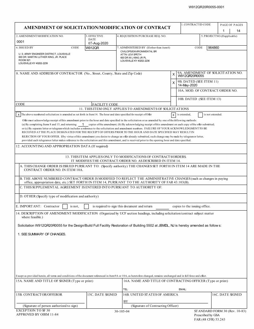
AMENDMENT OF SOLICITATION/MODIFICATION OF CONTRACT
Except as provided herein, all terms and conditions of the document referenced in Item 9A or 10A, as heretofore changed, remains unchanged and in full force and effect.
15A. NAME AND TITLE OF SIGNER (Type or print)
30-105-04EXCEPTION TO SF 30APPROVED BY OIRM 11-84
STANDARD FORM 30 (Rev. 10-83)Prescribed by GSAFAR (48 CFR) 53.243
Solicitation W912QR20R0055 for the Design/Build Full Facility Restoration of Building 5502 at JBMDL, NJ is hereby amended as follow s:
1. SEE SUMMARY OF CHANGES.
1. CONTRACT ID CODE PAGE OF PAGES
1 14
16A. NAME AND TITLE OF CONTRACTING OFFICER (Type or print)
16C. DATE SIGNED
BY
16B. UNITED STATES OF AMERICA15C. DATE SIGNED15B. CONTRACTOR/OFFEROR
(Signature of Contracting Officer)(Signature of person authorized to sign)
8. NAME AND ADDRESS OF CONTRACTOR (No., Street , County, State and Zip Code) X W912QR20R0055
X 9B. DATED (SEE ITEM 11)14-May-2020
10B. DATED (SEE ITEM 13)
9A. AMENDMENT OF SOLICITATION NO.
11. THIS ITEM ONLY APPLIES TO AMENDMENTS OF SOLICITATIONS
X The above numbered solicitation is amended as set forth in Item 14. The hour and date specified for receipt of Offer X is extended, is not extended.
Offer must acknowledge receipt of this amendment prior to the hour and date specified in the solicitation or as amended by one of the following methods:
(a) By completing Items 8 and 15, and returning 1 copies of the amendment; (b) By acknowledging receipt of this amendment on each copy of the offer submitted;
or (c) By separate letter or telegram which includes a reference to the solicitation and amendment numbers. FAILURE OF YOUR ACKNOWLEDGMENT TO BERECEIVED AT THE PLACE DESIGNATED FOR THE RECEIPT OF OFFERS PRIOR TO THE HOUR AND DATE SPECIFIED MAY RESULT IN
REJECTION OF YOUR OFFER. If by virtue of this amendment you desire to change an offer already submitted, such change may be made by telegram or letter, provided each telegram or letter makes reference to the solicitation and this amendment, and is received prior to the opening hour and date specified.
12. ACCOUNTING AND APPROPRIATION DATA (If required)
13. THIS ITEM APPLIES ONLY TO MODIFICATIONS OF CONTRACTS/ORDERS.IT MODIFIES THE CONTRACT/ORDER NO. AS DESCRIBED IN ITEM 14.
A. THIS CHANGE ORDER IS ISSUED PURSUANT TO: (Specify authority) THE CHANGES SET FORTH IN ITEM 14 ARE MADE IN THECONTRACT ORDER NO. IN ITEM 10A.
B. THE ABOVE NUMBERED CONTRACT/ORDER IS MODIFIED TO REFLECT THE ADMINISTRATIVE CHANGES (such as changes in paying office, appropriation date, etc.) SET FORTH IN ITEM 14, PURSUANT TO THE AUTHORITY OF FAR 43.103(B).
C. THIS SUPPLEMENTAL AGREEMENT IS ENTERED INTO PURSUANT TO AUTHORITY OF:
D. OTHER (Specify type of modification and authority)
E. IMPORTANT: Contractor is not, is required to sign this document and return copies to the issuing office.
14. DESCRIPTION OF AMENDMENT/MODIFICATION (Organized by UCF section headings, including solicitation/contract subject matterwhere feasible.)
10A. MOD. OF CONTRACT/ORDER NO.
2. AMENDMENT/MODIFICATION NO.
0001
5. PROJECT NO.(If applicable)
6. ISSUED BY
3.EFFECTIVE DATE
07-Aug-2020CODE
U. S. ARMY ENGINEER DISTRICT, LOUISVILLE600 DR. MARTIN LUTHER KING, JR. PLACEROOM 821LOUISVILLE KY 40202-2239
W912QR 7. ADMINISTERED BY (If other than item 6)
4. REQUISITION/PURCHASE REQ. NO.
CODE 964860
FACILITY CODECODE
EMAIL:TEL:
W912QR20R0055-0001
W912QR20R0055
Page 2 of 16
SECTION SF 30 BLOCK 14 CONTINUATION PAGE
SUMMARY OF CHANGES
SECTION SF 30 - BLOCK 14 CONTINUATION PAGE (SF 30)
The following have been added by full text: AMDT 0001 SUMMARY OF CHANGES
SUMMARY OF CHANGES
DRAWINGS:
Solicitation: W912QR20R0055 Project: Design/Build for a Full Facility Restoration (FFR) of Building 5502 Location: Joint Base McGuire-Dix-Lakehurst (JBMDL), NJ Amendment 0001 Summary of Changes
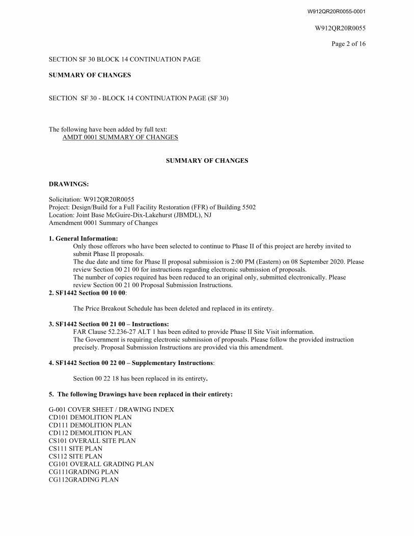
1. General Information:Only those offerors who have been selected to continue to Phase II of this project are hereby invited to submit Phase II proposals. The due date and time for Phase II proposal submission is 2:00 PM (Eastern) on 08 September 2020. Please review Section 00 21 00 for instructions regarding electronic submission of proposals. The number of copies required has been reduced to an original only, submitted electronically. Please review Section 00 21 00 Proposal Submission Instructions.
2. SF1442 Section 00 10 00:
The Price Breakout Schedule has been deleted and replaced in its entirety.
3. SF1442 Section 00 21 00 – Instructions:FAR Clause 52.236-27 ALT 1 has been edited to provide Phase II Site Visit information. The Government is requiring electronic submission of proposals. Please follow the provided instruction precisely. Proposal Submission Instructions are provided via this amendment.
4. SF1442 Section 00 22 00 – Supplementary Instructions:
Section 00 22 18 has been replaced in its entirety.
5. The following Drawings have been replaced in their entirety:
G-001 COVER SHEET / DRAWING INDEXCD101 DEMOLITION PLANCD111 DEMOLITION PLANCD112 DEMOLITION PLANCS101 OVERALL SITE PLANCS111 SITE PLANCS112 SITE PLANCG101 OVERALL GRADING PLANCG111GRADING PLANCG112GRADING PLAN
W912QR20R0055-0001
W912QR20R0055
Page 3 of 16
AD100 BASEMENT DEMOLITION PLAN AD110 FIRST DEMOLITION PLAN AD120 SECOND FLOOR DEMOLITION PLAN AD130 THIRD FLOOR DEMOLITION PLAN AD200 EXISTING BUILDING ELEVATIONS A-100 COMPOSITE BASEMENT PLANA-110 FIRST FLOOR PLANA-120 SECOND FLOOR PLANA-130 THIRD FLOOR PLANA-140 COMPOSITE ROOF PLANA-200 BUILDING ELEVATIONS
6. The following Drawing has been included:
G-201 LOCATION AND VICINITY MAPV-100 OVERALL SITE SURVEYV-111 SITE SURVEYV-112 SITE SURVEYES100 ELECTRICAL SITE PLANH-110 FIRST FLOOR HAZARDOUS MATERIAL PLANH-120 SECOND FLOOR HAZARDOUS MATERIAL PLANH-130 THIRD FLOOR HAZARDOUS MATERIAL PLANAD100 BASEMENT DEMOLITION PLANA-800 ENLARGED KITCHEN PLAN
Specifications:
7. The following Specification Sections have been added or replaced in their entirety:
VOLUMES 1a thru 1c
DIVISION 00
SF 1442 SECTION 00 10 00 SOLICITATION CONTRACT FORM PRICE BREAKOUT SCHEDULE SECTION 00 21 00 INSTRUCTIONS SECTION 00 22 16 - PROCEDURES FOR SUBMITTAL AND EVALUATION OF OFFERS FOR PHASE ONE SECTION 00 45 00 - REPRESENTATIONS AND CERTIFICATIONS SECTION 00 70 00 - CONDITIONS OF THE CONTRACT SECTION 00 73 00 - SUPPLEMENTARY CONDITIONS WAGE RATES SECTION 00 80 00.00 06 SPECIAL PROVISIONS ATTACHMENTS TO THE SPECIAL PROVISIONS
SUBMITTAL REGISTER
W912QR20R0055-0001
W912QR20R0055
Page 4 of 16
CONSTRUCTION PROJECT SIGNS
DIVISION 01
Section 01 02 00.00 48 Statement of Work Attachments to the Statement of Work
Section 01 03 00.00 48 Design Submission Requirements After Award Section 01 04 00.00 48 The Design/Build Process Section 01 32 01 00 06 Project Schedule Section 01 33 00.00 06 Submittal Procedures Section 01 33 29.00 06 Sustainability Reporting Section 01 35 26.00 06 Government Safety Requirements Section 01 42 00 Sources for Reference Publications Section 01 45 00.15 10 Resident Management System Contractor Mode (RMS CM) Section 01 45 04.10 06 Contractor Quality Control Section 01 45 35 Special Inspection Section 01 46 00.00 06 Total Building Commissioning (Contractor CxA) Section 01 50 00 Temporary Construction Facilities and Controls Section 01 57 19.00 06 Temporary Environmental Controls and Permits Section 01 74 19 Construction and Demolition Waste Management Section 01 78 23 Operation and Maintenance Data
DIVISION 02
Section 02 82 00 Asbestos Remediation Section 02 83 13.00 06 Lead in Construction Section 02 84 16 Handling of Lighting Ballasts and Lamps Containing PCB’s and Mercury Section 02 84 33 Removal and Disposal of Polychlorinated Biphenyls (PCBs)
DIVISION 27 – COMMUNICATIONS
27 05 28.36 48 Cable Trays for Communications Systems 27 10 00.00 48 Building Telecommunications Cabling Systems
DIVISION 33 – UTILITIES
33 82 00.00 48 Telecommunications Outside Plant OSP
VOLUME 2
DIVISION 03 -CONCRETE
03 11 13.00 48 Structural Cast-In-Place Concrete Forming 03 11 19.00 48 Insulating Concrete Form (ICF) System 03 20 00.00 48 Concrete Reinforcement 03 23 00.00 48 Stressed Tendon Reinforcement 03 30 00.00 48 Cast -in-Place Concrete 03 45 00.00 48 Precast Architectural Concrete 03 45 33.00 48 Precast Structural Concrete
DIVISION 04 - MASONRY
04 20 00.00 48 Unit Masonry
W912QR20R0055-0001
W912QR20R0055
Page 5 of 16
04 72 00.00 48 Cast Stone
DIVISION 05 - METAL
05 12 00.00 48 Structural Steel 05 21 00.00 48 Steel Joist Framing 05 31 00.00 48 Steel Decks 05 40 00.00 48 Cold-Formed Metal Framing 05 50 00.00 48 Metal Fabrications
DIVISION 06 – WOOD, PLASTICS, AND COMPOSITES
06 10 00.00 48 Rough Carpentry 06 20 00.00 48 Finish Carpentry 06 61 16.00 48 Solid Surfacing Fabrication
DIVISION 07 - THERMAL AND MOISTURE PROTECTION
07 11 13.00 48 Bituminous Dampproofing 07 19 00.00 48 Water Repellent Coating 07 21 00.00 48 Building Insulation 07 22 00.00 48 Roof and Deck Insulation 07 31 00.00 48 Fiber Glass Based Asphalt Shingle Roof System 07 41 14.00 48 Hydrostatic (Water Tight) Standing Seam Metal Roofing System (HS-SSMRS) 07 42 13.00 48 Metal Wall Panels 07 52 00.00 48 Modified Bituminous Roofing System 07 53 00.00 48 Ethylene Propylene Diene Monomer Roofing 07 54 19.00 48 Thermoplastic Membrane Roofing System 07 60 00.00 48 Flashing and Sheet Metal 07 84 00.00 48 Firestopping 07 90 00.00 48 Joint Sealers
DIVISION 08 - OPENINGS
08 11 13.00 48 Steel Doors and Frames 08 11 16.00 48 Aluminum Doors and Frames 08 14 00.00 48 Wood Doors 08 31 13.00 48 Access Doors and Frames 08 33 13.00 48 Metal Coiling Counter Doors 08 33 23.00 48 Overhead Rolling Doors 08 34 59.00 48 Vault Doors and Day Gates 08 44 00.00 48 Glazed Curtain Walls 08 45 23.00 48 Insulated Translucent Fiberglass Sandwich Panel 08 51 13.00 48 Aluminum Windows 08 70 00.00 48 Door Hardware 08 80 00.00 48 Glazing 08 90 00.00 48 Louvers and Vents
DIVISION 09 - FINISHES
09 29 00.00 48 Gypsum Board 09 30 00.00 48 Ceramic Tile 09 50 00.00 48 Acoustical Ceilings 09 65 00.00 48 Resilient Flooring 09 67 00.00 48 Fluid Applied Flooring
W912QR20R0055-0001
W912QR20R0055
Page 6 of 16
09 68 00.00 48 Carpeting 09 72 00.00 48 Wall Coverings 09 90 00.00 48 Paints and Coatings DIVISION 10 - SPECIALTIES 10 00 10.00 48 Miscellaneous Specialties 10 10 00.00 48 Visual Display Boards 10 12 00.00 48 Recessed Display Cases 10 14 01.00 48 Exterior Signage 10 14 02.00 48 Interior Signage 10 21 13.00 48 Plastic Toilet Partitions 10 22 13.00 48 Wire Mesh Partitions 10 22 26.00 48 Operable Partitions 10 26 00.00 48 Wall and Corner Guards 10 28 00.00 48 Toilet Accessories 10 44 00.00 48 Fire Extinguishers Cabinets and Accessories 10 50 00.00 48 Metal Lockers 10 55 00.00 48 Postal Specialties 10 56 13.00 13 Storage Shelving 10 75 00.00 48 Flag Poles DIVISION 11 - EQUIPMENT 11 13 00.00 48 Loading Dock Equipment 11 30 00.00 48 Residential Equipment 11 52 13.00 48 Projection Screens DIVISION 12 - FURNISHINGS 12 20 00.00 48 Window Treatment 12 48 00.00 48 Rugs and Mats DIVISION 13 – SPECIAL CONSTRUCTION 13 34 19.00 48 Pre-Engineered Structures DIVISION 14 – Vertical Transportation 14 24 00.00 48 Hydraulic Elevators DIVISION 21 – FIRE SUPPRESSION 21 13 13.00 48 Wet Pipe Sprinkler Systems, Fire Protection 21 21 03.00 48 Wet Chemical Extinguishment System 21 30 00.00 48 Fire Pumps DIVISION 22 – PLUMBING 22 11 23.00 48 Plumbing Pumps 22 13 00.00 48 Sanitary, Waste, Vent, and Storm Specialties 22 15 00.00 48 General Service Compressed Air Equipment 22 34 00.00 48 Domestic Water Heaters 22 42 00.00 48 Plumbing Fixtures
W912QR20R0055-0001
W912QR20R0055
Page 7 of 16
DIVISION 23 – HEATING VENTILATING AND AIR CONDITIONING 23 05 29.00 48 Hangers and Supports 23 05 48.00 48 Vibration Isolation 23 05 53.00 48 Identification for HVAC Piping and Equipment 23 05 93.00 48 Testing, Adjusting, and Balancing 23 07 00.00 48 Mechanical Insulation 23 09 00.00 48 HVAC Instrumentation and Controls 23 21 13.00 48 Piping 23 21 14.00 48 Valves 23 21 23.00 48 Pumps 23 31 13.00 48 Metal Ductwork 23 33 00.00 48 Ductwork Accessories 23 34 00.00 48 Fans 23 35 16.00 48 Overhead Vehicle Tailpipe Exhaust Systems 23 36 00.00 48 Air Terminal Units 23 37 00.00 48 Air Outlets and Inlets 23 38 13.00 48 Range Hood 23 40 00.00 48 Air Cleaning Devices 23 51 00.00 48 Breeching and Stacks 23 52 00.00 48 Heating Boilers and Accessories 23 54 16.00 48 Direct-Fired Makeup Air Units 23 64 10.00 48 Packaged Air-Cooled Scroll Chillers 23 64 26.00 48 Packaged Air-Cooled Rotary Screw Chillers 23 73 00.00 48 Air Handling Units 23 81 26.00 48 Split System Air Conditioning Units 23 81 43.00 48 Air-To-Air Heat Pumps 23 82 00.00 48 Terminal Heating Units 23 82 19.00 48 Fan Coil Units 23 83 00.00 48 Radiant Floor Heating System 23 84 16.00 48 Dehumidifier Units DIVISION 26 – ELECTRICAL 26 05 00.00 48 Common Work Results for Electrical 26 05 19.00 48 Low-Voltage Electrical Power Conductors and Cables 26 05 26.00 48 Grounding and Bonding for Electrical Systems 26 05 29.00 48 Hangers and Supports for Electrical Systems 26 05 33.00 48 Raceway and Boxes for Electrical Systems 26 05 53.00 48 Identification for Electrical Systems 26 06 00.00 48 Electrical Utility Services 26 08 00.00 48 Equipment Inspection and Testing 26 22 00.00 48 Low-Voltage Transformers 26 24 00.00 48 Switchboards, Panelboards, and Control Centers 26 27 13.00 48 Electricity Metering 26 27 26.00 48 Wiring Devices 26 28 16.00 48 Enclosed Switches and Circuit Breakers 26 29 00.00 48 Enclosed Controllers 26 41 13.00 48 Lightning Protection 26 51 00.00 48 Interior Lighting 26 56 00.00 48 Exterior Lighting 26 60 13.00 48 Low-Voltage Motors DIVISION 27 – COMMUNICATIONS
W912QR20R0055-0001
W912QR20R0055
Page 8 of 16
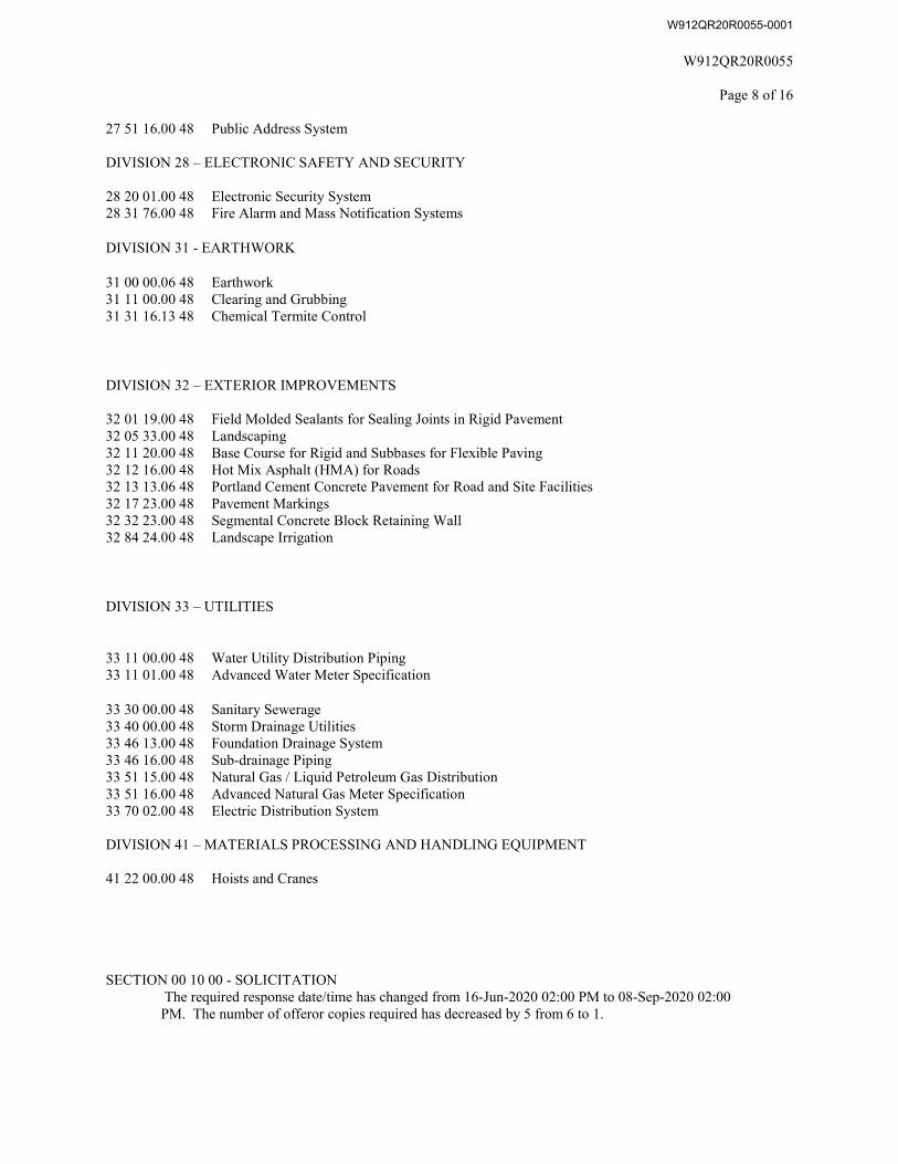
27 51 16.00 48 Public Address System
DIVISION 28 – ELECTRONIC SAFETY AND SECURITY
28 20 01.00 48 Electronic Security System 28 31 76.00 48 Fire Alarm and Mass Notification Systems
DIVISION 31 - EARTHWORK
31 00 00.06 48 Earthwork 31 11 00.00 48 Clearing and Grubbing 31 31 16.13 48 Chemical Termite Control
DIVISION 32 – EXTERIOR IMPROVEMENTS
32 01 19.00 48 Field Molded Sealants for Sealing Joints in Rigid Pavement 32 05 33.00 48 Landscaping 32 11 20.00 48 Base Course for Rigid and Subbases for Flexible Paving 32 12 16.00 48 Hot Mix Asphalt (HMA) for Roads 32 13 13.06 48 Portland Cement Concrete Pavement for Road and Site Facilities 32 17 23.00 48 Pavement Markings 32 32 23.00 48 Segmental Concrete Block Retaining Wall 32 84 24.00 48 Landscape Irrigation
DIVISION 33 – UTILITIES
33 11 00.00 48 Water Utility Distribution Piping 33 11 01.00 48 Advanced Water Meter Specification
33 30 00.00 48 Sanitary Sewerage 33 40 00.00 48 Storm Drainage Utilities 33 46 13.00 48 Foundation Drainage System 33 46 16.00 48 Sub-drainage Piping 33 51 15.00 48 Natural Gas / Liquid Petroleum Gas Distribution 33 51 16.00 48 Advanced Natural Gas Meter Specification 33 70 02.00 48 Electric Distribution System
DIVISION 41 – MATERIALS PROCESSING AND HANDLING EQUIPMENT
41 22 00.00 48 Hoists and Cranes
SECTION 00 10 00 - SOLICITATION The required response date/time has changed from 16-Jun-2020 02:00 PM to 08-Sep-2020 02:00 PM. The number of offeror copies required has decreased by 5 from 6 to 1.
W912QR20R0055-0001
W912QR20R0055
Page 9 of 16
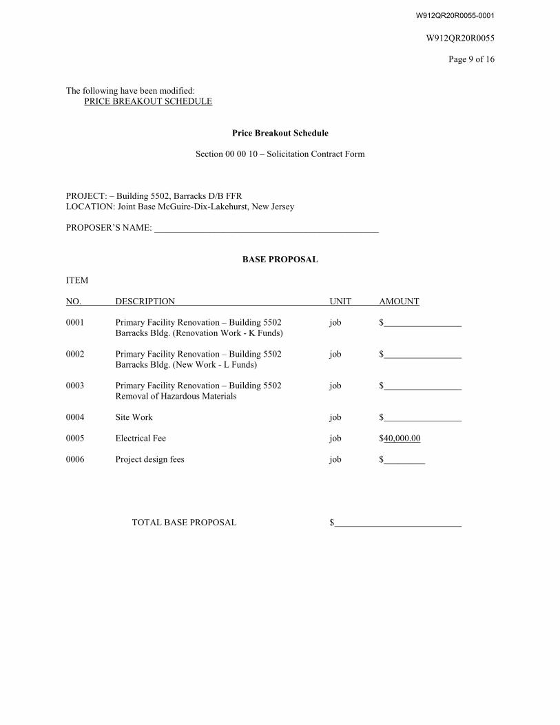
The following have been modified: PRICE BREAKOUT SCHEDULE
Price Breakout Schedule
Section 00 00 10 – Solicitation Contract Form
PROJECT: – Building 5502, Barracks D/B FFR LOCATION: Joint Base McGuire-Dix-Lakehurst, New Jersey
PROPOSER’S NAME: _________________________________________________
BASE PROPOSAL
ITEM
NO. DESCRIPTION UNIT AMOUNT
0001 Primary Facility Renovation – Building 5502 job $ Barracks Bldg. (Renovation Work - K Funds)
0002 Primary Facility Renovation – Building 5502 job $ Barracks Bldg. (New Work - L Funds)
0003 Primary Facility Renovation – Building 5502 job $ Removal of Hazardous Materials
0004 Site Work job $
0005 Electrical Fee job $40,000.00
0006 Project design fees job $_________
TOTAL BASE PROPOSAL $
W912QR20R0055-0001
W912QR20R0055
Page 10 of 16
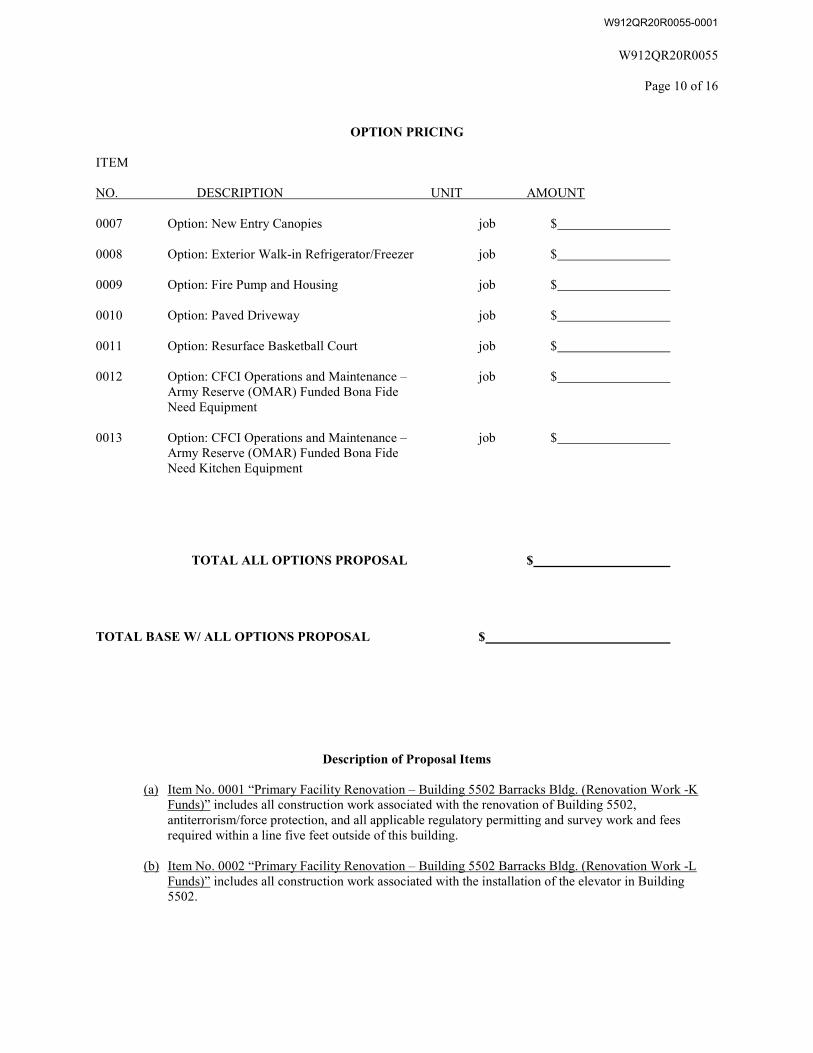
OPTION PRICING
ITEM
NO. DESCRIPTION UNIT AMOUNT
0007 Option: New Entry Canopies job $
0008 Option: Exterior Walk-in Refrigerator/Freezer job $
0009 Option: Fire Pump and Housing job $
0010 Option: Paved Driveway job $
0011 Option: Resurface Basketball Court job $
0012 Option: CFCI Operations and Maintenance – job $ Army Reserve (OMAR) Funded Bona Fide Need Equipment
0013 Option: CFCI Operations and Maintenance – job $ Army Reserve (OMAR) Funded Bona Fide Need Kitchen Equipment
TOTAL ALL OPTIONS PROPOSAL $
TOTAL BASE W/ ALL OPTIONS PROPOSAL $
Description of Proposal Items
(a) Item No. 0001 “Primary Facility Renovation – Building 5502 Barracks Bldg. (Renovation Work -KFunds)” includes all construction work associated with the renovation of Building 5502, antiterrorism/force protection, and all applicable regulatory permitting and survey work and fees required within a line five feet outside of this building.
(b) Item No. 0002 “Primary Facility Renovation – Building 5502 Barracks Bldg. (Renovation Work -LFunds)” includes all construction work associated with the installation of the elevator in Building 5502.
W912QR20R0055-0001
W912QR20R0055
Page 11 of 16
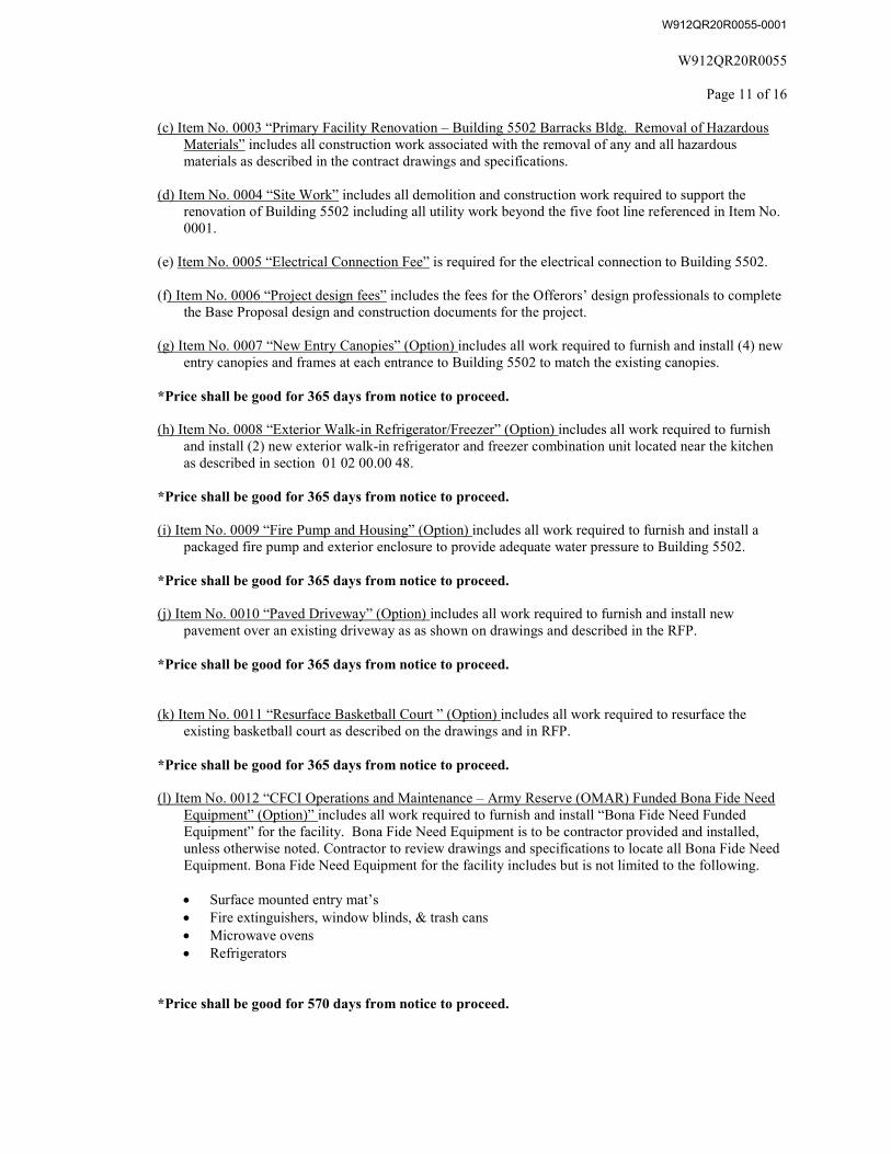
(c) Item No. 0003 “Primary Facility Renovation – Building 5502 Barracks Bldg. Removal of HazardousMaterials” includes all construction work associated with the removal of any and all hazardous materials as described in the contract drawings and specifications.
(d) Item No. 0004 “Site Work” includes all demolition and construction work required to support therenovation of Building 5502 including all utility work beyond the five foot line referenced in Item No.0001.
(e) Item No. 0005 “Electrical Connection Fee” is required for the electrical connection to Building 5502.
(f) Item No. 0006 “Project design fees” includes the fees for the Offerors’ design professionals to completethe Base Proposal design and construction documents for the project.
(g) Item No. 0007 “New Entry Canopies” (Option) includes all work required to furnish and install (4) newentry canopies and frames at each entrance to Building 5502 to match the existing canopies.
*Price shall be good for 365 days from notice to proceed.
(h) Item No. 0008 “Exterior Walk-in Refrigerator/Freezer” (Option) includes all work required to furnishand install (2) new exterior walk-in refrigerator and freezer combination unit located near the kitchenas described in section 01 02 00.00 48.
*Price shall be good for 365 days from notice to proceed.
(i) Item No. 0009 “Fire Pump and Housing” (Option) includes all work required to furnish and install apackaged fire pump and exterior enclosure to provide adequate water pressure to Building 5502.
*Price shall be good for 365 days from notice to proceed.
(j) Item No. 0010 “Paved Driveway” (Option) includes all work required to furnish and install newpavement over an existing driveway as as shown on drawings and described in the RFP.
*Price shall be good for 365 days from notice to proceed.
(k) Item No. 0011 “Resurface Basketball Court ” (Option) includes all work required to resurface theexisting basketball court as described on the drawings and in RFP.
*Price shall be good for 365 days from notice to proceed.
(l) Item No. 0012 “CFCI Operations and Maintenance – Army Reserve (OMAR) Funded Bona Fide NeedEquipment” (Option)” includes all work required to furnish and install “Bona Fide Need Funded Equipment” for the facility. Bona Fide Need Equipment is to be contractor provided and installed, unless otherwise noted. Contractor to review drawings and specifications to locate all Bona Fide Need Equipment. Bona Fide Need Equipment for the facility includes but is not limited to the following.
Surface mounted entry mat’s Fire extinguishers, window blinds, & trash cans Microwave ovens Refrigerators
*Price shall be good for 570 days from notice to proceed.
W912QR20R0055-0001

W912QR20R0055
Page 12 of 16
(m) Item No. 0013 “CFCI Operations and Maintenance – Army Reserve (OMAR) Funded Bona Fide Need Kitchen Equipment” (Option) includes all work required to furnish and install “Bona Fide Need Funded Kitchen Equipment” for the facility. Bona Fide Need Kitchen Equipment is to be contractor provided and installed, unless otherwise noted. Contractor to review drawings and specifications to locate all Bona Fide Need Equipment. Refer to the RFP for a list of Kitchen Equipment.
*Price shall be good for 570 days from notice to proceed.
W912QR20R0055-0001

W912QR20R0055
Page 13 of 16
SECTION 00 21 00 - INSTRUCTIONS
The following have been modified: SUBMISSION INSTRUCTIONS
Proposals: ALL SUBMISSIONS TO THIS PROPOSAL ANNOUNCEMENT SHALL BE SUBMITTED ELECTRONICALLY THROUGH DOD SAFE. No paper copies, CD-ROMs or facsimile submissions will be accepted. Electronic Proposal Submission is required through the Army’s Electronic File Sharing Service, DOD SAFE (https://safe.apps.mil). The DOD SAFE Application is used to send large files to individuals that would normally be too large to send via email. There are no user accounts for SAFE. Authentication is handled via email. Anyone has access to DOD SAFE, and the application is available for use by anyone. The SAFE “Getting Started Guide” has information on how to utilize the system (https://safe.apps.mil/about.php). Instructions for uploading are as follows:
1. Send an email to the Contracting Officer and Contract Specialist to receive the link to drop off yourproposal. This will need to be completed five (5) business days prior to proposal due date.
a. Levi Speth, Contract Specialist at [email protected]. Emily Moore, Contracting Officer at [email protected]
2. You will receive an email with the link to submit your drop-off. The link will be provided no later than two(2) business days prior to the proposal due date.
3. Short Note to the Recipients: Click the Add Files or Drag and Drop your files. For file description, enterW912QR20R0055-FIRMNAME.
4. Click Upload button to send documents. Note: all files should be uploaded at the same time as the link onlyallows one upload occurrence.
5. Guest users will need to check their email to verify their email address before the recipients will benotified. (Government-issued Common Access Cards (CACs) are not required).
File Size Limitations: Offerors are advised to follow the DOD SAFE instructions for uploading files. DOD SAFE supports delivery up to 8GB. If needed, Offerors are advised to break the files down into smaller sections in order to upload it to the system. In such cases, please divide the sections as logically as possible and be sure to clearly name the files as specified below.
File Naming Convention: To ensure your submission is received and processed appropriately, it is important that interested parties CAREFULLY ensure their electronic files adhere to the following naming convention:
W912QR20R0055-FIRMNAME-VOLUME I W912QR20R0055-FIRMNAME-VOLUME II
Each file name shall begin with the solicitation number followed by the firm’s name and a brief file description. Please see examples above.
File Organization: Although hard copies are not accepted, each file shall be clearly indexed, and logically assembled. Font size shall be 10 or larger. Pages shall be letter sized (larger page sizes (such as 11x17 fold-outs, etc.) will be counted as two pages. Proposals shall be in a narrative format, organized and titled so that each section of the proposal follows the order and format of the factors. Information presented should be organized so as to pertain to only the evaluation factor in the section that the information is presented. Information pertaining to more than one evaluation factor should be repeated in the each section for each factor.
W912QR20R0055-0001

W912QR20R0055
Page 14 of 16
Upload Completion & Deadline: Interested parties shall submit responses no later than the date specified on the solicitation document. The time & date of proposal receipt will be the upload completion / delivery time & date recorded within DOD SAFE site. Do not assume that electronic submission will occur instantaneously. Large files (e.g. 10MB or more) will take some time to upload. Offerors should time their upload effort with prudence by not waiting until the last few minutes—this will allow for unexpected delays in the transmittal process. Offerors are encouraged to keep a copy of the upload confirmation for their record. Submissions after the deadline will be considered late and will be processed in accordance with FAR 15.208.
Electronic Files: Files shall be in their native format (i.e. doc, xls, ppt, etc.), or if in pdf format, shall be in searchable text. Text and graphics portfolios of the electronic copies shall be in a format readable by Microsoft Office or Adobe applications. Data submitted in a spreadsheet format shall be readable by MS Excel (all cells and formulas should be unlocked).
Any information, presented in a proposal that the Offeror wants safeguarded from disclosure to other parties must be identified and labeled in accordance with the requirements of Provision “FAR 52.215-1, Instructions to Offerors – Competitive Acquisition (Jan 2017),” subparagraph (e), which is found in 00 21 00 Instructions of the RFP. The Government will endeavor to honor the restrictions against release requested by Offerors, to the extent permitted under United States law and regulations.
W912QR20R0055-0001
W912QR20R0055
Page 15 of 16
52.236-27 SITE VISIT (CONSTRUCTION) (FEB 1995) – ALTERNATE I (FEB 1995) (a) The clauses at 52.236-2, Differing Site Conditions, and 52.236-3, Site Investigations and Conditions Affecting the Work, will be included in any contract awarded as a result of this solicitation. Accordingly, offerors or quoters are urged and expected to inspect the site where the work will be performed. (b) Tour contact: Barbara Folk Staff Engineer U.S. Army Support Activity, Fort Dix 5513 Texas Avenue, Rm 305 JB MDL, NJ 08640 Office: 609-562-5736/DSN: 562-5736 Cell: 908-770-3050 Fax: 609-562-3377 [email protected] Tours will be scheduled between the dates 24 Aug 2020 and 27 Aug 2020 at the site on Alabama Avenue within the Joint Base McGuire Dix Lakehurst. Visitors will need to process through the visitor center/gate. Maximum of 10 members in a barracks building at a time. (End of provision)
W912QR20R0055-0001
W912QR20R0015
Page 15 of 21
SECTION 00 22 00 - SUPPLEMENTARY INSTRUCTIONS
The following have been modified: SECTION 00 22 16
SECTION 00 22 16 PROCEDURES FOR SUBMITTAL AND EVALUATION OF OFFERS FOR PHASE TWO
1. Overview.
1.1
1.2
1.3
The intent of this solicitation is to select one contractor for the Design and Construction of a Full Facility Restoration (FFR) project to renovate and repair Barracks Building 5502 at Joint Base McGuire-Dix-Lakehurst in Burlington County, NJ.
This is a two-phase procurement and the basis of award is the Best Value Trade-Off Process. Following completion of the evaluation of Phase I, up to a maximum of five (5) most highly qualified offerors will be selected to participate in Phase II. The selected offerors for Phase II will be invited to submit the information described in this Section 00 22 16, Procedures for Submittal and Evaluation of Offers for Phase II, for review and evaluation by the Government. Following completion of the Phase II evaluation, the Contracting Officer will award a firm fixed price contract to the responsible offeror whom the Source Selection Authority determines conforms to the solicitation, is fair and reasonable, and offers the best overall value to the Government, all factors considered. The Government reserves the right to accept other than the lowest priced offer or to reject all offers. For Phase II submittals, requirements stated in this RFP are minimums.
NOTE: The rating information from Phase I will not be considered in Phase II or in the final selection.
The target ceiling for contract award is $14,500,000.00 based on the funds made available for this project. The Government cannot guarantee that additional funds will be available for award. Offerors are under no obligation to approach this ceiling.
2. Submittal of Offers.
2.1 Offerors submitting proposals for this project should limit submissions to data essential for evaluation of proposals so that a minimum of time and monies will have been expended in preparing information required herein. However, in order to be effectively and equitably evaluated, the proposals must include information sufficiently detailed to clearly describe the offeror's capability for successfully completing the solicited project. For Phase II, requirements stated in this Request for Proposal (RFP) are minimums. Innovative, creative, or cost-saving proposals that meet or exceed the requirements are encouraged and will be rated accordingly. Proposals should follow in the order of sequence set forth in the RFP. Information provided out of sequence may not be evaluated and may result in the offeror’s disqualification from award.
2.2 Offerors shall submit their proposals electronically in accordance with the Proposal Submission Instructions in Section 00 21 00 of the solicitation. Please follow the instructions precisely as proposals must complete the upload no later than the time and date specified in Block 13 of Standard Form 1442. NOTE: The Louisville District is in the Eastern Time Zone.
2.3 The Government is using a two-phase procurement approach for this design/build project. For Phase II, offerors are required to submit a proposal consisting of the information identified in paragraphs 2.4 and 2.5 below. All proposal materials shall be electronically in accordance with the Proposal Submission Instructions in Section 0 21 00 of the solicitation. The sections should parallel the submission requirements identified herein.
W912QR20R0055-0001
W912QR20R0015
Page 16 of 21
2.4 The complete Volume I shall be submitted electronically in accordance with the Proposal Submission Instructions in Section 00 21 00 of the solicitation and include the following information:
• Volume I – Factor I: Design Narrative• Volume I – Factor II: Design Drawings
*NOTE: Failure to place the required submission information under the appropriate tab (factor or subfactor) may result in a lower rating if the evaluators cannot readily find the appropriate information. Anyspecified page limits will be strictly adhered to and enforced. Information submitted that exceeds thespecified limit(s) will not be evaluated.
2.5 Volume II shall be submitted electronically in accordance with the Proposal Submission Instructions in Section 00 21 00 of the solicitation and shall include the following information:
• Volume II – Tab A: Standard Form 1442 and Price Breakout Schedule• Volume II – Tab B: Joint Venture Agreements• Volume II – Tab C: Evidence of Ability to Obtain Bonding and Proof of Financial Ability• Volume II – Tab D: Pre-Award Information
NOTE: Failure to place the required submission information under the appropriate tab may result in a lower rating if the evaluators cannot readily find the appropriate information.
3. Proposal Evaluation Process.
3.1 A Source Selection Evaluation Board (SSEB) comprised of representatives of the Corps of Engineers, User/Customer, and other required personnel will evaluate the proposals. Offerors are advised that the technical evaluation and rating of proposals will be conducted in strict confidence. Technical (Volume I) proposals will be reviewed and rated without knowledge of the price offered. The number and identities of offerors are not revealed to anyone not involved in the evaluation and award process or to other offerors. Proposals will be evaluated based on the factors described herein, and the basis of award is a Best Value Trade-Off, as stated above.
3.2 The evaluation process for Phase II essentially consists of four parts: proposal compliance review and responsibility review, technical evaluation, price evaluation, and price/technical trade-off analysis.
3.2.1 Proposal Compliance / Responsibility Review: This is an initial review to ensure that all required forms and certifications are complete, that both a technical and price proposal were received, and that the offeror is financially capable of sustaining performance under the contract and is able to obtain the required level of performance and payment bonds from an acceptable surety.
3.2.2 Technical Evaluation: The SSEB will evaluate and rate the Phase II Volume I proposals against the RFP requirements. Factors I and II (Design Narrative and Design Drawings) will be rated using Table 4 below.
3.2.3 Price Evaluation: The SSEB and Contracting Officer/SSA will evaluate price proposals independent of the technical evaluation. The SSEB will not have access to price information until completion of the technical evaluation.
3.2.4 Price/Technical Trade-off Analysis: After all above evaluations are complete, the Contracting Officer/SSA will compare the relative advantages and disadvantages of technical proposals and compare prices. The Source Selection Authority (SSA) will then consider all factors to select the proposal offering the best value to the Government.
W912QR20R0055-0001
W912QR20R0015
Page 17 of 21
4. Proposal Information and Related Evaluation Factors.
4.1 Phase II proposals will be evaluated in accordance with the factors below, listed in relative order of importance. All evaluation factors, other than price, when combined are considered approximately equal to price. The Government intends to evaluate proposals and award a contract without discussions with offerors (except clarifications as described in FAR 15.306(a)). Therefore, the offeror’s initial proposal should contain the offeror’s best terms from a price and technical standpoint. The Government reserves the right to conduct discussions if the Contracting Officer later determines them to be necessary. If the Contracting Officer determines that the number of proposals that would otherwise be in the competitive range exceeds the number at which an efficient competition can be conducted, the Contracting Officer may limit the number of proposals in the competitive range to the greatest number that will permit an efficient competition among the most highly rated proposals.
4.2 Volume I – Factor I: Design Narrative 1st
4.3 Volume I – Factor II: Design Drawings 2nd
4.4 Volume II - Price and Pro Forma Information (Sealed Envelope)
Tab A Standard Form 1442 and Price Breakout Schedule Not Rated
Tab B Joint Venture Agreement Not Rated
Tab C Evidence of Ability to Obtain Bonding and Not Rated Proof of Financial Ability
Tab D Pre-Award Information Not Rated
W912QR20R0055-0001
W912QR20R0015
Page 18 of 21
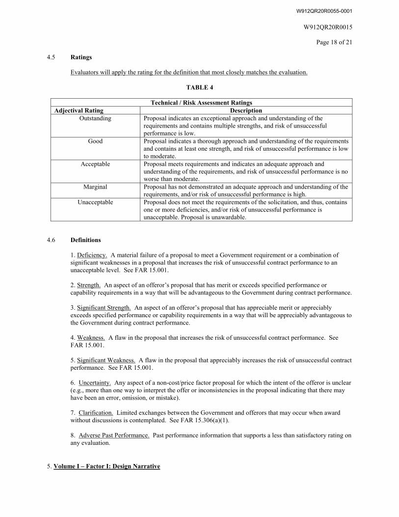
4.5 Ratings
Evaluators will apply the rating for the definition that most closely matches the evaluation.
TABLE 4
Technical / Risk Assessment Ratings Adjectival Rating Description
Outstanding Proposal indicates an exceptional approach and understanding of the requirements and contains multiple strengths, and risk of unsuccessful performance is low.
Good Proposal indicates a thorough approach and understanding of the requirements and contains at least one strength, and risk of unsuccessful performance is low to moderate.
Acceptable Proposal meets requirements and indicates an adequate approach and understanding of the requirements, and risk of unsuccessful performance is no worse than moderate.
Marginal Proposal has not demonstrated an adequate approach and understanding of the requirements, and/or risk of unsuccessful performance is high.
Unacceptable Proposal does not meet the requirements of the solicitation, and thus, contains one or more deficiencies, and/or risk of unsuccessful performance is unacceptable. Proposal is unawardable.
4.6 Definitions
1. Deficiency. A material failure of a proposal to meet a Government requirement or a combination ofsignificant weaknesses in a proposal that increases the risk of unsuccessful contract performance to anunacceptable level. See FAR 15.001.
2. Strength. An aspect of an offeror’s proposal that has merit or exceeds specified performance orcapability requirements in a way that will be advantageous to the Government during contract performance.
3. Significant Strength. An aspect of an offeror’s proposal that has appreciable merit or appreciablyexceeds specified performance or capability requirements in a way that will be appreciably advantageous tothe Government during contract performance.
4. Weakness. A flaw in the proposal that increases the risk of unsuccessful contract performance. SeeFAR 15.001.
5. Significant Weakness. A flaw in the proposal that appreciably increases the risk of unsuccessful contractperformance. See FAR 15.001.
6. Uncertainty. Any aspect of a non-cost/price factor proposal for which the intent of the offeror is unclear(e.g., more than one way to interpret the offer or inconsistencies in the proposal indicating that there mayhave been an error, omission, or mistake).
7. Clarification. Limited exchanges between the Government and offerors that may occur when awardwithout discussions is contemplated. See FAR 15.306(a)(1).
8. Adverse Past Performance. Past performance information that supports a less than satisfactory rating onany evaluation.
5. Volume I – Factor I: Design Narrative
W912QR20R0055-0001
W912QR20R0015
Page 19 of 21
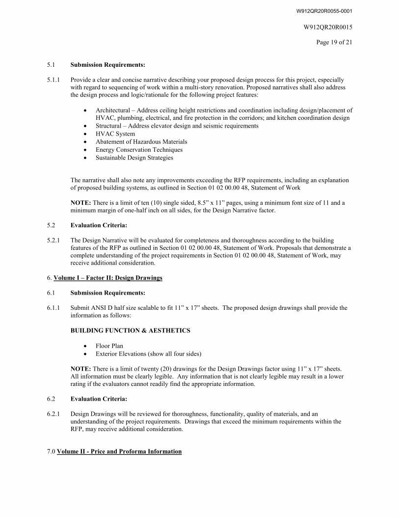
5.1 Submission Requirements:
5.1.1 Provide a clear and concise narrative describing your proposed design process for this project, especially with regard to sequencing of work within a multi-story renovation. Proposed narratives shall also address the design process and logic/rationale for the following project features:
• Architectural – Address ceiling height restrictions and coordination including design/placement ofHVAC, plumbing, electrical, and fire protection in the corridors; and kitchen coordination design
• Structural – Address elevator design and seismic requirements• HVAC System• Abatement of Hazardous Materials• Energy Conservation Techniques• Sustainable Design Strategies
The narrative shall also note any improvements exceeding the RFP requirements, including an explanation of proposed building systems, as outlined in Section 01 02 00.00 48, Statement of Work
NOTE: There is a limit of ten (10) single sided, 8.5” x 11” pages, using a minimum font size of 11 and a minimum margin of one-half inch on all sides, for the Design Narrative factor.
5.2 Evaluation Criteria:
5.2.1 The Design Narrative will be evaluated for completeness and thoroughness according to the building features of the RFP as outlined in Section 01 02 00.00 48, Statement of Work. Proposals that demonstrate a complete understanding of the project requirements in Section 01 02 00.00 48, Statement of Work, may receive additional consideration.
6. Volume I – Factor II: Design Drawings
6.1 Submission Requirements:
6.1.1 Submit ANSI D half size scalable to fit 11” x 17” sheets. The proposed design drawings shall provide the information as follows:
BUILDING FUNCTION & AESTHETICS
• Floor Plan• Exterior Elevations (show all four sides)
NOTE: There is a limit of twenty (20) drawings for the Design Drawings factor using 11” x 17” sheets. All information must be clearly legible. Any information that is not clearly legible may result in a lower rating if the evaluators cannot readily find the appropriate information.
6.2 Evaluation Criteria:
6.2.1 Design Drawings will be reviewed for thoroughness, functionality, quality of materials, and an understanding of the project requirements. Drawings that exceed the minimum requirements within the RFP, may receive additional consideration.
7.0 Volume II - Price and Proforma Information
W912QR20R0055-0001
W912QR20R0015
Page 20 of 21
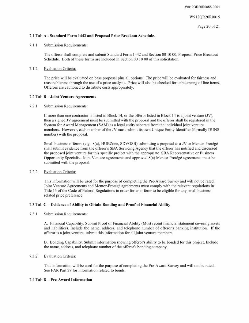
7.1 Tab A - Standard Form 1442 and Proposal Price Breakout Schedule.
7.1.1 Submission Requirements:
The offeror shall complete and submit Standard Form 1442 and Section 00 10 00, Proposal Price Breakout Schedule. Both of these forms are included in Section 00 10 00 of this solicitation.
7.1.2 Evaluation Criteria:
The price will be evaluated on base proposal plus all options. The price will be evaluated for fairness and reasonableness through the use of a price analysis. Price will also be checked for unbalancing of line items. Offerors are cautioned to distribute costs appropriately.
7.2 Tab B – Joint Venture Agreements
7.2.1 Submission Requirements:
If more than one contractor is listed in Block 14, or the offeror listed in Block 14 is a joint venture (JV), then a signed JV agreement must be submitted with the proposal and the offeror shall be registered in the System for Award Management (SAM) as a legal entity separate from the individual joint venture members. However, each member of the JV must submit its own Unique Entity Identifier (formally DUNS number) with the proposal.
Small business offerors (e.g., 8(a), HUBZone, SDVOSB) submitting a proposal as a JV or Mentor-Protégé shall submit evidence from the offeror's SBA Servicing Agency that the offeror has notified and discussed the proposed joint venture for this specific project with the appropriate SBA Representative or Business Opportunity Specialist. Joint Venture agreements and approved 8(a) Mentor-Protégé agreements must be submitted with the proposal.
7.2.2 Evaluation Criteria:
This information will be used for the purpose of completing the Pre-Award Survey and will not be rated. Joint Venture Agreements and Mentor-Protégé agreements must comply with the relevant regulations in Title 13 of the Code of Federal Regulations in order for an offeror to be eligible for any small business-related price preference.
7.3 Tab C – Evidence of Ability to Obtain Bonding and Proof of Financial Ability
7.3.1 Submission Requirements:
A. Financial Capability. Submit Proof of Financial Ability (Most recent financial statement covering assetsand liabilities). Include the name, address, and telephone number of offeror's banking institution. If theofferor is a joint venture, submit this information for all joint venture members.
B. Bonding Capability. Submit information showing offeror's ability to be bonded for this project. Includethe name, address, and telephone number of the offeror's bonding company.
7.3.2 Evaluation Criteria:
This information will be used for the purpose of completing the Pre-Award Survey and will not be rated. See FAR Part 28 for information related to bonds.
7.4 Tab D – Pre-Award Information
W912QR20R0055-0001
W912QR20R0015
Page 21 of 21
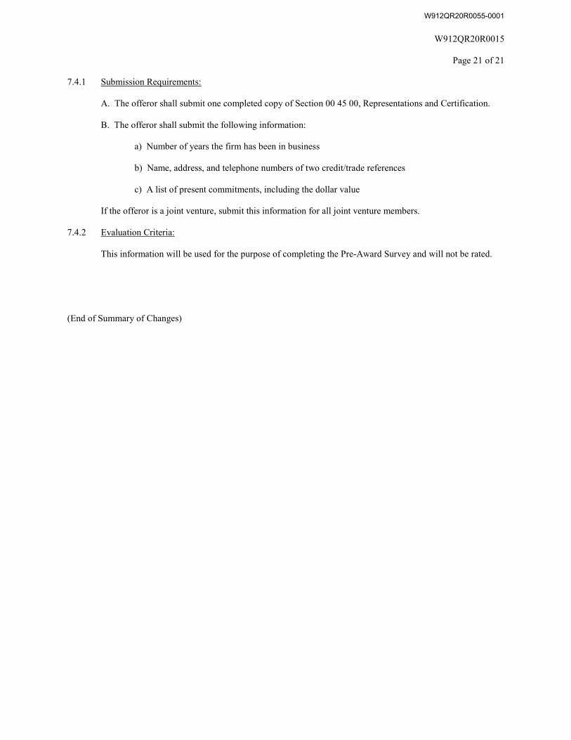
7.4.1 Submission Requirements:
A. The offeror shall submit one completed copy of Section 00 45 00, Representations and Certification.
B. The offeror shall submit the following information:
a) Number of years the firm has been in business
b) Name, address, and telephone numbers of two credit/trade references
c) A list of present commitments, including the dollar value
If the offeror is a joint venture, submit this information for all joint venture members.
7.4.2 Evaluation Criteria:
This information will be used for the purpose of completing the Pre-Award Survey and will not be rated.
(End of Summary of Changes)
W912QR20R0055-0001
Building 5502, Barracks D/B FFR P2 #481648 Joint Base McGuire-Dix-Lakehurst, NJ W912QR20R0055
TOC - 1
DESIGN/BUILD RFP for BUILDING 5502 FULL FACILITY RENOVATION PROJECT
JOINT BASE McGUIRE-DIX-LAKEHURST, NJ
Table of Contents – Volume 1
Division Zero Specifications
Section 00010 Solicitation Contract Form Section 00 80 00.00 06 Special Provisions Submittal Register Construction Project Signs
Wage Rates
Division One Specifications
Section 01 02 00.00 48 Statement of Work Attachments to the Statement of Work
Section 01 03 00.00 48 Design Submission Requirements After Award Section 01 04 00.00 48 The Design/Build Process Section 01 32 01 00 06 Project Schedule Section 01 33 00.00 06 Submittal Procedures Section 01 33 29.00 06 Sustainability Reporting Section 01 35 26.00 06 Government Safety Requirements Section 01 42 00 Sources for Reference Publications Section 01 45 00.15 10 Resident Management System Contractor Mode (RMS CM) Section 01 45 04.10 06 Contractor Quality Control Section 01 45 35 Special Inspection Section 01 46 00.00 06 Total Building Commissioning (Contractor CxA) Section 01 50 00 Temporary Construction Facilities and Controls Section 01 57 19.00 06 Temporary Environmental Controls and Permits Section 01 74 19 Construction and Demolition Waste Management Section 01 78 23 Operation and Maintenance Data Division Two Specifications
Section 02 82 00 Asbestos Remediation Section 02 83 13.00 06 Lead in Construction Section 02 84 16 Handling of Lighting Ballasts and Lamps Containing PCB’s and
Mercury Section 02 84 33 Removal and Disposal of Polychlorinated Biphenyls (PCBs)
W912QR20R0055-0001
Building 5502, Barracks D/B FFR P2 #481648 Joint Base McGuire-Dix-Lakehurst, NJ W912QR20R0055
TOC - 2
Division Three through Forty-One Technical Specifications
Section 27 05 28.36 48 Cable Trays for Communications Systems Section 27 10 00.00 48 Building Telecommunications Cabling System Section 33 82 00.00 48 Telecommunications Outside Plant (OSP) See separate Table of Contents in Volume 2 for additional Technical Specifications
Reference Drawings
W912QR20R0055-0001
Building 5502 P2 #481648JB MDL, NJ W912QR20R0055
SECTION 00 80 00.00 0 6
SPECIAL PROVISIONS02/20
PART 1 GENERAL
Attachments to this specification are as follows:
Construction Project Sign DetailsProject Submittal Register
1.1 REFERENCES
The publications listed below form a part of this specification to the extent referenced. The publications are referred to within the text by the basic designation only.
U.S. DEPARTMENT OF DEFENSE (DOD)
UFC 3-600-01 (2016; with Change 2, 2018) Fire Protection Engineering for Facilities
NATIONAL FIRE PROTECTION ASSOCIATION (NFPA)
NFPA 241 (2019) Standard for Safeguarding Construction, Alteration, and Demolition Operations
U.S. ARMY (DA)
AR 530-1 Operation Security
U.S. ARMY CORPS OF ENGINEERS (USACE)
EM 385-1-1 (2014) Safety and Health Requirements Manual
EP 1110-1-8 (2016) Construction Equipment Ownership and Operating Expense Schedule
U.S. NATIONAL ARCHIVES AND RECORDS ADMINISTRATION (NARA)
29 CFR 1926.59 Hazard Communication
1.2 SUBMITTALS
Government approval/acceptance is required for submittals with a "G" designation; submittals not having a "G" designation are for information only. When used, a designation following the "G" designation identifies the office that will review the submittal for the Government. The following shall be submitted in accordance with LRL Section 01 33 00.00 06 SUBMITTAL PROCEDURES:
SD-01 Preconstruction Submittals
Labor, Equipment, and Material Report; G
DOCUMENT 00 80 00.00 06 Page 1 0177025502
W912QR20R0055-0001
Building 5502 P2 #481648JB MDL, NJ W912QR20R0055
Daily Equipment Report; G
Fingerprints of all persons employed or to be employed
SD-02 Shop Drawings
Mechanical/Electrical Room Layout; G
SD-04 Samples
Equipment Warranty Identification Tags; G
SD-05 Design Data
SF1413 Statement and Acknowledgement; G
Local Agency Check; G
Progress Photographs; G
SD-07 Certificates
Warranty of Construction; G
NO ASBESTOS - CONTAINING MATERIAL (ACM) CERTIFICATION; G
Insurance; G
Sales and Use Tax; G
SD-11 Closeout Submittals
Preliminary (Working) As-Built Drawings; G
Final As-Built Drawings; G
CAD Working As-Built Drawings; G
Maintenance and Parts Data; G
Warranty Management Plan; G
1.3 COMMENCEMENT, PROSECUTION AND COMPLETION OF WORK
Refer to FAR 52.211-12 "LIQUIDATED DAMAGES" in Section 00 70 00 for the amount of Liquidated Damages for the project.
Refer to FAR 52.211-10 "Commencement, Prosecution, and Completion of Work" in Section 00 70 00 for a notification of significant contract dates.
1.3.1 Additional Requirements/Clarifications of Work Included Within the Contract
a. The time stated in FAR 52.211-10 "Commencement, Prosecution, and Completion of Work" in Section 00 70 00 for completion shall include installation of Government-furnished furniture as well as as-built drawings, O&M manuals, operational tests/reports/training/instructions, equipment lists.
DOCUMENT 00 80 00.00 06 Page 2 0177025502
W912QR20R0055-0001
Building 5502 P2 #481648JB MDL, NJ W912QR20R0055
b. Those areas of the building receiving Government-furnished furniture and IT/Telecom equipment shall be made available for Government installation to begin no less than 30 calendar days prior to the contractor's accepted scheduled Construction Completion Date updated in accordance with FAR 52.211-10 "Commencement, Prosecution, and Completion of Work" in Section 00 70 00. The Contractor shall participate in a Furniture Pre-Installation Building Inspection, Daily Furniture Installation Building Inspections, and a Final Furniture Installation Building Inspection along with the furniture installation supervisor and a Government representative.
c. If the Contractor fails to meet the requirements in paragraph "Requirements for Completion of Designated Areas Prior to Furniture Installation", by the Contractor's accepted scheduled Furniture Installation Start Date,the Contractor shall pay liquidated damages to the Government in the amount of $3,900 for each week of the delay until the requirement is fulfilled. The liquidated damages contained in this paragraph are independent of and in addition to those references in FAR 52.211-12 "Liquidated Damages - Construction". Changes to the Contractor's Scheduled Furniture Installation Start Date and Construction Completion Date must be received and accepted no later than forty-nine (49) calendar days prior to the Contractor's current Scheduled Furniture Installation Start Date in order to avoid liquidated damages associated with the furniture installation. Commencement of furniture installation on or after the Contractor's scheduled Furniture Installation Start Date prior to the fulfillment of these requirements does not relieve the Contractor of their liquidated damages obligation.
1.3.2 Requirements for Completion of Designated Areas Prior to Furniture Installation
a. The Contractor is responsible for access to the building, security and ownership during the furniture and IT/Telecom equipment installation. Facility operation and maintenance during the furniture and IT/Telecom equipment installation is the responsibility of the Contractor.
b. The Government will be installing IT/Telecom equipment, including the telephone switch and individual telephone sets, during the furniture installation period.
c. The Contractor shall be responsible for coordination with its subcontractors and the Government furniture and IT/Telecom installation contractors, as necessary, to accommodate the furniture and IT/Telecom equipment installation.
d. The exterior roads, parking areas, walks, and building entrances shall be sufficiently complete to support the delivery of furniture products by semi-tractor trailers and made available for use to the Government furniture and IT/Telecom installation contractors.
e. All interior building finishes of areas receiving furniture, including all furniture entries, pathways, staging, and storage areas shall be complete. Completed building finishes shall include all flooring materials and base, interior walls, ceilings, lighting, HVAC systems and controls, doors, doorframes, and trim. All areas are to be cleaned, vacuumed, and an initial waxing applied as appropriate for the installation of furniture.
DOCUMENT 00 80 00.00 06 Page 3 0177025502
W912QR20R0055-0001
Building 5502 P2 #481648JB MDL, NJ W912QR20R0055
f. All utilities and systems serving the building shall be fully operational. The HVAC system(s) must be in operation, fully balanced and commissioned. The elevator(s) shall be operable and certified for use by the approving agency prior to the delivery of the furniture package and must be made available, at no additional cost, for use by the furniture and IT/Telecom equipment installation contractors.
g. The pre-final building punch inspections shall be performed and punch list items corrected by the Contractor prior to the Government Furniture and IT/Telecom installations.
h. During installation of the furniture and IT/Telecom, the Contractor shall participate in inspections as noted above in paragraph "Additional Requirements/Clarifications of Work Included Within the Contract"(b). Repairs to any damaged areas shall be performed at no additional cost to the Government by the appropriate party as determined by the Government during these inspections.
i. The Contractor shall be responsible for the electrical hookup of the power feed(s) and phone/data wiring to-as well as providing all data/com faceplates and jacks for-all powered modular systems furniture. This work may be coordinated with the Government Furniture and IT/Telecom installation contractors to occur while they continue their installations.
j. The Contractor shall perform the final buffing and waxing of areas after the furniture and IT/Telecom installation contractors have indicated either installation in those areas is complete or that the final buffing and waxing should be performed in certain areas prior to the placement of furniture. The final buffing and waxing of corridors shall be performed by the Contractor after the furniture and IT/Telecom installation contractors have indicated installation is complete for the building.
k. After furniture and IT/Telecom installation by the Government, the Contractor shall perform a complete final cleaning in all impacted areas. Final Inspection and Acceptance may occur only after all furniture and IT/Telecom installation by the Government is complete.
1.4 NATIVE FILES FOR PROPOSAL DEVELOPMENT ON DESIGN/BUILD PROJECT
Included, in addition to the drawings that are part of the solicitation, are Native CAD files in one and only one format that contain limited preliminary notional design concepts and site characteristics that were created during the solicitation development process and are not necessarily all inclusive. They are not reference materials and are not incorporated into the solicitation directly or by reference. The files are provided only for the convenience of the contractor in his preparation of a proposal. The material is given “as is” and no explanation or clarifications will be made with regard to these materials. The Government makes no representations as to the content of the files, their completeness or their accuracy. The solicitation governs in any conflict between these files and the solicitation requirements. The Government does not represent these materials as indicating any preferences with regard to the RFP requirements, nor does it represent that the files show design or technical approaches that will meet the RFP requirements. In addition, the Government affirmatively states that it does not warrant the accuracy of files, including any site conditions represented in these materials. The
DOCUMENT 00 80 00.00 06 Page 4 0177025502
W912QR20R0055-0001
Building 5502 P2 #481648JB MDL, NJ W912QR20R0055
offeror waives any and all claims based upon information represented in the Native CAD files.
1.5 NOT USED
1.6 CONTRACT DRAWINGS AND SPECIFICATIONS
In addition to DFARS 252.236-7001 "Contract Drawings and Specifications" in Section 00 70 00 the following will apply:
a. After Award or no later than Notice to Proceed (NTP), the Government will furnish the Contractor a compact disk containing all technical contract documents in electronic media only. This disk will include a complete set of drawing files and technical specification files which have all amendments included. The disk will contain drawing files in PDF format along with technical specifications in PDF format. These PDF files are the contract documents that represent the construction requirements of the contract, and are being provided for the Contractor's use in printing paper copies of contract documents.
b. In addition, native CAD files(this includes, but not limited to, all source files, models, custom fonts and linestyles, plot files, and images used to create the contract drawings) are provided in accordance with the "AS-BUILT DOCUMENTS" paragraph for the Contractor's use in maintaining and preparing as-built plans. If another CAD Program is used other than the Using Agency's System, all native CAD files that were generated with that software and all support files will also be included. Only native files are to be used for As-Built preparation and information.
c. Native files are to be used for As-Built preparation only. The PDF files are the contract documents that represent the construction requirements of the contract.
1.7 NOT USED
1.8 AS-BUILT DOCUMENTS FOR DESIGN BUILD PROJECTS
1.8.1 General
It is the scope of this section to provide guidance to the Contractor on preparing as-built drawings for design-build projects. An as-built drawing is a contract construction drawing revised to reflect the final as-built conditions of the project because of modifications, changes, corrections to the project design required during construction, submittals and extensions of design. The terms "drawings," "contract drawings," "drawing files," "working as-built drawings" and "final as-built drawings" refer to contract drawings that are revised to be used for the "RECORD DRAWING AS-BUILTS".
1.8.2 Withholding
Maintenance of working as-builts is considered part of the value of the facilities being constructed and will not be paid for as a separate line item. All costs in conjunction with periodic as-built maintenance and final preparation shall be considered a subsidiary obligation of the Contractor.
DOCUMENT 00 80 00.00 06 Page 5 0177025502
W912QR20R0055-0001
Building 5502 P2 #481648JB MDL, NJ W912QR20R0055
1.8.2.1 Failure to Maintain
If the Contractor fails to maintain the working as-built drawings as specified herein, the Contracting Officer will deduct from the monthly progress payment an amount up to 10% or which, in the Contracting Officer's judgment, represents the estimated cost of bringing the as-built documents up to date. This monthly deduction will continue until an agreement can be reached between the Contracting Officer and the Contractor regarding the accuracy and completeness of working as-built documents. This includes conversion of submittals and other miscellaneous documents.
1.8.2.2 As-Builts Prepared by Contractor
The Contractor is required to prepare and provide final as-built drawings utilizing the native files provided by the Government. If translation is required, the original design models (BIM or CAD) shall be updated to As-Built conditions and then appropriately translated. Updating translated drawings will not be accepted. The contractor shall update the CAD working as-built drawings, in accordance with paragraph "Maintenance of As-Built Drawings", on a quarterly basis and submit them for independent Government review. Both paper and electronic documents shall be available at all times and shall be provided promptly to the Contracting Officer's Representatives when requested. The Contractor shall be responsible for backup of electronic files during construction and for controlling release of information.
The Contractor shall include an activity in the cost-loaded schedule for the final As-Built drawing submittal in the amount defined in the following paragraph. See LRL Section 01 32 01.00 06, PROJECT SCHEDULE, para "Basis for Payment and Cost Loading". This amount shall be withheld and not paid until the final As-Built drawing submittal has been accepted by the Government.
Withholding for the final as-built drawing submittal shall be in the amount of: 1% for contract awards less than $5,000,000; $50,000 for contracts awarded from $5,000,000 to $10,000,000; or $100,000 for contracts awarded greater than $10,000,000. Withholding shall be withheld until the final as-built drawing submittal has been approved and accepted by the Government.
1.8.3 Maintenance of Working As-Built Drawings
The Contractor shall revise two (2) sets of paper drawings by red-line process to show the as-built conditions during the prosecution of the project. These as-built marked drawings shall be kept current on a weekly basis and available on the jobsite at all times. Changes in the work from the contract or additional information which is uncovered in the course of construction shall be accurately and neatly recorded as they occur by means of details and notes. Changes must be reflected on all sheets that the change affects . The working as-built marked drawings will be jointly reviewed for accuracy and completeness by the Contracting Officer and the Contractor before submission of each monthly pay estimate. The working as-built drawings shall show the following information if applicable to the project, but not be limited thereto:
a. The actual location, kinds and sizes of all sub-surface utility lines. In order that the location of these lines and appurtenances may be determined in the event the surface openings or indicators
DOCUMENT 00 80 00.00 06 Page 6 0177025502
W912QR20R0055-0001
Building 5502 P2 #481648JB MDL, NJ W912QR20R0055
become covered over or obscured, the as-built drawings shall show, by offset dimensions to two permanently fixed surface features, the end of each run including each change in direction. Valves, splice boxes and similar appurtenances shall be located by dimensioning along the utility run from a reference point. The average depth below the surface of each run shall also be recorded.
b. The location and dimensions of any changes within the building structure.
c. The correct, alignments, grade elevations, typical cross section, earthwork, structures, or utilities if any changes were made from contract plans.
d. Additional as-built information that exceeds the detail shown on the Contract Drawings. These as-built conditions include those that reflect structural details, fabrication, erection, installation plans and placing details, pipe sizes, insulation material, dimensions of equipment foundations and layouts, equipment, sizes, mechanical and electrical room layouts and other extensions of design, that were not shown in the original contract documents because the exact details were not known until after the time of approved shop drawings. It is recognized that the shop drawing submittals (revised showing as-built conditions) will serve as the as-built record without actual incorporation into the contract drawings. The final as-built construction drawing shall reference the shop drawing file that includes the as-built information. In turn, the shop drawing shall reference the applicable construction as-built drawing. All such shop drawing submittals must include the paper copy and PDF of the drawings.
e. The invert elevations and grades of any drainage structures or ditches installed or affected as part of the project construction.
f. Changes or modifications which result from the final inspection.
g. Where contract drawings present options, only the option selected for construction shall be shown on the final as-built drawings.
h. Systems designed or enhanced by the Contractor, such as HVAC controls, fire alarms, fire sprinklers, fire protection, fire detection and irrigation systems and other related systems are included in this project, the as-built drawings will include detailed information for all aspects of the systems including wiring, piping, and equipment drawings.
i. Typically, room numbers shown on the contract drawings are selected for design convenience and do not represent the actual numbers intended for use by the end user. Final as-built drawings shall reflect actual room numbers adopted by the end user.
j. Contract modifications (change order price) shall include the Contractor's cost to change working and final as-built drawings to reflect modifications and compliance with the following procedures:
(1) Directions in the modification for posting descriptive changes shall be followed.
(2) A Revision Triangle shall be placed at the location of each deletion.
DOCUMENT 00 80 00.00 06 Page 7 0177025502
W912QR20R0055-0001
Building 5502 P2 #481648JB MDL, NJ W912QR20R0055
(3) For new details or sections which are added to a drawing, a Revision Triangle shall be placed by the detail or section title.
(4) For minor changes, a Revision Triangle shall be placed by the area changed on the drawing (each location).
(5) For major changes to a drawing, a Revision Triangle shall be placed by the title of the affected plan, section, or detail at each location.
(6) For changes to schedules or drawings, a Revision Triangle shall be placed either by the schedule heading or by the change in the schedule.
1.8.4 Computer Aided Design and Drafting (CAD) Drawings
Only personnel proficient in the preparation of CAD drawings shall be employed to prepare and modify the construction drawings or prepare additional new drawings. Additions and corrections to the construction drawings shall be equal in quality to that of the originals. Line work, line weights, lettering, layering conventions, and symbols shall be the same as the original line work, line weights, lettering, layering conventions, and symbols. If additional drawings are required, they shall be prepared using the specified electronic file format applying the same guidance specified for original drawings. Three dimensional (3D) elements shall be placed in files in their proper locations when using 3D files with spatially correct elements. The title block and drawing border to be used for any new final as-built drawings shall be identical to that used on the contract drawings.
1) Additions and corrections to the contract drawings shall be accomplished using CAD media files supplied by the Designers of Record. All work by the Contractor shall be done on files in the format in which they are provided. Translation of files to a different format, for the purpose of As-Built production, and then retranslating back to the format originally provided, will not be acceptable. These contract drawings will already be compatible with the Using Agency's system when received by the Contractor. The Using Agency uses Bentley Systems MicroStation Version 5 CAD software system. The media files will be supplied by the Contractor to the COR on ISO 9660 Format CD-ROM using Agency's specified media. The Contractor shall be responsible for providing all program files and hardware necessary to prepare final as-built drawings. The Contracting Officer will review final as-built drawings for accuracy and the Contractor shall make all required corrections, changes, additions, and deletions.
2) When final revisions have been completed, the cover sheet drawingshall show the wording "RECORD DRAWING AS-BUILT" followed by the name of the Contractor in letters at least 3/16 inch high. All other contract drawings shall be marked in the bottom right-hand corner of each drawing either "AS-BUILT" drawing denoting no revisions on the sheet, or "REVISED AS-BUILT" denoting one or more revisions. Original contract drawings shall be dated in the revision block.
DOCUMENT 00 80 00.00 06 Page 8 0177025502
W912QR20R0055-0001
Building 5502 P2 #481648JB MDL, NJ W912QR20R0055
1.8.5 Not Used
1.8.6 Preliminary (Working) As-Built Drawings Submittal
Six (6) weeks before occupancy of this facility by the Government, the Contractor shall submit one (1) set of the original paper working as-built drawings to the Contracting Officer for review and approval. These working as-built marked drawings shall be neat, legible and accurate. The review by Government personnel will be expedited to the maximum extent possible. If upon review, the working as-built drawings are found to contain errors and/or omissions, they will be returned to the Contractor for corrections. The Contractor shall complete the corrections and return the working as-built marked drawings to the Contracting Officer within 14 calendar days. Upon approval, the working as-built drawings will be returned to the Contractor for use in preparation of final as-built drawings.
1.8.7 Final As-Built Drawings
The contract drawings shall be modified as may be necessary to correctly show the features of the project as it has been constructed by bringing the contract drawings into agreement with approved working as-built drawings, adding such additional drawings as may be necessary. These final as-built drawings are part of the permanent records of the project and the Contractor shall be responsible for the protection and safety thereof until returned to the Contracting Officer. Any drawings damaged or lost by the Contractor shall be satisfactorily replaced by the Contractor at no expense to the Government.
When electronic cad files are a part of the as-built process, a set of files shall be provided to the government as a part of the Final As-Built submittal for a review to verify the correctness of the as-built markups and that all changes have been incorporated into the electronic files. Should errors be determined, the contractor shall update the files and provide a corrected set of files within fourteen (14) calendar days of receipt of comments. An independent Government review will be made on the accepted files to determine compliance with the As-Built requirements of this section, National CAD Standards, and the AEC CAD Standards; and to verify graphic changes were done properly in preparing the electronic files. This review will require submission of electronic files, containing all the files needed to reproduce the contract drawings, a full size set of contract drawings in PDF format, all shop drawings in PDF format, a scanned copy of the paper markups and the paper markups. Upon receipt of any comments from this independent review, the contractor shall update the electronic files and provide a corrected set of files within fourteen (14) calendar days of receipt of the comments.
When BIM models are a part of the as-built process, the models shall be provided to the Government as a part of the Final As-Built submittal for a review to verify the correctness of the as-built markups and confirm that all changes have been incorporated into the models. Should errors be determined, the contractor shall update the files and provide a corrected set of files within fourteen (14) calendar days of receipt of comments. An independent Government review will be made on the accepted files to determine compliance to the As-Built requirements and to verify graphics changes were done properly. This review will require the electronic model files, all the files needed to reproduce the contract drawings, a full size set of contract drawings in PDF format, all the shop drawings in PDF format, a scanned copy of the paper markups and the paper markups. Upon receipt of any comments from this independent review, the contractor shall
DOCUMENT 00 80 00.00 06 Page 9 0177025502
W912QR20R0055-0001
Building 5502 P2 #481648JB MDL, NJ W912QR20R0055
update the electronic model files and provide a corrected set of files within fourteen (14) calendar days of receipt of the comments.
In the event the Contractor accomplishes additional work which changes the as-built conditions of the facility, after submission and approval of the working as-built drawings, the Contractor shall be responsible for the addition of these changes to the working as-built drawings and also to the final as-built documents and electronic models.
1.8.8 Title Blocks
Title Blocks shall be clearly marked to indicate final as-built drawings.
1.8.9 Other As-Built Documents
All other documents such as design analysis, catalog cuts or certification documents that are not available in native electronic format shall be scanned and provided in an organized manner in Adobe PDF format.
1.9 EQUIPMENT DATA, O&M, & REPAIR MANUALS WITH FIELD TRAINING REQUIREMENTS
1.9.1 Real Property Equipment
OPTION #2 Equipment-in-Place DataContractor shall be required to make an Equipment-in-Place list of all installed equipment furnished under this contract. This list shall include all information usually listed on manufacturer's name plate. The Form is part of SPECIAL PROVISIONS and is included following the SPECIAL PROVISIONS, so to positively identify the piece of property. The list shall also include the cost of each piece of installed property F.O.B. construction site. For each of the items which are specified herein to be guaranteed for a specified period from the date of acceptance thereof, the following information shall be given: The name, serial and model number address of equipment supplier, or manufacturer originating the guaranteed item. The information shall also be provided in excel spreadsheet format with columns for above information in addition to floor, space id as listed in the drawings, system, and submittal register id number for the item. The Contractor's guarantee to the Government of these items will not be limited by the terms of any manufacturer's guarantee to the Contractor. Furnish the list as one (1) reproducible and three (3) copies, and in electronic format on CD to the Contracting Officer thirty (30) calendar days before completion of any segment of the contract work which has an incremental completion date.
Maintenance and Parts Data The Contractor will be required to furnish a brochure, catalog cut, parts list, manufacturer's data sheet or other publication which will show detailed parts data on all other equipment subject to repair and maintenance procedures not otherwise required in Operations and Maintenance Manuals specified elsewhere in this contract. This information shall be provided electronically in PDF format with bookmarks for each piece of equipment with file name included in a separate column or linked worksheet in the equipment data excel spreadsheet as described in the paragraph above. Distribution of directives shall follow the same requirements as listed in paragraph above.
1.9.2 O&M and Repair Manuals
OPTION #2 Withholding & Copies
DOCUMENT 00 80 00.00 06 Page 10 0177025502
W912QR20R0055-0001
Building 5502 P2 #481648JB MDL, NJ W912QR20R0055
The Contractor shall provide 6 electronic format copies on CD of the Equipment Operating, Maintenance, and Repair Manuals and two complete hardcopies; these requirements shall apply even through the Technical Specification section indicates otherwise. The manuals shall be prepared electronically in PDF format containing bookmarks for each table of contents item. The PDF file shall be referenced in a separate column or linked worksheet in the equipment data excel spreadsheet as described previously. Separate manuals shall be provided for each utility system as defined per the Technical Specification. Operations and Maintenance manuals shall be accepted/approved before field training or ninety (90) calendar days before substantial completion (whichever occurs earlier). An amount of $20,000 shall be withheld until submittal and acceptance/approval of O&M manuals is complete. A draft outline and table of contents shall be submitted for acceptance/approval at 50% contract completion. See paragraph "EQUIPMENT DATA, O&M, & REPAIR MANUALS WITH FIELD TRAINING REQUIREMENTS" for detail O&M and Repair Manual format.
1.9.3 Field Training
1.9.3.1 Training Course
Contractor shall conduct a training course for the operating staff for each particular component and system. Where the training period is not identified by the technical specification, a minimum of 1 hour of training shall be provided for that component or system. Training shall only occur after the Manuals have been approved/ accepted by the Government and during normal working time, and shall start after the system or component is functionally completed. The field instructions shall cover all of the items contained in the Equipment Operating, Maintenance and Repair Manuals as identified per individual Technical Specifications. The training will include both classroom and "hands-on" training. The Contractor shall submit a lesson plan outlining the information to be discussed during training periods. This lesson plan will be submitted ninety (90) calendar days before contract completion and accepted/approved before the field training occurs. Training shall be documented by the Contractor and a list of attendees shall be furnished to the Government.
1.9.3.2 Training Recording
The Contractor shall provide all equipment, materials, and trained personnel required to visually and audibly record all site operations and maintenance (O&M) training sessions. The video technician/trainer shall be employed by a video production company that has been in business for a minimum of 2 years. The Contractor shall submit for acceptance by the Government, the resume of the technician/trainer and the video production company, and the proposed video format. The video format shall be one in wide use, and any software necessary to view the video shall be provided to the Government. Video shall be provided to the Government on DVD. Audio shall be adjusted, filtered or otherwise controlled to ensure the presenter can be understood at all times. Each system or piece of equipment shall be covered on a single DVD or set of DVDs, which shall be identified with a type written label showing the name of the project, equipment or system, and contract number. This same information shall be provided as an introduction on each DVD. When two or more DVDs are provided for a single system or piece of equipment, they shall be packaged as a set in an appropriate storage case. Provide three copies of each DVD(s) for each training session. Training DVDs shall be furnished to the Government within ten (10) working days following training.
DOCUMENT 00 80 00.00 06 Page 11 0177025502
W912QR20R0055-0001
Building 5502 P2 #481648JB MDL, NJ W912QR20R0055
1.10 AVAILABILITY OF UTILITIES
a. Availability and Use of Utility Services
Electric Power for Small Tools not exceeding 20 amperes and 115 volts will be furnished from existing outlets, as specified in the contract, at no cost to the Contractor. Power for the Construction Trailers will be provided by the Government with no cost to the Contractor.
b. Additional Requirements
(1) Drinking Water may not be obtained from existing outlets by Contractor personnel.
(2) Existing Washing Facilities in the building may not be used by Contractor employees.
1.10.1 Alterations to Utilities
Where changes and relocations of utility lines are noted to be performed by others, the Contractor shall give the Contracting Officer at least thirty (30) calendar days written notice in advance of the time that the change or relocation is required. In the event that, after the expiration of thirty (30) calendar days after the receipt of such notice by the Contracting Officer, such utility lines have not been changed or relocated and delay is occasioned to the completion of the work under contract, the Contractor will be entitled to a time extension equal to the period of time lost by the Contractor after the expiration of said thirty (30) calendar day period. Any modification to existing or relocated lines required as a result of the Contractor's method of operation shall be made wholly at the Contractor's expense and no additional time will be allowed for delays incurred by such modifications.
1.10.2 Interruptions of Utilities
(1) No utility services shall be interrupted by the Contractor to make connections, to relocate, or for any purpose without approval of the Contracting Officer.
(2) Request for Permission to shut down services shall be submitted in writing to the Contracting Officer not less than seventeen (17) working days before date of proposed interruption. The request shall give the following information:
(a) Nature of Utility. (Gas, L.P. or H.P., Water, etc.)(b) Size of line and location of shutoff.(c) Buildings and services affected .(d) Hours and date of shutoff.(e) Estimated length of time services will be interrupted.
(3) Services shall not be shut off until receipt of approval of the proposed hours and date from the Contracting Officer.
(4) Shutoffs which will cause interruption of Government work operations as determined by the Contracting Officer shall be accomplished during regular non-work hours or on non-work days of the Using Agency without any additional cost to the Government.
(5) Operation of valves on water mains will be by Government personnel.
DOCUMENT 00 80 00.00 06 Page 12 0177025502
W912QR20R0055-0001
Building 5502 P2 #481648JB MDL, NJ W912QR20R0055
Where shutoff of water lines interrupts service to fire hydrants or fire sprinkler systems, the Contractor shall arrange his operations and have sufficient material and personnel available to complete the work without undue delay or to restore service without delay in event of emergency.
(6) Flow in gas mains which have been shut off shall not be restored until the Government inspector has determined that all items serviced by the gas line have been shut off.
1.11 NOT USED
1.12 PERFORMANCE OF WORK BY THE CONTRACTOR
a. For Small Business or certified 8(a) firm set-aside:The requirements found in Section 00 70 00, FAR 52.219-14 "Limitations on Subcontracting" apply.
b. For purposes of Section 00 70 00, clause, above, "WORK BY THE CONTRACTOR" is defined as prime Contractor direct contract labor (including testing and layout personnel), exclusive of other general condition or field overhead personnel, material, equipment, or subcontractors. The "TOTAL AMOUNT OF WORK" is defined as total direct contract labor (including testing and layout personnel), exclusive of other general condition or field overhead personnel, material, or equipment.
c. Within seven (7) calendar days after the award of any subcontract, either by himself or a subcontractor, the Contractor shall deliver to the Contracting Officer a completed Standard Form SF1413 Statement and Acknowledgement (available at the GSA Forms Library, https://www.gsa.gov/reference/forms# ). The form shall include the subcontractor's acknowledgement of the inclusion in his subcontract of the provisions of this contract entitled FAR 52.222-4 "Contract Work Hours and Safety Standards - Overtime Compensation"; FAR 52.222-8 "Payrolls and Basic Records"; FAR 52.222-7 "Withholding of Funds"; FAR 52.222-14 "Disputes Concerning Labor Standards"; FAR 52.222-13 "Compliance with Construction Wage Rate Requirements and Related Regulations"; FAR 52.222-6 "Construction Wage Rate Requirements"; FAR 52.222-9 "Apprentices and Trainees"; FAR 52.222-10 "Compliance with Copeland Act Requirements"; FAR 52.222-11 "Subcontracts (Labor Standards); FAR 52.222-12 "Contract Termination - Debarment"; FAR 52.222-15 "Certification of Eligibility". Nothing contained in this contract shall create any contractual relation between the subcontractor and the Government.
d. Veterans Employment Emphasis for U.S. Army Corps of Engineers Contracts
In addition to complying with the requirements outlined in FAR Part 22.13, FAR Clause 52.222-35, FAR Clause 52.222-37, DFARS 222.13 and Department of Labor regulations, U.S. Army Corps of Engineers (USACE) contractors and subcontractors at all tiers are encouraged to promote the training and employment of U.S. veterans while performing under a USACE contract. While no set-aside, evaluation preference, or incentive applies to the solicitation or performance under the resultant contract, USACE contractors are encouraged to seek out highly qualified veterans to perform services under this contract. The following resources are available to assist USACE contractors in their outreach efforts:
1)U.S. Department of Labor Veterans’ Employment and Training Service
DOCUMENT 00 80 00.00 06 Page 13 0177025502
W912QR20R0055-0001
Building 5502 P2 #481648JB MDL, NJ W912QR20R0055
(VETS): https://www.dol.gov/vets/
2)Federal Veteran Employment Information: https://www.fedshirevets.gov/
3)Veterans Opportunity to Work (VOW) Program: https://www.benefits.va.gov/vow/
4)U.S. Army Warrior Transition Command Employment Index: https://wct.army.mil/modules/employers/index.html
5)Hiring Our Heroes: https://www.uschamberfoundation.org/hiring-our-heroes
1.13 SUPERINTENDENCE OF SUBCONTRACTORS
a. The Contractor shall be required to furnish the following, in addition to the superintendence required by FAR 52.236-6 - "Superintendence By The Contractor".
(1) If more than 50 percent and less than 70 percent of the value of the contract work is subcontracted, one superintendent shall be provided at the site and on the Contractor's payroll to be responsible for coordinating, directing, inspecting and expediting the subcontract work.
(2) If 70 percent or more of the value of the work is subcontracted, the Contractor shall be required to furnish two such superintendents to be responsible for coordinating, directing, inspecting and expediting the subcontract work.
b. If the Contracting Officer, at any time after 50 percent of the subcontracted work has been completed, finds that satisfactory progress is being made, he may waive all or part of the above requirements for additional superintendence subject to the right of the Contracting Officer to reinstate such requirement if at any time during the progress of the remaining work he finds that satisfactory progress is not being made.
1.14 IDENTIFICATION OF EMPLOYEES .
a. The Contractor shall be responsible for furnishing an identification badge/card to each employee prior to the employees work on-site, and for requiring each employee engaged on the work to display identification as may be approved and directed by the Contracting Officer. All prescribed identification shall immediately be delivered to the Contracting Officer for cancellation upon release of the employee. The Contractor shall obtain and submit fingerprints of all persons employed or to be employed on the project.
b. The Contractor is required to provide a Local Agency Check for each individual that will be working on this contract.
1.15 NO ASBESTOS - CONTAINING MATERIAL (ACM) CERTIFICATION
1.15.1 Design Phase
Before final payment of the project design fee, the designer of record (DOR) will submit to the government, on their firm's letterhead, a signed, dated copy of the following statement:
I hereby certify that no asbestos-containing material (ACM) was
DOCUMENT 00 80 00.00 06 Page 14 0177025502
W912QR20R0055-0001
Building 5502 P2 #481648JB MDL, NJ W912QR20R0055
specified as a building material in any construction document for this project.
Furthermore, I certify that no product containing mineral fibers was specified as a building material in any construction document for this project unless I either:
(1) Have on file and have submitted to the Government, the manufacturer's certification that the material does not contain asbestos, or
(2) Have supplied to the Government documentation to show that the material has been microscopically examined by an AIHA- or NVLAP-certified laboratory and the lab has determine that it does not contain asbestos."
1.15.2 Construction Phase
Before final payment to the contractor, the contractor's project engineer/manager will sign and submit to the government, on the contracting firm's letterhead, a dated copy of the following statement:
I hereby certify that to the best of my knowledge no asbestos-containing material (ACM) was used as a building material during this project.
I understand that the building owner presumes that all materials marked "May Contain mineral fibers" are considered asbestos unless I either:
(1) Have on file and have submitted to the Government the manufacturer's certification that the material does not contain asbestos, or
(2) Have supplied to the Government documentation to show that the material has been microscopically examined by an AIHA- or NVLAP-certified laboratory and the lab has determine that it that it does not contain asbestos."
1.16 WARRANTY OF CONSTRUCTION
a. In addition to the requirements found in FAR 52.246-21 "WARRANTY OF CONSTRUCTION" in Section 00 70 00 the following shall be included:
(1) This warranty shall continue for a period of 1 year from the date of final acceptance of the work. If the Government takes possession of any part of the work before final acceptance, this warranty shall continue for a period of 1 year from the date the Government takes possession.
(2) Provide names, addresses, and telephone numbers of all subcontractors, equipment suppliers, or manufacturers with specific designation of their area of responsibilities if they are to be contacted directly on warranty corrections.
b. Warranty Management
(1) Warranty Management Plan
DOCUMENT 00 80 00.00 06 Page 15 0177025502
W912QR20R0055-0001
Building 5502 P2 #481648JB MDL, NJ W912QR20R0055
The Contractor shall develop a warranty management plan which shall contain information relevant to the clause "Warranty of Construction" in FAR 52.246-21. At least thirty (30) calendar days before the planned pre-warranty conference, the Contractor shall submit the warranty management plan for Government approval. The warranty management plan shall include all required actions and documents to assure that the Government receives all warranties to which it is entitled. The plan shall be in narrative form and contain sufficient detail to render it suitable for use by future maintenance and repair personnel, whether tradesmen, or of engineering background, not necessarily familiar with this contract. The term "status" as indicated below shall include due date and whether item has been submitted or was accomplished. Warranty information made available during the construction phase shall be submitted to the Contracting Officer for approval prior to each monthly pay estimate. Approved information shall be assembled in a binder and shall be turned over to the Government upon acceptance of the work. The construction warranty period shall begin on the date of project acceptance and shall continue for the full product warranty period. A joint 4 month and 9 month warranty inspection shall be conducted, measured from time of acceptance, by the Contractor, Contracting Officer and the Customer Representative. Information contained in the warranty management plan shall include, but shall not be limited to, the following:
(a) Roles and responsibilities of all personnel associated with the warranty process, including points of contact and telephone numbers within the organizations of the Contractors, subcontractors, manufacturers or suppliers involved.
(b) Listing and status of delivery of all Certificates of Warranty for extended warranty items, to include roofs, HVAC balancing, pumps, motors, transformers, and for all commissioned systems such as fire protection and alarm systems, sprinkler systems, lightning protection systems, etc.
(c) A list for each warranted equipment, item, and feature of construction or system indicating:
1. Name of item.
2. Model and serial numbers.
3. Location where installed.
4. Name and phone numbers of manufacturers or suppliers.
5. Names, addresses and telephone numbers of sources of spare parts.
6. Warranties and terms of warranty. This shall include one-year overall warranty of construction. Items which have extended warranties shall be indicated with separate warranty expiration dates.
7. Cross-reference to warranty certificates as applicable.
8. Starting point and duration of warranty period.
9. Summary of maintenance procedures required to continue the
DOCUMENT 00 80 00.00 06 Page 16 0177025502
W912QR20R0055-0001
Building 5502 P2 #481648JB MDL, NJ W912QR20R0055
warranty in force.
10. Cross-reference to specific pertinent Operation and Maintenance manuals.
11. Organization, names and phone numbers of persons to call for warranty service.
12. Typical response time and repair time expected for various warranted equipment.
(d) The Contractor's plans for attendance at the 4 and 9 month post-construction warranty inspections conducted by the Government.
(e) Procedure and status of tagging of all equipment covered by extended warranties.
(f) Copies of instructions to be posted near selected pieces of equipment where operation is critical for warranty and/or safety reasons.
c. Performance Bond
(1) The Contractor's Performance Bond will remain effective throughout the construction warranty period and warranty extensions.
(2) In the event the Contractor or his designated representative(s) fails to commence and diligently pursue any work required under this clause, and in a manner pursuant to the requirements thereof, the Contracting Officer shall have a right to demand that said work be performed under the Performance Bond by making written notice on the surety. If the surety fails or refuses to perform the obligation it assumed under the Performance Bond, the Contracting Officer shall have the work performed by others, and after completion of the work, may make demand for reimbursement of any or all expenses incurred by the Government while performing the work, including, but not limited to administrative expenses.
(3) In the event sufficient funds are not available to cover the construction warranty work performed by the Government at the Contractor's expense, the Contracting Officer will have the right to recoup expenses from the bonding company.
(4) Following oral or written notification of required warranty repair work, the Contractor will respond as dictated by para. 1.16e "Contractor's Response to Warranty Service Requirements". Written verification will follow oral instructions. Failure of the Contractor to respond will be cause for the Contracting Officer to proceed against the Contractor as outlined in the paragraph 1.15c (2)and/or (3) above.
d. Pre-Warranty Conference
Prior to contract completion and at a time designated by the Contracting Officer, the Contractor shall meet with the Contracting Officer to develop a mutual understanding with respect to the requirements of this clause. Communication procedures for Contractor notification of warranty defects, priorities with respect to the type of defect, reasonable time required for Contractor response, and other details deemed necessary by the
DOCUMENT 00 80 00.00 06 Page 17 0177025502
W912QR20R0055-0001
Building 5502 P2 #481648JB MDL, NJ W912QR20R0055
Contracting Officer for the execution of the construction warranty shall be established/reviewed at this meeting. In connection with these requirements and at the time of the Contractor's quality control completion inspection, the Contractor will furnish the name, telephone number and address of a licensed and bonded company which is authorized to initiate and pursue warranty work action on behalf of the Contractor. This point of contact will be located within the local service area of the warranted construction, will be continuously available, and will be responsive to Government inquiry on warranty work action and status. This requirement does not relieve the Contractor of any of his responsibilities in connection with other portions of this provision.
e. Contractor's Response to Warranty Service Requirements.
Following oral or written notification by the Contracting Officer or an authorized representative of the installation designated in writing by the Contracting Officer, the Contractor shall respond to warranty service requirements in accordance with the "Warranty Service Priority List" and the three categories of priorities listed below. The Contractor shall submit a report on any warranty item that has been repaired during the warranty period. The report shall include the cause of the problem, date reported, corrective action taken, and when the repair was completed. If the Contractor does not perform the construction warranty within the timeframe specified, the Government will perform the work and backcharge the construction warranty payment item established.
(1) First Priority Code 1 Perform on-site inspection to evaluate situation, determine course of action, initiate work within 24 hours and work continuously to completion or relief.
(2) Second Priority Code 2 Perform on-site inspection to evaluate situation, determine course of action, initiate work within 48 hours and work continuously to completion or relief.
(3) Third Priority Code 3 All other work to be initiated within (5) five work days and work continuously to completion or relief.
(4) The "Warranty Service Priority List" is as follows:
Code 1 Air Conditioning Systema. Buildings with computer equipment.b. Barracks, mess halls, (entire building down) .
Code 2 Air Conditioning Systemsa. Recreational support. b. Air conditioning leak in part of building, if causing
damage.c. Air conditioning system not cooling properlyd. Admin buildings with ADP equipment not on priority list.
Code 1 Electricala. Power failure (entire area or any building operational
after 1600 hours).b. Security lightsc. Smoke detectors and fire alarm systems
Code 2 Electricala. Power failure (no power to a room or part of building).b. Receptacle and lights.
DOCUMENT 00 80 00.00 06 Page 18 0177025502
W912QR20R0055-0001
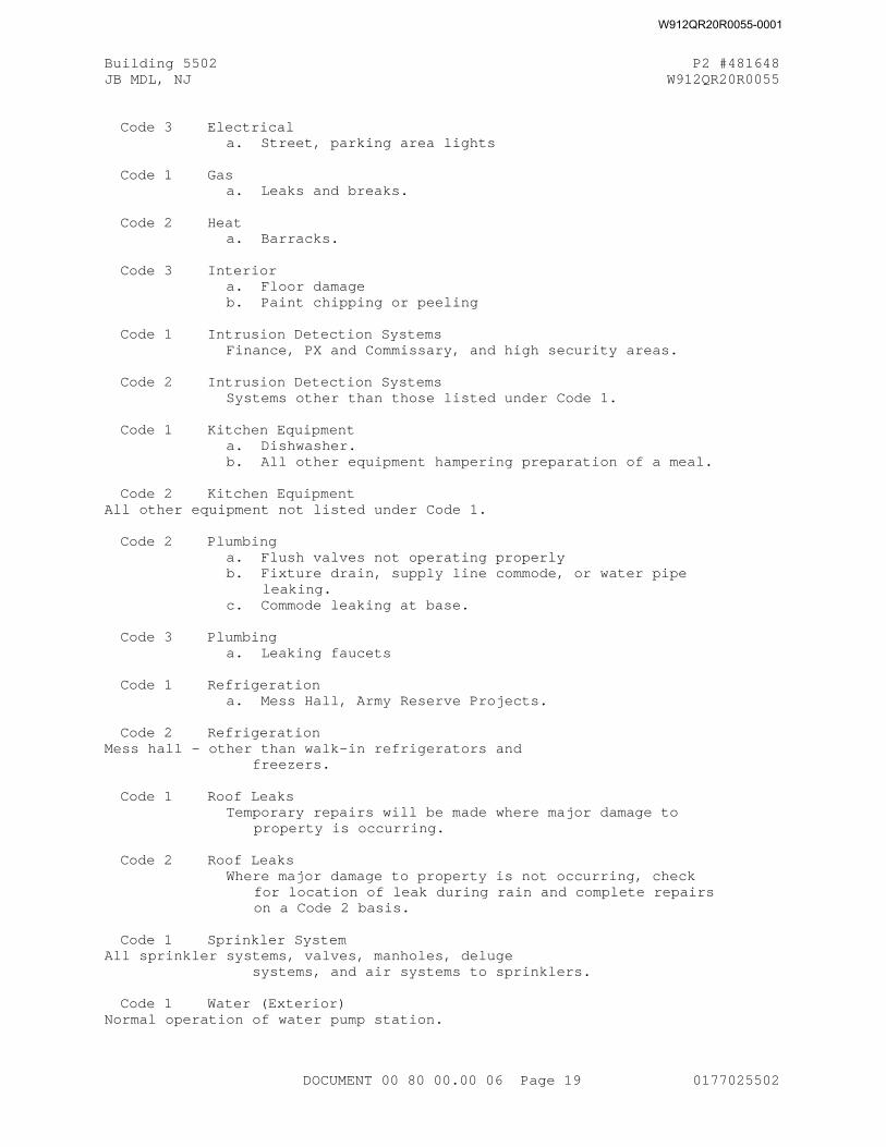
Building 5502 P2 #481648JB MDL, NJ W912QR20R0055
Code 3 Electricala. Street, parking area lights
Code 1 Gasa. Leaks and breaks.
Code 2 Heata. Barracks.
Code 3 Interiora. Floor damageb. Paint chipping or peeling
Code 1 Intrusion Detection SystemsFinance, PX and Commissary, and high security areas.
Code 2 Intrusion Detection SystemsSystems other than those listed under Code 1 .
Code 1 Kitchen Equipmenta. Dishwasher.b. All other equipment hampering preparation of a meal.
Code 2 Kitchen EquipmentAll other equipment not listed under Code 1.
Code 2 Plumbinga. Flush valves not operating properly b. Fixture drain, supply line commode, or water pipe
leaking.c. Commode leaking at base.
Code 3 Plumbinga. Leaking faucets
Code 1 Refrigerationa. Mess Hall, Army Reserve Projects.
Code 2 RefrigerationMess hall - other than walk-in refrigerators and freezers.
Code 1 Roof LeaksTemporary repairs will be made where major damage to
property is occurring.
Code 2 Roof LeaksWhere major damage to property is not occurring, check
for location of leak during rain and complete repairs on a Code 2 basis.
Code 1 Sprinkler System All sprinkler systems, valves, manholes, deluge systems, and air systems to sprinklers.
Code 1 Water (Exterior)Normal operation of water pump station.
DOCUMENT 00 80 00.00 06 Page 19 0177025502
W912QR20R0055-0001
Building 5502 P2 #481648JB MDL, NJ W912QR20R0055
Code 2 Water (Exterior)No water to facility.
Code 1 Water, Hot (and Steam)a. Barracks (entire building).
Code 2 Water, HotNo hot water in portion of building listed under
Code 1 (items a through c)
(5) Should parts be required to complete the work and the parts are not immediately available, the Contractor shall have a maximum of 12 hours after arrival at the job site to provide the Contracting Officer or an authorized representative of the installation designated in writing by the Contracting Officer, with firm written proposals for emergency alternatives and temporary repairs for Government participation with the Contractor to provide emergency relief until the required parts are available on site for the Contractor to perform permanent warranty repair. The Contractors proposals shall include a firm date and time that the required parts shall be available on site to complete the permanent warranty repair. The Contracting Officer or an authorized representative of the installation designated in writing by the Contracting Officer, will evaluate the proposed alternatives and negotiate the alternative considered to be in the best interest of the Government to reduce the impact of the emergency condition. Alternatives considered by the Contracting Officer or an authorized representative of the installation designated in writing by the Contracting Officer will include the alternative for the Contractor to "Do Nothing" while waiting until the required parts are available to perform permanent warranty repair. Negotiating a proposal which will require Government participation and the expenditure of Government funds shall constitute a separate procurement action by the using service.
f. Equipment Warranty Identification Tags
(1) The Contractor at the time of installation shall provide warranty identification tags on all Contractor and Government furnished equipment which he has installed.
(a) The tags shall be suitable for interior and exterior locations, resistant to solvents, abrasion, and to fading caused by sunlight, precipitation, etc. These tags shall have a permanent pressure-sensitive adhesive back, and they shall be installed in a position that is easily (or most easily) noticeable. Contractor furnished equipment that has differing warranties on its components will have each component tagged.
(b) Sample tags shall be submitted for Government review and approval. These tags shall be filled out representative of how the Contractor will complete all other tags.
(c) Tags for Warrantied Equipment: The tag for this equipment shall be similar to the following. Exact format and size will be as approved.
DOCUMENT 00 80 00.00 06 Page 20 0177025502
W912QR20R0055-0001
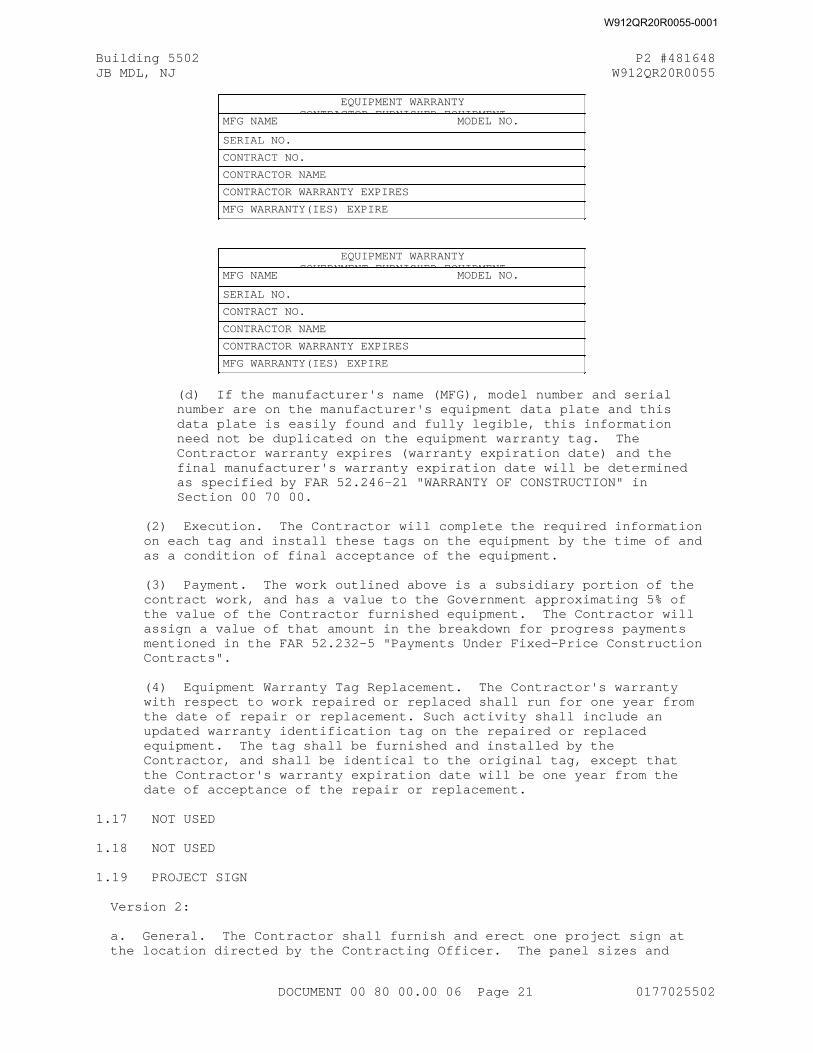
Building 5502 P2 #481648JB MDL, NJ W912QR20R0055
EQUIPMENT WARRANTYCONTRACTOR FURNISHED EQUIPMENT
MFG NAME MODEL NO.
SERIAL NO.
CONTRACT NO.
CONTRACTOR NAME
CONTRACTOR WARRANTY EXPIRES
MFG WARRANTY(IES) EXPIRE
EQUIPMENT WARRANTYGOVERNMENT FURNISHED EQUIPMENT
MFG NAME MODEL NO.
SERIAL NO.
CONTRACT NO.
CONTRACTOR NAME
CONTRACTOR WARRANTY EXPIRES
MFG WARRANTY(IES) EXPIRE
(d) If the manufacturer's name (MFG), model number and serial number are on the manufacturer's equipment data plate and this data plate is easily found and fully legible, this information need not be duplicated on the equipment warranty tag. The Contractor warranty expires (warranty expiration date) and the final manufacturer's warranty expiration date will be determined as specified by FAR 52.246-21 "WARRANTY OF CONSTRUCTION" in Section 00 70 00.
(2) Execution. The Contractor will complete the required information on each tag and install these tags on the equipment by the time of and as a condition of final acceptance of the equipment.
(3) Payment. The work outlined above is a subsidiary portion of the contract work, and has a value to the Government approximating 5% of the value of the Contractor furnished equipment. The Contractor will assign a value of that amount in the breakdown for progress payments mentioned in the FAR 52.232-5 "Payments Under Fixed-Price Construction Contracts".
(4) Equipment Warranty Tag Replacement. The Contractor's warranty with respect to work repaired or replaced shall run for one year from the date of repair or replacement. Such activity shall include an updated warranty identification tag on the repaired or replaced equipment. The tag shall be furnished and installed by the Contractor, and shall be identical to the original tag, except that the Contractor's warranty expiration date will be one year from the date of acceptance of the repair or replacement.
1.17 NOT USED
1.18 NOT USED
1.19 PROJECT SIGN
Version 2:
a. General. The Contractor shall furnish and erect one project sign at the location directed by the Contracting Officer. The panel sizes and
DOCUMENT 00 80 00.00 06 Page 21 0177025502
W912QR20R0055-0001
Building 5502 P2 #481648JB MDL, NJ W912QR20R0055
graphic formats have been standardized for visual consistency throughout all Corps operations.
b. Materials. Panels are fabricated using HDO plywood with dimensional lumber uprights and bracing.
c. Painting. All legends shall be painted in the sizes and styles as specified by the graphic formats shown at the end of this section. The signs (including back and edges), posts and braces shall be given two coats of Benjamin Moore No. 120-60 poly-silicone enamel or approved equal before lettering. The 4' x 4' right section of the project sign shall be white with black lettering. The 2' x 4' left section shall be Communication Red (CR) with white lettering. Paint colors shall be as follow:
Black - Federal Standard 595a Color Number 27038White - Federal Standard 595a Color Number 27875Red - PANTONE 032
An example of the sign including mounting and fabrication details are also provided at the end of this specification section.
Name of the project shall be as follows: Barracks FFR, Building 5502
Name of the designer shall be as follows: The Mason & Hanger Group
d. Erection. The signs shall be erected at the designated location(s). Signs shall be plumb and backfill of post holes shall be well tamped to properly support the signs in position throughout the life of the contract.
e. Maintenance. The signs shall be maintained in good condition until completion of the contract, shall remain the property of the Contractor, and shall be removed from the site upon completion of work under the contract.
f. Logos. The Corps of Engineers and Army Star logo will be provided by the Contracting Officer.
g. Payment. No separate payment will be made for furnishing and erecting the project signs as specified and costs thereof shall be considered a subsidiary obligation of the Contractor.
1.20 TIME EXTENSIONS FOR UNUSUALLY SEVERE WEATHER ER 415-1-15
This provision specifies the procedure for the determination of time extensions for unusually severe weather in accordance with the FAR 52.249-10 "Default (Fixed-Price Construction)". In order for the Contracting Officer to award a time extension under this clause, the following conditions must be satisfied:
The weather experienced at the project site during the contract period must be found to be unusually severe, that is, more severe than the adverse weather anticipated for the project location during any given month.
Indicate the location of the National Weather Service office closest to the site. See: https://www.weather.gov/srh/nwsoffices The Contractor shall make his own investigations and determinations as to weather conditions at the site. Data may be obtained from various National
DOCUMENT 00 80 00.00 06 Page 22 0177025502
W912QR20R0055-0001
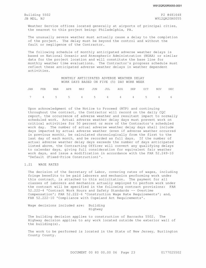
Building 5502 P2 #481648JB MDL, NJ W912QR20R0055
Weather Service offices located generally at airports of principal cities, the nearest to this project being: Philadelphia, PA.
The unusually severe weather must actually cause a delay to the completion of the project. The delay must be beyond the control and without the fault or negligence of the Contractor.
The following schedule of monthly anticipated adverse weather delays is based on National Oceanic and Atmospheric Administration (NOAA) or similar data for the project location and will constitute the base line for monthly weather time evaluations. The Contractor's progress schedule must reflect these anticipated adverse weather delays in weather dependent activities.
MONTHLY ANTICIPATED ADVERSE WEATHER DELAYWORK DAYS BASED ON FIVE (5) DAY WORK WEEK
JAN FEB MAR APR MAY JUN JUL AUG SEP OCT NOV DEC
7 4 5 5 4 5 4 4 4 5 4 6
Upon acknowledgment of the Notice to Proceed (NTP) and continuing throughout the contract, the Contractor will record on the daily CQC report, the occurrence of adverse weather and resultant impact to normally scheduled work. Actual adverse weather delay days must prevent work on critical activities for 50 percent or more of the Contractor's scheduled work day. The number of actual adverse weather delay days shall include days impacted by actual adverse weather (even if adverse weather occurred in previous month), be calculated chronologically from the first to the last day of each month, and be recorded as full days. If the number of actual adverse weather delay days exceeds the number of days anticipated listed above, the Contracting Officer will convert any qualifying delays to calendar days, giving full consideration for equivalent fair weather work days, and issue a modification in accordance with the FAR 52.249-10 "Default (Fixed-Price Construction)".
1.21 WAGE RATES
The decision of the Secretary of Labor, covering rates of wages, including fringe benefits to be paid laborers and mechanics performing work under this contract, is attached to this solicitation. The payment for all classes of laborers and mechanics actually employed to perform work under the contract will be specified in the following contract provisions: FAR 52.222-4 "Contract Work Hours and Safety Standards -- Overtime Compensation"; FAR 52.222-6 "Construction Wage Rate Requirements"; and, FAR 52.222-10 "Compliance with Copeland Act Requirements".
Wage decisions included are: Building Highway
The building decision applies to construction of Barracks 5502. The Highway decision applies to any work located outside the exterior wall of the building(s).
The work to be performed is located in the State of New Jersey, Burlington County County.
DOCUMENT 00 80 00.00 06 Page 23 0177025502
W912QR20R0055-0001
Building 5502 P2 #481648JB MDL, NJ W912QR20R0055
1.21.1 CONTRACTOR SUPPLY AND USE OF ELECTRONIC SOFTWARE FOR PROCESSING WAGE REQUIREMENT STATUE CERTIFIED LABOR PAYROLLS
(a) The contractor is encouraged to use a commercially-available electronic system to process and submit certified payrolls electronically to the Government. The requirements for preparing, processing and providing certified labor payrolls are established by the Wage Rate Requirements statute.
(b) If the contractor elects to use an electronic payroll processing system, then the contractor shall be responsible for obtaining and providing for all access, licenses, and other services required to provide for receipt, processing, certifying, electronically transmitting to the Government, and storing weekly payrolls and other data required for the contractor to comply with the Wage Rate Requirements statute. When the contractor uses an electronic payroll system, the electronic payroll service shall be used by the contractor to prepare, process, and maintain the relevant payrolls and basic records during all work under this construction contract and the electronic payroll service shall be capable of preserving these payrolls and related basic records for the required 3 years after contract completion. If the contractor chooses to use an electronic payroll system, then the contractor shall obtain and provide electronic system access to the Government, as required to comply with the Wage Rate Requirements over the duration of this construction contract. The access shall include electronic review access by the Government contract administration office to the electronic payroll processing system used by the contractor.
(c) The contractor's provision and use of an electronic payroll processing system shall meet the following basic functional criteria:
(1) commercially available;
(2) compliant with appropriate Wage Rate Requirements statute payroll provisions in the Federal Acquisition Regulation (FAR);
(3) able to accommodate the required numbers of employees and subcontractors planned to be employed under the contract
(4) capable of producing an Excel spreadsheet-compatible electronic output of weekly payroll records for export in an Excel spreadsheet to be imported into the contractor's Quality Control System (QCS) version of Resident Management System (RMS), that in turn shall export payroll data to the Government's RMS;
(5) demonstrated security of data and data entry rights;
(6) ability to produce contractor-certified electronic versions of weekly payroll data;
(7) ability to identify erroneous entries and track the date/time of all versions of the certified Wage Rate Requirements statute payrolls submitted to the government over the life of the contract;
(8) capable of generating a durable record copy, that is, a CD or DVD and PDF file record of data from the system database at end of the contract closeout. This durable record copy of data from the electronic payroll processing system shall be provided to the
DOCUMENT 00 80 00.00 06 Page 24 0177025502
W912QR20R0055-0001
Building 5502 P2 #481648JB MDL, NJ W912QR20R0055
Government during contract closeout.
(d) All contractor-incurred costs related to the contractor's provision and use of an electronic payroll processing service shall be included in the contractor's price for the overall work under the contract. The costs for compliance with the Wage Rate Requirements statute by using electronic payroll processing services shall not be a separately bid or reimbursed item under this contract.
1.22 NOT USED
1.23 INTERFERENCE WITH TRAFFIC AND PUBLIC AND PRIVATE PROPERTY
a. The Contractor at all times shall dispose his plant and conduct the work in such manner as to cause as little interference as possible with private and public travel. Damage (other than that resulting from normal wear and tear) to roads, shall be repaired to as good a condition as they were prior to the beginning of work and to the satisfaction of the Contracting Officer.
b. The Contractor shall provide and maintain as may be required by the State of New Jersey, Department of Transportation, County of Burlington. Contractor shall provide proper barricades, fences, danger signals and lights, provide a sufficient number of watchmen, and take such other precautions as may be necessary to protect life, property and structures, and shall be liable for and hold the Government free and harmless from all damages occasioned in any way by his act or neglect, or that of his agents, employees, or workmen.
1.24 NOT USED
1.25 NOT USED
1.26 COMPLIANCE WITH POST/BASE REGULATIONS
a. The site of the work is on a military reservation and all rules and regulations issued by the Commanding Officer covering general safety, security, sanitary requirements, pollution control and traffic regulations, shall be observed by the Contractor. Information regarding these requirements may be obtained by contacting the Contracting Officer, who will provide such information or assist in obtaining same from appropriate authorities.
b. Contractor personnel shall park only in areas authorized by the Contracting Officer.
c. Fort Dix Criminal Background Check
The contractor shall provide criminal history background/security checks on all personnel who must enter the Fort Dix military installation to perform the contract. At a minimum the background check will consist of a criminal history background check and social security number verification with fingerprints going back at least five years. This background/security check shall be performed by the New Jersey State Police or by a private investigative agency that is specifically licensed and bonded for this purpose in the state of New Jersey. Furthermore, all applicants shall be U.S. citizens or be legally eligible to work within the United States. Results of the check will be mailed directly to the U.S. Army Corps of Engineers resident office located at Fort Dix. Forms
DOCUMENT 00 80 00.00 06 Page 25 0177025502
W912QR20R0055-0001
Building 5502 P2 #481648JB MDL, NJ W912QR20R0055
sent from the contractor will not be accepted. An access list containing names, social security numbers, and results of the investigation shall be submitted to the Fort Dix Public Safety Directorate/Department of Defense Police by the resident office no later than three (3) working days prior to the start of contract performance. This is a prerequisite to receiving an identification badge or pass for access to the installation. As names are added or deleted, this information must be reported immediately to the Department of Defense Police. Pen and ink deletions may be made to the access list, but additions require the generation of a new list. Background checks must also be updated every three years. In addition to the contractor provided background check, additional agency checks may be performed at the discretion of the Department of Defense Police or other security personnel. The contractor agrees to cooperate and ensure that contractor personnel provide any documentation required to complete these checks. This may include but is not limited to a Standard Form 85 or an SF-85-P for an NCIC check. Personnel may be required to complete and sign this form. Any person lacking proper identification credentials or deemed a security threat may be denied access to Fort Dix. Such action in no way relieves the contractor from performance of the contract.
d. OPSEC Requirements
1. All contractor employees, to include subcontractor employees, requiring access to Army installations, facilities, controlled access areas, or require network access, shall complete AT Level I awareness training within 30 calendar days after contract start date or effective date of incorporation of this requirement into the contract, whichever is applicable. Upon request, the contractor shall submit certificates of completion for each affected contractor employee and subcontractor employee, to the COR or to the contracting officer (if a COR is not assigned), within 5 calendar days after completion of training by all employees and subcontractor personnel. AT Level I awareness training is available at the following website: http://jko.jten.mil/courses/atl1/launch.htmlor it can be provided by the RA ATO in presentation form which will be documented via memorandum
2. All contractor and all associated sub-contractors employees shall comply with applicable installation, facility and area commander installation/facility access and local security policies and procedures (provided by government representative). The contractor shall also provide all information required for background checks to meet installation/facility access requirements to be accomplished by installation Provost Marshal Office, Director of Emergency Services or Security Office. Contractor workforce must comply with all personal identity verification requirements (FAR clause 52.204-9, Personal Identity Verification of Contractor Personnel) as directed by DOD, HQDA and/or local policy. In addition to the changes otherwise authorized by the changes clause of this contract, should the Force Protection Condition (FPCON) at any installation or facility change, the Government may require changes in contractor security matters or processes."
3. Contractor and all associated sub-contractors employees shall comply with adjudication standards and procedures using the National Crime Information Center Interstate Identification Index (NCIC-III) and Terrorist Screening Database (TSDB) (Army Directive 2014-05 / AR 190-13), applicable installation, facility and area commander
DOCUMENT 00 80 00.00 06 Page 26 0177025502
W912QR20R0055-0001
Building 5502 P2 #481648JB MDL, NJ W912QR20R0055
installation/facility access and local security policies and procedures (provided by government representative, as NCIC and TSDB are available), or, at OCONUS locations, in accordance with status of forces agreements and other theater regulations.
4. The contractor and all associated sub-contractors shall receive a brief/training (provided by the RA) on the local suspicious activity reporting program. This locally developed training will be used to inform employees of the types of behavior to watch for and instruct employees to report suspicious activity to the project manager, security representative or law enforcement entity. This training shall be completed within 30 calendar days of contract award and within 30 calendar days of new employees commencing performance with the results reported to the COR NLT 5 calendar days after the completion of the training.
5. The Contractor must pre-screen Candidates using the E-verify Program ( http://www.uscis.gov/e-verify )website to meet the established employment eligibility requirements. The Vendor must ensure that the Candidate has two valid forms of Government issued identification prior to enrollment to ensure the correct information is entered into the E-verify system. An initial list of verified/eligible Candidates must be provided to the COR no later than 3 business days after the initial contract award.
6.All contract employees, including subcontractor employees who are not in possession of the appropriate security clearance or access privileges, will be escorted in areas where they may be exposed to classified and/or sensitive materials and/or sensitive or restricted areas."
7. The Contractor must pre-screen Candidates using the E-verify Program (http://www.uscis.gov/e-verify )website to meet the established employment eligibility requirements. The Vendor must ensure that the Candidate has two valid forms of Government issued identification prior to enrollment to ensure the correct information is entered into the E-verify system. An initial list of verified/eligible Candidates must be provided to the COR no later than 3 business days after the initial contract award.
1.27 EQUIPMENT OWNERSHIP AND OPERATING EXPENSE SCHEDULE)
a. This clause does not apply to terminations. See FAR 52.249-5000, "Basis for Settlement of Proposals", Part 49.
b. Allowable costs for construction and marine plant and equipment in sound workable condition owned or controlled and furnished by a contractor or subcontractor at any tier shall be based on actual cost data for each piece of equipment or groups of similar serial and series for which the Government can determine both ownership and operating costs from the contractor's accounting records. When both ownership and operating costs cannot be determined for any piece of equipment or groups of similar serial or series equipment from the contractor's accounting records, costs for that equipment shall be based upon the applicable provisions of Engineer Pamphlet EP 1110-1-8 , Construction Equipment Ownership and Operating Expense Schedule. Working conditions shall be considered to be average for determining equipment rates using the schedule unless specified otherwise by the contracting officer. For equipment not included in the schedule, rates for comparable pieces of equipment may be used or a rate may be developed using the formula provided in the schedule. For
DOCUMENT 00 80 00.00 06 Page 27 0177025502
W912QR20R0055-0001
Building 5502 P2 #481648JB MDL, NJ W912QR20R0055
forward pricing, the schedule in effect at the time of negotiations shall apply. For retroactive pricing, the schedule in effect at the time the work was performed shall apply.
c. Equipment rental costs are allowable, subject to the provisions of FAR 31.105(d)(ii) and FAR 31.205-36. Rates for equipment rented from an organization under common control, lease-purchase arrangements, and sale-leaseback arrangements, will be determined using the schedule, except that actual rates will be used for equipment leased from an organization under common control that has an established practice of leasing the same or similar equipment to unaffiliated lessees.
d. When actual equipment costs are proposed and the total amount of the pricing action exceeds the simplified acquisition threshold (SAT), the contracting officer shall request the contractor to submit either certified cost or pricing data, or partial/limited data, as appropriate. The data shall be submitted on Standard Form 1411, Contract Pricing Proposal Cover Sheet.
1.28 LABOR, EQUIPMENT, AND MATERIAL REPORTS
Daily Equipment Report. The Contractor shall submit a daily report of all Contractor-owned or rented equipment at the jobsite. A similar report is required for all subcontractor equipment. The subcontractor's report may be separate or included with the Contractor's report provided the equipment is adequately identified as to ownership. The required equipment report shall include each item of equipment (hand-operated small tools or equipment excluded) on the job and shall specifically identify each item as to whether it is Contractor-owned or rented, shifts, hours of usage, down time for repairs, and standby time. Identification of the equipment shall include make, model and plant number of all items. Separate identification by a key sheet providing these data may be utilized with the daily report indicating the type of equipment and the equipment plant numbers. The format of the Daily Equipment Report will be as approved by the Government in the field.
Labor, Equipment, and Material Report for Extra Work/Cost. A Report shall also be submitted by the Contractor listing any labor, equipment and materials expended on and/or impacted by any change order directed by the Government and for which total price/time agreement has not been reached. These requirements also apply to subcontractors at any tier. The same Report is required at any time the Contractor claims or intends to claim for extra costs whether or not there is Government recognition (constructive changes). This requirement is in addition to any Contractor "Notice" or "Reservation of Rights". Submittal of such a report will not be construed as satisfying the "Notice" required under FAR 52.243-4 - "Changes" or any other clause. But, absence of such Reports submitted to the Government contemporaneously with the alleged extra work/cost will be considered as evidence that no such extra work/cost occurred that are chargeable to the Government.
The Report shall be detailed to the degree required by the Government in the field and shall contain the following as a minimum:
a. The cause of the extra labor, equipment or materials costs.
b. For extra labor - Indicate crew, craft, hours, location and cost. Describe nature or type of extra costs, i.e., extra work, overtime, acceleration, interference, reassignment, mobilizations and
DOCUMENT 00 80 00.00 06 Page 28 0177025502
W912QR20R0055-0001
Building 5502 P2 #481648JB MDL, NJ W912QR20R0055
demobilizations, supervision, overhead, type of inefficiency, etc.
c. For extra equipment - Indicate type and description, hours, location, cost; whether working, idle, standby, under repair, extra work involved, etc.
d. For extra materials - Indicate type and description, where used, whether consumed, installed or multi-use, quantity, cost, extra work involved, etc.
e. Affected activities - Relate to Contract Schedule (Network Analysis); demonstrate whether delay or suspension is involved.
f. Segregate all entries by prime and each subcontractor.
g. Summarize costs daily and by cumulative subtotal or with frequency required by the Government.
This report will not be considered as evidence that any of the alleged extra costs actually occurred. The report will be used to check against over obligation of funds for change orders directed prior to price/time agreement and to track alleged extra costs the Contractor considers otherwise chargeable against the Government. The Government may respond at any interval to either challenge, amend or confirm the report. Absence of a Government response is not to be considered acquiescence or denial. The Government may order work stoppage if deemed necessary to avoid over obligation of funds. The frequency of the report shall be daily or as otherwise approved by the Government representative in writing.
1.29 ENGLISH-SPEAKING REPRESENTATIVE
At all times when any performance of the work at any site is being conducted by any employee of the Contractor or his subcontractors, the Contractor shall have a representative present at each site who has the capability of receiving instructions in the English language, fluently speaking the English language and explaining the work operations to persons performing the work, in the language that those performing the work are capable of understanding. The Contracting Officer shall have the right to determine whether the proposed representative has sufficient technical bilingual capabilities, and the Contractor shall immediately replace any individual not acceptable to the Contracting Officer.
1.30 SALES and USE TAX
Some states have tax exemptions for certain aspects of work when done for the federal government and the Contractor shall check with the state where the project is located for more information. If a sales tax exemption is applicable, the contractor is responsible for obtaining any required exemption certification.
1.31 CONTRACTOR SECURITY TRAINING/FACILITY ACCESS REQUIREMENTS
1) All contractor employees, to include subcontractor employees, shall complete AT Level 1 awareness training within seven (7) calendar days after commencing work on the site. The contractor shall submit a roster for each affected contractor employee and subcontractor employee to the COR or to the Contracting Officer within seven (7) calendar days after completion of training by all employees and subcontractor personnel. AT Level 1 awareness training is available
DOCUMENT 00 80 00.00 06 Page 29 0177025502
W912QR20R0055-0001
Building 5502 P2 #481648JB MDL, NJ W912QR20R0055
at the following website: https://jko.jten.mil/courses/atl1/launch.html
2) All contractor employees, to include subcontractor employees, shall comply with applicable installation, facility and area commander installation/facility access and local security policies and procedures (provided by government representative). The contractor shall also provide all information required for background checks to meet installation access requirements to be accomplished by installation Provost Marshal Office, Director of Emergency Services or Security Office. Contractor workforce must comply with all personal identity verification requirements as directed by DOD, HQDA and/or local policy. In addition to the changes otherwise authorized by FAR 52.243-4 - "Changes" of this contract, should the Force Protection Condition (FPCON) at any individual facility or installation change, the Government may require changes in contractor security matters or processes.
3) Per AR 530-1 , Operations Security, all contractor employees and associated subcontractor employees must complete Level 1 OPSEC Training within thirty (30) calendar days of commencing work. Additionally, all contractor employees and associated subcontractor employees must complete annual OPSEC awareness training.
4) Refer to FAR 52.222-54: "Employment Eligibility Verification" in Section 00 70 00 for e-Verify requirements.
1.32 INSURANCE--WORK ON A GOVERNMENT INSTALLATION
In addition to the requirements of FAR 52.228-5 "Insurance - Work on a Government Installation" found in Section 00 70 00 the following shall be provided:
(1) Coverage complying with State laws governing insurance requirements, such as those requirements pertaining to Workman's Compensation and Occupational Disease Insurance. Employer's Liability Insurance shall be furnished in limits of not less than $100,000.00 except in states with exclusive or monopolistic funds.
(2) Comprehensive General Liability Insurance for bodily injury coverage shall be furnished in limits of not less than $500,000 per occurrence.
(3) Comprehensive Automobile Liability Insurance for both bodily injury and property damage, shall be furnished in limits of not less than $200,000.00 per person, $500,000.00 per accident for bodily injury, and $20,000.00 per accident for property damage. When the Financial Responsibility or Compulsory Insurance Law of the State, requires higher limits, the policy shall provide for coverage of at least those higher limits.
1.33 EQUIPMENT OPERATING, MAINTENANCE, AND REPAIR MANUALS
1.33.1 Repair Manual Format
1.33.1.1 Hard Cover Binders
The manuals shall be hard cover with posts, or 3-ring binders, so sheets may be substituted easily. The following identification shall be printed on the cover: the words "EQUIPMENT OPERATING, MAINTENANCE, AND REPAIR
DOCUMENT 00 80 00.00 06 Page 30 0177025502
W912QR20R0055-0001
Building 5502 P2 #481648JB MDL, NJ W912QR20R0055
MANUALS," the project name, building number, and an indication of utility or systems covered, the name of the Contractor, and the Contract number. Manuals shall be approximately 8-1/2 by 11-inches with large sheets folded in and capable of being easily pulled out for reference. All manuals for the project must be similar in appearance, and be of professional quality.
1.33.1.2 Warning Page
A warning page shall be provided to warn of potential dangers (if they exist, such as high voltage, toxic chemicals, flammable liquids, explosive materials, carcinogens, high pressures, etc.). The warning page shall be placed inside the front cover and in front of the title page. Also, any necessary Safety Data Sheets (SDS) shall be included here.
1.33.1.3 Title Page
The title page shall include the same information shown on the cover and show the name of the preparing firm and the date of publication.
1.33.1.4 Table of Contents
Each volume of the set of manuals for this project shall include a table of contents, for the entire set, broken down by volume.
1.33.2 Table of Contents Requirements
TABLE OF CONTENTS
PART I. Introduction
(a) Equipment Description(b) Functional Description(c) Installation Description
PART II. Operating Principles
PART III. Safety
PART IV. Preventive Maintenance
(a) Preventive Maintenance Checklist. Lubrication(b) Charts and Diagrams .
PART V. Spare Parts Lists
(a) Troubleshooting Guide(b) Adjustments(c) Common Repairs and Parts Replacement
PART VI. Illustrations
1.33.2.1 Part I Introduction
Part I shall provide an introduction, equipment or system description, functional description and theory of operation, and installation instructions for each piece of equipment. Complete instructions for uncrating, assembly, connection to the power source and pre-operating lubrication shall be included in the installation instructions as applicable. Illustrations, including wiring and cabling diagrams, are
DOCUMENT 00 80 00.00 06 Page 31 0177025502
W912QR20R0055-0001
Building 5502 P2 #481648JB MDL, NJ W912QR20R0055
required as appropriate in this section. Halftone pictures of the equipment should be included in the introduction and equipment description, as well as system layout drawings with each item of equipment located and marked. Copies of previously submitted shop drawings shall not be used in these manuals.
1.33.2.2 Part II Operating Principles
Part II shall provide complete instructions for operating the system, and each piece of equipment. Illustrations, halftone pictures, tables, charts, procedures, and diagrams are required when applicable. This will include step-by-step procedures for start-up and shutdown of both the system and each component piece of equipment, as well as adjustments required to obtain optimum equipment performance, and corrective actions for malfunctions. Performance sheets and graphs showing capacity data, efficiencies, electrical characteristics, pressure drops, and flow rates shall be shown here, also. Marked-up catalogs or catalog pages do not satisfy this requirement. Performance information shall be presented as concisely as possible and contain only data pertaining to equipment actually installed. Actual test data collected for Contractor performance shall be included here.
1.33.3 Part III Safety
Part III shall contain the general and specific safety requirements peculiar to each item of equipment. Safety information should be repeated as notes cautions, and warnings in other sections where appropriate to operations described.
1.33.4 Part IV Preventive Maintenance
Part IV shall contain a troubleshooting guide, including detailed instructions for all common adjustments and alignment procedures, including a detailed maintenance schedule. Also, include a diagnostic chart showing symptoms and solutions to problems. Include test hookups to determine the cause, special tools and test equipment, and methods for returning the equipment to operating conditions. Information may be in chart form or in tabular format with appropriate headings. Instructions shall be included for the removal, disassembly, repair, reassembly, and replacement of parts and assemblies where applicable and the task is not obvious.
1.33.5 Part V Spare Parts List
Part V shall contain a tabulation of description data and parts location illustrations for all mechanical and electrical parts. The heading of the parts list shall clearly identify the supplier, purchase order number, and equipment. The unit price for each part shall be included, also. Parts shall be listed by major assemblies, and the listing shall be arranged in columnar form. Also, names and addresses of the nearest manufacturer's representatives will be included, as well as any special warranty information.
1.33.6 Part VI Illustrations
Part VI shall contain assembly drawings for the complete equipment or system and for all major components. Complete wiring diagrams and schematics shall be included. Other illustrations, such as exploded views, block diagrams, and cutaway drawings, are required as appropriate.
DOCUMENT 00 80 00.00 06 Page 32 0177025502
W912QR20R0055-0001
Building 5502 P2 #481648JB MDL, NJ W912QR20R0055
1.33.7 Framed Instructions
Framed instructions under glass or in laminated plastic, including wiring and control diagrams showing the complete layout of the entire system, including equipment, ductwork, piping valves, dampers, and control sequence, shall be posted at a location near the equipment described. Condensed operating instructions explaining preventive maintenance procedures methods of checking the system for normal safe operation, valve schedule and procedures for safely starting and stopping the system shall be prepared in type form, framed as specified above for the wiring and control diagrams and posted beside the diagrams. Proposed diagrams, instructions, and other sheets shall be submitted prior to posting. The framed instructions shall be posted before field training.
1.34 AVAILABILITY OF SAFETY AND HEALTH REQUIREMENTS MANUAL (EM 385-1-1)
As covered by FAR 52.236-13 "Accident Prevention", compliance with EM 385-1-1 is a requirement for this contract. Copies may be downloaded from the following website:
http://www.publications.usace.army.mil/USACEPublications/EngineerPamphlets.aspx Select EM_385-1-1
1.35 FIRE PROTECTION DURING CONSTRUCTION
The Contractor is alerted to the requirements of FAR 52.236-12 "Cleaning Up" and more specifically to the requirements for fire protection during construction spelled out in UFC 3-600-01 , EM 385-1-1 , and NFPA 241 Building Construction and Demolition Operations. This item must be covered in the submittal required under FAR 52.236-13 "Accident Prevention".
1.36 NOT USED
1.37 RADIOACTIVE MATERIAL/EQUIPMENT
All equipment (e.g. nuclear density gauges) or items containing radioactive material brought onto any military or private installation must be licensed by the Nuclear Regulatory Commission, and or State/Local authorities having jurisdiction. Some locations are considered a non-agreement sites with respect to reciprocity with State permits and special permitting may be required prior to accessing the site with the equipment. Be aware that there may be several week review and processing periods that vary from location to location. Permitting for each site must be evaluated, with a copy of any obtained permit or license provided to the Contracting Officer.
1.38 NOT USED
1.39 CONSTRUCTION HAZARD COMMUNICATION
The Contractor is required to comply with the requirements of the OSHA Hazard Communication Standard in alignment with the Globally Harmonized System (GHS) ( 29 CFR 1926.59 ). This standard is designed to inform workers of safe and appropriate methods of working with hazardous substances in the workplace. The standard has five requirements, and every hazardous or potentially hazardous substance used or stored in the work area is subject to all five. They are:
DOCUMENT 00 80 00.00 06 Page 33 0177025502
W912QR20R0055-0001
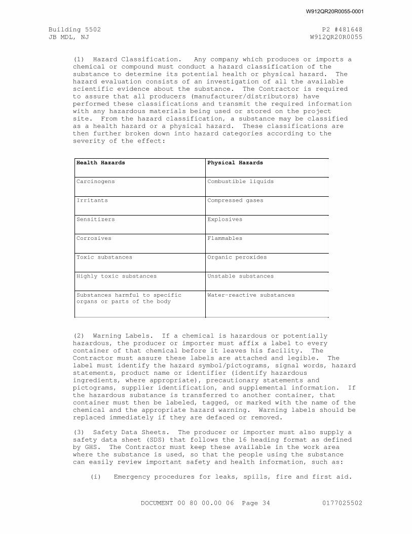
Building 5502 P2 #481648JB MDL, NJ W912QR20R0055
(1) Hazard Classification. Any company which produces or imports a chemical or compound must conduct a hazard classification of the substance to determine its potential health or physical hazard. The hazard evaluation consists of an investigation of all the available scientific evidence about the substance. The Contractor is required to assure that all producers (manufacturer/distributors) have performed these classifications and transmit the required information with any hazardous materials being used or stored on the project site. From the hazard classification, a substance may be classified as a health hazard or a physical hazard. These classifications are then further broken down into hazard categories according to the severity of the effect:
Health Hazards Physical Hazards
Carcinogens Combustible liquids
Irritants Compressed gases
Sensitizers Explosives
Corrosives Flammables
Toxic substances Organic peroxides
Highly toxic substances Unstable substances
Substances harmful to specificorgans or parts of the body
Water-reactive substances
(2) Warning Labels. If a chemical is hazardous or potentially hazardous, the producer or importer must affix a label to every container of that chemical before it leaves his facility. The Contractor must assure these labels are attached and legible. The label must identify the hazard symbol/pictograms, signal words, hazard statements, product name or identifier (identify hazardous ingredients, where appropriate), precautionary statements and pictograms, supplier identification, and supplemental information. If the hazardous substance is transferred to another container, that container must then be labeled, tagged, or marked with the name of the chemical and the appropriate hazard warning. Warning labels should be replaced immediately if they are defaced or removed.
(3) Safety Data Sheets. The producer or importer must also supply a safety data sheet (SDS) that follows the 16 heading format as defined by GHS. The Contractor must keep these available in the work area where the substance is used, so that the people using the substance can easily review important safety and health information, such as:
(i) Emergency procedures for leaks, spills, fire and first aid.
DOCUMENT 00 80 00.00 06 Page 34 0177025502
W912QR20R0055-0001
Building 5502 P2 #481648JB MDL, NJ W912QR20R0055
(ii) Precautions necessary for use, handling, and storage.
(iii) Useful facts about the substance's physical or chemicalproperties.
(iv) Regulatory information and any other pertinent information including information on preparation and revision of the SDS.
(4) Work Area Specific Training. Because of hazardous substance may react differently depending on how it is used or the environment of the work area, the Contractor must conduct work area specific training; special training which takes the Contractor's operations, environment, and work policies into consideration. Work area training presents:
The hazardous substances which are present in the work place and the hazards they pose.
Ways to protect against those hazards, such as protective equipment, emergency procedures, and safe handling.
Where the SDS's are kept, and an explanation of the labeling system.
Where the Contractor's written Hazard Communication Program is located.
(5) The Written Hazard Communication Program. In accordance with OSHA and the EM 385-1-1 requirements, the Contractor must prepare a written Hazard Communication Program. This document will be included in the Contractor's Accident Prevention Plan. This document states the hazardous or toxic agent inventory, how the Contractor plans to ensure that hazardous materials are appropriately labeled, how and where SDS's will be maintained, and how employees will be provided with specific information and training.
1.40 NOT USED
1.41 MECHANICAL/ELECTRICAL ROOM LAYOUT (LRL)
Detailed mechanical/electrical room layout drawings shall be submitted for approval in accordance with LRL Section 01 33 00.00 06 SUBMITTAL PROCEDURES. Layout drawings shall show location and maintenance clearances for all mechanical/electrical room equipment, and all utility runs/chases for mechanical, electrical, telephone and other similar systems. Drawings shall be submitted at the same time as the submittals for the equipment to be located within the mechanical/electrical room.
1.42 RED ZONE MEETING
Approximately 120 calendar days prior to anticipated construction completion date, if different than the required contract completion date, and the contract work has progressed to 80% including interior finishes in progress or complete if applicable, the Contractor and the Government's project delivery team will conduct what is known as the Red Zone Meeting to discuss the close-out process, to schedule the events and review responsibilities for actions necessary to produce a timely physical, as well as fiscal, project close-out. The Red Zone meeting derives its name from the football term used to describe the team effort to move the ball
DOCUMENT 00 80 00.00 06 Page 35 0177025502
W912QR20R0055-0001
Building 5502 P2 #481648JB MDL, NJ W912QR20R0055
the last 20 yards into the end zone. The close-out of a construction project sometimes can be equally as hard and most definitely requires the whole team's efforts.
1.43 NOT USED
1.44 PARTNERING
In order to most effectively accomplish this contract, the Government proposes to form a partnership with the Contractor to develop a cohesive building team. It is anticipated that this partnership would involve Project Delivery Team members from the Corps of Engineers, Program Sponsor, facility user representatives, the Contractor, primary subcontractors, and the designers. The partnership will draw upon the strength of each organization in an effort to achieve a project that is without any safety mishaps, conforms to the Contract, stays within budget and on schedule. The Government encourages partnering to be initiated near the beginning of the Contract and endure through the life of the Contract.
1.44.1 Formal Partnering
A partnering workshop shall be held within thirty (30) calendar days of NTP. The Initial Partnering Session shall be scheduled for a minimum one (1) day duration. The partnering session may take place concurrently with the Pre-Construction Meeting. The workshop shall be led by an independent facilitator experienced in conducting Partnering Workshops. The facilitator shall be selected as mutually agreed upon by both the Government and the Contractor, from a list of facilitators constituted of those that may be suggested by either the Contractor or the Government. The Facilitator shall be responsible for the development of the workshop agenda and for leading the team in a timely manner to make sure that issues are identified and resolved.
The Contractor and Government will bear their own respective labor and travel expenses. The partnering session venue will be provided by the Government, preferably at a place off the construction site to avoid disturbances. The Government will pay for costs to provide the venue, and the Contractor shall pay the costs of the independent facilitator, including fees and incidental costs such as those incurred by the facilitator for travel, handout reproduction, audio-visual equipment, highlighters, pads and other items customarily provided by, or necessary for the facilitator's use.
1.44.2 Partnering Participants
Participants shall include the Corps of Engineers, Contractor personnel, and personnel of primary subcontractors. Additionally, the following shall be invited to attend: the customer/end user, the designers, Program Sponsor, Department of Public Works, and other stakeholders deemed appropriate by the Contracting Officer. Consideration should be given to inviting utility companies and permit agencies where long lead times and/or extensive work or relocations affect the Contractor's performance of the work.
1.44.3 Follow-On Partnering Sessions
The Government encourages partnering to be initiated near the beginning of the Contract and endure through the life of the contract. Follow-on
DOCUMENT 00 80 00.00 06 Page 36 0177025502
W912QR20R0055-0001
Building 5502 P2 #481648JB MDL, NJ W912QR20R0055
Partnering Sessions should be scheduled to be for approximately four hours in duration and on a frequency of approximately three to six month intervals, as dictated by the needs of the Project. Follow-on meetings may be held at a location off-site, at the project site, or in a Government Facility and may be scheduled for convenience, concurrent with other scheduled meetings. Attendees need only be those required to resolve current issues.
If mutually determined necessary by the Contractor and Government because of project concerns, the partnership may consider holding an additional formal partnering session. Scope and scheduling for an additional formal partnering session shall be agreed to by both the Contractor and the Government. The workshop shall be led by an independent facilitator experienced in conducting Partnering Workshops. The facilitator shall be selected as mutually agreed upon by both the Government and the Contractor. However, if a formal partnering session was already conducted, consideration should be given to utilizing the same Facilitator from the Initial Partnering session to achieve best results and for continuity.
The Contractor and Government will bear their own respective labor and travel expenses for an additional formal partnering session. The partnering session venue will be provided by the Government, preferably at a place off the construction site to avoid disturbances. The Government will pay for costs to provide the venue, and the Contractor shall pay the costs of the independent facilitator, including fees and incidental costs such as those incurred by the facilitator for travel, handout reproduction, audio-visual equipment, highlighters, pads and other items customarily provided by, or necessary for the facilitator's use.
1.45 PROGRESS PHOTOGRAPHS
Version 1The Contractor shall furnish digital photos depicting the progress of the work during construction and, after final inspection by the Contracting Officer, of the conditions at the completion of the contract.
The monthly photography shall be performed between the first and fifth of each month, and uploaded to RMS no later than the 10th of each month taken. A minimum of six views from different positions shall be taken as directed to show, inasmuch as possible, work accomplished during the previous month, and a minimum of six views shall be taken of the completed work. Additional views and positions may be required by the Contracting Officer to depict the work done.
Photos shall be at least 4 megapixels and in JPEG format. Each Photo shall be identified with the date made, contract title and number, location of work, as well as a brief description of work depicted.
No separate payment will be made for these services and all costs in connection thereto shall be considered a subsidiary obligation of the Contractor.
1.46 DAMAGE TO WORK (LRL)
Version 1The responsibility for damage to any part of the permanent work shall be as set forth in FAR 52.236-7 "Permits And Responsibilities". However, if in the judgment of the Contracting Officer, any part of the permanent work
DOCUMENT 00 80 00.00 06 Page 37 0177025502
W912QR20R0055-0001
Building 5502 P2 #481648JB MDL, NJ W912QR20R0055
performed by the Contractor is damaged by flood or earthquake, which damage is not due to the failure of the Contractor to take reasonable precautions or to exercise sound engineering and construction practices in the conduct of the work, the Contractor will make the repairs as ordered by the Contracting Officer and full compensation for such repairs will be made at the applicable contract unit prices as fixed and established in the contract. If, in the opinion of the Contracting Officer, there are no contract unit prices applicable to any part of such work, an equitable adjustment pursuant to FAR 52.243-4 "Changes", will be made as full compensation for the repairs of that part of the permanent work for which there are no applicable contract unit prices. Except as herein provided, damage to all work (including temporary construction), utilities, materials, equipment and plant shall be repaired to the satisfaction of the Contracting Officer at the Contractor's expense, regardless of the cause of such damage.
1.47 NOT USED
1.48 NOT USED
1.49 PROPOSED BETTERMENTS
a. The minimum requirements of the contract are identified in the Request for Proposal. All betterments offered in the proposal become a requirement of the awarded contract.
b. "Betterment" is defined as any component or system which exceeds the minimum requirements stated in the Request for Proposal. This includes all proposed betterments listed in accordance with Submittal Requirements of Section 00 22 00 of the RFP, and all Government identified betterments.
c. "Government identified betterments" include the betterments identified on the "List of Accepted Project Betterments" prepared by the Proposal Evaluation Board and made a part of the contract by alteration, and all other betterments identified in the accepted Proposal after award.
1.50 SEQUENCE OF DESIGN/CONSTRUCTION
Version 2
Fast Track Design Sequence:
a. The Contractor must submit for Government Acceptance a design Quality Control Plan in accordance with LRL Section 01 45 04.10 06, CONTRACTOR QUALITY CONTROL, Paragraph Design Quality Control Plan, before design may proceed.
b. After receipt of Notice to Proceed (NTP), the Contractor shall initiate design, comply with all design submission requirements as covered under Division 01 General Requirements, and obtain Government review of each submission. The Contractor may begin construction on portions of the work for which the Government has reviewed the final design submission, all Government required revisions have been completed, revised documents have been resubmitted and are deemed satisfactory by the Government. The ACO or COR will notify the Contractor by letter when the design is cleared for construction. The Government will not grant any time extension for any design resubmittal required when, in the opinion of the ACO or COR, the initial submission failed to meet the minimum quality requirements as set forth in the Contract.
DOCUMENT 00 80 00.00 06 Page 38 0177025502
W912QR20R0055-0001
Building 5502 P2 #481648JB MDL, NJ W912QR20R0055
c. No payment will be made for any in-place construction until all required submittals have been made, reviewed and are satisfactory to the Government.
1.51 REGISTRATION OF DESIGNERS
In addition to the requirements found in FAR 52.236-25 "Registration Of Designers" in Section 00 70 00 the following shall be required:
Additional Requirements/Clarifications Designer Registration The design of architectural, structural, mechanical, electrical, civil, fire protection geotechnical, interior design, information technology, or other engineering features of the work shall be accomplished or reviewed and approved by designers registered/licensed to practice in the particular professional field involved in a State or possession of the United States, in Puerto Rico, or in the District of Columbia. Each final design submittal drawing and certified final drawings ready for construction shall be signed and sealed by the registered professional (Designer of Record) responsible for the design indicated on the particular sealed sheet.
1.52 DESIGN CONFERENCES
a. Pre-Work: As part of the Pre-work meeting conducted after contract award, key representatives of the Government and the Contractor will review the design submission and review procedures specified herein, discuss the preliminary design schedule and provisions for phase completion of the D/B documents with construction activities (fast tracking), as appropriate, meet with Corps of Engineers Design Review personnel and key Using Agency points of contact and any other appropriate pre-design discussion items.
b. Design Charette: After award of the contract, the Contractor shall visit the site and conduct extensive interviews, and problem solving discussions with the individual users, base personnel, Corps of Engineers personnel to acquire all necessary site information, review user operations, and discuss user needs. The Contractor shall document all discussions. The design shall be finalized as direct result of these meetings.
c. Design Review Conferences: Review conferences will be held on base for each design for each submittal. The Contractor shall bring the personnel that developed the design submittal to the review conference. The conferences will take place the week after the review is complete.
1.53 GOVERNMENT-FURNISHED RFP DRAWINGS, SURVEYS AND SPECIFICATIONS
This is to clarify that DFARS 252.236-7001 "Contract Drawings and Specifications", refers to any Government-furnished design or design criteria included in the Request for Proposal (RFP).
1.54 DESIGN-BUILD CONSTRUCTION CONTRACTS
1.54.1 Design-Build Contract Order of Precedence.
The contract includes the standard contract clauses and schedules current at the time of contract award. It entails (1) the Solicitation in its entirety, including all drawings, cuts, and illustrations, and any
DOCUMENT 00 80 00.00 06 Page 39 0177025502
W912QR20R0055-0001
Building 5502 P2 #481648JB MDL, NJ W912QR20R0055
amendments, and (2) the successful offeror’s accepted proposal. The contract constitutes and defines the entire agreement between the Contractor and the Government. No documentation shall be omitted which in any way bears upon the terms of that agreement.
(1) In the event of conflict or inconsistency between any portion of this contract, precedence shall be given in the following order:
i. Betterments: Any portions of the accepted proposal which both conform to and exceed the requirements of the Solicitation.
ii. The requirements of the Solicitation. (See also FAR 52.236-21, "Specifications and Drawings for Construction").
iii. All other elements of the accepted proposal.
iv. Any design products including, but not limited to, plans, specifications, engineering studies and analyses, shop drawings, equipment installation drawings, etc. These are "deliverables" under the contract and are not part of the contract itself. Design products must conform to all provisions of the contract, in the order of precedence herein.
1.54.2 Personnel, subcontractors, and outside associates or consultants.
In connection with this contract, any in-house personnel, subcontractors, and outside associates or consultants will be limited to individuals or firms that were specifically identified in the Contractor's accepted proposal. The Contractor shall obtain the Contracting Officer's written consent before making any substitution for these designated in-house personnel, subcontractors, associates, or consultants. If the Contractor proposes a substitution, it shall submit the same type of information that was submitted in the accepted proposal to the Contracting Officer for evaluation and approval. The level of qualifications and experience submitted in the accepted proposal or that required by the Solicitation, whichever is greater, is the minimum standard for any substitution.
1.54.3 Responsibility of the Contractor for Design
The Contractor shall be responsible for the professional quality, technical accuracy, and the coordination of all designs, drawings,specifications, and other non-construction services furnished by the Contractor under this contract. The Contractor shall, without additional compensation, correct or revise any errors or deficiency in its designs, drawings, specifications, and other non-construction services and perform any necessary rework or modifications, including any damage to real or personal property, resulting from the design error or omission.
(1) The standard of care for all design services performed under this agreement shall be the care and skill ordinarily used by members of the architectural or engineering professions practicing under similar conditions at the same time and locality. Notwithstanding the above, in the event that the contract specifies that portions of the Work be performed in accordance with a performance standard, the design services shall be performed so as to achieve such standards.
(2) Neither the Government's review, approval or acceptance of, nor payment for, the services required under this contract, shall be construed to operate as a waiver of any rights under this contract or
DOCUMENT 00 80 00.00 06 Page 40 0177025502
W912QR20R0055-0001
Building 5502 P2 #481648JB MDL, NJ W912QR20R0055
of any cause of action arising out of the performance of this contract. The Contractor shall be and remain liable to the Government in accordance with applicable law for all damages to the Government caused by the Contractor's negligent performance of any of these services furnished under this contract.
(3) The rights and remedies of the Government provided for under this contract are in addition to any other rights and remedies provided by law.
(4) If the Contractor is comprised of more than one legal entity, each entity shall be jointly and severally liable hereunder.
1.54.4 Contractor's Role during the Design Process
The Contractor's construction management key personnel shall be actively involved during the design process to effectively integrate the design and construction requirements of this contract. In addition to the typical required construction activities, the Contractor's involvement includes, but is not limited to actions such as: integrating the design schedule into the Master Schedule to maximize the effectiveness of fast-tracking design and construction (within the limits allowed in the contract), ensuring constructability and economy of the design, integrating the shop drawing and installation drawing process into the design, executing the materialand equipment acquisition programs to meet critical schedules, effectively interfacing the design and construction quality control (QC) management programs with the design QC program, and maintaining and providing the design team with accurate, up-to-date redline and as-built documentation for eventual submission as Record Drawings.. The Contractor shall require and manage the active involvement of key trade subcontractors in the above activities.
1.54.5 Deviating from the Accepted Design
The Contractor must obtain the approval of the Designer of Record and the Government's concurrence, in the form of supplemental agreement to the contract, for any Contractor-proposed revision to the professionally stamped-and-sealed and Government-reviewed final design that has been released for Construction before proceeding with the revision. The Government reserves the right to disapprove such a revision.
(1) The Government reserves the right to non-concur with any revision to the final design that has been released for construction, including those which may impact furniture, furnishings, equipment selections or operations decisions that were made, based on the reviewed design.
(2) Any Contractor-proposed revision to the design which deviates from the contract requirements (i.e., the Request for Proposal (RFP) and the accepted proposal), will require a bilateral modification (e.g. supplemental agreement) to the contract before any work commences.
(3) Unless the Government initiates a change to the contract requirements, or the Government determines that the Government furnished design criteria are incorrect and must be revised, any Contractor initiated proposed change to the contract requirements, which results in additional cost, shall strictly be at the Contractor's expense.
DOCUMENT 00 80 00.00 06 Page 41 0177025502
W912QR20R0055-0001
Building 5502 P2 #481648JB MDL, NJ W912QR20R0055
(4) The Contractor shall track all approved revisions to the reviewed and accepted design and shall incorporate them into the as-built design documentation, in accordance with agreed procedures. The Designer of Record shall document its professional concurrence on the as-builts for any revisions in the stamped and sealed drawings and specifications.
1.54.6 Value Engineering after Award
In reference to FAR 52.248-3, "Value Engineering - Construction", the Government may refuse to entertain a "Value Engineering Change Proposal" (VECP) for those "performance oriented" aspects of the Solicitation documents which were addressed in the Contractor's accepted contract proposal and which were evaluated in competition with other offerors for award of this contract.
(1) The Government may consider a VECP for those "prescriptive" aspects of the Solicitation documents, not addressed in the Contractor's accepted contract proposal or addressed but evaluated only for minimum conformance with the Solicitation requirements.
(2) For purposes of this clause, the term "performance oriented" refers to those aspects of the design criteria or other contract requirements, which allow the offeror or Contractor certain latitude, choice of and flexibility to propose in its accepted proposal a choice of design, technical approach, design solution, construction approach or other approach to fulfill the contract requirements. Such requirements generally tend to be expressed in terms of functions to be performed, performance required or essential physical characteristics, without dictating a specific process or specific design solution for achieving the desired result.
(3) In contrast, for purposes of this clause, the term "prescriptive" refers to those aspects of the design criteria or other Solicitation requirements wherein the Government expressed the design solution or other requirements in terms of specific material, approaches, systems, and/or processes to be used. Prescriptive aspects typically allow the offerors little or no freedom in the choice of design approach, materials, fabrication techniques, methods of installation, or any other approach to fulfill the contract requirements.
1.54.7 Warranty of Design
The Contractor warrants that the design shall be performed in accordance with the contract requirements. Design and design related construction notconforming to the Contract requirements shall be corrected at no additional cost to the Government. The standard of care for design is defined in paragraph, "Responsibility of the Contractor for Design".
(1) The period of this warranty shall commence upon final completion and the Government's acceptance of the work, or in the case of the Government's beneficial occupancy of all or part of the work for its convenience, prior to final completion and acceptance, at the time of such occupancy.
(2) This design warranty shall be effective from the above event through the Statute of Limitations and Statute of Repose or host nation law, as applicable to the place of construction performance.
DOCUMENT 00 80 00.00 06 Page 42 0177025502
W912QR20R0055-0001
Building 5502 P2 #481648JB MDL, NJ W912QR20R0055
(3) The rights and remedies of the Government provided for under this clause are in addition to any other rights and remedies provided in this contract or by law.
1.54.8 Government Re-Use of Design
In conjunction with the Defense Federal Acquisition Regulation Supplement DFARS 252.227-7022, "Government Rights (Unlimited)", the Government will not ask for additional originals or copies of the design works after theContractor provides all required design documentation and record drawing documentation under the instant contract. Further, if the Government uses the design for other projects without additional compensation to the Contractor for re-use, the Government releases the Contractor from liability in the design on the other projects, due to defects in the design that are not the result of fraud, gross mistake as amounts to fraud, gross negligence or intentional misrepresentation.
1.55 FINAL CLEANING
Clean the premises in accordance with FAR 52.236-12 "Cleaning Up" and additional requirements state here. Remove stains, foreign substances, and temporary labels from surfaces. Vacuum carpet and soft surfaces. Clean equipment and fixtures to a sanitary condition. Clean or replace filters of operating equipment if cleaning is not possible or practicable. Remove debris from roofs, drainage systems, gutters, and downspouts. Sweep paved areas and rake clean landscaped areas. Remove waste, surplus materials, and rubbish from the site. Remove all temporary structures, barricades, project signs, fences and construction facilities. A list of completed clean-up items shall be submitted on the day of final inspection.
1.56 BASIS FOR SETTLEMENT OF PROPOSALS
Actual costs will be used to determine equipment costs for a settlement proposal submitted on the total cost basis under FAR 49.206-2(b)"Basis for Settlement of Proposals". In evaluating a termination settlement proposal using the total cost basis, the following principles will be applied to determine allowable equipment costs:
(a) Actual costs for each piece of equipment, or groups of similar serial or series equipment, need not be available in the contractor's accounting records to determine local actual equipment costs.
(b) If equipment costs have been allocated to a contract using predetermined rates, those charges will be adjusted to actual costs.
(c) Recorded job costs adjusted for unallowable expenses will be used to determine equipment operating expenses.
(d) Ownership costs (depreciation) will be determined using the contractor's depreciation schedule (subject to the provisions of FAR 31.205-11 "Depreciation".
(e) License, taxes, storage and insurance costs are normally recovered as an indirect expense and unless the contractor charges these costs directly to contracts, they will be recovered through the indirect expense rate.
DOCUMENT 00 80 00.00 06 Page 43 0177025502
W912QR20R0055-0001

Building 5502 P2 #481648JB MDL, NJ W912QR20R0055
PART 2 PRODUCTS NOT USED
PART 3 EXECUTION NOT USED
-- End of Section --
DOCUMENT 00 80 00.00 06 Page 44 0177025502
W912QR20R0055-0001
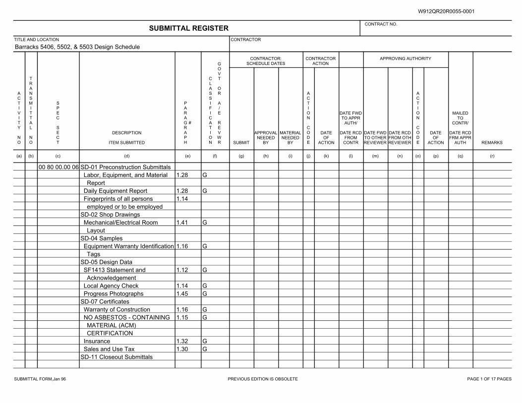
SUBMITTAL FORM,Jan 96 PREVIOUS EDITION IS OBSOLETE PAGE 1 OF 17 PAGES
Barracks 5406, 5502, & 5503 Design Schedule
00 80 00.00 06 SD-01 Preconstruction Submittals
1.28 GLabor, Equipment, and Material
Report
1.28 GDaily Equipment Report
1.14Fingerprints of all persons
employed or to be employed
SD-02 Shop Drawings
1.41 GMechanical/Electrical Room
Layout
SD-04 Samples
1.16 GEquipment Warranty Identification
Tags
SD-05 Design Data
1.12 GSF1413 Statement and
Acknowledgement
1.14 GLocal Agency Check
1.45 GProgress Photographs
SD-07 Certificates
1.16 GWarranty of Construction
1.15 GNO ASBESTOS - CONTAINING
MATERIAL (ACM)
CERTIFICATION
1.32 GInsurance
1.30 GSales and Use Tax
SD-11 Closeout Submittals
SUBMITTAL REGISTERCONTRACT NO.
TITLE AND LOCATION CONTRACTOR
CONTRACTOR:SCHEDULE DATES
CONTRACTORACTION
APPROVING AUTHORITY
ACTIVITY NO
TRANSMITTAL NO
SPEC SECT
DESCRIPTION
ITEM SUBMITTED
PARAGRAPH
#
CLASSIFICATION
GOVT OR A/E REVWR SUBMIT
APPROVALNEEDED
BY
MATERIALNEEDED
BY
ACTION CODE
DATEOF
ACTION
DATE FWDTO APPR
AUTH/
DATE RCDFROM
CONTR
DATE FWDTO OTHERREVIEWER
DATE RCDFROM OTHREVIEWER
ACTION CODE
DATEOF
ACTION
MAILEDTO
CONTR/
DATE RCDFRM APPR
AUTH REMARKS
(a) (b) (c) (d) (e) (f) (g) (h) (i) (j) (k) (l) (m) (n) (o) (p) (q) (r)
W912QR20R0055-0001
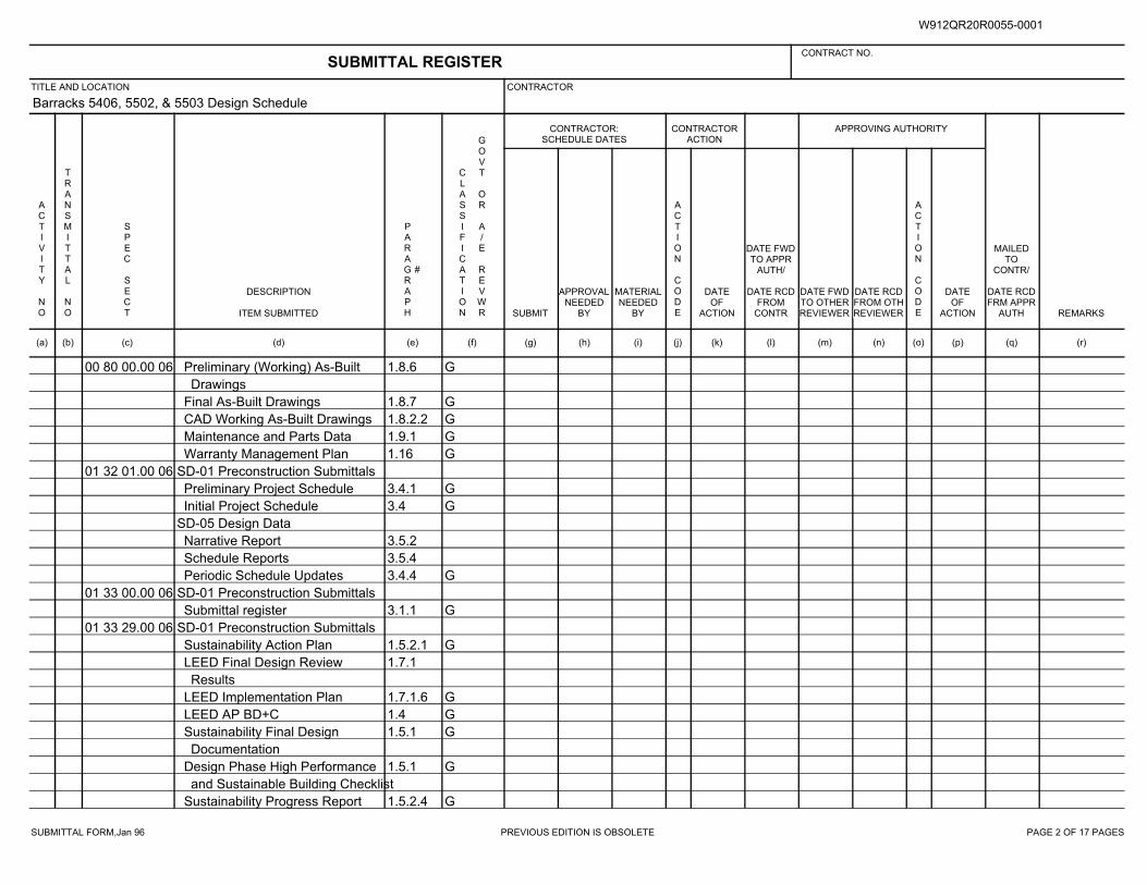
SUBMITTAL FORM,Jan 96 PREVIOUS EDITION IS OBSOLETE PAGE 2 OF 17 PAGES
Barracks 5406, 5502, & 5503 Design Schedule
00 80 00.00 06 1.8.6 GPreliminary (Working) As-Built
Drawings
1.8.7 GFinal As-Built Drawings
1.8.2.2 GCAD Working As-Built Drawings
1.9.1 GMaintenance and Parts Data
1.16 GWarranty Management Plan
01 32 01.00 06 SD-01 Preconstruction Submittals
3.4.1 GPreliminary Project Schedule
3.4 GInitial Project Schedule
SD-05 Design Data
3.5.2Narrative Report
3.5.4Schedule Reports
3.4.4 GPeriodic Schedule Updates
01 33 00.00 06 SD-01 Preconstruction Submittals
3.1.1 GSubmittal register
01 33 29.00 06 SD-01 Preconstruction Submittals
1.5.2.1 GSustainability Action Plan
1.7.1LEED Final Design Review
Results
1.7.1.6 GLEED Implementation Plan
1.4 GLEED AP BD+C
1.5.1 GSustainability Final Design
Documentation
1.5.1 GDesign Phase High Performance
and Sustainable Building Checklist
1.5.2.4 GSustainability Progress Report
SUBMITTAL REGISTERCONTRACT NO.
TITLE AND LOCATION CONTRACTOR
CONTRACTOR:SCHEDULE DATES
CONTRACTORACTION
APPROVING AUTHORITY
ACTIVITY NO
TRANSMITTAL NO
SPEC SECT
DESCRIPTION
ITEM SUBMITTED
PARAGRAPH
#
CLASSIFICATION
GOVT OR A/E REVWR SUBMIT
APPROVALNEEDED
BY
MATERIALNEEDED
BY
ACTION CODE
DATEOF
ACTION
DATE FWDTO APPR
AUTH/
DATE RCDFROM
CONTR
DATE FWDTO OTHERREVIEWER
DATE RCDFROM OTHREVIEWER
ACTION CODE
DATEOF
ACTION
MAILEDTO
CONTR/
DATE RCDFRM APPR
AUTH REMARKS
(a) (b) (c) (d) (e) (f) (g) (h) (i) (j) (k) (l) (m) (n) (o) (p) (q) (r)
W912QR20R0055-0001
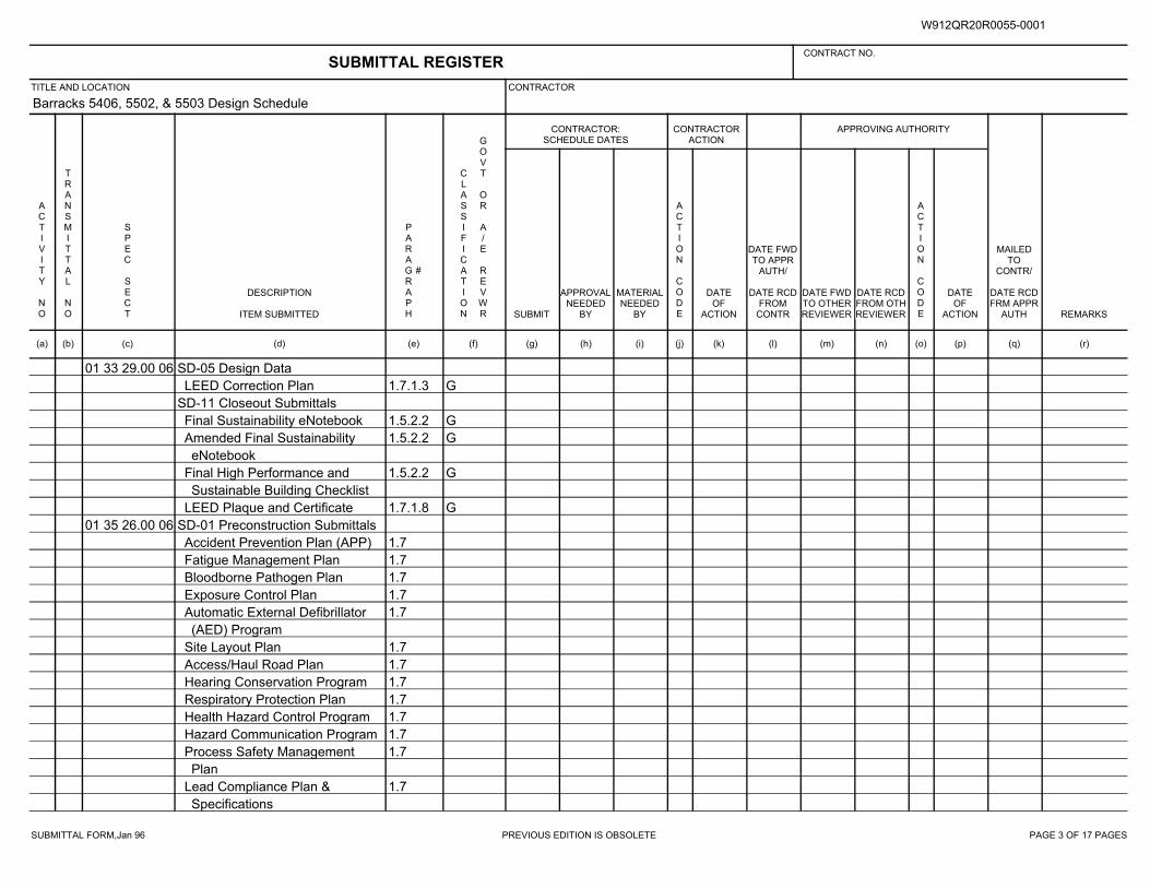
SUBMITTAL FORM,Jan 96 PREVIOUS EDITION IS OBSOLETE PAGE 3 OF 17 PAGES
Barracks 5406, 5502, & 5503 Design Schedule
01 33 29.00 06 SD-05 Design Data
1.7.1.3 GLEED Correction Plan
SD-11 Closeout Submittals
1.5.2.2 GFinal Sustainability eNotebook
1.5.2.2 GAmended Final Sustainability
eNotebook
1.5.2.2 GFinal High Performance and
Sustainable Building Checklist
1.7.1.8 GLEED Plaque and Certificate
01 35 26.00 06 SD-01 Preconstruction Submittals
1.7Accident Prevention Plan (APP)
1.7Fatigue Management Plan
1.7Bloodborne Pathogen Plan
1.7Exposure Control Plan
1.7Automatic External Defibrillator
(AED) Program
1.7Site Layout Plan
1.7Access/Haul Road Plan
1.7Hearing Conservation Program
1.7Respiratory Protection Plan
1.7Health Hazard Control Program
1.7Hazard Communication Program
1.7Process Safety Management
Plan
1.7Lead Compliance Plan &
Specifications
SUBMITTAL REGISTERCONTRACT NO.
TITLE AND LOCATION CONTRACTOR
CONTRACTOR:SCHEDULE DATES
CONTRACTORACTION
APPROVING AUTHORITY
ACTIVITY NO
TRANSMITTAL NO
SPEC SECT
DESCRIPTION
ITEM SUBMITTED
PARAGRAPH
#
CLASSIFICATION
GOVT OR A/E REVWR SUBMIT
APPROVALNEEDED
BY
MATERIALNEEDED
BY
ACTION CODE
DATEOF
ACTION
DATE FWDTO APPR
AUTH/
DATE RCDFROM
CONTR
DATE FWDTO OTHERREVIEWER
DATE RCDFROM OTHREVIEWER
ACTION CODE
DATEOF
ACTION
MAILEDTO
CONTR/
DATE RCDFRM APPR
AUTH REMARKS
(a) (b) (c) (d) (e) (f) (g) (h) (i) (j) (k) (l) (m) (n) (o) (p) (q) (r)
W912QR20R0055-0001
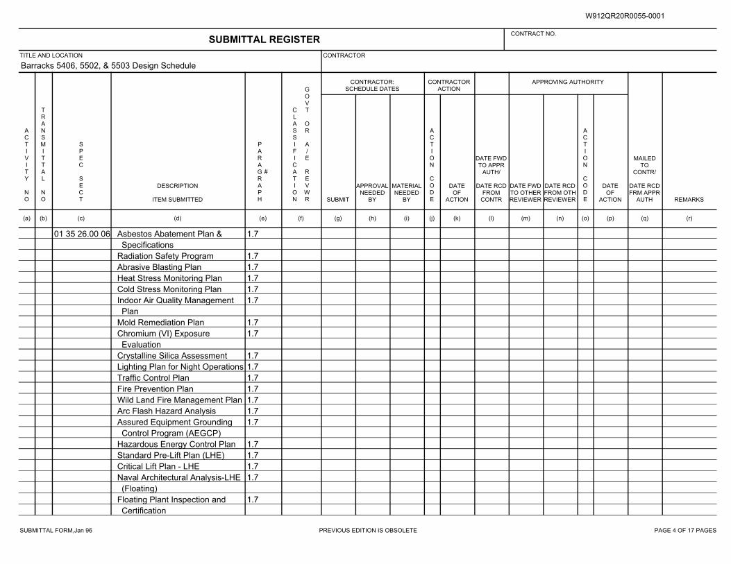
SUBMITTAL FORM,Jan 96 PREVIOUS EDITION IS OBSOLETE PAGE 4 OF 17 PAGES
Barracks 5406, 5502, & 5503 Design Schedule
01 35 26.00 06 1.7Asbestos Abatement Plan &
Specifications
1.7Radiation Safety Program
1.7Abrasive Blasting Plan
1.7Heat Stress Monitoring Plan
1.7Cold Stress Monitoring Plan
1.7Indoor Air Quality Management
Plan
1.7Mold Remediation Plan
1.7Chromium (VI) Exposure
Evaluation
1.7Crystalline Silica Assessment
1.7Lighting Plan for Night Operations
1.7Traffic Control Plan
1.7Fire Prevention Plan
1.7Wild Land Fire Management Plan
1.7Arc Flash Hazard Analysis
1.7Assured Equipment Grounding
Control Program (AEGCP)
1.7Hazardous Energy Control Plan
1.7Standard Pre-Lift Plan (LHE)
1.7Critical Lift Plan - LHE
1.7Naval Architectural Analysis-LHE
(Floating)
1.7Floating Plant Inspection and
Certification
SUBMITTAL REGISTERCONTRACT NO.
TITLE AND LOCATION CONTRACTOR
CONTRACTOR:SCHEDULE DATES
CONTRACTORACTION
APPROVING AUTHORITY
ACTIVITY NO
TRANSMITTAL NO
SPEC SECT
DESCRIPTION
ITEM SUBMITTED
PARAGRAPH
#
CLASSIFICATION
GOVT OR A/E REVWR SUBMIT
APPROVALNEEDED
BY
MATERIALNEEDED
BY
ACTION CODE
DATEOF
ACTION
DATE FWDTO APPR
AUTH/
DATE RCDFROM
CONTR
DATE FWDTO OTHERREVIEWER
DATE RCDFROM OTHREVIEWER
ACTION CODE
DATEOF
ACTION
MAILEDTO
CONTR/
DATE RCDFRM APPR
AUTH REMARKS
(a) (b) (c) (d) (e) (f) (g) (h) (i) (j) (k) (l) (m) (n) (o) (p) (q) (r)
W912QR20R0055-0001
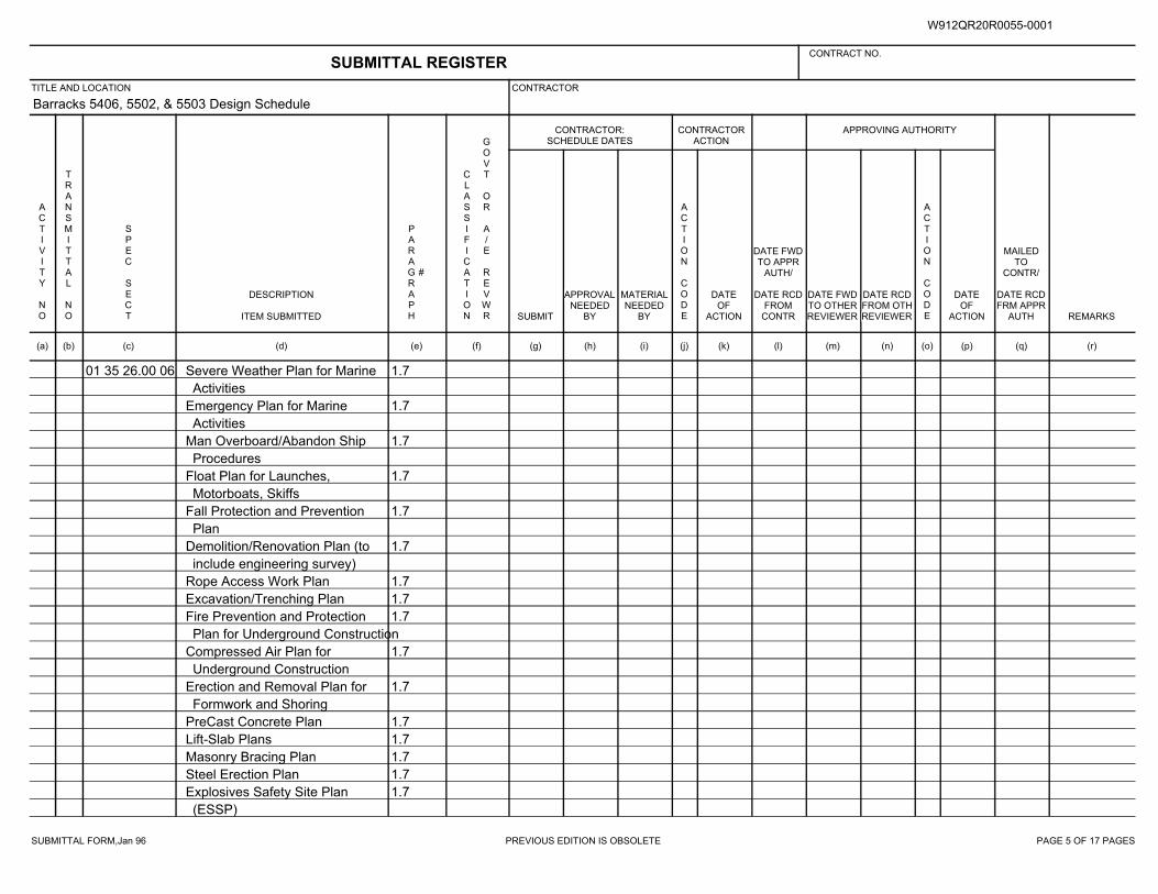
SUBMITTAL FORM,Jan 96 PREVIOUS EDITION IS OBSOLETE PAGE 5 OF 17 PAGES
Barracks 5406, 5502, & 5503 Design Schedule
01 35 26.00 06 1.7Severe Weather Plan for Marine
Activities
1.7Emergency Plan for Marine
Activities
1.7Man Overboard/Abandon Ship
Procedures
1.7Float Plan for Launches,
Motorboats, Skiffs
1.7Fall Protection and Prevention
Plan
1.7Demolition/Renovation Plan (to
include engineering survey)
1.7Rope Access Work Plan
1.7Excavation/Trenching Plan
1.7Fire Prevention and Protection
Plan for Underground Construction
1.7Compressed Air Plan for
Underground Construction
1.7Erection and Removal Plan for
Formwork and Shoring
1.7PreCast Concrete Plan
1.7Lift-Slab Plans
1.7Masonry Bracing Plan
1.7Steel Erection Plan
1.7Explosives Safety Site Plan
(ESSP)
SUBMITTAL REGISTERCONTRACT NO.
TITLE AND LOCATION CONTRACTOR
CONTRACTOR:SCHEDULE DATES
CONTRACTORACTION
APPROVING AUTHORITY
ACTIVITY NO
TRANSMITTAL NO
SPEC SECT
DESCRIPTION
ITEM SUBMITTED
PARAGRAPH
#
CLASSIFICATION
GOVT OR A/E REVWR SUBMIT
APPROVALNEEDED
BY
MATERIALNEEDED
BY
ACTION CODE
DATEOF
ACTION
DATE FWDTO APPR
AUTH/
DATE RCDFROM
CONTR
DATE FWDTO OTHERREVIEWER
DATE RCDFROM OTHREVIEWER
ACTION CODE
DATEOF
ACTION
MAILEDTO
CONTR/
DATE RCDFRM APPR
AUTH REMARKS
(a) (b) (c) (d) (e) (f) (g) (h) (i) (j) (k) (l) (m) (n) (o) (p) (q) (r)
W912QR20R0055-0001
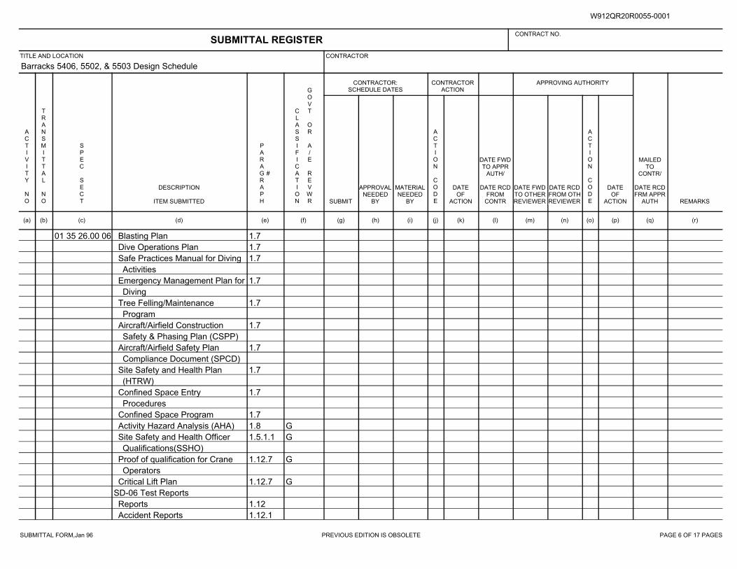
SUBMITTAL FORM,Jan 96 PREVIOUS EDITION IS OBSOLETE PAGE 6 OF 17 PAGES
Barracks 5406, 5502, & 5503 Design Schedule
01 35 26.00 06 1.7Blasting Plan
1.7Dive Operations Plan
1.7Safe Practices Manual for Diving
Activities
1.7Emergency Management Plan for
Diving
1.7Tree Felling/Maintenance
Program
1.7Aircraft/Airfield Construction
Safety & Phasing Plan (CSPP)
1.7Aircraft/Airfield Safety Plan
Compliance Document (SPCD)
1.7Site Safety and Health Plan
(HTRW)
1.7Confined Space Entry
Procedures
1.7Confined Space Program
1.8 GActivity Hazard Analysis (AHA)
1.5.1.1 GSite Safety and Health Officer
Qualifications(SSHO)
1.12.7 GProof of qualification for Crane
Operators
1.12.7 GCritical Lift Plan
SD-06 Test Reports
1.12Reports
1.12.1Accident Reports
SUBMITTAL REGISTERCONTRACT NO.
TITLE AND LOCATION CONTRACTOR
CONTRACTOR:SCHEDULE DATES
CONTRACTORACTION
APPROVING AUTHORITY
ACTIVITY NO
TRANSMITTAL NO
SPEC SECT
DESCRIPTION
ITEM SUBMITTED
PARAGRAPH
#
CLASSIFICATION
GOVT OR A/E REVWR SUBMIT
APPROVALNEEDED
BY
MATERIALNEEDED
BY
ACTION CODE
DATEOF
ACTION
DATE FWDTO APPR
AUTH/
DATE RCDFROM
CONTR
DATE FWDTO OTHERREVIEWER
DATE RCDFROM OTHREVIEWER
ACTION CODE
DATEOF
ACTION
MAILEDTO
CONTR/
DATE RCDFRM APPR
AUTH REMARKS
(a) (b) (c) (d) (e) (f) (g) (h) (i) (j) (k) (l) (m) (n) (o) (p) (q) (r)
W912QR20R0055-0001
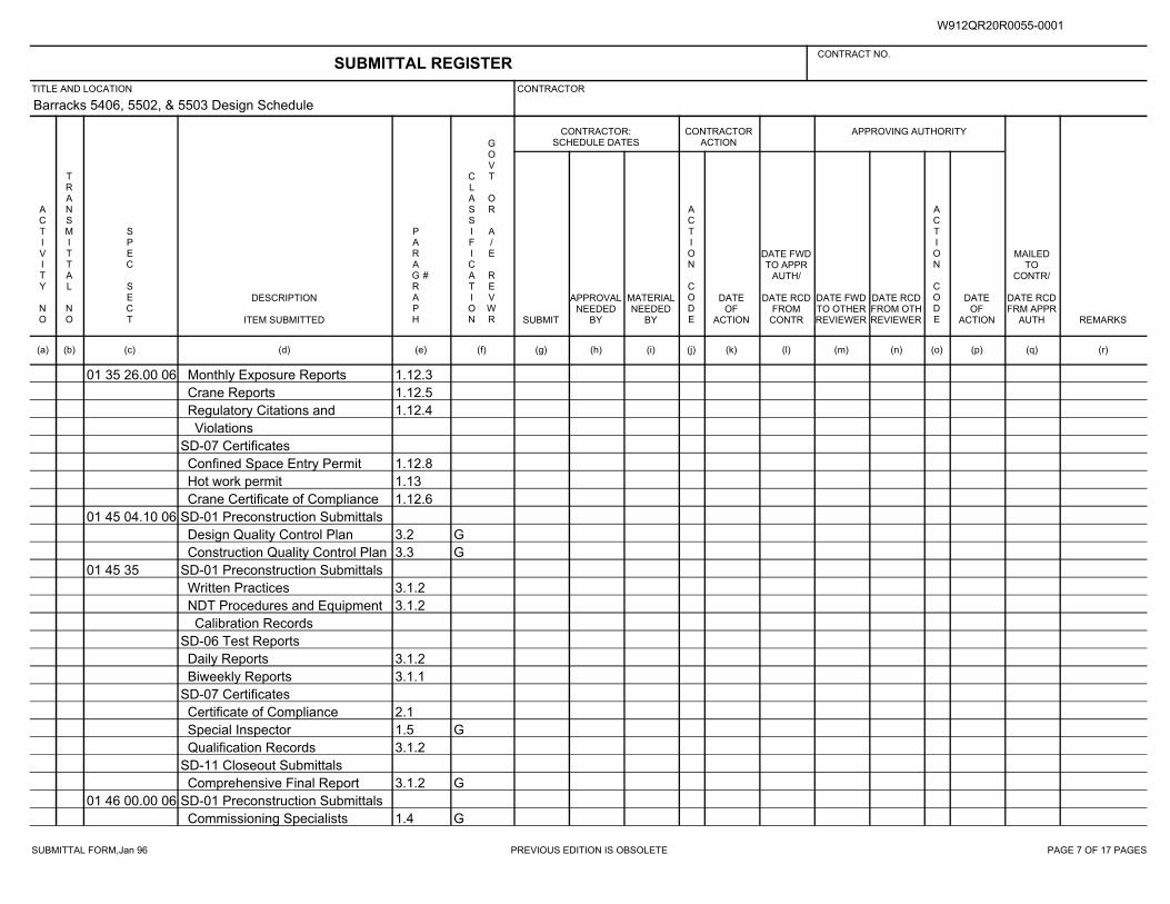
SUBMITTAL FORM,Jan 96 PREVIOUS EDITION IS OBSOLETE PAGE 7 OF 17 PAGES
Barracks 5406, 5502, & 5503 Design Schedule
01 35 26.00 06 1.12.3Monthly Exposure Reports
1.12.5Crane Reports
1.12.4Regulatory Citations and
Violations
SD-07 Certificates
1.12.8Confined Space Entry Permit
1.13Hot work permit
1.12.6Crane Certificate of Compliance
01 45 04.10 06 SD-01 Preconstruction Submittals
3.2 GDesign Quality Control Plan
3.3 GConstruction Quality Control Plan
01 45 35 SD-01 Preconstruction Submittals
3.1.2Written Practices
3.1.2NDT Procedures and Equipment
Calibration Records
SD-06 Test Reports
3.1.2Daily Reports
3.1.1Biweekly Reports
SD-07 Certificates
2.1Certificate of Compliance
1.5 GSpecial Inspector
3.1.2Qualification Records
SD-11 Closeout Submittals
3.1.2 GComprehensive Final Report
01 46 00.00 06 SD-01 Preconstruction Submittals
1.4 GCommissioning Specialists
SUBMITTAL REGISTERCONTRACT NO.
TITLE AND LOCATION CONTRACTOR
CONTRACTOR:SCHEDULE DATES
CONTRACTORACTION
APPROVING AUTHORITY
ACTIVITY NO
TRANSMITTAL NO
SPEC SECT
DESCRIPTION
ITEM SUBMITTED
PARAGRAPH
#
CLASSIFICATION
GOVT OR A/E REVWR SUBMIT
APPROVALNEEDED
BY
MATERIALNEEDED
BY
ACTION CODE
DATEOF
ACTION
DATE FWDTO APPR
AUTH/
DATE RCDFROM
CONTR
DATE FWDTO OTHERREVIEWER
DATE RCDFROM OTHREVIEWER
ACTION CODE
DATEOF
ACTION
MAILEDTO
CONTR/
DATE RCDFRM APPR
AUTH REMARKS
(a) (b) (c) (d) (e) (f) (g) (h) (i) (j) (k) (l) (m) (n) (o) (p) (q) (r)
W912QR20R0055-0001
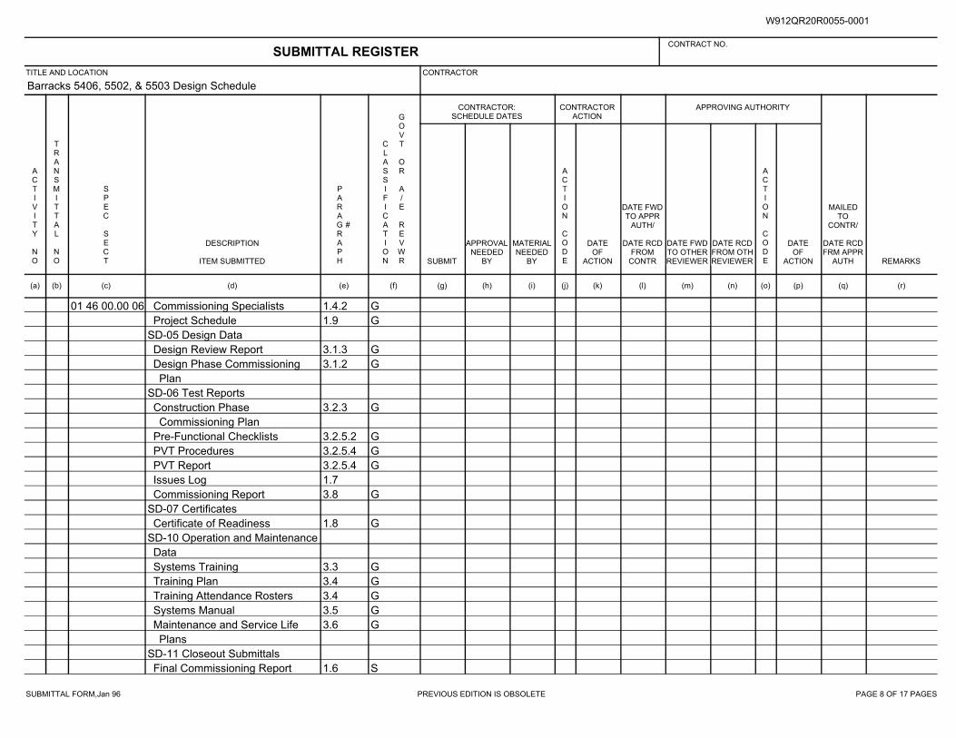
SUBMITTAL FORM,Jan 96 PREVIOUS EDITION IS OBSOLETE PAGE 8 OF 17 PAGES
Barracks 5406, 5502, & 5503 Design Schedule
01 46 00.00 06 1.4.2 GCommissioning Specialists
1.9 GProject Schedule
SD-05 Design Data
3.1.3 GDesign Review Report
3.1.2 GDesign Phase Commissioning
Plan
SD-06 Test Reports
3.2.3 GConstruction Phase
Commissioning Plan
3.2.5.2 GPre-Functional Checklists
3.2.5.4 GPVT Procedures
3.2.5.4 GPVT Report
1.7Issues Log
3.8 GCommissioning Report
SD-07 Certificates
1.8 GCertificate of Readiness
SD-10 Operation and Maintenance
Data
3.3 GSystems Training
3.4 GTraining Plan
3.4 GTraining Attendance Rosters
3.5 GSystems Manual
3.6 GMaintenance and Service Life
Plans
SD-11 Closeout Submittals
1.6 SFinal Commissioning Report
SUBMITTAL REGISTERCONTRACT NO.
TITLE AND LOCATION CONTRACTOR
CONTRACTOR:SCHEDULE DATES
CONTRACTORACTION
APPROVING AUTHORITY
ACTIVITY NO
TRANSMITTAL NO
SPEC SECT
DESCRIPTION
ITEM SUBMITTED
PARAGRAPH
#
CLASSIFICATION
GOVT OR A/E REVWR SUBMIT
APPROVALNEEDED
BY
MATERIALNEEDED
BY
ACTION CODE
DATEOF
ACTION
DATE FWDTO APPR
AUTH/
DATE RCDFROM
CONTR
DATE FWDTO OTHERREVIEWER
DATE RCDFROM OTHREVIEWER
ACTION CODE
DATEOF
ACTION
MAILEDTO
CONTR/
DATE RCDFRM APPR
AUTH REMARKS
(a) (b) (c) (d) (e) (f) (g) (h) (i) (j) (k) (l) (m) (n) (o) (p) (q) (r)
W912QR20R0055-0001
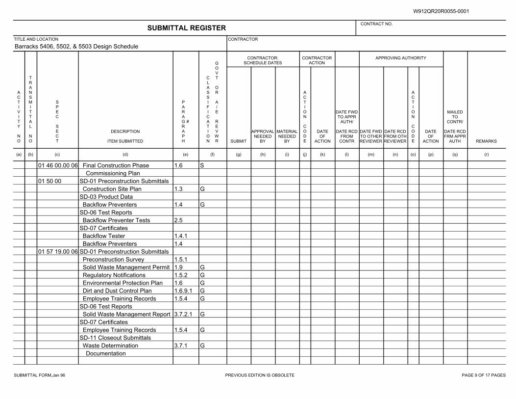
SUBMITTAL FORM,Jan 96 PREVIOUS EDITION IS OBSOLETE PAGE 9 OF 17 PAGES
Barracks 5406, 5502, & 5503 Design Schedule
01 46 00.00 06 1.6 SFinal Construction Phase
Commissioning Plan
01 50 00 SD-01 Preconstruction Submittals
1.3 GConstruction Site Plan
SD-03 Product Data
1.4 GBackflow Preventers
SD-06 Test Reports
2.5Backflow Preventer Tests
SD-07 Certificates
1.4.1Backflow Tester
1.4Backflow Preventers
01 57 19.00 06 SD-01 Preconstruction Submittals
1.5.1Preconstruction Survey
1.9 GSolid Waste Management Permit
1.5.2 GRegulatory Notifications
1.6 GEnvironmental Protection Plan
1.6.9.1 GDirt and Dust Control Plan
1.5.4 GEmployee Training Records
SD-06 Test Reports
3.7.2.1 GSolid Waste Management Report
SD-07 Certificates
1.5.4 GEmployee Training Records
SD-11 Closeout Submittals
3.7.1 GWaste Determination
Documentation
SUBMITTAL REGISTERCONTRACT NO.
TITLE AND LOCATION CONTRACTOR
CONTRACTOR:SCHEDULE DATES
CONTRACTORACTION
APPROVING AUTHORITY
ACTIVITY NO
TRANSMITTAL NO
SPEC SECT
DESCRIPTION
ITEM SUBMITTED
PARAGRAPH
#
CLASSIFICATION
GOVT OR A/E REVWR SUBMIT
APPROVALNEEDED
BY
MATERIALNEEDED
BY
ACTION CODE
DATEOF
ACTION
DATE FWDTO APPR
AUTH/
DATE RCDFROM
CONTR
DATE FWDTO OTHERREVIEWER
DATE RCDFROM OTHREVIEWER
ACTION CODE
DATEOF
ACTION
MAILEDTO
CONTR/
DATE RCDFRM APPR
AUTH REMARKS
(a) (b) (c) (d) (e) (f) (g) (h) (i) (j) (k) (l) (m) (n) (o) (p) (q) (r)
W912QR20R0055-0001
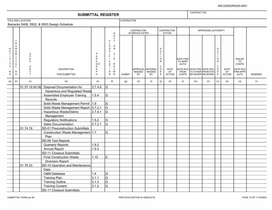
SUBMITTAL FORM,Jan 96 PREVIOUS EDITION IS OBSOLETE PAGE 10 OF 17 PAGES
Barracks 5406, 5502, & 5503 Design Schedule
01 57 19.00 06 3.7.4.6 GDisposal Documentation for
Hazardous and Regulated Waste
1.5.4 GAssembled Employee Training
Records
1.9 GSolid Waste Management Permit
3.7.2.1 GSolid Waste Management Report
3.7.4.1 GHazardous Waste/Debris
Management
1.5.2 GRegulatory Notifications
3.7.2.1 GSales Documentation
01 74 19 SD-01 Preconstruction Submittals
1.7 GConstruction Waste Management
Plan
SD-06 Test Reports
1.9.2Quarterly Reports
1.9.3Annual Report
SD-11 Closeout Submittals
1.10 SFinal Construction Waste
Diversion Report
01 78 23 SD-10 Operation and Maintenance
Data
1.4 GO&M Database
3.1.1 GTraining Plan
3.1.3 GTraining Outline
3.1.2 GTraining Content
SD-11 Closeout Submittals
SUBMITTAL REGISTERCONTRACT NO.
TITLE AND LOCATION CONTRACTOR
CONTRACTOR:SCHEDULE DATES
CONTRACTORACTION
APPROVING AUTHORITY
ACTIVITY NO
TRANSMITTAL NO
SPEC SECT
DESCRIPTION
ITEM SUBMITTED
PARAGRAPH
#
CLASSIFICATION
GOVT OR A/E REVWR SUBMIT
APPROVALNEEDED
BY
MATERIALNEEDED
BY
ACTION CODE
DATEOF
ACTION
DATE FWDTO APPR
AUTH/
DATE RCDFROM
CONTR
DATE FWDTO OTHERREVIEWER
DATE RCDFROM OTHREVIEWER
ACTION CODE
DATEOF
ACTION
MAILEDTO
CONTR/
DATE RCDFRM APPR
AUTH REMARKS
(a) (b) (c) (d) (e) (f) (g) (h) (i) (j) (k) (l) (m) (n) (o) (p) (q) (r)
W912QR20R0055-0001
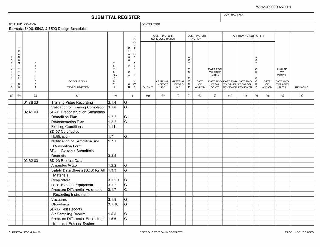
SUBMITTAL FORM,Jan 96 PREVIOUS EDITION IS OBSOLETE PAGE 11 OF 17 PAGES
Barracks 5406, 5502, & 5503 Design Schedule
01 78 23 3.1.4 GTraining Video Recording
3.1.6 GValidation of Training Completion
02 41 00 SD-01 Preconstruction Submittals
1.2.2 GDemolition Plan
1.2.2 GDeconstruction Plan
1.11Existing Conditions
SD-07 Certificates
1.7 GNotification
1.7.1Notification of Demolition and
Renovation Form
SD-11 Closeout Submittals
3.3.5Receipts
02 82 00 SD-03 Product Data
1.2.2 GAmended Water
1.3.9 GSafety Data Sheets (SDS) for All
Materials
3.1.2.1 GRespirators
3.1.7 GLocal Exhaust Equipment
3.1.7 GPressure Differential Automatic
Recording Instrument
3.1.8 GVacuums
3.1.10 GGlovebags
SD-06 Test Reports
1.5.5 GAir Sampling Results
1.5.6 GPressure Differential Recordings
for Local Exhaust System
SUBMITTAL REGISTERCONTRACT NO.
TITLE AND LOCATION CONTRACTOR
CONTRACTOR:SCHEDULE DATES
CONTRACTORACTION
APPROVING AUTHORITY
ACTIVITY NO
TRANSMITTAL NO
SPEC SECT
DESCRIPTION
ITEM SUBMITTED
PARAGRAPH
#
CLASSIFICATION
GOVT OR A/E REVWR SUBMIT
APPROVALNEEDED
BY
MATERIALNEEDED
BY
ACTION CODE
DATEOF
ACTION
DATE FWDTO APPR
AUTH/
DATE RCDFROM
CONTR
DATE FWDTO OTHERREVIEWER
DATE RCDFROM OTHREVIEWER
ACTION CODE
DATEOF
ACTION
MAILEDTO
CONTR/
DATE RCDFRM APPR
AUTH REMARKS
(a) (b) (c) (d) (e) (f) (g) (h) (i) (j) (k) (l) (m) (n) (o) (p) (q) (r)
W912QR20R0055-0001
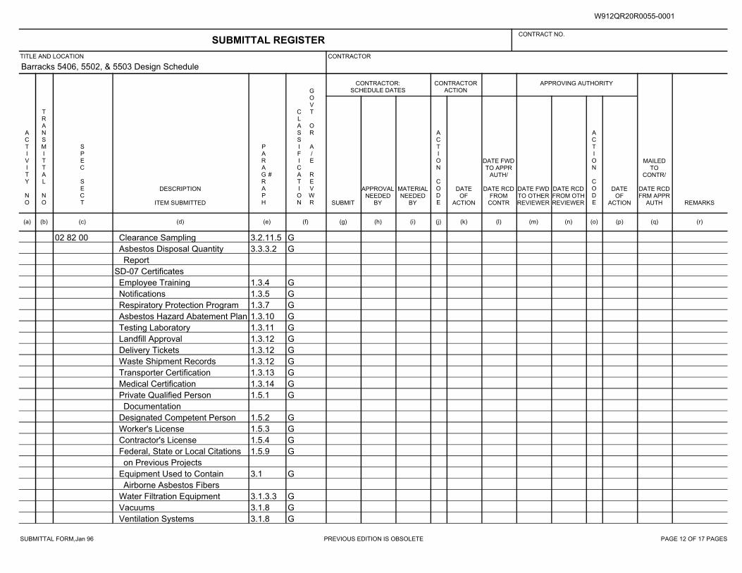
SUBMITTAL FORM,Jan 96 PREVIOUS EDITION IS OBSOLETE PAGE 12 OF 17 PAGES
Barracks 5406, 5502, & 5503 Design Schedule
02 82 00 3.2.11.5 GClearance Sampling
3.3.3.2 GAsbestos Disposal Quantity
Report
SD-07 Certificates
1.3.4 GEmployee Training
1.3.5 GNotifications
1.3.7 GRespiratory Protection Program
1.3.10 GAsbestos Hazard Abatement Plan
1.3.11 GTesting Laboratory
1.3.12 GLandfill Approval
1.3.12 GDelivery Tickets
1.3.12 GWaste Shipment Records
1.3.13 GTransporter Certification
1.3.14 GMedical Certification
1.5.1 GPrivate Qualified Person
Documentation
1.5.2 GDesignated Competent Person
1.5.3 GWorker's License
1.5.4 GContractor's License
1.5.9 GFederal, State or Local Citations
on Previous Projects
3.1 GEquipment Used to Contain
Airborne Asbestos Fibers
3.1.3.3 GWater Filtration Equipment
3.1.8 GVacuums
3.1.8 GVentilation Systems
SUBMITTAL REGISTERCONTRACT NO.
TITLE AND LOCATION CONTRACTOR
CONTRACTOR:SCHEDULE DATES
CONTRACTORACTION
APPROVING AUTHORITY
ACTIVITY NO
TRANSMITTAL NO
SPEC SECT
DESCRIPTION
ITEM SUBMITTED
PARAGRAPH
#
CLASSIFICATION
GOVT OR A/E REVWR SUBMIT
APPROVALNEEDED
BY
MATERIALNEEDED
BY
ACTION CODE
DATEOF
ACTION
DATE FWDTO APPR
AUTH/
DATE RCDFROM
CONTR
DATE FWDTO OTHERREVIEWER
DATE RCDFROM OTHREVIEWER
ACTION CODE
DATEOF
ACTION
MAILEDTO
CONTR/
DATE RCDFRM APPR
AUTH REMARKS
(a) (b) (c) (d) (e) (f) (g) (h) (i) (j) (k) (l) (m) (n) (o) (p) (q) (r)
W912QR20R0055-0001
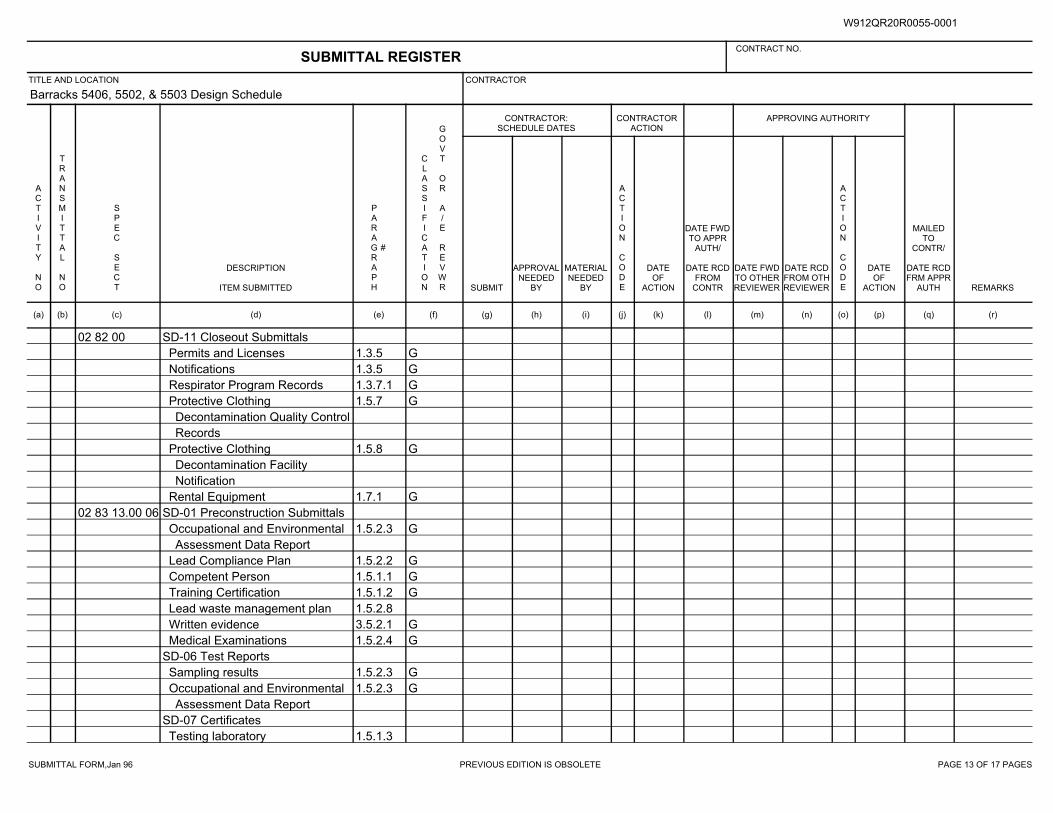
SUBMITTAL FORM,Jan 96 PREVIOUS EDITION IS OBSOLETE PAGE 13 OF 17 PAGES
Barracks 5406, 5502, & 5503 Design Schedule
02 82 00 SD-11 Closeout Submittals
1.3.5 GPermits and Licenses
1.3.5 GNotifications
1.3.7.1 GRespirator Program Records
1.5.7 GProtective Clothing
Decontamination Quality Control
Records
1.5.8 GProtective Clothing
Decontamination Facility
Notification
1.7.1 GRental Equipment
02 83 13.00 06 SD-01 Preconstruction Submittals
1.5.2.3 GOccupational and Environmental
Assessment Data Report
1.5.2.2 GLead Compliance Plan
1.5.1.1 GCompetent Person
1.5.1.2 GTraining Certification
1.5.2.8Lead waste management plan
3.5.2.1 GWritten evidence
1.5.2.4 GMedical Examinations
SD-06 Test Reports
1.5.2.3 GSampling results
1.5.2.3 GOccupational and Environmental
Assessment Data Report
SD-07 Certificates
1.5.1.3Testing laboratory
SUBMITTAL REGISTERCONTRACT NO.
TITLE AND LOCATION CONTRACTOR
CONTRACTOR:SCHEDULE DATES
CONTRACTORACTION
APPROVING AUTHORITY
ACTIVITY NO
TRANSMITTAL NO
SPEC SECT
DESCRIPTION
ITEM SUBMITTED
PARAGRAPH
#
CLASSIFICATION
GOVT OR A/E REVWR SUBMIT
APPROVALNEEDED
BY
MATERIALNEEDED
BY
ACTION CODE
DATEOF
ACTION
DATE FWDTO APPR
AUTH/
DATE RCDFROM
CONTR
DATE FWDTO OTHERREVIEWER
DATE RCDFROM OTHREVIEWER
ACTION CODE
DATEOF
ACTION
MAILEDTO
CONTR/
DATE RCDFRM APPR
AUTH REMARKS
(a) (b) (c) (d) (e) (f) (g) (h) (i) (j) (k) (l) (m) (n) (o) (p) (q) (r)
W912QR20R0055-0001
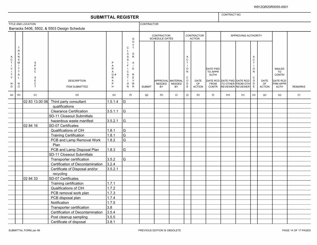
SUBMITTAL FORM,Jan 96 PREVIOUS EDITION IS OBSOLETE PAGE 14 OF 17 PAGES
Barracks 5406, 5502, & 5503 Design Schedule
02 83 13.00 06 1.5.1.4 GThird party consultant
qualifications
3.5.1.1 GClearance Certification
SD-11 Closeout Submittals
3.5.2.1 Ghazardous waste manifest
02 84 16 SD-07 Certificates
1.8.1 GQualifications of CIH
1.8.1 GTraining Certification
1.8.2 GPCB and Lamp Removal Work
Plan
1.8.3 GPCB and Lamp Disposal Plan
SD-11 Closeout Submittals
3.5.2 GTransporter certification
3.2.4Certification of Decontamination
3.5.2.1Certificate of Disposal and/or
recycling
02 84 33 SD-07 Certificates
1.7.1Training certification
1.7.2Qualifications of CIH
1.7.3PCB removal work plan
1.7.4PCB disposal plan
1.7.5Notification
3.8Transporter certification
3.5.4Certification of Decontamination
3.5.5Post cleanup sampling
3.8.1Certificate of disposal
SUBMITTAL REGISTERCONTRACT NO.
TITLE AND LOCATION CONTRACTOR
CONTRACTOR:SCHEDULE DATES
CONTRACTORACTION
APPROVING AUTHORITY
ACTIVITY NO
TRANSMITTAL NO
SPEC SECT
DESCRIPTION
ITEM SUBMITTED
PARAGRAPH
#
CLASSIFICATION
GOVT OR A/E REVWR SUBMIT
APPROVALNEEDED
BY
MATERIALNEEDED
BY
ACTION CODE
DATEOF
ACTION
DATE FWDTO APPR
AUTH/
DATE RCDFROM
CONTR
DATE FWDTO OTHERREVIEWER
DATE RCDFROM OTHREVIEWER
ACTION CODE
DATEOF
ACTION
MAILEDTO
CONTR/
DATE RCDFRM APPR
AUTH REMARKS
(a) (b) (c) (d) (e) (f) (g) (h) (i) (j) (k) (l) (m) (n) (o) (p) (q) (r)
W912QR20R0055-0001
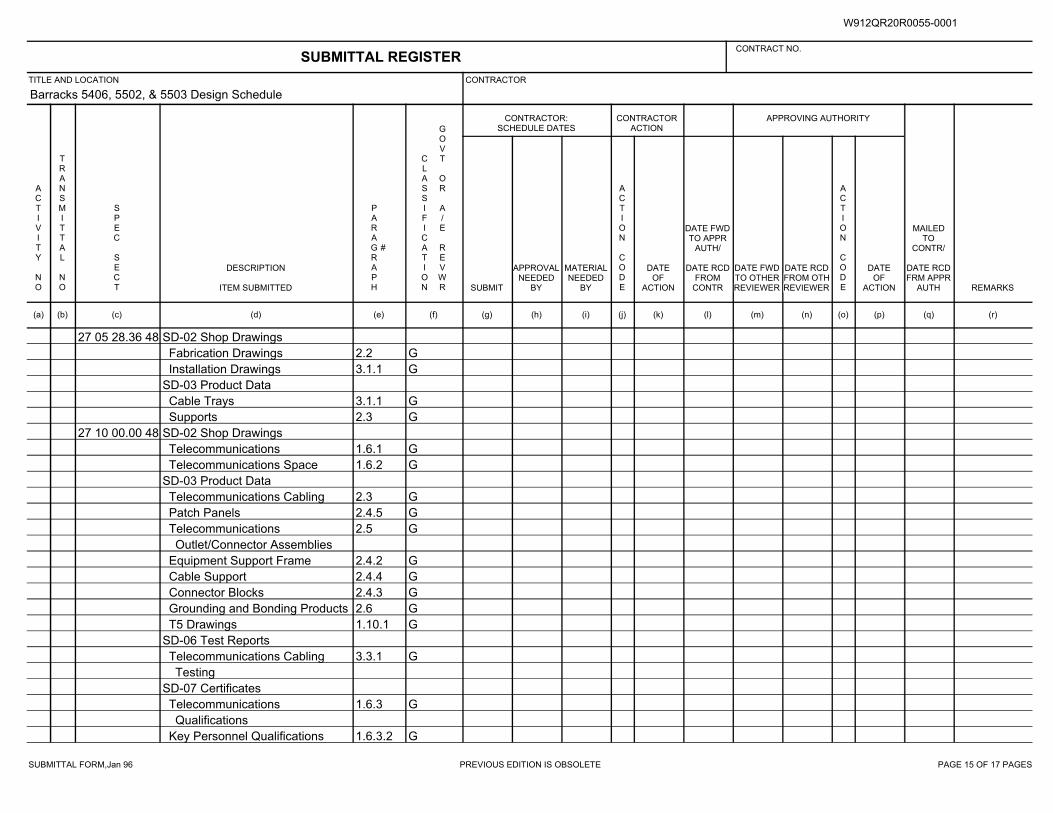
SUBMITTAL FORM,Jan 96 PREVIOUS EDITION IS OBSOLETE PAGE 15 OF 17 PAGES
Barracks 5406, 5502, & 5503 Design Schedule
27 05 28.36 48 SD-02 Shop Drawings
2.2 GFabrication Drawings
3.1.1 GInstallation Drawings
SD-03 Product Data
3.1.1 GCable Trays
2.3 GSupports
27 10 00.00 48 SD-02 Shop Drawings
1.6.1 GTelecommunications
1.6.2 GTelecommunications Space
SD-03 Product Data
2.3 GTelecommunications Cabling
2.4.5 GPatch Panels
2.5 GTelecommunications
Outlet/Connector Assemblies
2.4.2 GEquipment Support Frame
2.4.4 GCable Support
2.4.3 GConnector Blocks
2.6 GGrounding and Bonding Products
1.10.1 GT5 Drawings
SD-06 Test Reports
3.3.1 GTelecommunications Cabling
Testing
SD-07 Certificates
1.6.3 GTelecommunications
Qualifications
1.6.3.2 GKey Personnel Qualifications
SUBMITTAL REGISTERCONTRACT NO.
TITLE AND LOCATION CONTRACTOR
CONTRACTOR:SCHEDULE DATES
CONTRACTORACTION
APPROVING AUTHORITY
ACTIVITY NO
TRANSMITTAL NO
SPEC SECT
DESCRIPTION
ITEM SUBMITTED
PARAGRAPH
#
CLASSIFICATION
GOVT OR A/E REVWR SUBMIT
APPROVALNEEDED
BY
MATERIALNEEDED
BY
ACTION CODE
DATEOF
ACTION
DATE FWDTO APPR
AUTH/
DATE RCDFROM
CONTR
DATE FWDTO OTHERREVIEWER
DATE RCDFROM OTHREVIEWER
ACTION CODE
DATEOF
ACTION
MAILEDTO
CONTR/
DATE RCDFRM APPR
AUTH REMARKS
(a) (b) (c) (d) (e) (f) (g) (h) (i) (j) (k) (l) (m) (n) (o) (p) (q) (r)
W912QR20R0055-0001
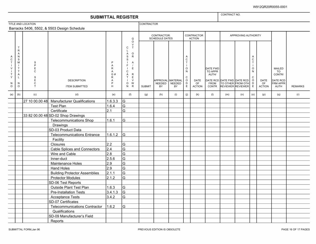
SUBMITTAL FORM,Jan 96 PREVIOUS EDITION IS OBSOLETE PAGE 16 OF 17 PAGES
Barracks 5406, 5502, & 5503 Design Schedule
27 10 00.00 48 1.6.3.3 GManufacturer Qualifications
1.6.4 GTest Plan
2.1 GCertificate
33 82 00.00 48 SD-02 Shop Drawings
1.6.1 GTelecommunications Shop
Drawings
SD-03 Product Data
1.6.1.2 GTelecommunications Entrance
Facility
2.2 GClosures
2.4 GCable Splices and Connectors
2.8 GWire and Cable
2.5.6 GInner-duct
2.9 GMaintenance Holes
2.9 GHand Holes
2.1.1 GBuilding Protector Assemblies
2.1.2 GProtector Modules
SD-06 Test Reports
1.6.3 GOutside Plant Test Plan
3.4.1.3 GPre-Installation Tests
3.4.2 GAcceptance Tests
SD-07 Certificates
1.6.2 GTelecommunications Contractor
Qualifications
SD-09 Manufacturer’s Field
Reports
SUBMITTAL REGISTERCONTRACT NO.
TITLE AND LOCATION CONTRACTOR
CONTRACTOR:SCHEDULE DATES
CONTRACTORACTION
APPROVING AUTHORITY
ACTIVITY NO
TRANSMITTAL NO
SPEC SECT
DESCRIPTION
ITEM SUBMITTED
PARAGRAPH
#
CLASSIFICATION
GOVT OR A/E REVWR SUBMIT
APPROVALNEEDED
BY
MATERIALNEEDED
BY
ACTION CODE
DATEOF
ACTION
DATE FWDTO APPR
AUTH/
DATE RCDFROM
CONTR
DATE FWDTO OTHERREVIEWER
DATE RCDFROM OTHREVIEWER
ACTION CODE
DATEOF
ACTION
MAILEDTO
CONTR/
DATE RCDFRM APPR
AUTH REMARKS
(a) (b) (c) (d) (e) (f) (g) (h) (i) (j) (k) (l) (m) (n) (o) (p) (q) (r)
W912QR20R0055-0001
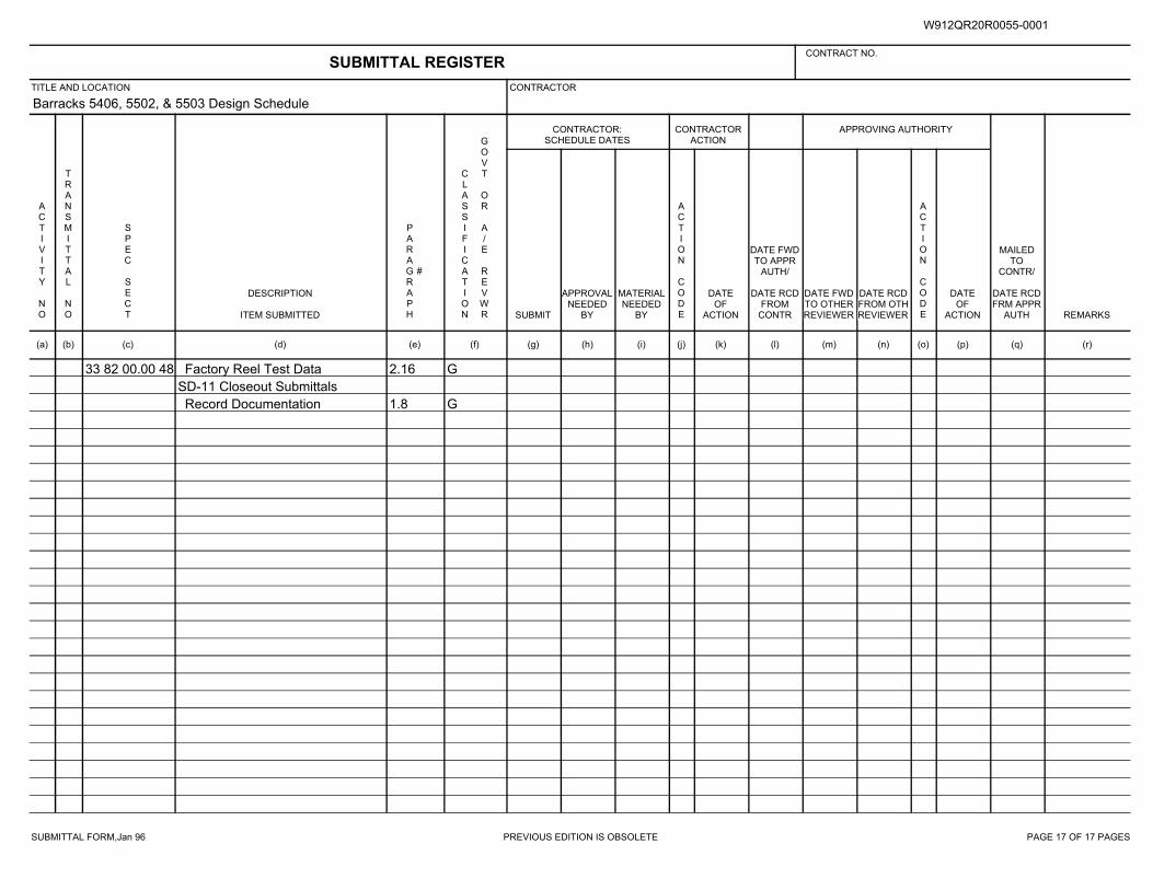
SUBMITTAL FORM,Jan 96 PREVIOUS EDITION IS OBSOLETE PAGE 17 OF 17 PAGES
Barracks 5406, 5502, & 5503 Design Schedule
33 82 00.00 48 2.16 GFactory Reel Test Data
SD-11 Closeout Submittals
1.8 GRecord Documentation
SUBMITTAL REGISTERCONTRACT NO.
TITLE AND LOCATION CONTRACTOR
CONTRACTOR:SCHEDULE DATES
CONTRACTORACTION
APPROVING AUTHORITY
ACTIVITY NO
TRANSMITTAL NO
SPEC SECT
DESCRIPTION
ITEM SUBMITTED
PARAGRAPH
#
CLASSIFICATION
GOVT OR A/E REVWR SUBMIT
APPROVALNEEDED
BY
MATERIALNEEDED
BY
ACTION CODE
DATEOF
ACTION
DATE FWDTO APPR
AUTH/
DATE RCDFROM
CONTR
DATE FWDTO OTHERREVIEWER
DATE RCDFROM OTHREVIEWER
ACTION CODE
DATEOF
ACTION
MAILEDTO
CONTR/
DATE RCDFRM APPR
AUTH REMARKS
(a) (b) (c) (d) (e) (f) (g) (h) (i) (j) (k) (l) (m) (n) (o) (p) (q) (r)
W912QR20R0055-0001
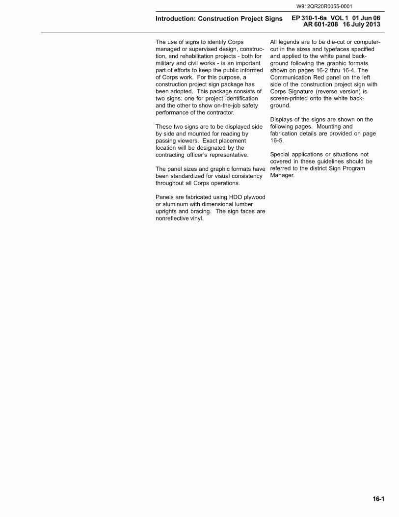
Introduction: Construction Project Signs EP 310-1-6a VOL 1 01 Jun 06 AR 601-208 16 July 2013
16-1
The use of signs to identify Corpsmanaged or supervised design, construc-tion, and rehabilitation projects - both formilitary and civil works - is an importantpart of efforts to keep the public informedof Corps work. For this purpose, aconstruction project sign package hasbeen adopted. This package consists oftwo signs: one for project identificationand the other to show on-the-job safetyperformance of the contractor.
These two signs are to be displayed sideby side and mounted for reading bypassing viewers. Exact placementlocation will be designated by thecontracting officer’s representative.
The panel sizes and graphic formats havebeen standardized for visual consistencythroughout all Corps operations.
Panels are fabricated using HDO plywoodor aluminum with dimensional lumberuprights and bracing. The sign faces arenonreflective vinyl.
All legends are to be die-cut or computer-cut in the sizes and typefaces specified and applied to the white panel back-ground following the graphic formats shown on pages 16-2 thru 16-4. The Communication Red panel on the left side of the construction project sign with Corps Signature (reverse version) is screen-printed onto the white back-ground.
Displays of the signs are shown on the following pages. Mounting and fabrication details are provided on page 16-5.
Special applications or situations not covered in these guidelines should be referred to the district Sign Program Manager.
W912QR20R0055-0001
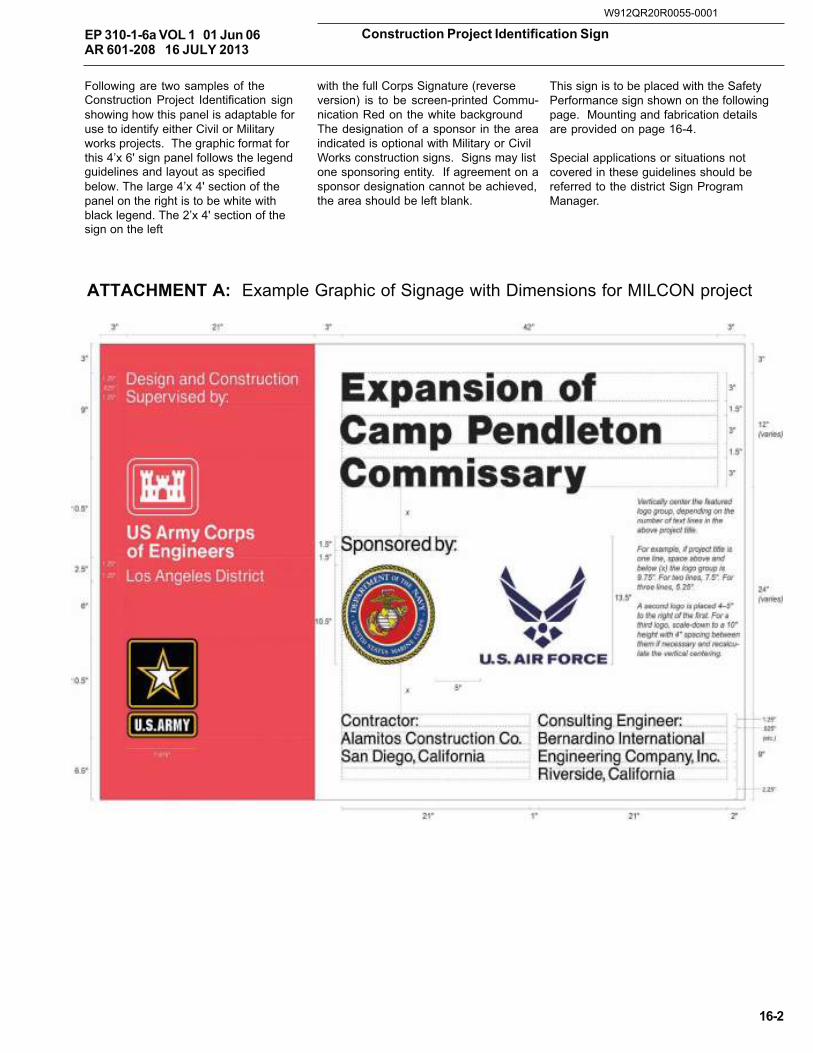
Construction Project Identification Sign
16-2
EP 310-1-6a VOL 1 01 Jun 06 AR 601-208 16 JULY 2013
with the full Corps Signature (reverseversion) is to be screen-printed Commu-nication Red on the white backgroundThe designation of a sponsor in the areaindicated is optional with Military or CivilWorks construction signs. Signs may listone sponsoring entity. If agreement on asponsor designation cannot be achieved,the area should be left blank.
This sign is to be placed with the SafetyPerformance sign shown on the followingpage. Mounting and fabrication detailsare provided on page 16-4.
Special applications or situations notcovered in these guidelines should bereferred to the district Sign ProgramManager.
Following are two samples of the Construction Project Identification sign showing how this panel is adaptable for use to identify either Civil or Military works projects. The graphic format for this 4’x 6' sign panel follows the legend guidelines and layout as specified below. The large 4’x 4' section of the panel on the right is to be white with black legend. The 2’x 4' section of the sign on the left
ATTACHMENT A: Example Graphic of Signage with Dimensions for MILCON project
W912QR20R0055-0001
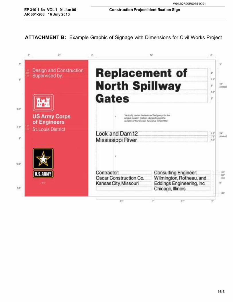
Construction Project Identification Sign
16-3
EP 310-1-6a VOL 1 01 Jun 06AR 601-208 16 July 2013
ATTACHMENT B: Example Graphic of Signage with Dimensions for Civil Works Project
W912QR20R0055-0001
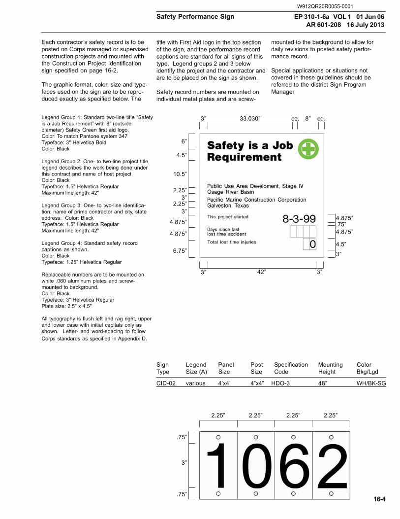
Safety Performance Sign EP 310-1-6a VOL 1 01 Jun 06AR 601-208 16 July 2013
16-4
Each contractor’s safety record is to beposted on Corps managed or supervisedconstruction projects and mounted withthe Construction Project Identificationsign specified on page 16-2.
The graphic format, color, size and type-faces used on the sign are to be repro-duced exactly as specified below. The
title with First Aid logo in the top sectionof the sign, and the performance recordcaptions are standard for all signs of thistype. Legend groups 2 and 3 belowidentify the project and the contractor andare to be placed on the sign as shown.
Safety record numbers are mounted onindividual metal plates and are screw-
mounted to the background to allow fordaily revisions to posted safety perfor-mance record.
Special applications or situations notcovered in these guidelines should bereferred to the district Sign ProgramManager.
Legend Group 1: Standard two-line title “Safetyis a Job Requirement” with 8” (outsidediameter) Safety Green first aid logo.Color: To match Pantone system 347Typeface: 3" Helvetica BoldColor: Black
Legend Group 2: One- to two-line project titlelegend describes the work being done underthis contract and name of host project.Color: BlackTypeface: 1.5" Helvetica RegularMaximum line length: 42"
Legend Group 3: One- to two-line identifica-tion: name of prime contractor and city, stateaddress. Color: BlackTypeface: 1.5" Helvetica RegularMaximum line length: 42"
Legend Group 4: Standard safety recordcaptions as shown.Color: BlackTypeface: 1.25” Helvetica Regular
Replaceable numbers are to be mounted onwhite .060 aluminum plates and screw-mounted to background.Color: BlackTypeface: 3" Helvetica RegularPlate size: 2.5" x 4.5"
All typography is flush left and rag right, upperand lower case with initial capitals only asshown. Letter- and word-spacing to followCorps standards as specified in Appendix D.
3” 33.030” eq. 8” eq.
6”
4.5”
10.5”
2.25”3”
2.25”3”
4.875”
4.875”
6.75”
4.875”.75”4.875”
4.5”
3”
3” 42” 3”
2.25” 2.25” 2.25” 2.25”
.75”
3”
.75”
Sign Legend Panel Post Specification Mounting ColorType Size (A) Size Size Code Height Bkg/Lgd
CID-02 various 4’x4’ 4”x4” HDO-3 48” WH/BK-SG
W912QR20R0055-0001
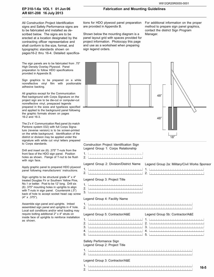
Fabrication and Mounting GuidelinesEP 310-1-6a VOL 1 01 Jun 06AR 601-208 16 July 2013
16-5
tions for HDO plywood panel preparationare provided in Appendix B.
Shown below the mounting diagram is apanel layout grid with spaces provided forproject information. Photocopy this pageand use as a worksheet when preparingsign legend orders.
For additional information on the propermethod to prepare sign panel graphics,contact the district Sign ProgramManager.
All Construction Project Identification signs and Safety Performance signs are to be fabricated and installed as de-scribed below. The signs are to be erected at a location designated by the contracting officer representative and shall conform to the size, format, and typographic standards shown on pages16-2 thru 16-4. Detailed specifica-
The sign panels are to be fabricated from .75" High Density Overlay Plywood. Panel preparation to follow HDO specifications provided in Appendix B.
Sign graphics to be prepared on a white nonreflective vinyl film with positionable adhesive backing.
All graphics except for the Communication Red background with Corps Signature on the project sign are to be die-cut or computer-cut nonreflective vinyl, prespaced legends prepared in the sizes and typefaces specified and applied to the background panel following the graphic formats shown on pages16-2 and 16-3.
The 2’x 4’ Communication Red panel (to match Pantone system 032) with full Corps Signa-ture (reverse version) is to be screen-printed on the white background. Identification of the district or division may be applied under the signature with white cut vinyl letters prepared to Corps standards.
Drill and insert six (6) .375" T-nuts from the front face of the HDO sign panel. Position holes as shown. Flange of T-nut to be flush with sign face.
Apply graphic panel to prepared HDO plywood panel following manufacturers’ instructions.
Sign uprights to be structural grade 4" x 4" treated Douglas Fir or Southern Yellow Pine, No.1 or better. Post to be 12' long. Drill six (6) .375" mounting holes in uprights to align with T-nuts in sign panel. Countersink (.5") back of hole to accept socket head cap screw (4" x .375").
Assemble sign panel and uprights. Imbed assembled sign panel and uprights in 4' hole. Local soil conditions and/or wind loading may require bolting additional 2" x 4" struts on inside face of uprights to reinforce installation as shown.
48”
48”
18”
Construction Project Identification SignLegend Group 1: Corps Relationship1.2.
Legend Group 2: Division/District Name1.2.
Legend Group 3: Project Title1.2.3.
Legend Group 4: Facility Name1.2.
Legend Group 5: Contractor/A&E1.2.3.4.5.
Safety Performance SignLegend Group 2: Project Title1.2.
Legend Group 3: Contractor/A&E1.2.
Legend Group 2a: Military/Civil Works Sponsor1.2.
Legend Group 5b: Contractor/A&E1.2.3.4.5.
W912QR20R0055-0001
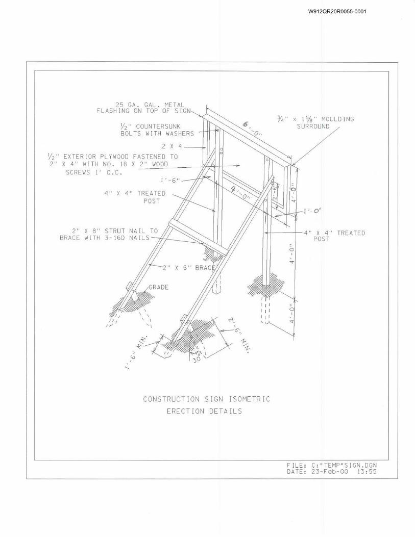
W912QR20R0055-0001
Building 5502, Barracks D/B FFR P2 #481648 Joint Base McGuire-Dix-Lakehurst, NJ W912QR20R0055
01 02 00.00 48 - 1
SECTION 01 02 00.00 48 – STATEMENT OF WORK
TABLE OF CONTENTS Page
PART 1 DESIGN OBJECTIVES, AND FUNCTIONAL AND AREA REQUIREMENTS 5
1.1 SCOPE OF WORK. 5 1.2 DESIGN OBJECTIVES. 5 1.3 CONTRACTOR RESPONSIBILITY. 7 1.4 SURVEY AND GEOTECHNICAL INFORMATION. 8 1.5 RFP DRAWINGS. 8 1.6 SPECIFICATIONS. 8 1.7 SITE. 9 1.8 FUNCTIONAL AND AREA REQUIREMENTS. 11 1.9 OPTIONS 12
PART 2 APPLICABLE CRITERIA AND COORDINATION WITH LOCAL AUTHORITIES 13
2.1 APPLICABLE CRITERIA. 13 2.2 LOCAL AND STATE CODES OR STANDARDS. 14 2.3 MILITARY CRITERIA. 14 2.4 OTHER APPLICABLE CRITERIA. 16 2.5 SOURCES FOR GOVERNMENT PUBLICATIONS. 20 2.6 PERMITS AND COORDINATION WITH LOCAL AUTHORITIES. 21
PART 3 SITE CIVIL ENGINEERING 23
3.1 GRADING. 23 3.2 SURVEY, GEOTECHNICAL, AND EARTHWORK 23 3.3 UTILITIES. 25 3.4 CIRCULATION AND PARKING. 25 3.5 DEMOLITION. 25 3.6 CLEARING AND GRUBBING. 26 3.7 BORROW MATERIAL. 26 3.8 OFF-SITE WORK. 26 3.9 ANTI-TERRORISM STANDARDS 26 3.10 RECORD OF ENVIRONMENTAL CONSIDERATION (REC) 26 3.11 CONTRACTOR LAYDOWN AREA 26 3.12 SITE IMPROVEMENTS 26
PART 4 SITE ELECTRICAL ENGINEERING 28
4.1 UTILITY POWER. 28 4.2 CATHODIC PROTECTION 29
PART 5 LANDSCAPE ARCHITECTURE 30
5.1 QUALITY ASSURANCE. 30 5.2 SOIL TESTING. 30 5.3 INSTALLATION. 30
W912QR20R0055-0001
Building 5502, Barracks D/B FFR P2 #481648 Joint Base McGuire-Dix-Lakehurst, NJ W912QR20R0055
01 02 00.00 48 - 2
5.4 ESTABLISHMENT PERIOD. 30 5.5 WARRANTY. 30 5.6 LANDSCAPE IRRIGATION. 30 5.7 TURF AND MEADOW GRASSES. 30 5.8 MISCELLANEOUS. 30
PART 6 ARCHITECTURAL AND INTERIOR DESIGN 32
6.1 DESIGN GOAL. 32 6.2 GENERAL CONSTRUCTION REQUIREMENTS. 33 6.3 OCCUPANCY AND BUILDING TYPE CLASSIFICATIONS. 34 6.4 EXTERIOR DESIGN. 35 6.5 INTERIOR DESIGN. 38 6.6 FURNITURE AND EQUIPMENT. 42
PART 7 STRUCTURAL DESIGN 45
7.1 GENERAL REQUIREMENTS. 45 7.2 STRUCTURAL WORK. 45 7.3 STRUCTURAL DESIGN CRITERIA. 46 7.4 STRUCTURAL SYSTEMS. 47 7.5 SPECIAL REQUIREMENTS. 47
PART 8 THERMAL DESIGN 48
8.1 THERMAL CHARACTERISTICS. 48 8.2 THERMAL INSULATION AND VAPOR RETARDER. 48 8.3 HUMID AREA DESIGN. 48 8.4 INFILTRATION. 48
PART 9 PLUMBING DESIGN 49
9.1 DESIGN CRITERIA. 49 9.2 DESIGN NARRATIVE AND CALCULATIONS. 49 9.3 PLUMBING DEMOLITION 50 9.4 PLUMBING FIXTURES AND EQUIPMENT. 50 9.5 PIPING SYSTEMS. 51 9.6 NATURAL GAS PIPING SYSTEMS. 53
PART 10 ELECTRICAL DESIGN 54
10.1 DESIGN CRITERIA 54 10.2 DESIGN CALCULATIONS 54 10.3 DEMOLITION 54 10.4 INTERIOR LIGHTING 55 10.5 EXTERIOR LIGHTING 55 10.6 BUILDING ELECTRICAL DISTRIBUTION 55 10.7 SPECIAL POWER REQUIREMENTS 56 10.8 LIGHTNING PROTECTION 57 10.9 EXISTING VAULT 57
W912QR20R0055-0001
Building 5502, Barracks D/B FFR P2 #481648 Joint Base McGuire-Dix-Lakehurst, NJ W912QR20R0055
01 02 00.00 48 - 3
PART 11 HVAC DESIGN 58
11.1 DESIGN CRITERIA. 58 11.2 DESIGN CALCULATIONS. 59 11.3 DEMOLITION 60 11.4 HVAC SYSTEMS 61 11.5 DUCTWORK, PIPING AND ACCESSORIES 63 11.6 TESTING, ADJUSTING, AND BALANCING. 64 11.7 BUILDING OCCUPANCY FOR ENERGY CALCULATIONS 64
PART 12 ENERGY CONSERVATION AND SUSTAINABLE DESIGN 66
12.1 ENERGY CONSERVATION. 66 12.2 ENERGY CONSERVATION STRATEGIES. 66 12.3 SUSTAINABLE DESIGN 66
PART 13 FIRE PROTECTION DESIGN 68
13.1 DESIGN CRITERIA. 68 13.2 FIRE PROTECTION SYSTEM DESIGN AND CALCULATIONS 69 13.3 FIRE PROTECTION EQUIPMENT. 70 13.4 FIRE ALARM AND MASS NOTIFICATION SYSTEM. 70
PART 14 COMMISSIONING AND BUILDING ENVELOPE SEALING PERFORMANCE REQUIREMENTS 75
14.1 COMMISSIONING. 75 14.2 BUILDING ENEVLOPE SEALING PERFORMANCE REQUIREMENTS. 75
PART 15 TELECOMMUNICATIONS DESIGN 76
15.1 DESIGN CRITERIA 76 15.2 DEMOLITION 76 15.3 SITE TELECOMMUNICATION SERVICE 76 15.4 TELECOMMUNICATIONS PREMISES DISTRIBUTION 77 15.5 CABLE TELEVISION (CATV) SERVICE 79 15.6 ACCESS CONTROL SYSTEM 79
PART 16 ADDITIONAL REQUIREMENTS 80
16.1 WARRANTIES. 80 16.2 AIR BARRIER 80 16.3 CYBERSECURITY 80 16.4 RADON 80 16.5 SOLE SOURCE ITEMS 80
W912QR20R0055-0001
Building 5502, Barracks D/B FFR P2 #481648 Joint Base McGuire-Dix-Lakehurst, NJ W912QR20R0055
01 02 00.00 48 - 4
ATTACHMENTS TO THE STATEMENT OF WORK Attachment A Room Requirements Attachment B Hazardous Material Report Attachment C Preliminary Geotechnical Report Attachment D Fire Flow Data Attachment E Seismic Evaluation, Structural Integrity, and Progressive Collapse Study Attachment F Fire Protection/Life Safety Code Analysis Template Attachment G LEED Checklist Attachment H Installation Design Guide Attachment I Historical Drawings of Similar Barracks Buildings Attachment J Gas Meter Information Attachment K Water Meter Information Attachment L Washer & Dryer Cut Sheets Attachment M USAR Network Enterprise Center Infrastructure Technical Criteria Attachment N ARCOS Memo 2013-2 IT Attachment O Elevator Protection Attachment P AF Form 813 Attachment Q Sample Form 1354 Attachment R Kitchen Equipment Schedule Attachment S Existing Kitchen Equipment Attachment T TB MED 530 Attachment U Existing Barracks 5502 Photographs Attachment V Antiterrorism Standards for Buildings Checklist
W912QR20R0055-0001
Building 5502, Barracks D/B FFR P2 #481648 Joint Base McGuire-Dix-Lakehurst, NJ W912QR20R0055
01 02 00.00 48 - 5
PART 1 DESIGN OBJECTIVES, AND FUNCTIONAL AND AREA REQUIREMENTS
1.1 SCOPE OF WORK.
The objective of this solicitation is to obtain a renovated Barracks facility that will operate efficiently and serve the Transient Training Soldiers at Joint Base McGuire-Dix-Lakehurst effectively for many years to come. The Transient Training Soldiers Barracks is a place that will house unac-companied enlisted personnel who will be conducting training exercises at Joint Base McGuire-Dix-Lakehurst. The existing Building 5502 was originally constructed in 1954, used as a barracks, kitchen and dining hall and has had upgrades including changing the dining area into an office and storage area for the kitchen staff to use while preparing meals for troops in the field. Currently, the facility does not meet the needs of a Transient Training Soldiers barracks but needs to be renovated to provide additional barracks, upgrade the mechanical, electrical and fire protection systems along with upgrading the finishes. The kitchen will also be renovated including new ap-pliances.
1.1.1 Requirements stated in this RFP are minimums; design and construction shall meet or exceed the requirements. The design and technical criteria contained and cited in this RFP es-tablish minimum standards for design and construction quality. Innovative, creative, and life cy-cle cost effective solutions which meet or exceed these requirements are encouraged.
1.1.2 This project shall consist of the design and renovation/conversion of existing building 5502 to a Transient Training Soldiers Barracks facility complete with upgrades to the exterior finishes, a new / replacement of the existing asphalt roof, a new elevator, required utilities, com-munications, electric, HVAC, fire protection/alarm systems, EMCS, signage for force protection measures, exterior lighting, site improvements and grading on a Government-owned facility at Joint Base McGuire-Dix-Lakehurst, New Jersey.
1.1.3 Contractor shall provide design for furniture and some equipment to be purchased and installed by the Government.
1.1.4 Bid Options. The Government has identified Option Items which may be included in the project, if available funds allow and government authorization is given. The Option Items are listed individually on the Price Breakout Schedule and described at 1.9 below.
1.2 DESIGN OBJECTIVES.
1.2.1 Applicable Criteria. Applicable design and construction criteria references are listed in this Statement of Work and in the Outline Technical Specifications. Criteria shall be taken from the most current references as of the date of issue of the RFP, unless noted otherwise. Refer-enced codes and standards are minimum acceptable requirements.
1.2.1.1 This RFP and its referenced documents define the necessary criteria to plan and de-sign the renovated barracks facility. Functional space requirements, including general lighting, communications, power, tempered air requirements, finishes, etc. are contained within the RFP and its referenced documents and design guides. Typical functional space furniture layouts and inventories are provided in the RFP drawings (these drawings are preliminary only. It is up to the contractors DOR to design to the RFP’s requirements); Contractor’s designers shall adapt these to the final floor plans.
W912QR20R0055-0001
Building 5502, Barracks D/B FFR P2 #481648 Joint Base McGuire-Dix-Lakehurst, NJ W912QR20R0055
01 02 00.00 48 - 6
1.2.1.2 Where specific manufacturer or vendor names are called out in this RFP, the inten-tion is to provide the desired quality and salient features for the system or material. Unless the manufacturer or vendor is identified as “sole-source”, or with similar language, the Contractor may provide an equivalent or better system or material of another vendor or manufacturer
1.2.1.3 The project shall be designed and constructed using English (inch-pound) units of measurement.
1.2.2 Primary Consideration. The primary consideration of this solicitation is to obtain a fully functional renovated Barracks Facility within funds available, and to maximize design quality. Offerors are encouraged to review the RFP to familiarize themselves with all RFP requirements.
1.2.3 Design Quality. Design quality is achieved through the optimization of interior planning, integration of the building with the site, sustainability, selection of building materials and sys-tems for low-cost maintenance and operation, and an overall balance of esthetics and function-ality. The Army Reserve encourages a project design of award-winning caliber.
1.2.4 Design Freedom. Requirements stated in this RFP are minimums. Innovative, crea-tive, or cost-saving proposals, which meet or exceed these requirements are encouraged, and will be considered more favorably.
1.2.4.1 The project conceptual design was developed by the Army Reserve, the Corps of Engineers, and an A/E design team; this conceptual design is accepted by the Government.
1.2.4.2 The conceptual design Drawings, this Statement of Work, and the Outline Technical Specifications, along with the other information and requirements in this RFP, serve as require-ments for Contractor building design and construction completion, along with other code, regula-tory and professional practice requirements. The extent of development of these RFP docu-ments in no way relieves the successful offeror from responsibility for completing the design, construction documentation, and construction of the facility in conformance with Applicable Cri-teria and codes.
1.2.4.3 The conceptual design illustrates desired general arrangements, orientation, and ad-jacencies, it is not intended to dictate the final layout and image for the project. The Contrac-tor’s designers shall develop and refine the conceptual site and building design in their comple-tion of the design and construction documents. Such development shall be consistent with the criteria and acceptable to the Government.
1.2.4.4 The Contractor shall accommodate minor site and building plan changes by the Gov-ernment in the early stages of the design process, as a normal part of the design development process. The Contractor may adjust spaces, within the overall and specific functional area guidelines, as required to accommodate structural layout, and as necessary to provide ade-quate space for mechanical, electrical and communication spaces. The mechanical and electri-cal spaces must provide adequate space to safely and efficiently accommodate equipment op-eration and maintenance. The spatial relationships and adjacencies in the RFP drawings, how-ever, must be maintained, unless the Contractor recommends changes to the Government, and the Government accepts such changes.
1.2.4.5 The Contractor shall develop and refine the exterior image and esthetics of the build-ing as part of the design development process. The Contractor shall utilize materials, detailing, fenestration, lighting and ornamentation to develop a high-quality exterior image for the facility.
W912QR20R0055-0001
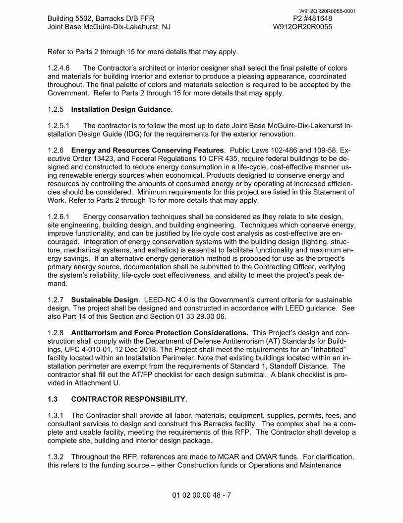
Building 5502, Barracks D/B FFR P2 #481648 Joint Base McGuire-Dix-Lakehurst, NJ W912QR20R0055
01 02 00.00 48 - 7
Refer to Parts 2 through 15 for more details that may apply.
1.2.4.6 The Contractor’s architect or interior designer shall select the final palette of colors and materials for building interior and exterior to produce a pleasing appearance, coordinated throughout. The final palette of colors and materials selection is required to be accepted by the Government. Refer to Parts 2 through 15 for more details that may apply.
1.2.5 Installation Design Guidance.
1.2.5.1 The contractor is to follow the most up to date Joint Base McGuire-Dix-Lakehurst In-stallation Design Guide (IDG) for the requirements for the exterior renovation.
1.2.6 Energy and Resources Conserving Features. Public Laws 102-486 and 109-58, Ex-ecutive Order 13423, and Federal Regulations 10 CFR 435, require federal buildings to be de-signed and constructed to reduce energy consumption in a life-cycle, cost-effective manner us-ing renewable energy sources when economical. Products designed to conserve energy and resources by controlling the amounts of consumed energy or by operating at increased efficien-cies should be considered. Minimum requirements for this project are listed in this Statement of Work. Refer to Parts 2 through 15 for more details that may apply.
1.2.6.1 Energy conservation techniques shall be considered as they relate to site design, site engineering, building design, and building engineering. Techniques which conserve energy, improve functionality, and can be justified by life cycle cost analysis as cost-effective are en-couraged. Integration of energy conservation systems with the building design (lighting, struc-ture, mechanical systems, and esthetics) is essential to facilitate functionality and maximum en-ergy savings. If an alternative energy generation method is proposed for use as the project's primary energy source, documentation shall be submitted to the Contracting Officer, verifying the system’s reliability, life-cycle cost effectiveness, and ability to meet the project’s peak de-mand.
1.2.7 Sustainable Design. LEED-NC 4.0 is the Government’s current criteria for sustainable design. The project shall be designed and constructed in accordance with LEED guidance. See also Part 14 of this Section and Section 01 33 29.00 06.
1.2.8 Antiterrorism and Force Protection Considerations. This Project’s design and con-struction shall comply with the Department of Defense Antiterrorism (AT) Standards for Build-ings, UFC 4-010-01, 12 Dec 2018. The Project shall meet the requirements for an “Inhabited” facility located within an Installation Perimeter. Note that existing buildings located within an in-stallation perimeter are exempt from the requirements of Standard 1, Standoff Distance. The contractor shall fill out the AT/FP checklist for each design submittal. A blank checklist is pro-vided in Attachment U.
1.3 CONTRACTOR RESPONSIBILITY.
1.3.1 The Contractor shall provide all labor, materials, equipment, supplies, permits, fees, and consultant services to design and construct this Barracks facility. The complex shall be a com-plete and usable facility, meeting the requirements of this RFP. The Contractor shall develop a complete site, building and interior design package.
1.3.2 Throughout the RFP, references are made to MCAR and OMAR funds. For clarification, this refers to the funding source – either Construction funds or Operations and Maintenance
W912QR20R0055-0001
Building 5502, Barracks D/B FFR P2 #481648 Joint Base McGuire-Dix-Lakehurst, NJ W912QR20R0055
01 02 00.00 48 - 8
funds – for the Project. The funding source has no bearing on the Scope of the Work.
1.3.3 For purposes of clarification, this RFP identifies parts of the Project for which some re-sponsibility is borne by the Government. The responsibility for some work items addressed elsewhere in the RFP is brought to the Contractor’s attention in the following table. If not identi-fied as Government-furnished in the table below, or elsewhere, all work required by the RFP is the responsibility of the Contractor.
1.3.3.1 For items noted with an asterisk (*) below, Contractor is responsible for design of power, data, and other necessary mechanical or electrical provisions for the item.
Item Designed
by Furnished by
Installed by
Makes final connection
Freestanding furniture Cont Govt Govt --- Window Treatments Cont Cont Cont --- Fire extinguishers Cont Cont Cont --- Surface Mounted Entry Mats Cont Cont Cont --- Washers and Dryers* Cont Govt Govt Govt Refrigerators* Cont Cont Cont Cont Countertop Microwave* Cont Cont Cont Cont Kitchen Equipment Cont Cont Cont Cont Vending Machines Cont Govt Govt Govt Metal Utility Shelving Cont Cont Cont --- Televisions Cont Govt Govt Govt
1.4 SURVEY AND GEOTECHNICAL INFORMATION.
1.4.1 A survey has been performed by a licensed surveyor and is provided in these docu-ments. Refer to the RFP Drawings. The Contractor shall, at its own expense, verify existing conditions and obtain any additional information required to provide a complete and useable de-sign. Do not contact the surveyor during the preparation of proposals for the solicitation.
1.4.2 A preliminary Subsurface Characterization report is being performed and will be included in the RFP upon completion The design parameters provided in the report are for information only. The design parameters upon which the bid is based is the responsibility of the contractor’s geotechnical engineer.
1.5 RFP DRAWINGS.
The conceptual drawings are included as a part of this RFP to provide preliminary information and criteria for the Contractor’s completion of the design.
1.6 SPECIFICATIONS.
1.6.1 The Outline Technical Specifications are provided primarily in outline format. They shall be utilized as design and submittal criteria, and minimum standards for the corresponding con-struction work, and shall be met or exceeded unless Contractor obtains specific Government approval for proposed reductions. These outline specifications shall not be considered com-plete and suitable for final construction specifications. Contractor’s designers shall expand the outline specifications to provide comprehensive, three-part, CSI-format Specifications and shall
W912QR20R0055-0001
Building 5502, Barracks D/B FFR P2 #481648 Joint Base McGuire-Dix-Lakehurst, NJ W912QR20R0055
01 02 00.00 48 - 9
edit the Specifications to indicate actual products to be used in the construction. Final specifica-tions shall include as a minimum, a description of the technical requirements, criteria for deter-mining whether the criteria are met, and quality control requirements and procedures. The standards referenced in the outline specifications establish minimum requirements for the final construction specifications.
1.6.1.1 The Outline Technical Specifications provide design and construction criteria that supplement project-specific requirements listed in Section 01 02 00.00 48 and 01 03 00.00 48.
1.6.2 Not all Outline Technical Specification sections provided in this RFP may be required for this project, and designers shall provide additional Specification Sections or items if necessi-tated by their final design or RFP requirements.
1.6.3 Some Outline Technical Specification Sections are more detailed and extensive than the majority; these represent the Government’s required specification approach to this project. Contractor’s designers must still take complete responsibility for the design and specification of the project, and shall satisfy themselves that these Sections are complete and suitable for the final design. Most of the outline specification sections are adapted from typical Government Unified Facility Guides Specifications (UFGS) and reflect Army Reserve-approved approaches and products. The outline specification requirements shall be used as the basis for selection of construction materials, products, and systems. Contractor’s final specifications shall be devel-oped from the UFGS. The use of industry prototype specifications (such as MasterSpec) is not allowed.
1.6.3.1 The following order of priority applies:
1.6.3.1.1 First select Sections specifically developed for Army Reserve facilities. Such Sec-tions have “48” as the fifth level of their MasterFormat 2004 numbering, such as Section 07 31 13.00 48. These Army Reserve-specific (RST) Sections can be accessed from the Corps of En-gineers, Louisville District, Army Reserve Customer Website (https://www.lrl.usace.army.mil/Missions/Engineering/Specs.aspx). Refer to Part 2 of this Sec-tion.
1.6.3.1.2 If no RST Section exists, select a Louisville District-specific Section (LRL), accessi-ble from the same website. Such Sections have a “06” as the fifth level of their MasterFormat 2004 numbering.
1.6.3.1.3 If no Section described above exists, select an Army Section. Such Sections have a “10” as the fourth level of their MasterFormat 2004 numbering.
1.6.3.1.4 If none of the above Section exist, select a unified Section. Such Sections have no fourth or fifth level in their numbering.
1.6.4 In case of conflicts between the project-specific requirements in Section 01 02 00.00 48 or 01 03 00.00 48, and the requirements in the Outline Technical Specifications, Section 01 02 00.00 48 or 01 03 00.00 48 governs. This is true for all Outline Technical Specification Sec-tions, including the more extensive and detailed Sections.
1.7 SITE.
The site described on the RFP drawings is included as part of this solicitation and consists of a total of approximately 1.7 acres. The site lies on Alabama Avenue within Joint Base McGuire-
W912QR20R0055-0001
Building 5502, Barracks D/B FFR P2 #481648 Joint Base McGuire-Dix-Lakehurst, NJ W912QR20R0055
01 02 00.00 48 - 10
Dix-Lakehurst (JB MDL) in Burlington county New Jersey. Site work includes all design and con-struction of site features described in the RFP, including but not limited to, site planning, clearing, grading, erosion control, site drainage, signage, site lighting, and physical security measures.
1.7.1 Special Utilities and Supplementary Construction.
Not Used.
1.7.2 Demolition Considerations and Requirements. Site demolition for the renovation of 5502 will primarily consist of the removal of the broken sidewalk surrounding the building and all exterior stairs and handrails. There are no mature trees on site that will need to be removed as part of this RFP.
Materials shall be disposed of off government property in a state certified landfill. The contractor must obtain required demolition permits and disposal permits. Obtain approval of the disposal site from the Contracting Officer. Cleared and grubbed material will be ground for mulch and recycled with the excess disposed of offsite in an approved disposal area.
1.7.3 Environmental Considerations and Mitigation Requirements. Contractor is to review the Hazmat Report located in the attachments for location and types of asbestos materials and lead paint that will need to be removed.. The Contractor shall comply with the requirements of OSHA 29 cfr 1926.62 – lead exposure in construction during building and structure demolition. The hazardous waste criterion for lead waste is established under the federal resource conser-vation and recovery act (RCRA), subtitle c, as 5.0 mg/l measured with the toxicity characteristics leaching procedure (TCLP). In addition, the crushing or recycling of materials with LBP is strictly prohibited.
1.7.3.1 The Contractor shall use the following numbers in addition to the quantities found in the Hazardous Materials Survey (Attachment P):
Asbestos Cement Board on interior perimeter walls: 6,500 SF Window Caulk (Interior & Exterior): 7,400 LF Building Expansion Joint caulk (Exterior): 1,800 LF Fluorescent Bulbs – 2ft L (PCB): 400 EA Fluorescent Bulbs – 4ft L (PCB): 150 EA
1.7.3.2 In the process of demolition should the contractor uncover tar vapor barrier on the exterior wall that contains asbestos containing material, the contractor shall cover it with new wall construction. Should any additional suspected hazardous materials be encountered during site investigations or construction, the Contractor shall immediately stop work in the affected area, notify the Contracting Officer, and await Contracting Officer’s direction before proceeding with additional work in the area.
1.7.3.3 Buildings must be designed and constructed to maintain space humidity at reasona-ble levels to prevent mold.
1.7.4 Site Development Constraints. The project site is on U. S. government property and the normal RFP requirements associated with a U. S. government installation shall apply. Known site development constraints include minimum AT/FP setbacks as per UFC criteria.
1.7.5 Contractor’s Use of the Site. Except for utility service provider access, required coor-dination with local agencies, and observation and oversight by the Government, the Contractor
W912QR20R0055-0001
Building 5502, Barracks D/B FFR P2 #481648 Joint Base McGuire-Dix-Lakehurst, NJ W912QR20R0055
01 02 00.00 48 - 11
shall have complete use of the site within final limits of construction to be recommended by the Contractor and approved by the Government.
1.7.5.1 Security and Identification Requirements. Refer to Section 00 80 00.00 06.
1.7.5.2 Contractor’s trailers and other equipment and materials on the site shall be tied down to resist storm force winds. Contractor shall maintain the site free from debris that could repre-sent a hazard during storm force winds.
1.7.6 Verification of Conditions. The Contractor shall field verify existing conditions prior to beginning work. The Contractor and the designers of record shall be responsible for investigat-ing all differing site conditions, discrepancies, and field related issues that are encountered dur-ing the design and construction process. The designers of record shall be responsible for providing guidance to the Contractor for the resolution of all such issues. The Contractor shall provide notice to the Government of any such issues prior to proceeding and with sufficient time to avoid cost or schedule impacts.
1.7.7 Verification of Utilities. The Contractor and the designers of record shall be responsi-ble for verifying the condition, location, and capacity for all utilities necessary for the project. The Contractor and designers of record shall further verify that all utilities will meet the require-ments of this project.
1.7.8 Regulatory Compliance. The Contractor shall assure that the site development com-plies with all applicable local, State and Federal regulations. A list of known regulations is lo-cated in Part 2 of this Statement of Work. Timely acquisition of the necessary design and con-struction related permits shall be the responsibility of the Contractor. The Contractor, upon no-tice to proceed, shall immediately begin working on the permits so as not to delay completion of the project. The Contractor shall prepare permits, associated drawings, public notices, and other related documentation as necessary to successfully meet permit approval status. The Contractor shall pay for all associated permit fees.
1.8 FUNCTIONAL AND AREA REQUIREMENTS.
The Army Reserve’s primary criteria documents are the following: “Draft: UFC 4-171-05 Certified Final Submittal November 15, 2012”, Army Reserve Facilities, commonly referred to as the De-sign Guide or DG; and “Operational Readiness Training Complex (ORTC) Standard Design – Revision 4.6, 24 August 2012”. IT spaces are addressed in the Army Reserve IT Manual: Infor-mation Technology Design and Construction Guide, dated 15 February 2008 with Change 3, 17 October 2011.
1.8.1 The existing Building 5502 gross square footage is approximately 39,770. The renovation will include renovating the existing building floor plan, mechanical, electrical, fire protection, com-munication systems and interior finishes. The new floor plan will consist of two person barracks with a shared bathroom, mechanical rooms, day room, laundry and elevator on all three floors. The single story wing houses a kitchen that will be renovated with new equipment. The kitchen has no interior access to the barracks. The sub-grade basement presently contains a certified weapons vault with Intrusion Detection and will remain but be upgraded.
1.8.2 Individual spaces shall meet the functional and environmental requirements of the above referenced criteria documents, as well as any applicable code requirements, and additional re-quirements in this RFP. Refer to the RFP attachment “A” for Room Requirements.
W912QR20R0055-0001
Building 5502, Barracks D/B FFR P2 #481648 Joint Base McGuire-Dix-Lakehurst, NJ W912QR20R0055
01 02 00.00 48 - 12
1.8.2.1 The areas shown in the “Target Net Area” column of Room Requirement Attachment “A” reflect the areas achieved on the RFP Drawings, however minor variation is allowed. It is acceptable for the actual clear area of any space to vary from the values in the table by plus or minus 5%. If space sizes are varied, functionality and furniture requirements shall be maintained.
1.8.2.1.1 The minimum width for offices shall be 9’-6”.
1.9 OPTIONS
1.9.1 Options. The Government has identified Option Items that they wish included in the pro-ject if available funds allow. The Option Items are identified in the RFP, listed individually on the Bidding Schedule, and described briefly below.
1.9.1.1 Option – New Entry Canopies. All work required to furnish and install (4) new entry canopies and frames at each entrance to Building 5502 to match the existing canopies.
1.9.1.2 Option – Exterior Walk-in Refrigerator/Freezer. All work required to furnish and install (2) new exterior walk-in refrigerator and freezer combination unit located near the kitchen as de-scribed in section 01 02 00.00 48.
1.9.1.3 Option – Fire pump and Housing. All work required to design, furnish and install a packaged fire pump and exterior enclosure to provide adequate water pressure to Building 5502.
1.9.1.4 Option – Paved Driveway. All work required to furnish and install new pavement over an existing driveway as shown on drawings and described in the RFP.
1.9.1.5 Option – Resurface Basketball Court. All work required to resurface the existing bas-ketball court as described on the drawings and in RFP.
1.9.1.6 Option – Army Reserve (OMAR) Funded Bona Fide Need Equipment. All work re-quired to design, furnish and install “Bona Fide Need Funded Equipment” for the facility.
1.9.1.7 Option – Army Reserve (OMAR) Funded Bona Fide Need Kitchen Equipment. All work required to design, furnish and install “Bona Fide Need Funded Kitchen Equipment” for the facility.
W912QR20R0055-0001
Building 5502, Barracks D/B FFR P2 #481648 Joint Base McGuire-Dix-Lakehurst, NJ W912QR20R0055
01 02 00.00 48 - 13
PART 2 APPLICABLE CRITERIA AND COORDINATION WITH LOCAL AUTHORITIES
2.1 APPLICABLE CRITERIA.
Applicable design and construction criteria references are listed in this Statement of Work and in the Specifications of this RFP. Criteria shall be taken from the most current references as of the date of issue of the RFP, unless otherwise noted. However, following contract award, Contrac-tor shall bring any criteria updates to the attention of the Contracting Officer. Referenced codes and standards are minimum acceptable criteria. Administrative, contractual, and procedural features of the contract shall be as described in other sections of the RFP. Sources for criteria documents are listed below.
2.1.1 In order for a facility to be occupied by Department of Defense personnel, the design and construction must meet specific requirements. The Government’s primary guidance on fire protection is UFC 3-600-01, Design – Fire Protection Engineering for Facilities. Design and construction of Army Reserve real property improvements shall comply with UFC 3-600-01, and shall comply with the specific applicable requirements of IBC, NFPA 101, and other commercial codes and standards that are referenced in UFC 3-600-01. The Contractor shall complete a Fire Protection/Life Safety Code Submittal form, for the project to demonstrate compliance. The form is available on the Corps of Engineers, Louisville District, Army Reserve Customer Website.
2.1.2 Design and construction of Army Reserve real property improvements shall also comply with the requirements of this document and with the current edition of the industry and Federal Government standards listed in this RFP. Where UFC 3-600-01 or any other Federal Govern-ment standard refers to other Federal Government standards not listed in this RFP, the stand-ards not listed in this RFP do not apply.
2.1.3 Some State and local code and regulatory agencies may not have jurisdiction over Fed-eral Government construction on Federal property. However, the Army Reserve wishes to com-ply with State and local codes and regulations, and the Contractor remains responsible for such compliance. Therefore, design and construction of Army Reserve real property improvements shall also comply with all current and applicable State and local codes, and with all other appli-cable laws and regulations governing development, design and construction at the site. If cer-tain of such requirements appear particularly onerous, or hamper Army Reserve required func-tionality of the project, the Contractor may recommend the Government waive the requirement or implement a lesser requirement. The Government’s acceptance of such recommendations is not assured.
2.1.4 Where any of the applicable requirements conflict, the most stringent shall govern. In no case shall building code, fire protection and life safety requirements be reduced below those re-quired in UFC 3-600-01 and this RFP.
2.1.5 The requirements of the International Mechanical Code (IMC) shall apply except as fol-lows. Where conflicts exist between the IMC and the requirements of this document, this docu-ment shall govern. Where the IMC references the ICC Electrical Code, the NEC National Elec-trical Code shall be the applicable code. Where the IMC references the International Fuel Gas Code, the NFPA 54 National Fuel Gas Code shall be the applicable code. Where the IMC refer-ences the International Fire Code, the National Fire Codes published by the National Fire Pro-tection Association (NFPA) shall be the applicable code. Where the IMC references the Interna-tional Energy Conservation Code, the ASHRAE Standard 90.1 Energy Standard for Buildings –
W912QR20R0055-0001
Building 5502, Barracks D/B FFR P2 #481648 Joint Base McGuire-Dix-Lakehurst, NJ W912QR20R0055
01 02 00.00 48 - 14
Except Low Rise Residential Buildings shall be the applicable reference. The requirements of ASHRAE Standard 62.1 Ventilation for Acceptable Indoor Air Quality shall be used in lieu of the ventilation requirement contained in the IMC.
2.1.6 The primary criteria and guidance for detailed design of Army Reserve Training Centers is UFC 4-171-05 “Army Reserve Facilities” (Design Guide or DG). The Contractor shall follow the guidance of the DG in developing the project design, unless this RFP directs otherwise. For the purposes of this RFP, when the word “should” is used in the DG, it indicates a mandatory requirement for this project. When the DG references Government criteria documents not refer-enced in this RFP, those criteria do not apply to this project.
2.1.6.1 The DG is considered the primary criteria, if conflicting with the UFC's and other cri-teria, and shall be followed as first precedence.
2.1.6.2 The requirements of the Army Reserve Design Process and Submittal Requirements (DPSR), shall take precedence over any conflicting UFC requirements regarding Predesign, De-sign, Post Design Services, and Submission Requirements.
2.1.7 Best Practices (Chapters or Appendices) listed in any UFCs shall be considered recom-mendations and are not contract requirements, unless otherwise noted in this RFP.
2.1.8 Accessibility – Design and construction must comply with ADA-ABA Accessibility Stand-ard for Department of Defense Facilities and UFAS, whichever is most stringent. Buildings shall be considered to be “commercial facilities” under ADA-ABA.
2.1.9 Design and construction shall comply with applicable Federal laws and regulations, such as EPA Clean Water and Clean Air Act and OSHA requirements.
2.2 LOCAL AND STATE CODES OR STANDARDS.
The following specifications, codes, standards, bulletins and handbooks form a part of this RFP.
2.2.1 State and Local
New Jersey Department of Transportation Standard Specifications for Highway and Bridge Construction
The Standards for Soil Erosion and Sediment Control in New Jersey
New Jersey Environmental Control Requirements
New Jersey Storm Water Management Requirements
2.2.2 National.
IBC – International Building Code 2018
IEBC – International Existing Building Code 2018
IPC – International Plumbing Code 2018
IMC – International Mechanical Code 2018
NEC – National Electrical Code.
2.3 MILITARY CRITERIA.
W912QR20R0055-0001
Building 5502, Barracks D/B FFR P2 #481648 Joint Base McGuire-Dix-Lakehurst, NJ W912QR20R0055
01 02 00.00 48 - 15
2.3.1 The following publications form a part of this document. The applicable editions are those current as of the date of issue of the RFP.
AR 190-11 Physical Security of Weapons, Ammunition and Explosives (for design and construction of arms vaults only)
AR 380-5 Department of the Army Information Security Program - Chap-
ter 7, Section III CR-200010 Joint Service Oil/Water Separator Guidance Document
MIL HDBK 1013/1A Military Handbook: Design Guide for Physical Security of Facil-
ities - for protection of openings into secure areas such as SIPRNET Café, and COMSEC
I3A Technical Criteria for The Installation Information Infrastructure
Architecture (I3A) (for outside plant design criteria only) ECB 2018-11 Control System Cybersecurity Coordination Requirement UFC 1-200-01 DoD Building Code
UFC 1-200-02 High Performance and Sustainable Building Requirements UFC 3-101-01 Architecture UFC 3-110-03 Roofing UFC 3-120-01 Design: Sign Standard UFC 3-120-10 Interior Design UFC 3-201-01 Civil Engineering UFC 3-201-02 Landscape Architecture UFC 3-210-10 Low Impact Development UFC 3-220-01 Geotechnical Engineering UFC 3-250-01 Pavement Design for Roads and Parking UFC 3-301-01 Structural Engineering UFC 3-401-01 Mechanical Engineering UFC 3-410-01 Heating, Ventilating, and Air Conditioning Systems UFC 3-410-02 Direct Digital Control for HVAC and Other Building Control
Systems UFC 3-420-01 Plumbing Systems UFC 3-501-01 Electrical Engineering UFC 3-520-01 Interior Electrical Systems UFC 3-530-01 Interior and Exterior Lighting Systems and Controls UFC 3-550-01 Exterior Electrical Power Distribution UFC 3-580-01 Telecommunications Building Cabling Systems Planning and
Design UFC 3-600-01 Fire Protection Engineering for Facilities UFC 3-490-06 Elevators
W912QR20R0055-0001
Building 5502, Barracks D/B FFR P2 #481648 Joint Base McGuire-Dix-Lakehurst, NJ W912QR20R0055
01 02 00.00 48 - 16
UFC 4-010-01 DoD Minimum Antiterrorism Standards for Buildings UFC 4-010-06 Cybersecurity of Facility-Related Control Systems UFC 4-021-01 Design and O&M: Mass Notification Systems UFC 4-023-03 Design of Buildings to Resist Progressive Collapse UFC 4-171-05 Design Guide for US Army Reserve Facilities
No number Army Reserve Network Enterprise Center Infrastructure Tech-
nical Criteria (ARNEC ITC) No number USAR Design Process and Submittal Requirements (DPSR) No number ADA-ABA Accessibility Standard for Department of Defense
Facilities No number 2017 Implementing Guidance, Army Stormwater Management
Using Low Impact Development No number MEMORANDUM FOR PPMD titled “Implementation of UFC 4-
010-01 revision 12 Dec 2018” dated 22 January 2019. No number Department of the Army Sustainable Design and Development
(SDD) Policy memo dated January 17, 2017 No number IDS Responsibilities memo; Arms Vault IDS system No number Caging Details; Unit Storage and Arms Vault, and other rooms
with caging. No number US Army Reserve Color Board SDDCTEA Pamphlet 55-17 Better Military Traffic Engineering
2.4 OTHER APPLICABLE CRITERIA.
Applicable design and construction criteria references are listed below. This list is not intended to include all criteria that may apply or to restrict design and construction to only those refer-ences listed.
Air Conditioning and Refrigeration Institute (ARI) ARI 310/380 Packaged Terminal Air-Conditioners and Heat Pumps ARI 440 Room Fan-Coil and Unit Ventilator ARI 445 Room Air-Induction Units ARI 880 Air Terminals
Air Movement and Control Association (AMCA) AMCA 210 Laboratory Methods of Testing Fans for Rating
American Architectural Manufacturers Association (AAMA) AAMA 605 Voluntary Specification Performance Requirements and Test Proce-
dures for High Performance Organic Coatings on Aluminum Extrusions and Panels
W912QR20R0055-0001
Building 5502, Barracks D/B FFR P2 #481648 Joint Base McGuire-Dix-Lakehurst, NJ W912QR20R0055
01 02 00.00 48 - 17
AAMA 607.1 Voluntary Guide Specifications and Inspection Methods for Clear Anodic Finishes for Architectural Aluminum
AAMA 1503 Voluntary Test Method for Thermal Transmittance and Condensa-tion Resistance of Windows, Doors, and Glazed Wall Sections
American Association of State Highway and Transportation Officials (AASHTO) Roadside Design Guide [guardrails, roadside safety devices] Standard Specifications for Transportation Materials and Methods of Sampling
and Testing [Road Construction Materials] Standard Specifications for Structural Supports for Highway Signs, Luminaries
and Traffic Signals A Policy of Geometric Design of Highways and Streets Guide for Design of Pavement Structures, Volumes 1 and 2 [pavement design
guide] American Bearing Manufacturers Association (AFBMA)
AFBMA Std. 9 Load Ratings and Fatigue Life for Ball Bearings AFBMA Std. 11 Load Ratings and Fatigue Life for Roller Bearings
American Boiler Manufacturers Association (ABMA) ABMA ISEI Industry Standards and Engineering Information
American Concrete Institute ACI 318, Building Code Requirements for Structural Concrete ACI SP-66, Details Manual ACI 530/530.1, Building Code Requirements and Specification for Masonry
Structures American Concrete Pipe Association
Design Manual Installation Manual
American Institute of Steel Construction (AISC) Steel Construction Manual and all standards and specification therein Seismic Design Manual and all standards and specification therein Steel Design Guide 11, Floor Vibrations due to Human Activity
American Iron and Steel Institute (AISI) AISI, S100, North American Specification for the Design of Cold-Formed Steel
Structural Members AISI D100, Cold-Formed Steel Design Manual AISI S400, North American Standard for Seismic Design of Cold-Formed Steel
Structural Systems American National Standards Institute 11 (ANSI)
ANSI Z21.10.1 Gas Water Heaters Vol. 1, Storage water Heaters with Input Rat-ings of 75,000 Btu per Hour or less
ANSI Z124.3 American National Standard for Plastic Lavatories ANSI Z124.6 Plastic Sinks ANSI Z21.45 Flexible Connectors of Other Than All-Metal Construction for Gas
Appliances ANSI Z358.1 Emergency Eyewash and Shower Equipment ANSI C2 National Electrical Safety Code ANSI/AF&PA NDS National Design Specification for Wood Construction
American Society of Civil Engineers (ASCE) Minimum Design Loads and Associated Criteria for Buildings and Other Struc-
tures – ASCE 7 Design and Construction of Sanitary and Storm Sewers, Manuals and Reports on
Engineering Practice – No. 37 [sanitary sewer and storm drain design criteria]
W912QR20R0055-0001
Building 5502, Barracks D/B FFR P2 #481648 Joint Base McGuire-Dix-Lakehurst, NJ W912QR20R0055
01 02 00.00 48 - 18
American Society of Heating, Refrigerating and Air Conditioning Engineers (ASHRAE) ASHRAE Hdbk-IP Handbook, Fundamentals I-P Edition ASHRAE HVAC Applications Hdbk – Handbook, HVAC Applications ASHRAE Standard 15 Safety Standard for Refrigeration Systems ASHRAE Standard 55 Thermal Environmental Conditions for Human Occupancy ASHRAE Standard 62.1 Ventilation for Acceptable Indoor Air Quality. Edition
year and to the extent as referenced in UFC 3-410-01. ASHRAE 90.1 Energy Standard for Buildings Except Low-Rise Residential Build-
ings. Edition year and to the extent as referenced in UFC 1-200-02. ASHRAE 189.1 Standard for the Design of High-Performance Green Buildings.
Edition year and to the extent as referenced in UFC 1-200-02, and to the ex-tent indicated in the RFP.
American Society of Mechanical Engineers International (ASME) ASME BPVC SEC VII Boiler and Pressure Vessel Code: Section VII Recom-
mended Guidelines for the Care of Power Boilers ASME A17.1 Safety Code for Elevators and Escalators
American Society for Testing and Materials (ASTM) E1592 Standard Test Method for Structural Performance of Sheet Metal Roof
and Siding Systems by Uniform Static Air Pressure Difference American Water Works Association (AWWA)
AWWA Standards [standards for water line materials and construction] American Welding Society (AWS)
D1.X Standards Architectural Woodwork Institute (AWI)
AWI Quality Standards Associated Air Balance Council (AABC)
AABC MN-1 National Standards for Testing and Balancing Heating, Ventilating, and Air Conditioning Systems
AABC Commissioning Group Commissioning Guidelines Builders Hardware Manufacturers Association (BHMA)
ANSI/BHMA A156.4 American National Standards for Door Controls – Closers… Cast Iron Soil Pipe Institute (CISPI) Code of Federal Regulations (CFR)
49 CFR 192 Transportation of Natural and Other Gas by Pipeline: Minimum Fed-eral Safety Standards
10 CFR 430 Energy Conservation Program for Consumer Products Ductile Iron Pipe Research Association (DIPRA), Design of Ductile Iron Pipe Environmental Protection Agency
EPA 625-R-92-016 Radon Prevention in the Design and Construction of Schools and Other Large Buildings
Federal Highway Administration (FHWA) Manual on Uniform Traffic Control Devices for Streets and Highways [signage for
streets and highways] Illuminating Engineering Society (IES)
The Lighting Handbook, Reference and Application Institute of Electrical and Electronics Engineers Inc. (IEEE)
Standard for Use of the International System of Units (SI): the Modern Metric System
National Electrical Safety Code ANSI C2 Institute of Traffic Engineers (ITE)
W912QR20R0055-0001
Building 5502, Barracks D/B FFR P2 #481648 Joint Base McGuire-Dix-Lakehurst, NJ W912QR20R0055
01 02 00.00 48 - 19
Trip Generation Transportation Planning Handbook
LEED: Leadership in Energy and Environmental Design Green Building Rating Sys-tem, Version 4, as developed by the U.S. Green Building Council (USGBC)
Metal Building Manufacturer’s Association (MBMA) MBMA Metal Building Systems Manual, with latest Supplement MBMA Seismic Design Guide for Metal Building Systems National Association of Corrosion Engineers International (NACE) NACE SP0169 Control of External Corrosion on Underground or Submerged Metallic
Piping Systems NACE SP0185 Extruded, Polyolefin Resin Coating Systems with Soft Adhesives
for Underground or Submerged Pipe NACE SP0285 Corrosion Control of Underground Storage Tank Systems by Ca-
thodic Protection NACE SP0286 Electrical Isolation of Cathodically Protected Pipelines
National Electrical Manufacturers Association (NEMA) National Environmental Balancing Bureau (NEBB)
NEBB Procedural Standards for Testing Adjusting Balancing of Environmental Systems
NEBB Procedural Standards for Building Systems Commissioning National Fire Protection Association (NFPA)
NFPA 1 Fire Code Handbook NFPA 10 Standard for Portable Fire Extinguishers NFPA 13 Installation of Sprinkler Systems NFPA 13R Residential Occupancies up to and Including Four Stories in Height
Sprinkler Systems NFPA 20 Installation of Centrifugal Fire Pumps NFPA 24 Standard for the Installation of Private Fire Service Mains and Their Ap-
purtenances (underground fire protection system design) NFPA 30 Flammable and Combustible Liquids Code NFPA 30A Motor Fuel Dispensing Facilities and Repair Garages NFPA 31 Installation of Oil Burning Equipment NFPA 54 National Fuel Gas Code NFPA 58 Liquefied Petroleum Gas Code NFPA 70 National Electrical Code NFPA 70E Standard for Electrical Safety in the Workplace NFPA 72 National Fire Alarm Code NFPA 80 Standard for Fire Doors and Fire Windows NFPA 90a Installation of Air Conditioning and Ventilating Systems NFPA 96 Standard for Ventilation Control and Fire Protection of Commercial
Cooking Operations NFPA 101 Life Safety Code NFPA 291 Recommended Practice for Fire Flow testing and Marking of Hydrants NFPA 780 Standard for the Installation of Lightning Protection Systems
National Food Code FDA Model Food Code
National Institute of Standards and Technology (NIST) RP8 - Standards of Seismic Safety for Existing Federally Owned and Leased
Buildings – ICSSC Recommended Practice 8 (RP8). NIST GCR 11-917-12. National Roofing Contractors Association
NRCA Roofing and Waterproofing Manual
W912QR20R0055-0001
Building 5502, Barracks D/B FFR P2 #481648 Joint Base McGuire-Dix-Lakehurst, NJ W912QR20R0055
01 02 00.00 48 - 20
Occupational Safety and Health Administration (OSHA) OSHA Construction Industry Standards, Title 29, Code of Federal Regulations,
Part 1926, Safety and Health Regulations for Construction Plumbing and Drainage Institute (PDI)
PDI G 101 Testing and Rating Procedure for Grease Interceptors with Appendix of Sizing and Installation Data
PDI WH201 Water Hammer Arrestors Precast Concrete Institute
PCI Design Handbook – Precast and Prestressed Concrete Sheet Metal and Air Conditioning Contractor’s National Association (SMACNA)
SMACNA HVAC Duct Construction Standards HVAC Duct Construction Stand-ards - Metal and Flexible
SMACNA Architectural Manual Architectural Sheet Metal Manual Steel Door Institute (SDI)
ANSI A250.8/SDI 100 Standard Steel Doors and Frames Steel Deck Institute (SDI)
Floor Deck Design Manual Roof Deck Design Manual Diaphragm Design Manual
Steel Joist Institute (SJI) Standard Specifications for K-Series, LH-Series, and DLH-Series Open Web
Steel Joist, and for Joist Girders. Load Tables and Weights for K-Series, LH-Series, and DLH-Series Open Web
Steel Joists and Joist Girders SJI Tech Digest #5 Vibration of Steel-Joist Concrete Slab Floors
Telecommunications Industries Association (TIA) TIA 568 Generic Telecommunications Cabling For Customer Premises TIA 569 Telecommunications Pathways and Spaces TIA 606-B (2012) Administration Standard for Telecommunications Infrastructure TIA 607 Generic Telecommunications Bonding and Grounding (Earthing) for
Customer Premises TIA 758 Customer-Owned Outside Plant Telecommunications Infrastructure
Standard The Masonry Society (TMS)
TMS 402/602 Building Code Requirements and Specification for Masonry Struc-tures
Underwriters Laboratories (UL) UL 300 Standard for Safety for Fire Testing of Fire Extinguishing Systems for
Protection of Restaurant Cooking Areas Uni-Bell PVC Pipe Association, Handbook of PVC Pipe: Design and Construction Recommended Standards for Wastewater Facilities, by Health Research, Inc.
2.5 SOURCES FOR GOVERNMENT PUBLICATIONS.
2.5.1 AR (Army Regulations) is available at the following website link: http://www.apd.army.mil
2.5.2 ADA-ABA is available at the following website link: http://www.access-board.gov/guide-lines-and-standards/buildings-and-sites
W912QR20R0055-0001
Building 5502, Barracks D/B FFR P2 #481648 Joint Base McGuire-Dix-Lakehurst, NJ W912QR20R0055
01 02 00.00 48 - 21
2.5.3 References to the Corps of Engineers, Louisville District, Army Reserve Customer Web-site shall utilize the following website link: https://www.lrl.usace.army.mil/Missions/Engineer-ing/Design-Guide/Military-Programs/Army-Reserve-Customers/
Items posted on this site are applicable only if referenced in the RFP.
2.5.4 The following documents are available at the Corps of Engineers, Louisville District, Army Reserve Customer Website:
UFC 4-171-05 Army Reserve Facilities (Design Guide) I3A ARNEC ITC USAR Design Process and Submittal Requirements (DPSR) 2017 Implementing Guidance, Army Stormwater Management Using Low Impact De-
velopment MEMORANDUM FOR PPMD titled “Implementation of UFC 4-010-01 revision 12
Dec 2018” dated 22 January 2019 Department of the Army Sustainable Design and Development (SDD) Policy memo
dated January 17, 2017 IDS Responsibilities memo; Arms Vault IDS system Caging Details; Unit Storage and Arms Vault, and other rooms with caging. US Army Reserve Color Board Specification Section 27 05 28.00 48 Cable Trays, For Communications Systems Specification Section 27 05 29.00 48 Protective Distribution System (PDS) for
SIPRNET Communications Systems Specification Section 27 10 00.00 48 Building Telecommunications Cabling Specification Section 28 13 00.00 48 CAC Compatible Physical Access Control Sys-
tem Specification Section 33 82 00.00 48 Telecom Outside Plant (OSP)
2.5.5 The Joint Service Oil/Water Separator Guidance Document is available from the U.S. Army Environmental Center, and can be ordered on CD-ROM by calling 1-800-USA-3845.
2.5.6 SDDCTEA Pamphlet 55-17 is available at the following website link: https://www.sddc.army.mil/sites/TEA/Functions/SpecialAssistant/TrafficEngineeringBranch/Pages/pamphlets.aspx
2.5.7 ECB 2018-11 is available at the following website link: www.wbdg.org
2.6 PERMITS AND COORDINATION WITH LOCAL AUTHORITIES.
2.6.1 General. The Contractor is responsible for making all applications and obtaining re-quired municipal, utility, and regulatory agency coordination, reviews, permits, inspections and
W912QR20R0055-0001
Building 5502, Barracks D/B FFR P2 #481648 Joint Base McGuire-Dix-Lakehurst, NJ W912QR20R0055
01 02 00.00 48 - 22
approvals, and is responsible for payment of any associated fees or charges. If Government in-formation, signatures, names or addresses are required for applications, approvals or permits, the Contractor is responsible for obtaining same. This is a Federal Government project; there-fore, some reviews, permits, inspections and approvals are not required. The Contractor is re-sponsible for identifying such requirements for a commercial project and verifying with the Gov-ernment which of these will be waived. Permit requirements which have been identified are listed below. This list is not all-inclusive, and Contractor is responsible for verifying that infor-mation below remains accurate.
2.6.2 Jurisdiction. By Federal and New Jersey State law, most State and local governmental agencies do not have jurisdiction over Federal construction on Federal land. It is the intention of the Army Reserve to be a “good neighbor” to the State and local governmental agencies, and to comply with applicable State and local codes and regulations. The Contractor is required to comply with local codes and regulations, as noted in Section 2.1.3. The Contractor shall strive to keep local governmental agencies informed of the design and construction progress of the project.
2.6.3 Streets, Rights of Way, and Street Access. Not applicable.
2.6.4 Planning and Zoning. Not applicable.
2.6.5 Building Code. The Contractor is responsible for compliance with applicable building codes. The Government’s review of Contractor’s design and construction will include review for code compliance, but does not relieve Contractor of compliance responsibility.
2.6.6 Fire Protection. The Contractor is responsible for compliance with applicable fire pro-tection and life safety codes. The Government’s review of Contractor’s design and construction will include review of documentation of the project compliance with requirements, but does not relieve Contractor of compliance responsibility. Point of contact is Clarence Hon.
2.6.7 Water. See Part 3 of this Section for additional information.
2.6.8 Sanitary Sewer. See Part 3 of this Section for additional information.
2.6.9 Natural Gas. See Part 3 of this Section for additional information.
2.6.10 Electric. See Part 4 of this Section for additional information.
2.6.11 Telecommunication. See Part 15 of this Section for additional information.
2.6.12 Cable Television. See Part 15 of this Section for additional information.
2.6.13 Storm Drainage, and Soil and Water Conservation. See Part 3 of this Section for ad-ditional information.
W912QR20R0055-0001
Building 5502, Barracks D/B FFR P2 #481648 Joint Base McGuire-Dix-Lakehurst, NJ W912QR20R0055
01 02 00.00 48 - 23
PART 3 SITE CIVIL ENGINEERING
3.1 GRADING.
3.1.1 The difference in grade between the finished floor elevation (FFE) and stoops outside of personnel doors shall meet ABA requirements. The ground outside the building shall have a minimum of 5% slope away from all exterior walls for the first 10 feet and positive drainage thereafter. The Contractor’s geotechnical engineer shall identify if steeper grades are neces-sary based on shrink/swell soil characteristics.
3.1.2 Design grades to provide required sight lines related to traffic and roadway design.
3.1.3 Design grades to meet accessibility requirements where required.
3.1.4 The Contractor shall be responsible for dewatering necessary for grading and other sub-surface works for the construction of the Project.
3.1.5 A balance of the quantity of cut and fill soils which would create a smooth transition of graded areas into the existing natural site is desired. Site specific conditions such as flood and drainage protection, slopes and access reasons may cause unbalanced earthwork operations and are to be identified by the Contractor in the first Site/Utility Design submittal.
3.1.6 The plan should reflect selective site clearing that preserves groups of trees.
3.1.7 Erosion and Sediment Control Facilities shall comply with Federal, State and local regu-lations. The Contractor is responsible for compliance with stormwater NPDES Permit, Storm-water Pollution Prevention Plan, and NOI/NOT requirements, and for any associated fees and permits. See Section 01 57 19.00 06.
3.1.8 The Contractor shall obtain and pay fees required for any grading, excavation or earth-work permit as required.
3.1.9 The Contractor shall notify utilities and obtain marked utility locations prior to start of construction. State “One Call” utility location programs are to be used where available.
3.2 SURVEY, GEOTECHNICAL, AND EARTHWORK
3.2.1 Survey. A survey has been performed by a licensed surveyor and is provided in these documents. Refer to the RFP Drawings. The Contractor shall, at its own expense, verify exist-ing conditions and obtain any additional information required to provide a complete and useable design. Do not contact the surveyor during the preparation of proposals for the solicitation.
3.2.2 Subsurface Characterization Report. A preliminary Subsurface Characterization report will be performed and will be included in the RFP as an attachment. The design parameters pro-vided in the report are for information only. The design parameters upon which the bid is based is the responsibility of the geotechnical engineer.
3.2.3 A preliminary report is being prepared to characterize the subsurface conditions at the project site and will be appended to these specifications. The report provides a general over-
W912QR20R0055-0001
Building 5502, Barracks D/B FFR P2 #481648 Joint Base McGuire-Dix-Lakehurst, NJ W912QR20R0055
01 02 00.00 48 - 24
view of the soil and geologic conditions. The Contractor's team shall include a licensed geotech-nical engineer to interpret the subsurface conditions (assuming they are consistent with the site subsurface conditions) and develop earthwork and foundation requirements and design param-eters on which to base the Contractor's proposal. Foundation type, pavement and earthwork re-quirements on which the Contractor's bid is based shall be presented in his proposal along with the resume of the geotechnical engineer. Refer to Section 01 03 00.00 48 for additional ge-otechnical requirements.
3.2.4 Contractor’s Geotechnical Report: A final geotechnical evaluation report shall be pre-pared by the Contractor’s licensed professional geotechnical engineer.
3.2.5 Soil Compaction and Foundation Excavations.
3.2.4.1 Soil Compaction shall be achieved by equipment approved by a professional ge-otechnical engineer. Material shall be moistened or aerated as necessary to provide the mois-ture content that shall readily facilitate obtaining the compaction specified with the equipment used. Each layer of fill placement shall be no greater than 8 inches thick. Compact each layer to not less than the percent of maximum density specified in Table 3-1, determined in accord-ance with ASTM D-1557.
Table 3-1 Soil Compaction Foundations 95% Concrete Work and Pavements 95% Landscaping 85% Retaining Wall Backfill 85%*
*at non-structural or pavement locations The requirements shall be verified or modifications recommended by the Contractor’s geotech-nical engineer in the report whenever engineering, soils or climatic factors indicate the neces-sity. Any modifications to the stated compaction requirements shall require approval from the USACE ACO. 3.2.4.2 Subgrade suitability (by proof rolling operations), fill placement and compaction oper-ations shall be observed and tested on a full-time basis by a qualified independent testing agency as directed by the Contractor’s licensed professional geotechnical engineer. Field in-place density shall be determined and checked in accordance with the appropriate ASTM meth-odologies. The rate of in-place density testing shall be specified in the earthwork specifications. Representative Optimum Moisture and Laboratory Maximum Density Tests shall be made for each type of material or source of material. Upon completion of all earthwork, the Contractor’s geotechnical engineer shall certify in writing that the fill was placed in accordance with the re-quirements and provide the backup data including but not limited to: Proctor curves (mois-ture/density relationship), moisture contents, Atterberg limits, field density checks, sieve analy-sis, etc. Testing locations and elevations for all results shall be documented so that their posi-tion can be substantiated and relocated if necessary.
3.2.4.3 During construction, foundation excavations shall be inspected and approved by the Contractor’s licensed professional geotechnical engineer prior to placing concrete.
3.2.6 Capillary Water Barrier. A capillary water barrier is required for all interior slabs on
W912QR20R0055-0001
Building 5502, Barracks D/B FFR P2 #481648 Joint Base McGuire-Dix-Lakehurst, NJ W912QR20R0055
01 02 00.00 48 - 25
grade, including garages, carports and storage rooms.
3.3 UTILITIES.
See Part 2 and site drawings for additional utility information.
3.3.1 Gas Distribution System. The existing gas distribution system at 5502 will remain in place and will not be changed.
3.3.2 Water Distribution System. The existing water distribution system at 5502 will remain as is and will not be changed. The existing water line is located along Alabama Ave.
3.3.2.1 Analysis of Existing System Capacity. Existing flow characteristics shown in Attach-ment D are for information only. The Contractor shall perform, or have performed by a qualified fire protection designer, a flow test to verify the results noted in this RFP. See Part 13 of this RFP for detailed fire protection requirements.
3.3.3 Sanitary Sewer System. The existing sanitary sewer system at 5502 will remain as is and will not be changed. The existing grease trap at the northeast corner of the facility shall be replaced as part of this project.
3.3.3.1 Analysis of Existing System Condition. The Contractor shall provide video documen-tation of the condition of the sanitary sewer lines between the building and the nearest existing sanitary sewer manhole on the main.
3.3.3.2 Analysis of Existing System Capacity. The Contractor shall provide design calcula-tions or conforming documentation from the wastewater utility that shows the existing system is capable of conveying and treating the additional flows from this facility.
3.3.4 Storm Drainage Collection Systems and Grading.
3.3.4.1 Building Connections. Replacement of building roof drain lines shall be designed and constructed in accordance with the latest edition of the International Building Code and UFCs.
3.3.4.2 Drainage of Grass and Landscaped Areas. Minimum slopes across grass and land-scaped surfaces shall be two percent. In grass areas, overland sheet flow shall be held to a maximum length of 100 feet or the length that can be shown not to erode the surface vegetation; then, a ditch, a swale or an inlet must be used. Minimum slopes in ditch or swale centerlines shall be 0.5 percent.
3.4 CIRCULATION AND PARKING.
The pedestrian circulation system shall promote safe, efficient movement of vehicles and pedes-trians within the site area.
3.4.1 Life Safety. Exit doors which discharge into paved areas providing vehicular access to a building shall be protected to assure that exit door swing cannot be obstructed by vehicles. In such areas, provide curbs, bollards or similar physical barriers to prevent parked or moving vehi-cles from impeding full swing of exit door and pedestrian route away from the building.
3.5 DEMOLITION.
W912QR20R0055-0001
Building 5502, Barracks D/B FFR P2 #481648 Joint Base McGuire-Dix-Lakehurst, NJ W912QR20R0055
01 02 00.00 48 - 26
3.5.1 Site demolition will include the removal of the concrete sidewalk around the perimeter of the building as well as the exterior stairs and rails at the facility doors. Refer to sheet CD101 for the demolition plan.
3.5.2 Materials shall be disposed of off government property in a state certified landfill. Obtain required demolition permits and disposal permits. Obtain approval of the disposal site from the Contracting Officer.
3.6 CLEARING AND GRUBBING.
3.6.1 Clear and grub all trees and vegetation necessary for construction.
3.7 BORROW MATERIAL.
3.7.1 Fill should be acquired on-site to the extent feasible. Any fill bought onto the installation must be approved by the Contracting Officer and local authorities prior to be being brought to the site. It is the responsibility of the Contractor to have any off site fill material certified that the fill material is suitable and meets environmental fill requirements, if applicable. The fill material shall be deemed suitable via sampling by an environmental engineering firm acceptable to the Contracting Officer's Representative (COR). This confirmation shall include obtaining and test-ing representative samples from the proposed borrow source. The engineering firm will submit certification of environmentally suitable material signed by a licensed professional engineer. This certification along with all proposed borrow sources, borrow materials, sampling and analy-sis plans and reports shall be deemed acceptable to the COR prior to transportation of borrow material to the site.
3.8 OFF-SITE WORK.
3.8.1 The Contractor shall obtain the required approvals, permits and pay associated fees for any work to be accomplished off site, including but not limited to design fees, utility plan review fees, utility tap fees or permits as required by local issuing agencies.
3.9 ANTI-TERRORISM STANDARDS
3.9.1 Site and building design shall incorporate requirements noted and illustrated in the UFC 4-010-01, latest edition, “Department of Defense Minimum Antiterrorism Standards for Buildings”. Refer to Part 1 paragraph 1.2.8 for implementation requirements of UFC 4-010-01 and exceptions noted for this project.
3.10 RECORD OF ENVIRONMENTAL CONSIDERATION (REC)
3.10.1 The project does not have a significant impact on the environment and thus no Environ-mental Assessment or Record of Environmental Consideration is required.
3.11 CONTRACTOR LAYDOWN AREA
3.11.1 The Contractor is required to coordinate with Joint Base McGuire-Dix-Lakehurst (JB MDL) Department of Public Works for the location of the laydown area. The point of contact with JB MDL will be Barbara Folk, (609) 562-5736, [email protected].
3.12 SITE IMPROVEMENTS
W912QR20R0055-0001
Building 5502, Barracks D/B FFR P2 #481648 Joint Base McGuire-Dix-Lakehurst, NJ W912QR20R0055
01 02 00.00 48 - 27
3.12.1 The contractor shall provide new concrete sidewalk throughout the site as shown on the site drawings. The contractor shall provide new concrete stairs and railings at all building en-trances as well as replace all exterior signage on the site. The contractor shall also provide de-tectable warning surfaces at all interfaces between the sidewalks and the roadways/driveways on the site.
3.12.2 The contractor shall provide a 12-inch wide concrete mow strip around the building.
3.12.3 There is an option to replace the existing bituminous basketball court on the site.
3.12.4 There is an option to replace the existing bituminous driveway and concrete curb.
3.12.5 Facility Sign. The facility sign shall be provided along Alabama Ave. The signage stand-ards for JB MDL are as follows: Reflective 2'6"H x 3'6"W sign with 2" x 2" x 8' L posts. Installed sign shall be 6’H x 3’6” W with a minimum of 3’ deep x 6” diameter concrete footing.
a. 063 aluminum
b. Color: Contractor shall refer to JB MDL Design Guide for Sign, Posts & Connections.
c. Double faced sign panel to have square corners & Marking Film per JB MDL Design Guide.
d. Connections: 1/2" x 1/2" x 2' L angle to mount sign panel to posts with Stainless Bolts & nuts painted to match.
e. White reflective copy per JB MDL Design Guide with spacing between rows is to be 1-1/2"
f. Line 1 (Building #): 4” Numbers in Helvetica Medium (2” from top & 3” in from left)
Line 2: 1/8” wide line (10.5” down from top x 3’6” across entire sign)
Line 3 (Verbiage TBD): 3” copy in Helvetica Medium (12” down from top & 3” in from left)
Line 4 (Verbiage TBD): 3” copy in Helvetica Regular (16.5” down from top & 3” in from left)
Line 5 (Verbiage TBD): 3” copy in Helvetica Regular (21” down from top & 3” in from left)
W912QR20R0055-0001
Building 5502, Barracks D/B FFR P2 #481648 Joint Base McGuire-Dix-Lakehurst, NJ W912QR20R0055
01 02 00.00 48 - 28
PART 4 SITE ELECTRICAL ENGINEERING
4.1 UTILITY POWER. Jersey Central Power & Light (JCP&L) owns and maintains the existing primary electrical distribution system (12,470V, 3P, 4-wire) on this part of the Base. Coordinate electric power service with JCP&L. Confirm in writing JCP&L requirements for an underground primary line, pad-mounted transformer, metering, and underground secondary service. Provide JCP&L with load calculations, current characteristic requirements, dimensioned site plan, and additional information as required to properly coordinate and order electric service to the facility. Pay required design and installation fees; initiate application for service; and assist the Government in completing application for service, accepting installation of service, and start-up of service. Coordinate the meter location with JCP&L, typically next to the pad-mounted transformer. The Government requires the ability to measure and monitor hourly electricity consumption for the facility. Provide metering that provides a digital output and meets the advanced metering specification. Meter shall be connected to the building DDC sys-tem.
4.1.1.1 The local electric service provider is JCP&L. The point of contact for JCP&L is Mike Brownfield (732) 370-7273; email: [email protected].
4.1.1.2 Preliminary coordination with JCP&L indicated that JCP&L will provide the following: electrical work associated with the project including but not limited to connections to the existing overhead primary, fusing and fuses, underground primary conductors, a pad-mounted trans-former, meter, and all primary connections at the transformer. Contractor will include a fee in their bid to be paid to JCP&L for this work.
4.1.1.3 Preliminary coordination with JCP&L indicated that the Contractor provides the fol-lowing: electrical work associated with the project including but not limited to primary conduits up to 10’ on the existing riser pole, primary trenching and backfill, concrete encased primary duct banks with polyvinyl-chloride (PVC) conduits and PVC coated rigid galvanized steel (RGS) sweep elbows, secondary duct banks with PVC conduits and PVC coated RGS sweep elbows, secondary conductors, secondary trenching and backfill, a transformer pad and protective bol-lards if required, transformer grounding and ground ring, all secondary connections at the trans-former, a current transformer (CT) cabinet and conduits at the transformer for the meter, and all connections at the building main service disconnecting means. The secondary ductbanks are not required to be concrete encased. Provide an additional 5” underground conduit with pull string from the pad mounted transformer to the utility pole for spare. Provide an additional 4” un-derground conduit with pull string from the pad mounted transformer to the main switchboard within the facility for spare. Install utility standoffs and brackets on the existing riser pole, which will be furnished by JCP&L. Demolish existing concrete transformer pad. Contractor to obtain a ‘cutting card’ from a third party inspection for JCP&L to make the final connections and energize the electrical service.
4.1.1.4 Demolish and remove the existing power feed to the facility including the primary and secondary service wiring to the building. Underground conduit between the transformer and building may be abandoned in place.
4.1.1.5 Obtain a copy of any requirements and/or guidelines for electric service installation from JCP&L. Provide equipment and work designed to meet the requirements and guidelines.
W912QR20R0055-0001
Building 5502, Barracks D/B FFR P2 #481648 Joint Base McGuire-Dix-Lakehurst, NJ W912QR20R0055
01 02 00.00 48 - 29
4.1.1.6 Obtain any available rebates from the utility and credit those rebates to the Govern-ment in the bid.
4.1.1.7 Provide grounding electrode system per UFC 4-171-05.
4.2 CATHODIC PROTECTION
4.2.1 Contractor has the option to utilize piping that does not require cathodic protection. However, if metal piping is utilized that will require cathodic protection, Contractor shall hire a licensed corrosion engineer for the design. As a minimum, the drawings are to show and the contractor is to furnish and install all materials and labor for the cathodic protection.
W912QR20R0055-0001
Building 5502, Barracks D/B FFR P2 #481648 Joint Base McGuire-Dix-Lakehurst, NJ W912QR20R0055
01 02 00.00 48 - 30
PART 5 LANDSCAPE ARCHITECTURE
No new plants are required for this project, only the removal of some trees and shrubs. In addition, all current landscaping shall be in conformance with UFC 4-010-01 DoD Minimum Antiterrorism Standards for Buildings unobstructed space requirements.
5.1 QUALITY ASSURANCE.
5.1.1 Source. No new plants or plant varieties are required for this project.
5.1.2 Quality. Not applicable.
5.2 SOIL TESTING.
5.2.1 Percolation Test. Not applicable.
5.2.2 Planting Soil & Topsoil Test. Not applicable.
5.3 INSTALLATION.
5.3.1 Before excavations are made, precautionary measures shall be taken to protect nearby existing vegetation during construction operations.
5.4 ESTABLISHMENT PERIOD.
5.4.1 Plant and Seed Establishment Period. Not applicable.
5.4.2 Maintenance during Establishment Period. Not applicable.
5.4.3 Unhealthy Plant. Not applicable.
5.5 WARRANTY.
5.5.1 Plant Warranty. Not applicable.
5.6 LANDSCAPE IRRIGATION.
Permanent irrigation is not required.
5.7 TURF and MEADOW GRASSES.
Not Applicable.
5.8 MISCELLANEOUS.
5.8.1 Edger. Not applicable.
5.8.2 Mulch. Not applicable.
5.8.3 Building Maintenance Strip. Not applicable.
W912QR20R0055-0001

Building 5502, Barracks D/B FFR P2 #481648 Joint Base McGuire-Dix-Lakehurst, NJ W912QR20R0055
01 02 00.00 48 - 31
5.8.4 Non-woven weed barrier fabric. Not applicable.
W912QR20R0055-0001
Building 5502, Barracks D/B FFR P2 #481648 Joint Base McGuire-Dix-Lakehurst, NJ W912QR20R0055
01 02 00.00 48 - 32
PART 6 ARCHITECTURAL AND INTERIOR DESIGN
6.1 DESIGN GOAL.
The overall architectural design goal for the facility is to provide a functional, visually appealing facility that is a source of pride for facility users. The RFP conceptual building drawings present a building renovation scheme which considers the Joint Base McGuire-Dix-Lakehurst (JB MDL) Barracks Building 5502 functional requirements and which has been accepted by the Govern-ment. This does not preclude the Contractor from making improvements to the design so long as such improvements are consistent with the requirements of the RFP and acceptable to the Government. The building design is conceptual; the Contractor shall finalize all elements of the design, including exact dimensions. In completing the design, the Contractor will be allowed some latitude in manipulating the plans and elevations to improve functional layout, to accom-modate structural, mechanical, electrical and other systems, and to allow flexibility for de-sign/esthetic expression. The spatial relationships and adjacencies, however, must be main-tained, unless the Contractor recommends changes to the Government, and the Government approves such changes. The Room Requirements are included in Attachment A.
6.1.1 Site Planning Objectives. Refer to Part 3 Site Civil Engineering of this Statement of Work.
6.1.2 Exterior Design Objectives. The exterior design of Building 5502 shall meet the re-quirements of the JB MDL Installation Design Guide and shall enhance the visual environment of the surrounding area. Exterior materials and detailing shall comply with the provisions of this RFP. Use durable, low-maintenance materials.
6.1.2.1 The Army Reserve and JB MDL have accepted the conceptual building plan, includ-ing the color scheme as discussed herein. Any appreciable change to the building footprint re-quires Army Reserve and JB MDL acceptance.
6.1.2.2 The existing concrete stairs, in four locations leading up to the first floor on the bar-racks are in poor condition and are spawling, cracking and falling apart. These concrete stairs and steel railings are to be removed and replaced with new concrete stairs. Refer to the RFP Drawings for the location of all the exterior stairs that will be removed and replaced.
6.1.3 Interior Design Objectives. The interior design for the building shall be to present an efficient interior space that utilizes durable materials and furnishings to convey an organized space situated around the Barracks Building functions. Finishes and furnishings shall be easily maintained and/or replaced when they have reached their useful life. Interior surfaces shall be easy to clean and light in color, avoiding trendy or bright color schemes. Where feasible, spaces shall be arranged to allow re-arrangement of furniture to meet future needs.
6.1.3.1 The RFP provides basic finishes and a color palette for most spaces. Contractor’s designers are required to develop a more comprehensive finish and color palette for acceptance by the Government, including accent colors and finishes, especially for common-use areas of the building. Such finish and color palette shall include doors, door frames and window frames.
6.1.3.2 Functional space requirements shall be as noted in this Statement of Work. The Contractor’s designer shall coordinate the layout with the Government. The layout shall be de-
W912QR20R0055-0001
Building 5502, Barracks D/B FFR P2 #481648 Joint Base McGuire-Dix-Lakehurst, NJ W912QR20R0055
01 02 00.00 48 - 33
veloped in conformance with the requirements of this RFP and the Design Guide, for the ac-ceptance from the Government.
6.1.3.3 Where the Contractor provides schedules, labeling or key plans (for signage, lockset keying, electrical panel schedules, communications/data wiring, etc.), Contractor shall use final room numbers if different from construction document room numbers. Refer to UFC 4-171-05 for guidance on room numbering.
6.1.4 Material and Product Selection Criteria. Materials shall meet the requirements of this RFP, including but not limited to the Outline Technical Specifications, which establish a mini-mum quality level. Higher quality materials will be evaluated more favorably.
6.1.5 Installation Design Guide Applicability. The Joint Base McGuire-Dix-Lakehurst In-stallation Design Guide shall be followed for all exterior elements of this project.
6.2 GENERAL CONSTRUCTION REQUIREMENTS.
The goal of the renovation of Building 5502 at Joint Base McGuire-Dix-Lakehurst is to turn a run-down barracks building into a fully functional, healthy, and sustainable Barracks facility to be used for a Transient Training Barracks. The renovation includes 3 stories above ground which are currently serving as barracks and a functioning kitchen that is used to prepare meals for troops in the field training. A sub-grade basement has a fully functional arms vault but will be re-duced in size by providing new walls using pre-manufactured panels that meet AR-190 require-ments with an Intrusion Detection system. Successful renovation of the existing facility will re-quire extensive planning and foresight, as the structure is not conducive to any major structural modification. The structural shell of the building shall remain in it’s entirety, while the interior walls will be completely demolished. The existing facility was also built with hazardous materials that will have to be mitigated. Attachment I - Historical Drawings of Similar Barracks Buildings is provided to convey ceiling clearances and structural limitations.
The final configuration will contain 15 (2+0) barracks, a lounge area, day room, laundry room, storage, mechanical and electrical room, teleconference room, elevator, elevator machine room, a kitchen with an office, storage and restroom on the first floor and 18 (2+0) barracks on the second and third floors each for a total of 51 new barracks. The second and third floor shall in-clude a Day Room and a Laundry Room. The basement will be renovated by adding new pre-manufactured walls to create a new arms vault. The Room Requirements are included in At-tachment A.
The existing kitchen, office and storage rooms will be renovated with new finishes and equip-ment. The existing kitchen equipment will be removed and delivered to Building 5021. New kitchen equipment, replaced in kind, will be designed and installed by the contractor.
Barracks include a living/kitchenette area, and a bath area including a water closet, lavatory, and a shower. Each room may contain a mechanical closet, as well as a built-in cabinetry in-cluding a location for a residential-type microwave and refrigerator (3.5 cu ft. min. size). Micro-waves and refrigerators are to be provided by the Contractor. Rooms are to be T.V. cable ready but are not required to have telephone outlets.
W912QR20R0055-0001
Building 5502, Barracks D/B FFR P2 #481648 Joint Base McGuire-Dix-Lakehurst, NJ W912QR20R0055
01 02 00.00 48 - 34
Day Rooms are incorporated on each floor for the purpose of officer recreation: watching televi-sion, playing cards, and other recreational activities. A primary Day Room is located on the first floor and is sized to accommodate larger activities.
Laundry rooms on each floor shall include 4 washers and 4 dryers per floor. Space is provided for units to be side by side, but units may be stackable type as well. A laundry sink is also pro-vided, as well as space and power for vending equipment (1 snack machine and 1 drink ma-chine) within the room.
The existing stairs shall remain with the interior finishes renovated. The stairs shall have rubber tread provided, the walls shall be repainted and the handrails and guardrails replaced with handrails and guardrails to meet NFPA 101. Contractor shall provide all design, material, equip-ment and labor required to complete this work.
An elevator shall be incorporated into the facility, but will not serve the basement. The elevator shall be the holeless hydraulic type. Telecommunication Rooms and Janitor’s Closets are adja-cent to the elevator on all floors. The elevator will follow the requirements of UFC 3-490-06.
The existing access to the attic is provided with a ladder and hatch located in either both stair-wells or in the existing bathrooms on the third floor. The Contractor is to verify that the existing attic access is presently located in each of the stairwells. If access is located in the existing bathrooms or any other room, that access shall be closed and a new access provided in each of the two stairwells. If the attic hatch needs to be relocated, then the existing steel ladder shall be relocated to the new location.
As described in UFC 1-200-02: 2-2.6.2.1 Storage and Collection of Recyclables, the contractor shall provide the space and the receptacles for the storage and collection of recyclables.
6.2.1 The exterior walls are clad with Exterior Insulation and Finish System (EIFS). The EIFS shall be patched in areas of deficiency, and the entire EIFS cladding shall be repainted.
6.2.2 The roofing system is asphalt shingles. The roof shingles shall be removed and replaced with new shingles. The new shingles will be secured to a new layer of nail base roof insulation panels that are attached to the existing roof rafters. The soffit will be closed off and insulated. This will allow the attic to be kept at a temperature above freezing and allow the sprinkler sys-tem to be a wet pipe throughout the building.
6.2.3 The gutters, downspouts, trim and flashing shall be replaced.
6.2.4 The exterior windows shall be replaced, and in some cases new windows shall be added. All windows shall comply with AT/FP requirements per UFC 4-010-01. Windows are typi-cally part of a larger assembly which includes insulated metal panels. Replacement shall include the entire assembly with new insulated metal panels to match the existing. Supporting struc-tures shall be concealed within the wall finishes.
6.3 OCCUPANCY AND BUILDING TYPE CLASSIFICATIONS.
In accordance with UFC 3-600-01 the IBC must be utilized to determine the occupancy classifi-cation as it relates to allowable construction type, building height, building area, building separa-tion distance, occupancy separation and associated requirements, and NFPA 101 must be uti-
W912QR20R0055-0001
Building 5502, Barracks D/B FFR P2 #481648 Joint Base McGuire-Dix-Lakehurst, NJ W912QR20R0055
01 02 00.00 48 - 35
lized to determine the occupancy classification as it relates to fire/smoke resistance rating of in-terior non-load bearing partitions (other than occupancy separation), means of egress, interior finish, features of fire protection (including vertical openings) and associated requirements.
6.4 EXTERIOR DESIGN.
6.4.1 Acceptable Materials and Colors. The exterior building materials shall conform to the Installation Design Guide for JB MDL.
6.4.2 Exterior Walls. The existing exterior walls for Building 5502 are EIFS. The EIFS shall be patched in areas of deficiency, a troweled on, ¼” thick skim coat of EIFS over the entire existing EIFS to provide a smooth appealing look, and the entire exterior EIFS cladding shall be re-painted. An area of 10 sf shall be bid to repair any defective areas of the E.I.F.S. On the interior side of the exterior walls the existing sheathing and stud framing shall be removed to the struc-tural wall, and replaced with new framing and drywall sheathing. The exterior walls shall meet the Energy requirements described in this RFP.
6.4.2.1 Brick Wall Repair. Contractor to clean and remove the grout between the bottom of the brick course and steel lintel. Clean steel lintel and repaint. Contractor to install new weep holes / vents and regrout. Contractor to remove existing expansion joint between the three story building and the single story and replace with ne expansion joint.
6.4.3 Roofs. The existing roof on Building 5502 is a shingle roof system. The existing roof shingles and roofing felt shall be removed to the plywood deck. A new shingle roof system shall be installed including asphalt-saturated felt underlayment and associated ice dam underlay-ment. Shingles shall meet the fire resistance requirements of UL 790 for Class A and the wind resistance requirements of ASTM D3161/D3161M, Class F. The new shingles will be secured to a new layer of nail base roof insulation panels that are attached to the existing roof rafters. This will allow the attic to be kept at a temperature above freezing and allow the sprinkler system to be a wet pipe throughout the building. The insulation thickness will be determined by R value needed for this location.
6.4.3.1 All roof systems shall have 50-year material, finish, and weather-tightness no dollar limit warranties. See Outline Technical Specifications for required warranty language. Five year bond is not required.
6.4.4 Trim and Flashing. Gutters, downspouts, and fascias shall be prefinished metal; com-ply with SMACNA Architectural Sheet Metal Manual. Provide manufacturer's 20-year material and finish warranty.
6.4.4.1 Provide gutters, downspouts, splash blocks and other roof drainage elements as ap-propriate to direct runoff away from the building without damage or erosion to landscaping or paving.
6.4.5 Miscellaneous Exterior Elements.
6.4.5.1 Knox Box. Provide a Knox Box at the Barracks Facility. Location shall be coordi-nated during the Design.
6.4.5.2 Entry Canopies. Provide new canopies at 4 side door locations, as a bid option. Re-fer to Attachment H – Installation Design Guide, page 9 for example. Canopy frames shall be
W912QR20R0055-0001
Building 5502, Barracks D/B FFR P2 #481648 Joint Base McGuire-Dix-Lakehurst, NJ W912QR20R0055
01 02 00.00 48 - 36
welded aluminum. Fabric shall be 100% acrylic with a fluorocarbon finish warranted against fading for 5 years. Shall be bid as an option. Refer to Price Breakout Schedule.
6.4.5.3 Exterior Expansion Joints. The expansion joints between the three story building and the single story building shall be removed and replaced.
6.4.6 Exterior Signage. The following are minimum requirements. Additional exterior signage may also be provided.
6.4.6.1 Contractor shall provide exterior signage on the building at exterior doors indicating associated interior spaces. Contractor shall coordinate style, size, and text of signs with JB MDL Department of Public Works.
6.4.6.2 The exterior existing building sign with the building number shall remain. Contractor to leave in place. Provide “Do Not Enter” signs on egress only doors. Provide appropriate signs to lead all occupants and visitors to the main entry.
6.4.7 Exterior Personnel Doors and Frames.
6.4.7.1 Exterior Doors and Hardware. Contractor shall remove and replace all exterior doors and frames. Exterior doors and frames opening to spaces other than corridors or vestibules shall be insulated hollow metal; comply with ANSI A250.8/SDI 100. Doors shall be Level 3, physical performance Level A, Model 2; insulated; top edge closed flush. Frames shall be Level 3, 14 gauge, with continuously welded corners and seamless face joints. Doors and frames shall be constructed of hot dipped zinc coated steel sheet, complying with ASTM A653, Com-mercial Steel, Type B, minimum A40 coating weight; factory primed. Anchors and accessories shall be zinc coated. Frames in masonry shall have bituminous back-coating, plaster guards, and shall be grouted solid. Fire-rated openings shall comply with NFPA 80 and the require-ments of the labeling authority. Exit devices shall comply with Life Safety requirements of NFPA 101 and UL listed modern rim style device and shall be fail secure. The exit device shall have a dogging feature or have the ability to lock the latch in a retracted position for unrestricted build-ing entry at times of the User’s choosing. Design of glass, glazing, frames, connections and structure shall comply with antiterrorism minimum standards and other code requirements. Re-fer to Part 1 paragraph 1.2.8 for implementation requirements of UFC 4-010-01 and exceptions noted for this project.
6.4.7.1.1 Hinges. ANSI/BHMA A156.1; template, full mortise, heavy duty, ball bearing, minimum size 4 1/2 inch x 4 1/2 inch, non-ferrous base metal, non-removable pins.
6.4.7.1.2 Locksets. ANSI/BHMA A156.2; series 4000, Grade 1 cylindrical locksets, non-ferrous base metal, removable core. Specific requirements are as follows:
6.4.7.1.2.1 Entry Doors shall be Lever Handle that can be unlocked using key in outside lever. All cylinders shall be BEST Peaks 7-pin interchangeable core. Any proposed sub-stitutions must be compatible with the existing keying system and must be approved by the Government.
6.4.7.1.3 Exit (Panic) Devices. ANSI/BHMA 156.3; heavy-duty touch-pad type, through-bolted mounting. Listed and labeled for panic protection based on UL 305.
6.4.7.1.4 Closers. ANSI/BHMA A156.4; series C02000, Grade 1, hydraulic, factory-sized,
W912QR20R0055-0001
Building 5502, Barracks D/B FFR P2 #481648 Joint Base McGuire-Dix-Lakehurst, NJ W912QR20R0055
01 02 00.00 48 - 37
adjustable to meet field conditions. Provide for all exterior doors, all doors opening to corridors, and as otherwise required by codes. At all exterior doors provide overhead holders or closers with hold-open capability.
6.4.7.1.5 Auxiliary Hardware. ANSI/BHMA A156.16. Provide wall or floor stops for all ex-terior doors that do not have overhead holder/stops. Provide other hardware as necessary for a complete installation.
6.4.7.1.6 Thresholds. ANSI/BHMA A156.21; non-ferrous metal. Provide at all exterior doors.
6.4.7.1.7 Weatherstripping. ANSI/BHMA A156.22. Provide at all exterior doors.
6.4.7.1.8 Kick Plates. ANSI/BHMA A156.6; non-ferrous metal. Provide at all doors with closers.
6.4.8 Exterior Windows. Provide operable aluminum windows complying with American Ar-chitectural Manufacturers Association AAMA/NWWDA 101 / I.S.2 in all dorm/sleeping rooms. Minimum performance class shall be Heavy Commercial (HC). Minimum wind load and result-ing design pressure and performance grade shall be determined in accordance with the Interna-tional Building Code (IBC). Provide windows with insulating glass and thermal break necessary to achieve a minimum Condensation Resistance Factor (CRF) of 45. Finish shall be Architec-tural Class I anodic coating or AAMA 2605 organic coating. Design of glass, glazing, frames, connections and structure shall comply with antiterrorism minimum standards and other code requirements. Refer to Part 1 paragraph 1.2.8 for implementation requirements of UFC 4-010-01 and exceptions noted for this project. Supporting structures shall be concealed within the wall finishes. Provide non-operable aluminum windows complying with American Architectural Manufacturers Association AAMA/NWWDA 101 / I.S.2 in all offices, classrooms, dayrooms, laundry, kitchen, dining hall, storage rooms, stairwells and all non-dorm/sleeping rooms. Mini-mum performance class shall be Heavy Commercial (HC). Minimum wind load and resulting design pressure and performance grade shall be determined in accordance with the Interna-tional Building Code (IBC). Provide windows with insulating glass and thermal break necessary to achieve a minimum Condensation Resistance Factor (CRF) of 45. Finish shall be Architec-tural Class I anodic coating or AAMA 2605 organic coating. Design of glass, glazing, frames, connections and structure shall comply with antiterrorism minimum standards and other code requirements. Refer to Part 1 paragraph 1.2.8 for implementation requirements of UFC 4-010-01 and exceptions noted for this project. Supporting structures shall be concealed within the wall finishes. Windows shall not be provided in any electrical, mechanical or telecommunication rooms.
6.4.8.1 Storefront systems. Provide swing-type aluminum doors and storefront frames of size and design sufficient to withstand design minimum wind load, and with resulting design pressure determined in accordance with the International Building Code (IBC). Deflection shall be limited to not more than 1/175 times the length of the member, with a safety factor of not less than 1.65. Provide glazing beads, moldings, and trim of not less than 0.050 inch nominal thick-ness. Provide doors complete with frames, framing members, subframes, transoms, adjoining sidelights, adjoining window wall, trim, and accessories. Provide windows with insulating glass and thermal break to achieve no water penetration at a pressure of 8 pounds per square foot of fixed area, and air infiltration not to exceed 0.06 cubic feet per minute per square foot of fixed area at a test pressure of 6.24 pounds per square foot. Finish shall be Architectural Class I an-odic coating or AAMA 2605 organic coating. Design of glass, glazing, frames, connections and
W912QR20R0055-0001
Building 5502, Barracks D/B FFR P2 #481648 Joint Base McGuire-Dix-Lakehurst, NJ W912QR20R0055
01 02 00.00 48 - 38
structure shall comply with antiterrorism minimum standards and other code requirements. Re-fer to Part 1 paragraph 1.2.8 for implementation requirements of UFC 4-010-01 and exceptions noted for this project.
6.4.9 Thermal Insulation. Provide exterior wall, floor, and roof/ceiling assemblies with ther-mal transmittance (U-values) required to comply with the energy calculations for the facilities. Loose or blanket insulation shall be continuously supported and restrained from movement by a continuous layer of gypsum board or other code-compliant sheathing. Insulation shall not be installed directly on top of suspended acoustical panel ceilings. The building envelope shall at a minimum meet all ASHRAE Standard 90.1 requirements. Minimum insulation values for the ex-terior walls and for the roof shall comply with Part 8 Thermal Design of this section.
6.4.9.1 Moisture control shall be provided for the crawlspace areas by ensuring water from roof drainage system does not enter crawl space.
6.4.10 Exterior Signage. There is an existing building sign with the building number. Contrac-tor to leave in place. Provide “Do Not Enter” signs on egress only doors. Provide appropriate signs to lead all occupants and visitors to the main entry.
6.5 INTERIOR DESIGN.
6.5.1 General Guidance. The Army Reserve’s primary criteria documents are the following: UFC 4-171-05, Army Reserve Facilities, commonly referred to as the Design Guide or DG. Inte-rior design guidelines are addressed in Section 3.6 of the UFC. Where finishes are indicated as “preferred” or are listed first, with alternative finishes noted, the preferred or first-listed finishes are the minimum requirement of this RFP. Individual spaces shall meet the functional and envi-ronmental requirements of the above referenced criteria documents, as well as any applicable code requirements, and additional requirements in this RFP. Refer to the RFP attachments, At-tachment A – Room Requirements.
6.5.1.1 The Army Reserve has created four basic color palettes for interior design of AR fa-cilities – Rust, Red, Green, and Blue. These color palettes show specific examples of each color scheme and are intended to assist the User in selecting a palette that will later be further developed by the Designer. For this project, the Users selected the “Rust” color scheme as the primary color palette. If needed, the Contractor’s Interior Designer shall contact the Reserve Support Team (RST) for further direction in developing the Rust color scheme for this facility. The actual products specified by the Designer for this project must conform to the Buy American Act.
6.5.1.2 The STC ratings for spaces shall conform to UFC 4-171-05 and the criteria on At-tachment A – Room Requirements. All STC ratings shall include sound transmission above ceiling and accordingly all STC rated walls shall be continuous to the structural deck above.
6.5.2 Floors. Non-combustible construction is preferable, even where combustible materials are allowed by code. Floor finish materials shall be as specified in the Design Guide and in At-tachment A – Room Requirements. Where multiple flooring materials are listed in the DG, the first flooring material listed shall be the minimum requirement for this project, unless noted else-where in this RFP.
6.5.3 Porcelain Floor Tile. Comply with ANSI A 137.1 and the recommendations of Tile
W912QR20R0055-0001
Building 5502, Barracks D/B FFR P2 #481648 Joint Base McGuire-Dix-Lakehurst, NJ W912QR20R0055
01 02 00.00 48 - 39
Council of America (TCA) Handbook For Tile Installation. Provide metal transition strip under doors where porcelain tile floor meets a different floor finish. Follow TCA Handbook recommen-dations for “wet” backup material such as cement board in wet environments. All grout shall be epoxy. Unglazed colorbody porcelain tile is preferred.
6.5.4 Modular Carpet Tile. Modular Carpet Tile. Provide solution-dyed modular carpet tile with an ounce weight of 21 or greater and a minimum density of 6000.
6.5.5 Concrete Floor. Provide a durable sealer on all sealed concrete floors and paint on all painted concrete floors.
6.5.6 Resilient Flooring:
6.5.6.1 Rubber Floor Tile. Rubber tile with a textured surface shall be used on stair land-ings and with a grit strip for stairs.
6.5.6.2 Luxury Vinyl Tile. Provide a durable LVT with a wear layer thickness of 0.50 mm and a minimum overall thickness of 2.5 mm.
6.5.6.3 Static Dissipative Flooring. Static control resilient flooring shall be a homogeneous vinyl product and conform to ASTM F1700. Tile shall be 1/8 inch thick.
6.5.6.4 Rubber Wall Base. Provide rubber cove wall base minimum of 4” height. Use roll goods only.
6.5.7 Surface Mounted Entry Mat. Provide surface mounted entry mat at the building en-trances. Design to width of entry doors and length appropriate for walk off, also taking into ac-count LEED prerequisites. Provide heavy duty scraper fibers in a neutral color that will hide dirt. Surface Mounted Entry Mat shall have a beveled frame that is attached to the floor and shall ac-cept the mat. The mat shall be easily removed for cleaning and maintenance.
6.5.8 Interior Walls and Partitions. Non-combustible construction is preferable, even where combustible materials are allowed by code. All stud partitions shall be steel stud. Provide ac-cess panels where required for access to equipment, controls, valves, boxes, etc. Provide a minimum R value of 20 for any wall that separates a heated/cooled area from an unheated area.
6.5.9 Metal Support Systems. Non-load bearing metal studs and furring shall comply with ASTM C 645; stud gauge shall be as required by height and loading, but shall not be less than 25 gauge. Maximum stud spacing: 16 inches on center. Provide galvanized finish.
6.5.10 Gypsum Board. Comply with ASTM C 1396. Minimum panel thickness shall be 5/8 inch. Provide Type X panels in fire-rated assemblies. Provide moisture resistant panels at loca-tions subject to moisture such as ceilings in the Bath Areas of Barracks the ceilings and walls of Janitor’s Closets. Provide impact-resistant panels for areas likely to have high circulation such as Corridors, Day Rooms, and Stairs (as applicable). Joint treatment: ASTM C 475. Screws ASTM C 646. Drywall installation: ASTM C 840.
6.5.11 Porcelain Wall Tile. Comply with ANSI A 137.1 and the recommendations of Tile Council of America (TCA) Handbook For Ceramic Tile Installation. Substrate for wall tile shall be mortar setting bed or cement backer board (gypsum board is not acceptable). All grout shall be epoxy. Follow TCA Handbook recommendations for “wet” backup material such as cement
W912QR20R0055-0001
Building 5502, Barracks D/B FFR P2 #481648 Joint Base McGuire-Dix-Lakehurst, NJ W912QR20R0055
01 02 00.00 48 - 40
board in kitchen and other wet environments. Unglazed colorbody Porcelain tile is preferred.
6.5.12 Glass / Accent Wall Tile. Decorative wall tile may be used minimally to add subtle in-terest.
6.5.13 Ceilings. Non-combustible construction is preferable, even where combustible materi-als are allowed by code. Provide access panels where required for access to equipment, con-trols, valves, boxes, etc. Acoustical ceiling tile shall have factory applied mold prevention treat-ment.
6.5.14 Interior Doors and Frames. Provide hollow metal frames, and wood or hollow metal doors. Doors to each barrack unit, Bath Areas, Day Rooms, Laundry Rooms, and other com-mon areas shall be wood; doors to utilitarian spaces shall be hollow metal. Provide vision pan-els in doors where reasonable based on space usage and borrowing of daylight. Refer to “Draft: UFC 4-171-05 Certified Final Submittal November 15, 2012”, Section 3.5.5 for additional guidance on interior doors. STC requirements are included on Attachment A – Room Require-ments.
6.5.14.1 Hollow Metal Doors. Comply with ANSI A250.8/SDI 100. Doors shall be Level 2, physical performance Level B, Model 2; factory primed. Anchors and accessories shall be zinc coated. Frames in masonry shall have bituminous back-coating, plaster guards, and shall be grouted solid.
6.5.14.2 Wood Doors. Solid core flush wood door with staved lumber or particleboard core, Type II flush doors for interior use conforming to WWDA I.S.1-A with faces of premium grade hardwood veneer. Fire Rated Wood Doors shall conform to the requirements of UL 10B, ASTM E 152, or NFPA 252 for the class of door indicated and shall be provided with hardware rein-forcement blocking in compliance with the manufacturer's labeling requirements and shall not be mineral material similar to the core. Affix a permanent metal label with raised or incised markings indicating testing agency's name and approved hourly fire rating to hinge edge of each door. Doors shall be factory stained.
6.5.14.3 Hollow Metal Frames. Comply with ANSI A250.8/SDI 100. Frames shall be Level 2, 16 gauge, with continuously welded corners and seamless face joints; factory primed. An-chors and accessories shall be zinc coated. Frames in masonry shall have bituminous back-coating, plaster guards, and shall be grouted solid.
6.5.14.4 Fire-rated and Smoke Control Doors and Frames. Comply with International Building Code (IBC), NFPA 80, and requirements of labeling authority. Doors and frames shall bear labels from IBC approved testing laboratory. Comply with positive pressure testing re-quirements of IBC.
6.5.15 Interior Door Finish Hardware. Refer to “Draft: UFC 4-171-05 Certified Final Submittal November 15, 2012”, Section 3.5.3 for guidance on door hardware and lockset guidance.
6.5.15.1 Hinges. ANSI/BHMA A156.1; template, full mortise; heavy duty, ball bearing on doors with closers; standard duty anti-friction bearing on doors without closers. Minimum size: 4 ½” by 4 ½”.
6.5.15.2 High Security Locksets. None required.
W912QR20R0055-0001
Building 5502, Barracks D/B FFR P2 #481648 Joint Base McGuire-Dix-Lakehurst, NJ W912QR20R0055
01 02 00.00 48 - 41
6.5.15.3 Locksets on Interior Doors to Barracks Units. ANSI/BHMA A156.2, Grade 1. Heavy duty lock with 3/4 inch two piece, anti-friction reversible latchbolt and 2-3/4 inch backset.
Lockset shall be B.A.S.I.S. G Cylindrical Lock with Magnetic Stripe, Model# 9KG3 7 DV 14 MS STK 626. All cylinders shall be BEST Peaks 7-pin interchangeable core. Any proposed substi-tutions must be compatible with the existing keying system and must be approved by the Gov-ernment. Hospitality Lock Key Programming System. System controller shall be a stand-alone controller that controls and operates locking system. System shall have an encoder base with integral card swipe that writes each cardholder's personal code onto the magnetic stripe card. System shall have a removable handset that allows the controller to become a portable lock programming unit.
6.5.15.4 Locksets on Interior Doors (other than Barracks entrance doors). ANSI/BHMA A156.2; series 4000, Grade 1 cylindrical locksets, non-ferrous base metal, removable core. Pro-vide 7 pin cylinder manufactured by Best. Specific requirements are as follows:
6.5.15.4.1 Laundry and Day Room Doors shall be Cylindrical Lever Handle that can be unlocked using key in outside lever and always unlocked (no pushbutton) by inside lever. All cylinders shall be BEST Peaks 7-pin interchangeable core. Any proposed substitutions must be compatible with the existing keying system and must be approved by the Government.
6.5.15.4.2 Electrical, Mechanical, Communication Room Doors shall be Cylindrical Lever Handle that can be unlocked using key in outside lever and always unlocked (no pushbutton) by inside lever. All cylinders shall be BEST 7-pin interchangeable core (not Peaks). Any proposed substitutions must be compatible with the existing keying system and must be approved by the Government.
6.5.15.5 Exit (Panic) Devices. ANSI/BHMA 156.3; heavy-duty touch-pad type, through-bolted mounting. Listed and labeled for panic protection based on UL 305.
6.5.15.6 Closers. ANSI/BHMA A156.4; series C02000, Grade 1, hydraulic, factory-sized, ad-justable to meet field conditions. Provide for all doors opening to corridors and as required by codes.
6.5.15.7 Auxiliary Hardware. ANSI/BHMA A156.16. Provide wall stops for all doors that do not have overhead holder/stops. Provide other hardware as necessary for a complete installa-tion.
6.5.15.8 Kick Plates. ANSI/BHMA A156.6; non-ferrous metal. Provide at all doors with clos-ers.
6.5.16 Casework. Provide architectural casework complying with AWI Section 400, Custom Grade cabinets with high pressure decorative laminate finish meeting NEMA LD3 standards. Horizontal laminate: nominal 0.05 inch thick; vertical laminate: nominal 0.03 inch thick. Door and drawer edges shall be heavy duty 1/8 inch extruded polyvinyl chloride with self-locking ser-rated tongue. Work surfaces and counter shall be solid surface material.
6.5.17 Vanity Countertop. Countertops shall be solid surfacing material with integral coved backsplash, end splashes, against wall side, with vitreous china bowl. Substrate shall be one layer of 3/4 inch thick exterior grade plywood. Reinforce countertop with concealed steel angles so that top will not deflect more than 1/4 inch when a 250 pound load is applied at mid-span. Comply with AWI Section 400, Custom Grade requirements.
W912QR20R0055-0001
Building 5502, Barracks D/B FFR P2 #481648 Joint Base McGuire-Dix-Lakehurst, NJ W912QR20R0055
01 02 00.00 48 - 42
6.5.18 Window Treatments. Provide heavy-duty 1” horizontal aluminum blinds with room-darkening feature at all exterior windows. Color shall be coordinated to serve as a neutral with the color palette, and provide a uniform appearance from the exterior of the building.
6.5.19 Interior Signage. Comply with requirements of UFC 3-120-01, and ADAAG. Provide interior room identification signage for all rooms, directional signage, and building directory in corridor at main entry. Provide permanent evacuation plan signage. Coordinate locations with User. List all rooms which require room identification signage; coordinate with the installation interior signage standard, if one exists. Provide an aluminum framed glass display case (2’t x 4’w) with tackable surface to be used for dining hall menus, located in hallway outside Dining hall.
6.5.20 Tack boards. Provide 4’ x 4’ tack board in each Day Room and (2) 4’ x 4’ tack boards at each stair entrance on each floor in the corridors. Tackable surfaces for the tack boards are to be colored cork
6.5.21 Bumper, Corner and Wall Guards. Provide resilient bumper guards at a height just above the rubber base in all corridors. Provide floor-to-ceiling height resilient corner guards at all outside corners in high-traffic areas. Provide resilient wall guards in Day Rooms.
6.5.22 Closets. Provide a coated wire, free sliding combination shelf and closet rod in all clos-ets. Width of shelf to be 12” the entire length of the closet. Provide a 6’ long shelf / rod in each Laundry room. Coordinate location with equipment in the room.
6.5.23 Television & Accessories. Provide wood blocking in the walls to support the T.V. wall mounted brackets and TVs. Coordinate location of Television bracket with Joint Base McGuire-Dix-Lakehurst representative. Coordinate electrical and cable outlets with location of TVs. Refer to section 6.6 below.
6.5.23.1 TV Accessories (Mounting Bracket and HDMI cable) shall be a tilting, articulating wall-mounting bracket for the televisions. Bracket shall be capable of holding a minimum 60” TV. Wood blocking shall be provided in the walls to support the bracket and TV. HDMI cable shall be long enough to connect TV to wall outlet with slack. TV’s and TV accessories shall be funded with the FF&E package.
6.5.24 Revise the RFP Outline Technical Specifications as follows:
6.5.24.1 Section 10 28 00.00 48 – TOILET ACCESSORIES – Under Products, revise A17, Stainless Steel Curtain Hook to add “Shall include 5 roller balls”. Revise A18, Opaque White Vi-nyl Shower Curtain to add “Shower curtains to be heavy duty”.
6.6 FURNITURE AND EQUIPMENT.
6.6.1 The Contractor shall purchase and install the following Kitchenette equipment in the lo-cation agreed upon by the government and these RFP documents.
Refrigerator (min. size 3.5 cu. ft.) – All Dorm Rooms & Break Rooms
Countertop Microwave – All Dorm Rooms, Break Rooms and Dayrooms
W912QR20R0055-0001
Building 5502, Barracks D/B FFR P2 #481648 Joint Base McGuire-Dix-Lakehurst, NJ W912QR20R0055
01 02 00.00 48 - 43
6.6.2 The Contractor shall purchase and install the following Kitchen equipment located in the existing kitchen and dining area and these RFP documents.
Kitchen Equipment: To be furnished by the General Contractor as described on drawing A-800 and Existing Kitchen Equipment List provided in the Attachments.
6.6.3 The contractor is required to keep existing exterior refrigerator and freezer units opera-tional throughout length of construction. At the end of construction units must be cleaned and in good working order. As a bid option, the contractor shall provide an exterior prefabricated com-bination freezer/refrigerator. Minimum 32’ long x 15’ wide x 8’-6” tall, one exterior door and 1 in-terior door to freezer portion. Freezer/refrigerator will be located where existing units are sitting. Contractor will need to disconnect electricity from existing unit, remove unit s as well as con-crete pads. New concrete pads will need to be provided, size to match new unit.
6.6.4 The Contractor shall provide design and design documents (Comprehensive Interior De-sign or CID which includes SID/FFE), as described in this RFP, for the furniture and some equipment that is to be purchased and installed by the Government (Government-furnished, Government-installed or GFGI). The following items are the GFGI furniture and equipment in this project (see also Paragraph 1.3.3 and “A” Series Drawings):
Furniture. Barracks Furniture (for 2 personnel): Extra Long Twin Bed including Mattress, Desk with Task Chair and Task Light, Wardrobe Cabinet Office Furniture: Desk, Task Chair, (2) Guest chairs per desk. Provide additional desks with chairs if space allows for more than one desk. Day Room Furniture: Table and Chairs, Lounge Seating, 60” wall mounted LED Television with accessories, including mounting bracket and HDMI cable.
Dining Room: Tables and chairs – No booths
Laundry Room Furniture: Counter-height work table
Laundry Room Equipment. Four (4) Washers (Refer to Attachment L) Four (4) Dryers (Refer to Attachment L) General. Trash: Two (2) per Barrack Room, One (1) per Day Room, One (1) per Office, One (1) per Laundry Room Recycling: One (1) per Office, Two (2) per Day Room (1 for paper, 1 for plastic/cans)
6.6.4.1 Provide design and other required documentation for furniture in all spaces as indi-cated on floor plans, furniture plans, in Part 1 of this Section, and in Section 01 03 00.00 48.
W912QR20R0055-0001

Building 5502, Barracks D/B FFR P2 #481648 Joint Base McGuire-Dix-Lakehurst, NJ W912QR20R0055
01 02 00.00 48 - 44
6.6.4.2 The Government will purchase and install the furniture and equipment, using the Contractor’s design documents and information. See Section 01 03 00.00 48 and its attach-ments for requirements for design documents and information (CID). Furniture and equipment shall be shown and called out on the “I” series drawings. The Contractor is responsible for coor-dinating its work with the furniture and equipment installation, and for connection of power, voice and data cabling and devices to the system furniture once it is installed. Verify with the Govern-ment which manufacturers have been established as the provider for this project.
W912QR20R0055-0001
Building 5502, Barracks D/B FFR P2 #481648 Joint Base McGuire-Dix-Lakehurst, NJ W912QR20R0055
01 02 00.00 48 - 45
PART 7 STRUCTURAL DESIGN
7.1 GENERAL REQUIREMENTS.
The general and specific criteria detailed herein shall be used for structural loading, analysis, design and construction of structural systems and foundations, including manufacturing, erec-tion, supervision, testing and quality assurance of the completed renovation of the existing build-ing. The structural renovations must be compatible with the intended building functions. Sys-tems and components should allow for flexibility in future reconfigurations of the interior space. Refer to Part 2 for Applicable Criteria. A “Seismic Evaluation and Structural Integrity Report” is included for reference as an Attach-ment. Required repairs resulting from this report are discussed below and in Parts 3 and 6.
7.2 STRUCTURAL WORK.
The structural work consists of, but is not limited to, design and construction of:
7.2.1 Exterior Stairs and Stoops. New exterior stairs, stoops, and ramps are required for ADA/ABA accessibility to the existing building. The design of the foundation systems shall be in accordance with the recommendations of the Contractor’s Geotechnical Report. Spread foot-ings, continuous strip (wall) footings, piles, drilled piers or others shall be constructed as recom-mended by the final Contractor’s geotechnical report. Design settlement for stairs and stoops shall not result in slopes or abrupt changes of elevation in excess of ADA requirements.
7.2.2 Elevated Structural Systems. Areas that are to receive increased loadings due to me-chanical/electrical equipment, changes in live loading requirements, etc., shall be analyzed and strengthened, if necessary. Concrete pan joist capacities shall be investigated and if found to be inadequate shall be strengthened using a composite FRP system.
7.2.3 Attic Access Hatch. Provide openings in the existing concrete pan joist floor system and modifications to the existing wood roof trusses as necessary to construct attic access hatches as indicated.
7.2.4 Supporting Structure for Windows. Replacement window systems and their connec-tions shall be provided.
7.2.5 Arms Vault Provide modular concrete walls for the arms vault to be in accordance with AR 190-11. Seal to the floor structure above. Provide reinforcement of the ceiling by one of the methods listed in paragraph G-2 of AR 190-11.
7.2.6 Concrete Repairs. Surface repairs shall be made by removing loose concrete down to sound concrete, preparing the surface of the concrete and reinforcing, and applying an epoxy modified mortar or grout, in accordance with manufacturer’s recommendations. Crack repair shall be made by routing and sealing.
7.2.6.1 The underside of several joists and slabs within the crawlspace require concrete sur-face repairs due to honeycombing, spalling, and corroded reinforcement. New reinforcement of equivalent cross-sectional area shall be spliced to replace corroded reinforcement. Contractor shall include an allowance in the base bid for 80 SF of surface area repairs and 50 LF of new #5 rebar.
W912QR20R0055-0001
Building 5502, Barracks D/B FFR P2 #481648 Joint Base McGuire-Dix-Lakehurst, NJ W912QR20R0055
01 02 00.00 48 - 46
7.2.6.2 Repair spalled concrete and cracks at stair leading to the basement and underside of beam near the basement entrance. Include 20 SF of surface area repairs, 40 LF of crack re-pairs, and 50 LF of new #5 rebar.
7.2.6.3 Repair spalled concrete beam near the entrance to the basement mechanical room. Include 20 SF of surface area repairs and 40 LF of new #5 rebar. New reinforcement of equiva-lent cross-sectional area shall be spliced to replace corroded reinforcement.
7.2.7 Miscellaneous Repairs.
7.2.7.1 Fill holes in exterior walls where abandoned piping is removed.
7.2.8 Elevator. A new elevator shall be constructed in the location shown on the drawings. The existing structure shall be shored and demolished as necessary for the construction of the new elevator shaft. Permanent supports for new and existing structures shall be provided as required. Foundations shall be constructed within the existing crawlspace. The design of the foundation systems shall be in accordance with the recommendations of the Contractor’s Ge-otechnical Report. Spread footings, continuous strip (wall) footings, piles, drilled piers or other foundation systems shall be constructed as recommended by the final Contractor’s geotechnical report. Soils improvement and foundation design and detailing shall be consistent with maxi-mum allowable settlement criteria of ½” differential settlement and 1” total settlement, unless otherwise accepted by the Government. The structural and geotechnical effects caused by the interaction between the existing foundations and the new elevator foundations shall be consid-ered and mitigated.
7.2.9 Flowable Fill. Groundhog tunnels within the crawlspace have created voids beneath a spread footing. Contractor shall include an allowance to place flowable fill beneath two individ-ual footings to fill voids.
7.2.10 Seismic Bracing. All existing CMU walls that are indicated to remain shall be braced at the top of the wall in accordance with the IBC.
7.2.11 Non-Structural Connections. Including attachments for architectural, mechanical and electrical elements to the structural systems. Includes any special detailing for attachments of such items for seismic, wind and/or AT/FP resistance.
7.2.12 Site Structures and Foundations. Including but not limited to slabs/foundations for site structures of concrete or concrete masonry.
7.2.13 Other Considerations. Including but not limited to expansion, contraction, movement and control joints, changes in floor elevations, and special loads. Caution shall be taken not to cut or drill through concrete joists and beams, or damage the existing structural system, during construction. If damage occurs, the Contractor shall repair the structure to its original condition and strength.
7.3 STRUCTURAL DESIGN CRITERIA.
Structural loads and design for new construction, including deflection limitations, shall be in ac-cordance with the International Building Code (IBC) UFC 1-200-01 and all codes referenced therein and as modified below. Structural loads include all dead, live, snow, wind, seismic, earth, vehicular and hydrodynamic forces as applicable.
W912QR20R0055-0001
Building 5502, Barracks D/B FFR P2 #481648 Joint Base McGuire-Dix-Lakehurst, NJ W912QR20R0055
01 02 00.00 48 - 47
7.3.1 Minimum Live Load Requirements. Per IBC, UFC 3-301-01, and ASCE 7, whichever is the most stringent.
7.3.2 Wind Loads. As a minimum, the structure(s) shall be designed for a minimum wind speed of 115 mph, exposure C following the criteria in IBC/ASCE 7, in addition to the codes and other Applicable Criteria listed in Part 2.
7.3.3 Seismic Loads. Analysis of the existing structure shall use minimum seismic coeffi-cients of SS = 0.193 g and S1 = 0.049 g. The anticipated site classification is D, which shall be confirmed by the contractor’s geotechnical report.
7.3.4 Snow Loads. Ground snow load – 25 psf.
7.3.5 Frost Penetration/Minimum Footing Cover. Minimum cover for foundations shall be as required in the contractor’s final geotechnical report.
7.3.6 Floor Live Loads. All other building floor live loads shall be as determined in accord-ance with the IBC, UFC 3-301-01, and ASCE 7 whichever is the most stringent.
7.3.7 Equipment Live Loads. Applicable areas of roof and floor structures shall be designed for the weights, dynamic loads and other effects of mechanical and electrical equipment and any permanently mounted equipment.
7.3.8 Construction Loads. The use of motorized scissors lifts or similar equipment during construction of the renovation is prohibited unless the contractor provides thorough site investi-gation and structural analysis and calculations, for review and approval by the Contracting Of-ficer, showing that the existing floor system can safely carry these construction loads. Tempo-rary shoring is permitted at the expense of the contractor.
7.4 STRUCTURAL SYSTEMS.
New structural systems selected shall conform to all applicable criteria as well as industry stand-ards and commonly accepted methods of practice.
7.5 SPECIAL REQUIREMENTS.
7.5.1 Antiterrorism/Force Protection. All designs and components of design shall conform to UFC 4-010-01, DoD Minimum Antiterrorism Standards for Buildings and associated supple-mental guidance and instructions listed in Part 2. This facility shall be considered “Inhabited” and is located at a distance greater than 50’ from the installation perimeter. Standoff distances in Standard 1 of UFC 4-010-01 do not apply. Compliance with UFC 4-023-03, Design of Build-ings to Resist Progressive Collapse, is not required.
W912QR20R0055-0001
Building 5502, Barracks D/B FFR P2 #481648 Joint Base McGuire-Dix-Lakehurst, NJ W912QR20R0055
01 02 00.00 48 - 48
PART 8 THERMAL DESIGN
8.1 THERMAL CHARACTERISTICS.
8.1.1 Building construction, as a minimum, shall conform to the requirements of ASHRAE 90.1-2013. The R and U values shall be calculated in accordance with ASHRAE methods. See also Part 6 of this Statement of Work.
8.2 THERMAL INSULATION AND VAPOR RETARDER.
8.2.1 A vapor retarder shall be provided on the warm-in-winter side of exterior wall where pos-sible.
8.3 HUMID AREA DESIGN.
8.3.1 Climates with a minimum of 3000 hours of 67 degree F or higher wet bulb temperature during the warmest six consecutive months, or with a minimum of 1500 hours or more of 73 de-grees F or higher wet bulb temperature during the warmest six consecutive months, shall be considered humid areas. Other areas that do not meet the strict definition of a humid area, but experience humid conditions on numerous occasions, may also be considered by the designer of record as appropriate for humid area design. An effective infiltration barrier is critical to limit-ing moisture flow into occupied spaces. In humid areas, interior surfaces of ceilings and exterior walls shall be covered with materials which allow escape of water vapor from inside the walls into the conditioned space to prevent the growth of mold on interior surfaces. The vapor re-tarder in humid areas shall be located on the outside face of the exterior wall or ceiling/roof insu-lation
8.3.2 Moisture control shall be provided for the crawlspace areas.
8.4 INFILTRATION.
8.4.1 For information on the building envelope air barrier and envelope sealing requirements, see Part 13 of this section
W912QR20R0055-0001

Building 5502, Barracks D/B FFR P2 #481648 Joint Base McGuire-Dix-Lakehurst, NJ W912QR20R0055
01 02 00.00 48 - 49
PART 9 PLUMBING DESIGN
9.1 DESIGN CRITERIA.
9.1.1 Design and install (labor, material, permits, licenses, etc.) the plumbing system. Plumb-ing system shall be designed, installed, and tested in accordance with All Applicable Criteria lo-cated in Part 2.
9.1.2 System design and installation shall conform to the mandatory energy and water conser-vation criteria in the latest edition of ASHRAE Standard 189.1. Employ water conservation tech-niques that exceed EPAct 1992 and meet LEED V4 silver requirements.
9.1.3 The Contractor shall utilize the 2015 Annual Water Consumer Confidence Report lo-cated at http://www.jointbasemdl.af.mil/Portals/47/docu-ments/CCR_Dix_Water_Plant_2015.pdf?ver=2017-01-31-114433-050
9.1.4 Water softening equipment shall be provided when the water analysis indicates a total hardness exceeding 10 grains / gallon, however JB MDL has indicated they do not want water softening equipment. Therefore, all plumbing equipment must be compatible with existing water hardness without the use of a water softener.
9.1.5 Piping systems shall be identified per ANSI requirements. Equipment shall be identified with engraved and laminated plastic nameplates or black lamicoid sheets with white lettering. Valves shall be provided with tags and indexed to a master schedule.
9.1.6 Equipment and materials shall be as specified. Installation shall meet the requirements specified. All materials and equipment shall be the manufacturer’s latest design.
9.1.7 The Contractor shall comply with minimum Antiterrorism/Force Protection criteria in ac-cordance with UFC 4-010-01 requirements. Refer to Part 1 paragraph 1.2.8 for implementation requirements of UFC 4-010-01 and exceptions noted for this project.
9.1.8 Systems requiring seasonal drainage shall not be used.
9.1.9 No roof-mounted plumbing equipment is permitted.
9.1.10 Equipment layout shall make provisions for manufacturer’s recommended clearance and code requirements.
9.1.11 Equipment (piping, ductwork, machinery, etc) that does not serve the EF, TER, or TR(s) shall not be installed above, below (i.e. in or under slab) or in these IT spaces nor will this equipment pass through or enter the EF, TER, or TR(s).
9.1.12 Any motor, transformer, or other electrical device greater than 5KVA will have a mini-mum of a 47” buffer from any wall of the EF, TER, or TR(s).
9.2 DESIGN NARRATIVE AND CALCULATIONS.
W912QR20R0055-0001
Building 5502, Barracks D/B FFR P2 #481648 Joint Base McGuire-Dix-Lakehurst, NJ W912QR20R0055
01 02 00.00 48 - 50
9.2.1 Provide a design narrative and calculations as indicated in the Army Reserve Design Process and Submittal Requirements.
9.2.2 Piping design shall be based on the Applicable Criteria for domestic water, sanitary waste and vent piping. All water piping shall be sized in accordance with methods outlined in the International Plumbing Code. An isometric diagram of the water system shall be included in the design submittal. An isometric diagram of the sanitary sewer system shall be included in the design submittal.
9.2.3 Hot water heater sizing shall be based on the methods described in the ASHRAE guide-lines for the specific building occupancy and usage and UFC 3-420-01 with change 11, appen-dix E.
9.3 PLUMBING DEMOLITION
9.3.1 Existing plumbing equipment shall be removed including but not limited to, hot water heaters, storage tanks, pumps, piping and controls.
9.3.2 All domestic piping shall be removed. Cold water piping shall be removed back to exist-ing water entry in the mechanical room. Domestic water piping shall be replaced with new based on new floor plans.
9.3.3 All gas piping inside the building shall be removed to gas meter and replaced with new based on new gas fired equipment. Gas meter outside the building shall remain as is. Refer to attachment J.
9.3.4 All sanitary and vent piping inside the building shall be removed and replaced with new based on new floor plans.
9.3.5 All plumbing fixtures shall be removed and replaced with new based on new bathroom layouts. All kitchen fixtures shall be removed and replaced with new kitchen equipment. The ex-isting grease trap will be removed and replaced with new grease trap.
9.3.6 All plumbing penetrations through wall, floors and roof shall be patched to match adja-cent surfaces.
9.4 PLUMBING FIXTURES AND EQUIPMENT.
9.4.1 High quality plumbing fixtures with fittings and trim as applicable shall be provided. Fix-tures shall be water conservation type in accordance with the IPC. Provide fixtures as follows:
9.4.1.1 Public water closets shall be low flow (1.28 gpf), manual flush valve type, wall mounted, and vitreous china type with elongated bowl open front seat. Barrack water closets shall be low flow pressure assist tank type (1.28 gpf), floor mounted, and vitreous china type with elongated bowl, closed seat and cover.
9.4.1.2 Lavatories (oval shaped) will be low flow, (0.5 gpm) barrier free, integral to the solid surface counter with single lever faucet, mounted on the counter top. Solid surface counter shall have side splashes.
9.4.1.3 Showers will be 3’x3’ fiberglass inserts with pressure balanced, single lever type with
W912QR20R0055-0001
Building 5502, Barracks D/B FFR P2 #481648 Joint Base McGuire-Dix-Lakehurst, NJ W912QR20R0055
01 02 00.00 48 - 51
hot water limit safety stops and adjustable spray showerhead with 1.5 gallons per minute flow restrictor.
9.4.1.4 Additional fixtures shall include a precast terrazzo floor mounted sink, with wall mounted faucet, elevated vacuum breaker and ¾” male pipe thread connection, in the Janitors Closet and single compartment laundry tub with legs, capable of handling 600lbs, 9 ½” swing spout with 4” wrist blades (2.0 gpm) in laundry room.
9.4.1.5 Freeze proof wall hydrants shall be located at approximate 100-foot intervals on the building exterior. Freeze proof hydrants shall be located on each side of the main entrance to the building where the public accessibility is an issue.
9.4.1.6 Hose bibbs shall be provided in all mechanical rooms.
9.4.1.7 Washer boxes shall have 2” drain, recessed, ¾” male hose connections with water hammer arrestors and ¼ turn brass ball valves. Washer drains shall have lint traps. Refer to attachment L.
9.4.1.8 Electric water coolers will be surface mounted, hi/lo combination with bottle refill sta-tion.
9.4.1.9 Water hammer arrestors shall be used to minimize water system noise.
9.4.2 Domestic Water Heating Systems.
9.4.2.1 The water heater sizes will be based on ASHRAE guidelines for the specific building occupancy and usage. Water heaters shall be sized per UFC 3-420-01 Appendix E, with stor-age tank recovery within 2 hours of peak use demand. Water heaters shall comply with the en-ergy conservation requirements of ASHRAE Standard 90.1. Hot water demand shall be met through the use of gas-fired condensing type storage water heaters. Solar hot water generation shall not be used. Water heaters shall be provided with fully automatic controls with safety relief valves. The hot water heater and storage tank(s) shall be provided and shall be located in the mechanical room. Domestic water shall be stored at 140 degrees F. The building hot water supply temperature for the fixtures shall be 120 degrees F provided through a digital water tem-pering and recirculation assembly. The kitchen will have both 120 deg F and 140 deg F supply temperatures. The 140 deg F will have a separate return system from the 120 deg F return sys-tem. Individual gas-fired water heaters shall not exceed 1,000,000 BTU’s per base require-ments. Provide flus per manufacturers recommendations.
9.4.2.2 The domestic hot water system shall be served by a recirculation system to provide hot water at remote fixtures continuously when the building is occupied. Recirculation system shall be monitored through the BAS, including pump status, temperature and alarm conditions. Pump shall be scheduled to operate when the building is occupied by the BAS. Provide scald protection at each fixture or group of fixtures.
9.5 PIPING SYSTEMS.
9.5.1 Domestic Water Piping System.
W912QR20R0055-0001
Building 5502, Barracks D/B FFR P2 #481648 Joint Base McGuire-Dix-Lakehurst, NJ W912QR20R0055
01 02 00.00 48 - 52
9.5.1.1 There is a domestic water service line already entering in the mechanical room. Pro-vide a new shut-off valve, drain valve, reduced pressure backflow preventer with check valve and water meter in the mechanical room separate from the billing meter. Isolation shutoff valves shall be provided. Plumbing piping shall be sized to accommodate flush valve plumbing fixtures. All meters shall report to the BAS. Refer to attachment K.
9.5.1.2 The new domestic water piping shall be extended to fixtures, outlets, and equipment. The domestic hot water and cold water piping shall be arranged and installed to permit draining. The supply piping to each piece of equipment or fixture, except faucets, flush valves, or other control valves which are supplied with integral stops, shall be equipped with an accessible shutoff valve to enable isolation of the item for repair and maintenance without interfering with operation of other equipment or fixtures. Supply piping to fixtures, faucets, hydrants, and flush-ing devices shall be anchored to prevent movement. Insulate all domestic cold water, domestic hot water and recirculating water systems.
9.5.1.3 All domestic water piping will be new type “L” copper pipe, with insulation. No PVC allowed.
9.5.1.4 Provide a line sized isolation valve at each branch connection. Locate the valve as close as possible to the branch takeoff. Corridor ceiling space is very limited, utilize crawl space when possible.
9.5.1.5 Access panels/doors shall be provided for valves and appurtenances of the plumbing system located behind hard walls or ceilings.
9.5.1.6 Do not route any piping through electric rooms, TER, IT, TR or EF rooms.
9.5.1.7 No domestic water piping shall be installed below ground.
9.5.1.8 Water hammer arrestors shall be used to minimize water system noise.
9.5.1.9 Provide new meters on the domestic cold water line to the water heater and on the water make-up line for the HVAC equipment. Both meters shall be monitored thru a connection to the BAS. Refer to attachment K.
9.5.2 Sanitary Drain, Waste, and Vent Piping Systems.
9.5.2.1 See Part 3 of this Section for site utility requirements. Piping system runs within the building are to be kept as short as possible. Metallic vent piping shall be used through the roof from at least 6 inches below the roof to the required point of termination above the roof.
9.5.2.2 New sanitary and vent piping is cast iron hub and spigot below grade with PVC or cast iron no-hub joints allowed above grade. All vents thru roof will be cast iron.
9.5.2.3 Sanitary piping from drain pans of R-410a coils shall not be PVC, CPVC, or ABS.
9.5.2.4 All lavatory and sink drains and P-traps shall be coordinated with millwork to isolate drains. The building sanitary sewer shall be designed in accordance with the International Plumbing Code. Coordinate location of floor sinks and floor drains for floor sloping require-ments. Floor sinks and floor drain traps shall be equipped with trap primers. Provision shall be made to collect condensate from the condensate drains and drain to the sanitary sewer system.
W912QR20R0055-0001
Building 5502, Barracks D/B FFR P2 #481648 Joint Base McGuire-Dix-Lakehurst, NJ W912QR20R0055
01 02 00.00 48 - 53
9.5.2.5 The existing sump pump in the mechanical room will be replaced and the sump pit cleaned. The lines from area and floor drains will also be flushed. A new sump pump will be added in the new elevator pit for water build up or hydraulic leaks. Elevator sump pump shall have alarms and tie into the BAS.
9.5.2.6 Provide new floor drains in laundry room’s public restrooms areas, mechanical rooms, and janitor’s closets and in the kitchen, as needed for general floor cleaning. The exist-ing floor drains in the mechanical room shall be repaired as needed. In kitchen area provide floor sinks for all dishwashing equipment, two and three compartment sinks and any other grease laden equipment. Kitchen Floor sinks shall be routed through a new grease interceptor. Grease interceptor shall be sized for the new kitchen load. Grease interceptor shall be made of single-piece molded polyethylene or thermoplastics. Grease interceptor shall be anchored in the ground. Provide floor sink at location of new backflow preventer in the mechanical room.
9.6 NATURAL GAS PIPING SYSTEMS.
9.6.1.1 The building has an existing gas entry that shall remain. Provide an additional smart meter after building meter for collecting meter information at the BAS. Natural gas system in-side the building shall be low pressure. Refer to attachment J.
9.6.1.2 Contractor shall size all gas piping per new piping layout and provide all new piping.
9.6.1.3 The new gas piping from the gas meter to the equipment shall be schedule 40 black steel with fittings of malleable iron. Piping connections to all gas burning equipment shall be made with rigid pipe and fittings. All gas risers shall be anodeless.
9.6.1.4 A gas pressure regulator shall be provided for each piece of gas-fired plumbing and kitchen equipment to reduce the gas pressure to the pressure required by the gas-fired equip-ment. Vents shall be piped to the outside of the building.
W912QR20R0055-0001
Building 5502, Barracks D/B FFR P2 #481648 Joint Base McGuire-Dix-Lakehurst, NJ W912QR20R0055
01 02 00.00 48 - 54
PART 10 ELECTRICAL DESIGN
10.1 DESIGN CRITERIA
10.1.1 The electrical system shall be designed and installed in compliance with Applicable Cri-teria located in Part 2 of this section. Provide all labor, materials, licenses, permits, etc. Com-ply with ASHRAE 90.1, UFC 01-200-02, and LEED. See Attachment G for LEED checklist.
10.1.2 Seismic Protection. Provide seismic protection for electrical equipment and electrical systems as required for the project seismic zone in accordance with applicable local code.
10.1.3 Ceiling space within this facility is extremely limited, especially in the corridors and under existing beams. Contractor shall take great care to coordinate all disciplines and designs to en-sure required spaces and ceiling heights are achieved and maintained.
10.2 DESIGN CALCULATIONS
Provide calculations in accordance with the DSPR for the following:
10.2.1 Interior Lighting. Provide calculations for each room or area. Emergency/egress light-ing calculations shall also be provided for all applicable areas. Emergency/egress calculations shall indicate the minimum, the average and the uniformity for each area to assure compliance with NFPA 101, International Building Code (IBC), and the National Electrical Code (NEC). Pro-vide calculations verifying the design meets or exceeds ASHRAE 90.1 and ASHRAE 189.1.
10.2.2 Exterior Lighting. Provide calculations for all exterior building mounted lighting to in-clude exterior emergency egress lighting and security.
10.2.3 Load Analysis. Provide load analysis for the building to include connected and esti-mated demand. Separate loads by categories such as lighting, receptacles, HVAC, special equipment, etc.
10.2.4 Fault Analysis. Provide short circuit calculations for entire electrical system, from the utility transformer down to the furthest electrical panel within the distribution system.
10.2.5 Arc Flash Calculations. Provide arc flash calculations/analysis per UFC 3-501-01.
10.2.6 Voltage Drop. Provide calculations to verify voltage drops. Do not exceed limits as given in the NEC, ASHRAE 90.1, and UFC 4-171-05, whichever is more stringent.
10.2.7 Coordination. Provide data to verify proper protection and coordination is provided for the electrical system.
10.3 DEMOLITION
10.3.1 Demolish and remove all existing electrical and communications systems and equipment including but not limited to: lighting, panelboards, feeder and branch circuit wiring and conduit, junction boxes, combination starters, safety switches, switches and receptacles, backbone and horizontal cabling and pathways, communications outlets, etc.
W912QR20R0055-0001
Building 5502, Barracks D/B FFR P2 #481648 Joint Base McGuire-Dix-Lakehurst, NJ W912QR20R0055
01 02 00.00 48 - 55
10.3.2 The existing building contains many hazardous materials that will be required to be de-molished, such as PCBs within the light fixtures, mercury within the fluorescent lamps and light switches, and tritium within the exit signs and smoke detectors.
10.4 INTERIOR LIGHTING
10.4.1 All existing lighting within the facility shall be demolished and replaced with new energy efficient Light-Emitting Diode (LED) type lighting suitable for the area in which it is installed.
10.4.1.1 Provide wet location and corrosion resistant enclosed and gasketed fixtures in the shower areas.
10.4.1.2 Provide light fixtures in each Day Room to provide thirty (30) foot-candles average.
10.4.1.3 Provide light fixtures in each laundry area to provide thirty (30) foot-candles average.
10.4.1.4 Provide light fixtures in each Barracks Unit to provide thirty (30) foot-candles average except for the following: provide five (5) foot-candles average in the sleeping areas and three (3) foot-candles average in the living room/main living area.
10.4.1.5 Provide light fixtures in each classroom and office area to provide forty (40) foot-can-dles average.
10.4.1.6 Provide occupancy sensors and/or dual level switching for lighting control where re-quired in ASHRAE 90.1 and UFC 3-530-01.
10.4.2 Efficiency. Interior lighting shall be both energy efficient and color corrected, with a Color Rendering Index (CRI) of 80 or better and a standard lighting color of 3000 K required.
10.4.3 Emergency egress fixtures shall be provided with battery backup to meet life safety code requirements (NFPA 101, IBC, and the NEC). Batteries for emergency lighting fixtures shall have a minimum warranty of five years and a minimum expected battery life of 10 years. Batter-ies shall provide egress lighting continuously for at least 90 minutes.
10.5 EXTERIOR LIGHTING
10.5.1 All existing exterior building mounted lighting shall be demolished and replaced with new energy efficient lighting suitable for the area in which it is installed.
10.5.2 Exterior building mounted area lighting shall be LED type fixtures.
10.5.3 Provide building mounted exterior lighting fixtures at all main entrances/exits. All exterior fixtures shall be full-cutoff, controlled by photocell/time clock, and as required by ASHRAE 90.1. Lighting levels as required in UFC 3-530-01 and NFPA 101 shall be achieved. No other exte-rior/site lighting shall be required.
10.5.4 Exterior emergency egress fixtures shall be provided with battery backup to meet life safety code requirements (NFPA 101, IBC, and the NEC). Batteries for emergency lighting fix-tures shall have a minimum warranty of five years and a minimum expected battery life of 10 years. Batteries shall provide egress lighting continuously for at least 90 minutes.
10.6 BUILDING ELECTRICAL DISTRIBUTION
W912QR20R0055-0001
Building 5502, Barracks D/B FFR P2 #481648 Joint Base McGuire-Dix-Lakehurst, NJ W912QR20R0055
01 02 00.00 48 - 56
10.6.1 All existing building electrical distribution equipment, conduits, and conductors shall be demolished and replaced with new distribution equipment, conduits and conductors as required for the new building design.
10.6.2 Contractor shall determine building utilization voltage based on final estimated demand loads, equipment space within the building, and efficiency and maintenance of the final system.
10.6.3 Provide electrical distribution equipment to meet all applicable codes and UFC require-ments. All new electrical panelboards shall contain copper busses, and the main panel-board/switchboard shall contain built in surge protective devices and an advanced digital meter-ing system.
10.6.4 Provide arc-fault protection and ground-fault circuit interruption where required by appli-cable codes and UFC requirements.
10.6.5 Provide surge-protective devices (SPD) on the main electrical service panelboard and any downstream panelboards to comply with UFC 3-530-01.
10.6.6 Provide grounding for the electrical and communications systems as required by applica-ble codes and UFC requirements, including dedicated grounding busbars within each communi-cation and electrical room.
10.6.7 All conductors shall be copper.
10.6.8 Due to the low floor to floor clearances under the structure, care and coordination shall be taken with any conduits, wire routing, etc that shall run above the ceiling down the corridor or between the sleeping quarters. No conduits, wires, etc shall be routed directly in front of the windows.
10.7 SPECIAL POWER REQUIREMENTS
10.7.1 Provide receptacles for televisions within each sleeping quarters, Day Room, Lounge Area, Classroom, and Dining Hall.
10.7.2 Provide receptacles and dedicated circuit within each sleeping quarters for a microwave.
10.7.3 Provide receptacles and dedicated circuit within each sleeping quarters for a refrigerator.
10.7.4 Provide automatic control of receptacles as required in ASHRAE 90.1, and special mark-ings as required by National Electrical Code.
10.7.5 Provide tamper resistant receptacles where required by applicable codes and UFC re-quirements.
10.7.6 Provide receptacles for washing machines and dryers located in the laundry areas. Re-fer to Attachment L for washer and dryer power requirements. Provide a minimum of one (1) convenience receptacle on each wall in the laundry areas. Provide receptacles for vending ma-chines (one snack machine and one drink machine) in each laundry room.
10.7.7 Provide receptacles for vending machines located at each vending machine area.
W912QR20R0055-0001
Building 5502, Barracks D/B FFR P2 #481648 Joint Base McGuire-Dix-Lakehurst, NJ W912QR20R0055
01 02 00.00 48 - 57
10.7.8 Provide power for all building automation and controls systems.
10.7.9 Provide power connections as for all equipment / trades as needed.
10.7.10 Provide receptacles within each Office per National Electrical Code and UFC’s. As a minimum, provide one (1) convenience receptacle on each wall and one receptacle for each data drop location.
10.7.11 Provide a minimum of (2) convenience receptacles located within each recycling area.
10.7.12 Provide receptacles within each sleeping quarters per National Electrical Code and UFC’s. As a minimum, provide one (1) convenience receptacle on each wall of the sleeping quarters except the bathroom. Provide a minimum of one (1) GFCI receptacle located above the sink in the bathroom.
10.7.13 Provide receptacles within each Day Room per National Electrical Code and UFC’s. As a minimum, provide one (1) convenience receptacle on each wall of the Day Room, one (1) dedicated receptacle for a refrigerator in each Day Room, and one (1) dedicated receptacle for a microwave in each Day Room.
10.7.14 Provide all new receptacles, junction boxes, disconnect switches, etc as required for a complete one-for-one replacement of the existing Kitchen equipment. Refer to Attachment S for existing list of kitchen equipment. If Contractor changes any electrical characteristic (volt-age, amperage, number of phases, etc), Contractor shall be responsible to provide matching power for a complete and code-compliant system.
10.7.15 Contractor shall take care to keep existing exterior refrigerator and exterior freezer located near the Kitchen in good, working, and mold-free condition. Both the existing refrigera-tor as well as the existing freezer shall remain operational during the course of construction. Contractor shall provide a generator or other means to provide power to this equipment and keep it operational. At the commencement of construction, Contractor shall be responsible for turning over the existing refrigerator and freezer to the Users in good operational and mold-free condition.
10.8 LIGHTNING PROTECTION
10.8.1 A lightning protection system is not required for this facility.
10.9 EXISTING VAULT
10.9.1 There is an existing vault located in the basement of the building. The vault has an ex-isting Intrusion Detection System (IDS) that is currently active and monitored. Although the IDS is not required to be functional during construction, Contractor shall ensure the IDS is protected during construction and is in its functional, certifiable, and monitored condition after construction is complete, including all power, communications, and monitoring cables and connections. All requirements of AR-190 shall be met in order for IDS to be reactivated and certified. Contact Kevin Townsend (609-562-4071) for deactivation prior to work commencement, and for reacti-vation at the end of work commencement.
W912QR20R0055-0001
Building 5502, Barracks D/B FFR P2 #481648 Joint Base McGuire-Dix-Lakehurst, NJ W912QR20R0055
01 02 00.00 48 - 58
PART 11 HVAC DESIGN
11.1 DESIGN CRITERIA.
11.1.1 Design and install (labor, material, permits, licenses, etc.) the HVAC systems. HVAC systems shall be designed, installed, and tested in accordance with all Applicable Criteria lo-cated in Part 2.
11.1.2 HVAC control schemes and sequences shall as a minimum meet the requirements of ASHRAE Standard 90.1, Energy Standard for Buildings – Except Low-Rise Residential Build-ings. Provide system enhancements beyond the minimum requirements of ASHRAE Standard 90.1 2013 as required to meet energy conservation requirements in Section 01 02 00.0048 Part 12 - Energy Conservation. Comply with UFC 1-200-02 with exception of the life cycle cost anal-ysis which were already completed.
11.1.3 The Contractor is responsible for obtaining any available rebates from the utility and crediting those rebates to the Government in the bid.
11.1.4 Piping systems shall be identified per ANSI requirements. Equipment shall to be identi-fied with engraved and laminated plastic nameplates or black lamicoid sheets with white letter-ing. Fan coil units are to be labeled at their underside to allow identification after installation. Valves shall be provided with tags and indexed to a master schedule.
11.1.5 Heating installations shall include pressure stack natural-draft Class B vent or venting suitable for condensing flue gases required by the application.
11.1.6 The design of HVAC systems with respect to noise and vibration control shall be in ac-cordance with ASHRAE HVAC Applications and UFC 3-450-01 Noise and Vibration Control.
11.1.7 Exhaust vents for all buildings shall have low leakage dampers and be located at least 15 feet from outdoor air intakes in accordance with UFC 4-010-01 and UFC 4-171-05 Section 3-8.5 requirements to prevent short-circuiting of exhaust air. Outdoor air intakes shall have low leakage dampers.
11.1.8 All materials and equipment shall be the standard cataloged product of manufacturers regularly engaged in production of such materials and equipment, and shall be the manufac-turer’s latest standard design.
11.1.9 The Contractor shall comply with minimum Antiterrorism/Force Protection criteria in ac-cordance with UFC 4-010-01 requirements to include locating outdoor air intakes at least 10 feet above grade with low leakage dampers. Contracting Officer will designate the locations of the emergency air distribution shut-off switches.
11.1.10 No roof mounted equipment shall be permitted.
11.1.11 Equipment layout shall make provisions for manufacturer’s recommended clearance and code requirements.
11.1.12 Select mechanical equipment utilizing replacement HFC-type refrigerants unless the
W912QR20R0055-0001

Building 5502, Barracks D/B FFR P2 #481648 Joint Base McGuire-Dix-Lakehurst, NJ W912QR20R0055
01 02 00.00 48 - 59
equipment is only available with HCFC-type refrigerants. Equipment utilizing CFC-type refriger-ants shall not be used. The Government preference is to not utilize HCFC-22 and other HCFC-type refrigerants.
11.1.13 The HVAC systems listed in this part have proven in the past to provide reasonable efficiency (i.e. meet EPACT 2005) when coupled with minor envelope improvements. To meet increasing energy goals these systems may need to be enhanced (energy recovery, demand controlled ventilation, more envelope improvements). VRF systems are not permitted. Section 01 02 00.0048 Part 12 - Energy Conservation further details the energy requirements of this project.
11.1.14 Due to low floor to floor clearances under the structure, care and coordination shall be taken with any ductwork or piping that shall run above the ceiling down the corridor or be-tween the barracks.
11.1.15 Refer to Part 1 paragraph 1.2.8 for implementation requirements of UFC 4-010-01 and exceptions noted for this project.
11.1.16 Any large outdoor cooling equipment shall be located between the buildings near the basement level mechanical room.
11.1.17 Any indoor mechanical units shall have proper maintenance clearances and access panels as necessary to replace any units.
11.1.18 Do not route any mechanical piping or ductwork through an electrical room, TER or TR room unless specifically serving that room. Equipment shall not be located over the IT rack, equipment and cable tray.
11.2 DESIGN CALCULATIONS.
11.2.1 Load Calculations. Provide a design narrative and calculations as indicated in the Army Reserve Design Process and Submittal Requirements. Heat gain and loss calculations shall be, at a minimum, in accordance with the current edition of the American Society of Heating, Refrig-erating, and Air Conditioning Engineers (ASHRAE) Handbook of Fundamentals and the latest edition of the ASHRAE Cooling and Heating Load Calculation Manual. The load calculations shall be in accordance with ASHRAE Non-residential Cooling and Heating Load Calculations. Calculations shall be performed on a room-by-room basis. Heating load calculations shall not consider lights or internal loads as supplementing the heating system. Clearly describe the fea-tures of the systems being used. Demonstrate compliance with ASHRAE 90.1 2013 by complet-ing the proper compliance forms available from ASHRAE. Summarize the outdoor and indoor design conditions used. State the design objectives and design assumptions to provide a com-fortable building environment within ASHRAE 55 requirements. Outline design decisions made that affect the operation and maintenance of the systems. Provide all calculations used to sup-port equipment selections, including but not limited to items such as; hydronic piping analysis, duct design analysis for air handler selection, air separator selection, utility service piping selec-tion, boiler and chiller loads, etc. Calculations shall be checked for accuracy and initialed or signed by the design professional. The method of zoning the building spaces used for comput-erized building load calculation input shall be clearly shown as part of the calculations
11.2.2 Outside Design Conditions. Obtain outside design conditions will be as required by UFC 3-410-01 Heating, Ventilating, and Air Conditioning Systems, with Change 6.
W912QR20R0055-0001
Building 5502, Barracks D/B FFR P2 #481648 Joint Base McGuire-Dix-Lakehurst, NJ W912QR20R0055
01 02 00.00 48 - 60
11.2.2.1 The 99% dry bulb temperature shall be used for the heating outside design condition.
11.2.2.2 The dedicated outside air system (DOAS) cooling coil and the single zone air han-dling unit cooling coil load shall be calculated at the cooling outside design condition and the 0.4% Dew Point / Mean coincident Dry bulb condition. The equipment shall be designed for the greater of the two cooling loads.
11.2.2.3 This project is in Burlington County, New Jersey, which is Climate Zone 4A. This is considered a humid climate.
11.2.3 Heating and Cooling - Design Conditions.
Conditioned Spaces (Barracks, Offices, Classrooms, Dining Room and Day Rooms): Heating: 68 deg Cooling: 78 deg F, 50% RH Unoccupied: Cooling: 85 deg F, Heating: 60 deg F Ventilated Spaces (Storage & Laundry Rooms): Heating: 68 deg F occupied, 55 deg F unoccupied Cooling: 10 deg F or less above outdoor db temperature
Refer to UFC 4-171-05 Design Guide for Army Reserve Facilities for Specific Space Criteria.
11.2.4 Occupancy Loads: The sensible and latent loads for the occupied spaces shall be in accordance with the ASHRAE Handbook – Fundamentals. The number of people shall be de-termined by using UFC 4-171-05 and ASHRAE recommendations. One person is located in each barracks room. Confirm occupancy schedules during design.
11.2.5 Lighting Load: Fixture count and heat release data shall be used to calculate the light-ing loads in each space.
11.2.6 Equipment Loads: A 0.75 watt per square foot allowance shall be included for bar-racks rooms. A 1.5 watt per square foot allowance shall be included for open office spaces. A 100 watt allowance shall be included for each desk and instructor position indicated on the furni-ture plans to accommodate laptop computers in classrooms. Use actual equipment for equip-ment loads within TER, TR and other similar computer server rooms.
11.2.7 Ventilation Requirements: Refer to ASHRAE 62.1-2019 for ventilation requirements, such as within toilets, showers, mechanical rooms and other specific areas. Refer to UFC 4-171-05 for ventilation requirements in the arms vault.
11.2.7.1 Provide positive pressurization for TER, TR, and other similar computer server rooms.
11.2.7.2 Ventilate the crawlspace per IMC as well as to prevent radon concentrations with ex-haust fan (see Section 16.4). Outdoor air intakes do not need to meet AT/FP requirements.
11.3 DEMOLITION
11.3.1 All mechanical systems in the building shall all be removed and replaced with new. Any openings in the walls or roof shall be repaired and sealed watertight.
11.3.2 The following is equipment and systems to be removed. This list may not include some
W912QR20R0055-0001
Building 5502, Barracks D/B FFR P2 #481648 Joint Base McGuire-Dix-Lakehurst, NJ W912QR20R0055
01 02 00.00 48 - 61
small items and accessories within the building needing to be removed.
Demolish the heating hot water boiler, all hot water piping, the pumps and all associ-ated accessories and the flue.
Demolish the radiant heating units and unit heaters throughout building
Demolish all window AC units
Demolish both indoor and outdoor split AC units and associated refrigerant piping
Demolish any thermostats and control systems
Demolish bathroom exhaust fans and ductwork
Demolish kitchen hoods, make up air unit, and associated fans and ductwork
Demolish steam boiler and associated piping and accessories for the kitchen
11.4 HVAC SYSTEMS
11.4.1 Four Pipe Fan Coil - Barracks
11.4.1.1 Provide a dedicated vertical fan coil for each barracks room. Heating shall be pro-vided by a hot water coil served by hot water boilers. Cooling shall be provided by a chilled wa-ter coil served by an air cooled chiller. The barracks fan coils will be located in a mechanical shafts or closets to be easily accessible for maintenance from within room. Individual thermo-stat control shall be provided for each unit. Outside air shall be ducted to each space from the DOAS. Barracks fan coil units shall supply air using minimal ductwork.
11.4.2 The dining facility shall be conditioned by a single zone VAV air handling unit with chilled water and hot water coils. Exhaust hoods shall be replaced to meet current codes. Provide a heated make up air system for the kitchen.
11.4.3 The kitchen office shall be conditioned with a ductless mini split unit.
11.4.4 Natural gas-fired boilers shall provide heat for the building. Two boilers shall be pro-vided; each boiler shall be sized for 70% of the total calculated heating load. As one of the strategies to help achieve the Government’s energy conservation requirement, the acceptable boilers to be supplied shall be condensing type boilers. Boiler systems shall be piped in accord-ance with manufacturer’s recommendations. Boilers shall be capable of running during the summer for reheat.
11.4.4.1 A single-loop variable speed parallel pumping system with standby variable speed pump shall be provided.
11.4.4.2 The hot water design supply temperature is 140 degrees F, and the hot water design return temperature is 110 degrees F. Hot water supply and return temperatures shall be ad-justed to maximize the efficiency of the condensing boiler.
11.4.5 An air-cooled scroll or rotary screw packaged water chiller, located on grade between
W912QR20R0055-0001
Building 5502, Barracks D/B FFR P2 #481648 Joint Base McGuire-Dix-Lakehurst, NJ W912QR20R0055
01 02 00.00 48 - 62
the buildings, shall provide cooling for the building.
11.4.5.1 A single-loop variable speed parallel pumping system with standby variable speed pump shall be provided, each with its own variable frequency drive shall be provided. A standby secondary building circulation pump is not required. The pumping system shall be subject to the minimum flow requirements of the packaged water chiller.
11.4.5.2 Propylene glycol shall be used to provide chilled water freeze protection in climates where freezing can occur. Contractor shall install the proper percentage of glycol antifreeze re-quired for specific outdoor design conditions; applicable system use; and in accordance with glycol manufacturer’s recommendations for application freeze or burst protection. Provide a chilled water buffer tank if volume is not sufficient in the system.
11.4.5.3 The chilled water supply temperature is 44 degrees F and the chilled water return temperature is 58 degrees F.
11.4.6 Contractor shall verify actual space available in the mechanical rooms based on what is being removed and new HVAC, plumbing equipment and fire and water backflow prevention de-vices being added into the mechanical room.
11.4.7 A DOAS shall be utilized to precondition ventilation air as required by UFC 3-410-01. The maximum dewpoint of the ventilation leaving the DOAS shall be 53 deg F. Energy recovery shall be provided utilizing the restroom exhaust for heat and humidity transfer. Design the DOAS control with a dehumidification sequence.
11.4.8 Each laundry room shall have an inline fan to assist in dryer exhaust through wall cap. All dryer exhaust shall be made up to the space. See Appendix H for dryer exhaust require-ments.
11.4.9 Provide ultra low leak opposed blade dampers (AMCA Class 1A certified) on the outside air and return air ductwork to the air handling units. Locate these dampers a minimum of 3 equivalent duct diameters upstream of the air handling unit. Each damper shall be powered by a separate control output of the DDC system with no mechanical linkages between the damp-ers. No face and bypass dampers are allowed.
11.4.10 Provide dedicated split system DX refrigerant air conditioning equipped for year around operation for the TER, EF and TR rooms. Recirculating DX air conditioning unit shall be located in ceiling space of rooms or wall mounted. Air-cooled condensing units shall be located outdoor at grade. Maintain the rooms slightly positive in relationship to the adjoining spaces.
11.4.11 Provide dedicated split system DX refrigerant air conditioning equipped for year around operation for the electrical rooms with high heat gains from transformers. Recirculating DX air conditioning unit shall be located in ceiling space of rooms. Air-cooled condensing units shall be located outdoor at grade.
11.4.12 Provide cooling along with hydronic unit heaters in mechanical room in order to keep space cleaner. Provide cabinet hydronic unit heaters in vestibule and stair areas.Provide venti-lation and conditioning for elevator machine room per ASME and elevator manufacturer require-ments.
W912QR20R0055-0001
Building 5502, Barracks D/B FFR P2 #481648 Joint Base McGuire-Dix-Lakehurst, NJ W912QR20R0055
01 02 00.00 48 - 63
11.4.13 Barracks toilet rooms shall not be directly cooled. First floor restrooms shall be di-rectly heated. Air shall be transferred from the adjacent ceiling plenum spaces or rooms into these areas. The DOAS energy recovery shall relieve air from these spaces maintaining a slight negative pressure for odor control. The exhaust shall be continuous when the building is occupied.
11.4.14 Provide dehumidification and freeze protection for vault. Any penetrations shall only serve the vault and maintain the vault certification requirements.
11.4.15 Maintain 40 deg F in the attic space. Alarm to BAS if the temperature should drop below 40 deg F for any reason.
11.4.16 A direct digital control (DDC) automatic temperature control system shall be provided to control and monitor all HVAC systems. This includes all exhaust fans, unit heaters, small air conditioning units and packaged terminal units. The system shall be capable of monitoring en-ergy usage through the electric, water, and gas meters. The DDC system shall have its own dedicated communications network with a single point at the front end for connection to the ARnet for the purpose of offsite communication, alarm monitoring, scheduling, troubleshooting etc.
11.4.16.1 The DDC system shall have a dedicated and unique color wire such that it is immedi-ately distinguishable from all other wiring in the building. Provide a Cat 6 network connection to basewide EMCS. Coordinate Joint Base MDL basewide EMCS interface with DPW. The sys-tem shall meet BACnet protocol with Niagara framework requirements.
11.4.16.2 Provide alarms for all equipment. Status alarms shall be generated after an adjusta-ble time delay when equipment is in opposite position from commanded. Provide set point alarms for sensors (space temperature, humidity, etc. Provide alarm when device measure-ment is above or below set point for longer than an adjustable delay.
11.4.16.3 Provide individual graphic for each floor of the building. Floor plan shall include the display of space temperatures, humidity, hvac equipment locations, etc. Provide individual graphic for controlled equipment including domestic hot water heater, recirculation pump, FCUs, boilers, chiller, air handlers, exhaust fans, etc. Flow diagram graphic shall be provided to dis-play pumps and other relevant monitored or controlled devices in the heating and cooling hy-dronic systems and domestic hot water system.
11.4.16.4 Small split systems shall include a DDC space temperature sensor and DDC alarm for out of range temperatures.
11.5 DUCTWORK, PIPING AND ACCESSORIES
11.5.1 Duct System Design.
11.5.1.1 The ductwork shall be sized using industry standard friction rates and velocities. Duct locations shall be coordinated with all disciplines. Insulate ductwork per ASHRAE 9.1. Provide volume control dampers at supply and return branch duct work take-off locations. Bal-ancing shall not be performed at the grilles, registers, and diffusers.
11.5.1.2 Flexible duct shall be insulated metallic and shall be limited to 5’-0” spans.
W912QR20R0055-0001
Building 5502, Barracks D/B FFR P2 #481648 Joint Base McGuire-Dix-Lakehurst, NJ W912QR20R0055
01 02 00.00 48 - 64
11.5.1.3 Provide duct access panels before and after all duct-mounted equipment.
11.5.1.4 Equipment (piping, ductwork, machinery, etc) that does not serve the EF, TER, or TR(s) shall not be installed above, below (i.e. in or under slab) or in these IT spaces nor will this equipment pass through or enter the EF, TER, or TR(s).
11.5.1.5 Any motor, transformer, or other electrical device greater than 5KVA will have a mini-mum of a 47” buffer from any wall of the EF, TER, or TR(s).
11.5.2 Fire Dampers and Smoke Dampers.
11.5.2.1 Fire dampers and smoke dampers shall be fire rated according to the areas being protected. Fire dampers and smoke dampers shall be dynamically rated.
11.5.3 Hydronic and Refrigerant Piping.
11.5.3.1 Hydronic piping shall be designed to be efficient, easily hydraulically balanced, and accessible. Pipe size to be within ASHRAE standards. Riser piping located in interior partitions or exterior walls is prohibited. Insulate hydronic and refrigerant piping systems.
11.5.3.2 All HVAC piping shall be threaded, flanged or welded. No mechanical or grooved piping type fittings or joints shall be used.
11.5.4 Access Panels.
11.5.4.1 Access panels/doors shall be provided for valves and appurtenances of the HVAC system located behind hard walls or ceilings.
11.5.5 Water Quality and Treatment.
11.5.5.1 The Contractor shall provide a chemical pot feeder and accessories for injection of chemical treatment, including chemical treatment, of the hydronic heating hot water system.
11.5.5.2 Chemical treatment supplier shall provide test kit and 10 gallons of concentrated chemical for system treatment maintenance.
11.5.6 Diffusers, Grilles and Registers.
11.5.6.1 Air distribution devices shall be factory-fabricated of steel, corrosion-resistant steel, or aluminum and shall distribute the specified quantity of air evenly over space intended without causing noticeable drafts.
11.6 TESTING, ADJUSTING, AND BALANCING.
11.6.1 Testing, adjusting, and balancing shall be provided for HVAC ductwork systems and hy-dronic heating and cooling systems. Air balance shall not occur until successful building enve-lope sealing test is completed. See the Technical Outline Specifications for additional require-ments.
11.7 BUILDING OCCUPANCY FOR ENERGY CALCULATIONS
11.7.1 For bidding purposes the following occupancy shall be used. Actual occupancy rates
W912QR20R0055-0001
Building 5502, Barracks D/B FFR P2 #481648 Joint Base McGuire-Dix-Lakehurst, NJ W912QR20R0055
01 02 00.00 48 - 65
shall be determined during design with coordination with the users.
11.7.2 Each barracks room shall have two occupants.
11.7.3 The dining facility will be occupied during normal meal times.
W912QR20R0055-0001
Building 5502, Barracks D/B FFR P2 #481648 Joint Base McGuire-Dix-Lakehurst, NJ W912QR20R0055
01 02 00.00 48 - 66
PART 12 ENERGY CONSERVATION AND SUSTAINABLE DESIGN
12.1 ENERGY CONSERVATION.
12.1.1 Energy and Resources Conserving Features. Public Laws 102-486 and 109-58, Ex-ecutive Order 13423, and Federal Regulations 10 CFR 435, require federal buildings to be de-signed and constructed to reduce energy consumption using renewable energy sources when economical. Products designed to conserve energy and resources by controlling the amounts of consumed energy or by operating at increased efficiencies should be considered. Minimum re-quirements for this project are listed in this Statement of Work.
12.1.1.1 Energy conservation techniques shall be considered as they relate to site design, site engineering, building design, and building engineering. Techniques which conserve energy and improve functionality are encouraged. Integration of energy conservation systems with the building design (lighting, structure, mechanical systems, and esthetics) is essential to facilitate functionality and maximum energy savings. If an alternative energy generation method is pro-posed for use as the project's primary energy source, documentation shall be submitted to the Contracting Officer, verifying the system’s reliability, and ability to meet the project’s peak de-mand.
12.2 ENERGY CONSERVATION STRATEGIES.
12.2.1 Design criteria for alternative energy conservation strategies shall be in accordance with Applicable Criteria identified in Part 2; including but not limited to UFC 1-200-02 and ASHRAE 90.1 (edition year and to the extent as referenced in UFC 1-200-02).
12.2.2 Design the buildings, including the building envelope, HVAC systems, service water heating, power, and lighting systems to achieve energy consumption savings. The contractor shall provide energy modelling based on actual design and the baseline and report energy re-duction as required in 01 03 00.00 48. Comply with UFC 1-200-02 except for the life cycle cost analysis.
12.2.3 The Contractor and their Designer of Record is responsible for an integrated design ap-proach, including all disciplines, to provide a comprehensive design which complies with the en-ergy and sustainability requirements of this RFP.
12.3 SUSTAINABLE DESIGN
12.3.1 Refer to the Department of the Army Sustainable Design and Development (SDD) Policy memo dated January 17, 2017; available on the Corps of Engineers, Louisville District, Army Reserve Customer Website.
12.3.2 See UFC 1-200-02 High Performance and Sustainability Building Requirements, and Specification Section 01 33 29.00 06 Sustainability Reporting and its related attachment(s) (in-cluding the LEED Credit Guidance Checklist). Sustainable design techniques shall be consid-ered as they relate to site and building design, construction, operation and deconstruction.
12.3.3 Life Cycle Cost Analysis was already run when preparing the RFP. This selected the system and determined that Solar domestic hot water systems were not life cycle cost effective
W912QR20R0055-0001
Building 5502, Barracks D/B FFR P2 #481648 Joint Base McGuire-Dix-Lakehurst, NJ W912QR20R0055
01 02 00.00 48 - 67
and will not be a part of the project. Photovoltaic energy systems were not life cycle cost effec-tive and will not be a part of this project.
12.3.4 Refer to Specification Section 01 33 29.00 06 for the LEED version and certification re-quirements. The project shall be designed and constructed in accordance with LEED guidance, unless otherwise noted.
12.3.5 For the purposes of energy calculations for LEED, the anticipated utility rates are as fol-lows:
(i) Electricity: $0.11/kWh
(ii) Natural Gas: $0.82/therm
12.3.6 Refer to Specification Section 01 46 00.00 06 for the project’s Owner Project Require-ments (OPR) attachment.
12.3.7 Upon LEED Certification, provide (1) aluminum LEED plaque at a prominent location in the corridor or lobby at the main entrance of the building. Refer to Specification Section 01 33 29.00 06.
12.3.8 Sustainability Design Goals. The goals for improving the sustainability of facilities in-clude:
12.3.8.1 Using resources efficiently and minimizing raw material resource consumption, in-cluding energy, water, land and materials, both during the construction process and throughout the life of the facility.
12.3.8.2 Maximizing resource reuse, while maintaining financial stewardship.
12.3.8.3 Moving away from fossil fuels, and toward renewable energy sources.
12.3.8.4 Creating a healthy and productive work environment for all who use the facility.
12.3.8.5 Building facilities of long-term value.
12.3.8.6 Protecting and, where appropriate, restoring the natural environment.
W912QR20R0055-0001
Building 5502, Barracks D/B FFR P2 #481648 Joint Base McGuire-Dix-Lakehurst, NJ W912QR20R0055
01 02 00.00 48 - 68
PART 13 FIRE PROTECTION DESIGN
13.1 DESIGN CRITERIA.
13.1.1 The fire protection system shall be designed in compliance with Applicable Criteria lo-cated in Part 2 of this section. The fire protection design must be performed by a Qualified Fire Protection Engineer (QFPE). The final fire protection design analysis, fire suppression plans, fire alarm plans and life safety plans must be signed and sealed by the QFPE. The QFPE must re-view the complete 100 percent design drawings and specification submission (all disciplines) and document in writing that the design is in compliance with UFC 3-600-01 and all applicable fire protection and life safety design criteria.
13.1.2 Shop drawings, product data and calculations shall be prepared by the sprinkler system designer and combined and submitted as one complete package. The QFPE shall review the shop drawings, product data and calculations submittal package for completeness and compli-ance with the contract provisions prior to submission to the Government. The QFPE shall pro-vide a letter of confirmation that they have reviewed the submittal package for compliance with the contract provisions. This letter must include their professional engineer stamp and signature. Partial submittals and submittals not reviewed by the QFPE shall be returned disapproved with-out review.
13.1.3 The sprinkler system designer shall be certified as a Level III or IV Technician by the Na-tional Institute for Certification in Engineering Technologies (NICET) in the water-based systems layout subfield of fire protection engineering technology in accordance with NICET 1014-7.
13.1.4 The Contractor shall be responsible for the installation, testing and field certifying of the entire system. The sprinkler system installer shall be regularly engaged in the installation of the type and complexity of the system specified in the contract documents, and shall have served in a similar capacity for at least three systems that have performed in the manner intended for a period of not less than 6 months.
13.1.5 This project shall consist of the repurposing, design and renovation of the existing three story barracks building with administrative spaces, and storage with an attic. The barracks con-struction consists of noncombustible walls and floors, and a combustible attic/roof. This is con-sidered an IBC Type IIIB construction (Building 5502) with a building height of 40ft (three stories above grade and a basement. The barracks building is located at JB MDL, ASA Dix. The reno-vation work is extensive and a change of occupancy, requiring the entire building to be consid-ered a reconstruction and comply with UFC 3-600-01, Section 34-1.6.
13.1.6 Originally constructed in 1954, as a barracks building with kitchen, it was converted in 1985 to an office, administrative classroom and storage building. During this time period, a 4:12 gabled ordinary joisted roof with shingle covering was constructed over the former flat concrete roof creating a combustible attic space. The three stories, basement, and attic are un-sprin-klered. This project will include installing automatic sprinkler systems for the entire facility. The three stories and basement will be provided with a wet pipe automatic sprinkler system and the attic will be protected with a nitrogen based dry pipe sprinkler system unless the attic is provided with a heating system capable of maintaining a temperature equal to or greater than 40 degrees Fahrenheit. The building will be modified and provided with a kitchen and dining area. The kitchen will be equipped with a wet chemical fire extinguishing system and existing sleeping quarters will be modified to a dining room area.
W912QR20R0055-0001
Building 5502, Barracks D/B FFR P2 #481648 Joint Base McGuire-Dix-Lakehurst, NJ W912QR20R0055
01 02 00.00 48 - 69
13.1.7 Design and installation (labor, material, permits, licenses, etc.) for the fire protection sys-tem shall be designed and provided throughout the entire facility per UFC 3-600-01 and NFPA 13. Additionally, the fire protection systems shall be installed and tested in accordance with Ap-plicable Criteria listed in Part 2, the latest edition of NFPA codes, and applicable local codes. All electrical work performed shall comply with the National Electrical Code (NFPA 70) for work-manship and installation requirements.
13.1.1 Contractor shall submit a Fire Protection / Life Safety Code Analysis at the first submit-tal. All information in the Fire Protection / Life Safety Code Analysis shall be provided on the Life Safety Drawings. Refer to the Submittal Requirements Manual and UFC 3-600-01.
13.1.2 Refer to Part 1 paragraph 1.2.8 for implementation requirements of UFC 4-010-01 and exceptions noted for this project.
13.2 FIRE PROTECTION SYSTEM DESIGN AND CALCULATIONS
13.2.1 Each building of the entire facility shall be protected in accordance with UFC 3-600-01, NFPA 13 and International Building Code. Water velocity in the fire sprinkler system piping shall not exceed 20 feet per second. The Contractor shall be responsible for the installation, testing and field certifying of the entire system. The hazard classification requirements for this facility with regard to sprinkler protection are defined per the following:
13.2.1.1 Ordinary Hazard Classified Areas. These areas include, but are not limited to: kitch-ens, armorer’s rooms, arms vaults, janitor closets, small storage closets for office supplies, chair and table storage, mechanical rooms, and electrical rooms.
13.2.1.2 Light Hazard Group Classified Areas. All areas not classified as ordinary hazard ar-eas including combustible attic space.
13.2.1.3 All storage areas (except small janitor closets, or small office supply closets) will be assumed to contain Class IV commodities unless a greater hazard is indicated. Storage of plas-tic storage cases shall be protected per UFC 3-600-01.
13.2.1.4 Sprinkler protection must be based on the maximum potential height of storage. The maximum potential height of storage shall be based on the roof or ceiling height NOT the height of the shelving or cages.
13.2.1.5 Roof slope may not exceed a rise of 2 units per 12 units of run unless the protected space is provided with a flat ceiling.
13.2.1.6 The sprinkler design demand, minimum K-factor, and hose stream shall meet the more stringent of UFC 3-600-01 and NFPA requirements.
13.2.2 A registered fire protection engineer shall prepare preliminary calculations and provide the requirements for the fire protection system design. The fire protection system shop draw-ings and hydraulic calculations shall bear the review stamp and signature of a Qualified Fire Protection Engineer (QFPE).
13.2.3 Preliminary waterflow test data is provided in the Attachments of this Statement of Work.
W912QR20R0055-0001
Building 5502, Barracks D/B FFR P2 #481648 Joint Base McGuire-Dix-Lakehurst, NJ W912QR20R0055
01 02 00.00 48 - 70
This data shall be used by the Offeror to bid the fire suppression system including possible stor-age tank or fire pump.
13.2.4 The Contractor shall perform a waterflow test in accordance with UFC 3-600-01 at nearby hydrants to determine static and residual pressure and waterflow rates. Waterflow test shall be performed on a weekday at a similar time of day as prior test. The waterflow test must be witnessed by the Qualified Fire Protection Engineer (QFPE).
13.2.5 Please note when contractor conducts flow test, contractor shall verify that the Water Fil-tration Plant Pump D (700gpm pump) shall be operating with Pump A and Pump B held in re-serve. Pump D will normally be the primarily operated pump to maintain water quality in the three (3) water system elevated gravity tanks.
13.2.6 If the Contractor’s test data is different than the preliminary waterflow data provided in Attachment B, consult the Contracting Officer for determination of which test data to use for de-sign.
13.2.7 Provide double check valve backflow preventer. Hydraulic calculations must include a minimum pressure drop of 8 psi for double check backflow preventer.
13.2.8 Exterior underground fire water piping shall be in accordance with NFPA 24. It shall have a minimum depth and cover of 54 inches.
13.2.9 Protect elevator and elevator machine room in accordance with ASME A17.1 Elevator Safety Code, UFC 3-490-06, and UFC 3-600-01.
13.2.10 Wet chemical fire protection system shall be provided for the kitchen hood and ex-haust duct system within the Training Building in accordance with NFPA 17A and NFPA 96.
13.3 FIRE PROTECTION EQUIPMENT.
13.3.1 Recessed or concealed heads will be used in areas with ceilings. Concealed heads are to be provided in the Lobby and circulation spaces. Upright or pendant heads will be used in exposed areas with no ceilings. Provide dry heads (where possible) in areas subject to freez-ing.
13.3.2 Arms vault sprinkler heads shall be provided with head guards regardless of configura-tion (upright or pendant).
13.3.3 Sprinkler heads in COMM rooms shall have guards over them, sprinkler piping in these rooms shall have drainage troughs. Limit piping through these rooms to only that required for the room. Consider the use of sidewall sprinklers, and location of telecommunications equip-ment and wiring trays etc.
13.3.4 A fire pump or fire pumps, if necessary, shall be provided as a bid option in accordance with UFC 3-600-01. If required, fire pump to include housing including but not limited to lighting, receptacles, communications, fire alarm devices and monitor modules, heating and ventilation.
13.3.5 Provide "knox box" at facility entrance. Coordinate location(s) with local fire department.
13.4 FIRE ALARM AND MASS NOTIFICATION SYSTEM.
W912QR20R0055-0001
Building 5502, Barracks D/B FFR P2 #481648 Joint Base McGuire-Dix-Lakehurst, NJ W912QR20R0055
01 02 00.00 48 - 71
13.4.1 Demolish and remove the existing fire alarm system including but not limited to the fire alarm control panel, radio transmitter, antenna, pull stations, horns, strobes, smoke and heat detectors, fire alarm conduit and wiring, etc.
13.4.2 Provide a combined Fire Alarm and Mass Notification Control Panel (FMCP), Radio Alarm Transmitter (RAT), Fire Alarm Remote Annunciator (FAA), Local Operating Console (LOC), alarm initiating devices, alarm notification appliances, signaling devices, wiring, and test-ing in accordance with UFC 3-600-01, UFC 4-021-01, ECB 2018-17, UFC 4-171-05, NFPA 72 and NFPA 101. Refer to Part 1 paragraph 1.2.8 for implementation requirements of UFC 4-010-01 and exceptions noted for this project. Provide NEMA 3R enclosure for RAT and FMCP as required.
13.4.3 The main FMCP shall be compatible and have the capacity to connect to the base Giant Voice system.
13.4.4 Provide Fire Protection Systems power requirements in accordance with UFC 3-520-01.
13.4.5 Provide 24Vdc smoke alarms with sounder bases in sleeping quarters in accordance with NFPA 72 and UFC 3-600-01. Smoke detectors in sleeping rooms must cause the sounder base to activate for all smoke detectors within that specific sleeping quarters and send an alarm signal to activate the fire alarm control panel. If the sounder base alarm is not cleared within one minute, the building’s evacuation alarm shall be activated.
13.4.6 Provide a complete UL listed addressable fire alarm and mass notification system with full control, supervisory, alarm, signal, display, and battery backup features in compliance with NFPA 72, UFC 3-600-01 and UFC 4-021-01.
13.4.7 Provide a Fire Alarm Remote Annunciator (FAA) Panel that indicates alarm conditions by device and with alarm silence control.
13.4.8 Provide Mass Notification System LOC(s) as required and in an area not visible from the exterior, and accessible to a person in a wheelchair. LOC(s) pushbuttons shall be located at 42” to 48” above finished floor, and shall contain a description of keyword to identify which mes-sage is associated with it. Any unused buttons shall be provided with covers.
13.4.9 Provide addressable alarm initiating devices in compliance with NFPA 72 including:
13.4.9.1 Provide double action manual pull stations located in accordance with NFPA 72. Break-glass type pull stations are prohibited, including the break-glass rod types.
13.4.9.2 Provide photoelectric smoke detectors and heat detectors as required by NFPA 72 and all UFC requirements, including but not limited to: for fire-rated door automatic releasing de-vices at stairwells, fire shutter control (if needed for this project), at each elevator lobby for ele-vator recall and firefighter service, and complete coverage of the communication rooms. Pro-vide photoelectric smoke detectors and heat detectors in the elevator machine room and top of the elevator shaft as required by NFPA 72 and UFC 3-600-01.
13.4.9.3 Provide contact switches at fire/smoke dampers in an accessible location for inspec-tion and resetting. Tripped dampers shall send a supervisory alarm to the FMCP.
W912QR20R0055-0001
Building 5502, Barracks D/B FFR P2 #481648 Joint Base McGuire-Dix-Lakehurst, NJ W912QR20R0055
01 02 00.00 48 - 72
13.4.9.4 Provide photoelectric duct smoke detectors in all HVAC main supply ducts when sys-tem is greater than 2,000 cfm, and in all HVAC returns when system capacity is greater than 15,000 cfm as required by NFPA 90A. Provide duct smoke detectors to control fire/smoke dampers. Provide remote testing stations located between 42” and 48” above finished floor and in an accessible location. Upon alarm of smoke detectors, fire alarm shall be activated (send alarm signal) and respective blower shall be shut down.
13.4.9.5 Provide monitor modules to monitor the flow switches, tamper switches, and pres-sure switches.
13.4.9.6 Provide voice evacuation amplifiers and power supplies remotely located throughout the building as required per all applicable codes.
13.4.9.7 Where Carbon Monoxide detection is provided in accordance with UFC 3-600-01, install a blue strobe (with identification signage) next to the entry door of the area where carbon monoxide is being detected, and a blue strobe (with identification signage) at the Emergency Response Location for the building.
13.4.9.8 Fire Alarm system to interface with the kitchen chemical suppression system control panel. Activation of kitchen chemical suppression system to cause range power/fuel shut down and send signal to Fire Alarm Control Panel.
13.4.10 Initiation.
13.4.10.1 Provide addressable alarm initiating devices in compliance with NFPA 72 including:
13.4.10.2 Provide double action manual pull stations located at main exit, kitchen exit, exits ad-joining assembly occupancies, and boiler room exit. Break-glass type pull stations are prohib-ited, including the break-glass rod types.
13.4.10.3 Provide smoke detectors for elevator recall and supervision in accordance with UFC 3-600-01, NFPA 72, and ASME A17.1. Provide connection from the fire sprinkler flow switch to the FMCP to activate the elevator shunt trip circuit breaker.
13.4.10.4 Provide smoke detectors for fire-rated door hold-opens, fire shutter control, and spaces designated in UFC 4-171-05.
13.4.10.5 Provide duct smoke detectors where required by UFC 3-600-01.
13.4.11 Notification Appliances. Provide audible and visual notification appliances in com-pliance with UFC 3-600-01, UFC 4-021-01 and NFPA 72 including:
13.4.11.1 Provide a weatherproof horn/strobe located on the outside of the building at the fire protection water service “Siamese” connection in accordance with NFPA 13.
13.4.11.2 Provide audible notification appliances (speakers) throughout the MEP area.
13.4.11.3 Provide audible notification appliances (speakers) throughout each building in ac-cordance with the Americans with Disabilities Act – Accessibility Guidelines (ADA-AG). Provide audible notification appliances (speakers) on the exterior of buildings in accordance with UFC 4-021-01.
W912QR20R0055-0001

Building 5502, Barracks D/B FFR P2 #481648 Joint Base McGuire-Dix-Lakehurst, NJ W912QR20R0055
01 02 00.00 48 - 73
13.4.11.3.1 During a fire alarm event, speakers shall emit temporal pulse signal followed by a voice evacuation message in accordance with NFPA 72.
13.4.11.3.2 During a mass notification event, speakers shall broadcast either a pre-recorded message applicable to this facility (in a female voice) or a live microphone message.
13.4.11.4 Provide visual notification appliances throughout each building in accordance with the ADA-AG, UFC 4-021-01 and NFPA 72. Provide clear strobes marked “ALERT” for fire alarm and mass notification. Provide textual notification appliances in accordance with UFC 4-021-01 and Outline Technical Specification Section 28 31 76.00 48.
13.4.12 Signal and Control.
13.4.12.1 Provide initiation, notification, signal, and control wiring in conduit in accordance with UFC 3-600-01 and Outline Technical Specification Section 28 31 76.00 48.
13.4.12.2 Provide signals to elevator controller for elevator recall, shutdown and supervision, in accordance with UFC 3-600-01, NFPA 72, and ASME A17.1.
13.4.12.3 Provide radio transponder unit with a dedicated telephone line backup to send signal directly to local fire department via radio.
13.4.12.3.1 Provide Monaco radio transceiver (12 points minimum) to send signal directly to the Base Fire Department. The transceiver shall be compatible with the existing base wide Monaco D-21 Alarm System at the Dispatch Center and existing supervising station equipment (shall be capable of sending distinct fire, supervisory, and malfunction alarms to the central sta-tion). The Dispatch Center shall be alarmed upon FA/MNS system initiation.
13.4.12.4 Connect alarm initiating devices to Signal Line Circuits (SLC), Class B, in accord-ance with NFPA 72.
13.4.12.5 Connect alarm notification appliances to notification appliance circuits (NAC), Class B, in accordance with NFPA 72.
13.4.13 Provide power to the FMCP from a locking circuit breaker that is painted or integrally colored red and is clearly marked “FIRE ALARM CONTROL PANEL.” Also provide a label at the FMCP identifying the panel and circuit number that is providing power to the system.
13.4.14 Provide magnetic door holders/automatic releasing devices at selected locations as necessary (fire-separation doors, etc).
13.4.15 System Testing.
13.4.15.1 Provide acceptance testing. Provide preliminary testing as required to complete sys-tem and submit the Certificate of Completion, in accordance with NFPA 72. Provide final testing to complete and submit the Inspection and Testing Form, in accordance with NFPA 72. Provide Speech Intelligibility testing in accordance with NFPA 72 and Outline Technical Specification Section 28 31 76.00 48.
13.4.16 Emergency Power.
W912QR20R0055-0001

Building 5502, Barracks D/B FFR P2 #481648 Joint Base McGuire-Dix-Lakehurst, NJ W912QR20R0055
01 02 00.00 48 - 74
Provide battery backup for the fire alarm and mass notification system in accordance NFPA 72 and UFC 3-600-01 and Outline Technical Specification Section 28 31 76.00 48. If the facility has an emergency generator providing standby power, battery backup is also required.
W912QR20R0055-0001
Building 5502, Barracks D/B FFR P2 #481648 Joint Base McGuire-Dix-Lakehurst, NJ W912QR20R0055
01 02 00.00 48 - 75
PART 14 COMMISSIONING AND BUILDING ENVELOPE SEALING PERFORMANCE
REQUIREMENTS
14.1 COMMISSIONING.
14.1.1 See Section 01 46 00.00 06 for commissioning requirements. LEED Enhanced Commis-sioning is required.
14.2 BUILDING ENEVLOPE SEALING PERFORMANCE REQUIREMENTS.
14.2.1 Due to the nature of the project being a renovation of an existing building with minimum construction effort to the exterior wall, air leakage around the exterior wall is still a concern. Contractor shall extend and seal all new gypsum board from the floor to the concrete deck above that is installed along the exterior wall. All thru wall penetrations shall be sealed.
W912QR20R0055-0001

Building 5502, Barracks D/B FFR P2 #481648 Joint Base McGuire-Dix-Lakehurst, NJ W912QR20R0055
01 02 00.00 48 - 76
PART 15 TELECOMMUNICATIONS DESIGN
15.1 DESIGN CRITERIA
15.1.1 The telecommunications system shall be designed in compliance with Applicable Criteria located in Part 2 of this section. See Attachment M for USAR Network Enterprise Center Infra-structure Technical Criteria.
15.2 DEMOLITION
15.2.1.1 All existing communications (voice and data) systems within the building shall be de-molished in their entirety and replaced with new communications systems in accordance with all applicable criteria.
15.3 SITE TELECOMMUNICATION SERVICE
15.3.1 Voice and data communications systems at ASA Dix are owned and maintained by ASA Dix Base Communications. Coordinate telecommunications service with ASA Dix Base Communications. Confirm in writing the Base Communications’ requirements for an under-ground copper cable telephone service and single mode fiber optic data service. Provide Base Communications with a dimensioned site plan, and any additional information required to properly coordinate and order telephone/data service to the facility. Provide start-up of service; activation of specific telephone numbers and dedicated lines for security, and activation of data services. Coordinate point of demarcation located in the main Telecommunications Room of the facility.
15.3.1.1 Demolish and remove the existing copper communications services to the facility in-cluding all overhead and underground cabling to the building. The existing copper communica-tion service to this facility includes 100 pair copper cable (#14, 451 - 500) from MHC2 and 24-pair copper cable (#5, 1520-1544) from Pole #JC61276. Provide a new 50-pair copper cable (voice) service and pathway from existing manhole MHC2 located adjacent to the site to new COMM room in basement.
15.3.1.2 Demolish and remove the existing fiber communications services to the facility in-cluding all overhead and underground cabling to the building. The existing fiber communication service to this facility is 12 strand single mode fiber optic cable. Provide new 12 strand single mode fiber optic cable fiber communications services and pathway from existing manhole MHC2 located adjacent to the site to new TEF (001 COMM) in the basement.
15.3.1.3 The point of contact for engineering related issues is Barbara Folk (609) 562-5736, email: [email protected].
15.3.1.4 Preliminary coordination with the Base Communications indicated that they will pro-vide the following: Witness of contractor provided testing.
15.3.1.5 Preliminary coordination with the Base Communications indicated that the Contractor shall be required to provide the following: All telecommunications work associated with the pro-ject including but not limited to: telephone/data service to the facility, including all copper voice and fiber optic data cables, all splices as required, all cabling terminations, and all testing.
W912QR20R0055-0001
Building 5502, Barracks D/B FFR P2 #481648 Joint Base McGuire-Dix-Lakehurst, NJ W912QR20R0055
01 02 00.00 48 - 77
15.3.1.6 Telephone/Data service to the facility shall include the 50 pair copper telephone ca-ble and 12 strand single mode outside plant (OSP) fiber optic data cable. Route new 4” PVC conduits to new Telecommunications Equipment Room (TER) as required. Provide rigid steel conduit with corrosion resistive coated elbows for site communications conduits passing through foundation walls and stubbing up into Telecomm rooms. Provide maintenance loops at each end of the cables.
15.3.1.7 Obtain a copy of any requirements and/or guidelines for telecommunications service installation from Base Communications. Provide equipment and work in compliance with the requirements and guidelines.
15.3.1.8 Provide a minimum of one (1) 4” schedule 40 PVC underground conduit with pull string from the main Telecommunications Room to an existing utility pole on the site for future wireless internet service provider’s use. Cap and label conduit as such.
15.4 TELECOMMUNICATIONS PREMISES DISTRIBUTION
15.4.1 Communications – Voice/Data Cabling System.
15.4.1.1 Provide a communications and data cabling system in accordance with TIA/EIA 568, 569, and 606; ANSI-J-STD-607-A; USAR Network Enterprise Center Infrastructure Technical Criteria; and UFC 3-580-01. In the event of a discrepancy between all criteria and telecommuni-cations specifications, USAR Network Enterprise Center Infrastructure Technical Criteria shall govern.
15.4.1.2 Provide telecommunications grounding in accordance with ARNEC ITC, Outline Technical Specification Section 26 05 26.00 48 and Louisville District, Army Reserve Specifica-tion Section 27 10 00.00 48, and TIA-607.
15.4.1.3 The Contractor shall include the Louisville District, Army Reserve Specification Sec-tions 27 05 28.36 48, 27 10 00.00 48, and 33 82 00.00 48 in the technical specifications for the project and incorporate the requirements into the design for construction.
15.4.1.4 All communications outlets shall contain four (4) RJ-45 jacks and four (4) CAT6 ca-bles, with the exception of wall mounted telephones and as noted otherwise. Wall mounted tel-ephones shall contain one (1) RJ-45 jack and one (1) CAT6 cable.
15.4.1.5 The minimum size of the Telecommunications Equipment Room (TER) within the UFC 3-580-01, Change 1 (2016). is not required. A smaller, lockable room is sufficient, and can be shared between Army and Joint Base.
15.4.1.6 The corridors and Day Rooms on each floor shall include wireless access points and meet the IT requirements per UFC 4-171-05. Wireless access points shall utilize Power over Ethernet (PoE).
15.4.1.7 Provide a minimum of one (1) voice outlet for wall mounted telephone adjacent to the main entry doors of the facility.
15.4.1.8 Provide a minimum of one (1) voice outlet for wall mounted telephone in the corridor
W912QR20R0055-0001
Building 5502, Barracks D/B FFR P2 #481648 Joint Base McGuire-Dix-Lakehurst, NJ W912QR20R0055
01 02 00.00 48 - 78
on each floor.
15.4.1.9 Provide a minimum of one (1) data outlet within each main mechanical equipment space.
15.4.1.10 Provide voice outlets as required for the elevator.
15.4.1.11 No voice outlets will be required within each sleeping quarters.
15.4.1.12 No voice or data outlets will be required within each laundry area.
15.4.1.13 Provide a minimum of one (1) voice outlet and one (1) data outlet located within each Day Room.
15.4.1.14 Provide cable television distribution system for televisions: within each sleeping quar-ters, each Day Room, at four (4) locations within the Dining Hall (two along each wall). All cable television distribution shall be routed through dedicated CATV Rooms to house equipment (splitters, amplifiers, slack/maintenance coils, etc as required).
15.4.1.15 Provide one (1) outlet (two jacks used for voice and two jacks used for data) at the cashier’s station within the Kitchen dining area. Coordinate exact locations with Users.
15.4.1.16 Provide one (1) data outlet for each of the three (3) future workstations located within the Training Kitchen dining area. Coordinate exact locations with Users.
15.4.1.17 Communications outlets shall be fed from the telecommunications room located on the same level.
15.4.1.18 All telecommunications equipment (switches, routers, telephone handsets, LAN equipment, etc.) and patch cords are GFGI. All telecommunications infrastructure (including but not limited to: all equipment racks, backboards, patch panels, conduits and cable trays, copper horizontal cables, and jacks) is CFCI.
15.4.1.19 All cabling shall be Category 6 and all jacks shall be RJ-45.
15.4.1.20 Any motor, transformer, or other electrical device greater than 5kVA will have a mini-mum of a 47” buffer from any wall of communication rooms.
15.4.1.21 Due to the low floor to floor clearances under the structure, care and coordination shall be taken with any conduits, cable trays, wire routing, etc that shall run above the ceiling down the corridor or between the sleeping quarters. No conduits, cable tray, wires, etc shall be routed directly in front of the windows.
15.4.1.22 The main communications room shall be secured with a B1 lock. The room shall have an HVAC system to support 1000 Btu/hr. A 2”x24”x1/4” Telecommunications Main Ground Bar (TMBG) shall be provided with a #6 AWG conductor routed between the main elec-trical service facility ground and the TMGB. A wall mounted 12U cabinet shall be provided with a fiber optic distribution panel to terminate the incoming fiber optic cables with LC connectors, as well as a 50 count CAT 6 patch panel for incoming copper cables. The wall mounted cabinet shall be grounded to the TMGB. The incoming 50 pair copper cable shall be terminated on a grounded 66 block with lightning protectors. Contractor shall test each communications line
W912QR20R0055-0001
Building 5502, Barracks D/B FFR P2 #481648 Joint Base McGuire-Dix-Lakehurst, NJ W912QR20R0055
01 02 00.00 48 - 79
from each wall outlet to the Main Distribution Frame (MDF).
15.5 Cable Television (CATV) Service
15.5.1 Comcast owns and maintains the CATV service this part of the Base. Coordinate CATV service with Comcast. Confirm in writing Comcast requirements for an underground CATV service. Provide Comcast information as required to properly coordinate and order CATV service to the facility. Pay required design and installation fees; initiate application for service; and assist the Government in completing application for service, accepting installation of ser-vice. Provide a minimum of one (1) 4” schedule 40 PVC underground conduit from the CATV demarcation within the building to an existing utility pole on site, as required by Comcast, to ob-tain CATV service. Coordinate the exact location of existing pole on site with Comcast.
15.5.2 Provide cable television distribution system for televisions within each sleeping quarters, Dining Hall, each Day Room, Lounge Area, and as indicated elsewhere. All cable television dis-tribution shall be routed through dedicated CATV Rooms to house equipment (splitters, amplifi-ers, slack/maintenance coils, etc as required). All CATV cables, conduits, CATV outlets, and splitters shall be labeled with both origination and termination locations for easy identification by the Users.
15.6 Access Control System
15.6.1.1 Refer to Part 6 for information on locks and access systems.
W912QR20R0055-0001
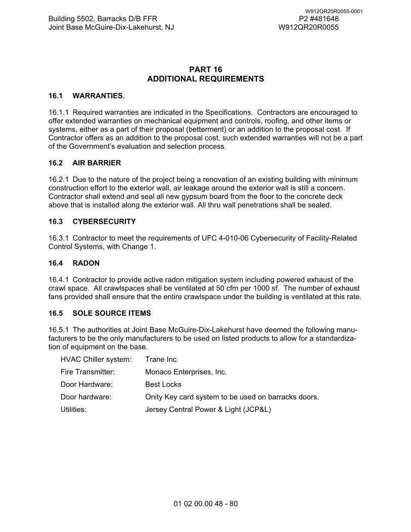
Building 5502, Barracks D/B FFR P2 #481648 Joint Base McGuire-Dix-Lakehurst, NJ W912QR20R0055
01 02 00.00 48 - 80
PART 16 ADDITIONAL REQUIREMENTS
16.1 WARRANTIES.
16.1.1 Required warranties are indicated in the Specifications. Contractors are encouraged to offer extended warranties on mechanical equipment and controls, roofing, and other items or systems, either as a part of their proposal (betterment) or an addition to the proposal cost. If Contractor offers as an addition to the proposal cost, such extended warranties will not be a part of the Government’s evaluation and selection process.
16.2 AIR BARRIER
16.2.1 Due to the nature of the project being a renovation of an existing building with minimum construction effort to the exterior wall, air leakage around the exterior wall is still a concern. Contractor shall extend and seal all new gypsum board from the floor to the concrete deck above that is installed along the exterior wall. All thru wall penetrations shall be sealed.
16.3 CYBERSECURITY
16.3.1 Contractor to meet the requirements of UFC 4-010-06 Cybersecurity of Facility-Related Control Systems, with Change 1.
16.4 RADON
16.4.1 Contractor to provide active radon mitigation system including powered exhaust of the crawl space. All crawlspaces shall be ventilated at 50 cfm per 1000 sf. The number of exhaust fans provided shall ensure that the entire crawlspace under the building is ventilated at this rate.
16.5 SOLE SOURCE ITEMS
16.5.1 The authorities at Joint Base McGuire-Dix-Lakehurst have deemed the following manu-facturers to be the only manufacturers to be used on listed products to allow for a standardiza-tion of equipment on the base.
HVAC Chiller system: Trane Inc.
Fire Transmitter: Monaco Enterprises, Inc.
Door Hardware: Best Locks
Door hardware: Onity Key card system to be used on barracks doors.
Utilities: Jersey Central Power & Light (JCP&L)
W912QR20R0055-0001
Building 5502, Barracks D/B FFR P2 #481648 Joint Base McGuire-Dix-Lakehurst, NJ W912QR20R0055
Section 01 02 00.00 48
ATTACHMENT ‘A’
Room By Room Supplemental Requirements
W912QR20R0055-0001
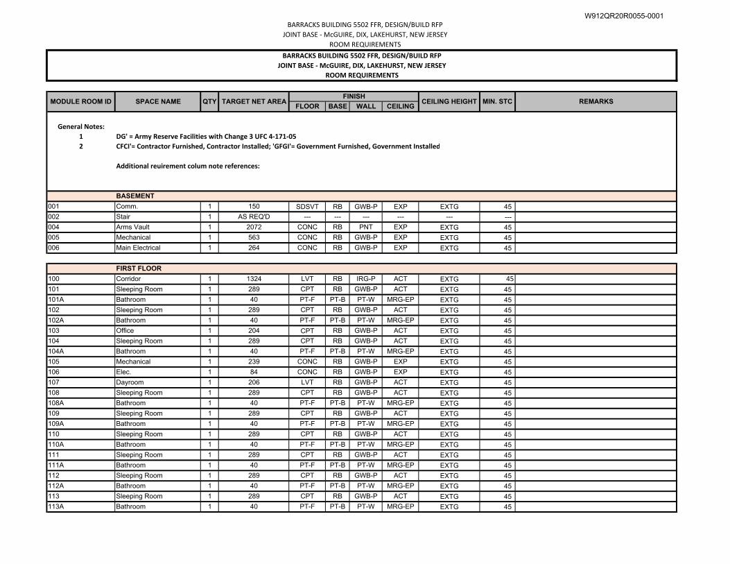
BARRACKS BUILDING 5502 FFR, DESIGN/BUILD RFP
JOINT BASE ‐ McGUIRE, DIX, LAKEHURST, NEW JERSEY
ROOM REQUIREMENTS
FLOOR BASE WALL CEILING
General Notes:1 DG' = Army Reserve Facilities with Change 3 UFC 4‐171‐052 CFCI'= Contractor Furnished, Contractor Installed; 'GFGI'= Government Furnished, Government Installed
Additional reuirement colum note references:
BASEMENT
001 Comm. 1 150 SDSVT RB GWB-P EXP EXTG 45
002 Stair 1 AS REQ'D --- --- --- --- --- ---
004 Arms Vault 1 2072 CONC RB PNT EXP EXTG 45
005 Mechanical 1 563 CONC RB GWB-P EXP EXTG 45
006 Main Electrical 1 264 CONC RB GWB-P EXP EXTG 45
FIRST FLOOR
100 Corridor 1 1324 LVT RB IRG-P ACT EXTG 45
101 Sleeping Room 1 289 CPT RB GWB-P ACT EXTG 45
101A Bathroom 1 40 PT-F PT-B PT-W MRG-EP EXTG 45
102 Sleeping Room 1 289 CPT RB GWB-P ACT EXTG 45
102A Bathroom 1 40 PT-F PT-B PT-W MRG-EP EXTG 45
103 Office 1 204 CPT RB GWB-P ACT EXTG 45
104 Sleeping Room 1 289 CPT RB GWB-P ACT EXTG 45
104A Bathroom 1 40 PT-F PT-B PT-W MRG-EP EXTG 45
105 Mechanical 1 239 CONC RB GWB-P EXP EXTG 45
106 Elec. 1 84 CONC RB GWB-P EXP EXTG 45
107 Dayroom 1 206 LVT RB GWB-P ACT EXTG 45
108 Sleeping Room 1 289 CPT RB GWB-P ACT EXTG 45
108A Bathroom 1 40 PT-F PT-B PT-W MRG-EP EXTG 45
109 Sleeping Room 1 289 CPT RB GWB-P ACT EXTG 45
109A Bathroom 1 40 PT-F PT-B PT-W MRG-EP EXTG 45
110 Sleeping Room 1 289 CPT RB GWB-P ACT EXTG 45
110A Bathroom 1 40 PT-F PT-B PT-W MRG-EP EXTG 45
111 Sleeping Room 1 289 CPT RB GWB-P ACT EXTG 45
111A Bathroom 1 40 PT-F PT-B PT-W MRG-EP EXTG 45
112 Sleeping Room 1 289 CPT RB GWB-P ACT EXTG 45
112A Bathroom 1 40 PT-F PT-B PT-W MRG-EP EXTG 45
113 Sleeping Room 1 289 CPT RB GWB-P ACT EXTG 45
113A Bathroom 1 40 PT-F PT-B PT-W MRG-EP EXTG 45
MIN. STC REMARKS
JOINT BASE ‐ McGUIRE, DIX, LAKEHURST, NEW JERSEYBARRACKS BUILDING 5502 FFR, DESIGN/BUILD RFP
ROOM REQUIREMENTS
MODULE ROOM ID SPACE NAME QTY TARGET NET AREAFINISH
CEILING HEIGHT
W912QR20R0055-0001
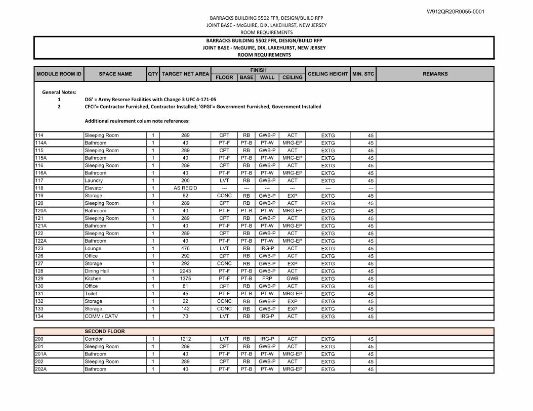
BARRACKS BUILDING 5502 FFR, DESIGN/BUILD RFP
JOINT BASE ‐ McGUIRE, DIX, LAKEHURST, NEW JERSEY
ROOM REQUIREMENTS
FLOOR BASE WALL CEILING
General Notes:1 DG' = Army Reserve Facilities with Change 3 UFC 4‐171‐052 CFCI'= Contractor Furnished, Contractor Installed; 'GFGI'= Government Furnished, Government Installed
Additional reuirement colum note references:
MIN. STC REMARKS
JOINT BASE ‐ McGUIRE, DIX, LAKEHURST, NEW JERSEYBARRACKS BUILDING 5502 FFR, DESIGN/BUILD RFP
ROOM REQUIREMENTS
MODULE ROOM ID SPACE NAME QTY TARGET NET AREAFINISH
CEILING HEIGHT
114 Sleeping Room 1 289 CPT RB GWB-P ACT EXTG 45
114A Bathroom 1 40 PT-F PT-B PT-W MRG-EP EXTG 45
115 Sleeping Room 1 289 CPT RB GWB-P ACT EXTG 45
115A Bathroom 1 40 PT-F PT-B PT-W MRG-EP EXTG 45
116 Sleeping Room 1 289 CPT RB GWB-P ACT EXTG 45
116A Bathroom 1 40 PT-F PT-B PT-W MRG-EP EXTG 45
117 Laundry 1 200 LVT RB GWB-P ACT EXTG 45
118 Elevator 1 AS REQ'D --- --- --- --- --- ---
119 Storage 1 62 CONC RB GWB-P EXP EXTG 45
120 Sleeping Room 1 289 CPT RB GWB-P ACT EXTG 45
120A Bathroom 1 40 PT-F PT-B PT-W MRG-EP EXTG 45
121 Sleeping Room 1 289 CPT RB GWB-P ACT EXTG 45
121A Bathroom 1 40 PT-F PT-B PT-W MRG-EP EXTG 45
122 Sleeping Room 1 289 CPT RB GWB-P ACT EXTG 45
122A Bathroom 1 40 PT-F PT-B PT-W MRG-EP EXTG 45
123 Lounge 1 476 LVT RB IRG-P ACT EXTG 45
126 Office 1 292 CPT RB GWB-P ACT EXTG 45
127 Storage 1 292 CONC RB GWB-P EXP EXTG 45
128 Dining Hall 1 2243 PT-F PT-B GWB-P ACT EXTG 45
129 Kitchen 1 1375 PT-F PT-B FRP GWB EXTG 45
130 Office 1 81 CPT RB GWB-P ACT EXTG 45
131 Toilet 1 45 PT-F PT-B PT-W MRG-EP EXTG 45
132 Storage 1 22 CONC RB GWB-P EXP EXTG 45
133 Storage 1 142 CONC RB GWB-P EXP EXTG 45
134 COMM / CATV 1 70 LVT RB IRG-P ACT EXTG 45
SECOND FLOOR
200 Corridor 1 1212 LVT RB IRG-P ACT EXTG 45
201 Sleeping Room 1 289 CPT RB GWB-P ACT EXTG 45
201A Bathroom 1 40 PT-F PT-B PT-W MRG-EP EXTG 45
202 Sleeping Room 1 289 CPT RB GWB-P ACT EXTG 45
202A Bathroom 1 40 PT-F PT-B PT-W MRG-EP EXTG 45
W912QR20R0055-0001
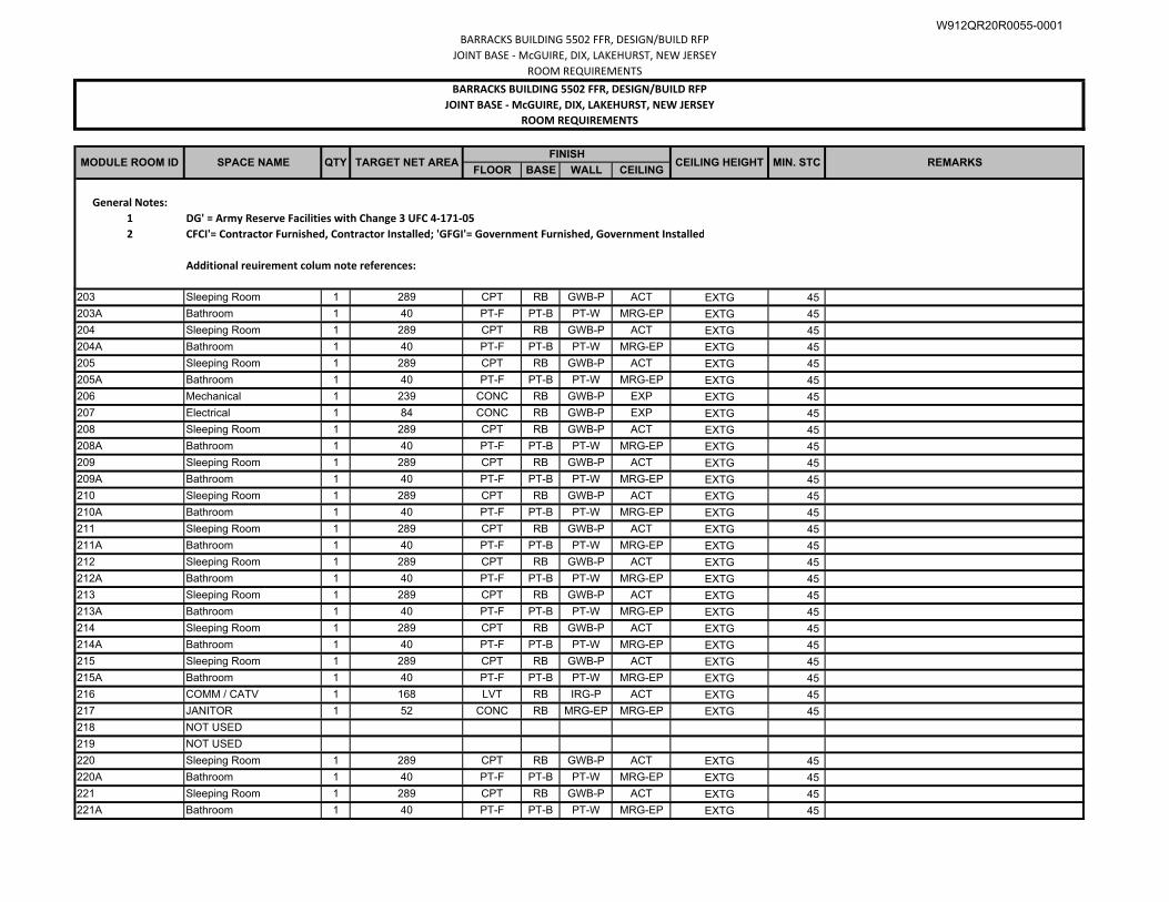
BARRACKS BUILDING 5502 FFR, DESIGN/BUILD RFP
JOINT BASE ‐ McGUIRE, DIX, LAKEHURST, NEW JERSEY
ROOM REQUIREMENTS
FLOOR BASE WALL CEILING
General Notes:1 DG' = Army Reserve Facilities with Change 3 UFC 4‐171‐052 CFCI'= Contractor Furnished, Contractor Installed; 'GFGI'= Government Furnished, Government Installed
Additional reuirement colum note references:
MIN. STC REMARKS
JOINT BASE ‐ McGUIRE, DIX, LAKEHURST, NEW JERSEYBARRACKS BUILDING 5502 FFR, DESIGN/BUILD RFP
ROOM REQUIREMENTS
MODULE ROOM ID SPACE NAME QTY TARGET NET AREAFINISH
CEILING HEIGHT
203 Sleeping Room 1 289 CPT RB GWB-P ACT EXTG 45
203A Bathroom 1 40 PT-F PT-B PT-W MRG-EP EXTG 45
204 Sleeping Room 1 289 CPT RB GWB-P ACT EXTG 45
204A Bathroom 1 40 PT-F PT-B PT-W MRG-EP EXTG 45
205 Sleeping Room 1 289 CPT RB GWB-P ACT EXTG 45
205A Bathroom 1 40 PT-F PT-B PT-W MRG-EP EXTG 45
206 Mechanical 1 239 CONC RB GWB-P EXP EXTG 45
207 Electrical 1 84 CONC RB GWB-P EXP EXTG 45
208 Sleeping Room 1 289 CPT RB GWB-P ACT EXTG 45
208A Bathroom 1 40 PT-F PT-B PT-W MRG-EP EXTG 45
209 Sleeping Room 1 289 CPT RB GWB-P ACT EXTG 45
209A Bathroom 1 40 PT-F PT-B PT-W MRG-EP EXTG 45
210 Sleeping Room 1 289 CPT RB GWB-P ACT EXTG 45
210A Bathroom 1 40 PT-F PT-B PT-W MRG-EP EXTG 45
211 Sleeping Room 1 289 CPT RB GWB-P ACT EXTG 45
211A Bathroom 1 40 PT-F PT-B PT-W MRG-EP EXTG 45
212 Sleeping Room 1 289 CPT RB GWB-P ACT EXTG 45
212A Bathroom 1 40 PT-F PT-B PT-W MRG-EP EXTG 45
213 Sleeping Room 1 289 CPT RB GWB-P ACT EXTG 45
213A Bathroom 1 40 PT-F PT-B PT-W MRG-EP EXTG 45
214 Sleeping Room 1 289 CPT RB GWB-P ACT EXTG 45
214A Bathroom 1 40 PT-F PT-B PT-W MRG-EP EXTG 45
215 Sleeping Room 1 289 CPT RB GWB-P ACT EXTG 45
215A Bathroom 1 40 PT-F PT-B PT-W MRG-EP EXTG 45
216 COMM / CATV 1 168 LVT RB IRG-P ACT EXTG 45
217 JANITOR 1 52 CONC RB MRG-EP MRG-EP EXTG 45
218 NOT USED
219 NOT USED
220 Sleeping Room 1 289 CPT RB GWB-P ACT EXTG 45
220A Bathroom 1 40 PT-F PT-B PT-W MRG-EP EXTG 45
221 Sleeping Room 1 289 CPT RB GWB-P ACT EXTG 45
221A Bathroom 1 40 PT-F PT-B PT-W MRG-EP EXTG 45
W912QR20R0055-0001
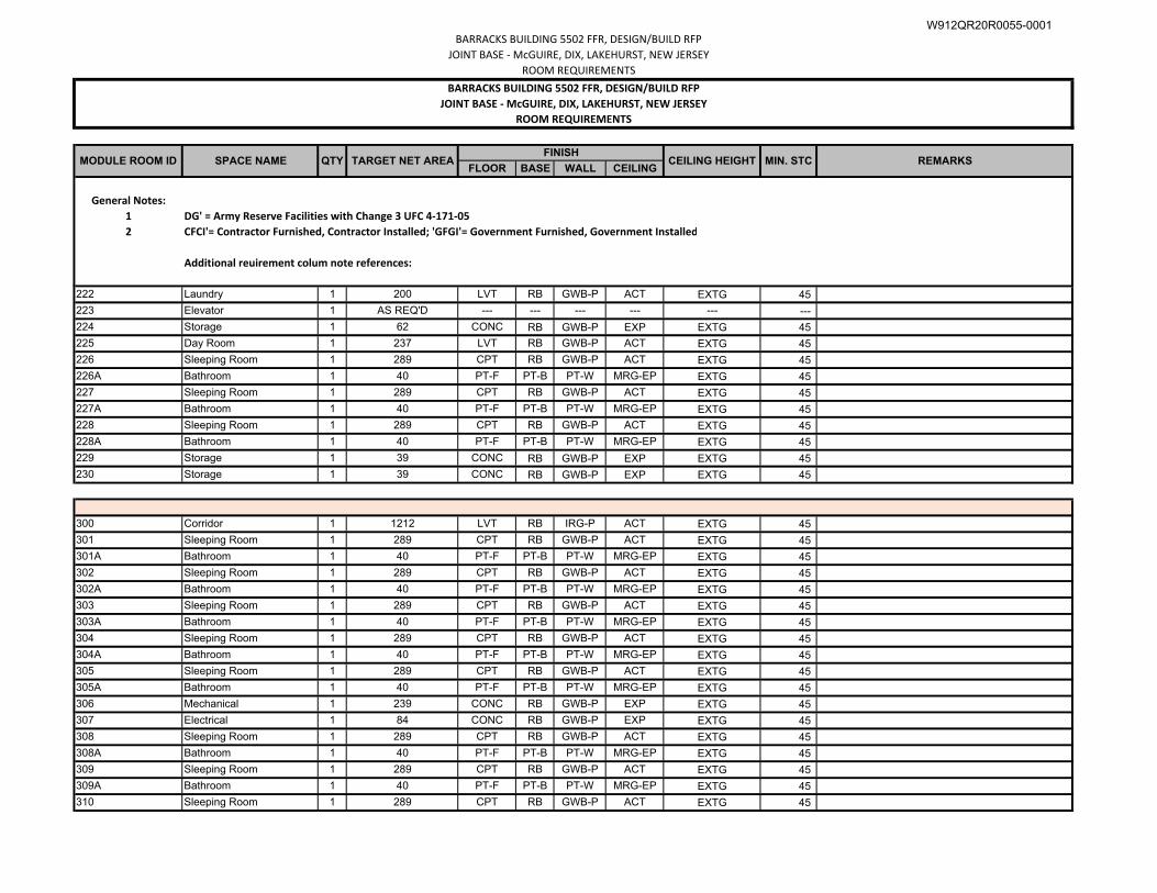
BARRACKS BUILDING 5502 FFR, DESIGN/BUILD RFP
JOINT BASE ‐ McGUIRE, DIX, LAKEHURST, NEW JERSEY
ROOM REQUIREMENTS
FLOOR BASE WALL CEILING
General Notes:1 DG' = Army Reserve Facilities with Change 3 UFC 4‐171‐052 CFCI'= Contractor Furnished, Contractor Installed; 'GFGI'= Government Furnished, Government Installed
Additional reuirement colum note references:
MIN. STC REMARKS
JOINT BASE ‐ McGUIRE, DIX, LAKEHURST, NEW JERSEYBARRACKS BUILDING 5502 FFR, DESIGN/BUILD RFP
ROOM REQUIREMENTS
MODULE ROOM ID SPACE NAME QTY TARGET NET AREAFINISH
CEILING HEIGHT
222 Laundry 1 200 LVT RB GWB-P ACT EXTG 45
223 Elevator 1 AS REQ'D --- --- --- --- --- ---
224 Storage 1 62 CONC RB GWB-P EXP EXTG 45
225 Day Room 1 237 LVT RB GWB-P ACT EXTG 45
226 Sleeping Room 1 289 CPT RB GWB-P ACT EXTG 45
226A Bathroom 1 40 PT-F PT-B PT-W MRG-EP EXTG 45
227 Sleeping Room 1 289 CPT RB GWB-P ACT EXTG 45
227A Bathroom 1 40 PT-F PT-B PT-W MRG-EP EXTG 45
228 Sleeping Room 1 289 CPT RB GWB-P ACT EXTG 45
228A Bathroom 1 40 PT-F PT-B PT-W MRG-EP EXTG 45
229 Storage 1 39 CONC RB GWB-P EXP EXTG 45
230 Storage 1 39 CONC RB GWB-P EXP EXTG 45
300 Corridor 1 1212 LVT RB IRG-P ACT EXTG 45
301 Sleeping Room 1 289 CPT RB GWB-P ACT EXTG 45
301A Bathroom 1 40 PT-F PT-B PT-W MRG-EP EXTG 45
302 Sleeping Room 1 289 CPT RB GWB-P ACT EXTG 45
302A Bathroom 1 40 PT-F PT-B PT-W MRG-EP EXTG 45
303 Sleeping Room 1 289 CPT RB GWB-P ACT EXTG 45
303A Bathroom 1 40 PT-F PT-B PT-W MRG-EP EXTG 45
304 Sleeping Room 1 289 CPT RB GWB-P ACT EXTG 45
304A Bathroom 1 40 PT-F PT-B PT-W MRG-EP EXTG 45
305 Sleeping Room 1 289 CPT RB GWB-P ACT EXTG 45
305A Bathroom 1 40 PT-F PT-B PT-W MRG-EP EXTG 45
306 Mechanical 1 239 CONC RB GWB-P EXP EXTG 45
307 Electrical 1 84 CONC RB GWB-P EXP EXTG 45
308 Sleeping Room 1 289 CPT RB GWB-P ACT EXTG 45
308A Bathroom 1 40 PT-F PT-B PT-W MRG-EP EXTG 45
309 Sleeping Room 1 289 CPT RB GWB-P ACT EXTG 45
309A Bathroom 1 40 PT-F PT-B PT-W MRG-EP EXTG 45
310 Sleeping Room 1 289 CPT RB GWB-P ACT EXTG 45
W912QR20R0055-0001
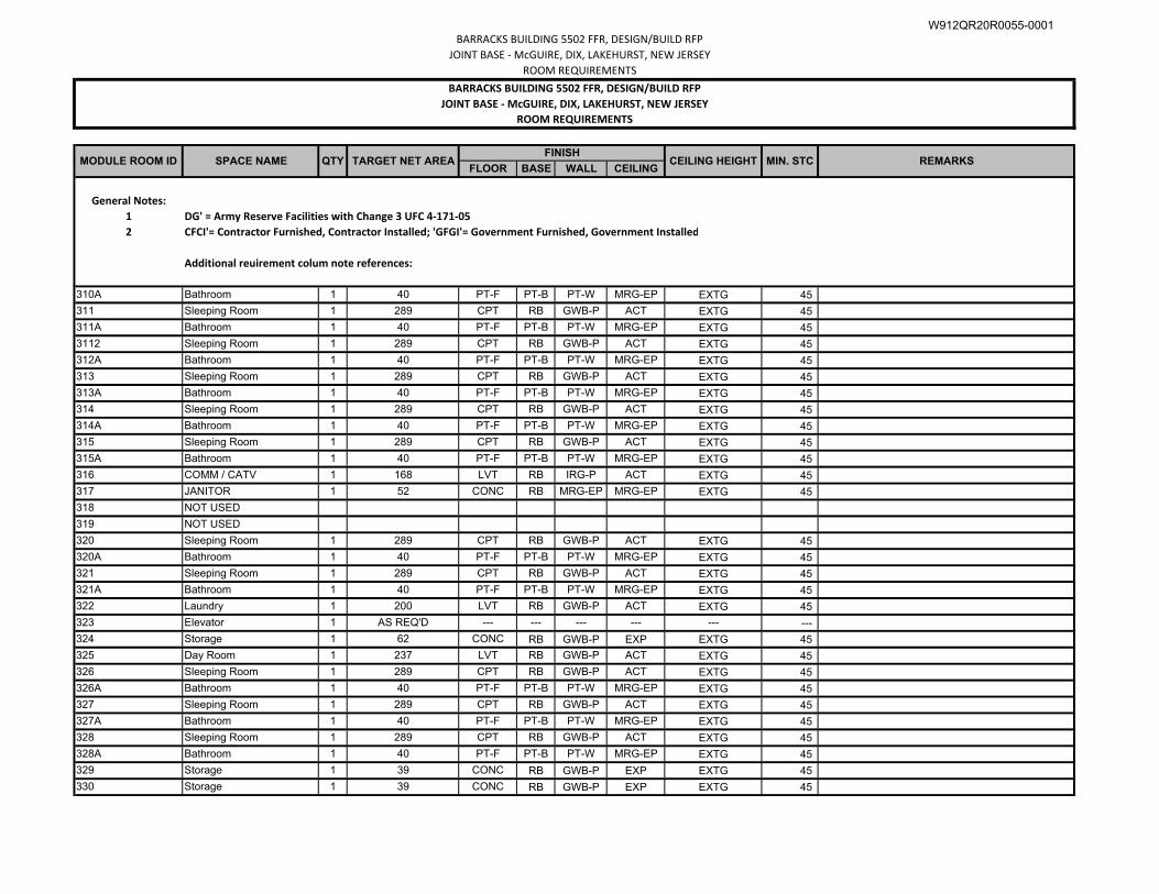
BARRACKS BUILDING 5502 FFR, DESIGN/BUILD RFP
JOINT BASE ‐ McGUIRE, DIX, LAKEHURST, NEW JERSEY
ROOM REQUIREMENTS
FLOOR BASE WALL CEILING
General Notes:1 DG' = Army Reserve Facilities with Change 3 UFC 4‐171‐052 CFCI'= Contractor Furnished, Contractor Installed; 'GFGI'= Government Furnished, Government Installed
Additional reuirement colum note references:
MIN. STC REMARKS
JOINT BASE ‐ McGUIRE, DIX, LAKEHURST, NEW JERSEYBARRACKS BUILDING 5502 FFR, DESIGN/BUILD RFP
ROOM REQUIREMENTS
MODULE ROOM ID SPACE NAME QTY TARGET NET AREAFINISH
CEILING HEIGHT
310A Bathroom 1 40 PT-F PT-B PT-W MRG-EP EXTG 45
311 Sleeping Room 1 289 CPT RB GWB-P ACT EXTG 45
311A Bathroom 1 40 PT-F PT-B PT-W MRG-EP EXTG 45
3112 Sleeping Room 1 289 CPT RB GWB-P ACT EXTG 45
312A Bathroom 1 40 PT-F PT-B PT-W MRG-EP EXTG 45
313 Sleeping Room 1 289 CPT RB GWB-P ACT EXTG 45
313A Bathroom 1 40 PT-F PT-B PT-W MRG-EP EXTG 45
314 Sleeping Room 1 289 CPT RB GWB-P ACT EXTG 45
314A Bathroom 1 40 PT-F PT-B PT-W MRG-EP EXTG 45
315 Sleeping Room 1 289 CPT RB GWB-P ACT EXTG 45
315A Bathroom 1 40 PT-F PT-B PT-W MRG-EP EXTG 45
316 COMM / CATV 1 168 LVT RB IRG-P ACT EXTG 45
317 JANITOR 1 52 CONC RB MRG-EP MRG-EP EXTG 45
318 NOT USED
319 NOT USED
320 Sleeping Room 1 289 CPT RB GWB-P ACT EXTG 45
320A Bathroom 1 40 PT-F PT-B PT-W MRG-EP EXTG 45
321 Sleeping Room 1 289 CPT RB GWB-P ACT EXTG 45
321A Bathroom 1 40 PT-F PT-B PT-W MRG-EP EXTG 45
322 Laundry 1 200 LVT RB GWB-P ACT EXTG 45
323 Elevator 1 AS REQ'D --- --- --- --- --- ---
324 Storage 1 62 CONC RB GWB-P EXP EXTG 45
325 Day Room 1 237 LVT RB GWB-P ACT EXTG 45
326 Sleeping Room 1 289 CPT RB GWB-P ACT EXTG 45
326A Bathroom 1 40 PT-F PT-B PT-W MRG-EP EXTG 45
327 Sleeping Room 1 289 CPT RB GWB-P ACT EXTG 45
327A Bathroom 1 40 PT-F PT-B PT-W MRG-EP EXTG 45
328 Sleeping Room 1 289 CPT RB GWB-P ACT EXTG 45
328A Bathroom 1 40 PT-F PT-B PT-W MRG-EP EXTG 45
329 Storage 1 39 CONC RB GWB-P EXP EXTG 45
330 Storage 1 39 CONC RB GWB-P EXP EXTG 45
W912QR20R0055-0001
Building 5502, Barracks D/B FFR P2 #481648 Joint Base McGuire-Dix-Lakehurst, NJ W912QR20R0055
Section 01 02 00.00 48
ATTACHMENT ‘B’
Hazardous Material Report
W912QR20R0055-0001
FINAL PRE-RENOVATION HAZARDOUS MATERIALS SURVEY REPORT Building 5502 Joint Base McGuire-Dix-Lakehurst Fort Dix, New Jersey PREPARED FOR: Mason & Hanger A Day & Zimmerman Company 300 W. Vine Street, Suite 1300 Lexington, Kentucky 40507-1814 PREPARED BY: PARS Environmental, Inc. 500 Horizon Drive, Suite 540 Robbinsville, NJ 08691 PARS PROJECT NO. 803-05
July 2020
W912QR20R0055-0001
Final Pre-Renovation Hazardous Materials Survey Report Joint Base McGuire-Dix-Lakehurst
Building 5502 July 2020
i
Table of Contents EXECUTIVE SUMMARY ......................................................................................................................................... 1 1.0 INTRODUCTION .............................................................................................................................................. 4 2.0 METHODOLOGY............................................................................................................................................. 6
2.1 ASBESTOS SURVEY APPROACH ........................................................................................................................... 6 2.2 LEAD-CONTAINING SUBSTANCES SURVEY APPROACH ........................................................................................ 6 2.3 RADON SAMPLING APPROACH ............................................................................................................................. 6 2.4 HAZARDOUS MATERIALS SURVEY APPROACH .................................................................................................... 6
3.0 ANALYTICAL METHODS ............................................................................................................................. 8 3.1 ASBESTOS ............................................................................................................................................................ 8 3.2 LEAD-CONTAINING PAINT AND MATERIALS ........................................................................................................ 8 3.3 RADON ................................................................................................................................................................ 8 3.4 HAZARDOUS MATERIALS SURVEY ...................................................................................................................... 8
4.0 RESULTS ......................................................................................................................................................... 10 4.1 ASBESTOS .......................................................................................................................................................... 10 4.2 LEAD-CONTAINING PAINT/LEAD-CONTAINING MATERIALS ............................................................................. 10 4.3 RADON .............................................................................................................................................................. 11 4.4 HAZARDOUS MATERIALS SURVEY .................................................................................................................... 11
5.0 CONCLUSIONS AND RECOMMENDATIONS .......................................................................................... 13 List of Figures Figure 1 – ACM Sample Location Map List of Results Tables Table 1 – Asbestos Homogeneous Application Table Table 2 – XRF Lead-Based Paint Test Results Table 3 – Chip Sample Results List of Appendices Appendix A – Licenses and Certifications Appendix B – ACM Photo Log Appendix C – Hazardous Materials Survey & LBP Photo Log Appendix D – EMSL Laboratory Reports Appendix E – Radon Laboratory Report Appendix F – 29 CFR 1926.62 Summary
W912QR20R0055-0001
Final Pre-Renovation Hazardous Materials Survey Report Joint Base McGuire-Dix-Lakehurst
Building 5502 July 2020
1
EXECUTIVE SUMMARY On January 14 and February 10, 2020, PARS Environmental, Inc. (PARS) conducted a Pre-Renovation Hazardous Materials Survey (hereinafter the “Survey”) of Building 5502 located at Joint Base McGuire-Dix-Lakehurst (JBMDL), New Jersey (hereinafter the “Property”). The survey was conducted in accordance with PARS Proposal No. 2019-156 signed by the Mason & Hanger Group, Inc. and PARS on October 28, 2019. The objective of the Survey was to identify suspect asbestos-containing materials (ACM), lead-based paint (LBP), radon gas, and other hazardous materials that may be present within Building 5502. These other hazardous materials may include batteries, mercury-containing equipment, and lamps; equipment containing or potentially containing other hazardous materials including polychlorinated biphenyls (PCBs), fuels, oils, metals, compressed gas, and radioactive materials. Sufficient sampling was conducted to reliable evaluate the presence, location, and quantity of accessible ACM, LBP, PCBs, and radon gas. Limited destructive sampling techniques were utilized. The building is a 40,000 square foot (ft2) three-story structure with a concrete exterior and multi-roof system, with part of the structure having a basement, and the rest over a crawlspace. The building was constructed in the 1950s, is used as a barracks by JBMDL, and is slated for renovation. The building contains mostly residential housing, with approximately 90 individual units, with common bathrooms, laundry rooms, cafeteria, recreational room, and kitchen. The mechanical room is located in the basement, and only accessible from the outside of the building. Flooring within the building is primarily vinyl floor tile, with some areas of ceramic tiling and carpeting. SUMMARY OF FINDINGS Asbestos Asbestos-containing materials were identified throughout Building 5502. A location map of confirmed ACM is provided as Figure 1. The estimated quantities of these materials are:
1,350 square feet of Mastic associated with the Bottom Layer 12” x 12” Vinyl Floor Tile
160 square feet of Green (bottom layer) Vinyl Floor Tile 160 square feet of Mastic associated with the Green (bottom layer) Vinyl Floor Tile 70 square feet of Gray (bottom layer) Vinyl Floor Tile 70 square feet of Mastic associated with the Gray (bottom layer) Vinyl Floor Tile 800 square feet of Green 12” x 12” (bottom layer) Vinyl Floor Tile 36,450 square feet of Mastic associated with the 12” x 12” (bottom layer) Vinyl Floor
Tile 100 linear feet of Exterior Window Caulk – within the red brick exterior porch areas 100 linear feet of Exterior Door Caulk – within the red brick exterior porch areas
W912QR20R0055-0001
Final Pre-Renovation Hazardous Materials Survey Report Joint Base McGuire-Dix-Lakehurst
Building 5502 July 2020
2
Lead-based Paint Lead-based paint was identified via XRF within Building 5502 in the following locations:
Armory (Basement) – Concrete Walls Armory (Basement) – Door Frames and Jambs Armory (Basement) – Windows Kitchen – Brick Walls Kitchen – Windows Recreation Room – Columns Stairwells – Railings, Risers, Stringers, Treads, Walls Throughout – Metal Archways Throughout – Concrete Window Frames Throughout – Concrete Walls Throughout – Metal Door Frames and Jambs
Lead-based paint was also identified via Paint Chip testing in the following locations:
Throughout – Beige, Green, Gray Wall Paint (Multiple Layers)
Radon Radon test results were below the 4.0 picoCuries per liter (pCi/l) action level indicated by the New Jersey Department of Environmental Protection (NJDEP) and the United States Environmental Protection Agency (USEPA) as cause for mitigation. Hazardous Materials Suspect PCB-containing, mercury-containing, and radioactive-containing equipment and other hazardous materials were observed throughout the building. Suspect PCB-containing caulk samples were all found to be non-detect for PCB’s. CONCLUSIONS AND RECOMMENDATIONS Significant amounts of ACM are present in Building 5502, at the locations noted above. Asbestos containing building materials that will be subject to demolition or replacement must be removed from the building prior to the commencement of such activities in accordance with the requirements of 40 CFR Part 61. The ACM must be disposed of in accordance with the Guidance Document for the Management of Asbestos-Containing Material (ACM) issued by the NJDEP. All work impacting suspect lead-based or lead-containing substances will need to be performed in accordance with the Lead in Construction specification and the OSHA Lead in Construction Standard 29 CFR 1926.62. Should lead-based paint abatement be performed, all work should be in compliance with local, state, and federal rules and regulations regarding lead-based paint abatement. All lead abatement waste should also be characterized. The Survey also identified other equipment that may contain one of more of the hazardous materials noted above. During the renovation, the light ballasts should be inspected for a PCB-
W912QR20R0055-0001
Final Pre-Renovation Hazardous Materials Survey Report Joint Base McGuire-Dix-Lakehurst
Building 5502 July 2020
3
free label. If the ballasts do not possess such a label, they must be assumed to contain PCBs. The removal and disposal of PCB-containing light ballasts should be performed according to all applicable laws, rules, and regulations governing PCB-containing equipment. All suspect mercury-containing, PCB-containing equipment, and oil-containing equipment should be removed and disposed of according to all applicable laws, rules, and regulations governing this equipment. Leaking equipment should be containerized separately from non-leaking equipment. Radiological sources (e.g., smoke detectors, exit signs) should be removed and properly disposed of from the Property prior to demolition.
W912QR20R0055-0001
Final Pre-Renovation Hazardous Materials Survey Report Joint Base McGuire-Dix-Lakehurst
Building 5502 July 2020
4
1.0 INTRODUCTION
On January 14 and February 10, 2020, PARS Environmental, Inc. (PARS) conducted a Pre-Renovation Hazardous Materials Survey (hereinafter the “Survey”) of Building 5502 located at Joint Base McGuire-Dix-Lakehurst (JBMDL), New Jersey (hereinafter the “Property”). The objective of the Survey was to identify suspect asbestos-containing materials (ACM), lead-based paint (LBP), radon gas, and other hazardous materials that may be present within Building 5502. These other hazardous materials may include batteries, mercury-containing equipment, and lamps; equipment containing or potentially containing other hazardous materials including polychlorinated biphenyls (PCBs), fuels, oils, metals, compressed gas, and radioactive materials. The building is a 40,000 square foot (ft2) three-story structure with a concrete exterior and multi-roof system, with part of the structure having a basement, and the rest over a crawlspace. The building was constructed in the 1950s, is used as a barracks by JBMDL, and is slated for renovation. The building contains mostly residential housing, approximately 90 individual units, with common bathrooms, laundry rooms, cafeteria, recreational room, and kitchen. The mechanical room is located in the basement, and only accessible from the outside of the building. Flooring within the building is mostly vinyl floor tile, with some areas of ceramic tiling. The Survey was completed by Ms. Lela Stratton, Mr. Bruce Lockwood and Mr. Julian Fernandez-Obregon. Ms. Stratton, Mr. Lockwood, and Mr. Fernandez-Obregon are certified Asbestos Hazard Emergency Response Act (AHERA) asbestos inspectors. Mr. Fernandez-Obregon and Mr. Lockwood are also State of New Jersey licensed lead inspectors/risk assessors. A copy of relevant licenses and certifications are included in Appendix A. The United States Environmental Protection Agency (USEPA) defines an ACM as a material that contains greater than one percent (> 1%) asbestos). The purpose of the ACM Survey was to determine the presence of suspect materials at the Property, sample and test the suspect materials, summarize the findings, and propose additional services that may be needed to comply with current National Emission Standards for Hazardous Air Pollutants (NESHAP), Occupational Safety and Health Administration (OSHA), New Jersey Department of Health (NJDOH), and USEPA regulations prior to the renovation of the Property. The USEPA and the New Jersey Department of Community Affairs (NJDCA) New Jersey Lead Hazard Evaluation and Abatement Code (N.J.A.C. 5:17) consider painted surfaces containing lead at a concentration of 1.0 milligram per square centimeter (mg/cm2) or greater to be LBP. The USEPA also defines a chip sample LBP when lead exceeds 0.5%/wt. PARS conducted LBP testing to assess whether LBP was present at levels exceeding the USEPA and NJDCA Lead Hazard Evaluation and Abatement Code. PARS deployed and collected Radon canisters in sufficient quantity to determine the presence or absence of radon gas based on the square footage and layout of the building.
W912QR20R0055-0001
Final Pre-Renovation Hazardous Materials Survey Report Joint Base McGuire-Dix-Lakehurst
Building 5502 July 2020
5
PARS also conducted a Hazardous Materials Survey (HMS) of the Property. The purpose of the HMS was to visually identify and assess the condition of equipment that may contain hazardous materials and estimate the quantities of such equipment at the Property. The materials of interest for the HMS included Universal Wastes such as batteries, mercury-containing equipment, and lamps; equipment containing or potentially containing other hazardous materials including polychlorinated biphenyls (PCBs), fuels, oils, metals, compressed gas, and radioactive materials. Bulk samples of suspect PCB-containing caulking were also collected and submitted for analysis.
W912QR20R0055-0001
Final Pre-Renovation Hazardous Materials Survey Report Joint Base McGuire-Dix-Lakehurst
Building 5502 July 2020
6
2.0 METHODOLOGY 2.1 ASBESTOS SURVEY APPROACH On January 14, 2020, PARS performed an asbestos survey at the Site. The Survey approach included a visual inspection and destructive testing for suspect ACM. Suspect materials were divided into homogeneous areas, which are building materials evaluated by the inspector to be the same based on their color, texture, and age. Representative samples were collected of each homogeneous material. Suspect materials identified and sampled are listed in Table 1. A sample location map is included as Figure 1. Bulk samples of suspect materials were collected in 4-mil plastic bags and sealed for transport to the laboratory under chain-of-custody protocols. Each sample was assigned a unique homogeneous application number (HA-01 through HA-21) and sample identification number (e.g., 5502-01). The follow are the homogenous materials symbols used for identification in this report: T = Thermal System Insulation M = Miscellaneous Materials S = Surfacing Materials (troweled or spray applied)
2.2 LEAD-CONTAINING SUBSTANCES SURVEY APPROACH On January 14, 2020, PARS also conducted a lead-based paint survey of representative interior surfaces that may be impacted by the planned renovation activities. PARS collected representative “readings” of presumed lead-containing paint using an X-Ray Fluorescence (XRF) device to test for the presence of lead in paint. The XRF used for the evaluation was a Niton XL2 600, Serial No. 110706. PARS also collected representative paint chip samples to confirm XRF results. XRF Results are provided in Table 2. Chip sample results are provided in Table 3. 2.3 RADON SAMPLING APPROACH PARS deployed and collected 14 radon test canisters, sufficient to determine the presence or absence of radon gas based on the square footage and layout of the building. Radon test canisters are charcoal absorption devices. Radon traveling in the air is absorbed on the charcoal and the decay products are measured at a laboratory to determine the concentration of radon in the air following prescribed methods. 2.4 HAZARDOUS MATERIALS SURVEY APPROACH PARS performed a visual assessment for potential mercury and PCB-containing materials and equipment, and other hazardous materials including fuels, oils, metals, compressed gas, and radioactive materials. PARS conducted the HMS throughout the Property building. Visual observations were performed to evaluate the presence and location of hazardous materials at the Property.
W912QR20R0055-0001
Final Pre-Renovation Hazardous Materials Survey Report Joint Base McGuire-Dix-Lakehurst
Building 5502 July 2020
7
PARS took photographs of all suspect hazardous materials. Photo-documentation of the hazardous materials is presented in Appendix C. PARS collected a total of eight samples to be analyzed for PCBs via SW-846 Method 8082A. Samples of suspect PCB-containing materials were collected in 4-ounce glass jars and sealed for transport to the laboratory under chain-of-custody protocols. Each sample was assigned a unique sample identification number (e.g., PCB-01).
W912QR20R0055-0001

Final Pre-Renovation Hazardous Materials Survey Report Joint Base McGuire-Dix-Lakehurst
Building 5502 July 2020
8
3.0 ANALYTICAL METHODS 3.1 ASBESTOS Material identification was performed via Polarized Light Microscopy with Dispersion Staining (PLM/DS) in accordance with New Jersey requirements (N.J.A.C. 8:60 and 12:120) using USEPA Method 600/R-93/116 and for Transmission Electron Microscopy (TEM) analysis using USEPA Method 600/R-93/116B Section 2.5.5.1 For those materials yielding less than 1% asbestos using PLM, Transmission Electron Microscopy (TEM) analysis was performed for confirmation. Laboratory analysis was conducted by EMSL Analytical located in Cinnaminson, New Jersey. EMSL is certified by the National Institute of Standards and Technology and National Voluntary Laboratory Accreditation Program (NIST-NVLAP # 101048) for asbestos analysis. EMSL’s certifications are provided in Appendix A. 3.2 LEAD-CONTAINING PAINT AND MATERIALS Tested components were evaluated according to the specifications described in the protocols for LBP inspection in the Lead Hazard Evaluation and Abatement Code (N.J.A.C. 5:17) of the State of New Jersey using an XRF instrument. Calibration and actual readings were taken using the Quantify Lead Paint mode. The calibration of the instrument was performed in accordance with the specifications for this instrument. The instrument was calibrated using the paint film nearest 1.0 mg/cm2 in the National Institute of Standard & Technology (NIST) Standard Reference Material (e.g., for NIST SRM 2573, 1.2 mg/cm 2 would be used for color code Red and for NIST SRM 2570, <0.001 mg/cm2 would be used for color code White). Three calibration readings were taken before and after the testing to insure manufacturer standards were met. XRF testing was conducted throughout the entirety of Building 5502. Inconclusive readings appear on Table 2 as ‘Inconclusive,’ and any readings that did not return any results at all (e.g. misfire from early trigger release) were removed from the table entirely. Confirmatory paint chip samples were also collected from areas where XRF testing was conducted or multiple layers of paint were observed. Chip samples were submitted for lead analysis to verify XRF readings. The USEPA defines a chip sample LBP when lead exceeds 0.5%/wt. Paint chip samples were analyzed by EMSL for lead by flame atomic absorption spectroscopy (AAS) via method SW846 3050B/7000B. EMSL is certified by the American Industrial Hygiene Association Environmental Lead Laboratory Accreditation Program (AIHA ELLAP #100194). 3.3 RADON The radon canisters collected were submitted to Radon Testing Corporation of America located in Elmsford, New York (NJDEP ID#NY933, NJMES #11089). Test results were compared to the NJDEP and USEPA action level for radon of 4.0 picoCuries per liter (pCi/L). 3.4 HAZARDOUS MATERIALS SURVEY PARS performed a visual survey for potential PCB, mercury, and other equipment containing
W912QR20R0055-0001
Final Pre-Renovation Hazardous Materials Survey Report Joint Base McGuire-Dix-Lakehurst
Building 5502 July 2020
9
hazardous materials in the building. Visual observations were performed to evaluate the presence and location of these items in the survey area. The materials of interest included batteries, mercury-containing equipment, and lamps; equipment containing or potentially containing other hazardous materials including PCBs, fuels, oils, metals, compressed gas, and radioactive materials. Material identification was performed on collected suspect PCB-containing caulk samples via SW-846 Method 8082A. The samples were analyzed by EMSL Analytical, Inc. of Cinnaminson, NJ. EMSL is accredited by the National Environmental Laboratory Accreditation Program (NELAP 03036).
W912QR20R0055-0001
Final Pre-Renovation Hazardous Materials Survey Report Joint Base McGuire-Dix-Lakehurst
Building 5502 July 2020
10
4.0 RESULTS 4.1 ASBESTOS Based on the laboratory analysis, ACM was identified at the Property. A total of 90 bulk samples were collected for analysis. Based on the laboratory report and results of the visual assessment, the following materials contain asbestos in excess of 1% and therefore are considered to be ACM:
M-06: Mastic associated with the 12” x 12” Vinyl Floor Tile M-16: Green Vinyl Floor Tile M-17: Mastic associated with Green Vinyl Floor Tile M-18: Gray Vinyl Floor Tile M-19: Mastic associated with Gray Vinyl Floor Tile M-25: 12” x 12” Green Vinyl Floor Tile M-31: Mastic associated with 12” x 12” Vinyl Floor Tile (Bottom Layer) M-33: Window Caulk – within the red brick exterior porch areas M-34: Door Caulk – within the red brick exterior porch areas
EMSL, located in Cinnaminson, New Jersey, was selected to perform the laboratory analysis of the collected samples. The results of the bulk sampling grouped by Homogeneous Application are presented in Table 1. Photo-documentation of the positive ACM is included as Appendix B. Results of analysis and Chains of Custody are found in Appendix D. A copy of EMSL’s laboratory certification is provided in Appendix A. 4.2 LEAD-CONTAINING PAINT/LEAD-CONTAINING MATERIALS PARS performed LBP testing of the interior and exterior painted surfaces in the Survey area. A lead reading by the XRF of 1.0 mg/cm2 or greater is considered positive for the presence of LBP in accordance with the Lead Hazard Evaluation and Abatement Code (N.J.A.C. 5:17). XRF results for the building and locations are presented in Table 2. Chip Sample Results and locations are provided in Table 3. A total of 475 XRF readings and eight paint chip samples were taken from representative suspect LBP components throughout Building 5502. Results of analysis and chains of custody are included in Appendix D. Photographs of confirmed LBP is included in Appendix C. Identified LBP Surfaces LBP in amounts equal to or exceeding the USEPA and/or Lead Hazard Evaluation and Abatement Code criteria of 1.0 mg/cm2 was found on the following painted substrates:
Armory (Basement) – Concrete Walls Armory (Basement) – Door Frames and Jambs
W912QR20R0055-0001
Final Pre-Renovation Hazardous Materials Survey Report Joint Base McGuire-Dix-Lakehurst
Building 5502 July 2020
11
Armory (Basement) – Windows Kitchen – Brick Walls Kitchen – Windows Recreation Room – Columns Stairwells – Railings, Risers, Stringers, Treads, Walls Throughout – Metal Archways Throughout – Concrete Window Frames Throughout – Concrete Walls Throughout – Metal Door Frames and Jambs
Lead-based paint was also identified via Paint Chip testing in the following locations:
Throughout – Beige, Green, Gray Wall Paint (Multiple Layers)
The above substrates are wood, metal and concrete. Confirmatory paint chip samples were collected from areas where XRF testing was conducted or multiple layers of paint were observed. 4.3 RADON Radon was not identified in exceedance of the NJDEP/USEPA action level for radon of 4.0 picoCuries per liter (pCi/L) within the Property, with laboratory results provided in Appendix E. 4.4 HAZARDOUS MATERIALS SURVEY PARS identified equipment that contains or may contain mercury, PCBs and other hazardous materials including fuels, oils, metals, compressed gas, and radioactive materials. The equipment that was identified during the Survey that is suspected to contain mercury and PCBs includes, among others:
fluorescent light ballasts, fluorescent light bulbs, and transformers.
Other hazardous materials include heavy metals, fuel, oil, and potential radiological sources. The Survey identified other equipment that may contain one of more of the hazardous materials noted above including:
compressor, chemical components associated with housekeeping products, chemical additives associated with the condenser and boiler systems, fire extinguishers, unmarked steel drum, firearm clearing barrel air-conditioning units, refrigeration equipment, contents of the flammable cabinet,
W912QR20R0055-0001
Final Pre-Renovation Hazardous Materials Survey Report Joint Base McGuire-Dix-Lakehurst
Building 5502 July 2020
12
batteries associated with emergency lighting, smoke detectors, and exit signs.
Fluorescent light ballasts are presumed to be PCB-containing unless otherwise labeled. Photo-documentation of the equipment containing suspect hazardous materials is included as Appendix C. Laboratory analytical results indicated that none of the eight grab samples of caulk from the building were found to be PCB-containing. The following caulking sample locations were tested by laboratory analysis for PCBs:
Interior caulk perimeter of windows Interior caulk along brick ledges in dorm rooms Interior caulk around hallway door frames Exterior caulk stone ledge below windows Exterior caulk around metal vents below windows Exterior expansion joint caulk Exterior window silicone caulk Interior caulk Kitchen ceramic tile ledge
W912QR20R0055-0001
Final Pre-Renovation Hazardous Materials Survey Report Joint Base McGuire-Dix-Lakehurst
Building 5502 July 2020
13
5.0 CONCLUSIONS AND RECOMMENDATIONS Asbestos-Containing Materials Significant quantities of ACM are present in Building 5502, in the materials noted above. Asbestos-containing buildings materials that will be subject to demolition or replacement must be removed from the building prior to the commencement of such activities in accordance with the requirements of 40 CFR Part 61. The ACM must be disposed of in accordance with the Guidance Document for the Management of Asbestos-Containing Material (ACM) issued by the NJDEP. Lead-Containing Substances XRF testing indicated there were LBP surfaces throughout Building 5502, on the materials noted above. Paint chip testing confirmed LBP throughout the Property. Lead-safe work practices and worker/occupant protection practices complying with current USEPA and Occupational Safety and Health Administration ( OSHA) standards will be necessary to safely complete all work involving the disturbance of LBP coated surfaces and components. In addition, any work considered lead hazard control will enlist the use of interim control (temporary) methods and/or abatement (permanent) methods. It should be noted that all lead hazard control activities have the potential of creating additional hazards, or even creating hazards that were not present before. All persons and/or firms performing lead hazard control activities must have received proper training in Lead-Safe Work Practices and/or Lead Abatement. Details for the listed lead hazard control options and issues surrounding occupant/worker protection practices can be found in the publication titled: Guidelines for the Evaluation and Control of LBP Hazards in Housing (Second Edition, July 2012) (HUD Guidelines), published by HUD, as well as in the OSHA regulations found in 29 CPR, Part 1926.62, known as the OSHA Lead Exposure in Construction Industry Standard. A summary of this standard is provided in Appendix F. Based on the findings of the Assessment, PARS recommends the following action be implemented to minimize the potential exposure to LBP: Interim Control: Interim controls are measures designed to temporarily reduce human exposure or possible exposure to lead-based paint hazards. The recommended interim control measures include:
Paint film stabilization (paint the LBP with a coat of lead-free paint); and/or Enclosure or encapsulation.
Interim control measures should be employed for the identified intact LBP surfaces identified during the Survey.
W912QR20R0055-0001
Final Pre-Renovation Hazardous Materials Survey Report Joint Base McGuire-Dix-Lakehurst
Building 5502 July 2020
14
Permanent Control (Abatement): Abatement is a measure or measures designed to permanently eliminate the LBP hazard. The recommended permanent control measures include:
Paint removal by a heat gun, chemical or contained abrasive; and/or Removal and replacement of LBP building components. Abatement of the lead dust hazard via wet wiping and High Efficiency Particulate Air
(HEPA) vacuum techniques. The LBP identified in Building 5502 is in intact condition. PARS recommends implementing Interim Controls, specifically paint stabilization. As an alternative to Interim Controls, an LBP abatement also can be performed on the LBP surfaces. However, PARS recommends that the general contractor and any sub-trades be advised of the requirements for compliance with the OSHA Lead in Construction standard. The Lead in Construction standard is applicable to all occupational exposure to lead in all construction work in which lead in any amount is present. Any proposed paint impact operations must be completed in accordance with applicable Federal, State and /or local regulations including but not limited to:
OSHA 29 CFR Part 1926.62 Lead Exposure in Construction; and EPA RCRA Hazardous and Solid Waste Amendments.
Radon The laboratory analytical results indicated there were no elevated concentrations of radon gas identified within Building 5502 at the time of the survey. Based on these findings, PARS recommends no further action for the investigation or mitigation of radon in the building. Hazardous Materials Survey The Survey also identified other equipment that may contain one of more of the hazardous materials noted above. During the demolition, the light ballasts should be inspected for a PCB-free label. If the ballasts do not possess such a label, they must be assumed to contain PCBs. The removal and disposal of PCB-containing light ballasts should be performed according to all applicable laws, rules, and regulations governing PCB-containing equipment. All suspect mercury-containing and PCB-containing equipment should be removed and disposed of according to all applicable laws, rules, and regulations governing this equipment. Proper removal and disposal of PCB-containing equipment includes the containerization of all light ballasts in 55-gallon drums for transport and disposal. Leaking equipment should be containerized separately from non-leaking equipment. Radiological sources (e.g., smoke detectors, exit signs) should be removed and properly disposed of from the Property prior to demolition.
W912QR20R0055-0001
Final Pre-Renovation Hazardous Materials Survey Report Joint Base McGuire-Dix-Lakehurst
Building 5502 July 2020
15
-o0o- PARS appreciates the opportunity to assist the Mason & Hangar Group, Inc., with this project. Should you have any questions or comments please feel free to contact us at (609) 890-7277. Respectfully submitted, PARS ENVIRONMENTAL, INC.
Bruce Lockwood Julian Fernandez-Obregon Senior Industrial Hygienist Manager, Health & Safety Division
W912QR20R0055-0001

Final Pre-Renovation Hazardous Materials Survey Report Joint Base McGuire-Dix-Lakehurst
Building 5502 July 2020
FIGURE 1
ACM Sample Location Map
W912QR20R0055-0001
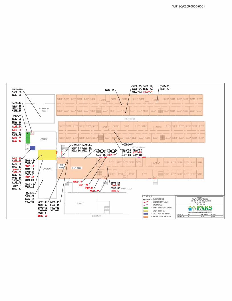
W912QR20R0055-0001
Final Pre-Renovation Hazardous Materials Survey Report Joint Base McGuire-Dix-Lakehurst
Building 5502 July 2020
TABLE 1
Asbestos Homogeneous Application Table
W912QR20R0055-0001
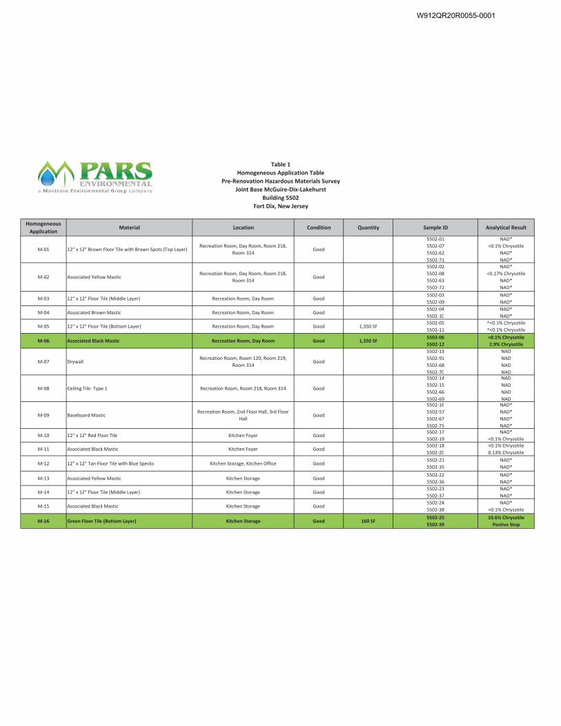
W912QR20R0055-0001
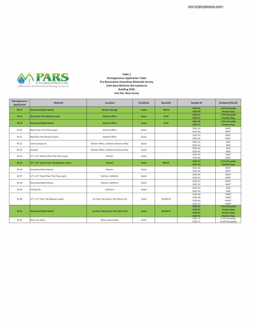
W912QR20R0055-0001
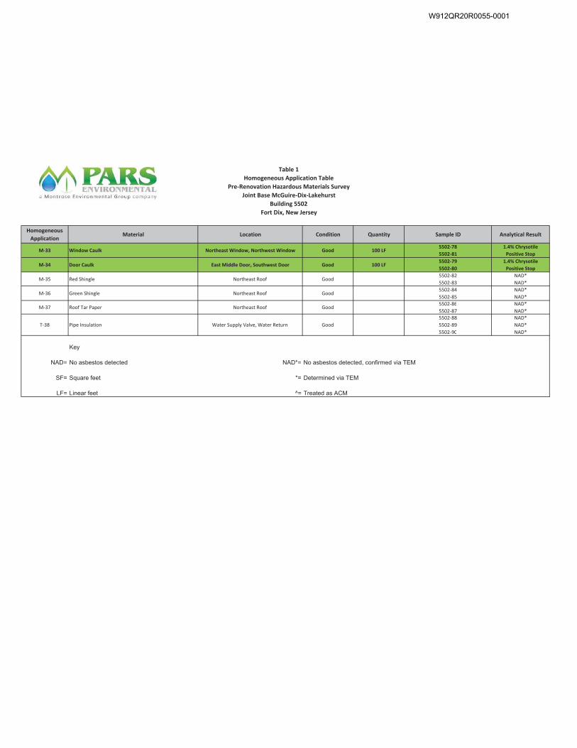
W912QR20R0055-0001
Final Pre-Renovation Hazardous Materials Survey Report Joint Base McGuire-Dix-Lakehurst
Building 5502 July 2020
TABLE 2
XRF Testing Results
W912QR20R0055-0001
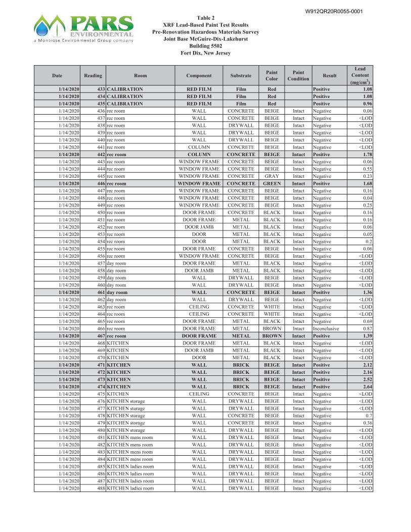
W912QR20R0055-0001
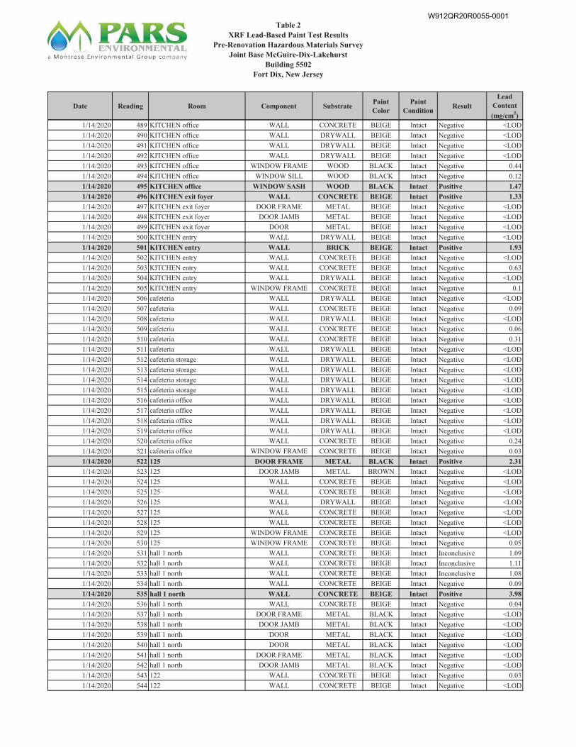
W912QR20R0055-0001
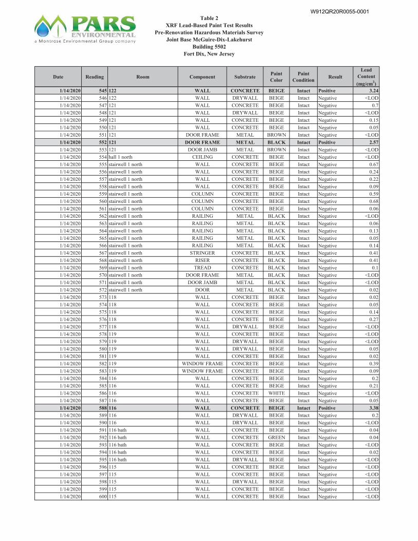
W912QR20R0055-0001
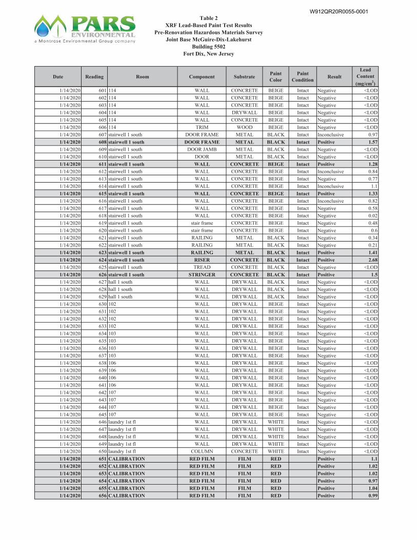
W912QR20R0055-0001
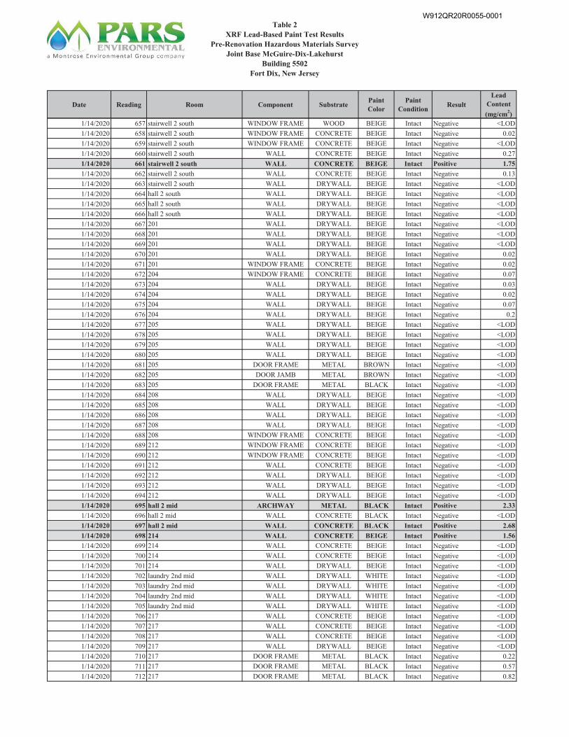
W912QR20R0055-0001
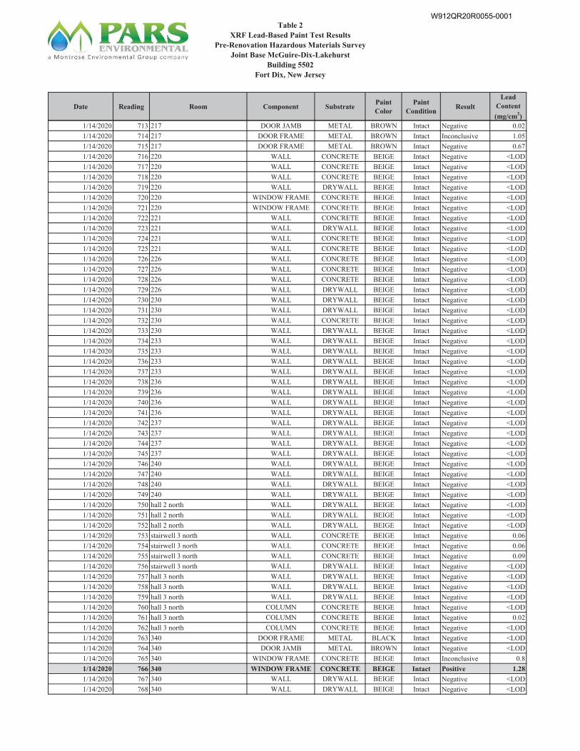
W912QR20R0055-0001
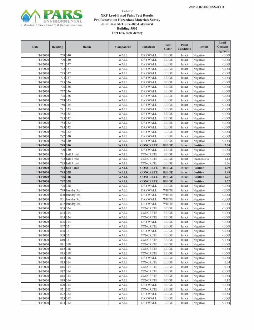
W912QR20R0055-0001
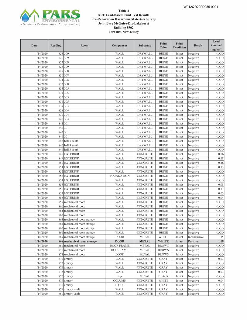
W912QR20R0055-0001
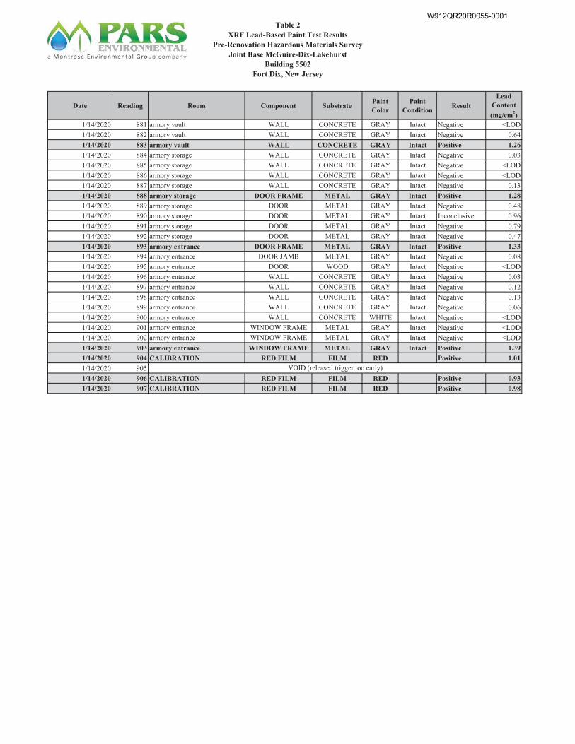
W912QR20R0055-0001

Final Pre-Renovation Hazardous Materials Survey Report Joint Base McGuire-Dix-Lakehurst
Building 5502 July 2020
TABLE 3
Paint Chip Sampling Results
W912QR20R0055-0001
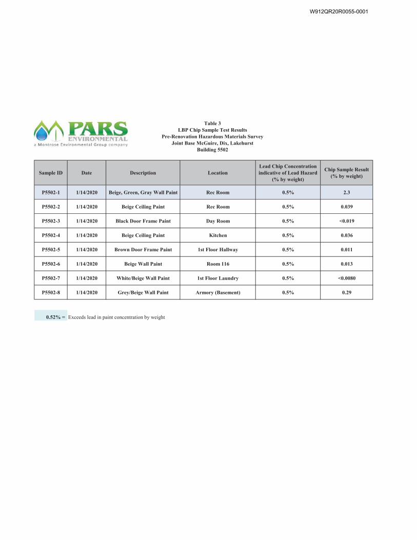
W912QR20R0055-0001

Final Pre-Renovation Hazardous Materials Survey Report Joint Base McGuire-Dix-Lakehurst
Building 5502 July 2020
APPENDIX A
Licenses and Certifications
W912QR20R0055-0001
W912QR20R0055-0001
W912QR20R0055-0001
W912QR20R0055-0001

W912QR20R0055-0001

W912QR20R0055-0001
W912QR20R0055-0001
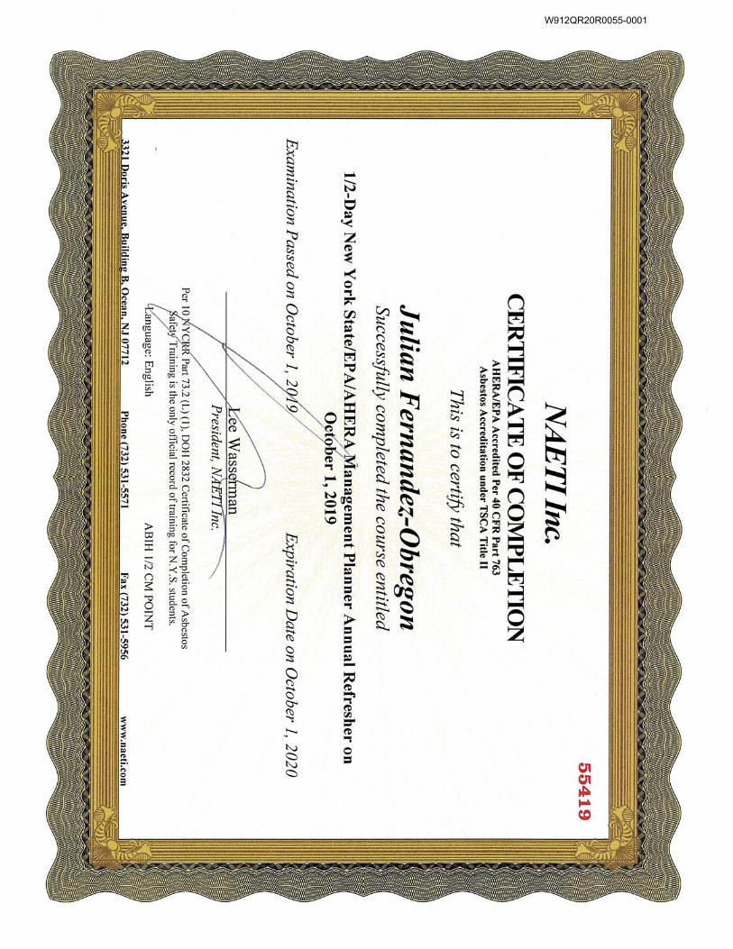
W912QR20R0055-0001
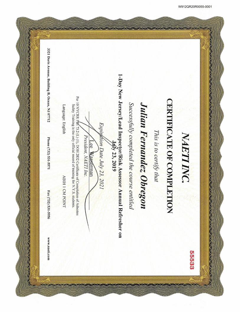
W912QR20R0055-0001
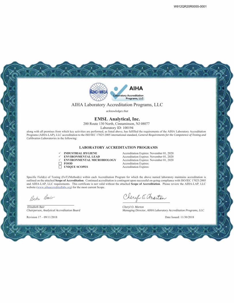
AIHA Laboratory Accreditation Programs, LLC
acknowledges that
EMSL Analytical, Inc. 200 Route 130 North, Cinnaminson, NJ 08077
Laboratory ID: 100194 along with all premises from which key activities are performed, as listed above, has fulfilled the requirements of the AIHA Laboratory Accreditation Programs (AIHA-LAP), LLC accreditation to the ISO/IEC 17025:2005 international standard, General Requirements for the Competence of Testing and Calibration Laboratories in the following:
LABORATORY ACCREDITATION PROGRAMS
INDUSTRIAL HYGIENE Accreditation Expires: November 01, 2020 ENVIRONMENTAL LEAD Accreditation Expires: November 01, 2020 ENVIRONMENTAL MICROBIOLOGY Accreditation Expires: November 01, 2020 FOOD Accreditation Expires:
UNIQUE SCOPES Accreditation Expires: Specific Field(s) of Testing (FoT)/Method(s) within each Accreditation Program for which the above named laboratory maintains accreditation is outlined on the attached Scope of Accreditation. Continued accreditation is contingent upon successful on-going compliance with ISO/IEC 17025:2005 and AIHA-LAP, LLC requirements. This certificate is not valid without the attached Scope of Accreditation. Please review the AIHA-LAP, LLC website (www.aihaaccreditedlabs.org) for the most current Scope.
Elizabeth Bair Chairperson, Analytical Accreditation Board
Cheryl O. Morton Managing Director, AIHA Laboratory Accreditation Programs, LLC
Revision 17 – 09/11/2018 Date Issued: 11/30/2018
W912QR20R0055-0001
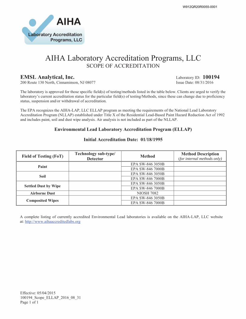
Effective: 05/04/2015100194_Scope_ELLAP_2016_08_31Page 1 of 1
AIHA Laboratory Accreditation Programs, LLC
SCOPE OF ACCREDITATION
EMSL Analytical, Inc. Laboratory ID: 100194200 Route 130 North, Cinnaminson, NJ 08077 Issue Date: 08/31/2016
The laboratory is approved for those specific field(s) of testing/methods listed in the table below. Clients are urged to verify the laboratory’s current accreditation status for the particular field(s) of testing/Methods, since these can change due to proficiency status, suspension and/or withdrawal of accreditation.
The EPA recognizes the AIHA-LAP, LLC ELLAP program as meeting the requirements of the National Lead Laboratory Accreditation Program (NLLAP) established under Title X of the Residential Lead-Based Paint Hazard Reduction Act of 1992 and includes paint, soil and dust wipe analysis. Air analysis is not included as part of the NLLAP.
Environmental Lead Laboratory Accreditation Program (ELLAP)
Initial Accreditation Date: 01/18/1995
A complete listing of currently accredited Environmental Lead laboratories is available on the AIHA-LAP, LLC website at: http://www.aihaaccreditedlabs.org
Field of Testing (FoT)Technology sub-type/
DetectorMethod Method Description
(for internal methods only)
PaintEPA SW-846 3050BEPA SW-846 7000B
SoilEPA SW-846 3050BEPA SW-846 7000B
Settled Dust by WipeEPA SW-846 3050BEPA SW-846 7000B
Airborne Dust NIOSH 7082
Composited WipesEPA SW-846 3050BEPA SW-846 7000B
W912QR20R0055-0001
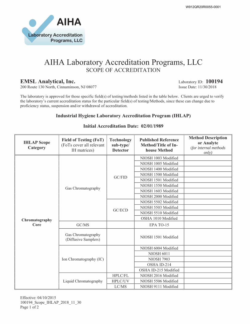
Effective: 04/10/2015 100194_Scope_IHLAP_2018_11_30 Page 1 of 2
AIHA Laboratory Accreditation Programs, LLC
SCOPE OF ACCREDITATION
EMSL Analytical, Inc. Laboratory ID: 100194 200 Route 130 North, Cinnaminson, NJ 08077 Issue Date: 11/30/2018 The laboratory is approved for those specific field(s) of testing/methods listed in the table below. Clients are urged to verify the laboratory’s current accreditation status for the particular field(s) of testing/Methods, since these can change due to proficiency status, suspension and/or withdrawal of accreditation.
Industrial Hygiene Laboratory Accreditation Program (IHLAP)
Initial Accreditation Date: 02/01/1989
IHLAP Scope Category
Field of Testing (FoT) (FoTs cover all relevant
IH matrices)
Technology sub-type/ Detector
Published Reference Method/Title of In-
house Method
Method Description or Analyte
(for internal methods only)
Chromatography Core
Gas Chromatography
GC/FID
NIOSH 1003 Modified NIOSH 1005 Modified NIOSH 1400 Modified NIOSH 1500 Modified NIOSH 1501 Modified NIOSH 1550 Modified NIOSH 1603 Modified NIOSH 2000 Modified
GC/ECD
NIOSH 5502 Modified NIOSH 5503 Modified NIOSH 5510 Modified OSHA 1010 Modified
GC/MS EPA TO-15
Gas Chromatography (Diffusive Samplers) NIOSH 1501 Modified
Ion Chromatography (IC)
NIOSH 6004 Modified NIOSH 6011 NIOSH 7903
OSHA ID-214 OSHA ID-215 Modified
Liquid Chromatography HPLC/FL NIOSH 2016 Modified HPLC/UV NIOSH 5506 Modified
LC/MS NIOSH 9111 Modified
W912QR20R0055-0001
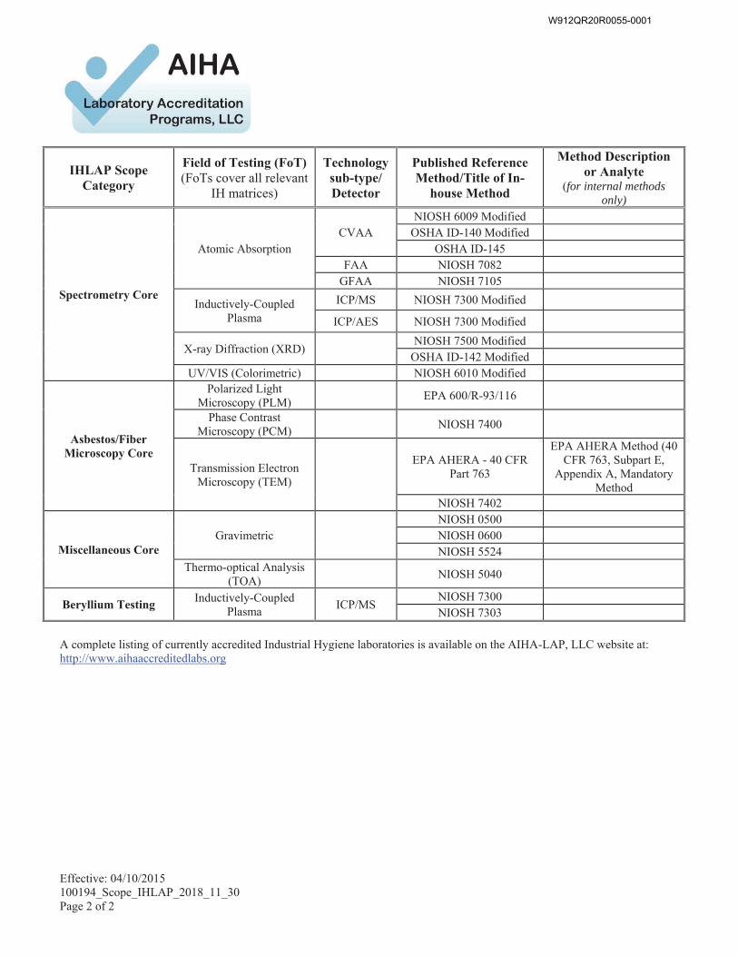
Effective: 04/10/2015 100194_Scope_IHLAP_2018_11_30 Page 2 of 2
IHLAP Scope Category
Field of Testing (FoT) (FoTs cover all relevant
IH matrices)
Technology sub-type/ Detector
Published Reference Method/Title of In-
house Method
Method Description or Analyte
(for internal methods only)
Spectrometry Core
Atomic Absorption CVAA
NIOSH 6009 Modified OSHA ID-140 Modified
OSHA ID-145 FAA NIOSH 7082
GFAA NIOSH 7105
Inductively-Coupled Plasma
ICP/MS NIOSH 7300 Modified
ICP/AES NIOSH 7300 Modified
X-ray Diffraction (XRD) NIOSH 7500 Modified
OSHA ID-142 Modified UV/VIS (Colorimetric) NIOSH 6010 Modified
Asbestos/Fiber Microscopy Core
Polarized Light Microscopy (PLM) EPA 600/R-93/116
Phase Contrast Microscopy (PCM) NIOSH 7400
Transmission Electron Microscopy (TEM)
EPA AHERA - 40 CFR Part 763
EPA AHERA Method (40 CFR 763, Subpart E,
Appendix A, Mandatory Method
NIOSH 7402
Miscellaneous Core Gravimetric
NIOSH 0500 NIOSH 0600 NIOSH 5524
Thermo-optical Analysis (TOA) NIOSH 5040
Beryllium Testing Inductively-Coupled
Plasma ICP/MS
NIOSH 7300 NIOSH 7303
A complete listing of currently accredited Industrial Hygiene laboratories is available on the AIHA-LAP, LLC website at: http://www.aihaaccreditedlabs.org
W912QR20R0055-0001
Final Pre-Renovation Hazardous Materials Survey Report Joint Base McGuire-Dix-Lakehurst
Building 5502 July 2020
APPENDIX B
ACM Photo Log
W912QR20R0055-0001
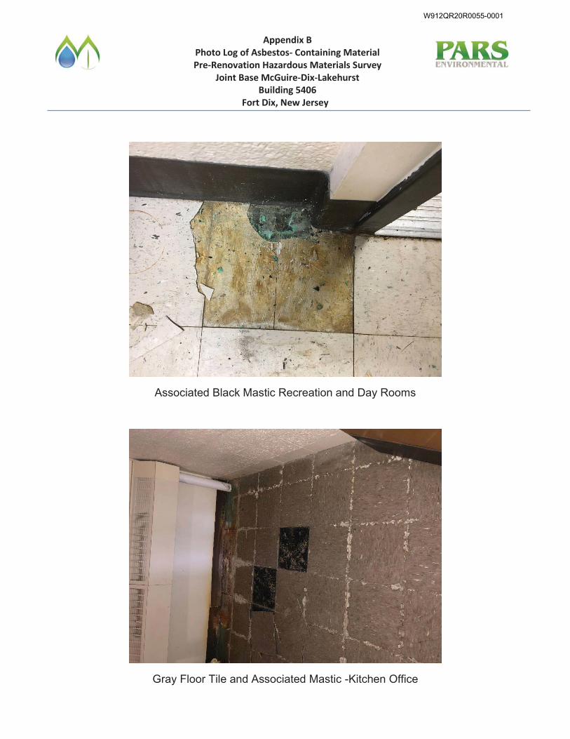
Appendix B Photo Log of Asbestos- Containing Material Pre-Renovation Hazardous Materials Survey
Joint Base McGuire-Dix-Lakehurst Building 5406
Fort Dix, New Jersey
Associated Black Mastic Recreation and Day Rooms
Gray Floor Tile and Associated Mastic -Kitchen Office
W912QR20R0055-0001
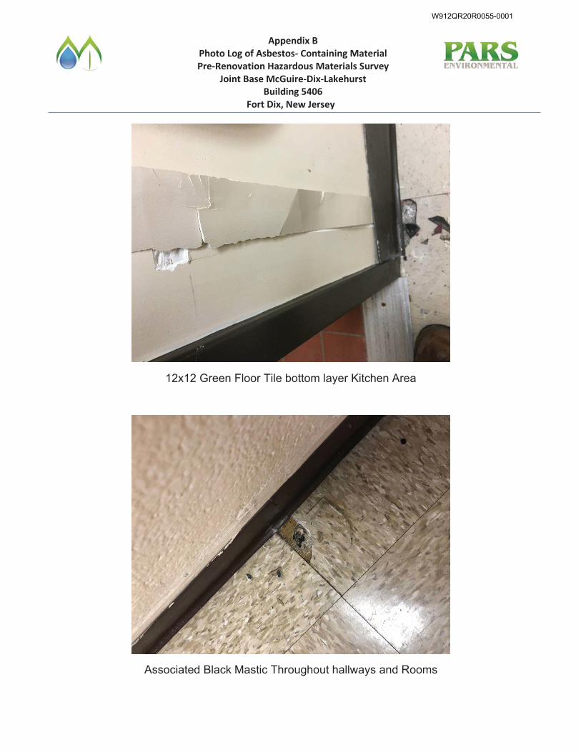
Appendix B Photo Log of Asbestos- Containing Material Pre-Renovation Hazardous Materials Survey
Joint Base McGuire-Dix-Lakehurst Building 5406
Fort Dix, New Jersey
12x12 Green Floor Tile bottom layer Kitchen Area
Associated Black Mastic Throughout hallways and Rooms
W912QR20R0055-0001
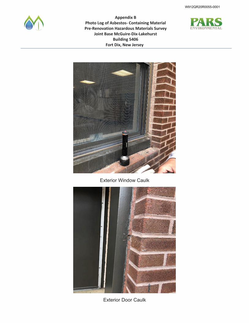
Appendix B Photo Log of Asbestos- Containing Material Pre-Renovation Hazardous Materials Survey
Joint Base McGuire-Dix-Lakehurst Building 5406
Fort Dix, New Jersey
Exterior Window Caulk
Exterior Door Caulk
W912QR20R0055-0001
Final Pre-Renovation Hazardous Materials Survey Report Joint Base McGuire-Dix-Lakehurst
Building 5502 July 2020
APPENDIX C
Hazardous Materials Survey Photo Log
W912QR20R0055-0001
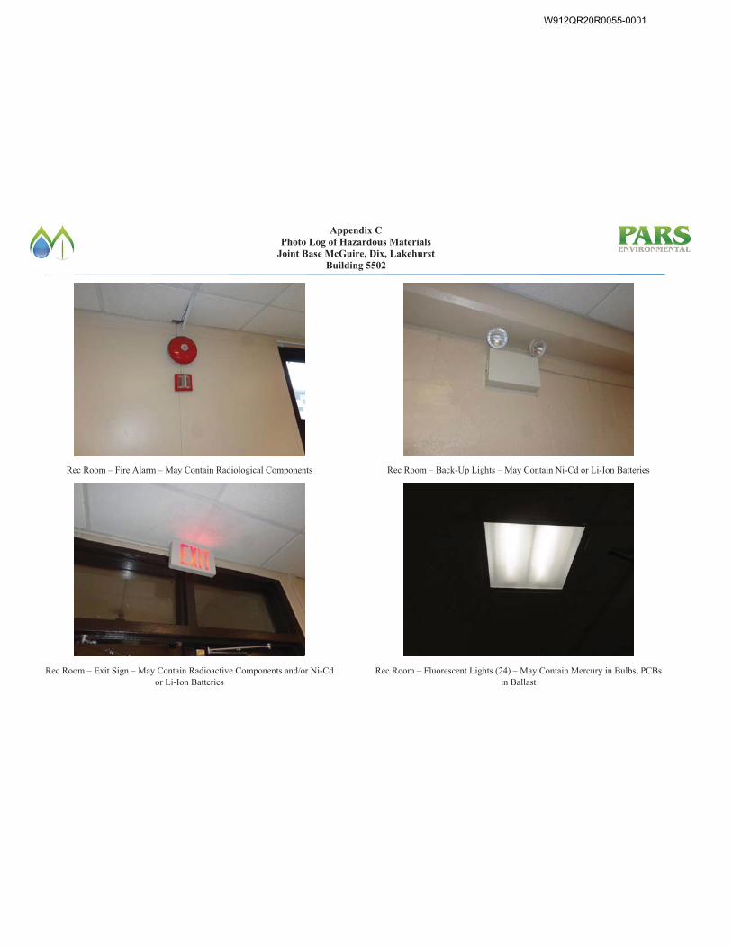
Appendix C Photo Log of Hazardous Materials
Joint Base McGuire, Dix, Lakehurst Building 5502
Rec Room – Fire Alarm – May Contain Radiological Components
Rec Room – Exit Sign – May Contain Radioactive Components and/or Ni-Cd or Li-Ion Batteries
Rec Room – Back-Up Lights – May Contain Ni-Cd or Li-Ion Batteries
Rec Room – Fluorescent Lights (24) – May Contain Mercury in Bulbs, PCBs in Ballast
W912QR20R0055-0001
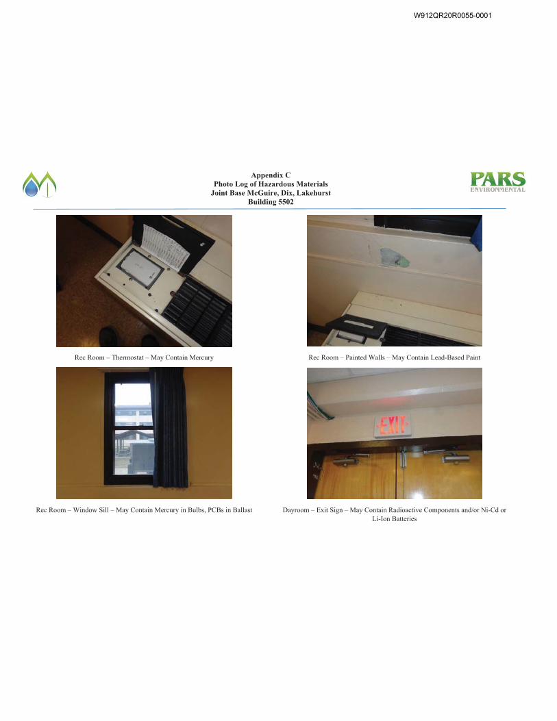
Appendix C Photo Log of Hazardous Materials
Joint Base McGuire, Dix, Lakehurst Building 5502
Rec Room – Thermostat – May Contain Mercury
Rec Room – Window Sill – May Contain Mercury in Bulbs, PCBs in Ballast
Rec Room – Painted Walls – May Contain Lead-Based Paint
Dayroom – Exit Sign – May Contain Radioactive Components and/or Ni-Cd or Li-Ion Batteries
W912QR20R0055-0001
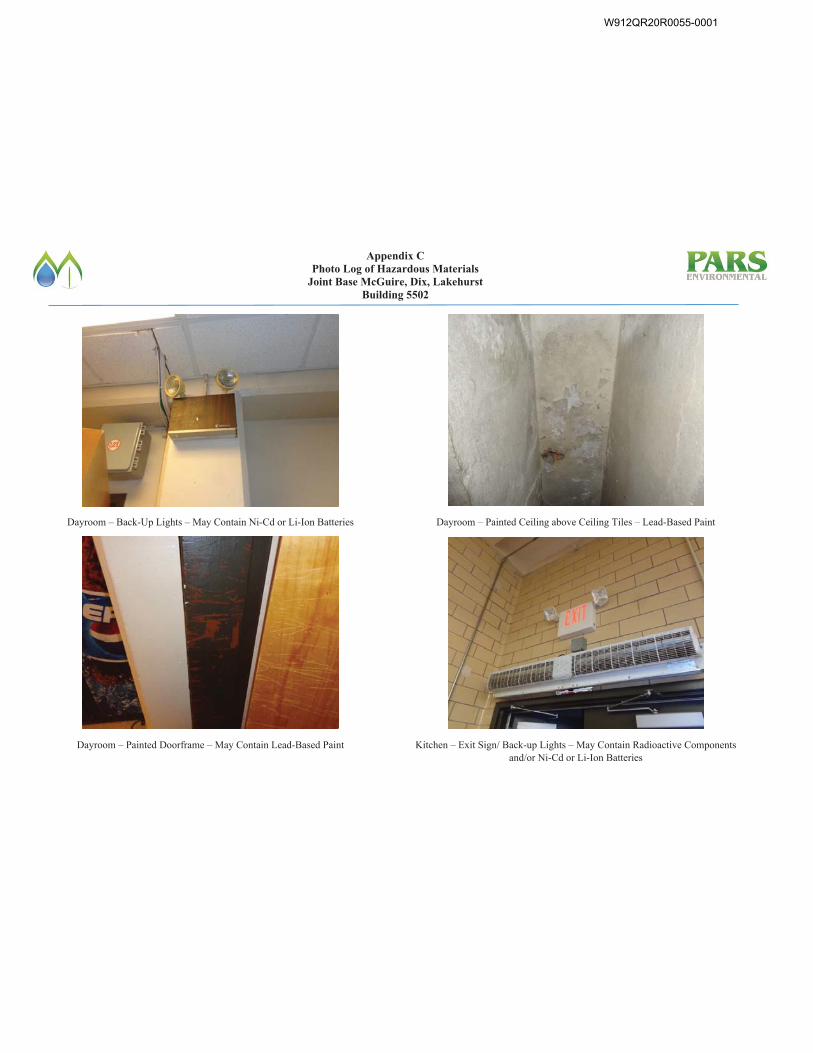
Appendix C Photo Log of Hazardous Materials
Joint Base McGuire, Dix, Lakehurst Building 5502
Dayroom – Back-Up Lights – May Contain Ni-Cd or Li-Ion Batteries
Dayroom – Painted Doorframe – May Contain Lead-Based Paint
Dayroom – Painted Ceiling above Ceiling Tiles – Lead-Based Paint
Kitchen – Exit Sign/ Back-up Lights – May Contain Radioactive Components and/or Ni-Cd or Li-Ion Batteries
W912QR20R0055-0001
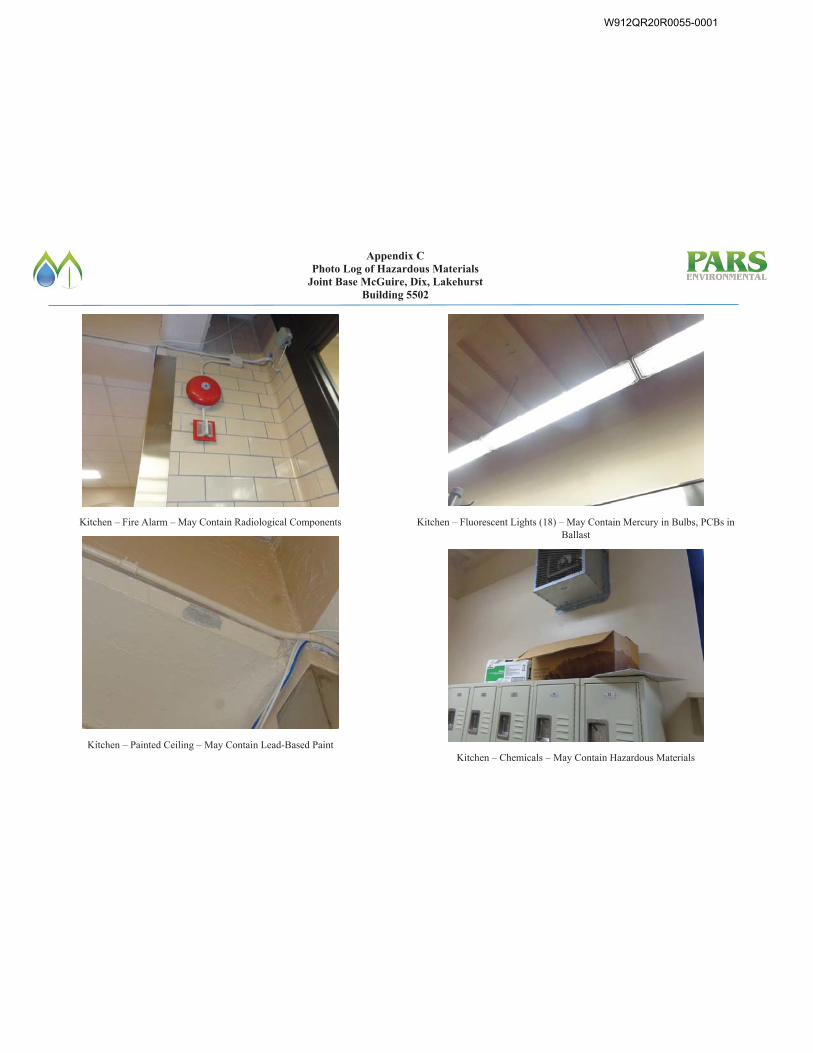
Appendix C Photo Log of Hazardous Materials
Joint Base McGuire, Dix, Lakehurst Building 5502
Kitchen – Fire Alarm – May Contain Radiological Components
Kitchen – Painted Ceiling – May Contain Lead-Based Paint
Kitchen – Fluorescent Lights (18) – May Contain Mercury in Bulbs, PCBs in Ballast
Kitchen – Chemicals – May Contain Hazardous Materials
W912QR20R0055-0001
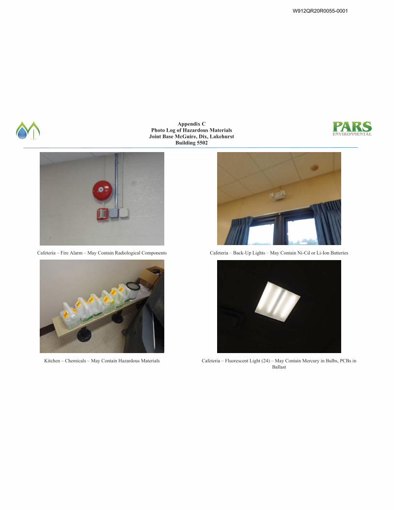
Appendix C Photo Log of Hazardous Materials
Joint Base McGuire, Dix, Lakehurst Building 5502
Cafeteria – Fire Alarm – May Contain Radiological Components
Kitchen – Chemicals – May Contain Hazardous Materials
Cafeteria – Back-Up Lights – May Contain Ni-Cd or Li-Ion Batteries
Cafeteria – Fluorescent Light (24) – May Contain Mercury in Bulbs, PCBs in Ballast
W912QR20R0055-0001
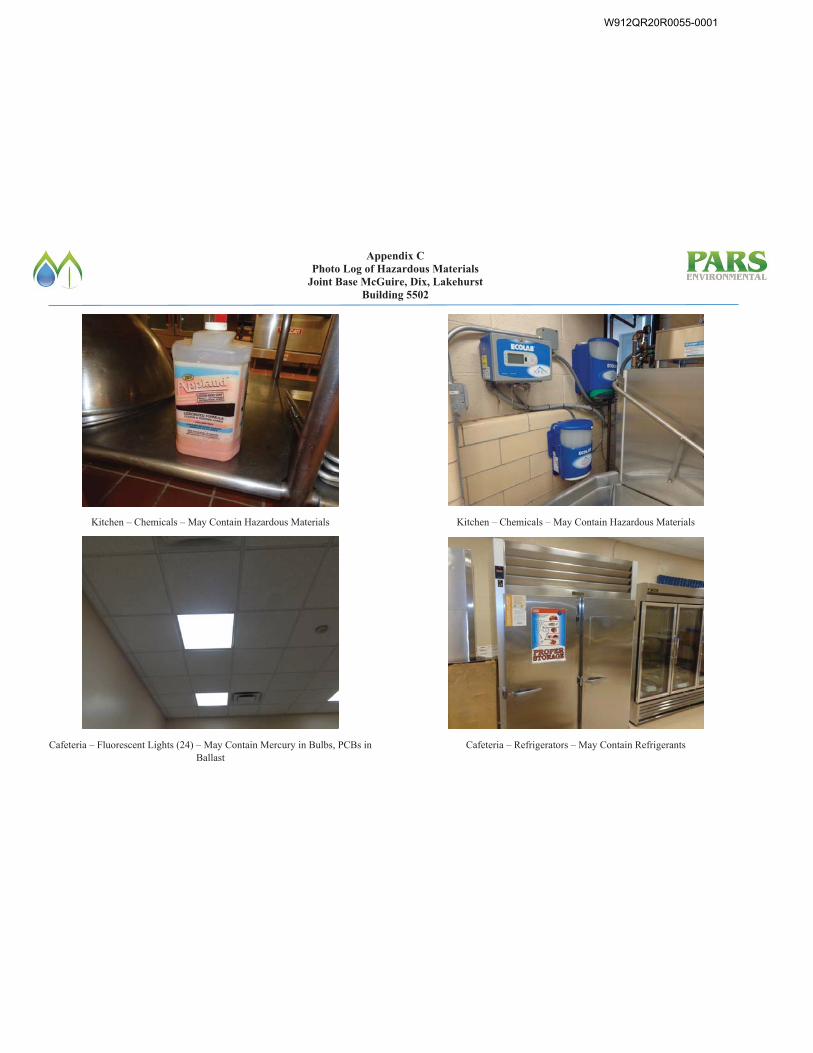
Appendix C Photo Log of Hazardous Materials
Joint Base McGuire, Dix, Lakehurst Building 5502
Kitchen – Chemicals – May Contain Hazardous Materials
Cafeteria – Fluorescent Lights (24) – May Contain Mercury in Bulbs, PCBs in Ballast
Kitchen – Chemicals – May Contain Hazardous Materials
Cafeteria – Refrigerators – May Contain Refrigerants
W912QR20R0055-0001
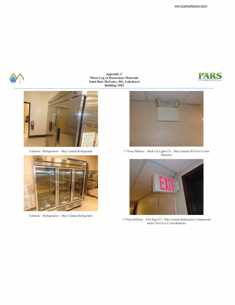
Appendix C Photo Log of Hazardous Materials
Joint Base McGuire, Dix, Lakehurst Building 5502
Cafeteria - Refrigerators – May Contain Refrigerants
Cafeteria – Refrigerators – May Contain Refrigerants
1st Floor Hallway – Back-Up Lights (3) – May Contain Ni-Cd or Li-Ion Batteries
1st Floor Hallway – Exit Sign (3) – May Contain Radioactive Components and/or Ni-Cd or Li-Ion Batteries
W912QR20R0055-0001
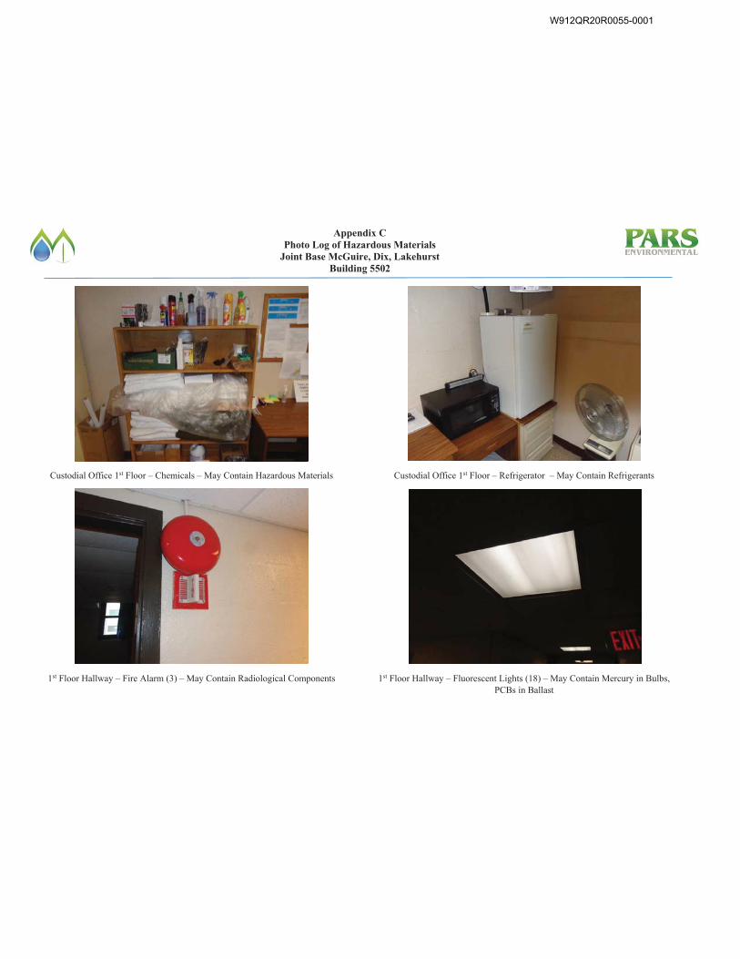
Appendix C Photo Log of Hazardous Materials
Joint Base McGuire, Dix, Lakehurst Building 5502
Custodial Office 1st Floor – Chemicals – May Contain Hazardous Materials
1st Floor Hallway – Fire Alarm (3) – May Contain Radiological Components
Custodial Office 1st Floor – Refrigerator – May Contain Refrigerants
1st Floor Hallway – Fluorescent Lights (18) – May Contain Mercury in Bulbs, PCBs in Ballast
W912QR20R0055-0001
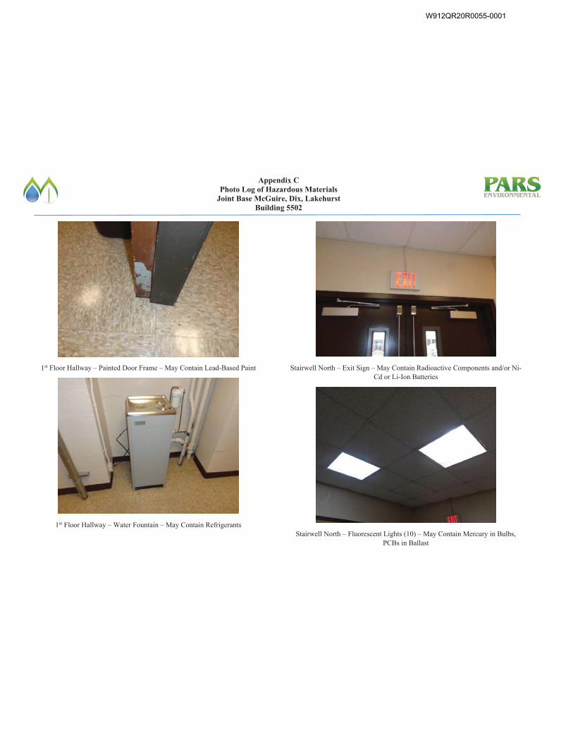
Appendix C Photo Log of Hazardous Materials
Joint Base McGuire, Dix, Lakehurst Building 5502
1st Floor Hallway – Painted Door Frame – May Contain Lead-Based Paint
1st Floor Hallway – Water Fountain – May Contain Refrigerants
Stairwell North – Exit Sign – May Contain Radioactive Components and/or Ni-Cd or Li-Ion Batteries
Stairwell North – Fluorescent Lights (10) – May Contain Mercury in Bulbs, PCBs in Ballast
W912QR20R0055-0001

Appendix C Photo Log of Hazardous Materials
Joint Base McGuire, Dix, Lakehurst Building 5502
1st Floor Hallway – Room 118 Painted Door Frame – May Contain Lead-Based Paint
Stairwell North – Back-Up Lights (4) – May Contain Ni-Cd or Li-Ion Batteries
1st Floor Hallway Rooms – Thermostat – May Contain Mercury
1st Floor Hallway Rooms – Refrigerator – May Contain Refrigerants
W912QR20R0055-0001
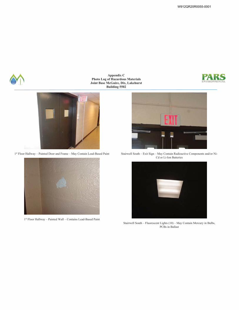
Appendix C Photo Log of Hazardous Materials
Joint Base McGuire, Dix, Lakehurst Building 5502
1st Floor Hallway – Painted Door and Frame – May Contain Lead-Based Paint
1st Floor Hallway – Painted Wall – Contains Lead-Based Paint
Stairwell South – Exit Sign – May Contain Radioactive Components and/or Ni-Cd or Li-Ion Batteries
Stairwell South – Fluorescent Lights (10) – May Contain Mercury in Bulbs, PCBs in Ballast
W912QR20R0055-0001
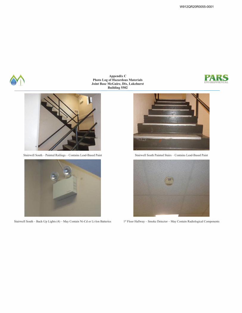
Appendix C Photo Log of Hazardous Materials
Joint Base McGuire, Dix, Lakehurst Building 5502
Stairwell South – Painted Railings – Contains Lead-Based Paint
Stairwell South – Back-Up Lights (4) – May Contain Ni-Cd or Li-Ion Batteries
Stairwell South Painted Stairs – Contains Lead-Based Paint
1st Floor Hallway – Smoke Detector – May Contain Radiological Components
W912QR20R0055-0001
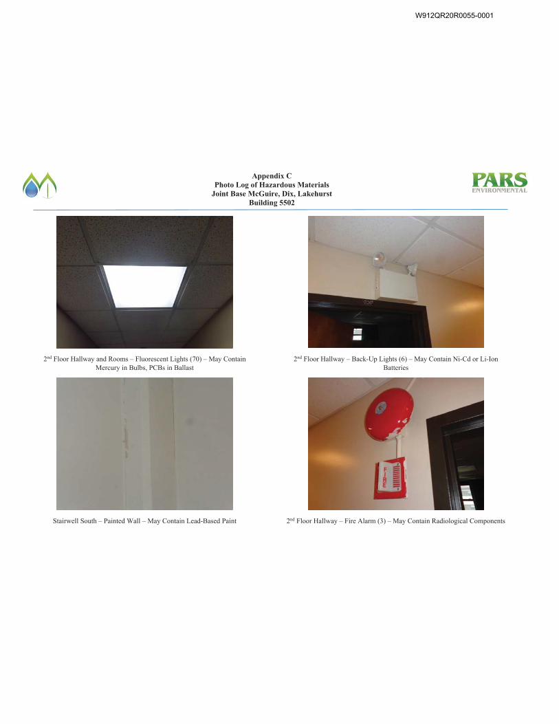
Appendix C Photo Log of Hazardous Materials
Joint Base McGuire, Dix, Lakehurst Building 5502
2nd Floor Hallway and Rooms – Fluorescent Lights (70) – May Contain Mercury in Bulbs, PCBs in Ballast
Stairwell South – Painted Wall – May Contain Lead-Based Paint
2nd Floor Hallway – Back-Up Lights (6) – May Contain Ni-Cd or Li-Ion Batteries
2nd Floor Hallway – Fire Alarm (3) – May Contain Radiological Components
W912QR20R0055-0001
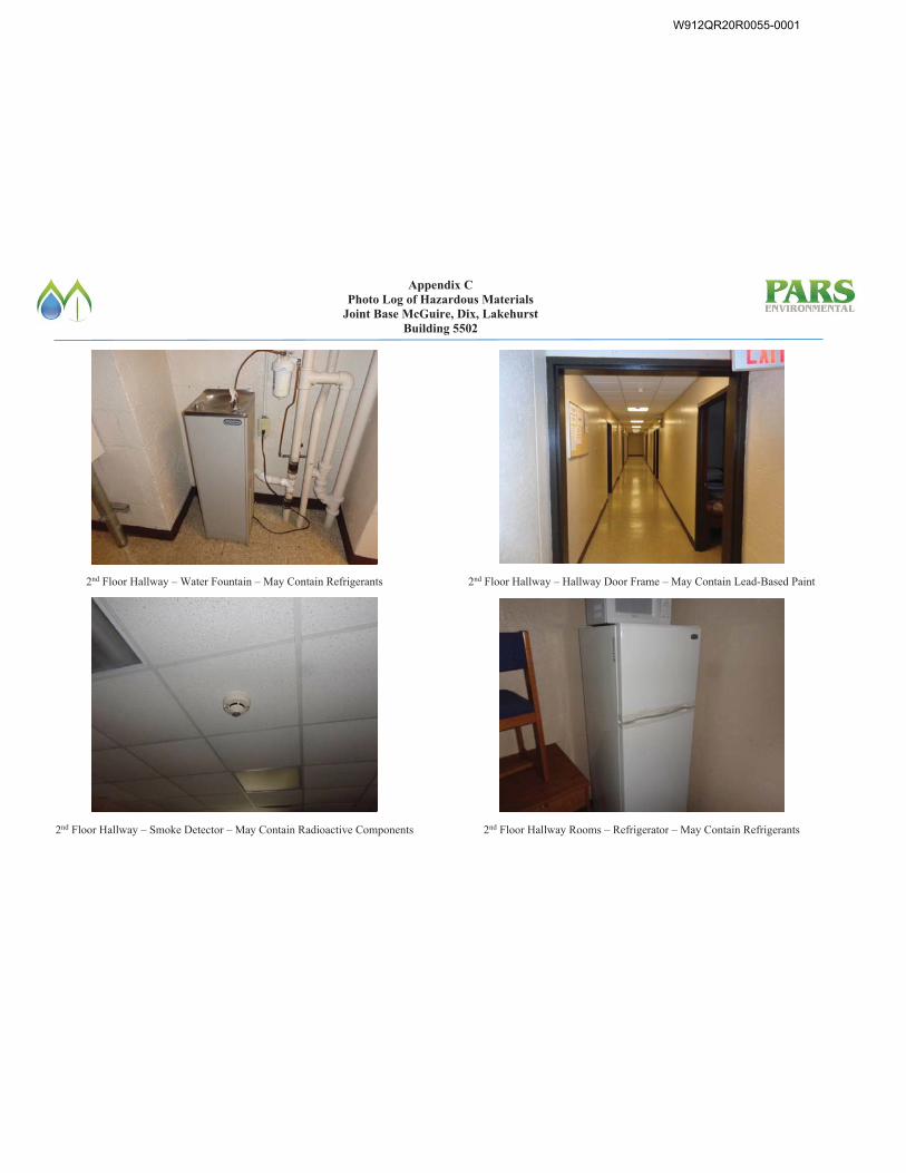
Appendix C Photo Log of Hazardous Materials
Joint Base McGuire, Dix, Lakehurst Building 5502
2nd Floor Hallway – Water Fountain – May Contain Refrigerants
2nd Floor Hallway – Smoke Detector – May Contain Radioactive Components
2nd Floor Hallway – Hallway Door Frame – May Contain Lead-Based Paint
2nd Floor Hallway Rooms – Refrigerator – May Contain Refrigerants
W912QR20R0055-0001
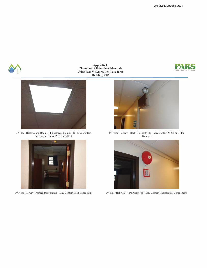
Appendix C Photo Log of Hazardous Materials
Joint Base McGuire, Dix, Lakehurst Building 5502
3nd Floor Hallway and Rooms – Fluorescent Lights (70) – May Contain Mercury in Bulbs, PCBs in Ballast
3rd Floor Hallway –Painted Door Frame – May Contain Lead-Based Paint
3nd Floor Hallway – Back-Up Lights (8) – May Contain Ni-Cd or Li-Ion Batteries
3nd Floor Hallway – Fire Alarm (3) – May Contain Radiological Components
W912QR20R0055-0001
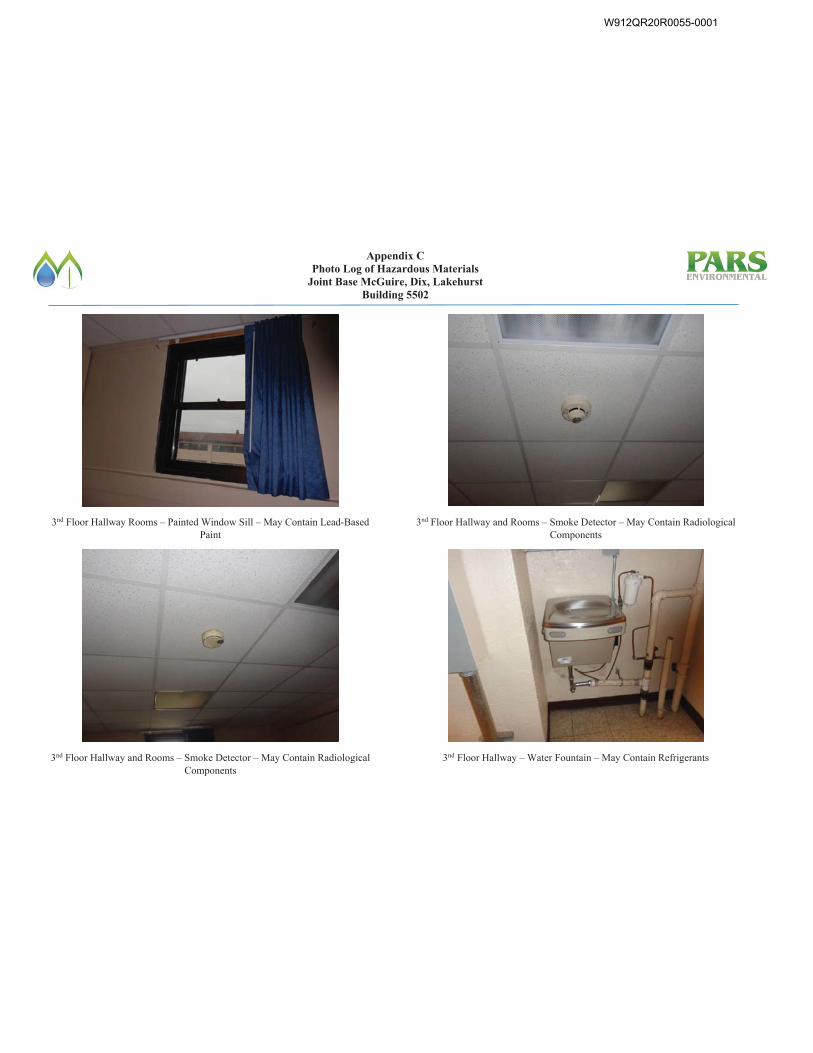
Appendix C Photo Log of Hazardous Materials
Joint Base McGuire, Dix, Lakehurst Building 5502
3nd Floor Hallway Rooms – Painted Window Sill – May Contain Lead-Based Paint
3nd Floor Hallway and Rooms – Smoke Detector – May Contain Radiological Components
3nd Floor Hallway and Rooms – Smoke Detector – May Contain Radiological Components
3nd Floor Hallway – Water Fountain – May Contain Refrigerants
W912QR20R0055-0001
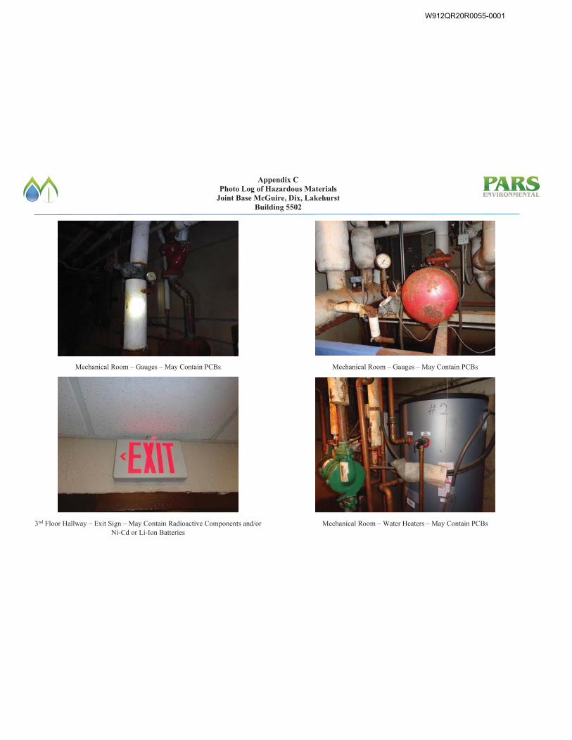
Appendix C Photo Log of Hazardous Materials
Joint Base McGuire, Dix, Lakehurst Building 5502
Mechanical Room – Gauges – May Contain PCBs
3nd Floor Hallway – Exit Sign – May Contain Radioactive Components and/or Ni-Cd or Li-Ion Batteries
Mechanical Room – Gauges – May Contain PCBs
Mechanical Room – Water Heaters – May Contain PCBs
W912QR20R0055-0001
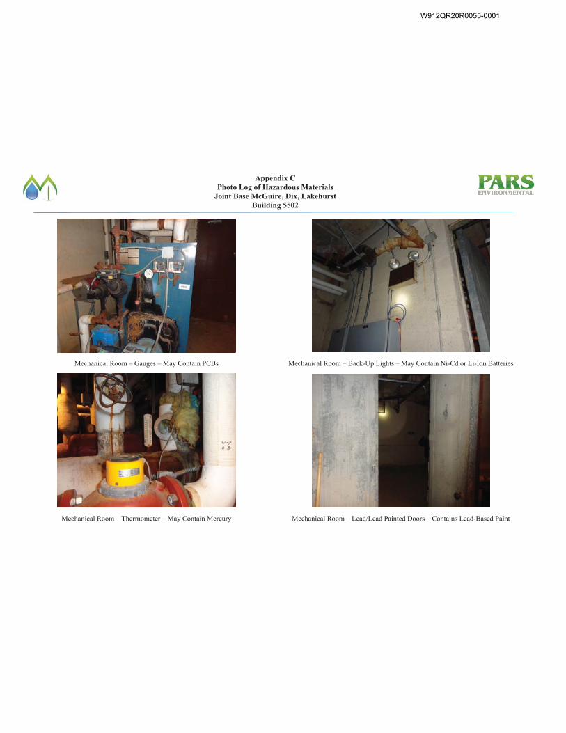
Appendix C Photo Log of Hazardous Materials
Joint Base McGuire, Dix, Lakehurst Building 5502
Mechanical Room – Gauges – May Contain PCBs
Mechanical Room – Thermometer – May Contain Mercury
Mechanical Room – Back-Up Lights – May Contain Ni-Cd or Li-Ion Batteries
Mechanical Room – Lead/Lead Painted Doors – Contains Lead-Based Paint
W912QR20R0055-0001
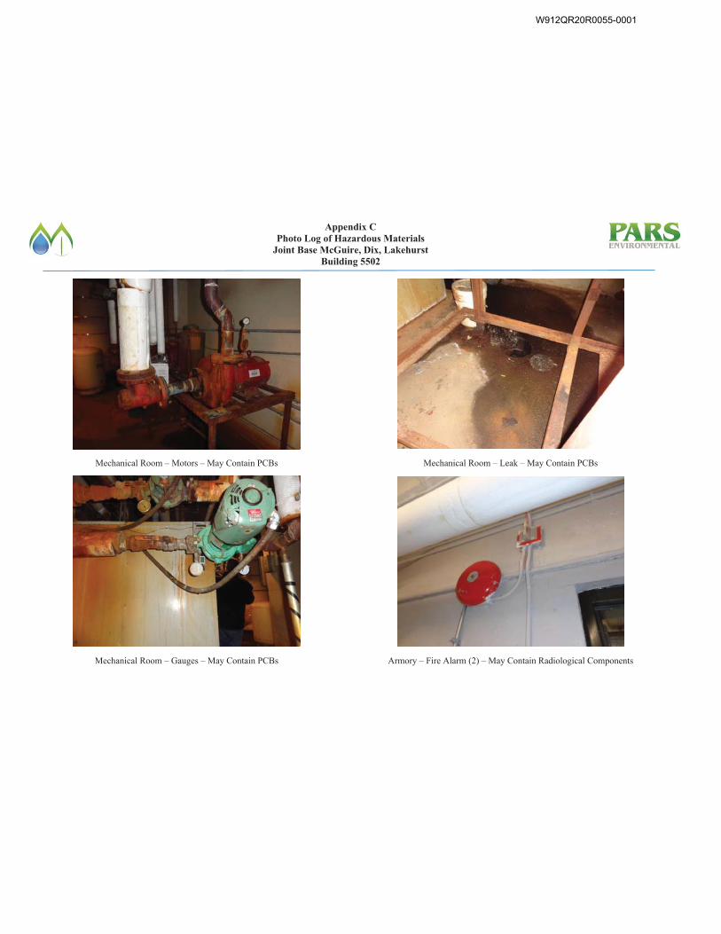
Appendix C Photo Log of Hazardous Materials
Joint Base McGuire, Dix, Lakehurst Building 5502
Mechanical Room – Motors – May Contain PCBs
Mechanical Room – Gauges – May Contain PCBs
Mechanical Room – Leak – May Contain PCBs
Armory – Fire Alarm (2) – May Contain Radiological Components
W912QR20R0055-0001
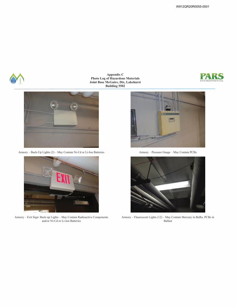
Appendix C Photo Log of Hazardous Materials
Joint Base McGuire, Dix, Lakehurst Building 5502
Armory – Back-Up Lights (2) – May Contain Ni-Cd or Li-Ion Batteries
Armory – Exit Sign/ Back-up Lights – May Contain Radioactive Components and/or Ni-Cd or Li-Ion Batteries
Armory – Pressure Gauge – May Contain PCBs
Armory – Fluorescent Lights (12) – May Contain Mercury in Bulbs, PCBs in Ballast
W912QR20R0055-0001
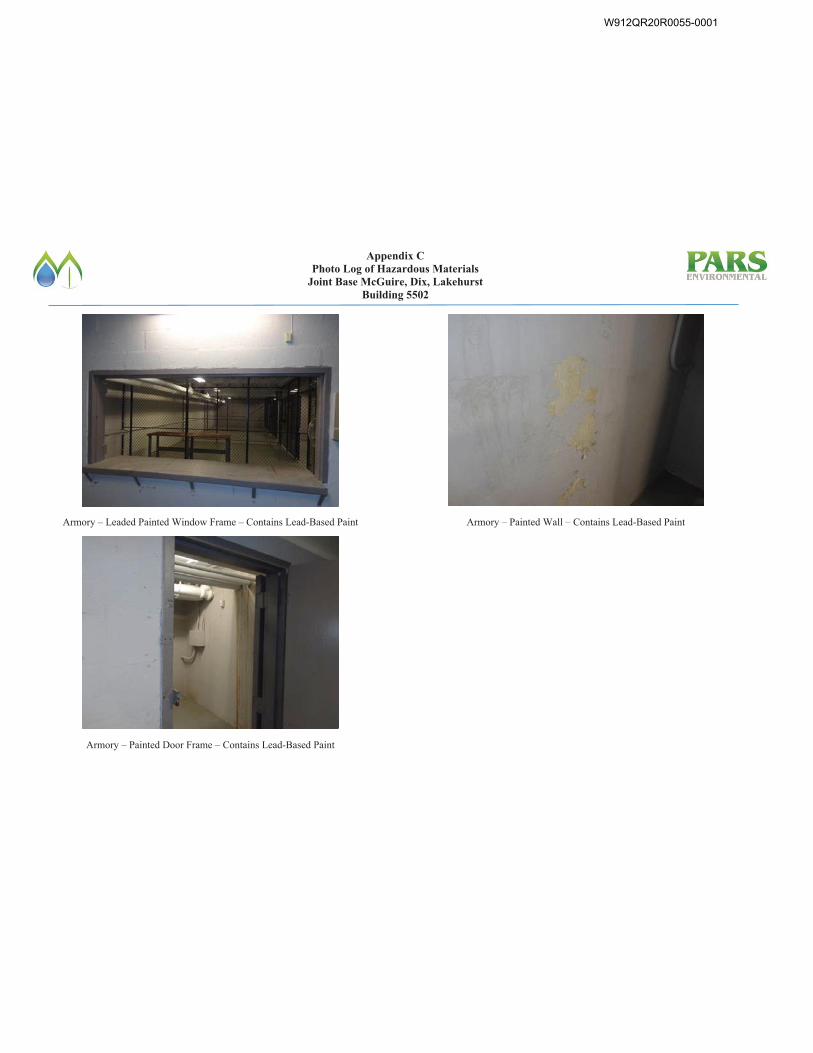
Appendix C Photo Log of Hazardous Materials
Joint Base McGuire, Dix, Lakehurst Building 5502
Armory – Leaded Painted Window Frame – Contains Lead-Based Paint
Armory – Painted Door Frame – Contains Lead-Based Paint
Armory – Painted Wall – Contains Lead-Based Paint
W912QR20R0055-0001
Final Pre-Renovation Hazardous Materials Survey Report Joint Base McGuire-Dix-Lakehurst
Building 5502 July 2020
APPENDIX D
EMSL Laboratory Reports
W912QR20R0055-0001
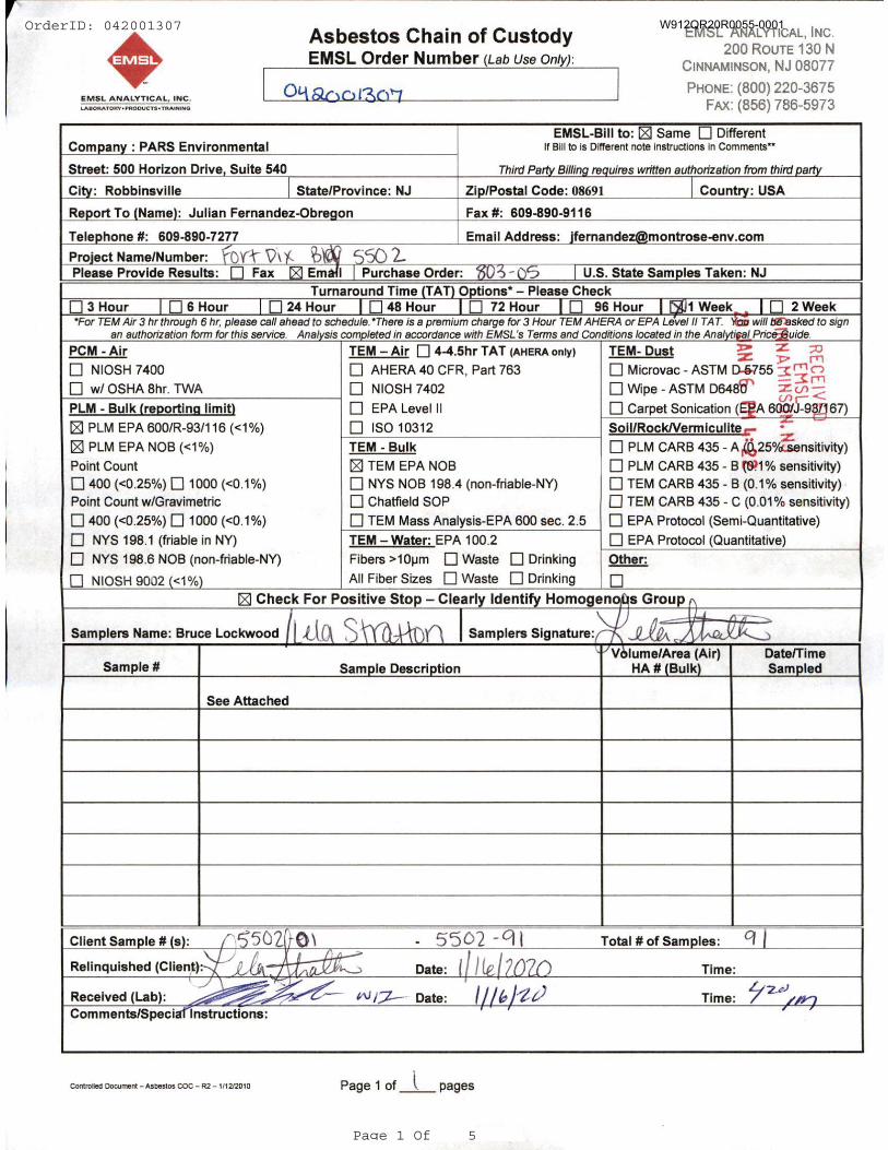
OrderID: 042001307
Page 1 Of 5
W912QR20R0055-0001
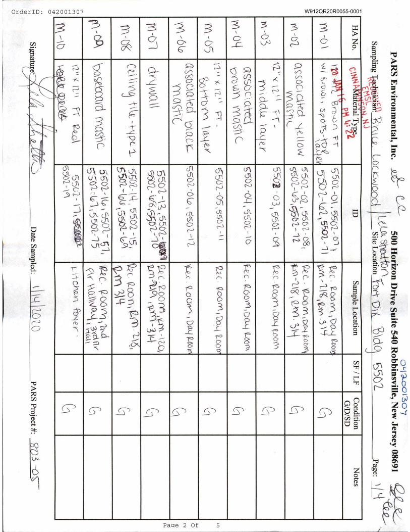
OrderID: 042001307
Page 2 Of 5
W912QR20R0055-0001
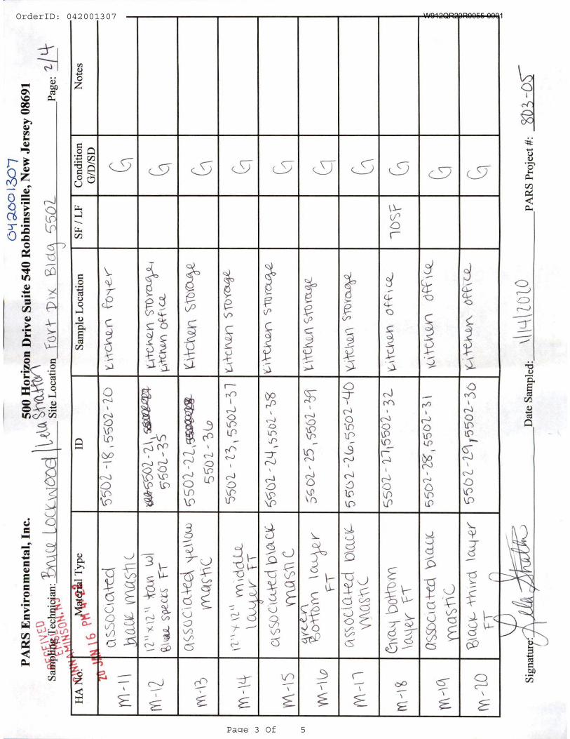
OrderID: 042001307
Page 3 Of 5
W912QR20R0055-0001
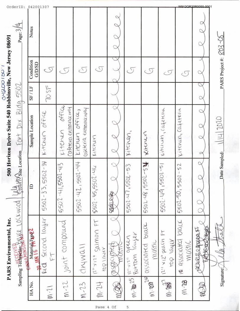
OrderID: 042001307
Page 4 Of 5
W912QR20R0055-0001
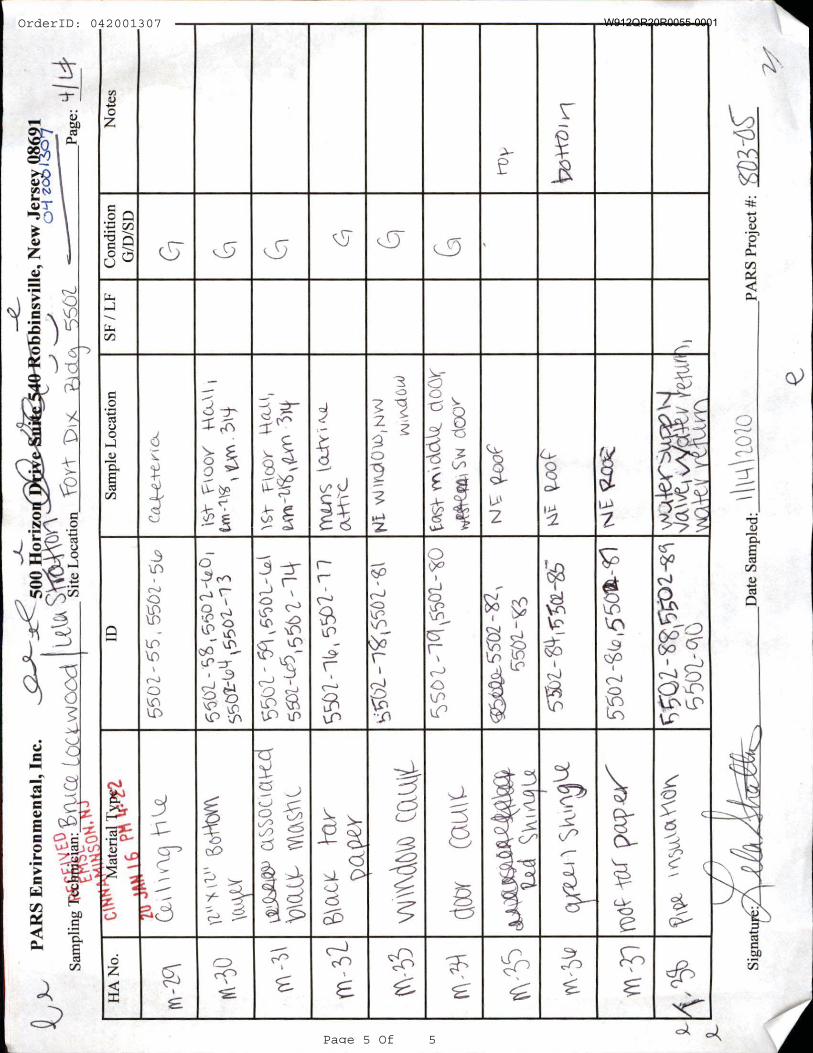
OrderID: 042001307
Page 5 Of 5
W912QR20R0055-0001
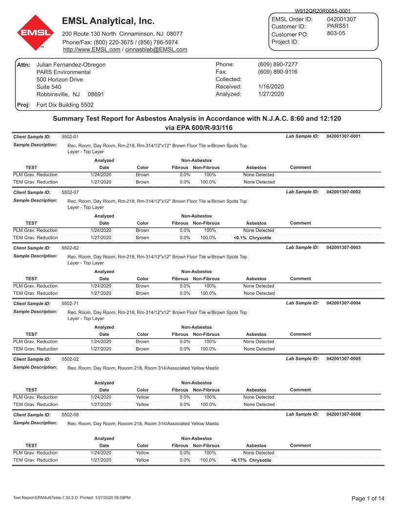
W912QR20R0055-0001
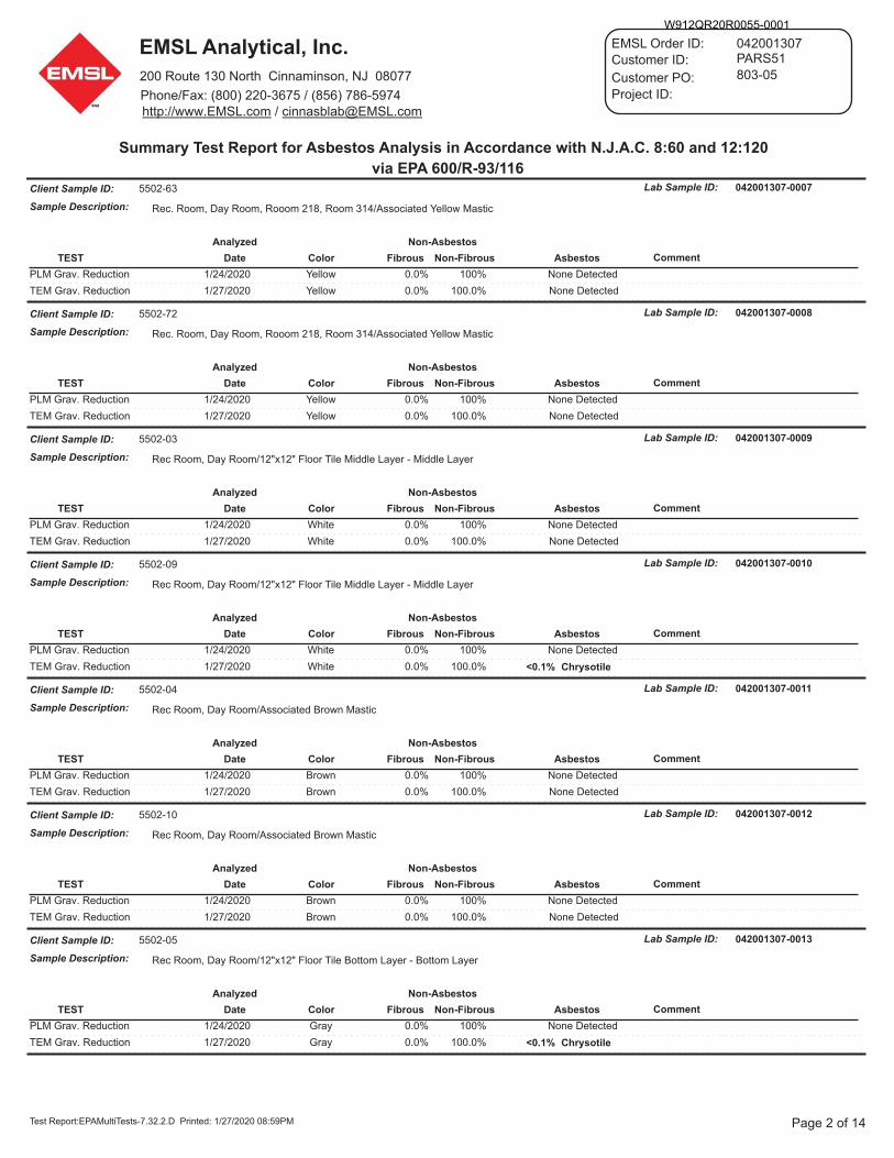
W912QR20R0055-0001
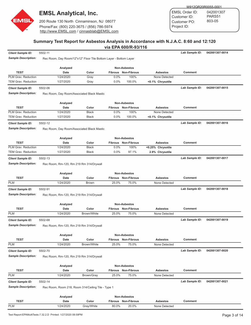
W912QR20R0055-0001
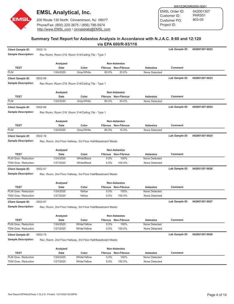
W912QR20R0055-0001
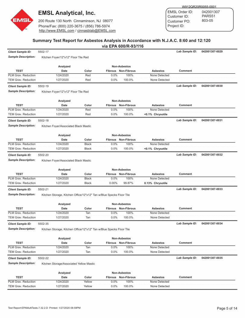
W912QR20R0055-0001
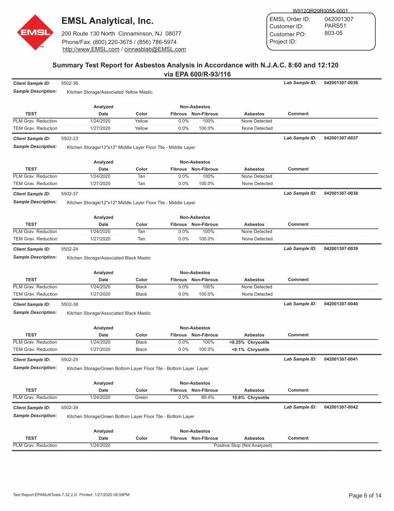
W912QR20R0055-0001

W912QR20R0055-0001
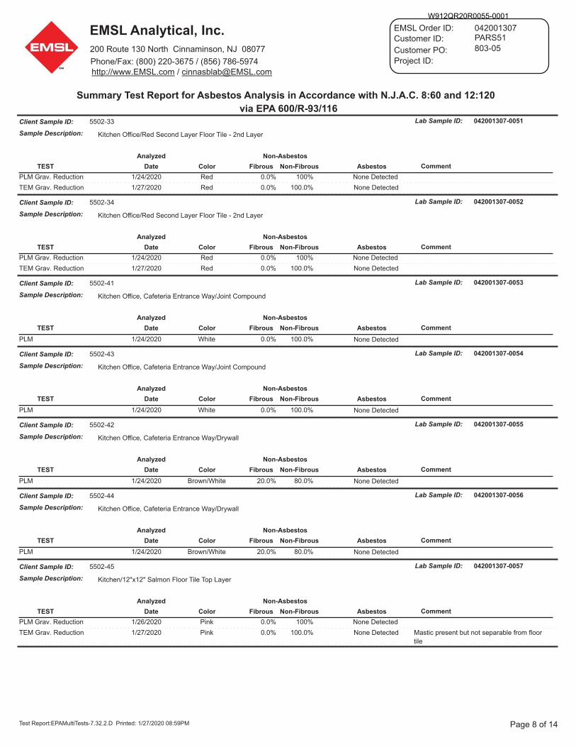
W912QR20R0055-0001
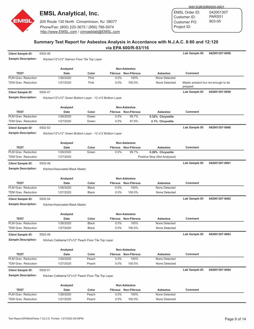
W912QR20R0055-0001
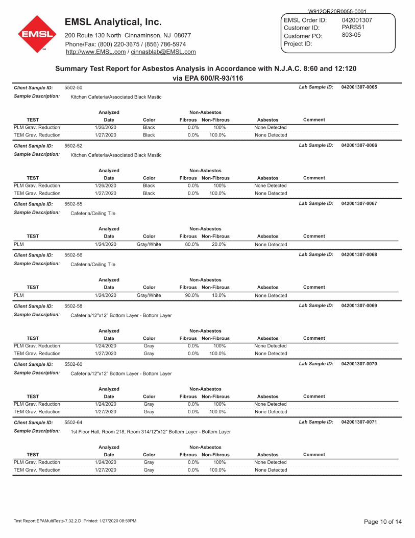
W912QR20R0055-0001
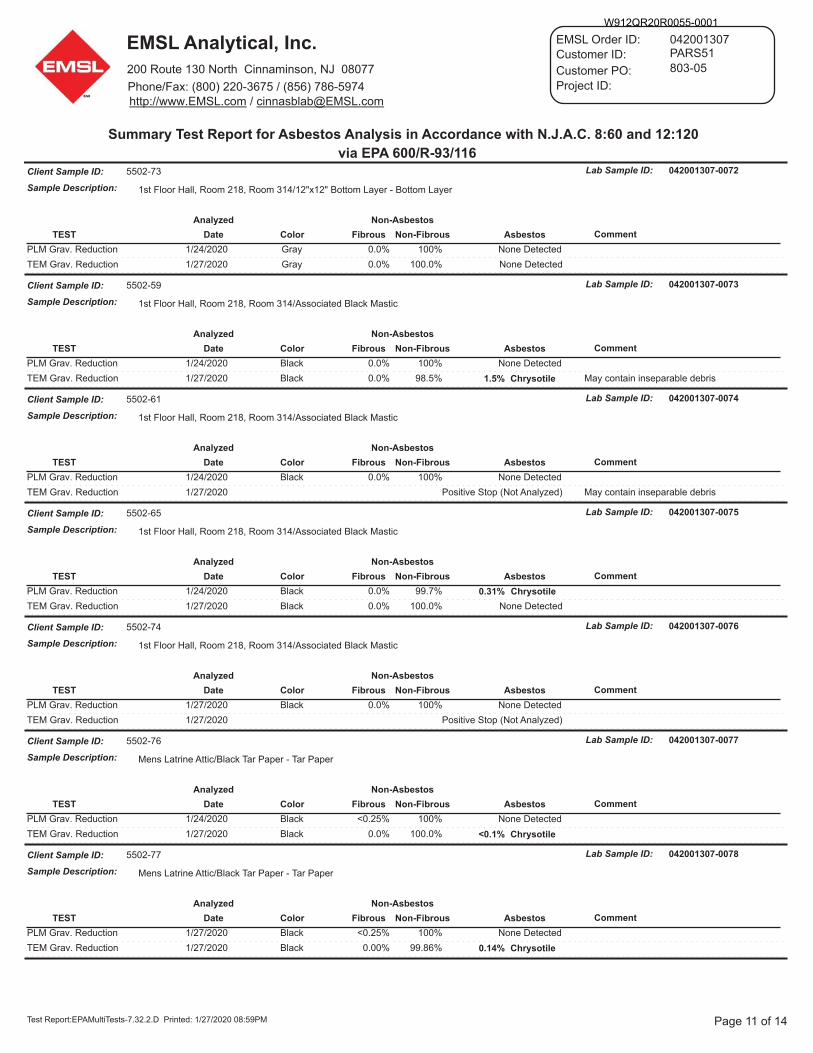
W912QR20R0055-0001
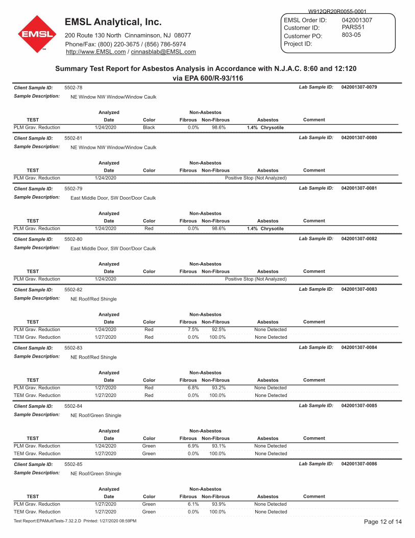
W912QR20R0055-0001
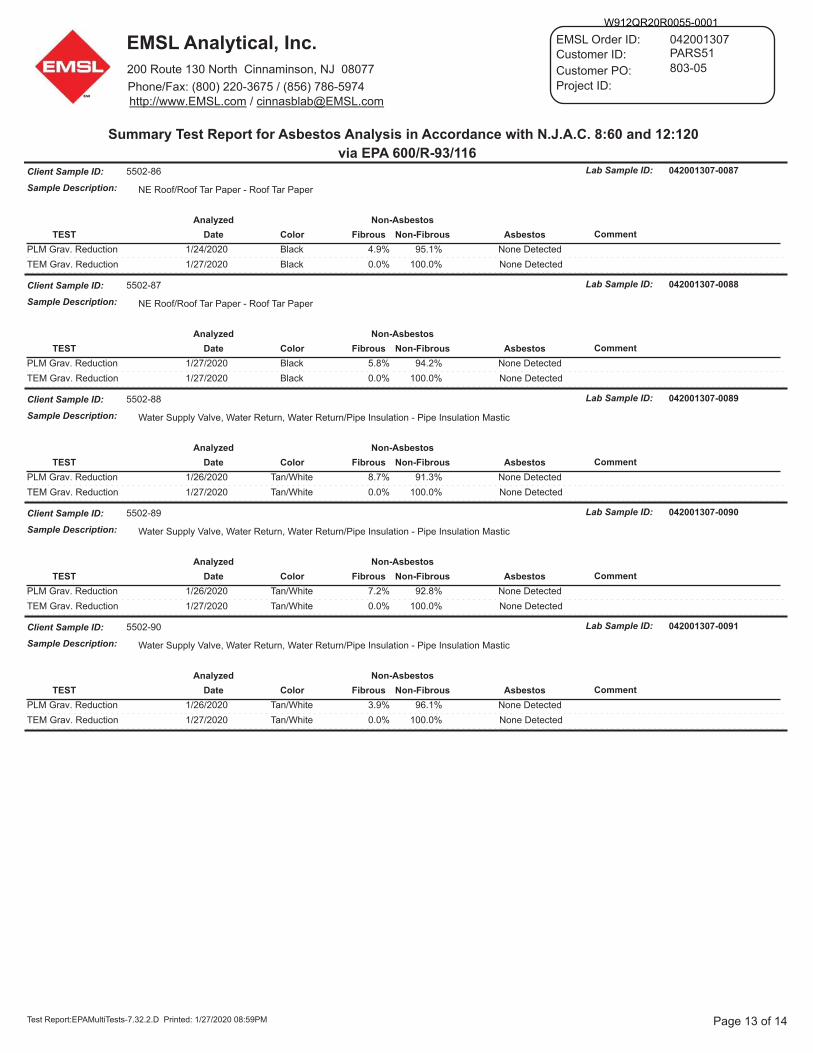
W912QR20R0055-0001
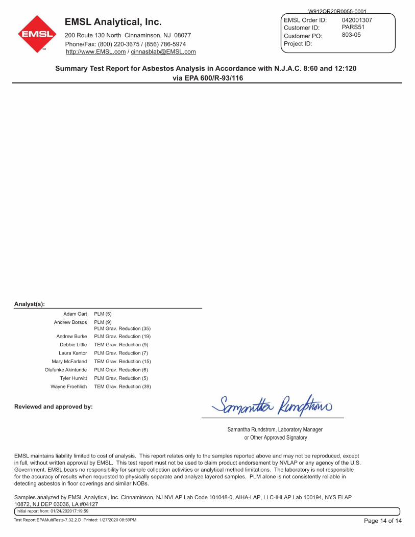
W912QR20R0055-0001
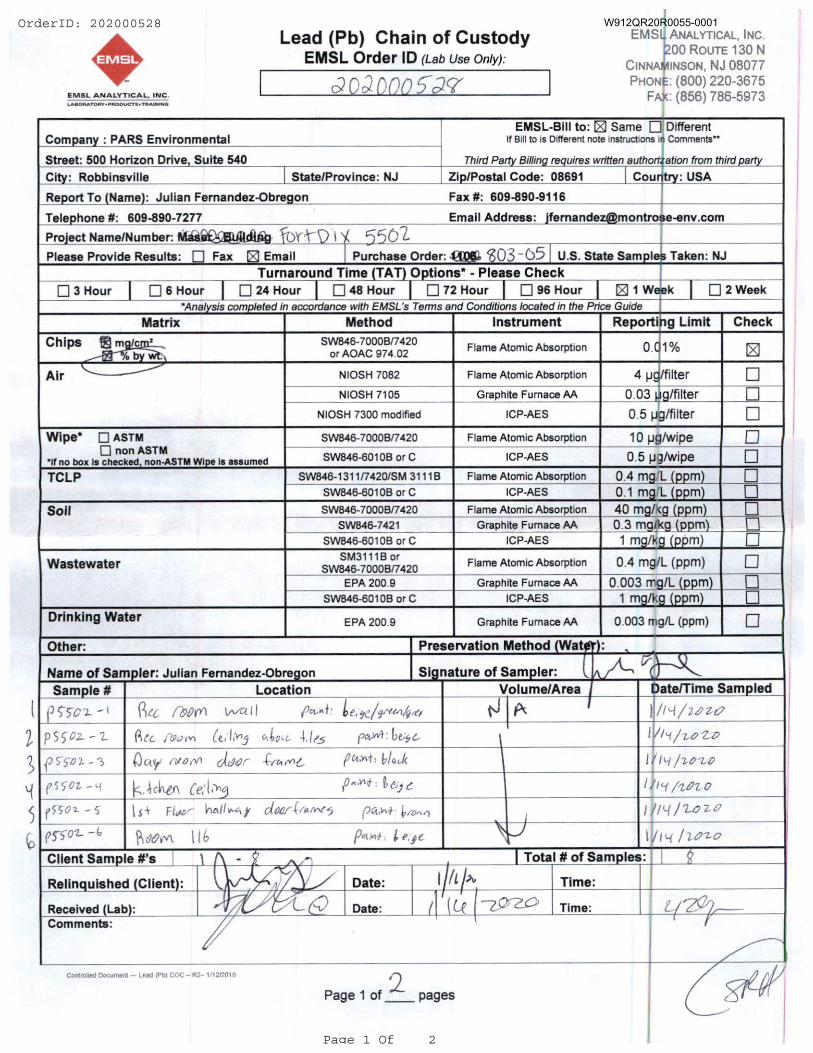
OrderID: 202000528
Page 1 Of 2
W912QR20R0055-0001
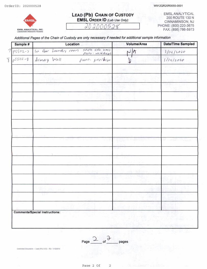
OrderID: 202000528
Page 2 Of 2
W912QR20R0055-0001
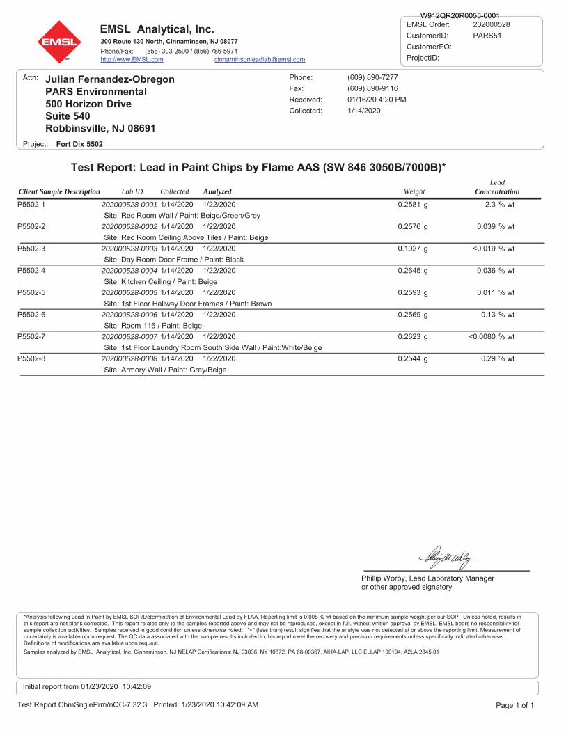
Client Sample Description ConcentrationLab ID Analyzed WeightLead
Collected
EMSL Analytical, Inc.200 Route 130 North, Cinnaminson, NJ 08077
Phone/Fax: (856) 303-2500 / (856) 786-5974http://www.EMSL.com [email protected]
Attn: Julian Fernandez-ObregonPARS Environmental500 Horizon DriveSuite 540Robbinsville, NJ 08691
Received: 01/16/20 4:20 PM
Fort Dix 5502
Fax: (609) 890-9116
Phone: (609) 890-7277
Project:
1/14/2020Collected:
Test Report: Lead in Paint Chips by Flame AAS (SW 846 3050B/7000B)*
202000528
CustomerID: PARS51
CustomerPO:
ProjectID:
EMSL Order:
0.2581
Site: Rec Room Wall / Paint: Beige/Green/Grey
202000528-0001P5502-1 2.3 % wt1/22/2020 g1/14/2020
0.2576
Site: Rec Room Ceiling Above Tiles / Paint: Beige
202000528-0002P5502-2 0.039 % wt1/22/2020 g1/14/2020
0.1027
Site: Day Room Door Frame / Paint: Black
202000528-0003P5502-3 <0.019 % wt1/22/2020 g1/14/2020
0.2645
Site: Kitchen Ceiling / Paint: Beige
202000528-0004P5502-4 0.036 % wt1/22/2020 g1/14/2020
0.2593
Site: 1st Floor Hallway Door Frames / Paint: Brown
202000528-0005P5502-5 0.011 % wt1/22/2020 g1/14/2020
0.2569
Site: Room 116 / Paint: Beige
202000528-0006P5502-6 0.13 % wt1/22/2020 g1/14/2020
0.2623
Site: 1st Floor Laundry Room South Side Wall / Paint:White/Beige
202000528-0007P5502-7 <0.0080 % wt1/22/2020 g1/14/2020
0.2544
Site: Armory Wall / Paint: Grey/Beige
202000528-0008P5502-8 0.29 % wt1/22/2020 g1/14/2020
Page 1 of 1
Phillip Worby, Lead Laboratory Manageror other approved signatory
Test Report ChmSnglePrm/nQC-7.32.3 Printed: 1/23/2020 10:42:09 AM
*Analysis following Lead in Paint by EMSL SOP/Determination of Environmental Lead by FLAA. Reporting limit is 0.008 % wt based on the minimum sample weight per our SOP. Unless noted, results inthis report are not blank corrected. This report relates only to the samples reported above and may not be reproduced, except in full, without written approval by EMSL. EMSL bears no responsibility forsample collection activities. Samples received in good condition unless otherwise noted. "<" (less than) result signifies that the analyte was not detected at or above the reporting limit. Measurement ofuncertainty is available upon request. The QC data associated with the sample results included in this report meet the recovery and precision requirements unless specifically indicated otherwise.Definitions of modifications are available upon request.
Samples analyzed by EMSL Analytical, Inc. Cinnaminson, NJ NELAP Certifications: NJ 03036, NY 10872, PA 68-00367, AIHA-LAP, LLC ELLAP 100194, A2LA 2845.01
Initial report from 01/23/2020 10:42:09
W912QR20R0055-0001
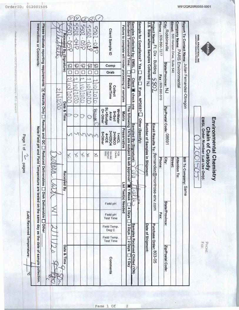
OrderID: 012001505
Page 1 Of 2
W912QR20R0055-0001
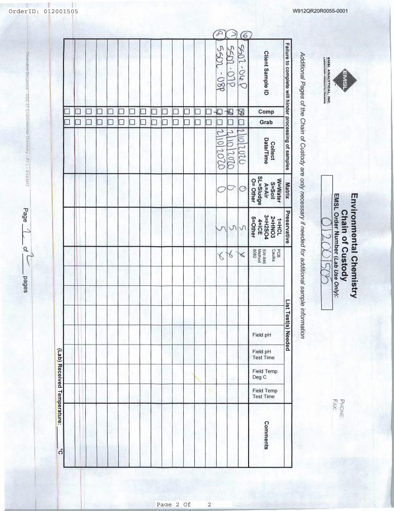
OrderID: 012001505
Page 2 Of 2
W912QR20R0055-0001
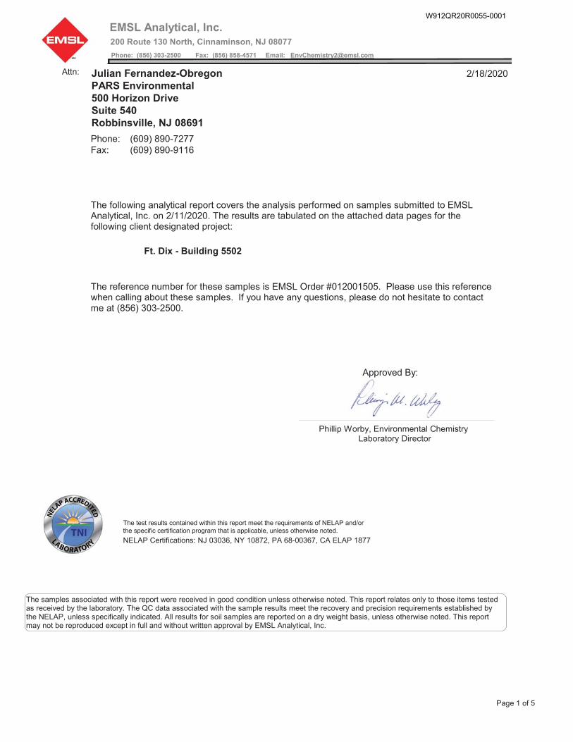
Phillip Worby, Environmental ChemistryLaboratory Director
Approved By:
Fax: (609) 890-9116Phone: (609) 890-7277
The following analytical report covers the analysis performed on samples submitted to EMSLAnalytical, Inc. on 2/11/2020. The results are tabulated on the attached data pages for thefollowing client designated project:
Ft. Dix - Building 5502
The reference number for these samples is EMSL Order #012001505. Please use this referencewhen calling about these samples. If you have any questions, please do not hesitate to contactme at (856) 303-2500.
2/18/2020Attn: Julian Fernandez-ObregonPARS Environmental500 Horizon DriveSuite 540Robbinsville, NJ 08691
The test results contained within this report meet the requirements of NELAP and/orthe specific certification program that is applicable, unless otherwise noted.
NELAP Certifications: NJ 03036, NY 10872, PA 68-00367, CA ELAP 1877
The samples associated with this report were received in good condition unless otherwise noted. This report relates only to those items testedas received by the laboratory. The QC data associated with the sample results meet the recovery and precision requirements established bythe NELAP, unless specifically indicated. All results for soil samples are reported on a dry weight basis, unless otherwise noted. This reportmay not be reproduced except in full and without written approval by EMSL Analytical, Inc.
EMSL Analytical, Inc.200 Route 130 North, Cinnaminson, NJ 08077
Phone: (856) 303-2500 Fax: (856) 858-4571 Email: [email protected]
Page 1 of 5
W912QR20R0055-0001
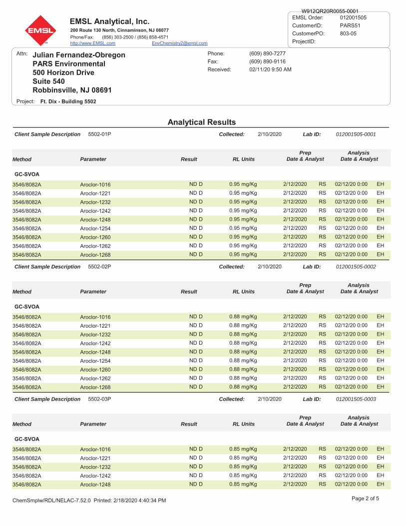
EMSL Analytical, Inc.200 Route 130 North, Cinnaminson, NJ 08077
Phone/Fax: (856) 303-2500 / (856) 858-4571http://www.EMSL.com [email protected]
012001505
CustomerID: PARS51
CustomerPO: 803-05
ProjectID:
EMSL Order:
Analytical Results
Attn: Julian Fernandez-ObregonPARS Environmental500 Horizon DriveSuite 540Robbinsville, NJ 08691
Received: 02/11/20 9:50 AM
Ft. Dix - Building 5502
Fax: (609) 890-9116
Phone: (609) 890-7277
Project:
Client Sample Description Lab ID:5502-01P 012001505-0001Collected: 2/10/2020
Method Parameter Result UnitsAnalysis
Date & AnalystRLPrep
Date & Analyst
GC-SVOA
3546/8082A Aroclor-1016 EHND mg/Kg 02/12/20 0:000.95 2/12/2020 RSD
3546/8082A Aroclor-1221 EHND mg/Kg 02/12/20 0:000.95 2/12/2020 RSD
3546/8082A Aroclor-1232 EHND mg/Kg 02/12/20 0:000.95 2/12/2020 RSD
3546/8082A Aroclor-1242 EHND mg/Kg 02/12/20 0:000.95 2/12/2020 RSD
3546/8082A Aroclor-1248 EHND mg/Kg 02/12/20 0:000.95 2/12/2020 RSD
3546/8082A Aroclor-1254 EHND mg/Kg 02/12/20 0:000.95 2/12/2020 RSD
3546/8082A Aroclor-1260 EHND mg/Kg 02/12/20 0:000.95 2/12/2020 RSD
3546/8082A Aroclor-1262 EHND mg/Kg 02/12/20 0:000.95 2/12/2020 RSD
3546/8082A Aroclor-1268 EHND mg/Kg 02/12/20 0:000.95 2/12/2020 RSD
Client Sample Description Lab ID:5502-02P 012001505-0002Collected: 2/10/2020
Method Parameter Result UnitsAnalysis
Date & AnalystRLPrep
Date & Analyst
GC-SVOA
3546/8082A Aroclor-1016 EHND mg/Kg 02/12/20 0:000.88 2/12/2020 RSD
3546/8082A Aroclor-1221 EHND mg/Kg 02/12/20 0:000.88 2/12/2020 RSD
3546/8082A Aroclor-1232 EHND mg/Kg 02/12/20 0:000.88 2/12/2020 RSD
3546/8082A Aroclor-1242 EHND mg/Kg 02/12/20 0:000.88 2/12/2020 RSD
3546/8082A Aroclor-1248 EHND mg/Kg 02/12/20 0:000.88 2/12/2020 RSD
3546/8082A Aroclor-1254 EHND mg/Kg 02/12/20 0:000.88 2/12/2020 RSD
3546/8082A Aroclor-1260 EHND mg/Kg 02/12/20 0:000.88 2/12/2020 RSD
3546/8082A Aroclor-1262 EHND mg/Kg 02/12/20 0:000.88 2/12/2020 RSD
3546/8082A Aroclor-1268 EHND mg/Kg 02/12/20 0:000.88 2/12/2020 RSD
Client Sample Description Lab ID:5502-03P 012001505-0003Collected: 2/10/2020
Method Parameter Result UnitsAnalysis
Date & AnalystRLPrep
Date & Analyst
GC-SVOA
3546/8082A Aroclor-1016 EHND mg/Kg 02/12/20 0:000.85 2/12/2020 RSD
3546/8082A Aroclor-1221 EHND mg/Kg 02/12/20 0:000.85 2/12/2020 RSD
3546/8082A Aroclor-1232 EHND mg/Kg 02/12/20 0:000.85 2/12/2020 RSD
3546/8082A Aroclor-1242 EHND mg/Kg 02/12/20 0:000.85 2/12/2020 RSD
3546/8082A Aroclor-1248 EHND mg/Kg 02/12/20 0:000.85 2/12/2020 RSD
Page 2 of 5ChemSmplw/RDL/NELAC-7.52.0 Printed: 2/18/2020 4:40:34 PM
W912QR20R0055-0001
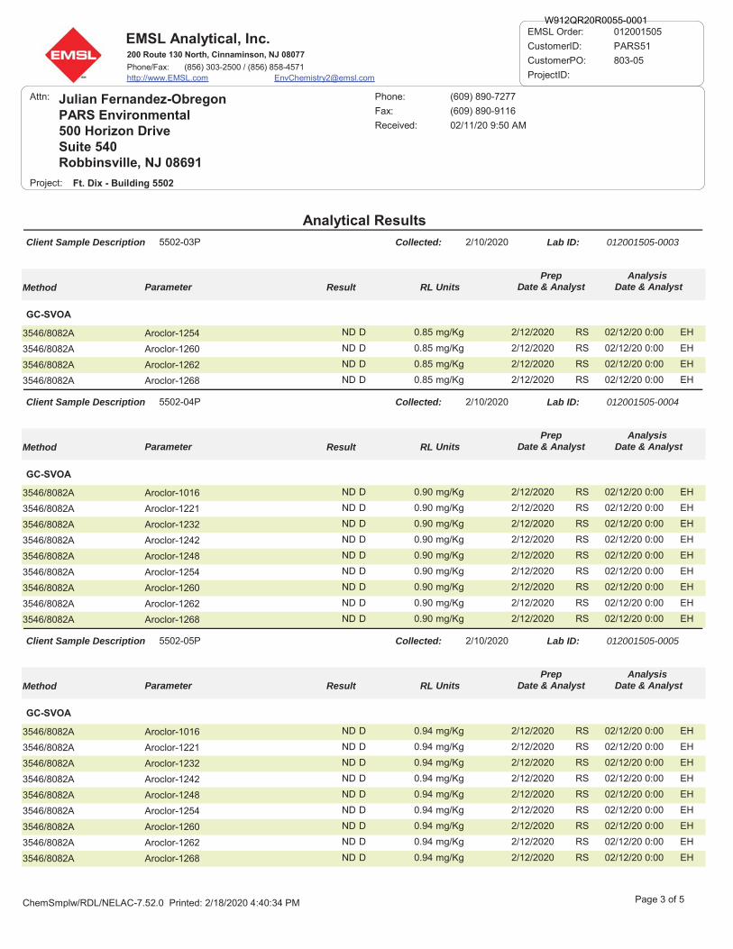
EMSL Analytical, Inc.200 Route 130 North, Cinnaminson, NJ 08077
Phone/Fax: (856) 303-2500 / (856) 858-4571http://www.EMSL.com [email protected]
012001505
CustomerID: PARS51
CustomerPO: 803-05
ProjectID:
EMSL Order:
Analytical Results
Attn: Julian Fernandez-ObregonPARS Environmental500 Horizon DriveSuite 540Robbinsville, NJ 08691
Received: 02/11/20 9:50 AM
Ft. Dix - Building 5502
Fax: (609) 890-9116
Phone: (609) 890-7277
Project:
Client Sample Description Lab ID:5502-03P 012001505-0003Collected: 2/10/2020
Method Parameter Result UnitsAnalysis
Date & AnalystRLPrep
Date & Analyst
GC-SVOA
3546/8082A Aroclor-1254 EHND mg/Kg 02/12/20 0:000.85 2/12/2020 RSD
3546/8082A Aroclor-1260 EHND mg/Kg 02/12/20 0:000.85 2/12/2020 RSD
3546/8082A Aroclor-1262 EHND mg/Kg 02/12/20 0:000.85 2/12/2020 RSD
3546/8082A Aroclor-1268 EHND mg/Kg 02/12/20 0:000.85 2/12/2020 RSD
Client Sample Description Lab ID:5502-04P 012001505-0004Collected: 2/10/2020
Method Parameter Result UnitsAnalysis
Date & AnalystRLPrep
Date & Analyst
GC-SVOA
3546/8082A Aroclor-1016 EHND mg/Kg 02/12/20 0:000.90 2/12/2020 RSD
3546/8082A Aroclor-1221 EHND mg/Kg 02/12/20 0:000.90 2/12/2020 RSD
3546/8082A Aroclor-1232 EHND mg/Kg 02/12/20 0:000.90 2/12/2020 RSD
3546/8082A Aroclor-1242 EHND mg/Kg 02/12/20 0:000.90 2/12/2020 RSD
3546/8082A Aroclor-1248 EHND mg/Kg 02/12/20 0:000.90 2/12/2020 RSD
3546/8082A Aroclor-1254 EHND mg/Kg 02/12/20 0:000.90 2/12/2020 RSD
3546/8082A Aroclor-1260 EHND mg/Kg 02/12/20 0:000.90 2/12/2020 RSD
3546/8082A Aroclor-1262 EHND mg/Kg 02/12/20 0:000.90 2/12/2020 RSD
3546/8082A Aroclor-1268 EHND mg/Kg 02/12/20 0:000.90 2/12/2020 RSD
Client Sample Description Lab ID:5502-05P 012001505-0005Collected: 2/10/2020
Method Parameter Result UnitsAnalysis
Date & AnalystRLPrep
Date & Analyst
GC-SVOA
3546/8082A Aroclor-1016 EHND mg/Kg 02/12/20 0:000.94 2/12/2020 RSD
3546/8082A Aroclor-1221 EHND mg/Kg 02/12/20 0:000.94 2/12/2020 RSD
3546/8082A Aroclor-1232 EHND mg/Kg 02/12/20 0:000.94 2/12/2020 RSD
3546/8082A Aroclor-1242 EHND mg/Kg 02/12/20 0:000.94 2/12/2020 RSD
3546/8082A Aroclor-1248 EHND mg/Kg 02/12/20 0:000.94 2/12/2020 RSD
3546/8082A Aroclor-1254 EHND mg/Kg 02/12/20 0:000.94 2/12/2020 RSD
3546/8082A Aroclor-1260 EHND mg/Kg 02/12/20 0:000.94 2/12/2020 RSD
3546/8082A Aroclor-1262 EHND mg/Kg 02/12/20 0:000.94 2/12/2020 RSD
3546/8082A Aroclor-1268 EHND mg/Kg 02/12/20 0:000.94 2/12/2020 RSD
Page 3 of 5ChemSmplw/RDL/NELAC-7.52.0 Printed: 2/18/2020 4:40:34 PM
W912QR20R0055-0001

EMSL Analytical, Inc.200 Route 130 North, Cinnaminson, NJ 08077
Phone/Fax: (856) 303-2500 / (856) 858-4571http://www.EMSL.com [email protected]
012001505
CustomerID: PARS51
CustomerPO: 803-05
ProjectID:
EMSL Order:
Analytical Results
Attn: Julian Fernandez-ObregonPARS Environmental500 Horizon DriveSuite 540Robbinsville, NJ 08691
Received: 02/11/20 9:50 AM
Ft. Dix - Building 5502
Fax: (609) 890-9116
Phone: (609) 890-7277
Project:
Client Sample Description Lab ID:5502-06P 012001505-0006Collected: 2/10/2020
Method Parameter Result UnitsAnalysis
Date & AnalystRLPrep
Date & Analyst
GC-SVOA
3546/8082A Aroclor-1016 EHND mg/Kg 02/12/20 0:000.99 2/12/2020 RSD
3546/8082A Aroclor-1221 EHND mg/Kg 02/12/20 0:000.99 2/12/2020 RSD
3546/8082A Aroclor-1232 EHND mg/Kg 02/12/20 0:000.99 2/12/2020 RSD
3546/8082A Aroclor-1242 EHND mg/Kg 02/12/20 0:000.99 2/12/2020 RSD
3546/8082A Aroclor-1248 EHND mg/Kg 02/12/20 0:000.99 2/12/2020 RSD
3546/8082A Aroclor-1254 EHND mg/Kg 02/12/20 0:000.99 2/12/2020 RSD
3546/8082A Aroclor-1260 EHND mg/Kg 02/12/20 0:000.99 2/12/2020 RSD
3546/8082A Aroclor-1262 EHND mg/Kg 02/12/20 0:000.99 2/12/2020 RSD
3546/8082A Aroclor-1268 EHND mg/Kg 02/12/20 0:000.99 2/12/2020 RSD
Client Sample Description Lab ID:5502-07P 012001505-0007Collected: 2/10/2020
Method Parameter Result UnitsAnalysis
Date & AnalystRLPrep
Date & Analyst
GC-SVOA
3546/8082A Aroclor-1016 EHND mg/Kg 02/12/20 0:000.83 2/12/2020 RSD
3546/8082A Aroclor-1221 EHND mg/Kg 02/12/20 0:000.83 2/12/2020 RSD
3546/8082A Aroclor-1232 EHND mg/Kg 02/12/20 0:000.83 2/12/2020 RSD
3546/8082A Aroclor-1242 EHND mg/Kg 02/12/20 0:000.83 2/12/2020 RSD
3546/8082A Aroclor-1248 EHND mg/Kg 02/12/20 0:000.83 2/12/2020 RSD
3546/8082A Aroclor-1254 EHND mg/Kg 02/12/20 0:000.83 2/12/2020 RSD
3546/8082A Aroclor-1260 EHND mg/Kg 02/12/20 0:000.83 2/12/2020 RSD
3546/8082A Aroclor-1262 EHND mg/Kg 02/12/20 0:000.83 2/12/2020 RSD
3546/8082A Aroclor-1268 EHND mg/Kg 02/12/20 0:000.83 2/12/2020 RSD
Client Sample Description Lab ID:5502-08P 012001505-0008Collected: 2/10/2020
Method Parameter Result UnitsAnalysis
Date & AnalystRLPrep
Date & Analyst
GC-SVOA
3546/8082A Aroclor-1016 EHND mg/Kg 02/12/20 0:000.87 2/12/2020 RSD
3546/8082A Aroclor-1221 EHND mg/Kg 02/12/20 0:000.87 2/12/2020 RSD
3546/8082A Aroclor-1232 EHND mg/Kg 02/12/20 0:000.87 2/12/2020 RSD
3546/8082A Aroclor-1242 EHND mg/Kg 02/12/20 0:000.87 2/12/2020 RSD
3546/8082A Aroclor-1248 EHND mg/Kg 02/12/20 0:000.87 2/12/2020 RSD
Page 4 of 5ChemSmplw/RDL/NELAC-7.52.0 Printed: 2/18/2020 4:40:34 PM
W912QR20R0055-0001
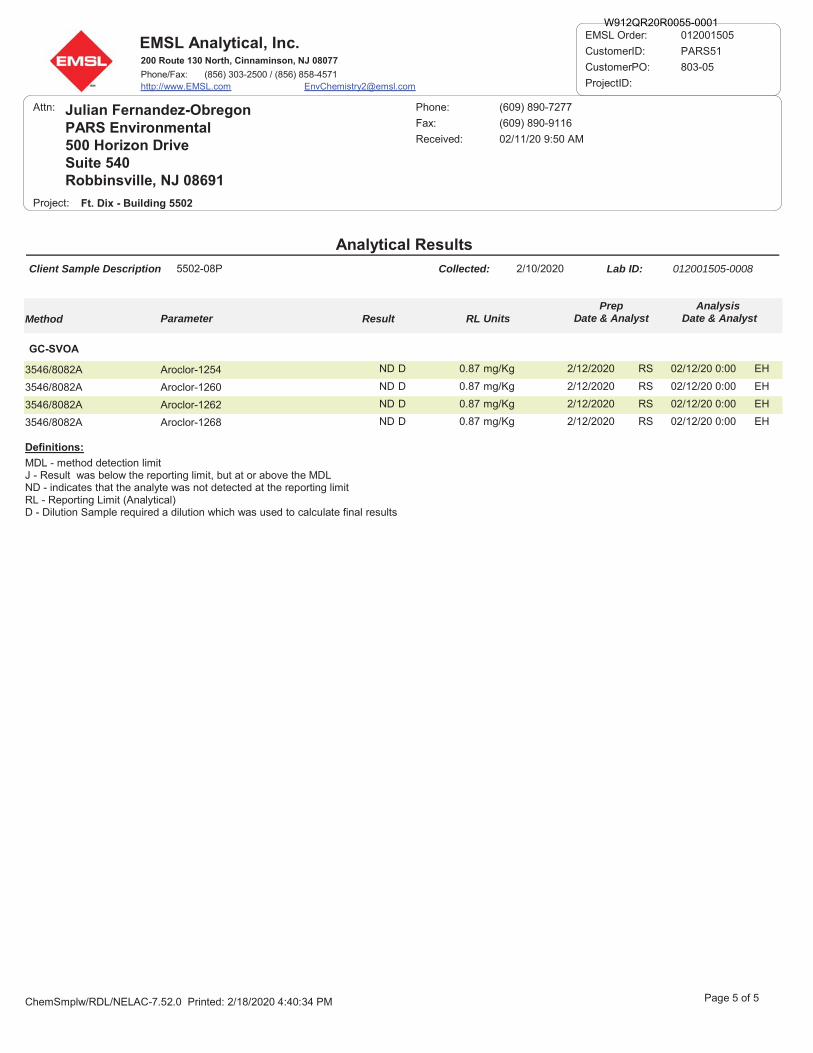
EMSL Analytical, Inc.200 Route 130 North, Cinnaminson, NJ 08077
Phone/Fax: (856) 303-2500 / (856) 858-4571http://www.EMSL.com [email protected]
012001505
CustomerID: PARS51
CustomerPO: 803-05
ProjectID:
EMSL Order:
Analytical Results
Attn: Julian Fernandez-ObregonPARS Environmental500 Horizon DriveSuite 540Robbinsville, NJ 08691
Received: 02/11/20 9:50 AM
Ft. Dix - Building 5502
Fax: (609) 890-9116
Phone: (609) 890-7277
Project:
Client Sample Description Lab ID:5502-08P 012001505-0008Collected: 2/10/2020
Method Parameter Result UnitsAnalysis
Date & AnalystRLPrep
Date & Analyst
GC-SVOA
3546/8082A Aroclor-1254 EHND mg/Kg 02/12/20 0:000.87 2/12/2020 RSD
3546/8082A Aroclor-1260 EHND mg/Kg 02/12/20 0:000.87 2/12/2020 RSD
3546/8082A Aroclor-1262 EHND mg/Kg 02/12/20 0:000.87 2/12/2020 RSD
3546/8082A Aroclor-1268 EHND mg/Kg 02/12/20 0:000.87 2/12/2020 RSD
MDL - method detection limitJ - Result was below the reporting limit, but at or above the MDLND - indicates that the analyte was not detected at the reporting limitRL - Reporting Limit (Analytical)D - Dilution Sample required a dilution which was used to calculate final results
Definitions:
Page 5 of 5ChemSmplw/RDL/NELAC-7.52.0 Printed: 2/18/2020 4:40:34 PM
W912QR20R0055-0001

Final Pre-Renovation Hazardous Materials Survey Report Joint Base McGuire-Dix-Lakehurst
Building 5502 July 2020
APPENDIX E
Radon Laboratory Report
W912QR20R0055-0001
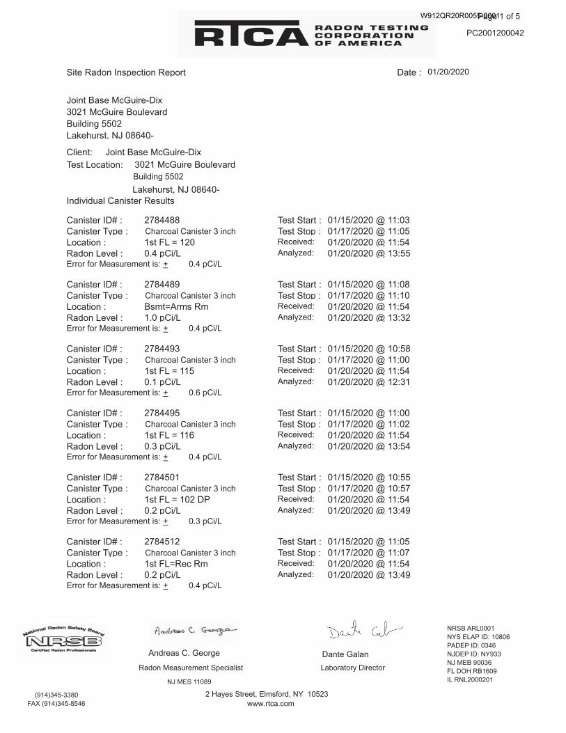
W912QR20R0055-0001

W912QR20R0055-0001
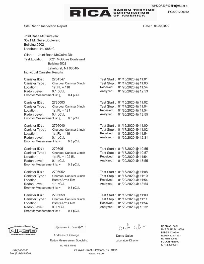
W912QR20R0055-0001
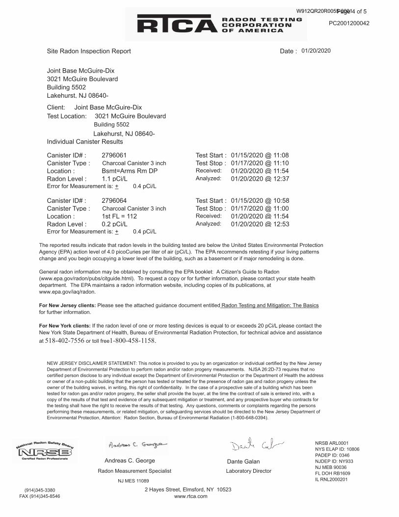
W912QR20R0055-0001
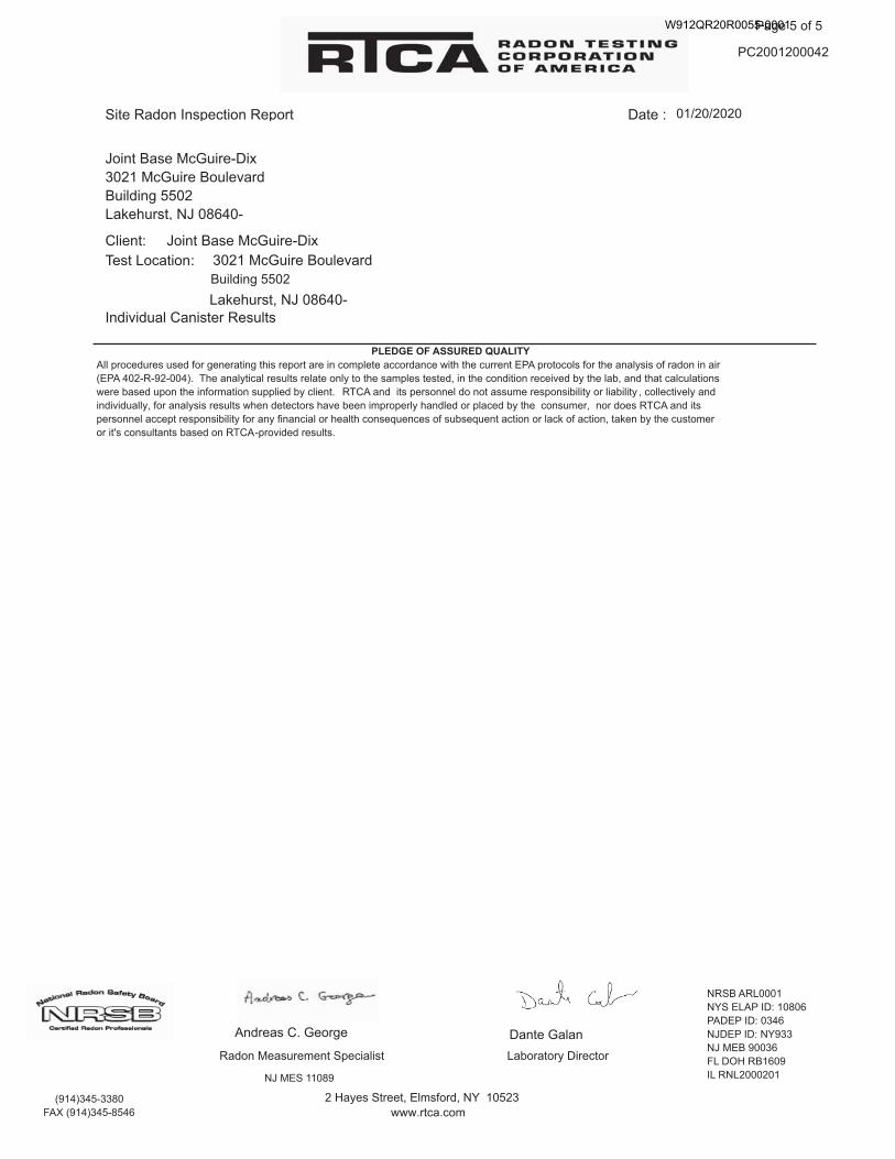
W912QR20R0055-0001

Final Pre-Renovation Hazardous Materials Survey Report Joint Base McGuire-Dix-Lakehurst
Building 5502 July 2020
APPENDIX F
29 CFR 1926.62 Summary
W912QR20R0055-0001
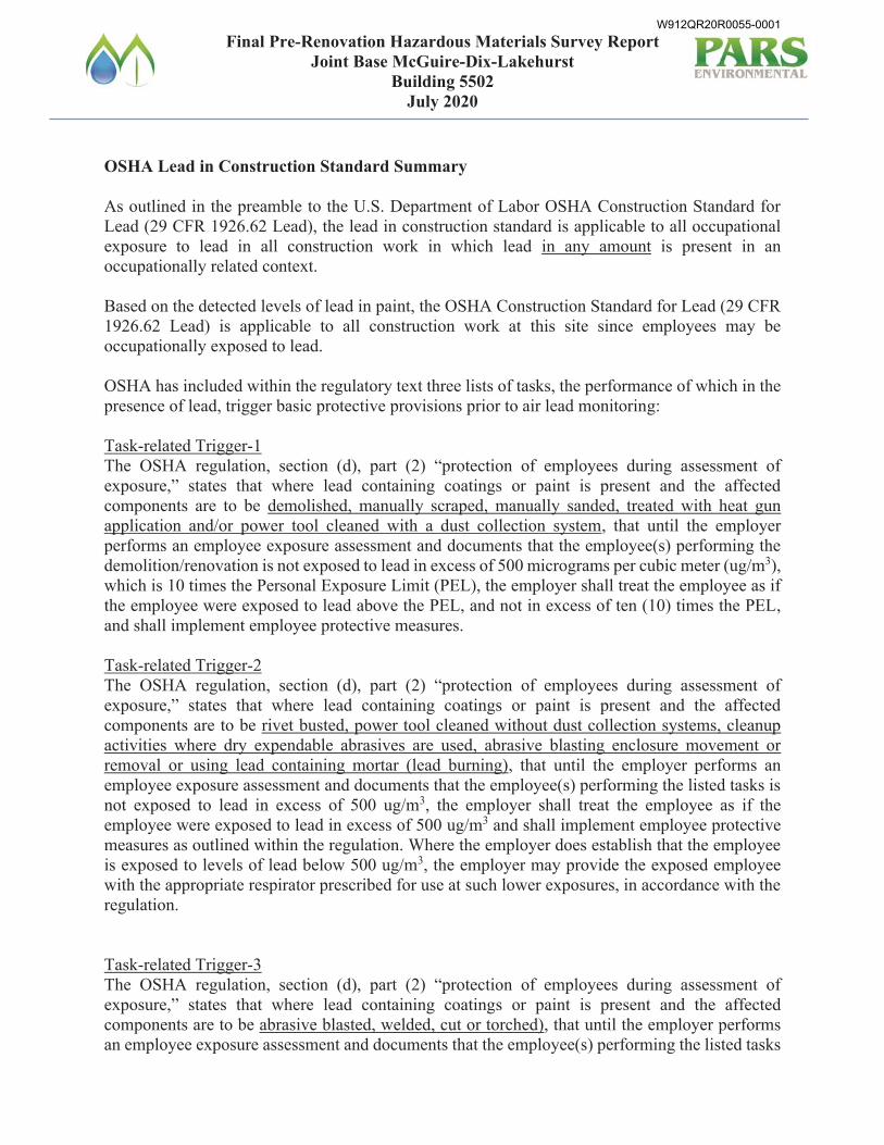
Final Pre-Renovation Hazardous Materials Survey Report Joint Base McGuire-Dix-Lakehurst
Building 5502 July 2020
OSHA Lead in Construction Standard Summary As outlined in the preamble to the U.S. Department of Labor OSHA Construction Standard for Lead (29 CFR 1926.62 Lead), the lead in construction standard is applicable to all occupational exposure to lead in all construction work in which lead in any amount is present in an occupationally related context. Based on the detected levels of lead in paint, the OSHA Construction Standard for Lead (29 CFR 1926.62 Lead) is applicable to all construction work at this site since employees may be occupationally exposed to lead. OSHA has included within the regulatory text three lists of tasks, the performance of which in the presence of lead, trigger basic protective provisions prior to air lead monitoring: Task-related Trigger-1 The OSHA regulation, section (d), part (2) “protection of employees during assessment of exposure,” states that where lead containing coatings or paint is present and the affected components are to be demolished, manually scraped, manually sanded, treated with heat gun application and/or power tool cleaned with a dust collection system, that until the employer performs an employee exposure assessment and documents that the employee(s) performing the demolition/renovation is not exposed to lead in excess of 500 micrograms per cubic meter (ug/m3), which is 10 times the Personal Exposure Limit (PEL), the employer shall treat the employee as if the employee were exposed to lead above the PEL, and not in excess of ten (10) times the PEL, and shall implement employee protective measures. Task-related Trigger-2 The OSHA regulation, section (d), part (2) “protection of employees during assessment of exposure,” states that where lead containing coatings or paint is present and the affected components are to be rivet busted, power tool cleaned without dust collection systems, cleanup activities where dry expendable abrasives are used, abrasive blasting enclosure movement or removal or using lead containing mortar (lead burning), that until the employer performs an employee exposure assessment and documents that the employee(s) performing the listed tasks is not exposed to lead in excess of 500 ug/m3, the employer shall treat the employee as if the employee were exposed to lead in excess of 500 ug/m3 and shall implement employee protective measures as outlined within the regulation. Where the employer does establish that the employee is exposed to levels of lead below 500 ug/m3, the employer may provide the exposed employee with the appropriate respirator prescribed for use at such lower exposures, in accordance with the regulation. Task-related Trigger-3 The OSHA regulation, section (d), part (2) “protection of employees during assessment of exposure,” states that where lead containing coatings or paint is present and the affected components are to be abrasive blasted, welded, cut or torched), that until the employer performs an employee exposure assessment and documents that the employee(s) performing the listed tasks
W912QR20R0055-0001

Final Pre-Renovation Hazardous Materials Survey Report Joint Base McGuire-Dix-Lakehurst
Building 5502 July 2020
is not exposed to lead in excess of 2,500 ug/m3 (50X PEL), the employer shall treat the employee as if the employee were exposed to lead in excess of 2,500 ug/m3 and shall implement employee protective measures as outlined within the regulation. Where the employer does establish that the employee is exposed to levels of lead below 2,500 ug/m3, the employer may provide the exposed employee with the appropriate respirator prescribed for use at such lower exposures, in accordance with the regulation. Until the employer performs an employee exposure assessment and determines actual employee exposure, the employer shall provide the employee(s) with interim protection as follows:
a) Appropriate respiratory protection b) Appropriate personal protective clothing c) Change areas d) Hand washing facilities e) Biological Monitoring f) Respiratory, Safety and Hazard Communication Training
Where the employer has previously monitored for lead exposures, and the data was obtained within the past 12 months during work operations conducted under workplace conditions closely resembling the process, type of material, control methods, work practices, and environmental conditions used and prevailing in the employee's current operations, the employer may rely on such earlier monitoring results to satisfy the requirements of the regulation if the sampling and analytical methods meet the accuracy and confidence levels of the regulation. The employer of construction workers is responsible for the development and implementation of a worker protection program in accordance with 29 CFR 1926.20 and 29 CFR 1926.62 (e). To implement the worker protection program properly, the employer needs to designate a competent person, i.e., one who is capable of identifying existing and predictable hazards or working conditions which are hazardous or dangerous to employees, in accordance with the general safety and health provisions of OSHA’s construction standards. At the minimum, the following elements should be included in the employer’s worker protection program for employees exposed to lead:
Hazard determination, including exposure assessment Engineering and work practice controls Respiratory protection Protective clothing and equipment Housekeeping Hygiene facilities and practices Medical surveillance and provisions for medical removal Training Signs; and Recordkeeping
W912QR20R0055-0001
Final Pre-Renovation Hazardous Materials Survey Report Joint Base McGuire-Dix-Lakehurst
Building 5502 July 2020
It is OSHA policy that respirators are not to be used in lieu of engineering and work practices to reduce employee exposures to below the PEL. Respirators can only be used in combination with engineering controls and work practices to control employee exposures. This report is for planning purposes only. This report should not be used as the sole document for lead related activities.
W912QR20R0055-0001
Building 5502, Barracks D/B FFR P2 #481648 Joint Base McGuire-Dix-Lakehurst, NJ W912QR20R0055
Section 01 02 00.00 48
ATTACHMENT ‘C’
Preliminary Geotechnical Report
W912QR20R0055-0001

Building 5502, Barracks D/B FFR P2 #481648 Joint Base McGuire-Dix-Lakehurst, NJ W912QR20R0055
Section 01 02 00.00 48
ATTACHMENT ‘D’
Fire Flow Data
(For Information Only)
W912QR20R0055-0001
1
Hurst, Anthony S.
From: Tony Ordile <[email protected]>
Sent: Wednesday, November 27, 2019 2:31 PM
To: Hurst, Anthony S.
Cc: Leggio, Peter
Subject: [EXTERNAL] RE: Fort Dix Water Tests at 5406, 5502 & 5503
Anthony,
We actually conducted the tests last Thursday, November 21st around mid-morning with all the Joint Base
representatives (Tom Trumbetas (Base Project Manager), Clarence Hon (Base Fire Protection Engineer), Brian Dupuis
(Joint Base Fire Department), and Bob Lauer (Assistant Water Treatment Plant Manager)).
For Bldg 5406: Hydrant 5406 was the pressure hydrant and Hydrant 5405 was the flow hydrant. Hydt 5406 is on
Pennsylvania Ave at the corner of 1st Street, just off of the 12-inch main in 1st Street. Hydt 5405 is on West 1st Street, east
and down the block from Bldg. 5406. The dominant supply of water in this area comes from the south and west with the
water moving from west to east along West 1st Street. The results were:
Static = 57.5-psi
Residual = 53.4-psi while flowing 836 gpm
Residual = 49.8-psi while flowing 1,532 gpm
For Bldgs 5502 & 5503: Hydrant 5502 was the pressure hydrant and Hydrant 5504 was the flow hydrant. Both hydrants
are on the 12-inch main in Alabama Ave with the dominant supply of water coming from the east and the 12-inch main
in Texas Ave. The results were:
Static = 62.5-psi
Residual = 57.6-psi while flowing 869 gpm
Residual = 53.3-psi while flowing 1,604 gpm
I will get the official PE sealed report out to you over the next few weeks; I have some travel in the next couple of weeks
but will be back in the office in mid-December and should be able to complete the report then.
Have a happy Thanksgiving holidays.
Anthony M. Ordile, P.E.
Principal Engineer – Level II
HAINES FIRE & RISK CONSULTING CORPORATION
1 Linda Lane, Suite 'B'
Southampton, New Jersey 08088
Cell: 267-496-2375
Office: 609-388-4467
W912QR20R0055-0001
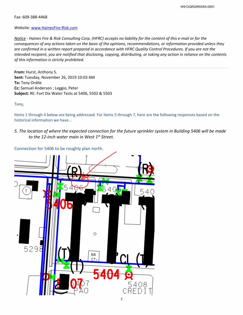
2
Fax: 609-388-4468
Website: www.HainesFire-Risk.com
Notice - Haines Fire & Risk Consulting Corp. (HFRC) accepts no liability for the content of this e-mail or for the
consequences of any actions taken on the basis of the opinions, recommendations, or information provided unless they
are confirmed in a written report prepared in accordance with HFRC Quality Control Procedures. If you are not the
intended recipient, you are notified that disclosing, copying, distributing, or taking any action in reliance on the contents
of this information is strictly prohibited.
From: Hurst, Anthony S.
Sent: Tuesday, November 26, 2019 10:03 AM
To: Tony Ordile
Cc: Samuel Anderson ; Leggio, Peter
Subject: RE: Fort Dix Water Tests at 5406, 5502 & 5503
Tony,
Items 1 through 4 below are being addressed. For items 5 through 7, here are the following responses based on the
historical information we have…
5. The location of where the expected connection for the future sprinkler system in Building 5406 will be made
to the 12-inch water main in West 1st Street.
Connection for 5406 to be roughly plan north.
W912QR20R0055-0001
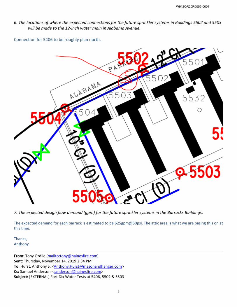
3
6. The locations of where the expected connections for the future sprinkler systems in Buildings 5502 and 5503
will be made to the 12-inch water main in Alabama Avenue.
Connection for 5406 to be roughly plan north.
7. The expected design flow demand (gpm) for the future sprinkler systems in the Barracks Buildings.
The expected demand for each barrack is estimated to be 625gpm@50psi. The attic area is what we are basing this on at
this time.
Thanks,
Anthony
From: Tony Ordile [mailto:[email protected]]
Sent: Thursday, November 14, 2019 2:34 PM
To: Hurst, Anthony S. <[email protected]>
Cc: Samuel Anderson <[email protected]>
Subject: [EXTERNAL] Fort Dix Water Tests at 5406, 5502 & 5503
W912QR20R0055-0001
4
Anthony,
I believe we have a fully executed PO, so I would like to get these water tests completed prior to Thanksgiving as the
weather is starting to break not in our favor.
But, I have yet to see any responses to the information I requested in our proposal. That information was as follows and
as listed on Page 3 of the proposal:
Information that will be needed prior to scheduling the tests is as follows:
1. The Project Contact or Coordinator at the Joint Base MDL for this project that we should contact to schedule
the tests and arrange our clearance through Base Security.
2. The contact for the Fort Dix Water Department that we should contact to discuss the flow tests and the
current operation of the Fort Dix Base water supply system.
3. Confirmation that Mr. Clarence Hon, Joint Base MDL Fire Protection Engineer, does or does not wish to
witness these tests.
4. The list of any other parties that need to be advised of our tests or wish to witness our tests.
5. The location of where the expected connection for the future sprinkler system in Building 5406 will be made
to the 12-inch water main in West 1st Street.
6. The locations of where the expected connections for the future sprinkler systems in Buildings 5502 and
5503 will be made to the 12-inch water main in Alabama Avenue.
7. The expected design flow demand (gpm) for the future sprinkler systems in the Barracks Buildings.
If you have any questions, give a call.
Anthony M. Ordile, P.E.
Principal Engineer – Level II
HAINES FIRE & RISK CONSULTING CORPORATION
1 Linda Lane, Suite 'B'
Southampton, New Jersey 08088
Cell: 267-496-2375
Office: 609-388-4467
Fax: 609-388-4468
Website: www.HainesFire-Risk.com
Notice - Haines Fire & Risk Consulting Corp. (HFRC) accepts no liability for the content of this e-mail or for the
consequences of any actions taken on the basis of the opinions, recommendations, or information provided unless they
are confirmed in a written report prepared in accordance with HFRC Quality Control Procedures. If you are not the
intended recipient, you are notified that disclosing, copying, distributing, or taking any action in reliance on the contents
of this information is strictly prohibited.
W912QR20R0055-0001
Building 5502, Barracks D/B FFR P2 #481648 Joint Base McGuire-Dix-Lakehurst, NJ W912QR20R0055
Section 01 02 00.00 48
ATTACHMENT ‘E
Seismic Evaluation, Structural Integrity, and Progressive Collapse Study
W912QR20R0055-0001
Seismic Evaluation and Structural Integrity Report
Of
Building 5502
Joint Base / McGuire-Dix-Lakehurst, New Jersey
Final Submittal
M&H Job No.177.02
July 2020
Prepared for
U.S. Army Corps of Engineers Louisville District
Prepared by
David C. Dickey, PE
300 West Vine Street, Suite 1300
Lexington, KY 40507
W912QR20R0055-0001
Seismic Evaluation and Structural Integrity Report Joint Base / McGuire-Dix-Lakehurst, NJ
Building 5502
1
Executive Summary This study includes a seismic evaluation using the criteria presented in ASCE 41-13, “Seismic Evaluation and Retrofit of Existing Buildings”, and a structural integrity report for Building 5502 at Joint Base / McGuire-Dix-Lakehurst, NJ. The seismic evaluation of the building was completed for the Life Safety (LS) level of performance. The site is located in an area of moderate seismicity as designated in ASCE 41-13. The condition of the structure is summarized in the structural integrity report and repairs required to restore the structure’s strength or durability are noted. These studies are concurrent with the preparation of a Design/Build RFP for the Full Facility Renovation of Barracks Building 5502. Structural drawings of Building 5515, a building nearly identical to Bldg 5502, were made available for reference. The drawings indicate that original design was in 1951 with the As-Built stamp dated 1955. On-site observations of the Building 5502 were made during the weeks of Oct. 21, 2019 and Feb. 3, 2020. A summary of the findings of the seismic evaluation is shown in Table 1, pg. 5. All items evaluated, except one non-structural item, were found to be in compliance with the requirements of ASCE 41-13. The only special seismic retrofitting proposed in this report is to add connections for lateral support at the tops of the interior unreinforced masonry walls which are to remain. This connection has been added as a requirement within the Design/Build RFP for the Full Facility Renovation project. Repairs to improve structural integrity are included within this report and as requirements in the D/B RFP. These include: concrete surface repairs, exterior grading modifications for positive drainage away from the building, weatherproof louvers to cover openings into the crawlspace, and placing flowable fill under spread footings to address the possibility of groundhog tunnel voids beneath spread footings.
W912QR20R0055-0001
Seismic Evaluation and Structural Integrity Report Joint Base / McGuire-Dix-Lakehurst, NJ
Building 5502
2
Seismic Evaluation Scope of Work and Evaluation Criteria A seismic evaluation of Building 5502 at Joint Base / McGuire-Dix-Lakehurst, NJ has been performed using the criteria presented in ASCE 41-13, “Seismic Evaluation and Retrofit of Existing Buildings.” This evaluation accompanies the preparation of a Design/Build RFP for a Full Facility Renovation project. The requirement to initiate a seismic evaluation for a building stems from RP 8 “Standards of Seismic Safety for Existing Federally Owned and Leased Buildings” and UFC 3-301-01. A seismic evaluation is triggered when “for buildings assigned to Seismic Design Category C (as defined by ASCE 7) a project is planned which significantly extends the building’s useful life through alterations or repairs which total more than 50% of the replacement value of the facility.” The renovation costs of this project have the potential to exceed the 50% threshold. The evaluation procedure of ASCE 41-13 consists of three “Tiers” with each tier increasing in complexity of analysis. Tier 1 consists of checklists specific to the type of building being evaluated. Items on each checklist are marked as “compliant, non-compliant, or not applicable.” If an item is found to be non-compliant, a more in-depth Tier 2 analysis should be performed for that item. In some cases an even more in-depth Tier 3 analysis may be necessary. Tier 1 checklists and Tier 2 analyses have been completed for this evaluation. Tier 3 analyses were not necessary. Evaluation of the existing building was completed for a Life-Safety (LS) level of performance. When subjected to maximum credible earthquake ground motions, buildings that are designed to the Life-Safety level of performance are expected to remain standing but will experience a moderate amount of damage. Buildings should maintain some residual strength and stiffness with gravity-load-bearing elements still functioning. However, some permanent drift and damage to partitions, walls, and exterior finishes are expected. The buildings could be damaged beyond economical repair. Design to the Life Safety performance level is the minimum acceptable level for federal buildings.
References ICSSC RP 8 Standards of Seismic Safety for Existing Federally Owned and
Leased Buildings (NIST GCR 11-917-12) UFC 3-301-01 Structural Engineering ASCE 41-13 Seismic Evaluation and Retrofit of Existing Buildings
Site Seismicity Two of the most important factors in determining a region's seismicity are the magnitudes and distances of historical earthquakes. Multiple moderate earthquakes have occurred near Joint Base / McGuire-Dix-Lakehurst in recent times. Some first-hand reports of the earthquakes’ effects according to the USGS are:
W912QR20R0055-0001
Seismic Evaluation and Structural Integrity Report Joint Base / McGuire-Dix-Lakehurst, NJ
Building 5502
3
June 1, 1927, centered in the Asbury Park area and is the highest intensity earthquake ever observed in New Jersey. Three shocks occurred and affected approximately 3,000 square miles. Near the epicenter, intensities of VII on the Modified Mercalli Scale were observed, resulting in toppled chimneys, cracked plaster and object thrown from shelves. September 1, 1895, centered near High Bridge: felt over 35,000 square miles in a long, narrow elliptical zone extending from Maine to Virginia. Articles fell from shelves (intensity VI) and buildings rocked near High Bridge and in Philadelphia windows broke. In 1957 a similar intensity earthquake occurred in the same vicinity, though it was felt over a much smaller area. October 9, 1871, strongest at Wilmington, Delaware, but was also felt in New Jersey. At Wilmington, chimneys toppled and windows broke, giving it an intensity of VII.
Starting in colonial times, records exist of small earthquakes and infrequent, damaging larger ones affecting the New York – Philadelphia urban corridor, which includes JB MDL. Generally, moderately damaging earthquakes affect the urban area twice a century and smaller earthquakes every 2-3 years. These historical earthquakes contribute in determining the site’s probabilistic ground motion. Figure 1 shows the geographic deaggregation of the seismic hazard at JB MDL. The heights of the vertical bars are proportional to the contribution that each geographical cell makes to the ground motion exceedance hazard. The two somewhat taller bars likely reference large earthquakes from the late 19th century or a large quake that occurred near New York City in 1737. The distance and azimuth to predominant sources and their magnitudes can be seen graphically. The contributions from both the local seismic activity and more distant quakes are shown in Figure 1.
W912QR20R0055-0001
Seismic Evaluation and Structural Integrity Report Joint Base / McGuire-Dix-Lakehurst, NJ
Building 5502
4
Figure 1: Geographic Deaggregation of the Seismic Hazard at JB MDL
Per UFC 3-301-01, the ground motion for the seismic evaluation to the Life Safety performance objective shall be “BSE-1E.”
This Basic Safety Earthquake level is taken as seismic hazard with a 20% probability of exceedance in 50 years. Per UFC 3-301-01, Table E-3, the short period ground acceleration value SS, 20/50 = 0.03g and the 1-second period acceleration value S1, 20/50 = 0.01g.
W912QR20R0055-0001
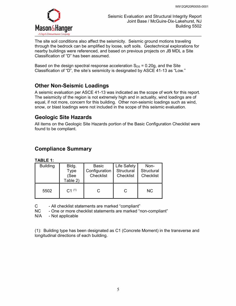
Seismic Evaluation and Structural Integrity Report Joint Base / McGuire-Dix-Lakehurst, NJ
Building 5502
5
The site soil conditions also affect the seismicity. Seismic ground motions traveling through the bedrock can be amplified by loose, soft soils. Geotechnical explorations for nearby buildings were referenced, and based on previous projects on JB MDL a Site Classification of “D” has been assumed. Based on the design spectral response acceleration SDS = 0.20g, and the Site Classification of “D”, the site’s seismicity is designated by ASCE 41-13 as “Low.”
Other Non-Seismic Loadings A seismic evaluation per ASCE 41-13 was indicated as the scope of work for this report. The seismicity of the region is not extremely high and in actuality, wind loadings are of equal, if not more, concern for this building. Other non-seismic loadings such as wind, snow, or blast loadings were not included in the scope of this seismic evaluation.
Geologic Site Hazards All items on the Geologic Site Hazards portion of the Basic Configuration Checklist were found to be compliant.
Compliance Summary TABLE 1:
Building Bldg. Type (See
Table 2)
Basic Configuration
Checklist
Life Safety Structural Checklist
Non-Structural Checklist
5502
C1 (1)
C
C
NC
C - All checklist statements are marked “compliant” NC - One or more checklist statements are marked “non-compliant” N/A - Not applicable (1): Building type has been designated as C1 (Concrete Moment) in the transverse and longitudinal directions of each building.
W912QR20R0055-0001
Seismic Evaluation and Structural Integrity Report Joint Base / McGuire-Dix-Lakehurst, NJ
Building 5502
6
TABLE 2: BUILDING TYPES
Bldg. Type Building Description W1 Wood Light Frames
W1A Multi-Story, Multi-Unit Residential Wood Frames W2 Wood Frames, Commercial and Industrial S1 Steel Moment Frames with Stiff Diaphragms
S1A Steel Moment Frames with Flexible Diaphragms S2 Steel Braced Frames with Stiff Diaphragms
S2A Steel Braced Frames with Flexible Diaphragms S3 Steel Light Frames S4 Steel Frames with Concrete Shear Walls S5 Steel Frames with Infill Masonry Shear Walls and Stiff Diaphragms
S5A Steel Frames with Infill Masonry Shear Walls and Flexible Diaphragms C1 Concrete Moment Frames C2 Concrete Shear Wall Buildings with Stiff Diaphragms
C2A Concrete Shear Wall Buildings with Flexible Diaphragms C3 Concrete Frames with Infill Masonry Shear Walls and Stiff Diaphragms
C3A Concrete Frames with Infill Masonry Shear Walls and Flex. Diaphragms PC1 Pre-cast/Tilt-up Concrete Frames with Stiff Diaphragms
PC1A Pre-cast/Tilt-up Concrete Frames with Flexible Diaphragms PC2 Pre-cast Concrete Frames with Shear Walls
PC2A Pre-cast Concrete Frames with Moment Frames RM1 Reinforced Masonry Bearing Wall Buildings with Flexible Diaphragms RM2 Reinforced Masonry Bearing Wall Buildings with Stiff Diaphragms URM Unreinforced Masonry Wall Buildings with Flexible Diaphragms
URMA Unreinforced Masonry Wall Buildings with Stiff Diaphragms
W912QR20R0055-0001
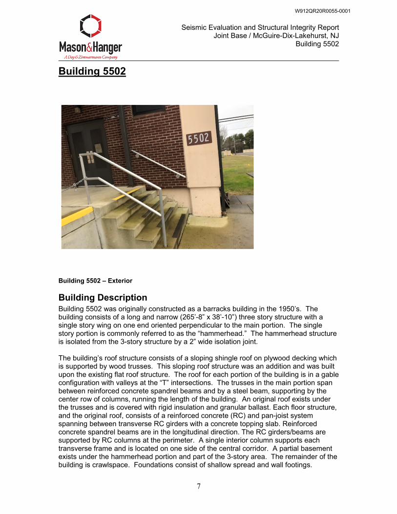
Seismic Evaluation and Structural Integrity Report Joint Base / McGuire-Dix-Lakehurst, NJ
Building 5502
7
Building 5502
Building 5502 – Exterior
Building Description Building 5502 was originally constructed as a barracks building in the 1950’s. The building consists of a long and narrow (265’-8” x 38’-10”) three story structure with a single story wing on one end oriented perpendicular to the main portion. The single story portion is commonly referred to as the “hammerhead.” The hammerhead structure is isolated from the 3-story structure by a 2” wide isolation joint. The building’s roof structure consists of a sloping shingle roof on plywood decking which is supported by wood trusses. This sloping roof structure was an addition and was built upon the existing flat roof structure. The roof for each portion of the building is in a gable configuration with valleys at the “T” intersections. The trusses in the main portion span between reinforced concrete spandrel beams and by a steel beam, supporting by the center row of columns, running the length of the building. An original roof exists under the trusses and is covered with rigid insulation and granular ballast. Each floor structure, and the original roof, consists of a reinforced concrete (RC) and pan-joist system spanning between transverse RC girders with a concrete topping slab. Reinforced concrete spandrel beams are in the longitudinal direction. The RC girders/beams are supported by RC columns at the perimeter. A single interior column supports each transverse frame and is located on one side of the central corridor. A partial basement exists under the hammerhead portion and part of the 3-story area. The remainder of the building is crawlspace. Foundations consist of shallow spread and wall footings.
W912QR20R0055-0001
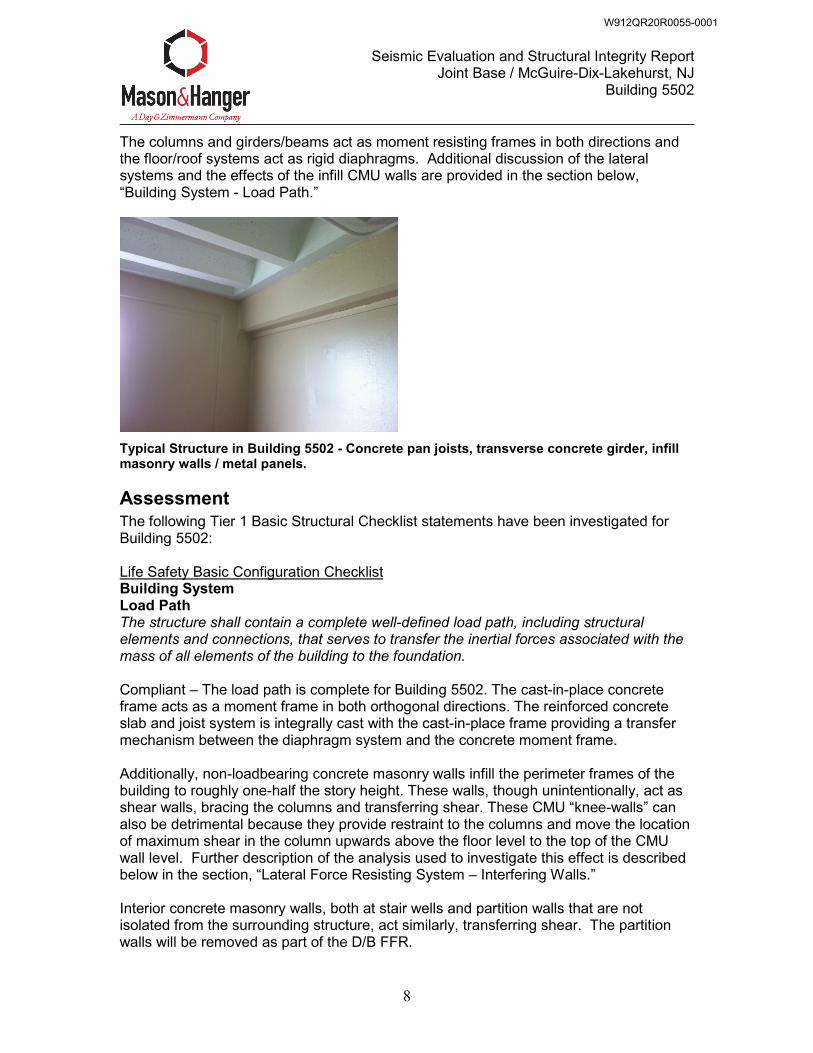
Seismic Evaluation and Structural Integrity Report Joint Base / McGuire-Dix-Lakehurst, NJ
Building 5502
8
The columns and girders/beams act as moment resisting frames in both directions and the floor/roof systems act as rigid diaphragms. Additional discussion of the lateral systems and the effects of the infill CMU walls are provided in the section below, “Building System - Load Path.”
Typical Structure in Building 5502 - Concrete pan joists, transverse concrete girder, infill masonry walls / metal panels.
Assessment The following Tier 1 Basic Structural Checklist statements have been investigated for Building 5502: Life Safety Basic Configuration Checklist Building System Load Path The structure shall contain a complete well-defined load path, including structural elements and connections, that serves to transfer the inertial forces associated with the mass of all elements of the building to the foundation. Compliant – The load path is complete for Building 5502. The cast-in-place concrete frame acts as a moment frame in both orthogonal directions. The reinforced concrete slab and joist system is integrally cast with the cast-in-place frame providing a transfer mechanism between the diaphragm system and the concrete moment frame. Additionally, non-loadbearing concrete masonry walls infill the perimeter frames of the building to roughly one-half the story height. These walls, though unintentionally, act as shear walls, bracing the columns and transferring shear. These CMU “knee-walls” can also be detrimental because they provide restraint to the columns and move the location of maximum shear in the column upwards above the floor level to the top of the CMU wall level. Further description of the analysis used to investigate this effect is described below in the section, “Lateral Force Resisting System – Interfering Walls.” Interior concrete masonry walls, both at stair wells and partition walls that are not isolated from the surrounding structure, act similarly, transferring shear. The partition walls will be removed as part of the D/B FFR.
W912QR20R0055-0001
Seismic Evaluation and Structural Integrity Report Joint Base / McGuire-Dix-Lakehurst, NJ
Building 5502
9
The diaphragm system integrally cast with the lateral force resisting systems, and the unintended contribution of the non-loadbearing concrete masonry walls, combine to provide a complete lateral load path. Adjacent Buildings The clear distance between the building being evaluated and any adjacent building is greater than 4 percent of the height of the shorter building. Non-Compliant Based Upon Tier 1 – The separation between the main portion of Building 5502 and the “hammerhead” wing consists of a 2 inch expansion joint. The approximate height of the wing (shorter building) is 18 feet; 4 percent of that height equals 8.64 inches which is greater than 2 inches, therefore Tier 2 applies. A Tier 2 analysis, which consists of creating a 3D model using the software program “Ram Elements”, was performed to determine the approximate drift. The drift in the longitudinal direction of the 3-story portion was calculated to be 0.13” at an elevation of approx. 20’ (See Appendix). Multiplying this value by the deflection amplification factor of 3.0, the seismic drift is 0.39”. Assuming that the deflection of the hammerhead portion of the building on the opposite side of the expansion joint is nearly the same or even double, the total drift of both buildings will be less than 2”. Therefore, this item for “Adjacent Buildings” is deemed to be Compliant. Mezzanines Interior mezzanine levels are braced independently from the main structure, or are anchored to the seismic-force-resisting elements of the main structure. Not Applicable – No Mezzanines Building Configuration Weak Story The sum of the shear strengths of the seismic-force-resisting system in any story in each direction is not less than 80 percent of the strength in the adjacent story above. Compliant – Each story has a nearly identical lateral-force resisting system. Soft Story The stiffness of the seismic-force-resisting system in any story is not less than 70 percent of the seismic-force-resisting system stiffness in an adjacent story above or below, or less than 80 percent of the average seismic-force-resisting system stiffness of the three stories above or below. Compliant – Each story has similar stiffness. Vertical Irregularities All vertical elements in the seismic-force-resisting system are continuous to the foundation. Compliant – All concrete columns in the seismic-force-resisting system are continuous to the footing.
W912QR20R0055-0001
Seismic Evaluation and Structural Integrity Report Joint Base / McGuire-Dix-Lakehurst, NJ
Building 5502
10
Geometry There are no changes in the net horizontal dimension of the seismic-force-resisting system of more than 30 percent in a story relative to adjacent stories, excluding one-story penthouses and mezzanines. Compliant – Each story of the main portion of Building 5502 has identical dimensions. The “hammerhead” wing is separated by an expansion joint and thus is considered a separate single story building. Mass There is no change in effective mass more than 50 percent from one story to the next. Light roofs, penthouses, and mezzanines need not be considered. Compliant – Each story has similar mass Torsion The estimated distance between the story center of mass and the story center of rigidity is less than 20 percent of the building width in either plan dimension. Compliant – Each floor of each building has similar mass distributed throughout. The distance between center of mass and rigidity is less than 20% of the building width. Life Safety Structural Checklist for Building Type C1: Concrete Moment Frames Seismic Force Resisting System Redundancy The number of lines of moment frames in each principal direction is greater than or equal to 2. The number of bays of moment frames in each line is greater than or equal to 2. Compliant – there are at least 2 lines of moment frames in each principal direction. Column Axial Stress Check The axial stress caused by unfactored gravity loads in columns subjected to overturning forces because of seismic demands is less than 0.20f’c. Alternatively, the axial stresses caused by overturning forces alone, calculated using the Quick Check procedure of Section 4.5.3.6, is less than 0.30f’c. Compliant – Using the alternative check, which considers the overturning forces alone, the allowable axial stress, �� = 0.30� = 1050 ��. According to the Quick Check procedure of Section 4.5.3.6 the axial stress in the columns due to overturning forces is 16.8 ��. The maximum axial stress due to overturning forces calculated using RAM Elements is 58.2 ��. Therefore, both the Quick Check and the detailed analysis indicate that the actual axial stresses are less than the allowable axial stress. Connections – Concrete Columns All concrete columns are doweled into the foundation with a minimum of 4 bars. Compliant – All concrete columns are doweled into the foundation with a minimum of 4 bars.
W912QR20R0055-0001
Seismic Evaluation and Structural Integrity Report Joint Base / McGuire-Dix-Lakehurst, NJ
Building 5502
11
Interfering Walls All concrete and masonry infill walls placed in moment frames are isolated from structural elements. (This item is required for Moderate Seismicity structure, and is not required to be checked for Low Seismicity structures. However, because this item can be of significant concern it has been investigated as follows.) Non-Compliant – Existing masonry infill walls are not isolated from the concrete moment frame; therefore, a Tier 2 analysis from Section 5.5.2.1.1 is necessary. ASCE 41-13 C5.5.2.1.1 states, “A moment frame system that has interfering walls requires evaluation as an infill frame. Interfering walls should be checked for forces induced by the frame, particularly where damage to these walls can lead to falling hazards near means of egress. The frames should be checked for forces induced by contact with the walls, particularly if the walls are not full height or do not completely fill the bay.” An analysis was performed by modeling a representative portion of the building using RAM Elements. The partial-story-height, ungrouted, concrete masonry walls were modeled by placing a stiff HSS brace in the location of the masonry walls. This method modeled the effects of the infill masonry walls on the concrete moment frame, and the member forces in the brace were used to check the compressive and shear stresses imparted upon the masonry walls. The model indicated that the masonry walls do not prohibit the concrete moment frame from adequately resisting the applied forces. Shear stresses in the columns were within allowable limits. Additionally, the compressive and shear stresses in the masonry walls are less than the allowable stresses. The compressive stress (at ultimate strength level forces) applied to the masonry wall is 629 psi , and according to ACI 530-11 for Strength Design, the allowable compressive stress is 0.8�� = 0.8�1500 ��� = 1200 ��, which is greater than the applied stress. The applied shear stress determined from the brace member forces is 27.5 psi, while the
allowable stress determined from ACI 530-11 is 56 ��, which is also greater than the ultimate stress. Therefore, while the masonry infill walls are not isolated from the surrounding structural frame, the detailed analysis of the interaction between the frame and masonry walls indicates that the resulting system is not compromised by the applied forces and the item is Compliant. Shear Stress Check The shear stress in the concrete columns, calculated using the Quick Check procedure
for Section 4.5.3.2,is less than the greater of 100 psi or 2��′.
Compliant – For f’c = 3500psi, 2��′ = 118.3 �� > 100 ��. Using the Quick Check
procedure for Section 4.5.3.2, the maximum shear stress in the columns, due to lateral forces, is 15.2 ��. However, a partial building analysis using RAM Elements revealed a
maximum shear stress of 52 �� due to lateral forces. This check is compliant because both calculated shear stresses are less than the allowable shear stress of 118.3 ��.
W912QR20R0055-0001
Seismic Evaluation and Structural Integrity Report Joint Base / McGuire-Dix-Lakehurst, NJ
Building 5502
12
Nonstructural Assessment
Refer to the appendix for the completed Nonstructural Checklist.
Many of the items are marked N/A because all existing components will be demolished as part of the FFR and new components which meet current codes will be installed. Also, many of the nonstructural items on the checklist are not required to be evaluated for Low seismicity structures at the Life Safety level. Partitions – Unreinforced Masonry Unreinforced masonry or hollow clay tile partitions are braced at a spacing of at most 10 feet in low seismicity. Non-compliant for Tier 1 – The interior non-loadbearing masonry walls are infilled between the floor and the concrete floor girders. The gap between top of the walls and the girder is filled with grout, but no reliable connection to resist out-of-plane forces exists. In Building 5502, most existing non-loadbearing CMU walls will be removed. For any non-loadbearing CMU walls that will remain, the D/B RFP requires bracing connections at the top of the walls in accordance with the IBC. Heavy Partitions Supported by Ceilings The tops of masonry or hollow-clay tile partitions are not laterally supported by an integrated ceiling system. Compliant Masonry Veneer – Ties Masonry veneer is connected to the back-up with corrosion-resistant ties. There is a minimum of one tie for every 2-2/3 square feet, and the ties have spacing no greater than the following: for Life Safety in Low Seismicity, 36 inches. Compliant Masonry Veneer – Shelf Angles Masonry veneer is supported by shelf angles or other elements at each floor level above the ground floor. Compliant Masonry Veneer – Weakened Planes Masonry veneer is anchored to the back-up adjacent to weakened planes, such as at the locations of flashing. Compliant Masonry Veneer – Unreinforced Masonry Backup There is no unreinforced masonry backup.
W912QR20R0055-0001
Seismic Evaluation and Structural Integrity Report Joint Base / McGuire-Dix-Lakehurst, NJ
Building 5502
13
Non-Compliant – Unreinforced infill masonry walls exist. Tier 2: Section 13.6.1.2. The exterior unreinforced infill walls are adequately anchored to resist seismic forces computed in accordance with Section 13.4.3. The drift ratio calculated in accordance with Section 13.4.4 is less than 0.02. From the Tier 2 analysis, the item is Compliant. URM Parapets or Cornices Laterally unsupported unreinforced masonry parapets or cornices have height-to-thickness ratios no greater than 2.5 for Life Safety in Low Seismicity Compliant Stair Enclosures Hollow-clay tiles or unreinforced masonry walls around stair enclosures are restrained out-of-plane and have height-to-thickness ratios not greater than 15-to-1 for Life Safety in Low Seismicity. Compliant – Maximum height to thickness ratio for existing walls around stair enclosures is 14. Stair Details In moment frame structures, the connection between the stairs and the structure does not rely on shallow anchors in concrete. Alternatively, the stair details are capable of accommodating the drift calculated using the Quick Check procedure of Section 4.5.3.1 without including lateral stiffness contribution from the stairs. Compliant – The stairs are cast monolithically with the structure.
Geological Site Hazards Liquefaction Liquefaction-susceptible, saturated, loose granular soils that could jeopardize the building’s seismic performance shall not exist in the foundation soils at depths within 50 feet under the building. Compliant Slope Failure The building site is sufficiently remote from potential earthquake-induced slope failures or rockfalls to be unaffected by such failures or is capable of accommodating any predicted movements without failure. Compliant Surface Fault Rupture Surface fault rupture and surface displacement at the building site is not anticipated. Compliant
W912QR20R0055-0001
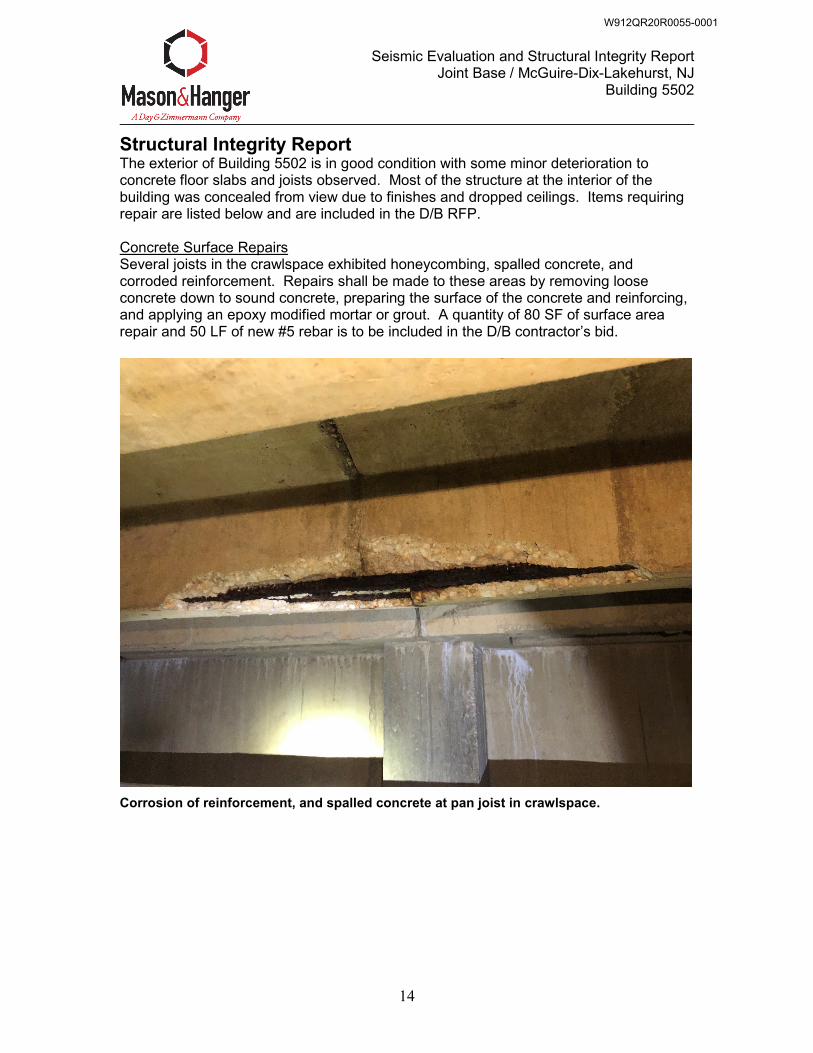
Seismic Evaluation and Structural Integrity Report Joint Base / McGuire-Dix-Lakehurst, NJ
Building 5502
14
Structural Integrity Report The exterior of Building 5502 is in good condition with some minor deterioration to concrete floor slabs and joists observed. Most of the structure at the interior of the building was concealed from view due to finishes and dropped ceilings. Items requiring repair are listed below and are included in the D/B RFP. Concrete Surface Repairs Several joists in the crawlspace exhibited honeycombing, spalled concrete, and corroded reinforcement. Repairs shall be made to these areas by removing loose concrete down to sound concrete, preparing the surface of the concrete and reinforcing, and applying an epoxy modified mortar or grout. A quantity of 80 SF of surface area repair and 50 LF of new #5 rebar is to be included in the D/B contractor’s bid.
Corrosion of reinforcement, and spalled concrete at pan joist in crawlspace.
W912QR20R0055-0001
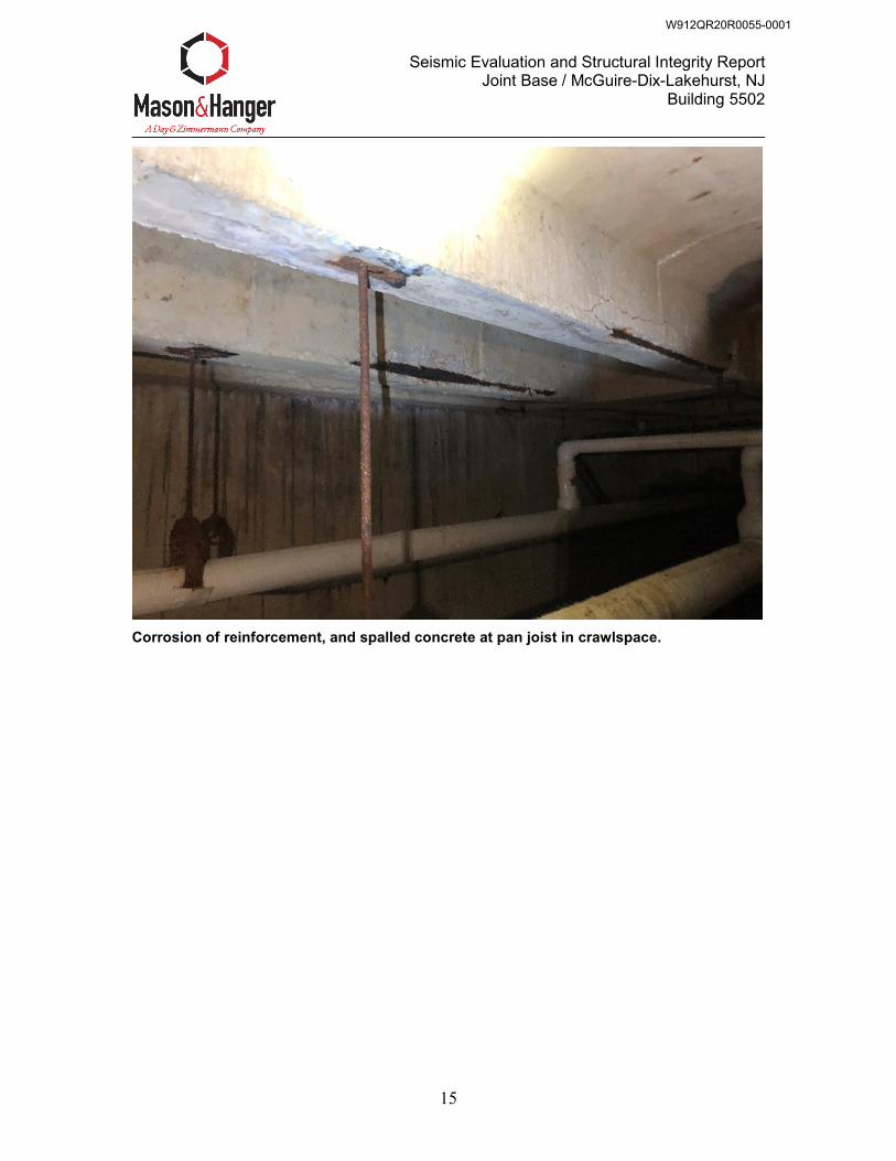
Seismic Evaluation and Structural Integrity Report Joint Base / McGuire-Dix-Lakehurst, NJ
Building 5502
15
Corrosion of reinforcement, and spalled concrete at pan joist in crawlspace.
W912QR20R0055-0001
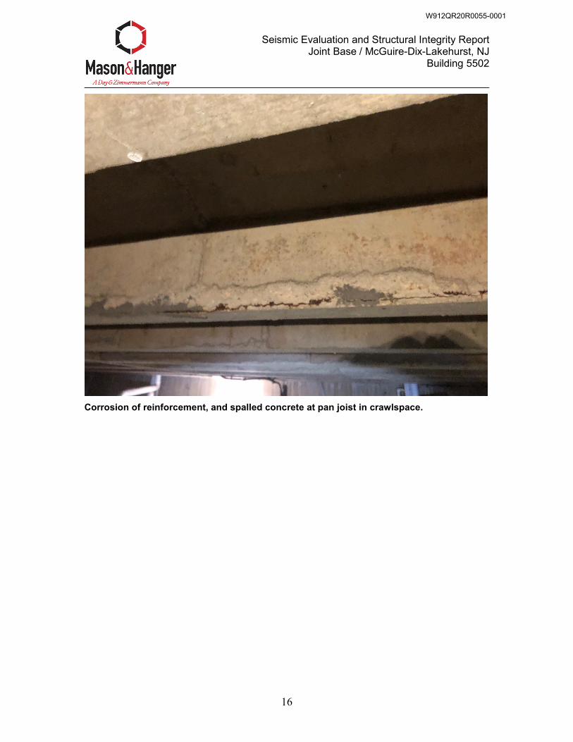
Seismic Evaluation and Structural Integrity Report Joint Base / McGuire-Dix-Lakehurst, NJ
Building 5502
16
Corrosion of reinforcement, and spalled concrete at pan joist in crawlspace.
W912QR20R0055-0001
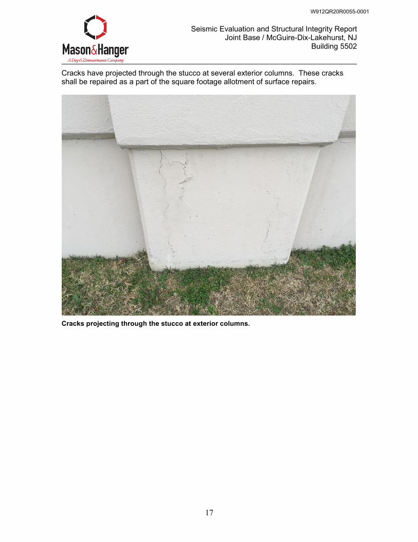
Seismic Evaluation and Structural Integrity Report Joint Base / McGuire-Dix-Lakehurst, NJ
Building 5502
17
Cracks have projected through the stucco at several exterior columns. These cracks shall be repaired as a part of the square footage allotment of surface repairs.
Cracks projecting through the stucco at exterior columns.
W912QR20R0055-0001
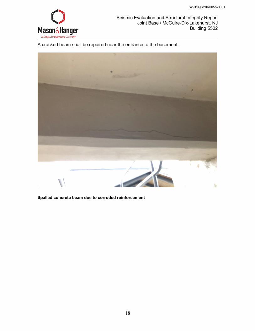
Seismic Evaluation and Structural Integrity Report Joint Base / McGuire-Dix-Lakehurst, NJ
Building 5502
18
A cracked beam shall be repaired near the entrance to the basement.
Spalled concrete beam due to corroded reinforcement
W912QR20R0055-0001
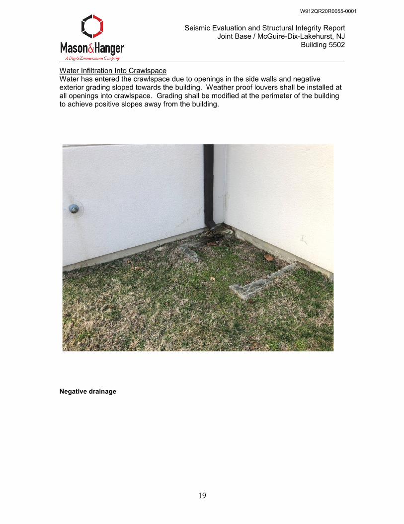
Seismic Evaluation and Structural Integrity Report Joint Base / McGuire-Dix-Lakehurst, NJ
Building 5502
19
Water Infiltration Into Crawlspace Water has entered the crawlspace due to openings in the side walls and negative exterior grading sloped towards the building. Weather proof louvers shall be installed at all openings into crawlspace. Grading shall be modified at the perimeter of the building to achieve positive slopes away from the building.
Negative drainage
W912QR20R0055-0001
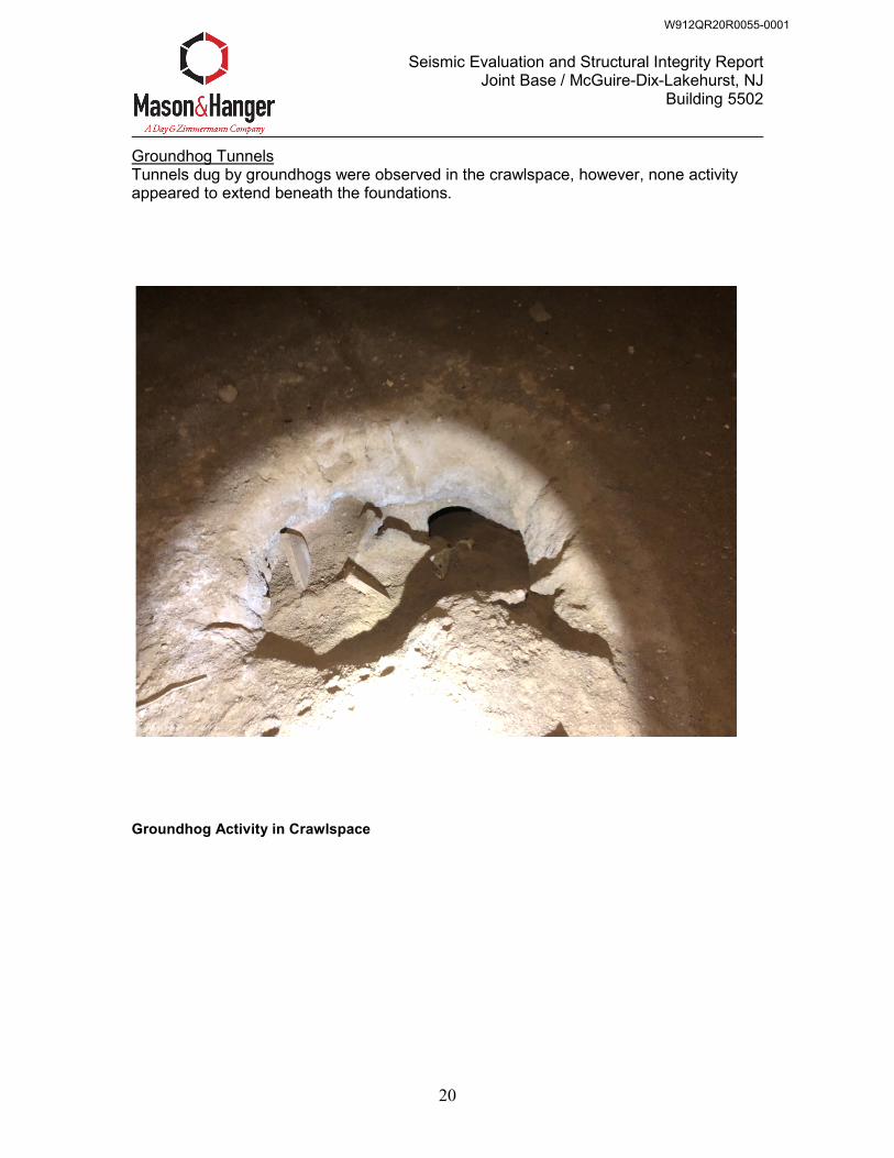
Seismic Evaluation and Structural Integrity Report Joint Base / McGuire-Dix-Lakehurst, NJ
Building 5502
20
Groundhog Tunnels Tunnels dug by groundhogs were observed in the crawlspace, however, none activity appeared to extend beneath the foundations.
Groundhog Activity in Crawlspace
W912QR20R0055-0001

Seismic Evaluation and Structural Integrity Report Joint Base / McGuire-Dix-Lakehurst, NJ
Building 5502
21
APPENDIX
W912QR20R0055-0001
SEISMIC EVALUATION APPENDIX
W912QR20R0055-0001
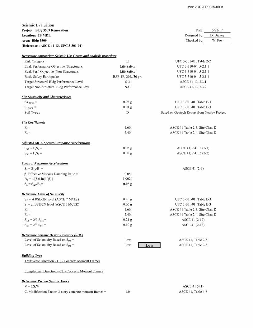
Seismic EvaluationProject: Bldg 5509 Renovation Date: 5/22/17
Location: JB MDL Designed by: D. Dickey
Area: Bldg 5509 Checked by: W. Foy
(Reference : ASCE 41-13, UFC 3-301-01)
Determine appropriate Seismic Use Group and analysis procedure
Risk Category: II UFC 3-301-01, Table 2-2
Eval. Performance Objective (Structural): Life Safety UFC 3-310-04, 5-2.1.1
Eval. Perf. Objective (Non-Structural): Life Safety UFC 3-310-04, 5-2.1.1
Basic Safety Earthquake BSE-1E, 20%/50 yrs UFC 3-310-04, 5-2.1.1
Target Structural Bldg Performance Level S-3 ASCE 41-13, 2.3.1
Target Non-Structural Bldg Performance Level N-C ASCE 41-13, 2.3.2
Site Seismicity and Characteristics
Ss 20/50 = 0.03 g UFC 3-301-01, Table E-3
S1 20/50 = 0.01 g UFC 3-301-01, Table E-3
Soil Type : D Based on Geotech Report from Nearby Project
Site Coefficients
Fa = 1.60 ASCE 41 Table 2-3, Site Class D
Fv = 2.40 ASCE 41 Table 2-4, Site Class D
Adjusted MCE Spectral Response Accelerations
SXS = FaSs = 0.05 g ASCE 41, 2.4.1.6 (2-1)
SX1 = FvS1 = 0.02 g ASCE 41, 2.4.1.6 (2-2)
Spectral Response Accelerations
Sa = SXS/B1 = ASCE 41 (2-6)
, Effective Viscous Damping Ratio = 0.05
B1 = 4/[5.6-ln(10)] 1.0024
Sa = SXS/B1 = 0.05 g
Determine Level of Seismicity
Ss = at BSE-2N level (ASCE 7 MCER) 0.20 g UFC 3-301-01, Table E-3
S1 = at BSE-2N level (ASCE 7 MCER) 0.06 g UFC 3-301-01, Table E-3
Fa = 1.60 ASCE 41 Table 2-3, Site Class D
Fv = 2.40 ASCE 41 Table 2-4, Site Class D
SDS = 2/3 SMS = 0.21 g ASCE 41 (2-12)
SD1 = 2/3 SM1 = 0.10 g ASCE 41 (2-13)
Determine Seismic Design Category (SDC)Level of Seismicity Based on SDS = Low ASCE 41, Table 2-5
Level of Seismicity Based on SD1 = Low Low ASCE 41, Table 2-5
Building Type
Transverse Direction - C1 - Concrete Moment Frames
Longitudinal Direction - C1 - Concrete Moment Frames
Determine Pseudo Seismic Force
V = CSaW ASCE 41 (4.1)
C, Modification Factor, 3-story concrete moment frames = 1.0 ASCE 41, Table 4-8
W912QR20R0055-0001
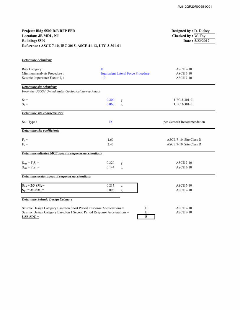
Project: Bldg 5509 D/B RFP FFR Designed by : D. DickeyLocation: JB MDL, NJ Checked by : W. FoyBuilding: 5509 Date : 5/22/2017Reference : ASCE 7-10, IBC 2015, ASCE 41-13, UFC 3-301-01
II ASCE 7-10ASCE 7-10
1.0 ASCE 7-10
Ss = 0.200 g UFC 3-301-01S1 = 0.060 g UFC 3-301-01
Determine site characteristics
Soil Type : D per Geotech Recommendation
Determine site coefficients
Fa = 1.60 ASCE 7-10, Site Class D
Fv = 2.40 ASCE 7-10, Site Class D
Determine adjusted MCE spectral response accelerations
SMS = FaSs = 0.320 g ASCE 7-10
SM1 = FvS1 = 0.144 g ASCE 7-10
Determine design spectral response accelerations
SDS = 2/3 SMS = 0.213 g ASCE 7-10SD1 = 2/3 SM1 = 0.096 g ASCE 7-10
Seismic Design Category Based on Short Period Response Accelerations = B ASCE 7-10Seismic Design Category Based on 1 Second Period Response Accelerations = B ASCE 7-10USE SDC = B
Determine Seismicity
Risk Category :Minimum analysis Procedure : Equivalent Lateral Force ProcedureSeismic Importance Factor, IE :
Determine site seismicity
Determine Seismic Design Category
From the USGS ( United States Geological Survey ) maps,
W912QR20R0055-0001
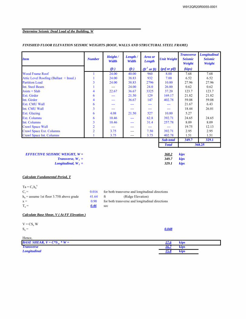
Item NumberHeight / Width
Length / Width
Area or Length
Unit Weight Transverse
Seismic Weight
Longitudinal Seismic Weight
(ft ) (ft ) (ft 2 or ft) (psf or plf) (kips)
Wood Frame Roof 1 24.00 40.00 960 8.00 7.68 7.68Attic Level Roofing (Ballast + Insul.) 1 24.00 38.83 932 7.00 6.52 6.52Partition Load 3 24.00 38.83 2796 10.00 27.96 27.96Int. Steel Beam 1 --- 24.00 24.0 26.00 0.62 0.62Joists + Slab 4 22.67 36.67 3325 37.20 123.7 123.7Ext. Girder 6 --- 21.50 129 169.17 21.82 21.82Int. Girder 4 --- 36.67 147 402.78 59.08 59.08Ext. CMU Wall 6 --- --- --- --- 21.67 6.43Int. CMU Wall 3 --- --- --- --- 18.44 26.01Ext. Glazing 6 4.08 21.50 527 10.00 5.27Ext. Columns 6 10.46 --- 62.8 392.71 24.65 24.65Int. Columns 3 10.46 --- 31.4 257.78 8.09 8.09Crawl Space Wall 2 --- --- --- --- 19.75 12.13Crawl Space Ext. Columns 2 3.75 --- 7.50 392.71 2.95 2.95Crawl Space Int. Columns 1 3.75 --- 3.75 402.78 1.51 1.51
Sub-total 349.7 329.1
Total
EFFECTIVE SEISMIC WEIGHT, W = 368.2 kipsTransverse, W t = 349.7 kips
Longitudinal, W l = 329.1 kips
Ta = Ct hnx
Ct = 0.016
hn = assume 1st floor 3.75ft above grade 41.64 ft (Ridge Elevation)x = 0.90Ta = 0.46 sec
Calculate Base Shear, V ( At FF Elevation )
V = CSa W
Sa = 0.048
Hence, 17.6 kips
Transverse 16.7 kipsLongitudinal 15.8 kips
Determine Seismic Dead Load of the Building, W
FINISHED FLOOR ELEVATION SEISMIC WEIGHTS (ROOF, WALLS AND STRUCTURAL STEEL FRAME)
Calculate Fundamental Period, T
for both transverse and longitudinal directions
for both transverse and longitudinal directions
BASE SHEAR, V = C*S a * W =
368.25
W912QR20R0055-0001
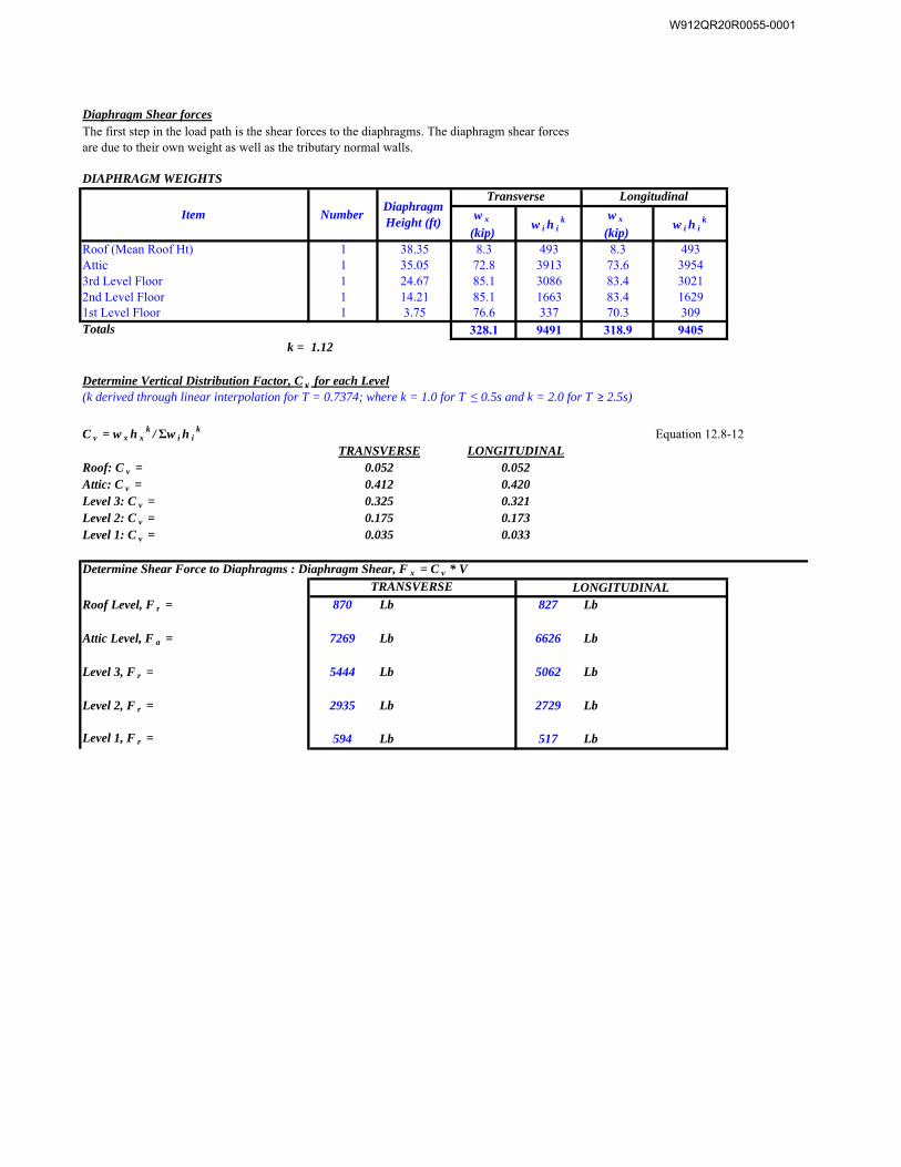
Diaphragm Shear forcesThe first step in the load path is the shear forces to the diaphragms. The diaphragm shear forces are due to their own weight as well as the tributary normal walls.
w x
(kip)w i h i
k w x
(kip)w i h i
k
Roof (Mean Roof Ht) 1 38.35 8.3 493 8.3 493Attic 1 35.05 72.8 3913 73.6 39543rd Level Floor 1 24.67 85.1 3086 83.4 30212nd Level Floor 1 14.21 85.1 1663 83.4 16291st Level Floor 1 3.75 76.6 337 70.3 309Totals 328.1 9491 318.9 9405
k = 1.12
Determine Vertical Distribution Factor, C v for each Level(k derived through linear interpolation for T = 0.7374; where k = 1.0 for T ≤ 0.5s and k = 2.0 for T ≥ 2.5s)
C v = w x h xk / Σw i h i
k Equation 12.8-12
Roof: C v =Attic: C v =Level 3: C v =Level 2: C v =Level 1: C v =
Roof Level, F r = 870 Lb 827 Lb
Attic Level, F a = 7269 Lb 6626 Lb
Level 3, F r = 5444 Lb 5062 Lb
Level 2, F r = 2935 Lb 2729 Lb
Level 1, F r = 594 Lb 517 Lb
TRANSVERSE0.0520.412
LONGITUDINALTRANSVERSE
Transverse Longitudinal
DIAPHRAGM WEIGHTS
Determine Shear Force to Diaphragms : Diaphragm Shear, F x = C v * V
Item NumberDiaphragm Height (ft)
0.3250.1750.035
LONGITUDINAL0.0520.4200.3210.1730.033
W912QR20R0055-0001
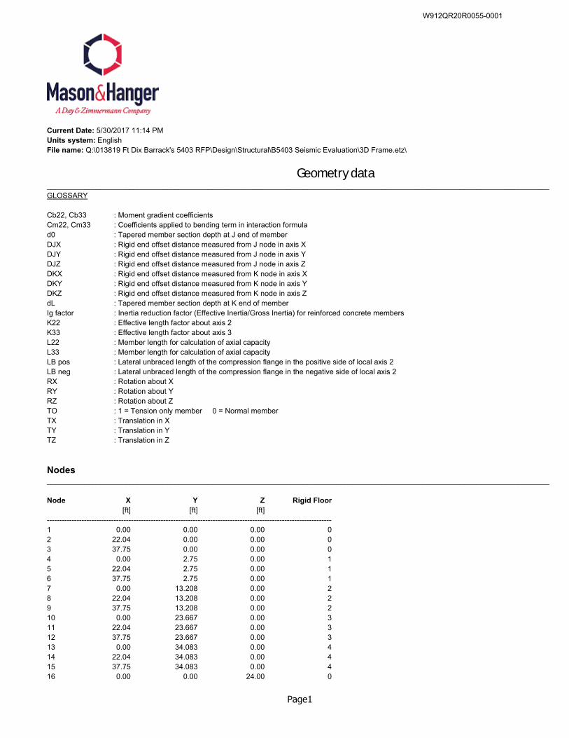
Current Date: 5/30/2017 11:14 PMUnits system: EnglishFile name: Q:\013819 Ft Dix Barrack's 5403 RFP\Design\Structural\B5403 Seismic Evaluation\3D Frame.etz\
Geometry data__________________________________________________________________________________________________________________________GLOSSARY
Cb22, Cb33 : Moment gradient coefficientsCm22, Cm33 : Coefficients applied to bending term in interaction formulad0 : Tapered member section depth at J end of memberDJX : Rigid end offset distance measured from J node in axis XDJY : Rigid end offset distance measured from J node in axis YDJZ : Rigid end offset distance measured from J node in axis ZDKX : Rigid end offset distance measured from K node in axis XDKY : Rigid end offset distance measured from K node in axis YDKZ : Rigid end offset distance measured from K node in axis ZdL : Tapered member section depth at K end of memberIg factor : Inertia reduction factor (Effective Inertia/Gross Inertia) for reinforced concrete membersK22 : Effective length factor about axis 2K33 : Effective length factor about axis 3L22 : Member length for calculation of axial capacityL33 : Member length for calculation of axial capacityLB pos : Lateral unbraced length of the compression flange in the positive side of local axis 2LB neg : Lateral unbraced length of the compression flange in the negative side of local axis 2RX : Rotation about XRY : Rotation about YRZ : Rotation about ZTO : 1 = Tension only member 0 = Normal memberTX : Translation in XTY : Translation in YTZ : Translation in Z
Nodes__________________________________________________________________________________________________________________________
Node X Y Z Rigid Floor[ft] [ft] [ft]
--------------------------------------------------------------------------------------------------------------------1 0.00 0.00 0.00 02 22.04 0.00 0.00 03 37.75 0.00 0.00 04 0.00 2.75 0.00 15 22.04 2.75 0.00 16 37.75 2.75 0.00 17 0.00 13.208 0.00 28 22.04 13.208 0.00 29 37.75 13.208 0.00 210 0.00 23.667 0.00 311 22.04 23.667 0.00 312 37.75 23.667 0.00 313 0.00 34.083 0.00 414 22.04 34.083 0.00 415 37.75 34.083 0.00 416 0.00 0.00 24.00 0
Page1
W912QR20R0055-0001
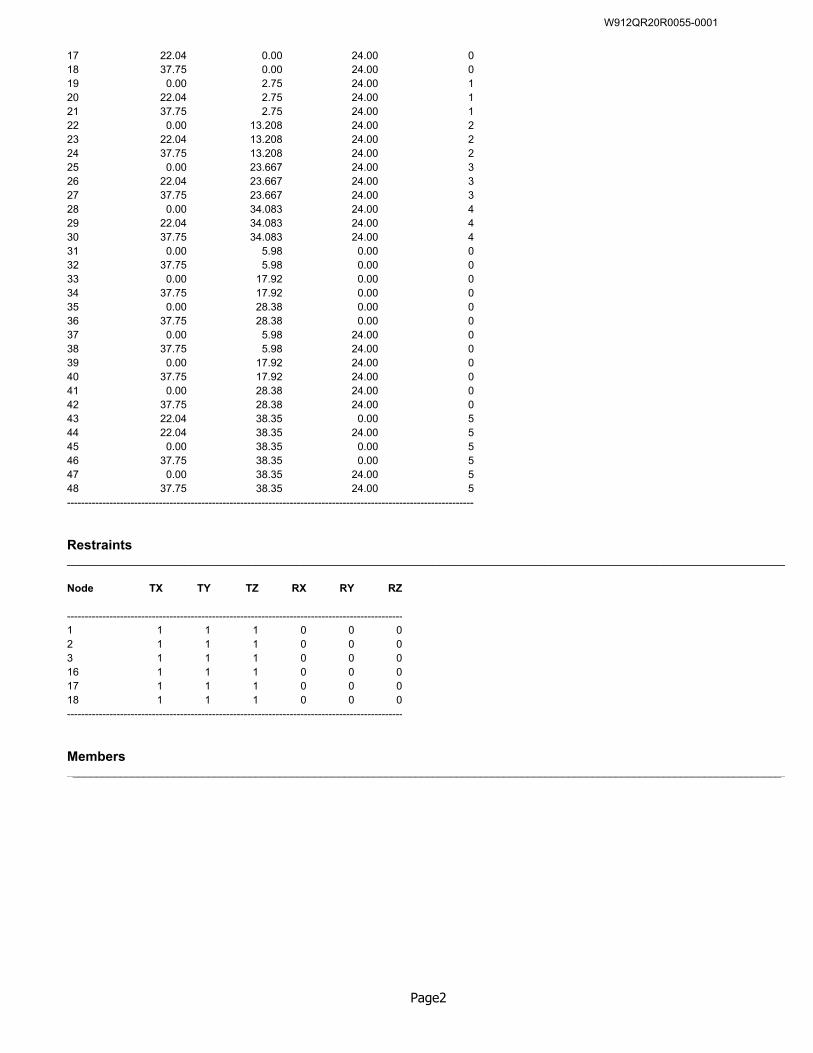
17 22.04 0.00 24.00 018 37.75 0.00 24.00 019 0.00 2.75 24.00 120 22.04 2.75 24.00 121 37.75 2.75 24.00 122 0.00 13.208 24.00 223 22.04 13.208 24.00 224 37.75 13.208 24.00 225 0.00 23.667 24.00 326 22.04 23.667 24.00 327 37.75 23.667 24.00 328 0.00 34.083 24.00 429 22.04 34.083 24.00 430 37.75 34.083 24.00 431 0.00 5.98 0.00 032 37.75 5.98 0.00 033 0.00 17.92 0.00 034 37.75 17.92 0.00 035 0.00 28.38 0.00 036 37.75 28.38 0.00 037 0.00 5.98 24.00 038 37.75 5.98 24.00 039 0.00 17.92 24.00 040 37.75 17.92 24.00 041 0.00 28.38 24.00 042 37.75 28.38 24.00 043 22.04 38.35 0.00 544 22.04 38.35 24.00 545 0.00 38.35 0.00 546 37.75 38.35 0.00 547 0.00 38.35 24.00 548 37.75 38.35 24.00 5--------------------------------------------------------------------------------------------------------------------
Restraints__________________________________________________________________________________________________________________________
Node TX TY TZ RX RY RZ
-----------------------------------------------------------------------------------------------1 1 1 1 0 0 02 1 1 1 0 0 03 1 1 1 0 0 016 1 1 1 0 0 017 1 1 1 0 0 018 1 1 1 0 0 0-----------------------------------------------------------------------------------------------
Members__________________________________________________________________________________________________________________________
Page2
W912QR20R0055-0001
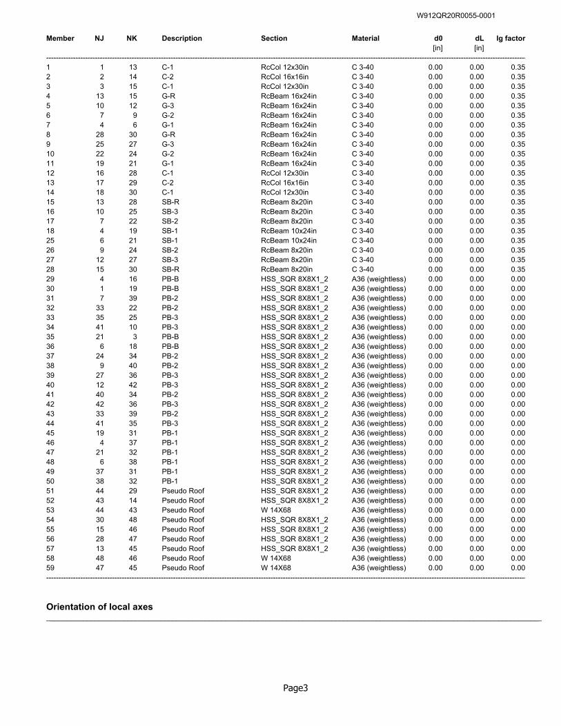
Member NJ NK Description Section Material d0 dL Ig factor[in] [in]
-----------------------------------------------------------------------------------------------------------------------------------------------------------------------------------------------------1 1 13 C-1 RcCol 12x30in C 3-40 0.00 0.00 0.352 2 14 C-2 RcCol 16x16in C 3-40 0.00 0.00 0.353 3 15 C-1 RcCol 12x30in C 3-40 0.00 0.00 0.354 13 15 G-R RcBeam 16x24in C 3-40 0.00 0.00 0.355 10 12 G-3 RcBeam 16x24in C 3-40 0.00 0.00 0.356 7 9 G-2 RcBeam 16x24in C 3-40 0.00 0.00 0.357 4 6 G-1 RcBeam 16x24in C 3-40 0.00 0.00 0.358 28 30 G-R RcBeam 16x24in C 3-40 0.00 0.00 0.359 25 27 G-3 RcBeam 16x24in C 3-40 0.00 0.00 0.3510 22 24 G-2 RcBeam 16x24in C 3-40 0.00 0.00 0.3511 19 21 G-1 RcBeam 16x24in C 3-40 0.00 0.00 0.3512 16 28 C-1 RcCol 12x30in C 3-40 0.00 0.00 0.3513 17 29 C-2 RcCol 16x16in C 3-40 0.00 0.00 0.3514 18 30 C-1 RcCol 12x30in C 3-40 0.00 0.00 0.3515 13 28 SB-R RcBeam 8x20in C 3-40 0.00 0.00 0.3516 10 25 SB-3 RcBeam 8x20in C 3-40 0.00 0.00 0.3517 7 22 SB-2 RcBeam 8x20in C 3-40 0.00 0.00 0.3518 4 19 SB-1 RcBeam 10x24in C 3-40 0.00 0.00 0.3525 6 21 SB-1 RcBeam 10x24in C 3-40 0.00 0.00 0.3526 9 24 SB-2 RcBeam 8x20in C 3-40 0.00 0.00 0.3527 12 27 SB-3 RcBeam 8x20in C 3-40 0.00 0.00 0.3528 15 30 SB-R RcBeam 8x20in C 3-40 0.00 0.00 0.3529 4 16 PB-B HSS_SQR 8X8X1_2 A36 (weightless) 0.00 0.00 0.0030 1 19 PB-B HSS_SQR 8X8X1_2 A36 (weightless) 0.00 0.00 0.0031 7 39 PB-2 HSS_SQR 8X8X1_2 A36 (weightless) 0.00 0.00 0.0032 33 22 PB-2 HSS_SQR 8X8X1_2 A36 (weightless) 0.00 0.00 0.0033 35 25 PB-3 HSS_SQR 8X8X1_2 A36 (weightless) 0.00 0.00 0.0034 41 10 PB-3 HSS_SQR 8X8X1_2 A36 (weightless) 0.00 0.00 0.0035 21 3 PB-B HSS_SQR 8X8X1_2 A36 (weightless) 0.00 0.00 0.0036 6 18 PB-B HSS_SQR 8X8X1_2 A36 (weightless) 0.00 0.00 0.0037 24 34 PB-2 HSS_SQR 8X8X1_2 A36 (weightless) 0.00 0.00 0.0038 9 40 PB-2 HSS_SQR 8X8X1_2 A36 (weightless) 0.00 0.00 0.0039 27 36 PB-3 HSS_SQR 8X8X1_2 A36 (weightless) 0.00 0.00 0.0040 12 42 PB-3 HSS_SQR 8X8X1_2 A36 (weightless) 0.00 0.00 0.0041 40 34 PB-2 HSS_SQR 8X8X1_2 A36 (weightless) 0.00 0.00 0.0042 42 36 PB-3 HSS_SQR 8X8X1_2 A36 (weightless) 0.00 0.00 0.0043 33 39 PB-2 HSS_SQR 8X8X1_2 A36 (weightless) 0.00 0.00 0.0044 41 35 PB-3 HSS_SQR 8X8X1_2 A36 (weightless) 0.00 0.00 0.0045 19 31 PB-1 HSS_SQR 8X8X1_2 A36 (weightless) 0.00 0.00 0.0046 4 37 PB-1 HSS_SQR 8X8X1_2 A36 (weightless) 0.00 0.00 0.0047 21 32 PB-1 HSS_SQR 8X8X1_2 A36 (weightless) 0.00 0.00 0.0048 6 38 PB-1 HSS_SQR 8X8X1_2 A36 (weightless) 0.00 0.00 0.0049 37 31 PB-1 HSS_SQR 8X8X1_2 A36 (weightless) 0.00 0.00 0.0050 38 32 PB-1 HSS_SQR 8X8X1_2 A36 (weightless) 0.00 0.00 0.0051 44 29 Pseudo Roof HSS_SQR 8X8X1_2 A36 (weightless) 0.00 0.00 0.0052 43 14 Pseudo Roof HSS_SQR 8X8X1_2 A36 (weightless) 0.00 0.00 0.0053 44 43 Pseudo Roof W 14X68 A36 (weightless) 0.00 0.00 0.0054 30 48 Pseudo Roof HSS_SQR 8X8X1_2 A36 (weightless) 0.00 0.00 0.0055 15 46 Pseudo Roof HSS_SQR 8X8X1_2 A36 (weightless) 0.00 0.00 0.0056 28 47 Pseudo Roof HSS_SQR 8X8X1_2 A36 (weightless) 0.00 0.00 0.0057 13 45 Pseudo Roof HSS_SQR 8X8X1_2 A36 (weightless) 0.00 0.00 0.0058 48 46 Pseudo Roof W 14X68 A36 (weightless) 0.00 0.00 0.0059 47 45 Pseudo Roof W 14X68 A36 (weightless) 0.00 0.00 0.00-----------------------------------------------------------------------------------------------------------------------------------------------------------------------------------------------------
Orientation of local axes__________________________________________________________________________________________________________________________
Page3
W912QR20R0055-0001
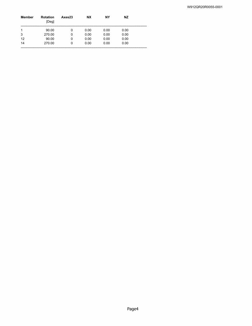
Member Rotation Axes23 NX NY NZ[Deg]
--------------------------------------------------------------------------------------------------------------------1 90.00 0 0.00 0.00 0.003 270.00 0 0.00 0.00 0.0012 90.00 0 0.00 0.00 0.0014 270.00 0 0.00 0.00 0.00--------------------------------------------------------------------------------------------------------------------
Page4
W912QR20R0055-0001
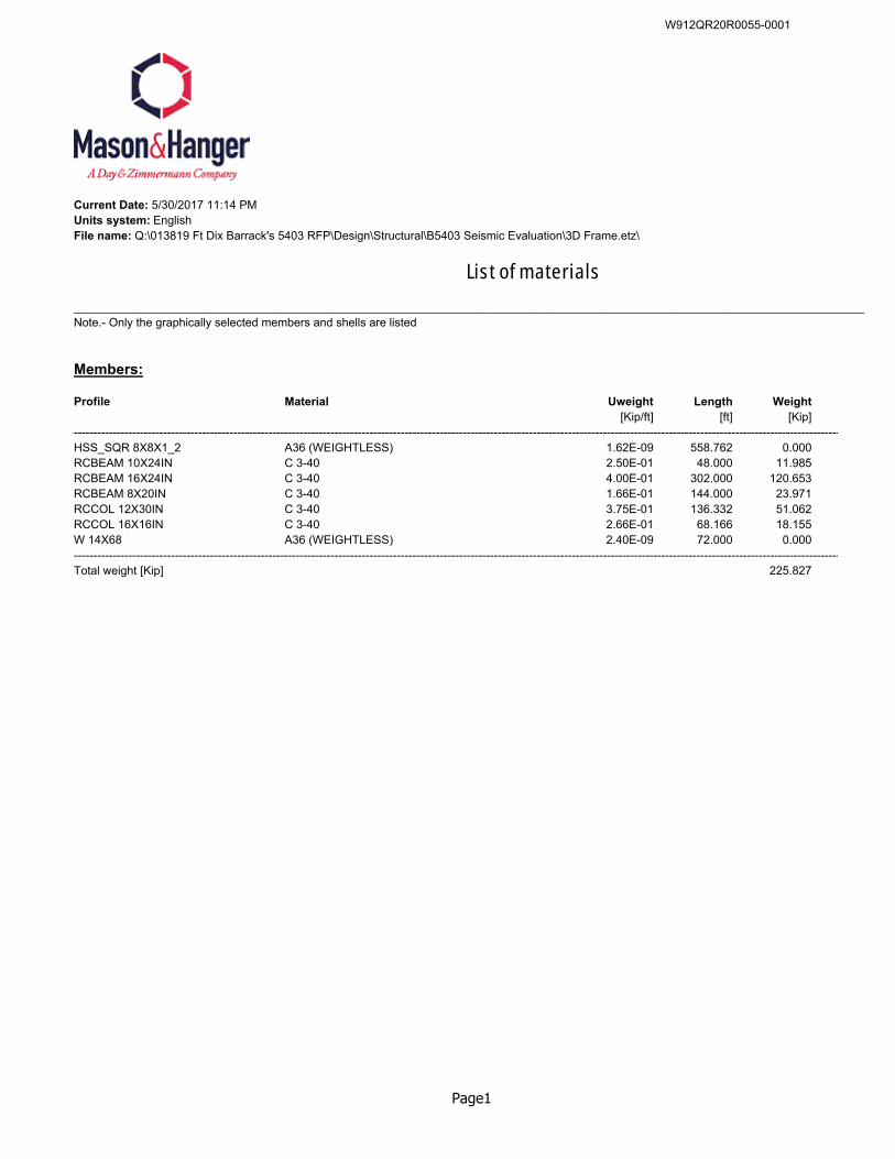
Current Date: 5/30/2017 11:14 PMUnits system: EnglishFile name: Q:\013819 Ft Dix Barrack's 5403 RFP\Design\Structural\B5403 Seismic Evaluation\3D Frame.etz\
List of materials
__________________________________________________________________________________________________________________________Note.- Only the graphically selected members and shells are listed
Members:
Profile Material Uweight Length Weight[Kip/ft] [ft] [Kip]
-----------------------------------------------------------------------------------------------------------------------------------------------------------------------------------------------------HSS_SQR 8X8X1_2 A36 (WEIGHTLESS) 1.62E-09 558.762 0.000RCBEAM 10X24IN C 3-40 2.50E-01 48.000 11.985RCBEAM 16X24IN C 3-40 4.00E-01 302.000 120.653RCBEAM 8X20IN C 3-40 1.66E-01 144.000 23.971RCCOL 12X30IN C 3-40 3.75E-01 136.332 51.062RCCOL 16X16IN C 3-40 2.66E-01 68.166 18.155W 14X68 A36 (WEIGHTLESS) 2.40E-09 72.000 0.000-----------------------------------------------------------------------------------------------------------------------------------------------------------------------------------------------------Total weight [Kip] 225.827
Page1
W912QR20R0055-0001
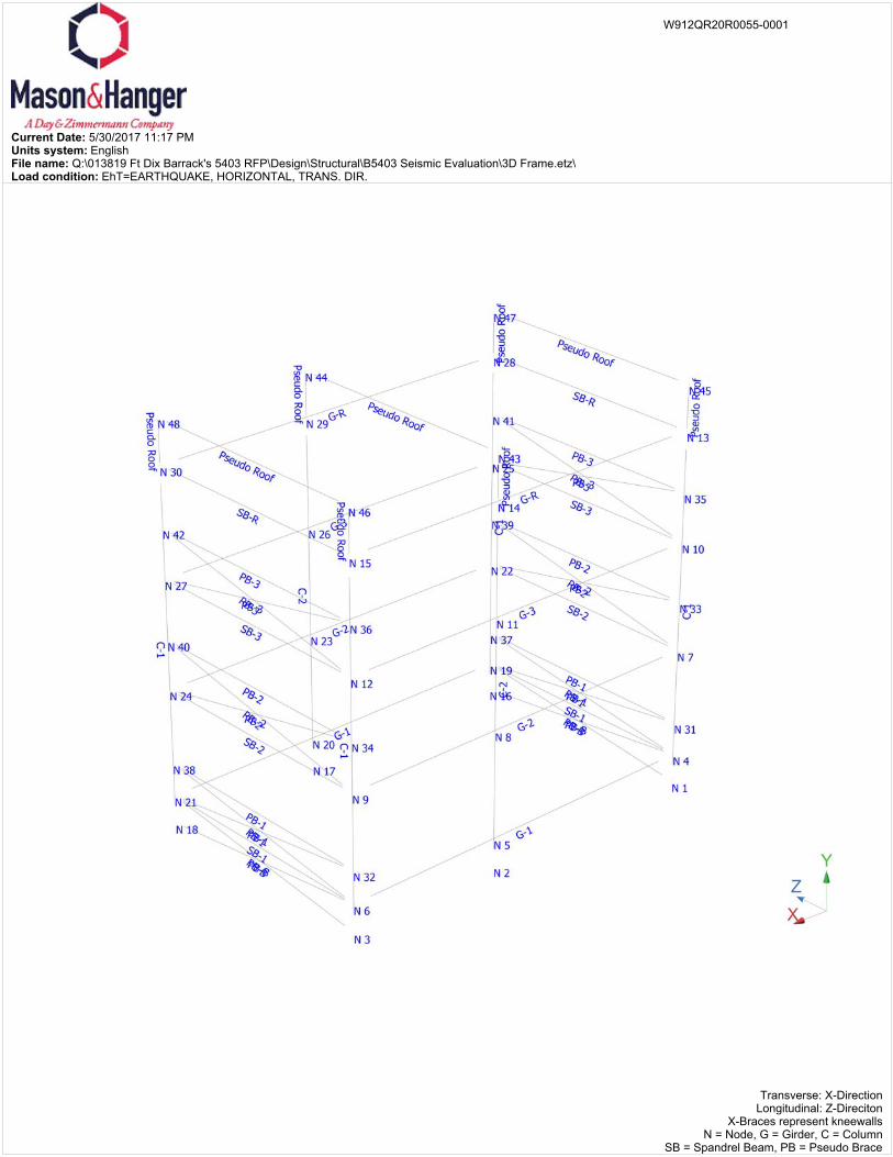
Current Date: 5/30/2017 11:17 PMUnits system: EnglishFile name: Q:\013819 Ft Dix Barrack's 5403 RFP\Design\Structural\B5403 Seismic Evaluation\3D Frame.etz\Load condition: EhT=EARTHQUAKE, HORIZONTAL, TRANS. DIR.
Transverse: X-DirectionLongitudinal: Z-Direciton
X-Braces represent kneewallsN = Node, G = Girder, C = Column
SB = Spandrel Beam, PB = Pseudo Brace
W912QR20R0055-0001
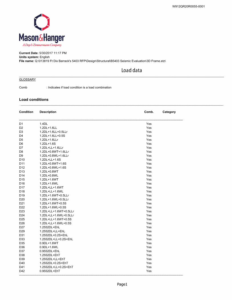
Current Date: 5/30/2017 11:17 PMUnits system: EnglishFile name: Q:\013819 Ft Dix Barrack's 5403 RFP\Design\Structural\B5403 Seismic Evaluation\3D Frame.etz\
Load data__________________________________________________________________________________________________________________________GLOSSARY
Comb : Indicates if load condition is a load combination
Load conditions__________________________________________________________________________________________________________________________
Condition Description Comb. Category
-------------------------------------------------------------------------------------------------------------------------------------------------------------------D1 1.4DL YesD2 1.2DL+1.6LL YesD3 1.2DL+1.6LL+0.5LLr YesD4 1.2DL+1.6LL+0.5S YesD5 1.2DL+1.6LLr YesD6 1.2DL+1.6S YesD7 1.2DL+LL+1.6LLr YesD8 1.2DL+0.8WT+1.6LLr YesD9 1.2DL+0.8WL+1.6LLr YesD10 1.2DL+LL+1.6S YesD11 1.2DL+0.8WT+1.6S YesD12 1.2DL+0.8WL+1.6S YesD13 1.2DL+0.8WT YesD14 1.2DL+0.8WL YesD15 1.2DL+1.6WT YesD16 1.2DL+1.6WL YesD17 1.2DL+LL+1.6WT YesD18 1.2DL+LL+1.6WL YesD19 1.2DL+1.6WT+0.5LLr YesD20 1.2DL+1.6WL+0.5LLr YesD21 1.2DL+1.6WT+0.5S YesD22 1.2DL+1.6WL+0.5S YesD23 1.2DL+LL+1.6WT+0.5LLr YesD24 1.2DL+LL+1.6WL+0.5LLr YesD25 1.2DL+LL+1.6WT+0.5S YesD26 1.2DL+LL+1.6WL+0.5S YesD27 1.2552DL+EhL YesD29 1.2552DL+LL+EhL YesD31 1.2552DL+0.2S+EhL YesD33 1.2552DL+LL+0.2S+EhL YesD35 0.9DL+1.6WT YesD36 0.9DL+1.6WL YesD37 0.9552DL+EhL YesD38 1.2552DL+EhT YesD39 1.2552DL+LL+EhT YesD40 1.2552DL+0.2S+EhT YesD41 1.2552DL+LL+0.2S+EhT YesD42 0.9552DL+EhT Yes-------------------------------------------------------------------------------------------------------------------------------------------------------------------
Page1
W912QR20R0055-0001
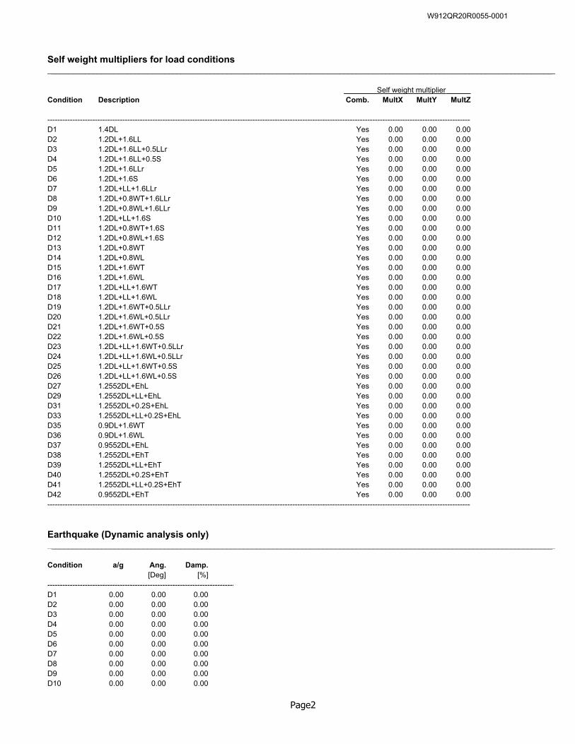
Self weight multipliers for load conditions__________________________________________________________________________________________________________________________
Self weight multiplier Condition Description Comb. MultX MultY MultZ
--------------------------------------------------------------------------------------------------------------------------------------------------------------------------D1 1.4DL Yes 0.00 0.00 0.00D2 1.2DL+1.6LL Yes 0.00 0.00 0.00D3 1.2DL+1.6LL+0.5LLr Yes 0.00 0.00 0.00D4 1.2DL+1.6LL+0.5S Yes 0.00 0.00 0.00D5 1.2DL+1.6LLr Yes 0.00 0.00 0.00D6 1.2DL+1.6S Yes 0.00 0.00 0.00D7 1.2DL+LL+1.6LLr Yes 0.00 0.00 0.00D8 1.2DL+0.8WT+1.6LLr Yes 0.00 0.00 0.00D9 1.2DL+0.8WL+1.6LLr Yes 0.00 0.00 0.00D10 1.2DL+LL+1.6S Yes 0.00 0.00 0.00D11 1.2DL+0.8WT+1.6S Yes 0.00 0.00 0.00D12 1.2DL+0.8WL+1.6S Yes 0.00 0.00 0.00D13 1.2DL+0.8WT Yes 0.00 0.00 0.00D14 1.2DL+0.8WL Yes 0.00 0.00 0.00D15 1.2DL+1.6WT Yes 0.00 0.00 0.00D16 1.2DL+1.6WL Yes 0.00 0.00 0.00D17 1.2DL+LL+1.6WT Yes 0.00 0.00 0.00D18 1.2DL+LL+1.6WL Yes 0.00 0.00 0.00D19 1.2DL+1.6WT+0.5LLr Yes 0.00 0.00 0.00D20 1.2DL+1.6WL+0.5LLr Yes 0.00 0.00 0.00D21 1.2DL+1.6WT+0.5S Yes 0.00 0.00 0.00D22 1.2DL+1.6WL+0.5S Yes 0.00 0.00 0.00D23 1.2DL+LL+1.6WT+0.5LLr Yes 0.00 0.00 0.00D24 1.2DL+LL+1.6WL+0.5LLr Yes 0.00 0.00 0.00D25 1.2DL+LL+1.6WT+0.5S Yes 0.00 0.00 0.00D26 1.2DL+LL+1.6WL+0.5S Yes 0.00 0.00 0.00D27 1.2552DL+EhL Yes 0.00 0.00 0.00D29 1.2552DL+LL+EhL Yes 0.00 0.00 0.00D31 1.2552DL+0.2S+EhL Yes 0.00 0.00 0.00D33 1.2552DL+LL+0.2S+EhL Yes 0.00 0.00 0.00D35 0.9DL+1.6WT Yes 0.00 0.00 0.00D36 0.9DL+1.6WL Yes 0.00 0.00 0.00D37 0.9552DL+EhL Yes 0.00 0.00 0.00D38 1.2552DL+EhT Yes 0.00 0.00 0.00D39 1.2552DL+LL+EhT Yes 0.00 0.00 0.00D40 1.2552DL+0.2S+EhT Yes 0.00 0.00 0.00D41 1.2552DL+LL+0.2S+EhT Yes 0.00 0.00 0.00D42 0.9552DL+EhT Yes 0.00 0.00 0.00--------------------------------------------------------------------------------------------------------------------------------------------------------------------------
Earthquake (Dynamic analysis only)__________________________________________________________________________________________________________________________
Condition a/g Ang. Damp.[Deg] [%]
---------------------------------------------------------------------------D1 0.00 0.00 0.00D2 0.00 0.00 0.00D3 0.00 0.00 0.00D4 0.00 0.00 0.00D5 0.00 0.00 0.00D6 0.00 0.00 0.00D7 0.00 0.00 0.00D8 0.00 0.00 0.00D9 0.00 0.00 0.00D10 0.00 0.00 0.00
Page2
W912QR20R0055-0001
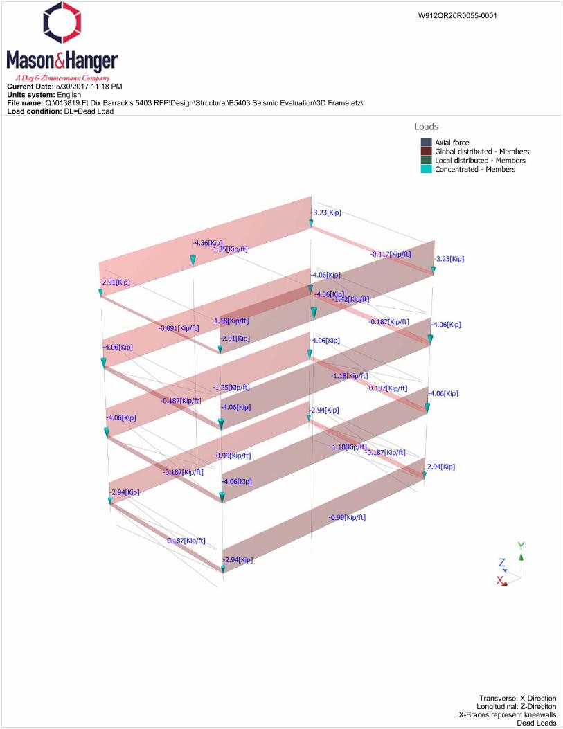
Current Date: 5/30/2017 11:18 PMUnits system: EnglishFile name: Q:\013819 Ft Dix Barrack's 5403 RFP\Design\Structural\B5403 Seismic Evaluation\3D Frame.etz\Load condition: DL=Dead Load
Transverse: X-DirectionLongitudinal: Z-Direciton
X-Braces represent kneewallsDead Loads
W912QR20R0055-0001
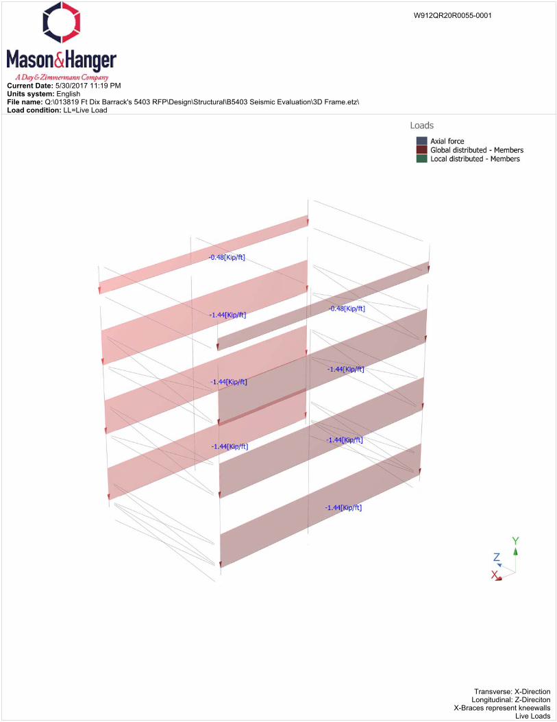
Current Date: 5/30/2017 11:19 PMUnits system: EnglishFile name: Q:\013819 Ft Dix Barrack's 5403 RFP\Design\Structural\B5403 Seismic Evaluation\3D Frame.etz\Load condition: LL=Live Load
Transverse: X-DirectionLongitudinal: Z-Direciton
X-Braces represent kneewallsLive Loads
W912QR20R0055-0001
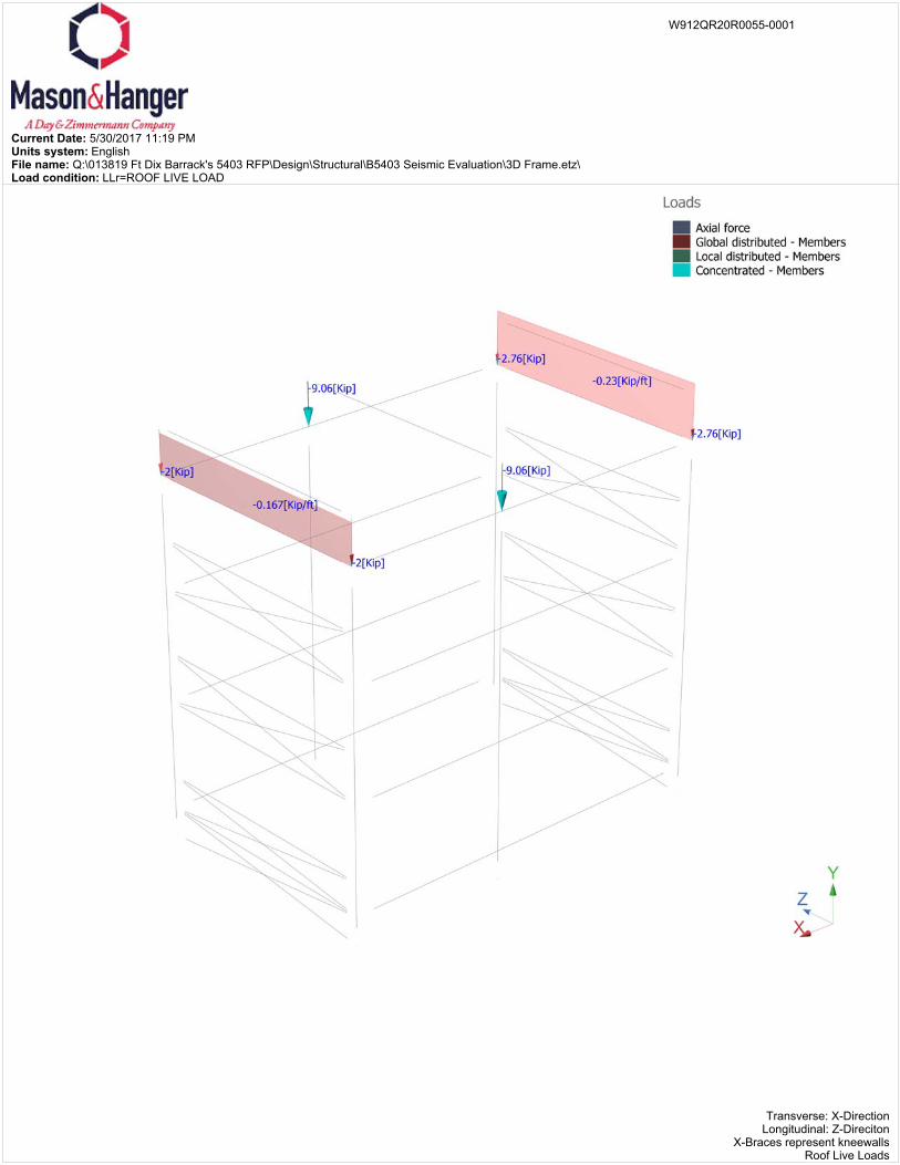
Current Date: 5/30/2017 11:19 PMUnits system: EnglishFile name: Q:\013819 Ft Dix Barrack's 5403 RFP\Design\Structural\B5403 Seismic Evaluation\3D Frame.etz\Load condition: LLr=ROOF LIVE LOAD
Transverse: X-DirectionLongitudinal: Z-Direciton
X-Braces represent kneewallsRoof Live Loads
W912QR20R0055-0001
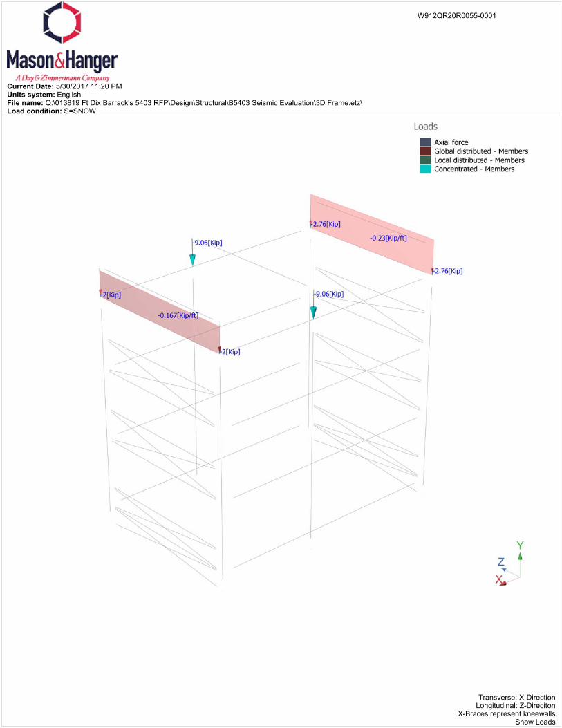
Current Date: 5/30/2017 11:20 PMUnits system: EnglishFile name: Q:\013819 Ft Dix Barrack's 5403 RFP\Design\Structural\B5403 Seismic Evaluation\3D Frame.etz\Load condition: S=SNOW
Transverse: X-DirectionLongitudinal: Z-Direciton
X-Braces represent kneewallsSnow Loads
W912QR20R0055-0001
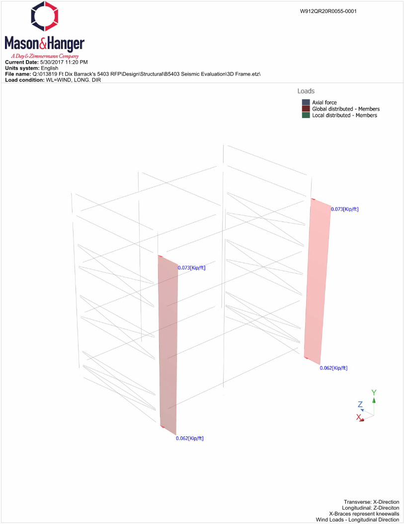
Current Date: 5/30/2017 11:20 PMUnits system: EnglishFile name: Q:\013819 Ft Dix Barrack's 5403 RFP\Design\Structural\B5403 Seismic Evaluation\3D Frame.etz\Load condition: WL=WIND, LONG. DIR
Transverse: X-DirectionLongitudinal: Z-Direciton
X-Braces represent kneewallsWind Loads - Longitudinal Direction
W912QR20R0055-0001
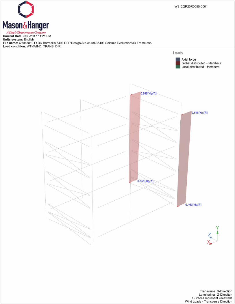
Current Date: 5/30/2017 11:21 PMUnits system: EnglishFile name: Q:\013819 Ft Dix Barrack's 5403 RFP\Design\Structural\B5403 Seismic Evaluation\3D Frame.etz\Load condition: WT=WIND, TRANS. DIR.
Transverse: X-DirectionLongitudinal: Z-Direciton
X-Braces represent kneewallsWind Loads - Transverse Direction
W912QR20R0055-0001
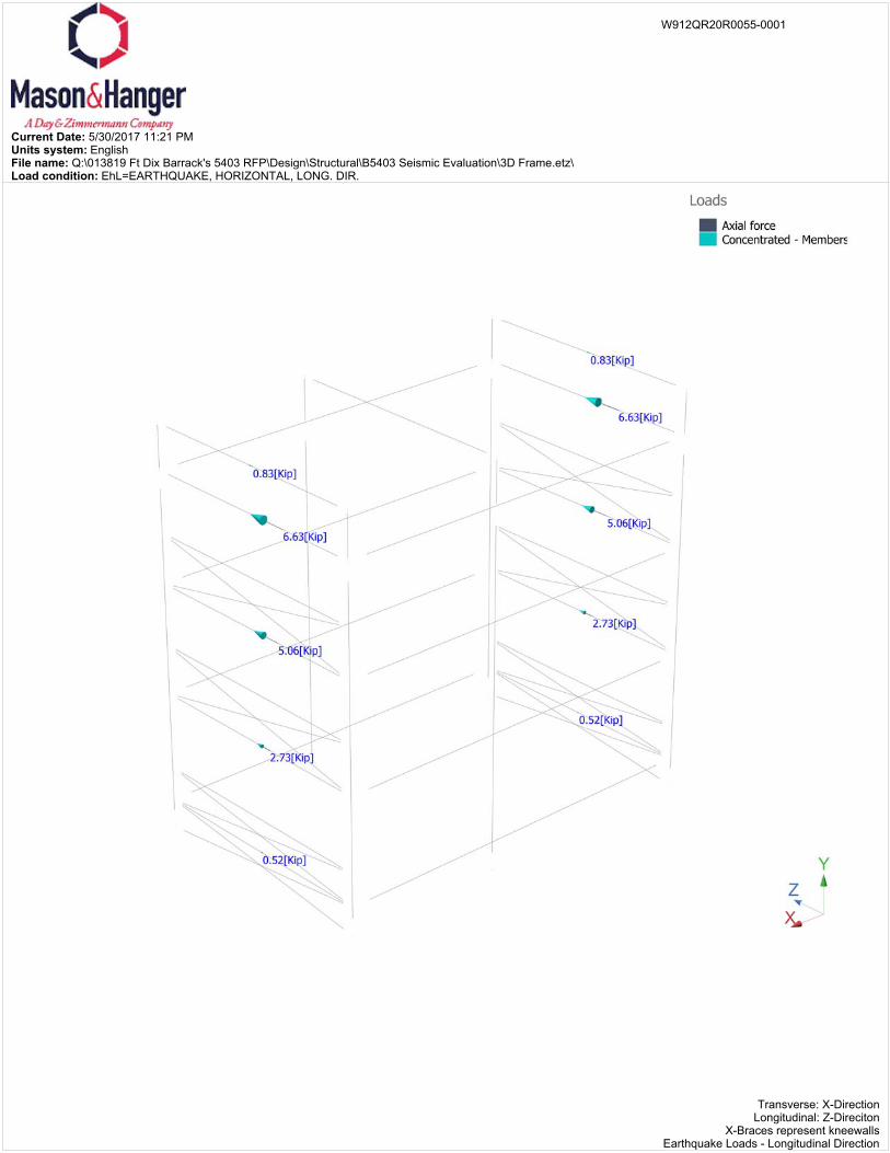
Current Date: 5/30/2017 11:21 PMUnits system: EnglishFile name: Q:\013819 Ft Dix Barrack's 5403 RFP\Design\Structural\B5403 Seismic Evaluation\3D Frame.etz\Load condition: EhL=EARTHQUAKE, HORIZONTAL, LONG. DIR.
Transverse: X-DirectionLongitudinal: Z-Direciton
X-Braces represent kneewallsEarthquake Loads - Longitudinal Direction
W912QR20R0055-0001
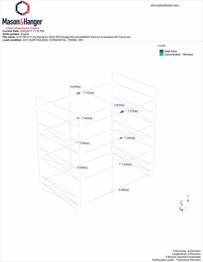
Current Date: 5/30/2017 11:22 PMUnits system: EnglishFile name: Q:\013819 Ft Dix Barrack's 5403 RFP\Design\Structural\B5403 Seismic Evaluation\3D Frame.etz\Load condition: EhT=EARTHQUAKE, HORIZONTAL, TRANS. DIR.
Transverse: X-DirectionLongitudinal: Z-Direciton
X-Braces represent kneewallsEarthquake Loads - Transverse Direction
W912QR20R0055-0001
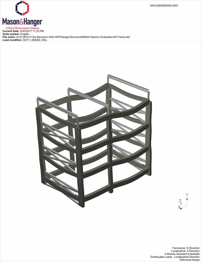
Current Date: 5/30/2017 11:23 PMUnits system: EnglishFile name: Q:\013819 Ft Dix Barrack's 5403 RFP\Design\Structural\B5403 Seismic Evaluation\3D Frame.etz\Load condition: D27=1.2552DL+EhL
Transverse: X-DirectionLongitudinal: Z-Direciton
X-Braces represent kneewallsEarthquake Loads - Longitudinal Direction
Deformed Shape
W912QR20R0055-0001
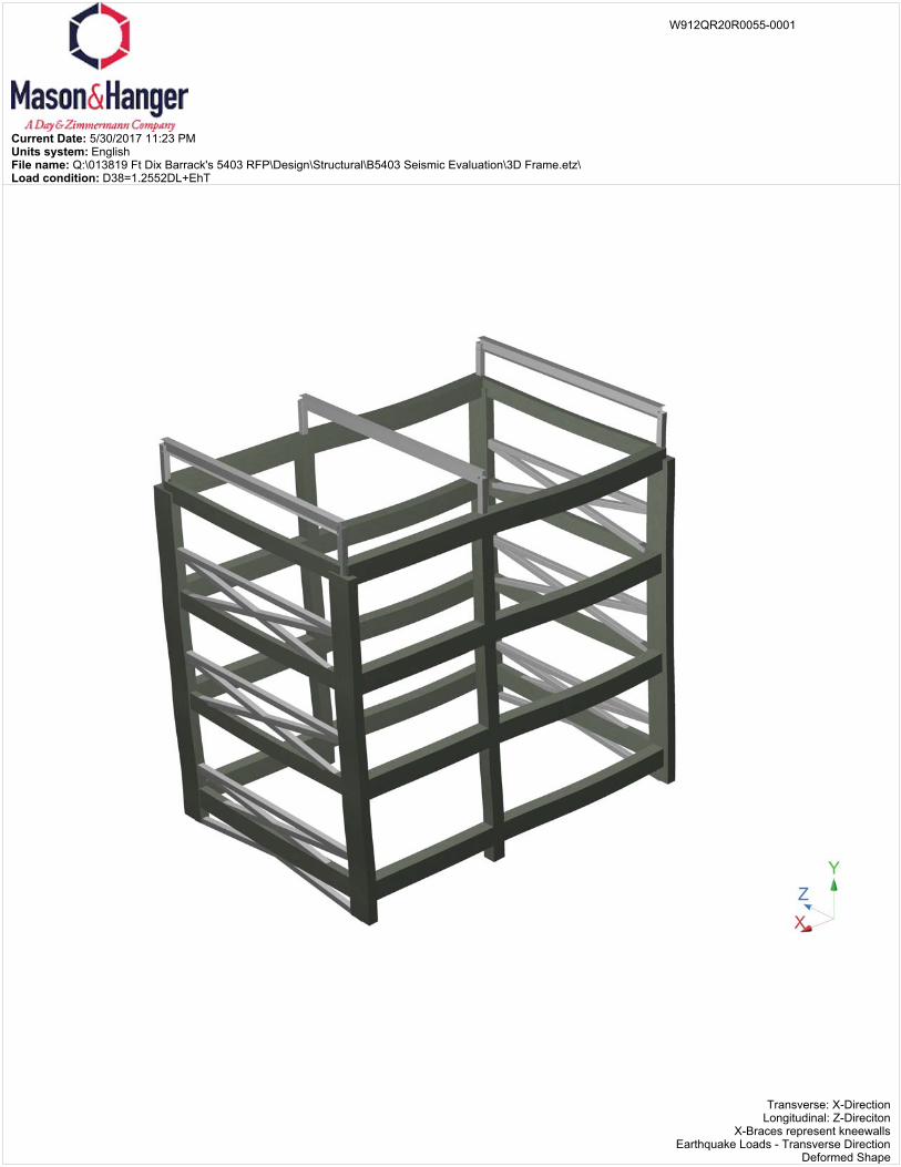
Current Date: 5/30/2017 11:23 PMUnits system: EnglishFile name: Q:\013819 Ft Dix Barrack's 5403 RFP\Design\Structural\B5403 Seismic Evaluation\3D Frame.etz\Load condition: D38=1.2552DL+EhT
Transverse: X-DirectionLongitudinal: Z-Direciton
X-Braces represent kneewallsEarthquake Loads - Transverse Direction
Deformed Shape
W912QR20R0055-0001
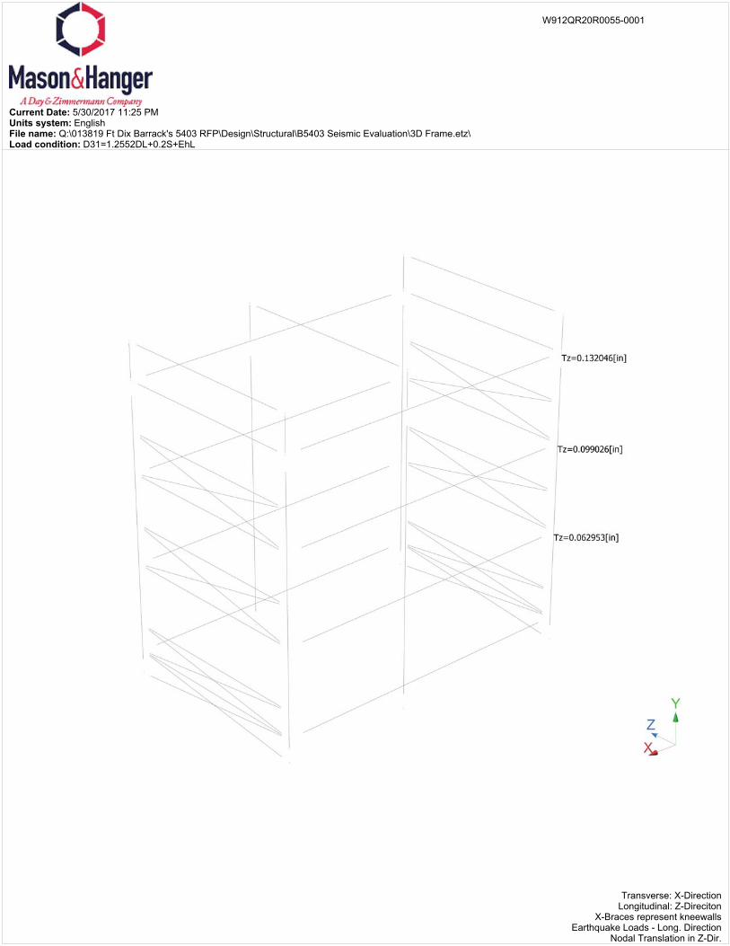
Current Date: 5/30/2017 11:25 PMUnits system: EnglishFile name: Q:\013819 Ft Dix Barrack's 5403 RFP\Design\Structural\B5403 Seismic Evaluation\3D Frame.etz\Load condition: D31=1.2552DL+0.2S+EhL
Transverse: X-DirectionLongitudinal: Z-Direciton
X-Braces represent kneewallsEarthquake Loads - Long. Direction
Nodal Translation in Z-Dir.
W912QR20R0055-0001
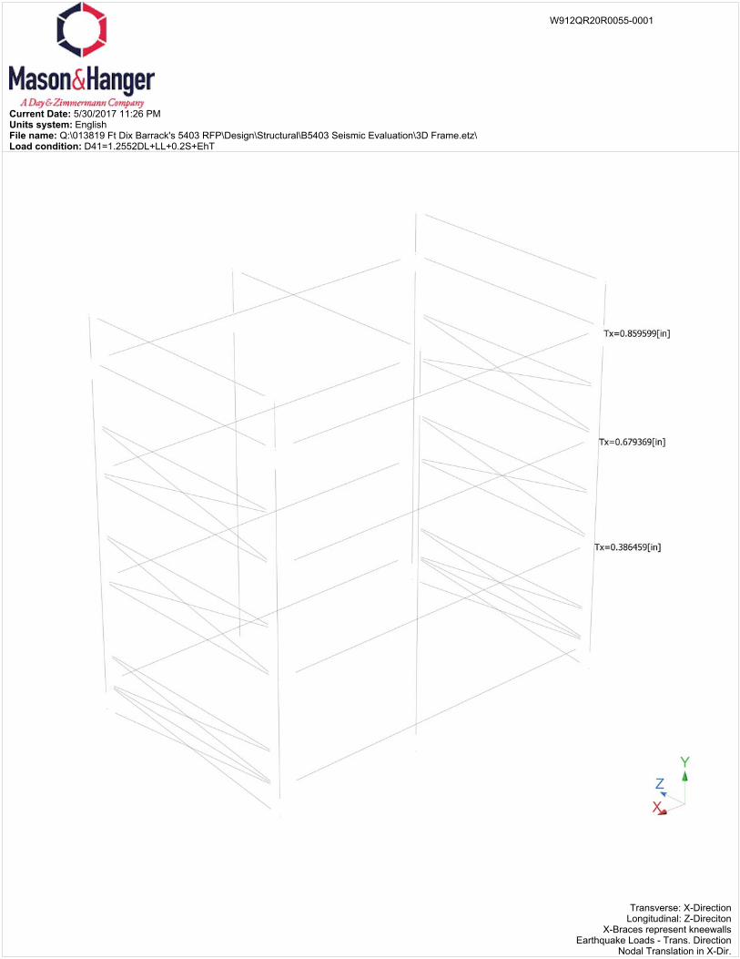
Current Date: 5/30/2017 11:26 PMUnits system: EnglishFile name: Q:\013819 Ft Dix Barrack's 5403 RFP\Design\Structural\B5403 Seismic Evaluation\3D Frame.etz\Load condition: D41=1.2552DL+LL+0.2S+EhT
Transverse: X-DirectionLongitudinal: Z-Direciton
X-Braces represent kneewallsEarthquake Loads - Trans. Direction
Nodal Translation in X-Dir.
W912QR20R0055-0001
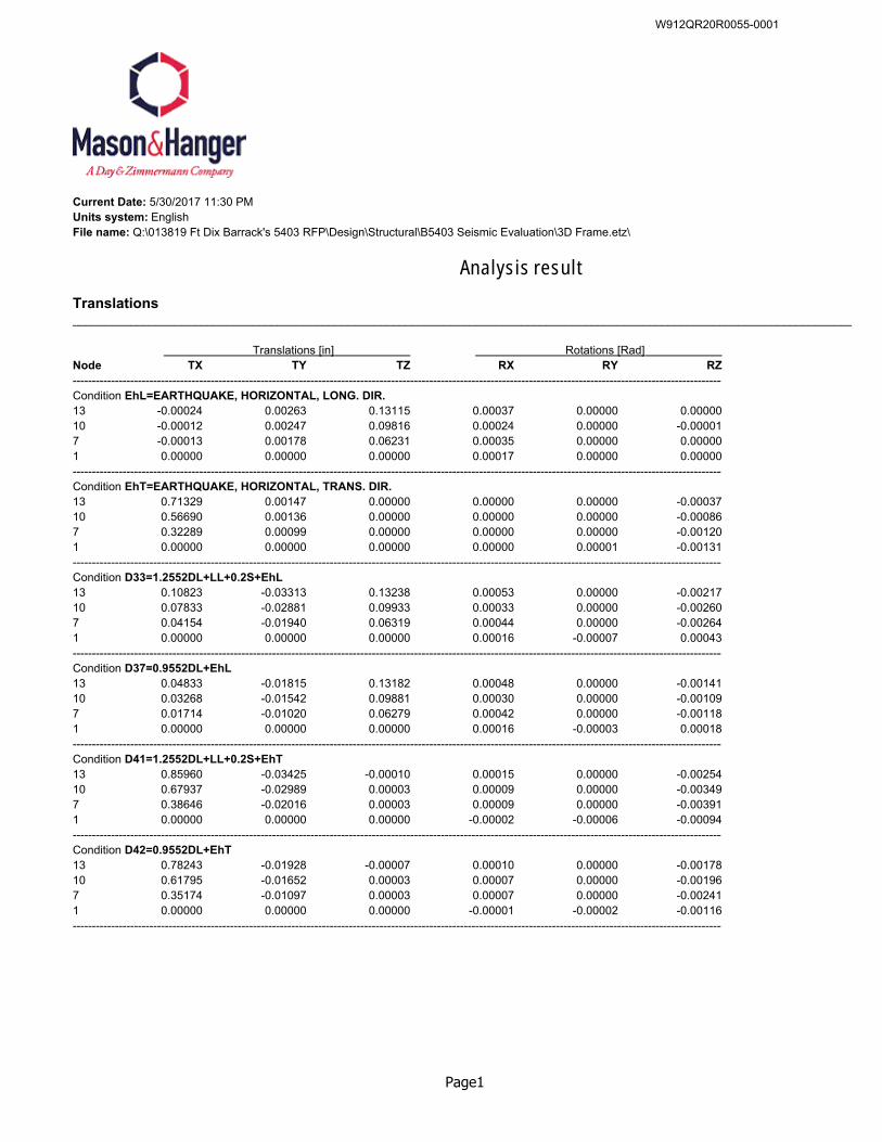
Current Date: 5/30/2017 11:30 PMUnits system: EnglishFile name: Q:\013819 Ft Dix Barrack's 5403 RFP\Design\Structural\B5403 Seismic Evaluation\3D Frame.etz\
Analysis result
Translations__________________________________________________________________________________________________________________________
Translations [in] Rotations [Rad] Node TX TY TZ RX RY RZ--------------------------------------------------------------------------------------------------------------------------------------------------------------------------Condition EhL=EARTHQUAKE, HORIZONTAL, LONG. DIR.13 -0.00024 0.00263 0.13115 0.00037 0.00000 0.0000010 -0.00012 0.00247 0.09816 0.00024 0.00000 -0.000017 -0.00013 0.00178 0.06231 0.00035 0.00000 0.000001 0.00000 0.00000 0.00000 0.00017 0.00000 0.00000--------------------------------------------------------------------------------------------------------------------------------------------------------------------------Condition EhT=EARTHQUAKE, HORIZONTAL, TRANS. DIR.13 0.71329 0.00147 0.00000 0.00000 0.00000 -0.0003710 0.56690 0.00136 0.00000 0.00000 0.00000 -0.000867 0.32289 0.00099 0.00000 0.00000 0.00000 -0.001201 0.00000 0.00000 0.00000 0.00000 0.00001 -0.00131--------------------------------------------------------------------------------------------------------------------------------------------------------------------------Condition D33=1.2552DL+LL+0.2S+EhL13 0.10823 -0.03313 0.13238 0.00053 0.00000 -0.0021710 0.07833 -0.02881 0.09933 0.00033 0.00000 -0.002607 0.04154 -0.01940 0.06319 0.00044 0.00000 -0.002641 0.00000 0.00000 0.00000 0.00016 -0.00007 0.00043--------------------------------------------------------------------------------------------------------------------------------------------------------------------------Condition D37=0.9552DL+EhL13 0.04833 -0.01815 0.13182 0.00048 0.00000 -0.0014110 0.03268 -0.01542 0.09881 0.00030 0.00000 -0.001097 0.01714 -0.01020 0.06279 0.00042 0.00000 -0.001181 0.00000 0.00000 0.00000 0.00016 -0.00003 0.00018--------------------------------------------------------------------------------------------------------------------------------------------------------------------------Condition D41=1.2552DL+LL+0.2S+EhT13 0.85960 -0.03425 -0.00010 0.00015 0.00000 -0.0025410 0.67937 -0.02989 0.00003 0.00009 0.00000 -0.003497 0.38646 -0.02016 0.00003 0.00009 0.00000 -0.003911 0.00000 0.00000 0.00000 -0.00002 -0.00006 -0.00094--------------------------------------------------------------------------------------------------------------------------------------------------------------------------Condition D42=0.9552DL+EhT13 0.78243 -0.01928 -0.00007 0.00010 0.00000 -0.0017810 0.61795 -0.01652 0.00003 0.00007 0.00000 -0.001967 0.35174 -0.01097 0.00003 0.00007 0.00000 -0.002411 0.00000 0.00000 0.00000 -0.00001 -0.00002 -0.00116--------------------------------------------------------------------------------------------------------------------------------------------------------------------------
Page1
W912QR20R0055-0001
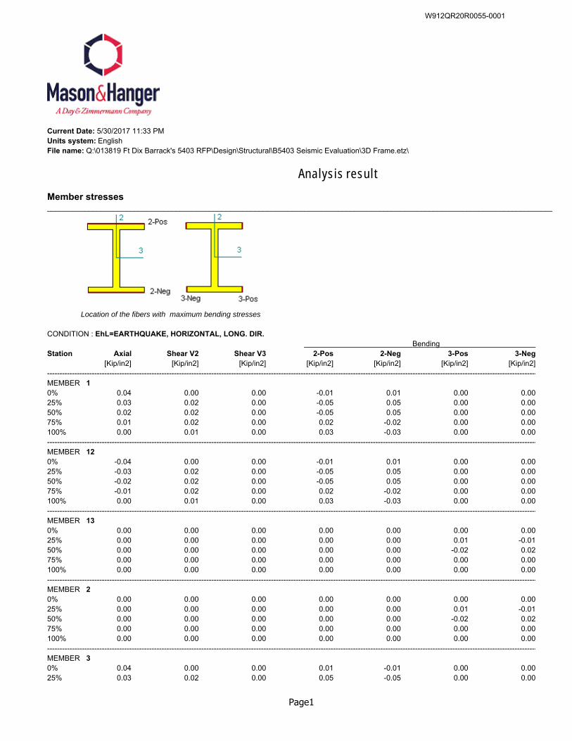
Current Date: 5/30/2017 11:33 PMUnits system: EnglishFile name: Q:\013819 Ft Dix Barrack's 5403 RFP\Design\Structural\B5403 Seismic Evaluation\3D Frame.etz\
Analysis result
Member stresses__________________________________________________________________________________________________________________________
Location of the fibers with maximum bending stresses
CONDITION : EhL=EARTHQUAKE, HORIZONTAL, LONG. DIR. Bending
Station Axial Shear V2 Shear V3 2-Pos 2-Neg 3-Pos 3-Neg[Kip/in2] [Kip/in2] [Kip/in2] [Kip/in2] [Kip/in2] [Kip/in2] [Kip/in2]
-----------------------------------------------------------------------------------------------------------------------------------------------------------------------------------------------------MEMBER 10% 0.04 0.00 0.00 -0.01 0.01 0.00 0.0025% 0.03 0.02 0.00 -0.05 0.05 0.00 0.0050% 0.02 0.02 0.00 -0.05 0.05 0.00 0.0075% 0.01 0.02 0.00 0.02 -0.02 0.00 0.00100% 0.00 0.01 0.00 0.03 -0.03 0.00 0.00-----------------------------------------------------------------------------------------------------------------------------------------------------------------------------------------------------MEMBER 120% -0.04 0.00 0.00 -0.01 0.01 0.00 0.0025% -0.03 0.02 0.00 -0.05 0.05 0.00 0.0050% -0.02 0.02 0.00 -0.05 0.05 0.00 0.0075% -0.01 0.02 0.00 0.02 -0.02 0.00 0.00100% 0.00 0.01 0.00 0.03 -0.03 0.00 0.00-----------------------------------------------------------------------------------------------------------------------------------------------------------------------------------------------------MEMBER 130% 0.00 0.00 0.00 0.00 0.00 0.00 0.0025% 0.00 0.00 0.00 0.00 0.00 0.01 -0.0150% 0.00 0.00 0.00 0.00 0.00 -0.02 0.0275% 0.00 0.00 0.00 0.00 0.00 0.00 0.00100% 0.00 0.00 0.00 0.00 0.00 0.00 0.00-----------------------------------------------------------------------------------------------------------------------------------------------------------------------------------------------------MEMBER 20% 0.00 0.00 0.00 0.00 0.00 0.00 0.0025% 0.00 0.00 0.00 0.00 0.00 0.01 -0.0150% 0.00 0.00 0.00 0.00 0.00 -0.02 0.0275% 0.00 0.00 0.00 0.00 0.00 0.00 0.00100% 0.00 0.00 0.00 0.00 0.00 0.00 0.00-----------------------------------------------------------------------------------------------------------------------------------------------------------------------------------------------------MEMBER 30% 0.04 0.00 0.00 0.01 -0.01 0.00 0.0025% 0.03 0.02 0.00 0.05 -0.05 0.00 0.00
Page1
W912QR20R0055-0001
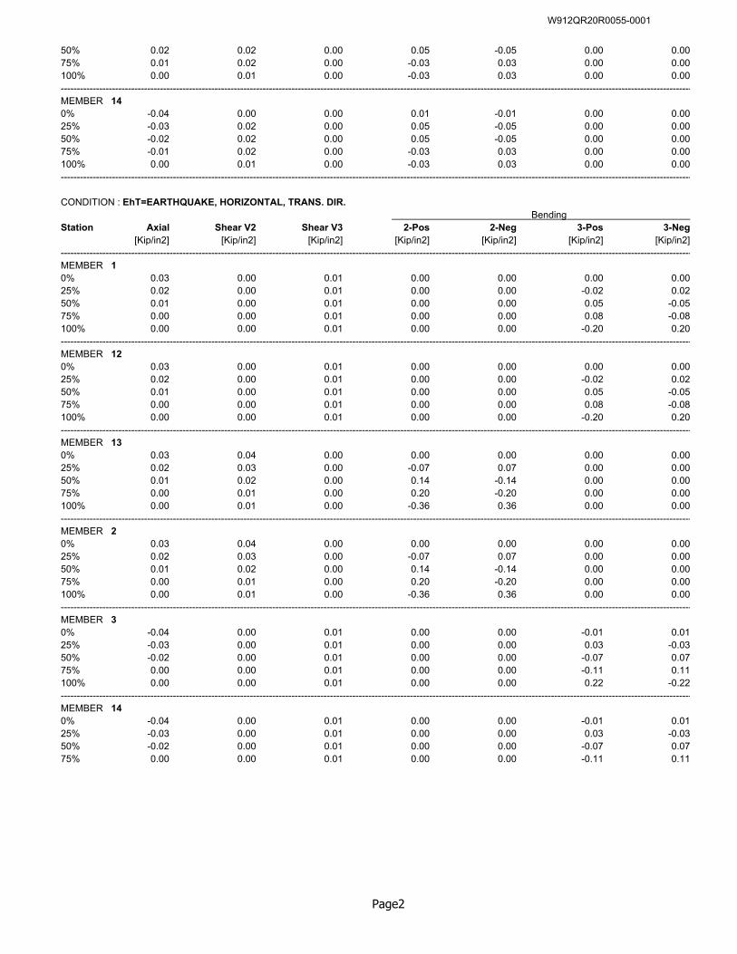
50% 0.02 0.02 0.00 0.05 -0.05 0.00 0.0075% 0.01 0.02 0.00 -0.03 0.03 0.00 0.00100% 0.00 0.01 0.00 -0.03 0.03 0.00 0.00-----------------------------------------------------------------------------------------------------------------------------------------------------------------------------------------------------MEMBER 140% -0.04 0.00 0.00 0.01 -0.01 0.00 0.0025% -0.03 0.02 0.00 0.05 -0.05 0.00 0.0050% -0.02 0.02 0.00 0.05 -0.05 0.00 0.0075% -0.01 0.02 0.00 -0.03 0.03 0.00 0.00100% 0.00 0.01 0.00 -0.03 0.03 0.00 0.00-----------------------------------------------------------------------------------------------------------------------------------------------------------------------------------------------------
CONDITION : EhT=EARTHQUAKE, HORIZONTAL, TRANS. DIR. Bending
Station Axial Shear V2 Shear V3 2-Pos 2-Neg 3-Pos 3-Neg[Kip/in2] [Kip/in2] [Kip/in2] [Kip/in2] [Kip/in2] [Kip/in2] [Kip/in2]
-----------------------------------------------------------------------------------------------------------------------------------------------------------------------------------------------------MEMBER 10% 0.03 0.00 0.01 0.00 0.00 0.00 0.0025% 0.02 0.00 0.01 0.00 0.00 -0.02 0.0250% 0.01 0.00 0.01 0.00 0.00 0.05 -0.0575% 0.00 0.00 0.01 0.00 0.00 0.08 -0.08100% 0.00 0.00 0.01 0.00 0.00 -0.20 0.20-----------------------------------------------------------------------------------------------------------------------------------------------------------------------------------------------------MEMBER 120% 0.03 0.00 0.01 0.00 0.00 0.00 0.0025% 0.02 0.00 0.01 0.00 0.00 -0.02 0.0250% 0.01 0.00 0.01 0.00 0.00 0.05 -0.0575% 0.00 0.00 0.01 0.00 0.00 0.08 -0.08100% 0.00 0.00 0.01 0.00 0.00 -0.20 0.20-----------------------------------------------------------------------------------------------------------------------------------------------------------------------------------------------------MEMBER 130% 0.03 0.04 0.00 0.00 0.00 0.00 0.0025% 0.02 0.03 0.00 -0.07 0.07 0.00 0.0050% 0.01 0.02 0.00 0.14 -0.14 0.00 0.0075% 0.00 0.01 0.00 0.20 -0.20 0.00 0.00100% 0.00 0.01 0.00 -0.36 0.36 0.00 0.00-----------------------------------------------------------------------------------------------------------------------------------------------------------------------------------------------------MEMBER 20% 0.03 0.04 0.00 0.00 0.00 0.00 0.0025% 0.02 0.03 0.00 -0.07 0.07 0.00 0.0050% 0.01 0.02 0.00 0.14 -0.14 0.00 0.0075% 0.00 0.01 0.00 0.20 -0.20 0.00 0.00100% 0.00 0.01 0.00 -0.36 0.36 0.00 0.00-----------------------------------------------------------------------------------------------------------------------------------------------------------------------------------------------------MEMBER 30% -0.04 0.00 0.01 0.00 0.00 -0.01 0.0125% -0.03 0.00 0.01 0.00 0.00 0.03 -0.0350% -0.02 0.00 0.01 0.00 0.00 -0.07 0.0775% 0.00 0.00 0.01 0.00 0.00 -0.11 0.11100% 0.00 0.00 0.01 0.00 0.00 0.22 -0.22-----------------------------------------------------------------------------------------------------------------------------------------------------------------------------------------------------MEMBER 140% -0.04 0.00 0.01 0.00 0.00 -0.01 0.0125% -0.03 0.00 0.01 0.00 0.00 0.03 -0.0350% -0.02 0.00 0.01 0.00 0.00 -0.07 0.0775% 0.00 0.00 0.01 0.00 0.00 -0.11 0.11
Page2
W912QR20R0055-0001
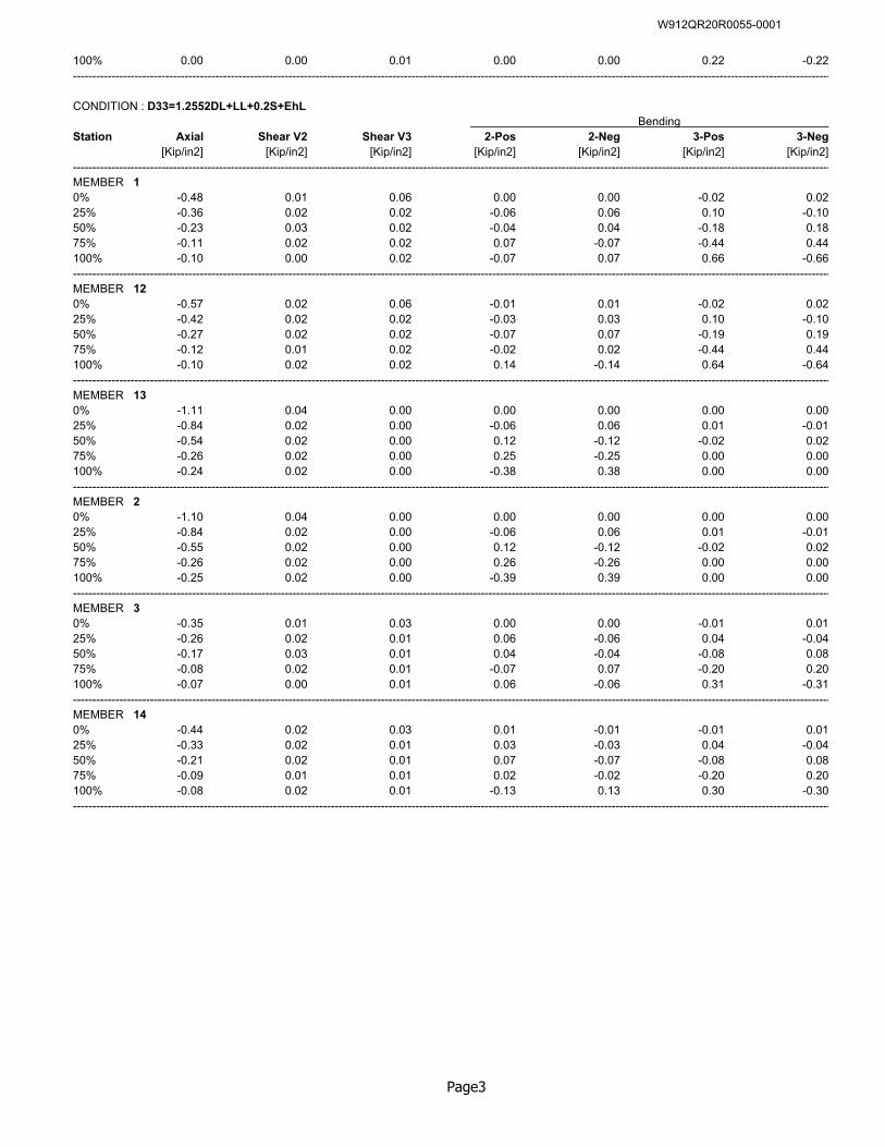
100% 0.00 0.00 0.01 0.00 0.00 0.22 -0.22-----------------------------------------------------------------------------------------------------------------------------------------------------------------------------------------------------
CONDITION : D33=1.2552DL+LL+0.2S+EhL Bending
Station Axial Shear V2 Shear V3 2-Pos 2-Neg 3-Pos 3-Neg[Kip/in2] [Kip/in2] [Kip/in2] [Kip/in2] [Kip/in2] [Kip/in2] [Kip/in2]
-----------------------------------------------------------------------------------------------------------------------------------------------------------------------------------------------------MEMBER 10% -0.48 0.01 0.06 0.00 0.00 -0.02 0.0225% -0.36 0.02 0.02 -0.06 0.06 0.10 -0.1050% -0.23 0.03 0.02 -0.04 0.04 -0.18 0.1875% -0.11 0.02 0.02 0.07 -0.07 -0.44 0.44100% -0.10 0.00 0.02 -0.07 0.07 0.66 -0.66-----------------------------------------------------------------------------------------------------------------------------------------------------------------------------------------------------MEMBER 120% -0.57 0.02 0.06 -0.01 0.01 -0.02 0.0225% -0.42 0.02 0.02 -0.03 0.03 0.10 -0.1050% -0.27 0.02 0.02 -0.07 0.07 -0.19 0.1975% -0.12 0.01 0.02 -0.02 0.02 -0.44 0.44100% -0.10 0.02 0.02 0.14 -0.14 0.64 -0.64-----------------------------------------------------------------------------------------------------------------------------------------------------------------------------------------------------MEMBER 130% -1.11 0.04 0.00 0.00 0.00 0.00 0.0025% -0.84 0.02 0.00 -0.06 0.06 0.01 -0.0150% -0.54 0.02 0.00 0.12 -0.12 -0.02 0.0275% -0.26 0.02 0.00 0.25 -0.25 0.00 0.00100% -0.24 0.02 0.00 -0.38 0.38 0.00 0.00-----------------------------------------------------------------------------------------------------------------------------------------------------------------------------------------------------MEMBER 20% -1.10 0.04 0.00 0.00 0.00 0.00 0.0025% -0.84 0.02 0.00 -0.06 0.06 0.01 -0.0150% -0.55 0.02 0.00 0.12 -0.12 -0.02 0.0275% -0.26 0.02 0.00 0.26 -0.26 0.00 0.00100% -0.25 0.02 0.00 -0.39 0.39 0.00 0.00-----------------------------------------------------------------------------------------------------------------------------------------------------------------------------------------------------MEMBER 30% -0.35 0.01 0.03 0.00 0.00 -0.01 0.0125% -0.26 0.02 0.01 0.06 -0.06 0.04 -0.0450% -0.17 0.03 0.01 0.04 -0.04 -0.08 0.0875% -0.08 0.02 0.01 -0.07 0.07 -0.20 0.20100% -0.07 0.00 0.01 0.06 -0.06 0.31 -0.31-----------------------------------------------------------------------------------------------------------------------------------------------------------------------------------------------------MEMBER 140% -0.44 0.02 0.03 0.01 -0.01 -0.01 0.0125% -0.33 0.02 0.01 0.03 -0.03 0.04 -0.0450% -0.21 0.02 0.01 0.07 -0.07 -0.08 0.0875% -0.09 0.01 0.01 0.02 -0.02 -0.20 0.20100% -0.08 0.02 0.01 -0.13 0.13 0.30 -0.30-----------------------------------------------------------------------------------------------------------------------------------------------------------------------------------------------------
Page3
W912QR20R0055-0001
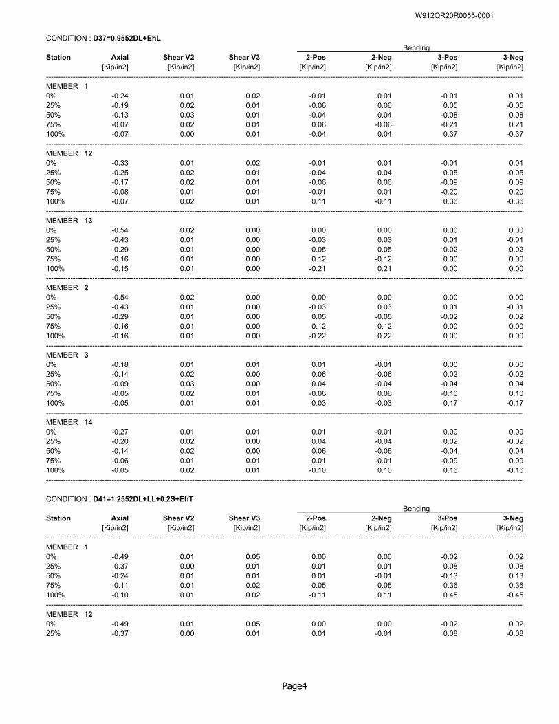
CONDITION : D37=0.9552DL+EhL Bending
Station Axial Shear V2 Shear V3 2-Pos 2-Neg 3-Pos 3-Neg[Kip/in2] [Kip/in2] [Kip/in2] [Kip/in2] [Kip/in2] [Kip/in2] [Kip/in2]
-----------------------------------------------------------------------------------------------------------------------------------------------------------------------------------------------------MEMBER 10% -0.24 0.01 0.02 -0.01 0.01 -0.01 0.0125% -0.19 0.02 0.01 -0.06 0.06 0.05 -0.0550% -0.13 0.03 0.01 -0.04 0.04 -0.08 0.0875% -0.07 0.02 0.01 0.06 -0.06 -0.21 0.21100% -0.07 0.00 0.01 -0.04 0.04 0.37 -0.37-----------------------------------------------------------------------------------------------------------------------------------------------------------------------------------------------------MEMBER 120% -0.33 0.01 0.02 -0.01 0.01 -0.01 0.0125% -0.25 0.02 0.01 -0.04 0.04 0.05 -0.0550% -0.17 0.02 0.01 -0.06 0.06 -0.09 0.0975% -0.08 0.01 0.01 -0.01 0.01 -0.20 0.20100% -0.07 0.02 0.01 0.11 -0.11 0.36 -0.36-----------------------------------------------------------------------------------------------------------------------------------------------------------------------------------------------------MEMBER 130% -0.54 0.02 0.00 0.00 0.00 0.00 0.0025% -0.43 0.01 0.00 -0.03 0.03 0.01 -0.0150% -0.29 0.01 0.00 0.05 -0.05 -0.02 0.0275% -0.16 0.01 0.00 0.12 -0.12 0.00 0.00100% -0.15 0.01 0.00 -0.21 0.21 0.00 0.00-----------------------------------------------------------------------------------------------------------------------------------------------------------------------------------------------------MEMBER 20% -0.54 0.02 0.00 0.00 0.00 0.00 0.0025% -0.43 0.01 0.00 -0.03 0.03 0.01 -0.0150% -0.29 0.01 0.00 0.05 -0.05 -0.02 0.0275% -0.16 0.01 0.00 0.12 -0.12 0.00 0.00100% -0.16 0.01 0.00 -0.22 0.22 0.00 0.00-----------------------------------------------------------------------------------------------------------------------------------------------------------------------------------------------------MEMBER 30% -0.18 0.01 0.01 0.01 -0.01 0.00 0.0025% -0.14 0.02 0.00 0.06 -0.06 0.02 -0.0250% -0.09 0.03 0.00 0.04 -0.04 -0.04 0.0475% -0.05 0.02 0.01 -0.06 0.06 -0.10 0.10100% -0.05 0.01 0.01 0.03 -0.03 0.17 -0.17-----------------------------------------------------------------------------------------------------------------------------------------------------------------------------------------------------MEMBER 140% -0.27 0.01 0.01 0.01 -0.01 0.00 0.0025% -0.20 0.02 0.00 0.04 -0.04 0.02 -0.0250% -0.14 0.02 0.00 0.06 -0.06 -0.04 0.0475% -0.06 0.01 0.01 0.01 -0.01 -0.09 0.09100% -0.05 0.02 0.01 -0.10 0.10 0.16 -0.16-----------------------------------------------------------------------------------------------------------------------------------------------------------------------------------------------------
CONDITION : D41=1.2552DL+LL+0.2S+EhT Bending
Station Axial Shear V2 Shear V3 2-Pos 2-Neg 3-Pos 3-Neg[Kip/in2] [Kip/in2] [Kip/in2] [Kip/in2] [Kip/in2] [Kip/in2] [Kip/in2]
-----------------------------------------------------------------------------------------------------------------------------------------------------------------------------------------------------MEMBER 10% -0.49 0.01 0.05 0.00 0.00 -0.02 0.0225% -0.37 0.00 0.01 -0.01 0.01 0.08 -0.0850% -0.24 0.01 0.01 0.01 -0.01 -0.13 0.1375% -0.11 0.01 0.02 0.05 -0.05 -0.36 0.36100% -0.10 0.01 0.02 -0.11 0.11 0.45 -0.45-----------------------------------------------------------------------------------------------------------------------------------------------------------------------------------------------------MEMBER 120% -0.49 0.01 0.05 0.00 0.00 -0.02 0.0225% -0.37 0.00 0.01 0.01 -0.01 0.08 -0.08
Page4
W912QR20R0055-0001
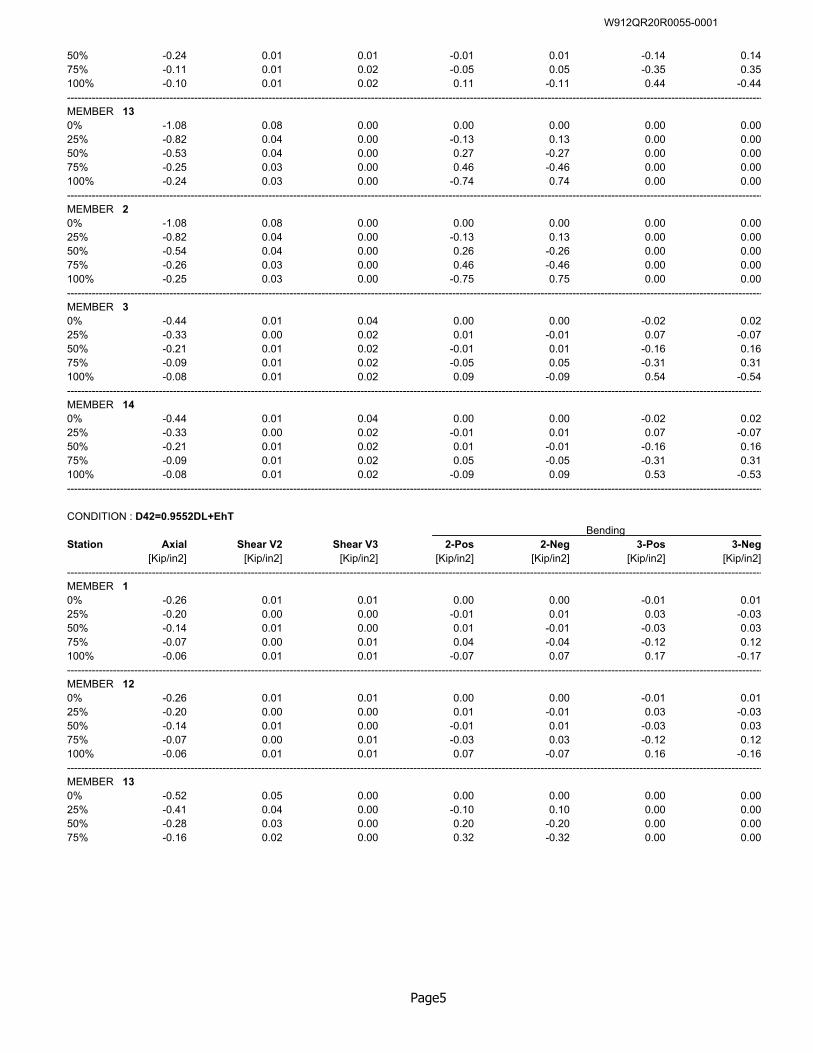
50% -0.24 0.01 0.01 -0.01 0.01 -0.14 0.1475% -0.11 0.01 0.02 -0.05 0.05 -0.35 0.35100% -0.10 0.01 0.02 0.11 -0.11 0.44 -0.44-----------------------------------------------------------------------------------------------------------------------------------------------------------------------------------------------------MEMBER 130% -1.08 0.08 0.00 0.00 0.00 0.00 0.0025% -0.82 0.04 0.00 -0.13 0.13 0.00 0.0050% -0.53 0.04 0.00 0.27 -0.27 0.00 0.0075% -0.25 0.03 0.00 0.46 -0.46 0.00 0.00100% -0.24 0.03 0.00 -0.74 0.74 0.00 0.00-----------------------------------------------------------------------------------------------------------------------------------------------------------------------------------------------------MEMBER 20% -1.08 0.08 0.00 0.00 0.00 0.00 0.0025% -0.82 0.04 0.00 -0.13 0.13 0.00 0.0050% -0.54 0.04 0.00 0.26 -0.26 0.00 0.0075% -0.26 0.03 0.00 0.46 -0.46 0.00 0.00100% -0.25 0.03 0.00 -0.75 0.75 0.00 0.00-----------------------------------------------------------------------------------------------------------------------------------------------------------------------------------------------------MEMBER 30% -0.44 0.01 0.04 0.00 0.00 -0.02 0.0225% -0.33 0.00 0.02 0.01 -0.01 0.07 -0.0750% -0.21 0.01 0.02 -0.01 0.01 -0.16 0.1675% -0.09 0.01 0.02 -0.05 0.05 -0.31 0.31100% -0.08 0.01 0.02 0.09 -0.09 0.54 -0.54-----------------------------------------------------------------------------------------------------------------------------------------------------------------------------------------------------MEMBER 140% -0.44 0.01 0.04 0.00 0.00 -0.02 0.0225% -0.33 0.00 0.02 -0.01 0.01 0.07 -0.0750% -0.21 0.01 0.02 0.01 -0.01 -0.16 0.1675% -0.09 0.01 0.02 0.05 -0.05 -0.31 0.31100% -0.08 0.01 0.02 -0.09 0.09 0.53 -0.53-----------------------------------------------------------------------------------------------------------------------------------------------------------------------------------------------------
CONDITION : D42=0.9552DL+EhT Bending
Station Axial Shear V2 Shear V3 2-Pos 2-Neg 3-Pos 3-Neg[Kip/in2] [Kip/in2] [Kip/in2] [Kip/in2] [Kip/in2] [Kip/in2] [Kip/in2]
-----------------------------------------------------------------------------------------------------------------------------------------------------------------------------------------------------MEMBER 10% -0.26 0.01 0.01 0.00 0.00 -0.01 0.0125% -0.20 0.00 0.00 -0.01 0.01 0.03 -0.0350% -0.14 0.01 0.00 0.01 -0.01 -0.03 0.0375% -0.07 0.00 0.01 0.04 -0.04 -0.12 0.12100% -0.06 0.01 0.01 -0.07 0.07 0.17 -0.17-----------------------------------------------------------------------------------------------------------------------------------------------------------------------------------------------------MEMBER 120% -0.26 0.01 0.01 0.00 0.00 -0.01 0.0125% -0.20 0.00 0.00 0.01 -0.01 0.03 -0.0350% -0.14 0.01 0.00 -0.01 0.01 -0.03 0.0375% -0.07 0.00 0.01 -0.03 0.03 -0.12 0.12100% -0.06 0.01 0.01 0.07 -0.07 0.16 -0.16-----------------------------------------------------------------------------------------------------------------------------------------------------------------------------------------------------MEMBER 130% -0.52 0.05 0.00 0.00 0.00 0.00 0.0025% -0.41 0.04 0.00 -0.10 0.10 0.00 0.0050% -0.28 0.03 0.00 0.20 -0.20 0.00 0.0075% -0.16 0.02 0.00 0.32 -0.32 0.00 0.00
Page5
W912QR20R0055-0001
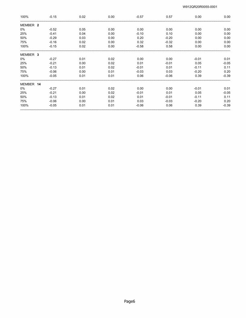
100% -0.15 0.02 0.00 -0.57 0.57 0.00 0.00-----------------------------------------------------------------------------------------------------------------------------------------------------------------------------------------------------MEMBER 20% -0.52 0.05 0.00 0.00 0.00 0.00 0.0025% -0.41 0.04 0.00 -0.10 0.10 0.00 0.0050% -0.29 0.03 0.00 0.20 -0.20 0.00 0.0075% -0.16 0.02 0.00 0.32 -0.32 0.00 0.00100% -0.15 0.02 0.00 -0.58 0.58 0.00 0.00-----------------------------------------------------------------------------------------------------------------------------------------------------------------------------------------------------MEMBER 30% -0.27 0.01 0.02 0.00 0.00 -0.01 0.0125% -0.21 0.00 0.02 0.01 -0.01 0.05 -0.0550% -0.13 0.01 0.02 -0.01 0.01 -0.11 0.1175% -0.06 0.00 0.01 -0.03 0.03 -0.20 0.20100% -0.05 0.01 0.01 0.06 -0.06 0.39 -0.39-----------------------------------------------------------------------------------------------------------------------------------------------------------------------------------------------------MEMBER 140% -0.27 0.01 0.02 0.00 0.00 -0.01 0.0125% -0.21 0.00 0.02 -0.01 0.01 0.05 -0.0550% -0.13 0.01 0.02 0.01 -0.01 -0.11 0.1175% -0.06 0.00 0.01 0.03 -0.03 -0.20 0.20100% -0.05 0.01 0.01 -0.06 0.06 0.39 -0.39-----------------------------------------------------------------------------------------------------------------------------------------------------------------------------------------------------
Page6
W912QR20R0055-0001
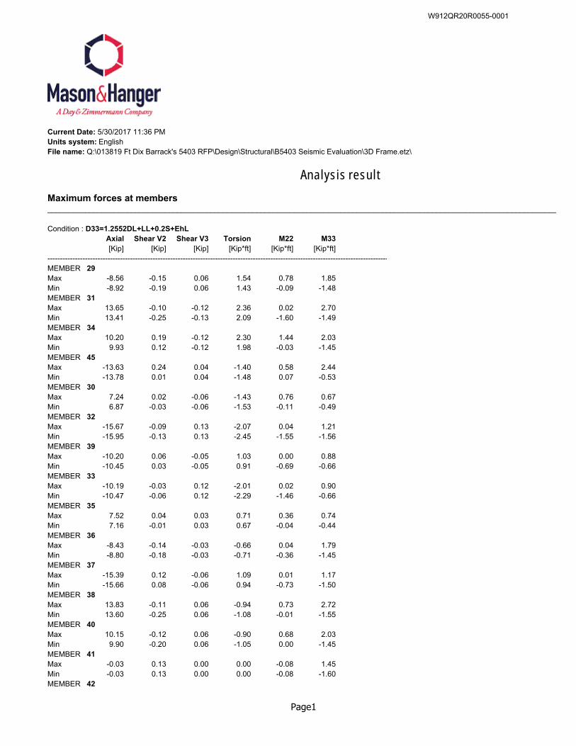
Current Date: 5/30/2017 11:36 PMUnits system: EnglishFile name: Q:\013819 Ft Dix Barrack's 5403 RFP\Design\Structural\B5403 Seismic Evaluation\3D Frame.etz\
Analysis result
Maximum forces at members__________________________________________________________________________________________________________________________
Condition : D33=1.2552DL+LL+0.2S+EhLAxial Shear V2 Shear V3 Torsion M22 M33[Kip] [Kip] [Kip] [Kip*ft] [Kip*ft] [Kip*ft]
----------------------------------------------------------------------------------------------------------------------------------------MEMBER 29Max -8.56 -0.15 0.06 1.54 0.78 1.85Min -8.92 -0.19 0.06 1.43 -0.09 -1.48MEMBER 31Max 13.65 -0.10 -0.12 2.36 0.02 2.70Min 13.41 -0.25 -0.13 2.09 -1.60 -1.49MEMBER 34Max 10.20 0.19 -0.12 2.30 1.44 2.03Min 9.93 0.12 -0.12 1.98 -0.03 -1.45MEMBER 45Max -13.63 0.24 0.04 -1.40 0.58 2.44Min -13.78 0.01 0.04 -1.48 0.07 -0.53MEMBER 30Max 7.24 0.02 -0.06 -1.43 0.76 0.67Min 6.87 -0.03 -0.06 -1.53 -0.11 -0.49MEMBER 32Max -15.67 -0.09 0.13 -2.07 0.04 1.21Min -15.95 -0.13 0.13 -2.45 -1.55 -1.56MEMBER 39Max -10.20 0.06 -0.05 1.03 0.00 0.88Min -10.45 0.03 -0.05 0.91 -0.69 -0.66MEMBER 33Max -10.19 -0.03 0.12 -2.01 0.02 0.90Min -10.47 -0.06 0.12 -2.29 -1.46 -0.66MEMBER 35Max 7.52 0.04 0.03 0.71 0.36 0.74Min 7.16 -0.01 0.03 0.67 -0.04 -0.44MEMBER 36Max -8.43 -0.14 -0.03 -0.66 0.04 1.79Min -8.80 -0.18 -0.03 -0.71 -0.36 -1.45MEMBER 37Max -15.39 0.12 -0.06 1.09 0.01 1.17Min -15.66 0.08 -0.06 0.94 -0.73 -1.50MEMBER 38Max 13.83 -0.11 0.06 -0.94 0.73 2.72Min 13.60 -0.25 0.06 -1.08 -0.01 -1.55MEMBER 40Max 10.15 -0.12 0.06 -0.90 0.68 2.03Min 9.90 -0.20 0.06 -1.05 0.00 -1.45MEMBER 41Max -0.03 0.13 0.00 0.00 -0.08 1.45Min -0.03 0.13 0.00 0.00 -0.08 -1.60MEMBER 42
Page1
W912QR20R0055-0001
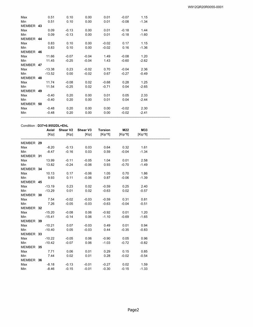
Max 0.51 0.10 0.00 0.01 -0.07 1.15Min 0.51 0.10 0.00 0.01 -0.08 -1.34MEMBER 43Max 0.09 -0.13 0.00 0.01 -0.18 1.44Min 0.09 -0.13 0.00 0.01 -0.18 -1.60MEMBER 44Max 0.83 0.10 0.00 -0.02 0.17 1.15Min 0.83 0.10 0.00 -0.02 0.16 -1.36MEMBER 46Max 11.66 -0.07 -0.04 1.49 -0.08 1.20Min 11.45 -0.25 -0.04 1.43 -0.60 -2.62MEMBER 47Max -13.38 0.23 -0.02 0.70 -0.04 2.36Min -13.52 0.00 -0.02 0.67 -0.27 -0.49MEMBER 48Max 11.74 -0.08 0.02 -0.68 0.28 1.25Min 11.54 -0.25 0.02 -0.71 0.04 -2.65MEMBER 49Max -0.40 0.20 0.00 0.01 0.05 2.33Min -0.40 0.20 0.00 0.01 0.04 -2.44MEMBER 50Max -0.48 0.20 0.00 0.00 -0.02 2.30Min -0.48 0.20 0.00 0.00 -0.02 -2.41----------------------------------------------------------------------------------------------------------------------------------------
Condition : D37=0.9552DL+EhLAxial Shear V2 Shear V3 Torsion M22 M33[Kip] [Kip] [Kip] [Kip*ft] [Kip*ft] [Kip*ft]
----------------------------------------------------------------------------------------------------------------------------------------MEMBER 29Max -8.20 -0.13 0.03 0.64 0.32 1.61Min -8.47 -0.16 0.03 0.59 -0.04 -1.34MEMBER 31Max 13.99 -0.11 -0.05 1.04 0.01 2.58Min 13.82 -0.24 -0.06 0.93 -0.70 -1.49MEMBER 34Max 10.13 0.17 -0.06 1.05 0.70 1.86Min 9.93 0.11 -0.06 0.87 -0.06 -1.39MEMBER 45Max -13.19 0.23 0.02 -0.59 0.25 2.40Min -13.29 0.01 0.02 -0.63 0.02 -0.57MEMBER 30Max 7.54 -0.02 -0.03 -0.59 0.31 0.81Min 7.26 -0.05 -0.03 -0.63 -0.04 -0.51MEMBER 32Max -15.20 -0.08 0.06 -0.92 0.01 1.20Min -15.41 -0.14 0.06 -1.10 -0.69 -1.65MEMBER 39Max -10.21 0.07 -0.03 0.49 0.01 0.94Min -10.40 0.05 -0.03 0.44 -0.35 -0.83MEMBER 33Max -10.22 -0.05 0.06 -0.90 0.05 0.96Min -10.42 -0.07 0.06 -1.03 -0.72 -0.82MEMBER 35Max 7.71 0.06 0.01 0.29 0.15 0.85Min 7.44 0.02 0.01 0.28 -0.02 -0.54MEMBER 36Max -8.18 -0.13 -0.01 -0.27 0.02 1.59Min -8.46 -0.15 -0.01 -0.30 -0.15 -1.33
Page2
W912QR20R0055-0001
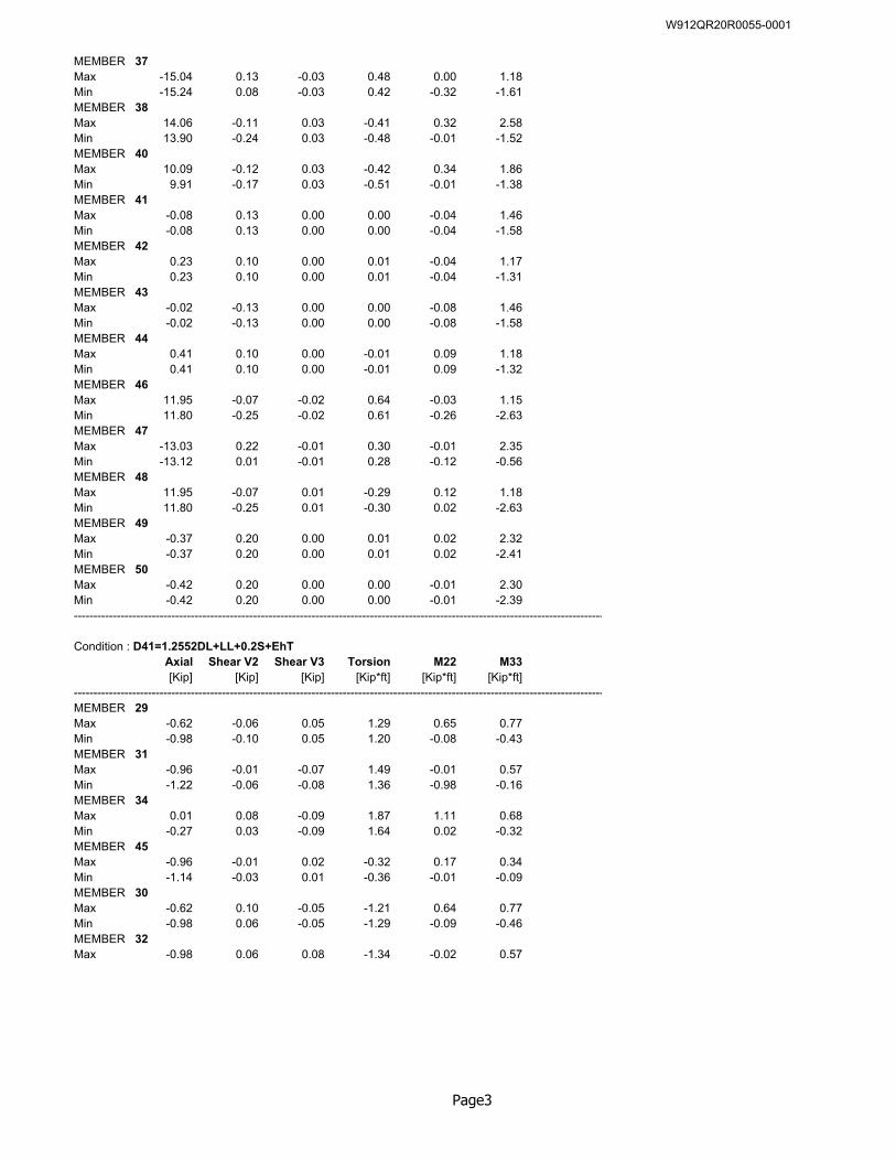
MEMBER 37Max -15.04 0.13 -0.03 0.48 0.00 1.18Min -15.24 0.08 -0.03 0.42 -0.32 -1.61MEMBER 38Max 14.06 -0.11 0.03 -0.41 0.32 2.58Min 13.90 -0.24 0.03 -0.48 -0.01 -1.52MEMBER 40Max 10.09 -0.12 0.03 -0.42 0.34 1.86Min 9.91 -0.17 0.03 -0.51 -0.01 -1.38MEMBER 41Max -0.08 0.13 0.00 0.00 -0.04 1.46Min -0.08 0.13 0.00 0.00 -0.04 -1.58MEMBER 42Max 0.23 0.10 0.00 0.01 -0.04 1.17Min 0.23 0.10 0.00 0.01 -0.04 -1.31MEMBER 43Max -0.02 -0.13 0.00 0.00 -0.08 1.46Min -0.02 -0.13 0.00 0.00 -0.08 -1.58MEMBER 44Max 0.41 0.10 0.00 -0.01 0.09 1.18Min 0.41 0.10 0.00 -0.01 0.09 -1.32MEMBER 46Max 11.95 -0.07 -0.02 0.64 -0.03 1.15Min 11.80 -0.25 -0.02 0.61 -0.26 -2.63MEMBER 47Max -13.03 0.22 -0.01 0.30 -0.01 2.35Min -13.12 0.01 -0.01 0.28 -0.12 -0.56MEMBER 48Max 11.95 -0.07 0.01 -0.29 0.12 1.18Min 11.80 -0.25 0.01 -0.30 0.02 -2.63MEMBER 49Max -0.37 0.20 0.00 0.01 0.02 2.32Min -0.37 0.20 0.00 0.01 0.02 -2.41MEMBER 50Max -0.42 0.20 0.00 0.00 -0.01 2.30Min -0.42 0.20 0.00 0.00 -0.01 -2.39----------------------------------------------------------------------------------------------------------------------------------------
Condition : D41=1.2552DL+LL+0.2S+EhTAxial Shear V2 Shear V3 Torsion M22 M33[Kip] [Kip] [Kip] [Kip*ft] [Kip*ft] [Kip*ft]
----------------------------------------------------------------------------------------------------------------------------------------MEMBER 29Max -0.62 -0.06 0.05 1.29 0.65 0.77Min -0.98 -0.10 0.05 1.20 -0.08 -0.43MEMBER 31Max -0.96 -0.01 -0.07 1.49 -0.01 0.57Min -1.22 -0.06 -0.08 1.36 -0.98 -0.16MEMBER 34Max 0.01 0.08 -0.09 1.87 1.11 0.68Min -0.27 0.03 -0.09 1.64 0.02 -0.32MEMBER 45Max -0.96 -0.01 0.02 -0.32 0.17 0.34Min -1.14 -0.03 0.01 -0.36 -0.01 -0.09MEMBER 30Max -0.62 0.10 -0.05 -1.21 0.64 0.77Min -0.98 0.06 -0.05 -1.29 -0.09 -0.46MEMBER 32Max -0.98 0.06 0.08 -1.34 -0.02 0.57
Page3
W912QR20R0055-0001
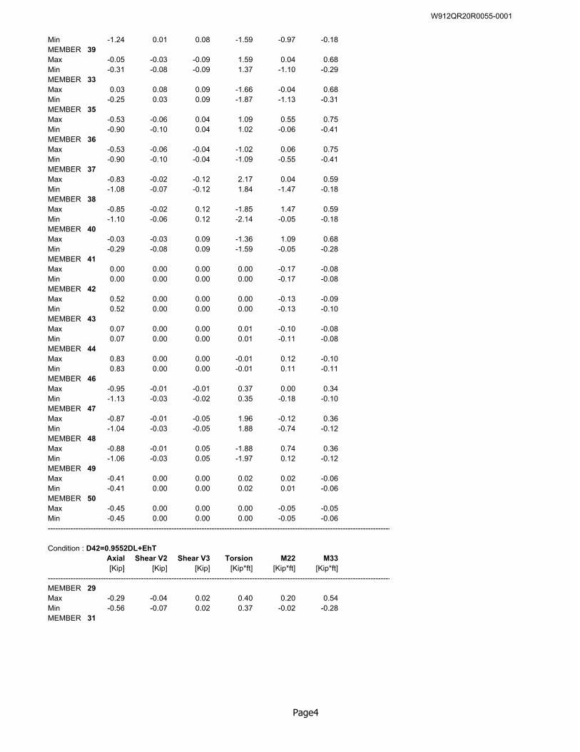
Min -1.24 0.01 0.08 -1.59 -0.97 -0.18MEMBER 39Max -0.05 -0.03 -0.09 1.59 0.04 0.68Min -0.31 -0.08 -0.09 1.37 -1.10 -0.29MEMBER 33Max 0.03 0.08 0.09 -1.66 -0.04 0.68Min -0.25 0.03 0.09 -1.87 -1.13 -0.31MEMBER 35Max -0.53 -0.06 0.04 1.09 0.55 0.75Min -0.90 -0.10 0.04 1.02 -0.06 -0.41MEMBER 36Max -0.53 -0.06 -0.04 -1.02 0.06 0.75Min -0.90 -0.10 -0.04 -1.09 -0.55 -0.41MEMBER 37Max -0.83 -0.02 -0.12 2.17 0.04 0.59Min -1.08 -0.07 -0.12 1.84 -1.47 -0.18MEMBER 38Max -0.85 -0.02 0.12 -1.85 1.47 0.59Min -1.10 -0.06 0.12 -2.14 -0.05 -0.18MEMBER 40Max -0.03 -0.03 0.09 -1.36 1.09 0.68Min -0.29 -0.08 0.09 -1.59 -0.05 -0.28MEMBER 41Max 0.00 0.00 0.00 0.00 -0.17 -0.08Min 0.00 0.00 0.00 0.00 -0.17 -0.08MEMBER 42Max 0.52 0.00 0.00 0.00 -0.13 -0.09Min 0.52 0.00 0.00 0.00 -0.13 -0.10MEMBER 43Max 0.07 0.00 0.00 0.01 -0.10 -0.08Min 0.07 0.00 0.00 0.01 -0.11 -0.08MEMBER 44Max 0.83 0.00 0.00 -0.01 0.12 -0.10Min 0.83 0.00 0.00 -0.01 0.11 -0.11MEMBER 46Max -0.95 -0.01 -0.01 0.37 0.00 0.34Min -1.13 -0.03 -0.02 0.35 -0.18 -0.10MEMBER 47Max -0.87 -0.01 -0.05 1.96 -0.12 0.36Min -1.04 -0.03 -0.05 1.88 -0.74 -0.12MEMBER 48Max -0.88 -0.01 0.05 -1.88 0.74 0.36Min -1.06 -0.03 0.05 -1.97 0.12 -0.12MEMBER 49Max -0.41 0.00 0.00 0.02 0.02 -0.06Min -0.41 0.00 0.00 0.02 0.01 -0.06MEMBER 50Max -0.45 0.00 0.00 0.00 -0.05 -0.05Min -0.45 0.00 0.00 0.00 -0.05 -0.06----------------------------------------------------------------------------------------------------------------------------------------
Condition : D42=0.9552DL+EhTAxial Shear V2 Shear V3 Torsion M22 M33[Kip] [Kip] [Kip] [Kip*ft] [Kip*ft] [Kip*ft]
----------------------------------------------------------------------------------------------------------------------------------------MEMBER 29Max -0.29 -0.04 0.02 0.40 0.20 0.54Min -0.56 -0.07 0.02 0.37 -0.02 -0.28MEMBER 31
Page4
W912QR20R0055-0001
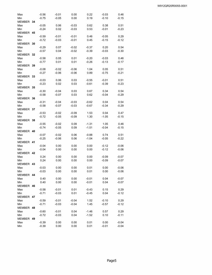
Max -0.56 -0.01 0.00 0.22 -0.03 0.46Min -0.75 -0.05 0.00 0.19 -0.10 -0.15MEMBER 34Max -0.05 0.06 -0.03 0.62 0.38 0.51Min -0.24 0.02 -0.03 0.53 -0.01 -0.23MEMBER 45Max -0.59 -0.01 -0.01 0.46 -0.05 0.29Min -0.72 -0.03 -0.01 0.45 -0.15 -0.12MEMBER 30Max -0.29 0.07 -0.02 -0.37 0.20 0.54Min -0.57 0.04 -0.02 -0.39 -0.03 -0.30MEMBER 32Max -0.58 0.05 0.01 -0.20 -0.03 0.46Min -0.77 0.01 0.01 -0.26 -0.13 -0.17MEMBER 39Max -0.08 -0.02 -0.06 1.04 0.05 0.51Min -0.27 -0.06 -0.06 0.89 -0.75 -0.21MEMBER 33Max -0.03 0.06 0.03 -0.55 -0.01 0.51Min -0.23 0.02 0.03 -0.61 -0.39 -0.23MEMBER 35Max -0.30 -0.04 0.03 0.67 0.34 0.54Min -0.58 -0.07 0.03 0.62 -0.04 -0.29MEMBER 36Max -0.31 -0.04 -0.03 -0.62 0.04 0.54Min -0.58 -0.07 -0.03 -0.67 -0.34 -0.29MEMBER 37Max -0.53 -0.02 -0.09 1.53 0.04 0.47Min -0.72 -0.05 -0.09 1.30 -1.05 -0.15MEMBER 38Max -0.55 -0.02 0.09 -1.31 1.05 0.46Min -0.74 -0.05 0.09 -1.51 -0.04 -0.15MEMBER 40Max -0.07 -0.02 0.06 -0.88 0.74 0.51Min -0.25 -0.06 0.06 -1.04 -0.05 -0.22MEMBER 41Max -0.04 0.00 0.00 0.00 -0.12 -0.06Min -0.04 0.00 0.00 0.00 -0.12 -0.06MEMBER 42Max 0.24 0.00 0.00 0.00 -0.09 -0.07Min 0.24 0.00 0.00 0.00 -0.09 -0.07MEMBER 43Max -0.03 0.00 0.00 0.01 0.00 -0.06Min -0.03 0.00 0.00 0.01 0.00 -0.06MEMBER 44Max 0.40 0.00 0.00 -0.01 0.04 -0.07Min 0.40 0.00 0.00 -0.01 0.04 -0.07MEMBER 46Max -0.58 -0.01 0.01 -0.43 0.15 0.29Min -0.71 -0.03 0.01 -0.45 0.04 -0.12MEMBER 47Max -0.59 -0.01 -0.04 1.52 -0.10 0.29Min -0.71 -0.03 -0.04 1.45 -0.57 -0.12MEMBER 48Max -0.60 -0.01 0.04 -1.46 0.57 0.29Min -0.72 -0.03 0.04 -1.52 0.10 -0.11MEMBER 49Max -0.39 0.00 0.00 0.01 0.00 -0.04Min -0.39 0.00 0.00 0.01 -0.01 -0.04
Page5
W912QR20R0055-0001

MEMBER 50Max -0.38 0.00 0.00 0.00 -0.04 -0.04Min -0.38 0.00 0.00 0.00 -0.04 -0.04----------------------------------------------------------------------------------------------------------------------------------------
Page6
W912QR20R0055-0001

Building 5502, Barracks D/B FFR P2 #481648 Joint Base McGuire-Dix-Lakehurst, NJ W912QR20R0055
Section 01 02 00.00 48
ATTACHMENT ‘F
Fire Protection / Life Safety Code Analysis Template
W912QR20R0055-0001
1. PROJECT'S APPLIED CODES & STANDARDS (Edit to indicate actual dates, codes, & standards used for this project.)
a. Occupancy Classification:IBC Chapter 3
b. Construction Type: Indicate project's building code (IBC) construction type.IBC Chapter 6Table 601
c. Mixed Use & Occupancy Separations
q. NFPA 90A, 2018: Standard Installation of Air Conditioning & Ventilation Systems , for protection of openings, shafts, fire dampers, smoke dampers, penetrations and fan control
UFC 1-200-01 DOD BUILDING CODE (GENERAL REQUIREMENTS) provides requirements for incorporating fire protection and life safety codes into military construction, particularly in paragraphs 1-4.1 and Chapter 3 which dictates use of UFC 3-600-01 and IBC. UFC 3-600-01, FIRE PROTECTION ENGINEERING FOR FACILITIES, paragraph 1-4.2.6 indicates application of NFPA.
f. NFPA 1, 2018: Fire Code , for determining vehicle access requirements
h. NFPA 10, 2018: Standard for Portable Fire Extinguishers
n. NFPA 70, 2017: National Electrical Code (NEC) - Article 500 Hazardous Locations & Article 511 Commercial Garages, Repair & Storage
p. NFPA 72, 2019: National Fire Alarm and Signaling Code
Indicate project's occupancy classification information based on IBC for building code requirements. Exception For Repair Garage, UFC 3-600-01: 4-43.1.2 to use NFPA 30A( 3.3.12.2 & NFPA 101 40-1.2.1)
o. NFPA 80, 2019: Standard for Fire Doors and Other Opening Protectives
Indicate project's intention for mixed use or separated occupancy. Per UFC 3-600-01: 5-5, IBC Section 509 does
t. ASME A17.1, 2016: Safety Code for Elevators and Escalatorss. NFPA 291, 2019: Recommended Practice for Fire Flow Testing and Marking of Hydrants
Fire Protection / Life Safety / Accessibility Code ReviewForm version 26 dated 15 May 2019
Instructions: The Designer of Record (DOR) shall use this form to record Fire Protection, Life Safety and Accessibility features for all building projects, including unoccupied facilities. The form shall be edited, adding and subtracting criteria followed on the left with actual method to meet criteria on the right. The DOR must also sign the form where indicated. The signed form shall be provided in the Design Analysis and same review text shall be included on a Code Review drawing.
r. NFPA 96, 2017: Standard for Ventilation Control and Fire Protection of Commercial Cooking
Applicability: A Fire Protection/Life Safety/Accessibility Code Review shall be developed and included in ALL project submittals for government review and comment, including unoccupied facilities. Fire Protection/Life Safety/Accessibility Floor Plan(s) drawings shall be developed and included in ALL project submittals for government review and comment.
Fire Protection/Life Safety/Accessibility drawings shall be developed, graphically showing all features of fire protection/ life safety/accessibility in plan. These drawings shall include note, "This drawing is for reference only. It is not part of the construction contract and all information contained here is located on construction documents". Drawings shall illustrate features from all disciplines including longest travel distance, longest dead-end distance, longest common path, accessible means of egress, wall ratings, emergency lights, exit signs, manual alarm pulls, detectors, strobes, speakers, horns, FACP, and fire extinguishers, .
Insert Project Name and Location
d. UFC 4-021-01: Design and O&M: Mass Notification Systems , with Change 1, January 2010
a. UFC 1-200-01: General Building Requirements , Change 2, 1 Nov 2018
g. NFPA 101, 2018: Life Safety Code , for building egress and life safety except as modified in UFC 3-600-01
u. ABA (Architectural Barriers Act) Accessibility Standards as directed by DoD Policy Memo "Access for People with Disabilities" dated 31 Oct 2008.
i. NFPA 13, 2019: Standard for Installation of Sprinkler Systems , minimum requirements for design and installation of automatic fire sprinkler systems and exposure protection
b. UFC 3-490-06: Elevators , 8 June 2018
e. IBC 2015: International Building Code for fire resistance requirements, allowable floor area, building height limits, and building separation distance, except as modified by UFC 3-600-01
l. NFPA 30, 2018: Flammable and Combustible Liquids Code , for construction requirements and fire resistance ratings for liquid storage areas
m. NFPA 30A, 2018: Code for Motor Fuel Dispensing Facilities and Repair Garages , for occupancy classification, construction requirements and means of egress for repair garages and organizational maintenance shops
c. UFC 3-600-01: Design: Fire Protection Engineering for Facilities , with Change 3, 10 May 2019.
j. NFPA 20, 2019: Standard for the Installation of Stationary Pumps for Fire Protection, for construction & installation rqmts for fire pumps
k. NFPA 22, 2019: Standard for Water Tanks for Private Fire Protection
1. BUILDING CODE REQUIREMENTS:
v. ECB 2018-17: New Requirements for Visual Notification for Mass Notification Systems
Page 1 of 7
W912QR20R0055-0001
UFC 3-600-01: 5-4, 5-5IBC Section 508
S-1 H-222,300sf + 213sf = .347 < 1 (okay)65,625sf 26,250sf
d. Area Limitations / Modifications:UFC 3-600-01: 5-3IBC Section 503, 506, 507
Area DeterminationAt = 16000 > actual = 9503Is = 2 for sprinkler increaseIf = 0Aa = 16000 + [16000(0)] + [16000(2)] = 48000 > actual 27843 okay
e. Height Limitations:IBC Section 503Tables 504.3 & 504.4
f. Vertical Enclosures, Continuity, Protection:UFC 3-3.1.1NFPA 101: 7.1.3, 8.6NFPA 90A: 4.3.1.2, 5.3.4
g. Opening Protectives & Thru-PenetrationsNFPA 101: 8.3 thru 8.6NFPA 90ANFPA 80NFPA 13
h. Horizontal Separations:IBC: Table 508.4
i. Fire Resistive Requirements: Indicate requirements based on construction type:IBC: Table 601 and Section 602 Primary Structural Frame - ( ) hour rating
Exterior Bearing Walls - ( ) hour ratingInterior Bearing Walls - ( ) hour ratingExterior Nonbearing partitions - ( ) hour ratingInterior Nonbearing partitions - ( ) hour ratingFloor Construction & Secondary Members - ( ) hour ratingRoof Construction & Secondary Members - ( ) hour rating
j. Enclosure Protection: Indicate enclosure protection requirement for specific spaces and what is actually provided, example:NFPA 101: Specific Occupancy Chapters Mechanical Rm requires 1 Hr or sprinklered - sprinkler provided.ASME A17.1 Janitor Closet requires 1 Hr or sprinklered - Sprinkler provided.
k. Fire Protection System:UFC 3-600-01: Chapters 4 & 9UFC 3-600-01: Appendix B
UFC 3-600-01; 1-12.12, 9-7.3.1.1, 4-44NFPA 13
UFC 3-600-01: Chapter 9-7.4NFPA 13
l. Available Water Supply TestingUFC 3-600-01: 1-12.5, 9-6.4
Determine the requirement for fire protection systems, stating which systems are required and criteria to which they are designed.
Provide results of water flow tests per the UFC requiring a fire protection engineer or engineer experienced in water flow testing to perform or witness the flow testing per NFPA 291. Water supply data shall show available water
Indicate the hazard category based on occupancy for various rooms, using UFC 3-600-01, Appendix "B". Consider classifying the entire bldg and noting exceptions for differing rooms. For example, for a light hazard (LH) bldg, the mechanical, electrical and storage rooms are classified as ordinary hazard (OH).
Indicate fire protection provisions for stair enclosures, utility shafts, elevators, laundry chutes, etc. Indicate vertical enclosure requirements & provisions based on number of bldg stories for stairways, elevator hoistways, light shafts, bldg expansion joints, etc. List required fire resistance ratings of shafts, for example: 2-Story Shaft Enclosures - ( ) hour rating; 3-Story Laundry Chute Enclosure - ( ) hour rating.
UFC 3-600-01; 9-7, except as modified in Chapter 4 of UFC for specific facility types
not apply. Include equations proving the area allowances for separated occupancy per 508.4.2 if it applies. For example:
For each occupancy hazard category based on Tables 9-3 & 9-4 for non-storage applications, indicate Sprinkler Design Density, Sprinkler Design Area, Water Demand for Hose Streams, providing supply pressure and source requirements.
Indicate location for horizontal separation and provision such as fire or smoke rated floors between occupancies or exit enclosures.
Coverage per sprinkler must be in accordance with NFPA 13, not exceeding 225 sf for light hazard or 130 sf for ordinary hazard. Extended coverage heads are not permitted.
Indicate specific project's height limitations, providing maximum height allowed and actual height per building height definition in Section 502.
For warehouse and storage facilities include commodity classification, maximum storage height, storage configuration (racks, shelves, palletized, bin box, and solid-piled), aisle width, clearance to ceiling and sprinklers type and temperature rating.
Indicate project's area limitations, Table 506.2. Describe area modifications taken. Include equations proving allowable area increases using frontage and automatic sprinkler factors. Only need to show increases if needed to increase allowable area. For example:
Indicate requirements & provisions for fire barriers, smoke partitions, smoke barriers, vertical openings, and special hazard protection. Per NFPA 13, 8.15.4, vertical openings not meeting 8.15.4.4 require closely spaced sprinklers and draft stops.
Page 2 of 7
W912QR20R0055-0001
NFPA 291
UFC 3-600-01: 9-2.2 NFPA 1: Table 18.4.5.2.1
UFC 3-600-01: 1-12.10, 4-38
m. Water Storage Tank RequirementsUFC 3-600-01: 1-12.4, Chapter 9-4NFPA 22
n. Backflow Preventer & TestingNFPA 13: 8.16.4.6.1UFC 3-600-01; 9-6.3.5, 9-6.6
o. Fire Pump(s)UFC 3-600-01: Chapter 9-5NFPA 20
a. Classification of Occupancy:NFPA 101: Ch 6
b. Occupant Load:NFPA 101: 7.3.1.2 & Chapters 12-42
Actual floor area Business: 5,626 GSF / 100 GSF = 56.37 ~ 57Actual floor area Assembly: 1,920 NSF / 15 NSF = 128.002 ~ 129Total Floor Maximum Occupancy: 186
c. Capacity of Means of Egress:NFPA 101: 7.3.3 & Chapters 12-42
d. Number of Exits: Indicate number of exits required based on egress capacity needed. Indicate number of exits provided.NFPA 101: 7.4 & Chapters 12-42
e. Arrangement of Means of Egress Indicate requirements for means of egress arrangement, including project's provisions to comply.NFPA 101: 7.5 & Chapters 12-42
f. Accessible Means of Egress Indicate requirements for accessible means of egress with project's provisions to comply.NFPA 101: 7.5.4
g. Travel Distance to Exits:NFPA 101: 7.6 & Chapters 12-42
h. Illumination of Means of Egress: Indicate required and provided provisions for means of egress illumination.NFPA 101: 7.8 & Chapters 12-42
i. Emergency Lighting: Indicate required and provided provisions for emergency lighting.NFPA 101: 7.9 & Chapters 12-42
j. Marking of Means of Egress: Indicate required and provided provisions for marking of egress lighting.NFPA 101: 7.10 & Chapters 12-42
k. Interior Finish Classification Limits: Indicate required and provided provisions for interior finish classification limitations.NFPA 101: Table A.10.2.2
l. Detection, Alarm, & Communications:UFC 3-600-01: Chapter 9-18NFPA 101: 9.6 & Chapters 12-42
m. Portable Fire Extinguishers:
Provide information regarding project site reliable power, pump type, pump start and shutdown, pump drive and controllers. Provide fire pump(s) flow and pressure requirements, locations, and construction enclosure.
supply, static pressure, & residual pressure at flow. Based on this data & estimated flow & pressure required for the bldg sprinkler system(s), determine the need for a fire pump. Indicate test & flow hydrant locations, elevations, & water flow data on contract drgs.
For range and remote facilities, provide capacity & fire flow information requirement per NFPA 1142. Provide information indicating how the local fire department will meet the fire flow requirement. Provide code analysis and calculation per NFPA 1142 to District Fire Protection Engineer (DFPE) to get AHJ concurrence.
Provide backflow preventor valves as required by local authority or water surveyor. On contract drawings show and provide test piping and valve located downstream of the backflow preventer for flow testing of the backflow preventer at full system demand flow. Route the discharge to an appropriate location outside the building. Minimum pressure drop across reduced pressure backflow preventer is 12 psi. Assure that backflow preventer is 8 psi for hydraulic calcualtions.
2. LIFE SAFETY REQUIREMENTS:
Indicate total occupant load, showing occupant load factors and subtotals of various occupancies for each floor, for example:
Indicate egress capacity for components of all means of egress including stairs, corridors, ramps, and doors. Include total egress capacity needed.
Indicate project's occupancy classification information based on NFPA 101 for life safety code requirements. Exception For Repair Garage, UFC 3-600-01: 4-43.1.2 to use NFPA 30A (3.3.12.2 & NFPA 101 40-1.2.1)
Indicate requirements for FE and project provision. See provision in UFC 4-171-05, 3-4.1.5 & 5.4.2 for Arms
Indicate travel distance requirements and project's provisions to comply using worst case distance. Include common path, dead end, and travel distance limits for each occupancy.
Indicate requirements for manual alarm initiation, automatic detection, and alarm notification. Include location to which notification is sent.
For non-sprinkler facilities, fire flow & duration must meet minimum requirement in NFPA 1, Table 18.4.5.2.1.
Provide water storage requirements including capacity, type of storage tank and storage tank monitoring.
Page 3 of 7
W912QR20R0055-0001
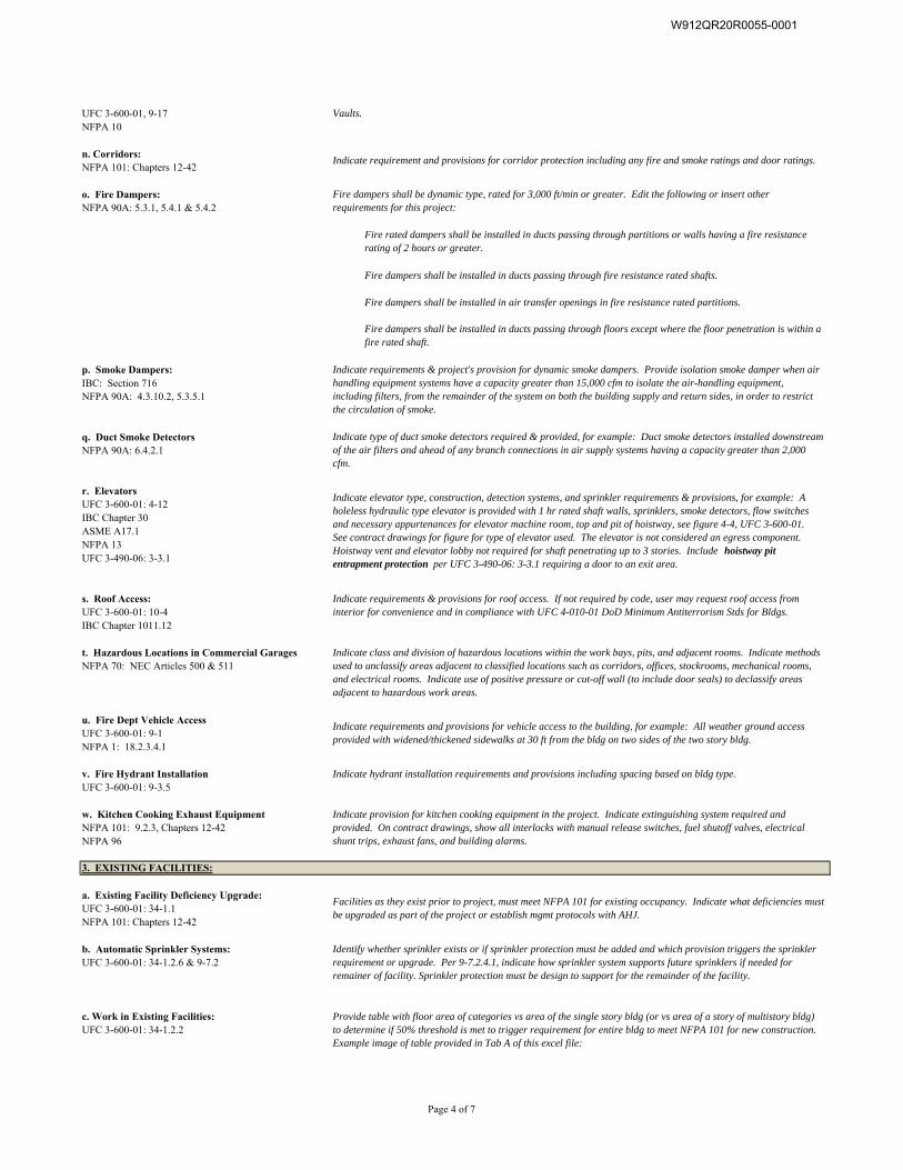
UFC 3-600-01, 9-17NFPA 10
n. Corridors:NFPA 101: Chapters 12-42
o. Fire Dampers:NFPA 90A: 5.3.1, 5.4.1 & 5.4.2
Fire dampers shall be installed in ducts passing through fire resistance rated shafts.
Fire dampers shall be installed in air transfer openings in fire resistance rated partitions.
p. Smoke Dampers:IBC: Section 716 NFPA 90A: 4.3.10.2, 5.3.5.1
q. Duct Smoke DetectorsNFPA 90A: 6.4.2.1
r. ElevatorsUFC 3-600-01: 4-12IBC Chapter 30ASME A17.1 NFPA 13UFC 3-490-06: 3-3.1
s. Roof Access:UFC 3-600-01: 10-4IBC Chapter 1011.12
t. Hazardous Locations in Commercial GaragesNFPA 70: NEC Articles 500 & 511
u. Fire Dept Vehicle AccessUFC 3-600-01: 9-1NFPA 1: 18.2.3.4.1
v. Fire Hydrant Installation Indicate hydrant installation requirements and provisions including spacing based on bldg type.UFC 3-600-01: 9-3.5
w. Kitchen Cooking Exhaust EquipmentNFPA 101: 9.2.3, Chapters 12-42NFPA 96
a. Existing Facility Deficiency Upgrade:UFC 3-600-01: 34-1.1NFPA 101: Chapters 12-42
b. Automatic Sprinkler Systems:UFC 3-600-01: 34-1.2.6 & 9-7.2
c. Work in Existing Facilities:UFC 3-600-01: 34-1.2.2
Identify whether sprinkler exists or if sprinkler protection must be added and which provision triggers the sprinkler requirement or upgrade. Per 9-7.2.4.1, indicate how sprinkler system supports future sprinklers if needed for remainer of facility. Sprinkler protection must be design to support for the remainder of the facility.
Fire dampers shall be installed in ducts passing through floors except where the floor penetration is within a fire rated shaft.
Indicate class and division of hazardous locations within the work bays, pits, and adjacent rooms. Indicate methods used to unclassify areas adjacent to classified locations such as corridors, offices, stockrooms, mechanical rooms, and electrical rooms. Indicate use of positive pressure or cut-off wall (to include door seals) to declassify areas adjacent to hazardous work areas.
Indicate type of duct smoke detectors required & provided, for example: Duct smoke detectors installed downstream of the air filters and ahead of any branch connections in air supply systems having a capacity greater than 2,000 cfm.
Indicate elevator type, construction, detection systems, and sprinkler requirements & provisions, for example: A holeless hydraulic type elevator is provided with 1 hr rated shaft walls, sprinklers, smoke detectors, flow switches and necessary appurtenances for elevator machine room, top and pit of hoistway, see figure 4-4, UFC 3-600-01. See contract drawings for figure for type of elevator used. The elevator is not considered an egress component. Hoistway vent and elevator lobby not required for shaft penetrating up to 3 stories. Include hoistway pit entrapment protection per UFC 3-490-06: 3-3.1 requiring a door to an exit area.
3. EXISTING FACILITIES:
Facilities as they exist prior to project, must meet NFPA 101 for existing occupancy. Indicate what deficiencies must be upgraded as part of the project or establish mgmt protocols with AHJ.
Indicate provision for kitchen cooking equipment in the project. Indicate extinguishing system required and provided. On contract drawings, show all interlocks with manual release switches, fuel shutoff valves, electrical shunt trips, exhaust fans, and building alarms.
Indicate requirements & project's provision for dynamic smoke dampers. Provide isolation smoke damper when air handling equipment systems have a capacity greater than 15,000 cfm to isolate the air-handling equipment, including filters, from the remainder of the system on both the building supply and return sides, in order to restrict the circulation of smoke.
Indicate requirement and provisions for corridor protection including any fire and smoke ratings and door ratings.
Fire dampers shall be dynamic type, rated for 3,000 ft/min or greater. Edit the following or insert other requirements for this project:
Fire rated dampers shall be installed in ducts passing through partitions or walls having a fire resistance rating of 2 hours or greater.
Vaults.
Indicate requirements and provisions for vehicle access to the building, for example: All weather ground access provided with widened/thickened sidewalks at 30 ft from the bldg on two sides of the two story bldg.
Provide table with floor area of categories vs area of the single story bldg (or vs area of a story of multistory bldg) to determine if 50% threshold is met to trigger requirement for entire bldg to meet NFPA 101 for new construction. Example image of table provided in Tab A of this excel file:
Indicate requirements & provisions for roof access. If not required by code, user may request roof access from interior for convenience and in compliance with UFC 4-010-01 DoD Minimum Antiterrorism Stds for Bldgs.
Page 4 of 7
W912QR20R0055-0001
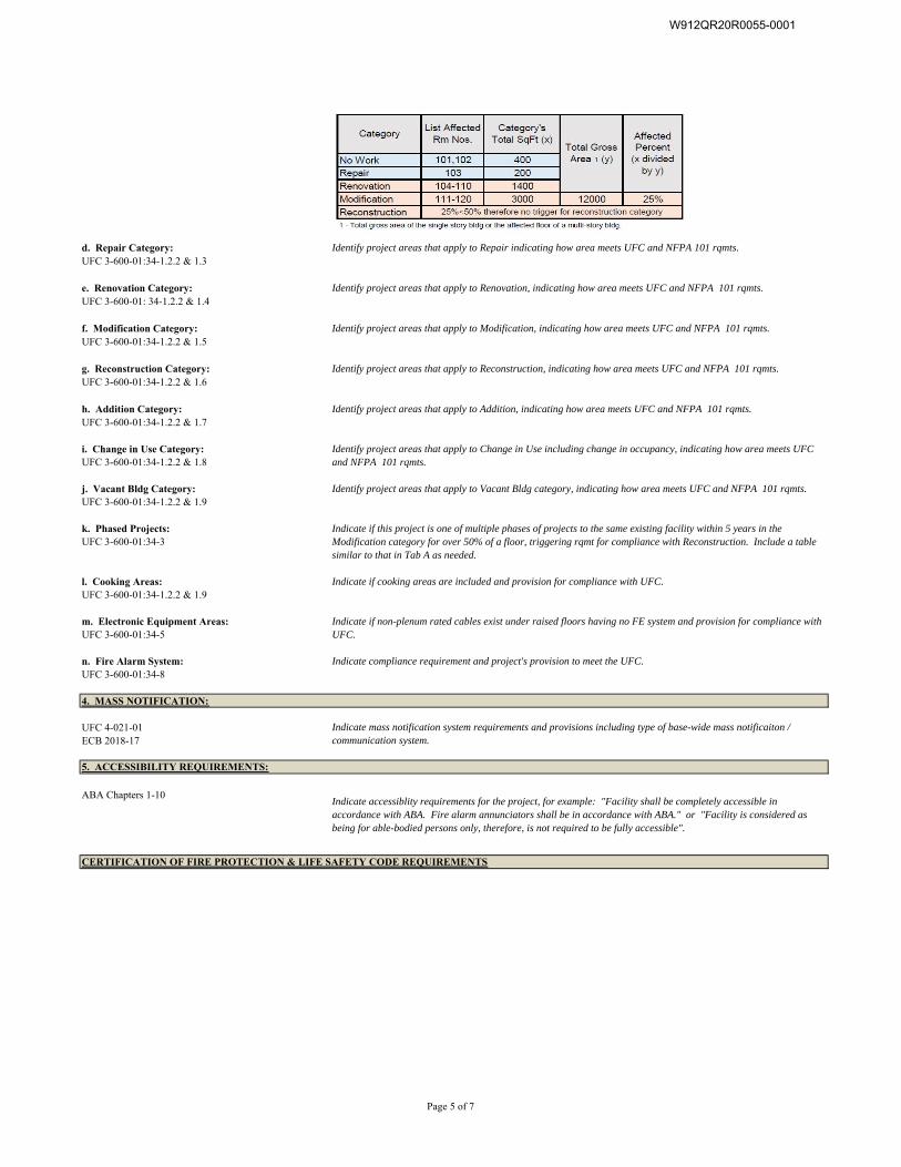
d. Repair Category:UFC 3-600-01:34-1.2.2 & 1.3
e. Renovation Category:UFC 3-600-01: 34-1.2.2 & 1.4
f. Modification Category:UFC 3-600-01:34-1.2.2 & 1.5
g. Reconstruction Category:UFC 3-600-01:34-1.2.2 & 1.6
h. Addition Category:UFC 3-600-01:34-1.2.2 & 1.7
i. Change in Use Category:UFC 3-600-01:34-1.2.2 & 1.8
j. Vacant Bldg Category:UFC 3-600-01:34-1.2.2 & 1.9
k. Phased Projects:UFC 3-600-01:34-3
l. Cooking Areas:UFC 3-600-01:34-1.2.2 & 1.9
m. Electronic Equipment Areas:UFC 3-600-01:34-5
n. Fire Alarm System:UFC 3-600-01:34-8
4. MASS NOTIFICATION:
UFC 4-021-01ECB 2018-17
ABA Chapters 1-10
Identify project areas that apply to Change in Use including change in occupancy, indicating how area meets UFC and NFPA 101 rqmts.
Identify project areas that apply to Vacant Bldg category, indicating how area meets UFC and NFPA 101 rqmts.
Indicate if non-plenum rated cables exist under raised floors having no FE system and provision for compliance with UFC.
Indicate compliance requirement and project's provision to meet the UFC.
Indicate accessiblity requirements for the project, for example: "Facility shall be completely accessible in accordance with ABA. Fire alarm annunciators shall be in accordance with ABA." or "Facility is considered as being for able-bodied persons only, therefore, is not required to be fully accessible".
Indicate mass notification system requirements and provisions including type of base-wide mass notificaiton / communication system.
Identify project areas that apply to Repair indicating how area meets UFC and NFPA 101 rqmts.
Identify project areas that apply to Renovation, indicating how area meets UFC and NFPA 101 rqmts.
Indicate if this project is one of multiple phases of projects to the same existing facility within 5 years in the Modification category for over 50% of a floor, triggering rqmt for compliance with Reconstruction. Include a table similar to that in Tab A as needed.
Indicate if cooking areas are included and provision for compliance with UFC.
5. ACCESSIBILITY REQUIREMENTS:
Identify project areas that apply to Reconstruction, indicating how area meets UFC and NFPA 101 rqmts.
Identify project areas that apply to Addition, indicating how area meets UFC and NFPA 101 rqmts.
Identify project areas that apply to Modification, indicating how area meets UFC and NFPA 101 rqmts.
CERTIFICATION OF FIRE PROTECTION & LIFE SAFETY CODE REQUIREMENTS
Page 5 of 7
W912QR20R0055-0001
Qualified Fire Protection Engineer (QFPE) of Record - Insert Typed Name
Architect of Record - Insert Typed Name
Mechanical Engineer of Record - Insert Typed Name
Electrical Engineer of Record - Insert Typed Name
Civil Engineer of Record - Insert Typed Name
Insert Review Milestone (Preliminary, Interim, Final, or Corrected Final Review)
Preparers of this docuemtn certify the accuracy and completeness of the Fire Protection and Life Safety features for this project indicated with the attached, completed signature forms.
Signature Date
Signature Date
Architect-Engineer DesignCertification of Fire Protection / Life Safety / Accessibility Code Requirements
Preparers of this document certify the accuracy, completeness, and incorporation of theall required fire protection, life safety, and accessibility features in this project for the indicated milestone review.
Signature Date
Signature Date
Insert Project Name and Location
Signature Date
Page 6 of 7
W912QR20R0055-0001
Qualified Fire Protection Engineer (QFPE) - Insert Typed Name
Project Design Team Leader - Insert Typed Name
Architectural Fire Team Member - Insert Typed Name
Mechanical Fire Team Member - Insert Typed Name
Electrical Fire Team Member - Insert Typed Name
Civil Fire Team Member - Insert Typed Name
all required fire protection, life safety, and accessibility features in this project for the indicated milestone review.
LOUISVILLE DISTRICT IN-HOUSE DESIGNFIRE PROTECTION / LIFE SAFETY / ACCESSIBILITLY CODE REVIEW
Signature Date
Insert Project Name and Location
Signature Date
Signature Date
Signature Date
Signature Date
Signature Date
Preparers of this document certify the accuracy, completeness, and incorporation of the
Insert Review Milestone (Preliminary, Interim, Final, or Corrected Final Review)
Page 7 of 7
W912QR20R0055-0001

Building 5502, Barracks D/B FFR P2 #481648 Joint Base McGuire-Dix-Lakehurst, NJ W912QR20R0055
Section 01 02 00.00 48
ATTACHMENT ‘G
LEED Checklist
W912QR20R0055-0001
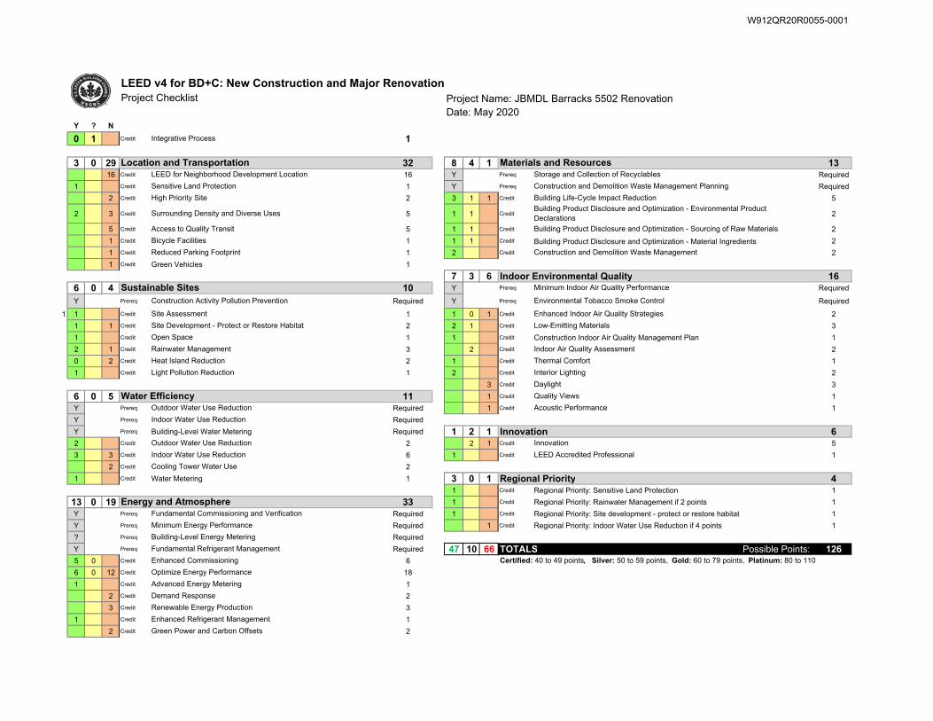
LEED v4 for BD+C: New Construction and Major RenovationProject Checklist Project Name: JBMDL Barracks 5502 Renovation
Date: May 2020Y ? N
0 1 Credit 1
3 0 29 32 8 4 1 1316 Credit 16 Y Prereq Required
1 Credit 1 Y Prereq Required
2 Credit 2 3 1 1 Credit 5
2 3 Credit 5 1 1 Credit 2
5 Credit 5 1 1 Credit 2
1 Credit 1 1 1 Credit Building Product Disclosure and Optimization - Material Ingredients 2
1 Credit 1 2 Credit 2
1 Credit Green Vehicles 1
7 3 6 Indoor Environmental Quality 166 0 4 10 Y Prereq Required
Y Prereq Required Y Prereq Required
1 1 Credit 1 1 0 1 Credit 2
1 1 Credit 2 2 1 Credit 3
1 Credit 1 1 Credit Construction Indoor Air Quality Management Plan 1
2 1 Credit 3 2 Credit 2
0 2 Credit 2 1 Credit 1
1 Credit 1 2 Credit 2
3 Credit 3
6 0 5 11 1 Credit 1
Y Prereq Required 1 Credit 1
Y Prereq Required
Y Prereq Building-Level Water Metering Required 1 2 1 Innovation 62 Credit 2 2 1 Credit 5
3 3 Credit 6 1 Credit 1
2 Credit 2
1 Credit Water Metering 1 3 0 1 Regional Priority 41 Credit Regional Priority: Sensitive Land Protection 1
13 0 19 33 1 Credit Regional Priority: Rainwater Management if 2 points 1
Y Prereq Required 1 Credit Regional Priority: Site development - protect or restore habitat 1
Y Prereq Required 1 Credit Regional Priority: Indoor Water Use Reduction if 4 points 1
? Prereq Required
Y Prereq Required 47 10 66 TOTALS Possible Points: 1265 0 Credit 6
6 0 12 Credit 18
1 Credit 1
2 Credit 2
3 Credit 3
1 Credit 1
2 Credit 2
Minimum Indoor Air Quality Performance
Building Product Disclosure and Optimization - Environmental Product Declarations
Integrative Process
Construction Activity Pollution Prevention
High Priority Site
Bicycle Facilities
Construction and Demolition Waste Management Planning
Materials and ResourcesStorage and Collection of Recyclables
Construction and Demolition Waste Management
Building Product Disclosure and Optimization - Sourcing of Raw Materials
Location and Transportation
Building Life-Cycle Impact Reduction
Sensitive Land Protection
LEED for Neighborhood Development Location
Surrounding Density and Diverse Uses
Sustainable Sites
Green Power and Carbon Offsets
Heat Island Reduction
Outdoor Water Use Reduction
Indoor Water Use Reduction
Outdoor Water Use Reduction
Indoor Water Use Reduction
Enhanced Commissioning
Building-Level Energy Metering
Water Efficiency
Fundamental Commissioning and Verification
Demand Response
Renewable Energy Production
Enhanced Refrigerant Management
Optimize Energy Performance
Advanced Energy Metering
Certified: 40 to 49 points, Silver: 50 to 59 points, Gold: 60 to 79 points, Platinum: 80 to 110
Access to Quality Transit
Reduced Parking Footprint
Open Space
Site Assessment
Interior Lighting
Daylight
LEED Accredited Professional
Innovation
Rainwater Management
Light Pollution Reduction
Environmental Tobacco Smoke Control
Energy and Atmosphere
Minimum Energy Performance
Fundamental Refrigerant Management
Cooling Tower Water Use
Site Development - Protect or Restore Habitat
Acoustic Performance
Quality Views
Enhanced Indoor Air Quality Strategies
Low-Emitting Materials
Indoor Air Quality Assessment
Thermal Comfort
W912QR20R0055-0001
Building 5502, Barracks D/B FFR P2 #481648 Joint Base McGuire-Dix-Lakehurst, NJ W912QR20R0055
Section 01 02 00.00 48
ATTACHMENT ‘H
Installation Design Guide
W912QR20R0055-0001
Joint Base McGuire-Dix-Lakehurst
Vol. 2: JBMDL Dix IFS
30 JANUARY 2019
JOINT BASE MCGUIRE-DIX-LAKEHURST INSTALLATION FACILITIES STANDARDS (IFS)
VOL. 2: JBMDL DIX
Installation Elements
Size image to: 170 pixels width x 170 pixels height
Click here to insert image
Site Development
Size image to: 170 pixels width x 170 pixels height
Click here to insert image
Facilities Exteriors
Size image to: 170 pixels width x 170 pixels height
Click here to insert image
Facilities Interiors
Size image to: 170 pixels width x 170 pixels height
Click here to insert image
Installation Elements Site Development Facilities Exteriors Facilities Interiors
APPROVED FOR PUBLIC RELEASE; DISTRIBUTION UNLIMITED
Signature Field ARCHER.CHRISTOPHER.1230416423
Digitally signed by ARCHER.CHRISTOPHER.1230416423 Date: 2019.02.01 16:37:11 -05'00'
W912QR20R0055-0001
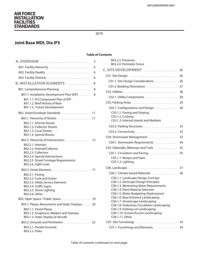
AIR FORCE INSTALLATION FACILITIES STANDARDS
2019
Joint Base MDL Dix IFS
Table of Contents
A. OVERVIEW .............................................................. 5
A01. Facility Hierarchy ............................................................. 6
A02. Facility Quality .................................................................. 6
A03. Facility Districts ............................................................... 6
B. INSTALLATION ELEMENTS .............................. 8
B01. Comprehensive Planning ............................................. 8
B01.1. Installation Development Plan (IDP) ................ 8B01.1.1. IFS Component Plan of IDP B01.1.2. Brief History of Base B01.1.3. Future Development
B02. Street Envelope Standards ........................................... 11
B02.1. Hierarchy of Streets ................................................. 11B02.1.1. Arterial Streets B02.1.2. Collector Streets B02.1.3. Local Streets B02.1.4. Special Routes
B02.2. Hierarchy of Intersections ..................................... 15B02.2.1. Arterials B02.2.2. Arterial/Collector B02.2.3. Collectors B02.2.4. Special Intersections B02.2.5. Street Frontage Requirements B02.2.6. Sight Lines
B02.3. Street Elements ......................................................... 17B02.3.1. Paving B02.3.2. Curb and Gutter B02.3.3. Utility Service Elements B02.3.4. Traffic Signs B02.3.5. Street Lighting B02.3.6. Other
B03. Open Space / Public Space ........................................... 19
B03.1. Plazas, Monuments and Static Displays ........... 20
B03.1.1. Paved Plazas B03.1.2. Sculptures, Markers and Statuary B03.1.3. Static Display of Aircraft
B03.2. Grounds and Perimeters ....................................... 22
B03.2.1. Parade Grounds B03.2.2. Parks
B03.2.3. Preserves B03.2.4. Perimeter Fence
C. SITE DEVELOPMENT ........................................... 26
C01. Site Design ......................................................................... 26
C01.1. Site Design Considerations .................................. 26
C01.2. Building Orientation ............................................... 27
C02. Utilities ................................................................................ 28
C02.1. Utility Components.................................................. 28
C03. Parking Areas .................................................................... 29
C03.1. Configurations and Design .................................. 30C03.1.1. Paving and Striping C03.1.2. Curbing C03.1.3. Internal Islands and Medians
C03.2. Parking Structures ................................................... 33
C03.3. Connectivity ............................................................... 33
C04. Stormwater Management ............................................ 33
C04.1. Stormwater Requirements ................................... 34
C05. Sidewalks, Bikeways and Trails ................................... 35
C05.1. Circulation and Paving .......................................... 35C05.1.1. Ramps and Stairs C05.1.2. Lighting
C06. Landscape .......................................................................... 37
C06.1. Climate-based Materials ....................................... 38C06.1.1. Landscape Design Concept C06.1.2. Xeriscape Design Principles C06.1.3. Minimizing Water Requirements C06.1.4. Plant Material Selection C06.1.5. Water Budgeting (Hydrozones) C06.1.6. Base Entrance Landscaping C06.1.7. Streetscape Landscaping C06.1.8. Pedestrian Circulation Landscaping C06.1.9. Parking Lot Landscaping C06.1.10. Screen/Accent Landscaping C06.1.11. Other
C07. Site Furnishings ................................................................ 43
C07.1. Furnishings and Elements .................................... 44
Table of contents continued on next page
W912QR20R0055-0001
Table of contents continued
C07.2. Site Furnishings Products, Materials / Color .. 45
C07.2.1. Barbeque Grills C07.2.2. Benches C07.2.3. Bike Racks C07.2.4. Bike Lockers C07.2.5. Bollards C07.2.6. Bus Shelters C07.2.7. Drinking Fountains C07.2.8. Dumpster Enclosures / Gates C07.2.9. Fencing C07.2.10. Flagpoles C07.2.11. Lighting – Landscape / Accent C07.2.12. Litter and Ash Receptacles C07.2.13. Picnic Tables C07.2.14. Planters – Free Standing C07.2.15. Play Equipment C07.2.16. Screen Walls C07.2.17. Tree Grates C07.2.18. Other
C08. Exterior Signs .................................................................... 57
C08.1. Colors and Types ..................................................... 57C08.1.1. Materials and Color Specifications C08.1.2. Installation and Gate Identification Signs C08.1.3. Building Identification Signs C08.1.4. Traffic Control Devices (Street Signs) C08.1.5. Directional and Wayfinding Signs C08.1.6. Informational Signs C08.1.7. Motivational Signs C08.1.8. Parking Lot Signs C08.1.9. Regulatory Signs C08.1.10. Other
C09. Lighting ............................................................................... 65
C09.1. Fixtures and Lamping ............................................ 65
C09.2. Light Fixture Types .................................................. 66
C09.2.1. Street Lighting C09.2.2. Parking Lot Lighting C09.2.3. Lighted Bollards C09.2.4. Sidewalk Lighting C09.2.5. Walls / Stairs Lighting C09.2.6. Other
D. FACILITIES EXTERIORS ...................................... 70
D01. Supporting the Mission ................................................ 70
D02. Sustainability .................................................................... 70
D03. Architectural Features ................................................... 71
D03.1. Orientation, Massing and Scale .......................... 72
D03.2. Architectural Character ......................................... 72
D03.3. Details and Color ..................................................... 72D03.3.1. Climate-based Data D03.3.2. Natural Ventilation System D03.3.3. Thermal Mass
D03.3.4. Thermal Shading D03.3.5. Renewable Heating/Cooling D03.3.6. Solar Photovoltaic System D03.3.7. Solar Thermal System
D04. Building Entrances .......................................................... 78
D04.1. Primary Entrances ................................................... 79
D04.2. Secondary Entrances ............................................. 79
D05. Wall Systems ..................................................................... 80
D05.1. Hierarchy of Materials ........................................... 81
D05.2. Layout, Organization and Durability ............... 81
D05.3. Equipment, Vents and Devices .......................... 82
D05.4 Wall Systems Materials ........................................... 82
D05.4.1. Flat Metal Panels D05.4.2. Brick Veneer D05.4.3. Architectural Precast D05.4.4. Stucco Over Sheathing D05.4.5. Curtain Wall D05.4.6. Cast-in Place Concrete D05.4.7. Tilt-up Concrete D05.4.8. Ribbed Metal Sheeting D05.4.9. EIFS D05.4.10.GFRC D05.4.11.Concrete Block D05.4.12. Fiber Cement Siding D05.4.13. Other
D06. Doors and Windows ....................................................... 87
D06.1. Types ............................................................................ 88
D06.2. Layout and Geometry ............................................ 88
D06.3. Glazing and Shading .............................................. 88
D06.4. Hardware .................................................................... 88
D06.5. Doors and Windows Materials ............................ 89D06.5.1. Anodized Aluminum D06.5.2. Hollow Metal D06.5.3. Aluminum-clad Wood D06.5.4. Other
D07. Roof Systems ..................................................................... 91
D07.1. Roof Type and Form ............................................... 92
D07.2. Roof Slope .................................................................. 93
D07.3. Parapets and Copings ............................................ 93
D07.4. Color and Reflectivity ............................................. 93
D07.5. Gutters, Downspouts, Scuppers, Drains ......... 93
D07.6. Roof Vents and Elements ..................................... 94
D07.7. Clerestories and Skylights .................................... 94
D07.8. Vegetated Roof ........................................................ 94
Table of contents continued on next page
W912QR20R0055-0001
Table of contents continued
D07.9. Roof Systems Materials ......................................... 94D07.9.1. Standing Seam Metal D07.9.2. Membrane Single-ply D07.9.3. Built-up Multi-ply D07.9.4. Concrete Tile D07.9.5. Clay Tile D07.9.6. Slate Shingles D07.9.7. Vegetated System D07.9.8. Ribbed Metal Sheeting D07.9.9. Composite Shingles D07.9.10. Other
D08. Structural Systems .......................................................... 98
D08.1. Systems and Layouts ............................................. 99
D08.2. Structural Systems Materials ............................... 99D08.2.1. Concrete D08.2.2. Insulated Concrete Forming (ICF) D08.2.3. Steel D08.2.4. Pre-Engineered Steel D08.2.5. Masonry D08.2.6. Heavy Timber D08.2.7. Light-gauge Steel D08.2.8. Lumber Framing D08.2.9. Other
D09. Mechanical, Electrical and Plumbing ....................... 102
D09.1. Passive and Active Systems ................................. 103
D09.2. Functionality and Efficiency ................................ 103
E. FACILITIES INTERIORS ........................................104
E01. Building Configurations ................................................105
E01.1. Layout and Common Areas ..................................105
E01.1.1. Interior Design Process E01.1.2. Codes and Regulations
E01.2. Quality and Comfort ............................................... 106
E02. Floors .................................................................................... 107
E02.1. Floor Materials ...........................................................107
E02.1.1. Prepared Slabs E02.1.2. Natural Stone and Terrazzo E02.1.3. Quarry Tile E02.1.4. Ceramic Tile E02.1.5. Resilient Floor E02.1.6. Carpet E02.1.7. Rapidly-Renewable Products E02.1.8. Other
E03. Walls ......................................................................................114
E03.1. Wall Materials .............................................................114E03.1.1. Concrete E03.1.2. Masonry E03.1.3. Ceramic Tile E03.1.4. Gypsum Board E03.1.5. Metal Panels E03.1.6. Wood Paneling E03.1.7. Rapidly-Renewable Products E03.1.8. Other
E04. Ceilings .................................................................................117
E04.1. Ceiling Materials ....................................................... 117
E04.1.1. Exposed Framing (Roof / Floor Structure Above) E04.1.2. Exposed Concrete E04.1.3. Grid and Acoustical Tile E04.1.4. Gypsum Board E04.1.5. Metal Panels E04.1.6. Wood E04.1.7. Rapidly-Renewable Products E04.1.8. Other
E05. Doors and Windows ........................................................120
E05.1. Doors and Windows and Frames Materials .... 120E05.1.1. Aluminum E05.1.2. Hollow Metal E05.1.3. Wood E05.1.4. Other
E06. Casework Systems ............................................................124
E06.1. Casework Materials ..................................................124E06.1.1. Plastic Laminate E06.1.2. Solid Polymer Surface E06.1.3. Rapidly-Renewable Products E06.1.4. Metal E06.1.5 Other
E06.2. Countertop Materials ..............................................127
E06.2.1. Plastic Laminate E06.2.2. Solid Polymer Surface E06.2.3. Natural Stone E06.2.4. Cast Stone E06.2.5. Metal E06.2.6 Other
E07. Furnishings .........................................................................129
E07.1. Durability and Serviceability ................................ 129
E07.2. Accessories ................................................................. 129
E08. Interior Signs ......................................................................129
E08.1 Types and Color ......................................................... 129
E08.2. Interior Signs Materials .......................................... 130
E09. Lighting, Power and Communication .......................130
E09.1. Functionality and Efficiency ................................. 130
E09.2. Types and Color ........................................................ 130
F. Appendices ............................................................. 131
G. Appendices .............................................................131
Version 02.00.10
W912QR20R0055-0001
Page 5 of 134Joint Base MDL Dix IFS
A. OVERVIEW
Comply with Air Force Corporate Standards for Overview: http://afcfs.wbdg.org/index.html
This Installation Facilities Standards (IFS) document is part of the Air Force Corporate Facilities Standards (AFCFS) program to assist bases in implementing and maintaining facilities standards as appropriate for efficient operations within the respective climate region. IFS fully replaces, consolidates and simplifies existing facilities standards documents, such as the Architectural Compatibility Plan (ACP) or ACGs, FEPs, etc., and organizes information using the same structure, or Table of Contents, as the AFCFS website.
IFS reflects the AFCFS’ concepts of "Facility Hierarchy" (categorizing facilities into group numbers) and “Facility Quality” (assigning an appropriate level of quality to each group number) and applies these principles at the base level. Applicable DoD and Air Force criteria such as UFCs, AFIs, Memoranda, and UFGSs (Guide Specs) are referenced and linked within IFS to ensure the document is always current.
Navigating within this IFS is efficient and straightforward. Please use the interactive Table of Contents to locate subject matter, and click on the title of a section to access it. From any page, click on the “Back to Table of Contents” footer to return. Content is organized into 4 major sections: Installation Elements, Site Development, Facilities Exteriors and Facilities Interiors.
This IFS document begins as a fill-in PDF form, which is fully editable, and becomes a "living document" that can be regularly updated by base-level personnel following a format that is consistent across the Air Force. While the format is standardized, IFS content is customized for base operations and the local climate to ensure mission success while emphasizing reduced maintenance and reduced initial costs, life-cycle costs, energy use, and water use.
1. Conformance to Air Force Corporate Facilities Standards (AFCFS) and Installation Facilities Standards (IFS) are required by Air Force Instruction (AFI) 32-1023 and Air Force Memorandum. Please refer to the AFCFS website for links to documentation on current policy.
2. Requests to deviate from any installation facilities standards, that are Unified Facilities Criteria (UFC) requirements, will follow the process outlined in the AFCFS for UFC waivers and exemptions.
3. The IFS is a component plan of the Installation Development Plan (IDP) per Air Force Instruction (AFI) 32-7062 (replacing the Architectural Compatibility Plan). All military construction projects and Non-Appropriated Funds (NAF) facilities are required to comply with the IDP and its IFS component plan by AFI 32-1023. The Base Civil Engineer (BCE) maintains and implements the IDP and its component plans, to include the IFS.
4. Please refer to the AFCFS website as a portal to reference materials and requirements documents for design and construction projects (via links). Specific references to current DoD memoranda and Air Force criteria are updated periodically to provide the most current guidance and requirements. Programming, design and contract documents should list “current edition” for all reference and requirements documents. The documents in force at the date of execution of the design and/or construction contract shall be the governing version.
5. Advanced Modeling Requirements: For all Air Force projects requiring advanced modeling, to include 3D visualization, Building Information Modeling (BIM), facility data, quantity take-off, geospatial, etc., follow the Army standards. Refer to USACE Minimum Model Matrix (M3) and Project Execution Plan (PxP) which outline required model uses. Refer to CAD BIM Technology Center (Contract Requirements) for more information on M3 and PxP.
6. Joint Bases shall implement IFS under their Joint-Base designation with volume numbers for individual installations following the IFS Development Tool template. For example, for Joint Base Langley-Eustis, provide: Vol. 1 Langley AFB and Vol. 2 Fort Eustis.
7. References and Supplementary Documents listed in Appendix G are included in these Installation Facilities Standards by reference and are fully part of this document. Please refer to Appendix G for a listing of documents, which are available via hyperlink for viewing and downloading.
W912QR20R0055-0001
Page 6 of 134Joint Base MDL Dix IFS
Large graphicsApplicable N/A
Applicable N/A Small graphics
A01. FACILITY HIERARCHY
Comply with AF Corporate Standards for Facility Hierarchy (and subsections): http://afcfs.wbdg.org/facility-hierarchy/index.html
A02. FACILITY QUALITY
Comply with AF Corporate Standards for Facility Quality (and subsections): http://afcfs.wbdg.org/facility-quality/index.html
A03. FACILITY DISTRICTS
Comply with AF Corporate Standards for Facility Districts (and subsections): http://afcfs.wbdg.org/facility-districts/index.html
W912QR20R0055-0001
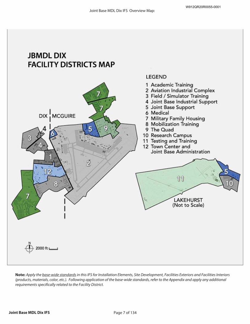
Page 7 of 134Joint Base MDL Dix IFS
Note: Apply the base-wide standards in this IFS for Installation Elements, Site Development, Facilities Exteriors and Facilities Interiors (products, materials, color, etc.). Following application of the base-wide standards, refer to the Appendix and apply any additional requirements specifically related to the Facility District.
Insert Base Map with districts indicated.
Size image to: 800 pixels width x 800 pixels height
Click here to insert image
(jpg or png format)
Overview Map:Joint Base MDL Dix IFSW912QR20R0055-0001
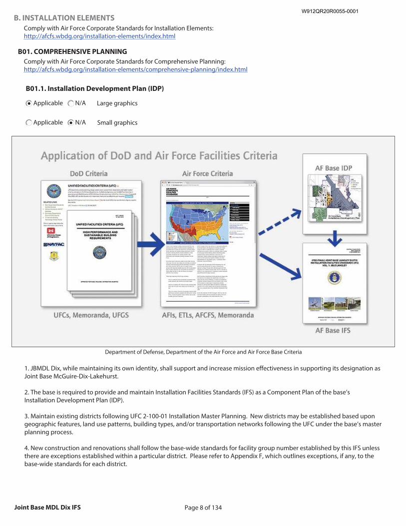
Page 8 of 134Joint Base MDL Dix IFS
B. INSTALLATION ELEMENTS
Comply with Air Force Corporate Standards for Installation Elements: http://afcfs.wbdg.org/installation-elements/index.html
B01. COMPREHENSIVE PLANNING
Comply with Air Force Corporate Standards for Comprehensive Planning: http://afcfs.wbdg.org/installation-elements/comprehensive-planning/index.html
B01.1. Installation Development Plan (IDP)
Applicable N/A Large graphics
Applicable N/A Small graphics
Insert IDP graphic
Size image to: 800 pixels width x 440 pixels in height
Click here to insert image
(jpg or png format)
Department of Defense, Department of the Air Force and Air Force Base Criteria
1. JBMDL Dix, while maintaining its own identity, shall support and increase mission effectiveness in supporting its designation as Joint Base McGuire-Dix-Lakehurst. 2. The base is required to provide and maintain Installation Facilities Standards (IFS) as a Component Plan of the base’s Installation Development Plan (IDP). 3. Maintain existing districts following UFC 2-100-01 Installation Master Planning. New districts may be established based upon geographic features, land use patterns, building types, and/or transportation networks following the UFC under the base’s master planning process. 4. New construction and renovations shall follow the base-wide standards for facility group number established by this IFS unless there are exceptions established within a particular district. Please refer to Appendix F, which outlines exceptions, if any, to the base-wide standards for each district.
W912QR20R0055-0001
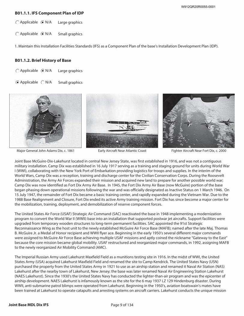
Page 9 of 134Joint Base MDL Dix IFS
B01.1.1. IFS Component Plan of IDP
Applicable N/A Large graphics
Applicable N/A Small graphics
1. Maintain this Installation Facilities Standards (IFS) as a Component Plan of the base’s Installation Development Plan (IDP).
B01.1.2. Brief History of Base
Applicable N/A Large graphics
Applicable N/A Small graphics
Insert History of Base graphic
Size image to: 250 pixels width x 188 pixels height
Click here to insert image
Major General John Adams Dix, c. 1861
Insert History of Base graphic
Size image to: 250 pixels width x 188 pixels height
Click here to insert image
Early Aircraft Near Atlantic Coast
Insert History of Base graphic
Size image to: 250 pixels width x 188 pixels height
Click here to insert image
Fighter Aircraft Near Fort Dix, c. 2000
Joint Base McGuire-Dix-Lakehurst located in central New Jersey State, was first established in 1916, and was not a contiguous military installation. Camp Dix was established in 16 July 1917 serving as a training and staging ground for units during World War I (WWI), collaborating with the New York Port of Embarkation providing logistics for troops and supplies. In the interim of the World Wars, Camp Dix was a reception, training and discharge center for the Civilian Conservation Corps. During the Roosevelt Administration, the Army Air Forces expanded their mission and acquired new land to prepare for another possible world war; Camp Dix was now identified as Fort Dix Army Air Base. In 1945, the Fort Dix Army Air Base (now McGuire) portion of the base began phasing down operational missions following the war and was officially designated as Inactive Status on 1 March 1946. On 15 July 1947, the remainder of Fort Dix became a basic training center, and rapidly expanded during the Vietnam War. Due to the 1988 Base Realignment and Closure, Fort Dix ended its active Army training mission. Fort Dix has since become a major center for the mobilization, training, deployment, and demobilization of reserve component forces. The United States Air Force (USAF) Strategic Air Command (SAC) reactivated the base in 1948 implementing a modernization program to convert the World War II (WWII) base into an installation that supported postwar jet aircrafts. Support facilities were upgraded from temporary wooden structures to long-term permanent facilities. SAC appointed the 91st Strategic Reconnaissance Wing as the host unit to the newly established McGuire Air Force Base (MAFB); named after the late Maj. Thomas B. McGuire Jr. a Medal of Honor recipient and WWII flyer ace. Beginning in the early 1950’s several different major commands were assigned to McGuire Air Force Base achieving multiple USAF missions and aptly coined the nickname “Gateway to the East” because the core mission became global mobility. USAF restructured and reorganized major commands, in 1992, assigning MAFB to the newly reorganized Air Mobility Command (AMC). The Imperial Russian Army used Lakehurst Maxfield Field as a munitions testing site in 1916. In the midst of WWI, the United States Army (USA) acquired Lakehurst Maxfield Field and renamed the site to Camp Kendrick. The United States Navy (USN) purchased the property from the United States Army in 1921 to use as an airship station and renamed it Naval Air Station (NAS) Lakehurst after the nearby town of Lakehurst, New Jersey; the base was later renamed Naval Air Engineering Station Lakehurst (NAES Lakehurst). Since the 1930’s the United States Navy has conducted the lighter-than-air program and was the epicenter of airship development. NAES Lakehurst is infamously known as the site for the 6 may 1937 LZ 129 Hindenburg disaster. During WWII, anti-submarine patrol blimps were operated from Lakehurst. Beginning in the 1950’s, aviation boatswain’s mates have been trained at Lakehurst to operate catapults and arresting systems on aircraft carriers. Lakehurst conducts the unique mission
W912QR20R0055-0001
Page 10 of 134Joint Base MDL Dix IFS
of supporting and developing the Aircraft Launch and Recovery Equipment and Support Equipment for naval aviation. The Electromagnetic Aircraft Launch System (EMALS) and the Advanced Arresting Gear (AAG) system, which will replace the existing steam catapults and the MK-7 arresting gear, are being developed and tested at full-scale shipboard representative test facilities at Lakehurst. Beginning in 2005, the Base Realignment and Closure Commission recommended consolidating McGuire Air Force Base, Fort Dix, and NAES Lakehurst, into a single joint base. Since all three installations performed common functions in support of base facilities and personnel, and shared common boundaries, there was “significant opportunity to reduce duplication of efforts with resulting reduction of overall manpower and facilities requirements capable of generating savings.” Furthermore, the Commission stressed that, “while acknowledging the importance of savings as a BRAC goal, the Commission went beyond a business model analysis of DoD’s recommendations and weighed the strategic environment within which recommendations would be implemented and their effect on DoD’s transformation goals.” Implementation of combining the three adjoining facilities follows in accordance to congressional legislation as prescribed in BRAC Commission Report to the President. At joint bases, a lead Service or “supporting Service Component” is designated to manage the installation support on behalf of the joint base. Other Military Services at the joint base are known as the “supported Service Component(s)”. All installation support functions are transferred to the supporting Service Component along with the supported Service Component’s associated real property, funding, and equipment resources. The Air Force is the lead service, also known as the host Service Component, at Joint Base McGuire-Dix-Lakehurst. On 1 October 2009, Joint Base McGuire-Dix-Lakehurst (JBMDL) became fully operational. The 87th Air Base Wing (ABW) was activated to provide installation management; personnel from all three services were incorporated into leadership roles. JBMDL is the Department of Defense’s first tri-service base that consolidated Air Force, Army and Navy installations during a 2009 BRAC (Base Realignment and Closure) initiative.
B01.1.3. Future Development
Applicable N/A Large graphics
Applicable N/A Small graphics
1. Follow AFI 32-7062 for Air Force Comprehensive Planning, the Comprehensive Planning Process, Comprehensive Planning Requirements, and Geospatial Mapping. 2. Address all future development under the Installation Development Plan (IDP). 3. Integrate into future project development the following encroachment concerns outlined in the Installation Complex Encroachment Management Plan (ICEMAP): a. Airspace / Land Restrictions: JBMDL is located within the busiest airport corridor and any changes to capacity, approaches, and airspace potentially impact operations. b. Airspace / Land Restrictions: Growth within local civilian UAV traffic poses a flight safety risk and carries with it communication requirements between base and neighboring municipalities. c. Airspace / Land Restrictions: Hazardous Cargo Loading Area (HCLA) impacts operational functionality due to the nature of ordnance storage and shutting down Lima Taxiway. d. Airspace / Land Restrictions: Restricted Area R-5001A/B prevents pattern work to the east of McGuire Field. Due to the caliber of the ammunitions used during training activities the weapons danger zone (WDZs) heavy coordination is required between range and aviation activities. e. Safety / Security: The Bird / Wildlife Aircraft Strike Hazard (BASH) risk to habitat areas for state-listed bird species; operations are restricted during peak periods of migratory bird activity. 4. Consider current “Enhanced-Use Leasing” initiatives in new project development: a. SAF/IE selected Starwood Siemens as the Highest Ranked Offeror (HRO). JBMDL identified six (6) non-contiguous sites for energy leasing consideration. b. Technologies cited EULs include solar, biomass, waste-to-energy, combined cycle gas turbine (CCGT) and focus on energy security. 5. Integrate the following “Energy Assurance” initiatives: a. 2017 Phase I Energy Assurance Master plan; Phase II targeted for contract award in FY 17.
W912QR20R0055-0001
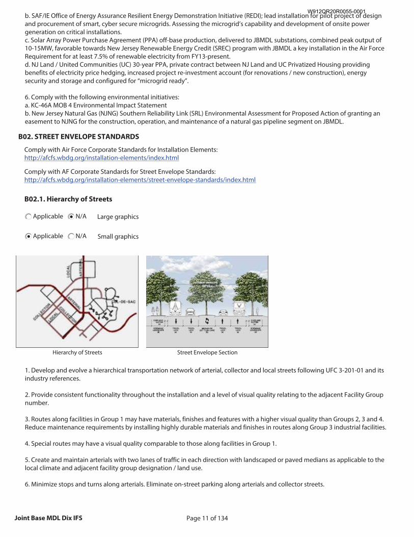
Page 11 of 134Joint Base MDL Dix IFS
b. SAF/IE Office of Energy Assurance Resilient Energy Demonstration Initiative (REDI); lead installation for pilot project of design and procurement of smart, cyber secure microgrids. Assessing the microgrid’s capability and development of onsite power generation on critical installations. c. Solar Array Power Purchase Agreement (PPA) off-base production, delivered to JBMDL substations, combined peak output of 10-15MW, favorable towards New Jersey Renewable Energy Credit (SREC) program with JBMDL a key installation in the Air Force Requirement for at least 7.5% of renewable electricity from FY13-present. d. NJ Land / United Communities (UC) 30-year PPA, private contract between NJ Land and UC Privatized Housing providing benefits of electricity price hedging, increased project re-investment account (for renovations / new construction), energy security and storage and configured for “microgrid ready”. 6. Comply with the following environmental initiatives: a. KC-46A MOB 4 Environmental Impact Statement b. New Jersey Natural Gas (NJNG) Southern Reliability Link (SRL) Environmental Assessment for Proposed Action of granting an easement to NJNG for the construction, operation, and maintenance of a natural gas pipeline segment on JBMDL.
B02. STREET ENVELOPE STANDARDS
Comply with Air Force Corporate Standards for Installation Elements: http://afcfs.wbdg.org/installation-elements/index.html
Comply with AF Corporate Standards for Street Envelope Standards: http://afcfs.wbdg.org/installation-elements/street-envelope-standards/index.html
B02.1. Hierarchy of Streets
Applicable N/A Large graphics
Applicable N/A Small graphics
Insert Hierarchy of Streets graphic
Size image to: 250 pixels width x 188 pixels height
Click here to insert image
Hierarchy of Streets
Insert Hierarchy of Streets graphic
Size image to: 250 pixels width x 188 pixels height
Click here to insert image
Street Envelope Section
1. Develop and evolve a hierarchical transportation network of arterial, collector and local streets following UFC 3-201-01 and its industry references. 2. Provide consistent functionality throughout the installation and a level of visual quality relating to the adjacent Facility Group number. 3. Routes along facilities in Group 1 may have materials, finishes and features with a higher visual quality than Groups 2, 3 and 4. Reduce maintenance requirements by installing highly durable materials and finishes in routes along Group 3 industrial facilities. 4. Special routes may have a visual quality comparable to those along facilities in Group 1. 5. Create and maintain arterials with two lanes of traffic in each direction with landscaped or paved medians as applicable to the local climate and adjacent facility group designation / land use. 6. Minimize stops and turns along arterials. Eliminate on-street parking along arterials and collector streets.
W912QR20R0055-0001
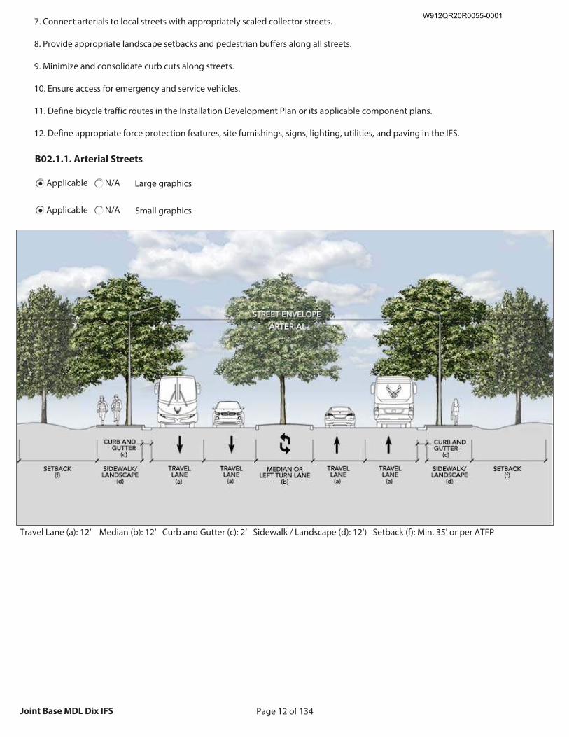
Page 12 of 134Joint Base MDL Dix IFS
7. Connect arterials to local streets with appropriately scaled collector streets. 8. Provide appropriate landscape setbacks and pedestrian buffers along all streets. 9. Minimize and consolidate curb cuts along streets. 10. Ensure access for emergency and service vehicles. 11. Define bicycle traffic routes in the Installation Development Plan or its applicable component plans. 12. Define appropriate force protection features, site furnishings, signs, lighting, utilities, and paving in the IFS.
B02.1.1. Arterial Streets
Applicable N/A Large graphics
Applicable N/A Small graphics
Insert Arterial Streets graphic
Size image to: 800 pixels width x 440 pixels in height
Click here to insert image
(jpg or png format)
Travel Lane (a): 12’ Median (b): 12’ Curb and Gutter (c): 2’ Sidewalk / Landscape (d): 12’) Setback (f): Min. 35' or per ATFP
W912QR20R0055-0001
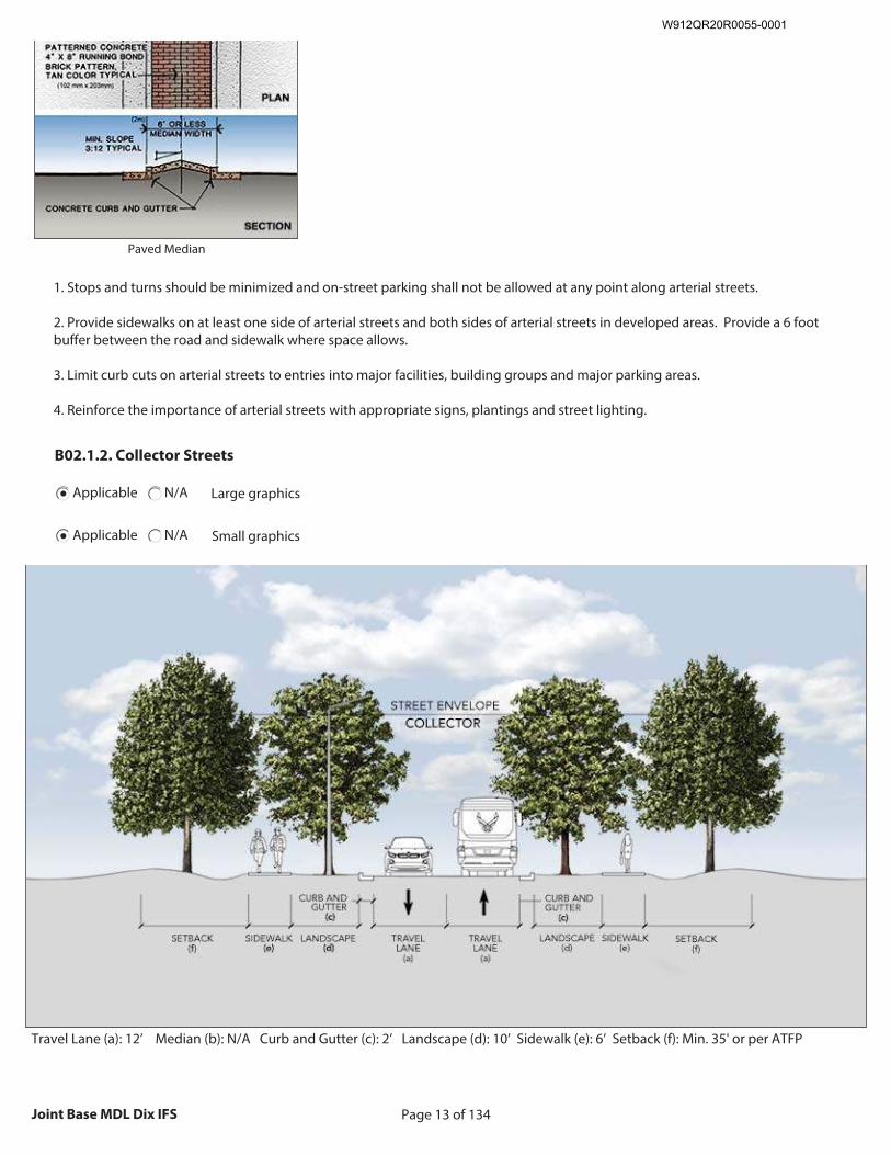
Page 13 of 134Joint Base MDL Dix IFS
Insert Arterial Streets graphic
Size image to: 250 pixels width x 188 pixels height
Click here to insert image
Paved Median
1. Stops and turns should be minimized and on-street parking shall not be allowed at any point along arterial streets. 2. Provide sidewalks on at least one side of arterial streets and both sides of arterial streets in developed areas. Provide a 6 foot buffer between the road and sidewalk where space allows. 3. Limit curb cuts on arterial streets to entries into major facilities, building groups and major parking areas. 4. Reinforce the importance of arterial streets with appropriate signs, plantings and street lighting.
B02.1.2. Collector Streets
Applicable N/A Large graphics
Applicable N/A Small graphics
Insert Collector Streets graphic
Size image to: 800 pixels width x 440 pixels in height
Click here to insert image
(jpg or png format)
Travel Lane (a): 12’ Median (b): N/A Curb and Gutter (c): 2’ Landscape (d): 10’ Sidewalk (e): 6’ Setback (f): Min. 35' or per ATFP
W912QR20R0055-0001
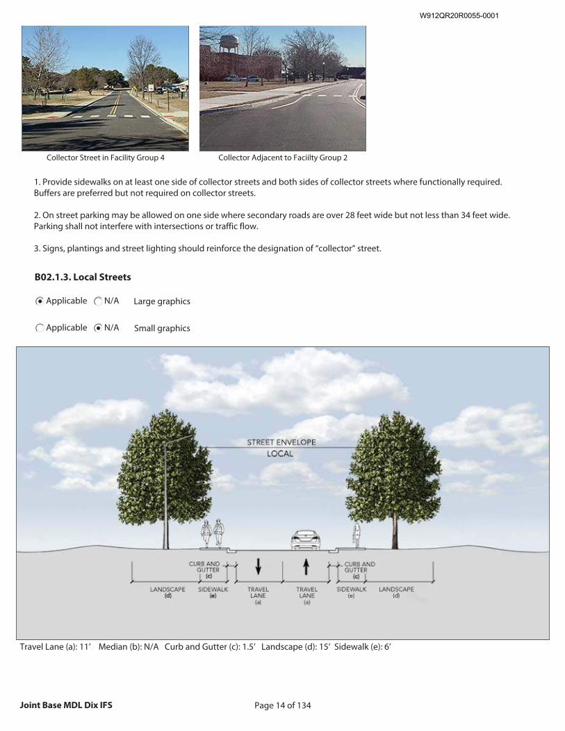
Page 14 of 134Joint Base MDL Dix IFS
Insert Collector Streets graphic
Size image to: 250 pixels width x 188 pixels height
Click here to insert image
Collector Street in Facility Group 4
Insert Collector Streets graphic
Size image to: 250 pixels width x 188 pixels height
Click here to insert image
Collector Adjacent to Faciilty Group 2
1. Provide sidewalks on at least one side of collector streets and both sides of collector streets where functionally required. Buffers are preferred but not required on collector streets. 2. On street parking may be allowed on one side where secondary roads are over 28 feet wide but not less than 34 feet wide. Parking shall not interfere with intersections or traffic flow. 3. Signs, plantings and street lighting should reinforce the designation of “collector” street.
B02.1.3. Local Streets
Applicable N/A Large graphics
Applicable N/A Small graphics
Insert Local Streets graphic
Size image to: 800 pixels width x 440 pixels in height
Click here to insert image
(jpg or png format)
Travel Lane (a): 11’ Median (b): N/A Curb and Gutter (c): 1.5’ Landscape (d): 15’ Sidewalk (e): 6’
W912QR20R0055-0001
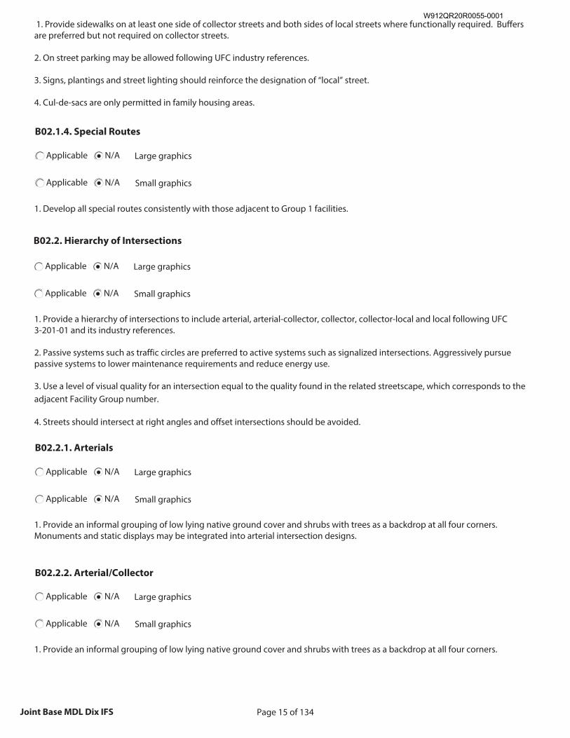
Page 15 of 134Joint Base MDL Dix IFS
1. Provide sidewalks on at least one side of collector streets and both sides of local streets where functionally required. Buffers are preferred but not required on collector streets. 2. On street parking may be allowed following UFC industry references. 3. Signs, plantings and street lighting should reinforce the designation of “local” street. 4. Cul-de-sacs are only permitted in family housing areas.
B02.1.4. Special Routes
Applicable N/A Large graphics
Applicable N/A Small graphics
1. Develop all special routes consistently with those adjacent to Group 1 facilities.
B02.2. Hierarchy of Intersections
Applicable N/A Large graphics
Applicable N/A Small graphics
1. Provide a hierarchy of intersections to include arterial, arterial-collector, collector, collector-local and local following UFC 3-201-01 and its industry references. 2. Passive systems such as traffic circles are preferred to active systems such as signalized intersections. Aggressively pursue passive systems to lower maintenance requirements and reduce energy use. 3. Use a level of visual quality for an intersection equal to the quality found in the related streetscape, which corresponds to the adjacent Facility Group number. 4. Streets should intersect at right angles and offset intersections should be avoided.
B02.2.1. Arterials
Applicable N/A Large graphics
Applicable N/A Small graphics
1. Provide an informal grouping of low lying native ground cover and shrubs with trees as a backdrop at all four corners. Monuments and static displays may be integrated into arterial intersection designs.
B02.2.2. Arterial/Collector
Applicable N/A Large graphics
Applicable N/A Small graphics
1. Provide an informal grouping of low lying native ground cover and shrubs with trees as a backdrop at all four corners.
W912QR20R0055-0001
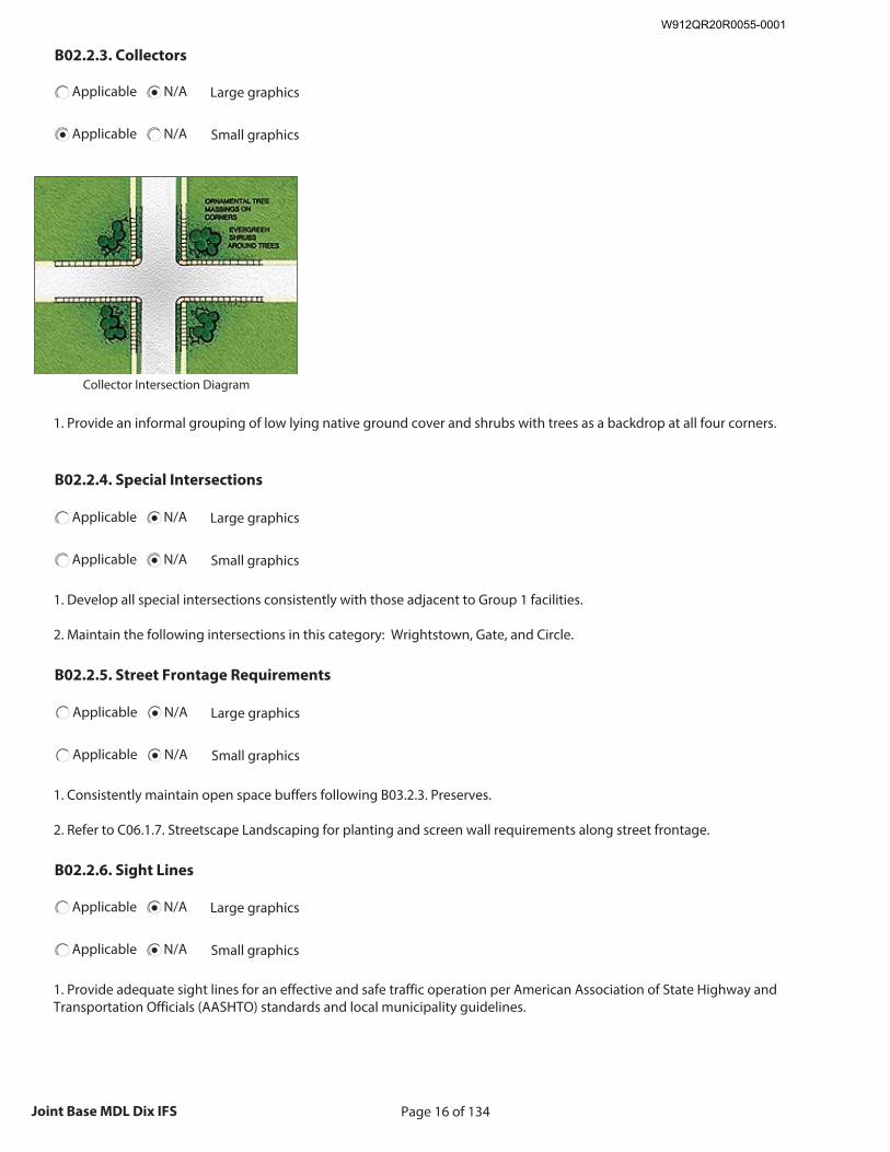
Page 16 of 134Joint Base MDL Dix IFS
B02.2.3. Collectors
Applicable N/A Large graphics
Applicable N/A Small graphics
Insert Collectors graphic
Size image to: 250 pixels width x 188 pixels height
Click here to insert image
Collector Intersection Diagram
1. Provide an informal grouping of low lying native ground cover and shrubs with trees as a backdrop at all four corners.
B02.2.4. Special Intersections
Applicable N/A Large graphics
Applicable N/A Small graphics
1. Develop all special intersections consistently with those adjacent to Group 1 facilities. 2. Maintain the following intersections in this category: Wrightstown, Gate, and Circle.
B02.2.5. Street Frontage Requirements
Applicable N/A Large graphics
Applicable N/A Small graphics
1. Consistently maintain open space buffers following B03.2.3. Preserves. 2. Refer to C06.1.7. Streetscape Landscaping for planting and screen wall requirements along street frontage.
B02.2.6. Sight Lines
Applicable N/A Large graphics
Applicable N/A Small graphics
1. Provide adequate sight lines for an effective and safe traffic operation per American Association of State Highway and Transportation Officials (AASHTO) standards and local municipality guidelines.
W912QR20R0055-0001
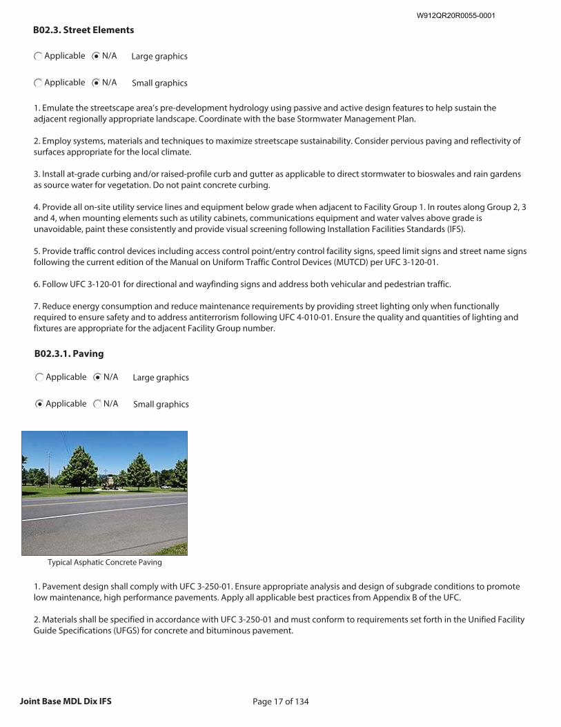
Page 17 of 134Joint Base MDL Dix IFS
B02.3. Street Elements
Applicable N/A Large graphics
Applicable N/A Small graphics
1. Emulate the streetscape area’s pre-development hydrology using passive and active design features to help sustain the adjacent regionally appropriate landscape. Coordinate with the base Stormwater Management Plan. 2. Employ systems, materials and techniques to maximize streetscape sustainability. Consider pervious paving and reflectivity of surfaces appropriate for the local climate. 3. Install at-grade curbing and/or raised-profile curb and gutter as applicable to direct stormwater to bioswales and rain gardens as source water for vegetation. Do not paint concrete curbing. 4. Provide all on-site utility service lines and equipment below grade when adjacent to Facility Group 1. In routes along Group 2, 3 and 4, when mounting elements such as utility cabinets, communications equipment and water valves above grade is unavoidable, paint these consistently and provide visual screening following Installation Facilities Standards (IFS). 5. Provide traffic control devices including access control point/entry control facility signs, speed limit signs and street name signs following the current edition of the Manual on Uniform Traffic Control Devices (MUTCD) per UFC 3-120-01. 6. Follow UFC 3-120-01 for directional and wayfinding signs and address both vehicular and pedestrian traffic. 7. Reduce energy consumption and reduce maintenance requirements by providing street lighting only when functionally required to ensure safety and to address antiterrorism following UFC 4-010-01. Ensure the quality and quantities of lighting and fixtures are appropriate for the adjacent Facility Group number.
B02.3.1. Paving
Applicable N/A Large graphics
Applicable N/A Small graphics
Insert Paving graphic
Size image to: 250 pixels width x 188 pixels height
Click here to insert image
Typical Asphatic Concrete Paving
1. Pavement design shall comply with UFC 3-250-01. Ensure appropriate analysis and design of subgrade conditions to promote low maintenance, high performance pavements. Apply all applicable best practices from Appendix B of the UFC. 2. Materials shall be specified in accordance with UFC 3-250-01 and must conform to requirements set forth in the Unified Facility Guide Specifications (UFGS) for concrete and bituminous pavement.
W912QR20R0055-0001
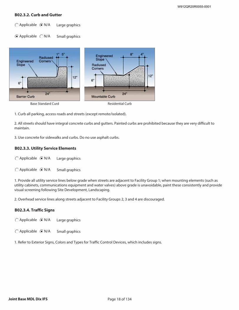
Page 18 of 134Joint Base MDL Dix IFS
B02.3.2. Curb and Gutter
Applicable N/A Large graphics
Applicable N/A Small graphics
Insert Curb and Gutter graphic
Size image to: 250 pixels width x 188 pixels height
Click here to insert image
Base Standard Curd
Insert Curb and Gutter graphic
Size image to: 250 pixels width x 188 pixels height
Click here to insert image
Residential Curb
1. Curb all parking, access roads and streets (except remote/isolated). 2. All streets should have integral concrete curbs and gutters. Painted curbs are prohibited because they are very difficult to maintain. 3. Use concrete for sidewalks and curbs. Do no use asphalt curbs.
B02.3.3. Utility Service Elements
Applicable N/A Large graphics
Applicable N/A Small graphics
1. Provide all utility service lines below grade when streets are adjacent to Facility Group 1; when mounting elements (such as utility cabinets, communications equipment and water valves) above grade is unavoidable, paint these consistently and provide visual screening following Site Development, Landscaping. 2. Overhead service lines along streets adjacent to Facility Groups 2, 3 and 4 are discouraged.
B02.3.4. Traffic Signs
Applicable N/A Large graphics
Applicable N/A Small graphics
1. Refer to Exterior Signs, Colors and Types for Traffic Control Devices, which includes signs.
W912QR20R0055-0001
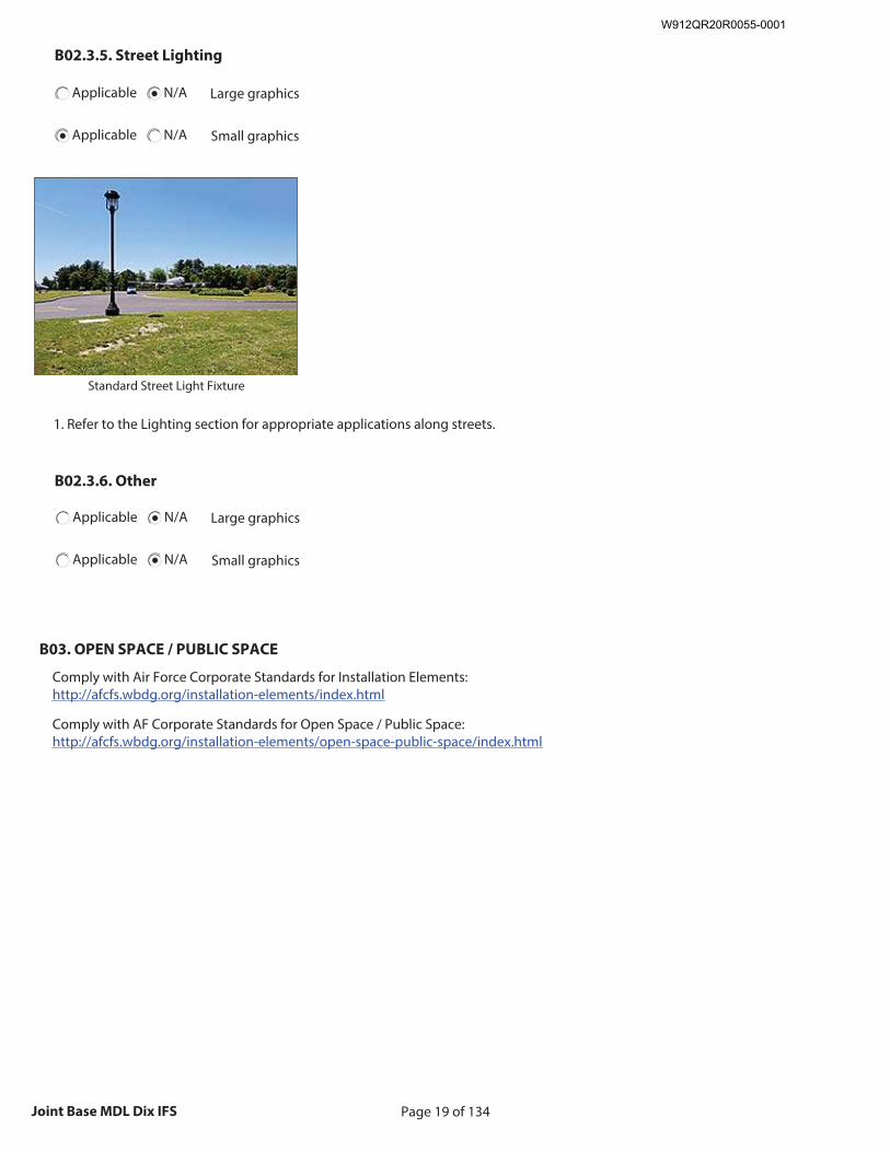
Page 19 of 134Joint Base MDL Dix IFS
B02.3.5. Street Lighting
Applicable N/A Large graphics
Applicable N/A Small graphics
Insert Street Lighting graphic
Size image to: 250 pixels width x 188 pixels height
Click here to insert image
Standard Street Light Fixture
1. Refer to the Lighting section for appropriate applications along streets.
B02.3.6. Other
Applicable N/A Large graphics
Applicable N/A Small graphics
B03. OPEN SPACE / PUBLIC SPACE
Comply with Air Force Corporate Standards for Installation Elements: http://afcfs.wbdg.org/installation-elements/index.html
Comply with AF Corporate Standards for Open Space / Public Space: http://afcfs.wbdg.org/installation-elements/open-space-public-space/index.html
W912QR20R0055-0001
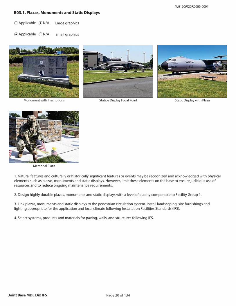
Page 20 of 134Joint Base MDL Dix IFS
B03.1. Plazas, Monuments and Static Displays
Applicable N/A Large graphics
Applicable N/A Small graphics
Insert Plazas, Monuments and Static Displays graphic
Size image to:
250 pixels width x 188 pixels height
Click here to insert image
Monument with Inscriptions
Insert Plazas, Monuments and Static Displays graphic
Size image to:
250 pixels width x 188 pixels height
Click here to insert image
Statice Display Focal Point
Insert Plazas, Monuments and Static Displays graphic
Size image to:
250 pixels width x 188 pixels height
Click here to insert image
Static Display with Plaza
Insert Plazas, Monuments and Static Displays graphic
Size image to:
250 pixels width x 188 pixels height
Click here to insert image
Memorial Plaza
1. Natural features and culturally or historically significant features or events may be recognized and acknowledged with physical elements such as plazas, monuments and static displays. However, limit these elements on the base to ensure judicious use of resources and to reduce ongoing maintenance requirements. 2. Design highly durable plazas, monuments and static displays with a level of quality comparable to Facility Group 1. 3. Link plazas, monuments and static displays to the pedestrian circulation system. Install landscaping, site furnishings and lighting appropriate for the application and local climate following Installation Facilities Standards (IFS). 4. Select systems, products and materials for paving, walls, and structures following IFS.
W912QR20R0055-0001
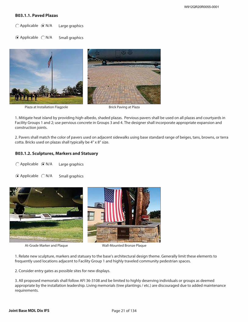
Page 21 of 134Joint Base MDL Dix IFS
B03.1.1. Paved Plazas
Applicable N/A Large graphics
Applicable N/A Small graphics
Insert Paved Plazas graphic
Size image to: 250 pixels width x 188 pixels height
Click here to insert image
Plaza at Installation Flagpole
Insert Paved Plazas graphic
Size image to: 250 pixels width x 188 pixels height
Click here to insert image
Brick Paving at Plaza
1. Mitigate heat island by providing high-albedo, shaded plazas. Pervious pavers shall be used on all plazas and courtyards in Facility Groups 1 and 2; use pervious concrete in Groups 3 and 4. The designer shall incorporate appropriate expansion and construction joints. 2. Pavers shall match the color of pavers used on adjacent sidewalks using base standard range of beiges, tans, browns, or terra cotta. Bricks used on plazas shall typically be 4” x 8” size.
B03.1.2. Sculptures, Markers and Statuary
Applicable N/A Large graphics
Applicable N/A Small graphics
Insert Sculptures, Markers and Statuary graphic
Size image to:
250 pixels width x 188 pixels height
Click here to insert image
At-Grade Marker and Plaque
Insert Sculptures, Markers and Statuary graphic
Size image to:
250 pixels width x 188 pixels height
Click here to insert image
Wall-Mounted Bronze Plaque
1. Relate new sculpture, markers and statuary to the base’s architectural design theme. Generally limit these elements to frequently used locations adjacent to Facility Group 1 and highly traveled community pedestrian spaces. 2. Consider entry gates as possible sites for new displays. 3. All proposed memorials shall follow AFI 36-3108 and be limited to highly deserving individuals or groups as deemed appropriate by the installation leadership. Living memorials (tree plantings / etc.) are discouraged due to added maintenance requirements.
W912QR20R0055-0001
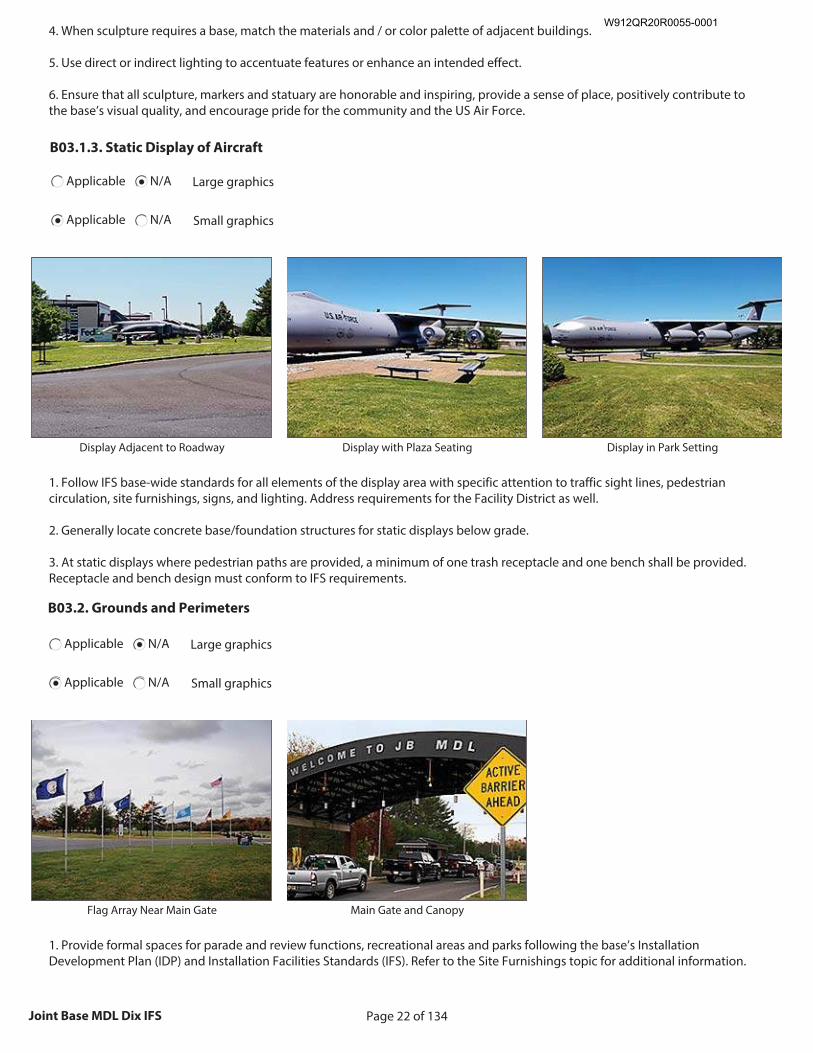
Page 22 of 134Joint Base MDL Dix IFS
4. When sculpture requires a base, match the materials and / or color palette of adjacent buildings. 5. Use direct or indirect lighting to accentuate features or enhance an intended effect. 6. Ensure that all sculpture, markers and statuary are honorable and inspiring, provide a sense of place, positively contribute to the base’s visual quality, and encourage pride for the community and the US Air Force.
B03.1.3. Static Display of Aircraft
Applicable N/A Large graphics
Applicable N/A Small graphics
Insert Static Display of Aircraft graphic
Size image to:
250 pixels width x 188 pixels height
Click here to insert image
Display Adjacent to Roadway
Insert Static Display of Aircraft graphic
Size image to:
250 pixels width x 188 pixels height
Click here to insert image
Display with Plaza Seating
Insert Static Display of Aircraft graphic
Size image to:
250 pixels width x 188 pixels height
Click here to insert image
Display in Park Setting
1. Follow IFS base-wide standards for all elements of the display area with specific attention to traffic sight lines, pedestrian circulation, site furnishings, signs, and lighting. Address requirements for the Facility District as well. 2. Generally locate concrete base/foundation structures for static displays below grade. 3. At static displays where pedestrian paths are provided, a minimum of one trash receptacle and one bench shall be provided. Receptacle and bench design must conform to IFS requirements.
B03.2. Grounds and Perimeters
Applicable N/A Large graphics
Applicable N/A Small graphics
Insert Grounds and Perimeters graphic
Size image to:
250 pixels width x 188 pixels height
Click here to insert image
Flag Array Near Main Gate
Insert Grounds and Perimeters graphic
Size image to:
250 pixels width x 188 pixels height
Click here to insert image
Main Gate and Canopy
1. Provide formal spaces for parade and review functions, recreational areas and parks following the base’s Installation Development Plan (IDP) and Installation Facilities Standards (IFS). Refer to the Site Furnishings topic for additional information.
W912QR20R0055-0001
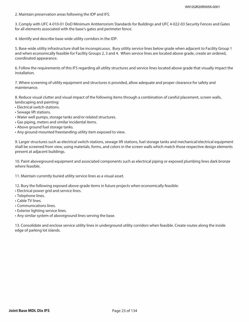
Page 23 of 134Joint Base MDL Dix IFS
2. Maintain preservation areas following the IDP and IFS. 3. Comply with UFC 4-010-01 DoD Minimum Antiterrorism Standards for Buildings and UFC 4-022-03 Security Fences and Gates for all elements associated with the base’s gates and perimeter fence. 4. Identify and describe base-wide utility corridors in the IDP. 5. Base-wide utility infrastructure shall be inconspicuous. Bury utility service lines below grade when adjacent to Facility Group 1 and when economically feasible for Facility Groups 2, 3 and 4. When service lines are located above grade, create an ordered, coordinated appearance. 6. Follow the requirements of this IFS regarding all utility structures and service lines located above grade that visually impact the installation. 7. Where screening of utility equipment and structures is provided, allow adequate and proper clearance for safety and maintenance. 8. Reduce visual clutter and visual impact of the following items through a combination of careful placement, screen walls, landscaping and painting: • Electrical switch-stations. • Sewage lift stations. • Water well pumps, storage tanks and/or related structures. • Gas piping, meters and similar incidental items. • Above ground fuel storage tanks. • Any ground-mounted freestanding utility item exposed to view. 9. Larger structures such as electrical switch-stations, sewage lift stations, fuel storage tanks and mechanical/electrical equipment shall be screened from view, using materials, forms, and colors in the screen walls which match those respective design elements present at adjacent buildings. 10. Paint aboveground equipment and associated components such as electrical piping or exposed plumbing lines dark bronze where feasible. 11. Maintain currently buried utility service lines as a visual asset. 12. Bury the following exposed above-grade items in future projects when economically feasible: • Electrical power grid and service lines. • Telephone lines. • Cable TV lines. • Communications lines. • Exterior lighting service lines. • Any similar system of aboveground lines serving the base. 13. Consolidate and enclose service utility lines in underground utility corridors when feasible. Create routes along the inside edge of parking lot islands.
W912QR20R0055-0001
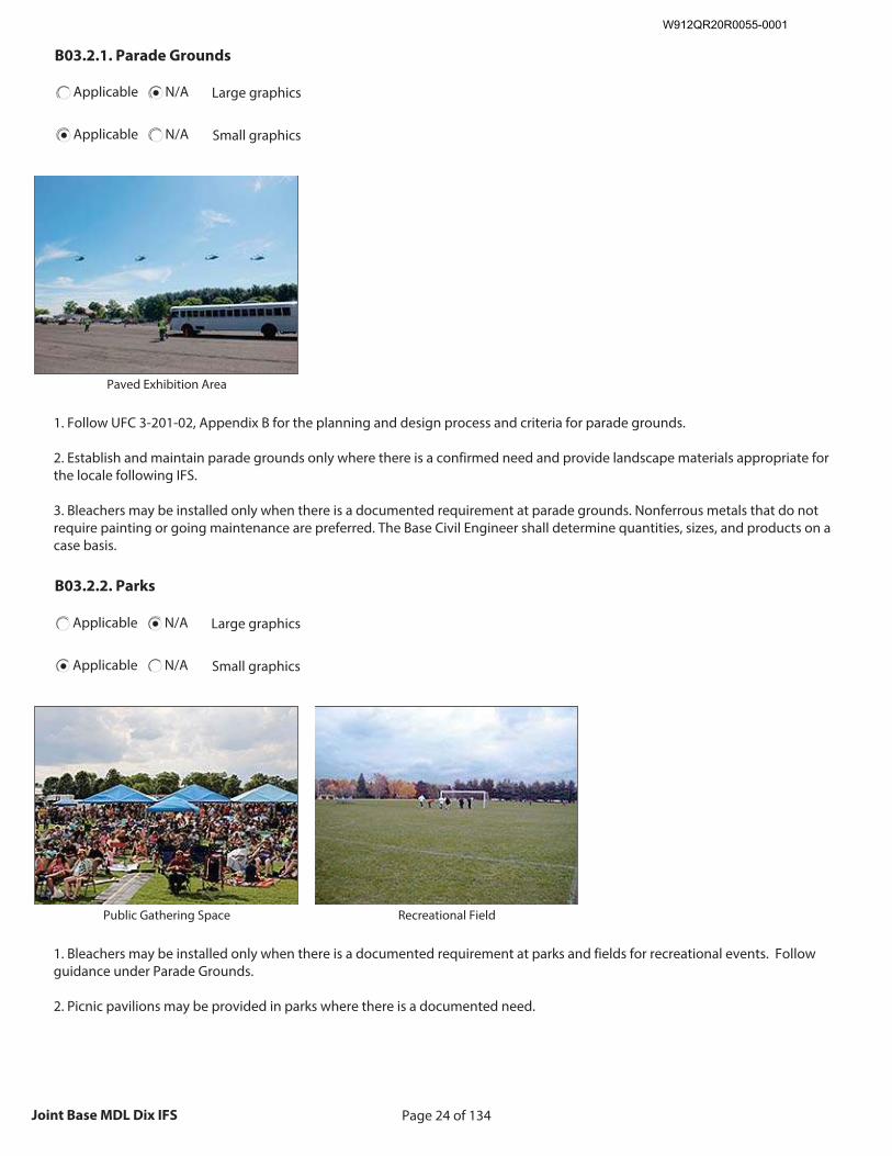
Page 24 of 134Joint Base MDL Dix IFS
B03.2.1. Parade Grounds
Applicable N/A Large graphics
Applicable N/A Small graphics
Insert Parade Grounds graphic
Size image to: 250 pixels width x 188 pixels height
Click here to insert image
Paved Exhibition Area
1. Follow UFC 3-201-02, Appendix B for the planning and design process and criteria for parade grounds. 2. Establish and maintain parade grounds only where there is a confirmed need and provide landscape materials appropriate for the locale following IFS. 3. Bleachers may be installed only when there is a documented requirement at parade grounds. Nonferrous metals that do not require painting or going maintenance are preferred. The Base Civil Engineer shall determine quantities, sizes, and products on a case basis.
B03.2.2. Parks
Applicable N/A Large graphics
Applicable N/A Small graphics
Insert Parks graphic
Size image to: 250 pixels width x 188 pixels height
Click here to insert image
Public Gathering Space
Insert Parks graphic
Size image to: 250 pixels width x 188 pixels height
Click here to insert image
Recreational Field
1. Bleachers may be installed only when there is a documented requirement at parks and fields for recreational events. Follow guidance under Parade Grounds. 2. Picnic pavilions may be provided in parks where there is a documented need.
W912QR20R0055-0001
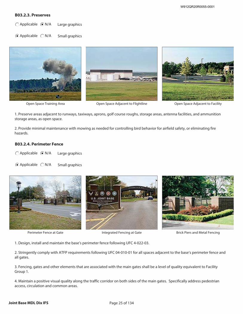
Page 25 of 134Joint Base MDL Dix IFS
B03.2.3. Preserves
Applicable N/A Large graphics
Applicable N/A Small graphics
Insert Preserves graphic
Size image to: 250 pixels width x 188 pixels height
Click here to insert image
Open Space Training Area
Insert Preserves graphic
Size image to: 250 pixels width x 188 pixels height
Click here to insert image
Open Space Adjacent to Flightline
Insert Preserves graphic
Size image to: 250 pixels width x 188 pixels height
Click here to insert image
Open Space Adjacent to Facility
1. Preserve areas adjacent to runways, taxiways, aprons, golf course roughs, storage areas, antenna facilities, and ammunition storage areas, as open space. 2. Provide minimal maintenance with mowing as needed for controlling bird behavior for airfield safety, or eliminating fire hazards.
B03.2.4. Perimeter Fence
Applicable N/A Large graphics
Applicable N/A Small graphics
Insert Perimeter Fence graphic
Size image to: 250 pixels width x 188 pixels height
Click here to insert image
Perimeter Fence at Gate
Insert Perimeter Fence graphic
Size image to: 250 pixels width x 188 pixels height
Click here to insert image
Integrated Fencing at Gate
Insert Perimeter Fence graphic
Size image to: 250 pixels width x 188 pixels height
Click here to insert image
Brick Piers and Metal Fencing
1. Design, install and maintain the base’s perimeter fence following UFC 4-022-03. 2. Stringently comply with ATFP requirements following UFC 04-010-01 for all spaces adjacent to the base’s perimeter fence and all gates. 3. Fencing, gates and other elements that are associated with the main gates shall be a level of quality equivalent to Facility Group 1. 4. Maintain a positive visual quality along the traffic corridor on both sides of the main gates. Specifically address pedestrian access, circulation and common areas.
W912QR20R0055-0001
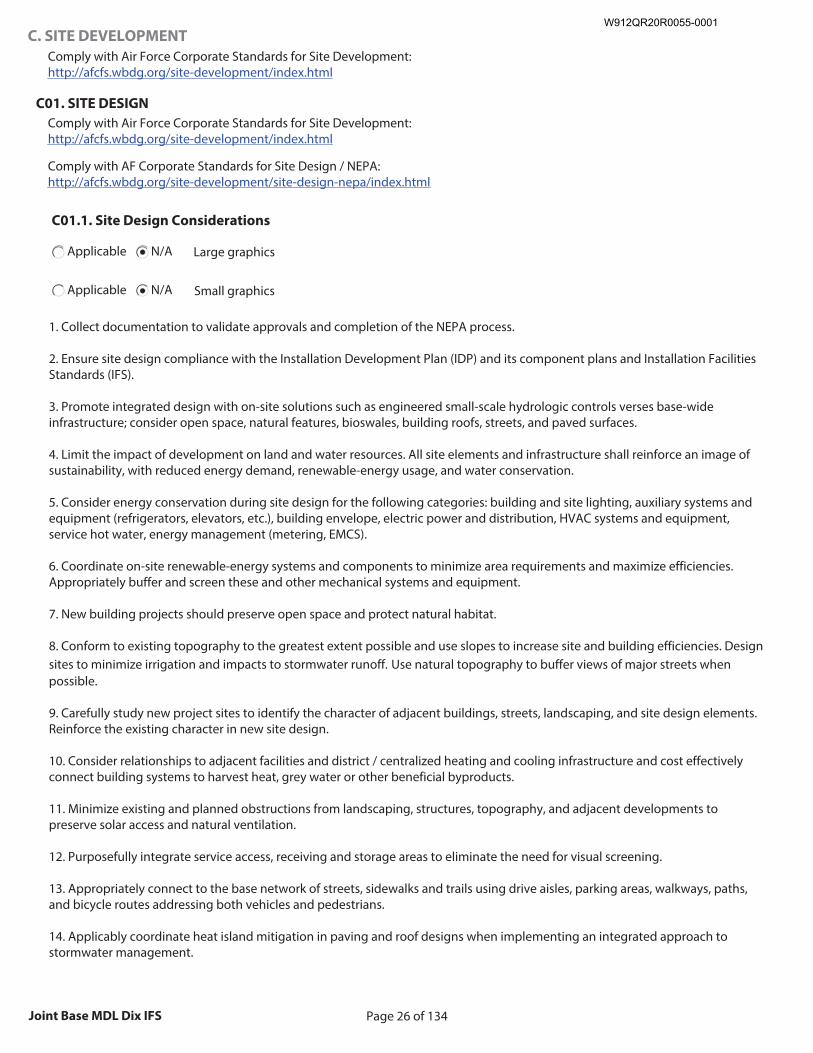
Page 26 of 134Joint Base MDL Dix IFS
C. SITE DEVELOPMENT
Comply with Air Force Corporate Standards for Site Development: http://afcfs.wbdg.org/site-development/index.html
C01. SITE DESIGN
Comply with Air Force Corporate Standards for Site Development: http://afcfs.wbdg.org/site-development/index.html
Comply with AF Corporate Standards for Site Design / NEPA: http://afcfs.wbdg.org/site-development/site-design-nepa/index.html
C01.1. Site Design Considerations
Applicable N/A Large graphics
Applicable N/A Small graphics
1. Collect documentation to validate approvals and completion of the NEPA process. 2. Ensure site design compliance with the Installation Development Plan (IDP) and its component plans and Installation Facilities Standards (IFS). 3. Promote integrated design with on-site solutions such as engineered small-scale hydrologic controls verses base-wide infrastructure; consider open space, natural features, bioswales, building roofs, streets, and paved surfaces. 4. Limit the impact of development on land and water resources. All site elements and infrastructure shall reinforce an image of sustainability, with reduced energy demand, renewable-energy usage, and water conservation. 5. Consider energy conservation during site design for the following categories: building and site lighting, auxiliary systems and equipment (refrigerators, elevators, etc.), building envelope, electric power and distribution, HVAC systems and equipment, service hot water, energy management (metering, EMCS). 6. Coordinate on-site renewable-energy systems and components to minimize area requirements and maximize efficiencies. Appropriately buffer and screen these and other mechanical systems and equipment. 7. New building projects should preserve open space and protect natural habitat. 8. Conform to existing topography to the greatest extent possible and use slopes to increase site and building efficiencies. Design sites to minimize irrigation and impacts to stormwater runoff. Use natural topography to buffer views of major streets when possible. 9. Carefully study new project sites to identify the character of adjacent buildings, streets, landscaping, and site design elements. Reinforce the existing character in new site design. 10. Consider relationships to adjacent facilities and district / centralized heating and cooling infrastructure and cost effectively connect building systems to harvest heat, grey water or other beneficial byproducts. 11. Minimize existing and planned obstructions from landscaping, structures, topography, and adjacent developments to preserve solar access and natural ventilation. 12. Purposefully integrate service access, receiving and storage areas to eliminate the need for visual screening. 13. Appropriately connect to the base network of streets, sidewalks and trails using drive aisles, parking areas, walkways, paths, and bicycle routes addressing both vehicles and pedestrians. 14. Applicably coordinate heat island mitigation in paving and roof designs when implementing an integrated approach to stormwater management.
W912QR20R0055-0001
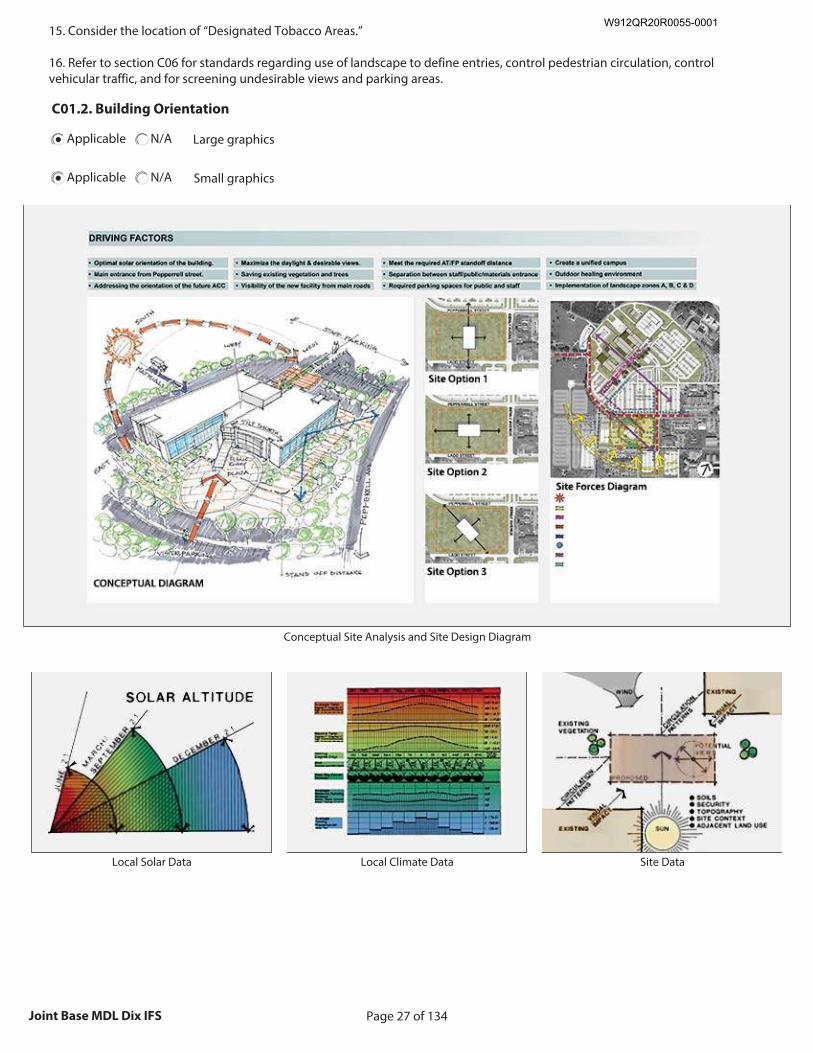
Page 27 of 134Joint Base MDL Dix IFS
15. Consider the location of “Designated Tobacco Areas.” 16. Refer to section C06 for standards regarding use of landscape to define entries, control pedestrian circulation, control vehicular traffic, and for screening undesirable views and parking areas.
C01.2. Building Orientation
Applicable N/A Large graphics
Applicable N/A Small graphics
Insert Building Orientation graphic
Size image to: 800 pixels width x 440 pixels in height
Click here to insert image
(jpg or png format)
Conceptual Site Analysis and Site Design Diagram
Insert Building Orientation graphic
Size image to: 250 pixels width x 188 pixels height
Click here to insert image
Local Solar Data
Insert Building Orientation graphic
Size image to: 250 pixels width x 188 pixels height
Click here to insert image
Local Climate Data
Insert Building Orientation graphic
Size image to: 250 pixels width x 188 pixels height
Click here to insert image
Site Data
W912QR20R0055-0001
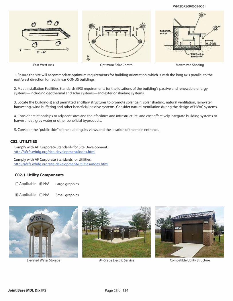
Page 28 of 134Joint Base MDL Dix IFS
Insert Building Orientation graphic
Size image to: 250 pixels width x 188 pixels height
Click here to insert image
East-West Axis
Insert Building Orientation graphic
Size image to: 250 pixels width x 188 pixels height
Click here to insert image
Optimum Solar Control
Insert Building Orientation graphic
Size image to: 250 pixels width x 188 pixels height
Click here to insert image
Maximized Shading
1. Ensure the site will accommodate optimum requirements for building orientation, which is with the long axis parallel to the east/west direction for rectilinear CONUS buildings. 2. Meet Installation Facilities Standards (IFS) requirements for the locations of the building’s passive and renewable-energy systems—including geothermal and solar systems—and exterior shading systems. 3. Locate the building(s) and permitted ancillary structures to promote solar gain, solar shading, natural ventilation, rainwater harvesting, wind buffering and other beneficial passive systems. Consider natural ventilation during the design of HVAC systems. 4. Consider relationships to adjacent sites and their facilities and infrastructure, and cost effectively integrate building systems to harvest heat, grey water or other beneficial byproducts. 5. Consider the “public side” of the building, its views and the location of the main entrance.
C02. UTILITIES
Comply with AF Corporate Standards for Site Development: http://afcfs.wbdg.org/site-development/index.html
Comply with AF Corporate Standards for Utilities: http://afcfs.wbdg.org/site-development/utilities/index.html
C02.1. Utility Components
Applicable N/A Large graphics
Applicable N/A Small graphics
Insert Utility Components graphic
Size image to: 250 pixels width x 188 pixels height
Click here to insert image
Elevated Water Storage
Insert Utility Components graphic
Size image to: 250 pixels width x 188 pixels height
Click here to insert image
At-Grade Electric Service
Insert Utility Components graphic
Size image to: 250 pixels width x 188 pixels height
Click here to insert image
Compatible Utility Structure
W912QR20R0055-0001
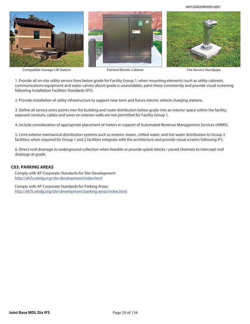
Page 29 of 134Joint Base MDL Dix IFS
Insert Utility Components graphic
Size image to: 250 pixels width x 188 pixels height
Click here to insert image
Compatible Sewage Lift Station
Insert Utility Components graphic
Size image to: 250 pixels width x 188 pixels height
Click here to insert image
Painted Electric Cabinet
Insert Utility Components graphic
Size image to: 250 pixels width x 188 pixels height
Click here to insert image
Fire Service Standpipe
1. Provide all on-site utility service lines below grade for Facility Group 1; when mounting elements (such as utility cabinets, communications equipment and water valves) above grade is unavoidable, paint these consistently and provide visual screening following Installation Facilities Standards (IFS). 2. Provide installation of utility infrastructure to support near term and future electric vehicle charging stations. 3. Define all service entry points into the building and route distribution below grade into an interior space within the facility; exposed conduits, cables and wires on exterior walls are not permitted for Facility Group 1. 4. Include consideration of appropriate placement of meters in support of Automated Revenue Management Services (ARMS). 5. Limit exterior mechanical distribution systems such as exterior steam, chilled water, and hot water distribution to Group 3 facilities; when required for Group 1 and 2 facilities integrate with the architecture and provide visual screens following IFS. 6. Direct roof drainage to underground collection when feasible or provide splash blocks / paved channels to intercept roof drainage at grade.
C03. PARKING AREAS
Comply with AF Corporate Standards for Site Development: http://afcfs.wbdg.org/site-development/index.html
Comply with AF Corporate Standards for Parking Areas: http://afcfs.wbdg.org/site-development/parking-areas/index.html
W912QR20R0055-0001
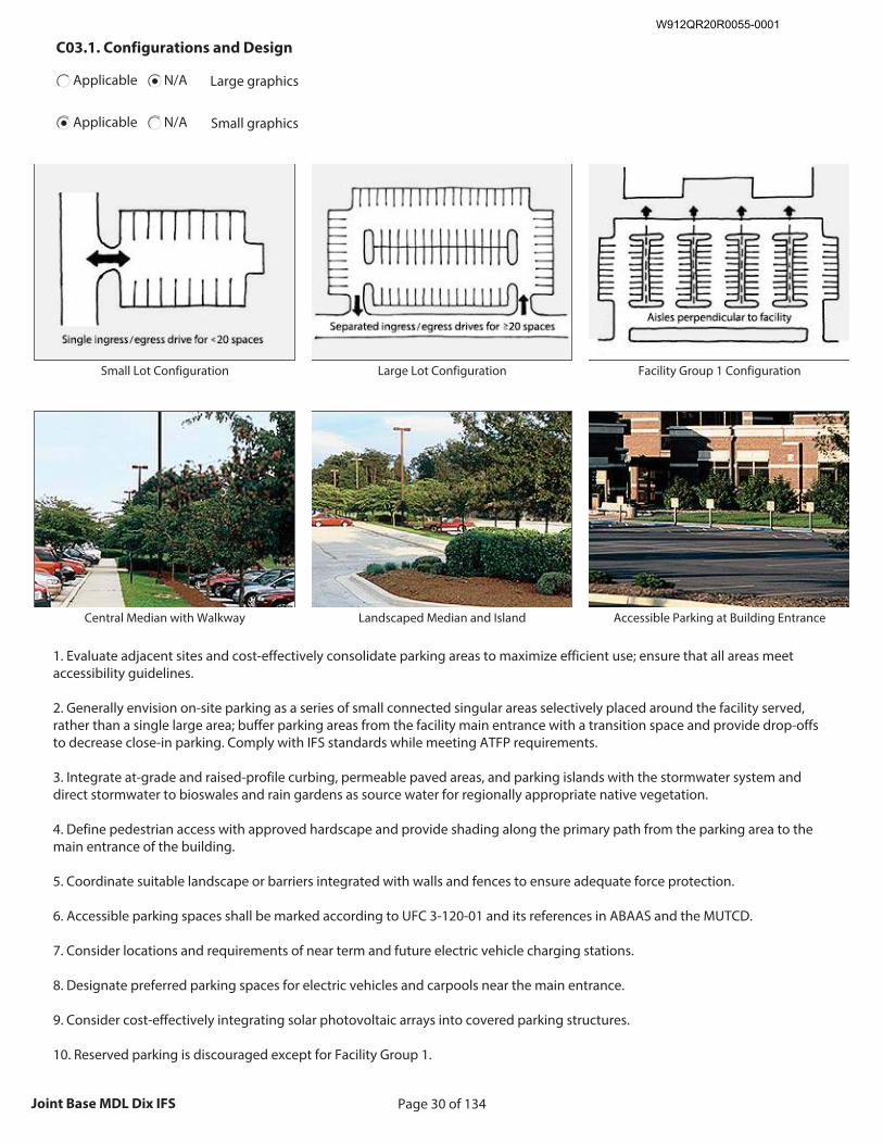
Page 30 of 134Joint Base MDL Dix IFS
C03.1. Configurations and Design
Applicable N/A Large graphics
Applicable N/A Small graphics
Insert Configurations and Design graphic
Size image to:
250 pixels width x 188 pixels height
Click here to insert image
Small Lot Configuration
Insert Configurations and Design graphic
Size image to:
250 pixels width x 188 pixels height
Click here to insert image
Large Lot Configuration
Insert Configurations and Design graphic
Size image to:
250 pixels width x 188 pixels height
Click here to insert image
Facility Group 1 Configuration
Insert Configurations and Design graphic
Size image to:
250 pixels width x 188 pixels height
Click here to insert image
Central Median with Walkway
Insert Configurations and Design graphic
Size image to:
250 pixels width x 188 pixels height
Click here to insert image
Landscaped Median and Island
Insert Configurations and Design graphic
Size image to:
250 pixels width x 188 pixels height
Click here to insert image
Accessible Parking at Building Entrance
1. Evaluate adjacent sites and cost-effectively consolidate parking areas to maximize efficient use; ensure that all areas meet accessibility guidelines. 2. Generally envision on-site parking as a series of small connected singular areas selectively placed around the facility served, rather than a single large area; buffer parking areas from the facility main entrance with a transition space and provide drop-offs to decrease close-in parking. Comply with IFS standards while meeting ATFP requirements. 3. Integrate at-grade and raised-profile curbing, permeable paved areas, and parking islands with the stormwater system and direct stormwater to bioswales and rain gardens as source water for regionally appropriate native vegetation. 4. Define pedestrian access with approved hardscape and provide shading along the primary path from the parking area to the main entrance of the building. 5. Coordinate suitable landscape or barriers integrated with walls and fences to ensure adequate force protection. 6. Accessible parking spaces shall be marked according to UFC 3-120-01 and its references in ABAAS and the MUTCD. 7. Consider locations and requirements of near term and future electric vehicle charging stations. 8. Designate preferred parking spaces for electric vehicles and carpools near the main entrance. 9. Consider cost-effectively integrating solar photovoltaic arrays into covered parking structures. 10. Reserved parking is discouraged except for Facility Group 1.
W912QR20R0055-0001
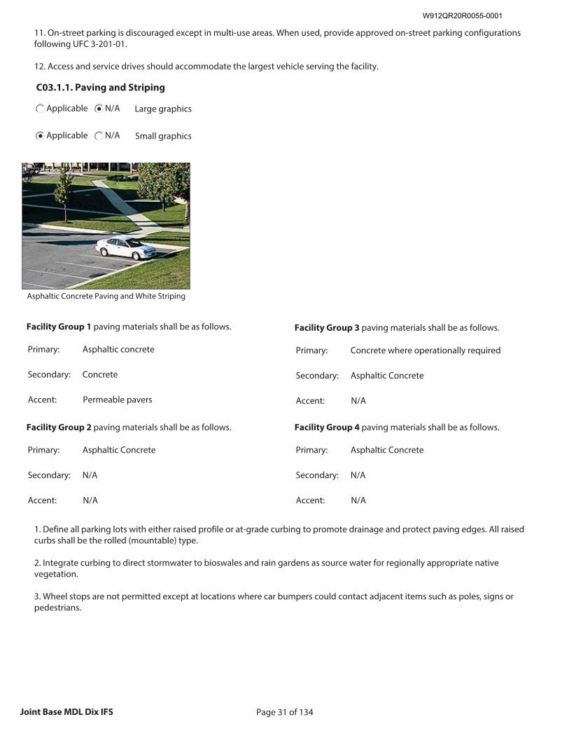
Page 31 of 134Joint Base MDL Dix IFS
11. On-street parking is discouraged except in multi-use areas. When used, provide approved on-street parking configurations following UFC 3-201-01. 12. Access and service drives should accommodate the largest vehicle serving the facility.
C03.1.1. Paving and Striping
Applicable N/A Large graphics
Applicable N/A Small graphics
Insert Paving and Striping graphic
Size image to: 250 pixels width x 188 pixels height
Click here to insert image
Asphaltic Concrete Paving and White Striping
Facility Group 1 paving materials shall be as follows.
Primary: Asphaltic concrete
Secondary: Concrete
Accent: Permeable pavers
Facility Group 2 paving materials shall be as follows.
Primary: Asphaltic Concrete
Secondary: N/A
Accent: N/A
Facility Group 3 paving materials shall be as follows.
Primary: Concrete where operationally required
Secondary: Asphaltic Concrete
Accent: N/A
Facility Group 4 paving materials shall be as follows.
Primary: Asphaltic Concrete
Secondary: N/A
Accent: N/A
1. Define all parking lots with either raised profile or at-grade curbing to promote drainage and protect paving edges. All raised curbs shall be the rolled (mountable) type. 2. Integrate curbing to direct stormwater to bioswales and rain gardens as source water for regionally appropriate native vegetation. 3. Wheel stops are not permitted except at locations where car bumpers could contact adjacent items such as poles, signs or pedestrians.
W912QR20R0055-0001
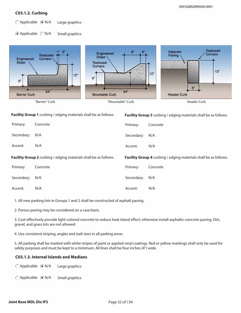
Page 32 of 134Joint Base MDL Dix IFS
C03.1.2. Curbing
Applicable N/A Large graphics
Applicable N/A Small graphics
Insert Curbing graphic
Size image to: 250 pixels width x 188 pixels height
Click here to insert image
"Barrier" Curb
Insert Curbing graphic
Size image to: 250 pixels width x 188 pixels height
Click here to insert image
"Mountable" Curb
Insert Curbing graphic
Size image to: 250 pixels width x 188 pixels height
Click here to insert image
Header Curb
Facility Group 1 curbing / edging materials shall be as follows.
Primary: Concrete
Secondary: N/A
Accent: N/A
Facility Group 2 curbing / edging materials shall be as follows.
Primary: Concrete
Secondary: N/A
Accent: N/A
Facility Group 3 curbing / edging materials shall be as follows.
Primary: Concrete
Secondary: N/A
Accent: N/A
Facility Group 4 curbing / edging materials shall be as follows.
Primary: Concrete
Secondary: N/A
Accent: N/A
1. All new parking lots in Groups 1 and 2 shall be constructed of asphalt paving. 2. Porous paving may be considered on a case basis. 3. Cost-effectively provide light-colored concrete to reduce heat island effect; otherwise install asphaltic concrete paving. Dirt, gravel, and grass lots are not allowed. 4. Use consistent striping, angles and stall sizes in all parking areas. 5. All parking shall be marked with white stripes of paint or applied vinyl coatings. Red or yellow markings shall only be used for safety purposes and must be kept to a minimum. All lines shall be four inches (4") wide.
C03.1.3. Internal Islands and Medians
Applicable N/A Large graphics
Applicable N/A Small graphics
W912QR20R0055-0001
Page 33 of 134Joint Base MDL Dix IFS
1. Install landscape islands and medians as visual breaks, to reduce heat island effects and to accommodate bioswales and rain gardens with consideration for snow removal. Coordinate suitable landscape or barriers integrated with walls and fences to ensure adequate force protection. 2. When lighting is necessary, contain fixture bases within medians or internal landscape islands.
C03.2. Parking Structures
Applicable N/A Large graphics
Applicable N/A Small graphics
1. Parking structures are encouraged in land-constrained locations when economically feasible. 2. Consider near term and future electric vehicle charging stations and renewable energy generation development during the analysis and design. 3. Consider opportunities for integrating parking structures into multi-use developments with pedestrian-oriented uses located on the ground floor and parking on upper levels; ensure ATFP guidelines are fully addressed. 4. Structures may be constructed below grade with roofs serving as vegetated areas or plazas.
C03.3. Connectivity
Applicable N/A Large graphics
Applicable N/A Small graphics
1. Refer to the Installation Development Plan (IDP) for locations of transit stops and pedestrian and cycling networks; provide appropriately sized sidewalks and bike paths to connect facilities and users to these networks. 2. Provide amenities such as rain and shade shelters, trees, and benches to encourage and facilitate use of public transportation. 3. Evaluate the IDP for the current and planned network of roads and optimally develop vehicular access to and from the site.
C04. STORMWATER MANAGEMENT
Comply with AF Corporate Standards for Site Development: http://afcfs.wbdg.org/site-development/index.html
Comply with AF Corporate Standards for Stormwater Management: http://afcfs.wbdg.org/site-development/stormwater-management/index.html
W912QR20R0055-0001
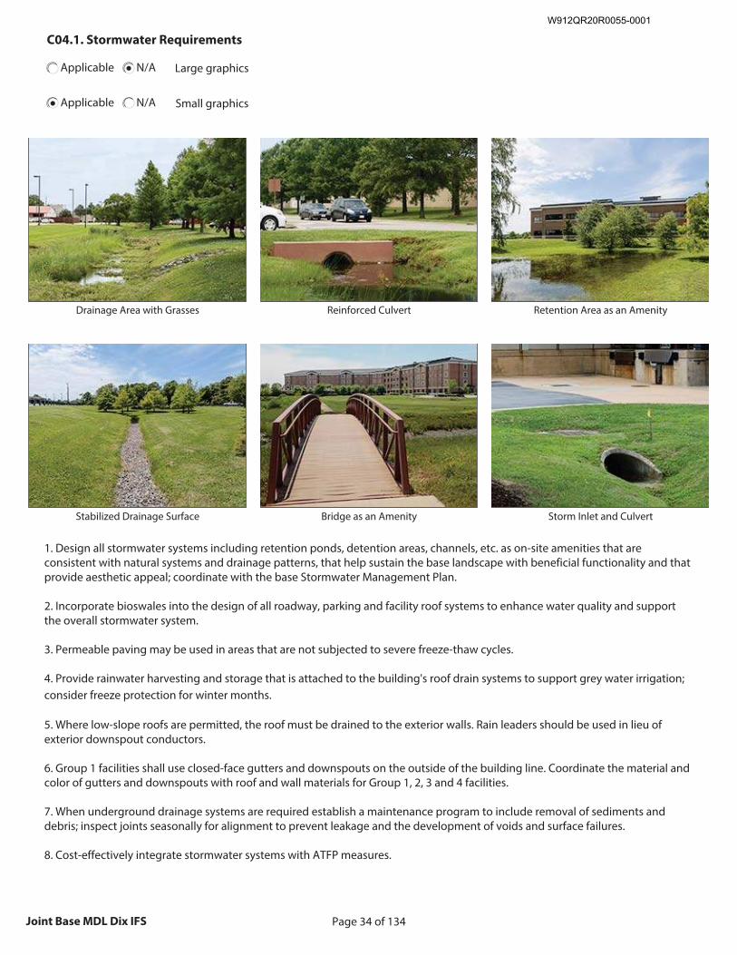
Page 34 of 134Joint Base MDL Dix IFS
C04.1. Stormwater Requirements
Applicable N/A Large graphics
Applicable N/A Small graphics
Insert Stormwater Requirements graphic
Size image to:
250 pixels width x 188 pixels height
Click here to insert image
Drainage Area with Grasses
Insert Stormwater Requirements graphic
Size image to:
250 pixels width x 188 pixels height
Click here to insert image
Reinforced Culvert
Insert Stormwater Requirements graphic
Size image to:
250 pixels width x 188 pixels height
Click here to insert image
Retention Area as an Amenity
Insert Stormwater Requirements graphic
Size image to:
250 pixels width x 188 pixels height
Click here to insert image
Stabilized Drainage Surface
Insert Stormwater Requirements graphic
Size image to:
250 pixels width x 188 pixels height
Click here to insert image
Bridge as an Amenity
Insert Stormwater Requirements graphic
Size image to:
250 pixels width x 188 pixels height
Click here to insert image
Storm Inlet and Culvert
1. Design all stormwater systems including retention ponds, detention areas, channels, etc. as on-site amenities that are consistent with natural systems and drainage patterns, that help sustain the base landscape with beneficial functionality and that provide aesthetic appeal; coordinate with the base Stormwater Management Plan. 2. Incorporate bioswales into the design of all roadway, parking and facility roof systems to enhance water quality and support the overall stormwater system. 3. Permeable paving may be used in areas that are not subjected to severe freeze-thaw cycles. 4. Provide rainwater harvesting and storage that is attached to the building's roof drain systems to support grey water irrigation; consider freeze protection for winter months. 5. Where low-slope roofs are permitted, the roof must be drained to the exterior walls. Rain leaders should be used in lieu of exterior downspout conductors. 6. Group 1 facilities shall use closed-face gutters and downspouts on the outside of the building line. Coordinate the material and color of gutters and downspouts with roof and wall materials for Group 1, 2, 3 and 4 facilities. 7. When underground drainage systems are required establish a maintenance program to include removal of sediments and debris; inspect joints seasonally for alignment to prevent leakage and the development of voids and surface failures. 8. Cost-effectively integrate stormwater systems with ATFP measures.
W912QR20R0055-0001
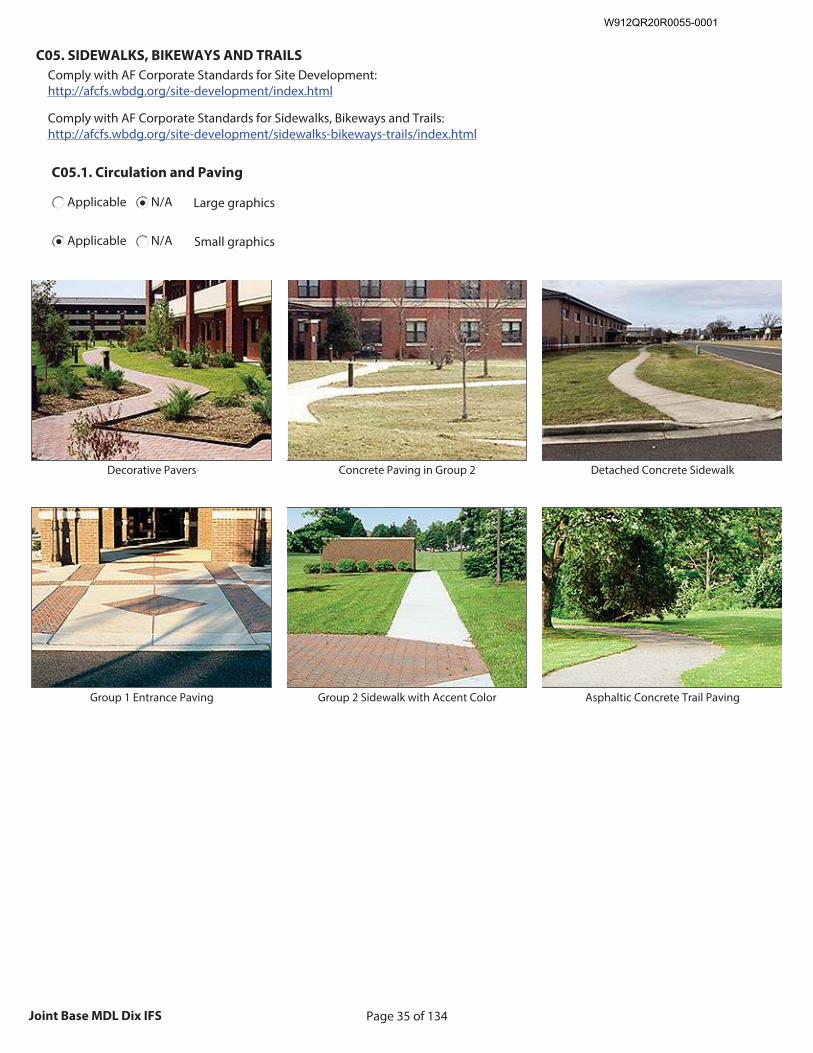
Page 35 of 134Joint Base MDL Dix IFS
C05. SIDEWALKS, BIKEWAYS AND TRAILS
Comply with AF Corporate Standards for Site Development: http://afcfs.wbdg.org/site-development/index.html
Comply with AF Corporate Standards for Sidewalks, Bikeways and Trails: http://afcfs.wbdg.org/site-development/sidewalks-bikeways-trails/index.html
C05.1. Circulation and Paving
Applicable N/A Large graphics
Applicable N/A Small graphics
Insert Circulation and Paving graphic
Size image to:
250 pixels width x 188 pixels height
Click here to insert image
Decorative Pavers
Insert Circulation and Paving graphic
Size image to:
250 pixels width x 188 pixels height
Click here to insert image
Concrete Paving in Group 2
Insert Circulation and Paving graphic
Size image to:
250 pixels width x 188 pixels height
Click here to insert image
Detached Concrete Sidewalk
Insert Circulation and Paving graphic
Size image to:
250 pixels width x 188 pixels height
Click here to insert image
Group 1 Entrance Paving
Insert Circulation and Paving graphic
Size image to:
250 pixels width x 188 pixels height
Click here to insert image
Group 2 Sidewalk with Accent Color
Insert Circulation and Paving graphic
Size image to:
250 pixels width x 188 pixels height
Click here to insert image
Asphaltic Concrete Trail Paving
W912QR20R0055-0001
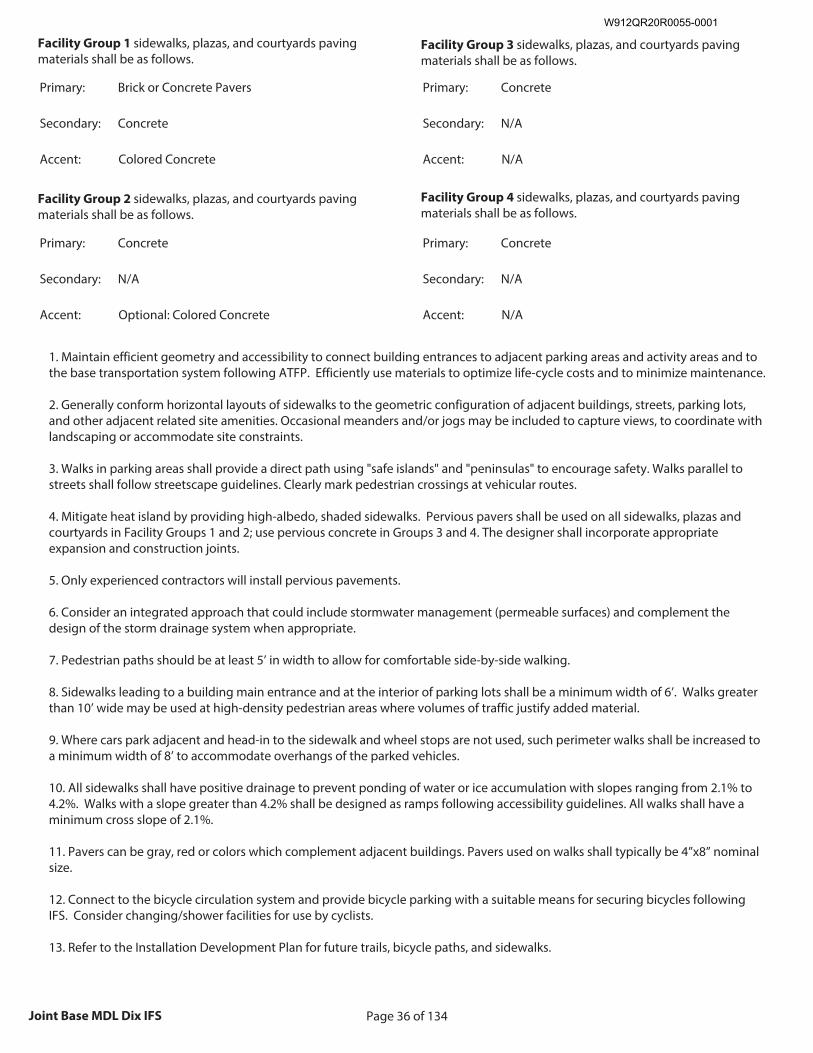
Page 36 of 134Joint Base MDL Dix IFS
Facility Group 1 sidewalks, plazas, and courtyards paving materials shall be as follows.
Primary: Brick or Concrete Pavers
Secondary: Concrete
Accent: Colored Concrete
Facility Group 2 sidewalks, plazas, and courtyards paving materials shall be as follows.
Primary: Concrete
Secondary: N/A
Accent: Optional: Colored Concrete
Facility Group 3 sidewalks, plazas, and courtyards paving materials shall be as follows.
Primary: Concrete
Secondary: N/A
Accent: N/A
Facility Group 4 sidewalks, plazas, and courtyards paving materials shall be as follows.
Primary: Concrete
Secondary: N/A
Accent: N/A
1. Maintain efficient geometry and accessibility to connect building entrances to adjacent parking areas and activity areas and to the base transportation system following ATFP. Efficiently use materials to optimize life-cycle costs and to minimize maintenance. 2. Generally conform horizontal layouts of sidewalks to the geometric configuration of adjacent buildings, streets, parking lots, and other adjacent related site amenities. Occasional meanders and/or jogs may be included to capture views, to coordinate with landscaping or accommodate site constraints. 3. Walks in parking areas shall provide a direct path using "safe islands" and "peninsulas" to encourage safety. Walks parallel to streets shall follow streetscape guidelines. Clearly mark pedestrian crossings at vehicular routes. 4. Mitigate heat island by providing high-albedo, shaded sidewalks. Pervious pavers shall be used on all sidewalks, plazas and courtyards in Facility Groups 1 and 2; use pervious concrete in Groups 3 and 4. The designer shall incorporate appropriate expansion and construction joints. 5. Only experienced contractors will install pervious pavements. 6. Consider an integrated approach that could include stormwater management (permeable surfaces) and complement the design of the storm drainage system when appropriate. 7. Pedestrian paths should be at least 5’ in width to allow for comfortable side-by-side walking. 8. Sidewalks leading to a building main entrance and at the interior of parking lots shall be a minimum width of 6’. Walks greater than 10’ wide may be used at high-density pedestrian areas where volumes of traffic justify added material. 9. Where cars park adjacent and head-in to the sidewalk and wheel stops are not used, such perimeter walks shall be increased to a minimum width of 8’ to accommodate overhangs of the parked vehicles. 10. All sidewalks shall have positive drainage to prevent ponding of water or ice accumulation with slopes ranging from 2.1% to 4.2%. Walks with a slope greater than 4.2% shall be designed as ramps following accessibility guidelines. All walks shall have a minimum cross slope of 2.1%. 11. Pavers can be gray, red or colors which complement adjacent buildings. Pavers used on walks shall typically be 4”x8” nominal size. 12. Connect to the bicycle circulation system and provide bicycle parking with a suitable means for securing bicycles following IFS. Consider changing/shower facilities for use by cyclists. 13. Refer to the Installation Development Plan for future trails, bicycle paths, and sidewalks.
W912QR20R0055-0001
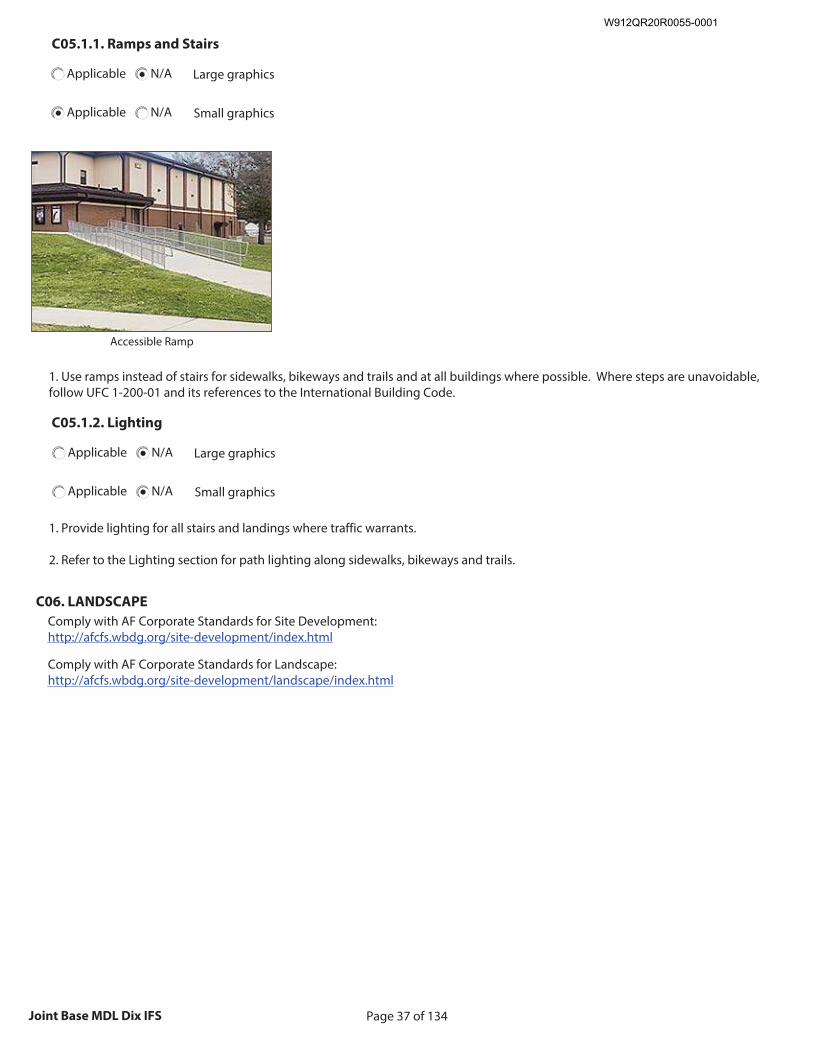
Page 37 of 134Joint Base MDL Dix IFS
C05.1.1. Ramps and Stairs
Applicable N/A Large graphics
Applicable N/A Small graphics
Insert Ramps and Stairs graphic
Size image to: 250 pixels width x 188 pixels height
Click here to insert image
Accessible Ramp
1. Use ramps instead of stairs for sidewalks, bikeways and trails and at all buildings where possible. Where steps are unavoidable, follow UFC 1-200-01 and its references to the International Building Code.
C05.1.2. Lighting
Applicable N/A Large graphics
Applicable N/A Small graphics
1. Provide lighting for all stairs and landings where traffic warrants. 2. Refer to the Lighting section for path lighting along sidewalks, bikeways and trails.
C06. LANDSCAPE
Comply with AF Corporate Standards for Site Development: http://afcfs.wbdg.org/site-development/index.html
Comply with AF Corporate Standards for Landscape: http://afcfs.wbdg.org/site-development/landscape/index.html
W912QR20R0055-0001
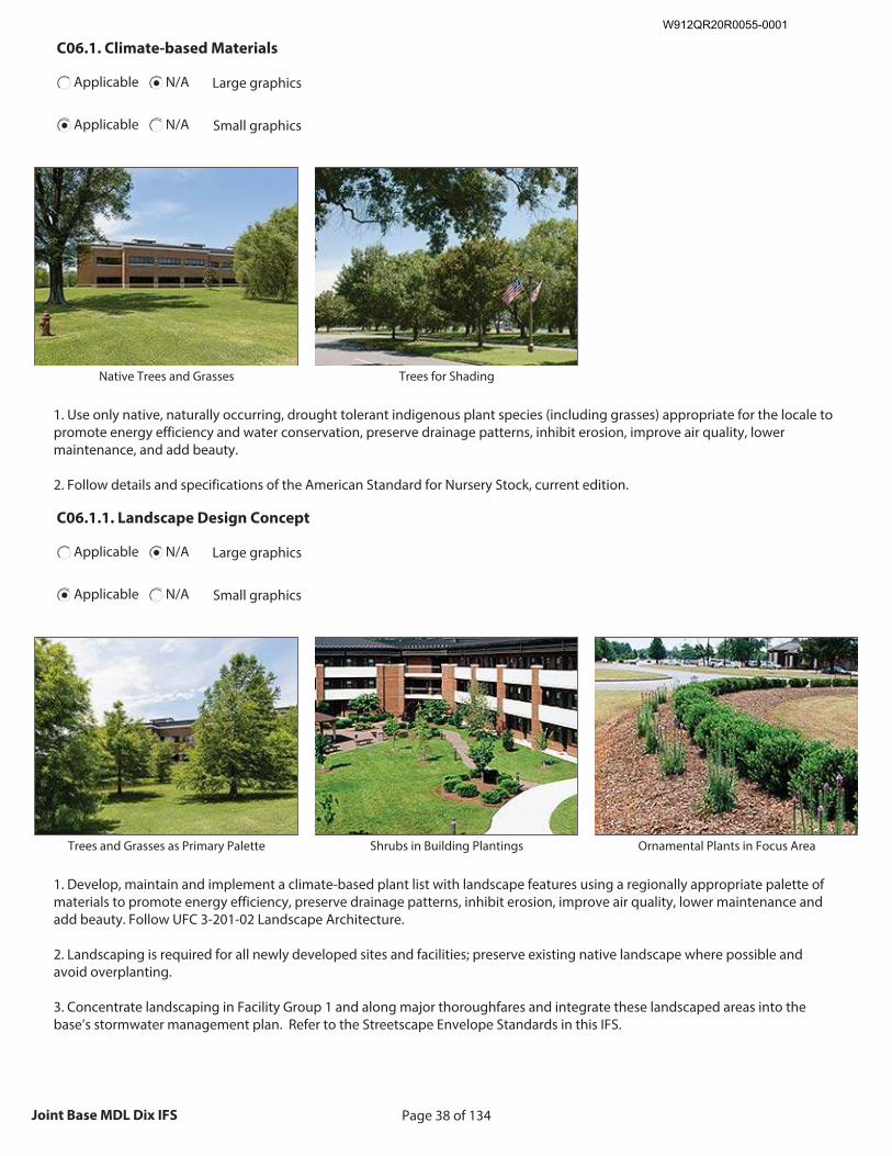
Page 38 of 134Joint Base MDL Dix IFS
C06.1. Climate-based Materials
Applicable N/A Large graphics
Applicable N/A Small graphics
Insert Climate-based Materials graphic
Size image to:
250 pixels width x 188 pixels height
Click here to insert image
Native Trees and Grasses
Insert Climate-based Materials graphic
Size image to:
250 pixels width x 188 pixels height
Click here to insert image
Trees for Shading
1. Use only native, naturally occurring, drought tolerant indigenous plant species (including grasses) appropriate for the locale to promote energy efficiency and water conservation, preserve drainage patterns, inhibit erosion, improve air quality, lower maintenance, and add beauty. 2. Follow details and specifications of the American Standard for Nursery Stock, current edition.
C06.1.1. Landscape Design Concept
Applicable N/A Large graphics
Applicable N/A Small graphics
Insert Landscape Design Concept graphic
Size image to:
250 pixels width x 188 pixels height
Click here to insert image
Trees and Grasses as Primary Palette
Insert Landscape Design Concept graphic
Size image to:
250 pixels width x 188 pixels height
Click here to insert image
Shrubs in Building Plantings
Insert Landscape Design Concept graphic
Size image to:
250 pixels width x 188 pixels height
Click here to insert image
Ornamental Plants in Focus Area
1. Develop, maintain and implement a climate-based plant list with landscape features using a regionally appropriate palette of materials to promote energy efficiency, preserve drainage patterns, inhibit erosion, improve air quality, lower maintenance and add beauty. Follow UFC 3-201-02 Landscape Architecture. 2. Landscaping is required for all newly developed sites and facilities; preserve existing native landscape where possible and avoid overplanting. 3. Concentrate landscaping in Facility Group 1 and along major thoroughfares and integrate these landscaped areas into the base’s stormwater management plan. Refer to the Streetscape Envelope Standards in this IFS.
W912QR20R0055-0001
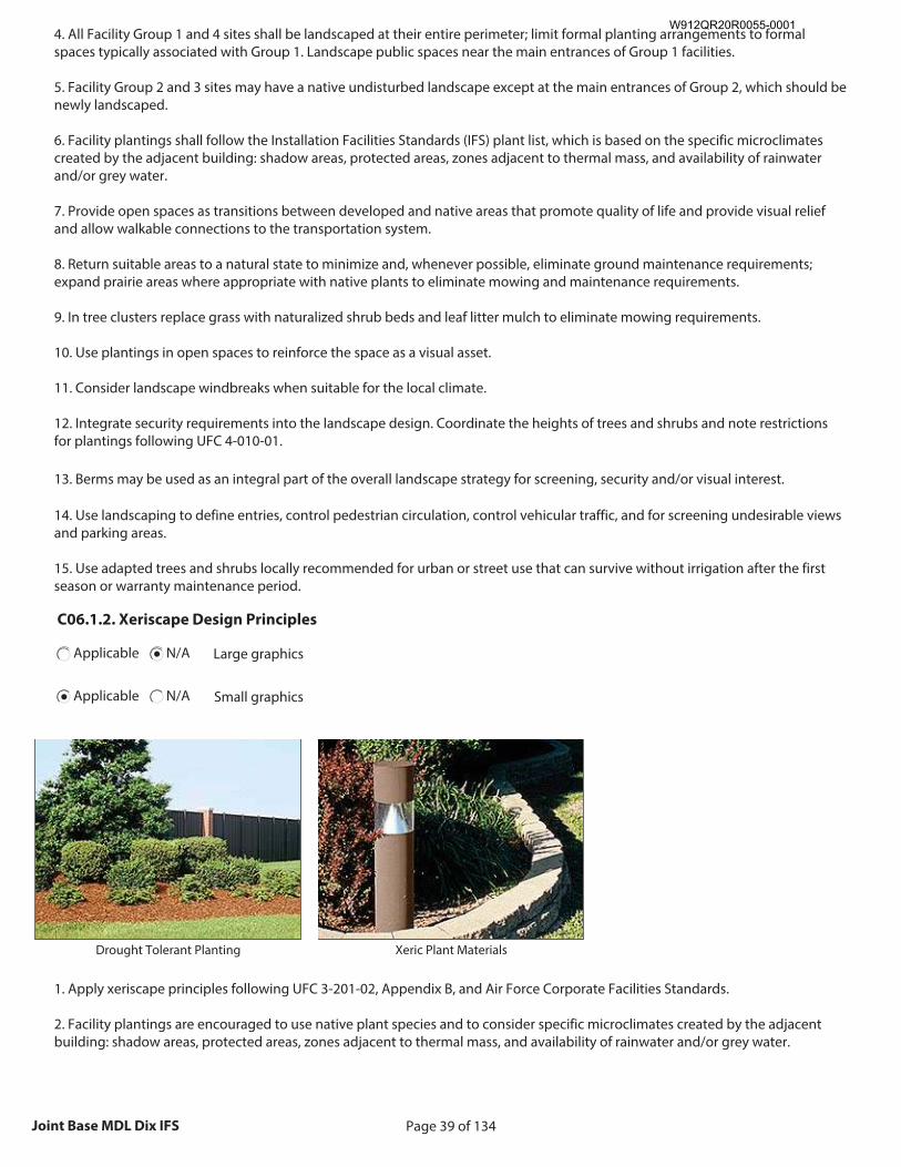
Page 39 of 134Joint Base MDL Dix IFS
4. All Facility Group 1 and 4 sites shall be landscaped at their entire perimeter; limit formal planting arrangements to formal spaces typically associated with Group 1. Landscape public spaces near the main entrances of Group 1 facilities. 5. Facility Group 2 and 3 sites may have a native undisturbed landscape except at the main entrances of Group 2, which should be newly landscaped. 6. Facility plantings shall follow the Installation Facilities Standards (IFS) plant list, which is based on the specific microclimates created by the adjacent building: shadow areas, protected areas, zones adjacent to thermal mass, and availability of rainwater and/or grey water. 7. Provide open spaces as transitions between developed and native areas that promote quality of life and provide visual relief and allow walkable connections to the transportation system. 8. Return suitable areas to a natural state to minimize and, whenever possible, eliminate ground maintenance requirements; expand prairie areas where appropriate with native plants to eliminate mowing and maintenance requirements. 9. In tree clusters replace grass with naturalized shrub beds and leaf litter mulch to eliminate mowing requirements. 10. Use plantings in open spaces to reinforce the space as a visual asset. 11. Consider landscape windbreaks when suitable for the local climate. 12. Integrate security requirements into the landscape design. Coordinate the heights of trees and shrubs and note restrictions for plantings following UFC 4-010-01. 13. Berms may be used as an integral part of the overall landscape strategy for screening, security and/or visual interest. 14. Use landscaping to define entries, control pedestrian circulation, control vehicular traffic, and for screening undesirable views and parking areas. 15. Use adapted trees and shrubs locally recommended for urban or street use that can survive without irrigation after the first season or warranty maintenance period.
C06.1.2. Xeriscape Design Principles
Applicable N/A Large graphics
Applicable N/A Small graphics
Insert Xeriscape Design Principles graphic
Size image to:
250 pixels width x 188 pixels height
Click here to insert image
Drought Tolerant Planting
Insert Xeriscape Design Principles graphic
Size image to:
250 pixels width x 188 pixels height
Click here to insert image
Xeric Plant Materials
1. Apply xeriscape principles following UFC 3-201-02, Appendix B, and Air Force Corporate Facilities Standards. 2. Facility plantings are encouraged to use native plant species and to consider specific microclimates created by the adjacent building: shadow areas, protected areas, zones adjacent to thermal mass, and availability of rainwater and/or grey water.
W912QR20R0055-0001
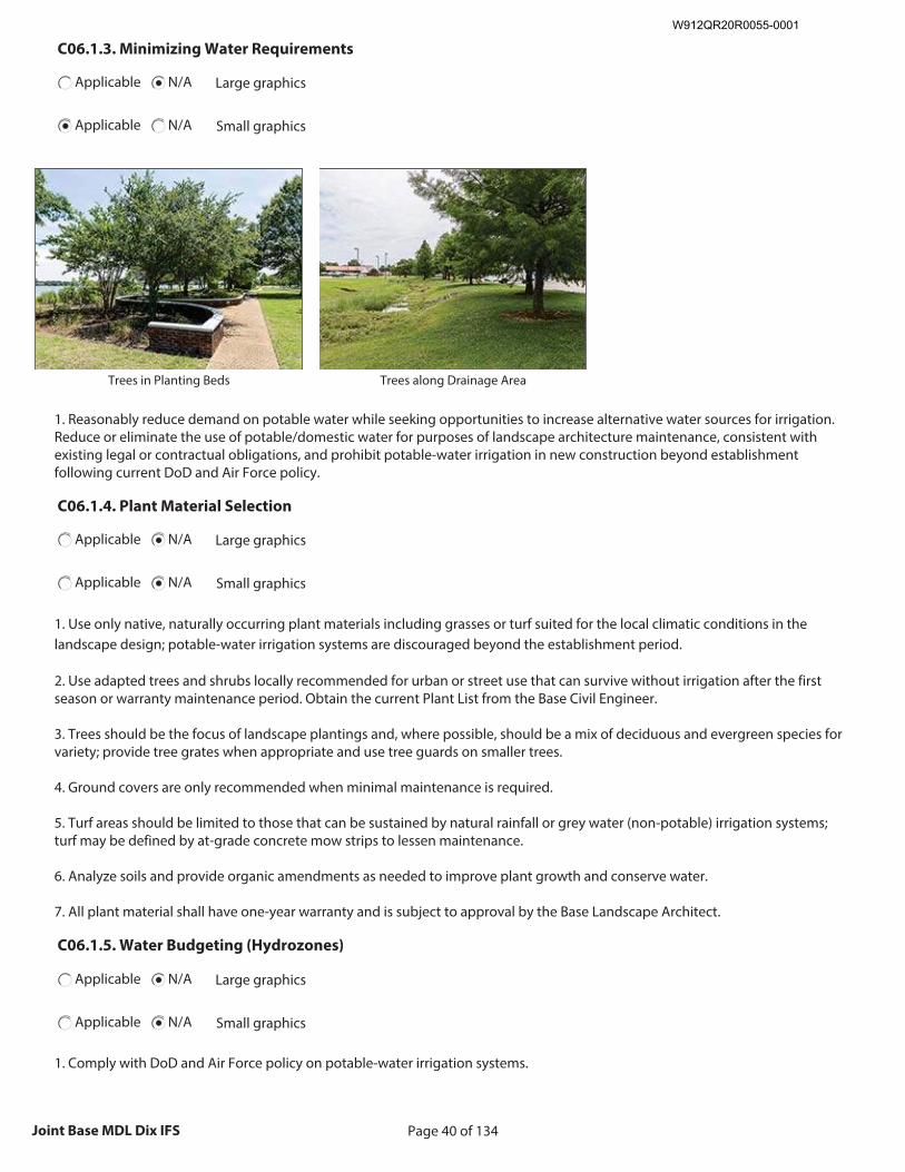
Page 40 of 134Joint Base MDL Dix IFS
C06.1.3. Minimizing Water Requirements
Applicable N/A Large graphics
Applicable N/A Small graphics
Insert Minimizing Water Requirements graphic
Size image to:
250 pixels width x 188 pixels height
Click here to insert image
Trees in Planting Beds
Insert Minimizing Water Requirements graphic
Size image to:
250 pixels width x 188 pixels height
Click here to insert image
Trees along Drainage Area
1. Reasonably reduce demand on potable water while seeking opportunities to increase alternative water sources for irrigation. Reduce or eliminate the use of potable/domestic water for purposes of landscape architecture maintenance, consistent with existing legal or contractual obligations, and prohibit potable-water irrigation in new construction beyond establishment following current DoD and Air Force policy.
C06.1.4. Plant Material Selection
Applicable N/A Large graphics
Applicable N/A Small graphics
1. Use only native, naturally occurring plant materials including grasses or turf suited for the local climatic conditions in the landscape design; potable-water irrigation systems are discouraged beyond the establishment period. 2. Use adapted trees and shrubs locally recommended for urban or street use that can survive without irrigation after the first season or warranty maintenance period. Obtain the current Plant List from the Base Civil Engineer. 3. Trees should be the focus of landscape plantings and, where possible, should be a mix of deciduous and evergreen species for variety; provide tree grates when appropriate and use tree guards on smaller trees. 4. Ground covers are only recommended when minimal maintenance is required. 5. Turf areas should be limited to those that can be sustained by natural rainfall or grey water (non-potable) irrigation systems; turf may be defined by at-grade concrete mow strips to lessen maintenance. 6. Analyze soils and provide organic amendments as needed to improve plant growth and conserve water. 7. All plant material shall have one-year warranty and is subject to approval by the Base Landscape Architect.
C06.1.5. Water Budgeting (Hydrozones)
Applicable N/A Large graphics
Applicable N/A Small graphics
1. Comply with DoD and Air Force policy on potable-water irrigation systems.
W912QR20R0055-0001
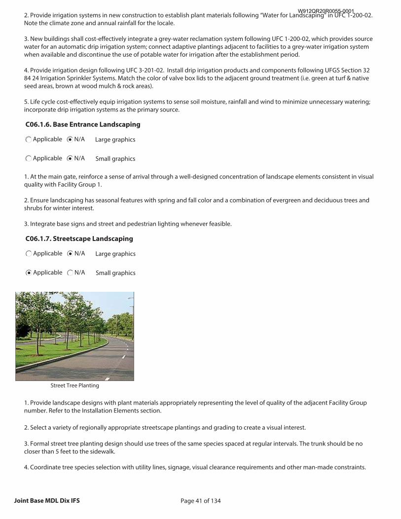
Page 41 of 134Joint Base MDL Dix IFS
2. Provide irrigation systems in new construction to establish plant materials following “Water for Landscaping” in UFC 1-200-02. Note the climate zone and annual rainfall for the locale. 3. New buildings shall cost-effectively integrate a grey-water reclamation system following UFC 1-200-02, which provides source water for an automatic drip irrigation system; connect adaptive plantings adjacent to facilities to a grey-water irrigation system when available and discontinue the use of potable water for irrigation after the establishment period. 4. Provide irrigation design following UFC 3-201-02. Install drip irrigation products and components following UFGS Section 32 84 24 Irrigation Sprinkler Systems. Match the color of valve box lids to the adjacent ground treatment (i.e. green at turf & native seed areas, brown at wood mulch & rock areas). 5. Life cycle cost-effectively equip irrigation systems to sense soil moisture, rainfall and wind to minimize unnecessary watering; incorporate drip irrigation systems as the primary source.
C06.1.6. Base Entrance Landscaping
Applicable N/A Large graphics
Applicable N/A Small graphics
1. At the main gate, reinforce a sense of arrival through a well-designed concentration of landscape elements consistent in visual quality with Facility Group 1. 2. Ensure landscaping has seasonal features with spring and fall color and a combination of evergreen and deciduous trees and shrubs for winter interest. 3. Integrate base signs and street and pedestrian lighting whenever feasible.
C06.1.7. Streetscape Landscaping
Applicable N/A Large graphics
Applicable N/A Small graphics
Insert Streetscape Landscaping graphic
Size image to:
250 pixels width x 188 pixels height
Click here to insert image
Street Tree Planting
1. Provide landscape designs with plant materials appropriately representing the level of quality of the adjacent Facility Group number. Refer to the Installation Elements section. 2. Select a variety of regionally appropriate streetscape plantings and grading to create a visual interest. 3. Formal street tree planting design should use trees of the same species spaced at regular intervals. The trunk should be no closer than 5 feet to the sidewalk. 4. Coordinate tree species selection with utility lines, signage, visual clearance requirements and other man-made constraints.
W912QR20R0055-0001
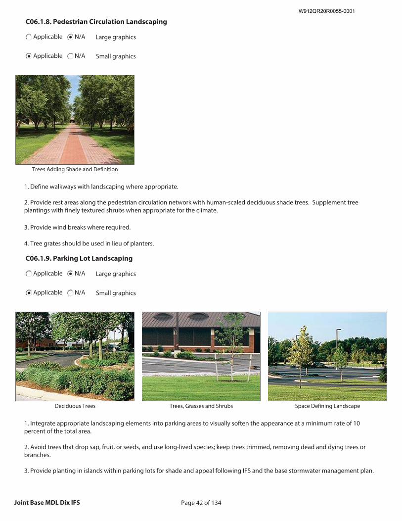
Page 42 of 134Joint Base MDL Dix IFS
C06.1.8. Pedestrian Circulation Landscaping
Applicable N/A Large graphics
Applicable N/A Small graphics
Insert Pedestrian Circulation Landscaping graphic
Size image to:
250 pixels width x 188 pixels height
Click here to insert image
Trees Adding Shade and Definition
1. Define walkways with landscaping where appropriate. 2. Provide rest areas along the pedestrian circulation network with human-scaled deciduous shade trees. Supplement tree plantings with finely textured shrubs when appropriate for the climate. 3. Provide wind breaks where required. 4. Tree grates should be used in lieu of planters.
C06.1.9. Parking Lot Landscaping
Applicable N/A Large graphics
Applicable N/A Small graphics
Insert Parking Lot Landscaping graphic
Size image to:
250 pixels width x 188 pixels height
Click here to insert image
Deciduous Trees
Insert Parking Lot Landscaping graphic
Size image to:
250 pixels width x 188 pixels height
Click here to insert image
Trees, Grasses and Shrubs
Insert Parking Lot Landscaping graphic
Size image to:
250 pixels width x 188 pixels height
Click here to insert image
Space Defining Landscape
1. Integrate appropriate landscaping elements into parking areas to visually soften the appearance at a minimum rate of 10 percent of the total area. 2. Avoid trees that drop sap, fruit, or seeds, and use long-lived species; keep trees trimmed, removing dead and dying trees or branches. 3. Provide planting in islands within parking lots for shade and appeal following IFS and the base stormwater management plan.
W912QR20R0055-0001
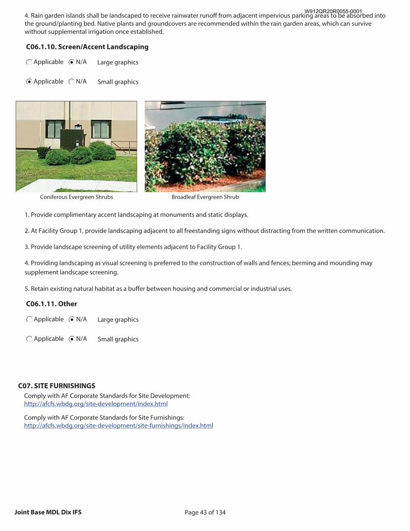
Page 43 of 134Joint Base MDL Dix IFS
4. Rain garden islands shall be landscaped to receive rainwater runoff from adjacent impervious parking areas to be absorbed into the ground/planting bed. Native plants and groundcovers are recommended within the rain garden areas, which can survive without supplemental irrigation once established.
C06.1.10. Screen/Accent Landscaping
Applicable N/A Large graphics
Applicable N/A Small graphics
Insert Screen/Accent Landscaping graphic
Size image to:
250 pixels width x 188 pixels height
Click here to insert image
Coniferous Evergreen Shrubs
Insert Screen/Accent Landscaping graphic
Size image to:
250 pixels width x 188 pixels height
Click here to insert image
Broadleaf Evergreen Shrub
1. Provide complimentary accent landscaping at monuments and static displays.
2. At Facility Group 1, provide landscaping adjacent to all freestanding signs without distracting from the written communication. 3. Provide landscape screening of utility elements adjacent to Facility Group 1. 4. Providing landscaping as visual screening is preferred to the construction of walls and fences; berming and mounding may supplement landscape screening. 5. Retain existing natural habitat as a buffer between housing and commercial or industrial uses.
C06.1.11. Other
Applicable N/A Large graphics
Applicable N/A Small graphics
C07. SITE FURNISHINGS
Comply with AF Corporate Standards for Site Development: http://afcfs.wbdg.org/site-development/index.html
Comply with AF Corporate Standards for Site Furnishings: http://afcfs.wbdg.org/site-development/site-furnishings/index.html
W912QR20R0055-0001
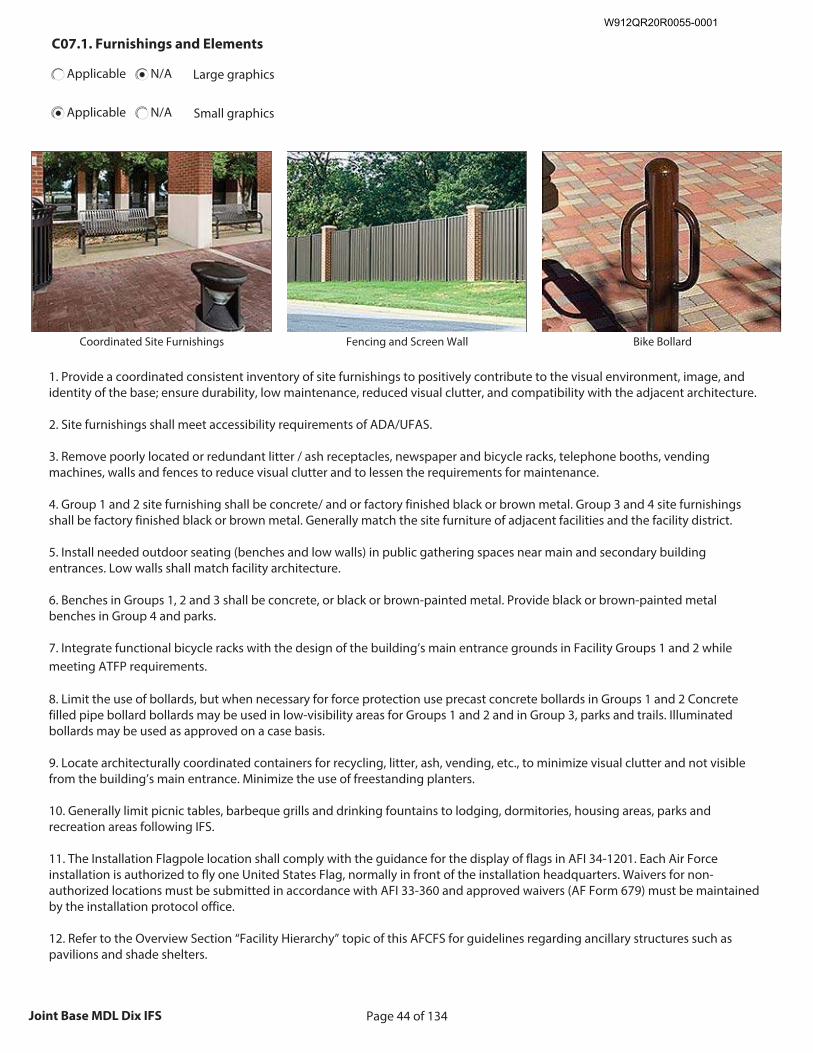
Page 44 of 134Joint Base MDL Dix IFS
C07.1. Furnishings and Elements
Applicable N/A Large graphics
Applicable N/A Small graphics
Insert Furnishings and Elements graphic
Size image to:
250 pixels width x 188 pixels height
Click here to insert image
Coordinated Site Furnishings
Insert Furnishings and Elements graphic
Size image to:
250 pixels width x 188 pixels height
Click here to insert image
Fencing and Screen Wall
Insert Furnishings and Elements graphic
Size image to:
250 pixels width x 188 pixels height
Click here to insert image
Bike Bollard
1. Provide a coordinated consistent inventory of site furnishings to positively contribute to the visual environment, image, and identity of the base; ensure durability, low maintenance, reduced visual clutter, and compatibility with the adjacent architecture. 2. Site furnishings shall meet accessibility requirements of ADA/UFAS. 3. Remove poorly located or redundant litter / ash receptacles, newspaper and bicycle racks, telephone booths, vending machines, walls and fences to reduce visual clutter and to lessen the requirements for maintenance. 4. Group 1 and 2 site furnishing shall be concrete/ and or factory finished black or brown metal. Group 3 and 4 site furnishings shall be factory finished black or brown metal. Generally match the site furniture of adjacent facilities and the facility district. 5. Install needed outdoor seating (benches and low walls) in public gathering spaces near main and secondary building entrances. Low walls shall match facility architecture. 6. Benches in Groups 1, 2 and 3 shall be concrete, or black or brown-painted metal. Provide black or brown-painted metal benches in Group 4 and parks. 7. Integrate functional bicycle racks with the design of the building’s main entrance grounds in Facility Groups 1 and 2 while meeting ATFP requirements. 8. Limit the use of bollards, but when necessary for force protection use precast concrete bollards in Groups 1 and 2 Concrete filled pipe bollard bollards may be used in low-visibility areas for Groups 1 and 2 and in Group 3, parks and trails. Illuminated bollards may be used as approved on a case basis. 9. Locate architecturally coordinated containers for recycling, litter, ash, vending, etc., to minimize visual clutter and not visible from the building’s main entrance. Minimize the use of freestanding planters. 10. Generally limit picnic tables, barbeque grills and drinking fountains to lodging, dormitories, housing areas, parks and recreation areas following IFS. 11. The Installation Flagpole location shall comply with the guidance for the display of flags in AFI 34-1201. Each Air Force installation is authorized to fly one United States Flag, normally in front of the installation headquarters. Waivers for non-authorized locations must be submitted in accordance with AFI 33-360 and approved waivers (AF Form 679) must be maintained by the installation protocol office. 12. Refer to the Overview Section “Facility Hierarchy” topic of this AFCFS for guidelines regarding ancillary structures such as pavilions and shade shelters.
W912QR20R0055-0001
Page 45 of 134Joint Base MDL Dix IFS
13. Bus shelters shall be provided only where there is a documented need and when approved on a case basis. Generally emulate the designs of adjacent shelters. 14. Monuments and static displays shall be limited. New elements are generally discouraged unless these are fully vetted through the base’s approval process and designed following IFS. 15. When visual screening is necessary, consider landscaping as the first option; screen walls are permitted only in Group 1 finished with red brick matching adjacent buildings. 16. For fencing, apply the standards for “Products, Materials and Color” in the following section. Limit those with the highest visual quality to Facility Group 1 where there is sustained maintenance. Define all levels of security and visual quality. 17. Do not use chain-link fencing at Group 1, 2 or 4 facilities; Limit the use of barbed-wire outriggers on chain-link fencing at industrial sites, unless required for additional security or protection of assets. 18. Wood fencing may be used in Facility Group 4 and in recreation areas following IFS for material and finish when there is sustained periodic maintenance. 19. Provide trash dumpster enclosures for Group 1, 2 and 3 with red brick to match adjacent facilities; all gates shall be metal, factory finished dark brown. 20. Specify screen wall materials and finishes that do not require painting or maintenance beyond periodic cleaning. 21. Group 1, 2, 3 and 4 picnic tables and seating shall be black or brown-painted metal. Generally limit picnic tables, barbeque grills and drinking fountains to lodging, dormitories, housing areas, parks and recreation area. 22. Limit the use of freestanding planters to areas with ongoing maintenance. 23. Provide kiosks only where there is a documented need for visual communication of posted messages. When used, match adjacent facilities in materials and detailing and consolidate kiosks with other site furnishings within 30 feet of major pedestrian paths. Limit kiosks to facility Groups 1 and 2 and parks. 24. Manufacturers listed below are only provided to establish a baseline of equivalency among all applicable manufacturers.
C07.2. Site Furnishings Products, Materials and Color
Note: Apply the below base-wide standards for Site Furnishings (products, materials and color). Then refer to the Appendix and apply any additional requirements specifically related to the Facility District in which the project is located.
W912QR20R0055-0001
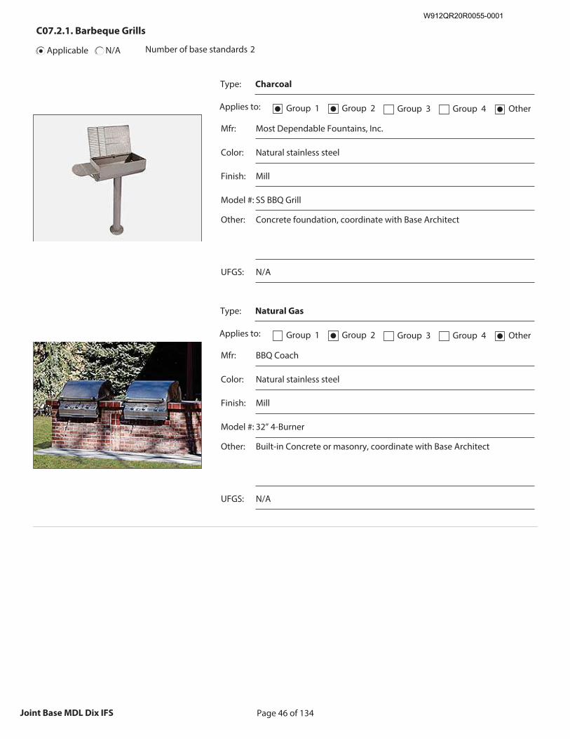
Page 46 of 134Joint Base MDL Dix IFS
C07.2.1. Barbeque Grills
Applicable N/A Number of base standards 2
Type: Charcoal
Applies to: Group 1● Group 2● Group 3 Group 4 Other●
Mfr: Most Dependable Fountains, Inc.
Color: Natural stainless steel
Finish: Mill
Model #: SS BBQ Grill
Other: Concrete foundation, coordinate with Base Architect
Recommended Image: Example of Grill Type
Size image to:
250 pixels width x 188 pixels height
Click here to insert image
UFGS: N/A
Type: Natural Gas
Applies to: Group 1 Group 2● Group 3 Group 4 Other●
Mfr: BBQ Coach
Color: Natural stainless steel
Finish: Mill
Model #: 32” 4-Burner
Other: Built-in Concrete or masonry, coordinate with Base Architect
Recommended Image: Example of Grill Type
Size image to:
250 pixels width x 188 pixels height
Click here to insert image
UFGS: N/A
W912QR20R0055-0001
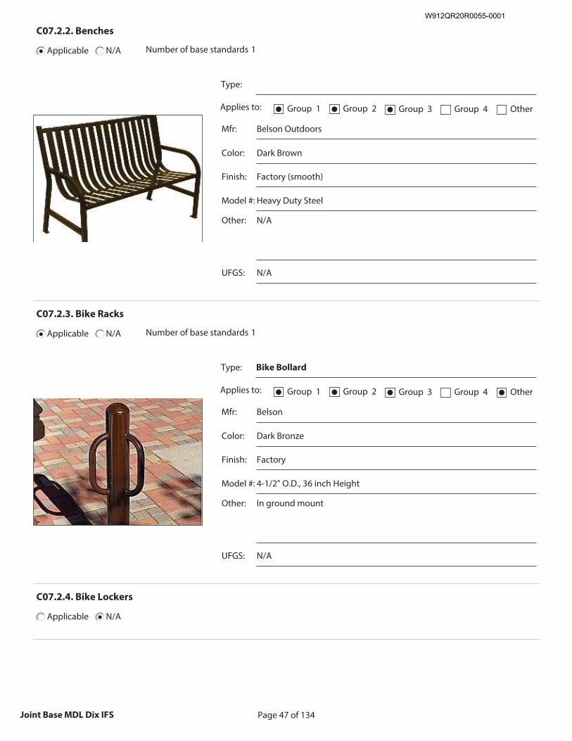
Page 47 of 134Joint Base MDL Dix IFS
C07.2.2. Benches
Applicable N/A Number of base standards 1
Type:
Applies to: Group 1● Group 2● Group 3● Group 4 Other
Mfr: Belson Outdoors
Color: Dark Brown
Finish: Factory (smooth)
Model #: Heavy Duty Steel
Other: N/A
Recommended Image: Example of Bench Type
Size image to:
250 pixels width x 188 pixels height
Click here to insert image
UFGS: N/A
C07.2.3. Bike Racks
Applicable N/A Number of base standards 1
Type: Bike Bollard
Applies to: Group 1● Group 2● Group 3● Group 4 Other●
Mfr: Belson
Color: Dark Bronze
Finish: Factory
Model #: 4-1/2" O.D., 36 inch Height
Other: In ground mount
Recommended Image: Example of Bike Rack Type
Size image to:
250 pixels width x 188 pixels height
Click here to insert image
UFGS: N/A
C07.2.4. Bike Lockers
Applicable N/A
W912QR20R0055-0001
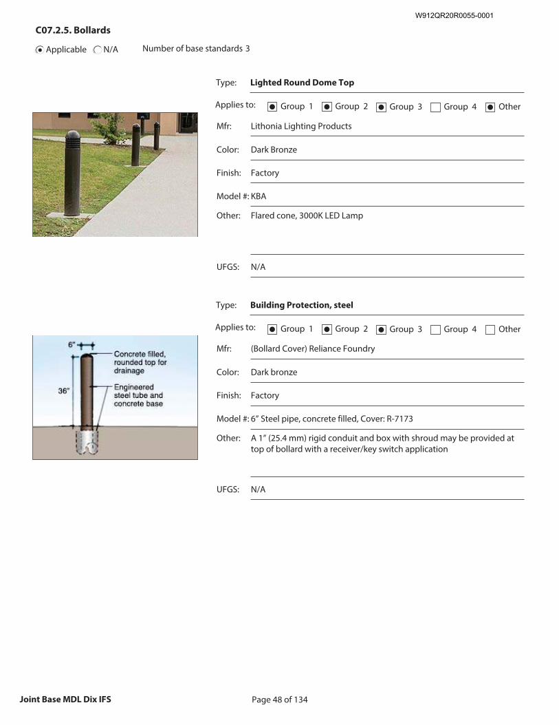
Page 48 of 134Joint Base MDL Dix IFS
C07.2.5. Bollards
Applicable N/A Number of base standards 3
Type: Lighted Round Dome Top
Applies to: Group 1● Group 2● Group 3● Group 4 Other●
Mfr: Lithonia Lighting Products
Color: Dark Bronze
Finish: Factory
Model #: KBA
Other: Flared cone, 3000K LED Lamp
Recommended Image: Example of Bollard Type
Size image to:
250 pixels width x 188 pixels height
Click here to insert image
UFGS: N/A
Type: Building Protection, steel
Applies to: Group 1● Group 2● Group 3● Group 4 Other
Mfr: (Bollard Cover) Reliance Foundry
Color: Dark bronze
Finish: Factory
Model #: 6” Steel pipe, concrete filled, Cover: R-7173
Other: A 1” (25.4 mm) rigid conduit and box with shroud may be provided at top of bollard with a receiver/key switch application
Recommended Image: Example of Bollard Type
Size image to:
250 pixels width x 188 pixels height
Click here to insert image
UFGS: N/A
W912QR20R0055-0001
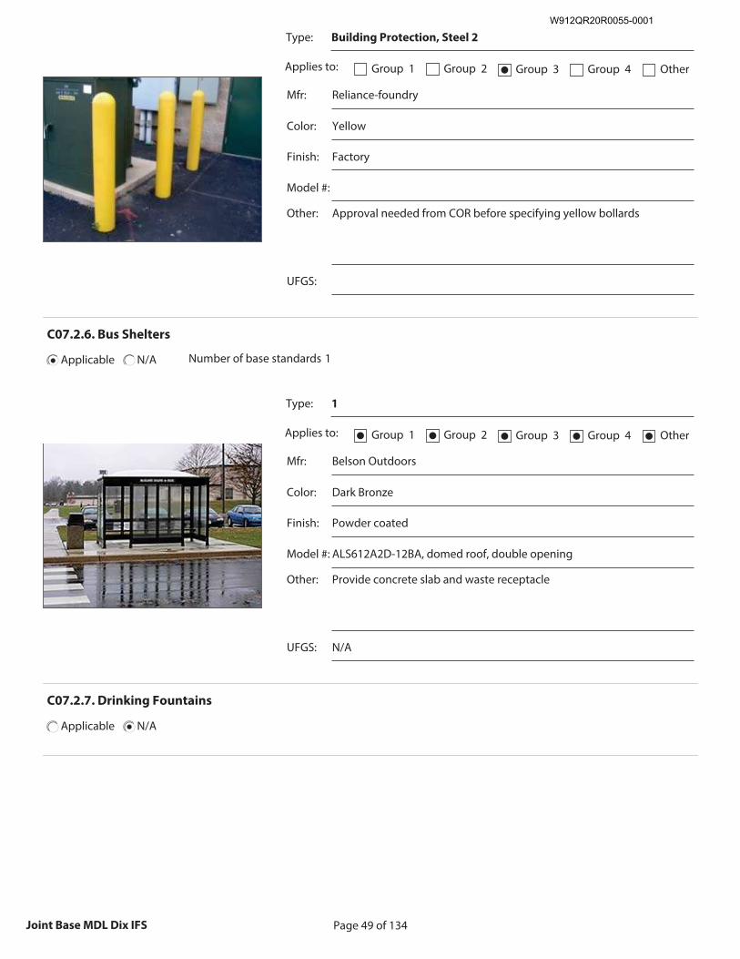
Page 49 of 134Joint Base MDL Dix IFS
Type: Building Protection, Steel 2
Applies to: Group 1 Group 2 Group 3● Group 4 Other
Mfr: Reliance-foundry
Color: Yellow
Finish: Factory
Model #:
Other: Approval needed from COR before specifying yellow bollards
Recommended Image: Example of Bollard Type
Size image to:
250 pixels width x 188 pixels height
Click here to insert image
UFGS:
C07.2.6. Bus Shelters
Applicable N/A Number of base standards 1
Type: 1
Applies to: Group 1● Group 2● Group 3● Group 4● Other●
Mfr: Belson Outdoors
Color: Dark Bronze
Finish: Powder coated
Model #: ALS612A2D-12BA, domed roof, double opening
Other: Provide concrete slab and waste receptacle
Recommended Image: Example of Bus Shelter Type
Size image to:
250 pixels width x 188 pixels height
Click here to insert image
UFGS: N/A
C07.2.7. Drinking Fountains
Applicable N/A
W912QR20R0055-0001
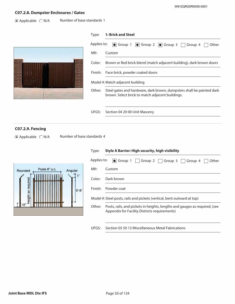
Page 50 of 134Joint Base MDL Dix IFS
C07.2.8. Dumpster Enclosures / Gates
Applicable N/A Number of base standards 1
Type: 1: Brick and Steel
Applies to: Group 1● Group 2● Group 3● Group 4 Other
Mfr: Custom
Color: Brown or Red brick blend (match adjacent building), dark brown doors
Finish: Face brick, powder coated doors
Model #: Match adjacent building
Other: Steel gates and hardware, dark brown, dumpsters shall be painted dark brown. Select brick to match adjacent buildings.
Recommended Image: Example of Dumpster Enclosure/
Gate Type
Size image to: 250 pixels width x 188 pixels height
Click here to insert image
UFGS: Section 04 20 00 Unit Masonry
C07.2.9. Fencing
Applicable N/A Number of base standards 4
Type: Style A Barrier: High security, high visibility
Applies to: Group 1● Group 2 Group 3 Group 4 Other
Mfr: Custom
Color: Dark brown
Finish: Powder coat
Model #: Steel posts, rails and pickets (vertical, bent outward at top)
Other: Posts, rails, and pickets in heights, lengths and gauges as required, (see Appendix for Facility Districts requirements)
Recommended Image: Example of Fencing Type
Size image to:
250 pixels width x 188 pixels height
Click here to insert image
UFGS: Section 05 50 13 Miscellaneous Metal Fabrications
W912QR20R0055-0001
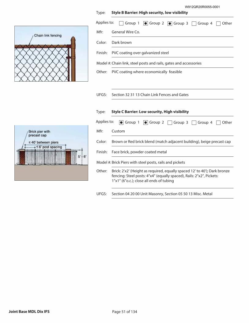
Page 51 of 134Joint Base MDL Dix IFS
Type: Style B Barrier: High security, low visibility
Applies to: Group 1 Group 2● Group 3● Group 4 Other
Mfr: General Wire Co.
Color: Dark brown
Finish: PVC coating over galvanized steel
Model #: Chain link, steel posts and rails, gates and accessories
Other: PVC coating where economically feasible
Recommended Image: Example of Fencing Type
Size image to:
250 pixels width x 188 pixels height
Click here to insert image
UFGS: Section 32 31 13 Chain Link Fences and Gates
Type: Style C Barrier: Low security, High visibility
Applies to: Group 1● Group 2● Group 3 Group 4 Other
Mfr: Custom
Color: Brown or Red brick blend (match adjacent building), beige precast cap
Finish: Face brick, powder coated metal
Model #: Brick Piers with steel posts, rails and pickets
Other: Brick: 2’x2’ (Height as required, equally spaced 12’ to 40’); Dark bronze fencing: Steel posts: 4”x4” (equally spaced), Rails: 2”x2”, Pickets: 1”x1” (6”o.c.); close all ends of tubing
Recommended Image: Example of Fencing Type
Size image to:
250 pixels width x 188 pixels height
Click here to insert image
UFGS: Section 04 20 00 Unit Masonry, Section 05 50 13 Misc. Metal
W912QR20R0055-0001
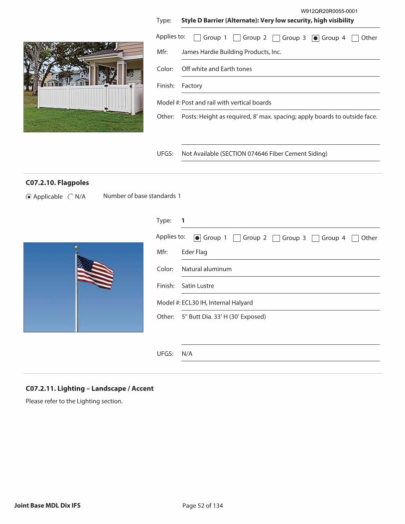
Page 52 of 134Joint Base MDL Dix IFS
Type: Style D Barrier (Alternate): Very low security, high visibility
Applies to: Group 1 Group 2 Group 3 Group 4● Other
Mfr: James Hardie Building Products, Inc.
Color: Off white and Earth tones
Finish: Factory
Model #: Post and rail with vertical boards
Other: Posts: Height as required, 8’ max. spacing; apply boards to outside face.
Recommended Image: Example of Fencing Type
Size image to:
250 pixels width x 188 pixels height
Click here to insert image
UFGS: Not Available (SECTION 074646 Fiber Cement Siding)
C07.2.10. Flagpoles
Applicable N/A Number of base standards 1
Type: 1
Applies to: Group 1● Group 2 Group 3 Group 4 Other
Mfr: Eder Flag
Color: Natural aluminum
Finish: Satin Lustre
Model #: ECL30 IH, Internal Halyard
Other: 5” Butt Dia. 33’ H (30’ Exposed)
Recommended Image: Example of Flagpole Type
Size image to:
250 pixels width x 188 pixels height
Click here to insert image
UFGS: N/A
C07.2.11. Lighting – Landscape / Accent
Please refer to the Lighting section.
W912QR20R0055-0001
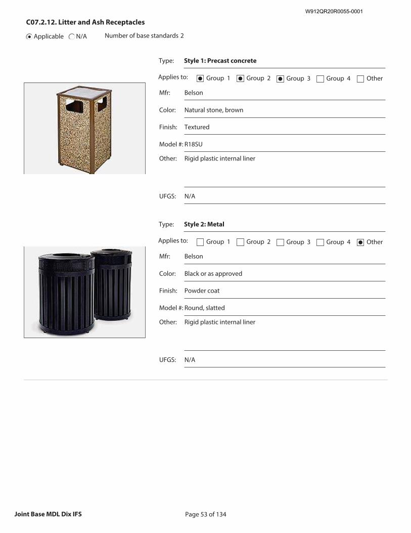
Page 53 of 134Joint Base MDL Dix IFS
C07.2.12. Litter and Ash Receptacles
Applicable N/A Number of base standards 2
Type: Style 1: Precast concrete
Applies to: Group 1● Group 2● Group 3● Group 4 Other
Mfr: Belson
Color: Natural stone, brown
Finish: Textured
Model #: R18SU
Other: Rigid plastic internal liner
Recommended Image: Example of Litter / Ash Recepticle
Type
Size image to: 250 pixels width x 188 pixels height
Click here to insert image
UFGS: N/A
Type: Style 2: Metal
Applies to: Group 1 Group 2 Group 3 Group 4 Other●
Mfr: Belson
Color: Black or as approved
Finish: Powder coat
Model #: Round, slatted
Other: Rigid plastic internal liner
Recommended Image: Example of Litter / Ash Recepticle
Type
Size image to: 250 pixels width x 188 pixels height
Click here to insert image
UFGS: N/A
W912QR20R0055-0001
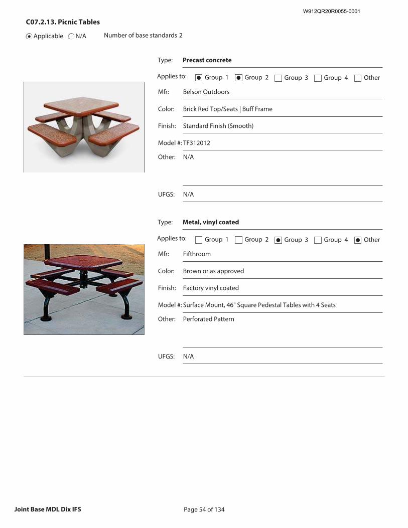
Page 54 of 134Joint Base MDL Dix IFS
C07.2.13. Picnic Tables
Applicable N/A Number of base standards 2
Type: Precast concrete
Applies to: Group 1● Group 2● Group 3 Group 4 Other
Mfr: Belson Outdoors
Color: Brick Red Top/Seats | Buff Frame
Finish: Standard Finish (Smooth)
Model #: TF312012
Other: N/A
Recommended Image: Example of Picnic Table Type
Size image to:
250 pixels width x 188 pixels height
Click here to insert image
UFGS: N/A
Type: Metal, vinyl coated
Applies to: Group 1 Group 2 Group 3● Group 4 Other●
Mfr: Fifthroom
Color: Brown or as approved
Finish: Factory vinyl coated
Model #: Surface Mount, 46" Square Pedestal Tables with 4 Seats
Other: Perforated Pattern
Recommended Image: Example of Picnic Table Type
Size image to:
250 pixels width x 188 pixels height
Click here to insert image
UFGS: N/A
W912QR20R0055-0001
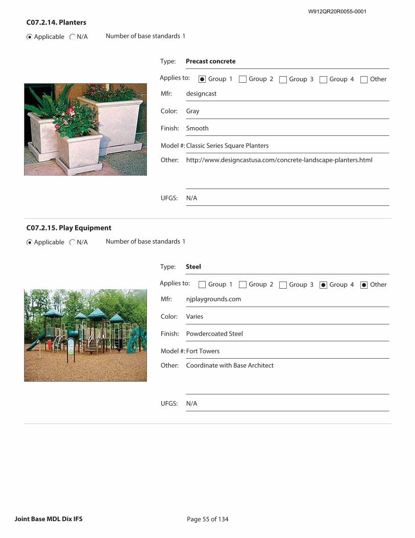
Page 55 of 134Joint Base MDL Dix IFS
C07.2.14. Planters
Applicable N/A Number of base standards 1
Type: Precast concrete
Applies to: Group 1● Group 2 Group 3 Group 4 Other
Mfr: designcast
Color: Gray
Finish: Smooth
Model #: Classic Series Square Planters
Other: http://www.designcastusa.com/concrete-landscape-planters.html
Recommended Image: Example of Planter Type
Size image to:
250 pixels width x 188 pixels height
Click here to insert image
UFGS: N/A
C07.2.15. Play Equipment
Applicable N/A Number of base standards 1
Type: Steel
Applies to: Group 1 Group 2 Group 3 Group 4● Other●
Mfr: njplaygrounds.com
Color: Varies
Finish: Powdercoated Steel
Model #: Fort Towers
Other: Coordinate with Base Architect
Recommended Image: Example of Play Equipment Type
Size image to:
250 pixels width x 188 pixels height
Click here to insert image
UFGS: N/A
W912QR20R0055-0001
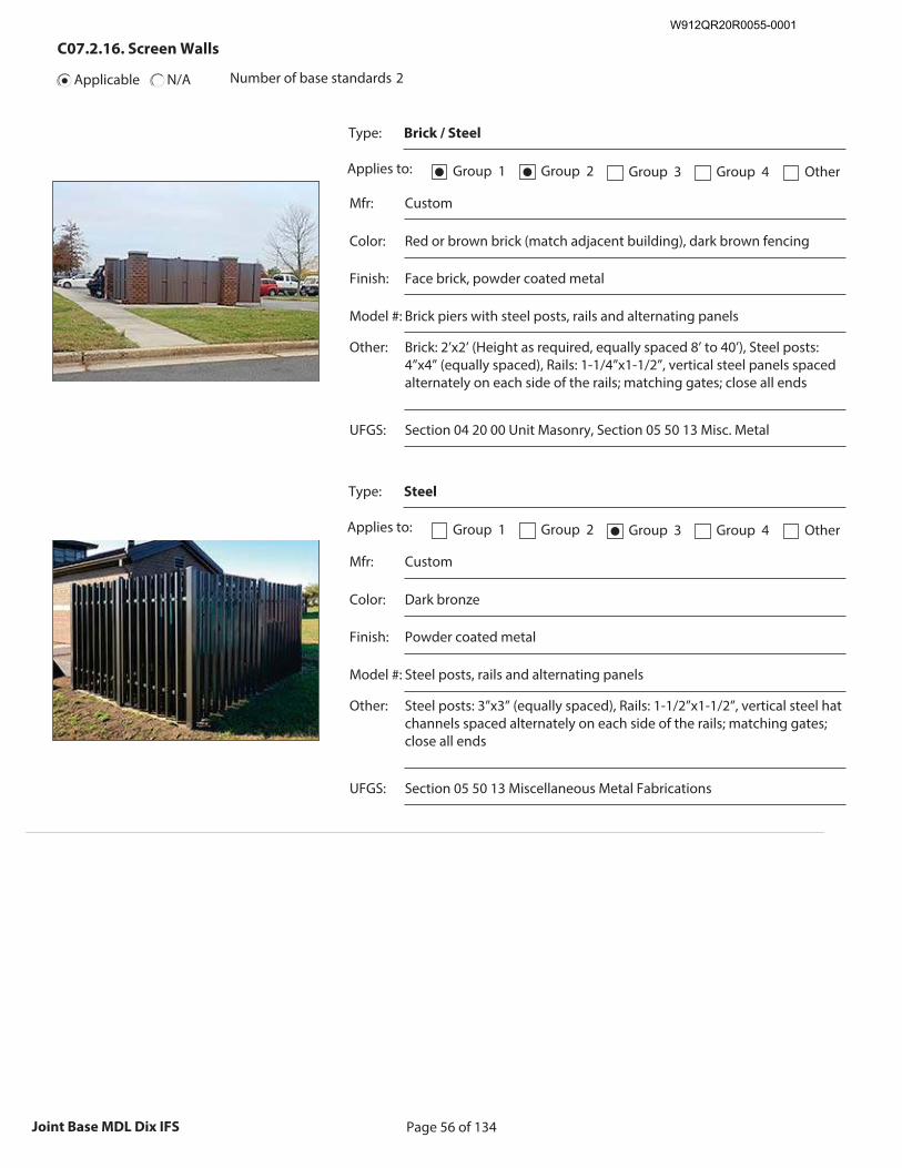
Page 56 of 134Joint Base MDL Dix IFS
C07.2.16. Screen Walls
Applicable N/A Number of base standards 2
Type: Brick / Steel
Applies to: Group 1● Group 2● Group 3 Group 4 Other
Mfr: Custom
Color: Red or brown brick (match adjacent building), dark brown fencing
Finish: Face brick, powder coated metal
Model #: Brick piers with steel posts, rails and alternating panels
Other: Brick: 2’x2’ (Height as required, equally spaced 8’ to 40’), Steel posts: 4”x4” (equally spaced), Rails: 1-1/4”x1-1/2”, vertical steel panels spaced alternately on each side of the rails; matching gates; close all ends
Recommended Image: Example of Screen Wall Type
Size image to:
250 pixels width x 188 pixels height
Click here to insert image
UFGS: Section 04 20 00 Unit Masonry, Section 05 50 13 Misc. Metal
Type: Steel
Applies to: Group 1 Group 2 Group 3● Group 4 Other
Mfr: Custom
Color: Dark bronze
Finish: Powder coated metal
Model #: Steel posts, rails and alternating panels
Other: Steel posts: 3”x3” (equally spaced), Rails: 1-1/2”x1-1/2”, vertical steel hat channels spaced alternately on each side of the rails; matching gates; close all ends
Recommended Image: Example of Screen Wall Type
Size image to:
250 pixels width x 188 pixels height
Click here to insert image
UFGS: Section 05 50 13 Miscellaneous Metal Fabrications
W912QR20R0055-0001
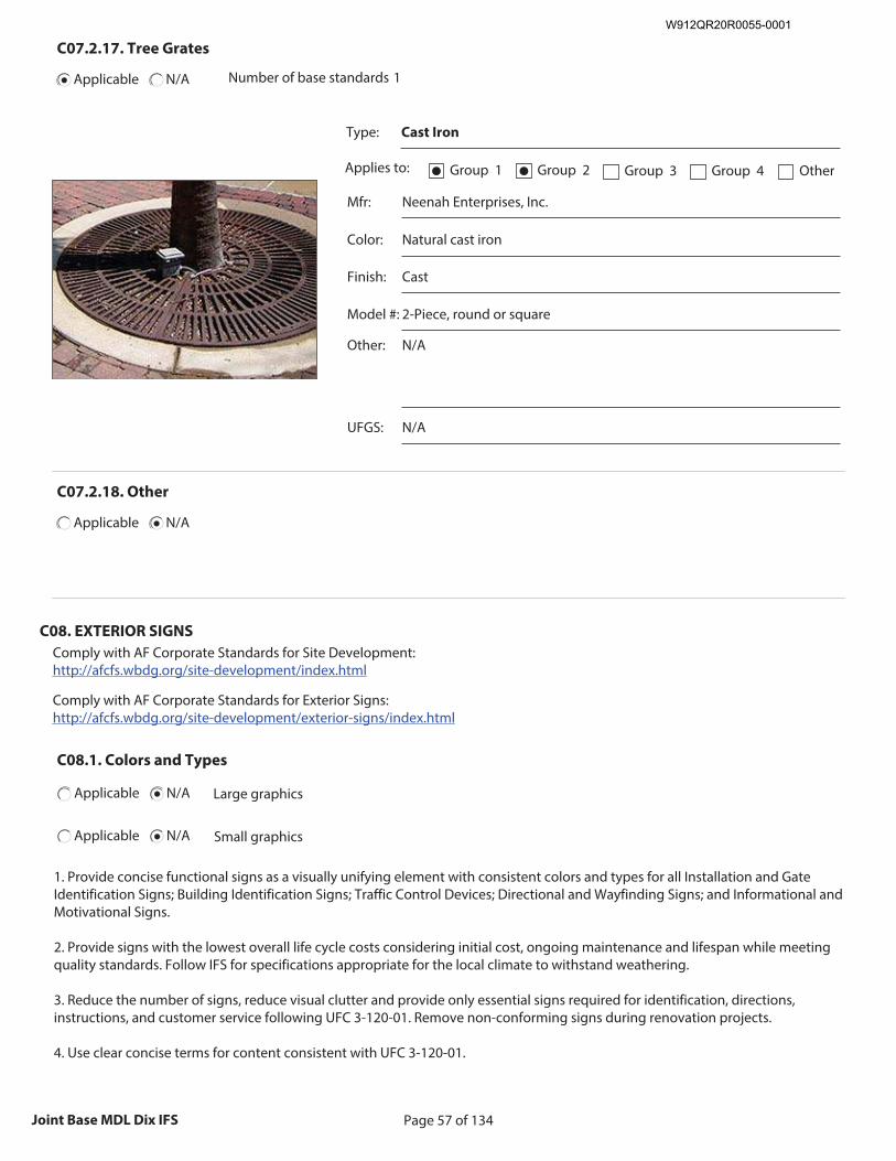
Page 57 of 134Joint Base MDL Dix IFS
C07.2.17. Tree Grates
Applicable N/A Number of base standards 1
Type: Cast Iron
Applies to: Group 1● Group 2● Group 3 Group 4 Other
Mfr: Neenah Enterprises, Inc.
Color: Natural cast iron
Finish: Cast
Model #: 2-Piece, round or square
Other: N/A
Recommended Image: Example of Tree Grate Type
Size image to:
250 pixels width x 188 pixels height
Click here to insert image
UFGS: N/A
C07.2.18. Other
Applicable N/A
C08. EXTERIOR SIGNS
Comply with AF Corporate Standards for Site Development: http://afcfs.wbdg.org/site-development/index.html
Comply with AF Corporate Standards for Exterior Signs: http://afcfs.wbdg.org/site-development/exterior-signs/index.html
C08.1. Colors and Types
Applicable N/A Large graphics
Applicable N/A Small graphics
1. Provide concise functional signs as a visually unifying element with consistent colors and types for all Installation and Gate Identification Signs; Building Identification Signs; Traffic Control Devices; Directional and Wayfinding Signs; and Informational and Motivational Signs. 2. Provide signs with the lowest overall life cycle costs considering initial cost, ongoing maintenance and lifespan while meeting quality standards. Follow IFS for specifications appropriate for the local climate to withstand weathering. 3. Reduce the number of signs, reduce visual clutter and provide only essential signs required for identification, directions, instructions, and customer service following UFC 3-120-01. Remove non-conforming signs during renovation projects. 4. Use clear concise terms for content consistent with UFC 3-120-01.
W912QR20R0055-0001
Page 58 of 134Joint Base MDL Dix IFS
5. Display of emblems on building exterior walls or other permanent structures is prohibited by UFC. 6. Raised “standout” letters and numbers may be used for Group 1 with approval on a case basis. 7. Group 2 and 3 facilities shall have wall mounted facility signs with sizes and layouts following UFC 3-120-01. Signs are not permitted for Group 4 facilities. 8. Only one identification sign is permitted at each building entrance. Include a building address consistent with US Postal Service protocols following UFC 3-120-01. 9. Traffic Control Devices, which regulate vehicular traffic on the installation, shall conform to the standards in the Manual of Uniform Traffic Control Devices (MUTCD) published by the Federal Highway Administration. Coordinate street signs with this IFS. 10. Provide Directional and Wayfinding Signs and address both pedestrian and vehicular traffic following UFC 3-120-01 for size, layout and content. 11. Reserved parking signs should be kept to a minimum. When approved, provide post-mounted sign faces in base standard materials and colors. Consider "bracketing" a designated area with a single sign at each end. 12. Parking lot identification signs may be used to identify areas or rows within large lots. 13. Follow the guidelines and requirements in ABAAS and the MUTCD for accessible parking signs. 14. Follow UFC 3-120-01 for Informational and Motivational Signs for size, layout and content. 15. Symbols or pictographs (graphic expressions of actual objects) may be used to indicate service, mandatory / prohibitory, sports, and recreation when rapid communication is necessary. 16. Force Protection signage may be applied to glass doors using white vinyl lettering. 17. Refer to UFC 3-120-01 for prohibited signs, which include those with animated, blinking, chasing, flashing, or moving effects. 18. Manufacturers listed below are only provided to establish a baseline of equivalency among all applicable manufacturers.
C08.1.1. Materials and Color Specifications
Applicable N/A Large graphics
Applicable N/A Small graphics
1. Fabricate sign panels from aluminum, painted brown. Sign posts shall be 3” square aluminum with capped ends in a concrete base. 2. Fence mounted sign panels may be attached with exposed fasteners. 3. Freestanding signs shall have white letters on brown background. Finish shall be fluoropolymer (e.g. Kynar 500) coating or equal. 4. All signage shall follow Federal Highway Administration (FHWA) Manual on Uniform Traffic Control Devices (MUTCD) using standard colors. Refer to MUTCD color specifications, which provide cross-referenced Pantone Matching System (PMS) numbers. a. Standard Blue b. Standard Dark Bronze (also Federal Standard Color 30040) c. Standard Red d. Standard Black (non-reflective) e. Standard White f. Standard Brown
W912QR20R0055-0001
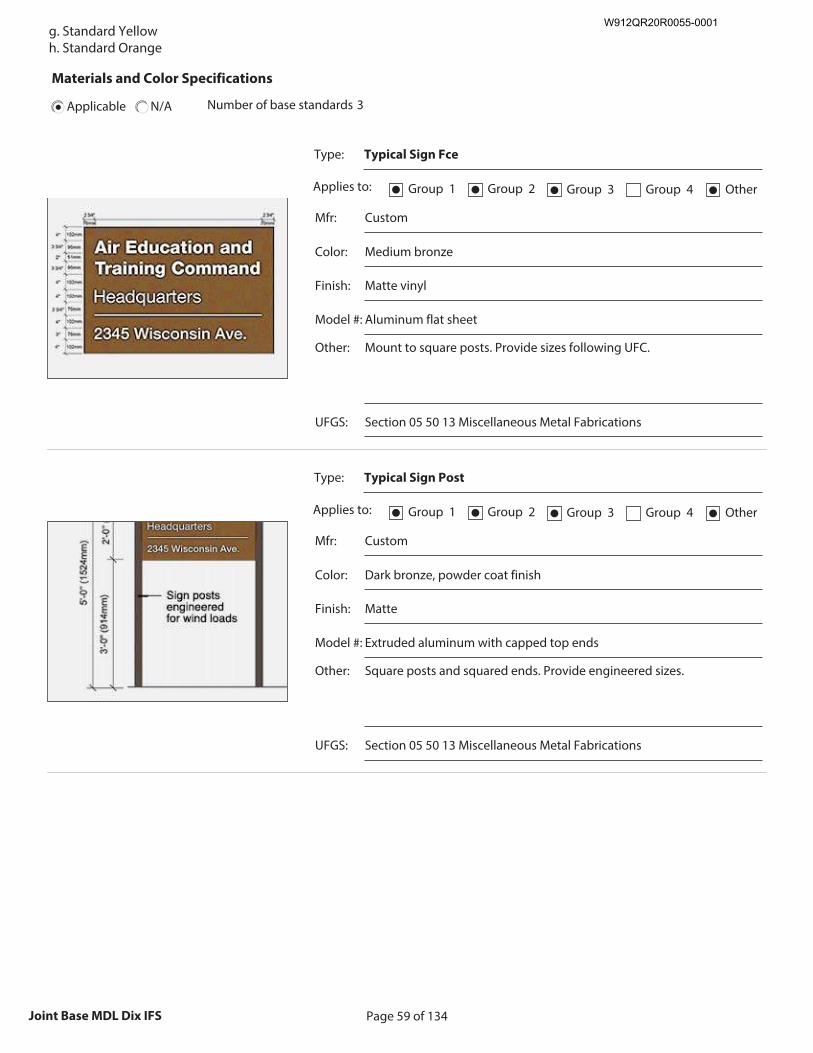
Page 59 of 134Joint Base MDL Dix IFS
g. Standard Yellow h. Standard Orange
Materials and Color Specifications
Applicable N/A Number of base standards 3
Type: Typical Sign Fce
Applies to: Group 1● Group 2● Group 3● Group 4 Other●
Mfr: Custom
Color: Medium bronze
Finish: Matte vinyl
Model #: Aluminum flat sheet
Other: Mount to square posts. Provide sizes following UFC.
Recommended Image: Example of Materials and Color
Specifications
Size image to: 250 pixels width x 188 pixels height
Click here to insert image
UFGS: Section 05 50 13 Miscellaneous Metal Fabrications
Type: Typical Sign Post
Applies to: Group 1● Group 2● Group 3● Group 4 Other●
Mfr: Custom
Color: Dark bronze, powder coat finish
Finish: Matte
Model #: Extruded aluminum with capped top ends
Other: Square posts and squared ends. Provide engineered sizes.
Recommended Image: Example of Materials and Color
Specifications
Size image to: 250 pixels width x 188 pixels height
Click here to insert image
UFGS: Section 05 50 13 Miscellaneous Metal Fabrications
W912QR20R0055-0001
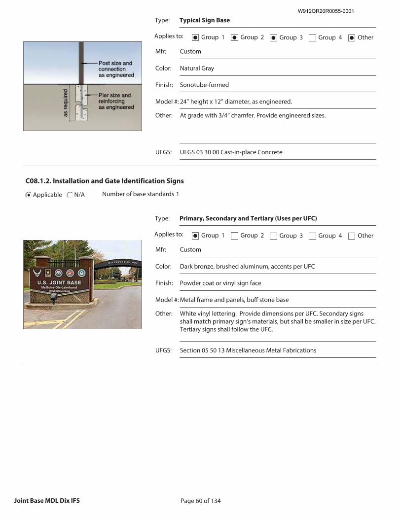
Page 60 of 134Joint Base MDL Dix IFS
Type: Typical Sign Base
Applies to: Group 1● Group 2● Group 3● Group 4 Other●
Mfr: Custom
Color: Natural Gray
Finish: Sonotube-formed
Model #: 24” height x 12” diameter, as engineered.
Other: At grade with 3/4” chamfer. Provide engineered sizes.
Recommended Image: Example of Materials and Color
Specifications
Size image to: 250 pixels width x 188 pixels height
Click here to insert image
UFGS: UFGS 03 30 00 Cast-in-place Concrete
C08.1.2. Installation and Gate Identification Signs
Applicable N/A Number of base standards 1
Type: Primary, Secondary and Tertiary (Uses per UFC)
Applies to: Group 1● Group 2 Group 3 Group 4 Other
Mfr: Custom
Color: Dark bronze, brushed aluminum, accents per UFC
Finish: Powder coat or vinyl sign face
Model #: Metal frame and panels, buff stone base
Other: White vinyl lettering. Provide dimensions per UFC. Secondary signs shall match primary sign’s materials, but shall be smaller in size per UFC. Tertiary signs shall follow the UFC.
Recommended Image: Example of Installation and Gate
Identification Signs
Size image to: 250 pixels width x 188 pixels height
Click here to insert image
UFGS: Section 05 50 13 Miscellaneous Metal Fabrications
W912QR20R0055-0001
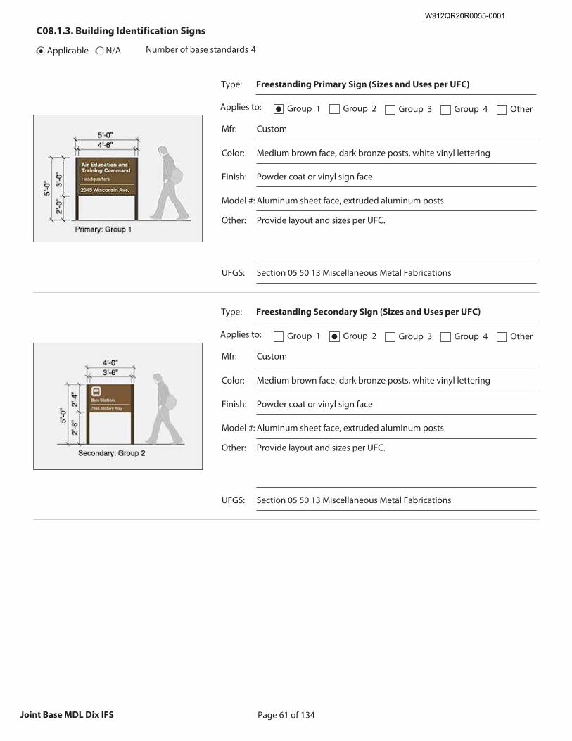
Page 61 of 134Joint Base MDL Dix IFS
C08.1.3. Building Identification Signs
Applicable N/A Number of base standards 4
Type: Freestanding Primary Sign (Sizes and Uses per UFC)
Applies to: Group 1● Group 2 Group 3 Group 4 Other
Mfr: Custom
Color: Medium brown face, dark bronze posts, white vinyl lettering
Finish: Powder coat or vinyl sign face
Model #: Aluminum sheet face, extruded aluminum posts
Other: Provide layout and sizes per UFC.
Recommended Image: Example of Building Identification
Signs
Size image to: 250 pixels width x 188 pixels height
Click here to insert image
UFGS: Section 05 50 13 Miscellaneous Metal Fabrications
Type: Freestanding Secondary Sign (Sizes and Uses per UFC)
Applies to: Group 1 Group 2● Group 3 Group 4 Other
Mfr: Custom
Color: Medium brown face, dark bronze posts, white vinyl lettering
Finish: Powder coat or vinyl sign face
Model #: Aluminum sheet face, extruded aluminum posts
Other: Provide layout and sizes per UFC.
Recommended Image: Example of Building Identification
Signs
Size image to: 250 pixels width x 188 pixels height
Click here to insert image
UFGS: Section 05 50 13 Miscellaneous Metal Fabrications
W912QR20R0055-0001
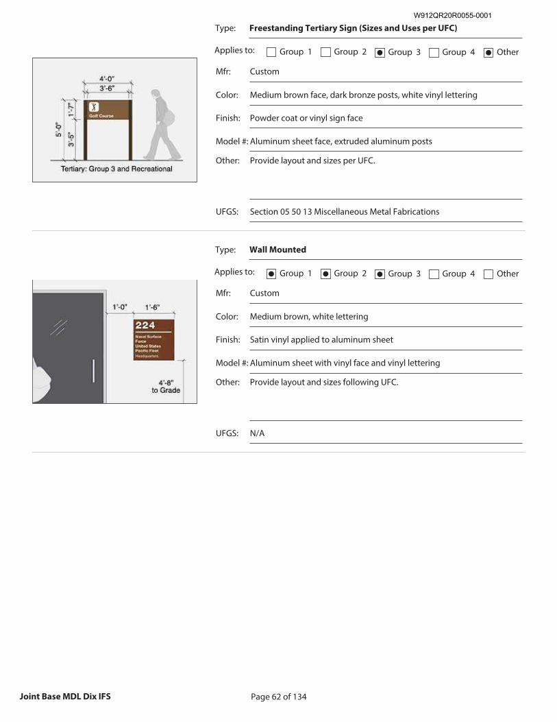
Page 62 of 134Joint Base MDL Dix IFS
Type: Freestanding Tertiary Sign (Sizes and Uses per UFC)
Applies to: Group 1 Group 2 Group 3● Group 4 Other●
Mfr: Custom
Color: Medium brown face, dark bronze posts, white vinyl lettering
Finish: Powder coat or vinyl sign face
Model #: Aluminum sheet face, extruded aluminum posts
Other: Provide layout and sizes per UFC.
Recommended Image: Example of Building Identification
Signs
Size image to: 250 pixels width x 188 pixels height
Click here to insert image
UFGS: Section 05 50 13 Miscellaneous Metal Fabrications
Type: Wall Mounted
Applies to: Group 1● Group 2● Group 3● Group 4 Other
Mfr: Custom
Color: Medium brown, white lettering
Finish: Satin vinyl applied to aluminum sheet
Model #: Aluminum sheet with vinyl face and vinyl lettering
Other: Provide layout and sizes following UFC.
Recommended Image: Example of Building Identification
Signs
Size image to: 250 pixels width x 188 pixels height
Click here to insert image
UFGS: N/A
W912QR20R0055-0001
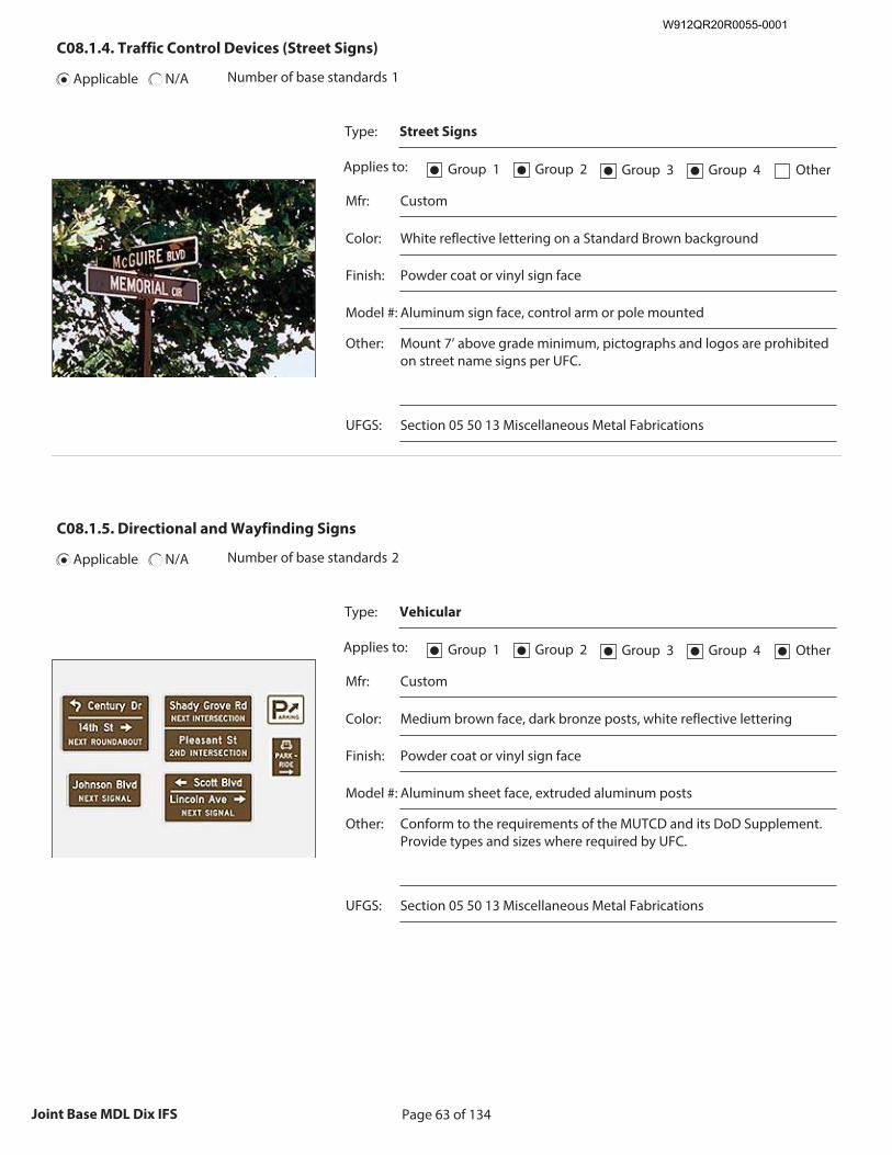
Page 63 of 134Joint Base MDL Dix IFS
C08.1.4. Traffic Control Devices (Street Signs)
Applicable N/A Number of base standards 1
Type: Street Signs
Applies to: Group 1● Group 2● Group 3● Group 4● Other
Mfr: Custom
Color: White reflective lettering on a Standard Brown background
Finish: Powder coat or vinyl sign face
Model #: Aluminum sign face, control arm or pole mounted
Other: Mount 7’ above grade minimum, pictographs and logos are prohibited on street name signs per UFC.
Recommended Image: Example of Traffic Control Device
Size image to:
250 pixels width x 188 pixels height
Click here to insert image
UFGS: Section 05 50 13 Miscellaneous Metal Fabrications
C08.1.5. Directional and Wayfinding Signs
Applicable N/A Number of base standards 2
Type: Vehicular
Applies to: Group 1● Group 2● Group 3● Group 4● Other●
Mfr: Custom
Color: Medium brown face, dark bronze posts, white reflective lettering
Finish: Powder coat or vinyl sign face
Model #: Aluminum sheet face, extruded aluminum posts
Other: Conform to the requirements of the MUTCD and its DoD Supplement. Provide types and sizes where required by UFC.
Recommended Image: Example of Directional and
Wayfinding Sign
Size image to: 250 pixels width x 188 pixels height
Click here to insert image
UFGS: Section 05 50 13 Miscellaneous Metal Fabrications
W912QR20R0055-0001
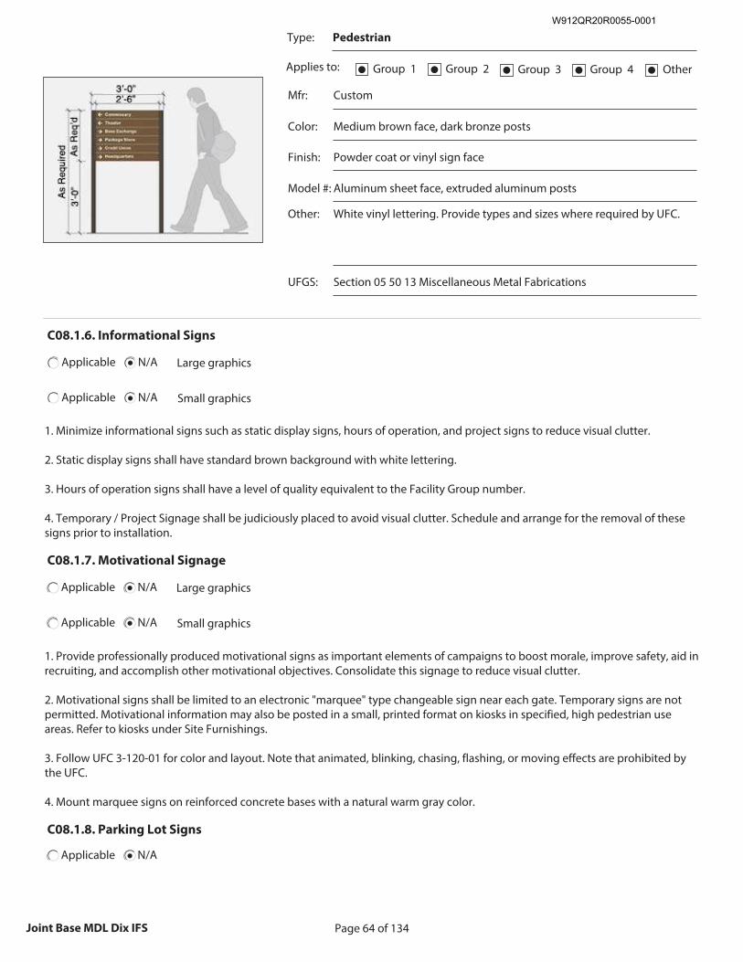
Page 64 of 134Joint Base MDL Dix IFS
Type: Pedestrian
Applies to: Group 1● Group 2● Group 3● Group 4● Other●
Mfr: Custom
Color: Medium brown face, dark bronze posts
Finish: Powder coat or vinyl sign face
Model #: Aluminum sheet face, extruded aluminum posts
Other: White vinyl lettering. Provide types and sizes where required by UFC.
Recommended Image: Example of Directional and
Wayfinding Sign
Size image to: 250 pixels width x 188 pixels height
Click here to insert image
UFGS: Section 05 50 13 Miscellaneous Metal Fabrications
C08.1.6. Informational Signs
Applicable N/A Large graphics
Applicable N/A Small graphics
1. Minimize informational signs such as static display signs, hours of operation, and project signs to reduce visual clutter. 2. Static display signs shall have standard brown background with white lettering. 3. Hours of operation signs shall have a level of quality equivalent to the Facility Group number. 4. Temporary / Project Signage shall be judiciously placed to avoid visual clutter. Schedule and arrange for the removal of these signs prior to installation.
C08.1.7. Motivational Signage
Applicable N/A Large graphics
Applicable N/A Small graphics
1. Provide professionally produced motivational signs as important elements of campaigns to boost morale, improve safety, aid in recruiting, and accomplish other motivational objectives. Consolidate this signage to reduce visual clutter. 2. Motivational signs shall be limited to an electronic "marquee" type changeable sign near each gate. Temporary signs are not permitted. Motivational information may also be posted in a small, printed format on kiosks in specified, high pedestrian use areas. Refer to kiosks under Site Furnishings. 3. Follow UFC 3-120-01 for color and layout. Note that animated, blinking, chasing, flashing, or moving effects are prohibited by the UFC. 4. Mount marquee signs on reinforced concrete bases with a natural warm gray color.
C08.1.8. Parking Lot Signs
Applicable N/A
W912QR20R0055-0001
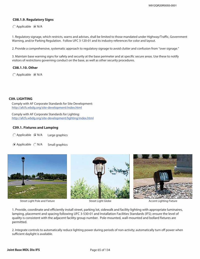
Page 65 of 134Joint Base MDL Dix IFS
C08.1.9. Regulatory Signs
Applicable N/A
1. Regulatory signage, which restricts, warns and advises, shall be limited to those mandated under Highway/Traffic, Government Warning, and/or Parking Regulation. Follow UFC 3-120-01 and its industry references for color and layout. 2. Provide a comprehensive, systematic approach to regulatory signage to avoid clutter and confusion from “over signage.” 3. Maintain base warning signs for safety and security at the base perimeter and at specific secure areas. Use these to notify visitors of restrictions governing conduct on the base, as well as other security procedures.
C08.1.10. Other
Applicable N/A
C09. LIGHTING
Comply with AF Corporate Standards for Site Development: http://afcfs.wbdg.org/site-development/index.html
Comply with AF Corporate Standards for Lighting: http://afcfs.wbdg.org/site-development/lighting/index.html
C09.1. Fixtures and Lamping
Applicable N/A Large graphics
Applicable N/A Small graphics
Insert Fixtures and Lamping graphic
Size image to:
250 pixels width x 188 pixels height
Click here to insert image
Street Light Pole and Fixture
Insert Fixtures and Lamping graphic
Size image to:
250 pixels width x 188 pixels height
Click here to insert image
Street Light Globe
Insert Fixtures and Lamping graphic
Size image to:
250 pixels width x 188 pixels height
Click here to insert image
Accent Lighting Fixture
1. Provide, coordinate and efficiently install street, parking lot, sidewalk and facility lighting with appropriate luminaires, lamping, placement and spacing following UFC 3-530-01 and Installation Facilities Standards (IFS); ensure the level of quality is consistent with the adjacent facility group number. Pole-mounted, wall-mounted and bollard fixtures are permitted. 2. Integrate controls to automatically reduce lighting power during periods of non-activity; automatically turn off power when sufficient daylight is available.
W912QR20R0055-0001
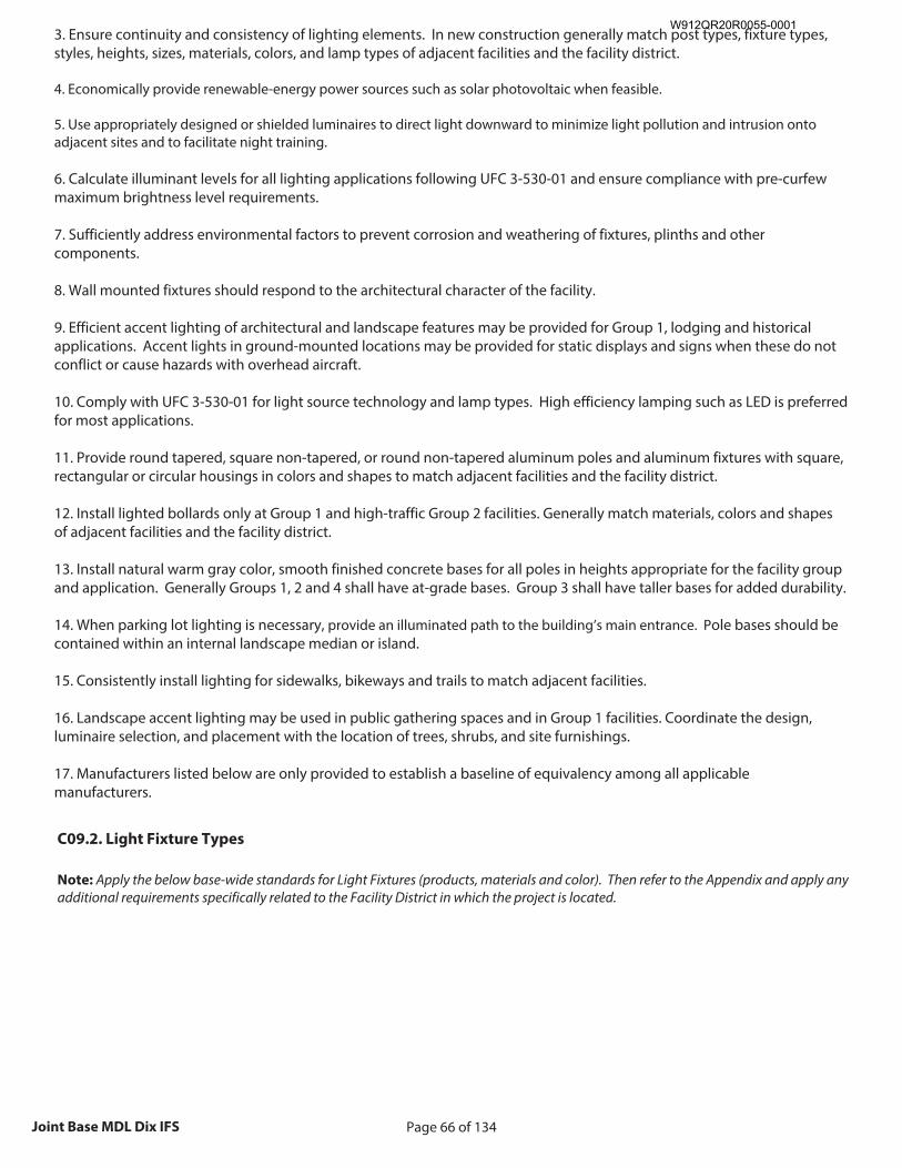
Page 66 of 134Joint Base MDL Dix IFS
3. Ensure continuity and consistency of lighting elements. In new construction generally match post types, fixture types, styles, heights, sizes, materials, colors, and lamp types of adjacent facilities and the facility district. 4. Economically provide renewable-energy power sources such as solar photovoltaic when feasible. 5. Use appropriately designed or shielded luminaires to direct light downward to minimize light pollution and intrusion onto adjacent sites and to facilitate night training. 6. Calculate illuminant levels for all lighting applications following UFC 3-530-01 and ensure compliance with pre-curfew maximum brightness level requirements. 7. Sufficiently address environmental factors to prevent corrosion and weathering of fixtures, plinths and other components. 8. Wall mounted fixtures should respond to the architectural character of the facility. 9. Efficient accent lighting of architectural and landscape features may be provided for Group 1, lodging and historical applications. Accent lights in ground-mounted locations may be provided for static displays and signs when these do not conflict or cause hazards with overhead aircraft. 10. Comply with UFC 3-530-01 for light source technology and lamp types. High efficiency lamping such as LED is preferred for most applications. 11. Provide round tapered, square non-tapered, or round non-tapered aluminum poles and aluminum fixtures with square, rectangular or circular housings in colors and shapes to match adjacent facilities and the facility district. 12. Install lighted bollards only at Group 1 and high-traffic Group 2 facilities. Generally match materials, colors and shapes of adjacent facilities and the facility district. 13. Install natural warm gray color, smooth finished concrete bases for all poles in heights appropriate for the facility group and application. Generally Groups 1, 2 and 4 shall have at-grade bases. Group 3 shall have taller bases for added durability. 14. When parking lot lighting is necessary, provide an illuminated path to the building’s main entrance. Pole bases should be contained within an internal landscape median or island. 15. Consistently install lighting for sidewalks, bikeways and trails to match adjacent facilities. 16. Landscape accent lighting may be used in public gathering spaces and in Group 1 facilities. Coordinate the design, luminaire selection, and placement with the location of trees, shrubs, and site furnishings. 17. Manufacturers listed below are only provided to establish a baseline of equivalency among all applicable manufacturers.
C09.2. Light Fixture Types
Note: Apply the below base-wide standards for Light Fixtures (products, materials and color). Then refer to the Appendix and apply any additional requirements specifically related to the Facility District in which the project is located.
W912QR20R0055-0001
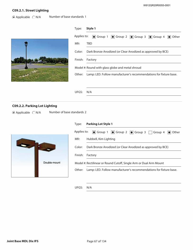
Page 67 of 134Joint Base MDL Dix IFS
C09.2.1. Street Lighting
Applicable N/A Number of base standards 1
Type: Style 1
Applies to: Group 1● Group 2● Group 3● Group 4● Other●
Mfr: TBD
Color: Dark Bronze Anodized (or Clear Anodized as approved by BCE)
Finish: Factory
Model #: Round with glass globe and metal shroud
Other: Lamp: LED. Follow manufacturer’s recommendations for fixture base.
Recommended Image: Example of Street Lighting
Size image to:
250 pixels width x 188 pixels height
Click here to insert image
UFGS: N/A
C09.2.2. Parking Lot Lighting
Applicable N/A Number of base standards 2
Type: Parking Lot Style 1
Applies to: Group 1● Group 2● Group 3● Group 4 Other●
Mfr: Hubbell, Kim Lighting
Color: Dark Bronze Anodized (or Clear Anodized as approved by BCE)
Finish: Factory
Model #: Rectilinear or Round Cutoff, Single Arm or Dual Arm Mount
Other: Lamp: LED. Follow manufacturer’s recommendations for fixture base.
Recommended Image: Example of Parking Lot Lighting
Size image to:
250 pixels width x 188 pixels height
Click here to insert image
UFGS: N/A
W912QR20R0055-0001
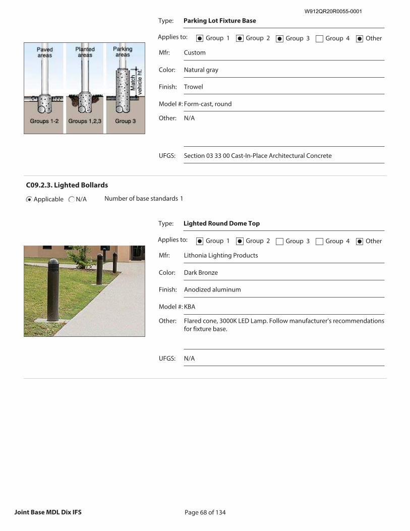
Page 68 of 134Joint Base MDL Dix IFS
Type: Parking Lot Fixture Base
Applies to: Group 1● Group 2● Group 3● Group 4 Other●
Mfr: Custom
Color: Natural gray
Finish: Trowel
Model #: Form-cast, round
Other: N/A
Recommended Image: Example of Parking Lot Lighting
Size image to:
250 pixels width x 188 pixels height
Click here to insert image
UFGS: Section 03 33 00 Cast-In-Place Architectural Concrete
C09.2.3. Lighted Bollards
Applicable N/A Number of base standards 1
Type: Lighted Round Dome Top
Applies to: Group 1● Group 2● Group 3 Group 4 Other●
Mfr: Lithonia Lighting Products
Color: Dark Bronze
Finish: Anodized aluminum
Model #: KBA
Other: Flared cone, 3000K LED Lamp. Follow manufacturer’s recommendations for fixture base.
Recommended Image: Example of Lighted Bollards
Size image to:
250 pixels width x 188 pixels height
Click here to insert image
UFGS: N/A
W912QR20R0055-0001
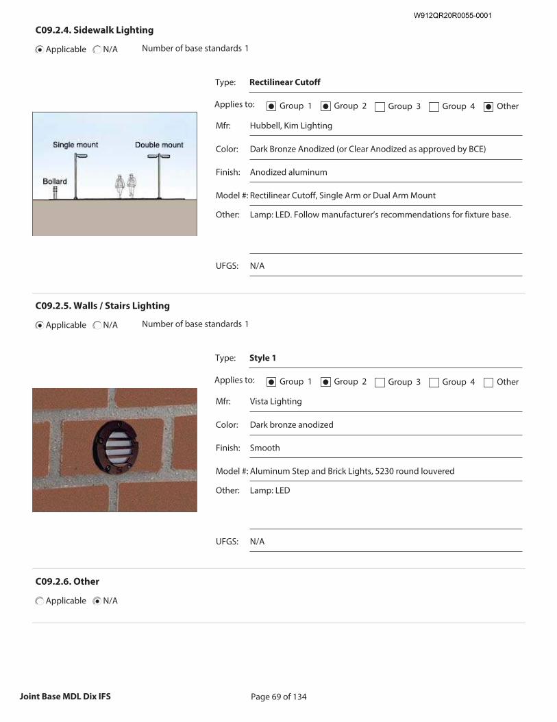
Page 69 of 134Joint Base MDL Dix IFS
C09.2.4. Sidewalk Lighting
Applicable N/A Number of base standards 1
Type: Rectilinear Cutoff
Applies to: Group 1● Group 2● Group 3 Group 4 Other●
Mfr: Hubbell, Kim Lighting
Color: Dark Bronze Anodized (or Clear Anodized as approved by BCE)
Finish: Anodized aluminum
Model #: Rectilinear Cutoff, Single Arm or Dual Arm Mount
Other: Lamp: LED. Follow manufacturer’s recommendations for fixture base.
Recommended Image: Example of Sidewalk Lighting
Size image to:
250 pixels width x 188 pixels height
Click here to insert image
UFGS: N/A
C09.2.5. Walls / Stairs Lighting
Applicable N/A Number of base standards 1
Type: Style 1
Applies to: Group 1● Group 2● Group 3 Group 4 Other
Mfr: Vista Lighting
Color: Dark bronze anodized
Finish: Smooth
Model #: Aluminum Step and Brick Lights, 5230 round louvered
Other: Lamp: LED
Recommended Image: Example of Walls / Stairs Lighting
Size image to:
250 pixels width x 188 pixels height
Click here to insert image
UFGS: N/A
C09.2.6. Other
Applicable N/A
W912QR20R0055-0001

Page 70 of 134Joint Base MDL Dix IFS
D. FACILITIES EXTERIORS
Comply with Air Force Corporate Standards for Facilities Exteriors: http://afcfs.wbdg.org/facilities-exteriors/index.html
Large graphicsApplicable N/A
Applicable N/A Small graphics
D01. SUPPORTING THE MISSION
Comply with AF Corporate Standards for Supporting the Mission: http://afcfs.wbdg.org/facilities-exteriors/supporting-the-mission/index.html
D02. SUSTAINABILITY
Comply with Air Force Corporate Standards for Sustainability: http://afcfs.wbdg.org/facilities-exteriors/supporting-the-mission/index.html
W912QR20R0055-0001
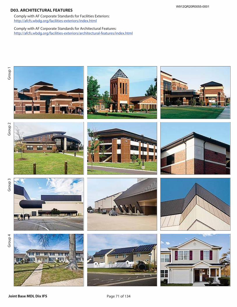
Page 71 of 134Joint Base MDL Dix IFS
D03. ARCHITECTURAL FEATURES
Comply with AF Corporate Standards for Facilities Exteriors: http://afcfs.wbdg.org/facilities-exteriors/index.html
Comply with AF Corporate Standards for Architectural Features: http://afcfs.wbdg.org/facilities-exteriors/architectural-features/index.html
Gro
up 1
Gro
up 2
Gro
up 3
Gro
up 4
Recommended Image: Overall facility architecture
Size image to: 250 pixels width x 188 pixels height
Click here to insert image
Recommended Image: Primary Feature Size image to:
250 pixels width x 188 pixels height
Click here to insert image
Recommended Image: Architectural Detail
Size image to: 250 pixels width x 188 pixels height
Click here to insert image
Recommended Image: Overall facility architecture
Size image to: 250 pixels width x 188 pixels height
Click here to insert image
Recommended Image: Primary Feature Size image to:
250 pixels width x 188 pixels height
Click here to insert image
Recommended Image: Wall showing secondary material
Size image to: 250 pixels width x 188 pixels height
Click here to insert image
Recommended Image: Overall facility architecture
Size image to: 250 pixels width x 188 pixels height
Click here to insert image
Recommended Image: Primary Feature Size image to:
250 pixels width x 188 pixels height
Click here to insert image
Recommended Image: Architectural Detail
Size image to: 250 pixels width x 188 pixels height
Click here to insert image
Recommended Image: Overall facility architecture
Size image to: 250 pixels width x 188 pixels height
Click here to insert image
Recommended Image: Primary Feature
Size image to: 250 pixels width x 188 pixels height
Click here to insert image
Recommended Image: Architectural Detail
Size image to: 250 pixels width x 188 pixels height
Click here to insert image
W912QR20R0055-0001
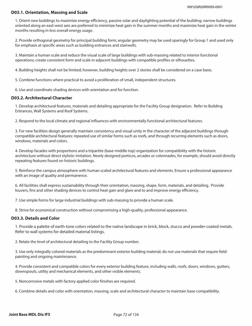
Page 72 of 134Joint Base MDL Dix IFS
D03.1. Orientation, Massing and Scale
1. Orient new buildings to maximize energy efficiency, passive solar and daylighting potential of the building; narrow buildings oriented along an east-west axis are preferred to minimize heat gain in the summer months and maximize heat gain in the winter months resulting in less overall energy usage. 2. Provide orthogonal geometry for principal building form; angular geometry may be used sparingly for Group 1 and used only for emphasis at specific areas such as building entrances and stairwells. 3. Maintain a human scale and reduce the visual scale of large buildings with sub-massing related to interior functional operations; create consistent form and scale in adjacent buildings with compatible profiles or silhouettes. 4. Building heights shall not be limited; however, building heights over 2 stories shall be considered on a case basis. 5. Combine functions where practical to avoid a proliferation of small, independent structures. 6. Use and coordinate shading devices with orientation and for function.
D03.2. Architectural Character
1. Develop architectural features, materials and detailing appropriate for the Facility Group designation. Refer to Building Entrances, Wall Systems and Roof Systems. 2. Respond to the local climate and regional influences with environmentally functional architectural features. 3. For new facilities design generally maintain consistency and visual unity in the character of the adjacent buildings through compatible architectural features: repeated use of similar forms such as roofs, and through recurring elements such as doors, windows, materials and colors. 4. Develop facades with proportions and a tripartite (base-middle-top) organization for compatibility with the historic architecture without direct stylistic imitation. Newly designed porticos, arcades or colonnades, for example, should avoid directly repeating features found on historic buildings. 5. Reinforce the campus atmosphere with human scaled architectural features and elements. Ensure a professional appearance with an image of quality and permanence. 6. All facilities shall express sustainability through their orientation, massing, shape, form, materials, and detailing. Provide louvers, fins and other shading devices to control heat gain and glare and to and improve energy efficiency. 7. Use simple forms for large industrial buildings with sub-massing to provide a human scale. 8. Strive for economical construction without compromising a high-quality, professional appearance.
D03.3. Details and Color
1. Provide a palette of earth-tone colors related to the native landscape in brick, block, stucco and powder-coated metals. Refer to wall systems for detailed material listings. 2. Relate the level of architectural detailing to the Facility Group number. 3. Use only integrally colored materials as the predominant exterior building material; do not use materials that require field painting and ongoing maintenance. 4. Provide consistent and compatible colors for every exterior building feature, including walls, roofs, doors, windows, gutters, downspouts, utility and mechanical elements, and other visible elements. 5. Noncorrosive metals with factory applied color finishes are required. 6. Combine details and color with orientation, massing, scale and architectural character to maintain base compatibility.
W912QR20R0055-0001
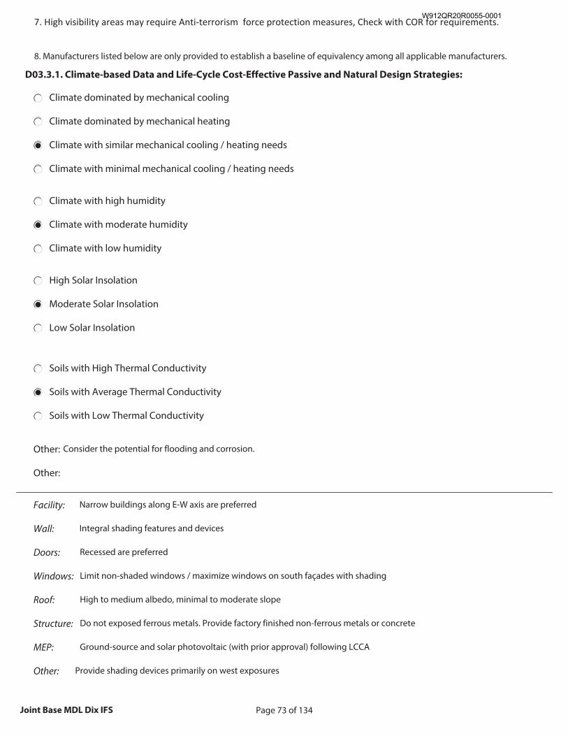
Page 73 of 134Joint Base MDL Dix IFS
7. High visibility areas may require Anti-terrorism force protection measures, Check with COR for requirements. 8. Manufacturers listed below are only provided to establish a baseline of equivalency among all applicable manufacturers.
D03.3.1. Climate-based Data and Life-Cycle Cost-Effective Passive and Natural Design Strategies:
Climate dominated by mechanical cooling
Climate dominated by mechanical heating
Climate with similar mechanical cooling / heating needs●
Climate with minimal mechanical cooling / heating needs
Climate with high humidity
Climate with moderate humidity●
Climate with low humidity
High Solar Insolation
Moderate Solar Insolation●
Low Solar Insolation
Soils with High Thermal Conductivity
Soils with Average Thermal Conductivity●
Soils with Low Thermal Conductivity
Other: Consider the potential for flooding and corrosion.
Other:
Facility: Narrow buildings along E-W axis are preferred
Wall: Integral shading features and devices
Doors: Recessed are preferred
Windows: Limit non-shaded windows / maximize windows on south façades with shading
Roof: High to medium albedo, minimal to moderate slope
Structure: Do not exposed ferrous metals. Provide factory finished non-ferrous metals or concrete
MEP: Ground-source and solar photovoltaic (with prior approval) following LCCA
Other: Provide shading devices primarily on west exposures
W912QR20R0055-0001
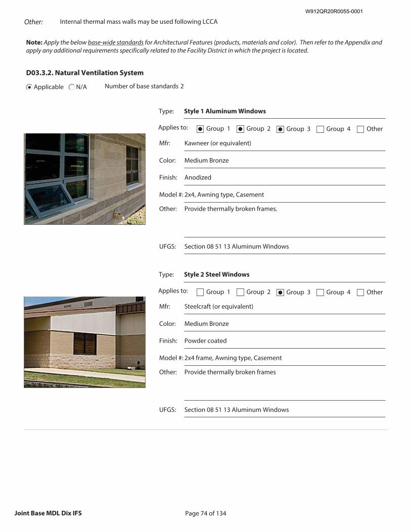
Page 74 of 134Joint Base MDL Dix IFS
Other: Internal thermal mass walls may be used following LCCA
Note: Apply the below base-wide standards for Architectural Features (products, materials and color). Then refer to the Appendix and apply any additional requirements specifically related to the Facility District in which the project is located.
D03.3.2. Natural Ventilation System
Applicable N/A Number of base standards 2
Type: Style 1 Aluminum Windows
Applies to: Group 1● Group 2● Group 3● Group 4 Other
Mfr: Kawneer (or equivalent)
Color: Medium Bronze
Finish: Anodized
Model #: 2x4, Awning type, Casement
Other: Provide thermally broken frames.
Recommended Image: Example of Natural Ventilation
System
Size image to: 250 pixels width x 188 pixels height
Click here to insert image
UFGS: Section 08 51 13 Aluminum Windows
Type: Style 2 Steel Windows
Applies to: Group 1 Group 2 Group 3● Group 4 Other
Mfr: Steelcraft (or equivalent)
Color: Medium Bronze
Finish: Powder coated
Model #: 2x4 frame, Awning type, Casement
Other: Provide thermally broken frames
Recommended Image: Example of Natural Ventilation
System
Size image to: 250 pixels width x 188 pixels height
Click here to insert image
UFGS: Section 08 51 13 Aluminum Windows
W912QR20R0055-0001
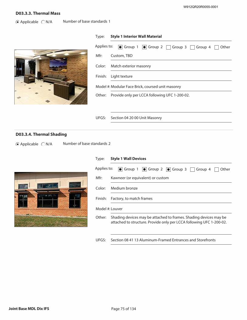
Page 75 of 134Joint Base MDL Dix IFS
D03.3.3. Thermal Mass
Applicable N/A Number of base standards 1
Type: Style 1 Interior Wall Material
Applies to: Group 1● Group 2● Group 3 Group 4 Other
Mfr: Custom, TBD
Color: Match exterior masonry
Finish: Light texture
Model #: Modular Face Brick, coursed unit masonry
Other: Provide only per LCCA following UFC 1-200-02.
Recommended Image: Example of Thermal Mass
Size image to:
250 pixels width x 188 pixels height
Click here to insert image
UFGS: Section 04 20 00 Unit Masonry
D03.3.4. Thermal Shading
Applicable N/A Number of base standards 2
Type: Style 1 Wall Devices
Applies to: Group 1● Group 2● Group 3● Group 4 Other
Mfr: Kawneer (or equivalent) or custom
Color: Medium bronze
Finish: Factory, to match frames
Model #: Louver
Other: Shading devices may be attached to frames. Shading devices may be attached to structure. Provide only per LCCA following UFC 1-200-02.
Recommended Image: Example of Thermal Shading
Size image to:
250 pixels width x 188 pixels height
Click here to insert image
UFGS: Section 08 41 13 Aluminum-Framed Entrances and Storefronts
W912QR20R0055-0001
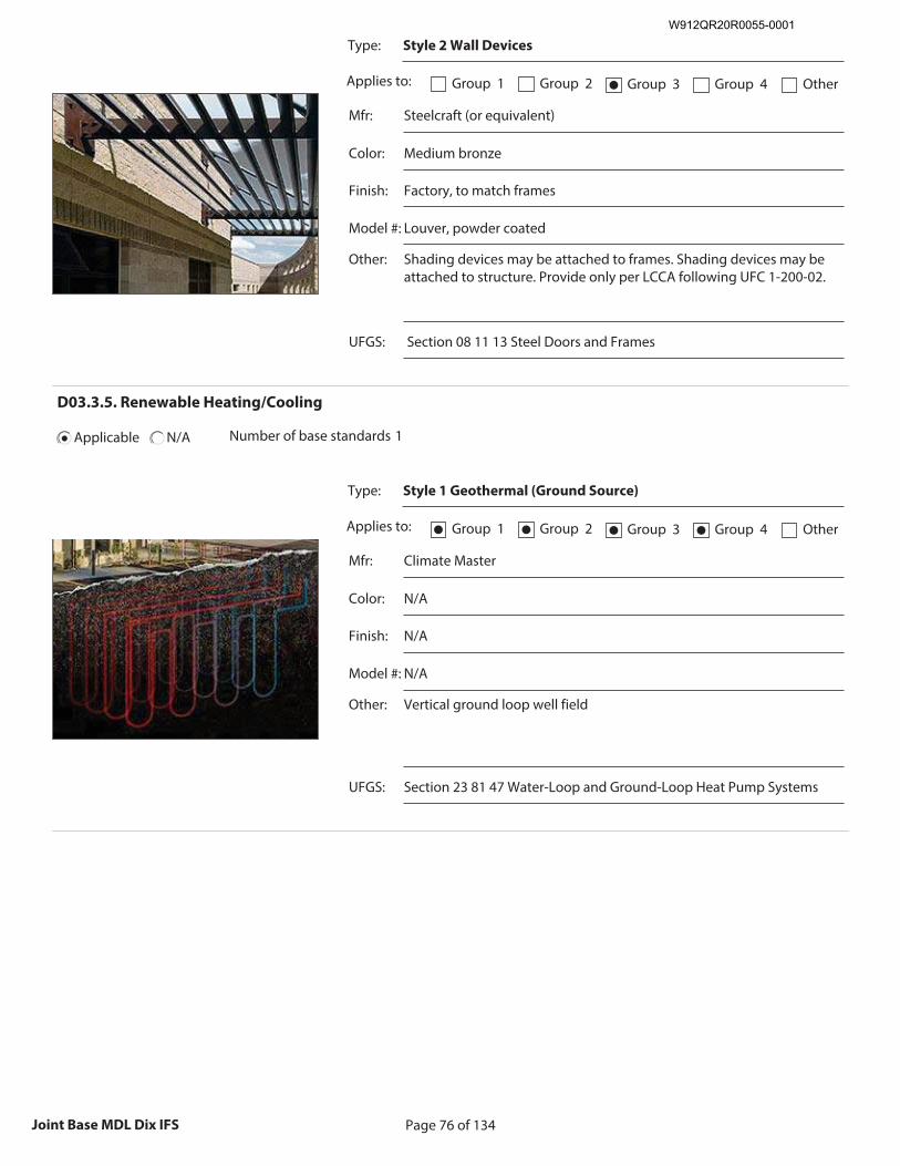
Page 76 of 134Joint Base MDL Dix IFS
Type: Style 2 Wall Devices
Applies to: Group 1 Group 2 Group 3● Group 4 Other
Mfr: Steelcraft (or equivalent)
Color: Medium bronze
Finish: Factory, to match frames
Model #: Louver, powder coated
Other: Shading devices may be attached to frames. Shading devices may be attached to structure. Provide only per LCCA following UFC 1-200-02.
Recommended Image: Example of Thermal Shading
Size image to:
250 pixels width x 188 pixels height
Click here to insert image
UFGS: Section 08 11 13 Steel Doors and Frames
D03.3.5. Renewable Heating/Cooling
Applicable N/A Number of base standards 1
Type: Style 1 Geothermal (Ground Source)
Applies to: Group 1● Group 2● Group 3● Group 4● Other
Mfr: Climate Master
Color: N/A
Finish: N/A
Model #: N/A
Other: Vertical ground loop well field
Recommended Image: Example of Renewable Heating/
Cooling
Size image to: 250 pixels width x 188 pixels height
Click here to insert image
UFGS: Section 23 81 47 Water-Loop and Ground-Loop Heat Pump Systems
W912QR20R0055-0001
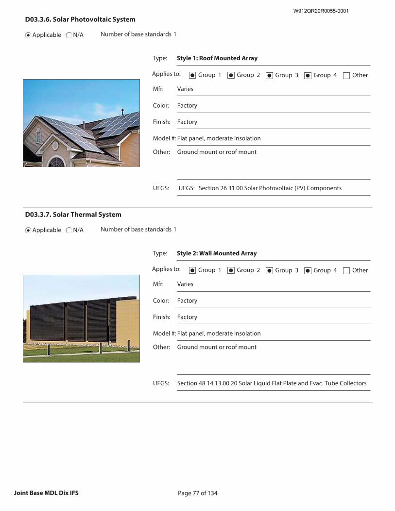
Page 77 of 134Joint Base MDL Dix IFS
D03.3.6. Solar Photovoltaic System
Applicable N/A Number of base standards 1
Type: Style 1: Roof Mounted Array
Applies to: Group 1● Group 2● Group 3● Group 4● Other
Mfr: Varies
Color: Factory
Finish: Factory
Model #: Flat panel, moderate insolation
Other: Ground mount or roof mount
Recommended Image: Example of Solar Photovoltaic
System
Size image to: 250 pixels width x 188 pixels height
Click here to insert image
UFGS: UFGS: Section 26 31 00 Solar Photovoltaic (PV) Components
D03.3.7. Solar Thermal System
Applicable N/A Number of base standards 1
Type: Style 2: Wall Mounted Array
Applies to: Group 1● Group 2● Group 3● Group 4● Other
Mfr: Varies
Color: Factory
Finish: Factory
Model #: Flat panel, moderate insolation
Other: Ground mount or roof mount
Recommended Image: Example of Solar Thermal System
Size image to:
250 pixels width x 188 pixels height
Click here to insert image
UFGS: Section 48 14 13.00 20 Solar Liquid Flat Plate and Evac. Tube Collectors
W912QR20R0055-0001
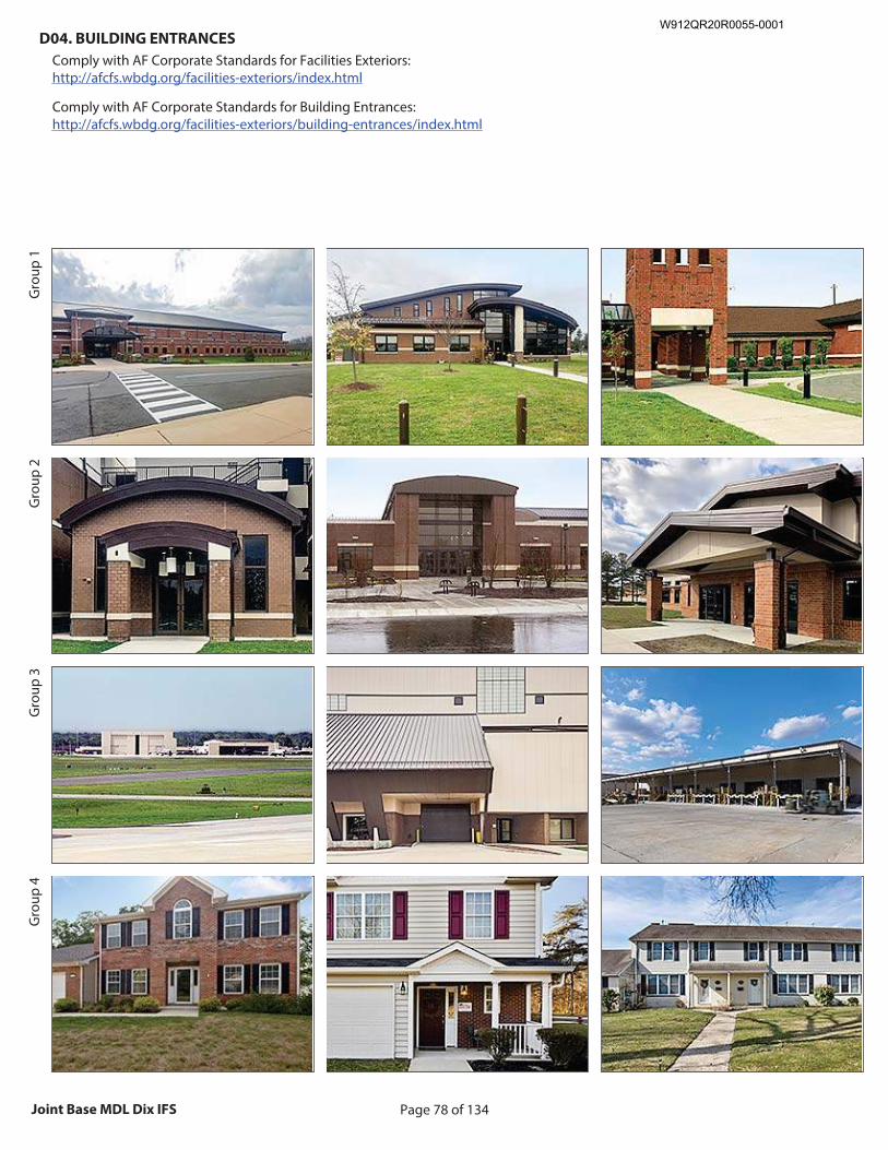
Page 78 of 134Joint Base MDL Dix IFS
D04. BUILDING ENTRANCES
Comply with AF Corporate Standards for Facilities Exteriors: http://afcfs.wbdg.org/facilities-exteriors/index.html
Comply with AF Corporate Standards for Building Entrances: http://afcfs.wbdg.org/facilities-exteriors/building-entrances/index.html
Gro
up 1
Gro
up 2
Gro
up 3
Gro
up 4
Recommended Image: Overall facility showing entrance
Size image to: 250 pixels width x 188 pixels height
Click here to insert image
Recommended Image: Primary Entrance
Size image to: 250 pixels width x 188 pixels height
Click here to insert image
Recommended Image: Secondary Entrance
Size image to: 250 pixels width x 188 pixels height
Click here to insert image
W912QR20R0055-0001
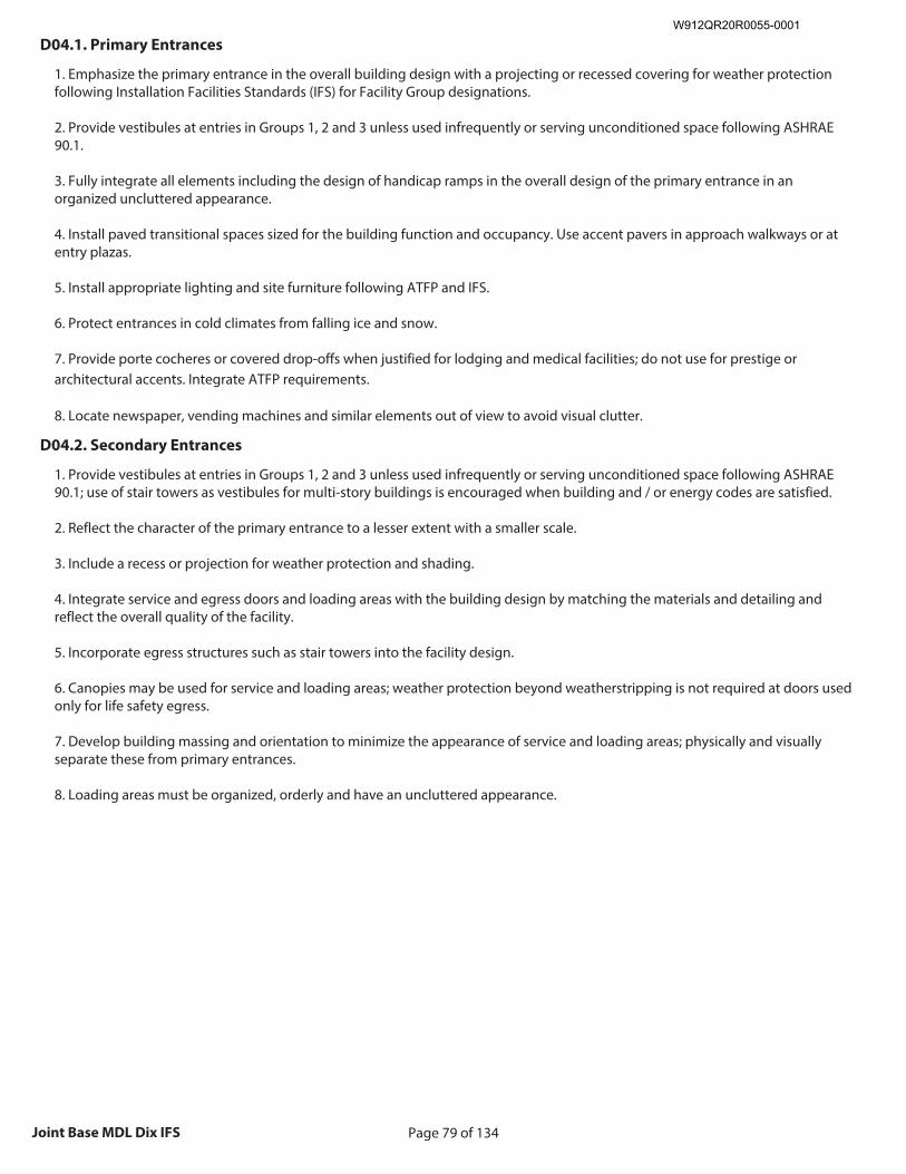
Page 79 of 134Joint Base MDL Dix IFS
D04.1. Primary Entrances
1. Emphasize the primary entrance in the overall building design with a projecting or recessed covering for weather protection following Installation Facilities Standards (IFS) for Facility Group designations. 2. Provide vestibules at entries in Groups 1, 2 and 3 unless used infrequently or serving unconditioned space following ASHRAE 90.1. 3. Fully integrate all elements including the design of handicap ramps in the overall design of the primary entrance in an organized uncluttered appearance. 4. Install paved transitional spaces sized for the building function and occupancy. Use accent pavers in approach walkways or at entry plazas. 5. Install appropriate lighting and site furniture following ATFP and IFS. 6. Protect entrances in cold climates from falling ice and snow. 7. Provide porte cocheres or covered drop-offs when justified for lodging and medical facilities; do not use for prestige or architectural accents. Integrate ATFP requirements. 8. Locate newspaper, vending machines and similar elements out of view to avoid visual clutter.
D04.2. Secondary Entrances
1. Provide vestibules at entries in Groups 1, 2 and 3 unless used infrequently or serving unconditioned space following ASHRAE 90.1; use of stair towers as vestibules for multi-story buildings is encouraged when building and / or energy codes are satisfied. 2. Reflect the character of the primary entrance to a lesser extent with a smaller scale. 3. Include a recess or projection for weather protection and shading.
4. Integrate service and egress doors and loading areas with the building design by matching the materials and detailing and reflect the overall quality of the facility. 5. Incorporate egress structures such as stair towers into the facility design. 6. Canopies may be used for service and loading areas; weather protection beyond weatherstripping is not required at doors used only for life safety egress. 7. Develop building massing and orientation to minimize the appearance of service and loading areas; physically and visually separate these from primary entrances. 8. Loading areas must be organized, orderly and have an uncluttered appearance.
W912QR20R0055-0001
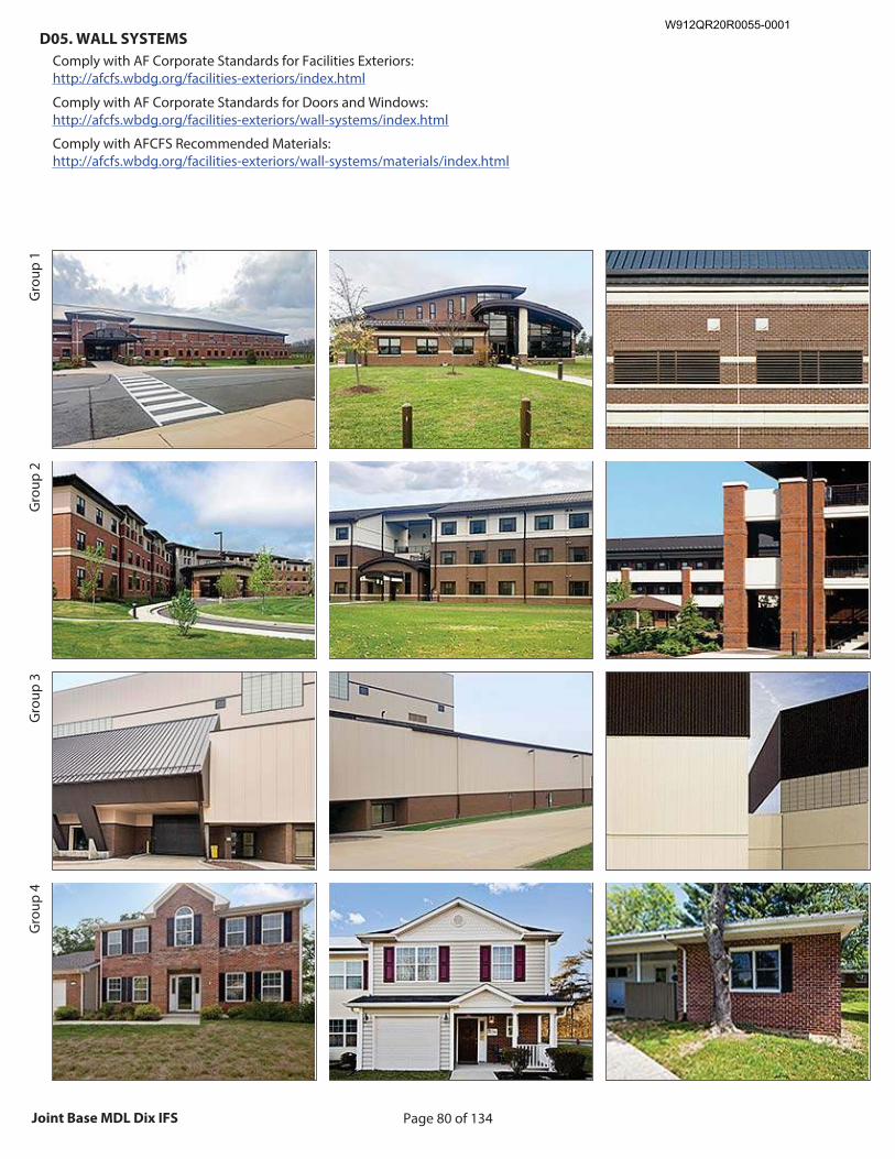
Page 80 of 134Joint Base MDL Dix IFS
D05. WALL SYSTEMS
Comply with AF Corporate Standards for Facilities Exteriors: http://afcfs.wbdg.org/facilities-exteriors/index.html
Comply with AF Corporate Standards for Doors and Windows: http://afcfs.wbdg.org/facilities-exteriors/wall-systems/index.html
Comply with AFCFS Recommended Materials: http://afcfs.wbdg.org/facilities-exteriors/wall-systems/materials/index.html
Gro
up 1
Gro
up 2
Gro
up 3
Gro
up 4
Recommended Image: Overall facility showing materials
Size image to: 250 pixels width x 188 pixels height
Click here to insert image
Recommended Image: Wall showing primary material
Size image to: 250 pixels width x 188 pixels height
Click here to insert image
Recommended Image: Wall showing secondary material
Size image to: 250 pixels width x 188 pixels height
Click here to insert image
W912QR20R0055-0001
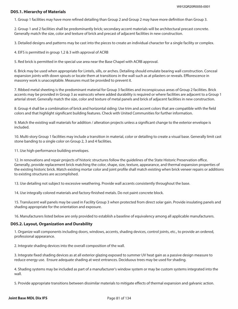
Page 81 of 134Joint Base MDL Dix IFS
D05.1. Hierarchy of Materials
1. Group 1 facilities may have more refined detailing than Group 2 and Group 2 may have more definition than Group 3. 2. Group 1 and 2 facilities shall be predominantly brick; secondary accent materials will be architectural precast concrete. Generally match the size, color and texture of brick and precast of adjacent facilities in new construction. 3. Detailed designs and patterns may be cast into the pieces to create an individual character for a single facility or complex. 4. EIFS is permitted in group 1,2 & 3 with approval of ACRB 5. Red brick is permitted in the special use area near the Base Chapel with ACRB approval. 6. Brick may be used when appropriate for Lintels, sills, or arches. Detailing should emulate bearing wall construction. Conceal expansion joints with down spouts or locate them at transitions in the wall such as at pilasters or reveals. Efflorescence in masonry work is unacceptable. Measures must be provided to prevent it. 7. Ribbed metal sheeting is the predominant material for Group 3 facilities and inconspicuous areas of Group 2 facilities. Brick accents may be provided in Group 3 as wainscots where added durability is required or where facilities are adjacent to a Group 1 arterial street. Generally match the size, color and texture of metal panels and brick of adjacent facilities in new construction. 8. Group 4 shall be a combination of brick and horizontal siding: Use trim and accent colors that are compatible with the field colors and that highlight significant building features. Check with United Communities for further information. 9. Match the existing wall materials for addition / alteration projects unless a significant change to the exterior envelope is included. 10. Multi-story Group 1 facilities may include a transition in material, color or detailing to create a visual base. Generally limit cast stone banding to a single color on Group 2, 3 and 4 facilities. 11. Use high-performance building envelopes. 12. In renovations and repair projects of historic structures follow the guidelines of the State Historic Preservation office. Generally, provide replacement brick matching the color, shape, size, texture, appearance, and thermal expansion properties of the existing historic brick. Match existing mortar color and joint profile shall match existing when brick veneer repairs or additions to existing structures are accomplished. 13. Use detailing not subject to excessive weathering. Provide wall accents consistently throughout the base. 14. Use integrally colored materials and factory-finished metals. Do not paint concrete block. 15. Translucent wall panels may be used in Facility Group 3 when protected from direct solar gain. Provide insulating panels and shading appropriate for the orientation and exposure. 16. Manufacturers listed below are only provided to establish a baseline of equivalency among all applicable manufacturers.
D05.2. Layout, Organization and Durability
1. Organize wall components including doors, windows, accents, shading devices, control joints, etc., to provide an ordered, professional appearance. 2. Integrate shading devices into the overall composition of the wall. 3. Integrate fixed shading devices as at all exterior glazing exposed to summer UV heat gain as a passive design measure to reduce energy use. Ensure adequate shading at west entrances. Deciduous trees may be used for shading. 4. Shading systems may be included as part of a manufacturer’s window system or may be custom systems integrated into the wall. 5. Provide appropriate transitions between dissimilar materials to mitigate effects of thermal expansion and galvanic action.
W912QR20R0055-0001
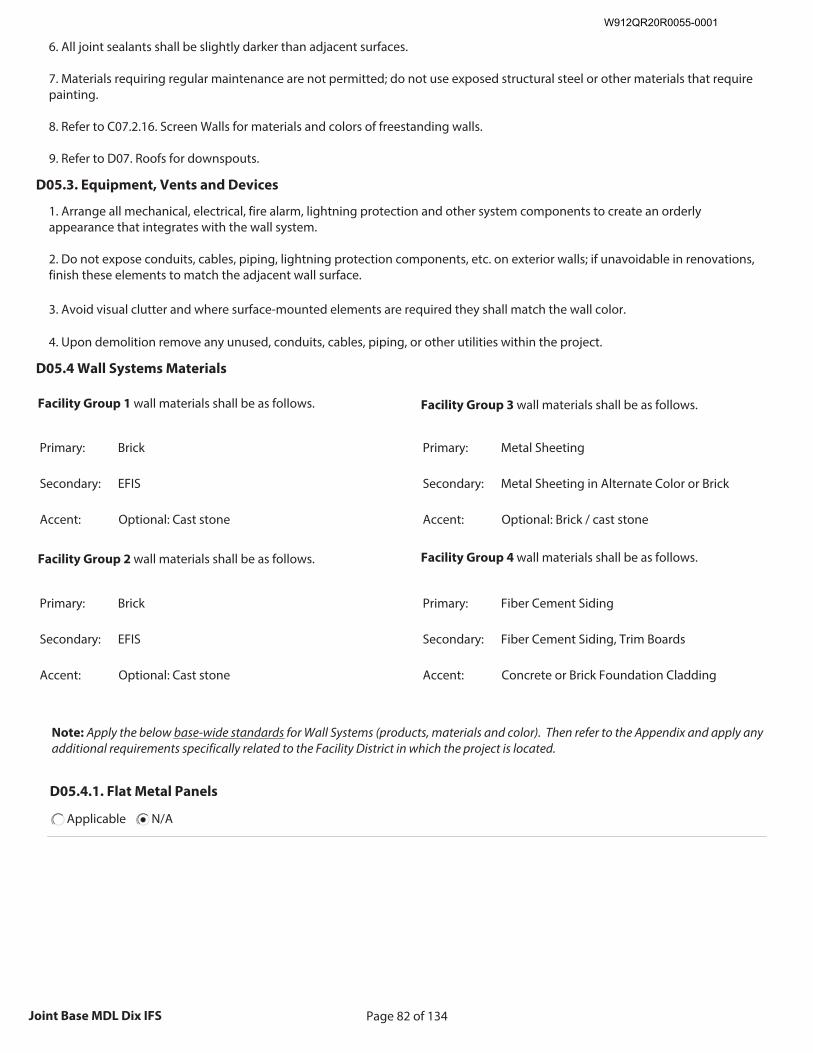
Page 82 of 134Joint Base MDL Dix IFS
6. All joint sealants shall be slightly darker than adjacent surfaces. 7. Materials requiring regular maintenance are not permitted; do not use exposed structural steel or other materials that require painting. 8. Refer to C07.2.16. Screen Walls for materials and colors of freestanding walls. 9. Refer to D07. Roofs for downspouts.
D05.3. Equipment, Vents and Devices
1. Arrange all mechanical, electrical, fire alarm, lightning protection and other system components to create an orderly appearance that integrates with the wall system. 2. Do not expose conduits, cables, piping, lightning protection components, etc. on exterior walls; if unavoidable in renovations, finish these elements to match the adjacent wall surface. 3. Avoid visual clutter and where surface-mounted elements are required they shall match the wall color. 4. Upon demolition remove any unused, conduits, cables, piping, or other utilities within the project.
D05.4 Wall Systems Materials
Facility Group 1 wall materials shall be as follows.
Primary: Brick
Secondary: EFIS
Accent: Optional: Cast stone
Facility Group 2 wall materials shall be as follows.
Primary: Brick
Secondary: EFIS
Accent: Optional: Cast stone
Facility Group 3 wall materials shall be as follows.
Primary: Metal Sheeting
Secondary: Metal Sheeting in Alternate Color or Brick
Accent: Optional: Brick / cast stone
Facility Group 4 wall materials shall be as follows.
Primary: Fiber Cement Siding
Secondary: Fiber Cement Siding, Trim Boards
Accent: Concrete or Brick Foundation Cladding
Note: Apply the below base-wide standards for Wall Systems (products, materials and color). Then refer to the Appendix and apply any additional requirements specifically related to the Facility District in which the project is located.
D05.4.1. Flat Metal Panels
Applicable N/A
W912QR20R0055-0001
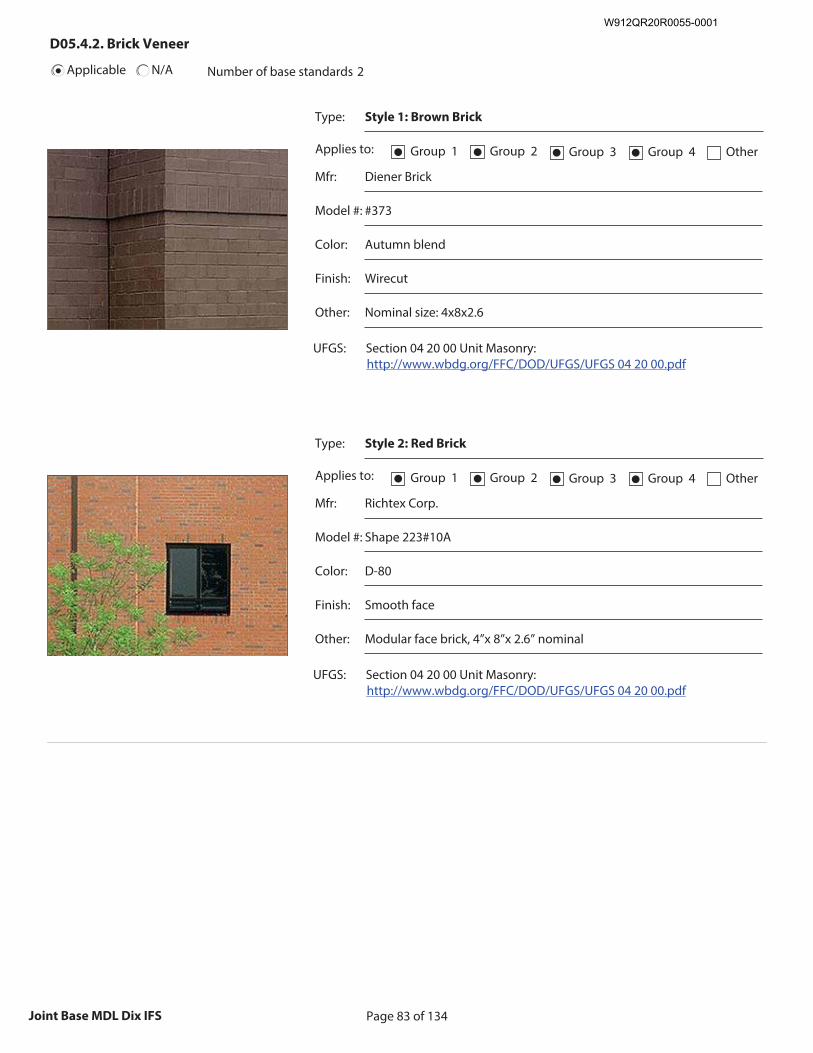
Page 83 of 134Joint Base MDL Dix IFS
Applicable N/A
D05.4.2. Brick Veneer
Number of base standards 2
Type: Style 1: Brown Brick
Applies to: Group 1● Group 2● Group 3● Group 4● Other
Mfr: Diener Brick
Model #: #373
Color: Autumn blend
Finish: Wirecut
Other: Nominal size: 4x8x2.6
UFGS: Section 04 20 00 Unit Masonry: http://www.wbdg.org/FFC/DOD/UFGS/UFGS 04 20 00.pdf
Recommended Image: Detail of brick Veneer
Size image to:
250 pixels width x 188 pixels height
Click here to insert image
Type: Style 2: Red Brick
Applies to: Group 1● Group 2● Group 3● Group 4● Other
Mfr: Richtex Corp.
Model #: Shape 223#10A
Color: D-80
Finish: Smooth face
Other: Modular face brick, 4”x 8”x 2.6” nominal
UFGS: Section 04 20 00 Unit Masonry: http://www.wbdg.org/FFC/DOD/UFGS/UFGS 04 20 00.pdf
Recommended Image: Detail of brick Veneer
Size image to:
250 pixels width x 188 pixels height
Click here to insert image
W912QR20R0055-0001
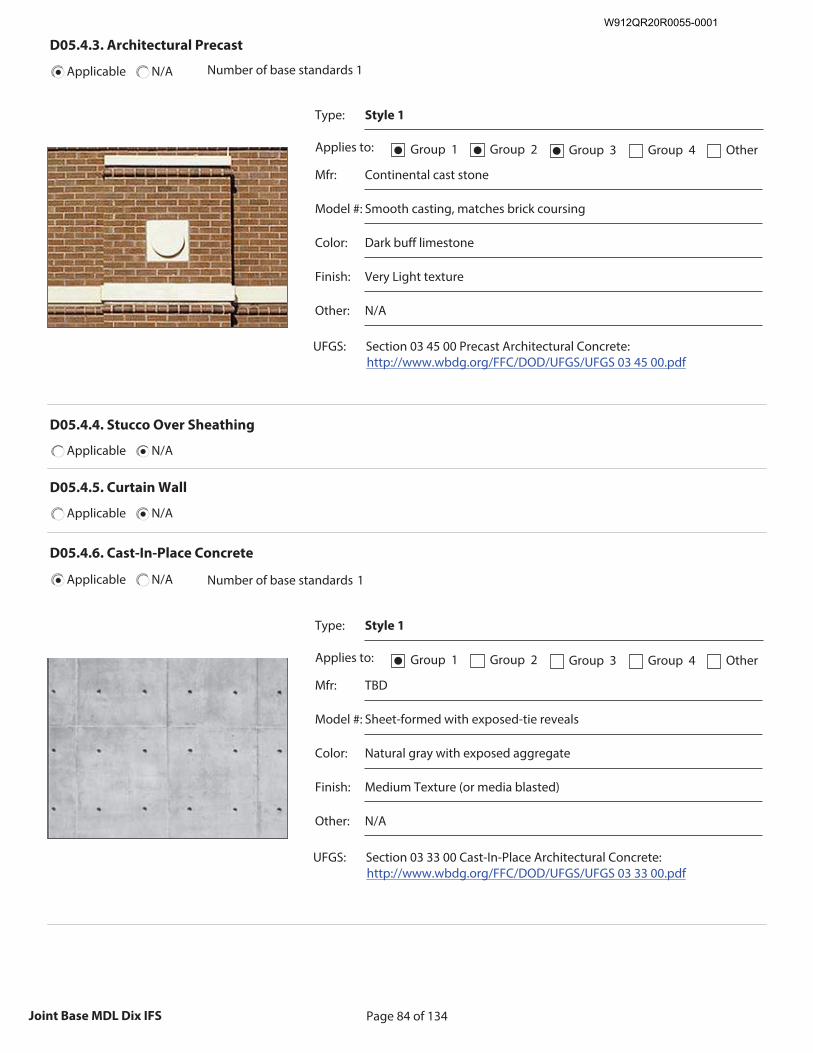
Page 84 of 134Joint Base MDL Dix IFS
D05.4.3. Architectural Precast
Applicable N/A Number of base standards 1
Type: Style 1
Applies to: Group 1● Group 2● Group 3● Group 4 Other
Mfr: Continental cast stone
Model #: Smooth casting, matches brick coursing
Color: Dark buff limestone
Finish: Very Light texture
Other: N/A
UFGS: Section 03 45 00 Precast Architectural Concrete: http://www.wbdg.org/FFC/DOD/UFGS/UFGS 03 45 00.pdf
Recommended Image: Detail of precast
Size image to:
250 pixels width x 188 pixels height
Click here to insert image
D05.4.4. Stucco Over Sheathing
Applicable N/A
D05.4.5. Curtain Wall
Applicable N/A
D05.4.6. Cast-In-Place Concrete
Applicable N/A Number of base standards 1
Type: Style 1
Applies to: Group 1● Group 2 Group 3 Group 4 Other
Mfr: TBD
Model #: Sheet-formed with exposed-tie reveals
Color: Natural gray with exposed aggregate
Finish: Medium Texture (or media blasted)
Other: N/A
UFGS: Section 03 33 00 Cast-In-Place Architectural Concrete: http://www.wbdg.org/FFC/DOD/UFGS/UFGS 03 33 00.pdf
Recommended Image: Detail of cast-in-place concrete
Size image to:
250 pixels width x 188 pixels height
Click here to insert image
W912QR20R0055-0001
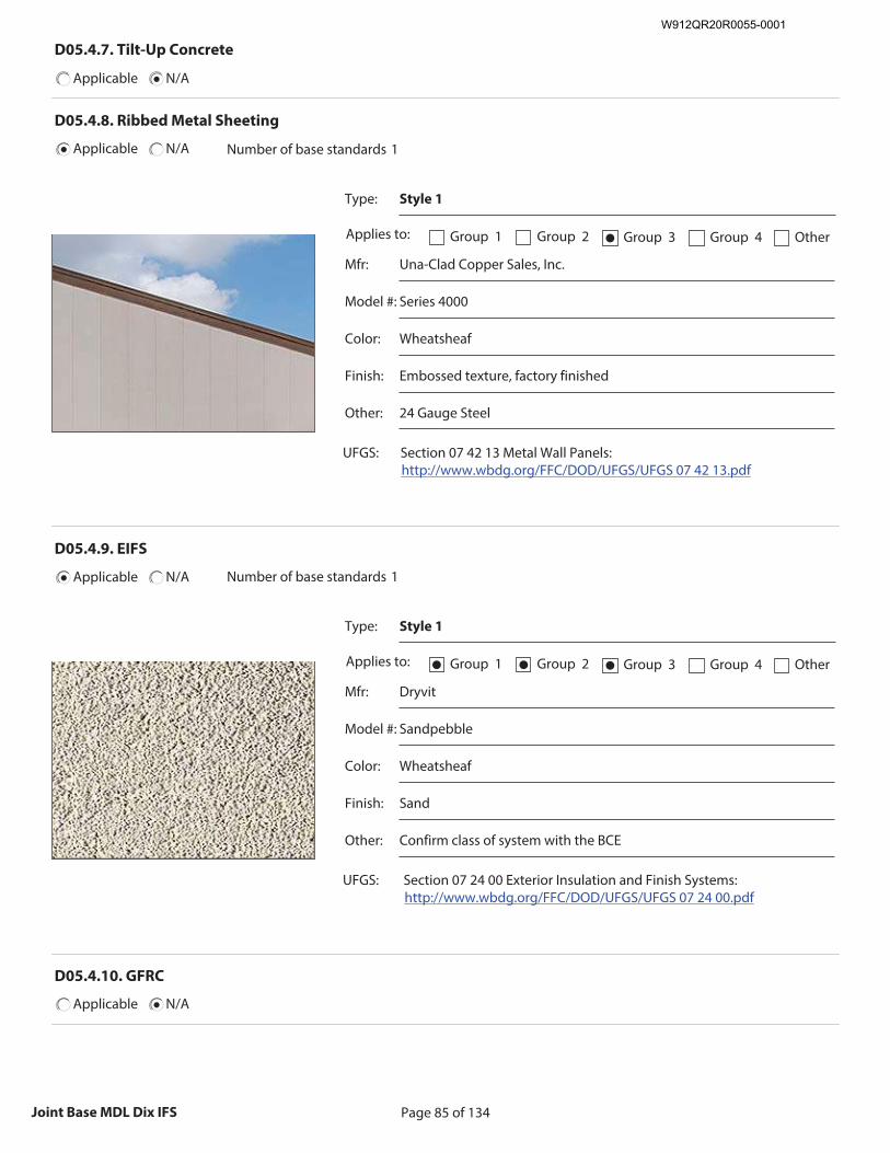
Page 85 of 134Joint Base MDL Dix IFS
D05.4.7. Tilt-Up Concrete
Applicable N/A
D05.4.8. Ribbed Metal Sheeting
Applicable N/A Number of base standards 1
Type: Style 1
Applies to: Group 1 Group 2 Group 3● Group 4 Other
Mfr: Una-Clad Copper Sales, Inc.
Model #: Series 4000
Color: Wheatsheaf
Finish: Embossed texture, factory finished
Other: 24 Gauge Steel
UFGS: Section 07 42 13 Metal Wall Panels: http://www.wbdg.org/FFC/DOD/UFGS/UFGS 07 42 13.pdf
Recommended Image: Detail of ribbed metal sheeting
Size image to:
250 pixels width x 188 pixels height
Click here to insert image
D05.4.9. EIFS
Applicable N/A Number of base standards 1
Type: Style 1
Applies to: Group 1● Group 2● Group 3● Group 4 Other
Mfr: Dryvit
Model #: Sandpebble
Color: Wheatsheaf
Finish: Sand
Other: Confirm class of system with the BCE
UFGS: Section 07 24 00 Exterior Insulation and Finish Systems: http://www.wbdg.org/FFC/DOD/UFGS/UFGS 07 24 00.pdf
Recommended Image: Detail of EIFS over framing
Size image to:
250 pixels width x 188 pixels height
Click here to insert image
D05.4.10. GFRC
Applicable N/A
W912QR20R0055-0001
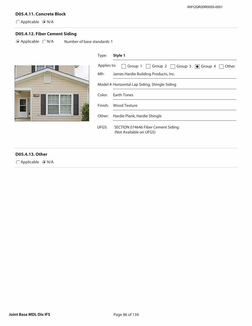
Page 86 of 134Joint Base MDL Dix IFS
D05.4.11. Concrete Block
Applicable N/A
D05.4.12. Fiber Cement Siding
Applicable N/A Number of base standards 1
Type: Style 1
Applies to: Group 1 Group 2 Group 3 Group 4● Other
Mfr: James Hardie Building Products, Inc.
Model #: Horizontal Lap Siding, Shingle Siding
Color: Earth Tones
Finish: Wood Texture
Other: Hardie Plank, Hardie Shingle
UFGS: SECTION 074646 Fiber Cement Siding: (Not Available on UFGS)
Recommended Image: Detail of fiber cement siding
Size image to:
250 pixels width x 188 pixels height
Click here to insert image
D05.4.13. Other
Applicable N/A
W912QR20R0055-0001
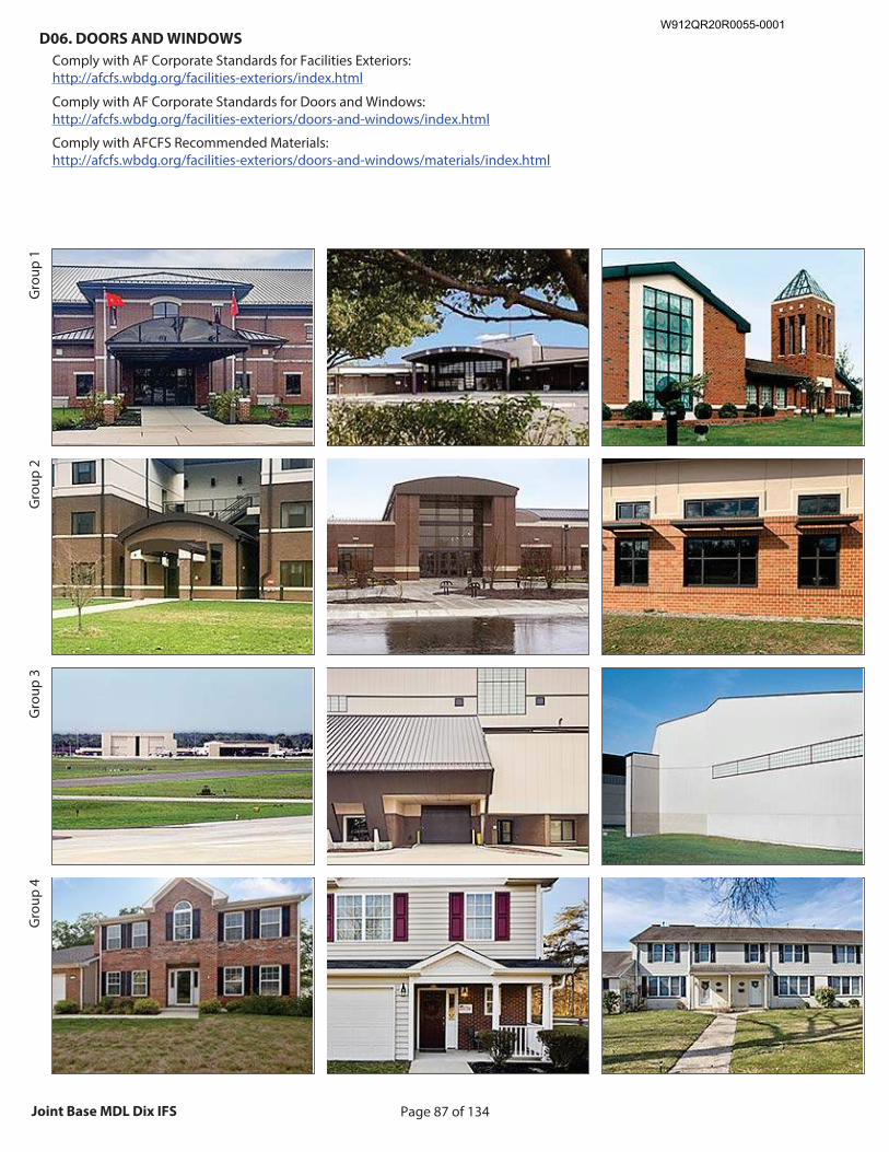
Page 87 of 134Joint Base MDL Dix IFS
D06. DOORS AND WINDOWS
Comply with AF Corporate Standards for Facilities Exteriors: http://afcfs.wbdg.org/facilities-exteriors/index.html
Comply with AF Corporate Standards for Doors and Windows: http://afcfs.wbdg.org/facilities-exteriors/doors-and-windows/index.html
Comply with AFCFS Recommended Materials: http://afcfs.wbdg.org/facilities-exteriors/doors-and-windows/materials/index.html
Gro
up 1
Gro
up 2
Gro
up 3
Gro
up 4
Recommended Image: Facility showing doors and
windows Size image to:
250 pixels width x 188 pixels height Click here to insert image
Recommended Image: Window system
Size image to: 250 pixels width x 188 pixels height
Click here to insert image
Recommended Image: Door system
Size image to: 250 pixels width x 188 pixels height
Click here to insert image
Recommended Image: Facility showing doors and
windows Size image to:
250 pixels width x 188 pixels heightClick here to insert image
Recommended Image: Window system
Size image to: 250 pixels width x 188 pixels height
Click here to insert image
Recommended Image: Door system
Size image to: 250 pixels width x 188 pixels height
Click here to insert image
W912QR20R0055-0001
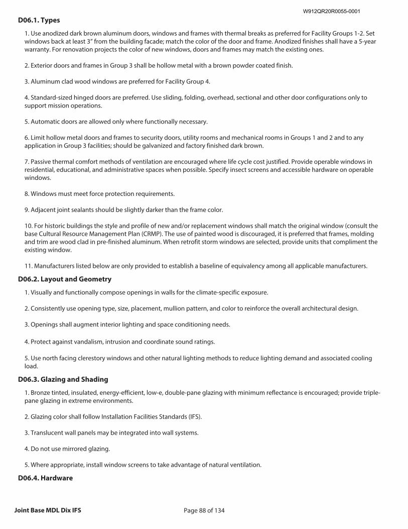
Page 88 of 134Joint Base MDL Dix IFS
D06.1. Types
1. Use anodized dark brown aluminum doors, windows and frames with thermal breaks as preferred for Facility Groups 1-2. Set windows back at least 3” from the building facade; match the color of the door and frame. Anodized finishes shall have a 5-year warranty. For renovation projects the color of new windows, doors and frames may match the existing ones. 2. Exterior doors and frames in Group 3 shall be hollow metal with a brown powder coated finish. 3. Aluminum clad wood windows are preferred for Facility Group 4. 4. Standard-sized hinged doors are preferred. Use sliding, folding, overhead, sectional and other door configurations only to support mission operations. 5. Automatic doors are allowed only where functionally necessary. 6. Limit hollow metal doors and frames to security doors, utility rooms and mechanical rooms in Groups 1 and 2 and to any application in Group 3 facilities; should be galvanized and factory finished dark brown. 7. Passive thermal comfort methods of ventilation are encouraged where life cycle cost justified. Provide operable windows in residential, educational, and administrative spaces when possible. Specify insect screens and accessible hardware on operable windows. 8. Windows must meet force protection requirements. 9. Adjacent joint sealants should be slightly darker than the frame color. 10. For historic buildings the style and profile of new and/or replacement windows shall match the original window (consult the base Cultural Resource Management Plan (CRMP). The use of painted wood is discouraged, it is preferred that frames, molding and trim are wood clad in pre-finished aluminum. When retrofit storm windows are selected, provide units that compliment the existing window. 11. Manufacturers listed below are only provided to establish a baseline of equivalency among all applicable manufacturers.
D06.2. Layout and Geometry
1. Visually and functionally compose openings in walls for the climate-specific exposure. 2. Consistently use opening type, size, placement, mullion pattern, and color to reinforce the overall architectural design. 3. Openings shall augment interior lighting and space conditioning needs. 4. Protect against vandalism, intrusion and coordinate sound ratings. 5. Use north facing clerestory windows and other natural lighting methods to reduce lighting demand and associated cooling load.
D06.3. Glazing and Shading
1. Bronze tinted, insulated, energy-efficient, low-e, double-pane glazing with minimum reflectance is encouraged; provide triple-pane glazing in extreme environments. 2. Glazing color shall follow Installation Facilities Standards (IFS). 3. Translucent wall panels may be integrated into wall systems. 4. Do not use mirrored glazing. 5. Where appropriate, install window screens to take advantage of natural ventilation.
D06.4. Hardware
W912QR20R0055-0001
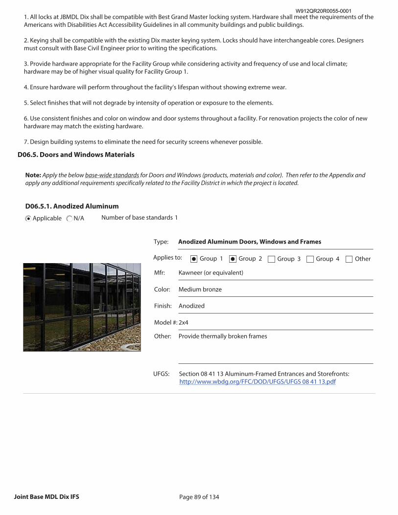
Page 89 of 134Joint Base MDL Dix IFS
1. All locks at JBMDL Dix shall be compatible with Best Grand Master locking system. Hardware shall meet the requirements of the Americans with Disabilities Act Accessibility Guidelines in all community buildings and public buildings. 2. Keying shall be compatible with the existing Dix master keying system. Locks should have interchangeable cores. Designers must consult with Base Civil Engineer prior to writing the specifications. 3. Provide hardware appropriate for the Facility Group while considering activity and frequency of use and local climate; hardware may be of higher visual quality for Facility Group 1. 4. Ensure hardware will perform throughout the facility’s lifespan without showing extreme wear. 5. Select finishes that will not degrade by intensity of operation or exposure to the elements. 6. Use consistent finishes and color on window and door systems throughout a facility. For renovation projects the color of new hardware may match the existing hardware. 7. Design building systems to eliminate the need for security screens whenever possible.
D06.5. Doors and Windows Materials
Note: Apply the below base-wide standards for Doors and Windows (products, materials and color). Then refer to the Appendix and apply any additional requirements specifically related to the Facility District in which the project is located.
D06.5.1. Anodized Aluminum
Applicable N/A Number of base standards 1
Type: Anodized Aluminum Doors, Windows and Frames
Applies to: Group 1● Group 2● Group 3 Group 4 Other
Mfr: Kawneer (or equivalent)
Color: Medium bronze
Finish: Anodized
Model #: 2x4
Other: Provide thermally broken frames
UFGS: Section 08 41 13 Aluminum-Framed Entrances and Storefronts: http://www.wbdg.org/FFC/DOD/UFGS/UFGS 08 41 13.pdf
Recommended Image: Anodized Aluminum
Framed Door and / or Window Size image to:
250 pixels width x 188 pixels height
Click here to insert image
W912QR20R0055-0001
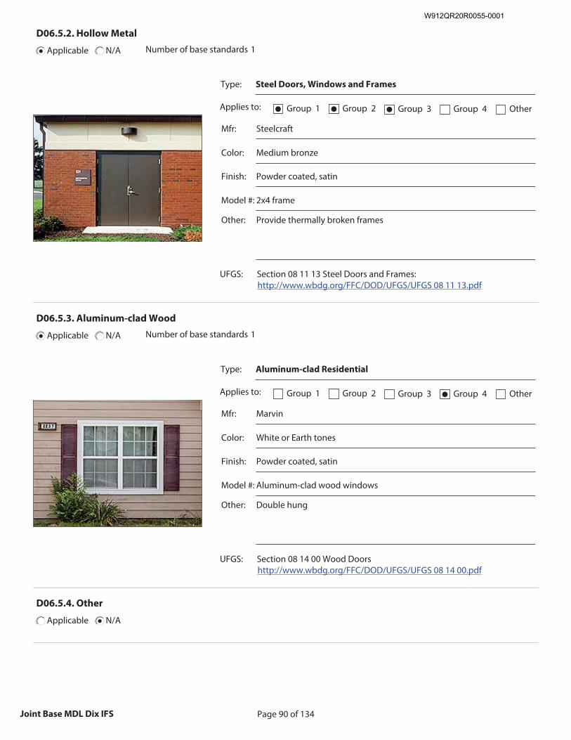
Page 90 of 134Joint Base MDL Dix IFS
D06.5.2. Hollow Metal
Applicable N/A Number of base standards 1
Type: Steel Doors, Windows and Frames
Applies to: Group 1● Group 2● Group 3● Group 4 Other
Mfr: Steelcraft
Color: Medium bronze
Finish: Powder coated, satin
Model #: 2x4 frame
Other: Provide thermally broken frames
UFGS: Section 08 11 13 Steel Doors and Frames: http://www.wbdg.org/FFC/DOD/UFGS/UFGS 08 11 13.pdf
Recommended Image: Hollow Metal Door
Size image to: 250 pixels width x 188 pixels height
Click here to insert image
D06.5.3. Aluminum-clad Wood
Applicable N/A Number of base standards 1
Type: Aluminum-clad Residential
Applies to: Group 1 Group 2 Group 3 Group 4● Other
Mfr: Marvin
Color: White or Earth tones
Finish: Powder coated, satin
Model #: Aluminum-clad wood windows
Other: Double hung
UFGS: Section 08 14 00 Wood Doors http://www.wbdg.org/FFC/DOD/UFGS/UFGS 08 14 00.pdf
Recommended Image: Aluminum-clad Wood Framed
Door and / or Window Size image to:
250 pixels width x 188 pixels height
Click here to insert image
D06.5.4. Other
Applicable N/A
W912QR20R0055-0001
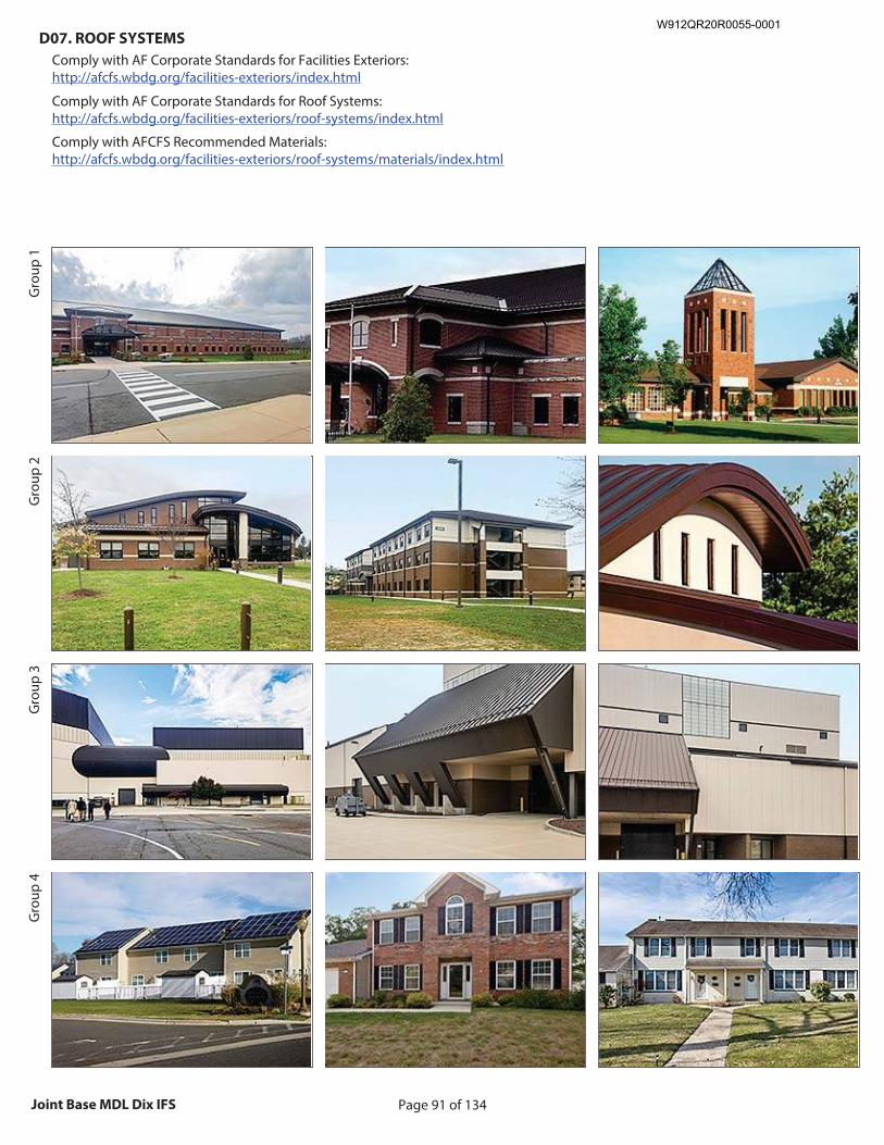
Page 91 of 134Joint Base MDL Dix IFS
D07. ROOF SYSTEMS
Comply with AF Corporate Standards for Facilities Exteriors: http://afcfs.wbdg.org/facilities-exteriors/index.html
Comply with AF Corporate Standards for Roof Systems: http://afcfs.wbdg.org/facilities-exteriors/roof-systems/index.html
Comply with AFCFS Recommended Materials: http://afcfs.wbdg.org/facilities-exteriors/roof-systems/materials/index.html
Gro
up 1
Gro
up 2
Gro
up 3
Gro
up 4
Recommended Image: Facility showing roof
Size image to: 250 pixels width x 188 pixels height
Click here to insert image
Recommended Image: Roof features Size image to:
250 pixels width x 188 pixels height
Click here to insert image
Recommended Image: Roof Detail
Size image to: 250 pixels width x 188 pixels height
Click here to insert image
W912QR20R0055-0001
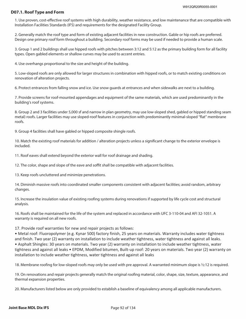
Page 92 of 134Joint Base MDL Dix IFS
D07.1. Roof Type and Form
1. Use proven, cost-effective roof systems with high durability, weather resistance, and low maintenance that are compatible with Installation Facilities Standards (IFS) and requirements for the designated Facility Group. 2. Generally match the roof type and form of existing adjacent facilities in new construction. Gable or hip roofs are preferred. Design one primary roof form throughout a building. Secondary roof forms may be used if needed to provide a human scale. 3. Group 1 and 2 buildings shall use hipped roofs with pitches between 3:12 and 5:12 as the primary building form for all facility types. Open gabled elements or shallow curves may be used to accent entries. 4. Use overhangs proportional to the size and height of the building. 5. Low-sloped roofs are only allowed for larger structures in combination with hipped roofs, or to match existing conditions on renovation of alteration projects. 6. Protect entrances from falling snow and ice. Use snow guards at entrances and when sidewalks are next to a building. 7. Provide screens for roof-mounted appendages and equipment of the same materials, which are used predominantly in the building’s roof systems. 8. Group 2 and 3 facilities under 5,000 sf and narrow in plan geometry, may use low-sloped shed, gabled or hipped standing seam metal) roofs. Larger facilities may use sloped-roof features in conjunction with predominantly minimal-sloped “flat” membrane roofs. 9. Group 4 facilities shall have gabled or hipped composite shingle roofs. 10. Match the existing roof materials for addition / alteration projects unless a significant change to the exterior envelope is included. 11. Roof eaves shall extend beyond the exterior wall for roof drainage and shading. 12. The color, shape and slope of the eave and soffit shall be compatible with adjacent facilities. 13. Keep roofs uncluttered and minimize penetrations. 14. Diminish massive roofs into coordinated smaller components consistent with adjacent facilities; avoid random, arbitrary changes. 15. Increase the insulation value of existing roofing systems during renovations if supported by life cycle cost and structural analysis. 16. Roofs shall be maintained for the life of the system and replaced in accordance with UFC 3-110-04 and AFI 32-1051. A warranty is required on all new roofs. 17. Provide roof warranties for new and repair projects as follows: • Metal roof: Fluoropolymer (e.g. Kynar 500) factory finish, 25 years on materials. Warranty includes water tightness and finish. Two year (2) warranty on installation to include weather tightness, water tightness and against all leaks. • Asphalt Shingles: 30 years on materials. Two year (2) warranty on installation to include weather tightness, water tightness and against all leaks • EPDM, Modified bitumen, Built-up roof: 20 years on materials. Two year (2) warranty on installation to include weather tightness, water tightness and against all leaks 18. Membrane roofing for low-sloped roofs may only be used with pre approval. A warranted minimum slope is ½:12 is required. 19. On renovations and repair projects generally match the original roofing material, color, shape, size, texture, appearance, and thermal expansion properties. 20. Manufacturers listed below are only provided to establish a baseline of equivalency among all applicable manufacturers.
W912QR20R0055-0001
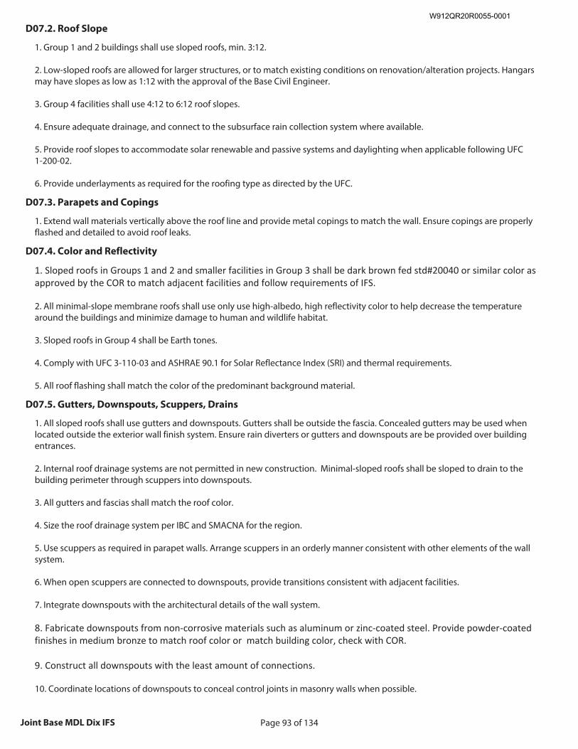
Page 93 of 134Joint Base MDL Dix IFS
D07.2. Roof Slope
1. Group 1 and 2 buildings shall use sloped roofs, min. 3:12. 2. Low-sloped roofs are allowed for larger structures, or to match existing conditions on renovation/alteration projects. Hangars may have slopes as low as 1:12 with the approval of the Base Civil Engineer. 3. Group 4 facilities shall use 4:12 to 6:12 roof slopes. 4. Ensure adequate drainage, and connect to the subsurface rain collection system where available. 5. Provide roof slopes to accommodate solar renewable and passive systems and daylighting when applicable following UFC 1-200-02. 6. Provide underlayments as required for the roofing type as directed by the UFC.
D07.3. Parapets and Copings
1. Extend wall materials vertically above the roof line and provide metal copings to match the wall. Ensure copings are properly flashed and detailed to avoid roof leaks.
D07.4. Color and Reflectivity
1. Sloped roofs in Groups 1 and 2 and smaller facilities in Group 3 shall be dark brown fed std#20040 or similar color as approved by the COR to match adjacent facilities and follow requirements of IFS. 2. All minimal-slope membrane roofs shall use only use high-albedo, high reflectivity color to help decrease the temperature around the buildings and minimize damage to human and wildlife habitat. 3. Sloped roofs in Group 4 shall be Earth tones. 4. Comply with UFC 3-110-03 and ASHRAE 90.1 for Solar Reflectance Index (SRI) and thermal requirements. 5. All roof flashing shall match the color of the predominant background material.
D07.5. Gutters, Downspouts, Scuppers, Drains
1. All sloped roofs shall use gutters and downspouts. Gutters shall be outside the fascia. Concealed gutters may be used when located outside the exterior wall finish system. Ensure rain diverters or gutters and downspouts are be provided over building entrances. 2. Internal roof drainage systems are not permitted in new construction. Minimal-sloped roofs shall be sloped to drain to the building perimeter through scuppers into downspouts. 3. All gutters and fascias shall match the roof color. 4. Size the roof drainage system per IBC and SMACNA for the region. 5. Use scuppers as required in parapet walls. Arrange scuppers in an orderly manner consistent with other elements of the wall system. 6. When open scuppers are connected to downspouts, provide transitions consistent with adjacent facilities. 7. Integrate downspouts with the architectural details of the wall system. 8. Fabricate downspouts from non-corrosive materials such as aluminum or zinc-coated steel. Provide powder-coated finishes in medium bronze to match roof color or match building color, check with COR. 9. Construct all downspouts with the least amount of connections. 10. Coordinate locations of downspouts to conceal control joints in masonry walls when possible.
W912QR20R0055-0001
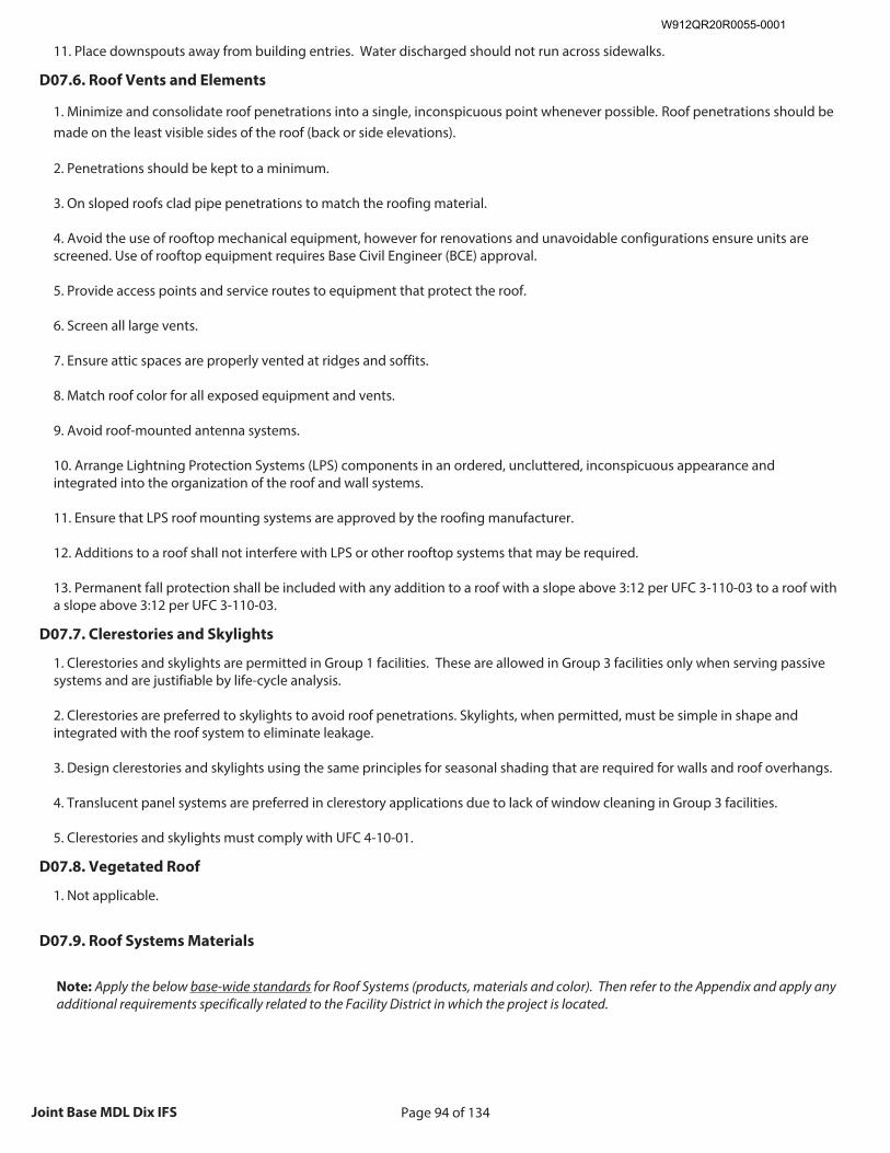
Page 94 of 134Joint Base MDL Dix IFS
11. Place downspouts away from building entries. Water discharged should not run across sidewalks.
D07.6. Roof Vents and Elements
1. Minimize and consolidate roof penetrations into a single, inconspicuous point whenever possible. Roof penetrations should be made on the least visible sides of the roof (back or side elevations). 2. Penetrations should be kept to a minimum. 3. On sloped roofs clad pipe penetrations to match the roofing material. 4. Avoid the use of rooftop mechanical equipment, however for renovations and unavoidable configurations ensure units are screened. Use of rooftop equipment requires Base Civil Engineer (BCE) approval. 5. Provide access points and service routes to equipment that protect the roof. 6. Screen all large vents. 7. Ensure attic spaces are properly vented at ridges and soffits. 8. Match roof color for all exposed equipment and vents. 9. Avoid roof-mounted antenna systems. 10. Arrange Lightning Protection Systems (LPS) components in an ordered, uncluttered, inconspicuous appearance and integrated into the organization of the roof and wall systems. 11. Ensure that LPS roof mounting systems are approved by the roofing manufacturer. 12. Additions to a roof shall not interfere with LPS or other rooftop systems that may be required. 13. Permanent fall protection shall be included with any addition to a roof with a slope above 3:12 per UFC 3-110-03 to a roof with a slope above 3:12 per UFC 3-110-03.
D07.7. Clerestories and Skylights
1. Clerestories and skylights are permitted in Group 1 facilities. These are allowed in Group 3 facilities only when serving passive systems and are justifiable by life-cycle analysis. 2. Clerestories are preferred to skylights to avoid roof penetrations. Skylights, when permitted, must be simple in shape and integrated with the roof system to eliminate leakage. 3. Design clerestories and skylights using the same principles for seasonal shading that are required for walls and roof overhangs. 4. Translucent panel systems are preferred in clerestory applications due to lack of window cleaning in Group 3 facilities. 5. Clerestories and skylights must comply with UFC 4-10-01.
D07.8. Vegetated Roof
1. Not applicable.
D07.9. Roof Systems Materials
Note: Apply the below base-wide standards for Roof Systems (products, materials and color). Then refer to the Appendix and apply any additional requirements specifically related to the Facility District in which the project is located.
W912QR20R0055-0001
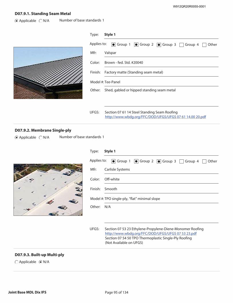
Page 95 of 134Joint Base MDL Dix IFS
D07.9.1. Standing Seam Metal
Applicable N/A Number of base standards 1
Type: Style 1
Applies to: Group 1● Group 2● Group 3● Group 4 Other
Mfr: Valspar
Color: Brown - fed. Std. #20040
Finish: Factory matte (Standing seam metal)
Model #: Tee-Panel
Other: Shed, gabled or hipped standing seam metal
UFGS: Section 07 61 14 Steel Standing Seam Roofing http://www.wbdg.org/FFC/DOD/UFGS/UFGS 07 61 14.00 20.pdf
Recommended Image: Detail of Standing Seam Metal Roof
Size image to:
250 pixels width x 188 pixels height
Click here to insert image
D07.9.2. Membrane Single-ply
Applicable N/A Number of base standards 1
Type: Style 1
Applies to: Group 1● Group 2● Group 3● Group 4 Other
Mfr: Carlisle Systems
Color: Off-white
Finish: Smooth
Model #: TPO single-ply, “flat” minimal slope
Other: N/A
UFGS: Section 07 53 23 Ethylene-Propylene-Diene-Monomer Roofing http://www.wbdg.org/FFC/DOD/UFGS/UFGS 07 53 23.pdf Section 07 54 50 TPO Thermoplastic Single-Ply Roofing (Not Available on UFGS)
Recommended Image: Detail of Membrane Single-ply Roof
Size image to:
250 pixels width x 188 pixels height
Click here to insert image
D07.9.3. Built-up Multi-ply
Applicable N/A
W912QR20R0055-0001
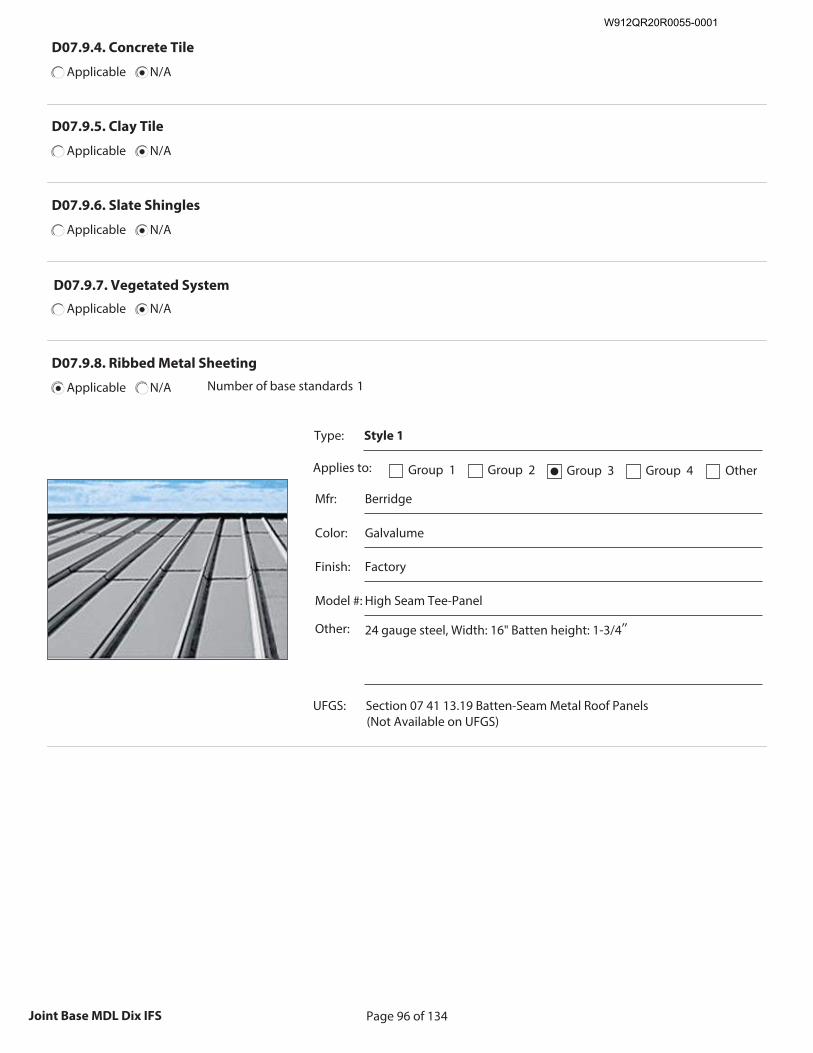
Page 96 of 134Joint Base MDL Dix IFS
D07.9.4. Concrete Tile
Applicable N/A
D07.9.5. Clay Tile
Applicable N/A
D07.9.6. Slate Shingles
Applicable N/A
D07.9.7. Vegetated System
Applicable N/A
D07.9.8. Ribbed Metal Sheeting
Applicable N/A Number of base standards 1
Type: Style 1
Applies to: Group 1 Group 2 Group 3● Group 4 Other
Mfr: Berridge
Color: Galvalume
Finish: Factory
Model #: High Seam Tee-Panel
Other: 24 gauge steel, Width: 16" Batten height: 1-3/4″
UFGS: Section 07 41 13.19 Batten-Seam Metal Roof Panels (Not Available on UFGS)
Recommended Image: Detail of Ribbed Metal Sheeted
Roof
Size image to: 250 pixels width x 188 pixels height
Click here to insert image
W912QR20R0055-0001
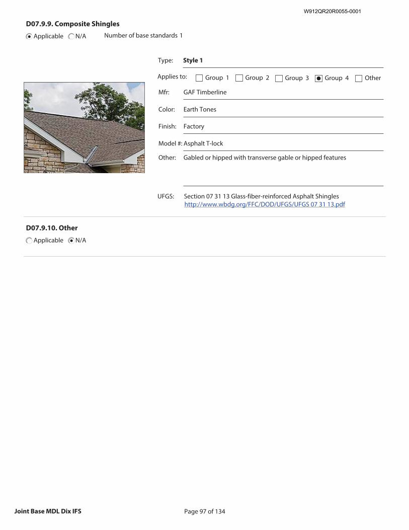
Page 97 of 134Joint Base MDL Dix IFS
D07.9.9. Composite Shingles
Applicable N/A Number of base standards 1
Type: Style 1
Applies to: Group 1 Group 2 Group 3 Group 4● Other
Mfr: GAF Timberline
Color: Earth Tones
Finish: Factory
Model #: Asphalt T-lock
Other: Gabled or hipped with transverse gable or hipped features
UFGS: Section 07 31 13 Glass-fiber-reinforced Asphalt Shingles http://www.wbdg.org/FFC/DOD/UFGS/UFGS 07 31 13.pdf
Recommended Image: Detail of Composite Shingled Roof
Size image to:
250 pixels width x 188 pixels height
Click here to insert image
D07.9.10. Other
Applicable N/A
W912QR20R0055-0001
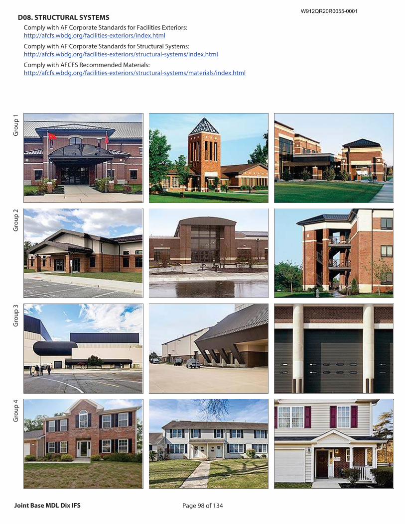
Page 98 of 134Joint Base MDL Dix IFS
D08. STRUCTURAL SYSTEMS
Comply with AF Corporate Standards for Facilities Exteriors: http://afcfs.wbdg.org/facilities-exteriors/index.html
Comply with AF Corporate Standards for Structural Systems: http://afcfs.wbdg.org/facilities-exteriors/structural-systems/index.html
Comply with AFCFS Recommended Materials: http://afcfs.wbdg.org/facilities-exteriors/structural-systems/materials/index.html
Gro
up 1
Gro
up 2
Gro
up 3
Gro
up 4
Recommended Image: Facility showing structure
Size image to: 250 pixels width x 188 pixels height
Click here to insert image
Recommended Image: Structural features
Size image to: 250 pixels width x 188 pixels height
Click here to insert image
Recommended Image: Structural Detail
Size image to: 250 pixels width x 188 pixels height
Click here to insert image
W912QR20R0055-0001
Page 99 of 134Joint Base MDL Dix IFS
D08.1. Systems and Layouts
1. Pre-engineered structural steel framing may be used for Groups 1, 2 and 3 facilities; Installation-appropriate thermal envelopes, materials and detailing are required. 2. Select economical structural systems that integrate roof and wall systems. 3. Narrow buildings 60’ or less in width with column-free interiors are preferred for office, administrative and personnel spaces; when interior columns are required optimize the structural grid layout for open-plan arrangements. 4. Fully coordinate structural grids with exterior window systems to align columns with window frames or wall systems. 5. When structure is exposed provide an organized appearance and coordinate with mechanical, electrical, plumbing, fire protection, information technology, and communications systems. 6. Limit the use of specialty systems (such as space frames, vaults or domes) and of structure as a visual feature. 7. Cost-effectively design interior bearing walls as thermal mass. 8. Manufacturers listed below are only provided to establish a baseline of equivalency among all applicable manufacturers.
D08.2. Structural Systems Materials
Note: Apply the below base-wide standards for Structural Systems (products, materials and color). Then refer to the Appendix and apply any additional requirements specifically related to the Facility District in which the project is located.
D08.2.1. Concrete
Applicable N/A
D08.2.2. Insulated Concrete Forming (ICF)
Applicable N/A
W912QR20R0055-0001
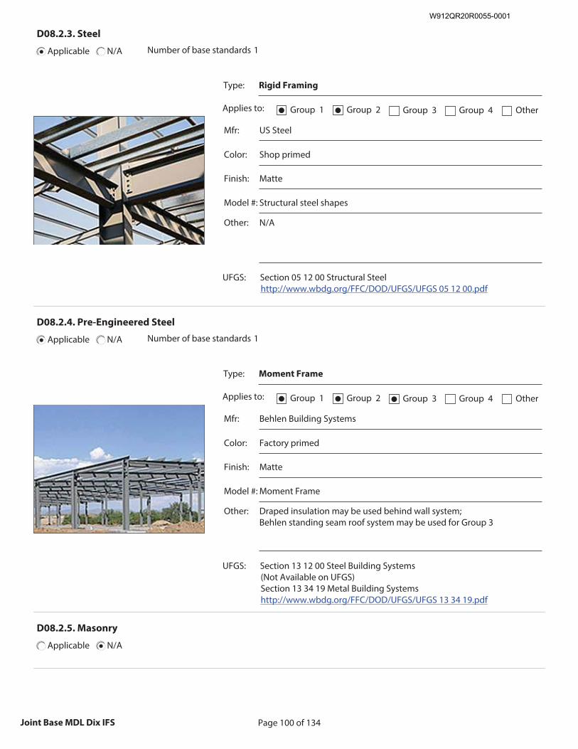
Page 100 of 134Joint Base MDL Dix IFS
D08.2.3. Steel
Applicable N/A Number of base standards 1
Type: Rigid Framing
Applies to: Group 1● Group 2● Group 3 Group 4 Other
Mfr: US Steel
Color: Shop primed
Finish: Matte
Model #: Structural steel shapes
Other: N/A
UFGS: Section 05 12 00 Structural Steel http://www.wbdg.org/FFC/DOD/UFGS/UFGS 05 12 00.pdf
Recommended Image: Detail of Steel Structure
Size image to:
250 pixels width x 188 pixels height
Click here to insert image
D08.2.4. Pre-Engineered Steel
Applicable N/A Number of base standards 1
Type: Moment Frame
Applies to: Group 1● Group 2● Group 3● Group 4 Other
Mfr: Behlen Building Systems
Color: Factory primed
Finish: Matte
Model #: Moment Frame
Other: Draped insulation may be used behind wall system; Behlen standing seam roof system may be used for Group 3
UFGS: Section 13 12 00 Steel Building Systems (Not Available on UFGS) Section 13 34 19 Metal Building Systems http://www.wbdg.org/FFC/DOD/UFGS/UFGS 13 34 19.pdf
Recommended Image: Detail of Pre-Engineered Steel
Structure
Size image to: 250 pixels width x 188 pixels height
Click here to insert image
D08.2.5. Masonry
Applicable N/A
W912QR20R0055-0001
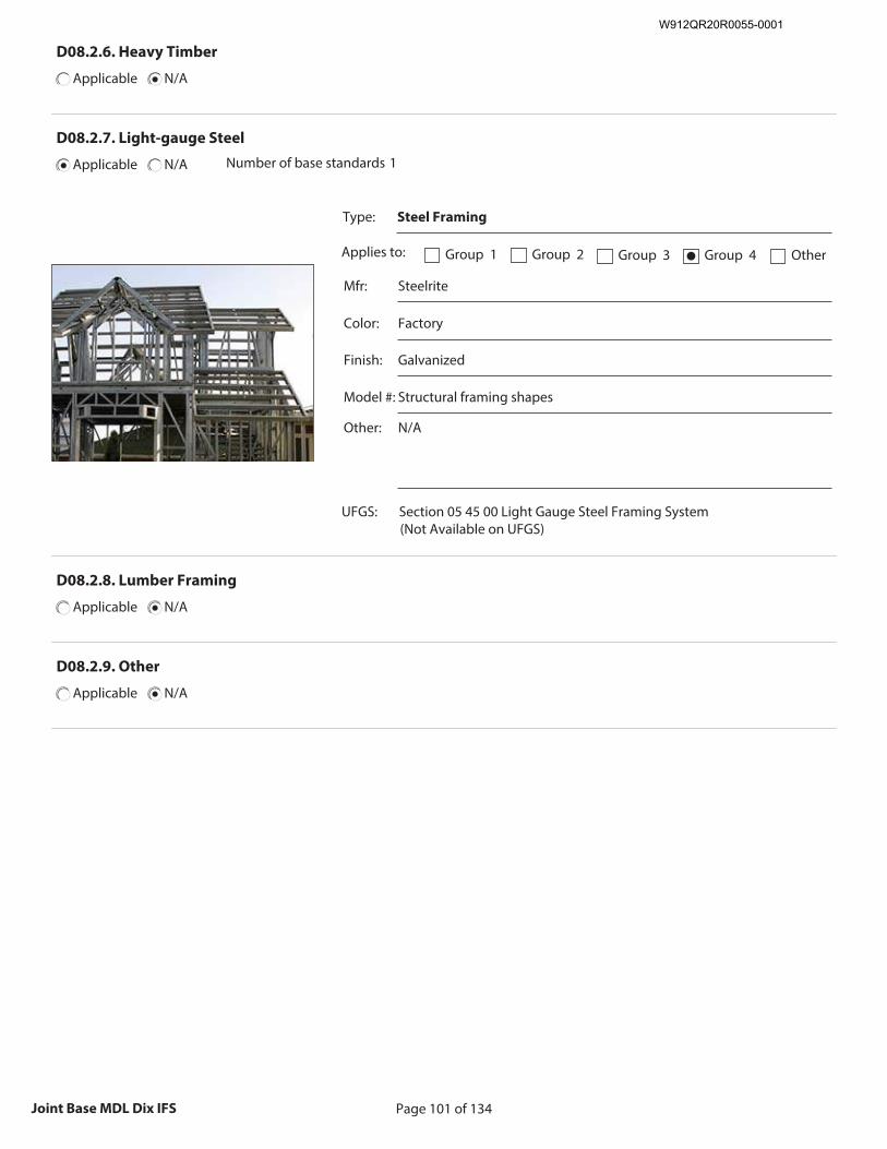
Page 101 of 134Joint Base MDL Dix IFS
D08.2.6. Heavy Timber
Applicable N/A
D08.2.7. Light-gauge Steel
Applicable N/A Number of base standards 1
Type: Steel Framing
Applies to: Group 1 Group 2 Group 3 Group 4● Other
Mfr: Steelrite
Color: Factory
Finish: Galvanized
Model #: Structural framing shapes
Other: N/A
UFGS: Section 05 45 00 Light Gauge Steel Framing System (Not Available on UFGS)
Recommended Image: Detail of Light-gauge Steel
Structure
Size image to: 250 pixels width x 188 pixels height
Click here to insert image
D08.2.8. Lumber Framing
Applicable N/A
D08.2.9. Other
Applicable N/A
W912QR20R0055-0001
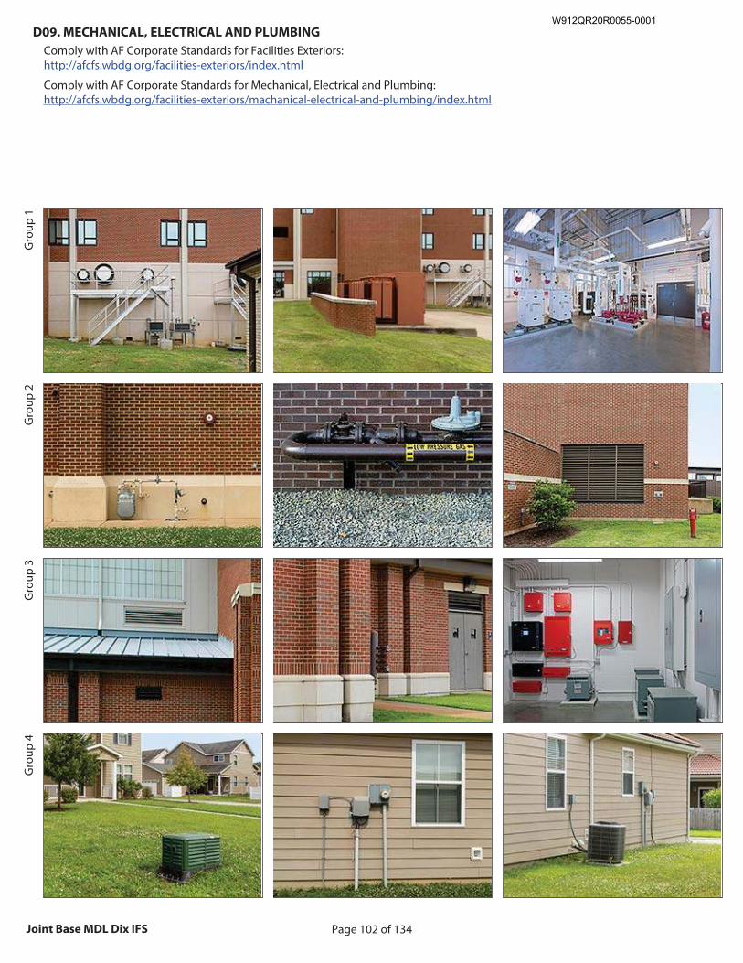
Page 102 of 134Joint Base MDL Dix IFS
D09. MECHANICAL, ELECTRICAL AND PLUMBING
Comply with AF Corporate Standards for Facilities Exteriors: http://afcfs.wbdg.org/facilities-exteriors/index.html
Comply with AF Corporate Standards for Mechanical, Electrical and Plumbing: http://afcfs.wbdg.org/facilities-exteriors/machanical-electrical-and-plumbing/index.html
Gro
up 1
Gro
up 2
Gro
up 3
Gro
up 4
Recommended Image: Facility showing MEP
Size image to: 250 pixels width x 188 pixels height
Click here to insert image
Recommended Image: MEP features Size image to:
250 pixels width x 188 pixels height
Click here to insert image
Recommended Image: MEP Detail
Size image to: 250 pixels width x 188 pixels height
Click here to insert image
W912QR20R0055-0001
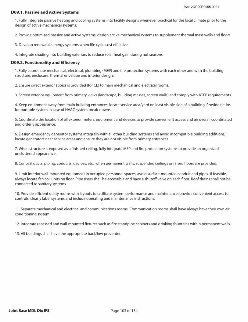
Page 103 of 134Joint Base MDL Dix IFS
D09.1. Passive and Active Systems
1. Fully integrate passive heating and cooling systems into facility designs whenever practical for the local climate prior to the design of active mechanical systems. 2. Provide optimized passive and active systems; design active mechanical systems to supplement thermal mass walls and floors. 3. Develop renewable energy systems when life cycle cost effective. 4. Integrate shading into building exteriors to reduce solar heat gain during hot seasons.
D09.2. Functionality and Efficiency
1. Fully coordinate mechanical, electrical, plumbing (MEP) and fire protection systems with each other and with the building structure, enclosure, thermal envelope and interior design. 2. Ensure direct exterior access is provided (for CE) to main mechanical and electrical rooms. 3. Screen exterior equipment from primary views (landscape, building masses, screen walls) and comply with ATFP requirements. 4. Keep equipment away from main building entrances; locate service area/yard on least visible side of a building. Provide tie-ins for portable system in case of HVAC system break-downs. 5. Coordinate the location of all exterior meters, equipment and devices to provide convenient access and an overall coordinated and orderly appearance. 6. Design emergency generator systems integrally with all other building systems and avoid incompatible building additions; locate generators near service areas and ensure they are not visible from primary entrances. 7. When structure is exposed as a finished ceiling, fully integrate MEP and fire protection systems to provide an organized uncluttered appearance. 8. Conceal ducts, piping, conduits, devices, etc., when permanent walls, suspended ceilings or raised floors are provided. 9. Limit interior wall-mounted equipment in occupied personnel spaces; avoid surface-mounted conduit and pipes. If feasible, always locate fan coil units on floor. Pipe risers shall be accessible and have a shutoff valve on each floor. Roof drains shall not be connected to sanitary systems. 10. Provide efficient utility rooms with layouts to facilitate system performance and maintenance; provide convenient access to controls, clearly label systems and include operating and maintenance instructions. 11. Separate mechanical and electrical and communications rooms. Communication rooms shall have always have their own air conditioning system. 12. Integrate recessed and wall-mounted fixtures such as fire standpipe cabinets and drinking fountains within permanent walls. 13. All buildings shall have the appropriate backflow preventer.
W912QR20R0055-0001
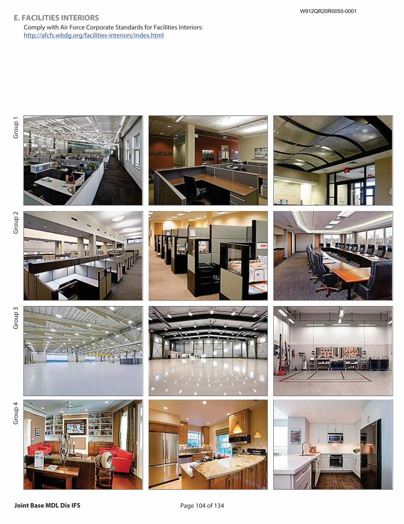
Page 104 of 134Joint Base MDL Dix IFS
E. FACILITIES INTERIORS
Comply with Air Force Corporate Standards for Facilities Interiors: http://afcfs.wbdg.org/facilities-interiors/index.html
Gro
up 1
Gro
up 2
Gro
up 3
Gro
up 4
Recommended Image: Typical facility interior
Size image to: 250 pixels width x 188 pixels height
Click here to insert image
Recommended Image: Interior features
Size image to: 250 pixels width x 188 pixels height
Click here to insert image
Recommended Image: Interior detail Size image to:
250 pixels width x 188 pixels height
Click here to insert image
W912QR20R0055-0001
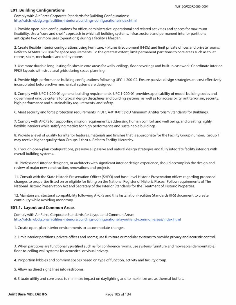
Page 105 of 134Joint Base MDL Dix IFS
E01. Building Configurations
Comply with Air Force Corporate Standards for Building Configurations: http://afcfs.wbdg.org/facilities-interiors/buildings-configurations/index.html
1. Provide open-plan configurations for office, administrative, operational and related activities and spaces for maximum flexibility. Use a “core and shell” approach in which all building systems, infrastructure and permanent interior partitions anticipate two or more uses (operations) during a facility’s lifespan. 2. Create flexible interior configurations using Furniture, Fixtures & Equipment (FF&E) and limit private offices and private rooms. Refer to AFMAN 32-1084 for space requirements. To the greatest extent, limit permanent partitions to core areas such as toilet rooms, stairs, mechanical and utility rooms. 3. Use more durable long-lasting finishes in core areas for walls, ceilings, floor coverings and built-in casework. Coordinate interior FF&E layouts with structural grids during space planning. 4. Provide high-performance building configurations following UFC 1-200-02. Ensure passive design strategies are cost effectively incorporated before active mechanical systems are designed. 5. Comply with UFC 1-200-01, general building requirements. UFC 1-200-01 provides applicability of model building codes and government unique criteria for typical design disciplines and building systems, as well as for accessibility, antiterrorism, security, high performance and sustainability requirements, and safety. 6. Meet security and force protection requirements in UFC 4-010-01: DoD Minimum Antiterrorism Standards for Buildings. 7. Comply with AFCFS for supporting mission requirements, addressing human comfort and well being, and creating highly flexible interiors while satisfying metrics for high performance and sustainable buildings. 8. Provide a level of quality for interior features, materials and finishes that is appropriate for the Facility Group number. Group 1 may receive higher quality than Groups 2 thru 4. Refer to Facility Hierarchy. 9. Through open-plan configurations, preserve all passive and natural design strategies and fully integrate facility interiors with overall building systems. 10. Professional interior designers, or architects with significant interior design experience, should accomplish the design and review of major new construction, renovations and projects. 11. Consult with the State Historic Preservation Officer (SHPO) and base-level Historic Preservation offices regarding proposed changes to properties listed on or eligible for listing on the National Register of Historic Places. Follow requirements of The National Historic Preservation Act and Secretary of the Interior Standards for the Treatment of Historic Properties. 12. Maintain architectural compatibility following AFCFS and this Installation Facilities Standards (IFS) document to create continuity while avoiding monotony.
E01.1. Layout and Common Areas
Comply with Air Force Corporate Standards for Layout and Common Areas: http://afcfs.wbdg.org/facilities-interiors/buildings-configurations/layout-and-common-areas/index.html
1. Create open-plan interior environments to accommodate changes. 2. Limit interior partitions, private offices and rooms; use furniture or modular systems to provide privacy and acoustic control. 3. When partitions are functionally justified such as for conference rooms, use systems furniture and moveable (demountable) floor-to-ceiling wall systems for acoustical or visual privacy. 4. Proportion lobbies and common spaces based on type of function, activity and facility group. 5. Allow no direct sight lines into restrooms. 6. Situate utility and core areas to minimize impact on daylighting and to maximize use as thermal buffers.
W912QR20R0055-0001
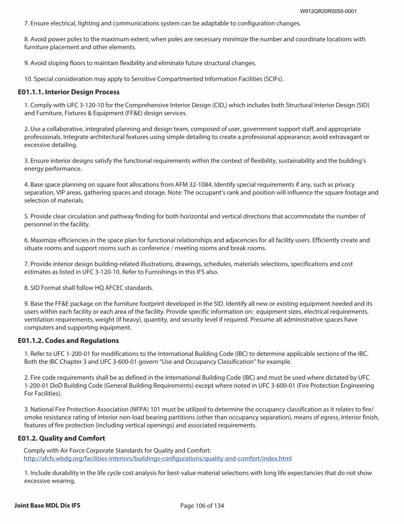
Page 106 of 134Joint Base MDL Dix IFS
7. Ensure electrical, lighting and communications system can be adaptable to configuration changes. 8. Avoid power poles to the maximum extent; when poles are necessary minimize the number and coordinate locations with furniture placement and other elements. 9. Avoid sloping floors to maintain flexibility and eliminate future structural changes. 10. Special consideration may apply to Sensitive Compartmented Information Facilities (SCIFs).
E01.1.1. Interior Design Process
1. Comply with UFC 3-120-10 for the Comprehensive Interior Design (CID,) which includes both Structural Interior Design (SID) and Furniture, Fixtures & Equipment (FF&E) design services. 2. Use a collaborative, integrated planning and design team, composed of user, government support staff, and appropriate professionals. Integrate architectural features using simple detailing to create a professional appearance; avoid extravagant or excessive detailing. 3. Ensure interior designs satisfy the functional requirements within the context of flexibility, sustainability and the building’s energy performance. 4. Base space planning on square foot allocations from AFM 32-1084. Identify special requirements if any, such as privacy separation, VIP areas, gathering spaces and storage. Note: The occupant’s rank and position will influence the square footage and selection of materials. 5. Provide clear circulation and pathway finding for both horizontal and vertical directions that accommodate the number of personnel in the facility. 6. Maximize efficiencies in the space plan for functional relationships and adjacencies for all facility users. Efficiently create and situate rooms and support rooms such as conference / meeting rooms and break rooms. 7. Provide interior design building-related illustrations, drawings, schedules, materials selections, specifications and cost estimates as listed in UFC 3-120-10. Refer to Furnishings in this IFS also. 8. SID Format shall follow HQ AFCEC standards. 9. Base the FF&E package on the furniture footprint developed in the SID. Identify all new or existing equipment needed and its users within each facility or each area of the facility. Provide specific information on: equipment sizes, electrical requirements, ventilation requirements, weight (if heavy), quantity, and security level if required. Presume all administrative spaces have computers and supporting equipment.
E01.1.2. Codes and Regulations
1. Refer to UFC 1-200-01 for modifications to the International Building Code (IBC) to determine applicable sections of the IBC. Both the IBC Chapter 3 and UFC 3-600-01 govern “Use and Occupancy Classification” for example. 2. Fire code requirements shall be as defined in the International Building Code (IBC) and must be used where dictated by UFC 1-200-01 DoD Building Code (General Building Requirements) except where noted in UFC 3-600-01 (Fire Protection Engineering For Facilities). 3. National Fire Protection Association (NFPA) 101 must be utilized to determine the occupancy classification as it relates to fire/smoke resistance rating of interior non-load bearing partitions (other than occupancy separation), means of egress, interior finish, features of fire protection (including vertical openings) and associated requirements.
E01.2. Quality and Comfort
Comply with Air Force Corporate Standards for Quality and Comfort: http://afcfs.wbdg.org/facilities-interiors/buildings-configurations/quality-and-comfort/index.html
1. Include durability in the life cycle cost analysis for best-value material selections with long life expectancies that do not show excessive wearing.
W912QR20R0055-0001
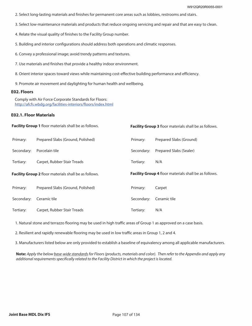
Page 107 of 134Joint Base MDL Dix IFS
2. Select long-lasting materials and finishes for permanent core areas such as lobbies, restrooms and stairs. 3. Select low-maintenance materials and products that reduce ongoing servicing and repair and that are easy to clean. 4. Relate the visual quality of finishes to the Facility Group number. 5. Building and interior configurations should address both operations and climatic responses. 6. Convey a professional image; avoid trendy patterns and textures. 7. Use materials and finishes that provide a healthy indoor environment. 8. Orient interior spaces toward views while maintaining cost-effective building performance and efficiency. 9. Promote air movement and daylighting for human health and wellbeing.
E02. Floors
Comply with Air Force Corporate Standards for Floors: http://afcfs.wbdg.org/facilities-interiors/floors/index.html
E02.1. Floor Materials
Facility Group 1 floor materials shall be as follows.
Primary: Prepared Slabs (Ground, Polished)
Secondary: Porcelain tile
Tertiary: Carpet, Rubber Stair Treads
Facility Group 2 floor materials shall be as follows.
Primary: Prepared Slabs (Ground, Polished)
Secondary: Ceramic tile
Tertiary: Carpet, Rubber Stair Treads
Facility Group 3 floor materials shall be as follows.
Primary: Prepared Slabs (Ground)
Secondary: Prepared Slabs (Sealer)
Tertiary: N/A
Facility Group 4 floor materials shall be as follows.
Primary: Carpet
Secondary: Ceramic tile
Tertiary: N/A
1. Natural stone and terrazzo flooring may be used in high traffic areas of Group 1 as approved on a case basis. 2. Resilient and rapidly renewable flooring may be used in low traffic areas in Group 1, 2 and 4. 3. Manufacturers listed below are only provided to establish a baseline of equivalency among all applicable manufacturers.
Note: Apply the below base-wide standards for Floors (products, materials and color). Then refer to the Appendix and apply any additional requirements specifically related to the Facility District in which the project is located.
W912QR20R0055-0001
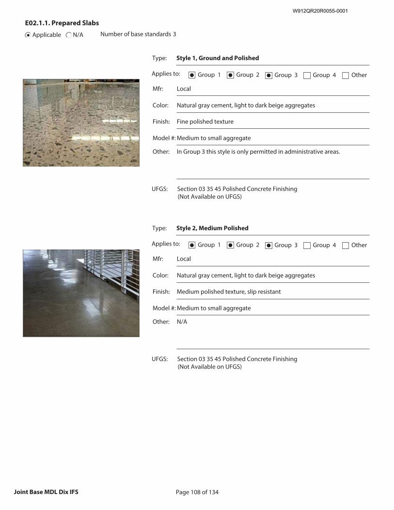
Page 108 of 134Joint Base MDL Dix IFS
E02.1.1. Prepared Slabs
Applicable N/A Number of base standards 3
Type: Style 1, Ground and Polished
Applies to: Group 1● Group 2● Group 3● Group 4 Other
Mfr: Local
Color: Natural gray cement, light to dark beige aggregates
Finish: Fine polished texture
Model #: Medium to small aggregate
Other: In Group 3 this style is only permitted in administrative areas.
UFGS: Section 03 35 45 Polished Concrete Finishing (Not Available on UFGS)
Recommended Image: Detail of Prepared Slab
Size image to:
250 pixels width x 188 pixels height
Click here to insert image
Type: Style 2, Medium Polished
Applies to: Group 1● Group 2● Group 3● Group 4 Other
Mfr: Local
Color: Natural gray cement, light to dark beige aggregates
Finish: Medium polished texture, slip resistant
Model #: Medium to small aggregate
Other: N/A
UFGS: Section 03 35 45 Polished Concrete Finishing (Not Available on UFGS)
Recommended Image: Detail of Prepared Slab
Size image to:
250 pixels width x 188 pixels height
Click here to insert image
W912QR20R0055-0001
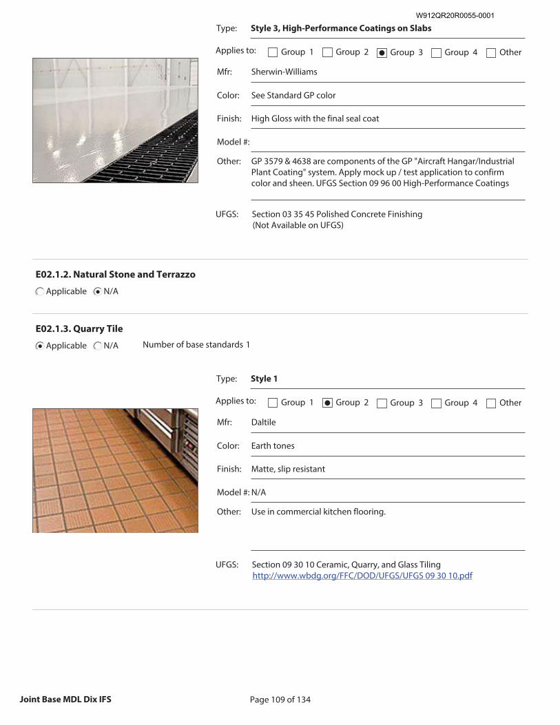
Page 109 of 134Joint Base MDL Dix IFS
Type: Style 3, High-Performance Coatings on Slabs
Applies to: Group 1 Group 2 Group 3● Group 4 Other
Mfr: Sherwin-Williams
Color: See Standard GP color
Finish: High Gloss with the final seal coat
Model #:
Other: GP 3579 & 4638 are components of the GP "Aircraft Hangar/Industrial Plant Coating" system. Apply mock up / test application to confirm color and sheen. UFGS Section 09 96 00 High-Performance Coatings
UFGS: Section 03 35 45 Polished Concrete Finishing (Not Available on UFGS)
Recommended Image: Detail of Prepared Slab
Size image to:
250 pixels width x 188 pixels height
Click here to insert image
E02.1.2. Natural Stone and Terrazzo
Applicable N/A
E02.1.3. Quarry Tile
Applicable N/A Number of base standards 1
Type: Style 1
Applies to: Group 1 Group 2● Group 3 Group 4 Other
Mfr: Daltile
Color: Earth tones
Finish: Matte, slip resistant
Model #: N/A
Other: Use in commercial kitchen flooring.
UFGS: Section 09 30 10 Ceramic, Quarry, and Glass Tiling http://www.wbdg.org/FFC/DOD/UFGS/UFGS 09 30 10.pdf
Recommended Image: Detail of Quarry Tile
Size image to:
250 pixels width x 188 pixels height
Click here to insert image
W912QR20R0055-0001
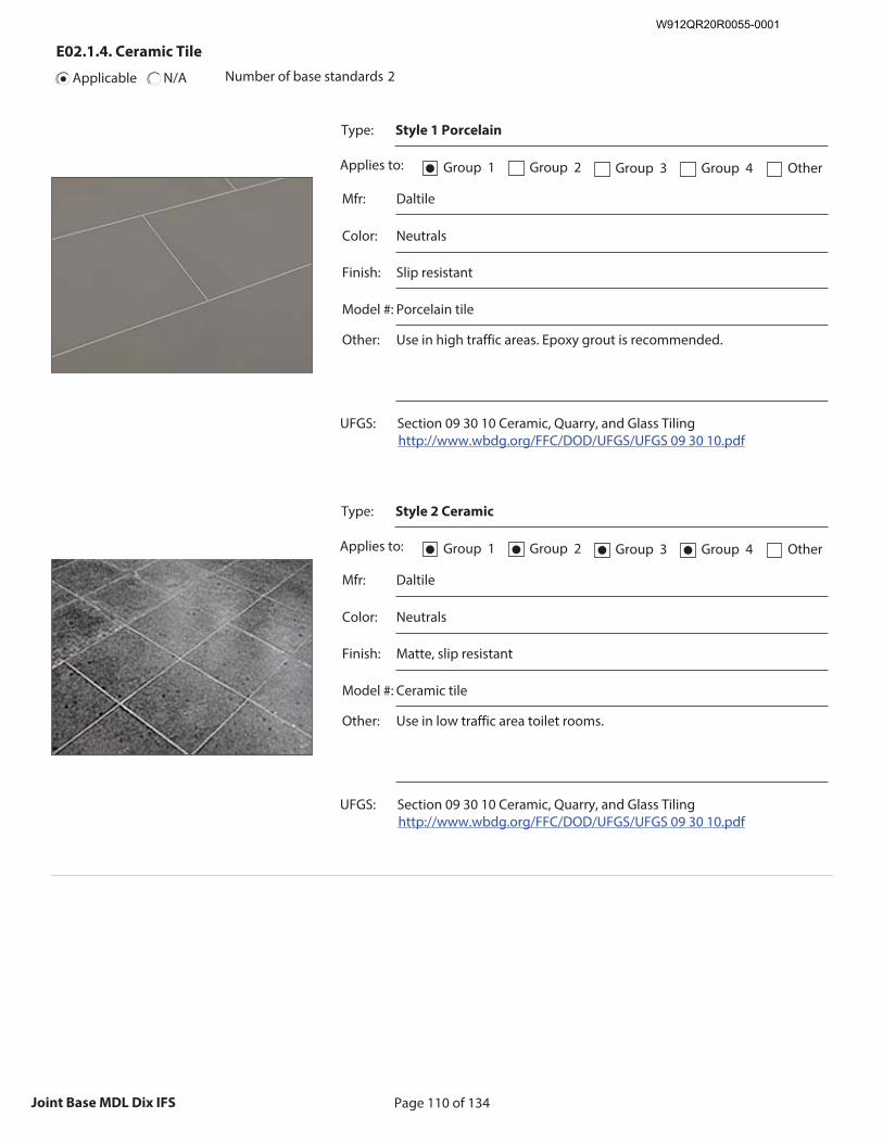
Page 110 of 134Joint Base MDL Dix IFS
E02.1.4. Ceramic Tile
Applicable N/A Number of base standards 2
Type: Style 1 Porcelain
Applies to: Group 1● Group 2 Group 3 Group 4 Other
Mfr: Daltile
Color: Neutrals
Finish: Slip resistant
Model #: Porcelain tile
Other: Use in high traffic areas. Epoxy grout is recommended.
UFGS: Section 09 30 10 Ceramic, Quarry, and Glass Tiling http://www.wbdg.org/FFC/DOD/UFGS/UFGS 09 30 10.pdf
Recommended Image: Detail of Ceramic Tile
Size image to:
250 pixels width x 188 pixels height
Click here to insert image
Type: Style 2 Ceramic
Applies to: Group 1● Group 2● Group 3● Group 4● Other
Mfr: Daltile
Color: Neutrals
Finish: Matte, slip resistant
Model #: Ceramic tile
Other: Use in low traffic area toilet rooms.
UFGS: Section 09 30 10 Ceramic, Quarry, and Glass Tiling http://www.wbdg.org/FFC/DOD/UFGS/UFGS 09 30 10.pdf
Recommended Image: Detail of Ceramic Tile
Size image to:
250 pixels width x 188 pixels height
Click here to insert image
W912QR20R0055-0001
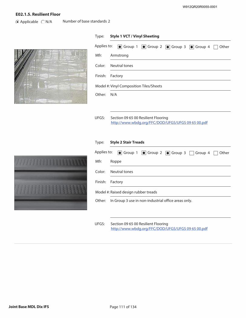
Page 111 of 134Joint Base MDL Dix IFS
E02.1.5. Resilient Floor
Applicable N/A Number of base standards 2
Type: Style 1 VCT / Vinyl Sheeting
Applies to: Group 1● Group 2● Group 3● Group 4● Other
Mfr: Armstrong
Color: Neutral tones
Finish: Factory
Model #: Vinyl Composition Tiles/Sheets
Other: N/A
UFGS: Section 09 65 00 Resilient Flooring http://www.wbdg.org/FFC/DOD/UFGS/UFGS 09 65 00.pdf
Recommended Image: Detail of Resilient Floor
Size image to:
250 pixels width x 188 pixels height
Click here to insert image
Type: Style 2 Stair Treads
Applies to: Group 1● Group 2● Group 3● Group 4 Other
Mfr: Roppe
Color: Neutral tones
Finish: Factory
Model #: Raised design rubber treads
Other: In Group 3 use in non-industrial office areas only.
UFGS: Section 09 65 00 Resilient Flooring http://www.wbdg.org/FFC/DOD/UFGS/UFGS 09 65 00.pdf
Recommended Image: Detail of Resilient Floor
Size image to:
250 pixels width x 188 pixels height
Click here to insert image
W912QR20R0055-0001
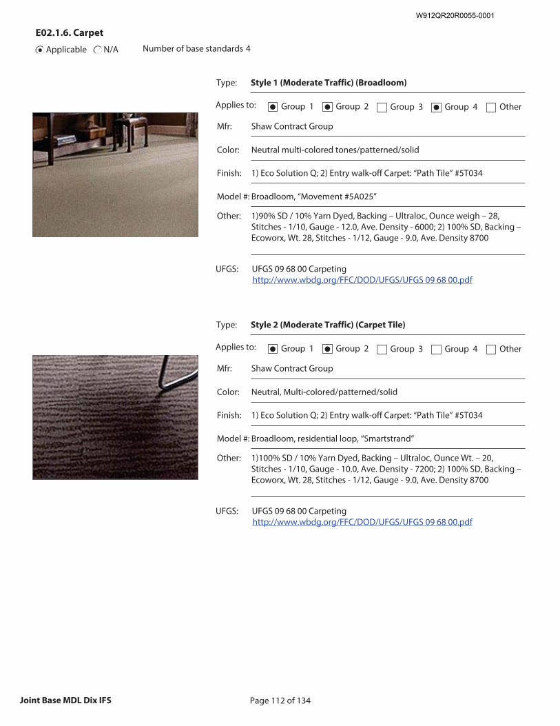
Page 112 of 134Joint Base MDL Dix IFS
E02.1.6. Carpet
Applicable N/A Number of base standards 4
Type: Style 1 (Moderate Traffic) (Broadloom)
Applies to: Group 1● Group 2● Group 3 Group 4● Other
Mfr: Shaw Contract Group
Color: Neutral multi-colored tones/patterned/solid
Finish: 1) Eco Solution Q; 2) Entry walk-off Carpet: “Path Tile” #5T034
Model #: Broadloom, “Movement #5A025”
Other: 1)90% SD / 10% Yarn Dyed, Backing – Ultraloc, Ounce weigh – 28, Stitches - 1/10, Gauge - 12.0, Ave. Density - 6000; 2) 100% SD, Backing – Ecoworx, Wt. 28, Stitches - 1/12, Gauge - 9.0, Ave. Density 8700
UFGS: UFGS 09 68 00 Carpeting http://www.wbdg.org/FFC/DOD/UFGS/UFGS 09 68 00.pdf
Recommended Image: Detail of Carpeting
Size image to:
250 pixels width x 188 pixels height
Click here to insert image
Type: Style 2 (Moderate Traffic) (Carpet Tile)
Applies to: Group 1● Group 2● Group 3 Group 4 Other
Mfr: Shaw Contract Group
Color: Neutral, Multi-colored/patterned/solid
Finish: 1) Eco Solution Q; 2) Entry walk-off Carpet: “Path Tile” #5T034
Model #: Broadloom, residential loop, “Smartstrand”
Other: 1)100% SD / 10% Yarn Dyed, Backing – Ultraloc, Ounce Wt. – 20, Stitches - 1/10, Gauge - 10.0, Ave. Density - 7200; 2) 100% SD, Backing – Ecoworx, Wt. 28, Stitches - 1/12, Gauge - 9.0, Ave. Density 8700
UFGS: UFGS 09 68 00 Carpeting http://www.wbdg.org/FFC/DOD/UFGS/UFGS 09 68 00.pdf
Recommended Image: Detail of Carpeting
Size image to:
250 pixels width x 188 pixels height
Click here to insert image
W912QR20R0055-0001
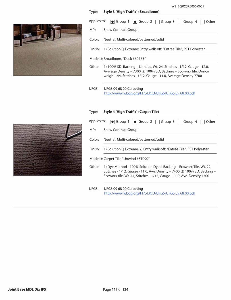
Page 113 of 134Joint Base MDL Dix IFS
Type: Style 3 (High Traffic) (Broadloom)
Applies to: Group 1● Group 2● Group 3 Group 4 Other
Mfr: Shaw Contract Group
Color: Neutral, Multi-colored/patterned/solid
Finish: 1) Solution Q Extreme; Entry walk-off: “Entrée Tile”, PET Polyester
Model #: Broadloom, “Dusk #60765”
Other: 1) 100% SD, Backing – Ultraloc, Wt. 24, Stitches - 1/12, Gauge - 12.0, Average Density – 7300; 2) 100% SD, Backing – Ecoworx tile, Ounce weigh – 44, Stitches - 1/12, Gauge - 11.0, Average Density 7700
UFGS: UFGS 09 68 00 Carpeting http://www.wbdg.org/FFC/DOD/UFGS/UFGS 09 68 00.pdf
Recommended Image: Detail of Carpeting
Size image to:
250 pixels width x 188 pixels height
Click here to insert image
Type: Style 4 (High Traffic) (Carpet Tile)
Applies to: Group 1● Group 2● Group 3 Group 4 Other
Mfr: Shaw Contract Group
Color: Neutral, Multi-colored/patterned/solid
Finish: 1) Solution Q Extreme, 2) Entry walk-off: “Entrée Tile”, PET Polyester
Model #: Carpet Tile, “Unwind #5T090”
Other: 1) Dye Method - 100% Solution Dyed, Backing – Ecoworx Tile, Wt. 22, Stitches - 1/12, Gauge - 11.0, Ave. Density – 7400; 2) 100% SD, Backing – Ecoworx tile, Wt. 44, Stitches - 1/12, Gauge - 11.0, Ave. Density 7700
UFGS: UFGS 09 68 00 Carpeting http://www.wbdg.org/FFC/DOD/UFGS/UFGS 09 68 00.pdf
Recommended Image: Detail of Carpeting
Size image to:
250 pixels width x 188 pixels height
Click here to insert image
W912QR20R0055-0001
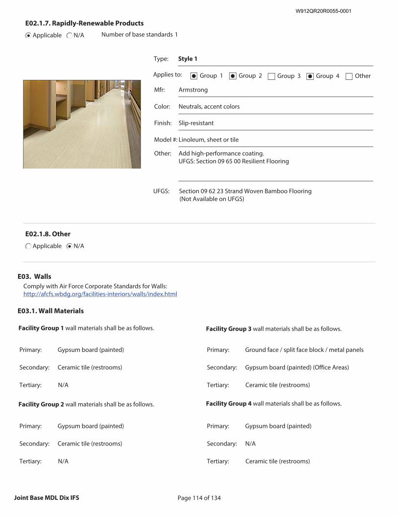
Page 114 of 134Joint Base MDL Dix IFS
E02.1.7. Rapidly-Renewable Products
Applicable N/A Number of base standards 1
Type: Style 1
Applies to: Group 1● Group 2● Group 3 Group 4● Other
Mfr: Armstrong
Color: Neutrals, accent colors
Finish: Slip-resistant
Model #: Linoleum, sheet or tile
Other: Add high-performance coating. UFGS: Section 09 65 00 Resilient Flooring
UFGS: Section 09 62 23 Strand Woven Bamboo Flooring (Not Available on UFGS)
Recommended Image: Detail of Rapidly-Renewable
Product
Size image to: 250 pixels width x 188 pixels height
Click here to insert image
E02.1.8. Other
Applicable N/A
E03. Walls
Comply with Air Force Corporate Standards for Walls: http://afcfs.wbdg.org/facilities-interiors/walls/index.html
E03.1. Wall Materials
Facility Group 1 wall materials shall be as follows.
Primary: Gypsum board (painted)
Secondary: Ceramic tile (restrooms)
Tertiary: N/A
Facility Group 2 wall materials shall be as follows.
Primary: Gypsum board (painted)
Secondary: Ceramic tile (restrooms)
Tertiary: N/A
Facility Group 3 wall materials shall be as follows.
Primary: Ground face / split face block / metal panels
Secondary: Gypsum board (painted) (Office Areas)
Tertiary: Ceramic tile (restrooms)
Facility Group 4 wall materials shall be as follows.
Primary: Gypsum board (painted)
Secondary: N/A
Tertiary: Ceramic tile (restrooms)
W912QR20R0055-0001
Page 115 of 134Joint Base MDL Dix IFS
1. Follow UFC 3-450-01 (Vibration and Noise Control) for acoustic design issues including speech privacy, sound isolation or sound masking. 2. Select and apply paint with sheens (gloss levels) appropriate for the application following UFGS Section 09 90 00 Paints and Coatings. 3. Provide ceramic tile on wet walls of kitchens, toilet rooms, locker rooms, etc., in all facility groups. 4. Neutral split-face or ground-face integrally colored block with a clear sealer may be used in Group 3. Do not paint block. 5. Provide rubber base on drywall partitions in Groups 1 and 2. 6. Hardwood base may only be used in Group 1 as approved on a case basis. 7. Hardwood chair rails / bumper rails may be used in high-use areas of Groups 1 and 2; aqueous clear finishes are preferred to reduce maintenance; plastic chair rails are permitted only in medical applications. 8. Decorative moldings may be used only in Group 1 when approved on a case basis. 9. Corner guards are permitted only in high traffic spaces with wheeled or cart use such as private service areas in Groups 1 and 2; stainless steel corners guards with a brushed finish may be judiciously used in Group 3. 10. Group 4 may use painted composite wood base. 11. Manufacturers listed below are only provided to establish a baseline of equivalency among all applicable manufacturers.
Note: Apply the below base-wide standards for Walls (products, materials and color). Then refer to the Appendix and apply any additional requirements specifically related to the Facility District in which the project is located.
E03.1.1. Concrete
Applicable N/A
W912QR20R0055-0001
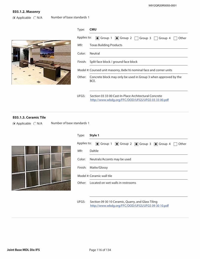
Page 116 of 134Joint Base MDL Dix IFS
E03.1.2. Masonry
Applicable N/A Number of base standards 1
Type: CMU
Applies to: Group 1● Group 2● Group 3 Group 4 Other
Mfr: Texas Building Products
Color: Neutral
Finish: Split face block / ground face block
Model #: Coursed unit masonry, 8x8x16 nominal face and corner units
Other: Concrete block may only be used in Group 3 when approved by the BCE.
UFGS: Section 03 33 00 Cast-In-Place Architectural Concrete http://www.wbdg.org/FFC/DOD/UFGS/UFGS 03 33 00.pdf
Recommended Image: Detail of Masonry Wall
Size image to:
250 pixels width x 188 pixels height
Click here to insert image
E03.1.3. Ceramic Tile
Applicable N/A Number of base standards 1
Type: Style 1
Applies to: Group 1● Group 2● Group 3● Group 4● Other
Mfr: Daltile
Color: Neutrals/Accents may be used
Finish: Matte/Glossy
Model #: Ceramic wall tile
Other: Located on wet walls in restrooms
UFGS: Section 09 30 10 Ceramic, Quarry, and Glass Tiling http://www.wbdg.org/FFC/DOD/UFGS/UFGS 09 30 10.pdf
Recommended Image: Detail of Ceramic Tile Wall
Size image to:
250 pixels width x 188 pixels height
Click here to insert image
W912QR20R0055-0001
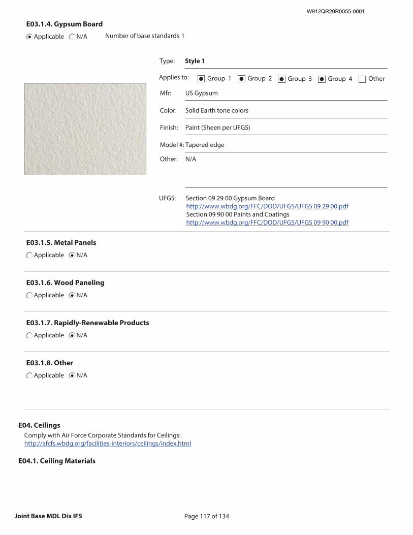
Page 117 of 134Joint Base MDL Dix IFS
E03.1.4. Gypsum Board
Applicable N/A Number of base standards 1
Type: Style 1
Applies to: Group 1● Group 2● Group 3● Group 4● Other
Mfr: US Gypsum
Color: Solid Earth tone colors
Finish: Paint (Sheen per UFGS)
Model #: Tapered edge
Other: N/A
UFGS: Section 09 29 00 Gypsum Board http://www.wbdg.org/FFC/DOD/UFGS/UFGS 09 29 00.pdf Section 09 90 00 Paints and Coatings http://www.wbdg.org/FFC/DOD/UFGS/UFGS 09 90 00.pdf
Recommended Image: Detail of Gypsum Board Wall
Size image to:
250 pixels width x 188 pixels height
Click here to insert image
E03.1.5. Metal Panels
Applicable N/A
E03.1.6. Wood Paneling
Applicable N/A
E03.1.7. Rapidly-Renewable Products
Applicable N/A
E03.1.8. Other
Applicable N/A
E04. Ceilings
Comply with Air Force Corporate Standards for Ceilings: http://afcfs.wbdg.org/facilities-interiors/ceilings/index.html
E04.1. Ceiling Materials
W912QR20R0055-0001
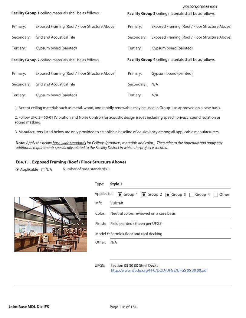
Page 118 of 134Joint Base MDL Dix IFS
Facility Group 1 ceiling materials shall be as follows.
Primary: Exposed Framing (Roof / Floor Structure Above)
Secondary: Grid and Acoustical Tile
Tertiary: Gypsum board (painted)
Facility Group 2 ceiling materials shall be as follows.
Primary: Exposed Framing (Roof / Floor Structure Above)
Secondary: Grid and Acoustical Tile
Tertiary: Gypsum board (painted)
Facility Group 3 ceiling materials shall be as follows.
Primary: Exposed Framing (Roof / Floor Structure Above)
Secondary: Exposed Framing (Roof / Floor Structure Above)
Tertiary: Gypsum board (painted)
Facility Group 4 ceiling materials shall be as follows.
Primary: Gypsum board (painted)
Secondary: N/A
Tertiary: N/A
1. Accent ceiling materials such as metal, wood, and rapidly renewable may be used in Group 1 as approved on a case basis. 2. Follow UFC 3-450-01 (Vibration and Noise Control) for acoustic design issues including speech privacy, sound isolation or sound masking. 3. Manufacturers listed below are only provided to establish a baseline of equivalency among all applicable manufacturers.
Note: Apply the below base-wide standards for Ceilings (products, materials and color). Then refer to the Appendix and apply any additional requirements specifically related to the Facility District in which the project is located.
E04.1.1. Exposed Framing (Roof / Floor Structure Above)
Applicable N/A Number of base standards 1
Type: Style 1
Applies to: Group 1● Group 2● Group 3● Group 4 Other
Mfr: Vulcraft
Color: Neutral colors reviewed on a case basis
Finish: Field painted (Sheen per UFGS)
Model #: Formlok floor and roof decking
Other: N/A
UFGS: Section 05 30 00 Steel Decks http://www.wbdg.org/FFC/DOD/UFGS/UFGS 05 30 00.pdf
Recommended Image: Detail of Exposed Framing
Size image to:
250 pixels width x 188 pixels height
Click here to insert image
W912QR20R0055-0001
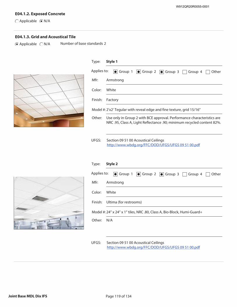
Page 119 of 134Joint Base MDL Dix IFS
E04.1.2. Exposed Concrete
Applicable N/A
E04.1.3. Grid and Acoustical Tile
Applicable N/A Number of base standards 2
Type: Style 1
Applies to: Group 1● Group 2● Group 3● Group 4 Other
Mfr: Armstrong
Color: White
Finish: Factory
Model #: 2’x2’ Tegular with reveal edge and fine texture, grid 15/16”
Other: Use only in Group 2 with BCE approval. Performance characteristics are NRC .95, Class A, Light Reflectance .90; minimum recycled content 82%.
UFGS: Section 09 51 00 Acoustical Ceilings http://www.wbdg.org/FFC/DOD/UFGS/UFGS 09 51 00.pdf
Recommended Image: Detail of Grid and Acoustical Tile
Size image to:
250 pixels width x 188 pixels height
Click here to insert image
Type: Style 2
Applies to: Group 1● Group 2● Group 3● Group 4 Other
Mfr: Armstrong
Color: White
Finish: Ultima (for restrooms)
Model #: 24” x 24” x 1” tiles, NRC .80, Class A, Bio-Block, Humi-Guard+
Other: N/A
UFGS: Section 09 51 00 Acoustical Ceilings http://www.wbdg.org/FFC/DOD/UFGS/UFGS 09 51 00.pdf
Recommended Image: Detail of Grid and Acoustical Tile
Size image to:
250 pixels width x 188 pixels height
Click here to insert image
W912QR20R0055-0001

Page 120 of 134Joint Base MDL Dix IFS
E04.1.4. Gypsum Board
Applicable N/A Number of base standards 1
Type: Style 1
Applies to: Group 1● Group 2● Group 3 Group 4● Other
Mfr: American Gypsum
Color: Factory, field painted solid neutral colors
Finish: Paint (sheen per UFGS)
Model #: Tapered edge
Other: Type X (Fire Rated), M-Block (Mold/Moisture Resistant)
UFGS: Section 09 29 00 Gypsum Board http://www.wbdg.org/FFC/DOD/UFGS/UFGS 09 29 00.pdf Section 09 90 00 Paints and Coatings http://www.wbdg.org/FFC/DOD/UFGS/UFGS 09 90 00.pdf
Recommended Image: Detail of Gypsum Board Ceiling
Size image to:
250 pixels width x 188 pixels height
Click here to insert image
E04.1.5. Metal Panels
Applicable N/A
E04.1.6. Wood
Applicable N/A
E04.1.7. Rapidly-Renewable Products
Applicable N/A
E04.1.8. Other
Applicable N/A
E05. Doors and Windows
Comply with Air Force Corporate Standards for Doors and Windows: http://afcfs.wbdg.org/facilities-interiors/doors-and-windows/index.html
E05.1. Doors and Windows and Frames Materials
W912QR20R0055-0001
Page 121 of 134Joint Base MDL Dix IFS
Facility Group 1
door (frame) and window frame materials shall be as follows.
Primary: Aluminum, clear anodized
Secondary: Hollow metal (painted)
Tertiary: N/A
Facility Group 1
door (leaf) materials shall be as follows.
Primary: Hardwood veneer
Secondary: Hollow metal (painted)
Tertiary: N/A
Facility Group 3
door (frame) and window frame materials shall be as follows.
Primary: Hollow metal (galvanized, painted)
Secondary: Hollow metal (galvanized)
Tertiary: N/A
Facility Group 3
door (leaf) materials shall be as follows.
Primary: Hollow metal (galvanized, painted)
Secondary: Hollow metal (galvanized)
Tertiary: N/A
Facility Group 2
door (frame) and window frame materials shall be as follows.
Secondary: Composite solid core
Tertiary: N/A
Primary: Wood solid core
Facility Group 4
door (leaf) materials shall be as follows.
Tertiary: N/A
Secondary: N/A
Primary: Wood
Facility Group 4
door (frame) and window frame materials shall be as follows.
Tertiary: N/A
Secondary: Hollow metal (painted)
Primary: Hardwood veneer
Facility Group 2
door (leaf) materials shall be as follows.
Tertiary: N/A
Secondary: Hollow metal (painted)
Primary: Aluminum, clear anodized
1. Hardwood casings may be provided over metal frames in Group 1 as approved on a case basis. 2. Paneled textured doors are preferred in Group 4. 3. Do not use hollow-core wood doors. 4. Generally match original hardware in renovations. 5. Manufacturers listed below are only provided to establish a baseline of equivalency among all applicable manufacturers.
Note: Apply the below base-wide standards for Doors and Windows (products, materials and color). Then refer to the Appendix and apply any additional requirements specifically related to the Facility District in which the project is located.
W912QR20R0055-0001
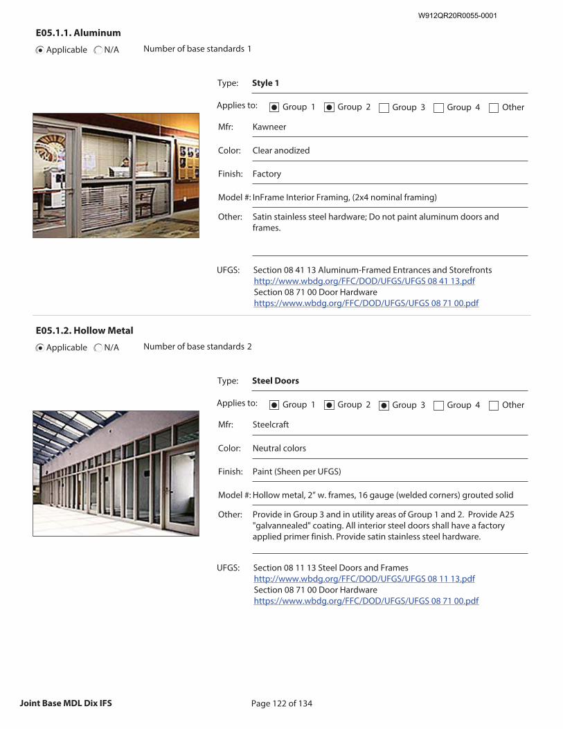
Page 122 of 134Joint Base MDL Dix IFS
E05.1.1. Aluminum
Applicable N/A Number of base standards 1
Type: Style 1
Applies to: Group 1● Group 2● Group 3 Group 4 Other
Mfr: Kawneer
Color: Clear anodized
Finish: Factory
Model #: InFrame Interior Framing, (2x4 nominal framing)
Other: Satin stainless steel hardware; Do not paint aluminum doors and frames.
UFGS: Section 08 41 13 Aluminum-Framed Entrances and Storefronts http://www.wbdg.org/FFC/DOD/UFGS/UFGS 08 41 13.pdf Section 08 71 00 Door Hardware https://www.wbdg.org/FFC/DOD/UFGS/UFGS 08 71 00.pdf
Recommended Image: Detail of Aluminum-Framed Entrance and / or Storefront
Size image to:
250 pixels width x 188 pixels height
Click here to insert image
E05.1.2. Hollow Metal
Applicable N/A Number of base standards 2
Type: Steel Doors
Applies to: Group 1● Group 2● Group 3● Group 4 Other
Mfr: Steelcraft
Color: Neutral colors
Finish: Paint (Sheen per UFGS)
Model #: Hollow metal, 2” w. frames, 16 gauge (welded corners) grouted solid
Other: Provide in Group 3 and in utility areas of Group 1 and 2. Provide A25 "galvannealed" coating. All interior steel doors shall have a factory applied primer finish. Provide satin stainless steel hardware.
UFGS: Section 08 11 13 Steel Doors and Frames http://www.wbdg.org/FFC/DOD/UFGS/UFGS 08 11 13.pdf Section 08 71 00 Door Hardware https://www.wbdg.org/FFC/DOD/UFGS/UFGS 08 71 00.pdf
Recommended Image: Detail of Steel Door and / or Frame
Size image to:
250 pixels width x 188 pixels height
Click here to insert image
W912QR20R0055-0001
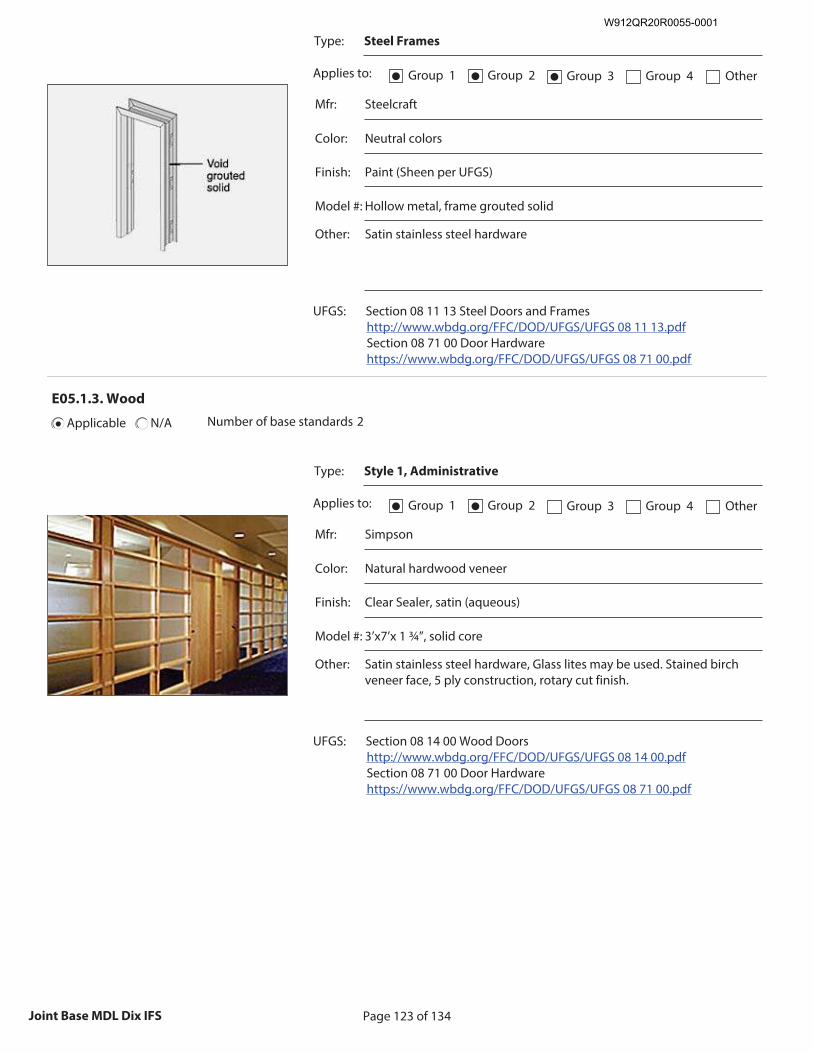
Page 123 of 134Joint Base MDL Dix IFS
Type: Steel Frames
Applies to: Group 1● Group 2● Group 3● Group 4 Other
Mfr: Steelcraft
Color: Neutral colors
Finish: Paint (Sheen per UFGS)
Model #: Hollow metal, frame grouted solid
Other: Satin stainless steel hardware
UFGS: Section 08 11 13 Steel Doors and Frames http://www.wbdg.org/FFC/DOD/UFGS/UFGS 08 11 13.pdf Section 08 71 00 Door Hardware https://www.wbdg.org/FFC/DOD/UFGS/UFGS 08 71 00.pdf
Recommended Image: Detail of Steel Door and / or Frame
Size image to:
250 pixels width x 188 pixels height
Click here to insert image
E05.1.3. Wood
Applicable N/A Number of base standards 2
Type: Style 1, Administrative
Applies to: Group 1● Group 2● Group 3 Group 4 Other
Mfr: Simpson
Color: Natural hardwood veneer
Finish: Clear Sealer, satin (aqueous)
Model #: 3’x7’x 1 ¾”, solid core
Other: Satin stainless steel hardware, Glass lites may be used. Stained birch veneer face, 5 ply construction, rotary cut finish.
UFGS: Section 08 14 00 Wood Doors http://www.wbdg.org/FFC/DOD/UFGS/UFGS 08 14 00.pdf Section 08 71 00 Door Hardware https://www.wbdg.org/FFC/DOD/UFGS/UFGS 08 71 00.pdf
Recommended Image: Detail of Wood Door
Size image to:
250 pixels width x 188 pixels height
Click here to insert image
W912QR20R0055-0001
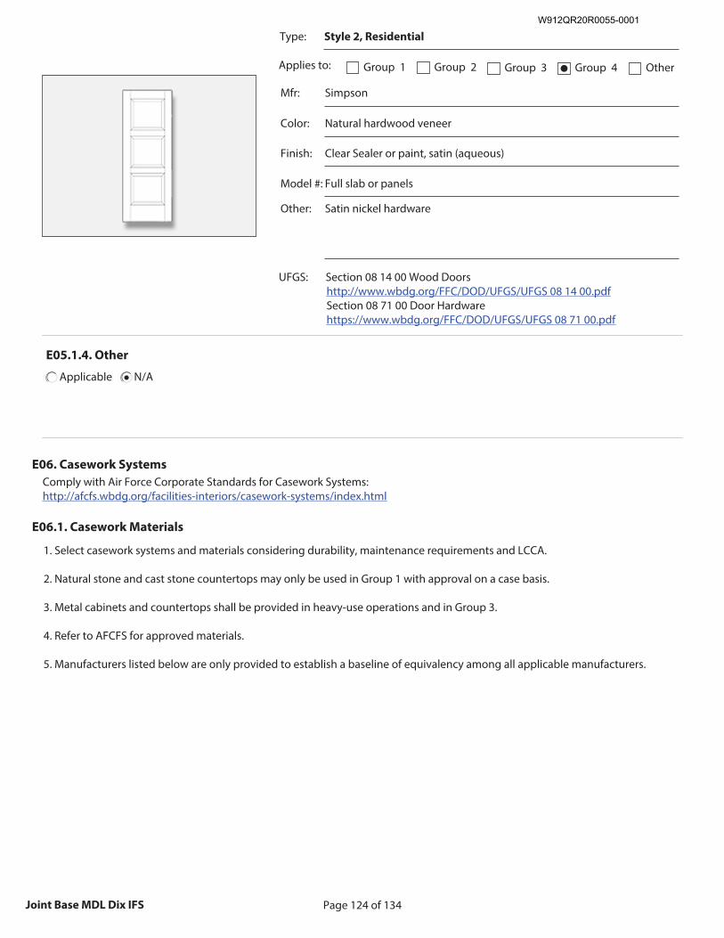
Page 124 of 134Joint Base MDL Dix IFS
Type: Style 2, Residential
Applies to: Group 1 Group 2 Group 3 Group 4● Other
Mfr: Simpson
Color: Natural hardwood veneer
Finish: Clear Sealer or paint, satin (aqueous)
Model #: Full slab or panels
Other: Satin nickel hardware
UFGS: Section 08 14 00 Wood Doors http://www.wbdg.org/FFC/DOD/UFGS/UFGS 08 14 00.pdf Section 08 71 00 Door Hardware https://www.wbdg.org/FFC/DOD/UFGS/UFGS 08 71 00.pdf
Recommended Image: Detail of Wood Door
Size image to:
250 pixels width x 188 pixels height
Click here to insert image
E05.1.4. Other
Applicable N/A
E06. Casework Systems
Comply with Air Force Corporate Standards for Casework Systems: http://afcfs.wbdg.org/facilities-interiors/casework-systems/index.html
E06.1. Casework Materials
1. Select casework systems and materials considering durability, maintenance requirements and LCCA. 2. Natural stone and cast stone countertops may only be used in Group 1 with approval on a case basis. 3. Metal cabinets and countertops shall be provided in heavy-use operations and in Group 3. 4. Refer to AFCFS for approved materials. 5. Manufacturers listed below are only provided to establish a baseline of equivalency among all applicable manufacturers.
W912QR20R0055-0001
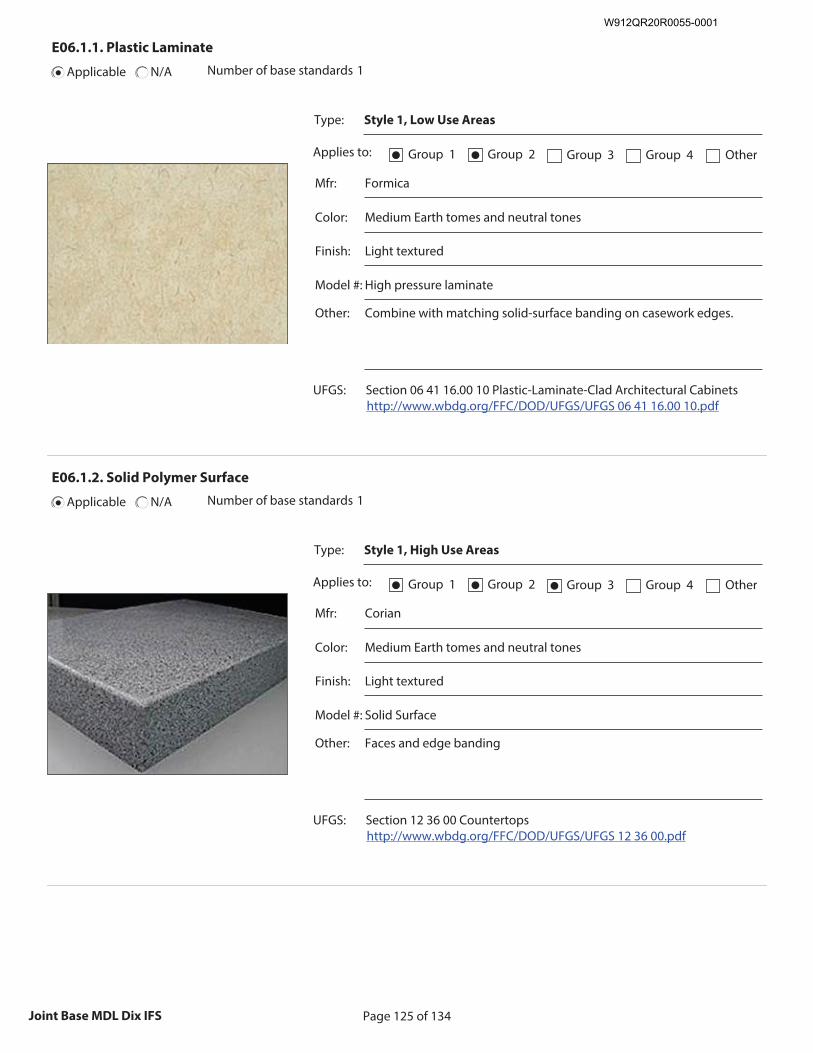
Page 125 of 134Joint Base MDL Dix IFS
E06.1.1. Plastic Laminate
Applicable N/A Number of base standards 1
Type: Style 1, Low Use Areas
Applies to: Group 1● Group 2● Group 3 Group 4 Other
Mfr: Formica
Color: Medium Earth tomes and neutral tones
Finish: Light textured
Model #: High pressure laminate
Other: Combine with matching solid-surface banding on casework edges.
UFGS: Section 06 41 16.00 10 Plastic-Laminate-Clad Architectural Cabinets http://www.wbdg.org/FFC/DOD/UFGS/UFGS 06 41 16.00 10.pdf
Recommended Image: Detail of Plastic Laminate
Size image to:
250 pixels width x 188 pixels height
Click here to insert image
E06.1.2. Solid Polymer Surface
Applicable N/A Number of base standards 1
Type: Style 1, High Use Areas
Applies to: Group 1● Group 2● Group 3● Group 4 Other
Mfr: Corian
Color: Medium Earth tomes and neutral tones
Finish: Light textured
Model #: Solid Surface
Other: Faces and edge banding
UFGS: Section 12 36 00 Countertops http://www.wbdg.org/FFC/DOD/UFGS/UFGS 12 36 00.pdf
Recommended Image: Detail of Solid Polymer Surface
Size image to:
250 pixels width x 188 pixels height
Click here to insert image
W912QR20R0055-0001
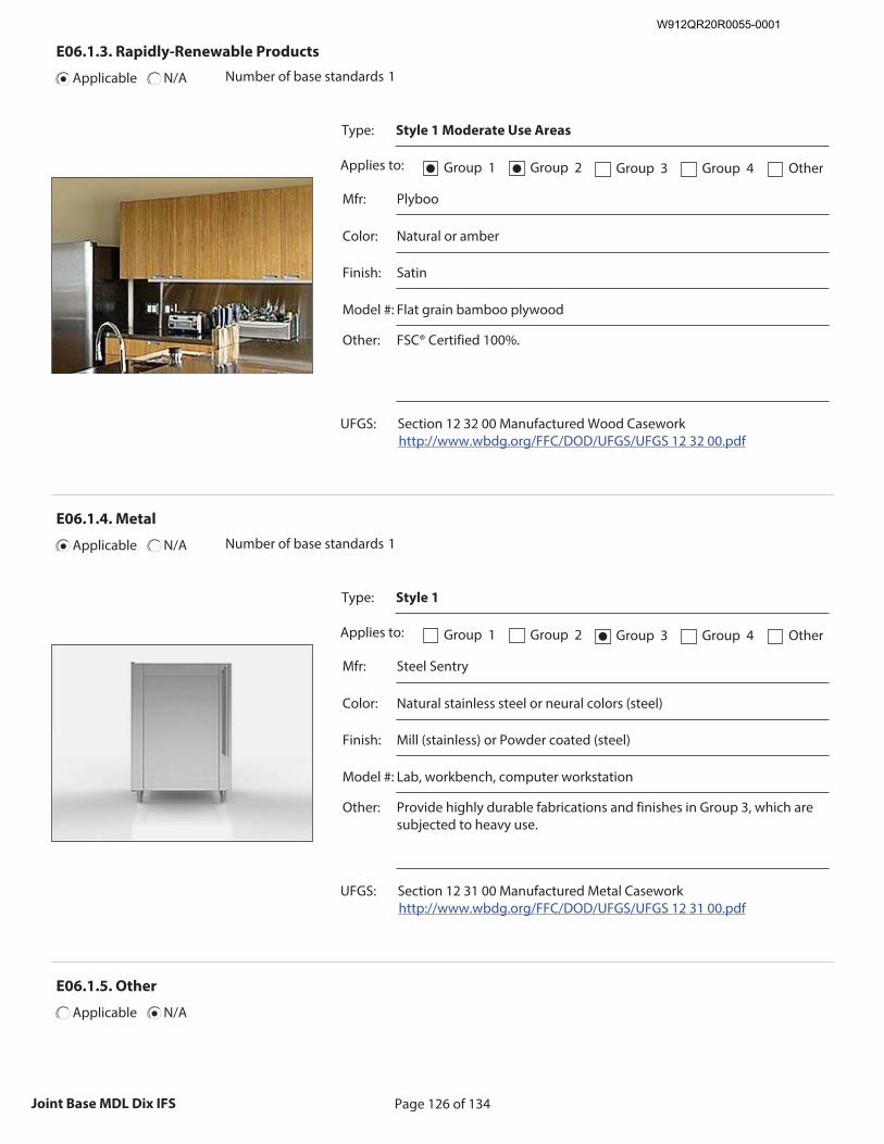
Page 126 of 134Joint Base MDL Dix IFS
E06.1.3. Rapidly-Renewable Products
Applicable N/A Number of base standards 1
Type: Style 1 Moderate Use Areas
Applies to: Group 1● Group 2● Group 3 Group 4 Other
Mfr: Plyboo
Color: Natural or amber
Finish: Satin
Model #: Flat grain bamboo plywood
Other: FSC® Certified 100%.
UFGS: Section 12 32 00 Manufactured Wood Casework http://www.wbdg.org/FFC/DOD/UFGS/UFGS 12 32 00.pdf
Recommended Image: Detail of Rapidly Renewable
Product
Size image to: 250 pixels width x 188 pixels height
Click here to insert image
E06.1.4. Metal
Applicable N/A Number of base standards 1
Type: Style 1
Applies to: Group 1 Group 2 Group 3● Group 4 Other
Mfr: Steel Sentry
Color: Natural stainless steel or neural colors (steel)
Finish: Mill (stainless) or Powder coated (steel)
Model #: Lab, workbench, computer workstation
Other: Provide highly durable fabrications and finishes in Group 3, which are subjected to heavy use.
UFGS: Section 12 31 00 Manufactured Metal Casework http://www.wbdg.org/FFC/DOD/UFGS/UFGS 12 31 00.pdf
Recommended Image: Detail of Metal Casework
Size image to:
250 pixels width x 188 pixels height
Click here to insert image
E06.1.5. Other
Applicable N/A
W912QR20R0055-0001
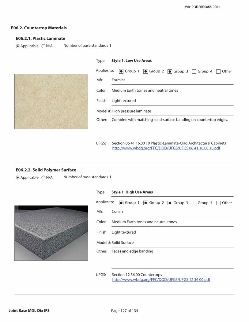
Page 127 of 134Joint Base MDL Dix IFS
E06.2. Countertop Materials
E06.2.1. Plastic Laminate
Applicable N/A Number of base standards 1
Type: Style 1, Low Use Areas
Applies to: Group 1● Group 2● Group 3● Group 4 Other
Mfr: Formica
Color: Medium Earth tomes and neutral tones
Finish: Light textured
Model #: High pressure laminate
Other: Combine with matching solid-surface banding on countertop edges.
UFGS: Section 06 41 16.00 10 Plastic-Laminate-Clad Architectural Cabinets http://www.wbdg.org/FFC/DOD/UFGS/UFGS 06 41 16.00 10.pdf
Recommended Image: Detail of Plastic Laminate
Countertop
Size image to: 250 pixels width x 188 pixels height
Click here to insert image
E06.2.2. Solid Polymer Surface
Applicable N/A Number of base standards 1
Type: Style 1, High Use Areas
Applies to: Group 1● Group 2● Group 3● Group 4 Other
Mfr: Corian
Color: Medium Earth tones and neutral tones
Finish: Light textured
Model #: Solid Surface
Other: Faces and edge banding
UFGS: Section 12 36 00 Countertops http://www.wbdg.org/FFC/DOD/UFGS/UFGS 12 36 00.pdf
Recommended Image: Detail of Solid Polymer Surface
Size image to:
250 pixels width x 188 pixels height
Click here to insert image
W912QR20R0055-0001
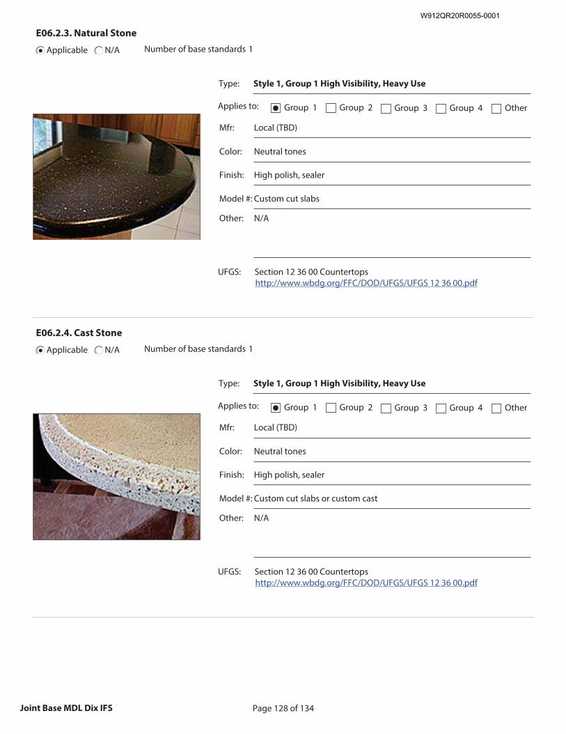
Page 128 of 134Joint Base MDL Dix IFS
E06.2.3. Natural Stone
Applicable N/A Number of base standards 1
Type: Style 1, Group 1 High Visibility, Heavy Use
Applies to: Group 1● Group 2 Group 3 Group 4 Other
Mfr: Local (TBD)
Color: Neutral tones
Finish: High polish, sealer
Model #: Custom cut slabs
Other: N/A
UFGS: Section 12 36 00 Countertops http://www.wbdg.org/FFC/DOD/UFGS/UFGS 12 36 00.pdf
Recommended Image: Detail of Natural Stone Countertop
Size image to:
250 pixels width x 188 pixels height
Click here to insert image
E06.2.4. Cast Stone
Applicable N/A Number of base standards 1
Type: Style 1, Group 1 High Visibility, Heavy Use
Applies to: Group 1● Group 2 Group 3 Group 4 Other
Mfr: Local (TBD)
Color: Neutral tones
Finish: High polish, sealer
Model #: Custom cut slabs or custom cast
Other: N/A
UFGS: Section 12 36 00 Countertops http://www.wbdg.org/FFC/DOD/UFGS/UFGS 12 36 00.pdf
Recommended Image: Detail of Cast Stone Countertop
Size image to:
250 pixels width x 188 pixels height
Click here to insert image
W912QR20R0055-0001
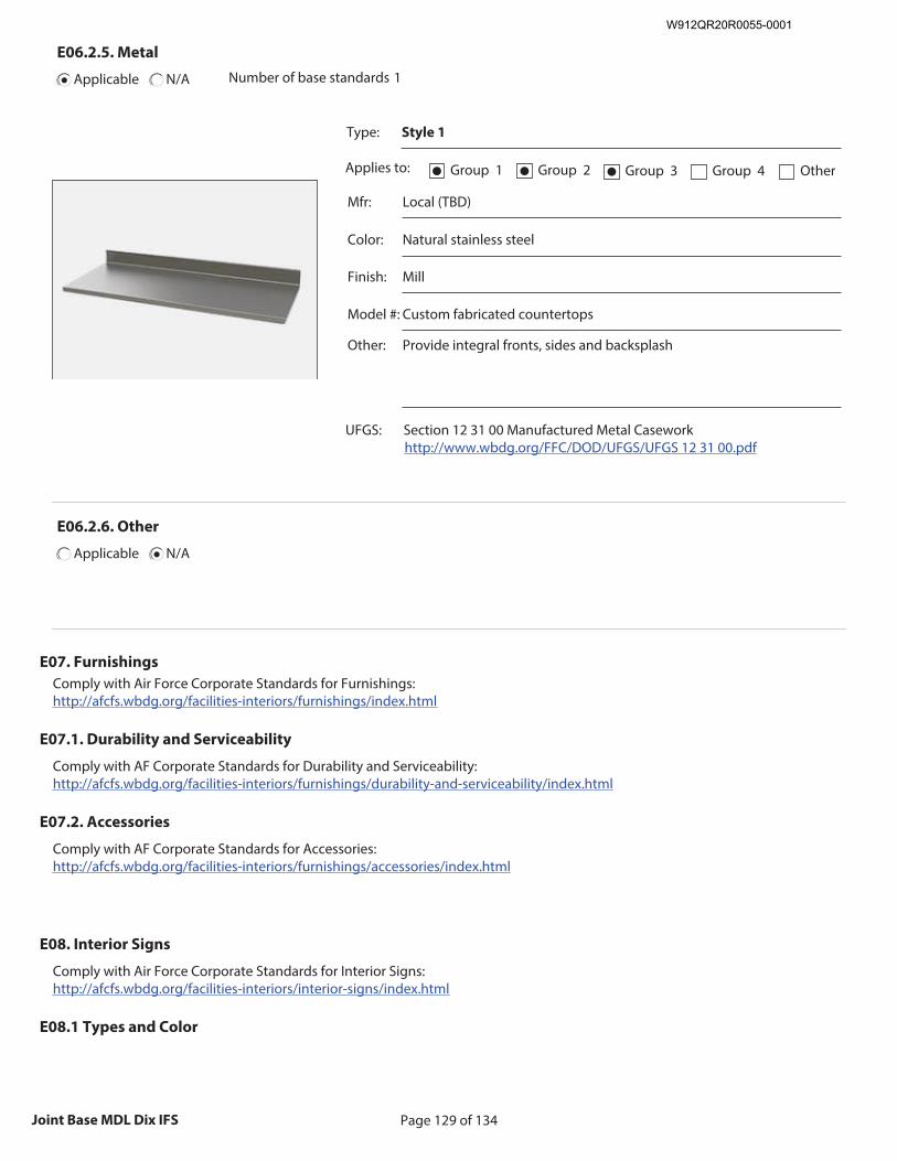
Page 129 of 134Joint Base MDL Dix IFS
E06.2.5. Metal
Applicable N/A Number of base standards 1
Type: Style 1
Applies to: Group 1● Group 2● Group 3● Group 4 Other
Mfr: Local (TBD)
Color: Natural stainless steel
Finish: Mill
Model #: Custom fabricated countertops
Other: Provide integral fronts, sides and backsplash
UFGS: Section 12 31 00 Manufactured Metal Casework http://www.wbdg.org/FFC/DOD/UFGS/UFGS 12 31 00.pdf
Recommended Image: Detail of Metal Countertop
Size image to:
250 pixels width x 188 pixels height
Click here to insert image
E06.2.6. Other
Applicable N/A
E07. Furnishings
Comply with Air Force Corporate Standards for Furnishings: http://afcfs.wbdg.org/facilities-interiors/furnishings/index.html
E07.1. Durability and Serviceability
Comply with AF Corporate Standards for Durability and Serviceability: http://afcfs.wbdg.org/facilities-interiors/furnishings/durability-and-serviceability/index.html
E07.2. Accessories
Comply with AF Corporate Standards for Accessories: http://afcfs.wbdg.org/facilities-interiors/furnishings/accessories/index.html
E08. Interior Signs
Comply with Air Force Corporate Standards for Interior Signs: http://afcfs.wbdg.org/facilities-interiors/interior-signs/index.html
E08.1 Types and Color
W912QR20R0055-0001

Page 130 of 134Joint Base MDL Dix IFS
Comply with Air Force Corporate Standards for Types and Color: http://afcfs.wbdg.org/facilities-interiors/interior-signs/types-and-color/index.html
E08.2. Interior Signs Materials
1. Natural stone, masonry and cast stone signs may only be used in Group 1 with approval on a case-by-case basis.
E09. Lighting, Power and Communication
http://afcfs.wbdg.org/facilities-interiors/lighting-power-and-communication/index.html
E09.1. Functionality and Efficiency
Comply with Air Force Corporate Standards for Functionality and Efficiency: http://afcfs.wbdg.org/facilities-interiors/lighting-power-and-communication/functionality-and-efficiency/index.html
E09.2. Types and Color
Interior Lighting:
1. All Interior lights shall be LED (light-emitting diode). Interior illumination levels typically range from 15-35 foot candles, adjusted higher or lower depending upon the use of the space. Power and Grounding System:
Comply with Air Force instruction for Grounding and Bonding:
https://www.wbdg.org/FFC/AF/AFI/afi_32_1065_2017.pdf 1. All conductors shall be copper and shall meet the requirements of NFPA and NEC. 2. Electrical system shall be grounded. Emergency Generator:
Comply with Air Force Instruction for Power Plants and Generators:
https://www.wbdg.org/FFC/AF/AFI/afi_32_1062.pdf 1. Provide double wall saddle tanks that are part of a package installation for generator installations. The fuel type shall be diesel.
Fire Protection:
Comply with Air Force Instruction for Fire Emergency Services
https://www.wbdg.org/FFC/AF/AFI/afi_32_2001.pdf https://www.wbdg.org/FFC/DOD/UFC/ufc_4_021_01_2008_c1.pdf
W912QR20R0055-0001
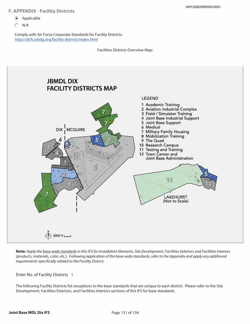
Page 131 of 134Joint Base MDL Dix IFS
F. APPENDIX - Facility Districts
Applicable
N/A
Comply with Air Force Corporate Standards for Facility Districts: http://afcfs.wbdg.org/facility-districts/index.html
Facilities Districts Overview Map:
Insert photo of a overall base map with all Facility Districts delineated in a contrasting color or outline.
Size image to:
800 pixels width x 600 pixels height
Click here to insert image (jpg or png format)
Note: Apply the base-wide standards in this IFS for Installation Elements, Site Development, Facilities Exteriors and Facilities Interiors (products, materials, color, etc.). Following application of the base-wide standards, refer to the Appendix and apply any additional requirements specifically related to the Facility District.
The following Facility Districts list exceptions to the base standards that are unique to each district. Please refer to the Site Development, Facilities Exteriors, and Facilities Interiors sections of this IFS for base standards.
Enter No. of Facility Districts 1
W912QR20R0055-0001
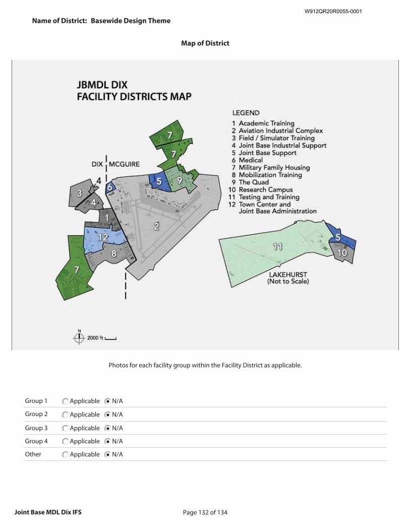
Page 132 of 134Joint Base MDL Dix IFS
Name of District: Basewide Design Theme
Map of District
Insert photo of a base map with the Facility District delineated in a contrasting color or outline.
Size image to:
800 pixels width x 600 pixels height
Click here to insert image (jpg or png format)
Photos for each facility group within the Facility District as applicable.
Group 1 Applicable N/A
Group 2 Applicable N/A
Group 3 Applicable N/A
Group 4 Applicable N/A
Other Applicable N/A
W912QR20R0055-0001
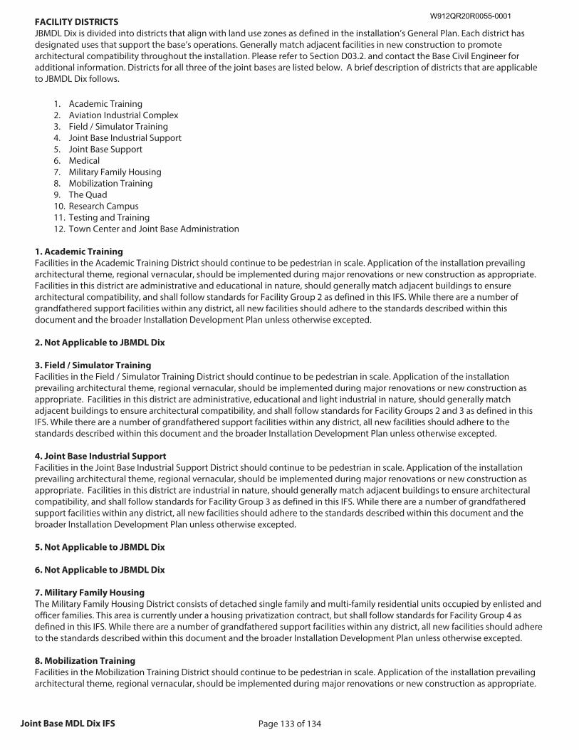
Page 133 of 134Joint Base MDL Dix IFS
FACILITY DISTRICTS
JBMDL Dix is divided into districts that align with land use zones as defined in the installation’s General Plan. Each district has designated uses that support the base’s operations. Generally match adjacent facilities in new construction to promote architectural compatibility throughout the installation. Please refer to Section D03.2. and contact the Base Civil Engineer for additional information. Districts for all three of the joint bases are listed below. A brief description of districts that are applicable to JBMDL Dix follows.
1. Academic Training 2. Aviation Industrial Complex 3. Field / Simulator Training 4. Joint Base Industrial Support 5. Joint Base Support 6. Medical 7. Military Family Housing 8. Mobilization Training 9. The Quad 10. Research Campus 11. Testing and Training 12. Town Center and Joint Base Administration
1. Academic Training
Facilities in the Academic Training District should continue to be pedestrian in scale. Application of the installation prevailing architectural theme, regional vernacular, should be implemented during major renovations or new construction as appropriate. Facilities in this district are administrative and educational in nature, should generally match adjacent buildings to ensure architectural compatibility, and shall follow standards for Facility Group 2 as defined in this IFS. While there are a number of grandfathered support facilities within any district, all new facilities should adhere to the standards described within this document and the broader Installation Development Plan unless otherwise excepted. 2. Not Applicable to JBMDL Dix
3. Field / Simulator Training
Facilities in the Field / Simulator Training District should continue to be pedestrian in scale. Application of the installation prevailing architectural theme, regional vernacular, should be implemented during major renovations or new construction as appropriate. Facilities in this district are administrative, educational and light industrial in nature, should generally match adjacent buildings to ensure architectural compatibility, and shall follow standards for Facility Groups 2 and 3 as defined in this IFS. While there are a number of grandfathered support facilities within any district, all new facilities should adhere to the standards described within this document and the broader Installation Development Plan unless otherwise excepted. 4. Joint Base Industrial Support
Facilities in the Joint Base Industrial Support District should continue to be pedestrian in scale. Application of the installation prevailing architectural theme, regional vernacular, should be implemented during major renovations or new construction as appropriate. Facilities in this district are industrial in nature, should generally match adjacent buildings to ensure architectural compatibility, and shall follow standards for Facility Group 3 as defined in this IFS. While there are a number of grandfathered support facilities within any district, all new facilities should adhere to the standards described within this document and the broader Installation Development Plan unless otherwise excepted.
5. Not Applicable to JBMDL Dix
6. Not Applicable to JBMDL Dix
7. Military Family Housing
The Military Family Housing District consists of detached single family and multi-family residential units occupied by enlisted and officer families. This area is currently under a housing privatization contract, but shall follow standards for Facility Group 4 as defined in this IFS. While there are a number of grandfathered support facilities within any district, all new facilities should adhere to the standards described within this document and the broader Installation Development Plan unless otherwise excepted. 8. Mobilization Training
Facilities in the Mobilization Training District should continue to be pedestrian in scale. Application of the installation prevailing architectural theme, regional vernacular, should be implemented during major renovations or new construction as appropriate.
W912QR20R0055-0001
Page 134 of 134Joint Base MDL Dix IFS
Facilities in this district are administrative, educational and light industrial in nature, should generally match adjacent buildings to ensure architectural compatibility, and shall follow standards for Facility Groups 2 and 3 as defined in this IFS. While there are a number of grandfathered support facilities within any district, all new facilities should adhere to the standards described within this document and the broader Installation Development Plan unless otherwise excepted. 9. Not Applicable to JBMDL Dix
10. Not Applicable to JBMDL Dix
11. Not Applicable to JBMDL Dix
12. Town Center and Joint Base Administration
Though Town Center facilities and Joint Base Administration are not currently sited in this district, Facilities in the Town Center and Joint Base Administration District should continue to be pedestrian in scale. Application of the installation prevailing architectural theme, regional vernacular, should be implemented during major renovations or new construction as appropriate. Facilities in this district are administrative, educational and community-oriented in nature, should generally match adjacent buildings to ensure architectural compatibility, and shall follow standards for Facility Groups 1 and 2 as defined in this IFS. While there are a number of grandfathered support facilities within any district, all new facilities should adhere to the standards described within this document and the broader Installation Development Plan unless otherwise excepted.
G. APPENDIX - References
Comply with Air Force Corporate Standards: http://afcfs.wbdg.org/index.html
W912QR20R0055-0001
Mason & Hanger 300 West Vine Street Suite 1300 Lexington, KY 40507 859.252.9980 masonandhanger.com
W912QR20R0055-0001