SOLICITATION AMENDMENT MODIFICATION DE L ...
61
1 1 RETURN BIDS TO: RETOURNER LES SOUMISSIONS À: Bid Receiving - PWGSC / Réception des soumissions - TPSGC 11 Laurier St. / 11, rue Laurier Place du Portage , Phase III Core 0B2 / Noyau 0B2 Gatineau Québec K1A 0S5 Bid Fax: (819) 997-9776 CCC No./N° CCC - FMS No./N° VME SOLICITATION AMENDMENT Time Zone MODIFICATION DE L'INVITATION 02:00 PM 2018-10-15 Fuseau horaire Eastern Daylight Saving Time EDT Destination: Other-Autre: FAX No. - N° de FAX ( ) - Issuing Office - Bureau de distribution Ship Construction, Refit and Related Services/Construction navale, Radoubs et services connexes 11 Laurier St. / 11, rue Laurier 6C2, Place du Portage Gatineau Québec K1A 0S5 indicated, all other terms and conditions of the Solicitation The referenced document is hereby revised; unless otherwise remain the same. les modalités de l'invitation demeurent les mêmes. Ce document est par la présente révisé; sauf indication contraire, Instructions: Voir aux présentes Instructions: See Herein Delivery Required - Livraison exigée Delivery Offered - Livraison proposée Vendor/Firm Name and Address Comments - Commentaires Raison sociale et adresse du fournisseur/de l'entrepreneur Title - Sujet BOAT, INFLATABLE Solicitation No. - N° de l'invitation W8482-183034/A Client Reference No. - N° de référence du client 6000412622 GETS Reference No. - N° de référence de SEAG PW-$$MC-038-26971 File No. - N° de dossier 038mc.W8482-183034 Solicitation Closes - L'invitation prend fin at - à on - le F.O.B. - F.A.B. Plant-Usine: Address Enquiries to: - Adresser toutes questions à: Robson, Vicki Telephone No. - N° de téléphone (613) 286-4376 ( ) Destination - of Goods, Services, and Construction: Destination - des biens, services et construction: 038mc Buyer Id - Id de l'acheteur Vendor/Firm Name and Address Raison sociale et adresse du fournisseur/de l'entrepreneur Facsimile No. - N° de télécopieur Telephone No. - N° de téléphone Name and title of person authorized to sign on behalf of Vendor/Firm (type or print) Nom et titre de la personne autorisée à signer au nom du fournisseur/ de l'entrepreneur (taper ou écrire en caractères d'imprimerie) Signature Date 2018-09-10 Date 001 Amendment No. - N° modif. Page 1 of - de 1
-
Upload
khangminh22 -
Category
Documents
-
view
4 -
download
0
Transcript of SOLICITATION AMENDMENT MODIFICATION DE L ...
1 1
RETURN BIDS TO:RETOURNER LES SOUMISSIONS À:Bid Receiving - PWGSC / Réception des soumissions -TPSGC11 Laurier St. / 11, rue LaurierPlace du Portage , Phase IIICore 0B2 / Noyau 0B2GatineauQuébecK1A 0S5Bid Fax: (819) 997-9776 CCC No./N° CCC - FMS No./N° VME
SOLICITATION AMENDMENTTime Zone
MODIFICATION DE L'INVITATION 02:00 PM2018-10-15
Fuseau horaireEastern Daylight SavingTime EDT
Destination: Other-Autre:
FAX No. - N° de FAX
( ) -
Issuing Office - Bureau de distribution
Ship Construction, Refit and Related Services/Construction navale, Radoubs et services connexes11 Laurier St. / 11, rue Laurier6C2, Place du PortageGatineauQuébecK1A 0S5
indicated, all other terms and conditions of the Solicitation
The referenced document is hereby revised; unless otherwise
remain the same.
les modalités de l'invitation demeurent les mêmes.
Ce document est par la présente révisé; sauf indication contraire,
Instructions: Voir aux présentes
Instructions: See Herein
Delivery Required - Livraison exigée Delivery Offered - Livraison proposée
Vendor/Firm Name and Address
Comments - Commentaires
Raison sociale et adresse dufournisseur/de l'entrepreneur
Title - SujetBOAT, INFLATABLESolicitation No. - N° de l'invitation
W8482-183034/A
Client Reference No. - N° de référence du client
6000412622GETS Reference No. - N° de référence de SEAG
PW-$$MC-038-26971
File No. - N° de dossier
038mc.W8482-183034
Solicitation Closes - L'invitation prend finat - àon - leF.O.B. - F.A.B.
Plant-Usine:
Address Enquiries to: - Adresser toutes questions à:
Robson, Vicki
Telephone No. - N° de téléphone
(613) 286-4376 ( )
Destination - of Goods, Services, and Construction:Destination - des biens, services et construction:
038mcBuyer Id - Id de l'acheteur
Vendor/Firm Name and Address
Raison sociale et adresse du fournisseur/de l'entrepreneur
Facsimile No. - N° de télécopieur
Telephone No. - N° de téléphone
Name and title of person authorized to sign on behalf of Vendor/Firm
(type or print)
Nom et titre de la personne autorisée à signer au nom du fournisseur/
de l'entrepreneur (taper ou écrire en caractères d'imprimerie)
Signature Date
2018-09-10Date
001Amendment No. - N° modif.
Page 1 of - de 1

N° de l'invitation - Solicitation No. N° de la modif - Amd. No. Id de l'acheteur - Buyer ID W8482-183034 001 038mc. N° de réf. du client - Client Ref. No. File No. - N° du dossier N° CCC / CCC No./ N° VME - FMS 038mc.W8482-183034
Solicitation Amendment 001 Solicitation Amendment #001 is being raised to respond to a question as part of Annex “E”.
N° de l'invitation - Solicitation No. N° de la modif - Amd. No. Id de l'acheteur - Buyer ID W8482-183034 001 038mc. N° de réf. du client - Client Ref. No. File No. - N° du dossier N° CCC / CCC No./ N° VME - FMS 038mc.W8482-183034
ANNEX “E”
BIDDER QUESTIONS AND CANADA RESPONSES
QUESTION 1
As per section 6.7 (see below), could we please get a copy of the highlighted referenced CFTO.
“6.7 Four Point Lift Sling and lifting eye bolts: The lifting points must be able to withstand twice the overall weight of the boat in a light condition (Boat, motor ancillary and 1 person). 2 lifting points are located on the forward side of the transom, 1 on the port side of the tube set or thrust board fwd and 1 on the starboard side of the tube set or thrust board fwd. The lifting sling arrangement must be tested IAW CFTO C-28-020-001/TB-001 In-Service Certification Requirements of Shipboard Lifting Equipment.”
RESPONSE 1
As requested, please see attached documentation.
ALL OTHER TERMS AND CONDITIONS REMAIN UNCHANGED
National Défense Defence nationale
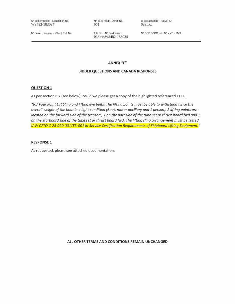
C-28-020-001/TB-001
TECHNICAL BULLETIN (MARINE)
IN-SERVICE CERTIFICATION REQUIREMENTS FOR SHIPBOARD LIFTING EQUIPMENT
APPLICABLE TO ALL CLASSES OF SHIPS
(BILINGUAL)
(Supersedes C-28-020-001/TB-001 dated 1995-05-01)
Issued on Authority of the Chief of the Defence Staff
Contact Officer: DMSS 2-2-7 OPI: DMSS 2-2-7 © 2011 DND/MDN Canada 2011-09-01
OBJECTIVE
1. The objective of this technical bulletin is to specify the requirements for the life cycle certification of Shipboard Lifting Equipment. This document provides guidelines, which describe the certification process and record-keeping requirements. It also identifies the roles and responsibilities of personnel designated to administer the certification program.
REFERENCES
2. The following references apply:
a. C-34-010-002/AM-000, Rigging Manual.
b. C-03-005-003/AA-000, Naval Engineering Manual.
Canada1
NOTICE This documentation has been reviewed by the technical authority and does not contain controlled goods. Disclosure notices and handling instructions originally received with the document shall continue to apply.
AVIS Cette documentation a été révisée par l’autorité technique et ne contient pas des marchandises contrôlées. Les avis de divulgation et les instructions de manutention reçues originalement doivent continuer de s’appliquer.

C-28-020-001/TB-001
BACKGROUND
3. In order for all Shipboard Lifting Equipment to be fit for the intended design purpose, certain measures must be followed to ensure that the equipment are of adequate strength, in good working condition and suitable for safe operation, which would reduce and minimize risks to humans, the environment and material assets.
4. From the design stage, the installation, and throughout the life of all Shipboard Lifting Equipment, the following factors contribute to the continuous reliability of personnel and material safety.
a. Acquisition, Design, Fabrication. Shipboard Lifting Equipment design shall comply with the agreed technical standards and shall be safe to fulfil their operational role. Design shall take into account the intended operations of the equipment and also the environment in which they are to be used.
b. Usage and Maintenance. Shipboard Lifting Equipment shall only be used for their intended purpose and shall be operated by fully trained personnel. The maintenance strategy shall be based on manufacturer’s recommendations, operating experience and integration of Preventative Maintenance (PM) techniques. PM routines shall also include periodical inspections.
c. In-service Certification. In-service Material Fitness Inspections (MFIs) and test activities are integral in determining if the Shipboard Lifting Equipment’s material condition is satisfactory. Shipboard Lifting Equipments are monitored for wear deterioration and malfunction by a series of periodic inspections and tests based on PM routines, system specific Canadian Forces Technical Orders (CFTOs), Inspection Plans and Trial Agendas (TA). Certification will be delivered upon successful completion of the inspection and required tests.
d. Record Keeping. As part of a due diligence requirement, the Shipboard Lifting Equipment life cycle certification documents shall be managed and maintained. This is normally facilitated by an information system that stores each Shipboard Lifting Equipment’s certification history.
INTRODUCTION
APPLICABILITY
5. This CFTO is applicable to Canadian Forces ships including submarines and auxiliaries.
6. Submarines have a specific document detailing material Certification Process (C-23-VIC-000/AG-001), which ensures compliance with design intent. This document is to take precedence over all other documents including the present CFTO. However, this technical bulletin is to be used as guidance, if required.
SCOPE
7. This document is intended to provide guidance to:
a. Identify and consolidate the requirements for life cycle certification of Shipboard Lifting Equipment.
b. Develop Trial Agendas for individual Lifting Appliances and Lifted Equipment.
c. Purchase Lifting Accessories needed for Shipboard Lifting Equipment (refer to appendix).
d. Define the roles and responsibilities of personnel designated to administer the certification program.
8. Test Requirements set forth in this CFTO, which include testing, inspection and documentation registration of Shipboard Lifting Equipment, will enable the in-service certification and improve the reliability and safety of Shipboard Lifting Equipment. These requirements shall be considered the minimum standard and not construed as the test requirements defined in specific Trial Agendas or specified by the equipment manufacturer.
2

C-28-020-001/TB-001
CLASSIFICATION OF SHIPBOARD LIFTING EQUIPMENT
9. Shipboard Lifting Equipment comprises the following categories:
a. Lifting Appliances,
b. Lifted Equipment,
c. Lifting Accessories,
d. Lifting Points, and
e. Non-lifting Equipment.
The diagram shown in Table 1 is representative of the main categories but is not comprehensive of all Shipboard Lifting Equipment. All equipment involved in lifting activities requires certification. There exists a broader range of equipment, which is not considered as lifting appliances, by definition, as they do not perform lifting; however, certification is required. Each category has specific certification requirements, which are covered in Annexes A to E.
3

C-28-020-001/TB-001
Table 1 Shipboard Lifting Equipment Classification
4

C-28-020-001/TB-001
DEFINITIONS
10. The following definitions are applicable to this technical order:
a. Shipboard Lifting Equipment. Shipboard Lifting Equipment is comprised of Lifting Appliances, Lifted Equipment, Lifting Accessories, and Lifting Points.
b. Lifting Appliances. Lifting Appliances are devices performing the lifting. These include all systems, devices or components and associated support structures, which are used for the purpose of lifting, lowering, slewing or otherwise moving personnel, material, or vehicles. These include but not limited to: A-frames and derricks, cranes, elevators, lifts, davits, monorails, hoists, winches, and similar equipment including equipment mountings and adjacent structure affected by the movement of loads.
c. Lifted Equipment. Lifted Equipments are used on board ships for suspending, raising or lowering loads or moving them from one position to another while suspended. These are equipment from which a load can be attached, supported or secured during a lifting operation. These include but not limited to: personnel cradles, billy pughs, personnel rescue sling (horse collars), pallet bars, skids, drum racks, netting, baskets, boats or other receptacles used to convey any cargo or personnel.
d. Lifting Accessories. Lifting Accessories are devices, which connect the load to the Lifting Appliance and they include any device or assembly of devices used to facilitate attachment of a load to a Lifting Appliance. Lifting Accessories do not form an integral part of the appliance or load. These include but not limited to: wire rope slings, chains and chain slings, hooks, spreader bars, lifting eyes, cable holders, shackles, disengaging gear, wires, and cordage. These are usually interchangeable from one Lifting Appliance to another.
e. Lifting Points. Lifting Points include but not limited to: welded eyeplates, strong points, cleats and similar securing items that can be used for tying-down, lashing or securing applications. Lifting pad eyes can also be loops, rings or eyebolts that are attached to equipment used for lifting. These pieces of hardware are sometimes referred to as lifting lugs.
f. Non-lifting Equipment. Non-lifting Equipment comprises all devices that do not specifically perform lifting activities; however, loads may be applied by the equipment and/or may sustain loads where safety is an issue and certification is required.
g. Inspection. Inspection consists of a visual and physical check, which examines the state of individual items of Shipboard Lifting Equipment prior to certification. The purpose of an inspection is to determine the presence of excessive wear and tear, malfunction, oil leakage, overheating, corrosion, unusual noise, dislocation, visual cracks, misalignment, overloading, abnormal slackening or elongation, excessive vibration, etc. The inspection is carried out to determine if the equipment is safe for continual use. Records of apparent external condition provide the basis for a continuing evaluation.
h. Material Fitness Inspection (MFI). MFI is a thorough examination, which entails a detailed visual examination supplemented if necessary by other means of examination in order to arrive at a reliable conclusion as to the material state of the lifting equipment examined.
i. Non Destructive Examination (NDE). NDE is a form of examining material without damaging the intended usefulness of the component. NDE incorporates a wide variety of technical methods used for various applications to identify specific flaws, such as:
(1) Magnetic Particle Testing (MT),
(2) Liquid Penetrant Testing (PT),
(3) Radiograph Testing (RT), and
(4) Ultrasonic Testing (UT).
5
C-28-020-001/TB-001
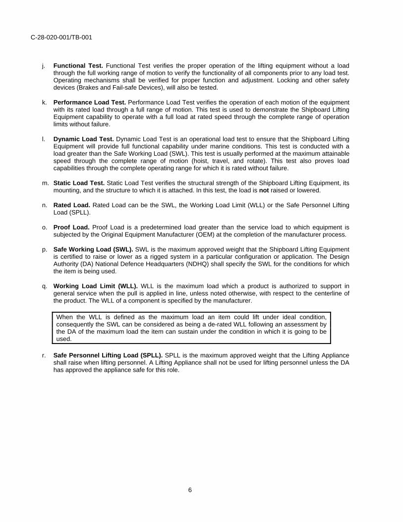
j. Functional Test. Functional Test verifies the proper operation of the lifting equipment without a load through the full working range of motion to verify the functionality of all components prior to any load test. Operating mechanisms shall be verified for proper function and adjustment. Locking and other safety devices (Brakes and Fail-safe Devices), will also be tested.
k. Performance Load Test. Performance Load Test verifies the operation of each motion of the equipment with its rated load through a full range of motion. This test is used to demonstrate the Shipboard Lifting Equipment capability to operate with a full load at rated speed through the complete range of operation limits without failure.
l. Dynamic Load Test. Dynamic Load Test is an operational load test to ensure that the Shipboard Lifting Equipment will provide full functional capability under marine conditions. This test is conducted with a load greater than the Safe Working Load (SWL). This test is usually performed at the maximum attainable speed through the complete range of motion (hoist, travel, and rotate). This test also proves load capabilities through the complete operating range for which it is rated without failure.
m. Static Load Test. Static Load Test verifies the structural strength of the Shipboard Lifting Equipment, its mounting, and the structure to which it is attached. In this test, the load is not raised or lowered.
n. Rated Load. Rated Load can be the SWL, the Working Load Limit (WLL) or the Safe Personnel Lifting Load (SPLL).
o. Proof Load. Proof Load is a predetermined load greater than the service load to which equipment is subjected by the Original Equipment Manufacturer (OEM) at the completion of the manufacturer process.
p. Safe Working Load (SWL). SWL is the maximum approved weight that the Shipboard Lifting Equipment is certified to raise or lower as a rigged system in a particular configuration or application. The Design Authority (DA) National Defence Headquarters (NDHQ) shall specify the SWL for the conditions for which the item is being used.
q. Working Load Limit (WLL). WLL is the maximum load which a product is authorized to support in general service when the pull is applied in line, unless noted otherwise, with respect to the centerline of the product. The WLL of a component is specified by the manufacturer.
When the WLL is defined as the maximum load an item could lift under ideal condition, consequently the SWL can be considered as being a de-rated WLL following an assessment by the DA of the maximum load the item can sustain under the condition in which it is going to be used.
r. Safe Personnel Lifting Load (SPLL). SPLL is the maximum approved weight that the Lifting Appliance shall raise when lifting personnel. A Lifting Appliance shall not be used for lifting personnel unless the DA has approved the appliance safe for this role.
6
C-28-020-001/TB-001
PART 1 – ROLES AND RESPONSIBILITIES
DESIGN AUTHORITY (DA)
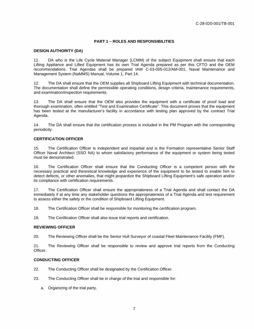
11. DA who is the Life Cycle Material Manager (LCMM) of the subject Equipment shall ensure that eachLifting Appliance and Lifted Equipment has its own Trial Agenda prepared as per this CFTO and the OEM recommendations. Trial Agendas shall be prepared IAW C-03-005-012/AM-001, Naval Maintenance and Management System (NaMMS) Manual, Volume 1, Part 14.
12. The DA shall ensure that the OEM supplies all Shipboard Lifting Equipment with technical documentation. The documentation shall define the permissible operating conditions, design criteria, maintenance requirements, and examination/inspection requirements.
13. The DA shall ensure that the OEM also provides the equipment with a certificate of proof load and thorough examination, often entitled “Test and Examination Certificate”. This document proves that the equipment has been tested at the manufacturer’s facility in accordance with testing plan approved by the contract Trial Agenda.
14. The DA shall ensure that the certification process is included in the PM Program with the corresponding periodicity.
CERTIFICATION OFFICER
15. The Certification Officer is independent and impartial and is the Formation representative Senior Staff Officer Naval Architect (SSO NA) to whom satisfactory performance of the equipment or system being tested must be demonstrated.
16. The Certification Officer shall ensure that the Conducting Officer is a competent person with the necessary practical and theoretical knowledge and experience of the equipment to be tested to enable him to detect defects, or other anomalies, that might jeopardize the Shipboard Lifting Equipment’s safe operation and/or its compliance with certification requirements.
17. The Certification Officer shall ensure the appropriateness of a Trial Agenda and shall contact the DA immediately if at any time any stakeholder questions the appropriateness of a Trial Agenda and test requirement to assess either the safety or the condition of Shipboard Lifting Equipment.
18. The Certification Officer shall be responsible for monitoring the certification program.
19. The Certification Officer shall also issue trial reports and certification.
REVIEWING OFFICER
20. The Reviewing Officer shall be the Senior Hull Surveyor of coastal Fleet Maintenance Facility (FMF).
21. The Reviewing Officer shall be responsible to review and approve trial reports from the Conducting Officer.
CONDUCTING OFFICER
22. The Conducting Officer shall be designated by the Certification Officer.
23. The Conducting Officer shall be in charge of the trial and responsible for:
a. Organizing of the trial party.
7

C-28-020-001/TB-001
b. Determining the prompt efficient and safe conduct of the trial as described in Part 3.
c. Preparing the trial documentation.
SHIP STAFF
24. Ship Staff play an integral part in the certification of Shipboard Lifting Equipment and are responsible for the following activities:
a. Maintaining current and valid certificate for each Shipboard Lifting Equipment.
b. Reporting major deficiencies/events of the Shipboard Lifting Equipment which may impact the certification to the Certification Officer.
c. Ensuring pre-operation inspection is conducted.
d. Purchasing of Lifting Accessories, when required, in accordance with appendix.
CERTIFICATION BY SUBCONTRACTORS
25. Subcontractors performing testing and certification shall comply with the guidelines of this document.
PART 2 – REQUIREMENTS
GENERAL INSTRUCTIONS
26. All Shipboard Lifting Equipment shall have a current and valid certificate prior to use. Shipboard Lifting Equipment certificates should never be allowed to expire while the vessel remains in commission.
27. All Lifting Appliances and Lifted Equipment shall have their own specific Trial Agenda, which provides the instructions for periodic trials that are set out in C-03-005-003/AA-000. Trial Agendas are to be developed IAW C-03-005-012/AM-001, Volume 1, Part 14.
28. For the replacement of existing Lifting Accessories, the purchasing shall be done in accordance with this CFTO as detailed in appendix.
CERTIFICATION FREQUENCY
29. All Shipboard Lifting Equipment shall be tested and certified on the following occasions:
a. Initial Installation. All Shipboard Lifting Equipment shall be certified before being taken into use for the first time. For new equipment acquisition, certification will be issued following the completion of the documentation verification, initial examination and test.
b. Fixed Periodicity. Unless otherwise specified, the standard periodicity for official re-certification of Shipboard Lifting Equipment is at least once in every four years when the equipment is used for general purpose and two years if used to lift personnel or ammunition.
c. Following Corrective Maintenance Actions. Shipboard Lifting Equipment subjected to substantial alteration or after repair to any stress bearing parts, which may have affected the strength of the Lifting Equipment, shall be re-certified. Formation Technical Authority (FTA), in consultation with the DA, shall confirm what tests are required following any specific corrective maintenance activity (refer to Annex F, Test Requirements of Shipboard Lifting Equipment After Corrective Maintenance).
8
C-28-020-001/TB-001
d. Following Overload of the Shipboard Lifting Equipment. If there is any reason to suspect that the Shipboard Lifting Equipment has been unduly loaded or for any other reason may be unfit for service, the Commanding Officer, without waiting for the usual test period, shall submit an Operational Deficiency (OPDEF) and forward a work request to the Certification Officer, requesting a survey and retest, quoting this CFTO as authority. The Shipboard Lifting Equipment shall not be used until the retest has been satisfactorily completed. The Certification Officer should be consulted for further guidance or to discuss possible remedial or waiver action while deployed.
INSTRUCTIONS TO REINSTATE CERTIFICATION
30. Should it be operationally essential to use a Shipboard Lifting Equipment, which certification has become invalid due to unusual circumstances, the Certification Officer shall be advised and may issue a waiver for an extension or re-certification of the Shipboard Lifting Equipment. The waiver may limit the usage of the Shipboard Lifting Equipment to a limited period and/or for specific usage under specified conditions. The instructions to reinstate certification are listed in Table 2.
9

C-28-020-001/TB-001
Unusual Circumstances In Home Port At Sea/Foreign Port
Certification has expired. a., b., e., f., l. a., b., c., d., g., h., i., j., k.
Major repairs following corrective maintenance. a., b., e., f., l. a., b., c., d., g., h., i., j., k.
Overload of the Shipboard Lifting Equipment. a., b., e., j., k. a., b., c., d., g., h., i., j., k.
a. Do not use the Shipboard Lifting Equipment until instructions from the Certification Officer are provided.
b. Ship must request a waiver/extension or re-certification of the Shipboard Lifting Equipment to the Certification Officer via message. It must include reason for deficiencies and actions taken by SS to address the issue. (Examples of messages for certification extension request are found in Annex G.)
c. A MFI instruction shall be provided by FTA of the subject equipment.
d. A MFI shall be conducted by the Marine Systems Engineering Officer (MSEO).
e. A MFI shall be completed by the Conducting Officer.
f. Fixed periodic test for re-certification will be completed by the Conducting Officer.
g. The MSEO will forward the results of the MFI to the Certification Officer for assessment and request instructions if the subject equipment can be tested.
h. Test instruction shall be provided by FTA of the subject equipment based on the results of the MFI.
i. If MFI is found satisfactory; conduct test as specified by FTA.
j. Test results are sent to the Certification Officer.
k. The Certification Officer will assess the MFI and test results and will respond via message. The Certification Officer can issue an interim certificate with instructions for course of action to follow, restriction on usage of equipment and expiry date of the new certificate.
l. The Certification Officer will issue a new certificate or an interim certificate with instructions for course of action to follow, restriction on usage of equipment and expiry date of the new certificate.
Table 2 Instructions to Reinstate Certification
10
C-28-020-001/TB-001
PART 3 – IN-SERVICE CERTIFICATION PROCEDURE
GENERAL
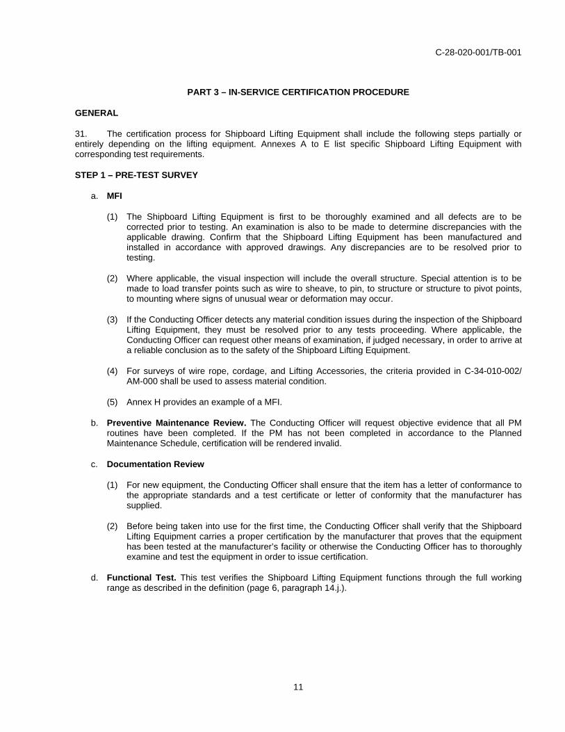
31. The certification process for Shipboard Lifting Equipment shall include the following steps partially or entirely depending on the lifting equipment. Annexes A to E list specific Shipboard Lifting Equipment with corresponding test requirements.
STEP 1 – PRE-TEST SURVEY
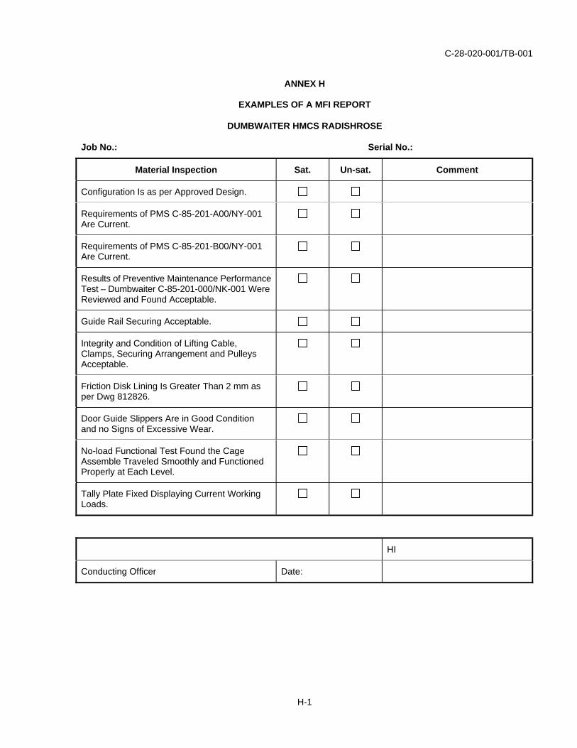
a. MFI
(1) The Shipboard Lifting Equipment is first to be thoroughly examined and all defects are to be corrected prior to testing. An examination is also to be made to determine discrepancies with the applicable drawing. Confirm that the Shipboard Lifting Equipment has been manufactured and installed in accordance with approved drawings. Any discrepancies are to be resolved prior to testing.
(2) Where applicable, the visual inspection will include the overall structure. Special attention is to be made to load transfer points such as wire to sheave, to pin, to structure or structure to pivot points, to mounting where signs of unusual wear or deformation may occur.
(3) If the Conducting Officer detects any material condition issues during the inspection of the Shipboard Lifting Equipment, they must be resolved prior to any tests proceeding. Where applicable, the Conducting Officer can request other means of examination, if judged necessary, in order to arrive at a reliable conclusion as to the safety of the Shipboard Lifting Equipment.
(4) For surveys of wire rope, cordage, and Lifting Accessories, the criteria provided in C-34-010-002/ AM-000 shall be used to assess material condition.
(5) Annex H provides an example of a MFI.
b. Preventive Maintenance Review. The Conducting Officer will request objective evidence that all PM routines have been completed. If the PM has not been completed in accordance to the Planned Maintenance Schedule, certification will be rendered invalid.
c. Documentation Review
(1) For new equipment, the Conducting Officer shall ensure that the item has a letter of conformance to the appropriate standards and a test certificate or letter of conformity that the manufacturer has supplied.
(2) Before being taken into use for the first time, the Conducting Officer shall verify that the Shipboard Lifting Equipment carries a proper certification by the manufacturer that proves that the equipment has been tested at the manufacturer’s facility or otherwise the Conducting Officer has to thoroughly examine and test the equipment in order to issue certification.
d. Functional Test. This test verifies the Shipboard Lifting Equipment functions through the full working range as described in the definition (page 6, paragraph 14.j.).
11

C-28-020-001/TB-001
STEP 2 – LOAD TESTS
32. All Shipboard Lifting Equipment purchased prior to 2011 shall continue to be tested under their applicable Trial Agendas until revised by the DA.
a. Static Load Test
(1) Static Load Tests are generally only performed on Shipboard Lifting Equipment after initial installation or after major modification/repairs that may affect the structural integrity of the Shipboard Lifting Equipment. Periodic Static Load Tests should not be required unless specified under Trial Agendas. If a load test is unachievable, such as welded eyepads located directly above equipment, a design review and NDE, if appropriate, shall be completed to ascertain the item’s capacity and condition.
(2) The following applies for Static Test Load (STL) factors:
(a) For SWL under 10 tonnes: STL = 2.0 x SWL/WLL.
(b) For SWL 10 tonnes and over: STL = 1.2 x SWL + 8 tonnes.
(c) For Personnel Lifting: STL = 2.2 x SWL.
(d) For Winch Brakes (Long Arm [LA] only): STL = 1.5 x SWL.
b. Dynamic Load Test
(1) Dynamic Load Tests (DTL) are generally performed at fixed periodicity to ensure that the Shipboard Lifting Equipment provides full functional capability under marine conditions.
(2) The following applies to DTL factors for Shipboard Lifting Equipments that are used in harbor, where ship motions are limited.
(a) For SWL under 10 tons/tonnes: DTL = 1.25 x SWL.
(b) For SWL 10 tons/tonnes and over: DTL = 1.1 x SWL + 4 tonnes.
(c) For Personnel Lifting: DTL = 1.33 x SWL tonnes.
(d) For Winch Brakes (LA only): DTL = 1.1 x SWL tonnes.
(3) Load factors for offshore cranes shall be determined by the DA.
c. Performance Load Test
(1) Performance Load Test is performed to determine condition of functional operation of the Lifting Appliance and repeatability of functions under loading conditions.
(2) A Performance Load Test is conducted at 100% of the rated load and rated speed.
STEP 3 – POST TEST SURVEY
33. After completion of any test, the whole of the Shipboard Lifting Equipment is to be carefully examined for flaws and defects. Defects found are to be repaired and retests are to be carried out in accordance with this order. Defects and their method of repair are to be discussed with FTA and are to be recorded. Repetitive defects indicate a weakness in design and shall be reported to the DA.
12
C-28-020-001/TB-001
STEP 4 – ISSUANCE OF CERTIFICATE FOR SHIPBOARD LIFTING EQUIPMENT
34. Whenever a test is applied on a Shipboard Lifting Equipment, three copies of the certificate (Annex I) shall be prepared by the Conducting Officer and submitted through the normal administration procedure in accordance with the following distribution list:
a. HMCS Ship (customer); Her Majesty’s Canadian Ship (Customer).
b. NDHQ/DMCM or NDHQ DMSS CDM; (as applicable); and National Defence Head Quarters/Director Maritime Class Management or Ship Support Class Desk Management.
c. MARPAC/MARLANT FTA. Maritime Forces Pacific/Maritime Forces Atlantic Formation Technical Authority.
STEP 5 – INSTALLATION OF MARKINGS OR TALLY PLATES
35. When Shipboard Lifting Equipment is certified, the Conducting Officer is to ensure that a test tally plate is fixed in a conspicuous position on the equipment. Care is to be taken that any securing holes for the attachment of test tally plates and any center punch marking are positioned so that the strength of the fitting is not impaired. If this cannot be done, the test tally plate is to be suitably mounted near the lifting equipment. The following data is to be given on all tally plates:
a. Name of the Shipboard Lifting Equipment.
b. Rated Load for specific condition.
c. State if approved or not approved for lifting personnel (SPLL)
d. Expiry date of the certificate.
e. Initials of the Conducting Officer.
f. Unique identifier (CT Number).
13


C-28-020-001/TB-001
ANNEX A
CERTIFICATION REQUIREMENTS FOR LIFTING APPLIANCES
A-1

C-28-020-001/TB-001
Table A-1 (Sheet 1 of 3) Certification Requirements for Lifting Appliances
A-2
C-28-020-001/TB-001
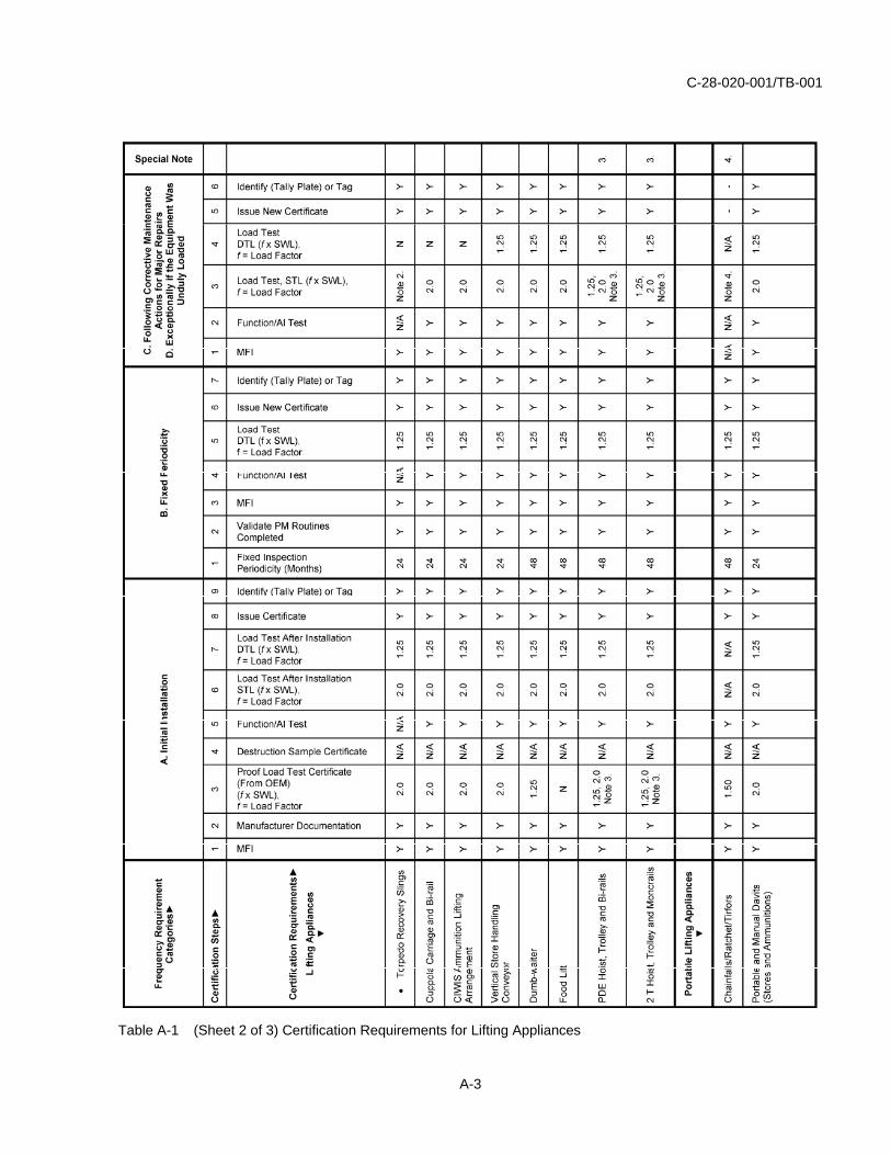
Table A-1 (Sheet 2 of 3) Certification Requirements for Lifting Appliances
A-3

C-28-020-001/TB-001
NOTES
1. This item is to be replaced every 24 months. Wire rope shall be tested by sample, where a piece is tested to destruction. All wire rope and cordage shall be certified prior to being put in service. Normally, manufacturers provide a certificate stating the breaking strength of the manufactured batch that the shipment originated from.
2. Load test will not be necessary. Discard and replace with a newly certified item.
3. Rails are tested initially at 2.00 x SWL and hoists are tested at 1.25 x SWL.
4. Discard and replace with a new item if the portable Lifting Appliance is found defective.
Table A-1 (Sheet 3 of 3) Certification Requirements for Lifting Appliances
A-4

C-28-020-001/TB-001
REMARKS
1. Lifting Appliances that do not have a Trial Agenda should be tested in accordance to Table A-1, otherwise FTA shall be contacted for directions.
2. Tests are to be carried out on board with the system rigged according to the applicable Trial Agenda. Tests are to be applied with the ship alongside, moored, or in dock and in an upright and steady condition, except when a sea trial is specified.
3. Static Load Tests shall be performed on Lifting Appliances that requires installation and fastening to the ship structure in order to validate the strength of the design and installation.
4. Static Load Tests are to be applied and held for an amount of time specified in the Trial Agenda, generally held for at least three minutes. The total deflection of the appliance while the load is applied shall be measured and recorded. The load shall be removed and any permanent deflection shall be measured and recorded. If permanent deflection occurs, the appliance shall be repaired and retested; the design of the appliance shall be reviewed by the FTA to ensure that it is adequate. The following precautions are to be observed:
a. Slipping clutches, where fitted, are to be adjusted for maximum compression for the duration of the test and reset to design overload upon completion. The adjustment is to be recorded in the appropriate ancillary equipment test sheet.
b. In hydraulic systems, where a device is tested with extended cylinder pistons, a means of isolating the control valve shall be used to prevent safety blow-offs when load is applied.
c. On all Lifting Appliances, the STL is not to be suspended by the purchase, but is to hang by a strop on the head of the derrick or davit. In circumstances where this is impracticable, the Trial Agenda shall specify the appropriate procedure.
5. The DTL is to be applied and held for one minute. The load is then to be raised and traveled throughout the full working range of the item under test. For variable boom systems, the appropriate load is to be applied at maximum, intermediate and minimum boom radius. For load testing at the minimum radius, the test loads shall not exceed the winch manufacturers rated SWL. If the test load exceeds winch design safety margins for inner radius conditions, the inner radius shall be de-rated to the same load as the intermediate SWL load.
6. Performance Load Test is to be performed through the complete range of the Lifting Appliance operating motion (hoist, lower, top rotate, travel), including testing of brakes and emergency features. For variable boom systems, the appropriate load is to be applied at maximum, intermediate and minimum radius.
7. A power-operated unit may be incapable of lifting the DTL throughout the full range, due to protective devices being out of adjustment or system deterioration (e.g. clutch, overload relay safety valve etc.). When this occurs, adjustment of the protective device should not be set to exceed specified limits.
8. For brakes, the winch shall be wound to the maximum number of turns. A STL shall be applied and held on the winch brake for one minute then lowered for one complete revolution of the winch barrel shaft.
9. For brakes, a DTL shall be lowered at maximum lowering speed through a distance of at least three meters and stopped sharply. The test load shall drop no more than one meter when the brake is applied.
10. Trial Agendas are also required for Lifting Appliances that are installed temporarily as a complete system. In addition, prescribed checks in accordance with the system’s documentation shall be conducted after each installation.
A-5

C-28-020-001/TB-001
ANNEX B
CERTIFICATION REQUIREMENTS FOR LIFTED EQUIPMENT
B-1
C-28-020-001/TB-001
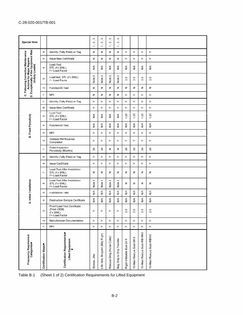
Table B-1 (Sheet 1 of 2) Certification Requirements for Lifted Equipment
B-2

C-28-020-001/TB-001
NOTES
1. This item is to be replaced every 48 months.
2. Load test will not be necessary. Discard and replace the item with a newly certified Lifted Equipment.
3. During the initial certification, load tests are not required if the OEM has provided a Test and Examination Certificate proving the accessory was tested by the manufacturer. Lifted Equipment purchased prior to 2011 may not have a Proof Load Test Certificate from the OEM; hence a load test shall be required. After 2011, all Lifted Equipment shall be purchased from a manufacturer that provides a Test and Examination Certificate.
Table B-1 (Sheet 2 of 2) Certification Requirements for Lifting Equipment
B-3

C-28-020-001/TB-001
REMARKS
1. Lifted Equipment shall be tested in accordance with the appropriate Trial Agenda, which specifies the test requirements, or as per Table B-1.
2. The test can be carried out on board or on land with the system rigged in accordance with the applicable Trial Agenda.
B-4

C-28-020-001/TB-001
ANNEX C
CERTIFICATION REQUIREMENTS FOR LIFTING ACCESSORIES
C-1
C-28-020-001/TB-001
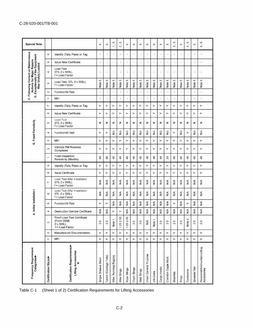
Table C-1 (Sheet 1 of 2) Certification Requirements for Lifting Accessories
C-2
C-28-020-001/TB-001
NOTES
1. Wire rope shall be tested by sample where a piece is tested to destruction. All wire rope and cordage shall be certified prior to entering in service. Normally, manufacturers provide a certificate stating the breaking strength of the manufactured batch that the shipment originated from. Wire rope or cordage not assigned to any Lifting Appliance system shall be thoroughly examined on an annual basis, which has to be prescribed in PM Routines.
2. The proof load factor is 1.25 times the vertical rated load for hand-tuck splices. The proof load factor is 2.00 times the vertical rated load for mechanical splices.
3. Shackles samples shall be subjected to proof loads of two times the WLL. The manufacturer for selected samples from each lot shall provide a certificate. The certificate shall indicate as a minimum: Size, WLL, test weights and date of test. Shackles are not normally accompanied by an individual declaration of conformity for each item; the manufacturer produces one declaration for a batch. However, the declaration should contain sufficient information to relate it to the individual item.
4. Turnbuckle samples shall be subjected to two times the WLL for the end pull. The manufacturer for selected samples shall provide a certificate from each lot. The certificate shall indicate as a minimum: Size, WLL, test weights and date of test.
5. Discard and replace with a new item if the lifting accessory is found defective.
6. Lifting Accessories part of a Lifting Appliance, which have been approved for lifting personnel and/or ammunition shall be identified as such and shall be subjected to the standard of the Lifting Appliance Trial Agenda.
Table C-1 (Sheet 2 of 2) Certification Requirements for Lifting Accessories
C-3
C-28-020-001/TB-001
REMARKS
1. Load test are not required if the OEM has provided a Test and Examination Certificate proving the accessory was tested by the manufacturer.
2. Lifting accessories can be assigned to one of two categories:
a. Assigned to a specific lifting equipment system.
b. Not assigned to any specific system.
3. Lifting Accessories assigned to a specific system must be individually certified, assigned an ID/serial number, and marked accordingly prior to entering in service. Subsequently, thorough survey of the Shipboard Lifting Equipment system will consist of an inventory check and thorough examination of all Lifting Accessories.
4. The system Lifting Accessories must be retained with the parent equipment and not be detached and used elsewhere. Complete Shipboard Lifting Equipment, together with its Lifting Accessories, is covered by a test certificate. The Trial Agenda is developed to ensure that all load-bearing components are included so the Lifting Accessories are functionally tested with the exception of spare Lifting Accessories and those not assigned to any specific system.
5. Spare Lifting Accessories must receive a thorough examination. If the results of an examination reveals any reason to suspect the material condition has changed then the item shall be condemned and replaced with a newly certified component compliant with the specified material configuration drawings and appendix of this document.
6. Lifting Accessories not assigned to a specific system shall carry individual certificates with an assigned an ID/serial number and marked accordingly prior to entering in service. Subsequently, each Lifting Accessories shall have its own schedule of thorough examinations and carry its own certificate.
7. Shipboard Lifting Equipment systems may be comprised of many components, some of which being Lifting Accessories. If the system is subjected to its SWL, the various Lifting Accessories will be subjected to different component loads, where the component design load is identified and an appropriate component configuration is selected. Therefore, if a Lifting Accessory is condemned, it is to be replaced by a Lifting Accessory in full compliance with the design configuration and certified with its component rating rather than as a fixed function of the system rated load.
C-4

C-28-020-001/TB-001
ANNEX D
CERTIFICATION REQUIREMENTS FOR LIFTING POINTS
D-1
C-28-020-001/TB-001
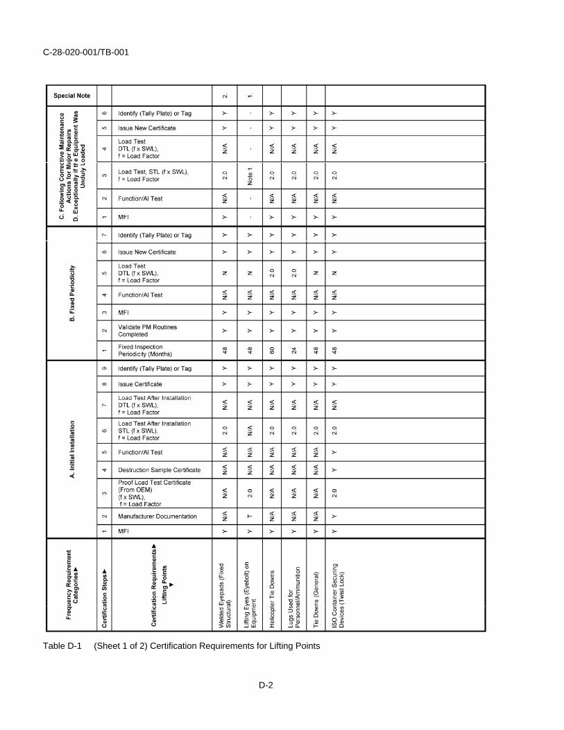
Table D-1 (Sheet 1 of 2) Certification Requirements for Lifting Points
D-2
C-28-020-001/TB-001
NOTES
1. Discard and replace with a new item one if found defective.
2. Shall be stamped, raise lettering, engraved, or tally plate attached to the item.
Table D-1 (Sheet 2 of 2) Certification Requirements for Lifting Points
D-3
C-28-020-001/TB-001
REMARKS
1. Lifting pad eyes are only to be fitted in locations where they can be tested in place, either by direct loading or by connecting with the test loads of the lifting system which they are associated with.
2. Where eyeplates are fitted for shipping machinery and it is impossible to test them without removing the machinery, then at the discretion of the Certification Officer, they may be subjected to a visual examination or a NDE, as required.
3. Periodic testing of machinery lifting eyes is not required. However, machinery lifting eyes shall not be used unless they have been certified within the past 60 months. Therefore, ships entering a scheduled work period should request certification of all eye-pads that will be used for planned or corrective maintenance during the next 60 months. Certification can consist of either a visual inspection or NDE in accordance with an inspection plan approved by the FTA. During the visual inspection, pad eyes should be visually examined for distortion, mechanical damage or any other sign of distress or overload. In most instances, the structure on which the lifting eye is connected should be examined.
4. Eye pads that sustain the lifted load shall be either static tested or surveyed in accordance with an approved inspection plan. Cracks and flaws can often be detected by “ringing”. Therefore, performing a “hammer test” by tapping the unit with a metal hammer may highlight any weakness. Conducting a “hammer test” doesn’t eliminate the need for a thorough visual inspection.
5. Lifting lugs should be permanently marked with the following applicable information:
a. For lifting, hoisting or winching – either WLL or SWL.
b. For lugs used for lashing – LC (Lashing Capacity).
D-4
C-28-020-001/TB-001
ANNEX E
CERTIFICATION REQUIREMENTS FOR NON-LIFTING EQUIPMENT
E-1

C-28-020-001/TB-001
Table E-1 (Sheet 1 of 2) Certification Requirements for Non-lifting Equipment
E-2

C-28-020-001/TB-001
NOTES
1. Refer to the corresponding TRIAL AGENDA.
2. Discard and replace with a new item one if found defective.
3. Shall comply to the instructions included in CSA-Z259, standards for Fall Arresters, Vertical Lifelines and Rails.
Table E-1 (Sheet 2 of 2) Certification Requirements for Non-lifting Equipment
E-3

C-28-020-001/TB-001
REMARKS
1. Non-lifting Equipment requires specific test instructions that are to be included in the Trial Agendas.
E-4
C-28-020-001/TB-001
ANNEX F
TEST REQUIREMENT OF SHIPBOARD LIFTING EQUIPMENT AFTER CORRECTIVE MAINTENANCE
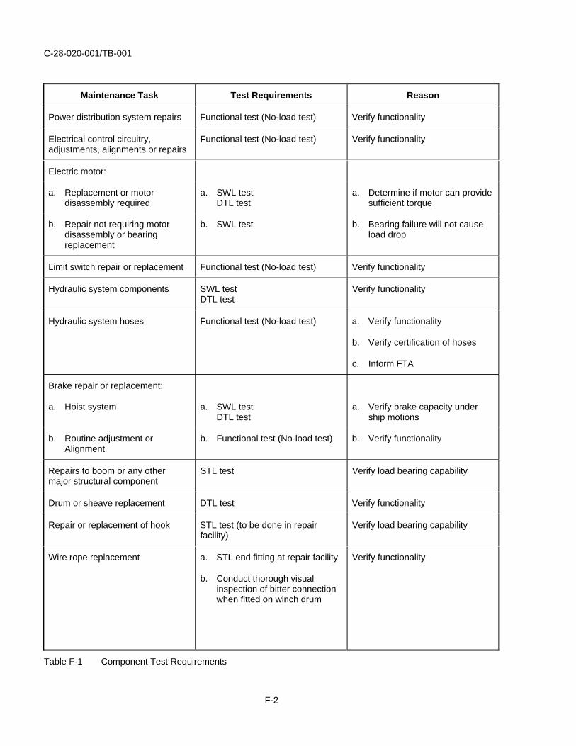
1. Corrective maintenance of certain load bearing or load controlling components can be tested by methods other than a complete load test. Guidance on specific test requirements following certain identified maintenance tasks, are found in Table F-1.
2. The table should only be used as guidance since a large range of corrective maintenance activities can have a unique risk associated with compromising the equipment’s safety or fitness. The FTA, in consultation with the DA, if required, shall confirm what tests are required following any specific corrective maintenance activity.
3. Load tests specified in this document shall be preceded by appropriate visual inspection and a functional test (no-load).
4. The tests below are meant to reconfirm the existing appliance certification. A complete test is required upon expiration of the unit’s certification.
5. The functional test (No-load test) shall exercise the system through the full working range of the unit.
6. For Halifax and Iroquois Classes, damaged cargo or torpedo cranes assembly including winch, pedestal, and boom shall be returned to the Canadian Forces Supply System (CFSS) for repair by Fleet Management Facility (FMF) or third line repair facility. The replacement crane shall be certified prior to entering in service.
F-1
C-28-020-001/TB-001
Maintenance Task Test Requirements Reason
Power distribution system repairs Functional test (No-load test) Verify functionality
Electrical control circuitry, adjustments, alignments or repairs
Functional test (No-load test) Verify functionality
Electric motor:
a. Replacement or motor disassembly required
a. SWL test DTL test
a. Determine if motor can provide sufficient torque
b. Repair not requiring motor disassembly or bearing replacement
b. SWL test b. Bearing failure will not cause load drop
Limit switch repair or replacement Functional test (No-load test) Verify functionality
Hydraulic system components SWL test DTL test
Verify functionality
Hydraulic system hoses Functional test (No-load test) a. Verify functionality
b. Verify certification of hoses
c. Inform FTA
Brake repair or replacement:
a. Hoist system a. SWL test DTL test
a. Verify brake capacity under ship motions
b. Routine adjustment or Alignment
b. Functional test (No-load test) b. Verify functionality
Repairs to boom or any other major structural component
STL test Verify load bearing capability
Drum or sheave replacement DTL test Verify functionality
Repair or replacement of hook STL test (to be done in repair facility)
Verify load bearing capability
Wire rope replacement a. STL end fitting at repair facility
b. Conduct thorough visual inspection of bitter connection when fitted on winch drum
Verify functionality
Table F-1 Component Test Requirements
F-2
C-28-020-001/TB-001
ANNEX G
EXAMPLES OF MESSAGES FOR CERTIFICATION EXTENSION REQUESTS
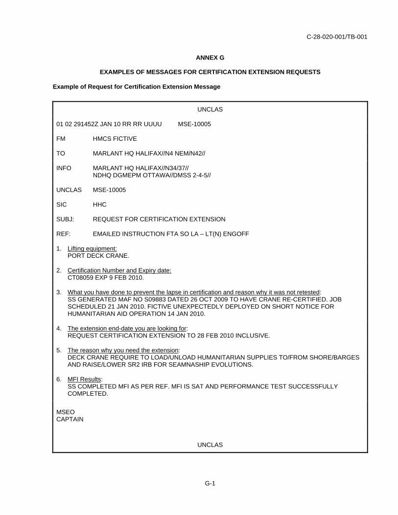
Example of Request for Certification Extension Message
UNCLAS
01 02 291452Z JAN 10 RR RR UUUU MSE-10005
FM HMCS FICTIVE
TO MARLANT HQ HALIFAX//N4 NEM/N42//
INFO MARLANT HQ HALIFAX//N34/37// NDHQ DGMEPM OTTAWA//DMSS 2-4-5//
UNCLAS MSE-10005
SIC HHC
SUBJ: REQUEST FOR CERTIFICATION EXTENSION
REF: EMAILED INSTRUCTION FTA SO LA – LT(N) ENGOFF
1. Lifting equipment:PORT DECK CRANE.
2. Certification Number and Expiry date:CT08059 EXP 9 FEB 2010.
3. What you have done to prevent the lapse in certification and reason why it was not retested:SS GENERATED MAF NO S09883 DATED 26 OCT 2009 TO HAVE CRANE RE-CERTIFIED. JOB SCHEDULED 21 JAN 2010. FICTIVE UNEXPECTEDLY DEPLOYED ON SHORT NOTICE FOR HUMANITARIAN AID OPERATION 14 JAN 2010.
4. The extension end-date you are looking for:REQUEST CERTIFICATION EXTENSION TO 28 FEB 2010 INCLUSIVE.
5. The reason why you need the extension:DECK CRANE REQUIRE TO LOAD/UNLOAD HUMANITARIAN SUPPLIES TO/FROM SHORE/BARGES AND RAISE/LOWER SR2 IRB FOR SEAMNASHIP EVOLUTIONS.
6. MFI Results:SS COMPLETED MFI AS PER REF. MFI IS SAT AND PERFORMANCE TEST SUCCESSFULLY COMPLETED.
MSEOCAPTAIN
UNCLAS
G-1
C-28-020-001/TB-001
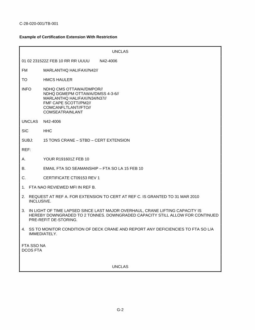
Example of Certification Extension With Restriction
UNCLAS
01 02 231522Z FEB 10 RR RR UUUU N42-4006
FM MARLANTHQ HALIFAX//N42//
TO HMCS HAULER
INFO NDHQ CMS OTTAWA//DMPOR// NDHQ DGMEPM OTTAWA//DMSS 4-3-6// MARLANTHQ HALIFAX//N34/N37// FMF CAPE SCOTT//PM2// COMCANFLTLANT//FTO// COMSEATRAINLANT
UNCLAS N42-4006
SIC HHC
SUBJ: 15 TONS CRANE – STBD – CERT EXTENSION
REF:
A. YOUR R191601Z FEB 10
B. EMAIL FTA SO SEAMANSHIP – FTA SO LA 15 FEB 10
C. CERTIFICATE CT09153 REV 1
1. FTA NAO REVIEWED MFI IN REF B.
2. REQUEST AT REF A. FOR EXTENSION TO CERT AT REF C. IS GRANTED TO 31 MAR 2010 INCLUSIVE.
3. IN LIGHT OF TIME LAPSED SINCE LAST MAJOR OVERHAUL, CRANE LIFTING CAPACITY IS HEREBY DOWNGRADED TO 2 TONNES. DOWNGRADED CAPACITY STILL ALLOW FOR CONTINUED PRE-REFIT DE-STORING.
4. SS TO MONITOR CONDITION OF DECK CRANE AND REPORT ANY DEFICIENCIES TO FTA SO L/A IMMEDIATELY.
FTA SSO NA DCOS FTA
UNCLAS
G-2
C-28-020-001/TB-001
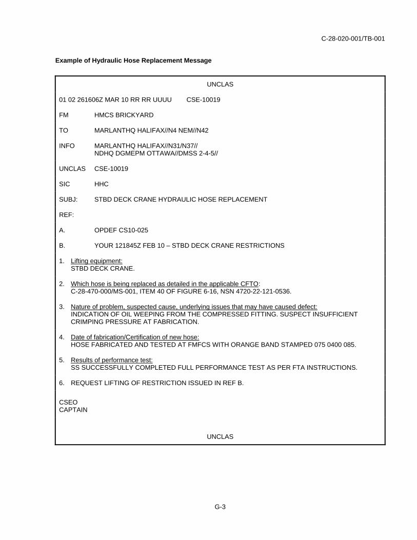
Example of Hydraulic Hose Replacement Message
UNCLAS
01 02 261606Z MAR 10 RR RR UUUU CSE-10019
FM HMCS BRICKYARD
TO MARLANTHQ HALIFAX//N4 NEM//N42
INFO MARLANTHQ HALIFAX//N31/N37// NDHQ DGMEPM OTTAWA//DMSS 2-4-5//
UNCLAS CSE-10019
SIC HHC
SUBJ: STBD DECK CRANE HYDRAULIC HOSE REPLACEMENT
REF:
A. OPDEF CS10-025
B. YOUR 121845Z FEB 10 – STBD DECK CRANE RESTRICTIONS
1. Lifting equipment:STBD DECK CRANE.
2. Which hose is being replaced as detailed in the applicable CFTO:C-28-470-000/MS-001, ITEM 40 OF FIGURE 6-16, NSN 4720-22-121-0536.
3. Nature of problem, suspected cause, underlying issues that may have caused defect:INDICATION OF OIL WEEPING FROM THE COMPRESSED FITTING. SUSPECT INSUFFICIENT CRIMPING PRESSURE AT FABRICATION.
4. Date of fabrication/Certification of new hose:HOSE FABRICATED AND TESTED AT FMFCS WITH ORANGE BAND STAMPED 075 0400 085.
5. Results of performance test:SS SUCCESSFULLY COMPLETED FULL PERFORMANCE TEST AS PER FTA INSTRUCTIONS.
6. REQUEST LIFTING OF RESTRICTION ISSUED IN REF B.
CSEOCAPTAIN
UNCLAS
G-3

C-28-020-001/TB-001
ANNEX H
EXAMPLES OF A MFI REPORT
DUMBWAITER HMCS RADISHROSE
Job No.: Serial No.:
Material Inspection Sat. Un-sat. Comment
Configuration Is as per Approved Design.
Requirements of PMS C-85-201-A00/NY-001 Are Current.
Requirements of PMS C-85-201-B00/NY-001 Are Current.
Results of Preventive Maintenance Performance Test – Dumbwaiter C-85-201-000/NK-001 Were Reviewed and Found Acceptable.
Guide Rail Securing Acceptable.
Integrity and Condition of Lifting Cable, Clamps, Securing Arrangement and Pulleys Acceptable.
Friction Disk Lining Is Greater Than 2 mm as per Dwg 812826.
Door Guide Slippers Are in Good Condition and no Signs of Excessive Wear.
No-load Functional Test Found the Cage Assemble Traveled Smoothly and Functioned Properly at Each Level.
Tally Plate Fixed Displaying Current Working Loads.
HI
Conducting Officer Date:
H-1


C-28-020-001/TB-001
ANNEX I
SAMPLE – CERTIFICATE OF SHIPBOARD LIFTING EQUIPMENT
Certificate Number: 01-0013 Issue Date: DD-MM-YY
For: HMCS VANCOUVER
Date of Certification: DD-MM-YY
System/Lifting Equipment Name: Boat Rigid Inflatable
Repair Facility Job Reference Number: 1111-2222-3
This Certificate Replaces Certificate: 01-0004
Date Retest is required: DD-MM-YY
Comments/Reservations:
(Example) This is an interim certificate valid only for one year. System will need to be fully tested upon completion of the mission.
1. This certificate confirms that IAW C-28-020-001/TB-001, In-service Certification Requirements for Shipboard Lifting Equipment, the subject Shipboard Lifting Equipment has been visually inspected and/or has been weight tested as per the specification and/or TRIAL AGENDA and has met the requirements with the exception of reservations noted above.
2. The certification of this Shipboard Lifting Equipment remains valid until the retest required date listed above. This retest date is conditional upon continued compliance with all required PM Schedules and assumes thatretest is not required prior to this date as per paragraph 3. below.
3. This certification becomes invalid and a retest shall be conducted following any operational deficiencies,repairs or alterations, which may affect the strength of any part of the lifting appliance. Exception is givenwhere C-28-020-001/TB-001, Annex F, Test Requirement of Shipboard Lifting Equipment After Corrective Maintenance, specifies the test action required upon repair of certain components.
Witnessed By:
H.S.Conducting Officer, Hull Surveyor
Issued By:
R.O.Reviewing Officer, Senior Hull Surveyor
Authorized By:
LCdr N.A.Certification Officer, Senior Staff Officer Naval Architect, Formation Technical Authority
I-1

C-28-020-001/TB-001
System Name: Booms and Lifting Appliances
Sub-system Name: Boat Davit System
ERN: E-28-400-000
Component: RIB Davit
Serial No.: 100001
Reference Information:
PM Routines: C-28-400-000/NY-001
C-28-400-000/NY-002
Trial Agendas: C-28-400-000/NT-A01
C-28-400-000/NT-A02
Drawing: SC987654
Data List No.: DL123456
Test Periodicity: 24 m
Inspection Periodicity: 24 m
Condition 1:
SWL: 1000 lb
SPLL: 750 lb
Boom Reach: 20 ft
Condition 2:
SWL: 600 lb
SPLL: 450 lb
Boom Reach: 25 ft
Conducting Officer confirms that the following items were completed Initials
A. Pre-test survey
B. Load Tests: (if applicable, otherwise N/A)
C. Post-test survey
D. Tally plate installation/Markings verification
NOTE
When electrical, hydraulic, or temperature readings are required in accordance with the specification or TRIAL AGENDA, this data is to be collected by the Conducting Officer and appended to the certificate.
I-2
C-28-020-001/TB-001
APPENDIX 1
LIFTING ACCESSORIES PROCUREMENT GUIDELINES
OBJECTIVE
1. The intent of this appendix is to identify and consolidate the requirements and purchasing guidelines of Shipboard Lifting Accessories and their components, which are intended to improve the reliability and safety of the Shipboard Lifting Equipment. The requirements set forth in this appendix shall be considered minimum standards and used as a reference not construed with the design requirements that are defined in specific regulations.
PURPOSE
2. Canadian Forces Shipboard Lifting Accessories design and selection shall comply with the agreed technical standards and shall be safe to fulfil their operational role. Design and selection shall take into account the intended operational aspects of the Shipboard Lifting Accessories and also the environment in which they are to be used. These guidelines identify and consolidate the requirements for design and selection and provide guidance in procuring Shipboard Lifting Accessories.
DEFINITION
3. Shipboard Lifting Accessories are defined as equipment attached to a Lifting Appliance that is subjected to a load; however, does not form an integral part of the appliance or load. Shipboard Lifting Accessories include but not limited to any steel wire rope, shackle, block, hook, clamp, grab, lifting beam, connecting plate, swivel, ring, chain, beam sling, overhauling weight, lifting beam, spreader, lifting frame or any other similar devices that are designed and/or used to facilitate loading and/or unloading of cargo.
LIFTING ACCESSORIES REQUIREMENTS
4. These guidelines apply to the replacement of Shipboard Lifting Accessories.
PROCUREMENT GUIDELINES FOR SHIPBOARD LIFTING ACCESSORIES
GENERAL INSTRUCTIONS
5. These instructions provide guidance in the procurement of Shipboard Lifting Accessories replacements. This primarily contains procurement criteria for off-the-shelf type items. The instructions provide information on the standards to be used for fabrication, the Factor of Safety and general requirements that shall be part of the definition of the requirements when selecting and purchasing Lifting Accessories. The DA shall be consulted if this document is referenced in the procurement specifications for special handling equipment.
PURCHASER RESPONSIBILITIES
6. The purchaser is responsible to identify and list the technical specifications for the procurement of Shipboard Lifting Accessories. The purchaser must determine the WLL of the Shipboard Lifting Accessory replacement. This load is defined as the maximum load the Shipboard Lifting Accessory should ever be subjected to in service.
7. The minimum Factor of Safety (FoS) must be included in the Purchase Order (PO) for Shipboard Lifting Accessories. Specific FoS for Shipboard Lifting Accessories are listed in Table I1-1 (pages I1-5 to I1-7). The FoS is defined as the ratio of the breaking stress of a structure to the estimated maximum stress in normal operational use. Essentially, how much stronger the system is than it usually needs to be for an intended load. The FoS should not be considered as reserve strength and should not be reduced under any circumstance.
I1-1
C-28-020-001/TB-001
8. Appropriate specification or standard references and requirements should be properly verified prior to procuring of Shipboard Lifting Accessories. Some specific requirements listed in this document are more stringent than standard requirements; however, ensure materials of adequate quality and workmanship are provided. Lifting Accessories for British procured vessels (i.e. submarines) are to follow the standard(s) referenced in the applicable equipment or system Technical Data Package (TDP).
9. The purchaser shall ensure that the manufacturer supply the documentation required for the review of conformance, which include:
a. Certificate of compliance with applicable standards.
b. Load test certification.
MANUFACTURER RESPONSIBILITIES
10. The manufacturer shall provide any documentation being requested (e.g. rated load certification, proof-load test certification, and material certification). The documentation shall be signed by the manufacturer’s authorized representative.
11. Hoisting and rigging materials and equipment are to be manufactured in accordance with recognized standards (refer to Table I1-1). The manufacturer shall provide a certificate of compliance to the recognized standard.
NOTES ON FACTOR OF SAFETY:
12. The FoS is the product of two different components: Load factor and stress factor.
a. Load factor consists of weight factor (including self weight, added weight, and future growth margin), service factor (environmental), duty factor (frequency), geometric factor, and dynamic factor (dynamic effects).
b. Stress factor is determined based on the type of material, expected life of component, and uncertainties such as human factors (maintenance and usage).
13. Distinctions shall be made on the different applications of the FoS based on the condition that the Shipboard Lifting Accessory will be used in Harbour Condition and Offshore Condition.
a. Harbour Condition. The FoS listed in Table I1-1 are applicable and the SWL is to be used unless the Shipboard Lifting Accessory is used on a Lifting Appliance that is de-rated (SPLL) then the original SWL is to be used.
b. Offshore Condition. A Dynamic Amplification Factor (DAF) will be introduced to consider the specific factors related to an offshore condition, such as the location of the Lifting Appliance, the stiffness of the components and the exciting forces that the equipment will encounter, such as ship motion. The FoS listed in Table I1-1 should be multiplied by an appropriate DAF.
14. DA shall be consulted if:
a. any of the above variables are changed;
b. SWL for existing equipment is determined based on unknown standards; and
c. equipment may be used differently than intended.
I1-2
C-28-020-001/TB-001
FACTOR OF SAFETY FOR SHIPBOARD LIFTING ACCESSORIES FOR LIFTING PERSONNEL
15. The FoS required for lifting personnel shall be higher than for normal loads, typically this is double for personnel lifting applications.
16. Environmental and other limits for personnel lifts shall be defined in the lift instructions, which shall explain the difference in limits for other lifts.
17. The allowable stresses are defined by standards or regulations.
18. Shipboard Lifting Accessories used for lifting personnel shall be selected, designed, approved/certified and clearly marked where applicable and if suitable for lifting personnel. Any equipment not marked shall not be used for lifting personnel.
REGISTRATION OF NEW SHIPBOARD LIFTING ACCESSORIES
19. For rigging hardware and accessories and synthetic slings, the review of conformance requirements consists of performing an initial inspection of the equipment prior to being in service.
20. When a Shipboard Lifting Accessory is purchased or obtained, the test certificate from the manufacturer must be provided. Wire and fiber slings should also have a certificate showing the SWL and include a reference to the batch sample test carried out on the material from which the rope of sling was made.
21. Some Shipboard Lifting Accessories may be purchased in batches and tested with a sample representation of the group.
22. Shipboard Lifting Accessories shall have a certificate of initial proof load testing signed by an authorized person or by an approved testing authority.
23. Shipboard Lifting Accessories that are associated to a Lifting Appliance or a Lifted Equipment may be tested with the associate Lifting Appliance or Lifted Equipment. All removable Shipboard Lifting Accessories that are not associated to a specific Lifting Appliance or Lifted Equipment must be registered individually.
I1-3

C-28-020-001/TB-001
Lifting Accessories Manufacturing Standards FoS
(min)
ASME B30.20
LR, Code for Lifting Appliances in a Marine Environment
DNV, Rules for Certification of Lifting Appliances
Below the hook structural and mechanical lifting devices: Beams – lifting beams, spreader beams, lifting frames
BS 2853 BS 2573
3
ASME B 30.9
ASTM A 391M-96
ASTM A 906-A 906M
ISO 3056
LR, Code for Lifting Appliances in a Marine Environment
DNV, Rules for Certification of Lifting Appliances
BS 3114
BS 4942 Part 1 and 6
Slings – chain
BS EN 818-5:1999
5
ASME B 30.9 Slings – flat woven webbing
BS EN 1492-1
5
Web Sling and Tie Down Association
ASME B 30.9
DNV, Rules for Certification of Lifting Appliances
LR, Code for Lifting Appliances in a Marine Environment
BS 6668 Part 2
Slings – round man-made fiber
BS EN 1492-2
5
Slings – wire rope API Spec 9 5
API 9B
ASME B 30.9
ISO 2408
ISO 4309
ISO 8792
ISO 7531
DNV, Rules for Certification Appliances
LR, Code for Lifting Appliances
Table I1-1 (Sheet 1 of 3) Lifting Accessories Standards and FoS Matrix
I1-4

C-28-020-001/TB-001
Lifting Accessories Manufacturing Standards FoS(min)
Marine Environment
BS 463 Part 1
BS 6210
BS 6166 Part 1
Slings – wire rope (Cont)
BS EN 13414
Clips – wire rope Federal Specs FF-C450D 5
ASME B 18.15
ASTM specification A489 for “Carbon Steel Eye Bolts”
ASTM F541 “Standard Specification for Alloy Steel Eyebolts”
Eye bolts and swivel hoist rings
ANSI/ASME B18.15 “Forged Eye Bolts”
5
Hooks ASME B 30.10 5
ASME B 30.9
Federal Specifications (US) RR-C- 271D
ISO 2415
ISO 2731
DNV, Rules for Certification of Lifting Appliances—Loose Gear
LR, Code for Lifting Appliances in a Marine Environment
BS 3032
BS 3551
Hoist rings, pear shape links, shackles
BS 6994
5
US Federal Specification FF-T-791 B
ASTM F1145
DNV, Rules for Appliances
Turnbuckles
BS 4429
5
ASME B30.20 Clamps – beam and plate lifting
DNV, Rules for Certification of Lifting Appliances
API 8A Snatch blocks
DNV, Rules for Certification of Lifting Appliances
BS 4018
Table I1-1 (Sheet 2 of 3) Lifting Accessories Standards and FoS Matrix
I1-5
C-28-020-001/TB-001
Lifting Accessories Manufacturing Standards FoS(min)
ASTM A-574 and UNC-3A
ASME/ANSI B18.3.1M
ISO 3266
ISO 3268
DNV, Rules for Certification of Lifting Appliances
LR, Code for Lifting Appliances in a Marine Environment
BS 4278
Eye bolts and swivel hoist rings
DIN 912 and DIN 582
Rigging Components not Listed Above
All running gear other than ropes N/A 6
All other components N/A 4.5
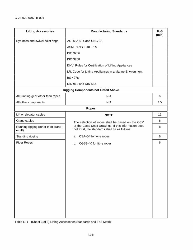
Ropes
Lift or elevator cables 12
Crane cables 6
Running rigging (other than crane or lift)
8
Standing rigging 6
Fiber Ropes
NOTE
The selection of ropes shall be based on the OEM or the Class Desk Drawings. If this information does not exist, the standards shall be as follows:
a. CSA-G4 for wire ropes
b. CGSB-40 for fibre ropes 6
Table I1-1 (Sheet 3 of 3) Lifting Accessories Standards and FoS Matrix
I1-6

C-28-020-001/TB-001
DETAILED REQUIREMENTS FOR GENERIC LIFTING ACCESSORIES
The following paragraphs provide information on the standard to be used for the fabrication, the FoS and general requirements that should be used when selecting and purchasing lifting accessories.
BELOW THE HOOK STRUCTURAL AND MECHANICAL LIFTING
24. Requirements include, but are not limited to the following:
a. Shall conform to standards listed in Table I1-1.
b. Shall have the rated load capacity marked on the main structure where it is visible. If the lifter is made up of several lifters, each detachable form the group, these lifters shall also be marked with their individual rated loads.
c. Shall be load tested with a load not exceeding 125% of the rated load.
d. Shall be supplied with a Load Test Certificate (LTC) indicating the date of load test, amount of load applied, and confirmation of lifter load rating.
e. Shall not be used with a load that exceeds more than 80% of the maximum load sustained during the test.
f. Shall have a complete or other permanent marking affixed to the lifter displaying the following:
(1) Manufacturer’s Name.
(2) Serial Number/Unique Identification Number.
(3) Lifted Weight.
(4) Rated Load Capacity.
CHAIN SLINGS
25. Requirements include, but are not limited to the following:
a. Shall conform to requirements of standards listed in Table I1-1.
b. Shall be Grade 80 minimum.
c. Shall be supplied with permanently affixed durable identification tag stating size, manufacturer’s grade, rated load and angle upon which the rating is based, reach, number of legs, and sling manufacturer.
d. Shall be supplied with hooks, rings, oblong links, pear-shaped links, welded or mechanical coupling links or other attachments having a rated load at least equal to that of alloy steel chain with which they are used.
e. Shall be supplied with hooks attached to chain slings meeting the requirements of ASME/ANSI B30.10.
f. Shall be supplied with welded components that are proof tested by the component or sling manufacturer to 200% of the rated load.
g. Shall be supplied with a certificate of proof test by the manufacturer or supplier referring to the specific sling identification number, date of test, and amount of load applied.
I1-7
C-28-020-001/TB-001
SYNTHETIC SLINGS
26. Requirements include, but are not limited to the following:
a. Shall conform to requirements of standards listed in Table I1-1.
b. Shall be fabricated with the following characteristics:
(1) Uniform thickness and width.
(2) Full woven width, including selvage edges.
(3) Sealed webbing ends by heat, or other suitable means, to prevent raveling.
(4) Thread used in the manufacture of synthetic web slings shall be the same generic type yarn as the sling webbing.
(5) Stitches shall be lock-stitched and preferably continuous. When not continuous, it shall be back stitched at the ends to prevent raveling.
c. Shall have a minimum design factor of five.
d. Shall be supplied with fittings that have sufficient strength to sustain twice the rated load of the sling without permanent deformation.
e. Shall be supplied with permanent marking showing the following information:
(1) Manufacturer’s name or trademark.
(2) Manufacturer’s code or stock number.
(3) Type of synthetic web material.
(4) Rated loads for the type of hitches used.
NOTE
Hand written, or ink embossed markings are not acceptable. Sling tags shall be indelibly marked and the lettering shall not wear off with use. The markings shall remain legible for the life of the sling.
f. Shall be supplied with product warnings relative to the proper use, care, and maintenance shall accompany the shipment.
g. Shall be supplied with a LTC for each lot of slings supplied. The LTC shall reference as a minimum, the PO number, date of proof test, amount of load applied, sling capacity, and lot/run number. The LTC shall be signed by the manufacturers authorized representative.
NOTE
Sling lengths shall be within a specified tolerance. Synthetic sling manufacturer normal tolerance is ±1% of the sling length. If stringent tolerance is required, the purchaser should specifically request required tolerance on the PO.
I1-8

C-28-020-001/TB-001
SYNTHETIC POLYESTER ROUND SLINGS
27. Requirements include, but are not limited to the following:
a. Shall conform to standards listed in Table I1-1.
b. Shall be fabricated with the following characteristics:
(1) The core(s) shall be formed from one or more ends of yarn, wound together on a plurality of turns. The core(s) should be uniformly wound to ensure even distribution of the load.
(2) The cover(s) shall be made of the same fiber type as the load bearing core(s). When the cover is a different fiber type than the load bearing core, follow the manufacturer’s recommendations for use.
(3) The cover(s) shall be made from one length of material.
(4) When the core and the cover are of the same fiber, the thread shall also be of that fiber type. When the core and cover are of different fiber types, the thread should be of the same fiber type as the core.
(5) All stitching shall be lock-stitched type and should be continuous. When not continuous, they shall be back stitched or overstitched to prevent raveling.
c. Shall be supplied with permanent marking or label showing:
(1) Name or trademark of manufacturer.
(2) Manufacturer’s code or stock number.
(3) Rated capacities for the basic hitches (vertical, choker, vertical basket).
(4) Core fiber type – if cover(s) is of a different fiber type, both fiber types shall be identified.
(5) Length (reach) – bearing point to bearing point.
d. Shall be provided with a LTC for each lot of slings supplied. The LTC shall reference as a minimum, the PO number, date of proof test, amount of load applied, sling capacity and lot/run number. The LTC shall be signed by the manufacturer’s authorized representative.
WIRE ROPE SLINGS
28. Requirements include, but are not limited to the following:
a. Shall conform to standards listed in Table I1-1.
b. Shall have documentation for wire rope from the manufacturer traceable to the material furnished and signed by the manufacturer’s authorized representative. Documentation shall reference as a minimum, the PO number, the diameter, number of strands, core, lay, grade, manufacturing lot/run number, master reel number and nominal breaking strength of sample.
c. Shall be shipped with a suitable preservative and a protective covering (i.e. plastic or cardboard).
d. Shall have a minimum of 5 to 1 FoS.
I1-9

C-28-020-001/TB-001
e. Shall be individually tagged with a durable tag, including the following information:
(1) WLL.
(2) PO number or serial number.
(3) Manufacturer’s name or ID.
f. Shall have a LTC for each lot of slings supplied. The LTC shall reference as a minimum, the PO number, date of proof test, amount of load applied, sling capacity, lot/run number. The LTC shall be signed by the manufacturer’s authorized representative;
WIRE ROPE CLIPS (CLAMPS)
29. Requirements include, but are not limited to the following:
a. Shall conform to standards listed in Table I1-1.
EYE BOLTS
30. Requirements include, but are not limited to the following:
a. Shall conform to standards listed in Table I1-1.
b. Shall be supplied with the manufacturer’s name or trademark, size and/or rated load identification mark in raised characters on the surface of the eyebolt eye used for lifting service. Alloy steel eye bolts shall have the symbol “A” (denoting alloy).
HOOKS
31. Requirements include, but are not limited to the following:
a. Shall conform to standards listed in Table I1-1.
b. Shall have manufacturer’s identification, SWL/WLL forged cast or die stamped on a low stress non-wearing area of the hook.
c. Shall be sufficiently ductile so that, when fractured, the hook shall show a permanent distortion before breaking.
d. Shall be able to withstand proof load application, without permanent deformation, when a load is applied for a minimum of 15 seconds when proof tests are used to verify manufacturing process, material, or configuration, hooks. Proof loads for hooks up to 50 tonnes capacity shall be 200% of the rated capacity.
SWIVEL HOIST RINGS
32. Requirements include, but are not limited to the following:
a. Shall conform to standards listed in Table I1-1.
b. Shall be individually proof load tested to a minimum of 200% of the rated capacity.
c. Shall have a proof load certificate supplied from the manufacturer with each swivel hoist ring.
I1-10

C-28-020-001/TB-001
d. Shall have the manufacturer’s name or trademark permanently marked on the swivel hoist ring.
e. Shall be permanently marked by the manufacturer with the SWL and recommended torque value.
f. Shall be packaged with proper application instructions and warning information.
HOIST RINGS, PEAR SHAPED LINKS
33. Requirements include, but are not limited to the following:
a. Shall conform to standards listed in Table I1-1.
b. Shall be supplied with Nondestructive Weld Test (NDT) documentation for welded rings or links.
NOTE
NDT is not required for forged rings or links.
c. Shall be proof tested by the manufacturer prior to initial use.
d. Shall be supplied with permanent marking with the manufacturer’s name or trademark and ring or link size.
SHACKLES
34. Requirements include, but are not limited to the following:
a. Shall conform to standards listed in Table I1-1.
b. Shall have each shackle body permanently and legibly marked in raised or stamped letters on the side of the shackle bow with the identifying manufacturer’s name or trademark, shackle size, and the SWL:
(1) Grade A regular strength shackle pins and bolts shall be unmarked.
(2) Grade B high strength shackle pins and bolts shall be marked by the raised or stamped letters “HS” on the head.
(3) Shackle markings shall be raised or stamped letters of the maximum height permitted by the size of the shackle component being marked.
c. Shall have shackle samples subjected to proof loads of 200% of the rated capacity.
d. Shall have shackle pins fit freely without binding and seat properly.
e. Shall have shackles sufficiently ductile so that, when fractured, the fractured member shall show a permanent distortion before breaking.
TURNBUCKLES
35. Requirements include, but are not limited to the following:
a. Shall conform to requirements of standards listed in Table I1-1.
b. Shall be fabricated from forged alloy steel.
c. Shall be provided with a jam nut of a type which does not depend upon deformation of the threads for security.
I1-11
C-28-020-001/TB-001
d. Shall have the certificate of proof test be provided by the manufacturer for selected samples from each lot. Certificate shall indicate as a minimum, the size, WLL, test weight, and date of test.
e. Shall have proof test loads certificates performed at one-half the specified breaking strength for the end pull.
f. Shall be permanently marked on the body of the turnbuckle with the manufacturer’s name and rated load.
WIRE ROPES
36. Requirements include, but are not limited to the following:
a. Shall conform to requirements detailed in Table I1-1.
b. Shall be selected based on the specifications of the OEM or the Class Desk Drawings. If this information does not exist, the Canadian Standard Association CSA-G4 for wire ropes shall be used.
c. Shall be provided with documentation referring as a minimum the PO number, the diameter, number of strands, core, lay, grade, manufacturer’s lot/run number, material number and the nominal breaking strength. Manufacturer shall also provide a LTC stating the breaking strength of a destruction sample test.
d. Shall be shipped with suitable preservative and a protective covering (i.e. plastic or cardboard).
e. Shall use FoS applicable to the published wire rope breaking strengths given in Table I1-1 when determining the SWL of steel wire ropes for use in or with Lifting Appliance.
FIBRE ROPES
37. Requirements include, but are not limited to the following:
a. Shall conform to requirements detailed in Table I1-1.
b. Shall use the specifications of the OEM or the Class Desk Drawings. If this information does not exist, the Canadian General Standards Board CGSB-40 for fibre ropes shall be used.
c. Shall be provided with documentation referring as a minimum the PO number, the diameter, number of strands, core, lay, grade, manufacturer’s lot/run number, material number and the nominal breaking strength. The manufacturer shall also provide a LTC stating the breaking strength of a destruction sample test.
HIGH-MODULUS POLYETHYLENE (HMPE) FIBRE LINES
38. This type of material is used in shipboard applications where a chance of snap back is possible. Due to relative high cost of HMPE, its use can be been confined to larger lines, such as hawsers and mooring lines. The higher strength material allows for smaller diameter rope, which is easier to handle, but brings with it the requirement to change system components to accommodate the reduced size. The low benefit-to-cost ratio for use of this material in running rigging applications has limited its wide spread application. If use of this material is anticipated, the equipment Life Cycle Manager at NDHQ should be contacted for specific applications.
I1-12